Robinson Helicopter Company RTR 660 (Number R00015LA). Maintenance Manual (2012) - page 1
Type Certificate Number R00015LA
Robinson Helicopter Company
Phone:
(310) 539-0508
2901 Airport Drive
Fax:
(310) 539-5198
Torrance, California 90505-6115
Web:
UNITED STATES
OFFICE HOURS
Monday through Friday, 7:30 a.m. to 4:30 p.m., Pacific Time.
Lunch hour is 11:30 a.m. to 12:30 p.m.
HOLIDAYS
for a complete list of holidays and company shutdowns.
CUSTOMER SUPPORT AND ORDERS
for a complete service directory.
Procure parts from any R66 Dealer or Service Center, or order directly
from assigned RHC Customer Service Representative via email, fax, or phone.
PUBLICATIONS
to view our publications electronically.
Introduction
Page i
SUBSCRIPTION SERVICE FORM
Name:
Phone:
Address:
Fax:
Email:
I Own R22 Serial Number(s):
I Own R44/R44 II Serial Number(s):
I Own R66 Serial Number(s):
Covers updates during the subscription period only. Requests for revisions produced before the subscription period are subject
to an additional charge at the full subscription rate for each past year requested.
MODEL/CLASS
DESCRIPTION
PRICE/YR.
QTY.
TOTAL
R22
A
Future updates to R22 Pilot’s Operating Handbook & Safety Notices
$15.00
B
Future updates to R22 Pilot’s Operating Handbook & Safety Notices, R22 Service
Bulletins & Service Letters
$25.00
C
Future updates to R22 Pilot’s Operating Handbook & Safety Notices, R22 Service
Bulletins, Service Letters, & R22 Maintenance Manual/Parts Catalog revisions
$35.00
R44
Q
Future updates to R44 Pilot’s Operating Handbook & Safety Notices
$15.00
R
Future updates to R44 Pilot’s Operating Handbook & Safety Notices, R44 Service
Bulletins & Service Letters
$25.00
S
Future updates to R44 Pilot’s Operating Handbook & Safety Notices, R44 Service
Bulletins, Service Letters, & R44 Maintenance Manual/Parts Catalog revisions
$35.00
R44 II
V
Future updates to R44 II Pilot’s Operating Handbook & Safety Notices
$15.00
W
Future updates to R44 II Pilot’s Operating Handbook & Safety Notices, R44 Service
Bulletins & Service Letters
$25.00
X
Future updates to R44 II Pilot’s Operating Handbook & Safety Notices, R44 Service
Bulletins, Service Letters, & R44 Maintenance Manual/Parts Catalog revisions
$35.00
R66
J
Future updates to R66 Pilot’s Operating Handbook & Safety Notices
$15.00
K
Future updates to R66 Pilot’s Operating Handbook & Safety Notices, R66 Service
Bulletins & Service Letters
$25.00
L
Future updates to R66 Pilot’s Operating Handbook & Safety Notices, R66 Service
Bulletins, Service Letters, & R66 Maintenance Manual/Parts Catalog revisions
$35.00
Method of Payment: No cash or CODs. We cannot be responsible for cash sent by mail. For faster processing, order online.
U.S. Check, Money Order, payable to Robinson Helicopter Company
Wire Transfer (subscription will not take effect until wire transfer has been received)
VISA, MasterCard or American Express
Credit Card Number:
Month / Year:
Cardholder Signature:
Verification Code:
Billing Zip:
Return to: ROBINSON HELICOPTER COMPANY Attn: Subscriptions
2901 Airport Drive, Torrance, CA 90505 Fax: (310) 539-5198
Page ii
Introduction
CHAPTER LIST
Introduction
Chapter
1
General
Chapter
4
Airworthiness Limitations
Chapter
5
Inspection Schedule
Chapter
6
Dimensions and Descriptions
Chapter
7
Jacking and Hoisting
Chapter
8
Weight and Balance
Chapter
9
Ground Handling
Chapter
10
Parking and Storage
Chapter
11
Placards and Markings
Chapter
12
Servicing
Chapter
18
Track and Balance
Chapter
20
Standard Practices
Chapter
21
Environment Control
Chapter
25
Furnishings
Chapter
28
Fuel System
Chapter
32
Landing Gear
Chapter
52
Doors and Windows
Chapter
53
Fuselage
Chapter
62
Main Rotor
Chapter
63
Main Rotor Drive System
Chapter
64
Tail Rotor
Chapter
65
Tail Rotor Drive System
Chapter
67
Flight Controls
Chapter
71
Powerplant
Chapter
75
Engine Air Systems
Chapter
76
Engine Controls
Chapter
79
Engine Oil System
Chapter
95
Instrument System
Chapter
96
Electrical System
Chapter
98
Wiring Diagrams
Chapter
99
Special Tools
Chapter
100
Revision Log
Introduction
Page iii
TECHNICAL PUBLICATIONS
RECOMMENDED CHANGE REPORT
Please direct recommended changes to RHC Technical Publications via the email address listed below, by phone,
or by submitting a duplicate of this completed form by fax or mail. Please include or have available the information
detailed by this form.
Recommended changes may include but are not limited to: general comments, corrections, omitted information,
or clarification of instructions.
Please send recommendations to:
Email:
techpubs@robinsonheli.com
Robinson Helicopter Company
Attention: Technical Publications
Phone:
(310) 539-0508
2901 Airport Drive
Fax:
(310) 539-5198
Torrance, CA
90505-6115
UNITED STATES
Date:
Publication:
Name:
Chapter:
Company:
Section:
Helicopter Model:
Page:
Serial Number:
Revision:
Phone:
Email:
COMMENTS:
Page iv
Introduction
LIMITED AIRCRAFT WARRANTY
Effective R66 Serial Number 0003 & on
Robinson Helicopter Company, Inc. (hereafter referred to as RHC) warrants each new helicopter to be free
from defects in material and workmanship appearing within two years from the date of delivery from the RHC
factory or during the first one thousand (1000) hours of operation, whichever event occurs first; provided, the
aircraft has been subjected to normal use and service. This Warranty is limited to repair or replacement on an
exchange basis, as selected by RHC, of any part, which upon examination by RHC is deemed to have been
defective when the aircraft left the factory. A new warranty period is not established for parts replaced under
the terms of this Warranty. Such replacement parts are warranted only for the remainder of the original war-
ranty period. This Warranty shall not apply to any helicopter or part which has been repaired or altered out-
side the factory, and which, in RHC’s judgment, has affected the performance or reliability of the helicopter
or part. This Warranty shall not apply to any helicopter or part which has been subject to corrosion, misuse,
negligence or accident, nor to any parts normally replaced during routine maintenance, such as, air cleaners,
skid shoes, rod end or spherical bearings, light bulbs, etc. This Warranty shall not apply to any helicopter,
which has been crated for shipping unless such crating is performed by RHC. RHC is not responsible for the
cost of shipping parts under the terms of this Warranty. However, RHC will credit the RHC Dealership, which
sold and delivered the new helicopter to its original owner, with an allowance for labor performed by that
Dealership for removing and reinstalling the defective part. No credit will be issued for trouble-shooting.
RHC makes no Warranty with respect to batteries, instruments, avionics or other trade accessories since
they are usually warranted separately by their respective manufacturers. New aircraft are equipped with new
engines which have a separate Rolls Royce limited warranty.
ADDITIONAL WARRANTY FOR MAIN & TAIL GEARBOXES
In addition to the warranty specified above, an extended pro-rated warranty shall apply to the main and tail
gearboxes for the first 2000 hours of service or three years from the date of manufacture, whichever event
occurs first. During this period, if a gearbox must be overhauled due to failure of a part which was defective
when it left the factory, RHC will pro-rate the cost of the overhaul by dividing the hours in service by 2000
or the months in service by thirty-six (36), whichever fraction is greater.
THE FOREGOING WARRANTY IS EXCLUSIVE AND IS GIVEN AND ACCEPTED IN LIEU OF
ANY AND ALL OTHER WARRANTIES AND REPRESENTATIONS, EXPRESS, IMPLIED, OR
STATUTORY, WHETHER WRITTEN OR ORAL, INCLUDING WITHOUT LIMITATION ANY
IMPLIED WARRANTIES OF MERCHANTABILITY, FITNESS FOR A PARTICULAR PURPOSE OR
TRADE USAGE, THE REMEDIES OF THE BUYER SHALL BE LIMITED TO THOSE PROVIDED
HEREIN. IN NO EVENT WILL THE MANUFACTURER BE LIABLE FOR LOSSES RESULTING
FROM LOSS OF USE OF THE HELICOPTER, COLLATERAL, CONSEQUENTIAL OR SPECIAL
DAMAGES, OR ANY OTHER COSTS.
Warranty adjustments with respect to any helicopter or parts manufactured by RHC will be made only upon
compliance with the following procedure:
(1) The defective part or assembly, together with a written Warranty Claim, must be returned to RHC not
later than thirty (30) days after discovery of the defect nor more than thirty (30) days after expiration
of the Warranty period.
(2) RHC will, after inspection, determine whether the material or part was defective when it left the
factory and will respond accordingly. Final determination of a Warranty adjustment rests with RHC.
ROBINSON HELICOPTER COMPANY, INC.
2901 Airport Drive
Effective 1 June 2010
Torrance, California 90505 U.S.A.
Introduction
Page v
Intentionally Blank
Page vi
Introduction
CONTENTS
INTRODUCTION
Section
Title
Page
— Cover Page
i
— Subscription Service Form
ii
— Chapter List
iii
— Recommended Change Report
iv
— Limited Aircraft Warranty
v
— Contents
vii
CHAPTER 1 — GENERAL
Section
Title
Page
1-10
Introduction
1.1
1-20
R66 Maintenance Manual Revisions
1.1
1-30
R66 Maintenance Authorization
1.1
1-40
R66 Component Overhaul Authorization
1.1
1-50
Notations
1.2
1-60
Definitions and Abbreviations
1.2
1-70
Service Directory
1.4
1-80
Assembly Instructions for R66 Helicopter Crated for Export
1.5
CHAPTER 4 — AIRWORTHINESS LIMITATIONS
Section
Title
Page
4-10
Airworthiness Limitations
4.1
4-20
Type Certificate Data Sheet (TCDS)
4.3
CHAPTER 5 — INSPECTION SCHEDULE
Section
Title
Page
5-10
Life-Limited Components
5.1
5-11
Time In Service Records
5.1
5-12
Retirement Procedure
5.1
5-20
Scheduled Maintenance and Inspections
5.3
5-30
Standard Inspection Criteria
5.5
5-31
Ball and Roller Bearings
5.5
5-32
Push-Pull Tubes
5.5
5-33
Rod Ends and Spherical Bearings
5.5
5-34
Elastomeric Bearings
5.7
5-35
Telatemp Indicators
5.7
5-40
Operation Checks for 100-hour / Annual Maintenance and Inspection
5.8
5-41
Ground Check
5.8
5-42
Run-Up
5.10
5-43
Flight Check
5.11
5-45
100-Hour / Annual Maintenance and Inspection
5.13
5-50
2000-Hour Maintenance and Inspection
5.36B
5-55
12-Year Maintenance and Inspection
5.36D
5-60
Special Maintenance and Inspections
5.37
Introduction
Page vii
CONTENTS
CHAPTER 5 — INSPECTION SCHEDULE (Continued)
Section
Title
Page
5-61
Tail Skid Strike
5.37
5-62
Tail Rotor Strike
5.38
5-63
Main Rotor Strike
5.39
5-64
Rotor/Engine Overspeed
5.40
5-65
Hard Landing
5.41
5-66
Dye Penetrant Inspection of F020-1 Upper Frame
5.42
5-67
Corrosion on F020-1 Upper Frame
5.42
5-68
Main Rotor Gearbox Overtemp Illumination
5.42
5-69
Main Rotor Gearbox (MR) Chip Light Illumination
5.43
5-70
Tail Rotor Gearbox (TR) Chip Light Illumination
5.43
5-71
Main Rotor Gearbox Filter Bypass Indicator
5.43
CHAPTER 6 — DIMENSIONS AND DESCRIPTIONS
Section
Title
Page
6-10
Version Description
6.1
6-20
Datum
6.1
6-30
Method of Measurement
6.1
6-40
External Dimensions
6.3
6-50
Baggage Compartment Dimensions
6.4
6-60
Station Diagrams
6.6
6-61
Fuselage Station (FS) Locations
6.6
6-62
Tailcone Station (TS) Locations
6.7
6-63
Water Line (WL) Station Locations
6.8
6-64
Butt Line (BL) Station Locations
6.9
6-70
Access and Inspection Panels
6.11
6-80
Antenna Locations
6.12
CHAPTER 7 — JACKING AND HOISTING
Section
Title
Page
7-10
Jacking
7.1
7-20
Hoisting
7.5
CHAPTER 8 — WEIGHT AND BALANCE
Section
Title
Page
8-10
Leveling
8.1
8-11
Leveling for Weight and Balance
8.1
8-12
Leveling for Rigging
8.3
8-20
Weighing
8.5
8-21
Preparing Helicopter for Weighing
8.5
8-22
Weighing Procedure and Calculations
8.7
8-30
Fixed Ballast
8.11
8-31
Nose Ballast
8.11
8-32
Empennage Ballast
8.13
Page viii
Introduction
CONTENTS
CHAPTER 9 — GROUND HANDLING
Section
Title
Page
9-10
Ground Handling
9.1
9-11
Ground Handling Wheels
9.1
9-12
Moving Helicopter on Ground Handling Wheels
9.3
9-13
Ground Handling Carts
9.3
9-14
Ground Power Start
9.3
9-20
Trailering
9.4
CHAPTER 10 — PARKING AND STORAGE
Section
Title
Page
10-10
Parking
10.1
10-11
Parking in High Wind or Turbulent Air
10.1
10-12
Main Rotor Blade Tie-Downs
10.3
10-13
Main Rotor Blade Supports
10.5
10-20
Storage (Greater than 30 days)
10.6
CHAPTER 11 — PLACARDS AND MARKINGS
Section
Title
Page
11-10
Placard Locations
11.1
11-20
Placard Illustrations
11.3
CHAPTER 12 — SERVICING
Section
Title
Page
12-10
Main Rotor Gearbox
12.1
12-11
Servicing
12.1
12-12
Filter Replacement
12.3
12-13
Chip Detector and Sight Gage
12.3
12-20
Tail Rotor Gearbox
12.7
12-21
Servicing
12.7
12-22
Chip Detector and Sight Gage
12.8
12-23
Drain and Flush
12.8
12-30
Hydraulic System
12.9
12-31
Servicing
12.9
12-32
Filter Replacement
12.9
12-33
Drain and Flush
12.11
12-34
Bleeding
12.12
12-40
Fuel System
12.13
12-41
Fueling
12.13
12-42
Defueling
12.13
12-50
Main Rotor Blades
12.15
12-51
Filling Spindle Assembly
12.15
12-60
Engine Oil Servicing
12.16
12-70
(Engine) Compressor Rinse and Wash
12.17
Introduction
Page ix
CONTENTS
CHAPTER 12 — SERVICING (Continued)
Section
Title
Page
12-80
Air Conditioning System
12.18
12-81
Refrigerant Recovery and System Charging
12.18
12-82
Desiccant Replacement
12.19
12-83
Leak Detection
12.19
CHAPTER 18 — TRACK AND BALANCE
Section
Title
Page
18-10
Main Rotor Track and Balance
18.1
18-11
Preparing Helicopter for Main Rotor Track and Balance
18.3
18-12
Flight Checks
18.5
18-13
Track Adjustment
18.7
18-14
Balance Adjustment
18.10
18-15
Troubleshooting
18.11
18-16
Autorotational RPM Adjustment
18.12
18-20
Tail Rotor Dynamic Balance
18.17
18-21
Preparing Helicopter for Tail Rotor Dynamic Balance
18.17
18-22
Ground Checks
18.19
18-23
Balance Adjustment
18.19
18-30
Main Rotor Flight Control Rigging
18.21
18-40
Main Rotor Blade Rigging
18.23
18-41
Cyclic Travel
18.24
18-42
Collective Travel
18.26
18-50
Tail Rotor Flight Control Rigging
18.28
18-51
Pedals
18.28
18-52
Forward Bellcrank
18.28
18-53
Intermediate Bellcrank
18.28
18-60
Tail Rotor Blade Control Rigging
18.29
CHAPTER 20 — STANDARD PRACTICES
Section
Title
Page
20-10
Cleaning
20.1
20-20
Lubrication
20.2
20-30
Torque Requirements
20.3
20-31
Torque Seal
20.5
20-32
Standard Torques
20.6
20-33
Special Torques
20.7
20-34
Push-Pull Tube Rod End Adjustment
20.11
20-40
Non-Destructive Testing
20.12
20-41
Magnetic Particle Inspection
20.12
20-42
Fluorescent Penetrant Inspection
20.13
20-50
Corrosion Control
20.13
20-60
Priming and Painting
20.13
20-70
Approved Materials
20.16
20-71
Paint Strippers
20.16
20-72
Solvents and Cleaners
20.16
20-73
Fillers and Putty
20.17
Page x
Introduction
CONTENTS
CHAPTER 20 — STANDARD PRACTICES (Continued)
Section
Title
Page
20-74
Torque Seal
20.17
20-75
Primers
20.17
20-76
Powder Coat
20.18
20-77
Paints
20.19
20-78
Lubricants
20.22
20-79
Adhesives and Sealants
20.23
20-80
Storage Limits
20.24
20-90
Miscellaneous Practices
20.25
20-91
Part Interchangeability
20.25
20-92
Thermal Fitting Parts
20.26
20-93
Replacement Component Identification (Data) Plates
20.26
CHAPTER 21 — ENVIRONMENT CONTROL
Section
Title
Page
21-00
Description
21.1
21-10
Ventilation
21.3
21-11
Nose Vent
21.3
21-20
Air Conditioning
21.5
21-21
Compressor Assembly
21.5
21-22
Condenser and Fan Assemblies
21.7
21-23
Evaporator Assembly
21.8
21-24
Troubleshooting
21.9
21-30
Cabin Heat
21.11
21-31
Valve Assembly and Control Rigging
21.11
21-32
Muffler Assembly
21.12
21-33
Diffuser and Tee Assemblies
21.12
CHAPTER 25 — FURNISHINGS
Section
Title
Page
25-00
Description
25.1
25-10
Seat Harnesses
25.3
25-11
Seat Harness Removal
25.3
25-12
Seat Harness Installation
25.4
25-20
Seat Assemblies and Back Rests
25.5
25-21
Seat Assembly Removal and Installation
25.5
25-22
Back Rest Assembly Removal and Installation
25.5
25-23
Back Rest Cushion Replacement
25.5
25-30
Carpet
25.7
25-40
Insulation (Foam and Headliner)
25.8
25-50
General Maintenance
25.8
25-51
Pilot's Operating Handbook (POH) Strap Replacement
25.8
25-52
License Holder Replacement
25.9
25-53
Map Pocket Replacement
25.9
25-60
Emergency Equipment
25.10
25-61
Emergency Locator Transmitter (ELT)
25.10
25-62
Fire Extinguisher
25.11
Introduction
Page xi
CONTENTS
CHAPTER 28 — FUEL SYSTEM
Section
Title
Page
28-00
Description
28.1
28-10
Bladder Assembly
28.3
28-11
Roll-Over Vent Valves
28.6
28-12
Sump Valve
28.6
28-20
Fuel Quantity
28.7
28-21
Fuel Quantity Sender
28.7
28-22
Low-Fuel Switch Assembly
28.8
28-30
Fuel Valve
28.11
28-31
Fuel Valve Control Rigging
28.11
28-40
Fuel Flow Check
28.12
CHAPTER 32 — LANDING GEAR
Section
Title
Page
32-00
Description
32.1
32-10
Landing Gear Assembly
32.1
32-20
Cross Tubes
32.5
32-30
Skid Tubes
32.7
32-31
Skid Shoes
32.8
32-32
Skid Extension Replacement
32.8
32-33
Ground Handling Wheel Support Replacement
32.8
32-40
Fairing Assemblies
32.9
32-50
Maintenance
32.9
32-60
Pop-Out Floats Installation
32.11
32-61
Cylinder Assembly
32.11
32-62
Lever Rigging and Shear-Rivet Replacement
32.17
32-63
Float Installation
32.19
32-64
System Maintenance
32.22
CHAPTER 52 — DOORS AND WINDOWS
Section
Title
Page
52-00
Description
52.1
52-10
Door Assembly
52.1
52-11
Door Lock Replacement
52.4
52-12
Weather Seal (Door Assembly) Replacement
52.4
52-13
Gas Springs
52.7
52-20
Door Vent Replacement
52.7
52-21
Weather Seal (Door Vent) Replacement
52.7
52-22
Door Vent Hinge Replacement
52.8
52-23
Pivot Friction Adjustment
52.8
52-30
Windshield Assembly
52.11
CHAPTER 53 — FUSELAGE
Section
Title
Page
53-00
Description
53.1
53-10
Cabin Assembly
53.1
Page xii
Introduction
CONTENTS
CHAPTER 53 — FUSELAGE (Continued)
Section
Title
Page
53-11
Repair
53.1
53-20
Fairing, Cowlings, and Panels
53.3
53-21
Engine Cowling
53.3
53-22
Mast Fairing
53.3
53-23
Tailcone Cowling
53.4
53-24
Access and Inspection Panels
53.4
53-30
Frame Assemblies
53.5
53-31
Lower Frames
53.5
53-32
Hydraulic Servo Support Frame
53.9
53-33
Upper Frame
53.10
53-40
Tailcone Assembly
53.13
53-41
Inspection and Repair
53.15
53-50
Empennage Assembly
53.17
53-51
Vertical Stabilizer
53.17
53-52
Horizontal Stabilizer
53.19
53-53
Tail Rotor Guard
53.21
53-54
Tail Skid
53.22
CHAPTER 62 — MAIN ROTOR
Section
Title
Page
62-00
Description
62.1
62-10
Main Rotor Blades
62.1
62-11
Blade Boots
62.6
62-20
Main Rotor Hub
62.7
62-21
Bearing Replacement
62.9
62-30
Main Rotor Assembly
62.11
62-31
Journal and Shim Calculations
62.11
62-32
Adjusting Hinge Friction
62.15
62-33
Drilling Nuts and Bolts
62.17
62-40
Inspection of Main Rotor Blades
62.19
62-41
Scratches and Corrosion
62.19
62-42
Dents
62.21
62-43
Spar Damage
62.23
62-44
Root Fitting Damage
62.23
62-45
Nicks and Notches
62.23
62-46
Voids and Debonds
62.25
62-50
Repair of Main Rotor Blades
62.27
62-51
Sealing, Filling, and Fairing
62.27
62-52
Painting
62.28
CHAPTER 63 — MAIN ROTOR DRIVE SYSTEM
Section
Title
Page
63-00
Description
63.1
63-10
Engine Shaft Weldment
63.1
63-11
(Engine Driveline) Forward Flex Plate Shimming
63.2
63-12
Clutch Assembly
63.5
Introduction
Page xiii
CONTENTS
CHAPTER 63 — MAIN ROTOR DRIVE SYSTEM (Continued)
Section
Title
Page
63-20
Main Rotor Gearbox Assembly
63.6
63-21
Yoke and Seal Replacement
63.8
63-30
Rotor Brake
63.11
63-31
Pad Replacement
63.12
63-40
Rotor RPM
63.12
CHAPTER 64 — TAIL ROTOR
Section
Title
Page
64-00
Description
64.1
64-10
Tail Rotor Assembly
64.1
64-11
Static Balance
64.5
64-20
Tail Rotor Blades
64.8
64-30
Tail Rotor Blade Inspection and Repair
64.9
64-31
Scratches and Corrosion
64.9
64-32
Dents
64.9
64-33
Erosion
64.11
64-34
Root Fitting Damage
64.11
64-35
Nicks and Notches
64.11
64-36
Painting
64.11
64-40
Tail Rotor Hub
64.13
64-41
Bearing Replacement
64.13
64-42
Inspection
64.13
CHAPTER 65 — TAIL ROTOR DRIVE SYSTEM
Section
Title
Page
65-00
Description
65.1
65-10
Tail Rotor Drive Fan Shaft
65.1
65-20
Tail Rotor Drive Shaft Assembly
65.3
65-21
Runout
65.5
65-22
Damper Assembly
65.7
65-30
(Tail Rotor Driveline) Intermediate Flex Plate Shimming
65.8
65-40
Tail Rotor Gearbox Assembly
65.10
65-41
Output Shaft Seal Replacement
65.11
65-42
Input Shaft Seal Replacement
65.12
CHAPTER 67 — FLIGHT CONTROLS
Section
Title
Page
67-00
Description
67.1
67-10
Cyclic Controls
67.1
67-11
Cyclic Control Assembly
67.1
67-12
Cyclic Grip Assembly
67.4
67-13
Cyclic Friction Assembly
67.6
67-20
Collective Control
67.6
67-21
Collective Stick Assembly
67.6
67-22
Collective Friction
67.8
Page xiv
Introduction
CONTENTS
CHAPTER 67 — FLIGHT CONTROLS (Continued)
Section
Title
Page
67-30
Jackshaft and Strut Assembly
67.8
67-31
Jackshaft
67.8
67-40
Swashplate
67.9
67-41
Swashplate Tilting Friction Adjustment
67.11
67-42
Upper and Lower Scissor Assemblies
67.11
67-50
Hydraulic System
67.13
67-51
Hydraulic Pump
67.13
67-52
Hydraulic Reservoir
67.14
67-53
Hydraulic Servos
67.15B
67-60
Tail Rotor Controls
67.19
67-61
Pedals
67.19
67-62
Pitch Control
67.20
67-70
Bellcranks
67.21
67-71
C317-5 Bellcrank
67.21
67-72
C317-7 Bellcrank
67.22
67-73
F316-1 Bellcrank
67.22
67-74
A331-4 Bellcrank
67.23
67-75
A120-5 Bellcrank
67.24
CHAPTER 71 — POWERPLANT
Section
Title
Page
71-00
Description
71.1
71-10
Engine
71.3
71-11
Preparing Engine for Rolls-Royce Maintenance Facility
71.6
71-12
Preparing Engine for Helicopter Installation
71.7
71-20
Induction
71.11
71-21
Air Filter Assembly
71.11
71-22
Cage Assembly
71.12
71-23
Engine Inlet Bellmouth
71.12
71-30
Exhaust Weldment
71.15
71-40
Accessories
71.16
71-41
Starter-Generator
71.16
71-42
Generator Control Unit (GCU)
71.16
71-43
Engine Monitoring Unit (EMU)
71.17
CHAPTER 75 — ENGINE AIR SYSTEMS
Section
Title
Page
75-00
Description
75.1
75-10
Engine Anti-Ice
75.1
CHAPTER 76 — ENGINE CONTROLS
Section
Title
Page
76-00
Description
76.1
76-10
Fuel Control Unit (FCU)
76.1
76-11
FCU Throttle Control Rigging
76.3
Introduction
Page xv
CONTENTS
CHAPTER 76 — ENGINE CONTROLS (Continued)
Section
Title
Page
76-12
FCU Fuel Cutoff Control Rigging
76.3
76-20
Power Turbine Governor (PTG)
76.5
76-21
PTG Control Rigging
76.5
76-22
PTG Rigging Check
76.7
CHAPTER 79 — ENGINE OIL SYSTEM
Section
Title
Page
79-00
Description
79.1
79-10
Scroll and Fanwheel Assemblies
79.3
79-11
Fanwheel-to-Inlet Gaps
79.3
79-20
Oil Tank Assembly
79.5
79-21
Oil Temperature Sender
79.6
79-22
Sight Gage
79.7
79-30
Engine Oil Cooler
79.7
79-40
Engine Oil Line Assemblies and Fittings
79.8
CHAPTER 95 — INSTRUMENT SYSTEM
Section
Title
Page
95-00
Description
95.1
95-10
Pitot-Static System
95.3
95-20
Primary Instruments
95.5
95-21
Vertical Speed Indicator
95.5
95-22
Airspeed Indicator
95.5
95-23
Engine (N2) and Rotor Dual Tachometer
95.5
95-24
Altimeter
95.5
95-25
Torquemeter
95.6
95-26
Magnetic Compass
95.6
95-30
Engine Gages
95.6
95-31
N1 Tachometer
95.6
95-32
Measured Gas (Turbine) Temperature (MGT) Gage
95.6
95-33
Engine Oil Pressure Gage
95.6
95-34
Engine Oil Temperature Gage
95.6
95-35
Fuel Quantity Gage
95.6
95-40
Additional Standard Indicating Equipment
95.7
95-41
Clock
95.7
95-42
Ammeter
95.7
95-43
Outside Air Temperature (OAT) Gage/Voltmeter
95.7
95-44
Hourmeters
95.7
95-50
Instrument Markings
95.7
95-60
Troubleshooting Guide
95.7
CHAPTER 96 — ELECTRICAL SYSTEM
Section
Title
Page
96-00
Description
96.1
96-10
Battery
96.2
Page xvi
Introduction
CONTENTS
CHAPTER 96 — ELECTRICAL SYSTEM (Continued)
Section
Title
Page
96-20
External Power
96.5
96-30
Starter and Ignition System
96.5
96-40
Lighting System
96.6
96-50
Annunciator Panel
96.6
96-60
Low Rotor RPM Warning Unit Adjustment
96.7
96-70
Audio System
96.7
96-80
Engine Monitoring Unit (EMU)
96.8
96-90
Emergency Locator Transmitter (ELT)
96.8
96-100
Electrical Load Analysis
96.9
CHAPTER 98 — WIRING DIAGRAMS
Figure
Title
Page
98-1
R66 Electrical System (F024 Revision I)
98.1
98-2
R66 Electrical System (F024 Revision G)
98.2
98-3
Air Conditioning Installation
98.3
98-4
ADF Installation
98.5
98-5
Standard Audio System
98.7
98-6
Dual Audio Control Installation
98.9
98-7
PA/Siren Installation
98.11
CHAPTER 99 — SPECIAL TOOLS
Section
Title
Page
99-10
Special Tools
99.1
99-20
Illustrations and Tasks
99.3
CHAPTER 100 — REVISION LOG
Section
Title
Page
— Revision Log
100.1
Introduction
Page xvii
Intentionally Blank
Page xviii
Introduction
CHAPTER 1
GENERAL
Section Title
Page
1-10
Introduction
1.1
1-20
R66 Maintenance Manual Revisions
1.1
1-30
R66 Maintenance Authorization
1.1
1-40
R66 Component Overhaul Authorization
1.1
1-50
Notations
1.2
1-60
Definitions and Abbreviations
1.2
1-70
Service Directory
1.4
1-80
Assembly Instructions for R66 Helicopter Crated for Export
1.5
Chapter 1 General
Page 1.i
Intentionally Blank
Page 1.ii
Chapter 1 General
CHAPTER 1
GENERAL
1-10 Introduction
The R66 Maintenance Manual contains instructions necessary for proper maintenance, servicing,
and handling of the R66 helicopter. The R66 Instructions for Continued Airworthiness (ICA)
include the R66 Maintenance Manual (MM), R66 Illustrated Parts Catalog (IPC), R66 Pilot’s
Operating Handbook (POH), R66 Service Bulletins (SB), R66 Service Letters (SL), RR300 Series
Operation and Maintenance Manual (OMM), applicable Rolls-Royce technical publications, and
applicable component manufacturer technical publications.
Service Bulletins may be issued by Robinson Helicopter Company
(RHC), Rolls-Royce,
or component manufacturers. Service Bulletin compliance is mandatory. RHC technical
Rolls-Royce technical publications are available on the internet at: https://fast.aeromanager-
online.com.
The R66 Maintenance Manual is formatted in Air Transport Association of America Specification
No. 100 (ATA-100). Style, content, and structure deviates from ATA-100 when necessary
for clarity, and for logic of presentation. A list of chapters, and a complete list of contents is
located in the Introduction. Chapters are separated by tab dividers; chapter contents are listed
in the chapter front pages.
CAUTION
Always read instructions completely before performing a task.
1-20 R66 Maintenance Manual Revisions
Before using the R66 Maintenance Manual, verify it consists of effective pages. A complete
list of effective pages is located in the Revision Log in Chapter 100. When a new manual is
purchased, complete and submit the Subscription Service Form located in the Introduction.
Subscription owners receive publication revisions for a one-year period. Renew subscriptions
annually. The revision status for all RHC technical publications is available on our website,
1-30 R66 Maintenance Authorization
Only appropriately certificated mechanics who have successfully completed a R66 factory-
sponsored maintenance course, or are under direct supervision of the above-stated mechanic,
are authorized to perform maintenance, repairs, or inspections on the R66 Turbine helicopter.
Annual inspections of U.S.-registered light helicopters must be performed by holders of an
Inspection Authorization (IA) certificate or by repair stations certificated by the Federal Aviation
Administration (FAA). The daily preflight and some preventive maintenance may be performed
by the above-stated mechanics, or by the pilot/owner after receiving appropriate instruction in
accordance with the R66 Pilot’s Operating Handbook and applicable aviation regulations.
1-40 R66 Component Overhaul Authorization
Only appropriately certificated mechanics who have successfully completed a R66 factory-
sponsored component overhaul course, and who possess special tools and technical data
supplied by RHC, are authorized to disassemble and overhaul or repair specific components.
Chapter 1 General
Page 1.1
1-50 Notations
The following notations will be found throughout the manual:
NOTE
A NOTE provides emphasis or supplementary explanation.
CAUTION
Equipment damage can result if a CAUTION is not followed.
WARNING
Personal injury or death can result if a WARNING is not followed.
1-60 Definitions and Abbreviations
Refer to R66 Pilot's Operating Handbook (POH) Section 1 for additional definitions and
abbreviations.
A. Definitions
12 years:
With respect to a 12 year inspection or life-limit, 12 years means 12 years from the date
of the factory-issued airworthiness certificate.
Annually:
With respect to an annual inspection, annually means within the preceding 12 calendar
months.
Datum:
An imaginary vertical plane from which all horizontal measurements are taken for balance
purposes with the aircraft in level flight attitude. Refer to Section 6-20 for R66 datum
location.
Empty Weight:
Empty Weight includes the weight of the airframe, powerplant, required and installed
equipment, fixed ballast, hydraulic fluid, unusable fuel, and gearbox oil. Refer to R66
Turbine Type Certificate Data Sheet (TCDS) in Section 4-20. Refer to Equipment List/
Weight and Balance Data Sheet (RF 134) and Weight and Balance Record in R66 POH
Section 6 for installed equipment.
Life-Limited Part:
Refer to Section 4-10. Any part for which a mandatory replacement limit is specified in the
type design, the Instructions for Continued Airworthiness, or the maintenance manual.
Time in Service:
With respect to maintenance time records, time in service means the time from the moment
an aircraft leaves the surface of the earth until it touches it at the next point of landing.
Page 1.2
Chapter 1 General
1-60 Definitions and Abbreviations (continued)
B.
Abbreviations
14 CFR: Title 14 of the Code of Federal Regulations. The Federal Aviation Regulations
(FARs) are part of the CFR.
AOG: Aircraft on Ground
ATA-100: Air Transport Association of America Specification No. 100
BL: Butt Line Station locations
CO: Carbon Monoxide
CRA: Component Return/Authorization
ELT: Emergency Locator Transmitter
EMU: Engine Monitoring Unit
FCU: Fuel Control Unit
FS: Fuselage Station locations
GCU: Generator Control Unit
HID: High Intensity Discharge
LBL: Left Butt Line Station locations
LED: Light Emitting Diode
MRDS: Main Rotor Driveshaft
MRGB: Main Rotor Gearbox
OEM: Original Equipment Manufacturer
PTG: Power Turbine Governor
R66 IPC: R66 Illustrated Parts Catalog
R66 MM:
R66 POH: R66 Pilot's Operating Handbook
RHC: Robinson Helicopter Company
RR300 Series OMM: Rolls-Royce RR300 Series Operation and Maintenance Manual
SB: Service Bulletin
SL: Service Letter
TCDS: Type Certificate Data Sheet
TRDS: Tail Rotor Driveshaft
TRGB: Tail Rotor Gearbox
TS: Tailcone Station locations
WL: Water Line Station locations
Chapter 1 General
Page 1.3
1-70 Service Directory
service directory.
Procure parts from any R66 Dealer or Service Center, or order directly from assigned RHC
Customer Service Representative via email, fax, or phone.
Page 1.4
Chapter 1 General
1-80 Assembly Instructions for R66 Helicopter Crated for Export
NOTE
Aircraft assembly to be performed by a certificated mechanic.
1.
Remove top of cabin assembly crate. Remove wall marked “A” by removing lag bolts
painted black. Remove empennage assembly. Remove remaining walls. Remove all
parts, except cabin assembly, from crate base. Open crate containing blades, skid tubes,
and tailcone.
2.
Refer to R66 Illustrated Parts Catalog (IPC) Figure 32-1. Install hardware securing forward
and aft strut assemblies (cross tubes installed) onto skid tubes. Standard torque bolts per
Section 20-32 and torque stripe per Figure 5-1.
3.
Remove tailcone cowling per Section 53-23. Remove engine cowling per Section 53-21.
4.
Remove shipping supports (ty-raps, foam, tape, etc.) from main rotor gearbox compartment,
but leave cannon plugs taped and fluid line dust caps installed. Remove engine air intake
cover by opening air filter bypass door and pulling string and cover through the door.
Remove main rotor gearbox mounting hardware, nylon spacers, and upper frame strut
assemblies.
5.
Remove top of main rotor gearbox crate and position crate so gearbox is upright. Refer
to Section 7-20. Install hoisting equipment and lifting fixture or nylon rope on main
rotor hub. Remove hoist slack to support gearbox, remove lag bolts securing gearbox to
wooden divider, and carefully hoist gearbox from crate (do not damage pitot tube).
6.
Install main rotor gearbox per Section 63-20 steps 1 thru 9, but do not remove hoisting
equipment and lifting fixture or nylon rope.
7.
Perform (engine driveline) forward flex plate shimming per Section 63-11.
8.
Refer to Section 7-20. Remove hoist slack to support cabin assembly, remove lag and
carriage bolts securing metal angles to crate, and hoist cabin & attached metal angles off
of crate base.
CAUTION
Do not lift helicopter and attached crate using main rotor hub;
damage to main rotor gearbox and frames could result.
9.
Remove metal angles from cabin assembly landing gear attach points. Install landing gear
assembly per Section 32-10.
Chapter 1 General
Page 1.5
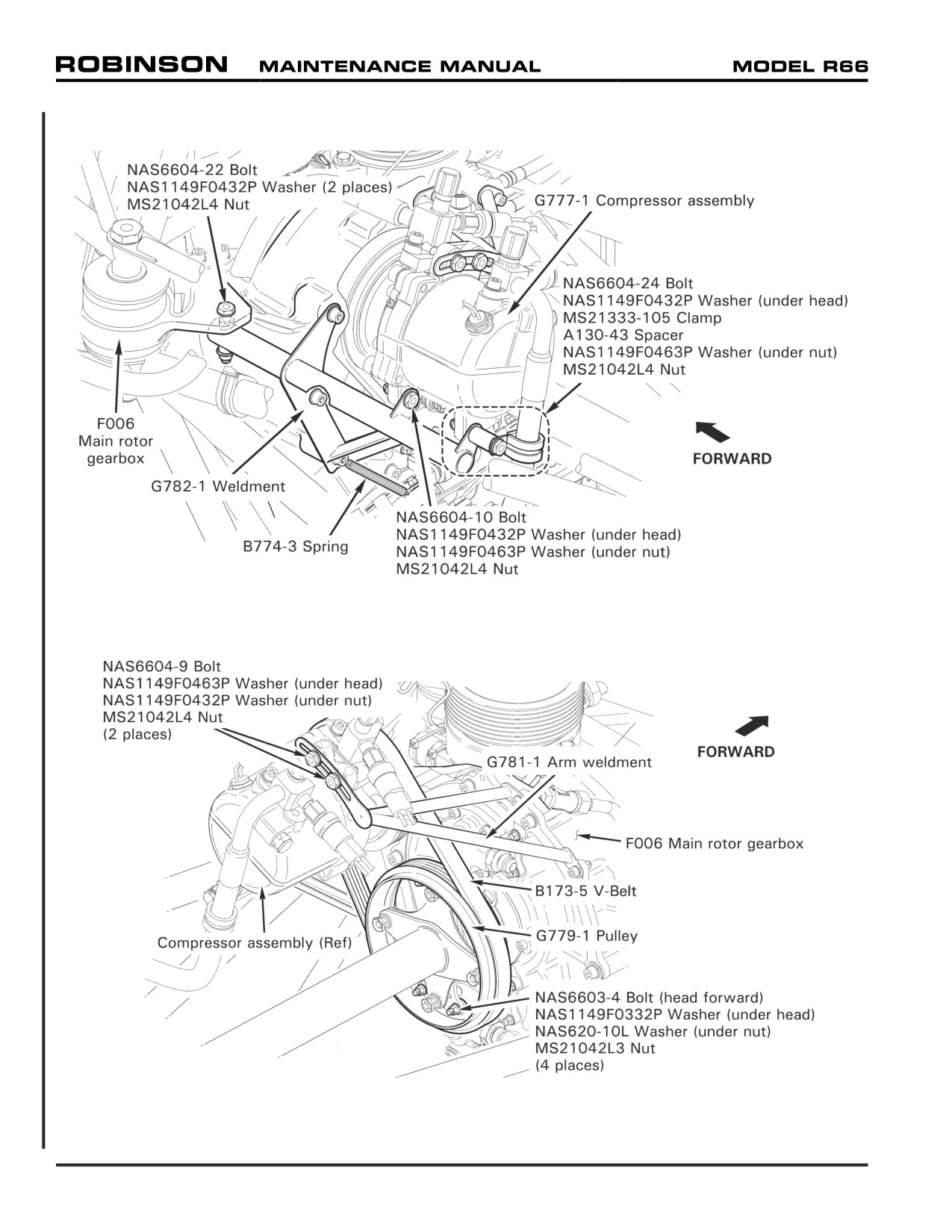
FIGURE 1-1 ASSEMBLY INSTRUCTIONS FOR R66 HELICOPTER CRATED FOR EXPORT
FIGURE 1-2 ASSEMBLY INSTRUCTIONS FOR R66 HELICOPTER CRATED FOR EXPORT
Page 1.6
Chapter 1 General
1-80 Assembly Instructions for R66 Helicopter Crated for Export (continued)
10. For air-conditioned ships:
a. Refer to Figure 1-1. Remove shipping supports (ty-raps, foam, tape, etc.) from G777-1
compressor assembly. Install hardware securing G782-1 mount weldment to main rotor
gearbox. Standard torque hardware per Section 20-32 and torque stripe per Figure
5-1. Hook B774-3 spring in drilled hole of NAS1352-4H14 screw. Verify security.
b. Refer to Figures 1-1 and 1-2. Verify B173-5 v-belt is in good condition. Fit belt around
G779-1 pulley and compressor pulley, and install hardware securing compressor to
G782-1 mount weldment. Standard torque bolts per Section 20-32.
c. Refer to Figure 1-2. Install hardware securing compressor to G781-1 arm weldment.
Rotate compressor up and outboard to tension belt, then tighten hardware securing
compressor to weldment. Verify belt is properly aligned on both pulleys. Adjust belt
tension until 4.5-5.5 lb of force applied mid-span deflects belt 0.16-inch. Standard
torque bolts per Section 20-32.
d. Connect compressor assembly wiring to airframe harness at connectors and install ty-
raps as required. Cinch ty-raps until snug without over-tightening, and trim tips flush
with heads.
11. Refer to IPC Figure 79-1. Remove F237-1 tailcone frame weldment and F305-5 (aft)
inlet. Install tail rotor drive fan shaft (fanwheel installed) through scroll assembly. Install
hardware securing aft inlet to scroll assembly. Verify security.
12. Refer to IPC Figure 65-1. Install hardware securing C947-3 plate assembly to F908-1
yoke and tail rotor drive fan shaft. Standard torque bolts and palnuts per Section 20-32
and torque stripe per Figure 5-1.
13. Remove shipping supports (ty-raps, foam, tape, etc.) from tailcone assembly, and install
tailcone per Section 53-40 steps 1 thru 7. Install strobe light. Install communication and
GPS antennas (if equipped).
14. Install empennage assembly per Section 53-50. Install aux stabilizer assembly per Section
53-52.
15. Service tail rotor gearbox per Section 12-21. Service main rotor gearbox per Section 12-
11.
16. Remove hydraulic reservoir shipping plug. Install D487-3 vent assembly, special torque
vent to 100 in.-lb, and torque stripe per Section Figure 5-1 (do not safety wire).
17. Install tail rotor assembly per Section 64-10. Match color-coded markings on blades with
pitch links.
18. Install main rotor blades per Section 62-10. Match color-coded markings on blades with
markings on hub and pitch links.
19. Inside engine compartment, remove anti-ice valve cap, starter-generator cap, inducer bleed
hose cover, exhaust pipe cover and desiccant, and combustion case drain valve cap.
Connect inducer bleed hose to box assembly and tighten clamp. Verify security.
Chapter 1 General
Page 1.7
1-80 Assembly Instructions for R66 Helicopter Crated for Export (continued)
20. If ship is equipped with attitude horizon, directional gyro, turn coordinator, and/or vertical
card magnetic compass:
A. Attitude Horizon, Directional Gyro, and Turn Coordinator Installation
CAUTION
Directional gyro mount screws must not exceed 1-inch in length.
1. Place a piece of foam under instrument face. Remove (6) screws securing face to
console and gently pull face forward. Remove hardware securing instrument hole
covers to face and remove covers. Install instruments and secure to face with
hardware provided.
2. Connect straight connector(s) to directional gyro and/or turn coordinator. Connect
angle connector to attitude horizon, ensuring strain relief points down. Ensure
connectors lock. Ty-rap excess wiring. Install screws securing instrument face
to console.
B. Vertical Card Magnetic Compass Installation
1. Locate airframe wiring (in windshield center bow), install 2-inch length of B158-3
heat shrink over wiring, and connect compass pins to airframe sockets (polarity is
not critical). Slide heat shrink over connection and apply heat. Install (4) screws
securing compass to mount, securing wiring atop compass.
21. Connect battery per Section 96-10.
22. Perform pitot-static leak check per Section 95-10.
23. Install Emergency Locator Transmitter (ELT) per Section 25-61, as required. Install tailcone
cowling assembly per Section 53-23.
24. Install fire extinguisher per Section 25-62, as required.
25. Fuel helicopter per Section 12-41.
26. Verify all shipping supports (ty-raps, foam, tape etc.) have been removed from helicopter.
Refer to Section 6-70. Secure access panels and inspection doors.
NOTE
Flight checks to be performed by a qualified pilot and certificated
mechanic.
27. Perform ground check per Section 5-41 steps 2 thru 9.
28. Depreserve the engine after storage per RR300 Series Operation and Maintenance Manual
(OMM). Install starter-generator cooling hose. Install engine cowling per Section 53-21.
29. Install tail rotor dynamic balance equipment per Section 18-21.
30. Perform run-up per Section 5-42 steps 2 thru 16.
Page 1.8
Chapter 1 General
1-80 Assembly Instructions for R66 Helicopter Crated for Export (continued)
31. Perform tail rotor dynamic balance per Section 18-20.
32. Remove tail rotor dynamic balance equipment. Install main rotor balance equipment per
Section 18-11.
CAUTION
Mast fairing, cowlings, and panels must be installed for flight.
33. Perform hover checks per Section 5-43 step 1. DO NOT proceed into forward flight.
34. Track and balance main rotor per Section 18-12.
35. While climbing at maximum continuous torque, 60 KIAS:
a. Evaluate vibration level and controllability.
b. Perform momentary 30° left yaw to check for adequate directional control.
36. Level flight at 2000 feet density altitude (deviate as required for weather and terrain),
maximum continuous torque:
a. Evaluate longitudinal and lateral cyclic control forces.
b. Evaluate collective control forces.
37. Evaluate vibration level at maximum continuous torque and straight-and-level flight.
38. During autorotation at 50 KIAS and 90% rotor RPM, perform momentary 30° right yaw
to check for adequate directional control.
39. Check all instruments, gages, and avionics for proper operation.
Chapter 1 General
Page 1.9
Intentionally Blank
Page 1.10
Chapter 1 General
CHAPTER 4
AIRWORTHINESS LIMITATIONS
Section Title
Page
4-10
Airworthiness Limitations
4.1
4-20
Type Certificate Data Sheet (TCDS)
4.3
25 OCT 2010
Chapter 4 Airworthiness Limitations
Page 4.i
Intentionally Blank
Page 4.ii
Chapter 4 Airworthiness Limitations
25 OCT 2010
4-10 Airworthiness Limitations
The Airworthiness Limitations Section is FAA approved and specifies inspections and other
maintenance required under 14 CFR §§ 43.16 and 91.403, unless an alternative program has
been FAA approved.
A. Fatigue Life-Limited Parts
Part Number
Description
Maximum Service Life
C023-21, -34, & -35
Tailcone Assembly
2000 Hours
C044-1
Horizontal Stabilizer
2000 Hours
C154-1
Main Rotor Hub
2000 Hours
C158-1
Main Rotor Spindle
2000 Hours
C251-3
Main Rotor Shaft
2000 Hours
C545-1
Gear Set, Tail Gearbox
2000 Hours
C647-12
Bearing Set, Swashplate
2000 Hours
D079-1
Tail Rotor Guard
2000 Hours
D196-1
Tail Rotor Drive Shaft
2000 Hours
F016-2
Main Rotor Blade
2000 Hours or 12 years*
F020-1
Upper Frame
2000 Hours
F029-1
Tail Rotor Blade
2000 Hours or 12 years*
F143-1
Pinion, Main Gearbox
2000 Hours
F146-1
Pinion, Main Gearbox
2000 Hours
F195-1
Yoke, Tail Rotor Drive Shaft
2000 Hours
F235-13
Strut, Upper Frame
2000 Hours
F252-1
Strut, Upper Frame
2000 Hours
F263-1
Housing, Main Gearbox
2000 Hours
F270-1
Cartridge, Main Gearbox
2000 Hours
G062-2
Tail Rotor Hub
2000 Hours
G201-1
Frame, Servo Support
2000 Hours
* Whichever limit occurs first.
FAA Approved: This page constitutes the Airworthiness Limitations Section in its entirety,
is considered segregated from the rest of the document, and sets forth the FAA approved
mandatory replacement times for the fatigue life-limited parts listed above.
SEP 2011
Chapter 4 Airworthiness Limitations
Page 4.1
Intentionally Blank
Page 4.2
Chapter 4 Airworthiness Limitations
SEP 2011
4-20 Type Certificate Data Sheet (TCDS)
The Robinson R66 Turbine Type Certificate Data Sheet (TCDS) reprinted on the following
pages is subject to revision.
Visit the Aircraft Certification Regulatory and Guidance Library online database for TCDS
revision status at: http://rgl.faa.gov.
25 OCT 2010
Chapter 4 Airworthiness Limitations
Page 4.3
Intentionally Blank
Page 4.4
Chapter 4 Airworthiness Limitations
25 OCT 2010
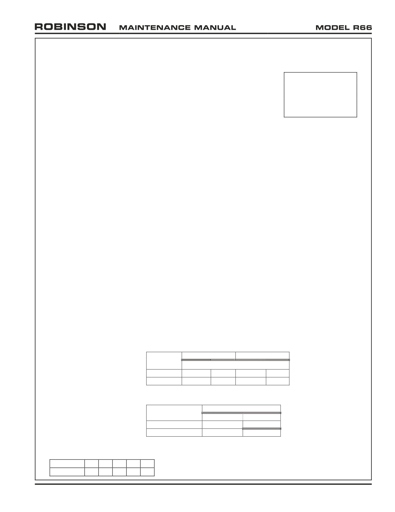
DEPARTMENT OF TRANSPORTATION
FEDERAL AVIATION ADMINISTRATION
R00015LA
New
Robinson
R66
October 25, 2010
TYPE CERTIFICATE DATA SHEET NO. R00015LA
This data sheet, which is a part of Type Certificate No. R00015LA, prescribes conditions and limitations under
which the product for which the type certificate was issued meets the airworthiness requirements of Title 14,
Code of Federal Regulations.
Type Certificate Holder:
Robinson Helicopter Company
2901 Airport Drive
Torrance, California 90505
I. Model R66 (Normal Category Rotorcraft), Approved October 25, 2010
Engine
One Rolls-Royce 250-C300/A1, Type Certificate number E4CE
Fuel
Jet A or Jet A-1 conforming to ASTM D 1655
Jet B conforming to ASTM D 6615
JP-4 or JP-5 conforming to MIL-DTL-5624
JP-8 conforming to MIL-DTL-83133
Engine Limits
Power Ratings at N2 speed of 6016 rpm (100% rpm):
Maximum continuous:
224 hp (83% Torque)
Takeoff (5 minute):
270 hp (100% Torque)
Maximum speeds:
Output shaft (N2):
101% (6076 rpm)
Gas producer shaft (N1):
105% (53519 rpm)
Maximum Measured gas temperature:
During start:
927° C (10 second limit above 810°C)
5 minute during operation:
782° C
Continuous during operation: 706° C
Rotor Speed Limits
Minimum
Maximum
Condition
( rpm* )
( % )
( rpm* )
( % )
Power On
404
99
412
101
Power Off
359
88
432
106
* Main Rotor
Transmission Torque Limits
Max Torque at 100% N2
Rating
( ft-lb )
( % )
Takeoff (5 min)
236
100
Max Continuous
196
83
Page No.
1
2
3
4
5
Rev. No.
-
-
-
-
-
25 OCT 2010
Chapter 4 Airworthiness Limitations
Page 4.5
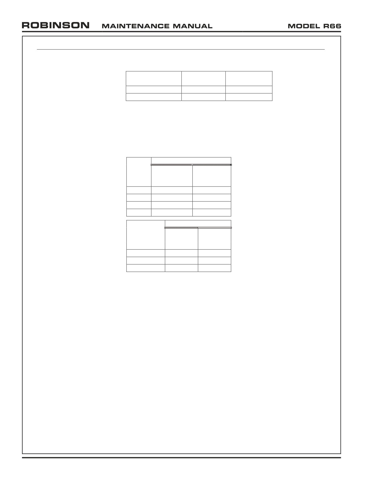
R00015LA
Page 2 of 4
Airspeed Limits
Takeoff
Power On VNE
Power Off VNE
Gross Weight
( KIAS )
( KIAS )
Less than 2200 lb
140
100
2200 lb to 2700 lb
130
100
Sea level VNE values shown above. For reduction of VNE with altitude and
temperature, see R66 Pilot’s Operating Handbook and FAA Approved
Rotorcraft Flight Manual (RTR 661).
Airspeed limit is 65 KIAS for power settings above 83% torque.
Airspeed limit is 100 KIAS for any combination of doors off.
Center of Gravity (C.G.) Range
Longitudinal C.G.
Gross
Forward
Weight
Aft Limit
Limit
( lb )
( in )
( in )
1400
91.0
102.5
2300
102.5
2500
91.0
2700
92.0
98.0
Lateral C.G.
Longitudinal
Right
C.G.
Left Limit
Limit
( in )
( in )
( in )
91.0
-3.5
+3.5
100.0
-3.5
+3.5
102.5
-1.5
+1.5
Notes:
1. Straight line variation between points shown
2. Lateral C.G. limits valid for all gross weights
Empty Weight C.G. Range
None. The aircraft’s empty weight and empty weight C.G. must be determined
by the procedures in Section 8 of the R66 Maintenance Manual, RTR 660.
Datum
100 inches forward of main rotor centerline.
Leveling Means
For weight and balance: Level placed laterally and longitudinally on aft tunnel
cover immediately forward of aft middle seat. If cover is not straight, use keel
panel upper flanges, accessed by removing aft tunnel cover.
For rigging: Level placed on top of main rotor hub parallel with teeter bolt.
Main rotor blades are aligned fore-aft for lateral levelling, and teeter bolt is
aligned fore-aft for longitudinal levelling.
Maximum Weight
2700 lb
Minimum Crew
1 pilot in forward right seat.
Number of Seats
5
Page 4.6
Chapter 4 Airworthiness Limitations
25 OCT 2010
Page 3 of 4
R00015LA
Seat Locations
Pilot and forward occupant at STA 49.0 in
Aft outboard occupants at STA 80.0 in
Aft center occupant at STA 78.0 in
Maximum Compartment
Main baggage compartment
Weights
Maximum weight is 300 lb at STA 107.0 in
Maximum loading density is 50 lb/ft2
Underseat baggage compartments
Forward seats - Maximum weight is 50 lb at STA 42.0 in
Rear seats - Maximum weight is 50 lb at STA 82.0 in
Note: For any seat location, the maximum combined weight of the
load on the seat (e.g., occupant) plus the weight of stowed items
and any installed equipment in the underseat baggage
compartment is 300 lb.
Fuel Capacity
Fuel tank capacity is 74.6 U.S. gallons
Usable fuel quantity is 73.6 U.S. gallons at STA 102.5 in
Note: Aircraft empty weight includes 1.0 U.S. gallon of unusable fuel.
Oil Capacities
Component
Capacity (qt)
STA ( in )
Engine
6
126.0
Main Rotor Transmission
2
100.0
Tail Rotor Transmission
0.11
327.0
Hydraulic Reservoir
0.65
110.8
Maximum Operating Altitude
14,000 feet Density Altitude.
Maximum altitude above ground level is 9,000 ft.
Rotor Blade and
Control Movements
Main Rotor Blades
Collective Pitch
13.0° ±0.5° total travel
Forward
13.50° to 14.25°
Cyclic Pitch
Aft
13.50° to 14.25°
Left
7.5° to 8.5°
Right
6.0° to 7.0°
Note: Collective low pitch to be established in accordance
with the Maintenance Manual and Instructions for
Continued Airworthiness (RTR 660) procedures to
obtain proper autorotation RPM.
Tail Rotor Blades
Left pedal
15.5° to 16.5°
Collective Pitch
Right pedal
18.5° to 19.0°
All blade angles measured at 75% radius
Manufacturer’s Serial Numbers
0002 and subsequent.
Certification Basis
14 CFR Part 27, dated February 1, 1965, as amended by Amendment 27-1 through
Amendment 27-44.
Exemption No. 9589, dated January 28, 2008, to § 27.695. This exemption was
granted to permit a powered flight control system without considering the
jamming of a control valve as a possible single failure.
25 OCT 2010
Chapter 4 Airworthiness Limitations
Page 4.7
R00015LA
Page 4 of 4
14 CFR Part 36, dated December 1, 1969, as amended by Amendment 36-1
through Amendment 36-28.
Compliance with the ditching requirements of § 27.801 was not demonstrated.
Compliance with the ice protection requirements of § 27.1419 was not
demonstrated.
The R66 is approved for day and night VFR operations only.
TC Application Date: September 06, 2006.
TC Issue Date: October 25, 2010.
Production Basis
Production Certificate No. 424WE dated October 25, 2010.
Equipment
The basic required equipment as prescribed in the applicable airworthiness
regulations (see Certification Basis) must be installed in the aircraft for
certification. In addition, the following FAA-approved Rotorcraft Flight
Manual is required:
R66 Pilot’s Operating Handbook and FAA Approved Rotorcraft Flight
Manual (RTR 661), dated October 25, 2010, or later approved revision.
GENERAL NOTES
NOTE 1.
A current weight and balance report, including a list of equipment included in the certificated
empty weight, and loading instructions when necessary, must be provided for each aircraft at the
time of original airworthiness certification and at all times thereafter, except in the case of
operators having an approved weight control system.
NOTE 2.
The following placard must be installed in clear view of the pilot:
“THIS ROTORCRAFT APPROVED FOR DAY AND NIGHT VFR OPERATIONS”
For additional placards, see the Rotorcraft Flight Manual. All placards required in the FAA-
approved Rotorcraft Flight Manual must be installed in the appropriate locations.
NOTE 3.
Information essential to the proper maintenance of the helicopter, including retirement time of
critical components, is contained in the Robinson R66 Maintenance Manual and Instructions for
Continued Airworthiness (RTR 660). Retirement times are listed in the FAA approved
“AIRWORTHINESS LIMITATIONS” section. The values of retirement or service lives and
inspection intervals cannot be changed without FAA Engineering approval.
NOTE 4.
Any changes to the type design of this helicopter by means of an amended type certificate (TC),
supplemental type certificate (STC), or amended STC, requiring instructions for continued
airworthiness (ICA's) must have the ICA’s submitted thru the project certification office for
review and acceptance by the Fort Worth -Aircraft Evaluation Group (FTW-AEG) Flight
Standards District Office (FSDO) prior to the aircraft delivery, or upon issuance of the first
standard airworthiness certificate for the affected aircraft, whichever occurs later as prescribed by
Title 14 CFR 21.50. Type design changes by means of a Form 337 “field approval” that require
ICA's must have those ICA's reviewed by the field approving FSDO.
NOTE 5.
Any cockpit instruments installed by a 3rd party must be marked with limit markings and range
markings in accordance with Robinson’s marking scheme.
NOTE 6.
Determination for compliance with 27.562(c)(5), Head Impact Criteria (HIC) must be performed
for any equipment installed in the cockpit or passenger cabin.
--- END ---
Page 4.8
Chapter 4 Airworthiness Limitations
25 OCT 2010
CHAPTER 5
INSPECTION SCHEDULE
Section
Title
Page
5-10
Life-Limited Components
5.1
5-11
Time In Service Records
5.1
5-12
Retirement Procedure
5.1
5-20
Scheduled Maintenance and Inspections
5.3
5-30
Standard Inspection Criteria
5.5
5-31
Ball and Roller Bearings
5.5
5-32
Push-Pull Tubes
5.5
5-33
Rod Ends and Spherical Bearings
5.5
5-34
Elastomeric Bearings
5.7
5-35
Telatemp Indicators
5.7
5-40
Operation Checks for 100-Hour / Annual Maintenance and Inspection
5.8
5-41
Ground Check
5.8
5-42
Run-Up
5.10
5-43
Flight Check
5.11
5-45
100-Hour / Annual Maintenance and Inspection
5.13
5-50
2000-Hour Maintenance and Inspection
5.36B
5-55
12-Year Maintenance and Inspection
5.36D
5-60
Special Maintenance and Inspections
5.37
5-61
Tail Skid Strike
5.37
5-62
Tail Rotor Strike
5.38
5-63
Main Rotor Strike
5.39
5-64
Rotor/Engine Overspeed
5.40
5-65
Hard Landing
5.41
5-66
Dye Penetrant Inspection of F020-1 Upper Frame
5.42
5-67
Corrosion on F020-1 Upper Frame
5.42
5-68
Main Rotor Gearbox Overtemp Illumination
5.42
5-69
Main Rotor Gearbox (MR) Chip Light Illumination
5.43
5-70
Tail Rotor Gearbox (TR) Chip Light Illumination
5.43
5-71
Main Rotor Gearbox Filter Bypass Indicator
5.43
Chapter 5 Inspection Schedule
Page 5.i
Intentionally Blank
Page 5.ii
Chapter 5 Inspection Schedule
CHAPTER 5
INSPECTION SCHEDULE
5-10 Life-Limited Components
5-11 Time In Service Records
It is the operator’s responsibility to maintain accurate time in service records for the aircraft
airframe, engine, and life-limited components. Two hourmeters are standard equipment
in R66 helicopters: one is mounted in the console and another is located outboard of the
pilot's seat. Both hourmeters require main rotor gearbox oil pressure to activate. The
outboard hourmeter is collective activated and is approved for recording time in service.
Engine life is limited by engine time in service and accumulated start cycles. The engine
is equipped with an electronic Engine Monitoring Unit (EMU), which may be used to verify
time in service and accumulated start cycles. An official, independent record of start
cycles must be maintained by the operator.
When a life-limited replacement part or overhauled component is installed in the helicopter,
record the part name, part number, serial number, and previous time in service in the aircraft
maintenance record, including the installation date and helicopter total time. Previous time
in service must be included when calculating remaining component life or time between
overhaul (TBO).
CAUTION
Components with mandatory overhaul times or life-limits whose
time in service is not reliably documented cannot be considered
airworthy and must be removed from service.
If a part is fatigue life-limited or has a mandatory overhaul requirement and is interchanged
between an R44 and an R66 helicopter, and if the part life-limit or overhaul requirement is
different between an R44 and an R66 helicopter, the shorter life-limit or overhaul requirement
must be used. If a part is fatigue life-limited or has a mandatory overhaul requirement,
and the accumulated cycles and/or time in service are known but the helicopter type is
unknown, the shorter life-limit or overhaul requirement must be used.
5-12 Retirement Procedure
The FAA-approved Airworthiness Limitations section in Chapter 4 lists the mandatory
replacement time for affected components. Life-limited components must be removed from
the helicopter at specified intervals and permanently retired from service by destroying or
damaging each part beyond repair or beyond appearance of serviceable condition.
Chapter 5 Inspection Schedule
Page 5.1

Replace main rotor gearbox filter per
•
•
Section 12-12.
Perform 100-hour / annual maintenance
•
•
and inspection per Section 5-45.
As required by RR300 Series Operation
and Maintenance Manual (OMM), perform
•
•
•
•
•
maintenance and inspection.
Replace hydraulic filter per Section 12-32.
•
Drain and flush tail rotor gearbox per
•
Section 12-23.
Clean gearbox chip detectors per Section
•
•
12-13 & 12-22.
Perform 2000-hour maintenance and
•
inspection per Section 5-50.
Inspect emergency locator transmitter
•
(ELT) per 14 CFR § 91.207.
Perform pop-out float leak check per
•
Section 32-64 Part A.
Test and inspect transponder per 14 CFR
•
§ 91.413.
Perform pop-out float inflation check per
•
Section 32-64 Part B.
Peform pop-out float pressure cylinder
•
hydrostatic test.
Perform 12-year maintenance and
•
inspection per Section 5-55.
Pop-out float pressure cylinder maximum
•
life.
TABLE 5-1 SCHEDULED MAINTENANCE AND INSPECTIONS
* One-time maintenance after new or overhauled main rotor gearbox is installed.
** Recurring inspection not to exceed given interval.
*** See Section 1-60 Definitions and Abbreviations.
Page 5.2
Chapter 5 Inspection Schedule
5-20 Scheduled Maintenance and Inspections
The R66 helicopter required inspection intervals are given in Table 5-1. Some aircraft will
reach calendar intervals before accumulating the associated service time. Unless noted, use
the more conservative inspection interval. Refer to Section 5-45 for inspection procedures.
Some aircraft may require maintenance and inspections in addition to the requirements in
Table 5-1. Consult aircraft maintenance records, Service Bulletins (SB), aviation regulations,
Airworthiness Limitations, and Airworthiness Directives (AD) for applicability.
Preventive maintenance is required between scheduled inspections. Fluid leaks, discoloration,
fretting, galling, chafing, nicks, scratches, dents, cracks, and corrosion all warrant further
investigation. Unairworthy items must be replaced or repaired as allowed by RHC.
Chapter 5 Inspection Schedule
Page 5.3
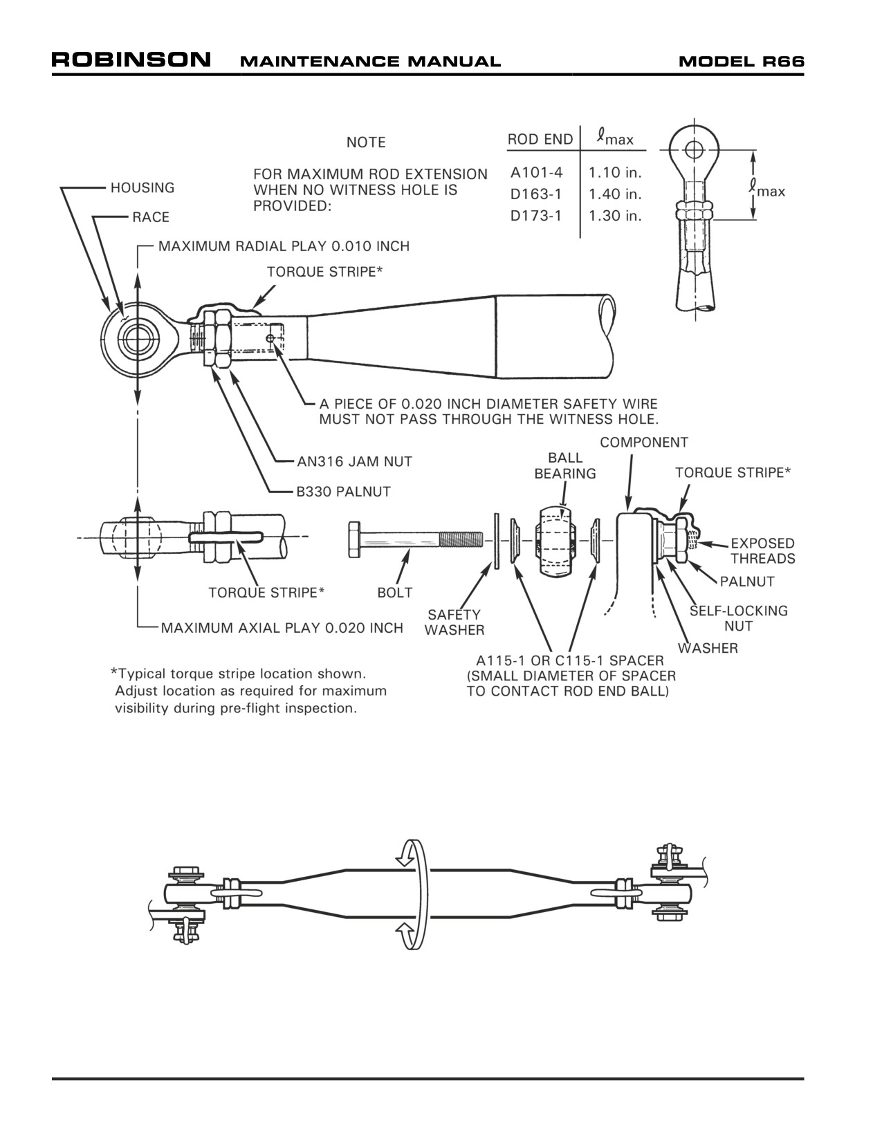
FIGURE 5-1 ROD END AND SPHERICAL BEARING PLAY LIMITS AND TORQUE STRIPE APPLICATION
Position rod ends for maximum rotation
FIGURE 5-2 ROD END CENTERING
Page 5.4
Chapter 5 Inspection Schedule
5-30 Standard Inspection Criteria
This section contains standard inspection criteria for
100-hour/annual maintenance and
inspection.
5-31 Ball and Roller Bearings
The first indication of bearing failure is usually an increase in bearing noise. Noise will almost
always start several hours prior to bearing failure. Listen to drive system during start-up
and shutdown. A failing bearing will produce a loud whine, rumble, growl, or siren sound.
Upon hearing an unusual noise, thoroughly inspect all bearings before further flight.
A failing bearing may have a distorted seal or be exuding a large amount of grease. Monitor
bearings for increase in temperature, but do not rely on Telatemps to detect failing bearings
as temperature increase may occur only seconds before bearing disintegrates.
5-32 Push-Pull Tubes
1. Nicks, cuts, or scratches in tube not more than 0.010 inch deep and not more than 1/4
of tube circumference may be polished out in lengthwise direction using 320-grit or finer
wet-or-dry abrasive paper to 1 inch minimum blend radius. Replace push-pull tube if
depth exceeds these limits.
2. Replace push-pull tube if tube is dented or flattened more than 5% of its diameter in
unswaged area; dents or flattening is not permitted in swaged (tapered and threaded)
ends of tubes.
5-33 Rod Ends and Spherical Bearings
1.
Maximum axial play:
0.020 inch
Maximum radial play: 0.010 inch
2.
Looseness between bearing outer race and rod end housing is not permitted.
3.
Rod ends not riveted in place must block passage of 0.020-inch diameter wire through
witness hole. Refer to Figure 5-1 for maximum rod end extension when no witness hole
is provided.
4.
Rod end jam nuts and palnuts must be torqued per Section 20-32 and torque striped
per Figure 5-1 at the most visible position for pre-flight inspection. Torque stripe must
extend across nuts to both rod end shank and push-pull tube (or pitch link barrel, yoke,
support, strut, etc.). Torque stripes are subject to deterioration and must be periodically
renewed.
5.
Refer to Figure 5-2. Rod ends must be centered, or positioned, to allow as much push-
pull tube or link rotational movement as possible without binding.
CAUTION
Teflon-lined bearings must not be lubricated or solvent cleaned.
WARNING
Assembly of flight controls is critical and requires inspection
by a qualified person. If a second person is not available,
RHC recommends the installer take a 5-minute break prior to
inspecting flight control connections he has assembled.
Chapter 5 Inspection Schedule
Page 5.5
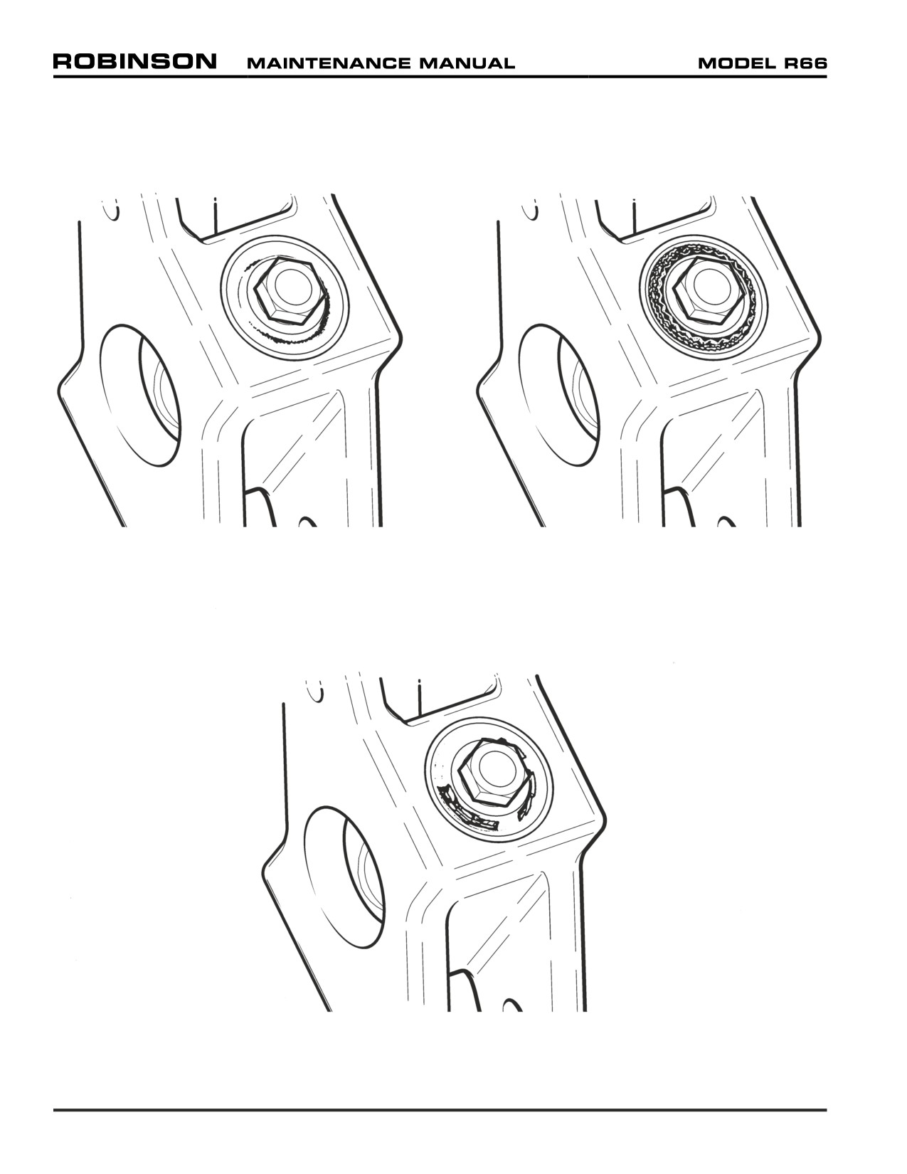
Elastomer Fatigue
Elastomer Oil Contamination
Elastomer Overload
FIGURE 5-3 ELASTOMERIC BEARING DAMAGE
Page 5.6
Chapter 5 Inspection Schedule
5-34 Elastomeric Bearings
Refer to Figure 5-3. Elastomeric bearings are used in the G062-1 tail rotor hub. Fatigue,
oil contamination, or overload can degrade the elastomer.
Small surface cracks (fatigue cracks) and elastomer dust or “eraser crumbs” are normal and
are not cause for replacement. As cracks grow, enough elastomer will be lost to cause
reduced stiffness and increased vibration. Replace bearing if crack is deeper than 0.10 inch
or cracks are present over more than 25% of elastomer face.
Avoid elastomer exposure to oil, grease, hydraulic fluid, cleaning solvent, and rust-
preventative fluids. Immediately wash off contaminants with detergent and water. Replace
a contaminated bearing that exhibits swelling, wavy edges, or debonding.
Overload occurs when elastomer’s tensile strength or rubber-to-metal bond strength
is exceeded. This can occur when normal loads are applied to a bearing weakened by
fatigue or oil contamination. Overload is indicated by large clean cracks or extrusions from
elastomer.
Elastomer may also separate (debond) from metal bushings. Replace bearing if separation
exceeds 25% of bonded area.
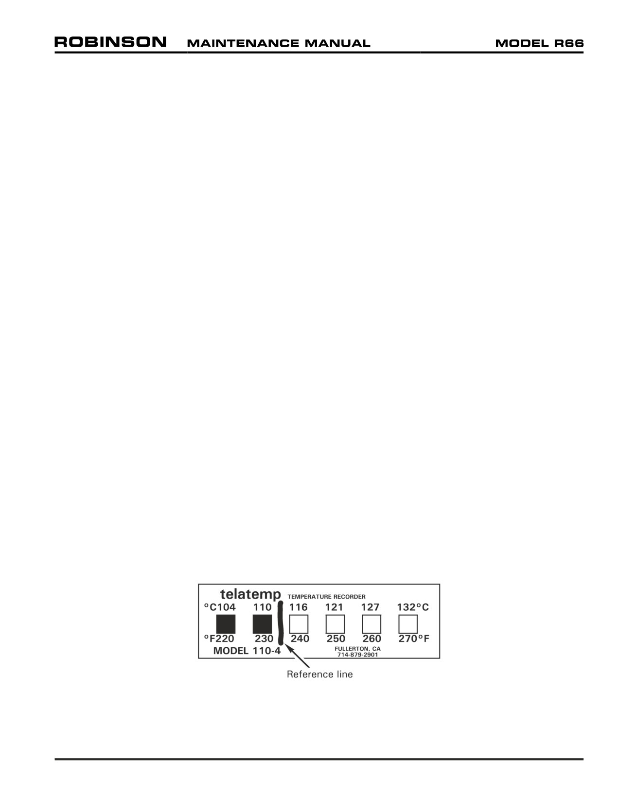
5-35 Telatemp Indicators
Refer to Figure 5-4. Self-adhesive Telatemp indicators record increases in operating
temperatures of the hydraulic pump and tail rotor gearbox. To use a Telatemp, draw a
reference line between the highest temperature square which has darkened during normal
operation and the next undarkened square. During every check thereafter, determine if an
additional block has blackened. If an indicated temperature increase cannot be accounted
for by a change in operating conditions, subject component should be carefully examined
before further flight.
Part Number
Temperature Range
110-2
60°C / 140°F
— 88°C / 190°F
110-3
82°C / 180°F
— 110°C / 230°F
110-4
104°C / 220°F
— 132°C / 270°F
FIGURE 5-4 TELATEMP WITH DRAWN REFERENCE LINE
Chapter 5 Inspection Schedule
Page 5.7
5-40 Operation Checks for 100-Hour / Annual Maintenance and Inspection
Complete the following checklists in conjunction with 100-hour / annual maintenance and
inspection. Note and correct any discrepancies.
5-41 Ground Check (aircraft not running)
1.
Replace air filter assembly per Section 71-21, if required.
2.
Twist Grip:
Verify twist grip smooth rotation without binding in full up and full down
collective position. Verify over center spring holds twist grip full open or
closed.
3.
Fuel Cutoff Valve:
Verify smooth actuation without binding. Verify proper function of lock
button.
4.
Collective Control:
Verify proper operation through full control travel with and without friction
applied. With friction off, verify approximately one-half inch total free play
before encountering hydraulic resistance. Verify normal hydraulic resistance
throughout remainder of control travel. With friction on, verify increased
resistance but no binding or locking of control. Verify power turbine governor
rigging as follows:
a.
Turn BATTERY switch ON. With collective full down, hold beep
switch actuator all the way down. Have a second person verify
the PTG reads approximately 45°.
b.
With collective full down, hold beep switch actuator all the way
up. Have a second person verify the PTG reads approximately
65°. Return actuator to nominal position. Turn BATTERY
switch OFF.
5.
Cyclic Control:
With friction off, verify approximately one-half inch total longitudinal and one
inch total lateral free play before encountering hydraulic resistance. Verify
normal hydraulic resistance throughout remainder of control travel. With
friction on, verify increased resistance but no binding or locking of control.
6.
Tail Rotor Pedals:
Verify smooth actuation without binding. Verify proper pedal position for
pilot and locking pin security.
7.
Removable Controls (if installed):
Verify proper operation and locking pin security.
Page 5.8
Chapter 5 Inspection Schedule
5-41 Ground Check (continued)
8.
Lighting and Instruments: (Turn BATTERY switch ON)
ANNUNCIATOR PANEL
a.
Main rotor gearbox temperature / pressure segment illuminates.
b.
Engine oil segment illuminates.
c.
Generator segment illuminates.
d.
Rotor brake segment illuminates (if rotor brake is applied).
e.
Low RPM segment illuminates.
f.
All segments illuminate when test button is depressed (slight
delay on low fuel light).
EXTERIOR LIGHTING
a.
Position lights - check function.
b.
Anticollision light - check function.
c.
Landing lights - check function.
INTERIOR LIGHTING
a.
Panel lighting and dimmer control
- check function
(position
lights must be illuminated to enable panel lighting and dimmer
control).
b.
Map light - check function.
c.
Digital voltmeter - indicates approximately 24 volts.
d.
Oil temperature gage - slight needle deflection with engine cold.
e.
Fuel quantity gage - indication of fuel level.
(Turn BATTERY switch OFF)
9.
Aircraft Documents:
(Additional documents may be required in countries other than the US.)
a.
Inspect condition and verify R66 MT699-1 laminated pilot's
checklist is current revision. Check revision status on our website,
b.
Inspect condition and verify R66 Pilot’s Operating Handbook
is current revision and contains correct Equipment List/Weight
& Balance Data. Check revision status on our website, www.
robinsonheli.com, under the Publications tab.
c.
Verify airworthiness certificate onboard & matches helicopter S/N.
d.
Verify registration certificate onboard & matches helicopter S/N
and all registration markings.
Chapter 5 Inspection Schedule
Page 5.9
5-42 Run-Up
1.
Clean engine gas path per RR300 Series Operation and Maintenance Manual
(OMM).
2.
Perform Pilot's Operating Handbook (POH) Section 4 “Preflight” checklist.
3.
Perform POH Section 4 “Before Starting Engine” checklist.
4.
Prior to start, verify rotor brake locks out starter.
5.
Perform POH Section 4 “Starting Engine and Run-Up” checklist.
6.
Generator light off.
7.
Verify N2/Rotor tachometer functions with battery and generator switches
off. Return switches to on.
8.
No unusual bearing noise when varying RPM through operating range.
9.
Verify proper governor operation.
10.
Verify tachometer needles are properly adjusted/governed.
11.
Verify proper generator voltage.
12.
Heater operates properly.
13.
Verify acceptable instrument variation when transmitting on various
frequencies.
14.
Verify operation and adjustment of low rotor RPM warning light and horn.
15.
Engine performance indications are within acceptable parameters.
16.
Check hydraulic system operation. Using cyclic-mounted hydraulics switch,
turn hydraulics OFF. Using small longitudinal cyclic inputs, there should be
approximately one-half inch of freeplay before encountering stiffness and
feedback. Return cyclic to neutral. Turn hydraulics ON. Controls should be
free with no feedback or uncommanded motion (“motoring”). Complete flight
checks with hydraulics on.
17.
Air conditioning (if installed): Verify system blows cold air on both low and high
settings. Verify no EMI/RFI with other instruments and systems. After a flight
with air conditioning on, verify water drains from drain tube in ship’s belly (may
be little or no water in very dry conditions).
5-43 Flight Check
1.
Hover:
a.
Verify normal gage indications.
b.
Verify controllability in left and right pedal turns.
c.
Verify hydraulic system zeros cyclic stick forces.
d.
Verify acceptable and normal vibration levels.
Page 5.10
Chapter 5 Inspection Schedule
5-43 Flight Check (continued)
2.
Level Flight:
Conduct at typical cruise altitude
(weather permitting) and maximum
continuous torque. Loading to typical operating conditions or nominal weight
and CG in middle of envelope will provide the most useful evaluation.
a.
Verify tail rotor pedal position when yaw string is centered.
Right pedal 0.25 to 0.75 inch forward of left pedal.
b.
Verify tail rotor elastic trim cord zeros pedal forces (cord applies
left pedal force).
c.
Verify hydraulic system zeros cyclic stick forces and collective
is balanced with no feedback.
Verify acceptable control forces
(feedback) with hydraulics
d.
off.
e.
Verify acceptable and normal vibration levels.
3.
Power Assurance Check:
Refer to R66 Pilot's Operating Handbook (POH) Chapter 5 power assurance
chart. Conduct at typical cruise altitude (weather permitting) and maximum
continuous torque (83%). Turn heater, generator, and anti-ice switches OFF.
Stabilize N2/R at 100% (beep as required) and record the following values:
a.
N1
b.
% Torque (83% nominal)
c.
OAT
d.
MGT
e.
Pressure altitude
f.
Oil pressure
g.
Oil temperature
h.
Determine max allowable MGT from power assurance chart.
i.
Calculate margin = Max allowable MGT - Actual MGT.
4.
Autorotation:
a.
Autorotate at 100 KIAS. Verify normal control forces and flying
characteristics.
5.
Shutdown:
a.
Perform POH “Shutdown Procedure” checklist.
b.
Verify rotor brake function and ROTOR BRAKE annunciator
segment illuminates.
Chapter 5 Inspection Schedule
Page 5.11
Intentionally Blank
Page 5.12
Chapter 5 Inspection Schedule
5-45 100-Hour / Annual Maintenance and Inspection
[1 of 25 Pages]
RHC recommends retaining a copy of the most recently performed 100-hour / annual checklist
with the aircraft’s maintenance records to meet the requirement of 14 CFR § 91.417 (b)(1).
Serial No.:
Technician Name:
Registration No.:
Time In Service
Technician
Hourmeter Indication:
Certificate Number:
Helicopter Total Time:
A. Preparation
Operation Checks:
Perform ground and flight checks per Section 5-40.
Cleaning (required by 14 CFR Part 43, Appendix D, paragraph (a)):
Note any fluid leakage before cleaning. Clean main and tail rotor blades, hubs, and
airframe exterior with a mild soap and water solution per Chapter 20.
CAUTION
Do not spray main rotor hub, tail rotor gearbox vent, hydraulic
reservoir vent, swashplate area, or bearing seals with high-
pressure water or solvent as water or solvent may cause
corrosion or breakdown of lubricants. See RR300 Series
Operation and Maintenance Manual (OMM) for engine cleaning
instructions and precautions.
Access and Inspection Panels:
Refer to Section 6-70. Remove or open necessary panels, doors, covers, fairings, and
cowlings in accordance with 14 CFR Part 43, Appendix D, paragraph (a).
NOTE
If radio antennas are installed on removed panels, disconnect
antenna lead and corresponding ground wire. Pull respective
radio circuit breaker and tag circuit breaker with
“Antenna
Removed.”
B.
Inspection
CABIN FORWARD FOOTWELLS
Tail Rotor Pedal Bearing Blocks:
Remove pedal bearing block covers as required per Section 6-70. Examine accessible
portion with inspection light and mirror. Inspect condition. Check for looseness or
play in pedal bearings. Maximum allowable play is 0.080 inch axially and 0.030 inch
radially. Verify bearing block security.
Chapter 5 Inspection Schedule
Page 5.13
5-45 100-Hour / Annual Maintenance and Inspection
[2 of 25 Pages]
CABIN FORWARD FOOTWELLS (continued)
Adjustable Tail Rotor Pedals:
Inspect condition. Verify no cracks in welds. Verify locking pins engage holes to
secure adjustable pedals. Verify proper operating clearance and smooth actuation.
Co-Pilot Removable Tail Rotor Pedals:
Inspect condition. Verify no cracks in welds. Verify locking pins engage holes to
secure removable pedals. Verify proper operating clearance and smooth actuation.
Cabin Heater Diffusers:
Inspect condition. Verify marking legibility. Verify no significant nicks, scratches or
dents, or cracks in welds. Verify security.
Fire Extinguisher and Mount:
Inspect condition. Inspect fire extinguisher per manufacturer’s instructions. Verify no
loss of charge or obstructions in extinguisher nozzle. Verify security.
Map Holders:
Inspect condition. Verify no defects, tears, or material deterioration. Remove foreign
objects and verify security.
License Holder:
Inspect condition. Verify no defects, cracks in plastic, or material deterioration. Verify
security.
Cabin Chin and Floor:
Inspect condition. Verify equipment security. Retrieve and discard trapped debris.
CONSOLE
Console Assembly:
Inspect condition. Verify no significant nicks, scratches or dents; verify no cracks,
corrosion, or loose rivets in lower console assembly. Verify hinge security.
HID Landing Lights:
Inspect condition. Verify proper installation and security of wiring and equipment.
Flight & Engine Instruments:
Inspect condition. Verify proper instrument markings per R66 POH Section 2. Verify
proper installation and security of wiring and equipment.
Post Lights:
Inspect condition. Verify proper function and equipment security.
Fuel Cutoff Control and Guard:
Inspect condition. Verify cable and mounting bezel security. Verify proper adjustment
and smooth operation of knob. Verify guard is attached to console.
Radios and Radio Trays:
Inspect condition. Verify no cracks or corrosion. Verify proper installation and security
of wiring and equipment.
Pitot & Static Lines:
Inspect pitot and static lines for obstructions, cracking, chafing, pinching or kinking.
Verify integrity of pitot and static line connections. Verify line security.
Page 5.14
Chapter 5 Inspection Schedule
5-45 100-Hour / Annual Maintenance and Inspection
[3 of 25 Pages]
CONSOLE (continued)
Tail Rotor Pedal Bearing Block Supports:
Examine accessible portion with inspection light and mirror. Inspect both vertical sheet
metal supports inside lower console and verify no cracks. Pay particular attention to area
near NAS6603-13 bolts. Replace any cracked support prior to flight.
Tail Rotor Controls:
Examine accessible portion with inspection light and mirror. Inspect tail rotor control
components for obvious defects. Verify operating clearance.
Cabin Heater Hose:
Inspect condition. Verify no collapsed areas or chafing. Verify hose clamp and hose
security.
Copper Bus Bars:
Inspect condition. Verify no corrosion or bends in bus bar. Verify bus bar security and
isolation from surrounding structure.
Wiring:
Inspect condition. Verify no loose, chafed, or broken wires or terminals. Verify
neatness, proper routing and installation, and security.
Fasteners & Torque Stripes:
Inspect condition. Verify proper installation and security of fasteners. Renew
deteriorated torque stripes per Figure 5-1.
Close & Secure:
Verify foreign objects are removed. Verify equipment security and cleanliness of
interior. Close console and verify security.
PILOT-SIDE CONSOLE (Optional equipment)
Pilot Avionics Support Weldment:
Inspect condition. Verify no significant nicks, scratches, or dents on console shell.
Verify no cracks in welds. Verify weldment mounting security.
CIRCUIT BREAKER PANEL
CAUTION
Ensure BATTERY switch is turned off while circuit breaker panel
is open.
Panel Cover:
Inspect condition. Verify no damage to nutplates and rails in panel interior. Verify
marking legibility.
Fuses and Fuse Holders:
Inspect condition. Verify security and no corrosion. Verify correct fuse installation.
Circuit Breakers:
Inspect condition. Check airworthiness directive applicability. Verify proper installation
and security.
Chapter 5 Inspection Schedule
Page 5.15
5-45 100-Hour / Annual Maintenance and Inspection
[4 of 25 Pages]
CIRCUIT BREAKER PANEL (continued)
Copper Bus Bars:
Inspect condition. Verify no corrosion or bends in bus bars. Verify bus bar security
and isolation from surrounding structure.
Wiring:
Inspect condition. Verify no loose, chafed, or broken wires or terminals. Verify
neatness, proper routing and installation, and security.
Fasteners & Torque Stripes:
Inspect condition. Verify proper installation and security of fasteners. Renew
deteriorated torque stripes per Figure 5-1.
Close & Secure:
Verify foreign objects are removed. Verify equipment security. Verify cleanliness of
interior and of access cover. Close cover and verify security.
BATTERY (When installed under left front seat)
Battery:
Inspect condition. Verify no cracks or corrosion on or near battery cable terminals. As
required, perform capacity test or replace battery per manufacturer’s instructions. Verify
battery cable security. Verify no corrosion in surrounding structure.
HORIZONTAL CONTROL TUNNEL (Front seats)
Covers:
Inspect condition. Verify marking legibility.
Antenna Wiring & Connectors:
Inspect condition. Verify no loose, chafed, frayed, or broken wires. Verify no damaged
connectors. Verify neatness, proper routing and installation, and security.
Cyclic Box Assembly:
Inspect condition. Verify no nicks, scratches, dents, cracks, corrosion, or loose rivets.
Verify no distortion or damage on cyclic stop sheet metal assembly. Verify security.
Cyclic Stick Assembly:
Inspect condition. Verify no nicks, scratches, dents, cracks, or corrosion. Verify no
cracks in welds. Verify security, proper operating clearance, and smooth actuation.
Verify security of co-pilot control and locking pin.
Cyclic Boot:
Inspect condition. Verify proper locking function of boot snaps. Verify no defects,
tears, or material deterioration. Verify security.
Cyclic Friction Assembly:
Inspect condition. Inspect link rod end bearings per Section 5-33. Verify no excessive
flaring at either end of friction spacer. Verify proper installation, security, and operation.
Cyclic Pivot:
Inspect condition. Verify no nicks, scratches, dents, cracks, or corrosion. Inspect
spherical bearings per Section 5-33. Verify proper installation, security, and operating
clearance.
Page 5.16
Chapter 5 Inspection Schedule
5-45 100-Hour / Annual Maintenance and Inspection
[5 of 25 Pages]
HORIZONTAL CONTROL TUNNEL (Front seats; continued)
Cyclic Horizontal Torque Tube:
Examine accessible portion with inspection light and mirror. Verify no nicks, scratches,
dents, cracks, or corrosion. Verify no cracks around reinforcement blocks on both
ends of torque tube. Verify proper installation, security, and operating clearance.
Horizontal Push-Pull Tubes:
Examine accessible portion with inspection light and mirror. Inspect condition per
Section 5-32. Verify no nicks, scratches, chafing, dents, cracks, or corrosion. Inspect
rod end bearings per Section 5-33; verify rod ends are centered and palnut and jam
nut are tight. Check witness holes for proper thread engagement. Verify proper
installation, security, and operating clearance.
Collective Stick Assembly:
Inspect condition. Verify no nicks, scratches, dents, cracks, or corrosion. Verify no
cracks in welds. Verify proper installation, security, and operation of collective micro
switches. Verify security, proper operating clearance, and smooth actuation of both
flight and throttle controls. Verify over center spring holds twist grip on full-fuel or
idle stop (twist grip should not stay mid-travel without force applied). Verify placard
legibility.
Collective Stick Torque Tube:
Inspect condition. Verify no nicks, scratches, dents, cracks, or corrosion.
Collective Boot:
Inspect condition. Verify proper locking function of boot snaps. Verify ty-rap is
properly installed (loosely securing boot around collective stick). Verify no defects,
tears, or material deterioration. Verify security.
Fuel Valve Knob and Guard:
Inspect condition. Verify cable and mounting bezel security. Verify proper adjustment
and smooth operation of valve. Verify guard is present.
Collective Friction & Stop Assembly:
Inspect condition. Verify no nicks, scratches, dents, cracks, or corrosion in stop
assembly. Verify no bending or binding of stop through full control travel, with and
without friction applied. Measure collective friction per Section 67-22. Verify proper
installation and security of collective friction lever and stop assembly.
Co-Pilot Removable Collective Stick Assembly:
Remove co-pilot collective stick assembly. Inspect condition. Verify no nicks,
scratches, dents, cracks, or corrosion. Verify no damage to spring pin and safety
wire at coupling. Firmly grasp coupling and rotate twist grip in each direction with
opposite hand. Verify no free play of coupling or spacer relative to torque tube. Install
removable collective stick in helicopter and verify both locking pins engage holes to
secure stick. Verify security, proper operating clearance, and smooth actuation of
both flight and throttle controls. Verify placard legibility.
Co-Pilot Removable Collective Boot:
Inspect condition. Verify proper locking function of boot snaps. Verify ty-rap is
properly installed (loosely securing boot around collective stick). Verify no defects,
tears, or material deterioration. Verify security.
Chapter 5 Inspection Schedule
Page 5.17
5-45 100-Hour / Annual Maintenance and Inspection
[6 of 25 Pages]
HORIZONTAL CONTROL TUNNEL (Front seats; continued)
Pitot & Static Lines & Drains:
Inspect pitot and static lines for obstructions, cracking, chafing, pinching, or kinking.
Remove drain plugs from tee fittings in each line and clear any moisture from system. Install
drain plugs. Verify integrity of pitot and static line connections. Verify line security.
Wiring:
Inspect condition. Verify no loose, chafed, or broken wires or terminals. Verify
neatness, proper routing and installation, and security.
Fasteners & Torque Stripes:
Inspect condition. Verify proper installation and security of fasteners. Renew
deteriorated torque stripes per Figure 5-1.
Antennas:
Inspect condition. Verify no cracks where antennas mount to cowling. Verify security.
Close & Secure:
Verify foreign objects are removed. Verify equipment security. Verify cleanliness of
interior and of inspection and access covers and cowlings. Connect ELT (if installed)
wiring at connectors and anti-ice switch wiring terminals under cyclic box cover. Connect
antenna leads and ground wires (if installed). Install covers and cowlings removed in
preceding steps. Verify security. Verify security of removable and adjustable controls.
Fasten cyclic, collective, and removable collective boot snaps.
HORIZONTAL CONTROL TUNNEL (Aft seats)
Covers:
Inspect condition. Verify marking legibility.
Antenna Wiring & Connectors:
Inspect condition. Verify no loose, chafed, frayed, or broken wires. Verify no damaged
connectors. Verify neatness, proper routing and installation, and security.
Cyclic Yoke:
Inspect condition. Verify no cracks, corrosion, or fretting. Inspect spherical bearings
per Section 5-33. Verify proper installation, security, and operating clearance.
Cyclic Fork:
Inspect condition. Verify no nicks, scratches, dents, cracks, or corrosion. Inspect
rod end bearings per Section 5-33. Verify proper installation, security, and operating
clearance.
Cyclic Horizontal Torque Tube:
Examine accessible portion with inspection light and mirror. Verify no nicks, scratches,
dents, cracks, or corrosion. Verify no cracks around reinforcement blocks on both
ends of torque tube. Verify proper installation, security, and operating clearance.
Horizontal Push-Pull Tubes:
Examine accessible portion with inspection light and mirror. Inspect condition per
Section 5-32. Verify no nicks, scratches, chafing, dents, cracks, or corrosion. Inspect
rod end bearings per Section 5-33; verify rod ends are centered and palnut and jam
nut are tight. Check witness holes for proper thread engagement. Verify proper
installation, security, and operating clearance.
Page 5.18
Chapter 5 Inspection Schedule
5-45 100-Hour / Annual Maintenance and Inspection
[7 of 25 Pages]
HORIZONTAL CONTROL TUNNEL (Aft seats; continued)
Fuel Cutoff and Throttle Control:
Inspect condition. Verify proper fuel cutoff and throttle control clearance to installed
equipment and surrounding structure. Verify proper installation and security.
Cabin Heater Valve and Control:
Inspect condition. Verify control clearance to installed equipment and surrounding
structure. Verify heater valve security. Verify proper installation and smooth operation
of valve.
Flight Control Bellcranks:
Inspect condition. Verify no nicks, scratches, dents, cracks, or corrosion. Inspect
spherical bearings per Section 5-33. Verify proper installation, security, and operating
clearance.
Bellcrank Support:
Inspect condition. Verify no cracks or corrosion in welds. Verify no cracks where
support mounts to keel panels. Verify proper installation and security.
Evaporator and Blower Assembly (Air Conditioning; if installed):
Remove middle seat assembly and cover, and inspect condition. Verify refrigerant line
security, no damage, and clearance to adjacent structure. Verify no loose, chafed,
frayed, or broken wires. Verify proper installation and security of blower and evaporator
components.
Evaporator Drain Tubes and Valve (Air Conditioning; if installed):
Remove middle seat assembly and cover, and covers inside left and right seat
compartments to access drain system. Verify tubes are unobstructed. Function-
check drain system by simultaneously squeezing drain tube and sediment tube near
tee-fitting and verify check-valve ball moves up momentarily.
VERTICAL CONTROL TUNNEL
Vertical Push-Pull Tubes:
Examine accessible portion with inspection light and mirror. Inspect condition per
Section 5-32. Verify no nicks, scratches, chafing, dents, cracks, or corrosion. Inspect
rod end bearings per Section 5-33; verify rod ends are centered and palnut and jam
nut are tight. Check witness holes for proper thread engagement. Verify proper
installation, security, and operating clearance.
Beep Switch Actuator:
Inspect condition. Verify proper control clearance to installed equipment and surrounding
structure. Verify proper actuator installation, security, and operation.
Tunnel Interior:
Verify general cleanliness of tunnel interior. Inspect for fluid leaks or seepage;
investigate cause and correct.
Seat Backs:
Inspect condition. Verify upholstery cleanliness and security.
Chapter 5 Inspection Schedule
Page 5.19
5-45 100-Hour / Annual Maintenance and Inspection
[8 of 25 Pages]
CABIN BULKHEAD
Blind Encoder & Engine Monitoring Unit (EMU):
Inspect condition. Inspect wiring for obvious damage. Verify no cracks where units
mount to bulkhead. Verify proper installation and security. Download EMU data as
required per RR300 Series OMM.
Fuse Block and Fuses (Air Conditioning; if installed):
Inspect condition. Verify no corrosion. Verify correct fuse amperage and security.
Antenna Wiring:
Inspect condition. Verify no loose, chafed, frayed, or broken wires. Verify neatness,
proper routing and installation, and security. Check grommets for proper installation.
Pitot & Static Lines:
Inspect pitot and static lines for obstructions, cracking, chafing, pinching, or kinking.
Verify integrity of pitot and static line connections. Verify line security.
Seat Back Interior:
Verify general cleanliness of seat back interior. Inspect for fluid leaks or seepage;
investigate cause and correct.
Cabin Bulkhead:
Examine accessible portion with inspection light and mirror. Verify no nicks, scratches,
dents, cracks, corrosion, or loose rivets. Verify stiffener security. Verify upholstery
cleanliness and security.
Wiring:
Inspect condition. Verify no loose, chafed, or broken, wires or terminals. Verify
neatness, proper routing and installation, and security.
Fasteners & Torque Stripes:
Inspect condition. Verify proper installation and security of fasteners. Renew
deteriorated torque stripes per Figure 5-1.
Antennas:
Inspect condition. Verify no cracks where antennas mount to cowlings. Verify
security.
Close & Secure:
Verify foreign objects are removed. Verify equipment security. Verify cleanliness of
interior and of inspection and access covers and cowlings. Connect antenna leads and
ground wires (if installed). Install covers and cowlings removed in preceding steps.
Verify security.
BAGGAGE COMPARTMENT
Door:
Inspect condition. Verify proper operation of micro switch and COWL DOOR warning
segment. Inspect hinges and latches for obvious defects. Verify security and proper
latching/locking function.
Carpet:
Inspect condition. Verify no defects, tears, or material deterioration. Verify proper
installation and security.
Page 5.20
Chapter 5 Inspection Schedule
5-45 100-Hour / Annual Maintenance and Inspection
[9 of 25 Pages]
BAGGAGE COMPARTMENT (continued)
Interior:
Inspect condition. Verify no structural damage. Verify general cleanliness of baggage
compartment. Verify any installed equipment or passenger cargo are secure.
Generator Control Unit (GCU) & Wiring:
Inspect condition. Verify no exposed, loose, chafed, or broken, wires or terminals.
Verify proper installation and security of wiring covers and Generator Control Unit
(GCU).
BATTERY (When installed in baggage compartment)
Battery:
Inspect condition. Verify no cracks or corrosion on or near battery cable terminals. As
required, perform capacity test or replace battery per manufacturer’s instructions. Verify
battery cable security. Verify no corrosion in surrounding structure.
MAIN ROTOR GEARBOX COMPARTMENT
Cowling Doors:
Inspect condition. Verify proper operation of fasteners.
Antenna Wiring & Connectors:
Inspect condition. Verify no loose, chafed, frayed, or broken wires. Verify no damaged
connectors. Verify neatness, proper routing and installation, and security. Check
grommets for proper installation.
Placards:
Verify placard legibility, proper installation, and security. Refer to Chapter 11.
Fuel Tank:
Examine accessible portion with inspection light and mirror. Inspect condition of
exterior and verify no leakage. Check bladder interior for foreign objects or debris.
Verify security.
Fuel Gage Sender & Wiring:
Inspect condition. Verify no loose, chafed, or broken, wires or terminals. Verify
proper installation and security of sender and wiring.
Low-Fuel Switch Assembly Warning:
Turn BATTERY switch ON. With a clean wooden dowel, gently depress low-fuel
sender float in fuel bladder and verify LOW FUEL warning segment illuminates after
approximate 1-second delay. Turn BATTERY switch OFF.
Fuel Cap:
Inspect condition. Verify no damage or deterioration of gasket. Install cap and verify
proper locking function. Verify security.
Fuel Tank Rollover Vents:
Inspect condition. Inspect Tygon® tube for defects, tears, or material deterioration.
Verify proper safety wire installation and security. Verify 0.25 inch minimum clearance
between cable assembly and vent assembly Tygon® tube; adjust cable as required.
Verify no obstructions in vents.
Chapter 5 Inspection Schedule
Page 5.21
5-45 100-Hour / Annual Maintenance and Inspection
[10 of 25 Pages]
MAIN ROTOR GEARBOX COMPARTMENT (continued)
Fuel Tank Sump Drain:
Inspect condition. Verify drain valve opens easily, drains fuel freely, springs closed,
and seals completely. Inspect drain tube and clamp for defects, tears, or material
deterioration. Clear fuel from drain tube and install clamp.
Fuel Valve:
Inspect condition. Verify cable and component security. Verify proper installation and
(smooth) operation of valve.
Cabin Bulkhead:
Inspect condition. Verify no deformation, buckling, wrinkling, nicks, scratches, dents,
cracks, corrosion, fretting, or loose rivets. Verify no leakage from fuel tanks. Verify
security.
Main Rotor Gearbox:
Inspect condition. Verify no damage, material deterioration, or deformation of gearbox
mounts. Verify no leakage at mast tube-to-gearbox attachment. Inspect mast tube for
cracks. With ship on level ground, verify correct oil level and cleanliness through sight
gage and adjust or flush as required. Verify security of Hall Effect senders and yoke
magnets. Inspect oil lines for leakage, chafing, or obvious damage. Inspect oil pump
mounting and fittings for leaking or obvious damage. Inspect gearbox oil filter for leakage
or for tripped bypass indicator. Verify oil system proper installation and security.
NOTE
At 600 hours time in service or annually, whichever occurs
first, remove chip detector and clean off varnish build-up from
detector’s magnetic probe and adjacent metal body (a toothbrush
dampened with solvent works well). Service gearboxes, change
oil and filter, and clean chip detectors at intervals recommended
in Section 5-20.
Rotor Brake:
Inspect condition. Verify integrity of brake pads and 0.030 inch minimum pad thickness.
Verify brake pads are clear of engine shaft with brake released. Inspect micro switches
for cracks. Verify no loose, chafed, or broken wires or terminals. Verify security.
Inspect both pulleys (one at end of lever, one next to fuel tank) for cracks. Verify no
frayed strands or binding of rotor brake activating cable. Verify proper routing and
installation, security, and operation of brake and brake micro switch.
Hydraulic Servo Support Frame:
Inspect condition. Inspect rod ends per Section 5-33. Use an inspection light and
mirror to inspect all parts of each weld. Verify no cracks or corrosion in servo support.
Verify proper installation and security.
Jackshaft:
Inspect condition. Verify no cracks or corrosion in welded assembly. Inspect jackshaft
to vertical push-pull tube attachment. Inspect jackshaft aft support frame attachment and
forward attachment rod end per Section 5-33. Inspect C343-8 tube and rod ends linking
jackshaft to aft servo. Verify security and proper operating clearance.
Page 5.22
Chapter 5 Inspection Schedule
5-45 100-Hour / Annual Maintenance and Inspection
[11 of 25 Pages]
MAIN ROTOR GEARBOX COMPARTMENT (continued)
Main Rotor Push-Pull Tubes:
Examine accessible portion with inspection light and mirror. Inspect condition per
Section 5-32. Verify no nicks, scratches, chafing, dents, cracks or corrosion. Inspect
rod end bearings per Section 5-33; verify rod ends are centered and palnut and jam
nut are tight. Check witness holes for proper thread engagement. Verify proper
installation, security, and operating clearance.
Tail Rotor Push-Pull Tube & Forward Bellcrank:
Examine accessible portion with inspection light and mirror. Inspect condition per
Section 5-32. Verify no nicks, scratches, chafing, dents, cracks, or corrosion. Inspect
rod end bearings per Section 5-33; verify rod ends are centered and palnut and jam
nut are tight. Check witness holes for proper thread engagement. Inspect bellcrank
and bellcrank sheet metal mounting for nicks, scratches, dents, cracks, or corrosion.
Inspect spherical bearings per Section 5-33. Verify proper installation, security, and
operating clearance.
Hydraulic Reservoir:
Inspect condition. Verify no significant leakage. Replace filter and packing at intervals
specified in Section 5-20. Drain and flush hydraulic system per Section 12-33 if oil
has turned dark or emits bad odor. Add fluid as required. Verify security.
CAUTION
Cleanliness of hydraulic fluid is vital to proper system operation.
Service hydraulic system with clean fluid from sealed containers.
Verify funnels, tubing, and other service tooling is free of
contaminants.
Hydraulic Servos:
Inspect condition. Inspect rod ends per Section 5-33. Verify approximately 0.040 inch
total free play at servo valve input. Verify no significant servo leakage. Clean servo
input rod end/clevis area with no-residue, non-alcoholic solvent as required. Verify
no obvious defects and security of scissors at upper clevis of servos. Verify proper
installation and clearance from surrounding structure through full control travel.
CAUTION
Use LPS PreSolve to clean hydraulic parts. Do not use alcohol.
Hydraulic Hoses, Lines, & Fittings:
Inspect condition. Verify no leakage, chafing, or obvious damage to hydraulic lines.
Verify integrity of connections. Verify fluid line clearance to installed equipment and
surrounding structure and sufficient fluid hose slack available through full control
travel. Verify proper installation and security.
Hydraulic Pump:
Inspect condition. Inspect Telatemp per Section 5-35. Verify no significant leakage.
Verify proper installation and security.
Chapter 5 Inspection Schedule
Page 5.23
5-45 100-Hour / Annual Maintenance and Inspection
[12 of 25 Pages]
MAIN ROTOR GEARBOX COMPARTMENT (continued)
Upper Steel Tube Frame:
Inspect condition. Verify no nicks, scratches, dents, cracks, or corrosion. Verify no
chafing where wires, hoses, or clamps attach to frame. Examine each weld for cracks
with an inspection light and mirror.
CAUTION
Upper steel tube frame is fatigue loaded and therefore susceptible
to fatigue cracks. Inspect all joints thoroughly.
F908-1 (Tail Rotor Drive) Yoke Assembly:
Inspect condition. Verify no cracks, corrosion, or fretting. Verify proper installation,
security, and operating clearance. Verify security of magnets.
G779-1 Pulley (Air Conditioning; if installed):
Inspect condition. Verify no cracks, corrosion, or fretting. Verify no nicks or sharp
edges in fins that could damage v-belt. Verify proper installation, security, and
operating clearance.
V-Belt (Air Conditioning; if installed):
Inspect condition. Replace belt if exhibiting frayed edges, excessive cracking, heat
damage, or rubber deterioration. Verify 4.5-5.5 lb of force applied mid-span deflects
belt 0.16-inch; adjust as required per Section 21-21.
Compressor Assembly (Air Conditioning; if installed):
Inspect condition. Verify security of mounting. Verify no loose, chafed, frayed, or
broken wires. Verify proper installation and security of pressure switches, snubber,
and refrigerant lines.
Refrigerant Hose Assemblies (Air Conditioning; if installed):
Verify security, no damage, and clearance to adjacent structure. Verify dust caps
installed on service fittings where lines mount to compressor.
INTERMEDIATE STAGE & SCROLL ASSEMBLY
F196-1 (Tail Rotor Drive) Fan Shaft:
Inspect condition. Verify no shaft corrosion. Remove any light surface corrosion and
apply wax or suitable corrosion inhibitor. Verify no cracks, corrosion, or fretting in
fore and aft weldment. Verify proper installation, security, and operating clearance.
C947-3 (Tail Rotor Drive) Plate Assemblies, Forward and Intermediate:
Inspect condition. Verify no distortion, cracks, corrosion, or fretting. If fretting is
detected, contact RHC Technical Support. Verify bonded washers are installed on
both sides of each flex plate ear. Verify proper installation, security, and operating
clearance.
Fanwheel Assembly and Scroll Assembly:
Clean fanwheel blades and inspect condition. Verify no cracks, corrosion, or obvious
damage on blade leading edges or fan assembly. Verify 0.10 inch minimum gap
between G174-1 fanwheel assembly and forward and aft F305-5 inlets. Check gap
all the way around; rotate fanwheel and check gap again (several positions). If gap
does not meet minimum limit, trim inlets per Section 79-11. Verify proper installation,
security, and operating clearance. Verify no cracks or damage to scroll assembly.
Page 5.24
Chapter 5 Inspection Schedule
5-45 100-Hour / Annual Maintenance and Inspection
[13 of 25 Pages]
INTERMEDIATE STAGE & SCROLL ASSEMBLY (continued)
Emergency Locator Transmitter (ELT; if installed):
Inspect condition. Verify proper installation, security, and clearance from drive train
components. Comply with 14 CFR § 91.207 (d), if required.
Pitot Line & Static Vent:
Inspect pitot and static lines for obstructions, cracking, chafing, pinching or kinking.
Verify integrity of pitot and static line connections. Verify line security.
Horizontal Firewall:
Inspect condition. Verify no deformation, buckling, wrinkling, nicks, scratches, dents,
cracks, corrosion, fretting, or loose rivets. Verify no leakage from fuel tanks.
Wiring:
Inspect condition. Verify no loose, chafed, or broken wires or terminals. Verify
neatness, proper routing and installation, and security.
Fasteners & Torque Stripes:
Inspect condition. Verify proper installation and security of fasteners. Renew
deteriorated torque stripes per Figure 5-1.
Antennas:
Inspect condition. Verify no cracks where antennas mount to cowling. Verify security.
Cowling Doors:
Inspect condition. Verify proper operation of fasteners.
F910-1 (Main Rotor Drive) Yoke:
Inspect condition. Verify no cracks, corrosion, or fretting. Inspect weld for cracks or
corrosion. Verify proper installation, security, and operating clearance.
A947-2 (Main Rotor Drive) Plate Assemblies:
Inspect condition. Inspect flex plate for distortion, cracks, corrosion, or fretting. If
fretting is detected, contact RHC Technical Support. Verify bonded washers are
installed on both sides of each flex plate ear. Verify proper installation, security, and
operating clearance.
F642-1 (Engine) Shaft Weldment:
Inspect condition. Verify 0.2 inch minimum clearance between shaft weldment and
firewall grommet; verify equal gap concentrically between shaft and box assembly
hole edges. Adjust F174-1 support weldment rod ends per Section 53-31 as required.
Verify no shaft corrosion. Remove any light surface corrosion and apply wax or
suitable corrosion inhibitor. Verify no cracks, corrosion, or fretting in fore and aft
weldment. Verify proper installation, security, and operating clearance.
Engine Firewall:
Inspect condition. Verify no deformation, buckling, wrinkling, nicks, scratches, dents,
cracks, corrosion, fretting, or loose rivets. Verify no leakage from fuel tanks.
Engine Oil Tank:
Inspect condition. Verify no leakage or obvious damage to oil tank exterior. Check
tank interior for foreign objects. Add oil as required per R66 POH Section 8. Verify
tank security.
Chapter 5 Inspection Schedule
Page 5.25
5-45 100-Hour / Annual Maintenance and Inspection
[14 of 25 Pages]
INTERMEDIATE STAGE & SCROLL ASSEMBLY (continued)
Tailcone Attachment:
Inspect condition. Verify no cracks near fasteners attaching tailcone to upper frame.
Verify proper installation and security.
Upper Steel Tube Frame:
Inspect condition. Verify no nicks, scratches, dents, cracks, or corrosion. Verify no
chafing where wires, hoses, or clamps attach to frame. Examine each weld for cracks
with an inspection light and mirror.
CAUTION
Upper steel tube frame is fatigue loaded and therefore susceptible
to fatigue cracks. Inspect all joints thoroughly.
Antenna Wiring & Connectors:
Inspect condition. Verify no loose, chafed, frayed, or broken wires. Verify no damaged
connectors. Verify neatness, proper routing and installation, and security. Check
grommets for proper installation.
Fasteners & Torque Stripes:
Inspect condition. Verify proper installation and security of fasteners. Renew
deteriorated torque stripes per Figure 5-1.
Antennas:
Inspect condition. Verify no cracks where antennas mount to cowling. Verify security.
Close & Secure:
Verify foreign objects are removed. Verify equipment security. Verify cleanliness
of interior and of inspection and access doors and cowlings. Connect antenna leads
and ground wires, if installed. Install/close doors and cowlings removed in preceding
steps. Verify security.
ENGINE
Refer to RR300 Series OMM, and applicable engine component manufacturer’s maintenance
publications for 100-hour or annual service and inspection procedures.
Additional service and inspection intervals are specified in Section 5-20.
NOTE
For engine-related matters, if there is a conflict between this
manual and Rolls-Royce instructions, Rolls-Royce instructions
take precedence. Notify RHC of discrepancy.
Inlet Plenum & Air Filter:
Inspect plenum condition. Verify no foreign object debris or loose items. Turn
BATTERY switch ON. Verify annunciator panel warning segment illuminates when
bypass doors are opened individually, then simultaneously. Turn BATTERY switch
OFF. (Refer to Section 5-40. Engine compressor rinse or chemical wash and air filter
assembly replacement, if required, to be accomplished prior to 100-hour inspection.)
Page 5.26
Chapter 5 Inspection Schedule
5-45 100-Hour / Annual Maintenance and Inspection
[15 of 25 Pages]
ENGINE (continued)
Cooling Panels:
Inspect condition. Verify no cracks or missing or loose fasteners. Verify security.
Engine Hoses:
Inspect condition. Verify no rips, holes, or collapsed areas. Verify proper installation
and security.
Exhaust Pipe:
Inspect condition. Verify no cracks near welds at angle where weldment attaches to
exhaust collector. Verify no cracks in struts or near strut welds where exhaust gases
exit pipe. Inspect condition and security of F173-1 struts; verify no cracks near welds
where struts attach to support ears. Inspect condition and security of gearbox hose
and clamps.
Fuses & Holders:
Inspect condition. Verify integrity of fuse and correct fuse installation. Verify no
cracks or corrosion in fuse holder. Verify security.
Starter-Generator & Wiring:
Inspect condition. Verify no loose, chafed, frayed, or broken wires. Verify no damaged
connectors. Verify neatness, proper routing and installation, and security.
Engine Oil and Oil Filter:
Add oil as required per R66 POH Section 8. Change oil and oil filter as required per
RR300 OMM. Verify filter security.
Oil Lines:
Inspect condition. Verify no leakage where line connects to tank. Verify no leakage,
chafing, or obvious damage to oil lines. Verify line clearance to installed equipment
and surrounding structure. Verify security.
Cooling Duct and Oil Coolers:
Verify installation security with no cracks in duct or mounting. Verify cooler line
connections are tight and coolers have no nicks, dents, cracks, or corrosion. Verify
duct and cooler cores are free of debris to allow full airflow.
Fuel Control Unit (FCU) and Control Rigging:
Verify proper routing and security of throttle and fuel cutoff controls; verify smooth
actuation of both controls without binding. Verify FCU throttle arm contacts idle
stop with twist grip closed and contacts maximum throttle stop with twist grip open.
Verify FCU cutoff lever rests in detent when control is OFF and has 0.030-0.090 inch
clearance from maximum fuel stop when control is ON.
Fuel Filter:
Inspect condition; service fuel filter per RR300 OMM, as required. Verify proper
installation and security of wiring and housing.
Fuel Hose:
Inspect condition. Verify no leakage, chafing, or obvious damage to fuel lines. Verify
line clearance to installed equipment and surrounding structure. Verify security.
Chapter 5 Inspection Schedule
Page 5.27
5-45 100-Hour / Annual Maintenance and Inspection
[16 of 25 Pages]
ENGINE (continued)
Firewalls:
Inspect condition. Verify no deformation, buckling, wrinkling, nicks, scratches, dents,
cracks, corrosion, fretting, or loose rivets. Pay particular attention to structural
attachment points. Inspect condition of engine-to-firewall seal. Verify no open holes.
WARNING
Open holes in engine-to-firewall seals are potential fire leak paths.
Engine Mounts:
Inspect condition. Verify no cracks or corrosion in engine mount weldment. Verify
proper torque of fasteners and safety wire installation. Verify security.
Lower Steel Tube Frame:
Inspect condition. Verify no nicks, scratches, dents, cracks, or corrosion. Verify no
chafing where wires, hoses, or clamps attach to frame. Examine each weld for cracks
with an inspection light and mirror.
CAUTION
Lower steel tube frame is fatigue loaded and therefore susceptible
to fatigue cracks. Inspect all joints thoroughly.
Condenser and Fan Assemblies (Air Conditioning; if installed):
Inspect condition. Verify security of fans, box assembly, consdenser, and firewall
supports. Verify security of dessicant cap.
Refrigerant Line Assemblies (Air Conditioning; if installed):
Inspect condition. Verify security, no damage, and clearance to adjacent structure.
Wiring:
Inspect condition. Verify no loose, chafed, or broken wires or terminals. Check for
heat or fluid damage. Verify neatness, proper routing and installation, and security.
Fasteners & Torque Stripes:
Inspect condition. Verify proper installation and security of fasteners. Renew
deteriorated torque stripes per Figure 5-1.
Close & Secure:
Verify foreign objects are removed. Verify equipment security. Verify cleanliness of
interior and of cover or cowling. Install/close inspection covers or cowlings removed
in preceding steps. Verify security.
Page 5.28
Chapter 5 Inspection Schedule
5-45 100-Hour / Annual Maintenance and Inspection
[17 of 25 Pages]
TAILCONE
Inspection Plugs:
Inspect condition. Verify proper operation of fasteners.
Tail Rotor Drive Shaft Assembly:
Examine accessible portion through inspection holes with inspection light and mirror.
Verify no cracks, corrosion, or fretting in fore and aft weldment. Verify no evidence
of drive shaft contact with tailcone bays. Verify no bowing, bends, dents, cracks,
or corrosion. Perform tail rotor drive shaft runout per Section 65-21. Verify proper
installation, security, and operating clearance.
CAUTION
Bowing, bends, dents, cracks, or corrosion are cause for immediate
replacement of tail rotor drive shaft.
Tail Rotor Push-Pull Tube & Forward Bellcrank:
Examine accessible portion through inspection holes with inspection light and mirror.
Inspect condition per Section 5-32. Verify no nicks, scratches, chafing, dents, cracks,
or corrosion. Inspect rod end bearings per Section 5-33; verify rod ends are centered and
palnut and jam nut are tight. Check witness holes for proper thread engagement. Inspect
bellcrank and bellcrank mount for nicks, scratches, dents, cracks, or corrosion. Inspect
spherical bearings per Section 5-33. Verify proper installation, security, and operating
clearance. Verify tail rotor guard mounting screw shanks clear push-pull tube.
Tail Rotor Drive Shaft Hanger Bearing & Hanger:
Inspect condition. Inspect bearing for obvious damage. Verify integrity of bearing
seals. Verify bearing’s inner race-to-drive shaft torque stripe is intact and no evidence
of bearing slippage. Verify no bends, cracks, corrosion, or obvious damage to hanger
and hanger mount to tailcone bulkhead. Verify proper installation, security, and smooth
operation.
Tail Rotor Drive Shaft Damper Assembly:
Inspect condition. Inspect bearing for obvious damage. Verify integrity of bearing
seals. Inspect bearing housing for cracks or corrosion. Verify bearing’s inner race-
to-drive shaft torque stripe is intact and no evidence of bearing slippage. Verify no
bends, cracks, corrosion or obvious damage to friction arms and (Teflon) bearings.
Verify proper installation, security, and smooth operation.
Tailcone Interior:
Inspect condition. Verify no nicks, scratches, dents, cracks, corrosion, fretting or
loose rivets. Verify no cracks where damper assembly mounts to tailcone. Verify
no excessive wear in bulkhead bushings from push-pull tubes. Retrieve and discard
trapped debris.
Tailcone Exterior:
Inspect condition. Refer to Section 53-41. Inspect tailcone exterior for nicks, scratches,
dents, cracks, corrosion, fretting or loose rivets. Verify no obstructions in drain hole
at forward edge of each bay (except forward bay).
Antennas:
Inspect condition. Verify no cracks where antennas mount to tailcone. Verify
security.
Chapter 5 Inspection Schedule
Page 5.29
5-45 100-Hour / Annual Maintenance and Inspection
[18 of 25 Pages]
TAILCONE (continued)
Anti-Collision Light:
Inspect condition. Verify no cracks where anti-collision light mounts to tailcone. Verify
lens cleanliness, clarity, and security. Verify proper operation.
Tail Rotor Visual Warning Guard:
Inspect condition. Verify no cracks where guard mounts to tailcone. Inspect guard
welds for cracks or corrosion. Verify security.
Wiring:
Inspect condition. Verify no loose, chafed, or broken wires or terminals. Verify
neatness, proper routing and installation, and security.
Fasteners & Torque Stripes:
Inspect condition. Verify proper installation and security of fasteners. Renew
deteriorated torque stripes per Figure 5-1.
Close & Secure:
Verify foreign objects are removed. Verify equipment security. Verify cleanliness
of interior and of inspection plugs. Install plugs removed in preceding steps. Verify
security.
TAIL ROTOR & TAIL ROTOR GEARBOX
NOTE
Verify proper hardware installation securing plastic inspection
cover. Longer screws could contact aft flex coupling and yoke.
Plastic Inspection Cover:
Clean cover and inspect condition. Replace as required.
C947-3 (Tail Rotor Drive) Plate Assembly, Aft:
Inspect condition. Inspect flex plate for distortion, cracks, corrosion, and fretting.
If fretting is detected, contact RHC Technical Support. Verify bonded washers are
installed on both sides of each flex plate ear. Verify proper installation, security, and
operating clearance.
Tail Rotor Gearbox Input Yoke:
Inspect condition. Verify no cracks, corrosion, or fretting. Inspect weld for cracks or
corrosion. Verify proper installation, security, and operating clearance.
Tail Rotor Gearbox:
Inspect condition. Verify gearbox-to-tailcone mounting security. Verify no leakage
at input or output seals, chip detector, vent plug-filler assembly, or sight gage. With
ship on level ground, verify correct oil level and oil cleanliness through sight gage and
adjust or flush as required. Inspect Telatemp per Section 5-35. Inspect output shaft
for nicks, scratches, dents, cracks, or corrosion. Verify proper installation of safety
wire.
Page 5.30
Chapter 5 Inspection Schedule
5-45 100-Hour / Annual Maintenance and Inspection
[19 of 25 Pages]
TAIL ROTOR & TAIL ROTOR GEARBOX (continued)
Empennage:
Inspect condition. Verify no nicks, scratches, dents, cracks, corrosion, fretting, or
loose rivets on skins or near attachment points. Check tail rotor skid for evidence
of tail rotor or tail rotor skid strike. Refer to Section 5-61 for tail rotor skid strike
inspection criteria. Verify no obstructions in lower vertical stabilizer and skid drain
holes. Verify proper installation and security.
Aft Navigation Light:
Inspect condition. Verify no cracks where aft navigation light mounts to empennage.
Verify lens cleanliness, clarity, and security. Verify proper operation.
Pitch Control Bearing Assembly & Aft Bellcrank:
Inspect condition. Verify pitch control assembly has less than 0.25 inch rotational
play measured at pitch link attach bolt. Verify no leakage at bearing seals. Verify
no nicks, scratches, dents, cracks, or corrosion on pitch control housing or bellcrank.
Inspect bellcrank spherical bearings per Section 5-33. Inspect spherical bearing atop
stud protruding from underside of pitch control for cracks. Verify proper installation,
security, and smooth actuation without binding.
Pitch Links:
Inspect condition. Inspect rod ends per Section 5-33. Remove and reinstall pitch links
with outboard end inboard and inboard end outboard as required to obtain maximum
service life. Reinstall chordwise weights at respective attachment points for balance
purposes. Verify proper installation of hat washers. Verify proper installation, security
and operating clearance.
Tail Rotor Blades:
Inspect condition. Inspect blade surfaces for excessive erosion, nicks, scratches,
buckling, voids or debonding, dents, cracks, or corrosion. Refer to Section 64-30 for
tap testing instructions and damage limitations. Verify no fretting of tail rotor blade
root fitting bearings. Inspect bearings per Section 5-33. Verify no obstructions in
blade tip drain holes. Verify proper installation, security, and pitch change operation.
WARNING
Structural damage may occur if compressed air is applied to blade
tip drain holes.
Tail Rotor Hub:
Inspect condition. Verify no nicks, scratches, gouges, dents, cracks, or corrosion.
Inspect elastomeric teeter bearings per Section 5-34. Teeter rotor hub and verify
teeter bearing bolt, spacers, and nuts do not rotate. Verify hub teeters smoothly.
Verify proper installation and security of blade bolts.
Wiring:
Inspect condition. Verify no loose, chafed, or broken wires or terminals. Verify
neatness, proper routing and installation, and security.
Fasteners & Torque Stripes:
Inspect condition. Verify proper installation and security of fasteners. Renew
deteriorated torque stripes per Figure 5-1.
Chapter 5 Inspection Schedule
Page 5.31
5-45 100-Hour / Annual Maintenance and Inspection
[20 of 25 Pages]
MAST FAIRING
Mast Fairing:
Inspect condition. Verify no nicks, scratches, dents, cracks, corrosion, fretting, or loose
rivets. Verify no yielding or cracking of pitot line and fuel vent restraint assembly.
NOTE
Yielding can be caused by over tightening screws in restraint
nutplates.
Upper & Lower Ribs:
Inspect condition. Inspect for cracks especially around mast tube attachments. Verify
proper installation and security of ribs and lower rib clamp.
Vertical Push-Pull Tubes:
Examine accessible portion with inspection light and mirror. Inspect condition per
Section 5-32. Verify no nicks, scratches, chafing, dents, cracks or corrosion. Inspect
rod end bearings per Section 5-33; verify rod ends are centered and palnut and jam
nut are tight. Check witness holes for proper thread engagement. Verify proper
installation, security, and operating clearance.
Pitot Tube & Line:
Inspect pitot and static lines for obstructions, cracking, chafing, pinching or kinking.
Verify integrity of pitot and static line connections. Verify proper routing and security
of pitot tube and line. Verify no cracks where pitot tube mounts to mast fairing. Verify
no obstructions in pitot tube.
Fuel Vent Weldment and Tygon® Tubes:
Inspect condition. Verify no obstructions, cracking, chafing, pinching or kinking in
plastic tubes. Inspect vents for cracks or obvious damage. Verify proper installation
and security of safety wire.
Swashplate Upper Scissors:
Inspect condition. Verify bearing play within limits referenced in Section 67-42.
Closely examine scissor linkage while a second person raises and lowers collective
stick. Verify bolts and washers rotate together through full control travel without
binding. Inspect fork assembly rod end bearing per Section 5-33; verify rod end is
centered and palnut and jam nut are tight. Verify proper installation of all parts, part
security, and operating clearance.
Swashplate Lower Scissors:
Inspect condition. Verify bearing play within limits referenced in Section 67-42.
Closely examine scissor linkage while a second person raises and lowers collective
stick. Verify bolts and washers rotate together through full control travel without
binding. Inspect fork assembly rod end bearing per Section 5-33; verify rod end is
centered and palnut and jam nut are tight. Verify proper installation of all parts, part
security, and operating clearance.
Swashplate Slider Tube:
Inspect condition. Verify no cracks, corrosion, or loose rivets near tube base flange.
Verify no damage or wearing through of anodized coating on tube surface.
Page 5.32
Chapter 5 Inspection Schedule
5-45 100-Hour / Annual Maintenance and Inspection
[21 of 25 Pages]
MAST FAIRING (continued)
Swashplate Interior:
Remove swashplate boot lower ty-rap. Lift boot from swashplate, and verify no boot
defects, tears, or material deterioration. Examine swashplate interior with inspection
light and mirror. Verify no corrosion or debris between main rotor drive shaft and
inside of slider tube. Install swashplate boot lower ty-rap. Verify proper boot position,
security, and operating clearance.
Swashplate:
Inspect condition. Verify no nicks, scratches, gouges, dents, cracks, or corrosion.
Verify 0.020 inch maximum radial play between swashplate ball and slider tube.
Rotate rotor by hand and verify no rough or dry bearings. Verify proper operation.
Swashplate Shimming:
Closely examine area between lower swashplate and swashplate ball while a second
person slowly raises and lowers collective stick. Verify synchronized movement of
swashplate ball with swashplate when swashplate reverses direction.
NOTE
Swashplate shimming is required when swashplate ball lags
collective inputs, indicating axial play. Shim swashplate per
Chapter 67.
Fasteners & Torque Stripes:
Inspect condition. Verify proper installation and security of fasteners. Renew
deteriorated torque stripes per Figure 5-1.
Close & Secure:
Verify foreign objects are removed. Verify equipment security. Verify cleanliness of
interior and of access fairing. Close mast fairing and verify security.
ROTOR HUB & MAIN ROTOR BLADES
Hub:
Inspect condition. Verify no nicks, scratches, gouges, dents, cracks, or corrosion.
Verify no brown or black residue indicating bearing wear. Verify proper installation
and security.
Hinge Bolts:
Inspect condition. Check blade hinge friction by lifting blades until spindle tusks
clear droop stops. Hold one blade level and cone opposite blade; rotor hub should
not teeter as blade is coned. Repeat check on opposite blade. Verify cotter pins are
properly installed and secure. Verify bolt heads and nuts are torque striped to thrust
washers.
Pitch Links & Rod Ends:
Inspect condition. Inspect rod end bearings per Section 5-33; verify rod ends are
centered and palnut and jam nut are tight. Check witness holes for proper thread
engagement. Verify security of rivet in pitch link barrel. Verify no corrosion of pitch
link assembly. Verify proper installation of safety wire and hat washers. Inspect
condition of mandatory spacers contacting lower rod end bearings. Verify proper
installation, security, and operating clearance.
Chapter 5 Inspection Schedule
Page 5.33
5-45 100-Hour / Annual Maintenance and Inspection
[22 of 25 Pages]
ROTOR HUB & MAIN ROTOR BLADES (continued)
Blade Spindles & Root Fittings:
Inspect condition. Verify no cracks, corrosion, or obvious damage to blade spindles
and horns. Verify no cracks, corrosion or missing paint in blade root fittings, especially
in area adjacent to inboard edges of skin and doublers.
Blade Boots:
Inspect condition. Verify no boot defects, tears, material deterioration, or pinholes
resulting in oil leakage. Verify proper boot position and security. Verify sufficient
clearance from hub assembly through full control travel.
Fasteners & Torque Stripes:
Inspect condition. Verify proper installation and security of fasteners. Renew
deteriorated torque stripes per Figure 5-1.
Skin-to-Spar Bond Joint:
Inspect both top and bottom skins along skin-to-spar bond joint. If any portion of bond
line is exposed, visually inspect leading edge of exposed (bare metal) blade skin. Tap
test all exposed skin-to-spar bonded areas with an AN970-4 washer or 1965-or later
U.S. quarter dollar coin. If any indications of separation or any voids are detected,
blade is unairworthy.
Exposed Skin-to-Spar Bond Line:
Refinish exposed bond line per Section 62-50.
Blade Surfaces:
Inspect condition. Inspect blade surfaces for excessive erosion, nicks, scratches,
buckling, voids or debonding, dents, cracks, or corrosion. Refer to Section 62-40 for
damage and repair limits. Bond joint delamination may be indicated by cracks in paint
covering joints and a loose feel or dull sound when the surface is tapped lightly with a
coin. Tap test bond joints per Section 62-40.
Blade Tips:
Remove tip covers. Verify no corrosion or foreign material in blade tip interiors or on
covers. Epoxy prime, or prime and paint, any exposed bare metal that may contact
installed tip cover. Verify no obstructions in tip cover and blade tip drain holes. Install
tip covers and verify security. Verify placard legibility and remove old tracking tape
and/or residue.
WARNING
Structural damage may occur if compressed air is applied to blade
tip drain holes.
LANDING GEAR
Landing Gear Fairings (if installed):
Open as required to access landing gear structure for inspection. Inspect condition.
Verify no nicks, scratches, dents, cracks, corrosion, fretting, or loose rivets. Verify
hose clamp security and acceptable general cleanliness of fairing interior. Close and
secure fairings.
Page 5.34
Chapter 5 Inspection Schedule
5-45 100-Hour / Annual Maintenance and Inspection
[23 of 25 Pages]
LANDING GEAR (continued)
Skid Tubes & Shoes:
Inspect condition. Verify skid tube and skid shoe wear is within limits specified in
Section 32-30 & 32-31. Verify drain holes are not obstructed. Verify security of rain
caps; if rain cap is loose or damaged, verify no internal corrosion.
Struts Assemblies:
Inspect condition. Verify no cracks or corrosion, especially at collar and gusset joints
and in weld areas at bottom of struts. Torque-check strut-to-skid-tube bolts. Verify
security.
Cross Tubes:
Inspect condition. With helicopter on level ground, verify minimum tail skid height per
Section 32-20. Verify no cracks, corrosion, or fretting at elbows. Verify security of
rain caps; if rain cap is loose or damaged, verify no internal corrosion.
Landing Gear Attach Points:
Inspect condition. Verify no buckling, cracks, fretting, or loose fasteners. Inspect
mounts and verify no loose swages or worn bearings.
Fasteners & Torque Stripes:
Inspect condition. Verify proper installation and security of fasteners. Renew
deteriorated torque stripes per Figure 5-1.
D679 Cylinder assembly (Pop-out floats; if installed):
Inspect condition. Verify security. Verify pressure gage indicates correct pressure for
ambient temperature; refer to placard on cylinder for limits.
Inflation manifold (Pop-out floats; if installed):
Inspect condition. Verify no chafing or pinching of hoses, especially where hoses pass
though structure.
Float assemblies (Pop-out floats; if installed):
Inspect condition of stowed floats. Verify no holes, cuts, tears, abrasion through or
unraveling of, float covers. If cover damage is found, inflate and inspect floats per
Section 32-64. Annually apply A257-7 dry-film lubricant to float cover snap mating
surfaces. Verify snaps and hook-and-loop fasteners are properly secured. Verify
float-to-skid attachment security.
CABIN
General Interior:
Inspect condition. Verify general cleanliness of cabin and seat compartment interior.
Verify no loose objects or equipment, which could foul controls or injure occupants in
a hard landing. Verify legibility of placards and markings. Verify serviceable condition
of switches, knobs, handles, and other controls.
Chapter 5 Inspection Schedule
Page 5.35
5-45 100-Hour / Annual Maintenance and Inspection
[24 of 25 Pages]
CABIN (continued)
Seat Belts & Shoulder Harnesses:
Inspect condition. Verify no fraying or broken stitching of seat belts or shoulder
harnesses. Check inertia reels for proper operation by pulling harness quickly to verify
locking function. Check buckles for proper operation. Check belt and reel attachment
points for security. Verify no cracks in seat belt anchor welds. Verify rear seat
suspension straps are not stretched or otherwise damaged. Verify security.
NOTE
TSO tag not required on factory-installed harnesses.
Windshields & Windows:
Inspect condition. Minor defects or imperfections that do not impair pilot visibility
or indicate impending structural failure are acceptable. Refer to Section 52-30 for
damage and repair limits. Verify proper installation and security.
Static Ports:
Inspect condition. Verify no obstructions.
Yaw String:
Inspect condition. Verify minimum string length is 3 inches on each side of clip.
Verify security.
Landing & Taxi Lights:
Inspect condition. Verify lens cleanliness, clarity, and security. Verify proper operation.
Landing Light Retainer & Support:
Inspect condition. Verify no cracks where retainer mounts to support. Verify security.
Left & Right Navigation Lights:
Inspect condition. Verify no cracks where right and left navigation lights mount to
fuselage. Verify red left, green right, lens cleanliness, clarity, and security. Verify
proper operation.
Exterior:
Inspect condition. Inspect cabin exterior for nicks, scratches, dents, cracks, corrosion,
fretting, or loose rivets. Loose rivets may be indicated by cracked paint and/or black
residue around heads. Verify general cleanliness.
Doors:
Inspect condition. Verify no cracks and proper fit of door-to-door frame. Verify no
structural cracks near door hinges or latches. Verify proper operation of door latching
and locking mechanisms. Ensure door hinge pins are secured with cotter rings. Verify
security of hinge mounting screws. Verify proper installation and operation of gas
struts and door vent assembly.
SPECIAL EQUIPMENT
Transmit and Intercom Switches:
Verify proper operation of special transmit and intercom switches.
PA/Siren Speaker:
Inspect condition. Verify no cracks in speaker. Verify security of mounting.
Page 5.36
Chapter 5 Inspection Schedule
5-45 100-Hour / Annual Maintenance and Inspection
[25 of 25 Pages]
SPECIAL EQUIPMENT (continued)
Wiring:
Inspect condition. Verify no loose, chafed, or broken wires or terminals. Verify
neatness, proper routing and installation, and security.
PLACARDS
Placards:
Verify required aircraft placards are properly installed and legible. Refer to Section 2
of Pilot’s Operating Handbook.
LIFE-LIMITED PARTS, AIRWORTHINESS DIRECTIVES, & SERVICE BULLETINS
Life-Limited Parts:
Verify installed life-limited parts correspond with those listed in aircraft records. Verify
sufficient time remaining on life-limited parts for projected aircraft operations.
Airworthiness Directives:
Verify all applicable airframe, engine, and accessory Airworthiness Directives have been
performed according to AD compliance procedures. Some aircraft may be affected
by Airworthiness Directives that require recurring inspections at less than 100-hour
or annual intervals. Recent U.S. Airworthiness Directives may be accessed online at:
www.faa.gov.
Service Bulletins:
Verify all applicable airframe, engine, and accessory Service Bulletins have been
complied with according to manufacturers’ instructions. Some aircraft may be affected
by Service Bulletins that require recurring inspections at less than 100-hour or annual
intervals. Subscribers to RHC revision service receive RHC Service Bulletins by US
under the Publications tab.
INSPECTION & ACCESS COVERS
Foreign Objects Removed:
Verify all tools, loose hardware, rags, and other foreign objects are removed from
helicopter.
Covers Closed & Secure:
Refer to Section 6-70. Install/close inspection and access covers and cowlings removed
in preceding steps. Verify proper installation and security.
MAINTENANCE RECORDS
Maintenance Records:
Verify maintenance records are accurate, legible, and complete. Include scope of
maintenance performed (such as part replacement, equipment adjustments, servicing,
and lubrication) and inspection data. Data must include a description of (or reference
to data acceptable to the Administrator) the work performed, date, helicopter total
time in service, signature, certificate type and certificate number of person approving
aircraft return to service.
Chapter 5 Inspection Schedule
Page 5.36A
5-50 2000-Hour Maintenance and Inspection
A. Parts Required
1.
Replace the following parts when they have accumulated 2000 hours or 12 years time
in service, whichever occurs first, since new or since last overhaul:
ITEM
PART NUMBER
DESCRIPTION
QUANTITY
NUMBER
PARTS REQUIRED
1
A120-5
Bellcrank - Aft (tail rotor control)
1
2
A522-10
Control Cable (FCU fuel cutoff)
1
3
A522-11
Control Cable (fuel valve)
1
4
A522-14
Control Cable (heater valve)
1
5
A785-36
Hose (engine accessory gearbox)
1
6
A785-37
Hose (inducer bleed)
1
7
A785-38
Hose (starter-generator)
1
8
A918-5
Elastic Cord (tail rotor controls)
1
9
A947-2
Plate Assembly (engine drive line)
2
10
B173-5
V-Belt (compressor drive - cabin air conditioning)
1
11
B283-12
Hose Assembly - Fuel
1
12
B345-4
Pitch Link - Tail Rotor
2
13
C005-13
Main Rotor Blade
2
14
C008-10*
Tail Rotor Assembly
1
15
C017-6
Main Rotor Swashplate
1
16
C021-1
Tail Rotor Gearbox
1
17
C023*
Tailcone Assembly (C023-21, -34, & -35)
1
18
C031-1
Tail Rotor Pitch Control
1
19
C044-1*
Horizontal Stabilizer
1
20
C119-2
Bumper - Tail Rotor (teeter)
1
21
C121-17
P/P Tube Assembly (tail rotor controls, intermediate-to-aft
1
bellcrank)
22
C152-1
Washer - Thrust (main rotor)
6
23
C154-1*
Main Rotor Hub
1
24
C189-14
Nut - Hinge (main rotor)
3
25
C522-10
Control Cable (FCU throttle)
1
26
C522-11
Control Cable (PTG)
1
27
C947-3
Plate Assembly (tail rotor drive line)
3
28
D079-1*
Tail Rotor Guard
1
29
D082-1
Tube Assembly (tail rotor guard mounting)
1
Page 5.36B
Chapter 5 Inspection Schedule
5-50 2000-Hour Maintenance and Inspection (continued)
A. Parts Required (continued)
ITEM
PART NUMBER
DESCRIPTION
QUANTITY
NUMBER
PARTS REQUIRED (Cont’d)
30
D205-19
Hose Assembly - MRGB oil
1
31
D205-20
Hose Assembly - MRGB oil
1
32
D211-3
Hydraulic Reservoir
1
33
D212-5
Hydraulic Servo
2
34
D212-6
Hydraulic Servo
1
35
D224-3*
Tail Rotor Drive Shaft Assembly
1
36
D500-2
Hydraulic Pump Assembly
1
37
D500-3
Main Rotor Gearbox Oil Pump Assembly
1
38
D918-1
Elastic Cord (cyclic pivot, longitudinal)
1
39
D918-2
Elastic Cord (cyclic pivot, lateral)
1
40
D930-2
Spring - Safety (throttle)
1
41
F006-1
Main Rotor Gearbox
1
42
F018-1
Clutch Assembly
1
43
F020-1*
Upper Frame
1
44
F169-1
Exhaust Weldment
1
45
F169-2
Base (exhaust interface)
1
46
F173-1
Strut (exhaust weldment supports)
3
47
F235-13*
Strut, Upper Frame
2
48
F252-1*
Strut, Upper Frame
1
49
F579-1
Seal - Firewall
1
50
F628-1
Connector Assembly - Seat Belt
1
51
F628-2
Connector Assembly - Seat Belt
1
52
F628-3
Connector Assembly - Seat Belt
2
53
F628-4
Connector Assembly - Seat Belt
1
54
F628-5
Buckle Assembly - Seat Belt
2
55
F628-6
Buckle Assembly - Seat Belt
3
56
F651-2
Element - MRGB Filter
1
57
F651-3
Seal Kit - MRGB Filter
1
58
F723-1
Line Assembly - Engine oil
1
59
F723-2
Line Assembly - Engine oil
1
60
F723-3
Line Assembly - Engine oil
1
61
F723-4
Line Assembly - Engine oil
1
Chapter 5 Inspection Schedule
Page 5.36C
5-50 2000-Hour Maintenance and Inspection (continued)
A. Parts Required (continued)
ITEM
PART NUMBER
DESCRIPTION
QUANTITY
NUMBER
PARTS REQUIRED (Cont’d)
62
F724-1
Line Assembly - MRGB oil
1
63
F724-2
Line Assembly - MRGB oil
1
64
F724-3
Line Assembly - MRGB oil
1
65
F771-1
Filter - Intake
1
66
F792-1
Dual Tachometer
1
67
G201-1*
Frame, Servo Support
1
68
G391-1
Line Assembly - Customer air
1
69
G391-2
Line Assembly - Heater
1
70
G391-4
Line Assembly - Heater
1
71
G391-5
Line Assembly - Heater
1
72
G400-1
Tee Assembly - Heater
1
73
R5352
Main Rotor Blade Crate
1
74
R7982
Main Rotor Gearbox Crate
1
75
R7983
C017-5 Swashplate Installation Kit
1
76
MS24665-423
Cotter Pin (main rotor hinge bolts)
3
77
NAS557-32A
Grommet - Firewall (engine drive shaft weldment)
1
78
NAS634-105
Bolt (main rotor hinge)
3
79
NAS6604-56
Bolt (clutch assembly)
1
* Fatigue life-limited part. Refer to Airworthiness Limitations in Section 4-10.
B.
Procedure
[Reserved].
5-55 12-Year Maintenance and Inspection
[Reserved].
Page 5.36D
Chapter 5 Inspection Schedule
5-60 Special Maintenance and Instructions
WARNING
Do not install or return to service any part removed from a
damaged aircraft unless the part can be verified as undamaged.
Return suspect parts to RHC, with details of damage history,
for airworthiness evaluation.
5-61 Tail Skid Strike
A.
If evidence of scuffing is found on the tail skid, inspect the rotorcraft as follows:
1. Visually inspect tail rotor blades for evidence of solid object or ground
contact. If tail rotor damage is found, inspect tail rotor for strike per
Section 5-62.
2. Visually inspect vertical stabilizer for evidence of buckling, cracks, or loose
rivets at tail skid and at lower vertical stabilizer-to-horizontal stabilizer
attach points.
3. Visually inspect tail rotor guard for bending or cracking at attach mounts.
4. Visually inspect the horizontal stabilizer-to-tailcone attach points for
evidence of buckling, loose rivets, or cracking.
5. Visually inspect tailcone for damage and tailcone-to-upper steel tube
structure attach points for buckling and loose attach bolts.
B.
For skid bending or breakage, or buckling of lower vertical stabilizer, perform
the
following inspections in addition to those listed in Step A.
1.
Perform tail rotor drive shaft runout per Section 65-21.
2.
Remove tailcone assembly per Section 53-40. Perform dye penetrant
inspection of F020 upper frame at tailcone attach points per Section 5-66.
3.
Visually inspect tailcone attachment points for elongated holes (0.454-inch
diameter maximum).
4.
Remove empennage assembly per Section 53-50. Remove tail rotor
gearbox per Section 65-40. Remove paint from tailcone casting using a
suitable paint remover per Section 20-70. Dye penetrant inspect casting
according to manufacturer's instructions.
5.
Visually inspect horizontal stabilizer attach points for elongated holes
(0.386-inch diameter maximum) loose rivets or buckling.
6.
Remove lower vertical stabilizer per Section 53-51. Visually inspect attach
points on vertical and horizontal stabilizers for elongated holes (0.266-
inch diameter maximum); verify no buckling, cracks or loose rivets. Loose
rivets may be drilled out and replaced.
7.
Remove tail rotor guard per Section 53-53. Remove paint from forward and
aft attachment points and dye penetrant inspect according to manufacturer's
instructions. Remove guard mount from tailcone by removing four 10-32
screws and dye penetrant inspect same as above step.
25 OCT 2010
Chapter 5 Inspection Schedule
Page 5.37
5-62 Tail Rotor Strike
The tail rotor strike inspection is listed in two parts. Part 1 concerns damage received by a
tail rotor blade due to contact with a small stone, tall grass, or some small object contacting
rotor blade in free air. Part 2 is concerned with sudden stoppage of tail rotor due to ground
or solid object contact causing bending or shearing of a tail rotor blade or blades.
1.
Inspect tail rotor blades per Section 64-30 and perform Part 2, step (a).
2.
If one or both tail rotor blades contact ground or a solid object causing bending or
shearing of blades a tail rotor sudden stoppage inspection must be performed. Inspect
per following procedure:
a.
Perform tail rotor drive shaft runout per Section 65-21. If runout exceeds 0.025 inch
at any location the shaft must be replaced or repaired.
b.
Remove tail rotor assembly per Section 64-10 and tail rotor gearbox per Section 65-
40 and return to RHC.
c.
Visually inspect D224-3 tail rotor drive shaft for evidence of twisting, nicks, dents
or scratches. Nicks and scratches may be polished out to a maximum of 0.003 inch
deep. Evidence of twisting or dents is cause for replacement of the drive shaft.
d.
Remove yokes from each end of tail rotor drive shaft. Inspect arms for deformation
and holes for any elongation. Strip paint and dye penetrant inspect yokes according
to manufacturer's instructions (forward yoke may be magnetic particle inspected).
e.
Remove F196-1 (tail rotor drive) shaft weldment per Section 65-10. Strip paint back
at least 2 inches from welds at both ends of shaft and dye penetrant or magnetic
particle inspect. Verify no cracks.
f.
Replace C947-3 plate assemblies (forward, intermediate, and aft).
g.
Visually inspect F193-1 hanger and F172-1 bearing assembly for cracks or
deformation.
h.
Visually inspect tailcone and empennage for evidence of a tail rotor blade strike.
i.
Visually inspect main rotor system.
Page 5.38
Chapter 5 Inspection Schedule
25 OCT 2010
5-63 Main Rotor Strike
The main rotor strike inspection is listed in two parts. Part 1 concerns contact of main
rotor blades with object in free air such as small stones, brush, small birds, etc. Part 2 is
concerned with sudden stoppage of main rotor due to ground or solid object contact.
1.
If main rotor blade has contacted a small object in free air such as small stones, brush,
small birds, etc., inspect main rotor blades as follows:
a. Verify any nicks, scratches, and dents are within Section 62-10 limits; repair as
required.
b. Visually inspect trailing edge of blade for evidence of buckling or bending. This will
be most evident near root of blade.
CAUTION
Any blade buckling or permanent bending is considered sudden
stoppage and requires a sudden stoppage inspection of the entire
rotorcraft.
2.
If main rotor blade or blades have contacted ground or a solid object, they must be
inspected for sudden stoppage. Sudden stoppage is evident when buckling or bending of
the main rotor blades has occurred. Use the following procedure for inspecting rotorcraft
after main rotor sudden stoppage has occurred:
a. Perform tail rotor drive shaft runout per Section 65-21.
b. Visually inspect G027 scroll assembly and F193 bearing hanger for cracks and/or
deformation.
c. Remove the following components and return to RHC for inspection.
C005-10 Main Rotor System
F006 Main Rotor Gearbox
F018 Clutch Assembly
A947-2 Flex Plates
C947-3 Flex Plates
C017 Swashplate
F906 Yoke
F908 Yoke
F910 Yoke
F196 Shaft Weldment
F642 Shaft Weldment
G174 Fanwheel
d. Inspect engine for sudden stoppage per engine manufacturer’s instructions.
25 OCT 2010
Chapter 5 Inspection Schedule
Page 5.39
5-64 Rotor/Engine Overspeed
1.
For rotor overspeeds between 106 and 112%:
NOTE
Refer to Part 3 if a power-on overspeed occurs.
a. Check main rotor and tail rotor dynamic balance. Compare pre-overspeed and post-
overspeed balance.
CAUTION
Any change in rotor dynamic balance greater than 0.3 ips
requires inspection per Part 2.
b. Remove main rotor blades. Drain pitch bearing housings. Remove outer blade boot
clamps and fold boots away from pitch horns. Rotate spindles to verify no brinelling
of pitch bearings.
NOTE
Bearings have a high preload; slight drag is normal. If roughness is
evident, return blade and spindle assembly to RHC for repair.
c. Visually inspect main and tail rotor blades.
d. Check tail rotor drive shaft runout per Section 65-21.
2.
If an overspeed at or above 112% is reported or suspected or if balance changes or
pitch bearing roughness is evident, perform following inspections in addition to Part 1.
NOTE
Refer to Part 3 if a power-on overspeed occurs.
a. Perform Part 1 inspection.
b. Check coning hinge bolts for evidence of bending. Replace any bent bolts.
c. Coning hinge bolts, washers, and journals must be magnetic particle inspected.
Replace any cracked bolts, journals or washers.
d. Visually inspect hub and dye penetrant inspect any areas suspected of having cracks.
Dye penetrant inspect according to manufacturer's instructions.
e. Reinstall blades and check balance. If a change in balance is evident, rotor system
should be returned to RHC for inspection and/or repair.
3.
Refer to RR300 Series Operation and Maintenance Manual (OMM) for overspeed
inspection requirements.
Page 5.40
Chapter 5 Inspection Schedule
25 OCT 2010
5-65 Hard Landing
The hard landing inspection is listed in two parts. Part 1 concerns yielding (bending) of the
cross tubes due to hard landing such as hovering autorotations or run-on landings that do
not apply side loads to the landing gear. Part 2 concerns hard landings that, in addition to
yielding of cross tubes, have yielding of steel tube frames or fuselage primary structure.
NOTE
Buckling and bent steel tube structure are evidence of side loads
on the airframe.
1.
Yielding of cross tube due to hard landing with no side loads:
a. Perform tail rotor drive shaft runout per Section 65-21.
b. Visually inspect main rotor blades for oil canning of skins and buckling. Inspect and
repair main rotor blades per Sections 62-40 and 62-50.
c. Check landing gear cross tubes for yielding beyond serviceable limit. Place rotorcraft
on level ground, push up on tail rotor gearbox and release, allowing rotorcraft to
settle, then measure from tip of tail skid to ground. If less than 38 inches, one or
both cross tubes must be replaced.
d. Inspect front seat structure for yielding. Visually inspect, thru vent holes in beat
bottoms, the internal box structure for any deformation. Inspect aft seat structure
for yielding.
2.
If yielding of steel tube frame(s) OR fuselage has occurred, inspect rotorcraft as
follows:
a. Perform Part 1 inspection.
b. Verify no yielding or cracks in steel tube frames.
c. Visually inspect fuselage, landing gear attach points, and firewalls for buckling or
cracks.
d. Dye penetrant inspect upper steel tube structure and all welded joints.
e. Visually inspect tailcone for buckling or loose rivets.
f. Visually inspect landing gear skid tube-to-strut attach points for bending and
cracks.
g. Hard landings can be accompanied by tail skid strikes, tail rotor strikes, main rotor
blade strikes, etc. To inspect for these conditions, refer to the appropriate instructions
in Section 5-60. Refer to Section 53-11 for cabin repairs. Any cracks, yielding or
buckling in steel tube structure or tailcone are cause for replacement.
25 OCT 2010
Chapter 5 Inspection Schedule
Page 5.41
5-66 Dye Penetrant Inspection of F020-1 Upper Frame
1. Carefully clean all paint, primer, oil, grease, etc from steel tube structure around and
adjacent to four tailcone mounts.
2. Apply epoxy paint remover and allow the softening action to complete (temperature
affects time required).
3. Remove softened paint by hand using a wire brush. Be sure steel structure is perfectly
clean before application of dye penetrant.
4. Carefully check for cracks in and around each weld bead and along each steel supporting
tube for at least two inches away from weld beads. Replace any frame exhibiting crack
indications.
5. If no cracks are found, clean all inspection materials from steel tubing.
6. Prime with good quality zinc chromate or epoxy primer and allow adequate drying
time.
7. Refinish area with gray epoxy top coat or equivalent.
5-67 Corrosion on F020-1 Upper Frame
1. Polish out corrosion on steel frame tube members.
a. Polish out light surface corrosion on frame members using Scotchbrite or 400 grit
wet-or-dry sandpaper. Verify 0.002 inch maximum depth after rework
b. Polish out corrosion pitting using 320-grit wet-or-dry sandpaper. Verify 0.004 inch
maximum depth and 0.10 inch maximum diameter, after rework
NOTE
For large areas of corrosion, it may be necessary to remove
entire upper frame from aircraft and strip off paint to adequately
determine extent of damage.
2. Prime bare metal with a good quality zinc chromate or epoxy primer.
3. Refinish area with gray epoxy top coat or equivalent.
5-68 Main Rotor Gearbox Overtemp Inspection
If the gearbox overtemp annunciator segment illuminates, remove main rotor gearbox per
Section 63-20 and return to RHC.
NOTE
Light illuminates at 240±5ºF.
Page 5.42
Chapter 5 Inspection Schedule
25 OCT 2010
5-69 Main Rotor Gearbox (MR) Chip Light Illumination
If the MR CHIP annunciator segment illuminates:
1. Remove main rotor gearbox chip detector per Section 12-13. Inspect any particles
found on the chip detector. Examine the particles and perform following appropriate
corrective action:
a. For fuzz particles: Clean chip detector with compressed air or toothbrush (do not use
magnet) and reinstall per Section 12-13. Normal wear, especially new gearboxes,
will produce fine fuzz.
b. For flake particles or slivers longer than 0.12 inch or wider than 0.02 inch: Clean
chip detector. Replace gearbox filter per Section 12-12. Visually examine old filter
with 10X magnification; return gearbox to RHC if metallic debris is detected.
c. For large ferrous chips or chunky particles: Remove gearbox per Section 63-20 and
return to RHC. Return chips and/or particles if possible.
5-70 Tail Rotor Gearbox (TR) Chip Light Illumination
If the TR CHIP annunciator segment illuminates:
1. Drain the gearbox per Section 12-21, straining the oil through a 190-micron (or finer)
paint filter into a clean container.
2. Inspect any particles found in the paint filter or on the chip detector. Examine the
particles for size; any particles larger (0.09 inch long or 0.02 inch wide) than fine fuzz
(normal wear) should be identified as ferrous or non-ferrous by using a magnet. If
particles are ferrous, remove tail rotor gearbox per Section 65-40 and return it to RHC.
5-71 Main Rotor Gearbox Filter Bypass Indicator
NOTE
Extremely cold temperatures may cause the bypass to
activate.
If the main rotor gearbox filter bypass indicator button continues to activate after two
consecutive resets (at operating temperature), perform the following:
1. Service filter per Section 12-12. Examine filter for particles.
a. If filter is clean, replace bypass indicator.
b. If filter is contaminated, return main rotor gearbox to RHC for overhaul, replace main
rotor gearbox oil cooler and flush oil lines.
25 OCT 2010
Chapter 5 Inspection Schedule
Page 5.43
Intentionally Blank
Page 5.44
Chapter 5 Inspection Schedule
25 OCT 2010
CHAPTER 6
DIMENSIONS AND DESCRIPTIONS
Section Title
Page
6-10
Version Description
6.1
6-20
Datum
6.1
6-30
Method of Measurement
6.1
6-40
External Dimensions
6.3
6-50
Baggage Compartment Dimensions
6.4
6-60
Station Diagrams
6.6
6-61
Fuselage Station (FS) Locations
6.6
6-62
Tailcone Station (TS) Locations
6.7
6-63
Water Line (WL) Station Locations
6.8
6-64
Butt Line (BL) Station Locations
6.9
6-70
Access and Inspection Panels
6.11
6-80
Antenna Locations
6.12
25 OCT 2010
Chapter 6 Dimensions and Descriptions
Page 6.i
Intentionally Blank
Page 6.ii
Chapter 6 Dimensions and Descriptions
25 OCT 2010
CHAPTER 6
DIMENSIONS AND DESCRIPTIONS
6-10 Version Description
Refer to Section 4-20 for Type Certificate Data Sheet.
R66, Turbine:
Five place, single-engine, single main rotor, light turbine helicopter. Two-
bladed teetering main rotor system with conventional two-bladed tail rotor.
Rolls-Royce model 250-C300/A1 turboshaft engine normally rated at 300
shaft horsepower (SHP); 270 SHP 5-minute take-off rating. Maximum
gross weight 2700 pounds. Primary fuel is Jet-A (see R66 Pilot's Operating
Handbook); 74.6 US gallon fuel tank capacity.
6-20 Datum
The datum is located 100 inches forward of main rotor centerline.
6-30 Method of Measurement
Fuselage station, tailcone station, water line station, and butt line station values are measured
in inches, rounded to the nearest hundredth.
25 OCT 2010
Chapter 6 Dimensions and Descriptions
Page 6.1
Intentionally Blank
Page 6.2
Chapter 6 Dimensions and Descriptions
25 OCT 2010
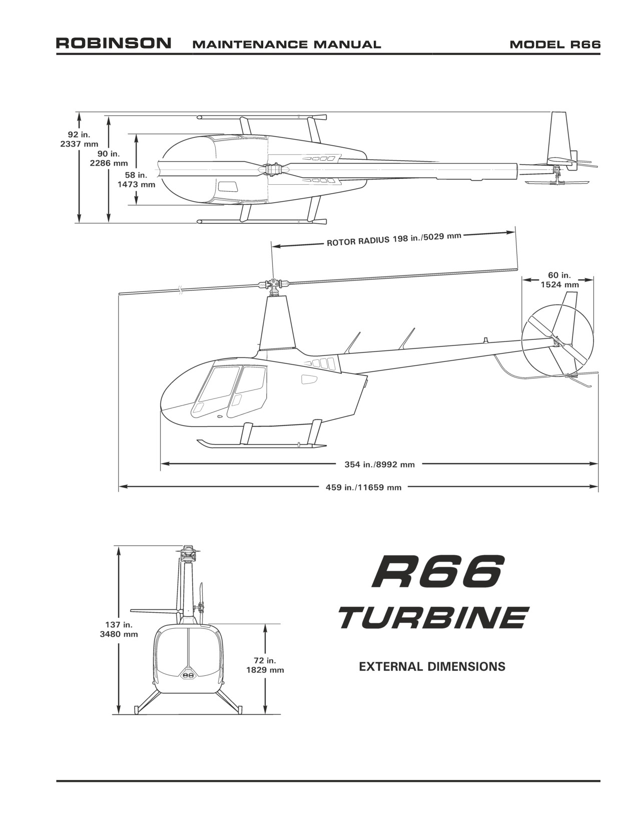
6-40 External Dimensions
FIGURE 6-1 EXTERNAL DIMENSIONS
25 OCT 2010
Chapter 6 Dimensions and Descriptions
Page 6.3
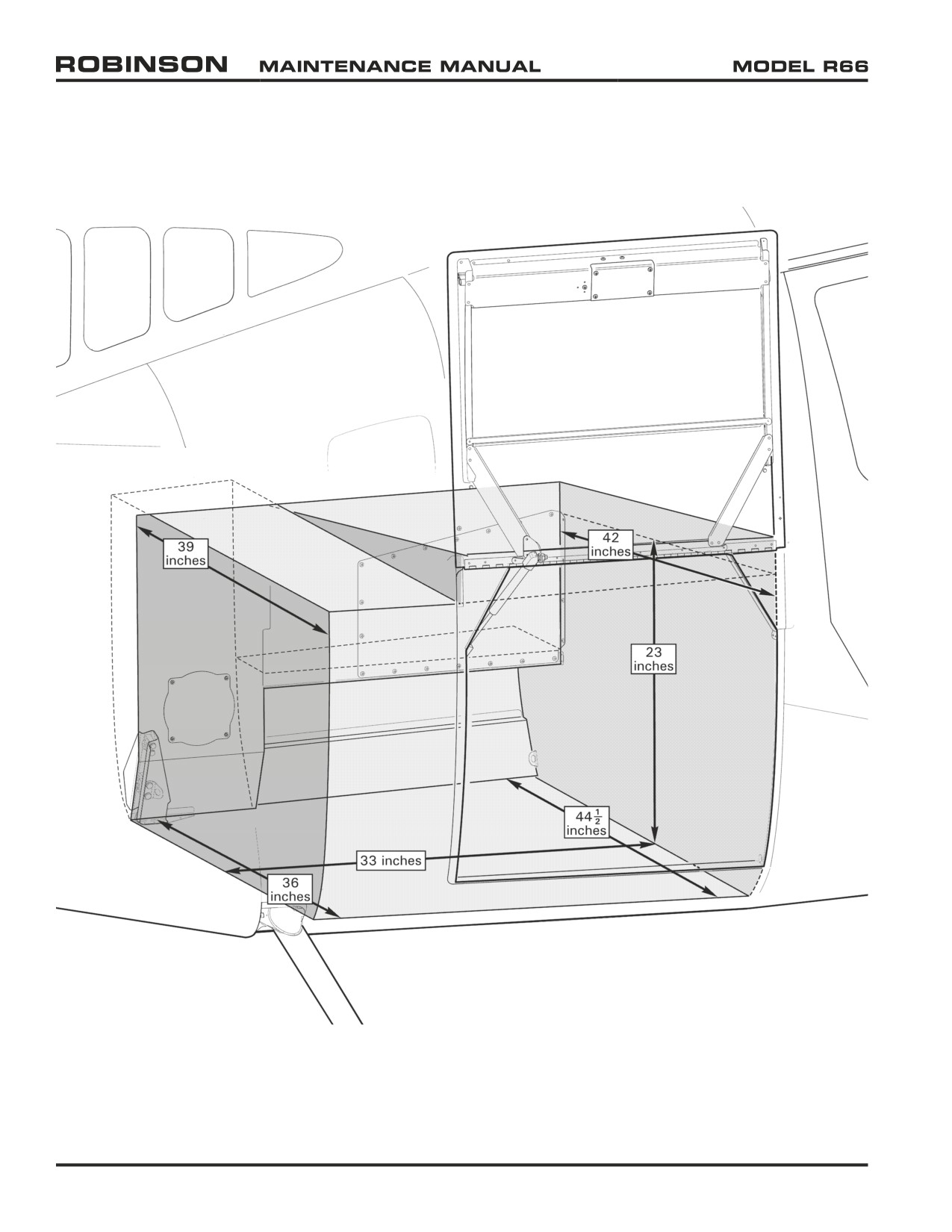
6-50 Baggage Compartment Dimensions
FIGURE 6-2 BAGGAGE COMPARTMENT INTERIOR DIMENSIONS
(Dimensions given are approximate)
Page 6.4
Chapter 6 Dimensions and Descriptions
25 OCT 2010
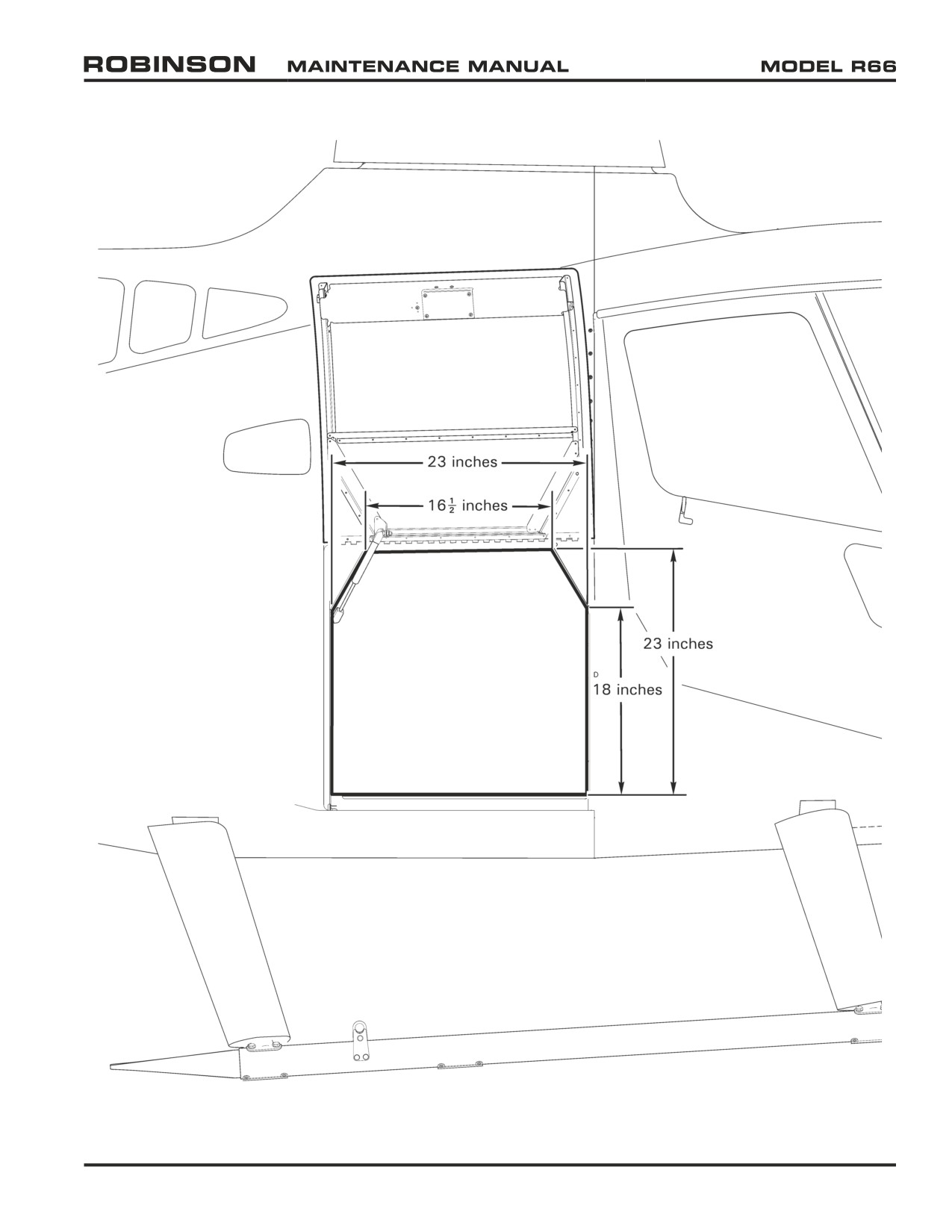
6-50 Baggage Compartment Dimensions (continued)
FIGURE 6-3 BAGGAGE COMPARTMENT ACCESS DIMENSIONS
(Dimensions given are approximate)
25 OCT 2010
Chapter 6 Dimensions and Descriptions
Page 6.5
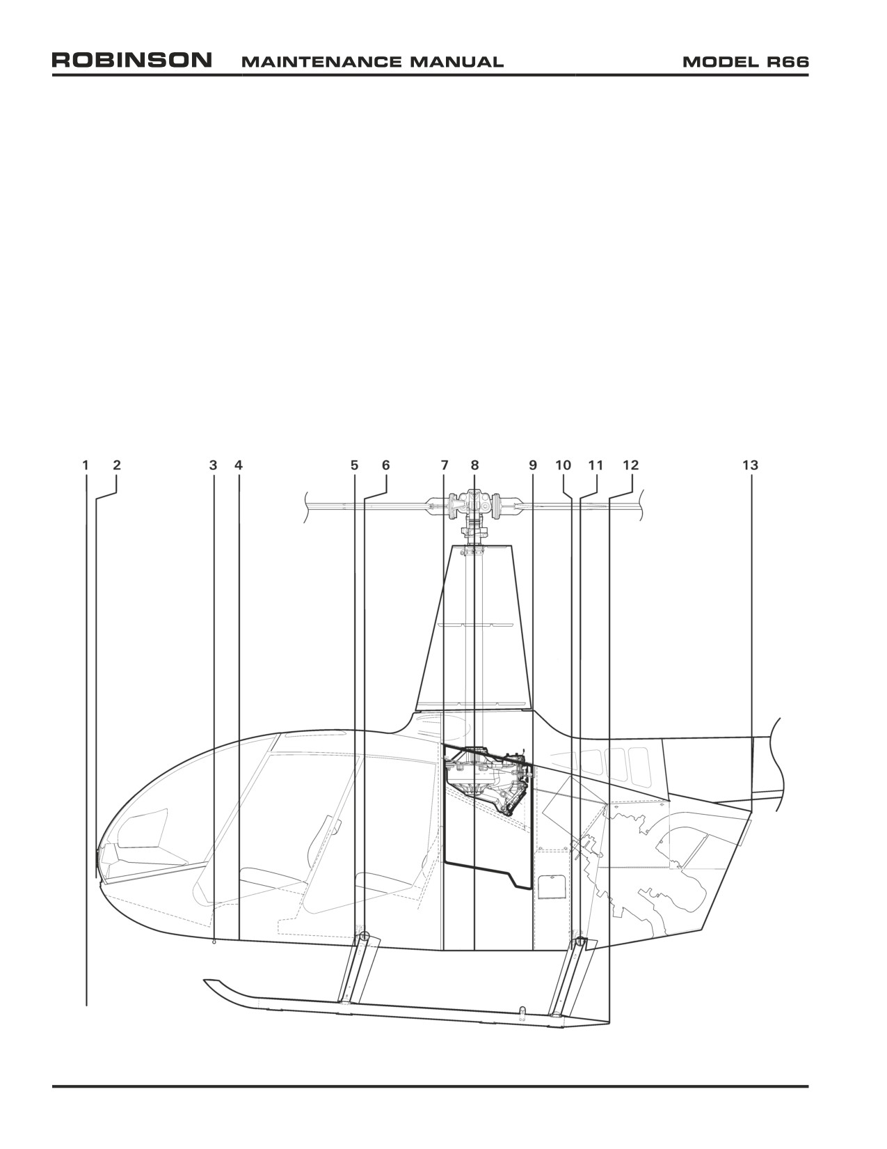
6-60 Station Diagrams
6-61 Fuselage Station (FS) Locations
1
Datum
FS 0.00
2
Nose Bracket (tie-down)
FS 2.36
3
Ground Handling Ball (center point, bottom)
FS 32.67
4
Seat Box Assembly - Forward (front wall)
FS 39.50
5
Seat Box Assembly - Aft (front wall)
FS 69.30
6
Cross Tube - Forward (centerline, at strut)
FS 71.56
7
Baggage Compartment (forward wall)
FS 92.00
8
Main Rotor Drive Shaft (centerline)
FS 100.00
9
Fuel Cell - Structure (aft wall)
FS 115.00
10
Engine Firewall - Vertical
FS 125.00
11
Cross Tube - Aft (centerline, at strut)
FS 127.35
12
Skid Extension (aft edge)
FS 134.78
13
Engine Cowling (aft point)
FS 171.45
FIGURE 6-4 FUSELAGE STATION LOCATIONS
Page 6.6
Chapter 6 Dimensions and Descriptions
25 OCT 2010
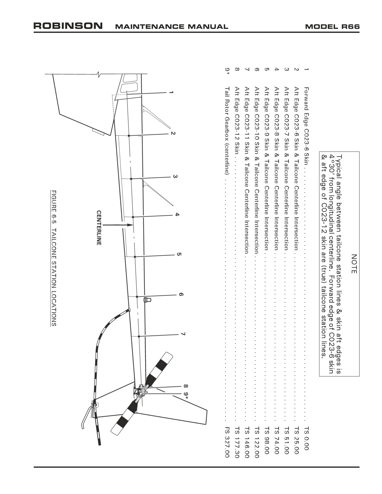
6-62 Tailcone Station (TS) Locations
25 OCT 2010
Chapter 6 Dimensions and Descriptions
Page 6.7
//////////////////////////////////////////