Robinson Helicopter Company RTR 660 (Number R00015LA). Maintenance Manual (2012) - page 2
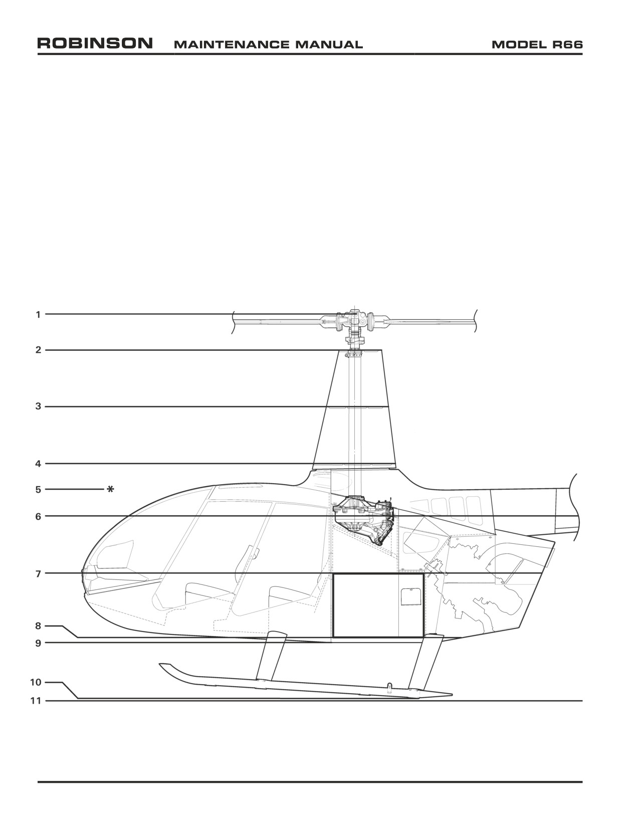
6-63 Water Line (WL) Station Locations
1
Teeter Hinge Bolt (main rotor)
WL 138.00
2
Upper Rib (top)
WL 125.17
3
Middle Rib (top)
WL 104.88
4
Lower Rib (top)
WL 84.59
5* Tail Rotor Gearbox (centerline)
WL 75.50
6
Main Rotor Gearbox (tail rotor and main rotor drive shaft intersection point)
WL 66.00
7
Baggage Compartment (ceiling, lowest point)
WL 45.60
8
Baggage Compartment (floor)
WL 22.59
9
Belly
WL 20.78
10
Landing Gear
WL 0.79
11
Origin
WL 0.00
FIGURE 6-6 WATER LINE STATION LOCATIONS
Page 6.8
Chapter 6 Dimensions and Descriptions
25 OCT 2010
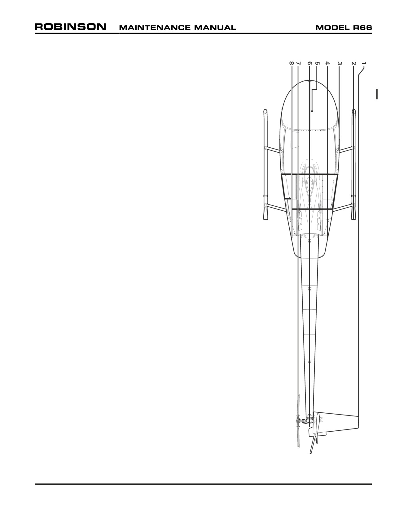
6-64 Butt Line (BL) Station Locations
1
Horizontal Stabilizer (outboard point)
HS 43.00
2
Skid Tube (centerline)
BL 42.00
3
Door Post (between forward & aft doors)
BL 28.25
4
Jack Lug/Tab (aft strut assembly)
BL 16.73
5
Ground Handling Ball (jack point)
BL 4.13
6
Origin
BL 0.00
7
Teeter Hinge Bolt (tail rotor)
LBL 11.01
8
Jack Tab (aft strut assembly)
LBL 16.73
FIGURE 6-7 BUTT LINE STATION LOCATIONS
Chapter 6 Dimensions and Descriptions
Page 6.9
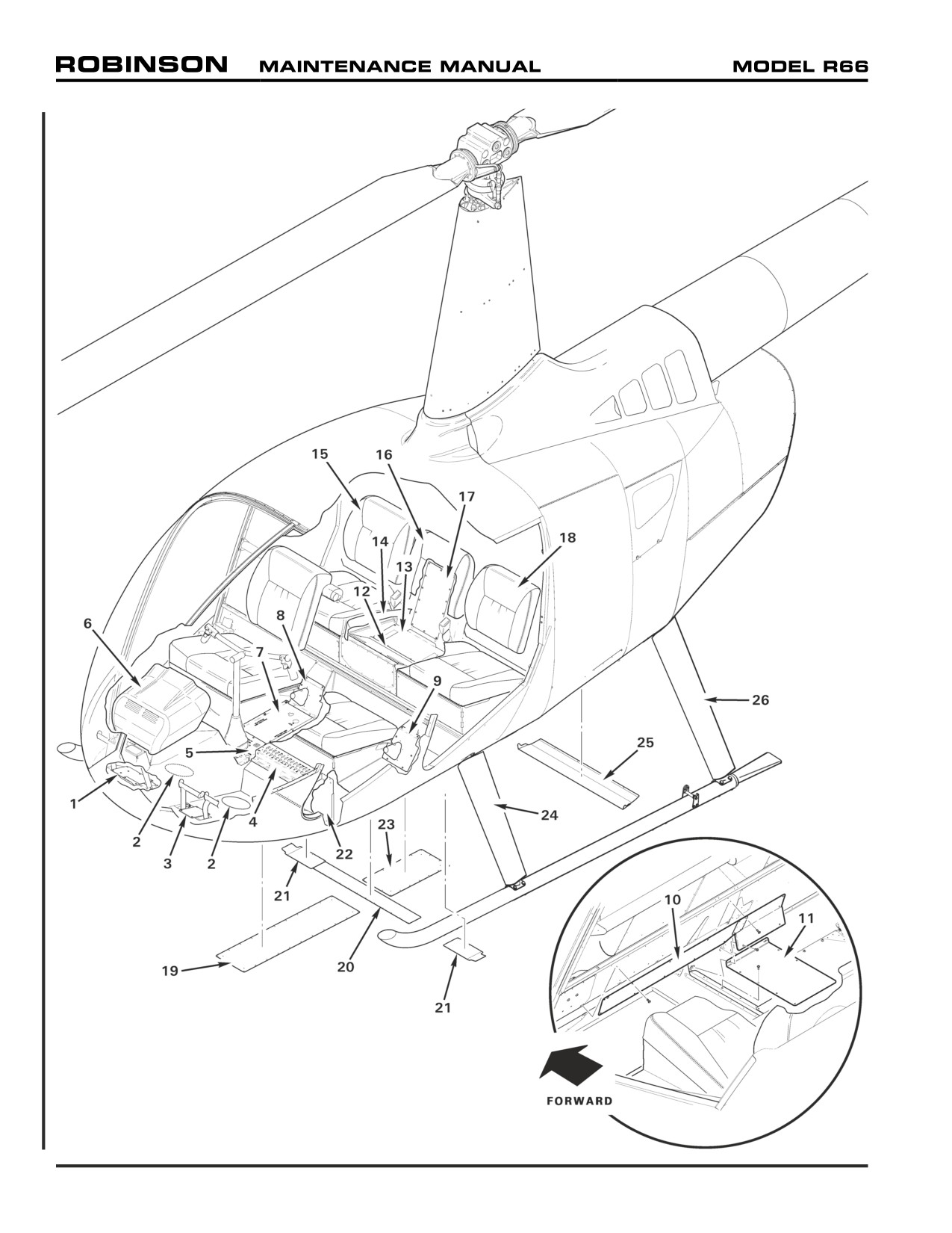
FIGURE 6-8 INTERIOR ACCESS & INSPECTION PANELS
Page 6.10
Chapter 6 Dimensions and Descriptions
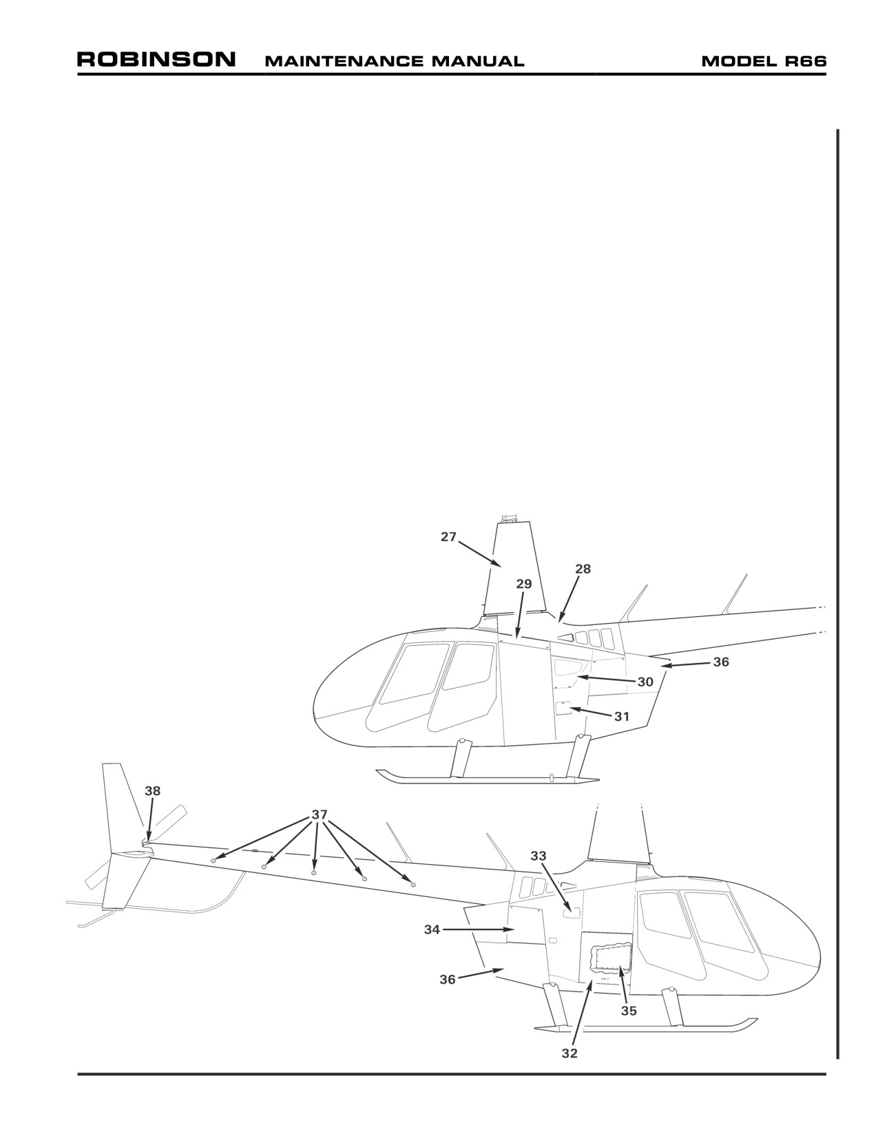
6-70 Access and Inspection Panels
ITEM
PART NO. DESCRIPTION
ITEM
PART NO. DESCRIPTION
1
A412-3
Cover - Pedal Bearing Block
24
F082-2
Fairing Assembly - Landing Gear, Forward (RH)
2
2451
Cover - Floor Panel
F082-3
Fairing Assembly - Landing Gear, Forward (LH)
3
A412-1
Cover - Pedal Bearing Block
25
G308-2
Cover - Aft Cowling
4
F490-1
Panel Assembly - Circuit Breaker
26
F082-4
Fairing Assembly - Landing Gear, Aft (RH)
5
F444-1
Cover - Cyclic Box
F082-5
Fairing Assembly - Landing Gear, Aft (LH)
6
B050
Console Assembly - Upper
27
F261-1
Mast Fairing Assembly
7
F445-1
Cover Assembly - Forward Tunnel
28
F706-1
Tailcone Cowling Assembly
8
F680-3
Cover Assembly - Collective (Pilot)
29
G004-2
Aft Fuselage Assembly - Door, Fuel Fill
9
F680-1
Cover Assembly - Collective (Copilot)
30
G004-10
Aft Fuselage Assembly - Door, Access
10
F461-1
Cover Assembly - Collective Cross Tube
31
G927-1
Aft Fuselage Assembly - Door, Fuel Sample
11
F463-1
Cover Assembly - Mid Tunnel
32
G900-1
Door Assembly - Baggage
12
F380-8
Angle
33
G910-1
Scoop Assembly - Air Inlet
13
F474-1
Cover Assembly - Middle Seat
34
G040-5
(2) Cowling Assembly - Aft (Door)
14
F931-1
Seat Assembly - Middle
35
G248-1
Cover - GCU
15
F003-4
Seat Back Assembly (RH)
36
G040-1
Cowling Assembly - Aft (Engine)
16
F932-1
Back Rest Assembly - Middle Seat
37
A231-1
(5) Plug Assembly - Tailcone Inspection
17
F474-2
Cover - Middle Seat
38
A558-2
Cover - Tailcone Inspection, Aft
18
F003-3
Seat Back Assembly (LH)
19
F794-1
Panel - Belly Cover (FWD)
20
F475-1
Cover Assembly - Cross Tube
21
F475-6
(2) Cover - Cross Tube, Outboard
22
F748-1
Cover Assembly - Battery
23
F794-2
Panel - Belly Cover (AFT)
FIGURE 6-9 EXTERIOR ACCESS & INSPECTION PANELS
Chapter 6 Dimensions and Descriptions
Page 6.11
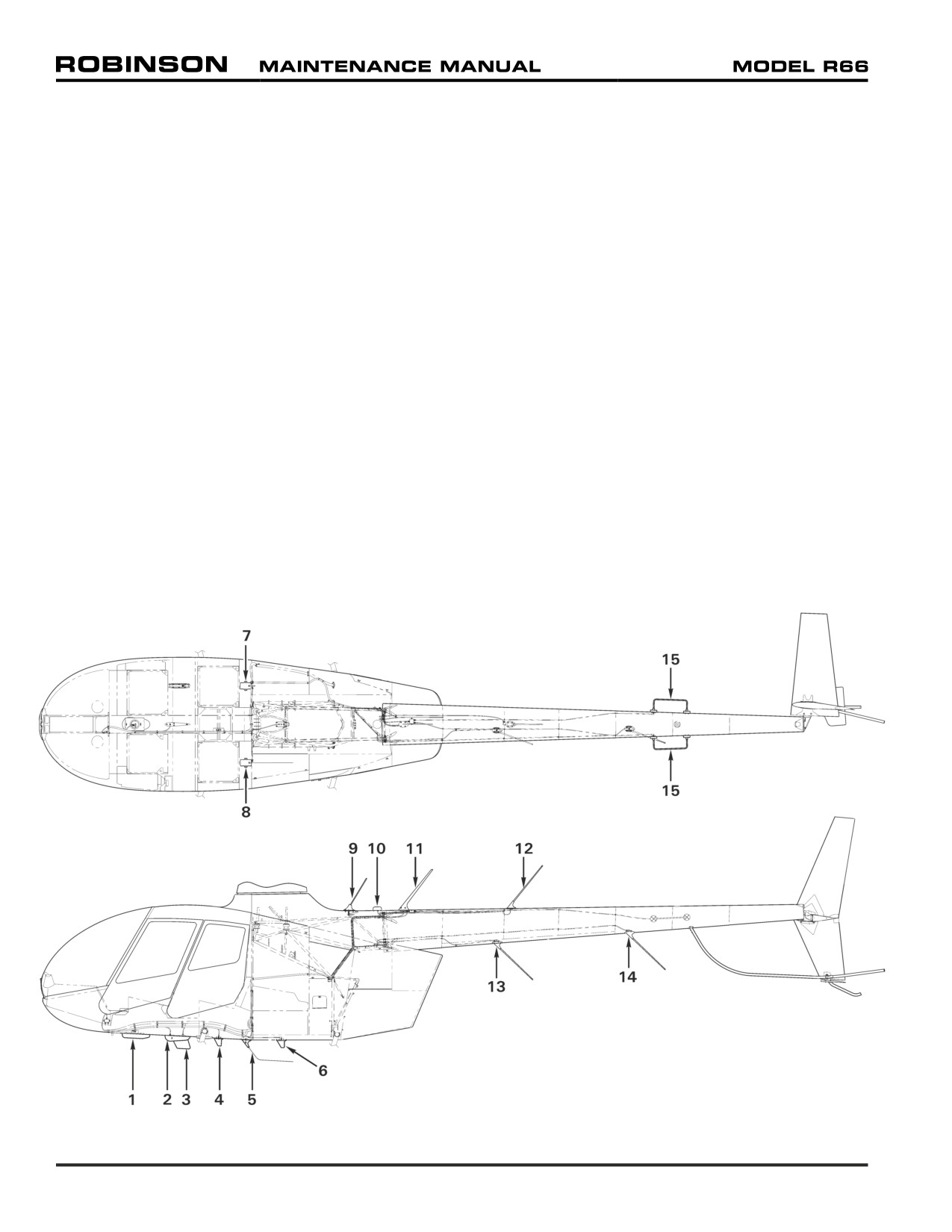
6-80 Antenna Locations
ITEM ANTENNA
MHz
PART NO.
ITEM
ANTENNA
MHz
PART NO.
1
ADF
—
KA44B
12
Upper Aft COM . . .
—
CI 121, CI 248-5
2
Marker Beacon
—
CI 102
Upper Aft FM
—
CI 177
3
RH Belly UHF
400-960
CI 285
UpperAftCOM/GPS
—
CI 2580-200
4
DME
—
CI 105-16, KA60
13
Lower Fwd FM
—
CI 177
5
LH/RH Belly (Ref)
—
See Item 7 and 8
Lower Fwd FM
403-512
CI 273, CI 272-1, CI 271
6
Transponder
—
CI 105-16, KA60
800-870
CI 306
7
RH Belly FM
138-174
CI 292-3
14
Lower Aft FM
—
CI 177
450-470
CI 177-20
Lower Aft VHF
118-136
CI 122
RH Belly AM/FM
—
CI 222
Lower Aft FM
403-512
CI 273, CI 272-1, CI 271
RH Belly FM
403-512
CI 273, CI 272-1, CI 271
800-870
CI 306
8
LH Belly FM
138-174
CI 292-3
15
NAV
108-118 &
D20543 (VOR &
329-335
LOCALIZER)
450-470
CI 177-20
220-225
D721-1
108-118 &
D20543 (VOR &
329-335
LOCALIZER W/DIPLEXER)
LH Belly FM
403-512
CI 273, CI 272-1, CI 271
LH Belly COM
118-136
CI 122
9
ELT
—
AV-300
10
Cowling GPS
—
GA 29
11
Upper Fwd COM
—
CI 121, CI 248-5
Upper Fwd FM
—
CI 177
Upper Fwd FM
403-512
CI 273, CI 272-1, CI 271
800-870
CI 306
Upper Fwd COM/GPS
—
CI 2580-200
FIGURE 6-10 ANTENNA LOCATIONS
Page 6.12
Chapter 6 Dimensions and Descriptions
CHAPTER 7
JACKING AND HOISTING
Section Title
Page
7-10
Jacking
7.1
7-20
Hoisting
7.5
25 OCT 2010
Chapter 7 Jacking and Hoisting
Page 7.i
Intentionally Blank
Page 7.ii
Chapter 7 Jacking and Hoisting
25 OCT 2010
CHAPTER 7
JACKING AND HOISTING
7-10 Jacking
CAUTION
When jacking helicopter, use mechanical or locking hydraulic
jacks, when available. Unlocked hydraulic jacks are subject
to pressure-loss which can affect critical measurements during
leveling or cause a raised helicopter to become unstable.
CAUTION
Never jack helicopter in windy conditions.
CAUTION
Perform jacking on a clean, flat, hard surface free of water,
oil, solvent, grease, or residue that could cause equipment or
personnel to slip during jacking procedure.
CAUTION
Do not actuate jacks from underneath helicopter. Remain clear
of landing gear skid tubes when helicopter is raised.
A. Jacking
1. Refer to Figure 7-1. Place one (appropriate capacity) jack under each (landing gear)
aft strut assembly jack lug/tab and under the ground handling ball. Install jacking point
adapters as required.
CAUTION
Ground handling ball must slide unrestricted across a flat surface
during jacking. When weighing, verify ball is not under side
load which could produce an erroneous weight indication.
2. Position jack levers for convenient access and engage jacks at lugs/tabs and ball.
Sandbag jacks for increased stability, as required.
3. Actuate jacks slowly and simultaneously (one person per jack recommended), maintaining
helicopter stability. Raise helicopter to required height.
CAUTION
Minimize personnel movement around raised helicopter.
Chapter 7 Jacking and Hoisting
Page 7.1
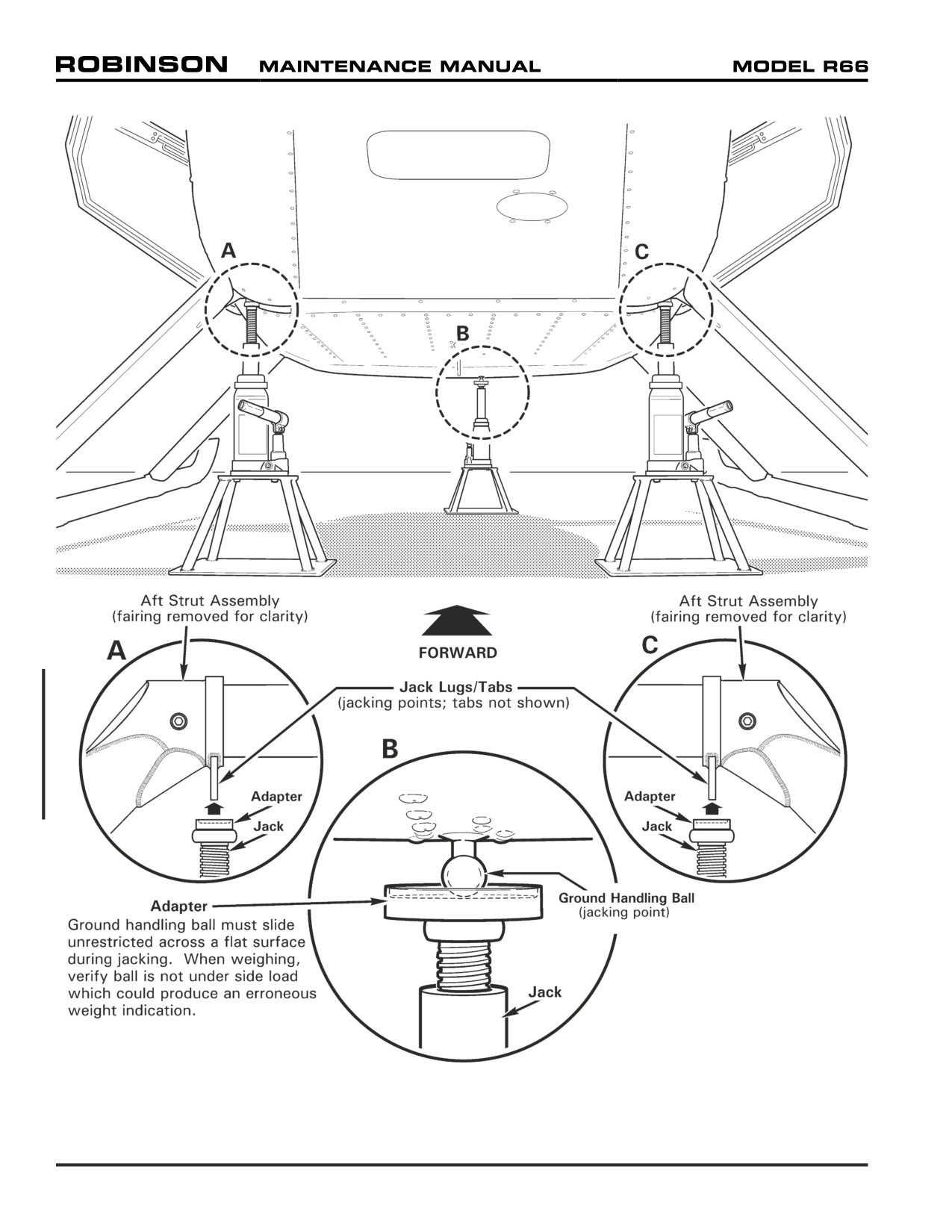
FIGURE 7-1 JACKING
Page 7.2
Chapter 7 Jacking and Hoisting
7-10 Jacking (continued)
B. Lowering
CAUTION
Skids spread as aircraft weight settles on landing gear.
1. Refer to Figure 7-1. Slowly and simultaneously (one person per jack recommended)
lower each jack ram, maintaining helicopter stability. Lower aircraft to ground.
2. Clear jacks from lugs/tabs and ball, and clear equipment from area.
Chapter 7 Jacking and Hoisting
Page 7.3
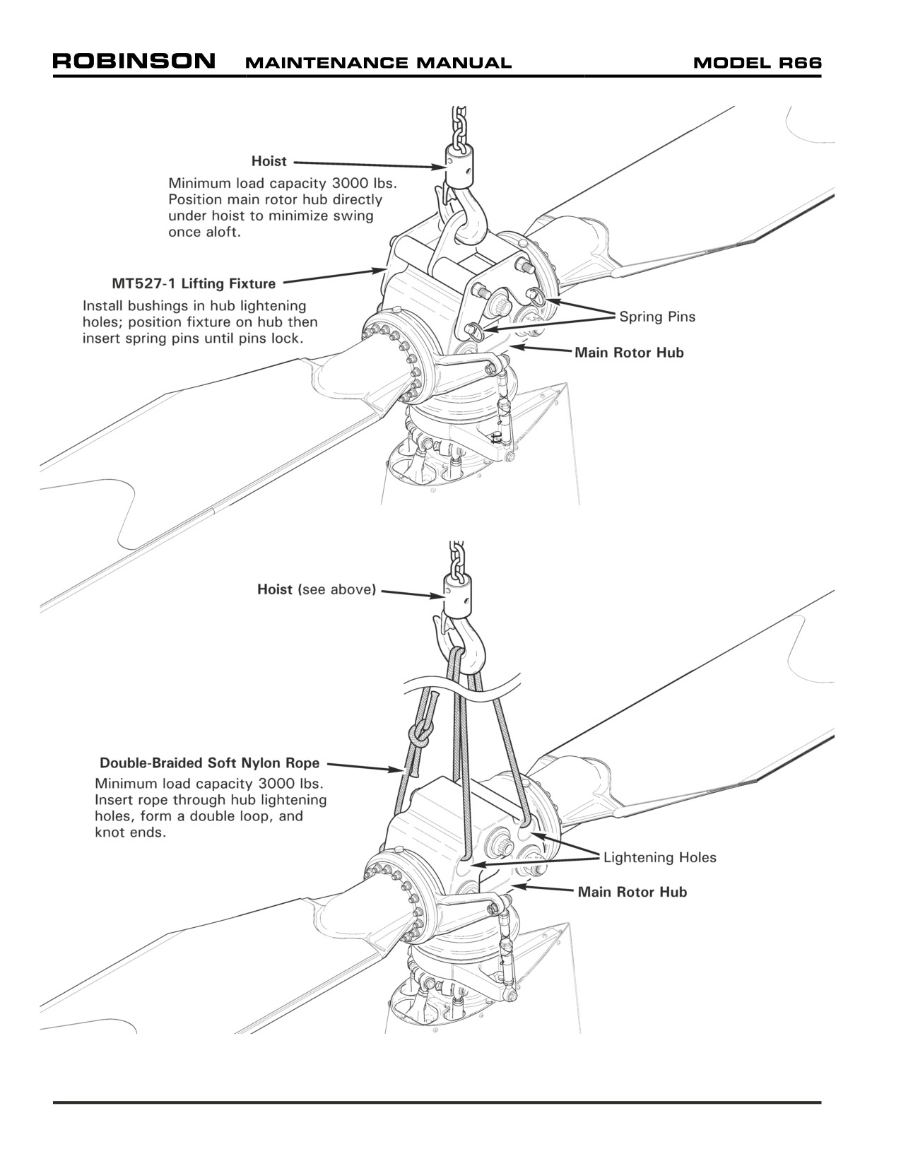
FIGURE 7-2 HOISTING
Page 7.4
Chapter 7 Jacking and Hoisting
7-20 Hoisting
CAUTION
Avoid hoisting helicopter in windy conditions.
CAUTION
Verify ground is free of water, oil, solvent, grease, or residue
that could cause equipment or personnel to slip during hoisting
procedure.
CAUTION
Remain clear of area beneath helicopter when helicopter is raised.
Minimize personnel movement around raised helicopter.
A. Hoisting with Lifting Fixture
1. Refer to Figure 7-2. Verify hoisting equipment has minimum load capacity of 3000 lbs.
2. Position main rotor hub directly under hoist to minimize helicopter swing once aloft.
3. Remove two spring pins and four nylon bushings from MT527-1 lifting fixture and install
bushings in main rotor hub lightening holes. Position lifting fixture on hub then insert
spring pins through fixture and bushings until pins lock. Verify security.
4. Connect hoist to lifting fixture. Verify security.
5. Stabilize helicopter as required by guiding tail skid, but do not exert force (tail skid is
secondary structure). Raise helicopter to required height.
B.
Hoisting with Nylon Rope
1. Refer to Figure 7-2. Verify hoisting equipment has minimum load capacity of 3000 lbs.
Verify minimum work load limit for 1-inch diameter twisted or double braided (preferred)
soft nylon rope is 3000 lbs.
2. Position main rotor hub directly under hoist to minimize helicopter swing once aloft.
3. Insert rope through main rotor hub lightening holes, form a double loop, and knot ends.
Connect hoist to nylon rope. Verify security.
4. Stabilize helicopter as required by guiding tail skid, but do not exert force (tail skid is
secondary structure). Raise helicopter to required height.
25 OCT 2010
Chapter 7 Jacking and Hoisting
Page 7.5
7-20 Hoisting (continued)
C. Lowering
CAUTION
Skids spread as aircraft weight settles on landing gear.
1. Refer to Figure 7-2. Stabilize helicopter as required by guiding tail skid, but do not exert
force (tail skid is secondary structure). Slowly lower aircraft to ground.
2. Disconnect hoisting equipment, remove lifting fixture or nylon rope from main rotor hub,
and clear equipment from area.
Page 7.6
Chapter 7 Jacking and Hoisting
25 OCT 2010
CHAPTER 8
WEIGHT AND BALANCE
Section Title
Page
8-10
Leveling
8.1
8-11
Leveling for Weight and Balance
8.1
8-12
Leveling for Rigging
8.3
8-20
Weighing
8.5
8-21
Preparing Helicopter for Weighing
8.5
8-22
Weighing Procedure and Calculations
8.7
8-30
Fixed Ballast
8.11
8-31
Nose Ballast
8.11
8-32
Empennage Ballast
8.13
25 OCT 2010
Chapter 8 Weight and Balance
Page 8.i
Intentionally Blank
Page 8.ii
Chapter 8 Weight and Balance
25 OCT 2010
CHAPTER 8
WEIGHT AND BALANCE
8-10 Leveling
NOTE
Perform leveling and weighing in a zero-wind environment.
NOTE
Verify spirit level is calibrated by placing level on a designated
surface and noting bubble position. Rotate spirit level 180°;
verify bubble is in the same position.
8-11 Leveling for Weight and Balance
NOTE
Main rotor blade position does not affect weight and balance
calculations.
1. Jack helicopter per Section 7-10.
2. Refer to Figure 8-1. Place a spirit level laterally on F463-1 aft tunnel cover. Verify
cover is flat; if cover is not flat, remove cover and place spirit level across keel panel
flanges.
3. Adjust jacks at (landing gear) aft strut assembly jack lugs/tabs until helicopter is level
laterally.
4. Position spirit level longitudinally on aft tunnel cover, or atop left or right keel panel
if cover is removed. Adjust jack under ground handling ball until helicopter is level
longitudinally.
Chapter 8 Weight and Balance
Page 8.1
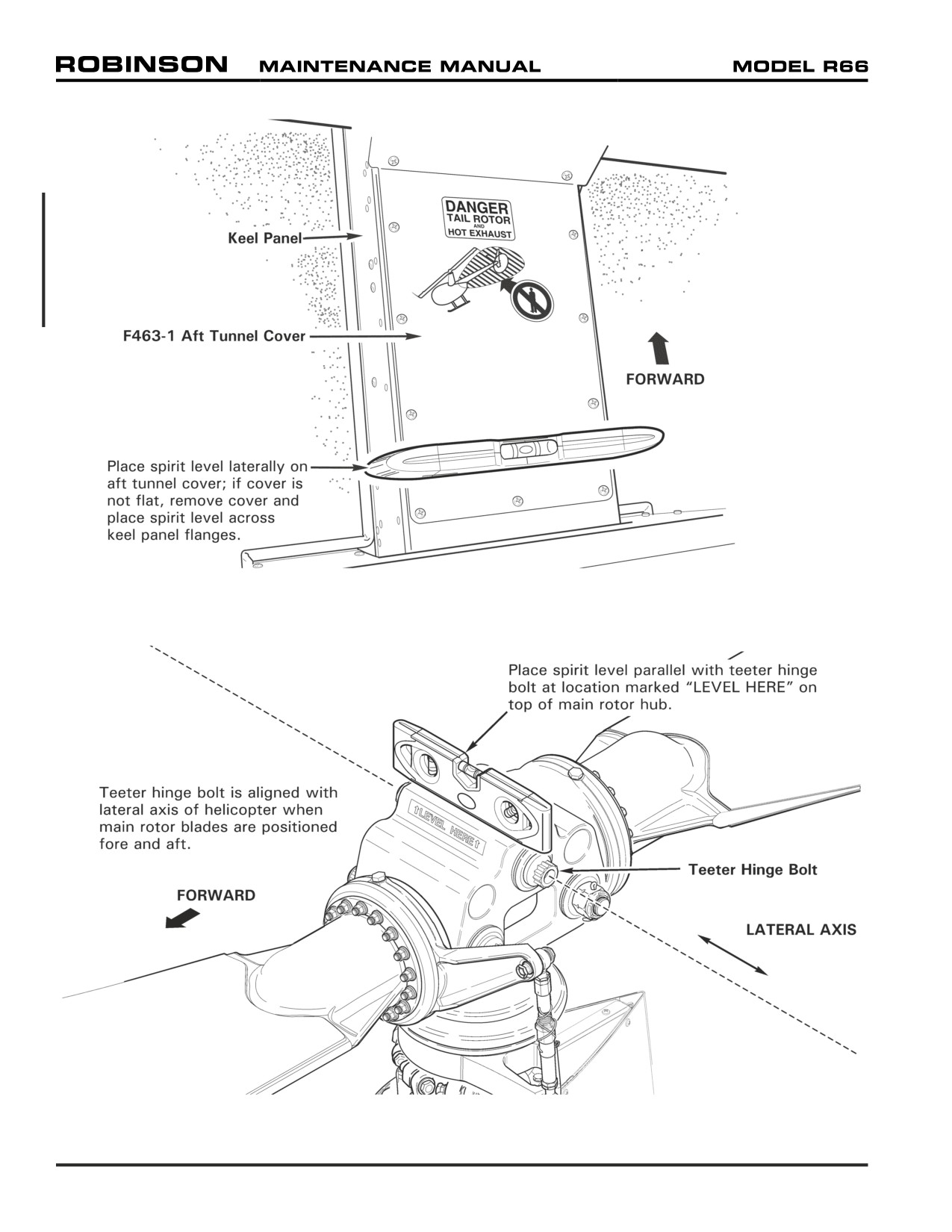
FIGURE 8-1 LEVELING FOR WEIGHT AND BALANCE
(Lateral shown; view looking down between aft seat footwells)
FIGURE 8-2 LEVELING FOR RIGGING
(Lateral shown)
Page 8.2
Chapter 8 Weight and Balance
8-12 Leveling for Rigging
1. Refer to Figure 8-2. Place cyclic stick in vertical position and apply cyclic friction.
Position main rotor blades approximately fore and aft and apply rotor brake.
(Teeter
hinge bolt is aligned with lateral axis of helicopter.)
2. Jack helicopter per Section 7-10.
3. Place a spirit level parallel with teeter hinge bolt at location marked "LEVEL HERE" on
top of main rotor hub.
4. Adjust jack at (landing gear) aft strut assembly jack lugs/tabs until helicopter is level
laterally.
5. Release rotor brake and rotate main rotor until teeter hinge bolt is aligned with longitudinal
axis of the helicopter. Apply rotor brake. Verify cyclic stick is in vertical position with
friction applied.
6. Adjust jack under ground handling ball until helicopter is level longitudinally. Remove
spirit level.
Chapter 8 Weight and Balance
Page 8.3
Intentionally Blank
Page 8.4
Chapter 8 Weight and Balance
8-20 Weighing
Reweigh helicopter when helicopter empty weight and empty weight center of gravity have
been modified and if the accuracy of additional calculations is suspect.
Maintain a continuous record of the helicopter’s weight and balance using the Weight and
Balance Record in R66 Pilot’s Operating Handbook (POH) Section 6.
NOTE
Verify scales are calibrated. Operate scales according to scale
manufacturer’s instructions.
NOTE
Never weigh the helicopter in the wind. Weigh helicopter on a
flat, hard surface in a zero-wind environment for accurate scale
readings.
8-21 Preparing Helicopter for Weighing
1. Defuel helicopter per Section 12-42.
2. Service engine oil, hydraulic fluid, and main & tail rotor gearboxes per Chapter 12.
3. Clean aircraft per Section 20-10. Ensure helicopter is completely dry prior to weighing.
4. Remove foreign objects from baggage compartments and stowage areas.
5. Verify cowlings, removable panels, cabin doors, removable controls, and R66 Pilot’s
Operating Handbook (POH) are installed.
6. Verify Equipment List/Weight and Balance Data sheet (RF 134) and modifications
recorded in the Weight and Balance Record correspond with installed equipment and
recorded equipment locations.
25 OCT 2010
Chapter 8 Weight and Balance
Page 8.5
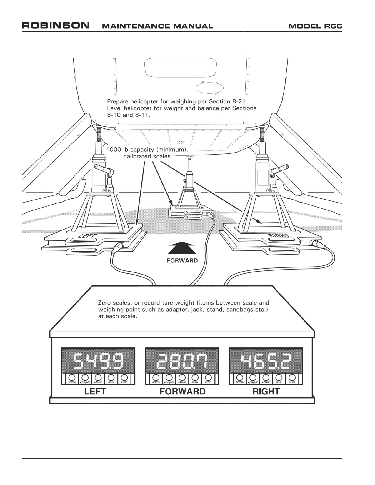
FIGURE 8-3 WEIGHING
(Scale indications for demonstration only)
Page 8.6
Chapter 8 Weight and Balance
25 OCT 2010
8-22 Weighing Procedure and Calculations
NOTE
• Arm is the distance in inches from datum.
• Datum is located 100 inches forward of main rotor centerline.
• CG (arm) is determined by dividing total moment by total weight.
1.
Refer to Section 8-20. Prepare helicopter for weighing per Section 8-21.
2.
Refer to Figure 8-3. Place a jack and one 1000-lb capacity (minimum) scale under each
(landing gear) aft strut assembly jack lug/tab and under the ground handling ball.
3.
Zero scales, or record tare weight (items between scale and weighing point such as
adapter, jack, stand, sandbags, etc.) at each scale.
4.
Level helicopter for weight and balance per Sections 8-10 and 8-11. Remove spirit
level. If removed, carefully replace F463-1 aft tunnel cover, unsecured, on top of keel
panels.
5.
Calculate net weights:
Weighing Point Scale Indication
Tare Weight
Net Weight
Forward:
-
=
lb
Left:
-
=
lb
Right:
-
=
lb
Chapter 8 Weight and Balance
Page 8.7
8-22 Weighing Procedure and Calculations (continued)
6.
Calculate weight and CG per the following table. Adjust ballast per steps 6b thru 6e as
required until calculated CG is between 101.50 and 102.50 per step 6a.
Longitudinal CG
Item
Weight (lb)
(arm, inches)
Moment (in.-lb)
Forward Net:
x
32.67
=
Left Net:
x
127.35
=
Right Net:
x
127.35
=
Pilot (right forward seat; add):
160.00
x
49.00
=
7840.00
Unusable fuel (add):
6.70
x
110.40
=
739.68
Calculated weight and CG:
a.
If Calculated CG is between 101.50 and 102.50, (additional) ballast is not required.
Proceed to step 7.
b.
If Calculated CG is less than 101.50 and nose ballast is not installed, install empennage
ballast per Section 8-32. Reweigh helicopter and calculate new weight and CG per
the previous steps.
c.
If Calculated CG is less than 101.50 and nose ballast is installed, determine (minimum)
nose ballast to remove:
(102.50 - Calculated CG) X Calculated weight
=
97.35
lb
Round down to nearest 0.25 lb. Remove nose ballast per Section 8-31. Reweigh
helicopter and calculate new weight and CG per the previous steps.
d.
If Calculated CG is greater than 102.50 and empennage ballast is installed, remove
empennage ballast per Section 8-32. Reweigh helicopter and calculate new weight
and CG per the previous steps.
e.
If Calculated CG is greater than 102.50 and empennage ballast is not installed,
determine (minimum) additional nose ballast required:
(Calculated CG - 102.50) X Calculated weight
=
97.35
lb
Round up to nearest 0.25 lb. Install nose ballast per Section 8-31. Reweigh helicopter
and calculate new weight and CG per the previous steps.
7.
Lower helicopter per Section 7-10. Secure aft tunnel cover.
Page 8.8
Chapter 8 Weight and Balance
8-22 Weighing Procedure and Calculations (continued)
8.
Calculate basic empty weight and longitudinal CG:
Longitudinal CG
Item
Weight (lb)
(arm, inches)
Moment (in.-lb)
Forward Net:
x
32.67
=
Left Net:
x
127.35
=
Right Net:
x
127.35
=
Unusable fuel (add):
6.70
x
110.40
=
739.68
Basic empty weight and
longitudinal CG:
9.
Calculate basic empty weight and lateral CG:
Lateral CG
Item
Weight (lb)
(arm, inches)
Moment (in.-lb)
Forward Net:
x
4.13
=
Left Net:
x
- 16.73
=
Right Net:
x
16.73
=
Unusable fuel (add):
6.70
x
- 20.70
=
- 138.69
Basic empty weight
and lateral CG:
25 OCT 2010
Chapter 8 Weight and Balance
Page 8.9
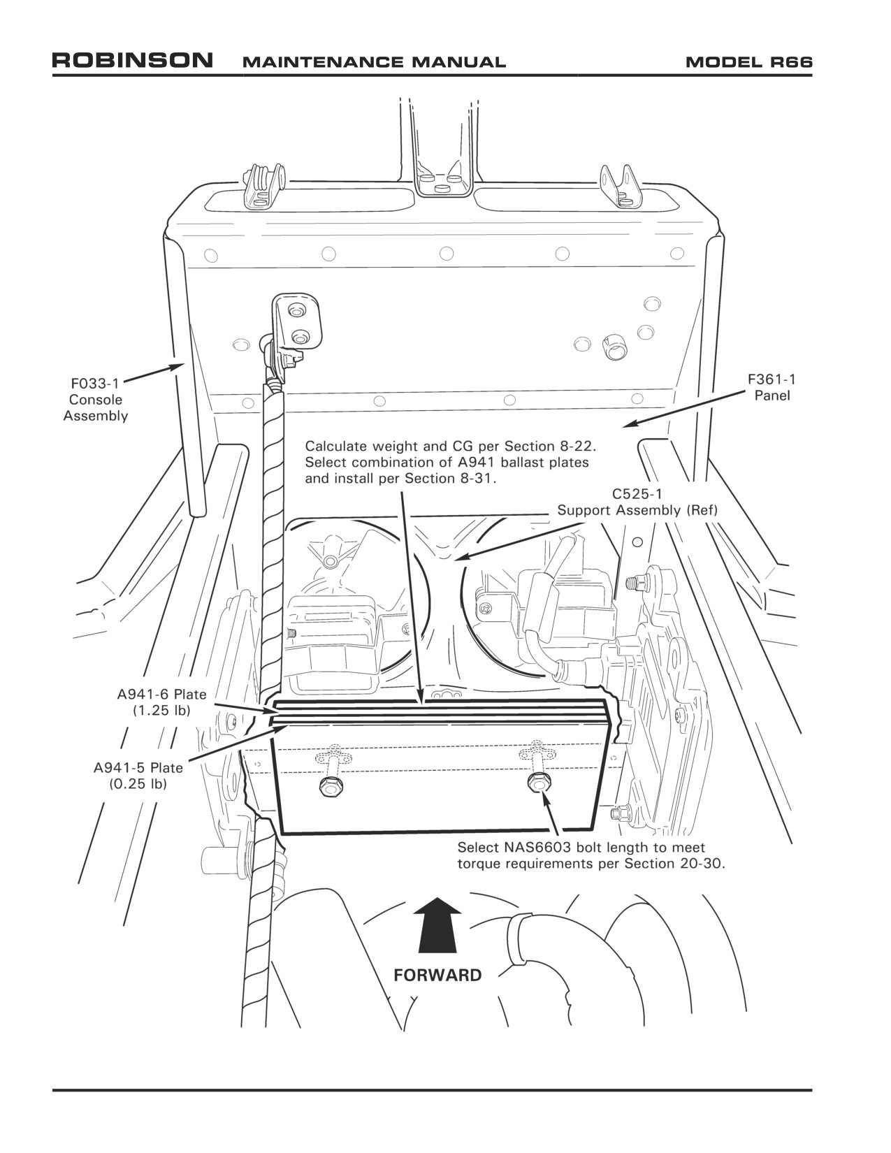
FIGURE 8-4 NOSE BALLAST
(View inside lower console assembly with upper console hinged aft)
Page 8.10
Chapter 8 Weight and Balance
25 OCT 2010
8-30 Fixed Ballast
8-31 Nose Ballast
Refer to R66 Illustrated Parts Catalog (IPC) Figure 8-1.
NOTE
Maximum allowable nose ballast is 15.00 lb.
CAUTION
Altering fixed ballast can appreciably affect helicopter center of
gravity (CG). If fixed ballast information is unknown, reweigh
helicopter per Section 8-22.
1.
Refer to Figure 8-4. Remove screws securing B050-22 or -23 upper console assembly to
F033-1 lower console assembly and hinge upper console assembly aft. Protect instrument
face with foam support or equivalent.
2.
Remove hardware securing A941-5 or -6 ballast plate(s), if installed, to F361-1 panel.
3.
Remove or install ballast plates per calculations performed in Section 8-22. Select NAS6603
bolt length to meet torque requirements per Section 20-30. Install hardware, torque bolts
per Section 20-32, and torque stripe per Figure 5-1.
4.
Hinge upper console assembly forward and install screws securing upper and lower
console assemblies. Verify security.
5.
Reweigh and/or calculate basic empty weight and CG per Section 8-22.
6.
Revise Weight and Balance Record in R66 Pilot's Operating Handbook (POH) Section 6
to reflect ballast removal or installation using the following data:
Weight
Longitudinal
Longitudinal
Lateral Arm
Lateral
Arm
Moment
Moment
Nose ballast
0-15.00 lb
5.15 in.
Variable
0.00 in.
0.00 in.-lb
25 OCT 2010
Chapter 8 Weight and Balance
Page 8.11
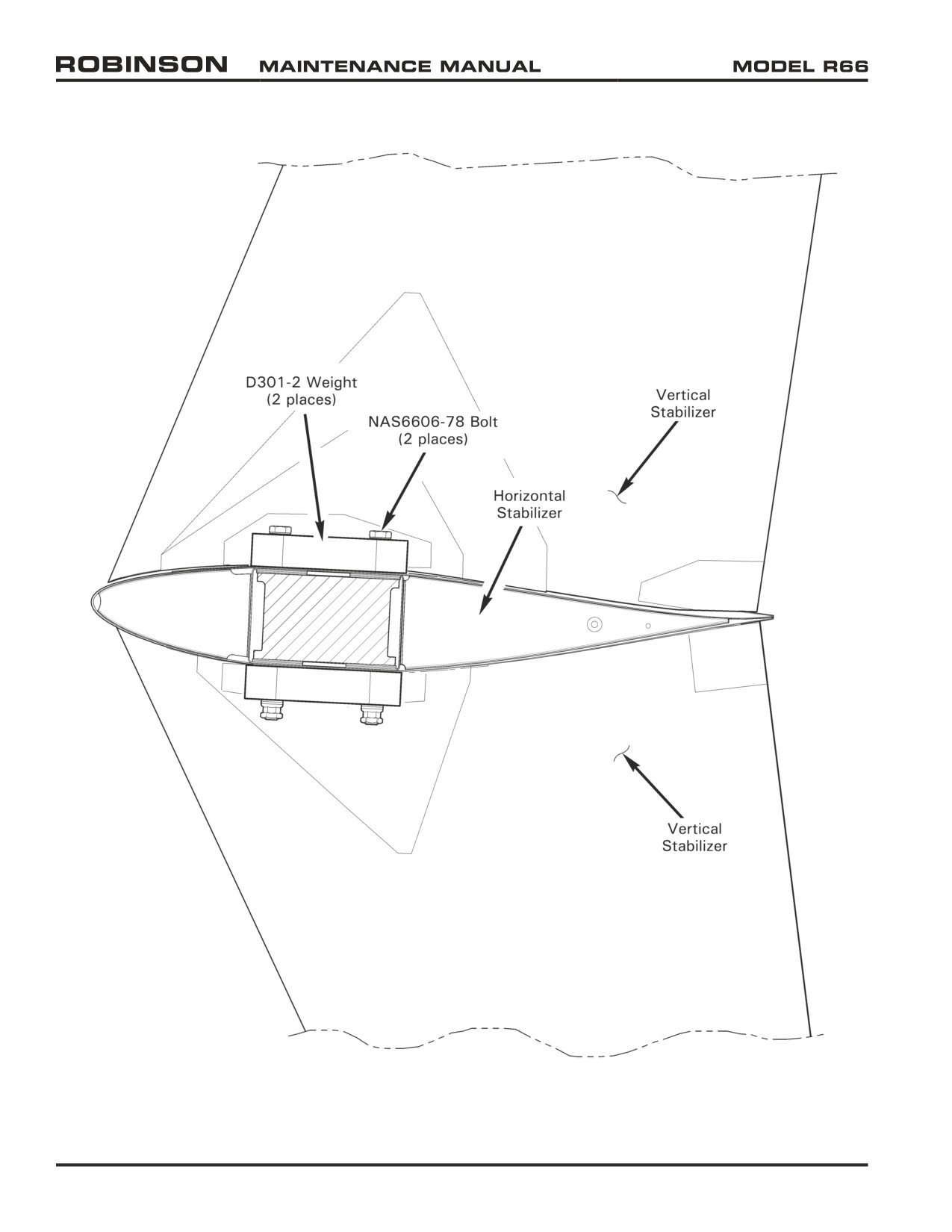
FIGURE 8-5 EMPENNAGE BALLAST
Page 8.12
Chapter 8 Weight and Balance
25 OCT 2010
8-32 Empennage Ballast
Refer to R66 Illustrated Parts Catalog (IPC) Figure 8-1.
NOTE
Use only approved materials listed in Section 20-70.
CAUTION
Altering fixed ballast can appreciably affect helicopter center of
gravity (CG). If fixed ballast information is unknown, reweigh
helicopter per Section 8-22.
WARNING
Maximum allowable empennage ballast is 3.00 lb. If empennage
ballast is required per Section 8-22, two D301-2 weights must
be installed as shown in Figure 8-5.
A. Removal
1. Refer to Figure 8-5. Remove empennage assembly, including D301-2 ballast weights,
per Section 53-50.
2. Solvent-clean bare metal around and between bolt holes on horizontal stabilizer upper
and lower surfaces.
3. Apply light coat zinc-chromate or epoxy primer to bare metal surfaces. While primer
is wet, install empennage assembly per Section 53-50. Topcoat hardware with
colored paint as desired.
4. Reweigh and/or calculate basic empty weight and CG per Section 8-22.
5. Revise Weight and Balance Record in R66 Pilot's Operating Handbook (POH) Section
6 to reflect ballast removal using the following data:
Weight
Longitudinal
Longitudinal
Lateral
Lateral
Arm
Moment
Arm
Moment
Empennage ballast
3.00 lb
325.44 in.
976.32 in.-lb
4.45 in.
13.35 in.-lb
B.
Installation
1. Refer to Figure 8-5. Remove empennage assembly per Section 53-50.
2. Solvent-clean bare metal around and between bolt holes on horizontal stabilizer upper
and lower surfaces.
3. Temporarily install D301-2 weights per R66 IPC Figure 8-1. Torque bolts per Section
20-32.
4. Trace outline of weights onto horizontal stabilizer upper and lower surfaces using
felt-tip, non-permanent marker or tape. Remove weights.
Chapter 8 Weight and Balance
Page 8.13
8-32 Empennage Ballast (continued)
B. Installation (continued)
5. Remove paint within traced outlines on stabilizer by block sanding (to maintain
flatness). Finish sanding using 320-grit or finer wet-or-dry sandpaper, or using
approved stripper per Section 20-71. Similarly, on each D301-2 weight, remove
paint from one flat surface which will clamp against stabilizer.
6. Remove tracing media. Solvent-clean bare metal on horizontal stabilizer and weight
clamping surfaces.
7. Reweigh and/or calculate basic empty weight and CG per Section 8-22.
8. Revise Weight and Balance Record in R66 Pilot's Operating Handbook (POH) Section
6 to reflect ballast installation using the following data:
Weight
Longitudinal
Longitudinal
Lateral
Lateral
Arm
Moment
Arm
Moment
Empennage ballast
3.00 lb
325.44 in.
976.32 in.-lb
4.45 in.
13.35 in.-lb
Page 8.14
Chapter 8 Weight and Balance
CHAPTER 9
GROUND HANDLING
Section Title
Page
9-10
Ground Handling
9.1
9-11
Ground Handling Wheels
9.1
9-12
Moving Helicopter on Ground Handling Wheels
9.3
9-13
Ground Handling Carts
9.3
9-14
Ground Power Start
9.3
9-20
Trailering
9.4
25 OCT 2010
Chapter 9 Ground Handling
Page 9.i
Intentionally Blank
Page 9.ii
Chapter 9 Ground Handling
25 OCT 2010
CHAPTER 9
GROUND HANDLING
9-10 Ground Handling
9-11 Ground Handling Wheels
Refer to R66 Illustrated Parts Catalog (IPC) Figure 9-1.
NOTE
R66 ground handling wheels are installed inboard of landing
gear skid tubes. C063-5 (LH) and C063-6 (RH) ground handling
wheel assemblies are not interchangeable. When wheels are
installed and in locked position, both handles point aft.
CAUTION
Handle has a tendency to snap over when raising and lowering the
helicopter. Grip handle firmly with both hands during operation.
CAUTION
Remain clear of landing gear skid tubes when helicopter is
raised.
WARNING
Remove ground handling wheels for flight.
A. Installation
NOTE
Verify proper inflation of ground handling wheel tires. Maximum
tire inflation pressure is 70 psi.
1. Extend ground handling wheel retractable handle by depressing locking pins and
sliding handle out until pins engage outer holes. Verify security.
2. Refer to Figure 9-1. Hold ground handling wheel assembly inboard of skid with
handle forward, wheel aft, and spindle pointed outboard. Insert spindle completely
into skid-mounted support, then pull handle in rearward arc (raises helicopter) until
handle is in locked position, parallel with the skid.
3. Repeat steps to install second wheel assembly. Helicopter will rest on skid toes.
25 OCT 2010
Chapter 9 Ground Handling
Page 9.1
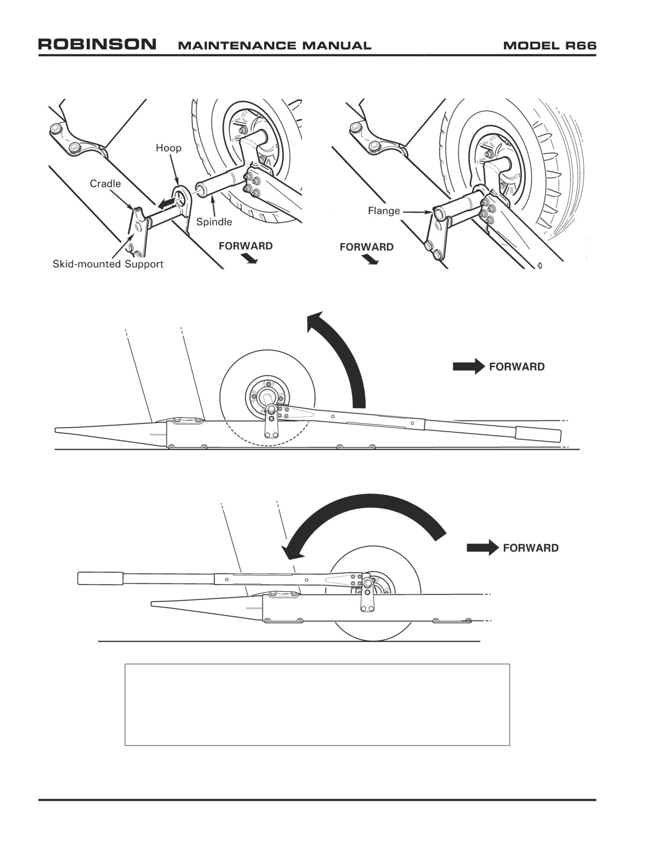
1. Insert spindle into skid-mounted support.
2. Verify flange is outboard of cradle.
3. Pull handle in rearward arc to raise helicopter.
4. Handle is in locked position when parallel with the skid.
NOTE
R66 ground handling wheels are installed inboard of landing
gear skid tubes. C063-5 (LH) and C063-6 (RH) ground handling
wheel assemblies are not interchangeable. When wheels are
installed and in locked position, both handles point aft.
FIGURE 9-1 GROUND HANDLING WHEELS
Page 9.2
Chapter 9 Ground Handling
25 OCT 2010
9-11 Ground Handling Wheels (continued)
B. Removal
1. Refer to Figure 9-1. Pull ground handling wheel handle in forward arc (lowers
helicopter) until handle is in unlocked position, parallel with the skid. Remove spindle
from skid-mounted support and remove wheel assembly. Repeat step to remove
second wheel assembly.
2. Retract handle by depressing locking pins and sliding handle in until pins engage
inner holes. Verify security.
9-12 Moving Helicopter on Ground Handling Wheels
1.
Position main rotor blades approximately fore and aft and apply rotor brake.
2.
Install ground handling wheels per Section 9-11.
3.
Verify ground handling area is free of foreign object debris.
4.
Have one person pull down on tail rotor gearbox until skid tubes are parallel with the
ground. During ground handling, balance helicopter to minimize wear on forward skid
shoes and rear extensions.
NOTE
Steer helicopter by gripping the tail rotor gearbox, aft tailcone
section, or inboard part of horizontal stabilizer between tailcone
and vertical stabilizers.
CAUTION
Do not steer helicopter by gripping the tail rotor guard, vertical
stabilizers, outboard part of horizontal stabilizer, tail rotor, tail
rotor controls, or tail skid.
5.
a. If moving helicopter forward, nose first: Open engine cowling door(s). Have one
person (or two people) push on the engine door frame(s) forward ledge.
b. If moving helicopter backward, tail first: Have one person (or two people) push on
either side of nose vent.
9-13 Ground Handling Carts
The R66 can be handled by one person using the MT950-1 Universal ground handling cart.
Product specifications, as well as MT950 Operating Instructions, Maintenance Manuals,
the Customer Support tab.
9-14 Ground Power Start
See R66 Pilot's Operating Handbook (POH) Section 4.
Chapter 9 Ground Handling
Page 9.3
9-20 Trailering
CAUTION
Trailering the R66 is not normally recommended. Most trailers
large enough to accommodate the helicopter are designed for
much heavier loads; the trailer’s springs and shock absorbers
will not function properly when lightly-loaded. Also, without
support, the tailcone can resonate with trailer vibrations,
subjecting the tailcone to greatly amplified loads.
If trailering is unavoidable, observe the following precautions:
1. Load trailer with ballast to an average weight the trailer is designed to carry.
2. Support the tailcone. Cushion support point(s) to prevent tailcone damage.
3. Perform one of the following options:
a. Remove main rotor blades per Section 62-10. Pack blades in shipping crate. See R66
Illustrated Parts Catalog [IPC] Figure 99-11.
b. Install main rotor blade supports per Section 10-13.
c. Fabricate blade supports to unload droop stops. Position supports inboard of blade
extended tab. Cushion support points to prevent blade damage.
4. Restrain tail rotor to prevent teetering.
5. Fuel helicopter per Section 12-41.
6. Protect windshield, windows, rotor systems, and all fragile equipment from exposure to
highway debris and subsequent damage.
7. After trailering, perform 100-hour maintenance and inspection per Section 5-45.
Page 9.4
Chapter 9 Ground Handling
CHAPTER 10
PARKING AND STORAGE
Section Title
Page
10-10
Parking
10.1
10-11
Parking in High Wind or Turbulent Air
10.1
10-12
Main Rotor Blade Tie-Downs
10.3
10-13
Main Rotor Blade Supports
10.5
10-20
Storage (Greater than 30 days)
10.6
25 OCT 2010
Chapter 10 Parking and Storage
Page 10.i
Intentionally Blank
Page 10.ii
Chapter 10 Parking and Storage
25 OCT 2010
CHAPTER 10
PARKING AND STORAGE
10-10 Parking
1.
Place cyclic stick in vertical position and apply cyclic friction.
2.
Place collective stick full down and apply collective friction.
CAUTION
Never pull down on main rotor blade. To teeter blades, push up
on the opposite blade.
3.
Open three left-side fuselage access doors, observe placards, and climb steps to access
main rotor. Teeter blades by pushing up on one blade until opposite blade contacts teeter
stop. Rotate low blade forward. Position rotor blades approximately fore and aft and apply
rotor brake.
4.
Install main rotor blade tie-down(s) per Section 10-12. Install engine exhaust cover.
5.
Close and latch all access doors. Close and latch baggage compartment door.
6.
Verify BATTERY switch is OFF, buckle seat harnesses, and close and latch cabin doors (if
installed).
10-11 Parking in High Wind or Turbulent Air
A. High Wind or Turbulent Air
Helicopter should be hangared or moved to a safe area during storm conditions or when
storm conditions are forecasted. When parking helicopter in high winds or when aircraft
is exposed to prop/rotor wash or jet blast:
1. Position helicopter with nose pointed in the direction of prevailing wind or turbulent
air.
2. Park helicopter per Section 10-10. Position rotor blades slightly offset from fore and
aft to prevent aft blade from flapping into tailcone, and apply rotor brake.
B.
Extreme Conditions
In extreme conditions, at the operator's discretion:
1. Remove main rotor blades per Section 62-10. Remove tail rotor assembly per Section
64-10. Store main rotor blades and tail rotor assembly in hangar or safe area.
2. Remove main rotor pitch links per steps below, or temporarily secure links together
using ty-rap(s) or safety wire:
a. Mark an "X" on one pitch link lower rod end and corresponding swashplate ear
using a colored grease pencil. Mark an "O" on opposite link and corresponding
swashplate ear.
Chapter 10 Parking and Storage
Page 10.1
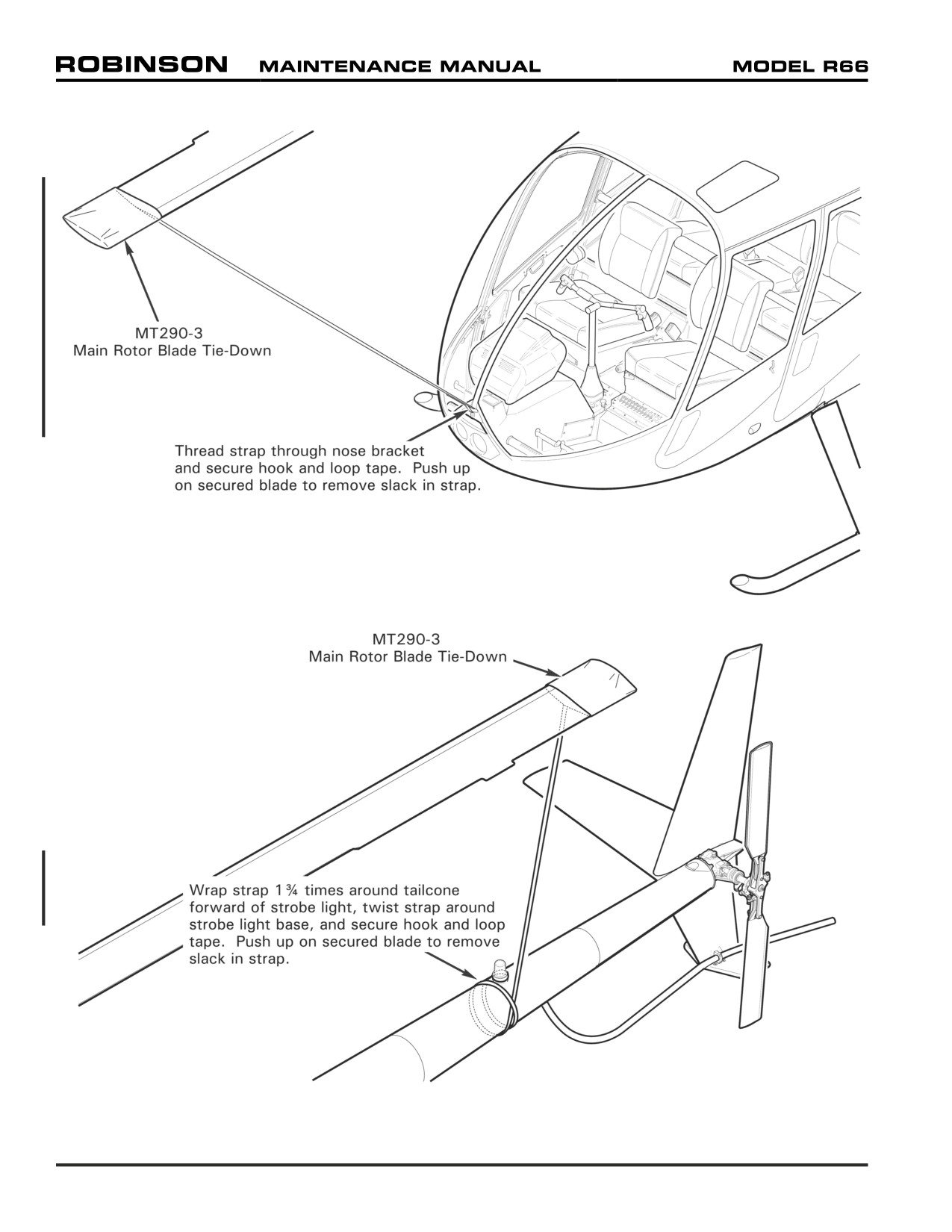
FIGURE 10-1 MAIN ROTOR BLADE TIE-DOWNS
Page 10.2
Chapter 10 Parking and Storage
10-11 Parking in High Wind or Turbulent Air (continued)
B. Extreme Conditions (continued)
2. b. Remove hardware securing pitch links to swashplate assembly.
3. Remove tail rotor pitch links per steps below:
a. Refer to Figure 64-1. Tag each pitch link with corresponding blade serial number.
Disconnect pitch links from tail rotor blades; keep associate balancing hardware
with each link.
b. Remove hardware securing pitch links to tail rotor pitch control assembly.
10-12 Main Rotor Blade Tie-Downs
CAUTION
Overtightening tie-down straps can damage main rotor blades.
Maximum tie-down tension is 5 lb.
1. Park helicopter and position blades per Section 10-10 or 10-11.
2. Refer to Figure 10-1. Slide MT290-3 tie-down jacket over forward (lowered) main rotor
blade tip, with white lettering facing down. Thread strap through nose bracket and
secure tie-down hook and loop tape. Push up on secured blade to remove slack in tie-
down strap.
3. As required, install MT290-3 tie-down on aft main rotor blade. Slide jacket over blade
tip, with white lettering facing down. Wrap strap 1¾ times around tailcone forward of
strobe light, twist strap around strobe light base, and secure tie-down hook and loop
tape. Push up on secured blade to remove slack in tie-down strap.
25 OCT 2010
Chapter 10 Parking and Storage
Page 10.3
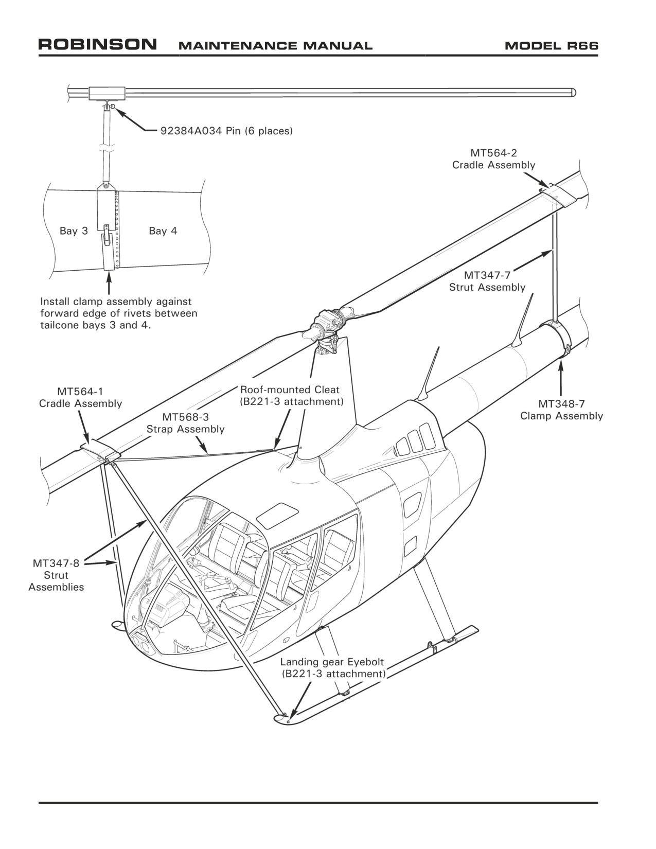
FIGURE 10-2 MAIN ROTOR BLADE SUPPORTS
Page 10.4
Chapter 10 Parking and Storage
25 OCT 2010
10-13 Main Rotor Blade Supports
Refer to R66 Illustrated Parts Catalog (IPC) Figure 10-7.
CAUTION
Do not allow strut assemblies to hang from cradle assemblies
installed on main rotor blades. Support strut assemblies during
strut removal or installation.
A. Removal
1. Refer to Figure 10-2. Remove 92384A034 retaining pins securing MT347-7 strut
assembly to MT564-2 cradle assembly and MT348-7 clamp assembly; remove strut
assembly. Remove cradle and clamp assemblies.
2. Remove retaining pin securing one MT347-8 strut assembly to landing gear eyebolt,
then remove pin securing same strut to MT564-1 cradle assembly. Repeat step to
remove second strut assembly.
3. Detach MT568-3 strap assembly hook and loop tape near roof-mounted cleat and
unthread strap from cleat. Remove cradle assembly.
B.
Installation
NOTE
B221-3 attachment installation (landing gear eyebolts and roof-
mounted cleat) is required for mounting blade supports.
1. Refer to Figure 10-2. Position main rotor blades approximately fore and aft.
2. Install MT564-1 cradle assembly inboard of forward blade extended tab, with MT568-
3 strap assembly attached. Thread opposite end of strap assembly through roof-
mounted cleat and secure strap hook and loop tape.
3. Secure one MT347-8 strut assembly to cradle assembly, then to landing gear eyebolt,
using 92384A034 retaining pins. Repeat step to secure second strut assembly.
4. Install MT564-2 cradle assembly inboard of aft blade extended tab. Install MT348-7
clamp assembly against forward edge of rivets between tailcone bays 3 and 4.
5. Secure MT347-7 strut assembly to cradle and clamp assemblies using retaining pins.
Verify strut is approximately vertical.
6. Engage rotor brake. If desired, mark cradle assembly location on blade using felt-tip
marker, to facilitate future installation.
25 OCT 2010
Chapter 10 Parking and Storage
Page 10.5
10-20 Storage (Greater than 30 days)
NOTE
Helicopter should be hangared or moved to a safe area during
storage.
NOTE
Periodically inspect aircraft for corrosion and correct as required.
Aircraft stored in humid environments are subject to aggressive
corrosive reaction and require more frequent inspection.
1.
Record the date helicopter is prepared and placed in storage.
2.
Preserve engine for aircraft storage per RR300 Series Operation and Maintenance Manual
(OMM).
3.
Refinish main rotor blades per Section 62-52. Refinish tail rotor blades per Section 64-36.
4.
Open applicable circuit breakers.
5.
Remove battery per Chapter 96. Inspect & service battery according to battery manufacturer’s
instructions.
6.
Service engine oil, hydraulic fluid, and main & tail rotor gearboxes per Chapter 12.
7.
Fuel helicopter per Section 12-41.
NOTE
Fuel lubricates bladder inner liner and keeps it from drying out
or cracking. Refuel helicopter after run-ups during storage per
Section 12-41.
8.
Clean aircraft per Section 20-10. Ensure helicopter is clean and dry prior to storing. Open
door vents and doors to ventilate cabin and baggage compartment as required.
9.
Close and latch all access doors. Install engine exhaust cover.
Page 10.6
Chapter 10 Parking and Storage
25 OCT 2010
CHAPTER 11
PLACARDS AND MARKINGS
Section Title
Page
11-10
Placard Locations
11.1
11-20
Placard Illustrations
11.3
Chapter 11 Placards and Markings
Page 11.i
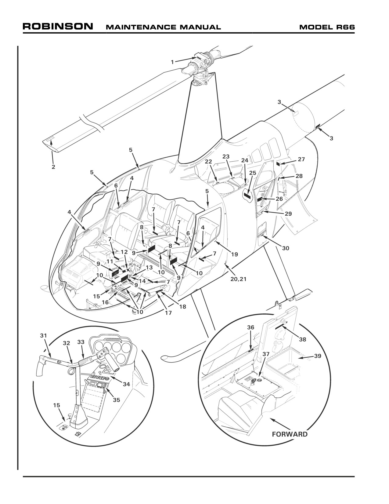
FIGURE 11-1 PLACARD LOCATIONS
Page 11.0
Chapter 11 Placards and Markings
11-10 Placard Locations
ITEM
PART NO.
DESCRIPTION
QTY
1
A654-18
Decal - "LEVEL HERE"
1
2
A654-25
Decal - “NEVER PULL DOWN / PUSH UP OPPOSITE BLADE”
2
3
A654-94
Decal - “DANGER HOT EXHAUST”
2
4
F654-21
Decal - “Push handle down...”
4
5
F654-22
Decal - “EXIT” (above each cabin door)
4
6
F654-20
Decal - “PUSH TO LOCK / DO NOT LOCK IN FLIGHT”
2
7
F654-19
Decal - "ENERGY-ABSORBING SEAT / DO NOT MODIFY"
5
8
C654-17
Decal - “INTERCOM”
2
9
F654-10
Decal - “CAUTION” (seat compartment loading)
4
10
F654-17
Decal - "MAX FILL LINE"
7
11
F654-1
Decal - “THROTTLE OPEN”
1
12
A654-7
Decal - “FRICTION INCREASE” (collective stick)
1
13
F445-1
Cover Assembly - FWD Tunnel
1
F445-3
Cover Assembly - FWD Tunnel (float ships; not shown)
1
14
A654-45
A950-1 Guard Assembly (fuel valve)
1
15
F444-1
Cover - Cyclic Box
1
16
F490-1
Panel Assembly - Circuit Breaker
1
17
A654-6
Decal - “THROTTLE OPEN” (collective stick)
1
18
A654-21
Decal - “NO STOWAGE / KEEP AREA CLEAR”
1
19
A654-12
Decal - “OPEN” (LH door, outside; black lettering)
2
A654-10
Decal - “OPEN” (LH door, outside; white lettering)
2
20
C654-7
Decal - “STATIC PORT” (black lettering)
2
21
C654-8
Decal - “STATIC PORT” (white lettering)
2
22
F654-5
Decal - “FUEL GRADE”
1
23
F654-6
Decal - “GROUND EITHER PLACE”
1
24
F654-15
Decal - "STEP HERE/HAND HOLD"
1
25
F654-12
Decal - “HYDRAULIC FLUID AND GEARBOX OIL”
1
26
F654-3
Decal - “ENGINE OIL”
1
27
23052363
Decal - “FAILURE TO PROPERLY INSTALL...”
1
28
A654-38
Decal - "PUSH TO OPEN"
1
29
F654-11
Decal - “STEP HERE”
1
30
F654-16
Decal - "STEP HERE LEFT FOOT"
1
31
A321-19
Marking - Weldment, Pistol Grip (left side)
1
32
A756-24
Marking - Weldment, Pistol Grip (right side)
1
33
F654-4
Decal - “NEVER EXCEED SPEED”
1
F654-28
Decal - “NEVER EXCEED SPEED” (float ships / police version; not shown)
1
34
B051-20
Face Assembly - R66 (Phaostron)
1
35
A654-45
A950-3 Guard Assembly (fuel cutoff)
1
36
A654-17
Decal - “NO SMOKING”
1
Chapter 11 Placards and Markings
Page 11.1
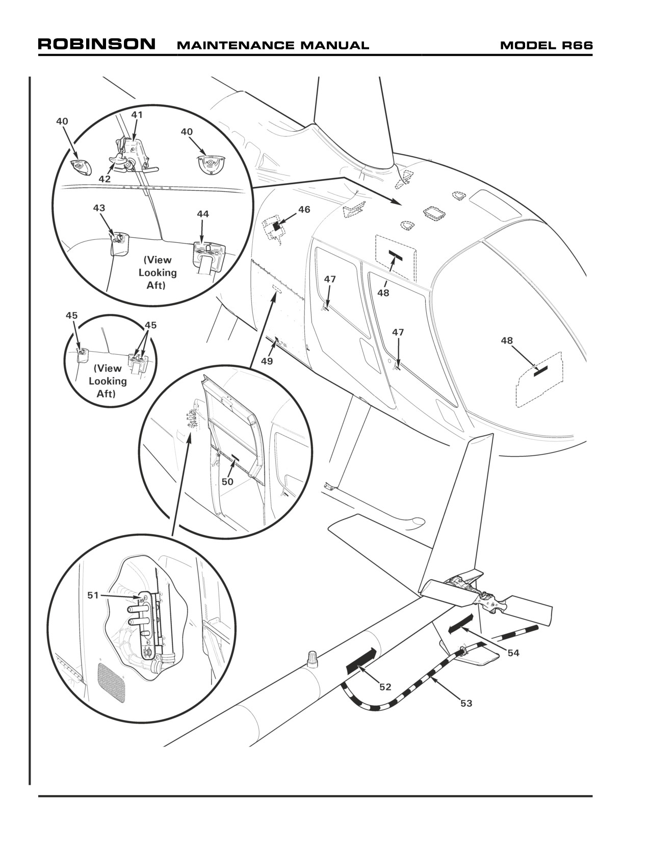
FIGURE 11-2 PLACARD LOCATIONS
Page 11.2
Chapter 11 Placards and Markings
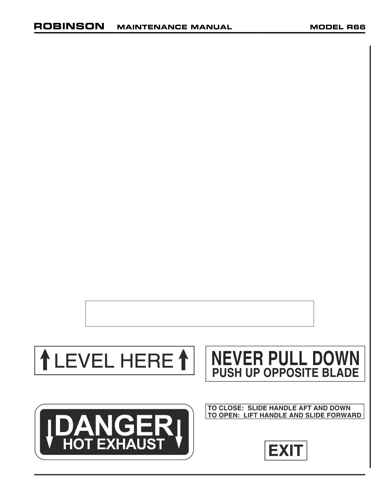
11-10 Placard Locations (continued)
ITEM
PART NO.
DESCRIPTION
QTY
37
F463-1
Cover Assembly - Mid Tunnel
1
38
F654-27
Decal (console compartment capacity)
1
39
G749-2
Console Assembly (Incl item 38, Ref)
40
C710-1
Cover
2
41
C712-2
Cover - Spotlight
1
42
D119-1
Handle - Rotor Brake
1
43
F436-6
Cover Assembly (RH)
1
44
F436-5
Cover Assembly (LH)
1
45
A654-16
Decal - “HEADSET” (early R66s)
3
46
F654-25
Decal (dongle programming instructions)
1
47
A654-11
Decal - “OPEN” (RH door, outside; black lettering)
2
A654-9
Decal - “OPEN” (RH door, outside; white lettering)
2
48
F654-24
Decal - “BATTERY LOCATED BEHIND THIS PANEL”
1
49
F654-8
Decal - “LATCH” (black lettering)
1
F654-9
Decal - “LATCH” (white lettering)
1
50
F654-7
Decal - “CAUTION” (baggage compartment loading)
1
F654-26
Decal - “CAUTION” (baggage compartment loading; police version)
1
51
G598-1
Faceplate - "28V / BATT CHARGE"
1
52
A654-3
Decal - “DANGER” Arrow (tail rotor)
2
53
D079-1
Tail Rotor Guard (Ref)
54
C654-2
Decal - “DANGER” Arrow (tail rotor)
2
11-20 Placard Illustrations
NOTE
Placards (decals) and markings are not to scale.
1. Decal A654-18
2. Decal A654-25
3. Decal A654-94
4. Decal F654-21
5. Decal F654-21
Chapter 11 Placards and Markings
Page 11.3
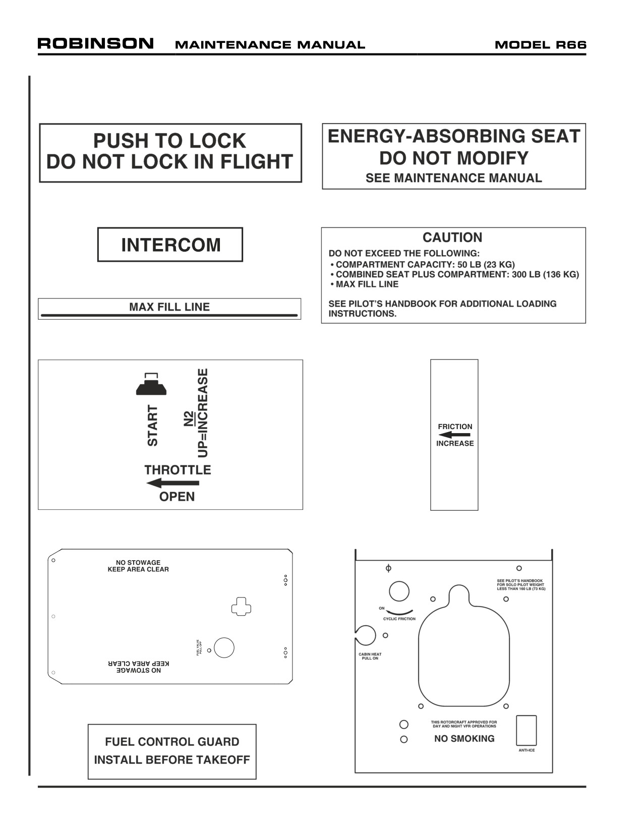
11-20 Placard Illustrations (continued)
6. Decal F654-20
7. Decal F654-19
8. Decal C654-17
9. Decal F654-10
10. Decal F654-17
11. Decal F654-1
12. Decal A654-7
13. Cover F445-1
15. Cover F444-1
14. Decal A654-45
Page 11.4
Chapter 11 Placards and Markings
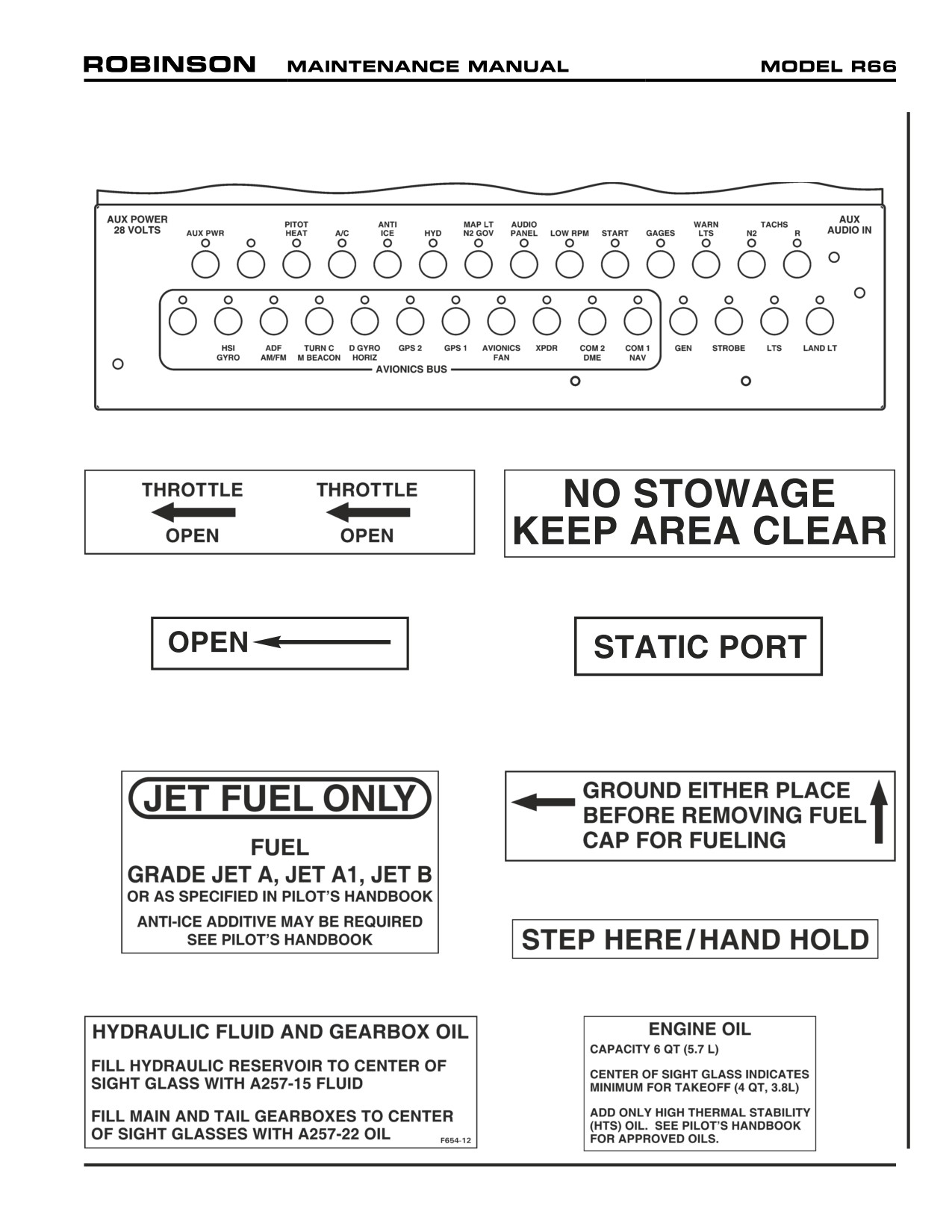
11-20 Placard Illustrations (continued)
16. Panel Assembly F490-1
17. Decal A654-6
18. Decal A654-21
19. Decal A654-12
20. Decal C654-7
21. Decal C654-8 (not shown; see No. 20)
22. Decal F654-5
23. Decal F654-6
24. Decal F654-15
25. Decal F654-12
26. Decal F654-3
Chapter 11 Placards and Markings
Page 11.5
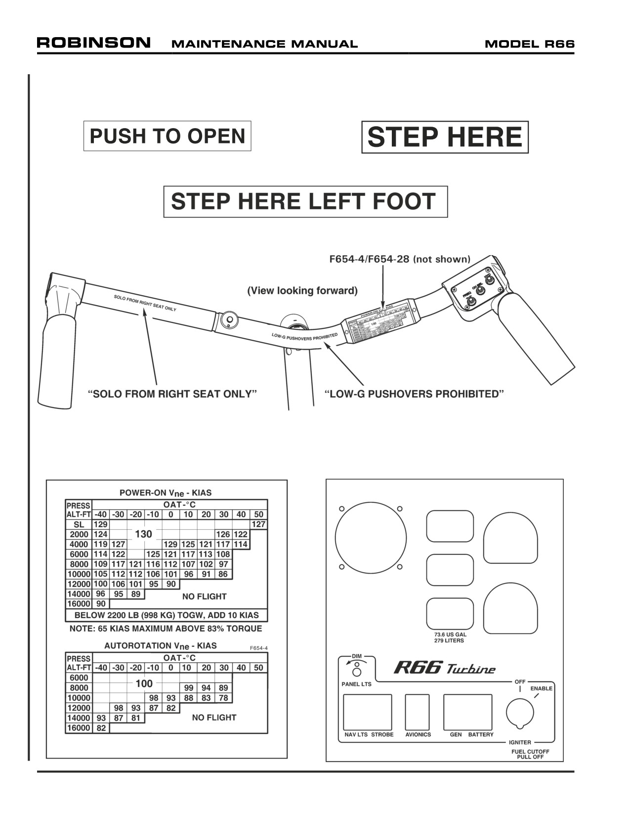
11-20 Placard Illustrations (continued)
28. Decal A654-38
29. Decal F654-11
30. Decal F654-16
31. Marking A321-19 (co-pilot weldment)
32. Marking A756-24 (pilot weldment, see No. 31)
33. Decal F654-4 (see No. 31)
34. Face Assembly B051-20
Page 11.6
Chapter 11 Placards and Markings
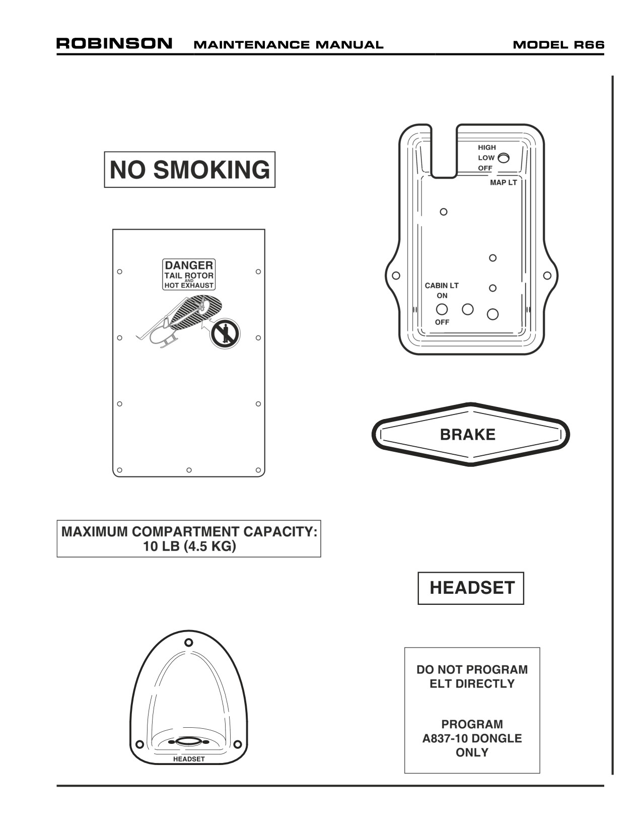
11-20 Placard Illustrations (continued)
35. Decal A654-45 (see No. 14)
41. Cover C712-2
36. Decal A654-17
37. Cover Assembly F463-1
42. Handle D119-1
43. Cover Assembly F436-6 (RH)
38. Decal F654-27
44. Cover Assembly F436-5 (LH)
45. Decal A654-16
39. Console Assembly G749-2 (Ref)
40. Cover C710-1
46. Decal F654-25
Chapter 11 Placards and Markings
Page 11.7
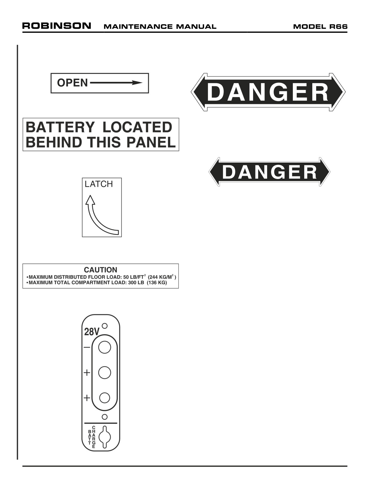
11-20 Placard Illustrations (continued)
47. Decal A654-11
52. Decal A654-3
48. Decal F654-24
53. D079-1 Tail rotor guard (Ref)
54. Decal C654-2
49. Decal F654-9
50. Decal F654-7
51. Faceplate G598-1
Page 11.8
Chapter 11 Placards and Markings
CHAPTER 12
SERVICING
Section
Title
Page
12-10
Main Rotor Gearbox
12.1
12-11
Servicing
12.1
12-12
Filter Replacement
12.3
12-13
Chip Detector and Sight Gage
12.3
12-20
Tail Rotor Gearbox
12.7
12-21
Servicing
12.7
12-22
Chip Detector and Sight Gage
12.8
12-23
Drain and Flush
12.8
12-30
Hydraulic System
12.9
12-31
Servicing
12.9
12-32
Filter Replacement
12.9
12-33
Drain and Flush
12.11
12-34
Bleeding
12.12
12-40
Fuel System
12.13
12-41
Fueling
12.13
12-42
Defueling
12.13
12-50
Main Rotor Blades
12.15
12-51
Pitch Bearing Housing
12.15
12-60
Engine Oil Servicing
12.16
12-70
(Engine) Compressor Rinse and Wash
12.17
12-80
Air Conditioning System
12.18
12-81
Refrigerant Recovery and System Charging
12.18
12-82
Desiccant Replacement
12.19
12-83
Leak Detection
12.19
Chapter 12 Servicing
Page 12.i
Intentionally Blank
Page 12.ii
Chapter 12 Servicing
CHAPTER 12
SERVICING
12-10 Main Rotor Gearbox
WARNING
Refer to appropriate Material Safety Data Sheet (MSDS) and
take necessary safety precautions when working in proximity
to hazardous materials.
12-11 Servicing
NOTE
Inspect main rotor gearbox and gearbox lubrication system for
leaks when “top off” is required.
NOTE
Verify aircraft is on level ground when evaluating gearbox oil
level.
A. Draining Fluid
1. Refer to Figure 12-1. Disconnect chip detector wiring, as required. Remove chip
detector from housing.
2. Refer to Figure 12-2. Insert MT054-1 drain assembly into chip detector housing.
Position drain hose overboard into a suitable drain container. Jam wedge between
support panel stiffener and drain assembly fitting to open valve.
B.
Adding Fluid
1. Install chip detector per Section 12-13, if removed.
2. Refer to Figure 12-1. Remove gearbox filler-plug. Fill gearbox with A257-22 lubricant
to center of sight glass.
3. Rotate rotor system by hand for several revolutions and pull down on tail rotor
gearbox several times. Check gearbox oil level and adjust level as required.
4. Install filler-plug and special torque plug per Section 20-33.
5. Run-up helicopter approximately five minutes at
60-70% RPM per R66 Pilot’s
Operating Handbook (POH) Section 4.
6. Check gearbox oil level, and adjust level per steps 2 thru 6 as required.
Chapter 12 Servicing
Page 12.1
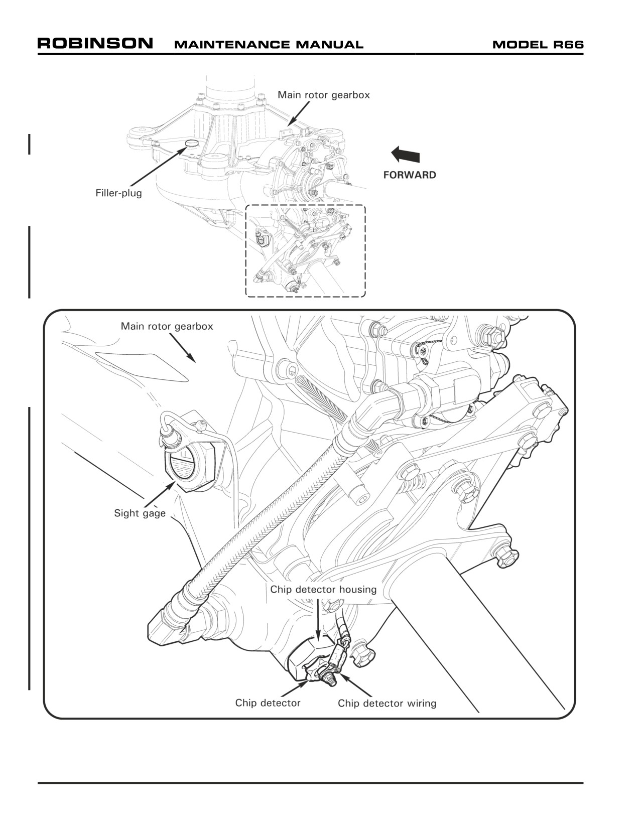
FIGURE 12-1 MAIN ROTOR GEARBOX SERVICING
Page 12.2
Chapter 12 Servicing
12-12 Filter Replacement
Refer to R66 Illustrated Parts Catalog (IPC) Figure 63-13.
NOTE
Replace main rotor gearbox oil every
600 hours. When
replacing a filter after new or overhauled main rotor gearbox
has accumulated 100 hours, replacing oil is not required.
1. Drain main rotor gearbox oil per Section 12-11, if required.
2. Cut and discard safety wire securing bowl & indicator assembly to head assembly.
Unscrew bowl and remove and discard element. Remove o-ring and back-up ring from
head assembly.
3. Clean and dry bowl assembly; install new F651-3 seals kit and F651-2 element.
4. Hand-tighten bowl assembly until tight against head assembly. Install 0.032-inch
diameter lockwire and safety bowl to head.
5. Service main rotor gearbox per Section 12-11.
12-13 Chip Detector and Sight Gage
A. Removal
1. Refer to Figure 12-1. Disconnect chip detector wiring, as required. Remove chip
detector from housing.
NOTE
Remove chip detector housing and inspect for obvious damage
if housing leaks.
2. Drain main rotor gearbox oil per Section 12-11, if removing chip detector housing or
sight gage. Remove housing and/or gage as required.
B. Cleaning Chip Detector (and Housing)
1. Scrub chip detector (and housing, if applicable) with a toothbrush and approved
solvent per Section 20-70. To remove debris, use compressed air or masking tape;
do not use a magnet. Dry chip detector with compressed air or a lint-free cloth.
2. Refer to Figure 12-1. Connect chip detector electrical wiring and special torque
terminal nut per Section 20-33. Turn BATTERY switch ON and ground detector’s
central magnetic probe to airframe. Verify appropriate CHIP warning segment
illuminates. Turn BATTERY switch OFF.
Chapter 12 Servicing
Page 12.3
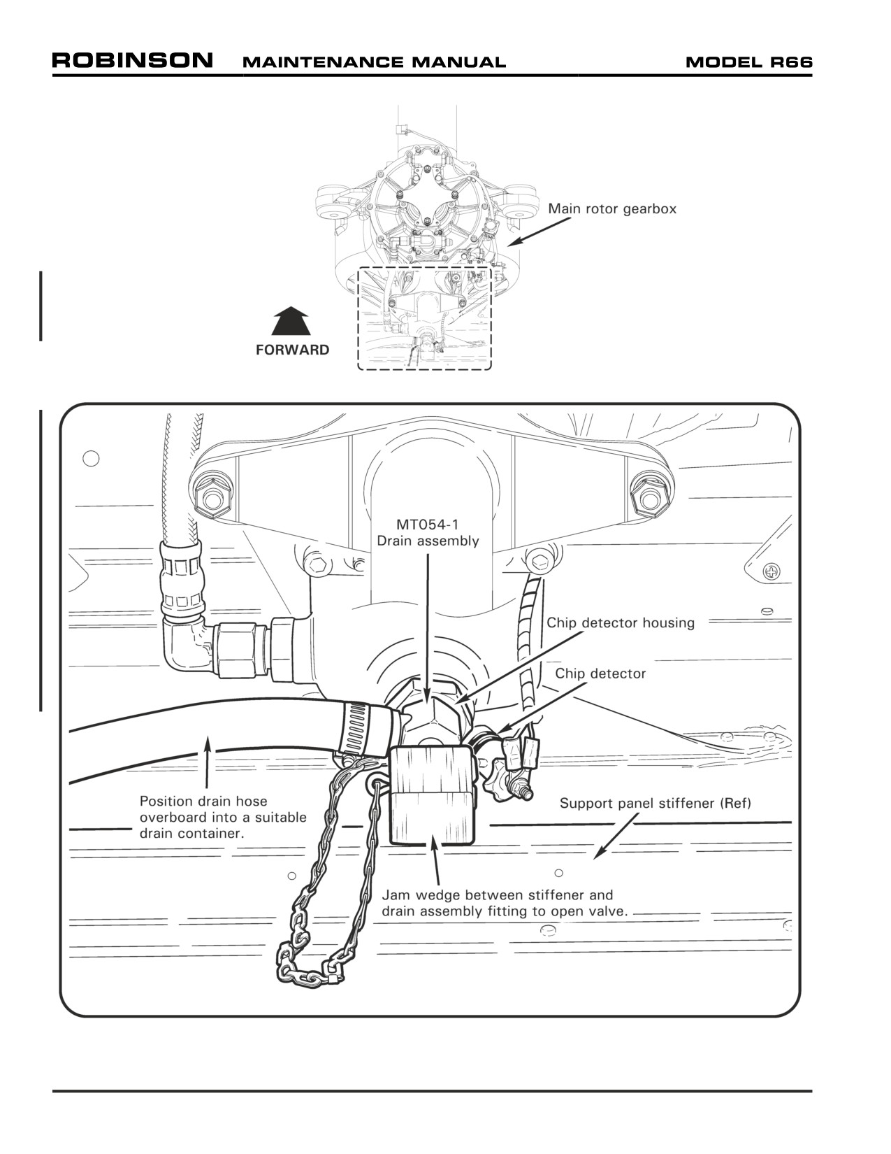
FIGURE 12-2 DRAINING MAIN ROTOR GEARBOX OIL
Page 12.4
Chapter 12 Servicing
12-13 Chip Detector and Sight Gage (continued)
C. Installation
1. Refer to Figure 12-1. Verify cleanliness and clarity of sight gage. As required,
remove sight gage per Part A and clean with approved solvent per Section 20-70.
Install sight gage and special torque per Section 20-33.
2. Verify cleanliness of chip detector and housing. As required, remove and clean
chip detector and housing per Parts A and B. Install housing and special torque per
Section 20-33. Install chip detector.
3. Turn BATTERY switch ON. Verify MR CHIP warning segment illuminates when test
button is depressed. Turn BATTERY switch OFF.
Chapter 12 Servicing
Page 12.5
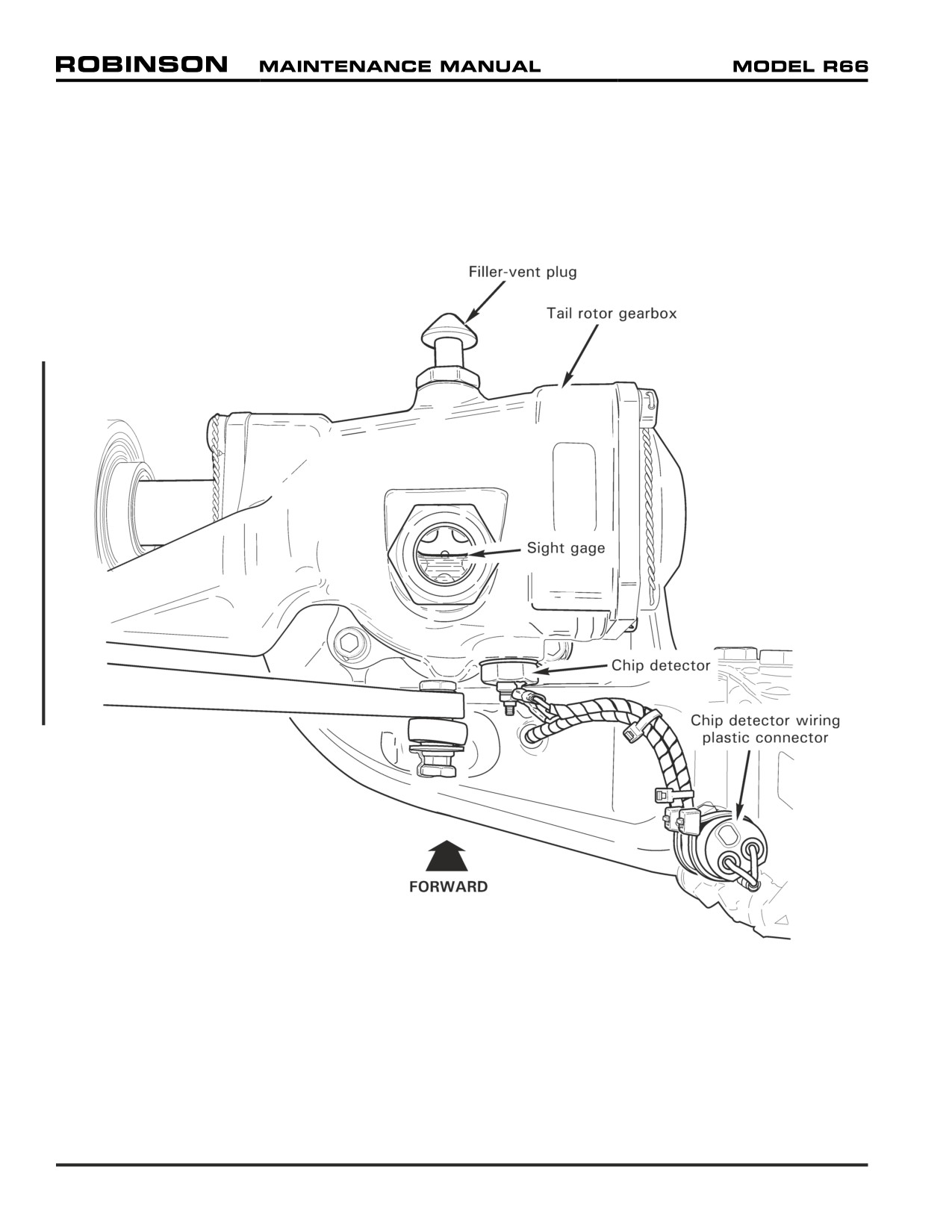
FIGURE 12-3 TAIL ROTOR GEARBOX
Page 12.6
Chapter 12 Servicing
12-20 Tail Rotor Gearbox
WARNING
Refer to appropriate Material Safety Data Sheet (MSDS) and
take necessary safety precautions when working in proximity
to hazardous materials.
12-21 Servicing
NOTE
Inspect tail rotor gearbox for leaks when “top off” is required.
NOTE
Verify aircraft is on level ground when evaluating gearbox oil
level.
A. Draining Fluid
1. Refer to Figure 12-3. Cut and discard ty-raps as required and disconnect chip detector
wiring from airframe harness at connectors.
2. Place a suitable drain container under gearbox to catch oil, then remove chip
detector.
B. Adding Fluid
1. Install chip detector per Section 12-22.
2. Refer to Figure 12-3. Remove filler-vent plug and fill gearbox with A257-22 lubricant
to center of sight glass.
3. Install plug and special torque per Section 20-33.
Chapter 12 Servicing
Page 12.7
12-22 Chip Detector and Sight Gage
A. Removal
1. Drain tail rotor gearbox oil per Section 12-21.
2. Remove sight gage, as required.
B.
Cleaning Chip Detector
1. Clean chip detector per Section 12-13 Part B (main rotor gearbox).
C. Installation
1. Refer to Figure 12-3. Verify cleanliness and clarity of sight gage. As required,
remove sight gage per Part A and clean with approved solvent per Section 20-70.
Install sight gage and special torque per Section 20-33.
2. Verify cleanliness of chip detector. As required, clean chip detector per Section 12-
13 Part B (main rotor gearbox). Install chip detector and special torque per Section
20-33.
3. Connect chip detector wiring and install ty-raps, as required. Cinch ty-raps until
snug without over-tightening, and trim tips flush with heads.
4. Turn BATTERY switch ON. Verify TR CHIP warning segment illuminates when test
button is depressed. Turn BATTERY switch OFF.
5. Service tail rotor gearbox per Section 12-21.
12-23 Drain and Flush
1. Drain tail rotor gearbox oil per Section 12-21.
2. Install chip detector and special torque per Section 20-33.
3. Remove filler-vent plug and add approximately five ounces of SAE30, SAE40, SAE50,
or SAE20W50 straight mineral engine oil to gearbox. Install plug and special torque per
Section 20-33.
4. Run-up helicopter approximately five minutes at 60-70% RPM per R66 Pilot's Operating
Handbook (POH) Section 4.
5. Drain tail rotor gearbox oil (mineral oil) per Section 12-21.
6. Clean and install chip detector per Section 12-22 Parts B and C.
Page 12.8
Chapter 12 Servicing
12-30 Hydraulic System
CAUTION
Do not contaminate hydraulic fluid. Service hydraulic system
with clean fluid from sealed containers, using clean tools.
WARNING
Refer to appropriate Material Safety Data Sheet (MSDS) and
take necessary safety precautions when working in proximity to
hazardous materials.
12-31 Servicing
A. Draining Fluid
1. Perform drain and flush per Section 12-33.
B. Adding Fluid
NOTE
Inspect hydraulic system for leaks when “top off” is required.
1. Refer to Figure 12-4. Remove filler-vent plug. With system filled and bled, fill
hydraulic reservoir to center of sight glass with new A257-15 fluid.
2. Install filler-vent plug and special torque per Section 20-33.
12-32 Filter Replacement
1. Refer to Figure 12-4. Remove D516-1 cap and filter and visually inspect element for
contaminants. If element is clear, proceed to step 3. If metal contamination is found, use
a magnet to determine if metal is ferrous. If metal is ferrous, perform the following:
a. Install new filter per steps 3 thru 5.
b. After one flight-hour, remove filter and inspect for ferrous metal. If ferrous metal is
found upon second inspection, replace hydraulic pump per Section 67-50, then drain
and flush hydraulic system per Section 12-33.
2. Discard cap packing. Clean cap with approved solvent per Section 20-70, and dry cap
with compressed air or a lint-free cloth. Lubricate new packing with A257-15 fluid and
install on cap.
3. Lubricate packing inside new filter with A257-15 fluid and install filter in reservoir.
Install cap and special torque per Section 20-33.
4. Service hydraulic reservoir per Section 12-31.
Chapter 12 Servicing
Page 12.9
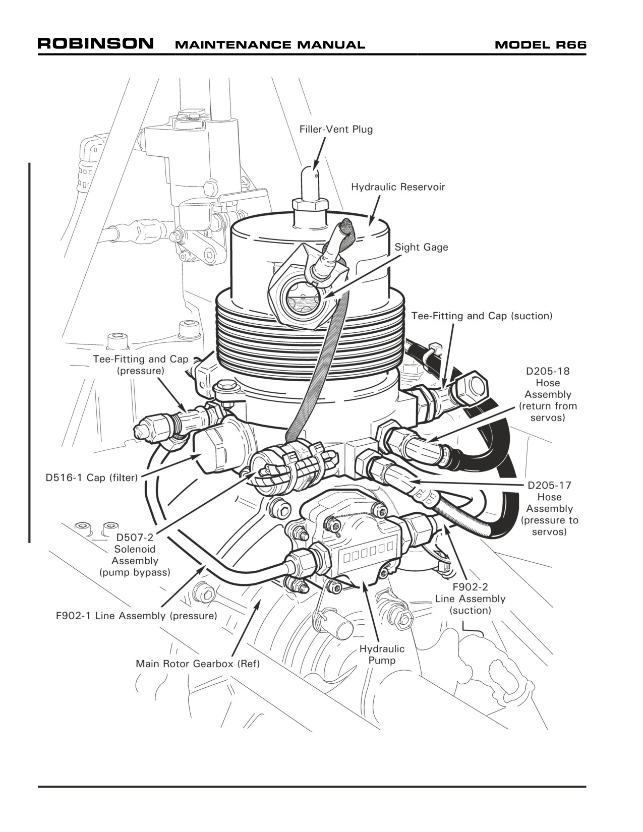
FIGURE 12-4 HYDRAULIC SYSTEM
Page 12.10
Chapter 12 Servicing
12-33 Drain and Flush
NOTE
Drain and flush hydraulic system if oil turns dark or emits bad
odor.
WARNING
Keep limbs clear of flight controls when operating test pump.
Hydraulic forces can cause injury.
1.
Refer to Figure 12-4. Remove filler-vent plug. Place a suitable drain container under
F902-1 (pressure) and F902-2 (suction) line assembly T-fittings, and remove caps.
Pour small amount of new A257-15 fluid into hydraulic reservoir to purge suction line.
Pressure line will drain in following step, when D516-1 cap is removed.
2.
Replace filter per Section 12-32.
3.
Connect MT384 (or equivalent) 0.8-1.2 gpm hydraulic test pump assembly to T-fittings.
(Pressure and suction fittings are different sizes to ensure correct connection.)
4.
Service hydraulic reservoir per Section 12-31.
5.
Disconnect D205-18 hose assembly (return) from reservoir. Place line into drain
container; cap union with a T-fitting cap.
6.
Activate test pump and inspect hydraulic system for leaks.
7.
Simultaneously fully raise collective and move cyclic fully forward then simultaneously
fully lower collective and move cyclic fully aft. Monitor reservoir fluid level and fill as
required. Repeat procedure until return line fluid is clean.
8.
Simultaneously fully raise collective and move cyclic fully aft then simultaneously fully
lower collective and move cyclic fully forward. Monitor reservoir fluid level and fill as
required. Repeat procedure until return line fluid is clean.
9.
Turn off test pump and disconnect equipment. Remove cap and connect hose assembly
(return) to reservoir. Using back-up wrench, standard torque hose nut per Section 20-
32 and torque stripe per Figure 5-1. Install caps on T-fittings, special torque caps per
Section 20-33, and torque stripe per Figure 5-1.
10. Bleed hydraulic system per Section 12-34.
11. Remove cap and filter and visually inspect element for contaminants. If debris is found,
repeat drain and flush procedure. If filter is clean, install filter & cap and special torque
cap per Section 20-33.
12. Service hydraulic reservoir per Section 12-31.
Chapter 12 Servicing
Page 12.11
12-34 Bleeding
WARNING
Keep limbs clear of flight controls when operating test pump.
Hydraulic forces can cause injury.
1.
Remove F902-1 (pressure) line assembly T-fitting cap. Connect MT384 (or equivalent)
0.8-1.2 gpm hydraulic test pump pressure line to T-fitting. (Pressure and suction fittings
are different sizes to ensure correct connection.)
2.
Remove filler-vent plug and cover hydraulic reservoir hole with finger to prevent fluid
loss (until suction line is connected). Remove F902-2 (suction) line assembly T-fitting
cap. Connect test pump suction line to T-fitting. Service reservoir with new A257-15
fluid, as required.
3.
Activate test pump and inspect hydraulic system for leaks.
4.
Simultaneously fully raise collective and move cyclic fully forward then simultaneously
fully lower collective and move cyclic fully aft. Repeat procedure ten times.
5.
Simultaneously fully raise collective and move cyclic fully aft then simultaneously fully
lower collective and move cyclic fully forward. Repeat procedure ten times.
6.
Turn off test pump and verify no leaks in hydraulic system.
7.
Cover reservoir hole with finger (until suction line T-fitting is capped). Disconnect test
pump suction line from suction line T-fitting and install cap.
8.
Disconnect test pump pressure line from pressure line T-fitting and install cap. Special
torque caps per Section 20-33 and torque stripe per Figure 5-1.
9.
Service hydraulic reservoir per Section 12-31.
Page 12.12
Chapter 12 Servicing
12-40 Fuel System
WARNING
Refer to appropriate Material Safety Data Sheet (MSDS) and
take necessary safety precautions when working in proximity to
hazardous materials.
WARNING
Always fuel helicopter in a well-ventilated area. No smoking
within 100 feet of aircraft during fueling.
12-41 Fueling
1. Turn BATTERY switch OFF.
2. Ground helicopter and ground fuel vehicle. Open fueling cowl door and connect fuel
vehicle ground cable to helicopter at location identified by decal.
3. Verify proper grade of aviation fuel. See R66 Pilot's Operating Handbook (POH) Section
2 for approved fuel grades and instructions for use of anti-ice additive.
4. Remove fuel cap and fuel helicopter as required.
5. Install fuel cap, remove grounding equipment, and close cowl door.
12-42 Defueling
Refer to R66 Illustrated Parts Catalog (IPC) Figure 28-9.
1. Remove engine cowling per Section 53-21.
2. Turn BATTERY switch OFF. Pull fuel valve control OFF.
3. Disconnect B283-12 hose at F670-1 valve, raise hose vertically, and plug hose inlet.
4. Fabricate drain hose (3 feet clear tubing with fitting) and connect to valve outlet. Position
drain hose overboard into a suitable, grounded drain container.
NOTE
If desired, perform low-fuel switch assembly check per Section
28-22.
5. Push fuel valve control ON and drain fuel; drain residual fuel via sump valve. Pull fuel
valve control OFF. Perform maintenance tasks as required.
6. Add minimum 5 gallons fuel per Section 12-41. Push fuel valve control ON until fuel
flows thru drain hose without bubbles. Pull fuel valve control OFF.
7. Connect B283-12 hose, special torque hose nut per Section 20-33, and torque stripe
per Figure 5-1.
8. Defuel engine as required per RR300 Series Operation and Maintenance Manual (OMM).
Chapter 12 Servicing
Page 12.13

FIGURE 12-5 MAIN ROTOR BLADE PITCH BEARING HOUSING
Page 12.14
Chapter 12 Servicing
12-50 Main Rotor Blades
WARNING
Refer to appropriate Material Safety Data Sheet (MSDS) and
take necessary safety precautions when working in proximity to
hazardous materials.
12-51 Pitch Bearing Housing
NOTE
MT147-1 Main rotor blade spindle air bleed tool includes supply
container, hose assemblies, and bleed fittings.
A. Servicing
1.
Remove main rotor blades per Section 62-10.
2.
Refer to Figure 12-5. Place a suitable drain container below main rotor blade spindle
assembly. Remove two B289-2 bolts and drain fluid.
3.
Install MT147-1 bleed tool fittings into ports. Attach drain hose assembly to (top)
bleed fitting, secure with two wraps 0.032-inch diameter lockwire, and safety tight.
Position drain hose into drain container.
4.
Place supply container with sufficient A257-4 fluid approximately 3 feet above
spindle. Route fill hose assembly into drain container and open brass valve. Open
supply container plastic valve and purge air from hose. Close valves.
5.
Connect brass valve to (bottom) bleed fitting by tightening brass compression
sleeve.
6.
Open valves and fill spindle housing until no air bubbles are visible in drain hose
assembly. Massage spindle boot, “pitch” blade up & down, and raise blade tip up &
down to remove trapped air.
7.
Remove drain hose assembly and (top) bleed fitting, and install B289-2 bolt. Roll
the blade over. After five minutes, inspect the boot for leaks. If no leaks are found,
close valves, remove fill hose assembly brass valve and (bottom) bleed fitting, and
install other bolt.
8.
Torque B289-2 bolts per Section 20-33 and torque stripe per Figure 5-1.
9.
Repeat steps for opposite blade.
Chapter 12 Servicing
Page 12.15
12-60 Engine Oil Servicing
Refer to R66 Illustrated Parts Catalog (IPC) Figures 79-5 and 79-7.
A. Draining Fluid
1. Run-up helicopter two to five minutes at 60-70% RPM per R66 Pilot's Operating
Handbook (POH) Section 4 to warm engine oil, as required.
2. Remove engine cowling per Section 53-21.
3. Place a suitable drain container below B289-2 bolt in bend of F723-1 line assembly, and
below AS5169D04 (drain) fitting in F649-1 oil cooler assembly.
4. Remove line assembly bolt and oil cooler assembly (drain) fitting and drain oil.
5. Service the engine oil system per RR300 Series Operation and Maintenance Manual
(OMM).
B.
Adding Fluid
NOTE
Do not contaminate engine oil. Service engine oil system with
clean fluid from sealed containers, using clean tools.
NOTE
When servicing airframe oil tank, full oil quantity is six quarts;
minimum quantity for takeoff is four quarts.
Six quart indication is top of knurled section of dipstick. Four
quart indication is bottom of knurled section of dipstick or center
of oil tank sight gage.
1.
Install B289-2 bolt in bend of F723-1 line assembly and special torque per Section 20-
33.
2.
Install AS5169D04 (drain) fitting in F649-1 oil cooler assembly and special torque per
Section 20-33.
3.
Install engine cowling per Section 53-21.
4.
Open access door, remove dipstick, and service airframe oil tank using approved turbine
engine oil per R66 Pilot's Operating Handbook (POH) Section 8.
5.
Install dipstick and close access door.
6.
Perform engine test per RR300 Series Operation and Maintenance Manual (OMM) as
required.
Page 12.16
Chapter 12 Servicing
12-70 (Engine) Compressor Rinse and Wash
Refer to R66 Illustrated Parts Catalog (IPC) Figure 71-9.
CAUTION
See RR300 Series Operation and Maintenance Manual (OMM)
requirements for compressor rinse and wash intervals.
CAUTION
Always perform compressor rinse or wash with sufficient
clearance for possible rotor system rotation.
1.
Remove engine cowling per Section 53-21.
2.
Open access door and remove (engine) compressor fluid-delivery tube cap.
3.
Refer to RR300 Series Operation and Maintenance Manual (OMM) for equipment and material
requirements. Operate compressor cleaning system per manufacturer's instructions.
4.
Connect appropriate cleaning system hose to delivery tube.
5.
Refer to RR300 Series OMM for compressor rinse and wash procedures.
To motor engine without ignition system:
a. Release rotor brake.
b. Turn BATTERY switch ON.
c. Verify fuel cutoff pulled OFF. Verify igniter (key) switched OFF.
d. Verify area is clear.
e. Close throttle.
f. Push and release start button as required to maintain N1 speed for required interval.
6.
Disconnect cleaning system hose from delivery tube. Install delivery tube cap and standard
torque per Section 20-32. Close access door.
7.
Refer to RR300 Series OMM for returning engine to service.
To perform ground run:
a. Refer to R66 Pilot's Operating Handbook (POH) Section 4 for run-up and shutdown
procedures.
8.
Install engine cowling per Section 53-21.
Chapter 12 Servicing
Page 12.17
12-80 Air Conditioning System
12-81 Refrigerant Recovery and System Charging
NOTE
In the United States, only personnel with EPA certification under
Section 609 of the Clean Air Act may charge the system with
refrigerant or work on the refrigerant system once it has been
charged. Different requirements may apply in countries other
than the United States.
Automotive-style air conditioning service equipment, compatible with R134a refrigerant,
is required to recover and charge the system with refrigerant. This equipment is available
from many manufacturers in varying levels of automation and complexity. Minimum
components include a vacuum pump, pressure pump, refrigerant supply, scale to measure
refrigerant charge, pressure/vacuum gage, and appropriate lines and fittings.
Ensure that the technician performing the task is appropriately qualified.
A. Refrigerant Recovery
NOTE
If a leak or other service problem is encountered after system is
charged with refrigerant, refrigerant must be recovered before
work on system can proceed.
1. Remove tailcone cowling per Section 53-23.
2. Automotive-style high- and low-side system service ports are located on G794
hose assemblies where they mount to the compressor assembly. Connect service
equipment to system quick-disconnect ports and recover refrigerant per equipment
manufacturer’s instructions.
B.
System Charging
CAUTION
Do not overcharge system. Perform leak detection per Section
12-83 if a leak is suspected, then use correct charge.
1. Remove tailcone cowling per Section 53-23.
2. Automotive-style high- and low-side system service ports are located on G794
hose assemblies where they mount to the compressor assembly. Connect service
equipment to system quick-disconnect ports.
3. Replace desiccant per Section 12-82. Vacuum system, then charge with R134a
refrigerant per equipment manufacturer’s instructions. Correct charge is 2.5 lb (40
oz) refrigerant.
4. Install tailcone cowling per Section 53-23.
Page 12.18
Chapter 12 Servicing
12-82 Desiccant Replacement
Refer to R66 Illustrated Parts Catalog (IPC) Figure 21-7.
NOTE
Replace desiccant when condenser or refrigerant system is
exposed to air. To eliminate moisture, replace desiccant, then
immediately vacuum system for charging per Section 12-81.
1. Remove engine cowling per Section 53-21.
2. Recover refrigerant per Section
12-81, if not previously accomplished. Remove
condenser cap and replace desiccant.
3. Install cap, special torque cap per Section 20-33, and torque stripe.
4. Charge system with refrigerant per Section 12-81.
12-83 Leak Detection
Leaks may be detected using several techniques, depending on equipment available. Leak
detection should not be attempted with the aircraft/system running. In addition to safety
hazards, leaks are more difficult to detect with the varying pressures and temperatures of
an operating system.
An empty system should hold full vacuum (27 to 29 inches mercury vacuum at sea level)
with no assistance from the vacuum pump for 20 minutes minimum. If a vacuumed system
creeps up in pressure, a leak may be present. The technician should be thoroughly familiar
with vacuum equipment to ensure leak is in aircraft system and not in vacuum equipment
or connections.
Leaks in a charged system may be detected using a mild soap and water solution applied
to lines and fittings in suspected leak areas (bubbles indicate leaks) or using commercially
available electronic refrigerant detectors. Follow detector manufacturer’s instructions.
Large leaks may be detected audibly if area is quiet or by formation of frost in area of leak.
NOTE
Frost does not necessarily indicate a leak. Normal system
operation and/or charging procedures can cause frost to
accumulate on some components.
NOTE
System pressure is not a reliable indicator of charge state or
the presence of leaks. Because R134a is a liquid/vapor mixture
with the system at rest, pressure will remain constant as more
liquid vaporizes until majority of charge is lost.
Very small leaks can be detected by charging the system with helium gas. Helium molecules
are smaller than R134a molecules and will leak more quickly. Charge system to 200
psi maximum. Use commercially available electronic helium detector or soap and water
solution to locate leaks.
Leaks are most likely to occur at fittings and crimped transitions between hard line and
flexible hose. Concentrate initial leak detection efforts in these areas.
Chapter 12 Servicing
Page 12.19
Intentionally Blank
Page 12.20
Chapter 12 Servicing
CHAPTER 18
TRACK AND BALANCE
Section
Title
Page
18-10
Main Rotor Track and Balance
18.1
18-11
Preparing Helicopter for Main Rotor Track and Balance . .
18.3
18-12
Flight Checks
18.5
18-13
Track Adjustment
18.7
18-14
Balance Adjustment
18.10
18-15
Troubleshooting
18.11
18-16
Autorotational RPM Adjustment
18.12
18-20
Tail Rotor Dynamic Balance
18.17
18-21
Preparing Helicopter for Tail Rotor Dynamic Balance . . .
18.17
18-22
Ground Checks
18.19
18-23
Balance Adjustment
18.19
18-30
Main Rotor Flight Control Rigging
18.21
18-40
Main Rotor Blade Angle Rigging
18.23
18-41
Collective Travel
18.24
18-42
Cyclic Travel
18.26
18-50
Tail Rotor Flight Control Rigging
18.28
18-51
Pedals
18.28
18-52
Forward Bellcrank
18.28
18-53
Intermediate Bellcrank
18.28
18-60
Tail Rotor Blade Rigging
18.29
Chapter 18 Track and Balance
Page 18.i
Intentionally Blank
Page 18.ii
Chapter 18 Track and Balance
CHAPTER 18
TRACK AND BALANCE
18-10 Main Rotor Track and Balance
NOTE
Calibrate track and balance equipment per manufacturer's
recommendation, at least once a year, or if equipment is
dropped, misused, or calibration is suspect.
NOTE
The Chadwick-Helmuth Vibrex system, the TEC ACES system,
the Dynamic Solutions Systems’ MicroVib system, or equivalent
equipment is required to perform dynamic rotor balancing and
in-flight track checks.
25 OCT 2010
Chapter 18 Track and Balance
Page 18.1
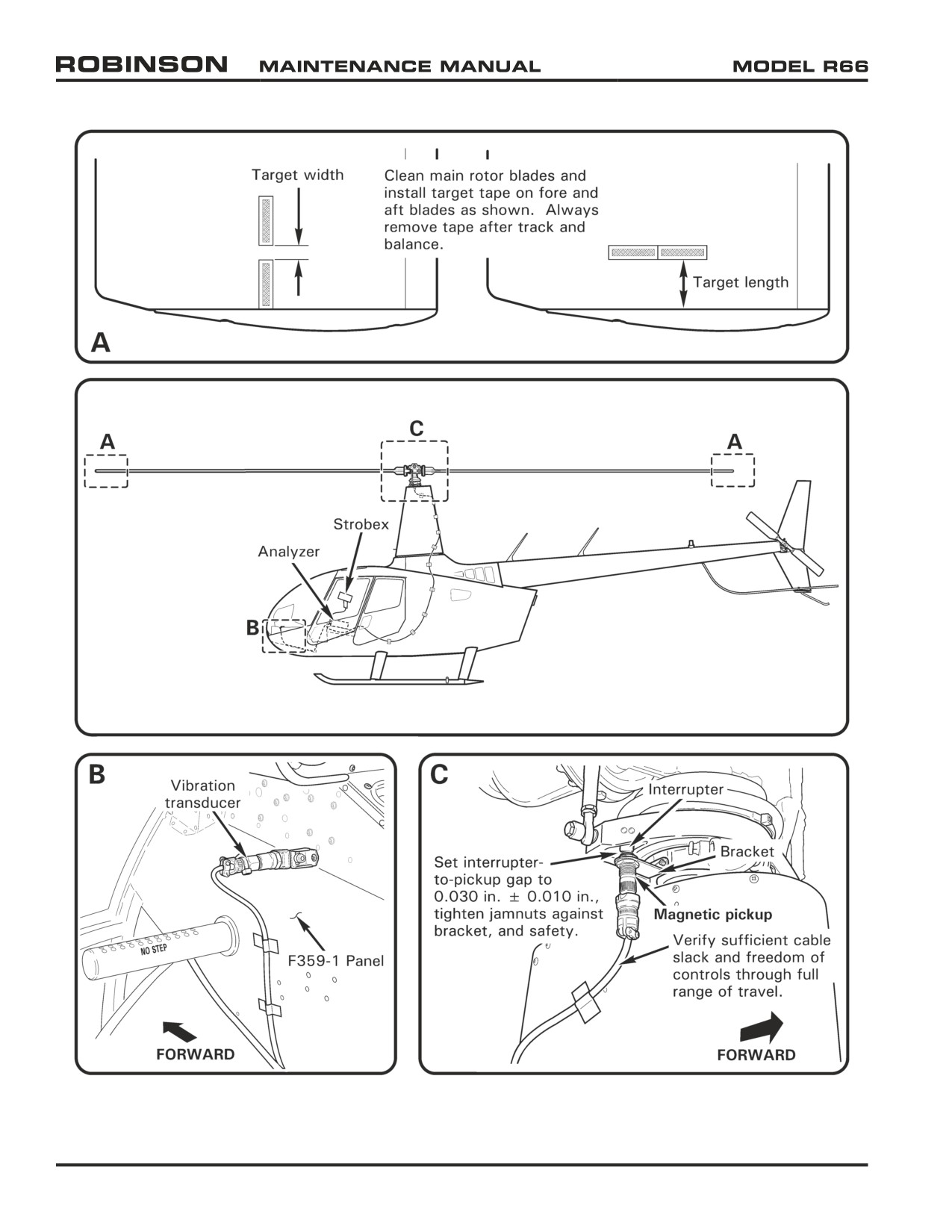
FIGURE 18-1 MAIN ROTOR BALANCING EQUIPMENT INSTALLATION
Page 18.2
Chapter 18 Track and Balance
25 OCT 2010
18-11 Preparing Helicopter for Main Rotor Track and Balance
NOTE
Use the following track & balance procedures in conjunction with
approved equipment manufacturer’s balancing instructions.
CAUTION
Cable security is critical; helicopter will be flown at VNE.
1.
Perform swashplate and rotor hub inspection per Section 5-45. Inspect tail rotor rod
ends and elastomeric bearings per Sections 5-33 and 5-34.
2.
Clean main and tail rotor blades per Section 20-10. Install main rotor blade target tape
per Figure 18-1.
3.
Refer to Figure 18-1. Using appropriate hardware, attach brackets to vibration transducer
and attach assembly to F359-1 panel as shown. Remove removable controls.
4.
Install magnetic pickup onto swashplate bracket. Set (swashplate-mounted) interrupter-
to-pickup gap to 0.030 inch ± 0.010 inch and tighten pickup nuts against bracket.
Safety nuts using 0.020-inch diameter lockwire. Recheck gap.
5.
Pull collective stick full up, push cyclic stick full left, and apply frictions. Connect proper
cable to magnetic pickup. Route cable down seam and to base of mast fairing, across
the cabin roof left side, and through the aft left door vent door. Attach the cable to the
fuselage using MS21919WDG3 clamps and existing fasteners, or secure cable every
12 inches with duct tape. Release control frictions and verify sufficient cable slack and
freedom of controls through full range of travel.
6.
Connect proper cable to vibration transducer. Connect transducer, magnetic pickup,
and tracker or strobe cables to analyzer. If strobe light is used, battery power may be
accessed thru auxiliary power socket located on circuit breaker panel. Neatly stow and
secure excess cables.
7.
Verify security of installation.
25 OCT 2010
Chapter 18 Track and Balance
Page 18.3
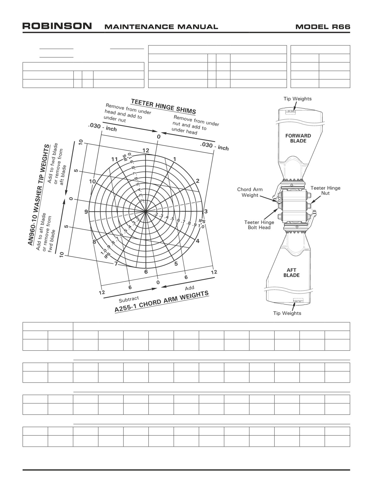
DATE
SERIAL NO.
TIP WEIGHTS
TEETER HINGE SHIMS
PAGE
(1) AN960-10 Washer
=
(2)
AN960-10L Washers
C117-8
0.012 inch
CHORD ARM WEIGHTS
(1) C298-2 Weight
=
(5)
AN960-10 Washers
C117-9
0.015 inch
(1) A255-1 Weight
=
(8)
AN970-4 Washers
(1) C298-3 Weight
=
(11)
AN960-10 Washers
C117-10
0.020 inch
(1) A255-2 Weight
=
(3)
A255-1 Weights
(1) C298-4 Weight
=
(4)
C298-3 Weights
C117-11
0.025 inch
BALANCE
TRACK (KNOTS)
CLOCK
IPS
HOVER
50
60
70
80
90
100
110
120
130
140
I
I
I
I
I
I
I
I
I
I
I
I
I
I
I
I
I
I
I
I
I
I
Adjustment:
CLOCK
IPS
HOVER
50
60
70
80
90
100
110
120
130
140
I
I
I
I
I
I
I
I
I
I
I
I
I
I
I
I
I
I
I
I
I
I
Adjustment:
CLOCK
IPS
HOVER
50
60
70
80
90
100
110
120
130
140
I
I
I
I
I
I
I
I
I
I
I
I
I
I
I
I
I
I
I
I
I
I
Adjustment:
CLOCK
IPS
HOVER
50
60
70
80
90
100
110
120
130
140
I
I
I
I
I
I
I
I
I
I
I
I
I
I
I
I
I
I
I
I
I
I
FIGURE 18-2 MAIN ROTOR TRACK AND BALANCE CHART
Page 18.4
Chapter 18 Track and Balance
25 OCT 2010
18-12 Flight Checks
NOTE
Run-up and shutdown helicopter throughout procedure as
required per R66 Pilot's Operating Handbook (POH) Section 4.
NOTE
Refer to Section 18-15 for track and balance troubleshooting
procedures.
WARNING
Tail rotor balancing equipment must be removed for flight.
WARNING
Do not exceed VNE of helicopter during flight checks.
1.
Prepare helicopter for main rotor track and balance per Section 18-11.
2.
Make a photocopy of Figure 18-2; use copy to record flight data. Check main rotor
blade track in a hover and record data. Maximum blade spread in a hover is 0.25 inch.
Adjust track per Section 18-13 as required, record change, and recheck blade track in a
hover. Repeat step as required until blade track is within limits.
3.
Check main rotor balance in a hover and record data. Maximum vibration allowance
is 0.2 ips (inches per second). Adjust balance per Section 18-14 as required, record
data, and recheck balance in a hover. Repeat step as required until main rotor balance
is within limits.
4.
Fly helicopter at 50, 60, 70, 80, 90, 100, 110, 120, 130, and 140 knots. Check main
rotor blade track at each airspeed and record data. Maximum blade spread between
airspeeds is 3/8 inch. Adjust trim tab(s) per Section 18-13 as required and record data.
Repeat step as required until blade track is within limits.
5.
Recheck main rotor balance in a hover per step 3.
6.
Perform autorotation RPM check per Section 18-16. Recheck main rotor balance in a
hover per step 3.
7.
Evaluate collective trim, longitudinal cyclic trim, and lateral cyclic trim. Adjust as
required. Recheck main rotor balance in a hover per step 3.
8.
Remove track and balance equipment. Torque stripe fasteners. Reinstall removable
controls, as required.
25 OCT 2010
Chapter 18 Track and Balance
Page 18.5
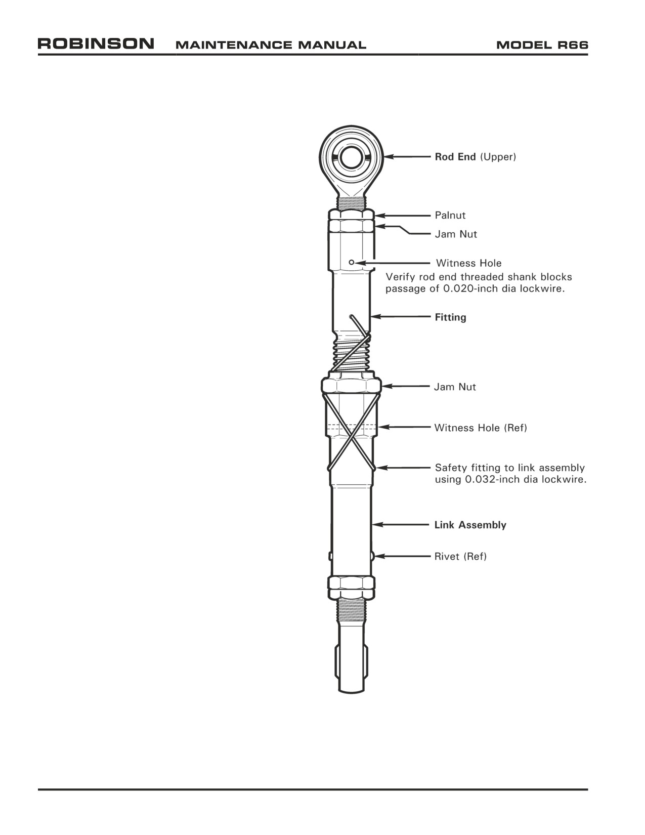
Coarse Length Adjustment
Rod End and Fitting
• One full turn changes blade angle 0.88º.
Medium Length Adjustment
(Upper) Rod End Only
• One-half rod end turn changes blade track 0.25 inch.
• One full rod end turn changes blade angle 0.48º.
Fine Adjustment
Fitting Only
• One full turn changes blade track 0.25 inch.
• One full turn changes blade angle 0.40º.
FIGURE 18-3 MAIN ROTOR PITCH LINK
Page 18.6
Chapter 18 Track and Balance
25 OCT 2010
18-13 Track Adjustment
A. Main Rotor Blade Pitch Link
Refer to R66 Illustrated Parts Catalog (IPC) Figure 62-5.
NOTE
Shorten high pitch blade when adjusting track in a hover.
NOTE
During rigging, adjust both pitch links exactly the same for
collective adjustments.
1.
Refer to Figure 18-3. For coarse length adjustment, adjust rod end and fitting per
the following steps:
a. Cut and discard pitch link assembly safety wire. Using backup wrench on link
assembly, loosen jam nut in middle of pitch link. Remove hardware securing
upper rod end to blade pitch horn.
b. Rotate rod end and fitting to shorten or lengthen pitch link as required. One full
turn changes blade angle by approximately 0.88°.
c. Refer to Figure 5-1. Verify rod end threaded shank blocks passage of 0.020-inch
diameter lockwire through pitch link witness hole. Install hardware securing rod
end to pitch horn and torque fastener per Section 20-32.
d. Position rod ends to allow as much pitch link rotation as possible without binding.
Using backup wrench on link assembly, torque jam nut per Section 20-32. Safety
fitting to link assembly using 0.032-inch diameter lockwire.
e. Repeat steps on opposite pitch link as required. Torque stripe per Figure 5-1.
2.
For medium length adjustment, adjust rod end only per the following steps:
a. Using backup wrench on fitting, loosen upper rod end palnut and jam nut. Remove
hardware securing rod end to blade pitch horn.
b. Rotate rod end to shorten or lengthen pitch link as required. One-half rod end
turn changes blade track approximately 0.25 inch. One full rod end turn changes
blade angle by approximately 0.48°.
c. Refer to Figure 5-1. Verify rod end threaded shank blocks passage of 0.020-inch
diameter lockwire through pitch link witness hole. Install hardware securing rod
end to pitch horn and torque fastener per Section 20-32.
d. Position rod ends to allow as much pitch link rotation as possible without binding.
Using backup wrench on fitting, torque rod end jam nut and palnut per Section
20-32.
e. Repeat steps on opposite pitch link as required. Torque stripe per Figure 5-1.
25 OCT 2010
Chapter 18 Track and Balance
Page 18.7
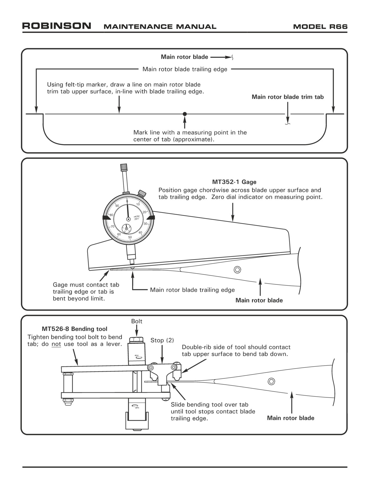
FIGURE 18-4 MAIN ROTOR BLADE TRIM TAB
Page 18.8
Chapter 18 Track and Balance
25 OCT 2010
18-13 Track Adjustment (continued)
A. Main Rotor Blade Pitch Link (continued)
3. For fine adjustment, adjust fitting only per the following steps:
a. Remove and discard pitch link assembly safety wire. Using backup wrench on
link assembly, loosen jam nut in middle of pitch link. Using backup wrench on
fitting, loosen upper rod end palnut and jam nut.
b. Rotate fitting to shorten or lengthen pitch link as required. One full turn changes
blade track approximately 0.25 inch. One full turn of fitting changes blade
angle approximately 0.40°. For finer adjustment, count hex flats while rotating
fitting.
c. Refer to Figure 5-1. Verify rod end threaded shank blocks passage of 0.020-inch
diameter lockwire through pitch link witness hole.
d. Using backup wrench on link assembly, torque jam nut per Section 20-32. Using
backup wrench on fitting, torque rod end jam nut and palnut per Section 20-32.
Safety fitting to link assembly using 0.032-inch diameter lockwire.
e. Repeat steps on opposite pitch link as required. Torque stripe per Figure 5-1.
B.
Main Rotor Blade Trim Tab
NOTE
To correct for a "climbing" blade condition (blade spread that
exceeds 3/8 inch with forward airspeed), bend high blade trim
tab down.
CAUTION
Do not use other helicopter manufacturers' trim tab bending
tools. Use of these tools will damage Robinson blades.
CAUTION
MT352-1 gage must contact trim tab trailing edge. If gage
does not contact tab trailing edge, tab is bent beyond limit.
CAUTION
Tighten MT526-8 bending tool bolt to bend tab; do not use tool
as a lever.
CAUTION
Bend tab upward only when absolutely necessary; bending tab
upward can increase rotor vibration.
1.
Using felt tip marker, ink mark main rotor blade trim tab per Figure 18-4. Mark line
with a measuring point in the center of the tab (approximate).
25 OCT 2010
Chapter 18 Track and Balance
Page 18.9
18-13 Track Adjustment (continued)
B. Main Rotor Blade Trim Tab (continued)
2. Position MT352-1 gage chordwise across blade upper surface and tab trailing edge.
Zero dial indicator on measuring point.
3. Position MT526-8 bending tool on tab per Figure 18-4. Slide tool completely over
tab until tool stops contact blade trailing edge. Double-rib side of tool should contact
tab upper surface to bend tab down. Double-rib side of tool should contact tab
bottom surface to bend tab up.
4. Tighten MT526-8 bending tool bolt to bend tab. Make slight bends and remeasure tab
with MT352-1 gage. Bend trim tab 0.015 inch (down) to effect dynamic movement
of main rotor blade tip approximately 0.2 inch (downward).
18-14 Balance Adjustment
WARNING
A rotor which is smooth after balancing but goes out of balance
within a few flights is suspect and must be examined by RHC
before further flight.
A. Tip Weights (Spanwise Balance Adjustment)
1. Remove screws securing tip cover to blade. Balance rotor assembly spanwise
by adjusting tip weights as required per Figure 18-2. Washers may be trimmed.
Special torque fasteners securing tip weights per Section 20-33. Install tip cover
and standard torque fasteners per Section 20-32.
(1) AN960-10 or NAS1149F0363P Washer =
(2) AN960-10L or NAS1149F0332P Washers
(1) C298-2 Weight
= (5) AN960-10 or NAS1149F0363P Washers
(1) C298-3 Weight
= (11) AN960-10 or NAS1149F0363P Washers
(1) C298-4 Weight
= (4) C298-3 Weights
B.
Teeter Hinge Bolt Shims (Chordwise Balance Adjustment - Coarse Adjustment)
1. Remove and discard teeter hinge nut cotter pin. Remove nut, thrust washer, and any
shims.
2. Have two people cone the main rotor blades. Push out teeter hinge bolt (and any
shims) with another bolt.
3. Balance rotor assembly chordwise by moving (or exchanging) existing teeter hinge
shims to other side of bolt (under head or under nut) as required per Figure 18-2.
Install teeter hinge bolt per Section 62-10.
C. Chord Arm Weight (Chordwise Balance Adjustment - Fine Adjustment)
1. Balance rotor assembly chordwise by adjusting chord arm weights or washers per
Figure 18-2. Total weight not to exceed four A255-2 weights (or equivalent).
(1) A255-1 Weight
=
(8) AN970-4 Washers
(1) A255-2 Weight
=
(3) A255-1 Weights
Page 18.10
Chapter 18 Track and Balance
25 OCT 2010
18-15 Troubleshooting
The following are some of the symptoms and corrections which occur in the Track and Balance
operations of the helicopter. Decide on the various causes of a given trouble and then eliminate
causes one by one, beginning with the most probable.
Symptom
Probable Cause
Correction
1.
Excessive Cyclic or
Main rotor (MR) out of track.
Track and balance per Section 18-10.
Stick Shake
Rough or binding A205-7 fork
Replace or refer to Section 67-40.
assembly (upper swashplate).
Brinelled spindle bearing
Send blade(s) to RHC for spindle bearing
(rough movement).
replacement.
Rough blade surface (chipped paint).
Repair blades per Section 62-60.
Rough or binding pitch links.
Replace pitch link rod ends
MR blade boot misaligned.
Realign or replace boot per Section 62-11.
MR teeter or coning hinge binding.
Replace bearings per Section 62-21.
MR blade trim tabs bent upward.
Bend trim tabs evenly down per Section 18-13.
Blade mismatch.
Send blade(s) to RHC for replacement.
2.
Excessive Ship
MR out of track and balance.
Track and balance per Section 18-10.
Vibration
MR teeter or coning hinge friction.
Adjust hinge friction per Section 62-32.
MR teeter or coning hinge binding.
Replace bearings per Section 62-21.
Brinelled spindle bearing
Send blade(s) to RHC for spindle bearing
(rough movement).
replacement.
MR teeter hinge bearings worn.
Replace bearings per Section 62-21.
3.
Excessive Cyclic
Brinelled spindle bearing
Send blade(s) to RHC for spindle bearing
Stick Forces
(rough movement).
replacement.
4.
Intermittent Blade
MR teeter or coning hinge friction
Adjust hinge friction per Section 62-32.
Track Picture
MR coning hinge binding.
Replace bearings per Section 62-21.
MR teeter hinge not "broken-in."
Track and balance per Section 18-10. Adjust
track to minimize error.
Brinelled spindle bearing
Send blade(s) to RHC for spindle bearing
(rough movement).
replacement.
5.
Radical Changes to
MR teeter hinge bearings worn.
Replace bearings per Section 62-21.
Cyclic Trim
Brinelled spindle bearing
Send blade(s) to RHC for spindle bearing
(rough movement).
replacement.
25 OCT 2010
Chapter 18 Track and Balance
Page 18.11
18-16 Autorotational RPM Adjustment
Use the following procedure for checking and adjusting autorotational RPM:
WARNING
Failure to properly adjust autorotational RPM (RPM too low)
may prevent the rotorcraft from achieving proper RPM at low
gross weights.
1.
Perform autorotation RPM check at minimum practical gross weight (less than 1900
lb). Calculate the takeoff gross weight of the helicopter. Record the time on the
hourmeter.
Take-Off gross weight:
Take-Off hourmeter reading:
2.
Set the altimeter to 29.92” Hg (1013.2 millibars) prior to performing the autorotation.
Autorotate with the collective control firmly held against the down stop with an airspeed
of 50 KIAS.
WARNING
Do not allow the rotor to overspeed when performing autorotation
checks. Progressively lengthen both main rotor pitch link rod
ends until full down collective can be obtained without over-
speeding the rotor.
Take at least 3 RPM readings at 500 to 1000 foot altitude intervals.
Record the following in-flight data:
Hourmeter
Pressure
Test %
Test #
Reading
OAT
Altitude
RPM
1
2
3
4
5
Page 18.12
Chapter 18 Track and Balance
25 OCT 2010
18-16 Autorotational RPM Adjustment (continued)
3. After test flight, determine the following:
Test #
1
2
3
4
5
Elapsed Time (in-flight hourmeter reading
minus take-off hourmeter reading):
Pounds of Fuel Consumed
(elapsed time x 140 lb/hr):
Test Gross Weight
(take-off gross weight minus fuel consumed):
Test Longitudinal Center of Gravity:
Chart % RPM*:
Test % RPM (from in-flight data):
RPM Correction
(chart % RPM minus test % RPM):
*Perform step 4 to obtain value.
4. Refer to Figure 18-5. To find Chart % RPM, perform the following:
a. Start at outside air temperature, and draw a vertical line up to pressure altitude.
b. Draw a horizontal line from pressure altitude to rotorcraft gross weight at time of
autorotation.
c. Draw a vertical line down from autorotation gross weight to required auto RPM.
5. Adjust pitch links based on average RPM correction required. Lengthen both pitch links
to decrease RPM if test RPM is greater than chart RPM; shorten both pitch links to
increase RPM. One full rod end turn will change RPM approximately 3½%. Adjust both
pitch links exactly the same so track will not be affected.
6. Repeat previous steps as required until the RPM correction is ± 1% of chart RPM.
25 OCT 2010
Chapter 18 Track and Balance
Page 18.13
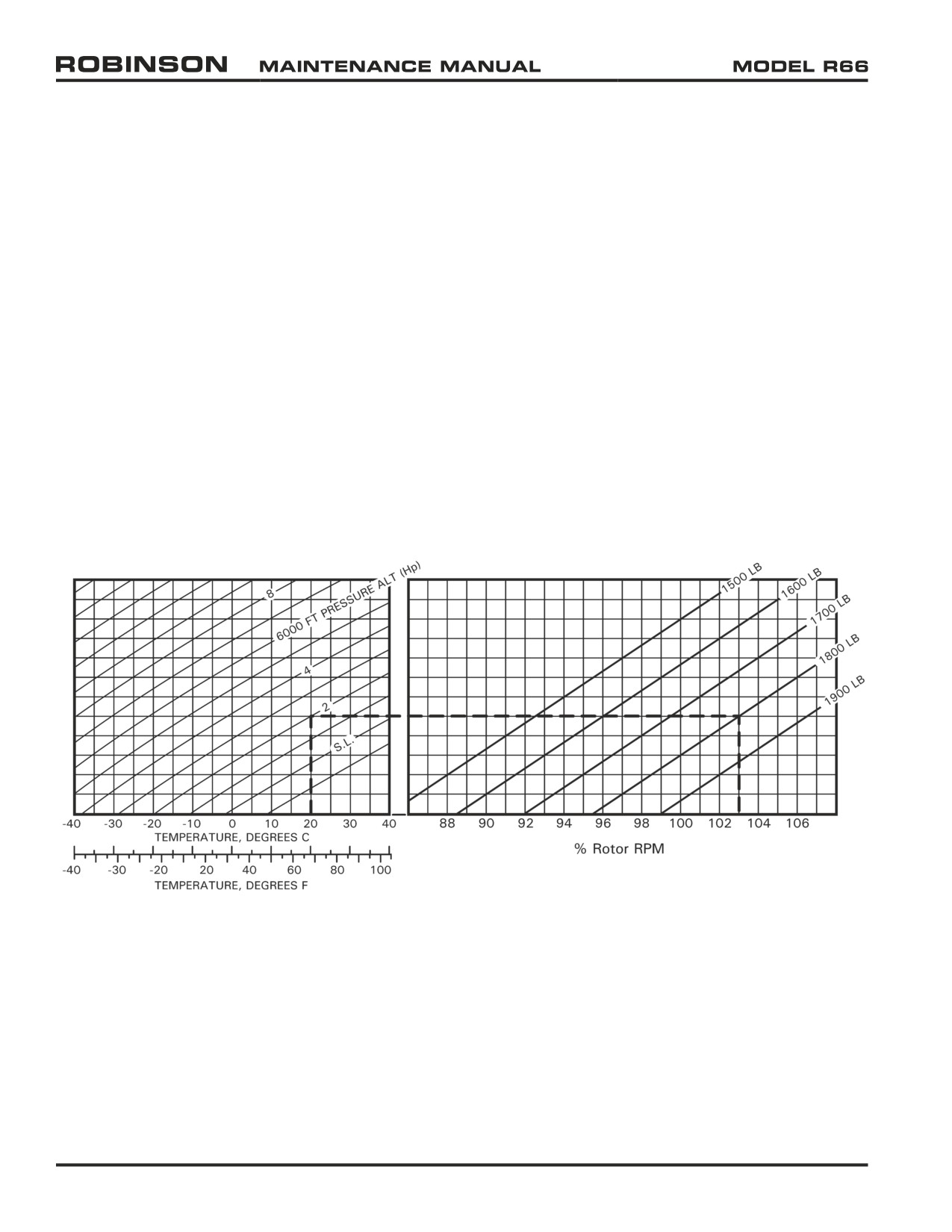
AUTOROTATION RPM
COLLECTIVE FULL DOWN
50 KIAS
One full turn of rod ends = approximately 3½% RPM change
One full turn of rod end = 1⅙ turns of barrel
Example: OAT=20°C, Hp=2000 ft, GW=1800 lb, RPM=103%
FIGURE 18-5 AUTOROTATION RPM ADJUSTMENT
Page 18.14
Chapter 18 Track and Balance
25 OCT 2010
Intentionally Blank
25 OCT 2010
Chapter 18 Track and Balance
Page 18.15
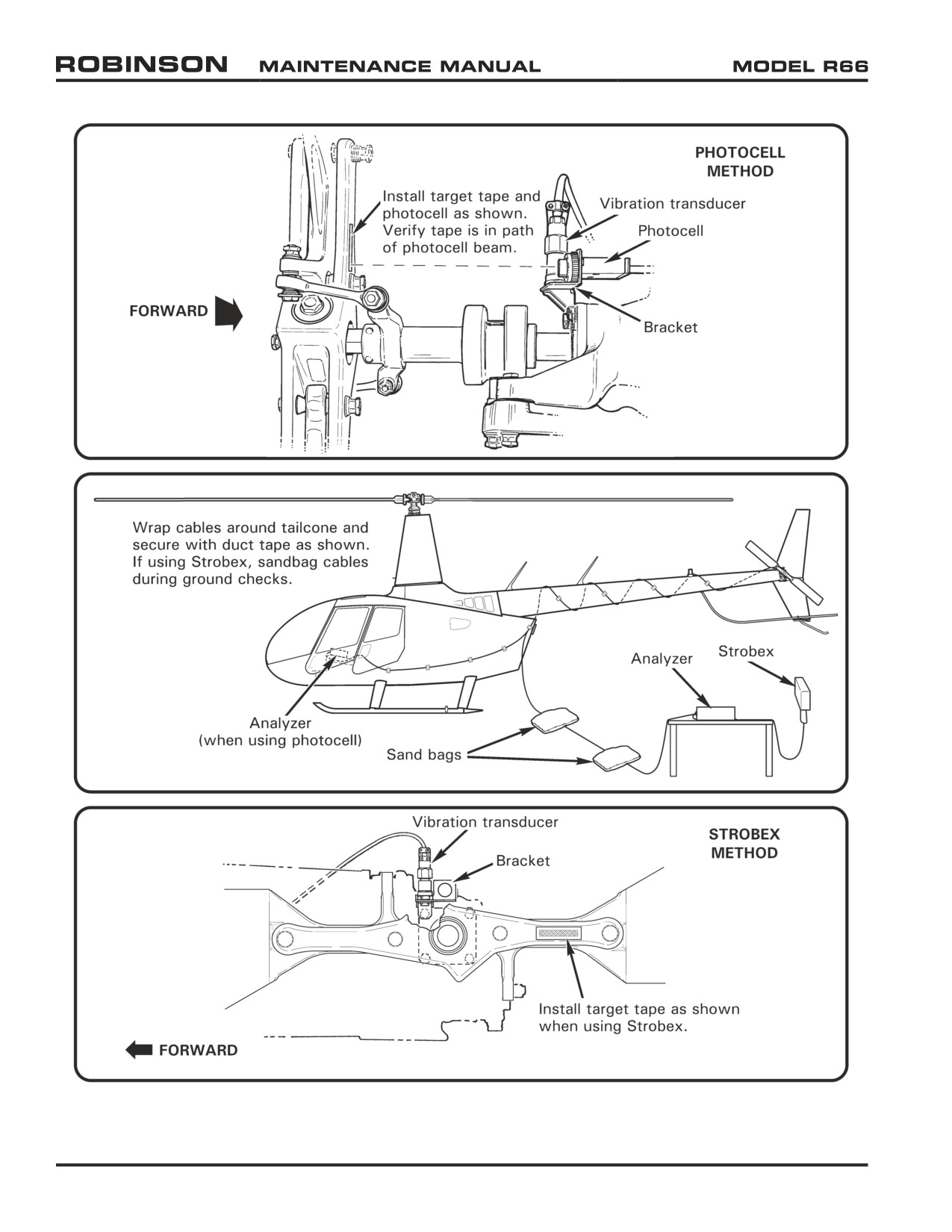
FIGURE 18-6 TAIL ROTOR BALANCING EQUIPMENT INSTALLATION
Page 18.16
Chapter 18 Track and Balance
25 OCT 2010
18-20 Tail Rotor Dynamic Balance
NOTE
Calibrate track and balance equipment per manufacturer's
recommendation, at least once a year, or if equipment is
dropped, misused, or calibration is suspect.
NOTE
The Chadwick-Helmuth Vibrex system, the TEC ACES system,
the Dynamic Solutions Systems’ MicroVib system, or equivalent
equipment is required to perform dynamic rotor balancing and
in-flight track checks.
18-21 Preparing Helicopter for Tail Rotor Dynamic Balance
NOTE
Use the following balance procedures in conjunction with
approved equipment manufacturer’s balancing instructions.
WARNING
Ensure cable(s) cannot entangle tail rotor.
1.
Clean tail rotor blades per Section 20-10. Inspect tail rotor rod ends and elastomeric
bearings per Sections 5-33 and 5-34.
2.
Track tail rotor blades per Section 64-10.
3.
Refer to Figure 18-6. If using photocell to obtain clock angle, install a target tape
spanwise on inboard side of one arm of tail rotor hub; if using Strobex, install a target
tape spanwise on outboard side of hub.
4.
Using appropriate hardware, attach bracket(s) to vibration transducer, and photocell, if
used. Secure bracket to tail rotor gearbox output shaft cap at forward, top attachment
bolt. Orient vibration transducer vertically.
5.
Connect cable(s) to transducer, and photocell, if used. Route cable(s) forward and into
cabin; wrap around tailcone several times, and secure with duct tape. If using Strobex,
route cable to a position located approximately 20 feet to left of tail rotor. Place
sandbags (or similar) on cable to prevent cable movement.
6.
Connect cable(s) to balancer. Verify security of installation.
Chapter 18 Track and Balance
Page 18.17
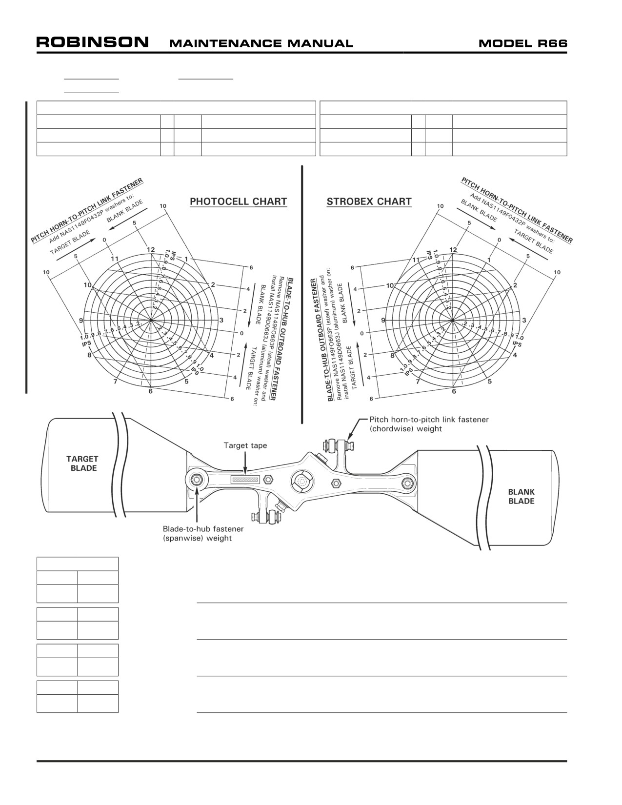
DATE
SERIAL NO.
PAGE
PITCH HORN-TO-PITCH LINK FASTENER (CHORDWISE) WEIGHTS
BLADE-TO-HUB OUTBOARD FASTENER (SPANWISE) WEIGHTS
(1) NAS1149F0463P Washer
=
(2)
NAS1149F0432P Washers
(1) C141-23 Washer
=
(3.5)
NAS1149F0663P Washers
(1) A214-3 Washer
=
(3.5)
NAS1149F0432P Washers
(1) C141-24 Washer
=
(7)
NAS1149F0663P Washers
(1) A141-14 Washer
=
(5)
NAS1149F0432P Washers
(2) NAS1149F0632P
(1)
NAS1149F0663P Washer
BALANCE
CLOCK
IPS
ADJUSTMENT:
CLOCK
IPS
ADJUSTMENT:
CLOCK
IPS
ADJUSTMENT:
CLOCK
IPS
ADJUSTMENT:
FIGURE 18-7 TAIL ROTOR DYNAMIC BALANCE CHART
Page 18.18
Chapter 18 Track and Balance
18-22 Ground Checks
NOTE
Run-up and shutdown helicopter throughout procedure as
required per R66 Pilot's Operating Handbook (POH) Section 4.
NOTE
Use the following balancing procedures in conjunction with
approved equipment manufacturer’s balancing instructions.
WARNING
Tail rotor balancing equipment must be removed for flight.
1.
Prepare helicopter for tail rotor dynamic balance per Section 18-21.
2.
Make a photocopy of Figure 18-7; use copy to record ground check data. Check tail rotor
balance at 99-101% RPM on ground and record data. Maximum vibration allowance is
0.2 ips (inches per second).
(If using Chadwick-Helmuth system, set Function Knob on
Balancer to appropriate channel, set balancer RPM Range knob to X10, and set RPM to
231. During ground run, view tail rotor assembly target tape through Strobex and tune
Balancer by adjusting RPM dial.)
3.
Adjust balance per Section 18-23 as required, record change, and recheck balance.
Repeat steps 2 and 3 as required until tail rotor balance is within limits.
4.
Remove track and balance equipment. Install tail rotor gearbox output shaft cap forward,
top attachment bolt and special torque per Section 20-33. Install 0.032-inch diameter
lockwire securing cap retaining hardware and safety in pairs.
WARNING
A rotor which is smooth after balancing but goes out of balance
within a few flights is suspect and must be examined by RHC
before further flight.
18-23 Balance Adjustment
Refer to R66 Illustrated Parts Catalog (IPC) Figure 64-1. Refer to Section 64-11 for tail
rotor assembly static balance procedure.
A. Pitch Horn-to-Pitch Link Fastener (Chordwise Balance Adjustment)
Chordwise dynamic balance is achieved by varying NAS6604 bolt length and nut-side
washers on tail rotor blade pitch horn-to-pitch link fastener. Select bolt length and
washers as required to balance tail rotor assembly chordwise per Figure 18-7, and
to meet torque requirements per Section 20-30. Standard torque nut and palnut per
Section 20-32, but do not torque stripe.
B. Blade-to-Hub Outboard Fastener (Spanwise Balance Adjustment)
Spanwise dynamic balance is achieved by varying nut-side washer size on tail rotor
blade-to-hub outboard fastener. Four washers are required under outboard nuts. Select
a combination of four washers to balance tail rotor assembly spanwise per Figure 18-7,
placing largest washers closest to hub assembly. Standard torque nuts and palnuts per
Section 20-32, but do not torque stripe.
25 OCT 2010
Chapter 18 Track and Balance
Page 18.19
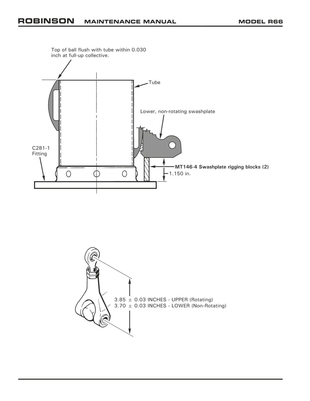
FIGURE 18-8 SWASHPLATE AND COLLECTIVE CONTROL RIGGING
FIGURE 18-9 A205-5 SWASHPLATE FORK RIGGING
Page 18.20
Chapter 18 Track and Balance
25 OCT 2010
18-30 Main Rotor Flight Control Rigging
NOTE
Refer to Section 5-33, and Figures 5-1 & 5-2 for standard rod
end adjustment procedures. Refer to Section 18-13 for main
rotor pitch link adjustment procedure.
For collective adjustments, both pitch links must be adjusted
exactly the same.
Track and balance helicopter per Sections 18-10 & 18-20 as
required after adjusting flight controls.
NOTE
Cyclic stick travel is non-adjustable. Travel is limited by A211-4
stop attached to the cyclic box assembly.
Collective stick travel is non-adjustable. Travel is limited by
A333-1 stop integral to the collective stick friction assembly.
Perform the following check to verify collective travel and
swashplate travel do not interfere.
1.
Install MT559-1 rigging blocks inside A211-4 cyclic stick stop. Position collective stick
full down. Apply cyclic and collective stick frictions.
2.
Rig the following push-pull tube assemblies and fork assembly, located between keel
panels, to the noted rod end center-to-center dimensions:
PART NUMBER
DIMENSION
C121-1
= 51.15 ± 0.03 inches
F121-1
= 32.36 ± 0.03 inches
G205-1
= 5.40 ± 0.03 inches
3.
Adjust length of F121-1 tube so that with collective full up, there is a 0.50 inch gap
between G205-1 yoke and F315-1 support.
4.
Refer to Figure 18-8. Position MT146-4 swashplate rigging blocks between lower, non-
rotating swashplate and C281-1 fitting. Refer to Section 5-33, and adjust push-pull
tube rod ends until aligned with swashplate attachment holes.
5.
Cut and discard ty-rap(s) as required to lift swashplate boot.
6.
Position collective stick full up. Verify top of C201-1 ball assembly is flush with top
edge of C208-1 tube within 0.030 inch. Refer to Section 5-33, and adjust push-pull
tube rod ends in or out equally to raise or lower swashplate as required.
7.
Refer to Figure 18-9. Adjust swashplate A205-5 lower fork assembly (non-rotating) to
3.70 ± 0.03 inch, and upper fork assembly (rotating) to 3.85 ± 0.03 inch.
25 OCT 2010
Chapter 18 Track and Balance
Page 18.21
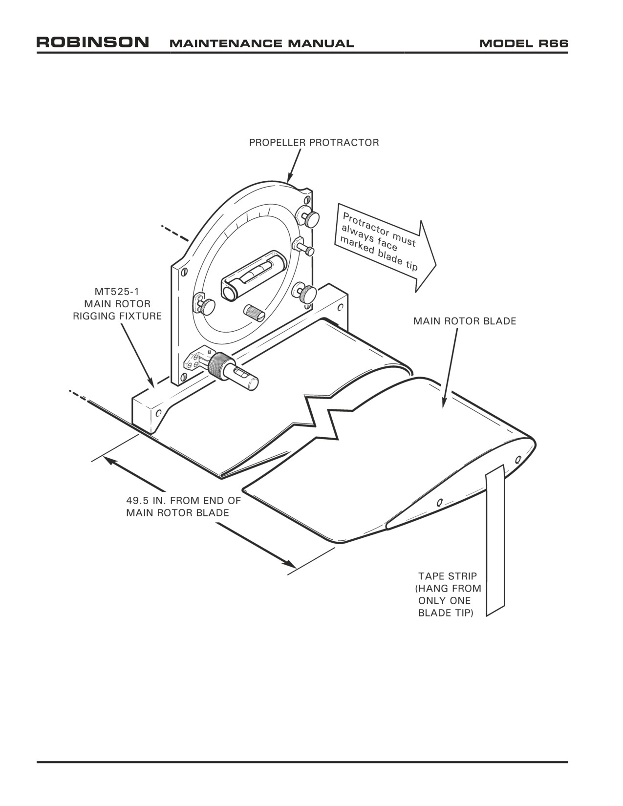
FIGURE 18-10 MAIN ROTOR BLADE RIGGING
Page 18.22
Chapter 18 Track and Balance
25 OCT 2010
18-40 Main Rotor Blade Angle Rigging
A. Procedure
NOTE
Refer to Section 5-33, and Figures 5-1 & 5-2 for standard rod
end adjustment procedures. Refer to Section 18-13 for main
rotor pitch link adjustment procedure.
1. Perform main rotor flight control rigging per Section 18-30.
2. Level helicopter laterally and longitudinally via main rotor hub per Section 8-12.
3. Perform collective travel rigging per Section 18-41 Parts A and B.
4. Perform cyclic travel rigging per Section 18-42 Parts A, B, C, and D.
5. Perform track and balance per Section 18-10 as required.
B.
Measuring Blade Angles
NOTE
Hydraulic flight controls must be pressurized while measuring
blade angles.
WARNING
Never adjust flight controls while hydraulics are pressurized.
Hydraulic forces can cause injury.
1.
Teeter main rotor hub until blade tips are approximately level. Place a tracking stick
at the end of one blade and mark the tip height. Rotate the rotor 180° and mark the
opposite blade’s tip height. Teeter main rotor hub as required until blade tips are level
within 1 inch.
2.
Refer to Figure 18-10. Using felt tip marker, mark upper surface of both main rotor
blades 49.5 inches inboard of seam between blade tip and tip cover. Lay 1-inch wide
length of masking tape chordwise on each blade, centered over marking. Mark each
rotor blade with a different color designation, such as red and blue.
3.
Hang a 6-inch length of masking tape from one blade tip for reference. Zero Kell-Strom
KS113 propeller protractor (or equivalent) on top of the main rotor hub, parallel to the
teeter hinge bolt, at location marked “LEVEL HERE”. During zeroing, point protractor
face toward the blade with hanging tape. When taking blade angle readings, always
point protractor face toward the blade with hanging tape.
4.
Position MT525-1 fixture on top of the blade’s tape at 49.5 inches, and tight against
the leading edge. Position protractor on top of fixture, point protractor face toward the
blade with hanging tape, and take blade angle reading.
Chapter 18 Track and Balance
Page 18.23