Robinson Helicopter Company RTR 660 (Number R00015LA). Maintenance Manual (2012) - page 4
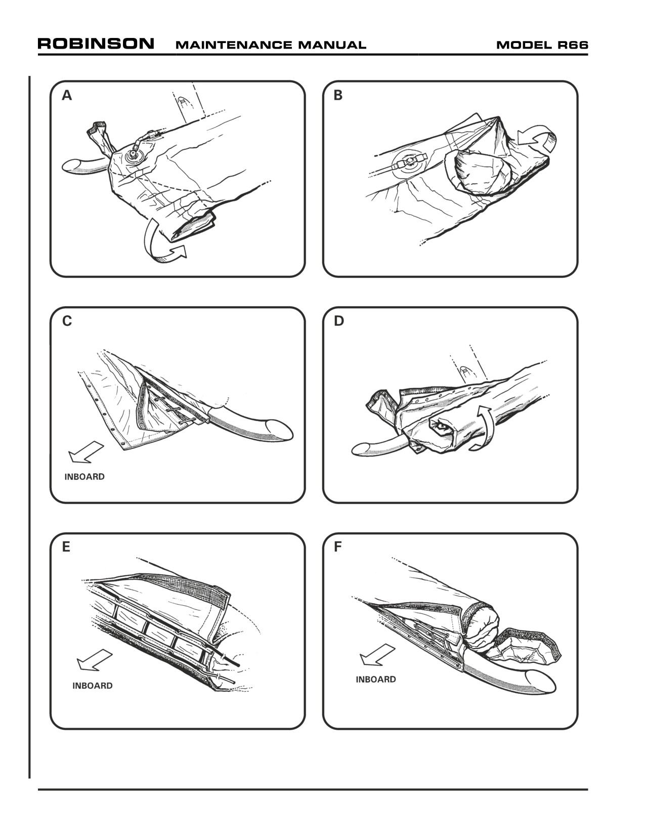
FIGURE 32-8 POP-OUT FLOATS FLOAT PACKING
Page 32.20
Chapter 32 Landing Gear
32-63 Float Installation (continued)
C. Packing
1.
Install floats per Section 32-63 Part B.
2.
Spread deflated float outboard of skid tube. Vacuum as much air as possible from
each float chamber through topping valves. Smooth out wrinkles.
3.
Lightly dust float and inside float cover with talcum powder.
4.
Refer to Figure 32-7 and Figure 32-8 Detail A. At girt forward edges, fold float
perpendicular to skid tube; tuck material under and aft of float as shown.
5.
Refer to Figure 32-8 Detail B. At girt aft edges, fold float perpendicular to skid tube;
lay material over and forward of float as shown.
6.
Refer to Figure 32-8 Detail C. Loosen lacing cords securing float cover to inboard
girt. Detach, align, and secure inboard hook and loop fasteners.
NOTE
If possible, roll float into cover with the assistance of six or
seven people.
7.
Refer to Figure 32-8 Detail D. Align hoses and valve cover flaps. Roll float from
outboard edge toward skid tube, as tightly as possible. Hold float on top of skid.
8.
Apply A257-7 lubricant to mating surfaces of float cover and (outboard) girt snaps.
Button snaps, and secure hook and loop fasteners.
9.
Refer to Figure 32-8 Detail E. Verify lacing cords are installed in cover grommets
in crossover (“ladder” lacing) method shown. Tighten cords starting at the aft
skid extension working forward: at each segment, pull cords tight or until material
edges join, but do not overtighten near valves. Tie cord ends in double square knots
(4 alternating overhand knots).
10.
Refer to Figure 32-8 Detail F. Tuck-in cord ends and secure hook and loop fasteners.
Secure hook and loop fasteners at end caps.
11.
Verify all fasteners are properly secured. Verify floats are rolled tight, with no
lumps or loose areas.
Chapter 32 Landing Gear
Page 32.21
32-64 System Maintenance
A. Leak Check
WARNING
D679 Cylinder contents are under extreme pressure. Install
MT545-1 pin assembly in D757-1 valve assembly during
maintenance to prevent cylinder discharge.
1.
Disconnect D674-1 line assembly from presssure cylinder valve. Install protective
cap on cylinder valve fitting. Cover D674-1 line fitting to prevent contamination, but
do not install an air-tight seal (D674-1 line fitting must be allowed to leak to verify
check valve function at each float chamber).
2.
Unfasten hook-and-loop fasteners along inboard sections of float cover to expose
lacing. Loosen, but do not remove, lacing.
3.
Unfasten outboard sections of float cover and unroll float to expose valves.
4.
Inflate floats with filtered, oil-free, dry air to 2.0 psig via topping valves.
5.
Allow float air temperature to stabilize for 5 minutes minimum then record OAT and
pressure in each float chamber.
6.
One to two hours after initial pressure check, again record OAT and pressure in each
float chamber. Allowable chamber pressure drop from initial measurement is 0.2
psig adjusted for any temperature change. Pressure will change by 0.06 psig per
degree C temperature change. For example, float chamber pressure will decrease
0.6 psig if temperature drops 10 degrees C.
7.
If leaks are detected, repair float with supplied repair kit and repeat steps 4, 5, & 6.
8.
Connect D674-1 line assembly to cylinder valve and torque per Section 20-33.
9.
Pack float per Section 32-63 Part C.
NOTE
Annually apply A257-7 dry-film lubricant (see Section 20-78) to
float cover snap mating surfaces.
Page 32.22
Chapter 32 Landing Gear
32-64 System Maintenance (continued)
B.
Inflation Check
WARNING
D679 Cylinder contents are under extreme pressure. Install
MT545-1 pin assembly in D757-1 valve assembly during
maintenance to prevent cylinder discharge.
1.
Unsnap outboard edge of both float covers.
2.
Remove locking pin from valve, move inflation lever safety to READY position, and
verify area around floats is clear.
3.
Squeeze inflation lever to inflate floats. Approximately 20 pounds force will be
required due to the shear-rivet. Time for floats to attain full shape without wrinkles
should be three seconds or less.
CAUTION
Floats inflate rapidly and with a loud noise. Keep area clear
during inflation and inform all nearby personnel. Remove or
close all doors prior to inflation. Open doors interfere with float
inflation and may be damaged.
4.
Allow float temperatures to stabilize for at least five minutes then record OAT and
pressure in each float chamber. Minimum allowable pressures are:
Minimum Pressure
Minimum Pressure
Minimum Pressure
OAT (degrees C)
(psig) in Forward
(psig) in Middle
(psig) in Aft Two
Two Chambers
Chamber
Chambers
5-9
1.30
1.00
0.60
10-14
1.60
1.30
0.90
15-19
1.90
1.60
1.20
20-24
2.20
1.90
1.50
25-29
2.50
2.20
1.80
30-34
2.80
2.50
2.10
35-39
3.10
2.80
2.40
Chapter 32 Landing Gear
Page 32.23
32-64 System Maintenance (continued)
B. Inflation Check (continued)
5.
Disconnect D674-1 hose assembly from pressure cylinder valve immediately after
initial pressure check. Install protective cap on cylinder valve fitting. Cover D674-1
hose fitting to prevent contamination, but do not install an air tight seal (D674-1 hose
must be allowed to leak to verify check valve function at each float chamber).
6.
Verify no rips or chafing on floats or covers.
7.
One to two hours after initial pressure check, again record OAT and pressure in
each float chamber. Allowable chamber pressure drop from initial measurement is
0.20 psi adjusted for any temperature change. For example, float chamber pressure
will decrease 0.6 psig if temperature drops 10 degrees C.
8.
If leaks are detected, repair float with supplied repair kit then perform leak check per
Section 32-64 Part A on repaired float chamber.
9.
Connect D674-1 hose assembly to valve fitting. Orient line as required to maintain
minimum 0.25 inch clearance to cylinder and C390-5 panel. Torque B-nut per
Section 20-33 and torque stripe.
10.
Pack floats per Section 32-63 Part C.
NOTE
Annually apply A257-7 dry-film lubricant (see Section 20-78) to
float cover snap mating surfaces.
11.
Remove cylinder assembly and depressurize cylinder per Section 32-61 Parts A &
B. Return cylinder to RHC for overhaul-exchange.
12.
Install serviceable cylinder assembly per Section 32-61 Part D.
Page 32.24
Chapter 32 Landing Gear
CHAPTER 52
DOORS AND WINDOWS
Section Title
Page
52-00
Description
52.1
52-10
Door Assembly
52.1
52-11
Door Lock Replacement
52.4
52-12
Weather Seal (Door Assembly) Replacement
52.4
52-13
Gas Springs
52.7
52-20
Door Vent Replacement
52.7
52-21
Weather Seal (Door Vent) Replacement
52.7
52-22
Door Vent Hinge Replacement
52.8
52-23
Pivot Friction Adjustment
52.8
52-30
Windshield Assembly
52.11
25 OCT 2010
Chapter 52 Doors and Windows
Page 52.i
Intentionally Blank
Page 52.ii
Chapter 52 Doors and Windows
25 OCT 2010
CHAPTER 52
DOORS AND WINDOWS
52-00 Description
The R66 has four passenger doors and one main baggage compartment door. Passenger doors
may be removed and installed by maintenance personnel or pilots.
Passenger doors are constructed of fiberglass and thermoplastics. Passenger doors, locks,
weather seal, gas springs, and door vents and hinges may be replaced, and vent pivot friction
may be adjusted.
Periodically inspect windshield for cracks or crazing and replace windshield that exceeds
damage criteria per Section 52-30.
52-10 Door Assembly
Refer to R66 Illustrated Parts Catalog (IPC) Chapter 52.
A. Removal
1. Refer to Figures 52-1 and 52-2. To disconnect door from gas spring mechanism:
a. Forward Doors: Pull D573-4 rod up and off of arm assembly ball joint.
b. Aft Doors: Insert flat-tip screwdriver and pry up spring clip locking C394-1 gas
spring to channel ball joint. Pull gas spring up and off of ball joint.
2. Remove rings from door hinge pins, lift pins up from door frame hinge assemblies, and
remove door.
B.
Installation
WARNING
Failure to install a ring in each door's two hinge pins may allow
door to depart aircraft in flight.
1. Refer to Figures 52-1 and 52-2. Align and insert door hinge pins in door frame hinge
assemblies.
2. Align forward door D573-4 rod with arm assembly ball joint, or aft door C394-1 gas
spring with channel ball joint, and push down to lock.
3. Install rings in door hinge pins.
25 OCT 2010
Chapter 52 Doors and Windows
Page 52.1
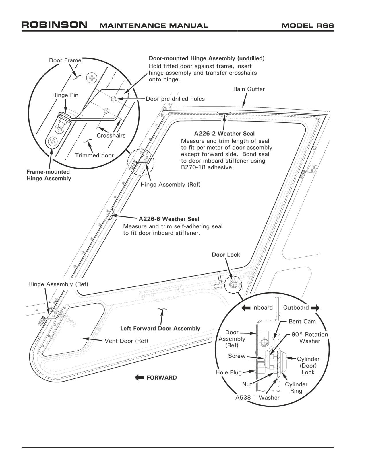
FIGURE 52-1 DOOR ASSEMBLY
Page 52.2
Chapter 52 Doors and Windows
25 OCT 2010
52-10 Door Assembly (continued)
C. Replacement
CAUTION
Use proper respiratory protection when handling fiberglass.
CAUTION
Protect door windows and paint from scratches or scuff marks
when door maintenance is performed on workbench.
1.
Refer to Figure 52-1. As required, lay masking tape on surfaces of door frame, new
door hinges, and new door, to mark with soft pencil.
2.
Press new door forward and top edge weather seals against door frame recess (rain
gutter interferes with top edge until trimmed).
3.
Using soft pencil, trace door forward edge onto masked frame, then transfer approximate
edge distance to door. From inside cabin, estimate approximate material to be removed
from door top edge, then transfer approximate edge distance to door. Remove door.
4.
Using 60-grit grinder, trim forward and top door edges. Perform steps 1 thru 3 until
weather seals sit approximately even against door frame recess.
5.
Using soft pencil and a straight edge, draw cross hairs through (centers of) door upper
hinge assembly pre-drilled holes. Hold fitted door against frame, insert new (door-
mounted) hinge assembly in frame-mounted hinge assembly, and transfer cross hairs
onto hinge. Remove hinge and door.
6.
Drill two 0.170-inch diameter holes at cross hair intersections in hinge assembly and
deburr. Remove tape, clean up debris, and prepare hinge assembly and door clamping
surfaces using approved solvents per Section 20-70.
7.
Install upper hinge assembly on door and special torque screws per Section 20-33.
8.
Repeat steps 5 thru 7 for lower door-mounted hinge assembly.
9.
Install door. Using 60-grit grinder, trim edges as required for final fitting. Verify doors
open and close smoothly and latch correctly. Remove door and bevel edges using 60-
grit sandpaper.
10.
Prepare surfaces with solvent and touch-up door using approved materials per Section
20-70. Install new door per Section 52-10.
25 OCT 2010
Chapter 52 Doors and Windows
Page 52.3
52-11 Door Lock Replacement
Refer to R66 Illustrated Parts Catalog (IPC) Figure 52-1.
CAUTION
Protect door windows and paint from scratches or scuff marks
when door maintenance is performed on workbench.
1. Remove door per Section 52-10.
2. Refer to Figure 52-1. Remove hole plug opposite key slot on door interior.
3. Remove screw, bent cam, and 90° rotation washer. Remove nut and A538-1 washer.
Press and catch cylinder lock and ring through door.
4. Install new cylinder lock and ring in door. Install lock so key is vertical with teeth
down in locked position. Apply thin coat B270-10 adhesive on screw threads, install
hardware, and tighten screw.
5. Bond hole plug in place using B270-9 adhesive.
52-12 Weather Seal (Door Assembly) Replacement
Refer to R66 Illustrated Parts Catalog (IPC) Figures 52-1 and 52-7.
1. Remove damaged weather seal using plastic wedge or putty knife. Remove hardened
adhesive using approved solvent per Section 20-70, or 60-grit sandpaper, as required.
2. Refer to Figure 52-1. Measure and trim continuous length of A226-2 seal to fit perimeter
of door except forward side, as shown. Neatly bond seal to stiffener using B270-18
adhesive. Wipe away excess adhesive prior to curing.
3. Measure and trim length of A226-6 seal to fit forward side of door. Remove self-
adhesive preserving strip and neatly bond seal to stiffener.
Page 52.4
Chapter 52 Doors and Windows
25 OCT 2010
Intentionally Blank
25 OCT 2010
Chapter 52 Doors and Windows
Page 52.5
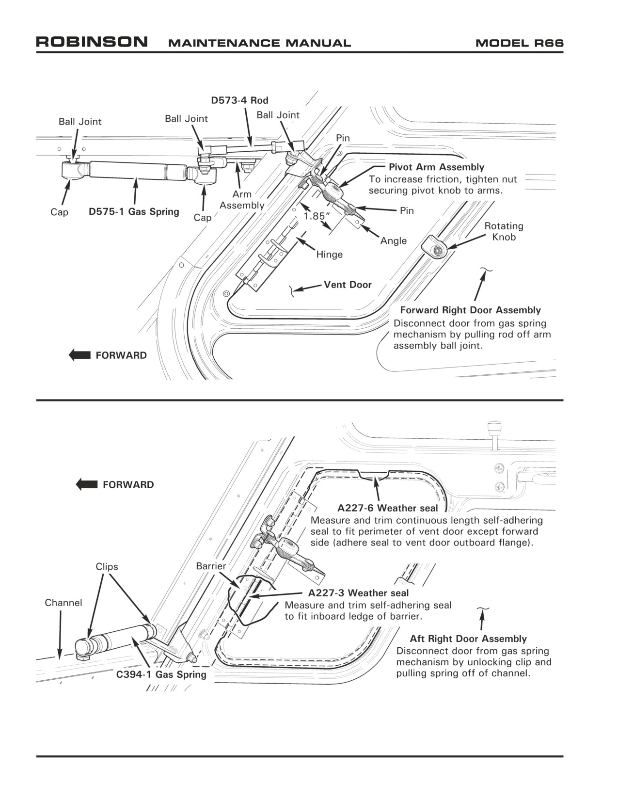
FIGURE 52-2 GAS SPRINGS AND DOOR VENTS
Page 52.6
Chapter 52 Doors and Windows
25 OCT 2010
52-13 Gas Springs
Refer to R66 Illustrated Parts Catalog (IPC) Figures 52-5 and 52-11.
A. Removal
1. a. Forward Doors: Insert flat-tip screwdriver and pry down on caps to unlock D575-
1 gas spring from ball joints. Push gas spring down and off of ball joints.
b. Aft Doors: Insert flat-tip screwdriver and pry up spring clips to unlock C394-1
gas spring from ball joints. Pull gas spring up and off of ball joints.
B. Installation
1. a. Forward Doors: Unlock D575-1 gas spring caps. Snap gas spring onto ball joints
and lock caps.
b. Aft Doors: Insert flat-tip screwdriver and pry up C394-1 gas spring spring clips.
Snap gas spring onto ball joints and release clips.
52-20 Door Vent Replacement
Refer to R66 Illustrated Parts Catalog (IPC) Figures 52-1 and 52-7.
CAUTION
Use proper respiratory protection when handling fiberglass.
1.
Refer to Figure 52-2. Drill out rivets securing hinge and pivot arm assembly angle to door
vent. Rotate knob to unlock and remove door vent.
2.
Using 60-grit grinder, trim new vent door forward edge as required to match door recess
and smooth corners. Bevel edges using 60-grit sandpaper.
3.
Hold fitted door vent in recess and match drill hinge four 0.098-inch diameter holes. Smooth
hole edges; clean up debris. Prepare surfaces for clamping using approved solvents per
Section 20-70. Install rivets securing door to hinge.
4.
Extend pivot arm to approximately 1.85 inch between center of pins. Match drill pivot
arm assembly angle two 0.098-inch diameter holes. Smooth hole edges; clean up debris.
Prepare surfaces for clamping using approved solvents per Section 20-70. Install rivets
securing door to arm assembly angle. Verify vent door opens and closes smoothly and
latches correctly.
52-21 Weather Seal (Door Vent) Replacement
Refer to R66 Illustrated Parts Catalog (IPC) Figures 52-1 and 52-7.
1. Remove damaged weather seal using plastic wedge or putty knife. Remove hardened
adhesive using approved solvent per Section 20-70, or 60-grit sandpaper, as required.
2. Refer to Figure 52-2. Measure and trim continuous length of A226-7 seal to fit perimeter
of vent door except forward side, as shown. Remove self-adhesive preserving strip and
neatly bond seal to stiffener.
3. Measure and trim length of A226-3 seal to fit ledge of barrier. Remove self-adhesive
preserving strip and neatly bond seal to stiffener.
25 OCT 2010
Chapter 52 Doors and Windows
Page 52.7
52-22 Door Vent Hinge Replacement
Refer to R66 Illustrated Parts Catalog (IPC) Figures 52-1 and 52-7.
CAUTION
Protect door windows and paint from scratches or scuff marks
when door maintenance performed on workbench.
1. Remove door per Section 52-10.
2. Refer to Figure 52-2. Drill out rivets securing hinge to door assembly and door vent.
Remove hinge.
3. Smooth hole edges; clean up debris. Prepare surfaces for clamping using approved
solvents per Section 20-70.
4. Refer to Section 52-20. Verify proper vent door fit; install rivets securing hinge to door
assembly and door vent. Prepare surfaces and touch-up rivet heads and hinge using
approved materials per Section 20-70.
52-23 Pivot Friction Adjustment
To increase pivot arm assembly friction, tighten nut securing pivot knob to arms. Do not
overtighten screw. No thread exposure required beyond nut.
Page 52.8
Chapter 52 Doors and Windows
25 OCT 2010
Intentionally Blank
25 OCT 2010
Chapter 52 Doors and Windows
Page 52.9
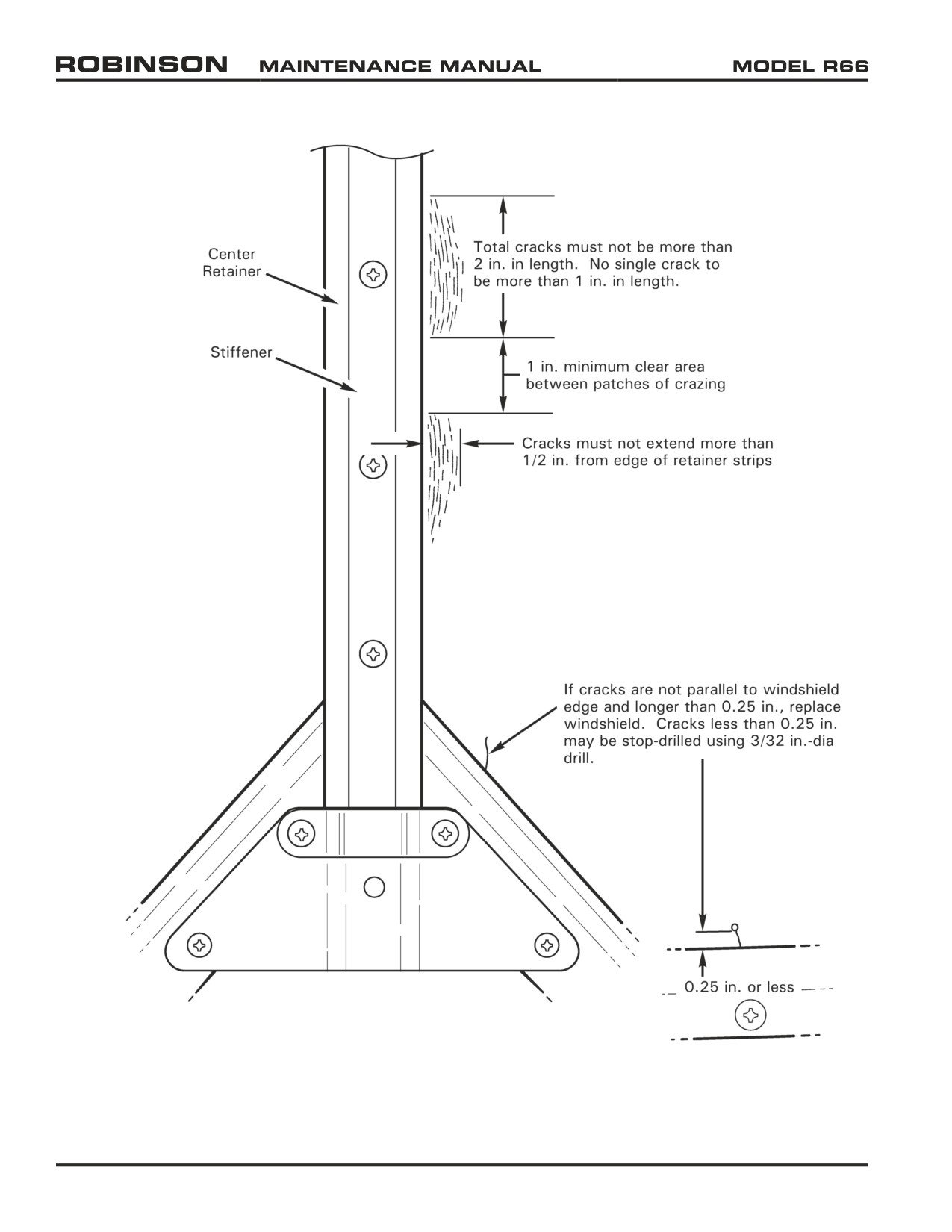
FIGURE 52-3 WINDSHIELD INSPECTION
Page 52.10
Chapter 52 Doors and Windows
25 OCT 2010
52-30 Windshield Assembly
Refer to R66 Illustrated Parts Catalog (IPC) Figure 52-17.
A. Removal
1. Remove forward door and hinges.
NOTE
To prevent scratching windshield, a protective cover should
be taped to the inside and outside of the windshield prior to
removal.
2. Remove screws and side retainer holding windshield.
3. Reinstall hinges and doors for cabin structure support with window removed.
4. Remove screws and retainers (upper, lower, and middle) holding windshield.
5. Clean silicone sealant from retainers.
6. Clean silicone sealant from windshield for reinstallation.
B.
Installation
1.
Remove all old sealant from cabin, retainers and windshield.
2.
Tape bottom and aft edges of windshield with A701-4 3/4” white polyvinyl chloride
tape (3M #471).
3.
Install windshield and cleco retainer strips.
4.
Mask windshield along edge of retainer strips with 1/2” masking tape. This will catch
silicone rubber squeeze-out on installation of retainer strips.
5.
Remove retainer strips.
6.
To ensure a proper seal, run a bead of B270-4 silicone rubber along entire edge of tape
line.
7.
While holding windshield in place, cleco retainer strips (center, upper and lower) into
place.
8.
With doors installed and closed, tighten center retainer strip first. Then tighten upper and
lower retaining strips. A second person will be required to tighten nuts inside ship.
9.
When center, upper and lower retaining strips are secure, remove door and hinges for
side strip installation.
10.
Install side retainer strip.
11.
Reinstall hinges and door. Ensure all fasteners are tight.
12.
Fill any gap between retainer and window with B270-4 silicone rubber.
13.
Remove masking tape next to retainers. Be careful not to smear wet sealant.
14.
Clean any sealant off windshield after it has been allowed to dry.
25 OCT 2010
Chapter 52 Doors and Windows
Page 52.11
52-30 Windshield Assembly (continued)
C. Inspection
1. Inspect windshield for cracks and crazing adjacent to retainer strips per Figure 52-3. If
cracks exceed these limits, replace windshields per Section 52-30 Part D.
D. Replacement
1.
Remove all old sealant on cabin and retainers if they are to be reused.
2.
Cleco all window retaining strips in place, checking for proper alignment.
3.
Install hinges and doors in door frames and secure. Remove bottom and center retaining
strips, leaving side retaining strip to hold door and door frame in position.
4.
Hold windshield in place by hand, and align it with frame according to contour of frame
and windshield.
5.
Mark windshield for trim using non-permanent marker, such as grease pencil or masking
tape.
6.
Trim to mark. A band saw is recommended. Band saw blade should contain at least
24 teeth per inch.
NOTE
Tape cardboard to band saw table to prevent scratching of
windshield. Saw carefully to prevent binding of saw blade and
cracking windshield.
7.
Hold windshield in place and check for fit. Re-trim as necessary.
8.
After windshield is fitted, carefully sand or scrape edges smooth.
9.
Install windshield per Section 52-30 Part B.
Page 52.12
Chapter 52 Doors and Windows
25 OCT 2010
CHAPTER 53
FUSELAGE
Section
Title
Page
53-00
Description
53.1
53-10
Cabin Assembly
53.1
53-11
Repair
53.1
53-20
Fairing, Cowlings, and Panels
53.3
53-21
Engine Cowling
53.3
53-22
Mast Fairing
53.3
53-23
Tailcone Cowling
53.4
53-24
Access and Inspection Panels
53.4
53-30
Frame Assemblies
53.5
53-31
Lower Frames
53.5
53-32
Hydraulic Servo Support Frame
53.9
53-33
Upper Frame
53.10
53-40
Tailcone Assembly
53.13
53-41
Inspection and Repair
53.15
53-50
Empennage Assembly
53.17
53-51
Vertical Stabilizer
53.17
53-52
Horizontal Stabilizer
53.19
53-53
Tail Rotor Guard
53.21
53-54
Tail Skid
53.22
25 OCT 2010
Chapter 53 Fuselage
Page 53.i
Intentionally Blank
Page 53.ii
Chapter 53 Fuselage
25 OCT 2010
CHAPTER 53
FUSELAGE
53-00 Description
The R66 is a five-place, single main rotor, single engine helicopter constructed primarily of
metal and equipped with skid type landing gear.
The primary fuselage structure is welded steel tubing and riveted aluminum sheet. The tailcone
is a monocoque structure in which aluminum skins carry most primary loads. Fiberglass and
thermoplastics are used in secondary cabin structure and in various ducts and fairings.
Several cowl doors provide access to the drive system, engine, engine oil tank, fuel filler cap,
and fuel sump drain. A right-side door provides access to the main baggage compartment.
Removable panels and cowlings allow additional access to controls and other components for
maintenance.
The instrument console hinges up and aft for instrument and avionics access. The battery is
installed behind an access panel under the left front seat, or in the main baggage compartment,
depending on aircraft configuration.
The engine is located aft of the main baggage compartment. The engine compartment is
isolated from the rest of the airframe by stainless steel firewalls in front of and above the
engine.
53-10 Cabin Assembly
The cabin assembly is a non-field-replaceable assembly.
53-11 Repair
1. Vertical firewall replacement must be performed at the factory in a jig. Firewall repairs
may be accomplished in accordance with U.S. FAA Advisory Circular 43.13-1B Section
4-59. Firewall material is 0.016 inch, type 301, one-quarter hard corrosion-resistant
(CRES) steel.
2. Keel panel replacement must be performed at the factory in a jig. Keel panel repairs may
be accomplished in accordance with U.S. FAA Advisory Circular 43.13-1B Sections
4-58 and 4-59. Keel panel material is 0.025 inch, 2024-T3 clad aluminum sheet.
3. To preserve crashworthiness, seat assembly maintenance is limited to replacement
only.
25 OCT 2010
Chapter 53 Fuselage
Page 53.1
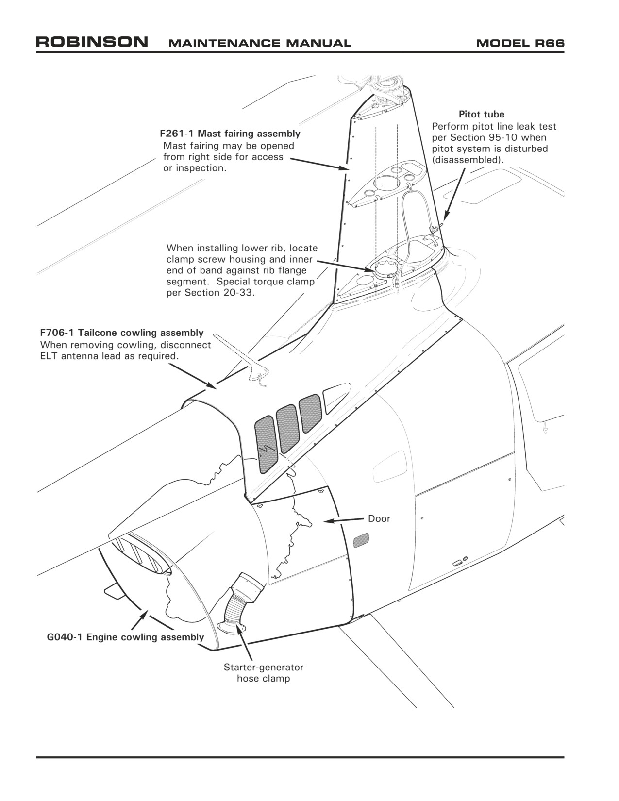
FIGURE 53-1 FAIRING, COWLINGS, AND PANELS
Page 53.2
Chapter 53 Fuselage
25 OCT 2010
53-20 Fairing, Cowlings, and Panels
CAUTION
Mast fairing, cowlings, and panels must be installed for flight.
53-21 Engine Cowling
Refer to R66 Illustrated Parts Catalog (IPC) Figure 53-1.
A. Removal
1. Refer to Figure 53-1. Open G040-1 engine cowling assembly right and left doors.
2. Loosen clamp securing starter-generator hose to air inlet. Slide hose off of inlet.
3. Remove screws securing cowling to fuselage and remove cowling.
B. Installation
1. Refer to Figure 53-1. Support G040-1 engine cowling assembly, and install screws
securing cowling to fuselage.
2. Slide starter-generator hose onto air inlet and tighten clamp. Close right and left
doors.
53-22 Mast Fairing
Refer to R66 Illustrated Parts Catalog (IPC) Figure 53-3.
A. Opening and Closing
1. Refer to Figure 53-1. Remove right-side screws securing F261-1 mast fairing
assembly at aft, vertical seam.
2. Remove right-side screws securing fairing to ribs. Keep fairing from springing open
and minimize strain on nutplates by holding fairing closed until all right-side screws
are removed. Slowly open fairing.
3. Hold fairing closed. Install right-side screws securing fairing to ribs, and screws
securing fairing at aft, vertical seam.
B. Removal
1. Open mast fairing assembly per Section 53-22 Part A.
2. Disconnect
(pitot system)
15-4-N-O union near G201-1 (servo support) frame
assembly. Cap fitting and plug line.
3. Remove remaining screws securing fairing to ribs and remove fairing.
25 OCT 2010
Chapter 53 Fuselage
Page 53.3
53-22 Mast Fairing (continued)
C. Installation
1. Refer to Figure 53-1. Install left-side screws securing F261-1 mast fairing assembly
to ribs.
2. Remove cap and plug and connect (pitot system) 15-4-N-O union near G201-1 (servo
support) frame assembly.
3. Hold fairing closed. Install right-side screws securing fairing to ribs, and screws
securing fairing at aft, vertical seam.
4. Perform pitot line leak test per Section 95-10.
53-23 Tailcone Cowling
Refer to R66 Illustrated Parts Catalog (IPC) Figure 53-5.
A. Removal and Installation
1. Refer to Figure 53-1. Thru left access door, disconnect ELT antenna lead from
antenna mounted to F706-1 tailcone cowling assembly, as required.
2. Remove screws securing cowling to fuselage and remove cowling.
3. Reinstall cowling and install screws securing cowling to fuselage.
4. Connect ELT antenna lead to cowling thru left access door, as required.
53-24 Access and Inspection Panels
Refer to Section 6-70 for access and inspection panel location and illustration.
Page 53.4
Chapter 53 Fuselage
25 OCT 2010
53-30 Frame Assemblies
NOTE
See Section
54-40 for F237-1 tailcone attachment frame
weldment replacement.
WARNING
R66 welded steel tube frames are stress relieved. Field weld
repairs are not allowed; send frames to RHC for repair.
53-31 Lower Frames
Refer to R66 Illustrated Parts Catalog (IPC) Figure 53-7.
A. Removal
1.
Remove engine per Section 71-10.
2.
Refer to Figure 53-2.
a. F046-1 (LH) only: Remove hardware securing power turbine governor control
cable clamps, F723-3 line assembly clamp, and firewall clamp to F046-1 lower
frame.
b. F046-2 (RH) only: Remove hardware securing battery cable harness clamp,
external power block, and firewall clamp to F046-2 lower frame.
3.
Remove hardware securing clamps to firewall securing F049-03 harness assembly,
as required. Cut and discard ty-raps as required, mark wires, and disconnect wires
at plastic connectors to liberate frame.
4.
Using plastic scraper, remove sealant around frame weldment(s) at firewalls.
5.
Support tailcone (until frames are reinstalled).
a. F046-1 (LH) only: Remove hardware securing frame to F574-5 block (access bolt
thru G246-1 brace, inside baggage compartment). Remove hardware securing
shackle and frame to F574-8 block (threaded).
b. F046-2 (RH) only: Remove hardware securing frame to F574-1 support assembly
(access bolts from inside baggage compartment).
6.
Remove hardware securing F174-1 support weldment rod end(s) to F046 lower
frame(s).
7.
Remove two bolts and associate hardware securing F020-1 frame weldment, firewall,
and F046 lower frame.
8.
Remove hardware securing F046 lower frame to F574-10 block assembly (threaded).
Remove lower frame.
25 OCT 2010
Chapter 53 Fuselage
Page 53.5
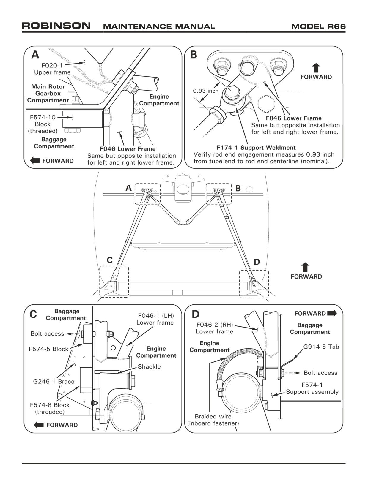
FIGURE 53-2 LOWER FRAMES
Page 53.6
Chapter 53 Fuselage
25 OCT 2010
53-31 Lower Frames (continued)
B.
Installation
1.
Refer to Figure 53-2.
a. F046-1 (LH) only: Install hardware securing shackle and frame to F574-8 block
(threaded). Special torque bolt per Section 20-33, and torque stripe per Figure
5-1. Install hardware securing frame to F574-5 block (insert bolt thru G246-1
brace, inside baggage compartment). Standard torque bolt per Section 20-32,
and torque stripe per Figure 5-1.
b. F046-2 (RH) only: Install hardware, and G914-5 tab, securing frame to F574-
1 support assembly (access bolts from inside baggage compartment). Remove
finish from surface under braided wire terminal. Standard torque bolts per Section
20-32, and torque stripe per Figure 5-1.
2.
Install hardware securing F046 lower frame to F574-10 block assembly (threaded).
Install hardware securing F020-1 frame weldment, firewall, and F046 lower frame.
Standard torque bolts per Section 20-32, and torque stripe per Figure 5-1.
3.
Verify rod end engagement in F174-1 support weldment is approximately 0.93
inch from tube end to rod end centerline on each side (nominal). Adjust rod ends
as required per Section 5-33, and Figures 5-1 & 5-2. Install hardware securing
weldment to lower frames, standard torque bolts per Section 20-32, and torque
stripe per Figure 5-1. Remove tailcone support.
4.
Seal around frame weldment(s) at firewalls using B270-1 sealant.
5.
Connect F049-03 harness assembly wires at plastic connectors, install hardware
securing clamps to firewall, and install ty-raps as required. Cinch ty-raps until snug
without over-tightening, and trim tips flush with heads.
6.
a. F046-1 (LH) only: Install hardware securing power turbine governor control cable
clamps, F723-3 line assembly clamp, and firewall clamp to F046-1 lower frame.
Standard torque hardware per Section 20-32, and torque stripe per Figure 5-1.
b. F046-2 (RH) only: Install hardware securing battery cable harness clamp,
external power block, and stiffener clamp to F046-2 lower frame. Standard
torque hardware per Section 20-32, and torque stripe per Figure 5-1.
7.
Install engine per Section 71-10.
25 OCT 2010
Chapter 53 Fuselage
Page 53.7
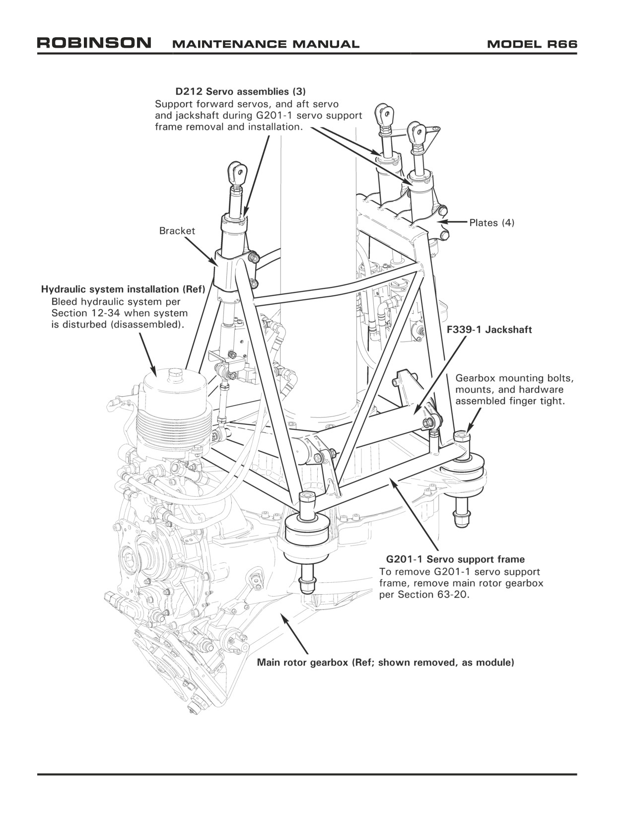
FIGURE 53-3 HYDRAULIC SERVO SUPPORT FRAME
Page 53.8
Chapter 53 Fuselage
25 OCT 2010
53-32 Hydraulic Servo Support Frame
Refer to R66 Illustrated Parts Catalog (IPC) Figure 67-19.
A. Removal
1. Remove main rotor gearbox per Section 63-20.
2. Remove main rotor hub per Section 62-20.
3. Remove mast fairing per Section 53-22.
4. Remove swashplate assembly per Section 67-40.
5. Refer to Figure 53-3. Tag F121-3 push-pull tube assemblies with corresponding
D212 servo assembly, and tag servos with location on G201-1 servo support frame.
Remove hardware securing push-pull tubes to servos.
6. Remove hardware securing F339-1 jackshaft weldment to frame.
7. Remove hardware securing servos to frame forward plates and aft bracket. Support
forward servos, and aft servo and jackshaft, during hardware removal.
8. Remove gearbox mounting bolts, mounts, and hardware. Lift frame off of gearbox,
over mast assembly.
B.
Installation
1. Refer to Figure 53-3. Lower G201-1 servo support frame over mast assembly, onto
main rotor gearbox. Install gearbox mounting bolts, mounts, and hardware. Install
nuts finger tight.
2. Remove tags and install hardware securing D212 servo assemblies to frame forward
plates and aft bracket. Standard torque bolts per Section 20-32, and torque stripe
per Figure 5-1.
3. Install hardware securing F339-1 jackshaft weldment to frame. Standard torque
bolts per Section 20-32, and torque stripe per Figure 5-1.
4. Install F121-3 push-pull tube assemblies as removed. Standard torque bolts per
Section 20-32, and torque stripe per Figure 5-1.
5. Install swashplate assembly per Section 67-40.
6. Install mast fairing per Section 53-22.
7. Install main rotor hub per Section 62-20.
8. Install main rotor gearbox per Section 63-20.
25 OCT 2010
Chapter 53 Fuselage
Page 53.9
53-33 Upper Frame
Refer to R66 Illustrated Parts Catalog (IPC) Figure 53-11 and 53-11B.
A. Removal
1.
Remove main rotor blades per Section 62-10.
2.
Remove tailcone assembly per Section 53-40.
3.
Remove tail rotor drive shaft weldment per Section 65-10.
4.
Remove hardware securing F236-1 scroll assembly to F306-1 box assembly. Remove
hardware securing box to firewall.
5.
Remove hardware securing F252-1 strut to F020-1 upper frame and remove strut.
6.
Remove air filter and cage assembly per Section 71-22. Disconnect air bypass
switch assembly wiring at connector and remove hardware securing G258-4 strap
to fuel bladder support assembly.
7.
Remove engine shaft weldment per Section 63-10.
8.
Remove engine per Section 71-10.
9.
Remove main rotor gearbox per Section 63-20, steps 2 thru 12.
10.
Cut and discard ty-raps securing wires and antenna cables to frame, as required.
11.
Disconnect D205-19 hose assembly and F724-1 line assembly from F823-1 thermostat
assembly. Plug hose and line and cap fittings. Remove hardware securing F651-1
oil filter assembly to frame.
12.
Remove hardware securing F231-8 braces to fuel bladder support, and to frame.
13.
Remove hardware securing rotor brake cable assembly to frame. Remove hardware
securing B157-1 (pulley) mount to frame.
14.
Remove ELT transmitter per Section 25-61, if installed. Remove hardware securing
clamps to upper frame and remove clamps.
15.
Remove palnut, nut, and spacer securing F316-1 bellcrank assembly to upper frame,
and slide C494-2 shaft inboard until it clears frame. Remove fastener securing
A331-4 bellcrank assembly to upper frame and swing bellcrank clear of frame.
16.
Remove fasteners securing upper frame to horizontal firewall.
17.
Using plastic scraper, remove sealant around frame weldment edges at firewalls,
cabin bulkhead, and fuel bladder support.
18.
Remove mounting hardware securing upper frame to firewalls, bulkhead, and support
and remove frame.
Page 53.10
Chapter 53 Fuselage
25 OCT 2010
53-33 Upper Frame (continued)
B.
Installation
1.
Position F020-1 upper frame inside helicopter. Install mounting hardware securing
upper frame to firewalls, cabin bulkhead, and fuel bladder support assembly. Standard
torque bolts per Section 20-32, and torque stripe per Figure 5-1. Seal around frame
weldment edges at firewalls, bulkhead, and support using B270-1 sealant.
2.
Install fasteners securing upper frame to horizontal firewall. Standard torque hardware
per Section 20-32, and torque stripe per Figure 5-1.
3.
Install hardware securing A331-4 bellcrank assembly to upper frame. Standard
torque bolt per Section 20-32, and torque stripe per Figure 5-1. Slide C494-2 shaft
outboard thru F316-1 bellcrank assembly and upper frame and install spacer, nut,
and palnut. Special torque nut per Section 20-33, and torque stripe per Figure 5-1.
4.
Install ELT transmitter per Section 25-61, if installed. Install clamps and hardware
securing clamps to upper frame.
5.
Install B157-1 (pulley) mount and hardware securing mount to frame. Install hardware
securing rotor brake cable assembly to frame.
6.
Install F231-8 braces and hardware securing braces to fuel bladder support, and to
frame.
7.
Install hardware securing F651-1 oil filter assembly to frame. Standard torque hardware
per Section 20-32, and torque stripe per Figure 5-1. Remove caps and plugs and
connect D205-19 hose assembly and F724-1 line assembly to F823-1 thermostat
assembly. Standard torque hose assembly nuts per Section 20-32, special torque line
assembly nuts per Section 20-33, & torque stripe per Figure 5-1.
8.
Install MS3367-4-9 or -5-9 ty-raps as required to secure wire harness & cables to
frame. Cinch ty-raps until snug without over-tightening, & trim tips flush with heads.
9.
Install main rotor gearbox per Section 63-20, but do not install F252-1 strut until
step 13.
10.
Install engine per Section 71-10.
11.
Install engine shaft weldment per Section 63-10.
12.
Install air filter and cage assembly per Section 71-22. Install hardware securing
G258-4 strap to fuel bladder support and connect air bypass switch assembly wiring
at connector.
13.
Install hardware securing F252-1 strut to F020-1 upper frame. Standard torque
bolts per Section 20-32, and torque stripe per Figure 5-1.
14.
Install F306-1 box assembly and hardware securing box to firewall. Install F236-1
scroll assembly and hardware securing scroll to box.
15.
Install tail rotor drive shaft weldment per section 65-10.
16.
Install tailcone assembly per Section 53-40.
25 OCT 2010
Chapter 53 Fuselage
Page 53.11
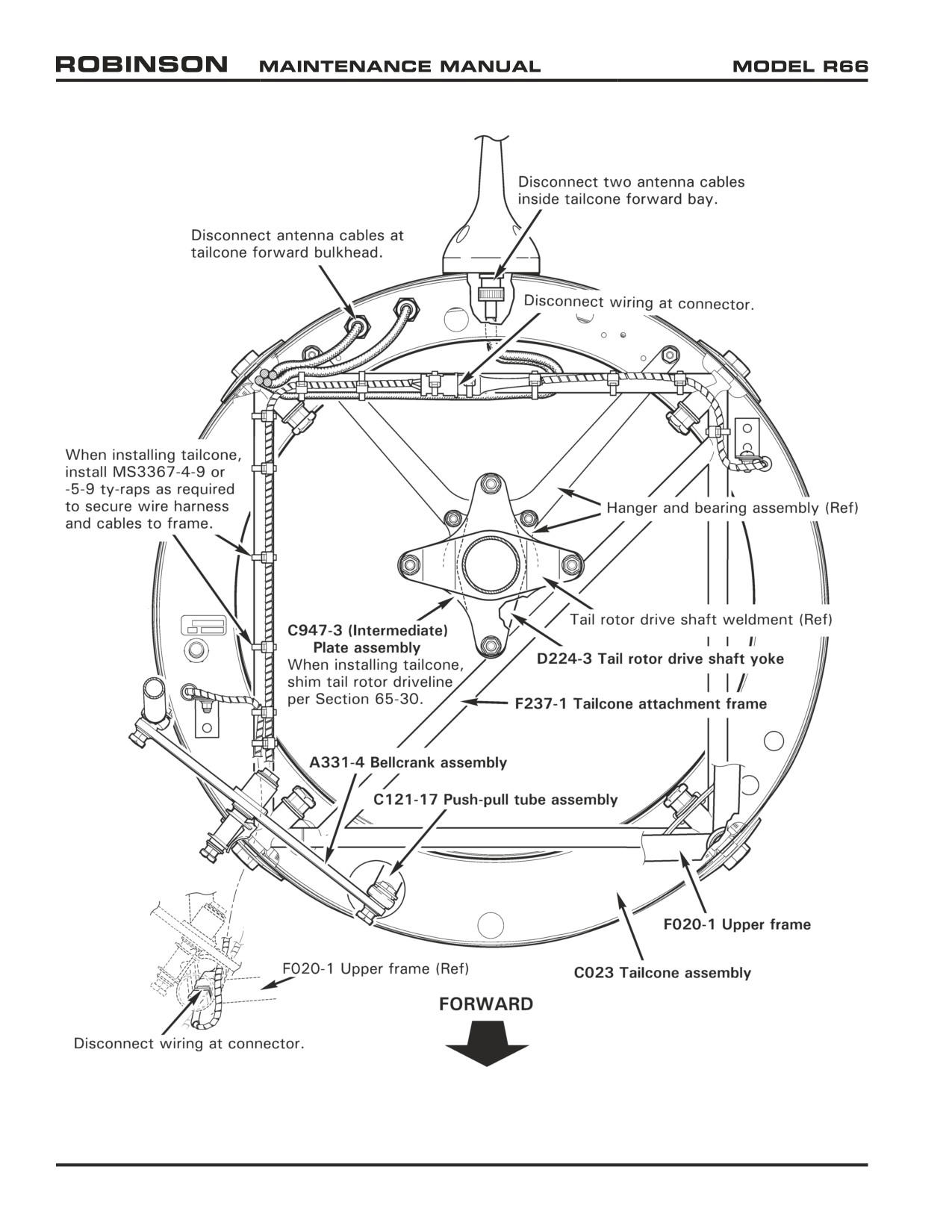
FIGURE 53-4 TAILCONE ASSEMBLY
Page 53.12
Chapter 53 Fuselage
25 OCT 2010
53-40 Tailcone Assembly
Refer to R66 Illustrated Parts Catalog (IPC) Figure 53-15.
A. Removal
1. Remove tailcone cowling assembly per Section 53-23. Remove engine cowling assembly
per Section 53-21.
2. Refer to Figure 53-4. Cut and discard ty-raps as required and disconnect tailcone wiring
at connectors. Disconnect two antenna cables inside tailcone forward bay, and cables
at forward bulkhead, as required.
3. Remove hardware securing D224-3 tail rotor drive shaft assembly yoke to C947-3
(intermediate) plate assembly, noting hardware removed.
4. Remove hardware securing C121-17 push-pull tube to A331-4 bellcrank assembly.
5. Remove hardware securing C023 tailcone assembly to frames and remove tailcone.
6. Cut and discard ty-raps as required and remove F237-1 tailcone attachment frame, as
required.
B.
Installation
1.
Refer to Figure 53-4. Install F237-1 tailcone attachment frame, if not previously
accomplished. Verify correct damper assembly orientation per Figure 65-3.
2.
Position C023 tailcone assembly on F020-1 upper frame assembly; do not pinch wiring
between tailcone bulkhead and frames. Install hardware securing tailcone to frames,
standard torque bolts per Section 20-32, and torque stripe per Figure 5-1.
3.
Install hardware securing D224-3 tail rotor drive shaft yoke to C947-3 (intermediate)
plate assembly. Shim tail rotor driveline per Section 65-30. Standard torque bolts per
Section 20-32, and torque stripe per Figure 5-1.
4.
Install hardware securing C121-17 push-pull tube to A331-4 bellcrank assembly.
Standard torque bolt per Section 20-32, and torque stripe per Figure 5-1.
5.
Perform tail rotor drive shaft runout per Section 65-21.
6.
Connect tailcone wiring at connectors, connect two antenna cables inside tailcone
forward bay, and connect antenna cables at forward bulkhead, as required. Individually
test and verify correct function of tail position light, strobe, and TR chip light circuits.
7.
Install MS3367-4-9 or -5-9 ty-raps as required to secure wire harness and cables to frame.
Cinch ty-raps until snug without over-tightening, and trim tips flush with heads.
8.
Install tailcone cowling assembly per Section 53-23. Install engine cowling assembly
per Section 53-21.
25 OCT 2010
Chapter 53 Fuselage
Page 53.13
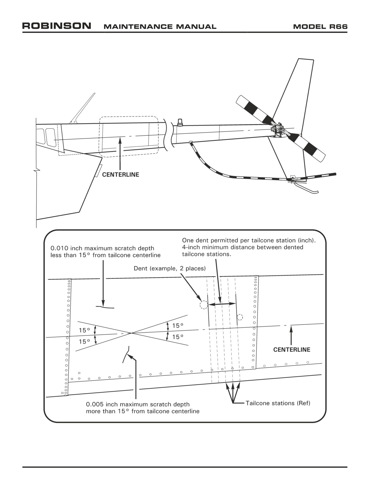
FIGURE 53-5 TAILCONE INSPECTION AND REPAIR
Page 53.14
Chapter 53 Fuselage
25 OCT 2010
53-41 Inspection and Repair
This procedure outlines the inspection criteria and repair limits for the tailcone assembly.
Repairs are limited to blending out scratches and refinishing skins. Contact RHC Technical
Support if allowable damage is exceeded.
A. Scratches
1. Refer to Figure 53-5. Verify damage does not exceed the following limits:
a.
0.005 inch maximum scratch depth more than 15° from tailcone centerline.
b.
0.010 inch maximum scratch depth less than 15° from tailcone centerline.
2. If damage exceeds limits, return tailcone assembly to RHC for repair. If damage is
within limits, blend out scratches with a 0.10 inch minimum blend radius. Refinish
skins using approved materials per Section 20-70.
B. Dents
1. Refer to Figure 53-5. Smooth, round bottom dents with 0.125 inch minimum radius
without sharp nicks or cracks are acceptable when damage does not exceed the
following limits:
a.
0.030 inch maximum dent depth.
b.
1.250 inch maximum dent diameter.
c. One dent permitted per tailcone station (inch).
d.
4.000 inch minimum distance between dented tailcone stations.
2. If damage exceeds limits, replace tailcone or return to RHC for repair.
25 OCT 2010
Chapter 53 Fuselage
Page 53.15
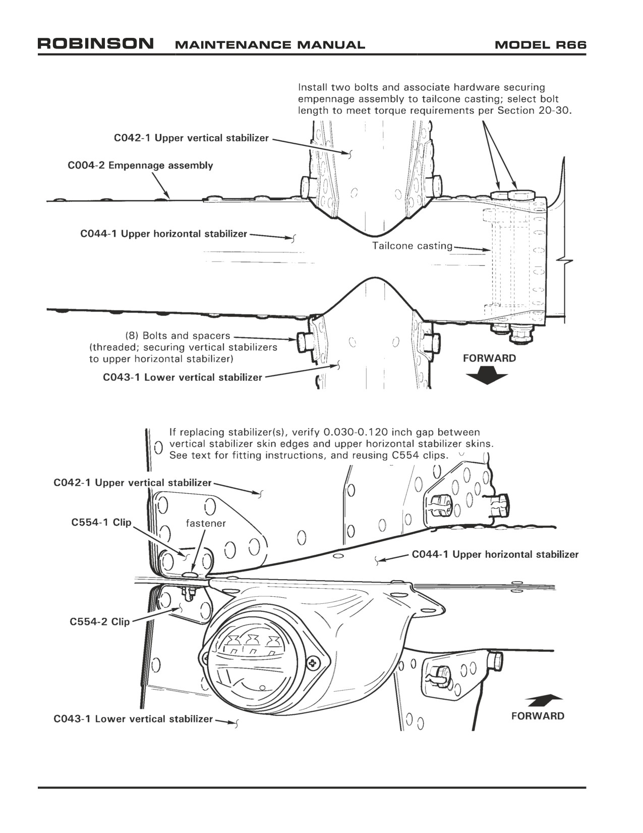
FIGURE 53-6 EMPENNAGE - TAILCONE CASTING
Page 53.16
Chapter 53 Fuselage
25 OCT 2010
53-50 Empennage Assembly
Refer to R66 Illustrated Parts Catalog (IPC) Figure 53-19.
A. Removal
1. Remove tail rotor guard assembly per Section 53-53.
2. Remove hardware securing forward MS21919WDG3 clamp to upper horizontal stabilizer.
Cut and discard ty-raps securing position light and gearbox chip detector wires and
connectors together. Disconnect position light at connectors.
3. Refer to Figure 53-6. Support C004-2 empennage assembly, remove two bolts and
associate hardware securing assembly to tailcone casting, and remove assembly.
B.
Installation
1. Refer to Figure 53-6. Position C004-2 empennage assembly on tailcone casting. Install
two bolts and associate hardware securing assembly to casting; select bolt length to
meet torque requirements per Section 20-30. Standard torque bolts per Section 20-32,
and torque stripe per Figure 5-1.
2. Connect position light wire connectors. Secure wires and install hardware securing
forward MS21919WDG3 clamp to upper horizontal stabilizer. Install MS3367-4-9 or
-5-9 ty-raps as required to secure wires and connectors together. Cinch ty-raps until
snug without over-tightening, and trim tips flush with heads.
3. Test and verify correct function of position and TR chip light circuits.
4. Install tail rotor guard assembly per Section 53-53.
53-51 Vertical Stabilizer
Refer to R66 Illustrated Parts Catalog (IPC) Figure 53-19.
A. Upper Vertical Stabilizer Removal
1. Refer to Figure 53-6. Remove fastener securing vertical stabilizer C554 clips to
upper horizontal stabilizer trailing edge.
2. Support C042-1 upper vertical stabilizer. Remove four bolts (threaded) and spacers
securing C042-1 stabilizer to upper horizontal stabilizer, and remove C042-1
stabilizer.
3. If replacing stabilizer, C554-1 clip may be reused. Drill out two rivets securing clip
to stabilizer.
25 OCT 2010
Chapter 53 Fuselage
Page 53.17
53-51 Vertical Stabilizer (continued)
B.
Upper Vertical Stabilizer Installation
1. Refer to Figure 53-6. Position C042-1 stabilizer on empennage. Verify 0.030-0.120
inch gap between C042-1 stabilizer skin edges and upper horizontal stabilizer skins.
File vertical stabilizer skin edge(s) as required.
2. Install four bolts (threaded) and spacers securing C042-1 stabilizer to upper horizontal
stabilizer. Special torque bolts per Section 20-33, and torque stripe per Figure 5-1.
3. Install fastener securing C554 clips to upper horizontal stabilizer trailing edge.
(If
reusing C554-1 clip, install clip and fastener, and match drill clip to vertical stabilizer
with #30 drill. Deburr holes and install rivets.) Torque stripe fastener per Figure
5-1.
C. Lower Vertical Stabilizer Removal
1. Remove tail rotor guard assembly per Section 53-53.
2. Remove aux stabilizer assembly per Section 53-52, and tail skid per Section 53-54,
as required.
3. Refer to Figure 53-6. Remove fastener securing C554 clips to upper horizontal
stabilizer trailing edge.
4. Support C043-1 lower vertical stabilizer. Remove four bolts (threaded) and spacers
securing C043-1 stabilizer to upper horizontal stabilizer, and remove C043-1
stabilizer.
5. If replacing stabilizer, C554-2 clip may be reused. Drill out two rivets securing clip
to stabilizer.
D. Lower Vertical Stabilizer Installation
1. Refer to Figure 53-6. Position C043-1 stabilizer on empennage. Verify 0.030-0.120
inch gap between C043-1 stabilizer skin edges and upper horizontal stabilizer skins.
File vertical stabilizer skin edge(s) as required.
2. Install four bolts (threaded) and spacers securing C043-1 stabilizer to upper horizontal
stabilizer. Special torque bolts per Section 20-33, and torque stripe per Figure 5-1.
3. Install fastener securing C554 clips to upper horizontal stabilizer trailing edge.
(If
reusing C554-2 clip, install clip and fastener, and match drill clip to vertical stabilizer
with #30 drill. Deburr holes and install rivets.) Torque stripe fastener per Figure
5-1.
4. Install aux stabilizer assembly per Section 53-52, and tail skid per Section 53-54, as
required.
5. Install tail rotor guard assembly per Section 53-53.
Page 53.18
Chapter 53 Fuselage
25 OCT 2010
53-52 Horizontal Stabilizer
Refer to R66 Illustrated Parts Catalog (IPC) Figure 53-19 and 53-23.
A. Upper Horizontal Stabilizer Removal
1. Remove C042-1 upper vertical stabilizer and C043-1 lower vertical stabilizer per
Section 53-51.
2. Refer to Figure 53-6. Remove hardware securing forward MS21919WDG3 clamp
to upper horizontal stabilizer. Cut and discard ty-raps securing position light and
gearbox chip detector wires and connectors together. Disconnect position light at
connectors.
3. Support C044-1 upper horizontal stabilizer, remove two bolts and associate hardware
securing C044-1 stabilizer to tailcone casting, and remove assembly.
B.
Upper Horizontal Stabilizer Installation
1. Refer to Figure 53-6. Position C044-1 upper horizontal stabilizer on tailcone casting.
Install two bolts and associate hardware securing stabilizer to casting; select bolt
length to meet torque requirements per Section 20-30. Standard torque bolts per
Section 20-32, and torque stripe per Figure 5-1.
2. Install C042-1 upper vertical stabilizer and C043-1 lower vertical stabilizer per Section
53-51.
3. If C044-1 stabilizer was replaced, match drill C554 clips 0.144-inch diameter hole
through trailing edge of horizontal stabilizer. Deburr hole and install fastener.
4. Connect position light wire connectors. Secure wires and install hardware securing
forward MS21919WDG3 clamp to upper horizontal stabilizer. Install MS3367-4-9
or -5-9 ty-raps as required to secure wires and connectors together. Cinch ty-raps
until snug without over-tightening, and trim tips flush with heads.
5. Test and verify correct function of position and TR chip light circuits.
C. Aux Stabilizer Assembly Removal
1. Remove tail skid per Section 53-54.
2. Refer to Figure 53-6. Using plastic scraper, remove sealant around edges where
C971 brackets attach to C716 doublers. Remove C050-2 aux stabilizer assembly.
D. Aux Stabilizer Assembly Installation
1. Refer to Figure 53-6. Position C050-2 aux stabilizer assembly on C043-1 lower
vertical stabilizer. Install tail skid per Section 53-54.
2. Seal C971 bracket edges to C716 doublers using B270-4 sealant.
25 OCT 2010
Chapter 53 Fuselage
Page 53.19
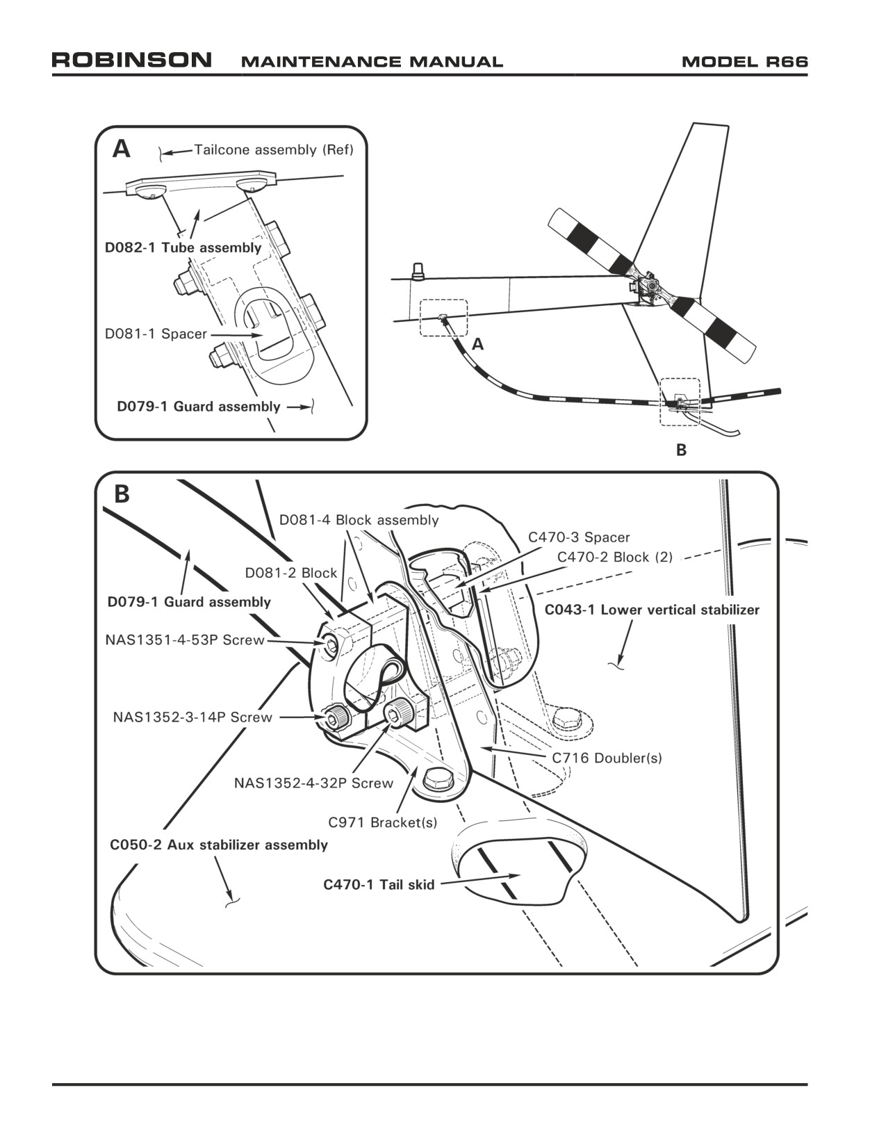
FIGURE 53-7 EMPENNAGE - TAIL ROTOR GUARD
Page 53.20
Chapter 53 Fuselage
25 OCT 2010
53-53 Tail Rotor Guard
Refer to R66 Illustrated Parts Catalog (IPC) Figures 53-19 and 53-23.
A. Removal
1. Refer to Figure 53-7. Loosen two (forward) fasteners securing D081-2 block and
D079-1 guard assembly to C043-1 lower vertical stabilizer.
2. Remove hardware securing guard to D082-1 tube assembly. Slide guard off of tube,
then forward through blocks. Remove D081-1 spacer from tube.
B.
Installation
1. Refer to Figure 53-7. Loosen two (forward) fasteners securing D081-2 block to
C043-1 lower vertical stabilizer, if not previously accomplished. Insert D079-1 guard
assembly aft through blocks.
2. Lightly coat retaining hardware and mating surfaces of D082-1 tube assembly
and D079-1 guard assembly with approved primer per Section 20-70, prior to
installation.
3. Install D081-1 spacer inside tube. While wet with primer, slide guard onto tube and
install hardware. Standard torque bolts per Section 20-32, and torque stripe per
Figure 5-1. Seal around end of guard with primer after assembly.
4. Verify D081 blocks clamp guard sleeve. For proper guard-to-stabilizer clamping, first
standard torque (forward, top) NAS1351-4-53P screw and associate hardware per
Section 20-32, then special torque (forward, bottom) NAS1352-3-14P screw and
associate hardware per Section 20-33. Torque stripe fasteners per Figure 5-1.
25 OCT 2010
Chapter 53 Fuselage
Page 53.21
53-54 Tail Skid
Refer to R66 Illustrated Parts Catalog (IPC) Figures 53-19.
A. Removal
1. Refer to Figure 53-7. Support D079-1 guard assembly. Remove hardware securing
D081-2 block to C043-1 lower vertical stabilizer and remove block.
2. Support C050-2 aux stabilizer assembly and C470-1 tail skid. Remove hardware
securing D081-4 block assembly to C043-1 stabilizer and remove block assembly.
3. Remove C470-1 tail skid, two C470-2 blocks, and remove C470-3 spacer from skid.
Support guard and C050-2 stabilizer while hardware is removed.
B. Installation
1. Refer to Figure 53-7. Install C470-3 spacer inside C470-1 tail skid. Install tail
skid and two C470-2 blocks inside C043-1 lower vertical stabilizer. Install D081-4
block assembly, and install hardware securing block assembly to stabilizer. Standard
torque screw per Section 20-32, and torque stripe per Figure 5-1.
2. Install D081-2 block, and hardware securing block to stabilizer. Verify D081 blocks
clamp guard sleeve. For proper guard-to-stabilizer clamping, first standard torque
(forward, top) NAS1351-4-53P screw and associate hardware per Section 20-32,
then special torque (forward, bottom) NAS1352-3-14P screw and associate hardware
per Section 20-33. Torque stripe fasteners per Figure 5-1.
Page 53.22
Chapter 53 Fuselage
25 OCT 2010
CHAPTER 62
MAIN ROTOR
Section
Title
Page
62-00
Description
62.1
62-10
Main Rotor Blades
62.1
62-11
Blade Boots
62.6
62-20
Main Rotor Hub
62.7
62-21
Bearing Replacement
62.9
62-30
Main Rotor Assembly
62.11
62-31
Journal and Shim Calculations
62.11
62-32
Adjusting Hinge Friction
62.15
62-33
Drilling Nuts and Bolts
62.17
62-40
Inspection of Main Rotor Blades
62.19
62-41
Scratches and Corrosion
62.19
62-42
Dents
62.21
62-43
Spar Damage
62.23
62-44
Root Fitting Damage
62.23
62-45
Nicks and Notches
62.23
62-46
Voids and Debonds
62.25
62-50
Repair of Main Rotor Blades
62.27
62-51
Sealing, Filling, and Fairing
62.27
62-52
Painting
62.28
25 OCT 2010
Chapter 62 Main Rotor
Page 62.i
Intentionally Blank
Page 62.ii
Chapter 62 Main Rotor
25 OCT 2010
CHAPTER 62
MAIN ROTOR
62-00 Description
The main rotor has two all-metal blades and a forged-aluminum hub. Blades mount to the hub
by coning hinge; the hub mounts to the main rotor shaft by teeter hinge. Coning and teeter
hinges have self-lubricated bearings inside the hub.
The leading edge of the main rotor blade is a corrosion and erosion resistant stainless-steel
spar. Aluminum skins are bonded to the spar approximately one inch aft of the leading edge,
to the aluminum honeycomb core, and to the forged-aluminum root fitting.
Each blade has six pitch change bearings that attach to a forged, stainless-steel spindle. The
bearings and part of the spindle are submerged in oil inside the root fitting housing. The housing
is sealed with an elastic boot. The spindle tusk contacts an aluminum droop stop attached to
the main rotor shaft, to minimize teetering when blades are at rest or turning at low RPM.
62-10 Main Rotor Blades
WARNING
Due to potentially destructive results, use of blade tape (anti-
erosion tape) is prohibited.
A. Removal
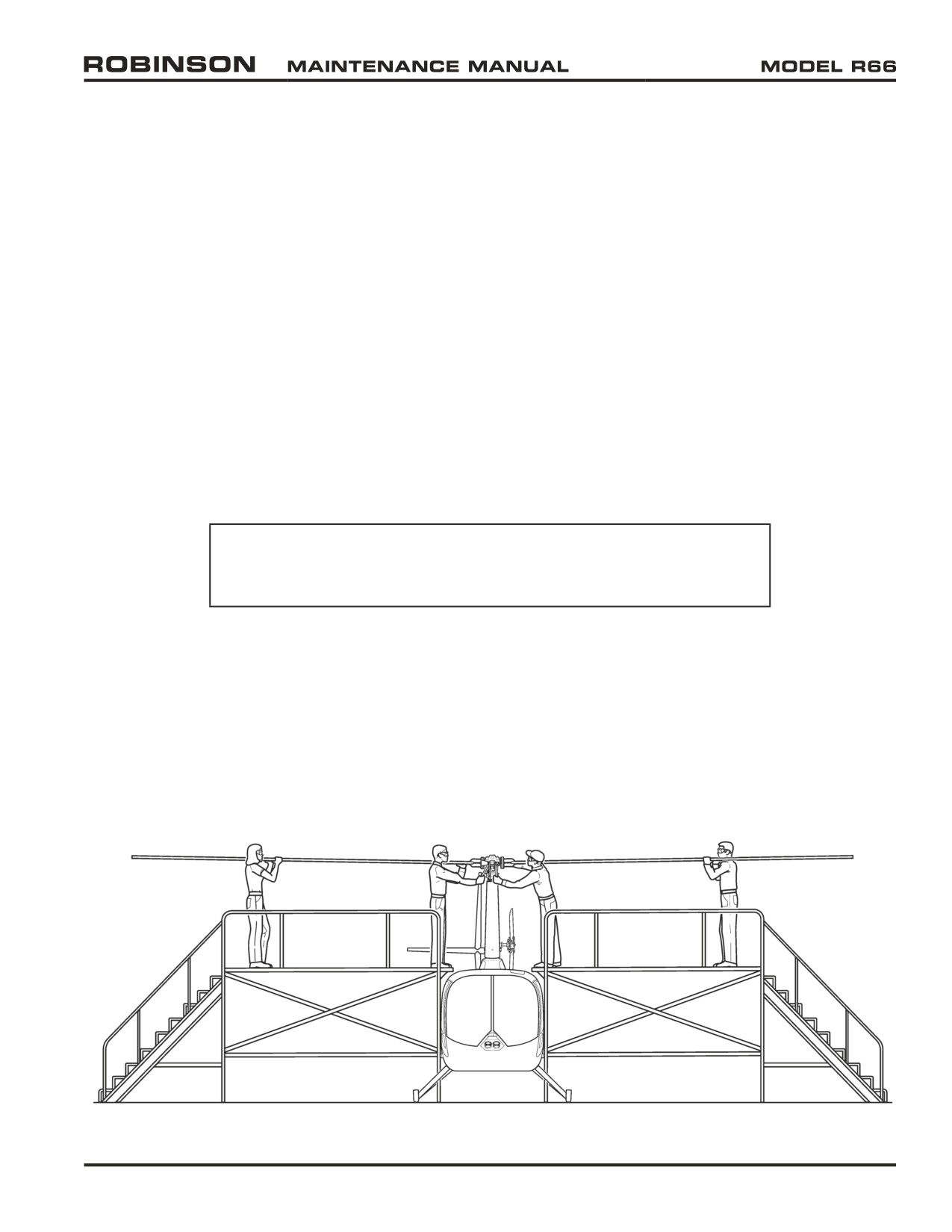
Refer to Figure 62-1. Four people will be required to remove the blades. One person must
support the blade approximately 2/3 its length from the root while another supports the
root and removes or installs the attached bolt.
1. Mark one blade and its corresponding hinge nut & bolt, pitch link and rotor head location
with a colored marker, such as a grease pencil and, mark as “X”. Using a different color
marker, mark as “O”, on the other blade, nut, bolt, pitch link and rotor head location.
2. Disconnect pitch links from each main rotor blade.
FIGURE 62-1 SUPPORTING MAIN ROTOR BLADES DURING BLADE REMOVAL OR INSTALLATION
25 OCT 2010
Chapter 62 Main Rotor
Page 62.1
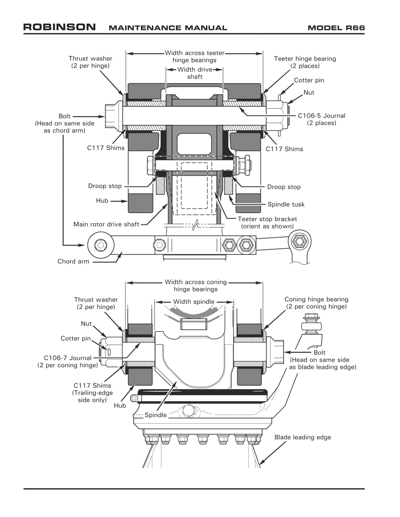
FIGURE 62-2 TEETER HINGE (HUB INSTALLATION)
FIGURE 62-3 CONING HINGE (BLADE INSTALLATION)
Page 62.2
Chapter 62 Main Rotor
25 OCT 2010
62-10 Main Rotor Blades (continued)
A. Removal (continued)
3. Refer to Figure 62-3. Remove cotter pins and loosen nuts of blade coning hinge bolts
so they are just finger tight.
4. Remove nut, thrust washer, and shims (if used) from trailing-edge side of one blade hinge
bolt. Cone blade so spindle tusk no longer contacts droop stop. While supporting blade
at root, carefully rotate pitch horn down and remove hinge bolt and thrust washer.
NOTE
Installation hardware is matched individually to each blade
installation; carefully reinstall all attach hardware into rotor hub
exactly as removed.
CAUTION
Support remaining main rotor blade in a level position during
and after removal of opposite blade.
5. Store rotor blades on a cushioned surface to prevent damage to blade skins.
6. Repeat step 4 to remove remaining blade.
B.
Installation
Refer to R66 Illustrated Parts Catalog (IPC) Figures 62-1, 62-3, and 62-5.
1.
Verify correct teeter hinge friction per Section 62-32, step 4.
2.
If previously installed information is unavailable, perform coning hinge journal and shim
calculation per Section 62-31.
3.
Refer to Figure 62-3. With rotor hub level, insert journals into coning hinge bearings.
Install thrust washer on coning hinge bolt.
4.
Position blade in hub until spindle hole aligns with journal bores, coning blade as required
to keep tusk away from droop stop. Rotate pitch horn down and install hinge bolt at
leading-edge side.
NOTE
To assist bolt installation, temporarily insert an old bolt from
trailing-edge side to align spindle with journals.
5.
Install trailing-edge shims (if used) and thrust washer and, prior to installing nut, coat
bolt threads and nut face with A257-9 anti-seize compound.
NOTE
Do not allow anti-seize compound to contact journals or hub
bearing areas. These areas must be clean and dry.
25 OCT 2010
Chapter 62 Main Rotor
Page 62.3
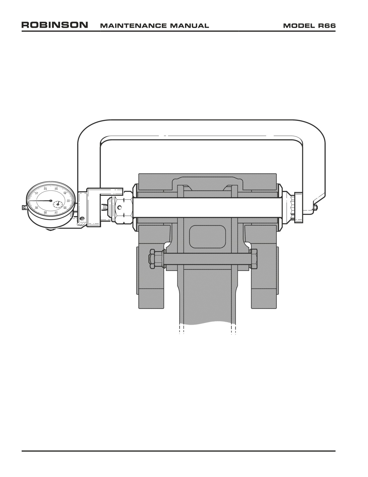
FIGURE 62-4 MEASURING BOLT STRETCH
(Shown on teeter hinge bolt)
Page 62.4
Chapter 62 Main Rotor
25 OCT 2010
62-10 Main Rotor Blades (continued)
B.
Installation (continued)
CAUTION
To prevent damage, level and support installed blade until
opposite blade is installed.
6.
With installed blade level and supported near tip, install opposite blade per steps 1 thru 5.
7.
Tighten nut on hinge bolt until journals and thrust washer are firmly seated. Then back
nut off until both thrust washers can be freely rotated.
8.
Install MT122-6 main rotor bolt stretch tool on hinge bolt per Figure 62-4. Zero dial
indicator by rotating dial face. Lock dial and remove tool.
9.
Using wrenches with at least 600 ft-lb torque capacity, tighten nut until drilled hole in
nut and bolt align. Reinstall MT122-6 tool and measure bolt stretch; the stretch must
be between 0.020 - 0.022 inch (0.021 - 0.022 inch for new, undrilled bolt). Remove
tool. Install a new cotter pin with wet epoxy primer.
NOTE
If drilled holes in nut and bolt do not align, both nut and bolt
must be replaced. Stretch new bolts per Section 20-33; drill
new nuts and bolts per Section 62-33.
WARNING
The main rotor blade and hub attach bolts must be stretched
from 0.020 - 0.022 inch (0.021 - 0.022 inch for new, undrilled
bolt) to obtain proper clamping force. Under-stretching or over-
stretching can cause catastrophic failure of the bolts.
10.
Connect pitch link to pitch horn. Standard torque per Section 20-32, install palnut, and
torque stripe per Figure 5-1.
11.
Repeat steps 1 thru 10 for remaining blade. If installed main rotor blade pitch bearing
housing has recently been serviced (including new or overhauled blades), perform steps
12 thru 16.
12.
Position cyclic and collective at approximately mid-travel positions to minimize wrinkles
in boots.
13.
Insert two (2) MT549-1 spacers between hub and boot with gaps at top and bottom.
Spacers should fit in recess of boot. Hold spacers in place against boot and insert
MT549-2 plate from top between hub and spacers. Push plate down until it contacts
spindle.
14.
Remove lower plug from pitch horn and allow oil to flow. Place a finger over hole as
soon as oil flow decreases to a drip to prevent air from being sucked inside blade.
15.
Remove finger from hole and quickly install drain plug. Special torque per Section 20-
33 and torque stripe per Figure 5-1.
16.
Remove plate and spacers. Repeat on second blade.
25 OCT 2010
Chapter 62 Main Rotor
Page 62.5
62-11 Blade Boots
Refer to R66 Illustrated Parts Catalog (IPC) Figure 62-1.
A. Removal
1. Remove main rotor blades per Section 62-10.
2. Place a suitable drain container below main rotor blade spindle assembly. Remove
two B289-2 bolts and drain fluid.
3. Remove outer boot clamp and hold boot back to expose inner boot clamp. Remove
inner clamp and peel boot from spindle. Boot inner portion may be sealed to spindle
with B270-1 sealant.
4. As required, use a plastic scraper and vacuum cleaner to remove old B270-1 sealant
from spindle area to be covered by boot inner lip. Avoid contaminating spindle
bearings with old sealant.
WARNING
Use only plastic scrapers to remove old sealant; chemical
removal is prohibited.
B.
Installation
1.
Visually inspect and verify boot is undamaged. Carefully stretch new boot over
spindle.
2.
If blade will be subjected to sub-freezing temperatures, sealing of boot’s inner lip
to spindle is recommended: Pull boot inner lip back enough to expose junction of
C147-1 spacer and C158-1 spindle. Solvent clean and dry boot inner lip, spacer,
and spindle surfaces clamped by boot inner lip. Apply an approximately 1/16-inch
diameter bead of B270-1 sealant completely around spacer-spindle junction. While
sealant is still wet, properly position boot inner lip; install C165-1 clamp assembly
and special torque per Section 20-33. Rotate spindle and verify adequate clearance
between clamp assembly and pitch horn. Wipe off excess sealant and allow to cure
in accordance with sealant manufacturer recommendations.
NOTE
When installing inner clamp, ensure that shoulder of boot inner
lip is not wedged beneath clamp or clamp may loosen in service.
Inspect boot interior and verify no cuts or punctures.
WARNING
Use only B270-1 sealant; silicon sealant is prohibited.
3.
Stretch boot outer lip over pitch horn flange. Rotate spindle and align pitch horn
arm bolt hole with spindle bolt hole. Install clamp assembly and standard torque per
Section 20-32.
4.
Fill pitch bearing housing per Section 12-51.
Page 62.6
Chapter 62 Main Rotor
25 OCT 2010
62-20 Main Rotor Hub
Refer to R66 Illustrated Parts Catalog (IPC) Figure 62-3.
A. Removal
1. Remove main rotor blades per Section 62-10.
2. Refer to Figure 62-2. Mark rotor hub using a grease pencil or soft marker as follows:
a. Indicate nut side of teeter bolt.
b. Indicate chord arm side of drive shaft.
3. Remove cotter pin, nut, thrust washers, C117 shims, C106 journals, and bolt. Rotate
hub as required and remove hub. Do not drop C152 thrust washers or C106 journals.
4. Reinstall bolt, thrust washers, shims, journals, and nut in rotor hub exactly as removed.
CAUTION
Main rotor chordwise balance is adjusted using C106 journals
and C117 shims. If assembly stackup is altered, an out-of-
balance condition can occur.
B.
Installation
1. Clean and dry teeter hinge hardware using approved solvent per Section 20-70. Inspect
journals and thrust washers for chipping of chrome plating, corrosion, and/or wear
grooves extending through chrome plating (0.0006 inch maximum wear). Replace
journal or thrust washer if any of these conditions exist.
2. Line up mark on hub with chord arm on rotor shaft.
3. Refer to Figure 62-2. Reinstall teeter hinge bolt, thrust washers, shims, and journals
exactly as removed. If previously installed information is unavailable, perform teeter
hinge journal and shim calculation per Section 62-31. Ensure journals are clear of droop
stops and fully contact drive shaft.
4. Coat nut face and bolt threads with A257-9 anti-seize compound, install and tighten
nut, then loosen nut until both thrust washers can be freely rotated.
WARNING
Do not allow anti-seize compound to contaminate drive shaft,
journals, shims, or thrust washer inner faces. Contamination
prevents proper joint clamp-up and may cause failure.
5. Position MT122-6 main rotor bolt stretch tool on teeter bolt per Figure 62-4. Zero and
lock dial indicator. Remove tool.
25 OCT 2010
Chapter 62 Main Rotor
Page 62.7
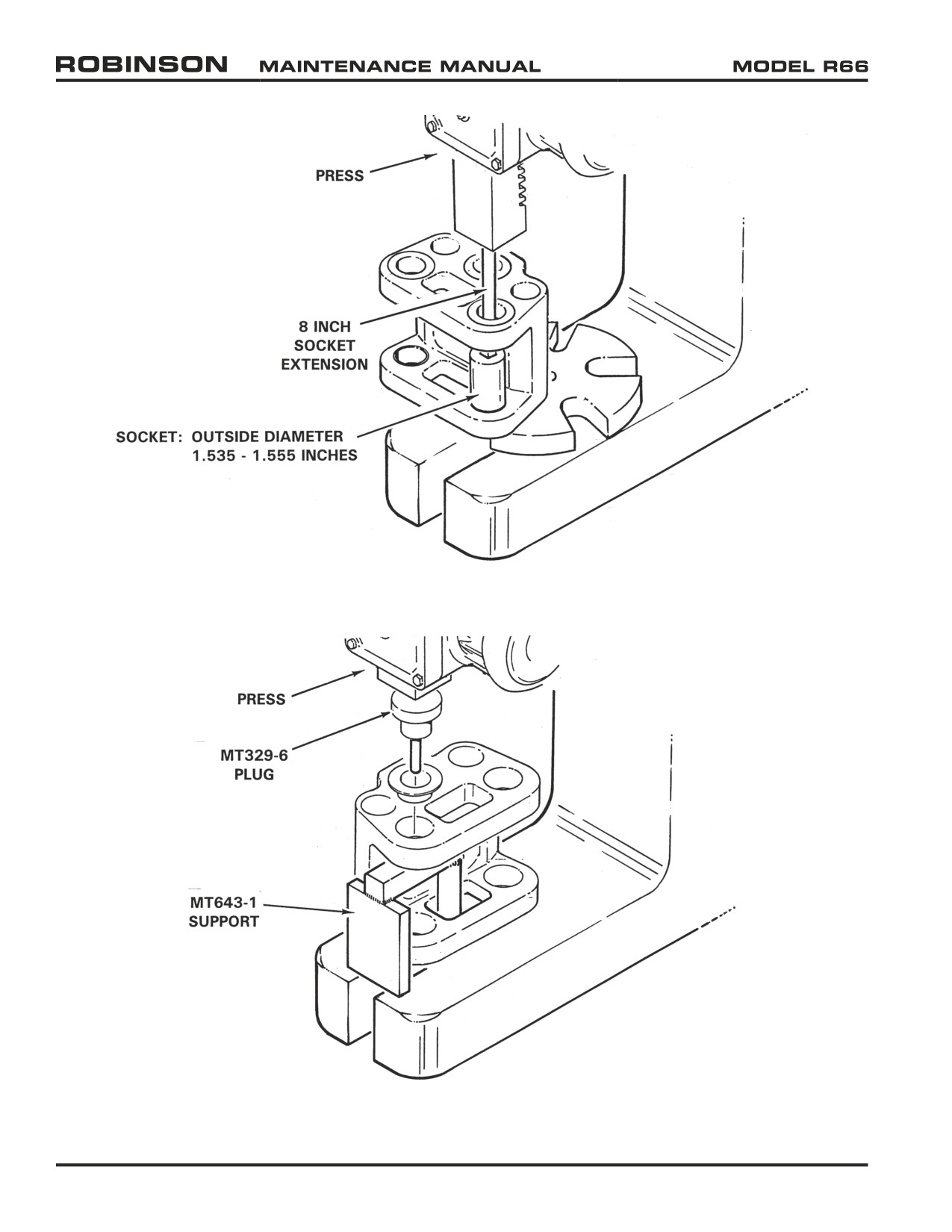
FIGURE 62-5 MAIN ROTOR HUB BEARING REMOVAL
FIGURE 62-6 MAIN ROTOR HUB BEARING INSTALLATION
Page 62.8
Chapter 62 Main Rotor
25 OCT 2010
62-20 Main Rotor Hub (continued)
B.
Installation (continued)
6. Using wrenches with at least 600 ft-lb torque capacity, tighten nut until drilled hole in
nut and bolt align. Reinstall MT122-6 tool and measure bolt stretch; the stretch must be
between 0.020-0.022 inch (0.021-0.022 inch for new, undrilled bolt). Remove tool.
NOTE
If drilled holes in nut and bolt do not align, both nut and bolt
must be replaced. Stretch new bolts per Section 20-33; drill
new nuts and bolts per Section 62-33.
WARNING
The main rotor blade and hub attach bolts must be stretched
from 0.020 - 0.022 inch (0.021 - 0.022 inch for new, undrilled
bolt) to obtain proper clamping force. Under-stretching or over-
stretching can cause catastrophic failure of the bolts.
7. Verify correct teeter hinge friction per Section 62-32; adjust as required and perform
step 6.
8. If required, drill cotter pin hole per Section 62-33. Coat a new cotter pin with epoxy
primer and install wet.
62-21 Bearing Replacement
Refer to R66 Illustrated Parts Catalog (IPC) Figure 62-3.
1.
Remove main rotor hub per Section 62-20.
2.
If main rotor hub is to be reinstalled with same blades, measure and record shim
thicknesses and locations in hub.
3.
Refer to Figures 62-2 and 62-3. Measure and record hub width across widest point of
teeter and coning hinge bearing faces (total of three measurements).
CAUTION
To prevent hub damage ensure all tool and bearing surfaces are
smooth.
4.
Refer to Figure 62-5. Press old bearing(s) out of hub using a socket having an outer
diameter of 1.535-1.555 inches and an 8 inch extension.
CAUTION
Ensure hub is flat on press table and socket is centered on
bearing to prevent hub damage.
5.
Inspect hub bearing bore. Verify no scoring or scratches. Polish out fretting and
corrosion to a maximum depth of 0.001 inch (0.005 inch on radius at edge of bore) using
320-grit or finer wet-or-dry sandpaper and 0.25 inch minimum blend radius. Replace
hub if fretting or corrosion cannot be polished out within limits.
25 OCT 2010
Chapter 62 Main Rotor
Page 62.9
62-21 Bearing Replacement (continued)
6. Ensure new bearing mating surfaces are clean and smooth. Coat hub bearing bore
and hub bearing mating surfaces with epoxy primer (see Section 20-70). Do not allow
primer to contaminate Teflon portion of bearing.
Refer to Figure 62-6. If seam of bearing Teflon liner is visible, orient bearing so seam
7.
is toward top of hub (as installed on helicopter). While primer is still wet, press in new
bearing using MT329-6 plug and MT643-1 support (support is not used when pressing
in teeter hinge bearings) until bearing flange contacts hub.
CAUTION
Use MT643-1 support when installing coning hinge bearings.
Never install coning hinge bearings into unsupported hub.
8. Seal between bearing flange and hub with epoxy primer. Similarly seal between
inboard edge of bearing and hub. Do not allow primer to contaminate Teflon portion of
bearing.
9. Measure hub width across teeter and coning hinge bearing faces. Compare widths with
measurements from step 3. Any hub width increase requires calculating new stack-up
for affected hinge per Section 62-31.
10. If reinstalling hub on same helicopter, install hardware as removed in step 2, subject to
preceding step. Reinstall hub per Section 62-20.
Page 62.10
Chapter 62 Main Rotor
25 OCT 2010
62-30 Main Rotor Assembly
62-31 Journal and Shim Calculations
Refer to Figures 62-2 and 62-3.
A. Teeter Hinge Calculation
1.
Measure main rotor hub width across the teeter hinge bearing faces:
inches
2.
Subtract measured width of C251 driveshaft at teeter hinge bolt hole: -
inches
Calculated empty space: =
inches
3.
Use one C106-5 journal and a selection of C117 shims to create a combined length of
approximately 1.835 inches. Use as many different size shims as possible. Place thrust
washer, shims, and journal under teeter bolt head; shims must be placed between thrust
washer and journal.
Subtract combined measured thickness of selected journal and shims: -
inches
Difference: =
inches
4.
Subtract measured length of C106-5 journal to be used on nut-side:
-
inches
Difference: =
inches
CAUTION
Initial teeter hinge hardware stack-up must be adjusted to
0.005/0.008 inch greater than calculated empty space. A
smaller initial stack-up could damage thrust washers and hub
bearings during installation.
5.
To accommodate dimensional change due to clamping force, add:
+ 0.005/0.008 inch
Result: =
inch
of C117 shims
6. Preceding Result is initial calculated C117 shim stack between nut-side journal and
thrust washer. Use as many different size shims as possible to facilitate head shifting
during balancing. Deviate from initial shim stack as required to meet teeter hinge
friction requirements (8-12 pounds is ideal).
25 OCT 2010
Chapter 62 Main Rotor
Page 62.11
62-31 Journal and Shim Calculations (continued)
B.
Coning Hinge Calculation
1.
Measure and record main rotor hub width across the coning hinge
bearing faces:
inches
2.
Subtract blade’s spindle width measured across faces at coning hinge
bolt bore:
-
inches
Calculated empty space: =
inches
CAUTION
Initial coning hinge hardware stack-up must be adjusted to
0.007/0.011 inch greater than calculated empty space. A
smaller initial stack-up could damage thrust washers and hub
bearings during installation.
3.
To accommodate dimensional change due to clamping force, add:
+ 0.007/0.011 inch
Sum: =
inch
4.
Subtract combined measured length of both C106-7 journals to be
installed:
-
inches
Result: =
inch
of C117 shims
5.
Preceding Result is initial calculated C117 shim stack required between trailing-edge
journal and thrust washer. Deviate from initial trailing edge shim stack-up as necessary
to meet coning hinge axial play per Figure 62-8 and maintain friction requirements as
follows: It must be possible to manually cone each blade without teetering the hub
when blades are held up off the droop stops and lifted at tip. Increasing shim stack-up
or journal length decreases hinge friction.
C106 Journal Lengths
Part No.
Length
Location
C106-5
1.775
Teeter hinge (two per hinge)
C106-7
1.284
Coning hinge (two per hinge)
C117 Shim Sizes
Part No.
Thickness
Location (Between thrust washer and journal)
C117-8
0.012
Teeter hinge; Coning hinge trailing-edge side
C117-9
0.015
Teeter hinge; Coning hinge trailing-edge side
C117-10
0.020
Teeter hinge; Coning hinge trailing-edge side
C117-11
0.025
Teeter hinge; Coning hinge trailing-edge side
TABLE 62-1 HINGE FRICTION JOURNALS AND SHIMS
(Journal length and shim thickness values given in inches)
Page 62.12
Chapter 62 Main Rotor
25 OCT 2010
Intentionally Blank
25 OCT 2010
Chapter 62 Main Rotor
Page 62.13
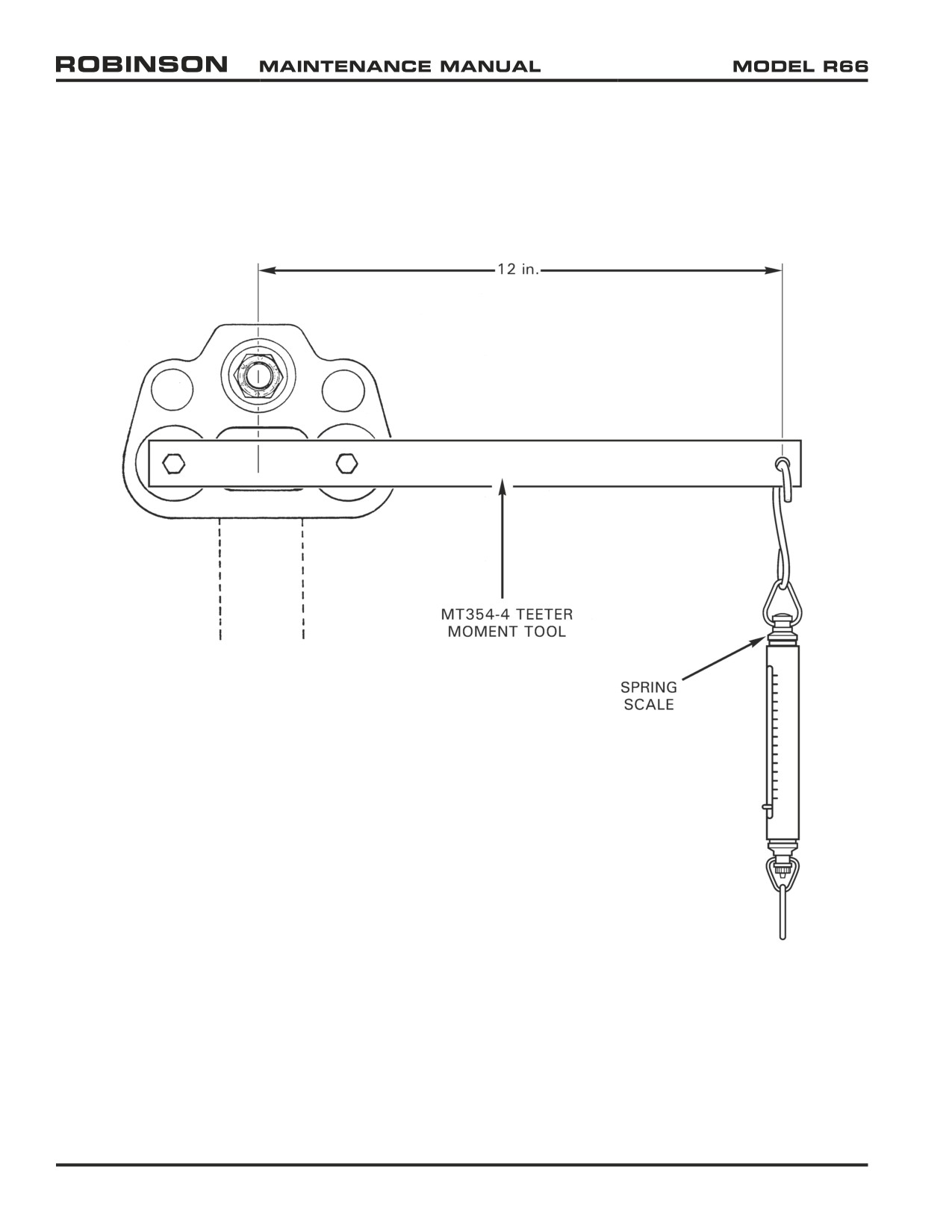
FIGURE 62-7 MEASURING TEETER HINGE FRICTION
Page 62.14
Chapter 62 Main Rotor
25 OCT 2010
62-32 Adjusting Hinge Friction
A. Teeter Hinge Adjustment
NOTE
Teeter hinge friction must be checked and adjusted with main
rotor blades removed from main rotor hub. If required, remove
main rotor blades per Section 62-10.
Teeter hinge friction is adjusted by changing C117 shim stack in small increments.
NOTE
If shim stack is changed per following instructions, a new bolt and
nut must be installed per Section 62-10 Part B, steps 3 thru 5.
1.
Refer to Figure 62-7. Install MT354 teeter moment tool into main rotor hub coning
hinge bearings. Using a spring scale, measure force required to teeter main rotor
hub; use sliding force reading, not breakaway reading. Force required to teeter main
rotor hub must be:
Minimum: No axial play
Maximum:
19 pounds
2.
Refer to Figure 62-2. Remove cotter pin and teeter hinge nut. Remove thrust
washer and C117 shims under nut.
3.
Refer to Table 62-1. Measure thickness of C117 shims under teeter hinge nut.
Change shims as necessary to adjust friction. Reducing shim stack-up by 0.003 -
0.005 inch will increase teeter friction. Increasing shim stack-up will reduce teeter
friction.
4.
Reassemble teeter shims, thrust washer, and nut. Repeat step 1. Torque teeter
hinge bolt per Section 62-20 Part B steps 4 thru 6 and check teeter friction often
while stretching bolt. Do not exceed maximum teeter hinge friction. If required,
increase shim stack-up per preceding step so proper bolt stretch is reached prior to
maximum friction.
5.
Cotter pin holes in nut and bolt will not align. Remove teeter hinge bolt by pressing
it out with an old bolt. Install a new bolt and nut per Section 62-10 Part B, steps
4 thru 6. Drill new bolt and nut per Section 62-33; coat new cotter pin with epoxy
primer and install wet.
6.
If required, install main rotor blades per Section 62-10.
25 OCT 2010
Chapter 62 Main Rotor
Page 62.15
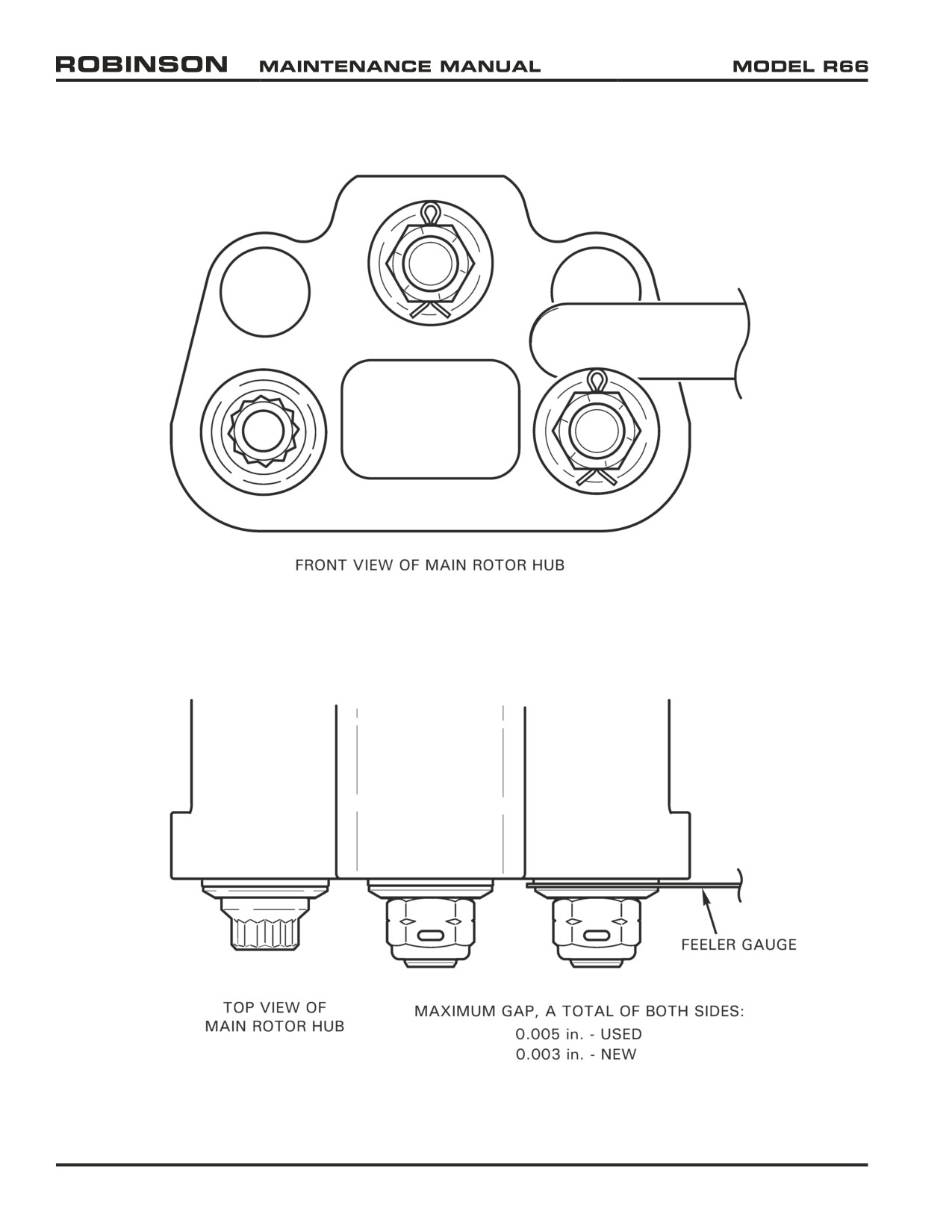
FIGURE 62-8 MEASURING THRUST WASHER AND HUB BEARING GAP
Page 62.16
Chapter 62 Main Rotor
25 OCT 2010
62-32 Adjusting Hinge Friction (continued)
B.
Coning Hinge Adjustment
Coning hinge friction is adjustable through use of various thickness C117 shims. Shims
are installed between the thrust washer and the trailing-edge journal.
1.
Check blade hinge friction by lifting blades until spindle tusks clear droop stops.
Hold one blade level and cone opposite blade. Rotor hub should not teeter as blade
is coned. Repeat check on opposite blade.
2.
Refer to Figure 62-8. Using a feeler gage, measure gap between thrust washer and
rotor hub bearing. Gap must be measured on both leading edge & trailing edge sides
of coning hinge and the total must not exceed 0.005 inch (0.003 inch if new hub
bearings are installed).
3.
Refer to Figure 62-3. Remove cotter pin, nut, and thrust washer from coning hinge
bolt.
4.
Refer to Table 62-1. Remove shim(s) to be changed. Measure shim thickness and
select next size thicker or thinner as required. A thicker shim will decrease blade’s
coning hinge friction. A thinner shim will increase blade’s coning hinge friction and
decrease any gap between blade’s thrust washers and hub bearings.
NOTE
When a shim is replaced with a shim of a different size, it will
be necessary to install a new nut and bolt. Drilled holes in
original bolts will not align at required bolt stretch.
5.
Replace coning hinge bolt with a new bolt.
6.
Install shims, and new bolt and nut, per Section 62-10 Part B, steps 4 thru 6.
7.
Repeat steps 1 and 2. Drill new bolt and nut per Section 62-33; coat new cotter pin
with epoxy primer and install wet. Repeat on opposite blade as required.
62-33 Drilling Nuts and Bolts
New bolts and nuts must be installed and bolts stretched to Section 20-32 limits prior to
drilling. Nuts have three blind holes pre-drilled into every other nut flat to be used as drilling
guides.
Using a six inch long 0.156-inch diameter Cobalt twist-drill, drill a hole through nut and bolt
using an accessible pre-drilled hole in nut. If a shorter length drill is used, protect hub from
damage due to chuck contact by wrapping chuck and/or covering hub edge with several
layers of tape. Prevent chips from contaminating other mechanisms.
NOTE
If none of the predrilled holes in nut are accessible for use as a
guide after stretching bolt, loosen nut and reposition bolt and
nut. Restretch bolt per Section 20-32.
25 OCT 2010
Chapter 62 Main Rotor
Page 62.17
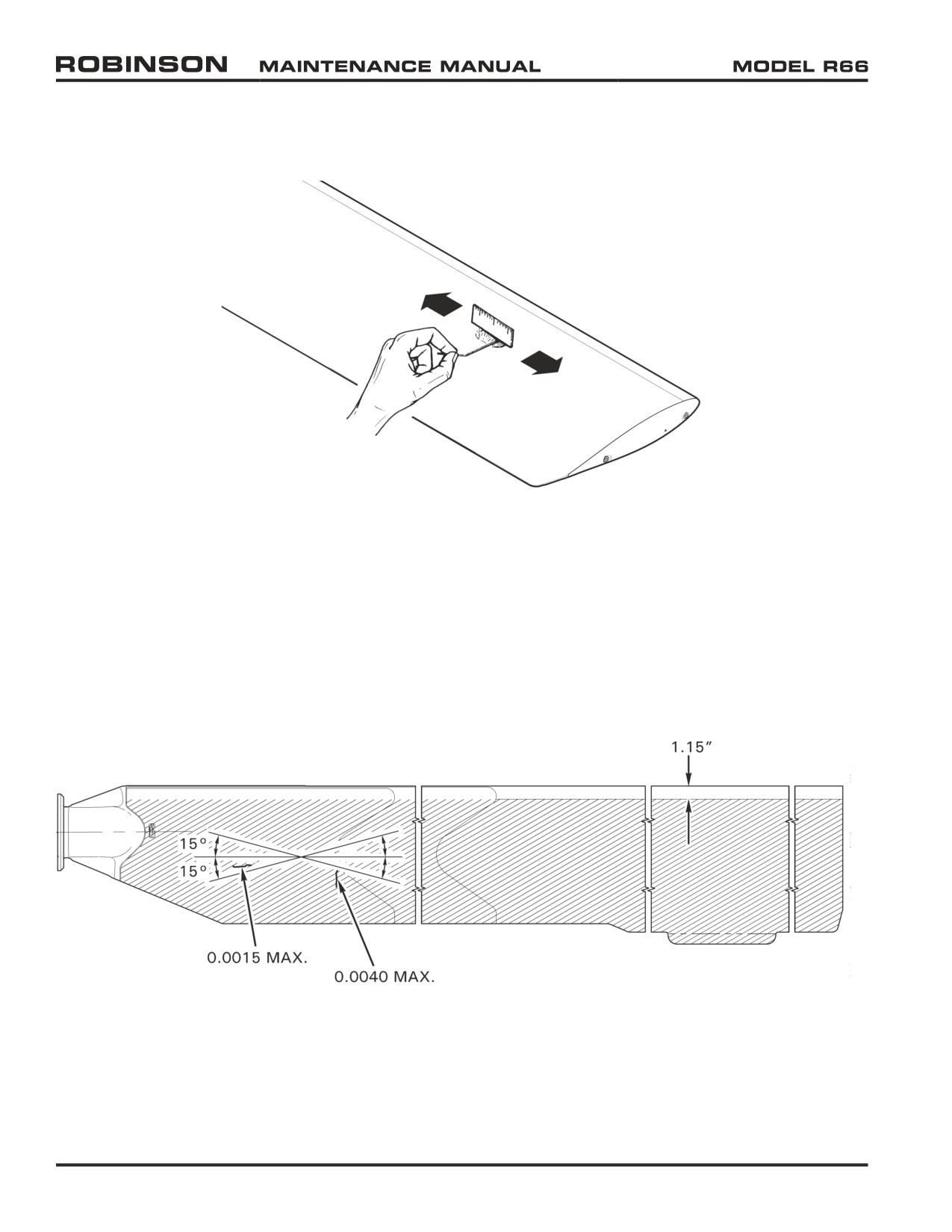
FIGURE 62-9 MEASURING BLADE DAMAGE WITH STRAIGHT EDGE
FIGURE 62-10 SCRATCHES AND CORROSION ON SKINS AND DOUBLERS - DAMAGE LIMITS
Page 62.18
Chapter 62 Main Rotor
25 OCT 2010
62-40 Inspection of Main Rotor Blades
This blade repair procedure outlines the repair limits, methods and materials used for repairing
main rotor blades. Repairs are limited to blending out scratches, dents, nicks, removing corrosion,
and refinishing the blades. The inspections, repairs and limitations contained herein refer to
damage sustained in service, including damage during shipping and handling (manufacturing
irregularities are treated separately by the factory). In-service damage will generally exhibit
paint scuffing or scratches and often times freshly-exposed metal in the form of scratches
in the finish. If there are any questions as to the possibility of a manufacturing irregularity,
contact RHC Technical Support.
CAUTION
A blade may be repaired more than one time. However, in no
case can more than the maximum material be removed or the
maximum dent depth be exceeded in any one location.
A. Measuring Damage
1. Refer to Figure 62-9. Measure blade damage using a straight edge and a thickness
gage. Keep straight edge parallel with the leading and trailing edges.
2. If blades are installed on the helicopter, measure damage using the shortest straight
edge possible to span damaged area. Using a straight edge of excessive length will
cause a false reading due to natural droop of the blade.
B.
Measuring Material Removed After Repair
1. Use calipers or micrometers and compare measurements before and after repair to
estimate amount of material removed.
2. Use a straight edge and thickness gage to measure repaired areas less than 2 inches
across in the blade skins and spar.
62-41 Scratches and Corrosion
A. Skins and Doublers
1. Refer to Figure 62-10. Verify damage does not exceed the following limits:
a.
0.0040 inch maximum depth for scratches more than 15º spanwise on skins and
doublers.
b.
0.0060 inch maximum depth for scratches less than 15º spanwise on skins and
doublers.
2. Refer to Section 62-50 for repair procedures for damage within limits. Blend out
scratches or corrosion on blade skins or doublers with a 0.10 inch blend radius.
25 OCT 2010
Chapter 62 Main Rotor
Page 62.19
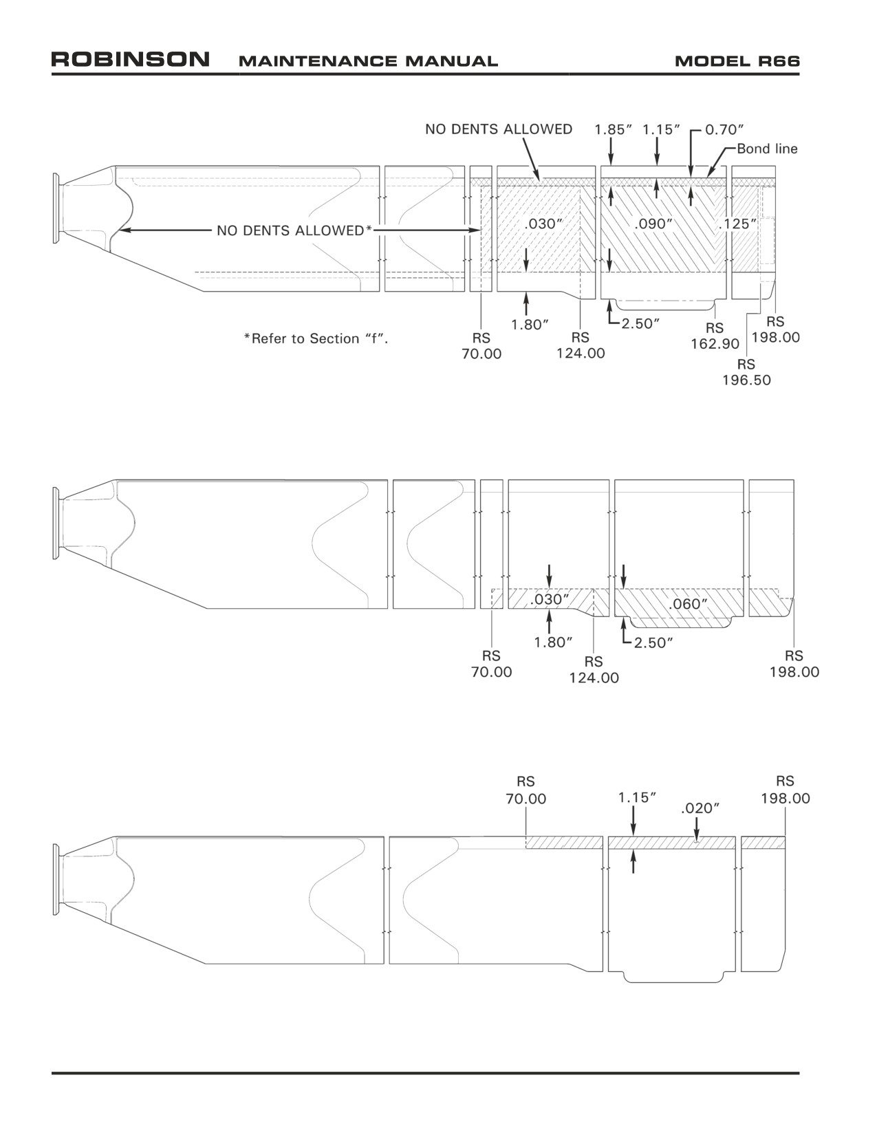
FIGURE 62-11 DENTS ON SKINS AND DOUBLERS - DAMAGE LIMITS
FIGURE 62-12 DENTS ON TRAILING EDGE BOND JOINTS - DAMAGE LIMITS
FIGURE 62-13 SPAR DAMAGE
Page 62.20
Chapter 62 Main Rotor
25 OCT 2010
62-42 Dents
CAUTION
Tap-test dented areas in honeycomb. If any voids are found
associated with dents, contact RHC Customer Service.
Tap-test voids, debonds, and dents in blades using an AN970-4
washer or 1965 or later U.S. quarter dollar coin in good condition.
CAUTION
When dented areas are found, inspect opposite side of the blade
for a bulge. Replace blade with a bulge greater than 0.010 inch
opposite a dent.
CAUTION
Do not repair any dent that has a sharp cut or break in the
skin. If necessary, locally penetrant inspect, keeping penetrant
materials away from bond joints.
A. Skins and Doublers
1. Refer to Figure 62-11. Smooth, round bottom dents with 0.060 inch minimum
radius that occur in honeycomb and unsupported areas of the blade as listed below
may be repaired when damage does not exceed the following limits:
a.
0.125 inch maximum depth dent between RS 162.90 and RS 196.50
b.
0.090 inch maximum depth dent between RS 124.00 and RS 162.90.
c.
0.030 inch maximum depth dent between RS 70.00 and RS 124.00.
d. Maximum area of any dent or dents is 12 square inches and maximum length is
2.0 inches between RS 70.00 and RS 162.90.
e. Maximum area of any dent or dents is 24 square inches and maximum length is
4.0 inches between RS 162.90 and RS 196.50.
f. Replace blade with any dent in 0.7 inch area immediately aft of skin-to-spar bond
line.
g. For dents in skins and/or doublers inboard of RS 70.00, contact RHC for repair
procedures.
2. Refer to Part C for leading edge cap damage. Refer to Section 62-50 for repair
procedures for damage within limits.
B.
Trailing Edge Bond Joints
1. Refer to Figure 62-12. Verify damage does not result in an edge void and does not
exceed the following limits:
a.
0.030 inch maximum damage between RS 70.00 and RS 124.00.
b.
0.060 inch maximum damage between RS 124.00 and 198.00.
c. Refer to Part A, step 1(d).
2. Refer to Section 62-50 for repair procedures for damage within limits. Blend out
dents in trailing edge bond joints with a 0.10 inch blend radius.
C. Leading Edge Cap
1. Verify damage does not result in a crack or tear and dent depth does not exceed
0.020 inch.
2. Dents do not require blending or filling. Dents may be blended with a 0.10 blend radius.
25 OCT 2010
Chapter 62 Main Rotor
Page 62.21
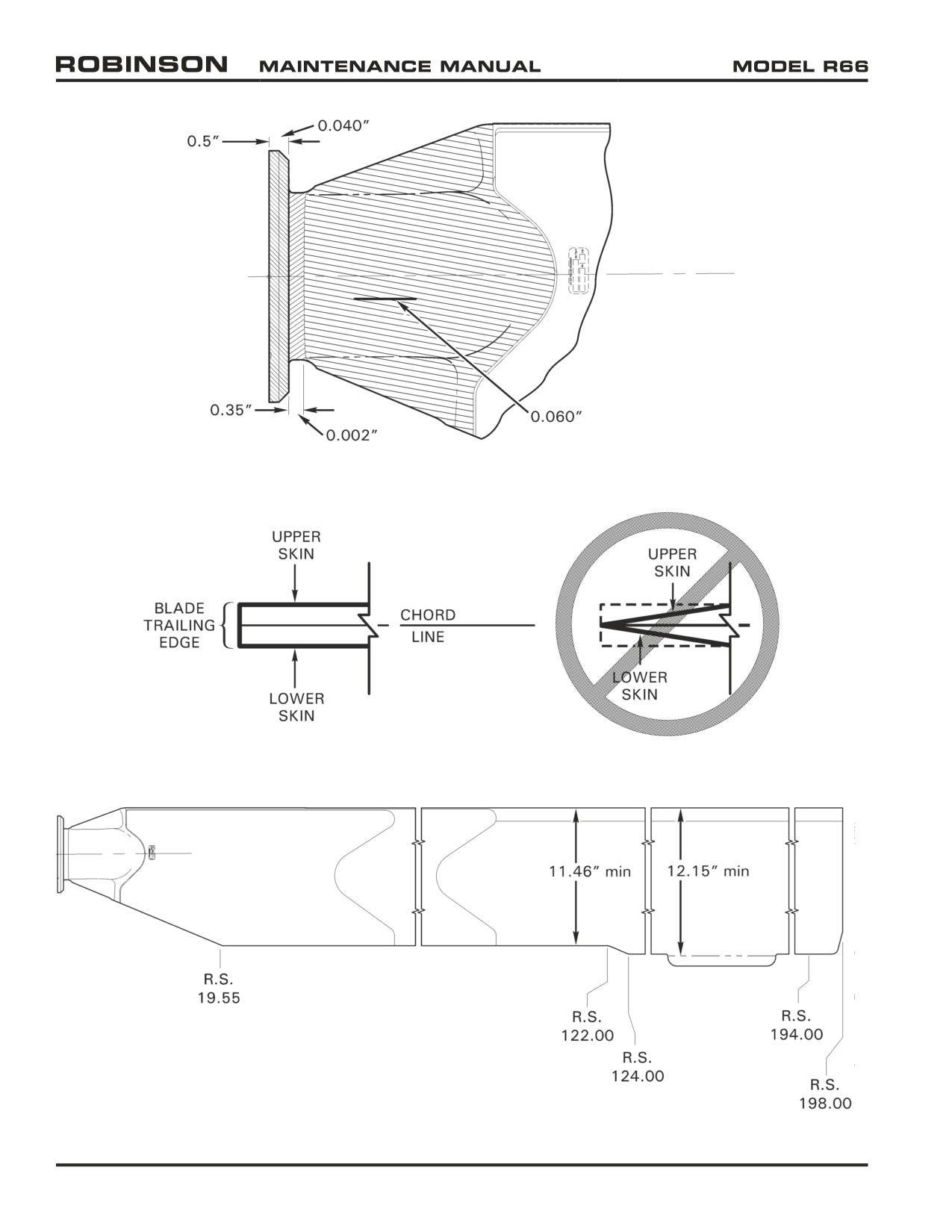
FIGURE 62-14 ROOT FITTING DAMAGE
FIGURE 62-15 REPAIRS TO BLADE AND TRIM TAB TRAILING EDGES
FIGURE 62-16 MINIMUM CHORD AFTER BLADE AND TRIM TAB TRAILING EDGE REPAIRS
Page 62.22
Chapter 62 Main Rotor
25 OCT 2010
62-43 Spar Damage
1. Refer to Figure 62-13. Spar damage limits exclude leading edge cap. Verify damage
does not exceed the following limits:
a.
0.020 inch maximum depth between RS 70.00 and RS 198.00.
b. Replace blade if erosion has reduced thickness at spar leading edge to 0.040 inch.
c. Replace blade if erosion has cause ripples in or deformation to spar leading edge.
2. Refer to Section 62-50 for repair procedures for damage within limits. Blend out spar
damage with a minimum 1.0 inch blend radius.
62-44 Root Fitting Damage
1. Refer to Figure 62-14. Verify damage does not exceed the following limits:
a.
0.040 inch maximum depth on outside diameter of flange.
b.
0.002 inch maximum depth on area 0.35 inch outboard of flange.
c.
0.060 inch maximum depth on other root fitting exposed areas.
2. Refer to Section 62-50 for repair procedures for damage within limits. Blend out root
fitting damage with a minimum 1.0 inch blend radius.
62-45 Nicks and Notches
A. Blade Trailing Edge (see also Blade Tip)
1. Refer to Figure 62-15 and Section 62-50 for repair procedures for damage within
limits. Blend out nicks and notches in blade trailing edge for 1.0 inch minimum each
side of nick or notch (with a minimum 12 inch blend radius).
2. Refer to Figure 62-16. After repair, verify minimum chord is within the following
limits:
a.
12.15 inch minimum chord between RS 124.00 and RS 194.00.
b.
11.46 inch minimum chord between RS 19.55 and RS 122.00.
3. See Section 62-42 for additional inspection criteria.
B.
Blade Tip
1. Refer to Figure 62-17. Using a fine-toothed hand file, file in spanwise or chordwise
direction, within limits indicated. Remove file marks using 220 grit or finer aluminum
oxide abrasive paper.
2. File trailing edge to maintain square edge at skins, perpendicular to chord line, per
Figure 62-15. Seal exposed trailing edge bond joint.
3. Track and Balance Main Rotor per Chapter 18.
C. Trim Tab Trailing Edge
1. Verify damage does not exceed 0.050 inch chordwise or 0.30 inch spanwise.
2. Refer to Figure 62-15 and Section 62-50 for repair procedures for damage within
limits. Blend out nicks & notches in trim tab trailing edges, 1.0 inch minimum each
side of nick or notch (with a minimum 12 inch blend radius) keeping edge parallel
with blade trailing edge.
25 OCT 2010
Chapter 62 Main Rotor
Page 62.23
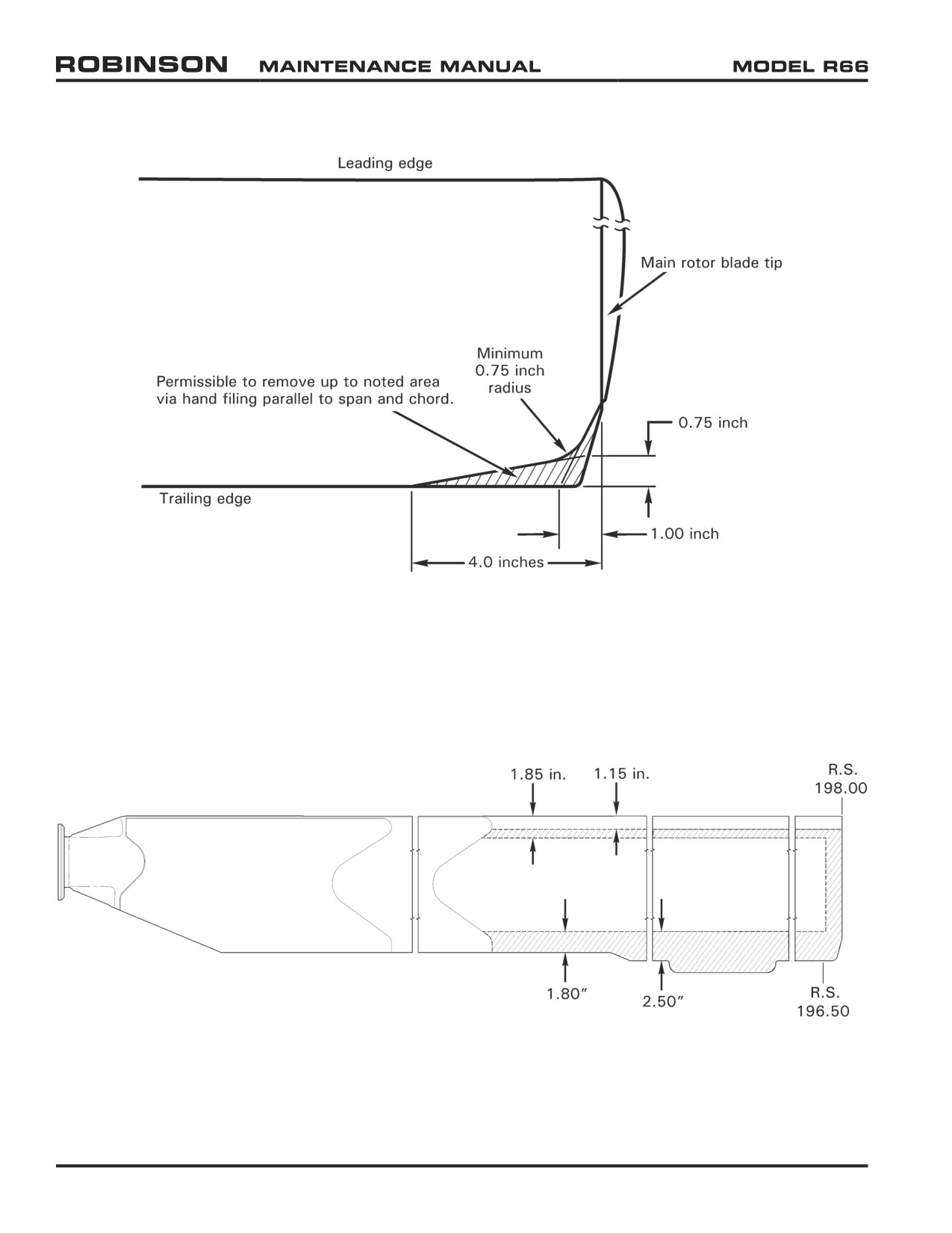
FIGURE 62-17 BLADE TIP REPAIR LIMITS
FIGURE 62-18 TIP CAP, SPAR, AND TRAILING EDGES - VOID AND DEBOND LIMITS
Page 62.24
Chapter 62 Main Rotor
25 OCT 2010
62-46 Voids and Debonds
NOTE
Tap-test dented areas in honeycomb. If any voids are found
associated with dents, contact RHC Customer Service.
Tap-test voids, debonds, and dents in blades using an AN970-4
washer or 1965 or later U.S. quarter dollar coin in good condition.
A. Tip Caps, Spars, and Trailing Edges
1. Refer to Figures 62-18. Verify no continuous void larger than 0.10 square inch.
90% of the area must be securely bonded. Voids separated by 0.25 inch or less
spanwise are considered continuous.
B.
Doublers
1. Refer to Figures 62-19. Voids or debonds in doublers are not field-repairable.
a. Critical Areas: Area less than 0.50 inch spanwise and less than 0.30 inch
chordwise from edge of doubler. Verify no individual void larger than 0.10 square
inch except at the doubler finger tips. The finger tips may be debonded from the
outboard tip to 1.0 inch inboard. Voids that are separated by less than 0.25 inch
shall be considered continuous.
b. Non-Critical Areas: Area more than .50 inch spanwise or more than .30 inch
chordwise from doubler edges. Verify void does not exceed 2.0 inches chordwise
by 7.0 inches spanwise maximum continuous void. Voids that are separated by
less than 0.25 inch shall be considered continuous. Total area of any void may
not exceed 6.0 square inches.
2. If voids or debonds are beyond limit, contact RHC Technical Support.
C. Honeycomb
1. Refer to Figures 62-20. Verify damage does not exceed the following limits:
a.
1.50 inch chordwise or 20.00 inch spanwise maximum continuous void between
RS 121.00 & inboard. Total area of any void may not exceed 15.0 square
inches.
b.
2.50 inch chordwise or 20.00 inch spanwise maximum continuous void between
RS 121.00 & RS 196.50. Total area of any void may not exceed 15.0 square
inches.
25 OCT 2010
Chapter 62 Main Rotor
Page 62.25
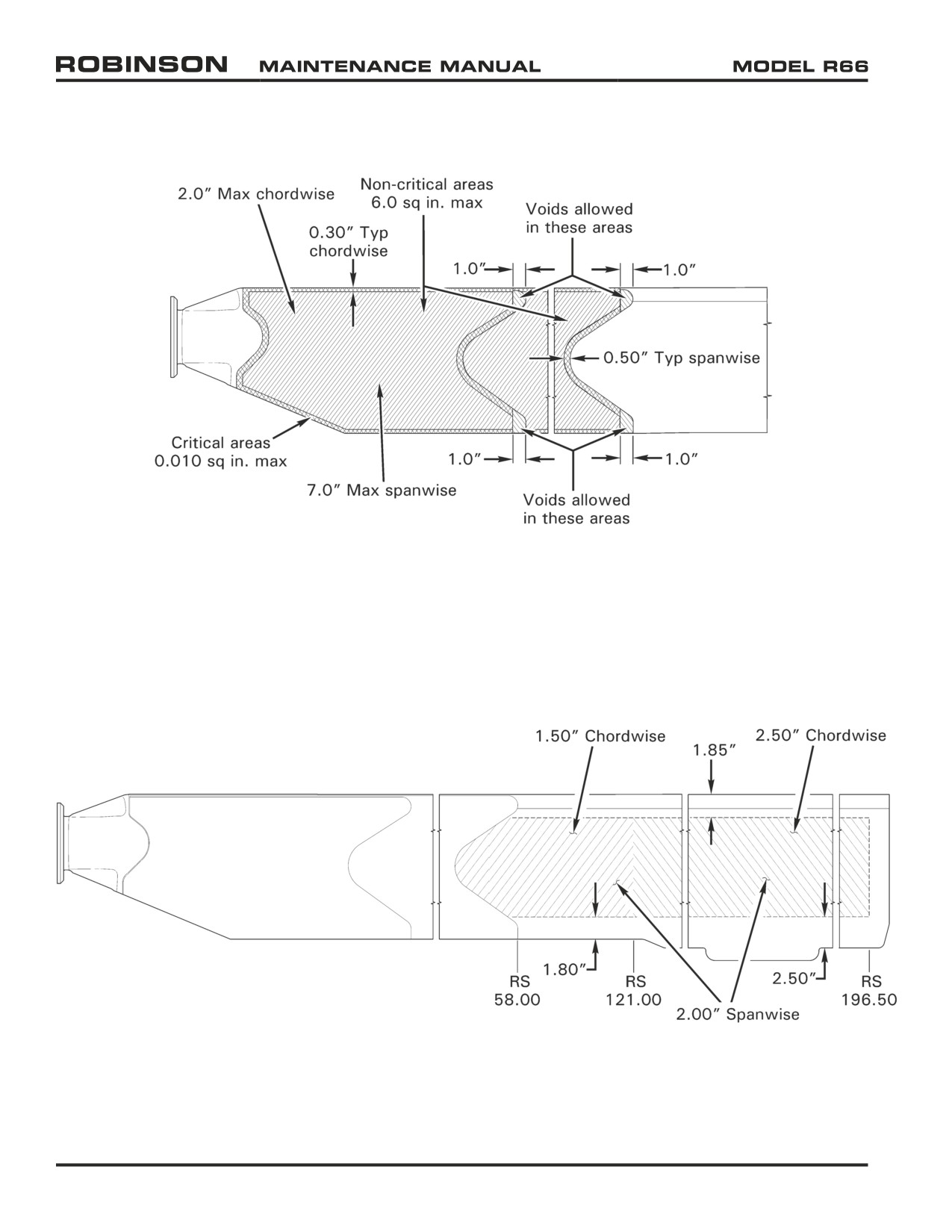
FIGURE 62-19 DOUBLERS - VOID AND DEBOND LIMITS
FIGURE 62-20 HONEYCOMB - VOID AND DEBOND LIMITS
Page 62.26
Chapter 62 Main Rotor
25 OCT 2010
62-50 Repair of Main Rotor Blades
CAUTION
DO NOT USE power tools or chemical paint strippers to remove
blade materials.
1.
Measure damage per Section 62-40.
2.
Polish out blade damage using 220 grit or finer wet-or-dry aluminum-oxide or silicon-carbide
abrasive paper, and finish with 320 grit or finer wet-or-dry abrasive paper.
3.
A fine-toothed file may be used along the spar and trailing edge, provided the area is
finished with 320 grit or finer wet-or-dry abrasive paper. Hand-sand or file in spanwise
direction.
4.
Remove only the material necessary to reach the bottom of the damage, and to blend the
reworked area to the radius or dimension required. Visually inspect and verify all damage
is removed.
5.
Measure reworked area and verify material removed and/or new chord dimension is
permissible per Section 62-40.
6.
Seal and fill per Section 62-51, as required. Paint per Section 62-52, as required.
7.
Track and balance main rotor per Chapter 18, as required.
62-51 Sealing, Filling, and Fairing
1. Clean area needing sealing, filling, and fairing with QSOL 220.
2. Apply Scotch-Weld structural adhesive #2216 B/A to bond joints with pin holes or other
openings in accordance with adhesive manufacturer’s instructions. Allow a minimum
of 24 hours cure time.
3. Using 240 grit or finer wet-or-dry aluminum-oxide or silicon-carbide abrasive paper, hand-
sand cured adhesive in spanwise direction to a smooth, aerodynamic finish, congruent
with the blade airfoil. Do not remove metal.
4. Hand-sand surrounding painted surface until 25% primer remains. Keep bare metal to
a minimum.
25 OCT 2010
Chapter 62 Main Rotor
Page 62.27
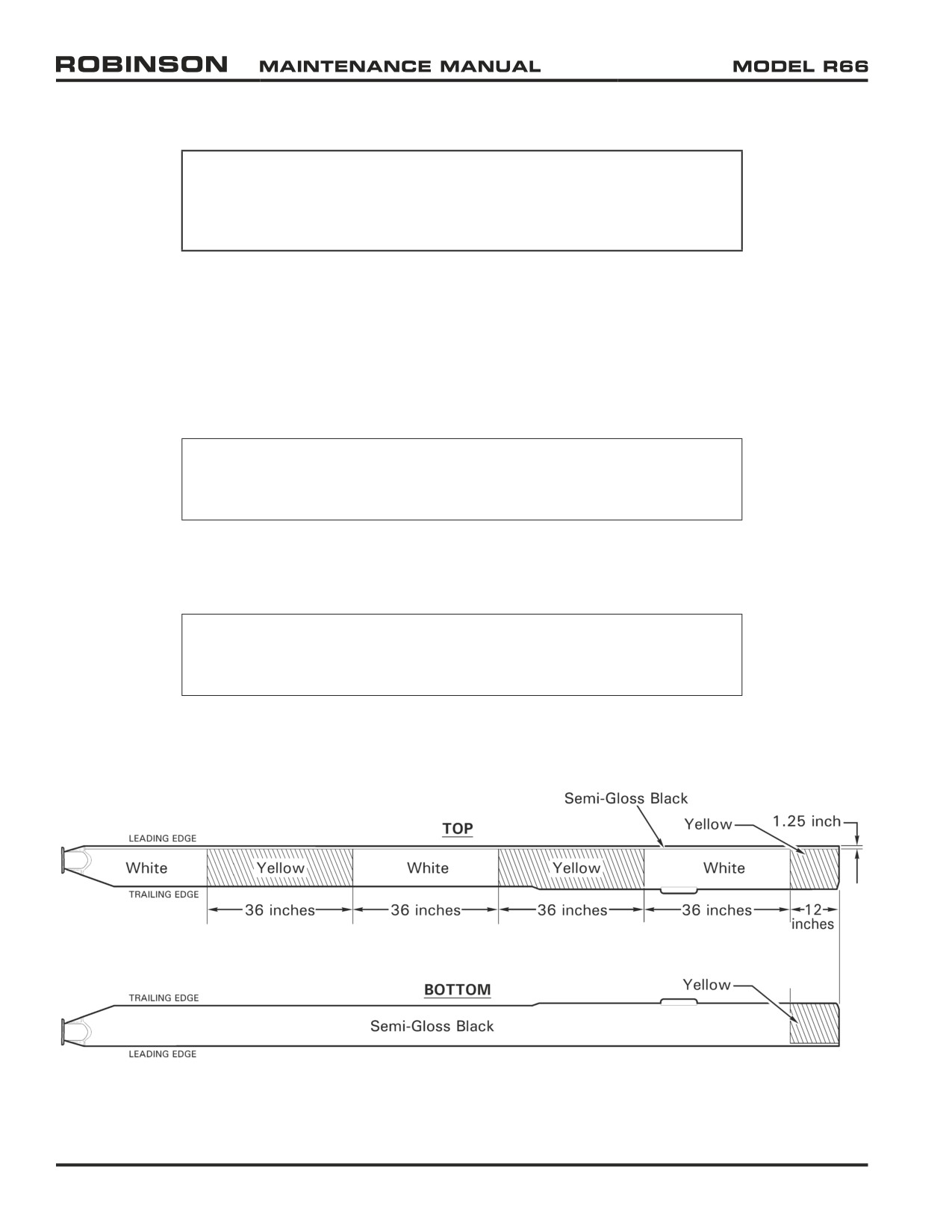
62-52 Painting
CAUTION
If force-drying paint, do not exceed 175°F surface temperature
on blade; monitor blade temperature by temporarily installing
P/N 110-2 Telatemp on blade skin.
1.
Mask area to prevent overspray contamination.
2.
Clean bare metal to be painted with a lint-free cloth dampened with enamel cleaner (see
Approved Materials, Section 20-70).
3.
Prime bare metal with at least two coats of epoxy primer. Scuff first coat of primer
with 320 grit abrasive paper (or very fine Scotch-Brite), and wipe down with a lint-free
cloth dampened with enamel cleaner prior to applying new coat.
NOTE
Best results are achieved if primer is allowed to air-dry for 12
hours prior to top coat application.
4.
Refer to Figure 62-21. Apply dark gray, flat black, white, and/or yellow Dupont Imron
polyurethane enamel (or equivalent; see Approved Materials, Section 20-70), as required,
to primed area in accordance with paint manufacturer's recommendations.
NOTE
Allow Imron paint to cure at least 72 hours before flying in
erosive conditions (such as drizzle, rain, or dust).
5.
Remove masking materials.
FIGURE 62-21 MAIN ROTOR BLADE PAINT SCHEME
Page 62.28
Chapter 62 Main Rotor
25 OCT 2010
CHAPTER 63
MAIN ROTOR DRIVE SYSTEM
Section Title
Page
63-00
Description
63.1
63-10
Engine Shaft Weldment
63.1
63-11
(Engine Driveline) Forward Flex Plate Shimming
63.2
63-12
Clutch Assembly
63.5
63-20
Main Rotor Gearbox Assembly
63.6
63-21
Yoke and Seal Replacement
63.8
63-30
Rotor Brake
63.11
63-31
Pad Replacement
63.12
63-40
Rotor RPM
63.12
Chapter 63 Main Rotor Drive System
Page 63.i
Intentionally Blank
Page 63.ii
Chapter 63 Main Rotor Drive System
CHAPTER 63
MAIN ROTOR DRIVE SYSTEM
63-00 Description
The engine is mounted in a 37º nose-up attitude. A sprag-type overrunning clutch mates
directly to the splined engine power take-off (PTO) shaft. The clutch is connected to a shaft
with flexible couplings at both ends to transmit power to the main gearbox. A ring and pinion
spiral bevel gearset at the main gearbox input reduces speed to tail rotor driveline RPM. A
second ring and pinion stage reduces speed from tail rotor driveline RPM to main rotor RPM.
The main gearbox is pressure lubricated. The oil is pumped through an airframe-mounted filter
and cooled by an oil cooler which receives its airflow from the cooling fan. The main gearbox
also drives the flight control hydraulic pump.
63-10 Engine Shaft Weldment
Refer to R66 Illustrated Parts Catalog (IPC) Figures 63-1 and 63-3.
A. Removal
1. Remove tailcone cowling assembly per Section 53-23. Remove engine cowling assembly
per Section 53-21.
2. Remove filter and cage assemblies per Section 71-22.
3. Refer to Figure 63-1. Remove hardware securing F453-1 box assembly to F234-1
firewall.
4. Remove hardware securing forward A947-2 flex plate assembly to F910-1 (main gearbox)
yoke and F642-1 (engine) shaft weldment forward flange, noting hardware removed.
Remove flex plate, and temporarily suppport forward portion of shaft weldment.
5. Remove hardware securing shaft weldment to aft A947-2 flex plate assembly. Remove
support, then remove shaft weldment through main gearbox compartment.
B.
Installation
1. Refer to Figure 63-1. Position F642-1 engine shaft weldment in helicopter, and install
hardware securing shaft weldment to aft A947-2 plate assembly. Standard torque nuts
and palnuts per Section 20-32, and torque stripe per Figure 5-1.
2. Shim engine driveline per Section 63-11.
3. Install hardware securing F453-1 box assembly to F234-1 firewall.
4. Verify 0.2 inch minimum clearance between shaft weldment and firewall grommet;
verify equal gap concentrically between shaft and box assembly hole edges. Adjust
F174-1 support weldment rod ends per Section 53-31 as required.
5. Install filter and cage assemblies per Section 71-22.
6. Install tailcone cowling assembly per Section 53-23. Install engine cowling assembly
per Section 53-21.
Chapter 63 Main Rotor Drive System
Page 63.1
63-11 (Engine Driveline) Forward Flex Plate Shimming
NOTE
The engine driveline is shimmed for
0.040
/
0.000 inch
compressive preload. Preload is alleviated by upward movement
of main gearbox during flight.
1.
Refer to Figure 53-2. Verify F174-1 support weldment rod end engagement measures
0.93 inch from tube end to rod end centerline (nominal; both sides). Verify 0.2 inch
minimum clearance between F642-1 (engine) shaft weldment and firewall grommet;
verify equal gap concentrically between shaft and F453-1 box assembly hole edges.
Adjust support weldment rod end engagement per Section 53-31 as required.
2.
Refer to Figure 63-1. If not previously accomplished, remove hardware securing forward
A947-2 flex plate assembly to F910-1 (main gearbox) yoke and F642-1 (engine) shaft
weldment forward flange. Remove flex plate, and temporarily suppport forward portion
of shaft weldment.
3.
Measure flex plate thickness at bonded washers (4 places) to determine average thickness:
(1st place)
inch
(2nd place) +
inch
(3rd place) +
inch
(4th place) +
inch
Total =
inch
Total ÷ 4 =
inch
(Flex plate average thickness)
4.
a.
Position F910-1 (main gearbox) yoke flange arms and F642-1 (engine) shaft weldment
forward flange arms at 3 o’clock and 9 o’clock positions (horizontal). Measure gap
between arms to determine average gap:
(3 o’clock position)
inch
(9 o’clock position) +
inch
Total =
inch
Total ÷ 2 =
inch
(Average gap between flange arms)
b.
Rotate F642-1 (engine) shaft weldment 180º, and repeat step a:
(3 o’clock position)
inch
(9 o’clock position) +
inch
Total =
inch
Total ÷ 2 =
inch
(Average gap between flange arms)
Page 63.2
Chapter 63 Main Rotor Drive System
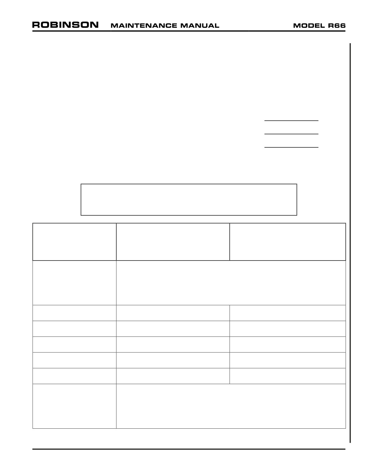
63-11 (Engine Driveline) Forward Flex Plate Shimming (continued)
5.
Evaluate flange straightness by calculating the difference between the 3 o’clock positions
in steps 4a and 4b. Also calculate the difference between the 9 o’clock positions in
steps 4a and 4b. If either calculated difference exceeds 0.015 inch, either one or both
flanges are bent and require replacement.
6.
Using the smaller average gap from step 4a or 4b, subtract the flex plate average
thickness determined in step 3:
Smaller average gap between flange arms (step 4a or 4b)
inch
Subtract flex plate average thickness (step 3) −
inch
Total =
inch
7.
Select shims per Table 63-1 and install forward A947-2 flex plate assembly. Standard
torque nuts and palnuts per Section 20-32 and torque stripe per Figure 5-1. Remove
F642-1 (engine) shaft weldment temporary support.
WARNING
Shim both arms of flanges equally. All fasteners must meet
torque requirements given in Section 20-33.
Shim required between
Shim required between
Calculated
forward A947-2 flex plate and
forward A947-2 flex plate and
Dimension
F642-1 (engine) shaft weldment
F910-1 (main gearbox) yoke
forward flange
NAS1149F0432P washer between aft A947-2 flex plate assembly
and F642-1 (engine) shaft weldment aft flange and/or F018-1
−0.041 inch or greater
clutch assembly yoke may be relocated under nut as required to
negative number
achieve −0.040 / 0.000 inch calculated dimension. Relocate
washers as required, and repeat steps 4 thru 7.
−0.040 / 0.000 inch
None
None
+0.001 / +0.029 inch
NAS1149F0432P washer
None
+0.030 / +0.059 inch
NAS1149F0432P washer
NAS1149F0432P washer
+0.060 / +0.090 inch
NAS1149F0463P washer
NAS1149F0432P washer
+0.091 / +0.121 inch
NAS1149F0463P washer
NAS1149F0463P washer
NAS1149F0432P washer between aft A947-2 flex plate assembly
and F642-1 (engine) shaft weldment aft flange and/or F018-1 clutch
+0.122 inch or greater
assembly yoke may be exchanged with NAS1149F0463P washer
positive number
as required to achieve −0.040 / 0.000 inch calculated dimension.
Exchange washers as required, and repeat steps 4 thru 7.
TABLE 63-1 ENGINE DRIVELINE
Chapter 63 Main Rotor Drive System
Page 63.3
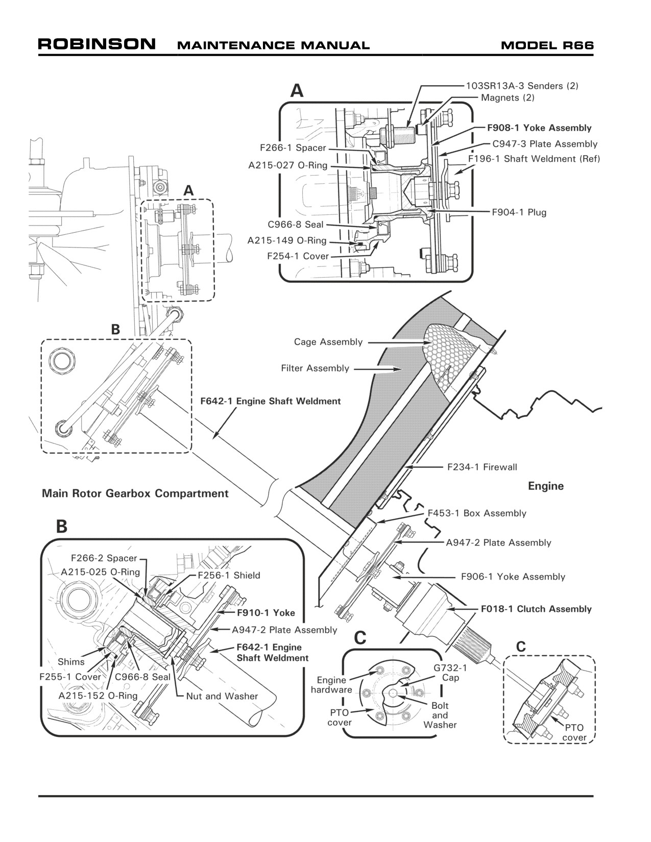
FIGURE 63-1 ENGINE DRIVELINE
Page 63.4
Chapter 63 Main Rotor Drive System
63-12 Clutch Assembly
Refer to R66 Illustrated Parts Catalog (IPC) Figure 63-1.
A. Removal
1. Remove engine shaft weldment per Section 63-10.
2. Refer to Figure 63-1. Mark F906-1 yoke assembly and A947-2 plate assembly, to
facilitate installation. Remove plate assembly, noting hardware removed.
3. Remove engine-supplied nuts & spacers, and engine-supplied rear PTO pad cover.
4. Remove bolt and washer securing G732-1 cap and F018-1 clutch assembly to Rolls-
Royce engine model 250-C300/A1. Remove clutch assembly through main rotor
gearbox compartment.
B.
Installation
1. Refer to Figure 63-1. Lubricate F018-1 clutch assembly splines using B270-21
protectant.
2. Route clutch assembly through main rotor gearbox compartment, insert clutch
assembly in Rolls-Royce engine model 250-C300/A1, and install G732-1 cap, bolt,
and washer at rear PTO pad. Standard torque bolt per Section 20-32 and torque
stripe per Figure 5-1.
3. Install engine-supplied rear PTO pad cover, and engine-supplied nuts & spacers.
Special torque nuts per Section 20-33 and torque stripe per Figure 5-1.
4. Install A947-2 plate assembly, as removed. Standard torque nuts and palnuts per
Section 20-32, and torque stripe per Figure 5-1.
5. Install engine shaft weldment per Section 63-10.
Chapter 63 Main Rotor Drive System
Page 63.5
63-20 Main Rotor Gearbox Assembly
A. Removal
1.
Remove main rotor blades per Section 62-10.
2.
Remove tailcone cowling assembly per Section 53-23.
3.
Disconnect (pitot system) 15-4-N-O union near G201-1 (servo support) frame assembly.
Cap fitting and plug line.
4.
Refer to Figure 63-1. Remove hardware securing F908-1 and F910-1 yoke assemblies
to plate assemblies, leaving plates attached to shaft weldments. Note hardware
removed.
5.
Refer to R66 Illustrated Parts Catalog (IPC) Figures 67-19 and 67-29. Remove hardware
securing F121-7 push-pull tube assembly to F339-1 jackshaft weldment, and F121-5
push-pull tube assemblies to D212-5 servo assemblies.
6.
Refer to R66 IPC Figure 63-9. Detach cable assembly from (rotor brake assembly)
B112-3 spring.
7.
Refer to R66 IPC Figure 63-9. Using back-up wrench, disconnect D205-19 and D205-
20 hose assemblies from F006-1 main rotor gearbox and D500-3 oil pump. Cap and
plug fittings and hoses.
8.
Disconnect F059-01 cabin harness assembly plug from F049-01 gearbox harness
assembly receptacle. Remove hardware securing A936-3 (ground) wire assembly to
F560-1 bulkhead assembly.
9.
Cut and discard safety wire securing Tygon® tube to G254-1 (fuel) vent assembly, and
clear tubing from workspace.
10.
Install hoisting equipment per Section 7-20, Part A, steps 1 thru 4; remove hoist
slack.
11.
Refer to R66 IPC Figure 53-13. Remove hardware securing F252-1 strut to F020-1
upper frame assembly. Remove (mounting bolt) nuts and washers securing gearbox to
upper frame. Remove aft mounting bolts securing F235-13 strut assemblies to servo
support frame, hardware securing struts to upper frame, and struts.
12.
Hoist gearbox
(with hydraulic installation, servo support frame, and mast fairing
assembled) up and away from helicopter.
Page 63.6
Chapter 63 Main Rotor Drive System
63-20 Main Rotor Gearbox Assembly (continued)
B.
Installation
1.
Refer to R66 Illustrated Parts Catalog (IPC) Figure 63-3. If installing new C653-3 (aft)
or A653-2 (forward) rubber mounts, lubricate mounts using water or A257-8 lubricant
and press into gearbox ears.
2.
Refer to Section 7-20. Hoist F006-1 main rotor gearbox (with hydraulic installation,
G201-1 [servo support] frame assembly, and mast fairing assembled) into helicopter,
onto F020-1 upper frame assembly.
3.
Install F252-1 strut and F235-13 strut assemblies, and install hardware securing strut
assemblies to upper frame. Install gearbox mounting bolts and associated hardware.
Special torque mounting bolts per Section 20-33, standard torque bolts securing struts
to upper frame per Section 20-32, and torque stripe per Figure 5-1.
4.
Remove hoisting equipment, and lifting fixture or nylon rope.
5.
Install Tygon® tube on G254-1 (fuel) vent assembly, wrap two turns 0.032-inch diameter
lockwire around tube and vent assembly, and safety tight.
6.
Install hardware securing A936-3 (ground) wire assembly to F560-1 bulkhead assembly.
Connect F059-01 cabin harness assembly plug to F049-01 gearbox harness assembly
receptacle.
7.
Remove caps and plugs and connect D205-19 and D205-20 hose assemblies to gearbox
and D500-3 oil pump. Using back-up wrench, special torque hose nuts per Section 20-
33, and torque stripe per Figure 5-1.
8.
Attach (rotor brake) D126-2 cable assembly to (rotor brake assembly) B112-3 spring.
Verify 0.25 inch minimum clearance between cable assembly and vent assembly Tygon®
tube; adjust cable attachments as required.
9.
Install hardware securing F121-7 push-pull tube assembly to F339-1 jackshaft weldment,
and F121-5 push-pull tube assemblies to D212-5 servo assemblies. Standard torque
hardware per Section 20-32 and torque stripe per Figure 5-1.
10.
Install hardware securing F908-1 and F910-1 yoke assemblies to plate assemblies, as
removed. Shim engine driveline per Section 63-11, and tail rotor driveline per Section
65-30. Standard torque nuts and palnuts per Section 20-32, and torque stripe per
Figure 5-1.
11.
Install tailcone cowling assembly per Section 53-23.
12.
Install main rotor blades per Section 62-10.
CAUTION
Prior to operation of a new, overhauled, or repaired main rotor
gearbox, inject 5-6 ounces A257-22 oil into mast tube vent
hole. Service gearbox per Section 12-11.
Chapter 63 Main Rotor Drive System
Page 63.7
63-21 Yoke and Seal Replacement
Refer to R66 Illustrated Parts Catalog (IPC) Figure 63-3.
A. (Tail Rotor Drive) F908-1 Yoke Assembly and Seal Removal
1. Remove tailcone cowling assembly per Section 53-23.
2. Refer to Figure 63-1. Remove hardware securing C947-3 (forward) plate assembly
to F908-1 yoke assembly, and C947-3 (intermediate) plate assembly to F196-1 fan
shaft, noting hardware removed. Support weldment to allow clearance for yoke
removal.
3. Cut and discard safety wire securing F904-1 plug to yoke assembly. Engage rotor
brake and remove plug, then remove yoke.
4. Remove hardware securing F254-1 cover with C966-8 seal to F006-1 main rotor
gearbox. Remove cover.
5. Using hydraulic press, press old seal from cover.
B.
(Tail Rotor Drive) F908-1 Yoke Assembly and Seal Installation
1. Refer to Figure 63-1. Remove F266-1 spacer and replace A215-027 o-ring, as
required. Reinstall spacer.
2. Clean and dry F254-1 cover; verify open face of seal points toward gearbox and
press in new seal until completely seated.
3. Replace A215-149 o-ring, as required. Install cover assembly over pinion shaft.
4. Verify yoke and pinion splines are clean and undamaged. Coat splines of pinion
with B270-21 protectant and install F908-1 yoke assembly. Lubricate F904-1 plug
threads with A257-9 anti-seize and install plug. Engage rotor brake and special
torque plug per Section 20-33. Install 0.020-inch diameter lockwire and safety plug
to yoke assembly. Tuck pigtail behind yoke flange.
5. Install hardware securing C947-3 (forward) plate assembly to F908-1 yoke assembly,
and C947-3 (intermediate) plate assembly to F196-1 fan shaft, as removed. Shim
tail rotor driveline per Section 65-30. Standard torque nuts and palnuts per Section
20-32, and torque stripe per Figure 5-1.
6. Install tailcone cowling assembly per Section 53-23.
7. Set hall effect sender-to-magnet gap per Section 63-40.
Page 63.8
Chapter 63 Main Rotor Drive System
63-21 Yoke and Seal Replacement (continued)
C. (Engine-Driven) F910-1 Yoke Assembly and Seal Removal
1. Remove tailcone cowling assembly per Section 53-23. Remove engine cowling
assembly per Section 53-21.
2. Refer to Figure 63-1. Remove hardware securing A947-2 (forward) plate assembly to
F910-1 yoke assembly, and A947-2 (aft) plate assembly to F642-1 shaft weldment,
noting hardware removed. Support weldment to allow clearance for yoke removal.
3. Place a wood block between firewall and yoke flange (to prevent yoke from rotating)
or engage rotor brake. Remove nut and washer securing yoke to pinion, then remove
yoke.
4. Remove rotor brake per Section 63-30.
5. Remove F255-1 cover with C966-8 seal, but do not remove shims under pinion
bearing.
6. Using hydraulic press, press old seal from cover.
D. (Engine-Driven) F910-1 Yoke Assembly and Seal Installation
CAUTION
Do not remove shims under pinion bearing. Shims control
bearing preload and gear backlash.
1. Refer to Figure 63-1. Remove F266-2 spacer and replace A215-025 o-ring, as
required. Reinstall spacer.
2. Clean and dry F255-1 cover; verify open face of seal points toward gearbox and
press in new seal until completely seated.
3. Replace A215-152 o-ring, as required. Install cover assembly over pinion shaft.
4. Install rotor brake per Section 63-30.
Chapter 63 Main Rotor Drive System
Page 63.9
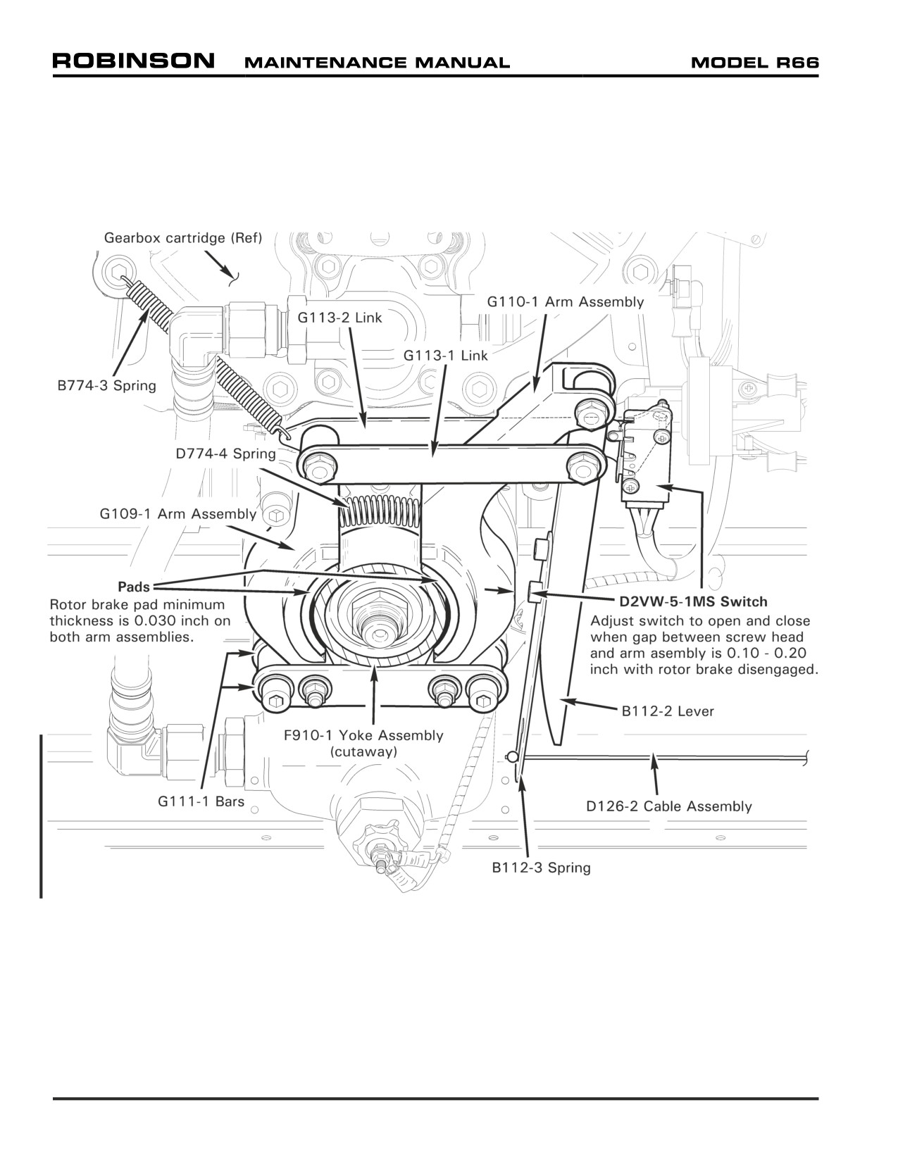
FIGURE 63-2 ROTOR BRAKE
Page 63.10
Chapter 63 Main Rotor Drive System
63-30 Rotor Brake
Refer to R66 Illustrated Parts Catalog (IPC) Figure 63-9.
A. Removal
1. Remove (engine-driven) F910-1 yoke assembly per Section 63-21, Part C steps 1 thru
3.
2. Refer to Figure 63-2. Detach D126-2 cable assembly from B112-3 spring. Detach
B774-3 spring from gearbox cartridge retaining screw or rotor brake assembly link.
3. Remove hardware securing D2VW-5-1MS switch to brake assembly link.
4. Remove hardware and spacers securing brake assembly mounting bars to gearbox
cartridge. Remove G033-1 brake assembly F256-1 shield (see Figure 63-1).
B.
Installation
1.
Refer to Figure 63-2. Verify minimum 0.030 inch rotor brake pad thickness on both arm
assemblies.
2.
Verify F910-1 yoke assembly and pinion splines are clean and undamaged. Coat splines
of pinion with B270-21 protectant.
3.
Install F256-1 shield, then position G033-1 brake assembly over pinion and install
spacers and hardware securing brake assembly mounting bars to gearbox cartridge.
Standard torque screws per Section 20-32 and torque stripe per Figure 5-1.
4.
Install yoke on pinion shaft. Place a wood block between firewall and yoke flange (to
prevent yoke from rotating). Install pinion retaining nut and washer and special torque
nut per Section 20-33. Coat nut and exposed pinion splines with B270-21 protectant.
When dry, torque stripe per Figure 5-1.
5.
Attach B774-3 spring to gearbox cartridge retaining screw and rotor brake assembly
link. Attach D126-2 cable assembly to B112-3 spring.
6.
Install hardware securing D2VW-5-1MS switch to brake assembly link, but do not
tighten. Adjust switch to open and close when gap between B112-3 spring lower
retaining screw screw head and G110-1 arm assembly is 0.10-0.20 inch with brake
disengaged. Pivot switch about lower fastener as required and tighten fasteners to set
gap.
7.
Install hardware securing A947-2 (forward) plate assembly to F910-1 yoke assembly,
and A947-2 (aft) plate assembly to F642-1 shaft weldment. Shim engine driveline per
Section 63-11. Standard torque nuts and palnuts per Section 20-32, and torque stripe
per Figure 5-1.
8.
Install tailcone cowling assembly per Section 53-23. Install engine cowling assembly
per Section 53-21.
Chapter 63 Main Rotor Drive System
Page 63.11
63-31 Pad Replacement
Refer to R66 Illustrated Parts Catalog (IPC) Figure 63-9.
A. Arm Removal
NOTE
Rotor brake pad minimum thickness is 0.030 inch on both
arm assemblies. Replace arm assemblies when pads are worn
beyond limit.
1. Remove rotor brake per Section 63-30.
2. Remove hardware and spacers securing G109-1 arm assembly to (2) G111-1 bars
and G113-1 & -2 links. Remove D774-4 spring.
3. Remove hardware and spacers securing G110-1 arm assembly to (2) G111-1 bars
and B112-2 lever. Loosen fastener securing G113-1 & -2 links to B112-2 lever.
B.
Arm Installation
1. Refer to Figure 63-2. Lubricate spacers with A257-1 grease and install in new G110-1
arm assembly. Install hardware securing G110-1 arm assembly to (2) G111-1 bars
and B112-2 lever, but do not torque.
2. Lubricate spacers with A257-1 grease and install in new G109-1 arm assembly.
Install D774-4 spring, and install hardware securing G109-1 arm assembly to (2)
G111-1 bars and G113-1 & -2 links. Standard torque all bolts and torque stripe per
Figure 5-1.
3. Install rotor brake per Section 63-30.
63-40 Rotor RPM
1. Remove tailcone cowling assembly per Section 53-23.
2. Refer to Figure 63-1. Measure gap between both F908-1 yoke assembly magnets at each
103SR13A-3 (Hall effect) sender. Verify gap is between 0.030 ± 0.010 inch.
3. As required, loosen sender jam nuts and adjust to obtain 0.030 ± 0.010 inch gap. Special
torque jam nuts per Section 20-33 and torque stripe per Figure 5-1.
4. Install tailcone cowling assembly per Section 53-23.
Page 63.12
Chapter 63 Main Rotor Drive System
CHAPTER 64
TAIL ROTOR
Section
Title
Page
64-00
Description
64.1
64-10
Tail Rotor Assembly
64.1
64-11
Static Balance
64.5
64-20
Tail Rotor Blades
64.8
64-30
Tail Rotor Blade Inspection and Repair
64.9
64-31
Scratches and Corrosion
64.9
64-32
Dents
64.9
64-33
Erosion
64.11
64-34
Root Fitting Damage
64.11
64-35
Nicks and Notches
64.11
64-36
Painting
64.11
64-40
Tail Rotor Hub
64.13
64-41
Bearing Replacement
64.13
64-42
Inspection
64.13
25 OCT 2010
Chapter 64 Tail Rotor
Page 64.i
Intentionally Blank
Page 64.ii
Chapter 64 Tail Rotor
25 OCT 2010
CHAPTER 64
TAIL ROTOR
64-00 Description
The R66 tail rotor assembly is a conventional, two-bladed teetering rotor system.
Tail rotor blades are constructed of a wrap-around aluminum skin, bonded to aluminum
honeycomb and a forged aluminum root fitting. Self-lubricating spherical bearings in the root
fitting allow blades to change pitch.
Tail rotor blades are assembled to the hub with a fixed precone angle.
The tail rotor aluminum hub mounts to the gearbox output shaft by teeter hinge. Elastomeric
bearings in the hub allow the rotor to teeter. The tail rotor hub teetering stop is a urethane
bumper, attached to the output shaft.
64-10 Tail Rotor Assembly
Refer to R66 Illustrated Parts Catalog (IPC) Figure 64-1.
A. Removal
1. Refer to Figure 64-1. Tag each pitch link with corresponding blade serial number for
reinstallation. Remove hardware securing pitch links to tail rotor blades, noting hardware
removed.
NOTE
Tail rotor pitch link-to-blade attach bolts may be different lengths
and/or have different washers installed under nut for dynamic
balancing. Reinstall hardware as removed.
2. Remove nut and A141-14 washer securing C119-2 bumper to tail rotor gearbox output
shaft.
3. Remove teeter hinge bolt, then slide tail rotor assembly and bumper off of shaft.
NOTE
Protect tail rotor assembly from damage when maintenance is
performed on workbench.
25 OCT 2010
Chapter 64 Tail Rotor
Page 64.1
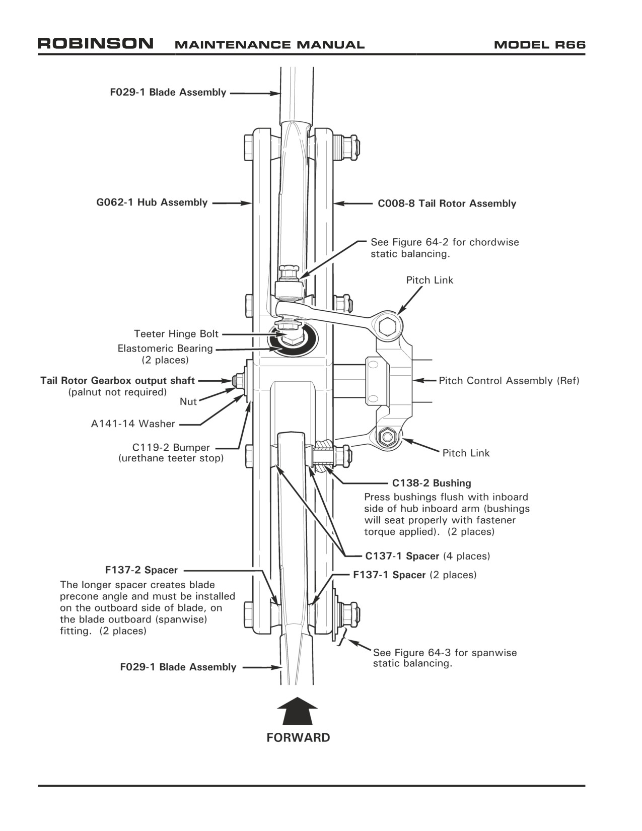
FIGURE 64-1 TAIL ROTOR INSTALLATION
Page 64.2
Chapter 64 Tail Rotor
25 OCT 2010
64-10 Tail Rotor Assembly (continued)
B.
Installation
1.
Refer to Figure 64-1. Position tail rotor assembly on tail rotor gearbox output shaft.
Verify tail rotor is installed for clockwise rotation when viewed from left side of aircraft.
Verify blades cone toward tail rotor gearbox.
2.
Remove tags, and match tail rotor blade serial number to corresponding pitch link.
Install teeter hinge bolt; tighten nut until elastomeric bearing metal spacers contact
output shaft, but do not torque.
3.
Install dynamic balancing hardware securing tail rotor blades to pitch links, as removed.
Standard torque nuts & palnuts per Section 20-32, and torque stripe per Figure 5-1.
NOTE
If dynamic balancing hardware information is unknown, install
standard hardware for initial dynamic check.
4.
Fabricate a tracking aid using 1x12-inch aluminum sheet; make a 90º bend 2 inches
from one end. With tail rotor horizontal, tape tracking aid to tailcone near blade tip.
5.
Rotate tail rotor drive shaft and mark tracking aid where each blade tip drain hole
passes. Adjust (teeter) tail rotor until both blade tips pass the same point within 0.125
inch. Special torque teeter hinge bolt per Section 20-33. Recheck track. Repeat step
until blades are tracked.
6.
Install palnut, standard torque per Section 20-32, and torque stripe per Figure 5-1.
Remove tracking aid.
7.
Teeter tail rotor back and forth. Verify teeter hinge bolt, bearing metal spacers, washers,
and nuts remain stationary when tail rotor is teetered.
8.
Install C119-2 bumper, A141-14 washer, and nut. Standard torque nut per Section 20-
32 and torque stripe per Figure 5-1.
9.
Dynamically balance tail rotor per Section 18-20.
25 OCT 2010
Chapter 64 Tail Rotor
Page 64.3
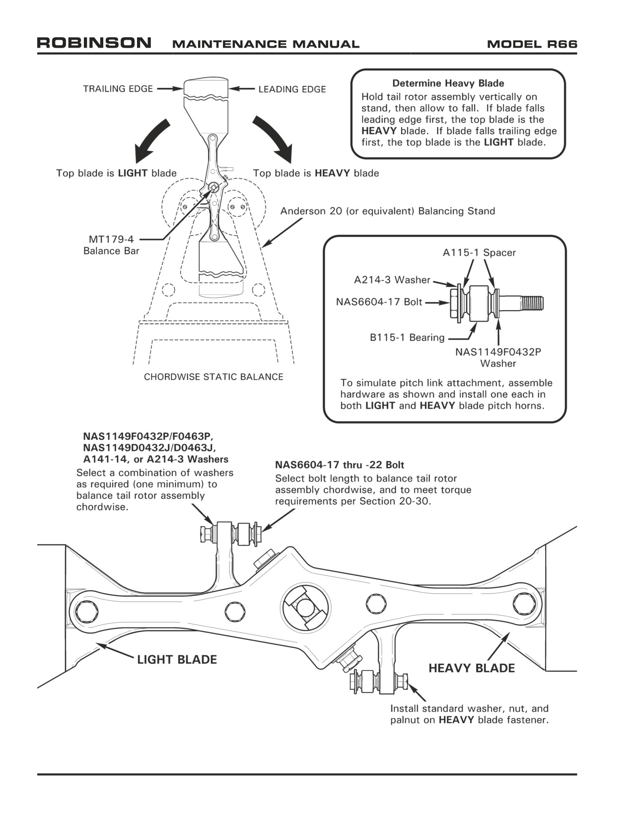
FIGURE 64-2 CHORDWISE STATIC BALANCE
Page 64.4
Chapter 64 Tail Rotor
25 OCT 2010
64-11 Static Balance
Refer to R66 Illustrated Parts Catalog (IPC) Figure 64-1.
A. Chordwise Static Balance
1. Refer to Figure 64-2. Install MT179-4 balance bar into tail rotor assembly. Install
teeter hinge bolt, and special torque nut to 350 in.-lb. Using a carpenters square,
adjust balance bar until approximately perpendicular to hub.
2. Place tail rotor assembly with balance bar on Anderson 20 or equivalent balancing
stand. Hold tail rotor assembly vertically, then allow to fall. If the blade falls leading
edge first, the top blade is the heavy blade. If the blade falls trailing edge first, the
top blade is the light blade.
3. To simulate pitch link attachment, assemble hardware as shown and install in blade
pitch horns. Install standard washer, nut, and palnut on heavy blade fastener.
Standard torque hardware per Section 20-32.
4. Chordwise balancing is achieved by varying NAS6604 bolt length and nut-side
washers on light blade fastener. Select bolt length and washers for balancing, and to
meet torque requirements per Section 20-30. Standard torque hardware per Section
20-32, and repeat step 2.
5. Blades are balanced chordwise when blade does not fall when positioned vertically
on balancing stand. Repeat step 4, adjusting bolts and washers until blades are
balanced.
6. Perform spanwise static balance per Section 64-11 Part B.
25 OCT 2010
Chapter 64 Tail Rotor
Page 64.5
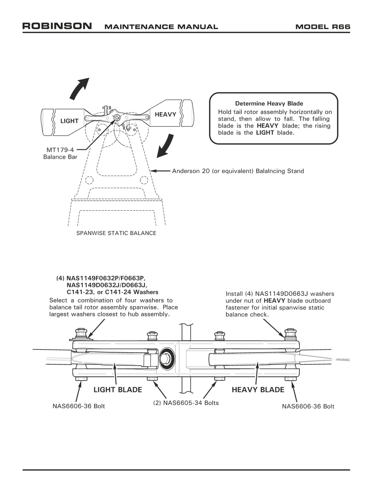
FIGURE 64-3 SPANWISE STATIC BALANCE
Page 64.6
Chapter 64 Tail Rotor
25 OCT 2010
64-11 Static Balance (continued)
Refer to R66 Illustrated Parts Catalog (IPC) Figure 64-1.
B.
Spanwise Static Balance
CAUTION
Verify four washers installed under each outboard blade fastener
prior to tail rotor assembly installation or dynamic balance.
1.
Refer to Figure 64-3. Install standard hardware for initial spanwise static balance
check. Standard torque fasteners per Section 20-32.
2.
Install MT179-4 balance bar into tail rotor assembly. Install teeter hinge bolt, and
special torque nut to 350 in.-lb. Using a carpenters square, adjust balance bar until
approximately perpendicular to hub.
3.
Place tail rotor assembly with balance bar on Anderson 20 or equivalent balancing
stand. Hold tail rotor assembly horizontally, then allow to fall. The falling blade is
the heavy blade; the rising blade is the light blade.
4.
Spanwise balancing is achieved by varying nut-side washer size on light blade
outboard fastener. Four washers are required under outboard fastener nuts; place
largest washers closest to hub assembly. Select washers for balancing, standard
torque hardware per Section 20-32, and repeat step 3.
5.
Blades are balanced spanwise when blade does not fall when positioned horizontally
on balancing stand. Repeat step 4, adjusting outboard fastener washers until blades
are balanced.
6.
Recheck chord and spanwise balance. Tail rotor assembly must be statically balanced
within 4 inch-grams. Remove MT179-4 balance bar.
25 OCT 2010
Chapter 64 Tail Rotor
Page 64.7
64-20 Tail Rotor Blades
Refer to R66 Illustrated Parts Catalog (IPC) Figure 64-1.
NOTE
Protect tail rotor assembly from damage when maintenance is
performed on workbench.
A. Removal
1. Remove tail rotor assembly per Section 64-10.
2. Refer to Figure 64-1. Remove hardware securing F029-1 blade assemblies to G062-1
hub assembly. Remove blades, spacers, and hardware; do not remove C138-2 bushings
unless required.
B.
Installation
CAUTION
F029-1 tail rotor blades are a matched set from RHC. If only
one blade is being replaced, contact RHC Technical Support with
airworthy blade serial number for a matching replacement blade.
1.
Inspect tail rotor hub per Section 64-30, as required.
2.
Refer to Figure 64-1. If removed, apply light coat of approved primer per Section 20-
70 to outer surface of C138-2 bushings; while primer is wet, press bushings flush
with inboard side of hub inboard arm (bushings will seat properly with fastener torque
applied).
CAUTION
F137-2 spacer creates blade precone angle and must be
installed on the outboard side of blade, on the blade outboard
(spanwise) fitting.
3.
Install tail rotor blades and spacers in hub. Assemble blades (if viewed from left side
of aircraft) for clockwise rotation, to cone toward tail rotor gearbox. Install hardware
securing blades to hub; install standard hardware on outboard fasteners for initial tail
rotor assembly static balance check. Tighten fasteners, but do not torque.
4.
Touch-up bolt heads using approved paint per Section 20-70.
5.
Perform tail rotor assembly static balance per Section 64-11.
Page 64.8
Chapter 64 Tail Rotor
25 OCT 2010
64-30 Tail Rotor Blade Inspection and Repair
This blade repair procedure outlines the repair limits, methods and materials used for repairing
tail rotor blades. Repairs are limited to blending out scratches, dents, nicks, removing corrosion,
and refinishing the blades. The inspections, repairs and limitations contained herein refer to
damage sustained in service, including damage during shipping and handling (manufacturing
irregularities are treated separately by the factory). In-service damage will generally exhibit
paint scuffing or scratches and often times freshly-exposed metal in the form of scratches
in the finish. If there are any questions as to the possibility of a manufacturing irregularity,
contact RHC Technical Support.
CAUTION
A blade may be repaired more than one time. However, in no
case can more than the maximum material be removed or the
maximum dent depth be exceeded in any one location.
Refer to Section 62-40 for measuring blade damage.
64-31 Scratches and Corrosion
1. Refer to Figure 64-4. Verify damage does not exceed the following limits:
a.
0.008 inch maximum damage between RS 18.00 and RS 30.00.
b.
0.005 inch maximum damage more than 15° spanwise between RS 18.00 and inboard.
c.
0.008 inch maximum damage less than 15° spanwise between RS 18.00 and inboard.
2. Refer to Section 62-50 (main rotor) for repair procedures for damage within limits.
Blend out scratches or corrosion on skins with a 0.10 inch blend radius.
64-32 Dents
CAUTION
Tap-test dented areas in honeycomb. If any voids are found
associated with dents, contact RHC Customer Service.
Tap-test voids, debonds, and dents in blades using an AN970-4
washer or 1965 or later U.S. quarter dollar coin in good condition.
CAUTION
When dented areas are found, inspect opposite side of the blade
for a bulge. Replace blade with a bulge greater than 0.010 inch
opposite a dent.
CAUTION
Do not repair any dent that has a sharp cut or break in the
skin. If necessary, locally penetrant inspect, keeping penetrant
materials away from bond joints.
WARNING
Any damaged tail rotor blade that cannot be repaired within the
limits of this section must be removed from service immediately
and marked "scrap."
25 OCT 2010
Chapter 64 Tail Rotor
Page 64.9
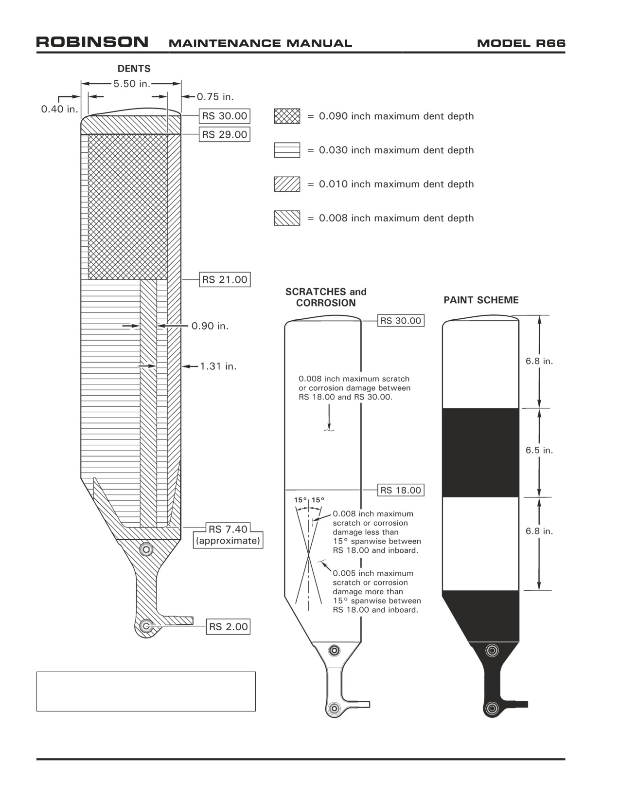
NOTE
See text for additional inspection criteria.
FIGURE 64-4 TAIL ROTOR BLADE INSPECTION CRITERIA
Page 64.10
Chapter 64 Tail Rotor
25 OCT 2010
64-32 Dents (continued)
A. Skins
1. Refer to Figure 64-4. Smooth, round bottom dents with 0.060 inch minimum radius
may be repaired when damage does not exceed the following limits:
a.
0.010 inch maximum depth between leading edge and 0.75 inch aft (chordwise).
b.
0.75 inch aft (chordwise) of leading edge:
i.
0.090 inch maximum dent depth between RS 21.00 and RS 29.00.
ii.
0.030 inch maximum dent depth between RS 21.00 and inboard.
c.
0.030 inch maximum depth between trailing edge and 0.40 inch forward (chordwise).
d.
0.008 inch maximum depth between RS 29.00 and RS 30.00.
e.
0.008 inch maximum depth over the skin-to-root fitting bond joint and carbon
fiber bonded area.
2. Refer to Section 62-50 (main rotor) for repair procedures for damage within limits.
64-33 Erosion
Replace any blade where erosion has caused deformation or ripples in the leading edge.
64-34 Root Fitting Damage
1. Verify damage does not exceed the following limits:
a. No repairs permitted within 1.5-inch diameter circle from center of spherical bearing.
b.
0.040 inch maximum depth on other root fitting exposed areas.
2. Refer to Section 62-50 (main rotor) for repair procedures for damage within limits.
Blend out root fitting damage with a minimum 1.0 inch blend radius.
64-35 Nicks and Notches
A. Trailing Edge
1. Verify damage does not exceed the following limits:
a.
0.050 inch maximum in the extreme trailing edge.
2. Refer to Section 62-50 (main rotor) for repair procedures for damage within limits.
Blend out nicks and notches in blade trailing edge for 1.0 inch minimum each side of
nick or notch.
64-36 Painting
Refer to Figure 64-4. See Section 62-52 (main rotor) for painting procedures.
25 OCT 2010
Chapter 64 Tail Rotor
Page 64.11