NATOPS FLIGHT MANUAL NAVY MODEL AV--8B/TAV--8B 161573 AND UP AIRCRAFT (2008) - page 9
A1-AV8BB--NFM--000
aircraft, blowing smoke or other physical signs of wind velocity. If the crosswind component for a rolling landing
cannot be reasonably ascertained, then execute a vertical landing.
22.2.3.4.2 Formation NORDO Recovery
In formation, a NORDO aircraft will normally fly a wingman position unless other conditions dictate that the
NORDO aircraft assume or retain the lead. If the flight was larger than a section, the remainder of the flight will
separate and execute the mission or return to base as briefed.
22.2.3.4.3 NORDO as Wingman
In the event the wingman loses the capability to communicate, the NORDO aircraft will join on the flight lead,
collapse into parade formation, and use hand and arm signals to communicate the aircraft status. Or if separated,
proceed to the briefed Lost Communication/Lost Lead rendezvous point and hold as briefed. If join--up does not
occur, return--to--base as a single aircraft once JOKER fuel is reached.
Once joined, point at the mask and ear independently with a follow on thumbs--up or thumbs--down to indicate the
capability to transmit and/or receive respectively. No HEFOP signal will indicate that the only problem is with the
radios. The NORDO aircraft will remain as the wingman during recovery.
If an emergency occurs, utilize standard HEFOP hand or light signals (see Figure 22-2). During the day, the NORDO
aircraft will give a weeping signal and then indicate with number of fingers associated with the affected system. At
night, the NORDO aircraft will use the flashlight. Holding the flashlight close to the top of the canopy and pointed
toward the wingman, the NORDO aircraft will signal his wingman the affected system with 1 to 5 dashes as
appropriate.
22.2.3.4.4 NORDO as Lead
If the NORDO aircraft is the flight lead, then the lead pilot will rock his wings to “knock--off” the training and
maneuver his aircraft to collapse the flight into a parade formation. Or if separated, proceed to the briefed Lost
Communication/Lost Lead rendezvous point and hold as briefed. If join--up does not occur, return--to--base as a single
aircraft once JOKER fuel is reached. Once joined, the lead pilot will communicate his status via hand and arm signals,
pass the lead, and remain as the wingman during recovery.
22.2.3.4.5 Recovery Procedures
The standard recovery is a straight--in section approach to an appropriate roll--on landing. If a vertical landing is
needed, the NORDO pilot will signal the lead this requirement with an open hand, palm down, up and down motion.
For dual runway airfields, lead shall position the NORDO aircraft on the left or right wing to correspond to the left
orright runway in use. The lead will, at a minimum, clear theflight to land on the duty runway and all availablepads.
To change configurations during the day, use the hand and arm signals as depicted in Figure 22-2. In all cases, the
NORDO aircraft should attempt to match the escort’s configuration for approach to landing. If an IMC approach is
anticipated and situation permits, configure the flight for landing before encountering IMC.
When the flight is cleared to land, the lead will indicate clearance to land via passing the lead to the NORDO aircraft.
The NORDO aircraft will consider the landing clearance is valid unless the escort flies past the NORDO aircraft with
his landing gear retracted and anti--collision light off. In this event, the NORDO aircraft will initiate a wave--off and
rejoin the escort as wingman.
22.2.3.4.6 Night Considerations
The NORDO aircraft signals lost communications by cycling the exterior lights master switch and collapses the
flight. Once the flight is joined, the NORDO aircraft keeps the anti--collision light on and slides aft into parade
position. The non--NORDO aircraft assumes the lead and extinguishes the anti--collision light to signal taking the
lead.
ORIGINAL
22-4
A1-AV8BB--NFM--000
Light signals to configurethe aircraft to land are depicted in Figure22-2. With clearance to land, thelead aircraft will
illuminatetheanti--collision light signaling theNORDO aircraftis clearedto landand hasthelead.Theescortaircraft
will then detach to monitor the NORDO aircraft’s landing. If clearance for landing is revoked, the escort flies by the
NORDO aircraft with landing gear retracted and the NORDO aircraft should execute a wave--off and rejoin on lead.
The NORDO aircraft should attempt to match the escort’s configuration during the wave--off.
22.2.4 Loading GPS time for HAVEQUICK and SINGCARS
1.
1. Ensure both C1 and C2 are in FF or MX channelization mode.
Note
MX channelization is only valid if the mixed list frequencies are mapped
to the fixed frequency list.
2. Select MENU--COMM on the MPCD.
3. Select HQ (PB14) on the COMM card page.
4. Select GPS (ODU option 4) to set GPS time in both radios.
5. Set both C1 and C2 to AJ channelization mode and a valid AJ preset.
6. Verify that TIME, DAY and FILL indication is blank on HQ TIME page.
7. Deselect HQ (PB 14) and verify GPS time is displayed under the upper COMM 1 and COMM
2 label of the
FF, AJ or MX COMM Card.
Note
GPS must be on--line and GPS time valid.
22.2.5 Time of Day Operations for HAVEQUICK
1. Select MENU--COMM on the MPCD.
2. Select HQ (PB14) on the COMM card page.
3. Select TIME (PB6) on the MPCD (if not already boxed).
4. ODU Selection:
a. Select XMT (ODU option1) then C1 or C2 (ODU option 4 and 5) to transmit the time of day using the
desired radio (COMM1 or COMM 2).
b. Select RCV (ODU option 2) to receive the time of day.
c. Select TRST (ODU option 3) then ACPT (ODU option 4) to reset the time or REJ (ODU option 5) to cancel
TRST.
Note
Prior to XMT or RCV operations, the radio(s) must be set to the proper FF
or MX preset (user defined or pointed to FF preset).
22.2.6 Time of Day Operations for SINGCARS
1. Ensure both C1 and C2 are set to AJ channelization mode and the preset is set to a SINGCARS Net.
2. Select MENU--COMM on the MPCD.
22-5
ORIGINAL
A1-AV8BB--NFM--000
3. Select SG (PB13) on the FF, AJ or MX COMM Cards.
4. Select TIME (ODU option 3) if not already colonized.
5. Enter the desired day and time to the minute.
Note
A two digit entry changes the minutes, a four digit entry changes the hour
and minutes, and a six digit entry changes the day, hour, and minutes.
22.2.7 HAVEQUICK MWOD Operations
1. Select MENU--COMM from the MPCD.
2. Select HQ (PB14) from the FF, AJ or MX COMM Card.
3. Select MWOD (PB7) on the MPCD (if not already boxed).
4. Program:
To program MWOD:
a. Select MWOD (ODU option 1).
b. Program all segments (20--15) and the Day (segment 14) and select LOAD (PB11).
To load Day into the radios:
c. Select LDAY (ODU option 2).
d. Enter the date to be loaded (0--31).
Note
A 1000 Hz tone is heard in the headset indicating that the day had been
loaded and accepted in the radios.
To verify that a radio has an MWOD loaded for a specific day:
e. Select VDAY (ODU option 3).
f. Enter the date to be checked (0--31).
g. Select C1 or C2 (for COMM 1 or COMM 2 in ODU windows 4 and 5).
Note
D A 1000Hz toneis heardin theheadset indicatingthat thecurrent radiohas
a valid MWOD loaded.
D Tones must be enabled to hear the associated 1000 Hz tones. From the AJ
or MX COMM Cards, COMM 1 (PB20) and COMM 2 (PB17) must be
unboxed.
22.2.8 Electronic Remote Fill (Cold Start)
1. Select CS (Coldstart frequency) using the channel select knob.
2. Colonize CS (ODU option 5).
ORIGINAL
22-6
A1-AV8BB--NFM--000
3. Select HSET (ODU option 3) or LSET (ODU option 4), whichever is to be received or transmitted.
4. Receive/Send:
To receive ERF data:
a. Enter the AJ preset where the ERF data is to be stored and select RCV.
Note
A 1000 Hz tone indicates successful storage of the ERF data.
To send ERF data:
b. Enter the preset of the data to be transmitted in the UFC.
c. Select HSET or LSET the select XMIT.
Note
XMIT is briefly cued and the transmission is heard in the headset.
5. Repeat step 4 as necessary.
22.2.9 Mixed Mode Editing
1. Press the desired radio knob to activate the UFCs.
2. Cycle ODU option 5 to MX.
3. Select MENU — COMM on the MPCD.
4. Select MX (PB9) on the COMM page.
5. Select the preset to be changed using the channel select knob or direct access entry.
6. Select EDIT (PB15) or re--enter the selected channel to activate the ODU for channel editing.
7. Select FF, AJ or UD on the ODU as desired.
8. Enter the desired Channel, Net ID, or frequency.
9. Repeat steps 4--7 as necessary.
22.2.10 Comm Alert Mode Procedures
The following are the procedures for comm. alert mode:
1. Battery switch — ALERT.
2. ACNIP controls — SET.
a. Successively actuate the code/mode switch to MODE until PL is displayed in KY 1 or 2 windows.
b. Baseband/diphase switches 1 and 2 — BB.
c. Ground and auxiliary volume control knobs — AS DESIRED.
d. Microphone switch — COLD or HOT.
e. MODE switch — MAN.
22-7
ORIGINAL
A1-AV8BB--NFM--000
3. V/UHF RSC — SET.
a. Squelch switch — SQL.
b. UHF mode selector switch — AS REQUIRED.
c. Brightness control knob — AS DESIRED.
d. Frequency mode selector knob — MAN.
e. Mode selector knob — T/R OT T/R + G.
4. UFC comm. 1 and 2 volume control knobs — AS DESIRED.
5. RSC frequency slew switches — SET DESIRED FREQUENCY.
6. PRGM switch — 1 or 2.
7. RSC mode selector knob — OFF (to conserve power); T/R OR T/R + G (to change frequency then OFF).
For KY--58 operations:
8. Successively actuate ACNIP code/mode switches to MODE until CY is displayed in KY 1--2 window.
9. Successively actuate ACNIP code/mode switches to CODE until desired code is displayed in KY 1 or 2.
22.2.11 Built--In--Test
BIT should be initiated anytime the FREQ/(CHAN) display blanks or indicates an erroneous readout. BIT is
performed as follows:
Note
BIT will fail if radio transmissions received during test.
1. To avoid reception, insert the frequency of an unused channel and key both comm. 1 and comm. 2.
2. MODE selector switch — TEST.
3. PRGM switch — 1.
4. BIT requires approximately 5 to 8 seconds, observe FREQ/(CHAN) display. No fault is indicated by 888.888.
5. MODE selector switch — T/R.
6. PRGM switch — 1.
Steady tone in headset stops.
7. Repeat the procedure for position 2 on the PRGM switch.
22.2.12 KY--58 Operation
With control--monitor set:
1. ACNIP controls — SET.
a. Baseband/diphase switch — BB.
b. MODE switch — UFC.
ORIGINAL
22-8
A1-AV8BB--NFM--000
2. ODU — SET.
a. Option 4 pushbutton — PRESS TO CIPH (tone heard).
On some aircraft, the tone is momentary and is automatically cleared. On other aircraft, the tone must be
cleared by pressing the comm. switch.
b. Option 5 pushbutton — PRESS (code displayed on scratch pad).
3. Comm switch — PRESS (tone stops).
With ACNIP controls:
4. ACNIP controls — SET.
a. MODE switch — MAN.
b. Successively actuate the code/mode switches to MODE until CY is displayed in KY--1/KY--2 window.
c. Successively actuate the code/mode switches to CODE until desired code is displayed.
22.3
VISUAL COMMUNICATIONS
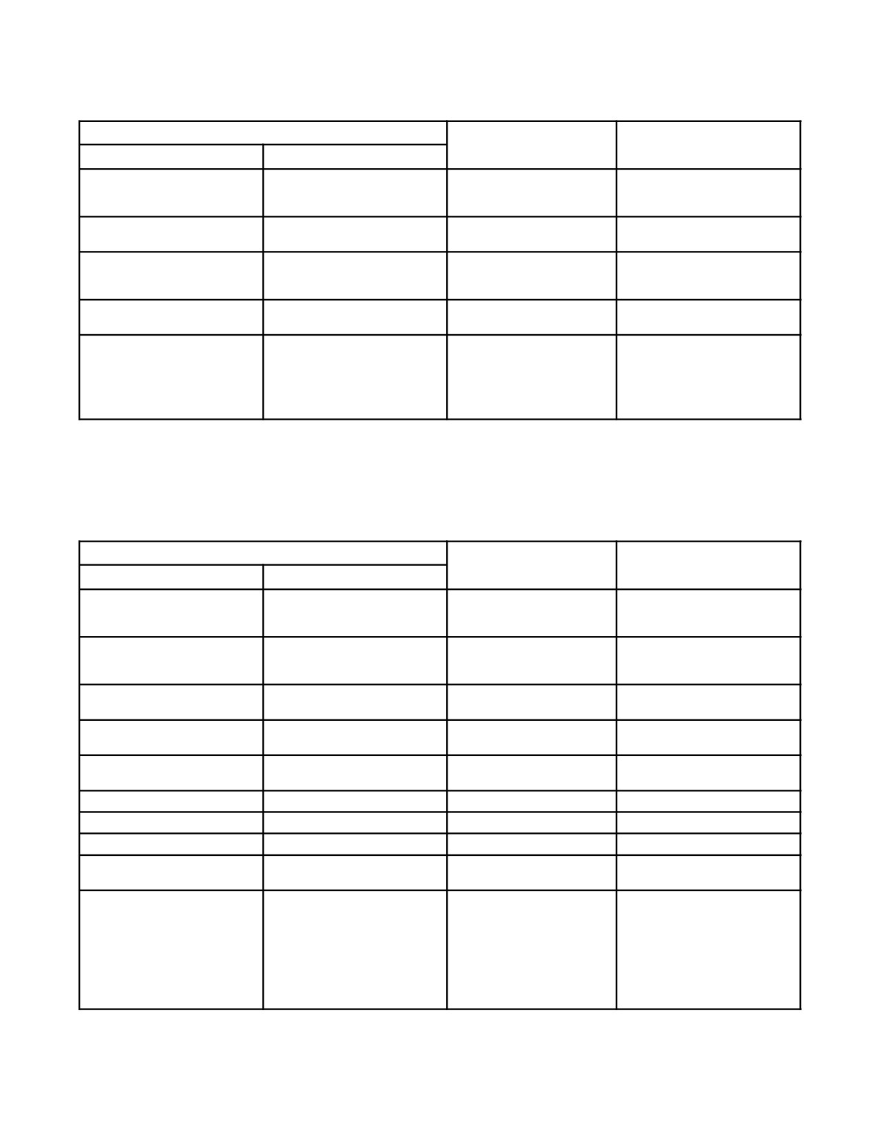
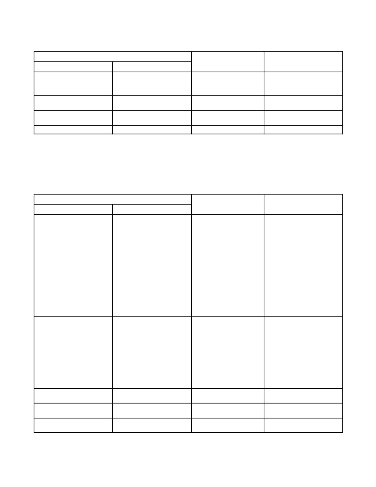
Communications between aircraft are visual whenever practical. Flight leaders shall ensure that all pilots in the
formation receive and acknowledge signals when given. The visual communications chapters of NAVAIR
00--80T--113 should be reviewed and practiced by all pilots. Common visual signals applicable to flight operations
are listed in Figure 22-2.
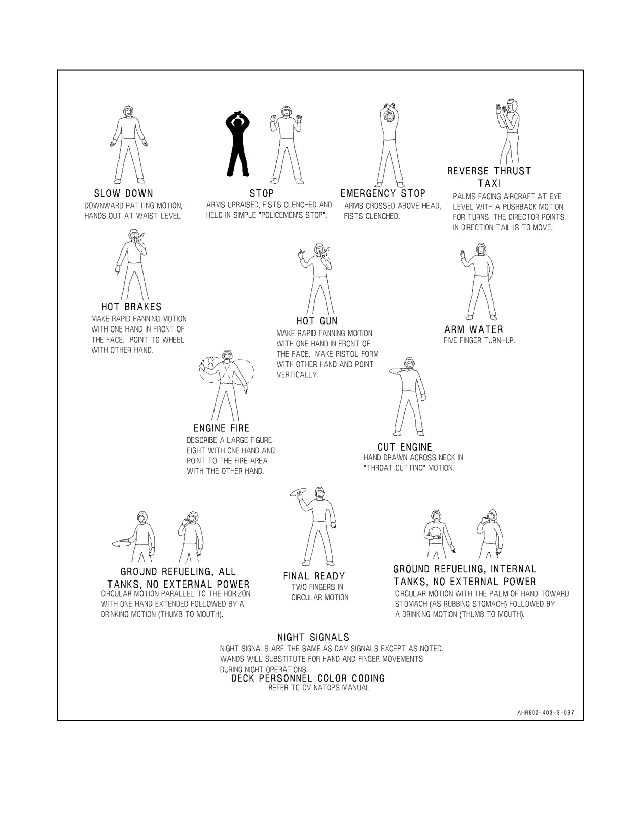
22.3.1 Deck/Ground Handling Signals
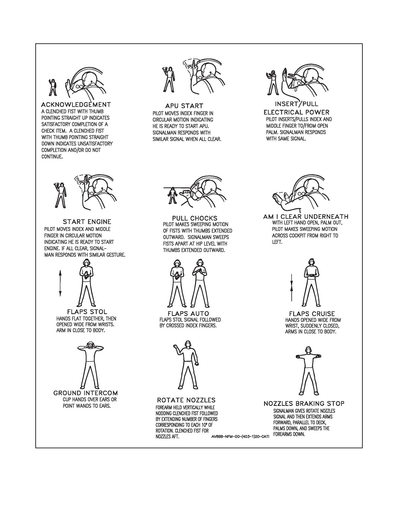
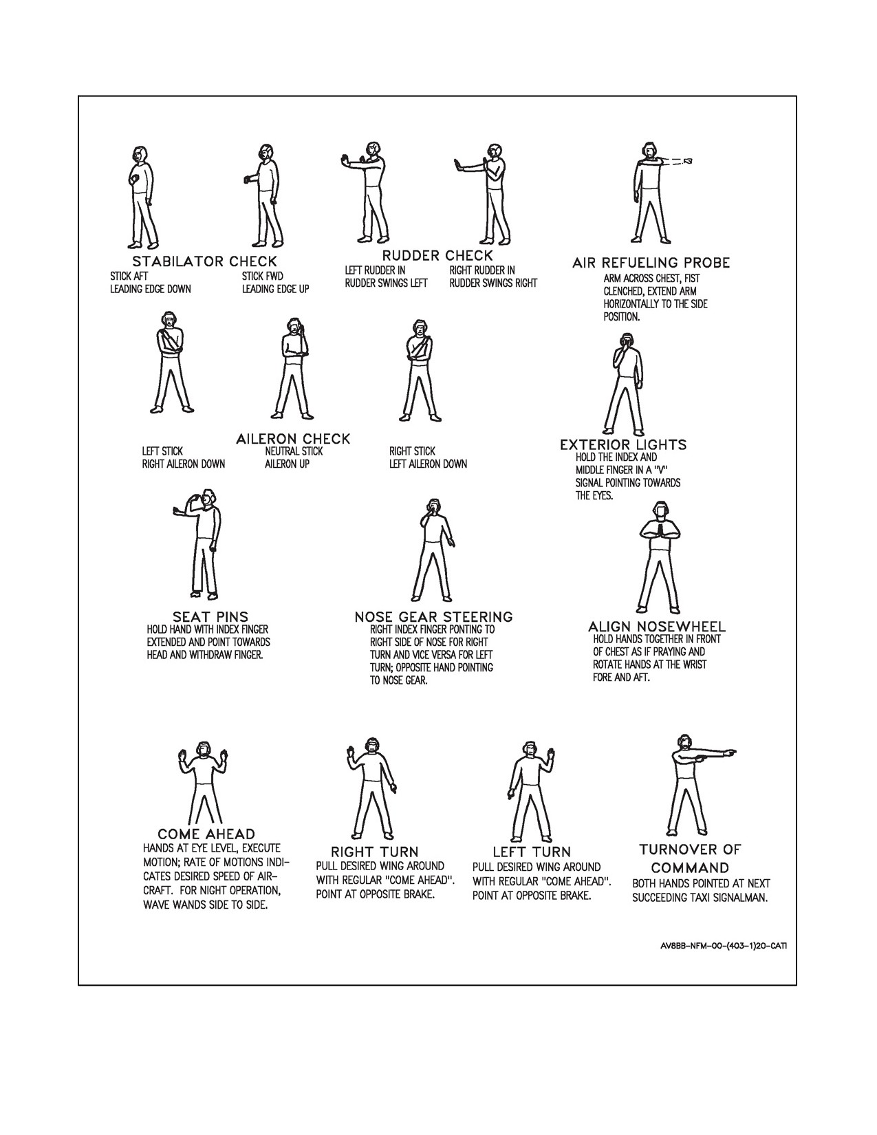
Communications between aircraft and ground personnel are visual whenever practical, operations permitting. The
visual communications chapters of Aircraft Signals NATOPS Manual (NAVAIR 00--80T--113) should be reviewed
and practiced by all flightcrew and groundcrew personnel. For ease of reference, visual signals applicable to
deck/ground handling are listed in Figure 22-3. During night operations, wands shall be substituted for hand and
finger movements.
22-9
ORIGINAL

A1-AV8BB--NFM--000
GENERAL SIGNALS
SIGNAL
MEANING
RESPONSE
DAY
NIGHT
Thumbs up, or nod of head.
Flashlight moved vertically
Affirmative. (“Yes,” or “I
up--and--down repeatedly.
understand.”)
Thumbs down, or turn of head
Flashlight moved horizontally
Negative. (“No,” or, “I do not
from side to side.
back--and--forth repeatedly.
understand.”)
Hand cupped behind ear as if
Question. Used in conjunction
As appropriate.
listening.
with another signal, this gesture
indicates that the signal is
interrogatory.
Hand held up, with palm outward.
Wait.
Employ fingers held vertically to
Numerals as indicated.
A nod of the head (“I understand”).
indicate desired numerals 1
To verify numerals, addressee
through 5. With fingers horizontal,
repeats. If originator nods,
indicate number which added to 5
interrogation is correct. If
gives desired number from 6 to 9.
originator repeats numerals,
A clenched fist indicates 0. (Hold
addressee should continue to
hand near canopy when
verify them until they are
signaling).
understood.
Make hand into cupshape, then
I am going to dump fuel.
make repeated pouring motions.
Slashing motion of index finger
I have stopped dumping fuel.
across throat.
Raised fist with thumb extended in
How much fuel have you?
Indicate remaining fuel in
drinking position.
hundreds of pounds by finger
numbers.
Figure 22-2. Visual Communications (Sheet 1 of 11)
CONFIGURATION CHANGES
SIGNAL
MEANING
RESPONSE
DAY
NIGHT
Rotary movement of clenched fist
Rotary motion of flashlight.
Lower or raise landing gear and
Execute when leader changes
in cockpit as if cranking wheels,
flaps to STOL/AUTO, as
configuration.
followed by head nod.
appropriate.
Forearm held vertically while
Horizontal movement of flashlight
Rotate nozzles.
Execute when leader changes
nodding, clenched fist followed by
followed by number of flashes for
configuration.
extending number of fingers for
each 10° of nozzle.
each 10° of nozzle rotation.
Open and close four fingers and
Extend or retract flaps, as
Execute upon head nod from
thumb.
appropriate.
leader or when leader’s flaps
extends/retract.
Rapid opening and closing four
Extend or retract speed brake
Execute upon head nod from
fingers and thumb.
as appropriate.
leader or when leader’s
speedbrake extends/retracts.
Figure 22-2. Visual Communications (Sheet 2)
ORIGINAL
22-10

A1-AV8BB--NFM--000
ARMAMENT
SIGNAL
MEANING
RESPONSE
DAY
NIGHT
1.
Pistol--cocking motion
1.
Ready or safety guns.
Repeat signal, and execute.
with either hand.
2.
Followed by
2.
How much ammo do
Thumbs up--“over half”; thumbs
question--signal.
you have?
down--“less than half.”
3.
Followed by
3.
I am unable to fire.
Nod head (“I understand”).
thumbs--down signal.
1.
Shaking fist.
1.
Arm or safety bombs,
1. Repeat signal and
as applicable.
execute.
2.
Followed by
2.
How many bombs do I
2. Indicate with appropriate
question--signal.
have?
finger--numerals.
3.
Followed by
3.
I am unable to drop.
3. Nod head
thumbs--down signal.
(“I understand”).
1.
Shaking hand, with
1.
Arm or safety
1. Repeat signal and
fingers extended
missile/rockets as
execute.
downward.
applicable.
2.
Followed by
2.
How many
2. Indicate with appropriate
question--signal.
missiles/rockets do I
finger--numerals.
have?
3.
Followed by
3.
I am unable to fire.
3. Nod head
thumbs--down signal.
(“I understand”).
Pistol--cocking motion with either
1.
Rotating beacon ON and
Jettison external stores:
Repeat signal and execute:
hand, followed by fore and aft
OFF by lead aircraft.
1. Set up your switches
1. Set up jettison ordnance
pulling motion with a clenched fist.
2.
Rotating beacon turned
for jettison.
switches.
ON for second time (allow
2. Your are cleared to
time for setting up
drop.
2. Execute.
switches).
Pistol--cocking motion followed by
Expendable check. First head
Wingman replies with thumbs up
head nod.
nod for flares, second head nod
or down for each head nod.
for chaff.
Figure 22-2. Visual Communications (Sheet 3)
MALFUNCTIONING EQUIPMENT (HEFOP CODE)
SIGNAL
MEANING
RESPONSE
DAY
NIGHT
Weeping signal and then
Flashlight held close to top of
Number of fingers or dashes
Day; not, or thumbs up (“I
indicating by finger--numbers 1 to
canopy, pointed toward wingman,
means:
understand”).
5 the affected system.
followed by 1 to 5 dashes to
1. Hydraulic system.
Night; Vertical movement of
indicate system affected.
flashlight.
2. Electric system.
3. Fuel system.
Pass lead to disable plane or
assume lead, if indicated.
4. Oxygen system.
5. Power.
Figure 22-2. Visual Communications (Sheet 4)
22-11
ORIGINAL
A1-AV8BB--NFM--000
ELECTRONIC COMMUNICATIONS AND NAVIGATION
SIGNAL
MEANING
RESPONSE
DAY
NIGHT
Tap earphones, followed by
Take over communications.
Repeat signals, pointing to self,
patting of head, and point to other
and assume communications
aircraft.
lead.
Tap earphones, followed by
I have taken over
Nod (“I understand”).
patting of head.
communications.
Tap earphones and indicate by
Shift to radio frequency
Repeat signal and execute.
finger--numerals, number of
indicated by numerals.
channel to which shifting.
Tap earphones, followed by
What channel (or frequency)
Indicate channel (or frequency) by
question signal.
are you on?
finger--numerals.
Vertical hand, with fingers pointed
What is bearing and distance to
Wait signal, or give magnetic
ahead and moved in a horizontal
the tacan station?
bearing and distance with
sweeping motion, with four fingers
finger--numerals. The first three
extended and separated.
numerals indicate magnetic
bearing and the last two or three,
distance.
Figure 22-2. Visual Communications (Sheet 5)
FORMATION
SIGNAL
MEANING
RESPONSE
DAY
NIGHT
Open hand held vertically and
Adjust wing position forward or
Wingman moves in direction
moved forward or backward, palm
aft.
indicated.
in direction of movement.
Open hand held horizontally and
Adjust wing position up or
Wingman moves up or down as
moved slowly up or down, palm in
down.
indicated.
direction of movement.
Open hand used as if beckoning
Adjust wing position laterally
Wingman moves in direction
inboard or pushing outboard.
toward or away from leader.
indicated.
Hand opened flat and palm down,
I am going to dive or climb.
Prepare to execute.
simulating dive or climb.
Hand moved horizontally above
Leveling off.
Prepare to execute.
glareshield, palm down.
Head moved backward.
Slow down.
Execute.
Head moved forward.
Speed up.
Execute.
Head nodded right or left.
I am turning right or left.
Prepare to execute.
Thumbs waved backward over
Take cruising formation or open
Execute.
shoulder.
up.
1. Holds up right (or left)
1. Wingman cross under
1. Execute.
forearm vertically, with
to right (or left) echelon
clenched fist or single
or in direction of
wing--dip.
wing--dips.
2. Same as above, except
2. Section cross under to
2. Execute.
with pumping motion or
right (or left) echelon or
double wing--dip.
in direction of
wing--dips.
Figure 22-2.
Visual Communications (Sheet 6)
ORIGINAL
22-12
A1-AV8BB--NFM--000
FORMATION (CONT)
SIGNAL
MEANING
RESPONSE
DAY
NIGHT
Triple wing--dip.
Division cross under.
Execute.
Form a Vee or balanced
Execute.
formation.
Porpoising of aircraft.
Close up or join up; join up on
Execute.
me.
Lead patting shoulder.
Airborne: Join in parade
Execute.
Ground: Section taxi.
Rocking of wings by leader.
Prepare to attack.
Execute preparation to attack.
Figure 22-2. Visual Communications (Sheet 7)
TAKEOFF, CHANGING LEAD, LEAVING FORMATION, BREAKUP, LANDING
SIGNAL
MEANING
RESPONSE
DAY
NIGHT
1.
Flight leader or wingman
1.
Flight leader/wingman
1. I have completed my
1. Return signal to flight
signal one finger.
turn approach light on.
takeoff checklist and I
leader/wingman when
am ready for takeoff.
ready for takeoff.
2.
Flight leader or wingman
2.
Flight leader/wingman
2. I am in position for
2. Return signal to flight
signal thumbs up.
turn approach light off.
takeoff.
leader/wingman when in
position for takeoff.
3.
Flight leader or wingman
3.
Flight leader or wingman
3. I have completed my
3. Return signal to flight
signal two finger.
turn approach light on.
two finger checks.
leader/wingman when two
finger checks are
complete.
4.
Flight leader nods head.
4.
Flight leader turns exterior
4. When head touches
4. Execute.
master switch off and
headrest, I will begin
back on.
takeoff roll.
1.
Leader pats self on the
1.
Lead aircraft cycles
Leader shifting lead to
1. Wingman pats head and
head, points to wing.
rotating beacon ON/OFF.
assumes lead.
wingman.
2.
If external lights are
2. Wingman turns rotating
inoperative, leader shines
beacon OFF and
flashlight on hard--hat,
assumes lead.
then shines light on
3. If external lights are
wingman.
inoperative, wingman
shines flashlight at leader,
then on his hard--hat and
assumes lead.
Leader pats self on head and
Leader shifting lead to division
Wingman relays signal; division
holds up two or more fingers.
designated by numerals.
leader designated assumes lead.
Pilot blows kiss to leader.
I am leaving formation.
Leader nods (“I understand”) or
waves good--bye.
Leader blows kiss and points to
Aircraft pointed out leave
Wingman indicated blows kiss and
aircraft.
formation.
executes.
Figure 22-2. Visual Communications (Sheet 8)
22-13
ORIGINAL

A1-AV8BB--NFM--000
TAKEOFF, CHANGING LEAD, LEAVING FORMATION, BREAKUP, LANDING (CONT)
SIGNAL
MEANING
RESPONSE
DAY
NIGHT
Leader points to wingman, then
Directs plane to investigate
Wingman indicated blows kiss and
points to eye, then to vessel or
object or vessel.
executes.
object.
Division leader holds up and
Section break off.
Wingman relays signal to section
rotates two fingers in horizontal
leader. Section leaders nods (“I
circle, preparatory to breaking off.
understand”) or waves good--bye
and executes.
Leader describes horizontal circle
Series of I’s in code, given by
Breakup (and rendezvous).
Wingman take lead pass signal
with forefinger.
external lights.
after leader breaks, and follows.
Landing motion with open hand:
Lower landing gear:
Refers to landing of aircraft,
generally used in conjunction
with another signal.
1. Followed by patting head.
1. Followed by selection of
1. I am landing.
1. Nods. (“I understand”) or
approach light ON.
waves goodbye.
2. Followed by pointing to
2. Selection of approach
2. Directs indicated
2. Aircraft indicated repeats
another aircraft.
light ON.
aircraft to land.
signal, blows a kiss and
executes.
Note
Landing motion with open hand
can be modified to signal a roll--on
landing or vertical landing.
Figure 22-2. Visual Communications (Sheet 9)
ARMING
SIGNAL
MEANING
RESPONSE
DAY
NIGHT
1.
Arming supervisor: Hands
Same.
Pilot: Check all armament
Pilot: Execute. Raise both hands to
over head.
switches OFF and SAFE.
view of arming supervisor after
checking switch position. (Hands
remain in view during check and
hook--up.)
2.
Arming supervisor points
Same.
Crew: Perform stray voltage
Arming crew: Execute. Give arming
at crew member (used if
checks.
supervisor THUMBS UP if no stray
applicable).
voltage exists.
3.
Arming supervisor; raises
Same.
Arming crew: (as applicable).
Arming crew: Execute. Give
fist, thumb extended
Hook up rocket pigtails and/or
arming supervisor THUMBS UP
upward, to meet
arm 20 MMs.
when arming completed and clear
horizontal palm of other
immediate area.
hand.
4.
Arming supervisor gives
Same.
pilot:
a. Aircraft is armed
a. Hold until arming crew
a. Thumbs up.
and all personnel
clear of arming.
and equipment
clear of area.
b. Thumbs down.
b. Aircraft is down.
b. Return to line.
5.
Arming supervisor gives
Arming supervisor gives pilot:
Apply/secure generator power.
Repeat signal. Turn on/off
pilot:
Rotating horizonal wand.
generator.
Rotating hand with
index finger and pinkey
extended.
Figure 22-2. Visual Communications (Sheet 10)
ORIGINAL
22-14

A1-AV8BB--NFM--000
DEARMING
SIGNAL
MEANING
RESPONSE
DAY
NIGHT
1. Dearming supervisor:
Same.
Pilot: Check all armament
Pilot: Execute. Raise both hands to
Hands over head.
switches OFF or SAFE.
view of dearming supervisor after
(checking
switch
positions).
(Hands remain in view during
dearming.)
2. Dearming supervisor
Same.
Crew: Disconnect rocket pigtail
Crew: Execute.
points at crew member.
and/or disconnect feed mech
air supply hose, clear rounds
from feed mech throat. (If
jammed, also disconnect
electrical lead to feed mech to
disable firing circuit). Comply
with appropriate local and
technical instructions for the
type armament concerned.
3. Dearming supervisor give
Same.
Pilot: Aircraft is dearmed and
Pilot: Hold until arming crew clear
pilot: Thumbs--up.
crew and equipment clear of
of arming area -- then return to
aircraft.
line.
Figure 22-2. Visual Communications (Sheet 11)
22-15
ORIGINAL
A1-AV8BB--NFM--000
Figure 22-3. Deck/Ground Handling Signals (Sheet 1 of 3)
ORIGINAL
22-16
A1-AV8BB--NFM--000
Figure 22-3. Deck/Ground Handling Signals (Sheet 2)
22-17
ORIGINAL
A1-AV8BB--NFM--000
Figure 22-3. Deck/Ground Handling Signals (Sheet 3)
ORIGINAL
22-18
A1-AV8BB--NFM--000
CHAPTER 23
Navigation
This chapter promulgates procedures associated with navigation systems of the AV--8B. For information on the
description, components, controls, displays, and modes of operations of communication systems, refer to NTRP
3--22.4--AV8B.
23.1
INERTIAL NAVIGATION SYSTEMS PROCEDURES
23.1.1 Ground Alignment Procedures
The following are the procedures for performing an Inertial Navigation Systems (INS) Ground Alignment:
1.
Select MENU--EHSD--DATA--A/C on the MPCD.
2.
Enter the correct current latitude (N--S) of the aircraft on the UFC and press ENTER.
3.
Enter the correct current longitude (E--W) of the aircraft on the UFC and press ENTER.
4.
Place the INS mode selector knob to GND position without pausing in the SEA position.
Note
During thefirst 1 to 2 minutes ofalignment theindicatorhasATT NOTOK
displayed to the right of QUAL.
5.
Place the INS mode selector knob to NAV anytime after the alignment quality (QUAL) number drops below
3.0.
Note
D If maximum accuracy is desired, wait until OK is displayed and then select
NAV or IFA.
D With AN/ASN--139, the time required to achieve an OK can be less than
4 minutes and temperature has no effect.
D If the parking brake is released during alignment the INS switches to align
hold and the time digits on the MPCD display will flash on and off.
D The INS caution light will illuminate if the INS present position and the
GPS Navigation data are both valid and the INS mode selector knob is set
to NAV. This is to indicate that the system should be in IFA.
23.1.2 SINS Sea Alignment Procedures
The following are the procedures for a SINS alignment aboard the ship:
Note
Entering current aircraft position prior to initiating a SINS alignment will
greatly enhance alignment accuracy and decrease its duration.
23-1
ORIGINAL
A1-AV8BB--NFM--000
With SINS cable connected:
1. Select MENU--EHSD--DATA--A/C on the MPCD.
2. Enter the correct current latitude (N--S) of the aircraft on the UFC and press ENTER.
3. Enter the correct current longitude (E--W) of the aircraft on the UFC and press ENTER.
4. Place the INS mode selector knob to SEA position.
5. Place the INS mode selector knob to NAV anytime after the alignment quality (QUAL) number drops below
3.0.
RF SINS alignment with no SINS cable:
1.
Select MENU--EHSD--DATA--A/C on the MPCD.
2.
Enter the correct current latitude (N--S) of the aircraft on the UFC and press ENTER.
3.
Enter the correct current longitude (E--W) of the aircraft on the UFC and press ENTER.
4.
Enter the SINS radio frequency in COMM 1 or COMM 2 as desired.
5.
Place the INS mode selector knob to SEA position.
6.
Colonize COM1 or COM2 on the ODU as appropriate.
Note
The ODU will be enabled for selection of SINS data source when the INS
mode selector knob is initially placed to the SEA position or whenever the
SINS option is re--boxed on the EHSD. The ODU defaults to DECK with
a SINS data cable connected and to COM2 if the avionics system does not
detect a cable. For RF SINS alignments with H4.0, due to a software
anomaly, colonize DECK prior to colonizing COM1 or re--colonizing
COM2.
7.
Place the INS mode selector knob to NAV anytime after the alignment quality (QUAL) number drops below
3.0.
Note
D If maximum accuracy is desired, wait until OK is displayed and then select
NAV or IFA.
D With AN/ASN--139, the time required to achieve an OK can be less than
4 minutes and temperature has no effect.
D If the parking brake is released during alignment the INS switches to align
hold and the time digits on the MPCD display will flash on and off.
D The INS caution light will illuminate if the INS present position and the
GPS Navigation data are both valid and the INS mode selector knob is set
to NAV. This is to indicate that the system should be in IFA.
23.1.3 Manual Sea Alignment Procedures
The following are the procedures for a Manual Sea Alignment:
1. Select MENU--EHSD--DATA--A/C on the MPCD.
2. Enter the correct current latitude (N--S) of the aircraft on the UFC and press ENTER.
ORIGINAL
23-2
A1-AV8BB--NFM--000
3. Enter the correct current longitude (E--W) of the aircraft on the UFC and press ENTER.
4. Press the SHIP option on the ODU. Enter the ships heading and speed in the UFC.
5. Press the THDG option on the ODU. Enter the aircraft true heading in the UFC.
6. Place the INS selector knob to the SEA position.
7. Select EHSD display and box the MAN legend at the top of the MPCD.
Note
D During thefirst 1 to 2 minutes ofalignment theindicatorhasATT NOTOK
displayed to the right of QUAL. The INS caution light will illuminate until
ATT NOT OK is replaced by a QUAL number.
D With AN/ASN--139 when the INS alignment is completed, the QUAL
number will be less than 1.0 and the time should be less than 10 minutes
and an OK is displayed.
8. Place the INS mode selector knob to NAV or IFA.
23.1.4 GPS Carrier Alignment
The following are the procedures to initiate a GPS carrier alignment:
1. Place the INS mode selector knob to IFA.
Note
D During the GPS carrier alignment, the MC must provide valid GPS data
from the MAGR. The magnetic heading input is not required since the INS
performs a wide angle alignment.
D If GPS velocity become invalid before wide angle alignment complete
(HDG displayed in the MPCD), the alignment will restart. This is due to
the Kalman filter extrapolations which require valid reference velocities
without interruption before high order AHRS.
23.1.5 Ground Stored Heading Alignment Procedures
This procedure can be performed if the aircraft is parked and an INS complete ground alignment has been done; if
the aircraft has not been moved since the alignment, and if NAV has not been selected on the miscellaneous control
panel. A stored heading alignment is indicated by SHDG option displayed on the upper left corner of the ground align
display. The procedures are as follow:
Note
The SHDG pushbutton should be selected as quickly as possible after
selecting a ground alignment. A recently operated system would be warm
and the SHDG option is displayed only as long as its use would assist in
the alignment. When the alignment progresses past the point that its use
would assist, the option is removed from the display.
1. Place the INS mode selector knob to GND. The MPCD will display INS ground alignment.
2. Press the SHDG pushbutton on the MPCD.
3. Observe the MPCD for ground alignment indications.
23-3
ORIGINAL
A1-AV8BB--NFM--000
Note
During the first portion of alignment the indicator may have ATT NOT OK
displayed to the right of QUAL. QUAL digits start counting down and
TIME digits start counting up. When INS heading is valid, HDG will be
displayed after the quality digits. When the INS alignment is completed,
OK will be displayed next to QUAL with less than 5 minutes.
4. Place the INS mode selector knob to NAV.
Note
Stored Heading Alignment is only available in C1+ aircraft.
23.1.6 INS Gyro Alignment Procedure
The following are procedures for INS gyro alignment:
1. Select MENU--EHSD--DATA--A/C on the MPCD.
2. Enter the correct current latitude (N--S) of the aircraft on the UFC and press ENTER.
3. Enter the correct current longitude (E--W) of the aircraft on the UFC and press ENTER.
4. Place the INS mode selector knob to GYRO.
Note
On the MPCD, after approximately 15 seconds HDG/COMP is replaced by
HDG/SLV. These options will disappear from the MPCD within 33
seconds.
5. Press the SYNC pushbutton on the MPCD to slave the magnetic heading from the magnetic azimuth detector
(MAD) to the platform heading.
6. Press the ERECT pushbutton to fast level the platform.
23.1.7 RADAR In--Flight Align
The procedures for a radar in--flight alignment (RIFA) are as follows:
Note
A complete RIFA may be initiated after a total INS shutdown and may take
up to 20 minutes to complete. During the RIFA the ADC must beavailable
to provide magnetic heading information and the radar must be capable of
providing continuous position velocity updates.
1. Ensure NAV master mode is selected.
2. Place the INS mode selector knob to IFA.
3. Select RIFA on the GPS Data page for C1+ aircraft and A/C Data page for H4.0 aircraft.
4. Observe that time begins to increment during the first 1 to 2 minutes of the alignment.
When RIFA displays an OK after the QUAL number:
5. Place the INS mode select switch to the NAV position.
ORIGINAL
23-4
A1-AV8BB--NFM--000
23.1.8 Post Evaluation Procedure
The post evaluation procedures are:
Note
To prevent erroneous results this procedure should only be performed
ashore.
1. On MPCD select — MENU, BIT, MAINT, INS, POST.
POST 1 data display appears for flight 1.
2. Record — ALN TIME, AQ (align quality), and PER (positional error rate).
3. Select — POST 1.
POST 2 data display appears for flight 1.
4. Record — UPDATE.
5. Select — POST 2.
POST 1 data display appears for flight 2.
6. Repeat steps 1 through 5 to record all stored flights.
23.2
POSITION UPDATE PROCEDURES
23.2.1 TACAN Position Update
There are two types of TACAN Position updates: 1) Single TACAN update; and 2) Two TACAN update. A single
TACAN update uses the range and bearing to the TACAN and its known position to calculate the aircraft’s position.
A two TACAN update uses the range and bearing from two TACANs to triangulate aircraft position. A TACAN
Position update will update the aircraft position and the INS position.
Note
D TACAN Position updates can only be performed using TACANs that are
entered on the EHSD--DATA--TCN page. The current aircraft TACAN
channel and mode (X/Y) must match a TACAN channel and mode entered
on the EHSD--DATA--TCN page. In the case where more than one TACAN
entry has the same channel and mode combination, the system will pick the
first match (TCN 0 -- TCN 4).
D A TACAN Position update cannot be performed while AWLS Steering or
EMCON is enabled.
D The range and bearing to the selected TACAN/TACANs must be valid.
23.2.1.1 Single TACAN Position Update
1. Place the INS mode selector knob to NAV. Select DGD/INS or DGD/ADC.
2. Turn on TACAN power and select the desired TACAN channel and X/Y mode.
3. Select UPDT on the EHSD, FLIR, A/G RDR, or DMT page.
4. Select TCN in ODU window 1.
23-5
ORIGINAL
A1-AV8BB--NFM--000
5. The TACAN bearing and range error is displayed in the scratchpad.
6. Select ACPT to accept the displayed bearing and range adjustments. Select REJ or unbox UPDT to cancel the
update.
23.2.1.2 Two TACAN Position Update
1. Perform steps 1 through 5 of the Single TACAN Position update.
2. Select TCN2 in ODU window 2. The scratchpad will display the TACAN number (as entered in the
EHSD--DATA--TCN page) and the TACAN’s channel number. Select TCN2 again to cycle to the next TACAN
station.
3. If the range and bearing to the second TACAN is valid, the ERR2 option will appear in option window 3 after
approximately 5 seconds.
4. Select ERR2 to display the two TACAN Position update bearing and range error in the scratchpad. Select
ERR1 in ODU window 1 to display the single TACAN Position update bearing and range error.
5. Select ACPT to accept the displayed bearing and range adjustments. Select REJ or unbox UPDT to cancel the
update.
23.2.2 Designate Position Update
There are two types of Designation Position updates: 1) WYPT Designate update; and 2) MAP Designate update.
A WYPT designation update uses the designation’s known location and its slewed position in the HUD to calculate
the aircraft’s position. A MAP designation update uses the slant range and bearing of a HUD designation and its
slewed position on the map to calculate the aircraft’s position. A Designate Position update will update the aircraft
position and the INS position.
Note
A designation is required before the Designate Position update can
calculate the error in the aircraft’s position. Although, a designation can be
made after a Designation Update is initiated, a known software anomaly
will sometimes cause the system to automatically reject the update.
Therefore, best practice would be to make a designation before selecting
DESG on the ODU.
23.2.2.1 WYPT Designate Update
1. Place the INS mode selector knob to NAV. Select DGD/INS or DGD/ADC.
2. Designate a waypoint, markpoint, or targetpoint.
3. Select UPDT on the EHSD, FLIR, A/G RDR, or DMT page.
4. Select DESG in ODU window 2.
5. Slew the diamond in the HUD over the designation.
6. The WYPT Designate bearing and range error is displayed in the scratchpad.
Select ACPT to accept the displayed bearing and range adjustments. Select REJ, unbox UPDT, or undesignate to
cancel the update.
ORIGINAL
23-6
A1-AV8BB--NFM--000
23.2.2.2 MAP Designate Update
1.
Place the INS mode selector knob to NAV. Select DGD/INS or DGD/ADC.
2.
Designate a landmark on the HUD.
3.
Select UPDT on the EHSD center or decenter page.
Note
An update can be initiated from the EHSD, FLIR, A/G RDR, or the DMT
page, but the EHSD center or decenter page must be displayed before MAP
appears on the ODU in window 2. Additionally a map set must be installed
in the aircraft and EMCON must be disabled.
4.
Select DESG in ODU window 2.
5.
Select MAP in ODU window 2. A crosshair is displayed in the center of the map. The center of the map is
moved to the designation’s location.
6.
Slew the crosshair on the map until it is over the landmark that is designated in the HUD.
7.
The MAP Designate bearing and range error is displayed in the scratchpad.
8.
Select ACPT to accept the displayed bearing and range adjustments. Select REJ, unbox UPDT, or undesignate
to cancel the update.
Note
A MAP Designate will be cancelled if the EHSD page is exited, if the
decenter compass rose is selected, or if the type of map (CHRT, DTED, or
CIB) is changed after MAP has been cued on the ODU. WYPT Designation
update can be reselected by uncolonizing MAP.
23.2.3 Overfly Position Update
There are three types of Overfly Position update: 1) WYPT Overfly update; 2) MAP Overfly update; and 3)
Navigation Fix Overfly update. A WYPT overfly update is used to update the aircraft’s position to the steer--to point’s
known location. It is also used to update the aircraft’s altitude. A MAP overfly update uses the map to select the
aircraft’s position. A navigation fix update allows the pilot to enter the aircraft’s latitude and longitude or 10--digit
UTM. An Overfly Position update will update the aircraft position and the INS position. If the radar altimeter is valid,
a WYPT overfly update can also be used to update the aircraft’s altitude.
23.2.3.1 WYPT Overfly Update
1. Place the INS mode selector knob to NAV. Select DGD/INS or DGD/ADC.
2. Select UPDT on the EHSD, FLIR, A/G RDR, or DMT page.
3. Select OVFY in ODU window 3 when the current waypoint, markpoint, or targetpoint is overflown.
4. The WYPT Overfly bearing and range error is displayed in the scratchpad.
5. Select ACPT to accept the displayed bearing and range adjustments. Select REJ to not accept the displayed
bearing and range adjustments.
6. The WYPT Overfly altitude error is displayed in the scratchpad if the radar altitude is valid.
7. Select ACPT to accept the altitude adjustments. Select REJ or unbox UPDT to cancel the update.
23-7
ORIGINAL
A1-AV8BB--NFM--000
23.2.3.2 MAP Overfly Update
1.
Place the INS mode selector knob to NAV. Select DGD/INS or DGD/ADC.
2.
Select UPDT on the EHSD center or decenter page.
Note
An update can be initiated from the EHSD, FLIR, A/G RDR, or the DMT
page, but the EHSD center or decenter page must be displayed before MAP
appears on the ODU in window 2. Additionally a map set must be installed
in the aircraft.
3.
Select OVFY in ODU window 3 when the desired map location is overflown.
4.
Select MAP in ODU window 2. A crosshair is displayed in the center of the map. The center of the map remains
at the aircraft location.
5.
Slew the crosshair on the map until it is over the landmark that was overflown.
6.
The MAP Overfly bearing and range error is displayed in the scratchpad.
7.
Select ACPT to accept the displayed bearing and range adjustments. Select REJ or unbox UPDT to cancel the
update.
Note
AMAPOverflywillbecancellediftheEHSDpageisexited,ifthedecenter
compass rose is selected, or if the type of map (CHRT, DTED, or CIB) is
changed after MAP has been cued on the ODU.
23.2.4 Manual GPS Update
A GPS update is used to update the aircraft’s position and the INS position if the position keeping mode/source is
DGD/INS or DGD/ADC. If the position keeping mode source is DGD/GPS, only the INS position is updated.
1. Place the INS mode selector knob to NAV. Select DGD/INS, DGD/GPS, or DGD/ADC.
2. Select UPDT on the EHSD, FLIR, A/G RDR, or DMT page.
3. Select GPS in ODU window 4.
4. The GPS bearing and range error is displayed in the scratchpad.
5. Select ACPT to accept the displayed bearing and range adjustments. Select REJ or unbox UPDT to cancel the
update.
23.3
ALL WEATHER LANDING SYSTEM PROCEDURE
1. UFC -- AWLS. Defaults to ON.
2. Cycle ON or OFF via UFC.
3. ODU option 1 -- enter channel (1--20) via UFC.
4. ODU option 2 -- enter glideslope (2.0 --6.0 in 0.1° increments) via UFC.
5. ODU option 3 -- enter azimuth offset option (+/-- 310 feet) via UFC.
6. ODU option 4 -- enter TACAN channel (1--126; alternate depressions of “TCN” option on ODU cycle between
X and Y) via UFC.
ORIGINAL
23-8
A1-AV8BB--NFM--000
7. ODU option 5 -- enter elevation offset option (0--31 feet) via UFC.
8. EHSD box AWLS option to select AWLS steering.
23.4
BUILT--IN--TEST PROCEDURES
23.4.1 TACAN Built--In--Test
1. Press BIT button on the MPCD menu.
2. Press the CNI pushbutton.
3. Observe TEST next to TCN (test takes 25 seconds).
4. If 1 next to TCN (TCN 1) — TACAN failed BIT check.
5. If space next TCN remains blank — TACAN passed BIT check.
23.4.2 AWLS BIT Check
1. Press BIT button on the MPCD menu.
2. Press the CNI pushbutton.
3. Observe TEST next to AWLS (test takes approximately 15 seconds).
4. If any number next to AWLS — AWLS failed BIT check.
5. If space next to AWLS remains blank — AWLS passed BIT check.
23.5
GLOBAL POSITIONING SYSTEM
The Global Positioning System (GPS) is a space--based radio positioning system which provides accurate position,
velocity, and time data to various targeting, navigation, and communication systems aboard the aircraft. See NATIP
NTRP 3--22.4 for in--depth theory and system operation.
23.5.1 Component Description
The aircraft components of the GPS system are the GPS antenna and the Miniaturized Airborne GPS Receiver
(MAGR).
23.5.1.1 GPS Antenna
The GPS antenna is a fixed radiation pattern low profile antenna mounted on door 51 next to the water fill tank door.
The antenna provides omnidirectional coverage above 10° elevation from its surface.
23.5.1.2 MAGR
The MAGR receives ranging codes and a navigation data message from the NAVSTAR satellites through the GPS
antenna. The MAGR can track five GPS satellites and calculate the aircraft exact position from the four best satellites
being tracked. The MAGR provides UTC time, aircraft position, aircraft velocity, and altitude data to the MC. The
MAGR contains a battery to provide power for a clock and to maintain memory when aircraft power is not supplied.
The MAGR has a built--in--test used for determining the status of the receiver and the battery.
23.5.2 GPS Controls and Indicators
The controls and indicators for the GPS include the upfront control, option display unit, multipurpose color display,
INS mode select switch, and GPS caution light.
23.5.2.1 Upfront Control
The scratch pad display on this control is used for displaying the position error when a GPS navigation update is
performed. The display is also used to display GPS time, in UTC, when REAL is selected in the ODU.
23-9
ORIGINAL
A1-AV8BB--NFM--000
23.5.2.2 Option Display Unit
This control/indicator provides a way of displaying and selecting the various options available for a GPS navigation
update and provides the option (REAL) for selecting the GPS time display on the UFC.
23.5.2.3 Multipurpose Color Display
TheEHSDdisplay,BITdisplay, andGPS waypointand datadisplays arepresented ontheMPCD.The20pushbutton
switches surrounding the crt provide display selection and control
23.5.2.4 INS Mode Select Switch
Selecting IFA initiates the in--flight alignment and enables a tightly--coupled navigation mode. Selecting NAV
enables a loosely coupled, degraded, navigation mode.
23.5.2.5 GPS Caution Light
When enabled, indicates aggressive maneuvering, GPS data is not valid or has stopped updating, or GPS horizontal
and vertical position error is not within the tolerance required for GPS navigation steering modes, normal (NORM)
and approach (APPR). The GPS light on the CAUTION/ADVISORY panel is illuminated along with the MASTER
CAUTION light if a GPS failure has been detected or if the GPS horizontal error exceeds a specified tolerance. If
theGPSisbeingusedasthepositionkeepingsourceandnormalmodeisselected,theGPScautionlightisilluminated
when the horizontal position error exceeds 333 meters for greater than 5 seconds. If the GPS is being used as the
position keeping source, approach mode is selected, true airspeed is valid and less than 300 knots, the GPS caution
light is illuminated when the horizontal position error exceeds 33 meters for greater than 5 seconds. With MAGR
not installed the system disables the GPS caution light, however it lights up with DC backup running.
Note
The GPS caution light will also illuminate if the INS present position and
the GPS navigation data are both valid and the INS mode selector knob is
set to NAV. This is to indicate that the system should be in IFA.
23.5.3 EHSD Display Format
The EHSD display format shows the aircraft position keeping source, navigation system coupling mode, and
additional information when utilizing the in--flight alignment mode or courseline feature.
23.5.4 GPS Flight Mode Selection
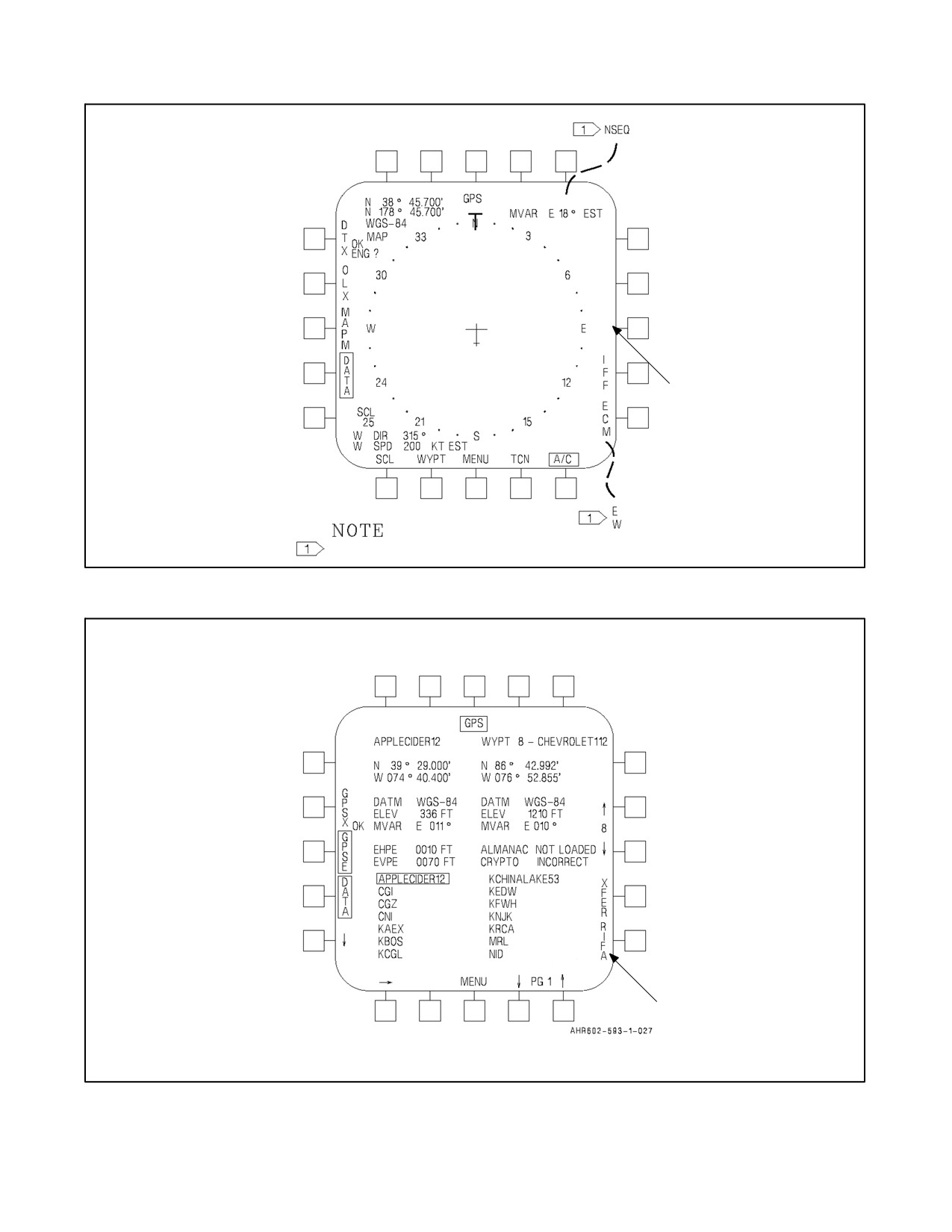
The GPS flight mode selections, APPR or NORM are available on the aircraft data display (POS/GPS or DGD/GPS,
DATA, A/C, NORM, or APPR). See Figure 23-1. These options specify a corridor (navigation tolerance) about the
desired aircraft course. If GPS position keeping is selected and the estimated error of the GPS exceeds the selected
mode tolerance, a cockpit warning is provided by a GPS advisory and MASTER CAUTION light. The default flight
mode selection at aircraft power--up with weight--on--wheels is normal mode. The flight mode selection option is only
available in POS/GPS and DGD/GPS position keeping modes. Currently GPS in USN aircraft is for tactical use only
and does not meet FAA standards for enroute or the terminal phase of flight. GPS is not used as the primary means
of navigation to file or fly in the National Airspace System. Reference CNO/N88/021214Z Aug 94.
23.5.5 GPS Data
The GPS data display format is enabled by selecting the GPS option from the EHSD--DATA display format with
OMNI 7.1 and C1+. The GPS data display format is enabled by selecting the GPS option from the SDAT--TFER
display format in H4.0. SeeFigure23-2. TheGPS datadisplay formatcontains GPSand tacticalwaypoint/markpoint
information, including the identifier, latitude, longitude, datum, elevation, and magnetic variation. The GPS data
display format is used to:
1. Upload waypoints into the MAGR from the data storage unit (DSU) or AMU mission card.
2. Transfer waypoint data stored in the MAGR into a tactical waypoint/markpoint/targetpoint.
ORIGINAL
23-10
A1-AV8BB--NFM--000
N
S
E
Q
N
O
R
M
RIFA DISPLAYED WITH H4.0
H4.0 ONLY.
Figure 23-1. Aircraft Data Display
(RADAR AIRCRAFT)
Figure 23-2. GPS Data Display (OMNI 7.1 and C1+)
23-11
ORIGINAL
A1-AV8BB--NFM--000
3. Examine the GPS almanac and crypto--key status (OMNI 7.1 and C1+ only).
4. Inspect the current estimated GPS position errors (OMNI 7.1 and C1+ only).
Note
With H4.0, the estimated GPS position errors are displayed on the EHSD
page and the GPS almanac and crypto--key status lines are displayed on BIT
page 2.
23.5.5.1 GPS Waypoint Data Upload
Selection of the GPSX option transfers the GPS waypoint database from the DSU or the AMU mission card to the
GPS. To get to the GPSX option select EHSD--DATA--GPS with OMNI 7.1 or C1+, or select SDAT--TFER--GPS
with H4.0. OK indicates the transfer was successful. ?? indicates an error occurred during transfer. OK or ?? is
displayed until another pushbutton is pressed. With H4.0, GPS waypoints that are corrupted on the DSU/AMU
mission card or were corrupted when read from the DSU/AMU mission card are displayed with the waypoint ID
????????????. These corrupted GPS points are moved to the end of the list. Corrupted GPS waypoints cannot be
transferred into waypoints, markpoints, or targetpoints.
23.5.5.2 GPS Waypoint Data Transfer (OMNI 7.1 and C1+)
To transfer waypoint data from over 200 waypoints stored in the MAGR into one of the tactical waypoints/markpoints
(0 through 24, MK1, MK2, MK3) do the following:
1. Select a tactical waypoint/markpoint.
2. Select a GPS waypoint.
3. Select XFER option.
The tactical waypoints/markpoints are selected by scrolling to the desired waypoint/markpoint number using the
increment or decrement arrow option on the right side of the display format. The GPS waypoint is selected by
scrolling to the desired page using the page up or page down arrow option and then by using the down and/or right
arrow option, the selection box is placed around the desired GPS waypoint. The transfer of the GPS waypoint data
into the tactical waypoint/markpoint is accomplished by selecting the XFER option. When the XFER option is
pressed, if the GPS waypoint is stored in the DSU, the MC transfers the waypoint and any associated offset data into
the tactical waypoint/markpoint. However, if the MC is forced to retrieve the GPS waypoint data from the MAGR,
only the waypoint data without any associated offset is transferred to the tactical waypoint/markpoint. The MAGR
does not store offset data.
23.5.5.3 GPS Almanac and Crypto--Key Status
After aircraft power--up with OMNI 7.1 or C1+, the GPS--Data page display format should be selected to examine
the almanac and crypto--key loading status. With H4.0, the GPS almanac and crypto--key status is located on theBIT
page.
1. Almanac Status. If the almanac data is not loaded in the MAGR, the NOT LOADED legend is displayed
adjacent to the ALMANAC legend. When the almanac data is loaded into the MAGR, LOADED is displayed
adjacent to ALMANAC . If no almanac is loaded, the MSC will attempt to transfer the almanac file from the
DSU or AMU mission card to the MAGR. Regardless of whether the almanac is LOADED or not, the MAGR
will strip a complete almanac from the satellite signal once it finds any satellite. This takes approximately 14
minutes after a satellite is located. Once an almanac is loaded , the MAGR will retain it even after shutdown.
Whenever the MAGR is changed or batteries in the MAGR are changed, the MAGR should be run on ground
power until a fix is obtained. There is no power switch or ON/OFF switch for the MAGR. The MAGR
functions any time APU or main generator power is available.
2. Crypto--Key Status. After communication with a satellite is established, the MAGR reports whether the
crypo--keys are correct. If the crypto keys are not loaded in the MAGR, NOT LOADED is displayed adjacent
to the CRYPTO legend. When the crypto keys are loaded into the MAGR and the MAGR has not verified
whether the keys are correct, LOADED is displayed adjacent to the CRYPTO legend. INCORRECT is
ORIGINAL
23-12
A1-AV8BB--NFM--000
displayed adjacent to the CRYPTO legend if the MAGR determines that the loaded keys are incorrect. OK
legend is displayed adjacent to the CRYPTO legend after the MAGR has determined that the loaded keys are
correct. Crypto--key verification may take up to 12 minutes.
23.5.5.4 GPS Estimated Position Error Status
To inspect the current estimated horizontal and vertical position errors of the GPS with OMNI 7.1 or C1+, the GPSE
option on the GPS data page can be selected. With H4.0, the estimated Horizontal Position Errors (abbreviated as
H) and Estimated Vertical Position Errors (abbreviated as V) are continuously displayed on the EHSD center,
decenter, and EW pages (see Figure 23-11). Leading zeroes are not depicted on the EHSD and EW pages.
Note
It is especially important to monitor GPS position errors when using the
GPS (POS/GPS or DGD/GPS) for low--level night navigation.
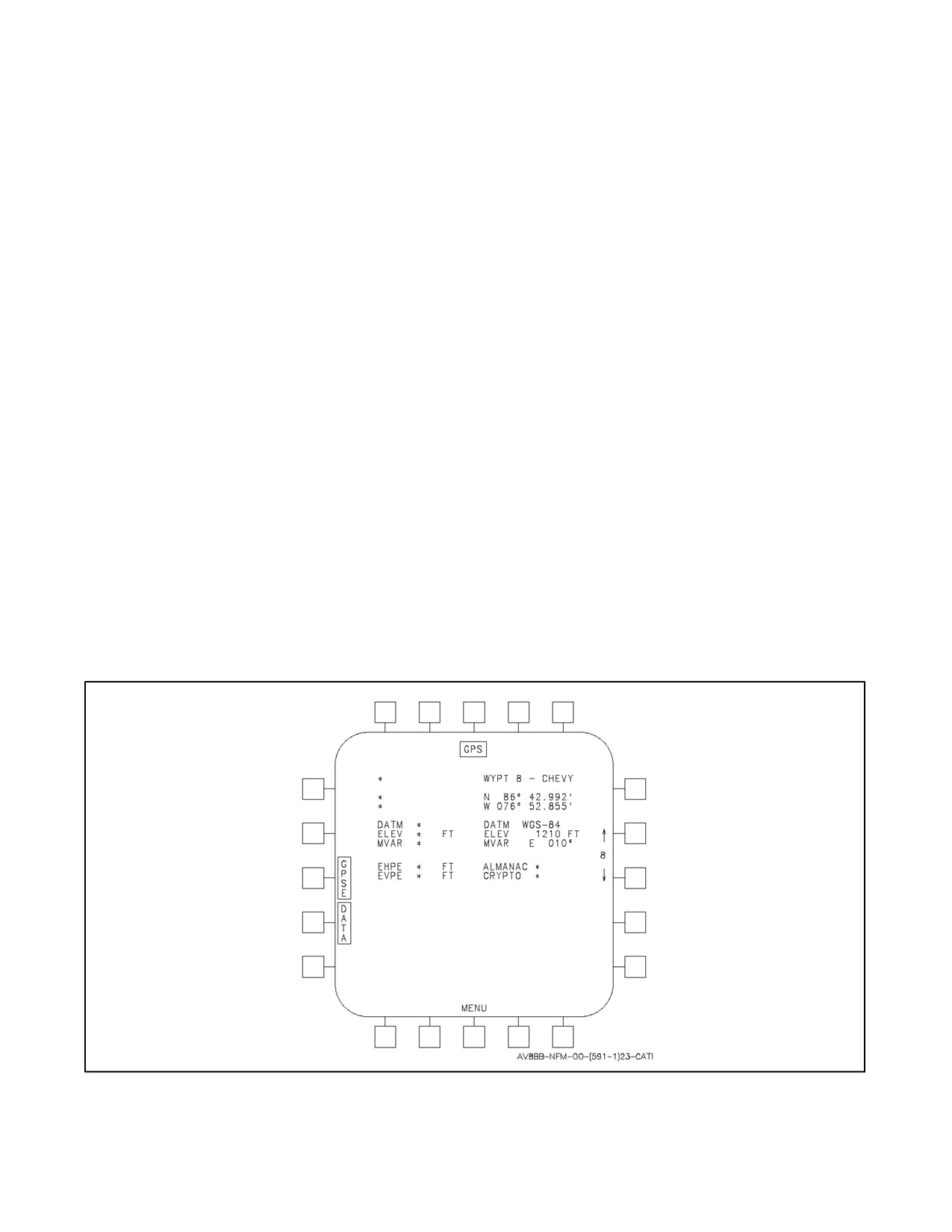
If a GPS failure exists an asterisk (*) is displayed adjacent to the position errors, almanac, and crypto--key status. The
GPSX option is removed if a DSU, AMU, or AMU mission card failure exists or the DSU/AMU mission card does
not contain GPS waypoints. The XFER option, the cursor arrow options, and the GPS waypoint data are not displayed
until valid GPS waypoints have been uploaded from the DSU or the AMU mission card. An asterisk is displayed next
to the GPS waypoint data when there are no GPS waypoints. See Figure 23-3.
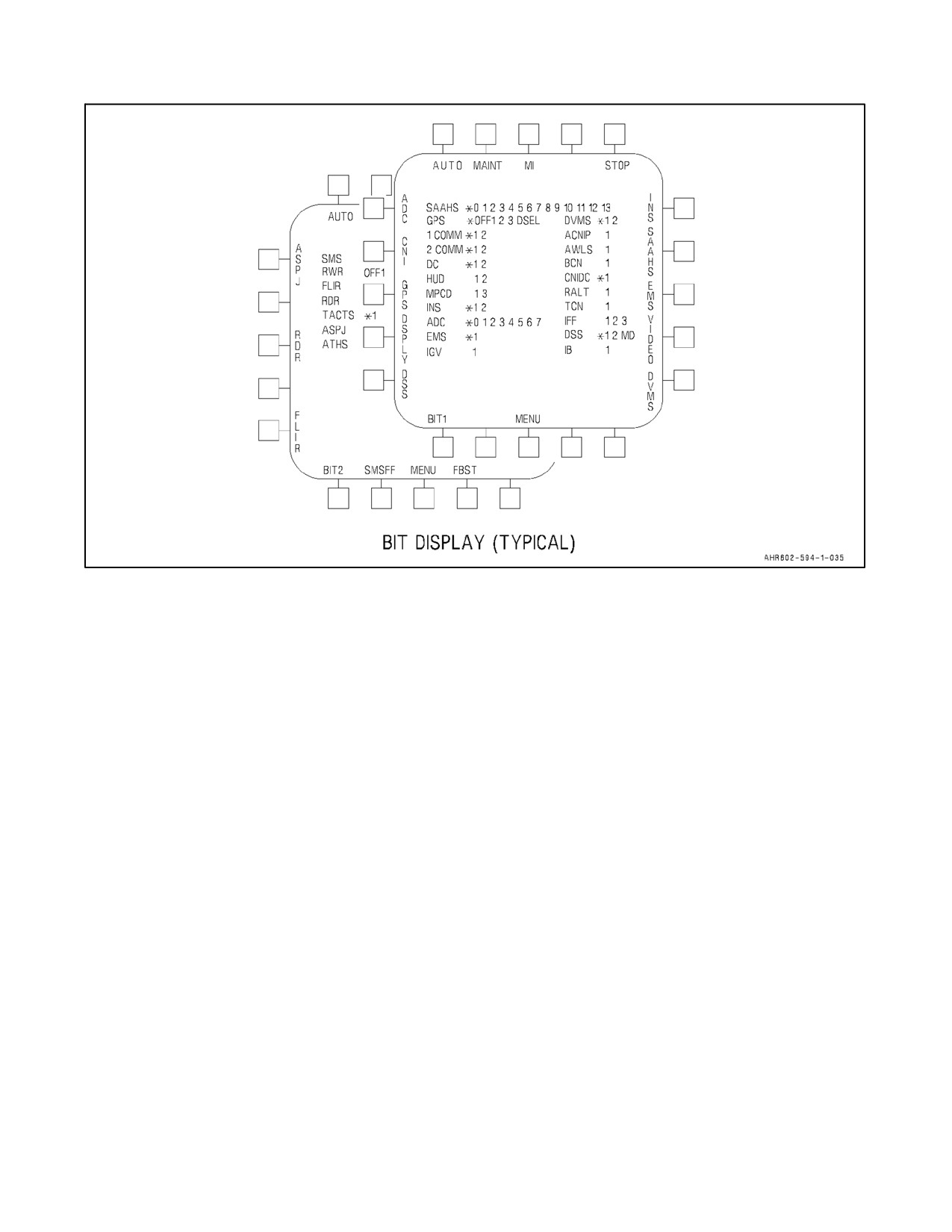
23.5.6 Built--In--Test Format
The GPS BIT reporting status can be inspected by selecting the BIT display format. In Radar and Night Attack
Aircraft the BIT display format is split into two displays, see Figure 23-4. The BIT1 format contains the weapon and
sensor subsystem BIT reporting and the BIT2 format contains the communication, identification, and navigation
subsystem BIT information.ThedefaultBIT displayformat atpower--up withweight--on--wheels istheBIT2display
format. The GPS BIT reporting information, found on the BIT2 format, includes receiver, battery, velocity, and
communication status. With H4.0, the BIT format also reports GPS antenna status. The GPS can only be placed into
initiated BIT with weight--on--wheels by selecting the GPS pushbutton option. The GPS option is not available with
weight--off--wheels.
Figure 23-3. GPS Failure and GPS Waypoints Not Present (OMNI 7.1 and C1+ page shown)
23-13
ORIGINAL
A1-AV8BB--NFM--000
Figure 23-4. GPS Bit (C1+ BIT page shown)
23.5.6.1 GPS BIT Reporting Status
GPS Asterisk (*) -- GPS MAGR present but not communicating.
GPS Off -- GPS MAGR not present or power off to it.
GPS 1 -- GPS Receiver Fail.
GPS 2 -- GPS Battery Fail.
GPS 3 -- Velocity Reasonableness Test Failure.
GPS 4 -- GPS Antenna Fail (H4.0 only).
GPS DSEL -- GPS was deselected as the position keeping source during the last flight because GPS data did
not meet quality/sanity checks.
23.6
POSITION KEEPING
23.6.1 Aircraft Without GPS
There are two methods of maintaining aircraft present position. INS, which is the primary mode, uses inertial
velocities and true heading to maintain present position. ADC position keeping uses true airspeed, magnetic heading,
attitude, angle of attack, and pilot entered wind data to keep track of present position. The system automatically
initializes toINS positionkeeping. Thisis indicatedby theDGD/INS nomenclatureabovethelowerrightpushbutton
ontheEHSI/EHSDdisplay.IfADCpositionkeepingisdesired,thepushbuttonshould bepressed todeselect theINS.
Also, if the INS velocities are not valid while in INS position keeping, the system automatically reverts to the ADC
position keeping mode. When DGD/ADC is selected or reverted to filtered values of ADC true airspeed (TAS) and
ADC AOA are used to determine all velocities, and therefore the velocity vector position on the HUD. On radar
aircraft INS velocities can be updated using the precision velocity update mode (PVU) of the radar. Refer to
A1--AV8BB--TAC--000.
ORIGINAL
23-14
A1-AV8BB--NFM--000
23.6.2 Aircraft With GPS
Therearethreesources formaintaining aircraft present position. Thethree sources in orderof priority are: INS, GPS,
and ADC. The position keeping mode legend on the EHSD (i.e., POS/INS) identifies the navigation sensor that is
used to determine aircraft present position. The aircraft position keeping source is pilot selectable by scrolling the
pushbutton option on the bottom right of the EHSD display (and also on the EW, STRS, FLIR, DMT and Maverick
display formats when in A/G master mode only). At power--up, the aircraft will initialize to ADC position keeping.
When the GPS completes initialization, the position keeping mode will automatically upgrade from ADC to GPS.
When the INS present position becomes valid, the position keeping mode will automatically upgrade from either
ADC or GPS to INS. The MC will automatically upgrade to the best available position keeping mode when the better
mode becomes available for the first time following aircraft power--up with weight--on--wheels. The MC also
degrades to the next best available position keeping source in the event the current source is deemed erroneous or
unavailable. The position keeping mode is selectable independent of the navigation system coupling mode
(tightly--coupled or loosely--coupled), with one exception that ADC position keeping is not allowed in a
tightly--coupled mode (INS and GPS valid). The navigation system coupling mode, which controls the interface
between the GPS and INS, is pilot selectable using the INS mode select switch.
23.6.2.1 Navigation System Coupling Modes
Selecting IFA on the INS mode select switch causes the navigation system to enter into tightly--coupled mode.
Whenever the navigation system is in tightly--coupled mode, the POS legend will appear as part of the position
keeping mode legend (i.e., POS/INS or POS/GPS).
Tightly--coupled refers to a navigation system in which the GPS is aided by ADC and INS data and continually returns
corrections to the INS platform. The aiding data permits the GPS to keep satellite lock and to stabilize the internal
Kalman filter. The platform correction data provides the INS with data it can use to better estimate its internal platform
errors. A tightly--coupled mode is accessible when: (1) an INS with GPS compatible software is installed in the
aircraft, (2) GPS navigation data is valid, and (3) the INS is in either in--flight align mode or aided navigation mode.
Loosely--coupled refers to a navigation system in which the GPS is aided by an external source, but the GPS does
not continually provide corrections to the INS platform. Selection of free inertial navigation mode, NAV on the INS
mode select knob, causes the navigation system to enter into loosely--coupled mode. In loosely--coupled mode, the
INS is not aided by the GPS. Whenever the navigation system is in loosely--coupled or uncoupled mode the DGD
(degraded) legend will appear as part of the position keeping mode legend (i.e., DGD/INS, DGD/GPS or DGD/ADC).
An uncoupled mode is not selectable by the pilot and is only entered when the INS and ADC, and/or GPS are not
providing valid data.
A complete list of definitions of the combinations of navigation system coupling and position keeping modes is given
below:
1. POS/INS -- Indicates a tightly--coupled navigation system in which the INS is being used as the position
keeping source.
2. POS/GPS -- Indicates a tightly--coupled navigation system in which the GPS is being used as the position
keeping source.
3. POS/ADC -- Not a possible configuration.
IFA
4. POS/INS -- Indicates a tightly--coupled navigation system in which the INS is being used as the position
keeping source. The INS is currently being aligned inflight using GPS data. (This legend will appear in the
final stages of an INS in--flight alignment.)
IFA
5. POS/GPS -- Indicates a tightly--coupled navigation system in which the GPS is being used as the position
keeping source. The INS is currently being aligned in--flight using GPS data. (This legend will appear in the
initial stages of an INS in--flight alignment.)
23-15
ORIGINAL
A1-AV8BB--NFM--000
IFA
6. POS/ADC -- Not a possible configuration.
7. DGD/INS -- Indicates a loosely--coupled/uncoupled navigation system in which the INS is being used as the
position keeping source.
8. DGD/GPS -- Indicates a loosely--coupled/uncoupled navigation system in which the GPS is being used as the
position keeping source.
9. DGD/ADC -- Indicates a loosely--coupled/uncoupled navigation system in which the ADC is being used as
the position keeping source.
10. DGD/blank -- Indicates that the navigation system does not have a valid position keeping source. (This mode
is not pilot selectable).
In summary:
1. POS -- Indicates the INS is automatically updated by GPS data. No manual updates are required.
2. DGD -- Indicates the INS is not automatically updated by the GPS. Manual updates are required to limit
navigation system errors and INS drift.
23.6.3 Velocity Reasonableness Test
Like the position keeping source, the aircraft velocity source (used for navigation and weapon delivery calculations)
is automatically selected by the MC and is based on the best available velocity source. The three sources of aircraft
velocity data are, in order of priority, INS, GPS, and ADC. The MC automatically upgrades to the best available
velocity source when the better source becomes available. The MC also degrades to the next best available velocity
source in the event the current source is unavailable or deemed erroneous by the velocity reasonableness tests. Delta
terms are added to aircraft velocity to provide a smooth transition during degradation from using INS to GPS as the
velocity source. The choice of velocity source is independent of the navigation system coupling and position keeping
mode,with theexception ofADC positionkeeping mode.When ADCposition keepingis selectedand thenavigation
system is loosely--coupled, the ADC is used as the velocity source.
There are three different velocity reasonableness tests: INS vs GPS, INS vs ADC, and GPS vs ADC. For the INS
vs GPS velocity reasonableness test to pass, the difference between the INS velocity and the GPS velocity must be
20 ft/s or less. For the INS vs ADC or GPS vs ADC tests to pass the difference between the INS or GPS velocity and
ADC true airspeed must be less than a threshold value for wind magnitude. The threshold value value for wind
magnitude is altitude dependent. The INS vs GPS velocity reasonableness test must not pass for 5 seconds to be
considered failed, and likewise; it must pass for 5 seconds to be considered passed. Both the INS vs ADC and the
GPS vs ADC velocity reasonableness tests must not pass for 3 seconds to be considered failed, and likewise; they
must pass for 3 seconds to be considered passed.
The best velocity source is indeterminate or unresolved if: 1) all three velocity reasonableness tests fail; 2) the INS
velocity is invalid and the GPS vs ADC velocity reasonableness test fails; 3) the GPS velocity is invalid and the INS
vs ADC velocity reasonableness test fails; or 4) the ADC velocity is invalid and the INS vs GPS velocity
reasonableness tests failed. In the event the best velocity source is indeterminate, the velocity source is tied to the
aircraft position keeping source selected by the pilot and VEL? appears above the current position keeping source
selected by the pilot. The system automatically degrades to DGD/ADC position keeping source if DGD/ADC is a
valid position keeping source.
The pilot is notified as to which velocity sources failed the velocity reasonableness tests on the BIT page. Whenever
the INS fails both of its velocity reasonableness tests, a code of 2 is displayed in the INS BIT codes on the BIT page.
In addition, the INS caution light on the caution/advisory light panel is lit. The INS caution light is also lit whenever
the INS experiences BIT failures or the horizontal velocity from the INS is invalid. A code of 3 is displayed in the
GPS BIT codes whenever theGPS fails both ofits velocity reasonableness tests. A codeof 7 is displayed in theADC
BIT codes whenever the ADC fails both of its corresponding velocity reasonableness tests. These BIT codes are for
pilot information only and are not maintenance issues.
ORIGINAL
23-16
A1-AV8BB--NFM--000
Note
While weight--on--wheels, all velocity reasonableness tests are automatic-
ally passed, therefore the BIT failures and VEL? are never displayed while
weight--on--wheels.
23.7
TACAN SYSTEM
The TACAN system gives precise bearing and/or slant range distance to a TACAN ground station or suitably
equipped aircraft. The TACAN system is limited to line of sight range which depends upon aircraft altitude. The
maximum operating range is 390 nautical miles when the selected TACAN station is a surface beacon and 200
nautical miles when the selected TACAN beacon is airborne beacon. The aircraft receives a three letter audio station
signal to identify thebeacon being received. When operating in conjunction with aircraft having air--to--aircapability
theA/A T/R modeprovides thesameas A/A REC mode. Additionally, it indicates lineofsight distanceto thenearest
complementary aircraft and transponds up to five complementary aircraft interrogations. A/A REC mode indicates
bearing to a suitable equipped aircraft (AWACS, KC 10, etc.).
23.7.1 TACAN Controls and Indicators
The controls and indicators for TACAN operation are on the UFC, ODU, DDI, ACNIP, and on TAV--8B and Day
Attack aircraft the HSI. See Figure 23-5.
23.7.1.1 Upfront Control
The pushbuttons and indicators on this control that are used for TACAN operation and display are the TACAN
function selector pushbutton (labeled TCN), the ON/OFF selector pushbutton, the EMCON pushbutton, the
pushbutton keyboard, and scratch pad.
23.7.1.1.1 TACAN Function Selector Pushbutton
Pressing the TCN pushbutton enables TACAN options to be displayed on the option display windows, enables the
TACAN status window on the scratch pad to ON, if TACAN is enabled, and allows the TACAN channel number to
be displayed on the scratch pad when entered on the keyboard.
23.7.1.1.2 On/Off Selector Pushbutton
Pressing this pushbutton turns the TACAN system on or off after first pressing the function selector pushbutton.
23.7.1.1.3 Emission Control
Selecting EMCON puts the TACAN in a non--transmitting mode by switching the system to a receive mode if it is
in the transmit/receive mode. At the same time, option displays 1 through 5 on the ODU are first blanked when
EMCON is selected, then option 1 displays :EMCN. A colon appears to the left of the option to indicate selection.
When the pushbutton is pressed again, deselecting EMCON returns the TACAN to its previous operating mode.
23.7.1.2 Option Display Unit
The pushbuttons and indicators on the ODU used for TACAN operation and display are the option select pushbuttons
and the option display windows.
23.7.1.2.1 Option Select Pushbuttons
The option select pushbuttons are numbered downward 1, 2, and 3 on the right side, and 4 and 5 on the left side. These
pushbuttons select the TACAN mode of operation. When TACAN is enabled, a colon appears to the left of the option
display windows to indicate the last mode and channel selection.
23-17
ORIGINAL
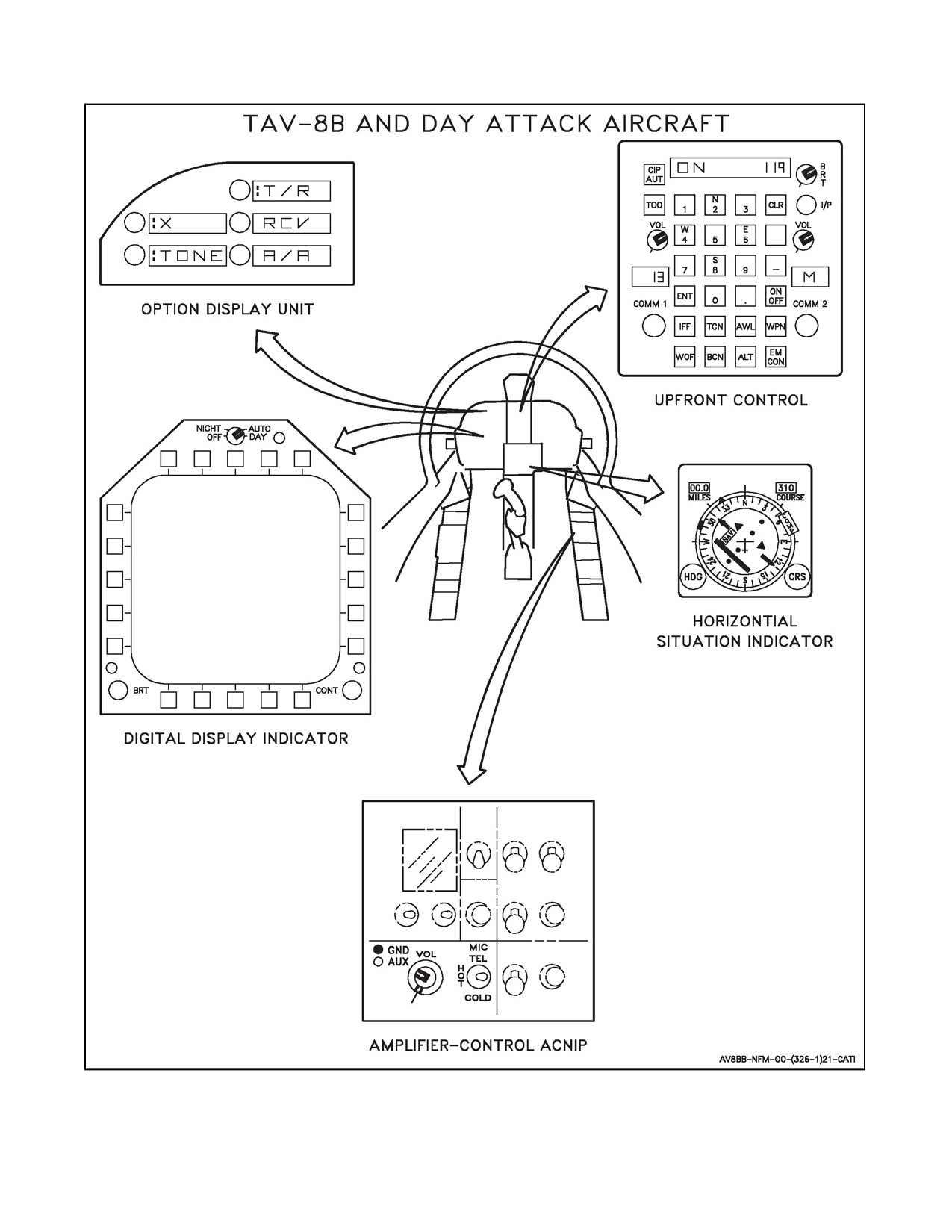
A1-AV8BB--NFM--000
Figure 23-5. TACAN Controls and Indicators (Sheet 1 of 2)
ORIGINAL
23-18
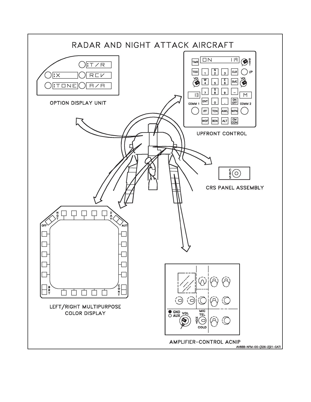
A1-AV8BB--NFM--000
Figure 23-5. TACAN Controls and Indicators (Sheet 2)
23-19
ORIGINAL
A1-AV8BB--NFM--000
1. Option 1. Selecting the :T/R option commands the TACAN Receiver--Transmitter (R/T) to operate in that
mode. Air--to--ground range and bearing information is provided by the R/T for display on the DDI
(EHSI/EHSD display), the HUD, and on TAV--8B and Day Attack aircraft the HSI. When :T/R is selected
range and bearing information is provided by a ground station, when :A/A is selected range and bearing is
provided by another aircraft.
2. Option 2. Selecting the :RCV option commands the TACAN R/T to operate in the air--to--ground receive mode.
Bearing information is provided by the receiver for display on the DDI (EHSI/EHSD display), the HUD and
on TAV--8B and Day Attack aircraft the HSI. The T/R and RCV options aremutually exclusive. In RCV mode
only bearing (not range) is provided by the ground station.
3. Option 3. Selecting the:A/A option commands theTACAN R/T to operatein theair--to--air mode. In A/A T/R
modedistanceinformationisprovidedfordisplay ontheDDI(EHSI/EHSD display),and onTAV--8B andDay
Attack aircraft the HSI. Bearing to a suitably equipped cooperating aircraft (AWACS, KC--10, etc.) is also
displayed on the EHSI/EHSD display and on TAV--8B and Day Attack aircraft the HSI. In A/A T/R mode the
TACAN R/T transmits a distance replay to an interrogating aircraft. Selecting :A/A again displays :PROX in
window 3 and enables A/A TACAN proximity warning. To disable A/A TACAN select :PROX in window
3. Deselecting A/A causes the TACAN to operate in the air--to--ground mode.
4. Option 4. Pressing this pushbutton selects either X or Y channel for R/T operation. The channel number may
be entered on the keyboard. Successive pressing of the pushbutton alternates between the X and Y channels.
5. Option 5. Pressing theTONE pushbutton allows theTACAN identification tonetobeturnedon oroff. Acolon
appears on the left side of the option display window when the tone is enabled.
23.7.1.3 DDI
For TACAN operation, pressing the TCN pushbutton on the DDI turns the TACAN on, if not on, and enables steering
data from the digital computer to be displayed on the EHSI/EHSD display on the DDI and the HUD. The symbols,
pointers and displays which appear on the DDI are the aircraft symbol, TACAN station symbol, TACAN bearing
pointer, TACAN course pointer and various digital TACAN displays. See Figure 23-6. The aircraft symbol represents
the aircraft position and the TACAN symbol represents the TACAN station position. The TACAN bearing pointer
indicates the bearing to the selected TACAN station. The TACAN course pointer indicates the course to/from the
selected TACAN station. The digital TACAN displays which appear on the DDI are the range, bearing, and
time--to--go to the station.
23.7.1.4 TACAN Volume Control
The volume control for the TACAN identification tone (when tone is enabled) is on the ACNIP. The control used
for TACAN volume is the outer knob (AUX).
23.7.1.5 Course Set Control (TAV--8B and Day Attack)
Thecourseset knob on theHSIonthemaininstrument panelis usedto setacourseforsteeringto orfrom theTACAN
station.
CAUTION
The course line displayed on the EHSI/EHSD and the course in the course
selector window of the HSI is not necessarily the same. The bearing
displayed in the course line data block in the lower right corner of the
EHSI/EHSD and the course line displayed on the EHSI/EHSD should be
used instead of the bearing in the course selector window of the HSI. See
Figure 23-6.
ORIGINAL
23-20
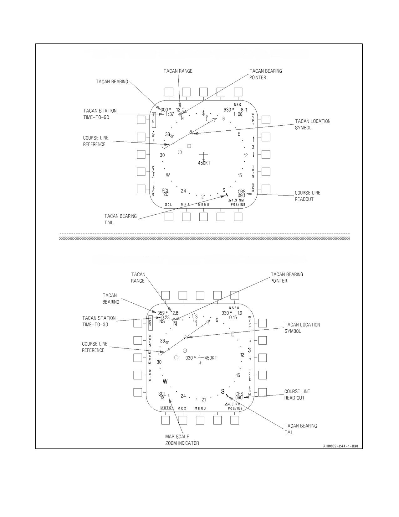
A1-AV8BB--NFM--000
TAV-8B WITH OMNI 7.1 AND DAY ATTACK AIRCRAFT
RADAR AND NIGHT ATTACK AIRCRAFT WITH C1+
Figure 23-6. TACAN Display
23-21
ORIGINAL
A1-AV8BB--NFM--000
23.7.1.6 Course Set Switch (Radar and Night Attack Aircraft)
The course set switch is on the CRS panel assembly on the main instrument panel (see Figure 23-5). This switch is
used to set a course for steering to or from the TACAN station when TACAN steering is selected. Holding theswitch
to the right slews the course arrow in a cw rotation, to the left a ccw rotation.
23.7.2 TACAN BIT Checks
To perform an initiated TACAN BIT check, press the BIT pushbutton on the DDI menu display to initiate a BIT
display. Press the CNI pushbutton and the word TEST appears next to TCN. After about 25 seconds the word TEST
disappears. If a number one then appears next to TCN the TACAN has failed the BIT check. If the space next to TCN
remains blank the TACAN has checked good.
23.7.3 TACAN and TACAN Offset Data
The pilot has the option of programming an offset for the selected TACAN station. TACAN offsets can be utilized
for area navigation on cross country flights. This allows the aircraft to fly a great circle route between two distant
points when the appropriate TACAN stations are not geographically located along the direct line of flight.
23.7.4 TACAN Data Entry
TACAN station data is stored for five TACAN stations. TACAN channel, position, elevation, and magnetic variation
are stored in the mission computer for use in updating the INS. Navigation can not be performed using the stored
TACAN information. On the DDI, press the EHSI/EHSD and then the DATA pushbutton. The WYPT data is
displayed. Press the TCN pushbutton and the DDI shows the TACAN data display. Pressing the down arrow or up
arrow pushbutton changes the TACAN station number (0 through 4). The option display unit and the upfront control
are used to manually enter TACAN data, as follows:
1.
On the option display unit, press the CH X or CH Y (channel) option pushbutton.
A colon appears to the left of the option display window. If X is displayed, press CH X pushbutton again and
Y is displayed.
2.
Type desired new channel on keyboard, then press ENT. Channel number appears on scratch pad.
3.
Press POS (position) option pushbutton.
A colon appears to the left of the option display window. Stored latitude of selected TACAN channel is dis-
played.
4.
Type N or S on keyboard, then type desired new latitude and press ENT.
If N093105 is typed, the scratch pad blanks momentarily and then displays N 09°31’05’’. Six numerics must
be entered for a degrees--minutes--seconds entry. The TACAN latitude may be entered to the thousandth of a
minute. IfN0931.083 is typed, thescratch pad blanks momentarily and then displays N 09°31.083’. A minim-
um of four numerics must be entered before the system will accept the entry.
5.
Press POS option pushbutton.
A colon appears to the left of the option display window. Stored longitude of selected TACAN channel is dis-
played.
6.
Type E or W on keyboard, then type desired longitude and press ENT.
Scratch pad blanks momentarily and then displays new longitude. Seven numerics must be entered for a de-
grees--minutes--seconds entry. The TACAN longitude may be entered to the thousandth of a minute. A minim-
um of five numerics must be entered before the system will accept the entry.
ORIGINAL
23-22
A1-AV8BB--NFM--000
7. Press ELEV option pushbutton.
A colon appears to the left of the option display window. Stored elevation of the selected TACAN channel is
displayed.
8. Type elevation in feet, then press ENT.
Elevation display blanks momentarily on scratch pad and then new elevation is displayed.
9. Press MVAR option pushbutton.
A colon appears to the left of the option display window. Stored magnetic variation of the selected TACAN
channel is displayed. If there is no stored magnetic variation for the selected TACAN then the scratch pad will
be blank.
10. Type E or W and two digits, then ENT.
Magnetic variation display blanks momentarily on scratch pad, then new magnetic variation is displayed. The
magnetic variation must always be typed as 2 digits. For 9° east type E 09. With H4.0, it is possible to enter
the magnetic variation to the nearest tenth of a degree.
23.7.5 TACAN Offset Data Entry
The selected TACAN has an associated offset capability. TACAN selection on the DDI EHSI/EHSD display changes
the waypoint offset (WO/S) option legend to the TACAN offset (TO/S) option legend. Selecting the TO/S option
boxes the legend and displays the currently selected TACAN offset on the DDI within the compass rose, changes the
waypoint data block to reflect current TACAN offset data, and displays the TACAN offset bearing and range options
on the ODU. The BRG (bearing) option initializes selected (cued) and the last entered value is displayed on the scratch
pad. The TO/S options are mutually exclusive with respect to UFC usage. Selecting an option on the ODU
automatically deselects the current option. The new selection is cued and the last entered data is displayed on the
scratch pad. The pilot enters TACAN offset data in terms of bearing and range from the associated TACAN. TACAN
offset data entry is as follows:
1. On the option display unit, press the BRG (bearing) option pushbutton.
A colon appears to the left of the option display window.
2. Type bearing in degrees magnetic, then press ENT.
Enter bearing in increments of 0.01°. Entry of leading zeroes is not required.
3. On the option display unit, press the RNG (range) option pushbutton.
A colon appears to the left of the option display window.
4. Type range in nautical miles , then press ENT.
Entries up to 999.999 nautical miles with 0.001 precision may be entered.
23.7.6 TACAN Steering
In TACAN steering, the pilot’s display shows the aircraft’s situation relative to the TACAN station. TACAN steering
is selected by pressing the TCN pushbutton on the EHSI/EHSD display. When TACAN steering is selected, the
TACAN option is boxed (see Figure 23-7) and the commanded heading marker (bug) on the HUD heading scale
shows relative bearing. The heading bug is corrected for drift. DME slant range is shown on the bottom right of the
HUD display. The bearing to the station is indicated by the pointer outside the compass rose. A digital readout of
23-23
ORIGINAL
A1-AV8BB--NFM--000
bearing and distance to the station is provided in the upper left corner of the EHSI/EHSD display. Time to go to the
stationinminutesandsecondsisprovided underthebearingand distance.Oncetheheading bugis positionedstraight
ahead, heading is maintained to fly directly to the TACAN station.
The mission computer uses the elevation and magnetic variation from the stored TACAN information to calculate
the position of the TACAN station on the EHSI/EHSD page and the steering information on the EHSI/EHSD page
and HUD. If the information for the selected TACAN is not stored in the mission computer, a default elevation of
0 FT MSL and the aircraft’s current magnetic variation are used instead.
CAUTION
The mission computer uses the TACAN channel to search for the stored
information, instead of the unique three letter station ID. It is possible that
the system can mistakenly use the elevation and magnetic variation
belonging to a different TACAN station that happens to use the same
channel number as the currently selected TACAN. An incorrect stored
magnetic variation will result in erroneous TACAN steering information.
To fly a selected course to or from a TACAN station, the course is set in with the course set knob on the HSI (TAV--8B
and Day Attack aircraft) or course set switch (Radar and Night Attack aircraft). The course appears on the bottom
right of the EHSI/EHSD display. A course line also appears on the display. The course line’s rate of movement is
used to anticipate when to turn to intercept the course.
CAUTION
In the TAV--8B and Day Attack aircraft, the course line displayed on the
EHSI/EHSD and the course in the course selector window of the HSI is not
necessarily the same. The bearing displayed in the course line data block
in the lower right corner of the EHSI/EHSD and the course line displayed
on the EHSI/EHSD should be used instead of the bearing in the course
selector window of the HSI. See Figure 23-6.
23.7.7 TACAN Offset Steering
TACAN offset steering (see Figure 23-7) may be used to steer to or away from an offset selected from any TACAN
station. The associated TACAN must be in the T/R mode and the aircraft operating in the NAV or V/STOL master
mode. TACAN offset steering is selected in the same manner as TACAN steering except that TO/S option must be
selected after selecting TCN. After selecting TO/S, enter the bearing and range of the offset from the TACAN station
selected. When TO/S is boxed, the TACAN bearing pointer stays on the bearing of the selected TACAN station, the
offset bearing pointer rotates around the inside of the compass rose to the bearing of the TO/S from the aircraft. The
waypoint data in the upper right corner of the EHSI/EHSD display changes to reflect TO/S data for the TACAN
stationselected. AcoursetotheTACANoffset maybeselectedin thesamemanneras describedforTACANsteering.
When TACAN offset steering is selected a bearing bug is displayed on the HUD. Ground range to the offset in nautical
miles is indicated next to the TO/S legend on the HUD. If EMCON is selected, TACAN offset data is removed from
the HUD and EHSI/EHSD display.
23.7.8 TACAN Cone of Confusion (H4.0 Only)
The TACAN steering data on the EHSD page is displayed using green symbology during the initial power up BIT
and anytime the aircraft calculates that it is within a 60 degree half angle cone (from the vertical) positioned at the
calculated TACAN position. A green CC legend also appears next to the TACAN range in the TACAN steering block.
ORIGINAL
23-24
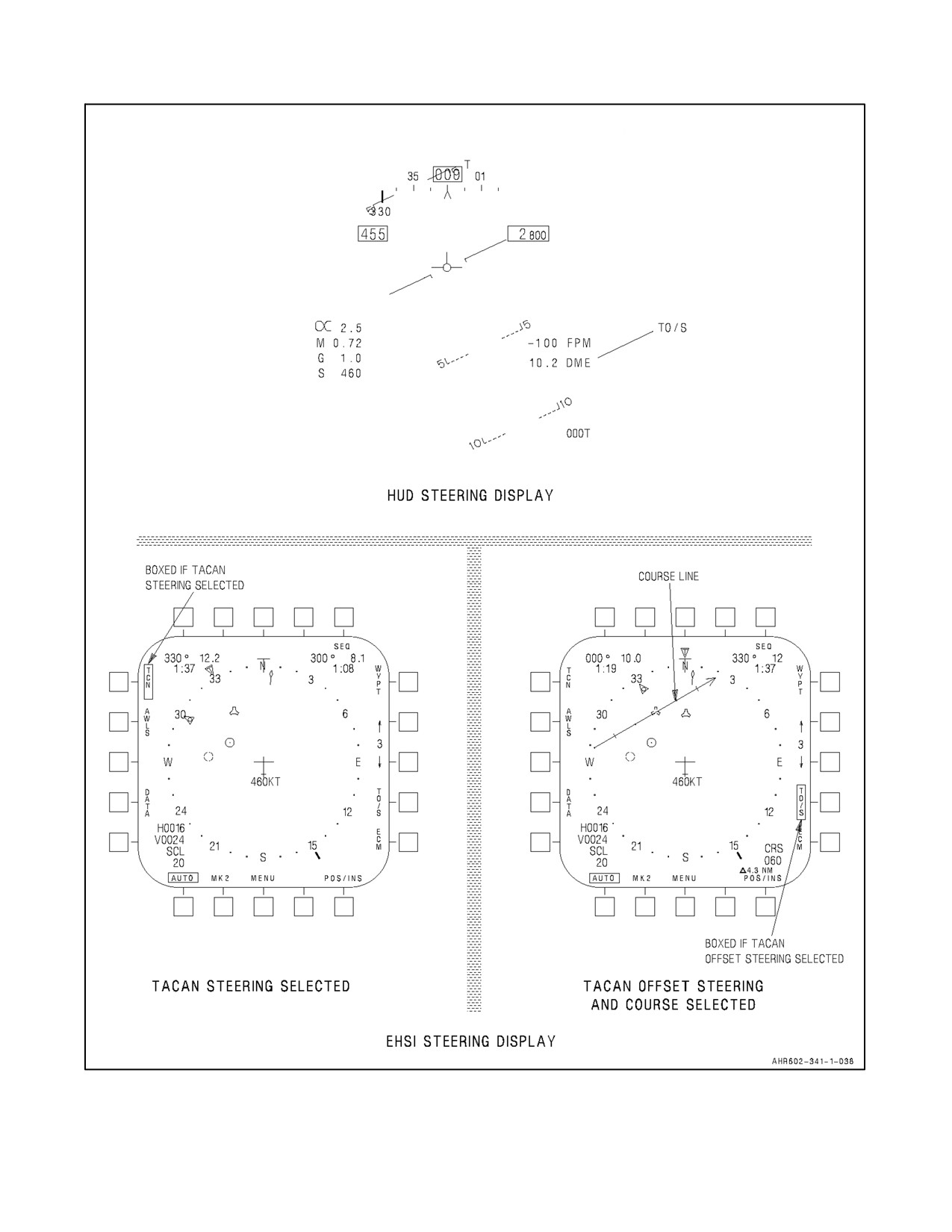
A1-AV8BB--NFM--000
TAV-8B WITH OMNI 7.1 AND DAY ATTACK AIRCRAFT
H0016
V0024
Figure 23-7. TACAN or TACAN Offset Steering (Sheet 1 of 3)
23-25
ORIGINAL
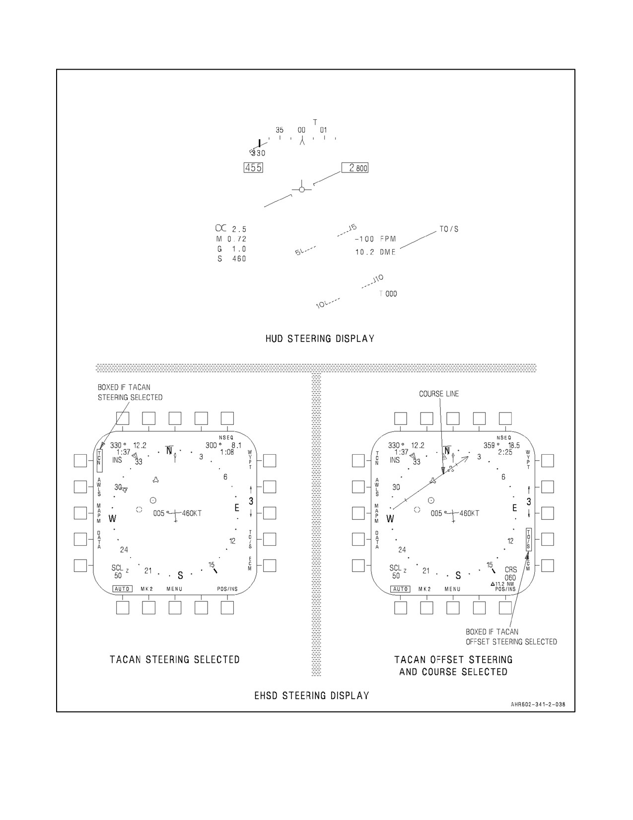
A1-AV8BB--NFM--000
RADAR AND NIGHT ATTACK AIRCRAFT WITH C1+
Figure 23-7. TACAN or TACAN Offset Steering (Sheet 2)
ORIGINAL
23-26
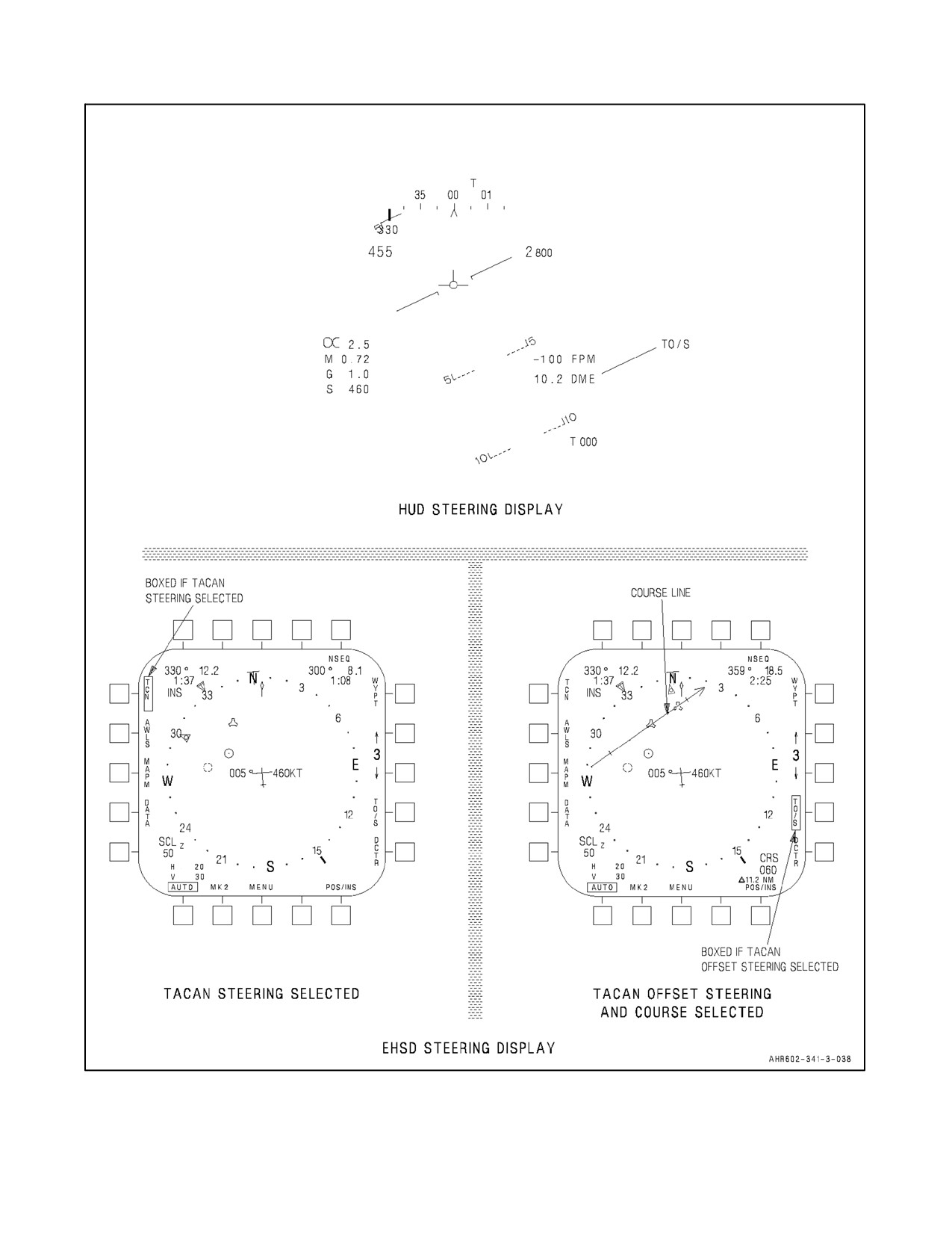
A1-AV8BB--NFM--000
TAV-8B, RADAR, AND NIGHT ATTACK AIRCRAFT WITH H4.0
Figure 23-7. TACAN or TACAN Offset Steering (Sheet 3)
23-27
ORIGINAL
A1-AV8BB--NFM--000
23.8
ALL WEATHER LANDING SYSTEM
The all weather landing system (AWLS) provides the aircraft with steering information to fly a selected glideslope
and localizer. The AWLS operates in conjunction with a ground system which provides azimuth and elevation angle
information along with range derived from TACAN DME. AWLS steering provides situation steering displays on
the HUD, representing aircraft position to maintain the localizer and selected glideslope. The azimuth steering bar
is displayed when the azimuth signal is valid. The elevation steering bar is displayed only when both elevation and
azimuth signals are valid. DME range is displayed when valid TACAN signals are present. Azimuth and elevation
offsets can be entered by the pilot if required to offset the steering signals to a station offset.
An obstacle clearance warning is provided when the aircraft descends below a predetermined elevation angle set on
thegroundstation.WhentheAWLSsensesit isat orbelow theobstacleclearanceangle, theelevation baron theHUD
flashes at a 2 Hz rate. On AV--8B 161573 through 163518, TAV--8B 162747 through 163207, in addition, when the
obstacle clearance region is first entered a warning tone is generated for 3 seconds. The warning consists of a 1000
Hz tone pulsed at a 1 Hz rate (same as radar altimeter LAW tone). On AV--8B 163519 and up, TAV--8B 163856 and
up, an OBSTACLE, OBSTACLE voice warning is provided in conjunction with the flashing elevation bar on the
HUD.
23.8.1 Controls and Indicators
Controls and indicators for the AWLS include the upfront control, the option display unit, the DDI, and the HUD
(see Figure 23-8).
23.8.1.1 Upfront Control
The pushbuttons and indicators on this control that are used for AWLS operation and display are the AWLS function
selector pushbutton (labeled AWL), the on/off selector pushbutton, the pushbutton keyboard, and the scratch pad.
23.8.1.1.1 AWLS Function Selector Pushbutton
Pressing the AWL pushbutton enables AWLS and displays the options associated with the AWLS system on the
ODU. The AWLS system will initialize on an AWLS channel and display the previously entered channel on the
scratch pad.
23.8.1.1.2 On/Off Selector Pushbutton
Pressing this pushbutton turns AWLS on or off after first pressing the AWLS function selector pushbutton. When
AWLS is first turned ON, the system goes through a 10 second warm--up and is commanded by the MC to perform
an AWLS BIT (15 seconds). Selection of AWLS on the DDIs EHSI/EHSD display also turns on the system.
23.8.1.2 Option Display Unit
The pushbuttons and indicators on this panel are the option select pushbuttons and the option display windows.
23.8.1.2.1 Option Select Pushbuttons
The option select pushbuttons are numbered downward 1, 2, and 3 on the right side, and 4 and 5 on the left side. A
colon displayed on the left side of an option display window indicates that option has been selected on the pushbutton.
1. Option 1. Displays the current AWLS ground station channel (CH 1 through 20). When the option is enabled,
the channel number appears on the scratch pad and the keyboard can be used to change channel number.
2. Option 2. Displays the letters GS. When the option is enabled, the scratch pad also displays the current
glideslope and allows the keyboard to be used to change glideslope (2° to 6° with resolution to 0.1°).
3. Option 3. Displays the letters AZ (Azimuth). When the AZ option is selected, the scratch pad displays the
current azimuth offset and the keyboard can be used to change the value. Azimuth offsets up to ±310 feet in
1 foot increments can be entered. Minus numbers mean centerline of runway is left of AWLS station and
positive numbers mean centerline of runway is right of the AWLS station. Zero is a valid azimuth offset entry.
ORIGINAL
23-28
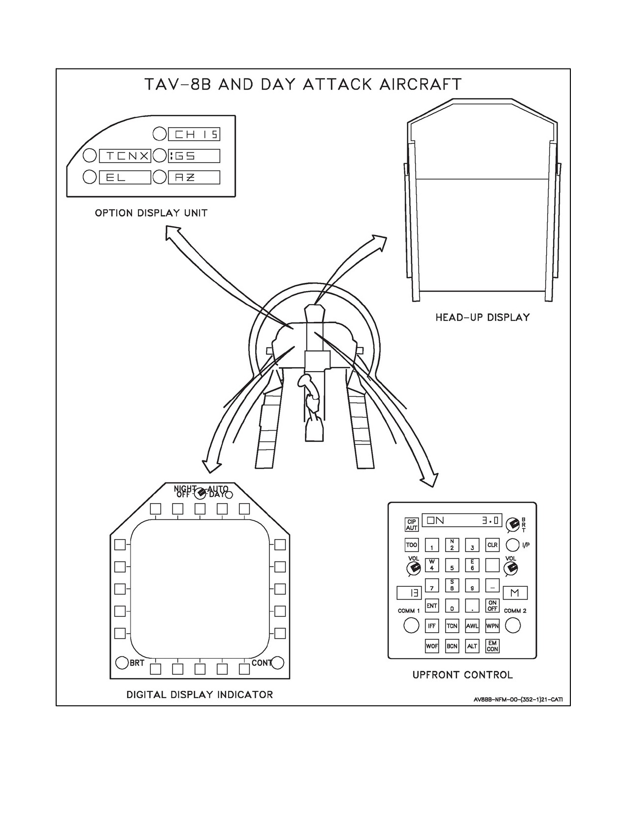
A1-AV8BB--NFM--000
Figure 23-8. AWLS Controls and Indicators (Sheet 1 of 2)
23-29
ORIGINAL
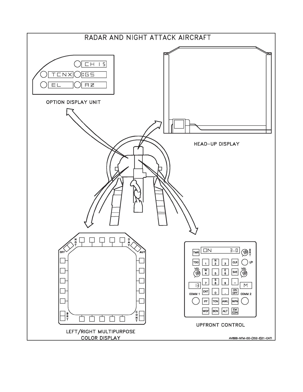
A1-AV8BB--NFM--000
Figure 23-8. AWLS Controls and Indicators (Sheet 2)
ORIGINAL
23-30
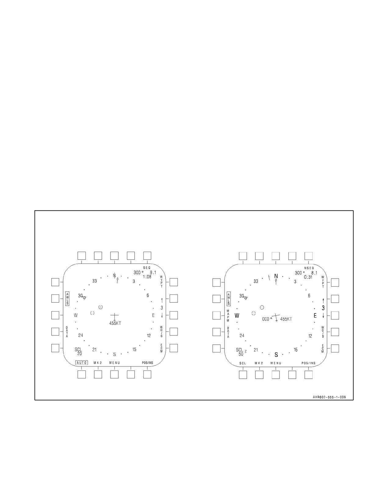
A1-AV8BB--NFM--000
4. Option 4. Displays the letters :TCNX or :TCNY. Successive pressing of the option 4 pushbutton alternates X
and Y and displays the TACAN channel number on the scratch pad and current X and Y selection in window
4.
5. Option 5. Displays the letters EL (Elevation). When the EL option is selected, the scratch pad displays the
current elevation offset and the keyboard can be used to change the value. Elevation offsets up to 31 feet in
1--foot increments can be entered. Zero is a valid azimuth or elevation offset entry. Offsets are automatically
zeroed upon changing AWLS stations.
23.8.1.3 DDI
If the DDI does not have a menu displayed, press the menu pushbutton. Then press the EHSI/EHSD pushbutton to
obtain an EHSI/EHSD display. On the display, press the AWLS pushbutton and AWLS is displayed in a box (see
Figure23-9).AWLSsteeringmodeisnowselectedandtheAWLSdisplayisseenontheHUDifintheguidancebeam.
Selection of the AWLS steering mode activates the AWLS and the TACAN, and tunes the TACAN to the preselected
channel. Selection of AWLS also deselects any other steering mode.
To prevent the TACAN from remaining in the channel associated with AWLS steering after AWLS steering
deselection, the TACAN channel prior to selecting AWLS steering is automatically saved. This TACAN channel is
restored when AWLS steering is deselected.
TAV-8B WITH OMNI 7.1 AND
RADAR AND NIGHT ATTACK
DAY ATTACK AIRCRAFT
AIRCRAFT WITH C1+
T
T
C
C
N
N
Figure 23-9. AWLS DDI Steering Displays
23-31
ORIGINAL
A1-AV8BB--NFM--000
23.8.1.4 HUD
TACAN or waypoint steering can be initially selected by the pilot until the 40° wide and 20° high guidance beam
is intercepted, at which time the pilot can select AWLS steering. When the beam is acquired, a vertical azimuth
steering bar and a horizontal elevation steering bar are displayed (see Figure 23-10). Both bars are referenced to the
velocity vector in the NAV mode and to the vertical flightpath symbol in the VSTOL mode. The azimuth bar
represents aircraft azimuth angle from the localizer and the horizontal bar represents elevation angle from glideslope.
Full deflection of the steering bars on the HUD represents ±2° for elevation and ±6° for azimuth. Azimuth steering
reference marks are provided adjacent to the velocity vector/vertical flightpath symbol when the AWLS steering
mode is selected. The reference markers denote 3° and 6° steering deviation (left and right).
The OFST (offset) legend appears when the azimuth and elevation steering bars are referenced to a station offset. If
the TACAN DME or offset data becomes invalid, the OFST legend is removed and steering reverts to beam
centerline.
Glideslope angles of less than 2° or in excess of6° should not beused. Thepilot must keep theelevation barcentered
on the velocity vector to fly the selected glideslope.
23.8.2 AWLS BIT Check
To perform an initiated AWLS BIT check, press the BIT pushbutton on the DDI menu display to initiate a BIT display.
Press the CNI pushbutton and the word TEST appears next to AWLS. After approximately 15 seconds the word TEST
disappears. If a number then appears next to AWLS the system has failed the BIT check. If the space next to AWLS
remains blank the system has checked good. AWLS initiated BIT is commanded automatically when AWLS power
is turned on.
23.9
NAVIGATION CONTROLS AND INDICATORS
The symbols and digital readouts that normally appear on the DDI display (see Figure 23-11 through Figure 23-14)
are discussed below. Targetpoints and the EW page are only available with H4.0.
23.9.1 Aircraft Symbol
The aircraft symbol represents the position of the aircraft.
23.9.2 Bearing Pointer
The bearing pointer indicates bearing to the selected waypoint, markpoint, targetpoint, waypoint/markpoint offset
or TACAN offset. With C1+, the bearing pointer does not indicate bearing to the TACAN offset.
23.9.3 Waypoint, Markpoint or Targetpoint Location Symbol
A circle represents the location of the selected waypoint or markpoint. With H4.0, triangles represent the location
ofalltargetpoints(exceptT0)currently withinthecompassrose, notjust theselected targetpoint.Small numbersnext
to each triangle identify the targetpoints.
23.9.4 Bearing (Upper Right Digital Readout)
This readout indicates the bearing to the selected waypoint, markpoint, targetpoint, waypoint/markpoint offset,
TACAN offset, or designated point. With C1+, the bearing does not indicate bearing to the TACAN offset.
23.9.5 Range (Upper Right Digital Readout)
This readout indicates theground rangeto theselected waypoint, markpoint, targetpoint, waypoint/markpoint offset,
TACAN offset, or designated point. With C1+, the range does not indicate ground range to the TACAN offset.
23.9.6 Time--to--Go (Upper Right Digital Readout)
This readout indicates the time--to--go to the selected waypoint, markpoint, targetpoint, waypoint/markpoint offset,
TACAN offset, or designated point. With C1+, the time--to--go does not indicate time--to--go to the TACAN offset.
ORIGINAL
23-32
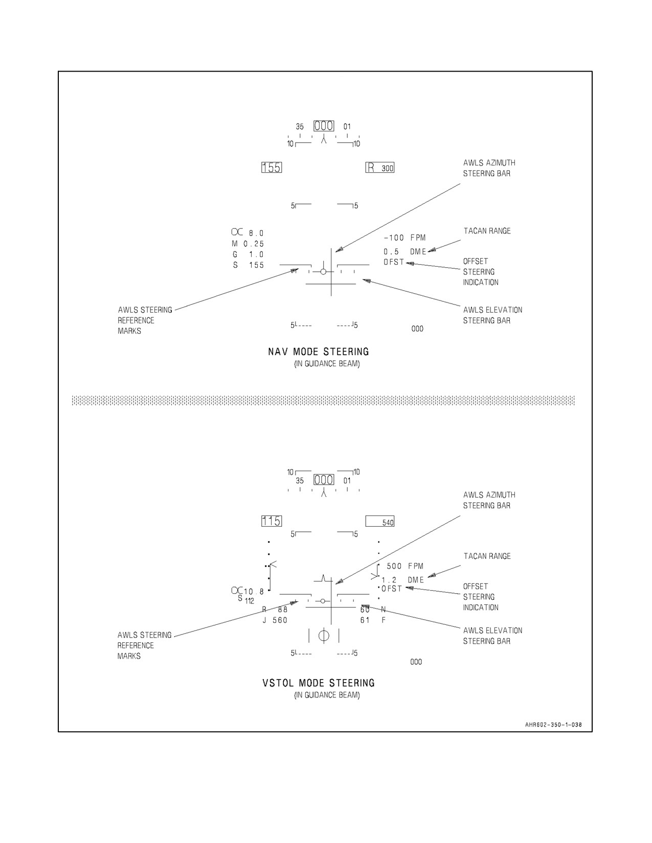
A1-AV8BB--NFM--000
TAV--8B WITH OMNI 7.1 AND
DAY ATTACK AIRCRAFT
Figure 23-10. AWLS HUD Steering Displays (Sheet 1 of 2)
23-33
ORIGINAL
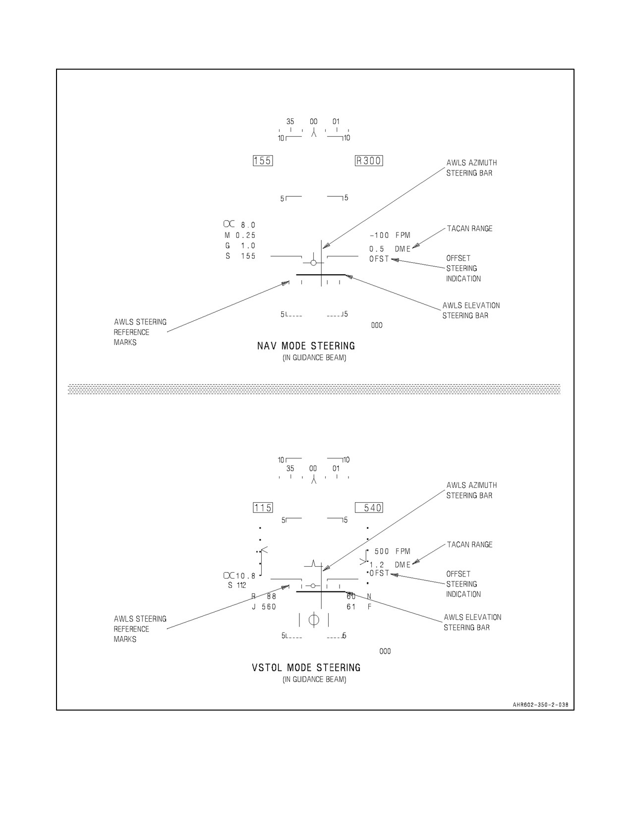
A1-AV8BB--NFM--000
RADAR AND NIGHT ATTACK AIRCRAFT WITH C1+
Figure 23-10. AWLS HUD Steering Displays (Sheet 2)
ORIGINAL
23-34
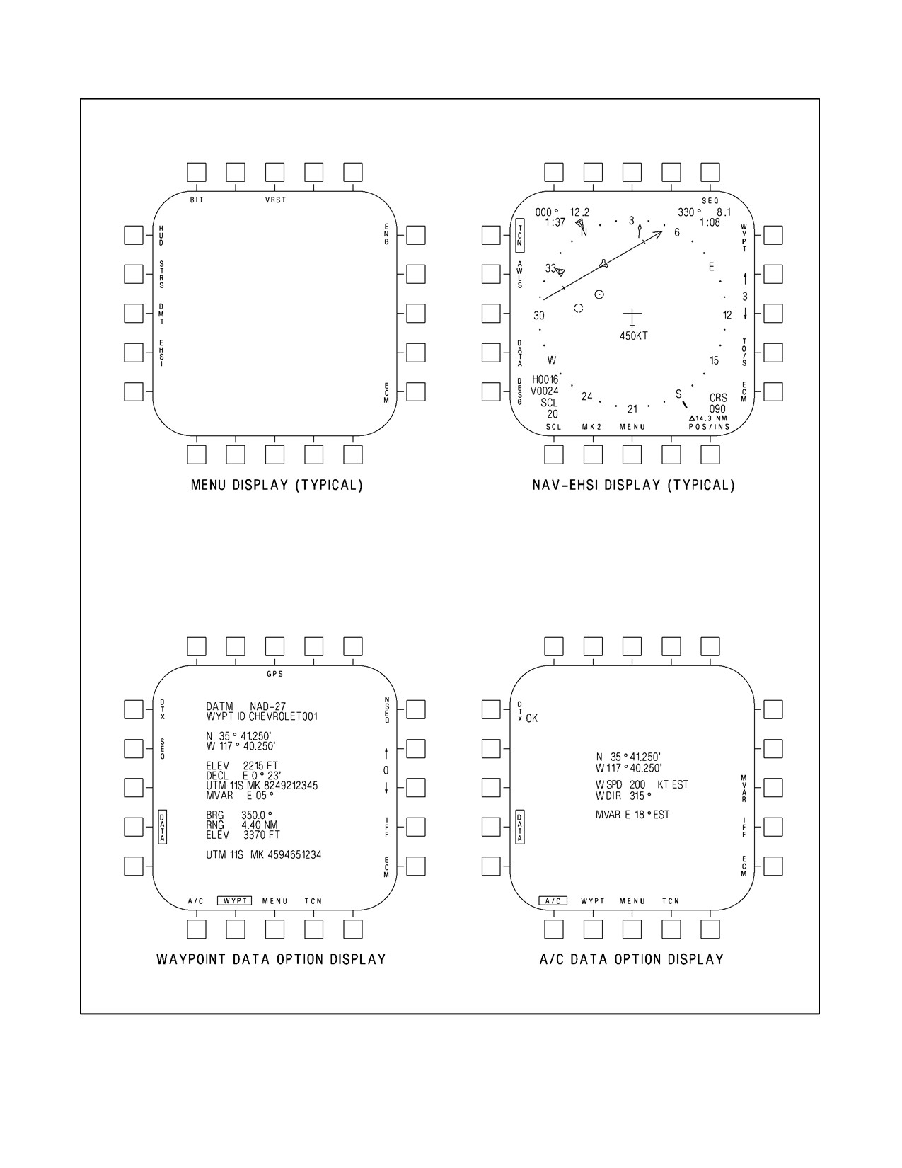
A1-AV8BB--NFM--000
TAV--8B WITH OMNI 7.1 AND DAY ATTACK AIRCRAFT
CUE
AHR602--242--1--038
Figure 23-11. Navigation Controls and Indicators (Sheet 1 of 5)
23-35
ORIGINAL
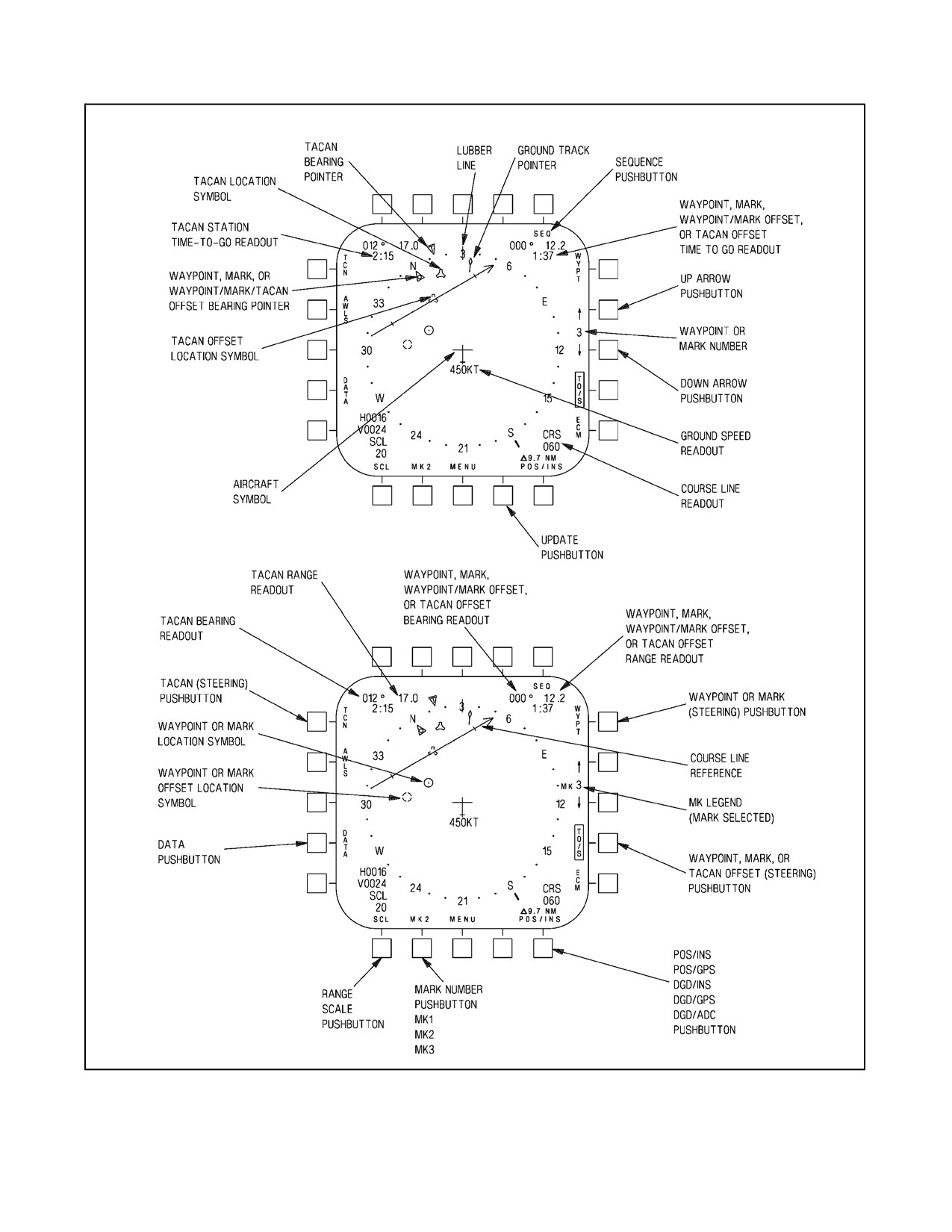
A1-AV8BB--NFM--000
TAV--8B WITH OMNI 7.1 AND DAY ATTACK AIRCRAFT
DESIGNATION,
DESIGNATION,
DESIGNATION,
AHR602--242--2--038
Figure 23-11. Navigation Controls and Indicators (Sheet 2)
ORIGINAL
23-36
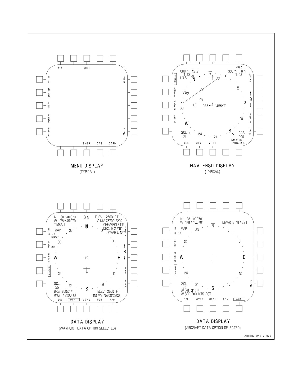
A1-AV8BB--NFM--000
RADAR AND NIGHT ATTACK AIRCRAFT WITH C1+
Figure 23-11. Navigation Controls and Indicators (Sheet 3)
23-37
ORIGINAL
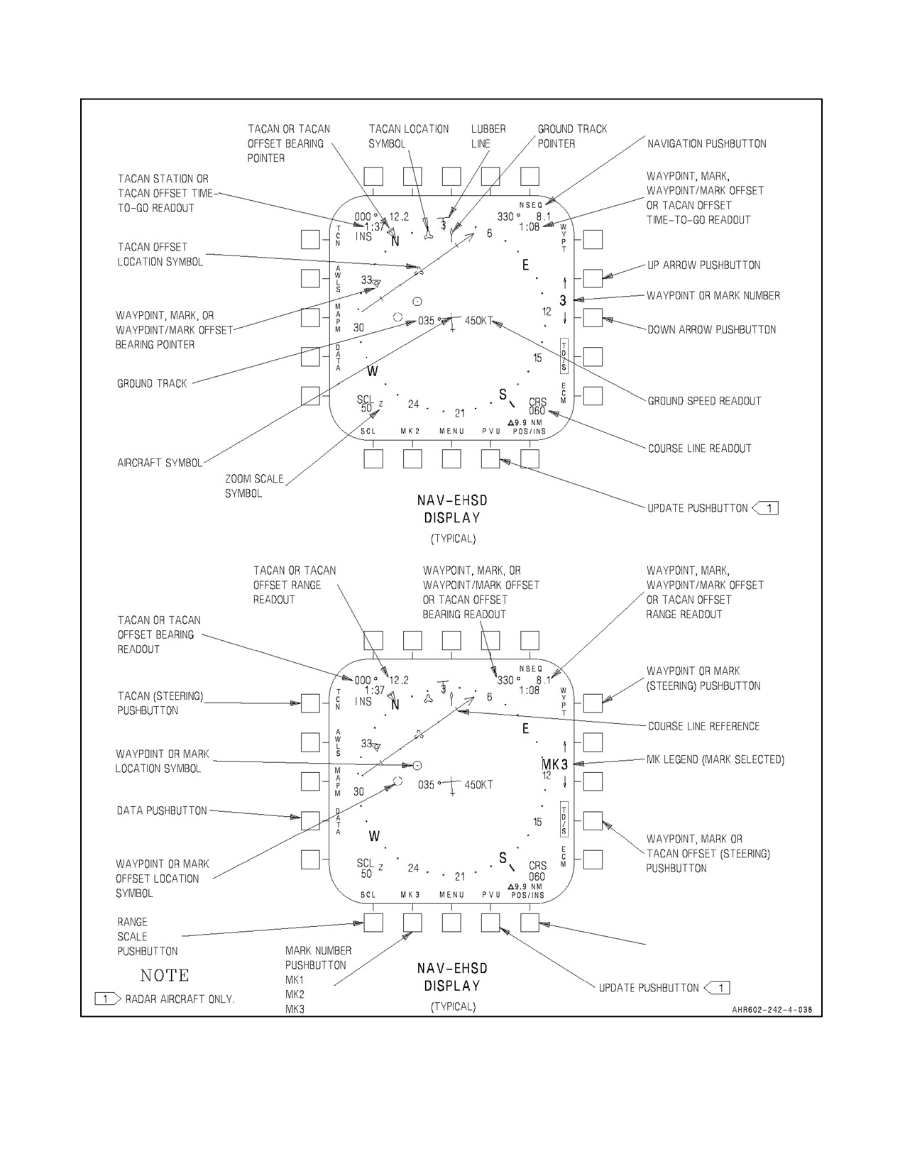
A1-AV8BB--NFM--000
RADAR AND NIGHT ATTACK AIRCRAFT WITH C1+
ROUTE
DESIGNATION,
DESIGNATION,
DESIGNATION,
POS/INS
POS/GPS
DGD/INS
DGD/GPS
DGD/ADC
PUSHBUTTON
Figure 23-11. Navigation Controls and Indicators (Sheet 4)
ORIGINAL
23-38
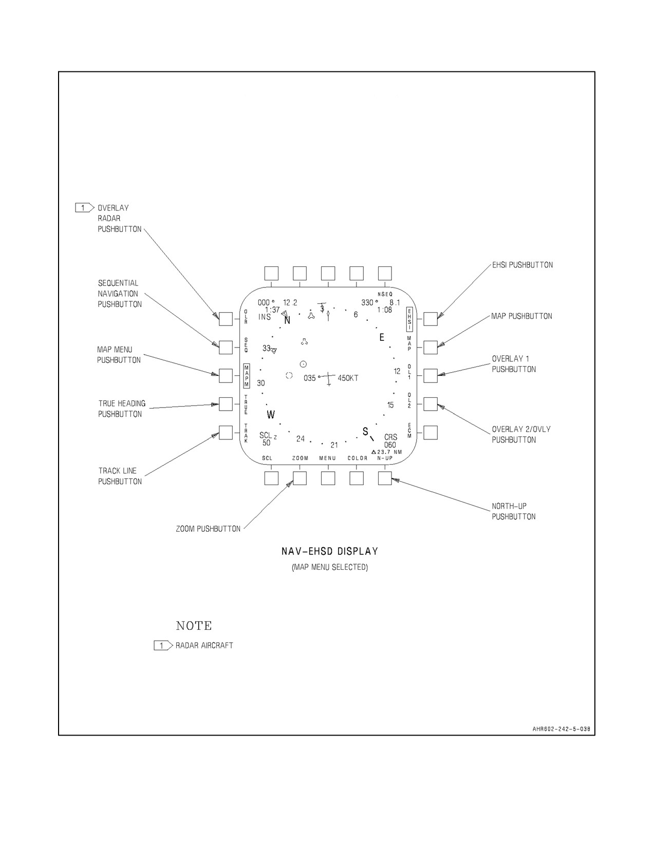
A1-AV8BB--NFM--000
RADAR AND NIGHT ATTACK AIRCRAFT WITH C1+
GROUND
Figure 23-11. Navigation Controls and Indicators (Sheet 5)
23-39
ORIGINAL
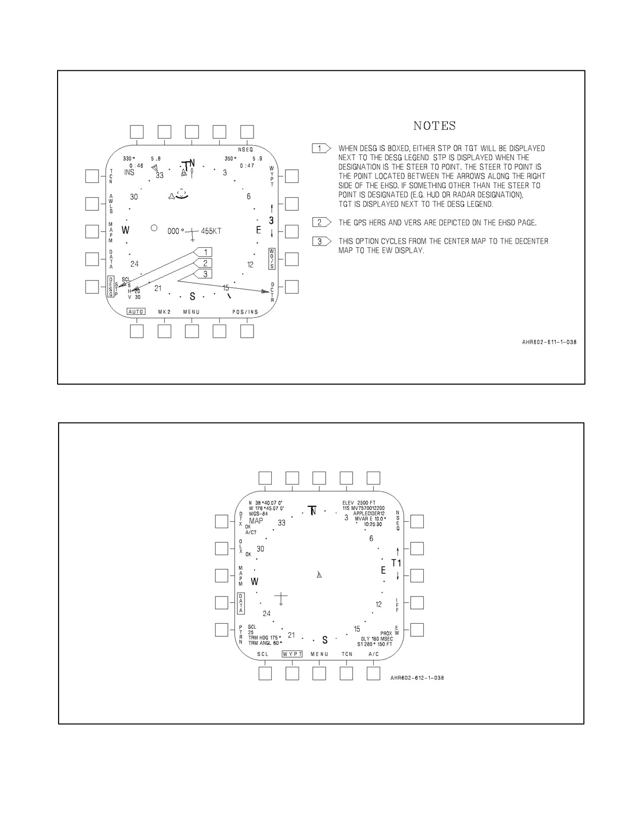
A1-AV8BB--NFM--000
Figure 23-12. EHSD with Steer to Point Designation (H4.0)
Figure 23-13. Waypoint Data Page with Targetpoint Selected (H4.0)
ORIGINAL
23-40
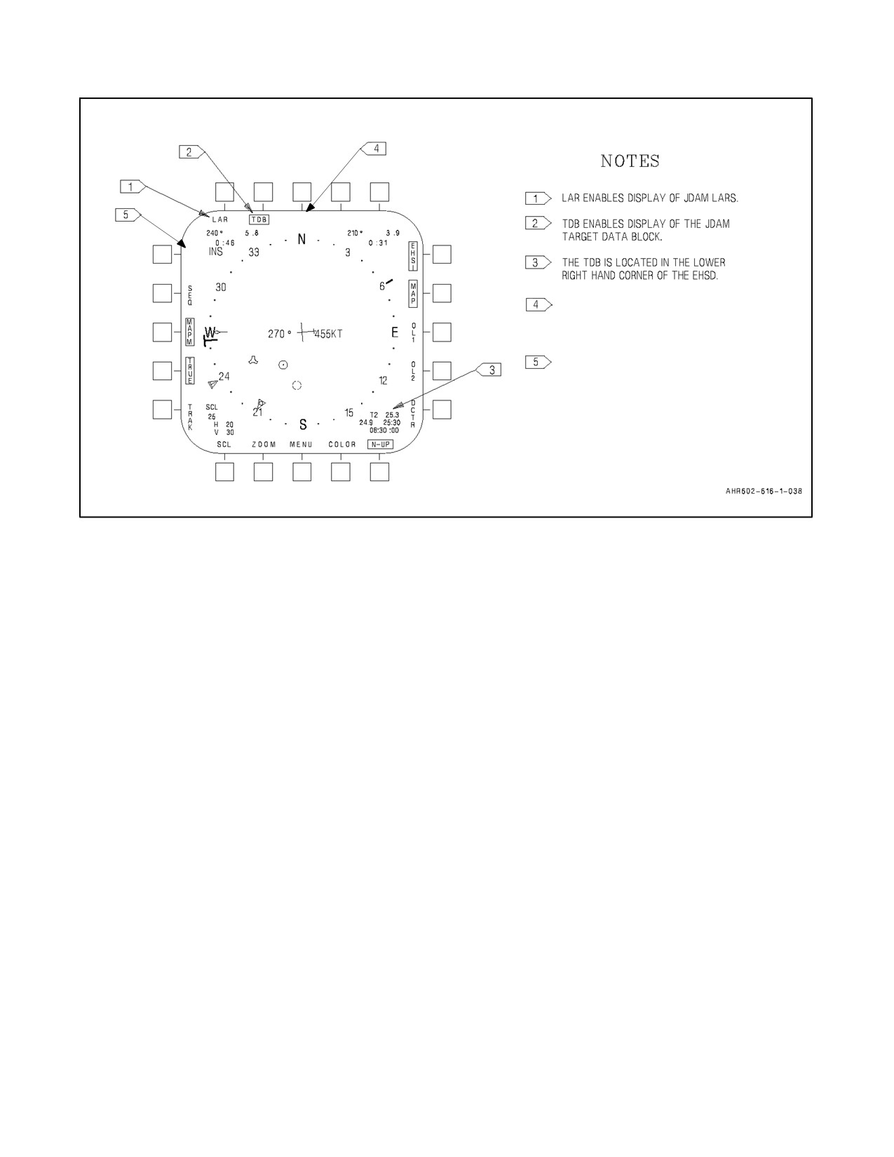
A1-AV8BB--NFM--000
CHRT
O
L
R
ONLY AVAILABLE IN RADAR AND
NIGHT ATTACK AIRCRAFT WITH
TAMMAC. AVAILABLE OPTIONS ARE
CHRT, DTED, AND CIB.
OVERLAY RADAR PUSHBUTTON
HERE FOR RADAR AIRCRAFT ONLY.
Figure 23-14. EHSD MAPM Option (H4.0)
23.9.7 Ground Track (Digital Readout) and Ground Track Pointer
This pointer indicates the aircraft true ground track. On Radar and Night Attack aircraft ground track is also a digital
readout. Trainer aircraft with H4.0 have a digital readout of ground track as well.
23.9.8 Ground Speed (Digital Readout)
This readout indicates ground speed.
23.9.9 Waypoint, Markpoint or Targetpoint Steering Pushbutton
This pushbutton selects waypoint (WYPT), markpoint (MK), or targetpoint steering for display on the HUD and on
TAV--8B and Day Attack aircraft, the HSI. When a targetpoint (other than T0) is selected, it is automatically
designated. It may be manually undesignated.
23.9.10 Up Arrow Pushbutton
This pushbutton, when depressed, selects the next waypoint, markpoint, or targetpoint as the steer--to--point for
display on the HUD. When this pushbutton is selected the WYPT option will box if not already boxed. With OMNI
7.1 and C1+ when waypoint 24 is reached, pressing this pushbutton selects markpoint 1. Likewise, when markpoint
3 is reached, pressing this pushbutton selects waypoint 0. With H4.0, the list of availablewaypoints, markpoints, and
targetpoints are limited to points that are not null. Therefore, when the last non--null waypoint is reached, pressing
this pushbutton selects waypoint 0, when the last non--null markpoint is reached, pressing this pushbutton selects
markpoint 0, and when the last non--null targetpoint is reached, pressing this pushbutton selects targetpoint 0. If route
steering is enabled, pressing this pushbutton selects the next point in the route or the first point in the route if the last
point was displayed. With H4.0, depressing this pushbutton for greater than 0.8 seconds causes the system to enter
the quick access mode. See paragraph 23.9.40 for a description of quick access.
23.9.11 # (Number)
This digital readout indicates the waypoint, markpoint, or targetpoint selected. Waypoints are represented by only
numbers. Markpoints are represented by numbers preceded by MK (OMNI 7.1 and C1+) or M (H4.0). Targetpoints
are represented by numbers preceded by T.
23-41
ORIGINAL
A1-AV8BB--NFM--000
23.9.12 Down Arrow Pushbutton
This pushbutton, when depressed, selects the previous waypoint, markpoint, or targetpoint as the steer--to--point for
display on the HUD. When this pushbutton is selected the WYPT option will box if not already boxed. With OMNI
7.1 and C1+ when waypoint 0 is reached, pressing this pushbutton selects markpoint 3. Likewise, when markpoint
1 is reached, pressing this pushbutton selects waypoint 24. With H4.0, the list of available waypoints, markpoints,
and targetpoints are limited to points that are not null. Therefore, when waypoint 0 is reached, pressing this
pushbutton selects the last non--null waypoint, when markpoint 0 is reached, pressing this pushbutton selects the last
non--null markpoint, and when targetpoint 0 is reached, pressing this pushbutton selects the last non--null targetpoint.
If route steering is enabled, pressing this pushbutton selects the previous point in the route or the last point in the route
if the first point was displayed. With H4.0, pressing this pushbutton for greater than 0.8 seconds causes the system
to enter the quick access mode. See paragraph 23.9.40 for a description of quick access.
23.9.13 WO/S or TO/S Pushbutton
Pressing the offset pushbutton commands the mission computer system to provide steering information to an offset
point from the selected waypoint, markpoint, or TACAN.
23.9.14 POS/ or DGD/ Pushbutton
This pushbutton indicates the data source that the mission computer system is using to compute the aircraft position
latitude and longitude. When pressed it scrolls the POS/ option or DGD/ option pushbutton legend. IFA appears
above this legend when the INS is being aligned inflight.
23.9.15 UPDT/PVU Pushbutton
Pressing this pushbutton provides an update (UPDT) option display on the coordinate data monitor, or a PVU. UPDT
is available only when the navigation system is not tightly--coupled, while PVU is only available on Radar aircraft
when the navigation system is tightly--coupled.
23.9.16 Data Pushbutton
Pressing this pushbutton provides the DATA option display.
23.9.17 TRUE Heading Pushbutton (TAV--8B with OMNI 7.1 and Day Attack Aircraft)
The TRUE pushbutton is located on the WYPT Data page. See Figure 23-16. Pressing this pushbutton selects true
heading for display. T legend appears in place of lubber line on EHSI display and a T appears above heading display
on HUD to indicate true heading displayed.
23.9.18 SCL Pushbutton (TAV--8B with OMNI 7.1 and Day Attack Aircraft)
Pressing this pushbutton decreases the scale once each time it is pressed. The scales displayed are 160, 80, 40, 20,
or10. Numbers indicatenautical miles from thetop to thebottom ofthedisplay. Symbology representing waypoints,
markpoints, waypoint/markpoint offsets, TACAN stations and TACAN offsets must be within selected scale range
to appearon display. Thereis an AUTO scaling option which appears afterthe10 milescale. When AUTO is selected
the EHSI scale changes based on sensor mode, steering selection, and TACAN, waypoint, mark, and waypoint, mark,
or TACAN offset ranges.
23.9.19 SCL Pushbutton (TAV--8B with H4.0 and Radar and Night Attack Aircraft)
Pressing this pushbutton decreases the scale once each time it is pressed. The scales displayed for the CHRT and
DTED (only availablein aircraft with TAMMAC installed) map types are100, 25, 13, or5 unless ZOOM is selected.
With ZOOM selected the displayed scales are 50, 13, 6, or 3. The scales displayed for the CIB (only available in
aircraft with TAMMAC installed) map type are 3 or 1 unless ZOOM is selected. With ZOOM selected the displayed
scales are 1 or 1. Numbers indicate the nautical miles from the top to the bottom of the display. Symbology
representing waypoints, markpoint, targetpoints, waypoint/markpoint offsets, TACAN stations and TACAN offsets
must be within selected scale range to appear on display. There is an AUTO scaling option which appears after the
ORIGINAL
23-42
A1-AV8BB--NFM--000
5
(or zoomed to 3) mile scale. When AUTO is selected the EHSD scale changes based on sensor mode, steering
selection, and TACAN, waypoint, markpoint, and waypoint, markpoint, or TACAN offset ranges. See Figure 23-15.
TheAUTO option is not availableontheDATApageorwhen theCIB maptypeisselected inaircraft withTAMMAC
installed. With TAMMAC installed, the SCL pushbutton works differently on the DATA page. The scales displayed
are 100, 25, 13, 5, 3, or 1 (or 50, 13, 6, 3, 1 or 1 if ZOOM is enabled) unless DTED is the selected map type. When
the map scale transitions from 5 to 3 (or 3 to 1 when ZOOM is enabled) the map type changes from CHRT to CIB.
When the map scale transitions from 1 to 100 (or 1 to 50 when ZOOM is enabled) the map type changes from CIB
to CHRT. This provides the pilot a way to quickly access the CIB map display while on the DATA page. If the map
type is DTED, the displayed scales on the DATA page are 100, 25, 13, or 5 (or 50, 13, 6, or 3 with ZOOM enabled).
CENTERED
DECENTERED
EW (H4.0 ONLY)
DISPLAY SCALE
ZOOM
SCALE
SCALE
SCALE
SCALE
SCALE
SCALE
DOWN
UP
DOWN
UP
DOWN
UP
100
8.0
NA
16.0
NA
6.0
NA
25
4.0
9.0
8.0
18.0
3.0
6.75
13
1.6
4.5
3.2
9.0
1.2
3.38
5
NA
1.8
NA
3.6
NA
1.35
50
Yes
4.0
NA
8.0
NA
3.0
NA
13
Yes
2.0
4.5
4.0
9.0
1.5
3.38
6
Yes
0.8
2.25
1.6
4.5
0.6
1.69
3
Yes
NA
0.9
NA
1.8
NA
0.68
Figure 23-15. Auto Scaling
23.9.20 Mark Number Pushbutton
If no designation exists, pressing the MK pushbutton stores aircraft present position as a markpoint. The source of
the altitude stored in the markpoint is dependent upon sensor validity at the time MK is depressed. With OMNI 7.1
and C1+ if RALT is valid, aircraft barometric altitude minus RALT is used. With H4.0 if RALT is valid, GPS altitude
minus RALT altitude is used if GPS is cued, otherwise aircraft barometric altitude minus RALT altitude is used. In
the absence of valid RALT, the altitude of the current steer to point is used. If a system designation exists with C1+
and H4.0, the calculated designation position is stored in the markpoint when the MK pushbutton is pressed. Only
3 markpoints (1--3)areavailablewithOMNI7.1and C1+.With H4.0,10 markpoints(0--9)areavailable. WithOMNI
7.1 and C1+, the system initializes the MK pushbutton to MK1 during initial power--up. With H4.0, the system
initializes the MK pushbutton to the markpoint number displayed during during the previous shut down (assuming
the MSC has not been reloaded, in which case the system initializes to MK0). Each time MK is depressed, position
and altitude data is written to the markpoint number displayed above the MK pushbutton, and the markpoint number
is incremented. If data exists in the markpoint displayed on the MK pushbutton, and the pushbutton is subsequently
depressed, the previously stored data is overwritten with current data.
23.9.21 Waypoint or Mark Offset Location Symbol
The symbol indicates relative location of the selected waypoint or mark offset.
23.9.22 TACAN Offset Location Symbol
The symbol indicates the relative location of the selected TACAN offset.
23-43
ORIGINAL
A1-AV8BB--NFM--000
23.9.23 SEQ Pushbutton (TAV--8B with OMNI 7.1 and Day Attack Aircraft)
The SEQ pushbutton is located on the WYPT and TCN Data pages. Pressing the pushbutton provides display of up
to five above and two below the currently selected waypoint if in the selected range scale (see Figures 23-16 and
23-17). Thenumbernext to thesmall waypoint circle indicates their associated waypoint number. Only thewaypoint
offset to the selected waypoint is displayed. If waypoint steering is selected, the steering and data block displayed
are to the selected waypoint. If one of the markpoints is currently selected, waypoints 23, 24, 0, 1, 2, 3, and 4 are
displayed if in the selected range scale. SEQ waypoint circles are not available on the DATA page format or in A/G
master mode.
23.9.24 NSEQ Pushbutton
(Located on the EHSI/EHSD page). Pressing this pushbutton enables nonsequential or sequential waypoint
navigation (see Figure 23-17). Refer to NTRP 3--22.4--AV8B to learn how to choose between sequential and
nonsequential routes. A programmed subset of waypoints are selected for navigation. Pressing the waypoint step
button or the waypoint increment button steps through each waypoint and offset in the sequential string, or steps
through each waypoint and offset in the ingress sequence and then step through each waypoint in the egress sequence.
With H4.0 only the offset to the terminal point in the sequential string or the terminal point of the ingress string of
a nonsequential route shall be included in a route. The button is not displayed, but the function is present in A/G
master mode. Waypoints, markpoints, and targetpoints are available for use in the NSEQ string with H4.0. A
targetpoint can be placed at the end of a sequential string with H4.0.
23.9.25 MAPM/EWM Pushbutton (TAV--8B with H4.0 and Radar and Night Attack Aircraft)
Pressing this pushbutton enables map menu pushbutton options. Options differ with different modes (CENTER,
DECENTER, EW (H4.0 only) and DATA). The legends EHSI, MAP, OL1/OL2, OVLY, N--UP, COLOR, ZOOM,
SCL/AUTO, TRAK, TRUE, and SEQ (also OLR on radar aircraft, LAR and TDB on aircraft with H4.0, and
CHRT/DTED/CIB in aircraft with TAMMAC installed) are displayed for 10 seconds and then return to the previous
display if no other pushbutton is pressed. Selecting or deselecting one of these functions restarts the 10 second timer
and enables display of these legends for another 10 seconds. A box displayed around the legend indicates the function
is enabled.
23.9.26 EHSI Pushbutton (TAV--8B with H4.0 and Radar and Night Attack Aircraft)
Selecting map menu (MAPM) on the centered or decentered EHSD display, any DATA display, or the EWM (with
H4.0) display enables the EHSI pushbutton legend. Selection of EHSI is independent for each MAPM. Pressing this
pushbutton on the Center, Decenter, or EW MAPM enables display of the compass rose, lubber line and T legend,
ground track pointer, waypoint and waypoint offset, TACAN and TACAN offset and target (with H4.0) bearing
pointers on the Center, Decenter and EW page. Pressing this pushbutton on the WYPT or TCN Data MAPM enables
display of the compass rose, lubber line and T legend, and aircraft symbol on the WYPT and TCN Data pages.
Pressing this pushbutton on the A/C Data MAPM enables display of the compass rose, and lubber line and T legend
on the A/C Data pages. When enabled the EHSI legend is boxed.
23.9.27 MAP Pushbutton (Radar and Night Attack Aircraft)
Pressing this pushbutton enables display of map video if location is covered by map and if map scene is ready for
display. When enabled MAP legend is boxed. Selection of MAP is independent for each MAPM. Although this
option is available in TAV--8B with H4.0 it is non--functional without a DMS.
23.9.28 OL1 Pushbutton (Radar and Night Attack Aircraft)
Pressing this pushbutton enables display of overlay 1. Selection of OL1 is independent for each MAPM. When
enabled OL1 legend is boxed. Although this option is available in TAV--8B with H4.0 it is nonfunctional without
a DMS.
ORIGINAL
23-44
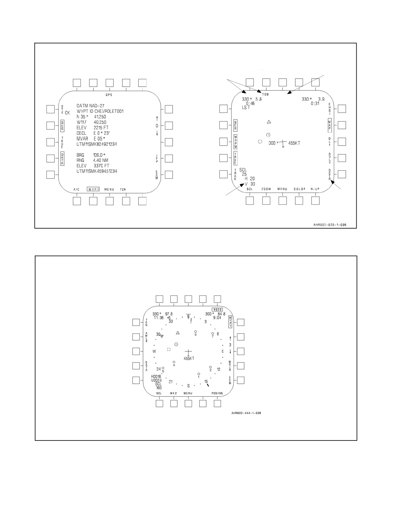
A1-AV8BB--NFM--000
TAV--8B WITH H4.0 AND
TAV--8B WITH OMNI 7.1
NIGHT ATTACK AND
AND DAY ATTACK AIRCRAFT
RADAR AIRCRAFT H4.0 WITH
TAMMAC INSTALLED
ONLY
H4.0 ONLY
LAR
CHRT
ECM WITH
H4.0 ONLY
OMNI C1+
Figure 23-16. SEQ and TRUE Navigation Display
Figure 23-17. SEQ and NSEQ Navigation Display
23-45
ORIGINAL
A1-AV8BB--NFM--000
23.9.29 OL2/OVLY Pushbutton (Radar and Night Attack Aircraft)
OL2 or OVLY is dependent on NSEQ selection. Pressing OL2 (NSEQ not boxed) pushbutton enables display of
overlay 2. When enabled OL2 legend is boxed. Pressing OVLY (NSEQ boxed) pushbutton enables the nonsequential
programmed ingress/egress route lines or the sequential route lines. When enabled OVLY is boxed. Selection of
OL2/OVLY is independent for each MAPM. Although this option is available in TAV--8B with H4.0 it is
non--functional without a DMS.
23.9.30 N--UP Pushbutton (TAV--8B with H4.0 and Radar and Night Attack Aircraft)
Pressing this pushbutton selects north--up or track--up mode. When N--UP legend is boxed north--up mode is enabled,
else track--up mode is enabled. Selection of N--UP is independent for each MAPM. N--UP legend is not displayed
in decenter mode or on the EW page.
23.9.31 ZOOM Pushbutton (TAV--8B with H4.0 and Radar and Night Attack Aircraft)
Magnifies map display by two. When selected ZOOM legend is boxed and Z legend is displayed next to SCL legend.
Selection of ZOOM is independent for each MAPM.
23.9.32 SCL Pushbutton (TAV--8B with H4.0 and Radar and Night Attack Aircraft)
Pressing this pushbutton selects the default map scale for the top--level page (CENTER, DECENTER, EW (with
H4.0) and DATA). The default map scale is the map scale that will be selected when first entering the corresponding
top--level page. Selection of SCL is independent for each MAPM. Pressing this pushbutton decreases the scale once
each time it is pressed. The scales displayed are 100, 25, 13, 5, and AUTO unless ZOOM is selected or the map type
is CIB. The scales displayed for the CIB map type (only available in aircraft with TAMMAC installed) are 3 and 1
unless ZOOM is selected. With ZOOM selected the displayed scales are 50, 13, 6, 3, and AUTO. The scales displayed
for the CIB map type with ZOOM enabled are 1 and 1. The AUTO option is not available on the DATA MAPM page.
With TAMMAC installed, the SCL pushbutton works differently on the DATA MAPM page. The scales displayed
are 100, 25, 13, 5, 3, and 1 (or 50, 13, 6, 3, 1 and 1 if ZOOM is enabled) unless the selected map type is DTED. When
the map scale transitions from 5 to 3 (or 3 to 1 when ZOOM is enabled) the map type changes from CHRT to CIB.
When the map scale transitions from 1 to 100 (or 1 to 50 when ZOOM is enabled) the map type changes from CIB
to CHRT. If the map type is DTED, the displayed scales on the DATA MAPM page are 100, 25, 13, and 5 (or 50,
13, 6, and 3 with ZOOM enabled).
23.9.33 TRAK Pushbutton (TAV--8B with H4.0 and Radar and Night Attack Aircraft)
Pressing this pushbutton enables display of ground track line. When selected TRAK legend is boxed. TRAK legend
not displayed in DATA mode. Selection of TRAK is independent for each MAPM.
23.9.34 TRUE Pushbutton (TAV--8B with H4.0 and Radar and Night Attack Aircraft)
When selected the system uses true heading to compute the orientation of the compass rose, aircraft symbol, ground
track pointer, map heading and bearing to waypoint, offset or TACAN station. The selection of true or magnetic also
affects the display of TACAN, waypoint, and markpoint offset bearing, targetpoint terminal heading and pattern
heading, and radar BRAA (bearing, range, altitude, aspect) and cursor data block displays. A T legend appears in
placeoflubberlineandalsoaTappears aboveheading displayon HUDto indicatetrueheadingdisplay. WhenTRUE
legend is boxed true heading is enabled, else magnetic heading is enabled. Selection of TRUE is NOT independent
for each MAPM. Selecting TRUE on any MAPM affects all displays.
23.9.35 SEQ Pushbutton (TAV--8B with H4.0 and Radar and Night Attack Aircraft)
Pressing the pushbutton provides display of up to five above and two below the currently selected waypoint if in the
selected range scale (see Figures 23-24 and 23-25). The number next to the small waypoint circle indicates their
associated waypoint number. Only the waypoint offset to the selected waypoint is displayed. If waypoint steering
is selected, the steering and data block displayed are to the selected waypoint. With C1+, if one of the markpoints
is currently selected, waypoints 23, 24, 0, 1, 2, 3, and 4 are displayed if in the selected range scale. With H4.0, if a
markpoint or targetpoint is currently selected, the four waypoints above and the two waypoints below the last selected
waypoint and the last selected waypoint itself are displayed if in the selected range scale. SEQ waypoint circles are
ORIGINAL
23-46
A1-AV8BB--NFM--000
not available on the Data page format or in A/G master mode. Selection of SEQ is NOT independent for each MAPM.
Selecting SEQ on any MAPM affects all displays.
23.9.36 OLR Pushbutton (Radar Aircraft with H4.0)
Pressing this pushbutton will display a corral on the EHSD which corresponds to the radar display corral when using
an EXPAND MODE. This feature aids the pilot in accurately placing expand corrals on the radar display by allowing
comparison between map and radar. The OLR legend is not displayed in DATA mode. Selection of OLR is NOT
independent for each MAPM. Selecting OLR on any MAPM affects all non--DATA displays.
23.9.37 LAR Pushbutton (with H4.0)
Selecting this option enables the display of the Launch Acceptable Region (LAR) for the Joint Direct Attack
Munitions (JDAM) on the EHSD. When selected LAR legend is boxed. The LAR legend is not displayed in DATA
mode. Selection of LAR is independent for each MAPM.
23.9.38 TDB Pushbutton (with H4.0)
Selection of the option enables the display of the targetpoint data block in the lower right hand corner of the EHSD
display. See Figure 23-18. The targetpoint data block is displayed after TDB has been boxed and a targetpoint has
been selected as a target contributor. This requires that at least one JDAM is loaded on the aircraft or training mode
is selected with a JDAM stores code loaded. When selected TDB legend is boxed. The TDB legend is not displayed
in DATA mode. Selection of TDB is independent for each MAPM.
23.9.39 CHRT/DTED/CIB Pushbutton (Radar and Night Attack Aircraft with TAMMAC Installed)
Selection of this option will scroll through the available map imagery formats. The pushbutton legend will scroll from
CHRT (chart) to DTED to CIB and back to CHRT. Selection of map format is independent for each MAPM. The CIB
map format is not available on the EWM page, instead the legend scrolls from CHRT to DTED and back to CHRT.
The map format legend is removed when the TAMMAC is not communicating with the MSC or is not installed.
CHRT is the default map format on all map pages after a fresh MSC load. See Figure 23-18.
23.9.40 Quick Access (with H4.0)
Pressing an up arrow, a down arrow, or the WINC button for greater than 0.8 seconds will cause entry into the Quick
Access (QA) mode. There are two types of quick access sessions. Steer--to--point (STP) quick access can be initiated
using the WINC button or the up and down arrows on the EHSD and the EW pages. Point--of--Interest (POI) quick
access can be initiated by using the up and down arrows on the WYPT Data page, NSEQ Data page, Radar Data page,
TFER page, or any of the six different VREST pages. STP QA is used to change the steer to point on the EHSD page
and therefore the steering cues presented in the HUD. POI QA is used to change the point on the page that is used
to initiate the QA session (i.e. WYPT Data page, NSEQ Data page, TFER Data page, Radar Data page, or any of the
six different VREST pages). The ODU displays WYPT in window 1, MKPT in window 2, TGPT in window 3, NSEQ
in window 4 (NSEQ is displayed only during a STP QA session), and TOT in window 5 (TOT is displayed only if
thecurrent point is targetpoint 1--4 ortheterminal point inasequential,ingress, oregress string).Selecting theNSEQ
option toggles NSEQ on the EHSD page. Selecting the TOT option enables the scratch pad for programming a
time--on--target for the selected point. If a system designation exists (radar designation, waypoint designation, etc.)
TGPT defaults to colonized and 0 is presented in the scratchpad when a STP QA session is initialized. If a system
designation does not exist, the current point displayed on the current page (or the EHSD page if QA was initiated
using the WINC option) is the initial default selection on the ODU and scratchpad. Quick accessing a point that is
not in the NSEQ string when NSEQ steering is selected causes NSEQ to become deselected. A QA session will time
out after 15 seconds of inactivity, or a QA session can be manually exited by pressing ENT on the UFCS when there
is no pending entry flashing on the scratch pad.
23.9.41 Null Points (with H4.0)
A Nullpoint is a point (waypoint, markpoint, or targetpoint) that has its null flag set true. The null flag is set in mission
planning and is meant to indicate a point that cannot be used as a STP or as a point of interest on the VREST and
Radar Data pages. WYPT 0, MKPT 0 and TGPT 0 cannot be null points. When stepping through points on the EHSD
page, null points are skipped. A null point can be converted to a non--null point by accessing the point on the EHSD
DATA page or the TFER DATA page.
23-47
ORIGINAL
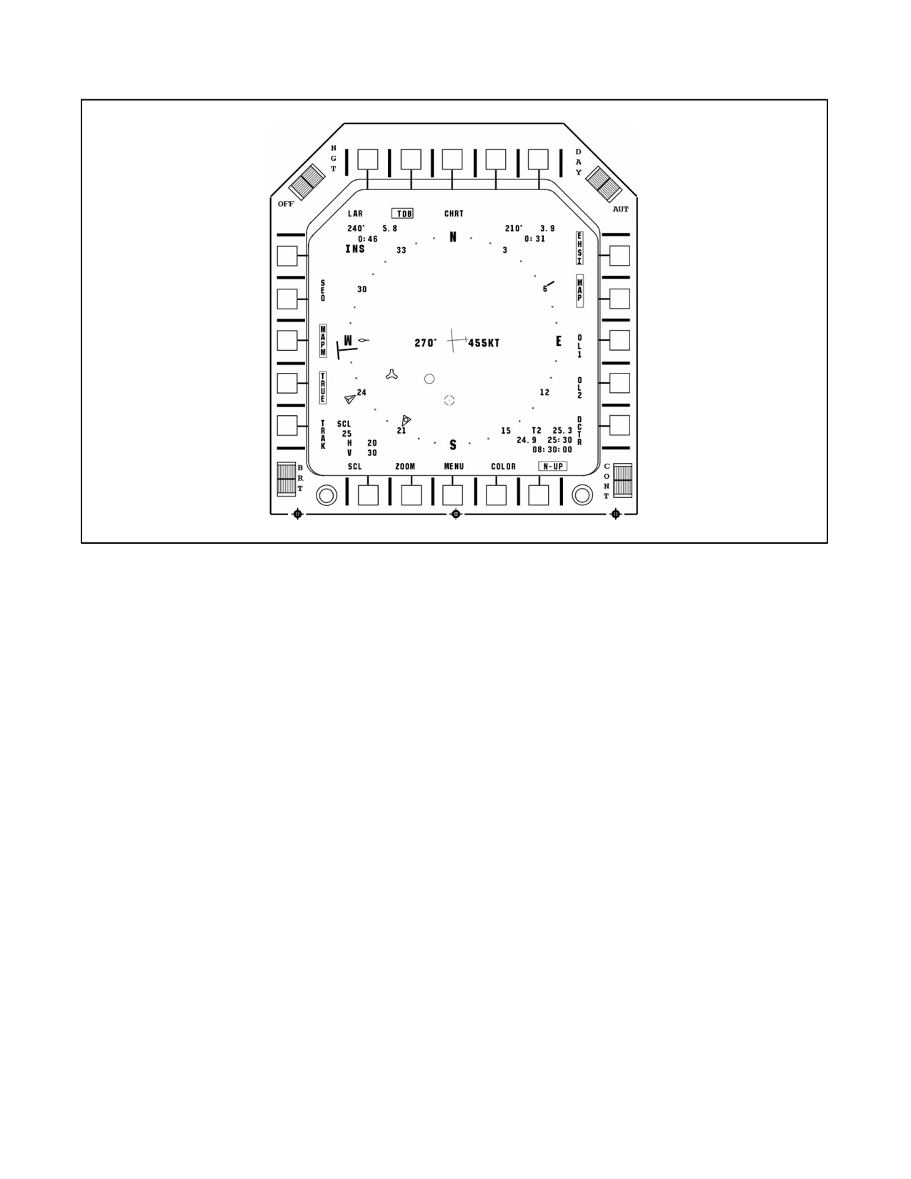
A1-AV8BB--NFM--000
Figure 23-18. Center EHSD Map Menu Page with TAMMAC Installed
23.9.42 Electronic Warfare Page (with H4.0)
The EW page is intended to help increase defensive situational awareness. The EW page can be selected by pressing
pushbutton 15 from theBasicMenu page, or it can beselected viaSensor Select Switch Left when not in AirCombat
Maneuvering (ACM) sensor mode or TPOD sensor mode. The EW page is the third page in the EHSD display
sequence (Center, De--Center, then EW).
23.9.42.1 EW Page Unique PB Options (with H4.0)
Depression of the EWM pushbutton (PB) selects the EW Menu page that provides the capability to control map,
waypoint, RWR and Radar footprint (radar aircraft only) symbology displayed on the EW page. See Figure 23-19.
A 10 second timeout applies to the EWM, similar to the MAPM selections, while the page is presented.
Pressing the RWR PB selects the RWR Page. Note that the Expendables information has been moved from the RWR
page to the CMDS page.
Pressing the CMDS PB selects the Countermeasures Dispensing System page.
23.9.42.1.1 EWM Page Unique Options (with H4.0)
Nav Option.
Selecting the NAV option displays the waypoint or waypoint offset steering information, waypoint or waypoint offset
data block, waypoint or waypoint offset symbols, course line and course line data block, and the GPS HERS and
VERS in the lower left corner.
RWR Option.
Selecting the RWR option displays the RWR threat symbols (maximum of six), critical ring and beam Cues. RWR
symbols are drawn in a brighter intensity of the color selected for the rest of the legends using the COLOR option
on the EW menu page.
ORIGINAL
23-48
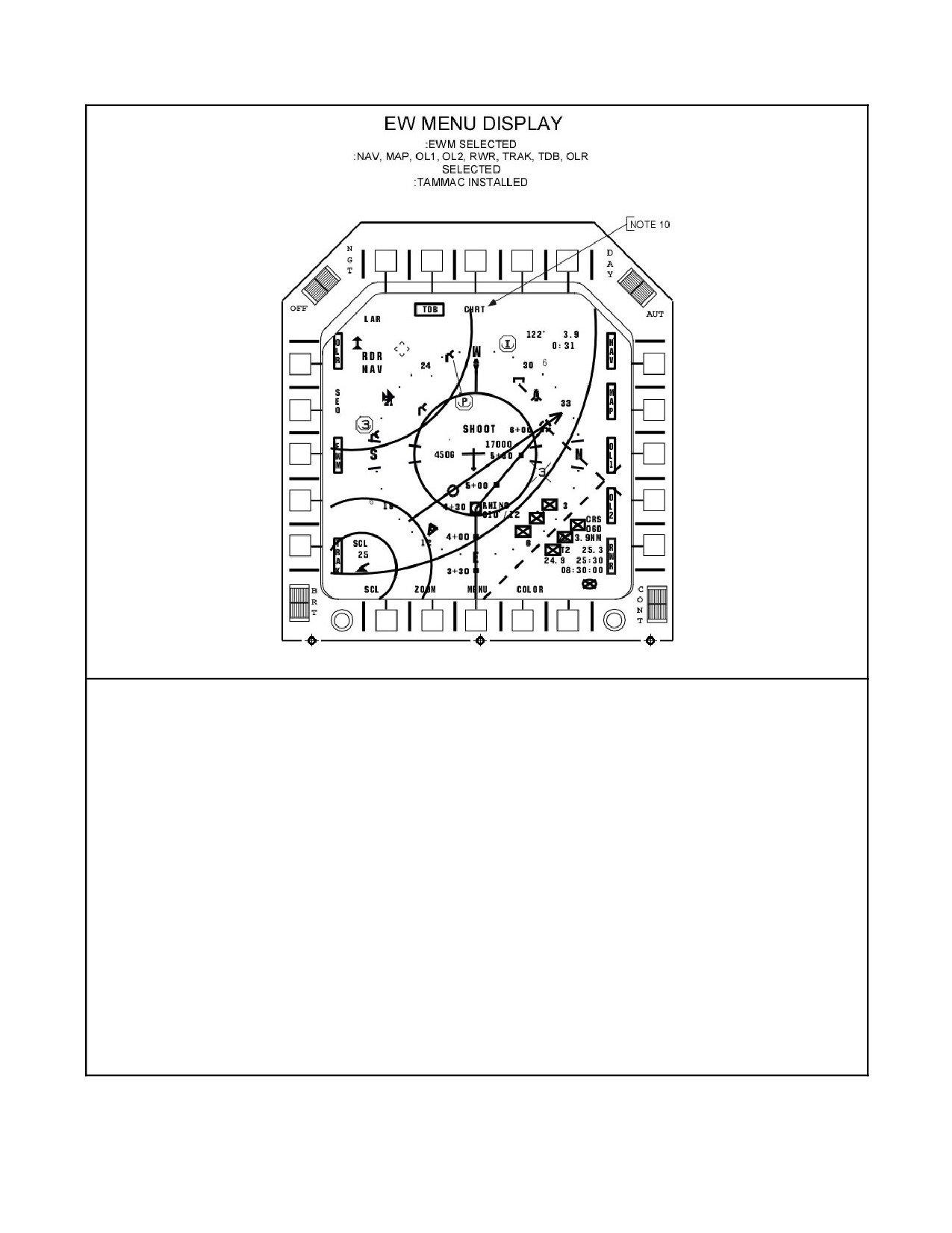
A1-AV8BB--NFM--000
NOTES:
1. THE EMW PAGE ALLOWS SELECTION OF SYMBOLOGY/INFORMATION TO BE DISPLAYED ON THE EW PAGE. FIRST
SELECTION OF THIS PAGE AFTER FRESH MSC LOAD WILL DEFAULT TO SCALE 25, COLOR YELLOW AND THE
FOLLOWING OPTIONS BOXED: NAV. MAP, OL1, OL2, RWR, TRAK, AND LAR. THE ZOOM, AND SEQ OPTIONS DEFAULT
UNBOXED. SUBSEQUENT SELECTIONS OF THIS PAGE WILL DISPLAY SETTINGS AS LAST SELECTED ON THE EW OR
EWM PAGE.
2. SELECTION OF NAV WILL ENABLE THE FOLLOWING SYMBOLOGY: WAYPOINT OR WAYPOINT O/S STEERING
INFORMATION, WAYPOINT OR WAYPOINT O/S DATA BLOCK, WAYPOINT OR WAYPOINT O/S SYMBOL, COURSE LINE,
COURSE LINE DATA DISPLAY. UNBOXING NAV WILL DECLUTTER THE DISPLAY BY REMOVING THE ABOVE INFORMATION.
3. SELECTION OF MAP ENABLES DISPLAY OF THE MAP UNDER THE COMPASS ROSE.
4. SELECTION OF TRAK ENABLES DISPLAY OF THE TRACK LINE.
5. THE RADAR TRACK FILES AS MECHANIZED ON THE EHSD ARE ALWAYS DISPLAYED ON THE EW MENU PAGE.
6. SELECTION OF RWR ENABLES DISPLAY OF RWR THREAT SYMBOLS, CRITICAL RING, CRITICAL TAILS AND BEAM CUES.
ORIENTATION OF RWR THREATS IS LETHALITY IN.
7. OL1, OL2, COLOR, ZOOM, SCL, SEQ, AND OLR PROVIDE THE SAME FUNCTIONALITY AS CURRENT AV--8B EHSD FOR THE
TOP LEVEL EW PAGE.
8. LAR (P/B #6) IS DISPLAYED WHEN JDAMS ARE INVENTORIED ON THE AIRCRAFT. BOXING IT DISPLAYS THE JDAM LARS.
9. TDB (P/B #7) CONTROLS DISPLAY OF THE JDAM DATA BLOCK IN THE LOWER RIGHT HAND CORNER OF THE EW PAGES.
BOXING IT DISPLAYS THE TARGET DATA BLOCK IN THE LOWER RIGHT HAND CORNER OF THE EW PAGES.
10. LEGEND ONLY AVAILABLE WHEN TAMMAC SYSTEM IS INSTALLED. PUSHBUTTON ALLOWS SELECTION OF MAP IMAGERY.
ROTARY PUSHBUTTON DISPLAYS CHART (CHART), DTED BACK TO CHRT DEFAULTS TO CHRT, SCALE 25 WITH NEW MSC
LOAD, CAN BE MISSION PLANNED AFTER THAT.
Figure 23-19. Electronic Warfare Menu Page
23-49
ORIGINAL
A1-AV8BB--NFM--000
23.9.42.2 Threat Symbols
With the RWR option selected on the EWM page, the RWR Threat Information is displayed on the EW page based
on lethality using the same symbology as the RWR page. Critical and missile launch RWR threats are positioned
along the inside circumference of the critical ring and have a tail extending from the critical ring to the compass rose.
Lethal RWR threats are positioned along the outside circumference of the critical ring. Nonlethal RWR threats are
positioned along the outside circumference of the compass rose.
23.9.42.3 Beam Cues
With the RWR option selected on the EWM page, the beam cues are displayed. The beam cues are broken X centered
about the aircraft symbol and extending out slightly over the compass rose. The beam cues are referenced to the
ground track of the aircraft and are fixed relative to the three/nine o’clock position on the compass rose. The cues
are offset from the beam by ±7.5 degrees (15 degrees total between tic marks).
23.9.42.4 SHOOT Cue
The avionics system displays a SHOOT cue in the center of the EW pages above the aircraft symbol only in A/A
master mode concurrent with the SHOOT cue on the HUD.
23.10 WAYPOINT, MARKPOINT, TARGETPOINT, AND OFFSET DATA ENTRY
With OMNI 7.1 and C1+, the mission computer can store 25 waypoints, numbered 0 through 24, and 3 mark points,
numbered 1 through 3. Scrolling past the end of the waypoints accesses the markpoints. Markpoints are denoted by
the MK legend.
With H4.0, the mission systems computer can store 60 waypoints, numbered 0 through 59, 10 markpoints, numbered
0 through 9, and 5 targetpoints, numbered 0 through 4. Markpoints are denoted by the M legend and Targetpoints
by the T legend. Quick Access must be used to change between point types (waypoint, markpoint, or targetpoint).
See paragraph 23.9.40 for a description of Quick Access. The waypoint, markpoint, or targetpoint currently selected
for navigation is indicated by the number located between the up and down arrows on the right side of the EHSI/EHSD
and EW display (see Figure 23-21). The point between the arrows is also called the steer to point.
23.10.1 Waypoint Data Display
The waypoint data display allows for viewing and/or inputting the data required for each waypoint, markpoint,
targetpoint, and their associated offsets. The display is enabled by selecting the DATA pushbutton on the EHSI/EHSD
display. The display is also available for selection on the DMT display when DMT video is not available in the Day
Attack and TAV--8B with OMNI 7.1. The display is also available for selection on the EW display with H4.0. The
display initializes with waypoint data selected, indicated by the boxed DATA and WYPT legends. The waypoint,
markpoint, or targetpoint position and elevation as well as the associated offset range, bearing and elevation are
displayed for the waypoint, markpoint, or targetpoint last selected on the EHSI/EHSD and EWdisplays. Cycling the
waypoint/markpoint/targetpoint number to inspect the other waypoints, markpoints, or targetpoints does not affect
the waypoint or markpoint, or targetpoint selected for navigation on the EHSI/EHSD and EW display. This allows
for data change in flight without effecting the steering information on the HUD. Deselecting DATA brings up the last
selected display, EHSI, EHSD, EW, or DMT. Data is entered into the system automatically by way of the data storage
set or manually by way of the UFC keyboard and ODU options.
23.10.2 Manual Data Entry
Manual data entry utilizes the UFC keyboard and scratch pad, and the ODU options. When entering data on the UFC
keyboard the scratch pad blanks with the first key depression. The last digit of a sequence being entered will flash
to indicate the entry is not complete. When the ENT key is pressed the scratch pad will blank momentarily and then
display the new entry, if the entry is valid. If the entry is not valid, incorrect number of keystrokes etc., the scratch
pad will flash until cleared. Valid entries are also displayed on the DDI.
23.10.2.1 Entering Waypoint or Markpoint, or Targetpoint Data
Selecting the waypoint data display enables the UFC and ODU for waypoint data entry. This is indicated by the colon
next to the WYPT (or TGPT) and POS options on the ODU, and the stored latitude of the selected waypoint,
markpoint, or targetpoint on the scratch pad.
ORIGINAL
23-50
A1-AV8BB--NFM--000
If a valid offset is stored for the selected waypoint or markpoint, the system initializes with the WO/S options selected
on the ODU. The WYPT and WO/S options are mutually exclusive, and successive depression of the associated
option pushbutton provides alternate displays of WYPT and WO/S in the first window on the ODU (with OMNI 7.1
and C1+). With H4.0, the first window of the ODU cycles from WYPT to WO/S to TGPT. If a number is entered
into the UFC after ODU window 1 cycles to TGPT and the enter button is pressed, the waypoint offset for the current
waypoint transfers into the targetpoint number that was entered.
To re--energize the DATA page ODU options, simply select the desired data entry pushbutton on the DATA page (i.e.
WYPT, TCN, or A/C). The data entry pushbuttons are boxed as an indication of what DATA page is currently active.
Selecting the data entry pushbuttons on the DATA page has the effect of energizing or de--energizing the ODU
options, so selecting a boxed data entry pushbutton will not deselect the DATA page.
23.10.2.1.1 Targetpoint Data Programming (with H4.0)
Targetpoints have additional data referred to as JDAM target data (terminal parameters and fuzing data) associated
with them that is primarily pertinent to JDAM deliveries. The TDB PB on the EHSD MAPM page controls whether
this information is displayed on the EHSD when a targetpoint is selected.
The initial ODU options displayed when the DATA page is active for a targetpoint are similar to those for a typical
waypoint except that TGPT is displayed in ODU window 1. Pressing PB 1 causes the ODU to cycle through the
display shown in Figure 23-20. Selection of the TGPT option changes the ODU to the terminal parameter options
ODU (TERM for terminal parameters options, HDG for heading, ANG for angle, and INV for invalidate in ODU
windows 1--3, and 5). HDG specifies the final heading that the JDAM tries to obtain at impact with the targetpoint.
ANG specifies the final angle (measured from the horizontal) that the JDAM tries to obtain at impact with the
targetpoint. INV is used to invalidate the HDG or ANG entries, whichever one is cued when INV is pressed. If the
HDG is invalid, the JDAM will proceed directly from the aircraft position at weapon release to the target. The type
of heading entered reflects the aircraft system mode (true or magnetic). If the ANG is invalid, the JDAM will try to
obtain a default value of 65 degrees. Changing the location or elevation of a targetpoint does not change the terminal
parameters associated with that targetpoint.
Pressing the TERM option changes the ODU to the pattern options ODU (PTRN for pattern options, SYM for
symmetric or AREA for area or LINE for line, PHDG for pattern heading, and INT for interval in ODU windows
1--4). SYM represents the currently selected pattern that is used if pattern is enabled on the EHSD. Pressing the SYM
ODU button cycles the pattern option through the three types of defined patterns (SYM, AREA, and LINE). Refer
to NATIP, NTRP 3--22.4--AV8B for a detailed description of the patterns available. The PTRN (for pattern) PB must
be selected on the EHSD DATA page for the pattern options to be enabled. The PTRN PB is not displayed unless
JDAMs are inventoried on the aircraft. Pressing PHDG enables the UFC scratchpad for entry of the heading on which
the pattern is based. Pressing INT enables the UFC scratchpad for entry of the interval (in feet) used in the pattern
calculations.
Pressing the PTRN option changes the ODU to the fuze options ODU (FUZE for fuze options, MSEC for
milliseconds ofdelay, MIN forminutes ofdelay, HRS forhours ofdelay, and PROX fortheproximityoption inODU
windows 1--5). Refer to NATIP, NTRP 3--22.4--AV8B for additional fuze option details.
Pressing the FUZE option changes the ODU to the time on target (TOT) option ODU that displays TOT in ODU
window 1. This enables the UFC scratchpad for TOT entry.
Pressing the TOT option returns the ODU to the TGPT options display.
23.10.2.1.2 Elevation
To enter the ELEV option on the ODU. A colon appears next to the ELEV option indicating selection and the scratch
pad displays the stored elevation for the selected waypoint, mark point, or targetpoint. The elevation range is --2,000
feet to 25,000 feet. Enter new elevation by selecting a negative sign and 1 to 4 digits if the elevation is below sea
level, or 1 to 5 digits if above sea level.
23-51
ORIGINAL
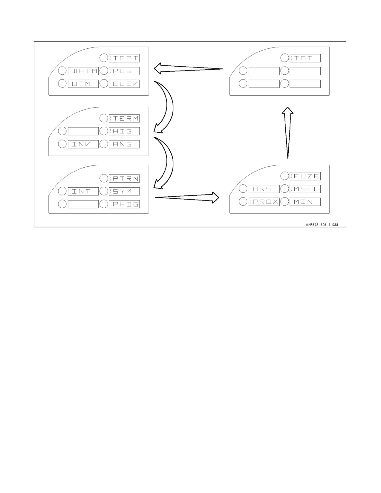
A1-AV8BB--NFM--000
Figure 23-20. Programming Targetpoints (with H4.0)
23.10.2.1.3 Magnetic Variation
To enter magnetic variation select the ELEV option twice. This option toggles between ELEV and MVAR. A colon
appears next to the MVAR option indicating selection, while the scratch pad displays the stored magnetic variation
for the selected waypoint. Magnetic variation can be entered to the nearest degree from W 90 degrees to E 90 degrees.
With H4.0 magnetic variation can be entered to the nearest tenth of a degree.
23.10.2.1.4 Datum
To enter a datum select the DATM option on the ODU. A colon appears next to the DATM option indicating selection
and the ODU displays last entered datum. Initial default shall be 47. If the DATM is invalid a blank scratchpad will
be displayed. Entries of 1 through 47 will be allowed for the appropriate datums. If an invalid DATM is entered the
invalid entry will flash.
23.10.2.1.5 Bearing
To enter bearing select the BRG option on the ODU. A colon appears next to the BRG option indicating selection
and the scratch pad displays the stored bearing for the selected offset. On the UFC keyboard, enter the new bearing
by sequentially entering values from 0 to 360° in 0.1° increments with OMNI 7.1 and 0.01° increments with C1+
and H4.0. Entry of leading zeros is not required. If TRUE is boxed on the MAPM/EWM page, then the entered bearing
is true. If TRUE is not boxed on the MAPM/EWM page, then the entered bearing is magnetic.
23.10.2.1.6 Offset Elevation
To enter offset elevation select the ELEV option on the ODU. A colon appears next to the ELEV option indicating
selection and the scratch pad displays the stored elevation for the selected waypoint offset or markpoint offset. The
elevation range is --2,000 feet to 25,000. Enter new elevation by selecting a negative sign and 1 to 4 digits if the
elevation is below sea level, or 1 to 5 digits if above sea level.
ORIGINAL
23-52
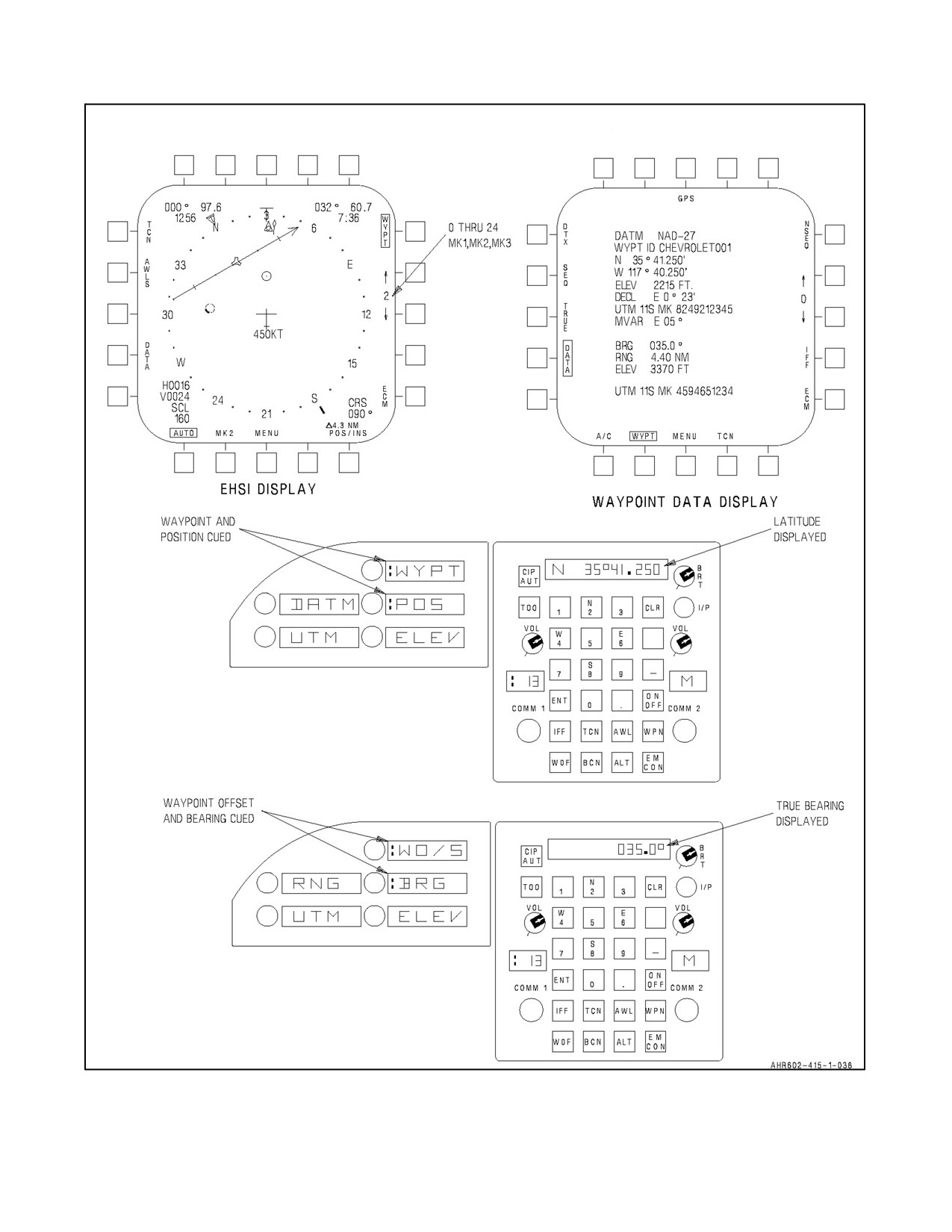
A1-AV8BB--NFM--000
TAV-8B WITH OMNI 7.1 AND DAY ATTACK AIRCRAFT
NSEQ
W
O
/
S
Figure 23-21. Waypoint, Mark, or Waypoint/Mark Offset Data Entry (Sheet 1 of 4)
23-53
ORIGINAL
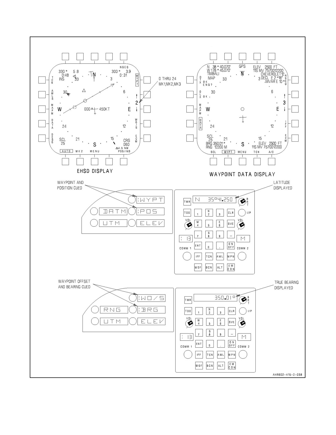
A1-AV8BB--NFM--000
RADAR AND NIGHT ATTACK AIRCRAFT WITH C1+
Figure 23-21. Waypoint, Mark, or Waypoint/Mark Offset Data Entry (Sheet 2)
ORIGINAL
23-54
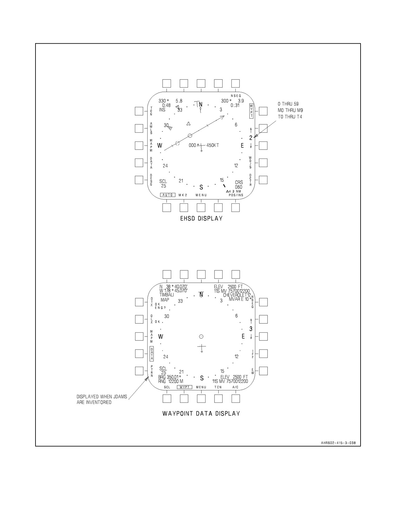
A1-AV8BB--NFM--000
TAV-8B WITH H4.0 AND RADAR AND NIGHT ATTACK AIRCRAFT
H
8
V
16
Figure 23-21. Waypoint, Mark, or Waypoint/Mark Offset Data Entry (Sheet 3)
23-55
ORIGINAL