NATOPS FLIGHT MANUAL NAVY MODEL AV--8B/TAV--8B 161573 AND UP AIRCRAFT (2008) - page 8

A1-AV8BB--NFM--000
*6. Airstart button — PRESS AND HOLD.
*7. Throttle — ADVANCE SLOWLY TO IDLE.
*8. JPT — MONITOR (475 °C MAX).
Do not continue airstart attempts below safe ejection altitude.
15.24 OIL SYSTEM FAILURE (OIL CAUTION LIGHT)
Operation of the engine with an oil system failure requires that the pilot ensure minimum loads are maintained on
the engine bearings. Set the minimum practical rpm within the band 75 to 85 percent (--406 engine) or 80 to 85 percent
(--408 engine) and maintain it constant with slow smooth throttle movement. Minimize the g loading and land as soon
as possible using a VNSL. Use nozzle braking if required, ensuring smooth throttle movements and be prepared for
engine failure. Set throttle off as soon as practical after landing. Nozzles, speedbrake, flaps and landing gear may be
used to control airspeed. Ifavertical landing is the only option, usethrottle slowly and progressively and beprepared
for engine failure.
*1. Throttle — MAINTAIN CONSTANT RPM.
a. 75 percent -- 85 percent RPM (--406 engine).
b. 80 percent -- 85 percent RPM (--408 engine).
15.25 NOZZLE DRIVE FAILURE
A nozzle drive failure will affect a single nozzle or either the front or rear nozzles, and will cause either a roll or pitch
as the nozzles are rotated. In either case, attempt to match the operating nozzles with the failed nozzle(s) and make
a fixed nozzle slow landing. The nozzle position indicator in the cockpit reads forward nozzle position only.
15.26 NOZZLE CONTROL FAILURE
Exact technique to be used in event of nozzle control failure depends on the position at which the nozzles are failed
and the phase of flight in which they fail. The following procedures provide a general guide which may require
modification due to the circumstances of a specific failure.
15.26.1 During STO
If not enough runway remains for either abort or CTO:
1. EJECT.
15.26.2 During Transition
1. Set nozzle lever to angle shown on indicator.
2. Lighten aircraft to HOVER weight (if feasible).
3. Make landing consistent with nozzle angle.
4. Be prepared for possible uncommanded nozzle rotation on approach.
5. Throttle — OFF WHEN STOPPED.
ORIGINAL
15-40

A1-AV8BB--NFM--000
With nozzle in braking position:
6. Accelerate to 50 knots.
7. Flare to hover attitude.
8. Touchdown before airspeed falls to zero.
9. Throttle — OFF WHEN STOPPED.
15.26.3 During Conventional Flight
1. Maintain 300 knots minimum until hover weight is reached.
15.27 ENGINE FIRE (FIRE WARNING LIGHT)
The first indication of fire is normally illumination of the FIRE warning light. If the FIRE warning light comes on
during ground operations or flight operations where an immediate landing can be accomplished, i.e., short final, or
vertical operations, the aircraft should be stopped and secured using the Engine Fire emergency procedures. If the
aircraft is airborne or in a position where an abort or immediate landing is not possible, the in--flight fire procedure
should be followed.
There are three possible sources of ignition in an engine bay fire: the RCS system, the GTS/APU, and the engine.
If the nozzles are down, they should be placed aft as soon as conditions allow. This means rapid acceleration to
wingborne flight if in the jetborne/semi--jetborne flight region and an immediate landing is not possible. The
GTS/APU should be secured, if it is operating, to eliminate it as the fire source. The throttle should be pulled to the
minimum powerrequired forsafeflight. This could beIDLE orMAX powerdepending on whetheryou areat 20,000
feet or on the deck in an accelerating transition. If the engine air valve is open (only applicable to an aircraft with
a fuselage gun on board) it should be closed by deselecting gun and placing the master arm switch to SAFE. The gun
will be deselected by switching to NAV or V/STOL master mode. Even with the gun deselected, it is still necessary
to secure Master Arm switch in order to close the engine air valve.
The engine air valve is open if a gun is present AND any of the following are true:
1. Master Arm — ON.
2. A/G Master Mode and gun selected (Master Arm OFF or ON).
3. A/A Gun selected (Master Arm OFF or ON).
For these reasons the Master Arm must be selected OFF and the gun (either A/G or A/A) must be deselected to secure
the valve.
After following the first four steps of the in--flight fire procedure, check for confirmatory signs of the fire. Engine
fires are normally accompanied by one or more of the following: abnormally high JPT, abnormally high or erratic
fuel flow, erratic or rough engine operation, or visible flames or smoke trail. If a FIRE warning light persists with
no other signs of fire, use minimum power and land as soon as possible.
If required runway length is available, keep nozzles aft during landing rollout. However, due consideration must be
given to the stopping distances required when PNB is not used after a conventional landing. Recommend landing
as light and as slow as possible. To achieve minimum braking distance, the antiskid system operates most efficiently
when the brakes are applied 2 seconds after touchdown using a quick, full pedal input held steady until taxi speed
is reached. Do not cycle, pump or lightly ride the brakes.
A momentary illumination of the FIRE warning light may indicate the circuitry has burned through so the circuit
should be tested by placing the COMP/LTS TEST switch to LTS TEST. If the circuit fails the test, further
investigation is required.
15-41
ORIGINAL

A1-AV8BB--NFM--000
CAUTION
Use nosewheel steering judiciously after engine shutdown. About three
cycles (neutral to 3° L to 3° R and back to neutral) are available after rpm
below 10 percent.
15.27.1 Ground
*1. Execute Emergency Shutdown.
15.27.2 Takeoff/Landing/Vertical Operation
*1. Abort or Land Immediately.
*2. Execute Emergency Shutdown.
15.27.3 Inflight
*1. Nozzles — AFT AS SOON AS POSSIBLE.
*2. APU GEN — OFF.
*3. MASTER ARM/GUN — OFF.
*4. Throttle — MINIMUM REQUIRED.
If fire persists:
*5. EJECT.
If light goes out:
6. Land as soon as possible.
15.28 ELECTRICAL FIRE
--406/--408A Engine:
1. MFS — SELECT.
Note
Emergency MFS battery activation may be required if unable to select
MFS.
All Aircraft:
2. Generator switch — OFF.
3. Cabin pressure switch — RAM.
4. Limit airspeed as follows:
Below 5,000 feet -- 0.4 Mach.
5,000 to 10,000 feet -- 0.6 Mach.
10,000 to 15,000 feet -- 0.7 Mach.
5. All electrical equipment — OFF.
ORIGINAL
15-42

A1-AV8BB--NFM--000
If fire persists:
6. Battery switch — OFF ECS reverts to normal with battery switch OFF.
7. Emergency oxygen actuator — PULL.
The OBOGS will not operate with the battery switch OFF.
8. Descend below 10,000 feet cockpit altitude.
9. Land as soon as practical.
15.29 ELIMINATION OF SMOKE AND FUMES
Considerallfumes inthecockpitas toxic.Do notconfusecondensationfrom theairconditioningsystem withsmoke.
The most probable source of visible smoke or fumes in the cockpit is from engine bleed. This smoke is blue gray
in color, has a characteristic pungent odor, and may cause the eyes to sting. Another source of smoke or fumes is an
electrical malfunction or overheat of equipment located in the cockpit. In the event of electrical short or overload
condition, this equipment may generate electrical smoke (usually white or gray in color) but should not cause an open
fire since cockpit equipment uses very little electrical current. Cockpit electrical wiring insulation may smolder and
create smoke, but will not erupt into a seriously damaging fire.
1. Emergency oxygen actuator — PULL.
2. Cabin pressure switch — RAM (requires DC power).
3. Limit airspeed as follows:
Below 5,000 feet -- 0.4 Mach.
5,000 to 10,000 feet -- 0.6 Mach.
10,000 to 15,000 feet -- 0.7 Mach.
4. Descend below 10,000 feet MSL.
If unable to clear smoke:
5. Slow aircraft.
6. MDC RING — PULL (eyes closed and visor down).
15.30 CROSSFEED FAILURE (R FEED WARNING LIGHT)
On the TAV--8B the R FEED warning light indicates automatic control of the crossfeed valve has failed and the valve
is in theincorrect position.Threesituationscan resultin thiswarning light.In allsituations, placingtheFuelQuantity
Indicator to FEED and checking the fuel quantity remaining in the feed tanks will determine subsequent required
actions. The fuel quantity will require monitoring.
1. R FEED warning with less than 300 pounds in the left feed tank and 300 pounds or greater in the right fuel
system — set the fuel proportioner switch to RT and check the R FEED advisory light comes on and the R
FEED warning light goes out.
2. R FEED warning with both feed tanks full, 300 pounds in each fuel system — set the fuel proportioner switch
to DL and verify the R FEED warning and advisory lights go out.
3. R FEED warning light with both right and left feed tanks indicating less than 300 pounds — set the fuel
proportioner switch to OFF and verify the R FEED warning and advisory lights go out.
15.31 FUEL TRANSFER FAILURE (L TRANS/R TRANS CAUTION LIGHT)
Fuel transfer pressure failure may occur in one or both sides of the fuel system and is indicated by the illumination
oftheL TRANS and/orR TRANS caution light(s). With afuel transferpressurefailure,internal fuelwill stilltransfer
15-43
ORIGINAL

A1-AV8BB--NFM--000
via siphon. Care must be taken not to uncover the mouth of any transfer pipe in the fuel tanks or siphon transfer will
be broken. If this occurs, the feed tanks, depending on aircraft fuel state, could deplete significantly before siphon
transfer can be re--established. Restrict altitude to 30,000 feet to prevent the possibility of fuel cavitation due to low
tank pressures. Do not maneuver excessively or exceed 5,000 feet/minute rate--of--descent to minimize negative
pressures in the tanks and to avoid the possibility of uncovering the tank transfer pipes.
With a transfer pressure failure, the feed tank fuel quantities should be monitored closely. If the quantity gauge on
the affected side indicates a steady reading of approximately 300 pounds, transfer is taking place. If the quantity gauge
shows a continuing decrease and fuel is in the transfer tanks, transfer has ceased. If both feed tanks are decreasing
after following checklist procedures, an immediate landing will be necessary due to fuel shortage.
If an external tank stops transferring fuel to the wing, transfer pressure is lost to that associated feed group. Transfer
from the wing tank to the next tanks downstream will continue but pressure in the internal wing tank will decrease
as fuel is consumed and the L TRANS or R TRANS caution light will eventually come on.
Transfer from the external tank may resume as the pressure in the wing tank decreases. If this does not occur, an
attempt to reestablish transfer from the external tank can be made after the wing tank is empty by opening the fuel
dump switch on the appropriate side. The dump switch must be held in the DUMP position. This will create an
increased pressure differential between the external tank and wing, increasing the potential for fuel transfer. When
fuel starts dumping from the dump mast, terminate dumping and check fuel gauges for continued transfer. If transfer
is not sustained, repeat the procedure until transfer is established or the external tanks are empty.
If fuel does not transfer from the external tank with the dump valve open, close the dump valve. Leaving the fuel dump
valve open for a prolonged period may result in a wing overtemperature condition.
Fuel jettison rates with transfer pressure failure will be slower than normal. If range is critical, jettison the failed side
external tank. With the fuel selector switch set to TOTAL, monitor fuel quantity for asymmetry. Follow asymmetric
landing procedures if wing fuel out--of--balance exceeds 250 pounds or if otherwise required.
Only 250 pounds of fuel or less is available from the feed tank associated
with the flashing FUEL caution. The engine will flameout when either feed
tank empties while the fuel flow proportioner is ON.
15.32 FUEL LOW LEVEL (L FUEL/R FUEL CAUTION LIGHT(S) FLASHING)
A flashing L FUEL or R FUEL caution light indicates the respective feed tank fuel level is 250 ±50 pounds. If this
light flashes when there is more than 300 pounds in the corresponding fuel group, the vapor release valve may have
failed closed allowing a high pressure air bubble to form and stop fuel transfer. Place the fuel quantity indicator switch
to FEED and check the feed tank fuel status. If the fuel level is low, apply negative and positive g’s in an attempt to
free the vapor release valve. If the fault persists, switch off the flow proportioner and failed side boost pump. If range
is critical, the boost pump can be turned on to use available feed tank fuel. If rangeis not critical, leavethe failed side
boost pump off to conserve its fuel for landing. Place the quantity indicator switch to TOTAL to monitor fuel
asymmetry. Follow asymmetric landing procedures if wing fuel out--of--balance exceeds 250 pounds or otherwise
required.
Only 250 pounds of fuel or less is available from the feed tank associated
with the flashing FUEL caution. The engine will flameout when either feed
tank empties while the fuel flow proportioner is ON.
ORIGINAL
15-44

A1-AV8BB--NFM--000
15.33 EXTERNAL FUEL TANK TRANSFER FAILURE
1. Wing tank (failed side) — BURN USABLE FUEL.
2. Dump switch (failed side) — DUMP (hold if necessary).
CAUTION
Do not leave dump switch in DUMP for an extended period if fuel fails to
transfer from external tank.
When fuel starts to dump from dump mast:
3. Dump switch — NORM.
4. Fuel quantity indicator — MONITOR FOR TRANSFER INDICATION.
5. Repeat procedure, as required, to use external fuel.
If fuel does not transfer from external fuel tank:
6. Balance internal wing tank fuel to minimize asymmetry for landing.
15.34 FUEL LEAK
1. Minimize maneuvering.
2. Air refueling switch — OUT.
3. Boost pumps — OFF.
4. Fuel flow proportioner — OFF.
5. Execute Inflight Fire procedure.
Note
Excessive maneuvering may discontinue fuel syphoning and may cause
fuel pooling in the bottom of the fuselage to come in contact with hot motor
sections. Use of nozzles may also increase the likely hood of igniting fuel
pooled in the fuselage.
15.35 AIR REFUEL PROBE FAILS TO RETRACT
1. A/R switch — CYCLE -- IN.
If probe remains out:
2. Do not exceed 300 knots.
If L TRANS/R TRANS caution(s) come on:
3. A/R switch — PRESS. (With the A/R switch in PRESS, automatic fuel transfer shutdown with an L TANK/R
TANK warning light is lost.)
15-45
ORIGINAL

A1-AV8BB--NFM--000
15.36 FLAPS CHANNEL FAILURE (FLAPS 1 OR FLAPS 2 CAUTION)
For aircraft without ECP--255 R1:
A FLAPS 1 failure may result in failure of the nozzle position indicator, the HUD nozzle indication in V/STOL, and
the flap position indicator. A FLAPS 2 failure may result in failure of the HUD flap indication in V/STOL. Either
a FLAPS 1 or FLAPS 2 failure may result in the ailerons being commanded out of the droop position when in the
STOL mode below 165 knots.
For aircraft with ECP--255 R1:
Either a FLAPS 1 or FLAPS 2 failure may result in the ailerons being commanded out of the droop position when
in the STOL mode below 165 knots.
15.37 AUTO FLAP FAILURE (AUT FLP CAUTION)
An AUT FLP caution may be an indication of ADC failure.
D When STOL flaps are selected with the AUT FLP caution on, aileron droop
and flap scheduling may occur as the nozzles are rotated past 25° regardless
of airspeed. At high speed, a severe nose down pitch will occur. Ensure
airspeed is below 165 knots and nozzles are 25° or greater prior to selecting
STOL flaps.
D With an AUT FLP caution light the LIDS fence may extend when the gear
is lowered regardless of airspeed. Ensure airspeed is below 200 KCAS
before lowering the landing gear.
15.38 FLAP FAILURE (FLAP WARNING LIGHT)
Beeping the flaps under certain flap system failures may result in an upward or downward movement of a single flap
at a significantly higher than normal rate. Momentarily depress emergency flaps retract button and monitor flaps for
increased asymmetry. If significant divergenceis apparent, do not attempt furtherflap retraction. After landing, beep
flaps up to avoid flap damage.
Rotation of the nozzles aft with failed flaps greater than 25° can cause a
severe nose down pitch due to nozzle blast impingement on flap surfaces.
The nose down pitch rate can be arrested by selecting a nozzle angle greater
than 40°. The aircraft must then be recovered from the nose down attitude.
Note
D In aircraft without ECP--255 R1, a dual channel failure (FLAP--1 and
FLAP--2 lights on) can result in a slow flap drift. Turning the flaps power
switch off will preclude further movement of the flaps.
D In aircraft with ECP--255 R1, if the FLAPS warning light is not cleared, the
FLAP FAILURE, FLAP FAILURE voice warning will recur once after 15
seconds if the flaps remain greater than 25°.
ORIGINAL
15-46

A1-AV8BB--NFM--000
15.39 UNCOMMANDED FLAP MOTION
*1. Nozzles — 40 DEGREES OR GREATER.
2. Flaps power switch — OFF.
D Cycling flap power, modeorresettingflaps maycauselargeuncommanded
flap transient motion.
D Uncommanded programming of the flaps greater than 25° with nozzles less
than 20° will cause a severe nose down pitch rate. The extreme attitudes
coupled with the negative g’s of up to --2.5, as experienced by the pilot, will
be extremely disorienting and make cockpit functions difficult to perform.
A combination of full aft stick and rotation of the nozzles to an angle greater
than 40° are required to arrest this condition.
15.40 UNCOMMANDED NOSE DOWN PITCH MOVEMENT
*1. Nozzles — 40 DEGREES OR GREATER.
For any uncommanded nose down pitching that is not recoverable with
backstick, lowering the nozzles is the only remaining option to regain
control. Any delay at low altitude in lowering the nozzles, if uncommanded
nose down pitching occurs, may result in loss of aircraft.
15.41 RUDDER TRIM FAILURE
1. RUD SVO circuit breaker — PULL.
Rudder trim series servo will center. Rudder trim and yaw stab aug inoperative.
15.42 AILERON OR STABILATOR TRIM FAILURE
If circuit breaker is out:
1. Applicable circuit breaker — RESET (one time only).
If circuit breaker is in:
2. Applicable circuit breaker — CYCLE.
15.43 Q--FEEL FAILURE
1. Q--FEEL switch — OFF.
2. Maintain airspeed below 500 knots/0.8 Mach.
15.44 SAS FAILURE
1. AFC — RESET.
15-47
ORIGINAL

A1-AV8BB--NFM--000
If erroneous input occurs:
2. Paddle switch — PRESS AND HOLD.
3. Appropriate stab aug switch(es) — OFF.
4. Paddle switch — RELEASE.
15.45 FLIGHT CONTROL MALFUNCTION
Stifforjammedflightcontrolscanbecausedbyimpropermaintenance,FOD,structuraldamage,ice,bindingreaction
control shutter, or flight control system malfunctions. When this occurs, the SAAHS should be checked as follows:
*1. Paddle switch — PRESS AND HOLD.
If condition has cleared:
2. Appropriate stab aug switches — OFF.
3. Paddle switch — RELEASE.
4. Land as soon as practical.
If condition has not cleared (possible jammed flight controls):
*5. Transition to conventional flight.
Note
If pitch control is restricted, nozzles may be used for pitch control. If roll
control is restricted, rudder may be used for lateral flight control. Trim
control may still be available with jammed flight controls.
6. Land as soon as possible.
15.46 HYD 1 FAILURE (HYD 1 CAUTION LIGHT)
If HYD 1 is not restored the following services will be lost:
Normal landing gear extension.
Fuel proportioner.
Air refueling probe.
LIDS Fence.
Speed brake.
Stab aug.
AFC.
Q--feel.
Aileron droop.
Powered rudder.
15.47 HYDRAULIC SYSTEM FAILURE (HYD WARNING LIGHT)
CAUTION
Use nosewheel steering judiciously. About 3 cycles (neutral to 3° L to
3° R and back to neutral) are available following dual hydraulic system
failure.
ORIGINAL
15-48

A1-AV8BB--NFM--000
15.48 GUN NOT CLEAR
Gun not clear is indicated by a NOT CLEAR legend on the DDI store display. The NATIP, NTRP 3--22.4--AV8B
contains a thorough discussion of gun operation/malfunctions.
1. Master arm switch — OFF.
2. Gun — DESELECT.
Failure to place the master arm switch to OFF and deselect the gun can
result in gun damage, gun pack overheat, and cook--off of rounds in the
breech area.
Before landing:
3. Notify landing facility of Hot Gun.
After landing:
4. Proceed immediately to Hot Gun area for dearming.
15-49/(15-50 blank)
ORIGINAL

A1-AV8BB--NFM--000
CHAPTER 16
Landing Emergencies
16.1
LANDING GEAR UNSAFE/FAILS TO EXTEND
An unsafe gear indication may result from HYD 1 failure, electrical failure, airframe damage, actuator failure, or a
faulty gear position indicator. With a confirmed gear malfunction, perform a VL. If required, water may be selected
to gain additional performance, with or without water on--board. If performance is inadequate for a VL, perform an
RVL as slow as possible. Recommend use of an LSO. The approach/hover or aux light will come on only if the main
landing gear is down and locked. The nose landing gear doors will close only if the nose landing gear is down and
locked. If the nose landing gear microswitch malfunctions, the nose landing gear doors may not close, but the gear
may still be down and locked. On AV--8B 165354 and up, an unsafe NLG may result in lo and hi gain steering failing
to centered steering mode, in which case the NWS legend on the Caution/Advisory Panel will be illuminated. If the
NLG doors are open due to a T handle failure (popped) the NWS will function normally. Blowing the gear down will
eliminate the steering failures. In the event the emergency gear extension system does not function, the steering
failures will persist. Steering should not be selected until there is no crab angle and the aircraft has an acceptable
heading.
If ground speed is excessive, NWS may not be adequate for directional
control during an RVL with a wing gear in trail.
Landing Gear Status Unknown
If one or more gear fails to indicate down:
1. Lights test switch — TEST.
Check 4 green, 4 amber, red GEAR and gear handle lights on. If green gear down light failed with red GEAR
and gear handle lights and amber in transit lights out, consider the gear down.
If lights test good:
2. Gear handle — DOWN.
If gear indicates unsafe or gear status remains unknown:
3. Landing Gear Unsafe/Fails to Extend Procedures — PERFORM.
Landing Gear Unsafe/Fails to Extend
1. Landing gear circuit breaker — CHECK IN.
(second circuit breaker from left on bottom row)
2. Request visual check (if circumstances permit).
3. Gear handle — CYCLE.
If gear does not extend:
4. Landing Gear Emergency Extension Procedures — PERFORM.
16-1
ORIGINAL

A1-AV8BB--NFM--000
If gear still indicates unsafe after emergency extension:
5. Fuel/Stores — JETTISON TO MINIMUM GROSS WEIGHT FOR LANDING (as required).
6. Perform gentle VL . Throttle — OFF, IF GEAR COLLAPSES.
7. Do not taxi. Install wing gear locks before engine shutdown.
If nose gear fails to extend:
8. Perform gentle VL, slowly lowering nose to ground.
9. Throttle — OFF.
Note
Nozzles angles greater than hover stop may be used to decrease attitude.
Landing Gear Emergency Extension
1. Gear handle — DOWN.
2. Landing gear circuit breaker — PULL (second circuit breaker from left on bottom row).
With Airspeed below 210 knots:
3. Gear handle — ROTATE 90° CLOCKWISE AND PULL.
If the gear is extended by the emergency method with a HYD1 failure, the speedbrake and LIDS will not extend
and VL capability will be reduced by 500 pounds. If gear handle will not move, rotate the handle 90° and pull.
The gear will extend by the emergency method with the gear handle up.
If gear still does not extend:
4. LDG GEAR EMER BATT — ACTUATE.
(after AFC--328)
16.2
BLOWN TIRE
Directional control will probably be lost if wing gear tire fails with taxi
speed above 25 knots.
1. Perform vertical landing.
If vertical landing not feasible or tire blows during landing roll:
2. ANTISKID switch — NWS (if main tire blown).
3. Use maximum nozzle braking.
4. Use nosewheel steering and reaction controls to maintain directional control.
If hot brakes suspected:
5. Do not set parking brake.
Due to the possibility of hydraulic seal failure with hot brakes and blown
main tires, a hydraulic fire may develop. Parking brake application will
increase the probability of fire.
ORIGINAL
16-2

A1-AV8BB--NFM--000
16.3
NOSEWHEEL STEERING/CASTER FAILURE
16.3.1 Before AFC--391
To determine whether the caster system or antiskid system has failed, press the NWS button. If the SKID light goes
out with the button pressed, suspect a caster failure. If the light stays on with the button pressed, suspect antiskid
system failure. A NWS failure can mask a caster failure.
1. ANTISKID switch — NWS.
2. Perform VL.
If unable to land vertically:
3. Minimize crab angle.
4. Perform RVL as slow as practical.
If the nosewheel steering system is suspected of a failure (i.e. failure to
respond to commands, caster failure, etc.) a vertical landing should be
performed. A failure of the nosewheel steering system during a rolling
landing may result in a loss of control and subsequent loss of aircraft.
Note
D Atimelydecisiontoperform atouchandgowhiletheaircraft isstill onthe
runway may prevent damage or loss of the aircraft.
D When nosewheel steering failure is suspected, have wingman check for
motion by pressing NWS button and cycling rudder to move nosewheel.
D If necessary, use reaction controls for steering. Nozzles should be near
hover stop and rpm over 50 percent.
16.3.2 After AFC--391 (Hi/Lo Gain NWS System)
Illumination of NWS light on the caution/advisory panel is an indication of a NWS system failure. NWS failure mode
is ascertained by comparing the modeselected by the pilot with themode displayed on theHUD. If CAST displayed
in the HUD with ANTISKID switch ON, engaging NWS button will result in either HI gain or centered steering
mode. If NWS displayed in HUD with ANTISKID switch on, caster mode has failed to LO gain NWS (“hot” NWS)
and will remain in LO gain when the NWS button is engaged. The mode displayed on the HUD is the active steering
mode.
INFLIGHT.
1. Perform VL.
If unable to perform VL:
2. Determine failure mode.
3. Perform RVL as slow as practical with minimum crab angle.
16-3
ORIGINAL

A1-AV8BB--NFM--000
If the NWS system is suspected of a failure (i.e. failure to respond to
commands, etc.) a vertical landing should be performed. Failure of the
NWS system during a rolling landing may result in a loss of control and
subsequent loss of aircraft.
Note
When NWS failure is suspected, have wingman check for motion by
pressing NWS button and cycling rudder to move nosewheel. Alternative-
ly, nosewheel motion can be verified by pressing the NWS button, cycling
rudder pedals and observing the gear centered indication on the HUD
cycles between displayed and non--displayed.
TAKEOFF/LANDING ROLL OUT.
*1. Attempt to get airborne.
If unable to get airborne:
*2. Engage NWS button at minimum practical ground speed.
If CASTdisplayed in HUD, engaging NWS button will result in either HI
gain or centered steering mode. If NWS displayed in HUD, engaging NWS
button may result in HI gain. Failure of the NWS system during a rolling
landing may result in loss of control and subsequent loss of aircraft.
Note
A timely decision to perform a touch and go while theaircraft is still on the
runway may prevent damage or loss of the aircraft.
16.4
SPEEDBRAKE FAILURE
With an electrical or hydraulic failure, airloads will close the speed brake.
If SPD BRK light on with gear down:
1. Speed brake circuit breaker — PULL.
If SPD BRK light still on:
2. Perform gentle RVL. Do not taxi.
ORIGINAL
16-4

A1-AV8BB--NFM--000
16.5
DAMAGED AIRCRAFT
When structural damage or any other failure is known or suspected that may adversely affect aircraft handling
characteristics, a controllability check should be performed as follows:
1. Proceed to a safe altitude.
Note
If conditions allow climb above 10,000 feet AGL. If unable to climb to
10,000 feet AGL it is recommended to climbto thehighest feasiblealtitude
prior to performing a controllability check.
2. Reduce gross weight to minimum practical.
3. Perform controllability check with gear down.
4. Determine if and what type of landing can be made.
If wing leading edge damage is suspected or confirmed:
Plan for an auto flap conventional landing. In the approach do not slow below 10 AOA or, in any case to an airspeed
where greater than 1/2 control input, in any axis, is required to maintain control. Use a 2° to 3° approach and make
shallow turn. If desired after touchdown, nozzles may be moved to the braking stop position, but power left at idle,
to assist in stopping the aircraft.
If wing trailing edge damage is suspected or confirmed:
Select flaps OFF, do not beep or extend flaps in order to avoid a split. Make only shallow AOB turns, if necessary
use rudder to turn aircraft. Use nozzles as required, perform a FNSL, gradually increasing nozzle angle, ensure ground
speed is below 180 knots at touchdown. If certain nozzles are not damaged a VNSL may be made.
5. If adequate control available, maintain configuration and make straight--in approach.
16.6
CRUISE FLAPS LANDING
A cruise landing is basically the same as a normal VL. For a CL or SL, the landing roll will increase due to the
increased airspeed at the landing AOA. The pattern should be expanded slightly. If possible, perform an SL or VL.
Do not touchdown above 180 knots ground speed, if possible.
16.7
SAAHS OFF RECOVERY AND LANDING
CAUTION
During a SAAHS off recovery and landing the pilot workload will be
substantially increased. Care must be taken to perform all transitions early
to allow the pilot time to trim the aircraft and gain familiarity with the
changing flight characteristics in the SAAHS off condition. This will also
allow time to assess the environmental conditions. Excursions from
balanced flight must be corrected immediately to maintain adequate control
power with the reaction control system.
1. Fly a straight--in approach if possible.
If wind, runway condition, aircraft malfunction(s) allow:
2. Perform a FNSL (Select a nozzle angle that produces a 90 to 120 KCAS approach).
16-5
ORIGINAL

A1-AV8BB--NFM--000
Note
Many aircraft malfunctions that degrade the SAAHS will also require an
RVL or VL to land due to other aircraft system degradations.
If wind, runway condition, aircraft malfunction(s) or other conditions prevent performing a FNSL:
3. Perform RVL or VL (Recommend a flatter than normal approach and avoid excessive closure).
A high, fast approach SAAHS off, especially on a decelerating transition
to a VL will increase likelihood of pilot over--controlling the aircraft
leading to loss of altitude awareness, AOA excursions, loss of sideslip
control and a possible loss of aircraft control in close proximity to the
ground.
4. Prior to touchdown — Ensure pitch attitude is maintained on the horizon; minimize yaw and roll angle.
16.8
REACTION CONTROL FAILURE
Reaction control failure may be caused by loss of RCS pressure/flow or by disconnection of an RCS shutter.
Loss of RCS pressure/flow is most often accompanied by low duct pressure and/or excessive nose--up pitch as the
nozzles are lowered. During a decelerating transition, the aircraft will become increasingly sluggish in response to
control inputs and, eventually, all control will be lost. Loss of RCS may indicate a bleed air duct failure which can
cause a fire.
Disconnect of an RCS shutter will cause degraded control authority or loss of control in one axis during jetborne
flight. A disconnect during wingborne flight will not become apparent until below 120 knots where it will appear
as an increasing pitch, roll, or yaw tendency as the aircraft slows. Disconnect of the front or rear pitch shutter will
probably result in a closed shutter and a lack of response from the failed shutter. The position of the yaw shutter after
a disconnect is not predictable. Disconnect of a roll shutter will probably result in full up--blowing on the failed side
and will be indicated by increasing opposite lateral stick required to maintain wings level as the aircraft slows.
Thetypeoffailurecan bedistinguished by ageneral degradation in control in all axes with loss of RCS pressure/flow
as opposed to degradation in only one axis with an RCS shutter disconnect. Disconnect of the rear pitch shutter may,
at first, appear similar to loss of RCS pressure/flow but, in this case, normal yaw and roll control is still available.
For any reaction control failure, the proper corrective action is to transition to conventional flight as fast as possible
or land immediately.
With an RCS shutter disconnect, especially with a roll shutter disconnect,
abrupt application of power may cause complete loss of control with
shutters down.
*1. Transition to conventional flight.
If transition to conventional flight not feasible:
2. Land immediately or eject.
ORIGINAL
16-6

A1-AV8BB--NFM--000
16.9
ASYMMETRIC LANDING
An asymmetric moment can result from fuel transfer failure or stores imbalance. An asymmetric vertical landing may
require use of water or reduced weight due to JPT rise from increased RCS bleed requirements (about 4 °C per 10,000
inch--pounds asymmetry). For an asymmetric slow landing, lateral control is improved by use of AUTO vice STOL
flaps. CG near the aft limit should be avoided during AUTO flap landings with more than 60° nozzles due to low
longitudinal control margin. Combinations of lateral asymmetry and longitudinal fuel imbalance should be avoided
due to inertia effects and decreased control authority. The relative wind should be placed under the heavy wing if
possible. Time in ground effect should be minimized.
CAUTION
Flight test results have shown a drop off in handling qualities with
asymmetries greater than 80,000 inch--pounds without the relative wind
under the heavy wing.
16.9.1 Asymmetric Stores Landing
The inboard pylon is 75.17 inches from the aircraft centerline, the intermediate pylon is 127.49 inches from the
aircraft centerline, and the outboard pylon is 157.06 inches from the aircraft centerline; therefore, a single store over
1,065 pounds on an inboard pylon, a single store over 628 pounds on an intermediate pylon, or a single store over
510 pounds on an outboard pylon will exceed the vertical landing limit. If two or more stores are retained, the
algebraic sum of their individual moments must be calculated to determine if the asymmetric moment is in excess
of the vertical landing limit (-- for stations 1, 2, and 3; + for stations 5, 6, and 7). See Figure 16-1. For store and
suspension equipment weights refer to the aircraft loading chart in part XI, A1--AV8BB--NFM--400. An AUTO flap
slow landing using 50° fixed nozzles will generally provide the most comfortable lateral control margin and landing
roll--out characteristics; however, nozzle setting may be varied depending on other factors such as touchdown speed
versus runway length, longitudinal control margin, RCS condition, etc. The two most important items for
controllability are use of AUTO flaps and limiting AOA to 12° maximum. Do not make sudden or large rpm
reductions during approach to prevent RCS control power reduction.
If asymmetric load over VL limit and VL required:
1. External stores — JETTISON.
If asymmetric load over 80,000 inch--pounds:
2. Climb to a safe altitude (3,000 feet AGL).
Note
If conditions allow climb above 10,000 feet AGL. If unable to climb to
10,000 feet AGL it is recommended to climbto thehighest feasiblealtitude
prior to performing a controllability check.
3. Slow to 250 knots.
4. Landing gear — DOWN.
5. Flaps — AUTO.
6. Slow to desired approach speed using nozzles (recommend 50° nozzles) and rpm to limit AOA to 12°.
7. Perform controllability check. (If rudder pedal shakers fire with a centered yaw vane, turn shakers off. Retain
stab aug.)
Note
All sideslip aids utilizing lateral accelerometer inputs (yaw stab, shakers,
HUD sideslip symbol) will operate erroneously.
16-7
ORIGINAL

A1-AV8BB--NFM--000
If lateral control margin inadequate and stores cannot be jettisoned:
8. EJECT.
16.9.2 Asymmetric Fuel Landing
Fuel imbalances will cause lateral asymmetry when the low side is above 1,400 pounds, and longitudinal cg shift
when the low side is below 1,400 pounds.
Depending on aircraft loading, fuselage fuel imbalance as low as 250 pounds may place the cg out of limits. When
a combination of lateral asymmetry and fuselage fuel imbalance exists, control authority may be substantially
reduced due to abnormal stick position and/or excessive bleed requirements.
If fuel imbalance exceeds 250 pounds:
1. Fuel proportioner — OFF.
2. Low side boost pump switch — OFF UNTIL FUEL BALANCED.
If fuel does not balance:
3. Heavy side wing fuel — JETTISON.
4. Low side boost pump switch — ON FOR LANDING.
5. Land as soon as practical.
If low side fuel below 850 pounds:
6. Perform a Fixed Nozzle Slow Landing if possible.
If total asymmetry including fuel and stores exceeds 80,000 inch--pounds:
7. Refer to Asymmetric Stores Landing.
To calculate asymmetry due to wing tank imbalance, enter Figure 16-2 with fuel in each wing tank. Asymmetry in
inch--pounds is (+) for the right wing tank and (--) for the left wing tank. Calculate the algebraic sum. Lateral control
authority is degraded with asymmetries above 85,000 inch--pounds at airspeeds below 200 knots with nozzles aft.
16.10 LANDING WITH ENGINE FAILURE
Landing with the engine inoperative shall not be attempted.
16.11 PRECAUTIONARY EMERGENCY APPROACH
The standard precautionary emergency approach is a straight--in approach to a conventional or slow landing, modified
as aircraft configuration and power available dictates. For conventional precautionary approaches, recommend
landing as light and as slow as possible. For conventional landings when PNB is not an available option, such as for
a fire light or nozzle malfunction, apply full brakes two seconds after touchdown. Do not cycle, pump or lightly ride
the brakes.
CAUTION
Conventional landings greater than 140 KGS above 20,000 LBS gross
weight without PNB will result in main tire fuse plug release. Landings at
this weight have exhibited this characteristic approximately 1 minute after
coming to a stop.
If engine control is in question but nozzles can be moved, recommend combining wheel brakes and idle PNB.
ORIGINAL
16-8

A1-AV8BB--NFM--000
16.12 CANOPY SEAL FAILS TO DEFLATE
If the canopy seal fails to deflate after landing, the canopy cannot be opened in the normal manner.
1. Cabin pressure switch — RAM.
2. Attempt to manually open the canopy.
With the canopy seal inflated, it takes at least 110 pounds of pull force to open the canopy.
3. Engine — SHUT DOWN.
4. Have maintenance personnel disconnect weight--on--wheels plug in main wheelwell.
If seal still inflated:
5. Have maintenance personnel check CS COOL circuit breaker — IN.
If canopy still will not open:
6. Puncture the canopy seal with a sharp object.
The aircraft may be flown below 25,000 feet cabin altitude with a punctured canopy seal.
16-9
ORIGINAL
A1-AV8BB--NFM--000
ASYMMETRY (INCH--POUNDS)
VL LIMIT
80,000
INCH--POUNDS
STORE
STATION
1(--)
2(--)
3(--)
7(+)
6(+)
5(+)
AIM--9L/M
1
29,684
24,096
—
AGM--65E
2
—
81,594
48,109
AGM--65F
2
—
85,291
50,289
TGM--65E
—
81,594
48,109
CATM--65F
—
85,291
50,289
TACTS
1
19,161
15,554
—
AN/AAQ 28, Litening Pod
5
—
62,470
36,833
CBU--78/B
76,802
62,343
36,758
CBU--99/100
79,315
64,382
37,961
Mk 20, Mod 9, 10, 11, 12
76,959
62,470
36,833
Mk 82, Conical
3
80,729
65,530
38,367
Mk 82, Mk 15
3
88,111
71,522
42,170
Mk 82, BSU--33
3
81,043
65,785
38,788
Mk 82, BSU--86
3
87,797
71,267
42,020
Mk 83, Conical
3
—
126,470
74,569
Mk 83, BSU--85
3
—
130,805
77,124
Mk 77 Mod 4, 5
—
69,482
40,968
Mk 36, Mk 15
3
88,425
71,777
42,321
Mk 36, BSU--86
86,540
70,247
41,419
Mk 40, MAU--91
—
134,502
79,304
GBU--12
—
77,641
45,779
GBU--16
—
139,729
82,386
GBU--32
—
131,060
77,275
GBU--38
—
73,307
43,223
Mk 76
4
—
26,390
15,560
BDU--33
4
—
26,008
15,335
Mk 106
4
—
18,741
11,050
BDU--48
4
—
20,271
11,952
LGTR
—
11,474
6,765
LGTR and ITR
—
27,920
16,462
LAU--10D/A (Full w/Fairings)
WARHEAD
MOTOR
FUZE
Mk 63
Mk 71
Mk 93
—
87,713
51,717
Mk 24
Mk 71
Mk 188
—
82,614
48,710
LAU--61C/A (Full w/Fairings)
WARHEAD
MOTOR
FUZE
M151
Mk 4
M427
—
70,629
41,644
Mk 1
Mk 4
Any
—
63,363
37,359
M151
Mk 66
M427
—
75,474
44,500
Figure 16-1.
Asymmetric Stores Calculation (Sheet
1 of 2)
ORIGINAL
16-10

A1-AV8BB--NFM--000
ASYMMETRY (INCH--POUNDS)
VL LIMIT 80,000
INCH--POUNDS
STORE
STATION
1(--)
2(--)
3(--)
7(+)
6(+)
5(+)
LAU--68D/A (Full w/Fairings)
WARHEAD
MOTOR
FUZE
M151
Mk 4
M427
—
29,577
17,439
Mk 1
Mk 4
Any
—
29,900
15,861
M151
Mk 66
M427
—
31,363
18,492
LUU--2B/B
SUU--25 (full)
—
59,665
—
LAU--7A--5 (empty)
14,135
11,474
—
LAU--117A (empty)
—
17,211
10,148
BRU--42/A (ITER) (empty)
—
16,446
9,697
ADU--299A/A
—
3,060
—
SUU--25F/A (empty)
—
33,402
—
LAU--10D/A (empty)
—
17,339
10,223
LAU--61C/A (empty)
—
19,761
11,651
LAU--68D/A (empty)
—
10,837
6,389
300 Gal Tank (empty)
—
25,243
14,884
Fuel (per 100 lbs.)
—
12,700
7,500
—
MXU--648 (w/removable tail cone)
Full
—
50,500
29,800
Empty
—
17,900
10,500
Outboard Pylon (sta. 1 and 7)
15,078
—
—
Intermediate Pylon (sta. 2 and 6)
—
16,701
—
Inboard Pylon (sta. 3 and 5)
—
—
10,749
NOTES:
1
Does not include Launcher LAU--7A--5 or Adapter ADU--299A/A.
2
Does not include Launcher LAU--117A.
3
Asymmetry calculated for thermal protected bombs.
4
Asymmetry calculated for full ITER.
5
Calculated for maximum pod weight.
Figure 16-1. Asymmetric Stores Calculation (Sheet 2)
16-11
ORIGINAL

A1-AV8BB--NFM--000
WING TANK FUEL POUNDS
ASYMMETRY INCH--POUNDS
100
11,500
200
22,200
300
32,200
400
41,000
500
49,200
600
56,500
700
63,100
800
69,100
900
75,000
1,000
80,300
1,100
85,000
1,200
89,500
1,300
93,500
1,400
97,000
1,500
100,300
1,600
103,500
1,700
106,500
1,800
109,400
1,900
112,100
2,000
114,800
2,100
117,100
2,200
119,200
2,300
120,800
2,400
122,100
Figure
16-2.
Asymmetric Fuel Calculations
ORIGINAL
16-12

A1-AV8BB--NFM--000
CHAPTER 17
Emergency Egress
17.1
GROUND EGRESS
Rapid egress is essential after forced landing, ditching, runway overrun, or other ground emergencies. The fastest
egress method is without the seat survival kit. On land, if the aircraft is burning, the extra time required to egress with
the survival kit could cause serious injury or death. After egress, if practical, return to the aircraft and retrieve the
survival kit.
If possibility of structural damage exists:
1. Emergency canopy shattering handle — PULL.
Note
D Beforepulling theinternal emergency canopy shattering handle, pull down
the helmet visor (if time permits), close eyes and keep hands and body as
far away as possible on the canopy.
D If aircraft is inverted, disconnect lap belt as last step.
To egress without survival kit:
2. Ejection Seat — SAFE.
Note
If unable to pull the ground safety handle to the up (SAFE) position, pulling
the emergency restraint release handle will safe the ejection seat.
3. Fittings/connections — RELEASE.
4. EGRESS.
To egress with survival kit:
5. Emergency restraint release handle — PULL.
6. Fittings/connections — RELEASE (except lap restraint).
7. EGRESS.
17.2
DITCHING
Ditching the aircraft should be the pilots last choice. However, if the situation demands ditching, the following
procedures should be observed.
17.2.1 Before Impact
1. Make radio distress call.
2. IFF — EMERGENCY.
3. External stores — JETTISON.
17-1
ORIGINAL

A1-AV8BB--NFM--000
4. Landing gear — UP.
5. Flaps — AS REQUIRED.
6. Seat — MID--POSITION.
7. Emergency oxygen actuator — PULL.
8. Oxygen mask — TIGHTEN.
9. NVG — REMOVE (if in use).
10. Helmet visor — DOWN.
11. Shoulder harness — LOCKED AND TIGHT.
12. Lap belt — TIGHTEN.
13. If wingborne, land parallel to swell pattern. If jetborne, land into the wind.
14. Remain braced until shocks stop.
17.2.2 After Impact
1. Parachute riser release fitting — RELEASE.
2. Emergency restraint release handle — SQUEEZE, PULL UP AND AFT.
3. Close eyes and pull internal emergency canopy shattering handle.
4. Abandon aircraft.
5. Inflate life vest.
6. Raft release — PULL.
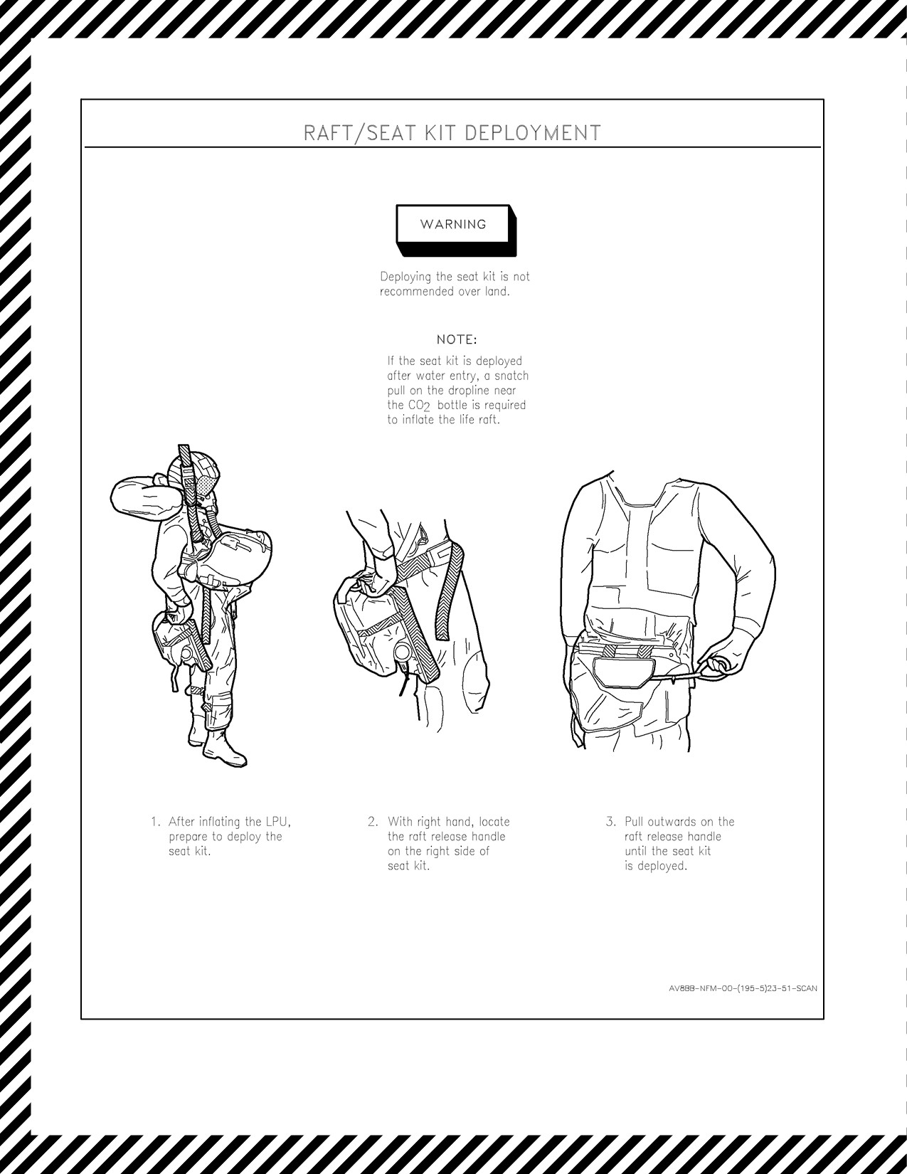
7. Oxygen mask — REMOVE.
8. Inflate raft and climb in.
Do not eject under water.
Note
Canopy will implode at 8 to 12 feet under water.
Underwater egress will be complicated by:
a. Aircraft sink rate under water is 20 to 30 feet per second.
b. Automatic inflation of life preserver unit (LPU) will occur restricting movement.
17.3
EJECTION
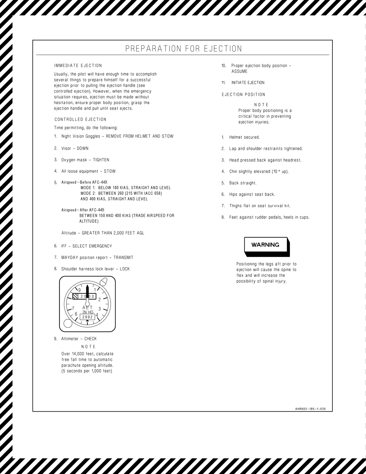
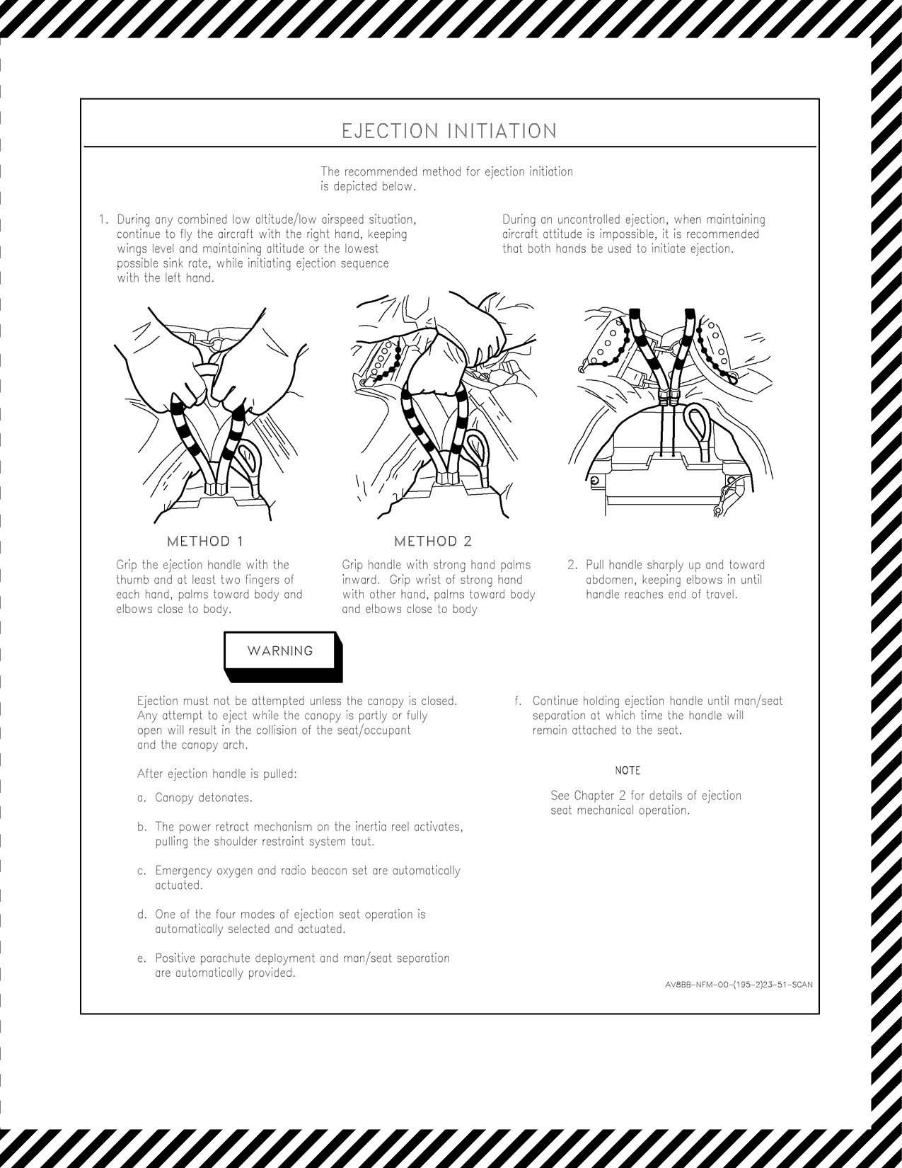
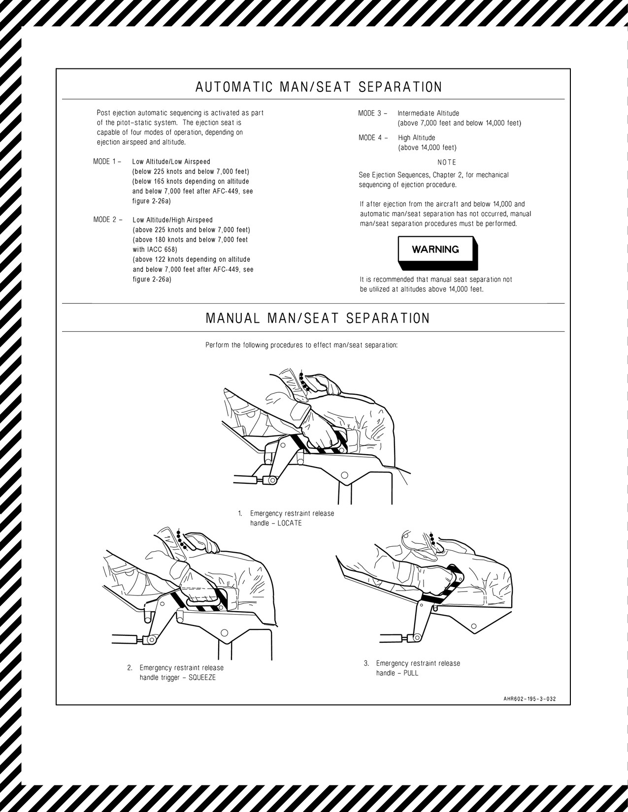
Escape from the aircraft inflight and in some instances, from ground level or water should be made with the ejection
seat (Figure 17-1). However, under water ejection is not recommended.
ORIGINAL
17-2

A1-AV8BB--NFM--000
Study and analysis of escape techniques by means of the ejection seat reveals that:
1. During ejection seat development and testing the SJU--4/A was qualified for use by male aviators with nude
weights from 136 to 213 pounds. Operation of the seat by personnel not within these parameters subjects the
occupant to increased risk of injury.
2. Appreciable forces are exerted on the body when ejection is performed at airspeeds of 400 to 600 knots
rendering escape more hazardous.
3. At speeds above 600 knots ejection is extremely hazardous because of excessive forces on the body.
4. When circumstances permit, slow the aircraft prior to ejection to reduce the forces exerted on the body.
5. Before AFC--449, because of the nature of the modes of operation of the seat, ejection near the transition area
between modes 1 and 2 can result in high ejection forces. Ejection below 7,000 ±750 feet MSL at airspeeds
between 180 and 260 KIAS (between 180 and 215 KIAS with IACC 658) increases the risk of injury.
D The emergency restraint release handle should never be actuated before an
ejection attempt.
D Should severe icing or damage occur causing the airspeed indicator to read
either zero or an erroneous value, the ejection seat could function in the low
speed (0.10 second)mode. If, at this time, theaircraft is actually above180
knots and below 7,000 ±750 feet MSL, above 165 KIAS and below 7,000
±100 feet MSL after AFC--449, the ejection forces on the body could be
extreme and severe damage could occur to the main parachute. Thus, below
7,000 ±750 feet MSL, 7,000 ±100 feet MSL after AFC--449, with a faulty
airspeed indication caused by icing or pitot systems damage, ejection must
be made at airspeeds below 180 knots.
D Ejection near the transition area between modes 1 and 2 can result in high
ejection forces. Ejection below 7,000 ±750 feet MSL at airspeeds between
180 and 260 KIAS (between 180 and 215 KIAS with IACC 658) increases
the risk of injury.
17.3.1 Low Altitude Ejection
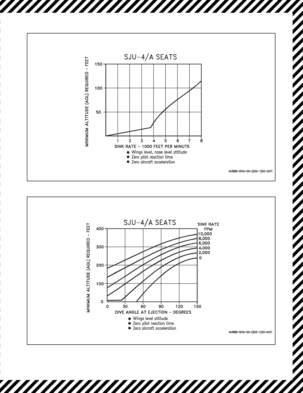
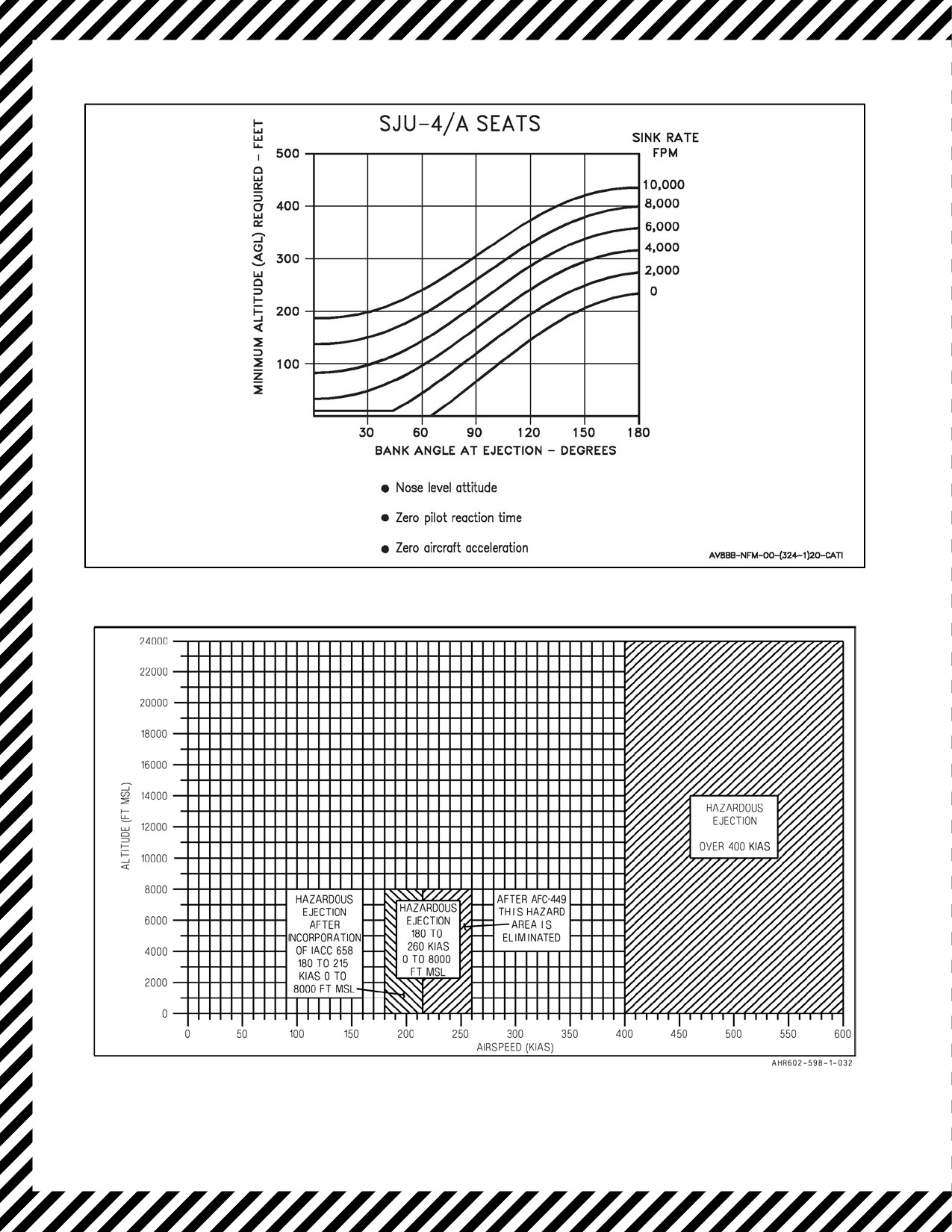
Low altitude ejection depends for its success on the observance of the sink rate, dive angle, bank angle, airspeed and
altitude (AGL) limitations. See Figure 17-2 through 17-6 for minimum ejection altitudes for these parameters. The
pilot must make the ultimate decision concerning the minimum safe altitude from which an ejection can be made in
the prevailing conditions. Every effort must be made to initiate ejection before the aircraft has descended to the
minimum safe altitude. Assuming that the aircraft is substantially straight and level, the ejection seat should provide
safe escape as follows:
1. At zero and low airspeeds — ground level.
2. At airspeeds above 400 knots — 50 feet minimum AGL.
The optimal controlled ejection conditions before AFC--449, see Figure 17-7:
Mode 1: below 180 KIAS, straight and level, and greater than 2,000 feet AGL.
Mode 2: between 260 (215 AFTER IACC 658) and 400 KIAS, straight and level, and greater than 2,000 feet
AGL.
17-3
ORIGINAL

A1-AV8BB--NFM--000
The optimal controlled ejection conditions after AFC--449 are between 150 and 400 KIAS (trade airspeed for
altitude).
17.3.1.1 Wingborne Flight
If the aircraft is controllable, and airspeed is not below approximately 150 knots, ejection from low altitude is
facilitated by pulling the aircraft nose up and initiating a zoom maneuver before ejecting. This increases the ejection
altitude and adds an upward component to seat velocity, thus allowing more time for man/seat separation and main
parachute development than in the level flight case. Below approximately 150 knots (e.g., conventional landing
approach) the zoom maneuver should not be attempted. If possible, and if time permits, any rate of descent should
bereduced orarrested beforeejection. Ejection must not be delayed when theaircraft is in adescending attitudefrom
which it cannot be recovered.
17.3.1.2 Jetborne Flight
During low level flight, an engine or control failure demands an immediate ejection since critical sink rate, attitude
and altitude conditions may prevent a successful ejection. Following engine/control failures, roll rates and pitch rates
will quickly develop leading rapidly to an aircraft attitude from which successful ejection cannot be made; therefore,
it is vital that ejection be initiated immediately after such a failure occurs.
When circumstances demand an immediate ejection from low level, no
attempt should be made to adjust aircraft attitude at the expense of further
increase in sink rate and further altitude loss.
17.3.2 Ejection From Surface Level
At surface level, the ejection option exists as long as the seat and parachute harness remain fastened (occupant
properly strapped in), the cockpit canopy remains closed and locked, and the aircraft is in a substantially upright
attitude. Ejection must not be attempted unless each of these conditions is satisfied. It is stressed that following, say,
a crash landing, where it is possible that damage to the canopy frame or front fuselage has occurred and where escape
by ejection may be the best course, no attempt should be made to open the canopy. If such an attempt were made and
resulted in the canopy jamming in a partially open position, the ejection option would be lost and manual egress from
the cockpit might also be lost. On the other hand, manual use of the MDC does not invalidate the ejection option and
does not prevent a subsequent manual escape. In such circumstances, the MDC must be used and the canopy must
not be opened. Further, the occupant should not unstrap until it is evident that no danger is present which might
prevent manual escape from the aircraft. In all circumstances, the pilot must make the ultimate decision as to whether
ejection offers the best escape chance in the given conditions. If the seat fails to operate, manual escape is the only
option. Refer to ground egress procedures, paragraph 17.1.
If the aircraft is ditched (which should only be attempted if the ejection seat
fails to provide escape from the airborne aircraft), a manual escape from the
cockpit must be made. Refer to ditching procedures, paragraph 17.2.
Consideration is given here only to escape by ejection from emergency
circumstances during shipborne or water platform type operations.
Escape from circumstances which result, or may result, in the aircraft entering the water should be made by ejecting.
Every effort must be made to initiate the ejection before impact with the surface.
ORIGINAL
17-4

A1-AV8BB--NFM--000
17.3.3 High Altitude Ejection
Forahigh altitudeejection, the basiclow level ejection procedureis applicable. Furthermore, thezoom up maneuver
is still useful to slow the aircraft to a safer ejection speed or provide more time and glide distance as long as an
immediate ejection is not mandatory. If the aircraft is descending uncontrolled as a result of a mid--air collision,
control failure, spin, or any other reason, abandon the aircraft at a minimum altitude of 10,000 feet above the terrain
if possible. If it is decided to abandon the aircraft while still in controlled flight at altitude, the pilot should abandon
the aircraft at a minimum altitude of 2,000 feet above the terrain.
17.4
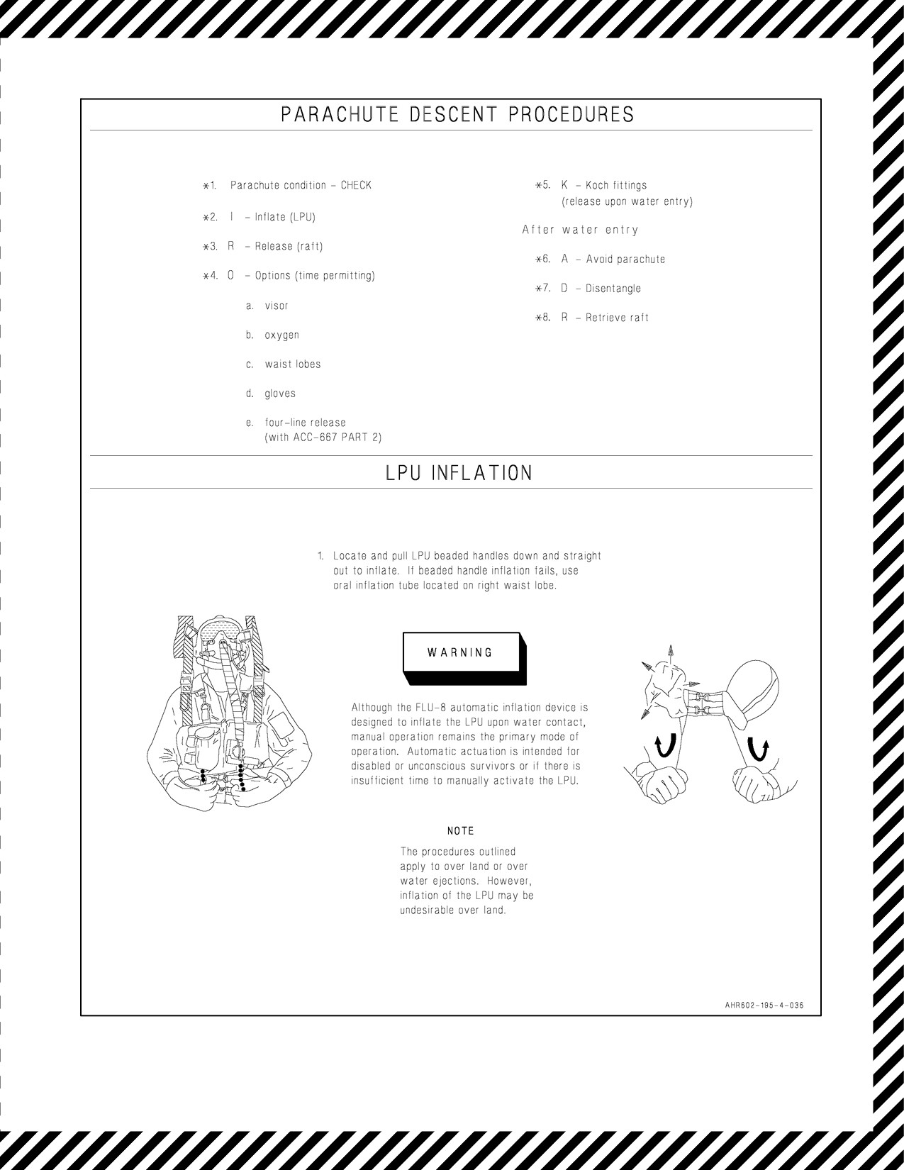
PARACHUTE DESCENT PROCEDURES
If the emergency oxygen is not activated during ejection, it can be activated by pulling the emergency oxygen actuator
on the inside of the left thigh support.
1. Parachute condition — CHECK.
2. I — Inflate (LPU).
3. R — Release (raft).
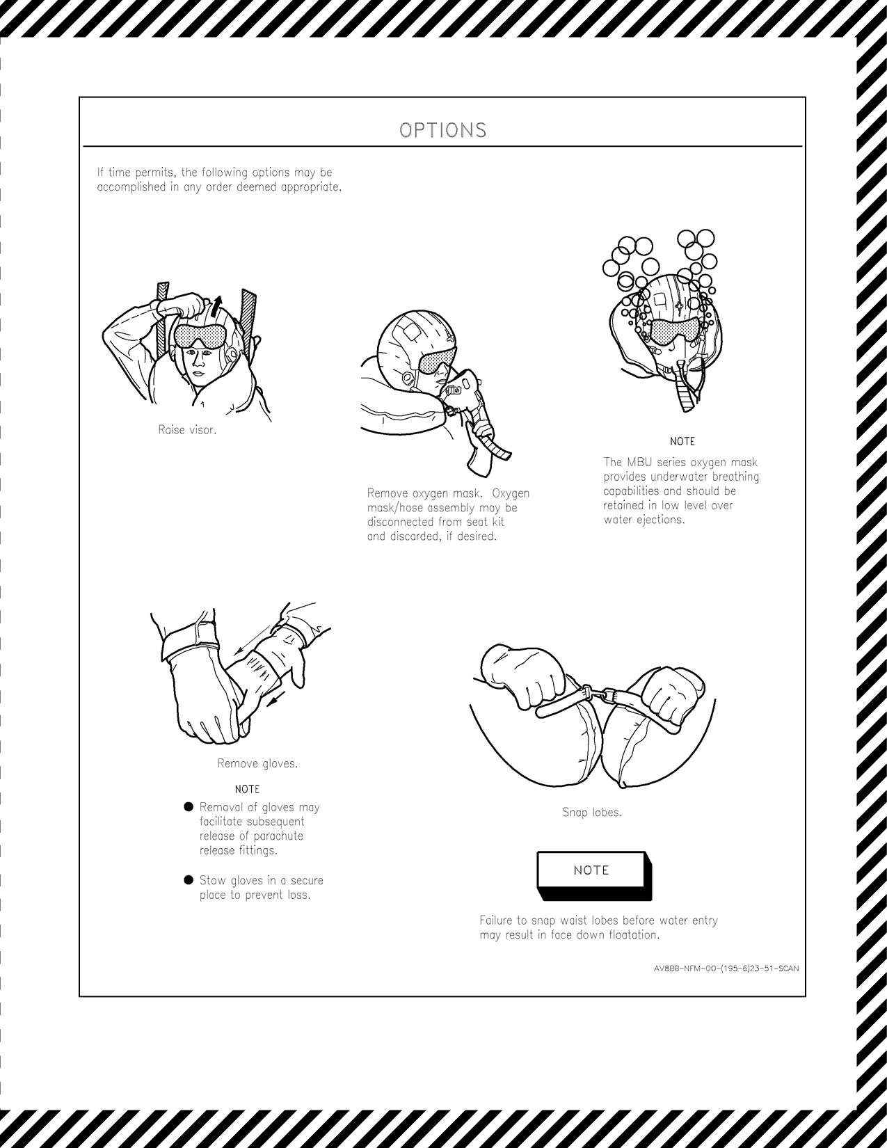
4. O — Options (time permitting).
a. Visor.
b. Oxygen.
c. Waist lobes.
d. Gloves.
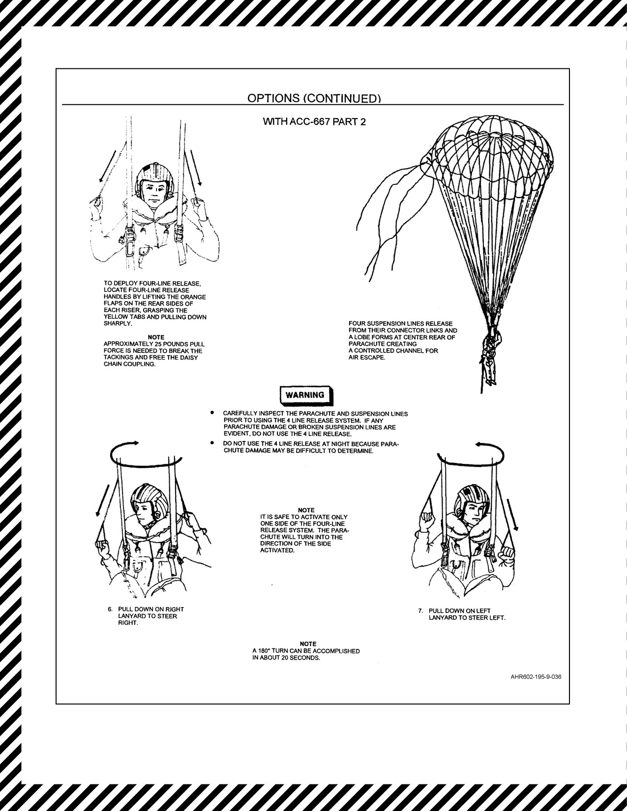
e. Four--line release (with ACC--667 PART 2).
5. K — Koch fittings (release upon water entry).
After Water Entry:
6. A — Avoid parachute.
7. D — Disentangle.
8. R — Retrieve raft.
17.5
A/P22P--14(V)3 CHEMICAL, BIOLOGICAL, RADIOLOGICAL PROTECTIVE RESPIRATOR
ASSEMBLY EMERGENCY PROCEDURES
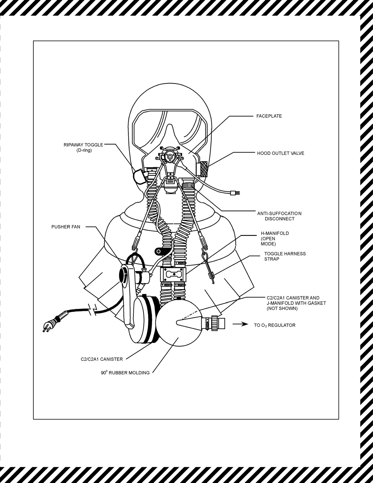
The A/P22P--14(V)3 (OBOGS aircraft) respirator assembly (see Figure 17-8) is authorized to be worn by all
T/AV--8B aircrew forprotection against theelements ofCBR warfare. Forgeneral information, donning and doffing,
and routine usage, refer to Aviation Crew Systems Manual, NAVAIR 13--1--6.10, Special Mission Aircrew
Equipment.
17.5.1 Emergency Egress On Land
1. Pusher fan — CONFIRM RUNNING.
2. If pusher fan is not operating hood outlet valve (Figure 17-9) — CLOSE.
Note
If in contaminated environment, CBR protection will be maintained, but
the faceplate may fog and prevent wearer from seeing anything.
17-5
ORIGINAL
A1-AV8BB--NFM--000
Figure 17-1. Ejection Procedures (Sheet 1 of 9)
ORIGINAL
17-6
A1-AV8BB--NFM--000
Figure 17-1. Ejection Procedures (Sheet 2)
17-7
ORIGINAL
A1-AV8BB--NFM--000
Figure 17-1. Ejection Procedures (Sheet 3)
ORIGINAL
17-8
A1-AV8BB--NFM--000
Figure 17-1. Ejection Procedures (Sheet 4)
17-9
ORIGINAL
A1-AV8BB--NFM--000
Figure 17-1. Ejection Procedures (Sheet 5)
ORIGINAL
17-10
A1-AV8BB--NFM--000
Figure 17-1. Ejection Procedures (Sheet 6)
17-11
ORIGINAL
A1-AV8BB--NFM--000
Figure 17-1. Ejection Procedures (Sheet 7)
ORIGINAL
17-12
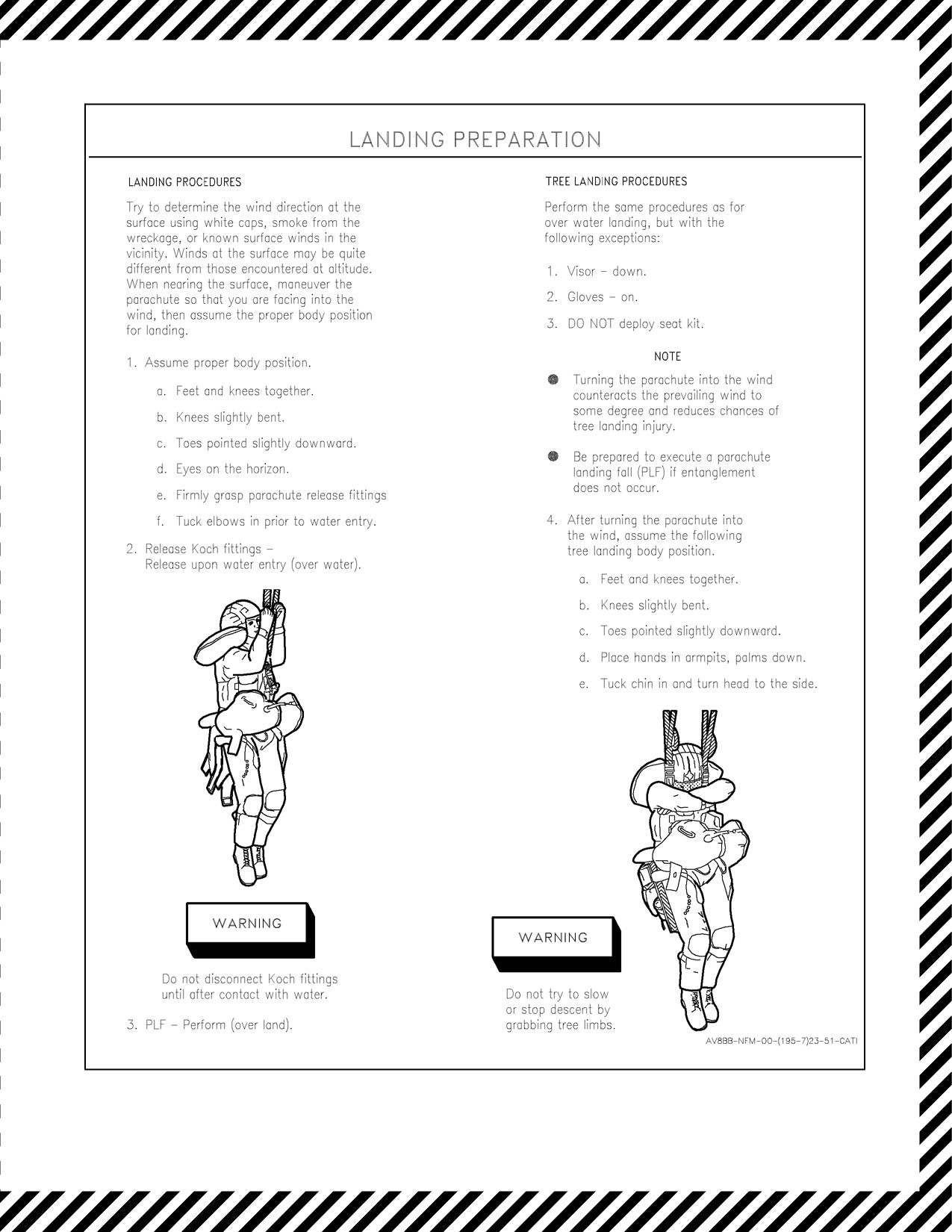
A1-AV8BB--NFM--000
Figure 17-1. Ejection Procedures (Sheet 8)
17-13
ORIGINAL
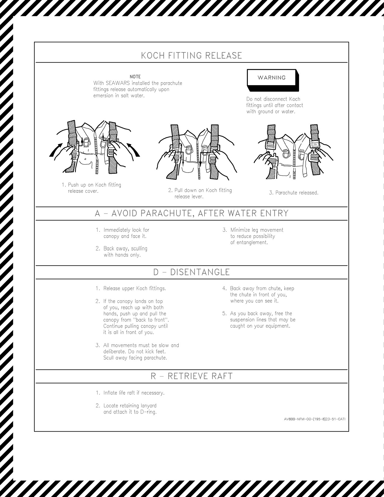
A1-AV8BB--NFM--000
Figure 17-1. Ejection Procedures (Sheet 9)
ORIGINAL
17-14
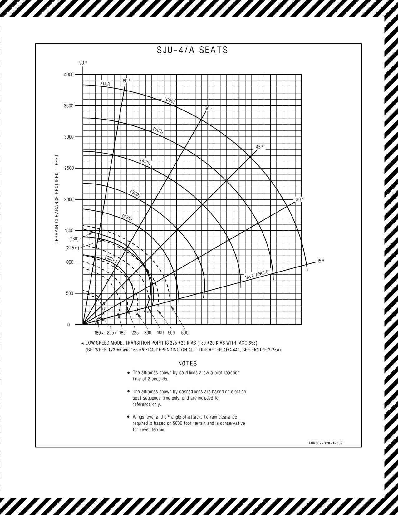
A1-AV8BB--NFM--000
Figure 17-2. Minimum Ejection Altitude vs Airspeed and Dive Angle, AV--8B
17-15
ORIGINAL
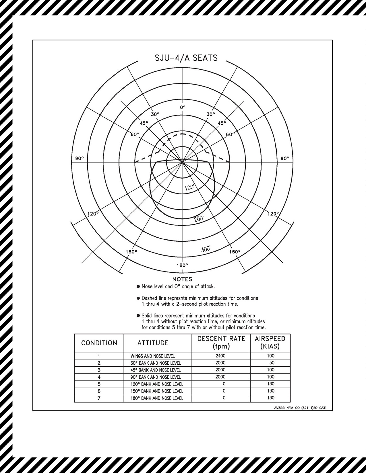
A1-AV8BB--NFM--000
Figure 17-3. Minimum Ejection Altitude (Terrain Clearance) vs Aircraft Attitudes, AV--8B
ORIGINAL
17-16
A1-AV8BB--NFM--000
Figure 17-4. Minimum Ejection Altitude vs Sink Rate at Zero Forward Airspeed, AV--8B
Figure 17-5. Minimum Ejection Altitude vs Dive Angle for Sink Rate at Zero Forward Airspeed, AV--8B
17-17
ORIGINAL
A1-AV8BB--NFM--000
Figure 17-6. Minimum Ejection Altitude vs Bank Angle for Sink Rate at Zero Forward Airspeed, AV--8B
Figure 17-7. Optimal Controlled Ejection Conditions
ORIGINAL
17-18
A1-AV8BB--NFM--000
Figure 17-8. A/P22P--14(V)3 Respirator Assembly
17-19
ORIGINAL

A1-AV8BB--NFM--000
17.5.2 Ejection Over Land (In a Non--Contaminated Environment) During the Option Phase of
Parachute Descent
1. Helmet visor — RAISE.
Note
If insufficient time to activate ripaway facility proceed to step 3.
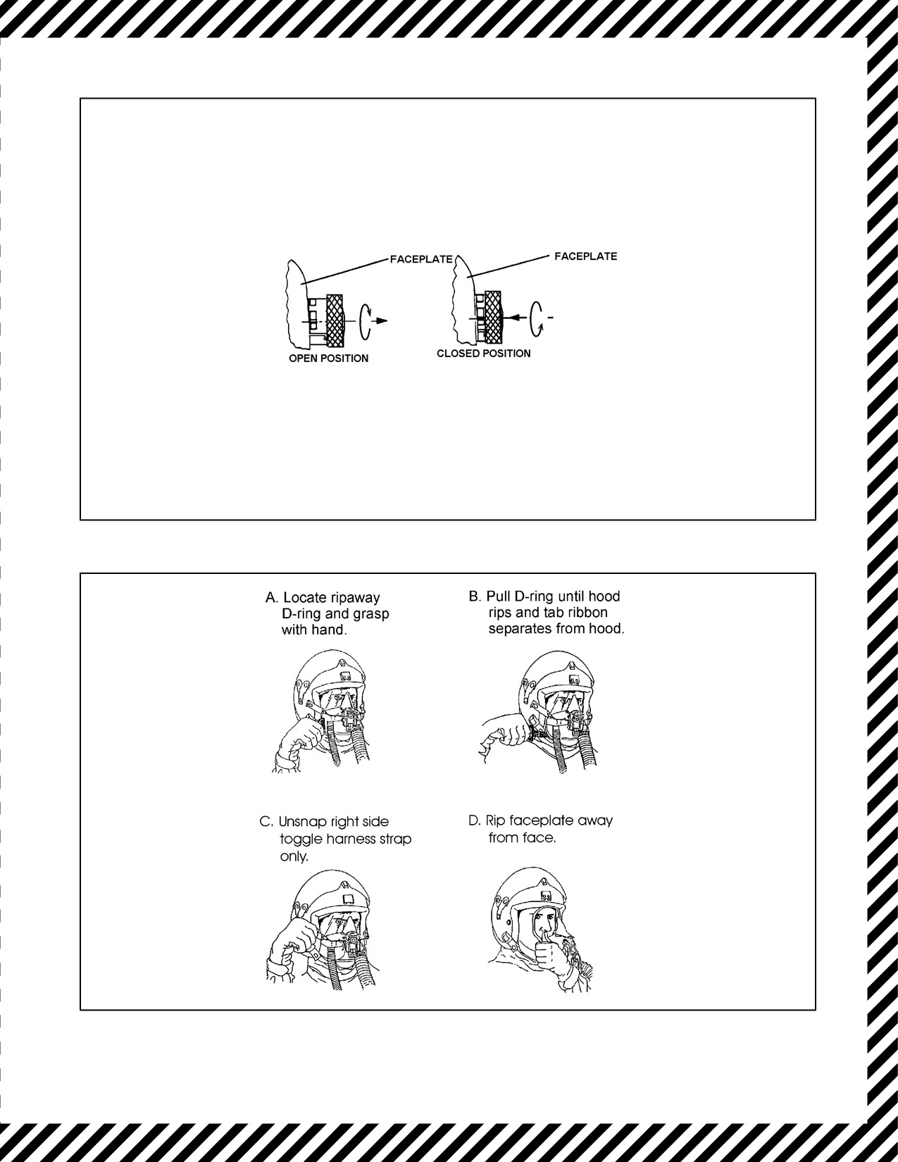
2. Mask — RIPAWAY (Figure 17-10).
CBR protection will be lost.
a. Locate and grasp ripaway D--ring.
b. Pull D--ring until hood rips and tab ribbon separates from hood.
c. Unsnap right--side toggle harness strap only.
Unsnapping both toggle harness straps will allow the faceplate to fall and
suspend from the hood and mask hoses resulting in a snag hazard.
d. Rip faceplate away from face.
If Unable To Perform Ripaway:
3. Anti--suffocation disconnect (Figure 17-11) — LOCATE AND DISCONNECT BY TWISTING AND
PULLING DOWN.
17.5.3 Ejection Over Land (In a Contaminated Environment) During the Option Phase of
Parachute Descent
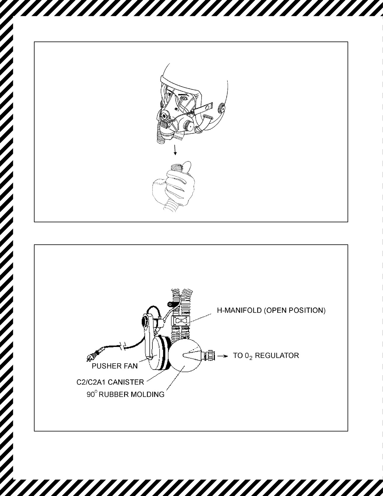
1. H--Manifold switch (Figure 17-12) — OPEN (Horizontal).
2. Pusher fan — CONFIRM RUNNING.
Note
The pusher fan will provide filtered ventilation and lens de--misting to the
respirator assembly hood compartment and filtered air to the orinasal mask.
If pusher fan is not running:
3. Hood outlet valve (Figure 17-9) — CLOSE IMMEDIATELY (Pull out on DISC, twist and release).
Note
CBR protection will be maintained, but the faceplate may fog and prevent
wearer from seeing anything.
ORIGINAL
17-20

A1-AV8BB--NFM--000
17.5.4 Ejection Over Water (In Either Contaminated or Non--Contaminated Environment) During
Option Phase of Parachute Descent
Upon entering water, filter canisters will become blocked and not pass air
or water into the mask.
1. Helmet visor — RAISE.
2. Mask — RIPAWAY (Figure 17-10).
CBR protection will be lost.
a. Locate and grasp ripaway D--ring.
b. Pull D--ring until hood rips and tab ribbon separates from hood.
c. Unsnap right--side toggle harness strap only.
Unsnapping both toggle harness straps will allow the faceplate to fall and
suspend from the hood and mask hoses resulting in a snag hazard.
d. Rip faceplate away from face.
IF Unable to perform ripaway:
3. Anti--suffocation disconnect (Figure 17-11) — LOCATE AND DISCONNECT BY TWISTING AND
PULLING DOWN.
After Contact With Water:
Contact with water may have forced water through the mask inlet adapter
into the orinasal mask.
4. If the anti--suffocation disconnect was activated, before taking a breath, forcibly exhale to blow water out of
the mask.
17-21
ORIGINAL

A1-AV8BB--NFM--000
17.5.5 Pusher Fan Malfunction
1. H--Manifold switch — OPEN (Horizontal) (Figure 17-12).
Note
Demand on the OBOGS oxygen supply will be twice the normal amount.
2. Battery switch — CONFIRM ON.
3. Power cord — CONFIRM SECURELY PLUGGED IN.
If pusher fan still not operating:
4. Battery — REPLACE.
If pusher fan operation is restored:
5. H--Manifold switch — CLOSED (Vertical).
17.5.6 Airsickness
If Airsick and Vomiting -- Into Mask:
1. Release the helmet chin strap and toggle harness adapter straps.
2. Pull orinasal mask away from face.
Note
CBR protection will still be maintained.
3. Allow the vomit to collect in the respirator assembly neck dam.
4. Reconnect the helmet chin strap and toggle harness adapter straps.
In The Event of Extreme Airsickness:
5. Helmet visor — RAISE.
6. Mask — RIPAWAY (Figure 17-10).
CBR protection will be lost.
a. Locate and grasp ripaway D--ring.
b. Pull D--ring until hood rips and tab ribbon separates from hood.
c. Unsnap right--side toggle harness strap only.
Unsnapping both toggle harness straps will allow the faceplate to fall and
suspend from the hood and mask hose resulting in a snag hazard.
d. Rip faceplate away from face.
17.5.7 OBOGS Failure
1. H--Manifold switch — OPEN (Horizontal) (Figure 17-12).
2. Immediately descend below 10,000 feet cockpit altitude.
ORIGINAL
17-22
A1-AV8BB--NFM--000
Figure 17-9. Hood Outlet Valve
Figure 17-10. Orinasal Mask Ripaway Procedures
17-23
ORIGINAL
A1-AV8BB--NFM--000
Figure 17-11. Anti--Suffocation Disconnect
Figure 17-12. H--Manifold Switch
ORIGINAL
17-24

A1-AV8BB--NFM--000
CHAPTER 18
Immediate Action Items
This chapter contains only immediate action items. It is intended for review only and does not contain any steps which
are not immediate action nor does it contain notes, cautions, warnings, or explanatory matter associated with
particular procedures.
18.1
ABNORMAL START
If the JPT rises rapidly between 350° and 400° (hot start), or if rpm stabilizes below idle (hung start), or if engine
does not light off within 10 seconds after selecting idle (wet start):
*1. Throttle — OFF.
If wet start:
*2. Engine start switch — OFF.
18.2
LOSS OF ENGINE CONTROL ON GROUND
If engine RPM--JPT indications on EDP freeze at approximately 22 percent or display an abnormal indication during
start, or if the voltmeter drops to zero when the DC test switch is set to STBY during standby TRU check, or during
any undemanded engine acceleration:
*1. Throttle — OFF.
*2. Fuel shutoff handle — OFF.
18.3
EMERGENCY SHUTDOWN
*1. Throttle — OFF.
*2. Fuel shutoff handle — OFF.
*3. Engine start switch — OFF.
*4. APU GEN — OFF.
*5. Battery switch — OFF.
18.4
NWS CAUTION LIGHT (AFTER AFC--391)
TAKEOFF/LANDING ROLL OUT:
*1. Attempt to get airborne.
If unable to get airborne:
*2. Engage NWS button at minimum practical groundspeed.
18.5
BRAKE FAILURE/SKID CAUTION LIGHT
On ground:
*1. ANTISKID switch — NWS.
18-1
ORIGINAL

A1-AV8BB--NFM--000
18.6
ABORT
18.6.1 Ashore (CTO or STO)
*1. Throttle — IDLE.
*2. Nozzles — BRAKING STOP.
*3. Throttle — AS REQUIRED.
*4. Brakes — AS REQUIRED.
18.6.2 Afloat
*1. Throttle — OFF.
*2. Brakes — FULL.
18.7
NO LIFTOFF ON STO ASHORE
*1. Nozzles — AFT.
*2. Increase speed 20 knots.
*3. Nozzles — STO STOP.
18.8
OVER ROTATION ON STO
*1. Stick — FULL FORWARD.
*2. Nozzles — REDUCE 20 DEGREES.
*3. Nozzles — STO STOP.
18.9
RPM STAGNATION/LOSS OF THRUST AFLOAT
If decision is made not to abort:
*1. MFS — SELECT.
*2. STO at nozzle rotation line.
*3. Stores — JETTISON (if required).
*4. Water switch — OFF.
18.10 L/R TANK WARNING LIGHT
18.10.1 During Air Refueling
*1. Break away.
18.10.2 During Hot Refueling
*1. Throttle — OFF.
ORIGINAL
18-2

A1-AV8BB--NFM--000
18.11 FIRE
18.11.1 Ground Fire (Engine, GTS/APU, Brake)
*1. Execute Emergency Shutdown.
18.11.2 Takeoff/Landing/Vertical Operation
*1. Abort or land immediately.
*2. Execute Emergency Shutdown.
18.11.3 Inflight
*1. Nozzles — AFT AS SOON AS POSSIBLE.
*2. APU GEN — OFF.
*3. Master arm/gun — OFF.
*4. Throttle — MINIMUM REQUIRED.
If fire persists:
*5. EJECT.
18.12 OIL CAUTION LIGHT
*1. Throttle — MAINTAIN CONSTANT RPM.
a. 75 percent -- 85 percent RPM (--406 engine).
b. 80 percent -- 85 percent RPM (--408 engine).
18.13 DUAL DECS FAILURE (EFC WARNING LIGHT)
In V/STOL Flight (Takeoff/Approach/Landing) Time Critical:
*1. MFS — SELECT.
*2. Water switch — OFF.
In Conventional Flight:
*1. Throttle — IDLE.
*2. MFS — SELECT.
*3. Throttle — ADVANCE SLOWLY.
If unable to select MFS and sufficient power not available:
*4. EFC switch — CHANGE LANE.
18.14 LOSS OF ENGINE CONTROL INFLIGHT
In Conventional Flight:
*1. Menu -- Engine -- IGVs — MONITOR.
*2. Throttle — SLOWLY REDUCE TO IDLE.
If IGV failure indicated (stuck IGVs or wandering with constant throttle position):
*3. Execute IGV failure procedures.
18-3
ORIGINAL

A1-AV8BB--NFM--000
If IGV failure not indicated:
*4. MFS — SELECT.
18.15 COMPRESSOR STALL
*1. Throttle — IDLE.
*2. AOA — REDUCE TO LEVEL FLIGHT AOA.
If JPT continues to rise; before 590 °C:
*3. Throttle — OFF.
18.16 AIRSTART
*1. Nozzles — AFT.
*2. Stores — JETTISON (if required).
*3. Throttle — OFF.
*4. Emergency oxygen actuator — PULL.
*5. MFS — AS REQUIRED.
*6. Airstart button — PRESS AND HOLD.
*7. Throttle — ADVANCE SLOWLY TO IDLE.
*8. JPT — MONITOR (475 °C MAX).
18.17 FLIGHT CONTROL MALFUNCTION
*1. Paddle switch — PRESS AND HOLD.
If condition not cleared (possible jammed flight controls):
*2. Transition to conventional flight as soon as possible.
18.18 REACTION CONTROL FAILURE
*1. Transition to conventional flight.
18.19 FLAP WARNING/UNCOMMANDED FLAP MOTION/UNCOMMANDED NOSE DOWN PITCH
*1. Nozzles — 40 DEGREES OR GREATER.
18.20 OUT--OF--CONTROL
18.20.1 Jetborne/Semi--Jetborne Out--of--Control Recovery
*1. Stick — FORWARD.
*2. Throttle — FULL.
*3. Stick — AGAINST ROLL.
*4. Rudder — AGAINST SIDESLIP.
If AOA not recovered and time and altitude permit:
*5. Nozzles — REDUCE 20 DEGREES.
When AOA recovered:
*6. Nozzles — AS REQUIRED.
ORIGINAL
18-4

A1-AV8BB--NFM--000
18.20.2 Out--of--Control/Spin/Falling Leaf Recovery
*1. Controls — NEUTRAL.
*2. Throttle — IDLE/OFF IF COMPRESSOR LOCKED IN STALL.
*3. Nozzles aft.
If spin positively confirmed after 2 turns with neutral controls:
*4. Rudder — FULL OPPOSITE SPIN DIRECTION.
*5. Aileron — FULL WITH SPIN IF UPRIGHT/NEUTRAL IF INVERTED.
If Falling Leaf positively confirmed after 5 seconds with neutral controls (TAV-8B and Radar aircraft only):
*6. Stick — FULL FORWARD.
When recovered:
*7. Initiate Airstart (if required).
*8. Nozzles aft.
If still out of control below 10,000 feet AGL:
*9. EJECT.
18.21 EMERGENCY DC BUS FAILURE
If above 10,000 feet cabin pressure.
*1. Emergency oxygen actuator — PULL.
*2. Descend below 10,000 feet cabin pressure.
With emergency oxygen activated or below 10,000 feet cabin pressure:
*3. DC test switch — SET TO STBY.
If power is not regained:
*4. DC test switch — SET TO MAIN.
18.22 CANOPY EXPLOSION INFLIGHT
*1. Emergency descent — IF REQUIRED.
*2. Lower seat — AS REQUIRED.
*3. Throttle — AVOID ABRUPT THROTTLE MOVEMENTS.
18.23 OXY CAUTION LIGHT
*1. Emergency oxygen actuator — PULL.
*2. Oxygen switch — OFF.
18-5/(18-6 blank)
ORIGINAL W/IC 37

A1-AV8BB--NFM--000
CHAPTER 19
Emergency Procedures Checklist Display
Use of the emergency procedure checklist display without TAMMAC
installed is not authorized.
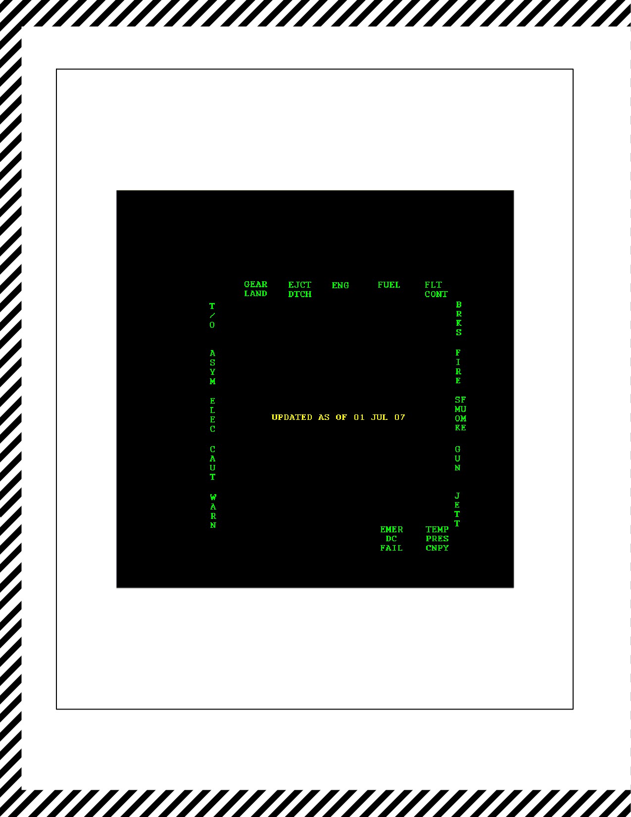
In radar and night attack aircraft the emergency procedures checklist (EPC) display is selected by pressing the EMER
pushbutton on the MENU display. The primary purpose of this display is to present selected digitized pages of
emergency procedures from the NATOPS pocket checklist. The EPC pages are contained on data frames that reside
in memory on the TAMMAC digital map computer. The EPC data frames are downloaded with themap theaterfrom
the MAP card in the AMU during a theater load.
19.1
EPC SELECTION
At power--up with weight--on--wheels, pressing EMER calls up the EPC menu (Figure 19-1). At any other time,
pressing EMER calls up the last selected emergency subject and page. If the selected EPC has additional pages
associated with it, as with the asymmetric stores chart (ASYM STR1), CONTINUED is displayed at the bottom of
the page. The additional pages are selected by pressing the pushbutton for the next page in the subject sequence
(ASYM STR2). Deselecting the emergency subject (boxed legend) recalls the emergency menu display.
If a frame is not available, NO FRAME is displayed in the center of the MPCD. If a frame is available but not yet
ready for display, STBY is displayed in the lower left corner of the display while the frame is being called up.
When the EMER page is enabled, the MSC will disable any displayed maps (i.e. MAP is unboxed on the displayed
map page’s respective (MAPM)/EWM page). When the EMER page is exited, the map is enabled again. If a map
is enabled whiletheEPC is displayed, theEMER pagewill beexited and thetop level MENU pagewill bedisplayed.
19.2
UPDATING THE EPC
ThedatethattheEPCwaslastupdatedisdisplayed centeredon theEPC menu.TheEPCis releasedduring thenormal
Joint Mission Planning Station (JMPS) block upgrade cycle, and is updated as necessary. The EPC is updated in the
TAMMAC DMC during a theater load.
Note
Once the EPC has been updated in JMPS, either through a block upgrade
or an interim EPC update, the EPC must be loaded into the TAMMAC
DMC by performing a theater load. Otherwise, the update will not display
in the cockpit.
19-1
ORIGINAL
A1-AV8BB--NFM--000
Figure 19-1. Emergency Procedures Checklist Display
ORIGINAL
19-2
A1-AV8BB-NFM-000
PART VI
All−Weather Operation
Chapter 20 — Instrument Procedures
Chapter 21 — Extreme Weather Operations
79/(80 blank)
ORIGINAL
A1-AV8BB--NFM--000
CHAPTER 20
Instrument Procedures
20.1
SIMULATED INSTRUMENT PROCEDURES
Instrument flight is primarily a problem of time and distance navigation wherein all, or part, of the flight is conducted
under instrument conditions. To complete a successful instrument flight, pilots must be properly prepared and have
conducted the necessary planning. All pilots will maintain a current instrument rating and be guided by current
OPNAV INSTRUCTION 3710.7 (General Flight and Operating Instructions for Naval Aircraft) and Federal Air
Regulations.
20.1.1 Chase Plane Procedures
The chase pilot’s duties on instrument flights are to act as lookout and to be a flight monitor. The best position for
thisisaloosetacticalwingposition whereairspeed, attitude,and altitudemay bemonitored whilemaintaining agood
lookout. During ground controlled approaches (GCA), the chase will fly a position as directed by GCA.
20.2
ACTUAL INSTRUMENT PROCEDURES
20.2.1 Instrument Flight
The ability of the aircraft to fly at slow speeds and to hover dictates some modification of standard instrument
procedures.
It is recommended that certain critical operations such as shipboard IMC, restricted site, night, etc., be performed
only with a fully functional head--up display. When flying aircraft with an ASN--130 and GPS into or through IMC,
the aircraft should be flown with the INS in NAV. Also, the mission computer V/STOL master mode may be used
in IMC in order to increase HUD attitude display reliability. Due to the way the INS information is translated for
presentation in the HUD, the V/STOL master mode provides a more reliable IMC attitude presentation than the other
master modes (NAV, AA, and AG). If INS velocity information begins to degrade, the other modes may present
attitude information that is inaccurate. In IMC conditions this inaccurate presentation could result in an unrecognized
spatial disorientation. This is a particular concern when operating the ASN--130 in a coupled mode with the GPS.
Therefore, the V/STOL master mode should be the presentation of choice when flying in IMC conditions. Use of
V/STOL will help to minimize attitude presentation errors when INS velocities are degrading and should provide
a relatively stable attitude reference up to the point of INU failure.
20.2.1.1 Instrument Flight Planning
On instrument flights, delays in departure and descent and low climb rates to altitude are often required in high density
control areas. These factors make fuel consumption and flight endurance critical. All instrument flights should be
carefully planned and consideration given to the additional time and fuel which may be required. A complete weather
briefing for all pilots on the flights will be obtained and the appropriate flight plan will be filed. For planning and
filing purposes the AV--8B pilot should reference category C minimums (approach speeds of 121--140 knots). The
pilot should file as an equipment code I in the equipment code block of the DD--175 (RNAV and transponder with
mode C).
20.2.1.2 Before Starting Engine
When practical, an ATC clearance should be obtained before starting the engine.
20.2.1.3 Before Takeoff
It is essential that the instrument and navigation equipment be thoroughly checked prior to takeoff. INS ground speed
should bechecked when stopped to ensureminimum drift. Head up and head down displays should becrosschecked.
Selection of APU to ON is recommended.
20-1
ORIGINAL
A1-AV8BB--NFM--000
20.2.1.4 Instrument Takeoff
Same as normal takeoff.
20.2.1.5 Instrument Climb
The simplified climb technique described in Part 4, Section XI of the Performance Chart Manual should be used to
optimize fuel consumption and climb rates. Turns should be kept to a minimum during climb. Follow the clearance
exactly as given. If unable to comply with the clearance, it is mandatory that ATC be advised immediately.
20.2.1.6 Penetration Procedures
Three to five minutes prior to making a descent, the cabin temperature control should be set at the maximum
comfortable level and the cabin air switch should be set to MAX DEFOG to prevent the canopy from fogging up when
descending to warmer altitudes. Instrument descent configuration should be based on wingman and aircraft limits.
Selection of APU to ON is recommended during IMC. Contact approach control 10 minutes prior to ETA or as
directed by ARTC, and conform to the provision of Section 2, Flight Planning Document. Three minutes prior to
entering holding, adjust power to arrive at the holding fix with maximum endurance airspeed (230 knots maximum).
Prior to descent, the pilot will check missed approach procedures and will obtain the latest weather information at
the destination and at the alternate if required. Refer to Descent/Instrument Penetration procedures, Section III.
Instrument descent configuration is briefed in consideration of wingmen and aircraft limits (recommend 250 knots,
AUTO flaps, speedbrake, 8° to 10° AOA maximum on formation). Selection of APU to ON is recommended during
IMC.
20.2.1.7 Radar Controlled Penetration
The approaches are basically the same as previously described with the following additions. The controlling activity
will normally ask for turns or specific IFF squawks for positive identification. The controlling activity will advise
of turns or headings which will produce the desired flight path. They will also advise as to distance from the
destination and direct a descent to lower minimum altitudes as traffic and terrain permit.
20.2.1.7.1 GCA Approaches
Target 250 knots in the GCA pattern. Perform landing checks on base leg or as directed and maintain 8° to 10° AOA.
One to two miles prior to intercepting the glide slope, select 25° nozzles and STOL flaps. Maintain 8° to 10° AOA
on the glide slope until visual contact with the landing area is established. When visual contact is made, use nozzles
as required to decelerate for the desired landing or take separation from wingman.
The ability to counter nose down pitch with stick alone during flap
programming and aileron droop may be significantly reduced due to
decreased RCS pitch authority when the throttle is at minimum power.
Abnormally fast approach speeds in combination with low throttle settings
could lead to an unrecoverable condition if left unchecked in close
proximity to the ground.
ORIGINAL
20-2
A1-AV8BB--NFM--000
Note
D Be aware of flap programming if exceeding 25° nozzles and less than 165
knots while IMC. Flap programming can produce undesirable handling
characteristics while IMC; however the added benefits of reduced
groundspeeds may make the selection of nozzles greater than 25 and STOL
flaps desirable.
D When wingman is a consideration, maintain airspeeds outside of the flap
programming/droop transition range to ease wingman workload. AUTO
flaps may also be utilized.
20.2.1.7.2 Minimum Fuel GCA
A minimum fuel GCA is flown by delaying gear extension until just prior to thedescent point. The controllershould
notify the pilot when the aircraft is approximately 30 seconds from the glideslope. At this point, the aircraft is
configured for landing, the checklist is completed and the remainder of the approach is flown normally.
20.2.2 Turbulent Air and Thunderstorm Operation
Intentional flight through thunderstorms should be avoided, because of the high probability of damage to the airframe
by ice, hail, and lightning and possiblecompressor stall due to negative AOA encountered in turbulence. Theaircraft
is capable of climbing over the top of small and moderately developed thunderstorms. Thunderstorms have been
reported to eject ice and lightning several miles from the buildup. Flight path should be planned accordingly.
20.2.2.1 Penetration
If necessary to penetrate, the basic structure of the aircraft is capable of withstanding the accelerations and gust
loadings associated with the largest thunderstorms. The aircraft is stable and comparatively easy to control in the
severe turbulence; however, the effects of turbulence becomes noticeably more abrupt and uncomfortable at airspeeds
above optimum cruise and below 35,000 feet. The aircraft will not be displaced significantly from the intended flight
path and desired heading. Altitude, airspeed, and attitude can be maintained with reasonable accuracy.
20.2.2.1.1 Penetration Airspeeds
Theoptimum thunderstorm penetration speeds, based on pilot comfort,controllability, andengineconsiderationsare
between optimum cruise and 280 knots. Engine rpm should be maintained below 85 percent to reduce compressor
stall susceptibility.
20.2.2.2 Approaching the Storm
Adjust powerto establish therecommended penetration speed (less than 85 percent). Do not try to top thunderstorms
at the sacrifice of maintaining penetration speed. Flight through a thunderstorm at the proper airspeed and attitude
is much moreadvantageous than floundering into the storm at adangerously slow airspeed whileattempting to reach
the top. All cockpit lighting should be on at maximum brightness.
20.2.2.3 In the Storm
Maintain a normal instrument scan with added emphasis on the horizon bar. Attempt to maintain a constant pitch
attitude and, if necessary, accept moderate altitude and airspeed fluctuations in heavy precipitation, a reduction in
engine rpm may be necessary due to the increased thrust resulting from water ingestion. If compressor stalls or engine
stagnationdevelop,attempttoregainnormalengineoperationbymomentarilyretarding thethrottletoIDLE andthen
slowly advancing to the normal operating range. If the stall persists, shut down the engine and attempt a relight.
20.2.2.3.1 Angle--of--Attack System Failure
The angle--of--attack system may become temporarily inaccurate due to AOA probe icing with probe heat failure,
or it may permanently fail due to structural damage of the probe from ice or hail. Icing of the AOA probe is usually
characterized by zero angle of attack indication.
20-3
ORIGINAL
A1-AV8BB--NFM--000
20.2.3 Ice and Rain
The possibility of engine and/or airframe icing is always present when the aircraft is operating under instrument
conditions. Icing is most likely to occur when takeoffs must be made into low clouds with temperature at or near
freezing. Normal flight operations are carried on above the serious icing levels, and the aircraft high performance
capabilities will usually enable the pilot to move out of the dangerous areas quickly. When an icing condition is
encountered, immediate action should be taken to avoid further accumulation by changing altitude and/or course and
increasing the rate of climb or airspeed.
20.2.4 Hydroplaning
Operations on wet or flooded runways may produce three conditions under which tire traction may be reduced to an
insignificant value.
1. Dynamic hydroplaning.
2. Viscous hydroplaning.
3. Reverted rubber skids.
Hydroplaning will not present a significant problem unless a conventional landing must be made. Nozzle braking
is effective regardless of runway condition.
20.2.4.1 Dynamic Hydroplaning
As the tire velocity is increased, the hydrodynamic pressure acting on the leading portion of the tire footprint will
increase to a value sufficient to support the vertical load acting on the tire. The speed at which this occurs is called
total hydroplaning speed. This speed (in knots) can be computed by multiplying 9 times the square root of the tire
pressure (105 knots for 135 psi tire pressure). Any increase in ground speed above this critical value lifts the tire
completely off the pavement, leaving it supported by the fluid alone. Since the fluid cushion is incapable of sustaining
any appreciable shear forces, braking and sideforce coefficients become almost nonexistent.
20.2.4.2 Viscous Hydroplaning
Viscous hydroplaning occurs due to the inability of the tire to penetrate the very thin fluid film found under damp
runway conditions. This condition is aggravated when more viscous fluids such as oil, or road dust and water mixed
are present, and is improved in the presence of a coarse textured runway surface. Viscous hydroplaning occurs at
medium to high speed with rolling or skidding tires, and the speed at which it occurs is not dependent on tire pressure.
20.2.4.3 Reverted Rubber Skids
Reverted rubber skids occur after a locked--wheel skid has started on a wet runway. Enough heat may be produced
to turn the entrapped water to steam. The steam in turn melts the rubber. The molten rubber forms a seal preventing
the escape of water and steam. Thus the tire rides on a cushion of steam which greatly reduces the friction coefficient
and may continue to do so to very low speeds.
20.3
UNUSUAL ATTITUDE RECOVERY
Unusual attitudes are entered due to pilot disorientation, vertigo, excessive task--loading, or unusual maneuvering
while IMC. Timely recognition of an unusual attitude situation is paramount for achieving an effective recovery.
1. Altitude — CHECK.
2. Attitude and Airspeed — CHECK.
If nose--high, 200 to 300 KCAS:
3. Throttle — MAINTAIN THROTTLE SETTING.
ORIGINAL
20-4
A1-AV8BB--NFM--000
If nose--high, 100 to 200 KCAS:
4. Throttle — FULL POWER.
Recovery:
5. Attitude — LOWER TO HORIZON.
6. ROLL TO UPRIGHT, WINGS--LEVEL (as required).
If nose--high, less than 100 KCAS:
7. Execute Out--of--Control procedures.
If nose--low:
8. Roll wings level and recover to horizon.
If airspeed exceeds 300 KCAS:
9. Throttle — IDLE.
D If an unusual attitude situation occurs at low altitude, a timely ejection
decision may be required based on altitude, attitude, airspeed, sink rate, and
configuration.
D Ensure an inverted, nose--high attitude is not confused with an inverted,
nose--low attitude.
20-5/(20-6 blank)
ORIGINAL
A1-AV8BB--NFM--000
CHAPTER 21
Extreme Weather Operation
Extreme weather operations include hot and cold ambient air temperatures and high altitudes, or combinations of
both. Conditions are considered extreme when it becomes necessary to modify the normal shore--based procedures
promulgated in Chapter 7. This chapter enumerates many considerations of extreme weather operations. However,
the specific operating environment and mission requirements must be carefully assessed before modifying
procedures in Chapter 7.
21.1
COLD WEATHER OPERATION
21.1.1 Preflight
Ensure that the aircraft is free of frost, snow, and ice. These accumulations present a major flight hazard resulting
in loss of lift and increased stall speeds. Do not allow ice to be chipped or scraped from the aircraft: damage to the
airframe may result. Inspect shock struts, actuating cylinders, pitot--static sources, and fuel vents for ice and dirt
accumulation.
21.1.2 Interior Check
In temperatures below 0 °F, difficulty may be experienced when connecting the oxygen mask hose to the connector,
due to a stiff O--ring in the connector. Application of a small amount of heat to the connector will alleviate this
problem. Also, if the oxygen mask is not fastened, keep it well clear of the face to prevent freezing of the inhalation
valves.
21.1.3 Engine Start
If any abnormal sounds or noises are present during starting, discontinue starting and apply intake duct preheating
for 10 to 15 minutes.
21.1.4 Before Taxi
If the outside ambient air temperature is below freezing and the aircraft has not flown recently, initial movement of
controls in the line should be mild and gradual for 3 to 5 minutes to minimize stress on possible frozen hydraulic lines
and seals. Place the PROBE HEAT switch to HT prior to taxi to allow sufficient warmup time. Insufficient warmup
time may result in erroneous airspeed and altitude displays and cause the system to improperly revert to POS/ADC
in flight.
21.1.5 Taxiing
Avoid taxiing in deep or rutted snow; frozen brakes will probably result. Increase the interval between taxiing aircraft
to insure a safe stopping distance and to prevent icing of the aircraft surfaces by the snow and ice melted by the jet
blast of the preceding aircraft. Trim 4° ND to keep nose puffer duct closed.
21.1.6 Before Takeoff
During the engine runups, an ice--free area should be selected if possible. The engine thrust is noticeably greater at
lowtemperatures andtheprobabilityofskiddingtheaircraftis likely.Engineperformancewill likelybeRPMlimited
Use of power hex will preclude confusion regarding maximum corrected rpm power margins.
Note
D Certainenvironmentalconditionsmayrequiremodificationsofestablished
takeoff procedures (i.e., ice, snow, FOD, etc.).
D Certain items may not be safely accomplished while stationary due to ice,
FOD, etc. (i.e., acceleration checks, duct pressure check, etc). When
required these checks should be accomplished during taxi. If these checks
cannot be completed, the operational necessity of the flight must be
considered.
21-1
ORIGINAL
A1-AV8BB--NFM--000
21.1.7 Landing
Perform an RVL or VL landing, if feasible, to reduce rollout distance.
21.1.8 Before Leaving Aircraft
Weather permitting, leave the canopy partially open to allow for air circulation. This will help prevent canopy
cracking from differential cooling and decreases the possibility of windshield and canopy frosting.
21.2
HOT WEATHER OPERATION
Conditions associated with hot weather operations include high ambient temperatures, gusty winds, and blowing
sand and dust. In addition to affecting engine performance, high temperatures adversely affect avionics systems,
especially during ground operations when temperatures exceed 90 °F (32 °C). Due to decreased effectiveness of the
ground cooling fan when temperatures exceed 90 °F (32 °C), minimize prolonged operation of avionics systems to
avoid damage.
21.2.1 Ground Procedures
Avoid applying power to avionics systems until absolutely necessary based on mission requirements, airfield
procedures (i.e. arming and dearming), and/or ground crew coordination. The TPOD, RADAR, IFF, TACAN and
NAVFLIR should not be on for more than 10 minutes when the temperature exceeds 90 °F (32 °C) to prevent system
damage and ensure proper airborne operation. Specifically, radar installation is divided between the forward and aft
avionics bays. All radar components in the aft bay are mounted on the avionics shelf. With aircraft weight on wheels,
the cooling air for the aft bay is ambient air drawn from the ram air inlet at the base of the vertical stabilizer by the
aft avionics auxiliary cooling fan. Components in the forward bay are cooled by conditioned air from the forward
ECS except the transmitter, which is cooled by liquid coolant. The radar liquid coolant is in turn cooled by
conditioned air from the aft ECS in a heat exchanger located in the aft bay. At high ambient air temperature, cooling
airflow to the aft equipment rack with weight on wheels may be insufficient to properly cool the RTDP and CPS.
In this case, the radar may not successfully complete the ORT.
When the outside air temperature is reported to be greater than 90 °F, secure power to avionics equipment until ready
for taxi. If verification of the avionics system(s) is required for the mission, apply power, allow the system to
warm--up, execute the applicable BIT, and then secure power if a significant ground delay is expected.
21.2.2 Engine Start
Do not operate the engine in a sand or dust storm if avoidable. To initially increase the amount of cool air flow during
engine start, allow rpm to build to 6 to 8 percent prior to selecting idle. Maintain JPT during engine start. With JP--4,
high ambient temperature, and hot engine, an intermittent beat similar to the chuffing noise of a helicopter rotormay
be emitted by the engine below about 50 percent rpm. Avoid prolonged operation in this condition.
21.2.3 Takeoff
The required takeoff distances and ground speed increases as air temperature increases. Acceleration checks may not
have a valid time due to high idle rpm at high altitudes. Ensure takeoff does not exceed 180 knots ground speed to
maintain tire limits (consider wet takeoffs). Note IGV band for appropriate temp range.
21.2.4 Landing
At high density altitudes, there will be high airspeeds associated with normal KCAS and AOA. Landing speed must
remain below 180 knots ground speed. Reduce gross weight to maximum extent practical. At high density altitudes
a compromise must be achieved between power committed to the total lift vector and maintaining an adequate margin
for wave--off. Therefore, to reduce landing speeds and maintain wave--off capability, execute a STOL flap, VNSL
landing, water armed. No later than the 180 position, select 50° nozzles and throttle to 104 percent. Gradually increase
nozzleangleuntil 8 to 10 AOA achieved(this maybe50°to 70°depending uponconditions). At50 feet,go tothrottle
and complete the landing.
21.2.5 Post Landing
Once the post--landing checks are complete and the aircraft is safely taxiing back for shutdown, initiate an AUTO
BIT as soon as practical. As avionics components complete their BIT sequence, record any failure indications, and
secure power to each component. Consider securing power to the following components as soon as practical:
RADAR, NAVFLIR, IFF, TACAN, RWR, RADALT, and AWLS.
ORIGINAL
21-2
A1-AV8BB-NFM-000
PART VII
Communications − Navigation Equipment
and Procedures
Chapter 22 — Communications
Chapter 23 — Navigation
81/(82 blank)
ORIGINAL
A1-AV8BB--NFM--000
CHAPTER 22
Communications
This chapter promulgates standards and procedures associated with administrative flight operations and the
communications systems of the AV--8B. For information on the description, components, controls, displays, and
modes of operations of communication systems, refer to NTRP 3--22.4--AV8B.
22.1
STANDARDS
22.1.1 Communication Brevity
Utilize communication brevity terms in accordance with MCRP 3--25B Multi--service Air--Air, Air--Surface,
Surface--Air Brevity Codes published by the Air, Land, and Sea Application (ALSA) Center. Although brevity is
preferable, do not sacrifice accuracy and/or clarity. If there is a possibility of misunderstanding, use plain language.
Clear, concise, situational awareness enhancing communications is always the objective.
22.1.2 Priority Communications
The flight member with priority communication is the flight lead or the tactical lead. All other flight members will
limit communications to that specific to safety--of--flight, mission accomplishment, or as directed. The division lead
and/or section lead have priority communication.
22.1.3 Cockpit Management
With two operative radios, R/T 1 should be used for communications external to the flight and R/T 2 should be used
for intra--flight communications and/or safety of flight frequencies.
22.1.4 Nomenclature
For directing actions referable to the aircraft radios (i.e. direct a frequency change) proper nomenclature is “Comm
1” and “Comm 2” respectively vice “#1/#2”, “front/back” or “left/right”.
22.1.5 Callsigns
All tactical radio transmissions will be initiated and acknowledged with full tactical callsigns. Do not abbreviate
callsigns on the radio by using only the numbered portion, “Razor 11” vice “11.” Callsigns may be abbreviated using
the flight callsign (“Razor”). Be diligent to ensure you do not clip your transmission. Key the Mike, pause, and then
talk. Administrative transmissions (frequency changes/check ins) will be acknowledged with flight position number
(“Razor 1, check”, “2, 3, 4”) on the same radio as the check--out/check in is initiated.
22.1.6 Directive and Descriptive Communications
Descriptive calls are started with your own callsign (“Razor 01, Joker”). Directive calls are started with the unit or
aircraft addressed (“Razor 02, Break Right!”).
22.2
PROCEDURES
22.2.1 Communication Checks
If there are no alibis, the comm procedures will start when the flight lead initiates the Comm--Checks as depicted in
Figure 22-1.
22-1
ORIGINAL
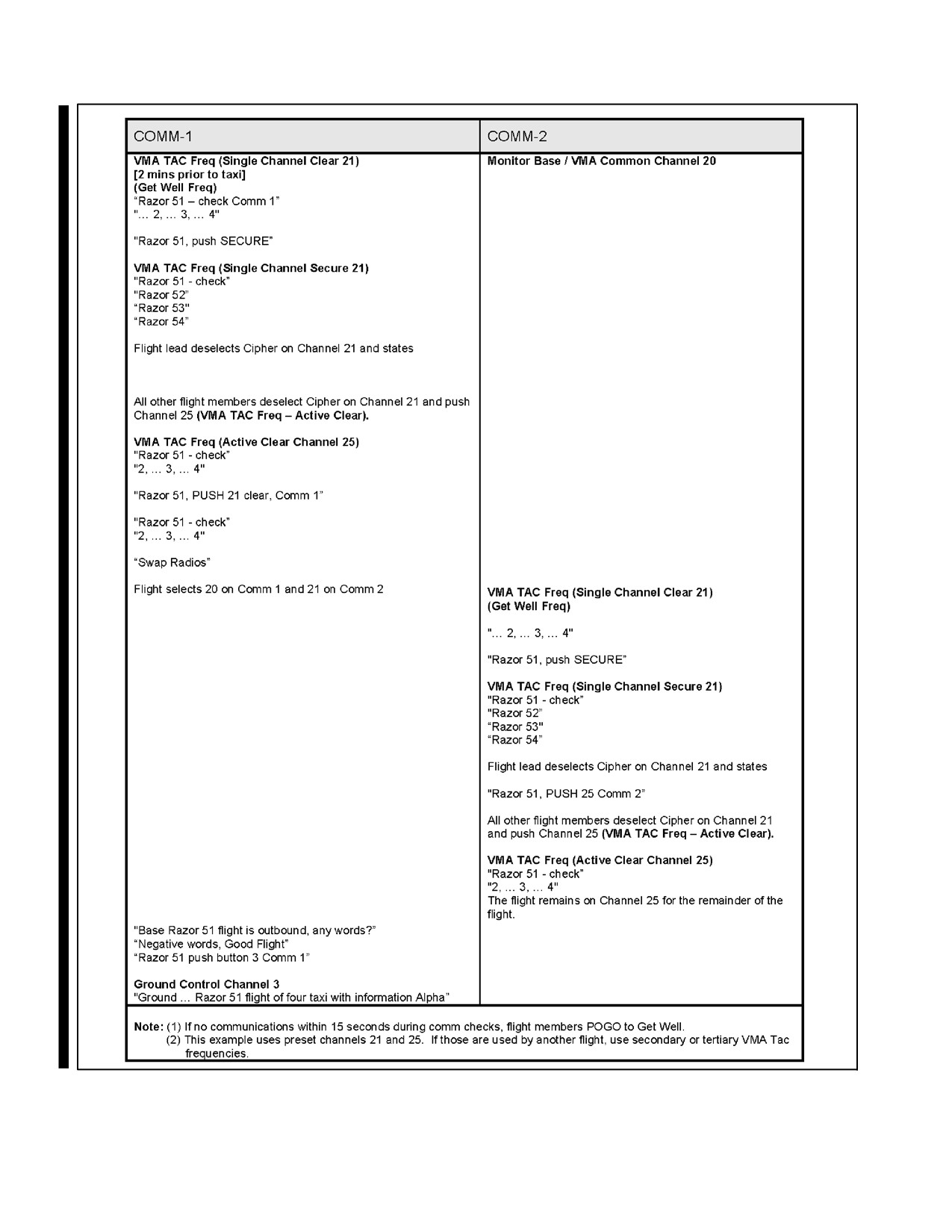
A1-AV8BB--NFM--000
“Razor 51 -- check Comm 2”
Figure 22-1. Communication Checks
ORIGINAL
22-2
A1-AV8BB--NFM--000
22.2.2 Frequency Changes
The standard format for a changing frequencies is: Callsign, Action, COMSEC status, Channel/Frequency/NET, RT
assigned. Frequency changes are signaled by the term “PUSH” or “GO”.
D “PUSH” -- Indicates positive check in only.
D “GO” -- Positive check out and check in. If a wingman is known single
radio, the standard is to use “GO” in order to confirm acknowledgement.
D “Clear” -- Unencrypted, or un--secure.
D “Single--channel” -- Singular frequency, non--hopping.
D “ACTIVE” -- Anti--jam frequency hopping.
D “SECURE” -- Encrypted, or secure.
D “Channel” -- Implies a pre--set.
D “NET” -- SINGARS, HQ I or II NET ID.
Example 1: “Razor 11, PUSH ACTIVE, clear, Channel 2, Comm--1” means the entire flight will meet on pre--set
channel 2 anti--jam, clear.
Example 2: “Razor 11, PUSH 318.925, Comm--2” means the entire flight will meet on a manual inputted UHF
frequency on comm.--2. Single--channel, un--secure is implied unless otherwise stated.
Example 3: “Razor 11, PUSH 318.925 SECURE, Comm--2” means the entire flight will meet on a manual inputted
UHF frequency on comm.--2. The frequency will be encrypted.
22.2.3 Degraded Communications
22.2.3.1 Single Radio
If single radio, tune it to the R/T 1 planned frequencies unless otherwise briefed or directed.
22.2.3.2 Get Well
The frequency used whenever the flight becomes “lost lead on the radios.” If no transmission is received within 30
seconds after a frequency change, or during single radio operation, switch to the briefed “get well” frequency.
22.2.3.3 Microphone Failure
In the event of microphone failure, key the transmit button to communicate as follows:
D 1 click -- “NO”
D 2 clicks -- “YES”
D 3 clicks -- “SAY AGAIN”
22.2.3.4 NORDO
References governing two--way radio failure procedures for a single aircraft are provided in Federal Aviation
Regulations part 91 and the DOD Flight Information Handbook. These procedures do not alleviate a pilot to remain
predictable in recovering NORDO (No radio) aircraft.
22.2.3.4.1 V/STOL Considerations
NORDO aircraft will attempt to execute recovery to the last known duty runway, or the primary runway for which
an instrument approach is designated, in order to predictably enter the landing pattern. If unable to determine the duty
runway, select MENU--DATA--AC to attempt to estimate wind velocity. Additionally, conduct a search for other
22-3
ORIGINAL