NATOPS FLIGHT MANUAL NAVY MODEL AV--8B/TAV--8B 161573 AND UP AIRCRAFT (2008) - page 7
A1-AV8BB--NFM--000
11.10.5.5 Formation V/STOL
Aircraft performing a formation takeoff or landing must ensure that intakes are forward of cold nozzle exhaust or is
far enough aft that the following aircraft are airborne before the preceding aircraft’s takeoff point. When performing
line abreast takeoffs or landings the potential for FOD is greatly increased if following aircraft become sucked on
bearing. When performing trailing takeoffs or landings FOD risks can be reduced by alternating sides of the runway.
Generally a 300 foot buffer added to the takeoff distance is enough to ensure following aircraft get airborne prior to
picking up any “energized” FOD from preceding aircraft.
11.10.5.6 Ground Operations
There are numerous apertures, holes and cavities in the airframe through which dirt, stones, and other objects may
enter the aircraft and cause damage. Of special concern to a pilot are the following areas.
11.10.5.6.1 Intake Suction Doors
These should never be used as steps and nothing should ever be placed on these. Objects can rest on the inside of
these doors, especially the lower doors, and get ingested by the engine on start. The only way to be sure they are free
from FOD is to enter the intake to look at them from the inside. If this is done extreme care must be taken to ensure
the inspector is free from all objects which may FOD the intake.
11.10.5.6.2 Boundary Layer Doors
Small objects can get stuck inside the bottom landing behind these doors and make their way into the engine. With
the canopy closed objects can fall into this area from the ducts on top of the aircraft in the rear skirt of the canopy.
During preflight careful attention to looking inside the doors at the bottom of the landing is necessary.
11.10.5.6.3 Cockpit Conditioning System Cooling Ducts
Care must be taken anytime someone is on top of the aircraft. Objects falling into openings may enter the engine or
the GTS and cause FOD. Inlets on top of the intake cowl allow air to enter the heat exchanger and then pass through
the bullet fairing in the intake to the motor. Objects that enter these inlets may FOD the motor.
11.10.5.6.4 Footsteps
The footstep receptacles are potential debris traps. Boots should be free of mud and any objects before stepping on
the aircraft or the footsteps so that debris does not enter the cockpit, get stuck in the footsteps or fall into another
aircraft cavity and cause damage.
11.10.5.6.5 Intake
Theintakeshould neverbeused as ashelfon which tohold anything.It shouldnot beused asastepeithersincedebris
on the soles of foot gear can be deposited in the intakes. Care must be taken to limit the items taken in the cockpit.
Everything must be secure and accounted for when entering and leaving the cockpit. Items should never be placed
on the glare shield or canopy edge as they may get sucked out and down the engine.
11.10.6 Hot Gas Ingestion
In a normal hover at 50 to 60 feet, the jets from the nozzles merge prior to reaching the surface and there is, therefore,
no interaction as at lower levels. Instead, the merged exhaust acts as a single jet and upon striking the surface, expands
radially through 360°. The ground jet sheet velocity decays rapidly and, as the velocity approaches zero, the warm
exhaust gases commence to rise by convection. The gases break from the surface and commence to raise at a radius
of 50 to 100 feet dependent upon hover height, wind, surface roughness and ambient temperature. As the gases rise
they are blown by the wind. The gases which are upwind will be blown toward the aircraft and will envelope it.
Ingestion of this warm gas will reduce engine thrust if JPT--limiting is reached. Figure 11-11 illustrates the best and
worst case. With the aircraft pointed into the wind, the ingested gases will be predominantly from the front nozzles,
thus cooler than in the case where the aircraft is pointed downwind and thus ingesting gas predominantly from the
rear nozzles. At lower hovers, convection is still present but the major part of the gas is blown directly back by the
exhaust reaction with the surface and reaches the aircraft much hotter than the convection gas, therefore, low hovers
cannot usually be sustained and are not recommended. Reingestion can become critical at low forward speeds on or
near the ground (Figure 11-12).
ORIGINAL
11-38
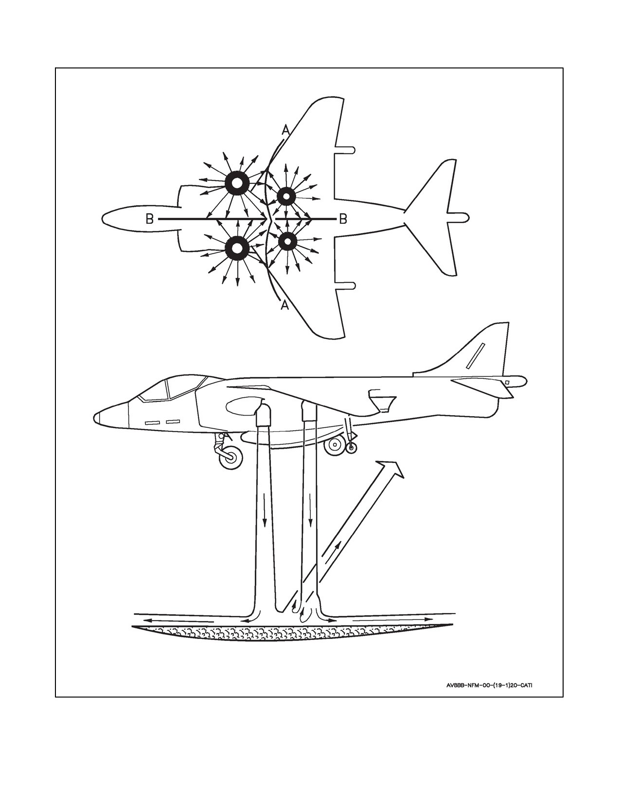
A1-AV8BB--NFM--000
Figure 11-9. Nozzles Exhaust Pattern
11-39
ORIGINAL
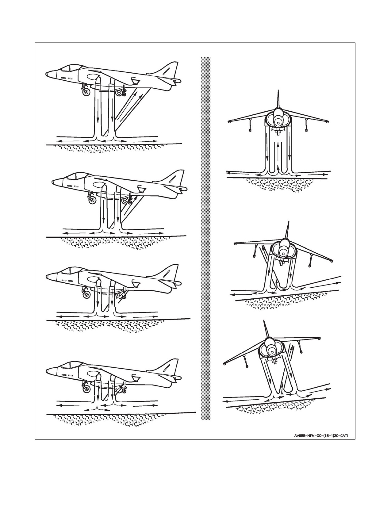
A1-AV8BB--NFM--000
Figure 11-10. Instability Due to Ground Effect
ORIGINAL
11-40
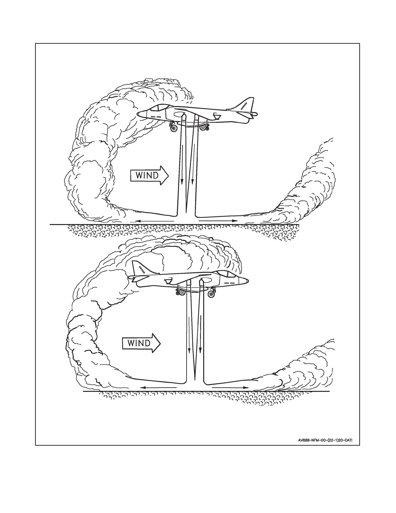
A1-AV8BB--NFM--000
Figure 11-11. Hot Gas Reingestion
11-41
ORIGINAL
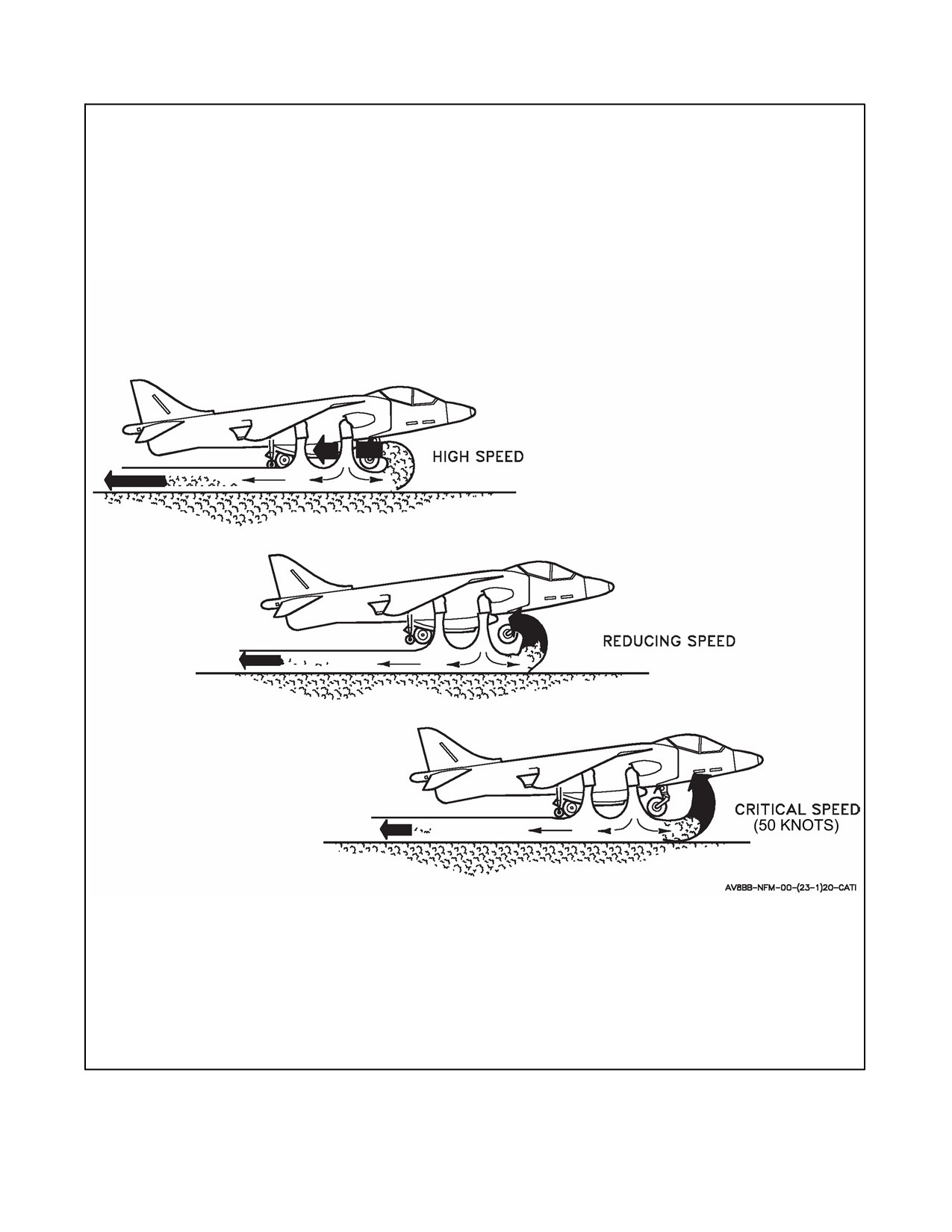
A1-AV8BB--NFM--000
Figure 11-12. Reingestion Critical Speed
ORIGINAL
11-42

A1-AV8BB-NFM-000
PART V
Emergency Procedures
Page
No.
PART V — EMERGENCY PROCEDURES
CHAPTER
12
— GENERAL EMERGENCIES
12.1
GENERAL EMERGENCY PROCEDURES
12--1
12.1.1
Immediate Action Items
12--1
12.1.2
Warning/Caution/Advisory Lights
12--2
CHAPTER
13
— GROUND EMERGENCIES
13.1
EMERGENCY SHUTDOWN
13--1
13.2
GROUND FIRE
13--1
13.3
ABNORMAL START
13--1
13.4
LOSS OF ENGINE CONTROL ON GROUND
13--1
13.5
BRAKE FAILURE
13--2
13.5.1
Ground
13--2
13.5.2
Air
13--2
13.6
HOT BRAKE
13--2
CHAPTER
14
— TAKEOFF EMERGENCIES
14.1
ABORT
14--1
14.1.1
Ashore (CTO or STO)
14--1
14.1.2
Afloat (STO)
14--1
14.2
NO LIFTOFF ON STO
14--2
14.3
RPM STAGNATION/LOSS OF THRUST AFLOAT
14--2
14.4
OVER ROTATION ON STO
14--2
14.5
BLOWN TIRE ON TAKEOFF
14--2
14.6
LANDING GEAR FAILS TO RETRACT
14--2
73
ORIGINAL

A1-AV8BB-NFM-000
Page
No.
CHAPTER
15
— IN--FLIGHT EMERGENCIES
15.1
MISSION COMPUTER FAILURE
15--1
15.2
AIR DATA COMPUTER FAILURE
15--7
15.3
INS FAILURE
15--8
15.4
OBOGS FAILURE
15--11
15.5
CANOPY UNSAFE INFLIGHT
15--11
15.5.1
Canopy Explosion Inflight
15--11
15.6
COCKPIT TEMPERATURE HOT/COLD
15--11
15.7
COCKPIT UNDER PRESSURE
15--12
15.8
COCKPIT OVER PRESSURE
15--12
15.9
MAIN GENERATOR FAILURE (GEN, DC AND STBY TR CAUTION LTS)
15--12
15.10
MAIN TRU FAILURE (DC CAUTION LIGHT)
15--13
15.11
STANDBY TRU FAILURE (STBY TR CAUTION LIGHT)
15--18
15.12
APU GENERATOR FAILURE (APU GEN CAUTION LIGHT)
15--18
15.13
TOTAL ELECTRICAL FAILURE (GEN, APU GEN, DC, STBY TRU)
15--18
15.14
EMERGENCY DC BUS FAILURE
15--18
15.14.1
DC Emergency Bus, Circuits
15--19
15.14.2
Alert Bus, 7 Circuits
15--24
15.14.3
Failure Analysis
15--25
15.14.4
Discussion
15--26
15.14.5
Emergency DC Bus Failure Procedures
15--26
15.15
OUT--OF--CONTROL
15--28
15.15.1
Jetborne/Semi--Jetborne
15--28
15.15.2
Out of Control/Spin/Falling Leaf Recovery
15--29
15.16
FUEL CONTROL
15--30
15.16.1
EFC CAUTION AND JPTL WARNING LIGHTS ON
15--30
15.16.2
SINGLE DECS FAILURE (EFC CAUTION LIGHT)
15--30
15.16.3
DUAL DECS FAILURE (EFC WARNING LIGHT)
15--30
15.17
MINOR RPM FLUCTUATION
15--33
15.18
MFS RECOVERY
15--34
ORIGINAL
74

A1-AV8BB-NFM-000
Page
No.
15.19
COMPRESSOR STALL
15--35
15.20
ENGINE MECHANICAL FAILURE/ENGINE VIBRATION
15--35
15.21
IGV FAILURE
15--36
15.21.1
Stuck at High Angle
15--37
15.21.2
Stuck at Low Angle
15--37
15.22
LOSS OF ENGINE CONTROL INFLIGHT
15--38
15.23
AIRSTART
15--38
15.24
OIL SYSTEM FAILURE (OIL CAUTION LIGHT)
15--40
15.25
NOZZLE DRIVE FAILURE
15--40
15.26
NOZZLE CONTROL FAILURE
15--40
15.26.1
During STO
15--40
15.26.2
During Transition
15--40
15.26.3
During Conventional Flight
15--41
15.27
ENGINE FIRE (FIRE WARNING LIGHT)
15--41
15.27.1
Ground
15--42
15.27.2
Takeoff/Landing/Vertical Operation
15--42
15.27.3
Inflight
15--42
15.28
ELECTRICAL FIRE
15--42
15.29
ELIMINATION OF SMOKE AND FUMES
15--43
15.30
CROSSFEED FAILURE (R FEED WARNING LIGHT)
15--43
15.31
FUEL TRANSFER FAILURE (L TRANS/R TRANS CAUTION LIGHT)
15--43
15.32
FUEL LOW LEVEL (L FUEL/R FUEL CAUTION LIGHT(S) FLASHING)
15--44
15.33
EXTERNAL FUEL TANK TRANSFER FAILURE
15--45
15.34
FUEL LEAK
15--45
15.35
AIR REFUEL PROBE FAILS TO RETRACT
15--45
15.36
FLAPS CHANNEL FAILURE (FLAPS 1 OR FLAPS 2 CAUTION)
15--46
15.37
AUTO FLAP FAILURE (AUT FLP CAUTION)
15--46
15.38
FLAP FAILURE (FLAP WARNING LIGHT)
15--46
15.39
UNCOMMANDED FLAP MOTION
15--47
75
ORIGINAL

A1-AV8BB-NFM-000
Page
No.
15.40
UNCOMMANDED NOSE DOWN PITCH MOVEMENT
15--47
15.41
RUDDER TRIM FAILURE
15--47
15.42
AILERON OR STABILATOR TRIM FAILURE
15--47
15.43
Q--FEEL FAILURE
15--47
15.44
SAS FAILURE
15--47
15.45
FLIGHT CONTROL MALFUNCTION
15--48
15.46
HYD 1 FAILURE (HYD 1 CAUTION LIGHT)
15--48
15.47
HYDRAULIC SYSTEM FAILURE (HYD WARNING LIGHT)
15--48
15.48
GUN NOT CLEAR
15--49
CHAPTER
16
— LANDING EMERGENCIES
16.1
LANDING GEAR UNSAFE/FAILS TO EXTEND
16--1
16.2
BLOWN TIRE
16--2
16.3
NOSEWHEEL STEERING/CASTER FAILURE
16--3
16.3.1
Before AFC--391
16--3
16.3.2
After AFC--391 (Hi/Lo Gain NWS System)
16--3
16.4
SPEEDBRAKE FAILURE
16--4
16.5
DAMAGED AIRCRAFT
16--5
16.6
CRUISE FLAPS LANDING
16--5
16.7
SAAHS OFF RECOVERY AND LANDING
16--5
16.8
REACTION CONTROL FAILURE
16--6
16.9
ASYMMETRIC LANDING
16--7
16.9.1
Asymmetric Stores Landing
16--7
16.9.2
Asymmetric Fuel Landing
16--8
16.10
LANDING WITH ENGINE FAILURE
16--8
16.11
PRECAUTIONARY EMERGENCY APPROACH
16--8
16.12
CANOPY SEAL FAILS TO DEFLATE
16--9
CHAPTER
17
— EMERGENCY EGRESS
17.1
GROUND EGRESS
17--1
17.2
DITCHING
17--1
ORIGINAL
76

A1-AV8BB-NFM-000
Page
No.
17.2.1
Before Impact
17--1
17.2.2
After Impact
17--2
17.3
EJECTION
17--2
17.3.1
Low Altitude Ejection
17--3
17.3.2
Ejection From Surface Level
17--4
17.3.3
High Altitude Ejection
17--5
17.4
PARACHUTE DESCENT PROCEDURES
17--5
17.5
A/P22P--14(V)3 CHEMICAL, BIOLOGICAL, RADIOLOGICAL
PROTECTIVE RESPIRATOR ASSEMBLY EMERGENCY PROCEDURES
17--5
17.5.1
Emergency Egress On Land
17--5
17.5.2
Ejection Over Land (In a Non--Contaminated Environment) During the Option
Phase of Parachute Descent
17--20
17.5.3
Ejection Over Land (In a Contaminated Environment) During the Option
Phase of Parachute Descent
17--20
17.5.4
Ejection Over Water (In Either Contaminated or Non--Contaminated Environment)
During Option Phase of Parachute Descent
17--21
17.5.5
Pusher Fan Malfunction
17--22
17.5.6
Airsickness
17--22
17.5.7
OBOGS Failure
17--22
CHAPTER
18
— IMMEDIATE ACTION ITEMS
18.1
ABNORMAL START
18--1
18.2
LOSS OF ENGINE CONTROL ON GROUND
18--1
18.3
EMERGENCY SHUTDOWN
18--1
18.4
NWS CAUTION LIGHT (AFTER AFC--391)
18--1
18.5
BRAKE FAILURE/SKID CAUTION LIGHT
18--1
18.6
ABORT
18--2
18.6.1
Ashore (CTO or STO)
18--2
18.6.2
Afloat
18--2
18.7
NO LIFTOFF ON STO ASHORE
18--2
18.8
OVER ROTATION ON STO
18--2
18.9
RPM STAGNATION/LOSS OF THRUST AFLOAT
18--2
18.10
L/R TANK WARNING LIGHT
18--2
18.10.1
During Air Refueling
18--2
18.10.2
During Hot Refueling
18--2
77
ORIGINAL

A1-AV8BB-NFM-000
Page
No.
18.11
FIRE
18--3
18.11.1
Ground Fire (Engine, GTS/APU, Brake)
18--3
18.11.2
Takeoff/Landing/Vertical Operation
18--3
18.11.3
Inflight
18--3
18.12
OIL CAUTION LIGHT
18--3
18.13
DUAL DECS FAILURE (EFC WARNING LIGHT)
18--3
18.14
LOSS OF ENGINE CONTROL INFLIGHT
18--3
18.15
COMPRESSOR STALL
18--4
18.16
AIRSTART
18--4
18.17
FLIGHT CONTROL MALFUNCTION
18--4
18.18
REACTION CONTROL FAILURE
18--4
18.19
FLAP WARNING/UNCOMMANDED FLAP MOTION/UNCOMMANDED
NOSE DOWN PITCH
18--4
18.20
OUT--OF--CONTROL
18--4
18.20.1
Jetborne/Semi--Jetborne Out--of--Control Recovery
18--4
18.20.2
Out--of--Control/Spin/Falling Leaf Recovery
18--5
18.21
EMERGENCY DC BUS FAILURE
18--5
18.22
CANOPY EXPLOSION INFLIGHT
18--5
18.23
OXY CAUTION LIGHT
18--5
CHAPTER
19
— EMERGENCY PROCEDURES CHECKLIST DISPLAY
19.1
EPC SELECTION
19--1
19.2
UPDATING THE EPC
19--1
ORIGINAL
78

A1-AV8BB--NFM--000
CHAPTER 12
General Emergencies
12.1
GENERAL EMERGENCY PROCEDURES
This part contains procedures to be followed to properly respond to and manage a system malfunction or emergency
condition. These procedures will ensure maximum safety for the pilot and/or aircraft until a safe landing or other
appropriate action is accomplished. Multiple emergencies, adverse weather and other peculiar conditions may require
modification of these procedures. It is essential, therefore, that pilots determine the correct course of action by use
of common sense and sound judgement. The pilot must assess many factors that will dictate the options available
to him. These factors include, but are not limited to, aircraft speed, drift rate, engine status, airworthiness,
configuration, and the environmental conditions of the pad/runway and the surface adjacent to the pad/runway, such
as winds, ambient lighting, and weather. These factors must be evaluated and remain part of the operating mind set
during flight operations. As soon as possible, the pilot should notify the flight/flight leader and appropriate
controlling agency of any existing emergency and of the intended action. When practical notify the Operations Duty
Officer (ODO). When an emergency occurs, three basic rules are established which apply to airborne emergencies.
They should be thoroughly understood by all pilots:
1. Maintain aircraft control.
2. Analyze the situation and take proper action.
3. Land as soon as practical.
When an airborne emergency occurs and flight conditions permit, the pilot should record and/or broadcast all
available information such as airspeed, altitude, power settings, instrument readings and fluctuations, warning lights
illuminated, loss of thrust and unusual noises. Flight leaders, wingmen, other pilots, or any ground station receiving
suchinformationshouldcopyitandrecordtheirobservationsofvapor,smoke,flamesorotherphenomena.Whenever
possible,aneffortshouldbemadetoescortanaircraftwithadeclaredemergencyuntil ithas safelylanded. Thisescort
should observe the distressed aircraft for any external indications or symptoms of the problem, provide assistance
or advice that may be required, and assist in a search and rescue (SAR) effort if required. ODOs, when assisting
distressed aircraft, may call the 24 hour Boeing Hotline number, (314) 232--9999 or (888) 222--0058, for technical
assistance. ODOs should identify themselves and request Conference X--Ray assistance. They will then be connected
with the appropriate department for assistance and guidance for the airborne emergency.
In troubleshooting a system discrepancy or in accomplishment of an
emergency procedure, the operation of a system control (such as flap,
throttle,flight control,electrical switch,etc.)isusually required.Duetothe
nature of some failures and/or the occurrence of successive malfunctions,
some control operations may occasionally result in undesirable aircraft
responses, such as unexpected roll or pitch, smoke, unstable engine
operation, etc. Often the most prudent action to take to eliminate such an
undesirable response is to immediately return the operated control to its
former setting. The pilot must be mentally conditioned to take that action
promptly when appropriate.
12.1.1 Immediate Action Items
Procedural steps preceded by an asterisk (*) are considered immediate action items. Pilots should be able to
accomplish these steps without reference to the checklist.
12-1
ORIGINAL

A1-AV8BB--NFM--000
12.1.2 Warning/Caution/Advisory Lights
Thewarning, caution, and advisory lightsarelistedin Figure12-1 togetherwith thecauseandcorrectiveaction.They
are listed under three major headings:
1. Warning Lights.
2. Caution Lights.
3. Advisory Lights.
Each light is listed alphabetically under its major heading; however, if preceded by L or R that letter is not used to
place the light alphabetically. Emergency procedures associated with a warning or caution display are shown in this
figure and are not repeated elsewhere in this manual.
WARNING LIGHTS
INDICATOR
CAUSE/REMARKS
CORRECTIVE ACTION
AAA
Al
Refer to A1--AV8BB--TAC--100/(S).
CW
(AV--8B only)
IN V/STOL FLIGHT (Takeoff/Approach/Landing)
Time Critical
*1. MFS — SELECT.
*2. Water switch — OFF.
If rpm does not recover:
3. EJECT.
IN CONVENTIONAL FLIGHT
*1. Throttle — IDLE.
*2. MFS — SELECT.
EFC
*3. Throttle — ADVANCE SLOWLY.
1
(Voice -- FUEL
Number 1 and 2 DECU failed.
If unable to select MFS and sufficient power not
CONTROL, FUEL
L Refer to paragraph 15.16.3 Dual DECS Failure.
available:
CONTROL)
*4. EFC switch — CHANGE LANE.
If available power insufficient for recovery:
5. EJECT.
If MFS fails to restore control but sufficient power:
6. Cautiously use nozzles to control airspeed.
7. Flaps — AUTO.
8. Land as soon as practical.
After landing:
9. Use nozzle braking as required.
10. Throttle — OFF.
11. Fuel shutoff handle — OFF.
Figure 12-1. Warning/Caution/Advisories (Sheet 1 of 13)
ORIGINAL
12-2

A1-AV8BB--NFM--000
WARNING LIGHTS
INDICATOR
CAUSE/REMARKS
CORRECTIVE ACTION
GROUND
*1. Execute emergency shutdown.
TAKEOFF/LANDING/VERTICAL/OPERATION
*1. Abort or land immediately.
Fire in the engine compartment.
*2. Execute emergency shutdown.
FIRE
-- -- -- -- -- -- -- -- -- -- -- -- -- -- -- -- -- -- -- -- -- -- -- -- -- -- -- -- -- -- -- -- -- -- -- -- -- -- -- -- --
INFLIGHT
1
(Voice --
GROUND FIRE (ENGINE)
ENGINE FIRE,
*1. Nozzles — AFT AS SOON AS POSSIBLE.
L Refer to paragraph 13.2 Ground Fire.
ENGINE FIRE)
*2. APU GEN — OFF.
-- -- -- -- -- -- -- -- -- -- -- -- -- -- -- -- -- -- -- -- -- -- -- -- -- -- -- -- -- -- -- -- -- -- -- -- -- -- -- -- --
*3. Master arm/gun — OFF.
TAKEOFF/LANDING/VERTICAL/INFLIGHT
L Refer to paragraph
15.27 Fire.
*4. Throttle — MINIMUM REQUIRED.
If fire persists:
*5. EJECT.
If light goes out:
6. Land as soon as possible.
TAKEOFF/LANDING/VERTICAL/OPERATION
*1. Nozzles — 40° OR GREATER.
2. Stores — JETTISON (if required).
3. Land as soon as practical.
If flap retraction required:
4. Emergency flaps retract button — SLOWLY BEEP
FLAPS UP.
FLAP
INFLIGHT
1
(Voice --
Flap failure.
1. Climb to safe altitude (5,000 feet AGL minimum, 250
FLAP FAILURE, FLAP
L Refer to paragraph
15.36 Flap Failure.
KCAS maximum).
FAILURE)
2. Flap mode switch — CRUISE.
3. Land as soon as practical.
If flap retraction required:
4. Emergency flap retract — SLOWLY BEEP FLAPS
UP.
If asymmetry occurs:
5. Do not attempt further retraction.
6. Flap power switch — OFF.
7. Nozzles as required (no less than 20° less than flap
position).
Steady light -- In transit or unsafe.
L Refer to paragraph 14.6 Landing Gear Fails to
GEAR
STEADY:
Retract or paragraph 16.1 Landing Gear
Gear Handle
Unsafe/Fails to Extend.
1. Check gear down indicators.
1
(Voice -- LANDING
GEAR, LANDING
-- -- -- -- -- -- -- -- -- -- -- -- -- -- -- -- -- -- -- -- -- -- -- -- -- -- -- -- -- -- -- -- -- -- -- -- -- -- -- -- --
-- -- -- -- -- -- -- -- -- -- -- -- -- -- -- -- -- -- -- -- -- -- -- -- -- -- -- -- -- -- -- -- -- -- -- -- -- -- -- -- -- -- -- -- -- -- --
GEAR)
Flashing light -- Gear up and below 6,000 feet
FLASHING:
slower than 160 knots and rate of descent over 250
1. Gear — DOWN.
feet/minute.
2. Increase airspeed or altitude.
Figure 12-1. Warning/Caution/Advisories (Sheet 2)
12-3
ORIGINAL

A1-AV8BB--NFM--000
WARNING LIGHTS
INDICATOR
CAUSE/REMARKS
CORRECTIVE ACTION
1. Generator switch — CYCLE.
If GEN resets:
2. Continue flight.
If GEN warning, DC, and STBY TR cautions still on or
after reset, generator drops off line:
3. Generator switch — OFF.
--406/--408A engine:
4. MFS — SELECT.
All aircraft:
5. APU GEN — ON (when in APU starting envelope).
If APU comes on line:
6. MFS — AS REQUIRED.
GEN
AC generator off the line.
If APU GEN caution comes on:
1
(Voice --
L Refer to paragraph 15.9 Main Generator
GENERATOR,
Failure.
7. APU GEN — RESET/ON (attempt as required).
GENERATOR)
If APU GEN caution still on:
8. APU GEN — OFF.
--406/--408A engine:
9. MFS — SELECT.
All aircraft:
10. Nonessential DC equipment — OFF.
11. Landing Gear — DOWN AS SOON AS POSSIBLE
(below 200 knots and 16 volts minimum).
12. Do not select STOL flaps above 165 knots and less
than 25° nozzles.
13. Fuel boost pump switches — DC (before landing).
14. Land as soon as practical. Perform a VL if possible
(HOT NWS).
INFLIGHT
1. Slow to 250--300 knots.
2. Hydraulic systems pressures — CHECK.
HYD
If both hydraulic systems failing:
1
(Voice --
HYD 1 and HYD 2 failed.
HYDRAULICS,
L Refer to paragraph 15.47
Hydraulic
System
3. EJECT.
HYDRAULICS)
Failure.
ON GROUND
1. Throttle — OFF.
2. Parking brake — SET WHEN STOPPED.
JPTL control inoperative:
1. JPTL switch — CHECK ON.
D JPTL switch set to OFF.
If no EFC warning or caution light:
D Failure detected in controlling DECU
JPTL
2. EFC switch — SET TO OTHER DECU.
JPT limiting function.
1
(Voice --
D Electrical power lost to either or both
If light remains on:
LIMITER OFF,
DECUs (EFC warning or caution also
3. JPTL switch — OFF.
LIMITER OFF)
illuminated).
D State input fault external to DECU
4. Maintain JPT/RPM limits manually.
(fast deceleration solenoid may be
inoperative).
Figure 12-1. Warning/Caution/Advisories (Sheet 3)
ORIGINAL
12-4

A1-AV8BB--NFM--000
WARNING LIGHTS
INDICATOR
CAUSE/REMARKS
CORRECTIVE ACTION
LAW
1
(Voice --
Below set altitude.
Information.
ALTITUDE,
ALTITUDE)
1
(Voice --
Aircraft is at or below the set obstacle clearance
OBSTACLE,
Information.
elevation angle of the AWLS ground station.
OBSTACLE)
MASTER WARNING
(Radar/Night attack
A warning has been activated.
Check warnings.
aircraft)
If JPT exceeds 765 °C with --406 engine or 820 °C with
--408 engine. (OT light):
OT
JPT limits exceeded:
1. Land as soon as practical (conventionally if possible).
1
(Voice --
D Before AFC--394, an open
OVERTEMP,
thermocouple circuit will result in JPT
2. Use minimum power.
OVERTEMP)
indications rising to 999 °C.
If conventional landing not possible:
3. Jettison fuel and stores if feasible.
1. Fuel quantity indicator switch — FEED.
If left and right fuel quantities above 300 pounds:
2. Fuel proportioner switch — DL.
3. R FEED warning and advisory lights — OUT.
R FEED
(TAV--8B only)
If left fuel quantity less than 300 pounds and right fuel
1
(Voice --
quantity above 300 pounds:
Crossfeed system failure or valve in wrong position.
RIGHT FEED,
4. Fuel proportioner switch — RT.
RIGHT FEED)
5. R FEED advisory light — ON.
6. R FEED warning light — OUT.
If both left and right fuel quantities below 300 pounds:
7. Fuel proportioner switch — OFF.
8. R FEED warning and advisory lights — OUT.
SAM (AV--8B only)
Refer to A1--AV8BB--TAC--100/(S).
DURING AIR REFUELING.
*1. Break away.
L TANK
IN NORMAL FLIGHT.
R TANK
1. Throttle — MINIMUM REQUIRED.
1
(Voice --
Fuel tank overpressure or overtemperature.
LEFT TANK,
2. A/R switch — CHECK (out of PRESS position).
LEFT TANK or RIGHT
3. Fuel dump switches — NORM.
TANK, RIGHT TANK)
DURING HOT REFUELING.
*1. Throttle — OFF.
Figure 12-1. Warning/Caution/Advisories (Sheet 4)
12-5
ORIGINAL

A1-AV8BB--NFM--000
CAUTION LIGHTS
INDICATOR
CAUSE/REMARKS
CORRECTIVE ACTION
AFC
AFC malfunction or AFC deselected.
1. Assume control.
NON--RADAR AIRCRAFT.
1. EQUIP RESET switch — RESET (No more than
three RESETs allowed in a flight).
If AFT BAY caution reilluminates three consecutive times
or does not reset:
2. EQUIP RESET switch — OFF.
3. Limit airspeed as follows:
Below 5,000 feet -- 0.7 Mach.
Aft bay ECS failed.
5,000 to 10,000 feet -- 0.8 Mach.
10,000 to 15,000 feet -- 0.9 Mach.
Selection of reset will remove the AFT BAY Caution
from the Caution/Advisory Panel for 45 seconds. If
4. Land as soon as practical.
the overheat condition still exists, the AFT BAY
AFT BAY
RADAR AIRCRAFT.
Caution can be expected to return. Repeated AFT
BAY lights should be considered a system fault.
1. AFT EQUIP switch — RESET (No more than three
Repeated selection of RESET can result in aircraft
RESETs allowed in a flight).
damage.
If AFT BAY caution reilluminates three consecutive times
or does not reset:
2. Limit airspeed as follows:
Below 5,000 feet -- 0.4 Mach.
5,000 to 10,000 feet -- 0.6 Mach.
10,000 to 15,000 feet -- 0.7 Mach.
3. For operational necessity up to 0.2 Mach increase
over the above speeds is acceptable for 30 minutes.
4. Land as soon as practical.
1. APU switch — RESET/ON (attempt several times).
APU selected and emergency generator failed.
If APU GEN caution still on:
APU GEN
L Refer to paragraph 15.12 APU Generator Failure.
2. APU switch — OFF.
3. Land as soon as practical.
1. Flap control switch — RESET.
If flaps do not reset or AUT FLP caution reilluminates
during flight:
Auto flap mode or ADC failed.
2. Flap mode switch — CRUISE OR STOL (below 165
AUT FLP
L Refer to paragraph 15.37 AUTO Flap Failure.
knots and nozzles greater than 25°).
3. BIT display — CHECK FOR ADC FAILURE (ADC 1).
4. If ADC failure confirmed — do not extend landing
gear at airspeeds >200 KCAS.
BINGO
1
Fuel below bingo setting.
(Voice -- BINGO,
Information.
BINGO)
1. Descend below 25,000 feet.
2. Cabin pressure switch — DUMP.
Canopy not locked closed.
CANOPY
3. Slow below 250 knots.
L Refer to paragraph 15.5 Canopy Unsafe Inflight.
If unsafe latch can be determined:
4. Land as soon as practical.
On AV--8B 163677 and up; light is not used,
Information.
CASTER
illuminates on lights test only.
Figure 12-1. Warning/Caution/Advisories (Sheet 5)
ORIGINAL
12-6

A1-AV8BB--NFM--000
CAUTION LIGHTS
INDICATOR
CAUSE/REMARKS
CORRECTIVE ACTION
SMS unable to operate in computed delivery mode
CIP AUT
Information.
(AUTO and CCIP).
Combat thrust activated. Flashes after 2 1/2
CMBT
Information.
minutes.
Cockpit avionics cooling fan failed.
1. Cockpit temperature — AS COLD AS PRACTICAL.
CS COOL
2. Affected avionics — OFF (if not required).
Affected equipment:
HUD, ODU, DC, DDI, and ACP.
3. Land as soon as practical.
CW NOGO
Refer to A1--AV8BB--TAC--100/(S).
(AV--8B only)
Main transformer--rectifier failed
1. Confirm DC failure by checking hydraulic gauges.
L Refer to paragraph 15.10 Main TRU Failure.
2. Fuel boost pump switches — NORM OR OFF.
NOTES
3. Voltmeter and STBY TR caution — MONITOR.
D Hot NWS, perform RVL or VL if
4. Do not select STOL flaps above 165 knots and less
possible.
than 25° nozzles and do not lower landing gear
greater than 200 kts.
DC
D Below 16 volts, normal manual fuel
5. Land as soon as practical.
selection cannot be guaranteed.
If STBY TR caution on and/or voltmeter below 26 volts:
D DC equipment to consider for step 8:
6. MFS — SELECT (16 volts minimum).
DC boost pumps.
7. Landing gear — DOWN AS SOON AS POSSIBLE
Radios (transmit drains more power).
(below 200 knots and 16 volts minimum).
Seat adjust.
8. Nonessential DC equipment — OFF.
Trim.
Observe Prohibited Maneuvers and AOA Limitations without
DEP RES
Departure resistance reduced.
departure resistance.
DECU number 1 or 2 has failed.
1. Do not change lanes.
EFC
L Refer to paragraph 15.6.2 Single DECS Failure
2. Land as soon as practical.
(EFC caution).
Engine overspeed, overtemperature, or over g was
ENG EXC
Information.
detected.
FLAPS 1 and FLAPS 2.
1. Flaps — AUTO.
2. Flap power switch — RESET (single channel failure
FLAPS 1
Flaps channel 1 failed.
only).
If FLAPS 1 or FLAPS 2 does not reset or reilluminates
during flight:
3. Flap mode switch — CRUISE OR STOL (below 165
-- -- -- -- -- -- -- -- -- -- -- -- -- -- -- -- -- -- --
-- -- -- -- -- -- -- -- -- -- -- -- -- -- -- -- -- -- -- -- -- -- -- -- -- -- -- -- -- -- -- -- -- -- -- -- -- -- -- -- --
knots and nozzles greater than 25°).
FLAPS 2
Flaps channel 2 failed.
For FLAPS 2.
L Refer to paragraph 15.36 Flaps Channel Failure.
4. If flap circuit breaker popped — RESET.
Flashing Light.
1. Fuel quantity indicator switch — FEED.
2. Apply negative and then positive g’s.
L FUEL
If single feed tank decreasing:
R FUEL
3. Fuel proportioner switch — OFF.
1
(Voice -- when
4. Boost pump switch (flashing side) — OFF.
Steady light -- left or right fuel 750 pounds.
fuel is less than 250
5. Boost pump switch (nonflashing side) — ON.
pounds:
Flashing light -- left or right fuel 250 pounds.
6. Fuel asymmetry — MONITOR.
L Refer to paragraph 15.32 Fuel Low Level.
FUEL LOW LEFT, FUEL
7. Land as soon as practical.
LOW LEFT or FUEL
If both feed tanks decreasing:
LOW RIGHT, FUEL
LOW RIGHT)
8. Drop tanks — JETTISON.
9. Both boost pumps — NORM.
10. Fuel proportioner switch — OFF.
11. Land immediately.
Figure 12-1. Warning/Caution/Advisories (Sheet 6)
12-7
ORIGINAL

A1-AV8BB--NFM--000
CAUTION LIGHTS
INDICATOR
CAUSE/REMARKS
CORRECTIVE ACTION
1. FWD EQUIP switch — RESET.
If FWD BAY caution reilluminates or does not reset:
2. Descend to below 25,000 feet.
3. Limit airspeed as follows:
Below 5,000 feet -- 0.4 Mach.
FWD BAY
Forward ECS failure.
5,000 to 10,000 feet -- 0.6 Mach.
(Radar aircraft)
10,000 to 15,000 feet -- 0.7 Mach.
4. If radar mode is in OPR or STBY, limit airspeed
above 15,000 feet to 0.7 Mach.
If no ECS airflow from cockpit louvers:
5. PRESS switch — RAM.
GPS not valid, aggressive maneuvering or vertical
If not in maneuvering flight:
and horizontal position error not within tolerance for
1. Check GPS BIT and EHPE/EVPE status.
mode selected.
If BIT and EHPE/EVPE indicate GPS failure:
3
GPS
CAUTION
2. INS knob to NAV.
Continued INS operation in IFA following a GPS
caution can lead to INS failure.
H2O
Less than 15 seconds water remaining.
Information.
1
(Voice -- WATER,
WATER)
H2O SEL
Over 250 knots and water switch not OFF.
1. Water switch — OFF.
1. Fuel proportioner — OFF.
If failure indications persist:
2. Land as soon as practical (VL/RVL if practical).
3. Fuel asymmetry — MONITOR.
4. Below 210 knots, landing gear handle — DOWN,
HYD 1 pressure ≤1,400 psi.
TURN AND PULL.
Speedbrake and LIDS not available.
After touchdown.
Expect about 500 pounds decrease in VTOL/VL
lift.
5. Throttle — OFF.
HYD 1
L Refer to paragraph 15.46 HYD 1 Failure. HYD 1
6. Parking brake — SET WHEN STOPPED.
Caution is accompanied by the prop caution due to
the dependence of the fuel flow propotioner hydraulic
If VL/RVL not practical:
motor on HYD 1 system pressure.
7. Make slow landing.
8. Use power nozzle braking (60 knots minimum) then
steady brake pressure without antiskid cycling.
Braking will be lost if brake accumulator pressure
drops below 1,000 psi.
9. Shut down engine and set parking brake when
stopped.
1. Land as soon as practical.
HYD 2
HYD 2 pressure ≤1,400 psi.
2. Throttle — OFF WHEN CLEAR OF RUNWAY.
IFF
Mode 4 off, zeroized, or not responding.
Information.
Figure 12-1. Warning/Caution/Advisories (Sheet 7)
ORIGINAL
12-8

A1-AV8BB--NFM--000
CAUTION LIGHTS
INDICATOR
CAUSE/REMARKS
CORRECTIVE ACTION
1. Use the standby attitude indicator for attitude
reference.
2. INS switch — OFF (5 seconds -- ASN--139/
3 minutes -- ASN--130).
3. Maintain straight and level flight.
If attempting an in--flight alignment (IFA):
4. Master mode — NAV.
5. INS switch — IFA.
6. Make any required turns using greater than 30° AOB.
7. EHSD — Monitor alignment time and quality.
8. Alignment complete when HUD attitude information
returns. (GPS IFA with good satellite data may take
up to 10 minutes).
If attempting a radar IFA:
INS
INS aligning or failed.
9. Master mode — NAV.
10. Radar mode — Land or Sea based on terrain.
11. INS switch — IFA.
12. Make any required turns using greater than 30° AOB.
13. A/C data page — RIFA (GPS data page — RIFA with
C1+).
14. EHSD — Monitor alignment time and quality after 2
minutes.
15. INS caution — Verify extinguished (may take up to 20
minutes).
16. INS switch — NAV.
If IFA is unsuccessful, attempt a GYRO recovery:
17. INS switch — OFF (5 seconds -- ASN--139/
3 minutes -- ASN--130).
18. INS switch — GYRO.
JMR HOT
ASPJ Overtemp.
Information.
(Night Attack)
L
Left wing gear in transit.
Information.
With gear up:
1. Do not exceed 200 knots.
LIDS
LIDS not in correct position.
With gear down:
1. LIDS switch — CHECK NORM.
2. Expect about 500 pound decrease in VTO/VL lift.
LOAD
Fuel asymmetry over VL limit.
Refer to Asymmetric Landing.
M
Main landing gear in transmit.
Information.
A caution has been activated.
MASTER CAUTION
1
(Voice --
Check cautions.
CAUTION,
CAUTION)
Manual fuel system on.
MFS
CAUTION
1. MAN FUEL switch — POSITIVELY SELECT ON
1
(Voice -- MANUAL
AND RELEASE.
FUEL,
Verify the MFS switch has returned to neutral position
2
2. MFS EMER BATT switch — CHECK.
MANUAL FUEL)
prior to activating the emergency MFS battery. The
MFS switch in OFF will direct battery power away
from the MFS solenoid and prevent MF activation.
Figure 12-1. Warning/Caution/Advisories (Sheet 8)
12-9
ORIGINAL

A1-AV8BB--NFM--000
CAUTION LIGHTS
INDICATOR
CAUSE/REMARKS
CORRECTIVE ACTION
N
Nose landing gear in transit.
Information.
INFLIGHT
1. Perform VL.
If unable to perform VL:
2. Determine available steering mode.
3. Perform RVL as slow as practical with minimum crab
Nosewheel Steering Malfunction.
5
NWS
angle.
L Refer to paragraph 16.3 NWS Failure.
TAKEOFF/LANDING ROLL OUT
*1. Attempt to get airborne.
If unable to get airborne:
*2. Engage NWS button at minimum practical ground
speed.
*1. Throttle — MAINTAIN CONSTANT RPM (75 to 85%,
--406)
(80 to 85%, --408).
2. Minimize g--loading.
3. Land as soon as possible using VNSL.
4. Use nozzles, speedbrake, flaps, and landing gear to
Oil pressure low.
OIL
control airspeed.
L Refer to paragraph 15.24 Oil System Failure.
5. Fuel/Stores — JETTISON AS REQUIRED.
6. If vertical landing is the only option, use
throttle slowly and progressively and be prepared for
engine failure.
7. Throttle — OFF AS SOON AS PRACTICAL.
*1. Emergency oxygen actuator — PULL.
OBOGS malfunction.
*2. Oxygen switch — OFF.
OXY
L Refer to paragraph 15.4 OBOGS Failure.
3. Descend below 10,000 feet cockpit altitude.
4. Oxygen mask — RELEASE.
1. AFC — RESET.
If erroneous input occurs:
PITCH
Pitch stab aug off or failed.
2. Paddle switch — PRESS AND HOLD.
3. Pitch stab aug switch — OFF.
4. Paddle switch — RELEASE.
P NOGO
Refer to A1--AV8BB--TAC--100/(S).
(AV--8B only)
1. Fuel proportioner switch — OFF.
2. Monitor fuel quantity indicators.
PROP
Fuel proportioner off or failed.
3. Balance fuel by switching lowest feed group boost
pump switch OFF until balanced.
1. Boost pump switch (failed pump) — DC OPR.
If pump still failed:
L PUMP
Left or right boost pump pressure low.
2. Boost pump switch (failed pump) — OFF.
R PUMP
3. Fuel asymmetry — MONITOR.
4. Land as soon as practical.
Figure 12-1. Warning/Caution/Advisories (Sheet 9)
ORIGINAL
12-10

A1-AV8BB--NFM--000
CAUTION LIGHTS
INDICATOR
CAUSE/REMARKS
CORRECTIVE ACTION
R
Right wing gear in transit.
Information.
1. AFC — RESET.
If erroneous input occurs:
ROLL
Roll stab aug off or failed.
2. Paddle switch — PRESS AND HOLD.
3. Roll stab aug switch — OFF.
4. Paddle switch — RELEASE.
ON GROUND
*1. ANTISKID switch — NWS.
2. Brakes — MINIMUM REQUIRED.
If light stays on (antiskid failure).
If light goes out (caster failure). ⎯⎯⎯⎯⎯⎯⎯⎯"
INFLIGHT
1. Check ANTISKID switch — ON.
NOTE
2. Select NWS on stick grip.
4
SKID
A skid failure will mask a caster failure.
3. ANTISKID switch — NWS.
4. Perform VL.
If unable to land vertically:
5. Minimize crab angle.
6. Perform RVL as slow as practical.
7. Brakes — MINIMUM REQUIRED.
5
SKID
Antiskid System Malfunction.
1. Brakes — MINIMUM REQUIRED.
Standby TRU inoperative or off line.
STBY TR
1. Voltmeter and DC caution — MONITOR.
L Refer to paragraph 15.11 Standby TRU Failure.
1. Descend below 30,000 feet.
2. Air refuel switch — IN.
3. Dump switches — NORM.
4. Fuel quantity indicator switch — AS REQUIRED.
SINGLE FEED TANK DECREASING:
If L FUEL or R FUEL caution flashes:
1. Fuel proportioner switch — OFF.
2. Boost pump switch (flashing side) — OFF.
L TRANS
Low air pressure to left or right feed tanks.
3. Boost pump switch (non--flashing side) — ON.
R TRANS
L Refer to paragraph 15.31 Fuel Transfer Failure.
4. Fuel asymmetry — MONITOR.
5. Land as soon as practical.
BOTH FEED TANKS DECREASING:
If both L FUEL and R FUEL cautions flash:
1. Drop tanks — JETTISON.
2. Both boost pump switches — NORM.
3. Fuel proportioner switch — OFF.
4. Land immediately.
WSHLD
Windshield hot.
Information.
1. AFC — RESET.
If erroneous input occurs:
YAW
Yaw stab aug off or failed.
2. Paddle switch — PRESS AND HOLD.
3. Yaw stab aug switch — OFF.
4. Paddle switch — RELEASE.
15 SEC
1
(Voice --
JPT above normal lift rating (flashing after 15
1. Monitor JPT.
seconds).
FIFTEEN SECONDS,
FIFTEEN SECONDS)
Figure 12-1. Warning/Caution/Advisories (Sheet 10)
12-11
ORIGINAL
A1-AV8BB--NFM--000
ADVISORY LIGHTS
INDICATOR
CAUSE/REMARKS
CORRECTIVE ACTION
1
(Voice --
ACNIP GO,
ACNIP BIT passed.
Information.
ACNIP GO)
1
(Voice --
ACNIP FAIL,
ACNIP BIT failed.
Information.
ACNIP FAIL)
#AFC
AFC selected in front cockpit.
Information.
A/G
Air--to--ground HUD mode Information.
Information.
#ALTHD
Altitude hold selected in front cockpit.
Information.
APU
APU operating.
Information.
#AUTO
Flaps AUTO mode selected.
Information.
(Flap)
AUTO
VRS AUTO mode selected.
Information.
(VRS)
AV BIT
Light de--activated.
CW JAM
Refer to A1--AV8BB--TAC--100/(S).
(AV--8B only)
#CRS
Flaps CRUISE mode selected.
Information.
DROOP
Ailerons dropped.
Information.
#H20
H20 switch in TO or LDG.
Information.
L
Left wing gear locked down.
Information.
Flashing -- Left feed group full with air refuel probe
extended.
LEFT
-- -- -- -- -- -- -- -- -- -- -- -- -- -- -- -- -- -- -- -- -- -- -- -- -- -- -- -- -- -- -- -- -- -- -- -- -- -- --
Information.
Steady -- 4 external tanks aboard and left inboard
external tank full with air refuel probe extended.
M
Main landing gear locked down.
Information.
N
Nose landing gear locked down.
Information.
NAV
Navigation HUD mode.
Information.
P JAM
Refer to A1--AV8BB--TAC--100/(S).
(AV--8B only)
R
Right wing gear locked down.
Information.
R FEED
TAV--8B crossfeed valve in right feed position.
Information.
(TAV--8B only)
Air refuel probe extended and locked without fuel
READY
Information.
pressure/flow or tank pressurization.
REPLY
IFF responding to Mode 4 interrogation.
Information.
Flashing -- Right feed group full with air refuel probe
extended.
RIGHT
-- -- -- -- -- -- -- -- -- -- -- -- -- -- -- -- -- -- -- -- -- -- -- -- -- -- -- -- -- -- -- -- -- -- -- -- -- -- --
Information.
Steady -- 4 external tanks aboard and right inboard
external tank full with air refuel probe extended.
RUN
VRS RUN mode selected.
Information.
SEL
Combat thrust limiter selected.
Information.
Gear up and speed brake extended Gear down and
SPD BRK
Information.
speed brake not 25°.
Figure 12-1. Warning/Caution/Advisories (Sheet
11)
ORIGINAL
12-12

A1-AV8BB--NFM--000
ADVISORY LIGHTS
INDICATOR
CAUSE/REMARKS
CORRECTIVE ACTION
STO
Flap switch in STOL.
Information.
#STOL
Flaps STOL mode selected.
Information.
VSTOL
VSTOL HUD mode.
Information.
W
Water is flowing.
Information.
* Immediate action item
L Discussion in Part V
#Rear cockpit indicator
1
AV--8B 163519 and up, TAV--8B 163856 and up.
2
AV--8B 164151 and up; also TAV--8B, AV--8B 161573 through 164150 after AFC--328.
3
AV--8B 165384 and up; also 161573 through 165383, TAV--8B 162963 through 164542 after AFC--354 RevA/Part 2/Part 3.
4
AV--8B 161573 through 165312, TAV--8B.
5
AV--8B 165354 and up; also 161573 and up after AFC--391 Part 2, TAV--8B 162963 and up after AFC--391 Part 4.
Figure 12-1. Warning/Caution/Advisories (Sheet 12)
GPWS VOICE WARNINGS
INDICATOR
CAUSE/REMARKS
CORRECTIVE ACTION
Activated when the altitude is ≤90 feet and the
airspeed is ≥250 KCAS, or ≥200 KCAS, at least 60
1. Immediate pull up using the direction--of--pull arrow
PULL--UP
seconds after takeoff or waveoff, or aircraft
on the HUD.
calculates a dive recovery is required.
If <150 feet, between 100 and 200 KCAS, at least 60
1. Immediate roll to wings level and pull up using the
ROLL OUT
seconds after takeoff or waveoff, and at bank angle
direction--of--pull arrow on the HUD.
>45° for 1 second, ROLL OUT is annunciated.
Landing Phase.
If altitude <150 feet, <200 KCAS, more than 60
seconds after take--off or waveoff, and sink rate =
a threshold for 0.3 seconds, POWER is
1. Immediate power addition to control sink rate and pull
POWER
annunciated.
up using the direction--of--pull arrow on the HUD.
Takeoff Phase.
If altitude <150 feet, <250 KCAS, <60 seconds
after take--off or waveoff, and a sink rate ≥300
fpm, POWER is annunciated.
D GPWS detects the gear is not down
and locked.
D If <150 feet, between 100 and 200
CHECK GEAR
1. Lower landing gear.
KCAS, more than 60 seconds after
take--off or waveoff, and descending,
warning is activated if gear not down
and locked for 0.3 seconds.
TAV--8B with H4.0 and Night Attack/Radar Aircraft Only.
Figure 12-1. Warning/Caution/Advisories (Sheet 13)
12-13/(12-14 blank)
ORIGINAL

A1-AV8BB--NFM--000
CHAPTER 13
Ground Emergencies
13.1
EMERGENCY SHUTDOWN
*1. Throttle — OFF.
*2. Fuel shutoff handle — OFF.
*3. Engine start switch — OFF.
*4. APU GEN — OFF.
*5. Battery switch — OFF.
6. Egress.
13.2
GROUND FIRE
The first indication of a fire is normally illumination of the FIRE warning light. There are multiple sources of fire
while operating on the ground such as Engine Fire, GTS/APU Fire, and Brake Fire.
If a fire is suspected or is indicated by ground crews:
*1. Execute Emergency Shutdown.
13.3
ABNORMAL START
If the JPT rises rapidly between 350° and 400° (hot start), or if rpm stabilizes below idle (hung start), or if engine
does not light off within 10 seconds after selecting idle (wet start):
*1. Throttle — OFF.
If wet start:
*2. Engine start switch — OFF.
Perform dry cycle, if required:
3. Ignition isolate switch — ON.
4. Engine start switch — ENG ST (motoring automatically stops after 40 seconds).
5. Repeat cycle as necessary.
13.4
LOSS OF ENGINE CONTROL ON GROUND
If engine RPM--JPT indications on EDP freeze at approximately 22 percent or display an abnormal indication during
start, the voltmeter drops to zero when the DC test switch is set to STBY during standby TRU check, or during any
undemanded engine acceleration.
*1. Throttle — OFF.
*2. Fuel shutoff handle — OFF.
13-1
ORIGINAL

A1-AV8BB--NFM--000
13.5
BRAKE FAILURE
13.5.1 Ground
*1. ANTISKID switch — NWS.
2. Steer toward safe area.
3. Nozzles — HOVER/BRAKING STOP AS REQUIRED.
4. Throttle — OFF WHEN PRACTICAL.
13.5.2 Air
1. ANTISKID switch — NWS.
2. Perform VL.
3. Throttle — OFF WHEN CHOCKED.
13.6
HOT BRAKE
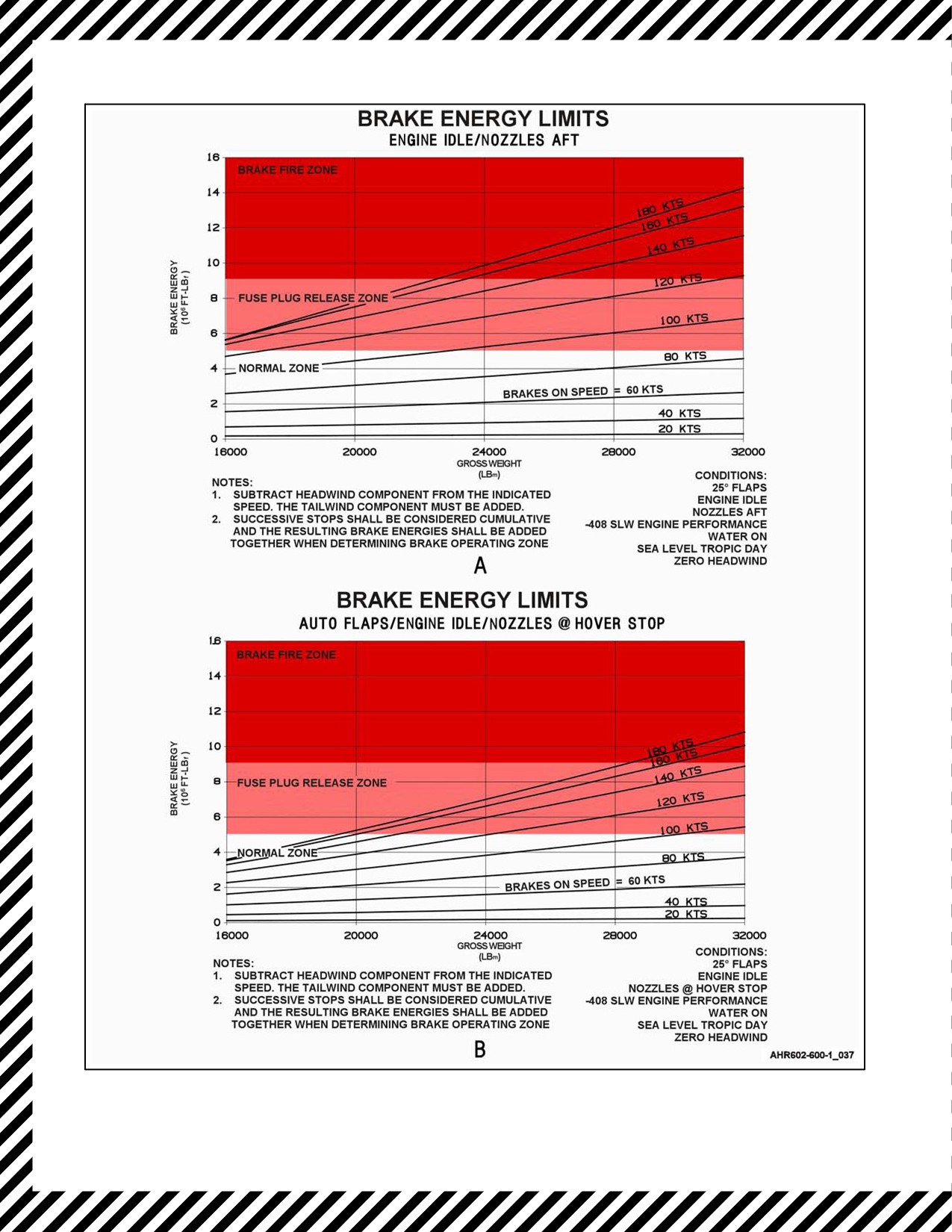
Brake energy zones for the two scenarios are provided in Figure 13-1. Chart A assumes that the nozzles are stuck
in the aft position and PNB is not available. Chart B assumes the nozzles are at the hover stop, engine speed
maintained at idle, and PNB is not available. In either scenario, brake overheat occurs when the energy absorbed by
an individual brake exceeds normal zone limits. Tire deflation due to wheel thermal fuse plug activation generally
occurs within 50 seconds after exceeding the normal zone. In the fuse plug release zone, fuse plug release is expected,
wheel/brake damage may occur, and brake fires are possible.
In the brake fire zone, fires are usually fueled by wheel or brake contaminates, and are easily extinguished. In the
brake fire zone, brake energies exceed all tested conditions and wheel/brake damage is certain. Hydraulic fluid fires
are possible in the brake fire zone due to the deterioration of seals within the brake assembly. Setting the parking brake
or applying pressure on the brake pedals will pressurize the brake assembly and drastically increase the probability
of fire due to hydraulic seal failure. The brake energy limit charts should be used whenever a takeoff is aborted, and
for emergency landings. As stated before, the effects of brake usage/heat buildup are cumulative. If brake overheat
occurs, the aircraft must not be operated for 90 minutes to allow the brakes to cool and have sufficient energy capacity
should the ensuing takeoff be aborted.
Brake overheat should be considered when:
1. Brakes are applied at speeds in excess of 80 knots.
2. Brakes are dragging during taxi.
3. Successive stops resulting in cumulative energies within the fuse plug release zone.
If brake overheating is suspected:
1. Taxi aircraft to closest safe location. Use brakes only as needed to stop or turn.
2. Turn aircraft into the wind.
3. Wheels — CHOCKED.
4. Brakes — RELEASE.
5. Place nozzles to 30° at idle rpm.
6. Shutdown engines after firefighting equipment arrives.
ORIGINAL
13-2

A1-AV8BB--NFM--000
D When brake overheat occurs, stay clear of an area extending at least 300 feet
in a 45° cone around the axle on both sides of the wheel until brakes have
cooled or until thermal release plugs have deflated the tires.
D Due to the possibility of hydraulic seal failure with hot brakes and blown
main tires, a hydraulic fire may develop. Parking brake application will
increase the probability of fire.
13-3
ORIGINAL
A1-AV8BB--NFM--000
Figure 13-1. Brake Energy Limits
ORIGINAL
13-4

A1-AV8BB--NFM--000
CHAPTER 14
Takeoff Emergencies
14.1
ABORT
14.1.1 Ashore (CTO or STO)
At all speeds, PNB is more effective at stopping the aircraft then the brakes alone. If PNB is not available due to
questionable engine control, combine idle PNB and braking. If the brake energy required to stop the aircraft is
anticipated to be above the normal energy zone (see Figure 13-1), bring the aircraft to a stop using maximum braking.
Light braking will cause heat build up and the main tire fuse plug release prior to stopping, greatly reducing braking
effect and causing damage to the wheel assembly. Expect the main tire fuse plugs to release shortly after stopping.
*1. Throttle — IDLE.
Manual fuel may be required in the event of EFC warning or loss of engine
control.
*2. Nozzles — BRAKING STOP.
*3. Throttle — AS REQUIRED.
*4. Brakes — AS REQUIRED.
If hot brakes are suspected:
5. Refer to Hot Brake procedure.
Note
Consideration should be given to ejecting prior to leaving a prepared
surface.
14.1.2 Afloat (STO)
Any delay in the decision to abort beyond about 2 seconds after throttle
slam may preclude a successful abort.
*1. Throttle — OFF.
*2. Brakes — FULL.
If unable to stop:
3. EJECT.
14-1
ORIGINAL

A1-AV8BB--NFM--000
14.2
NO LIFTOFF ON STO
*1. Nozzles — AFT.
*2. Increase speed 20 knots.
*3. Nozzles — STO STOP.
14.3
RPM STAGNATION/LOSS OF THRUST AFLOAT
*1. MFS — SELECT.
*2. STO at nozzle rotation line.
*3. Stores — JETTISON (if required).
*4. Water switch — OFF.
5. Land as soon as practical.
If unable to sustain level flight:
6. EJECT.
14.4
OVER ROTATION ON STO
*1. Stick — FULL FORWARD.
*2. Nozzles — REDUCE 20 DEGREES.
*3. Nozzles — STO STOP.
If control not Regained:
4. EJECT.
14.5
BLOWN TIRE ON TAKEOFF
If takeoff is continued:
1. Leave gear down.
2. Perform a VL if possible.
14.6
LANDING GEAR FAILS TO RETRACT
1. Gear handle — DOWN.
2. Landing gear circuit breaker — CHECK IN.
3. Obtain visual check.
If unable to obtain visual check:
4. Land as soon as practical.
If visual check indicates no damage:
5. Gear handle — UP.
If unsafe indication still present:
6. Gear handle — DOWN AS SOON AS PRACTICAL.
7. Land as soon as practical.
ORIGINAL
14-2

A1-AV8BB--NFM--000
CHAPTER 15
In--Flight Emergencies
15.1
MISSION COMPUTER FAILURE
If the mission computer fails, the following items are inoperative:
1. AFC.
2. AWLS.
3. Radar beacon.
TAV--8B, Day Attack and Night Attack Aircraft:
4. Dual mode tracker.
All Aircraft:
If the mission computer fails, the following items are affected:
5.
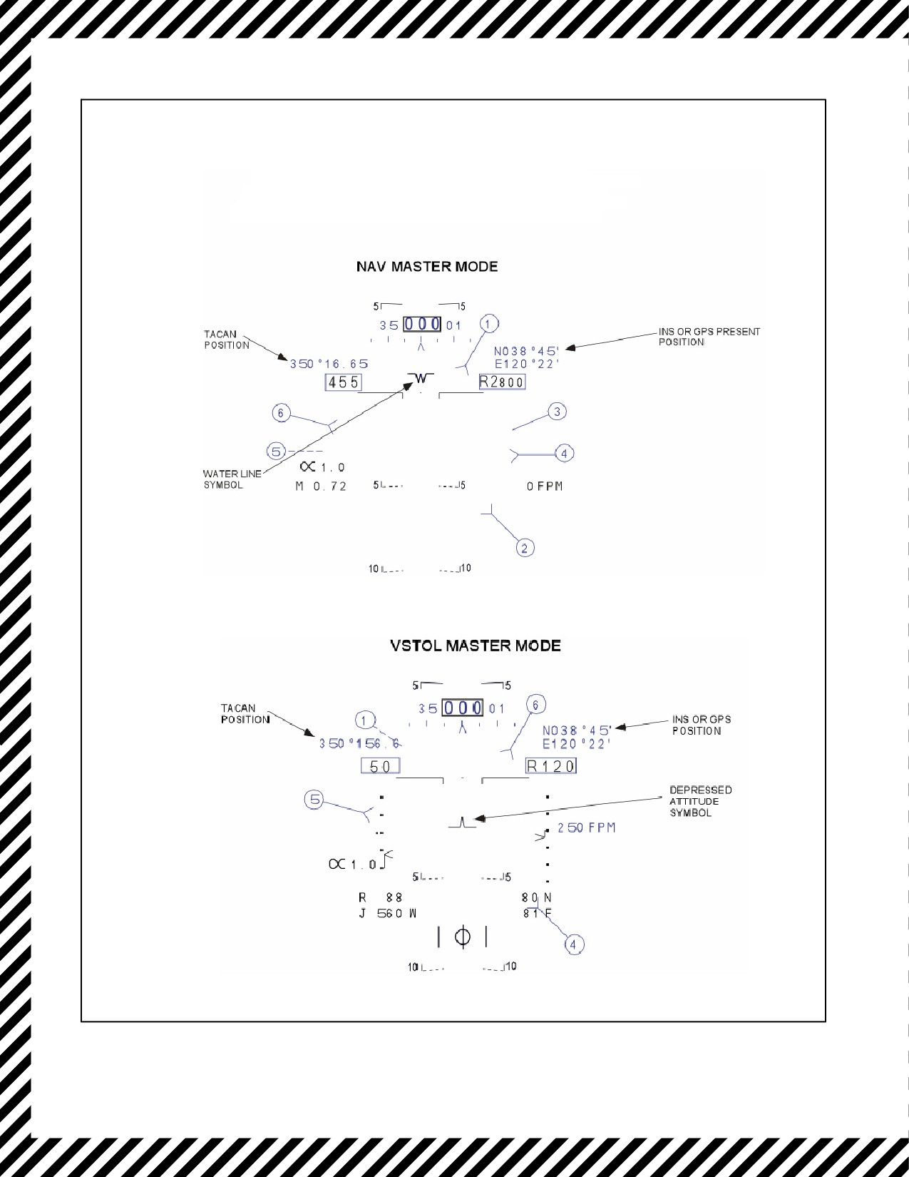
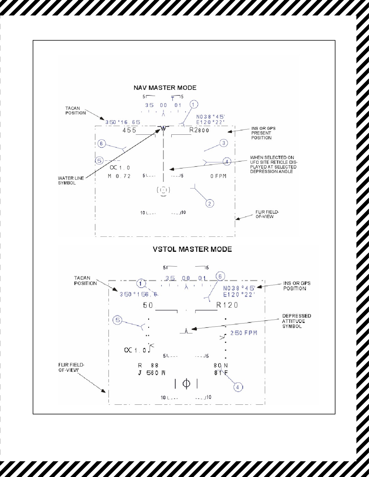
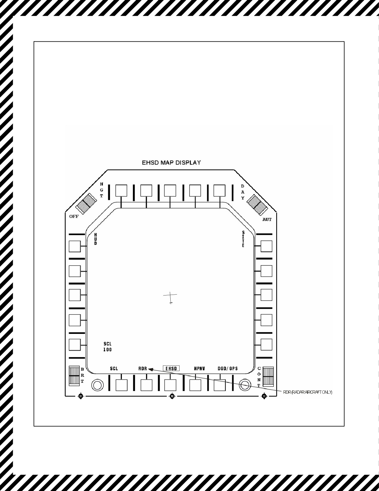
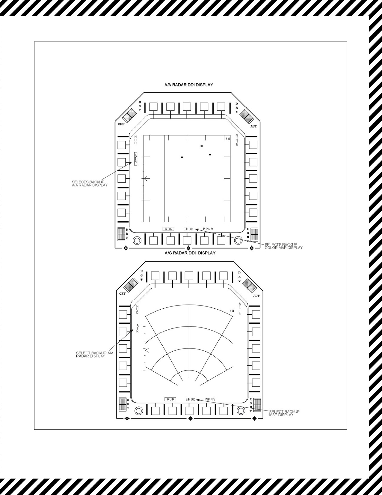
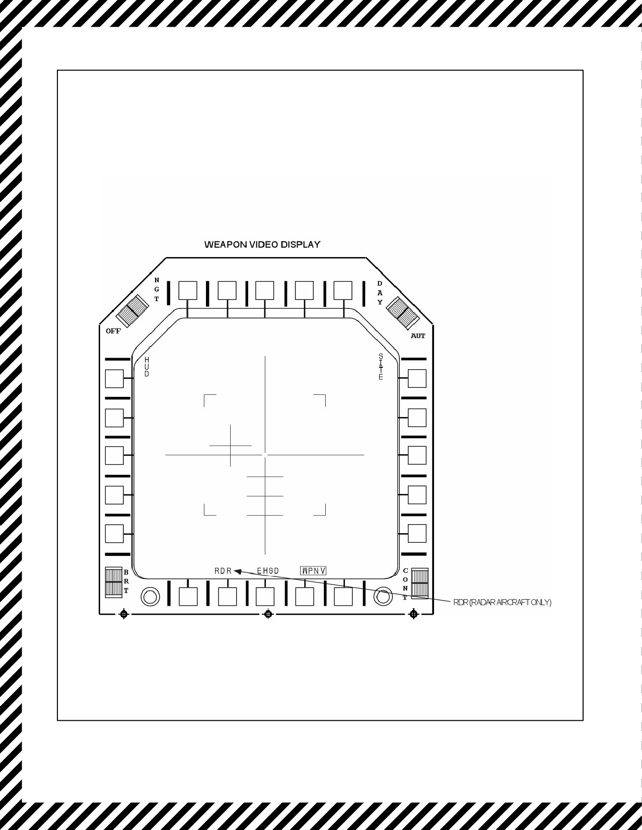
HUD — Reverts to back--up display. See Figure 15-1.
6.
DDI — See Figure 15-1.
a. TAV--8B, AV--8B Day Attack, reverts to HUD backup displays.
b. AV--8B Night Attack and Radar Aircraft, right DDI reverts to HUD backup display and left DDI reverts
to map backup display.
7.
SAS — Degraded.
8.
VHF/UHF — Operates in manual mode using radio set control.
9.
TACAN — Only X channels available. If Y channel selected, reverts to same number X channel. Range and
bearing displayed on HUD. Can be turned ON/OFF.
10.
INS — No steering. Pitch, roll, true heading and present position displayed.
11.
IFF — Goes OFF but can be turned ON. Modes 1 and 2 inoperative. Mode 3 code initialized to zero but can
be reset.
12.
Radar altimeter — Goes OFF but can be turned ON. Low altitude warning light fixed at 200 feet.
13.
HOTAS — Target designator control (TDC) and sensor select inoperative. The display alternate toggle
function is now performed with the WINC switch.
14.
SMS — No computed delivery modes, CIP/AUT light on.
a. Weapon delivery possible in DSL, DSL--1, or DIR modes using the roll stabilized site reticle.
b. The standby reticle can also be used on day attack and TAV--8B aircraft.
15.
RWR — No head--down ECM threat lethality display. Head--up ECM display provided on HUD and DDI.
16.
EMCON — Goes OFF but can be turned on.
15-1
ORIGINAL
A1-AV8BB--NFM--000
TAV-8B WITH OMNI 7.1 AND
DAY ATTACK AIRCRAFT
Figure 15-1. Mission Computer Failure Displays (Sheet 1 of 5)
ORIGINAL
15-2
A1-AV8BB--NFM--000
TAV-8B WITH H4.0, RADAR, AND
NIGHT ATTACK AIRCRAFT
T 100
T 100
Figure 15--1. Mission Computer Failure Displays (Sheet 2)
15-3
ORIGINAL
A1-AV8BB--NFM--000
TAV-8B WITH H4.0, RADAR, AND
NIGHT ATTACK AIRCRAFT
Figure 15--1. Mission Computer Failure Displays (Sheet 3)
ORIGINAL
15-4
A1-AV8BB--NFM--000
RADAR AIRCRAFT
Figure 15--1. Mission Computer Failure Displays (Sheet 4)
15-5
ORIGINAL
A1-AV8BB--NFM--000
TAV-8B WITH H4.0, RADAR, AND
NIGHT ATTACK AIRCRAFT
Figure 15--1. Mission Computer Failure Displays (Sheet 5)
ORIGINAL
15-6

A1-AV8BB--NFM--000
17. FLIR — On radar and night attack aircraft only the FLIR video is provided for display on the HUD and right
DDI backup displays. No DDI options, pushbutton legends, are available.
18. Map — On radar and night attack aircraft, backup map display provided on left DDI.
19. Radar — Backup radar display provided on right DDI. A/G program is limited to RBGM with a fixed 40 nm
range scale, 120° scan, and AUTO scan A/A program limited to RWS/with a fixed 40 nm range scale, INTL
PRF, 2 bar/140° scan, and 2 second target aging.
If backup display appears on the HUD and DDI:
20. MC switch — OVRD.
If normal operation not restored (STANDBY appears on displays or displays remain blank):
21. MC switch — OFF.
15.2
AIR DATA COMPUTER FAILURE
Air data computer failure may cause some or all air data (airspeed, Mach, altitude, AOA, rate of climb) to disappear
from the HUD. The Q--feel fails on. SAAHS reverts to fixed low gains. Aileron high speed stops fail disengaged.
The LIDS will extend with the landing gear regardless of airspeed. Landing gear warning, stall warning, departure
resistance, auto flaps, and IFF altitude reporting fail. The CIP/AUT and DEP RES lights will come on. The mission
computer and INS operate from degraded data.
If ADC failure is suspected:
1. BIT display — CHECK FOR ADC FAILURE (ADC 1).
CAUTION
D With an ADC failure, exercise caution in applying lateral stick above 250
knots.Withtheaileronhighspeedstopsnot engaged,excessivelateralstick
may cause structural damage.
D With an ADC failure, do not lower the landing gear above 200 knots to
prevent LIDS structural failure.
D With an ADC failure ensure airspeed is below 165 knots and nozzles are
25° or greater prior to selecting STOL flaps. Flap scheduling may occur
and, at high speed, this will cause a severe nose down pitch.
2. Flaps — OFF.
3. Determine appropriate landing type with consideration to flap position.
4. Land as soon as practical.
Faulty or fluctuating ADC airspeed signals sent to the Digital Flap
Controller(DFC)cancausesudden,unexpectedflapmovement.WithAuto
Flaps selected, theDigital Flap Controllerwill repositiontheflapsbetween
5 and 25 degrees any time an airspeed signal greater than 275 KIAS is
received, regardless of the gear position.
15-7
ORIGINAL

A1-AV8BB--NFM--000
CAUTION
After landing with flaps secured, any flap position greater than 25 degrees
will require flaps to be emergency retracted prior to going nozzles aft to
preclude flap damage due to exhaust temperatures.
15.3
INS FAILURE
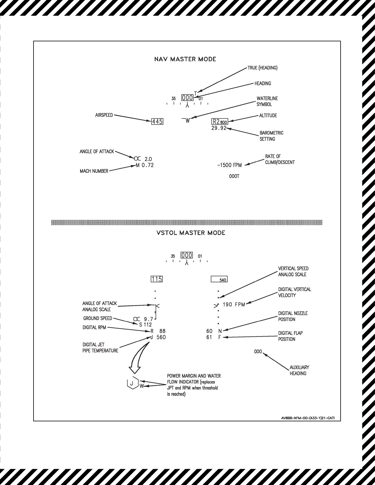
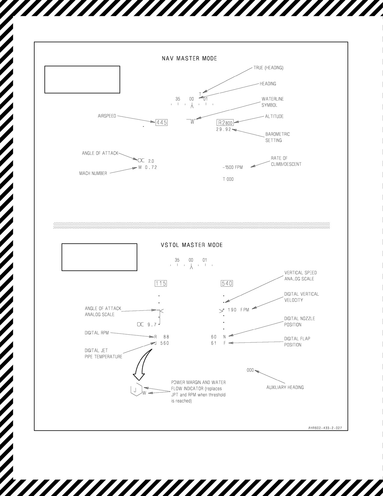
If there is an INS failure while in NAV master mode (see Figure 15-2), the HUD symbology is affected as follows:
The velocity vector, aircraft g, max g, and flight path/pitch ladder symbols are not displayed. If the INS reverts to
AHRS or if GYRO mode is selected, the flight path/pitch ladder symbol is displayed but the velocity vector, aircraft
g, and max g symbols are not displayed. If there is an INS failure while in VSTOL master mode, the flight path/pitch
ladder, sideslip acceleration, and pitch caret symbols are not displayed. If the INS reverts to AHRS or if the GYRO
mode is selected, the flight path/pitch ladder and pitch caret symbols are displayed but the sideslip acceleration
symbols are not displayed.
CAUTION
To prevent damage to the gyros on the AN/ASN--130A inertial navigation
system, afteran INS failure, theOFF position oftheINS modeswitchmust
be momentarily selected prior to selecting GYRO.
1. Use the standby attitude indicator for attitude reference.
2. INS switch — OFF (5 seconds -- ASN--139/3 minutes -- ASN--130).
3. Maintain straight and level flight.
If attempting an in--flight alignment (IFA):
4. INS switch — IFA.
5. Make any required turns using greater than 30° AOB (see note).
6. EHSD — MONITOR ALIGNMENT TIME AND QUALITY.
7. Alignment complete when HUD attitude information returns. (GPS IFA with good satellite data may take up
to 10 minutes).
If attempting a radar IFA:
8. Master mode — NAV.
9. Radar mode — LAND OR SEA BASED ON TERRAIN.
10. INS switch — IFA.
11. Make any required turns using greater than 30° AOB (see note).
12. A/C data page — RIFA (GPS data page — RIFA with C1+).
13. EHSD — MONITOR ALIGNMENT TIME AND QUALITY (after 2 minutes).
14. INS caution — VERIFY EXTINGUISHED (may take up to 20 minutes).
ORIGINAL
15-8
A1-AV8BB--NFM--000
TAV-8B WITH OMIN 7.1 AND DAY ATTACK AIRCRAFT
Figure 15-2. Total INS Failure Displays (Sheet 1 of 2)
15-9
ORIGINAL
A1-AV8BB--NFM--000
TAV-8B WITH H4.0, RADAR, AND NIGHT ATTACK AIRCRAFT
NOTE
ALTITUDE AND AIRSPEED BOXES
ARE REMOVED WITH H4.0.
NOTE
ALTITUDE AND AIRSPEED BOXES
ARE REMOVED WITH H4.0.
Figure 15-2. Total INS Failure Displays (Sheet 2)
ORIGINAL
15-10

A1-AV8BB--NFM--000
15. INS switch — NAV.
If IFA is unsuccessful, attempt a GYRO recovery:
16. INS switch — OFF (5 seconds -- ASN--139/3 minutes -- ASN--130).
17. INS switch — GYRO.
Note
The NAV system will enter align hold during an in--flight alignment when
aircraft roll exceeds 30° in order to reduce alignment time in non--wings
level flight.
15.4
OBOGS FAILURE
On--board oxygen generating system (OBOGS) failure may be indicated by the OXY caution light, reduced pressure
and/or quantity of breathing gas, or hypoxia symptoms. The failure may be a high temperature bleed air leak, a heat
exchanger, shut off valve or concentrator failure resulting in insufficient oxygen concentration. Any failure should
be treated as though the OXY caution light is on. Refer to the OXY light in the Warning/Caution/Indicator Lights
chart.
Failure to turn the OBOGS off and breathe from an alternate source when
a failure is indicated may result in system damage, fire, and hypoxia.
15.5
CANOPY UNSAFE INFLIGHT
An unsafe canopy may be indicated by a CANOPY caution light, a yellow latch or white off center indication in the
canopy latch viewport, or canopy movement. A partially engaged latch may disengage as cabin pressure differential
increases.
15.5.1 Canopy Explosion Inflight
*1. EMERGENCY DESCENT — IF REQUIRED.
*2. LOWER SEAT — AS REQUIRED.
*3. Throttle — AVIOD ABRUPT THROTTLE MOVEMENTS.
4. Minimize g--loading.
5. Land as soon as practical.
15.6
COCKPIT TEMPERATURE HOT/COLD
1. Cabin pressure switch — NORM.
2. Cabin air temperature knob — MANUAL -- REGULATE TEMPERATURE.
If temperature stays too hot/cold:
3. Descend to below 25,000 feet MSL.
4. Cabin pressure switch — RAM.
15-11
ORIGINAL

A1-AV8BB--NFM--000
5. Limit airspeed as follows:
Below 5,000 feet -- 0.4 Mach.
5,000 to 10,000 feet -- 0.6 Mach.
10,000 to 15,000 feet -- 0.7 Mach.
15.7
COCKPIT UNDER PRESSURE
1. Descend below 25,000 feet MSL.
15.8
COCKPIT OVER PRESSURE
1. Descend below 25,000 feet MSL.
2. Cabin pressure switch — DUMP.
If cockpit still over pressure:
3. Cabin pressure switch — RAM.
4. Limit airspeed as follows:
Below 5,000 feet -- 0.4 Mach.
5,000 to 10,000 feet -- 0.6 Mach.
10,000 to 15,000 feet -- 0.7 Mach.
15.9
MAIN GENERATOR FAILURE (GEN, DC AND STBY TR CAUTION LTS)
If the main generator fails with APU not selected on in the standby mode, the GEN, DC and STBY TR caution lights
will come on. The APU will have to be selected on if the main generator is not restored on the line.
Note
Loss of ac power will cause cockpit lights to come on full bright.
If the main generator fails with the APU selected on in the standby mode, the APU advisory light and the GEN
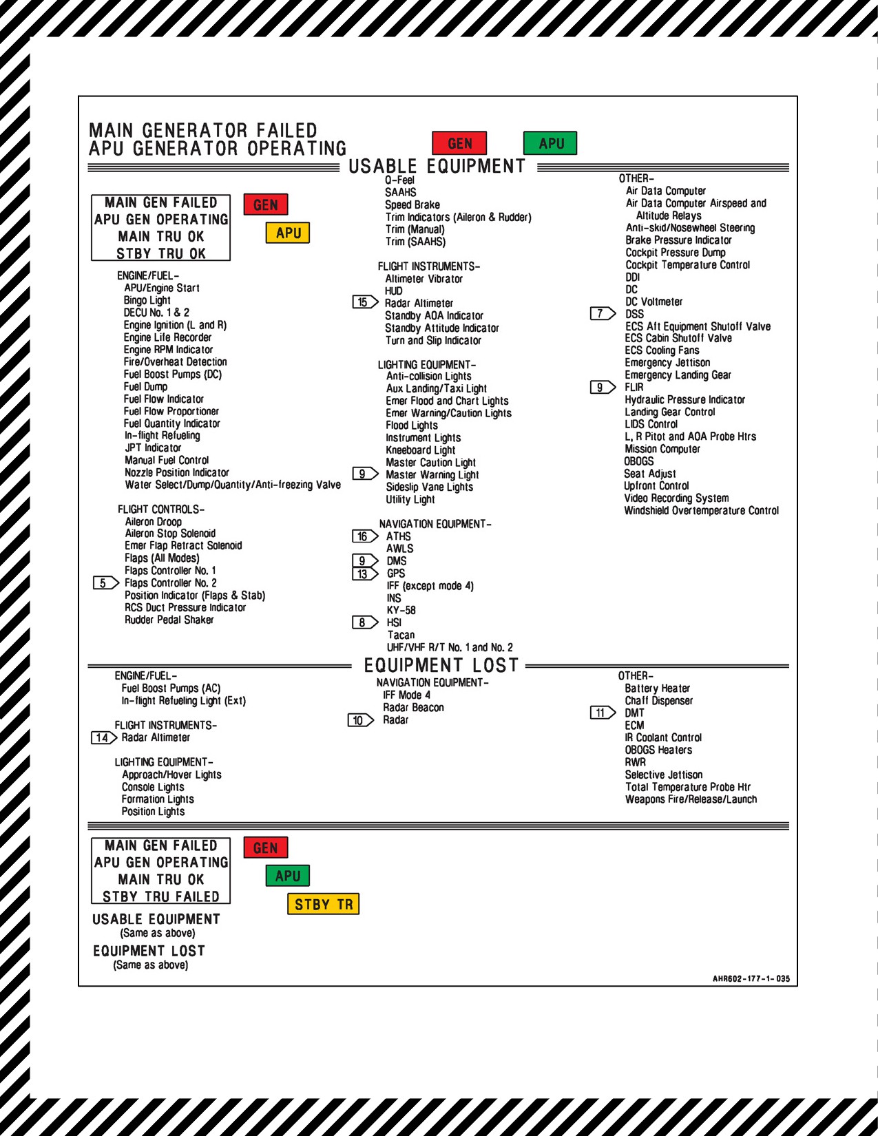
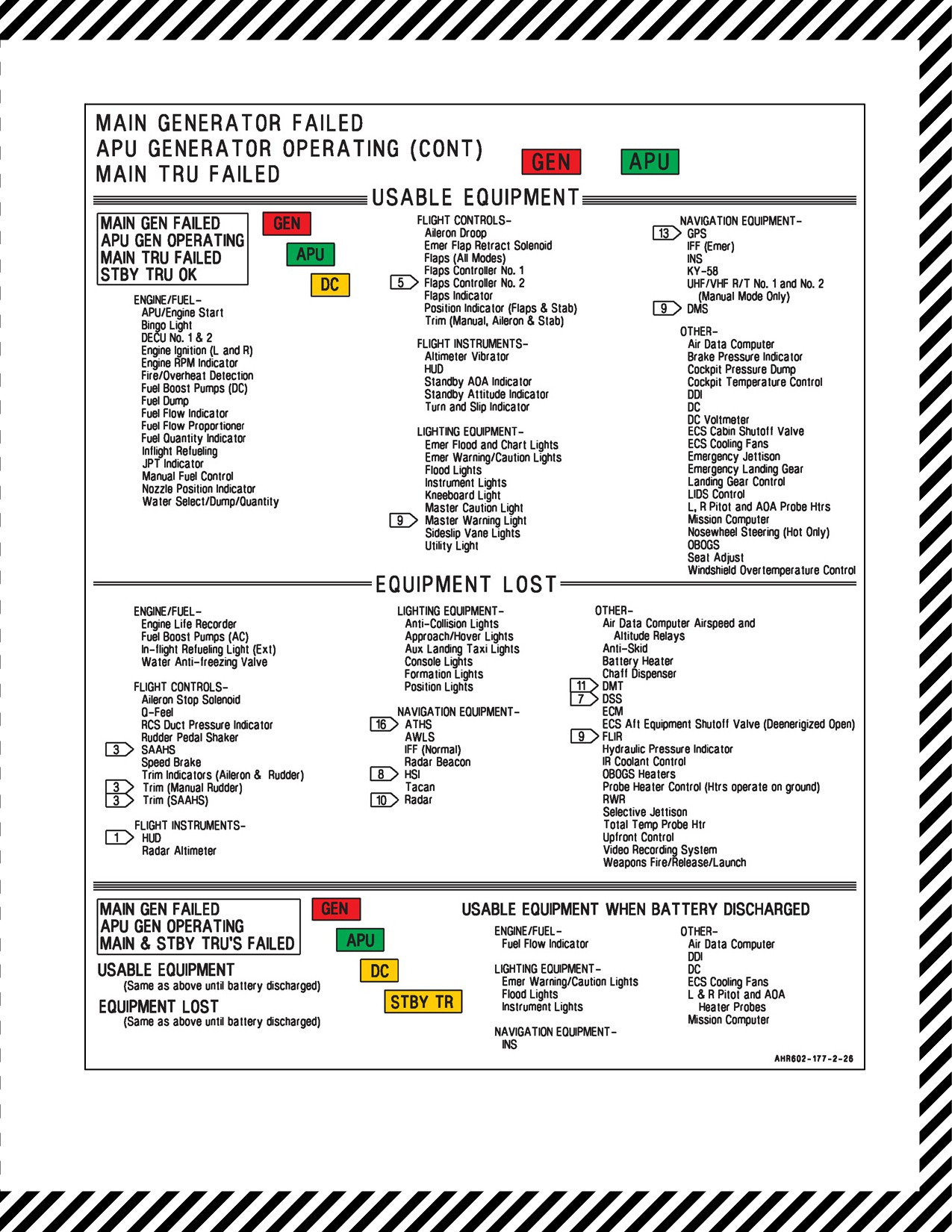
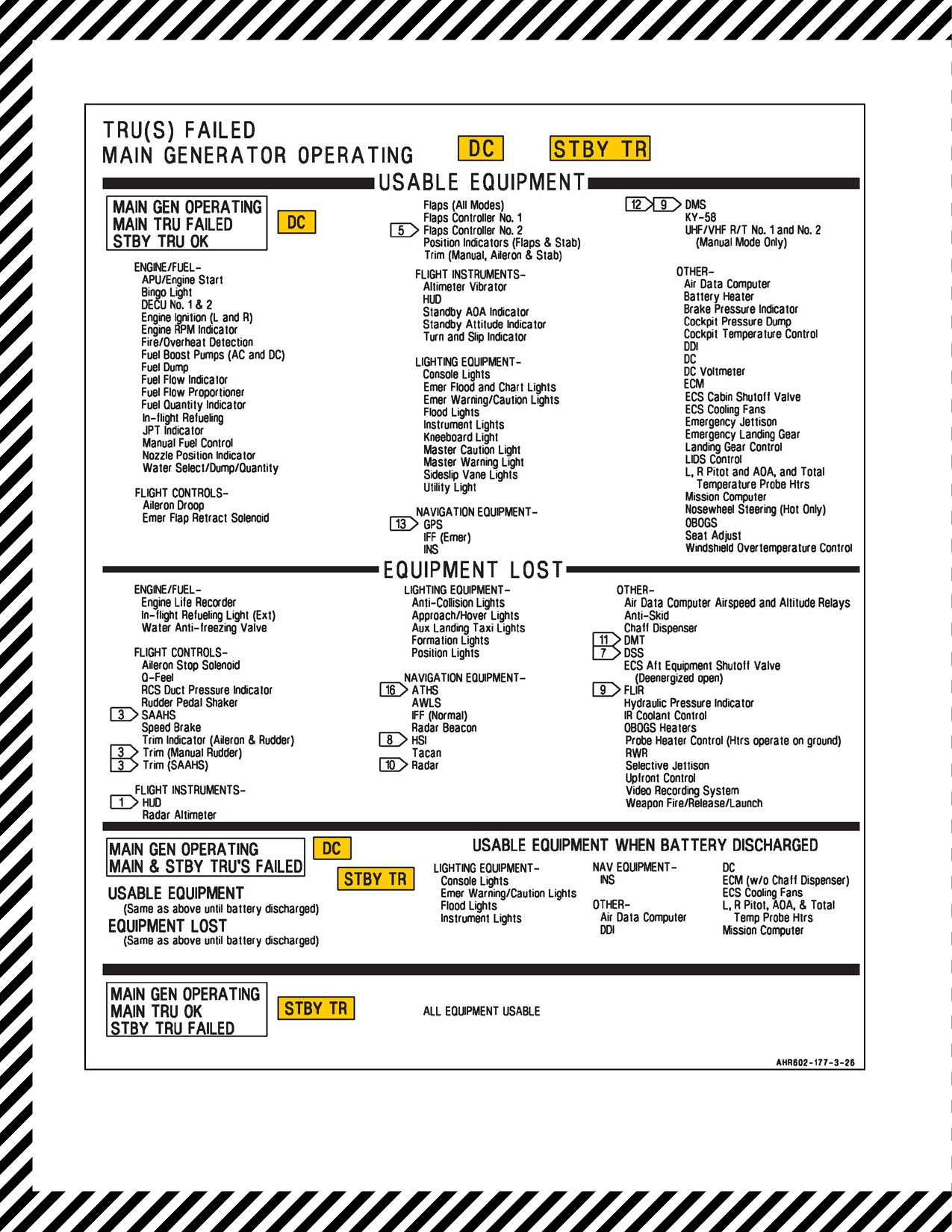
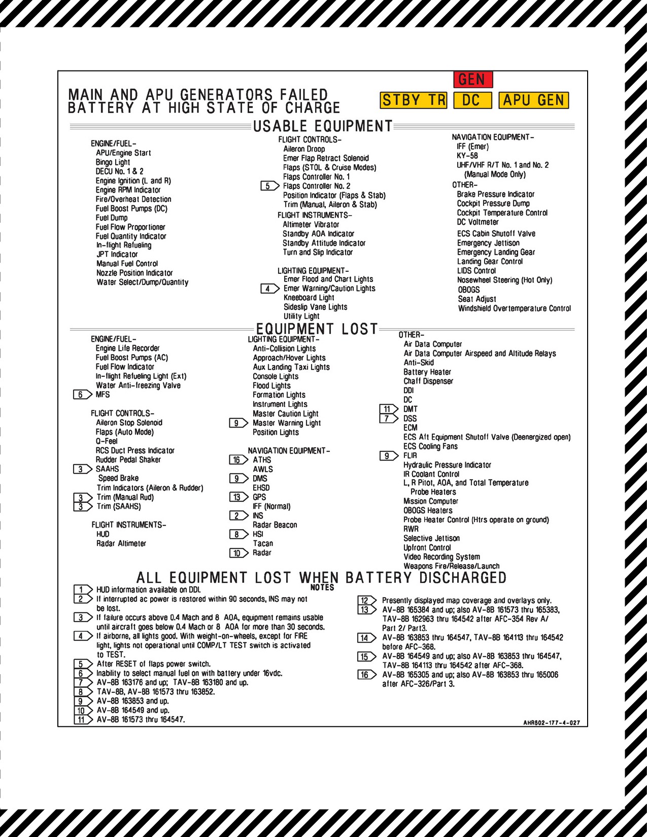
warning light will be on (but not the DC and STBY TR caution lights). For equipment lost/available, refer to
Emergency Power Distribution, see Figure 15-3.
Ontheground,amaingeneratorfailurewillcausethelossofallwarning,caution,andadvisorylightsexcept theFIRE
light. In this case, the main generator failure can be recognized by the loss of all ac powered equipment and absence
of the green gear down lights. Pressing the COMP/LTS TEST switch momentarily will restore operation of the
emergency warning, caution, and advisory lights. Should generator failure occur on takeoff, the emergency warning,
caution, and advisory lights will be restored when the aircraft becomes airborne.
DECS operation requires DC power which is supplied by the generator, battery, or APU. In some cases, attempts to
start the APU may drain the battery power to a level which would preclude MFS selection. On --408B engines, LANE
2 DECU is also powered continuously by the EVICS HMU permanent magnetic alternator. For aircraft equipped with
--408B engines and Emergency MFS batteries, DECS control as well as the potential to select MFS (if required) will
be maintained. For --408B engines, operation in EFC POS 2 will minimize battery drainage. For aircraft without
--408B engines or Emergency MFS batteries, MFS should be selected prior to placing additional drainage on the
battery and before battery voltage drops below 16 volts.
On AV--8B 164151 and up; also AV--8B 161573 through 164150, TAV--8B after AFC--328, manual fuel selection
and emergency landing gear extension can be accomplished with less than 16 volts indicated using the MFS
emergency battery and the LDG emergency battery. The MFS emergency battery provides an alternate source of
electrical power for manual fuel selection in time critical selection scenarios. Below 16 volts, normal manual fuel
selection cannot be guaranteed.
ORIGINAL
15-12

A1-AV8BB--NFM--000
On aircraft not equipped with --408B engines orMFS Emergency batteries,
failure to expeditiously switch to MFS could result in loss of engine
control. If generator failure is the result of electrical fire, switching to MFS
may not be possible.
CAUTION
D AmaingeneratorfailurewillcausetheAUTFLPcautionlighttocomeon.
Ensure airspeed is below 165 knots and nozzles are 25° or greater prior to
selecting STOL flaps.
D Nosewheel steering hot/No antiskid.
15.10 MAIN TRU FAILURE (DC CAUTION LIGHT)
Illumination of the DC caution light indicates the main transformer rectifier (TRU) has failed. Normally, the standby
TRU output automatically switches to power the emergency dc bus. Subsequent failure of the standby TRU is
indicated by theSTBY TR caution light coming on and/or thedc voltmeterdropping below 26 volts. Below 16 volts,
normal manual fuel selection cannot beguaranteed. Thepilot can considersecuring thefollowing systemsifthemain
and standby TRU fail in order to preserve battery life:
1. DC boost pumps.
2. Radios (transmit drains more power).
3. Seat adjust.
4. Trim.
For equipment lost/available refer to Emergency Power Distribution, see Figure 15-3.
CAUTION
D Do not lower landing gear above 200 knots.
D Nosewheel steering hot/No antiskid.
D Landing gear should be lowered before battery discharges below 16 volts.
D On aircraft not equipped with --408B engines or MFS Emergency battery,
MFS should be selected before battery discharges below 16 volts.
Note
Emergency MFS and LDG emergency battery activation may be required
if DC voltage depletes below 16 volts indicated.
15-13
ORIGINAL
A1-AV8BB--NFM--000
Figure 15-3. Emergency Power Distribution (Sheet 1 of 4)
ORIGINAL
15-14
A1-AV8BB--NFM--000
Figure 15-3. Emergency Power Distribution (Sheet 2)
15-15
ORIGINAL
A1-AV8BB--NFM--000
Figure 15-3. Emergency Power Distribution (Sheet 3)
ORIGINAL
15-16
A1-AV8BB--NFM--000
Figure 15-3. Emergency Power Distribution (Sheet 4)
15-17
ORIGINAL

A1-AV8BB--NFM--000
15.11 STANDBY TRU FAILURE (STBY TR CAUTION LIGHT)
Illumination of the STBY TR caution light indicates the standby TRU has failed or, during GTS start, is off line. When
the standby TRU fails, the main TRU powers the entire dc system, including charging of the battery. Subsequent
failure of the main TRU is indicated by the DC caution light coming on and/or the dc voltmeter dropping below 26
volts.
15.12 APU GENERATOR FAILURE (APU GEN CAUTION LIGHT)
Illumination of the APU GEN light indicates the APU generator is malfunctioning with the APU selected on. This
could occur in the standby mode before main generator failure, or it could occur after main generator failure in which
case the aircraft has lost all ac power and is operating on the battery unless one of the ac generators is restored. With
nominal load, the battery will provide power for about 30 minutes. With one DC boost pump operating, this time
is reduced to 15 minutes and with both DC boost pumps operating, this time is reduced to 8 minutes. Below 20 volts,
operation of battery powered equipment may be erratic. For equipment lost/available, refer to Emergency Power
Distribution, see Figure 15-3.
15.13 TOTAL ELECTRICAL FAILURE (GEN, APU GEN, DC, STBY TRU)
Aircraft not equipped with --408B engines:
1. MFS — SELECT.
All Aircraft:
2. Landing gear — DOWN (below 200 knots before dc power lost, if not fuel critical).
3. Non--essential dc power equipment — OFF.
If VMC:
4. Battery switch — ALERT (if necessary to reattempt communications).
Note
D Emergency MFS and LDG emergency battery activation may be required
if DC voltage depletes below 16 volts indicated. Below 16 volts, normal
manual fuel selection cannot be guaranteed.
D To minimize the drain on the battery, the igniters may be secured by
momentarily selecting the BATT switch to OFF or ALERT. However,
operating in MFS without continuous ignition gives a slightly increased
chance of engine flame out on slam deceleration.
D Hot NWS perform VL or RVL if possible.
D Selecting ALERT will secure standby AOA indicator, attitude gyro, and
turn and slip indicator.
D With hot NWS, perform VL. Engine fast deceleration solenoid function
lost.
15.14 EMERGENCY DC BUS FAILURE
The emergency DC bus is defined as the “emergency” DC bus because it is supposed to be one of the last busses to
lose power during any type of electrical failure. The emergency DC bus powers multiple components critical to
normal and emergency flight regimes. Ifthepower to the emergency DC bus is lost it constitutes a serious compound
emergency situation. The aircraft’s electrical priority is designed to provide power to the emergency DC bus even
when two of the three electrical supply components are lost. Since the alert bus is normally powered from the
ORIGINAL
15-18

A1-AV8BB--NFM--000
emergency DC bus, both busses will be lost during an emergency DC bus failure. It is important to first understand
which components you lose and the effects of each component if you have an emergency DC and alert bus failure.
It is also important to understand how the emergency DC and alert busses are powered, how they can lose power and
the ways power can be regained as well as the anomalies associated with certain power loses.
Systems affected and how they affect the operation of the aircraft.
15.14.1 DC Emergency Bus, Circuits
15.14.1.1 Landing Gear
Purpose: Powers solenoids in landing gear control valve which open/close doors and lower/raise the landing gear.
Indication/consequence to pilot if lost: Landing gear cannot be raised or lowered via normal means using the landing
gear handle.
15.14.1.2 Emergency Landing Gear
Purpose: To fireimpulsecartridge(CAD)whichdischarges thelanding gearemergency extensionbottle(blowdown
bottle) when the landing gear handle is turned 90 degrees and pulled.
Indication/consequence to pilot if lost: Emergency gear blow down does not occur when the landing gear handle is
turned 90 degrees and pulled. Note: CAD can still be fired and landing gear blown down using the landing gear
emergency battery.
15.14.1.3 Brake Pressure
Purpose: Powers the main landing gear brake pressure transmitter in the NLG wheel well and the hydraulic pressure
indicator in the cockpit.
Indication/consequence to pilot if lost: PSI X10 BRAKE indicator wheels will be driven to the striped position
(barber pole) indicating brake pressure indication is invalid. HYD--1 and HYD--2 pressure indications are also driven
to striped position (barber poles) and will indicate zero pressure. Actual hydraulic brake pressure is not affected.
15.14.1.4 Landing Gear Relay
Purpose: Energizes the landing gear handle down, MLG down and locked or MLG not down and locked relays if
condition exists.
Indication/consequence to pilot if lost: Neither the approach or the hover light can/will be turned on when the main
landing gear is down and locked. The total temperature probe heater will not be automatically turned off when the
landing gear handle is set to the down position. The side slip vane light will not illuminate when the landing gear
handle is set to the down position. The speed brake will not automatically deploy to between 23 and 27 degrees when
main landing gear is down and locked. With the landing gear down and locked, the speed brake can be fully extended
(to 66 degrees) and retracted. When the gear is not down and locked, erroneous JPTL datum will be provided to
DECU. IFF Mode--4 codes will be zeroized (due to de--energized MLG not down and locked relay). When gear is
not down and locked, an erroneous landing gear down signal will be provided to the DFC (due to de--energized MLG
not down and locked relay).
15.14.1.5 Nose Wheel Steering
Purpose: To energize the nosewheel steering switchover solenoid in NWS switchover valve when NWS is selected,
weight is on wheels and HYD--1 pressure is below 1,600 PSI.
Indication/consequence to pilot if lost: No indication. The switchover solenoid will be unable to automatically switch
NWS operation to HYD--2 if needed.
15.14.1.6 Anti Skid/Nose Landing Gear Steering
Purpose: Used to energize the nose wheel steering (NWS) control valve solenoid when ANTISKID is selected. It
is also used to energize the NWS selector solenoid when high gain NWS is selected.
15-19
ORIGINAL

A1-AV8BB--NFM--000
Indication/consequence to pilot if lost: When power to the NWS control valve solenoid is lost with ANTISKID
selected, the system will be stuck in low gain NWS instead of castor mode. When high gain is selected, the system
will stay in low gain NWS because power is not available to the NWS selector solenoid.
15.14.1.7 Aileron Droop
Purpose: Allows pilot to select aileron droop with flaps to produce greater lift.
Indication/consequence to pilot if lost: Unable to droop ailerons.
15.14.1.8 Flap Indicator
Purpose: Powers flaps position indicator on landing gear/flaps panel.
Indication/consequence to pilot if lost: No change in flaps position indicator with change in flaps. HUD flap
indication will still be valid.
15.14.1.9 Yaw SAAHS
Purpose: Powers YAW portion of SAAHS. Indication/consequence to pilot if lost: If DC emergency bus loses power
the yaw system would disengage and power to the rudder servo cylinder would discontinue. No auto control.
15.14.1.10 Flap Controller
Purpose: Powers the emergency flap retract switch on the engine throttle lever and retract solenoid P/O flap hydraulic
controller.
Indication/consequence to pilot if lost: Unable to retract flaps using the emergency flap retract switch.
15.14.1.11 Mission Computer (OMNI 7.1 and C1+)
Purpose: Powers the MC Relay which will remove AC power from the mission computer when the display computer
is in back--up mode and is therefore acting as the mux bus controller. This ensures that there is only one mux bus
controller at a time. The display computer enters back--up mode if it has not been able to communicate with the
mission computer for 2 seconds. After the display computer has entered back--up mode it energizes the Mux auto
switching relay, which in turn energizes the mission computer control relay.
Indication/consequence to pilot if lost: None, under most circumstances. If in back--up mode and the mission
computer comes back on--line, indications are erratic and/or incorrect data on the displays. In this case, the pilot can
switch the mission computer switch to either OVRD (mission computer control only) or Off (display computer
control only) to force only one of the computers to be the Mux controller.
15.14.1.12 Mission Computer (H4.0 Only)
Purpose: None. With H4.0, the mission computer control relay is no longer utilized. The mission computer software
ensures that there is only one MUX bus controller. Before becoming the MUX bus controller, the mission computer
will determine if the display computer is acting as the controller. If the display computer is acting as the MUX bus
controller, then the mission computer will initiate a handshaking process to resume control of the mux bus.
Indication/consequence to pilot if lost: None.
15.14.1.13 ACNIP Emergency Power
Purpose: Powers the ACNIP (28Vdc emergency input). If the 28Vdc emergency is not supplied, the ACNIP can be
powered from the alert bus by placing the battery switch in the ALERT position. The ACNIP is then turned on in
a power conservation mode to reduce the power drain on the aircraft storage battery.
Indication/consequence to pilot if lost: No audio in headset. No audible warnings. Loss of Radio Communication.
ORIGINAL
15-20

A1-AV8BB--NFM--000
15.14.1.14 IFF
Purpose: Powers APX--100 IFF transponder.
Indication/consequence to pilot if lost: Transponder indicator lights out (edge--lit panels will remain lighted). Unable
to transmit in all IFF modes.
15.14.1.15 Jettison Busses A/B
Purpose: Energizes Jettison Bus A and B contactors if landing gear handle is up or weight is off wheels.
Indication/consequence to pilot if lost: The pilot will be unable to selectively jettison stores and Emergency Jettison
is inoperable.
15.14.1.16 AOA Indicator
Purpose: Powers angle of attack indicator ID--2276/A.
Indication/consequence to pilot if lost: No head--down AOA indication (indicator back light remains on). AOA will
still be displayed on HUD.
15.14.1.17 Annunciator Light Circuits
Purpose: Together, these four circuits provide all of the electrical power for the Annunciator Light Controller.
Indication/consequence to pilot if lost: All warning, caution and advisory lights will be off. Amber and green landing
gear position lights will not be seen in cockpit as landing gear is lowered down and locked. Landing gear control
handle lights will not light. No audible warnings even when switched to ALERT mode. For TAV--8B only, landing
gear position lights will be seen during Emergency DC Bus failure.
15.14.1.18 Seat Adjust
Purpose: Powers seat height adjust motors through seat adjust switch.
Indication/consequence to pilot if lost: Pilot is unable to adjust seat height.
15.14.1.19 OBOGS Bleed Air Shut Off
Purpose: Powers OBOGS bleed air shutoff valve and oxygen concentrator.
Indication/consequence to pilot if lost: Loss of on board oxygen generation system without any indication to the pilot.
Setting the oxygen switch to the OFF position will not close the OBOGS bleed air shutoff valve. Shutoff valve will
remain open; engine bleed air will be supplied to pilot.
15.14.1.20 Oxygen Monitoring Unit
Purpose: Powers Oxygen Monitoring Unit.
Indication/consequence to pilot if lost: No indication of failure. Oxygen is no longer being monitored, no caution
light or ACNIP message will be provided if oxygen concentration falls below safe level.
15.14.1.21 Cockpit Temperature Relay
Purpose: Powers the cabin temperature control/selector and opens/closes the temperature regulating valve. Also,
energizes windshield over--temperature relay when windshield over--temperature switch senses windshield
temperature to be 250 ±8 °F.
Indication/consequence to pilot if lost: Loss of control of cabin temperature and windscreen overtemp protection.
Temperature regulating valve stays at same setting.
15-21
ORIGINAL

A1-AV8BB--NFM--000
15.14.1.22 Cabin Pressure Control Circuit Breaker
Purpose: Powers pressure reducing and shutoff valve, emergency ram air vent control valve and cabin dump control
valve when pressurization switch is in the RAM position.
Indication/consequence to pilot if lost: Unable to dump pressure but the pressure regulator and safety relief valve
will continue to regulate pressure.
15.14.1.23 Cabin ECS Circuit Breaker #2
Purpose: Powers pressure reducing and shutoff valve, emergency ram air vent control valve and canopy seal control
valve when pressurization switch is in the NORM position.
Indication/consequence to pilot if lost: Canopy seal will not deflate, the canopy will be harder to open. Ram air vent
cannot be opened, if needed.
15.14.1.24 Water Select
Purpose: Powers water selector switch, water injection pump solenoid and water dump switch.
Indication/consequence to pilot if lost: Unable to either inject water into engine or dump water overboard.
15.14.1.25 Flow Proportioner Indicator MFS Ignition Relay
Purpose: Powers fuel flow proportioner indicator and energizes manual fuel ignition relay when the MFS switch is
set to the ON position.
Indication/consequence to pilot if lost: No fuel flow proportioner caution light. No fuel priming or igniters when
the MFS switch is set to the ON position.
15.14.1.26 Right and Left Ignitor Engine Start
Purpose: Powers engine right and left igniter plugs and DC Boost Pump Contactors.
Indication/consequence to pilot if lost: No indication to pilot. Right and left igniters will not be functioning. Boost
Pumps cannot be operated in DC OPR mode.
15.14.1.27 Fuel Priming
Purpose: Powers the torch igniter (fuel priming) solenoid valve.
Indication/consequence to pilot if lost:No indication to pilot. The torch igniter will not be functioning.
15.14.1.28 Emergency Cockpit Power
All of the below.
RUDDER SERVO
Purpose: Powers the rudder servo valve for hydraulic control of rudder position.
Indication/consequence to pilot if lost: Loss of automatic control of rudder position.
STABILATOR TRIM
Purpose: Electrical trim control of stabilator (pitch trim).
Indication/consequence to pilot if lost: Pilot cannot manually trim stabilator.
AILERON TRIM
Purpose: Electrical trim control of ailerons (roll trim).
Indication/consequence to pilot if lost: Pilot cannot manually trim ailerons.
ORIGINAL
15-22

A1-AV8BB--NFM--000
15.14.1.29 Emergency Flood Chart Light
Purpose: Powers cockpit emergency floodlights No.1 and No.2 and emergency NVG floodlights No. 1 and No. 2
through the instrument panel control and floodlight control. Powers the cockpit chart light through the chart light
switch and brightness control.
Indication/consequence to pilot if lost: Emergency floodlights and chart light are off and cannot be turned on.
15.14.1.30 Right and Left IFR
Purpose: Powers the right and left fluid pressure regulator valve solenoid. When powered during ground or in--flight
refueling, this valve removes engine bleed air pressure and vents right--side fuel tanks to atmosphere.
Indication/consequence to pilot if lost: Cannot perform in--flight refueling.
15.14.1.31 Fuel Dump Control
Purpose: Powers the left and right fuel jettison (dump) valve motors through the fuel control panel left and right dump
switches.
Indication/consequence to pilot if lost: Unable to dump fuel.
15.14.1.32 Right and Left Boost Pumps
Purpose: Energizes the right and left AC boost pump relays when fuel control panel right and left pump switches
are set to NORM. This applies 3--phase AC power to the right and left boost pumps.
Indication/consequence to pilot if lost: Right and left boost pumps do not run when the fuel control panel right and
left pump switches are set to NORM but will run (powered from 28 Vdc Ground Service Bus) when the fuel control
panel right and left pump switches are set to DC.
15.14.1.33 Fuel Gauge Monitor
Purpose: Powers the fuel quantity processor and fuel digital display indicator.
Indication/consequence to pilot if lost: No fuel quantity information is displayed in cockpit. Fuel readings on the
fuel display panel will freeze at last state.
15.14.1.34 Fuel Prop Shut Off
Purpose: Powers the fuel flow proportioner solenoid selector valve when the fuel prop control switch is set to OFF.
Indication/consequence to pilot if lost: Unable to turn off fuel flow proportioner.
15.14.1.35 Fire Overheat Detector
Purpose: Powers the fire detector controller and engine fire warning circuit.
Indication/consequence to pilot if lost: Loss of engine fire warnings (visual and aural).
15.14.1.36 EMS
Purpose: Powers the engine monitoring unit, P3 pressure transducer and EMU incident recorder.
Indication/consequence to pilot if lost: Loss of the HUD power margin indicator.
15.14.1.37 EFC BIT
Purpose: Powers DECU BIT.
Indication/consequence to pilot if lost: No indication or consequence to pilot. Maintenance personnel would be
unable to perform DECU BIT check.
15-23
ORIGINAL

A1-AV8BB--NFM--000
15.14.1.38 EFC 2
Purpose: Powers DECU 2 and, through a diode arrangement, also powers DECU 1 if switched battery bus power
is lost.
Indication/consequence to pilot if lost: No indication to pilot. The selected DECU will continue to perform EFC
functions via the switched battery bus and backup DC power source to lane 2 DECU provided by permanent magnet
alternator on 4080--B EVICS engines.
15.14.1.39 JPT Limiter
Purpose: Powers JPTL switch and JPTL system.
Indication/consequence to pilot if lost: Loss of the DECS automatic jet pipe temperature limiting feature (same as
tripping JPTL switch on throttle quadrant) will limit the engine to short lift wet speed datum with no JPT limiting
(the lower of 120 percent indicated or 116.8 percent corrected regardless of JPT).
15.14.1.40 GTS Power
Purpose: Powers the GTS/APU digital control unit.
Indication/consequence to pilot if lost: Unable to start GTS/APU.
15.14.1.41 Engine Display Panel
Purpose: Powers the engine performance indicator (EPI).
Indication/consequence to pilot if lost: All EPI displays (fuel flow, duct PSI, stabilator position, RPM percent, JPT
degrees C, H2O remaining) will freeze. HUD display of engine performance data will disappear.
15.14.1.42 Altimeter Vibrator
Purpose: Powers vibrator in standby pressure altimeter.
Indication/consequence to pilot if lost: No indication to pilot but head down (standby) pressure altitude instrument
will become inaccurate.
15.14.1.43 Attitude Gyro
Purpose: Powers vertical reference gyroscope indicator.
Indication/consequence to pilot if lost: Off flag will be displayed. Gyro inertia maintains attitude reference within
±6° for a minimum of 9 minutes after electrical power is lost.
15.14.1.44 Turn/Slip Indicator
Purpose: Powers the turn and slip indicator.
Indication/consequence to pilot if lost: Off flag will be displayed in the turn and slip indicator.
15.14.2 Alert Bus, 7 Circuits
15.14.2.1 Communication Control
Purpose: Provides 28 Vdc alert power to the V/UHF radios.
Indication/consequence to pilot if lost: Cannot control V/UHF Radios via backup control panel. Power may be
regained if the battery switch is set to the ALERT position.
ORIGINAL
15-24

A1-AV8BB--NFM--000
15.14.2.2 ACNIP Alert Power/IFF Eject Seat
Purpose: To partially power the ACNIP when the battery switch is set to ALERT position and power the ejection
seat IFF Switch which zeroizes KY and KIT and sets the IFF to the eject mode.
Indication/consequence to pilot if lost: No audio in headset. No audible warnings. Loss of radio communications.
On ejection, IFF will not transmit distress code7700on mode3A; mode4A and4B securecodes willnot bezeroized.
Power may be regained if the battery switch is set to the ALERT position.
15.14.2.3 Voltage Indicator
Purpose: Provides a path for the alert and emergency DC bus voltage to be displayed on the DC voltmeter.
Indication/consequence to pilot if lost: The voltmeter will read zero volts (full left deflection) when the DC test
switch is in normal (center) position and the battery switch is set to BATT but will read battery voltage when the
battery switch is set to ALERT.
15.14.2.4 Utility Kneeboard Light
Purpose: Powers the left utility floodlight, utility floodlight and kneeboard light.
Indication/consequence to pilot if lost: The left utility floodlight, utility floodlight and kneeboard light are off and
cannot be turned on.
15.14.2.5 UHF/VHF Receive/Transmitter No. 1 and 2
Purpose: Powers both UHF/VHF receiver/transmitters.
Indication/consequence to pilot if lost: Unable to communicate via COMM 1 or COMM 2.
15.14.2.6 Communication Control
Purpose: Energizes COMM 1 and COMM 2 ON/OFF relays. Powers KY--58 NO.1, KY--58 NO.2 and the antenna
selector switch.
Indication/consequence to pilot if lost: Loss of secure radio communications. Unable to select UHF antenna.
A short or wire fire could lead to initial indications of an emergency DC bus failure only to turn into a much larger
emergency as failures develop. There are emergency procedures for other types of electrical emergencies to include
total electrical failure and dual DECS failure. The emergency DC bus failure procedure is focused on some type of
disconnect or breakage between the power source and the emergency DC bus. There are multiple terminal lugs,
contactors, and wires where a break can occur; it would be impossible to define every possible failure and indication
in this manual. If a breakage occurs between an operating power source and the emergency DC bus, the pilot has
options to change the power source supplying power to the emergency DC bus. A thorough understanding of the
system as described in paragraph 2.10 (Electrical Power Supply System) and this emergency procedure discussion
is necessary for a pilot to cope with this type of failure.
15.14.3 Failure Analysis
If an emergency DC bus failure occurs the pilot should immediately set the DC test switch to STBY.
If power is regained with DC test switch set to STBY, there is a failed connection between the main TRU output and
the emergency DC bus contactor. In this case the main TRU is operating correctly therefore the relays are operating
to supply power to the emergency DC bus from the main TRU. However, emergency DC bus is not working because
of the failed connection. By selecting STBY on the DC test switch the system is removing main TRU output power
from the DC emergency bus and connecting standby TRU output power. Once the standby TRU takes over as the
aircraft’s emergency DC bus power supply, certain relays open and others close providing power to the DC emergency
bus. As long as the DC test switch remains in the STBY position, all components that were previously lost will work
correctly to include vital systems like fuel quantity, fuel dump, communications and normal gear operation.
15-25
ORIGINAL

A1-AV8BB--NFM--000
If power is not regained with DC test switch set to STBY, the DC test switch should be set to MAIN. In this case the
emergency DC bus contractor has failed. The main TRU and the standby TRU are operating correctly but the failed
contactor is preventing DC power from reaching the emergency DC bus. To recover, aircraft battery power must be
connected to the emergency DC bus by de--energizing the standby TRU contactor. Setting the DC test switch to MAIN
will deenergize the standby TRU contactor but, depending on battery state--of--charge, it will take two to three
minutes.ThestandbyTRUcontactorwillremainenergizeduntil batteryvoltagedischargesto about24.5 volts.When
the DC test switch is set to MAIN, a valid battery voltage indication will appear on the BATT VOLTS indicator and
this voltage must be monitored.
If power is regained, with DC test switch set to MAIN and battery discharge to about 24.5 volts, the emergency DC
bus is being powered by the battery and its rate of discharge will increase. Only 15 or 20 minutes will be available
for lowering landing gear, communicating, jettisoning stores, dumping fuel etc. before the battery discharges to 16
volts and must be recharged. The battery can be recharged by setting the DC test switch to the center position for a
few minutes then returning it to MAIN. Power to the emergency DC bus is lost while the DC test switch is in the
center position (BATT VOLTS will read zero) but restored in MAIN after battery discharges to about 24.5 volts.
If power is not regained with DC test switch set to MAIN and battery discharged to less than 24 volts, multiple DC power
system failures have occurred and power cannot be regained. Set the DC test switch to the center position. The pilot will
have to estimate fuel state and perform the LANDING GEAR UNSAFE/FAILS TO EXTEND procedures in proper
sequence to include using the landing gear emergency battery.
15.14.4 Discussion
If using the previously mentioned methods to regain power to the emergency DC bus fail, and communications are
required, a pilot may select the ALERT position of the battery. When selecting ALERT, the emergency DC bus is
bypassed and the battery is connected directly to the alert bus.
If an emergency DC bus failure is experienced and the battery switch is in BATT, the battery voltage will always read
ZERO. The voltage readout on the gauge is supplied through the emergency DC bus while in the BATT position.
Moving the battery switch to ALERT will give a true reading of battery voltage. If the ALERT position is used it is
important to monitor the voltmeter and periodically return the battery switch to the BATT position to recharge the
battery.
Inability to communicate will be the first indication that something is wrong. If the radios have failed, look at the
HYD and Brake Pressure indications. They will read ZERO with barber poles. The HUD will be missing RPM, JPT
and PMI indications. Battery voltage will read ZERO. If a lights test is performed and the warning, caution and
advisory lights are inoperative, the emergency DC bus failure is confirmed.
15.14.5 Emergency DC Bus Failure Procedures
Initial evidence of an EMERGENCY DC BUS failure is indicated by the following:
1. Loss of communications.
2. Loss of hydraulic pressure indications (barber pole) — READS ZERO.
3. Loss of brake pressure indications (barber pole) — READS ZERO.
4. Loss of warning, caution and advisory lights (confirm with lights test).
5. Loss of fuel flow indications.
6. Loss of fuel quantity indications — Fuel quantity displayed will not be valid/current. Fuel quantity indication
will be frozen at amount when failure occurred.
7. Loss of RPM, JPT and PMI indications in HUD.
8. Stabilator Trim INOP.
9. Yaw SAS INOP.
ORIGINAL
15-26

A1-AV8BB--NFM--000
If emergency DC bus failure suspected:
If above 10,000 feet cabin pressure.
*1. Emergency oxygen actuator — PULL.
*2. Descend below 10,000 feet cabin pressure.
Activating emergency oxygen with an emergency dc bus failure does not
guarantee flow of 100 percent emergency oxygen to the mask. Failure to
achieve 10,000 feet cabin pressure altitude immediately increases the
possibility of hypoxia.
With emergency oxygen activated or below 10,000 feet cabin pressure:
*3. DC test switch — SET TO STBY.
If power is regained:
4. DC test switch — LEAVE IN STBY
5. Land as soon as practical.
If power is not regained:
*6. DC test switch — SET TO MAIN.
7. BATT VOLTS indicator — VOLTS slowly decreases to 24. (two to three minutes)
If power is regained:
8. DC test switch — LEAVE IN MAIN.
9. Land as soon as practical. If required, battery can be recharged by temporarily setting DC TEST switch to the
center position.
If power is not regained:
10. DC test switch — SET TO CENTER POSITION.
11. FUEL state — begin to calculate elapsed time for fuel quantity. Fuel quantity displayed will not be
valid/current. Fuel quantity indication will be frozen at amount when failure occurred.
If radio communication required:
12. Battery switch — ALERT to restore communications.
Note
When battery switch is in BATT voltage will read zero.
Prior to voltmeter reaching 16V:
13. Battery switch — BATT to charge batteries. Return to ALERT for communication as required.
15-27
ORIGINAL

A1-AV8BB--NFM--000
Prior to landing:
14. LANDING GEAR UNSAFE/FAILS TO EXTEND procedures — PERFORM.
Note
Landing gear indication lights and the approach light are inoperative.
TAV--8B only will have landing gear indication lights but no approach
light.
When prepared to land:
15. Land as soon as practical using a gentle VL if possible.
CAUTION
No antiskid. No JPT or RPM indications.
If unable to perform VL:
16. Land as slow as possible using a minimum rate of descent.
CAUTION
The canopy seal will not deflate quickly. If rapid egress is required the
emergency canopy shattering handle may be required.
15.15 OUT--OF--CONTROL
15.15.1 Jetborne/Semi--Jetborne
Out--of--Control Recovery. Always reduce angle of attack by placing the stick forward. Further, reducing the nozzle
angle will reduce AOA due to a decrease in down wash on the tail plane thus reducing nose up pitching moment. The
initial rudder requirement to bring the aircraft nose into the relative wind will bein thesame direction as therequired
aileron (i.e., right aileron right rudder, left aileron left rudder). Do not overcontrol as this can cause sideslip and bank
angle to diverge in the opposite direction. The primary piloting cue during recovery is lateral response to aileron. If
lateral response to recovery control is normal, vary control inputs as required to maintain wings level and minimize
sideslip. If lateral response is not immediate when recovery control is applied, ejection may be the only alternative.
Note
This procedure is designed to counter high AOA, uncontrolled nose up
pitch and roll due to sideslip at high angles of attack and will provide the
pilot with the best possible reaction to loss of control while in
semi--jetborne flight near the ground (landing pattern), where the reaction
should be immediate and positive to regain roll control.
*1. Stick — FORWARD.
*2. Throttle — FULL.
An increase in rpm will increase the reaction control duct pressure and thus the control available. In addi-
tion, the increased thrust will reduce AOA even without attitude change due to the flight path change.
ORIGINAL
15-28

A1-AV8BB--NFM--000
*3. Stick — AGAINST ROLL.
*4. Rudder — AGAINST SIDESLIP.
Note
Steps 1 through 4 should be applied simultaneously but the priority is in
the order shown.
If AOA not recovered and time and altitude permit:
*5. Nozzles — REDUCE 20 DEGREES.
When AOA recovered:
*6. Nozzles — AS REQUIRED.
15.15.2 Out of Control/Spin/Falling Leaf Recovery
Neutral controls are defined as zero degree rudder, zero degree aileron, and zero degree stabilator. The pilot can
confirm neutral controls by centering the rudder pedals, centering the stick laterally and fore--aft in the cockpit, and
by checking the stab position indicator on the engine display panel at zero degrees.
Unexpected g--forces during OCF can make it difficult for the pilot to operate flight controls and view cockpit
instruments. A locked shoulder harness assists the lap restraints with keeping the pilot in a proper position in the
ejections seat under these g--forces. Consideration should be given to locking the shoulder harness prior to
non--tactical maneuvering (i.e. intentional departures, practiceTVC drills, approach to stalls, FCF DEP RES checks)
where OCF may be encountered. For the same reason, the shoulder harness should be selected to the locked position
(if not already locked) if an aircraft departure is encountered. However, completion of the first three boldface
procedures takes precedence over locking the harness.
*1. Controls — NEUTRAL.
*2. Throttle — IDLE/OFF IF COMPRESSOR LOCKED IN STALL.
CAUTION
If throttle is not promptly retarded to idle at first indication of departure,
engine fan rub requiring engine removal is possible.
*3. Nozzles — AFT.
Rapid nozzle movement during the early phase of a departure may
aggravate the departure and/or result in more violent post--stall gyrations.
Nozzles should be moved aft smoothly (at a rate equivalent to from hover
stop to fully aft in three to five seconds).
If spin positively confirmed after 2 turns with neutral controls:
*4. Rudder — FULL OPPOSITE SPIN DIRECTION.
*5. Aileron — FULL WITH SPIN IF UPRIGHT, NEUTRAL IF INVERTED.
If Falling Leaf positively confirmed after 5 seconds with neutral controls (TAV--8B and Radar aircraft only):
*6. Stick — FULL FORWARD.
15-29
ORIGINAL

A1-AV8BB--NFM--000
When recovered:
*7. Initiate airstart (if required).
*8. Nozzles — AFT.
If still out--of--control below 10,000 feet AGL:
*9. EJECT.
15.16 FUEL CONTROL
15.16.1 EFC CAUTION AND JPTL WARNING LIGHTS ON
1. DECS enable switch — CHECK ON.
If lights extinguish:
2. The mission may be continued at the discretion of the pilot in command.
If lights do not extinguish:
3. Execute SINGLE DECU FAILURE procedures or select MFS and perform MFS RECOVERY procedures.
Note
The Caution light takes precedence over the JPTL Warning and the
SINGLE DECU FAILURE procedures are to be executed.
15.16.2 SINGLE DECS FAILURE (EFC CAUTION LIGHT)
1. Do not change lanes.
2. Land as soon as practical.
CAUTION
The EFC switch should not be repositioned during an in--flight DECU
failure. This could erroneously reset a failed DECU.
15.16.3 DUAL DECS FAILURE (EFC WARNING LIGHT)
Loss of engine control can be caused by a malfunction within the engine fuel control systems or a throttle linkage
failure. Probable failure modes within the current --408B configuration that may result in dual DECS Failure include
noise detected on fan or compressor speed signals and internal FMU actuator faults. Probable faults that may result
in apparent loss of throttle response without a corresponding DECS failure include: loss of P3 air signal to the FMU
(power restricted), internal FMU scheduled flow reset (power restricted), IGVs failed at high angle (power restricted),
IGVs failed at low angle (restricted deceleration) and throttle linkage failure. MFS selection will restore full engine
control for any of the probable mechanisms responsible with the exception of IGV faults and throttle linkage failure.
If the engine does not respond to throttle movement, time permitting, the engine page should be checked to verify
IGV functionality before selection of MFS. In conventional flight the throttle should be set to idle to reduce the risk
of compressor stall before MFS is selected.
ORIGINAL
15-30

A1-AV8BB--NFM--000
Note
D Care should be taken not to move the throttle faster than the engine will
normally accelerate when controlled by the primary fuel control system.
Moving the throttle from the idle stop to the mid--throttle position in less
than approximately six seconds or moving the throttle without appropriate
engine rpm response greatly increases the risk of engine surge. Since the
possibility of surge is greater at low rpm, throttle movement must be
slowest in the lower portion of the rpm band. (Approximately 4 seconds
from idle to 55 percent and 2.5 seconds from 55 percent to 100 percent).
D MFS is fuel flow limited to a maximum scheduled flow of approximately
260 pounds per minute. Selection of MFS near sea level static conditions
may result in significantly less thrust than that available under DECS
control depending upon engine operating conditions (bleed, water, and
prevailing ambient conditions).
If loss of engine control occurs in V/STOL flight, the decision to select MFS should be made with an understanding
of the expected thrust available. On aircraft with MFS battery, the MFS emergency battery provides an alternate
means for manual fuel selection. The required engine power should be adjusted after MFS selection has been
achieved. If the throttle has been retarded from the setting at which the failure occurred, the rpm will decrease rapidly
when MFS is selected. If after selecting MFS engine control is not restored, it is an indication of a throttle linkage
failure.
CAUTION
Selection of MFS with low engine rpm and high throttle lever angle
position will significantly increase the likelihood of engine surge.
The EFC warning light indicates complete DECS failure has occurred. The FMU stepper motor is magnetically
latched in its last commanded position. However, total scheduled fuel flow is dependent upon stepper motor position
and P3 air pressure signal. Subsequently, engine power may change depending upon the last demanded stepper motor
movement prior to failure. If failure occurred during a demanded acceleration or deceleration, the engine will likely
continue to accelerate or decelerate as scheduled fuel flow from the FMU continues to change with changes in P3
pressure. In the extreme case, the engine may either overspeed or run down to sub--idle. If failure occurred at a steady
speed setting below 35 percent fan speed, the engine may eventually either run down to sub--idle or accelerate to
approximately 75 percent over a period of approximately 30 seconds with the initial change occurring slowly and
increasing rapidly in the last 5 seconds. If failure occurred at a steady speed setting between 35 and 90 percent fan
speed, the engine may either decelerate or accelerate depending upon the response of the FMU to small changes in
spool speed and P3 pressure. The initial response will be slow, progressing rapidly through the range of 35 to 75
percent fan speed before eventually stabilizing. If failure occurred at a steady speed setting above approximately 90
percent fan speed, the engine speed will most likely remain at the level set prior to failure. In all cases, selection of
MFS will be required to restore full engine control.
DECS consists of two fully independent lanes of control with minimal potential single point failures by design.
Simultaneous failure of both lanes (complete DECS failure) indicates that both DECUs have either detected a fault
within one of the common input signals or components, or have both lost electrical power if accompanied by a JPTL
warning light. For the current --408B configuration, shared signals and components common to both lanes of DECS
within which a detected fault could result in failure of both lanes include the fan and compressor speed signals and
the FMU stepper motor. Selection of MFS will restore engine control.
15-31
ORIGINAL

A1-AV8BB--NFM--000
Failure of the Variable Inlet Guide Vane System (VIGVS) will change the matching relationship between the fan and
compressor, and subsequently alter the response of the DECS. For all current --408 configurations, DECS failure will
not occur as a result of VIGV failure. Failure of the IGVs to the fully closed (high angle, 31 to 39 degrees) position
during demanded engine acceleration will be apparent to the pilot as slow engine response with eventual engine
stagnation at approximately 75 percentfan speed.FailureoftheIGVsto thefully closedposition athigh enginespeed
may result in a brief fan stall, with rapid uncommanded deceleration to approximately 75 percent fan speed. In each
case, initial control by the DECU in response to the IGV error will be on the HP corrected speed limiter (105 percent
NH). Engine JPT will be abnormally higher in each case, and active control may shift to the JPT limiter with further
reduction in available engine power occurring depending upon ambient conditions. Selection of MFS and attempted
acceleration above approximately 75 percent NF will result in engine compressor stall. Failure of the IGVs to the
fully open (low angle, 0 to --4 degrees) position at high power settings will be apparent to the pilot as an inability
to decelerate the engine below approximately 70 percent fan speed. Selection of MFS and attempted deceleration
below approximately 70 percent will result in engine stall and flameout with little chance for recovery.
Throttle linkage failure may occur at any point within the throttle system. Most probable points of failure include
the throttle cable, the interface connection between the throttle cable and engine control system and the linkage
attachment point at the FMU. The engine response to throttle linkage failure depends upon the point of failure. Failure
at any point between the throttle quadrant and input connection to the engine control system Pilots Lever Angle Unit
(PLAU) will result in complete loss of input to the engine control system including MFS. In this case, failure will
be apparent to the pilot as a complete lack of response to throttle input, with potential for uncommanded changes in
engine speed which occur with changing altitude and airspeed. Failure of the interface connection between the PLAU
and FMU shut--off valve will result in loss of physical control of the shut--off valve and create the potential for linkage
jamming. The unrestrained shut--off valve may assume any position from off to fully open under the action of internal
hydraulic forces. Under DECS control, provided that the shut--off valve remains at any position greater than
approximately IDLE, full engine control will be available. Under MFS engine power available will change with
movement of the unrestrained shut--off valve.
If throttle linkage fails, the fuel control can assume any position from OFF
to FULL and may not remain stable at any power setting.
In V/STOL flight (Takeoff/Approach/and Landing):
Time Critical.
*1. MFS — SELECT.
Note
On aircraft after AFC--328, the MFS emergency battery provides an
alternate means of manual fuel selection.
*2. Water switch — OFF.
If rpm does not recover:
3. EJECT.
The ejection decision must be timely. The development of a high sink rate
can prevent a successful ejection.
ORIGINAL
15-32

A1-AV8BB--NFM--000
In Conventional Flight:
*1. Throttle — IDLE.
DECUs will prevent rpm reduction below 70 percent with IGVs failed at
low angles. Selection of manual fuel with throttle at idle will result in
engine surge with little chance of recovery. Time permitting, verify IGV
position commensurate with engine speed prior to selection of MFS.
*2. MFS — SELECT.
*3. Throttle — ADVANCE SLOWLY.
If unable to select MFS and sufficient power not available:
*4. EFC switch — CHANGE LANE.
If available power insufficient for recovery:
5. EJECT.
If MFS fails to restore control but sufficient power available:
Note
If MFS achieved, throttle linkage failed, or MFS fuel valve position
constant, rpm will increase approximately 1 percent per 1,000 feet altitude
gain and decrease by approximately 1 percent per 1,000 feet altitude lost.
Note
If MFS not achieved and DECS frozen, the rpm will increase in a descent
at constant Mach number and decrease during deceleration at constant
altitude. A descent from high altitude cruise to pattern altitude and speed
can result in a loss of rpm of up to 5 percent. As nozzles are selected and
as bleed is demanded, rpm will decrease. If the initial rpm prior to nozzle
selection is at 80 percent or below, the effect of bleed may run the engine
to a sub--idle condition. At higher initial rpm and with maximum bleed the
reduction in rpm may be up to 20 percent.
6. Cautiously use nozzles to control airspeed.
7. Flaps — AUTO.
8. Land as soon as practical.
After landing:
9. Use power nozzle braking as required.
10. Throttle — OFF.
11. Fuel shutoff handle — OFF.
15.17 MINOR RPM FLUCTUATION
For the current configuration of engine control system, the most probable causes for minor fluctuations in engine
speed are associated with excessive wear in the interface connection between the Pilots Lever Angle Unit (PLAU)
15-33
ORIGINAL

A1-AV8BB--NFM--000
input lever and aircraft throttle linkage system, excessive wear in the aircraft throttle linkage system inboard
transverse shaft assembly, and instability or fluctuation in VIGV position driving changes in high pressure spool
speed. In each case, fluctuations of up to 3 percent NF may be apparent near sea level conditions, and may become
larger with increasing altitude with no corresponding engine control system cautions or warnings. Typically,
fluctuations resulting from excessive wear in the throttle system are on the order of 1 percent NF, and are throttle
position dependent. Therefore, reducing throttle position may eliminate the fluctuation. If necessary, selection of
MFS may also reduce or eliminate the fluctuation due to the differences in throttle system interface and stiffness
between primary and backup control. Fluctuations driven by instability or fluctuation in VIGV position will be most
likely in the upper speed range operating near zero degrees VIGV position where aerodynamic loads on the VIGVs
are low. In this case, engine stall may become more likely in MFS. In all cases, if the engine fluctuations are not
detrimental to aircraft control, retaining DECS control of the engine is preferable to MFS operation.
In conventional flight:
1. Throttle — REDUCE.
If fluctuation continues:
2. Throttle — IDLE.
3. Verify IGV angle (time permitting).
If IGVs commensurate with throttle setting:
4. MFS — SELECT.
5. Throttle — ADVANCE SLOWLY.
6. Land as soon as practical.
15.18 MFS RECOVERY
Maximum throttle position in MFS will provide approximately 111.0
percent corrected fan speed versus the 116.8 percent corrected fan speed
limitation provided under DECS control. Actual mechanical speed and
thrust achieved in MFS will vary with ambient conditions. RCS bleed, and
water injection usage. Anticipate maximum achievable MFS performance
with nozzles at 10 degrees and neutral flight controls equal to or slightly
less than short lift dry performance under DECS control when operating
near sea level static conditions. Increase in RCS bleed or use of water
injection will reduce maximum speed and thrust available.
CAUTION
If the engine RPM goes sub--idle, the generator falls off line and
consequently NWS is hot, antiskid is off, and external lights are out.
1. Throttle — SMOOTHLY ADJUST (NO SLAMS) TO REMAIN WITHIN NORMAL LIMITS.
2. Climbs — LIMIT TO 90 percent (--406 engine) OR 100 percent (--408 engine) FOR SAFETY MARGIN.
ORIGINAL
15-34

A1-AV8BB--NFM--000
3. Recommend straight in approach. Any type landing may be performed:
a. If runway available — VNSL (rpm 80 to 95 percent).
b. If VL essential — VL.
Reduce aircraft weight to minimum practical and perform a smooth throttle deceleration.
4. PNB — ONLY IF REQUIRED USING SLOW SMOOTH THROTTLE MOVEMENT.
5. Throttle — IDLE, MAINTAIN IDLE RPM LIMITS.
Note
D For MFS recovery, consideration should be given to dumping fuel and
water to reduce landing airspeed.
D Inflight, once manual fuel has been selected, it should not normally be
deselected.
15.19 COMPRESSOR STALL
If the pilot experiences a loud bang with falling rpm and steady/rising JPT, compressor stall is likely. This is usually
a result of a combination of high AOA, low airspeed, and high power settings. At first indications of compressor stall,
the throttle should immediately be brought to idle to prevent a locked in stall. Monitor JPT closely. If the stall does
not clear, the JPT will rise rapidly and the engine will overtemp unless the throttle is immediately placed OFF. Due
to the possibility of structural damage, a VNSL is recommended.
*1. Throttle — IDLE.
*2. AOA — REDUCE TO LEVEL FLIGHT AOA.
If JPT continues to rise; before 590 °C:
*3. Throttle — OFF.
4. Emergency oxygen actuator — PULL.
5. Initiate airstart.
If time and altitude permit following a successful airstart:
6. Slowly advance power and monitor engine page for proper IGV operation.
7. If IGV angle does not decrease as rpm increases, execute IGV failure procedure.
15.20 ENGINE MECHANICAL FAILURE/ENGINE VIBRATION
If the pilot experiences a bang or bangs without a high AOA, low airspeed, and high power setting condition, or if
other indications accompany the bang or bangs, mechanical failure is likely. These other indications could include
any or all of the following: loss of rpm or seizure, vibration possibly accompanied by ENG EXC caution, increased
JPT, loss of thrust, and sparks from the hot nozzles. Vibrations that are specifically felt in the rudder pedals may be
the result of the radar slamming against the stops and may be eliminated by turning the radar to STBY or OFF.
Inflight.
If engine flames out or surges:
1. Follow compressor stall procedures.
15-35
ORIGINAL

A1-AV8BB--NFM--000
If engine continues to run:
2. Follow oil system failure (OIL caution light) procedures.
CAUTION
If the engine is still running, establish a constant rpm setting (75 to 85
percent --406 engine, 80 to 85 percent --408 engine is recommended).
Unnecessary movement of the throttle may increase the likelihood of
engine failure.
On ground.
1. Throttle — OFF.
2. Fuel shutoff handle — OFF.
15.21 IGV FAILURE
The IGVs may be visualized as a valve controlling corrected air mass flow into the high pressure compressor.
Complete failure of the variable inlet guide vane system will change the matching relationship between the fan and
compressor, and subsequently alter the response of the DECS. Potential failure modes for the current configuration
of engine and engine control system include failure of the IGV control system and binding/jamming of the IGV
linkage or operating mechanism. In the event of a complete EVICS failure the IGV will proceed to the fully closed
position (high angle, 31 to 39 degrees), resulting in limited available thrust. In this case, follow procedure for IGV
Failure -- Stuck at High Angle. In the event of an inlet guide vane failure in non --408B equipped aircraft, the IGVCU
may freeze the vanes or command them to either the fully open or fully closed position. In the event of
binding/jamming oftheIGV linkageoroperatingmechanism, theIGVs mayremain eitherfixed orrestricted inrange
of travel.
IGVs failed at a high angle during attempted engine acceleration from low speeds will result in a slow engine response
with eventual engine stagnation at approximately 75 percent fan speed. Failure of the VIGV system to the fully closed
position (high angle) at high engine speed may result in a brief fan stall, with rapid uncommanded deceleration to
approximately 75 percent fan speed. In each case, initial active control by the DECU in response to the VIGV error
will be on the high pressure compressor corrected speed limiter (105 percent NH). Thrust available will be degraded.
Engine JPT, fuel flow rate and high pressure compressor speed will all be abnormally high. In high ambient
temperatures, active DECU control may eventually shift from RPM limiting to JPT limiting with further reduction
in available engine power occurring to maintain selected short lift datum. In this case, selecting the JPTL switch to
OFF may restore available thrust back to that initially available on the corrected high pressure compressor speed
limiter without compromising stall margin. Selection of water will increase the JPT limiting datum to short lift wet;
however, water flow may compromise engine stall margin making engine stall more likely and is therefore not
recommended. Selection of MFS and attempted acceleration above approximately 75 percent fan speed will result
in engine compressor stall.
IGVs failed at a low angle position ( 0 to --4 degrees) at high power settings will be apparent to the pilot as abnormal
throttle response and inability to decelerate the engine below approximately 70 percent fan speed. Active control by
the DECU in response to the VIGV error will minimize potential for flameout. Sustained operation below
approximately 80 percent fan speed with IGVs failed open may result in catastrophic failure of the engine. Selection
of MFS and attempted deceleration below approximately 70 percent will result in engine stall and flameout with little
chance for recovery.
For the current configuration of engine and engine control systems, the engine will be better protected during IGV
failure in DECS control with the JPTL switch ON and water injection selected OFF, rather than in MFS. If the JPTL
switch is selected OFF, sustained operation at JPT values in excess of 800 degrees increases the probability of engine
hot end component failure.
ORIGINAL
15-36

A1-AV8BB--NFM--000
15.21.1 Stuck at High Angle
1. Throttle — IDLE, CHECK FOR SURGE.
2. Boost pumps — ON.
3. PROP — ON.
If locked in surge:
4. Follow compressor stall procedure.
If IGVs respond to throttle movement:
5. Land conventionally as soon as practical with cautious use of engine.
If IGVs fail to respond to throttle movement:
6. Land conventionally as soon as possible using minimum powerand slow, smooth throttlemovements. Do not
use nozzles. Consider reducing aircraft weight by jettisoning fuel, water and stores.
Continued operation of the engine at high JPT may result in enginefailure.
Use of nozzles will result in engine surge with mechanical failure likely.
The risk of surge is increased during throttle movement and as rpm is
increased. Use of water may result in engine surge.
Note
D If the JPTL is set OFF then ON, up to 15 seconds delay may occur before
the limiter actively controls the JPT under DECS control.
D Fuel flow may be increased by 50 percent, the JPT at 70 percent may be as
high as 850 °C (JPTL OFF).
D PNB is available but engine surge is highly likely.
D Do not select MFS.
D Limiters may be selected OFF to increase the available thrust if engine is
JPT limited, but engine failure becomes more likely with sustained
operation at high JPTs.
15.21.2 Stuck at Low Angle
1. Maintain maximum feasible power, avoid continuous operation below 80 percent rpm.
2. Perform fixed throttle variable nozzle slow landing as soon as practical.
3. Throttle — OFF (after touchdown).
Note
Do not select MFS.
15-37
ORIGINAL

A1-AV8BB--NFM--000
15.22 LOSS OF ENGINE CONTROL INFLIGHT
In conventional flight:
*1. Menu -- Engine -- IGVs — MONITOR.
*2. Throttle — SLOWLY REDUCE TO IDLE.
If IGV failure indicated (stuck IGVs or wandering with constant throttle position):
*3. Execute IGV failure procedures.
If IGV failure not indicated:
*4. MFS — SELECT.
Note
RPM fluctuations due to mechanical linkage wear are easier to manage in
MFS.
5. Throttle — ADVANCE SLOWLY.
6. Land as soon as practical.
15.23 AIRSTART
The manual fuel control should be used if there is time for only one airstart attempt. At low altitude, below
5,000
feet AGL, all airstart attempts should be initiated in manual fuel. If time permits, JPT should be allowed to cool below
300 °C to minimize the possibility of a hot start. If time does not permit JPT to cool below 300 °C, attempts should
be initiated while windmill rpm is above 20 percent with corresponding JPT below 400 °C to reduce the probability
of exceeding the starting JPT limit. Attempts made at greater than 250 KCAS within 10 seconds of shutdown from
high power setting will increase the chances of a satisfactory start. Positive indications of a relight should be visible
in15seconds;however,fullpowermaynotbeavailablefor30secondsormore.Timepermitting,rpmand JPTshould
be allowed to stabilize at idle before advancing the throttle. If required, airstarts performed with deflected nozzles
should be attempted above 250 KCAS to reduce the probability of hot start. Stagnant or falling rpm with JPT
increasing toward 475 °C during a relight is a clear indication of a hot start and the attempt should be terminated.
If practical, when in manual fuel control, throttle advance from OFF to IDLE should be done slowly to minimize
possibility of a hot start. If an airstart is made using manual fuel control, do not deselect manual fuel control. Climbs
in manual fuel control at a constant throttle setting will result in approximately 1 percent rpm increase per 1,000 feet
of altitude and will require continuous throttle reduction to prevent exceeding engine limits. The optimum airstart
envelope is below 25,000 feet (20,000 feet manual fuel) at an airspeed between 250 and 325 knots.
If time and altitude permits multiple airstart attempts and no fuel control malfunction is suspected, airstarts with
primary fuel may be made.
Considerations should be given to jettisoning external stores (see Figure 15-4) prior to executing immediate action
procedures. Stores should be jettisoned in accordance with NWP 3--22.5--AV8B VOL II to provide better
aerodynamic performance.
*1. Nozzles — AFT.
*2. Stores — JETTISON (if required).
*3. Throttle — OFF.
*4. Emergency oxygen actuator — PULL.
*5. MFS — AS REQUIRED.
ORIGINAL
15-38
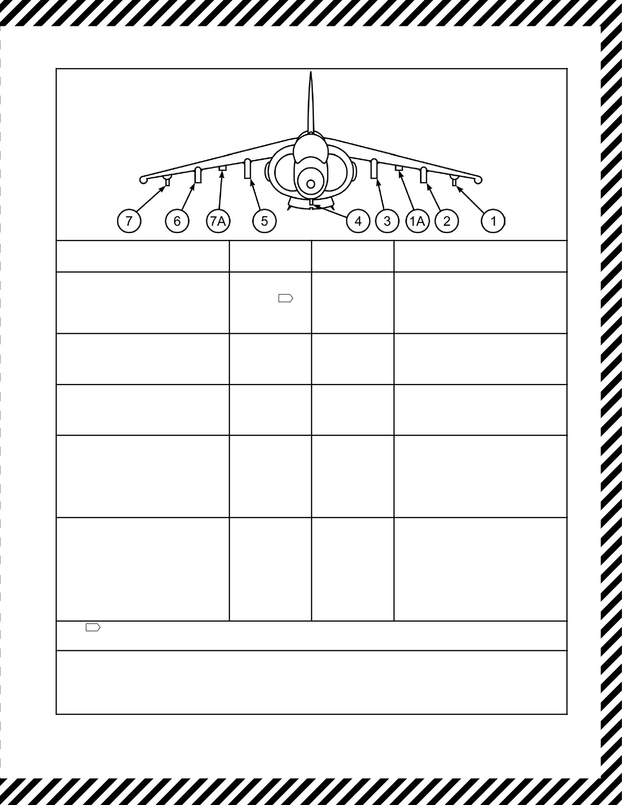
A1-AV8BB--NFM--000
EXTERNAL STATION(S)
INTERLOCKS
JETTISON
JETTISON
(STORES JETTISONED)
CONTROLS
PROCEDURE
All Stations (Emergency Mode)
Gear handle UP
Emergency
Emergency Jettison Button — PUSH.
(All stores and suspension equipment on
or aircraft weight
Jettison Button.
BRU--36 bomb racks. AIM--9/AGM--122s
off wheels.
1
suspended from LAU--7 launchers on
stations 1, 1A, 7 and 7A are retained).
All Stations (Combat Mode)
Gear handle UP
Selective Jettison
Selective Jettison Knob — CMBT.
(All stores and suspension equipment on
and aircraft weight
Knob, Selective
Selective Jettison Pushbutton — PUSH.
BRU--36 bomb racks, except all
off wheels.
Jettison
AIM--9/AGM--122s are retained).
Pushbutton.
2, 3, 5, 6 (Fuel Tank Mode)
Same as above.
Selective Jettison
Selective jettison Knob — FUEL.
(Fuel tanks dropped in pairs from 2 and
Knob, Selective
Station Select Buttons — PRESS.
6, then 3 and 5).
Jettison
APPROPRIATE BUTTON(S).
Pushbutton.
Selective Jettison Pushbutton — PUSH.
(Station Mode)
Same as above.
Selective Jettison
Selective Jettison Knob — STA.
All Selected Stations 1, 2, 3, 4, 5, 6,
Knob, Station
Station Select Buttons — PRESS.
and/or 7 (All stores, including
Select Buttons,
APPROPRIATE BUTTON(S).
suspension equipment on BRU--36
Selective Jettison
Selective Jettison Pushbutton — PUSH.
bomb racks. AIM--9/AGM--122s
Pushbutton.
suspended from LAU--7 launchers on
stations 1, 1A, 7 and 7A are retained).
(Stores Mode)
Same as above.
Selective Jettison
Select Jettison — STOR.
All Selected Stations 1, 2, 3, 4, 5, 6,
knob, Station
Station Select Buttons — PRESS.
and/or 7 (All stores and suspension
Select Buttons,
APPROPRIATE BUTTON(S).
equipment on BRU--36 bomb racks
Selective Jettison
Selective Jettison Pushbutton — PUSH.
except: stores mounted on ITERs are
Pushbutton.
jettisoned while retaining ITERs.
AIM--9/AGM--122s suspended from
LAU--7 launchers on stations 1, 1A, 7
and 7A, are retained).
1
A weight--on--wheels failure will inhibit jettison and prevent raising the gear handle. Emergency jettison can be
enabled by using the DN LOCK OVRD to raise the gear.
2. On Day Attack/TAV--8B aircraft, if emergency jettison is selected in A/G master mode with a weapon selected
SMS lock up will result. The weapons will be jettisoned, but weapon inhibit symbology will appear in the HUD and
WPN FAIL will be displayed on DDI. The STRS page will not show cleared and VRST calculations will be
affected. Selection of other master modes will not be possible until DSL--1 on the ACP is selected by rotating
MAN knob from NORM to N/T and selecting NAV or VSTOL master mode.
Figure 15-4. External Stores Jettison Chart
15-39
ORIGINAL