NATOPS FLIGHT MANUAL NAVY MODEL AV--8B/TAV--8B 161573 AND UP AIRCRAFT (2008) - page 6
A1-AV8BB--NFM--000
PROFILE
Note
D For AV--8B aircraft with F402--RR--408B
engine installed, after completion of pilot
checks and EVICS diagnostic checkout
(above), aircrew shall check the readings on the
IGV bit on BIT 1 page. An IGV 1 code
indicates a failure of the EVICS. If IGV 1 is
displayed flight is prohibited.
D Immediately report indication of failure to
AV8BFST.3, (252) 464--7335, DSN 451--7335
for evaluation and further instruction.
A B
8. Fuel proportioner — CHECK, THEN ON.
a. Turn FUEL PROP switch OFF and note PROP caution light on.
b. Turn FUEL PROP switch ON and note PROP caution light off.
TAV--8B Aircraft:
c. FUEL PROP switch — DL.
Check R FEED warning, PROP caution, and R FEED advisory lights off.
d. FUEL PROP switch — RT.
Check R FEED advisory light on, check R FEED warning light on after short delay.
e. FUEL PROP switch — AUTO.
Check R FEED warning, PROP caution, and R FEED advisory lights off.
All Aircraft:
A
C
9. Trim — CHECK, THEN SET.
a. Trim rudder full left and right. Check rudder and indicator. Have ground crew confirm
travel. Trim to neutral.
b. Trim aileron full left and right. Check aileron and indicator. Have ground crew confirm
travel. Trim to neutral.
c. Trim stabilator full up and down. Check stabilator indicator for travel (↓ 7--8° to ↑ 4°) on
the engine display panel. Trim to minimum 2° ND.
TAV--8B Aircraft After AFC--391:
A B C
10. Aft Seat High Gain Override — CHECK.
a. ANTISKID switch — NWS.
b. Front C/P NWS/Undesignate switch — PRESS AND HOLD (NWS HI in HUD).
ORIGINAL
10-8
A1-AV8BB--NFM--000
PROFILE
c. Rear C/P NWS/Undesignate switch — PRESS.
(1) NWS HI in HUD changes to NWS.
(2) Both C/P’s NWS/Undesignate switch — RELEASE.
d. ANTISKID switch — ON.
All Aircraft:
A
11. Standby attitude indicator — ERECT.
A
12. Altimeter — CHECK.
Set current barometric pressure and compare to field elevation. HUD and standby altimeter
should read within 75 feet of field elevation.
A
13. On--board oxygen system BIT — CHECK.
Press monitor plunger on monitor and check that OXY light comes on. Release plunger and
check OXY light out within 1 minute.
A
C
14. Flaps emergency retract — CHECK.
a. Flaps — ON, RESET (lights out).
b. Flaps — STOL.
c. Flaps — OFF, THEN ON.
d. Have ground crew confirm flaps retract evenly to 0°.
A
C
15. Flaps IBIT — PERFORM IN AUTO.
a. STOL flaps — SELECT.
Verify STOL flaps are selected by STO light. Verify aileron droop by DROOP light and by
moving stick full left and right, checking aileron position (DROOP light goes out at full
aileron deflection).
b. Flaps — CRUISE.
A
C
16. Flight controls — CHECK.
a. Rudder pedals — FULL LEFT AND RIGHT.
Check proper rudder direction.
b. Longitudinal stick — FULL FORWARD AND AFT.
Check proper stabilator direction and ↑ 10° and ↓ 11° on the engine display panel.
10-9
ORIGINAL
A1-AV8BB--NFM--000
PROFILE
c. Hold RPS/YAW switch in TEST.
(1) Move lateral stick — FULL LEFT (check proper aileron direction and rudder moves
left).
(2) Move lateral stick — FULL RIGHT (check proper aileron direction and rudder moves
right).
A
C
17. SAAHS BIT — INITIATE.
a. On BIT display — PRESS SAAHS.
(1) TEST is displayed next to SAAHS legend.
(2) AFC, PITCH, ROLL and YAW caution lights flash until MASTER CAUTION is
pressed.
(3)
40 seconds after BIT initiate, stick shakes in pitch axis.
b. BIT page — CHECK.
If IGV 1 is present, abort mission.
c. Plane Captain — CHECK THE DOLLS EYES IN THE AIRCRAFT REFUELING
PANEL (DOOR 22L).
If Dolls Eyes are popped, abort mission.
d. Record all failures.
e. All lights go out after successful completion of BIT.
A
18. DDI — AUTO BIT.
a. On BIT display — PRESS AUTO.
(1) Tones sound for 6 seconds.
(On TAV--8B 163856 and up, AV--8B 163519 and up, voice -- ACNIP GO, ACNIP GO
or ACNIP FAIL, ACNIP FAIL.)
(2) TEST is displayed next to equipment that is on.
(3) Failure codes (if any) are displayed next to failed equipment.
Note
On radar and night attack aircraft, the FLIR will
continue to cool down during AUTO BIT and
will begin initiated BIT when it has completed
the cool down sequence.
ORIGINAL
10-10
A1-AV8BB--NFM--000
PROFILE
Note
On night attack aircraft, the display computer
will cause the HUD to flicker and may display
an incomplete HUD display head--down on the
right DDI. On radar aircraft, the HUD display
will be blanked.
b. Record all failures.
A
C
19. Paddle switch — PRESS.
Check all three axes disengage, lights on.
A
20. LIDS switch — CYCLE.
Ensure LIDS caution light on with switch in RET position. Ground crewman should verify
LIDS fence fully retracts and extends.
A
21. Air refueling probe — CYCLE (if installed).
A
22. Exterior lights — CHECK.
A
23. Display Computer — CHECK.
a. Set DP switch to PRIM then ALTER, record any failure.
b. Set DP switch to AUTO.
A
24. Inertial navigation system — CHECK.
a. NAV selected.
b. OK displayed.
c. Select NAV waypoints — VERIFY.
A B C
25. Nozzles — FUNCTIONAL CHECK, STOL flaps schedule — CHECK.
Operation of the nozzle system shall be checked at idle rpm in a FOD free area using a
prebriefed ground crewman. Stiffness should be checked and if present, rpm will be increased
to 36 to 40 percent , the nozzles cycled, and normal feel subsequently verified at a maximum
of 29 percent rpm. Nozzle accuracy shall also be checked by selecting hover stop. Indicated
and actual nozzle position (verified by ground crewman) should be within 81° to 83°. If actual
nozzle position accuracy is not within this tolerance, nozzle position accuracy should be
checked at 50 percent rpm. If actual nozzle position at 50 percent rpm is not 81° to 83°, the
cause should be investigated before flight. Check friction knob secured with shear wire. Move
nozzles aft. Ground crewmen should verify all nozzles are 0° nozzles angle (±1°).
10-11
ORIGINAL
A1-AV8BB--NFM--000
PROFILE
CAUTION
As little as 2° negative nozzle angle on the cold
nozzle can cause a severe nose down pitch
during nozzle out. If any nozzle angle is not
within limits, the cause should be investigated
prior to flight.
A
26. VRS — CHECK.
Run in HUD and DDI/MPCD with HUD display on DDI. Check both DDIs on radar and night
attack aircraft.
A
27. DMT/FLIR — BORESIGHT.
10.5
DURING TAXI
A
C
1. Antiskid — CHECK.
While holding constant brake pressure, press and release the ANTISKID test switch, check
that brake pressure immediately drops to below 110 psi then builds up to 2,800 psi (within 12
seconds).
A
C
2. Nosewheel steering — CHECK.
Engage nosewheel steering and move rudder pedals left and right. (Afloat, ensure Launch
Officer checks nosewheel centered prior to launch).
Before AFC--391:
A
C
3. Nosewheel caster (ashore) — CHECK .
Release nosewheel steering while in a turn and ensure that it does not return to center at
maximum rate.
All Aircraft:
A
C
4. Rudder shaker — CHECK.
With nosewheel steering engaged, select RPS/YAW TEST and alternately deflect the rudder
pedals. Rearward rudder pedal should begin oscillation when HUD sideforce symbol touches
left or right limit line.
A
5. TACAN — FUNCTIONAL CHECK USING FIELD PLACARD.
a. The bearing pointer must center within ±1° of known course to station. Erratic bearing
pointer movement is unacceptable.
b. Range counter accuracy is ±0.2 miles plus 0.1 percent of total distance from station;
however, reading and flying accuracy will permit an accuracy check of no better than ±1
mile.
c. Check steering symbol on HUD.
ORIGINAL
10-12
A1-AV8BB--NFM--000
PROFILE
10.6
BEFORE TAKEOFF
A B
1. Perform engine check with nozzles aft.
a. Perform acceleration check.
(1) For the --406 engine, accelerate from 27 to 55 percent rpm. The engine shall reach 55
percent rpm within 3.7 to 4.3 seconds (Figure 7-3).
(2) For the --408 engines, accelerate from 35 to 60 percent rpm. The engine shall reach 60
percent rpm within 2.4 to 3.1 seconds (Figure 7-2).
b. Withtheenginestabilizedat55percentrpm(--406engine)or60percentrpm (--408engine),
check inlet guide vane angle. Check duct pressure with nozzles aft (0 to 3 psi) and at 50°.
A B
2. APU — START.
Start the APU before takeoff so the automatic shutdown feature can be checked in flight.
10.7
HOVER CHECKS AFLOAT
A B
1. Perform VTO and hover checks at 1,500 pounds (fuel low level lights on). See Hovers from
a VTO, paragraph 10.16.
Note
Ensure minimum wind over the deck to lessen
bleed usage.
10.8
TAKEOFF
A B
1. Perform a conventional takeoff (ashore) or STO (afloat). Ensure CMBT deselected. Check the
following:
a. RPM:
(1)
103.0 percent maximum (--406 engine).
(2)
113.5 percent maximum (--408 engine).
b. 15 SEC light at:
(1)
684 °C JPT (Night Attack aircraft with --406 engine and TAV--8B 164113 and up).
(2)
687 °C JPT (Day Attack aircraft with --406 engine and TAV--8B 162747 to 163861).
(3)
765 °C JPT (--408 engine).
c. JPT:
(1)
703 ±5 °C maximum (--406 engine).
(2)
780 ±5 °C maximum (--408 engine).
10-13
ORIGINAL
A1-AV8BB--NFM--000
PROFILE
d. JPT cutback:
Check may require less than full throttle.
(1)
625 ±5 °C (--406 engine).
(2)
710 ±5 °C (--408 engine).
e. RPM cutback:
(1)
98.4 to 99 percent (--406 engine).
(2)
108.8 to 109.2 percent (--408 engine).
f. APU automatic shutdown
— 325 KNOTS (accelerate and check that the APU
automatically shuts down as airspeed increases through 275 knots or 325 knots as
applicable).
10.9
CLIMB
A B C
1.
Aileron high speed stops — CHECK ENGAGED.
Check stops engaged above 0.4 Mach.
A
2.
Perform a functional check of the standby instruments. Compare with HUD indications and
note discrepancies.
a. Angle--of--attack indicator.
b. Altimeter.
c. Attitude indicator.
d. Vertical velocity indicator.
e. Airspeed indicator.
f. Turn and slip indicator.
g. HSI (TAV--8B, AV--8B 161573 to 163852).
h. Clock and second hand.
A B
3.
Full throttle climb — PERFORM.
Perform a full throttle climb to 40,000 feet at 300 knots/0.80 IMN and record rpm and JPT
when passing through 10,000, 30,000, and 40,000 feet. Monitor JPT and rpm for corrected rpm
cutback.
10.10
40,000 FEET
A
1.
Cabin pressure — CHECK.
At 40,000 feet thenominal cabin pressureis 16,800 feet. Theminimum pressureis 15,000 and
maximum pressure is 17,200 feet.
ORIGINAL
10-14
A1-AV8BB--NFM--000
PROFILE
A B
2.
Max power pushover — PERFORM.
At 40,000 feet and 0.8 Mach perform a maximum power pushover to 0 g.
A B
3.
Windup turn — PERFORM.
At 40,000 feet and 200 knots, perform a maximum power windup to:
a. 15° AOA (--406 engine).
b. 19° AOA (--408 engine).
Observe rpm cutback during windup turn.
A B
4.
Throttle slam — PERFORM.
At 40,000 feet, 200 knots and 15° AOA perform a slow (5 seconds) throttle slam from IDLE
to MAX.
A B
5.
Hot throttle reslam — PERFORM.
At 40,000 feet and 200 knots, run engine at full throttle for at least 1 minute. At 15° AOA ,
reduce throttle to IDLE for 2 seconds, then smoothly advance throttle to MAX in less than 5
seconds.
10.11
25,000 TO 20,000 FEET
A
C
1.
SAAHS/Departure Resistance — CHECK.
a. Maneuvering tone — CHECK.
At 25,000 feet MSL and 240 knots indicated airspeed (KIAS)start aslightly noselow turnand
go to full power. Pull to 21.5° AOA, ensuring above 225 KIAS and 0.45 Mach. Check the
maneuvering tone present and the aircraft stable with no lateral stick required.
b. Roll coordination — CHECK.
With the condition established and the maneuvering tone still present, apply aileron to the high
speed stop in the opposite direction of the turn. The aircraft should roll slowly in the proper
direction with little adverse yaw and no reversal of the roll rate.
Exceeding the high speed stop is likely to cause
a departure from controlled flight.
10.12
17,000 TO 10,000 FEET
A
1. Fuel dump BINGO — CHECK.
Set BINGO fuel below existing fuel quantity, but above 2,800 pounds, and place fuel dump
switches to DUMP. Check that fuel is dumped from each side and dump switches return to
NORM when BINGO caution light comes on. (On TAV--8B 163856 and up, AV--8B 163519
and up, voice — BINGO, BINGO).
10-15
ORIGINAL
A1-AV8BB--NFM--000
PROFILE
A
2. IFF — FUNCTIONAL CHECK.
Functional check of IFF to include mode C and emergency function.
Radar Aircraft:
A
3. Radar — FUNCTIONAL CHECK ALL MODES.
All Aircraft:
A
4. Windshield defog system — CHECK.
Functional check the windshield defog system in DEFOG and MAX DEFOG.
A B
5. APU — CHECK.
APU ON, check green light, APU OFF.
A
C
6. AFC — CHECK.
a. AFC — Select AFC ON and check that AFC captures pitch attitude, roll attitude and
heading hold.
b. ALT HOLD — With AFC ON, select ALT HOLD. Check that AFC and ALT HOLD
disengage by clicking the paddle switch.
A
C
7. AUTO flap — CHECK AND RECORD HEADS DOWN FLAP ANGLE. At 200 ±3 KCAS,
<0.50 IMN, Set 10° AOA. Verify flap angle 15° ±1°.
After AFC--391:
A B
8. NWS steering mode — CHECK (200 knots dirty, nozzles as required).
a. ANTISKID Switch — NWS.
Slowly advance throttle from below 65 percent while pressing the NWS steering button.
NWS HI changes to NWS between:
72 to 83 percent (--406 engine).
83 to 89 percent (--408 engine).
All Aircraft:
A
C
9. SAS — CHECK (200 knots dirty, AUTO flaps).
a. Pitch SAS ON — Lower nozzles and note stabilator position indicator. The stabilator trim
position indicator should drift downward (stabilator leading edge up). This is a positive
check that the pitch SAS is countering the nose up pitch caused by nozzle deflection. SAS
OFF, hand off stick, lower nozzles and note pitch trim indicator does not move.
b. Roll SAS ON — Rap the control stick and check for normal damping. SAS OFF, Rap the
control stick and note no damping. Turn roll SAS ON.
c. Yaw SAS ON — Pulse the rudder and check for normal damping. Enter a rudder free turn,
select yaw SAS OFF and note sideslip symbol in HUD deflects. Turn yaw SAS ON and
note sideslip symbol returns to center. SAS OFF, Pulse rudder and note no damping. Turn
yaw SAS ON.
ORIGINAL
10-16
A1-AV8BB--NFM--000
PROFILE
A
C
10. Rudder pedal shaker — CHECK (below 165 knots dirty, AUTO flaps).
Set 10° nozzle, induce side slips left and right and check for proper rudder pedal shaker
operation.
A B C
11. Nozzle trim — CHECK SAS OFF (150 knots dirty, AUTO flaps).
Set engine at 90 percent rpm (--406 engine) or 100 percent rpm (--408 engine), and maintain
150 knots. Ensureaircraft is in trim. Select hoverstop (note81°to 83°nozzleangle)andcheck
that directional trim change does not exceed one ball width. Maintain 90 percent rpm (--406)
or100 percent rpm (--408)as applicableand 150 knots and select braking stop (note95° to 98°
nozzle angle). Check that trim change is less than one ball width.
A
C
12. HUD sideslip — CHECK (120 knots, dirty, AUTO flaps).
The HUD sideslip symbol shall be within 1/4 width when the exterior sideslip vane is centered.
A B C
13. Inverted flight — PERFORM (clean).
At 85 percent rpm, invert the aircraft for a maximum of 15 seconds (less than zero g). Check
fuel pump caution lights do not illuminate and that oil light comes on. Check for FOD in the
cockpit. Check that flight controls are not restricted during inverted flight.
10.13
5,000 FEET
A
C
1.
Trim — CHECK.
Establish 450 knots, SAS ON, check aileron and rudder trim. Trim for hands off flight must
be 0 trim ±10 percent for aileron and 0 trim ±20 percent for rudder. If lateral and directional
trim requirements exceed the values above, note trim position, turn SAS OFF and note trim
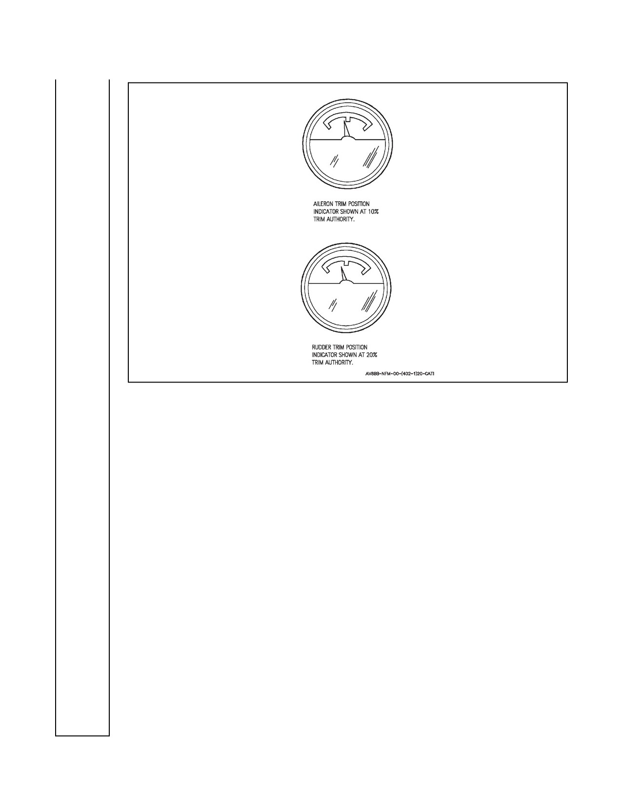
position again for future maintenance corrective action. See Figure 10-1 for trim indication.
A
C
2.
Q--feel — CHECK.
Perform a 4 g turn. Select Q FEEL switch OFF and ON. Note fore and aft stick movement.
A B
3.
G--suit — CHECK.
Check normal operation of the g--suit.
A B
4.
Combat thrust — CHECK.
a. Press CMBT switch/light — SEL LIGHT ON.
b. Throttle — FULL.
c. CMBT light — ON.
(1)
630 ±5 °C maximum (--406 engine).
(2)
715 ±5 °C maximum (--408 engine).
d. RPM — CHECK.
(1)
98.4 to 99 percent (--406 engine).
(2)
110.8 to 111.2 percent (--408 engine).
10-17
ORIGINAL
A1-AV8BB--NFM--000
PROFILE
Figure 10-1. Trim Position Indicators
e. JPT — CHECK.
(1)
665 ±5 °C (--406 engine).
(2)
750 ±5 °C (--408 engine).
f. Nozzles — CHECK CREEP.
g. Press CMBT switch/light — SEL LIGHT AND CMBT LIGHT OUT.
A
5.
HUD displays — CHECK.
Check the HUD display in A/G, A/A, NAV and VSTOL modes.
A
6.
Weapon systems — FUNCTIONAL CHECK.
Check proper symbology and functioning of all sensor and delivery modes.
A B
7.
IGV check — PERFORM.
Check the IGV angle against the provided charts with the engine fans speed set to 65 percent
(--406 engine/Figure 7-3)/80 percent (--408engine/Figure 7-2). IGV angles between the
maximum and minimum operating lines are normal as per the A1--AV8BB--NFM--700.
Operation outside the minimum maximum lines should be an abort and require further
investigation via a high power ground run.
ORIGINAL
10-18
A1-AV8BB--NFM--000
PROFILE
10.14
3,000 TO 1,000 FEET
A
1.
Low altitude warning — CHECK.
Check operation of the LAWS light and LAWS warning tone (On TAV--8B 163856 and up,
AV--8B 163519 and up, voice — ALTITUDE, ALTITUDE.)
A B
2.
Water injection (200 knots, nozzles as required, altitude hold as desired) — CHECK.
a.
Set 88 percent rpm and place water switch to TO — Slowly advance throttle — CHECK
WATER FLOW LIGHT ON AND OFF AT:
(1)
94 to 96 percent rpm (--406 engine).
(2)
103 to 105 percent (--408 engine).
b.
Set 97 percent rpm (--406 engine) or 106 percent rpm (--408 engine) — RECORD
STABILIZED JPT.
c.
Water switch OFF, reset rpm to 97 percent (--406 engine) or 106 percent (--408 engine) —
RECORD STABILIZED JPT.
(1) Should rise at least 25 °C (--406 engine).
(2) Should rise at least 15 °C (--408 engine).
d.
Water switch LDG.
Water flow at:
(1)
684 °C JPT (Night Attack aircraft with --406 engine and TAV--8B 164113 and up).
(2)
687 °C JPT (Day Attack aircraft with --406 engine and TAV--8B 162747 to 163861).
(3)
765 °C JPT (--408 engine).
e.
15 SEC light — CHECK.
(1)
702 °C JPT (Night Attack aircraft with --406 engine and TAV--8B 164113 and up).
(2)
705 °C JPT (Day Attack aircraft with --406 engine and TAV--8B 162747 to 163861).
(3)
780 °C JPT (--408 engine).
f.
Maximum rpm — CHECK.
(1)
107 percent (--406 engine).
(2)
120.2 percent (--408 engine).
10-19
ORIGINAL
A1-AV8BB--NFM--000
PROFILE
g. Maximum stabilized JPT — CHECK.
(1)
727 ±5 °C maximum (--406 engine).
(2)
800 ±5 °C maximum (--408 engine).
A
3.
Landing gear warning system — CHECK.
With airspeed below 160 knots, altitude below 6,000 feet, landing gear up and rate of descent
greater than 250 feet per minute, check the landing gear handle light flashes and warning tone
sounds (On TAV--8B 163856 and up, AV--8B 163519 and up, voice — LANDING GEAR,
LANDING GEAR.)
10.15
LANDING
A
C
1.
Angle--of--Attack — CHECK (Record Gross Weight and AOA).
With GEAR down, AUTO flaps, NOZZLES aft, level flight and 10° AOA, airspeed should
be 154 KCAS at 18,500 pounds gross weight. (Add ±1 KCAS for each ±250 pounds.) Verify
recorded airspeed at 10° AOA is ±3 KCAS of the above calculated value.
A
C
2.
Aileron high speed stops — CHECK DISENGAGED.
With gear down and below 0.4 Mach, check high speed stops disengaged.
Ashore:
A
C
3. Check for normal handling characteristics during theslow landing paying particularattention
to the reaction control.
A
4. Check function of antiskid system during rollout.
A
C
5. Perform STO.
Check for normal handling characteristics.
A
C
6. Check for normal handling characteristics during deceleration to a hover. Select water, ensure
H2O light comes on at 100 ±20 pounds (On TAV--8B 163856 and up, AV--8B 163519 and up,
voice — WATER, WATER.)
Afloat:
A
C
7. Check handling characteristics during slow landing approach/waveoff.
A
C
8. Perform vertical landing.
Select water -- ensure H20 light comes on at 100 ±20 pounds (On TAV--8B 163856 and up,
AV--8B 163519 and up, voice — WATER, WATER.)
ORIGINAL
10-20
A1-AV8BB--NFM--000
PROFILE
10.16
HOVERS FROM A VTO
If flight controls or engine adjustments have been made, do not attempt a VTO or performance
hover (PHOV) unless normal operation of the flight control system, nozzle system, DDI
stabilator position, and engine governor/limiter systems have been verified. On hover checks
that are not prescribed by A, B, or C card profile, the initial hover should be entered from a
decelerating transition to ensure proper aircraft operation.
A B
1.
Hover — PERFORM.
Check for normal hovering characteristics and allow the DDI/MPCD PHOV page to record
performance Figures (two acceptable dry hovers minimum).
The technique for the hover performance check is as follows: prior to each hover request the
ALTM setting and the accurate OAT from metro due to the fact that one degree of ambient
temperature error can skew computed thrust by 100 pounds. Do not use ATIS. If using the A/C
missioncomputertodetermineaperformancehoverthecorrectBAWandcurrentwaterweight
(with C1+ and OMNI 7.1 only) must be entered on the VREST page via the ODU before the
hover. Hovers should be performed dry. Water introduces a myriad of variables that current
performance calculations are not capable of accounting for. From a VTO the aircraft should
be brought to a steady hover at 100 ±10 feet and stabilized until the PHOV tape times out (10
seconds). The aircraft should be headed directly into the wind and hovered with minimum use
ofreaction controls. This willrequirethepilot toallow theaircraft todrift withthewind,rather
than remain stationary over the pad. Hover checks should not be conducted with winds in
excess of 10 knots. Accurate performance checks may not be possible with sustained winds
above 10 knots, or under gusty conditions. Note the stabilized idle JPT prior to the initial
performance hover and retarget that idle JPT prior to each additional hover. Cooling can be
accelerated by repositioning the aircraft on the pad. After the PHOV tape times out, record the
following parameters from the DDI PHOV page: stabilator position, RPM, JPT, fuel weight,
RALT, STPR, OAT, and ALTM. Accurate performance hovers may not be possible aboard
ship due to the lack of visual references and the inability to obtain a stable hover.
A
2.
Low fuel level lights — CHECK.
a. Fuel quantity selector switch — INT.
b. Lights come on steady at 750 ±250 pounds of fuel remaining.
c. Fuel quantity selector switch — FEED.
d. Lights begin flashing at 250 ±100 pounds of fuel remaining. (On TAV--8B 163856 and up,
AV--8B 163519 and up, voice — FUEL LOW LEFT, FUEL LOW LEFT or FUEL LOW
RIGHT, FUEL LOW RIGHT.)
10.17
AFTER LANDING
A B
1.
Auxiliary power unit — START.
A B
2.
Water switch — DUMP, THEN OFF.
Ensure water dumps and is then secured.
A
3.
After landing checks — COMPLETE.
Perform After Landing checks in accordance with paragraph 7.7.1.
10-21
ORIGINAL
A1-AV8BB--NFM--000
PROFILE
A
4. Probe heat — PRB HT.
Ensure probe heat switch automatically resets to the AUTO position after engine shutdown.
10.18
ENGINE SHUTDOWN
A B
1. Engine RPM switch — HI.
A B
2. Throttle — OFF.
a. Decelerate from 50 percent to 5 percent — 20 SECONDS MINIMUM.
A
3. After engine shutdown, check for a minimum of 25 brake applications.
A
4. Check OXY caution light.
A
5. Check AOA and pitot heaters for proper operation.
10.19
REAR COCKPIT CHECKFLIGHT REQUIREMENTS
10.19.1 Preflight
A
1. Before entering rear cockpit checks — PERFORM.
Perform the Before Entering Rear Cockpit checks in accordance with paragraph 7.1.8.
A
2. After entering rear cockpit checks — PERFORM.
Perform the After Entering Rear Cockpit checks in accordance with paragraph 7.1.9.
A
3. Warning and Caution lights — CHECK.
Check caution and warning lights for proper operation.
A
4. Throttle/Limiter, Trip/Ignitors — CHECK.
Check throttle movement, including override of JPTL switch then reset switch. Depress
airstart button to check ignitor plugs. Place MFS on and check ignitor plugs then MFS off.
A
5. Auxiliary Power Unit — MONITOR START.
The APU light comes on and the APU GEN light goes off.
10.19.2 Starting Engine
(Monitor JPT and RPM during start and compare with front cockpit).
A
1. At idle check the following:
a. RPM — CHECK.
(1)
25.8 to 26.2 percent (--406 engine).
(2)
28.4 to 29.0 percent (--408 engine).
ORIGINAL
10-22
A1-AV8BB--NFM--000
PROFILE
b. JPT — CHECK.
(1)
535 °C maximum (--406 engine).
(2)
545 °C maximum (--408 engine).
c. IGV 31° to 39°.
d. Fuel flow — CHECK.
(1)
18 to 24 PPM.
A
2. Landing gear position indicators — GREEN.
A
3. Select approach light from rear cockpit — CHECK.
Have ground personnel check light illumination.
10.19.3 Before Taxiing
A
1. Manual Fuel — CHECK, THEN OFF.
Place MAN FUEL switch ON and check MFS caution light on. Maintain idle limit. Place
water switch to TO and note steady rpm. Place water switch OFF, then place MAN FUEL
switch OFF. Check MFS light off.
A
2. Water switch — CHECK, THEN FWD.
PlacewaterswitchtoTOandnoterpmrise3.3to4.3percent(--406engine)or6.0to7.0percent
(--408 engine). Place water switch OFF and check idle.
A
3. Fuel proportioner — CHECK, THEN FWD.
Set FUEL PROP switch OFF and note PROP caution light on. Set FUEL PROP switch FWD
and note PROP caution light off.
A
4. Trim — CHECK OPERATION IN ALL THREE AXIS, THEN SET.
A
5. Standby Attitude Indicator — ERECT.
A
6. Altimeter — SET.
Set barometric pressure. Check ±75 feet of field elevation.
A
7. DDI cue function — CHECK.
10.19.4 During Taxi
A
1. Antiskid — CHECK.
Check that the SKID light illuminates both cockpits when the ANTISKID switch is OFF.
A
2. STO stop indicator — CHECK.
Set STO stop in front cockpit then check STO stop indicator in rear cockpit accuracy.
10-23
ORIGINAL
A1-AV8BB--NFM--000
PROFILE
10.19.5 Takeoff (Ashore)
A
1.
Monitor a conventional takeoff. Check the following:
a.
RPM — CHECK.
(1)
103.0 percent maximum (--406 engine).
(2)
113.5 percent maximum (--408 engine).
b.
15 SEC light — CHECK.
(1)
684 °C JPT (TAV--8B 164113 and with --406 engine).
(2)
687 °C JPT (TAV--8B 162747 to 163861, with --406 engine).
(3)
765 °C JPT (--408 engine).
c.
JPT — CHECK.
(1)
703 ±5 °C maximum (--406 engine).
(2)
780 ±5 °C maximum (--408 engine).
d.
JPT cutback — CHECK.
(1)
625 ±5 °C (--406 engine).
(2)
710 ±5 °C (--408 engine).
e.
RPM cutback — CHECK.
(1)
98.4 to 99 percent (--406 engine).
(2)
108.8 to 109.2 percent (--408 engine).
10.19.6 Climb
A
1. Perform afunctional check ofthestandby instruments and verify both cockpits read thesame:
a. AOA indicator.
b. Altimeter.
c. Attitude indicator.
d. Vertical velocity indicator.
e. Airspeed indicator.
f. Turn and slip indicator.
ORIGINAL
10-24
A1-AV8BB--NFM--000
PROFILE
10.19.7 17,000 to 10,000 Feet
A
1. Ensure AFC can be disengaged from the rear cockpit.
A
2. Inverted flight — CHECK COCKPIT FOR FOD.
10.19.8 Landing
A
1. AOA — CHECK.
Check airspeed within ±4 knots of front cockpit.
A
2. Braking Stop — CHECK.
Ensure Braking Stop can be selected form rear cockpit.
A
3. Hover Stop — CHECK.
Select Hover Stop from rear cockpit and check position, 81° to 83°.
10.19.9 Engine Shutdown
A
1. Secure engine from rear cockpit.
10.20 PERFORMANCE HOVER CHECKS
The performance hover (PHOV) is a precision maneuver meant to measure the condition of
the total aircraft/engine system. To obtain accurate information, consistency and standardiza-
tion of PHOV procedures is paramount. The data recorded during the (PHOV) is used to find
the relative hover performance (RHOV) and relative JPT (RJPT) using either Figures 10-2
through 10-6 or the Boeing AV--8B Hover Performance Software. These relations shall be
available to the pilot for computation of actual V/STOL performance capability.
The optimum configuration for performance hovers includes the centerline, inboard,
intermediate, and outboard pylons (without stores), port and starboard strakes (or gun with
ammunition pack), and the inflight refueling probe. LAU--7 launchers on the outboard pylons
are acceptable. No additional stores should be on the aircraft due to CG effects and associated
bleed requirements.
Before the Engine RPM Required to Hover and JPT in Hover chart may be used, it is necessary
to correct the barometric pressure recorded in A1--AV8BB--NFM--700 to hover altitude and
determine the actual weight of the aircraft during the hover.
To correct the recorded (ALTM) tower barometric pressure, which is corrected to sea level, add
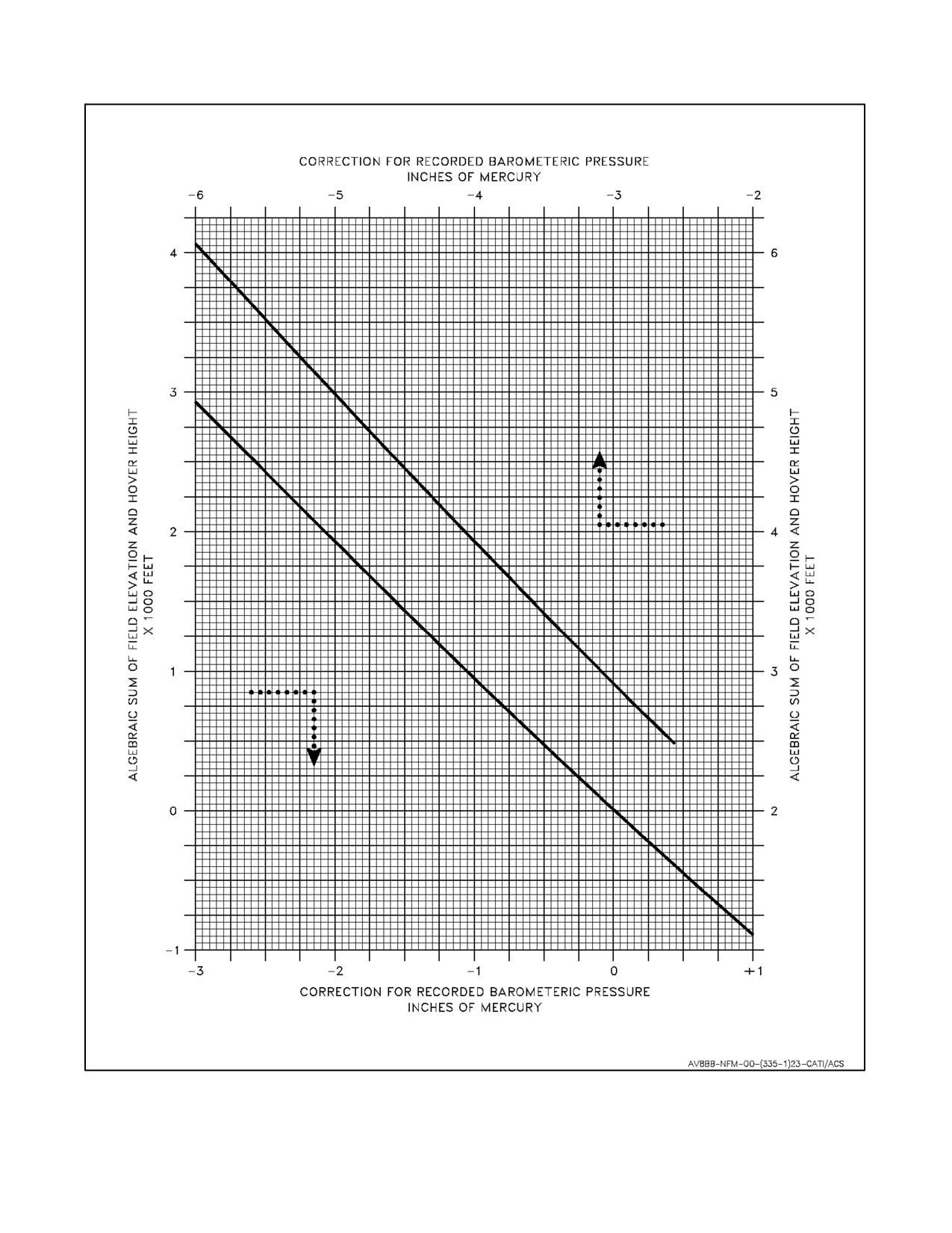
the field elevation and the hover height above ground level. With this value, enter the
Barometric Pressure Correction chart (Figure 10-2) and proceed horizontally to the reflector
curve. From the reflector curve proceed vertically to find the correction for the recorded
barometric pressure. Sum the recorded pressure and the correction. This value is used to enter
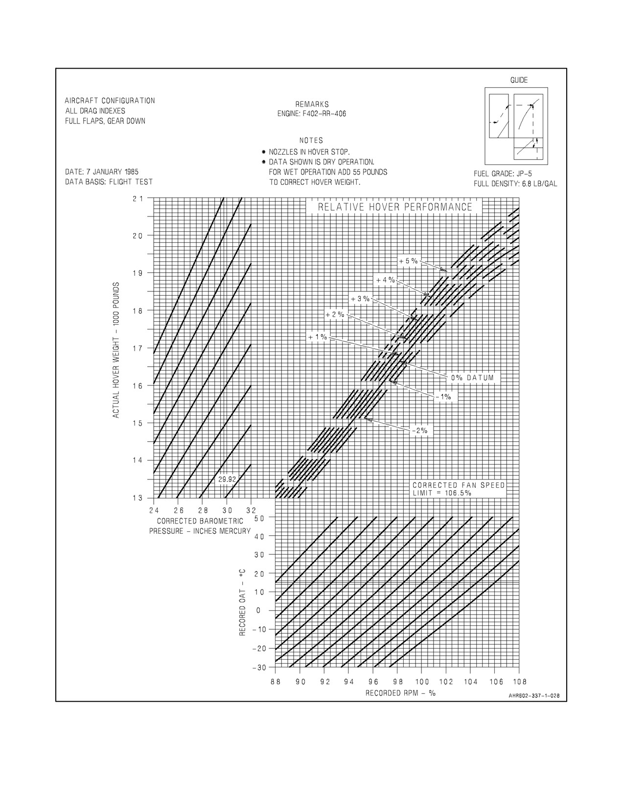
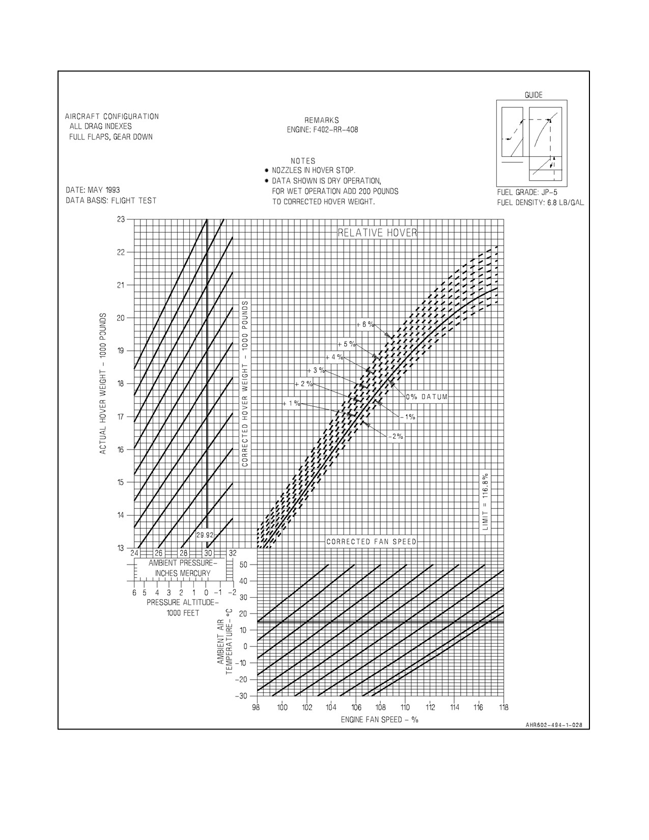
the Engine RPM Required to Hover chart (Figure 10-3 or 10-4) at the Corrected Barometric
Pressure abscissa (horizontal axis).
10-25
ORIGINAL
A1-AV8BB--NFM--000
PROFILE
If ADC measured static pressure at hover height (STPR) was valid (if invalid, asterisks will
be displayed next to STPR on PHOV page) use the recorded STPR instead of ALTM. Make
no corrections to STPR and enter the Engine RPM Required to Hover chart (Figure 10-3 or
10-4) at the Corrected Barometric Pressure abscissa (horizontal axis).
To determine aircraft hover weight, Form DD 365--4 must be adjusted for actual aircraft
configuration and for the fuel and water quantity recorded in A1--AV8BB--NFM--700. The
weight of the water is read from the DDI PHOV page. The weight of the fuel is read from the
fuel quantity indicator. After the actual hover weight is determined, it is used to enter the
Engine RPM Required to Hover chart (Figure 10-3 or 10-4) at the Hover Weight ordinate.
The stabilator position, RPM, JPT, OAT, and STPR recorded in A1--AV8BB--NFM--700 are
used without correction, when entering the Engine RPM Required to Hover and JPT in Hover
charts (Figures 10-3 through 10-6). The maximum allowable engine performance degradation
is defined as being --2 percent in RHOV or +20 °C in RJPT from the zero datum for the --406
and --408 engines.
10.20.1 Relative Hover Performance
To find the percent hover weight, first enter the Engine RPM Required to Hover chart (Figure
10-3 or 10-4) at the hover weight ordinate and proceed horizontally to the corrected barometric
pressure (or STPR). Parallel the reflector curves to the standard day pressure (29.92) and
proceed horizontally drawing a line through the hover performance curves. Second, enter the
chart at the recorded RPM abscissa and proceed vertically to the recorded OAT. Parallel the
reflector curves to the standard day temperature (15 °C) and proceed vertically passing through
the hover performance curves. The intersection of the horizontal and vertical lines define the
relative hover performance to a 0 percent datum engine.
10.20.2 Relative JPT
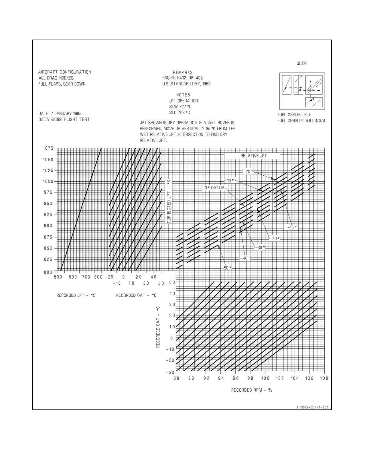
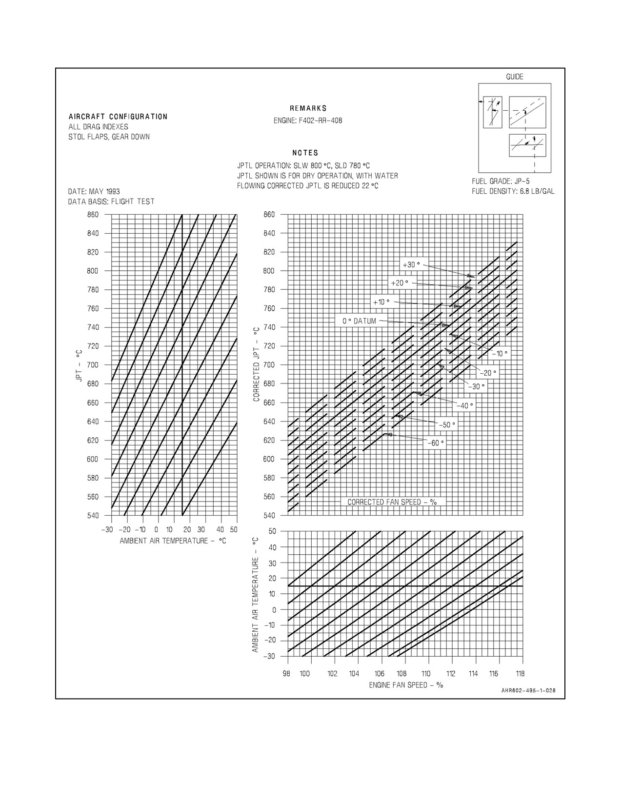
To find the RJPT, first enter the JPT in Hover chart at the recorded JPT abscissa and move
vertically to the reflector line (For F402--RR--408 engines, enter the JPT in Hover chart at the
recorded JPT ordinate) (Figure 10-5 or 10-6). From the reflector line proceed horizontally to
the recorded OAT then parallel the reflector curves to the standard day temperature (15 °C) then
proceed vertically passing through the JPT curves. Second, enter the chart at the recorded RPM
abscissa and move vertically to the recorded OAT. Parallel the reflector curves to the standard
day temperature (15 °C) then proceed vertically passing through the JPT curves. The
intersection of the horizontal and vertical lines define the RJPT to a 0° datum engine without
bleed compensation.
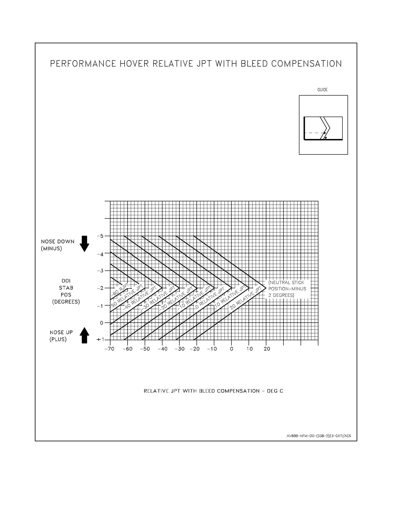
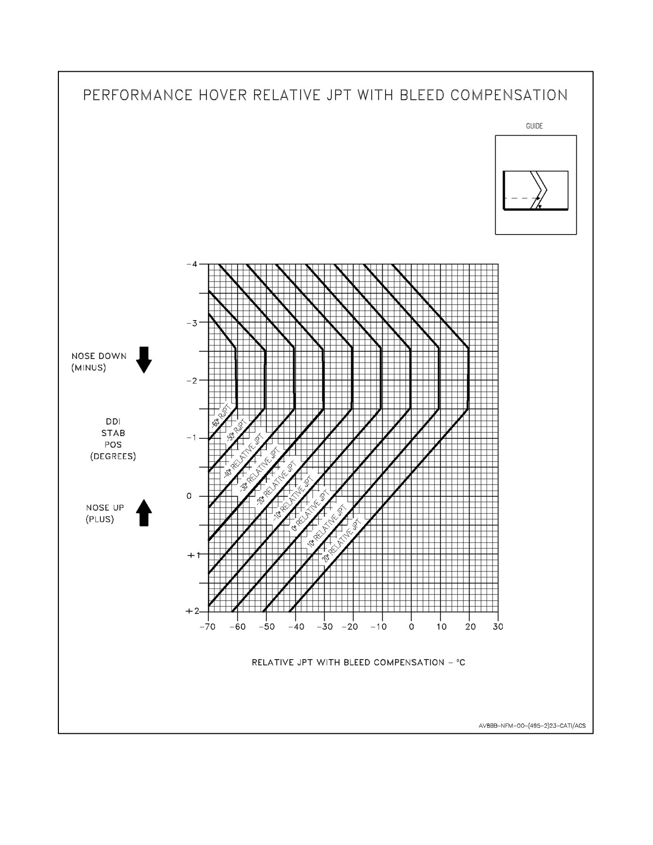
To correct for RCS bleed effects enter the PHOV relative with bleed JPT in hover chart (Figure
10-5 or 10-6) at the recorded DDI stabilator position. Move horizontally right to the
intersection with the RJPT line. Move vertically down from the intersection to read the RJPT
in hover with bleed compensation.
The RJPT with bleed compensation is used with the following charts in A1--AV8BB--NFM--
400: JPT in Hover, Hover Capability and Vertical Landing Capability.
ORIGINAL
10-26
A1-AV8BB--NFM--000
PROFILE
Sample Problem:
1.
Flight information recorded in A1--AV8BB--NFM--700 during Performance Hover Checks.
a. Engine
--406
b. DDI stabilator position
--↓1.5°
c. Fan rpm
95.8 percent
d. JPT
652 °C
e. Fuel quantity
980 pounds
f. Hover height (AGL)
100 feet
g. Water quantity
0 pounds
2.
Atmospheric information.
a. OAT
20 °C
b. Barometric pressure (ALTM)
30.05 inches Hg
c. Sum of field elevation and hover height
(1) Field elevation
+400 feet
(2) Hover height
+100 feet
(3) Sum
+500 feet
d. Correction for recorded barometric pressure
--0.55 inches Hg
e. Corrected hover barometric pressure (2b minus
2d)
29.50 inches Hg
3.
Aircraft weight.
a. Basic aircraft weight from DD 365F of NA 01--1B--40
(excluding fuel and water quantity)
14,260 pounds
b. Fuel quantity (1e)
980 pounds
c. Water quantity (1g)
0 pounds
d. Hover weight (sum of 3a, 3b and 3c)
15,240 pounds
4.
Hover performance check.
a. Fan rpm (1c)
95.8 percent
b. Hover weight (3d)
15,240 pounds
c. OAT (2a)
20 °C
10-27
ORIGINAL
A1-AV8BB--NFM--000
PROFILE
d. Corrected hover barometric pressure (2e)
29.50 inches Hg
e. RHOV performance using 4a, 4b, 4c, 4d
and Engine RPM Required to Hover
+0.8 percent
5.
JPT check
a. Fan rpm (1c)
95.8 percent
b. JPT (1d)
652 °C
c. OAT (2a)
20 °C
d. RJPT using 5a, 5b, 5c, and Figure 10-5 (sheet 2 of 2)
JPT in Hover
--8°
e. DDI stabilator position (1b)
--↓1.5°
f. RJPT using 5d, 5e and Figure 10-5, PHOV RJPT with
bleed compensation
--20°C
10.21
MC PERFORMANCE HOVER CALCULATIONS
Aircraft with the PHOV option incorporate a function to automatically freeze engine data
when criteria for a PHOV are satisfied. The MC calculates RHOV performance and corrected
relative JPT (RJPT) automatically. (On Day Attack and TAV--8B aircraft with OMNI 7.1 with
the F402--RR--408 engine installed, engine data is frozen and RHOV and RJPT are computed
as a F402--RR--406 engine. NATOPS charts (Figure 10-2 through 10-6), the Mission Planning
System (MPS) Operator Station (OPSTA) Program 9.0, or the Boeing AV--8B Hover
Performance Software must be used to calculate RHOV and RJPT). The pilot is given options
to accept and store data for three individual performance hovers and to reject or clear any data
not deemed valid. An average of the RHOV performance and corrected RJPT calculations for
the last three accepted hovers is provided on the PHOV display. The pilot retains the option
to manually freeze (FRZ) the engine data if unable to achieve steady hover requirements for
10 seconds. Accurate PHOV numbers may not be possible by using the freeze option.
Note
Accurate RHOV and RJPT calculations from
the MC rely on accurate BAW, water weight
and OAT. Select the VREST option on the DDI
menu display to ensure BAW is correct for
current configuration, and prior to each VTO
enter the correct water weight via the ODU for
the most accurate MC calculations (with C1+
and OMNI 7.1 only). Call metro (or tower)
while at the Hover Pad, obtain the current OAT,
and cue the OAT into the MC via the Up Front
Control (UFC) prior to each PHOV.
ORIGINAL
10-28
A1-AV8BB--NFM--000
PROFILE
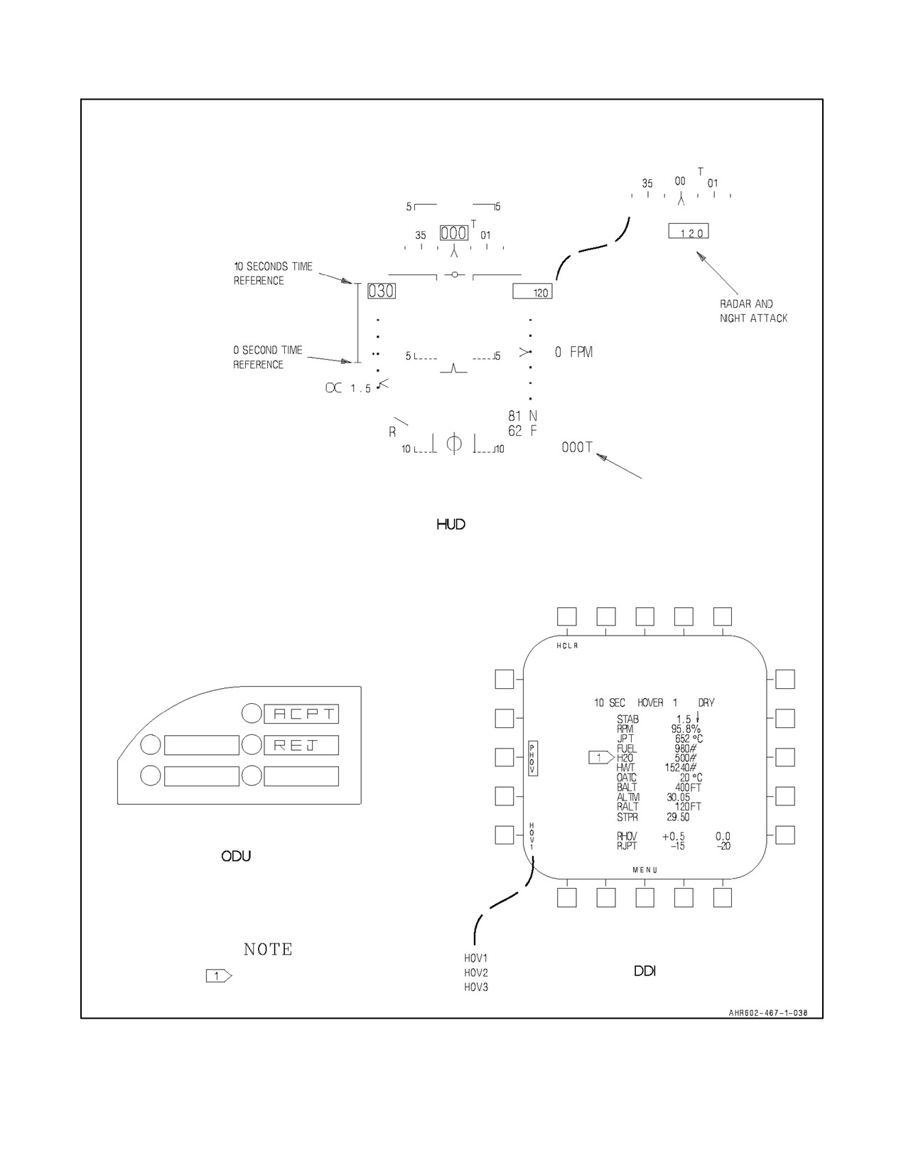
Select the PHOV option on the DDI engine display to obtain the PHOV display (Figure 10-7).
Then select the HOV1 option for the first check. Reselect the engine data display and perform
a VTO and stabilize the aircraft in a steady hover at 100 feet AGL. Steady hover requirements
are:
1.
Altitude — 100 ±10 feet for 10 seconds.
2.
Vertical speed — less than ±6 feet per second (INS).
3.
Stabilator movement — less than ±0.4°.
4.
RPM — less than ±0.8 percent.
5.
JPT — less than ±7 °C.
6.
Horizontal velocities (E/W and N/S) — less than ±6 feet per second (radar altimeter) (INS).
After the aircraft has met the preceding stabilization limits for 10 seconds, PHOV data is
automatically frozen on the DDI and the RHOV and corrected RJPT are computed and
displayed.
The pilot is then cued to accept or reject the data via ACPT and REJ options on the ODU. If
ACPT is pressed, the average RHOV and average corrected RJPT are computed and stored in
the MC for display and manual entry into the V/STOL--REST module as usable RHOV and
corrected RJPT. The hover may be rejected by selecting REJ on the ODU, deselecting FRZ
(unboxed) on the PHOV display prior to selecting ACPT on the ODU, or scrolling to the next
hover in the sequence by using the HOV option button. The PHOV data remains frozen until
the data is accepted, the data is rejected, or the engine data display is deselected. Changing
displays from the PHOV page before data is accepted may cause hover data to be lost.
A visual cue is provided on the HUD (Figure 10-7) for the pilot to more easily determine the
length of time stabilized in the hover. A time scale, just above the angle of attack symbol on
the HUD, climbs vertically to the top of the airspeed box as the 10--second period elapses.
When any of the standard deviations in the preceding paragraph are exceeded, the time scale
on the HUD resets to the 0 second time mark and again climbs when the standard deviation
hover conditions are met.
Repeat the VTO and hover stabilization for subsequent checks. The legend next to the hover
option button automatically increments to the next alphanumeric (HOV2, HOV3, HOV1, etc.)
and engine data are unfrozen when the ACPT option is selected.
The three sets of hover data can be reviewed by scrolling the hover option button. A RHOV
performance and RJPT calculation are provided for each check that is accepted adjacent to the
RHOV and RJPT legends (Figure 10-7). Averages of these parameters for the last three
accepted hovers are provided to the extreme right of the RHOV and RJPT legends.
Selecting the HCLR (hover clear) option clears performance data for the selected hover option
(HOV1, HOV2, or HOV3). Average values for RHOV and RJPT are recalculated based on data
for hovers which have not been cleared. Data for a particular hover may be overwritten by
scrolling the hover option button to the desired number, performing a hover check, and
accepting the data via the ODU (Figure 10-7).
Deselection of the PHOV option returns the DDI to the engine display.
10-29
ORIGINAL
A1-AV8BB--NFM--000
PROFILE
Note
Following PHOV, the hover numbers should be
reviewed for obvious discrepancies. The air-
craft will become lighter during successive
hovers due to fuel burn. This should be
reflected by reduced RPM and JPT. Trim
settings should only change slightly as the CG
shifts with fuel burn. Trends other than these
may reflect improper cooling, heat soaking the
engine, rough hovering, or other situations that
induce inaccuracies to the hover. These hovers
should not be included in the final RHOV and
RJPT calculations.
ORIGINAL
10-30
A1-AV8BB--NFM--000
Figure 10-2. Barometric Pressure Correction
10-31
ORIGINAL
A1-AV8BB--NFM--000
Figure 10-3. Engine RPM Required to Hover, F402--RR--406 Engine
ORIGINAL
10-32
A1-AV8BB--NFM--000
Figure 10-4. Engine RPM Required to Hover, F402--RR--408 Engine
10-33
ORIGINAL
A1-AV8BB--NFM--000
Figure 10-5. JPT in Hover, F402--RR--406 Engine (Sheet 1 of 2)
ORIGINAL
10-34
A1-AV8BB--NFM--000
Figure 10-5. JPT in Hover, F402--RR--406 Engine (Sheet 2)
10-35
ORIGINAL
A1-AV8BB--NFM--000
Figure 10-6. JPT in Hover, F402--RR--408 Engine (Sheet 1 of 2)
ORIGINAL
10-36
A1-AV8BB--NFM--000
Figure 10-6. JPT in Hover, F402--RR--408 Engine (Sheet 2)
10-37
ORIGINAL
A1-AV8BB--NFM--000
T 000 IN NIGHT ATTACK, RADAR,
AND TAV-8B WITH H4.0
WITH H4.0
Figure 10-7. Performance Hover Display
ORIGINAL
10-38
A1-AV8BB-NFM-000
PART IV
Flight Characteristics
Chapter 11 — Flight Characteristics
71/(72 blank)
ORIGINAL
A1-AV8BB--NFM--000
CHAPTER 11
Flight Characteristics
11.1
INTRODUCTION
The AV--8B, by its design as a V/STOL and transonic attack aircraft has many unique flight characteristics. For an
AV--8B pilot to fully realize the potential of the aircraft, a solid understanding of the flight characteristics in both
conventional and V/STOL flight is mandatory.
11.2
GENERAL FLIGHT CHARACTERISTICS
In conventional flight the AV--8B behaves much like any other tactical jet. It is, however, a transonic aircraft and
therefore has some high sub--sonic Mach considerations that must be understood. In addition, some of the design
compromises required for V/STOL flight affect the conventional flight characteristics. As described later in this
chapter some of these influences are beneficial and some are not.
In V/STOL flight, aircraft control is fairly intuitive: fore and aft stick still controls pitch, left and right lateral stick
still produces aroll, and rudder pedal inputs still yaw thenose left and right. The only significant changeis that when
theaircraft is semi--jetborneand especially when it is jetborne, pitch does notcontrol altitude;powercontrolsaltitude
and pitch controls forward velocity or closure with the landing site.
11.2.1 Wake Turbulence
Wake turbulence is primarily a product of lift and takes the form of two counter--rotating cylindrical vortices rolling
off the wing tips and trailing behind and below the aircraft. Vortex circulation is outward, upward, and around the
wing tips when viewed from either ahead or behind the aircraft. The vortices maintain about a wingspan apart from
one another downstream and sink approximately 400 to 500 feet per minute to a level--off altitude about 900 feet
below the aircraft’s flight path. The strength of the vortices is governed by the weight, speed, and shape of the wing
of the aircraft. The greatest vortex strength occurs when the generating aircraft is heavy, clean, and slow. However,
equally strong vortices are generated by small, lighter aircraft at faster speeds when pulling G’s. An encounter with
wake turbulence can be one or more jolts with varying severity depending upon the direction of the encounter,
distance from the generating aircraft and point of vortex encounter, and may result in structural damage. However,
the greatest hazard when flying up the core of a vortex is induced roll. If the ailerons of a long wingspan aircraft extend
beyond the vortex, counter--control would be more effective than for short wingspan aircraft which may have the
entire wingspan within the vortex. In the latter case, counter--control capability may not be great enough to stop the
roll. Avoid the area below and behind the generating aircraft.
Wake vortices must be avoided while maneuvering at low altitude. An
encounter with wake vortices while maneuvering at low altitude may result
in conditions from which recovery or successful ejection may be
impossible.
Wake turbulence in the landing pattern creates hazards for AV--8B pilots because it is a rather small aircraft. When
operating around larger aircraft (military or civilian) certain precautions should be made to ensure safe execution of
takeoffs and landings. The following vortex avoidance procedures are recommended for the various situations:
1. Landing behind a larger aircraft -- same runway. Stay at or above the larger aircraft’s final approach flight
path -- note its touchdown point -- land beyond it. This can be a factor even landing behind another AV--8B.
Flight leads should brief this as part of straight--in approaches and designate appropriate landing spots.
11-1
ORIGINAL
A1-AV8BB--NFM--000
2.
Landing behind a larger aircraft -- when parallel runway is closer than 2,500 feet. Consider possible vortex drift
to your runway depending on the prevailing winds. Stay at or above the larger aircraft’s final approach flight
path -- note its touchdown point.
3.
Landing behind a larger aircraft -- crossing runway. Cross above the larger aircraft’s flight path.
4.
Landing behind a departing larger aircraft -- same runway. Note the larger aircraft’s rotation point -- land well
prior to rotation point.
5.
Landing behind a departing larger aircraft -- crossing runway. Note the larger aircraft’s rotation point -- if past
the intersection -- continue the approach -- land prior to the intersection. If larger aircraft rotates prior to the
intersection, avoid flight below the larger aircraft’s flight path. Abandon the approach unless a landing is
ensured well before reaching the intersection.
6.
Departing behind a larger aircraft. Note the larger aircraft’s rotation point and rotate prior to the larger aircraft’s
rotation point. Continue climbing above the larger aircraft’s climb path until turning clear of the larger aircraft’s
wake. This can be challenging depending upon your flight clearance and with a formation flight. Avoid
subsequent headings which will cross below and behind a larger aircraft. Be alert for any critical takeoff
situation which could lead to a vortex encounter.
7.
Intersection takeoffs -- same runway. Be alert to adjacent larger aircraft operations, particularly upwind of your
runway. If intersection takeoff clearance is received, avoid subsequent heading which will cross below a larger
aircraft’s path.
8.
Departing or landing after a larger aircraft executing a low approach, missed approach, or touch--and--go
landing. Because vortices settle and move laterally near the ground (at approximately 2--3 mph outward), the
vortex hazard may exist along the runway and in your flight path after a larger aircraft has executed a low
approach, missed approach, or a touch--and--go landing, particular in light quartering wind conditions. You
should ensure that an interval of at least 2 minutes has elapsed before your takeoff or landing.
9.
En route VFR (thousand--foot altitude plus 500 feet). Avoid flight below and behind a large aircraft’s path. If
a larger aircraft is observed above on the same track (meeting or overtaking) adjust your position laterally,
preferably upwind.
Air traffic controllers should have AV--8Bs land with an interval of 4 to 6 miles behind the larger aircraft depending
if the aircraft is categorized as a large heavy or non--heavy aircraft (see Airman’s Information Manual for further
definitions).
AV--8Bs should also observe the air traffic control directed 3--minute interval when taking off behind (or on a parallel
runway from) a large heavy or non--heavy aircraft.
11.3
DEFINITIONS
To continue with any discussion on aircraft flight characteristics, several key definitions need to be made. It is
important tounderstand thatthefollowingdefinitions, althoughdealing withtechnical topics,arestatedas theyrelate
to what the pilot will experience in the cockpit.
11.3.1 Critical Mach
The free--stream Mach number at which there are first signs of local sonic airflow on the wing and hence shockwave
formation. Critical Mach (Mcrit) is measured in 1 g flight. This occurs on the AV--8B at 0.82 to 0.85 IMN (indicated
mach number).
11.3.1.1 Shock--induced Flow Separation
Loss of smooth (laminar) airflow over the wing can occur due to shock wave formation if the airflow over the wing
is allowed to become supersonic.
ORIGINAL
11-2
A1-AV8BB--NFM--000
11.3.1.2 Maneuvering Mcrit
Although Mcrit is measured in 1 g flight, theeffect of shock wave formation can occurat Mach numbers below Mcrit
due to AOA on the wing. The increasing AOA accelerates the airflow across the top of the wing so that it becomes
supersonic at an IMN less than the 1 g critical Mach. In the AV--8B this effect becomes apparent when maneuvering
above 0.78 IMN.
11.3.1.3 Transonic Wing Drop
All variants of the AV--8B can experience a sudden uncommanded roll--off, also called wing drop, caused by the
abrupt asymmetric stall of the wings. Wing drop occurs suddenly, with little or no warning to the pilot, and may occur
at AOAs below the maneuvering tone. The severity of wing drop increases as Mach number increases and as altitude
decreases. At Mach numbers greater than 0.8 IMN, wing drop may occur 3° AOA below the maneuvering tone. At
greater than 0.8 IMN wing drop may occur 3° AOA below maneuvering tone. The severity of wing drop increases
as Mach number increases and as altitude decreases. If wing drop occurs, flying qualities can be improved by reducing
AOA.
Transonic wing drop may occur at angles of attack below the maneuvering
tone. Extreme care should be exercised at elevated AOA when maneuver-
ing near ground level above Mach 0.8.
11.3.1.4 Force Divergence Mach Number/Drag Rise
The indicated Mach number above critical Mach, which produces a sharp change in the drag coefficient (boundary
layer separation due to shock wave formation ) is termed the “force divergence” Mach number. It is also referred to
as “drag divergence” and occurs on the Harrier at approximately 0.87 IMN and results in buffet, trim and stability
changes, and a decrease in control surface effectiveness. If the buffet is quite severe or prolonged, structural damage
or failure may occur when this boundary layer separation is experienced on the wing due to shock wave formation.
Therewill bealoss oflift and asubsequent loss ofdownwash aft oftheaffected area. When shock induced separation
occurs symmetrically at the wing root the decrease of downwash aft of this area results in a decrease in downwash
on the horizontal stabilator and thus we notice the aircraft’s tendency to “tuck”. If the wings shock unevenly due to
physical shape differences or sideslip, a rolling moment will be created in the direction of the initial loss of lift and
will contribute to “wing drop” and control difficulty. If either of these conditions occurs reduce the throttle and
decelerate the aircraft below 0.78 IMN while avoiding any large control inputs.
11.3.2 Dynamic Pressure
Dynamicpressure(q)is thepressureon theaircraft dueto thevelocity oftheaircraft and thedensity ofthe airthrough
which the aircraft is flying. Dynamic pressure is usually associated with the ability of the aircraft to maneuver due
to the interaction of the dynamic pressure with the control surfaces on the aircraft. The most obvious measure of
dynamic pressure to the pilot is the calibrated airspeed (KCAS) in the HUD. The relationship of pressure to velocity
is critical to understanding how dynamic pressure/KCAS and thus the aircraft’s maneuverability and stability will
vary with altitude. For a constant true airspeed (KTAS), an increase in altitude will cause a decrease in dynamic
pressure/KCAS due to decreased air density. Another interesting relationship is that of KCAS to IMN with varying
altitude. For a constant KCAS, increasing altitude increases the IMN of the aircraft. So, although 380 KCAS at 5,000
feet has the same dynamic pressure as 380 KCAS at 20,000 feet the aircraft will still suffer decreased stability and
therefore maneuverability due to all the above effects of flow separation caused by shockwave formation by flying
near critical Mach.
11-3
ORIGINAL
A1-AV8BB--NFM--000
11.3.3 Control Authority
Control authority is a measure of the amount of deflection a control surface can move -- i.e. 30°. Control authority
as it is commonly related to the AV--8B flight characteristics (expressed as a percentage of total control system
movement in any given axis) is the amount of control system movement the DEPRES can use to stabilize the jet.
It is merely the measure of the range of motion the DEPRES is allowed to move the rudder and/or the aileron to resist
departure. In the Harrier, the DEPRES has 30 percent authority in roll (ailerons) and 48 percent authority in yaw
(rudder).
11.3.4 Control Power
Where Control Authority is merely a measure of control surface range of motion, Control Power is the actual force
that is created by the surface area of a control surface deflection interacting with the airflow (dynamic pressure).
Control power equals control effectiveness and this varies depending on aircraft altitude, airspeed, AOA and IMN.
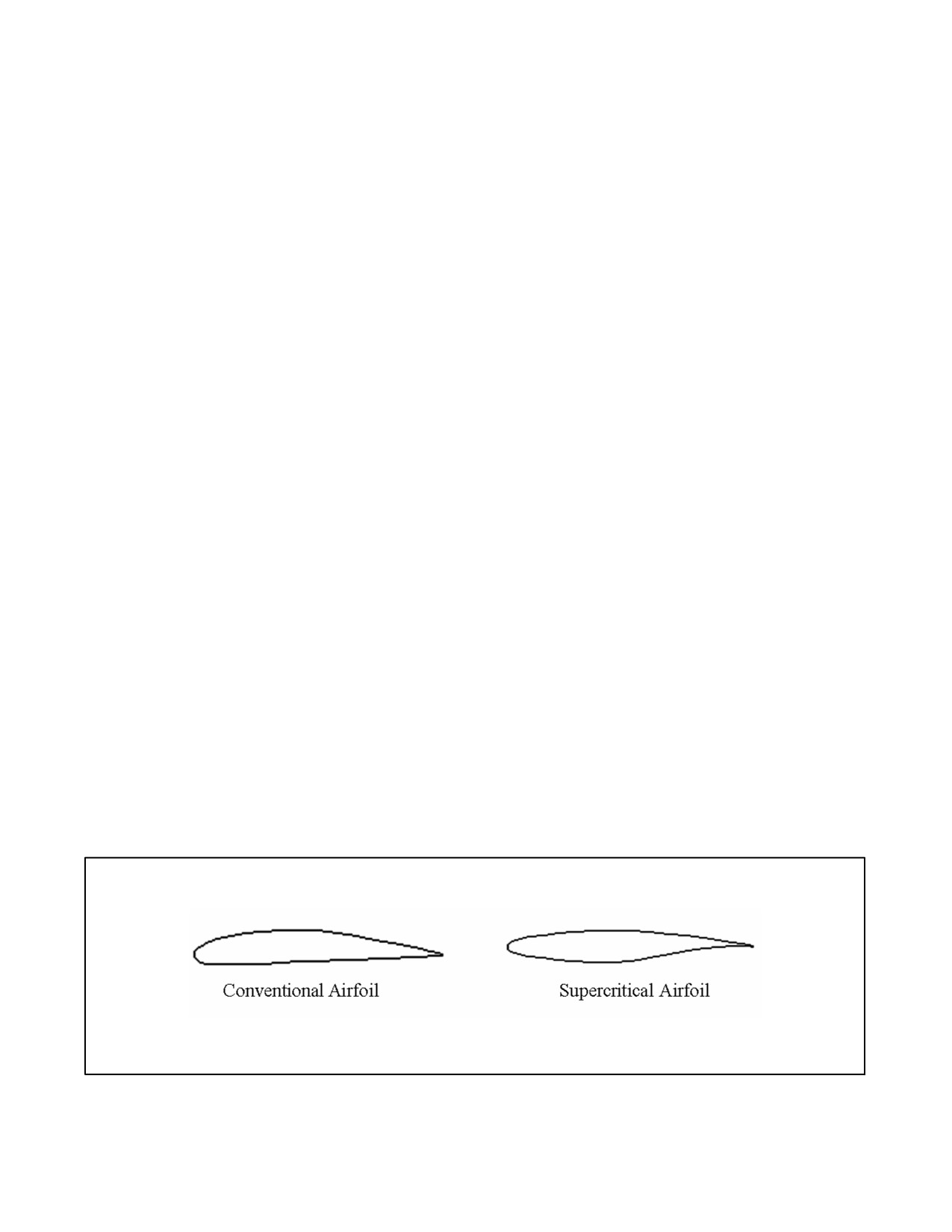
11.3.5 Supercritical Airfoil (Wing)
Asupercritical airfoil is an evolved wing design that allows aircraft to fly at transonicspeeds whiledelaying theonset
of critical Mach. This is possible due to the shape of the airfoil having a flatter top (see Figure 11-1) than a
conventional airfoil. This does not allow the airflow to accelerate as much over the top of the wing and therefore
delays shockwave formation. This would also create less lift for the airfoil if it did not have one other interesting
design feature, the scooped out shape seen on the aft portion of the bottom of the airfoil. This creates more pressure
on the bottom of the wing surface, which increases the pressure differential between the top and bottom of the wing
that we refer to as “lift”. It also more evenly distributes the pressure differential over the entire airfoil chord rather
than having a majority at the front as is common with a conventional airfoil. The benefit of this is that for the high
thickness to chord ratio of the AV--8B’s wing the aircraft has a higher Mcrit than would be possible with a
conventional airfoil. This allows the AV--8B to achieve higher transonic cruise speeds with greater fuel efficiency
due to delaying the detrimental drag associated with shock wave formation. The aircraft needs a high thickness to
chord ratio to increase the internal fuel capacity of the wing and to strengthen the wing for carriage of external stores.
However, there are always compromises in aircraft design; the supercritical wing design is susceptibleto sudden and
drastic flow separation once Mcrit is exceeded in maneuvering flight.
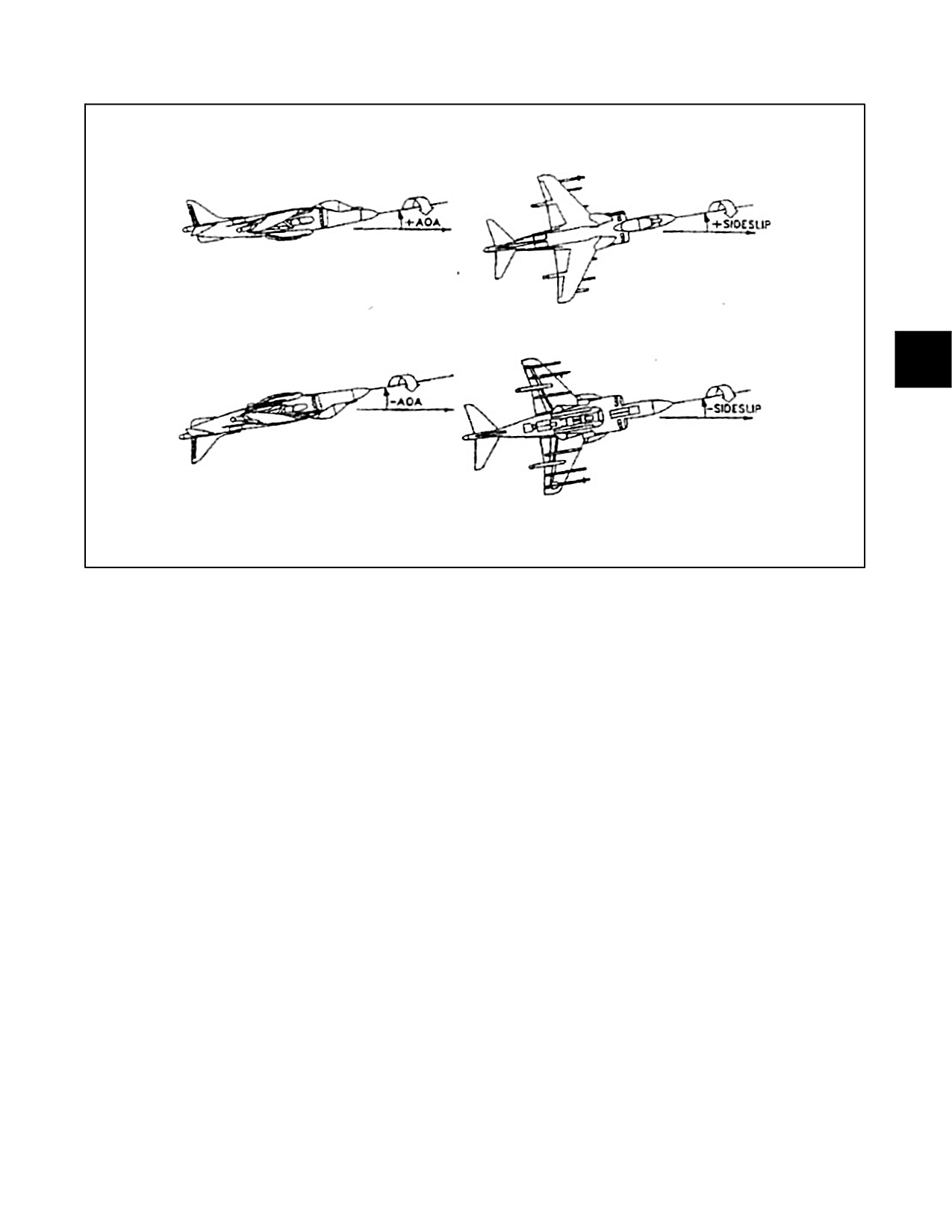
11.3.6 Kinematic Coupling
Kinematic coupling, as it relates to AV--8B departure avoidance, is the interchange between AOA and sideslip as the
aircraft rolls about its longitudinal axis. Kinematic coupling occurs when the longitudinal axis (around which the
aircraft rolls) is not aligned with the velocity vector. This can be a good thing if the aircraft has developed sideslip
and then rolls into the sideslip which will turn it into AOA (which the aircraft is more tolerant of). However, if the
aircraft is rolled while AOA (velocity vector not aligned with the longitudinal axis) is present, kinematic coupling
will turn the AOA into sideslip which must be compensated for (either by pilot input or DEPRES) or the aircraft is
susceptible to a departure. Figure 11-2 shows the mechanics of kinematic coupling.
Figure 11-1. Airfoil Differences
ORIGINAL
11-4
A1-AV8BB--NFM--000
Figure 11-2. Kinematic Coupling
11.4
CONVENTIONAL FLIGHT
11.4.1 Three Aircraft Analogy
In conventional flight there are effectively three different regimes that the aircraft may operate in that determine the
stabilityandmaneuverabilityoftheaircraft.Thisisanalogoustoflyingthreedifferentaircraft basedupon thelimiting
factor that determines the aircraft maneuverability and stability.
11.4.1.1 Mach Limited Aircraft
At tactical KCAS, above approximately 15,000 feet the aircraft will be approaching or above “maneuvering” Mcrit.
The pilot must be aware of the IMN before attempting to maneuver the aircraft. If dynamic maneuvering is required,
ensure the aircraft is decelerated below 0.78 IMN before adding AOA. Additionally, ensure the airspeed is not
allowed to exceed 0.78 IMN while maneuvering or shock--induced flow separation will cause a decrease in the
amount AOA that is controllable. The reduced AOA will not prevent the aircraft from continuing to accelerate, which
will further reduce the controllable AOA. This compounding cycle of decreasing AOA and increasing IMN will
continue (unless the throttle is reduced) until the pilot over--controls the AOA/sideslip and the aircraft departs or the
aircraft reaches Force Divergence Mach, where it has no maneuvering capability and is very unstable in even 1 g
flight.
11.4.1.2 AOA Limited Aircraft
At tactical speeds below 400 KCAS below 15,000 feet or above 15,000 at less than tactical KCAS, the aircraft
becomes more “traditionally” AOA limited. Pilots should be familiar with this type of flight regime from their earliest
days of flight training. There are two factors that can cause the AV--8B pilot maneuvering and stability problems in
this regime.
11.4.1.2.1 AOA Lag
During high AOA and/or g onset rates the HUD AOA has been seen to lag by up to 5 units. Therefore, as a pilot is
maneuvering in this regime if an attempt is made to pull instantaneously to a specific AOA the True AOA of the
11-5
ORIGINAL
A1-AV8BB--NFM--000
aircraft will exceed the HUD displayed AOA. If the True AOA overshoots the lift limit the aircraft will enter stall
or a departure.
11.4.1.2.2 Loaded Rolls
Loaded rolls create stability problems in several ways. First, if the AOA is just beneath the lift limit, rolling the aircraft
increases the camber of the up--rolling wing which may cause either laminar or shock--induced flow separation,
resulting in a loss of lift and an increase in drag away from the initial roll direction. At lower IMNs this will result
in wing rock; at higher IMNs it can accelerate immediately into a departure. Next, rolling the aircraft with AOA
present increases the AOA on the down rolling wing, which can be thought of as “roll friction” because it is opposite
the initial roll direction. Also, loaded rolls will induce the detrimental effect of kinematic coupling that turns AOA
intosideslip.Theresultoftheseeffectsisthataloadedrollthatcreatessideslipandrollingmomentsbeyondtheability
of DEPRES to compensate will lead to a departure.
11.4.1.3 G Limited Aircraft
At tactical airspeeds below 5,000 feet the aircraft becomes g limited. Although it is possible to induce an “AOA”
or “IMN” departure at these low altitudes, the inherent stability of the aircraft due to the high dynamic pressure and
the low IMN at tactical airspeeds, make it more tolerant to all but themost gross pilot control input errors. Therefore,
mishandling the aircraft will likely lead to an overstress instead of a departure.
11.4.2 Stability Augmentation and Attitude Hold System
Thethreeaxes stability augmentation and attitudehold system is installed to reducepilot work load, effect ofrandom
disturbances, and sideslip in V/STOL flight. Normal operation of the yaw SAS decreases the tendency for sideslip
to develop. The attitude hold functions provide additional pilot relief throughout the V/STOL regime. System
authority is adequate for pitch and roll hold provided that relative wind changes or power changes are not excessive.
Breakout forces for control stick steering are light (±1 pound) which allows normal pilot control and feel when desired
but requires a light touch to prevent attitude hold disengagement. The pilot can overridehardover failures in all three
axes.
11.4.3 Departure Resistance
Thedepartureresistance(DEP RES)control lawsoftheStability Augmentationand AttitudeHold System(SAAHS)
lessen the likelihood of departures by preventing build--up of sideslip angle. Sideslip control is provided by an
aileron--to--rudder interconnect to improve roll coordination. A lateral acceleration feedback to the ailerons and
rudder augments the lateral/directional static stability and a sideslip rate feedback to the ailerons and rudder augments
the lateral/directional damping and reduces wing rock. At AOA close to the maneuvering tone, sideslip build--up is
highly dependent upon the roll response of the aircraft. Consequently, the SAAHS roll axis provides the majority
of the departure resistance at high AOA. Disengagement of the SAAHS roll axis will not increase roll performance
and will significantly degrade the departure resistance of the aircraft.
The ability of the departure resistance system to control sideslip is also degraded to varying degrees by overriding
the lateral high speed stop, by largerudder pedal deflections, by large lateral weight asymmetries, and by installation
of the air refueling probe. These effects are cumulative and in combination can rapidly overwhelm the ability of the
departure resistance system to prevent departures.
Inadvertent large rudder pedal deflections resulting in departures may occur at high airspeeds with the Q--feel system
disengaged. On TAV--8B, and AV--8B (161573 through 164121), departures induced by large rudder pedal
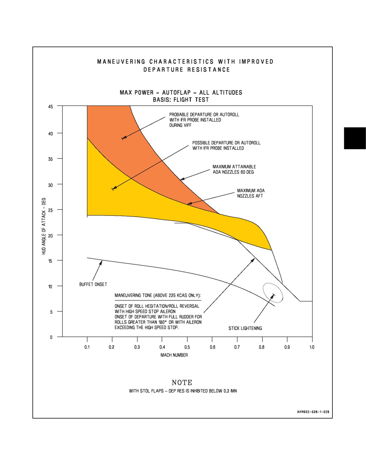
deflections primarily occur above the maneuvering tone when the air refueling probe is installed. Figure 11-3 shows
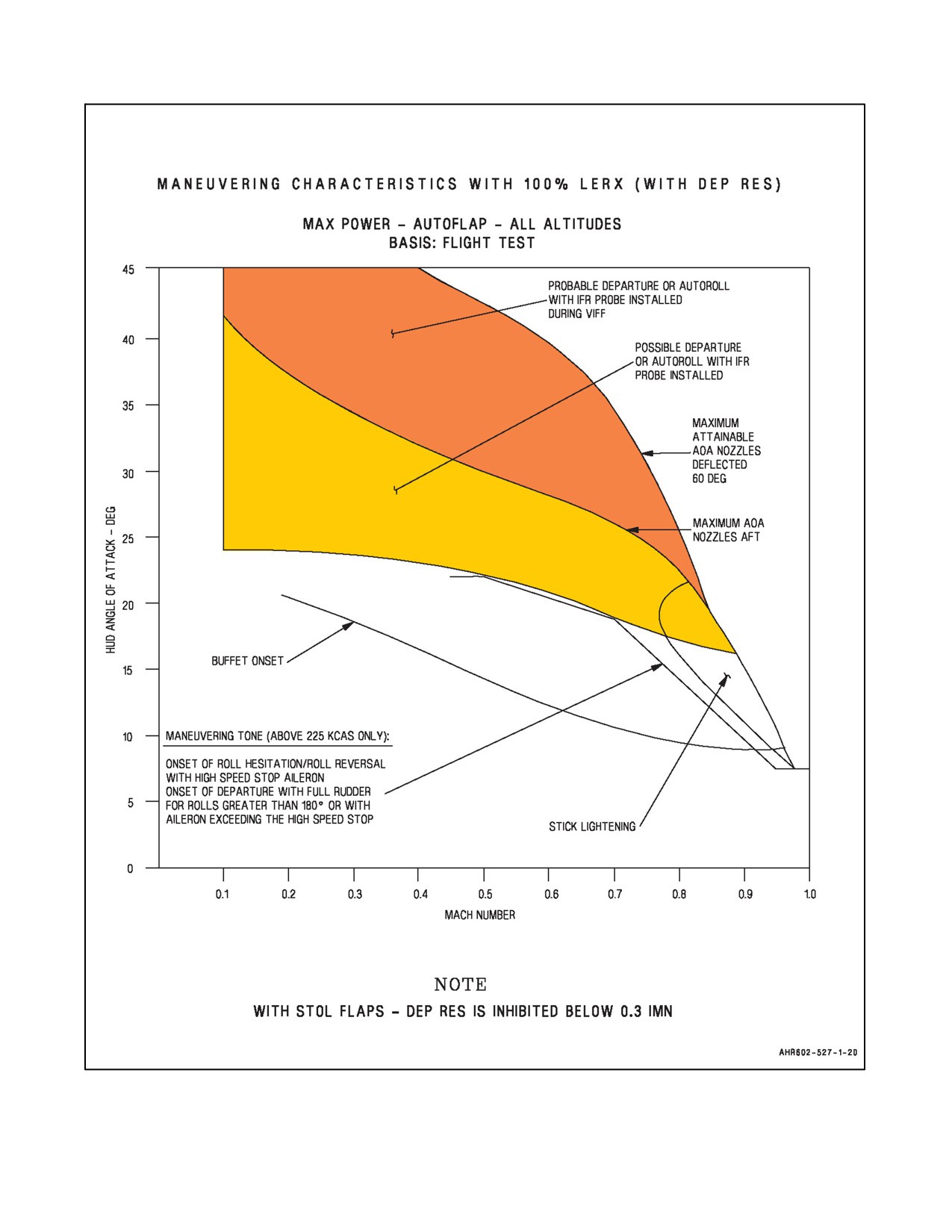
the maneuvering characteristics with the 65 percent LERX. Figure 11-4 shows the maneuvering characteristics with
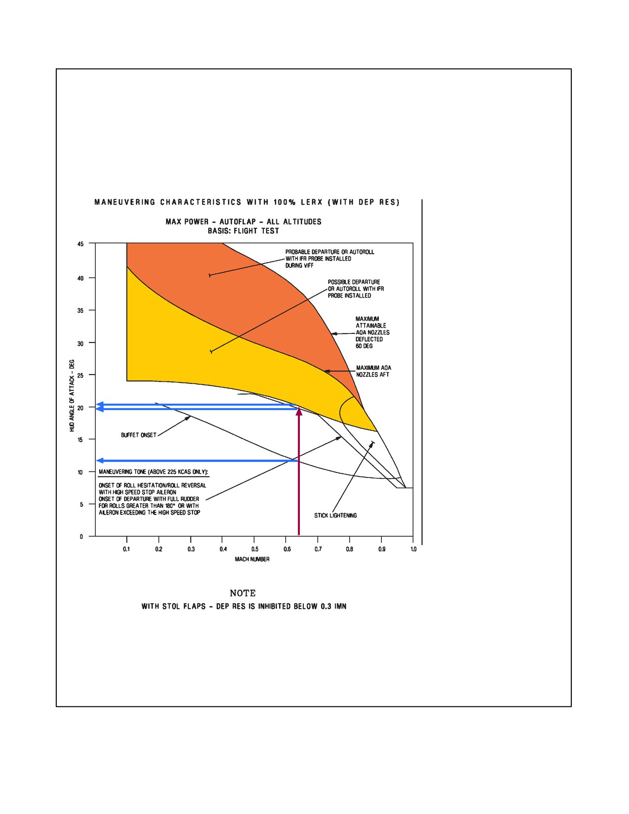
the100 percent LERX. Figure11-5 is an example ofhow to determine maneuvering characteristics from one ofthese
charts.
11.4.3.1 Aileron Rudder Interconnect
The yaw SAS also provides a lateral stick to rudder interconnect for improved turn coordination. Above 4° AOA,
lateral stick commands increasing rudder in the direction of the roll and decreasing aileron in order to reduce adverse
sideslip and improvehigh AOA roll performance. Lateral stick also commands nose--down stabilatorto reduceAOA
build--up from inertial and kinematic coupling. The maximum rudder commanded by the SAS is equivalent to 1/2
pedal and occurs at 8° AOA and above with lateral stick at the high speed stop.
ORIGINAL
11-6
A1-AV8BB--NFM--000
Figure 11-3. Maneuvering Characteristics with 65 Percent LERX
11-7
ORIGINAL
A1-AV8BB--NFM--000
Figure 11-4. Maneuvering Characteristics with 100 Percent LERX
ORIGINAL
11-8
A1-AV8BB--NFM--000
Example:
400 KTAS at 17,000 feet for a
45° ordnance delivery.
1. Determine IMN (from
NTRP 3--22.4--AV8B.
For this example it is 0.63 IMN.
2. Enter Maneuvering Characteristics
Chart from bottom with IMN.
3. Read up to buffet onset,
Maneuvering Tone and Possible
Departure Lines.
4. Read left at each of those data
points to determine the
corresponding AOA.
For this example:
S Buffet:
12 AOA.
S Maneuvering Tone: 19.5 AOA.
S Possible Departure: 20 AOA.
This builds an approximate
“maneuvering envelope” for the flight
regime.
Best sustained performance occurs
approximately at buffet onset. This
should be the target AOA if dynamic
maneuvering is required.
Be careful of AOA lag and understand
that these numbers are approximate
and the numbers and flight character-
istics will change with different aircraft
configurations. Rapid application of g,
rapid rolls to and past the high speed
stop, loaded rolls, and many other
factors can combine to result in a
departure well below the 19.5 or 20
units shown above.
Figure 11-5. Determining Maneuvering Characteristics
11-9
ORIGINAL
A1-AV8BB--NFM--000
11.4.4 Conventional Flight Characteristics
11.4.4.1 Pitch Stability
The aircraft is stable in maneuvering flight up to the maximum allowable AOA with all authorized loads. Flight
beyond the maximum allowable AOA has resulted in violent departures. Care must be taken to avoid overshoots.
When near maximum allowable AOA, reduce aft stick with a lateral input. Buffet and wing rock range from light
at lower Mach numbers to moderate at maximum speeds and occur 4° to 5° below departure AOA.
On AV--8B aircraft with 100 percent LERX, buffet is reduced significantly. On these aircraft and TAV--8B, AV--8B
161573 through 164121, wing rock is reduced or eliminated at most airspeeds (above 120 KCAS) through flight
control computer (FCC) control laws that provide improved lateral/directional dynamic damping. With Q--feel and
pitch SAS engaged, stick forces are moderate throughout the flight envelope and pitch control is smooth and well
damped. However, with Q--feel or SAS disengaged, pitch sensitivity is increased, particularly at high subsonic
speeds. In this case, care should be taken to prevent a maneuvering overshoot of either AOA or load factor.
On AV--8B aircraft with 100 percent LERX, at low to moderate AOA, additional augmentation is provided by the
pitch axis of the SAAHS in order to counter a loss in stability induced by the 100 percent LERX. Above 12° AOA,
this additional pitch augmentation is gradually reduced in order to obtain additional maneuvering capability (4° to
5° higher AOA) with full back stick. With the SAAHS pitch axis disengaged, increased pilot compensation will be
required to perform STOs and other low AOA tasks with aft centers--of--gravity and high stability index store
loadings.
Theaft mounted bobweight is alongitudinal control system devicewhich uses theinertial effects ofamass to modify
the stick forces under various maneuvering conditions. As the aircraft maneuvers, the inertial effects of the weight
on the bellcrank alter the longitudinal stick forces felt by the pilot.
One of the key features of the bobweight is its response to various types of maneuvers. For instance, during slow
pullups or steady state turns, the load factor acts on the bobweight to produce a force on the bellcrank in a direction
that relieves the stick forces. For abrupt maneuvering inputs, large pitch accelerations are produced which result in
a force that opposes stick movement, thereby increasing stick force. The net result is a control system which lightens
stick forces under steady, high g maneuvers, while reducing aircraft pitch sensitivity during very abrupt maneuvers.
11.4.4.2 Roll/Yaw Stability
Aileron forces are light and response is crisp but well damped at all speeds. Above 0.9 Mach, aileron effectiveness
isreducedandsomelateralstickmayberequiredtoholdwingslevel. Onaircraft withASC 020installed rollresponse
at high speed is increased.
Rudder forces are moderate throughout and provide good response up to maximum allowable AOA. However, with
Q--feel disengaged, rudder forces are extremely light, particularly at high subsonic speeds. In this case, care should
be taken to prevent inadvertent rudder pedal deflections. Carriage of gun packs at high speed will cause some loss
of yaw trim precision.
11.4.4.3 Angle of Attack Sensitivity
As airspeed decreases, AOA increases. It is important to recognize the aircraft’s sensitivity to AOA. At slow
airspeeds, small amounts of back--stick pressure and in some cases the release of small amounts of forward--stick
pressure may create a high AOA excursion. This may in turn lead to wing rock, directional instability, which the pilot
will recognize as a wandering sideslip vane, and a possible departure from controlled flight. The target AOA during
any slow speed flight should be 10 to 15 units AOA, although 15 to 20 units may be acceptable under certain
circumstances. AOA will always increase with roll when any sideslip is present and can rapidly increase as a function
of sink rate without significant pilot aggravation. During slow speed flight when the flight controls provide reduced
effectiveness, AOA management becomes critical.
11.4.4.4 Lateral Weight Asymmetry Effects
Weight asymmetry simply reduces the ability of the Harrier’s dihedral effect to lift the heavy wing should the aircraft
begin to yaw away from the asymmetry. Conversely, the weight asymmetry will also help the dihedral effect lower
ORIGINAL
11-10
A1-AV8BB--NFM--000
the heavy wing if the aircraft yaws into the asymmetry. The “beneficial” kinematic coupling that would control
sideslipistherebydecreasedyawing awayfrom theheavy wingand viceversa. Thisresults inabiasin lateralstability
that promotes sideslip away from the heavy wing (nose right with a heavy left wing).
11.4.4.5 Stick Lightening
As seen in Figures 11-3 and 11-4 there is a portion of the AV--8B maneuvering envelope above 0.75 IMN that yields
a disproportionately large pitch control response for a given aft stick input relative to the rest of the envelope. The
danger here is that it occurs at high transonic Mach numbers where the aircraft is already susceptible to shock induced
flow separation. The larger than expected pitch response will cause excessive AOA buildup leading to flow separation
(likely asymmetric) with a departure or overstress (low altitude).
11.4.4.6 SAAHS Off
Having previously discussed all the beneficial “work” that SAAHS/DEPRES perform to maintain aircraft stability
while increasing maneuverability, it should become apparent that if the SAAHS failed, the pilot will have to provide
all the inputs necessary to maintain control of the aircraft. In order to do this, the pilot must have an understanding
of what the flight characteristics of the aircraft are going to be if the SAAHS is off.
11.4.4.6.1 Pitch
With the SAAHS off or failed the aircraft is fairly stable in pitch at lower airspeeds (below approximately 0.5 IMN).
The stick forces will be light and a little moresensitive to control inputs. As speed increases thesensitivity to control
inputs also increases. Above approximately, 360 KCAS it is possible to overstress the aircraft with what would be
a “normal pull” with SAAHS on. Below this airspeed, “normal pulls” can yield AOA excursions above stall. If the
SAAHS has failed it is recommended that the pilot maintain airspeed below 300 KCAS/0.5 IMN and limit
maneuvering to less than 12 units AOA.
11.4.4.6.2 Roll
Typically the first “seat of the pants” indication a pilot will get that the SAAHS has failed is the aircraft becomes fairly
sensitive in roll. The aircraft is still stable in roll but the sensitivity is greater than the pilot is used to with the SAAHS
on. This tends to lead to pilot induced oscillations (PIO). The loss of SAAHS will also cause the pilot to experience
adverse yaw when a roll is initiated due to the loss of the ARI which normally deflects the rudder for the pilot to
prevent this. Roll rates with SAAHS off should be kept low and the VSTOL HUD mode should be selected to help
monitor sideslip during turns.
11.4.4.6.3 Yaw
The aircraft remains stable in yaw at conventional flight airspeeds due to the tail creating “lift” opposite any sideslip
to eliminate it. There will be decreased stability, as compared to SAAHS on. This is evident to the pilot as a nose
“swaying” sensation whenever sideslip is generated (by turbulence, adverse roll yaw, etc.). Again, the VSTOL HUD
mode should be selected to monitor the sideslip. At low AOA, if the swaying is mild and self--dampening, the pilot
may opt to not input a rudder correction, as this may create a yaw PIO condition. However, if the sideslip is excessive
a rudder correction must be input to stop the sideslip build up prior to a departure while the source of the sideslip
must be located and eliminated.
11.4.4.7 TAV--8B Mass Induced Oscillations
During the flight test program, the TAV--8B experienced a high frequency roll oscillation when the pilot in the aft
cockpit had control of the aircraft and the pilot in the forward cockpit had his hands off the stick. These roll oscillations
were excited solely by the lateral motion of the aft cockpit stick and were independent of SAS, AFC, Q--feel, or
longitudinal stick inputs.
There are four conditions which contribute to this oscillatory mode. First, the aft cockpit stick center of gravity is
above the roll center of the aircraft. The additional mass of the pilot’s hand and arm on the stick can generate stick
deflections opposite the roll during aircraft roll accelerations. Second, the TAV--8B exhibits greater roll accelerations
for the same commanded aileron deflection since the rolling moment of inertia is less than the single seat. Third, the
11-11
ORIGINAL
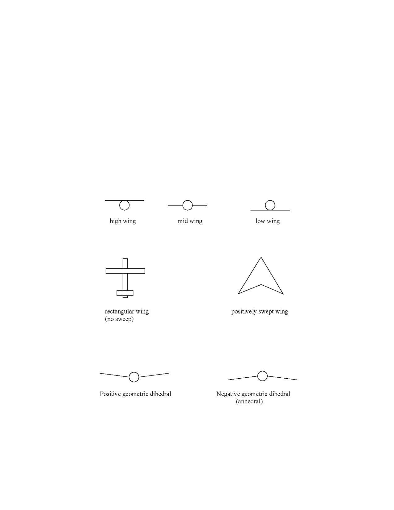
A1-AV8BB--NFM--000
moment arm of the aft cockpit stick is larger than the moment arm of the forward cockpit stick which will amplify
the effect of large roll accelerations. Fourth, the addition of the aft cockpit stick doubled the mass of the control stick
system. This caused a reduction to the system’s effective damping.
To stop the oscillation, the pilot in the forward cockpit can place his hands on either side of the stick and slowly bring
his palms together. At no time will the oscillations grow exponentially without pilot input. These oscillations will
only occur during high dynamic pressure flight conditions.
11.4.5 Stability Influences
11.4.5.1 Apparent Dihedral Effect
Apparent dihedral effect is defined as an aircraft’s tendency to develop roll rate due to sideslip. Positive apparent
dihedral effect equates to aroll rateinto asideslip (i.e. roll rateto theright dueto anose--right sideslip). It is produced
by a lift increase on the upwind wing and a lift reduction on the downwind wing. Positive dihedral is a desired flight
characteristic because kinematic coupling will tend to decrease sideslip, and thereby increase lateral and directional
dynamic stability.
There are 3 major contributors to an aircraft’s overall apparent dihedral effect:
Wing Location. Wing location with respect to fuselage (high wing, medium wing or low wing); high wing contributes
to positive dihedral effect.
Wing Sweep. Wing sweep (i.e. , the angle between the lateral axis of the aircraft and the leading edge of the wing);
positively swept wing contributes to positive dihedral effect.
Geometric Dihedral. This is the “slope” of the wing; positive geometric dihedral contributes to positive dihedral
effect.
Note that the Harrier has a high wing, which is positively swept. Both of these characteristics contribute to positive
apparent dihedral. However, the Harrier’s wing is also very anhedral, which contributes to negative apparent dihedral.
The overall effect, though, is that the Harrier exhibits a positive apparent dihedral effect.
At low AOA, the Harrier exhibits dynamic directional stability -- that is, if the nose becomes pointed out of the relative
wind, it will tend to correct itself. The vertical tail is the big contributor here; when it gets kicked out of the relative
wind, it is simply a wing on its side. It produces a net lift in the direction that puts the nose back into the relative wind.
ORIGINAL
11-12
A1-AV8BB--NFM--000
At high AOA, however, the fuselage essentially blocks the vertical tail from much of the relative airflow, so the tail
becomes largely ineffective. The tail’s lack of effectiveness at high AOA causes a loss of directional stability.
Positive dihedral effect can help with the loss of directional stability at high AOA. The positive dihedral effect results
in a roll rate into the sideslip direction. This roll rate will tend to reduce (or zero) sideslip.
11.4.5.2 Air Refueling Probe Effect
With the refueling probe retracted, the effect on flying qualities at low to moderate AOA is negligible. In maneuvering
flight at AOA near and above the tone, the probe causes a left wing down rolling moment that increases with
increasing AOA. This rolling moment is easily opposed with aileron but the combination of probe effect and opposing
aileron may cause departures at AOA above the maneuvering tone. On TAV--8B, AV--8B 161573 through 164121,
the combination of probe effect and rudder oraileron inputs may causedepartures orpositive AOA autorolls at AOA
above the maneuvering tone. At extreme AOA induced by VIFFing, low departure resistance and the air refueling
probe effect combine to increase the likelihood of departures in the absence of aileron or rudder inputs. With the probe
extended, a small amount of drag and resultant yaw is generated. If the probe fails to retract, some pilot rudder
compensation will be required for landing.
11.4.5.3 LERX
The LERX create a larger lifting surface forward of the center of gravity. This allows increased pitch rate in addition
to allowing a higher attainable AOA due to large lifting area and through vortex generation along the wing root
re--energizing the airflow and delaying laminar flow separation.
On AV--8B aircraft with 100 percent LERX, buffet is reduced significantly. Wing rock is reduced or eliminated at
most airspeeds (above 120 KCAS) through FCC control laws that provide improved lateral/directional dynamic
damping. On AV--8B aircraft with 100 percent LERX, at low to moderate AOA, additional augmentation is provided
by the pitch axis of the SAAHS in order to counter a loss in stability induced by the 100 percent LERX. Above 12°
AOA, this additional pitch augmentation is gradually reduced in order to obtain additional maneuvering capability
(4° to 5° higher AOA) with full back stick. The liability for this increased pitch performance is decreased pilot
feedback through wing rock/buffet of an impending departure.
11.4.5.4 External Stores
11.4.5.4.1 Maneuvering with Symmetric External Stores
Throughout its maneuvering envelope, the aircraft provides feedback to the pilot through flight--control response,
airframe buffet, uncommanded yaw or roll, and roll hesitation/reversal. Each indication appears in varying degrees
and rates. As the aircraft is maneuvered towards maximum angle of attack, a slight airframe buffet will occur. The
angle of attack where this airframe buffet begins indicates best--sustained turn--rate performance for a given flight
condition. Additional aft stick input will generate higher angles of attack and more airframe buffet with a slight
increase in turn performance, while the airspeed begins to decrease (bleed). If the aft stick input is rapid, it will delay
the initial onset of buffet, however the aircraft will transit directly into heavy buffet, or even a departure.
11.4.5.4.2 Gun Pack
CAUTION
The vibration from the GAU--12 firing can cause the nozzles to droop down
from the aft position. The increase in lift due to having the nozzles deflected
in conjunction with theRCS being energized increases the pitch sensitivity
of the aircraft. A pilot who is unaware of the nozzles deflection, trying to
perform the standard “conventional flight only” gun off target maneuver
will be surprised by the increased pitch response and will likely depart or
overstress the aircraft. Check the nozzles aft before pulling off target after
firing the gun. See paragraph 11.8.1.
11-13
ORIGINAL
A1-AV8BB--NFM--000
11.4.5.4.3 External Fuel Tanks
External fuel tanks make the aircraft less stable in pitch. Fuel in the drop tanks moves the CG aft and increases the
inertia on the wings should wing rock develop. Also, the fuel tanks, due to their shape can create lift. In certain flight
conditions this can create more AOA and buffet due to shedding disturbed airflow from the tank onto the wing. The
same effect can occur directionally (yaw axis) as well, creating sideslip. The destabilizing effects of external fuel
tanks is increased when the tanks are mounted on stations 2 and 6.
11.4.5.4.4 Maneuvering with Asymmetric Stores
At low angles of attack, the AV--8B has sufficient directional stability and low to neutral lateral stability, such that
an asymmetric configuration will cause the heavy wing to drop with little yaw effect. Balanced flight can be
reestablished by adjusting the lateral (aileron) trim to balance the asymmetric store and directional (rudder) trim to
offset the yaw created by unbalanced ailerons and external stores drag.
At high AOA the AV--8B has abundant lateral stability and little to no directional stability due to the tail being blocked
from the relative wind by the fuselage. The abundant lateral stability at high AOA is due to apparent dihedral effect.
With an asymmetric store loaded, at high AOA the aircraft will be more prone to a departure in a direction away from
the asymmetry. Weight asymmetry simply reduces the ability of the Harrier’s dihedral effect to lift the heavy wing
should the aircraft begin to yaw away from the asymmetry. It can be thought of as being more difficult to “pick up”
the heavy wing while trying to roll into the sideslip. Conversely, the weight asymmetry will also help the dihedral
effect lower the heavy wing if the aircraft yaws into the asymmetry. The “beneficial” kinematic coupling that would
control sideslip is thereby decreased yawing away from the heavy wing and vice versa. This results in a bias in lateral
stability that promotes sideslip away from the heavy wing (nose right with a heavy left wing).
To optimize controllability and decrease the demands on the DEPRES while maneuvering with an air refueling probe
installed and carrying an asymmetricstore, thestoreshould typicallybeloadedon theleft sideoftheaircraft. Arough
balance can then be achieved between the effects of the refueling probe and those of the wing mounted store; either
a 190--pound store on station 1, a 250--pound store on station 2, or a 500--pound store on station 3. This will help
avoid the de--stabilizing effect of the probe and balance the tendency of the aircraft to depart away from the heavy
wing. Heavier stores or asymmetries larger than those described above could overcompensate forthe refueling probe
and adversely affect the DEPRES yawing to the right.
CAUTION
High AOA maneuvering with the Litening TPOD or other right--wing
asymmetry and AR probe installed will increase the likelihood of
departures.
At asymmetries less than 60,000 inch--pounds, the aircraft requires minimal lateral (aileron)and directional (rudder)
trim to maintain wings level balanced flight. Maneuvering characteristics at AOA greater than 1 g are similar to those
of a symmetrically loaded aircraft, but require slightly more lateral stick to maintain the desired bank angle. Flying
qualities cues in the form of roll and pitch hesitations are present to warn the pilot of impending departure. Post stall
gyrations are generally similar to those of a clean aircraft with the exception that incipient spin motion is morelikely
to occur if departure occurs at high Mach number (≧0.7). Spin direction will be away from the heavy wing. The
aircraft, however, remains extremely spin resistant and neutral controls are sufficient to recover the aircraft within
1 to 2 turns.
Increasing asymmetry up to 148,000 inch--pounds will require progressively more lateral and directional trim to
maintain wings level balanced flight. Sufficient trim authority is available, however, to trim for hands off 1 g flight.
Increasing AOA will require significant lateral stick to hold the wings at the desired attitude until ultimately the
aileron high speed stop is reached. This provides the pilot an excellent cue he is operating close to the departure
boundary and further AOA increases should be avoided due to decreasing directional stability. The combination of
asymmetric drag, loss of directional stability, and significant dihedral effect will require the pilot to gradually reduce
ORIGINAL
11-14
A1-AV8BB--NFM--000
thelateralstickawayfromtheheavywing andto holdtheheavywing down.Crossing thelateral stickovertheneutral
position into the heavy wing is an excellent cue to the pilot that significant sideslip is being developed and that
departure is imminent.
Loaded rolls with the maneuvering tone are inadvisable. The best technique is to reduce AOA, roll with lateral stick,
and then pull back into the turn. If a loaded roll must be made, then the ailerons should be coordinated with an
appropriate amount of rudder. With a lateral weight asymmetry, departure resistance will be reduced for aileron--only
rolls in the direction of the asymmetry or for rudder--only rolls away from the asymmetry.
11.4.5.4.5 Dive Recovery with Asymmetric External Loads
The intent here is to draw attention to the adverse effects on aircraft handling of large weight asymmetries and high
IMN. This is generally experienced during ordnance delivery or recovery maneuvers when the aircraft is pointed at
the ground. Knowledge of these effects and the appropriate timely pilot compensation will minimize altitude loss
and uncommanded aircraft response. For odd quantity carriage, delivery, or dive recovery with asymmetry
approaching or exceeding 100,000 inch--pounds, care should be taken not to exceed 0.88 IMN or 520 KCAS. If an
uncommanded roll is experienced, therecovery techniqueis to slow theaircraft below 0.85 IMN, which will provide
for increased lateral control authority. Reducing the throttle and extending the speed brake can expeditiously slow
the aircraft. Additionally, since the rolling moment due to sideslip is based on the product of dynamic pressure
(proportional to KCAS), angle of attack and sideslip, the aircraft will experience a rolling moment unless at least one
of these three factors is zero. This means either zero airspeed, zero AOA, or zero sideslip. Understanding how to
control these three factors, where to find their indications, and how they couple to produce a rolling moment is key
to successful aircraft control during dynamic maneuvering, and is especially critical with asymmetric store loading.
11.4.5.5 Thrust/Power Setting
Theengine,inconventionalflight,willcontributetoadestabilizingnoseuppitchfromidleto about85 percent;above
85 percent it is considered a stabilizing force. The pitch--up occurs because the center of thrust is located slightly
below the CG of the airplane, and the increasing jet blast causes a localized increase in dynamic pressure on the top
of the stabilator. This effect is noticeable in all flight regimes, and can be used to help pitch the airplane at lower
airspeeds (coming over the top of an overhead, or pulling the nose up in a dive). A noticeable forward push on the
stick and forward trim is necessary to counteract the tendency to pitch up.
11.4.5.6 Nozzle Deflection
It is not the intent of this section to discuss the tactical employment of TVC; see Air NTTP 3.22--1. TVC affects
aircraft aerodynamics in several ways. Some of these effects are not beneficial; however, their combination results
in the overall increased capabilities described previously. Rotating the nozzles down at a constant attitude and thrust
setting decreases the local wing angle of attack, and therefore reduces wing lift. However, this effect is more than
compensated for at high power settings, because the perpendicular thrust vector component offsets the loss in wing
lift, providing more g available. Tailplane effectiveness decreases slightly as high energy air is deflected away from
its surface. At lower speeds, the loss in tailplane effectiveness is countered by the pitch reaction controls. (Reaction
controls lose effectiveness at higher airspeeds.) The addition of reaction controls allow the pilot to maintain control
of the aircraft at indicated angles of attack significantly higher than conventional flight stall angle of attack.
A characteristic pitch--up occurs when the nozzles are rotated down and the aircraft becomes more sensitive in pitch.
Deflecting the nozzle increases downwash aft of the wing and the resultant more negative angle of attack at the tail
causes the pitch up. The g should be monitored carefully during nozzle deflection to prevent overstress. The aircraft
can be maneuvered at low speed with high AOA and will display the same characteristics as in V/STOL flight. There
is little or no warning before a slow speed departure. At impending departure, defined by sideslip buildup or roll
hesitation, recovery is immediate if the pilot reduces AOA and sideslip. If a departure occurs, the controls should
be neutralized, throttle reduced to idle and nozzle selected aft.
11.4.6 Departure Contributors
11.4.6.1 Airspeed
Speeds above Mcrit, (0.82 to 0.85 IMN) in level 1 g flight significantly increases the tasking of the SAAHS/DEPRES
to compensateforasymmetricshock--induced flow separation, which reduces theamount ofDEPRES control power
available to compensate for other departure contributors.
11-15
ORIGINAL
A1-AV8BB--NFM--000
11.4.6.2 Airspeed and Altitude
Altitude changes the relationship between dynamic pressure (indicated airspeed) and indicated mach number. Even
in 1g flight,IMNs aboveMcrit increaseSAAHS/DEPRES saturationin orderto compensateforshock--inducedflow
separation. If we hold IMN constant, e.g. 0.85, as we increase altitude, indicated airspeed decreases. On a standard
day, at 5,000 feet, 0.85 IMN equates to about 530 KIAS. At 20,000 feet, 0.85 IMN is about 400 KIAS. For every
doubling of indicated airspeed, dynamic pressure is squared. (e.g. dynamic pressure at 300 knots is roughly 4 times
as great as it is at 150 knots) Therefore, at 0.85 IMN/400 KIAS at 20,000 feet there is roughly half the dynamic
pressure acting on the jet as there is at the same IMN at 530 KIAS and 5,000 feet. In practical terms, that means that
the aircraft has half the stability at 0.85 IMN at 20,000 feet than it has at 0.85 IMN at 5,000 feet due to decreased
control power. If we consider any IMN above Mcrit to be our instability constant, control power is the means available
to the DEPRES to compensate for that instability. Thus, the DEPRES has less control power at 0.85 IMN at 20,000
feet than it has 0.85 IMN at 5,000 feet because the dynamic pressure (IAS) is greater at 5,000 feet than it is at 20,000
feet even though the IMN is the same. Control authority is identical in both flight conditions.
11.4.6.3 Airspeed, Altitude, and Maneuvering
Flying the aircraft at high airspeeds and altitudes aggravates the total amount of instability the DEPRES must
compensate for in 1g flight. Maneuvering the jet (pulling G) effectively lowers Mcrit (see maneuvering Mcrit) and
increases the area over which shock--induced flow separation can occur. Therefore, instability is increased and the
DEPRES must work harder (use more of its control authority for a given flight condition) to compensate.
11.4.6.4 Airspeed, Altitude, Maneuvering and Greater Fuel Weight
Greater fuel weights equate to more fuel in the wings. This creates more aft CG (requiring slightly more compensation
from the SAAHS/DEPRES) but most significantly, heavier moment arms displaced laterally from the CG. In simple
terms, heavier moment arms mean more inertia within the instabilities present at a given flight condition, and thus
the DEPRES will be forced to use more of its control authority in order to compensate.
11.4.6.5 Airspeed, Altitude, Maneuvering, Greater Fuel Weight, and Commanding a Roll Rate
Going fast at altitude, turning the jet at higher fuel weights, and commanding a roll rate (making an aileron input)
can exceed the DEPRES ability to compensate for with ARI to keep sideslip under control. There have been
high--speed departures on intercept sorties because the pilot simply rolled the aircraft. One was flying around 25K
feet at 0.89 IMN. Another happened at 13K feet/0.67 IMN and 4.5 Gs -- because the pilot commanded a roll rate that
exceeded the DEPRES ability to compensate and the jet had 5,500 pounds of fuel on board.
11.5
DEPARTURE AVOIDANCE
Most pilots understand that pulling back on the stick too much will generate excessive AOA, which will cause wing
stall and eventually adeparture. Mostpilots alsounderstand thatstanding onarudderpedal willcausesideslip,which
can be beneficial to induce a pro--verse yaw roll, but above 0.5 IMN dynamic pressure over the larger anhedral wing
area actually prevents the roll due to the relative wind “trapping” the wing down and preventing the aircraft from
rolling. The loss of the kinematic coupling of the sideslip to AOA due to this “trapping” causes excessive sideslip
buildup, which will quickly lead to a departure. The use of rudder is tactically beneficial in somesituations but those
benefits must be weighed against the liabilities of a departure. If rudder is to be used, reducing “G” prior to rudder
inputs will decrease the AOA. The liabilities associated with high--speed departures usually outweigh the benefits
of rudder usage in most situations above 250 KIAS.
Because it is less intuitive, it is the aileron that is the most common culprit of departures in the AV--8B. A review
of basic aerodynamics applied to the Harrier reveals why. As the ailerons are deflected opposite each other an increase
in lift on one wing, caused by the increased camber due to aileron deflection, and a loss on the other creates a rolling
moment. Additionally, theup--rolling wing is actually rolling away from therelativewind, which decreases theAOA
on that wing, while the down--rolling wing is rolling into the relative wind which increases its AOA. The maximum
roll rate of an aircraft is defined by the balance between the angular acceleration caused by the increased camber of
the deflected aileron to the opposing angular acceleration caused by the increased AOA on the down--rolling wing.
The penalty for this roll rate is the increase in lift on the up--rolling wing causes induced drag (proportional to the
ORIGINAL
11-16
A1-AV8BB--NFM--000
amount of lift a wing creates) on that wing which makes the aircraft yaw away from the direction of the roll. This
sideslip ifnot corrected by eitherpilot orDEPRES (ARI)causes thedown--rolling wing to accelerateinto therelative
wind which increases the lift created by that wing which counters the pilot induced roll rate. So it is possible in this
aircraft to get a decreased roll rate with higher aileron deflection. The high aileron deflection is also increasing the
risk of a departure due to increased camber on the up--rolling wing causing either laminar flow separation (stall) below
transonic speeds or shock--induced flow separation due to decreasing Mcrit on the wing with the aileron deflected.
From the above discussion seven recurring “rules” become apparent for departure avoidance:
CAUTION
D Avoid use of the rudder above 250 KCAS.
D Near “Maneuvering” Mcrit, reduce the throttle prior to aggressively
maneuvering to ensure the airspeed remains less than Maneuvering Mcrit.
D Do not roll the aircraft with high roll rates under moderate (or greater)
G/AOA.
D DonotrolltheaircraftathigherG/AOAs.(ReduceG/AOApriortorolling).
Do not use high G/AOA onset rates.
D (Do not “snatch” on the G/AOA).
D Do not roll the aircraft with high roll rates at high mach numbers (Slow
below Mcrit prior to rolling/turning).
D Do not try to pull to “normal” maneuvering AOAs at greater than 0.78 IMN.
(Buffet onset can occur as low as 7 to 8 degrees AOA).
11.5.1 Impending Departure Indications
Most departures in the AV--8B are preceded (sometimes barely) by and indication of the impending departure. The
most common impending departure indicators, in order that they are likely to be encountered, are wing rock, roll
hesitation/reversal, heavy buffet and the maneuvering tone.
11.5.1.1 Wing Rock
Wing rock is a fast, uncommanded roll oscillation that occurs just prior to a departure. At low airspeeds (below
approximately 250 KCAS), the wings may “rock” 3 to 4 times before the aircraft actually departs. At higher speeds
(IMN), especially with 100 percent LERX, there may be no rock beyond just a single roll reversal followed instantly
by a departure. Wing rock also contributes to sideslip buildup. By creating an oscillatory yaw divergence, wing rock
usually leads to a departure unless the AOA is immediately reduced.
11.5.1.2 Roll Hesitation/Reversal
At slow speeds and high AOA the wing may not have the energy to develop a wing rock and instead creates a roll
hesitation, where a lateral (aileron) input yields no response; or a roll reversal where a lateral input causes the jet to
roll in the opposite direction to the input. The correction for either of these conditions is to quickly center the lateral
stick and reduce the AOA.
11.5.1.3 Heavy Buffet/Pitch Hesitation
In some flight regimes, usually at lower airspeed, the aircraft may get into very heavy buffet, characterized by
significant airframe vibration and stagnation of the pitch rate or “pitch hesitation” without first encountering wing
rock. This is typically due to AOA exceeding 20 units. If allowed to persist the aircraft will typically enter a roll
hesitation or reversal condition as soon as a lateral stick input is commanded or sideslip is encountered.
11-17
ORIGINAL
A1-AV8BB--NFM--000
11.5.1.4 Maneuvering Tone
The maneuvering tone operates as a function of AOA and IMN. If AOA onset is smooth and progressive the tone
will sound to warn the pilot that the aircraft is in a flight condition where the DEPRES is likely approaching
saturation. However, since the tone operates as a function of AOA and because HUD AOA can lag significantly with
high AOA onset rates, the aircraft can enter a departure condition without the tonesounding. Thesmart AV--8B pilot
should not rely on the tone to warn of an impending departure and should keep AOA onset rates smooth and
progressive. There have been quite a few high speed departures in this aircraft where the maneuvering tone begins
to sound as the aircraft is in its first or second post--stall gyration from a departure.
11.6
STALLS
Stalls in conventional flight can be defined as flight at an AOA above that where the wing produces maximum lift.
The stall AOA varies with aircraft configuration. Typical AV--8B values for normal stalls at sea level are 18° to 19°
for the clean (gear up, nozzles aft, flaps cruise) configuration (Figure 11-1). With nozzles deflected, flight below the
conventional stall airspeed for the given conditions requires engine thrust to augment wing lift in order to maintain
level flight and the RCS system to maintain aircraft control.
Note
With nozzles deflected, flight characteristics are significantly different.
Refer to V/STOL flight characteristics.
11.6.1 Normal Stalls
Normal (1 g) stalls are mild with little or no buffet. High sink rates can develop. With gear down and flaps CRUISE
or AUTO and/or with external stores, the characteristics are similar. The usual characteristic at stall is left or right
wing drop. Recovery is immediate when the back stick is relaxed.
11.6.2 Accelerated Stalls (with DEP RES)
In the accelerated stall, directional stability decreases and the wing stalls asymmetrically. The accelerated stall is
characterized by any of the following: (a) wing rock, (b) sideslip buildup, or (c) full back stick. Wing rock usually
occurs coincident with full back stick below 0.7 Mach. Wing rock is usually divergent with sideslip increasing with
each oscillation until departure occurs.
Wing rock and oscillatory departures have been significantly reduced during accelerated stalls. However, sudden
sideslip build--up may still occur without warning. Sideslip buildup is usually the result of control input. The rate
of sideslip buildup increases with Mach number. Sideslip defines the point of stall and, if allowed to continue, will
result in departure and post stall gyration (PSG). In the absence of wing rock or sideslip, full back stick defines the
stall. For large lateral stick inputs at AOA above the maneuvering tone, the initial response is generally good but a
roll hesitation with sideslip will occur after about 90° of bank angle change and departure is likely. Below 0.5 Mach,
therollratecanbeimprovedwithrudder.Above0.5Mach,therollduetoyawislesseffectiveandtheaircraftbecomes
increasingly prone to rudder induced departure with increasing AOA and/or Mach number. Above 0.7 Mach and at
AOA above the maneuvering tone, any appreciable rudder input will cause departure. Rudder pedal induced
departures primarily occur above the maneuvering tone when the air refueling probe is installed.
11.7
DEPARTURE, POST STALL GYRATION AND DEPARTURE RECOVERY
11.7.1 Departure and Post Stall Gyration
A departure is not a flight condition in itself, but the event separating controlled from uncontrolled flight. Post stall
gyration (PSG) is defined as uncontrolled motion about one or more aircraft axes following departure. Post stall
gyration, spin and deep stall are examples of out--of controlled flight. Departures at airspeeds less than 120 KCAS
are oscillatory and exhibit good warning with wing rock gradually increasing in severity until control is lost,
Departures are characterized by continued increase in sideslip which abruptly couples with roll rate as the aircraft
unloads. Theroll rateis 2 to 3 timesgreaterthantheyawratewhichgives thepilot thesensation ofarollingdeparture.
Departures between 120 and 250 KCAS gradually become more violent with increased airspeeds. Departures at
ORIGINAL
11-18
A1-AV8BB--NFM--000
airspeeds greater than 250 KCAS are usually non--oscillatory with little warning and can produce, at the pilot’s seat,
severe vertical, horizontal, and lateral accelerations that may abruptly reverse direction. Helmet/canopy impact is
possible as the pilot’s upper torso responds to these sudden accelerations. One or more uncommanded snap rolls in
the direction of and away from the departure may occur during the PSG as the aircraft loses airspeed and assumes
a steep, nose down attitude. Recovery from the PSG is prompt with neutral controls. If thedeparture occurred during
vectoring in forward flight (VIFF), rapidly moving the nozzles aft may aggravate the departure and/or result in more
violent PSG. Nozzle angle should be slowly reduced to zero; however, engine shutdown after locked--in surge may
prevent the nozzles from retracting fully aft. Departure recovery will not be effected with the nozzles deflected.
Airstarts have been successfully completed with nozzle angles up to 40°. Nozzle down airstarts resulted in slightly
higherJPT levels than nozzleaft airstarts and no significant differencein recovery altitude. Post relight diverecovery
and engine spool--up should be performed nozzles aft to prevent large nose up pitch/AOA excursions and possible
departure. Moving the nozzles aft may prolong the PSG by momentarily inducing a negative AOA autoroll.
Due to the abrupt and extreme changes in aircraft attitude that can occur during a departure and subsequent PSG, the
aircraft INS may cause erroneous maximum normal load factors (NZ) to be displayed on the HUD and the DDI
Fatigue Life Counter display. Following a departure, the pilot should use the Maximum Possible Normal Load Factor
Chart (see Figure 4-12) to estimate the maximum NZ attained by the aircraft. An over--g inspection of the aircraft
per the A1--AV8BB--GAI--400 Maintenance Manual is required if this estimated NZ exceeds the allowable structural
load factor limit.
11.7.2 Positive AOA Auto Roll
The positive AOA autoroll is characterized by positive AOA (20° to 45°), low to moderate yaw rate (35 to 70°/sec)
and moderate roll rate (70 to 120°/sec). Positive AOA autorolls may follow rudder rolls above the maneuvering
boundary with the IFR probe installed or may follow departures at extreme AOAs induced by VIFFing. This spin
like motion can be disorienting regarding the nature of the motion or the number of rolls. Recovery with neutral
controls normally occurs after 4 seconds or within 2 rolls. Recovery is aided with opposite rudder. Opposite aileron
in not effective and may induce additional sideslip and aggravate the post stall gyration.
11.7.3 Negative AOA Auto Roll
The negative AOA autoroll is characterized by negative AOA (--5° to --10°), approximately 90° nose down pitch
attitude and divergent roll rate (roll rates as high as 320 degrees/second have been recorded). This spin like motion
is disorienting, uncomfortable and easily misinterpreted as an inverted spin. With neutral controls the motion is
transient. With pro--spin control a spin will occasionally self--recover and deteriorate into a negative AOA autoroll.
Neutral controls are effective in all cases in producing recoveries in one to two turns, however, altitude loss from the
ensuing recovery is large (2,000 to 6,000 feet) because of the extreme nose down attitude and rapidly increasing
airspeed.
11.7.4 Upright Spins
The aircraft is very reluctant to enter and maintain upright spins, requiring precisely timed inputs of aft stick along
with crossed ailerons and rudder. The typical upright spin is steep and oscillatory in nature with yaw rates near
70°/second and AOA between 45° and 65°. For the symmetric aircraft, approximately 50 percent of all spin attempts
with full aft stick and crossed controls result in post stall motions classified as spins. Of these spins approximately
50 percent are self recovering even with full pro--spin controls and in all cases neutral controls are effective in
producing rapid spin recoveries within 7 seconds or 1 1/2 turns.
The effect of asymmetric store loadings on upright spins is to increase spin susceptibility and to decrease the ease
of recovery, requiring full anti--spin controls for recovery in one case with an asymmetric 300 gallon tank on the
intermediate station. The effects of weight asymmetries on upright spin characteristics are similar with a tendency
towards somewhat flatterand fasterspins than thesymmetric case. Neutral control recoveries provided a 100 percent
success rate only up to 12,000 inch--pounds asymmetry (example: AIM--9 on an outboard station = 29,700
inch--pounds).Neutralcontrolrecoveryprobabilitydecreasesrapidlywithincreasingasymmetryandbecomestotally
ineffective at 90,000 inch--pounds asymmetry (example: Mk--82 outboard = 88,000 inch--pounds). Only full
anti--spin controls are 100 percent effective in upright spin recoveries for asymmetries between 12,000 inch--pounds
and 90,000 inch--pounds, however, even at 90,000 inch--pounds asymmetry, recoveries using full anti--spin controls
were rapid with recoveries occurring within 5 seconds or 1 turn.
11-19
ORIGINAL
A1-AV8BB--NFM--000
11.7.5 Inverted Spins
Inverted spins are easily produced by sustained rudder and forward stick inputs. The typical inverted spin is steeper
and less oscillatory than the upright spin. Yaw rates were near 55°/second with AOAs between --30° and --45°.
Recoveries from inverted spins are almost immediate upon control neutralization, requiring 6 seconds or 1 1/2 turns.
Forinverted spins theeffect oflateral weight asymmetries is to flatten spins into theheavy wing, and to steepen those
away from the heavy wing, with little to no significant change in associated roll and yaw rates. For all asymmetries
tested, neutral controls resulted in rapid spin recoveries within 6 1/2 seconds or 1 1/2 turns.
11.7.6 Falling Leaf (TAV--8B and Radar Aircraft Only)
Departures and tailslides can result in prolonged, highly oscillatory PSGs that have been given the term Falling Leaf
due to the violent reversing characteristics of the motion. The motion is similar in nature to spins only to the extent
that equilibrium in the pitch axis is achieved through inertial coupling, thereby preventing a reduction in AOA. The
motion can be quite severe and disorienting to the pilot since the aircraft repeatedly reverses direction and does not
exhibit a predominant direction as does a left or right spin. Violent reversals in bank and heading angles can occur
along with extreme oscillations in AOA and pitch attitude. Altitude loss rate can be as high as 24,000 fpm. Engine
compressor stall, resulting in a locked surge requiring engine shutdown, is likely to occur. Recovery from the falling
leaf PSG is best achieved with full forward stick and neutral ailerons and rudder. Recovery from the PSG motion to
anosedown attitudecan takeseveral seconds. Additional timeand altitudearerequired to regain flying speed, restart
the engine, and recover to level flight.
11.7.7 Effects of Departure On Engine
Engine compressor stall/locked surge is likely to occur during high Mach/high altitude departures (less than 250
KCAS/greater than 0.7 Mach) or high airspeed/medium altitude departures (greater than 250 KCAS) and is indicated
by increasing JPT with decreasing rpm. Compressorstall/locked surgecan be accompanied by apop orseries ofpops
which can be felt in the airframe or be audible to the pilot. If engine rpm is low during the departure, locked
compressor stall/surge may only be apparent to the pilot through cross check of rpm and JPT. Departures at high
power setting will result in engine fan rub, possibly requiring engine removal. Fan rub can be greatly reduced by
promptly retarding the throttle to idle at the first indication of departure.
During a high speed departure (greaterthan 250 knots), LP fan rub is likely. LP fan rub reduces the ablativematerials
that protect the engine casing from the fan blades. Minimize maneuvering and land the aircraft as soon as practical.
Full authority of the engine is still available and should be used if necessary for a successful landing.
11.7.8 Recovery
Neutral controls are effective in producing recoveries from all departure post stall gyrations, inverted spins, positive
or negative AOA auto--rolls, and upright spins with lateral weight asymmetries up to 12,000 inch--pounds. Neutral
controls are defined as zero degree rudder, aileron and stabilator. The pilot can confirm neutral controls by centering
the rudder pedals, centering the stick laterally and fore--aft in the cockpit, and by checking the stabilator position
indicator on the EDP at zero degrees. Stabilator trim position can affect the pilot’s workload in maintaining a
consistent neutral control position due to stick pressure. Recovery from positive AOA auto--rolls may be hastened
with opposite rudder. For upright spins with large store and/or lateral weight asymmetries full anti--spin controls
(opposite rudder and aileron in the direction of the spin) may be necessary to effect spin recovery.
Unexpected forces during OCF can make it difficult for the pilot to operate flight controls and view cockpit
instruments. A locked shoulder harness may help keep the pilot in a position to manipulate the flight controls and
view the instruments. Consideration should be given to locking the shoulder harness prior to maneuvers where OCF
may be encountered.
11.8
SEMI--JETBORNE/JETBORNE FLIGHT CHARACTERISTICS
The Harrier, in wingborne flight, is similar to any other jet aircraft, but, in the semi--jetborne and jetborne regime,
it exhibits peculiar characteristics not readily apparent to those familiar only with conventional aircraft. The term
semi--jetborne indicates that some of the lift required for flight is provided by engine thrust with the remainder
supplied by wing lift. The semi--jetborne flight regime includes all altitudes and different aircraft configurations,
ORIGINAL
11-20
A1-AV8BB--NFM--000
including gearup ordown and is not limited to flight nearthe ground. The term jetborne indicates that all lift is being
generated by engine thrust (30 knots or less).
11.8.1 Pitch Stability
The aircraft exhibits neutral to unstable pitch stability characteristics in semi--jetborne flight. This is seen by the pilot
as a progressive forward movement of the control stick with increasing pitch sensitivity as AOA increases. Factors
which affect the stability are:
1. CG location. The greater the instability, the greater the tendency to over control. This characteristic is
particularly evident during high--performance STO. When operating at an aft cg, coarse back stick movement
should be avoided.
2. Carriage of forward extending inboard stores.
3. Engine thrust. Nose up pitching moments increase with increasing thrust. Use caution during turns or high
AOA flight. AOA excursions due to power increases, especially idle to full throttle slams, can lead to
departure. The effect increases with lower altitude, slower speed and increasing nozzle and wing flap
deflection. AOA excursions greater than 10° have occurred during throttle slams at 30° nozzles.
CAUTION
The carriage of outboard stores and water produces an aft cg condition
which increases pitch sensitivity.
11.8.2 Yaw Stability
Intake momentum drag which acts parallel to the relative wind and ahead of the cg is a destabilizing force in yaw.
See Figure 11-6. This destabilizing force is much smaller than the stabilizing effect of the vertical stabilizer at normal
wingborne flight speeds. It is obvious that the vertical stabilizer has no effect at zero airspeed; therefore, the intake
momentum drag makes theaircraft unstablein yaw in thehover. Theexact crossoverpoint is dependent upon several
factors, but the stability decreases progressively with decrease in airspeed. The aircraft is near neutral stability in yaw
between 50 and 60 knots and is unstable below 50 knots. Appreciable yaw between 30 and 90 knots can lead to loss
of control in roll.
11.8.3 Roll Stability
As in most aircraft, rolling moments are produced as a result of and proportional to sideslip. If the sideslip angle (angle
between the aircraft centerline and the relative wind) becomes so large that the rolling moment exceeds that produced
by the ailerons or other roll control devices, control is lost. At wingborne speeds the vertical stabilizer provides
sufficient directional stability to prevent loss ofroll control. Therolling moment produced by sideslip is proportional
to the product of indicated air speed (q), AOA (α) and sideslip angle (β). If any two of the terms have a large value,
it is obvious that even asmall valuefor thethird term will producea largerolling moment. Thus ifairspeed and AOA
are high (120 knots and 15°), a small sideslip angle will produce a large rolling moment. Likewise, a large sideslip
angle (30°) and a large AOA (15°) will produce a large rolling moment at a low airspeed.
While airspeed and sideslip angle can change fairly rapidly, it is obvious to the pilot from visual cues that this is
occurring; however, AOA can increase rapidly without obvious visual or feel cues. AOA can be increased rapidly
by stick application but, more dangerously because of poor visual cues, it can increase rapidly with sink rate. Most
dangerous of all, the AOA will increase instantly with roll if there is a sideslip angle present. This can result in an
almost instantaneous loss of control with very little or no warning. A typical loss of control sequence at low airspeed
involves allowing a sideslip to develop which introduces a rolling moment which, if not counteracted, instantly
increases AOA which increases the rolling moment so that the situation becomes progressive. This is why we keep
thenoseinto therelativewindon allV/STOL evolutionsand NEVERfly acrosswind approachusing thewing--down
top--rudder method.
11-21
ORIGINAL
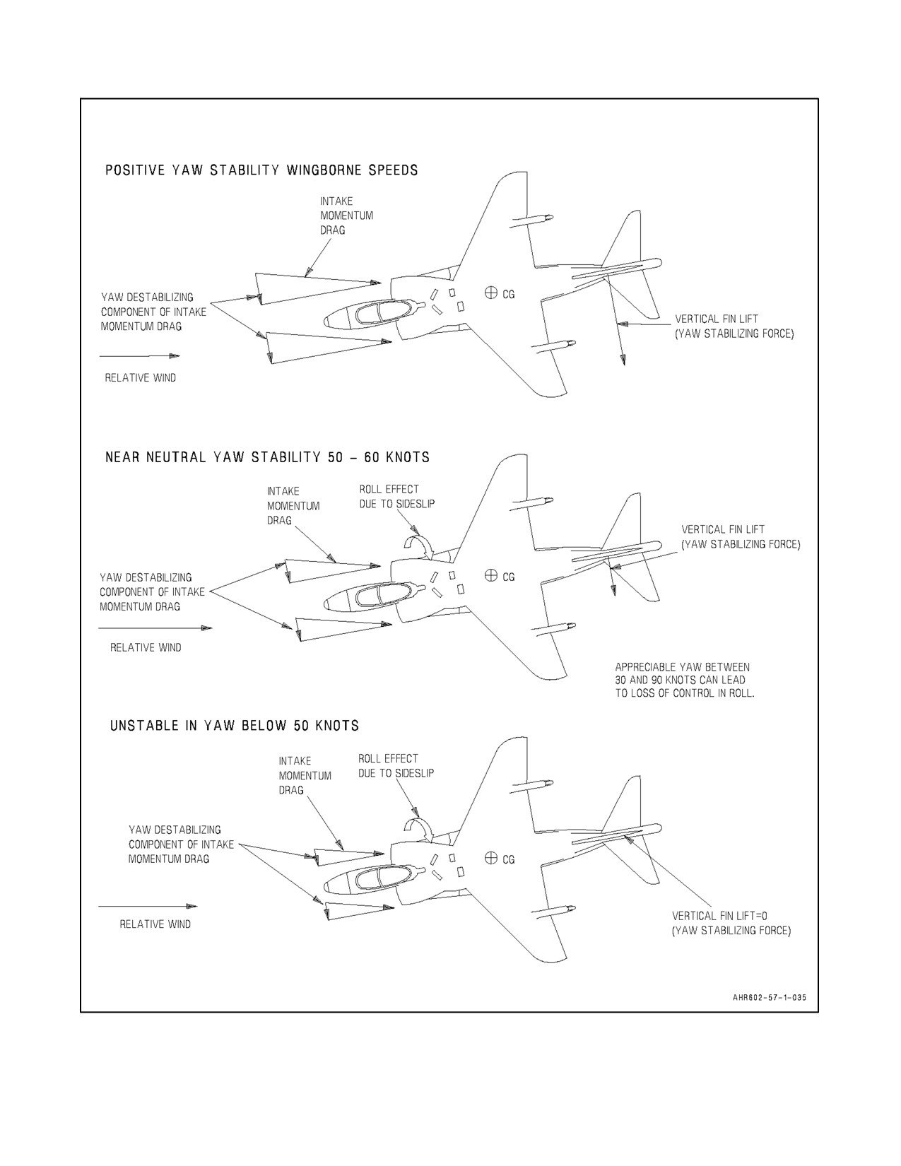
A1-AV8BB--NFM--000
Figure 11-6. Intake Momentum Drag
ORIGINAL
11-22
A1-AV8BB--NFM--000
11.8.4 Out--of--Control Roll Avoidance
From the preceding discussion it can be seen that, if the sideslip angle is zero, no rolling moment can exist. Control
of sideslip is therefore the primary method of avoiding (but not recovering from) loss of control. The most reliable
sideslip indicator is the yaw vane. The yaw vane points into the relative wind, in the direction of nose movement to
zero sideslip, and in the direction of the rudder pedal to zero sideslip. The HUD sideforce symbol is in the direction
of the relative wind and toward the rudder required to zero sideslip. The rudder pedal shaker shakes the rudder
required to zero sideslip (push the shaking pedal). The rudder pedal shaker is set at a relatively low sideforce so that
initiation of rudder pedal shaking does not indicate a requirement for large or coarse corrective action.
11.8.5 Reaction Control Power
Control in the semi--jetborne regime is provided by a combination of conventional aerodynamic controls and the
reaction control system (RCS). The effectiveness of the aerodynamic controls decreases with decreasing airspeed.
With SAS off, controls are sensitive in roll, fairly sensitive in pitch and sluggish in yaw. The pitch, roll and yaw
stability augmentation noticeably steadies the aircraft and reduces pilot workload. Simultaneous application of
control in more than one axis may result in a reduction of maximum available reaction control in all axes. This is
because a maximum control deflection in one axis uses over half the total RCS bleed air available. As an example,
full forward stick used to correct a pitch--up will degrade the pilot’s capability to correct a disturbance in yaw or roll,
and control inputs to correct this disturbance will reduce thrust of the rear pitch nozzle.
Large nose--up pitch rates must be avoided in V/STOL flight because
available tailplane and reaction control pitch authority maybe insufficient
to prevent theangleofattackfrom rapidlyincreasing abovethepointwhere
pitch control is lost. Uncontrollable pitch--up is most likely to occur at
extreme aft cg loadings and/or with the wing flaps deflected more than 25°.
Flap deflection more than 25° dramatically increases the downwash on the
tailplane. In extreme cases, this increased downwash on the tailplane
results in loss of pitch control. In these situations, the nose can be lowered
by moving the nozzle lever forward (reducing the nozzle angle 20° is
sufficient) followed by an immediate movement of the nozzle lever aft to
the previous nozzle angle (to the STO stop on a STO). If pitch control
cannot be regained with nozzle movement and altitude permits, initiate the
out--of--control/spin recovery procedure.
11.8.5.1 Nose Tuck with Flap Programming
Loss of horizontal stabilator effectiveness when the flaps program down greater than 25° can cause a nose down
pitching momentthat mustbearrestedwith RCSpressurefromtheforwardRCS duct.This effectis mostpronounced
in the TAV--8 and to a lesser extent the RADAR variant due to their heavier nose. The problem develops when the
flaps are allowed to program with the throttle at idle, providing very little pressure to the RCS. A typical scenario
that induces this is a weak pull in the break that does not decelerate the aircraft quickly so on the downwind the pilot
is fast abeam with the throttle still at idle while selecting gear down, nozzles to 60° and flaps to STOL. At the 180
position the pilot starts the approach turn descent and as the aircraft finally decelerates through the 165 KCAS the
flaps program from 25° to 62° near instantly causing a strong nose down pitching moment. Because the aircraft is
fast, the pilot still has the throttle at idle trying to get on--speed with little RCS pressure to stop the nose. This coupled
with already being in a descending approach turn can put the aircraft in an extreme nose low attitude with a high rate
of descent and very little altitude to recover. The fix for this problem is to add power prior to the flaps programming
to energize the RCS system to provide control power to stop the nose down pitch.
11-23
ORIGINAL
A1-AV8BB--NFM--000
11.8.6 Nozzle Blast Impingement
Nozzle blast impingement occurs when exhaust gases from the rear (hot) nozzles are directed onto the flap surfaces
resulting in a moderate to severe nose down pitch rate. Impingement will occur anytime the flap angle exceeds the
proper value dictated by the nominal STOL flap/nozzle interconnect schedule as shown in Figure 11-7. For example,
with a nozzle angle of 40°, a flap angle greater than 47° will result in impingement. Conversely, if flaps were failed
locked at 47°, a nozzle angle less than 40° would result in impingement. Since the flaps are located aft of the center
of gravity, any force acting on the flap surface will cause a rotation of the aircraft about the C.G. In the case ofnozzle
blastimpingement,theforceoftheengineexhaustfrom therearnozzlesacting ontheundersideoftheflaps willresult
in a nose down pitching moment. The severity of the pitch moment and pitch rate will vary with the magnitude of
flap impingement, engine rpm, and aircraft loading. Time and altitude to stop the pitch rate and recover the aircraft
will vary with pilot reaction time to apply aft stick and lower the nozzles, attitude at initiation of recovery, engine
rpm (thrust), airspeed (aerodynamic control), and initial aircraft pitch, roll, and yaw rates. Severe pitch rates of 40
to 50 degrees per second, cockpit load factors of --2.5 g, and a rapidly descending flight path can be generated by an
aircraft operating at light gross weight, nozzles aft, at full power, and flaps failed full down. Generally, full aft stick
withnozzlesmovedto40°orgreaterisrequiredtostopthepitchrateandrecovertheaircraftfromthisfailurescenario.
The extreme aircraft response to full flap deployment generally exists for nozzle angles of 20° or less. However,
beyond 20° nozzle, aircraft pitch rate response to full flap deployment quickly diminishes. Full flap deployment with
nozzle angle at 25° requires only aft stick to stop the pitch rate and establish the desired nose attitude for rapid
recovery. Full flap impingement with nozzles positioned at 30° requires little to no aft stick input to maintain the
desired climb attitude. In both cases, the aircraft maintains a zero to positive rate of climb flight path throughout the
initial impingement and subsequent recovery.
CAUTION
D Rotation of the nozzles aft with failed flaps can cause a severe nose down
pitch due to nozzle blast impingement on flap surfaces. The nose down
pitch rate will be arrested by a combination of aft stick and selection of a
nozzle angle greater than 40°. The aircraft must then be recovered from the
nose down attitude.
D Uncommanded programming of the flaps greater than 25° with nozzles less
than 20° will cause a severe nose down pitch rate. The extreme attitudes
coupled with negative g of up to --2.5, as experienced by the pilot, will be
extremely disorienting and make cockpit functions difficult to perform. A
combination of full aft stick and rotation of the nozzles to an angle greater
than 40° are required to arrest this condition.
11.8.7 Crosswind Accelerations
When conducting VTO--Accelerating Transitions, the preferred technique is to perform the maneuver directly into
the wind and then turn into the landing pattern once wingborne flight is achieved. However, there may be occasions
when local traffic procedures or the proximity of obstacles preclude this technique. When required, the accelerating
transition can be conducted along a track line that does not coincide with the wind line. After a normal into the wind
VTO, the pilot conducts a pedal turn until the nose of the aircraft is pointed down the desired acceleration path. When
the pedal turn has been completely stopped, a normal accelerating transition begins. Once forward velocity has been
established along the desired track, the pilot then centers the wind vane. This action must occur prior to reaching 30
KCAS. This normally requires thepilot to apply amoderate amount of rudderback toward the wind line shortly after
the accelerating transition begins. As aircraft velocity increases during the transition, less and less crab will be
required. This technique is referred to as a Continuous Crosswind Accel due to the fact that there is no pause between
the VTO and the transition, and the power remains at full throttle throughout the maneuver. When the desired track
substantially differs from the wind line, there is a risk that the pilot will lose adequate hover references before he can
establish a proper transition. This problem becomes more severe when excess performance is very high, the pedal
ORIGINAL
11-24
A1-AV8BB--NFM--000
turn is conducted slowly or visual cues are degraded due to darkness. If the pilot lacks proper visual cues to conduct
the maneuver or if the pilot begins the transition before stopping the pedal turn rotation, then a rapid loss of control
can occur. In order to minimize this risk, the pilot may elect to perform a Non--continuous Crosswind Accel. Due
to the use of a hover phase, this maneuver must be performed at or below hover weight. (MC computed VL weight
can be used as an in--flight substitute.) This maneuver starts with a normal into the wind PRESS--UP to a HOVER.
The pilot conducts a pedal turn until the nose of the aircraft is pointed down the desired acceleration path. When the
pedal turn has been completely stopped, the throttle is advanced to FULL and a normal accelerating transition begins.
Once forward velocity has been established along the desired track, the pilot then centers the wind vane. This action
must occur prior to reaching 30 KCAS. This normally requires the pilot to apply a moderate amount of rudder back
toward the wind line shortly after the accelerating transition begins. As aircraft velocity increases during the
transition, less and less crab will be required. Use of the hover helps to ensure that visual cues are maintained and
increases the likelihood that pedal turn will be fully stopped before the transition begins.
11.8.8 Short Takeoff
Takeoff distance charts in the Performance Data, Part XI, are based on use of the high performance Short Takeoff
(STO) technique. The essential difference between the normal and high performance STO is that, in the high
performance STO, the aircraft is rotated to a 14° pitch attitude which is maintained until all obstacles are cleared.
On a STO, the angle of attack shall not be greater than 15° Over rotation or high rotational rates may result in the
AOA rising uncontrollably even with stick full forward. When this occurs a nose down pitch may be induced by
moving the nozzle lever forward (reducing the nozzle angle 20° is sufficient) followed by an immediate movement
of the nozzle lever aft to the STO stop. Uncontrollable pitch--ups are most likely to occur at extreme aft cg loadings
and/or with the wing flaps deflected more than 25°.
During STOs with high lateral asymmetries:
1. Pilots should attempt to position the relative wind under the heavy wing (if feasible) or, if known in advance,
load the aircraft according to the prevailing relative wind.
CAUTION
Flight test results haveindicated that with asymmetries greaterthan 80,000
inch pounds pilot workload is dramatically reduced by positioning the
relative wind under the heavy wing.
2.
During initial ground roll, NWS will be required to correct tendency to drift toward the heavy wing.
3.
With lateral asymmetries above 32,000 inch--pounds, increase STO NRAS by 10 KCAS.
4.
With lateral asymmetries above 80,000 inch--pounds pilot workload is reduced and comfort level increases
by adding 15 KCAS to the NRAS.
5.
Rotating nozzles aft too quickly will reduce total roll control power requiring large lateral stick inputs away
from the heavy wing. The rate of nozzle rotation is dependent on excess performance and should be performed
at a rate which will allow the wings level attitude to be controlled without excessive lateral stick deflections.
Note
Takeoffs at aft cg positions in high crosswinds will require more forward
stick position and increased reaction control system demands. For short
takeoffs, AUTO flaps will require more forward stick displacements than
STOL flaps. AUTO flap STOs at cg positions approaching the aft limit in
crosswinds in excess of 10 knots are approaching the limits of control
authority. For crosswinds of more than 10 knots, a CTO is recommended
if runway length permits, otherwise a STOL flap STO is recommended.
11-25
ORIGINAL
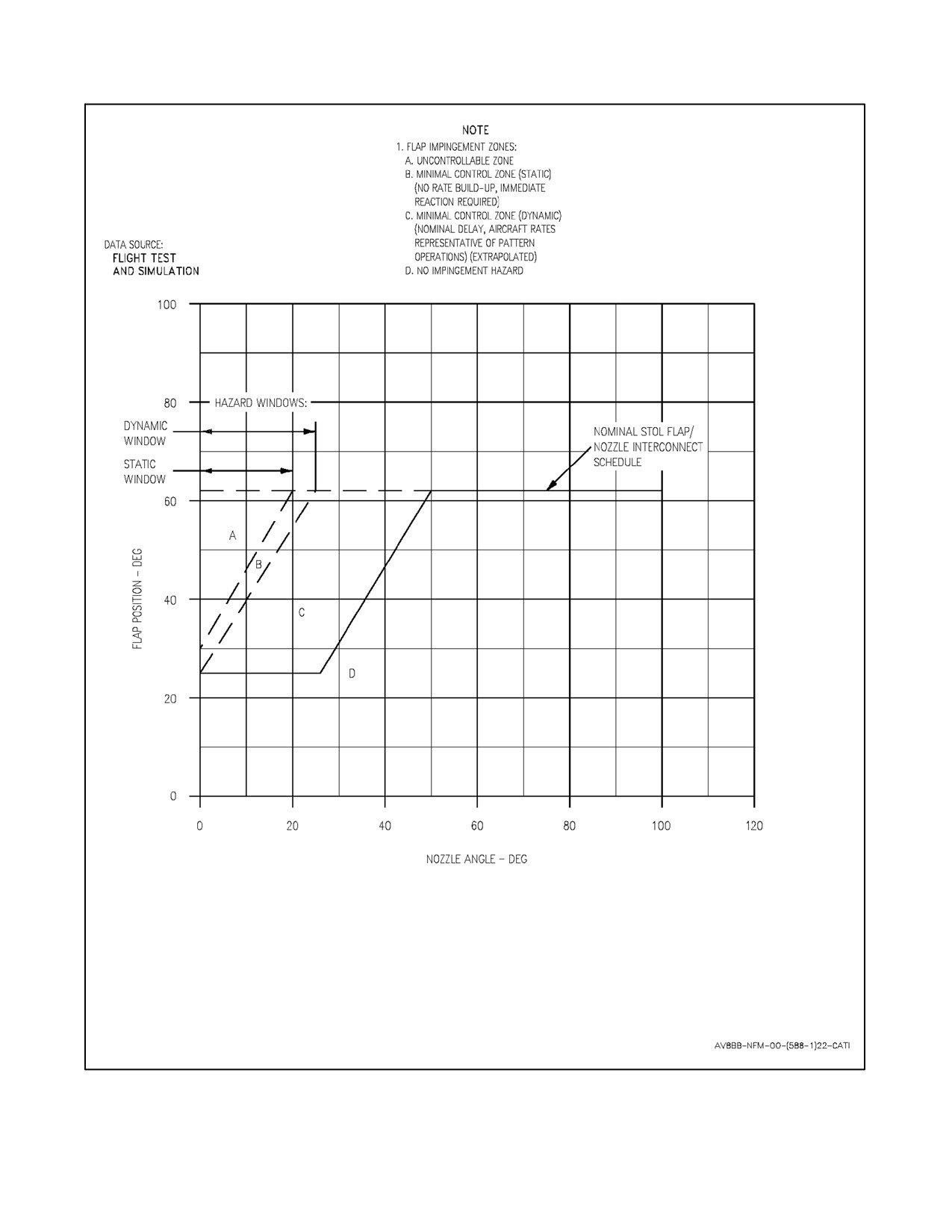
A1-AV8BB--NFM--000
Figure 11-7. Flap Impingement Envelope
ORIGINAL
11-26
A1-AV8BB--NFM--000
11.8.9 Vertical Takeoff
With SAS and LIDS operable and strakes or gun packs installed, VTOs are very smooth throughout and minimal pilot
control is required. For a maximum performance VTO, a small amount of back stick just after lift off may be required
to initially capturemoreoftheLIDS lifting pressure. IftheSAS and/orLIDS arenotoperable, upsetsin groundeffect
will be more noticeable and will require more aggressive pilot control to compensate.
During a VTO, some instability due to ground effect may occur resulting in uncommanded roll at lift--off. A
crosswind VTO may also result in uncommanded rolls at lift--off. It can be aggravated by: low performance margin,
improper longitudinal and lateral trim, lateral stick interference, allowing the heading to diverge downwind, and
nozzle misrigged/inaccuracy. To minimize those effects, VTO performance must be accurately computed, trim
properly set, stick interference avoided and heading maintained during lift--off.
Unstable rolling moments due to bank can reach a maximum at only 5° to 6° bank angle. This occurs very close to
the ground (1 foot above the deck). Crosswind during a VTO has little effect at low heights but produces a rolling
moment at zero bank angleas height increases. It is critical that any bank angleat lift--offbe immediately recognized.
Scan at lift--off on a VTO should be primarily straight ahead in order to more easily notice a roll attitude change.
Should a wing start to drop during a VTO, an immediate application of corrective control is needed to overcome the
instability. Both coarse rudder and aileron (frequently full opposite stick for a short period of time) may be required
to arrest a roll and maintain the desired heading into the wind. When too little corrective control has been applied,
or it has been applied too late, recovery to wings level may be impossible due to insufficient authority of the roll
reaction controls.
Should a roll be experienced and the bank angle cannot be reduced by full opposite control, the throttle should be
reduced and the aircraft landed if lateral velocity has not developed. Whenever possible VTOs should be executed
with nose into wind.
A VTO from a surface with lateral slope should be avoided, if possible, as the aircraft may tend to skip and skid during
engine acceleration due to the side component of lift relative to the true vertical. The wings cannot be leveled to
prevent the slide until wing gear freedom is attained and this occurs at a thrust level which exceeds that at which skip
and skid occurs. With the aircraft positioned heading up or down the slope, the nozzles may be adjusted away from
the hover stop by an angle equal to the slope so that a clean unstick may be achieved. Preferably, the aircraft heading
should be up the slope to minimize the recirculation effect.
11.8.10 Hovering
The aircraft is unstable in yaw and has neutral stability in pitch and roll in hovering flight. The reaction controls are
acceleration demand controls as opposed to the normal rate demand control of aerodynamic surfaces. This difference
requires no conscious change of pilot technique but can lead to over control until experience is gained. Turns with
very small angles of bank can be made at speeds up to 30 knots. Large sideslip angles can inadvertently develop due
to directional instability at low speed which results in yaw out of the relative wind. The sideslip which can be
developed causes large rolling moments which, in extreme cases, can lead to loss of control. If significant sideslip
develops, use rudder to reduce the sideslip and aileron to level the wings. If roll is used to reduce sideslip, a sudden
increase in incidence will occur with a resultant increase in rolling moment and possible loss of control.
11.8.11 Accelerating Transition
The aircraft is unstable in pitch during an accelerating transition. A constant attitude transition simplifies the pilot
task. If pitch attitude must be increased during transition, aim for 12° AOA and do not exceed 15° AOA. The pitch
reaction control bleed air required for trim during transition will cause a JPT increase; therefore, the JPT must be
monitored during transition. After sufficient wing lift has been attained, the throttle may be reduced to control JPT.
Transitions near performance limits require smooth and cautious nozzle control and stick movement to avoid
excessive pitch trim changes and resultant coarse corrective control. Coarse control may result in a reduction in
engine thrust due to excessive control bleed or JPT cutback. Smooth and cautious control is particularly important
when operating in confined sites where obstacle clearance is a factor.
11-27
ORIGINAL
A1-AV8BB--NFM--000
Below 120 knots, pilot action is required to minimize sideslip to prevent large mid--transition rolling moments. A
large aileron application to maintain roll attitude is an indication that excessive sideslip has developed. Rudder in
the same direction as aileron corrects sideslip. Above 120 knots, there is sufficient directional stability to control
sideslip with little pilot input required.
11.8.12 Crosswind Landing
During operations in crosswind conditions, the aircraft, in concert with the SAAHS system, reliably seeks and
maintains a zero sideslip, crabbed condition throughout the landing approach with little to no pilot input required.
The magnitude of the crab angle will vary as a function of approach speed and crosswind component. As the aircraft
enters ground effect at approximately 20 to 30 feet AGL, some natural alignment of the aircraft heading to the
established ground track will occur. The amount to which the aircraft aligns itself varies with approach speed and
rate of decent. During conventional landings, stabilized crab angles may be up to 6°, however, very little natural
alignment will occur prior to touchdown. During slow landings, the aircraft will tend to reduce approximately 50 to
75 percent ofthe stabilized crab angleprior to touchdown. During RVL landings, the aircraft will tend to nearly align
itself completely with the established ground track. Assuming that the aircraft does not stagnate in ground effect
during this natural alignment, very little deviation from the established ground track will be noted. Similarly, there
will be little to no rolling tendency associated with the natural alignment requiring pilot input to maintain a wings
level attitude for touchdown. Stagnation in ground effect or other delay in touchdown even in the presence of natural
alignment will permit sufficient lateral drift to develop resulting in sharply degraded handling qualities. Post
touchdown handling qualities will vary with gross weight, groundspeed, touchdown crab angle, and lateral drift.
While all these factors will ultimately determine how the aircraft behaves at touchdown, it is most sensitive to lateral
drift. With little to no lateral drift prior to touchdown, the aircraft completes its alignment and continues along the
established ground track with little to no initial pilot input required. If the aircraft is landed in a crab, side forces
applied to the landing gear at touchdown will result in the aircraft rolling away from the upwind wing as it aligns
itself. Theapparent severity and magnitude will vary with crab angleand touchdown speed, howeverthe aircraft will
seek and maintain the ground track established prior to touchdown. The recommended technique for landing in the
presence of crosswinds is a crabbed approach with pilot augmentation of whatever natural alignment occurs prior
to touchdown. The aircraft may be safely landed in a crabbed condition up to 10° within the crosswind envelope,
however, minimizing the crab angle prior to touchdown will minimize the touchdown aircraft motion described
above. The magnitude to which the pilot elects to further reduce the crab angle during alignment will be based on
his comfort level and proficiency. It is critical that the pilot not attempt to reduce the crab angle too early in the
approach nor stagnate in ground effect in order to minimize the opportunity for significant lateral drift to develop.
If the pilot is uncomfortable with the established crab angle during the approach and landing, he may reduce the crab
angle by either one or combination of two methods. The pilot may elect to increase his approach airspeed via use of
lower nozzle angle or flap angle with due consideration for runway length and stopping distance. If the pilot elects
to fly afasterairspeed, heshould ensurethat an on speed condition is maintained. Electing to flytheaircraftat afaster
airspeed by reducing the angle of attack to less than 10° units will effectively reduce the crab angle during the
approach, however, this will degrade touchdown and post touchdown handling qualities. His second option may be
to reduce crab angle just prior to touchdown via aircraft natural alignment or rudder input. If the pilot favors this
method, rudder input should be made after the landing attitude has been set, and prior to touchdown, generally 20
to 30 feet AGL. This will precludedevelopment oflateral drift at touchdown optimizing aircraft handling and rollout
characteristics.
During landing rollout, aircraft control and steering may be enhanced by selecting flaps to CRUISE. Selecting 4°
nose down trim when below 100 KIAS will also reduce the porpoising effect common to conventional landings.
Lateral stick into the wind will also assist with maintaining a wings level attitude during landing rollout. Forward
stick during landing rollout and PNB will result in more weight shifting to the nose gear sharply reducing
controllability and steering effectiveness. Runway centerline tracking immediately after touchdown should be
accomplished using rudder aerodynamic forces. As the rudder loses its effectiveness to maintain desired track, NWS
should be used for steering the aircraft. Care must be taken to ensure that the rudder pedals are centered prior to
engaging the nosewheel steering to preclude undesirable swerve and potential loss of control.
ORIGINAL
11-28
A1-AV8BB--NFM--000
11.8.13 Decelerating Transition
Power must be applied to maintain the desired flight path during deceleration. Use the stick to maintain 8° to 10°
AOA and the rudder to minimize sideslip. Should application of aft stick to the aft stick stop be required to maintain
approach angle of attack when not associated with flap transition in a V/STOL configuration, the aft RCS nozzle may
have failed in the open position. If this situation is encountered, emergency procedures for Reaction Control failure
should be initiated. With AUTO flaps, an appreciable power increase is required between 80 knots and 40 knots to
prevent sink as wing lift decreases rapidly. With STOL flaps, this power increase is delayed to below 40 knots.
Maintain 8° to 10° AOA until below 50 knots. Lower AOA will reduce nozzle angle and increase deceleration
distance. A combination of lower AOA and braking nozzle can be used to improve forward visibility when
approaching a restricted site but this is an inefficient balance between wing lift and jet lift. The optimum compromise
between performance and handling is 10° AOA which is the target value for all decelerating transitions.
Minimize sideslip, particularly with a crosswind. Aircraft directional stability will minimize sideslip above 120
knots, but, below 120 knots, and increasingly until 30 knots is reached, sideslip must be minimized by rudder to yaw
into the relative wind with the wings maintained as level as possible. If the surface wind is over 30 knots, judgement
of the deceleration path is particularly important since drift may induce the pilot to bank to achieve the desired hover
position. The desire to turn the aircraft toward a landing site after a late deceleration or misaligned approach must
be resisted until below 30 knots. At altitudes near 100 feet, significant speed relative to the ground may exist while
the aircraft appears stationary. For fine range correction to a landing site, vary the thrust axis by changing attitude.
Coarse range correction may require excessive throttle adjustment to compensate for wing lift change. A wave--off
from any point in a decelerating transition may be made by progressively moving the nozzle lever forward. A
wave--off should be made immediately if any control difficulties are encountered, or if JPT or rpm do not remain
within planned limits.
11.8.14 Vertical Landing
Without LIDS during a vertical landing, at about 15 feet above the ground, cobblestoning (random attitude
disturbances) may occur. Control stick activity will increase in order to hold attitude. Frequent coarse control
movements may be required just prior to touchdown. If the rate of descent is correct, only small power changes are
required close to the ground; however, a too fast descent will require a large power increase to arrest the descent. A
too slow descent may result in reingestion and a large throttle movement to compensate for the reduction in engine
thrust.
With LIDS, ground effect disturbances are reduced and control activity is small. The LIDS will cushion the descent,
normally requiring a power reduction below 10 feet. If the rate of descent is correct, only small power changes are
required close to the ground; however, a too fast descent will require a large power increase to arrest the descent. A
too slow descent may result in reingestion and additional power may be required to compensate for thrust loss due
to reingestion. Also, winds greater than 10 knots can reduce the effectiveness of the LIDS.
If the fast deceleration solenoid is disabled, the rate of descent for a vertical landing should be maintained at no more
than 200--300 feet per minute. Knowing that wind in excess of 10 knots can cause a “suck down” effect at
approximately 10 feet off the deck, using this modest rate of descent initially may keep the aircraft from developing
an excessive rate of descent just prior to landing that would require a large power addition and engine acceleration
with no countering “fast decel” effect after landing. Conversely, if the winds are light, as previously discussed, the
aircraft’s rate of descent will decrease just prior to landing due to encountering the LIDS cushion (“hung up in
cobblestones”). As the pilot senses the rate of descent decreasing the power may be reduced (decelerating the engine)
tomaintainaconstantrateofdescenttotouchdown,whichwillpartiallyfulfillthefunctionthat thefast decelsolenoid
would have performed. While descending through 10 to 20 feet AGL on a VL, pitch attitudes above 10 degrees can
result in a rapid increase in rate of descent due to loss of LIDS effectiveness and potentially hot gas reingestion.
11.8.15 Slow Approach and Landing
Fixed 60° nozzle STOL flap approaches optimize the entrained flow effects of the wing, flap, and nozzle geometry.
This reduces the average engine power and fuel flow required for approach, as well as affording the easiest and most
precise control of glideslope. Selection of the hover stop just prior to touchdown is an option to reduce landing rollout
distance.
11-29
ORIGINAL
A1-AV8BB--NFM--000
If considerations for maximum available engine power or minimum stopping distance dictate, a fixed throttle
approach can be flown with the following considerations:
With over 80 percent rpm in a slow approach, nozzle angles are typically 60° and above. A small change in nozzle
angle produces a large change in horizontal thrust but only a small change in vertical thrust. Higher rpm requires a
larger nozzle angle and the effect of change in nozzle angle is more marked. A wave--off, initiated on approach without
applying power, will result in a slight tendency to sink unless AOA is increased. Increased rpm will reduce the AOA
almost instantly, increase the airspeed, and reduce the rate of descent. Do not exceed 15° AOA during wave--off.
If the speed brake does not extend when the gear is lowered, a directional oscillation may occur during the approach
which can be controlled with rudder. Automatic speed brake extension does not occur when the landing gear
emergency lowering system is used.
During SL with high lateral asymmetries the following recommendations apply:
1. Relative wind should be placed under the heavy wing if feasible.
CAUTION
Flight tests have shown a drop off in handling qualities with asymmetries
greater than 80,000 inch--pounds without the relative wind under the heavy
wing.
2. Maximum lateral asymmetries will require considerable pilot compensation due to degraded flying qualities.
3. Full lateral trim authority may be required.
4. Pilot workload can be reduced by decreasing nozzle angle from 60° to 50°, or by using the variable nozzle SL
technique with auto flaps selected.
5. A firm touchdown should be utilized to minimize time in ground effect.
11.8.16 Center of Gravity Effects (Trim Bleed Rise)
The aircraft with a forward cg requires bleed from the forward RCS duct to balance the aircraft in a hover. This
requirement is due to a large difference between the cg of the aircraft and the thrust center of the engine. All AV--8B
aircraft experience this cg shift as fuel is burned from the fuselage tank. This is especially evident in the TAV--8B
and radar aircraft due to increased weight in the forward fuselage.
The problem of a forward cg manifests itself only during hot weather when the aircraft is performance limited by the
engine JPT. During these periods, the aircraft can perform V/STOL maneuvers only at light gross weights. As the
gross weight is adjusted to enable vertical operations, greater bleed demands from the forward RCS valve is required
to adjust for the forward shift in cg.
11.8.17 V/STOL with Asymmetric Loading
All sideslip aids utilizing lateral accelerometer inputs (yaw stab aug, shakers, HUD sideslip symbol) will operate
erroneously. The external sideslip vane should be used to minimize sideslip. If landing is required with significant
asymmetric loads, refer to Asymmetric Landing, Part V. A long straight--in approach will reduce pilot workload.
Small lateral/directional oscillations may occur during an approach in turbulence or gusts. If a steady approach has
been achieved, these oscillations will damp out. If a vertical landing is required, the decelerating transition shall be
made directly into the wind. The transition should be flown in as near level attitude as possible to avoid a need to
reduce power for altitude control as this significantly reduces available roll reaction control power. If control
difficulties or severe lateral/directional oscillations occur, immediately initiate a waveoff.
11.8.18 SAAHS--Off V/STOL
11.8.18.1 Flight Characteristics
Any discussion on the skills and procedures for safe recovery of an aircraft that has degraded or failed SAAHS must
begin with an understanding of the aircraft’s inherent stability in the various regimes of flight.
ORIGINAL
11-30
A1-AV8BB--NFM--000
11.8.18.1.1 Pitch
The airplane is neutral to unstable in pitch in the V/STOL regime. As the airspeed decreases below approximately
120 KCAS, during a decel with the nozzles down, the pilot must begin to program the stick forward and trim nose
down to counter the increasing nose--up pitch tendency. There is a “neutral point” around 100 to 110 KCAS where
the airplane will tend to maintain its attitude. Forward extending stores, water, and engine thrust (adding power) can
further increase the instability. In ground effect on roll--on landings and during the decel, approaching the hover, and
while executing the vertical landing, the AV--8B II+ and TAV--8B’s nose often tends to drop unless this is anticipated
by the pilot.
11.8.18.1.2 Yaw and Roll
The jet is increasingly stable in yaw and roll at speeds above60 to 70 KCAS as theairflow overthe vertical stabilizer
contributes a strong counter--force to yaw and aerodynamic flight controls regain effectiveness. The jet, however, is
near neutral stability in yaw and roll between 50 to 60 KCAS and unstable below 50 KCAS. In addition to honoring
theone--halflateral stick limitation, thepilot must control yaw at all times using thewind vane, rudder pedal shakers,
and VSTOL ball (HUD sideslip indicator) because appreciable yaw between 30 to 90 KCAS can lead to loss of control
due to sideslip--induced roll.
11.8.18.2 SAAHS--Off Landing (RVL and Decel/VL)
In many cases a degraded SAAHS or SAAHS--off landing will be performed as the result of another system
malfunction that provides inputs to the SAAHS. In these cases the pilot must make the appropriate decisions in light
of the malfunction, but must also deal with the SAAHS--off flight and landing of the airplane. By itself SAAHS--off
flight is manageable, but can be complicated by other malfunctions or external conditions so it is important for the
pilot to understand the considerations of operating without the SAAHS. Most of the system malfunctions that cause
the SAAHS to become degraded or fail will also require you to do an RVL or VL to land the aircraft therefore the
pilot must understand the capabilities of the primary flight control in the semi--jetborne and jetborne environment,
the Reaction Control System.
11.8.18.2.1 RCS
The reaction controls are relatively weak compared to aerodynamic controls in conventional flight. Reaction controls
are an “acceleration demand” control which means that their thrust displaces the aircraft in the desired direction at
a slowly increasing rate. Aerodynamic controls, on the other hand, are more powerful “rate demand” controls which
cause a more dramatic and immediate displacement of the aircraft (assumes that there is sufficient wind across the
control surfaces -- starts at approximately 60 KCAS and increases with airspeed.) This is why holding the nose of
the aircraft at the desired attitude is so important. If the nose movement is not controlled, it can accelerate at a rate
at which the reaction control system cannot overcome. The TAV--8B in a hover at lower fuel weights (approximately
2,000 lbs and below) uses approximately two--thirds of the available RCS power to hold the nose up because the CG
is slightly forward of the center of thrust. Care must be taken so momentum, gravity, and pitch rate do not overtake
the reaction control effectiveness. There is only a finite amount of control effectiveness available from the reaction
control system. A simultaneous demand from all axes results in a reduced amount of power from each RCS and,
therefore, a relatively diminished reaction control capability. Flying the aircraft in balanced flight (wings--level and
into the relative wind) will help reduce the overall bleed demand and provide more available pitch and roll control
power/effectiveness.
11.8.18.2.2 Approach and Landing
The key to a successful SAAHS--off V/STOL landing is anticipation, smooth airwork, and proper trimming of the
aircraft. The pilot essentially has to do the job of the SAS by immediately correcting any excursions from balanced
flight that may build up a rolling moment and prevent a safe landing. SAAHS--off V/STOL should be done into the
wind to keep sideslip at zero and maintain balanced flight. In addition to reducing the opportunity for a rolling
moment to build, this reduces thenumberofvariables the pilot must account for and thereby reduces pilot work load.
When performing a SAAHS--off landing, the pilot should lower the landing gear early and trim it for level flight
(either for a straight--in or in the landing pattern). The pilot should then fly a slightly longer pattern to allow more
straight away to trim and ensure the approach is into the relativewind. Thepilot should fly aslightly flatterapproach
11-31
ORIGINAL
A1-AV8BB--NFM--000
(avoiding unnoticed AOA buildup with increased rates of descent) and look for normal cues for the proper position
to select hover stop. Hover stop should be selected so braking stop and excessive nose up profiles are not required
to stop the aircraft over the landing spot. This would dramatically increase pilot workload. If this condition occurs,
a wave off should be initiated and the approach tried again. During the decel and in the hover until landing, the vane
must be kept into the wind at all times. This may be a challenge because the nose will want to wander due to intake
momentum drag with no balancing effect from the vertical stabilizer and the pilot will need to actively control the
aircraft to keep it centered. Any deviations in roll or yaw must immediately be countered so rates that exceed control
power/effectiveness are not exceeded (remember the finite capability of the accelerating reaction controls). As with
all V/STOL, on SAAHS--off V/STOL the pilot must fly the aircraft all the way to the deck. Deviations cannot be
allowed to go unchecked and the rate of descent must be kept under control. If there are winds approaching or
exceeding 15 knots, a power addition in close must be anticipated so a controlled descent can be made and a power
bounce can be avoided. This is especially important if the fast deceleration solenoid is disabled. The selection of an
RVL or VL is a factor of several considerations. The first of these considerations starts with the type of landing
NATOPS recommends for the aircraft malfunction. Other considerations include winds, runway length, condition,
and surface, type of malfunction(s), available performance, and others. For example, on a calm day, a SAAHS--off
RVL (there will rarely be a time when a 5 to 6 degree RVL is required, --3 degrees should be sufficient in most cases)
should beeasily controllable. However, with asignificant crosswind, avertical landingmay beabetterchoiceaslong
as the additional power requirement is anticipated and performance margin is available.
11.9
ENGINE HANDLING CHARACTERISTICS
11.9.1 Engine Handling on Takeoff
When accelerating from low power, the limiting rpm may be reached before reaching the limiting JPT due to thermal
lag. This condition is not a steady state. The JPT will continue to rise. The JPT will approach the limiting datum where
the JPTL will reduce fuel flow, hence rpm, to maintain the JPT limit. Three important factors which act to determine
the final JPT/RPM relationship are bleed usage, reingestion, and ambient temperature.
11.9.1.1 Bleed Usage
Refer to paragraph 2.3.8.1 for description of bleed effects on engine performance and thrust available. Large bleed
demands are associated with accelerating and decelerating transitions, particularly if accomplished at an AOA other
than optimum. Downward thrust from the wing RCS valves causes a nose down pitching moment that may be
countered by increasing downward thrust from the forward RCS valve. Increased forward RCS bleed demands
required to balance the aircraft in a hover are associated with lighter aircraft weights and the resulting forward cg.
11.9.1.2 Hot Gas Ingestion
Reingestion effects are small during a normal into--wind VTO. A no--go or excessively slow VTO, a downwind VTO,
a VTO where the aircraft drifts backwards, or a VTO where the nose is high can result in reingestion, large JPT
increases, and compressor stalls.
11.9.1.3 Ambient Temperature Effects
The JPT varies as a function of ambient temperature. As the ambient temperature decreases the JPT will decrease.
11.9.2 JPT Limiter
The engine fuel system reduces rpm as the short lift (wet or dry) limit is reached if the nozzles are deflected more
than 16° or the landing gear is selected down. The throttle must be reduced to enter normal lift from short lift.
Allowing the engine to continue to operate at the short lift limit, when not required, rapidly increases the life count.
When the landing gear are up and the nozzles are rotated up through 12 to 7 toward fully aft the JPTL will signal DECS
to reduce RPM to maintain JPT limits within the maximum thrust datum.
TheJPTL reduces enginerpm to themaximumthrust datumwhen boththelandinggearisselected upand thenozzles
are rotated up through 12° to 7° toward fully aft.
11.9.3 Water Injection
Water injection lowers the JPT about 35 °C for the --406 engine and about 20 °C for the --408 engine for a given thrust.
Water injection does not change engine handling technique. With the water injection switch in TO or LDG, the engine
ORIGINAL
11-32

A1-AV8BB--NFM--000
fuel system is reset to allow a 3.3 to 4.3 percent increase in maximum rpm for the --406 engine and 6.0 to 7.0 percent
increase for the --408 engine, even if water does not flow and the FLOW light does not come on.
When water is exhausted with the engine above the short lift dry limit, JPT will not be automatically reduced to the
short lift dry limit. When water is exhausted with the engine below the short lift wet limit, JPT will rise. If the JPT
reaches the short lift wet limit, a small thrust loss may occur. Whether or not water is flowing, the rpm (thrust) can
be maintained by overriding the limiters if required. The JPT will exceed the short lift dry limit.
Water flow is stopped by reducing the throttle below 94 to 96 percent rpm for the --406 engine, 103 to 105 percent
rpm for the --408 engine, or by selecting the water arm switch off. If water conservation is desired, the water switch
may be selected off before rpm is reduced. If the water switch is turned off above about 87 percent rpm, whether or
not water is flowing, there will be a 3 to 4 percent rpm reduction with the --406 engine and a 7 to 8 percent rpm
reduction with the --408 engine, due to governor limit reset.
After takeoff, if it is desired to use the water rather than jettison it, the throttle should be maintained at the lowest
rpm which will keep the water flowing. This will reduce engine wear caused by a slightly inferior flame pattern with
water.
11.9.4 Engine Life Versus JPT
Engine life is determined by flight hours and Engine Life Counts (ELC) and can be expended in either. Engine
operating time is one measure of engine life. If engine JPT is not considered, the engine would be pulled at the end
of the flight hour limit. Engine life counts is another measure of engine life and is a function of the thermal stress
placed on the engine. The greater the thermal stress, the more engine life that is expended. Over--temperature
conditions, besides using the entire engine life count, can literally melt the turbine section of an engine. Thermal stress
is measured in Engine Life Counts.
The engine life of the --406/--408 engines are as follows:
ENGINE
TIME (HOURS)
COUNTS
406A
500
5,500
406B
750
7,500
408A Pre--PPC 192
1,000
35,000
408A PPC 192/408B
1,000
50,000
The engine count rate (engine life counts per minute) is a logarithmic function of engine JPT, Figure 4-3. To help
explain this relationship, a comparison of --408A/B engine lift ratings versus engine life rate is as follows (a different
but similar relationship exits for the --406):
LIFT RATING
JPT
COUNT RATE (PER MINUTE)
SLW
800
Approximately 1,500
SLD
780
Approximately 600
Combat
750
Approximately 60
Max Thrust
710
Approximately 5
It is apparent that time spent at or near the engine lift ratings (SLW, SLD) greatly reduces engine life. Even a 15°
reduction in JPT (from 800° to 785 °C) can save hundreds of counts. Every attempt should be made by the pilot to
reduce aircraft gross weight when conducting vertical landings to avoid premature engine removal as a result of
excessive engine life counts.
11.9.5 Accelerating Transition
After a VTO, RVTO, or STO, JPT will increase during the transition due to RCS bleed demands needed to trim for
the transition. A progressive reduction in throttle cannot be made simultaneously with reduction of nozzle angle so
one or more step reductions in rpm may be necessary during the transition.
11-33
ORIGINAL
A1-AV8BB--NFM--000
11.9.6 P3 Limiter Fan Speed Fluctuations
When operating at high airspeeds (greater than 450 KCAS), low altitudes (below 3,000 feet) with low ambient
temperatures (ISO standard day temperature and below for --408), the engine operates on the P3 limit and fluctuations
in fan rpm ofapproximately 1to 3percent mayoccur. Thesefluctuations willoccuratarateof2to 3times persecond,
reducing the throttle slightly will cause the fluctuations to stop.
11.9.7 Decelerating Transition
Before commencing a decelerating transition pay due regard to landing site pressure altitude, temperature, wind, and
aircraft weight. As nozzles are lowered and deceleration begins, increase power to replace wing lift loss. With STOL
flaps, an appreciable power increase is required below 40 knots to prevent sink. A long slow deceleration with gentle
nozzle rotation and power application requires less bleed than one which uses the braking stop throughout the
deceleration. A braking stop deceleration will require about 2 percent more rpm than an equivalent hover stop
deceleration. Very coarse nozzle application and control usage can cause high bleed demands and JPT rise which will
dangerously reduce the performance margin. If either an rpm or JPT limit is approached, perform a wave--off and
reduce aircraft weight before commencing another approach.
11.9.8 Landing
Landing, like takeoff, can be an RPM or JPT limited maneuver. Use of the LDG position of the water injection switch
will increase power and save water by delaying flow until about 684 ±5 °C JPT with the --406 engine or 765 ±5 °C
JPT with the --408 engine. This flow point will occurlatein thedeceleration thereforeextraattentionto powermargin
available is required. If wave--off is not feasible and JPT is limiting power, consider overriding the JPT limiter.
11.10 JET EXHAUST INTERACTION
11.10.1 Energy Levels in V/STOL Flight
The front nozzles exhaust emerges at about 700 knots, 105 °C (220 °F) and 16 psi. The rear nozzles exhaust emerges
at about 1,050 knots, 645 °C (1,195 °F) and 11 psi. The reaction control valves exhaust emerges at about 1,500 knots,
400 °C (750 °F) and 150 psi. Although velocity, pressure, and temperature drop off with distance, the exhaust velocity
at ground level in a low hover can be 300 to 400 knots at 4 psi. If this pressure is permitted to build up under a surface
such as a landing mat or manhole cover by penetrating through holes or around unsealed edges, the lifting force
becomes tremendous. A pressure of 4 psi will lift 4--foot--thick concrete or 8--inch--thick steel. The aircraft has proven
to be an efficient manhole cover remover although it displays no discretion in depositing them after removal. The
aircraft has raised an 11 ton mat 4 feet above the ground. Pneumatically supported mats do not soften the landing;
therefore, all landing mats should be thoroughly sealed including the perimeter. The aircraft should never cross the
edge of a mat in V/STOL flight at less than 50 feet.
11.10.2 Single Exhaust Pattern
A jet exhaust will interact with a surface upon which it impinges to form a flow pattern as shown in Figure 11-8. In
the V/STOL mode the predominate surface is the ground which may be considered as a plane approximately normal
to theexhaust; however, thepresenceofotherlargesurfaces in theimmediatearea, such as buildingsorvehicles,may
alter the flow pattern to some extent. The jet exhaust will mix with the surrounding air by jet edge shear resulting
in a rapid drop in temperature and velocity but with a relatively small reduction in mass flow.
11.10.3 Complex Exhaust Patterns
Figure 11-9 is a pictorial representation of the interaction of the four exhaust nozzles and the ground for the aircraft
in a low level hover. Interactions of the control reaction jets are not shown in order to simplify the representation and
discussion. Their interaction has a considerably smaller though similar effect on the complete pattern.
Note that there are two intersecting surfaces of symmetry labeled A--A and B--B. Their point of intersection on the
ground is the initiation point for a relatively focused jet fountain which angles toward the tail of the aircraft. This
angle is due to the higher energy of the forward nozzles in comparison with the aft nozzles due to their exhausting
cooler air with a consequent higher mass flow.
ORIGINAL
11-34
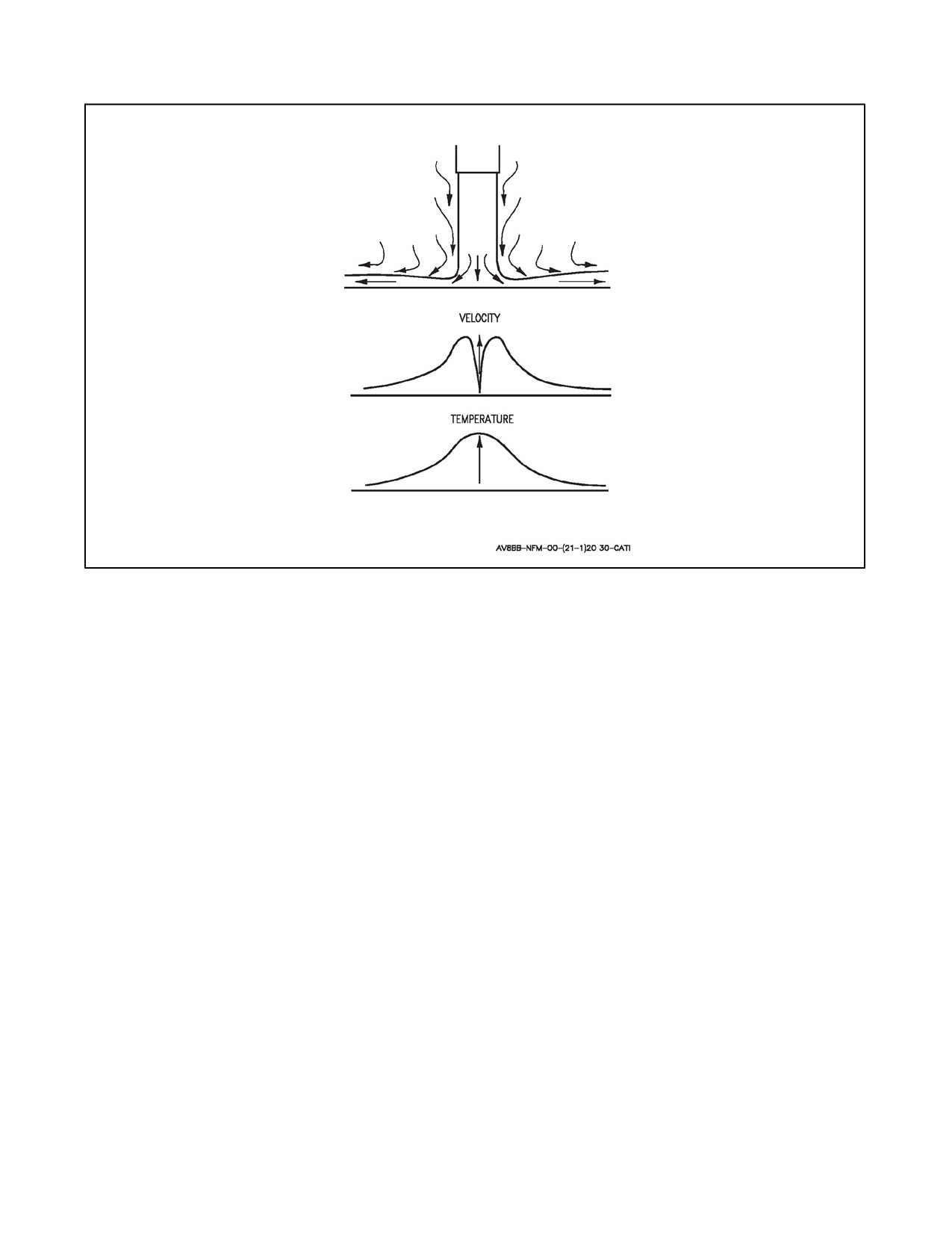
A1-AV8BB--NFM--000
Figure 11-8. Single Exhaust Pattern
11.10.4 Instability Due to Ground Effect
Figure 11-10 illustrates two instability mechanisms associated with the jet fountain. As the aircraft reaches a critical
altitude the jet fountain moves forward from aft of the aircraft and commences to impinge on the tail surfaces causing
a nose down trim change. As the aircraft descends, the center of pressure moves forward on the aircraft and at the
same time, becomes more powerful. These two actions tend to cancel each other, however, as the jet fountain moves
forward, its force is expended on varying surface areas resulting in random pitch trim changes. As the aircraft is rolled,
thejet fountain moves toward thehigh wing. If it then impinges upon theaircraft it will tend to increasethe roll angle
and may cause a pitch trim change. If it leaves the aircraft surface it will cause a nose up pitch trim change. Surface
irregularities will also cause deflection of the jet fountain causing rapid trim changes or turbulence sometimes known
as cobblestoning. Wind gusts will also cause random trim changes. If LIDS is used, these effects are greatly reduced.
11.10.5 FOD
V/STOL aircraft are particularly adept at creating their own FOD and then ingesting it. FOD can cover a wide range
of effects ranging from covering aircraft with dirt and dust to severe damage to the airframe and engine possibly
resulting in failure and catastrophic destruction to the aircraft as well as possible death or injury to the pilot. The most
FOD--sensitive component of the aircraft is the engine. The Pegasus engine is inherently capable of dealing with
ingested debris better than smaller engines in conventional fighters and has been qualified to withstand impact of a
1 pound bird at 600 knots when running at 97 percent Nf. If engine damage due to FOD is suspected airborne a pilot
should perform the Engine Mechanical Failure/Engine Vibration emergency procedures. In most cases FOD is not
noticed until post flight inspection by the pilot or maintenance personnel. Despite the ability of the Pegasus to
withstand FOD, it is highly susceptible to FOD due to the fact that the Harrier in V/STOL operations tends to disturb
more surface debris than conventional aircraft. The chance of FOD ingestion is dependent to a great degree on the
observance of correct operating procedures.
11-35
ORIGINAL
A1-AV8BB--NFM--000
11.10.5.1 Engine
The low pressure fan blades of the Pegasus engine are made of high--strength titanium alloy. These blades rotate at
over 6,000 rpm and can ingest objects at a relative speed in excess of 1,000 mph. Soft objects generally do not cause
damage, however harder objects such as stones or metallic objects that impact the blades at these high relative speeds
can seriously damage the engine. FOD is normally discovered on the LP fan blades or stator vanes, but not always
on the first stage. The first evidence of damage may occur on the second or third stage. The HP compressor blades
are also liable to be damaged. The 408 engine is more susceptible to later stage damage than the 406 engine due to
a reduced number of blades on the first stage (23 vice 26) and thus greater gaps through which objects can pass. Some
objects may shatter on impact and generally do not cause further damage to the engine. Harder objects have a tendency
to make multiple impacts as they bounce around the engine. Blade leading edges can be damaged causing poor
aerodynamics, reduced engine performance, possible surge and stress concentrations that can lead to blade failure
within a short time. Blade failures will cause further damage down the engine and may cause catastrophic engine
failure.
11.10.5.2 Jet/Ground Interaction
If a jet of air is directed at a solid surface like the ground it does not bounce off. The jet flows away smoothly in a
radial pattern as a sheet of air from the center of the impact area. This is called a wall jet, and at the center point of
impact a high pressure exists (stagnation point). When two or more of these sheets meet the effect is arising jet sheet
flow. Close to the ground the Harrier’s four exhaust jets, in a normal hover attitude, interact to create a rising fountain
at a point centered laterally about the aircraft and slightly aft of the center point between the nozzles. This interaction
results in a fountain that rises and flows rearward. As the aircraft descends the upflow increases in strength and the
fountain moves forward relative to the aircraft. At touchdown the fountain impinges at maximum strength directly
on the main gear and belly just forward of the main gear doors. This fountain is the cause of the “cobblestone” effect
identified by a high frequency buffet of the aircraft when in close proximity to the ground in a hover. The fountain
describes the concentration of the upflows, but in reality there exists a sheet of rising flow all along the center line
oftheaircraftforeandaft.WhileFODhasthepossibilitytoridethisupflowanddamagetheairframeaftoftheintakes,
its most dangerous region is the part of the upflow that goes to the intakes. When the nozzles are deflected aft the
upflow biases in a rearward direction, however some forward--moving upflow persists down to jet impact angles as
small as 20° to the ground. When the aircraft is moving forward the upflow tends to move rearward. This effect is
dependent on throttle position and nozzle angle. As the ground speed decreases the upflow will move progressively
forward towards the intakes until 50 knots, at which point the upflow will move forward of the intakes. It is this reason
that RVLs should target 60 knots ground speed, and should never be flown at less than 50 knots. It is also the reason
than PNB should cease at 60 knots. If lower airspeeds are used it must be understood that the risk of FOD increases.
After PNB, selecting idle below 50 knots will also help reduce FOD.
The energy output of the Pegasus engine exhaust flows in V/STOL flight is approximately 30,000 horsepower. In
V/STOL flight the forward cold nozzles have a jet velocity of around 800 mph, a stagnation pressure of 16 psi, and
a temperature of 105 °C. The rear hot nozzles have a jet velocity of about 1,200 mph, a stagnation pressure of 11 psi
and temperatures of about 700 °C. In V/STOL flight the reaction control system output is up to 1,700 mph jet velocity,
150 psi stagnation pressure, and 400 °C temperature. An object lying on the surface exposed to these high velocity
jet sheets can acquire speeds of up to a hundred or more mph in a relatively short distance. If the surface is rough
or uneven it almost inevitably bounces and may be deflected sharply up into the air. This path could be toward the
intake, particularly if the motion is caused by the front jet sheets.
The Pegasus engine also has the ability to damage surfaces that are not suitable. If the ground is granular a crater will
form immediately starting at the stagnation point. If unprepared surfaces are used, such as grass, the jets have a
tendency to dry the covering causing it to lose its cohesion and break up. This can occur in as little as a few seconds
over the same spot and thus requires the pilot to keep the aircraft and exhaust from residing over the same spot. For
this reason VTOs or VLs should never be attempted over unprepared natural ground, no matter how firm and stable
the surface appears. True vertical take--offs and landings always require a prepared surface (mat or concrete
pavement).
AM--2 aluminum mats can be used for V/STOL operations if prepared properly. The edges of the mats should be
sealed and anchored at the edges. If the aircraft’s exhaust sheet crosses the edge of a mat at a low hover height and
the mat is not anchored or sealed properly the mat and entire pad can become airborne. The same applies for the
ORIGINAL
11-36
A1-AV8BB--NFM--000
connections between mat sections. AM--2 mats should always have their edges properly sealed and should be securely
staked to the ground. Never rely on weight alone to hold down a pad. The aircraft should never cross the pad at less
than 50 feet to preclude the jet sheets from lifting the surface at the edges. Debris may be raised at these heights and
blown onto the pad or into the intakes and as such the Harrier should not perform a decelerating transition over a
surface where debris may get lifted or disturbed below 150 feet. Harriers should also avoid performing V/STOL
operations over manhole covers or other objects that may be picked up by the jet sheets. Concrete pads are normally
segmented slabs to allow for expansion. The joints of these slabs can contain loose debris and if unsealed may allow
for the pressure from the engine exhaust to lift the slabs. Any debris contained in these joints may also be blown out
violently and may cause FOD. These joints must be sealed continuously otherwise the jet can penetrate even a small
slot. Ifagap is present thesealantmay alsobeblownout andinto theairbytheaircraft.It isforthisreason thatHarrier
pilots should ensure that vertical takeoff and landing areas are free from FOD, slots in pavements are free from loose
debris and are properly and continuously sealed. The seal should extend the full slot depth and should not be cracked
or gapped.
Poor workmanship or inadequately repaired surfaces can produce unexpected hazards for FOD during V/STOL
operations. Care must be taken to inspect the surface for damage and cracking in areas that V/STOL operations may
be conducted that could result in high velocity exhaust exposing potential weaknesses in the surface. Asphalt or other
softer substance heat up quickly and can be damaged easily by the Harrier’s exhaust. If using a surface other than
properly sealed concrete or if in doubt about the integrity of the surface the aircraft should be operated to minimize
jet exhaust residence time on any one spot by using STO or RVTO and RVL or SL procedures to reduce the chances
of damage. Prolonged and repeated operations over the same surface will accelerate the wear and possible damage
to that surface. Consideration should be given to varying V/STOL spots on asphalt orsoft surfaces to maximizetheir
serviceability.
Vertical takeoffs and landings should only be performed on clean surfaces. Stabilizing above 50 feet for several
seconds over a landing spot may clear debris prior to landing and possibly reduce the chances of FOD. Vertical
takeoffs can benefit from reduced FOD risks by being performed after an aircraft has performed a vertical landing
at a spot in order to ensure any debris has been blown off the pad.
11.10.5.3 Taxi Operation
At low power settings the engine will not normally pick up objects that are not already airborne. The ground attitude
of the aircraft is greater than that of conventional aircraft. Even with the nozzles fully aft the jets meet the ground
close behind the aircraft, presenting a FOD hazard to following aircraft from surface debris which may be disturbed
and swept to the rear. The Harrier also has a much wider area of rearward jet flow than conventional aircraft since
the jets are separated by the fuselage and splayed outwards by 50 each side. The best formation for multiple aircraft
taxiing for FOD avoidance is line abreast with each aircraft’s intakes forward of the other cold nozzle exhaust. If it
is required to taxi in trail thedistance behind another Harriershould beno less than 600 feet with 1,000 feet normally
sufficient. Taxiing in a staggered formation may also help reduce the chances of following aircraft picking up debris
from preceding aircraft. When operating in close proximity to other aircraft the nozzles should be placed aft since
the exhaust tend to splash out to the sides more when the nozzles are deflected, causing a wider area of surface
disturbance. When taxiing nozzles should never be more than 60°, and if the surface is questionable 30° is the
maximum nozzle angle that should be used. Aircraft should not be taxied backwards as FOD risk is increased.
11.10.5.4 Reaction Control System
The reaction control system is energized when the nozzles are down. The front reaction control valve (RCV) is open
at stabilator positions of less than 2° nose down. The front RCV is forward of the intakes and has the greatest chance
of sending objects into the intake causing FOD. When taxiing, pilots shall ensure the front RCV is closed by
maintaining the stabilator position at least 2° nose down. If the nozzles are aft the RCV position is not critical since
the reaction control system is not energized. When landing, this RCV can kick up objects which can then beingested
by the engine. If excessive nose attitude is used during the landing, the nozzle angle and jet sheet are biased forward
causing a greater risk of FOD to the engine. Additionally, when landing with the nozzles deflected, any nose attitude
greater than the normal landing attitude will increase the front RCV output, increasing the FOD risk. It is also good
airmanship to avoid prolonged time in ground effect, which can increase the risk of FOD.
11-37
ORIGINAL