NATOPS FLIGHT MANUAL NAVY MODEL AV--8B/TAV--8B 161573 AND UP AIRCRAFT (2008) - page 10
A1-AV8BB--NFM--000
TAV-8B WITH H4.0 AND RADAR AND NIGHT ATTACK AIRCRAFT
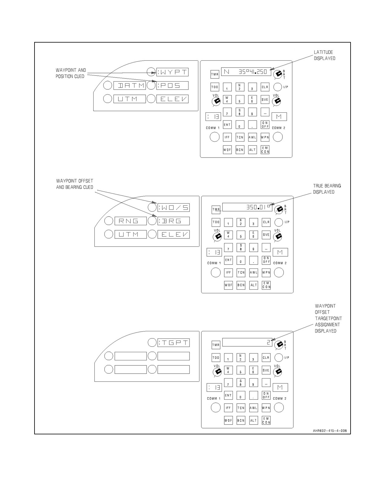
Figure 23-21. Waypoint, Mark, or Waypoint/Mark Offset Data Entry (Sheet 4)
ORIGINAL
23-56
A1-AV8BB--NFM--000
23.10.2.1.7 Range
To enter range select the RNG option on the ODU. A colon appears next to the RNG option indicating selection and
the scratch pad displays the stored range for the selected offset. Range is displayed in nautical miles or meters.
Successive depression of the cued RNG option provides alternate displays of range in nautical miles or meters. On
the UFC keyboard enter the new range. Entries of 100.000 or less are interpreted as nautical miles. Entries greater
than 100 are interpreted as meters. Nautical mile entries can be to the hundredths of a mile with OMNI 7.1 or to the
thousandths ofmilewith C1+ and H4.0 if adecimal is entered. Meterentries must be an integer from 101 to 185,200.
A range entry of zero forces the bearing entry to zero and sets the elevation equal to the waypoint or markpoint and
blanks the offset data on the DDI. With H4.0, it is possible to create an offset with 0 range, by entering an elevation
that is different than the waypoint’s elevation. Entering a range of 0 still removes the offset from the waypoint.
23.10.3 Transfer Data Page (with H4.0)
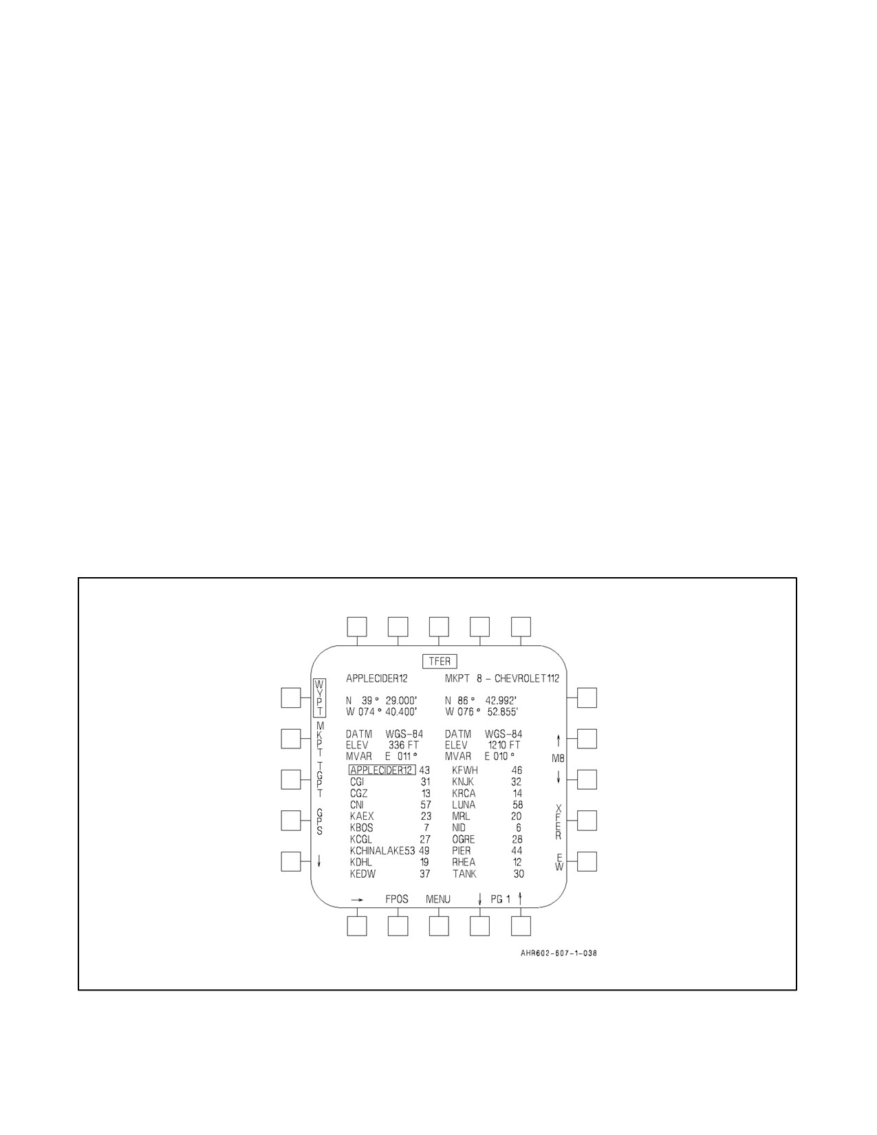
Selection of the TFER option on the SDAT page, displays the data point transfer page. See Figure 23-22. This page
provides the ability to transfer waypoints, GPS waypoints, markpoints, and targetpoints (current, pre--planned, and
another aircraft’s flight position) that have been located on the DSU or the AMU mission card, into a selected
waypoint, markpoint, or targetpoint. The aircrew must select both the point to be transferred (the transfer--from point
on the left side of the MPCD) and the point into which the data will be transferred (the transfer--to point on the right
side of the MPCD). The point data for both points is displayed at the top of each column.
23.10.3.1 Transfer--from Point
Waypoints, markpoints, targetpoints, and stored GPS points can be selected using PB 2--5. They are listed in
alphabetical order with the waypoint, markpoint, or targetpoint number displayed to the right of the point’s name.
The arrows at PB 1, 16, 17, and 20 can then be used to select the actual point number to be transferred. Since there
are only 10 markpoints, PB 16, 17 and 20 are not displayed if the transfer--from point is a markpoint. There are up
to three pages of targetpoint data available for selection. The first page contains T0--T4. The second page contains
the first twenty of the pre--planned targetpoints. The third page contains the last twelve pre--planned targetpoints.
Figure 23-22. Transfer Data (TFER) Page
23-57
ORIGINAL
A1-AV8BB--NFM--000
23.10.3.2 Transfer--to Point
Quick access must be used to switch between point types. The arrows at PB 12 and 13 can then be used to select the
actual point number to be overwritten.
23.10.3.3 Flight Position Transfer Page
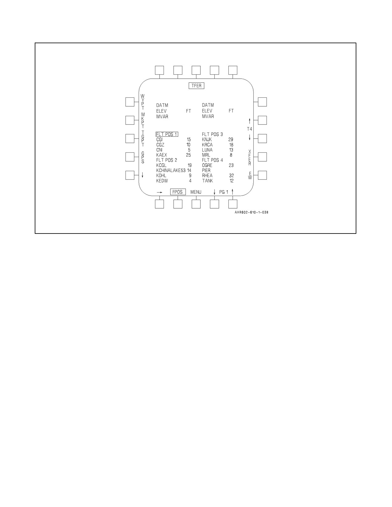
Depression of the FPOS option (PB 19) displays the first page of the flight position data. See Figure 23-23. The
arrows at PB 1, 16, 17, and 20 are used to select the desired targetpoint set for transfer. Selection of the FPOS transfer
option moves all targetpoints (T1--T4) and the associated targetpoint data (terminal heading, impact angle, TOT, etc.)
from that FPOS into the current aircraft targetpoints. If less than four targetpoints are transferred, the aircraft will reset
the remainder to default values and set them null.
23.10.3.4 XFER
Depressing the XFER option (PB 14) transfers data into the selected point. Offsets are only transferred between
waypoints, markpoints, and stored GPS points that are not read from the MAGR. Targetpoint data (terminal
parameters, pattern data, TOT, and fuze data) is transferred with the rest of the targetpoint data when transferred into
another targetpoint. If a waypoint, markpoint, or stored GPS point is transferred into a targetpoint, the targetpoint
remains the terminal parameters, pattern data, TOT, and fuze data.
23.11 UTM DATA ENTRY (OMNI 7.1 AND C1+)
Data may be entered in universal transverse mercator (UTM) coordinates for all 25 waypoints and 3 marks. The UTM
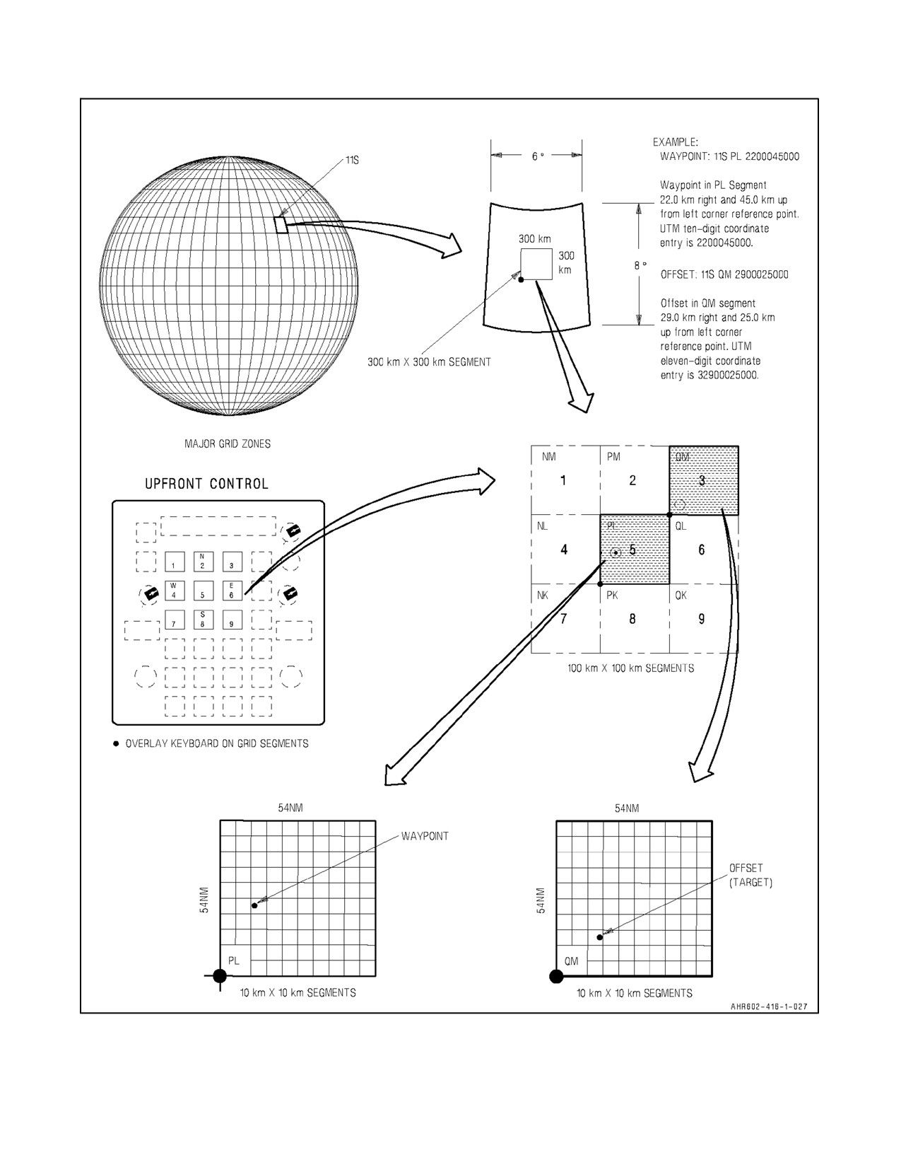
system subdivides 6° by 8° earth zones into a 300 km by 300 km segment (see Figure 23-24). This segment is
subdivided into nine 100 km by 100 km segments which are each further subdivided into 10 km by 10 km segments.
The UTM coordinates of a selected waypoint and offset are entered into the MC as 10 digit numbers if they are both
located within the same 100 km by 100 km grid segment. If the offset is located in an adjacent grid segment it must
have a 11 digit UTM number. Using the single waypoint entry method, only one waypoint or markpoint needs to be
in the same or adjacent grid segment for each offset. In this method accuracy is a function of latitude, offset range,
and declination angle. To use UTM data, the selected waypoint (within a 100 km by 100 km segment) must be entered
into the system in both earth and UTM coordinates. To manually enter UTM data, perform the following:
1. On the upfront control the latitude and longitude of the selected waypoint has been initially selected.
2. Press UTM pushbutton.
A colon appears to the left of the option display window. Stored UTM coordinates are displayed on the scratch
pad.
3. Type in ten--digit UTM numbers representing Eastings and Northings taken from a standard UTM grid map,
then press ENT.
The new UTM coordinates for the selected waypoint are displayed on the scratch pad and on the DDI.
4. Select UTM again, which brings up declination (DECL). UTM toggles between UTM and DECL.
A colon appears to the left of the option display window.
5. Type declination angle (difference between true north and UTM grid north), then press ENT.
The scratch pad and DDI display declination angle. The declination angle is a four key entry, E or W plus X°
XX’, and is limited to 9° 59’ East or West.
6. Press WYPT pushbutton on the ODU.
The ODU displays offset options in the display windows.
ORIGINAL
23-58
A1-AV8BB--NFM--000
TGPT4-XXXX
N 36° 00.000'
W 117° 00.000'
WGS-84
1000
E 10.0°
11
Figure 23-23. Flight Position Data Page
7. Type in 10 or 11 digit UTM of the offset or target, then press ENT.
The UTM coordinates for the selected offset or target are displayed on the scratch pad and on the DDI. The
UTM will only be 10 digits if it lies within the same grid segment as the waypoint. If the offset range extends
toanadjacentgridsegment, thefirst digitentered isthenumberoftheadjacent gridsegment inwhich theoffset
is located. For ease of entry, the adjacent grid segments correspond to the numbered buttons on the upfront
control and their position in relation to one another. The next 10 digits represent the offset Eastings and Nor-
things.
When the entries are completed, the range and bearing to the offset (target) from the waypoint is displayed on
the DDI. If required, these steps may be repeated to enter offsets for all the waypoints and markpoints.
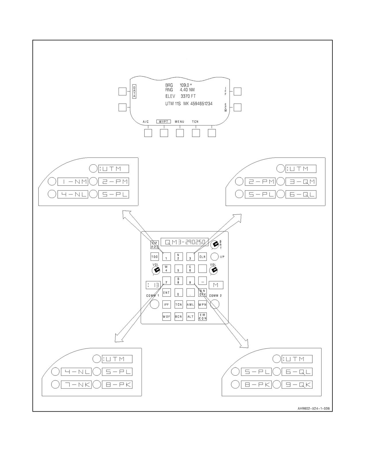
On TAV--8B and Day Attack aircraft, there are two different ways to enter UTM coordinates as follows:
1. If UTM data has been transferred from the data storage set the ODU will initialize with the first of four
selections of two--letter alpha identifiers of the UTM coordinates for the waypoint/mark point selected and the
adjacent grid segments (see Figure 23-25). Pressing the UTM option scrolls through the four quadrants of
selection. The two--letter alpha identifier corresponds to the applicable segment on the mercator chart. The
numeric preceding the alpha (e.g., 3--QM) corresponds to the same numeric on the UFC keyboard. Each grid
segment corresponds to a keyboard number. To enter the UTM coordinates select the desired alphas on the
ODU. The scratchpad displays the corresponding grid segment alpha identifier and related keyboard number.
Enter the ten--digit Northing and Easting on the keyboard. Entering a Northing or Easting, or selecting a new
alpha grid segment will recalculate the UTM bearing and range. If waypoint data for segment five is altered
the alphas on the ODU will be blanked.
23-59
ORIGINAL
A1-AV8BB--NFM--000
Figure 23-24. UTM Grid System
ORIGINAL
23-60
A1-AV8BB--NFM--000
TAV-8B WITH OMNI 7.1
AND DAY ATTACK AIRCRAFT
Figure 23-25. UTM Alpha Identifiers
23-61
ORIGINAL
A1-AV8BB--NFM--000
2. If UTM alpha segment identifiers are not available the offset UTM segment must be selected using the UFC
keyboard. As with the alpha segment identifier method, the waypoint or mark point is always the center key,
number five. The adjacent keys correspond to the eight surrounding UTM grid segments. To enter the UTM
coordinates select the desired segment on the keyboard and enter the ten--digit offset Easting and Northing.
If the UTM offset lies within the same grid segment as the waypoint or mark point only the offset Easting and
Northing needs to be entered.
On Radar and Night Attack aircraft, alpha segment identifiers are not available for waypoint or markpoint offset data
entry. The UTM segment is selected and the Northings and Eastings are entered using the UFC keyboard as stated
in the previous paragraph.
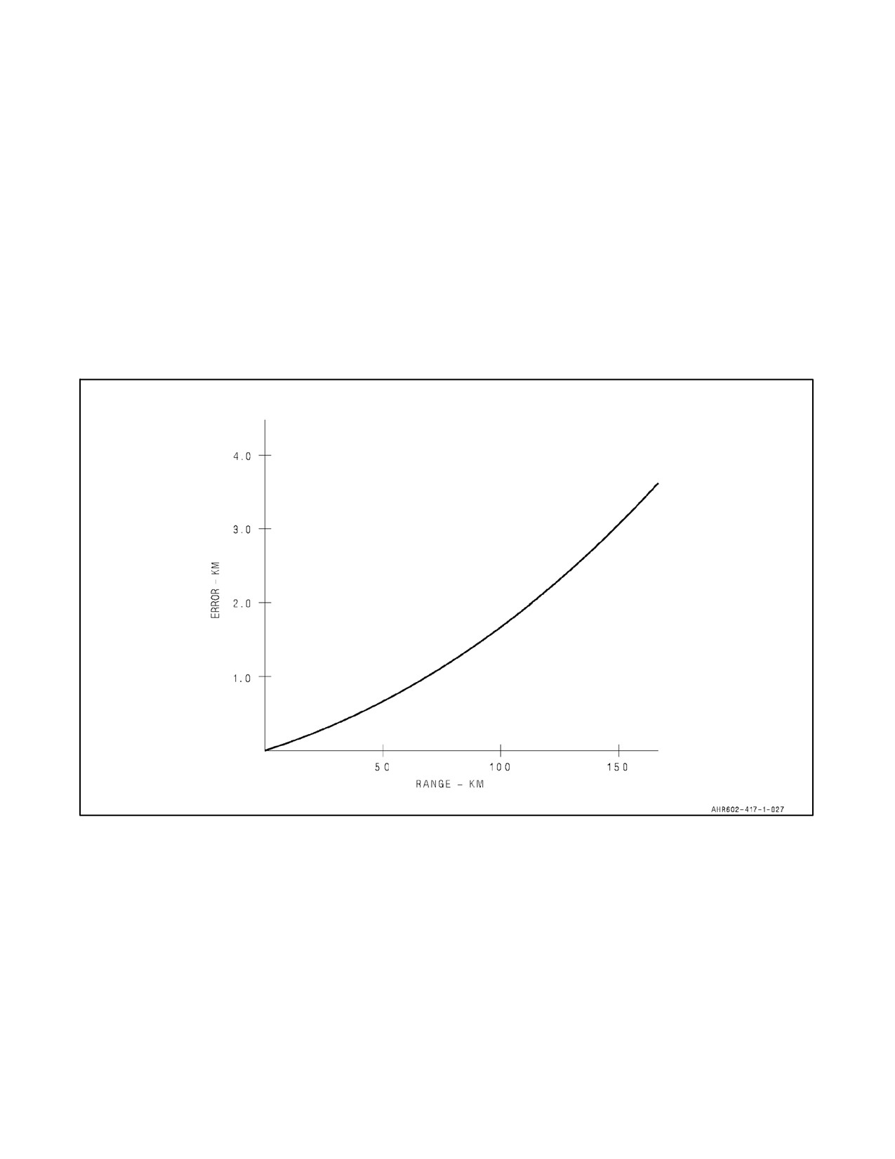
23.11.1 UTM Error vs Range (OMNI 7.1 and C1+)
When using the UTM to define offset, the system derives true bearing and range using declination data and a
comparison of the waypoint/markpoint UTM coordinates. Since this calculation makes a flat plate earth assumption,
the accuracy of the derived target location suffers as range from the waypoint/markpoint and the offset increase. See
Figure 23-26.
Figure 23-26. UTM Error vs. Range
23.12 UTM DATA ENTRY (WITH H4.0)
Positional data may be entered in universal transverse mercator (UTM) coordinates for all 60 waypoints and their
offsets, for all 10 markpoints and their offsets, and for all 5 targetpoints. The UTM system subdivides 6 degree by
8 degree earth zones into a 300 km segment (see Figure 23-24). This segment is subdivided into nine 100 km by 100
km segments segments which are each further subdivided into 10 km by 10 km segments. The UTM coordinates of
a selected waypoint and offset are entered into the MC as 10 digit numbers if they are both located in the same 100
km by 100 km grid segment. If the new point location or offset is located in an adjacent grid segment it must have
an odd digit UTM number (7, 9, or 11). The first digit entered is the number of the adjacent grid segment in which
the offset is located. For ease of entry, the adjacent grid segments correspond to the numbered buttons on the upfront
control and their position in relation to one another. The next 10 digits represent the offset Easting and Northing. The
ORIGINAL
23-62
A1-AV8BB--NFM--000
system does not allow the selection of an adjacent grid segment if that segment lies in another major grid zone (see
Figure 23-24). In other words, if the current row alpha is A then none of the segments south of the current segment
can be selected; if the current row alpha is V then none of the segments north of the current segment can be selected;
if the current column alpha is A then none of the segments west of the current segment can be selected; and if the
current column alpha is Z then none of the segments east of the current segment can be selected.
1. Press UTM pushbutton on the WYPT or TGPT ODU. A colon appears to the left of the option display window.
The stored 10--digit UTM coordinates of the point are displayed on the scratch pad preceded by an asterisk.
2. Type in 6 to 11 digit UTM numbers representing Easting and Northing, and then press ENT. The new UTM
coordinates for the selected point are displayed on the scratch pad and on the DDI. The point’s latitude and
longitude are updated to correspond to the entered UTM position. The UTM displayed on the scratch is 10
digits preceded by the segment number (1--9). If an even number of digits were entered then the segment
number is 5. The UTM displayed in the upper right data block on the DDI is the complete 15--digit UTM.
The position of a waypoint or markpoint offset can be moved within a grid segment or to an adjacent grid segment
by entering a UTM. After the UTM is entered, the MC recalculates and displays the new latitude and longitude. The
UTM will retain its 15 digit format. To manually enter UTM data for an offset from a point, perform the following:
1. Press WYPT pushbutton on the ODU. The ODU displays offset options in the display windows with a colon
next to UTM. The stored 10--digit UTM coordinates of the offset are displayed on the scratch pad preceded
by an asterisk.
2. Type in 6 to 11 digit UTM numbers representing Easting and Northing, and then press ENT. The new UTM
coordinates for the offset are displayed on the scratch pad and on the DDI. The range and bearing from the point
to the offset are updated to correspond to the entered UTM position. The UTM displayed on the scratch pad
is 10 digits preceded by the segment number (1--9). If an even number of digits were entered then the segment
number is 5. The UTM displayed in the lower right data block on the DDI is the complete 15--digit UTM.
If required, these steps may be repeated to enter offsets for all the waypoints and markpoints.
23.13 POSITION MARKING
With OMNI 7.1 and C1+, the mission computer has the capability to store three mark locations, MK1, MK2, MK3.
With H4.0, 10 markpoints numbered 0 through 9 are available for use. This is done by pressing the MK pushbutton
at the bottom of the EHSI/EHSD display on the DDI or by pressing the TOO pushbutton on the UFC. If MK1 is
displayed above the pushbutton, that is the storage location that is used when the pushbutton is pressed. Press the
pushbutton and the latitude and longitude of the ground point beneath the aircraft is stored in the mark 1 location.
MK2 is then displayed above the pushbutton in preparation for the next mark. With OMNI 7.1 and C1+, after the
second and third marks are stored, the system recycles and stores the next mark in the mark 1 location. With H4.0,
after the tenth mark is stored, the system recycles and stores the next mark in the mark 0 location. A mark location
can be used like a waypoint, including entry of offsets. With OMNI 7.1 and C1+, the three marks are stored at the
end of the 25 waypoints.
On night attack and radar aircraft and all aircraft with H4.0 position marking has been enhanced to allow marking
all designated points regardless of mode of designation. This allows the pilot to slew and designate the desired ground
point using the HUD, map, or radar sensors. Pressing the MK option on the EHSD will store the designation as a
markpoint.
With OMNI 7.1 and C1+, pressing the TOO pushbutton on the UFC stores the latitude and longitude of the ground
point beneath the aircraft in the mark location represented by the MK pushbutton at the bottom of the EHSI/EHSD
page regardless of whether a designation exists or not. With H4.0, pressing the TOO pushbutton on the UFC stores
the latitude and longitude of the ground point beneath the aircraft in the mark location represented by the MK
pushbutton at the bottom of the EHSI/EHSD only if a designation does not exist. If a designation exists, then pressing
the TOO pushbutton on the UFC stores the designation as a markpoint.
23-63
ORIGINAL
A1-AV8BB--NFM--000
With H4.0, the system also allows the pilot to enter the TOO position into a targetpoint (1 through 4). The default
targetpoint number is displayed on the scratch pad. Press ENT to accept the default targetpoint or enter a different
targetpoint number on the UFC. An entry of 0 on the UFC will cancel the targetpoint assignment portion of the TOO.
The default targetpoint is the first null targetpoint or targetpoint 1 if none of the targetpoints are null. A targetpoint
position can be sweetened by designating the targetpoint, slewing the position, and then selecting TOO on the UFC.
The updated position is put into the targetpoint. The targetpoint retains its previous identifier. If a targetpoint is
updated in this way, the MC replaces T0 in the JDAM priority list and the target data block (if displayed) with the
slewed targetpoint’s number.
23.14 POSITION UPDATE
There are four methods of correcting or updating the present position of the aircraft and one method (radar aircraft
only) of correcting the velocity of the aircraft. TACAN, overfly, designate, GPS, or VEL (Radar only). When the
update pushbutton is pressed on the EHSI/EHSD, FLIR, Radar, or DMT display, available only when thenavigation
system is in a loosely coupled position keeping mode, the four (or five) update options are displayed on the option
display unit. In trainer aircraft with OMNI 7.1 and Day Attack aircraft, the reject option is also displayed in case it
is desired to cancel the update.
On radar aircraft, position updating using the radar display can be performed by comparing the map or previously
entered waypoint coordinates to a point on the radar map. Refer to NATIP, NTRP 3--22.4 AV8B.
23.14.1 TACAN Position Update
Thesystem stores fiveTACAN stations and coordinates. A TACAN update can be performed anytime oneof thefive
stored stations is selected and is within operating range. After selection of the TACAN option, the position of the
aircraft is calculated using the range and bearing to the TACAN station. The computed position is then compared
to the aircraft position derived from either INS or air data. The error in degrees and nautical miles is displayed on
the scratch pad. Pressing the ACPT or REJ option select pushbutton on the option display unit either updates present
position or rejects the update as desired.
A two TACAN station update can be performed to improve TACAN ranging accuracy. If this is desired, the TCN2
option is selected to initialize the TACAN to the next stored channel of the five station sequence. If this is not the
desired station, successive pressing of the TCN2 pushbutton scrolls through the remaining stations excluding the
station used in the first update. After lockon, the second station is displayed on the EHSI/EHSD display. Pressing
the ERR2 pushbutton on the ODU displays bearing and range error on the scratch pad based on both TACAN stations.
Pressing the ERR1 pushbutton on the ODU displays bearing and range error on the scratch pad based on the first
TACAN station. Pressing the ACPT or REJ option select pushbutton on the ODU either updates present position or
rejects the update as desired.
23.14.2 Overfly Position Update
This method is thesameaswaypoint designateposition update,except theaircraft isflown directlyoverthewaypoint
and the OVFY option select pushbutton on the option display unit is pressed. The system then computes the position
error in degrees and nautical miles using the position derived by the onboard system compared with the stored
waypoint position. The error is displayed on the scratch pad. The update can then be accepted or rejected or, another
overfly position update may be made. If a second overfly position update is made without accepting or rejecting the
first update, the first update is automatically rejected.
23.14.2.1 Navigation Fix Update
A navigation fix update provides the capability to quickly update the navigation system on an unplanned navigation
point. To perform a FIX update, the aircraft is flown directly over the navigation point and the OVFY option select
pushbutton on the option display unit is pressed followed by the FIX option on the ODU. The fix (FIX) option on
the ODU enables position entry or UTM entry as a source for an update. With the position (POS) option pressed and
enabled, the latitude and longitude are entered and displayed on the scratch pad. When entry is completed the ERR
option is displayed and the UTM option blanks. Pressing the error (ERR) pushbutton displays the navigation error
on the scratch pad. The update can then be accepted or rejected.
ORIGINAL
23-64
A1-AV8BB--NFM--000
To make a UTM entry as an update source, the UTM option pushbutton is pressed and the overfly UTM coordinates
relative to the selected waypoint are entered. When entry is completed the ERR option is displayed and the POS
option blanks. Pressing the error pushbutton displays the navigation error which can then be accepted or rejected.
23.14.3 Designate Position Update
This method allows the aircraft to update its position by designating one of the stored waypoints, markpoints, or
targetpoints using the HUD or the dual mode tracker. A waypoint is selected and the designate (DESG) option is then
selected on the option display unit. The waypoint is visually acquired and then designated using either the HUD or
the dual mode tracker. The system then computes the position error by comparing the derived position from the
designated point with the existing present position and displays it on the upfront control scratch pad. The update can
then be accepted or rejected as desired.
23.14.4 MAP Position Update (Night Attack and Radar only)
A map position update is available when a map page is displayed. There are two types of map updates: overfly
(OVFY) and designate (DESG). In an overfly map update the aircraft position can be updated by over flying a
landmark that is on the digital map. Crosshairs are slewed over the location on the map. The navigation errors are
displayed in the scratchpad. The update can then be accepted or rejected.
The designation map update method allows the aircraft to update its position by slewing the position of a HUD
designation on the digital map. The system then computes the position error by comparing the derived position from
the designated point with the existing present position and displays it on the upfront control scratch pad. The update
can then be accepted or rejected as desired.
In aircraft with TAMMAC installed, map updates cannot be performed if the map type format is CIB. Map updates
are cancelled if the map type format changes (CHRT to DTED or DTED to CIB) during the update.
23.14.5 Manual GPS Update
This method allows the aircraft to update its position by using current GPS position as the source for the update. The
update displays current position errors as range and bearing errors. The update can then be accepted or rejected as
desired.
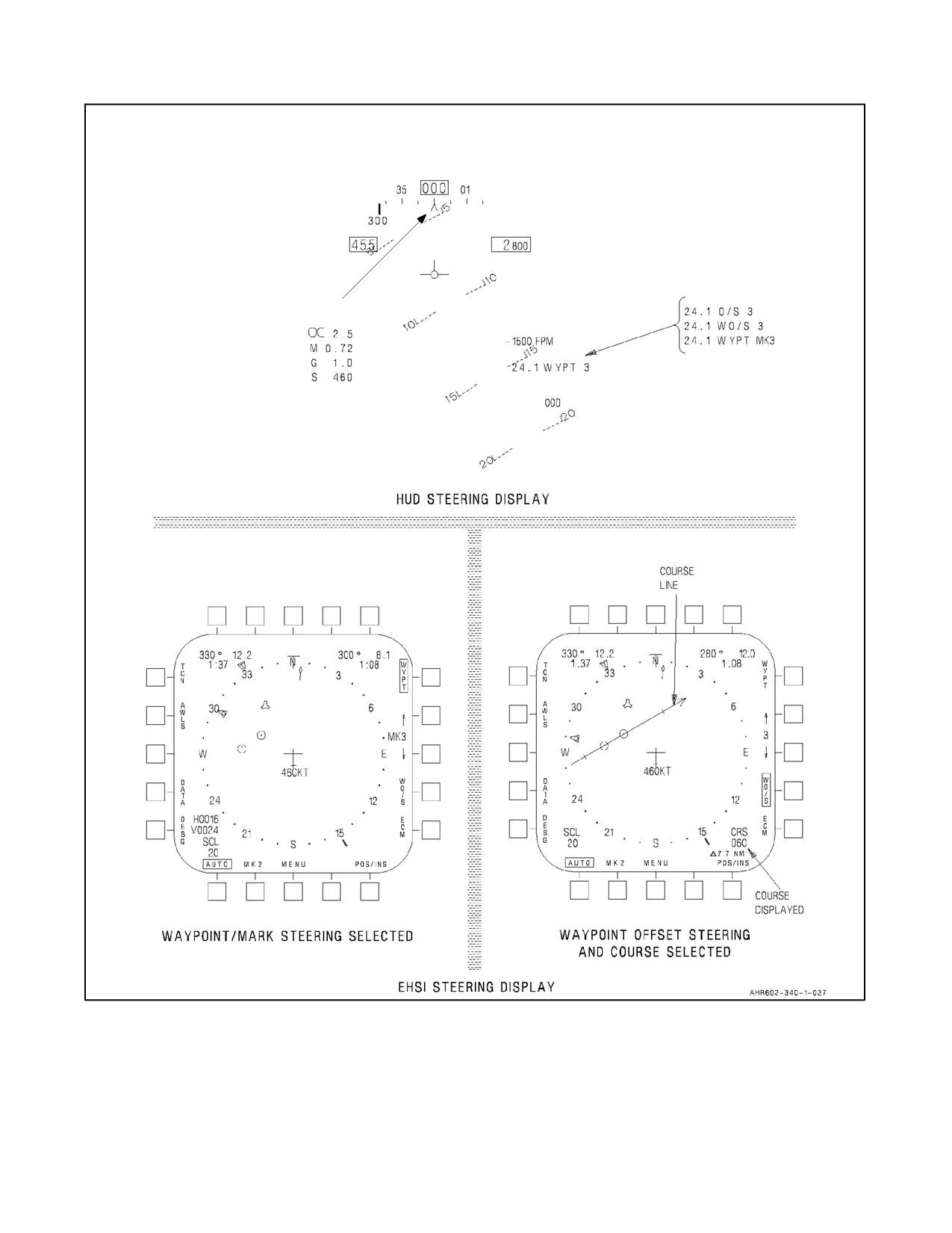
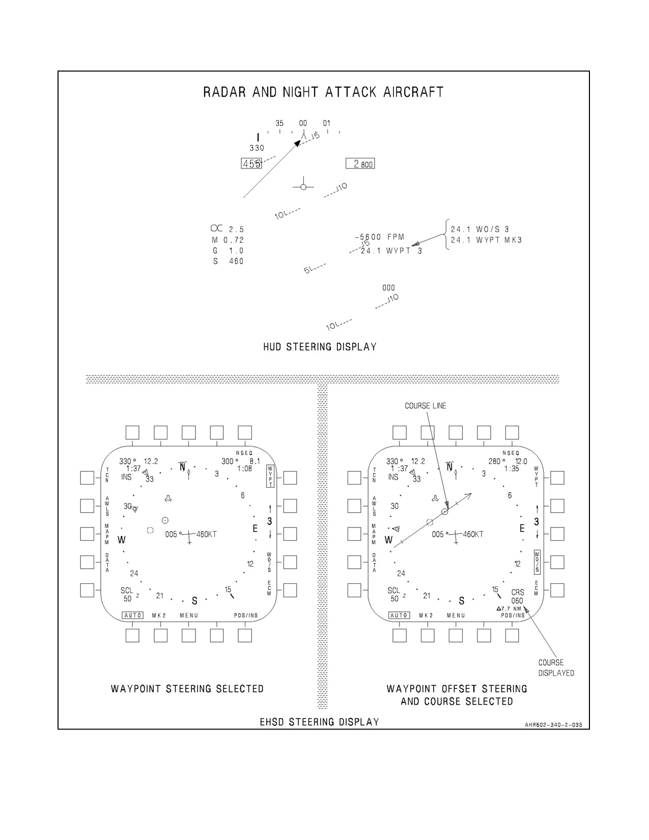
23.15 WAYPOINT, MARKPOINT, TARGETPOINT OR WAYPOINT/MARKPOINT OFFSET STEERING
Waypoint, markpoint, targetpoint, or waypoint/markpoint offset steering is provided to any of the waypoints, the
markpoints, the targetpoints, or their associated offsets. Waypoint, markpoint, or targetpoint steering is selected by
selecting the desired waypoint, markpoint, or targetpoint and pressing the WYPT pushbutton on the DDI. The WYPT
option is boxed (see Figure 23-27) and the bug (heading marker) on the heading scale indicates relative bearing to
the waypoint or mark. The bug is wind corrected. The waypoint, markpoint, or targetpoint range and number are
shown at the bottom right on the HUD. A digital readout of bearing and distance to the waypoint, markpoint, or
targetpoint is provided in the upper right corner of the EHSI/EHSD display. Time to go to the waypoint, markpoint,
or targetpoint in minutes and seconds is displayed under the bearing and distance.
To fly a selected course to a waypoint or mark, set in the course with the course knob on the HSI (TAV--8B and Day
Attack aircraft) or course set switch on the CRS panel (Radar and Night Attack aircraft). The course appears on the
bottom right of the EHSI/EHSD display and the course line is also displayed to indicate the position of the aircraft
relative to the course. The course line rate of movement is used to anticipate when to turn to intercept the course.
Steering to an offset from a waypoint or markpoint is also available by selecting the WO/S pushbutton to transfer
the steering to the offset point. In this case the HUD range nomenclature would change from WYPT to WO/S.
CAUTION
In the TAV--8B and Day Attack aircraft, the course line displayed on the
EHSI/EHSD and the course in the course selector window of the HSI are
not necessarily the same. The bearing displayed in the course line data
block in the lower right corner of the EHSI/EHSD and the course line
displayed on the EHSI/EHSD should not be used instead of the bearing in
the course selector window of the HSI. See Figure 23-27.
23-65
ORIGINAL
A1-AV8BB--NFM--000
TAV-8B WITH OMNI 7.1
AND DAY ATTACK AIRCRAFT
BEARING BUG
NSEQ
NSEQ
H0016
V0024
Figure 23-27. Waypoint, Mark, or Waypoint/Mark Offset Steering (OMNI 7.1) (Sheet 1 of 2)
ORIGINAL
23-66
A1-AV8BB--NFM--000
BEARING BUG
Figure 23-27. Waypoint, Mark, or Waypoint/Mark Offset Steering (OMNI C1+) (Sheet 2)
23-67
ORIGINAL
A1-AV8BB--NFM--000
23.16 NAVIGATION MASTER MODE
Navigation master mode is selected by pressing the NAV mode pushbutton on the main instrument panel. In the
navigation mode, primary flight information is presented on the HUD and aircraft horizontal situation is provided
on the EHSI/EHSD display on the DDI. Three navigation steering modes are provided and selectable from the EHSI
display: (1) waypoint, markpoint, targetpoint, or waypoint/markpoint offset steering, (2) TACAN or TACAN offset
steering, and (3) AWLS steering. Waypoint steering provides great circle steering to aselected waypoint, markpoint,
targetpoint, or waypoint/markpoint offset. TACAN steering provides the same capability to the selected TACAN
station orTACAN offset. AWLS steering provides localizerand glideslopesteering totheAWLSground station.The
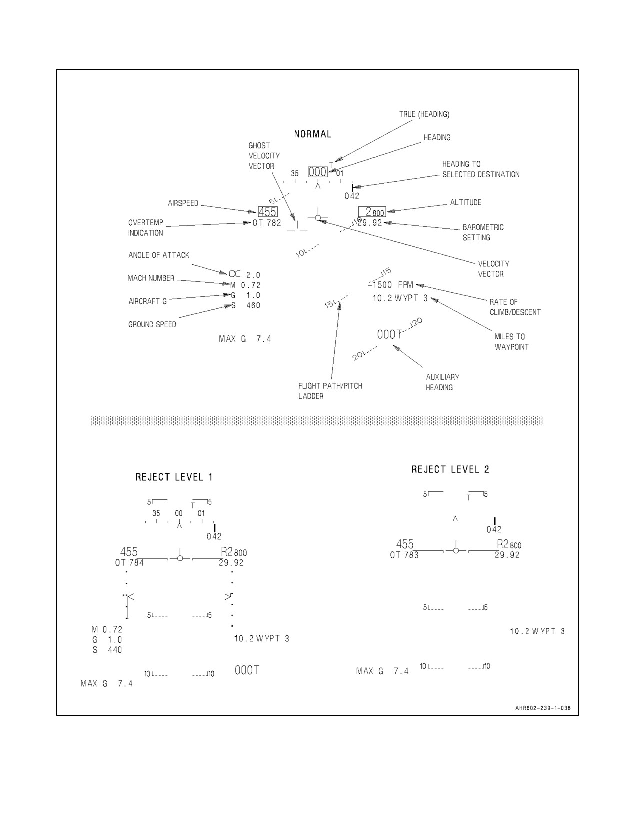
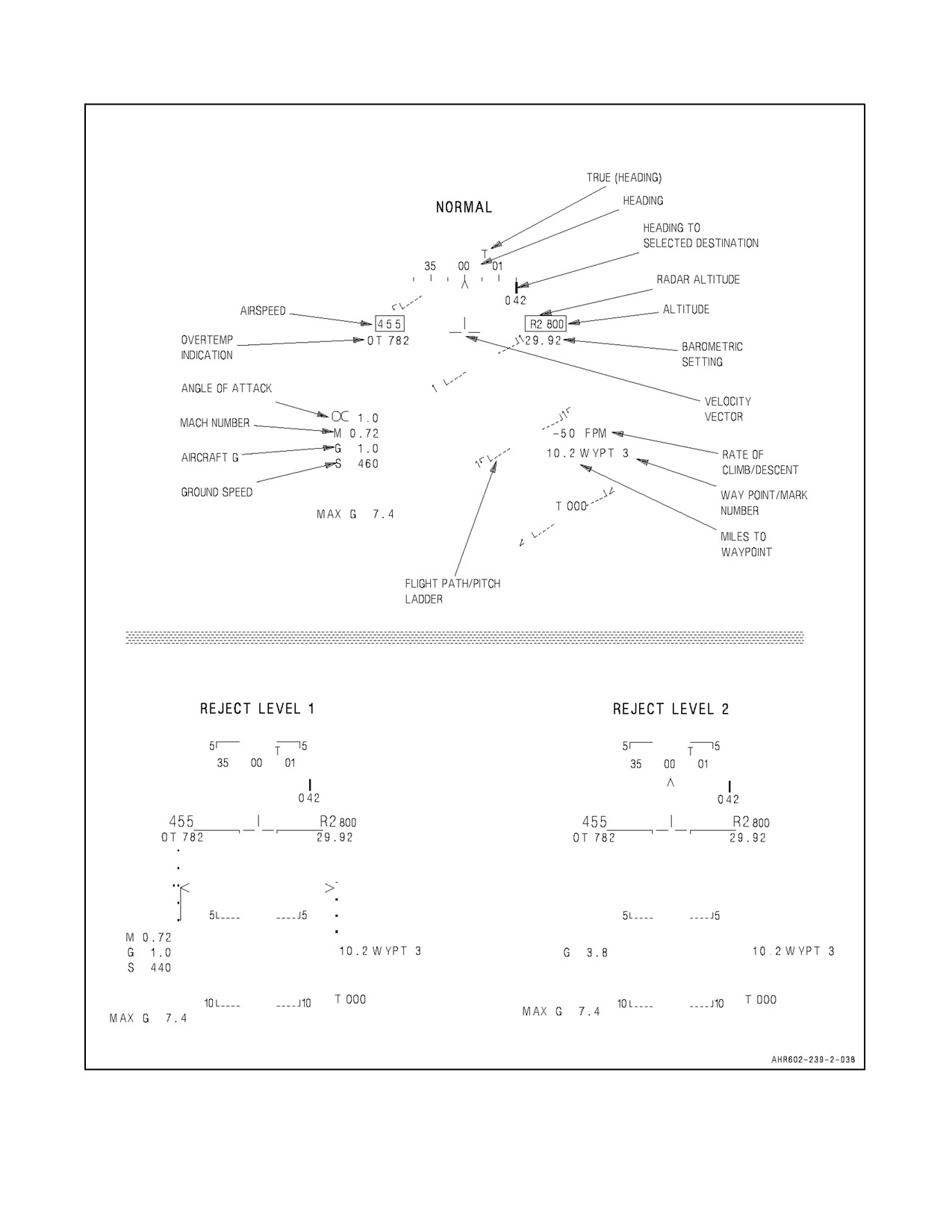
basic flight data presented on the HUD (see Figure 23-28) is described in the following paragraphs:
23.16.1 Heading
The aircraft true heading is indicated by the moving 360° scale. True heading is the initial heading with OMNI 7.1
and C1+ and T appears on the HUD display. If magnetic heading is desired the TRUE pushbutton on the DDI is
pressed and the box is removed from around the TRUE legend and the T is removed from the HUD display. Magnetic
heading is the initial heading and no T appears on the HUD display with H4.0. If true heading is desired the TRUE
pushbutton on the MAPM page is pressed and the box is displayed around the TRUE legend and the T appears on
the HUD display. The actual aircraft heading is directly above the caret. The moving heading scale provides trend
information during turns. As the aircraft turns right, the scale moves from right to left.
23.16.2 Airspeed
Calibrated airspeed from the air data computer is provided in the box on the left side of the HUD. With H4.0, the
box is no longer displayed around the calibrated airspeed.
23.16.3 Altitude
The altitude presented in the box on the right side of the HUD may be either barometric altitude or radar altitude
depending on the setting of the altitude switch on the HUD control panel. When the altitude switch is in the BARO
position, barometricaltitudeis displayed. When thealtitudeswitch is in theRDR position, radaraltitude is displayed
and is identified by an R next to the altitude. If the radar altitude becomes invalid, barometric altitude will be displayed
and a flashing B is displayed to the right of the box indicating barometric altitude. The flashing B remains until either
radar altitude becomes valid again or the altitude switch is placed in BARO. With H4.0, the box is no longer displayed
around the altitude.
23.16.4 Barometric Setting
The barometric setting used by the air data computer (ADC) is the value set in the standby altimeter. When the
barometric setting is changed on the standby altimeter by at least .02 inches of mercury, the ADC barometric setting
ispresentedbelowthealtitudeontheHUDtoprovideahead--up barosetcapability. Thedisplay remainsfor5seconds
after the change is made.
23.16.5 Angle of Attack
Angle of attack in degrees is displayed at the left center of the HUD.
23.16.6 Mach Number
The aircraft mach number (M) is displayed immediately below the angle of attack.
23.16.7 Aircraft G
Normal acceleration (G) is displayed immediately below the mach number.
23.16.8 Ground Speed
Ground speed (S) is displayed immediately below the aircraft G.
ORIGINAL
23-68
A1-AV8BB--NFM--000
TAV-8B WITH OMNI 7.1 AND DAY ATTACK AIRCRAFT
Figure 23-28. Nav Mode HUD Symbology (Sheet 1 of 2)
23-69
ORIGINAL
A1-AV8BB--NFM--000
RADAR AND NIGHT ATTACK WITH C1+
Figure 23-28. Nav Mode HUD Symbology (Sheet 2)
ORIGINAL
23-70
A1-AV8BB--NFM--000
23.16.9 Maximum G
Maximum normal acceleration (MAX G) attained since it was last reset is displayed below the ground speed
providing the maximum g exceeded 4.5g’s.
Note
It should be noted that, at gross weights above 20,000 pounds or with lateral
stick, the aircraft g--limit can be exceeded without exceeding 8g’s on either
the HUD or FLC.
23.16.10 Velocity Vector
The velocity vector provides the pilot with an outside world reference with regard to actual aircraft flight path. The
velocity vector represents the point towards which the aircraft is flying (aircraft flight path). In the NAV master mode,
the velocity vector is always caged to the vertical center line of the HUD. A ghost velocity vector is displayed at the
true velocity vector position if that position is more than 2° from the caged position. The flight path/pitch ladder and
steering information are referenced to the caged position. The ghost velocity vector will flash when limited. The
velocity vector is normally positioned by inertial velocities, derived from either INS or GPS velocities. When these
are invalid, filtered values of ADC TAS and ADC AOA are used to determine all velocities and therefore position
of the velocity vector.
23.16.11 Flight Path/Pitch Ladder
The vertical flight path angle of the aircraft is indicated by the position of the velocity vector on the flight path/pitch
ladder. The horizon and flight path/pitch angle lines represent the horizon and each 5° angle between plus and minus
30° and each 10° between 30° and 90°. Positive pitch lines are solid and are above the horizon line. Negative pitch
lines are dashed and are below the horizon line. The outer segments of the lines point toward the horizon. Each line
is numbered and the numbers rotate with the lines so that inverted flight can easily be determined. To aid in
determining flight path angle when it is changing rapidly, the pitch lines are angled toward the horizon at an angle
half that of the flight path angle. For example, in a 50° climb, the pitch lines are angled 25° toward the horizon. In
level flight, pitch lines are not angled. The zenith is indicated by a circle and the nadir is indicated by a circle with
an X in it. However, since the flight path/pitch ladder normally rotates about the velocity vector, determination of
pitch angle may be difficult at high roll angles.
23.16.12 Waypoint/Markpoint or Targetpoint Number
This number indicates the number of the waypoint, markpoint, targetpoint, or offset selected. With OMNI 7.1 and
C1+, MK precedes the number when a markpoint is selected. With H4.0, M precedes the number when a markpoint
is selected, and T precedes the number when a targetpoint is selected.
23.16.13 True Heading
The letter T is displayed when true heading is selected on the DDI. If there is no T displayed, magnetic heading is
being displayed.
23.16.14 Rate of Climb/Descent
This number indicates the feet per minute that the aircraft is climbing or descending. A minus sign indicates the
aircraft is descending.
23.16.15 Range
The range to the selected waypoint, markpoint, targetpoint, waypoint/markpoint offset, TACAN station or TACAN
offset is displayed in nautical miles.
23.16.16 Heading Marker
The heading marker (bug) indicates relative bearing to the selected waypoint, markpoint, targetpoint, waypoint/
markpoint offset, TACAN, TACAN offset, or designated point. The heading marker position varies along the heading
scale and will peg at scale limit. When pegged, the bearing numerals are displayed below the heading marker.
23-71
ORIGINAL
A1-AV8BB--NFM--000
23.16.17 Overtemp Indication
If the JPT exceeds the engine threshold value, the maximum JPT recorded is displayed on the HUD beneath the air
speed box adjacent to the OT legend. The OT indication is removed when the HUD reject level is changed if the
overtemp condition no longer exists. If another overtemp condition occurs, the current JPT at that time is displayed.
23.16.18 Auxiliary Heading
The auxiliary heading is displayed in all master modes and is a repeat of the HUD aircraft heading. The auxiliary
heading provides a way to view aircraft heading during video playback. A T is displayed if true heading is being
displayed. Auxiliary heading is not displayed in reject level 2 in the TAV--8B with OMNI 7.1 and the Day Attack
aircraft.
23.17 VSTOL MASTER MODE
The VSTOL mode is selected by pressing the VSTOL mode pushbutton on themain instrument panel. With VSTOL
selected while weight--on--wheels, two options are displayed on the option display unit. They are NRAS (nozzle
rotation airspeed) and PC (pitch carets). The basic flight data of heading, airspeed, altitude, barometric setting, angle
of attack, waypoint number, T, waypoint, markpoint, targetpoint, waypoint/markpoint offset, DME, or TACAN
offset range, and heading marker are displayed and function the same as described in the navigation master mode.
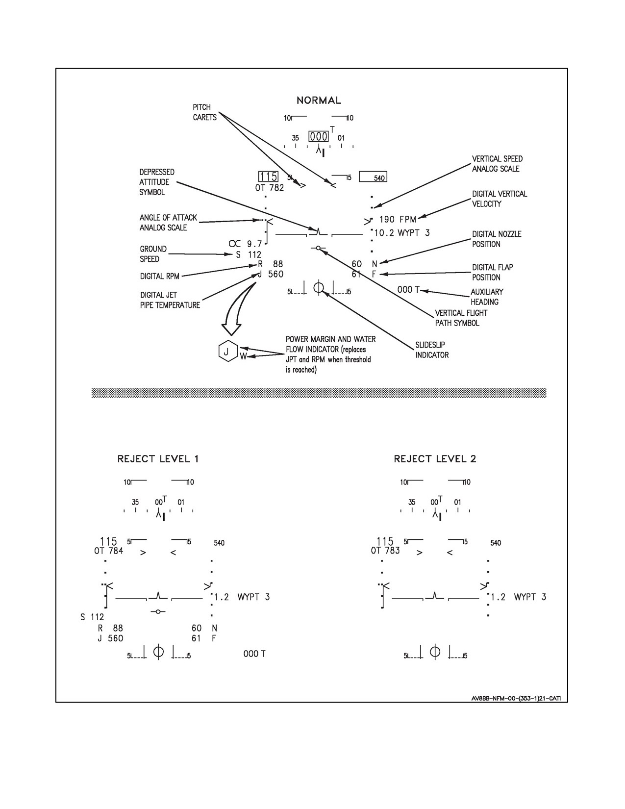
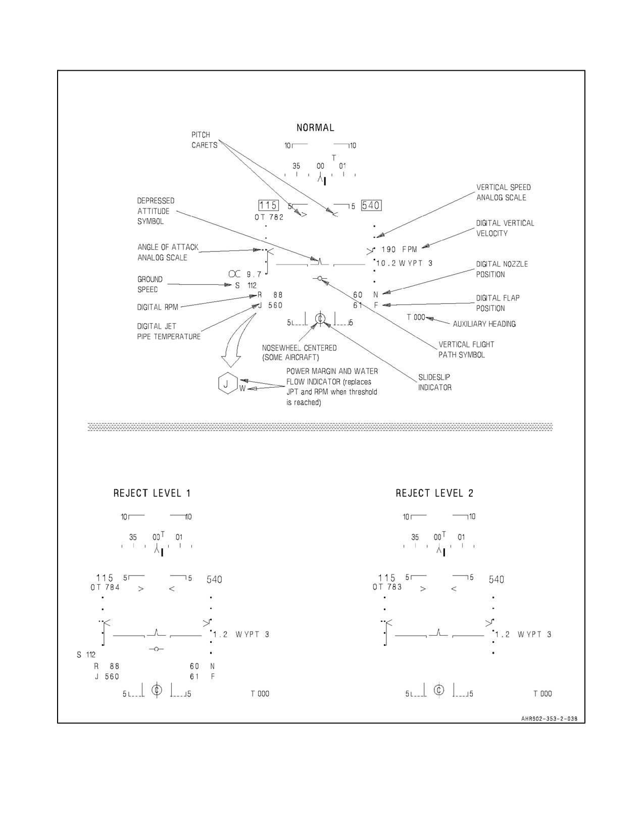
Additional and different functions in the VSTOL mode are described in the following paragraphs. See Figure 23-29.
23.17.1 Vertical Speed Analog Scale
The vertical speed analog scale provides trend information during climbs and dives. The scale range is +1,500 to
--2,000 feet per minute with graduations at +1,000, +500, 0, --500, --1,000 and --1,500 feet per minute. The moving
caret is displayed on the inboard side of the scale and when displaced from zero has a reference line connecting the
caret to the zero graduation.
23.17.2 FPM
Digital vertical velocity is displayed in feet per minute (FPM) with a limit of ±9,950 fpm and a resolution of 50 fpm.
Plus or minus signs are not displayed on the FPM display. Below 60 knots, the vertical speed analog scale and FPM
digital vertical velocity are not corrected for pitot static source error. Therefore, these displays should not be used
for sink rate information when the displayed vertical velocity is greater than 500 feet per minute.
23.17.3 N (Nozzle)
Digital nozzle position is displayed in degrees.
23.17.4 F (Flap)
Digital flap position is displayed in degrees.
23.17.5 Auxiliary Heading
The auxiliary heading is displayed in all master modes and is a repeat of the HUD aircraft heading. The auxiliary
heading provides a way to view aircraft heading during video playback. A T is displayed if true heading is being used.
Auxiliary heading is not displayed in reject level 2 in the TAV--8B with OMNI 7.1 and the Day Attack aircraft.
23.17.6 Vertical Flight Path Symbol
The vertical flight path symbol is caged laterally and above 60 knots provides climb and dive angle information and
is referenced to the flight path/pitch ladder. Below 60 knots, the vertical flight path symbol indicates vertical speed
in feet per minute. When referenced against the flight path/pitch ladder, 1° of displacement from the horizon line
equals 100 fpm vertical speed.
23.17.7 Sideslip Indicator
Sideslip is indicated by horizontal movement of the sideslip ball in relation to three vertical lines. Full movement
of the ball to either side is equal to 0.09g and is represented by the ball being bisected by an outer vertical line.
ORIGINAL
23-72
A1-AV8BB--NFM--000
TAV-8B WITH OMNI 7.1 AND DAY ATTACK AIRCRAFT
Figure 23-29. VSTOL Mode HUD Symbology (Sheet 1 of 2)
23-73
ORIGINAL
A1-AV8BB--NFM--000
RADAR AND NIGHT ATTACK AIRCRAFT WITH C1+
Figure 23-29. VSTOL Mode HUD Symbology (Sheet 2)
ORIGINAL
23-74
A1-AV8BB--NFM--000
23.17.8 Nosewheel Steering Mode (Aircraft After AFC--391)
Steering modes aredisplayed in V/STOL mastermodein allreject levelswith landinggearextended.Thefourmodes
are displayed to the right of the sideslip indicator. CAST, CTR, NWS, or NWS HI is displayed depending on which
steering mode is selected. Aircraft will also display a C inside the sideslip ball when the nosewheel is within 3° of
neutral steering angle.
23.17.9 Power Margin Display and W
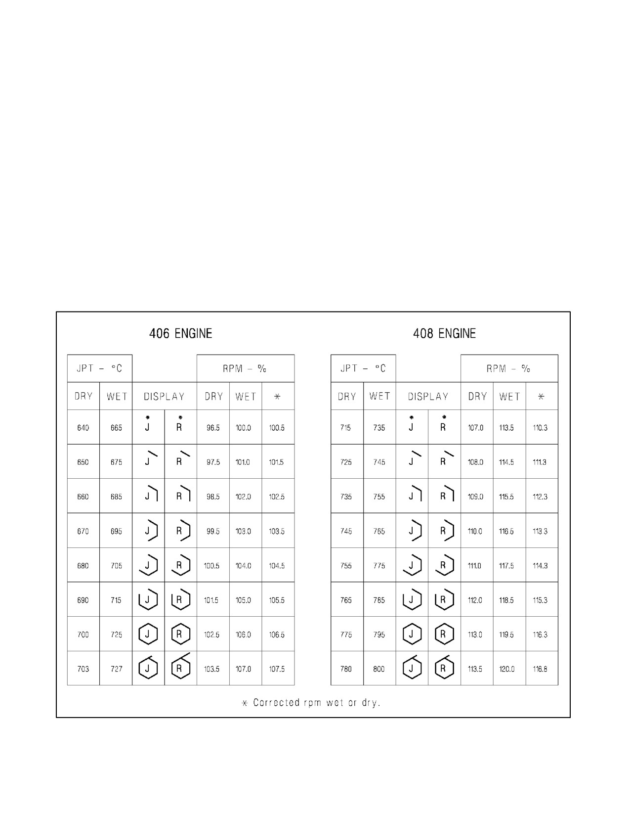
The power margin display (see Figure 23-30) replaces the JPT and rpm display when JPT is approximately 60° below
maximum JPT or when rpm is approximately 6 percent below maximum rpm. The display is a growing hexagon
around the letter J or R with each completed side representing 10 °C JPT or 1 percent rpm. The W is displayed when
water injection is selected (SLW) and water is flowing.
With the --406 engine the power margin threshold for JPT starts at 640 °C dry or 665 °C wet; the threshold for
indicated rpm starts at 96.5 percent dry or 100.0 percent wet, and corrected rpm starts at 100.5 percent. See Figure
23-30.
With the --408 engine the power margin threshold for JPT starts at 715 °C dry or 735 °C wet; the threshold for
indicated rpm starts at 107.0 percent dry or 113.5.0 percent wet, and corrected rpm starts at 110.3 percent. See Figure
23-30.
Figure 23-30. Power Margin Displays Series Engine
23-75
ORIGINAL
A1-AV8BB--NFM--000
There is no pilot indication that rpm threshold is reached by indicated or corrected rpm. The threshold reached first
determines whether J or R power margin is displayed. If JPT or rpm is still increasing after the hexagon is complete,
the last leg of the hexagon continues in a straight line. The length of this line is proportional to the increase in JPT
or rpm.
23.17.10 J (Jet Pipe Temperature)
Digital jet pipe temperature (JPT) is displayed in degrees Celsius with a resolution of 10 °C.
23.17.11 R (Rpm)
Digital engine rpm is displayed in percent with a resolution of 1 percent.
23.17.12 S (Ground Speed)
Digital ground speed is displayed in knots. Ground speed is removed in reject level 2.
23.17.13 Angle of Attack Analog Scale
The angle of attack analog scale has a range of +25° to --5° AOA with graduations at +20°, +15°, +10° (double dot),
+5° and 0°. The moving caret is displayed on the inboard side of the scale and when displaced from zero has a
reference line connecting the caret to the zero graduation.
23.17.14 Depressed Attitude Symbol
The depressed attitude symbol is fixed at 8° below the waterline. When the horizon bar of the flight path/pitch ladder
is aligned with the depressed attitude symbol, the aircraft is at the proper hover attitude. GS angle (2.0° through 6°)
entered through the upfront control will be maintained.
23.17.15 Pitch Carets Cue
The pitch carets (PC) initialize at 14° and provide a cue for pitch. The carets are adjustable from 0° to 30° in 1°
increments. When VSTOL mode is selected the PC option is displayed on the ODU. The carets are set by pressing
the PC option, typing the desired degrees of pitch (0° through 30°) on the UFC, then pressing ENT. The pitch carets
are referenced to the depressed attitude symbol and move with the pitch ladder.
23.17.16 Nozzle Rotation Airspeed Cue
With VSTOL mode selected while weight--on--wheels, the nozzle rotation airspeed (NRAS) cue is set by pressing
the NRAS option on the ODU, typing the desired airspeed (up to 160 knots) on the UFC, then pressing ENT. With
OMNI 7.1 and C1+ and with normal or reject 1 selected, the airspeed display is boxed when the set airspeed is reached.
With reject 2 selected, the airspeed box is removed when the set airspeed is reached. With H4.0 in all master modes,
the airspeed box is displayed when the set airspeed is reached and then removed when 160 knots indicated airspeed
is reached.
Note
With H4.0, if the NRAS airspeed is set close to or at the maximum (160
knots), the cue may appear only momentarily or not at all.
23.18 HUD SYMBOLOGY CHANGES (WITH H4.0)
With the additional HUD symbology, the time required to write all of the HUD symbology exceeded the time
available. This resulted in flickering HUD symbology. Changes in HUD symbology were made to decrease the
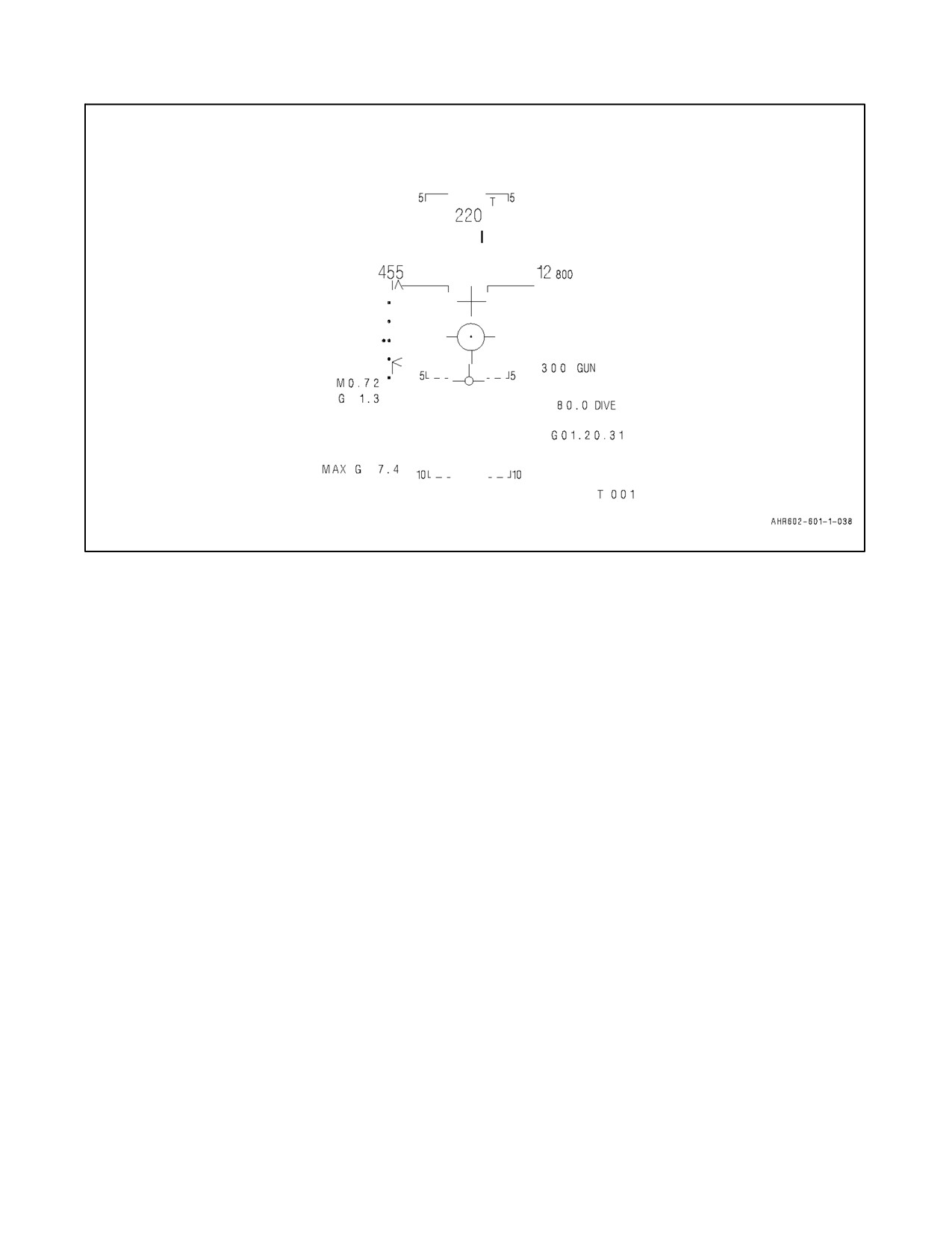
occurrence of flickering HUD symbology. The following actions were taken (see Figure 23-31):
1. Some symbology is written at a lower intensity in the A/G and A/A master modes with the HUD in the Day
mode. Examples include Mach Number, AOA, normal G, ground speed, RWR cues, and other text symbols
located on the sides of the HUD.
ORIGINAL
23-76
A1-AV8BB--NFM--000
Figure 23-31. Sample HUD with Write Time Changes
2. Some symbology is removed based upon the master mode. Examples include:
a. Nav, A/G, A/A modes -- altitude and airspeed boxes have been removed regardless of the HUD reject level.
b. A/G and A/A mode -- aircraft heading is a three digit number only. The heading tape has been removed.
The AOA and vertical analog scales have been removed regardless of the HUD reject level selected. There
is no difference between the NORM and REJ1 HUD reject levels.
3. The most important symbology is still written at the full intensity. Examples include thevelocity vector, pitch
ladders, airspeed, altitude, steer to point circle, and main weapon symbology.
23.19 HUD STEERING (WITH H4.0)
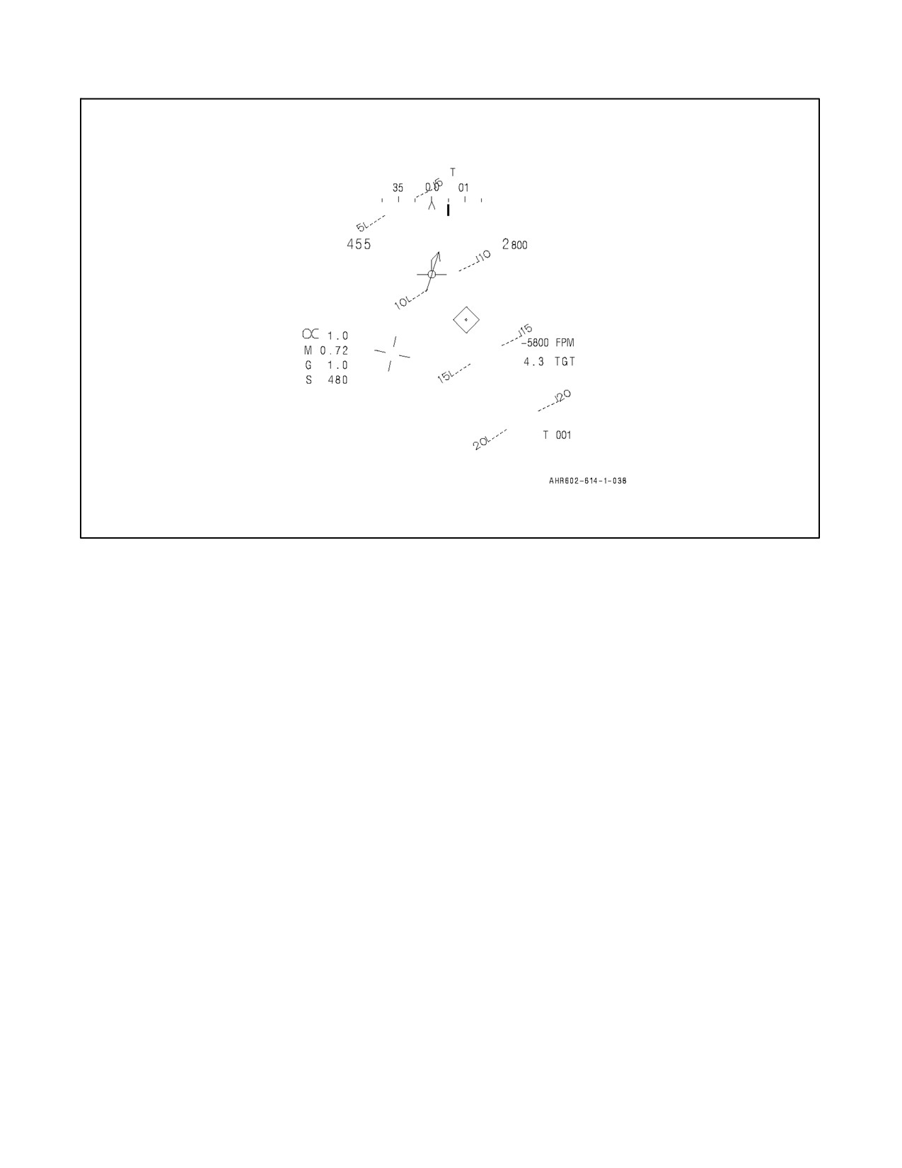
The steering bug and range depicted in the HUD always reference the steer to point (STP). The STP is the steering
reference selected on the EHSD (waypoint, markpoint, targetpoint, TACAN, or an offset). When a non--TACAN STP
is within the HUD FOV, a circle represents the STP position unless it is designated, in which case a diamond
represents it. See Figure 23-32. The reattack symbology always references the system designation (e.g. waypoint
designation, radar designation, HUD designation). Since designations are always stored in targetpoint zero, steering
and range to the system designation can be obtained by selecting targetpoint zero.
23.20 BACKUP/DEGRADED OPERATIONS
23.20.1 Backup Mode Initialization
Whenever the backup mode is entered the following items are affected as indicated:
1. HUD -- Reverts to backup display.
2. DDI -- On TAV--8B with OMNI 7.1 and Day Attack aircraft, displays HUD display.
3. Left DDI -- On Radar and Night Attack aircraft, displays map display.
23-77
ORIGINAL
A1-AV8BB--NFM--000
Figure 23-32. HUD Steering (with H4.0)
4. Right DDI -- On Radar and Night Attack aircraft, displays HUD display.
5. SAAHS -- Degraded mode.
6. VHF/UHF radio -- Operates in manual mode using radio set control and ACNIP.
7. INS -- No steering. Pitch, roll, true heading, and present position displayed.
8. IFF -- Turnedoffbutcanbeturnedbackon.Mode3codeinitializedto0000butcanbereset.Mode4A/Busable.
Modes 1 and 2 inoperative.
9. Radar altimeter -- Turned off but can be turned back on. Low altitude warning light fixed at 200 feet.
10. HOTASfunctions -- TDCinoperative.SensorcontrolswitchdepressedpositionfunctionsasHUDscenereject.
Waypoint increment button on the stick functions as the DAT button, alternating the HUD repeater and the map
display between the DDIs.
11. SMS -- No computed deliver modes, CIP/AUT light on. Weapon deliver possible in DSL, DSL--1, and DIR
modes using the roll stabilized sight.
12. RWR -- No head--down ECM threat lethality display. Head--up ECM display on HUD and right DDI.
13. EMCON -- Turned off but can be turned back on.
14. FLIR -- On Radar and Night Attack aircraft, reverts to default mode. Sensor select switch depressed position
alternately enables and disables FLIR video on HUD.
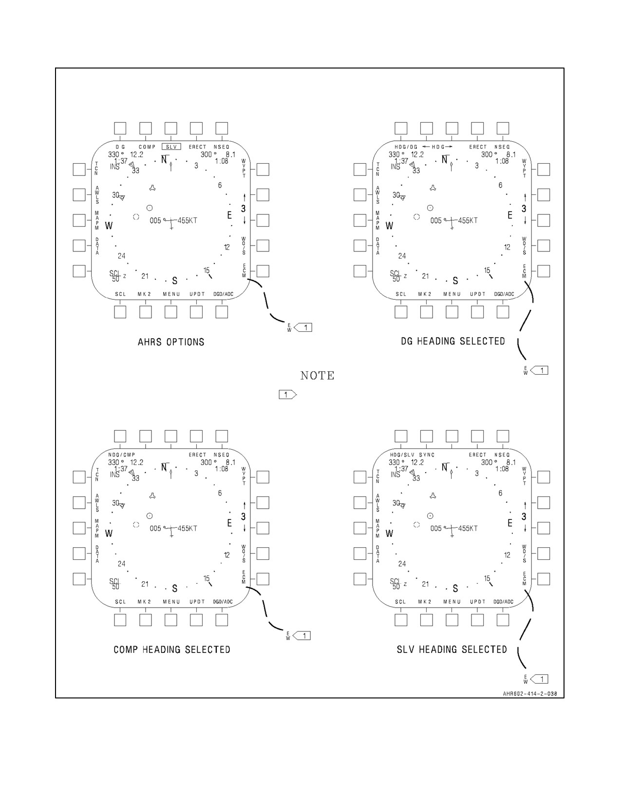
23.20.2 Attitude Heading Reference System
The attitude heading reference system is an INS backup mode. The INS system provides automatic INS degrading
toAHRSwhenINSBITdetectsasignificantfaultinthesystem.WhenAHRSoptionsappearautomaticallyasaresult
ofINSfailure,thebestavailableheadingsourceisdisplayedandused.AHRSdisplayontheEHSIis oneoftwotypes,
ORIGINAL
23-78
A1-AV8BB--NFM--000
first order or higher order. Higher order is available when gyro is selected on the miscellaneous control panel on the
ground. First order AHRS may be displayed when NAV is selected and INS BIT detects a failure which degrades
INS outputs or when GYRO is selected in flight. Full up INS mode cannot be regained in flight after selection of
GYRO mode. For full description of GYRO mode, see INS gyro alignment (AHRS) procedures paragraph 23.1.6.
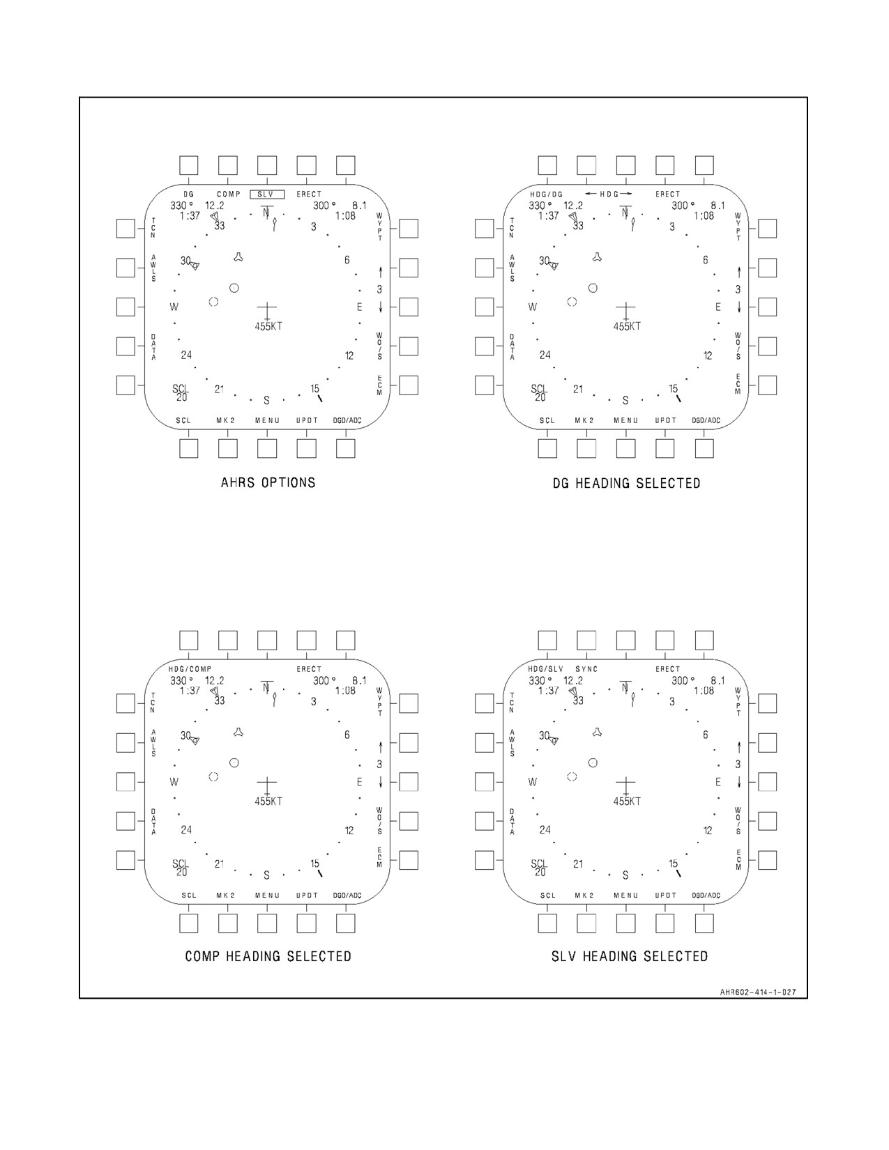
See Figure 23-33 for AHRS displays on the DDI. A description of the AHRS displays follows:
23.20.2.1 DG (Directional Gyro)
The DG legend appears as an AHRS option when directional gyro signals are available in the event of degraded INS
outputs. The box around DG means that directional gyro heading is displayed.
23.20.2.2 COMP (Compass)
The COMP legend appears as an AHRS option when magnetic azimuth detector (MAD) signals are available in the
event of degraded INS outputs. The box around COMP means that magnetic heading is displayed.
23.20.2.3 SLV (Slave)
TheSLVlegendappearswhenAHRSoptionsbecomeavailableduetoINSfailureinwhichINSoutputs aredegraded.
Sinceslaveheading is amixtureofHDG/COMP and HDG/DG, theSLV legend will appear only if magneticheading
and directional gyro outputs are available. The box around SLV means that slave heading is displayed.
23.20.2.4 ERECT
The ERECT legend appears when INS is in AHRS mode of operation. Pressing this pushbutton sends fast erect signal
to the INS for fast leveling of the platform. The signal continues for as long as this pushbutton is pressed.
23.20.2.5 HDG/DG
The HDG/DG legend appears and directional gyro heading is displayed when the mission computer system has
determined DG heading to be the best available AHRS option. Pressing the HDG/DG pushbutton causes available
AHRS options to be displayed with a box around DG.
23.20.2.6 HDG
TheHDG legend appears when DG heading is selected. Pressing left arrow pushbutton causes compass rose to rotate
counterclockwise for as long as the pushbutton is pressed. Pressing right arrow pushbutton causes compass rose to
rotate clockwise for as long as the pushbutton is pressed. This is done to slew compass rose to applicable heading
due to processing of the directional gyro.
23.20.2.7 SYNC
The SYNC legend appears when slave heading is selected. Pressing SYNC pushbutton slaves the platform heading
to magnetic heading.
23.20.2.8 HDG/CMP
The HDG COMP legend appears and magnetic heading is displayed when the mission computer system has
determined the magnetic heading to be the best available AHRS option. Pressing the HDG/COMP pushbutton causes
available AHRS option to be displayed with a box around COMP.
23.20.2.9 HDG/SLV
The HDG/SLV legend appears and slave heading is displayed when the mission computer system has determined
the slave heading is the best available AHRS option. Pressing the HDG/SLV pushbutton causes available AHRS
option to be displayed with a box around SLV.
23-79
ORIGINAL
A1-AV8BB--NFM--000
TAV-8B WITH OMNI 7.1 AND DAY ATTACK AIRCRAFT
NSEQ
NSEQ
H0016
H0016
V0024
V0024
NSEQ
NSEQ
H0016
H0016
V0024
V0024
Figure 23-33. AHRS Display (Sheet 1 of 2)
ORIGINAL
23-80
A1-AV8BB--NFM--000
TAV-8B WITH H4.0 AND RADAR AND NIGHT ATTACK AIRCRAFT
WITH H4.0.
GPS HERS AND VERS ARE
DISPLAYED IN THE LOWER
LEFT CORNER BELOW SCL
BLOCK WITH H4.0.
Figure 23-33. AHRS Display (Sheet 2)
23-81/(23-82 blank)
ORIGINAL
A1-AV8BB-NFM-000
PART VIII
Weapons Systems
Refer to NTRP 3.22-4-AV8B
83/(84 blank)
ORIGINAL
A1-AV8BB-NFM-000
PART IX
Flight Crew Coordination
Chapter 24 — Crew Resource Management
85/(86 blank)
ORIGINAL
A1-AV8BB--NFM--000
CHAPTER 24
Crew Resource Management
The AV--8B crew resource management (CRM) program shall be conducted IAW OPNAV 3710.7 and OPNAV
1542.7. The goal of CRM is to improve mission effectiveness by minimizing crew preventable errors, maximizing
crew coordination, and optimizing risk management. This will allow aircrew to use and integrate all available skills
and resources to collectively achieve and maintain crew efficiency, situational awareness, and mission effectiveness.
For a single seat aircraft this translates to close coordination with outside sources such as LSIs, LSSs, LSOs,
wingman, flight leaders, air traffic controllers, and ground personnel. The seven critical CRM behavioral skills shall
be integrated throughout the Harrier community’s academics, simulators and flight training. Aircrew shall receive
annual CRM ground training from an AV--8B trained CRM Instructor or Facilitator and the annual NATOPS check
shall serve as the annual CRM flight evaluation.
24.1
SEVEN CRITICAL SKILLS
24.1.1 Decision Making
The ability to choose a course of action using logical and sound judgment based on available information. Effective
decision--making requires:
1. Assessing the situation.
2. Verifying information.
3. Identifying solutions.
4. Anticipating decision consequences.
5. Making the decision.
6. Telling others of the decision and rationale.
7. Evaluating the decision.
24.1.2 Assertiveness
An individual’s willingness to actively participate, state, and maintain a position, until convinced by the facts that
other options are better. Assertiveness is respectful and professional, used to resolve problems appropriately, and to
improve mission effectiveness and safety.
24.1.3 Mission Analysis
The ability to develop short--term, long--term, and contingency plans and to coordinate, allocate, and monitor crew
and aircraft resources. Effective planning leads to flight conduct that removes uncertainty, increases mission
effectiveness, and enhances safety.
24.1.4 Communication
The ability to clearly and accurately send and acknowledge information, instructions, or commands, and provide
useful feedback. Effective communication is vital to ensure that all crewmembers understand aircraft and mission
status.
24.1.5 Leadership
The ability to direct and coordinate the activities of other crewmembers or wingmen, and to encourage the crew to
work together as a team. There are two types of leadership.
24-1
ORIGINAL
A1-AV8BB--NFM--000
24.1.5.1 Designated Leadership
Leadership by authority, crew position, rank, or title. This is the normal mode of leadership.
24.1.5.2 Functional Leadership
Leadership by knowledge or expertise, Functional leadership is temporary and allows the most qualified individual
to take charge of the situation.
24.1.6 Adaptability/Flexibility
The ability to alter a course of action based on new information, maintain constructive behavior under pressure, and
adapt to internal and external environmental changes. The success of a mission depends upon the the crew’s ability
to alter behavior and dynamically manage crew resources to meet situational demands.
24.1.7 Situational Awareness
The degree of accuracy by which one’s perception of the current environment mirrors reality. Maintaining a high level
of situational awareness will better prepare crews to respond to unexpected situations.
24.2
LOSS OF AIRCREW COORDINATION
The loss of aircrew coordination often results in one or more of the following:
1. Fixation on one task to the detriment of others.
2. Confusion.
3. Violation of NATOPS/flight minimums/SOP.
4. No one in charge/lack of flight leadership.
5. No lookout doctrine.
6. Absence of communication.
7. Failure to meet timeline or accomplish the mission.
24.3
FLIGHT MEMBER POSITIONS
24.3.1 Mission Commander
The mission commander shall be a qualified aviator designated by appropriate authority. The mission commander
shall be responsible for all phases of the assigned mission except those aspects of safety of flight which are related
to the physical control of aircraft and fall within the prerogatives of the pilot in command. The mission commander
shall direct acoordinated plan ofaction and beresponsibleforeffectiveness ofthemission.Themissioncommanders
responsibilities include, but are not limited to:
1. Allocation of assets.
2. Supervise and allocate planning tasks.
3. Assess capabilities and limitations of the flight.
4. Establish go/no--go criteria.
5. Assign roles and responsibilities.
6. Ensurecompliancewithapplicableorders,directives,rulesofengagement(ROE)/rulesofconduct (ROC),and
training rules.
7. Delegate authority as required.
ORIGINAL
24-2
A1-AV8BB--NFM--000
24.3.2 Formation Leader
A formation of two or more Naval aircraft shall be under the direction of a formation leader who is authorized to pilot
Naval aircraft. The formation leader may also be the mission commander when so designated. The status of each
member of the formation shall be clearly briefed and understood prior to takeoff. The formation leader is responsible
for the safe and orderly conduct of the formation. The formation leaders responsibilities are the same as the mission
commanders responsibilities with regard to his flight and in accordance with the mission commanders directives. A
section leader is a formation leader of two aircraft and may be part of a larger element. A division leader is a formation
leader of three or more aircraft and may be subordinate to a larger element formation leader or mission commander.
24.3.3 Wingman
A wingman is any member of a flight which is not specifically designated/assigned as a formation leader. A wingman
is responsible for the safe and orderly conduct of his aircraft. Additional responsibilities include but are not limited
to:
1. Understand the mission requirements.
2. Be involved in the planning process.
3. Be capable of assuming the lead when required.
4. Notify the leader of deficiencies (lost, confused, systems degradation, etc.).
5. Assist in look--out responsibilities.
6. Collision avoidance.
24.4
AIRCREW RESPONSIBILITIES BY FLIGHT PHASE
24.4.1 Mission Planning
All members of the flight should be involved in the mission planning process and must be familiar with the mission
requirements prior to the flight brief.
24.4.2 Brief
The flight brief shall be conducted with all members of the flight present. Any supporting assets (ground controlled
intercept (GCI), fighter escort, EW, etc.) shall be briefed face--to--face if possible. Flights requiring special
coordination or control should also be briefed face--to--face. Each type of flight or phase of flight may require unique
briefing requirements. The following is a partial list of flights and associated briefing requirements:
1. Shipboard operations — LSO.
2. Forward site operations — LSS.
3. FCF — QA, AMO, or designated representative.
4. Single aircraft operations — Operations Officer or designated representative.
5. Multi--element flights — Mission Commander, formation leader, subordinate formation leader.
6. Ground controlled intercept/vectoring — GCI, CCI, Strike vectoring controller, ASRT, etc.
7. Instrument flights — weather forecasters.
8. Ordnance flights — ordnance crew for loadout, weapon/fuzing selection, restrictions and arm/dearm
considerations/procedures.
24.4.3 Pre--Takeoff
As a single piloted aircraft, much of the preflight, prestart and post--start evolutions will be conducted individually
or with the aid of the ground maintenance crew (plane captain, ordnance, etc). Timing must be considered when
24-3
ORIGINAL
A1-AV8BB--NFM--000
operating with coordinating activities. Marshalling and taxi with a flight should be in order with special emphasis
on FOD avoidance. Squadrons should establish a minimum taxi interval based upon the local FOD situation. Engine
acceleration clears should be held until clear of other aircraft and in a relatively FOD free location (i.e., Takeoff
position or approaching takeoff position). Although the wheel brakes are not designed for lengthy taxi evolutions
and nozzles are recommended for speed control, this must be tempered with FOD and interval considerations when
operatinginformation.Sectiontaximaybethemostexpeditiousmethod,butlikeairborne,thewingmancannotfocus
on other tasks while taxiing and allow himself to get behind.
24.4.4 Departure
The AV--8B is capable of several types of takeoffs, and formations of AV--8Bs have several options. In addition to
the typical takeoff considerations such as gross weight, performance, surface type and abort capability, when
conducting a formation takeoff the following should also be considered and briefed: interval for FOD avoidance,
staggered line--up forabort, cross wind handling characteristics, jet exhaust/turbulence patterns and avoidance, abort
criteria and configuration changes prior to IMC. Departure procedures are dependent upon the takeoff type, weather
and mission requirements. The following are some considerations: clearance compliance, climb schedule and interval
of multi--plane--formations, weather avoidance or penetration and individual departure to join on top.
24.4.5 En route
En route procedures differ greatly with mission type but some special considerations are: formation type, position,
altitude, airspeed and role assignment and execution, navigation/INS management, lookout, command and control
requirements, coordination, deconfliction, ordnance and attack procedures and switchology, reconstitution and
rendezvous, support requirements, timing, fuel planning and management.
24.4.6 Recovery
Egress, approach and landing options are numerous and dependent upon mission objectives, weather, and landing
types. The following is a list of considerations: course rule, re--entry procedures, approach and landing weather,
landing type and capabilities (i.e., gross weight, performance, cross winds, ceiling and visibility), fuel for normal
and alternate recoveries, formation size and composition based upon maneuverability and landing area congestion,
instrument recovery--penetration procedures with two ormore aircraft in formation and power/maneuvering margins
for wingmen, jet wash/turbulence avoidance, landing interval and priorities, dearming procedures, FOD mechanisms
for landing and taxi, navigation, either internal (INS, TACAN, VISUAL) or external (GCI, GCA, APPROACH
CONTROL), terminal control and use or LSO, LSS.
24.4.7 Mission Critique
Mission assessment is critical following a flight whether the mission was a multi--aircraft strike, an FCLP period,
or a functional check flight. A critical and credible debrief will improve future mission success and evaluate current
mission effectiveness. A proper debrief should provide flight members and supporting agencies with information on
strengths and weaknesses so that future training and mission planning can address problem areas and exploit strong
areas.
24.5
EMERGENCIES
Mission planning and briefing should address contingencies which may affect the flight. Proper planning will
minimize the effect of deviations from the planned mission. The possibility of a mission abort or even the loss of
an aircraft or pilot can be significantly reduced by anticipating critical phases of flight and preparing for potential
emergency situations. An example is the thorough brief of bird strike emergencies and alternate landing areas along
a low--level navigation route. Part V of this manual provides emergency procedures for the pilot, but each formation
leader should state the procedures to be followed by other members of the flight in the event of an emergency
situation. An example may be for the aircraft experiencing the emergency to operate as a single aircraft and the other
member of the section to assume a chase position and provide assistance in the form of navigation, communication,
reading checklist procedures and acting as an observer for external indications and look--out. Standardized procedures
for downed aircraft and search and rescue (SAR) operations should be stated by the formation leader. Role
assignments for visual identification, comm relay and location should be stated.
ORIGINAL
24-4
A1-AV8BB-NFM-000
PART X
NATOPS Evaluation
Chapter 25 — NATOPS Evaluation
87/(88 blank)
ORIGINAL
A1-AV8BB--NFM--000
CHAPTER 25
NATOPS Evaluation
25.1
CONCEPT
The standard operating procedures prescribed in this manual represent the optimum operation of the
AV--8B/TAV--8B. The NATOPS evaluation is intended to evaluate systems knowledge and compliance with
NATOPS procedures through observation of pilots and squadrons. The objective of the NATOPS evaluation program
is to assist the commanding officer in improving unit readiness, safety, and standardization through constructive
comment.
25.2
IMPLEMENTATION
The NATOPS Evaluation program shall be carried out in every unit operating naval aircraft. Pilots desiring to
attain/retain qualification in the AV--8B/TAV--8B shall be evaluated initially in accordance with OPNAV Instruction
3510.9 series, and at least once during the 12 months following initial and subsequent evaluations. Individual and
unit NATOPS Evaluations will be conducted annually; however, instruction in and observation of adherence to
NATOPS procedures must be on a daily basis within each unit to obtain maximum benefits from the program. The
NATOPS Coordinators, Evaluators, and Instructors shall administer the program as outlined in OPNAV 3710.7
series. Evaluees who receive a grade of Unqualified on a ground or flight evaluation shall be allowed 30 days in which
to complete a re--evaluation. A maximum of 60 days may elapse between the date the initial ground evaluation was
commenced and the date the flight evaluation is satisfactorily completed.
25.3
DEFINITIONS
The following terms, used throughout this section, are defined as to their specific meaning within the NATOPS
program.
25.3.1 NATOPS Evaluation
A periodic evaluation of individual pilot standardization consisting of an open book examination, a closed book
examination, an oral examination, and a flight evaluation.
25.3.2 NATOPS Re--Evaluation
A partial NATOPS Evaluation administered to a pilot who has been placed in an Unqualified status by receiving an
Unqualified grade for any of his ground examinations or the flight evaluations. Only those areas in which an
unsatisfactory level was noted need be observed during a re--evaluation.
25.3.3 Qualified
Well standardized; evaluee demonstrated highly professional knowledge of and compliance with NATOPS standards
and procedures; momentary deviations from or minor omission in non--critical areas are permitted if prompt and
timely remedial action is initiated by the evaluee.
25.3.4 Conditionally Qualified
Satisfactorily standardized; one or more significant deviations from NATOPS standards and procedures, but no errors
in critical areas and no errors jeopardizing mission accomplishment or flight safety.
25.3.5 Unqualified
Not acceptably standardized; evaluee fails to meet minimum standards regarding knowledge of and/or ability to apply
NATOPS procedures, one or more significant deviations from NATOPS standards and procedures which could
jeopardize mission accomplishment or flight safety.
25-1
ORIGINAL
A1-AV8BB--NFM--000
25.3.6 Area
A routine of preflight, flight, or postflight.
25.3.7 Sub--Area
A performance sub--division within an area, which is observed and evaluated during an evaluation flight
25.3.8 Critical Area/Sub--Area
Any area or sub--area which covers items ofsignificant importanceto theoverall mission requirements, themarginal
performance of which would jeopardize safe conduct of the flight.
25.3.9 Emergency
An aircraft component, system failure, or condition which requires instantaneous recognition, analysis, and proper
action.
25.3.10 Malfunction
An aircraft component or system failure or condition which requires recognition and analysis, but which permits more
deliberate action than that required for an emergency.
25.4
GROUND EVALUATION
Within 15 days of commencing the flight evaluation, an evaluee must achieve a minimum grade of 3.5 on the open
book examination and a grade of 3.3 on closed book examinations on a 4.0 scale. Achieving these minimum grades
constitutes an adjective grade of Qualified. Not achieving these minimum grades constitutes an adjective grade of
Unqualified.
25.4.1 Open Book Examination
The open book examination shall include, but not be limited to, the open book examination question bank
promulgated by the AV--8B NATOPS Model Manager.
25.4.2 Closed Book Examination
The closed book examination shall include, but not be limited to, the immediate action emergency procedures and
aselection ofaircraft limitations and system questions from theclosed book examinationquestion bankpromulgated
by the AV--8B NATOPS Model Manager.
25.5
FLIGHT EVALUATION
25.5.1 Standards
The flight evaluation shall be conducted in the simulator unless operational requirements and resources preclude
simulator availability. In such cases, a flight evaluation shall be conducted on any flight with the exception offlights
launched for FCLP/CQ, FAM or FBO training. A NATOPS Instructor shall be a member of the flight. Emergencies
shall not be simulated in the aircraft.
The flight evaluation shall be conducted and graded in the areas of mission planning, briefing, normal operating
procedures, crew resource management, emergency procedures, and debriefing. The focus is on normal and
emergency procedures, not tactical execution. The flight evaluation objectives are:
1. Evaluate adherence to and execution of NATOPS normal and emergency procedures.
2. Evaluate Crew Resource Management skills.
3. Demonstrate takeoff and landing proficiency.
MAGs and squadrons should develop standardized scenarios to promote consistent evaluation. The flight evaluation
should be of a tactical nature in order to present realistic decision making opportunities but tactical execution
ORIGINAL
25-2
A1-AV8BB--NFM--000
proficiency shall not be specifically evaluated. Scenarios should be tailored to the pilot’s experience and flight
qualifications.
Concurrently, the flight evaluation shall also be the annual CRM evaluation. However, NATOPS Instructors and
Assistant NATOPS Instructors must be qualified Crew Resource Management Facilitators in order to conduct a CRM
evaluation.
Note
The number of flights required to complete the flight evaluation should be
kept to a minimum; normally one flight. The areas and sub--areas to be
observed and graded on a flight evaluation are outlined in the grading
criteria with critical areas marked by an asterisk (*). Sub--area grades will
be assigned in accordance with the grading criteria. These sub--areas shall
be combined to arrive at the overall grade for the flight. Area grades, if
desired, shall also be determined in this manner.
25.5.2 Evaluated Areas and Sub--Areas
25.5.2.1 Mission Planning, Briefing, and Debriefing
1. Oral examination shall be conducted to evaluate system knowledge, aircraft limitations, normal
and
emergency procedures. At a minimum, three questions will be asked.
2. Flight planning shall be IAW Air NTTP 3--22.1--AV8B AV--8B Employment standards.
3. Flight brief shall be IAW the MAWTS--1 AV--8B Mission Planning, Briefing, and Debriefing Guide.
4. Demonstrate knowledge of the contents and function of all components of flight equipment.
5. Flight debrief shall be IAW the MAWTS--1 AV--8B Mission Planning, Briefing, and Debriefing Guide.
25.5.2.2 Ground Procedures
Demonstrate proficiency in the following:
1. Aircraft Discrepancy Book (ADB) review.
2. Engine start procedures and checklist.
3. Before taxiing procedures and checklist.
4. Post landing procedures and checklist.
5. Shut--down procedures and checklist.
25.5.2.3 Takeoff and Departure (*)
Demonstrate proficiency and proper procedures of the following:
1. Pre--positioning procedures and checklist (CWAIVER).
2. Takeoff checklist.
3. A minimum of one STO with aircraft gross weight greater than
30,000 pounds and outside air temperature
greater than 30 °C.
4. A minimum of one CTO.
5. A minimum of one VTO.
6. Departure, climb, and level--off flight regimes.
7.
10,000--foot checklist.
8.
18,000--foot checklist.
25-3
ORIGINAL
A1-AV8BB--NFM--000
25.5.2.4 Approach and Landing (*)
Demonstrate proficiency and proper procedures of the following:
1. Descent checklist (SWIFT--A checks).
2. Landing checklist.
3. A minimum of one of each of the following landings with at least one executed SAAHS off:
a. CL
b. VNSL
c. RVL
d. VL
25.5.2.5 Communications
Demonstrate proficiency and proper procedures of the following:
1. Standard radio communications.
2. Standard visual signals.
25.5.2.6 Emergency Procedures (*)
At a minimum, respond to the number of emergencies specified in each phase of flight. One emergency shall result
in the necessity to execute a timely ejection.
1. Ground Emergencies: one.
2. Takeoff Emergencies: two.
3. In--flight Emergencies to a full--stop landing: one.
4. Emergencies during landings: two.
25.5.2.7 Crew Resource Management
Demonstrate proficiency IAW Chapter 24 of this manual.
25.5.2.8 Mission Evaluation
This area includes missions covered in the NATOPS Flight Manual, Tactical Employment, ANTTP 3--22.1--AV8B,
NWP, and NWIPs for which standardized procedures/techniques have been employed.
25.5.3 Applicable Publications
The NATOPS Flight Manual contains the standard operations criteria for AV--8B/TAV--8B aircraft. Publications
relating to environmental procedures peculiar to shorebased and shipboard operations and tactical missions are the
AV--8B NATIP, Tactical Employment, ANTTP 3--22.1--AV8B, NWP, NWIPs, ATC/CATCC Manual, Local Air
Operations Manual, Ship Operations Manual, and local range regulations SOPs as long as these publications are not
in violation of the NATOPS flight manual.
25.5.4 Flight Evaluation Grading
Only the areas and sub--areas listed in paragraph 25.5.2 shall be graded. Critical areas are marked by an asterisk (*).
The grade assigned is determined by assessing the degree of adherence and proficiency to standard operating
procedures. Momentary deviations from standard operating procedures should not be considered unqualifying
provided such deviations do not jeopardize flight safety and the evaluee applies prompt corrective action. A grade
of Unqualified in any critical area and/or sub--area will result in an overall grade of Unqualified for the flight
evaluation. Otherwise, flight evaluation grades shall be determined by assigning the numerical grade equivalents to
the adjective grade for each sub--area. Only the numerals 0, 2 or 4 shall be assigned. No interpolation is allowed.
ORIGINAL
25-4

A1-AV8BB--NFM--000
Unqualified
0.0
Conditionally qualified
2.0
Qualified
4.0
To determine the numerical grade for each area and the overall grade for the flight, add all the points assigned to the
sub--areas and divide this sum by the number of sub--areas graded. The adjective grade shall then be determined on
the basis of the following scale.
Unqualified
0.0 to 2.19
Conditionally Qualified
2.2 to 2.99
Qualified
3.0 to 4.0
25.6
FINAL GRADE DETERMINATION
The final NATOPS Evaluation grade shall be the same as the grade assigned to the flight evaluation. An evaluee who
receives an Unqualified grade on any ground examination or the flight evaluation shall be placed in an Unqualified
status until achieving a grade of Conditionally Qualified or Qualified on a re--evaluation.
25.7
RECORDS AND REPORTS
A NATOPS Evaluation Report (OPNAV From 3710--7) shall be completed for each evaluation and forwarded to the
evaluee’s commanding officer only. This report shall be filed in the individual NATOPS Flight Personnel
Training/Qualification jacket and retained therein permanently.
25.8
CRITIQUE
The critique is the terminal point in the NATOPS evaluation and will be given by the Evaluator/Instructor
administering the check. Preparation for the critique involves processing, reconstructing data collected, and oral
presentation of the NATOPS Evaluation Report. Deviations from standard operating procedures will be covered in
detail using all collected data and worksheets as a guide. Upon completion of the critique, the pilot will receive the
completed copy of the NATOPS Evaluation Report for certification and signature. The completed NATOPS
Evaluation Report will then be presented to the Unit Commanding Officer.
25-5
ORIGINAL
A1-AV8BB--NFM--000
NATOPS EVALUATION QUESTION BANK
NAME: ________________________________________
DATE:
________________________________________
1.
The red flashing light in the gear handle indicates? __________________________________________
2.
The red steady light in the gear handle indicates? ___________________________________________
3.
The BINGO profile is based on a fuel reserve of ____________________________________________
4.
The max range profile is based on a fuel reserve of __________________________________________
5.
Fuel may be dumped to a level of ________________________ lbs. (total fuselage fuel).
6.
All landing gear are mechanically locked in the down position.
a. True
b. False
7.
All landing gear are mechanically locked in the up position.
a. True
b. False
8.
The DECS provides engine control throughout the engine operating range in response to
a. _________________________ , b. _________________________ , c. _________________________ ,
d. _________________________ , e. _________________________ , f. _________________________
9.
With the MFS activated, the engine is cleared for operation in all flight regimes.
a. True
b. False
10.
As the nozzles pass approximately ________________________________________ ° down from full aft,
a microswitch changes the JPT limiter from max thrust to short lift.
11.
In the LDG mode of water augmentation:
--406 engine
--408 engine
a. water flows when below
________ knots
________knots
b. with JPT above
________°C
________°C
c. and throttle above
________ percent rpm
________ percent rpm
12.
The JPTL limits are:
--406 engine
--408 engine
a. Short lift wet __________________ °C
__________________°C
b. Short lift dry __________________ °C
__________________ °C
c. Combat ______________________ °C
__________________ °C
ORIGINAL
25-6
A1-AV8BB--NFM--000
d. Max thrust ____________________°C
__________________ °C
e. Gear up, nozzles aft _____________ percent rpm
__________________ percent rpm
13.
The 15 SEC light comes on at:
--406 engine __________________ °C dry or __________________ °C wet.
--408 engine __________________ °C dry or __________________ °C wet.
14.
The left fuel feed group consists of which tanks?____________________________________________
___________________________________________________________________________________
___________________________________________________________________________________
___________________________________________________________________________________
15.
The right fuel feed group consists of which tanks?___________________________________________
___________________________________________________________________________________
___________________________________________________________________________________
___________________________________________________________________________________
16.
The fuel low level lights illuminate steady at ______ ± ______ lbs and flash at ______ ± ______ lbs of fuel
remaining.
17.
The fuel low level indicating system is completely independent of the fuel quantity indicating system.
a. True
b. False
18.
During a generator failure the generator should be cycled to off, then on.
a. True
b. False
19.
The battery is normally charged by the STBY TRU.
a. True
b. False
20.
The HYD 2 loads are: a. __________________________ , b. __________________________ ,
c. __________________________ , and a backup for d. __________________________ .
21.
STOL flap selection provides ____________ ° of flaps if airspeed is over ____________ knots.
22.
AUTO flap selection provides __________________ ° of flaps with gear down.
23.
Aileron droop occurs when ____________________ selected, with airspeed below ________________
KCAS and nozzles greater than ____________________ °.
24.
Both the AFC and SAS are operational throughout the entire flight envelope.
a. True
b. False
25.
What are the recommended controlled ejection conditions?____________________________________
___________________________________________________________________________________
___________________________________________________________________________________
___________________________________________________________________________________
25-7
ORIGINAL
A1-AV8BB--NFM--000
26.
What are the procedures for ground egress? ________________________________________________
___________________________________________________________________________________
___________________________________________________________________________________
___________________________________________________________________________________
27.
The emergency jettison and selective jettison are inoperative unless weight is off the wheels.
a. True
b. False
28.
Below 0.45 Mach, the maneuvering tone will initially be heard when AOA exceeds ___________ °.
29.
Water injection is prohibited below ambient temperatures of ______________ °C (--406 engine)
or ______________ °C (--408 engine).
30.
Maximum continuous rpm is:
--406 engine ________________ percent, and JPT is ________________ °C.
--408 engine ________________ percent, and JPT is ________________ °C.
31.
The optimum airstart envelope is:
--406 engine ________________ to ________________ KCAS.
--408 engine ________________ to ________________ KCAS.
32.
Maximum altitude for starting the APU is:
With seals __________________ feet.
Radar aircraft ________________ feet.
33.
Maximum airspeed for gear down and locked is ______________________ KCAS.
34.
IGV limits for a standard day at 55percent rpm for the --406 engine are ________ ° to ________ ° and at
60percent rpm for the --408 engine are _________ ° to _________ °.
35.
What are the crosswind limits for approach speeds greater than 140 knots? Less than 140 knots?
____________________________________________________________________________________
____________________________________________________________________________________
____________________________________________________________________________________
36.
Vertical landing capability is based on a hover _______________ °C below the JPTL limiter, to account of
re--ingestion.
37.
After initiating a penetration descent at 65 percent, the rpm will decrease approximately 1 percent per 1,000
feet of altitude loss.
a. True
b. False
38.
Approximately what duct pressure should you read at 55 percent rpm with the --406 engine? _________ psi,
and at 60 percent rpm with the --408 engine? ________ psi.
39.
If a dual DECU failure occurs with the engine at a steady rpm, the rpm may ______________________
___________________________________________________________________________________
___________________________________________________________________________________
___________________________________________________________________________________
ORIGINAL
25-8
A1-AV8BB--NFM--000
40.
Give three indications of sideslip buildup:
a. ________________________________________________________________________________
b. ________________________________________________________________________________
c. ________________________________________________________________________________
41.
While in MFS, moving the throttle from the idle stop to the mid--throttle position in less than
__________________________________ or moving the throttle without appropriate engine response
greatly increases the risk of _______________________________ .
42.
The ______________________________________ are provided to a stepper motor which in turn operates
a ______________________________ to properly meter fuel for a desired engine response.
43.
What actions can cause fuel system datum cut--back?
___________________________________________________________________________________
___________________________________________________________________________________
___________________________________________________________________________________
44.
What does the action of arming the water injection switch result in?
___________________________________________________________________________________
___________________________________________________________________________________
___________________________________________________________________________________
45.
Selecting water to LDG with the rpm at 88 percent, what indications will you have of DECU datum shift?
___________________________________________________________________________________
___________________________________________________________________________________
___________________________________________________________________________________
46.
To avoid overheating the GTS starter motor, not more than ____________________________ GTS/APU
starting cycles may be made in any _______________________ minute period.
47.
If the water tank empties during “wet” lift, the JPTL automatically resets to dry datum with a resultant loss
of thrust.
a. True
b. False
48.
What is the minimum precharge pressure for the brake accumulator? __________________.
49.
The MFS solenoid changeover valve must have _______________________________________ and
___________________________________ to successfully select MFS.
50.
The maximum AOA which should not be exceeded above 50 knots with landing gear down is?
_________________.
51.
What are the limitations associated with in--flight nozzle vectoring?
__________________________________________________________________________________
__________________________________________________________________________________
__________________________________________________________________________________
52.
What are the acceleration limits (LBA)? __________________________________________________
a. Symmetrical
____________________________________________________________________
b. Asymmetrical ____________________________________________________________________
25-9
ORIGINAL
A1-AV8BB--NFM--000
53.
Maximum recommended altitude for engine airstart is:
--406 engine DECS _______________ MFS _______________________________________________
--408 engine DECS _______________ MFS _______________________________________________
54.
The optimum configuration for max range descent is ___________ KCAS, ___________ flap.
55.
What four immediate actions should you take if the aircraft starts an uncontrolled roll?
a. ________________________________________________________________________________
b. ________________________________________________________________________________
c. ________________________________________________________________________________
d. ________________________________________________________________________________
56.
What is the spin recovery procedure?_____________________________________________________
___________________________________________________________________________________
___________________________________________________________________________________
___________________________________________________________________________________
57.
The ___________________________________ is located on the left console below the landing gear
position indicators. The battery is a ________________________ for the extension of the landing gear
when electrical power is lost.
58.
A vertical landing is recommended if any landing gear malfunction is suspected.
a. True
b. False
59.
What action should be taken if an over--rotation occurs? ______________________________________
___________________________________________________________________________________
___________________________________________________________________________________
___________________________________________________________________________________
60.
A maximum performance STO is performed at ________________________ degrees pitch attitude.
61.
Three legs of the power hexagon indicate a JPT of:
--406 engine ________________ °C or rpm of ________________ percent.
--408 engine ________________ °C or rpm of ________________ percent.
62.
State the proper technique to decel down a line feature with a crosswind.
_____________________________________________________________________________________
_____________________________________________________________________________________
_____________________________________________________________________________________
63.
State the configuration and technique for an optimum climb to cruise altitude.
_____________________________________________________________________________________
_____________________________________________________________________________________
_____________________________________________________________________________________
64.
Vertical landing weight is based on ___________________ percent of hover capability.
ORIGINAL
25-10
A1-AV8BB--NFM--000
65.
State the abort procedures for a CTO or STO. ________________________________________________
_____________________________________________________________________________________
_____________________________________________________________________________________
_____________________________________________________________________________________
66.
State the procedures for a sudden rpm loss/engine failure to accelerate during V/STOL flight.
_____________________________________________________________________________________
_____________________________________________________________________________________
_____________________________________________________________________________________
_____________________________________________________________________________________
67.
State the procedures, speed, and rpm for thunderstorm penetration.
_____________________________________________________________________________________
_____________________________________________________________________________________
_____________________________________________________________________________________
68.
State the rpm limits for the following:
--406 engine
--408 engine
a. Short lift wet ____________________ percent
___________________ percent
b. Short lift dry ____________________ percent
___________________ percent
c. Max thrust _____________________ percent
___________________ percent
d. Combat thrust ___________________ percent
___________________ percent
e. Idle ___________________________ percent
___________________ percent
69.
Max airspeed for selection of STOL flaps is ______________________ KCAS.
70.
When executing the landing checklist, ensure _______________________ of nozzles or greater before
selecting STOL flaps.
71.
The landing gear emergency battery must be activated with the landing gear handle in the EMER position.
a. True
b. False
25-11/(25-12 blank)
ORIGINAL
A1-AV8BB-NFM-000
PART XI
Performance Data
Refer to NATOPS Flight Manual Performance Charts A1-AV8BB-NFM-400.
89/(90 blank)
ORIGINAL
A1-AV8BB-NFM-000
INDEX
Page
Page
No.
No.
A
READY light
2--29
Aircraft description
1--1
Abnormal start
13--1, 18--1
Day attack
1--1
Abort
14--1, 18--2
Night attack
1--1
Afloat
18--2
Radar
1--1
Afloat (STO)
14--1
Remanufacture
1--1
Ashore (CTO or STO)
14--1, 18--2
Trainer
1--1
AC electrical power
2--30
Aircraft dimensions
1--1
APU caution/advisory lights
2--31
Aircraft G
23--68
APU generator switch
2--32
Aircraft gross weight
1--2
Auxiliary power unit
2--31
Aircraft with GPS
23--15
Generator control switch
2--31
Navigation system coupling modes
23--15
Generator warning light
2--31
Aircraft without GPS
23--14
Main generator
2--30
Aircraft symbol
23--32
Acceleration limitations
4--14
Aircrew flight training syllabus
5--3
Actual instrument procedures
20--1
Aircrew responsibilities by flight phase
24--3
Adaptability/flexibility
24--2
Brief
24--3
After landing
7--63, 10--21
Departure
24--4
Aileron droop
2--52
En route
24--4
Aileron or stabilator trim failure
15--47
Mission critique
24--4
Air data computer
2--85
Mission planning
24--3
ADC BIT check
2--85
Pre--takeoff
24--3
Total temperature probe
2--85
Recovery
24--4
Air data computer failure
15--7
Airspeed
23--68
Air induction system
2--3
Airspeed limitations
4--7
Boundary layer doors
2--3, 11--38
Airstart
15--38, 18--4
Intake suction doors
2--3, 11--38
Alert bus, 7 circuits
15--24
Air refuel probe fails to retract
15--45
ACNIP alert power/IFF eject seat
15--25
Air refueling
9--17
Communication control
15--24, 15--25
Approach
9--19
Discussion
15--26
Before plug--in
9--17
Failure analysis
15--25
Contact
9--20
UHF/VHF receive/transmitter
Disengagement
9--20
No. 1 and 2
15--25
Missed approach
9--19
Utility kneeboard light
15--25
Refueling technique
9--19
Voltage indicator
15--25
Air refueling system
2--29
All weather landing system
23--28, 4--16
(A/R) switch
2--30
AWLS BIT check
23--32
Air refueling/dump system
2--30
AWLS function selector pushbutton
23--28
Air refueling probe light
2--30
Controls and indicators
23--28
Fuel quantity (TAV--8B)
2--30
DDI
23--31
LEFT and RIGHT full advisory lights
2--30
HUD
23--32
ORIGINAL
Index-1
A1-AV8BB-NFM-000
Page
Page
No.
No.
All weather landing system (cont)
COMP (compass)
23--79
On/off selector pushbutton
23--28, 2--67
DG (directional gyro)
23--79
Option display unit
23--28, 2--67
ERECT
23--79
Option select pushbuttons
23--28
HDG
23--79
Upfront control
23--28
HDG/CMP
23--79
All weather landing system procedure
23--8
HDG/DG
23--79
Altitude
23--68
HDG/SLV
23--79
Angle of attack
23--68
SLV (slave)
23--79
Angle of attack analog scale
23--76
SYNC
23--79
Anti--skid system
2--62
Backup mode initialization
23--77
Skid caution light
2--62
Barometric setting
23--68
AOA limitations (SAAHS OFF)
4--14
Bearing pointer
23--32
A/P22P--14(V) 3 chemical, biological,
Bearing (upper right digital readout)
23--32
radiological protective respirator
Before takeoff
10--13, 20--1, 21--1
assembly emergency procedures
17--5
Before taxiing
7--16, 7--27, 10--6, 10--23
Airsickness
17--22
All aircraft
10--6, 10--9
Applicable publications
25--4
Night attack aircraft
10--6
APU generator failure (APU GEN
Radar aircraft
10--6
CAUTION LIGHT)
15--18
TAV--8B aircraft
10--8
APU starting and operating envelope
4--7
BIT initiation
2--123
Area
25--2
BIT reporting
2--123
Arresting gear limitations
4--16
Block numbers
1--2
Assertiveness
24--1
Blown tire
16--2
Asymmetric landing
16--7
Blown tire on takeoff
14--2
Asymmetric fuel landing
16--8
Brake failure
13--2
Asymmetric stores landing
16--7
Air
13--2
Attitude heading reference system
23--78
Ground
13--2
COMP (compass)
23--79
Brake failure/skid caution light
18--1
DG (directional gyro)
23--79
Brief
24--3
ERECT
23--79
Briefing and debriefing
6--1
HDG
23--79
Briefing
6--1
HDG/CMP
23--79
Debriefing
6--1
HDG/DG
23--79
Built--in--test
2--116, 22--8
HDG/SLV
23--79
BIT display
2--117
SLV (slave)
23--79
Reversion
2--117
SYNC
23--79
Built--in--test format
23--13
Auto flap failure (AUT FLP CAUTION)
15--46
GPS BIT reporting status
23--14
Auxiliary heading
23--72
Built--in--test procedures
23--9
AWLS BIT check
23--9, 23--32
AWLS BIT check
23--9
TACAN built--in--test
23--9
B
C
Backup/degraded operations
23--77
Attitude heading reference system
23--78
Callsigns
22--1
Backup mode initialization
23--77
Canopy explosion inflight
15--11, 18--5
ORIGINAL
Index-2
A1-AV8BB-NFM-000
Page
Page
No.
No.
Canopy internal lock handles
2--91
Concept
25--1
Canopy latch viewports
2--88
Conditionally qualified
25--1
Canopy seal fails to deflate
16--9
Control stick
2--45
Canopy system (TAV--8B)
2--90
Controls and indicators
2--66, 23--28
Canopy unsafe inflight
15--11
AWLS function selector pushbutton
23--28
Canopy explosion inflight
15--11, 18--5
DDI
23--31
CG limitations
4--14
HUD
23--32
CHRT/DTED/CIB pushbutton (radar and night
On/off selector pushbutton
23--28
attack aircraft with TAMMAC installed)
23--47
Option display unit
2--67, 23--28
Climb
10--14, 10--24
Option select pushbuttons
23--28
3,000 to 1,000 feet
10--19
Upfront control
2--67, 23--28
5,000 feet
10--17
Conventional flight
11--5
17,000 to 10,000 feet
10--15
Aileron rudder interconnect
11--6
25,000 to 20,000 feet
10--15
Angle of attack sensitivity
11--10
40,000 feet
10--14
AOA lag
11--5
CLIMB performance data
7--46
AOA limited aircraft
11--5
Closed book examination
25--2
Departure resistance
11--6
Cockpit air conditioning
2--103
G limited aircraft
11--6
Temperature controller
2--104
Loaded rolls
11--6
Temperature management
2--103
Mach limited aircraft
11--5
Cockpit equipment cooling
2--106
Pitch
11--11
Crew station cool caution light
2--106
Roll
11--11
Cockpit over pressure
15--12
SAAHS off
11--11
Cockpit pressurization
2--105
Stability augmentation and
Cockpit altimeter
2--105
attitude hold system
11--6
Cockpit pressure switch
2--105
Stability influences
11--12
Safety relief valve
2--105
Stick lightening
11--11
Cockpit temperature hot/cold
15--11
TAV--8B mass induced oscillations
11--11
Cockpit management
22--1
Three aircraft analogy
11--5
Cockpit under pressure
15--12
Yaw
11--11
Cold weather operation
21--1
Conventional flight characteristics
11--10
Before leaving aircraft
21--2
Departure and post stall gyration
11--18
Before takeoff
21--1
Inverted spins
11--20
Before taxi
21--1
Negative AOA auto roll
11--19
Engine start
21--1
Positive AOA auto roll
11--19
Interior check
21--1
Recovery
11--20
Comm alert mode procedures
22--7
Upright spins
11--19
Communication
24--1
Conventional landing
7--61
Communication checks
22--1
Waveoff from vertical/slow landing
7--60
Communication brevity
22--1
Critical area/sub--area
25--2
Component description
23--9
Critique
25--5
GPS antenna
23--9
Crossfeed failure (R FEED
MAGR
23--9
WARNING LIGHT)
15--43
Compressor stall
15--35, 18--4
Crosswind landing
11--28
ORIGINAL
Index-3
A1-AV8BB-NFM-000
Page
Page
No.
No.
Crosswind limitations
4--15
V/STOL considerations
22--3
Landings
4--15
Formation NORDO recovery
22--4
Takeoffs
4--15
NORDO as wingman
22--4
Landing
21--2
NORDO as lead
22--4
Preflight
21--1
Recovery procedures
22--4
Taxiing
21--1
Night considerations
22--4
Cruise flaps landing
16--5
Departure
24--4
Departure avoidance
11--16
Impending departure indications
11--17
D
Heavy buffet/pitch hesitation
11--17
Damaged aircraft
16--5
Roll hesitation/reversal
11--17
Data pushbutton
23--42
Wing rock
11--17
DC electrical power
2--32
Departure contributors
11--15
Circuit breakers
2--33
Airspeed
11--15
DC caution light
2--32
Airspeed, altitude, and maneuvering
11--16
DC test switch
2--32
Airspeed, altitude, maneuvering and
DC voltmeter
2--32
greater fuel weight
11--16
Airspeed, altitude,maneuvering,
External electrical power
2--33
greater fuel weight, and
Ground alert
2--33
commanding a roll rate
11--16
STBY TR caution light
2--32
Airspeed and altitude
11--16
DDI mission computer OFP display
Departure, post stall gyration
(OMNI 7.1 and C1+)
2--128
and departure recovery
11--18
Decision making
24--1
Effects of departure on engine
11--20
Deck/ground handling signals
22--9
Falling leaf (TAV--8B and
Definitions
25--1
radar aircraft only)
11--20
Area
25--2
Depressed attitude symbol
23--76
Conditionally qualified
25--1
Descent
7--47
Critical area/sub--area
25--2
Designate position update
23--6, 23--65
Emergency
25--2
WYPT designate update
23--6
Malfunction
25--2
MAP designate update
23--7
NATOPS evaluation
25--1
Overfly position update
23--7
NATOPS re--evaluation
25--1
WYPT overfly update
23--7
Qualified
25--1
MAP overfly update
23--8
Sub--area
25--2
Manual GPS update
23--8
Unqualified
25--1
Digital electronic control unit
2--4
Defog system
2--104
Bleed air pressure switch
2--8
Defog shutoff valve
2--105
Engine fast deceleration solenoid
2--5
Defog switch
2--104
Fuel filter blockage
2--5
Windshield overheat caution light
2--105
P3 limiter
2--8
Degraded communications
22--3
Throttle position sensor assembly
2--5
Single radio
22--3
Total temperature probes
2--5
Get well
22--3
Digital engine control system
2--3
Microphone failure
22--3
Compressor speed limiting at altitude
2--8
NORDO
22--3
DECS limiting
2--8
ORIGINAL
Index-4
A1-AV8BB-NFM-000
Page
Page
No.
No.
Directive and descriptive communications
22--1
Man/seat separation system
2--101
Ditching
17--1
Parachute
2--100
After impact
17--2
Pilot harness and seat harness
2--99
Before impact
17--1
Post ejection sequencing system
2--100
Down arrow pushbutton
23--42
Rear cockpit ejection seat SJU--14/A
2--92
Dual DECS failure
Sea water activated release system
2--100
(EFC warning light)
15--30, 18--3
Seat adjust switch
2--99
During taxi
10--12, 10--23
Shoulder harness inertia reel and gas
generator
2--99
E
Shoulder harness lock lever
2--99
ECS air sources
2--103
Survival kit
2--92
Electrical fire
15--42
Bleed air
2--103
Electrical power supply system
2--30
Emergency/ground operation
2--106
Alert 28V DC bus
2--33
Forward equipment bay caution light
2--107
Emergency 28V DC bus
2--33
Forward equipment bay ECS switch
2--106
Ground power panel
2--34
Forward equipment cooling
2--106
Electronic remote fill (cold start)
22--6
Liquid cooling system
2--107
Electronic warfare page (with H4.0)
23--48
Normal operation
2--106
Beam cues
23--50
Radar waveguide pressurization
2--105
EW page unique PB options (with H4.0) . . 23--48
Ram air
2--103
EWM page unique options (with H4.0)
23--48
EFC caution and JPTL warning lights on
15--30
SHOOT Cue
23--50
EHSD display format
23--10
Threat symbols
23--50
EHSI pushbutton (TAV--8B with H4.0
Elimination of smoke and fumes
15--43
and radar and night attack aircraft)
23--44
Emergencies
24--4
Ejection
17--2
Emergency
25--2
Ejection from surface level
17--4
Emergency DC bus failure
15--18
High altitude ejection
17--5
Emergency DC bus failure procedures
15--26
Jetborne flight
17--4
Emergency egress on land
17--5
Low altitude ejection
17--3
Emergency equipment
2--108
Wingborne flight
17--4
Emergency flap retract button
2--49
Ejection over land (in a contaminated
Emergency locator beacon (AN/URT--33 or
environment) during the option phase
AN/URT--140 after ACC--689)
2--102
of parachute descent
17--20
Canopy/interseat sequencing system
2--102
Ejection over land (in a non--contaminated
environment) during the option phase
Ejection sequence selector
2--102
of parachute descent
17--20
Emergency oxygen
2--102, 2--116
Ejection over water (in either contaminated
Emergency oxygen release
2--102
or non--contaminated environment) during
Emergency restraint release handle
2--101
option phase of parachute descent
17--21
Front cockpit ejection seat SJU--13/A
2--92
Ejection seat (AV--8B)
2--91
Rear cockpit ejection seat SJU--14/A
2--92
Ejection control handle
2--99
Survival package
2--101
Four--line release system
2--100
Survival package release
2--102
Front cockpit ejection seat SJU--13/A
2--92
Emergency shutdown
13--1, 18--1
Ground safety control handle
2--100
En route
24--4
Leg restrainers
2--99
Engine
2--1
ORIGINAL
Index-5
A1-AV8BB-NFM-000
Page
Page
No.
No.
Engine airstart envelope
4--7
Engine handling on takeoff
11--32
Engine bleed limitations
4--7
Hot gas ingestion
11--32
Inlet guide vane angles
4--7
P3 limiter fan speed fluctuations
11--34
Engine HUD displays
2--20
Water injection limitations
4--7
Engine life versus JPT
11--33
Engine controls
2--15
JPT limiter
11--32
CMBT switch/light
2--18
Landing
11--34
CMBT switch/light (AFT cockpit)
2--18
Water injection
11--32
Engine fuel control switch
2--19
Engine limitations
4--1
JPTL switch
2--18
Engine airstart envelope
4--7
JPTL test switch
2--19
Engine starting limitations
4--7
Nozzles control lever
2--15
Oil system
4--1
Rear nozzles control lever (TAV--8B)
2--18
RPM limits
4--1
Rear throttle (TAV--8B)
2--15
Engine mechanical failure/engine vibration . . . 15--35
STO stop indicator (TAV--8B)
2--18
Engine shutdown
10--22, 10--25
Throttle
2--15
Engine ventilation and fire warning system
2--22
Engine data entry
2--79
Fire warning light
2--22
Engine DDI display
2--20
Engine warning/caution lights
2--21
Engine display panel
2--19, 15--24
15 SEC caution light (day attack aircraft) . . . 2--21
15 SEC caution light (TAV--8B, Radar
BIT switch
2--20
and night attack aircraft)
2--22
Duct pressure indicator
2--19
EFC caution light
2--22
Fuel flow indicator
2--19
EFC warning light
2--22
Jet pipe temperature indicator
2--19
JPTL warning light
2--21
Nozzle position indicator
2--20
OT warning light
2--21
Stabilator position indicator
2--19
Entrance/egress systems (AV--8B)
2--85
Tachometer
2--19
Canopy/boarding step mechanical link
2--88
Water flow light
2--20
Canopy bow handles
2--88
Water quantity indicator
2--19
Canopy caution light
2--88
Engine displays
2--19
Canopy caution lights
2--91
Engine fire (fire warning light)
15--41
Canopy latch viewports
2--88
Ground
15--42
Canopy system/boarding steps
2--85
Inflight
15--42
Canopy vent straps
2--91
Takeoff/landing/vertical operation
15--42
Damper lock handles
2--91
Emergency canopy shattering system
2--89
Engine fuel system
2--3
External canopy lock handles
2--90
Digital electronic control unit
2--4
Internal canopy shattering handle
2--89
Digital engine control system
2--3
Pilot assist handles
2--91
Effect of water injection on thrust
2--10
Environmental control system
2--103
Manual fuel switch
2--10
Aft equipment bay caution light
2--107
MFS caution light
2--11
Aft equipment bay ECS switch
2--107
MFS emergency battery
2--11
Aft fuselage equipment cooling
2--107
Engine handling characteristics
11--32
Anti--g system
2--106
Accelerating transition
11--27
Canopy seal
2--106
Ambient temperature effects
11--32
Emergency/ground operation
Bleed usage
11--32
(radar aircraft)
2--107
Decelerating transition
11--34
Normal operation
2--106, 2--107
ORIGINAL
Index-6
A1-AV8BB-NFM-000
Page
Page
No.
No.
EPC selection
19--1
Using indicated AIRSPEED
2--49
Evaluated areas and sub--areas
25--3
Using indicated AOA
2--49
Approach and landing (*)
25--4
Using MACH number
2--49
Communications
25--4
Flap warning/uncommanded flap motion/
Crew resource management
25--4
uncommanded nose down pitch
18--4
Emergency procedures (*)
25--4
Flaps warning light
2--49
Ground procedures
25--3
Flight control system
2--40
Mission evaluation
25--4
Aileron control system
2--40
Mission planning, briefing, and debriefing . . 25--3
Aileron safety cartridge assemblies
2--44
Takeoff and departure (*)
25--3
Aileron trim indicator
2--40
External fuel tank transfer failure
15--45
Lateral control feel and stop
2--40
External normal canopy release handle
2--87
Lateral trim system
2--40
External stores limitations
4--16
Longitudinal control feel
2--44
Primary flight controls
2--40
F
Stabilator control system
2--44
F (flap)
23--72
Flight evaluation
25--2
Final grade determination
25--5
Applicable publications
25--4
Fire
18--3
Approach and landing (*)
25--4
Ground fire (engine, GTS/APU, Brake)
18--3
Communications
25--4
Inflight
18--3
Crew resource management
25--4
Takeoff/landing/vertical operation
18--3
Emergency procedures (*)
25--4
Flaps caution lights
2--51
Evaluated areas and sub--areas
25--3
Flaps channel failure (flaps 1 or
Flight evaluation grading
25--4
flaps 2 caution)
15--46
Ground procedures
25--3
Flap failure (flap warning light)
15--46
Mission evaluation
25--4
Accelerating transition
11--33
Mission planning, briefing, and
Center of gravity effects
debriefing
25--3
(trim bleed rise)
11--30
Standards
25--2
Decelerating transition
11--29
Takeoff and departure (*)
25--3
Hovering
11--27
Flight evaluation grading
25--4
Short takeoff
11--25
Flight members positions
24--2
Slow approach and landing
11--29
Formation leader
24--3
Vertical landing
11--29
Vertical takeoff
11--27
Mission commander
24--2
V/STOL with asymmetric loading
11--30
Wingman
24--3
Flaps mode select switch
2--48
Flight path/pitch ladder
23--71
Flap position indicator
2--49
Flight training syllabus
5--3
Flaps schedule
2--49
FOD
11--35
Aileron droop
2--52
Boundary layer doors
11--38
Aileron droop light
2--52
Cockpit conditioning system
Flap IBIT
2--51
cooling ducts
11--38
Speedbrake
2--52
Engine
11--36
Speedbrake switch
2--52
Footsteps
11--38
STO advisory light
2--51
Formation V/STOL
11--38
ORIGINAL
Index-7
A1-AV8BB-NFM-000
Page
Page
No.
No.
FOD (cont):
Nav turns away from wingman
9--7
Ground operations
11--38
Nav turns into wingman
9--7
Hot gas ingestion
11--38
Night aided considerations
9--17
Intake
11--38
Night unaided considerations
9--17
Intake suction doors
11--38
Offensive combat spread
9--4
Parade
9--2
Jet/ground interaction
11--36
Running rendezvous
9--16
Reaction control system
11--37
Section administrative formations
9--2
Taxi operation
11--37
Section tactical formations
9--2
Formation flight
9--1
Section tactical maneuvering
9--5
Administrative 3--ship division formations . . . 9--9
Shackle
9--8
Balanced parade
9--9
Tacan rendezvous
9--17
Box maneuvering
9--15
Tactical 3--ship division formations
9--15
Check turn
9--6
Tac--turn
9--7
Check turns away from wingman
9--6
Tac--turn away from wingman
9--7
Check turns into wingman
9--6
Tac--turn into wingman
9--7
Combat spread
9--2
Turns
9--2
Combat spread execution
9--4
VFR parade turns
9--2
COMM--OUT maneuvering
9--6
Wall
9--15
Cross turn
9--8
Wall maneuvering
9--15
Cross--under
9--2
Wedge
9--11
Cruise
9--2
Wedge maneuvering
9--15
CV (circling) rendezvous
9--16
Formation leader
24--3
Defensive combat spread
9--2
Forward operating base
9--20
Deployed echelon
9--5,9--9
Airfield inspection
9--22
De--confliction
9--6
ATC services
9--22
Division administrative formations
9--8
Concept of employment
9--21
CTO and STO procedures
9--24
Division box
9--11
FBO execution
9--22
Division cruise
9--9
FBO supervision
9--23
Division maneuvering
9--15
FBO training
9--22
Division parade
9--8
Flight planning facilities
9--21
Division tactical formations
9--9
FOB operations preparation
9--21
Fighter wing
9--4
FOB site survey
9--21
Fingertip
9--9
Landing
9--25,
9--26
Fluid four
9--11
Landing site supervisor kit
9--22
Fluid four maneuvering
9--15
Night operations
9--26
Formation altitude splits
9--5
Normal and emergency procedures
Formation rendezvous
9--16
review
9--22
Hook turn
9--7
Preflight
9--23
Hook turns away from wingman
9--8
Recovery/approach
9--25
Hook turn into wingman
9--7
Takeoff
9--23,
9--26
IFR parade turns
9--2
Taxiing
9--23
Lead change
9--2
Visual aides
9--26
Maintaining combat spread position
9--4
Forward RCV safety cartridge assembly
2--44
Nav--turn
9--7
FPM
23--72
ORIGINAL
Index-8
A1-AV8BB-NFM-000
Page
Page
No.
No.
Frequency changes
22--3
Air refueling probe effect
11--13
Fuel control
15--30
Crosswind accelerations
11--24
Fuel distribution system
2--12
Crosswind landing
11--28
Dump valve and tank
2--12
Departure resistance
11--6
Torch igniter valve and primer jets
2--12
Stability augmentation and attitude
hold system
11--6
Water injection system
2--13
Wake turbulence
11--1
Fuel leak
15--45
General procedures
7--1, 10--1
Fuel low level (L FUEL/R FUEL caution
General shipboard procedures
8--1
light(s) flashing)
15--44
Global positioning system
4--16, 23--9
Fuel low level indicating system
2--26
Built--in--test format
23--13
Fuel metering unit
2--8
Component description
23--9
Fuel quantity (TAV--8B)
2--30
EHSD display format
23--10
Fuel quantity indicating system
2--27
GPS almanac and crypto--key status
23--12
Bingo caution light
2--27
GPS antenna
23--9
BIT display
2--27
GPS BIT reporting status
23--14
Fuel quantity indicator
2--27
GPS caution light
23--10
Fuel quantity selector switch
2--27
GPS controls and indicators
23--9
Load caution light
2--27
GPS data
23--10
Fuel shutoff handle
2--23
GPS estimated position error status
23--13
Fuel system
2--23
GPS flight mode selection
23--10
Boost pumps
2--25
GPS waypoint data transfer
Crossfeed valve (TAV--8B)
2--26
(OMNI 7.1 and C1+)
23--12
Engine driven fuel pumps
2--23
GPS waypoint data upload
23--12
Fuel boost system
2--25
INS mode select switch
23--10
Fuel crossfeed indicators (TAV--8B)
2--26
MAGR
23--9
Fuel flow proportioner
2--25
Multipurpose color display
23--10
Fuel prop switch (TAV--8B)
2--26
Option display unit
23--10
Fuel transfer failure
Upfront control
23--9
(L TRANS/R TRANS caution light)
15--43
GPS carrier alignment
23--3
Fuel transfer system
2--24
GPS controls and indicators
23--9
External fuel CG control
2--24
GPS caution light
23--10
Pressurization and vent system
2--24
INS mode select switch
23--10
Tanks overpressurized/overtemperature
Multipurpose color display
23--10
warning light (L or R TANK)
2--25
Option display unit
23--10
Transfer caution lights (L or R TRANS)
2--24
Upfront control
23--9
Wing fuel dump
2--26
GPS data
23--10
GPS almanac and crypto--key status
23--12
G
GPS estimated position error status
23--13
Gas turbine starter/auxiliary power unit
2--23
GPS waypoint data transfer
General
4--1
(OMNI 7.1 and C1+)
23--12
General emergency procedures
12--1
GPS waypoint data upload
23--12
Immediate action items
12--1
GPS flight mode selection
23--10
Warning/caution/advisory lights
12--2
Ground alignment procedures
23--1
General flight characteristics
11--1
Ground egress
17--1
ORIGINAL
Index-9
A1-AV8BB-NFM-000
Page
Page
No.
No.
Ground evaluation
25--2
Hot weather operation
21--2
Closed book examination
25--2
Engine start
21--2
Open book examination
25--2
Ground procedures
21--2
Ground fire
13--1
Landing
21--2
Ground refueling system
2--30
Post landing
21--2
Ground track (digital readout) and
Takeoff
21--2
ground track pointer
23--41
Taxiing
21--1
Ground training syllabus
5--1
Hover checks afloat
10--13
Ground speed
23--68
Hovers from a VTO
10--21
Ground speed (digital readout)
23--41
HUD steering (with 4.0)
23--77
Ground stored heading alignment
HUD symbology brightness control
2--75
procedures
23--3
HUD symbology brightness selector switch . . . 2--75
Gun not clear
15--49
HUD symbology changes (with 4.0)
23--76
HUD symbology reject switch
2--74
H
A/A mode
2--75
A/G mode
2--75
HAVEQUICK MWOD operations
22--6
NAV mode
2--74
Head--up display
2--67, 2--74
VSTOL mode
2--74
Altitude switch
2--75
HYD 1 failure (HYD 1 caution light)
15--48
HUD camera
2--75
Hydraulic power supply system
2--39
Heading
23--68
HYD 1 power generation system
2--39
Heading marker
23--71
HYD 2 power generation system
2--40
Horizontal situation indicator
2--64
Hydraulic system failure (HYD
Aircraft heading
2--64
warning light)
15--49
Aircraft symbol
2--64
Hydroplaning
20--4
Bearing pointer
2--65
Dynamic hydroplaning
20--4
Brightness control
2--69
Reverted rubber skids
20--4
Brightness selector knob
2--69
Viscous hydroplaning
20--4
Compass flag
2--65
Course arrow
2--65
I
Course deviation indicator
2--65
Ice and rain
20--4
Course set knob
2--65
Ignition system
2--12
DDI display
2--68
Battery switch
2--13
DDI switches and controls
2--69
Engine start switch
2--13
Deviation warning flag
2--65
Ignition isolation switch
2--13
Digital display indicator and/or
IGV failure
15--36
multipurpose color display
2--68
Stuck at high angle
15--37
Heading marker
2--64
Stuck at low angle
15--37
Heading set knob
2--66
Implementation
25--1
Radar altimeter BIT checks
2--68
Inflight
7--47, 18--3, 15--42
Range indicator
2--65
10,000 foot check
7--47
Sideslip vane
2--66
18,000 foot check
7--47
To--from indicator
2--65
IGV check (--408A or --406 engine only) . . . 7--47
Hot brake
13--2
Inertial navigation systems procedures
23--1
Hot refueling
7--65
GPS carrier alignment
23--3
ORIGINAL
Index-10
A1-AV8BB-NFM-000
Page
Page
No.
No.
Ground alignment procedures
23--1
Instrument lighting
2--37
Ground stored heading alignment
Rear cockpit
2--37
procedures
23--3
Utility floodlight (TAV--8B, AV--8B day
INS gyro alignment procedure
23--4
attack aircraft)
2--38
Utility floodlight (TAV--8B, radar and night
Manual sea alignment procedures
23--2
attack aircraft)
2--38
Post evaluation procedure
23--5
Warning/caution lights knob
2--38
RADAR in--flight align
23--4
SINS sea alignment procedures
23--1
J
INS failure
15--8
Instruments
2--62
J (jet pipe temperature)
23--76
All stroke (examples are MENU, CAS
Jet exhaust interaction
11--34
or no sensor video on MAP)
2--73
Complex exhaust patterns
11--34
Clock
2--63
Energy levels in V/STOL flight
11--34
Contrast control
2--69
FOD
11--35
GAIN control
2--71
Hot gas ingestion
11--38
Instruments
2--62
Instability due to ground effect
11--35
MAP selected
2--73
Single exhaust pattern
11--34
MPCD adjustment
2--73
Jettison systems
2--108
MPCD control setting retention
2--72
Emergency jettison button
2--108
Multipurpose color display
(after ECP 306)
2--71
Selective jettison
2--108
NGT/DAY brightness selector
2--71
Selective jettison select knob
2--108
OFF/BRT control
2--71
Station select buttons
2--108
Pitot static system
2--62
SYM control
2--71
K
Upfront control
2--67
KY--58 operation
22--8
INS gyro alignment procedure
23--4
Instrument flight
20--1
Before starting engine
20--1
L
Before takeoff
20--1
Landing
7--48, 10--20, 10--25, 11--34, 21--2
GCA approaches
20--2
Afloat
10--20
Instrument climb
20--2
Ashore
10--20
Instrument flight planning
20--1
Decelerating transition to a hover
7--51
Instrument takeoff
20--2
Landing checklist
7--50
Minimum fuel GCA
20--3
The hover
7--52
Penetration procedures
20--2
Vertical landing
7--52
Radar controlled penetration
20--2
Landing gear fails to retract
14--2
Interior lighting
2--37
Chart and kneeboard lights
2--39
Landing gear unsafe/fails
to extend
16--1
Compass/lights test switch
2--38
Landing systems
2--56
Compass/lights test switch (rear cockpit)
2--38
Console lighting
2--38
Emergency pneumatic system
2--58
Emergency floodlights
2--38
Landing gear system
2--56
Floodlights
2--38
Antiskid system
2--62
Front cockpit
2--37
Brake system
2--61
Front cockpit lights switch (rear cockpit)
2--39
DN lock OVRD button
2--58
ORIGINAL
Index-11
A1-AV8BB-NFM-000
Page
Page
No.
No.
Landing gear system (cont):
M
Emergency landing gear handle
Mach number
23--68
(TAV--8B)
2--57
Main generator failure (GEN, DC and STBY
Landing gear handle
2--56
TR CAUTION LTS)
15--12
Landing gear position indicators
2--58
Main TRU failure (DC caution light)
15--13
Landing gear warning lights
Malfunction
25--2
and aural tone
2--58
Maneuvering tone
2--109, 11--18
Landing gear warning lights (TAV--8B)
2--58
Manual data entry
23--50
LDG gear emergency battery
2--57
Bearing
23--52
Leadership
24--1
Elevation
23--51
Designated leadership
24--2
Entering waypoint or markpoint, or
Functional leadership
24--2
targetpoint data
23--50
LIDS switch
2--61
Datum
23--52
Magnetic variation
23--52
Lift improvement device system
2--61
Offset elevation
23--52
Main gear
2--56
Range
23--57
Nose gear
2--56
Targetpoint data programming
Parking brake
2--61
(with H4.0)
23--51
Wing gear
2--56
Manual fuel system
2--9
Landing with engine failure
16--8
Manual GPS update
23--65
LAR pushbutton (with H4.0)
23--47
Manual sea alignment procedures
23--2
Lateral weight asymmetry effects
11--10
Manual separation and emergency
LDG gear emergency battery
2--57
ground egress
2--101
Nosewheel steering (before AFC--391)
2--58
Emergency ground egress
2--101
Nosewheel steering (after AFC--391)
2--60
Manual separation
2--101
Map selected
2--73
Lighting
2--34
Digital display indicator (TAV--8B)
2--71
Anti--collision lights
2--36
Pushbuttons
2--69
Exterior lighting
2--34
Radar switch
2--76
Exterior lights master switch
2--34
Standby depression control (day
Formation lights
2--36
attack aircraft)
2--75
Landing/taxi lights
2--37
Standby reticle brightness control (day
Landing/taxi lights (rear cockpit)
2--37
attack aircraft)
2--75
Position lights
2--34
Video brightness control (radar and night
Sideslip vane lights
2--37
attack aircraft)
2--75
Video contrast control (radar and night
Loading GPS time for HAVEQUICK
attack aircraft)
2--75
and SINGCARS
22--5
MAP position update
Longitudinal trim system
2--44
(night attack and radar only)
23--65
Loss of aircrew coordination
24--2
MAP pushbutton (radar and night
Loss of engine control inflight
15--38, 18--3
attack aircraft)
23--44
Loss of engine control on ground
13--1
MAPM/EWM pushbutton (TAV--8B with H4.0
L/R tank warning light
18--2
and radar and night attack aircraft)
23--44
During air refueling
18--2
Mark number pushbutton
23--43
During hot refueling
18--2
Master caution light
2--110
ORIGINAL
Index-12
A1-AV8BB-NFM-000
Page
Page
No.
No.
Maximum G
23--71
All stroke (examples are MENU, CAS
MFS emergency battery
2--11
or no sensor video on MAP)
2--73
Monochrome video (examples are FLIR
Engine monitoring system (TAV--8B 163856
or EHSD without MAP selected)
2--73
and up, AV--8B 163176 and up)
2--12
MPCD switches and controls
EMS button (pilot record)
2--12
(before ECP 306)
2--69
MFS recovery
15--34
BRT switch
2--69
Minimum ground training syllabus
5--1
CONT switch
2--71
Air combat maneuvering
5--2
DAY/AUT switch
2--69
Anti--air warfare
5--2
OFF/NGT switch
2--69
Basic conventional weapons delivery
5--2
Pushbuttons
2--71
Basic fighter maneuvering
5--2
Electronic warfare
5--2
N
Familiarization
5--1
N (nozzle)
23--72
Formation
5--2
NATOPS evaluation
25--1
Instruments
5--2
NATOPS re--evaluation
25--1
Low altitude tactics
5--2
Navigation controls and indicators
23--32
Navigation
5--2
# (number)
23--41
Night procedures
5--2
Aircraft symbol
23--32
Offensive air support
5--2
Bearing pointer
23--32
Safety and survival training
5--2
Bearing (upper right digital readout)
23--32
Shipboard
5--2
Beam cues
23--50
Minor RPM fluctuation
15--33
CHRT/DTED/CIB pushbutton (radar
and night attack aircraft
Mission
1--2
with TAMMAC installed)
23--47
Mission analysis
24--1
Data pushbutton
23--42
Mission commander
24--2
Down arrow pushbutton
23--42
Mission computer
2--76
EHSI pushbutton (TAV--8B with H4.0 and
DP switch
2--76
radar and night attack aircraft)
23--44
Mission computer switch
2--76
Electronic warfare page (with H4.0)
23--48
Mission computer failure
15--1
EW page unique PB options (with H4.0) . . 23--48
Mission critique
24--4
EWM page unique options (with H4.0)
23--48
Mission planning
6--1, 24--3
Ground speed (digital readout)
23--41
Flight codes
6--1
Ground track (digital readout) and
General requirements
6--1
ground track pointer
23--41
LAR pushbutton (with H4.0)
23--47
Mixed mode editing
22--7
MAPM/EWM pushbutton (TAV--8B with H4.0
MPCD switches and controls
and radar and night attack aircraft)
23--44
(after ECP 306)
2--69
MAP pushbutton
OFF/BRT control
2--71
(radar and night attack aircraft)
23--44
NGT/DAY brightness selector
2--71
Mark number pushbutton
23--43
SYM control
2--71
Null points (with H4.0)
23--47
GAIN control
2--71
N--UP pushbutton (TAV--8B with H4.0 and
CONT control
2--72
radar and night attack aircraft)
23--46
MPCD control setting retention
2--72
OL1 pushbutton
MPCD adjustment
2--73
(radar and night attack aircraft)
23--44
ORIGINAL
Index-13
A1-AV8BB-NFM-000
Page
Page
No.
No.
Navigation controls and indicators (cont):
Auxiliary heading
23--72
OL2/OVLY pushbutton
Barometric setting
23--68
(radar and night attack aircraft)
23--46
Flight path/pitch ladder
23--71
OLR pushbutton
Ground speed
23--68
(radar aircraft with H4.0)
23--47
Heading
23--68
NSEQ pushbutton
23--44
Heading marker
23--71
POS/ or DGD/ pushbutton
23--42
Mach number
23--68
Quick access (with H4.0)
23--47
Maximum G
23--71
Range (upper right digital readout)
23--32
Overtemp indication
23--72
SCL pushbutton (TAV--8B with H4.0 and
Range
23--71
radar and night attack aircraft)
23--42
Rate of climb/descent
23--71
SCL pushbutton (TAV--8B with
True heading
23--71
OMNI 7.1 and day attack aircraft)
23--42
Velocity vector
23--71
SCL pushbutton (TAV--8B with H4.0
Waypoint/markpoint or
and radar and night attack aircraft)
23--46
targetpoint number
23--71
TDB pushbutton (with H4.0)
23--47
Night vision devices
9--27
SEQ pushbutton (TAV--8B with H4.0 and
AV--8B
9--27
radar and night attack aircraft)
23--46
TAV--8B
9--27
SEQ pushbutton (TAV--8B with OMNI 7.1
No liftoff on STO
14--2
and day attack aircraft)
23--44
Ashore (CTO or STO)
18--2
SHOOT cue
23--50
Nomenclature
22--1
TACAN offset location symbol
23--43
Normal canopy system
2--87
Threat symbols
23--50
Boarding steps
2--88
Time--to--go (upper right digital readout) . .
23--32
Canopy internal unlock handle
2--88
TRAK pushbutton (TAV--8B with H4.0
Nosewheel steering/caster failure
16--3
and radar and night attack aircraft)
23--46
Nosewheel steering mode
(aircraft after AFC--391)
23--75
TRUE heading pushbutton (TAV--8B with
OMNI 7.1 and day attack aircraft)
23--42
Nozzle control failure
15--38
TRUE pushbutton (TAV--8B with H4.0
During conventional flight
15--41
and radar and night attack aircraft)
23--46
During STO
15--40
Up arrow pushbutton
23--41
During transition
15--40
UPDT/PVU pushbutton
23--42
Nozzle drive failure
15--40
Waypoint, markpoint or targetpoint
Nozzle rotation airspeed cue
23--76
location symbol
23--32
NSEQ pushbutton
23--44
Waypoint, markpoint or targetpoint
N--UP pushbutton (TAV--8B with H4.0 and
steering pushbutton
23--41
radar and night attack aircraft)
23--46
Waypoint or mark offset location symbol . .
23--43
Null points (with H4.0)
23--47
WO/S or TO/S pushbutton
23--42
NWS caution light (after AFC--391)
18--1
ZOOM pushbutton (TAV--8B with H4.0
O
and radar and night attack aircraft)
23--46
Navigation master mode
23--68
OBOGS failure
15--11, 17--22
Aircraft G
23--68
OBOGS monitor
2--115
Airspeed
23--68
Ceiling/visibility requirements
5--3
Altitude
23--68
Minimum flight qualifications
5--3
Angle of attack
23--68
Operating criteria
5--3
ORIGINAL
Index-14
A1-AV8BB-NFM-000
Page
Page
No.
No.
Oxygen breathing regulator
2--115
Probe heat switch
2--62
Oxygen caution light
2--115
Standby airspeed indicator
2--64
Oxygen switch
2--115
Standby altimeter
2--64
Standby angle of attack indicator
2--63
Rear oxygen knob (TAV--8B)
2--115
Standby attitude indicator
2--64
Oil caution light
18--3
Standby magnetic compass
2--64
Oil system failure (oil caution light)
15--40
Standby vertical velocity indicator
2--64
OL1 pushbutton (radar and
Static pressure
2--62
night attack aircraft)
23--44
Stopwatch
2--63
OL2/OVLY pushbutton (radar and
Turn and slip indicator
2--63
night attack aircraft)
23--46
POS/ or DGD/ pushbutton
23--42
OLR pushbutton (radar aircraft with H4.0) . . .
23--47
Position keeping
23--14
On board oxygen generating system
2--115
Aircraft with GPS
23--15
Emergency oxygen
2--116
Aircraft without GPS
23--14
Emergency oxygen actuator
2--116
Navigation system coupling modes
23--15
Emergency oxygen supply gage
2--116
Velocity reasonableness test
23--16
Open book examination
25--2
Position marking
23--63
Option display unit
2--67
Position update
23--64
Option number 1 pushbutton and display
Designate position update
23--65
window
2--68
Manual GPS update
23--65
Out--of--control
15--28, 18--4
MAP position update (night attack and
Jetborne/semi--jetborne
15--28
radar only)
23--65
Jetborne/semi--jetborne out--of--control
Navigation fix update
23--64
recovery
18--4
Overfly position update
23--64
Out of control/spin/falling leaf
TACAN position update
23--64
recovery
15--29, 18--5
Position update procedures
23--5
Over rotation on STO
14--2, 18--2
Designate position update
23--6
Overfly position update
23--64
Manual GPS update
23--8
Navigation fix update
23--64
MAP designate update
23--7
Overtemp indication
23--72
MAP overfly update
23--8
OXY caution light
18--5
Overfly position update
23--7
Single TACAN position update
23--5
P
TACAN position update
23--5
Parachute descent procedures
17--5
Two TACAN position update
23--6
Performance hover check
10--25
WYPT designate update
23--6
MC performance hover calculations
10--28
WYPT overfly update
23--7
Relative hover performance
10--26
Post evaluation procedure
23--5
Relative JPT
10--26
Postflight
7--63
Pilot flight equipment
5--4
After landing
7--63
Minimum requirements
5--4
Postflight data retrieval
2--128
Pitch carets cue
23--76
Power margin display and W
23--75
Pitch stability
11--10, 11--21
Power plant systems
2--1
Pitot static system
2--62
Engine
2--1
Angle of attack probe
2--63
Inlet guide vanes
2--1
Clock
2--63
Interstage blow--off valves
2--1
Pitot pressure
2--62
Lubrication systems
2--3
ORIGINAL
Index-15
A1-AV8BB-NFM-000
Page
Page
No.
No.
Precautionary emergency approach
16--8
Q
Preflight
10--3
Q--feel failure
15--47
Preflight check
7--1
Quick access (with H4.0)
23--47
After entering cockpit
7--8
Qualified
25--1
After entering rear cockpit
7--25
Before entering cockpit
7--7
R
Before entering rear cockpit
7--24
R (rpm)
23--76
Before taxiing
7--16
Radar altimeter
2--66
Before taxiing (rear cockpit)
7--27
Altitude switch
2--66
Exterior inspection
7--1
Controls and indicators
2--66
General procedures
7--1
Low altitude warning light
2--66
Pre--start
7--12
RADAR in--flight align
23--4
Starting engine
7--14
Rapid dearm
7--66
Pre--takeoff
24--3
Range
23--71
Priority communications
22--1
Range (upper right digital readout)
23--32
Procedures
22--1
Rate of climb/descent
23--71
Built--in--test
22--8
Reaction controls
2--46
Comm alert mode procedures
22--7
Directional control
2--46
Communication checks
22--1
Duct pressure indicator
2--46
Degraded communications
22--3
Lateral control
2--46
Electronic remote fill (cold start)
22--6
Longitudinal control
2--46
Formation NORDO recovery
22--4
Reaction control failure
16--6, 18--4
Frequency changes
22--3
Reaction control system effects
Get well
22--3
on engine performance
2--15
HAVEQUICK MWOD operations
22--6
Rear cockpit checkflight requirements
10--22
KY--58 operation
22--8
17,000 to 10,000 feet
10--25
Loading GPS time for HAVEQUICK
Before taxiing
10--23
and SINGCARS
22--5
Climb
10--24
Microphone failure
22--3
During taxi
10--23
Mixed mode editing
22--7
Engine shutdown
10--25
Night considerations
22--4
Landing
10--25
NORDO
22--3
Preflight
10--22
NORDO as lead
22--4
Starting engine (monitor JPT and rpm during
NORDO as wingman
22--4
start and compare with front cockpit)
10--22
Recovery procedures
22--4
Takeoff (ashore)
10--24
Single radio
22--3
Records and reports
25--5
Time of day operations for HAVEQUICK . .
22--5
Recovery
24--4
Time of day operations for SINGCARS
22--5
Requirements for various flights phases
5--3
V/STOL considerations
22--3
Cross country
5--3
Prohibited maneuvers (all aircraft)
4--10
Forward based operations
5--4
Prohibited maneuvers (radar aircraft)
4--14
Night
5--3
Prohibited maneuvers (SAAHS OFF)
4--14
Ship qualification
5--4
Prohibited maneuvers (TAV--8B)
4--14
Roll/yaw stability
11--10
Pusher fan malfunction
17--22
RPM stagnation/loss of thrust afloat
14--2, 18--2
ORIGINAL
Index-16
A1-AV8BB-NFM-000
Page
Page
No.
No.
Rudder control system
2--45
SEQ pushbutton (TAV--8B with H4.0 and
Rudder feel system
2--45
radar and night attack aircraft)
23--46
Rudder pedals adjustment
2--45
SEQ pushbutton (TAV--8B with OMNI 7.1
and day attack aircraft)
23--44
Rudder pedal shakers
2--45
Servicing
3--1
Rudder pedal shaker switch
2--46
Seven critical skills
24--1
Rudder trim indicator
2--45
Adaptability/flexibility
24--2
Rudder trim system
2--45
Assertiveness
24--1
Rudder trim failure
15--47
Communication
24--1
Decision making
24--1
S
Designated leadership
24--2
S (ground speed)
23--76
Functional leadership
24--2
SAAHS off recovery and landing
16--5
Leadership
24--1
SAS failure
15--47
Mission analysis
24--1
SCL pushbutton (TAV--8B with OMNI 7.1
Situational awareness
24--2
and day attack aircraft)
23--42
Sideslip indicator
23--72
SCL pushbutton (TAV--8B with H4.0 and
Simulated instrument procedures
20--1
radar and night attack aircraft)
23--42, 23--46
Chase plane procedures
20--1
Scramble operation
7--67
Single DECS failure (EFC caution light)
15--30
Scramble engine start
7--68
SINS sea alignment procedures
23--1
Scramble interior check
7--68
Situational awareness
24--2
Secondary flight controls
2--46
Skid sink rate limitations
4--14
Flaps
2--46
Slow landing
7--55
Flap select switches and indicators
2--48
Fixed nozzle slow landing
7--55
Flaps power switch (AV--8B)
2--48
Hover stop/braking stop slow landing
7--57
Flaps power switch (TAV--8B)
2--48
Variable nozzle slow landing
7--56
For aircraft with ECP 255 R1
2--47
Software (H4.0 only)
4--16
For aircraft without ECP 255 R1
2--47
Software configuration page (H4.0 only)
2--128
Semi--jetborne/jetborne flight
Speedbrake failure
16--4
characteristics
11--20
Stability augmentation and attitude
Approach and landing
11--31
hold system
2--52
Flight characteristics
11--30
AFC mode -- AFC and ALT HOLD
Nose tuck with flap programming
11--23
switches engaged
2--54
Nozzle blast impingement
11--24
AFC mode -- AFC switch only engaged
2--54
Out--of--control roll avoidance
11--23
Automatic flight control
2--53
Pitch
11--31
In--flight monitor
2--56
Pitch stability
11--21
Maneuvering flight in AFC mode
2--55
RCS
11--31
Preflight initiated built--in--test
2--55
Reaction control power
11--23
Stability augmentation system
2--52
Roll stability
11--21
Stability influences
11--12
SAAHS-off landing (RVL and
Air refueling probe effect
11--13
decel/VL)
11--31
Apparent dihedral effect
11--12
SAAHS-off V/STOL
11--30
Dive recovery with asymmetric
Yaw and roll
11--31
external loads
11--15
Yaw stability
11--21
External fuel tanks
11--14
ORIGINAL
Index-17
A1-AV8BB-NFM-000
Page
Page
No.
No.
Stability influences (cont):
TACAN cone of confusion (H4.0 only)
23--24
External stores
11--13
TACAN controls and indicators
23--17
Gun pack
11--13
Upfront control
23--17
LERX
11--13
TACAN function selector pushbutton
23--17
Maneuvering with asymmetric stores
11--14
On/off selector pushbutton
23--17
Maneuvering with symmetric
Emission control
23--17
external stores
11--13
Option display unit
23--17
Nozzle deflection
11--15
Option select pushbuttons
23--17
Thrust/power setting
11--15
DDI
23--20
Stabilator position indicator
2--19, 2--44
TACAN volume control
23--20
Stability augmentation and attitude hold
Course set control
system (TAV--8B)
2--52, 2--55
(TAV--8B and day attack)
23--20
DEP RES light
2--53
Course set switch
Departure resistance
2--52
(radar and night attack aircraft)
23--22
Spin mode
2--53
TACAN data entry
23--22
Stalls
11--18
TACAN offset data entry
23--23
Accelerated stalls (with DEP RES)
11--18
TACAN offset location symbol
23--43
Normal stalls
11--18
TACAN offset steering
23--24
Transonic wing drop
11--3
TACAN position update
23--5, 23--64
Standards
22--1, 25--2
Single TACAN position update
23--5
Callsigns
22--1
Two TACAN position update
23--6
Cockpit management
22--1
Communication brevity
22--1
TACAN steering
23--23
TACAN system
23--17
Directive and descriptive
communications
22--1
Course set control
Nomenclature
22--1
(TAV--8B and day attack)
23--20
Priority communications
22--1
Course set switch
Standby TRU failure
(radar and night attack aircraft)
23--22
(STBY TR caution light)
15--18
DDI
23--20
Starting engine
7--14, 10--3, 10--22
Emission control
23--17
Sub--Area
25--2
On/off selector pushbutton
23--17
System limitations
4--16
Option display unit
23--17
All weather landing system
4--16
Option select pushbuttons
23--17
APG--65 operations (radar aircraft)
4--16
TACAN and TACAN offset data
23--22
Automatic flight controls
4--16
TACAN BIT checks
23--22
Canopy (AV--8B)
4--16
TACAN cone of confusion (H4.0 only)
23--24
Canopy (TAV--8B)
4--16
TACAN controls and indicators
23--17
Global positioning system
4--16
TACAN data entry
23--22
Nozzle/flap limitations
4--16
TACAN function selector pushbutton
23--17
Software (H4.0 only)
4--16
TACAN offset data entry
23--23
TACAN offset steering
23--24
T
TACAN steering
23--23
TACAN and TACAN offset data
23--22
TACAN volume control
23--20
TACAN BIT checks
23--22
Upfront control
23--17
ORIGINAL
Index-18
A1-AV8BB-NFM-000
Page
Page
No.
No.
Takeoff
7--35, 9--23, 10--13, 21--2
EFC 2
15--24
Accelerating transition
7--41, 11--27, 11--33
EFC BIT
15--23
After takeoff
7--46
Emergency cockpit power
15--22
Conventional takeoff
7--42
Emergency DC bus failure
15--18
Formation rolling vertical takeoff
7--43
Emergency flood chart light
15--23
Formation takeoff
7--43
Emergency landing gear
15--19
Formation vertical takeoff
7--43
EMS
15--23
Engine display panel
15--24
Jetborne/semi--jetborne takeoffs
7--37
Fire overheat detector
15--23
Radar aircraft
10--6,10--16
Flap controller
15--20
Radar trail departure
7--45
Flap indicator
15--20
Rolling vertical takeoff
7--39
Flow proportioner indicator MFS
Section CTO
7--44
ignition relay
15--22
Section STO
7--43
Fuel dump control
15--23
Section stream STO or division
Fuel gauge monitor
15--23
stream STO
7--44
Fuel priming
15--22
Short takeoff
7--40,11--25
Fuel prop shut off
15--23
Takeoff checklist
7--35
GTS power
15--24
Vertical takeoff
7--37, 11--27
IFF
15--21
Taxiing
7--27, 21--1
Jettison busses A/B
15--21
Pre--positioning checks
7--31
JPT limiter
15--24
Sub--idle taxiing on slippery surfaces
7--30
Landing gear
15--19
Taxiing on unprepared surfaces
7--30
Landing gear relay
15--19
TDB pushbutton (with H4.0)
23--47
Mission computer (H4.0 only)
15--20
Technical directives
1--2
Mission computer (OMNI 7.1 and C+1) . . .
15--20
Thrust vectoring
2--14
Nose wheel steering
15--19
Reaction control system effects on
OBOGS bleed air shut off
15--21
engine performance
2--15
Oxygen monitoring unit
15--21
Time of day operations for HAVEQUICK
22--5
Right and left boost pumps
15--23
Time of day operations for SINGCARS
22--5
Right and left IFR
15--23
Time--to--go (upper right digital readout)
23--32
Right and left ignitor engine start
15--22
Total electrical failure (GEN, APU GEN,
Seat adjust
15--21
DC, STBY TRU)
15--18
Turn/Slip indicator
15--24
ACNIP emergency power
15--20
Water select
15--22
Aileron droop
15--20
Yaw SAAHS
15--20
Altimeter vibrator
15--24
TRAK pushbutton (TAV--8B with H4.0 and
Annunciator light circuits
15--21
radar and night attack aircraft)
23--46
Anti skid/nose landing gear steering
15--20
Transfer data page (with H4.0)
23--57
AOA indicator
15--21
Flight position transfer page
23--58
Attitude gyro
15--24
Transfer--from point
23--57
Brake pressure
15--19
Transfer--to point
23--58
Cabin ECS circuit breaker #2
15--22
XFER
23--58
Cabin pressure control circuit breaker
15--22
True heading
23--71
Cockpit temperature relay
15--21
TRUE pushbutton (TAV--8B with H4.0 and
DC emergency bus, circuits
15--19
radar and night attack aircraft)
23--46
ORIGINAL
Index-19