F18. FLIGHT MANUAL (2008) - page 28
A1-F18EA-NFM-000
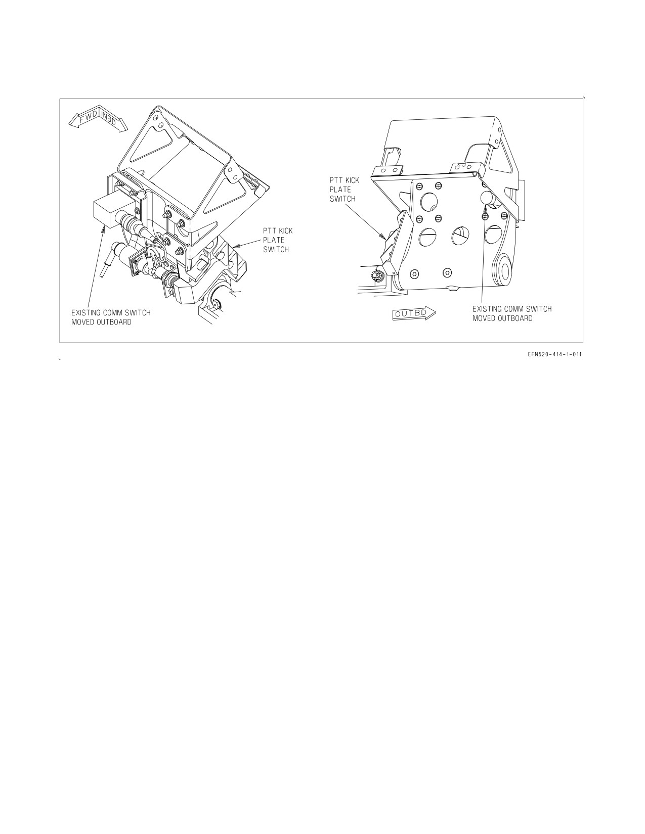
Figure 23-1. Aft Cockpit Rudder Pedal Switches - Lot 26 and up
Frequency Band (MHz)
Modulation
Guard Channel (MHz)
30 to 87.995
FM
121.5
*108 to 135.995
AM
−
136 to 155.995
AM/FM
−
156 to 173.995
FM
−
225 to 399.975
AM/FM
243.0
(AM)
*Cannot transmit on 108 thru 117.995 MHz
Transmission and reception of amplitude and frequency modulated signals (AM and FM) occur in
the respective frequency bands on spaced channels of 5 kHz. Twenty channels in the 30 to 400 MHz
band may be pre-set to assigned frequencies.
23.3.1 VHF/UHF Controls and Indicators. The COMM 1 and COMM 2 are operated by
1. Controls on the UFCD,
2. Controls on the ICS,
3. COMM 1 and 2, MIDS A and B transmit switches on the right (inboard) throttle grip,
4. In the F/A-18F, COMM 1 and 2 transmit switches on the left and right rear cockpit rudder pedals
respectively. The PTT panel controls the rudder pedal selection of COMM 1 or MIDS A, and
COMM 2 or MIDS B. The PTT panel is located on the left hand console LOTs 21-25, and on the left
hand outside bulkhead for LOTs 26 and up.
VII-23-3
ORIGINAL
A1-F18EA-NFM-000
23.3.1.1 UFCD - Up Front Control Display. The UFCD is on the main instrument panel above the
MPCD. The rear cockpit UFCD is on the main instrument panel above or below the MPCD. See figure
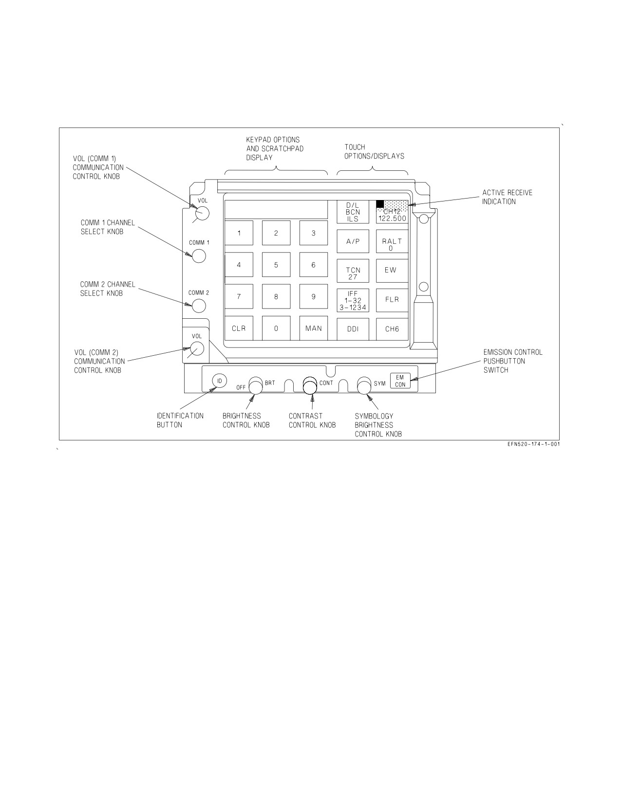
23-2 for top level CNI format. Controls on the UFCD for COMM 1 and 2 are:
1. VOL (volume) 1 and 2 COMM control knobs,
2. COMM 1 and 2 channel select knobs,
3. keypad options and scratchpad display,
4. touch options/displays,
5. ID (identification) button,
6. OFF/BRT (brightness) control knob,
7. CONT (contrast) control knob,
8. SYM (symbology) brightness control knob,
9. EM CON (emission control) pushbutton switch.
10. MIDS - turned on/off by pressing either the TACAN or LINK 16 options, then ON/OFF.
23.3.1.1.1 COMM 1 and 2 VOL (Volume) Control Knobs. Operation of the VOL control knobs is not
dependent on the operation of the MPCD or the UFCD. Each VOL control knob controls power
(on/off) and audio level to the associated COMM 1 and 2 radio. Tick marks on the VOL control knobs
and the face of the UFCD are used to indicate OFF for the associated COMM 1 or 2 radio. Clockwise
rotation from OFF applies power to the associated radio and continued rotation increases the audio
level. On F/A-18F aircraft, the cockpit and rear cockpit VOL control knobs must both be OFF to
remove power from the associated radio. When a radio is powered (on), the associated COMM radio
(unlabeled) touch option/display is corner highlighted (upper left corner).
23.3.1.1.2 COMM 1 and COMM 2 Channel Select Knobs. Operation of the COMM 1 or COMM 2
select knobs is not dependent on the operation of the MPCD or UFCD. Clockwise rotation of either
COMM channel select knob changes the associated COMM 1 or COMM 2 preset channel selections in
the order:
1. CH (1 thru 20) one of twenty preset channels,
2. CH G (guard channel),
3. CH M (manual frequency selection mode),
4. CH C (cue channel/frequency for Single Channel Ground and Airborne Radio System) (SINC-
GARS),
5. CH S (ship maritime).
Continued clockwise rotation repeats the change sequence. Counterclockwise rotation reverses the
change sequence. Rotating either COMM select knob to CH G tunes the associated radio to 243.0 MHz
UHF. To communicate on a guard frequency other than 243.0 MHz UHF, a different guard frequency
VII-23-4
ORIGINAL
A1-F18EA-NFM-000
must be manually entered. Rotating either knob with any AJ MENU sublevel selected returns the
UFCD to the COMM sublevel.
Figure 23-2. Top Level CNI Format on Up Front Control Display (UFCD)
23.3.1.1.3 COMM Keypad Options and Scratchpad Display. In the top level CNI format twelve
keypad options and a scratchpad display may be used to change the CH 1 thru 20 preset channel
numbers, CH G (guard) frequency, CH M (manual frequencies), CH C (cue channel/frequency) or CH
S (ship maritime frequencies). The keypad options are 0 thru 9, CLR (clear) and MAN (manual).
23.3.1.1.4 COMM Touch Option/Displays. On the top level CNI format ten touch option/displays
may be used to select COMM 1, COMM 2, or other sublevel formats. The upper right and lower right
touch option/displays are dedicated to the COMM 1 and COMM 2 radios respectively. Selecting other
sublevel formats does not remove the COMM 1 and 2 touch option/displays.
The COMM 1 and COMM 2 channel displays are also utilized to visually identify which audio
sources are currently active. When an active radio transmission is occurring, the upper half of the
COMM 1/2 option is backg2round shaded. When an active MIDS transmission is occurring, the lower
half of the COMM 1/2 option is backg2round shaded.
On Lot 26 and up aircraft with the 8 x 10 display installed, both UFCDs indicate an active
transmission in progress when either cockpit initiates the communication. The active transmission
indication is a rectangular border around the source (upper for COMM, lower for MIDS). When the
active transmit cue is illuminated, the frequency of the related radio is partially covered on the aft
UFCD.
VII-23-5
ORIGINAL
A1-F18EA-NFM-000
The remaining eight touch option/displays are:
1. D/L, BCN, ILS (data link, beacon and instrument landing system),
2. A/P (autopilot),
3. TCN (TACAN with channel number),
4. IFF (identification friend or foe with mode numbers),
5. DDI (digital display indicator),
6. RALT (radar altimeter with altitude reading),
Channels 10 and 20 are valid entries for Low Altitude Warning settings.
Due to the close proximity of the COMM 1 and RALT touch options/
displays, it is possible to inadvertently change the low altitude warning
setting for the radar altimeter when using COMM 1 fast data entry.
7. EW (electronic warfare),
8. FLR (forward looking infrared radar).
23.3.1.1.5 UFCD OFF/BRT (Brightness) Control Knob. The OFF/BRT control knob adjusts the
overall brightness of the UFCD for both symbology and video. Clockwise rotation from OFF applies
power to the UFCD and progressively increases brightness. Counterclockwise rotation to OFF removes
power from the UFCD. The UFCD does not need to be powered for COMM 1 or 2 to function.
23.3.1.1.6 UFCD CONT (Contrast) Control Knob. Clockwise rotation of the CONT control knob
increases video contrast. Counterclockwise rotation decreases video contrast.
23.3.1.1.7 UFCD SYM (Symbology) Control Knob. Clockwise rotation of the SYM brightness
control knob increases the brightness of the UFCD symbology only. Video brightness is not affected by
this knob.
23.3.1.1.8 EMCON - Emission Control Pushbutton. The EMCON pushbutton switch may be used
to terminate all onboard emitters except COMM transmitters and ALQ-165. If emergency is selected
on the ACI panel, the IFF and D/L respond with emergency, if interrogated. When EMCON is selected
with the EM CON pushbutton switch, emission can be restored only with this switch. When EMCON
is selected with the sensor control switch, emission can be restored with the sensor control switch or the
EM CON pushbutton switch. During EMCON operations, EMCON is displayed in the scratchpad for
top level CNI display or vertically in the left options for DDI displays on the UFCD.
23.3.1.2 COMM Control Panel. The COMM control panel is on the left console. The switches which
are used for VHF/UHF operation are the COMM relay switch and the COMM G XMT select switch.
23.3.1.2.1
RLY (Relay) Switch. The RLY switch, located on the COMM control panel, is used to
enable relay communications by allowing information received through one radio to be routed to the
other radio for transmission. The switch must be placed in the OFF position prior to the initial
VII-23-6
ORIGINAL
A1-F18EA-NFM-000
application of power to the aircraft.
CIPHER Enables CIPHER relay mode.
OFF
Relay mode disabled.
PLAIN
Enables PLAIN voice relay mode.
23.3.1.2.2
G XMIT (Guard Transmit) Switch. The G XMIT switch, located on the COMM control
panel, is used to manually tune the COMM 1 or COMM 2 receiver-transmitter to the guard frequency
of 243.0 MHz (AM). This function is provided in case the normal (UFCD) and primary backup modes
(UFC BU format) of frequency selection are lost.
COMM 1
Selects COMM 1 transmit.
OFF
Normal COMM operation selected.
COMM 2
Guard frequency manually selected on COMM 2.
23.3.1.3 COMM 1 ANT SEL (Antenna Select) Switch. The COMM 1 ANT SEL switch, located on the
ANT SEL panel on the outboard left console, is used to manually select the upper or lower blade
antenna for COMM 1 reception/transmission.
UPPER
Manually selects the upper blade antenna.
AUTO
COMM 1 automatically selects the antenna receiving a usable signal.
LOWER Manually selects the lower blade antenna.
COMM 1 receiver-transmitter automatically selects the antenna receiving a usable signal.
23.3.1.4 COMM Throttle Switch. The COMM throttle switch, located on the inboard side of the
right throttle, is used to enable radio transmission on COMM 1, MIDS A, COMM 2, or MIDS B. The
switch is spring-loaded to the center position.
Top
Selects COMM 1 transmit.
Bottom
Selects COMM 2 transmit.
Forward Selects MIDS A transmit.
Aft
Selects MIDS B transmit.
23.3.1.5 COMM Foot Pedal Switches (F/A-18F). In the missionized configuration the COMM
switches, located on the fixed foot pedals of the rear cockpit, are used to enable radio transmission on
COMM 1 and COMM 2, or MIDS A and MIDS B depending on the position of the PTT panel switches.
Each switch is spring-loaded to the up position.
VII-23-7
ORIGINAL
A1-F18EA-NFM-000
Left
Selects COMM 1 or MIDS A transmit.
Down
(Unmarked)
Both Up Both COMMs in receive.
(Unmarked)
Right
Selects COMM 2 or MIDS B transmit.
Down
(Unmarked)
23.3.2 COMM 1 and 2 Operation. The operation of COMM 1 and 2 is identical. The following
description addresses only COMM 1; however, it should be understood that the description is
applicable to COMM 2. Power to COMM 1 is applied by rotating the VOL 1 COMM control knob
clockwise. Power application is identified by a corner highlight in the upper left corner of the COMM
1 touch option/display. The channels and preset frequencies (CH 1 thru 20), CH G, CH M, CH C and
CH S may be selected by rotating the COMM 1 channel select knob until the desired CH sub level and
fixed frequency are displayed in the COMM 1 touch option/display. In the anti-jam mode, the fixed
frequency is replaced with H1, H2 or SG. When COMM 1 is actively receiving, the upper half of the
touch option/display is half intensity highlighted. The active receive indication is available only if the
radio is powered.
23.3.2.1
Top Level CNI Format Channel or Manual Frequency Change. In the top level CNI
format, the preset channel number is changed by touching the desired channel number on the keypad
and then touching the COMM 1 touch option/display (fast data entry). If an invalid channel entry is
made, ERROR is displayed in the scratchpad.
The manual frequency can be changed using the fast data entry mechanization. The manual
frequency is entered by entering the desired frequency on the keypad display and touching the COMM
1 or COMM 2 touch option display. Trailing zeroes need not be selected. If an invalid manual
frequency entry is made, ERROR is displayed in the scratchpad and the radio does not go to the CH
M (manual) channel. With non-AMCD aircraft, highlighting the MAN option and subsequently
touching the desired radio, changes that radio to the programmed MAN frequency. With AMCD
aircraft, selecting 0 and subsequently touching the desired radio, changes that radio to the pro-
grammed MAN radio frequency.
23.3.2.2 COMM Sublevel Selection. Touching the COMM 1 touch option/display while on CH 1
thru 20, CH G, CH M, CH C, or CH S selects that sublevel mode. When applicable, the sublevel mode
is used to:
1. Change a fixed frequency,
2. Change ship maritime preset,
3. Change the guard or cue frequency,
4. Enable or disable cipher mode,
5. Adjust squelch,
6. Enable or disable guard receive,
7. Non-AMCD aircraft - Enable or disable ADF,
8. Select modulation type (AM or FM),
VII-23-8
ORIGINAL
A1-F18EA-NFM-000
9. Enter anti-jam mode (AJ or AJ MENU),
10. Access Have Quick, Have Quick time, SINCGARS coldstart, Have Quick manual data fill, or
SINCGARS zeroize.
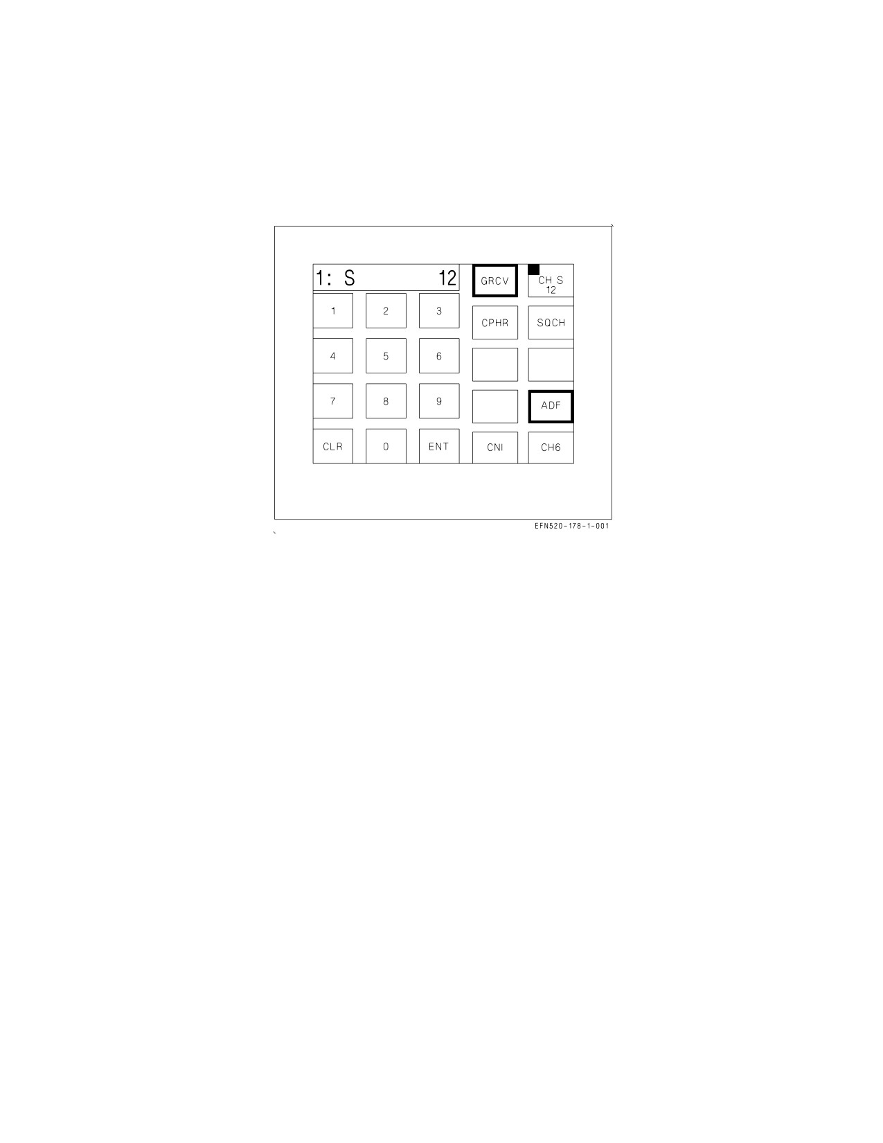
Figure 23-3. COMM Sublevel - Ship Maritime Preset
23.3.2.3 COMM Sublevel - Ship Maritime Preset. The Ship Maritime Preset COMM Sublevel is
selected by touching the COMM 1 touch option/display with CH S previously selected (see figure 23-3).
This sublevel is used to enable or disable squelch, cipher mode, guard receive, or ADF operation
(Non-AMCD aircraft). Selecting this sublevel displays a 1: (selected radio) followed by an S and the
current ship maritime preset number. The ship maritime preset number is changed by touching the
desired number(s) on the keypad options (numbers 1 thru 28 or 60 thru 88), verifying the new number
in the scratchpad, and touching ENT. If an invalid number is entered, ERROR is displayed in the
scratchpad. CPHR (cipher), SQCH (squelch), GRCV (guard receive), and ADF (If installed) are
enabled or disabled by touching the respective touch options/displays. An enabled option has a
highlighted border. CPHR or ADF operation is available for only one radio at a time. Enabling CPHR
or ADF on COMM 1 automatically disables CPHR or ADF on COMM 2 if previously enabled.
Enabling ADF automatically disables SQCH. SQCH may be enabled after selecting ADF by
touching the SQCH option; however, if SQCH was not enabled after selecting ADF it is automatically
enabled when ADF is disabled.
The modulation type (AM or FM), AJ, or AJ MENU options are not available on this sublevel.
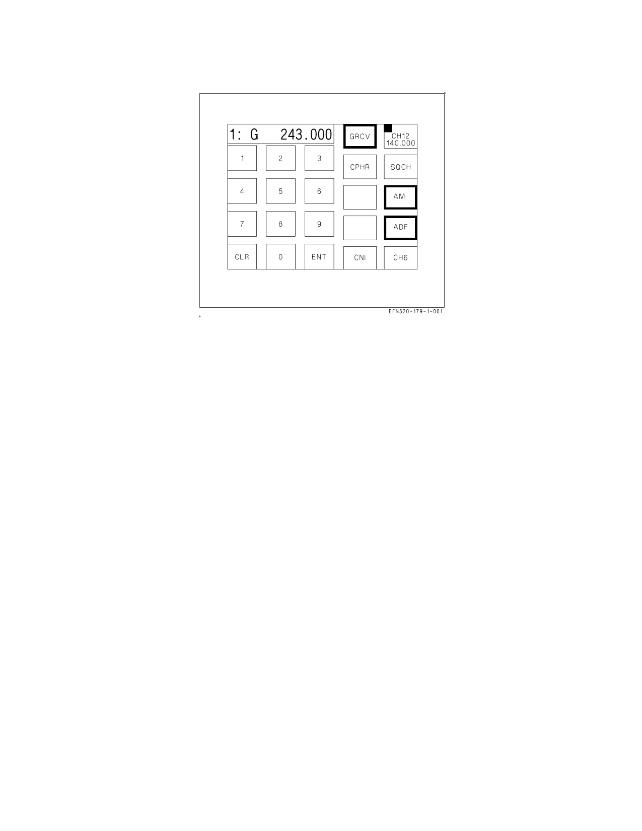
23.3.2.4 COMM Sublevel - Guard and Cue Presets. The Guard or Cue Preset COMM Sublevel is
selected by touching the COMM 1 touch option/display with CH G or CH C previously selected (see
figure 23-4). This sublevel is used to change the G (guard) or C (cue) frequency, to enable or disable
squelch, cipher mode, guard receive, ADF operation (If installed), or to select modulation type (AM or
FM). Selecting this sublevel displays a 1: (selected radio) followed by a G or C and the current fixed
frequency. The fixed frequency is changed by touching the desired numbers on the keypad options,
verifying the new number in the scratchpad, and touching ENT. Valid frequencies are:
VII-23-9
ORIGINAL
A1-F18EA-NFM-000
Figure 23-4. COMM Sublevel - Guard and Cue Presets
1.
30 thru 87.995 MHz (FM) - at increments of 0.005, 0.025 MHz for C
2.
108 thru 135.995 MHz (AM) - at increments of 0.005, 0.025 MHz for C
3.
136 thru 155.995 MHz (AM/FM) - at increments of 0.005, 0.025 MHz for C
4.
156 thru 173.995 MHz (FM) - at increments of 0.005, 0.025 MHz for C
5.
225 thru 399.975 MHz (AM/FM) - at increments of 0.025 MHz.
If an invalid number is entered, ERROR is displayed in the scratchpad.
SQCH (squelch), GRCV (guard receive), AM/FM, and ADF (If installed) are enabled or disabled by
touching the respective touch options/displays. An enabled option has a highlighted border. The
AM/FM option is always border highlighted and toggles between AM and FM. If the current frequency
is available only in AM or FM, the AM/FM option is not displayed. While in the UHF AM mode, the
cipher option cycles as follows: CPHR (no highlighted border-cipher disabled), CPHR (border
highlighted-cipher baseband enabled), CPDP (border highlighted-cipher diphase enabled). The CPHR
and CPDP options are mutually exclusive. Continued selection of this option repeats the above cycle.
CPHR (both diphase and baseband) or ADF operation (If installed) is available for only one radio at
a time. Enabling CPHR or ADF on COMM 1 automatically disables CPHR or ADF on COMM 2 if
previously enabled.
Enabling ADF automatically disables SQCH. SQCH may be enabled after selecting ADF by
touching the SQCH option; however, if SQCH was not enabled after selecting ADF it is automatically
enabled when ADF is disabled.
The AJ and AJ MENU options are not available on this sublevel.
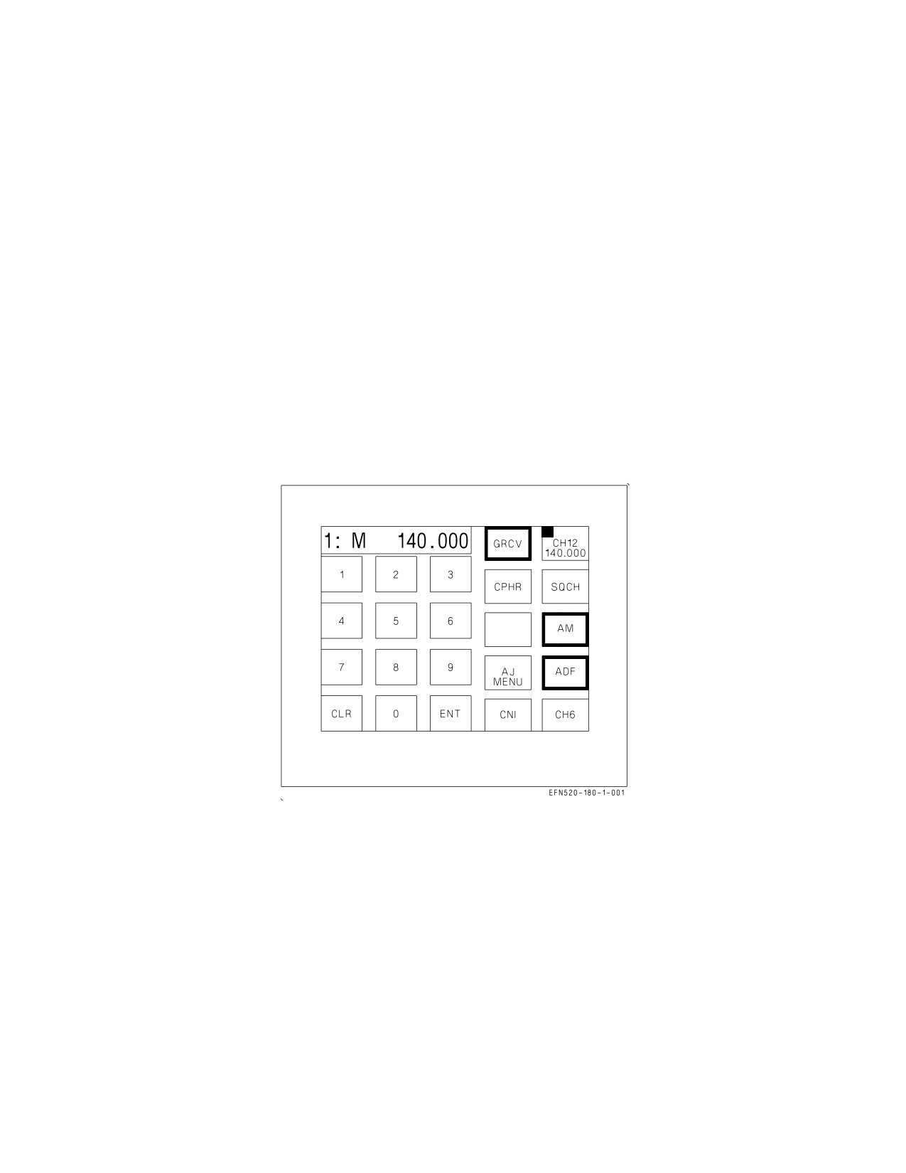
23.3.2.5 COMM Sublevel - Manual Preset. The Manual Preset COMM Sublevel is selected by
touching the COMM 1 touch option/display with CH M previously selected (see figure 23-5). This
sublevel is used to change the M (manual) frequency, to enable or disable squelch, cipher mode, guard
VII-23-10
ORIGINAL
A1-F18EA-NFM-000
receive, ADF operation (If installed), select modulation type (AM or FM) or to access Have Quick,
Have Quick time, SINCGARS coldstart, Have Quick manual data fill, and SINCGARS zeroize.
Selecting this sublevel displays a 1: (selected radio) followed by an M and the current fixed frequency.
The fixed frequency is changed by touching the desired numbers on the keypad options, verifying the
new number in the scratchpad, and touching ENT.
Valid frequencies are:
1.
30 thru 87.995 MHz (FM) - at increments of 0.005 MHz,
2.
108 thru 135.995 MHz (AM) - at increments of 0.005 MHz,
3.
136 thru 155.995 MHz (AM/FM) - at increments of 0.005 MHz,
4.
156 thru 173.995 MHz (FM) - at increments of 0.005 MHz,
5.
225 thru 399.975 MHz (AM/FM) - at increments of 0.025 MHz.
Figure 23-5. COMM Sublevel - Manual Preset
If an invalid number is entered, ERROR is displayed in the scratchpad.
SQCH (squelch), GRCV (guard receive), and ADF are enabled or disabled by touching the respective
touch options/displays. An enabled option has a highlighted border. The AM/FM option is always
border highlighted and toggles between AM and FM. If the current frequency is available only in AM
or FM, the AM/FM option is not displayed. While in the UHF AM mode, the cipher option cycles as
follows: CPHR (no highlighted border-cipher disabled), CPHR (border highlighted-cipher baseband
enabled), CPDP (border highlighted-cipher diphase enabled). The CPHR and CPDP options are
mutually exclusive. Continued selection of this option repeats the above cycle. CPHR (both diphase
and baseband) or ADF operation (If installed) is available for only one radio at a time. Enabling CPHR
or ADF on COMM 1 automatically disables CPHR or ADF on COMM 2 if previously enabled.
VII-23-11
ORIGINAL
A1-F18EA-NFM-000
Enabling ADF automatically disables SQCH. SQCH may be enabled after selecting ADF by
touching the SQCH option. However, if SQCH was not enabled after selecting ADF it is automatically
enabled when ADF is disabled.
The AJ option is not available on this sublevel.
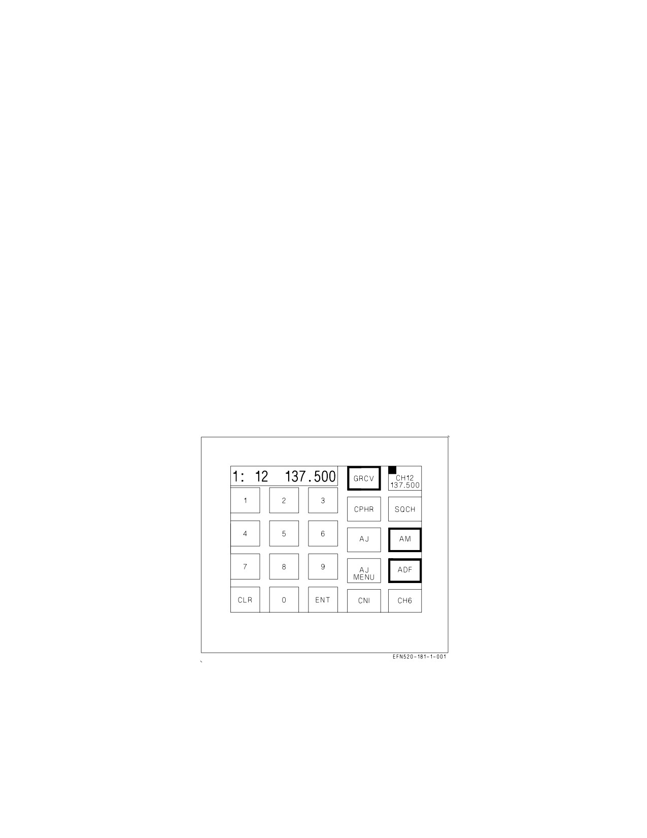
23.3.2.6 COMM Sublevel - Presets 1 Thru 20 (Fixed Frequency). The Preset 1 Thru 20 COMM
Sublevel is selected by touching the COMM 1 touch option/display with CH (1 thru 20) previously
selected (see figure 23-6). This sublevel is used to change the frequency, to enable or disable squelch,
cipher mode, guard receive, ADF operation, to select modulation type (AM or FM), to enter anti-jam
mode or to access Have Quick, Have Quick time, SINCGARS coldstart, Have Quick manual data fill,
or SINCGARS zeroize. Selecting this sublevel displays a 1: (selected radio) followed by the current
channel number and fixed frequency. The fixed frequency for any channel number (1 thru 20) is
changed by touching the desired numbers on the keypad options, verifying the new frequency number
in the scratchpad, and touching ENT.
1.
30 thru 87.995 MHz (FM) - at increments of 0.005 MHz,
2.
108 thru 135.995 MHz (AM) - at increments of 0.005 MHz,
3.
136 thru 155.995 MHz (AM/FM) - at increments of 0.005 MHz,
4.
156 thru 173.995 MHz (FM) - at increments of 0.005 MHz,
5.
225 thru 399.975 MHz (AM/FM) - at increments of 0.025 MHz.
Figure 23-6. COMM Sublevel - Presets 1 Thru 20 (Fixed Frequency)
If an invalid number is entered, ERROR is displayed in the scratchpad. SQCH (squelch), GRCV
(guard receive), and ADF are enabled or disabled by touching the respective touch options/displays. An
enabled option has a highlighted border. While in the UHF AM mode, the cipher option cycles as
follows: CPHR (no highlighted border-cipher disabled), CPHR (border highlighted-cipher baseband
enabled), CPDP (border highlighted-cipher diphase enabled). The CPHR and CPDP options are
mutually exclusive. Continued selection of this option repeats the above cycle. CPHR
(both
VII-23-12
ORIGINAL
A1-F18EA-NFM-000
diphase and baseband) or ADF operation is available for only one radio at a time. Enabling CPHR or
ADF on COMM 1 automatically disables CPHR or ADF on COMM 2 if it was previously enabled.
Enabling ADF automatically disables SQCH. SQCH may be enabled after selecting ADF by
touching the SQCH option; however, if SQCH was not enabled after selecting ADF it is automatically
enabled when ADF is disabled.
Selecting the AJ option on this sublevel selects COMM 1 anti-jam mode. If Have Quick is
pre-defined for the current preset, the radio enters Have Quick mode. If SINCGARS is pre-defined for
the current preset, the radio enters SINCGARS. If no data/waveform or time is stored in the radio for
the current preset, NO FILL is displayed in the scratchpad and the radio is in neither Have Quick or
SINCGARS. For Have Quick or SINCGARS data entry, see Have Quick or SINCGARS System
paragraphs, this chapter. Once the radio is in the anti-jam mode it remains in the anti-jam mode, even
if the preset channel is changed using the COMM channel select knob or the Top Level CNI Format
Channel Change paragraph procedure (fast data entry). The anti-jam mode is disabled by touching the
border highlighted AJ touch option/display.
23.3.3 Anti-Jam Operation. There is no AJ or AJ MENU option on the Ship Maritime Preset, Guard
Preset, or Cue Preset Sublevels. The Manual Preset Sublevel has an AJ MENU option but does not
have an AJ option. Anti-Jam operation is described in the Have Quick and SINCGARS System
paragraphs, this chapter.
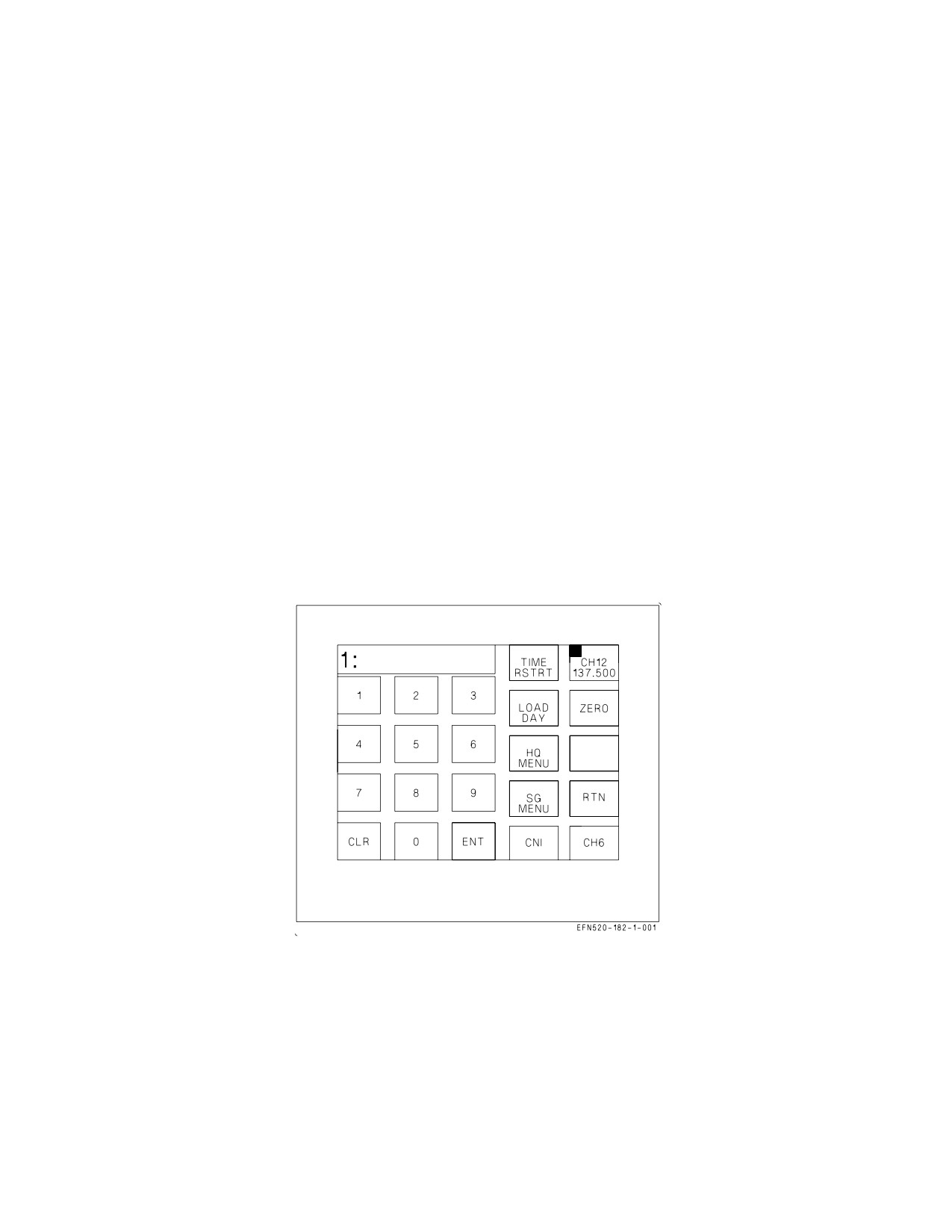
Figure 23-7. AJ MENU From Fixed Frequency COMM Sublevel
23.3.3.1 AJ MENU From Fixed Frequency COMM Sublevel. Touching the AJ MENU touch
option/display while on the COMM sublevel with a fixed frequency selects the AJ MENU From Fixed
Frequency COMM Sublevel (see figure 23-7). This sublevel initializes with no options selected and
displays a 1: (selected radio) in the scratchpad but does not display the fixed frequency. The AJ fixed
frequency sublevel is used to control Have Quick time, to control SINCGARS coldstart, to manually
load Have Quick fill, and to control Have Quick and SINCGARS zeroize.
VII-23-13
ORIGINAL
A1-F18EA-NFM-000
The TIME RSTRT option is used to restart the radio clock. To prevent inadvertent selection, this
option requires a double selection to start the radio clock. Touching TIME RSTRT option changes the
touch option/display to RSTRT ENABLE. Touching the RSTRT ENABLE option starts the radio
clock and returns the display to TIME RSTRT. If any option other than RSTRT ENABLE is touched
after touching TIME RSTRT the radio clock is not started and the display returns to TIME RSTRT.
The LOAD DAY option is used to load the Have Quick calendar day. Touching the LOAD DAY
touch option/display border highlights the option and enables calendar day entry by touching the
desired numbers on the keypad options (01 thru 31), verifying the new calendar day in the scratchpad,
and touching ENT. When the calendar day is entered into the radio a tone sounds in the head set.
Touching any other touch option/display removes the border highlight from the LOAD DAY option
and data entry is no longer available.
The ZERO option is used to erase the stored Have Quick word-of-day (WOD) and SINCGARS
transec data. To prevent inadvertent selection, this option requires a double selection to zero radio
data. Touching ZERO option changes the touch option/display to ZERO ENABLE. Touching the
ZERO ENABLE option zeroizes both (COMM 1 and 2) radios. The ZERO ENABLE option is border
highlighted for 2 seconds and the display returns to ZERO. If any option other than ZERO ENABLE
is touched after touching ZERO the radios are not zeroized and the display returns to ZERO.
The RTN option is used to return to the fixed frequency COMM sublevel.
23.4 HAVE QUICK SYSTEM
Have Quick is a slow hopping, UHF, AM line-of-sight jam-resistant voice communication system.
The operation involves coordinating and establishing communications nets. These nets have multiple
users that have the same ECCM information and are time synchronized. The nets are established and
operate with information for a specific word-of-day. The WOD is used to define the frequency hopping
pattern for that day. In conjunction with the WOD, a precise time-of-day (TOD), which is effectively
the net time synchronizer, is also required. The net number and type can be entered using the keypad
options. The three digits to the left of the decimal point are the net number and range from 000 to 999.
The three digits to the right of the decimal point represent type: .025 = HQII (NATO), and .050 = HQII
(non-NATO).
NOTE
The radios do not contain a clock. Time must be set during aircraft
preflight.
The principle functions available for Have Quick control are:
1. Anti-jam (AJ) mode and net selection,
2. Time synchronization including either the reception or the transmission of the TOD,
3. WOD verification and manual entry,
4. Zeroing WOD,
5. Training net control and manual entry.
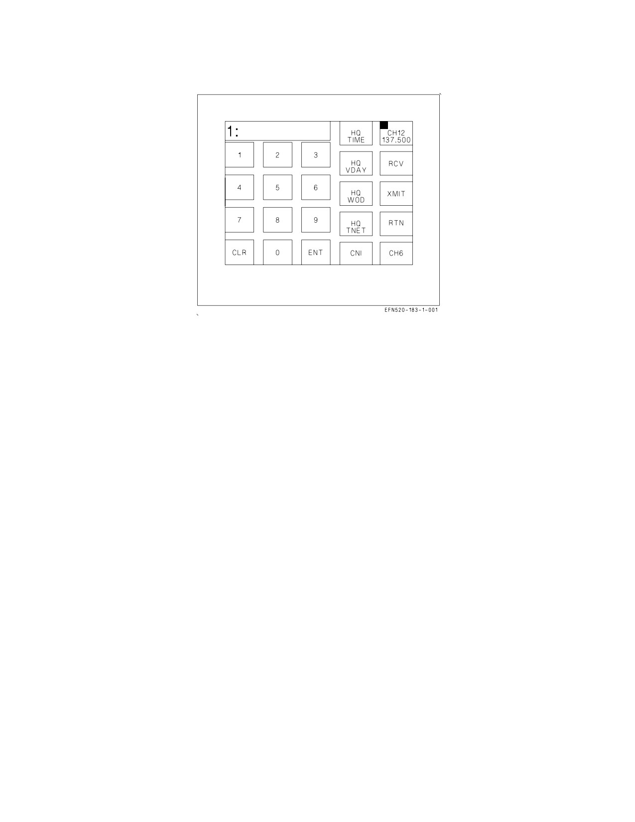
23.4.1 Have Quick Menu From AJ Menu Fixed Frequency COMM Sublevel. Touching the HQ
MENU touch option/display while on the AJ COMM sublevel with a fixed frequency selects the Have
VII-23-14
ORIGINAL
A1-F18EA-NFM-000
Figure 23-8. Have Quick Fixed Frequency Sublevel
Quick fixed frequency sublevel (see figure 23-8). This sublevel initializes with no options selected and
displays a 1: (selected radio) in the scratchpad. This sublevel is used for manual fill operation.
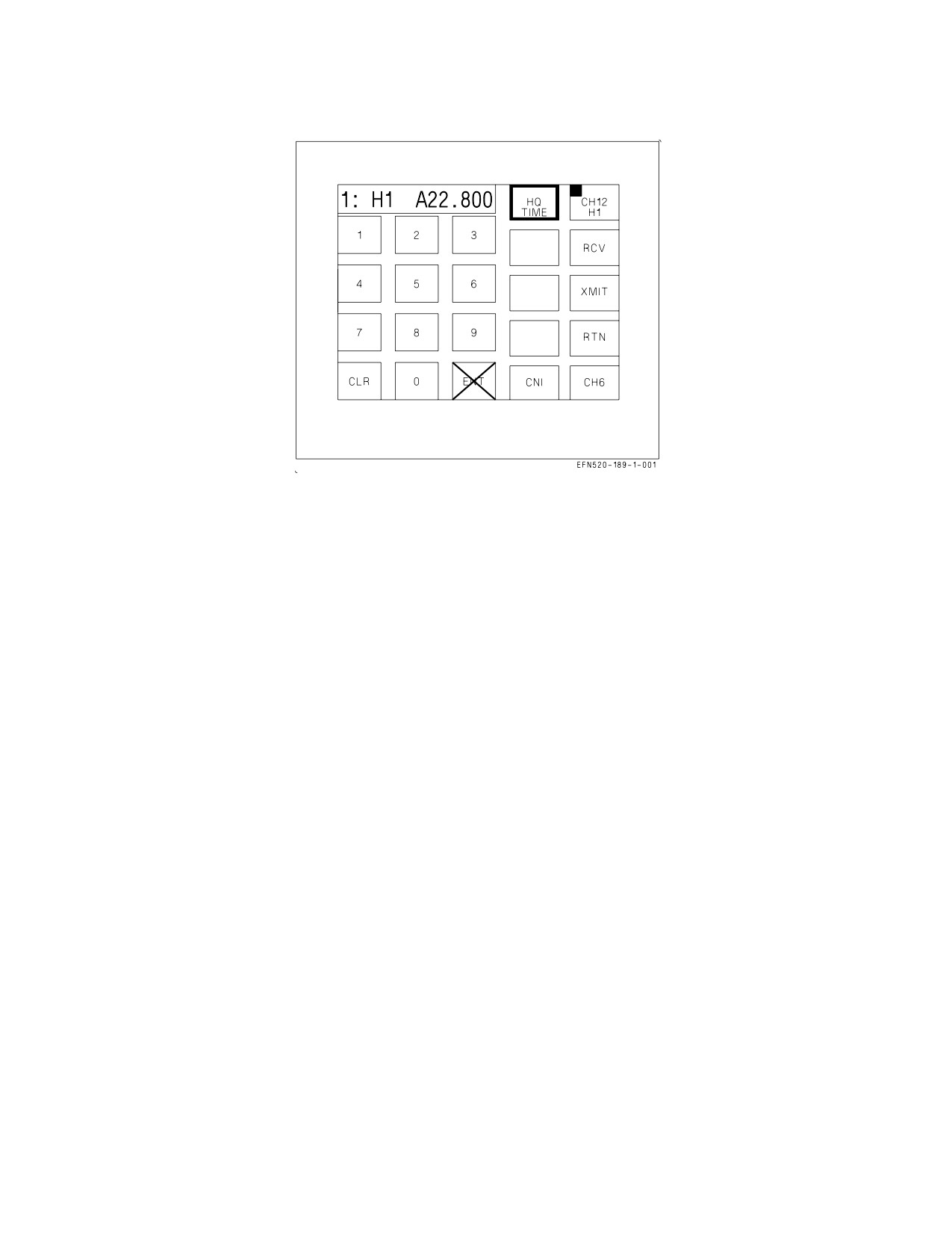
The HQ TIME option is used to transmit or receive Have Quick time. Touching the HQ TIME touch
option/display border highlights the option and enables the use of the RCV and XMIT options. With
HQ TIME selected, touching the RCV touch option/display border highlights the RCV option until
time is received, or until 60 seconds has elapsed. With HQ TIME selected, touching the XMIT touch
option/display border highlights the XMIT option for 2 seconds and time is transmitted. The XMIT
option is not displayed if ADF is enabled (for the selected radio). The HQ TIME option remains border
highlighted until HQ VDAY, HQ WOD or HQ TNET is selected.
The HQ VDAY option is used to verify that a Have Quick word-of-day is loaded for a particular day
(see figure 23-9). Touching the HQ VDAY touch option/display border highlights the option and
enables calendar day data entry by touching the desired numbers on the keypad options (01 thru 31),
verifying the new calendar day data entry and then touching ENT. If there is a stored word of day for
the entered calendar day a tone sounds in the head set. The HQ VDAY option remains border
highlighted until HQ TIME, HQ WOD or HQ TNET is selected.
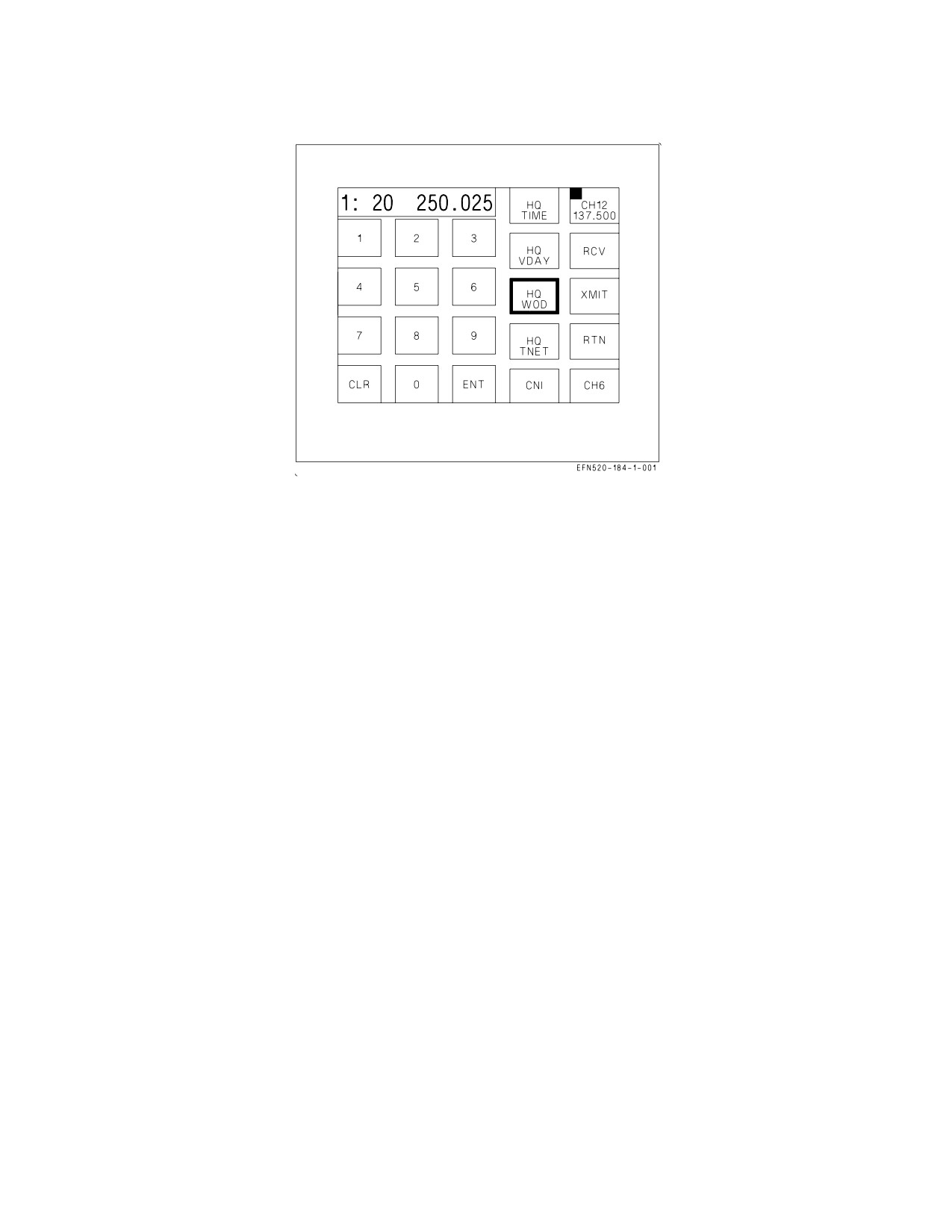
The HQ WOD option is used to manually enter the Have Quick word of day. Touching the HQ WOD
touch option/display border highlights this option and enables Have Quick word-of-day entry by
touching the desired numbers on the keypad options (WOD segments 200.000 thru 399.975 in
increments of 0.025), verifying the word of day in the scratchpad, and touching ENT. Each word-of-day
is six-segments that look like frequencies. When the HQ WOD is first selected, 20 is displayed in the
scratchpad followed by the first six-segments of data. There are six individual word-of-day segments
identified by the numbers 20 thru 15. As each six-segment data is entered, the number decrements thru
15. Trailing zeros need not be entered.
• 1st Segment - 20 000.000 ENT
• 2nd Segment - 19 000.000 ENT
• 3rd Segment - 18 000.000 ENT
• 4th Segment - 17 000.000 ENT
VII-23-15
ORIGINAL
A1-F18EA-NFM-000
Figure 23-9. Have Quick WOD Loading
• 5th Segment - 16 000.000 ENT
• 6th Segment - 15 000.000 ENT
The last segment (7th) is calendar day and is only two numbers (01 thru 31). After the calendar day
is entered, the HQ WOD option changes to an unhighlighted border WOD LOAD. No data entry is
available with WOD LOAD displayed. Touching the WOD LOAD option sends the word-of-day to the
radio, the option changes back to an unhighlighted border HQ WOD touch option/display, and a tone
sounds in the head set.
At any time during the data entry of the word- of-day, the border highlighted HQ WOD option may
be used to cycle to the next segment without changing the current segment. If on the calendar day
segment, touching HQ WOD cycles to WOD LOAD without changing the calendar day segment. The
HQ WOD option remains border highlighted until WOD LOAD, HQ TIME, HQ VDAY or HQ TNET
is selected. If HQ WOD data entry is exited before completion, the previously entered segments are
maintained and are displayed in the scratchpad when HQ WOD entry is continued.
Selecting the RTN option returns the Have Quick MENU format to the Fixed Frequency Anti-Jam
Menu format.
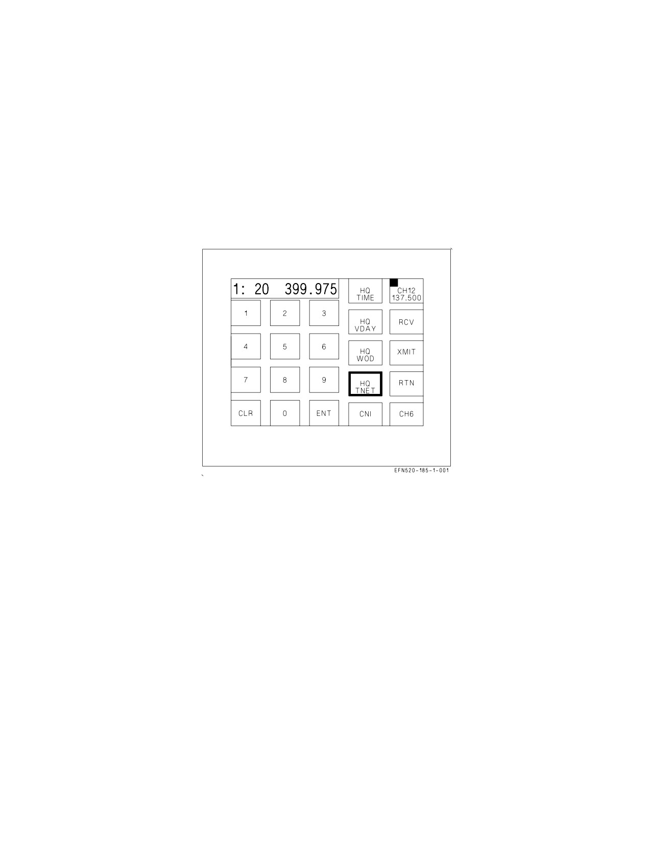
The HQ TNET option is used to manually enter the Have Quick 2 training nets (see figure 23-10).
Touching the HQ TNET touch option/display border highlights this option and enables Have Quick
2 training net data entry by touching the desired numbers on the keypad options, verifying the
frequency in the scratchpad, and then touching ENT. When the HQ TNET is first selected, 20 is
displayed in the scratchpad followed by the first training net frequency. There are 16 training net
frequencies identified by the numbers 20 thru 5. As each frequency is entered the number decrements
thru 5. Trailing zeros need not be entered.
• 1st Segment - 20 000.000 ENT
• 2nd Segment - 19 000.000 ENT
• 3rd Segment - 18 000.000 ENT
---- ----------- --
--
----- ---
---
VII-23-16
ORIGINAL
A1-F18EA-NFM-000
• 14th Segment - 7 000.000 ENT
• 15th Segment - 6 000.000 ENT
• 16th Segment - 5 000.000 ENT
The valid training net frequencies are:
1.
30.000 thru 87.995 MHz (FM) - at increments of 0.025 MHz,
2.
108.000 thru 173.975 MHz (AM) - at increments of 0.025 MHz,
3.
225.000 thru 399.975 MHz (AM/FM) - at increments of 0.025 MHz.
Figure 23-10. Have Quick TNET Loading
After the last training net frequency is entered, the HQ TNET option changes to an unhighlighted
border TNET LOAD. No data entry is available with TNET LOAD displayed. Touching the TNET
LOAD option sends the training net to the radio, the option changes back to an unhighlighted border
HQ TNET touch option/display and a tone sounds in the head set.
At any time during the data entry of the training net, the border highlighted HQ TNET option may
be used to cycle to the next frequency without changing the current frequency. If on the last training
net frequency, touching HQ TNET cycles to TNET LOAD without changing the last training net
frequency. The HQ TNET option remains border highlighted until TNET LOAD, HQ TIME, HQ
VDAY or HQ WOD is selected. If HQ TNET data entry is exited before completion, the previously
entered frequencies are maintained and are displayed in the scratchpad when HQ TNET entry is
continued.
Selecting the RTN option returns the Have Quick MENU format to the Fixed Frequency Anti-Jam
Menu format.
23.4.2
SINCGARS Menu From AJ Menu Fixed Frequency COMM Sublevel. Touching the SG
MENU touch option/display while on the AJ COMM sublevel with a fixed frequency selects the Single
Channel Ground and Airborne Radio System (SINCGARS) MENU fixed frequency sublevel (see
figure 23-11). This sublevel initializes with no options selected and displays a 1: (selected radio) in the
VII-23-17
ORIGINAL

A1-F18EA-NFM-000
scratchpad. This sublevel is used for SINCGARS coldstart operation. The SINCGARS coldstart
operation is used for receiving or transmitting SINCGARS hopsets and locksets so a user can be added
to the net. There is a 30 second time-out during option selections. The XMIT option is not displayed
if ADF is enabled for the current radio.
Figure 23-11. Single Channel Ground and Airborne Radio System (SINCGARS) MENU Fixed Fre-
quency Sublevel
The SG LSET is used to enter the SINCGARS lockset for transmission or reception. Touching the
SG LSET touch option/display border highlights the option and the last lockset is displayed in the
scratchpad. The lockset may be changed by touching the desired number on the keypad options (1 thru
8), verifying the new lockset in the scratchpad, and touching ENT. With the desired lockset displayed
in the scrathpad, the lockset is transmitted or received by touching the XMIT or RCV option.
Touching the XMIT option transmits the new radio lockset and the option is border highlighted for 2
seconds. Touching the RCV option enables the radio to receive the lockset and the option remains
border highlighted until the lockset is received.
Touching the SG HSET touch option/display border highlights the option and the last hopset is
displayed in the scratchpad. The hopset may be changed by touching the desired number on the
keypad options (1 thru 20), verifying the new hopset in the scratchpad, and touching ENT. With the
desired hopset displayed in the scratchpad, the hopset is transmitted or received by touching the
XMIT or RCV option. Touching the XMIT option transmits the new radio hopset and the option is
border highlighted for 2 seconds. Touching the RCV option enables the radio to receive the hopset and
the option remains border highlighted until the hopset is received. The XMIT and RCV options can
not be selected at the same time.
Selecting the RTN option returns the SINCGARS MENU format to the Fixed Frequency Anti-Jam
Menu format.
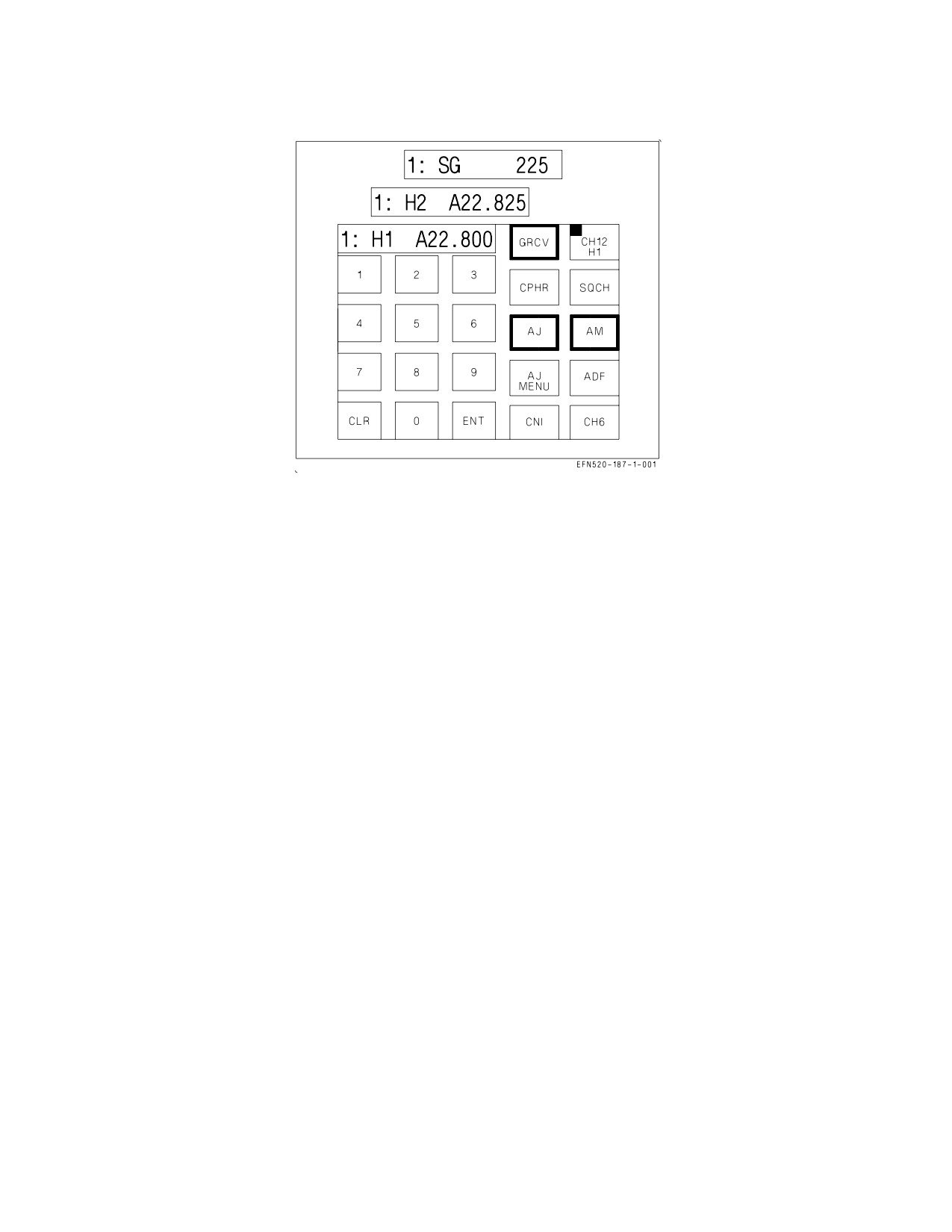
23.4.3 COMM Sublevel - Presets 1 Thru 20 (Anti-Jam). The Preset 1 thru 20 COMM Sublevel
(Anti-Jam) is selected by touching the COMM 1 or 2 touch option/display while on preset channel 1
thru 20 and in Have Quick or SINCGARS anti-jam mode (see figure 23-12).
VII-23-18
ORIGINAL
A1-F18EA-NFM-000
Figure 23-12. COMM Sublevel - Presets 1 to 20 (Anti-Jam)
In the Have Quick mode, this sublevel is used to change the net number, to enable or disable squelch,
cipher mode, guard receive, or ADF operation; to select modulation type (AM or FM); or to access time
receive and time transmit.
In the SINCGARS mode, this sublevel is used to enable or disable squelch, cipher mode, guard
receive, or ADF operation; to access master selection; to enter late net selection; to enter time; and to
transmit and receive hopsets and locksets. This sublevel, displays a 1: (selected radio) followed by H1
(Have Quick 1), H2 (Have Quick 2, or SG (SINCGARS) and the net number. In Have Quick mode, the
net number (00.000 thru 99.950) is changed by touching the desired numbers on the keypad options,
verifying the new net number in the scratchpad, and touching ENT. The last two digits of the net
number must be 00, 25 or 50. Trailing zeros need not be entered. If invalid data is entered, an error
indication is displayed in the scratchpad. The SINCGARS net number cannot be changed at this
sublevel.
SQCH (squelch), GRCV (guard receive), and ADF are enabled or disabled by touching the respective
touch options/displays. An enabled option has a highlighted border. The AM/FM option is always
border highlighted and toggles between AM and FM. If the current frequency is available only in AM
or in FM, the AM/FM option is not displayed. While in the UHF AM mode, the cipher option cycles
as follows: CPHR (no highlighted border-cipher disabled), CPHR (border highlighted-cipher baseband
enabled), CPDP (border highlighted-cipher diphase enabled). The CPHR and CPDP options are
mutually exclusive. Continued selection of this option repeats the above cycle. CPHR (both diphase
and baseband) or ADF operation is available for only one radio at a time. Enabling CPHR or ADF on
COMM 1 automatically disables CPHR or ADF on COMM 2 if it was previously enabled.
Enabling ADF automatically disables SQCH. SQCH may be enabled after selecting ADF by
touching the SQCH option. However, if SQCH was not enabled after selecting ADF it is automatically
enabled when ADF is disabled.
Touching the AJ option returns the selected radio to the COMM fixed frequency sublevel. This
selection applies to all presets and all preset channels which now become fixed frequency.
VII-23-19
ORIGINAL
A1-F18EA-NFM-000
Touching the AJ MENU option selects the Have Quick or SINCGARS menu sublevel depending on
whether the current preset is defined as Have Quick or SINCGARS.
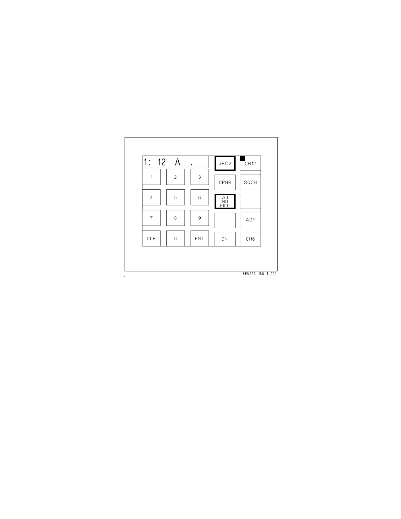
If the radio is in anti-jam mode but there is no valid data/waveform or time stored in the current
radio for the current preset channel, the AJ option changes to AJ NO FILL (see figure 23-13). The
AM/FM and AJ MENU options are not displayed when a NO FILL condition exists on the current
preset channel. In this condition, an A is displayed in the scratchpad and a Have Quick net number
may be entered.
Figure 23-13. AJ MENU From Have Quick COMM Sublevel
23.4.4 AJ MENU From Have Quick COMM Sublevel. Touching the AJ MENU touch option/display
while on the COMM sublevel with a Have Quick anti-jam mode selects the AJ Have Quick menu
sublevel initialized with the HQ TIME option selected and border highlighted (see figure 23-14). This
sublevel is used to transmit and receive Have Quick time. The scratchpad information is the same as
scratchpad information on the Have Quick COMM sublevel.
The HQ TIME option is used to transmit or receive Have Quick time while the radio is operating on
a Have Quick net. With the HQ TIME touch option/display border highlighted the option enables the
use of the RCV and XMIT options. Touching the RCV touch option/display border highlights the RCV
option until time is received or until 60 seconds have elapsed. Touching the XMIT touch option/
display border highlights the XMIT option for 2 seconds and time is transmitted. The XMIT option
is not displayed if ADF is enabled (for selected radio). Data entry is not available on this sublevel and
the ENT option is Xed out.
Selecting the RTN option returns the format to the AJ COMM sublevel.
23.5 SINCGARS SYSTEM
The radio can be operated with SINCGARS, which provides jam resistant line-of-sight (LOS) voice
communications in the VHF band employing frequency hopping. Established communication nets
require a TOD that is coordinated and used by all net users. The system also contains encoded locksets
VII-23-20
ORIGINAL
A1-F18EA-NFM-000
Figure 23-14. AJ Have Quick Menu Sublevel
and hopsets that define the set of frequencies that will be hopped on and will not be hopped on. The
system can store multiple nets correlating to hopsets and locksets. The principle functions available for
SINCGARS control are:
a. SINCGARS mode (AJ) selection,
b. time reception and transmission,
c. late net entry,
d. electronic remote fill (ERF),
e. cue operation,
f. coldstart.
23.5.1 AJ MENU From SINCGARS COMM Sublevel. Touching the AJ MENU touch option/display
while on the COMM sublevel with a SINCGARS anti-jam mode selects the AJ SINCGARS menu
sublevel (see figure 23-15) and may initialize with the MSTR option or LATE ENTRY option selected,
or no options selected. This sublevel is used to select MSTR (master operation), to select LATE
ENTRY (late entry operation), to enter time, and to transmit and receive hopsets and locksets.
The MSTR option is used to select master control of the net. Automatic time synchronization is
achieved by each of the net radios every time a transmission is received from the master. If the MSTR
option is border highlighted, master control of the net is enabled. If MSTR is not border highlighted,
master control of the net is disabled. The MSTR option toggles between control and no control.
The TIME option is used to enter time. Each user can enter the SINCGARS time. The time can be
used by the master to synchronize the rest of the net or to get on the net using late entry. Touching the
TIME option/display border highlights this option, a D, H, and M is displayed in the scratchpad, and
time data entry is enabled. The time may be entered in D (day), H (hour) and M (month) format by
VII-23-21
ORIGINAL

A1-F18EA-NFM-000
Figure 23-15. AJ MENU From SINCGARS COMM Sublevel
touching the desired number on the keypad options, verifying the new time in the scratchpad and
touching ENT. Trailing zeros need not be entered. If invalid data is entered, ERROR is displayed in
the scratchpad.
The LATE ENTRY is used to gain late entry into the net. Touching the LATE ENTRY
option/display border highlights the option and enables late entry into the SINCGARS net. This
option remains border highlighted until time synchronization into the net is achieved.
Touching the ERF (Electronic Remote Fill) option selects the AJ SINCGARS ERF sublevel (see
figure 23-16). ERF allows the system to be filled electronically over the air by another net user who has
the required net data (hopsets/locksets). The net user can either provide or receive the net data. The
Figure 23-16. AJ SINCGARS ERF Sublevel
VII-23-22
ORIGINAL
A1-F18EA-NFM-000
desired hopset/lockset can be selected one at a time for either transmission or reception. The process
is repeated until all desired sets are transmitted/received. This sublevel initializes with no options
selected and displays a 1: (selected radio) in the scratchpad. This sublevel is used for SINCGARS
coldstart operation. The SINCGARS coldstart operation is used for receiving or transmitting
SINCGARS hopsets and locksets so a user can be added to the net. There is no 30 second time-out
during option selections. The XMIT option is not displayed if ADF is enabled for the current radio.
The SG LSET is used to enter the SINCGARS lockset for transmission or reception. Touching the
SG LSET touch option/display border highlights the option and the last lockset is displayed in the
scratchpad. The lockset may be changed by touching the desired number on the keypad options (1 thru
8), verifying the new lockset in the scratchpad, and touching ENT. With the desired lockset displayed
in the scratchpad, the lockset is transmitted or received by touching the XMIT or RCV option.
Touching the XMIT option transmits the new radio lockset and the option is border highlighted for 2
seconds. Touching the RCV option enables the radio to receive the lockset and the option remains
border highlighted until the lockset is received.
Touching the SG HSET touch option/display border highlights the option and the last hopset is
displayed in the scratchpad. The hopset may be changed by touching the desired number on the
keypad options (1 thru 20), verifying the new hopset in the scratchpad, and touching ENT. With the
desired hopset displayed in the scratchpad, the hopset is transmitted or received by touching the
XMIT or RCV option. Touching the XMIT option transmits the new radio hopset and the option is
border highlighted for 2 seconds. Touching the RCV option enables the radio to receive the hopset and
the option remains border highlighted until the hopset is received. The XMIT and RCV options can
not be selected at the same time.
Selecting the RTN option returns the AJ SINCGARS ERF format to the AJ SINCGARS menu
sublevel. Selecting the RTN option again returns the AJ SINCGARS menu sublevel to the COMM
sublevel that is in the SINCGARS AJ mode.
23.5.2
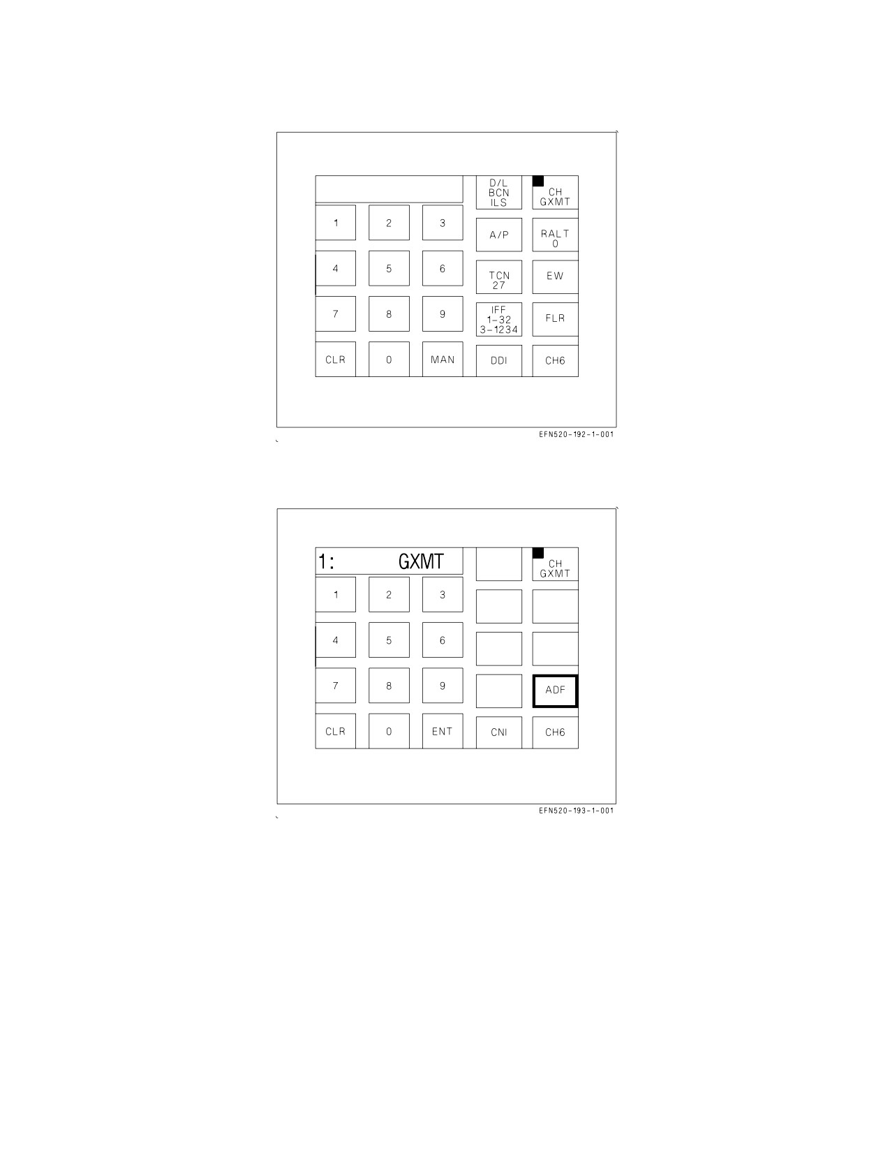
Guard Transmit on Top Level CNI Format. On the top level CNI format, placing the COMM
G XMT switch on the ACI panel to 1 or 2 selects guard transmit for that radio and GXMT replaces
the COMM touch option/display (see figure 23-17). The COMM sublevel also displays GXMT in the
scratchpad (see figure 23-18).
23.6 KY-58 - SECURE SPEECH SYSTEM
The secure speech system is used for ciphering (coding) or deciphering (decoding) audio routed
through the COMM 1 and COMM 2 receiver-transmitters. The system consists primarily of the KY-58
control panel assembly on the right console. Controls and indicators are on the KY-58 control panel
assembly and on the COMM control panel on the left console.
23.6.1 KY-58 Control Panel Assembly. The control panel assembly functions as a ciphering or
deciphering device for secure speech operation.
23.6.1.1 Ciphered Transmission. During ciphered transmissions, audio from the microphone is
routed through the COMM control panel to the KY-58 control panel assembly where it is enciphered.
The enciphered audio is routed back to the COMM control panel, then to COMM 1 or COMM 2
receiver-transmitter for transmission.
23.6.1.2 Ciphered Reception. During reception of ciphered information, the ciphered audio is
routed from the COMM 1 or COMM 2 receiver-transmitter to the COMM control panel, then to the
VII-23-23
ORIGINAL
A1-F18EA-NFM-000
Figure 23-17. Guard Transmit on Top Level CNI Format
Figure 23-18. Guard Transmit on COMM Sublevel
control panel assembly for deciphering. Deciphered audio is routed to the COMM control panel and
the headset.
23.6.1.3 Ciphered Relay Mode. During ciphered relay mode of operation, ciphered information
received on one radio is routed from the radio, through the COMM control panel to the second radio
for transmission. Ciphered information received on the first radio is also routed through the COMM
control panel to the KY-58 control panel assembly for deciphering. Deciphered audio is routed through
the COMM control panel to the headset. This enables the crewmember to hear deciphered relayed
audio in the ciphered relay mode. When cipher is selected on the COMM control panel immediately
after operating in relay plain, COMM 1 plain, or COMM 2 plain mode of operation, the crewmember
must press the transmit key for either COMM 1 or COMM 2 two times to enable ciphered relay
VII-23-24
ORIGINAL
A1-F18EA-NFM-000
Figure 23-19. KY-58 Control Panel Assembly
operations. When the relay aircraft is operating both radios within the same bandwidth, the two
frequency selections must be separated by a minimum of 10 MHz.
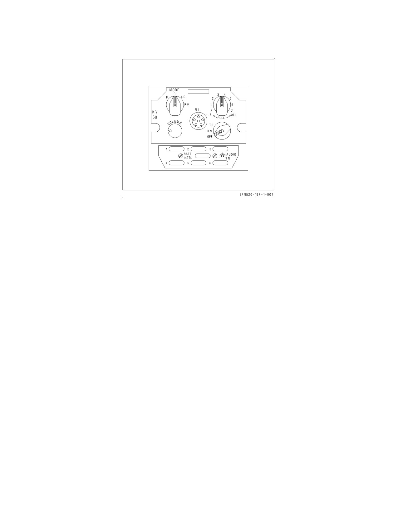
23.6.2 KY-58 Controls and Indicators. The only cipher control on the COMM control panel is the
RLY CIPHER/PLAIN switch (relay switch). The controls on the KY-58 control panel assembly are the
MODE select knob, unlabeled fill select knob, VOLUME control knob, and the unlabeled power select
knob (see figure 23-19).
23.6.2.1 KY-58 Mode Select Knob. The mode select knob has positions of P, C, LD, and RV. Placing
the knob to P enables plain mode of operation. Placing the knob to C enables the cipher mode of
operation. With the knob set to LD the load mode of operation is enabled. This mode is used for
loading data into the KY-58 control panel assembly. Information pertaining to the RV knob position
(receiver variable) will be supplied later.
23.6.2.2 KY-58 Fill Select Knob. The fill select knob has positions of 1 thru 6, a Z 1-5 position, and
a Z ALL position. Setting the knob to one of the six positions selects the position to be loaded with
data. Placing the knob to Z 1-5 zeroizes data in positions 1 thru 5. Placing the knob to Z ALL zeroizes
all data in positions 1 thru 6.
23.6.2.3 KY-58 Volume Control Knob. The volume control knob adjusts the volume of the KY-58
control panel assembly audio. The volume control knob should be set to full volume position during
secure voice transmission and reception.
23.6.2.4 KY-58 Power Knob. This knob has positions of ON, OFF, and TD. Placing the knob to ON
turns on power to the KY-58 control panel assembly if cipher mode has been selected. Placing the knob
to OFF removes power to the system. With the knob in TD, power is turned on for the system if cipher
mode has been selected and a time delay is selected for data processing. The knob must be in the TD
position for ciphered relay operations.
23.6.3 KY-58 Operation. Other stations or aircraft involved in cipher or cipher relay communication
must be in either the baseband or diphase mode.
VII-23-25
ORIGINAL
A1-F18EA-NFM-000
1. COMM 1 and COMM 2 radios - ON
COMM 1 and COMM 2 radios are turned on and volume adjusted with the VOL 1 and 2 COMM
control knobs on the UFCD.
2.
COMM 1 and COMM 2 channels - AS DESIRED
a. COMM 1 and COMM 2 channel select knobs - ROTATE (to select desired channel).
Selected channel is displayed in COMM 1 and 2 touch option/display on the UFCD.
3.
COMM 1 and COMM 2 channel frequency - SET
a. COMM 1 and COMM 2 touch option/display - TOUCH
Channel number and frequency displayed in scratchpad GRCV, SQCH, and CPHR options
appear on the option/display.
b. Channel frequency - AS DESIRED
Enter new frequency with keypad. Press the ENT key to enter the new frequency.
4.
CPHR touch option/display - TOUCH
The CPHR touch option/display is border highlighted and a series of tones are heard for 3
seconds indicating cipher is enabled with baseband operation. Touching the CPHR touch
option/display again changes the display to CPDP with the border highlighted and enables cipher
diphase mode.
23.6.3.1 KY-58 Cipher Mode. Other stations or aircraft involved in cipher communication must have
the KY-58 fill select knob in the same position.
1. KY-58 power knob - ON
2. KY-58 MODE knob - C
3. KY-58 VOLUME knob - ADJUST TO MAX VOLUME
4. COMM switch on inboard throttle - ACTUATE
UP for COMM 1, DOWN for COMM 2. A short tone is heard in the headset.
23.6.3.2 KY-58 Relay Mode. Relay mode can operate in Plain, Cipher and ECCM mode. Other
stations or aircraft involved in cipher relay communication must have the KY-58 fill select knob in the
same position.
1. KY-58 power knob - TD
Other stations or aircraft involved in cipher relay communication must have the KY-58 power
knob in the TD position.
2. KY-58 MODE knob - C
3. KY-58 VOLUME knob - ADJUST TO MAX VOLUME
4. COMM 1 antenna select switch - AUTO
VII-23-26
ORIGINAL

A1-F18EA-NFM-000
5. Relay switch select - CIPHER
6. COMM switch on inboard throttle - ACTUATE
UP for COMM 1, DOWN for COMM 2. A short tone is heard in the headset.
NOTE
When entering the cipher relay mode from any plain mode, the
COMM 1/COMM 2 transmit switch must be keyed twice; once to
initialize the KY-58 and a second time to transmit.
23.7 DIGITAL COMMUNICATION SYSTEM (DCS)
DCS provides all of the standard voice communication capabilities of earlier ARC-210 radios, plus
a digital data mode that greatly reduces pilot workload during Close Air Support (CAS) missions. It
enables the pilot to receive 9 line briefs, communicates target and mission data digitally from the
Forward Air Controller (FAC), and provides the capability to feed this information to weapon targeting
and navigation systems. Currently, this mission is handled via verbal communication and manual data
entry. A new communication control panel, incorporated with the Multifunctional Information
Distribution System (MIDS), is needed to interface with the DCS.
In the frequency range of 118.000 through 136.975 MHz, the DCS can be tuned to 8.3 KHz channels
to facilitate air traffic control communications in European air space. Tuning the radio to these
frequencies is performed via the UFCD as in any other band. In this band, however, the entered
frequency is not the actual tuned RF frequency. Refer to figure 23-20 for the convention adopted by
the International Civil Aviation Organization (ICAO).
Actual RF Frequency (MHz)
UFCD Frequency (MHz)
Channel BW (KHz)
118.0000
118.000
25
118.0000
118.005
8.3
118.0083
118.010
8.3
118.0166
118.015
8.3
118.0250
118.020
25
118.0250
118.025
25
118.2500
118.030
8.3
118.0333
118.035
8.3
118.0416
118.040
8.3
118.0450
118.045
25
118.0500
118.050
25
118.0500 thru 136.9750
118.55 thru 136.975
8.3 or 25
Figure 23-20. DCS Frequencies Conversions
23.7.1 VHF/UHF Communication System - DCS. The aircraft voice communications system consists
of an ARC-210 radio (COMM 1), a ARC-210/DCS radio (COMM 2), and KY-58 Secure Speech
VII-23-27
ORIGINAL
A1-F18EA-NFM-000
Equipment. DCS provides its own integrated secure speech encoder/decoder which allows COMM 1
and COMM 2 radios to simultaneously operate in cipher mode.
NOTE
The aircraft COMM 2 radio can also be installed with an ARC-210. In
this configuration, the KY-58 is shared between COMM 1 and COMM
2 as in earlier aircraft.
When operating the COMM 2 radio (either ARC-210 or DCS) in a band that allows selecting AM or
FM, make sure the modulation is selected before the frequency is entered. Failure to do this may not
allow the selected modulation to be accepted into memory.
23.7.1.1 ARC-210/DCS. DCS has additional capabilities which do not exist in the ARC-210. One
such capability is two-way digital data communications using Variable Message Format (VMF) for the
CAS mission. Another is storage of the cryptographic keys COMSEC communications. Finally, 8.3
KHz channel spacing is provided in the 118.00 through 136.975 MHz for Air Traffic Control (ATC)
communications required in European airspace.
23.7.1.1.1 COMM 1 and COMM 2 Volume Controls. The volume of the COMM 1 and COMM 2
radios is controlled by volume controls on the UFC.
23.7.2 DCS COMSEC (Communications Security).
23.7.2.1 Operation. During ciphered transmissions, audio from the aircrew’s microphone is routed
through the ACI panel to the DCS where it is encrypted. During reception of ciphered information, the
ciphered audio is deciphered by the DCS. The deciphered audio is routed back through the ACI panel
to the aircrew’s headset.
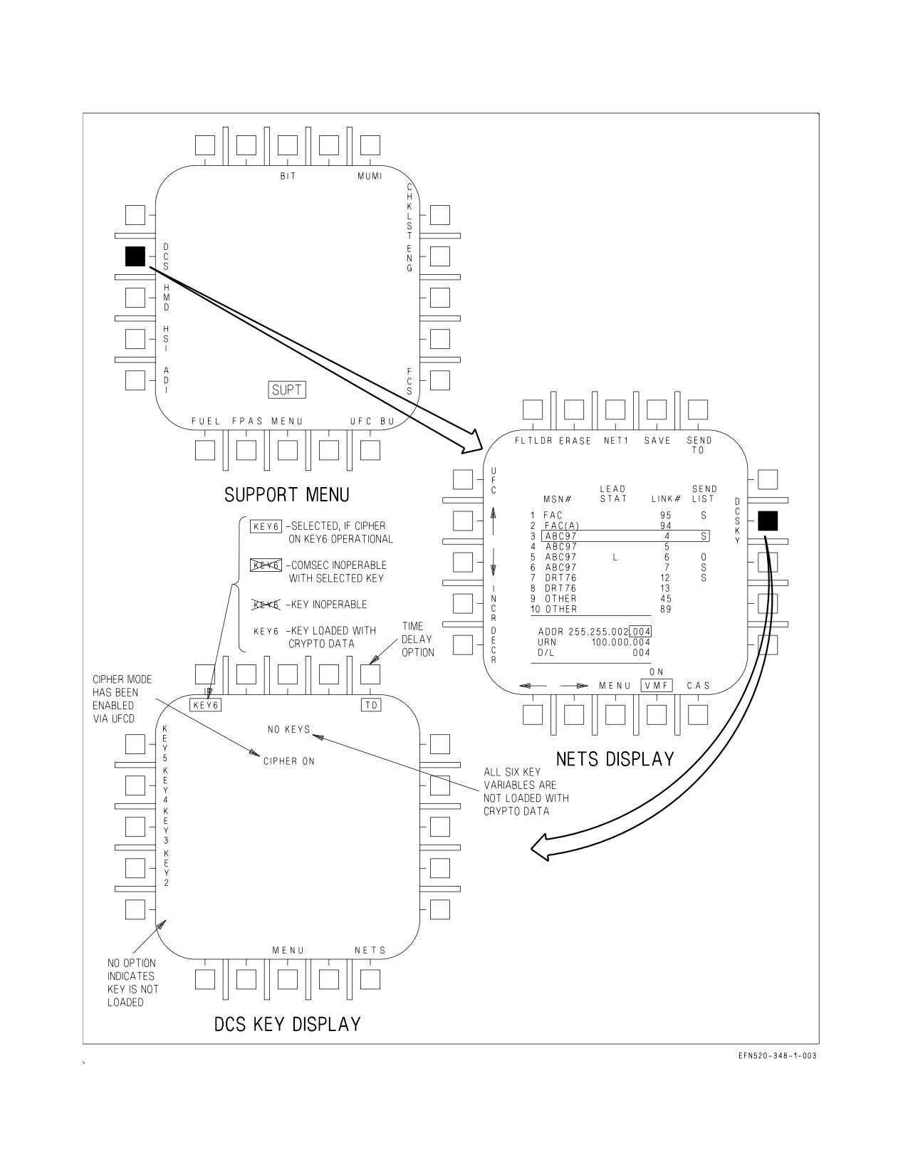
23.7.2.2 DDI Controls. Control of the internal DCS cryptographic functions is performed via the
DCS KEY display from the UFC. The DCS KEY display is accessed by selecting DCS on the SUPT
menu, then selecting DCSKY on the NETS (network) display. See figure 23-21. The functions
displayed are crypto keys (KEY1 thru KEY6) and TD (time delay). In F/A-18F aircraft, if one cockpit
has the DCS KEY display accessed, the other cockpit can access it by selecting only DCS on the SUPT
menu.
23.7.2.2.1 TD Control. The time delay mode is enabled by selecting/boxing TD on the DCS KEY
display. A subsequent selection disables time delay and removes the box. The effect of enabling time
delay mode does not take place until CPHR or CPDP has been selected via the UFCD.
23.7.2.2.2 Crypto Key Options. There are six available crypto keys. For example, if KEY1 is loaded
with crypto key data, the option KEY1 appears on the display. If a crypto key has not been loaded with
data, that key option is not displayed. A selected crypto key is indicated with a box around the
corresponding option. Only one crypto key may be selected at a time.
The DCS KEY display initializes to the previously selected crypto key. If the last crypto key selected
has been zeroed, the system selects the next available loaded crypto key. The DCS KEY display
defaults with KEY1 selected.
If CPHR or CPDP is selected and the normal default crypto key has been zeroized, NO FILL is
displayed on the UFCD scratchpad. When the DCS KEY display is selected, NO FILL is removed from
VII-23-28
ORIGINAL
A1-F18EA-NFM-000
the scratchpad. If no crypto keys are loaded, no crypto key options are displayed and a NO KEYS
status appears.
If CPHR or CPDP is selected prior to entering the DCS KEY display, an additional DCS COMSEC
status check is performed upon selection of a crypto key. This check takes approximately 1.5 to 2
seconds. If the DCS COMSEC function is operational there is no change on the DCS KEY display. The
boxed option with the CIPHER ON status indicator means the selected key is valid for use and DCS
COMSEC is operational.
If the status check determines there is a problem with the COMSEC function, the selected/boxed
crypto key option is Xd and a DCSCS advisory appears. However, it is possible the DCS COMSEC
function may be operational with other loaded crypto key options. Each crypto key option would have
to be selected (in CPHR or CPDP mode) to determine if the DCS COMSEC function is inoperable.
An Xd crypto key option may still be selected. If it is selected and the COMSEC error is no longer
indicated, the X is removed. All Xd status indications are cleared upon MC power-up.
If there is a problem with the DCS/COMSEC function, the boxed crypto key variable is covered by
an X. This indicates that DCS COMSEC function is inoperable with the selected crypto key. This does
not rule out the possibility the DCS COMSEC function may be operational with the other loaded
crypto keys. Each of the other crypto keys would have to be selected while in cipher or cipher diphase
modes before it could be determined the DCS COMSEC function is completely inoperable.
When a crypto key is unavailable and the applicable COMM switch is activated, a continuous audio
tone is heard in the headset.
23.7.3 UFCD - DCS. For normal UFCD operations, refer to Part 1, Chapter 2, or Part 7, Chapter 23.
23.7.3.1 ZEROIZE Function. Zeroization of DCS and KY-58 COMSEC KEYS, as well as TRANSEC
KEYS including HQ WODs (HAVE QUICK word of day) and SINCGARS EP (electronic protection),
is accomplished using the UFCD. The selection of the ZERO option causes the display to change to
ZERO ALL ENABLE, and clears the COMSEC and TRANSEC KEYS in the radios and KY-58. Both
COMSEC and TRANSEC KEYS are also zeroized upon pilot ejection. The ZERO ALL ENABLE
option is border highlighted for two seconds, and then the option returns to displaying ZERO. While
the ZERO ALL ENABLE option is displayed, selecting any option other than ZERO ALL ENABLE
causes the option to return to ZERO.
NOTE
The ACI panel IFF emergency switch no longer zeroizes the radios.
The DCS has an internal battery which is used to maintain the COMSEC KEYS in radio memory
during aircraft power transients and when aircraft power is removed. It also provides the energy to
zeroize the radio when the pilot ejects or if the radio is removed from the aircraft.
23.7.4 Relay Mode Of Operation. During cipher relay mode of operation using a DCS and an
ARC-210, encrypted information received on one radio is routed through the ACI panel to the second
radio for transmission. The encrypted information received on the first radio is also routed through the
ACI panel to the KY-58 for deciphering. The decrypted audio is routed back to the ACI panel, then to
the aircrew’s headset.
VII-23-29
ORIGINAL
A1-F18EA-NFM-000
Figure 23-21. DCS KEY Display
VII-23-30
ORIGINAL

A1-F18EA-NFM-000
The DCS COMSEC functions are not utilized during the cipher relay mode. In this mode the DCS
is always commanded to the plain voice mode, and all crypto relay transmissions are encrypted/
decrypted by the KY-58.
Certain constraints apply if cipher relay is selected and ADF bearing is needed. Cipher relay mode
may not be selected if ADF is already selected on COMM 2 (DCS). If ADF is selected on COMM 2 after
cipher relay mode has been enabled, COMM 2 ADF and cipher relay mode must be disabled before
control of DCS plain/CPHR/CHDP modes can be returned to COMM 2. If COMM 2 is an ARC-210,
the above constraints do not apply.
Cipher relay operation must be performed within the COMM 1 and COMM 2 relay band limitations
outlined in figure 23-22.
NOTE
With CPHR or CPDP enabled, selection of PLAIN on the RLY
selector switch (ACI panel) does not activate plain relay mode.
REMOTE
RELAY AIRCRAFT
REMOTE
STATION
COMM 1
COMM 2
STATION
1 OR 2
2 OR 1
A
*A
*A
A
B
*B
*B
B
C
*C
*C
C
D
*D
*D
D
E
*E
*E
E
A
A
C
C
C
C
A
A
A
A
D
D
D
D
A
A
C
C
D
D
D
D
C
C
B
B
E
E
E
E
B
B
A - 30.000 MHz to 87.975 MHz
B - 118.000 MHz to 155.975 MHz
* - When the relay aircraft is operating both radios
C - 156.000 MHz to 173.975 MHz
within the same band, the two frequency selec-
D - 225.000 MHz to 399.975 MHz
tions must be separated by a minimum of 10 MHz.
E - 225.000 MHz to 399.975 MHz
NOTE: Both remote stations and the relay aircraft must have the KY-58 power knob in the TD positions.
Figure 23-22. Relay Bandwidth Limitations
23.7.5 DCS - Avionics Subsystem.
23.7.5.1 Mission Computer System. Channels 2 and 4 link the mission computer to DCS.
VII-23-31
ORIGINAL
A1-F18EA-NFM-000
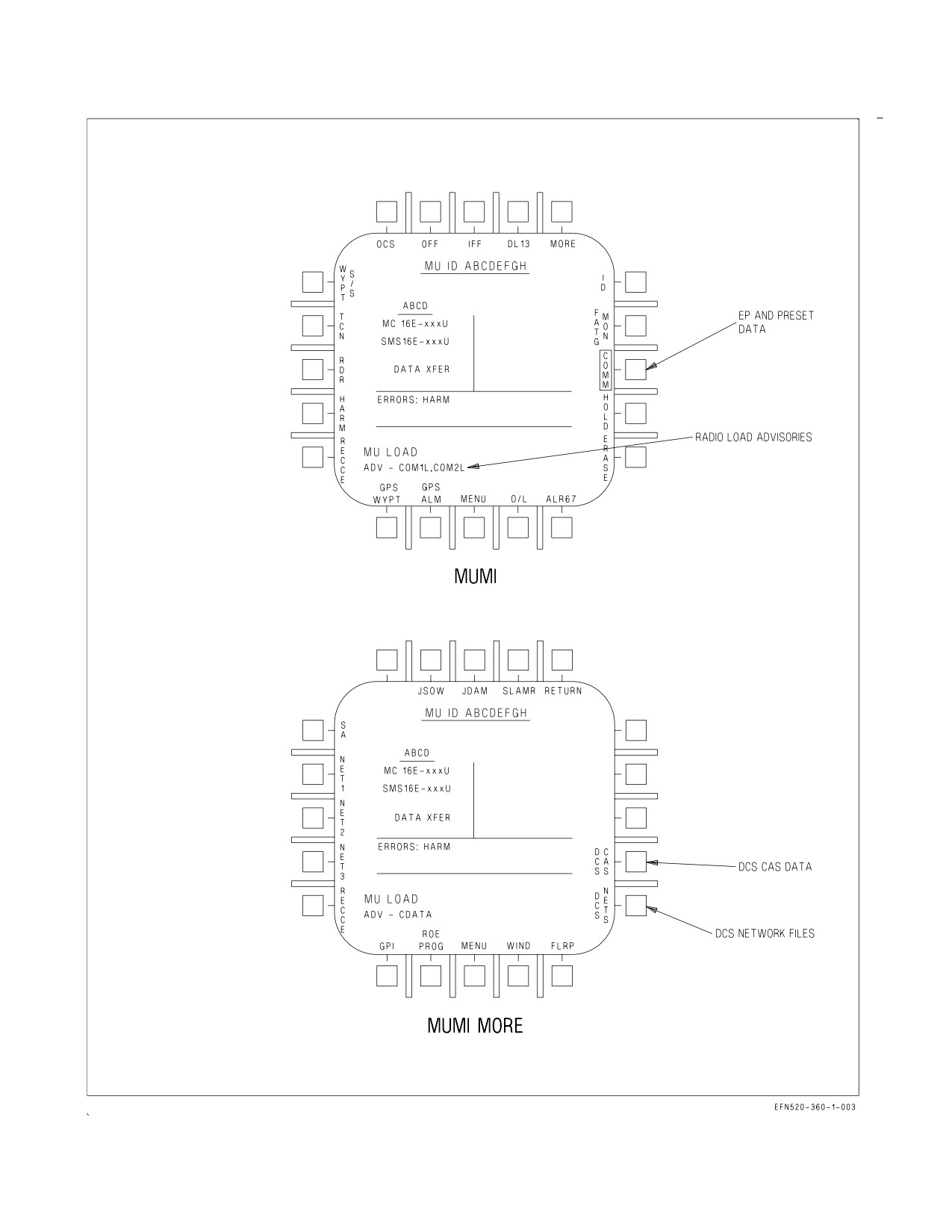
23.7.5.1.1 Mission Initialization. The AMU provides the capability to load the following mission
initialization files: COMM, DCS CAS, DCS NETS, and WYPT S/S. The COMM file contains the radio
presets, HAVE QUICK and SINCGARS data. The DCS CAS file contains pre-planned VMF FTXT
(free text) messages, pre-planned VMF 9-line brief messages, and an empty data file reserved for
inflight received CAS and/or FTXT messages. The DCS NETS file contains a set of network
parameters to be used for a unique network environment used in VMF message communications. The
WYPT S/S file contains a list of waypoint names for the IP (initial point) and control points that are
either entered or received in CAS 9-line briefs. See figure 23-23.
23.7.5.2 Status Monitoring.
23.7.5.2.1 Cautions and Advisories. DCS has the ability to trigger eight advisory messages;
COM1H(2H), COM1S(2S), COM1L(2L), BIT and DCSCS. COM1H(2H) is triggered when HAVE
QUICK time is not loaded. COM1S(2S) is triggered when SINCGARS time is not loaded. COM1L(2L)
advisory is triggered by an error in the MC to radio data loading process. BIT is triggered when a failure
is detected by BIT. DCSCS is triggered when a COMSEC failure is detected.
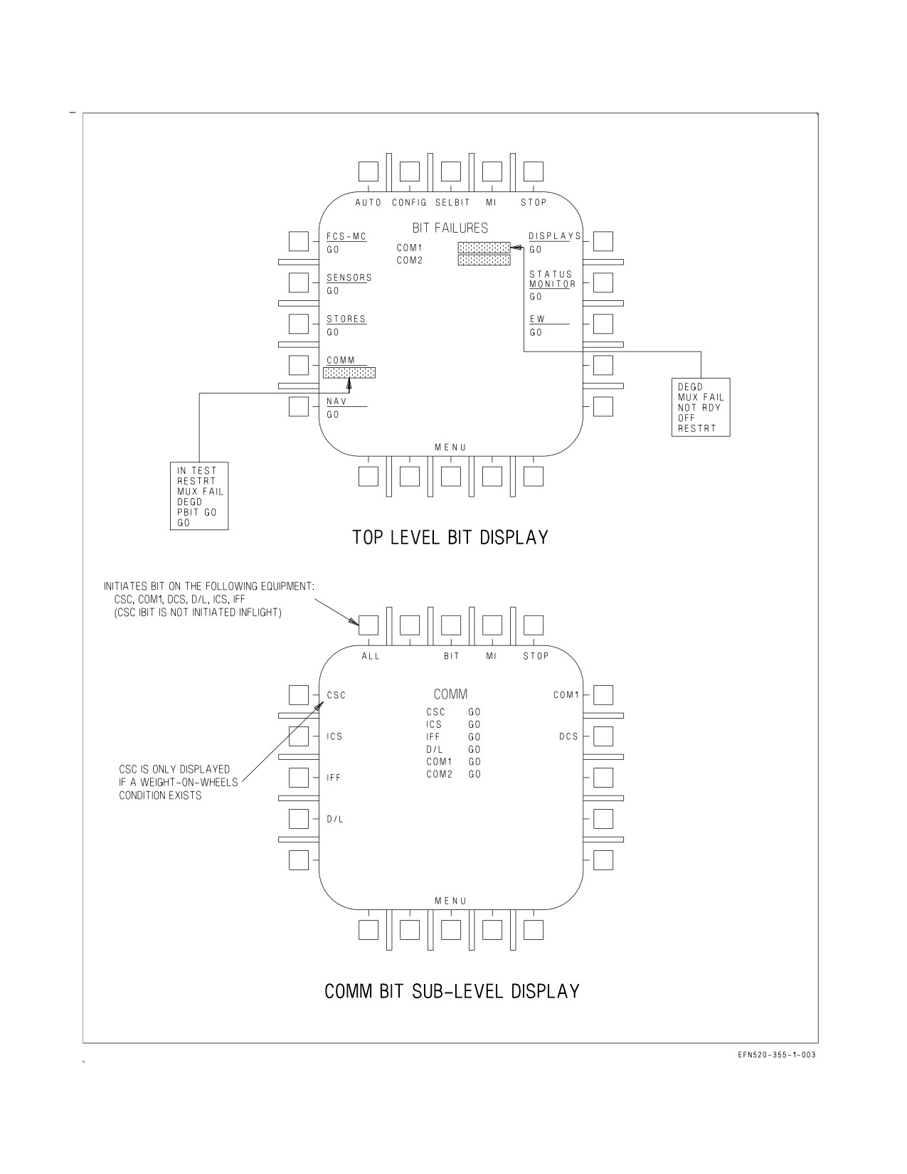
23.7.5.2.2 BIT Top Level Display. The top level BIT display for DCS is the same as the COM2
format. Status is indicated for DCS as COMM2. See figure 23-24.
23.7.5.2.3 COMM BIT Sub-Level Display. The COMM sub-level BIT display appears when the
COMM option on the top level BIT display is selected. The COMM BIT display for DCS is the same
as the ARC-210 with the DCS being represented as COM2.
a. DCS Option. Initiated BIT is run by selecting the COM2 option. DCS status is displayed in the
center of the page represented as COM2.
23.7.5.2.4 Software Configuration. The software configuration for the DCS is checked by selecting
CONFIG on the top level BIT display.
23.8 IDENTIFICATION FRIEND OR FOE (IFF)/COMBINED INTERROGATOR TRANSPONDER (CIT)
The AN/APX−111 CIT is a dual purpose Identification Friend or Foe (IFF) system with
transponder and interrogator capabilities. The transponder provides automatic identification of the
aircraft in which it is installed when challenged by a surface or airborne interrogator set and provides
momentary identification of position (I/P) upon request. The interrogator provides airborne target
identification capabilities.
23.8.1 IFF Transponder. The transponder system operates in Modes 1, 2, 3, 4A, 4B, C and S. Modes
1, 2, and 3 are selective identification feature (SIF) modes. Modes 4A and 4B are the crypto modes.
Mode C is the altitude reporting mode. Mode S is used in conjunction with the Civil Air Traffic Control
Surveillance System and is only available with MC OFP H4E AND UP.
With the IFF Programming (IFF PROG) page: A) Mode 1, 2, and 3 codes can be automatically
programmed to change at specified times or on a time interval, B) Mode 1, 2, 3, 4, C, and S can be
automatically programmed to enable/disable when the aircraft crosses a designated waypoint in a
specified direction, and C) Mode 4 can be automatically updated on Zulu day transition. The IFF can
also be programmed during mission planning.
The IFF emergency mode automatically becomes active upon ejection or can be manually selected
with the IFF MASTER switch.
VII-23-32
ORIGINAL
A1-F18EA-NFM-000
Figure 23-23. MUMI Displays
VII-23-33
ORIGINAL
A1-F18EA-NFM-000
Figure 23-24. BIT Displays
VII-23-34
ORIGINAL
A1-F18EA-NFM-000
23.8.1.1 IFF on Top Level CNI UFCD Format. On the top level CNI UFCD format, IFF power
application is identified by a corner highlight in the upper left corner of the IFF option. The option
displays the current Mode 1 and Mode 3 codes regardless of whether the IFF is powered or whether the
mode is enabled. The Mode 1 code may be changed by selecting two valid numbers (first digit equal
to 0−7, second digit equal to 0−3) and selecting the IFF option. Mode 2 and Mode 3 codes may be
changed by selecting four valid numbers (each digit equal to 0−7) and selecting the IFF option.
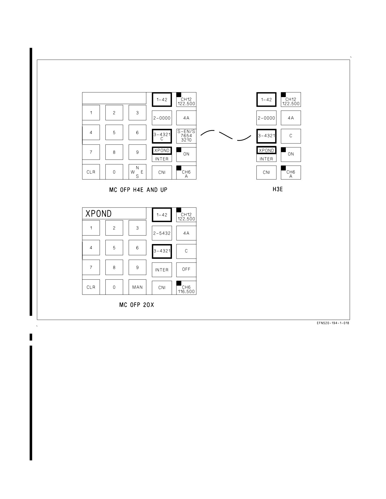
23.8.1.2 IFF Transponder UFCD Sublevel. The IFF Transponder (XPOND) UFCD sublevel is
displayed by selecting the IFF option before entering any data in the scratchpad (figure 23−25). This
sublevel is used to control power to the IFF system, to enable the transponder modes, to set Mode 1,
2, and 3 codes, to select Mode 4A or 4B, to view Mode S status, to set the temporary Mode S address,
and to select the Mode S sublevel. (See 23.8.1.2.1 for Mode S operation.)
The IFF is on when the ON/OFF option is corner highlighted and displays ON. The IFF system is
off when the option is not corner highlighted and displays OFF.
The Mode 1, 2, 3, C, 4A/4B options are border highlighted when selected for enable. A mode option
without a border highlighted is not selected for enable. Modes 1, 2, 3 and C may be selected for enable
or disable when the IFF system is either on or off. The IFF must be on to select Modes 4A or 4B. Any
mode that is border highlighted with the IFF system on is immediately enabled; any mode that is
border highlighted with the IFF system off is automatically enabled when the IFF system is turned on.
Modes 1, 2, and 3 are enabled and disabled by selecting the respective option. Mode C can not be
enabled without Mode 3 enabled, so enabling Mode C automatically enables Mode 3 and disabling
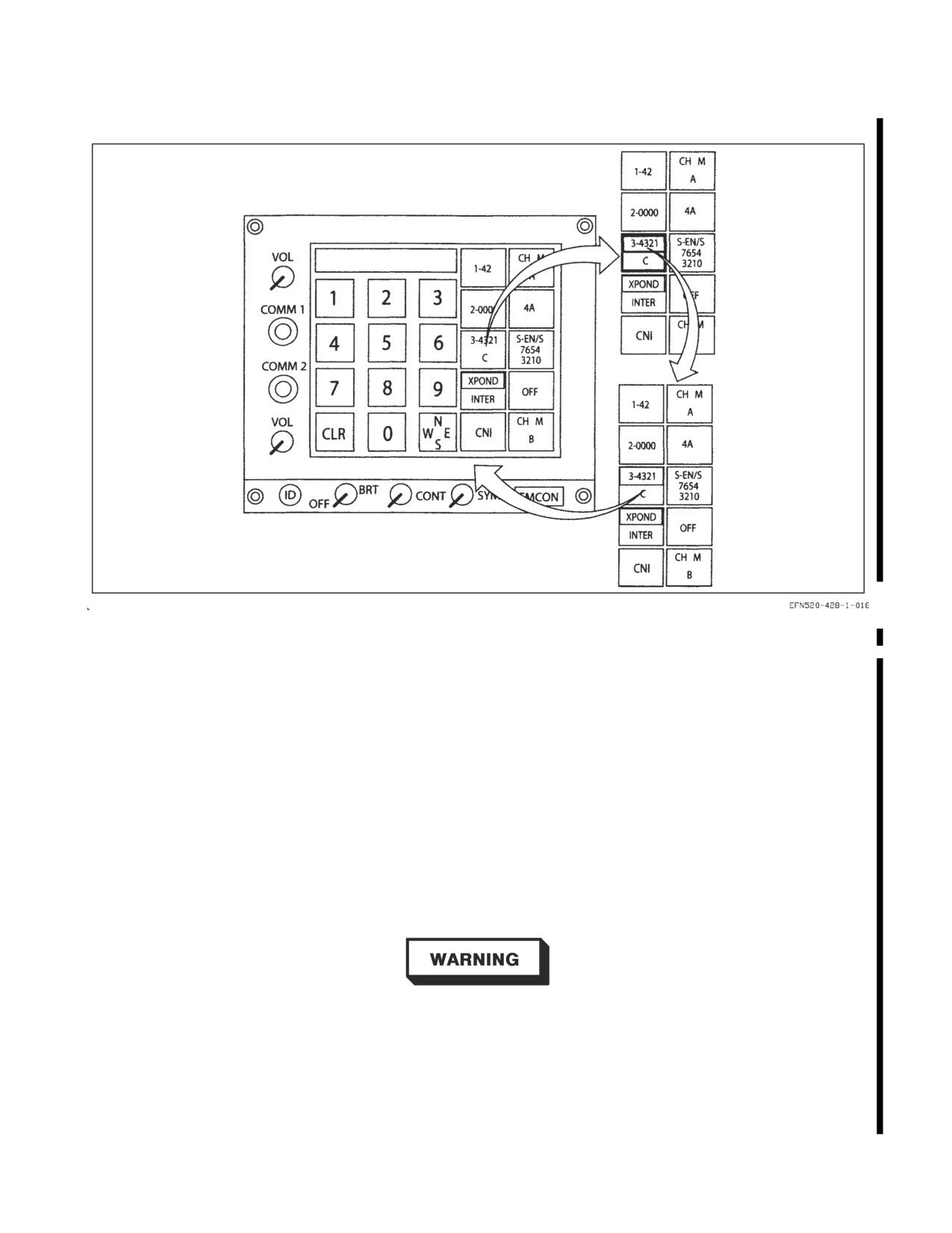
Mode 3 automatically disables Mode C. With MC OFP H4E AND UP, Mode 3 and Mode C are
combined as one option, so when neither Mode 3 nor Mode C is enabled, selecting the Mode 3/C option
results in the following sequence: both Mode 3 and Mode C enabled − Mode 3 enabled and Mode C
disabled − both Mode 3 and Mode C disabled (figure 23−26). The altitude encoding mode uses 29.92
inches Hg as a reference. When the KIV−6 is installed and the IFF is on, Mode 4A or Mode 4B can be
enabled. Selecting the Mode 4A option results in the following sequence: Mode 4A enabled − Mode 4A
disabled and legend changes to 4B − Mode 4B enabled − Mode 4B disabled and legend changes to 4A.
If the KIV−6 is not installed or the IFF is off, the Mode 4A/4B option is not displayed.
The Mode 1 code may be changed by selecting two valid numbers (first digit equal to 0−7, second
digit equal to 0−3) and selecting the Mode 1 option. The Mode 2 and 3 codes may be changed by
selecting four valid numbers (each digit equal to 0−7) and selecting the respective Mode option.
23.8.1.2.1 Mode S (MC OFP H4E AND UP). Mode S is a Civil Air Traffic Control Surveillance System
that can respond to selective interrogations and provide air-to-air and air-to-ground data of aircraft ID,
state, and intent information. The carriage and operation of Mode S Elementary Surveillance
functionality applies to aircraft that fly Instrument Flight Rules (IFR) and Visual Flight Rules (VFR)
flights in Mode S designated airspace.
The integration of Mode S Level 2 into Navy aircraft is divided into two surveillance levels,
Elementary (EL) and Enhanced (EN). It is beneficial to air traffic control to incorporate Enhanced
Surveillance to the extent practical on all Navy aircraft and to populate Enhanced Surveillance data
parameters to the extent permitted by existing aircraft sensors. As a result of the requirements,
Elementary Mode S is incorporated via a software modification to the CIT system. The system
provides most of the functionality of Enhanced Mode S, but for flight planning purposes only
Elementary Mode S is supported.
VII-23-35
ORIGINAL
A1-F18EA-NFM-000
Figure 23-25. IFF Transponder UFCD Sublevel
When Elementary Surveillance is selected, the aircraft transmits the following data:
1. 24 bit aircraft address
2. Secondary Surveillance Radar (SSR) Mode 3/A
3. Aircraft Identification (call sign used in flight)
4. Transponder Capability Report
5. Altitude reporting in 100 ft intervals
6. Flight Status (airborne/on ground)
When Enhanced Surveillance is selected, the aircraft transmits the following data:
1. Elementary Surveillance data
2. Magnetic Heading
3. Indicated Airspeed
VII-23-36
ORIGINAL
A1-F18EA-NFM-000
Figure 23-26. Mode 3 and Mode C Selection
4. Mach No.
5. Vertical Rate
6. Roll Angle
7. Track Angle Rate
8. True Track Angle
9. Ground Speed
All Mode S equipped aircraft have a permanent Mode S address which is assigned to the aircraft
BuNo. The permanent address is stored in DFIRS. A temporary Mode S address may also be used.
When available, the temporary address overrides the permanent address. Once a temporary Mode S
address has been entered, to revert back to the permanent Mode S address, it is necessary to enter the
permanent address as a temporary address.
The use of the same Mode S address in any two airborne aircraft presents
a safety of flight risk as air traffic computers cannot differentiate between
the two aircraft.
The MC requests the permanent Mode S address from DFIRS when Mode S is enabled and a
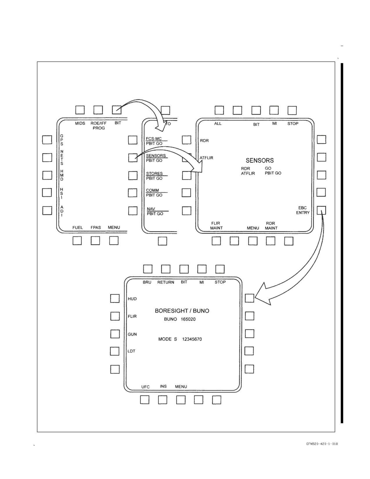
temporary Mode S address is not available. The permanent address is displayed on the Electronic
Boresight Constant (EBC) Entry sublevel when available with WonW. This is where the aircraft BuNo
VII-23-37
ORIGINAL
A1-F18EA-NFM-000
and permanent address can be entered by maintainers prior to flight. Figure 23−27 demonstrates the
path to the EBC to verify the BuNo and permanent address.
NOTE
If ERROR flashing persists with attempts to enter a valid address, this
indicates a DFIRS malfunction.
The Mode S transponder transmits acquisition squitters (unsolicited transponder replies) to permit
passive acquisition by interrogators. The acquisition squitter function is disabled if Mode S is turned
off.
Prior to takeoff, the aircrew can check the availability/status of Mode S, Mode S acquisition squitter,
permanent Mode S address, temporary Mode S address, and aircraft call sign. The aircrew can enter
an A/C call sign if desired or if mission planning does not provide one. The default A/C call sign
contains VV followed by the aircraft’s BuNo.
Mode S and the acquisition squitter function in the same manner during dual and single MC
operation. In the event that power is removed from both MC1 and MC2, Mode S data ages out. The
CIT continues to provide Mode S transmissions in Level 1 mode, providing the Mode S address at a
minimum.
VII-23-38
ORIGINAL
A1-F18EA-NFM-000
Figure 23-27. Electronic Boresight Constant (EBC) Display with W on W
VII-23-39
ORIGINAL
A1-F18EA-NFM-000
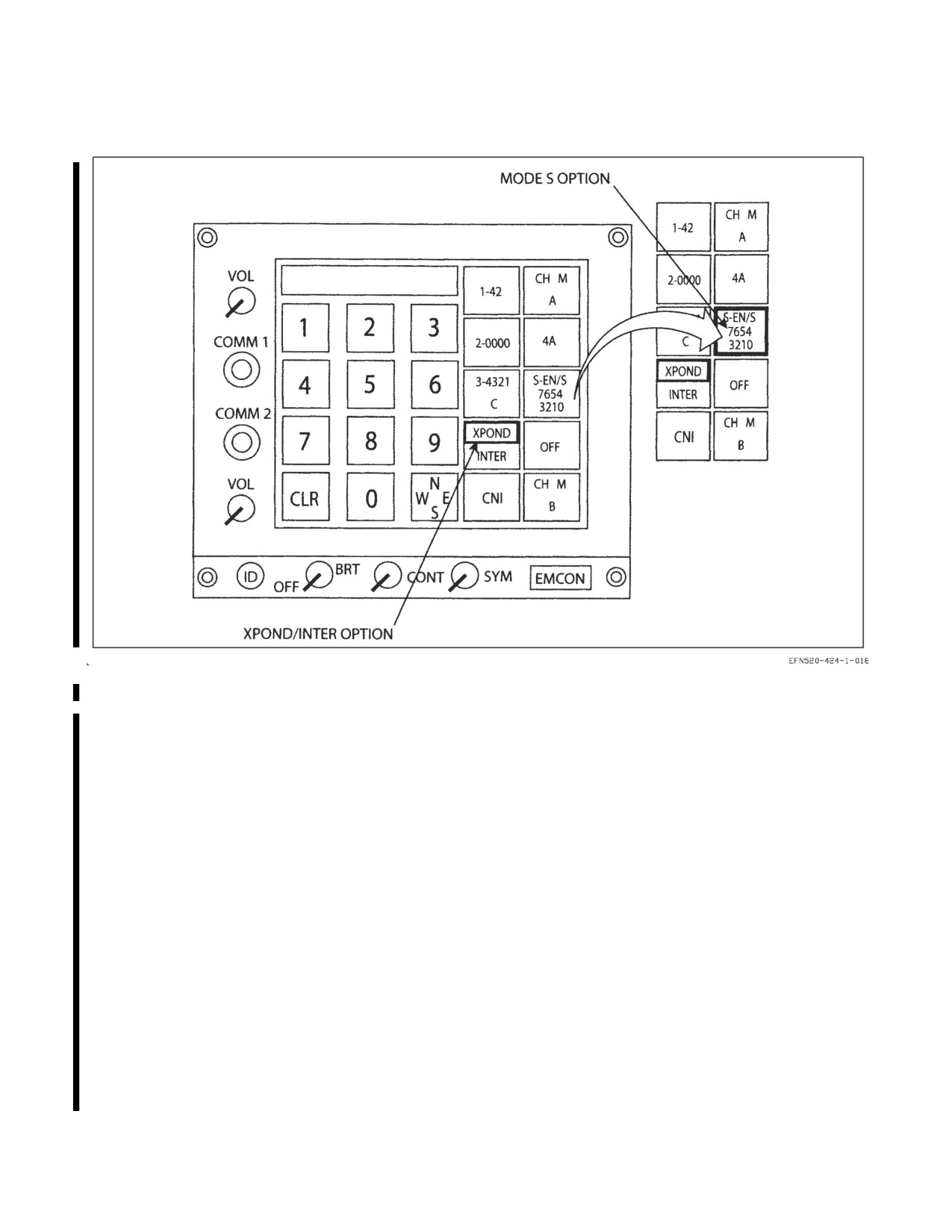
Figure 23-28. XPOND Format Selection to Enable Mode S Enhanced and Squitter
1. Mode S Option on Transponder UFCD Sublevel. With the IFF system on, the Mode S
option on the UFCD Transponder (XPOND) sublevel indicates the current status of the Mode S
transponder (figure 23−28). The first line of the Mode S option indicates the selected Mode S
surveillance and acquisition squitter options. Enhanced surveillance is indicated by
″EN″ and
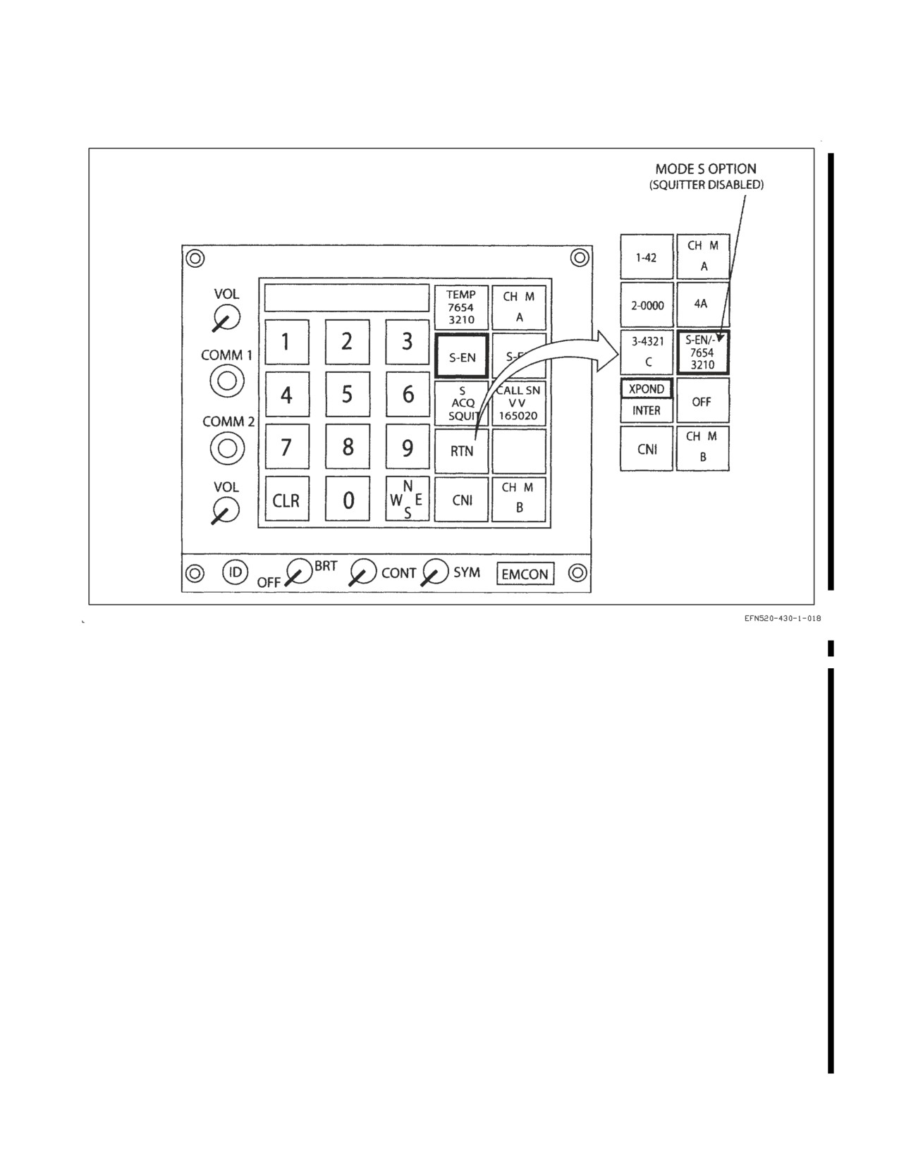
Elementary surveillance by ″EL″. An ″S″ after the slash indicates the squitter is enabled (e.g., S−EN/S)
and a dash indicates the squitter is disabled (e.g., S−EN/−) (figure 23−29). The second and third lines
indicate the temporary Mode S address. When a mission planning input is available, those Mode S
surveillance and acquisition squitter options and the temporary address are displayed. Otherwise, the
system defaults to Enhanced surveillance and squitter enabled (S−EN/S). Regardless of the Mode S
options selected, Mode S is disabled at power up.
The first selection of the Mode S option boxes the option and enables the displayed Mode S
functions. The second selection of the Mode S option displays the Mode S UFCD sublevel (figure
23−30).
If neither the permanent nor temporary Mode S address is available, Mode S is disabled, the Mode
S option is Xd out, and the first line displays ″S−″. If no temporary address has been provided by
mission planning or aircrew entry, all zeroes (00000000) are displayed (figure 23−31). A new temporary
address can be entered by selecting eight valid numbers (all digits equal to 0−7 and can not contain all
7’s or all 0’s) and selecting the Mode S option.
VII-23-40
ORIGINAL
A1-F18EA-NFM-000
Figure 23-29. Return to XPOND Format with Squitter Disabled
2. Mode S UFCD Sublevel. The Mode S sublevel is used to enable/disable the acquisition
squitter, select Enhanced or Elementary surveillance, and enter the aircraft call sign and temporary
address (figure 23−30). If the aircrew changes Mode S selections and disables Mode S, the aircrew’s
selections return when Mode S is re-enabled.
a. Temporary Mode S Address. The temporary Mode S address is displayed on the TEMP S option.
The temporary address can be provided via mission planning or aircrew entry. If a temporary address
is not available, all zeros (00000000) are displayed. A new temporary address can be entered by
selecting eight valid numbers (all digits equal to 0−7 and can not contain all 7’s or all 0’s) and selecting
the TEMP S option.
b. Mode S Surveillance Level. The Mode S Enhanced (S−EN) and Elementary (S−EL) Surveillance
level options are mutually exclusive. Selection of either option enables that option and disables the
other option. If neither option is enabled, enabling one option also enables the acquisition squitter (S
ACQ SQUIT). If both options are disabled, Mode S and the acquisition squitter are disabled.
c. Mode S Acquisition Squitter. Selecting the Mode S acquisition squitter (S ACQ SQUIT) option
toggles the squitter between enabled and disabled. When the squitter is disabled by selecting the
option, it remains disabled until enabled again by aircrew. The squitter is also disabled when Mode S
is not selected (S−EN and S−EL are deselected at the same time). Whether the squitter was disabled
by the S ACQ SQUIT option or S−EN and S−EL deselect, selecting S ACQ SQUIT enables S ACQ
SQUIT and the previous Mode S surveillance level (S−EN or S−EL). Squitter status is also displayed
VII-23-41
ORIGINAL
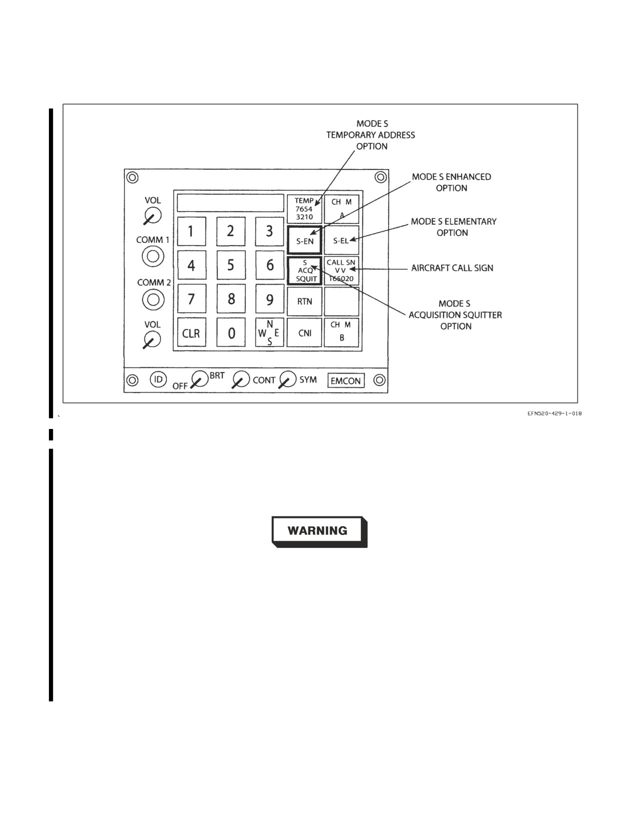
A1-F18EA-NFM-000
Figure 23-30. Mode S UFCD Sublevel
on the XPOND sublevel Mode S option. An ″S″ after the slash indicates enabled (e.g., S−EN/S) and
a dash indicates disabled (e.g., S−EN/−) (figure 23−29). The SQTTR advisory is also displayed
anytime Mode S is enabled while the acquisition squitter is disabled. The SQTTR advisory is cleared
when either Mode S is disabled or the acquisition squitter is enabled.
Keep Mode S acquisition squitter enabled (boxed) when Mode S is
enabled. Disabling Mode S acquisition squitter with Mode S enabled does
not allow TCAS in nearby aircraft to acquire track.
d. Mode S Aircraft Call Sign. The Mode S aircraft (A/C) call sign is displayed on the CALL SN
option. If the A/C call sign has not been made available from the aircrew or mission planning, the
default A/C call sign is VV plus the BuNo (e.g., VV166855). The A/C call sign may be changed by
selecting the CALL SN option which displays the A/C call sign UFCD sublevel and alphanumeric
keypad (figure 23−32). Valid A/C call signs are limited to no more than eight letters and numbers.
Leading or embedded spaces between characters in the A/C call sign are not accepted. Selecting the
CALL SN option after entering the new A/C call sign changes the call sign.
VII-23-42
ORIGINAL
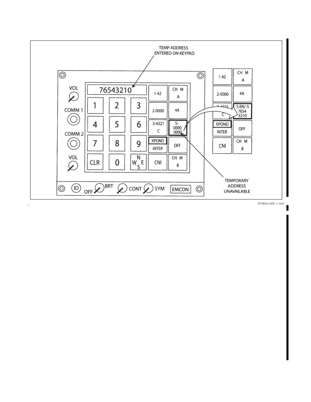
A1-F18EA-NFM-000
Figure 23-31. Mode S Address Not Available on XPOND Sublevel
23.8.2
IFF Interrogator. Interrogator operation is described in A1-F18EA-TAC-100 Tactical
Manual.
NOTE
All CIT equipped F/A−18s shall limit interrogator usage in
non−tactical flight regimes. Specifically, Auto Mode Interrogations
should not be selected during enroute transits to and from training
areas or during cross country ferry flight. This operational limitation is
intended for continental US flight operations only and is not intended
to impact tactical doctrine or safety of flight requirements whatsoever.
23.8.3
IFF BIT. IFF BIT status is displayed on the BIT page (figure 23−24). Initiated IFF BIT can
be performed by selecting the IFF option on the COMM sublevel of the BIT page.
23.8.4 IFF Programming (IFF PROG) Page. The IFF Programming (IFF PROG) page (figure 23-33)
allows the aircrew to program the MC to automatically change the IFF codes at specified times or on
a time interval, enable/disable IFF modes when the aircraft crosses a designated waypoint in a
specified direction, and update the Mode 4 transponder and interrogator on Zulu day transition. The
IFF PROG page is displayed by selecting the IFF/ROE PROG option on the SUPT page and then the
IFF PROG option. The IFF can also be programmed during mission planning. There is no MC backup
of this functionality. If either MC fails, this functionality is not usable.
VII-23-43
ORIGINAL
A1-F18EA-NFM-000
IFF programs are always set as classified when edited on the IFF PROG page. When IFF programs
are downloaded as an initialization file, the classification is set the same as the file, whether classified
or unclassified.
23.8.4.1 Top Level IFF PROG Page. The IFF PROG page is divided into two sections. The top section
contains the time based (TIME) code information while the bottom section contains the position
(POS) group information. There are 15 distinct times and 2 positions which can be entered.
With the TIME option boxed, the MC automatically updates the selected IFF codes at the specified
time. For each specified time, transponder codes may be set for Modes 1, 2, and 3. The times are
referenced to aircraft Zulu time of day (ZTOD) in the format of hours:minutes. The first column of a
TIME data line contains the ZTOD at which the codes are updated followed by the Mode 1, 2, and 3
code columns.
With the POS option boxed, the MC automatically enables/disables the selected Modes 1, 2, 3, C,
and S transponder functions and can enable the Mode 4 transponder and interrogator functions at the
designated waypoint. Mode 4 transponder and interrogator functions can not be automatically
disabled. A POS group data line consists of the group number, the list of the modes to be affected in
this group, whether the modes are enabled/disabled, and the cardinal direction and waypoint
combination to specify the location where the modes are enabled/disabled.
With the AUTO M4 option boxed, Mode 4 for both the transponder and the interrogator switches
from ″A″ to ″B″ when the aircraft clock passes through 00:00 Zulu time. If Mode 4 is already ″B″, this
feature has no effect.
The MC automatically disables the TIME and POS updates when Automatic Carrier Landing
(ACL) is selected. Once disabled, the desired automatic update state may be manually reselected. The
AUTO M4 feature is never automatically disabled.
When the EDIT option is selected, the IFF PROG EDIT sublevel is displayed.
23.8.4.2
IFF PROG EDIT Sublevel. The IFF PROG EDIT sublevel is used to select the time, mode
codes, position data and modes to be enabled/disabled and is displayed when the EDIT option on the
IFF PROG page is selected. The selection box indicates the currently selected data line. Selection
arrows are used to change the current selected data line. The CLEAR option clears the currently
selected data. The RETURN option returns to the IFF PROG page.
23.8.4.2.1 TIME Data. When editing a TIME data line, M1, M2, M3 and INTVL options are
displayed. When M1, M2, or M3 is selected, a UFCD format is displayed which allows aircrew to enter
the Zulu time for the currently selected data line as well as input the exact code to be used in the
selected mode. The mode code is selected by entering a valid code and selecting the UFCD CODE
option. The selected mode code is displayed in the appropriate mode column on the IFF PROG page
and in the CODE option. If no mode code has been selected, the column on the IFF PROG page is
blank and the CODE option displays zeros. Time is selected by entering a valid four digit Zulu time and
selecting the UFCD TIME option. The selected time is displayed in the TIME column on the IFF
PROG page and in the TIME option. The selection arrows on the UFCD allow the aircrew to scroll
sequentially through the times entered on the IFF PROG page.
When a new time is entered, the TIME data lines are sorted in increasing time order based on
current aircraft time. The earliest later time is displayed first, followed by the remaining times in
sequential order. The selection box is moved automatically when the data line is edited. Times that are
VII-23-44
ORIGINAL
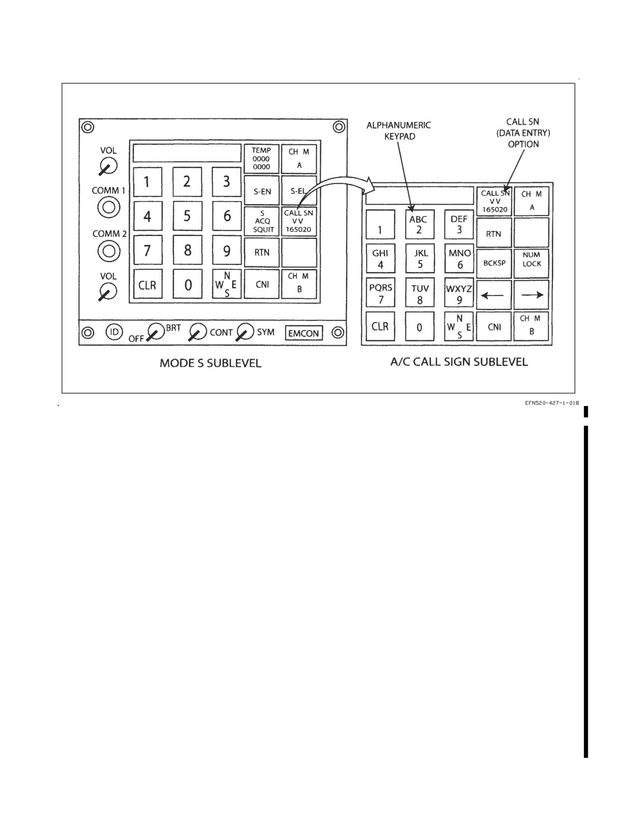
A1-F18EA-NFM-000
Figure 23-32. Mode S A/C Call Sign Sublevel
earlier than the current aircraft time are assumed to be specified for the next Zulu day. When a TIME
data line is CLEAR’ed, the data lines are re−sorted, moving the data selection box and the newly
cleared data line to the bottom of the display.
A TIME data line is considered invalid if it contains valid code entries but does not contain a valid
time. Invalid data lines are displayed at the bottom of the display and are not used by the IFF.
When INTVL is selected, a UFCD format is displayed which allows aircrew to enter a start time and
single time interval for changing the IFF codes automatically. Start time is selected by entering a valid
four digit Zulu time and selecting the UFCD START TIME option. The selected start time is displayed
in the START TIME option. The time interval is selected by entering a valid time interval (1−99
minutes) and selecting the UFCD LNGTH option. The selected time interval is displayed in the
LNGTH option.
When a start time and time interval are entered, all existing times are recomputed. The start time
is displayed in the first TIME data line with subsequent times equal to the previous time plus the time
interval. The codes currently specified for each data line are not changed.
23.8.4.2.2
POS Data When editing a POS group data line, M1, M2, M3, M4, MC, MS mode options,
ENBL/DSBL and cardinal direction options are displayed (figure 23−33). In order for group data line
to be valid, the following must occur: 1) At least one mode must be selected, 2) a direction must be
selected, 3) and a waypoint must be entered.
The mode options toggle the modes to be enabled or disabled into and out of the selected group. The
ENBL/DSBL option toggles between enabling and disabling the currently selected modes in the group.
The option affects all of the modes presently selected in the group. When the DSBL option is selected,
VII-23-45
ORIGINAL
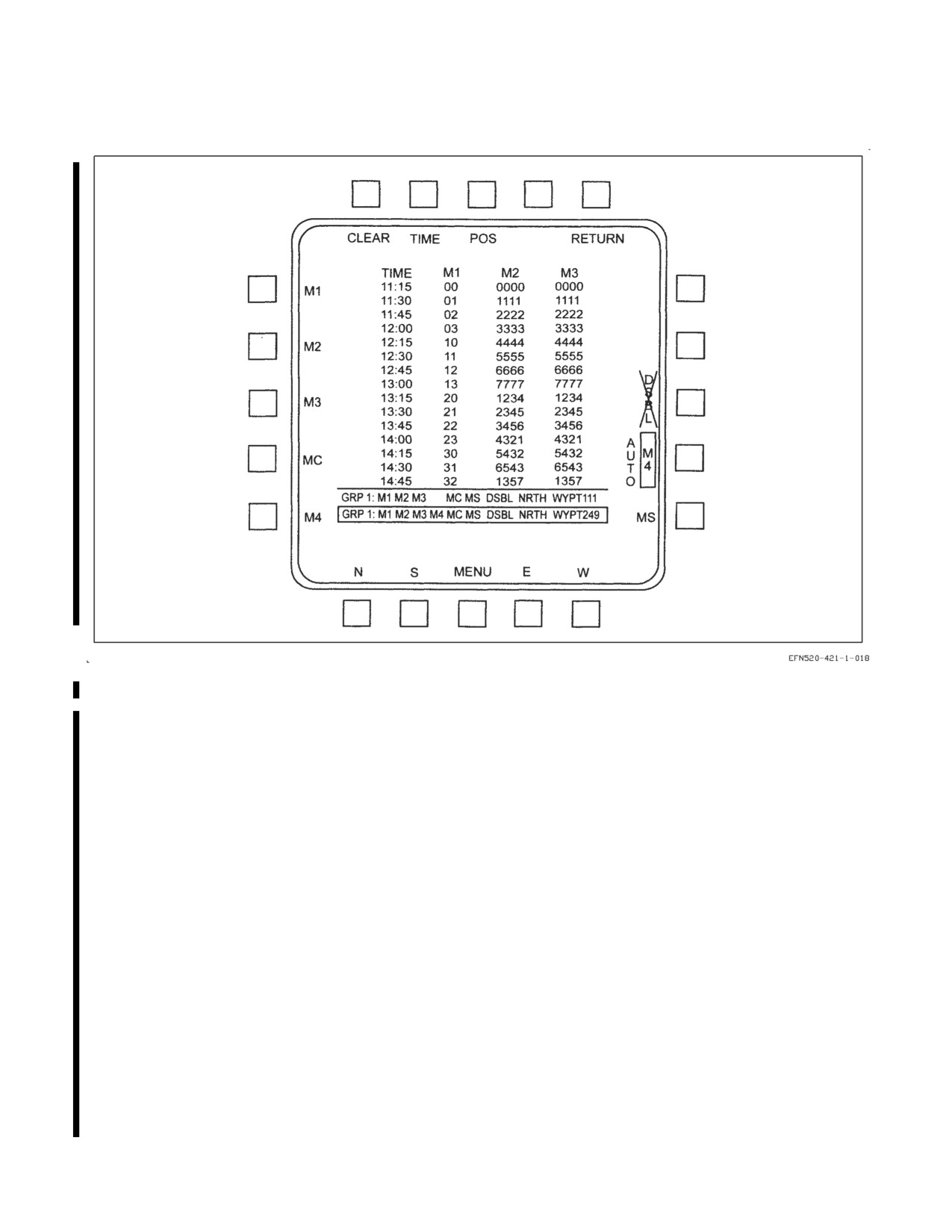
A1-F18EA-NFM-000
Figure 23-33. IFF PROG EDIT Sublevel - POS Data
DSBL is displayed in the selected group and all modes listed are disabled when the aircraft reaches the
designated waypoint. When the ENBL option is selected, ENBL is displayed in the selected group and
all modes listed are enabled when the aircraft reaches the designated waypoint. Since Mode 4 can not
be automatically disabled, whenever the selected POS group data line displays DSBL, the M4 option
is Xd out. Also, if M4 is displayed in the selected POS group data line, the DSBL option is Xd out.
To designate the waypoint, one of the cardinal direction (N, S, E, W) options must be selected. The
selected cardinal direction is the direction the aircraft must pass the designated waypoint in order to
cause the selected modes to be enabled or disabled automatically. When a cardinal direction option is
selected, a UFCD format is displayed which allows aircrew to enter the designated waypoint. The
waypoint is selected by entering a valid waypoint number (0−99) and selecting the UFCD WYPT
option. The selected waypoint number is displayed in the WYPT option. The selected waypoint
number and cardinal direction are displayed in the group data line.
23.8.5 IFF Controls.
23.8.5.1 IDENT (ID) Button. The ID button is located on left side of the UFCD and is used to
manually squawk ident. Pressing the ID button enables the IFF system to transmit identification of
position for approximately 18 seconds.
23.8.5.2 Emission Control Button. The emission control button is located on the right side of the
UFCD and is labeled EMCON. Pressing the EMCON button changes the IFF, if ON, to a standby
VII-23-46
ORIGINAL
A1-F18EA-NFM-000
mode so that it cannot transmit. At the same time, EMCON is displayed in the scratchpad for top level
displays or vertically in the left options for DDI displays on the UFCD. When EMCON is turned off
by pressing the button again, the IFF returns to the previous operating mode.
23.8.5.3
IFF Control Panel. The IFF control panel is located on the left hand console and contains
the MASTER switch, the MODE 4 switch, and the CRYPTO switch. The MODE 4 and CRYPTO
switches are used for Mode 4 on aircraft which have the KIV−6 installed.
23.8.5.3.1
MASTER Switch. This switch has positions of NORM and EMERG.
NORM
IFF replies to interrogations with selected codes.
EMERG IFF replies to interrogations with emergency replies. The IFF transponder turns on
if off. This selection also zeroes the ARC−210 radios.
23.8.5.3.2
MODE 4 Switch. This switch has positions of DIS/AUD, DIS, and OFF.
DIS/AUD Enables IFF 4 caution and ″MODE 4 REPLY″ voice alert, M4 OK and IFFAI
advisories, and the Mode 4 audio tone.
DIS
Disables the Mode 4 audio tone. The IFF 4 caution and ″MODE 4 REPLY″ voice
alert, and M4 OK and IFFAI advisories are enabled.
OFF
Disables IFF 4 caution and ″MODE 4 REPLY″ voice alert, M4 OK and IFFAI
advisories, and the Mode 4 audio tone.
23.8.5.3.3
CRYPTO Switch. This switch has positions of HOLD, NORM, and ZERO. The switch is
spring-loaded to the NORM position.
NOTE
Ensure the MIDS terminal is on, by ensuring L16 or TACAN is ON,
prior to any attempt to zeroize IFF Mode 4 Crypto Keys via the
CRYPTO switch.″
HOLD
Mode 4 codes are retained after power has been turned off if HOLD has been
selected after the landing gear handle has been raised and lowered.
NORM
Mode 4 codes are available until power is turned off after the landing gear handle
has been raised and lowered.
ZERO
Mode 4 codes are zeroized (erased).
23.8.5.4 IFF Antenna Select Switch. The IFF antenna select switch is located on the ANT SEL
panel on the left console. When the switch is moved from BOTH to either UPPER or LOWER, the
selection remains in effect for only 60 seconds, at which time the IFF automatically switches to BOTH.
If the IFF switch remains in either UPPER or LOWER, a false indication of the antenna exists after
the 60 second time limit. With WonW, the time limit is not in effect and the IFF operates in accordance
with the position of the IFF antenna select switch.
VII-23-47
ORIGINAL
A1-F18EA-NFM-000
UPPER
Selects upper antenna.
BOTH
Provides automatic antenna selection.
LOWER Selects lower antenna.
23.8.6
IFF Related Cautions and Advisories. The following IFF related cautions and advisories are
described in the Warning/Caution/Advisory Displays in Part V:
• IFF 4 caution
• IFF OVRHT caution
• MODE 4 REPLY voice alert
• EBC advisory
• IFFAI advisory
• M4 OK advisory
• SQTTR advisory
23.9 COMMUNICATION-NAVIGATION-IDENTIFICATION INTERFACE
The radios, ADF, TCN, ILS, data link, radar beacon, and IFF interface with the aircrew through the
UFCD. The UFCD power and symbology are provided by the MPCD. As commands are entered into
the UFCD, the MPCD transmits those commands to the mission computer. The MC accepts those
commands and transmits them either directly to the CNI equipment if it is MUX compatible or to the
CSC if it is not. For non-MUX CNI equipment, the CSC converts the commands to analog or discrete
information and directly interfaces with the equipment. The CSC also converts standby attitude
signals used in the electronic attitude display indicator (EADI) and if the CSC fails the EADI is not
available.
VII-23-48
ORIGINAL
A1-F18EA-NFM-000
CHAPTER 24
Navigation Equipment
Navigation equipment consists of the following: Inertial Navigation System (INS, AN/ASN-139)
and Global Positioning System
(GPS AN/ASN-163), or Accurate Navigation System (ANAV,
AN/ASN−181), which includes the INS and GPS, TACAN (RT 1159A/ARN-118, if installed),
Instrument Carrier Landing System (ICLS, AN/ARA-63), Data Link (D/L, RT/1379A/ASW), and
Automatic Direction Finder (ADF, OA-8697/ADR, if installed). When installed, the Multifunctional
Information Distribution System (MIDS) also serves as a navigation aid by providing TACAN and
precise relative navigation position keeping functions.
24.1 NAVIGATION CONTROLS AND INDICATORS
Navigation controls and indicators consist of the UFCD, MPCD, DDIs, HUD, INS mode switch,
course set switch, and COMM control panel. These controls and indicators are integrated in the
navigation system. MPCD and HUD symbology, and UFCD functions are described in Chapter 2.
24.1.1 UFCD Navigation Controls. The UFCD allows: ON/OFF operation of the ILS, TACAN, D/L,
and ADF; data entry for the TACAN and INS; and mode selection for the D/L.
24.1.2 Moving Map - Digital Map Set (DMS). (LOTs 21-24) The DMS utilizes the MPCD to provide
the pilot/WSO with a high resolution color map display for day/night navigation. The DMS display can
be selected on the front or rear MPCD or any DDI; however, a DDI only displays a monochrome image.
(LOTs 25 and up) The DMS is displayed in color and can be displayed on any AMPD, and the front
and rear MPCD.
24.1.2.1 MAP Option (HSI Option). The MAP option provides on/off control of the DMS map when
selected from an MPCD (MAP option is boxed when the map is ON). When MAP is selected from a
DDI, the HSI format source alternates between stroke (DDI symbol generator) and raster (DMS
mono-map) on all DDIs displaying the HSI format. The DMS map is commanded ON for the LDDI
and the MPCD when the raster HSI is selected on the DDI.
When map update is selected from the front cockpit MPCD, the TDC is assigned to the map slew
function. When map update is selected from the rear cockpit MPCD, the LDC is assigned to the map
slew function (if the LDDI is not communicating on the AVMUX, the RDC is assigned). When map
update is selected from the right or left DDI, the RDC or LDC, respectively, is assigned to the map slew
function. When map update is selected, MAP is automatically boxed. When map update is selected on
a DDI, all DDIs displaying the HSI format are driven by the DMS mono-map.
24.1.2.1.1 Moving Map Range Scales. For HSI in T UP (track up) or N UP (true north up), valid
range scale/map type combinations are as follows: 40/1:2M, 20/1:2M-ZOOM, 10/1:500K, 5/1:250K.
For HSI in DCTR (decenter), valid range scale/map type combinations are as follows: 80/1:2M,
40/1:2M-ZOOM, 20/1:500K, 10/1:250K.
Map compatible range scales are:
1. Centered (5, 10, 20, & 40 nm)
VII-24-1
ORIGINAL
A1-F18EA-NFM-000
2. Decentered (10, 20, 40, & 80 nm)
24.1.3 HSI Format. The MPCD displays TACAN, INS (also INS alignment data), D/L, ILS, and
ADF navigation symbology. The MPCD also allows selection of various TACAN, ILS, INS, and D/L
functions using the MPCD option pushbuttons. See figure 24-1.
The HSI format displayed on the MPCD is driven by the MPCD symbology overlaying the DMS
color map. The HSI format displayed on the DDI is driven by either a mono-map output from the DMS
or a DDI symbol generator. The DMS mono-map output contains the same information as the DMS
color output except for color, including cautions if they are provided with the color output. If the DMS
fails, the color map is unavailable; however, all stroke formats are available for display.
Navigation symbols and digital readouts are normally displayed on the MPCD. One of three TDC
assignment symbols can be displayed in the upper right corner of a TDC compatible display, to
indicate a TDC is assigned to the display in the front cockpit only, rear cockpit only, or both cockpits.
When a TDC is assigned to the map slew function, SLEW is displayed in the upper right corner of the
HSI display along with one of three arrows to indicate TDC assignment to the display in the front
cockpit only, rear cockpit only, or both cockpits.
24.1.3.1 HSI Option. This option returns the operator to the Top Level HSI format after the DMS
has been configured for operation. The HSI option coincides with the other HSI options found on
similar HSI formats to ensure consistency between formats. See figure 24-2.
24.1.3.2 MODE Option (HSI Format). The HSI display MODE option is located adjacent to the
center left push button of the DDI or MPCD. Selecting the MODE option enables T UP, N UP, DCTR,
MAP, and slew options to be displayed on the left side of the HSI display. At aircraft power-up/WonW,
the system initializes to map boxed (on), centered, T UP, and 40 nm scale.
24.1.3.2.1 MAP Operating Mode Option. This multifunction option combines the Chart (CHRT),
digital terrain elevation data (DTED), and controlled image base (CIB) map operating modes into a
single option. See figure 24-2.
24.1.3.3 MODE Backup. If aircraft magnetic heading or aircraft horizontal velocities become invalid,
the HSI format is limited to a centered north-up mode and the T UP and DCTR legends are removed
and selection inhibited from the HSI Mode sublevel. The N UP legend on the HSI Mode sublevel is
boxed under this condition. When aircraft magnetic heading and aircraft horizontal velocities become
valid, the HSI format is driven to the currently selected mode and the T UP, N UP and DCTR legends
are provided and processed on the HSI Mode sublevel.
NOTE
The currently selected HSI format mode option remains unchanged
when the aircraft magnetic heading or aircraft horizontal velocities
become invalid.
VII-24-2
ORIGINAL
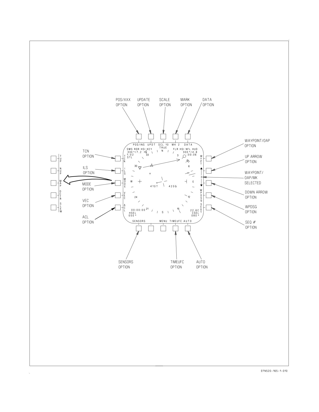
A1-F18EA-NFM-000
Figure 24-1. Navigation Controls and Indicators (Sheet 1 of 2)
VII-24-3
ORIGINAL
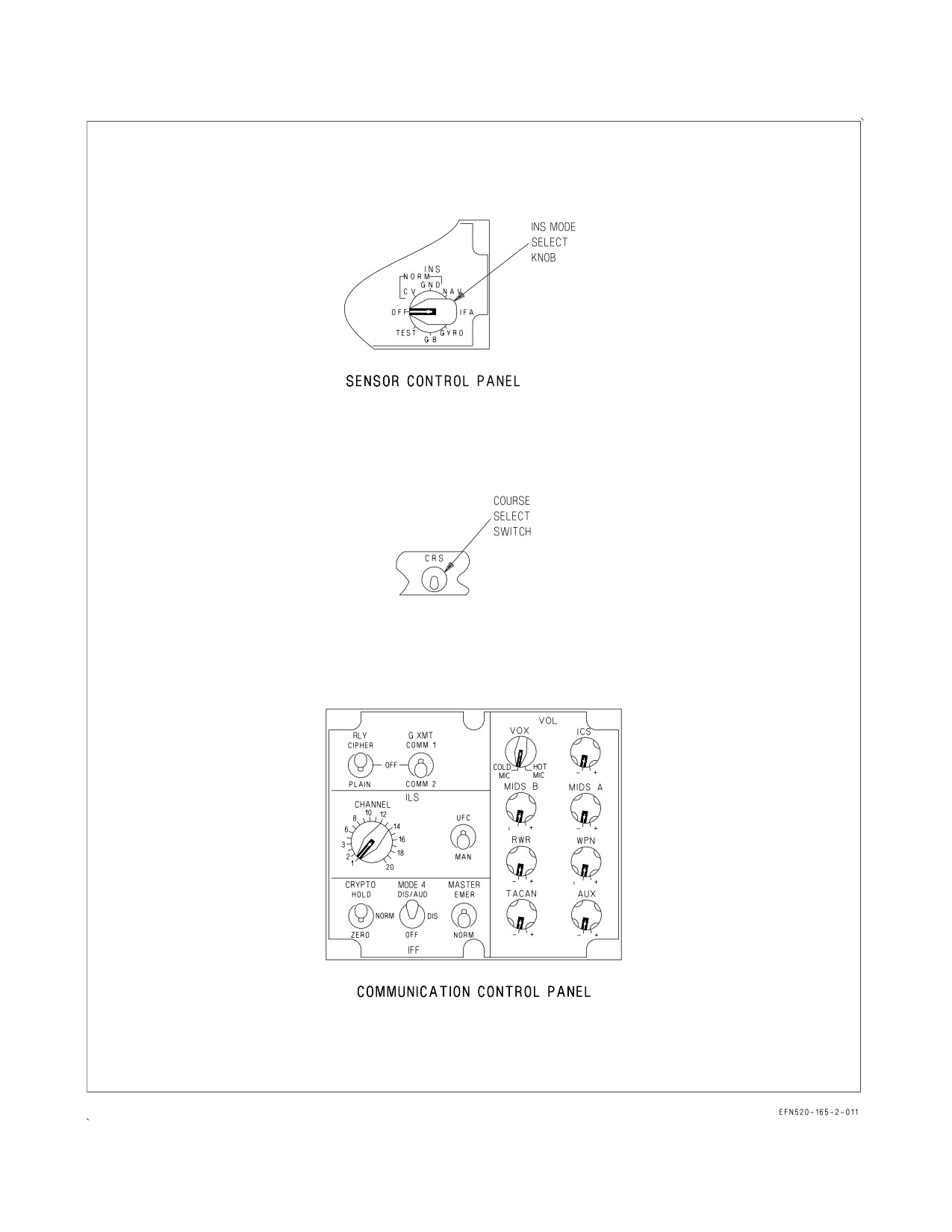
A1-F18EA-NFM-000
Figure 24-1. Navigation Controls and Indicators (Sheet 2 of 2)
VII-24-4
ORIGINAL
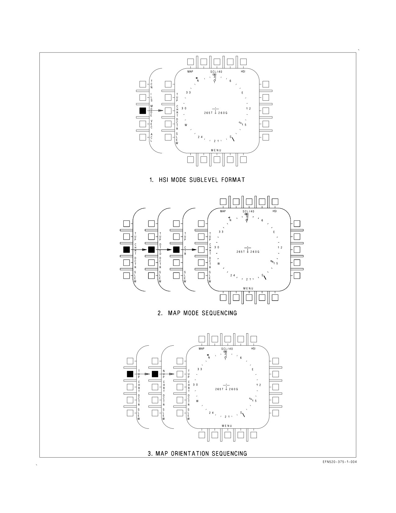
A1-F18EA-NFM-000
Figure 24-2. TAMMAC Mode Selections
VII-24-5
ORIGINAL
A1-F18EA-NFM-000
24.1.3.3.1 MAP Modes/Data Products. Each of the map modes (CHRT, DTED, and CIB) provides
a different plan-view map/image. The actual presentation and availability of the different maps/
images are independent and mutually exclusive. Only one map mode can be selected at any one time.
The detailed images and associated area coverage for each mode are dependent on the map (theater)
data loaded in the DMS or installed on the mission card. Each plan-view map, regardless of mode,
presents an image that can support moving map capability and/or slew mode functions. When toggling
through the different modes, different map images are available providing the mode specific data is
loaded/available for that particular geographic position and scale. The map modes and their associated
data products are:
1. Chart (CHRT) mode provides a plan-view color map derived from Compressed ARC Digitized
Raster Graphics (CADRG). This chart product replaces the Compressed Aeronautical Chart (CAC)
map data currently used in the existing map (AN/ASQ-196).
2. Digital Terrain Elevation Data (DTED) mode provides a plan-view, panchromatic (gray scale),
terrain plot with slope shading.
3. Controlled Image Base (CIB) mode provides a plan-view panchromatic image derived from a
variety of mission planning, command, control, communications, and intelligence systems.
24.1.3.4 Map Data. The MDATA option is provided on the HSI/DATA sublevel format. MDATA is
boxed when selected and remains boxed until A/C, WYPT, TCN, HSI, or INS CK is selected. When
MDATA is selected, the DATA option is provided on the UFCD. When MDATA is selected on the
HSI, all DDI/MPCD/UFCD with the HSI format are driven by the DMS mono-map and the data
frames written in raster. The number of data frames is limited to 100.
24.1.3.4.1 Map Orientation Option. This option is a multifunction option that combines the Track
Up (T UP) and North Up (N UP) map orientation functions into a single option. Successive selections
of the orientation option toggles the map between these two orientations as they are mutually
exclusive. The T UP orientation is the default orientation. The DMS mono-map output contains the
same information as the DMS color output (except for color), including cautions if they are provided
with the color output. See figure 24-2.
24.1.3.5 SLEW Option (HSI Format). When map update is selected from the cockpit, the TDC is
assigned to the slew function. When map update is selected from the rear MPCD, the LDC is assigned
to the slew function (if the left DDI has malfunctioned the right designator control (RDC) is assigned).
When map update is selected from the right or left DDI the RDC or LDC, respectively, is assigned to
the map slew function. When map update is selected, MAP is automatically boxed and when selected
on a DDI, all DDIs and MPCDs displaying the HSI display are commanded to be driven by the DMS
monochromatic map.
When WYPT slew is selected from the cockpit, the TDC is assigned to the MAP Slew function for
waypoint update. When WYPT Slew is selected from the aft MPCD, the LDC is assigned to the MAP
slew function for waypoint update (if the LDDI is not communicating on the AVMUX, the RDC is
assigned). When WYPT Slew is selected from the right or left DDI, the RDC or LDC, respectively, is
assigned to the map slew function for waypoint update. When WYPT Slew is selected, MAP is
automatically boxed. When WYPT slew is selected on a DDI, all DDIs and UFCDs displaying the HSI
format are commanded to be driven by the DMS mono-map.
24.1.3.6 POS/XXX Option (HSI Format). This option is located along the top row of the HSI display
and when selected provides the POS/XXX sublevel display. This sublevel display allows the selection
VII-24-6
ORIGINAL
A1-F18EA-NFM-000
of AINS, INS, GPS, MIDS (if installed), ADC, or TCN as the position keeping source. When one of
these options is selected the top level HSI display is returned, with the appropriate selection denoted
(Ex. POS/ADC). POS/INS is automatically selected during ground operations when INS data is valid.
Without MIDS, should the INS fail, the MC automatically begins position keeping with FCS air data
function (ADC) from the last valid INS position. If MIDS is installed and operating, MIDS is
automatically selected as the aircraft position keeping source if GPS and INS fail or become degraded.
Because MIDS position keeping is unreliable and inflight alignment is not possible when in
POS/MIDS, air data position keeping (POS/ADC) should be manually selected if POS/MIDS is
displayed.
24.1.3.7 UPDT Option (HSI Format). The UPDT option is located along the top row of the HSI
display and when selected provides the UPDT sublevel display. This sublevel display allows the
selection of VEL (velocity), TCN, DSG (designation), AUTO, or MAP as the update source. Following
the selection of one of the update options, an ACPT/REJ (accept/reject) display is presented in which
the update can either be accepted or rejected. After selection of ACPT or REJ, the top level HSI
display is returned. There is no ACPT/REJ display presented when the AUTO option is selected.
Velocity update is described in the A1-F18EA-TAC-000. If a previous update has been accepted, a
CANCEL option is also displayed on the UPDT sublevel to allow the aircrew to cancel the last accepted
update.
24.1.3.8 MK Option (HSI Format). This option is located along the top row of the HSI display. The
mark option is initialized to MK1 upon power up with WonW, regardless of the previous selection. A
maximum of nine mark points may be entered. If all mark points have been used and another mark
point is entered, MK1 is replaced with the new mark data.
If a waypoint/OAP is not designated and the MK option is selected, the lat/long of the current
overfly point is stored with the elevation set to zero. If a location is designated, the lat/long of the
designated location is stored. In this situation, the aircraft altitude minus the altitude above the
designated target is stored as the elevation.
24.1.3.9 DATA Option (HSI Format). The data option is located along the top row of the HSI display.
Selecting this option provides the DATA sublevel display. This display is used to enter waypoint/OAP
data, aircraft data, TACAN data, waypoint/OAP sequence data, radar and barometric altitude
warning, groundspeed data, and TOT data; and to select the INS check display. After selection of
either the WYPT, A/C, or TCN option, the UFC or SEQUFC option is used to initialize the UFCD for
data entry. The HSI option is used to return the HSI display to the top level format.
24.1.3.10 WYPT, OAP Option (HSI Format). The WYPT, OAP option is located along the right side
of the HSI. WYPT is displayed when steering is to a waypoint. OAP is displayed when steering is to
an OAP. If either the WYPT or OAP option is selected (boxed), direct great circle steering is provided
to that waypoint/OAP. TGT is displayed at this location when a target is designated.
24.1.3.10.1 Waypoint, OAP, Mark Point Selection. Along the right side of the HSI display just below
the WYPT/OAP/TGT options, there are two arrows pointing in opposite directions with a number in
between. This number indicates the current steer to waypoint/OAP/mark. The waypoint/OAP being
steered to can be incremented/decremented by selecting the appropriate arrow option, changing the
steer to number. After all of the waypoints/OAPs have cycled through (0 through 59), the mark points
can be selected for display. Marks are displayed with an M preceding the number.
24.1.3.11 WPDSG, O/S Option (HSI Format). This option is located along the right side of the HSI
display. Selecting this option designates a waypoint/OAP for weapon computations, sensor slaving,
VII-24-7
ORIGINAL
A1-F18EA-NFM-000
steering, or position updating. Selecting the WPDSG option designates the waypoint/OAP. After
designating a waypoint, the WPDSG option is removed and TGT replaces WYPT. After designating
an OAP, OAP remains boxed and O/S replaces WPDSG. When O/S is selected, the offset point is
designated, TGT replaces OAP, and O/S is removed.
24.1.3.12 SEQ # Option (HSI Format). The SEQ # option is located along the right side of the HSI
display. At power up with WonW, this option initializes to SEQ1 (unboxed). Successive actuations of
the option toggles through a display sequence in the following order: SEQ1 (boxed), SEQ2 (unboxed),
SEQ2 (boxed), SEQ3, (unboxed), SEQ3, (boxed), SEQL, (unboxed), SEQL, (boxed), and back to SEQ1
(unboxed). With the SEQ # option boxed, dashed lines are displayed connecting the waypoints of that
sequence. The dashed lines connecting the waypoints (SEQ # boxed) are displayed for all HSI range
scales and all HSI modes. The dashed lines are removed when magnetic heading is invalid, aircraft
position is invalid, or map slew is selected.
24.1.3.13 AUTO Option (HSI Format). The AUTO option is located along the bottom of the HSI
display. Selecting the AUTO option provides auto sequential steering to the first waypoint in the
selected sequence; boxing the AUTO and WYPT or OAP option (if not already boxed). Selecting the
AUTO option while boxed deselects auto sequential steering and unboxes the AUTO option. The
AUTO option is removed when:
1. The INS is in an alignment mode
2. INS heading failure occurs
3. Magnetic is invalid
4. Aircraft present position is invalid
5. Aircraft ground track is invalid
6. Selected sequence contains less than two waypoints
7. Aircraft is in auto or velocity update
8. FCS is coupled to the D/L
9. A ground point is designated
24.1.3.14 TIMEUFC Option (HSI Format). The TIMEUFC option is located along the bottom row of
the HSI display. The TIMEUFC option is removed from the HSI format during a GND or IFA GPS
alignment until the qual number is 6.2 or better, and is never displayed during a CV alignment.
Selecting this option boxes TIMEUFC and initializes the UFCD option display windows with the clock
options: DATE, ET counter, CD timer, ZTOD, and LTOD. Border highlights indicate that an option
is enabled for data entry. If an option is displayed on the HUD, the option has *HUD displayed below
it in addition to being border highlighted. The DATE, ET, ZTOD, LTOD, and CD options are mutually
exclusive; selecting one option deselects another option.
Data entry can be made for current date, current zulu or local time, or initial countdown time. No
data entry is available for the elapsed time option.
If DATE is highlighted, an M, D, and Y appear in the scratch pad and the month, day and year can
be entered on the keypad. If LTOD or ZTOD are highlighted two colons appear in the scratchpad and
VII-24-8
ORIGINAL
A1-F18EA-NFM-000
the hour, minutes and seconds can be entered on the keypad. If CD is highlighted one colon appears
in the scratchpad and minutes and seconds can be entered. Leading zeroes must be entered for the date
and time entries. Digits not entered are assumed to be zeroes, i.e., trailing zeroes need not be entered.
The time is displayed on the scratchpad as it is entered and displayed as ##:##:##. When the time
has been updated in the SDC it appears on the HUD and *HUD appears on the UFCD highlighted
option. The time display can be changed from local or zulu by selecting the appropriate option on the
UFCD and entering the appropriate time as before.
Countdown (CD) or elapsed (ET) time is selected and displayed in the same manner as local or zulu
time with the addition of START or STOP options. While CD START is displayed, the countdown
timer is counting down. The countdown timer defaults to 6 minutes on power up. If an invalid
countdown time is entered the timer sets to 59:59 and freezes. While ET START is displayed, the
elapsed timer is counting up to a maximum of 59:59.
24.1.3.15 MENU Option (HSI Format). When MENU is selected on the top level HSI display, the
TAC Menu is displayed. The Tactical (TAC) option provides access to weapons, sensors and HUD
formats. The TAC Menu is displayed when the MENU option on any format is pressed. The Support
(SUPT) menu is accessed by pressing the MENU option when the Tactical (TAC) menu is displayed.
When the SUPT menu is displayed, it provides access to the ADI, HSI, BIT, Checklists, Engines,
Flight Controls, UFC Backup and Fuel formats.
24.1.3.16 ACL Option (HSI Format). The ACL option is located on the left side of the HSI display.
When selected, ACL is boxed and the link 4 display appears on the left DDI.
24.1.3.17 SENSORS Option (HSI Format). Refer to A1-F18EA-TAC-100.
24.1.3.18 VEC Option (HSI Format). Refer to A1-F18EA-TAC-100.
24.1.3.19 D/L Option (HSI Format). Refer to A1-F18EA-TAC-100.
24.1.3.20 ILS Option (HSI Format). The ILS option is located on the left side of the HSI display.
When selected, ILS is boxed and ILS steering appears on the HUD.
24.1.3.21 TCN Option (HSI Format). The TCN option is located on the left side of the HSI display.
When selected, TCN is boxed and TACAN great circle steering appears on the HUD.
24.1.4 HSI Format on a DDI. The DDIs are capable of displaying HSI display and D/L information
by selecting the HSI or SA option on the applicable menu.
24.1.5 HUD - Navigation Information. The HUD displays basic flight symbology and steering
information for the TACAN, ILS, ACL, and INS.
VII-24-9
ORIGINAL
A1-F18EA-NFM-000
24.1.6 CRS Select Switch. The CRS select switch is used to set a course to the selected waypoint,
OAP, or TACAN station. When the switch is actuated with waypoint/OAP or TACAN direct great
circle steering already selected, a course line appears through the waypoint/OAP or TACAN symbol on
the HSI display and steering information appears on the HUD. The course line rotates clockwise when
the switch is held to the right and counterclockwise when the switch is held to the left. When a course
is selected, a digital readout appears on the lower right corner of the HSI display.
24.1.7 IFF Control Panel. This panel contains two ILS controls: ILS UFC/MAN switch and the ILS
channel thumbwheels.
24.1.7.1 ILS UFC/MAN Switch. When the switch is in the UFC position, ILS power and channel-
ization is controlled by the UFCD. With the switch in the MAN position, ILS power is enabled and ILS
channel changes are controlled by the ILS channel thumbwheels.
24.1.7.2 ILS Channel Thumbwheels. These thumbwheels are used to select ILS channels when the
ILS UFC/MAN switch is set to MAN.
24.2 INERTIAL NAVIGATION SYSTEM (INS)/GLOBAL POSITIONING SYSTEM (GPS)
There are two navigation system configurations. In one configuration, navigation data is provided by
two separate systems: INS (CAINS II) and GPS (MAGR or MAGR2K). In the other configuration,
navigation data is provided by a single system called Accurate Navigation (ANAV) which integrates
the INS and GPS together. Both configurations provide data to the MC for navigation, targeting, and
weapon delivery.
Additionally, ANAV integrates the Deflection of Vertical (DoV) database (also known as the Gravity
Map database). The DoV database is downloaded onto the mission card during mission planning. The
continual use of DoV data along the flight path assists in an improved navigation solution. If GPS data
is unavailable, the additional DoV data assists the ANAV system in maintaining unaided navigation
performance.
VII-24-10
ORIGINAL
A1-F18EA-NFM-000
24.2.1 Inertial Navigation System (INS). The INS is a self-contained, fully automatic dead
reckoning navigation system. The INS detects aircraft motion and provides acceleration, velocity,
present position, pitch, roll, and true heading.
Without good GPS satellite data, unaided INS (POS/INS) is the primary position keeping mode. In
POS/INS, the navigation system provides data by using the INS’s sensor data alone. In this mode, the
navigation data drifts in error over time. With ANAV installed, the error drift is minimized with the
use of the DoV data. POS/INS is selected by turning the INS knob to NAV after GND or CV alignment
or is automatically defaulted to when GPS data is lost while in aided INS (POS/AINS).
If the INS is turned off with the INS knob or shuts down abnormally
(power loss), the INS knob must be set to OFF for a minimum of 20
seconds.
NOTE
While it is acceptable to taxi with the INS off, the INS should be on,
whenever possible, to reduce accelerometer wear. It is preferable to
switch to the GYRO mode and wait for course level complete (NO
ATT clears) before taxiing.
24.2.2 Global Positioning System (GPS). The GPS provides position, velocity, and time (PVT) data
that can be used to aid the INS or as an independent navigation sensor. The GPS receives modulated
signals through the GPS antenna from 32 high orbit satellites. Satellite data is used to determine GPS
position and velocity. GPS can be initialized with crypto keys, enabling encrypted Y-code (precise/
encrypted) navigation signals to be received.
With good GPS satellite data, aided INS (POS/AINS) is the primary position keeping mode. In
POS/AINS, the navigation system provides data by blending the INS sensor data with GPS data.
POS/AINS is selected by turning the INS knob to IFA after a GND or CV alignment. The position
keeping mode remains POS/AINS unless GPS data is lost, an INS or GPS failure occurs, or the pilot
manually chooses a different position keeping source.
GPS has four modes of operation which are displayed on the GPS page (see figure 24-3). In NAV
mode, the GPS tracks all available satellite constellations possible to provide the most accurate PVT
solution. In Initialize (INIT) mode, the power supply is turned on, satellite tracking is not performed,
and almanac and waypoint data are loaded from the mission card into the GPS when initiated by the
MC. In Not Ready (NOT RDY) mode, the GPS is off or not communicating on the MUX. TEST mode
is provided for ground BIT testing.
Crypto key loading may be performed with an approved crypto loading device such as KYK-13,
CYZ−10, or Simple Key Loader (SKL) in any mode of operation.
It is important to set Zulu Time of Day (ZTOD) to aid in satellite acquisition. Local time, if desired,
should be set after takeoff. GPS is loaded with GPS precise times only once per cold start. Changing
the aircraft time or date with WonW re-initializes the GPS. An overall GPS Position Accuracy Figure
Of Merit (FOM) and Satellite (SAT) status is displayed on the GPS page to enhance the pilot’s
awareness of the overall GPS status.
24.2.3 Inertial Alignment Modes. INS alignment modes which can be selected using the INS knob
are CV (carrier alignment), GND
(ground alignment), IFA
(in−flight alignment), and GYRO
VII-24-11
ORIGINAL
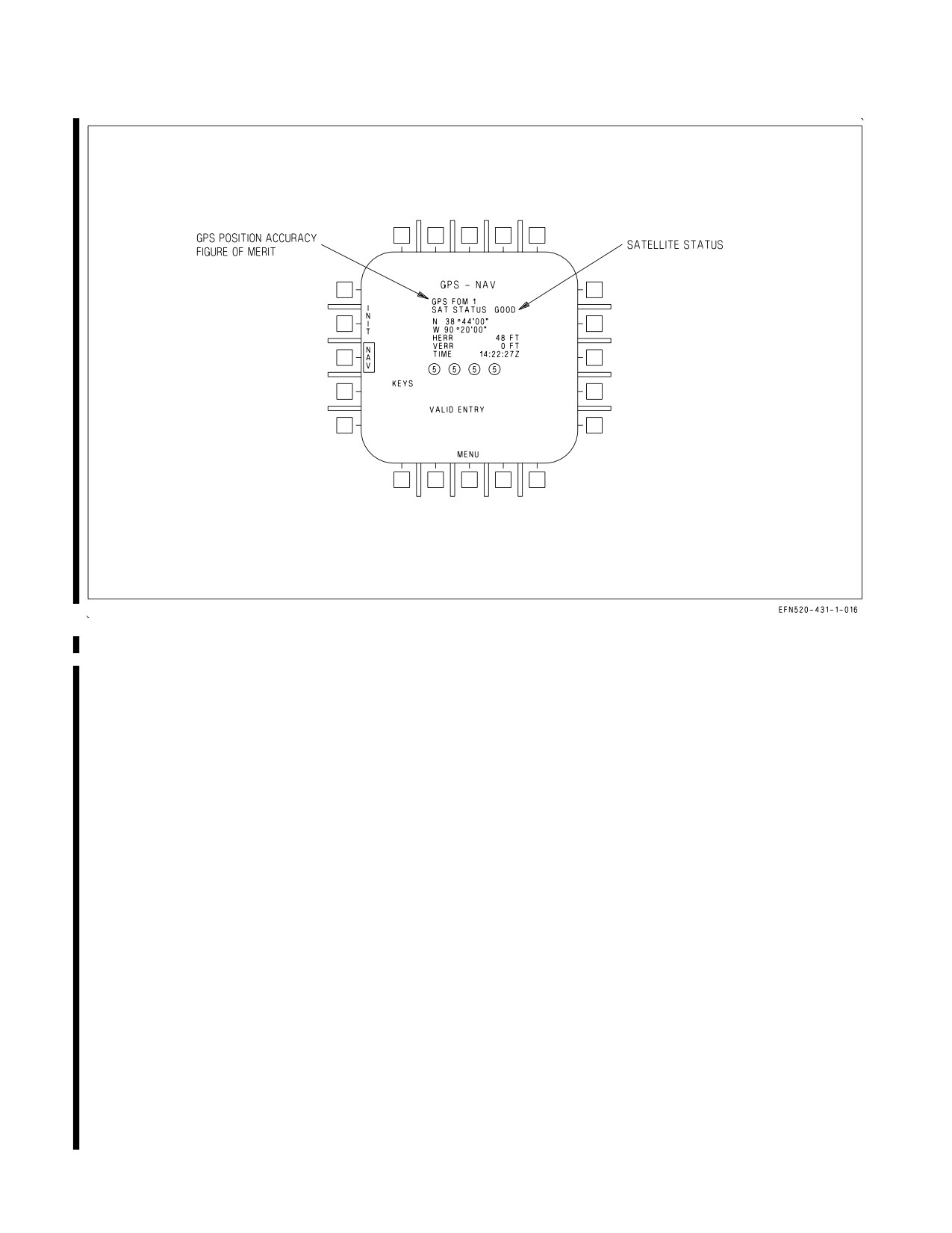
A1-F18EA-NFM-000
Figure 24-3. GPS Page
(AHRS attitude only). A Stored Heading alignment may also be selected to reduce CV/GND alignment
time if certain conditions are met.
During the first 30 seconds to 2 minutes of all alignments, NO ATT is displayed to the right of QUAL
on the HSI alignment display and the INS ATT caution is set. After the platform has leveled, NO ATT
is replaced with a quality (QUAL) number and the INS begins to determine true north. The QUAL
number is an estimate of present position accuracy in nm/hr 95% (CAINS) or nm/hr CEP (ANAV).
The INS ATT caution clears when the QUAL number becomes less than 5. Also during the alignment,
the GPS is initialized with WYPT 0, ZTOD, DATE, almanac and GPS waypoints if the aircraft is
WonW. After initialization, the GPS is commanded to search and acquire GPS satellites. OK is
displayed next to the QUAL number when a satisfactory alignment is achieved and the INS can be
switched to IFA (POS/AINS) or NAV (POS/INS). Also during the alignment, the TIME increments.
The TIME stops incrementing and flashes when the INS suspends alignment due to premature
parking brake release (GND or CV), parking brake release and motion detected (GND, ANAV only),
GPS data unavailable (IFA), ship INS (SINS) data unavailable (CV), POS ERROR caution set (ANAV
only), or waiting for carrier data entry or carrier heading and/or carrier velocity changes during CV
Manual alignment.
NOTE
With ANAV installed, changing the INS boresight values during
alignment causes the INS to re-initialize the alignment.
24.2.3.1 CV Alignment Modes. Turning the INS knob to CV provides CV alignment options of RF
(radio frequency), CBL (cable), and MAN (manual). During a RF or CBL alignment, the aircraft is
VII-24-12
ORIGINAL
A1-F18EA-NFM-000
data linked to the ship’s INS (SINS). The MAN option has no data link capability and alignment data
must be entered manually. Before selecting CV, WYPT 0, ZTOD and DATE should be entered and the
parking brake set. The parking brake must remain set until a satisfactory alignment is achieved (OK
displayed). If the parking brake is released before OK is displayed and the QUAL number is greater
than 5, the INS switches to GYRO mode (AHRS attitude only). A complete re−initialization is
required to achieve a satisfactory alignment (OK displayed). This can be accomplished by turning the
INS knob to OFF for 20 seconds and then selecting either IFA or CV. If the parking brake is released
before OK is displayed and the QUAL number is less than or equal to 5, the INS switches to POS/INS
with limited performance. This partial alignment can be completed by selecting IFA.
24.2.3.1.1 RF/CBL SINS Alignment. During the CV RF/CBL SINS alignment, the INS automati-
cally compensates for the difference between the aircraft deck position and SINS position. To perform
this alignment, the parking brake must be set and the INS knob turned to CV. The navigation system
and data link are turned on and CV alignment data is displayed on the HSI (figure 24-4). For an RF
alignment, information is received by radio frequency and CV RF is displayed. The alignment
frequency is displayed on the UFCD scratchpad for 30 seconds after selecting CV and may be changed
using the UFCD keypad. When a cable is connected to the aircraft, information is received on the cable
and CV CBL is displayed. RF/CBL and the TIME flashes until the SINS data becomes valid. If the
SINS data becomes invalid during the alignment, the TIME flashes and the INS suspends the
alignment until the SINS data becomes valid again. If the SINS data remains invalid for 30 seconds,
the INS automatically switches to CV Manual alignment using the last valid SINS data the INS
received. If the SINS data becomes valid during CV Manual alignment, the INS automatically switches
back to CV SINS alignment. CV SINS alignment time is normally less than 10 minutes.
While the platform is being leveled, a total of 10 waypoints can be received. When 10 waypoints have
been received, WYPTS is displayed below the TIME. If all waypoint data is not received, NO WYPTS
is displayed below the TIME. Reception of waypoint data is not required for the alignment to proceed.
24.2.3.1.2 CV MAN (Manual) Alignment. A CV Manual alignment can be performed if the data link
signal is not available or not desired, or occurs automatically if the CV SINS data is invalid for more
than 30 seconds. CV Manual alignment requires entering CV data on the UFCD. To perform this
alignment, the parking brake must be set and the INS knob turned to CV. The navigation system and
data link are turned on and CV alignment data is displayed on the HSI. Selecting the MAN option on
the HSI enables the CV Manual alignment display on the HSI and UFCD (figure 24-4). MAN is boxed
when selected and the STD HDG option is removed. Carrier latitude/longitude data (POSN), heading
(CHDG), and speed (CVEL) are entered through the UFCD. The INS uses this data to update present
position during the alignment. If the carrier heading changes more than 10° or carrier speed changes
more than 1 knot, the aircrew must re-enter carrier data to reinitialize the alignment. In the case where
the CV SINS data was invalid for more than 30 seconds, the INS uses the last valid SINS data to
complete a CV Manual alignment. If this occurs, no carrier data entry is required. CV Manual
alignment time is approximately 15 minutes.
CV MANUAL ALIGNMENT
1. Parking brake - SET
The parking brake must remain set until a satisfactory alignment is achieved (OK displayed). If the
parking brake is released before OK is displayed and QUAL > 5, the alignment must be restarted.
If the parking brake is released before OK is displayed and QUAL < 5, the partial alignment may be
completed by selecting IFA.
2. ATT switch - AUTO or INS
VII-24-13
ORIGINAL
A1-F18EA-NFM-000
3. Enter WYPT 0, ZTOD, and DATE
4. INS knob - CV
5. HSI MAN option - SELECT
On the UFCD -
6. Enter Latitude (POSN) (leading zeroes must be entered)
7. Enter Longitude (POSN) (leading zeroes must be entered)
8. Enter Carrier Heading (CHDG) (0 to 360)
9. Enter Carrier Speed (CVEL) (0 to 63)
After a satisfactory alignment is achieved (OK displayed) -
10. INS knob - IFA (POS/AINS). If GPS not available, then INS knob - NAV (POS/INS)
24.2.3.2 Ground (GND) Alignment. To perform a ground alignment, the parking brake must be set,
WYPT 0, ZTOD and DATE entered, and the INS knob turned to GND. The navigation system is
turned on and GRND alignment data is displayed on the HSI (figure 24-5). If the aircraft is taxied
during the alignment, the INS suspends the alignment as indicated by the TIME flashing. With ANAV
installed, the aircraft may be taxied without restarting the alignment if the QUAL number is less than
or equal to 5.
NOTE
The most accurate alignment of the INS is achieved by changing
aircraft heading at least 70° (180° optimum) after OK is displayed
next to the QUAL number and allowing the alignment to continue. An
alignment with TIME greater than 12 minutes has little to no benefit.
The MC automatically transfers WYPT 0 to the INS to be used as aircraft present position. This
information appears on the GRND alignment display. WYPT 0 position can be updated prior to
selecting GND but if an error is noticed after the alignment has begun, aircraft present position must
be corrected because WYPT 0 is transferred to the INS only once. If aircraft present position is
incorrect, it must be corrected or the INS will align improperly. Refer to Aircraft (A/C) Programming
(this chapter) to enter new aircraft position data.
CAINS Only: The INS restarts the alignment if more than one position update is performed. If the
parking brake is released at any time during the alignment, the alignment suspends. If the parking
brake is set, the alignment continues within 20 seconds if the QUAL number is less than or equal to 5
or restarts if the QUAL number is greater than 5.
ANAV Only: The INS does not restart the alignment if the position is updated with TIME less
than 30 seconds and if the update is no more than 0.4 nm from the original position. After 30 seconds,
any position update restarts the alignment. The parking brake may be released with TIME greater
than 30 seconds; however, if the INS detects aircraft motion with the parking brake released, the INS
suspends the alignment until no motion is detected for 20 seconds, at which point the alignment
continues if the QUAL number is less than or equal to 5 or restarts if the QUAL number is greater than
5.
VII-24-14
ORIGINAL