F18. FLIGHT MANUAL (2008) - page 27

A1-F18EA-NFM-000
Once stopped on runway -
7. Do not taxi (even if HYD 2A caution is removed).
If short field arresting gear NOT available and right engine crossbleed IS desired/required -
If APU ACCUM caution light on (i.e., landing gear emergency extended) -
3. Recharge the APU accumulator.
a. Left throttle - ADVANCE to 80%rpm minimum
b. ENG CRANK switch - R
When HYD 2 pressure restored -
c. HYD ISOL switch - ORIDE (until 10 seconds after APU ACCUM
caution removed -
approximately 30 seconds total)
d. ENG CRANK switch - OFF
With APU ACCUM caution off -
4. APU switch - ON (READY light on within 30 seconds)
5. ENG CRANK switch - R
When HYD 2 pressure restored -
6. HYD ISOL switch - ORIDE (until 10 seconds after APU ACCUM caution removed - approxi-
mately 40 seconds total)
7. EMERG BRK handle - VERIFY RESET
8. Make a normal landing using normal brakes with antiskid.
Once stopped on runway -
9. Do not taxi (even if HYD 2A caution is removed).
16.3 SINGLE ENGINE WAVEOFF/BOLTER
During a single engine waveoff or bolter, use of the afterburner on the operating engine is not
restricted as long as on-speed AOA is maintained. Best single engine rate of climb occurs at or near
on-speed AOA regardless of configuration, lateral weight asymmetry, or gross weight. If MAX power
is used, pilot workload is higher due to higher asymmetric thrust effects. Up to full rudder pedal may
be required to oppose yaw/roll. If required, coordinated lateral stick should be used to maintain wings
level.
1. Throttles - MIL (MAX if required)
2. Maintain on-speed AOA and balanced flight.
V-16-3
ORIGINAL
A1-F18EA-NFM-000
3. Climb, then accelerate to a safe altitude/airspeed.
16.4 FORCED LANDING
The aircraft is not designed to land on an unprepared surface. If a suitable landing site is not
available, perform a controlled ejection.
16.5 LANDING GEAR UNSAFE/FAILS TO EXTEND
A landing gear position of three down and locked is indicated by three steady green position lights
in either cockpit with the landing gear warning light and warning tone out. See figure 16-1.
If the LEFT or RIGHT landing gear position indicator is flashing, and the landing gear warning light
and warning tone are on, refer to PLANING LINK FAILURE.
If the landing gear warning light and warning tone are out -
1. AOA indexer lights - CONFIRM ON
2. INTR LT MODE switch - CHECK DAY
3. Landing gear position lights - CHECK FLUSH
4. LT TEST switch - TEST
If bulb(s) test bad -
5. It is safe to assume the landing gear is down and locked.
6. Get a visual inspection (if practical).
D The approach lights should be illuminated if the landing gear is down and locked.
7. Landing gear may be raised as necessary to conserve fuel.
8. Make a normal landing.
If the landing gear warning light and warning tone are on -
1. AOA indexer lights - CONFIRM OUT
2. LT TEST switch - TEST
D Verify that all 3 position lights and the landing gear warning light are on.
3. LDG GEAR handle - CHECK FULL DN (DO NOT CYCLE)
4. LG circuit breaker - CHECK IN
5. Get a visual inspection (if practical).
D If one or more landing gear indicates unsafe, a visual inspection can only confirm general
position and obvious damage.
D There is no external indication of a locked landing gear.
V-16-4
ORIGINAL
A1-F18EA-NFM-000
Perform the following in order until 3 down and locked -
6. LG circuit breaker - CYCLE
7. Perform Landing Gear Emergency Extension Procedure.
8. Perform positive and negative g maneuvers and gently roll and yaw aircraft to obtain safe gear
indication.
If HYD 2A is operative and any gear still unsafe -
9. LDG GEAR handle - PUSH IN then ROTATE 90° CCW
10. LDG GEAR handle - UP (DOWNLOCK ORIDE if required)
11. If all gear up and locked, consider selective jettison of unwanted stores.
D Selective jettison can only be performed with LDG GEAR handle UP and all landing gear up
and locked.
12. LDG GEAR handle - DN
13. Perform Landing Gear Emergency Extension procedure.
14. Perform positive and negative g maneuvers and gently roll and yaw aircraft to attempt to drive
the unsafe gear down and locked.
If any gear still indicates unsafe -
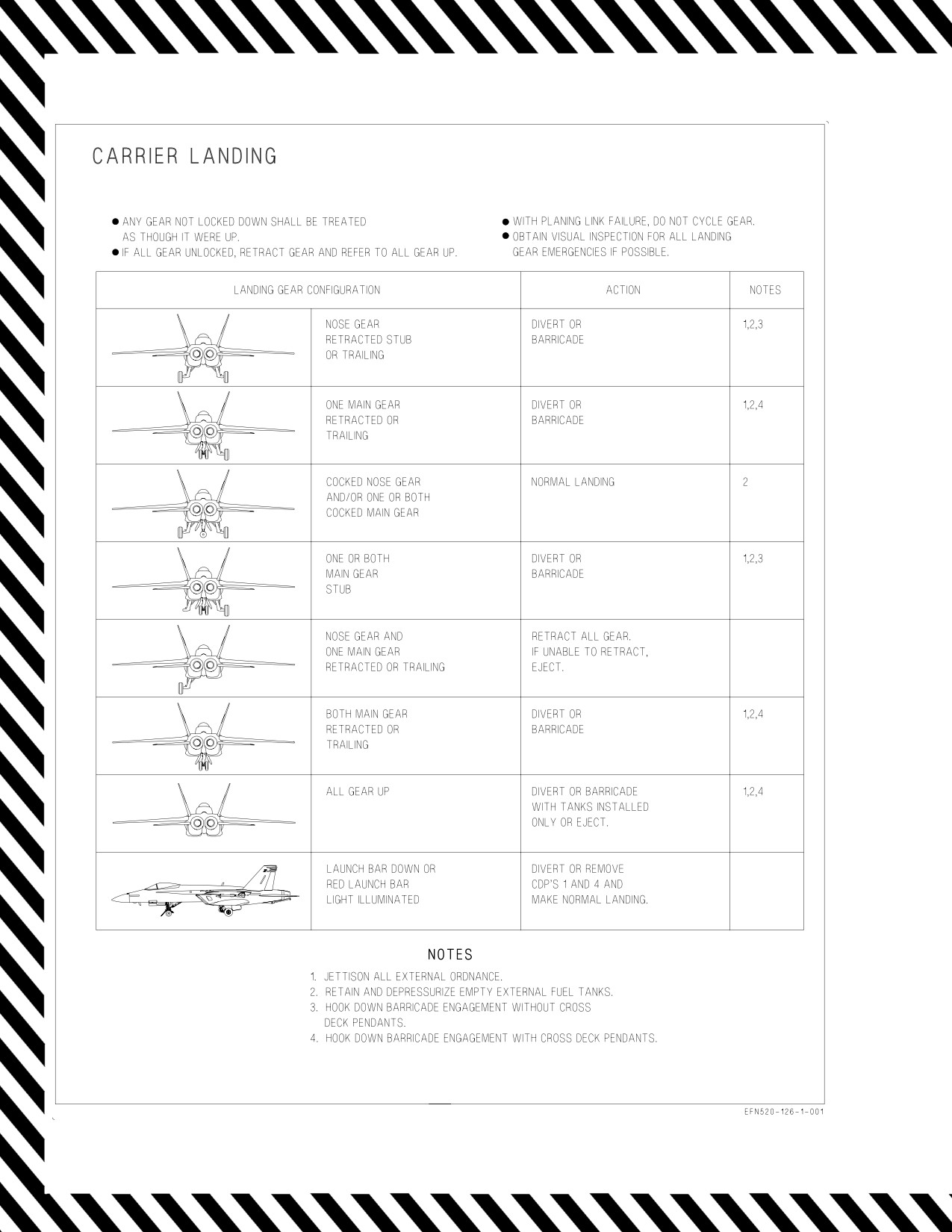
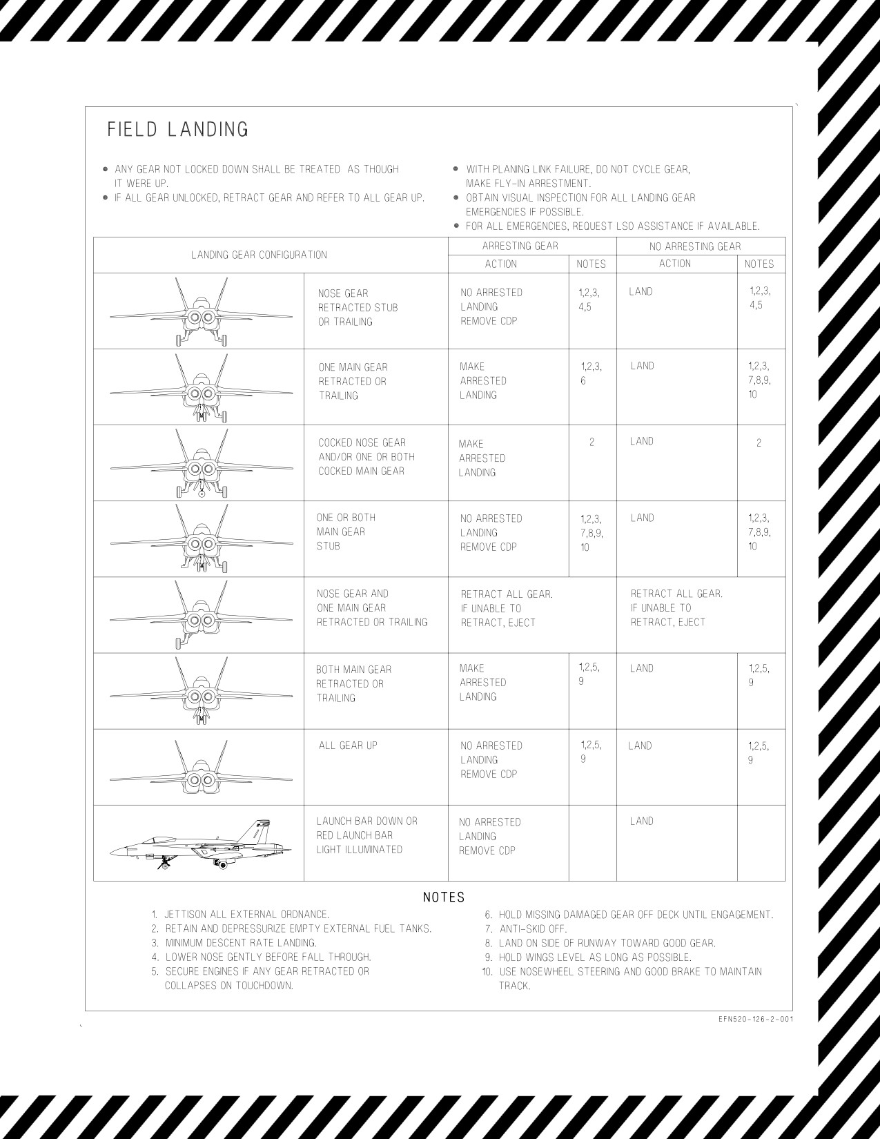
15. Refer to Landing Gear Malfunction - Landing Guide chart.
If at any time landing gear indicates three down and locked -
16. LDG GEAR handle - DO NOT CYCLE
17. Make minimum sink rate short field arrested landing (if available).
18. Pin the landing gear after landing.
16.6 LANDING GEAR EMERGENCY EXTENSION
1. Consider selective jettison of unwanted stores.
D Selective jettison can only be performed with LDG GEAR handle UP and all landing gear up
and locked.
2. FLAP switch - HALF or FULL
3. Slow below 170 KCAS.
4. LDG GEAR handle - DN
If LDG GEAR handle cannot be moved to the DN position -
5. LG circuit breaker - PULL
V-16-5
ORIGINAL
A1-F18EA-NFM-000
With LDG GEAR handle DN or UP (DN preferred) -
6. LDG GEAR handle - ROTATE 90° CLOCKWISE then PULL TO DETENT
7. Verify three down and locked.
8. Make a short field arrestment (if practical)
NOTE
If the landing gear was emergency extended with the LDG GEAR
handle in the UP position, the landing gear warning light remains on
with the gear down and locked.
9. EMERG BRK handle - PULL TO DETENT (Anti-skid is not available)
If the forward pressure reducer valve is failed, normal gear extension and
normal braking will be inoperative. If emergency gear extension was
required to achieve three down and locked with a good HYD 2A system,
emergency brakes should be selected prior to landing. If the landing gear
was emergency extended with a good HYD 2A system, emergency brakes
should be selected, as failure of normal braking is anticipated.
If HYD 2B is operative -
10. HYD ISOL switch - ORIDE (until 10 seconds after APU ACCUM caution removed -
approximately 30 seconds total)
V-16-6
ORIGINAL
A1-F18EA-NFM-000
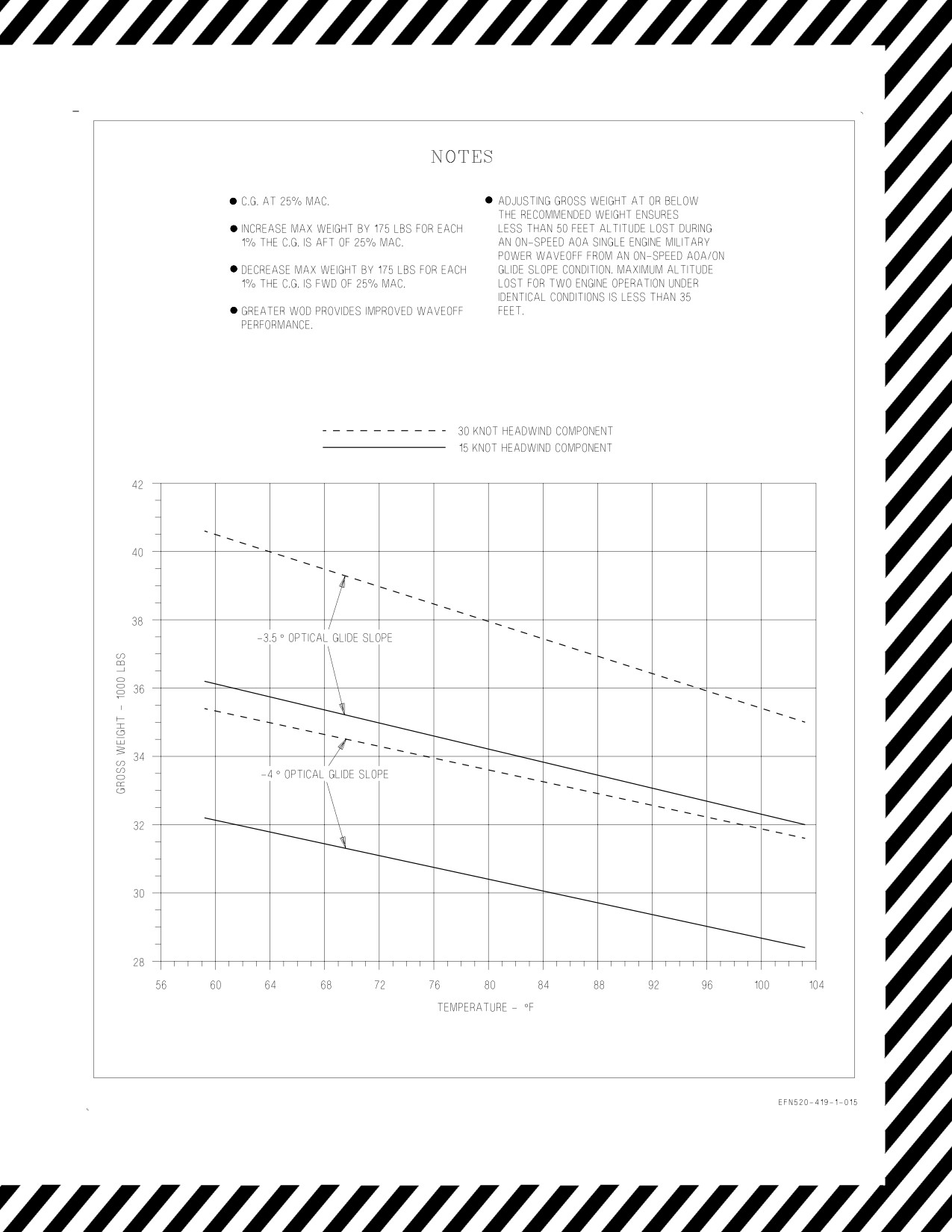
Figure 16-1. Maximum Single Engine Recovery Weight - Military Thrust
V-16-7
ORIGINAL
A1-F18EA-NFM-000
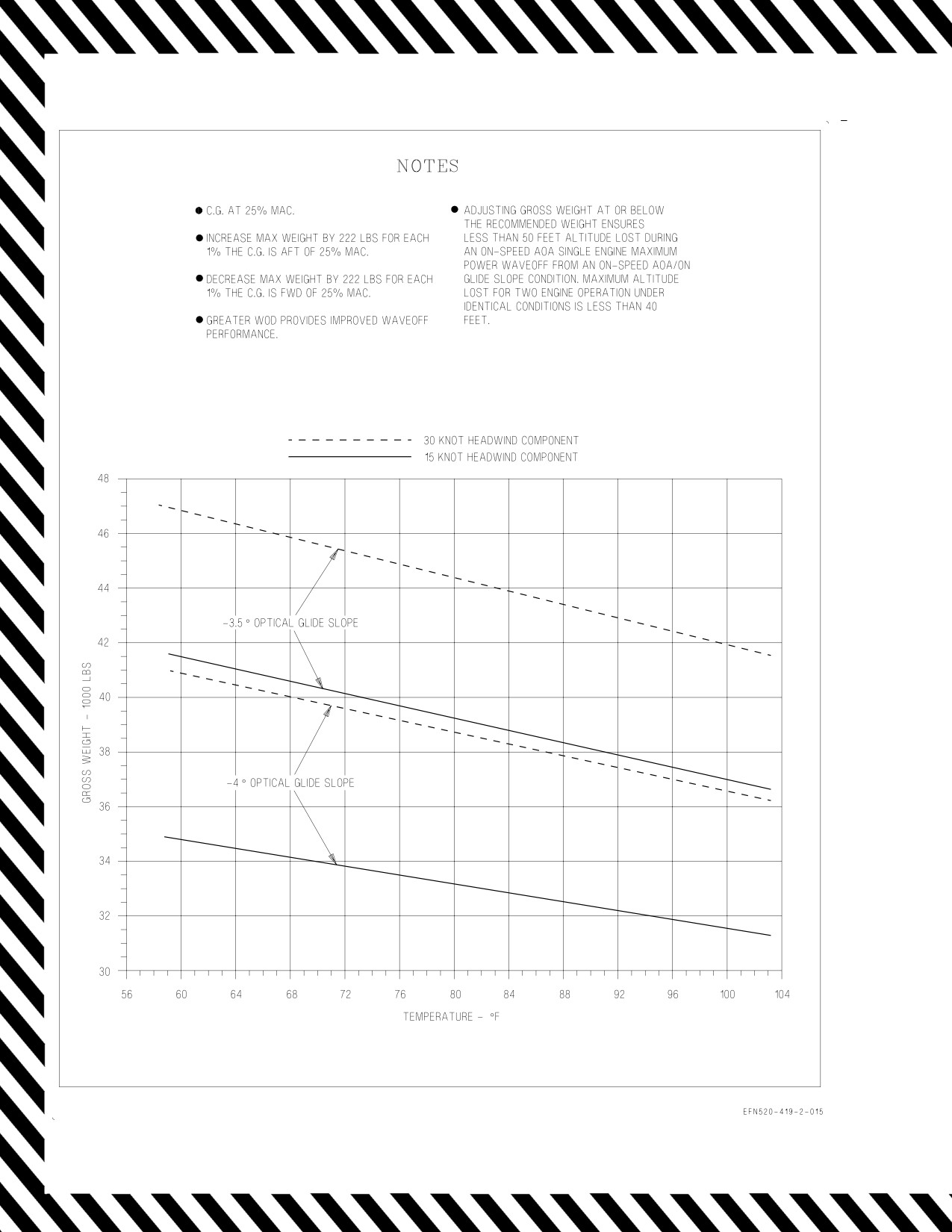
Figure 16-2. Maximum Single Engine Recovery Weight - Maximum Thrust
V-16-8
ORIGINAL
A1-F18EA-NFM-000
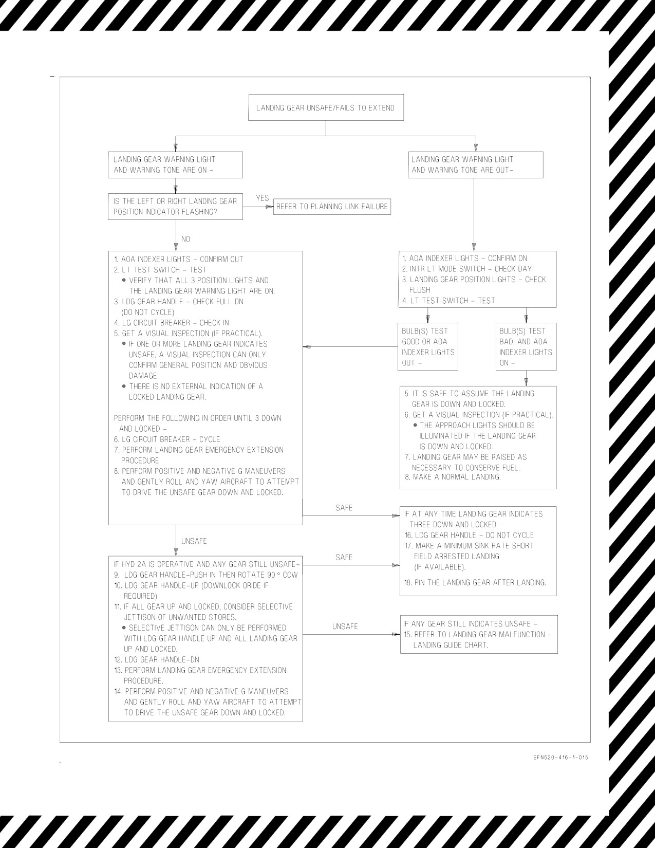
Figure 16-3. Landing Gear Emergency Flow Chart
V-16-9
ORIGINAL
A1-F18EA-NFM-000
Figure 16-4. Landing Gear Malfunction - Landing Guide (Sheet 1 of 2)
V-16-10
ORIGINAL
A1-F18EA-NFM-000
Figure 16-4. Landing Gear Malfunction - Landing Guide (Sheet 2 of 2)
V-16-11
ORIGINAL
A1-F18EA-NFM-000
16.7 PLANING LINK FAILURE
With the landing gear down and locked, a planing link failure is indicated by a flashing LEFT or
RIGHT landing gear position light, illumination of the landing gear warning light, and annunciation
of the landing gear warning tone.
• A planing link failure may cause a sudden swerve on touchdown in the
direction of the failed gear.
• Planing link failure may not be annunciated until after touchdown,
providing the pilot with little to no reaction time between initial
annunciation and a violent yaw/swerve. If flyaway airspeed is avail-
able, pilots should be prepared to make the decision to execute the Go
Around procedure immediately at initial planing link failure annun-
ciation.
Planing link failure indications that are momentary or disappear after
initial activation may be indicative of an actual planing link failure.
If detected after touchdown and flyaway airspeed available -
*1. Go Around
If flyaway airspeed not available -
*1. Select emergency brakes (if appropriate).
*2. HOOK handle - DOWN (if required)
If detected airborne, or following go around -
1. LDG GEAR handle - DO NOT CYCLE
2. ANTI SKID switch - OFF
If arresting gear available -
3. Make a fly-in short field arrestment with LSO assistance (if available).
If arresting gear not available -
3. Make a minimum sink rate landing.
4. Consider touchdown on good gear side of runway.
V-16-12
ORIGINAL

A1-F18EA-NFM-000
5. Avoid braking until as slow as practical or until needed to prevent loss of directional control.
6. Brake using the good gear and maintain directional control with NWS.
7. Use symmetrical braking only if necessary to avoid departing the runway.
• Use of symmetrical wheel brakes with a planing link failure may cause
a sudden swerve in the direction of the failed gear.
• The ability to maintain directional control with braking on the
appropriate side, NWS, and rudder will rapidly decrease as the aircraft
decelerates on rollout.
• Lateral asymmetry on the failed side may aggravate severity of
yaw/swerve in the direction of failed gear.
8. Do not taxi once stopped.
16.8 ARRESTMENT - FIELD
Maximum engaging speeds, gross weights, and off-center distances are listed in the Field Arresting
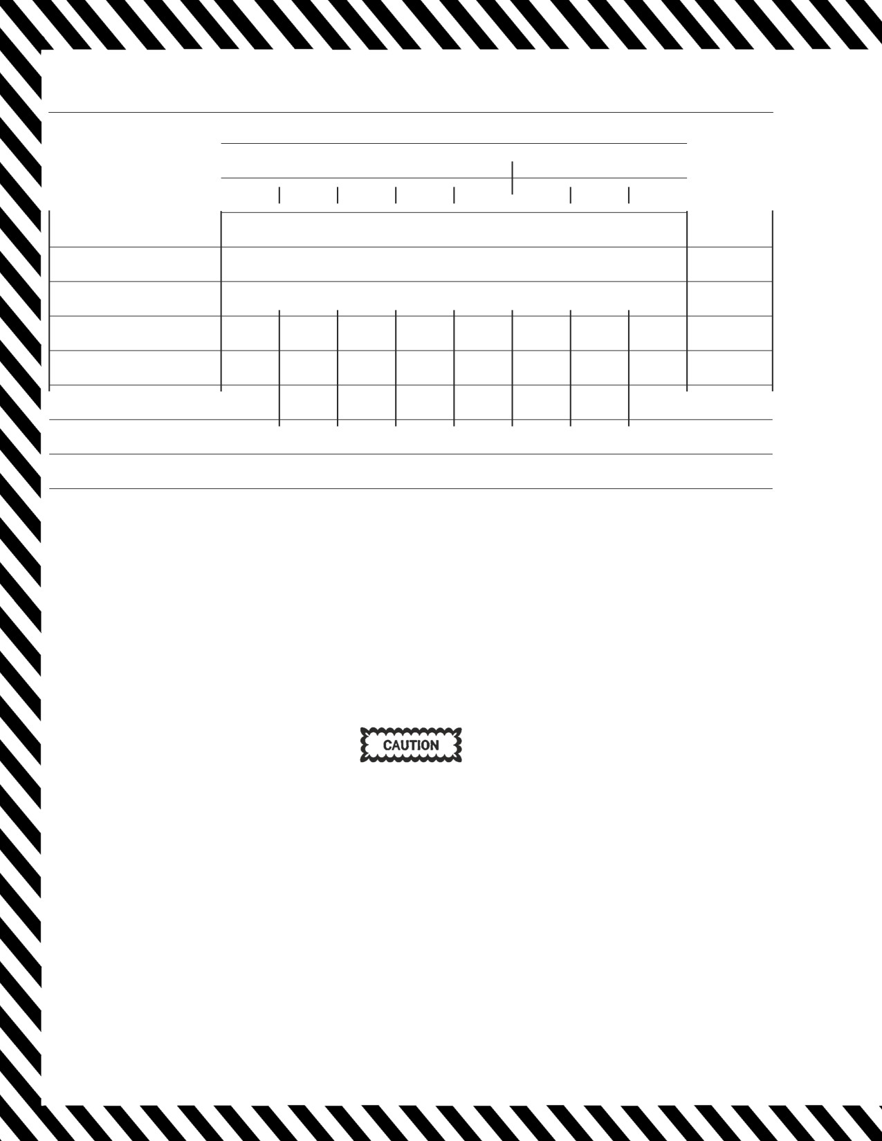
Gear Data charts, figure 16-5.
16.8.1 Arresting Gear Types. Field arresting gear includes anchor chain, water squeezer, and Morest
types. All types require arresting hook engagement with a crossdeck pendant cable rigged across the
runway. Arresting gear location varies as follows:
• SHORT FIELD - Located 1,500 to 2,000 feet past the approach end of the runway. May require
a request and slight delay to rig.
• MIDFIELD - Located near the halfway point of the runway. May require a request to rig for the
desired direction.
• LONG FIELD or ABORT - Located 1,500 to 2,000 feet short of the departure end of the runway.
Usually rigged for immediate use.
• OVERRUN - Located shortly past the departure end of runway. Usually rigged for immediate
use.
A field may have none, all, or any combination of these arresting gear types. Knowing the type,
location, and compatibility with the aircraft of the installed gear is mandatory. Knowing the local
policy for rigging installed gear is also required.
Wrong direction engagement of chain-type arresting gear can severely
damage the aircraft.
V-16-13
ORIGINAL
A1-F18EA-NFM-000
16.8.2 Arrestment Decision. The decision to take an arrested landing is dependent on the emergency
situation. In an emergency, use all available means to determine the status of the aircraft (instruments,
other aircraft, LSO, RDO, tower or other ground personnel). Typically, emergencies related to the loss
of the utility hydraulic system (e.g., loss of normal brakes and NWS), or to questionable braking, or
directional control (e.g., planing link failure, blown tire, or brake problem) dictate making an arrested
landing. If in doubt, a precautionary arrested landing is always prudent. If fuel is streaming, a field
arrested landing is not recommended due to the high probability that sparks and heat from the hook
may ignite the fuel.
Once the decision to arrest has been made, determine the best available arresting gear type and
location. Notify the control tower as far in advance as possible and give estimated time to landing in
minutes. Unrigged gear may require 10 to 20 minutes to rig. If winds are light and the emergency
situation dictates, the tower may request an arrested landing on an off-duty runway to retain the
capability to launch and recover other aircraft. If unfamiliar with arresting gear location, consider
making a practice pass.
Engage arresting gear on runway centerline, in the three-point attitude, as slow as practical, and with
feet off the brakes until engagement. After arrestment, common sense and conditions determine
whether to keep engines running or to shut down the engines and evacuate the aircraft.
16.8.3 Arrestment - Short Field. Make a short field arrested landing for anticipated directional
control or brake problems or if minimum rollout is desired. If available, request LSO assistance. The
LSO should have radio communications and be stationed near the touchdown point.
Inform the LSO of the intended touchdown point, if other than immediately before the gear. Lower
the hook before starting the approach and, if possible, get a positive hook down check.
Determine maximum engagement speed at the expected landing gross weight (see figure 16-5). Final
approach speed depends on flap setting and the specific emergency. If required, adjust gross weight to
minimize approach speed. A constant glideslope approach to touchdown is allowed (mirror or fresnel
lens if available). Plan the approach to touchdown on centerline at or just before the arresting wire. If
the required approach speed is in excess of maximum engaging speed, land short, select IDLE power,
and decelerate into the gear. Be prepared for nose gear tire failure above 195 KGS or main gear tire
failure above 210 KGS. Plan for a long field arrestment, if maximum short field engaging speed cannot
be met. If landing at or below maximum engaging speed, maintain approach power until arrestment is
assured. After engagement, retard the throttles to IDLE. Use moderate braking, if available, during
deceleration to prevent aircraft from two-blocking the arresting gear at higher engagement speeds or
gross weights. Secure engines and evacuate the aircraft, if required. If the wire is missed, waveoff
immediately.
16.8.4 Arrestment - Long Field. Make a long field arrestment when there is a stopping problem (e.g.,
aborted takeoff or loss of brakes with no loss of directional control, etc.). If possible, go around and
make a short field arrestment. Lower the hook in time for it to fully extend before engagement
(normally 1,000 feet prior to the arresting gear). Line up on runway centerline. If possible, inform the
control tower of intention to engage the long field gear, so that aircraft landing behind can be waved
off. Do not delay a decision to go around based solely on the availability of long field gear.
16.9 BARRICADE ARRESTMENT
If a barricade arrestment is required, the LSOs will give a detailed briefing of barricade procedures.
1. Burn down or dump fuel as required to obtain the lowest gross weight feasible.
V-16-14
ORIGINAL
A1-F18EA-NFM-000
2. External ordnance - JETTISON
3. External fuel tanks - JETTISON EXCEPT AS NOTED IN LANDING GEAR MALFUNCTION
- LANDING GUIDE - CARRIER LANDING
NOTE
Barricade engagement with installed AIM-7, AIM-120 and/or AIM-9
missiles is not recommended. AIM-7
and AIM-120
missiles may
separate and AIM-9 missiles will probably separate from the aircraft.
Inability to jettison/fire these missiles does not preclude successful
barricade engagement. Barricade may be engaged with empty external
tanks if tanks cannot be jettisoned. When live ordnance cannot be
jettisoned, barricade engagement should only be attempted with all
landing gear down.
4. Fly an on-speed, on-glideslope, on-centerline approach with zero drift all the way to touchdown.
When ″Cut-Cut″ called by LSOs -
5. Throttles - OFF
When aircraft motion ceases -
6. Egress.
16.10 CV RECOVERY MATRIX
See figure 16-6 for the CV recovery matrix.
V-16-15
ORIGINAL
A1-F18EA-NFM-000
AIRCRAFT GROSS WEIGHT (x 1,000 POUNDS)
MAXIMUM
LANDING
ABORTED TAKEOFF (3)
OFF-CENTER
TYPE OF
ENGAGE-
ARRESTING GEAR
MENT
31.5
35
40
45
50.6
55
60
66
(FEET)
MAXIMUM ENGAGING SPEED (Knots Groundspeed) (1)
E-28 (2)
170
170
170
170
170
156
138
130
40
M-21
150
150
145
140
130
125
120
115
10
M-31
158
158
158
120
120
150
150
150
10
BAK-9
160
160
160
160
158
148
138
128
30
BAK-12 (4)
160
160
160
160
150
132
(4)
(4)
50
DUAL BAK-12 (5)
160
160
160
160
160
160
160
160
30
BAK-13
160
160
160
160
160
156
138
130
40
NOTE
(1) Maximum engaging speed limited by arresting gear capacity, except where noted.
(2) Also for the E-28 systems at Keflavik and Bermuda (standard installations or with 920 foot tapes).
(3) Data provided in aborted takeoff column may be used for emergency high gross weight arrestment.
(4) Standard BAK-12 limits are based on 150 foot span, 1 inch cross deck pendant, 40,000 pound weight setting,
and 950 foot runout. No information available regarding applicability to other configurations. BAK-12
engaging speed limit is 96 knots at 59,000 pounds. Due to runout limitations, it is recommended this gear not
be engaged at weights greater than 59,000 pounds.
(5) Dual BAK-12 limits are based on 150 to 300 foot span, 1-1/4 inch cross deck pendant, 50,000 pound weight
setting, and 1,200 foot runout. No information available regarding applicability to other configurations.
For E-28 or BAK-13 arresting gear systems, two-blocking can occur at
aircraft weights above 50,000 pounds and at engaging speeds above 130
knots. Moderate braking should be utilized during deceleration, if avail-
able, to aid in stopping the forward motion of the aircraft and prevent an
aircraft with idle power from slowly pulling the gear to a two-block
position. If a two-block occurs and aircraft travel reverses, engine thrust
should be applied judiciously to minimize aircraft walkback. Brakes, if
available, should not be utilized during aircraft walkback, as they may
induce the aircraft to tip back onto the exhaust nozzles.
Figure 16-5. Field Arresting Gear Data (Sheet 1 of 2)
V-16-16
ORIGINAL

A1-F18EA-NFM-000
FOR E-5 CHAIN EMERGENCY ARRESTING GEAR
ARRESTING
LANDING or ABORTED
LANDING or ABORTED
ABORTED TAKEOFF
GEAR
TAKEOFF UP TO 44,000 LB
TAKEOFF UP TO 50,600 LB
50,700 to
66,000 LB
RATING
STD Chain
Heavy Chain
STD Chain
Heavy Chain
STD Chain
Heavy Chain
E-5
E-5-1
E-5
E-5-1
E-5
E-5-1
E-5
E-5-1
E-5
E-5-1
E-5
E-5-1
E-5-2
E-5-3
E-5-2
E-5-3
E-5-2
E-5-3
E-5-2
E-5-3
E-5-2
E-5-3
E-5-2
E-5-3
FEET of CHAIN
MAXIMUM ENGAGING SPEED (Knots Groundspeed)
300-349
43
43
44
44
40
40
41
41
35
35
36
36
350-399
50
50
51
51
46
46
48
48
40
40
42
42
400-449
56
56
59
59
53
53
55
55
46
46
49
49
450-499
63
63
67
67
59
59
63
63
51
51
55
55
500-549
69
69
76
76
65
65
71
71
57
57
62
62
550-599
76
76
84
84
71
71
78
78
63
63
69
69
600-649
82
82
92
92
77
77
86
86
68
68
76
76
650-699
88
88
101
101
83
83
94
94
74
74
83
83
700-749
95
95
109
109
89
89
102
102
79
79
90
90
750-799
101
101
118
118
95
95
110
110
85
85
97
97
800-849
107
107
127
127
101
101
119
119
91
91
104
104
850-899
114
114
136
136
107
107
127
127
96
96
112
112
900-949
120
120
145
145
114
114
135
135
102
102
119
119
950-999
127
127
150
154
120
120
144
144
108
108
127
127
1000-1049
133
133
150
163
126
126
150
153
113
113
134
134
1050-1099
139
139
150
165
132
132
150
161
119
119
142
142
1100
146
146
150
165
138
138
150
165
125
125
149
149
NOTE
• Maximum engaging speed for E-5 chain gear is limited by arresting gear capacity.
• Off center engagement into an E-5 system must not exceed 25% of the runway span.
• Before making an E-5 arrestment, confirm the type and chain length of installed gear (tower or
FLIP IFR Supplement) to ensure the corresponding maximum engaging speed is not exceeded.
Figure 16-5. Field Arresting Gear Data (Sheet 2 of 2)
V-16-17
ORIGINAL

A1-F18EA-NFM-000
Malfunction
Pages NFM-000/-500
Divert
Pull Fwd
Next Avail
Normal
Notes
ENGINES
Bleed Warning
V-12-3, -4/E56, E57
X
1, 2, 5
Engine Fire
V-12-4/E58
X
1, 2, 5
Single Engine
V-16-1/E30
X
2, 5, 9
Engine Stall
V-12-32/E101
X
2, 5, 9
AMAD PR Caution
V-12-7/E63
X
2,5
ATS Caution
V-12-9/E67
X
Dual BLD OFF Cautions (both BLEED
V-12-12/E70
X
11
Warn Lights Out)
BOOST LO Caution
V-12-13/E71
X
6
ENG Caution
V-12-17/E78
X
2, 5, 9
OIL PR Caution
V-12-29/E97
X
2, 5, 9
FUEL
Fuselage Fuel Leak
V-15-4/E6
X
3
DUMP OPEN Caution
V-12-16/E76
X
3, 7
FUEL INLT Caution
V-12-20/E84
X
2, 5, 9
FUEL LO Caution
V-12-20/E84
X
3
FUEL HOT Caution
V-12-20/E83
X
FUEL XFER Caution
V-12-21/E85
X
THERMAL Caution
V-12-33/E102
X
2, 5, 9
HYDRAULIC
Triple HYD Circuit Cautions
V-12-56/E140
X
2, 5
HYD 1A/2B Circuit Cautions
V-12-52/E134
X
2
All Other Dual HYD Circuit Cautions
V-12-50, -55/E132 - E139
X
2, 5, 9
Single HYD Circuit Caution
V-12-48,-49/E129 - E131
X
2, 5, 9
APU ACCUM Caution
V-12-8/E65
X
2
BRK ACCUM Caution
V-12-13/E72
X
2
HYD HOT Caution
V-12-63/E148
X
2, 5, 9
ELECTRICAL
AV AIR HOT Caution
V-12-10/E68
X
Dual GEN Cautions
V-12-22/V-15-11/E11, E86
X
2, 4, 5, 8, 11
V-12-22/V-15-13, -14/E14,
Single GEN Caution
X
E15, E86
Dual T/R Failure
V-15-12/E8
X
2, 5, 8, 11
DC FAIL Caution
V-12-15/E75
X
CAUT DEGD Caution
V-12-14/E73
X
FCS
AHRS Four Channel Failure
V-12-37/E107
X
FCS HOT Caution
V-12-42/E115
X
AHRS 1/2 Channel Failure
V-12-36/E106
X
FC AIR DAT Caution
V-12-41/E113
X
9
FCES Caution
V-12-35/E105
X
9
FLAPS OFF (LEF Fail) Caution
V-12-43/E116
X
9
FLAPS OFF (TEF Fail) Caution
V-12-44/E118
X
10
FLAP SCHED Caution
V-12-45/E120
X
9
Loss Of Any Control Surface
V-12-35/E105
X
9
MISCELLANEOUS
BAY FIRE Caution
V-12-11/E69
X
BAY DISCH Caution
V-12-10/E69
X
Blown Tire
V-14-4/E19
X
2
L BAR Warning
V-12-6/E60
X
Remove CDP 1
and 4
2, Refer to Figure 16-2.
Landing Gear Failure
V-16-9/E26
X
Landing Gear Malfunction -
Landing Guide
Planing Link Failure
V-16-12/E16
X
2
OBOGS DEGD Caution
V-12-28/E96
X
SDC Failure
I-2-22, I-2-171
X
Birdstrike
12
NOTES:
1. Aircraft will be flying a half flap straight-in. Approach speed will be higher, therefore wind over deck requirements will increase. Consult applicable ARB
for details. Possibility of malfunction affecting other engine. Make sure all possible effort is made to recover aircraft immediately.
2. Aircraft may require a tow out of the landing area.
3. Immediate tanking required if any delay in recovery exists.
4. Pilot will be unable to fold wings upon landing.
5. For HYD 2A or Dual T/R failure, landing gear will be emergency extended and aircraft will be committed to a dirty bingo if unable to recover. Consider
bingo options before extending landing gear.
6. Problem could be symptomatic of a fuel leak. If so, immediate recovery is required.
7. Approximately 4,400 pounds of fuel will be available in the engine feed tanks.
8. If battery gauge reads 24 volts (LOT 22 and up), or BATT SW caution light on (LOT 21), the essential bus is being powered by the aircraft battery and 5
to 10 minutes of flight remains.
9. Aircraft will be flying straight-in approach. If half-flap approach required, approach speed will be higher. Consult applicable ARB for WOD requirements.
10. Aircraft will be flying 10° AOA full or half flap straight-in approach. Approach speed will be higher; therefore, wind over deck requirements will increase.
Recovery WOD should be kept as close as possible to ARB recommendations.
11. Unable to transfer external fuel. Consider divert or jettison of external tanks.
12. Decision for Pull Fwd or Next Avail recovery determined by nature of damage sustained during birdstrike. Refer to appropriate emergency on recovery
matrix.
Figure 16-6. CV Recovery Matrix
V-16-18
ORIGINAL

A1-F18EA-NFM-000
CHAPTER 17
Ejection
17.1 EJECTION
The ejection seat must be used to escape from the aircraft in flight. If the canopy fails to jettison
during the ejection sequence, the seat will eject through the canopy.
17.1.1 Ejection Seat Restrictions. During ejection seat development and testing, the SJU-17(V) 1/A,
2/A, and 9/A NACES seats were qualified for use by aviators with nude weights from 136 to 213
pounds, while the SJU-17A (V)1/A, 2/A, and 9/A NACES seats were qualified for use by aviators with
nude body weights from 136 to 245 pounds. The minimum and maximum nude body weights allowed
by OPNAVINST 3710.7 Series for those on aviation duty are 100 pounds and 235 pounds, respectively.
Therefore, a gap exists between the ejection seat certified weight range and the weights of the current
aviator population.
• Operation of the ejection seat by personnel weighing less than the
qualified minimum nude weight, or more than the maximum qualified
weight (noted above), subjects the occupant to increased risk of injury.
• An increased risk of severe injury or death during parachute landing fall
(PLF) exists with surface winds exceeding 25 knots. High surface winds
contribute directly to total landing velocity. When time permits, select
parachute steering and turn into the wind to reduce landing velocity.
• Pilots should be trained in additional ejection risks associated with
JHMCS. Ejection with JHMCS may cause severe or fatal injury.
The ejection seat catapult was designed for the qualified weight range only. Ejection seat stability
is directly related to occupant restraint. All occupants should be properly restrained in the seat by the
torso harness for optimum performance and minimum injury risk. Inertial reel performance may be
degraded for occupants outside of the certified weight range
17.1.1.1 Injury Risks - Nude Weight Less than 136 Pounds. Lighter weight occupants are subject to
a higher risk of injury due to the following factors:
1. Excessive pull back during inertial reel retraction.
2. Poor positioning during ejection.
3. Greater acceleration during catapult firing.
4. Higher parachute opening shock during ejections near the upper end of Mode 1 (approaching 300
KCAS).
V-17-1
ORIGINAL
A1-F18EA-NFM-000
5. Seat instability during drogue deployment during ejections above 300 KCAS.
Lighter weight aircrew have greater risk of neck injury during ejection
while using the JHMCS configuration. Minimum nude aircrew weights
authorized to fly with the JHMCS helmet system is 136 pounds. Aircrew
weighing less than the authorized minimum nude weight are restricted
from flying with the JHMCS helmet system.
17.1.1.2 Injury Risks - Nude Weight Greater than 213 Pounds (245 Pounds for SJU-17A). Heavier
weight occupants are subject to a higher risk of injury due to the following factors:
1. Poor positioning during ejection due to insufficient pull back during inertial reel retraction.
2. Insufficient altitude to clear the aircraft tail structure.
3. Insufficient altitude for full parachute inflation in zero/zero cases or at extremely low altitude/
airspeed.
4. Higher descent rates during parachute landing.
17.1.1.3 Airspeed during Ejection. Ejection analysis shows:
1. Optimum speed for ejection is 250 KCAS and below.
2. Between 250 and 600 KCAS, appreciable forces are exerted on the body, making ejection more
hazardous.
3. Above 600 KCAS, excessive forces are exerted on the body making ejection extremely hazardous.
When possible, slow the aircraft before ejection to reduce the forces on the body.
Never actuate the manual override handle in flight, as ejection would then be impossible and the
aircrew would be unrestrained during landing. When the manual override handle is actuated, the
ejection seat SAFE/ARMED handle is rotated to the SAFE position, the aircrew is released from the
seat, and the harness cannot be reconnected.
If the seat becomes unlocked and slides partially up the rails, ejection
and/or parachute deployment is still possible but the ejection handle
must be pulled, followed by activation of the manual override handle.
Under these circumstances, low altitude ejection capabilities are compro-
mised.
V-17-2
ORIGINAL

A1-F18EA-NFM-000
Whenever possible, ejection airspeed should be limited to a maximum of 400 KCAS when flying with
the JHMCS helmet system.
The JHMCS configuration can contribute to increased neck loads during
ejection, particularly at moderate to high speeds. Generally, neck loads
increase as ejection airspeed increases and may cause severe or fatal
injury. Aircrews should eject at the lowest possible airspeed to minimize
neck and injury loads.
NOTE
Aircrew will brief system peculiarities and potential injury from out of
position and high speed ejections prior to each flight when using
A/A24A-56 JHMCS lightweight HGU-55 A/P helmet.
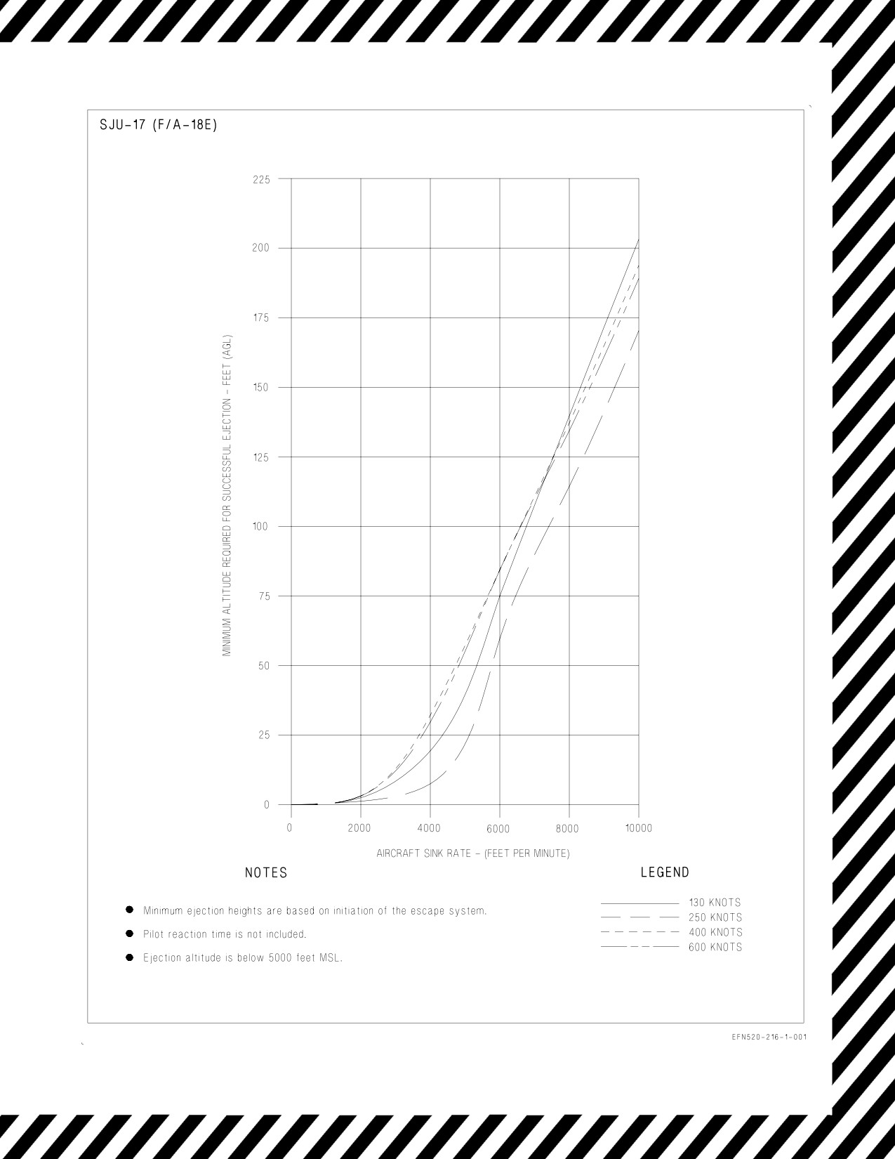
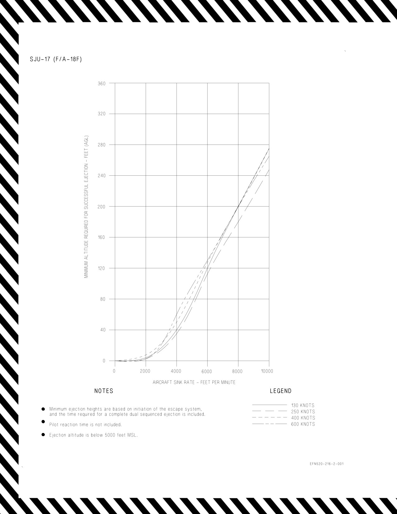
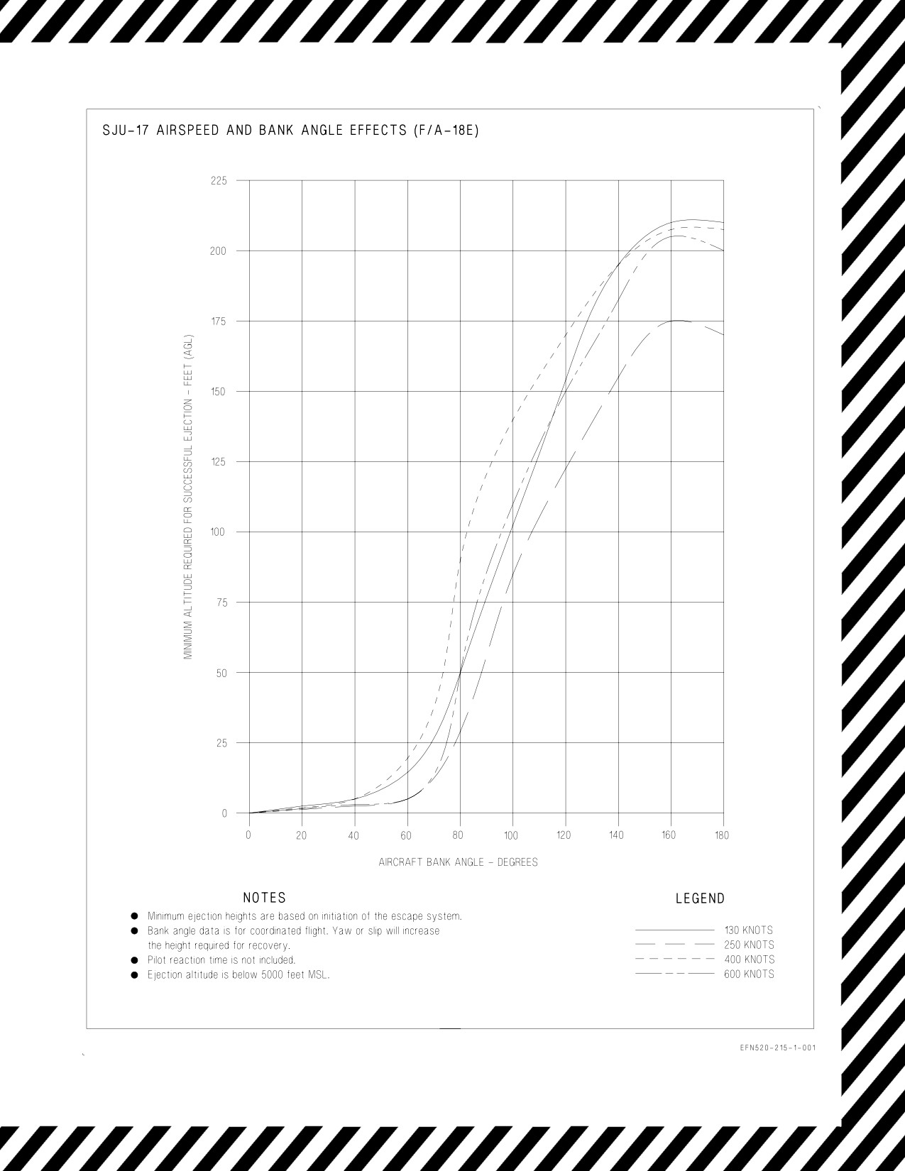
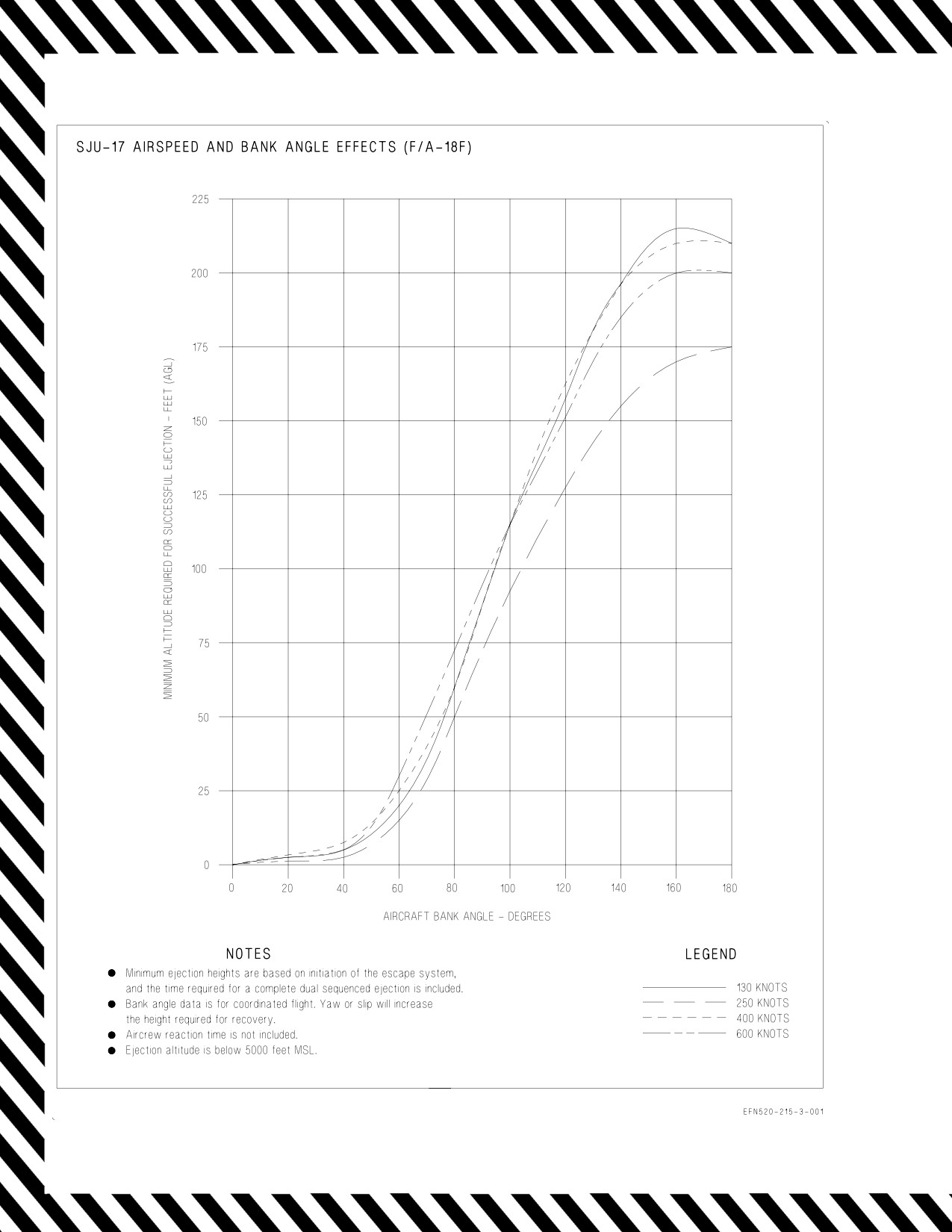
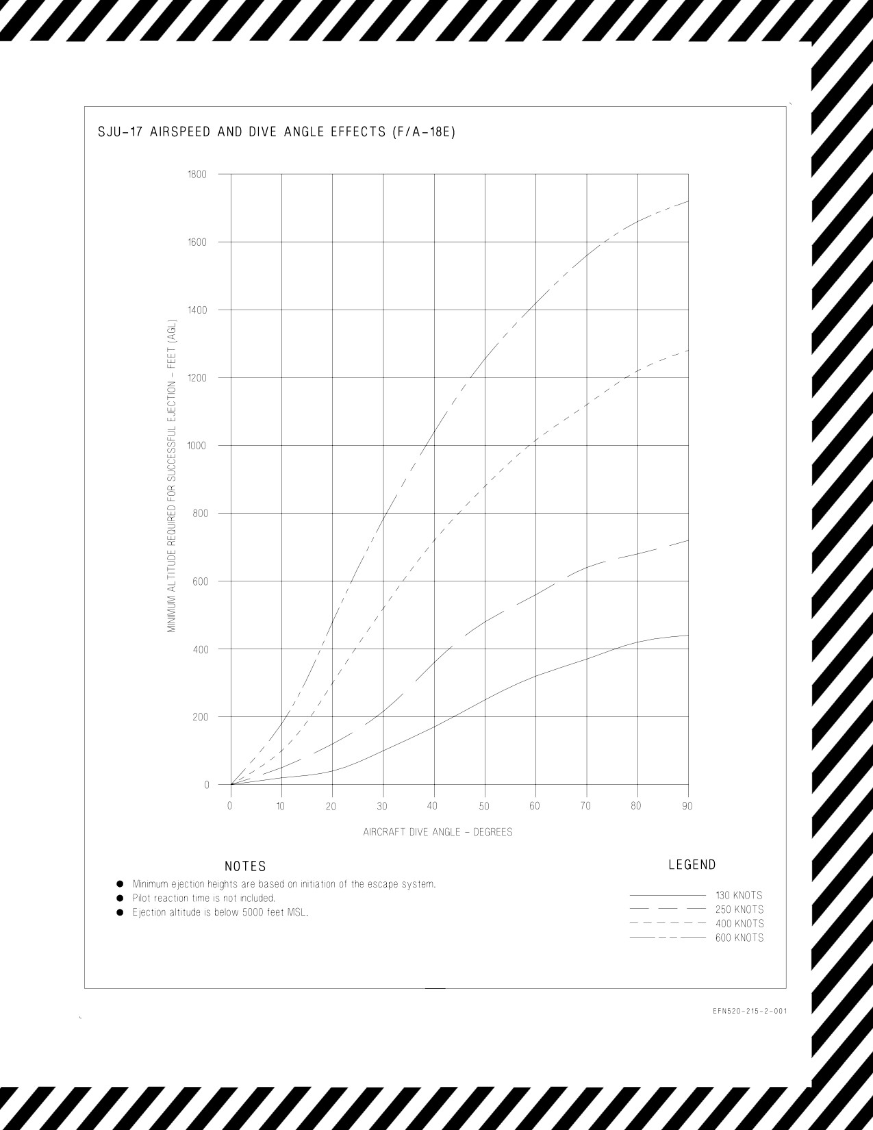
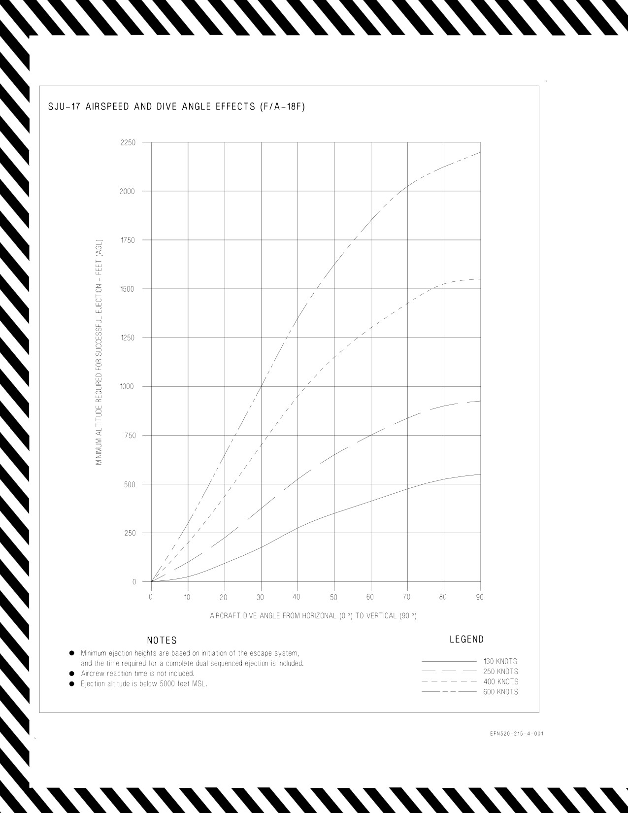
17.1.2 Low Altitude Ejection. The minimum altitude required for a successful ejection is dependent
on sink rate, airspeed and bank angle, and airspeed and dive angle. The effects of sink rate are shown
in figure 17-1. The effects of airspeed and bank angle are shown in figure 17-2. The effects of airspeed
and dive angle are shown in figure 17-3.
The decision to eject at low altitude must be based on these factors to ensure a successful ejection.
Additionally, ejection seat trajectory is improved if the aircraft is zoomed to a higher altitude prior to
ejection initiation. The additional altitude increases time available for seat separation and parachute
deployment. However, do not delay the decision to eject if the aircraft is nose down and cannot be
leveled.
With wings level and no sink rate, ejection is feasible within the following parameters:
1. Ground level - zero airspeed.
2. Surface to 50,000 feet MSL - 600 KCAS maximum.
Ejection at low altitude allows only a matter of seconds to prepare for landing. Over water, inflation
of the LPU is the most important step to be accomplished. Release of the parachute quick-release
fittings as the feet contact the water is the second most important step to prevent entanglement in the
parachute shroud lines.
When ejection is in the immediate vicinity of the carrier, parachute entanglement combined with
wake and associated turbulence can rapidly pull a survivor under. The deployed seat survival kit may
contribute to shroud line entanglement. Be prepared to cut shroud lines if the parachute is dragging
the survivor.
The crashed aircraft may release large quantities of jet fuel and fumes which could hamper breathing
and/or create a fire hazard. If jet fuel is present, do not use a flare marker. The emergency oxygen
V-17-3
ORIGINAL
A1-F18EA-NFM-000
system may be invaluable in this case. If emergency oxygen is required, do not discard the survival kit,
as this terminates the availability of emergency oxygen. However, totally discarding the survival kit
may be appropriate after considering weather, sea conditions, and rescue potential.
Low altitude ejection may result in parachute canopy disintegration due
to the aircraft impact fireball.
The variety and complexity of conditions encountered during the “time critical” actions following a
low altitude, overwater ejection make it impossible to formulate procedures to cover every contingency.
17.1.3 High Altitude Ejection. The basic low altitude procedure is applicable to high altitude
ejection. The zoom is useful to slow the aircraft to a safer ejection speed or to provide more time and
glide distance if immediate ejection is not necessary. If the aircraft is descending out of control, eject
by 6,000 feet AGL. Even if under control, do not delay ejection below 2,000 feet AGL. Head the aircraft
toward an unpopulated area, if possible.
17.1.4 Ejection Procedures. See figure 17-4.
17.2 DITCHING
In the event ejection has failed and the aircraft must be ditched, see figure 17-5.
17.3 SEAWATER ENTRY
If downed in seawater, SEAWARS releases the parachute canopy within 2 seconds. However, if able,
manually unlock each canopy release immediately on seawater entry. The SEAWARS does not operate
in freshwater.
V-17-4
ORIGINAL
A1-F18EA-NFM-000
Figure 17-1. Sink Rate Effects on Minimum Ejection Altitude (Sheet 1 of 2)
V-17-5
ORIGINAL
A1-F18EA-NFM-000
Figure 17-1. Sink Rate Effects on Minimum Ejection Altitude (Sheet 2 of 2)
V-17-6
ORIGINAL
A1-F18EA-NFM-000
Figure 17-2. Airspeed and Bank Angle Effects on Minimum Ejection Altitude (Sheet 1 of 2)
V-17-7
ORIGINAL
A1-F18EA-NFM-000
Figure 17-2. Airspeed and Bank Angle Effects on Minimum Ejection Altitude (Sheet 2 of 2)
V-17-8
ORIGINAL
A1-F18EA-NFM-000
Figure 17-3. Airspeed and Dive Angle Effects on Minimum Ejection Altitude (Sheet 1 of 2)
V-17-9
ORIGINAL
A1-F18EA-NFM-000
Figure 17-3. Airspeed and Dive Angle Effects on Minimum Ejection Altitude (Sheet 2 of 2)
V-17-10
ORIGINAL
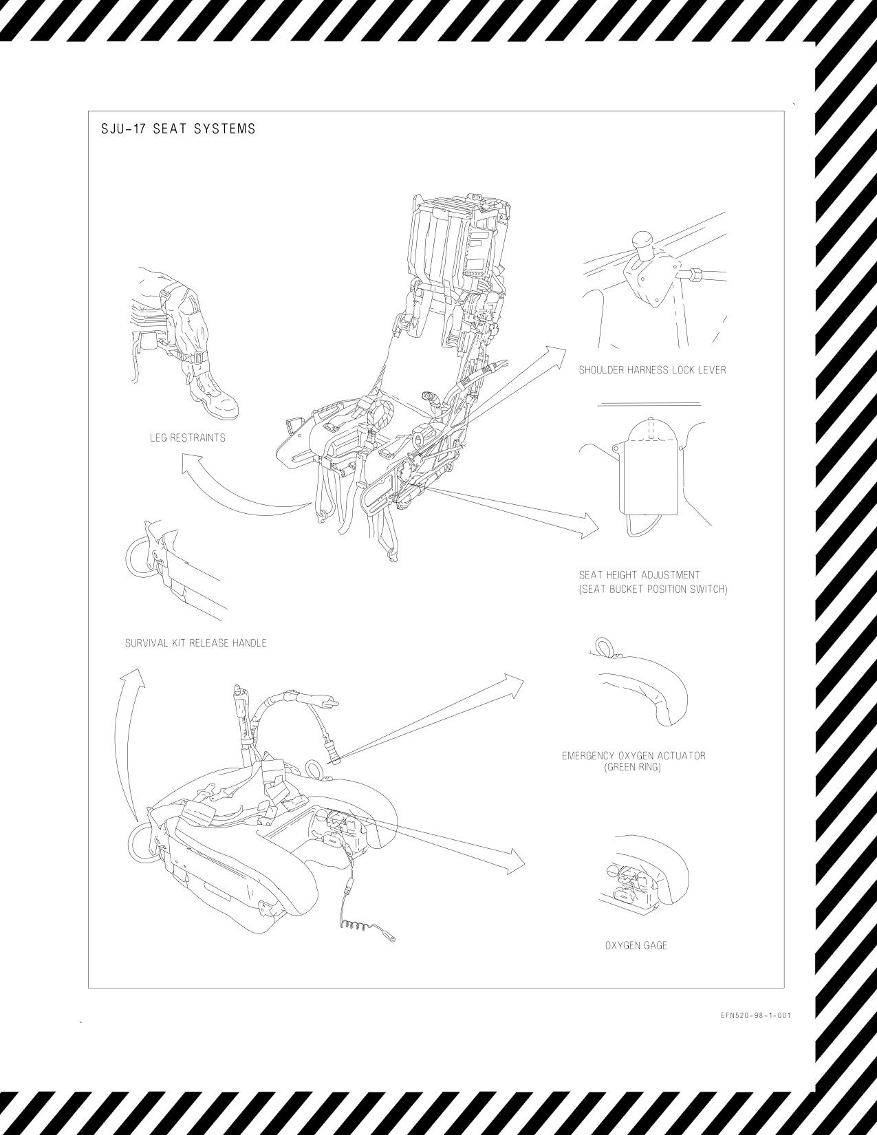
A1-F18EA-NFM-000
Figure 17-4. Ejection Procedures (Sheet 1 of 13)
V-17-11
ORIGINAL
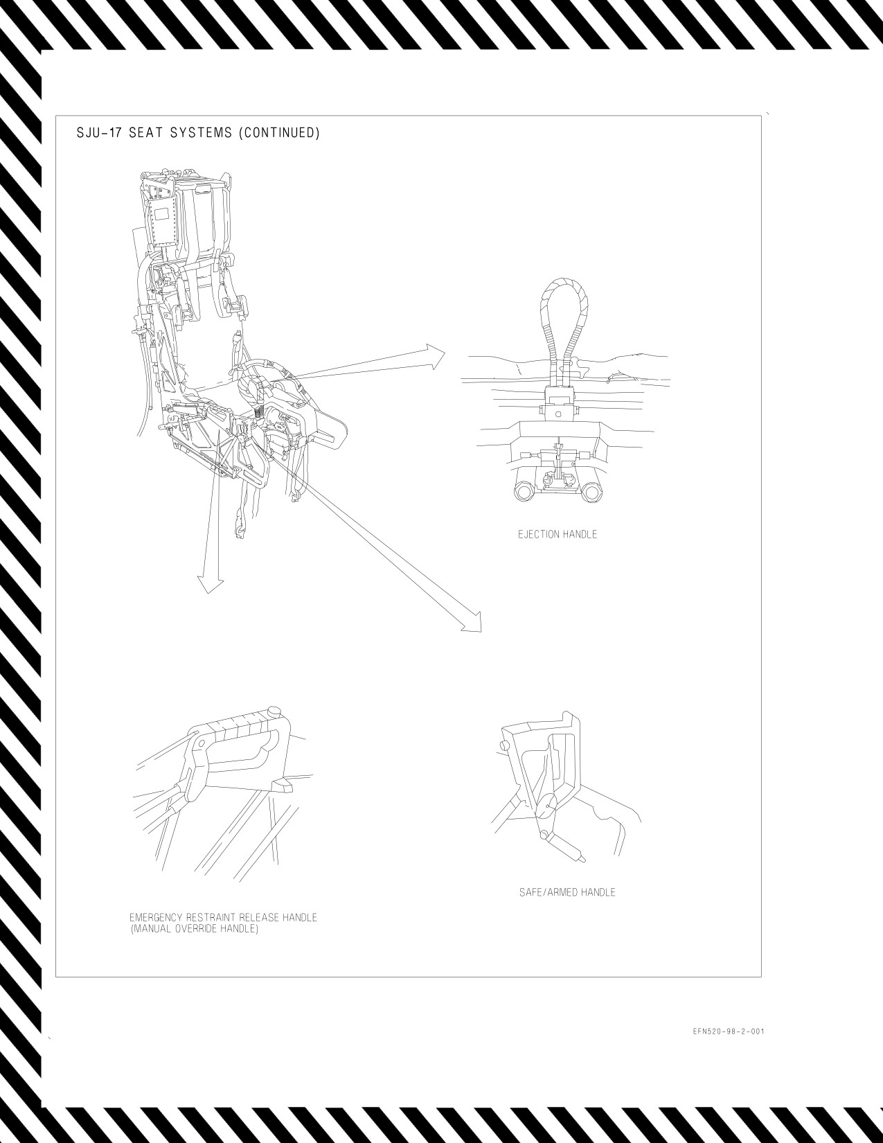
A1-F18EA-NFM-000
Figure 17-4. Ejection Procedures (Sheet 2 of 13)
V-17-12
ORIGINAL
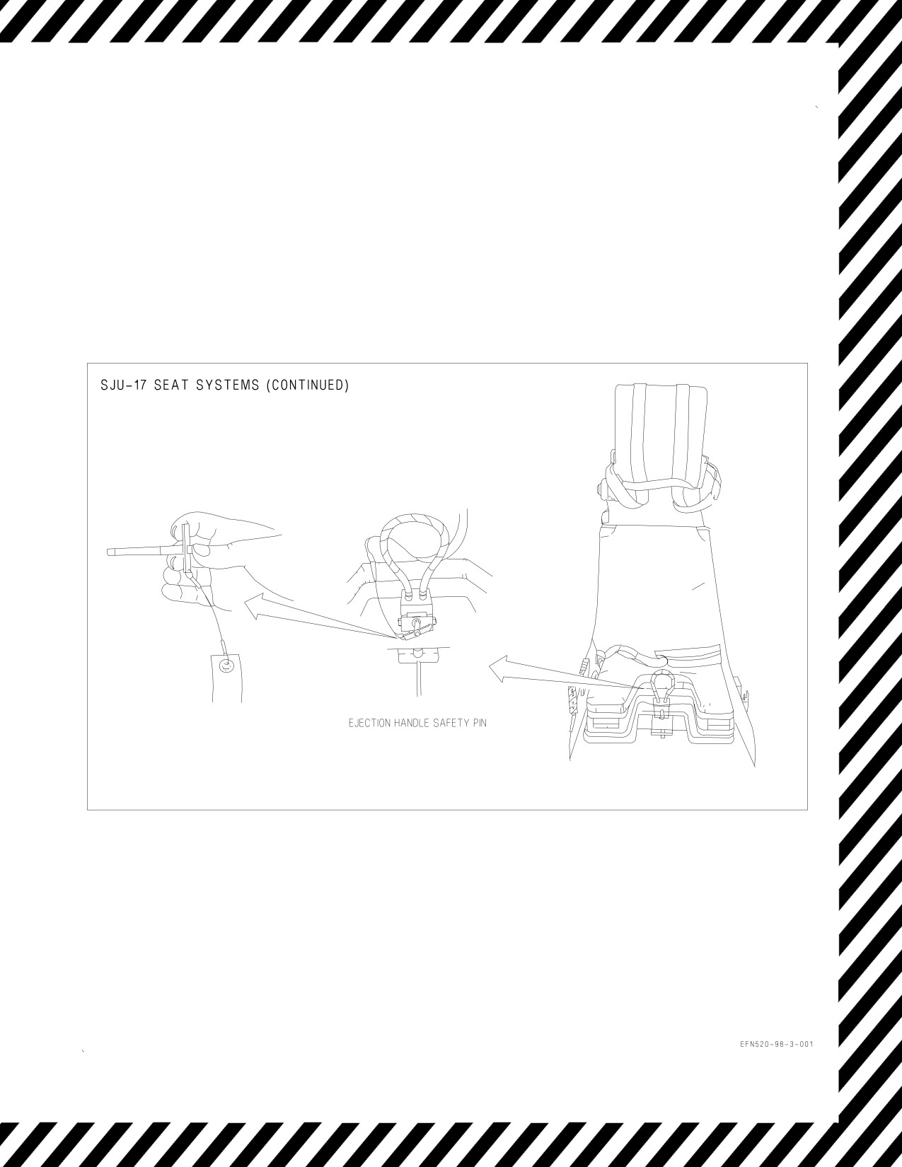
A1-F18EA-NFM-000
Figure 17-4. Ejection Procedures (Sheet 3 of 13)
V-17-13
ORIGINAL
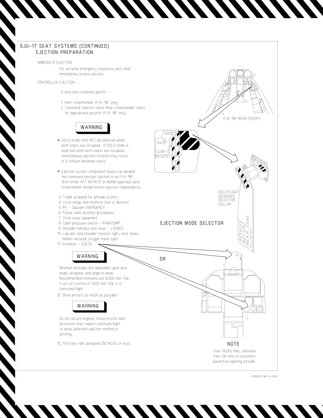
A1-F18EA-NFM-000
Figure 17-4. Ejection Procedures (Sheet 4 of 13)
V-17-14
ORIGINAL

A1-F18EA-NFM-000
SJU-17
Ejection Preparations
EJECTION INJURIES AND BODY POSITIONING
THESE PROPER BODY POSITIONS
MUST BE TAKEN TO PREVENT INJURIES
1. Press head firmly against headrest.
5. Press buttocks firmly against the seat back.
2. Elevate chin slightly (10°).
6. Place thighs flat against seat.
3. Press shoulders and back firmly against seat.
7. Press outside of thighs against side of seat.
4. Hold elbows and arms firmly towards sides.
8. Place heels firmly on deck, toes on rudder pedals.
If ejection occurs without QDC properly stowed in QMB, death will
probably result from neck injury.
EJECTION INITIATION
There are two acceptable methods for ejection initiation; the two-hand grip and the
single-hand grip.
Two-hand method -
1. Grip the ejection handle with the thumb and at least two fingers of each hand, palms
toward body.
Keep elbows close to body.
Single-hand method -
1. Grip handle with the strong hand, palm toward body. Grip wrist of strong hand with
other hand, palm toward body. Keep elbows close to body.
Both methods -
2. Pull handle sharply up and toward abdomen, keeping elbows in. Ensure handle
pulled to end of travel. Continue holding handle until seat/man separation.
NOTE
In low altitude situations, a one-handed method, using one hand to initiate
ejection and the other to maintain the aircraft in the safe operating envelope of
the ejection seat, may be required. If firing the seat by this method, particular
attention must be paid to maintaining proper body position.
Figure 17-4. Ejection Procedures (Sheet 5 of 13)
V-17-15
ORIGINAL
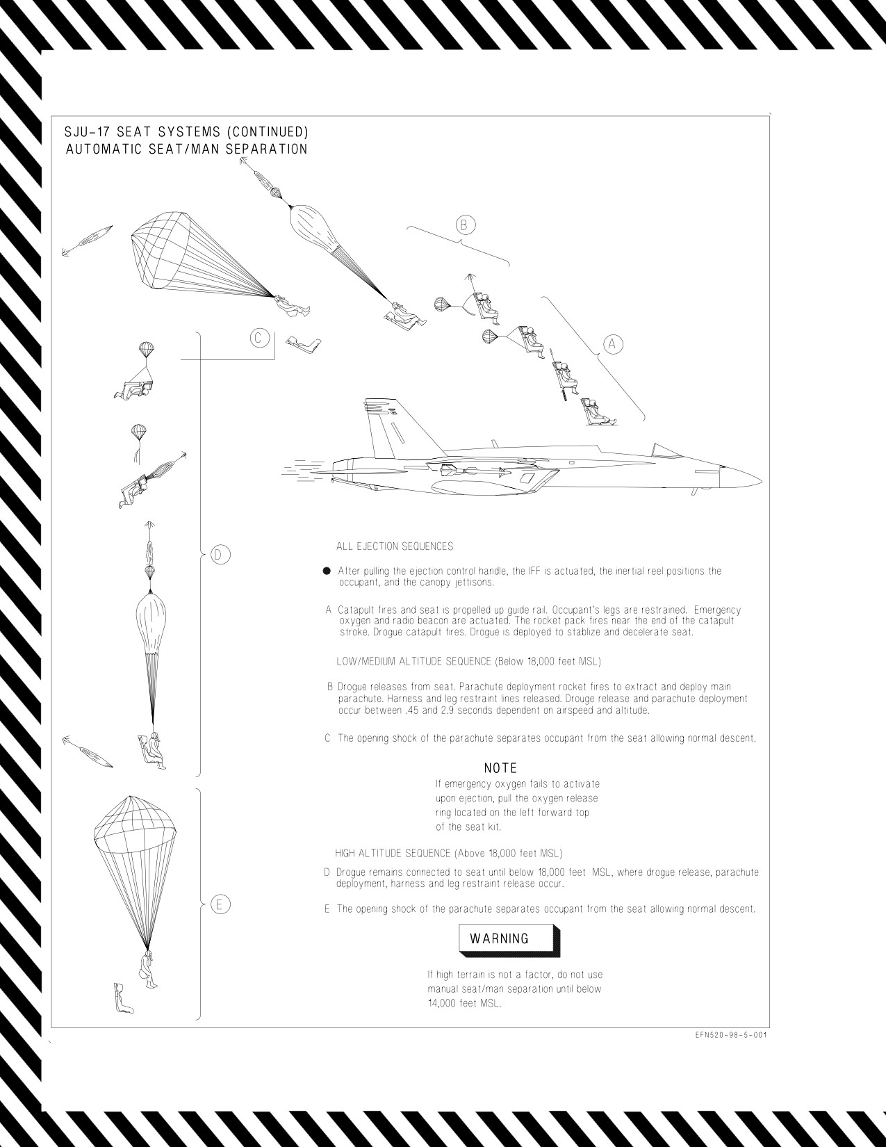
A1-F18EA-NFM-000
Figure 17-4. Ejection Procedures (Sheet 6 of 13)
V-17-16
ORIGINAL
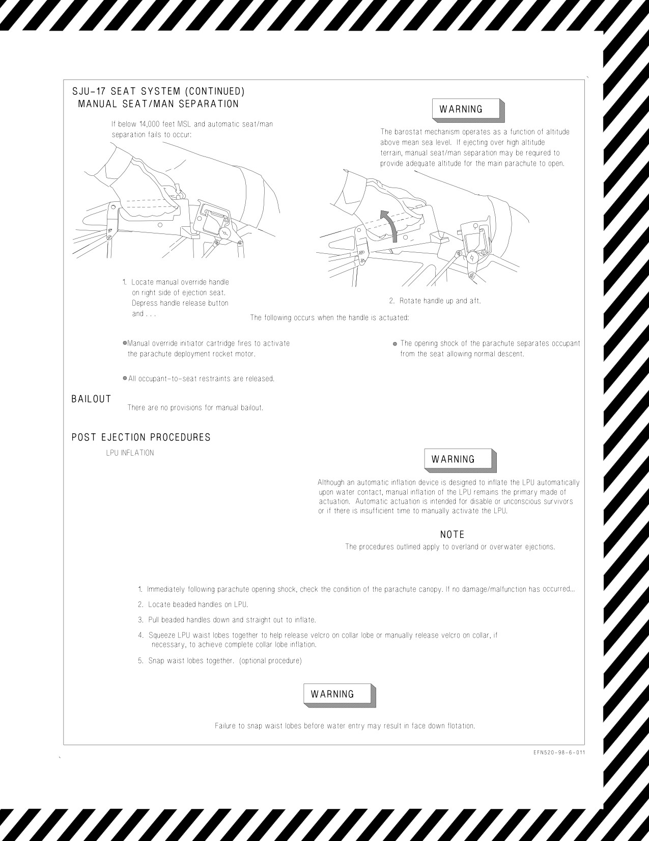
A1-F18EA-NFM-000
Figure 17-4. Ejection Procedures (Sheet 7 of 13)
V-17-17
ORIGINAL
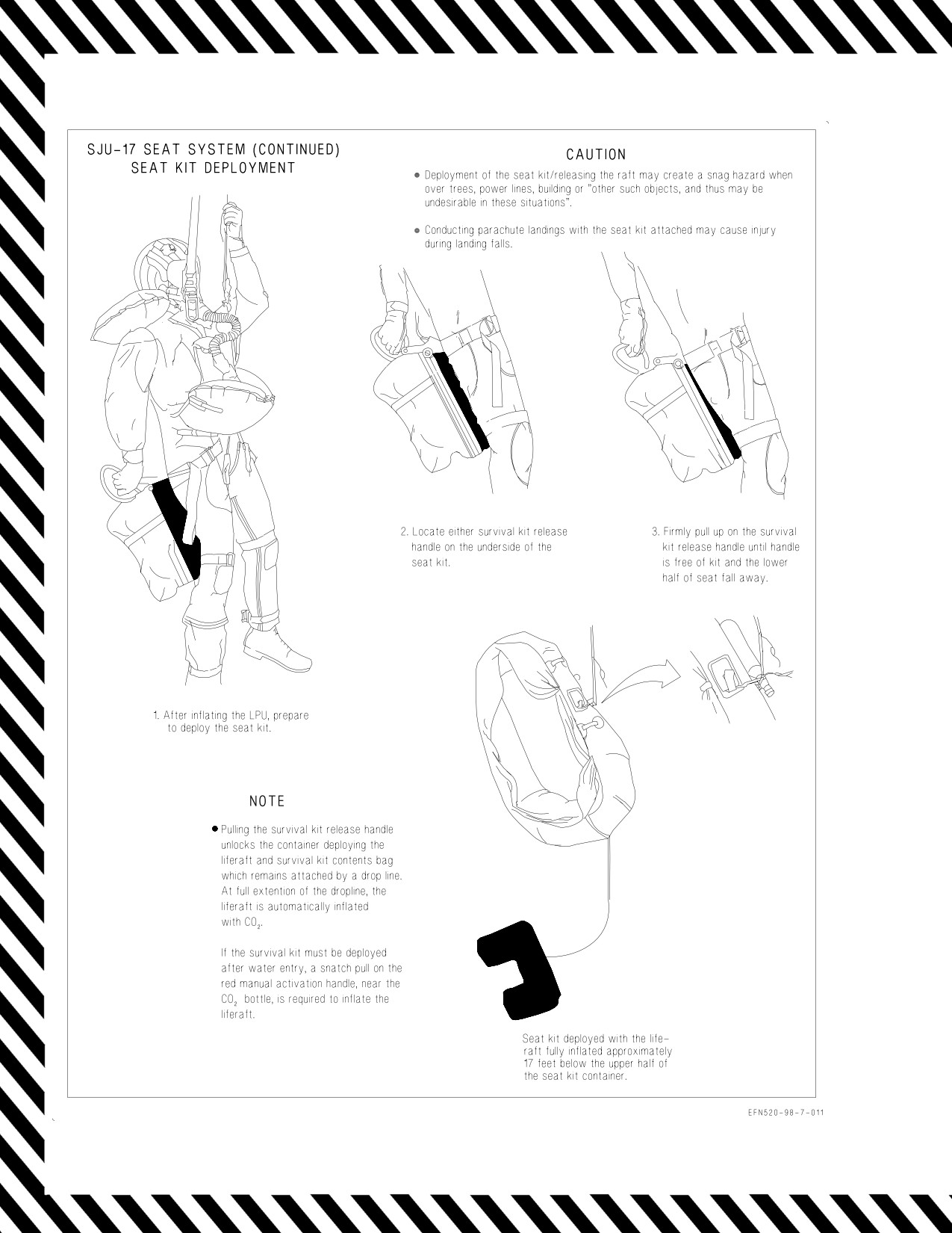
A1-F18EA-NFM-000
Figure 17-4. Ejection Procedures (Sheet 8 of 13)
V-17-18
ORIGINAL
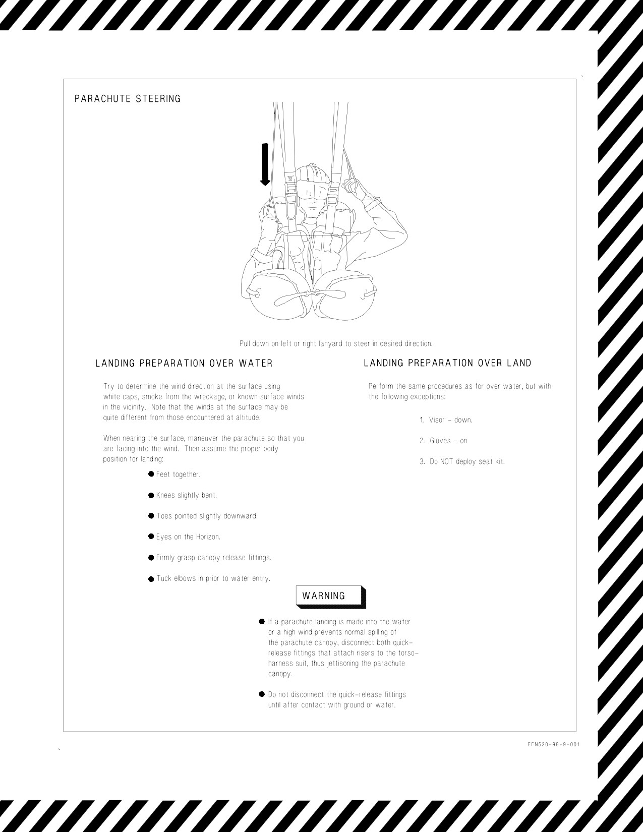
A1-F18EA-NFM-000
Figure 17-4. Ejection Procedures (Sheet 9 of 13)
V-17-19
ORIGINAL
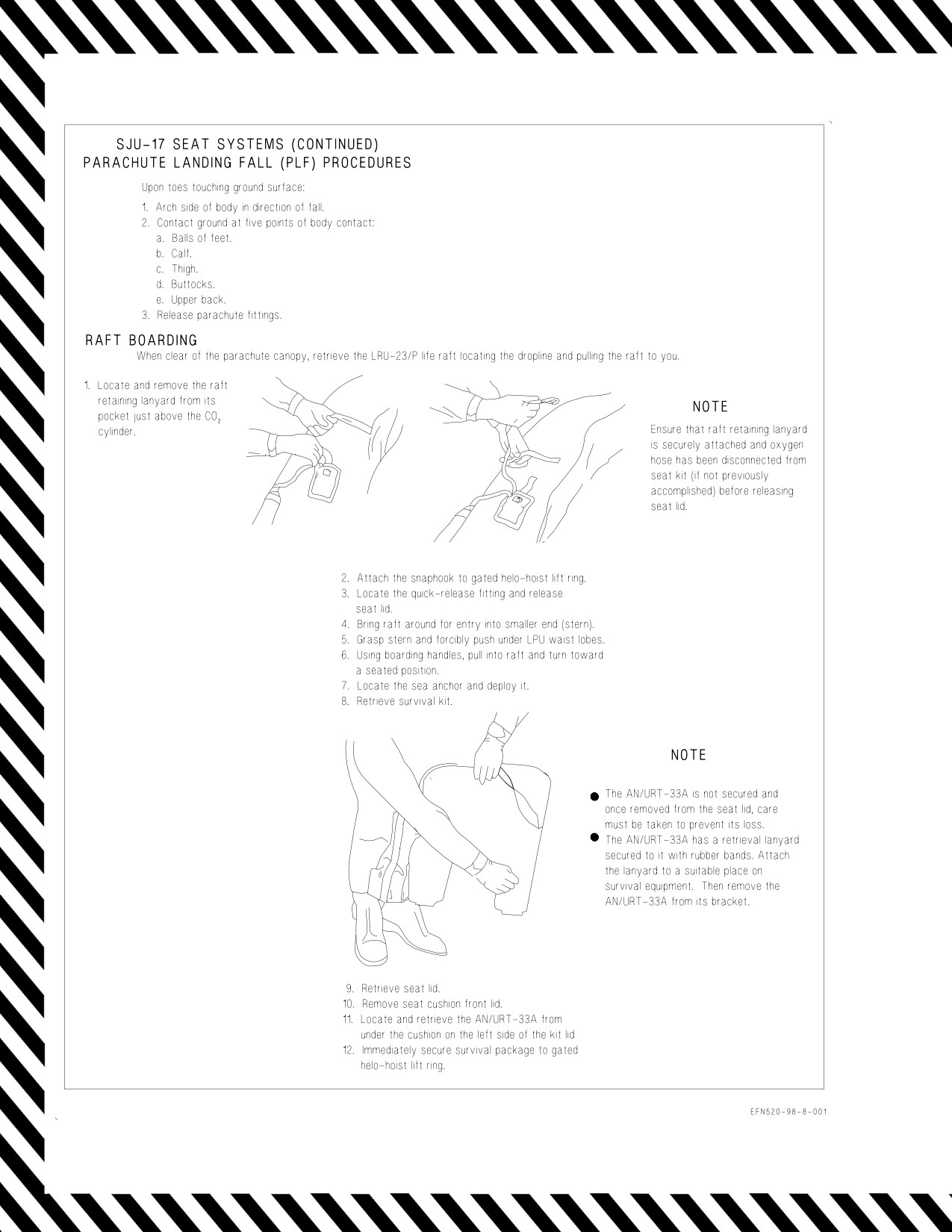
A1-F18EA-NFM-000
Figure 17-4. Ejection Procedures (Sheet 10 of 13)
V-17-20
ORIGINAL
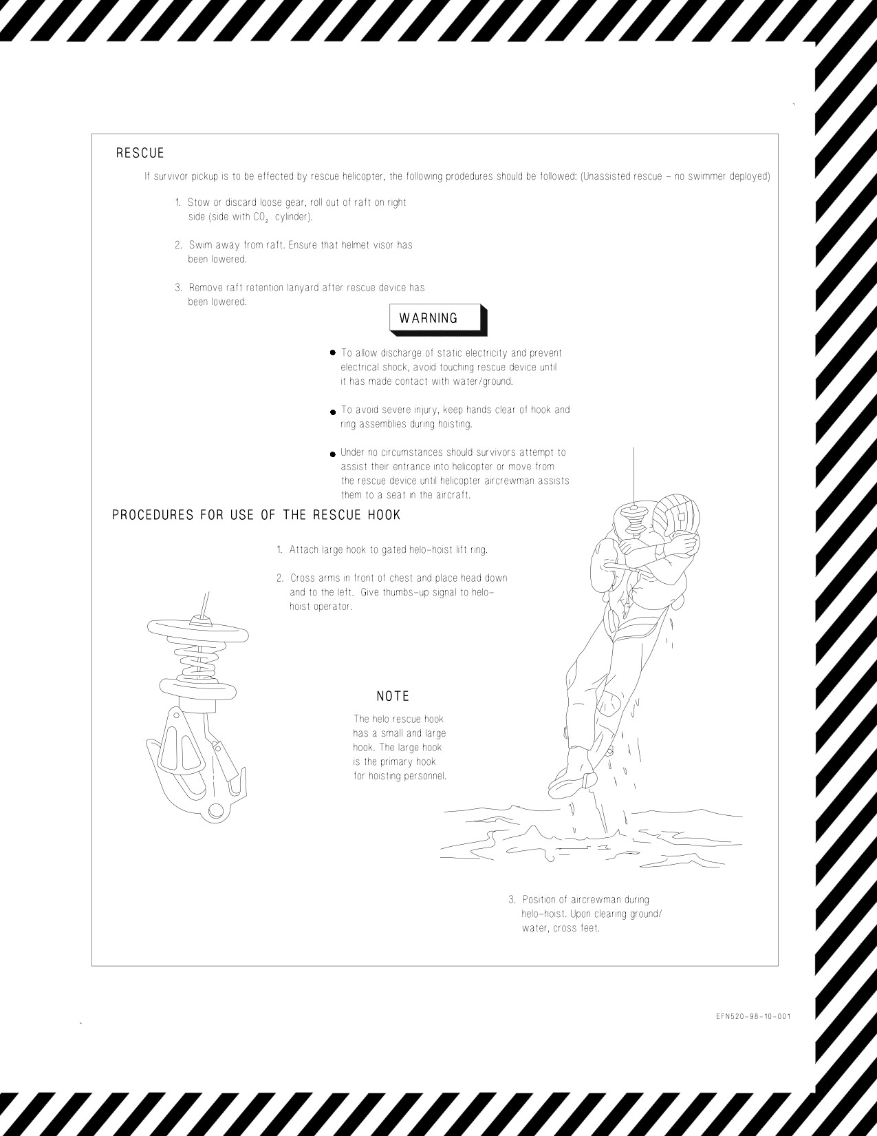
A1-F18EA-NFM-000
Figure 17-4. Ejection Procedures (Sheet 11 of 13)
V-17-21
ORIGINAL
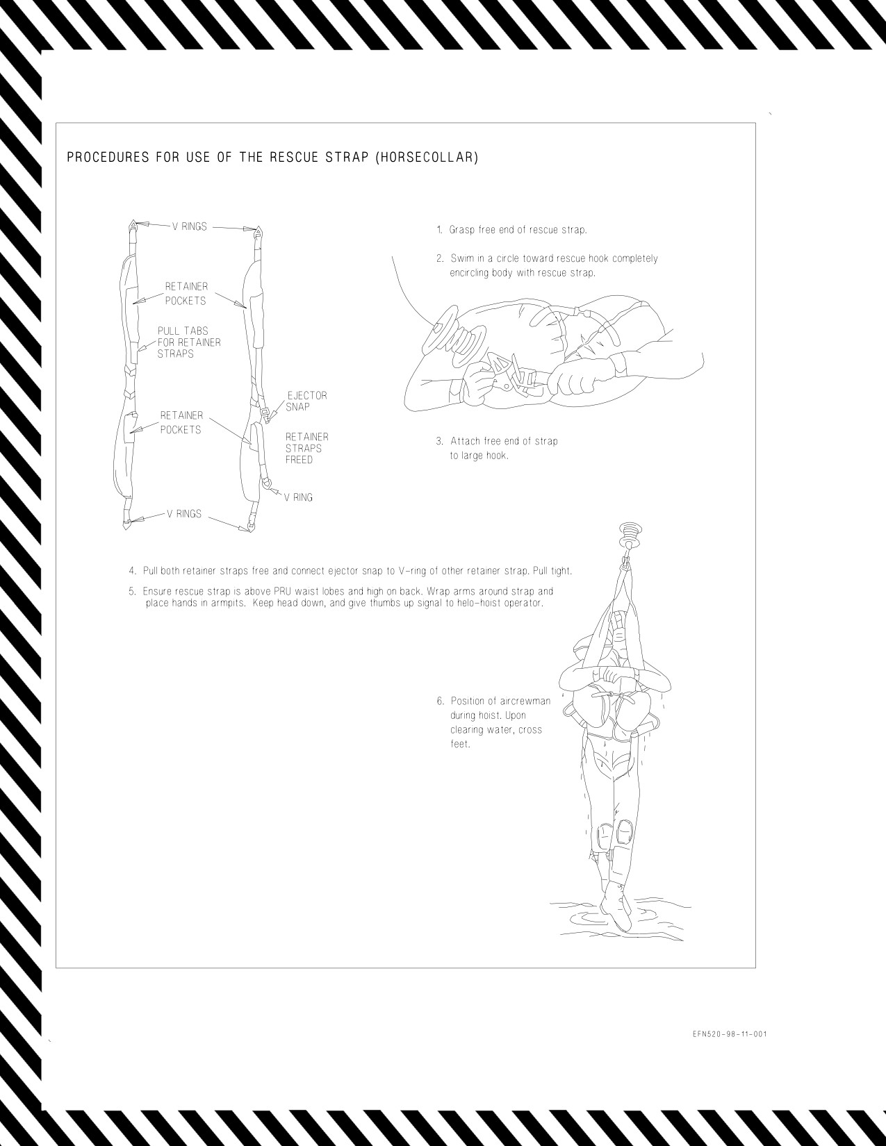
A1-F18EA-NFM-000
Figure 17-4. Ejection Procedures (Sheet 12 of 13)
V-17-22
ORIGINAL
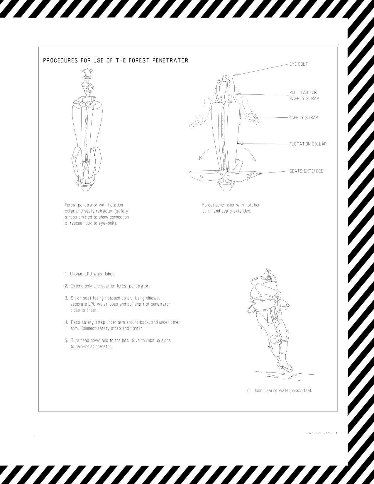
A1-F18EA-NFM-000
Figure 17-4. Ejection Procedures (Sheet 13 of 13)
V-17-23
ORIGINAL
A1-F18EA-NFM-000
The aircraft should be ditched only when ejection has failed.
DUTIES BEFORE IMPACT
1. Make radio distress call.
8. Oxygen mask - TIGHTEN
2. IFF - EMERGENCY
9. Lower seat, assume position for ditching
3. External stores - JETTISON
(feet on rudder pedals, knees flexed).
4. Landing gear - UP
10. Shoulder harness - LOCK
5. Flaps - DOWN
11. Canopy - JETTISON
6. Arresting Hook - DOWN
12. Fly parallel to swell pattern.
7. Visor - DOWN
13. Attempt to touch down along wave crest.
14. Throttles - OFF BEFORE IMPACT
DUTIES AFTER IMPACT
1. Manual override handle - PRESS BUTTON AND ROTATE AFT AND UP
2. Shoulder harness - RELEASE
3. Emergency oxygen - ACTIVATE
NOTE
In the event of under water egress, it is possible to survive underwater with
oxygen equipment until escape can be made.
4. Stand straight up without twisting to release survival kit sticker clips from the seat.
If the cockpit has flooded, the LPU may have inflated due to the FLU-8 water
activated automatic inflation device. If so, care must be taken during exit to avoid
catching the lobes causing entanglement or LPU damage.
5. Abandon aircraft.
6. If the LPU has not automatically inflated - INFLATE
7. Deploy survival kit and inflate life raft.
Should aircraft be abandoned under water, exhale while ascending to the surface to
prevent bursting of lungs due to pressure differential between lungs and outside of
body.
Figure 17-5. Ditching Procedures
V-17-24
ORIGINAL
A1-F18EA-NFM-000
CHAPTER 18
Immediate Action
18.1 GENERAL
This chapter contains only immediate action items. It is intended for review only and does not
contain any steps which are not immediate action nor does it contain notes, cautions, warnings, or
explanatory matter associated with particular procedures.
18.2 APU FIRE LIGHT
IN FLIGHT or on GROUND
*1. APU FIRE light - PUSH
*2. FIRE EXTGH READY light - PUSH
GROUND
*3. Throttles - OFF
18.3 DUAL L BLEED and R BLEED WARNING LIGHTS//L/R ATS CAUTION
*1. Throttles - Minimum practical
*2. Emergency oxygen green ring(s) - PULL
*3. BLEED AIR knob - OFF (DO NOT CYCLE)
*4. Initiate rapid descent to below 10,000 feet cabin altitude.
18.4 SINGLE L BLEED or R BLEED WARNING LIGHT
*1. Throttle affected engine - IDLE
*2. BLEED AIR knob - L OFF or R OFF (DO NOT CYCLE)
If light still on, do the following in order until the light goes out -
*3. Throttle affected engine - OFF
*4. Emergency oxygen green ring(s) - PULL
*5. BLEED AIR knob - OFF (DO NOT CYCLE)
*6. Initiate rapid descent to below 10,000 feet cabin altitude.
V-18-1
ORIGINAL
A1-F18EA-NFM-000
18.5 FIRE LIGHT
GROUND
*1. Throttles - OFF
*2. FIRE light affected engine - PUSH
*3. FIRE EXTGH READY light - PUSH AND HOLD UNTIL DISCH LIGHT COMES ON (5
seconds
maximum.)
IN FLIGHT
Dual FIRE lights -
*1. Throttles - Minimum practical
Single FIRE light or Dual when side confirmed -
*2. Throttle affected engine - OFF
*3. FIRE light affected engine - PUSH
*4. FIRE EXTGH READY light - PUSH AND HOLD UNTIL DISCH LIGHT COMES ON (5
seconds
maximum.)
*5. HOOK handle - DOWN
18.6 ENGINE CAUTIONS
L/R EGT HIGH, L/R ENG, L/R ENG VIB, L/R FLAMEOUT, L/R OIL HOT,
L/R OIL PR, L/R OVRSPD, and L/R STALL
*1. Throttle affected engine - IDLE
18.7 L/R FUEL INLT CAUTION
*1. Throttle affected engine - OFF
*2. FIRE light affected engine - PUSH
18.8 HYD1 (2) HOT CAUTION
*1. Throttle affected engine - OFF
18.9 OBOGS DEGD CAUTION//HYPOXIA/LOW MASK FLOW/NO MASK FLOW//LOSS OF CABIN
PRESSURIZATION/CABIN CAUTION LIGHT BELOW 47,000 FEET
*1. Emergency oxygen green ring(s) - PULL
*2. OXY FLOW knob(s) - OFF
*3. Initiate rapid descent to below 10,000 feet cabin altitude.
V-18-2
ORIGINAL
A1-F18EA-NFM-000
18.10 HOT START
If EGT climbs rapidly through 750°C -
*1. Throttle affected engine - OFF
18.11 BRAKE FAILURE/EMERGENCY BRAKES
If detected after touchdown and flyaway airspeed available -
*1. Go Around.
If brake failure occurs at slow speed or flyaway airspeed not available -
*2. Brakes - RELEASE
*3. EMERG BRK handle - PULL TO DETENT
*4. Brakes - APPLY gradually
18.12 EMERGENCY CATAPULT FLYAWAY
If flyaway airspeed available -
*1. Throttles - MAX
*2. Rudder pedal - FULL AGAINST YAW/ROLL
*3. EMERG JETT button - PUSH
*4. Maintain 10° to 12° pitch attitude with W symbol.
D Do not exceed 14° AOA (AOA tone).
If unable to arrest yaw/roll or stop settle -
*5. Eject
18.13 ABORT
*1. Throttles - IDLE
*2. Speedbrake - AS DESIRED
*3. Brakes - APPLY
*4. Stick - AFT below 100 knots (if required)
*5. HOOK handle - DOWN (if required)
18.14 LOSS OF DIRECTIONAL CONTROL DURING TAKEOFF OR LANDING/ PLANING LINK
FAILURE
If detected after touchdown and flyaway airspeed available -
*1. Go Around
If flyaway airspeed not available -
*1. Select emergency brakes (if appropriate)
*2. HOOK handle - DOWN (if required)
V-18-3
ORIGINAL
A1-F18EA-NFM-000
18.15 COCKPIT SMOKE, FUMES, OR FIRE
*1. Emergency oxygen green ring(s) - PULL
*2. OXY FLOW knob(s) - OFF
*3. Initiate rapid descent to below 10,000 feet cabin altitude.
*4. CABIN PRESS switch - RAM/DUMP
18.16 OCF RECOVERY
*1. Controls - RELEASE, FEET OFF RUDDERS, SPEEDBRAKE IN
If still out of control -
*2. Throttles - IDLE
*3. Altitude, AOA, airspeed, and yaw rate - CHECK
If command arrow present -
*4. Lateral stick - FULL WITH ARROW
When command arrow removed -
*5. Lateral stick - SMOOTHLY NEUTRAL
When recovery indicated by AOA and yaw rate tones removed, side forces subsided, and
airspeed accelerating above 180 KCAS -
*6. Recover
Passing 6,000 feet AGL, dive recovery not initiated -
*7. Eject
18.17 SINGLE ENGINE FAILURE IN LANDING CONFIGURATION
*1. Throttles - MIL or MAX
*2. FLAP switch - HALF
*3. Maintain on-speed AOA and balanced flight.
V-18-4
ORIGINAL
A1-F18EA-NFM-000
PART VI
ALL WEATHER PROCEDURES
Chapter
19 - Instrument Flight
Chapter
20 - Extreme Weather Procedures
Chapter
21 - Hot Weather Procedures
Chapter
22 - Cold Weather Procedures
69
(Reverse Blank)
ORIGINAL
A1-F18EA-NFM-000
CHAPTER 19
Instrument Flight
19.1 INSTRUMENT FLIGHT
19.1.1 Before Takeoff. If instrument flight is expected immediately following takeoff or flight in
RVSM airspace is planned, thoroughly check navigation equipment and crosscheck the HUD and
standby flight instruments. Check to ensure the HUD altitude is within 30 feet of parking spot
elevation, and the standby altimeter is within 60 feet of parking spot elevation. If flight in icing
conditions is anticipated, perform an engine anti-ice detector test (ENG ANTI ICE switch to TEST).
If icing conditions are anticipated immediately after takeoff, place the ENG and PITOT ANTI ICE
switches to ON just prior to takeoff roll.
19.1.2 Inflight. In RVSM controlled airspace, BALT autopilot mode must be engaged when level at
an assigned altitude on the HUD below Mach 0.90. This is required in order to fully comply with
RVSM requirements. After engagement, the Mach limit is Mach 0.92.
During instrument flight, particularly in icing conditions, and for flight in RVSM airspace,
frequently crosscheck standby flight instruments to verify that the primary systems are functioning
normally. A slowly flashing velocity vector indicates that the INS is providing valid attitude
information but the FCC air data functions are the source for the velocity vector.
The HUD altitude and standby altimeter readings will differ as a function of Mach number. In
RVSM controlled airspace, when at assigned altitude on HUD, periodically add standby altimeter
error (Standby Altimeter Error table below) to standby altimeter and compare to HUD altitude. If
altitudes differ by more than 250 feet, notify ATC that the aircraft is no longer RVSM compliant. With
MC OFP H5E AND UP, use the HSI/DATA/(A/C) page STBY CHK value to compare directly with
the standby altimeter. Both are uncorrected altitudes.
NOTE
The barometric setting is assumed to be 29.92 for all RVSM related
activities. Do not use the standby altimeter for RVSM altitude holding
requirements.
Standby Altimeter Error
Mach Number
Standby Altimeter Error (Feet)
0.50
120
0.60
150
0.65
175
0.70
200
0.75
220
0.80
280
0.85
260
0.90
330
0.92
380
VI-19-1
ORIGINAL
A1-F18EA-NFM-000
In RVSM controlled airspace, compare left and right AOA values immediately after establishing
assigned altitude on HUD. If L and R AOA values on the FCS page differ by more than 2 degrees,
notify ATC that the aircraft is no longer RVSM compliant. Allow time for the probes to settle if in
turbulent air.
19.1.3 Approaches.
19.1.3.1 Descent. If fuel conservation is of concern, an enroute descent should be flown at 250 KCAS
and IDLE power. Advancing the throttles slightly to ‘‘pucker’’ the nozzles reduces drag and results in
a slightly more efficient descent.
19.1.3.2 Holding. Fly the holding pattern as directed/depicted. For maximum endurance, maintain
approximately 225 to 250 KCAS between 15,000 and 25,000 feet MSL. Total fuel flow should be
approximately 4,000 pph.
19.1.3.3 AN/APG-79 AESA Considerations. Aircrew operating AN/APG-79 AESA equipped aircraft
shall be aware that directing AN/APG-79 AESA transmissions toward airfields may cause strong
electromagnetic interference (EMI) affecting the safety of aircraft on approach. Unless specifically
authorized for operational necessity or required for safety of flight, aircrew shall cease AN/APG-79
AESA radar transmissions whenever operating within 10 nm of civilian airfields. Reference Chapter 4.4
for AN/APG-79 AESA radar limitations.
19.1.3.4 Non-Precision. The navigation aids available provide excellent position keeping capability
with multiple redundancy and steering cues. INS offset data can be used to provide accurate steering
to a TACAN IAF and the CRS select option can be used to obtain a visual reference on the MPCD and
to provide steering cues on the HUD.
Penetration should be flown at 250 KCAS and approximately 75% N2 rpm with the speedbrake as
required to control descent rate. Dirty up at 10 nm from touchdown.
19.1.3.5 Precision Approaches. The downwind leg should be flown at 230 to 250 KCAS with gear UP
and flaps AUTO. Transition to the landing configuration when directed or no later than 6 nmi from
touchdown. To begin descent, lower the velocity vector to approximately -3° and maintain onspeed
AOA. Small changes in velocity vector placement can be used to control glideslope. Set the RALT at
decision height and be prepared for missed approach.
19.2 DEGRADED SYSTEMS
If the INS fails, the ATT switch should be placed to STBY.
VI-19-2
ORIGINAL W/IC 33
A1-F18EA-NFM-000
CHAPTER 20
Extreme Weather Procedures
20.1 ICE AND RAIN
Before flight, check with the weather service for the location of the freezing level and probable icing
conditions. Flight through known or suspected icing conditions should be avoided, if possible, to
prevent engine FOD from ice ingestion.
Prolonged flight in icing conditions is an emergency situation. Flight duration which allows a
noticeable accumulation of ice (more than 3/8 inch) on the LEFs constitutes prolonged flight. Ice forms
rapidly on the inlet lip and, if allowed to accumulate, can be drawn into the engine causing compressor
stalls and/or major FOD. Severe icing conditions can result in rapid ice accumulation in a very short
time. An INLET ICE caution should serve as a warning to take action to avoid further ice
accumulation.
If icing is anticipated or encountered -
1. Perform an engine anti-ice detector test (ENG ANTI ICE - TEST) to verify proper detector
operation.
20.1.1 Ground Operation.
If ambient temperature between 0 and 7°C -
1. Minimize engine operation above IDLE to reduce the potential for ice accumulation on the engine
inlet lips. Inlet lip icing can occur at these conditions without the INLET ICE caution.
If visible moisture exists (rain, fog) and the temperature is 45°F (7°C) or less -
1. ENG ANTI ICE switch - ON (after engine start)
2. PITOT ANTI ICE switch - ON (after taxi but prior to takeoff)
If an INLET ICE caution appears prior to takeoff -
1. Do not takeoff. Return to the line and have the engines inspected for possible FOD.
20.1.2 In Flight.
If icing is anticipated or encountered -
1. Enter the clouds at the last possible moment. If on top, descend rapidly.
2. ENG ANTI ICE switch - ON
3. PITOT ANTI ICE switch - ON
VI-20-1
ORIGINAL
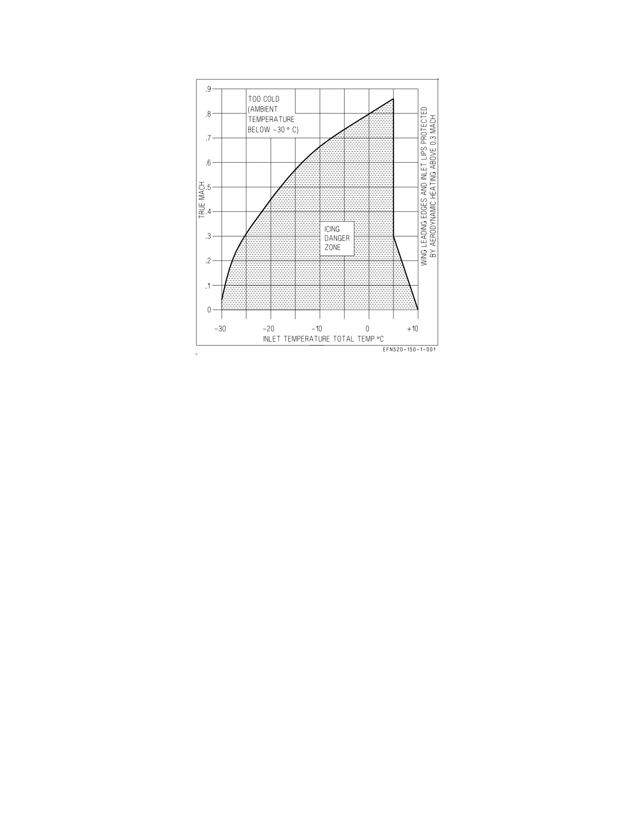
A1-F18EA-NFM-000
Figure 20-1. Icing Danger Zone
If no ice is visible on the LEFs -
4. Airspeed - Increase until INLET TEMP is at least +5°C (+10°C preferred) on ENG format (if
possible).
5. Climb or descend out of icing danger zone (figure 20-1).
Monitor INLET TEMP and Mach. If time and fuel permit, climb to a safe altitude. Altitudes
above about 25,000 feet or ambient temperatures below -30°C generally prevent ice formation
since the water droplets are frozen and do not adhere. Descend only if sure that ambient
temperature is well above freezing at a safe altitude below.
When clear of icing conditions -
6. ENG ANTI ICE switch - OFF
If ice is visible on the LEFs -
4. Throttles - Reduce below 80% N2 rpm (if possible). Avoid throttle transients above 90% N2 rpm.
5. Airspeed - Maintain above 250 KCAS.
6. AOA - Maintain less than 6° (if possible) to prevent ice accumulation on underside of LEX.
7. Avoid abrupt maneuvers and bank angles over 20°.
8. Descend rapidly below the freezing level.
VI-20-2
ORIGINAL
A1-F18EA-NFM-000
For landing -
9. WINDSHIELD switch - ANTI ICE or RAIN (as required)
The ANTI-ICE position should be used as required to clear the windshield of ice and/or visible
moisture.
Do not operate the windshield anti-ice/rain removal system on a dry
windshield. If a WDSHLD HOT caution appears, place the WIND-
SHIELD switch to OFF immediately to prevent heat damage to the
windshield.
10. Reduce airspeed and lower the landing gear at the last possible moment (minimizes ice
accumulation on the gear).
If a missed approach is necessary -
11. Slowly advance throttles to the minimum power required for a safe waveoff.
12. Raise landing gear and flaps as soon as possible.
Post-flight -
13. Report all icing encounters (INLET ICE caution) on VID MAF to ensure the engine is inspected
for FOD before the next flight.
20.1.3 Landing in Heavy Rain. Refer to the Wet Runway Landings section in chapter 7.
If landing in heavy rain -
1. WINDSHIELD switch - RAIN
Do not operate the windshield anti-ice/rain removal system on a dry
windshield. If a WDSHLD HOT caution appears, place the WIND-
SHIELD switch to OFF immediately after landing to prevent heat
damage to the windshield.
For wet (standing water) runway conditions -
2. Reduce gross weight to minimum practical.
3. ANTI-SKID switch - VERIFY ON (shore based)
4. Land onspeed or slightly slow with the power reduced to IDLE as soon as possible.
If directional control is comfortable after touchdown -
5. Use maximum anti-skid braking to minimize landing distance.
VI-20-3
ORIGINAL
A1-F18EA-NFM-000
If directional control problems occur -
6. Do not hesitate to add power and go around.
7. Make arrested landing, if possible.
20.2 TURBULENT AIR AND THUNDERSTORM OPERATION
Avoid flight through thunderstorms and microbursts. If penetration is unavoidable, fly at optimum
cruise airspeed but not less than 250 KCAS if above 35,000 feet MSL.
The radar MAP mode can be used to detect storm cells.
1. SURF MAP mode - SELECT (NAV or A/G)
2. RANGE SCALE - SELECT (AS DESIRED)
3. ANTENNA ELEVATION - Raise to horizon. Make sure the radar antenna is raised sufficiently
to preclude radar returns from the ground. The RDR ATTK format should display areas of
precipitation. If possible, deviate flightpath to avoid these areas.
VI-20-4
ORIGINAL
A1-F18EA-NFM-000
CHAPTER 21
Hot Weather Procedures
21.1 GENERAL
On the ground, the avionics ground cooling fan should provide adequate avionics cooling up to an
ambient temperature of approximately 103°F. Inflight, the ECS controller should provide adequate
avionics cooling at all conditions.
With outside air temperature greater than 103°F, fuel recirculation through the heat exchangers
during ground operations may be insufficient at IDLE RPM to keep engine and AMAD oil temperature
within limits. Increasing the affected engine rpm increases circulation and should clear an OIL HOT
caution within 20 seconds (normal operating system).
Under adverse conditions (i.e. hot, heavy, and forward CG), takeoff speeds may be significantly
higher than those seen at nominal conditions. Knowing the aircraft predicted takeoff performance
should prevent a high speed abort in what is a normally functioning aircraft.
21.2 GROUND OPERATIONS
If OAT is approaching or is above 103°F -
1. Non-essential avionics equipment (radar, TCN, IFF, etc.) ON and BIT then OFF (if required)
2. Consider increasing one engine at or above 74% N2 rpm (if possible)
3. ENG format - Monitor ENG OIL TEMP (149°C) and AMAD OIL TEMP (88°C)
4. Avionics equipment - ON JUST PRIOR TO TAKEOFF
If AV AIR HOT or L or R OIL HOT cautions appear -
5. Perform the appropriate caution corrective action procedures.
The AV AIR HOT caution corrective action procedures should remove the caution if the ECS system
is operating normally. If the caution cannot be cleared with the ECS MODE switch in AUTO,
maintenance action is required.
21.3 IN FLIGHT
At nominal ambient conditions, the aircraft fuel system should provide adequate cooling for the
FADECs and subsystem accessories. With extremely hot ambient conditions, feed tank fuel tempera-
tures can approach the 59°C inflight limit. During low altitude flight in hot conditions, particularly
with a low fuel state, an L or R FUEL HOT caution may appear. If sufficient cooling is unavailable,
the L or R OIL HOT cautions may also appear.
If OAT is approaching or is above 103°F -
1. Monitor feed tank fuel temperatures.
VI-21-1
ORIGINAL
A1-F18EA-NFM-000
If the L or R FUEL HOT, FADEC HOT, or OIL HOT cautions appear -
2. Perform the appropriate corrective action procedures.
3. Land as soon as practical.
21.4 DESCENT/RECOVERY
The windshield may fog rapidly under conditions of very high aircraft descent rates and high
humidity. In such conditions, consider preheating the windshield by placing the DEFOG handle to
HIGH. If possible, the maximum comfortable cockpit temperature should be maintained to aid in
windshield defog.
If OAT is approaching or is above 103°F -
1. Consider turning off non-essential avionics equipment before entering the landing pattern.
21.5 AFTER LANDING
During ground operations with fuel temperatures above 40°C, the LCS pump and ground cooling fan
are commanded on regardless of RADAR knob position to provide ram air cooling for the fuel system.
Placing the RADAR knob to OFF postflight removes the radar as a heat source, aids LCS/fuel cooling,
and should extend ground operating time.
Once clear of the runway -
1. Avionics equipment - OFF
2. RADAR knob - OFF
If line shutdown -
3. Canopy - LEAVE OPEN
If hotpits -
3. Monitor feed tank fuel temperatures.
NOTE
The ground L or R FUEL HOT caution thresholds are 79°C with less
than 5,000 pounds of fuel and 59°C with more than 5,000 pounds of
fuel.
If feed tank fuel temperatures are approaching limits -
4. Consider shutting down the left engine (significantly reduces the heat load).
If a L or R FUEL HOT caution appears -
5. Perform the corrective action items.
VI-21-2
ORIGINAL
A1-F18EA-NFM-000
CHAPTER 22
Cold Weather Procedures
22.1 EXTERIOR INSPECTION
If the aircraft has not flown within 4 hr -
1. Pay particular attention to the nosewheel oleo, and APU and brake accumulator pressures.
22.2 BEFORE ENTERING COCKPIT
If a battery/APU start is anticipated -
1. Consider using external power to raise the canopy to conserve battery power.
22.3 INTERIOR CHECK
1. Canopy - Consider leaving open until the right engine has been started to (1) conserve battery
power and (2) permit rapid egress.
If the aircraft has been cold soaked below -18°C (0°F) -
1. Rudder pedal adjustment may be difficult or impossible and the inertia reel may not retract
automatically until the cockpit warms up (typically 5 to 10 minutes).
22.4 ENGINE START
1. Perform normal engine starts (windmilling is not required).
APU starts should be successful if the battery and the APU accumulator are fully charged. The
FADEC modulates fuel flow as required to prevent a hung start. Successful engine starts have been
demonstrated at ambient temperatures down to -40°F without start anomalies; however, expect engine
starts to be slower than at nominal temperatures.
2. Avoid activating any hydraulic actuated system for 2 minutes after both engines are online.
This allows hydraulic fluid to warm both systems and prevents hydraulic seal damage and potential
hydraulic leaks.
3. Oil pressure on the EFD may appear as invalid if 200 psi is exceeded. Maximum oil pressure 2.5
minutes after engine start is 180 psi.
22.5 BEFORE TAXI
If ambient temperature between 0 and 7°C -
1. Minimize engine operation above IDLE to reduce the potential for ice accumulation on the engine
inlet lips. Inlet lip icing can occur at these conditions without the INLET ICE caution.
VI-22-1
ORIGINAL
A1-F18EA-NFM-000
If visible moisture exists (rain, fog) and the temperature is 7°C (45°F) or less -
1. ENG ANTI ICE switch - ON (after engine start)
2. PITOT ANTI ICE switch - ON (after taxi but prior to takeoff)
If the aircraft has not flown within 4 hr with ambient temperature below -18°C (0°F) -
1. Up to three selections of the FCS exerciser mode may be required in order to obtain a successful
FCS RESET after the initial 2 minute warm-up.
For cold weather operations below -18°C (0°F) -
1. Three arresting hook cycles should be performed to bring extension time within specification (2
seconds is nominal).
2. Proper operation of the OBOGS monitor may not occur until 2 minutes of warm up.
22.6 TAKEOFF
If snow or slush has accumulated on the landing gear -
1. Leave the gear down for 1 minute after takeoff to clear snow or slush.
2. The landing gear may be slow to retract (up to 30 seconds) following cold soak below -18°C (0°F).
Gear retraction times in excess of 15 seconds annunciate the landing gear warning tone.
3. Carefully monitor gear uplock signals (all three landing gear position lights out, landing gear
warning light out).
VI-22-2
ORIGINAL
A1-F18EA-NFM-000
PART VII
COMM-NAV EQUIPMENT
AND PROCEDURES
Chapter
23 - Communications-Identification Equipment
Chapter
24 - Navigation Equipment
Chapter
25 - Backup/Degraded Operations
Chapter
26 - Visual Communications
Chapter
27 - Deck/Ground Handling Signals
71
(Reverse Blank)
ORIGINAL
A1-F18EA-NFM-000
CHAPTER 23
Communication-Identification
Equipment
23.1 MULTIFUNCTION INFORMATION DISTRIBUTION SYSTEM (MIDS)
MIDS is an advanced, high capacity, jam resistant, digital communication link. MIDS is an
omnidirectional radio that uses frequency-hopping techniques similar to HAVEQUICK, and encryp-
tion for security. It is like a Local Area Network (LAN) in that multiple users can access information
simultaneously. MIDS is used to exchange near real-time information among air, ground and sea
elements engaged in tactical operations. LINK 16 equipped platforms can transfer voice and data.
Refer to TACMAN Vol 3 for Tactical information. Refer to Chapter 24 for navigation information.
23.2 ICS - INTERCOM SYSTEM
The ICS provides amplification and distribution of intercockpit voice communications, aircrew-to-
ground crew voice communications, ICS voice alerts and tones, as well as advisory tones originating
external to the ICS.
Volume controls are provided to control headset volume for:
1. Voice Activated Intercom (VOX)
2. Transmit sidetone/aircrew intercom audio/ground crew intercom audio
3. MIDS A audio
4. MIDS B audio
5. RWR audio
6. WPN delivery audio
7. TACAN ident
8. Auxiliary audio (available for other uses).
The ICS is also used to control the following COMM/IFF related functions:
1. Selection of PLAIN voice or CIPHER relay modes (RLY switch).
2. Selection of guard transmit (G XMT) for COMM 1 and 2 (G XMIT switch).
3. Hold or zeroize of IFF crypto code (CRYPTO switch).
4. Selection of IFF Mode 4 cautions, advisories, and voice alerts (MODE 4 switch).
5. Selection of IFF NORM or EMERG operating modes (IFF MASTER switch).
VII-23-1
ORIGINAL
A1-F18EA-NFM-000
23.2.1 ICS Function Selector Switch (F/A-18F). The ICS function selector switch is located in each
cockpit and is used to select the operating mode for ICS voice communications.
23.2.1.1 ICS Function Selector Switch Front Cockpit (F/A-18F). The switch is located on the ANT
SEL panel on the outboard left console in the front cockpit. In order for a crewmember to communicate
on the ICS, the ICS function switch in that cockpit must be in HOT MIC and the ICS VOL knob must
be set (as desired) above the LO position.
RADIO
Selects HOT MIC in both cockpits and ensures ICS volume is louder than COMM
ORIDE
volume.
HOT MIC Enables the front (rear) cockpit microphone for ICS transmissions.
COLD MIC Disables front (rear) cockpit microphone.
23.2.1.2 ICS Function Selector Switch Aft Cockpit (F/A-18F). The switch is located on the VOL
control panel on the left console in the aft cockpit. In order for a crewmember to communicate on the
ICS, the ICS function switch in that cockpit must be in NORM and the ICS VOL knob must be set (as
desired) above the LO position.
RADIO
Selects HOT MIC in both cockpits and ensures ICS volume is louder than COMM
ORIDE
volume.
NORM
Enables aft cockpit microphone for ICS transmissions.
23.2.1.3 ICS Aft Cockpit Kick Switches (F/A-18F Lot 26 and up). Two ICS kick switches are located
on the inboard side of each rudder pedal. These switches are in addition to COMM transmit switches
on the rudder pedals. Either switch will activate the ICS for intercockpit communication.
23.3 VHF/UHF COMMUNICATION SYSTEM
The aircraft has two ARC-210 voice communication radios. The VHF/UHF radios, COMM 1 and
COMM 2, provide air-to-air/air-to-ground voice communications; and, in conjunction with automatic
direction finding (ADF), equipment (If installed), provide a DF function. The radios can be operated
in plain mode, anti-jam (Have Quick 1 or 2) mode, secure mode (KY-58), or relay mode; in either
normal or secure voice. An additional function is generation by either COMM 1 or COMM 2 of a 1,020
hz tone (AM) or a 15 hz tone (FM) which serve as audio cues to the pilot. The COMM 1 and COMM
2 radios operate in the frequency bands listed below. When enabled, integral guard receivers
continuously monitor the emergency guard channels for each frequency band.
VII-23-2
ORIGINAL