F18. FLIGHT MANUAL (2008) - page 26

A1-F18EA-NFM-000
Failure to ensure all criteria are met may result in departure during
recovery.
Passing 6,000 ft AGL, dive recovery not initiated -
*7. Eject.
15.13.4 Post Departure Dive Recovery
• Recovery is indicated when AOA and YAW rate tones are removed,
side forces subside, and airspeed is accelerating above 180 knots.
Failure to ensure all criteria are met may result in redeparture during
recovery.
• Limit AOA to 10° during a recovery from departure caused by a flap
system failure/malfunction (FCS/FC AIR DAT/FLAPS OFF cau-
tions) to avoid departing the aircraft. Departure warning is character-
ized by an uncommanded yaw/roll.
• Post departure dive recovery initiated below 6,000 feet AGL is not
assured. Delaying the ejection decision below 6,000 feet AGL while
departed may result in unsuccessful ejection.
1. One-g roll to the nearest horizon.
2. Throttles - MAX (MIL if altitude not critical)
3. Pull to and maintain 25° to 35° AOA until positive rate of climb established (AOA configuration
dependent).
A positive rate of climb requires wings level pitch attitude (waterline)
greater than indicated AOA.
If aircraft departs during dive recovery below 6,000 ft AGL -
4. Eject.
V-15-21
ORIGINAL
A1-F18EA-NFM-000
15.14 CONTROLLABILITY CHECK
Requirement: Malfunction, failure, or damage, which degrades approach and landing character-
istics.
Purpose (to determine):
• Whether to attempt an approach or a controlled ejection.
• Safe landing configuration.
• Safe final approach airspeed/AOA.
1.
Climb to and maintain a safe altitude in VMC:
• 15,000 feet AGL (recommended)
• At or above 5,000 feet AGL (if practical)
2.
Coordinate a visual inspection (if possible).
3.
Plan to configure aircraft and conduct controllability check as close to field/CV as possible
(avoid populated areas if able).
• In all cases, consider BINGO fuel requirements.
4.
Reference the appropriate emergency procedure to plan the following:
• Normal or Emergency Landing Gear Extension
• Appropriate flap setting for controllability check and landing
• AOA and/or airspeed limitations
• Any controllability issues that may arise from landing gear and/or flap extension
• Desired landing gross weight and fuel dump plan
5.
Consider Select Jettison stores prior to gear extension if:
• Lateral weight asymmetry is over 12,000 ft-lb to establish a more symmetric configuration
• Emergency Landing Gear extension required (i.e., no HYD 2A)
• Stated in appropriate emergency procedure
If single engine -
6. Reduce gross weight (44,000 lb max, lower if practical).
7. Maintain operating engine above 80% RPM during flap and landing gear extension.
8. Do not exceed 15° AOB in turns (if possible).
If normal landing gear extension possible (i.e., no HYD2A caution) -
9. Slow to below 250 KCAS.
10. LDG GEAR handle - DN
If normal landing gear extension not possible -
9. Execute Landing Gear Emergency Extension procedure.
• Do not configure flaps during Landing Gear Emergency Extension.
• Return to Controllability Check procedure once gear extended.
V-15-22
ORIGINAL

A1-F18EA-NFM-000
Once landing gear down and locked -
10. DO NOT TRIM until minimum controllable airspeed is determined.
11. Crosscheck AOA and airspeed during decel.
12. FLAP switch − AUTO/HALF/FULL based on:
• Flap setting stated in appropriate emergency procedure
• If single engine, flaps HALF
• Consideration of type landing, failure/damage, engine performance, etc.
13. Determine minimum controllable airspeed by slowing in 10 knot increments.
• If still controllable at AOA limit stated in appropriate emergency procedure or on-speed, plan
on flying appropriate AOA for approach and landing.
• If one-half stick or rudder pedal deflection required to maintain balanced flight prior to AOA
limit stated in appropriate emergency procedure or on-speed, add 10 knots for airspeed to be
used during approach and landing.
• If lateral stick required for balanced flight, plan for turns in the direction of
stick
displacement (if possible).
14. Assess:
• Controllability in a 15° AOB turn
• Throttle response and wave-off maneuver
If controllability unacceptable to attempt landing -
15. Consider a controlled ejection over an unpopulated area (if possible).
If controllability acceptable to attempt landing -
15. Fly a straight-in approach.
• Do not go slower than the minimum-controllable-airspeed-plus-10 knots, or equivalent AOA,
as determined during controllability check.
If single engine -
16. Execute Single Engine Approach and Landing procedure.
If dual engine -
16. Return to appropriate emergency procedure to ensure all corrective action steps are
completed prior to attempting approach to landing.
17. If arrested landing desired/required, consider effects of approach speed on max arresting-
gear engagement speed.
18. If controllability changes or safe landing is not certain at any point on approach, execute
wave-off/missed approach immediately.
15.15 EXTERNAL STORES JETTISON
Refer to External Stores Jettison Chart (figure 15-9).
V-15-23
ORIGINAL
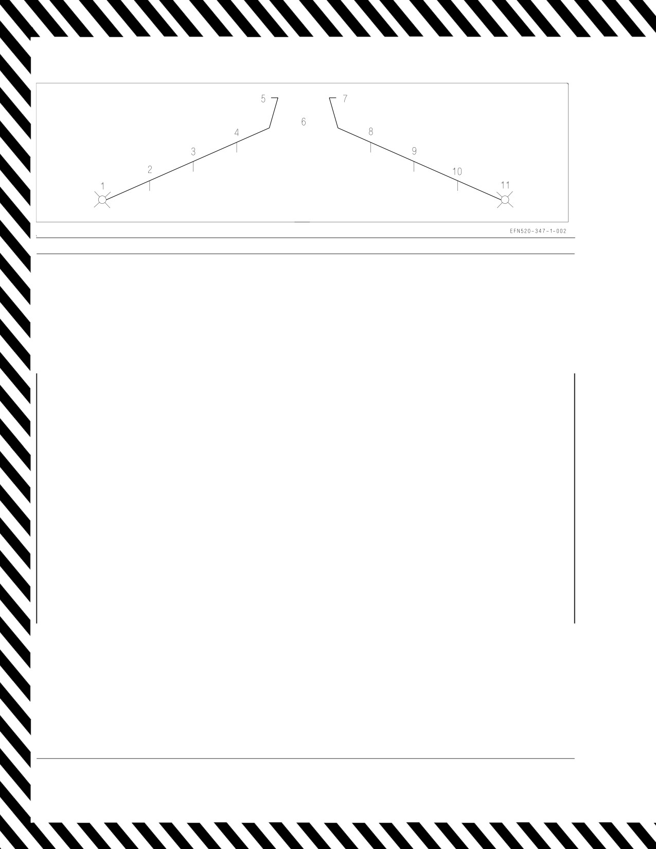
A1-F18EA-NFM-000
EMERGENCY JETTISON
Requirements: WoffW or LDG GEAR handle UP
1. EMERG JETT button - PUSH Jettison all stores/racks/launchers sequential by station pairs: 3 & 9, 2 & 10, 4 & 8, then 6 (100 ms)
SELECTIVE JETTISON
Requirements:
(1) WoffW, (2) LDG GEAR handle UP, (3) All landing gear up and locked
1. Find a clear area (if possible).
2. LT TEST switch - TEST Verify all JETT STATION SELECT buttons are illuminated.
3. JETT STATION SELECT buttons - SELECT DESIRED STATIONS (CTR, LI, RI, LM, RM, LO, RO)
4. SELECT JETT knob - ROTATE (as required)
a. L FUS MSL - Left fuselage missile
b. R FUS MSL - Right fuselage missile
c. RACK/LCHR - Rack/launcher (jettisons whatever is attached to the selected parent racks)
d. STORES - (1) Jettisons ordnance loaded on selected parent racks, CVERs, or IMERs;
(2) Jettisons missiles attached to launchers on selected stations except HARM;
(3) HARM anti-compromise launch.
5. SIM mode - UNBOXED
6. MASTER ARM switch - ARM
7. SELECT JETT button - PUSH Jettison sequential by selected stations: RM, LM, RI, LI, CL, RO, LO (350 ms)
After jettison -
8. MASTER ARM switch - SAFE
9. SELECT JETT knob - SAFE
NOTE
• Outboard station ADU-773 missile rails cannot be jettisoned, since they are installed in place of a BRU-32 rack.
• If multiple stations selected for STORE jettison include AGM-88s, the first HARM in the default sequence is launched first, then
the sequence continues from that station, releasing the remaining selected non-HARM stores. Regardless of the number
selected, only one HARM is launched each time the SELECT JETT button is pushed.
• With the SELECT JETT knob rotated out of the SAFE position, the SMS unlocks all racks/launchers. When SAFE is reselected,
racks/launchers are not locked again until commanded by either lowering the landing gear or selecting SIM mode.
AUX RELEASE
Requirements: (1) station must be HALKD or HAULK following a failed normal release or SELECT JETT attempt, (2) WoffW, (3)
MASTER ARM switch - ARM (SIM unboxed), (4) auxiliary cartridge installed in the HUNG parent rack.
WARNING
During an AUX REL, the Mk 19 auxiliary cartridge is fired, opening the selected parent rack’s hooks and allowing the attached
store or rack/launcher to free fall from the aircraft. Lacking a forced ejection, this release mode is prohibited except in an
emergency and then only in 1.0g level flight.
NOTE
A Mk 19 auxiliary cartridge is not installed in a parent rack when a wing station is loaded with an IMER, a HARM, a Maverick, a
Harpoon, or a SLAM.
1. Find a clear area (if possible).
2. LT TEST switch - TEST Verify all jettison pushtiles are illuminated.
3. AUX REL switch - ENABLE
4. Jettison pushtiles - SELECT HUNG STATION(S)
5. SELECT JETT knob - ROTATE TO EITHER RACK/LCHR or STORES
6. SIM mode - UNBOXED
7. MASTER ARM switch - ARM
8. SELECT JETT button - PUSH
Fires the aux cartridge(s) for gravity release of all stores/racks/launchers from the selected parent rack(s).
After AUX REL -
9. MASTER ARM switch - SAFE
10. SELECT JETT knob - SAFE
11. AUX REL switch - NORM
Figure 15-9. External Stores Jettison Chart
V-15-24
ORIGINAL

A1-F18EA-NFM-000
15.16 ARS MALFUNCTIONS
15.16.1 ARS Hose Fails to Retract.
1. Reduce airspeed to 230 KCAS or less.
2. Recycle HOSE switch.
A shipboard/field arrestment is not recommended with a trailing hose.
Either a field landing with arresting gear derigged, or a hose jettison is
recommended. Refer to ARS Refueling Hose Jettison.
15.16.2 ARS Refueling Hose Jettison.
1. Airspeed - Maintain 250 KCAS, level flight
2. HOSE CUT/SAFE switch - CUT (3 seconds minimum)
Consideration should be given to a controlled jettison in a safe retrieval
area, such as abeam the runway on a low altitude, slow speed pass to
possibly save the MA-3 coupling and basket.
NOTE
It is recommended that a visual inspection be made prior to, and
during, hose jettison.
15.16.3 ARS Hydraulic Pressure Light. If the HYD PRESS light illuminates, reel response may be
lost, a hydraulic failure may be imminent, and/or the hose may not retract.
1. Receiver aircraft - Disengage
2. Fuel TRANS switch - OFF
3. Reduce airspeed to 220 KCAS.
4. HOSE switch - RETR
5. PWR switch - OFF
V-15-25
ORIGINAL
A1-F18EA-NFM-000
15.16.4 No RDY Light.
1. Make sure tanker is clear aft.
2. Increase airspeed (do not exceed 300 KCAS).
3. HOSE switch - RESET
15.17 EMERGENCY TANKER DISENGAGEMENT
Emergency disengagement may be required if difficulties occur in either the tanker or the receiver
aircraft. Emergency breakaway signals are by radio transmission and/or turning on the lower
anti-collision lights. If the situation allows, normal, but expeditious, disconnect procedures should be
followed to minimize the possibility of aircraft damage.
The following procedures may result in damage to the tanker and/or
receiver aircraft.
Tanker -
1. Throttles - MIL
Receiver -
1. Throttles - IDLE
2. SPEEDBRAKE switch - AFT
V-15-26
ORIGINAL
A1-F18EA-NFM-000
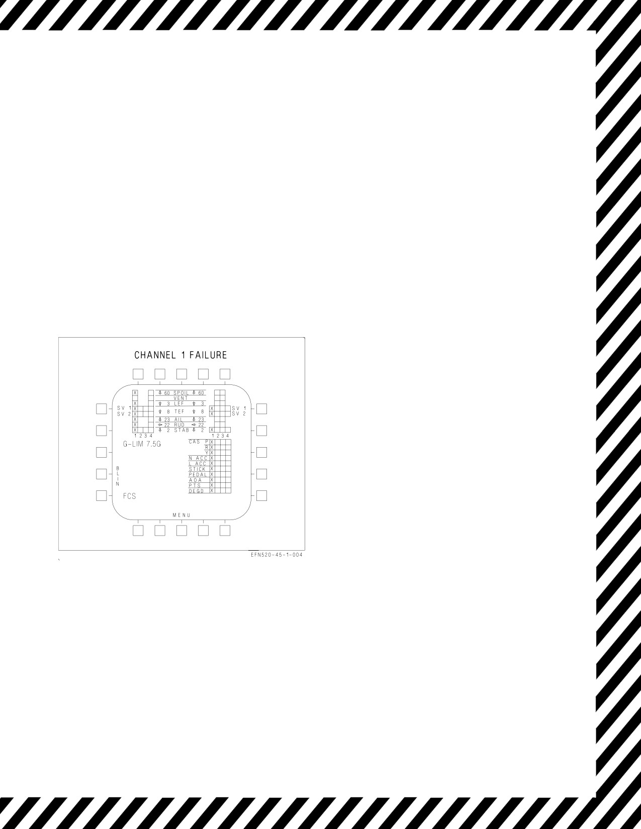
15.18 FCS FAILURE INDICATIONS AND EFFECTS
FCS failures are indicated by various cautions and by FCS format Xs and BLIN codes. Following
display or annunciation of an FCS caution, the FCS format should be used to identify the exact
malfunction/failure.
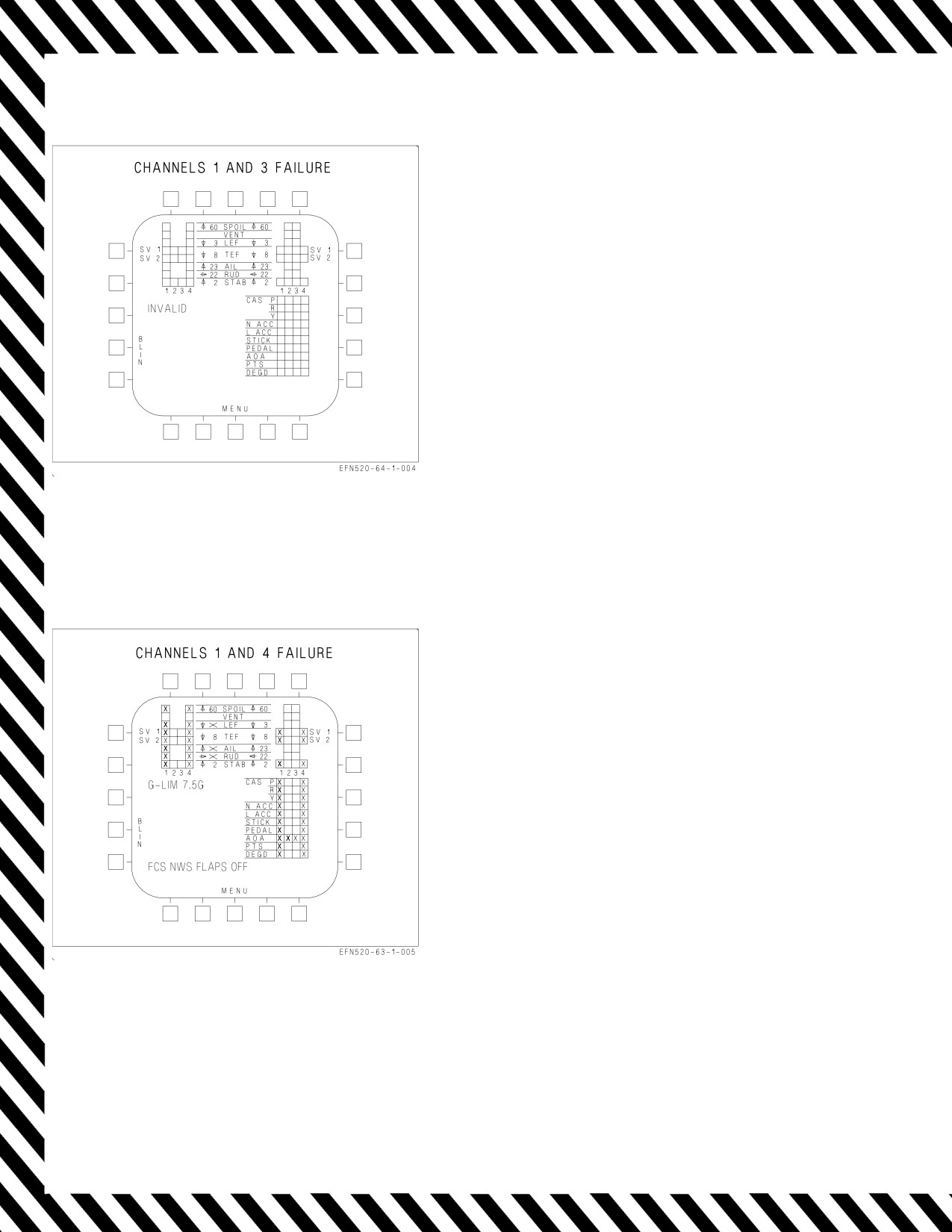
With the failure of FCC channels 1 and 3, the FCS format displays the word INVALID in place of
the G-LIM advisory. Subsequent FCS failures or resets will not be displayed.
The following figures depict typical FCS failure indications and their effects for the majority of FCS
related malfunctions/failures.
EFFECTS:
Loss of speedbrake function.
Figure 15-10. FCS Failure Indications and
Effects
V-15-27
ORIGINAL
A1-F18EA-NFM-000
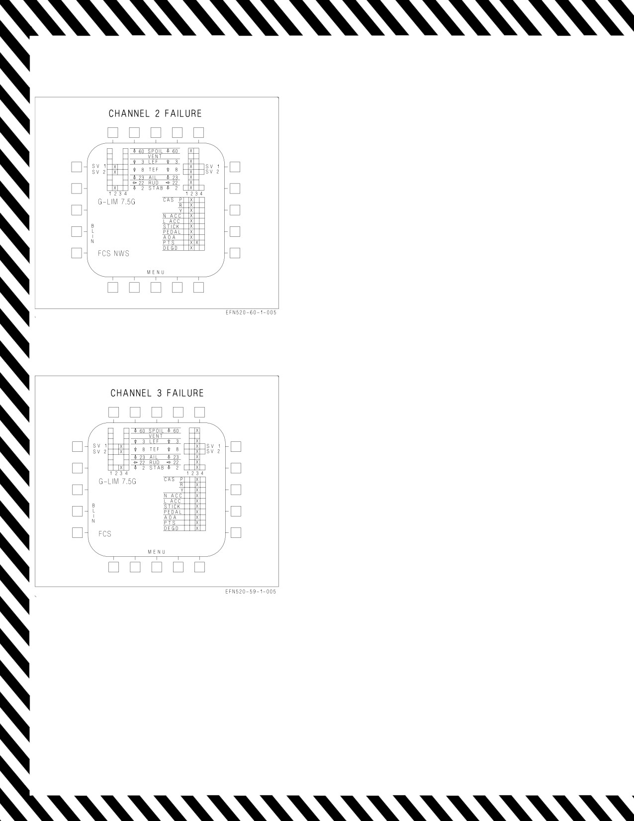
EFFECTS:
ATC inoperative.
Normal NWS inoperative.
Loss of HUD barometric altitude (radar altitude
available below 5,000 feet).
Standby altimeter available.
Loss of IFF altitude reporting.
Loss of speedbrake function.
Loss of Air Data from right pressure transmitter
set (PTS)
Loss of AOA/yaw rate warning tone.
Autopilot pitch mode defaults to FPAH if BALT
or RALT were previously selected.
MAD sensor data lost.
Figure 15-11. FCS Failure Indications and
Effects - Channel 2
EFFECTS:
Loss of speedbrake function.
Figure 15-12. FCS Failure Indications and
Effects - Channel 3
V-15-28
ORIGINAL
A1-F18EA-NFM-000
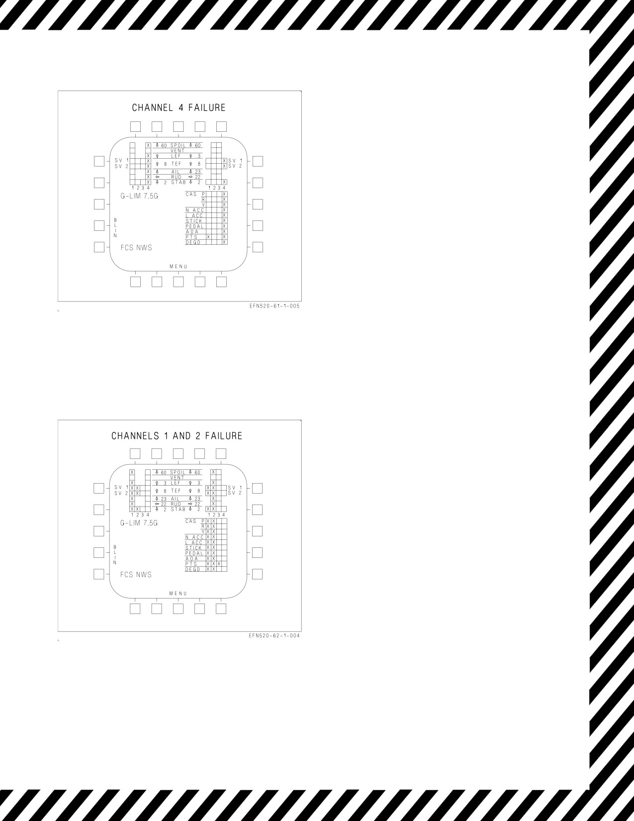
EFFECTS:
ATC inoperative.
Normal NWS inoperative.
Loss of Air Data from left pressure transmitter
set (PTS)
Loss of AOA approach/indexer lights.
Loss of speedbrake function.
Loss of AHRS over temperature detection.
Figure 15-13. FCS Failure Indications and
Effects - Channel 4
EFFECTS:
ATC inoperative.
Autopilot inoperative.
Normal NWS inoperative.
Loss of Air Data from left pressure transmitter
set (PTS)
Loss of HUD barometric altitude (radar altitude
available below 5,000 feet).
Standby altimeter available.
Loss of IFF altitude reporting.
Loss of speedbrake function.
MAD sensor data lost.
Figure 15-14. FCS Failure Indications and
Effects - Channels 1 and 2
V-15-29
ORIGINAL
A1-F18EA-NFM-000
NOTE
A simultaneous failure of channels 1
and 3 prevents the display of any
FCS cautions. The FCS display shows
the word INVALID. Use FCES light
to monitor FCS failures.
EFFECTS:
Autopilot inoperative.
Loss of HUD air data displays.
Roll rate limiting is failed. Use no more than ½
lateral stick with rate limited stores aboard.
FCS G-limiter defaults to 7.5g.
Degraded flying qualities
>20° in AUTO
FLAPS.
Use no more than ±15° bank when selecting
HALF or FULL FLAPS from AUTO
FLAPS.
Loss of speedbrake function.
Figure 15-15. FCS Failure Indications and
Effects - Channels 1 and 3
EFFECTS:
FLAP SCHED caution is not displayed.
Left probe AOA blanked from FCS status page.
Autopilot inoperative.
ATC inoperative.
Normal NWS inoperative.
Left leading edge flap locked in failed position.
Left aileron and left rudder failed
(flutter
damper).
Left spoiler.
Loss of Air Data from left pressure transmitter
set (PTS)
Flaps - AUTO:
Loss of speedbrake function.
Flaps freeze.
Flaps - HALF or FULL:
Right leading edge flap frozen.
Trailing edge flaps 30° or 40° maximum.
Scheduled with airspeed.
Figure
15-16. FCS Failure Indications and
No aileron droop.
Effects - Channels
1 and 4
No rudder toe-in.
Loss of AOA approach/indexer lights.
Loss of AHRS over temperature detection.
V-15-30
ORIGINAL
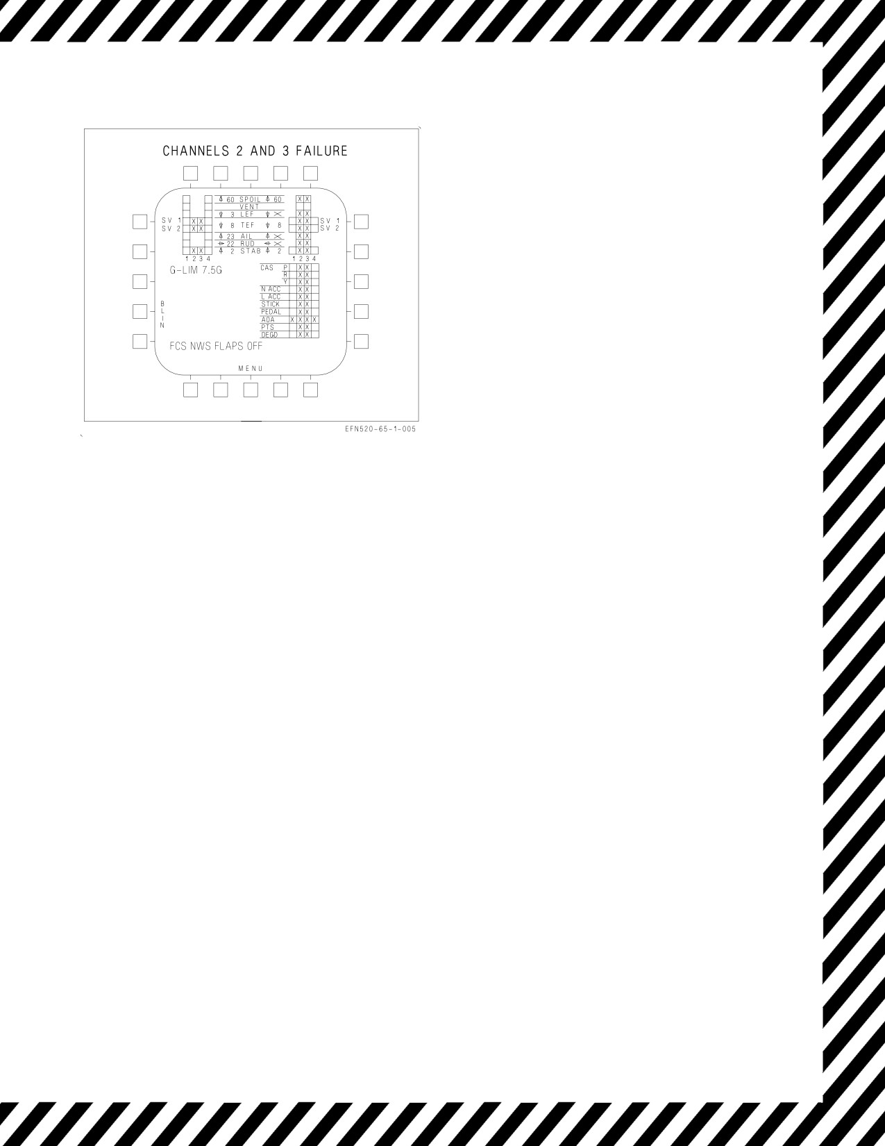
A1-F18EA-NFM-000
EFFECTS:
Right probe AOA blanked from FCS status page.
Autopilot inoperative.
ATC inoperative.
Normal NWS inoperative.
Right leading edge flap locked in failed position.
Right aileron and right rudder failed
(flutter damper).
Standby altimeter available.
Loss of IFF altitude reporting.
Loss of AOA/yaw rate warning tone.
MAD sensor data lost.
Flaps - AUTO:
TEFs will not schedule with AOA but operate
differentially for roll.
Loss of speedbrake function.
Flaps - HALF or FULL:
Left leading edge flap frozen.
Trailing edge flaps 30° or 40° maximum.
Scheduled with airspeed.
Figure
15-17. FCS Failure Indications and
No aileron droop.
Effects - Channels
2 and 3
No rudder toe-in.
V-15-31
ORIGINAL
A1-F18EA-NFM-000
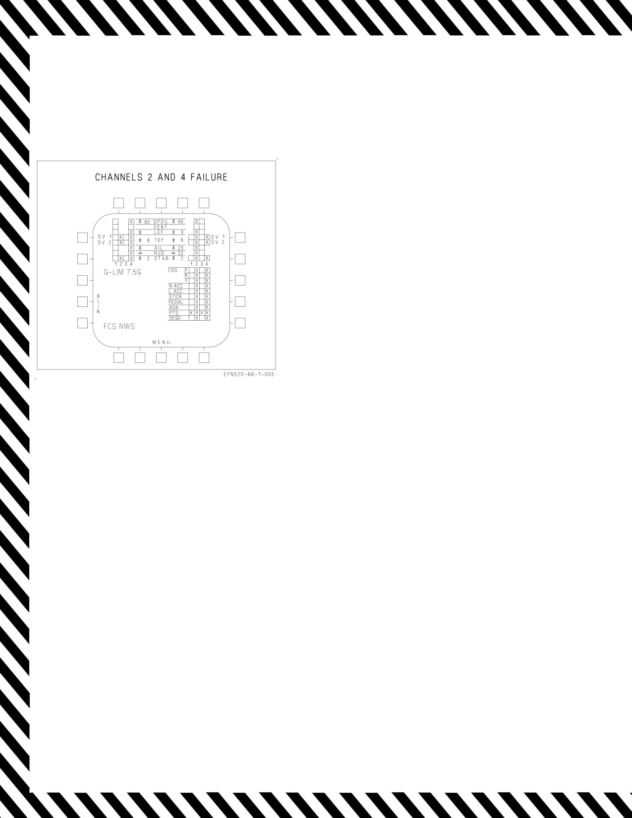
NOTE
If failure occurs in flaps AUTO,
GAIN ORIDE must be selected to
obtain HALF or FULL flaps setting.
EFFECTS:
FLAP SCHED caution may be displayed.
Autopilot inoperative.
ATC inoperative.
Loss of HUD barometric altitude, airspeed
and vertical velocity.
Loss of IFF altitude reporting.
Loss of FCES light.
Loss of AOA bracket and AOA approach/indexer
lights.
Loss of speedbrake function.
Loss of AOA/yaw rate warning tone.
Loss of air data.
MAD sensor data lost.
Loss of AHRS over temperature detection
Flaps - AUTO:
Degraded flying qualities.
Flaps function with frozen air data values.
Flaps schedule with AOA.
Figure
15-18. FCS Failure Indications and
Flaps - HALF or FULL:
Effects - Channels
2 and 4
Trailing edge flaps 30° or 40°.
Leading edge flaps and rudder toe-in schedule
with AOA.
NWS inoperative.
V-15-32
ORIGINAL
A1-F18EA-NFM-000
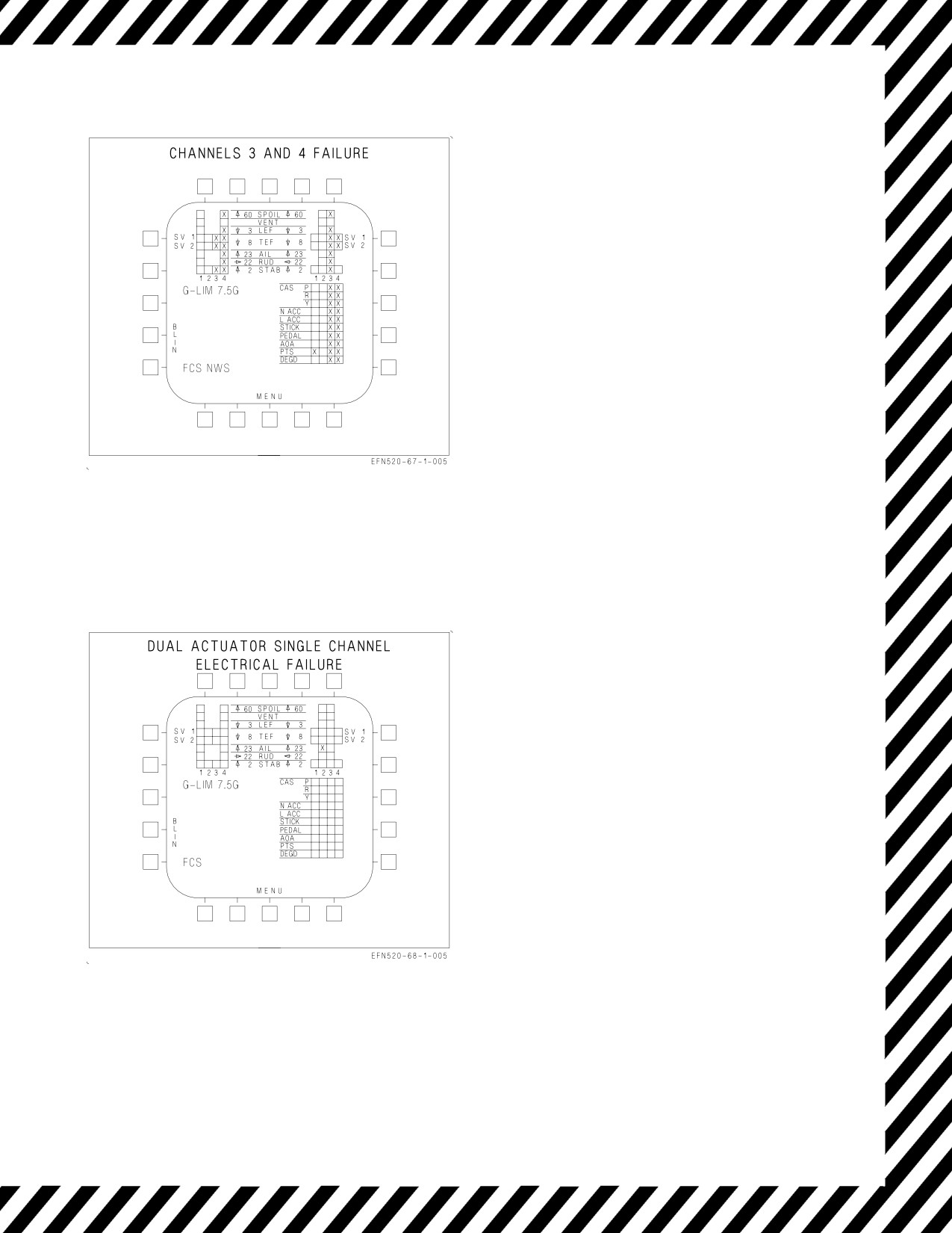
EFFECTS:
Autopilot inoperative.
ATC inoperative.
Normal NWS inoperative.
Loss of AOA bracket and AOA approach/indexer
lights.
Loss of speedbrake function.
Loss of AOA/yaw rate warning tone.
Loss of AHRS overtemperature detection.
Loss of Air Data from left pressure transmitter
set (PTS)
Figure 15-19. FCS Failure Indications and
Effects
NOTE
FCS status display is shown for a
right aileron channel 2 failure but is
typical for any single channel failure
of aileron, rudder, leading edge flap,
or spoiler.
EFFECTS:
No change in flying qualities.
One more electrical failure causes the actuator to
revert to degraded mode.
Figure 15-20. FCS Failure Indications and
Effects
V-15-33
ORIGINAL
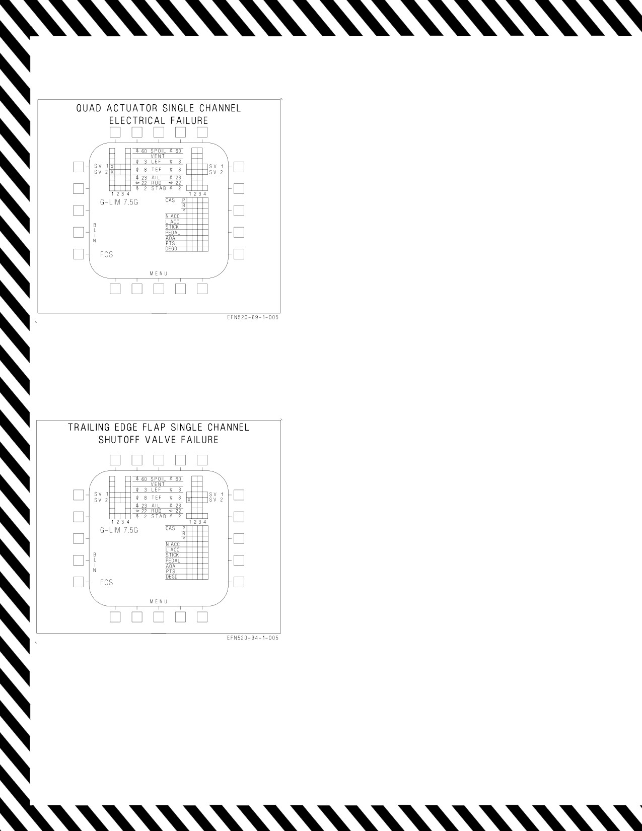
A1-F18EA-NFM-000
NOTE
FCS status display is shown for a left
trailing edge flap channel
1
failure
but is typical for any single channel
failure of trailing edge flap or
stabilator.
EFFECTS:
No change in flying qualities.
Two more electrical failures causes the actuator
to revert to degraded mode.
Figure 15-21. FCS Failure Indications and
Effects
NOTE
FCS status display is shown for a
channel
1
right trailing edge flap
shutoff valve 2 failure but is typical
for any channel failure of trailing
edge flaps shutoff valves.
EFFECTS:
No change in flying qualities.
Actuator reduced to half hinge moment capabil-
ity if four channels of single shutoff valve fail.
Figure 15-22. FCS Failure Indications and
Effects
V-15-34
ORIGINAL
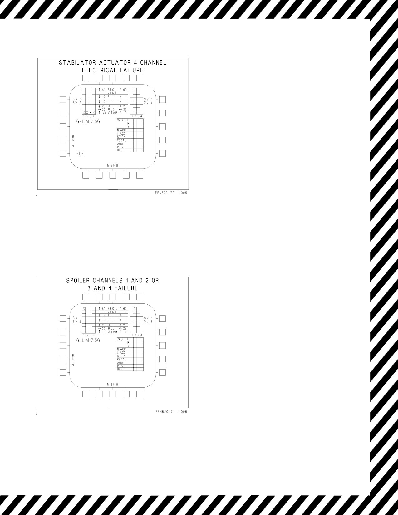
A1-F18EA-NFM-000
NOTE
FCS status display is shown for a left
stabilator 4 channel failure example.
EFFECTS:
Autopilot inoperative.
Failed stabilator hydraulically driven to 2°
trailing edge up.
Automatic compensation for failed stabilator.
Flaps - AUTO:
Low roll rate in transonic region below 20,000
feet.
Significant roll and yaw coupling may occur
with forward stick inputs when above Mach
1.4 and 30,000 feet.
Reduction in nose down pitch authority above
10° AOA.
Flaps - HALF:
Nearly normal flying qualities.
Figure
15-23. FCS Failure Indications and
Minor roll-yaw coupling with longitudinal
Effects
stick inputs.
Sudden, but controllable, yaw during rotation
on bolters or touch-and-go.
NOTE
FCS status display is shown for
channels 1 and 2 failure example.
EFFECTS:
FCS caution is not displayed.
No change in flying qualities.
Figure 15-24. FCS Failure Indications and
Effects
V-15-35
ORIGINAL
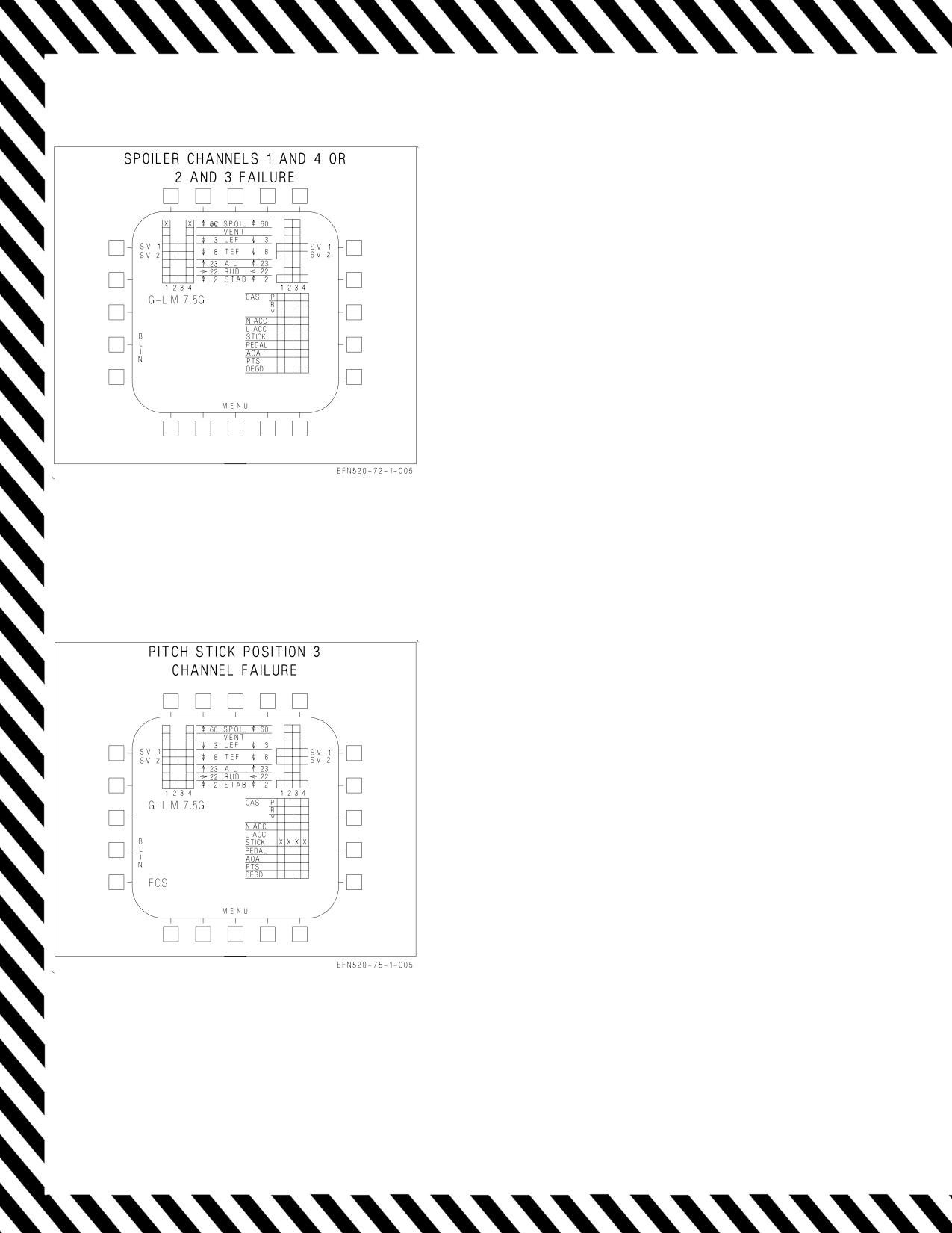
A1-F18EA-NFM-000
NOTE
FCS status display is shown for
channels 1 and 4 failure example.
EFFECTS:
Flaps - AUTO:
Spoiler failed closed -
•Available nose-down pitching moment
reduced at high AOA.
•Slight uncommanded roll and yaw can
occur at high AOA when functional
spoiler opens.
Figure 15-25. FCS Failure Indications and
Effects
EFFECTS:
Autopilot inoperative.
Reduced pitch stick authority.
Flaps - AUTO:
Increased stick force per g.
Flaps - HALF or FULL:
Increased stick force per AOA.
Figure 15-26. FCS Failure Indications and
Effects
V-15-36
ORIGINAL
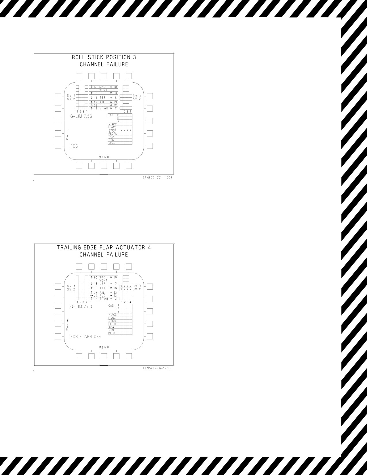
A1-F18EA-NFM-000
EFFECTS:
Autopilot inoperative.
Reduced roll stick authority.
Figure 15-27. FCS Failure Indications and
Effects
NOTE
FCS status display is shown for right
trailing edge flap four channels
failure example.
EFFECTS:
Autopilot inoperative.
Trailing edge flaps hydraulically driven to 5°.
Flaps - AUTO:
Speedbrake function disabled.
Flaps - HALF or FULL:
Select FULL flaps for maximum aileron
droop.
Excessive approach speed (refer to FLAPS
OFF FCS caution).
Left trailing edge flaps may fail OFF due to
asymmetry.
Figure 15-28. FCS Failure Indications and
Effects
V-15-37
ORIGINAL
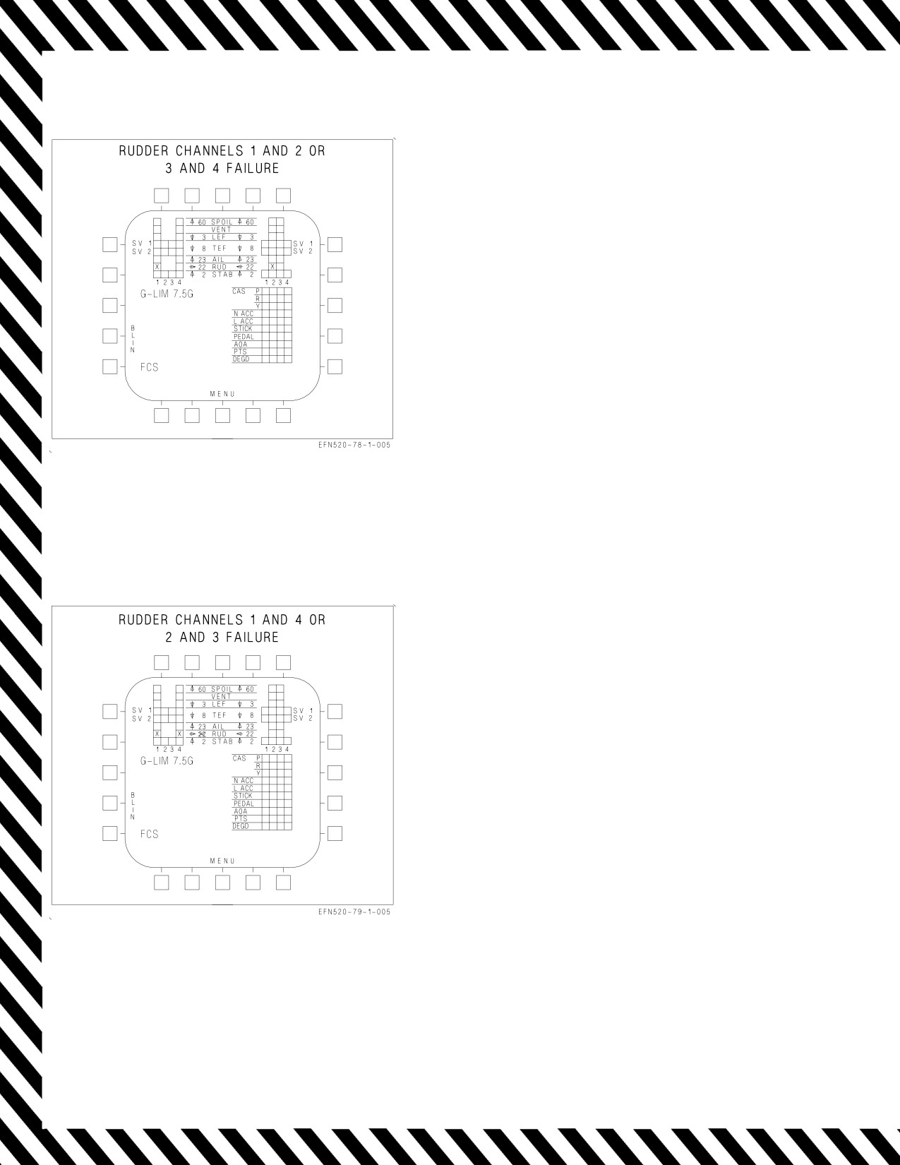
A1-F18EA-NFM-000
NOTE
FCS status display is shown for
channels 1 and 2 failure example.
EFFECTS:
No change in flying qualities.
Figure 15-29. FCS Failure Indications and
Effects
NOTE
FCS status display is shown for
channels 1 and 4 failure example.
EFFECTS:
Left rudder (channels 1 and 4) failed (flutter
damped) or right rudder (channels 2 and 3)
failed (flutter damped).
Directional control critical with one engine
inoperative.
Autopilot inoperative.
No rudder toe-in or flare.
Flaps - AUTO:
Speedbrake function disabled.
Figure 15-30. FCS Failure Indications and
Effects
V-15-38
ORIGINAL
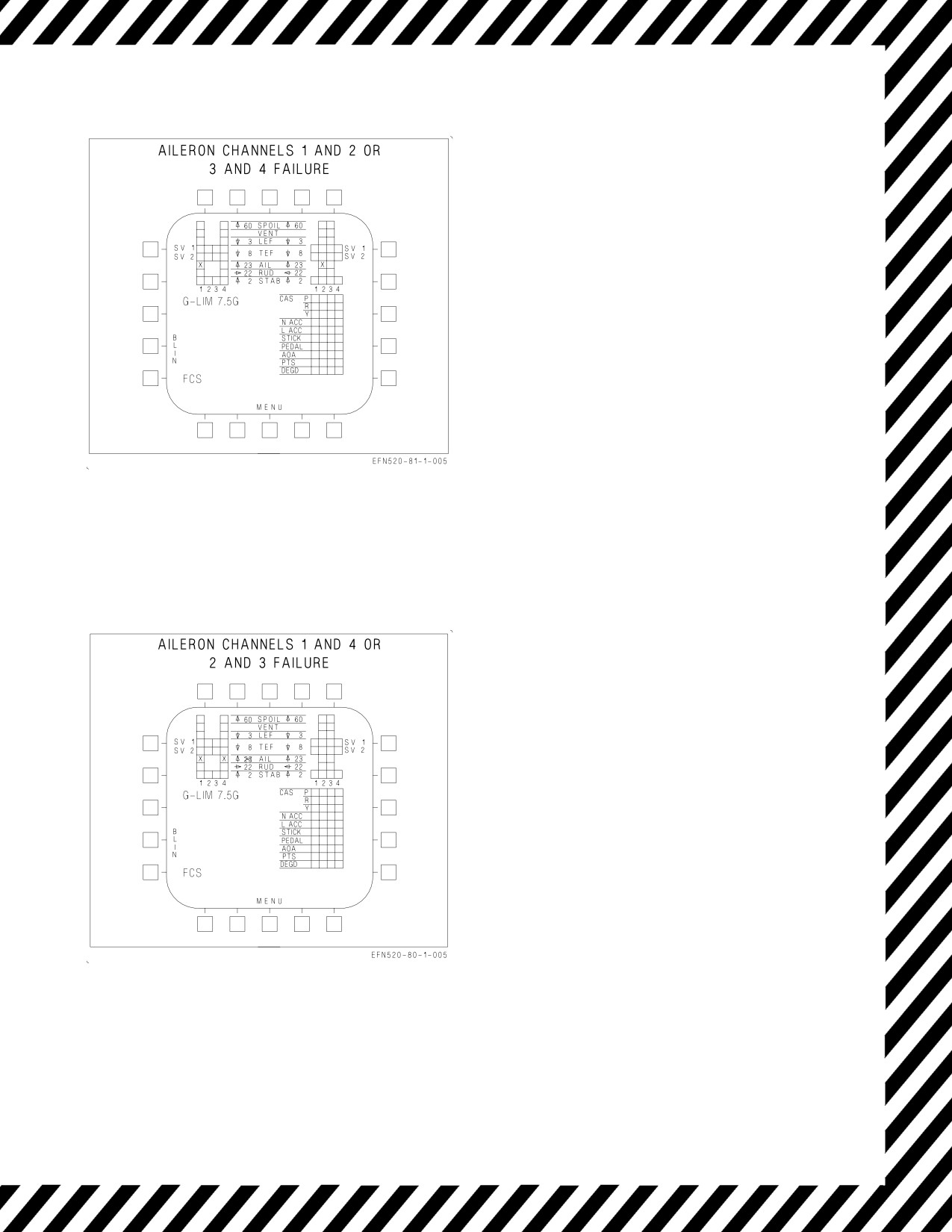
A1-F18EA-NFM-000
NOTE
FCS status display is shown for
channels 1 and 2 failure example.
EFFECTS:
No change in flying qualities.
Figure 15-31. FCS Failure Indications and
Effects - Aileron Channels 1 and 2 or 3 and 4
NOTE
FCS status display is shown for
channels 1 and 4 failure example.
EFFECTS:
Left aileron (channels 1 and 4) failed (flutter
damped) or right aileron (channels 2 and 3)
failed (flutter damped).
Autopilot inoperative.
Flaps - AUTO:
Speedbrake function disabled.
Flaps - HALF or FULL:
No aileron droop.
Trailing edge flaps 30° or 40°.
Leading edge flaps and rudder toe-in schedule
normally.
Figure 15-32. FCS Failure Indications and
Effects - Aileron Channels 1 and 4 or 2 and 3
V-15-39
ORIGINAL
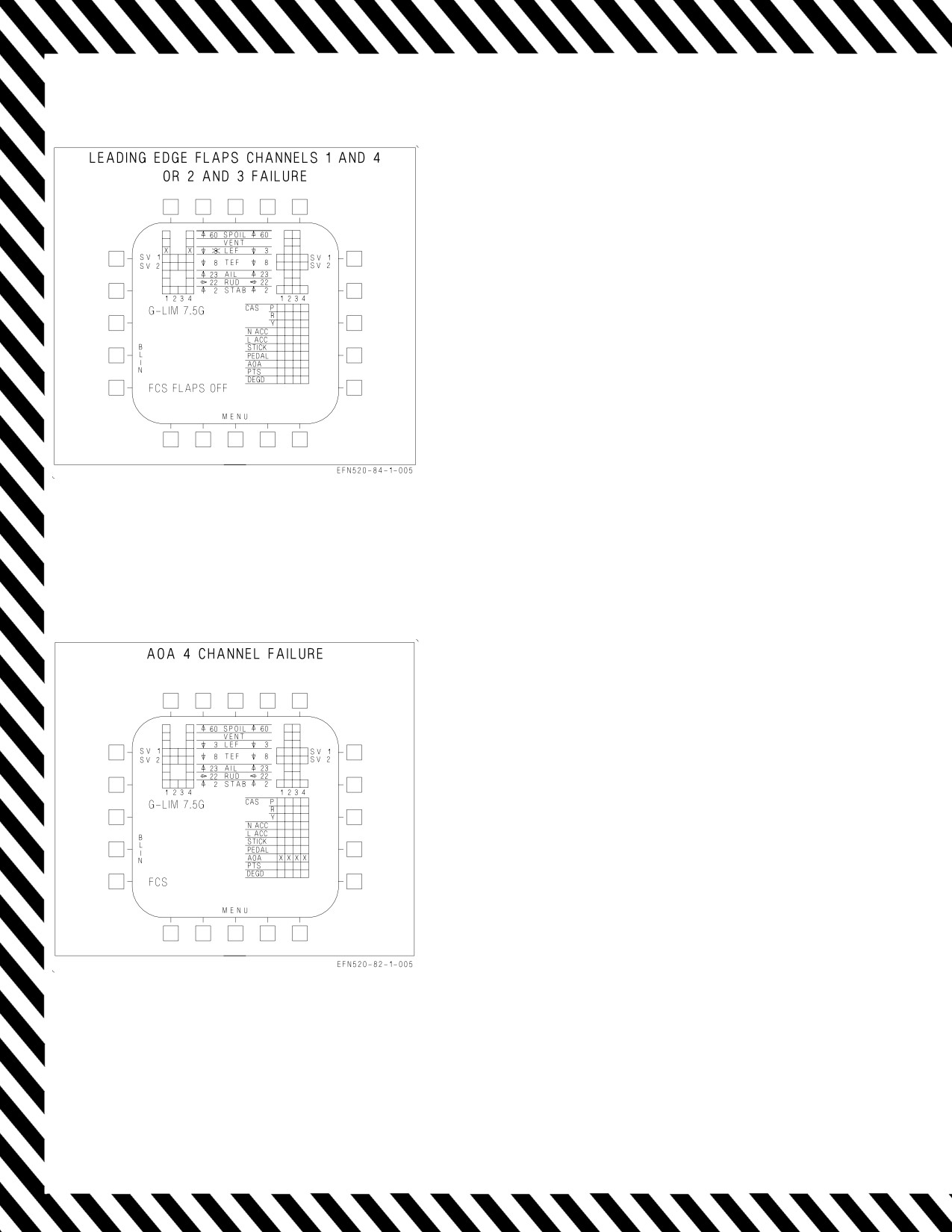
A1-F18EA-NFM-000
NOTE
FCS status display is shown for
channels 1 and 4 failure example.
EFFECTS:
Failed leading edge flap frozen.
Autopilot inoperative.
Flaps - AUTO:
Speedbrake function disabled.
Good flap frozen, responds to differential
commands only.
Flaps - HALF or FULL:
Good flap frozen.
Figure 15-33. FCS Failure Indications and
Effects - LEF Channels 1 and 4 or 2 and 3
EFFECTS:
Autopilot inoperative.
Flaps - AUTO:
Flaps schedule as a function of estimated
AOA.
Flaps go to 5°/4° if GAIN ORIDE selected.
Flaps - HALF or FULL/Gear - DOWN:
Nearly normal flying qualities at 8.1° AOA
with GAIN ORIDE selected.
Rudder toe-in disabled.
Loss of AOA bracket and AOA approach/
indexer lights without GAIN ORIDE
selected.
Flaps scheduled based on estimated AOA.
Figure 15-34. FCS Failure Indications and
Effects - AOA Channel 4
V-15-40
ORIGINAL
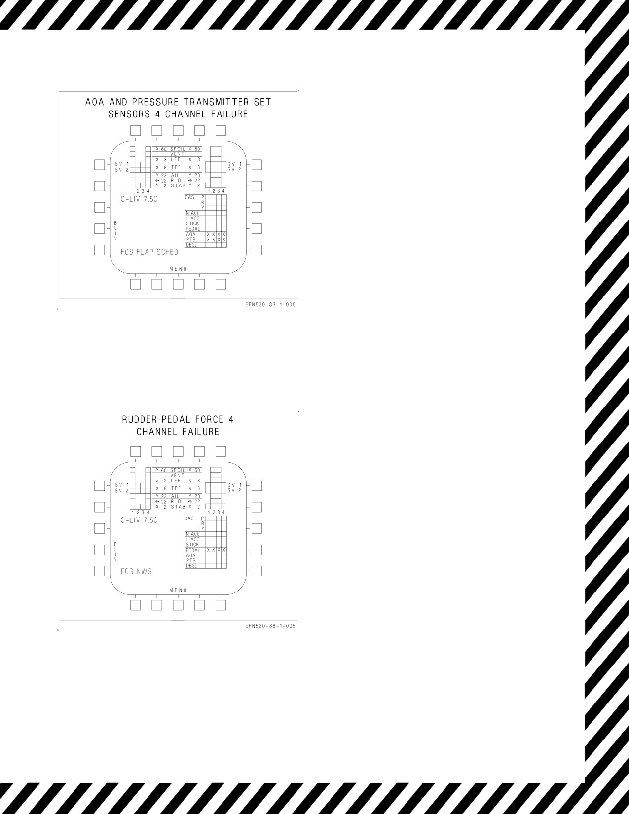
A1-F18EA-NFM-000
EFFECTS:
Pitot-static instruments may be inaccurate.
Autopilot inoperative.
Air data blanked from HUD.
Loss of HUD barometric altitude, airspeed, and
vertical velocity.
Standby altimeter may be available.
Flaps - AUTO:
Degraded flying qualities.
Flaps freeze.
Flaps go to 5°/4° if GAIN ORIDE selected.
Flaps - HALF or FULL:
No rudder toe-in.
Flaps freeze.
Flaps go to
21°/30° or
21°/40° if GAIN
ORIDE selected.
Loss of AOA bracket and AOA approach/
indexer lights without GAIN ORIDE
selected.
Figure 15-35. FCS Failure Indications and
Effects
EFFECTS:
NWS caution is also displayed.
Reduced rudder pedal authority.
Lateral stick gives rudder for roll coordination.
Flaps - AUTO:
Trim gives 10° rudder authority.
Flaps - HALF or FULL:
Trim gives 22.5° rudder authority.
NWS inoperative.
Figure 15-36. FCS Failure Indications and
Effects
V-15-41
ORIGINAL
A1-F18EA-NFM-000
NOTE
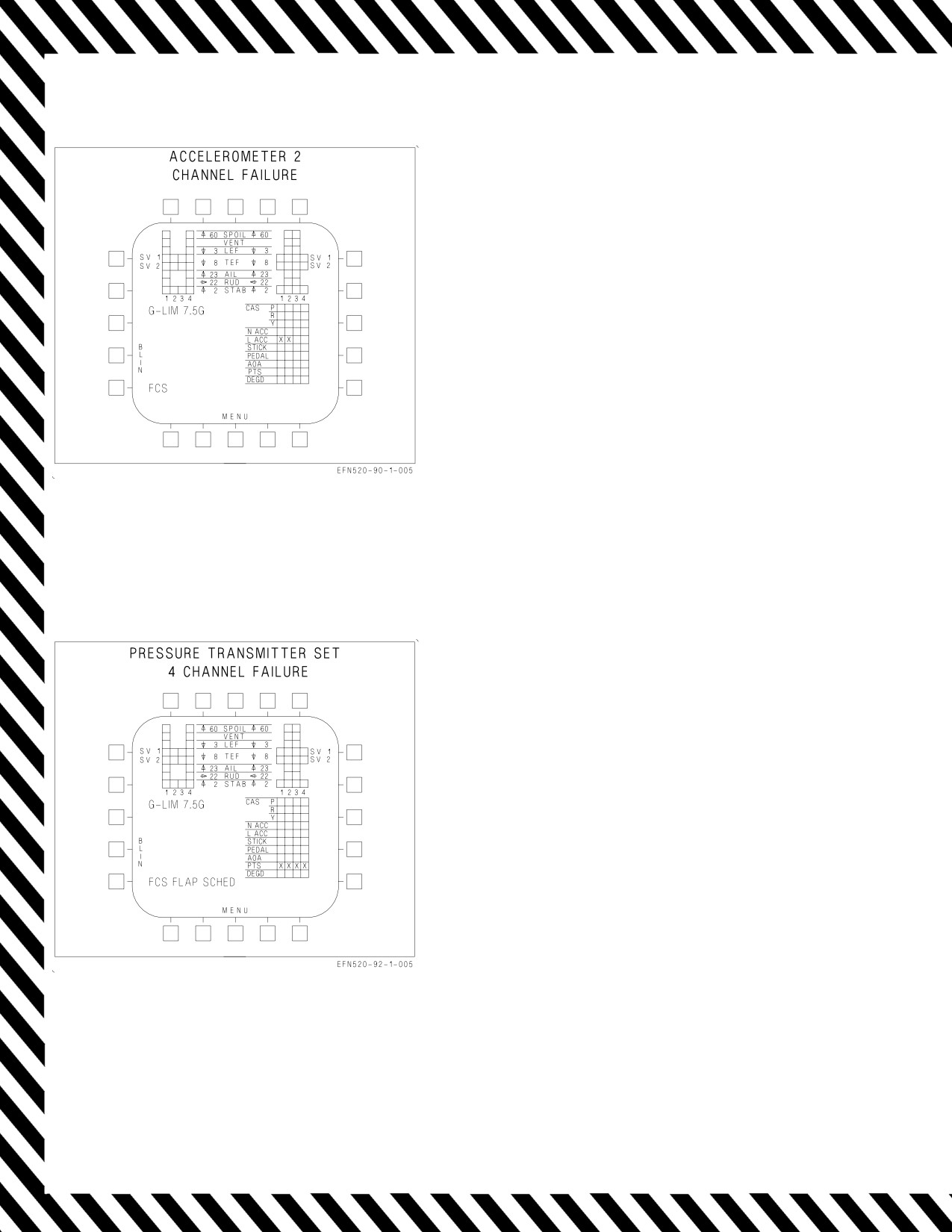
FCS status display is shown for
lateral accelerometer channels 1 and
2 failure example.
EFFECTS:
No change in flying qualities.
Autopilot inoperative.
Figure 15-37. FCS Failure Indications and
Effects
EFFECTS:
Pitot-static instruments may be inaccurate.
Autopilot inoperative.
Loss of HUD barometric altitude, airspeed, and
vertical velocity.
Standby altimeter available.
Flaps - AUTO:
Degraded flying qualities.
Flaps schedule with AOA only.
Flaps go to 5°/4° if ORIDE selected.
Flaps - HALF or FULL:
Trailing edge flaps go to 30° or 40°.
Leading edge flaps and rudder toe-in schedule
with AOA.
Figure 15-38. FCS Failure Indications and
Effects
V-15-42
ORIGINAL
A1-F18EA-NFM-000
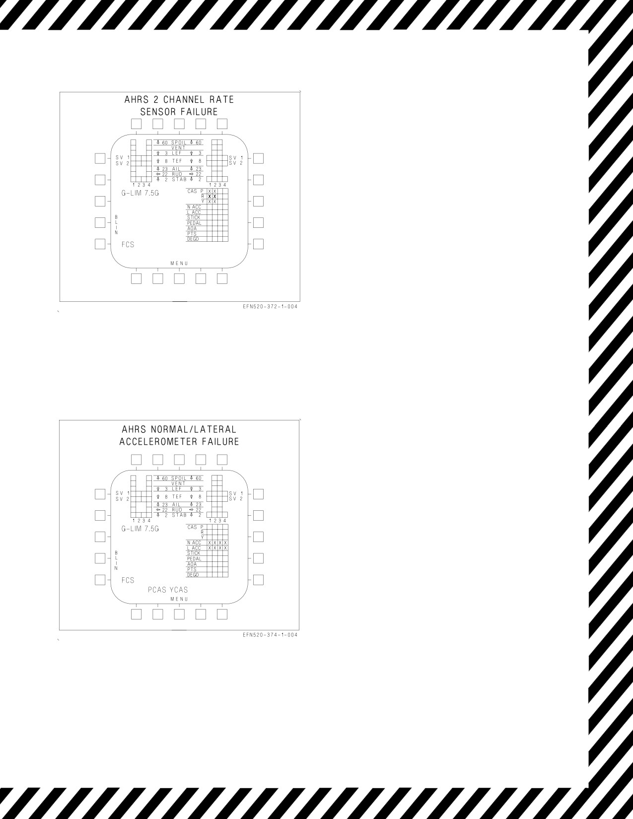
EFFECTS:
Autopilot inoperative.
If third undetected failure occurs, the following
flying qualities will be evident -
Poor roll coordination with large lateral
inputs.
Pitch coupling.
Sluggish pitch response.
Figure 15-39. FCS Failure Indications and
Effects
EFFECTS:
Autopilot inoperative.
ATC inoperative.
Spin recovery arrow not provided, but ASM still
available.
Flaps - AUTO:
Degraded pitch CAS
Degraded yaw CAS
Flaps - HALF or FULL:
Large sideslips with full rudder
Figure 15-40. FCS Failure Indications and
Effects
V-15-43
ORIGINAL
A1-F18EA-NFM-000
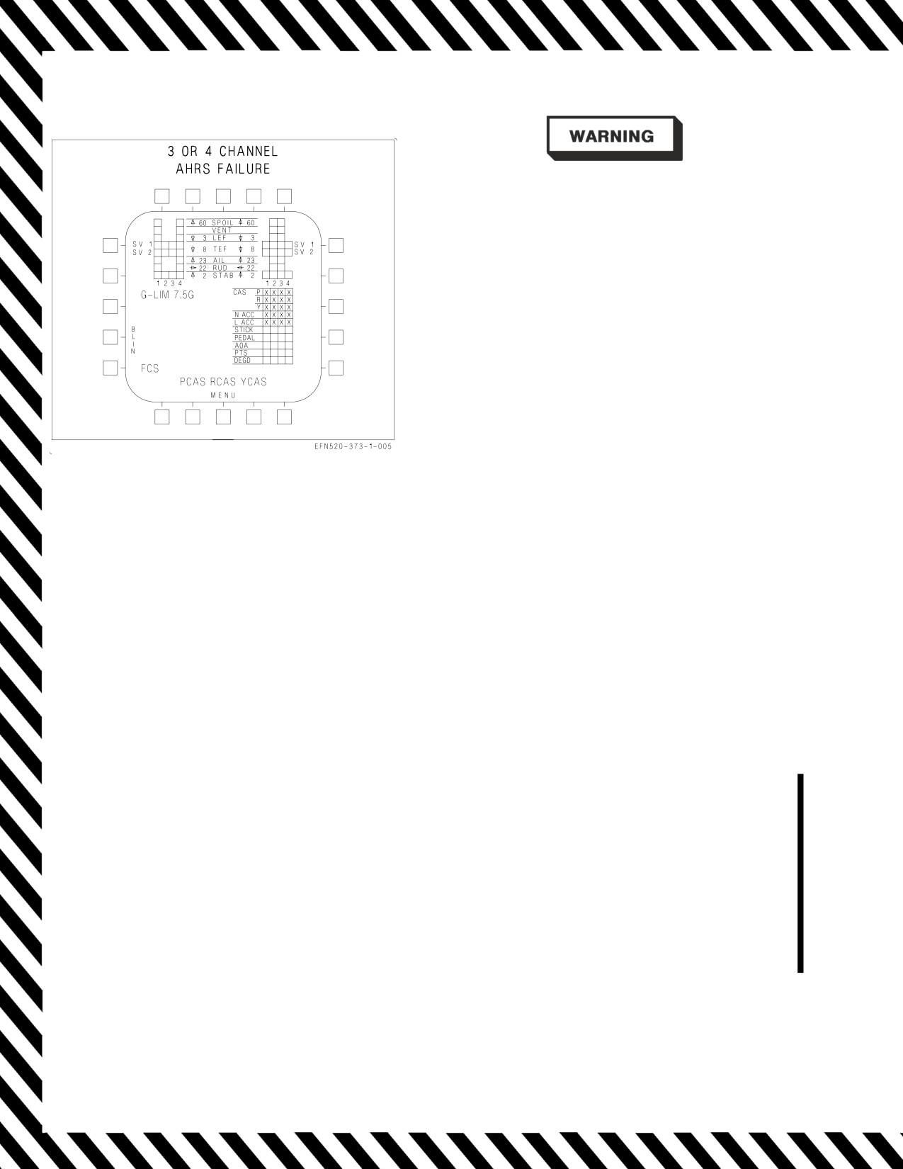
Do not select flaps HALF or FULL.
NOTE
If detected by the FCCs, the
indications for a three and four
channel failure are the same. A third
undetected channel failure appears as
a two channel failure.
EFFECTS:
Autopilot inoperative.
ATC inoperative.
Sensitive dynamic pitch characteristics.
Aggressive pitch inputs may result in PIO.
Degraded roll CAS.
Reduced roll damping.
Figure
15-41. FCS Failure Indications and
ASRM inoperative.
Effects
Flaps - AUTO:
Poor dutch roll damping.
Large sideslip with lateral stick.
Degraded roll CAS.
Reduced roll damping.
Flaps - HALF or FULL:
Uncontrollable.
15.19
ANGLE OF ATTACK (AOA) FAILURE
The AOA values displayed on the FCS Status page on the DDI represent source-error corrected AOA
values, also referred to as True AOA values. In normal operation, the average of the Left and Right
True AOA values is used to drive the HUD AOA numeric value, E-bracket and indexer lights. The AOA
values on the FCS Status page remain displayed even if a probe is damaged or binding. Pilots can use
these displayed values at any time to determine the health of each probe by: comparing their values to
each other; performing an AOA/airspeed crosscheck; or comparing each value to the center AOA value
derived from INS data.
When flaps are in Up/Auto, the HUD AOA numeric value is equal to the average of the displayed
left and right AOA probe values until AOA exceeds approximately 45° (True AOA), at which time INS
based AOA estimations are used for display.
In Flaps Up/Auto, whenever a filtered difference of the left and right AOA probe values exceeds
about 10° (a 15.5° uncorrected, local AOA probe-split), the L-versus-R AOA monitor is tripped, a
four-channel AOA failure is declared, and the HUD AOA numeric value is blanked. In Flaps
HALF/FULL, whenever the filtered difference of the left and right AOA probe values exceeds the
failure threshold (with zero sideslip, about 3° true, 5.5° local AOA), a four-channel AOA failure is
declared, and the HUD E-bracket, AOA numeric value and indexer lights are blanked. In Flaps
HALF/FULL, the failure threshold is increased as a function of sideslip. With no sideslip, the failure
threshold is about 3°, but increases to approximately 10° with 15° of sideslip.
V-15-44
ORIGINAL
A1-F18EA-NFM-000
When the L-versus-R AOA monitor is tripped, the following will occur:
• FCS caution is annunciated
• HUD numeric value blanks
• AOA four-channel X-out is displayed on the FCS status page
• An X appears next to the altitude (indicating altitude is not corrected)
• Autopilot will not engage, or will disengage if currently engaged
When flaps are in HALF or FULL, additional indications are:
• ATC will not engage or will disengage if currently engaged
• HUD E-bracket is blanked
• AOA indexer lights and external approach lights are blanked
NOTE
The effects on ATC, HUD E-bracket, AOA indexer lights and external
approach lights, and autopilot will also occur if the unfiltered
difference in the left and right AOA probes exceeds a failure threshold
(with zero sideslip, about 3.4° true AOA) for at least 0.5 seconds.
15.19.1 AOA PROBE DAMAGE OR BINDING. Pilots should be alert for AOA probe damage or
binding. Typically, probe-damage is a result of an IFR basket strike, a bird strike or heater
malfunction. In the cruise configuration, the FCS software will only recognize a probe is damaged if
that damaged probe has an electrical malfunction or has a value that differs from the nondamaged
probe by more than the AOA failure-threshold of 10° true AOA (15.5° local AOA). If AOA probe
damage is suspected, an AOA/airspeed crosscheck in the landing configuration should be made (with
a wingman if possible). After transitioning to the landing configuration, conduct a wings-level
AOA/airspeed crosscheck as well as compare the FCS page L and R AOA probe values against the
center INS AOA value. Also make gentle, banked turns to ensure the L and R probes are tracking one
another. If a damaged probe is confirmed, execute the AOA Four-Channel Failure procedure.
NOTE
In flaps AUTO, an L-versus-R AOA failure is not latched. When the
displayed AOA
10° probe-split is no longer exceeded, the failure
annunciation will automatically clear and the HUD AOA numeric
value will return. This does not mean that both AOA probes are fully
functioning. It’s only an indication the probes are now back within at
least 10° of one another.
A binding probe, on the other hand, can occur at any time as a result of faulty cover installation,
manufacturing and/or environmental elements. The best defense against encountering a binding probe
is judicious execution of the AOA probe condition-check during the Exterior Inspection prior to
takeoff. Once airborne, whenever in the landing configuration, the best defense against a binding-probe
condition is routine AOA/airspeed crosschecks and an occasional FCS page L/R AOA probe crosscheck.
V-15-45
ORIGINAL
A1-F18EA-NFM-000
In flight, a probe that is binding will typically only make itself apparent in the landing configuration,
during gentle, banked turns or wings-level flight, with airspeeds less than 145 KCAS. Binding that
causes the filtered difference in the left and right AOA probes to exceed 3° (true AOA) will result in
a four-channel X-out.
In flaps HALF/FULL, a L-versus-R AOA failure is latched. DO NOT
reset the four-channel AOA failure. When the 3° probe-split is no longer
exceeded, the failure annunication can be manually reset, but this does
not mean that both AOA probes are now properly functioning. It is only
an indication the probes are momentarily within at least 3° of one
another. It is highly likely that the binding-condition which initiated the
original failure still exists. When a failure annunciation is reset with an
FCS reset, the subsequent return of that failure will cause a reoccurrence
of the associated effects
(such as loss of rudder toe-in, pitch down
transient). This may occur at an inopportune time such as just prior to
weight on wheels.
A binding probe can occasionally free-up, providing a valid reset window, but the probe will likely
bind again, and it may result in an insidious probe-split of less than 3° that is only detectable by an
AOA/airspeed crosscheck or judicious scan of the FCS page. If the failure annunciation is reset with an
FCS reset, any transients experienced with the first occurrence of the failure can reoccur when the
failure is subsequently annunciated. The appropriate reaction is to execute the AOA Four-Channel
Failure procedure. This procedure is designed to drive the pilot to select GAIN ORIDE, enabling the
ability to select the functional probe, once it is identified, to regain HUD displays. In addition, GAIN
ORIDE provides the pilot with a fixed AOA gain (nominal flying qualities) that is no longer dependent
on the health of the AOA probes, thereby providing immunity from further AOA failure anomalies. A
binding probe can also be intermittent or momentary. If, during an approach where autopilot and
auto-throttle modes are engaged, these modes will disengage if the FCCs detect a momentary AOA
split. Simultaneously, the HUD AOA numeric value, E-bracket and indexer lights will blank, even if
the split does not persist. If this occurs, be aware that a binding-probe condition or 4-channel AOA
failure may be imminent. A persistent split will annunciate a four channel AOA X-out.
15.19.2 AOA PROBE SELECTION AOA probe selection is only available when GAIN ORIDE is
engaged. The selected AOA probe is used to drive the HUD AOA numeric value, the E-bracket and
indexer/approach lights. This ensures that both the pilot and LSO have valid data displayed, but the
selected AOA does not drive or affect the flying qualities. However, the GAIN ORIDE mode does force
the control system to employ a fixed set of gains for AOA and air data.
Selection of an AOA probe can only be performed while in GAIN ORIDE and is accomplished by
pressing the push-tile on the digital display labeled AOA. The first pressing of the push-tile selects and
boxes the left AOA probe and the second pressing selects and boxes the right AOA probe. While a third
pressing boxes the center/INS value, that value cannot be selected to drive the HUD displays.
15.19.3 SINGLE AOA FAILURE ON TAKEOFF The FCC software monitors the AOA probe values
during takeoff to provide protection against a slow to rotate AOA probe and/or protection for a single
stuck AOA probe. The protection activates special logic that is only available during the 12 seconds
after lift-off. This logic was developed to allow a safe recoverable field and catapult takeoff. The special
V-15-46
ORIGINAL
A1-F18EA-NFM-000
processing logic is engaged if the difference between the left and right AOA probe values exceed the
instantaneous mismatch threshold after airspeed exceeds 117 KCAS with weight on wheels or during
the first 12 seconds following the transition to weight off wheels.. If this special logic is engaged, an
AOA caution is annunciated for 12 seconds following transition to weight off wheels. During that time,
the FCCs will use a fixed AOA gain for fly away and the flap state will remain in FULL flaps
irrespective of FLAP switch position. If the Left versus Right failure persists, the AOA X-out condition
will occur along with an FCS caution. Even if the AOA X-out does not occur, it is recommended that
the AOA Four Channel Failure corrective action procedure is used for landing after the mission is
complete.
15.19.4 DUAL AOA FAILURE ON TAKEOFF. With FCC OFP 18E-102 and subsequent, there is added
protection provided to counter the unlikely event of a dual AOA failure (both probes binding) on
takeoff. The FCC software monitors the AOA probe values during takeoff to ensure that they are
moving properly. There are two monitors active on takeoff. The first monitor simply looks for both
AOA probes to be in the range of -6° to 10° as the aircraft accelerates through 100 to 112 KCAS, with
WonW and weight on the nosewheel. If both probes are outside this range for longer than 0.125
seconds, AOA special logic (fixed gains) is engaged. After transitioning to weight off wheels, there is an
additional monitor that compares the average corrected AOA values from the probes to an estimated
AOA value derived from pitch and flightpath angles. If average corrected AOA value from the probes
differs by 6° or more from the estimated AOA value within the first 8 seconds after takeoff, the AOA
special logic is engaged. The AOA special logic provides the control system a fixed AOA gain for a
nominal takeoff. Aircraft takeoff-characteristics are nominal, with a slight nose−down tendency. The
special logic is annunciated to the pilot in the form of an AOA caution which is set for a period of 12
seconds after the transition to weight off wheels. During the 12 second period the flaps are commanded
to FULL regardless of the FLAP switch position. At the end of the 12 seconds the flaps will move to
a position coincident with the FLAP switch position, and a FCS caution is set along with a four-channel
AOA X-out. This four-channel AOA X-out condition can not be reset in flight. Execute the AOA Four
Channel Failure corrective action procedure.
15.20
AILERON HINGE FAILURE - SUSPECTED, INBOARD.
Inboard aileron hinge failure may be suspected if a sudden uncommanded roll-off appears with no
corresponding aural ″Flight Controls, Flight Controls″ alert or associated FCS Xs or BLIN codes. If the
hinge has failed, the affected aileron will not respond normally to commanded inputs. However, the
aileron position indicator on the FCS page will function normally since the affected aileron actuator is
operating properly. In this case, the aileron position indicator on the FCS page will be indicating the
position of the actuator rod and not the aileron surface. The only true indication of this failure is a
visual check of the suspected aileron to determine if it is responding to control inputs.
For a failed hinge condition, the resultant flying qualities will be degraded but adequate for a shore-
based landing. Aircraft response to normal control inputs will be fairly uncoordinated and roll
performance away from the damaged aileron will be reduced. A failed inboard hinge may result in a
condition where wing and aileron oscillations occur, immediately reduce airspeed by decelerating at 1g
without using speedbrake until the oscillations subside.
NOTE
Do not use speedbrake to reduce airspeed. Ailerons contribute to the
integrated speedbrake function and selecting speedbrake with a
damaged aileron may cause roll transients.
V-15-47
ORIGINAL
A1-F18EA-NFM-000
If ship based, divert to an appropriate airfield. When determining the divert/BINGO profile,
consider the presence of wing or aileron oscillations and their impact on divert airspeed and fuel
management.
The presence of wing or aileron oscillations and the need to slow down
until the oscillations subside may significantly impact the planned
divert/BINGO profile.
Prior to landing, conduct a controllability check. During the controllability check, avoid selecting
flaps - HALF or FULL. Selecting flaps - HALF or FULL will cause significant roll-off into the failed
aileron. Because a hinge failure is undetected by the FCS, normal operation is assumed and aileron
droop will be commanded when flaps HALF or FULL is selected. The damaged aileron is likely to
remain undrooped and result in significant roll-off due to asymmetric aileron droop. For this case, large
stick deflections are required to maintain wings level and significant trim inputs are necessary to
reduce stick forces. Placing the flaps in HALF or FULL may also result in control surface binding if
the damaged aileron interferes with the deflection of the trailing edge flaps (TEF).
Lateral weight asymmetries will aggravate the roll-off and may preclude the aircrew’s ability to zero
the roll-off with trim. Consideration should be given to jettisoning stores to reduce lateral weight
asymmetries and to reduce gross weight for landing.
Execute a FLAPS-AUTO, straight-in approach (on-speed AOA, if controllable) to landing. Trim as
required to reduce lateral stick forces. Crosscheck aircraft groundspeed to ensure that it is below safe
tire speed limits and the maximum engagement speed for the arresting gear. If controllability is not in
question, fuel may be dumped to reduce airspeed. However, controllability checks should be completed
at the new (lighter) weight. The aircraft should then be re-trimmed on-speed for wings level and
balanced (ball centered) flight. As the aircraft slows, it will require more directional trim to center the
ball. Flying qualities should be adequate for a normal shore-based FLAPS-AUTO approach to landing.
Handling characteristics may be degraded such that aircraft response to control stick or throttle inputs
may be coupled in roll, pitch, and yaw. These transient aircraft motions may be annoying, but do not
significantly degrade glideslope and line-up capture.
15.20.1 Suspected Inboard Aileron Hinge Failure Corrective Action.
If failed inboard aileron hinge suspected -
1. Reduce load factor to 1g.
2. Oppose roll-off with lateral stick, rudder or trim.
If aileron or wing oscillations are present -
3. Airspeed - IMMEDIATELY REDUCE UNTIL OSCILLATIONS SUBSIDE.
DO NOT USE SPEEDBRAKE TO REDUCE AIRSPEED.
If aileron or wing oscillations are present, failure to immediately reduce
airspeed until oscillations cease can result in further structural failure.
V-15-48
ORIGINAL
A1-F18EA-NFM-000
If no aileron or wing oscillations are present -
3. Airspeed - MAINTAIN AS PRACTICAL
NOTE
Use of speedbrake with a damaged aileron will cause an immediate roll
transient and should be avoided.
4. Use smooth, small control inputs.
5. Land as soon as practical.
If ship based -
6. DIVERT
Bingo profile may be adversely affected due to reduced airspeed neces-
sary for given condition. Allow for a controllability check prior to landing.
For shore-based landing -
7. Perform controllability check with FLAPS AUTO at safe altitude. Trim as required.
8. Verify aircraft groundspeed is less than nose tire and arresting gear groundspeed limits.
9. Execute a straight-in approach with FLAPS AUTO.
10. Make a short field arrestment if situation permits.
V-15-49 (Reverse Blank)
ORIGINAL
A1-F18EA-NFM-000
CHAPTER 16
Landing Emergencies
16.1 SINGLE ENGINE FAILURE IN LANDING CONFIGURATION
At MIL power and below, the amount of yaw/roll caused by a single engine failure is minimal, and
the aircraft is easily controllable. If an engine fails with both throttles at MAX power (e.g., waveoff),
a significant amount of yaw/roll can be anticipated due to asymmetric thrust. In this case, timely
rudder pedal inputs (up to FULL) are required. Too much rudder pedal is not harmful, but too little
rudder pedal may cause controllability problems. Therefore, FULL rudder pedal to oppose yaw/roll is
prudent. If lateral stick is also required to oppose roll (worst case), inputs should be limited to
approximately ½ displacement. Lateral stick inputs greater than ½ throw may compromise direc-
tional controllability and result in excessive sideslip buildup. The demand on the rudders may be too
great when trying to balance asymmetric thrust and coordinate the adverse yaw generated by the
ailerons when opposing the tendency of the aircraft to roll into the failed engine. If the rudders are
saturated (surfaces against the stops) and additional adverse yawing moment is generated, sideslip
grows and an adverse yaw departure will result. During single engine operations, restricting lateral
stick inputs to less than ½ throw reduces the potential for an adverse yaw departure.
*1. Throttles - MIL or MAX
*2. FLAP switch - HALF
*3. Maintain on-speed AOA and balanced flight.
When single engine with the operating engine at MAX, the possibility of
an adverse yaw departure increases as AOA exceeds on-speed.
4. Refer to Single Engine Approach and Landing.
16.2 SINGLE ENGINE APPROACH AND LANDING
During a single engine approach and landing, use of the afterburner on the operating engine is not
restricted as long as on-speed AOA is maintained.
When single engine with the operating engine at MAX, the possibility of
an adverse yaw departure increases as AOA exceeds on-speed.
GENERAL CONSIDERATIONS -
1. Reduce gross weight (44,000 lb max, lower if practical).
2. Maintain operating engine above 80% RPM during flap and landing gear extension.
V-16-1
ORIGINAL
A1-F18EA-NFM-000
3. Consider crossbleed to provide HYD 2 pressure to extend the landing gear normally and to
preserve APU accumulator pressure for emergency braking and emergency nosewheel steering.
• Do not crossbleed if engine and/or AMAD related damage is sus-
pected.
• Extended crossbleeding of a failed engine traps feed tank fuel on that
side if the FIRE light has not been pushed, and may result in a
flameout.
• ATS exhaust may blister paint and cause possible door damage on the
aft underside of the fuselage.
• Starting the APU airborne may result in a BALD shutdown due to
ingestion of exhaust gases into the APU ducting.
4. Fly a straight-in approach.
5. Plan approach to make turns using shallow bank angle (≤15°)
6. Do not exceed on-speed AOA in turns.
7. Avoid turns into inoperative engine.
LEFT ENGINE FAILED -
1. FLAP switch - HALF
2. LDG GEAR handle - DN
3. Make a normal landing or a precautionary short field arrested landing (if practical).
RIGHT ENGINE FAILED -
1. FLAP switch - HALF
2. Execute Landing Gear Emergency Extension procedure.
If short field arresting gear available -
3. Make an arrested landing.
If short field arresting gear NOT available and right engine crossbleed NOT desired/required -
3. EMERG BRK handle - VERIFY PULLED TO DETENT (anti-skid is not available)
4. Make a normal landing.
5. Consider paddle switch - PRESS after touchdown to preserve APU ACCUM pressure for braking
and slow-speed NWS.
6. Use emergency brakes with steady brake pressure (Do Not Pump). Anti-skid is not available.
V-16-2
ORIGINAL