F18. FLIGHT MANUAL (2008) - page 29
A1-F18EA-NFM-000
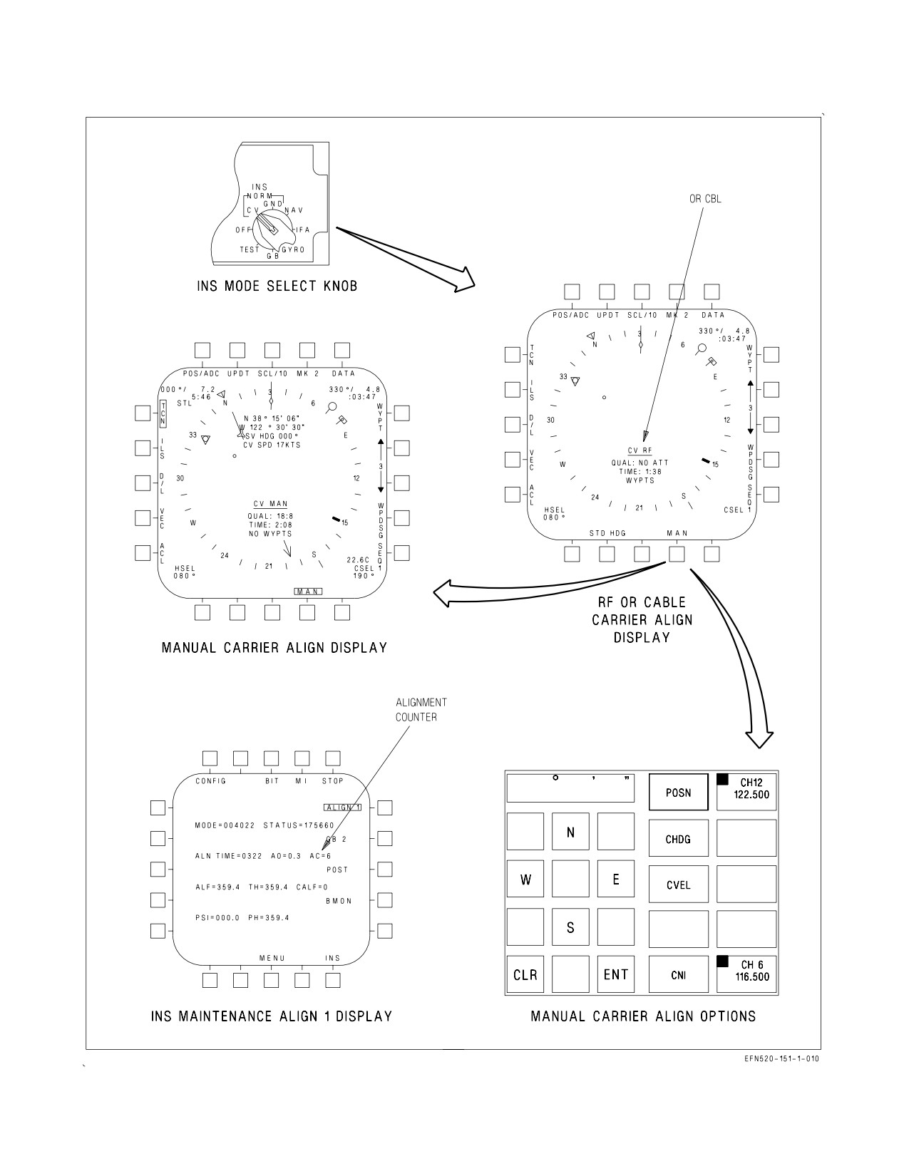
Figure 24-4. INS CV Align
VII-24-15
ORIGINAL
A1-F18EA-NFM-000
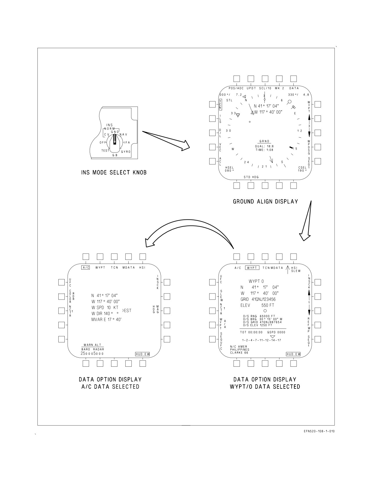
Figure 24-5. INS Ground Align
VII-24-16
ORIGINAL
A1-F18EA-NFM-000
If the aircraft takes off in GND mode before OK is displayed and the QUAL number is greater than
5, the INS switches to GYRO mode (AHRS attitude only). If the aircraft takes off in GND mode before
OK is displayed and the QUAL number is less than or equal to 5, the INS switches to POS/INS mode
with limited performance. These partial alignments can be completed by selecting IFA.
24.2.3.3 Stored Heading (STD HDG) Alignment. A Stored Heading alignment may be performed to
reduce alignment time if the INS was turned off after a good alignment, the parking brake was set at
shutdown, and no other INS mode was selected prior to turning the INS knob to OFF. The STD HDG
option is provided on the HSI CV/GND alignment display if available (figure 24−5). The STD HDG
option is removed when a GND or CV SINS alignment has progressed to the point where selecting the
STD HDG option would not reduce alignment time; or, during a CV alignment, when the MAN option
is selected.
Selecting the STD HDG option results in an alignment based on the stored heading when the INS
was turned off. To perform a Stored Heading alignment, the parking brake must be set, WYPT 0,
ZTOD, and DATE entered, the INS knob turned to CV or GND, and the STD HDG option selected.
During a Stored Heading alignment, the INS checks if the current heading is the same as the previous
alignment’s heading. If so, OK is displayed next to the QUAL number for CAINS, within 3 minutes for
a GND alignment and within 4 minutes for a CV SINS alignment; for ANAV, within 30 seconds for a
GND alignment and within 60 seconds for a CV SINS alignment. After OK is displayed, the INS knob
can be turned to IFA (POS/AINS) or NAV (POS/INS). If the aircrew allows the alignment to continue,
the QUAL number may decrease as the alignment continues normally.
If the aircrew believes that the aircraft has been moved or its shutdown heading has changed either
on the ground or with respect to the carrier deck, a Stored Heading alignment should not be attempted
even if the STD HDG option is available. If the aircraft has moved, poor performance may result if a
Stored Heading alignment is achieved.
24.2.3.4 In-Flight Alignment (IFA). An IFA may be used with WonW (IFA GPS only) or in−flight
to perform a complete alignment (e.g., INS failure) or complete a partial CV/GND alignment. With the
APG−73 Radar installed, an IFA can be performed with either magnetic heading and radar precision
velocity update (PVU) data (IFA RDR), or with GPS satellite data (IFA GPS). With the APG−79
Radar installed, an IFA can only be performed with GPS satellite data (IFA GPS). An IFA should be
considered a backup alignment mode to GND and CV alignments.
NOTE
The APG−79 Radar does not perform PVUs; therefore, radar IFA is
not possible. However, IFA RDR is displayed until good GPS satellite
data is acquired.
Present position can be provided but is not required for the alignment by performing a position
update using the UPDT option or by entering the aircraft data on the UFCD using the DATA option.
Another very good technique is to select TACAN position keeping if a stationary TACAN is available.
Velocity updates cannot be performed during an IFA. The VEL update option is displayed but is not
functional.
VII-24-17
ORIGINAL
A1-F18EA-NFM-000
24.2.3.4.1 IFA (APG-73). Select STBY with the ATT switch to verify the accuracy of HUD attitude
data by crosschecking the standby instruments. If POS/MIDS is the current position keeping mode,
select POS/ADC.
NOTE
If POS/MIDS is the current position keeping mode, select POS/ADC
before commencing IFA procedures.
Select NAV master mode and radar altitude to the HUD. Then turn the INS knob to OFF for 20
seconds. On the SUPT/HSI/DATA/(A/C) page, check magnetic variation, present position, and winds
aloft. To check the magnetic variation, observe the magnetic variation value on the SUPT/HSI/DATA/
(A/C) page or observe the difference between true heading and magnetic heading and compare this to
the known local magnetic variation. If aircraft data is incorrect, refer to Aircraft (A/C) Programming
(this chapter) to update.
NOTE
• Checking and correcting magnetic variation is critical. Excessive drift
error in magnetic variation causes insidious errors in aircraft heading.
This induces navigation deviations that are especially significant
during instrument departures and approaches.
• Since the magnetic variation changes as a function of the aircraft
position (latitude/longitude), the correct local magnetic variation must
be manually re-entered periodically to maintain an error−free mag-
netic heading. Updating the magnetic variation every 100 NM is
sufficient as long as the aircraft does not fly near or greater than 60°
North or South latitude. In these Polar Regions, magnetic variation (as
well as magnetic heading) changes significantly as a function of
aircraft position change. Flying True Heading is advisable in these
regions.
If the IFA is being performed with WonW, enter WYPT 0, ZTOD and Date. If in flight, maintain
straight and level, unaccelerated flight for 20 seconds, then turn the INS knob to IFA. The navigation
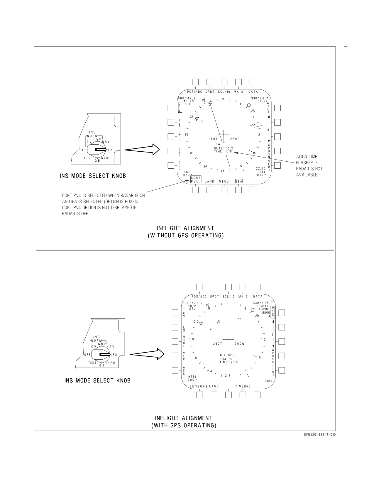
system is turned on and IFA alignment data is displayed on the HSI (figure 24-6). IFA RDR is
displayed but may immediately switch to IFA GPS with good satellite data. If IFA GPS is displayed,
complete the alignment with the IFA GPS Indicated steps. Maintain straight and level flight for at
least 30 seconds after selecting IFA. When IFA is selected, the radar may enter the PVU mode. In the
PVU mode, CONT PVU and SEA options are boxed (default selection). Verify that the proper radar
PVU mode is selected (LAND or SEA) and observe that the TIME begins to increment. During the
first 10 to 15 seconds of the alignment while the INS platform is being leveled, NO ATT is displayed
to the right of QUAL. Wait until after NO ATT clears and is replaced with the QUAL number. Then
select AUTO or INS with the ATT switch and the INS ATT caution clears when the QUAL number
becomes less than 5.0. Selecting AUTO or INS replaces standby attitude reference indicator data on
the HUD with INS attitude data. The waterline symbol is replaced with the velocity vector which may
be slowly flashing if vertical velocity is degraded. The velocity vector continues to slowly flash until
vertical velocity becomes valid (when the QUAL number is approximately 5.0). When horizontal
position becomes valid, the POS/ADC caution clears.
VII-24-18
ORIGINAL
A1-F18EA-NFM-000
IFA RDR Indicated -
Maintain straight and level flight for as much as practical during the alignment. If a turn must be
executed, rapidly exceed 30° AOB and return to straight and level flight as soon as possible. This
prevents the INS from aligning to a false reference by placing the alignment on hold until straight and
level flight is regained. During an IFA, air data dead reckoning is used for navigation to maintain a
current present position. When a satisfactory alignment is achieved (OK displayed), turn the INS knob
to NAV. For landing, crosscheck HUD information with the standby instruments.
Following an IFA RDR, make every attempt to maintain VMC with a
discernible horizon. Residual attitude errors may be subtle and difficult
to discern without reference to a visible horizon or the standby instru-
ments. If velocity vector information is suspect, select STBY to the HUD.
PVU mode may be overridden by deselecting the CONT PVU option but IFA quality will be
affected. Deselecting CONT PVU alternates PVU mode with the last selected radar mode. In PVU
mode, the radar provides Doppler velocities for INS alignment. The radar look-down angles are
optimized for land or sea return by selection of the LAND or SEA option. PVU is inhibited for IFA if
the aircraft is not in the NAV master mode. If the radar is not operating or is inhibited from operating
in PVU, the TIME flashes and the CONT PVU option is not displayed.
IFA GPS Indicated -
Perform one gentle 90° S-turn (less than 20° AOB and ± 10° pitch) to facilitate the alignment. Then
maintain straight and level flight as much as practical. When a satisfactory alignment is achieved, the
IFA alignment data is removed from the HSI and the MC automatical transitions to POS/AINS
position keeping mode. GPS IFA takes approximately 10 minutes.
If good GPS satellite data is lost prior to achieving a satisfactory alignment (OK not displayed)
during a GPS IFA, the INS suspends the alignment. If good satellite data is re-acquired within 65
seconds, the INS continues to align using GPS data. If good satellite data is not re-acquired within 65
seconds, the MC attempts to complete the alignment with a radar IFA as described in IFA RDR
Indicated. If WonW, wait until good GPS satellite data is available (SAT STATUS = GOOD on the
GPS page) or turn the INS knob to OFF for 20 seconds and perform the appropriate alignment (GND
or CV). If good GPS satellite data is lost after achieving a satisfactory alignment using GPS data, the
position keeping mode defaults to POS/INS and a P/INS advisory is displayed until good GPS satellite
data is available (SAT STATUS = GOOD on the GPS page) and then the position keeping mode
automatically returns to POS/AINS and the P/INS advisory clears.
IN-FLIGHT ALIGNMENT (APG-73)
1. ATT switch - STBY
2. If POS/MIDS is the current aircraft position keeping mode, select POS/ADC.
3. NAV master mode - SELECT
4. ALT switch - RDR
5. INS knob - OFF (20 seconds minimum)
VII-24-19
ORIGINAL
A1-F18EA-NFM-000
6. HSI/DATA/(A/C) page - Update MVAR, position, and winds aloft (if required).
7. If WonW, enter WYPT 0, ZTOD and DATE.
8. If in flight, maintain straight and level, unaccelerated flight for 20 seconds prior to selecting IFA.
9. INS knob - IFA
10. Maintain straight and level, unaccelerated flight for at least 30 seconds after selecting IFA.
11. HSI page - SELECT SEA or LAND (IFA RDR only)
After NO ATT is cleared from the HSI -
12. ATT switch - AUTO or INS (VV position is degraded if flashing slowly)
IFA RDR indicated -
13. Maintain straight and level flight as much as practical during alignment. If a turn must be
executed, rapidly exceed 30° AOB and return to straight and level flight as soon as possible.
When QUAL indicates OK (approximately 20 minutes) -
14. INS knob - NAV
Following an IFA RDR, make every attempt to maintain VMC with a
discernible horizon. Residual attitude errors may be subtle and difficult
to discern without reference to a visible horizon or the standby instru-
ments. If velocity vector information is suspect, select STBY to the HUD.
For landing -
15. Crosscheck HUD information with standby instruments.
IFA GPS indicated -
13. Perform one gentle 90° S-turn (less than 20° AOB and ± 10° pitch), then maintain straight and
level flight as much as practical.
Within approximately 10 minutes -
14. HSI page -Verify transition to POS/AINS.
VII-24-20
ORIGINAL
A1-F18EA-NFM-000
Figure 24-6. INS In-Flight Align
VII-24-21
ORIGINAL
A1-F18EA-NFM-000
24.2.3.4.2 IFA (APG-79). Select STBY with the ATT switch to verify the accuracy of HUD attitude
data by crosschecking the standby instruments. If POS/MIDS is the current position keeping mode,
select POS/ADC.
NOTE
If POS/MIDS is the current position keeping mode, select POS/ADC
before commencing IFA procedures.
Select NAV master mode and radar altitude to the HUD. Then turn the INS knob to OFF for 20
seconds. If the IFA is being performed with WonW, enter WYPT 0, ZTOD, and DATE. Turn the INS
knob to IFA and the navigation system is turned on and IFA alignment data is displayed on the HSI
(figure 24-6). While waiting for the GPS to acquire good GPS satellite data, IFA RDR is displayed, the
TIME flashes, and the INS suspends the alignment. Once good GPS satellite data is acquired, IFA
GPS is displayed and the alignment begins. During the first 10 to 15 seconds of the alignment while the
INS platform is being leveled, NO ATT is displayed to the right of QUAL. Maintain straight and level,
unaccelerated flight to level the INS and clear the NO ATT indication. NO ATT is replaced with the
QUAL number. Then select AUTO or INS with the ATT switch and the INS ATT caution clears when
the QUAL number becomes less than 5.0. Selecting AUTO or INS replaces standby attitude reference
indicator data on the HUD with INS attitude data. The waterline symbol is replaced with the velocity
vector which may be slowly flashing if vertical velocity is degraded. The velocity vector continues to
slowly flash until vertical velocity becomes valid. When the GPS horizontal position becomes valid, the
POS/ADC caution clears. Perform one gentle 90° S-turn (less than 20° AOB and ±10° pitch) to
facilitate the alignment. Then maintain straight and level flight as much as practical. When a
satisfactory alignment is achieved, the IFA alignment data is removed from the HSI and the MC
automatically transitions to POS/AINS position keeping mode. IFA takes approximately 10 minutes.
This time can be greatly reduced by performing the S-turn.
An IFA may be used to complete a partial CV/GND alignment. At takeoff with a partial alignment,
the INS platform should already be leveled (NO ATT replaced with a QUAL number). Select IFA and
the position keeping mode automatically transitions to POS/AINS once a satisfactory alignment has
been achieved. Completing a partial alignment with an IFA may occur very quickly.
If good GPS satellite data is lost prior to achieving a satisfactory alignment (OK not displayed), the
INS suspends the alignment. If good satellite data is not re-acquired within 65 seconds, the TIME
flashes. Wait until good GPS satellite data is available (SAT STATUS = GOOD on the GPS page) or
if WonW, turn the INS knob to OFF for 20 seconds and perform the appropriate alignment (GND or
CV). If good GPS satellite data is lost after achieving a satisfactory alignment, the position keeping
mode defaults to POS/INS and a P/INS advisory is displayed until good GPS satellite data is available
and then the position keeping mode automatically returns to POS/AINS and the P/INS advisory
clears.
IN-FLIGHT ALIGNMENT (APG-79)
1. ATT switch - STBY
2. If POS/MIDS is the current position keeping mode, select POS/ADC.
3. NAV master mode - SELECT
4. ALT switch - RDR
VII-24-22
ORIGINAL
A1-F18EA-NFM-000
5. INS knob - OFF (20 seconds minimum)
6. If WonW, enter WYPT 0, ZTOD, and DATE.
7. INS knob - IFA
8. Maintain straight and level, unaccelerated flight until NO ATT is cleared from the HSI.
9. ATT switch - AUTO or INS (VV position is degraded if flashing slowly)
10. Perform one gentle, 90° S-turn (less than 20° AOB and ± 10° pitch), then maintain straight and
level flight as much as practical.
Within approximately 10 minutes -
11. HSI page - Verify transition to POS/AINS
24.2.3.5 Gyro Recovery. A gyro recovery is actually an AHRS attitude only INS in which reliable
INS attitude data is recovered. With CAINS installed, the GPS may already be operating. With ANAV
installed, if the GPS is functional, the GPS initializes and acquires satellites. Select AUTO or INS with
the ATT switch and maintain straight and level, unaccelerated flight. Turn the INS knob to OFF for
20 seconds prior to selecting GYRO. The INS ATT caution does not clear and standby attitude
reference indicator data on the HUD remains until GPS velocity data is valid if operational. If takeoff
occurs with a partial alignment, GYRO mode is available.
24.2.4 Navigation System BIT.
24.2.4.1 CAINS and GPS. The INS and GPS uses start-up, periodic and initiated built−in test
(BIT). Start-up BIT is performed when power is applied to the INS or GPS. Periodic BIT monitors
essential parameters within the system and provides in-flight, shipboard, and ground failure detection
and isolation. Initiated BIT is performed on the ground and accomplishes that portion of the failure
detection and isolation capability which periodic BIT is unable to do. Initiated BIT can be performed
by selecting the INS (with the INS knob in TEST) or the GPS option on the NAV sublevel of the BIT
page. BIT status is displayed on the BIT page next to the INS and GPS legends.
24.2.4.2 ANAV. The ANAV (INS and GPS) uses start-up, periodic and initiated built-in test (BIT).
Start-up BIT is performed when power is applied to the ANAV. Periodic BIT monitors essential
parameters within the system and provides in-flight, shipboard, and ground failure detection and
isolation. Initiated BIT is performed on the ground and accomplishes that portion of the failure
detection and isolation capability which periodic BIT is unable to do. Initiated ANAV BIT can be
performed by turning the INS knob to TEST and selecting the INS/GPS option on the NAV sublevel
of the BIT page. If Initiated BIT is performed prior to the completion of Start-up BIT and the INS and
GPS are functioning properly, the GPS reports PBIT GO. If Initiated BIT is performed after the
completion of Start-up BIT and the INS and GPS are functioning properly, the GPS reports GO. BIT
status is displayed on the BIT page next to the INS and GPS legends.
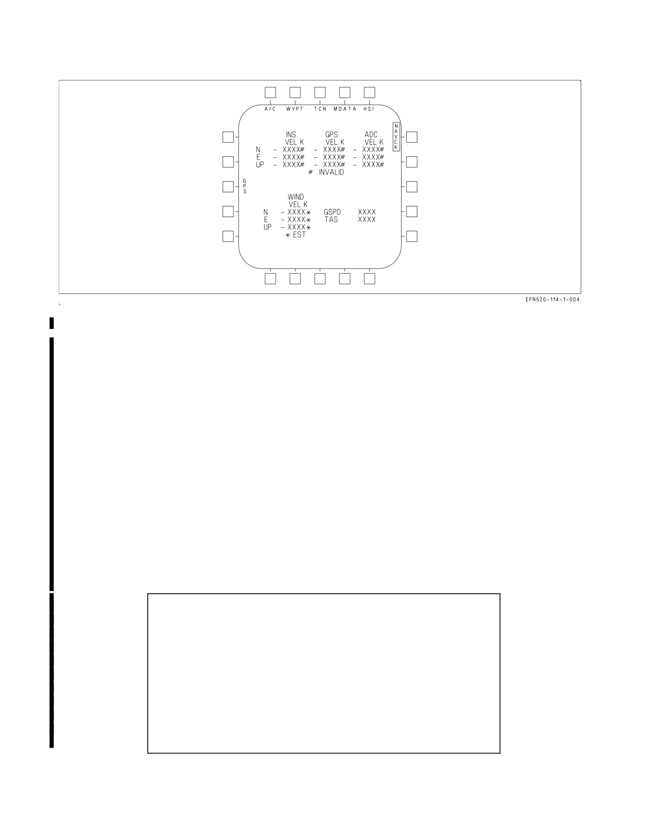
24.2.5 NAVCK Display. The NAVCK page allows analysis of INS/GPS/FCC air data function
reliability (figure 24-7). The page is displayed by selecting the NAV CK option on the HSI A/C DATA
page. The velocity check more readily indicates vertical or horizontal velocity discrepancy problems.
INS, GPS and FCC air data function velocities are periodically compared and when an excessive
disagreement is sensed, the NAV VVEL, NAV HVEL cautions or VVEL advisory (CAINS only) are
set.
VII-24-23
ORIGINAL
A1-F18EA-NFM-000
Figure 24-7. NAVCK Display
The top portion of the page consists of INS, GPS and FCC air data function (ADC) velocities. The
bottom portion consists of wind velocities, best available MC groundspeed (if valid) and best available
MC true airspeed (if not zero). INS, GPS and ADC velocity components are displayed even if invalid.
If INS, GPS or ADC data is invalid, a # is displayed to the right of the invalid data along with #
INVALID at the bottom of the page. If wind velocity is estimated, an * (asterisk) is displayed to the
right of the wind velocity components along with *EST at the bottom of the page.
24.2.6 GPS Page. The GPS page displays current GPS status (figure 24-3). The page is displayed by
selecting the GPS option on the SUPT MENU.
The GPS operating mode is displayed at the top of the page (GPS − XXXX) with possible modes
of NAV, INIT, NOT RDY, or TEST (see 24.2.2 for a description of operating modes). When the GPS
is not in TEST, the NAV and INIT options are available. The use of these two options is not
recommended.
The GPS Figure of Merit (FOM) is an indication of the estimated GPS position accuracy with a
value from 1 to 9, with 1 being the best and 9 the worst. The following table shows the corresponding
estimated accuracy.
FOM Value
Expected Position Error* (Meters)
1
Less than or equal to 25
2
Greater than 25 up to 50
3
Greater than 50 up to 75
4
Greater than 75 up to 100
5
Greater than 100 up to 200
6
Greater than 200 up to 500
7
Greater than 500 up to 1000
8
Greater than 1000 up to 5000
9
Greater than 5000
* 3−dimensional, 1−sigma
VII-24-24
ORIGINAL
A1-F18EA-NFM-000
The SAT STATUS is an indication of satellite signal integrity. Possible indications are GOOD,
MARGINAL, and JAMMED. An overall State 5 indicates GOOD, State 3 indicates MARGINAL, and
if not in State 5 and not in State 3, JAMMED is indicated.
The GPS current position is displayed along with the GPS’s Horizontal and Vertical Estimated
Errors (HERR and VERR) in feet and GPS TIME.
Up to 4 individual satellite channel states are displayed. If the number of satellites in State 5 are
greater than or equal to 4, all 4 positions indicate State 5. If less than 4 satellites are indicating State
5, the corresponding number of positions indicate State 5 and the remaining positions indicate State
3 or are blank.
The bottom of the page displays the crypto key status. Up to seven crypto key status messages can
be displayed. Three of the status messages are mutually exclusive: VERIFIED, UNVERIFIED, and
INCORRECT. The other six messages are displayed when reported by the GPS: GUV USER (group
unique variables), KEY FAIL (key failed parity), INSUFF KEY (insufficient keys), ERASE FAIL
(erase failure), 2 HR ALERT (2 hour alert), and VALID ENTRY (receiver contains keys).
24.2.7 INS Knob. The INS knob is located on the right hand console SNSR panel and has positions
of OFF, CV, GND, NAV, IFA, GYRO, GB, and TEST.
OFF
Removes power from INS. With ANAV installed, removes power from the INS and GPS.
CV
Commands the INS carrier alignment mode. With ANAV installed, GPS initializes and acquires
satellites.
GND Commands the INS ground alignment mode. With ANAV installed, GPS initializes and acquires
satellites.
NAV Commands the INS to unaided navigation mode (POS/INS) which enables the MC to use un-
aided INS or GPS data to provide navigation steering.
IFA
Commands the INS in-flight alignment mode. Also commands the INS into aided navigation
mode (POS/AINS) after a satisfactory alignment is achieved.
GYRO Commands the AHRS mode. With ANAV, GPS initializes and acquires satellites.
GB
Commands the INS to CV or GND alignment mode indefinitely. With ANAV installed, GPS ini-
tializes and acquires satellites.
TEST Enables the INS to perform an initiated BIT upon command from the MC. With ANAV in-
stalled, enables the INS and GPS to perform an initiated BIT upon command from the MC.
24.2.8
INS/GPS Related Cautions and Advisories. The following INS/GPS related cautions and
advisories are described in the Warning/Caution/Advisory Displays in Part V:
• GPS DEGD caution
• INS ATT caution
• INS DEGD caution
• NAV FAIL caution
• NAV HVEL caution
• NAV VVEL caution
• POS/ADC caution
• POS ERROR caution
• ALGN (x’d out) advisory
• GPS advisory
VII-24-25
ORIGINAL
A1-F18EA-NFM-000
• GPSMP advisory (ANAV only)
• NODOV advisory (ANAV only)
• NOSEC advisory
• P/INS advisory
• PCODE advisory
• VVEL advisory (CAINS only)
• YCODE advisory
24.2.9 Waypoints, Offset Aimpoints (OAP), and Offsets. A waypoint is a geographical point for
which latitude, longitude, and elevation are stored in the MC. An OAP is a waypoint which has an
offset associated with it. An offset is a point defined by bearing and range from the OAP along with
elevation of the point (offset).
Mission data such as waypoints and offsets may be entered using the Data Transfer Equipment
(DTE) and the mission initialization display or manually.
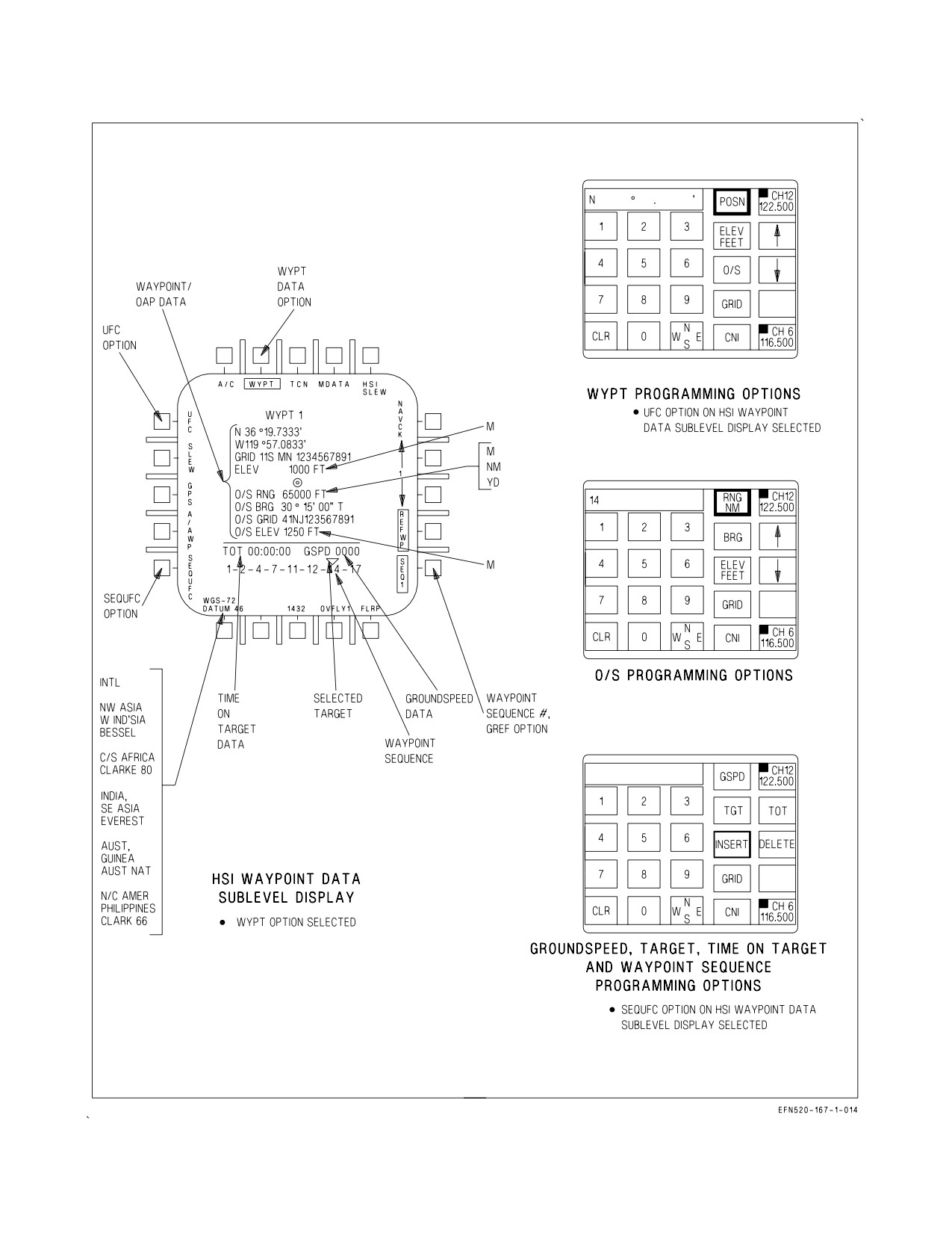
24.2.9.1 Waypoint/Offset Aimpoint Programming. Waypoint/OAP data is entered by selecting the
DATA option on the waypoint data top level display. The waypoint data display is automatically
initialized with WYPT boxed. This display shows the current waypoint/OAP data: waypoint lat/long
position, UTM Grid coordinates, and elevation; offset range, GRID, bearing, and elevation (if
applicable). Waypoint/OAP data is entered by selecting an up/down arrow to select the desired
waypoint/OAP and the UFC option to initialize the UFCD for waypoint/OAP data entry. On the
UFCD the following selections complete the selection: POSN option to enter lat/long data, ELEV
option to enter elevation data, and O/S option to enter offset data (offset range, bearing, UTM grid
coordinates and elevation). Offset data is in relation to the offset aimpoint. Waypoint/OAP data is
entered through the UFCD keypad, with a maximum of 60 waypoints (0 to 59) available for
programming. See figure 24-9, sheets 1 and 2.
Waypoint data can also be entered using the map slew method by selecting WYPT on the DATA
option display, and actuating the SLEW button. Pressing the TDC and slewing the map to the desired
lat/long position under the waypoint symbol locates the point.
NOTE
Lat/long and elevation data on the MPCD reflect the current map
position under the waypoint symbol as the map is being slewed.
Upon release of the TDC the current waypoint data is entered for the map position under the
waypoint symbol. Selecting the next waypoint number as required (using the waypoint increment/
decrement option buttons) allows further waypoint data entry.
Another map slew method is to select WYPT on the DATA option display, actuating the SLEW
button, and pressing and holding the TDC to slew the map to the desired lat/long position under the
waypoint symbol. This position is entered by selecting another waypoint (using the waypoint
increment/decrement option buttons). Continuing to hold the TDC, the map is slewed as required, and
the next waypoint is selected for further waypoint data entry.
Offset aimpoints may also be entered using the map slew method; however, the associated offset
must be entered through the UFCD.
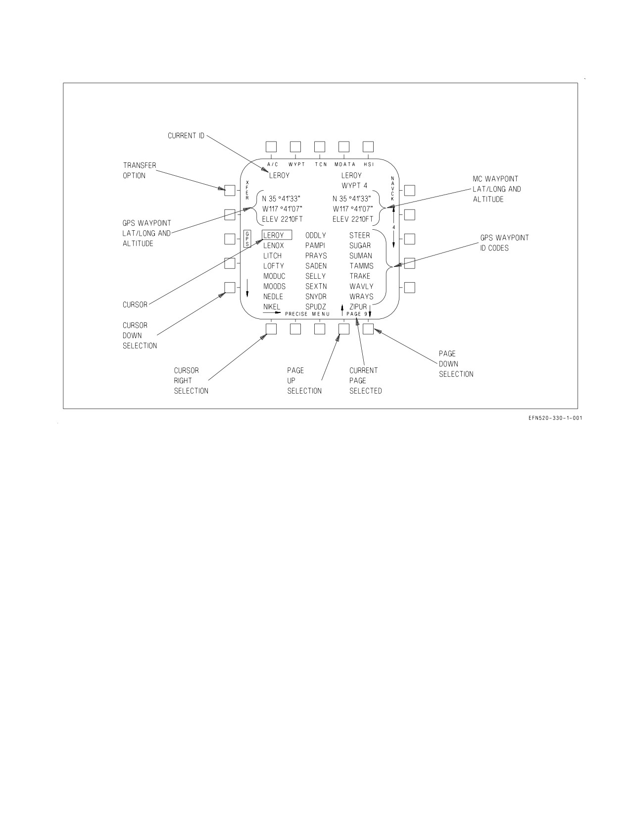
24.2.9.1.1 GPS Waypoint Programming. Aircraft with GPS can utilize the GPS to store up to 200
waypoints. GPS points are loaded into the GPS from the memory unit. GPS points can be displayed
VII-24-26
ORIGINAL
A1-F18EA-NFM-000
Figure 24-8. GPS Waypoint Display
and/or transferred into the MC waypoint data base using the HSI/DATA/GPS display. A GPS point
can be transferred into any MC waypoint by pressing the XFER option on the GPS display. When GPS
option is selected the first 24 GPS points are displayed in alphanumeric order. Selection of points to
load is accomplished by the right and down arrows and page selection arrows. Repeated selection of
these arrows causes the cursor to wrap around. It may take as long as 3 seconds to retrieve selected
position data and display it on the GPS display. See figure 24-8. GPS waypoints are transferred to the
MC by selecting the desired waypoint number with the up/down arrows on the HSI/DATA/GPS
sublevel, moving the cursor down/right and/or page up/down to the desired waypoint ID code, and
pressing XFER. The GPS LAT/LONG, GPS altitude, and current ID code displays are blanked and
the XFER option is removed. The selected ID code is displayed in the ‘‘Current ID’’ position indicating
that waypoint is requested. After approximately 3 seconds, the requested GPS LAT/LONG and GPS
altitude is displayed and the XFER option is returned for transfer selection. If a GPS ID code is
requested and is not available, the selected ID code is displayed with a line through it. Once a GPS
waypoint has been transferred from the GPS to the MC it becomes an MC waypoint. The waypoint ID
code is retained and is displayed on the top level HSI and HSI/DATA/WYPT formats when the
waypoint is selected as the current waypoint.
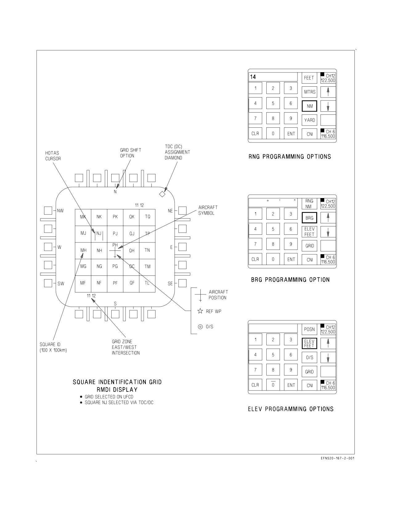
24.2.9.1.2 UTM Data Entry. Data for all waypoints and OAPs may be entered as universal transverse
mercator (UTM) coordinates. See figure 24-9. UTM grid coordinates are defined by a spheroid, grid
zone designation, square identification, and easting/northing. Grid zone designation divides the world
area between N84° and S80° into 100 km squares. At power up with WonW the MC initializes
VII-24-27
ORIGINAL
A1-F18EA-NFM-000
waypoint elevation, O/S range and elevation, and TACAN elevation in FEET, and O/S bearing to
TRUE. UTM data for waypoints are entered by performing the following:
1. Select DATA/WYPT on the HSI top level display.
2. Select the desired spheroid by selecting the spheroid option.
3. Select UFC on the HSI. The first cockpit to select UFC has control of grid data entry and has the
GRID display on the RDDI.
4. Select GRID on the UFCD. The MC determines the grid zone designation and 100 km square ID
of the reference position and constructs a five by five Square Identification Grid (SIG) centered
about the reference position and displayed on the RDDI. Reference position is either the A/C
present position or the referenced waypoint position (REF WP Boxed).
5. Slew the acquisition cursor into the desired square, depress and release the TDC.
6. On the UFCD enter the six digit easting/northing and press ENT. Leading zeros must be input
for easting/northing. The UTM coordinates are displayed on the HSI under the lat/long provided
the latitude is within the N84° to S80° limits.
UTM data for O/S are entered by performing the following:
7. Select DATA/WYPT on the HSI top level display.
8. Select UFC on the HSI.
9. Select O/S on the UFCD.
10. Select Grid on the UFCD.
11. Slew the HOTAS cursor into the desired square, depress and release the TDC.
12. Enter O/S easting/northing in the UFCD.
The MC converts the UTM Grid coordinates to latitude/ longitude and then to range and bearing.
O/S coordinates more than 400,000 feet from the OAP cause the UTM coordinates to flash in the O/S
grid field on the HSI. The UTM coordinate is displayed in the O/S field on the HSI.
SIG square blanking must be checked any time the SIG is built. If the latitude is out of UTM range
(above N84°or below S80°) the entire row is blanked. At certain latitudes, due to the convergence of
the earth, individual squares are blank.
Grid shift options are provided to view and select grid squares in the eight adjacent grid squares
whenever the A/C or Waypoint symbol is in the center square of the SIG and the adjacent SIGs exist.
See figure 24-9. N, S, E, W, SE, SW, NE, or NW can be selected by pressing the grid shift options on
the HSI, or by pressing and releasing the TDC when the HOTAS cursor is over a grid shift push button
legend. The MC determines a new center position about which to construct a new SIG. Selecting the
A/C or waypoint symbol returns the SIG to the original position.
VII-24-28
ORIGINAL
A1-F18EA-NFM-000
Units can be input as FEET or MTRS for elevation; FEET, MTRS, NM, or YARD for range. The
MC tests that all bearing, range and elevation data input through the UFCD are in the valid range.
Unit
Valid Range
Easting/Northing
000000 - 999999
Bearing
0 - 359° 59’ 59’’
Offset
0 - 400,000 FT
0 - 122,000 MTRS
0 - 66 NM
0 - 133,000 YDS
When data is outside the valid range, the MC causes the word ERROR to flash in the UFCD
scratchpad and requires the data to be reinput.
24.2.9.2 TGT (Target) Programming. A target must be entered in a waypoint/OAP sequence so the
MC can calculate the groundspeed required to arrive on target at the appropriate time. Only one
waypoint/OAP can be designated as a target for all three sequences. A waypoint/OAP is identified as
a target on the waypoint data sublevel display by an inverted triangle above the waypoint/OAP number
in the waypoint/OAP sequence. At power up with WonW the previous target waypoint/OAP is cleared.
A waypoint/OAP as a target in a waypoint/OAP sequence is designated the DATA option on the
MPCD top level display, the SEQUFC option on the waypoint data sublevel display to initialize the
UFCD, and the TGT option on the UFCD. Waypoint/OAP number is entered on the UFCD keypad
and the ENT option selected. The target waypoint/OAP is undesignated by either entering the target
waypoint/OAP a second time or entering an invalid waypoint/OAP. See figure 24-9.
24.2.9.3 TOT (Time On Target) Programming. TOT pertains to the programmed target waypoint/
OAP, and is relative to the programmed ZTOD (zulu time of day). ZTOD must be programmed before
TOT can be entered. TOT is programmed from 00:00:00 to 23:59:59 and is displayed on the waypoint
data sublevel display.
TOT is entered by selecting the DATA option on the MPCD top level display, selecting the
SEQUFC option on the waypoint data sublevel display to initialize the UFCD, selecting the TOT
option on the UFCD, entering the desired TOT value on the UFCD keypad, and selecting the ENT
option. See figure 24-9.
24.2.9.4 Groundspeed Programming. Groundspeed pertains to the desired groundspeed for the
final leg to the target waypoint in the sequence. Groundspeed values up to 999 knots may be entered.
Groundspeed is entered by selecting the DATA option on the HSI top level display, selecting the
SEQUFC option on the waypoint data sublevel display to initialize the UFCD, selecting the GSPD
option on the UFCD, entering the desired GSPD value on the UFCD keypad, and selecting the ENT
option. See figure 24-9.
24.2.9.5 Waypoint/OAP Sequence Programming. A total of three waypoint/OAP sequences are
available for waypoint/OAP sequence programming and a maximum of eight waypoint/OAPs may be
programmed in each sequence. These sequences are used for AUTO sequential steering and time on
target groundspeed cuing.
VII-24-29
ORIGINAL
A1-F18EA-NFM-000
The waypoint data sublevel display on the HSI display must be used with the UFCD to allow the
pilot to program a waypoint/OAP sequence. The SEQ # option on the lower right corner of the display
indicates the waypoint/OAP sequence in use and initializes to the sequence selected on the HSI top
level display. This option selects the sequence to be programmed (SEQ1, SEQ2, SEQ3, or SEQL).
Selecting the SEQUFC option, on the lower left corner of the display, initializes the UFCD for
waypoint sequence programming. A waypoint/OAP cannot appear more than once in sequence but a
waypoint/OAP may be entered in more than one sequence. Mark points cannot be programmed in a
sequence. Each waypoint/OAP entered is placed to the right of the last waypoint/OAP in the sequence.
If
15 waypoints/OAPs are programmed, the first waypoint in that sequence is deleted
and the
remaining waypoints/OAPs move to the left one space. Data for the current waypoint/OAP inserted/
deleted in the sequence is provided on the waypoint data level display.
A new waypoint/OAP sequence is programmed by selecting:
1. The waypoint data sublevel display using the DATA option
2. The desired sequence route number using the SEQ # option
3. The SEQUFC option to initialize the UFCD for sequence programming
4. The INSERT option on the UFCD
5. The desired waypoint/OAP number via the UFCD keypad
6. The ENT option on the UFCD keypad.
Repeat steps 4 through 6 for each waypoint/OAP in the sequence. See figure 24-9.
Waypoints/OAP are inserted into an existing sequence by selecting:
1. The waypoint data sublevel display using the DATA option
2. The desired sequence route number using the SEQ # option
3. The SEQUFC option to initialize the UFCD for programming
4. The INSERT option on the UFCD
5. The number of the waypoint/OAP to the left of the desired insertion point via UFCD keypad
6. The ENT option on the UFCD keypad
7. Number of the waypoint/OAP to be inserted via the UFCD keypad
8. The ENT option via the UFCD keypad
Waypoints are deleted from a sequence by selecting:
1. The waypoint data sublevel display using the DATA option, the desired sequence route number
using the SEQ # option
2. The SEQUFC option to initialize the UFCD for programming
3. The DELETE option on the UFCD
VII-24-30
ORIGINAL
A1-F18EA-NFM-000
Figure 24-9. INS Programming (Sheet 1 of 4)
VII-24-31
ORIGINAL
A1-F18EA-NFM-000
Figure 24-9. INS Programming (Sheet 2 of 4)
VII-24-32
ORIGINAL
A1-F18EA-NFM-000
Figure 24-9. INS Programming (Sheet 3 of 4)
VII-24-33
ORIGINAL
A1-F18EA-NFM-000
Figure 24-9. INS Programming (Sheet 4 of 4)
VII-24-34
ORIGINAL
A1-F18EA-NFM-000
4. The number of the waypoint/OAP to be deleted via the UFCD keypad
5. The ENT option via the UFCD keypad
When a waypoint/OAP is deleted from a sequence all waypoints/OAPs to the right of the deleted
waypoint/OAP shift left one space.
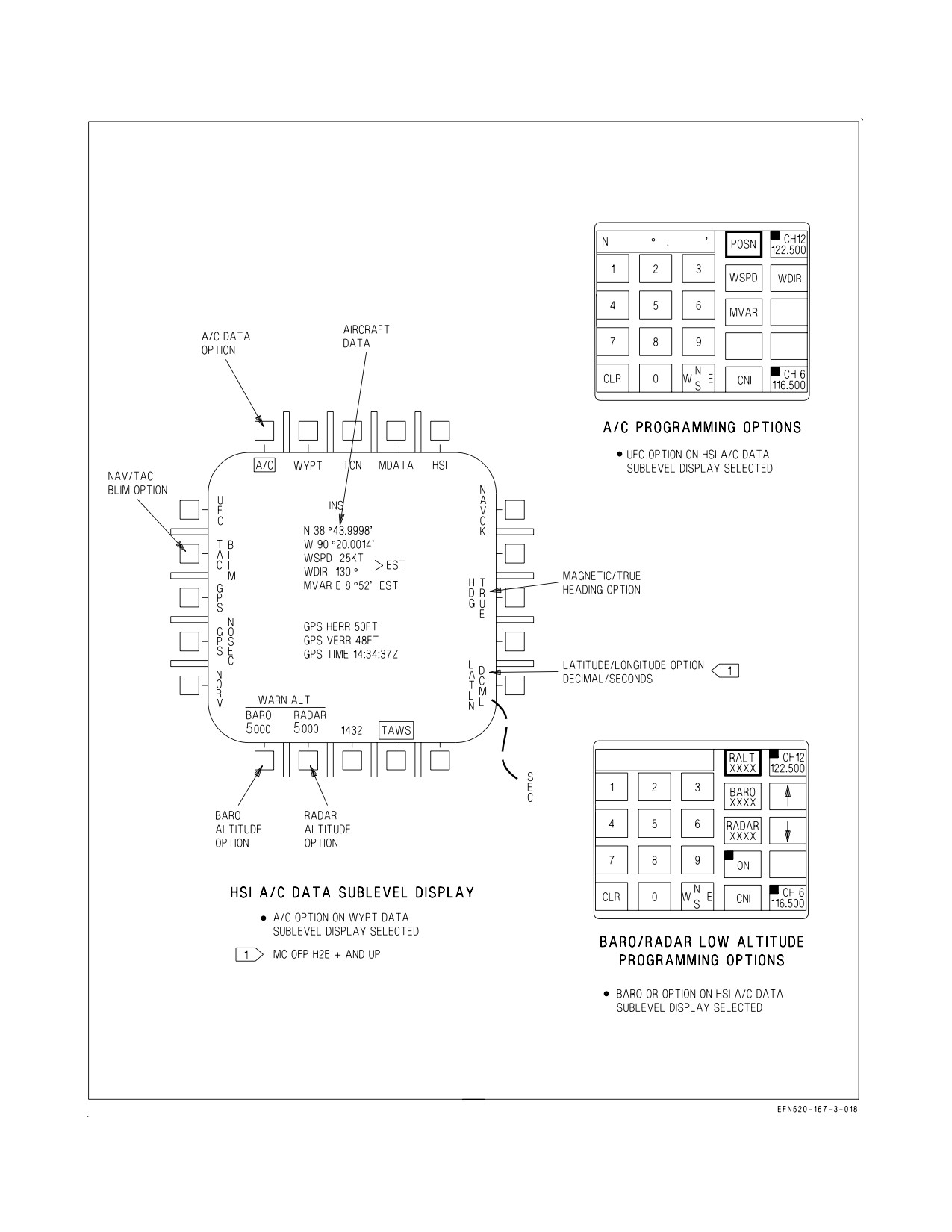
24.2.10 Aircraft (A/C) Programming. Aircraft data is entered by selecting the DATA option on the
HSI top level display and the A/C option on the waypoint data sublevel display to bring up the A/C
data sublevel display. This display shows the current aircraft data: latitude/longitude position, wind
speed, wind direction, magnetic variation, and magnetic/true heading selection. Aircraft data is
entered by selecting the UFC option to initialize the UFCD keypad for aircraft data entry, selecting the
LATLN DCML or SEC option and then POSN option to enter lat/long data, the WSPD option to enter
wind speed data, the WDIR option to enter wind direction, and MVAR to enter magnetic variation
(degrees/minutes beginning with E or W).
NOTE
Entering a MVAR value without selecting the MVAR option will result
in changing the aircraft position and may result in large INS position
keeping errors.
24.2.10.1 Latitude/Longitude Display/Entry. With MC OFP H2E+ AND UP, latitude and longi-
tude are displayed either as Degrees/ Minutes/ Ten Thousandths of minutes (LATLN DCML) or
Degrees/Minutes/Seconds/Hundredths of seconds (LATLN SEC). Actuating the LATLN XXXX
option toggles between the selection of LATLN DCML and LATLN SEC. The selected LATLN format
is reflected on all displays and UFCD formats throughout the cockpit. DCML is the cold start default.
24.2.10.1A True/Magnetic Heading Selection. Heading indications that appear on the HUD and
HSI display can be referenced to either true north or magnetic north. The capability to select a true
north heading is useful in extreme northern operations. With true north heading selected, the HSI
display, A/A and A/G radar displays, Link 4 display, and the HUD all are referenced to true north. The
true north indication on the HUD is a T displayed below the current heading. True north indications
on the HSI display consist of TRUE displayed below the current heading readout and a T displayed
below the lubber line. The true heading indications on the HSI display also appear on the Link 4
display. No indications of true north selection appear on the A/A or A/G radar display. Since aircraft
magnetic variation is used as the best available magnetic variation source, the heading reference should
not be changed when navigating a selected course.
With true heading selected, TACAN symbology is also referenced to true north if the TACAN
station is in the TACAN data table. If the TACAN station is not in the TACAN data table, magnetic
heading is used. There is no indication when magnetic heading is selected. When INS true heading
becomes invalid, magnetic heading is used. If MC1 fails, heading selection is not available. At power up
with WonW the system initializes with magnetic heading selected. The reference heading is selected by
selecting DATA on the HSI display and the A/C option to access the A/C data sublevel display.
Actuating the HDG XXX option toggles between the selection of HDG TRUE and HDG MAG.
24.2.10.2 Barometric (BARO)/Radar Low Altitude Warning Programming. The BARO/RADAR
altitude warning can be set up to a maximum of 25,000 feet for BARO and 5,000 feet for RADAR.
Setting the RADAR at a value greater than 5,000 feet results in 5,000 feet being used. Passing through
the BARO/RADAR programmed altitude from above results in the ALTITUDE voice alert. Setting
VII-24-35
ORIGINAL
A1-F18EA-NFM-000
the BARO/RADAR altitude warning to 0 feet disables this function. At power up with WonW, RADAR
altitude warning initializes to 0 feet and BARO altitude warning initializes to 5,000 feet. With MC OFP
H3E AND UP, at power up with WonW, RADAR altitude warning initializes to 5,000 feet and BARO
altitude warning initializes to 10,000 feet.
Set the BARO/RADAR low altitude warning function by selecting the DATA option on the HSI top
level MPCD display selecting the A/C option to bring up the A/C data sublevel display. The
BARO/RADAR altitude functions are located on the lower left corner of the display. Selecting BARO
or RADAR initializes the UFCD for altitude entry. Selecting the desired option on the UFCD and
entering the desired altitude through the UFCD keypad and pressing ENT. The entered altitude
appears on the A/C data sublevel display below BARO/ RADAR as appropriate. See figure 24-9, sheet
3.
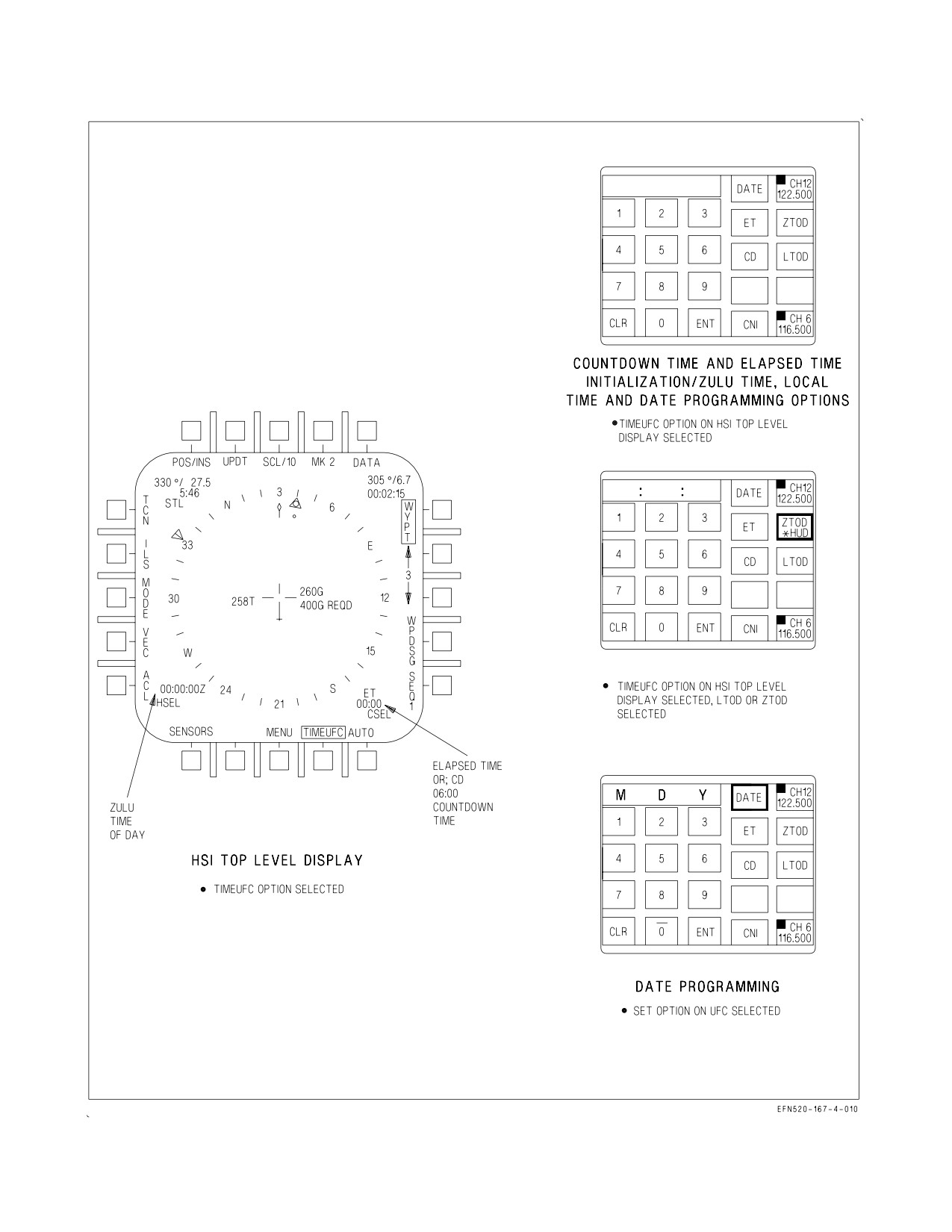
24.2.10.3 Zulu Time of Day (ZTOD). The FIRAMS Real Time Clock (RTC) is used to keep ZTOD.
The only time ZTOD needs to be set is if the FIRAMS RTC failed power up BIT. In this case the MC
internal counter would be used and requires the MC internal clock to be set. ZTOD is displayed on the
HUD and HSI display and is needed to calculate MC required groundspeed and TOT.
Enter ZTOD by selecting the TIMEUFC option on the HSI top level display to initialize the UFCD
for ZTOD programming. Then select the ZTOD option on the UFCD, enter ZTOD on the UFCD
keypad, and select the ENT option. At first selection of ZTOD, it is displayed on the HUD and HSI
display. ZTOD is displayed on the lower left corner of the HUD and HSI display. If time is displayed
on the HUD, the respective option has ″*HUD″ displayed below it. ZTOD is not displayed on the HUD
when either the ET or CD is selected for display. See figure 24-9, sheet 4.
24.2.10.4 Elapsed Time (ET). ET starts incrementing in minutes and seconds from 00:00 to 59:59.
When 59:59 is reached ET resets and begins incrementing again from 00:00. ET is displayed on the
lower left corner of the HUD and on the lower right corner of the HSI display. ET is not displayed on
the HUD or HSI display when either ZTOD, LTOD or CD is selected.
Activate ET by selecting the TIMEUFC option on the HSI top level display initializes the UFCD for
ET selection. Selecting the ET option on the UFCD displays ET 00:00 on the HUD and HSI display.
See figure 24-9, sheet 4.
24.2.10.5 Countdown Time (CD). CD starts decrementing in minutes and seconds from a default
value of 06:00. When 00:00 is reached, the CD timer is removed from the HUD and HSI displays. CD
is displayed on the lower left corner of the HUD and on the lower right corner of the MPCD. CD is not
displayed on the HUD or HSI when either ZTOD, LTOD or ET selected. The CD timer initializes to
the default value at power up with WonW.
Activate CD by selecting the TIMEUFC option on the MPCD top level display to initialize the
UFCD for CD selection. Selecting the CD option on the UFCD displays CD 06:00 on the HUD and HSI
display. See figure 24-9, sheet 4.
The CD default value can also be reset by entering in a value between 00:00 and 59:59 by selecting
the TIMEUFC option on the HSI top level display to initialize the UFCD for CD programming,
entering in the reset value through the UFCD keypad, and pressing the ENT option. The reset value
must be less than or equal to 59:59 so that when the ENT option is pressed the CD timer begins to
decrement. If the reset value is greater than 59:59, selection of the ENT option sets the reset value to
59:59 and freezes the CD timer.
VII-24-36
ORIGINAL
A1-F18EA-NFM-000
Figure 24-10. Position Keeping
24.2.10.6 Local Time Of Day Programming (LTOD). LTOD is displayed on the HUD and HSI
display. Set LTOD by selecting the TIMEUFC option on the MPCD top level display initializes the
UFCD for LTOD programming. Selecting the LTOD option on the UFCD, entering LTOD on the
UFCD keypad, and selecting the ENT option. The LTOD option is displayed if the FIRAMS passes
power up BIT. See figure 24-9, sheet 4.
24.2.10.7 Date (DATE). Set the date by selecting the TIMEUFC option on the MPCD top level
display initializes the UFCD for date programming. Selecting the DATE option on the UFCD allows
‘‘M’’, ‘‘D’’ and ‘‘Y’’ to appear on the scratchpad. Enter the date on the UFCD keypad, and select the
ENT option. The date must be entered as two digit values in the following order: month, day and year.
See figure 24-9.
24.2.10.8 Time Zone. The time zone is set by first entering ZTOD followed by LTOD. The MC uses
the difference between these values as the current time zone. Any future changes to ZTOD
automatically changes LTOD based on the current time zone. Any future changes to LTOD resets the
time zone.
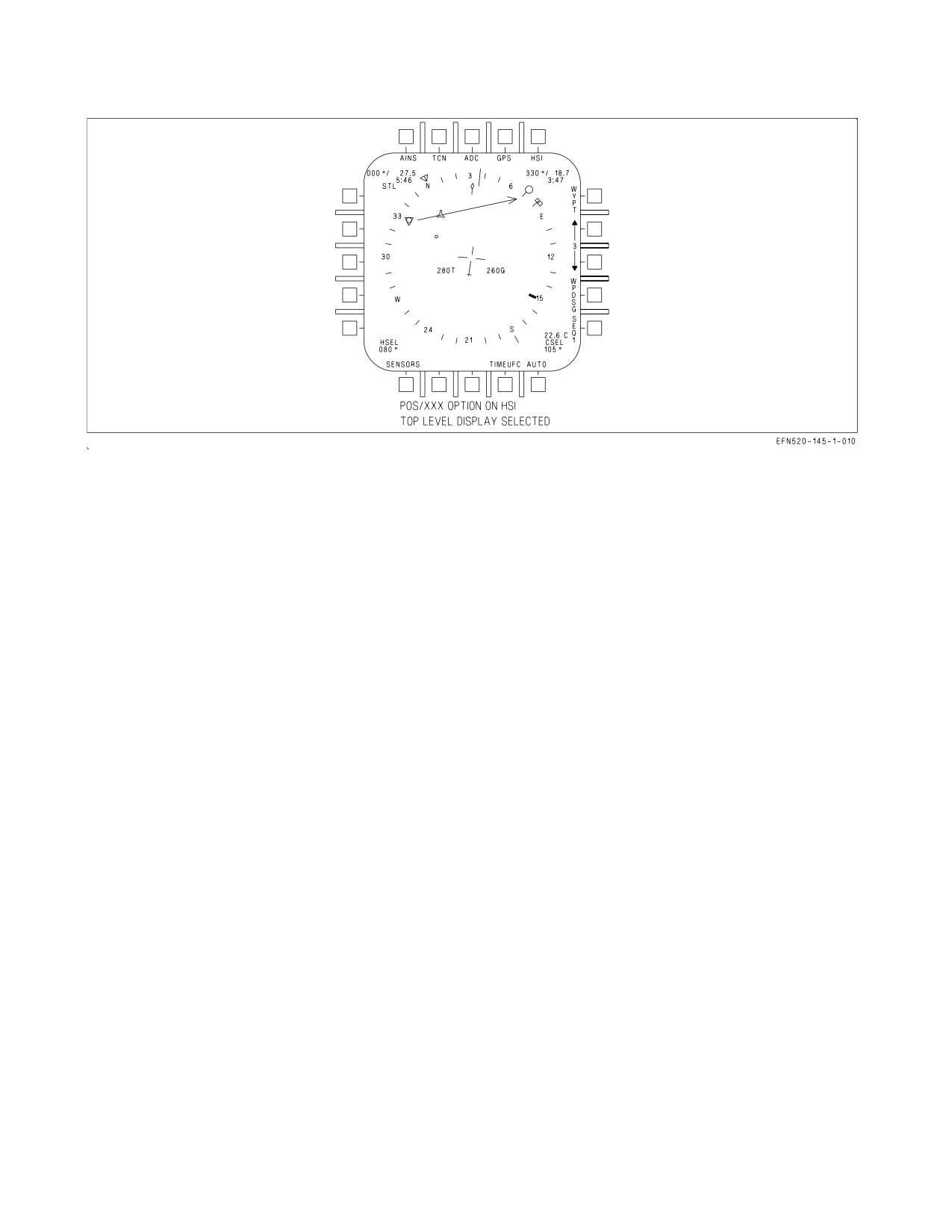
24.2.11 Position Keeping. Selection of the POS/XXX option on the MPCD top display provides the
position keeping option display, see figure 24-10. This display allows in-flight selection of POS/AINS,
POS/ADC, POS/GPS, POS/INS, POS/MIDS (if installed), or POS/TCN as the position keeping
source. Selecting one of these options returns the MPCD top level display with the appropriate position
keeping source selected. INS position keeping is automatically selected during ground operations when
INS data is valid. Should the INS fail, the mission computer automatically begins FCC air data
position keeping from the last valid INS position; however, it is unreliable.
AINS and GPS position keeping are not available unless good GPS data is available. GPS data is
good when the GPS vertical error (GPS VERR) and GPS estimated horizontal error (GPS HERR), as
shown on the aircraft data format, are each less than 100 feet. AINS position keeping is selected by
placing the INS mode switch in the IFA position. Automatic position keeping reversion with a
hierarchy of AINS, INS, GPS , MIDS (if installed) and FCC air data is provided in case of an INS
and/or GPS failure. TACAN position keeping provides distance data from one of the previously stored
VII-24-37
ORIGINAL
A1-F18EA-NFM-000
TACAN stations. The desired TACAN station is selected on the UFCD. See TACAN position keeping
this section.
MIDS Precise Participant Location and Identification (PPLI) altitude
shall not be used as an altitude reference for determining safe separation
of aircraft or terrain avoidance.
MIDS position keeping is the default position keeping mode if GPS and
INS are not available. Because MIDS alone is unreliable as a position
keeping source, POS/ADC should be selected if INS and GPS fail or
become unreliable as position keeping sources. Aircrew is unable to enter
data parameters required for an INS or radar IFA if POS/MIDS is the
position keeping source.
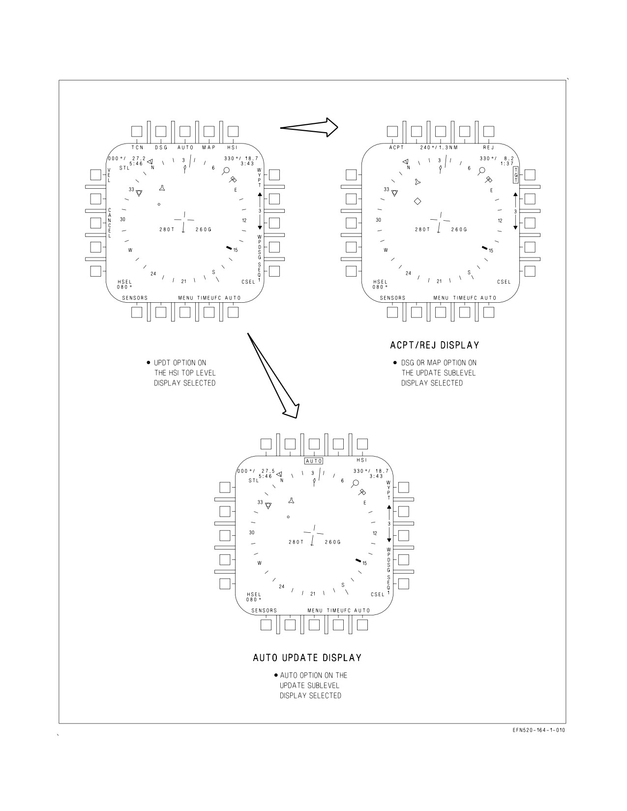
24.2.12 Position Updating. Selecting the UPDT (update) option on the MPCD top level display
provides the update sublevel display, see figure 24-11. This display allows in-flight selection of VEL
(velocity), TCN (TACAN), GPS, DSG (designate), AUTO (automatic), and MAP as the update
options. These options provide position/velocity updating to the INS/ADC during NAV or IFA modes.
All updates must be performed while in the NAV or A/G master modes, unless noted otherwise. TCN
position updating is described in the TACAN section, and VEL updating is described in A1-F18EA-
TAC-Series.
NOTE
The update option is not available in AINS position keeping.
After an update is performed, the CANCEL option is displayed on the HSI UPDATE option display.
Pressing the CANCEL option cancels the previous update and removes the CANCEL option. The INS
updates the aircraft position using the last accepted position update. The CANCEL option is also
removed on touchdown or when present position is changed using the UFCD.
24.2.12.1 Designation (DSG) Update. A designation update is performed by pressing the UPDT
option on the MPCD top level display. Selecting the DSG option on the UPDT sublevel display.
Designating a waypoint/OAP with a sensor (radar, FLIR, NFLR or LDT), a HUD designation, or an
overfly designation. The DSG option may be selected before or after waypoint designation. When the
designation has been performed and DSG option selected, sensor ranging components to the target are
added to the previously entered waypoint position to give an aircraft computed position. The
difference between the computed aircraft position and the onboard aircraft position produces the
position error readout in bearing and range on the ACPT/REJ display. Selecting the ACPT option
accepts the position update and returns the MPCD top level display. Selecting the REJ option rejects
the update and returns the MPCD top display. A DSG update may be performed in the A/A master
mode if the designation was performed in A/G prior to entering A/A. The selection of UPDT/DSG
suspends auto sequential steering and disengages coupled steering.
VII-24-38
ORIGINAL
A1-F18EA-NFM-000
24.2.12.2 Post-flight Update. The INS post-flight update collects terminal INS maintenance data.
The post flight update is performed using the overfly designation update method. The INS determines
the overfly designation update is a post flight update using the WonW transition. The aircraft must be
completely stopped and the parking brake engaged to prevent erroneous terminal velocity data. The
post flight update is not performed onboard ship.
The INS post flight update may be performed when the parking brake is set and the aircraft is
within 600 feet of the appropriate waypoint entered in the system (the update waypoint need not be
waypoint 0). If the waypoint position is known but not programmed in the system, the position may be
entered and used for the update. If no waypoints are available, no update should be attempted.
24.2.12.3 MAP Update. A MAP update is performed by selecting the UPDT option on the MPCD
top level display, designating a waypoint/OAP with a sensor (radar, FLIR or LDT), a HUD designation
or an overfly designation and selecting the MAP option on the update sublevel display. When this is
done the word SLEW appears in the upper right corner of the MPCD and the TDC is automatically
assigned to the MPCD (for map slewing). The map can now be slewed so the target on the map is under
the designation symbol (diamond). The difference between the target position and the designated
position produces the position error readout in bearing and range on the ACPT/REJ display. Selecting
the ACPT option accepts the position update and returns the MPCD top level display. Selecting the
REJ option rejects the position update and returns the MPCD top level display. The MAP option is
not available if a map is not installed.
24.2.12.4 AUTO Update. An AUTO update is performed by selecting the UPDT option on the
MPCD top level display and selecting the AUTO option on the UPDT sublevel display. When this is
done the AUTO option is boxed and the VEL, TCN, DSG and MAP options are removed. The pilot
must assign the TDC to the MPCD, overfly the waypoint/OAP and press the TDC while over the
waypoint/OAP. The MC enters the waypoint/OAP as the aircraft present position and the MPCD top
level display is returned. The next waypoint in succession becomes designated or, in the case of an
OAP, the offset becomes designated. There is no ACPT/REJ display in the AUTO update mode.
24.2.13 NAV/TAC Bank Limit Options. Bank angle control 1 (BAC1) is engaged when any coupled
steering mode is engaged. BAC1 provides aircraft steering commands and limits; and maintains the
aircraft on course to the selected waypoint(s), offset aim point(s), or TACAN station. BAC1 also
provides steering to capture and hold a course line through the current WYPT, OAP, or TACAN
station. The maximum bank limit (BLIM) is selectable on the A/C data display. TAC BLIM is used for
tactical missions and limits the bank angle between ±30° and ±60° with a bank rate between 10° and
30° per second based on airspeed. NAV BLIM is used for general navigation and sets bank angle to a
fixed ±30° limit with a maximum bank angle rate of 10° per second.
24.2.14 Steering. Types of waypoint/OAP steering described include direct great circle, course line,
auto sequential, and target.
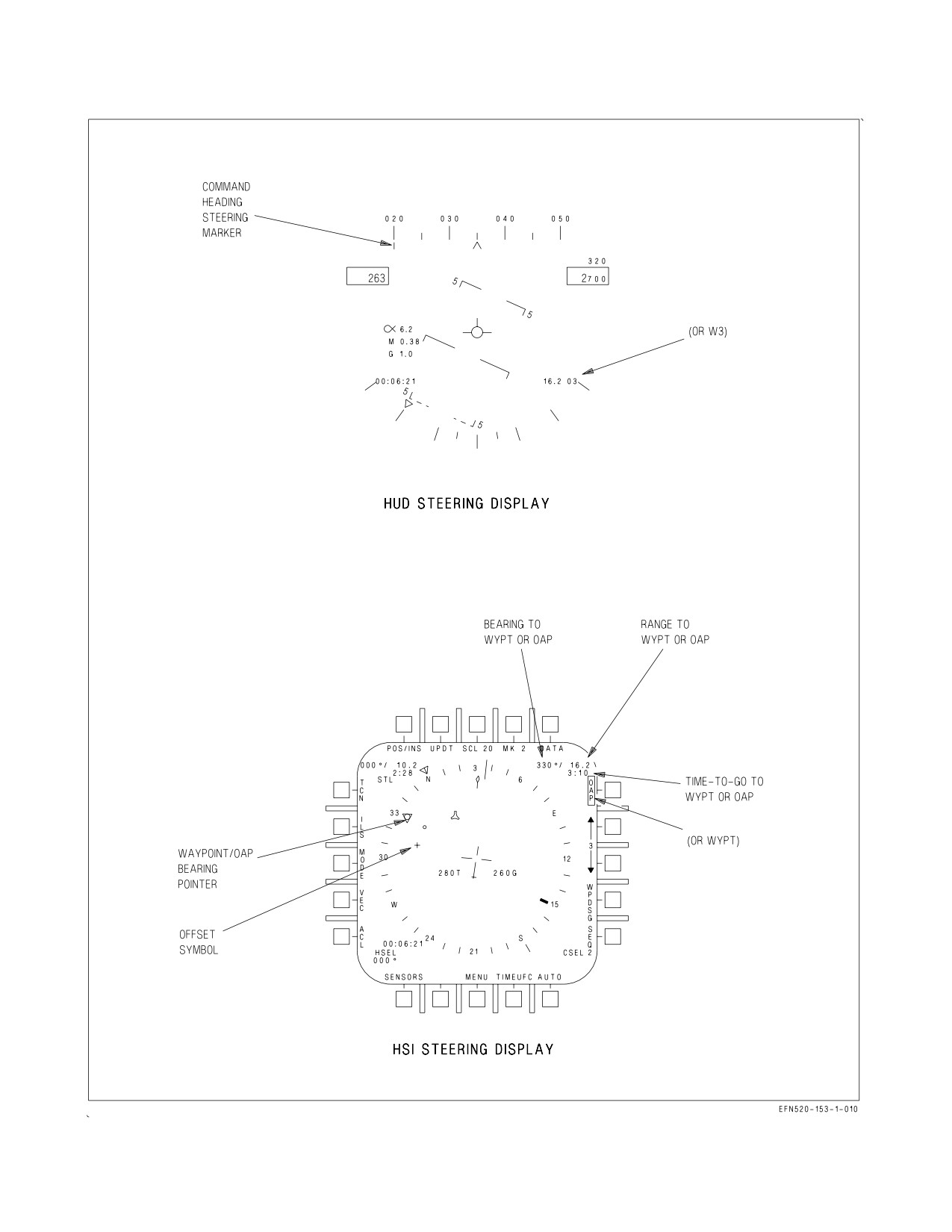
24.2.14.1 Waypoint/OAP Direct Great Circle Steering. Direct great circle steering is available in all
master modes and is selected/deselected by actuating the WYPT/OAP option on the MPCD. Selecting
waypoint/OAP steering deselects ILS, D/L, and TACAN steering. When steering is selected, the option
is boxed and direct great circle steering is provided on the HUD as shown in figure 24-12. To follow a
direct great circle path to the waypoint/OAP, the aircraft is turned so that the command heading
steering pointer under the heading scale is centered in the heading caret. The steering provided by the
steering pointer is corrected for wind drift. When the steering pointer is within ±5° of the caret as
measured on the heading scale, it provides a direct indication of steering error. Between ±5° and the
ends of the heading scale (±15°), the steering pointer moves nonlinearly so that it is at the end of the
VII-24-39
ORIGINAL
A1-F18EA-NFM-000
Figure 24-11. Position Updating Displays
VII-24-40
ORIGINAL
A1-F18EA-NFM-000
heading scale when the steering error is 30°. The steering pointer is displayed at the end of the heading
scale when the steering error is greater than 30°, the steering pointer begins to move to provide
anticipation for rolling out of the turn, and the actual steering error is indicated when within 5°.
Waypoint/OAP range, identification, and number are displayed on the lower right side of the HUD.
On the MPCD, the position of the waypoint/OAP is indicated by the waypoint/OAP symbol as
shown on figure 24-12. If the selected steer to point is an OAP, the position of the offset is indicated
by the offset symbol. Bearing to the waypoint/OAP is indicated by the pointer inside the compass rose.
The waypoint/OAP symbol and pointer are displayed whether or not direct great circle steering is
selected. They provide a navigation situation display only. Steering (corrected for drift) is provided
only on the HUD. A digital readout of bearing and range to the waypoint/OAP is provided on the upper
right corner of the MPCD. Time to go to the waypoint/OAP in minutes and seconds, based on range
and groundspeed, is provided under the bearing and range readout.
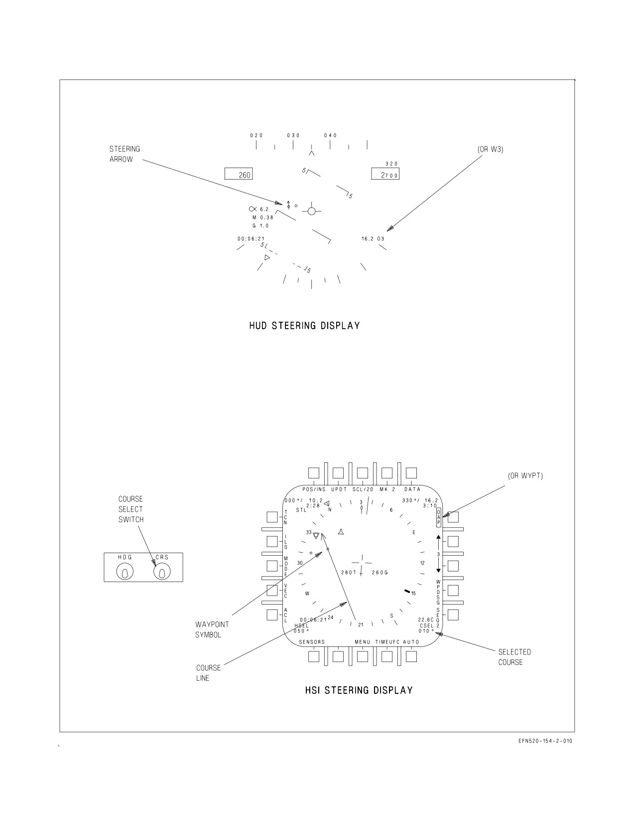
24.2.14.2 Waypoint/OAP Course Line Steering. Course line steering is used when it is desired to fly
a selected course to the waypoint/OAP. Course line steering is selected by selecting direct great circle
steering and actuating the course select switch. When the course select switch is actuated, the course
line appears through the waypoint/OAP symbol as shown in figure 24-13, sheet 1. The course line
rotates clockwise while the course select switch is held to the right and counterclockwise while it is held
to the left. A digital readout of the selected course is provided in the lower right corner of the MPCD.
When the waypoint/OAP symbol is beyond the range of the selected MPCD scale, the waypoint/OAP
symbol is limited at the inside of the compass rose coincident with the head of the pointer and the
course line rotates about the head of the pointer. It does not then overfly its correct position on the
map; but, does correctly indicate to which side of the aircraft the course lies, and the intercept angle
is correctly represented.
When a course line is selected, steering on the HUD is displayed. The arrow provides a horizontal
situation indication relative to the velocity vector. As shown, the aircraft is to the right of the selected
course, but is converging toward it. Two dots are displayed on the side of the velocity vector toward the
steering arrow and in a line perpendicular to it. The outermost dot represents full scale deflection of
the arrow (8°) and the innermost dot indicates half scale deflection (4°). If the arrow moves to the other
side of the velocity vector, the dots appear on that side. The dots are not displayed when within
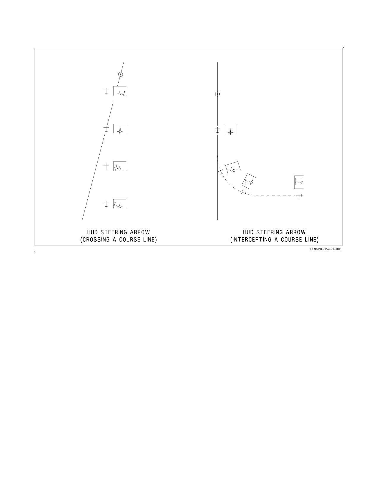
approximately 1.25° of being on course. Figure 24-13, sheet 2 shows an example of the HUD steering
arrow display as the aircraft crosses a course line. The HUD situation arrow display is available only
in NAV master mode, although waypoint/OAP steering can be selected and the course arrow can be
displayed and used on the MPCD in any master mode. Only waypoint/OAP direct great circle steering
is available on the HUD when designated. Course line steering can be deselected either by deselecting
waypoint/OAP direct great circle steering or by selecting a new waypoint/OAP, initializing direct great
circle steering.
24.2.14.3 Coupled Waypoint / OAP Steering. When waypoint steering is coupled, CPL WYPT is
displayed on the HUD and HSI display, and a CPLD advisory appears on the DDI. The aircraft steers
to intercept the desired course line, or flies to the point if no course line is selected. Bank angle is
limited by NAV or TAC bank limit option as selected on the A/C sublevel display and described in
chapter 2. As the aircraft gets close to the desired course, the bank angle is reduced to maintain the
aircraft on the desired course. If course line steering is not selected, when the aircraft reaches the
waypoint or offset aim point (OAP) WYPT steering uncouples and reverts to HDG hold. If course line
steering is selected, the aircraft remains coupled and flies an outbound radial. RALT or BALT,
whichever is selected, remains engaged when the aircraft passes the waypoint. If a ground point is
designated, WYPT steering does not couple, or uncouples if previously coupled. If waypoint steering
VII-24-41
ORIGINAL
A1-F18EA-NFM-000
Figure 24-12. Waypoint/OAP Direct Great Circle Steering
VII-24-42
ORIGINAL
A1-F18EA-NFM-000
Figure 24-13. Waypoint/OAP Course Line Steering (Sheet 1 of 2)
VII-24-43
ORIGINAL
A1-F18EA-NFM-000
Figure 24-13. Waypoint/OAP Course Line Steering (Sheet 2 of 2)
does not engage or disengages without being commanded, an AUTOPILOT caution is displayed on the
DDI, and CPL WYPT flashes for 10 seconds on the HUD and HSI displays. The caution can be cleared
with the paddle switch.
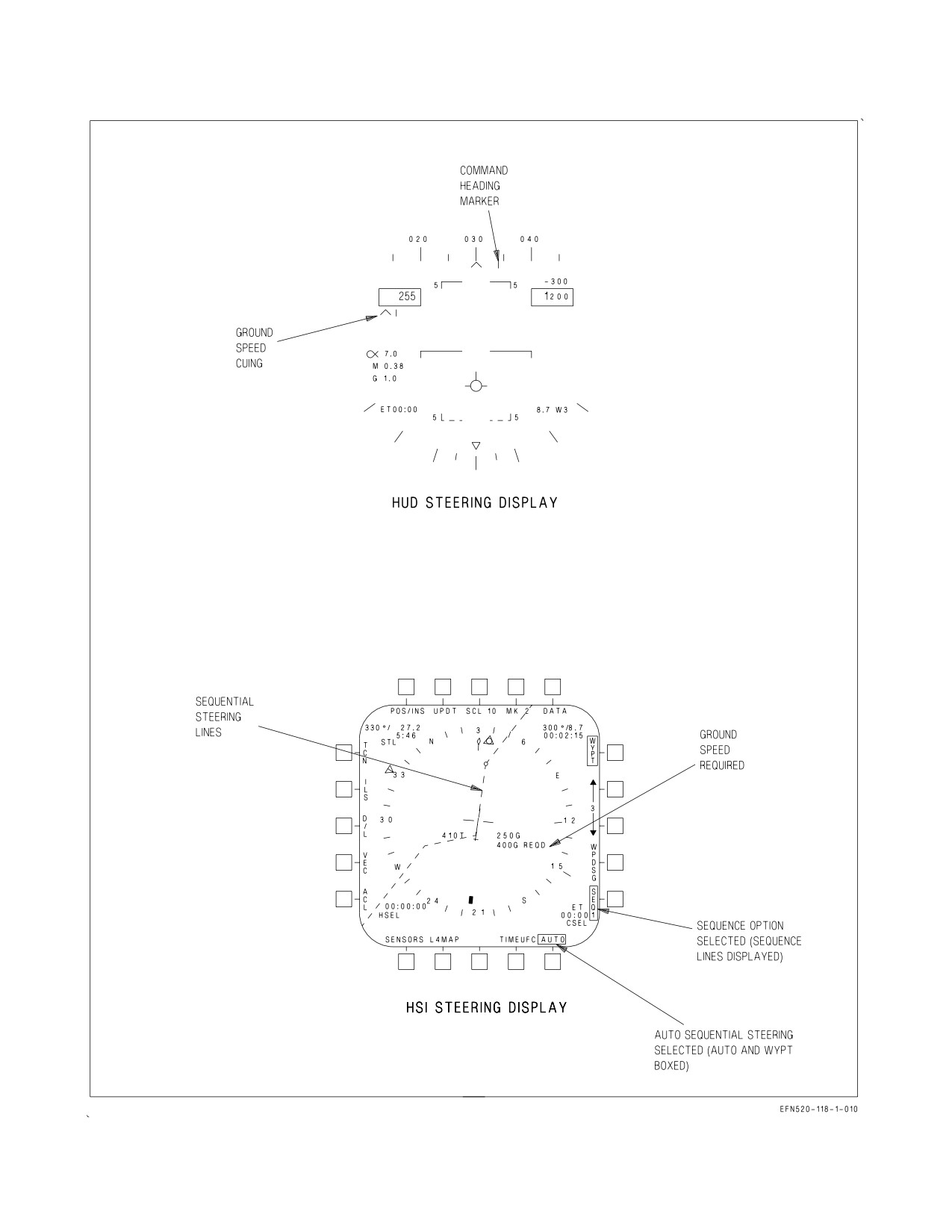
24.2.14.4 AUTO Sequential Steering. Before AUTO sequential steering can be selected a waypoint/
OAP sequence must be programmed.
AUTO sequential steering is selected by actuating the AUTO option (AUTO boxed) on the MPCD.
When selected, other steering modes not compatible with AUTO sequential are deselected.
With AUTO sequential steering engaged, great circle steering is provided to the first waypoint/OAP
in the selected sequence, see figure 24-14. When range to the steer to waypoint/OAP is less than 5 NM
and bearing is greater than 90°, the next waypoint/OAP in the sequence is automatically selected.
Great circle steering is automatically provided for each new steer to waypoint/OAP in the sequence.
During AUTO sequential steering course line steering is available but course line is deselected when
the steer to waypoint/OAP is within the range and bearing mentioned above. The waypoint/OAP
up/down arrows provide manual selection for steering to the desired waypoint/OAP in the sequence.
With AUTO sequential steering engaged, selecting the SEQ # option provides dashed lines on the
MPCD connecting the waypoint/OAPs of the chosen sequence.
AUTO sequential steering is deactivated when any of the following occur: the AUTO option
deselected (unboxed), the last waypoint/OAP in the sequence is within the parameters mentioned
above, selection of another steering mode, the FCS is coupled to the D/L, AUTO update is selected, a
VII-24-44
ORIGINAL
A1-F18EA-NFM-000
ground point is designated, magnetic heading is invalid, aircraft present position is invalid, aircraft
ground track is invalid, or steering waypoint/OAP range/bearing is invalid.
Auto sequential steering is suspended if UPDT/DSG is selected to perform an overfly designation.
The automatic transition to the next waypoint does not take place until the update is either accepted
or rejected and the sequence criteria is satisfied.
24.2.14.5 Coupled Auto Sequential Steering. When auto sequential steering is coupled CPL SEQ
#( ) (current sequence number: 1, 2, 3, or L replaces the parenthesis) is displayed on the HUD and HSI
display and a CPLD advisory appears on the DDI. The aircraft steers to intercept the desired course
of the current WYPT/OAP in the sequence. Bank angle is limited by NAV or TAC mode as described
in chapter 2. As the aircraft gets close to the desired course, the bank angle is reduced to maintain the
aircraft on the desired course. An OVFLY( ) option is available on the WYPT data option display.
When this option is selected (boxed), the aircraft overflies the current WYPT/OAP in the sequence
before intercepting the course of the next one. When OVFLY( ) is not selected, the aircraft performs
a lead turn to intercept the course of the next WYPT/OAP just prior to reaching the current point.
Once the aircraft reaches the last point in the sequence, auto sequential steering uncouples, reverting
to HDG hold in the roll axis. RALT or BALT, whichever is selected, remains engaged when the aircraft
passes the final point. If auto sequential steering does not engage or disengages without being
commanded, an AUTOPILOT caution is displayed on the DDI, and CPL SEQ( ) flashes for 10 seconds
on the HUD and HSI displays. The caution can be cleared with the paddle switch.
Coupled AUTO sequential steering is selected and deactivated as described above in the Auto
Sequential Steering paragraph.
Coupled auto sequential steering is disengaged if UPDT/DSG is selected to perform an overfly
designation. The automatic transition to the next waypoint does not take place. When auto disengage
from coupled steering occurs, autopilot cautions occur. Coupled steering is not automatically reengaged
after the update is complete.
24.2.14.6 Groundspeed Cuing. Before groundspeed cuing is available for display, certain criteria
must be meant: a waypoint/OAP sequence must be entered, a target waypoint/OAP in the sequence
must be selected, time of day must be entered (ZTOD or LTOD), and TOT must be entered. With
waypoint/OAP great circle steering engaged to the target waypoint/OAP, the MC calculates the
groundspeed required to arrive at the target based on a direct path to the target and the entered TOT.
With AUTO sequential engaged, the MC calculates the groundspeed required to arrive at target
waypoint/OAP taking the sequential path to the target. The MC calculates the necessary groundspeed
based on the pilot entered groundspeed, providing there is enough time to travel the final leg at the
entered groundspeed and arrive at the target at the TOT. If there is not enough time to travel the final
leg at the pilot entered groundspeed, the MC ignores the pilot entered groundspeed and calculates a
groundspeed to arrive at the target on time.
NOTE
• Programming a required groundspeed is not necessary for ground-
speed cuing calculations.
• The designated target waypoint/OAP must be in the waypoint/OAP
sequence in order for the required groundspeed cueing function to
operate.
VII-24-45
ORIGINAL
A1-F18EA-NFM-000
Figure 24-14. AUTO Sequential Steering
VII-24-46
ORIGINAL
A1-F18EA-NFM-000
If the target is an OAP the groundspeed required calculation includes the distance from the OAP to
the offset. If the target is NAV designated the MC uses the NAV designation location in the calculation
of groundspeed required for TOT. When the target waypoint/OAP is NAV designated, any other
designation means may be used to adjust the designation and the groundspeed calculation is calculated
to the adjusted designation.
HUD cuing of required groundspeed consists of a tick mark and arrow head located under the
airspeed box. The arrow head is referenced to the tick mark and indicates if the aircraft is traveling too
fast or too slow to reach the target on time. The arrow head is displayed to the left of the tick mark
when the aircraft is traveling too slow and to the right of the tick mark when the aircraft is traveling
too fast. Full displacement of the arrow head left or right of the tick mark indicates a difference of 30
knots between actual and required groundspeed. The aircraft is traveling the correct speed when the
arrow head is centered on the tick mark. The required groundspeed readout is displayed on the MPCD
under the present ground speed readout. See figure 24-14 for an example of HUD and MPCD
groundspeed cuing.
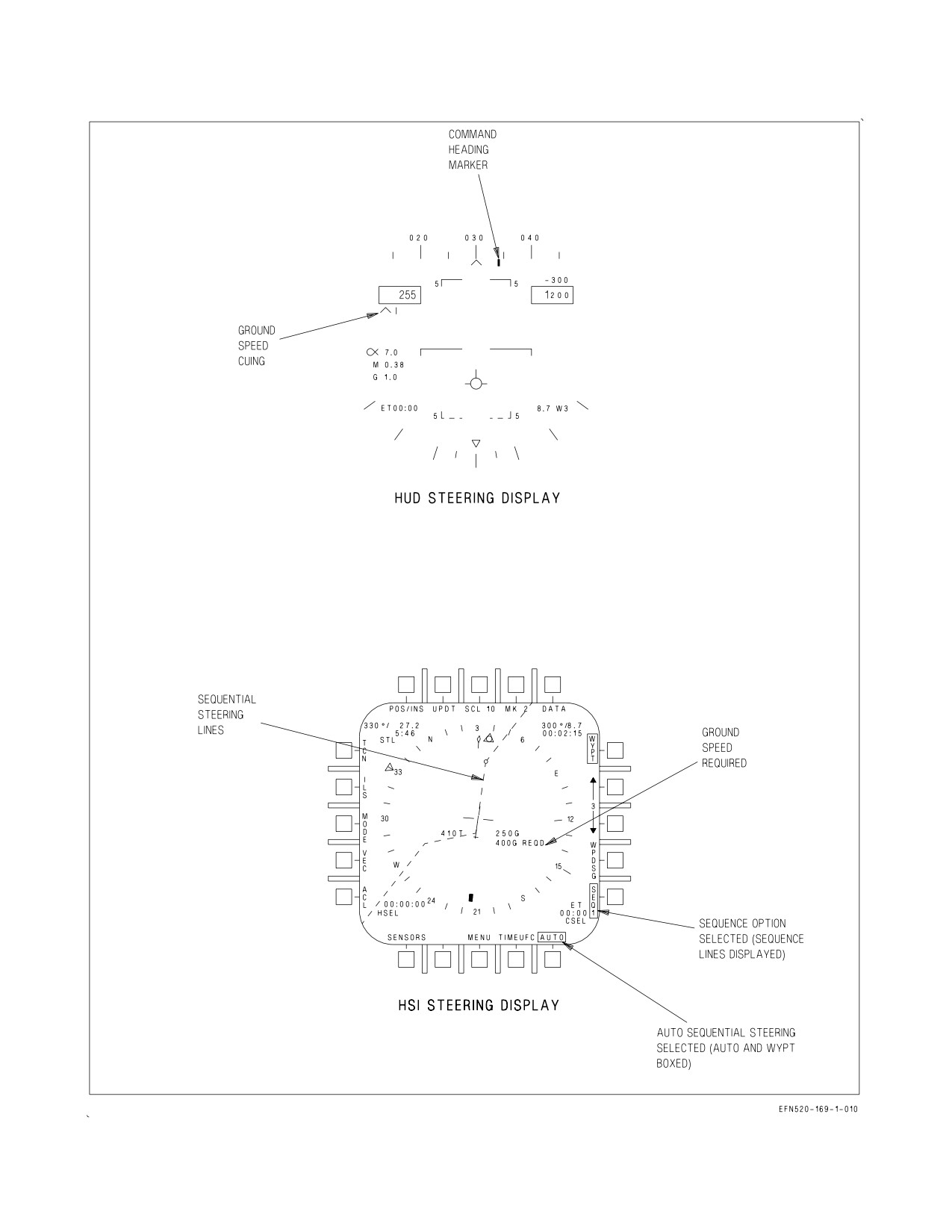
24.2.15 Designation. Designation of a waypoint/OAP is the action by which the pilot identifies a
waypoint/OAP position to the MC so that position can be used for sensor slaving, steering, or position
updating. Navigation and overfly designations are discussed here but sensor designations are described
in A1-F18EA-TAC-Series. Designating a waypoint/OAP initiates the following changes on the MPCD:
the WPDSG option is removed/replaced with the O/S option, WYPT/OAP is replaced with a boxed
TGT/OAP legend, the waypoint symbol is replaced with the target diamond, the waypoint symbol
inside the waypoint steering pointer is also replaced with the target diamond and the steering
information in the upper right corner now relates to the target. Designating a waypoint/OAP also
provides the following changes on the HUD: a target diamond appears below the heading scale to
provide target heading information, another target diamond also appears indicating the target line of
sight (LOS) and the WYPT data (range) on the lower right corner is replaced with TGT data. HUD
target steering operates the same as described for waypoint/OAP great circle steering.
24.2.15.1 WPDSG (Navigation) Designation. Selecting the WPDSG option designates the waypoint
as a target. The changes mentioned above appear at designation, see figure 24-15.
To WPDSG an OAP the procedure is slightly different. When the WPDSG option is selected, the
OAP is designated and all data for the designated target on the MPCD and HUD operate the same as
described above, except that the WPDSG legend is replaced with the O/S option and the OAP option
is boxed. The O/S option must now be selected to add the offset data to the OAP position and complete
the designation. Another method of adding the offset data to the OAP position (completing the
designation) is to assign the TDC to the MPCD and actuate the TDC. When this occurs, the O/S legend
is removed, the boxed OAP legend is replaced with a boxed TGT legend, the offset symbol is replaced
with the target diamond and the designated aimpoint reverts to the aimpoint symbol. A WPDSG
cannot be performed if a waypoint/OAP is already designated.
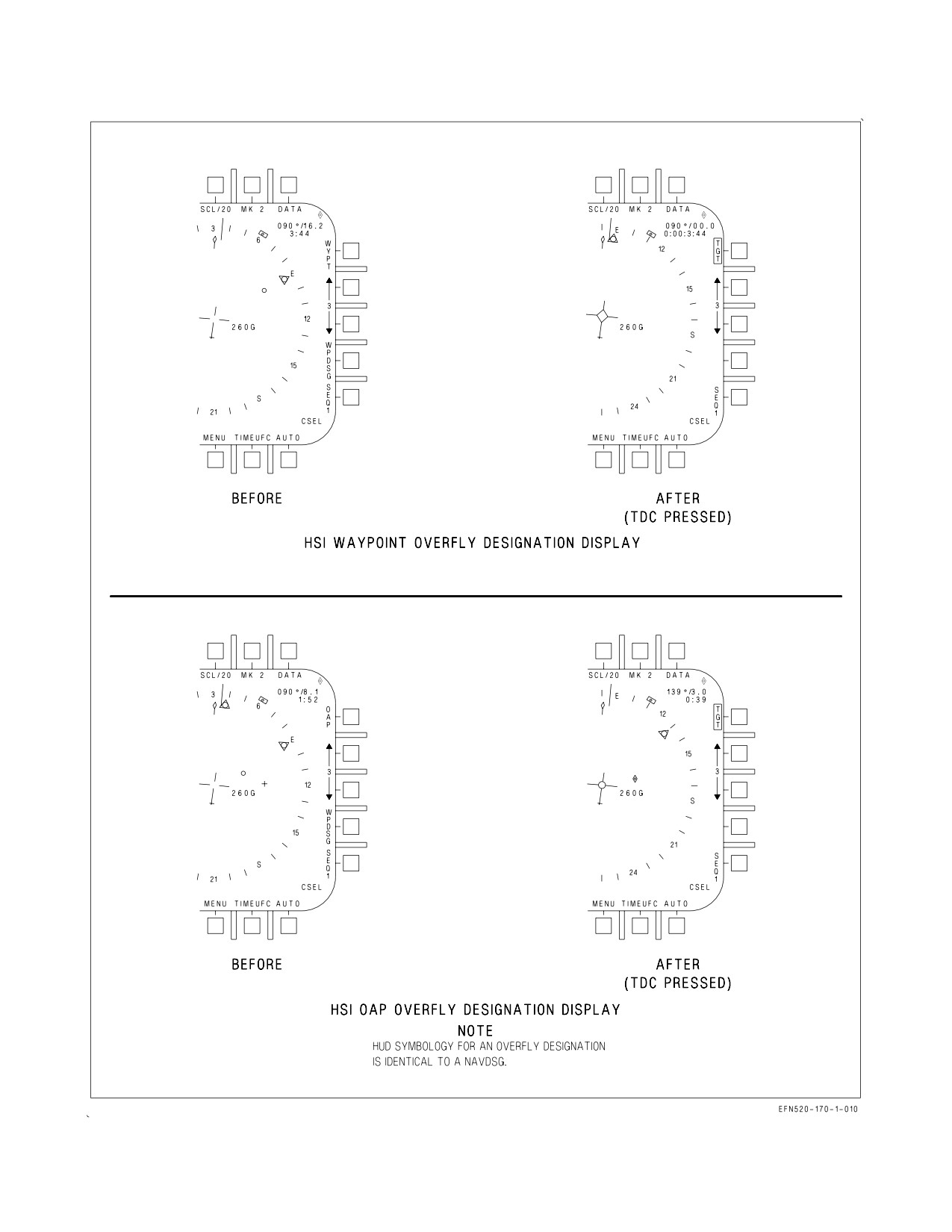
24.2.15.2 Overfly Designation. An overfly designation is performed on a waypoint/OAP by pressing
the TDC while it is assigned to the MPCD and the aircraft is overflying the waypoint/OAP. When this
happens, the MC assumes that the aircraft is over the waypoint/OAP and the aircraft position at that
time is designated as the waypoint/OAP position. In the case of an OAP the offset data is automatically
added to the aircraft present position to complete the designation. When an overfly designation is
performed the changes mentioned above occur, see figure 24-16.
VII-24-47
ORIGINAL
A1-F18EA-NFM-000
Figure 24-15. Navigation Designation (WYPT DSG)
VII-24-48
ORIGINAL
A1-F18EA-NFM-000
Figure 24-16. Overfly Designation
VII-24-49
ORIGINAL
A1-F18EA-NFM-000
24.2.16 INS Updates (not available in AINS).
Radar -
1.
Master mode - NAV (RADAR SURF) or A/G
2.
Radar mode - EXP 1, EXP 2, EXP 3, or MAP
3.
WYPT - SELECT
4.
WYPT DSG - PRESS
5.
TDC/DC - ASSIGN TO RADAR
6.
UPDT - PRESS
7.
DSG - PRESS
8.
Slew cursor over waypoint and release TDC/DC.
9.
Accept or reject.
HUD -
1.
WYPT - SELECT
2.
WYPT DSG - SELECT
3.
TDC - ASSIGN TO HUD
4.
UPDT - PRESS
5.
DSG - PRESS
6.
Slew HUD diamond over waypoint and release TDC/DC.
7.
Accept or reject.
Overfly -
1. WYPT - SELECT
2. TDC/DC - ASSIGN TO MPCD
3. UPDT - PRESS
4. DSG - PRESS
5. Actuate TDC/DC when aircraft is over waypoint.
6. Accept or reject.
VII-24-50
ORIGINAL
A1-F18EA-NFM-000
AUTO -
1. WYPT - SELECT
2. TDC/DC - ASSIGN TO MPCD
3. UPDT - PRESS
4. AUTO - PRESS
5. Actuate TDC/DC when aircraft is over waypoint.
Map -
1. WYPT - SELECT
2. UPDT - PRESS
3. MAP - PRESS (automatically assigns TDC/DC to MPCD)
4. Overfly desired geographical reference and actuate TDC/DC.
5. Select slew and slew map reference under aircraft symbol, release TDC/DC.
6. Accept or reject.
TACAN -
(1 of 10 available TACAN stations must be in reception range)
1. UPDT - PRESS
2. TCN - PRESS
3. Accept or reject.
Velocity -
1. UPDT - PRESS
2. VEL - PRESS
3. Accept or reject.
24.3 ADF (AUTOMATIC DIRECTION FINDER)
The OA-8697/ARD ADF is a VHF/UHF direction finder operating in the 100 to 400 MHz frequency
range. The system has an antenna section which receives and modulates rf signals and an audio
processing section which resolves bearing in the ADF audio received from the VHF/UHF receiver-
transmitter. Bearing information received by the ADF is sent to the MC where the data is processed
to position the ADF bearing pointer on the HSI display. The channel to the station to which ADF
bearing is required is selected on the COMM 1 or COMM 2 radio. The ADF system is turned on by
VII-24-51
ORIGINAL
A1-F18EA-NFM-000
selecting the ADF option on the UFCD COMM sublevel for the selected radio. Squelch is disabled for
the selected radio when ADF is turned on. Squelch can be reenabled by reselecting the SQCH option.
Selecting the COMM 2 radio indicates ADF bearing to the station selected on the COMM 2 radio.
ADF audio is adjusted by either the COMM 1 or COMM 2 volume control knob. ADF symbology
appears as a small circle on the HSI display.
Aircraft after ECP 6061 may not have ADF installed. When ADF is enabled on the COMM sub-level
without an ADF installed the following will occur:
D The EADI bearing indicator will jump erratically as if no ADF signal is present.
D Squelch will be disabled on the selected radio.
D The radio selected for ADF will not receive (no antenna), but will still transmit.
24.4 TACAN (TACTICAL AIR NAVIGATION)
The RT-1159A/ARN-118 TACAN system or the Multifunctional Information Distribution System
(MIDS) when installed gives precise relative bearing and/or slant range distance to a TACAN ground
station or range to a suitably equipped aircraft. The TACAN system operates in the L-band frequency
range, limiting the operating range to line of sight, which depends upon aircraft altitude. The
maximum operating range is 390 nm when the selected TACAN station is a surface beacon and 200 nm
when the selected TACAN station is an airborne beacon. The aircraft receives a three letter Morse code
signal to identify the beacon being received. When operating in conjunction with aircraft having
air-to-air capability, the A/A mode provides line of sight distance between two aircraft operating
TACAN sets 63 channels apart. Up to five aircraft can determine line of sight distance from a sixth,
lead aircraft in the A/A mode.
In MIDS equipped aircraft, TACAN functionality is embedded in the MIDS terminal, replacing the
AN/ARN-118 in door 13R. To preclude MIDS interference with the IFF system, notch frequency
filters were placed in the MIDS TACAN antenna lines. The upper filter is fixed, while the lower filter
is switched in for Link-16 transmissions, and out for TACAN transmissions and all reception. Because
the upper antenna is fixed, it filters A/A TACAN frequencies on channels 1 - 36 and 64 - 99 (X and Y).
A/A TACAN channels should be chosen outside of these ranges. Because the upper antenna filter is
fixed, it filters A/A TACAN frequencies on channels 1−36 and 64−99 (X AND Y). A/A TACAN
channels should be chosen outside of these ranges. The upper filter makes the top antenna unusable
for T/R (AIR TO GROUND) TACAN channels 1−29 X and Y, 47X to 63X and 64Y to 92Y. For
TACAN channels in these ranges, the bottom antenna is the only antenna for TACAN. With a
centerline tank installed, the antenna is blocked approximately 180 ± 15° relative to the aircraft nose.
This shadowing of the bottom antenna, combined with the lower transmitter power of the MIDS
(200W versus 1000W for AN/ARN−118), causes reduced ranges for DME at channels within the range
of the filter when flying directly away from the TACAN station. Flight test data at afloat stations
shows that maximum tail-aspect DME ranges of approximately 22 nm at 6,000 feet and 26 nm at 15,000
feet can be expected making DME unreliable when headed outbound in the marshal stack. At shore
stations, flight tests have shown substantially better tail-aspect DME ranges (e.g. 52 nm at 15,000 feet).
DME ranges in the forward and side quadrants of the aircraft, and bearing performance in all
quadrants, are not impacted. Therefore, approach performance on the affected channels is nominal.
There is also attenuation on A/G TACAN channels 1 to 36 (X and Y), 40X to 63X, and 64Y to 99Y on
the upper antenna, but is less of a problem due to A/G TACAN using primarily lower antenna.
NOTE
MIDS equipped aircraft may experience TACAN bearing and DME
dropouts. MIDS equipped aircraft with a centerline tank may
experience loss of DME during outbound legs from TACAN stations 1
to 29X and Y, 47X to 63X and 64Y to 92Y.
VII-24-52
ORIGINAL
A1-F18EA-NFM-000
Figure 24-17. TACAN Mode Selection
24.4.1 TACAN BIT. A TACAN BIT check is manually initiated by ensuring the TACAN is turned on
and pressing the TCN/IFF option on the BIT sublevel display. If the TACAN is good, the DDI shows
the BIT status as GO. If the TACAN does not pass the BIT check, BIT status is DEGD. The TACAN
system also has an automatically initiated BIT. If the automatic BIT check detects a wrong signal or
a failure, TACAN DEGD is displayed on the BIT display and the BIT line on the left DDI. If no fault
is detected, nothing is displayed next to TCN. In MIDS equipped aircraft, the only way to execute a
TACAN BIT is by initiating a MIDS BIT. To run a MIDS BIT, MIDS must be selected in the COMM
submenu of the BIT display.
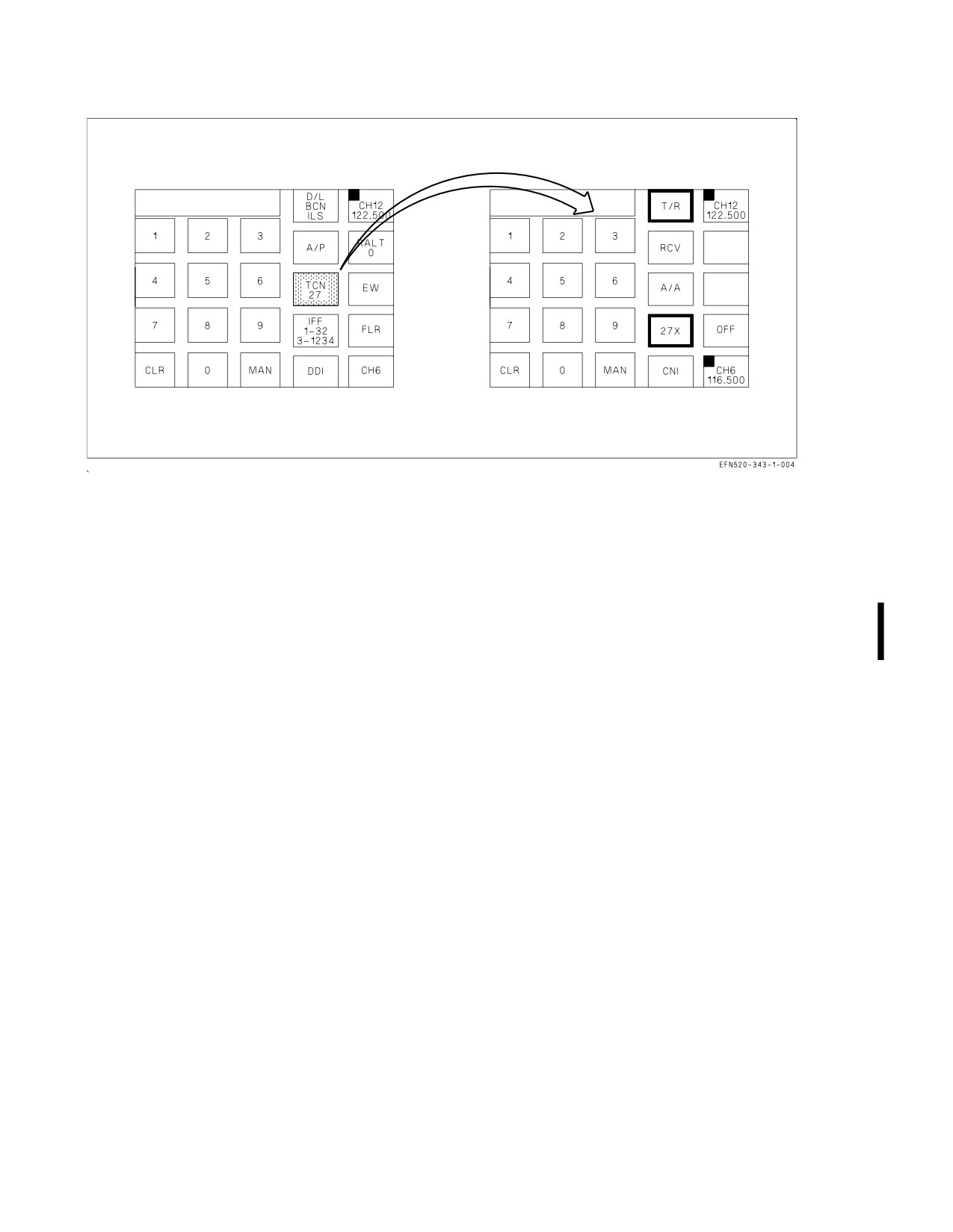
24.4.2 TACAN Mode Selection. To enable the TACAN system, select the TCN option on the UFCD
top level CNI display. The TACAN channel number is displayed on the TCN option. If the TACAN
is powered the TCN option is corner highlighted. If TCN is selected with no data entered in the
scratchpad the TACAN sublevel is displayed, see figure 24-17. TACAN operation is controlled from
the TACAN sublevel. The TACAN system is turned on by pressing the ON/OFF option on the TACAN
sublevel.
When the TACAN sublevel is selected, the following TACAN mode options appear: T/R (transmit/
receive), RCV (receive), A/A (air-to-air), and X and Y channel. Border highlights indicate which
TACAN mode is operating. In the T/R mode the TACAN computes bearing and measures slant range
from the selected TACAN station. In the RCV mode only bearing from the selected TACAN station
is computed. In the A/A mode, interrogations and replies are single pulse from one aircraft to another.
The TACAN channel mode is indicated in the X/Y option which is always border highlighted in the
TACAN sublevel and toggles between X and Y mode with each selection.
24.4.3 TACAN Programming. TACAN station data is entered by selecting the DATA option on the
MPCD top level display. Selecting the TCN option on the data sublevel display provides the TACAN
data sublevel display. This display shows the TACAN station lat/long position, elevation, and magnetic
variation. TACAN station data is entered by selecting the desired TACAN station number on the
UFCD keyboard. Pressing the X or Y option to select the TACAN channel, the POSN option enters
lat/long data, the ELEV option to enter elevation data, and the MVAR option to enter magnetic
variation. TACAN data is entered on the UFCD keypad for up to 252 TACAN stations (126 on X
channel, 126 on Y channel). See figure 24-18.
VII-24-53
ORIGINAL
A1-F18EA-NFM-000
24.4.4 TACAN Position Keeping. The TACAN system may be used for position keeping purposes. To
do this the TACAN system must be in the T/R mode with the proper channel (X or Y) and channel
number selected. The TACAN station selected must be one of the prestored stations. Selecting the
POS/XXX option on the MPCD top level display provides the position keeping option display.
Selecting the TCN option as the position keeping source causes the MPCD top level display to be
returned and POS/TCN to be displayed as the position keeping source.
24.4.5 TACAN Position Updating. The TACAN system may also be used for position updating
purposes. To do this the TACAN system must be in the T/R mode with the proper channel (X or Y)
and channel number selected. The TACAN station selected must be one of the prestored stations.
Selecting the UPDT option on the MPCD top level display provides the UPDT option display.
Selecting the TCN option causes the MC to use position data from the selected TACAN station to
compute aircraft present position. The difference between the TACAN computed present position and
the on board determination of aircraft present position produces the position error readout in bearing
and range on the ACPT/REJ display. Selecting the ACPT option accepts the position update and
returns the MPCD top level display. Selecting the REJ option rejects the update and returns the
MPCD top level display.
24.4.5.1 TACAN Steering. Types of TACAN steering available for selection are direct great circle,
and course line steering. These TACAN steering options are mechanized identical to waypoint/OAP
direct great circle and course line steering, with steering being referenced to the TACAN. Selecting the
TCN option on the MPCD top level display provides TACAN direct great circle steering, see figure
24-19. Activating the CSEL switch with TACAN direct great circle steering selected provides TACAN
course line steering, see figure 24-20.
24.4.5.2 Coupled TACAN Steering. When TACAN steering is coupled, CPL TCN is displayed on the
HUD and HSI display and a CPLD advisory appears on the DDI. The aircraft steers to intercept the
desired course line, or flies to the TACAN station if no course line is selected. Bank angle is limited by
NAV or TAC mode as described in chapter 2. As the aircraft gets close to the desired course, the bank
angle is reduced to maintain the aircraft on the desired course. If a course line is selected, the aircraft
continues past the TACAN station on the outbound radial until the mode is decoupled. If no course
line is selected, TACAN steering uncouples when the aircraft reaches the TACAN station, reverting to
HDG hold. RALT or BALT, whichever is selected, remains engaged when the aircraft passes the
TACAN station. If TACAN steering does not engage or disengages without being commanded, an
AUTOPILOT caution is displayed on the DDI, and CPL TCN flashes for 10 seconds on the HUD and
HSI displays. The caution can be cleared with the paddle switch.
24.5 INSTRUMENT CARRIER LANDING SYSTEM (ICLS)
The AN/ARA-63A ICLS is an all weather approach guidance system which operates with an aircraft
carrier installed transmitting set AN/SPN-41. The ICLS decodes transmitted azimuth and elevation
signals during an approach and provides steering information for display on the HUD, standby attitude
reference indicator, and EADI. The major components of the AN/ARA-63A system are a receiver and
a decoder.
24.5.1 ICLS Receiver. The ICLS receiver receives coded transmissions of azimuth and elevation
guidance data from surface transmitters. The receiver transforms these signals into coded pulses
VII-24-54
ORIGINAL
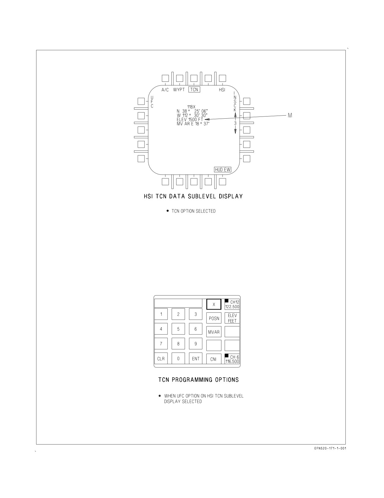
A1-F18EA-NFM-000
Figure 24-18. TACAN Programming
VII-24-55
ORIGINAL
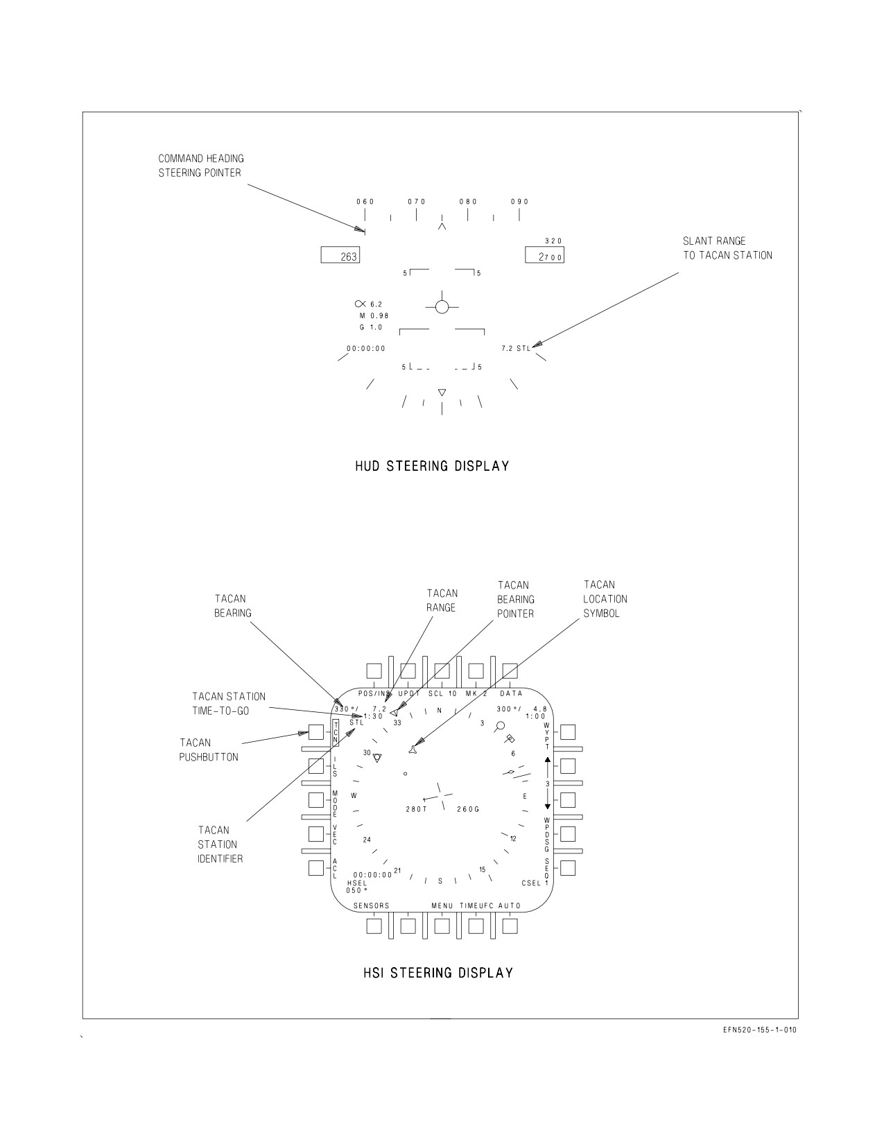
A1-F18EA-NFM-000
Figure 24-19. TACAN Direct Great Circle Steering
VII-24-56
ORIGINAL
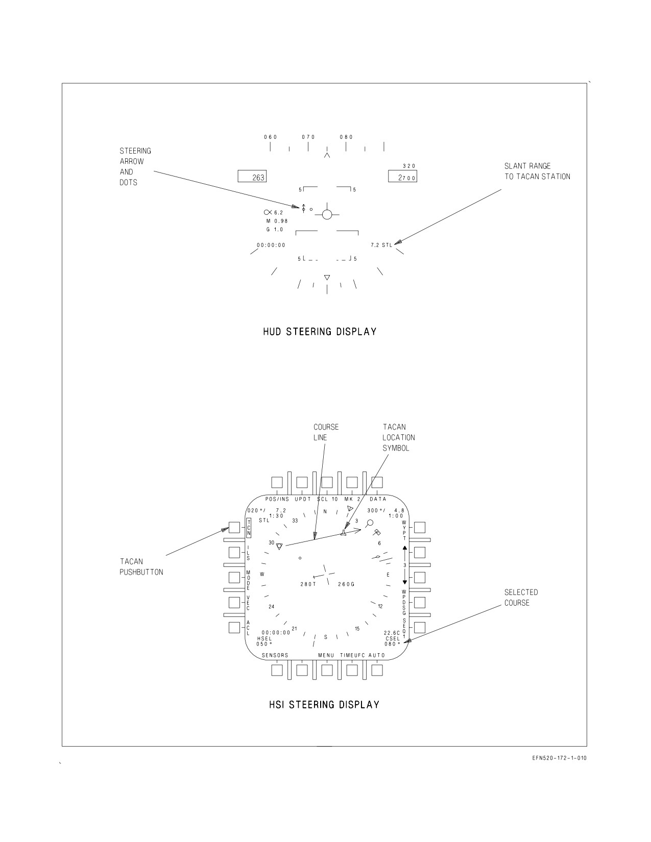
A1-F18EA-NFM-000
Figure 24-20. TACAN Course Line Steering
VII-24-57
ORIGINAL
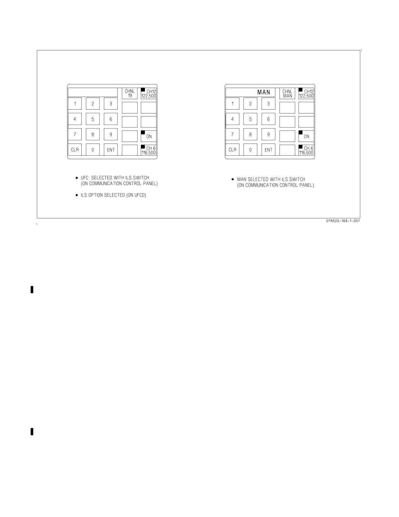
A1-F18EA-NFM-000
Figure 24-21. ICLS Initialization
suitable for processing in the decoder. A BIT module for system BIT check is contained within the
receiver.
24.5.2 ICLS Decoder. The ICLS decoder receives and decodes azimuth and elevation pulses from the
receiver and converts them to azimuth and elevation command signals for the HUD and standby
attitude reference indicator.
24.5.3 ICLS BIT. An ICLS BIT check is manually initiated by ensuring the ICLS is on and selecting
the ILS/AUG/BCN/D/L option on the BIT sublevel display. If any of the BIT monitored outputs fail,
a BIT status message of DEGD (degraded) appears on the BIT sublevel display. If the BIT checks are
good, a BIT status message of GO appears on the BIT sublevel display.
24.5.4 ICLS Initialization. The ICLS is enabled by placing the ILS UFC/MAN switch on the COMM
control panel to the UFC position, pressing the D/L BCN ILS option, and pressing the ILS option, on
the UFCD. This allows the ICLS channel number and ON/OFF status to be displayed on the UFCD
and CHNL # to appear on the CHNL option, see figure 24-21. Pressing the ON/OFF option turns the
ICLS on. The ICLS channel may be changed (1 to 20) using the UFCD keypad. The ICLS is
automatically selected when the ACL data link mode is selected.
Another method of enabling the ICLS is to place the ILS UFCD/MAN switch on the COMM control
panel to the MAN position. When this is done the ICLS is turned on and the ILS channel push buttons
on the COMM control panel are used for channel selection. The letters MAN appear on the scratchpad
and below the CHNL option.
VII-24-58
ORIGINAL
A1-F18EA-NFM-000
24.5.5 ICLS Steering. When the ICLS is on and the ILS option on the MPCD top level display is
selected (boxed), ICLS steering is provided on the HUD, the standby attitude reference indicator, and
the EADI, see figure 24-22. The azimuth and elevation deviation bars are referenced to the velocity
vector. When the waterline symbol is displayed, the deviation bars are referenced to it. As shown, the
deviation bars are deflected full scale and the aircraft is below glide slope and to the left of course. The
azimuth bar is deflected full scale for azimuth deviations of ±6° to ±20°. The elevation bar is deflected
full-scale down for elevation deviations of 1.4° to 20°, and full-scale up for deviations of -1.4° to -3°.
If a valid azimuth or elevation signal is not received by the ICLS, the corresponding bar is not
displayed.
ICLS steering is automatically provided when the ACL mode is selected and valid ICLS steering
signals are received.
24.6 DATA LINK SYSTEM
All information on the data link system, except for the automatic carrier landing mode, is contained
in A1-F18EA-TAC-100. For typical Automatic Carrier Landing procedures, refer to Chapter 8.
24.6.1 Automatic Carrier Landing Mode. The system for automatic landing of aircraft onto the
aircraft carrier deck is comprised of the AN/SPN-42 or AN/SPN-46 installed aboard the carrier and
Automatic Carrier Landing (ACL) equipment installed in the aircraft. The aircraft data link system is
the ACL component over which steering commands are received from the carrier for guidance of the
aircraft.
The data link automatic carrier landing (ACL) mode is available only when the NAV master mode
is selected. The ACL steering commands may be coupled to the flight control computer for fully
automatic approaches to touchdown, or the pilot may elect to use the steering displays for a manually
controlled landing. The traffic control (T/C) mode is a submode of ACL. The T/C mode provides data
link heading commands to aid the pilot in reaching the marshal point and/or it may be used for
azimuth alignment from marshal until ACL acquisition. These heading commands can be coupled to
the flight control computer for automatic lateral axis control or can be used for manual steering aids.
Two uplinked control messages (label 5 and label 6) are uniquely addressed to a specific aircraft and
received by the data link for ACL mode (and T/C submode) control and display. The label 5 message
is used only for T/C mode, while both label 5 and label 6 are required for ACL Modes 1, 1A, and 2
control and display. The contents of the uplinked label 5 and label 6 messages follows:
VII-24-59
ORIGINAL
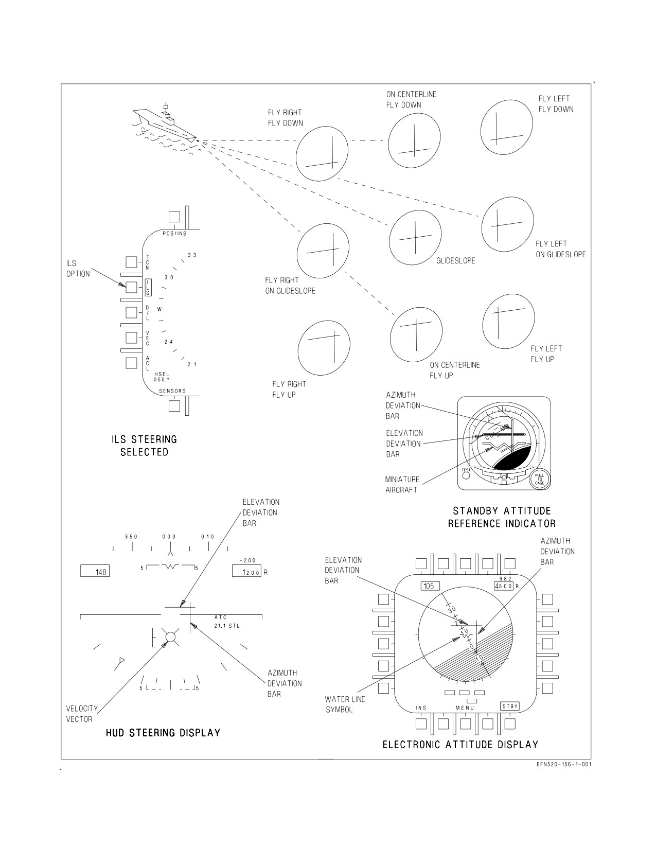
A1-F18EA-NFM-000
Figure 24-22. ICLS Steering
VII-24-60
ORIGINAL
A1-F18EA-NFM-000
Label
5
Message
Command Altitude
Displayed on SA display.
(feet)
Command Airspeed
Displayed on SA display.
(knots)
Command Rate of
Displayed on SA display.
Descent
(feet per minute)
Command Heading
Displayed on SA and HUD.
Group 1 Discretes
ACL RDY, CMD CNT, LND CHK, NOT
CMD, W/O, and CHG CHNL.
Group 2a Discretes
Monitor Altitude and Altitude Change
Warning
Receipt of either discrete causes the Command
Altitude and Command Rate of Descent to be
underlined on the SA display.
Group 2b Discretes
Monitor Speed and Speed Change Warning.
Receipt of either discrete causes the Command
Airspeed to be underlined on the SA display.
Group 2c Discretes
ADJ A/C, VOICE and 10 SEC.
Label
6
Message
Vertical Glide Slope Error
Used for data link HUD situation display.
Lateral Glide Slope Error
Used for data link HUD situation display.
Mode Status Discrete
Indicates that uplinked longitudinal and lateral
axes commands may be used for Mode 1 ap-
proach.
Longitudinal Axis Command
Used by FCS for longitudinal axis control.
(altitude rate in feet/second)
Lateral Axis Command
Used by FCS for lateral axis control.
(roll angle in degrees)
The ground station also periodically uplinks two universal test messages (UTM-3A and UTM-3B).
These two messages have a canned constant content and carry a universal address, rather than being
addressed uniquely to a controlled aircraft, as are the label 5 and label 6 messages. During ACL mode
test, the data link is commanded to accept these two UTM as part of the determination of onboard
ACL capability.
24.6.1.1 ACL Mode Displays. The ACL mode displays consist of the SA display on the DDI and the
data link situation display on the HUD. The following paragraphs contain a general description of the
VII-24-61
ORIGINAL
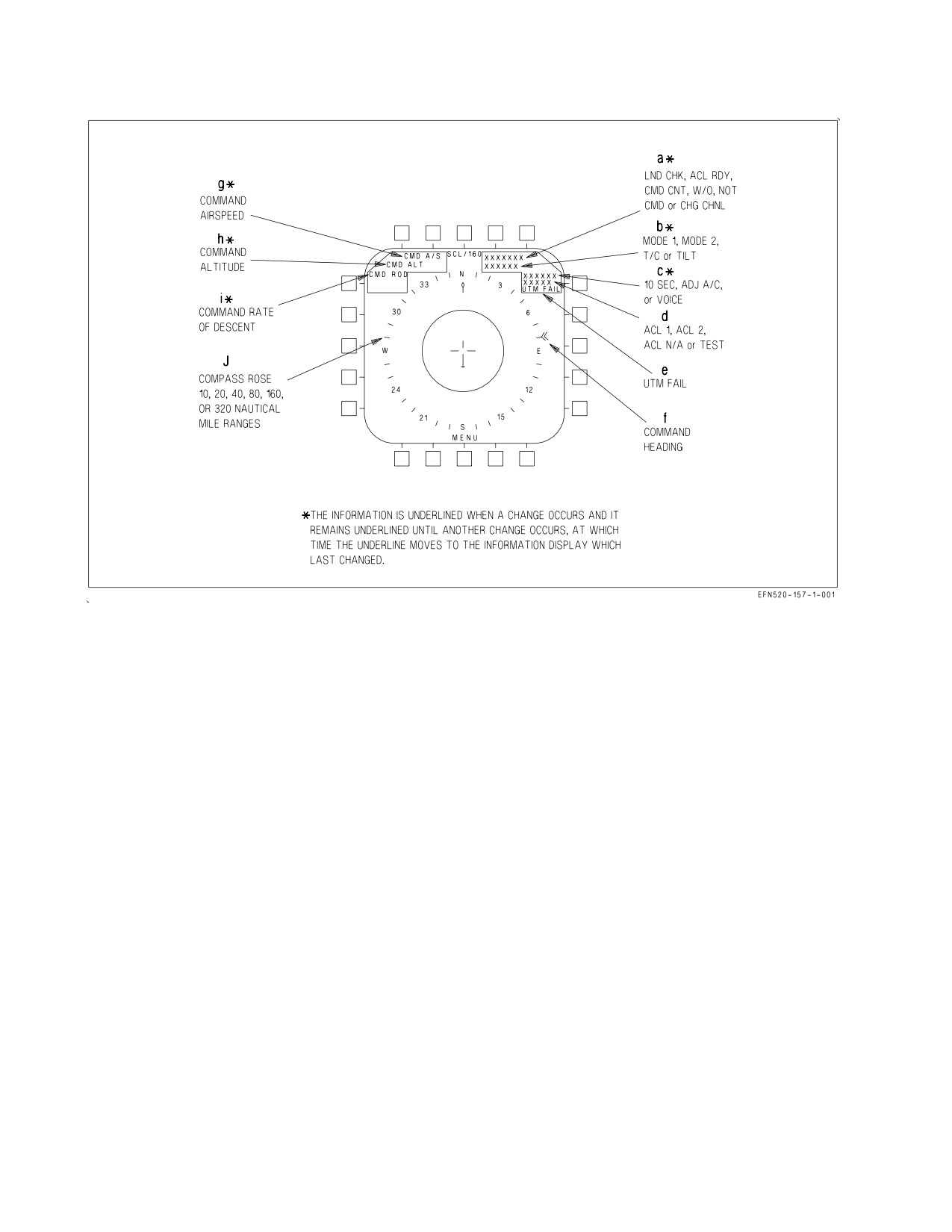
A1-F18EA-NFM-000
Figure 24-23. DDI SA ACL Display
displays related to the ACL mode. A more explicit definition of the utilization of these displays is
presented in ACL Mode Operation, this chapter.
24.6.1.1.1 SA Display. Figure 24-23 shows the ACL and T/C information which may be displayed on
the link SA display. The lettered symbols and cues on the display are described after the corresponding
letter in the following paragraphs.
a. The following uplinked group 1 discretes may be displayed in this slot:
LND CHK Landing check indicates that SPN-42/SPN-46 control radar communication has
been established. It also cues the pilot to be in the landing configuration with ATC
engaged.
ACL RDY ACL ready indicates that SPN-42/SPN-46 acquisition has occurred and uplinked
longitudinal axis (altitude rate) and lateral axis (roll rate) commands are being
received equal to zero. The ACL RDY indication is also displayed on the HUD.
Receipt of the ACL RDY discrete is one of the onboard prerequisites for ACL
couple.
CMD CNT Command control discrete indicates that the carrier has received a verbal confir-
mation from the pilot that FCS is coupled to the ACL longitudinal and lateral
commands, and further indicates to the pilot that longitudinal and lateral com-
mands are now active.
W/O
When this discrete is received the FCS is uncoupled from the uplinked commands.
VII-24-62
ORIGINAL
A1-F18EA-NFM-000
NOT CMD The not command discrete indicates that label 5 information is invalid. When this
discrete is received the label 5 information is removed from the SA display and the
FCS is uncoupled from the T/C heading command/ACL steering commands.
CHG
The change channel discrete indicates that the data link frequency should be
CHNL
changed.
b. The following ACL mode operational cues may be displayed in this slot.
MODE 1
Indicates that the entire loop is capable and ready for coupling for dual axes ACL
control.
MODE 2
Indicates that the entire loop is not capable of Mode 1 coupled approach but is
capable of Mode 2 manual control approach using uplinked situation steering.
T/C
Traffic control cue indicates that the entire loop is capable and ready for couple to
the T/C heading command.
TILT
Indicates that the uplinked information is not being updated. When this condition
exists all uplinked information is removed from the displays and the FCS is
uncoupled from the data link commands.
c. The following uplinked group 2 C discretes may be displayed in this slot. These cues are
displayed for 30 seconds after initial receipt, then removed.
10 SEC
Indicates that SPN-42/SPN-46 is now adding deck motion compensation to the
longitudinal and lateral axes commands. This discrete is received approximately
12.5 seconds before touchdown.
ADJ A/C
Adjacent aircraft cue indicates that another aircraft has been detected in the area
of controlled aircraft.
VOICE
Indicates that the pilot is to establish voice contact with control.
d. The following onboard capability cues are displayed in this slot.
ACL 1
Indicates that onboard systems are capable of an ACL or T/C couple to the FCS.
ACL 2
Indicates that onboard systems are not capable of ACL or T/C couple to FCS, but
are capable of displaying uplinked information for a Mode 2 manual approach.
ACL N/A Indicates that onboard systems are not capable of using uplinked information and
that a carrier controlled approach (CCA) must be made.
TEST
Indicates that ACL mode is in test.
e. The UTM FAIL cue is displayed in this slot when valid uplinked UTM 3A and UTM 3B were
not received during automatic test.
VII-24-63
ORIGINAL
A1-F18EA-NFM-000
f. Command heading is displayed by the double chevron symbol on the outside of the compass
rose.
g. Command airspeed is displayed in this slot.
h. Command altitude is displayed on this slot.
i. Command rate of descent is displayed in this slot.
j. The compass rose is track-up oriented with selectable ranges of 10, 20, 40, 80, 160, and 320 nm.
24.6.1.1.2 HUD ACL Display. Figure 24-24 shows the HUD ACL display information. The lettered
symbols and cues on the HUD are described after the corresponding letter in the following paragraphs.
a. Uplinked command heading is indicated by the command heading steering pointer below the
heading scale.
b. The following cues may be displayed in the command heading slot:
10 SEC
Displayed for 30 seconds after receipt and then removed. Also displayed on SA dis-
play.
TILT
Displayed when communication has been lost with data link control. Also on SA
display.
DATA
Displayed for 10 seconds and flashed at a rate of two times per second when new
data is initially displayed on the SA display.
W/O
When this discrete is received the FCS is uncoupled from the uplinked commands.
c. The following cues may be displayed in this slot:
ACL RDY Displayed when received via data link and the FCS is not coupled. Also displayed
on SA display.
CPL P/R Coupled in pitch and roll is displayed when the FCS is coupled to the longitudinal
and lateral commands. The cue is flashed for 10 seconds at two times per second
then removed if the couple attempt is unsuccessful, or if uncouple occurs for any
reason other than pilot deselection. Disengagement, other than pilot initiated, also
results in an AUTOPILOT caution.
CPL HDG Coupled to heading commands cue is displayed when FCS is coupled in the T/C
mode. This cue is flashed for the same reasons as described for the CPL P/R cue.
d. The following cues may be displayed in this slot. These cues may be displayed in any master
mode:
VII-24-64
ORIGINAL
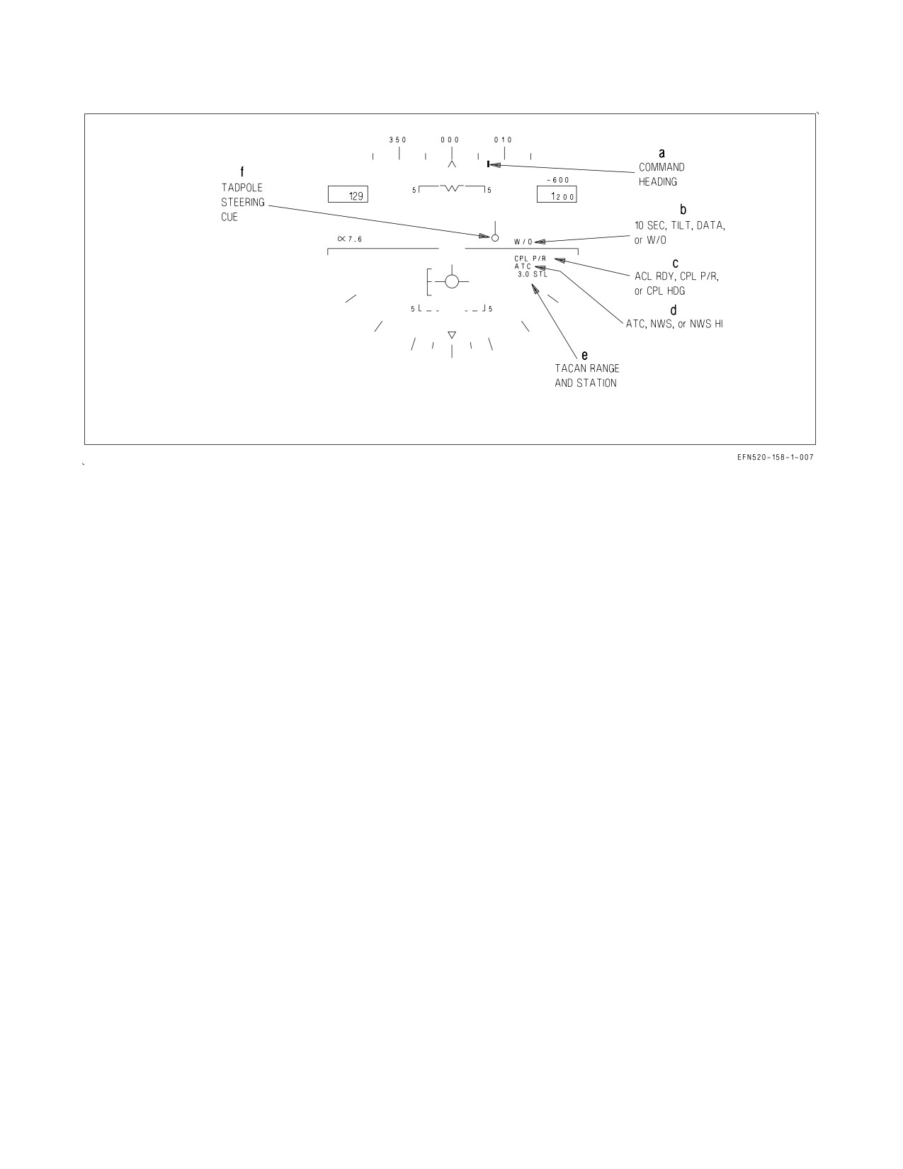
A1-F18EA-NFM-000
Figure 24-24. HUD ACL Display
ATC
Displayed when automatic throttle control is engaged. If an unsuccessful engage-
ment attempt occurs, or if the ATC disengages for any reason other than pilot
deselection, the ATC cue is flashed for 10 seconds at two times per second, then
removed.
NWS
Indicates low gain nosewheel steering is engaged.
NWS HI Indicates high gain nosewheel steering is engaged.
e. When ACL mode is initially selected, waypoint steering is automatically deselected, if selected,
and the system is automatically undesignated if an aimpoint is designated. If TACAN is on,
TACAN range is automatically displayed regardless of TACAN steering selection unless the
pilot subsequently designates an aimpoint or selects waypoint steering.
f. The tadpole steering symbol is referenced to the velocity vector and provides uplinked flight
path steering indications for the ACL glide slope and course.
24.6.1.2 ACL Mode Operation. The data link ACL mode is selected by actuating the ACL option
button on the MPCD.
24.6.1.2.1 Initialization. When selected, the ACL legend on the MPCD is boxed and the SA display
is automatically selected on the left DDI. The TEST cue is displayed indicating the ACL mode is in
test. The ICLS, data link, and radar beacon are automatically turned on if not previously on. IBIT is
run on the data link and radar beacon systems. The uplinked UTM is monitored for valid receipt.
When ACL testing is complete the TEST cue is removed, the systems are placed in the correct
operational mode, the stored data link ACL frequency is automatically selected, and the pilot is cued
on the SA display to onboard ACL capability (ACL 1, ACL 2, or ACL N/A) as previously described. If
during test, a valid uplinked UTM message was not received, the UTM FAIL cue is displayed on the
SA display.
VII-24-65
ORIGINAL
A1-F18EA-NFM-000
24.6.1.2.2 Traffic Control Couple. When an uplinked label 5 message is received, a determination is
automatically made relative to total loop capability. If the ACL loop is ready for a T/C couple, the T/C
cue appears on the SA display and autopilot options are initialized on the upfront control display with
the CPL HDG option displayed (figure 24-25). The prerequisites for a CPL HDG option for T/C
follows:
1. Onboard systems fully operational.
2. Valid label 5 message received.
3. Waveoff (W/O) discrete not received.
4. Uplinked information being updated (no TILT cue).
5. NOT CMD discrete not being received.
6. Label 6 message not being received.
With T/C displayed FCS couple is selected by actuating the CPL option button on the UFCD. When
coupling to the T/C heading command is successful a colon is displayed in front of the CPL option on
the UFCD and the CPL HDG cue is displayed on the HUD. After couple the FCS banks the aircraft
to a maximum of 30° to capture and hold the uplinked heading command. Aircraft pitch attitude may
be controlled by the pitch hold function of the heading hold mode or by the BALT or RALT altitude
hold modes of the autopilot. A T/C couple precludes use of all other outer loop autopilot modes except
BALT and RALT. The T/C couple disengages, with reversions as noted, for any of the following
reasons:
1. Heading hold mode disengagement with reversion to CAS operation.
2. Roll control stick steering engagement with reversion to lateral axis heading hold mode.
3. Loss of valid uplinked heading command for more than 10 seconds (TILT) with reversion to
lateral axis heading hold mode.
4. Pilot deselection of CPL option with reversion to lateral axis heading hold mode.
5. Pilot actuation of paddle switch with reversion to CAS.
6. Receipt of uplinked W/O discrete with reversion to lateral axis heading hold mode.
7. Receipt of uplinked NOT CMD discrete with reversion to lateral axis heading hold mode.
An unsuccessful T/C couple attempt, or disengagement of the T/C couple for any reason other than
pilot deselection, results in an AUTOPILOT caution as well as CPL HDG on the HUD flashing for 10
seconds.
24.6.1.2.3 ACL Mode 1. When an uplinked label 6 message is received, a determination is made with
respect to total loop capability relative to dual-axis (lateral and longitudinal) ACL couple. If ACL
couple is determined to be available, the Mode 1 cue is displayed on the SA display and the autopilot
options are initialized on the UFCD with CPL P/R option displayed as shown in figure 24-26.
VII-24-66
ORIGINAL
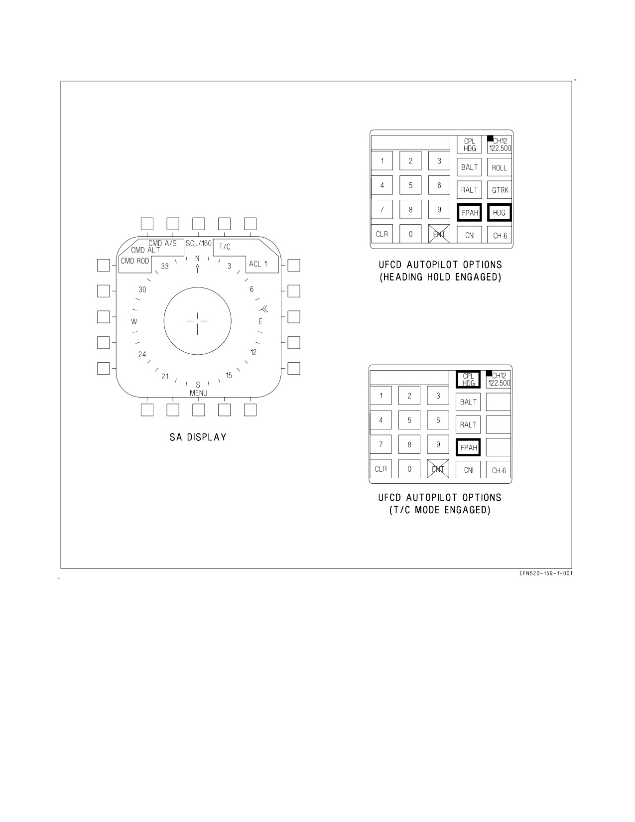
A1-F18EA-NFM-000
Figure 24-25. Traffic Control Couple Display
When the pilot selects the CPL P/R option on the UFCD, an ACL couple to the FCS is requested
if prerequisites are met.
NOTE
If FCS is already coupled to T/C command heading, actuation of the
CPL HDG option disengages T/C couple and a second actuation (CPL
P/R) requests ACL couple.
The MC prerequisites for initial ACL couple are:
VII-24-67
ORIGINAL
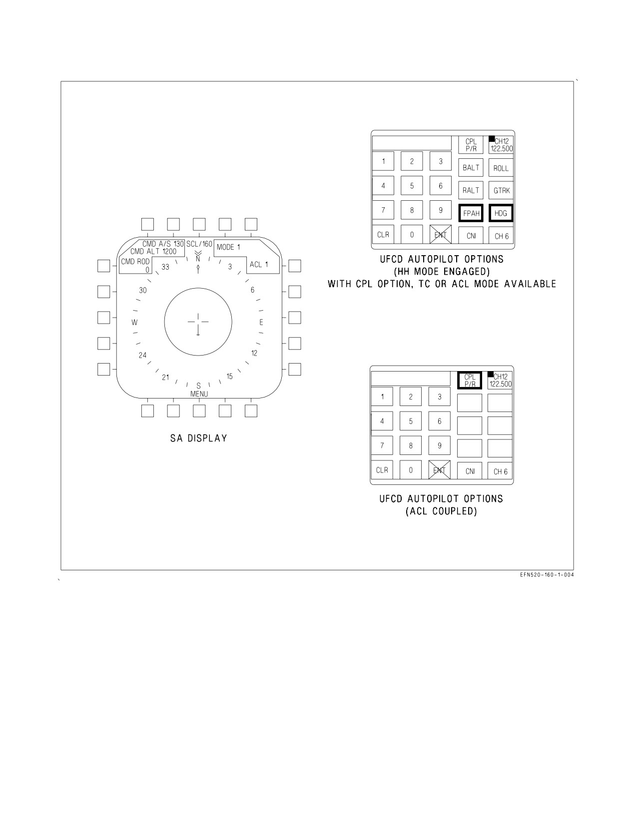
A1-F18EA-NFM-000
Figure 24-26. ACL Mode 1 Display
1. Basic FCS outer loop (heading hold) engaged. If heading hold is not engaged when the CPL
option is actuated it is automatically requested, and when FCS indicates it is engaged, ACL couple
is requested.
2. Onboard test results indicate ACL 1 capability.
3. Uplinked ACL RDY discrete being received. ACL RDY is required for initial couple only. It is not
required after ACL couple occurs.
4. Uplinked A/P bit set to couple state.
VII-24-68
ORIGINAL
A1-F18EA-NFM-000
5. Valid uplinked longitudinal and lateral axes commands being received (no TILT).
The CPL P/R option is highlighted on the UFCD and the CPL P/R cue is displayed on the HUD to
indicate FCS is coupled. When ACL couple initially occurs, the FCS fades in the longitudinal and
lateral uplinked commands to minimize engagement transients. After FCS is coupled to the dual-axis
commands, the FCS limits the accepted magnitude of the uplinked commands to prevent excessive
pitch or roll changes due to large and/or erroneous uplinked commands. When FCS is coupled to ACL,
uncouple occurs, with reversion as noted, for any of the following reasons.
1. Heading hold mode disengagement with reversion to CAS operation.
2. Pitch or roll control stick steering engagement with reversion to CAS when CSS is no longer
engaged.
3. WonW with reversion to CAS.
4. Paddle switch actuation with reversion to CAS.
5. UFCD CPL option actuation with reversion to CAS.
6. Receipt of W/O discrete with reversion to CAS.
7. Receipt of command degrading approach to Mode 2 state with reversion to CAS.
8. Loss of valid uplinked commands for more than 2 seconds (TILT) with reversion to CAS.
9. Detection of degraded onboard capability below that required for Mode 1 with reversion to CAS.
10. Selection of FLAPS AUTO.
11. MC Failure or selected to OFF
NOTE
With H2E+ and H3E MC OFPs, MC1 failed or selected to OFF and
coupled ACLS previously engaged, the option to re-couple to ACLS is
not presented on the autopilot page of the UFCD when MC1
is
restored. Deselecting and then reselecting ACL on the HSI will bring
the CPL P/R option back if all coupled ACL engagement conditions
are satisfied after the ACL TEST sequence is complete. If MC2 is
cycled with ACL selected, the CPL P/R option is available without
having to deselect/reselect ACL.
During an ACL coupled approach the D/L situation steering and the ICLS situation steering may
remain selected for HUD display to allow the pilot to monitor the progress of the automatic control in
capturing and holding the desired glide slope and azimuth.
NOTE
The D/L situation steering may be removed from the HUD by
unboxing ACL on the MPCD, however, reselection of the ACL option
reinitializes the system as described in section 24.6.1.2.1.
VII-24-69
ORIGINAL
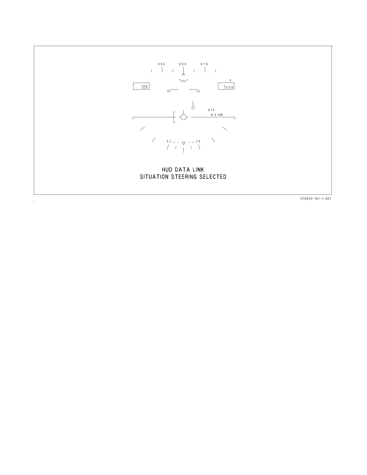
A1-F18EA-NFM-000
Figure 24-27. ACL Mode 2 Steering Display
24.6.1.2.4 ACL Mode 1A. For an ACL Mode 1A approach, the aircraft may be coupled to data link
commands as described in the Mode 1 paragraph, then uncoupled at minimums (200 feet and 0.5 mile)
and manual control as described for Mode 2 used the rest of the way to touchdown.
24.6.1.2.5 ACL Mode 2. When a label 6 message is initially received and a Mode 1 or Mode 2
capability exists, a Mode 2 manual approach may be made. Data link HUD steering is automatically
selected. The data link situation steering tadpole is displayed on the HUD with the tadpole referenced
to the velocity vector as shown in figure 24-26. The ICLS situation display may remain selected on the
HUD for crosscheck on the D/L situation display and/or either D/L or ICLS display may be deselected
by actuating the option button on the MPCD. Mode 2 approaches may be made with or without ATC
engaged, but ATC should be used for angle of attack/airspeed control, if it is available. If ATC is not
engaged the HUD angle of attack bracket should be used to control AOA/airspeed and the glide slope
maintained by flying the D/L situation steering display on the HUD.
24.6.1.3 Typical ACL Approach. Figures 24-26 and 24-27 describe the controls and displays for a
“canned” Mode 1 ACL approach. The ACL mode is optimized for the described approach, but
abbreviated approaches and/or deviations as required may be used, dependent upon existing
operational procedures and collaboration between the pilot and carrier control. Figure 24-27 shows a
plan view of the approach with controls and displays for selected points prior to marshal. Figure 24-28
shows descent from marshal to touchdown. The depicted scenario uses only D/L steering and
commands complemented with ICLS steering in order to more clearly define D/L capability. It does
not show TCN or WYPT steering which may be used in conjunction with, or independent of, D/L
steering during the approach.
24.7 NAVIGATION DATA ENTRY
The UFCD has two data entry protocols, Standard Data Entry (SDE) and Fast Data Entry (FDE).
VII-24-70
ORIGINAL
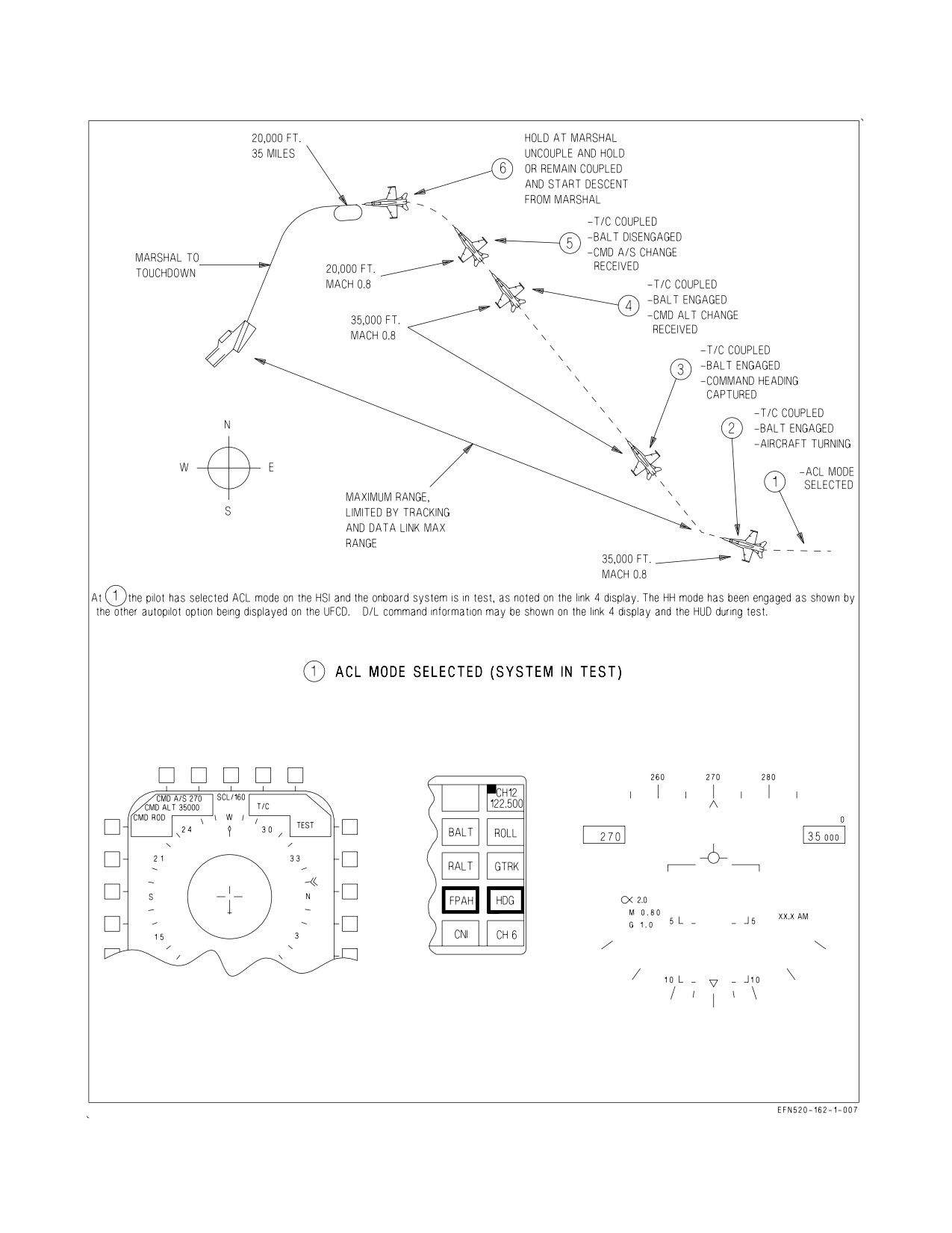
A1-F18EA-NFM-000
Figure 24-28. T/C Guidance to Marshal (Sheet 1 of 3)
VII-24-71
ORIGINAL
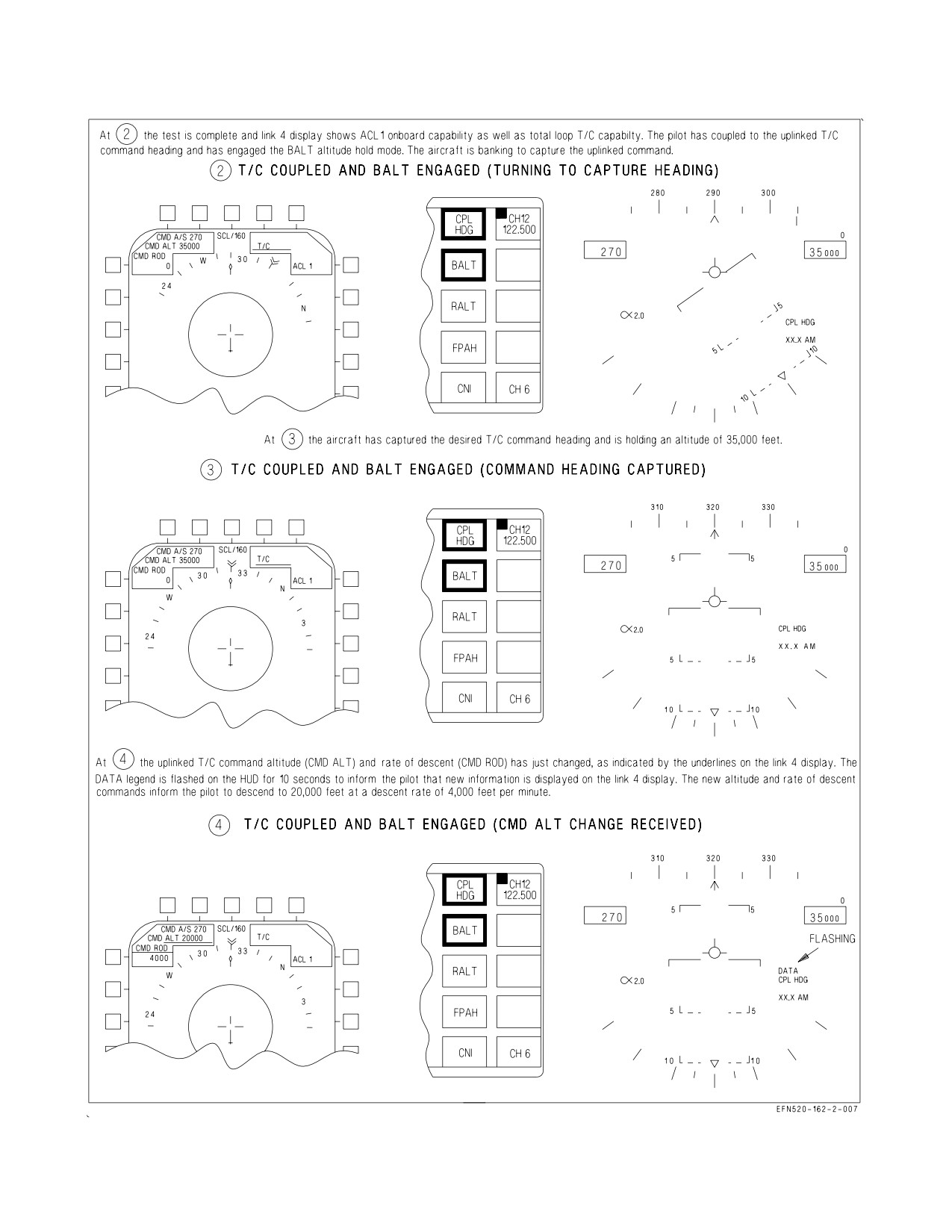
A1-F18EA-NFM-000
Figure 24-28. T/C Guidance to Marshal (Sheet 2)
VII-24-72
ORIGINAL
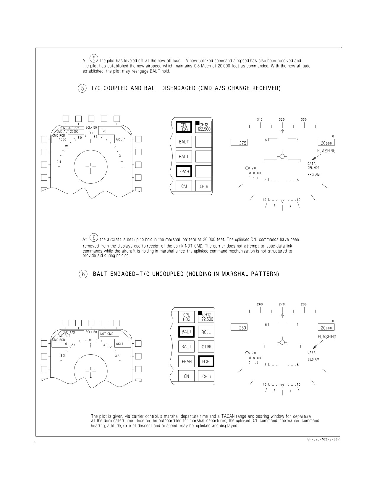
A1-F18EA-NFM-000
Figure 24-28. T/C Guidance to Marshal (Sheet 3)
VII-24-73
ORIGINAL
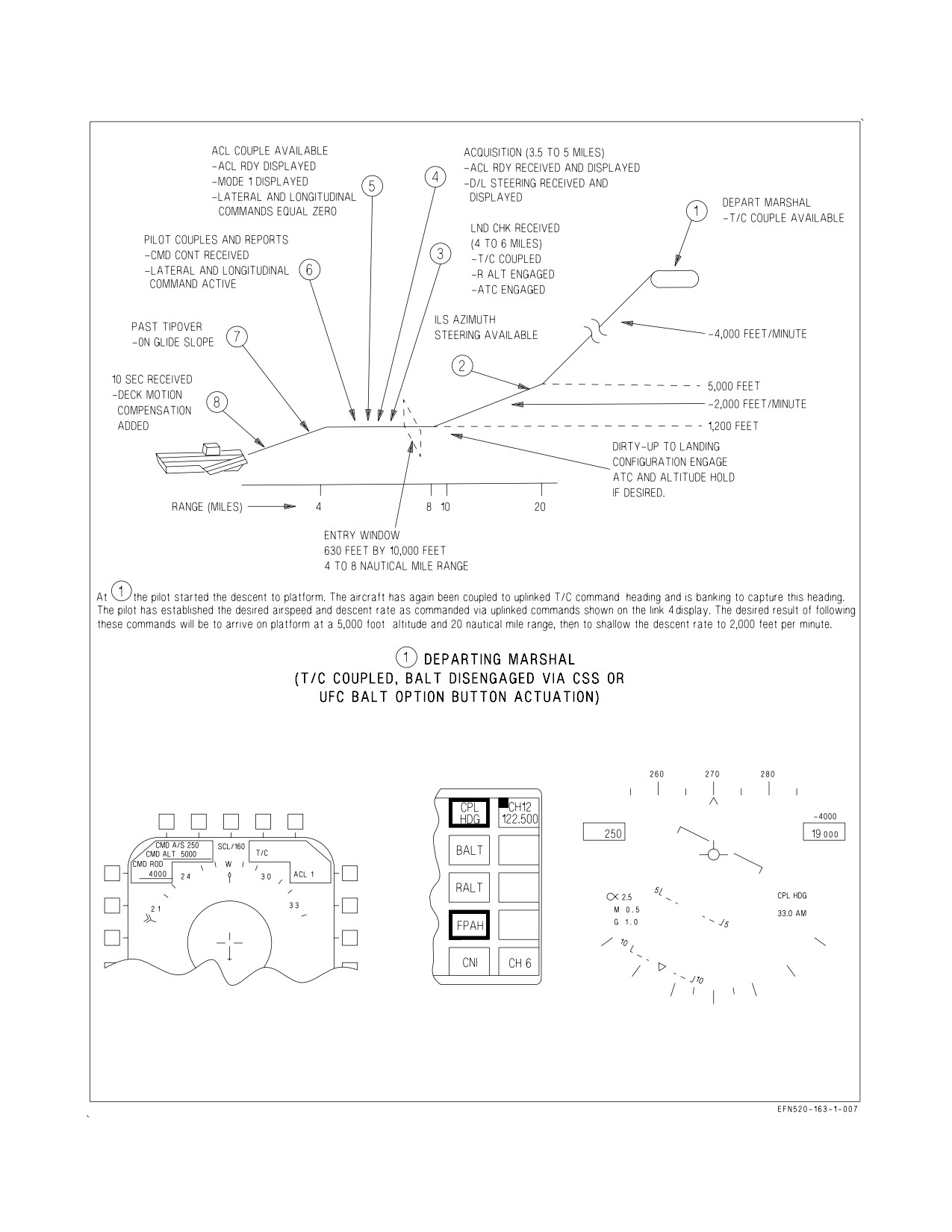
A1-F18EA-NFM-000
Figure 24-29. ACL Control - Marshal to Touchdown (Sheet 1 of 5)
VII-24-74
ORIGINAL