F18. FLIGHT MANUAL (2008) - page 14
A1-F18AC-NFM-000
The ADF system is turned on using the ADF function selector switch on the UFC. Placing the switch
to the 1 position applies power to the ADF and indicates ADF bearing to the station selected on the
comm 1 radio. Placing the switch to the 2 position applies power to the ADF and indicates ADF bearing
to the station selected on the comm 2 radio. Placing the switch to the OFF position removes power from
the ADF. ADF audio is adjusted by either the comm 1 or comm 2 volume control knob. ADF symbology
appears as a small circle on the HI/MPCD.
24.4 TACAN (Tactical Air Navigation).
The RT-1159A/ARN-118 TACAN system gives precise relative bearing and/or slant range distance
to a TACAN ground station or range to a suitably equipped aircraft. The TACAN system operates in
the L-Band frequency range, limiting the operating range to line of sight which depends upon aircraft
altitude. The maximum operating range is 390 nm when the selected TACAN station is a surface
beacon and 200 nm when the selected TACAN station is an airborne beacon. The aircraft receives a
three letter morse code signal to identify the beacon being received. When operating in conjunction
with aircraft having air-to-air capability, the A/A mode provides line of sight distance between two
aircraft operating their TACAN sets 63 channels apart. Up to five aircraft can determine line of sight
distance from a sixth lead aircraft in the A/A mode.
In MIDS-equipped aircraft, TACAN functionality is embedded in the MIDS terminal, replacing the
AN/ARN-118 in door 13R. To preclude MIDS interference with the IFF system, notch frequency
filters were placed in the MIDS TACAN antenna lines. The upper filter is fixed, while the lower filter
is switched in for LINK-16 transmissions, and out for TACAN transmissions and all reception. Because
the upper antenna filter is fixed, it filters A/A TACAN frequencies on channels 1-36 and 64-99 (X and
Y). A/A TACAN channels should be chosen outside of these ranges. The upper filter makes the top
antenna unusable for T/R (Air to Ground) TACAN channels 1-29 X and Y, 47X to 63X and 64Y to
92Y. For TACAN channels in these ranges, the bottom antenna is the only antenna for TACAN. With
a centerline tank installed, the antenna is blocked approximately 180°± 15° relative to the aircraft
nose. This shadowing of the bottom antenna, combined with the lower transmitter power of the MIDS
(200W versus 1000W for AN/ARN-118), causes reduced ranges for DME at channels within the range
of the filter when flying directly away from the TACAN station. Flight test data at afloat stations
shows that maximum tail-aspect DME ranges of approximately 22 nm at 6,000 feet and 26 nm at 15,000
feet can be expected to make DME unreliable when headed outbound in the marshal stack. At shore
stations, flight tests have shown substantially better tail-aspect DME ranges (e.g. 52 nm at 15,000 feet).
DME ranges in the forward and side quadrants of the aircraft, and bearing performance in all
quadrants, are not impacted. Therefore, approach performance on the affected channels is nominal.
NOTE
MIDS equipped aircraft may experience TACAN bearing and DME
dropouts. MIDS equipped aircraft with a centerline tank may
experience loss of DME during outbound legs from TACAN stations 1
to 29X and Y, 47X to 63X and 64Y to 92Y.
24.4.1 TACAN BIT. To manually initiate a TACAN BIT check, ensure the TACAN is turned on, then
press the TCN/IFF option on the BIT sublevel display. If the TACAN is good, the DDI shows the BIT
status as GO. If the TACAN does not pass the BIT check, the BIT status shows DEGD. The TACAN
system also has an automatically initiated BIT. If the automatic BIT check detects a wrong signal or
a failure, a TACAN DEGD is displayed on the DDI BIT display and the BIT line on the left DDI. If
no fault is detected, nothing is displayed next to TCN. In MIDS equipped aircraft, the only way to
execute a TACAN BIT is by initiating a MIDS BIT. To run a MIDS BIT, MIDS must be selected in
the COMM submenu of the BIT display.
VII-24-55
ORIGINAL
A1-F18AC-NFM-000
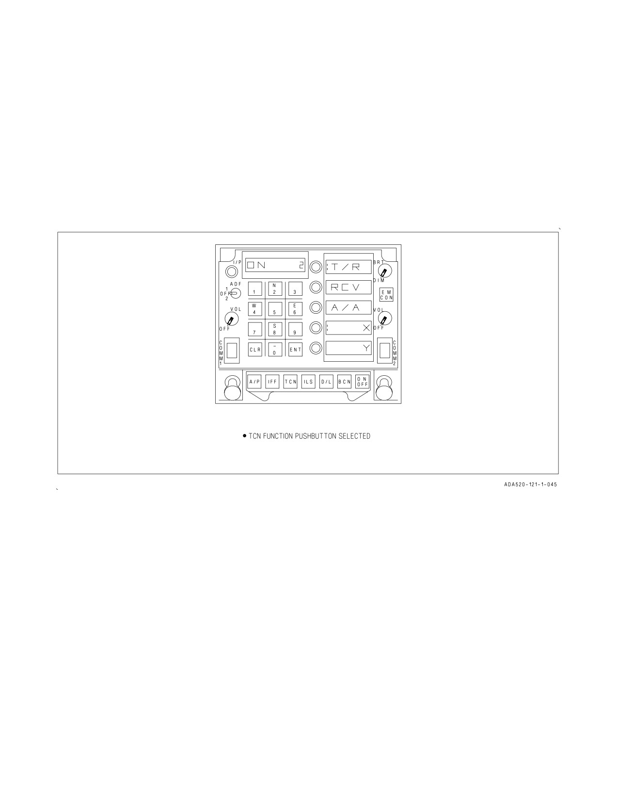
24.4.2 TACAN Mode Selection. To enable the TACAN system actuate the TCN function selector
pushbutton on the UFC. This allows the TACAN channel number and ON/OFF status to be displayed
on the UFC scratchpad, along with the TACAN mode options on the UFC option windows, see figure
24-17. Now actuate the ON/OFF selector pushbutton to turn the TACAN system on. The TACAN
channel number may be changed using the UFC keypad.
When the TCN pushbutton is selected, the following TACAN mode options appear: T/R (transmit/
receive), RCV (receive), A/A (air-to-air), along with the X and Y channels options. In the T/R mode
the TACAN computes bearing and measures slant range from the selected TACAN station. In the RCV
mode only bearing from the selected TACAN station is computed. In the A/A mode, interrogations and
replies are only single pulse from one aircraft to another.
Figure 24-17. TACAN Mode Selection
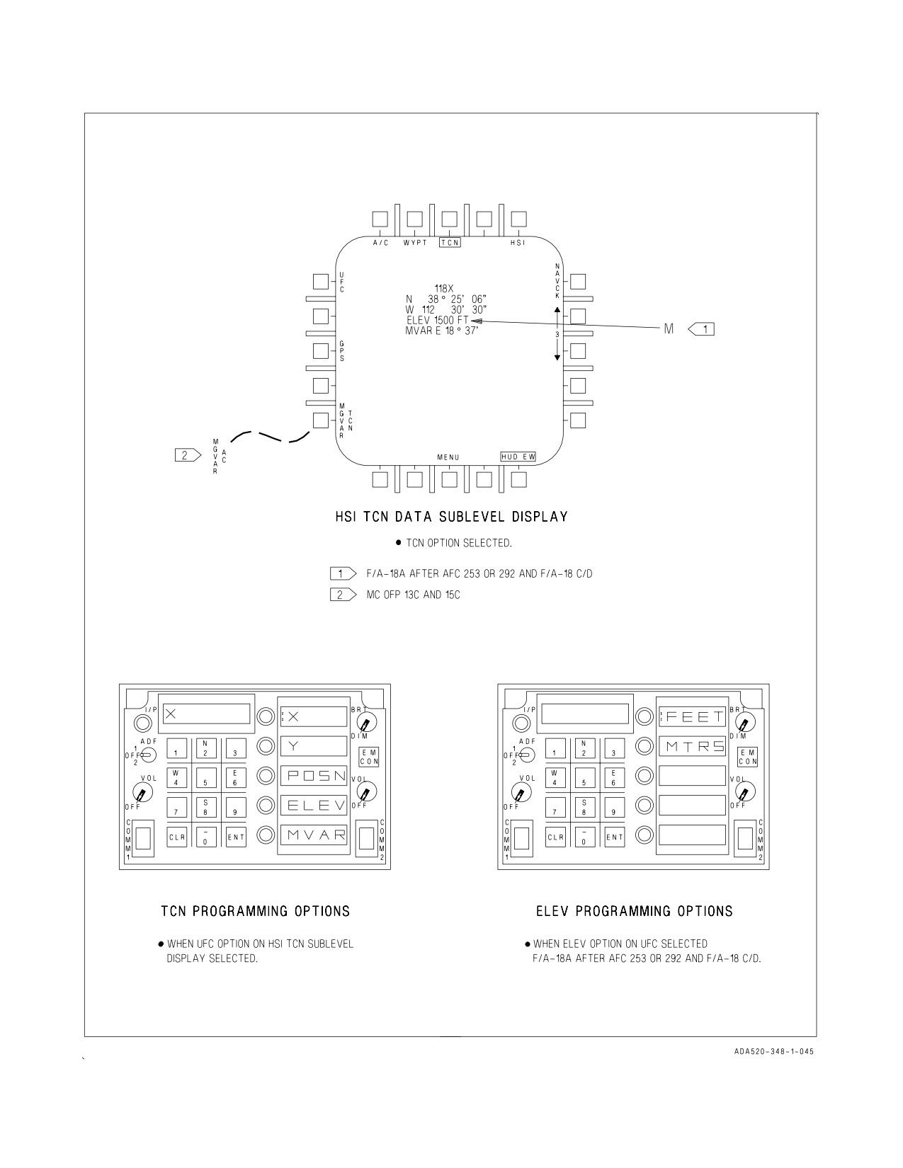
24.4.3 TACAN Programming. To enter TACAN station data, select the DATA option on the HSI
display. Then select the TCN option on the DATA sublevel display to bring up the TACAN data
sublevel display. This display shows the current TACAN station data: lat/long position, elevation and
magnetic variation. To enter the TACAN station number, select the up/down arrow to select the
desired TACAN station number. Next, select the UFC option to initialize the UFC for TACAN station
data entry. On the UFC select: the X or Y pushbutton to select the TACAN channel, the POSN
pushbutton to enter lat/long data, the ELEV pushbutton to enter elevation data, and the MVAR
pushbutton to enter magnetic variation. TACAN data is entered through the UFC keypad for up to 10
TACAN stations. See figure 24-18.
24.4.3.1 TCN/AC MGVAR Option (MC OFP 13C AND UP). TACAN or AC magnetic variation can be
selected from the HSI/DATA/TCN display. AC MGVAR is the default. In regions where the magnetic
variation is rapidly changing, selecting TCN MGVAR can give more consistent steering information
relative to the TCN station. See figure 24-18.
24.4.4 TACAN Position Keeping. The TACAN system may be used for position keeping purposes. To
do this the TACAN system must be in the T/R mode with the proper channel (X or Y) and channel
number selected. The TACAN station selected must be one of the prestored stations. Now select the
VII-24-56
ORIGINAL
A1-F18AC-NFM-000
POS/XXX option on the HSI display. This provides the position keeping option display, see figure
24-10. Next, select the TCN option as the position keeping source. When this is done the HSI display
is returned along with POS/TCN displayed as the position keeping source.
24.4.5 TACAN Position Updating. The TACAN system may also be used for position updating
purposes. To do this the TACAN system must be in the T/R mode with the proper channel (X or Y)
and channel number selected. The TACAN station selected must be one of the prestored stations. Now
select the UPDT option on the HSI display, this provides the UPDT option display, see figure 24-11.
Next, select the TCN option; when this is done the MC uses position data from the selected TACAN
station to compute aircraft present position. The difference between the TACAN computed present
position and the on board determination of aircraft present position produces the position error
readout in bearing and range on the ACPT/REJ display. Selecting the ACPT option accepts the
position update and returns the HSI display. Selecting the REJ option rejects the update and returns
the HSI display.
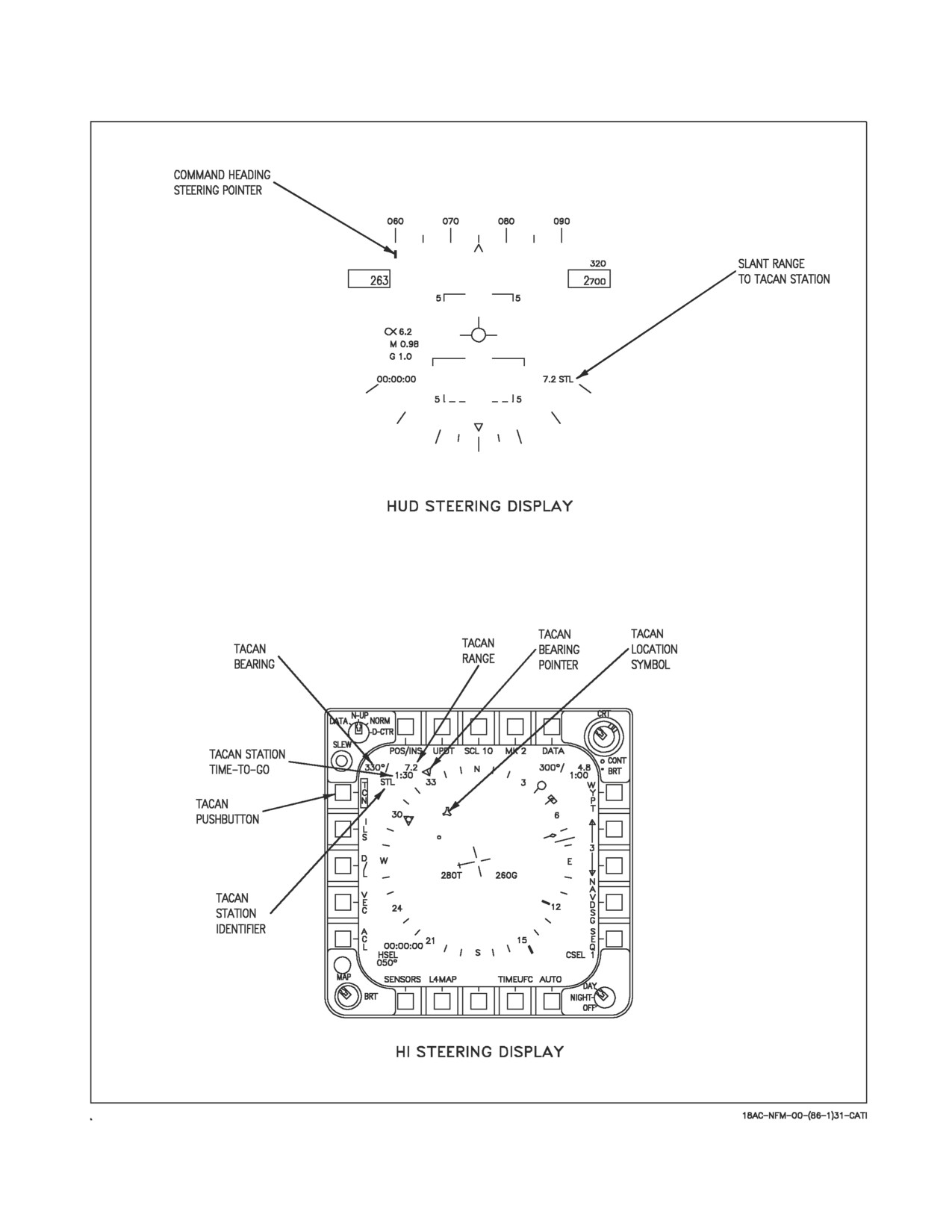
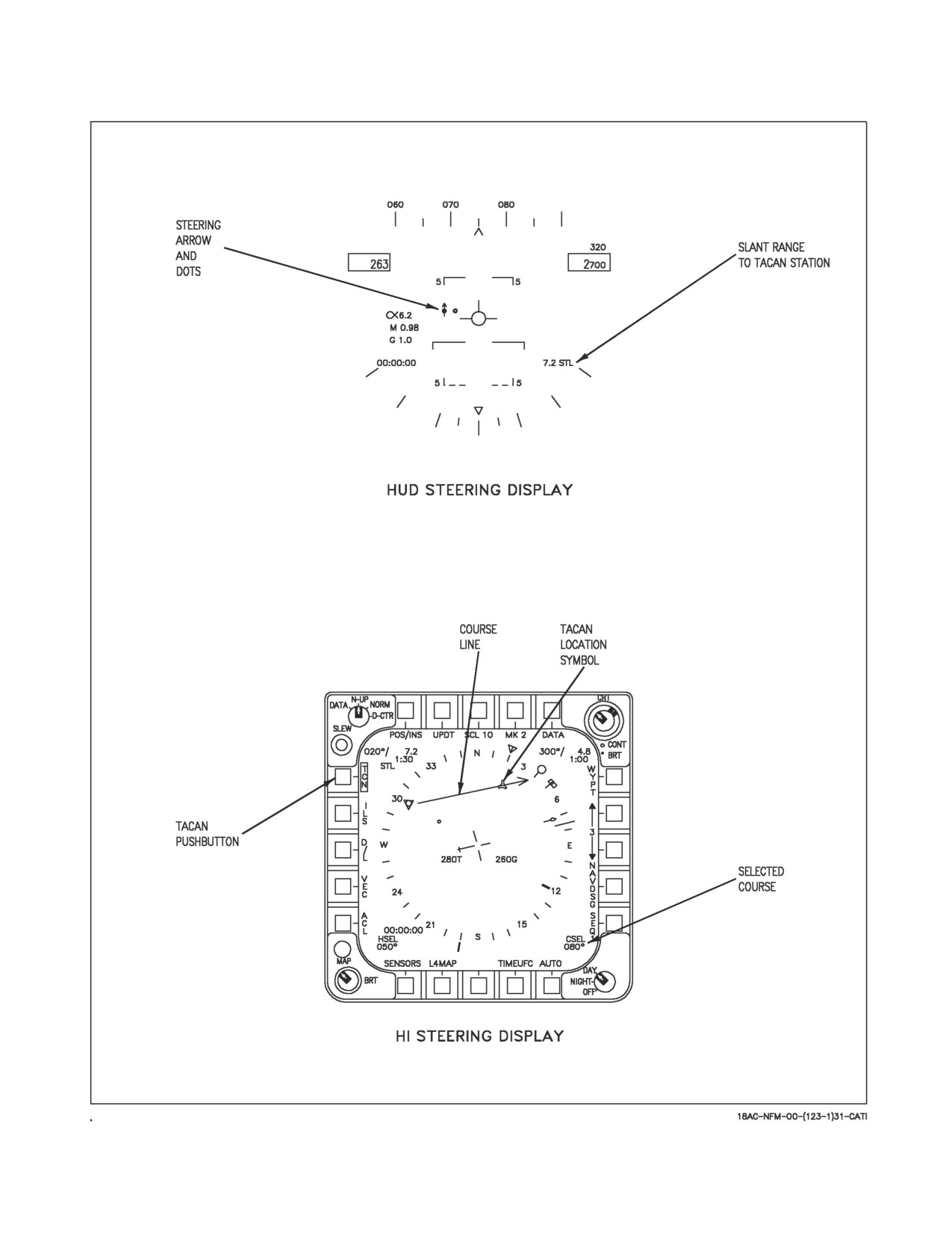
24.4.5.1 TACAN Steering. Two types of TACAN steering are available for selection: direct great
circle and course line steering. These TACAN steering options are mechanized identical to waypoint/
OAP direct great circle and course line steering, with steering being referenced to the TACAN.
Selecting the TCN option on the HSI display provides TACAN direct great circle, see figure 24-19.
Activating the CSEL switch with TACAN direct great circle already selected provides TACAN course
line steering, see figure 24-20.
24.4.5.2 Coupled TACAN Steering (F/A-18A after AFC 253 or 292 and F/A-18C/D). When TACAN
steering is coupled CPL TCN is displayed on the HUD and HSI display, and a CPLD advisory appears
on the DDI. The aircraft steers to intercept the desired course line, or flies to the TACAN station if no
course line is selected. Bank angle is limited by NAV or TAC mode as described in chapter 1. As the
aircraft gets close to the desired course, the bank angle is reduced to maintain the aircraft on the
desired course. If a course line is selected, the aircraft continues past the TACAN station on the
outbound radial until the mode is decoupled. If no course line is selected, TACAN steering uncouples
when the aircraft reaches the TACAN station. Heading hold and RALT or BALT (if selected) remain
engaged when the aircraft passes the TACAN station. If TACAN steering does not engage or
disengages without being commanded, an AUTOPILOT caution is displayed on the DDI, and CPL
TCN flashes for 10 seconds on the HUD and HSI displays. The caution can be cleared with the paddle
switch.
VII-24-57
ORIGINAL
A1-F18AC-NFM-000
Figure 24-18. TACAN Programming
VII-24-58
ORIGINAL
A1-F18AC-NFM-000
Figure 24-19. TACAN Direct Great Circle Steering
VII-24-59
ORIGINAL
A1-F18AC-NFM-000
Figure 24-20. TACAN Course Line Steering
VII-24-60
ORIGINAL
A1-F18AC-NFM-000
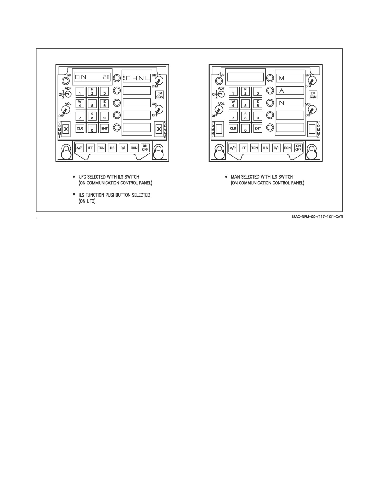
Figure 24-21. ILS Initialization
24.5 ILS (INSTRUMENT LANDING SYSTEM)
The AN/ARA-63A ILS is an all weather approach guidance system which operates with an aircraft
carrier installed transmitting set AN/SPN-41. The ILS decodes transmitted azimuth and elevation
signals during an approach and provides steering information for display on the HUD, standby attitude
reference indicator, and on F/A-18C/D aircraft the EADI. The major components of the AN/ARA-63A
system are a receiver and decoder.
24.5.1 ILS Receiver. The ILS receiver receives coded transmissions of azimuth and elevation
guidance data from surface transmitters. The receiver transforms these signals into coded pulses
suitable for processing in the decoder. A BIT module for system BIT check is contained within the
receiver.
24.5.2 ILS Decoder. The ILS decoder receives and decodes azimuth and elevation pulses from the
receiver, and converts them to azimuth and elevation command signals for the HUD and standby
attitude reference indicator.
24.5.3 ILS BIT. To manually initiate an ILS BIT check, ensure the ILS is on, then select the
ILS/AUG/BCN/D/L option on the BIT sublevel display. If any of the BIT monitored outputs fail, a
BIT status message of DEGD (degraded) appears on the BIT sublevel display. If the BIT checks are
good, a BIT status message of GO appears on the BIT sublevel display.
24.5.4 ILS Initialization. To enable the ILS, place the ILS UFC/MAN switch on the communication
control panel to the UFC position, then actuate the ILS function selector pushbutton on the UFC. This
allows the ILS channel number and ON/OFF status to be displayed on the UFC scratchpad along with
the CHNL option appearing on the UFC option window, see figure 24-21. Now actuate the ON/OFF
selector pushbutton to turn the ILS on. The ILS channel may be changed (1 to 20) using the UFC
keypad. The ILS is automatically selected when the ACL data link mode is selected.
VII-24-61
ORIGINAL
A1-F18AC-NFM-000
Another method of enabling the ILS is to place the ILS UFC/MAN switch on the communication
control panel to the MAN position. When this is done the ILS is turned on and the ILS channel
pushbuttons on the communication control panel are used for channel selection. Also, the letters M A
N appear vertically on the UFC option display windows, see figure 24-21.
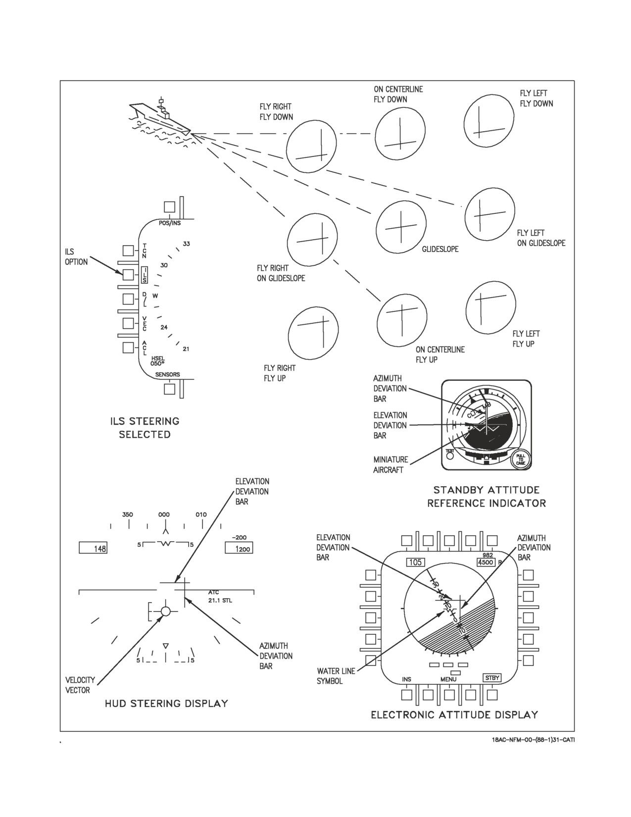
24.5.5 ILS Steering. When the ILS is on and the ILS option on the HSI display is selected (boxed),
ILS steering is provided on the HUD, the standby attitude reference indicator, and on F/A-18 C/D
aircraft the EADI, see figure 24-22. The azimuth and elevation deviation bars are referenced to the
velocity vector, however, when the waterline symbol is displayed, the deviation bars are referenced to
it. As shown, the deviation bars are deflected full scale and the aircraft is below glideslope and to the
left of course. The azimuth bar is deflected full scale for azimuth deviations of ±6° to ±20°. The
elevation bar is deflected full-scale down for elevation deviations of 1.4° to 20°, and full-scale up for
deviations of -1.4° to -3°. If a valid azimuth or elevation signal is not received by the ILS, the
corresponding bar is not displayed.
ILS steering is automatically provided when the ACL mode is selected and valid ILS steering signals
are received.
VII-24-62
ORIGINAL
A1-F18AC-NFM-000
Figure 24-22. ILS Steering
VII-24-63
ORIGINAL
A1-F18AC-NFM-000
24.6 DATA LINK SYSTEM
All information on the data link systems (i.e., LINK 4 and LINK 16), except for the automatic
carrier landing mode, is contained in the NTRP 3-22.2-FA18A-D NATIP. For typical Automatic
Carrier Landing procedures, refer to Chapter 8.
24.6.1 Automatic Carrier Landing Mode. The system for automatic landing of aircraft onto the
aircraft carrier deck comprises the AN/SPN-42 installed aboard the carrier and Automatic Carrier
Landing (ACL) equipment installed in the aircraft. The aircraft data link system is the ACL
component over which steering commands are received from the carrier for guidance of the aircraft.
The data link ACL mode is available only when the NAV master mode is selected. The ACL steering
commands may be coupled to the flight control computer for fully automatic approaches to touchdown,
or the pilot may elect to use the steering displays for a manually controlled landing. The traffic control
(T/C) mode is a submode of ACL. The T/C mode provides data link heading commands to aid the pilot
in reaching the marshal point and/or it may be used for azimuth alignment from marshal until ACL
acquisition. These heading commands can be coupled to the flight control computer for automatic
lateral axis control or can be used for manual steering aids.
Two uplinked control messages (label 5 and label 6) are uniquely addressed to a specific aircraft and
received via the data link for ACL mode (and T/C submode) control and display. The label 5 message
only is used for T/C mode, while both label 5 and label 6 are required for ACL modes 1, 1A, and 2
control and display. The contents of the uplinked label 5 and label 6 messages follows:
Label
5
Message
Command Altitude (feet)
Displayed on Link 4/SA display.
Command Airspeed (knots)
Displayed on Link 4/SA display.
Command Rate of Descent
Displayed on Link 4/SA display.
(feet per minute)
Command Heading
Displayed on Link 4/SA and HUD.
Group 1 Discretes
ACL RDY, CMD CNT, LND CHK, NOT
CMD, W/O, and CHG CHNL.
Group 2a Discretes
Monitor altitude and altitude change
Warning
Receipt of either discrete causes the command
altitude and command rate of descent to be un-
derlined on the Link 4/SA display.
Group 2b Discretes
Monitor speed and speed change warning. Re-
ceipt of either discrete causes the command air-
speed to be underlined on the Link 4/SA dis-
play.
Group 2c Discretes
ADJ A/C, VOICE and 10 SEC.
VII-24-64
ORIGINAL
A1-F18AC-NFM-000
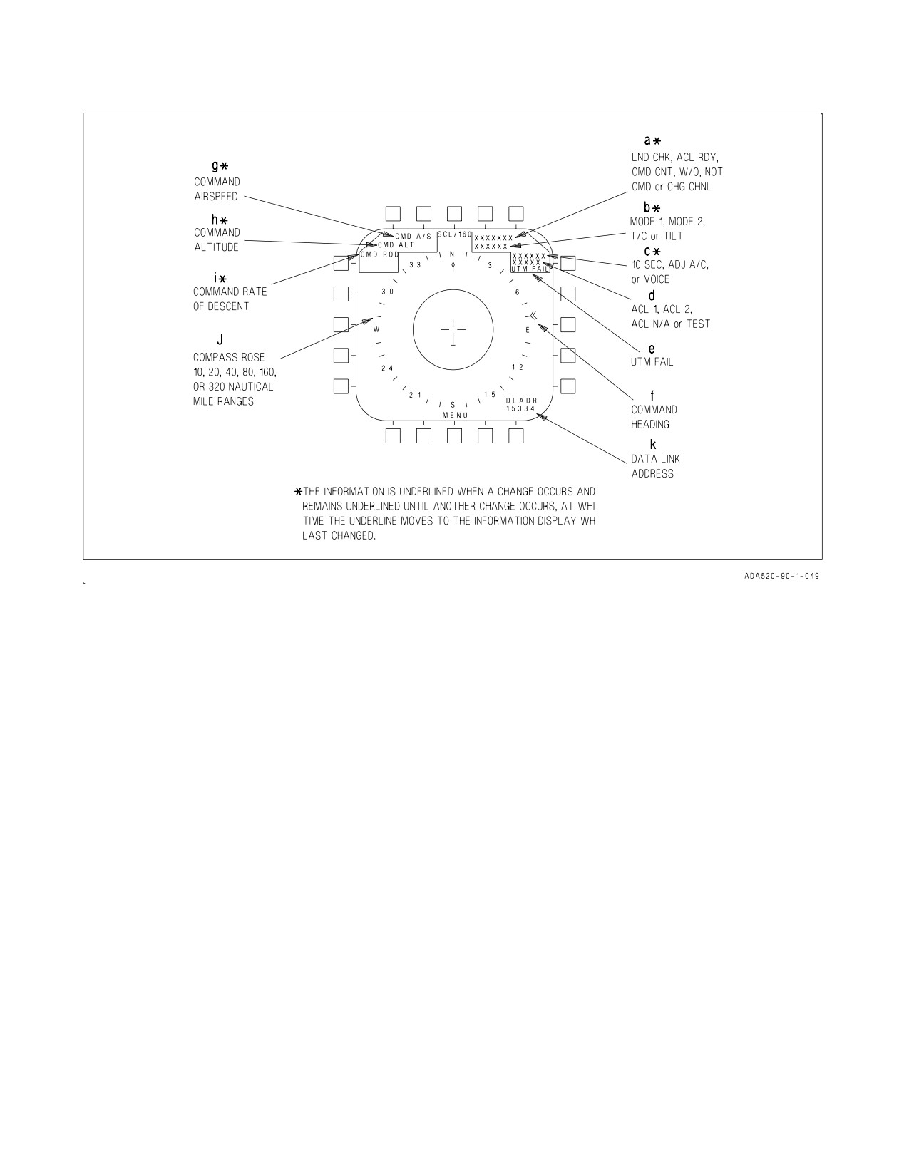
Figure 24-23. DDI Link 4 ACL Display
Label 6 Message
Vertical Glide Slope Error
Used for data link HUD situation display.
Lateral Glide Slope Error
Used for data link HUD situation display.
Mode Status Discrete
Indicates that uplinked longitudinal and lateral
axes commands may be used for mode 1 ap-
proach.
Longitudinal Axis Command
Used by FCS for longitudinal axis control.
(altitude rate in feet/second)
Lateral Axis Command
Used by FCS for lateral axis control.
(roll angle in degrees)
The ground station also periodically uplinks two universal test messages (UTM-3A and UTM-3B).
These two messages have a canned constant content and carry a universal address, rather than being
addressed uniquely to a controlled aircraft, as are the label 5 and label 6 messages. During ACL mode
test, the data link is commanded to accept these two UTM as part of the determination of onboard
ACL capability.
24.6.1.1 ACL Mode Displays. The ACL mode displays consist of the Link 4/SA display on the left
DDI and the data link situation display on the HUD. The following paragraphs contain a general
VII-24-65
ORIGINAL
A1-F18AC-NFM-000
description of the displays related to the ACL mode. A more explicit definition of the utilization of
these displays is presented in ACL Mode Operation, this chapter.
24.6.1.1.1 Link 4/SA Display. Figure 24-23 shows the ACL and T/C information which may be
displayed on the Link 4/SA display. The lettered symbols and cues on the display are described after
the corresponding letter in the following paragraphs.
a. The following uplinked group 1 discretes may be displayed in this slot.
LND CHK Landing check indicates that SPN-42 control radar communication has been estab-
lished. It also cues the pilot to be in the landing configuration with ATC engaged.
ACL RDY ACL ready indicates that SPN-42 acquisition has occurred and uplinked longitudi-
nal axis (altitude rate) and lateral axis (roll rate) commands are being received
equal to zero. The ACL RDY indication is also displayed on the HUD. Receipt of
the ACL RDY discrete is one of the onboard prerequisites for ACL couple.
CMD CNT Command control discrete indicates that the carrier has received a verbal confir-
mation from the pilot that FCS is coupled to the ACL longitudinal and lateral
commands, and further indicates to the pilot that longitudinal and lateral com-
mands are now active.
W/O
When this discrete is received the FCS is uncoupled from the uplinked commands.
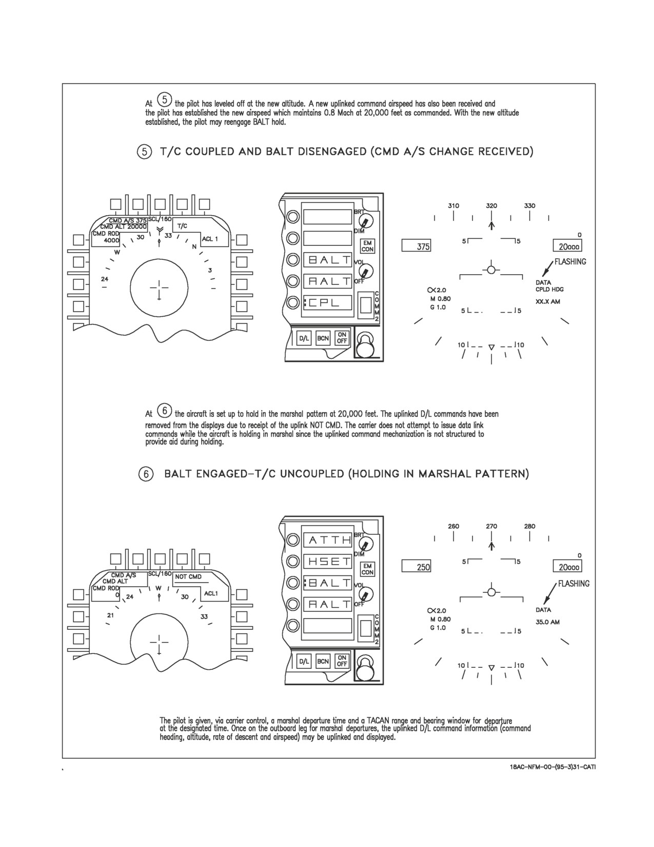
NOT CMD The not command discrete indicates that label 5 information is invalid. When this
discrete is received the label 5 information is removed from the Link 4/SA display
and the FCS is uncoupled from the T/C heading command/ACL steering com-
mands.
CHG
The change channel discrete indicates that the data link frequency should be
CHNL
changed.
b. The following ACL mode operational cues may be displayed in this slot.
MODE 1
Indicates that the entire loop is capable and ready for coupling for dual axes ACL
control.
MODE 2
Indicates that the entire loop is not capable of Mode 1 coupled approach but is
capable of Mode 2 manual control approach using uplinked situation steering.
T/C
Traffic control cue indicates that the entire loop is capable and ready for couple to
the T/C heading command.
TILT
Indicates that the uplinked information is not being updated. When this condition
exists all uplinked information is removed from the displays and the FCS is
uncoupled from the data link commands.
VII-24-66
ORIGINAL
A1-F18AC-NFM-000
c. The following uplinked group 2c discretes may be displayed in this slot. These cues are displayed
for 30 seconds after initial receipt, then removed.
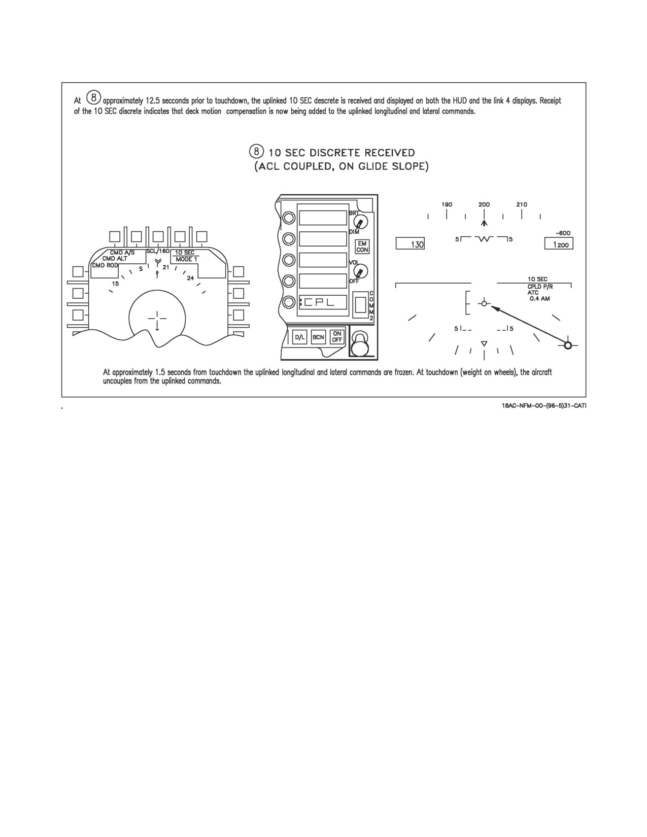
10 SEC
Indicates that SPN-42 is now adding deck motion compensation to the longitudi-
nal and lateral axes commands. This discrete is received approximately 12.5 sec-
onds before touchdown.
ADJ A/C
Adjacent aircraft cue indicates that another aircraft has been detected in the area
of controlled aircraft.
VOICE
Indicates that the pilot is to establish voice contact with control.
d. The following onboard capability cues are displayed in this slot.
ACL 1
Indicates that onboard systems are capable of an ACL or T/C couple to the FCS.
ACL 2
Indicates that onboard systems are not capable of ACL or T/C couple to FCS, but
are capable of displaying uplinked information for a mode 2 manual approach.
ACL N/A Indicates that onboard systems are not capable of using uplinked information and
that a carrier controlled approach (CCA) must be made.
TEST
Indicates that ACL mode is in test.
e. The UTM FAIL cue is displayed in this slot when valid uplinked UTM 3A and UTM 3B were not
received during automatic test.
f. Command heading is displayed via the double chevron symbol on the outside of the compass rose.
g. Command airspeed is displayed in this slot.
h. Command altitude is displayed on this slot.
i. Command rate of descent is displayed in this slot.
j. The compass rose is track-up oriented with selectable ranges of 10, 20, 40, 80, 160, and 320 nm.
k. Data Link Address that is currently set in the Link 4 RT.
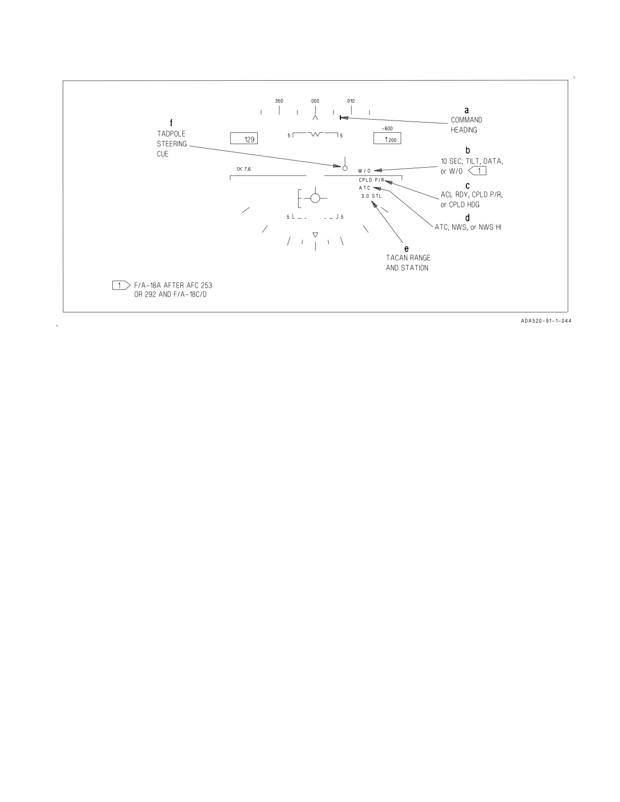
24.6.1.1.2 HUD ACL Display. Figure 24-24 shows the possible HUD display information. The
lettered symbols and cues on the HUD are described after the corresponding letter in the following
paragraphs.
a. Uplinked command heading is indicated by the command heading steering pointer below the
heading scale.
b. The following cues may be displayed in this slot:
10 SEC
Displayed for 30 seconds after receipt and then removed. Also displayed on Link
4/SA display.
VII-24-67
ORIGINAL
A1-F18AC-NFM-000
TILT
Displayed when communication has been lost with data link control. Also dis-
played on Link 4/SA display.
DATA
Displayed for 10 seconds and flashed at a rate of two times per second when new
data is initially displayed on the link 4/SA display.
W/O
(MC OFP 13C AND UP) When this discrete is received the FCS is uncoupled from
the uplinked commands.
c. The following cues may be displayed in this slot:
ACL RDY Displayed when received via data link and the FCS is not coupled. Also displayed
on Link 4/SA display.
CPLD P/R Coupled in pitch and roll is displayed when the FCS is coupled to the longitudinal
and lateral commands. The cue is flashed for 10 seconds at two times per second
then removed if the couple attempt is unsuccessful, or if uncouple occurs for any
reason other than pilot deselection. Disengagement, other than pilot initiated, also
results in an AUTOPILOT caution.
CPLD
Coupled to heading commands cue is displayed when FCS is coupled in the T/C
HDG
mode. This cue is flashed for the same reasons as described for the PLD P/R cue.
d. The following cues may be displayed in this slot. These cues are mode independent and may be
displayed in any master mode:
ATC
Displayed when automatic throttle control is engaged. If an unsuccessful engage-
ment attempt occurs, or if the ATC disengages for any reason other than pilot
deselection, the ATC cue to flashed for 10 seconds at two times per second, then
removed.
NWS
Indicates low gain nosewheel steering is engaged.
NWS HI Indicates high gain nosewheel steering is engaged.
e. When ACL mode is initially selected, waypoint steering is automatically deselected, if selected,
and the system is automatically undesignated if an aimpoint is designated. If tacan is on, tacan range
is automatically displayed regardless of tacan steering selection unless the pilot subsequently
designates an aimpoint or selects waypoint steering.
f. The tadpole steering symbol is referenced to the velocity vector and provides uplinked flight path
steering indications for the ACL glideslope and course.
24.6.1.2 ACL Mode Operation. The data link ACL mode is selected by actuating the ACL option
button on the HI/MPCD.
24.6.1.2.1 Initialization. When selected, the ACL legend on the HI/MPCD is boxed and the Link
4/SA display is automatically selected on the left DDI. The TEST cue is displayed indicating the ACL
mode is in test. The ILS, data link, and radar beacon are automatically turned on (if not previously on).
IBIT is run on the data link and radar beacon systems. The uplinked UTM is monitored for valid
receipt. When ACL testing is complete the TEST cue is removed, the noted systems are placed in the
correct operational mode, the stored data link ACL frequency is automatically selected, and the pilot
is cued on the Link 4/SA display relative to onboard ACL capability (ACL 1, ACL 2, or ACL N/A) as
VII-24-68
ORIGINAL
A1-F18AC-NFM-000
Figure 24-24. HUD ACL Display
previously described. If during test, a valid uplinked UTM message was not received, the UTM FAIL
cue is displayed on the Link 4/SA display.
With SCS 17C, the data link address that is currently set in the Link 4 is displayed. When the
aircraft is CIT equipped and the Mode 2 code is not equal to the last four digits being displayed in the
data link address, a M2ID advisory is displayed. The IFF Mode 2 code in the CIT can be set to the
proper D/L address by pressing the DL ADR option pushbutton. The M2ID advisory is removed when
the IFF mode 2 code is set equal to the last four digits of the D/L address.
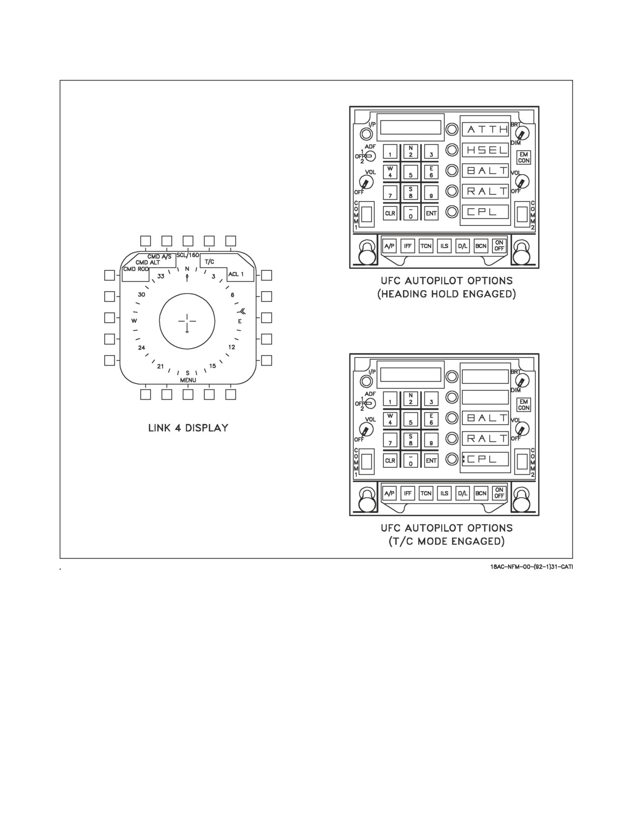
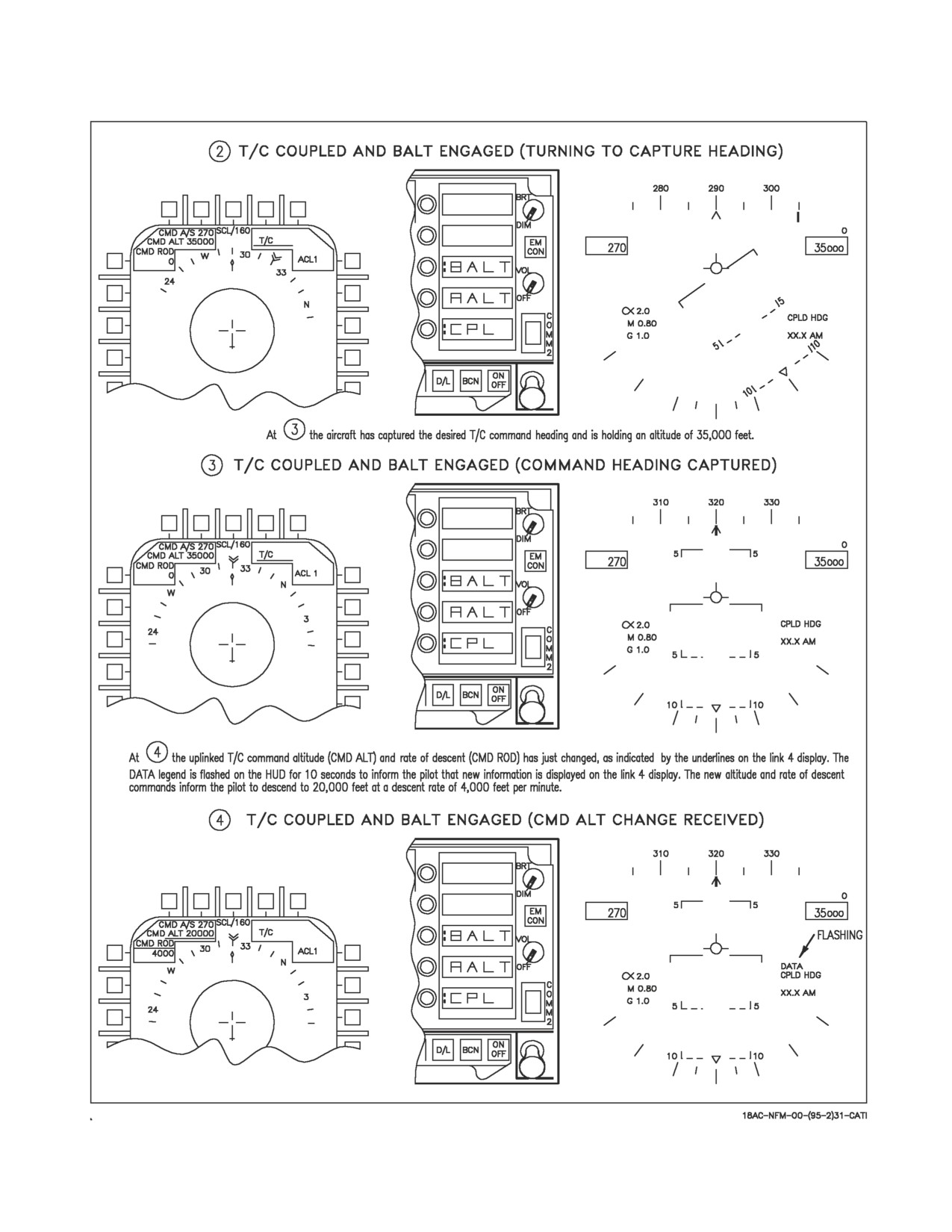
24.6.1.2.2 Traffic Control Couple. When an uplinked label 5 message is received, a determination
is automatically made relative to total loop capability. If the ACL loop is ready for a T/C couple, the
T/C cue appears on the Link 4/SA display and autopilot options are initialized on the upfront control
with the CPL option displayed (figure 24-25). The prerequisites for a CPL option for T/C follow:
1. Onboard systems fully operational.
2. Valid label 5 message received.
3. Waveoff (W/O) discrete not received.
4. Uplinked information being updated (no TILT cue).
5. NOT CMD discrete not being received.
6. Label 6 message not being received.
With T/C displayed FCS couple is selected by actuating the CPL option button on the UFC. When
coupling to the T/C heading command is successful a colon is displayed in front of the CPL option on
the UFC and the CPLD HDG cue is displayed on the HUD. After couple the FCS will bank the aircraft
to maximum of 30° to capture and hold the uplinked heading command. Aircraft pitch attitude may
be controlled by the pitch hold function of the heading hold mode or by the BALT or RALT altitude
VII-24-69
ORIGINAL
A1-F18AC-NFM-000
Figure 24-25. Traffic Control Couple Display
hold modes of the autopilot. A T/C couple precludes use of all other outer loop autopilot modes except
BALT and RALT. When engaged, the T/C couple disengages (with reversions as noted) for any of the
following reasons:
1. Heading hold mode disengagement with reversion to CAS operation.
2. Roll control stick steering engagement with reversion to lateral axis heading hold mode.
3. Loss of valid uplinked heading command for more than 10 seconds (TILT) with reversion to
lateral axis heading hold mode.
4. Pilot deselection of CPL option with reversion to lateral axis heading hold mode.
VII-24-70
ORIGINAL
A1-F18AC-NFM-000
5. Pilot actuation of paddle switch with reversion to CAS.
6. Receipt of uplinked W/O discrete with reversion to lateral axis heading hold mode.
7. Receipt of uplinked NOT CMD discrete with reversion to lateral axis heading hold mode.
An unsuccessful T/C couple attempt, or disengagement of the T/C couple for any reason other than
pilot deselection, results in an AUTOPILOT caution as well as the CPLD HDG on the HUD flashing
for 10 seconds.
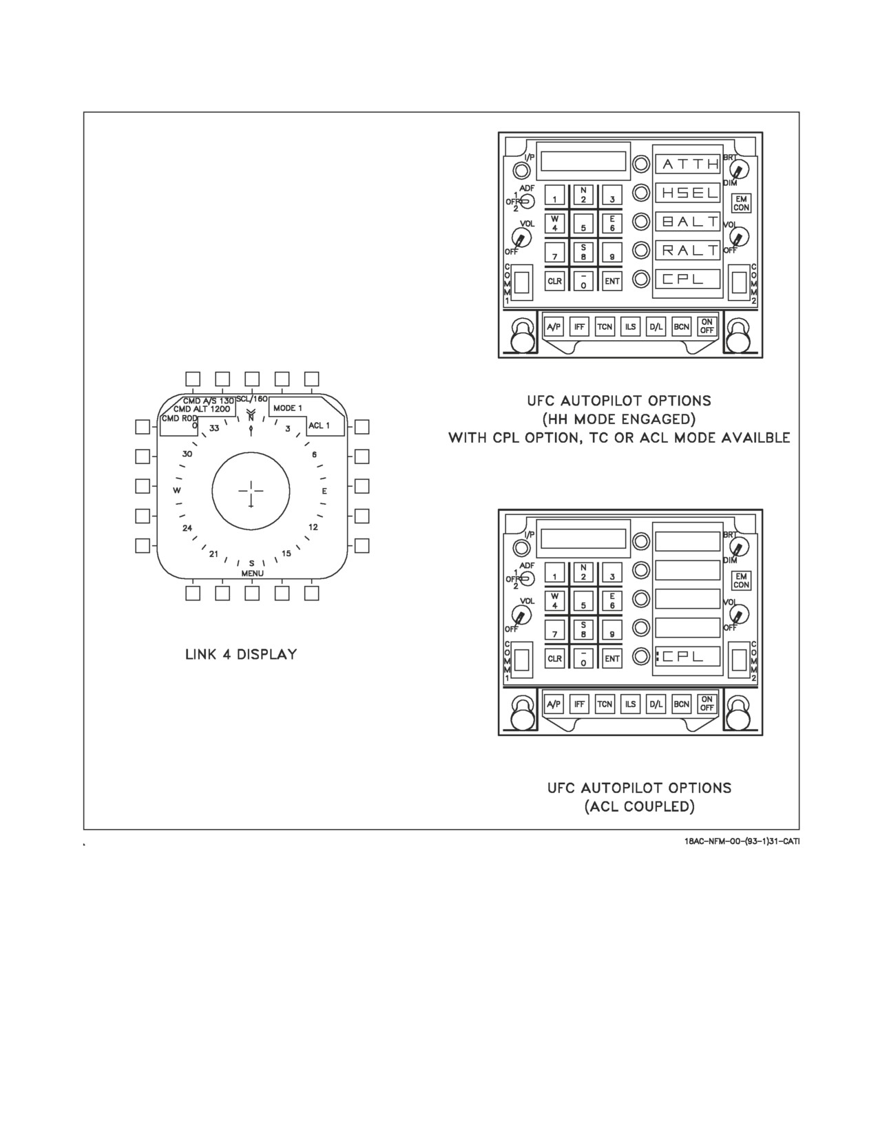
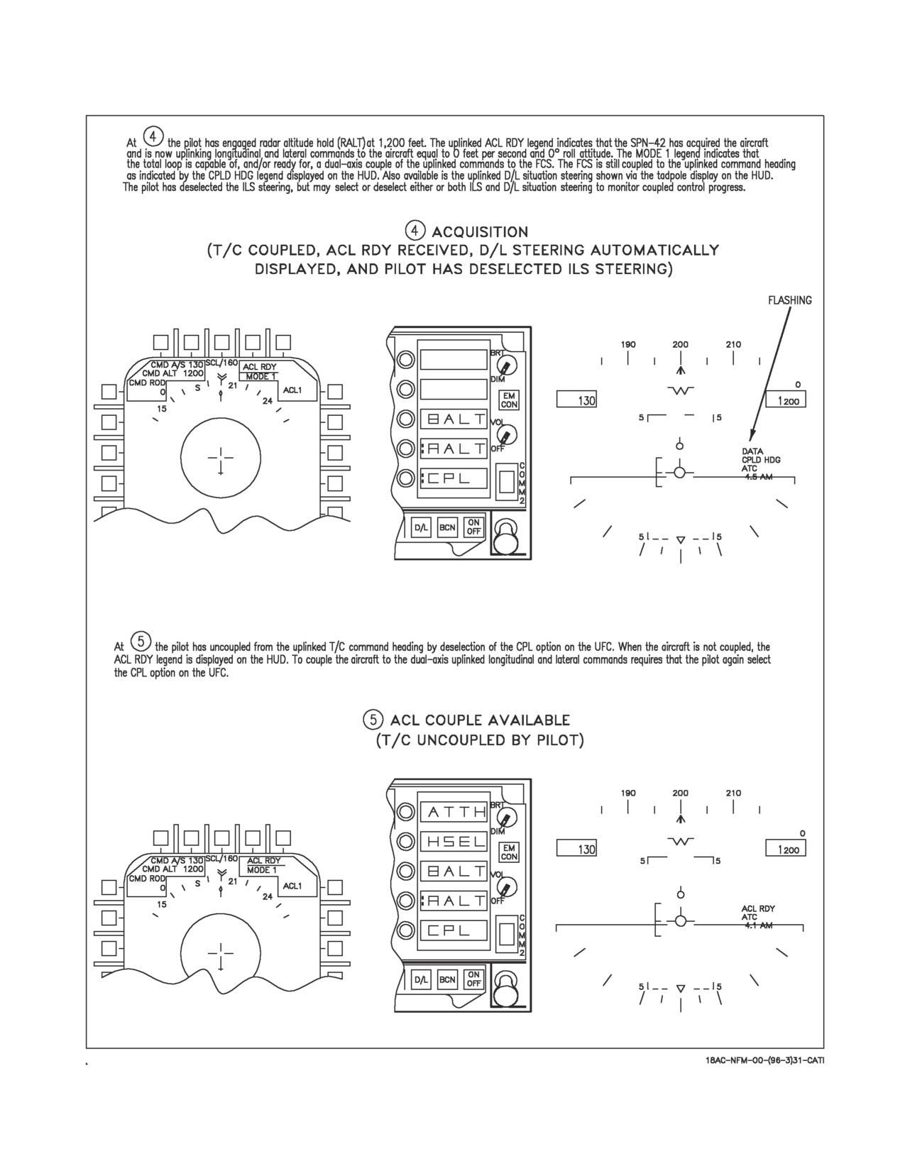
24.6.1.2.3 ACL Mode 1. When an uplinked label 6 message is received, a determination is made with
respect to total loop capability relative to dual-axis (lateral and longitudinal) ACL couple. If ACL
couple is determined to be available, the MODE 1 cue is displayed on the Link 4/SA display and the
autopilot options are initialized on the UFC with CPL option displayed as shown in figure 24-26.
When the pilot selects the CPL option on the UFC, an ACL couple to the FCS is requested if proper
prerequisites are met.
NOTE
•If FCS is already coupled to T/C command heading, the first
actuation of the CPL option disengages T/C couple and a second
actuation requests ACL couple.
•Mode 1 is available only with full flaps selected.
The MC prerequisites for initial ACL couple are as follows:
1. Basic FCS outer loop (heading hold) engaged. If heading hold is not engaged when the CPL
option is actuated it is automatically requested, and when FCS indicates it is engaged, ACL
couple is requested.
2. Onboard test results indicate ACL 1 capability.
3. Uplinked ACL RDY discrete being received. ACL RDY is only required for initial couple. It is not
required after ACL couple occurs.
4. Uplinked A/P bit set to couple state.
5. Valid uplinked longitudinal and lateral axes commands being received (no TILT).
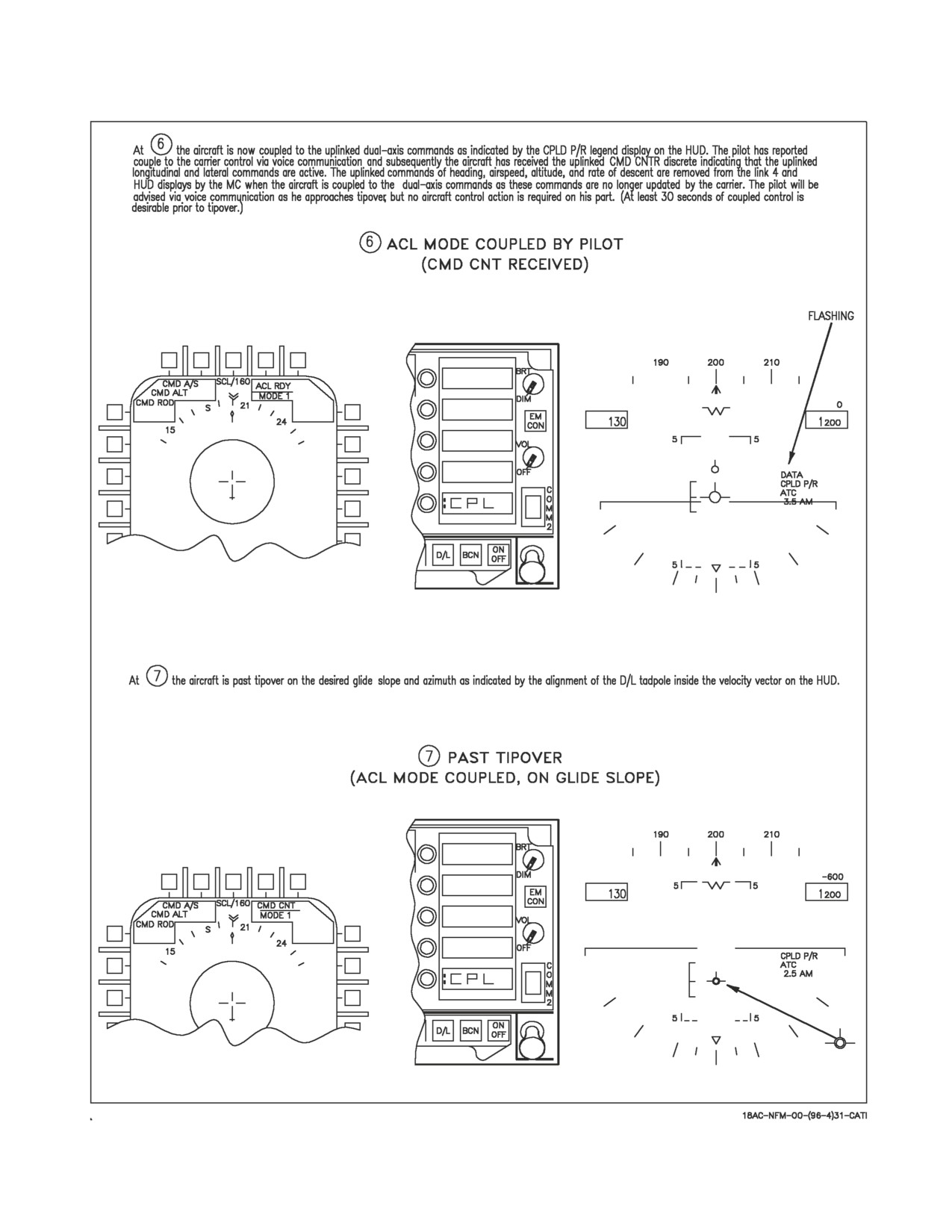
To indicate FCS is coupled, a colon is displayed next to CPL option on the UFC and the CPLD P/R
cue is displayed on the HUD. When ACL couple initially occurs, the FCS fades in the longitudinal and
lateral uplinked commands to minimize engagement transients. After FCS is coupled to the dual-axis
commands, the FCS limits the accepted magnitude of the uplinked commands to prevent excessive
pitch or roll changes due to large and/or erroneous uplinked commands. When FCS is coupled to ACL,
uncouple will occur, with reversion as noted, for any of the following reasons.
1. Heading hold mode disengagement with reversion to CAS operation.
2. Pitch or roll control stick steering engagement with reversion to CAS when CSS is no longer
engaged.
VII-24-71
ORIGINAL
A1-F18AC-NFM-000
Figure 24-26. ACL Mode 1 Display
3. WOW with reversion to CAS.
4. Paddle switch actuation with reversion to CAS.
5. UFC CPL option actuation with reversion to CAS.
6. Receipt of W/O discrete with reversion to CAS.
7. Receipt of command degrading approach to mode 2 state with reversion to CAS.
VII-24-72
ORIGINAL
A1-F18AC-NFM-000
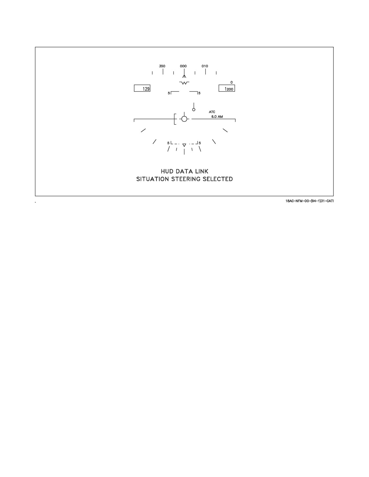
Figure 24-27. ACL Mode 2 Steering Display
8. Loss of valid uplinked commands for more than 2 seconds (TILT) with reversion to CAS.
9. Detection of degraded onboard capability below that required for MODE 1 with reversion to CAS.
During an ACL coupled approach the D/L situation steering and the ILS situation steering may
remain selected for HUD display to allow the pilot to monitor the progress of the automatic control in
capturing and holding the desired glideslope and azimuth.
24.6.1.2.4 ACL Mode 1A. For an ACL mode 1A approach, the aircraft may be coupled to data link
commands as described in the Mode 1 paragraph, then uncoupled at minimums (200 feet and 0.5 mile)
and manual control as described for Mode 2 used the rest of the way to touchdown.
24.6.1.2.5 ACL Mode 2. When a label 6 message is initially received and a mode 1 or mode 2
capability exists, a mode 2 manual approach may be made. The data link HUD steering which may be
manually selected with the D/L option button on the HI is automatically selected. The D/L legend on
the HI is boxed and the data link situation steering tadpole is displayed on the HUD with the tadpole
referenced to the velocity vector as shown in figure 24-27. The ILS situation display may remain
selected on the HUD for crosscheck on the D/L situation display and/or either D/L or ILS display may
be deselected by actuating the option button on the HI. Mode 2 approaches may be made with or
without ATC engaged, but if available, ATC should be used for angle of attack/airspeed control. If ATC
is not engaged the HUD angle of attack bracket should be used to control AOA/airspeed, while the
glide slope is maintained by flying the D/L situation steering display on the HUD.
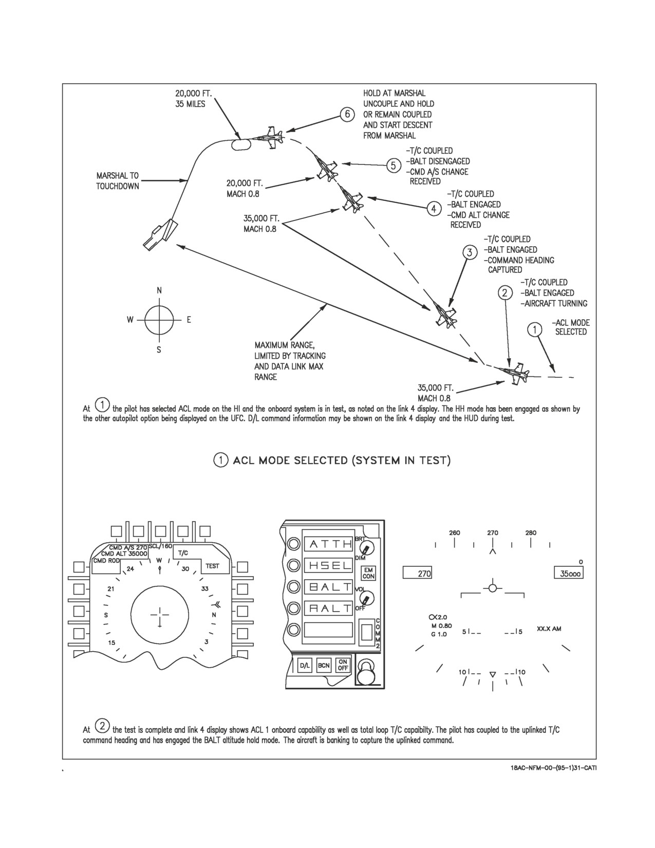
24.6.1.3 Typical ACL Approach.
Figures 24-28 and 24-29 describe the controls and displays for a “canned” mode 1 ACL approach.
The ACL mode is optimized for the described approach, but abbreviated approaches and/or deviations
VII-24-73
ORIGINAL
A1-F18AC-NFM-000
Figure 24-28. T/C Guidance to Marshal (Sheet 1 of 3)
VII-24-74
ORIGINAL
A1-F18AC-NFM-000
Figure 24-28. T/C Guidance to Marshal (Sheet 2 of 3)
VII-24-75
ORIGINAL
A1-F18AC-NFM-000
Figure 24-28. T/C Guidance to Marshal (Sheet 3 of 3)
VII-24-76
ORIGINAL
A1-F18AC-NFM-000
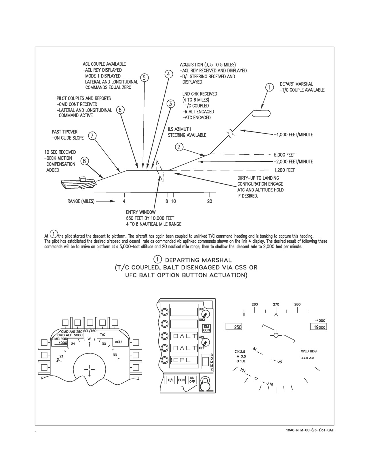
Figure 24-29. ACL Control - Marshal to Touchdown (Sheet 1 of 5)
VII-24-77
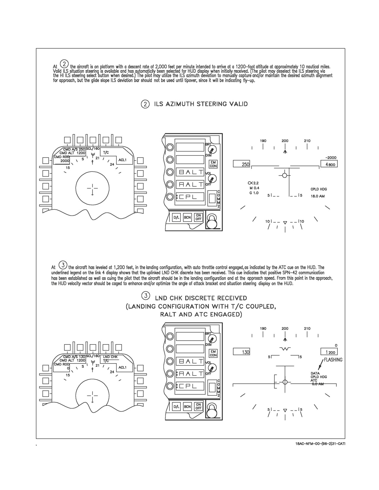
ORIGINAL
A1-F18AC-NFM-000
Figure 24-29. ACL Control - Marshal to Touchdown (Sheet 2 of 5)
VII-24-78
ORIGINAL
A1-F18AC-NFM-000
Figure 24-29. ACL Control - Marshal to Touchdown (Sheet 3 of 5)
VII-24-79
ORIGINAL
A1-F18AC-NFM-000
Figure 24-29. ACL Control - Marshal to Touchdown (Sheet 4 of 5)
VII-24-80
ORIGINAL
A1-F18AC-NFM-000
Figure 24-29. ACL Control - Marshal to Touchdown (Sheet 5 of 5)
as required may be used, dependent upon existing operational procedures and subsequent collabora-
tion between the pilot and carrier control. Figure 24-28 shows a plan view of the approach with controls
and displays for selected points prior to marshal. Figure 24-29 shows descent from marshal to
touchdown. The depicted scenario uses only D/L steering and commands complemented with ILS
steering in order to more clearly define D/L capability. It does not show TCN or WYPT steering which
may be used in conjunction with, or independent of, D/L steering during the approach.
VII-24-81
(Reverse Blank)
ORIGINAL
A1-F18AC-NFM-000
CHAPTER 25
Backup/Degraded Operations
25.1 MISSION COMPUTER NO. 1 FAILURE
If there is a failure of MC 1 (navigation computer), there are certain capabilities which are lost. The
flight control computer is not provided with g limiter and stores information. The FCC reverts to a 7.5
g aircraft with no roll rate limiting for stores. The control of CNI equipment via the UFC is not affected
by an MC 1 failure. Full Attack display and some basic Store display capability exists. MC 2 provides
limited backup for the functions described below.
25.1.1 Status Monitoring Functions. MC 2 provides limited backup for status monitoring functions.
MC 1, HYD 1A, HYD 1B, HYD 2A and HYD 2B cautions are available. An AUTO PILOT caution is
displayed if MC 1 fails while autopilot is selected. A backup Master Caution tone is provided when
voice alerts are not available. The data link advisories displayed during backup operation are TILT,
W/O and 10 SEC.
Failure of MC 1 causes a loss of all DDI caution displays except AUTO
PILOT, MC 1, HYD 1A, HYD 1B, HYD 2A, and HYD 2B.
25.1.2 Navigation Functions. Some basic navigation capabilities are provided by the backup
functions of MC 2. Functions not available when MC 1 is failed are the autopilot functions, the
HI/MPCD map and navigation situations display, EGI GPS or GPS and the HUD steering displays
(except for data link). In addition, the HSI functions of selecting the position keeping source, position
updating, target marking, and data entry and display are not provided when MC 1 is failed. The
functions provided by MC 2 are the basic HUD flight data, a backup HSI display with INS, TACAN
and ADF information, a mode II ACL capability, and automatic throttle control. ILS steering is
available on the standby attitude indicator. If the INS fails when MC 1 is failed, no backup position
keeping is provided. In this case the standby attitude reference indicator is used by MC 2 for attitude
information and the velocity vector is not displayed on the HUD.
25.1.3 Backup HUD Display. With MC 1 failed, the backup HUD display is identical with the
primary HUD display, except that the bank angle scale is not provided and the heading scale is at the
same position as in the weapon delivery modes. The ghost velocity vector is provided during backup
operation, and the velocity vector may be caged/uncaged. The landing HUD display and data link
steering are still available. On the ground, the position of the velocity vector and the pitch ladder may
be erratic. In some cases the velocity vector may be removed from the HUD.
25.1.4 Backup HSI Display. With MC 1 failed, the backup HSI display consists of a magnetic
compass rose oriented heading-up with a TACAN pointer and an ADF pointer. A digital readout of
TACAN bearing and distance and the station identifier are provided in the upper left corner. The INS
present position is displayed inside the compass rose at the top center. Waypoint 0 position is also
displayed. The ACL mode option pushbutton is also displayed for selection if desired.
VII-25-1
ORIGINAL
A1-F18AC-NFM-000
25.2 BACKUP ATTITUDE AND NAVIGATION SYSTEM
If a failure occurs in the primary attitude and navigation system (INS), output signals of pitch, roll,
magnetic heading, and airspeed are provided to the mission computer system for use in the backup
attitude navigation computations. The backup system consists of a standby attitude reference
indicator, a static power inverter, and a magnetic azimuth detector.
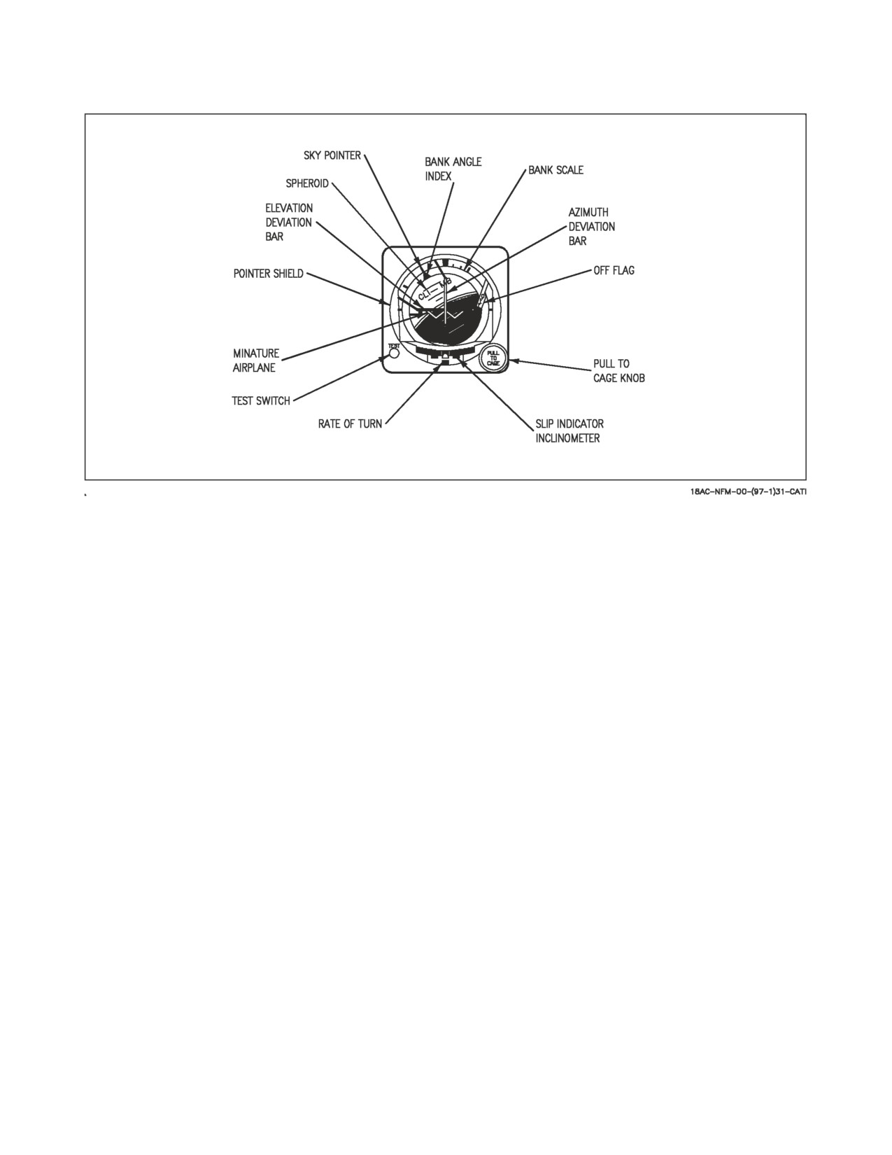
25.2.1 Standby Attitude Reference Indicator. The standby attitude reference indicator (figure
25-1) is a self-contained pitch and roll instrument on the main instrument panel. An electrically driven
vertical gyro maintains vertical orientation by use of an electronic erection system. The erection system
automatically cuts off the roll erection circuit when lateral accelerations exceed approximately 0.15 g,
the pitch erection circuit remains active. The gyro spin speed and erection system provides a minimum
of 3 minutes of attitude information with a total power loss. Pitch and roll synchros provide backup
pitch and roll attitude for use by other systems. The attitude presentation is 360° in roll, 92° in climb,
and 78° in dive.
25.2.2 Static Power Inverter. If there is an interruption or loss of aircraft ac power, 28 volt dc power
is applied to the static power inverter to produce the 115 volt ac power needed for standby attitude
reference indicator operation.
25.2.3 Magnetic Azimuth Detector. The magnetic azimuth detector (MAD) consists of 3 sensing
elements configured in a wye. The sensing elements are mounted so that their average positions are
maintained in the horizontal component of the earth’s magnetic field. The air data computer processes
the detected magnetic heading and develops the magnetic error compensation signals.
25.2.4 Backup Attitude and Navigation System Controls and Indicators. The controls and indica-
tors for the backup system are on the HI/MPCD and the standby attitude reference indicator.
25.2.4.1 HI/MPCD. The HI/MPCD provides horizontal situation and steering control displays.
25.2.4.2 Standby Attitude Reference Indicator Controls and Indicators. The controls and indica-
tors on the standby attitude reference indicator (figure 25-1) are described as follows:
1. OFF flag. This flag is in view when power is removed or the pull to cage knob is pulled out or does
not properly retract.
2. Miniature airplane. This represents the nose and wings of the airplane and indicates pitch and
roll attitude relative to the horizon. The miniature airplane is adjustable from +5° thru -10° of
pitch trim by rotating the pull to cage knob clockwise or counterclockwise when the knob is
pushed in.
3. Pull to cage knob. When the knob is pulled out and held it orients the gyro spin axis to the ARI
case (pitch and roll position). When the knob is pulled out and rotated clockwise to engage detent
the ARI becomes caged.
Damage to the gyro might occur if the indicator is moved rapidly in the
pitch or roll axes while the gyro is spinning and caged. If the knob is in the
locked position, it must be pulled out to clear the detent before it can be
turned counterclockwise.
VII-25-2
ORIGINAL
A1-F18AC-NFM-000
Figure 25-1. Standby Attitude Reference Indicator
4. Slip indicator (inclinometer). This mechanical indicator displays sideslip.
5. Rate of turn needle. This needle displays the rate of turn. One needle width of deflection indicates
a 90° per minute rate of turn.
6. Test switch. The test switch is pressed and the vertical and horizontal pointers position to center
of the miniature airplane and the rate of turn needle deflects two needle widths.
7. Pointer shield. This shield conceals the vertical pointer when in the stowed position.
8. Elevation deviation bar. In the ACLS/ICLS mode this bar provides direction information for
pitch steering.
9. Bank scale. The scale rotates with the aircraft to provide measurement of angular displacement
by the bank angle index during maneuvers.
10. Azimuth deviation bar. In the ACLS/ICLS MODE this bar provides direction information for
azimuth steering.
11. Sky pointer. The pointer rotates with the aircraft to indicate vertical (sky) in any roll attitude.
12. Bank angle index. The index indicates vertical in any roll attitude.
13. Display sphere. The sphere is directly coupled to the gyro gimbals to provide a direct reading of
pitch and roll. The sphere is marked at each 5° in pitch.
25.3 NAVIGATION BACKUP
Position keeping for aircraft navigation requires available sources of heading information, attitude
information and velocity. The INS normally provides position keeping for the aircraft. However, under
VII-25-3
ORIGINAL
A1-F18AC-NFM-000
various failure conditions, alternate sources of heading, attitude and/or velocity information may be
used for position keeping. The backup heading modes are discussed in a following paragraph. The
attitude reference indicator is the alternate source of attitude information. The alternate sources of
velocity information are GPS and air data (true airspeed and angle of attack) or radar doppler
velocities. Air data vertical velocity is an alternate velocity source if only the vertical component of INS
velocity is invalid. The flight control set is an alternate source for angle of attack information.
The system automatically reverts to alternate data sources under failure conditions. For example,
GPS (if installed), MIDS (if installed), or air data position keeping (in that order) is automatically
selected in case of an INS failure. If MIDS is installed and operating, MIDS will be automatically
selected as the aircraft position keeping source when INS or GPS (if installed) fails. Because MIDS
position keeping is unreliable, air data position keeping (POS/ADC) should be manually selected if
POS/MIDS is displayed. During air data position keeping, true airspeed and angle of attack from the
air data computer and the last computed wind, or the wind inserted by the pilot via the UFC, are used.
The wind can also be updated during air data position keeping by performing a velocity update. A new
wind is calculated when the velocity update is accepted. The velocity vector on the HUD is flashed at
a slow rate (on for 0.8 seconds and off for 0.8 seconds) during air data position keeping. A POS/ADC
caution is displayed on the DDI along with a master caution light and tone, when the INS reverts to
ADC position keeping.
The radar doppler velocities are automatically used by the mission computer if they are available
and no other velocity sources are available (INS, GPS and ADC failed). This applies whether or not
TACAN position keeping is selected. Doppler velocities are available when the radar is operating in a
doppler beam sharpened (DBS) mode or PVU mode. Thus, the MC automatically uses the doppler
velocities under these conditions if a DBS mode is selected, or if velocity update is selected (without
accepting or rejecting the update).
25.3.1 Navigation Controls and Indicators
25.3.1.1 HI/MPCD Display. The symbols and digital readouts that normally appear on the
HI/MPCD during backup system operation are the same as in the INS operation except for the POS
OPTION DISPLAY description.
25.3.1.2 POS Option Display. Pressing the POS/ADC pushbutton on the HSI display commands the
mission computer system to use air data computer true air speed, MAD heading, wind speed, and
direction to compute aircraft latitude and longitude in waypoint steering computation.
25.3.2 Backup Heading Mode Control. If the INS computer should fail or if the INS switch is
rotated to the GYRO position, the ASN-130 INS reverts to the attitude heading reference system
(AHRS) mode and true heading is no longer available from the INS. In this case, the mission computer
slaves the INS platform heading with the MAD to provide damped magnetic heading. The slaving of
the INS platform to the MAD occurs in straight and level flight. During maneuvers, when roll is greater
than ±5° or pitch is greater than ±10°, the MAD output is not used. Upon reversion to the Slaved
heading mode, the bottom row of option selections on the HSI are HDG/SLV, SYNC, and ERECT.
The sync option can be used to quickly synchronize the heading with the MAD output if a heading
error exists. The MC automatically synchronizes the heading with the MAD output when the heading
error is greater than 11.25° during level flight. Pressing the ERECT option commands the INS to
increase the gains in the INS erection loops, thus fast-leveling the platform. SYNC and ERECT are
momentary options and they should be used only in straight and level flight. Back up heading is not
available with the ASN-139 and EGI.
VII-25-4
ORIGINAL
A1-F18AC-NFM-000
If it is desired to change the backup heading mode, the heading status option pushbutton should be
pressed (HDG/SLV in this case) and the available heading options (SLV, DG, and COMP) are
presented on the HSI. Selecting any of these three options commands the MC to display the selected
option and necessary controls for that option. In the case of failure conditions, the next best available
source is automatically selected.
Selection of the DG heading mode or failure of the MAD while in the HDG/SLV mode, causes the
bottom pushbuttons on the HI/MPCD to display HDG/DG, HDG (arrow left), HDG (arrow right), and
ERECT. The MC computes aircraft heading using the INS platform heading as a smoothed heading
source compensating for wander angle (the difference between true north and platform heading) and
earth rate. The pilot may correct the aircraft heading by using the two HDG slew option buttons.
Following the initial setting of the heading, the MC provides heading compensation for earth rate.
However, changes in magnetic variation must be entered via the upfront control since the aircraft uses
the last known value of magnetic variation.
If the pilot selects the Compass heading mode, if the INS is turned off, or if the INS fails completely,
the mission computer uses the MAD output, damped with body rate data from the flight control
system. During maneuvers, when roll is greater than ±5° or pitch is greater than ±10°, the flight control
system body rates, alone, are used to determine heading. In the compass heading (HDG/COMP) mode,
the bottom buttons are labeled HDG/COMP and ERECT. The ERECT option is displayed only when
the ASN-130 INS is still operating in the AHRS mode. The MC uses the last known magnetic variation
to compute true heading.
25.4 BACKUP FREQUENCY CONTROL
Backup frequency control for the radios in case of an upfront control or communication system
control (CSC) malfunction is provided via the multiplex bus and a DDI display. The UFC backup
(UFC BU) display can be selected from the menu. Both Comm 1 and Comm 2 can be controlled from
the UFC BU display. When the COM1 or COM2 button is pressed, the frequency on which that radio
is operating is displayed below the legend COM1 or COM2, as appropriate. A new frequency is selected
by first selecting OVRD and then using the numerical buttons along the sides of the display and ENT
button at the bottom. With MC OFP 10A AND UP, four digit frequencies can be entered. Four digits
limit the frequency resolution to 100KHz. With MC OFP 13C AND UP, six digit frequencies can be
entered. Frequencies can be entered to 5 KHz of resolution. As the new frequency is entered, it is
displayed in the scratch pad above the COM1 or COM2 legend. When the ENT button is pressed, the
frequency displayed in the scratchpad is stored in the mission computer as the preset frequency for the
radio. Pressing the CLR button clears the scratchpad if an error is made when entering a backup
frequency. When OVRD option in the upper right corner of the display is selected, it is boxed and the
radio operates on the preset frequency stored for it in the mission computer, overriding the normal
frequency control from the UFC and CSC. When OVRD is deselected, frequency control reverts to the
upfront control. The frequency displayed below the COM1 or COM2 legend is always the frequency on
which the radio is operating, whether or not OVRD is selected. Upon power up with WOW, the preset
frequencies stored in the mission computer for COM1 and COM2 are initialized to be the same as the
last valid radio operating frequencies.
If the radio is operating in AJ mode, AJ is displayed in place of the frequency display. If the radio
is operating in AJ when OVRD is selected, the radio automatically tunes to the new frequency and exits
AJ mode.
VII-25-5
(Reverse Blank)
ORIGINAL

A1-F18AC-NFM-000
CHAPTER 26
Visual Communications
Communications between aircraft are visual whenever possible. Flight leaders shall ensure that all
pilots in the formation receive and acknowledge signals when given. The visual communications
chapters of NAVAIR 00-80T-113 should be reviewed and practiced by all pilots. Common visual signals
applicable to flight operations are listed in figure 26-1.
GENERAL SIGNALS
SIGNAL
MEANING
RESPONSE
DAY
NIGHT
Thumbs up, or nod of
Flashlight moved verti-
Affirmative. (‘‘Yes’’, or,
head.
cally up-and-down re-
‘‘I understand.’’)
peatedly.
Thumbs down, or turn
Flashlight moved hori-
Negative. (‘‘No’’, or, ‘‘I
of head from side to
zontally back-and-forth
do not understand.’’)
side.
repeatedly.
Hand cupped behind ear
Question. Used in con-
As appropriate.
as if listening.
junction with another
signal, this gesture indi-
cates that the signal is
interrogatory.
Hand held up, with
Wait
palm outward.
Hand waved back and
Letter N in code, given
Ignore my last signal.
forth in an erasing mo-
by external lights.
tion in front of face,
with palm turned for-
ward.
Employ fingers held ver-
Numerals as indicated.
A nod of the head (‘‘I
tically to indicate de-
understand’’). To verify
sired numeral 1 through
numerals, addressee re-
5. With fingers horizon-
peats. If originator nods,
tal, indicate number
interpretation is correct.
which added to 5 gives
If originator repeats nu-
desired number from 6
merals, addressee should
to 9. A clenched fist in-
continue to verify them
dicates 0. (Hold hand
until they are under-
near canopy when sig-
stood.
naling.)
Figure 26-1. Visual Communications (Sheet 1 of 9)
VII-26-1
ORIGINAL

A1-F18AC-NFM-000
GENERAL SIGNALS (CONT)
SIGNAL
MEANING
RESPONSE
DAY
NIGHT
Make hand into cup-
I am going to dump fuel.
shape, then make re-
peated pouring motions.
Slashing motion of index
I have stopped dumping
finger across throat.
fuel.
MALFUNCTIONING EQUIPMENT (HEFOE CODE)
SIGNAL
MEANING
RESPONSE
DAY
NIGHT
Weeping signal and then
Flashlight held close to
Number of fingers or
Day: Nod, or thumbs
indicating by finger -
top of canopy, pointed
dashes means:
up. (‘‘I understand.’’)
numbers 1 to 6 the af-
toward wingman, fol-
fected system.
lowed by 1 to 6 dashes to
1. Hydraulic
Night: Vertical move-
indicate system affected.
ment of flashlight.
2. Electric
Pass lead to disabled
3. Fuel
plane or assume lead, if
indicated.
4. Oxygen
5. Engine
6. FCS
Figure 26-1. Visual Communications (Sheet 2 of 9)
VII-26-2
ORIGINAL

A1-F18AC-NFM-000
TAKEOFF, CHANGING LEAD, LEAVING FORMATION, BREAKUP, LANDING
SIGNAL
MEANING
RESPONSE
DAY
NIGHT
1. Section/Division
1. Section/Division
1. I am ready to take
1. Standby for re-
Lead gives thumbs up.
Lead turns formation
position on the runway.
sponse from wingman.
lights off.
2. Wingman gives
2. Wingman turns for-
2. I am ready to take
2. Lead calls for take-
thumbs up.
mation lights off.
position on the runway.
off.
2a. Wingman turns
2a. I am ready for
2a. Section/Division
formation lights on.
takeoff roll.
Lead formation lights
on.
3. Section/Division
3. Section/Division
3. I am executing
3. Wingman roll in
Lead kisses off wingman.
Lead turns formation
takeoff roll.
order.
lights on.
1. Leader pats self on
1. Lead aircraft turns
Leader shifting lead to
1. Wingman pats head
the head, points to wing-
strobe lights ON.
wingman.
and assumes lead.
man.
2. If external lights
2. Wingman turns
are inoperative, leader
strobe lights OFF and
shines flashlight on
assumes lead.
hard-hat, then shines
light on wingman.
If external lights are
inop-
3. Wingman shines
flashlight at leader, then
on his hard hat and as-
sumes lead.
Leader pats self on head
Leader shifting lead to
Wingman relays signal;
and holds up two or
division designated by
division leader desig-
more fingers.
numerals.
nated assumes lead.
Pilot blows kiss to
I am leaving formation.
Leader nods (‘‘I under-
leader.
stand’’) or waves goodby.
Leader blows kiss and
Aircraft pointed out
Wingman indicated
points to aircraft.
leave formation.
blows kiss and executes.
Leader points to wing-
Directs plane to investi-
Wingman indicated
man, then points to eye,
gate object or vessel.
blows kiss and executes.
then to vessel or object.
Figure 26-1. Visual Communications (Sheet 3 of 9)
VII-26-3
ORIGINAL

A1-F18AC-NFM-000
TAKEOFF, CHANGING LEAD, LEAVING FORMATION, BREAKUP, LANDING (CONT)
SIGNAL
MEANING
RESPONSE
DAY
NIGHT
Division leader holds up
Section breakoff.
Wingman relays signal
and rotates two fingers
to section leader. Section
in horizontal circle, pre-
leader nods (‘‘I under-
paratory to breaking off.
stand’’) or waves goodby
and executes.
Leader describes hori-
Series of ‘‘I’s’’ in code,
Breakup (and rendez-
Wingman take lead, pass
zontal circle with fore-
given by external lights.
vous).
signal after leader breaks
finger.
and follow.
Landing motion with
Refers to landing of air-
open hand:
craft, generally used in
conjunction with another
signal.
1. Followed by patting
1. I am landing.
1. Nods. (‘‘I under-
head.
stand’’) or waves goodby.
2. Followed by pointing
2. Directs indicated air-
2. Aircraft indicated
to another aircraft.
craft to land.
repeats signal, blows a
kiss and executes.
Open hand held verti-
Adjust wing position for-
Wingman moves in di-
cally and moved forward
ward or aft.
rection indicated.
or backward, palm in
direction of movement.
Open hand held horizon-
Adjust wing position up
Wingman moves up or
tally and moved slowly
or down.
down as indicated.
up or down, palm in di-
rection of movement.
Open hand used as if
Adjust wing position lat-
Wingman moves in di-
beckoning inboard or
erally toward or away
rection indicated.
pushing outboard.
from leader.
Hand opened flat and
I am going to dive or
Prepare to execute.
palm down, simulating
climb.
dive or climb.
Hand moved horizon-
Leveling off.
Prepare to execute.
tally above glare shield,
palm down.
Figure 26-1. Visual Communications (Sheet 4 of 9)
VII-26-4
ORIGINAL

A1-F18AC-NFM-000
TAKEOFF, CHANGING LEAD, LEAVING FORMATION, BREAKUP, LANDING (CONT)
SIGNAL
MEANING
RESPONSE
DAY
NIGHT
Two fingers pointed to-
1. Turn IFF/SIF to
Repeat then execute.
ward eyes (meaning IFF/
‘‘STANDBY’’.
SIF signals), followed
by:
2. Set mode and code
indicated: first numeral-
1. CUT
mode, second and third
numerals-code.
2. 3-digit numerals
Head moved backward.
Slow down.
Execute.
Head moved forward.
Speed up.
Execute.
Headed nodded right or
I am turning right or
Prepare to execute.
left.
left.
Thumb waved backward
Series of 00s in code,
Take cruising formation
Execute.
over shoulder.
given by external lights.
or open up.
1. Holds up right (or
1. Single letter R (or
1. Wingman cross un-
1. Execute.
left) forearm vertically,
K) in code, given by ex-
der to right (or left) ech-
with clenched fist or
ternal lights.
elon or in direction of
single wing-dip.
wing-dips.
2. Same as above, except
2. Series of RRs (or
2. Section cross under
2. Execute.
with pumping motion or
KKs) in code, given by
to right (or left) echelon
double wing-dip.
external lights.
or in direction of wing-
dips.
Triple wing-dip.
Division cross under.
Execute.
Series of VVs in code,
Form a Vee or balanced
Execute.
given by external lights.
formation.
Series of zooms.
Series of XXs in code,
Close up or join up; join
Execute.
given by external lights.
up on me.
Rocking of wings by
Prepare to attack.
Execute preparation to
leader.
attack.
Rocking of wings by any
We are being, or are
Stand by for and ex-
other member of flight.
about to be, attacked.
ecute defensive maneu-
vers.
Figure 26-1. Visual Communications (Sheet 5 of 9)
VII-26-5
ORIGINAL

A1-F18AC-NFM-000
TAKEOFF, CHANGING LEAD, LEAVING FORMATION, BREAKUP, LANDING (CONT)
SIGNAL
MEANING
RESPONSE
DAY
NIGHT
Lead plane swishes tail.
All aircraft in this for-
Execute. Leader speeds
mation form step-down
up slightly to facilitate
column in tactical order
formation of column.
behind column leader.
Shaking of ailerons.
Long dash, given with
Execute signal; used as
Execute last signal
Head raised then low-
external lights.
required in conjunction
given.
ered.
with another signal.
Open and close four fin-
Three dashes with exter-
Extend or retract speed
Repeat signal. Execute
gers and thumb.
nal lights.
brake as appropriate.
upon head nod from
leader or when leader’s
speed brake extends/
retracts.
Rotary movement of
Two dashes with exter-
Lower or raise landing
Repeat signal. Execute
clenched fist in cockpit
nal lights.
gear and flaps, as appro-
when leader changes
as if cranking wheels,
priate.
configuration.
followed by head nod.
Pointing index finger
One dash with external
Landing runway or ball
Ashore: Take position
toward runway/ship in
lights.
and ship in sight.
for landing.
stabbing motion, repeat-
edly, followed by lead
Carrier: Breakoff and
change signal.
land.
Raised fist with thumb
How much fuel have
Repeat signal, then indi-
extended in drinking
you?
cate fuel in hundreds of
position.
pounds by finger-
numbers.
Leader lowers hook.
Letter H in code, given
Lower arresting hook.
Wingman lower arresting
by external lights.
hook. Leader indicates
wingman’s hook is down
with thumbs-up signal.
Open hand held up, fin-
Course to be steered is
Nod of head (‘‘I under-
gers together, moved in
present compass head-
stand’’).
fore-and-aft chopping
ing.
motion (by leader).
Figure 26-1. Visual Communications (Sheet 6 of 9)
VII-26-6
ORIGINAL

A1-F18AC-NFM-000
ELECTRONIC COMMUNICATIONS AND NAVIGATION
SIGNAL
MEANING
RESPONSE
DAY
NIGHT
Tap earphones, followed
Take over communica-
Repeat signals, pointing
by patting of head, and
tions.
to self, and assume com-
point to other aircraft.
munications lead.
Tap earphones, followed
I have taken over com-
Nod (‘‘I understand’’).
by patting of head.
munications.
Tap earphones and indi-
Shift to channels indi-
Repeat signal and ex-
cate by finger-numerals,
cated by numerals.
ecute.
number of channel to
which shifting.
Vertical hand, with fin-
What is bearing and dis-
Wait signal, or give mag-
gers pointed ahead and
tance to the TACAN sta-
netic bearing and dis-
moved in a horizontal
tion?
tance with finger-
sweeping motion with
numerals. The first three
four fingers extended
numerals indicate mag-
and separated.
netic and the last two or
three, distance.
VISUAL EMERGENCY SIGNALS (AIR-TO-AIR)
SIGNAL
MEANING
RESPONSE
DAY
NIGHT
Arms bent across fore-
Horizontal motion of
General emergency sig-
Carry out squadron doc-
head weeping.
flashlight shone at other
nal meaning, I am in
trine for escort of dis-
aircraft.
trouble.
abled aircraft.
Landing motion with
Circular motion of flash-
I must land immediately. Assume lead if indicated
open hand.
light shone at other air-
and return to base or
craft.
nearest suitable field.
Point to pilot and give
Flash series of dots with Are you having diffi-
Thumbs up: I am all
series of thumbs down
exterior lights.
culty?
right.
movements.
Thumbs down: I am
having trouble.
Lights off once then on
steady: I am all right.
Lights flashing: I am
having trouble.
Figure 26-1. Visual Communications (Sheet 7 of 9)
VII-26-7
ORIGINAL

A1-F18AC-NFM-000
ARMAMENT
SIGNAL
MEANING
RESPONSE
DAY
NIGHT
1. Pistol-cocking mo-
1. Ready or safety
1. Repeat signal and
tion with either hand.
guns.
execute.
2. Followed by
2. How much ammo
2. Thumbs up -‘‘over
question-signal.
do you have?
half’’; thumbs down
-‘‘less than half.’’
3. Followed by
3. I am unable to fire.
3. Nod head (‘‘I un-
thumbs-down signal.
derstand’’).
1. Shaking fist.
1. Arm or safety
1. Repeat signal and
bombs, as applicable.
execute.
2. Followed by
2. How many bombs
2. Indicate with ap-
question-signal.
do I have?
propriate finger-
numerals.
3. Followed by
3. I am unable to drop.
3. Nod head (‘‘I un-
thumbs-down signal.
derstand’’).
1. Shaking hand, with
1. Arm or safety
1. Repeat signal and
fingers extended down-
missile/rockets as appli-
execute.
ward.
cable.
2. Followed by
2. How many missiles/
2. Indicate with ap-
question-signal.
rockets do I have?
propriate finger-
numerals.
3. Followed by
3. I am unable to fire.
3. Nod head (‘‘I un-
thumbs-down signal.
derstand’’).
Jettison external stores.
Repeat signal and ex-
ecute.
Pistol cocking motion
1. Strobe light ON and
1. Set up your
with either hand, fol-
OFF by lead aircraft.
switches for jettison.
1. Set up jettison/
lowed by fore and aft
ordnance switches.
pulling motion with a
2. Strobe light turned
2. You are cleared to
clenched fist.
ON for second time (al-
drop.
2. Execute.
low time for setting up
switches).
Figure 26-1. Visual Communications (Sheet 8 of 9)
VII-26-8
ORIGINAL

A1-F18AC-NFM-000
AIR REFUELING
SIGNAL
MEANING
RESPONSE
DAY
NIGHT
One finger turn-up sig-
By receiver: start tur-
Tanker execute. Re-
nal.
bine.
ceiver gives thumbs-up
when turbine starts.
Form cone-shape with
Tanker execute. Re-
hand, all fingers ex-
ceiver give thumbs-up if:
tended aft (make signal
close to canopy).
1. Cone moved aft
1. By receiver: extend
1. Drogue extends
drogue.
properly.
2. Cone moved for-
2. By receiver: retract.
2. Drogue retracts
ward
fully and air turbine
feathers.
Make hand into cup-
By tanker: I am going to
By receiver: Nod. Give
shape, then make re-
dump fuel.
thumbs-up when fuel
peated pouring motions.
dumping commences.
Slashing motion of index
By tanker: I have
By receiver: Give
finger across throat.
stopped dumping fuel.
thumbs-up if fuel dump-
ing has ceased.
Figure 26-1. Visual Communications (Sheet 9 of 9)
VII-26-9
(Reverse Blank)
ORIGINAL
A1-F18AC-NFM-000
CHAPTER 27
Deck/Ground Handling Signals
Communications between aircraft and ground personnel are visual whenever practical, operations
permitting. The visual communications chapters of Aircraft Signals NATOPS Manual (NAVAIR
00-80T-113) should be reviewed and practiced by all flightcrew and ground crew personnel. For ease
of reference, visual signals applicable to deck/ground handling are listed in Figure 27-1. During night
operations, wands shall be substituted for hand and finger movements.
VII-27-1
ORIGINAL
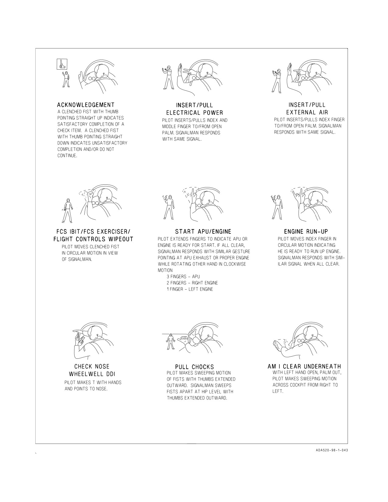
A1-F18AC-NFM-000
Figure 27-1. Deck Ground Handling Signals (Sheet 1 of 4)
VII-27-2
ORIGINAL
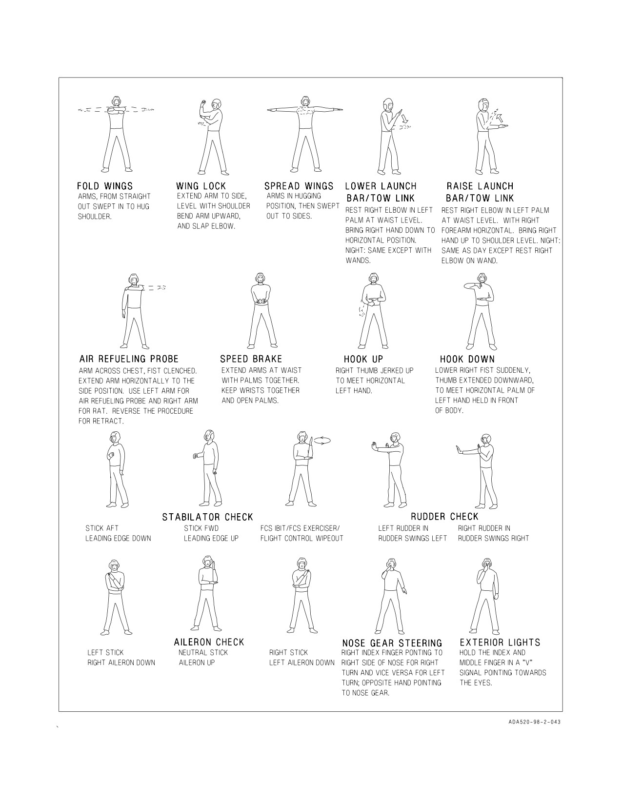
A1-F18AC-NFM-000
Figure 27-1. Deck Ground Handling Signals (Sheet 2 of 4)
VII-27-3
ORIGINAL
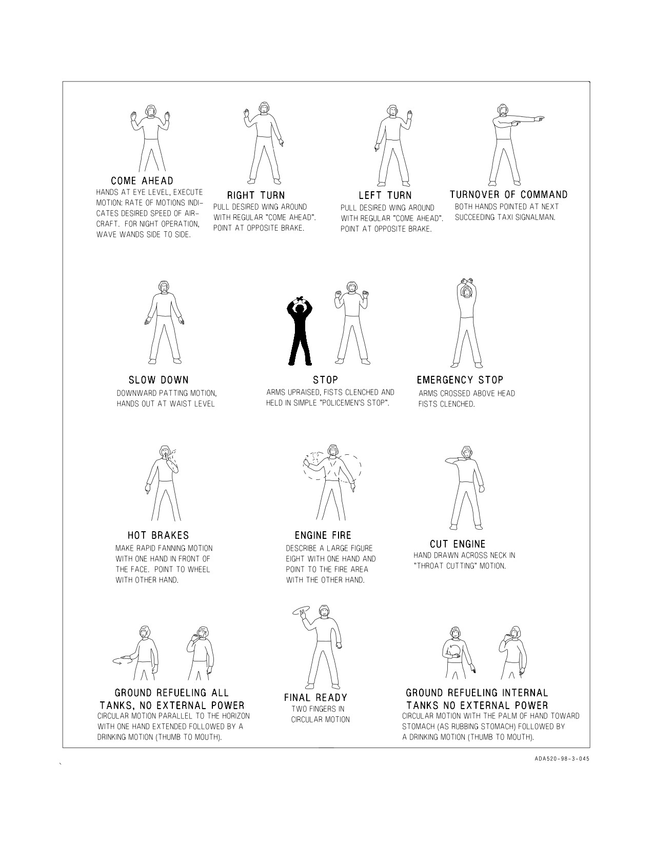
A1-F18AC-NFM-000
Figure 27-1. Deck Ground Handling Signals (Sheet 3 of 4)
VII-27-4
ORIGINAL
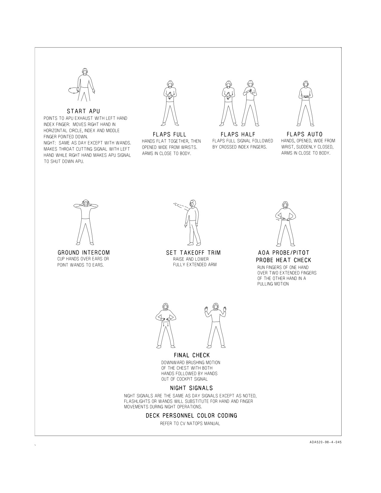
A1-F18AC-NFM-000
Figure 27-1. Deck Ground Handling Signals (Sheet 4 of 4)
VII-27-5
(Reverse Blank)
ORIGINAL
A1-F18AC-NFM-000
PART VIII
WEAPONS SYSTEMS
For F/A-18A-D safety-of-flight information, general stores and components, and unclassified
ballistic stores and weapons, see NTRP 3-22.4-FA18A-D.
For F/A-18A-D classified ballistic weapons, A/G guided weapons, A/A combat weapons and data,
other stores, radar systems, EW, EO/IR, reconnaissance, CNI, MSI, and tactical training systems,
see NTRP 3-22.2-FA18A-D.
73
(Reverse Blank)
ORIGINAL
A1-F18AC-NFM-000
PART IX
FLIGHT CREW COORDINATION
Chapter
28 - General
75
(Reverse Blank)
ORIGINAL
A1-F18AC-NFM-000
CHAPTER 28
Crew Resource Management
28.1 DEFINITION
Crew resource management is the use and integration of all available skills and resources to
collectively achieve and maintain flight efficiency, situational awareness, and mission effectiveness.
Effective crew coordination is essential for aircraft employment; however F/A-18 crew coordination
differs from previous crew served tactical aircraft in that ‘‘who does what when’’ is determined by the
mission and mission phase and not by where equipment controls are located in the cockpit. The most
successful crews are those who have flown together extensively and know each other’s areas of
responsibility before manning the aircraft. The mission commander is responsible for mission success.
The pilot as the aircraft commander is solely responsible for the safe control of the aircraft throughout
the entire mission. Crewmembers/WSOs assist the pilot as necessary and should anticipate develop-
ments. The responsibility for every evolution is a shared responsibility. Crew coordination provides a
system of checks and balances which, properly utilized, ensure effective and efficient mission
accomplishment.
28.2 CRITICAL SKILLS OF CREW RESOURCE MANAGEMENT
28.2.1 Decision Making. Effective decision making refers to the ability to use logical and sound
judgement to make decisions based on available information. This includes assessing the problem,
verifying information, identifying solutions, anticipating the consequences of decisions, informing
others of the decision and rationale, and evaluating these decisions. Good decisions optimize risk
management and minimize errors, while poor decisions can increase them and is a leading cause of
failure to complete missions and of mishaps.
28.2.2 Assertiveness. Assertiveness refers to the ability, willingness, and readiness to take action.
This involves making decisions, demonstrating initiative and the courage to act, and stating and
maintaining a position until convinced otherwise by the facts. Each flight member must be willing to
act assertively if they are going to fulfil their responsibility toward mission success.
28.2.3 Mission Analysis. Mission effectiveness relies on the aircrew’s ability to coordinate, allocate,
and monitor flight and aircraft resources. Mission analysis includes organizing and planning for what
will occur during the mission, monitoring the current situation, and reviewing and providing feedback
on what has occurred. Failure to develop a good plan, or to revise a plan when the situation changes,
can result in a failed mission or a mishap.
28.2.4 Communication. Effective aircrew communication skills ensure timely transfer and assimi-
lation of accurate information and provide useful feedback. Open professional communication that
avoids defensiveness and encourages accurate understanding of the intended message is critical to the
information flow in the flight. Aviators should be aware of the basic sociological, psychological, and
environmental barriers to communication and attempt to overcome them.
28.2.5 Leadership. Leadership is the ability to direct and coordinate the activities of the mission and
to stimulate the flight to work together as a team. The ultimate responsibility for safety of flight rests
with the aircraft commander/pilot in command. Every crewmember however has the responsibility
IX-28-1
ORIGINAL
A1-F18AC-NFM-000
toward safety of flight, compliance with NATOPS and SOPs, and mission accomplishment. Within the
chain of command each crewmember must exercise vigilance and support the aircraft commander with
timely recommendations and back up as directed.
28.2.6 Adaptability/Flexibility. The ability to alter one’s course of action, another’s action and/or
situational demands demonstrates good adaptability/flexibility. The critical aspects of being adaptable
are anticipating problems, recognizing and acknowledging any changes or abnormalities, taking
alternative actions, providing and asking for assistance, and interacting constructively with flight
members. The success of a mission depends on the ability to alter behavior and dramatically manage
flight resources to meet situational demands.
28.2.7 Situational Awareness. Situational awareness is the accurate comprehension of all factors
affecting the aircraft. It is the ability to identify the source and nature of problems, extract and
interpret essential information, maintain an accurate perception of the external environment, and
detect a situation requiring action. Mission accomplishment depends on the level of situational
awareness of all members of the flight and outside agencies.
28.2.8 Factors That Degrade Crew Resource Management
1. Fixation on one task to the detriment of others.
2. Confusion.
3. Violation of NATOPS/FLIGHT minimums.
4. Violations of SOP.
5. No one in charge.
6. No lookout doctrine.
7. Failure to meet mission/planning milestones.
8. Absence of communications.
28.3 FLIGHT MEMBER POSITIONS
28.3.1 Mission Commander. The mission commander shall be a qualified naval aviator or naval
flight officer designated by appropriate authority. The mission commander shall be responsible for all
phases of the assigned mission except those aspects of safety of flight which are related to the physical
control of aircraft and fall within the prerogatives of the pilot in command. In accomplishing this, the
mission commander may exercise command over a single naval aircraft or formations of naval aircraft.
The mission commander shall direct a coordinated plan of action and be responsible for effectiveness
of the mission. The mission commander’s responsibilities include, but are not limited to:
1. Allocation of assets.
2. Supervise and allocate planning tasks.
3. Assess capabilities and limitations of the flight.
4. Establish go/no-go criteria.
IX-28-2
ORIGINAL
A1-F18AC-NFM-000
5. Assign roles and responsibilities.
6. Ensure compliance with applicable orders, directives and ROE/ROC.
7. Delegate authority as required.
28.3.2 Pilot In Command. The pilot in command is the pilot of an individual aircraft. The pilot in
command is responsible for the safe, orderly flight of the aircraft and well-being of the crew. In the
absence of direct orders from higher authority cognizant of the mission, responsibility for starting or
continuing a mission with respect to weather or any other condition affecting the safety of the aircraft
rests with the pilot in command. The pilot in command may also be mission commander or formation
leader when so designated.
28.3.3 Formation Leader. A formation of two or more Naval aircraft shall be under the direction of
a formation leader who is authorized to pilot Naval aircraft. The formation leader is responsible for the
safe and orderly conduct of the formation. The status of each member of the formation shall be clearly
briefed and understood prior to takeoff. The formation leader may also be the mission commander
when so designated.
28.3.4 Crew Member. Personnel whose presence is required on board an aircraft to perform crew
functions in support of the assigned mission (i.e. copilot, bombardier/navigator, weapons and sensors
officer, air observer, special crew, trainee, etc.).
28.3.5 Weapons and Sensors Officer. The Weapons and Sensors Officer (WSO) is directly involved
in all operations and weapons systems employment of the F/A-18 aircraft except actual control of the
aircraft. The WSO integrates with the pilot to collectively achieve and maintain crew efficiency,
situational awareness, and mission effectiveness. When designated as mission commander, the WSO is
also responsible for all phases of the assigned mission, except those aspects of safety of flight which are
related to the actual physical control of the aircraft and fall within the prerogatives of the pilot in
command.
28.4 AIRCREW RESPONSIBILITIES BY FLIGHT PHASE
28.4.1 Mission Planning and Briefing. All members of the flight should be involved in the mission
planning process and must be familiar with the mission requirements prior to the flight brief.
The flight brief shall be conducted with all members of the flight present. Any supporting assets
(GCI, fighter escort, EW, etc.) shall be briefed face-to-face if possible. Flights requiring special
coordination or control should also be briefed face-to-face. Each type of flight or phase of flight may
require unique briefing requirements.
28.4.2 Pretakeoff. AOB review, preflight, prestart and poststart evolutions are conducted individu-
ally or jointly, for dual crewmember flights, with the aid of ground maintenance crews (plane captains,
trouble shooters, ordnance, etc.) Timing must be considered when coordinating operations with other
activities. Marshalling and taxi with a flight should be in order with special emphasis on FOD
avoidance. A minimum taxi interval should be emphasized for FOD considerations. During section taxi
the wingman cannot focus on other tasks or allow himself to get behind.
A challenge/reply acknowledgment is required in dual crewmember aircraft prior to canopy
repositioning and during the accomplishment of takeoff/landing checklist procedures. The use of
HOTMIKE should be considered during ground/flight phases where immediate action is required.
IX-28-3
ORIGINAL
A1-F18AC-NFM-000
28.4.3 Takeoff/Departure. The following should also be considered and briefed when conducting a
formation takeoff in addition to the typical takeoff considerations such as gross weight, performance,
and abort capability:
- interval for FOD avoidance
- staggered line-up for abort
- cross wind handling characteristics
- jet exhaust/turbulence patterns
- abort criteria and configuration changes prior to IMC
- wingman position
- airspeed
- runway
- abort
Departure procedures are dependent upon weather and mission requirements.
The following are some considerations that may require crew coordination:
- clearance compliance
- climb schedule and interval of multiplane formations
- weather avoidance or penetration
- individual departure to join on top.
28.4.4 Enroute. Enroute procedures may differ greatly depending on mission requirements. Some
task assignment and execution considerations are:
- navigation (INS management)
- specific sensor usage (i.e. radar, TFLIR)
- communications
- lookout
- transition TO/FROM NVG equipment usage
- weapon employment programming
‘‘Who does what to what when’’ should be in sufficient detail as to preclude redundant and possibly
negative effort.
28.4.5 Recovery. Egress, approach and landing options are numerous and dependent upon mission
objectives, weather, and types of landing. The following elements should be considered and may
require crew resource management: navigation and communication systems management, course rules,
re-entry procedures, approach and landing weather, landing type and capabilities (i.e. gross weight,
crosswind limitations, aircraft configuration), fuel for normal and alternate recoveries, formation size
and composition based upon maneuverability and landing area congestion, instrument recovery/
penetration procedures
(single aircraft and/or formation), power and maneuvering margins for
wingmen, jet wash and turbulence avoidance, terminal control/LSO procedures, landing interval and
priorities, FOD avoidance during landing and taxi, and dearming procedures.
28.4.6 Mission Critique. Mission assessment is critical following a flight whether the mission was a
multi-aircraft strike, an FCLP period, or a functional check flight. A critical and credible debrief of
mission effectiveness improves future mission success and enhances aircrew and supporting agency
coordination. A proper debrief should provide flight members and supporting agencies with informa-
tion on strengths and weaknesses so that future training and mission planning can focus on problem
areas and exploit strong areas.
IX-28-4
ORIGINAL
A1-F18AC-NFM-000
28.5 SPECIAL CONSIDERATIONS
28.5.1 Functional Checkflights. All requirements for functional checkflights are listed in COM-
NAVAIRFORINST 4790.2 series and are to be performed using the applicable functional check flight
checklist. Crew coordination shall be in accordance with standard NATOPS procedures and apply
during the entire checkflight. F/A-18 NATOPS chapter 10 outlines additional checks to establish
acceptance standards for the systems peculiar to the F/A-18 aircraft. All instrument and indicator
readings, warning lights, and radar and navigation displays in the aft cockpit will be compared
throughout the flight with the corresponding information available from the front cockpit. Close crew
coordination ensures proper and correct utilization of all functional check flight procedures. Only those
pilots and aircrew/WSOs designated in writing by the squadron commanding officer shall perform
squadron functional checkflights.
28.5.2 Formation Flights. Formation flights involving two or more aircraft require a high degree of
crew coordination to ensure mission accomplishment and to reduce the mid air collision potential to a
minimum. During all missions involving formation flights in either VFR or IFR weather, the
aircrew/WSO should aid in the operation of the aircraft radar, sensors, and weapons system. The pilot
should be able to devote primary attention to flying the aircraft and maintaining sight of all other
aircraft in the flight.
28.5.3 Air Combat Maneuvering (ACM). Delineating the entire realm of aircrew responsibility
during ACM is beyond the scope of this manual. Careful preplanning and briefing are necessary to
ensure adequate crew coordination prior to any ACM mission. As a minimum, each flight member must
have a constant awareness of the rules of engagement, flight safety, fuel state (including bingo),
attitude, and minimum prebriefed base altitude and carry on a continuous supportive commentary.
28.6 EMERGENCIES
Mission planning and briefing should address contingencies which may affect the flight. Proper
planning minimizes the effect of deviations from the planned mission. The possibility of a mission
abort or even the loss of an aircraft or aircrew can be significantly reduced by anticipating critical
phases of flight and preparing for potential emergency situations. An example is the thorough brief of
bird strike emergencies and divert fields along a low-level navigation route.
Part V contains procedures to correct an abnormal or emergency condition. Modify these procedures
as required in case of multiple emergencies, adverse weather, or other peculiar factors. Use common
sense and sound judgement to determine the correct course of action.
In dual crewmember aircraft, crew resource management is vital in an emergency situation. A plan
should be discussed as to each crewmember’s actions during an emergency, i.e., the pilot controls
aircraft and performs immediate action procedures, the crew member handles communication and
confirms immediate action and follow on emergency procedures from the PCL are completed. A plan
for both controlled and uncontrolled ejection should be discussed such as ejection selection handle
setting, ejection warning voice calls, who initiates ejection, etc. Ground egress procedures should also
be coordinated to preclude the ejection of an unstrapped crewmember and to deconflict egress routes.
IX-28-5 (Reverse Blank)
ORIGINAL
A1-F18AC-NFM-000
PART X
NATOPS EVALUATION
Chapter
29 - NATOPS Evaluation
77
(Reverse Blank)
ORIGINAL
A1-F18AC-NFM-000
CHAPTER 29
NATOPS Evaluation
29.1 CONCEPT
The standard operating procedures prescribed in this manual represent the optimum method of
operating the F/A-18 aircraft. The NATOPS Evaluation is intended to evaluate compliance with
NATOPS procedures by observing and grading individuals and units. This evaluation is tailored for
compatibility with various operational commitments and missions of both Navy and Marine Corps
units. The prime objective of the NATOPS Evaluation program is to assist the unit commanding
officer in improving unit readiness and safety through constructive comment. Maximum benefit from
the NATOPS Program is achieved only through the vigorous support of the program by commanding
officers as well as pilots.
29.1.1 Implementation. The NATOPS Evaluation program shall be carried out in every unit
operating naval aircraft. Pilots desiring to attain/retain qualification in the F/A-18 shall be evaluated
initially in accordance with OPNAVINST 3710.7 series, and at least once during the twelve months
following initial and subsequent evaluations. Individual and unit NATOPS Evaluations will be
conducted annually; however, instruction in and observation of adherence to NATOPS procedures
must be on a daily basis within each unit to obtain maximum benefits from the program. The NATOPS
Coordinators, Evaluators, and Instructors shall administer the program as outlined in OPNAVINST
3710.7 series. Evaluees who receive a grade of Unqualified on a ground or flight evaluation shall be
allowed 30 days in which to complete a reevaluation. A maximum of 60 days may elapse between the
date the initial ground evaluation was commenced and the date the flight evaluation is satisfactorily
completed.
29.1.2 Definitions. The following terms, used throughout this section, are defined as to their specific
meaning within the NATOPS program.
29.1.2.1 NATOPS Evaluation. A periodic evaluation of individual pilot standardization consisting of
an open book examination, a closed book examination, an oral examination, and a flight evaluation.
29.1.2.2 NATOPS Reevaluation. A partial NATOPS Evaluation administered to a pilot who has
been placed in an Unqualified status by receiving an Unqualified grade for any of his ground
examinations or the flight evaluations. Only those areas in which an unsatisfactory level was noted
need be observed during a reevaluation.
29.1.2.3 Qualified. Well standardized; evaluee demonstrated highly professional knowledge of and
compliance with NATOPS standards and procedures; momentary deviations from or minor omission
in non-critical areas are permitted if prompt and timely remedial action is initiated by the evaluee.
29.1.2.4 Conditionally Qualified. Satisfactorily standardized; one or more significant deviations
from NATOPS standards and procedures, but no errors in critical areas and no errors jeopardizing
mission accomplishment or flight safety.
29.1.2.5 Unqualified. Not acceptably standardized; evaluee fails to meet minimum standards
regarding knowledge of and/or ability to apply NATOPS procedures, one or more significant
X-29-1
ORIGINAL
A1-F18AC-NFM-000
deviations from NATOPS standards and procedures which could jeopardize mission accomplishment
or flight safety.
29.1.2.6 Area. A routine of preflight, flight or postflight.
29.1.2.7 Sub-area. A performance sub-division within an area, which is observed and evaluated
during an evaluation flight.
29.1.2.8 Critical Area/Sub-area. Any area or sub-area which covers items of significant importance
to the overall mission requirements, the marginal performance of which would jeopardize safe conduct
of the flight.
29.1.2.9 Emergency. An aircraft component, system failure, or condition which requires instanta-
neous recognition, analysis, and proper action.
29.1.2.10 Malfunction. An aircraft component or system failure or condition which requires
recognition and analysis, but which permits more deliberate action than that required for an
emergency.
29.2 GROUND EVALUATION
29.2.1 General. Prior to commencing the flight evaluation, an evaluee must achieve a minimum
grade of Qualified on the open book and closed book examinations. The oral examination is also part
of the ground evaluation but may be conducted as part of the flight evaluation. To assure a degree of
standardization between units, the NATOPS instructors may use the bank of questions contained in
this section in preparing portions of the written examinations.
29.2.1.1 Open Book Examination. The open book examination shall consist of, but not be limited
to, the question bank. The purpose of the open book examination portion of the written examination
is to evaluate the pilot’s knowledge of appropriate publications and the aircraft.
29.2.1.2 Closed Book Examination. The closed book examination may be taken from, but not
limited to, the question bank and shall include questions concerning normal/emergency procedures
and aircraft limitations. Questions designated critical are so marked.
29.2.1.3 Oral Examination. The questions may be taken from this manual and drawn from the
experience of the Instructor/Evaluator. Such questions should be direct and positive and should in no
way be opinionated.
29.2.1.4 OFT/WST Procedures Evaluation. An OFT may be used to assist in measuring the pilot’s
efficiency in the execution of normal operating procedures and his reaction to emergencies and
malfunctions. In areas not served by an OFT, this may be done by placing the pilot in an aircraft and
administering appropriate questions.
29.2.1.5 NAMT Systems Check. If desired by the individual squadron, Naval Air Maintenance
Trainer facilities may be utilized to evaluate pilot knowledge of aircraft systems and normal and
emergency procedures.
29.2.1.6 Grading Instructions. Examination grades shall be computed on a 4.0 scale and converted
to an adjective grade of Qualified or Unqualified.
X-29-2
ORIGINAL
A1-F18AC-NFM-000
29.2.1.6.1 Open Book Examination. To obtain a grade of Qualified, an evaluee must obtain a
minimum score of 3.5.
29.2.1.6.2 Closed Book Examination. To obtain a grade of Qualified, an evaluee must obtain a
minimum score of 3.3.
29.2.1.6.3 Oral Examination and OFT Procedure Check (If Conducted). A grade of Qualified or
Unqualified shall be assigned by the Instructor/Evaluator.
29.3 FLIGHT EVALUATION
The flight evaluation should be conducted in an OFT but may be conducted on any routine syllabus
flight with the exception of flights launched for FCLP/CARQUAL training. Emergencies will not be
simulated unless flight is accomplished in a F/A-18B/D with a qualified IP in the rear seat.
The number of flights required to complete the flight evaluation should be kept to a minimum;
normally one flight. The areas and sub-areas to be observed and graded on a flight evaluation are
outlined in the grading criteria with critical areas marked by an asterisk (*). Sub-area grades will be
assigned in accordance with the grading criteria. These sub-areas shall be combined to arrive at the
overall grade for the flight. Area grades, if desired, shall also be determined in this manner.
The areas and sub-areas in which pilots may be observed and graded for adherence to standardized
operating procedures are outlined in the following paragraphs.
NOTE
• If desired, units with training missions may expand the flight evalua-
tion to include evaluation of standardized training methods and
techniques.
• The IFR portions of the Flight Evaluation shall be in accordance with
the procedures outlined in the NATOPS Instrument Flight Manual.
29.3.1 Mission Planning/Briefing
1. Flight Planning.
2. Briefing.
3. Personal Flying Equipment (*)
29.3.2 Preflight/Line Operations. Inasmuch as preflight/line operations procedures are graded in
detail during the ground evaluation, only those areas observed on the flight check will be graded.
1. Aircraft Acceptance
2. Start
3. Before Taxiing Procedures
X-29-3
ORIGINAL