F18. FLIGHT MANUAL (2008) - page 12
A1-F18AC-NFM-000
*3. Brakes - APPLY
*4. Stick - AFT below 100 knots (if required)
*5. HOOK handle - DOWN (if required)
18.14 LOSS OF DIRECTIONAL CONTROL DURING TAKEOFF OR LANDING (BLOWN TIRE, NWS
FAILURE) / PLANING LINK FAILURE
If detected after touchdown and flyaway airspeed available -
*1. Go Around.
If flyaway airspeed not available -
*1. Select emergency brakes (if appropriate)
*2. HOOK handle - DOWN (if required)
18.15 DOUBLE GENERATOR OR DOUBLE TRANSFORMER - RECTIFIER FAILURE
If BATT SW caution light not on -
*1. BATT switch - ORIDE
18.16 HYPOXIA/LOW MASK FLOW/NO MASK FLOW
*1. Emergency oxygen green ring(s) - PULL
*2. OXY FLOW knob(s) or OXYGEN supply lever(s) - OFF
*3. Initiate rapid descent to below 10,000 feet cabin altitude.
18.17 COCKPIT SMOKE, FUMES, OR FIRE
OBOGS Aircraft -
*1. Emergency oxygen green ring(s) - PULL
*2. OXY FLOW knob(s) - OFF
All Aircraft -
*3. Initiate rapid descent to below 10,000 feet cabin altitude.
*4. CABIN PRESS switch - RAM/DUMP
*5. CABIN TEMP knob - FULL COUNTERCLOCKWISE
18.18 LOSS OF CABIN PRESSURIZATION
OBOGS Aircraft -
*1. Emergency oxygen green ring(s) - PULL
*2. OXY FLOW knob(s) - OFF
V-18-4
ORIGINAL
A1-F18AC-NFM-000
All Aircraft -
*3. Initiate rapid descent to below 10,000 feet cabin altitude.
18.19 CABIN CAUTION LIGHT
BELOW 47,000 FEET MSL
OBOGS Aircraft -
*1. Emergency oxygen green ring(s) - PULL
*2. OXY FLOW knob(s) - OFF
All Aircraft -
*3. Initiate rapid descent to below 10,000 feet cabin altitude.
18.20 OCF RECOVERY
*1. Controls - RELEASE, FEET OFF RUDDERS, SPEEDBRAKE IN
If still out of control -
*2. Throttles - IDLE
*3. Altitude, AOA, airspeed and yaw rate - CHECK
If command arrow present -
*4. Lateral stick - FULL WITH ARROW
When command arrow removed -
*5. Lateral stick - SMOOTHLY NEUTRAL
When recovery indicated by AOA and yaw rate tones removed, side forces subsided, and
airspeed accelerating above 180 KCAS -
*6. Recover.
Passing 6,000 feet AGL, dive recovery not initiated -
*7. Eject.
18.21 SINGLE ENGINE FAILURE IN LANDING CONFIGURATION
*1. Throttles - MIL or MAX
*2. FLAP switch - HALF
*3. Maintain on-speed AOA and balanced flight.
V-18-5 (Reverse Blank)
ORIGINAL W/IC
91
A1-F18AC-NFM-000
PART VI
ALL WEATHER PROCEDURES
Chapter
19 - Instrument Flight
Chapter
20 - Extreme Weather Procedures
Chapter
21 - Hot Weather Procedures
Chapter
22 - Cold Weather Procedures
69
(Reverse Blank)
ORIGINAL
A1-F18AC-NFM-000
CHAPTER 19
Instrument Flight
19.1 INSTRUMENT FLIGHT
19.1.1 Before Takeoff. Thoroughly check flight instruments (primary and standby) and navigation
equipment before takeoff. Cycle HUD attitude switch to STBY (note standby attitude reference
display) and back to AUTO.
If icing conditions may be encountered, perform engine anti-ice detector test. If a climb through
icing conditions is anticipated, place engine anti-ice and pitot switches ON.
19.1.2 In Flight. Frequently crosscheck primary and standby instruments. A slowly flashing velocity
vector indicates the INS is still providing valid attitude information from the Attitude Heading
Reference System (AHRS) mode, but ADC is now the data source for the velocity vector.
19.1.3 Approaches
19.1.3.1 Descent. Enroute descent should be flown at 250 knots, idle power.
19.1.3.2 Holding. Fly the holding pattern as directed/depicted and maintain 220 to 240 knots for
maximum endurance at 15,000 to 20,000 feet. Total fuel flow is approximately 3,600 pph (60
pounds/minute).
19.1.3.3 Non-Precision. The navigation aids available provide excellent position keeping capability,
multiple redundancy and steering cues. INS offset data can be used to provide accurate steering to a
tacan IAF and the course select option can be used to obtain a visual reference on the HSI and steering
cues on the HUD.
Penetration should be flown at 250 knots, 75% RPM and speedbrake as required. Dirty up at 10 nm
from touch down. Plan for 800 pounds of fuel required to fly from the IAF to landing for a typical CV
tacan approach from 20,000 feet. Use of HALF flaps reduces fuel flow and increases approach speed 7
to 9 knots.
19.1.3.4 Precision. The downwind leg should be flown at 230 to 250 knots with gear UP and flaps
AUTO. Transition to the landing configuration when directed or no later than 6 nm from touch down.
To begin descent, lower the velocity vector to approximately -3° and maintain ON-SPEED AOA. Small
changes in velocity vector placement can be used to control glidepath. Set radar altimeter at decision
height and be prepared for missed approach.
19.2 DEGRADED SYSTEMS
If the INS built-in test detects a malfunction in the INS processor that prevents inertial navigation,
the ASN-130 INS automatically reverts to the AHRS mode which provides unfiltered attitude data
VI-19-1
ORIGINAL
A1-F18AC-NFM-000
to the mission computer. The AHRS mode can also be selected by placing the INS switch to GYRO.
• When operating in AHRS mode at night or in IMC, avoid unnecessary
high-G maneuvering flight. AHRS attitude should be frequently
crosschecked with the standby attitude indicator, altimeter and mag-
netic compass.
• In the NAV mode, no indication of a slowly degrading INS is provided
to the pilot other than increasing velocity errors. If there is an
abnormally high velocity change, INS derived attitude should be
carefully monitored.
If the INS built-in-test detects a malfunction in the INS processor that prevents inertial navigation,
the ASN-139 INS and EGI INS automatically revert to standby attitude reference indicator. If the INS
fails, the standby attitude reference should be selected with the HUD attitude switch.
VI-19-2
ORIGINAL
A1-F18AC-NFM-000
CHAPTER 20
Extreme Weather Procedures
20.1 ICE AND RAIN
In freezing conditions, water draining from beneath the left engine inlet
can be drawn into the intake and freeze creating a potential ice FOD
danger. This situation is most likely at temperatures near freezing with a
dew point temp/freezing temp spread of less than 8°.
Before flight, check with the weather service for freezing level and probable icing areas. Flight
through known or suspected icing conditions should be avoided, if possible, to prevent engine FOD
from ice ingestion.
Prolonged flight in icing conditions is an emergency situation. Flight duration which allows a
noticeable accumulation of ice (more than 3/8 inch) on the wing leading edge flaps constitutes
prolonged flight. Ice will rapidly form on the inlet lip and, if allowed to accumulate, can be drawn into
the engine causing compressor stall and major FOD. Severe icing conditions can result in rapid ice
accumulation in a very short time. More than 1/2 inch of ice can form on the inlet lip in 8 minutes in
light to moderate icing conditions. Ice from the inlet lip has been ingested by the engine while at 92%
rpm and in a steady state 24° bank resulting in compressor stall. At lower power settings, similar inlet
ice has shed harmlessly overboard. An INLET ICE caution should serve as a warning to take
immediate action to avoid further ice accumulation.
If icing is anticipated -
1. ENG ANTI ICE switch - ON (after engine start)
D Verify LHEAT and RHEAT advisories present
NOTE
On deck with engines at ground idle, LHEAT/RHEAT advisory may
not be present. Re-attempt check at
70% RPM. If advisories not
present maintenance action is required.
2. ENG ANTI ICE switch - TEST
D Verify INLET ICE advisory present
VI-20-1
ORIGINAL
A1-F18AC-NFM-000
20.1.1 Ground Operation
If visible moisture exists (rain, fog) and the temperature is 45°F (7°C) or less -
1. ENG ANTI ICE switch - ON (after engine start)
D Verify LHEAT and RHEAT advisories present
NOTE
On deck with engines at ground idle, LHEAT/RHEAT advisory may
not be present. Re-attempt check at
70% RPM. If advisories not
present maintenance action is required.
2. PITOT ANTI ICE switch - ON (after taxi but prior to takeoff)
If an INLET ICE caution appears prior to takeoff -
3. Do not takeoff. Return to the line and have the engines inspected for possible FOD.
20.1.2 In Flight
1. ENG ANTI ICE switch - ON
2. PITOT ANTI ICE switch - ON
3. Adjust airspeed to provide at least +5°C (+10°C preferred) INLET TEMP on the DDI engine
display.
If INLET TEMP of at least +5°C not possible -
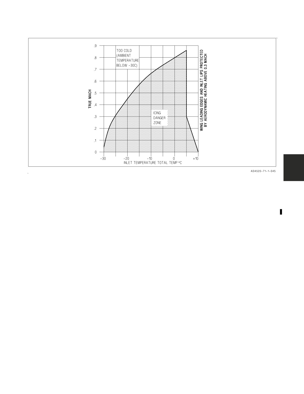
4. Climb or descend out of icing danger zone (see figure 20-1). Monitor INLET TEMP and Mach.
If time and fuel permit, climb to a safe altitude. Altitudes above about 25,000 feet or ambient
temperatures below -30°C will generally prevent icing since the water droplets are frozen and will
not adhere. Descend only if you are sure that ambient temperature is well above freezing at a safe
altitude below.
If penetration into known icing conditions is unavoidable -
5. Adjust airspeed to provide at least +5°C (+10°C preferred) INLET TEMP on the DDI engine
display.
6. Maintain less than 6° AOA, if possible. This reduces LEX ice accumulation.
7. Enter the cloud at the last possible moment and descend rapidly.
8. WINDSHIELD ANTI ICE/RAIN switch - AS REQUIRED
The ANTI-ICE position should be used as required to clear the windshield.
Do not operate the anti-ice system on a dry windshield. Place the
windshield anti-ice/rain switch OFF immediately if a WDSHLD HOT
caution appears.
VI-20-2
ORIGINAL
A1-F18AC-NFM-000
Figure 20-1. Icing Danger Zone
If at least +5°C INLET TEMP cannot be maintained and/or ice accumulation visible on leading
edge flaps -
9. Make a straight-in approach at 250 knots with throttles stabilized below 80% rpm (if possible).
Avoid throttle transients above 90% rpm.
10. Avoid abrupt maneuvers and bank angles over 20°.
11. Reduce airspeed and transition to landing configuration at the last possible moment. This will
minimize gear ice.
If missed approach necessary -
12. Slowly advance throttle to minimum power required for safe waveoff and raise gear and flaps as
soon as possible.
Report all icing encounters on VIDS MAF and ensure engine is inspected for FOD before next flight.
If landing in heavy rain -
13. WINDSHIELD ANTI ICE/RAIN - RAIN
Do not operate rain removal on a dry windshield. Turn rain removal OFF immediately after
landing or if WDSHLD HOT caution is displayed.
14. Reduce gross weight to minimum practical.
15. ANTI-SKID switch - ON
16. Land ON-SPEED.
VI-20-3
ORIGINAL
A1-F18AC-NFM-000
If directional control problems occur after touchdown -
17. Make arrested landing if possible.
20.2 TURBULENT AIR AND THUNDERSTORM OPERATION
Avoid flight through thunderstorms and microbursts. The radar MAP mode can be used to detect
storm cells. If penetration must be made, fly at optimum cruise airspeed but not less than 250 knots
if above 35,000 feet.
VI-20-4
ORIGINAL
A1-F18AC-NFM-000
CHAPTER 21
Hot Weather Procedures
21.1 BEFORE TAKEOFF
During ground operations all non-essential electronic equipment (radar, tacan, IFF, etc.) should be
OFF until just prior to takeoff. To increase cockpit and avionics cooling when the ambient temperature
is greater than 103° F, consider increasing the throttle setting above idle power or at ground idle, using
the APU in AUG pull mode to supply bleed air to the ECS.
On aircraft 161353 THRU 163175 BEFORE IAYC 853, to minimize
potential of APU damage due to surging, use bleed air AUG only when
absolutely necessary to maintain cooling.
Calculate the effect of temperature and altitude (density ratio) on takeoff and abort performance.
On aircraft THRU 161519 WITHOUT AFC 021 calculate minimum fuel for landing with the following
formula: Add 90 pounds per °C (50 pounds per °F) above 21°C (70°F) to 1,500 pounds.
21.2 IN FLIGHT
Low altitude flight with less than 4,000 pounds fuel remaining may cause the AMAD to overheat.
Monitor fuel temperature in flight and, if temperature exceeds 75°C, land as soon as practical to
prevent loss of AMAD(s) and generator(s). Extended low altitude high speed flight in ambient
conditions above 103°F may cause bleed air system overheat and shutdown. Refer to part 5.
21.3 DESCENT
When descending into warm humid conditions, abrupt canopy fogging can occur. To prevent this
condition, move the defog handle to HIGH before descent.
Turn non-essential electrical equipment OFF before entering the landing pattern.
21.4 AFTER LANDING
Immediately turn avionics equipment OFF. Ground operating time can be extended by shutting
down the left engine. After shutdown, leave the canopy open during the day to ventilate the cockpit if
blowing sand or dust is not a factor.
VI-21-1
(Reverse Blank)
ORIGINAL
A1-F18AC-NFM-000
CHAPTER 22
Cold Weather Procedures
22.1 EXTERIOR INSPECTION
If the aircraft has not flown within 4 hours, pay particular attention to the condition of the APU and
brake accumulator pressures, nosewheel oleo pressure, and possible fuel leaks near the AMAD bays and
along the inner lower wing roots.
22.2 BEFORE ENTERING COCKPIT
If APU start is anticipated, use the external canopy crank to raise the canopy, if possible, to conserve
battery power.
22.3 INTERIOR CHECK
Leave the canopy open until the right engine has been started to permit rapid emergency egress.
If the aircraft has been cold soaked below -18°C (0°F), rudder pedal adjustment will be difficult or
impossible and the inertia reel will not retract automatically until the cockpit warms up (5-10 minutes).
22.4 ENGINE START
APU starts can be successful if the UBATT voltage is at least 20.5 volts and the APU accumulator
is fully charged. Heat may have to be applied to the accumulator pump piston area to ensure proper
piston sealing and effective pumping.
For ambient temperatures below -23°C (-10°F), a deviation from normal crossbleed start procedures
is preferred. Operating engine fuel flow should be set to at least 1,900 PPH (72%-75% rpm). Using this
procedure, it may take 5 seconds longer to start.
Avoid activating any hydraulic actuated system for 2 minutes after both engines are on line. This
allows hydraulic fluid to warm both systems, preventing hydraulic leaks.
22.5 BEFORE TAXI
Maintain at least 70% rpm. Turn pitot and engine anti-ice ON.
If the aircraft has not flown within 4 hours with ambient temperature below -18°C (0°F), up to three
selections of the FCS exerciser mode may be required in order to obtain a successful FCS RESET after
initial warmup.
With engine anti-ice ON, ECS air flow may be low enough to cause an AVAIR HOT caution. Increase
rpm to increase air flow.
For cold weather operations below -18°C (0°F), three arresting hook cycles should be performed to
bring extension time within specification.
22.5.1 Aircraft 164196 THRU 164912 BEFORE AFC 216. During cold weather operations, proper
operation of the OBOGS monitor may not occur until after 15 minutes of warm up.
VI-22-1
ORIGINAL
A1-F18AC-NFM-000
22.6 TAKEOFF
If snow or slush has accumulated, leave gear down for 1 minute after takeoff to clear snow or slush
from the landing gear.
Very slow main landing gear retraction should be expected (about 30 seconds) following cold soak
below -18°C (0°F). Carefully monitor gear uplock signals and, if possible, request visual verification.
VI-22-2
ORIGINAL
A1-F18AC-NFM-000
PART VII
COMM-NAV EQUIPMENT
AND PROCEDURES
Chapter
23 - Communications-Identification Equipment
Chapter
24 - Navigation Equipment
Chapter
25 - Backup/Degraded Operations
Chapter
26 - Visual Communications
Chapter
27 - Deck Ground Handling Signals
71
(Reverse Blank)
ORIGINAL
A1-F18AC-NFM-000
CHAPTER 23
Communication-Identification
Equipment
23.1 INTERCOM SYSTEM
The intercom system (ICS) provides amplification and distribution of all voice communications,
voice alerts and tones originating within the ICS and advisory tones originating external to the ICS.
Intercommunications between the pilot and ground crew are also provided by the intercom system via
an external panel on the right side of the aircraft. A volume control on the external panel is provided
for adjusting audio volume to the ground crew headset.
23.1.1 Volume Control Before AFC 268. Six volume controls are provided to control pilot headset
volume for (1) TACAN ident, (2) transmit sidetone/aircrew intercom audio/ground crew intercom
audio, (3) RWR audio, (4) WPN delivery audio, (5) AUX 2 (formally ECM audio), and (6) auxiliary
audio (available for other uses). Additional functions performed by the ICS are (1) control of comm 1
and comm 2 plain/cipher text mode, (2) comm 1, comm 2 guard channel transmit, (3) control/zeroize
of IFF crypto code, (4) IFF Mode 4 control (visual and audible indications of interrogations) and, (5)
IFF master switch for normal/emergency operation.
23.1.2 Volume Control After AFC 268. Eight volume controls are provided to control pilot headset
volume for (1) voice activated intercom (VOX), (2) transmit sidetone/aircrew intercom audio/ground
crew intercom audio, (3) MIDS A audio, (4) MIDS B audio, (5) RWR audio, (6) WPN delivery audio,
(7) TACAN ident, and (8) auxiliary audio (available for other uses).
23.2 VHF/UHF AND MIDS COMMUNICATION SYSTEM
The aircraft has two voice communication radios which can be either two ARC-182, two ARC-
210(RT-1556), one of each, or one ARC-210(RT-1556) and F/A-18C/D AFTER AFC 269 one ARC 210
DCS (Digital Communication System). The ARC 210 DCS is only installed as a comm 2 radio. The
VHF/UHF radios, comm 1 and comm 2, provide air-to-air/air-to-ground voice communications, and in
conjunction with Automatic Direction Finding (ADF) equipment, provide a DF function. The radios
can be operated in a plain mode, an anti-jam (Have Quick) mode (ARC 210), a secure mode (KY-58 or
DCS), and a relay mode, in either normal or secure voice. An additional function is generation of a 1,020
hz tone by either comm 1 or comm 2 that serves as an ident tone for weapon release. With AFC 270,
the Multifunctional Information Distribution System (MIDS) is installed. MIDS, a joint service
system, provides secure, jam resistant voice and data communications utilizing spread spectrum,
frequency-hopping, and error detection/correction techniques. In addition, MIDS provides the
functionality of the AN/ARN-118 TACAN.
The comm 1 and comm 2 radios operate in fixed frequency plain, fixed frequency/secure, Electronic
Counter-Countermeasure (ECCM), or ECCM/secure mode. Comm 1 and comm 2 radios operate in the
frequency bands listed below and, when enabled, integral guard receivers continuously monitor the
emergency guard channels for each frequency band:
VII-23-1
ORIGINAL
A1-F18AC-NFM-000
ARC-182
Frequency
Modulation
Guard
Band
Channel
(MHz)
(MHz)
30 to 87.975
FM
40.5
*108 to 155.975
AM
121.5
156 to 173.975
FM
156.8
225 to 399.975
AM/FM
243.0
(AM)
*Cannot transmit on 108 thru 117.975 MHz
ARC-210(RT-1556 and DCS)
Frequency
Modulation
Guard
Band
Channel
(MHz)
(MHz)
30 to 87.995
FM
*108 to 135.995
AM
121.5
136 to 155.995
AM/FM
156 to 173.995
FM
225 to 399.975
AM/FM
243.0
(AM)
*Cannot transmit on 108 thru 117.995 MHz
Transmission and reception of amplitude and frequency modulated signals (AM and FM) occur in
the respective frequency bands on spaced channels of 100 kHz (aircraft 161353 THRU 161705), 25 kHz
(aircraft 161706 AND UP with ARC-182) or 5 kHz (ARC-210). Twenty channels in the 30 to 400 MHz
band may be pre-set to assigned frequencies as a convenience in the rapid selection of operating
frequencies.
When the Guard receiver (GRCV) is enabled, comm 1 or comm 2 is able to continuously monitor the
243.0 MHz AM Guard frequency while the radio is operating in the UHF band. When the radio is tuned
in the VHF band, 121.5 MHz is monitored.
The ECCM modes are Have Quick (HQ) I, II, and Single Channel Ground/Airborne Radio System
(SINCGARS). HQ I, an anti-jam (AJ) voice communication system, uses a single Word of Day (WOD)
and operates in UHF AM mode using frequency hopping techniques. HQ II is an extension of HQ I
operation that has multiple WODs and the capacity to store six multiple WODs. SINCGARS is also a
jam-resistant voice communication system that operates in VHF FM mode.
Secure voice operation is accomplished using the KY-58 system or DCS. With the ARC-210
(RT-1556) during secure operation, the radio provides a Baseband/Diphase (BB/DP) control signal to
the KY-58 to switch from BB to DP or vice versa. Diphase is the encrypted audio for the VHF/UHF
FM mode. With the ARC 210 DCS a secure voice capability is integral and does not require a KY-58
speech encoder.
Comm 1 and comm 2 may be operated in a relay mode, in either normal (plain), secure (cipher), or
ECCM operation. In this mode, the voice signal received by one communication set is retransmitted by
the other communication set on a different, pre-assigned frequency, provided the two frequencies are
spaced a minimum of 10 MHz apart. Cipher relay in Diphase mode is performed if and only if the
Diphase option has been enabled for comm 1 or comm 2.
VII-23-2
ORIGINAL
A1-F18AC-NFM-000
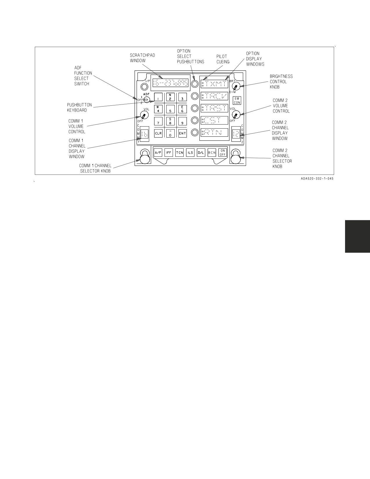
Figure 23-1. Upfront Control (UFC)
23.2.1 VHF/UHF/MIDS Controls and Indicators. The comm 1 and comm 2 are operated by (1)
off/on and volume controls on the UFC, (2) controls on the ICS, (3) communication switch on the right
(inboard) throttle grip, and (4) on aircraft 163986 AND UP in the Night Attack configuration comm
1 and comm 2 switches on the left and right rear cockpit rudder pedals respectively. With AFC 270
MIDS is turned on/off thru the UFC by pressing either TACAN or LINK 16 options, then ON/OFF.
On MIDS equipped aircraft the throttle mounted communication switch is a five position push-to-talk
switch (MIDS A/MIDS B/COMM 1/COMM 2 corresponding to: FWD/AFT/UP/DN with center
position OFF). On MIDS equipped F/A-18D aircraft a PTT panel contains two switches allowing the
selection of comm 1 or MIDS A, and comm 2 or MIDS B controling the operation of the rear cockpit
rudder pedal switches.
23.2.1.1 UFC. The UFC (figure 23-1) is located on the main instrument panel immediately below
the HUD. Controls on the UFC include (1) Volume controls for comm 1 and comm 2, (2) comm 1 and
comm 2 channel select knobs, (3) display windows for comm 1 and comm 2 selected frequencies, (4)
select switch for the ADF function, (5) pushbutton keypad and associated scratchpad window, (6)
option select pushbuttons, (7) option display windows, and (8) the brightness control knob.
23.2.1.1.1 Comm 1 and Comm 2 Volume Controls. The two volume controls turn ON and adjust
the audio volume of the respective comm 1 or comm 2.
23.2.1.1.2 Comm 1 and Comm 2 Channel Selector Knobs. When the comm 1 channel selector
knob is pulled, the UFC displays UFC Comm Display which is active for controls of comm 1 functions
only. When the comm 1 channel selector knob is rotated clockwise or counterclockwise in normal/
non-AJ mode, one of the following modes is selected for use by the comm 1 receiver-transmitter and
displayed: (1) one of 20 preset channels, (2) a manual frequency selection mode (M), (3) a guard
channel (G), (4) a cue (C) channel/frequency for Single Channel Ground and Airborne Radio System
(SINCGARS) (ARC-210), and (5) maritime (S) (ARC-210).
Rotating the comm 1 channel selector knob to position 1 through 20 selects the preset mode for the
preset channel number selected. The receiver and transmitter operates on the fixed frequency stored
in the selected preset channel. When the comm 1 selector knob is placed to G (guard), a G is displayed
in the comm 1 channel display window and the receiver-transmitter is tuned to 121.5 MHz in the VHF
VII-23-3
ORIGINAL
A1-F18AC-NFM-000
band or 243.0 UHF. The frequency selection is determined by the band currently in use. The M
position selects the manual frequency select mode. This tunes the radio to the preset manual
frequency. Using M channel allows the operator to change the communication frequency without
disturbing the twenty fixed frequency presets. The C position tunes the radio to the preset Cue
frequency in SINCGARS (SG) operation. The S position selects the maritime mode which tunes the
radio to the selected maritime channel.
When the active comm is in the AJ mode, by rotating the comm 1 channel selector knob, the operator
may select one of 20 Have Quick or SINCGARS preset channels, Manual Data Fill Mode (M), or Cue
channel (C).
In ECCM mode, the position 1, 2, ..., or 20 selects the preset mode. These preset channels can be
either a HQ I, II or SINCGARS presets. The radio operates on the Word Of Day, multiple WODs, or
net number stored in the selected preset channel. The M position in AJ operation selects the Manual
Data Fill Mode. This allows the operator to verify WOD for a particular day, manually load HQ WODs,
or clear all stored net data. The C position channel operates just as the Cue channel in normal mode.
All modes listed above are arranged and described in three main operations: (1) normal and plain
operation, (2) Have Quick, and (3) SINCGARS operation. Normal operation uses the twenty presets or
the manual select channel in fixed frequency operation. Also available are the Guard and maritime
channels. In Have Quick operation, the procedures for using (1) preset mode, (2) HQ Time options, and
(3) manual data fill mode, are described. Similar to Have Quick, the SINCGARS operation includes (1)
preset mode, (2) using SG Time options, (3) performing Electronic Remote Fill with ERF option, (4)
data fill using Cold Start option, and (5) Cue channel selection.
The comm 2 channel selector knob performs the same functions as the comm 1 channel selector knob
except that it controls the operation of the comm 2 receiver-transmitter.
23.2.1.1.3 Comm 1 and Comm 2 Channel Display Windows. These windows display the preset
channel (1 thru 20), guard channel selection (G), manual position (M), and with ARC-210 cue (C) or
maritime (S) as selected by the comm 1 or comm 2 channel selector knobs. In AJ mode, these windows
display 1 thru 20 for the indication of HQ or SG preset channel number, M for manual data fill mode
selection, or C for cue channel. In MIDS equipped aircraft the comm channel display window visually
identifies which audio sources are currently active. An inverted triangle indicates comm 1 or comm 2
is transmitting or receiving. An upright triangle indicates MIDS A or MIDS B is transmitting or
receiving. An hourglass symbol indicated simultaneous comm and MIDS radio operation. The
triangle/hourglass symbols remain as long as the audio source is transmitting or receiving. The comm
channel number (1 thru 20) is displayed for 2 seconds after a channel change occurs.
23.2.1.1.4 ADF Function Select Switch. The ADF function select switch has positions labeled 1, 2,
and OFF. Placing the switch to the 1 position turns on power to the ADF set and indicates ADF bearing
to the station selected on the comm 1 receiver-transmitter. Placing the switch to the 2 position turns
on power to the ADF set and indicates ADF bearing to the station selected on the comm 2
receiver-transmitter. With the switch set to OFF, power to the ADF is removed. The ADF bearing
symbol is a small circle displayed on the HSI display and indicates the ADF bearing to the station
selected. Squelch is deselected when the ADF is selected. After the ADF is turned on, the SQUELCH
has to be reselected.
23.2.1.1.5 Scratchpad Window. When the channel selector knob is pulled to the extended position
in normal mode, the scratchpad window either displays the preset channel number and the frequency
information, or it displays M- and the manual select frequency, G- and the Guard frequency, C- and
the cue frequency, S- and the maritime channel number. If the active comm is in the AJ mode, when
VII-23-4
ORIGINAL
A1-F18AC-NFM-000
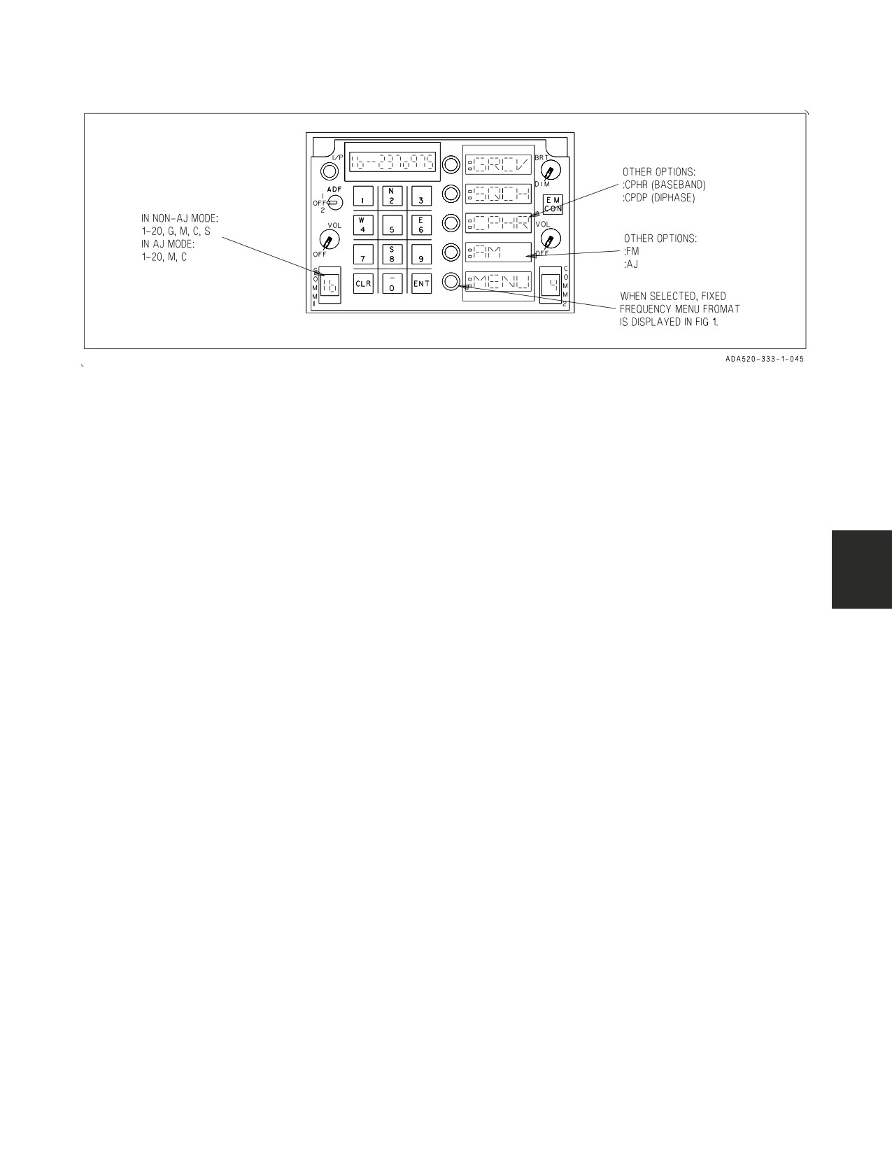
Figure 23-2. UFC COMM Display
pulled, the scratchpad window displays the net number and the preset channel designations, H1, H2,
or SG, depending upon the respective Have Quick I, II, or SINCGARS channel selected.
The scratchpad displays the new data or information entered using the UFC keyboard. In general,
when the entered data is invalid or out of range, the scratchpad flashes ERROR for a moment and
returns to the previous display.
23.2.1.1.6 Option Select Pushbuttons. An option is selected by pressing the pushbutton to the left
side of the corresponding option display window.
23.2.1.1.7 Option Display Windows. When the comm 1 or comm 2 channel selector knob is pulled,
the UFC displays Comm Display (see figure 23-2). GRCV and SQCH appear in option windows one and
two respectively. Option window three displays cipher mode options, either CPHR, :CPHR, or :CPDP.
Option window four displays the radio mode functions (either :AM, :FM, or :AJ) unless maritime mode
is selected. MENU is displayed in the option five window.
GRCV When pressed, guard receiver enabled and a colon appears to the left of GRCV in
option window one. Upon power up with WOW, status from last flight is remembered.
When pressed while GRCV is colonized, Guard receiver is disabled.
SQCH When pressed, squelch reduces noise level in radio. A colon appears to the left of SQCH
to indicate squelch is ON. When pressed while SQCH is colonized, squelch is OFF.
CPHR Upon successive pushbutton depressions, this option window toggles from CPHR (plain
voice through :CPHR, :CPDP, and then return to CPHR.
:CPHR When displayed, cipher mode is enabled with Baseband operation.
:CPDP When displayed, cipher mode is enabled with Diphase operation. This option is dis-
played only when the active comm is in AM UHF and Diphase mode is selected.
:AM or When displayed, indicates the active comm is in normal/non-AJ mode and the modula-
:FM
tion of the current preset is AM or FM, depending upon the frequency band or the
operator’s selection.
VII-23-5
ORIGINAL
A1-F18AC-NFM-000
:AJ
When displayed, indicates the active comm is in the AJ mode. The current channel is a
HQ or SG preset. When pressed, AJ mode is disabled and option window four displays
either AM or FM depending upon the frequency preset channel. If the radio is tuned to
a frequency in the AM only band and G, M, or C is the selected channel, option win-
dow four is blank.
MENU When pressed while :AM or :FM is displayed in option window four, the UFC displays
Fixed Frequency Menu Display Format. Otherwise, if AJ is displayed and the current
channel is either HQ or SG preset, respective UFC HQ Display or UFC SG Display.
Selection of RTN option causes the UFC to display UFC Comm Display.
23.2.1.1.8 Brightness Control Knob. The knob has positions of BRT (bright) and DIM. The
brightness of the display increases as the knob is rotated clockwise toward BRT.
23.2.2 Normal and Plain Operation
23.2.2.1
Fixed Frequency Preset. Unless otherwise specified, the UFC generally displays UFC
Comm Display in fixed frequency normal operation such that GRCV, SQCH, CPHR, :AM, or :FM, and
MENU are displayed in option windows one, two, three, four, and five, respectively.
Preset frequency selection: Disable AJ mode. Rotate the channel select knob to the desired preset
channel (1 to 20). The scratchpad displays the selected channel number and the frequency. Also, the
AM/FM modulation is updated and displayed in option window four.
Presetting frequencies: The operator can load or change the frequency of the twenty preset channels.
Rotate the channel select knob to the channel to which the frequency is to be preset. After selected, a
six digit frequency in Megahertz is entered using the keyboard. When a valid frequency is entered, the
system determines the proper AM/FM modulation for the entered frequency if the modulation is not
operator selectable. For frequencies in AM only or FM only, option window four is blank. If valid, the
frequency and AM/FM mode are loaded and stored in the selected channel.
23.2.2.2 Manual Frequency Mode Selection. Rotate the channel select knob to M position and
disable AJ mode. The scratchpad displays M- and the previously manual selected frequency. Option
window four displays preset AM/FM mode or blanks for frequencies in AM only or FM only. The
operator may enter a new frequency and modulation type using the keyboard and option window four
pushbutton, respectively.
23.2.2.3 Guard Channel Selection. Rotate the channel selector knob to the G position. The
scratchpad displays G- and the preset Guard frequency. The Guard channel only operates in non-AJ
and plain mode. The operator can change the Guard frequency in the same way as that of a fixed
frequency preset channel.
23.2.2.4 Maritime Mode Selection. Rotate the channel selector knob to the S position. The
scratchpad displays S- and the previously selected channel. The operator may enter two digits for the
desired maritime channel using the keyboard. These channel numbers must be in the range 1 to 28 or
60 to 88. The maritime channels are used to communicate with ships or coast stations only. Once a new
channel is selected, the active comm tunes to the preset frequency stored in the selected maritime
channel.
VII-23-6
ORIGINAL
A1-F18AC-NFM-000
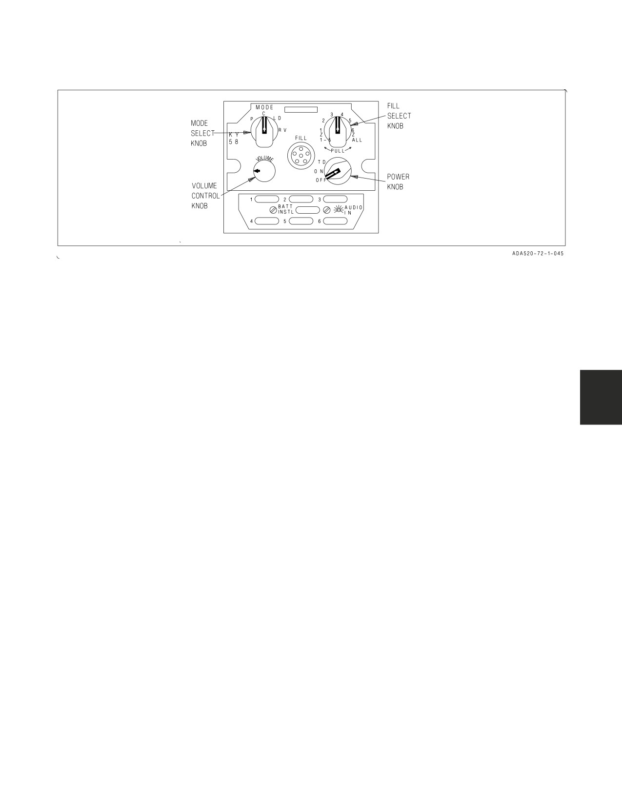
Figure 23-3. KY-58 Control Panel Assembly
23.3 SECURE SPEECH SYSTEM (KY-58)
The secure speech system is used for ciphering (coding) or deciphering (decoding) audio routed
through the COMM 1 and COMM 2 receiver-transmitters. The system consists primarily of the KY-58
control panel assembly on the right console. Controls and indicators are on the KY-58 control panel
assembly and on the communication control panel on the left console.
23.3.1 KY-58 Control Panel Assembly. The control panel assembly functions as a ciphering or
deciphering device for secure speech operation.
23.3.1.1 Ciphered Transmission. During ciphered transmissions, audio from the microphone is
routed through the communication control panel to the KY-58 control panel assembly where it is
enciphered. The enciphered audio is routed back to the communication control panel and then to
COMM 1 or COMM 2 receiver-transmitter for transmission.
23.3.1.2 Ciphered Reception. During reception of ciphered information, the ciphered audio is
routed from the COMM 1 or COMM 2 receiver-transmitter to the communication control panel and
then to the control panel assembly for deciphering. The deciphered audio is routed to the communi-
cation control panel and to the headset.
23.3.1.3 Ciphered Relay Mode. During ciphered relay mode of operation, ciphered information
received on one radio is routed from the radio, through the communication control panel to the second
radio for transmission. The ciphered information received on the first radio is also routed through the
communication control panel to the KY-58 control panel assembly for deciphering. The deciphered
audio is routed through the communication control panel to the headset. This enables the crewmember
to hear deciphered relayed audio when in the ciphered relay mode. When cipher is selected on the
communication control panel immediately after operating in a relay plain, COMM 1 plain, or COMM
2 plain mode of operation, the crewmember must press the transmit key for either COMM 1 or COMM
2 two times to enable ciphered relay operations. When the relay aircraft is operating both radios within
the same bandwidth, the two frequency selections must be separated by a minimum of 10 MHz.
23.3.2 Controls and Indicators. The only cipher control on the communication control panel is the
RLY CIPHER/PLAIN switch (relay switch). The controls on the KY-58 control panel assembly are the
MODE select knob, the unlabled fill select knob, the VOLUME control knob, and the unlabled power
select knob (see figure 23-3).
VII-23-7
ORIGINAL
A1-F18AC-NFM-000
23.3.2.1 Comm Relay Switch. This switch has positions of CIPHER, OFF, and PLAIN. Placing
the switch to CIPHER enables the cipher relay mode. With the switch in OFF the relay mode is
disabled. Placing the switch to PLAIN enables the plain relay mode.
23.3.2.2 Mode Select Knob. The mode select knob has positions of P, C, LD, and RV. Placing the
knob to P enables plain mode of operation. Placing the knob to C enables the cipher mode of operation.
With the knob set to LD the load mode of operation is enabled. This mode is used for loading data into
the KY-58 control panel assembly. Information pertaining to the RV knob position (receiver variable)
will be supplied later.
23.3.2.3 Fill Select Knob. The fill select knob has positions of 1 thru 6, a Z 1-5 position, and a Z
ALL position. Setting the knob to one of the six numbered positions selects the position to be loaded
with data. Placing the knob to Z 1-5 zeroizes data in positions 1 thru 5. Placing the knob to Z ALL
zeroizes all data in positions 1 thru 6.
23.3.2.4 Volume Control Knob. The volume control knob adjusts the volume of the KY-58 control
panel assembly audio. The volume control knob should be set to full volume position during secure
voice transmission and reception.
23.3.2.5 Power Knob. This knob has positions of ON, OFF, and TD. Placing the knob to ON turns
on power to the KY-58 control panel assembly if cipher mode has been selected. Placing the knob to
OFF removes power to the system. With the knob in TD, power is turned on for the system if cipher
mode has been selected and a time delay is selected for data processing. The knob must be in the TD
position for ciphered relay operations.
23.3.3 KY-58 Operation. Other stations or aircraft involved in cipher or cipher relay communica-
tion must be in either the baseband or diphase mode.
1. Comm 1 and Comm 2 radios - ON
Comm 1 and Comm 2 radios are turned on and volume adjusted with the VOL 1 and 2
communication control knobs on the UFCD.
2.
Comm 1 and Comm 2 channels - AS DESIRED
a. COMM 1 and COMM 2 channel select knobs - ROTATE (to select desired channel).
Selected channel is displayed in COMM 1 and 2 touch option/display on the UFCD.
3.
Comm 1 and Comm 2 channel frequency - SET
a. Comm 1 and Comm 2 touch option/display - TOUCH
Channel number and frequency displayed in scratchpad GRCV, SQCH, and CPHR options
appear on the option/ display.
b. Channel frequency - AS DESIRED
Enter new frequency with keypad. Press the ENT key to enter the new frequency.
4.
CPHR touch option/display - TOUCH
The CPHR touch option/display is border highlighted and a series of tones are heard for 3
seconds indicating cipher is enabled with baseband operation. Touching the CPHR touch
option/display again changes the display to CPDP with the border highlighted and enables cipher
diphase mode.
VII-23-8
ORIGINAL
A1-F18AC-NFM-000
23.3.3.1 KY-58 Cipher Mode. Other stations or aircraft involved in cipher communication must
have the KY-58 fill select knob in the same position.
5. KY-58 power knob - ON
6. KY-58 MODE knob - C
7. KY-58 VOLUME knob - ADJUST TO MAX VOLUME
8. Comm switch on inboard throttle - ACTUATE
UP for Comm 1, DOWN for Comm 2. A short tone is heard in the headset.
23.3.3.2 KY-58 Relay Mode. Relay mode can operate in Plain, Cipher and ECCM mode. Other
stations or aircraft involved in cipher relay communication must have the KY-58 fill select knob in the
same position.
5. KY-58 power knob - TD
Other stations or aircraft involved in cipher relay communication must have the KY-58 power
knob in the TD position.
6. KY-58 MODE knob - C
7. KY-58 VOLUME knob - ADJUST TO MAX VOLUME
8. COMM 1 ANT SEL switch - AUTO
9. Relay switch select - CIPHER
10. Comm switch on inboard throttle - ACTUATE
UP for Comm 1, DOWN for Comm 2. A short tone is heard in the headset.
NOTE
When the relay aircraft is operating both radios in the same
bandwidth, the two radio frequencies must be separated by at least 10
MHz.
23.4 HAVE QUICK OPERATION AND OPTIONS (ARC-210) (AIRCRAFT 164945 AND UP, F/A-18A
AFTER AFC 253 OR 292 AND AIRCRAFT 163427 THRU 164912 AFTER AFC 185.)
23.4.1 Preset Mode. Enable AJ mode to select a HQ preset channel while UFC Comm Display is
active. See figure 23-4. Rotate the channel select knob to the desired HQ preset channel (1 to 20). The
scratchpad displays H1 for HQ I (or H2 for HQ II) and the net number. If there is no valid
data/waveforms or time stored for the selected channel, the scratchpad displays NO FILL.
The operator can enter or change the HQ net number of the twenty preset channels. Rotate the
channel selector knob to the channel to which the net number is to be preset. AJ mode is enabled. A
six digit HQ net number may be entered using the keyboard. Valid HQ net numbers range from 000.000
to 999.000 with the last three digits being 000 for HQ I, 025 for HQ II (NATO), or 050 for HQ II
(non-NATO). A decimal point, separating the first three digits from the last three digits, is provided
VII-23-9
ORIGINAL
A1-F18AC-NFM-000
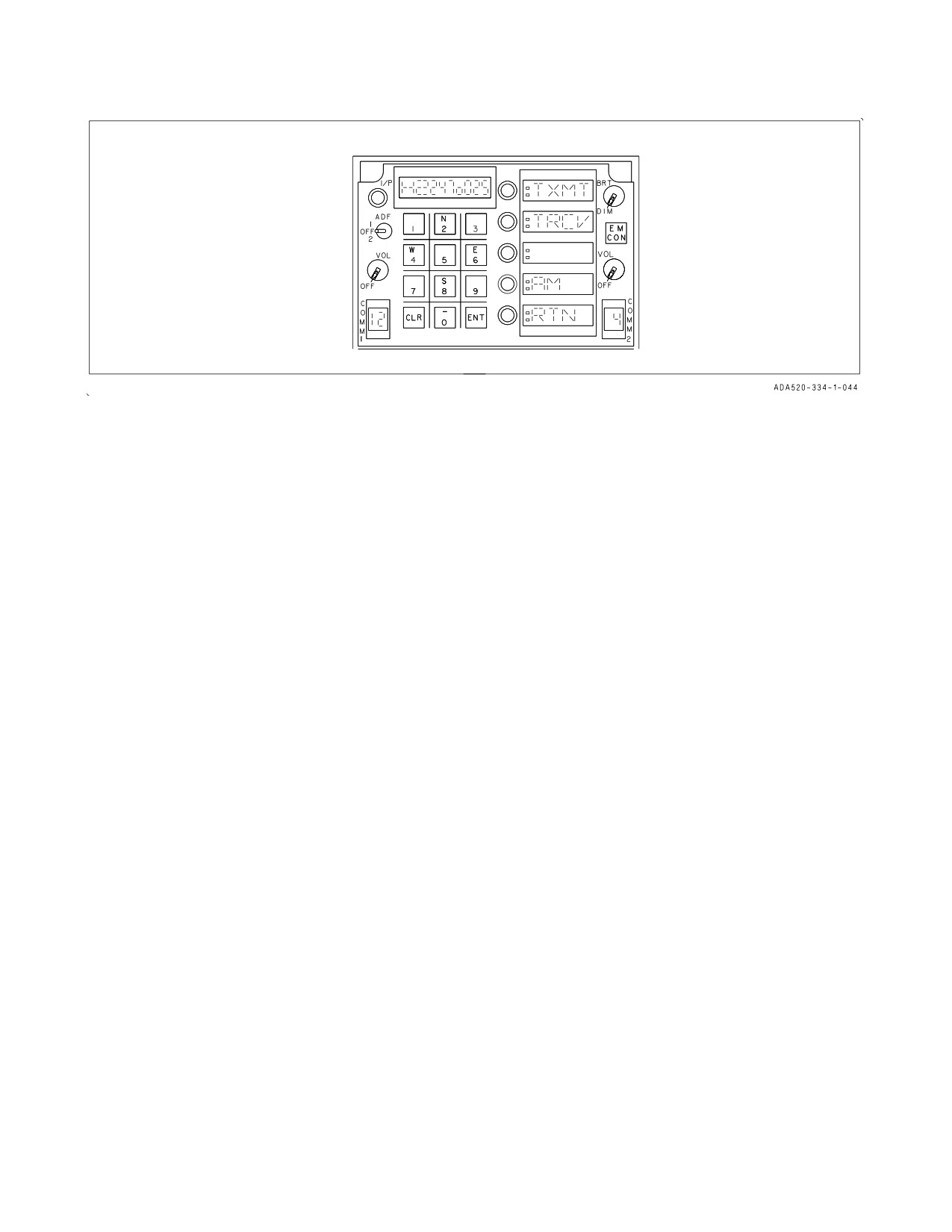
Figure 23-4. UFC Have Quick Display
in the scratchpad automatically. If the entered net number is not valid, the scratchpad flashes ERROR
and returns to the previous or NO FILL display. If valid, the active comm loads and stores the new net
number and associated waveforms in the selected channel.
23.4.2 Using HQ Time Options.
23.4.2.1 Transmitting or Receiving Time Using UFC HQ Display. When MENU option is selected
in UFC Comm Display and the selected channel is a HQ preset, the UFC displays the Have Quick
display.
NOTE
Loss of GPS timing may affect HAVE QUICK operation.
TXMT (Time Transmit), TRCV (Time Receive), AM (Amplitude Modulation) and RTN (Return)
are displayed in option windows one, two, four and five respectively. Option window three is blank.
TXMT When pressed, enables the active comm to transmit the Time Of Day (TOD) to other
units for net time synchronization. A colon appears to the left of TXMT in option win-
dow one for two seconds and then removed.
TRCV When pressed, enables the active comm to receive the transmitted TOD from another
net user. A colon appears to the left of TRCV in option window two until TOD is
received. If sixty seconds pass after the option selection, the colon is removed and the
Time Receive mode is deactivated.
RTN When pressed, causes the UFC to return to the UFC Comm Display.
23.4.2.2 Transmitting, Receiving, or Restarting Time Using Fixed Frequency Menu Format.
While the UFC displays Comm Display, disable AJ mode and rotate the channel selector knob to select
a fixed frequency preset. When MENU option is selected, the UFC displays Fixed Frequency Menu
Format. TXMT (Time Transmit), TRCV (Time Receive), TRST (Time Restart), CST (Cold Start),
and RTN (Return) are displayed in option windows one, two, three, four, and five, respectively. When
this format is active, the operator can restart time, transmit or receive time to/from other net users, or
use the Cold Start option.
VII-23-10
ORIGINAL
A1-F18AC-NFM-000
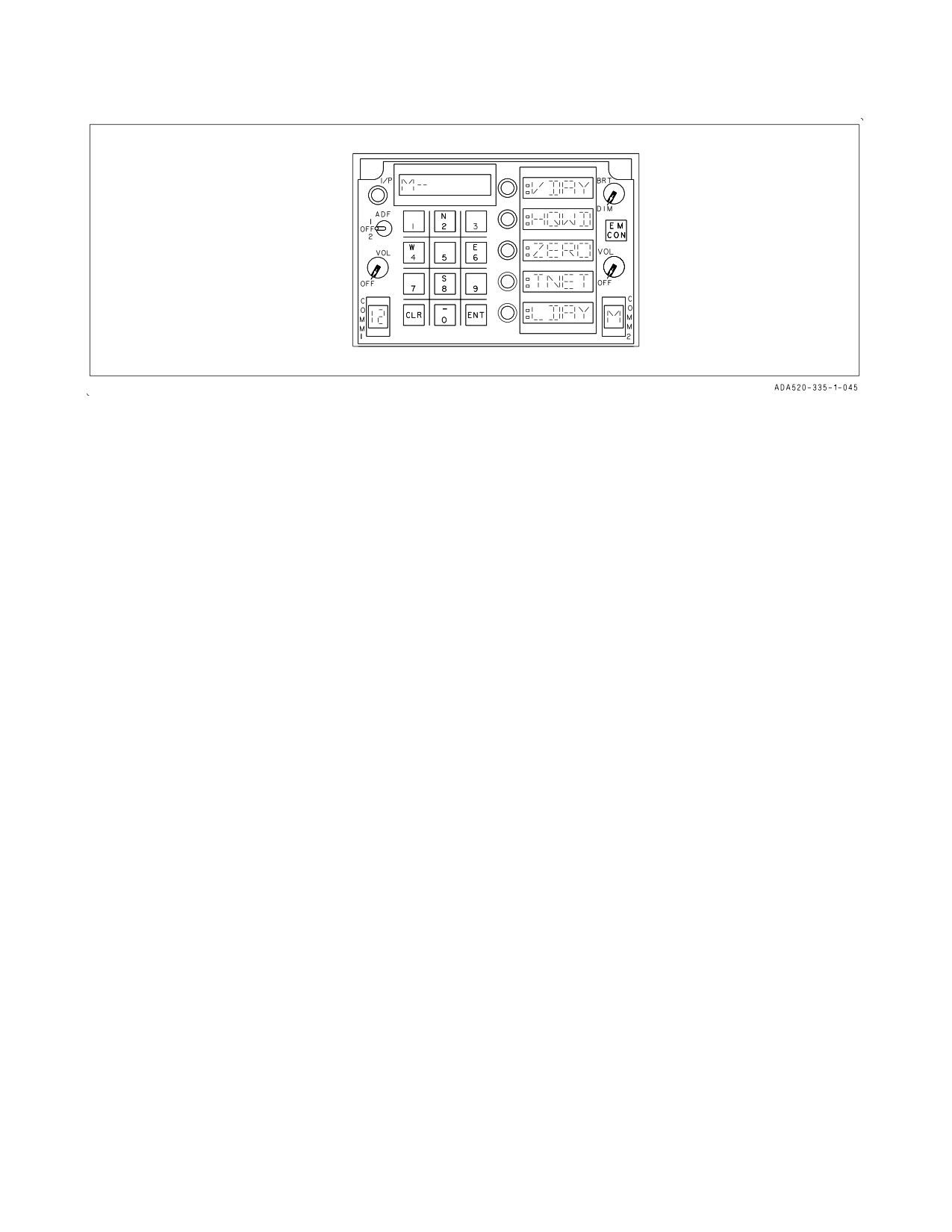
Figure 23-5. UFC Manual Data Fill Display
The operation of TXMT and TRCV options are the same as TXMT and TRCV options described
in the paragraph of Transmitting and Receiving Time Using UFC HQ Display. CST option is used
when an operator, that is not part of an active SINCGARS net, wants to join the net. The operation
of this option is described in Performing ERB (electronic remote fill) in SINCGARS Operation and
Options section.
The TRST option is used to start or initialize time in the radio system at power-up. Performing this
option takes two actions. First, upon selecting the option, the scratchpad displays ENABLE and a
colon appears at the left side of TRST in option window three. Then, the operator can press either the
CLR key to cancel TRST option, or the ENT key to activate Time start. When the CLR key is selected,
the colon from the option is removed and the scratchpad changes to display the fixed frequency.
Selection of the ENT key while ENABLE appears causes the radio to restart its clock. After executing
the option, the system removes the colon and changes the scratchpad to display fixed frequency.
When RTN is pressed, the UFC returns to the Comm Display Format.
23.4.2.3 Using Manual Data Fill Mode. To selecting M channel and display manual fill options,
enable AJ mode in UFC Comm Display before rotating the channel select knob to M position. The UFC
displays Manual Data Fill Display, VDAY, HQWD, ZERO, TNET, and LDAY are displayed in option
windows one, two, three, four, and five, respectively (see figure 23-5). The scratchpad displays M- in
the left most windows. AJ communication is not available in this mode. When Manual Data Fill Mode
is exited by selecting a preset channel, AJ mode is enabled.
VDAY option is used to verify that the HQ Word of Day has been loaded for a particular day. When
VDAY is pressed, a colon appears at the left side of VDAY in option window one. From the keyboard,
enter a two digit day code (in the range 0 to 31) followed by ENT key. The system generates an audible
beep in the operator’s headset if the entered day has a stored WOD for the selected day. Multiple days
can be verified by entering each day as desired.
The HQWD option allows the operator to manually enter the HQ I WOD or the HQ II multiple
WODs rather than using a data loader. A WOD consists of six segments (20 through 14). For HQ II, six
WOD segments and a two digit day code (0 to 31) make up a multiple WOD. The system can store a
single WOD or up to six multiple WODs.
VII-23-11
ORIGINAL
A1-F18AC-NFM-000
When HQWD is pressed, a colon appears at the left side of HQWD in option window two and 20 in
the scratchpad along with the associated WOD first segment. If this segment has no stored data, blanks
are displayed in the scratchpad. The first segment data in the range of 200.000 to 399.975 in .025
increments is entered or changed using the keyboard.
Each successive segment (19, 18, ... 15) can be selected by pressing option 2 pushbutton again while
the colonized HQWD is displayed. Data may be entered or changed for each segment, or the next
segment may be selected. When segment 14 is displayed, the day of the month of that WOD is
displayed in the far right windows. If no day code was stored, blanks are displayed and the day code
may be entered using the keyboard. If the colonized HQWD option is selected while 14 and the day
code are displayed, the scratchpad changes to display LOAD in the right-most windows. When the
ENT key on the UFC keyboard is depressed while LOAD is displayed, the WOD loading is
accomplished. If the loaded WOD is accepted by the radio system, a beep is heard in the operator’s
headset and the UFC displays M- in the two far left windows. Also, the colon from HQWD option
window is removed.
The operator can then enter the next WOD and associated date by starting the preceding sequence
over. The WOD loading is terminated by selecting another option or exiting the Manual Data Fill
Mode.
23.4.2.4 Erasing All Net Data. ZERO option is used to erase all the stored HQ WODs and
SINCGARS Transec data by filling with zeros.
When pressed, ZERO is displayed in the scratchpad window and a colon to the left of ZERO in
option window three. At that time the CLR and ENT key on the UFC keyboard are active for selection.
To cancel the selected option, press the CLR key. As a result, the colon from the option is removed and
the scratchpad changes to display M- in the two left-most windows. Otherwise, pressing the ENT key
while ZERO appears in the scratchpad initiates the ZERO function for the active comm. Once the
ZERO option has been executed, the active comm zeroes all the stored WODs and training nets from
its memory. After that, the UFC displays M- in the scratchpad and the colon is removed from the
ZERO option window.
23.4.2.5 Using Training Net. TNET option allows training on the overall operation of HQ I or HQ
II. These nets are unclassified. HQ I has 5 frequencies and HQ II has 16 frequencies used for frequency
hopping.
TNET when pressed, a colon appears to the left of TNET in option window four and M- 1 or 2 in
the scratchpad as a prompt for keyboard selection of HQ I or HQ II training nets, respectively. Because
HQ I training net is not available and now performed through WOD data, do not select HQ I. For
selecting HQ II training, enter 2 followed by the ENT key. The scratchpad displays 20 and the first
stored training net frequency. Blanks are displayed if no data was stored.
The procedure for loading the training net frequencies is similar to the one described above in
loading HQ WODs paragraphs. Upon successive depressions of option four pushbutton when TNET is
colonized, the scratchpad displays 19, 18, ... 6, in the left-most windows and the next corresponding
frequency in the right-most windows. If no training net frequencies have been stored in memory,
blanks are displayed in place of the frequency. A new frequency is entered using the keyboard.
If the option is selected while 5 and its associated frequency are displayed, the scratchpad changes
to display LOAD. When ENT key is pressed, sixteen HQ II training frequencies are sent to the system.
If the loaded data is accepted by the radio, a beep is heard in the operator’s headset and the scratchpad
displays M- in the left-most windows. The colon from TNET option window is removed.
VII-23-12
ORIGINAL
A1-F18AC-NFM-000
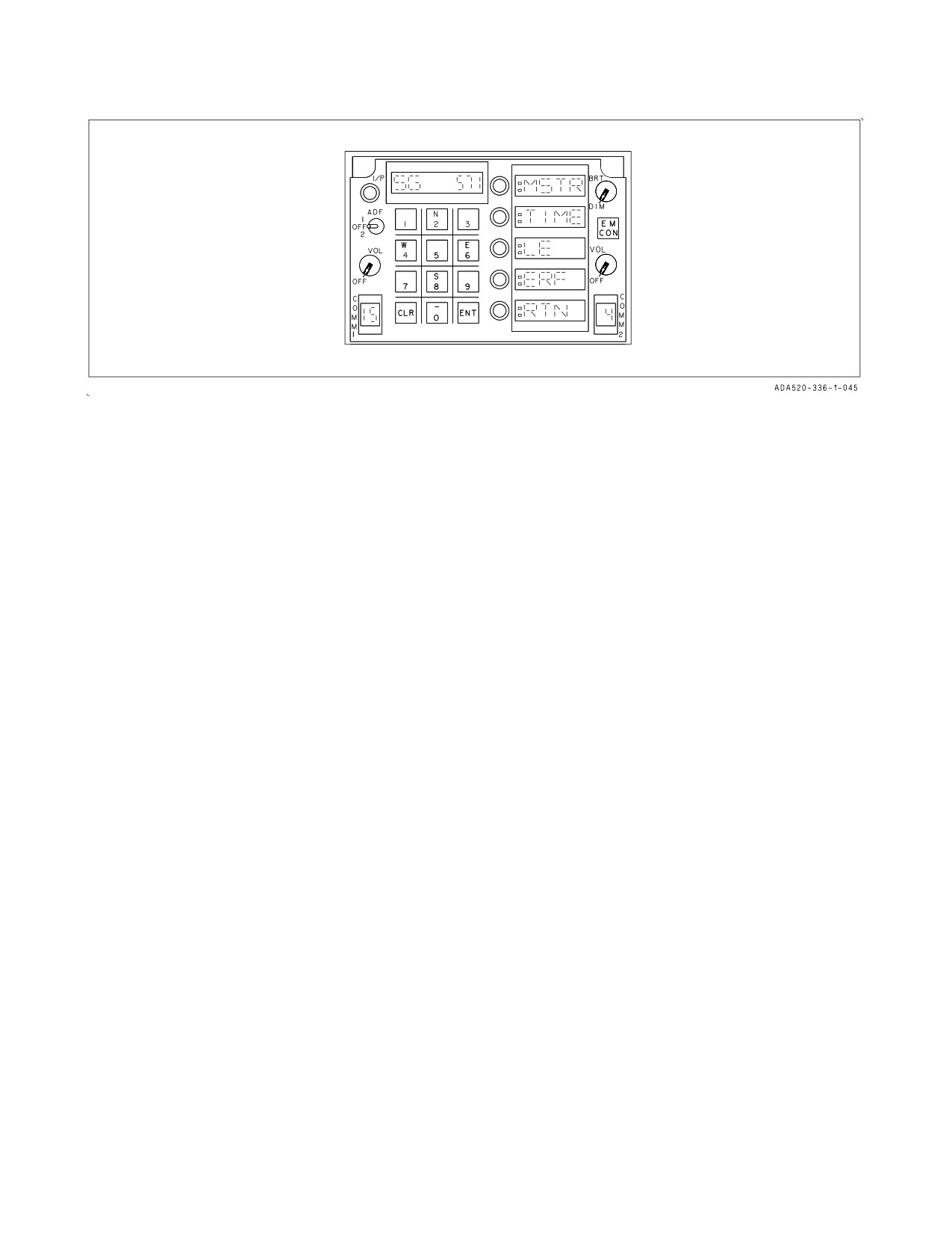
Figure 23-6. UFC SINCGARS Display
23.4.2.6
Loading an Operational Day. LDAY option is used to load the day of operation. The system
correlates the stored WODs and the identified day code with the operating day.
When LDAY is pressed, a colon appears to the left of LDAY in option window five. While the
scratchpad displays M- in the left-most windows, enter two digits (01 to 31) of the operating day. When
the ENT key on the keyboard is pressed, a beep is heard in the operator’s headset to indicate the day
has been entered.
23.5 SINCGARS OPERATION AND OPTIONS
23.5.1 Preset Mode. While the UFC displays Comm Display, enter AJ mode. Rotate the channel
selector knob to select an SG channel preset (1 to 20). If the channel is a SG preset, the scratchpad
displays an SG and the net number. A SINCGARS net number may not be entered or changed.
23.5.2 Using Time Options in SG Display. If MENU option is selected in UFC Comm Display and
the current channel is an SG preset, the UFC displays an SG Display. See figure 23-6. MSTR (Master
Clock), TIME (Time Entry), LE (Late Entry), ERF (Electronic Remote Fill), RTN (Return), are
displayed in option windows one, two, three, four, and five respectively. Selecting MSTR option
enables the active comm to become the master clock which provides the time reference for a
SINCGARS net. TIME option allows each user to enter SG time. LE option is used to synchronize time
to the net once time is entered using TIME option. When RTN is selected, the UFC returns to the
Comm Display.
When MSTR is pressed, a colon appears to the left of MSTR in option window one to indicate that
the comm has been designated as the master clock in the SG net. MSTR mode is active until another
option is selected.
When TIME is pressed, a colon is displayed to the left of TIME in option window two and the
scratchpad displays -- - to prompt the operator to enter in DD--HH-MM using the keyboard. If the
entered time is valid, the scratchpad displays time until another option is selected. If the option is
selected while colonized, the scratchpad changes to display SG and the net number.
When LE is pressed, the UFC displays a colon in front of LE in option window three. When the
active comm has synchronized its time with the net time, it removes the colon from LE option and
disables the Late Entry mode.
VII-23-13
ORIGINAL
A1-F18AC-NFM-000
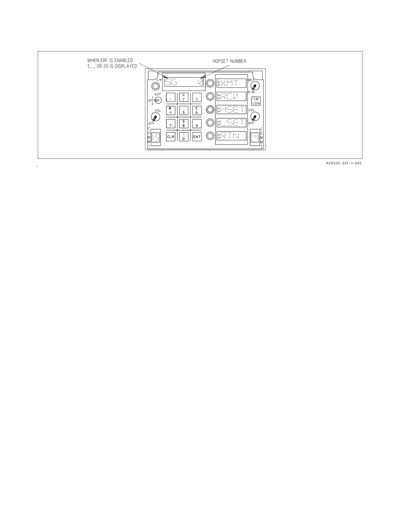
Figure 23-7. UFC Electronic Remote Fill Display
23.5.3 Performing Electronic Remote Fill (ERF) with ERF Option. While the UFC displays SG
Display, ERF appears in option window four. ERF allows the net data to be filled electronically over
the air by another net user who has the required net data.
When ERF is pressed, XMT (transmit), RCV (receive), HSET (hopset), LSET (lockout set), and
RTN (return) are displayed in UFC option windows one, two, three, four, and five respectively. See
figure 23-7. Pressing RTN causes UFC to display SG Display.
When ERF option is selected, the scratchpad displays SG in the two left-most windows and the
hopset or lockout set in the far right windows depending upon which option was last selected, HSET
or LSET. A colon appears in front of HSET or LSET in the option display window to indicate the
current selection. A new hopset or lockout set is entered by first selecting the desired HSET or LSET
option if different from the current selection, and then the desired set number (1 to 20 for the hopset
and 1 to 8 for the lockout set) using the keyboard. The entered set number is displayed in the
scratchpad.
23.5.3.1 Transmission or Reception of Hopset or Lockout Set. Depending on the selected set data,
selecting XMT option enables the radio to transmit the hopset or lockout set. A colon is displayed in
front of XMT for two seconds after the transmission occurs. The XMT option is blanked in ADF
operation.
Pressing the RCV option enables the radio to receive the selected set data. A colon is displayed
adjacent to RCV until the selected set is received.
23.5.3.2 Performing ERF with CST Option. First, disable AJ mode and select a fixed frequency to
perform cold start by changing channels or entering a new frequency. Then, MENU option on UFC
Comm Display is selected to display Fixed Frequency Menu. When CST option is selected, the UFC
displays the same ERF format as the one displayed when the ERF option is selected in the UFC SG
Display, with the exception of scratchpad display. The channel number and the fixed frequency are
displayed in the scratchpad. The operator can select these ERF options using the same procedures as
described in paragraph 23.5.3.
23.5.3.3 Cue Channel Selection. A non-net user who is currently not on a net can contact an SG
net user on the Cue frequency using the C channel. The C channel is selected using the channel selector
knob of the active comm. Rotate the channel select knob to C position. The UFC displays Comm
Display with option window five (MENU option) blanked. The scratchpad displays C- and the preset
VII-23-14
ORIGINAL
A1-F18AC-NFM-000
Cue frequency. AM/FM modulation information displayed in option window four is provided in the
same manner as it is for the fixed frequency presets. The Cue frequency can be changed similar to the
programming of a normal channel by manually entering the frequency using the keyboard.
Visual and audio indications are provided to the operator being contacted by a non-net user. The
channel display window flashes at a 1 Hz rate to signal the operator when the active comm receives the
cue signal. Also, a beep is heard momentarily in the operator’s headset. The operator generally selects
the C channel to respond to the contact on the Cue frequency.
23.6 IDENTIFICATION SYSTEM
The IFF (identification friend or foe) transponder set provides automatic identification of the
aircraft in which it is installed when challenged by a surface or airborne interrogator set and provides
momentary identification of position (I/P) upon request. The system operates in modes 1, 2, and 3/A
which are selective identification feature (SIF) modes and in mode C, the altitude reporting mode.
Mode 4, which is a crypto mode, is available when the transponder computer (KIT) is installed in the
aircraft.
23.6.1 Combined Interrogator Transponder (Aircraft 165222 AND UP, F/A-18A AFTER AFC
292, AND Aircraft 163985 THRU 165221 AFTER AFC 236). The Combined Interrogator Transpon-
der (CIT) System is a dual purpose IFF system with transponder and interrogator capabilities. When
functioning as a transponder, the system utilizes the ACI panel and antenna select panel controls. In
the air interrogator mode, the system incorporates a beam forming network and a five blade antenna
array mounted on the upper fuselage forward of the windscreen.
The CIT system can transmit on the ground. Ensure that personnel
remain more than 18 inches away from the nose barrel mounted antennas
during ground operation.
The CIT system works in conjunction with the MC, CC, ACI, UFC, ADC, IBU, LGCU and the
displays. The UFC displays and controls for the CIT are shown in figure 23-8.
23.6.1.1 Transponder Operation. The transponder responds to interrogations in modes 1, 2, 3/A, 4,
and C. The CIT only transponds when an interrogation in an enabled mode is received. The IFF
transponder modes and codes can be selected and changed by selecting the Transponder (XP) IFF
display on the UFC or automatically as described below. Initialization of the transponder codes is also
available via a file on the MC.
23.6.1.2
Transponder Control Via the UFC
The transponder operation is controlled through the UFC by selecting the IFF function key on the
UFC until XP is displayed in the scratchpad. Subsequent selection of the IFF function key toggles
between AI and XP IFF displays. The current mode 3 code is displayed in the scratchpad and the
modes that are currently enabled have colons displayed in the option windows. The mode 3 code is
changed by use of the keyboard. When the ENT key is pressed, the new mode 3 code is entered into
the IFF if valid. The modes and codes selected for transponder operation are selected independent of
the interrogator modes and codes.
VII-23-15
ORIGINAL
A1-F18AC-NFM-000
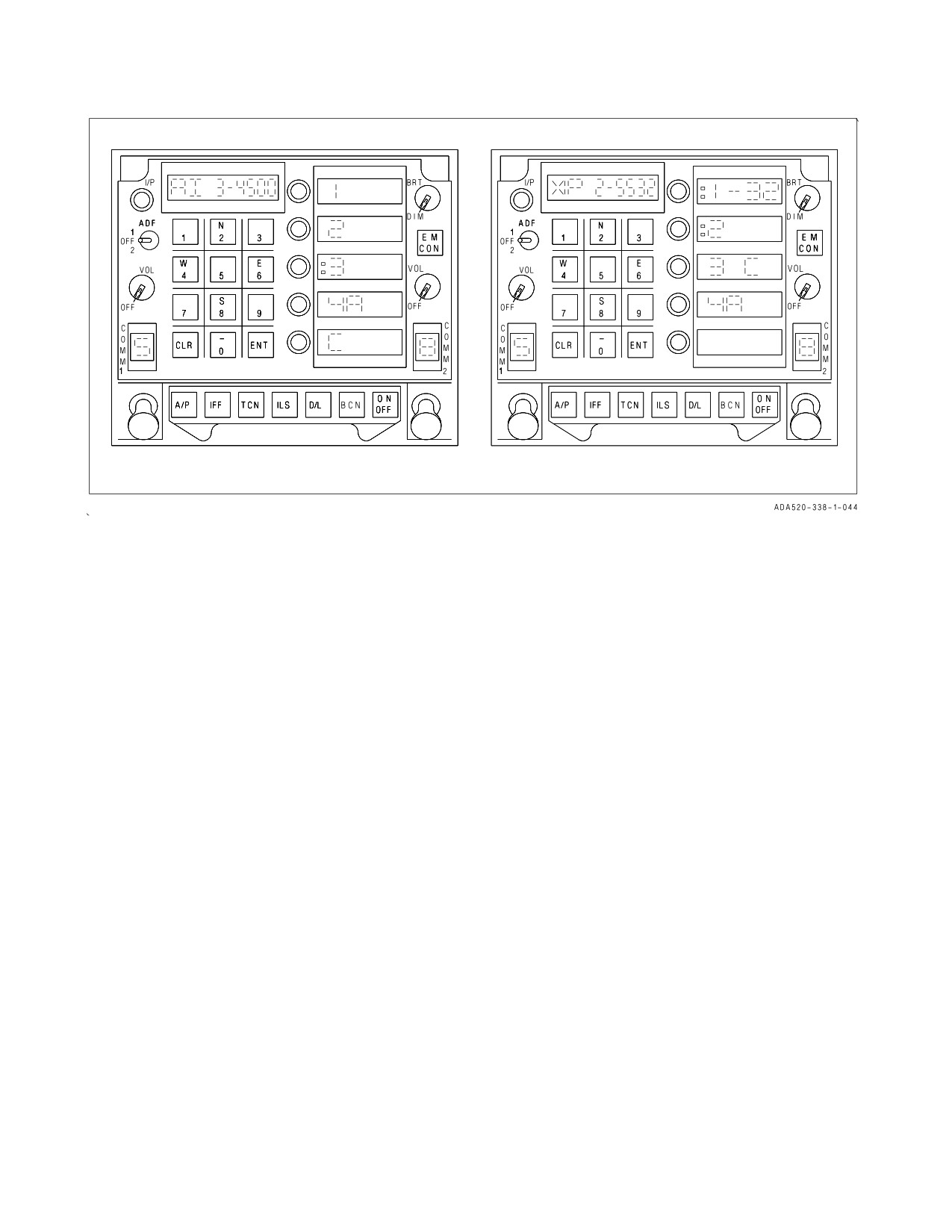
Figure 23-8. UFC IFF Display
Modes 1 and 2 are enabled/disabled by pressing the appropriate option select switches. When mode
1 is enabled, the mode 1 code is displayed in the scratchpad. The mode 1 code can then be changed
from the keyboard. A mode 1 code is valid if the first digit is 0-7 and the second digit is 0-3. When mode
2 is enabled, the mode 2 code is displayed in the scratchpad. The mode 2 code can then be changed
from the keyboard. When the ENT key is pressed, the new mode 2 code is entered into the IFF if valid,
(i.e. 4 digits, each 0-7).
Selection of option 3 provides the mode 3 code in the scratchpad and enables/disables modes 3 and
C. Mode 3 can be selected independently from mode C. The mode enables for 3 and C are toggled for
subsequent depressions of option 3 in the following order: 3 C displayed but disabled; :3 C displayed
and both modes enabled; :3 displayed and enabled. When mode C is enabled, the IFF replies to mode
C interrogations with digitally encoded pressure altitude from the air data computer. If mode 3 is not
enabled, mode C will reply with bracket pulses only (i.e., zero altitude).
The option 4 selection is used for enabling/disabling the secure mode. If the KIV-6 crypto module
is not installed, this option window is blanked. An IFF4 caution is displayed on the caution display line
whenever the mode 4 codes are invalid or zeroized, there is a fault in the crypto unit, or the transponder
is not replying to valid mode 4 interrogations (either due to mode 4 not being enabled or to a failure).
Associated with the IFF4 caution is the voice alert message, Mode 4 Reply. If the transponder is not
replying to valid mode 4 interrogations due to a code disparity, the mode 4 audio tone is presented in
the aircrew’s headset. If the transponder is replying to valid mode 4 interrogations, the M4 OK
advisory is displayed on the left DDI. The mode 4 tone and M4 OK advisory can be controlled with the
Mode 4 switch on the ACI.
VII-23-16
ORIGINAL
A1-F18AC-NFM-000
23.6.1.3 Interrogator Operation
The interrogator can challenge in modes 1, 2, 3/A, 4 and C. The air interrogator modes and codes can
be selected and changed by selecting the Air Interrogator (AI) IFF display on the UFC. Initialization
of the transponder codes is also available via a file on the MU.
NOTE
All Combined Interrogator Transponder equipped F/A-18 aircraft shall
limit CIT usage in non-tactical flight regimes. Specifically, Auto Mode
Interrogations should not be selected during enroute transits to and
from training areas or during cross country ferry flights. This
operational limitation is intended for continental US flight operations
only and is not intended to impact tactical doctrine or safety of flight
requirements whatsoever.
23.6.1.4 Interrogator Mode/Code Selection on the UFC
The interrogator mode/code selection is controlled through the UFC by selecting the IFF function
key on the UFC until AI is displayed in the scratchpad. Selection of the IFF function key toggles
between the AI and XP IFF displays as shown in figure 23-8. The current Mode 3 code is displayed in
the scratchpad and the modes that are currently enabled have colons displayed in the option windows.
For correct code interrogations, the aircrew is able to select and change the code for Mode 1, Mode 2,
or Mode 3 interrogations. The option windows on the interrogator display operate in the same manner
as those on the transponder display. When an interrogation is commanded by the aircrew, the CIT
interrogates in the modes selected on the AI UFC display. The modes and codes selected are sent to
the CIT on the AVMUX by the MC. The modes and codes selected for interrogator operation are
independent of the transponder modes and codes.
23.6.1.5 Automatic IFF Mode/Code Updates. The IFF update capability programs the mission
computer to automatically change the codes of the IFF at specified times and/or at an interval. IFF
modes can be enabled or disabled automatically when the aircraft crosses a specified geographic
location. The system can be programmed during mission planning or in the cockpit.
The Mode 4 transponder and interrogator can be automatically updated on Zulu day transition.
When this capability is enabled, Mode 4 automatically transitions to 4B when the aircraft Zulu time
changes from 23:59:59 to 00:00:00.
23.6.1.5.1 Manually Loading Mission Planned Automatic IFF Data. Pre-planned mission data, if
available, is loaded automatically by the MC during cold-start processing. The IFF pushbutton on the
MUMI reloads the pre-planned mission data from the memory unit.
23.6.1.5.2 Programming Automatic IFF Data. The ROE/IFF PROG option on the SUPT menu calls
up the Auto-IFF Program display allowing the pilot to review and edit the times, modes, and codes
programmed into the automatic IFF system.
23.6.1.5.3 Automatic Disabling The MC automatically disables all features of the automatic update
for IFF codes during automatic carrier landing, emission control, or following any manual update of the
IFF codes using the UFC. This does not include manual updates to the programmable ROE or the
manual enabling or disabling of IFF modes. When EMCON is removed, the system returns to its
automatic update state. For ACL and manual IFF code updates, once disabled, the pilot must
manually re-select the desired automatic update state.
VII-23-17
ORIGINAL
A1-F18AC-NFM-000
23.6.1.5.4 Erasure of Auto-IFF Data. The data used by the automatic IFF system is erased when
required. This includes full stop landing, ejection, or when commanded by the aircrew. The aircrew can
prevent the erasure of this data, if desired, using the method currently implemented on the aircraft for
sensitive/classified data.
23.6.2 IFF Controls and Indicators. The controls and indicators for IFF operation are on the UFC,
communication control panel, and the right or left DDI.
23.6.2.1 UFC. The pushbuttons and indicators on this control used for IFF operation and display are
the IFF function selector pushbutton, the ON/OFF selector pushbutton, the option select pushbuttons,
the option display windows, the pushbutton keyboard, and the scratch-pad window.
23.6.2.1.1 IFF Function Selector Pushbutton. Pressing this pushbutton enables IFF options to be
displayed on the option display windows (on the right side of the upfront control), enables the IFF
status window (at the far left side of the scratchpad window) to display ON if the IFF is enabled, and
allows the IFF code of the selected option to be displayed on the scratchpad window (located above the
pushbutton keyboard). Mode 3 code is automatically displayed in the scratchpad when the IFF
function selector pushbutton is pressed.
23.6.2.1.2 On/Off Selector Pushbutton. Pressing this pushbutton turns the IFF system on or off
after first pressing the IFF function selector pushbutton. When the IFF function selector pushbutton
is pressed, the status of the IFF modes are displayed via the cues in front of the option display windows.
The last mode 1 code selection appears in the option one display window and a 3 (for mode 3/A) and
a four digit code for the last mode 3 code entry appears on the scratchpad window.
23.6.2.1.3 Option Select Pushbuttons. The option select pushbuttons are used to select the IFF
mode desired. The pushbuttons, from the top pushbutton downward, select modes 1, 2, 3/A, 4, or C.
Alternately pressing the option 1 pushbutton enables or disables mode 1 operation. When option 1 is
enabled a colon appears to the left of the option 1 display window, and the scratchpad window displays
mode 1 and the last entered code. A mode 1 code can be set in with the pushbutton keyboard by
pressing the proper pushbuttons and then pressing ENT (enter). When option 2 is enabled, a colon
appears to the left of the window. A mode 2 code cannot be set in with the pushbutton keyboard.
Pressing the option 3 select pushbutton causes mode 3 and the last code entered to be displayed on the
scratchpad window. When option 3 is enabled a colon appears to the left of the window. A mode 3 code
can be set in with the pushbutton keyboard and then entered with the ENT pushbutton. On aircraft
with the mode 4 computer installed, pressing the option 4 pushbutton enables or disables mode 4A or
mode 4B. If the option display appears as a colon and a 4A, pressing the pushbutton again disables 4A
and a 4B appears in the option 4 display window. Pressing the option pushbutton again enables mode
4B indicated by the colon that appears to the left of the 4B. A mode 4 caution is displayed on the DDI
if the mode 4 codes are zeroized, if there is a fault in the mode 4 computer, or if the transponder is not
replying to valid mode 4 interrogations (either due to mode 4 not being enabled or to a failure). When
option 5 is enabled a colon appears to the left of the window. To enable the complete altitude encoding
mode (C), both option 3 and option 5 (mode C) select pushbuttons must be enabled. The altitude
encoding mode uses 29.92 as a reference.
23.6.2.1.4 I/P Pushbutton. Pressing the I/P pushbutton enables the IFF system to transmit
momentary identification of position.
23.6.2.2 Communication Control Panel. The communication control panel contains an IFF
master switch, an IFF mode 4 switch, and an IFF crypto switch. The IFF mode 4 and IFF crypto
switches are used for mode 4 on aircraft which have the mode 4 transponder computer (KIT) installed.
VII-23-18
ORIGINAL
A1-F18AC-NFM-000
With the IFF master switch in EMERG, the IFF R/T replies with the emergency code. With the switch
at NORM, the IFF R/T replies to interrogations with selected codes.
23.6.2.2.1 Mode 4 Switch. This switch has positions of OFF, DIS, and DIS/AUD.
OFF
Disables M4 OK advisory, mode 4 audio tone, IFF 4 caution, and voice alert.
DIS
Mode 4 advisory (M4 OK) appears when the IFF is responding to mode 4 interro-
gations. IFF 4 caution/voice alert enabled.
DIS/ AUD M4 OK advisory and audio tone enabled when IFF is interrogated with valid mode
4 is interrogations. IFF 4 caution/voice alert enabled.
23.6.2.2.2 Crypto Switch. This switch has positions of HOLD, NORM, and ZERO. Placing the
switch to HOLD, with the landing gear handle in the DN (down) position, retains the mode 4 codes if
power to the system is lost. In the NORM position, mode 4 codes are available as long as power is not
lost. Putting the switch to ZERO erases (zeroizes) the mode 4 codes. On aircraft equipped with MIDS,
the crypto switch commands the MIDS terminal to hold or zero the crypto variables. HOLD is
operational after the gear is down. If no action is taken, and the switch is left in the NORM position,
the crypto variables are zeroed upon terminal shutdown or loss of primary power.
NOTE
• Ensure the MIDS terminal is ON, by ensuring L16 or TACAN is ON,
prior to any attempt to zeroize IFF Mode 4 Crypto Keys via the
CRYPTO switch.
• If aircraft equipped with the MIDS compatible transponder and
KIT-1C, the manual ACI ZERO position does not zero MIDS keys. If
the crypto switch has been placed to HOLD prior to MIDS power off
after gear down, or if a landing gear cycle has not occurred, a
maintenance procedure must be performed using the AN/CYZ-10 data
transfer as outlined in A1-F18AC-600-300 to zeroize MIDS keys.
23.6.2.3 IFF 4 Caution/Voice Alert. An IFF 4 caution is displayed on the left DDI whenever the
mode 4 codes are zeroized, there is a fault in the KIT, or the transponder is not replying to valid mode
4 interrogations because of mode 4 not being enabled or because of a failure. At the same time that the
caution condition occurs, a corresponding voice alert message is heard twice in the pilot’s headset. The
voice alert message is “mode 4 reply, mode 4 reply”. The IFF 4 caution/voice alert are disabled
whenever the MODE 4 switch is in the OFF position.
23.6.2.4 IFFAI Caution. An IFFAI caution is displayed whenever the mode 4 codes are zeroized,
there is a fault in the mode 4 interrogator, or there is a fault with the entire interrogator. The caution
is not set if the KIV-6 crypto module is not installed in the CIT. The caution cannot be disabled via
the MODE 4 switch on the ACI panel.
23.6.2.5 IFF OVRHT Caution. An IFF OVRHT caution is displayed whenever an IFF (APX-111)
overheat condition is detected.
VII-23-19
ORIGINAL
A1-F18AC-NFM-000
23.6.2.6 Emission Control Pushbutton. The emission control pushbutton on the right side of the
UFC is labeled EMCON. Pressing the pushbutton switches the IFF or CIT, if on, to a standby mode
so that it cannot transmit. At the same time EMCON is displayed vertically on the option display
windows. When EMCON is turned off by pressing the pushbutton again, the IFF returns to its previous
operating mode.
23.6.2.7 IFF BIT Check. To manually initiate an IFF BIT check, press the TCN/IFF pushbutton
on the BIT display on the right DDI. IFF status is displayed on the BIT status display.
NOTE
If a KIT-1C is installed without Mode
4
crypto key installed,
performing an IBIT of the IFF will likely cause a degrade of the CSC.
A PBIT is performed when power is applied and an IBIT need not be
performed.
23.6.2.8 IFF Antenna Selector Switch. The antenna selector switch is on the left console.
UPPER
Selects upper antenna.
BOTH
Provides automatic antenna selection.
LOWER Selects lower antenna.
23.6.3 IFF Emergency Operation. The IFF emergency mode automatically becomes active upon
pilot ejection from the cockpit.
23.7 COMMUNICATION-NAVIGATION-IDENTIFICATION INTERFACE
The radios, ADF, TACAN, MIDS (after AFC 270), ILS, data link, radar beacon, and IFF interface
with the mission computer; and also interface with the CNI controls and upfront control displays
through the communication system control. The communication system control (CSC) does the
processing and data conversions necessary to communicate with and operate the equipment as
commanded by the pilot through the UFC or by the mission computer. The CSC also does the
processing for the UFC, including processing keyboard entries and providing the option readouts,
cuing, and scratchpad display.
The CSC powers the UFC and converts standby attitude indicator signals used in the Electronic
Attitude Display Indicator (EADI). If the CSC fails, the EADI display is unavailable.
VII-23-20
ORIGINAL
A1-F18AC-NFM-000
CHAPTER 24
Navigation Equipment
Navigation equipment consists of the following: Inertial Navigation System (INS, AN/ASN-130A/
139), Global Positioning System (GPS, AN/ASN 163) or Embedded INS/GPS (EGI), TACAN (RT
1159A/ARN-118), Instrument Landing System (ILS, AN/ARA-63), and Data Link (D/L, RT/1379A/
ASW). Even though the ADF is part of the communication system, it has application in the navigation
system and a brief description is provided.
24.1 NAVIGATION CONTROLS AND INDICATORS
Navigation controls and indicators consist of the UFC, HI/MPCD, DDI, HUD, INS mode switch,
course set switch, and communication control panel. These controls and indicators are integrated in the
navigation system. HI/MPCD and HUD symbology, and UFC functions are described in Chapter 2.
24.1.1 UFC. The UFC allows: ON/OFF operation of the ILS, TACAN, D/L, and ADF; data entry for
the TACAN, GPS, and INS; and mode selection for the D/L.
24.1.2 Moving Map - Digital Map Set (DMS) (163985 AND UP).
(Before AFC 327) The DMS utilizes
the MPCD to provide the pilot/ WSO with a high resolution color map display for day/night
navigation. The DMS display can be selected on the front or rear MPCDs; however, the DDIs display
only a monochrome image.
(After AFC 327) The DMS is displayed in color and can be displayed on any DDI and the front and
rear MPCD.
24.1.2.1 Map Option. The MAP option provides On/Off control of the DMS map when selected from
an MPCD (MAP option is boxed when the map is ON). When MAP is selected from a DDI, the HSI
format source alternates between stroke (DDI symbol generator) and raster (DMS mono-map) on all
DDIs displaying the HSI format. The DMS map is commanded ON when the raster HSI is selected on
a DDI or MPCD.
When Map Update is selected from the forward cockpit, the TDC is assigned to the Map Slew
function. When Map Update is selected from the aft MPCD, the LDC is assigned to the Map Slew
function (if the LDDI is not communicating on the AVMUX, the RDC will be assigned). When Map
Update is selected from the Right or Left DDI, the RDC or LDC, respectively, is assigned to the Map
Slew function. When Map Update is selected, MAP is automatically boxed. When Map Update is
selected on a DDI, all DDIs displaying the HSI format are driven by the DMS mono-map.
24.1.2.1.1 DMS Map Range Scales. For HSI in T UP (Track Up) or N UP (True North Up), valid
Range Scale/Map Type combinations are as follows: 40/1:2M, 20/1:2M-ZOOM, 10/1:500K, 5/1:250K.
For HSI in DCTR (Decenter) valid Range Scale/Map Type combinations are as follows: 80/1:2M,
40/1:2M-ZOOM, 20/1:500K, 10/1:250K.
Map compatible range scales are:
1. Centered (5, 10, 20, 40 nm)
VII-24-1
ORIGINAL
A1-F18AC-NFM-000
2. Decentered (10, 20, 40, 80 nm)
24.1.3 HSI Display. The HI/MPCD displays: TACAN, INS (also INS alignment data), GPS, D/L,
ILS, and ADF navigation symbology. The HI/MPCD also allows selection of various TACAN, ILS,
INS, and D/L functions using the HI/MPCD option pushbuttons. See figure 24-1.
The forward and aft MPCDs are driven by a color output from the DMS when displaying the HSI
format. The HSI format displayed on the DDI/MPCD is driven by either a mono-map output from the
DMS or a DDI symbol generator. The DMS mono-map output contains the same information as the
DMS color output (except for color), including cautions if they are provided with the color output. If
the DMS fails, the MC commands the DDI to drive both MPCDs (forward and aft MPCDs are
repeaters), and allows selection of all F/A-18 formats.
Navigation symbols and digital readouts are normally displayed on the MPCD. One of three TDC
assignment symbols can be displayed in the upper right corner of a TDC compatible display, to
indicate a TDC is assigned to the display in the front cockpit only, rear cockpit only, or both cockpits
(respectively). When a TDC is assigned to the map slew function, SLEW is displayed in the upper right
corner of the HSI display along with one of three arrows to indicate TDC assignment to the display in
the front only, rear only, or both cockpits (respectively). See figure 24-1
24.1.3.1 HSI Option (After AFC 327). This option returns the operator to the Top Level HSI display
after the DMS has been configured for operation. The HSI option coincides with the other HSI options
found on similar HSI displays to ensure consistency between displays. See figure 24-2.
24.1.3.2 MODE Option (Aircraft 163985 AND UP). The HSI display MODE option is located
adjacent to the center left pushbutton of the DDI or MPCD. Before AFC 327, selecting the MODE
option enables T UP (Track-up), N UP (true north up), DCTR (decenter), MAP, and slew options to
be displayed on the left side of the HSI display. After AFC 327, selecting the MODE option enables T
UP (Track-up), CHRT (chart), DCTR (decenter), and slew options to be displayed on the left side of
the HSI display. At aircraft power-up/WonW, the system initializes to: Map boxed (On), Centered, T
UP, and 40 nm scale. See figure 24-1.
24.1.3.3 MODE Backup (Aircraft 163985 AND UP). If aircraft magnetic heading or aircraft
horizontal velocities become invalid, the HSI format is limited to a Centered North-up mode. The T
UP and DCTR legends are removed and their selection inhibited from the HSI Mode sublevel. The N
UP legend on the HSI Mode sublevel is boxed under this condition. When aircraft magnetic heading
and aircraft horizontal velocities become valid, the HSI format is driven to the currently selected mode
and the T UP, N UP and DCTR legends are provided and processed on the HSI Mode sublevel.
NOTE
The currently selected HSI format mode option remains unchanged
when the aircraft magnetic heading or aircraft horizontal velocities
become invalid.
24.1.3.3.1 MAP Modes/Data Products. After AFC 327, each of the map modes (CHRT, DTED, and
CIB) provides a different plan-view map/image. The actual presentation and availability of the
different maps/images are independent and mutually exclusive. Only one map mode can be selected at
any one time. The detailed images and associated area coverage for each mode are dependent on the
map (theater) data loaded in the DMS or installed on the mission card. Each plan-view map, regardless
of mode, presents an image that can support moving map capability and/or slew mode functions. When
toggling through the different modes, different map images are available providing the mode specific
VII-24-2
ORIGINAL
A1-F18AC-NFM-000
data is loaded/available for that particular geographic position and scale. The map modes and their
associated data products are:
1. Chart (CHRT) mode provides a plan-view color map derived from Compressed ARC Digitized
Raster Graphics (CADRG). This chart product replaces the Compressed Aeronautical Chart (CAC)
map data currently used in the existing map (AN/ASQ-196).
2. Digital Terrain Elevation Data (DTED) mode provides a plan-view, panchromatic (gray scale),
terrain plot with slope shading.
3. Controlled Image Base (CIB) mode provides a plan-view panchromatic image derived from a
variety of mission planning, command, control, communications, and intelligence systems.
24.1.3.4 Map Data (163985 AND UP). The MDATA option is provided on the HSI/DATA sublevel
format. MDATA is boxed when selected and remains boxed until A/C, WYPT, TCN, HSI, or
INS/NAV CK is selected. When MDATA is selected, the DATA option is provided on the UFC. When
MDATA is selected on the HSI, all DDI/MPCDs with the HSI format are driven by the DMS
mono-map and the data frames are written in raster. The number of data frames is limited to 100.
24.1.3.4.1 Map Orientation Option. After AFC 327 this option is a multifunction option that
combines the Track Up (T UP) and North Up (N UP) map orientation functions into a single option.
Successive selections of the orientation option toggles the map between these two orientations as they
are mutually exclusive. The T UP orientation is the default orientation. The DMS mono-map output
contains the same information as the DMS color output (except for color), including cautions if they
are provided with the color output. See figure 24-2.
24.1.3.5 SLEW Option (163985 AND UP). When map update is selected from the front cockpit, the
TDC is assigned to the slew function. When map update is selected from the rear MPCD, the LDC is
assigned to the slew function (if the left DDI has malfunctioned the right designator control is
assigned). When map update is selected from the right or left DDI the right designator control (RDC)
or LDC, respectively, is assigned to the map slew function. When map update is selected, MAP is
automatically boxed and when selected on a DDI, all DDI and MPCDs displaying the HSI display are
commanded to be driven by the DMS monochromatic map.
When WYPT Slew is selected from the forward cockpit, the TDC is assigned to the MAP Slew
function for Waypoint Update. When WYPT Slew is selected from the aft MPCD, the LDC is assigned
to the MAP Slew function for Waypoint Update (if the LDDI is not communicating on the AVMUX,
the RDC is assigned). When WYPT Slew is selected from the right or left MPCD, the RDC or LDC,
respectively, is assigned to the Map Slew function for Waypoint Update. When WYPT Slew is selected,
MAP is automatically boxed. When WYPT Slew is selected on a DDI/MPCD, all DDIs/MPCDs
displaying the HSI format are commanded to be driven by the DMS mono-map.
24.1.3.6 POS/XXX Option. This option is located along the top row of the HSI display and when
selected provides the POS/XXX sublevel display. This sublevel display allows the selection of INS,
MIDS (if installed), ADC, or TCN as the position keeping source. In addition, AINS and GPS can be
selected in aircraft equipped with GPS. When one of these options is selected the top level HSI display
is returned, with the appropriate selection denoted, i.e. POS/ADC. In non-GPS aircraft, POS/INS is
automatically selected during ground operations when INS data is valid. Should the INS fail, the MC
automatically begins ADC position keeping from the last valid INS position.
If MIDS is installed and operating, MIDS will be automatically selected as the aircraft position keeping
source when INS fails. Because MIDS position keeping is unreliable and inflight alignment is not
VII-24-3
ORIGINAL
A1-F18AC-NFM-000
possible when in POS/MIDS, air data position keeping (POS/ADC) should be manually selected if
POS/MIDS is displayed.
In aircraft equipped with GPS, the normal present position keeping mode is Aided INS (AINS). In
this mode the INS and GPS mutually aid each other to provide the optimal navigation solution.
Automatic position keeping reversion with a hierarchy of AINS, INS, GPS, MIDS (if installed), and
ADC is provided in case of an INS and/or GPS failure.
24.1.3.7 UPDT Option. The UPDT option is located along the top row of the HSI display and when
selected provides the UPDT sublevel display. This sublevel display allows the selection of VEL
(velocity), TCN, GPS, DSG (designation), AUTO, or MAP as the update source. Following the
selection of one of the update options, an ACPT/REJ (accept/reject) display is presented in which the
update can either be accepted or rejected. After selection of ACPT or REJ the top level HSI display
is returned. There is no ACPT/REJ display presented when the AUTO option is selected. Velocity
update is described in NTRP 3-22.4-FA18A-D and NTRP 3-22.2-FA18A-D NATIP. For F/A-18C/D,
if a previous update has been accepted, a CANCEL option is also displayed on the UPDT sublevel
which allows the aircrew to cancel the last accepted update.
24.1.3.8 SCL Option This option is located along the top row of the HSI display, and selects the
range scales of 10, 20, 40, 80, or 160 nm. With aircraft 163985 AND UP, a 5 nm scale map is available.
The scale is distance from the aircraft to the inside edge of compass rose. Successive actuations of the
pushbutton causes the range scale to decrement and then to start over at 160 nm. The 250,000:1 map
is displayed when the 5 nm range scale is selected. The 500,000:1 map is displayed when the 10 nm
range scale is selected, and the 2,000,000:1 map is displayed when the 20 nm or 40 nm scale is selected.
No map is displayed when the 80 nm or 160 nm range scale is selected.
24.1.3.9 MK Option. This option is located along the top row of the HSI display. The mark option
is initialized to MK1 upon power up with WOW, regardless of the previous selection. A maximum of
nine mark points may be entered. If all mark points have been used, and another mark point is entered,
MK1 is replaced with the new mark data.
If a waypoint/OAP is not designated and the MK option is selected, the lat/long of the current
overfly point is stored, with the elevation set to zero. If a location is designated, then the lat/long of the
designated location is stored. In this situation, the aircraft altitude minus the altitude above the
designated target is stored as the elevation.
24.1.3.10 DATA Option. The data option is located along the top row of the HSI display. Selecting
this option provides the DATA sublevel display. This display is used to enter waypoint/OAP data,
aircraft data (A/C), TACAN data, waypoint/OAP sequence data, radar and barometric altitude
warning, groundspeed data, TOT data, and selection of the INS/NAV check display. Descriptions of
the HUD EW, WYPT A/A and NCTR options are provided in the NTRP 3-22.2-FA18A-D NATIP.
After selection of either the WYPT, A/C, or TCN option, the UFC or SEQUFC option is used to
initialize the UFC for data entry. The HSI option is used to return the HSI display to the top level
format.
24.1.3.11 WYPT, OAP Option. The WYPT, OAP option is located along the right side of the
HI/MPCD. WYPT is displayed when steering is to a waypoint, and OAP is displayed when steering is
to an OAP. If either the WYPT or OAP option is selected (boxed), direct great circle steering is
provided to that waypoint/OAP. TGT is displayed at this location when a target is designated. If the
selected waypoint is a GPS point, the GPS point identification code is displayed next to the WYPT
option pushbutton.
VII-24-4
ORIGINAL
A1-F18AC-NFM-000
24.1.3.11.1 Waypoint, OAP, Mark Point Selection. Along the right side of the HSI display just
below the WYPT, OAP, TGT option, there are two arrows pointing in opposite directions with a
number in between. This number indicates the current steer to waypoint/OAP/mark. The waypoint/
OAP being steered to can be incremented/decremented by selecting the appropriate arrow option, thus
changing the current steer to number. After all of the waypoints/OAPs have cycled through (0 through
24), the mark points can now be selected for display. Marks are displayed with an M preceding the
number.
24.1.3.12 NAVDSG, O/S Option. This option is located along the right side of the HSI display.
Selecting this option designates a waypoint/OAP, for weapon computations, sensor slaving, steering or
position updating. Selecting the NAVDSG option designates the waypoint/OAP. After designating a
waypoint, the NAVDSG option is removed, and TGT replaces WYPT. After designating an OAP, OAP
remains boxed, and O/S replaces NAVDSG. When O/S is selected the offset point is designated, TGT
replaces OAP, and O/S is removed.
24.1.3.13 SEQ # Option. The SEQ # option is located along the right side of the HSI display. At
power up with WOW, this option initializes to SEQ 1 (unboxed). Successive actuations of the option
toggles through a display sequence in the following order: SEQ 1 (boxed), SEQ 2 (unboxed), SEQ 2
(boxed), SEQ 3, (unboxed), SEQ 3, (boxed), and back to SEQ 1(unboxed). With the SEQ # option
boxed, dashed lines are displayed connecting the waypoints of that sequence. The dashed lines
connecting the waypoints (SEQ # boxed), are displayed for all HSI range scales, and all HSI modes.
The dashed lines are removed when magnetic heading is invalid, aircraft position is invalid, or map
slew is selected.
24.1.3.14 AUTO Option. The AUTO option is located along the bottom row of the HSI display.
Selecting the AUTO option provides auto sequential steering to the first waypoint in the selected
sequence; while boxing the AUTO and WYPT or OAP option (if not already boxed). Selecting the
AUTO option while boxed deselects auto sequential steering and unboxes the AUTO option. The
AUTO option is removed when: the INS is in an alignment mode, INS heading failure occurs, magnetic
is invalid, aircraft present position is invalid, aircraft ground track is invalid, selected sequence
contains less than two waypoints, aircraft is in auto or velocity update, FCS is coupled to the D/L or,
a ground point is designated.
24.1.3.15 TIMEUFC Option. The TIMEUFC option is located along the bottom row of the HSI
display. Selecting this option boxes TIMEUFC and initializes the UFC option display windows with
the following clock options: SET (F/A-18C/D only), ET counter, CD timer, ZTOD, and LTOD
(F/A-18C/D only). In aircraft equipped with GPS, it is important to load Zulu time as this aids in
satellite acquisition. If local time is desired, it should be set after takeoff. This option is removed when:
the INS is an alignment mode, INS heading failure occurs, or the aircraft is in velocity update. When
TIMEUFC is selected, the 30 second timer is disabled.
24.1.3.16 MENU Option (163985 AND UP). When MENU is selected on the top level HSI display,
the TAC Menu is displayed. The Tactical (TAC) option provides access to weapons, sensors and HUD
formats. The TAC Menu is also displayed when the MENU option on any format is pressed. The
Support (SUPT) menu is accessed through the Tactical (TAC) menu. When the SUPT menu is
pressed, it provides access to the ADI, HSI, BIT, Checklists, Engines, Flight Controls, UFC Backup
and Fuel formats.
24.1.3.17 L4MAP Option (F/A-18A/B). Refer to NTRP 3-22.2-FA18A-D NATIP.
24.1.3.18 SENSORS Option. Refer to NTRP 3-22.2-FA18A-D NATIP.
VII-24-5
ORIGINAL
A1-F18AC-NFM-000
24.1.3.19 ACL Option. The ACL option is located along the left side of the HSI display. When
selected, ACL is boxed and the link 4 display appears on the left DDI.
24.1.3.20 VEC Option. Refer to NTRP 3-22.2-FA18A-D NATIP.
24.1.3.21 D/L Option. Refer to NTRP 3-22.2-FA18A-D NATIP.
24.1.3.22 ILS Option. The ILS option is located along the left side of the HSI display. When
selected, ILS is boxed and ILS steering appears on the HUD. On F/A-18C/D aircraft, ILS steering also
appears on the EADI.
24.1.3.23 TCN Option. The TCN option is located along the left side of the HSI display. When
selected, TCN is boxed and TACAN great circle steering appears on the HUD.
24.1.4 DDI. The DDIs are capable of displaying HSI display and D/L information by selecting the
HSI or LINK4/SA option on the applicable menu.
24.1.5 HUD. The HUD displays basic flight symbology and steering information for the TACAN,
ILS, ACL, INS, and GPS.
24.1.6 Sensor Control Panel. This panel contains the INS Mode Selector Knob, which controls INS
mode selection. See figure 24-1.
24.1.6.1 INS Mode Select Knob. The INS mode select knob has switch positions of OFF, CV, GND,
NAV, IFA, GYRO, GB, and TEST. Selecting OFF removes power from the INS. Selecting CV
commands the INS carrier align mode with the MC providing the carrier align display. Selecting GND
commands the INS ground align mode with the MC providing the ground align display. Selecting NAV
commands the INS navigation mode which enables the MC to use INS information to provide
navigation steering. Selecting IFA without GPS, commands the INS IFA (Inflight Alignment) mode
with an IFA display. Selecting IFA with GPS, commands the Aided INS (AINS) position keeping or
GPS inflight alignment with an IFA display. Selecting GYRO commands the AHRS (Attitude Heading
Reference Set) mode. Selecting GB commands the gyro bias mode enabling the INS to do a gyro bias
calibration. Selecting TEST enables the INS to perform an initiated BIT upon command from the MC.
VII-24-6
ORIGINAL
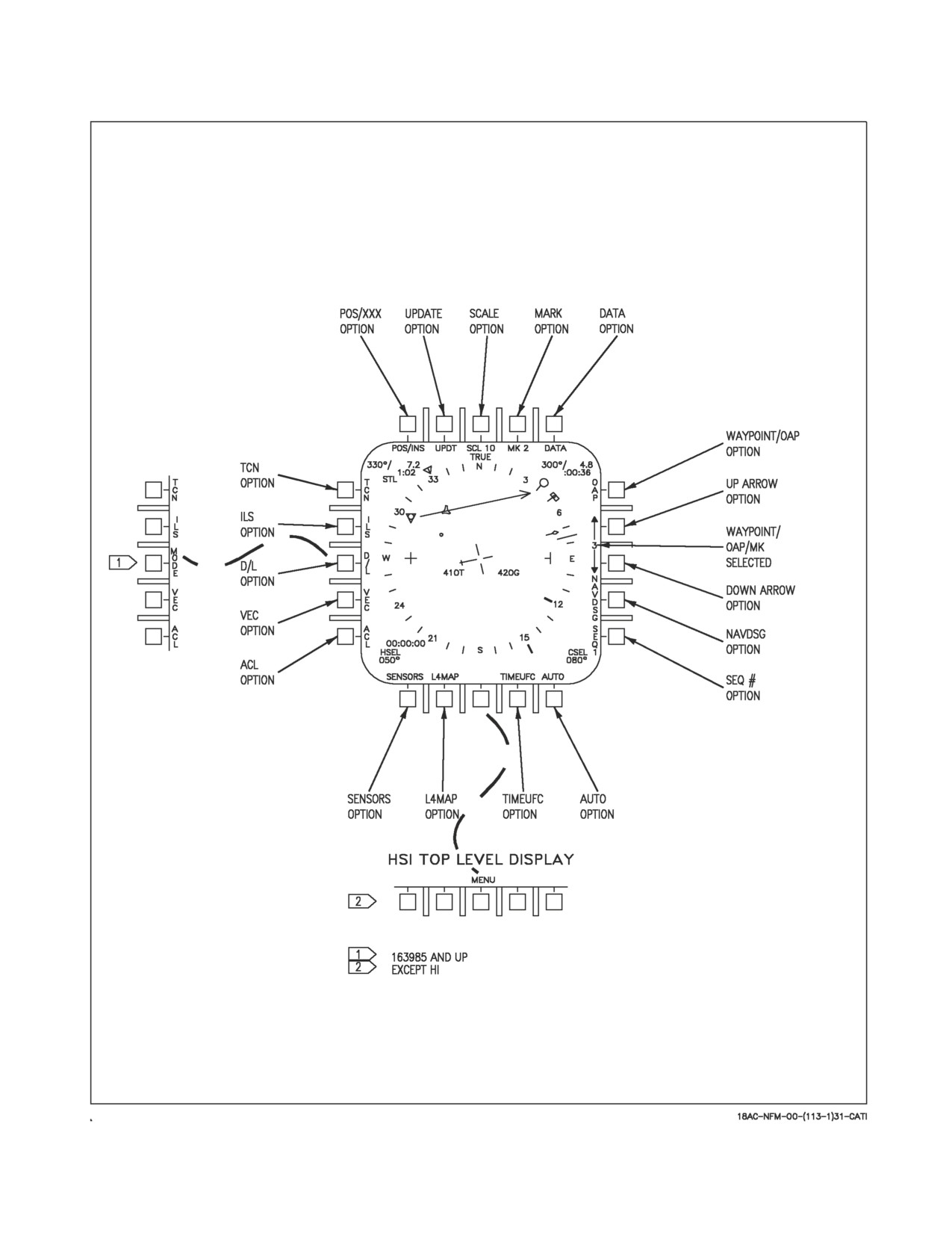
A1-F18AC-NFM-000
Figure 24-1. Navigation Controls and Indicators (Sheet 1 of 2)
VII-24-7
ORIGINAL
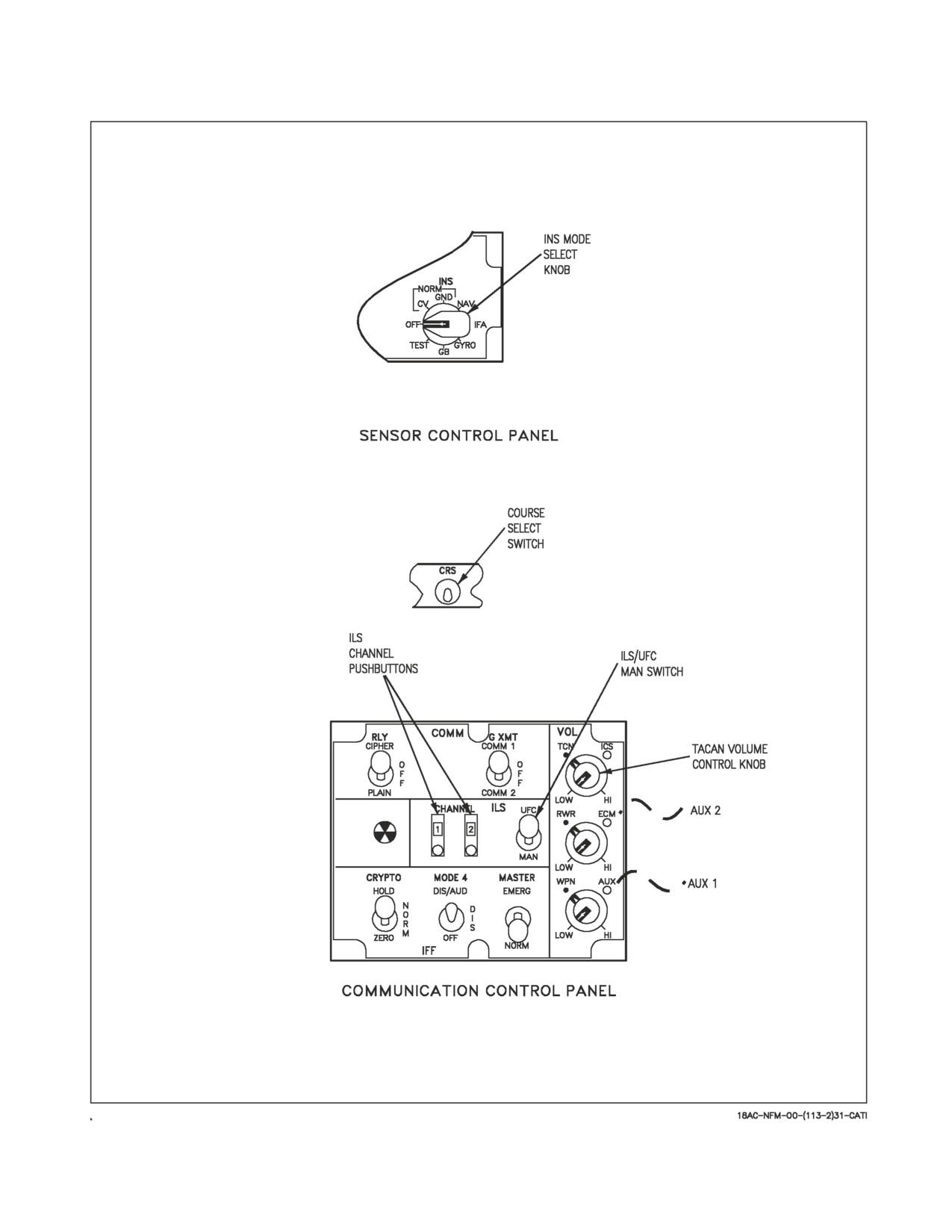
A1-F18AC-NFM-000
Figure 24-1. Navigation Controls and Indicators (Sheet 2 of 2)
VII-24-8
ORIGINAL
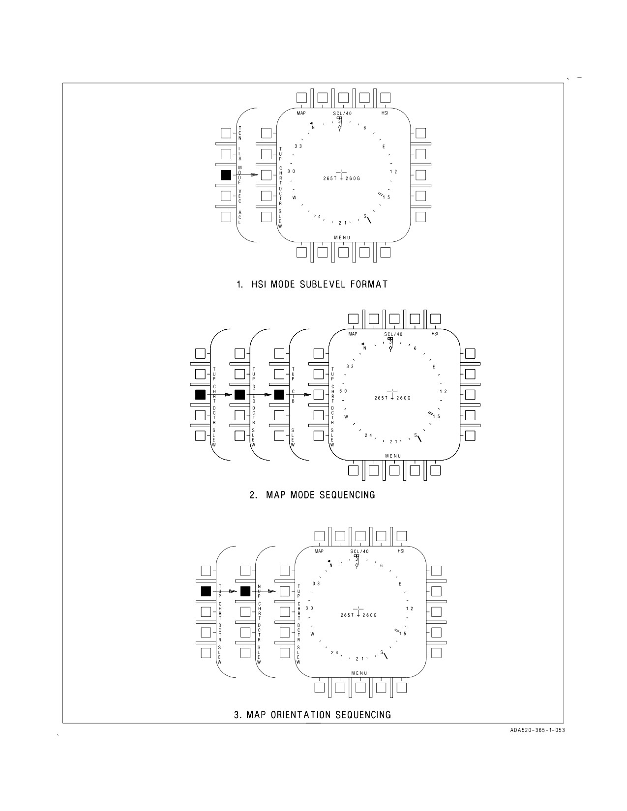
A1-F18AC-NFM-000
Figure 24-2. TAMMAC Mode Selections
VII-24-9
ORIGINAL
A1-F18AC-NFM-000
24.1.7 Course Select Switch. The course select switch is used to set a course to the selected
waypoint, OAP or TACAN station. When the switch is actuated with waypoint/OAP or TACAN direct
great circle steering already selected, a course line appears through the waypoint/OAP or TACAN
symbol on the HSI display, and steering information appears on the HUD. The course line rotates
clockwise when the switch is held to the right and counterclockwise when the switch is held to the left.
When a course is selected a digital readout appears on the lower right corner of the HSI display. See
figure 24-1.
24.1.8 Communication Control Panel. This panel contains two ILS controls: ILS UFC/MAN switch
and the ILS channel thumbwheels. It also contains the TACAN volume control knob.
24.1.8.1 ILS UFC/MAN Switch. When the switch is in the UFC position ILS power and channel-
ization is controlled by the UFC. With the switch in the MAN position, ILS power is enabled and ILS
channel changes are controlled by the ILS channel thumbwheels.
24.1.8.2 ILS Channel Thumbwheels. These thumbwheels are used to select ILS channels when the
ILS UFC/MAN switch is set to MAN.
24.1.8.3 TACAN Volume Control Knob. This knob controls TACAN volume.
24.2 INERTIAL NAVIGATION
SYSTEM (INS)/GLOBAL POSITIONING SYSTEM (GPS)
The AN/ASN-130A (aircraft 161353 THRU 163175 BEFORE AFC 231, 231 PT2, or 231 PT3), the
AN/ASN-139 (aircraft 163427 THRU 164912 BEFORE AFC 175 PT2), the Embedded GPS/INS (EGI)
(aircraft 161925 THRU 163175 AFTER AFC 231, 231 PT2, or 231 PT3), or the INS + GPS (aircraft
164945 AND UP, 163427 THRU 164912 AFTER AFC 175 PT2) inertial navigation system is a
self-contained, fully automatic dead reckoning navigation system. The INS detects aircraft motion and
provides acceleration, velocity, present position, pitch, roll, and true heading to related systems.
Correction signals from accelerometers provide constant leveling. In GPS capable aircraft the INS is
coupled to the GPS (in AINS mode) to provide a more accurate aided source of position and velocity.
The INS uses both periodic and initiated built-in test (BIT). The periodic BIT monitors essential
parameters within the system and provides inflight, shipboard, and ground failure detection and
isolation. Initiated BIT is performed on the ground and accomplishes that portion of the failure
detection and isolation capability which periodic BIT is unable to do. The INS system provides
automatic (AN/ASN-130A, manual for AN/ASN-139) INS degrading to an attitude heading reference
system (AHRS) when INS BIT detects a significant fault in the inertial processor. An indication of
automatic switching to AHRS is a flashing velocity vector on the HUD, a POS/ADC caution on the DDI
and a master caution, provided that the INS is the position keeping source. Operating in AHRS mode,
unfiltered INS attitude data is displayed to the pilot. While a properly functioning AHRS provides a
very stable attitude reference, it is more susceptible to precession during sustained maneuvering flight
VII-24-10
ORIGINAL
A1-F18AC-NFM-000
than the inertial mode. Slow climbs/dives, less than 7,000 feet per minute, can cause an error in the INS
vertical velocity for a short time resulting in an INS VEL/NAV VVEL caution. The error goes to zero
within a couple of minutes after the aircraft levels off and the caution goes away.
There are some subtle failure modes wherein INS attitude and/or velocity
can degrade or fail and the INS does not provide an indication of the
condition. Therefore, prior to and during flight conditions in which
accurate attitude information is required, a crosscheck of primary atti-
tude indications versus standby attitude instruments should be per-
formed. This crosscheck should also include the true airspeed/
groundspeed relationship on the HI/MPCD. If the BIT display indicates
an INS/ADC degrade, the standby instruments should be monitored and
the INS/NAV CK display consulted to determine component malfunc-
tion.
Landings and catapult shots, without power applied to the INS, could
cause damage to the accelerometers within the INS.
NOTE
It is acceptable to taxi with the INS in the OFF mode. It is preferable
to wait for NO ATT to disappear before taxiing.
24.2.1 Inertial Navigation Unit (INU). The INU contains an inertial measurement unit (IMU)
section, signal data converter section, and power supplies.
24.2.1.1 Inertial Measurement Unit (IMU) (AN/ASN-130A). The IMU contains a gyro stabilized
platform and other electronics to maintain a stabilized platform and interface output signals with the
signal data converter. If the signal data converter fails, the IMU operates as an attitude and heading
reference set (AHRS).
The platform contains three accelerometers and two gyros which are isolated from external angular
motion by a set of four gimbals. Gimbal motion and position are sensed by pick-off coils and synchro
devices. Four-gimbal mounting provides a full 360° freedom of rotation about the stable element,
allowing it to remain level with respect to local vertical and oriented to its alignment heading.
Platform outputs of acceleration, gyro motion, gimbal motion, and position are processed to align the
platform in pitch, roll, and azimuth. After alignment, acceleration and attitude signals are used in the
navigation computations. Signals representing pitch, roll, and relative azimuth are developed for
aircraft attitude indications.
24.2.1.2 Inertial Measurement Unit (IMU) (AN/ASN-139 and EGI). The inertial measurement unit
(IMU) contains ring laser gyros, accelerometers, and sensor electronics.
Three ring laser gyros (RLGs), one mounted in each aircraft reference axis, detect motion in their
sensitive axis and provide channel A and channel B frequency outputs to sensor electronics.
VII-24-11
ORIGINAL
A1-F18AC-NFM-000
Three accelerometers, one mounted in each aircraft reference axis, detect acceleration along their
sensitive axis and provide linear acceleration to sensor electronics.
Sensor electronics monitor RLG and accelerometer operations to provide stabilization. Torque
rebalance outputs provide accelerometer stabilization. Sensor electronics also provide processing of
Channel A, Channel B, and acceleration inputs. Channel A and Channel B inputs are processed
producing rotational counts representing aircraft roll, pitch, and yaw rates. Acceleration inputs are
processed producing delta acceleration outputs.
24.2.1.3 Global Positioning System (GPS) (Aircraft 163427 THRU 164912 AFTER AFC 175 PT2,
Aircraft 164945 AND UP, and aircraft with EGI). The Global Positioning System provides position,
velocity, and time (PVT) data that can be used as an aid to the INS or as an independent navigation
sensor.
NOTE
Standard military GPS systems do not provide a navigation integrity
function which would monitor and crosscheck the validity of satellite
transmitters and GPS receivers. GPS is only authorized as an aid to
visual navigation (VFR) and situational awareness (SA). GPS may not
be used as a primary or supplemental navigation source to file or fly in
the National Air Space (NAS).
The GPS consists of an aircraft mounted receiver/processor which receives modulated signals from
twenty-four high orbit satellites through the GPS antenna. The satellite data is used to determine
aircraft position and velocity. The GPS can be initialized with crypto keys, enabling encrypted P-code
(precise) navigation signals to be received. GPS has four modes of operation. In NOT READY mode
the system is off. With Initialize mode (INIT) the power supply is turned on, almanac data and
waypoint data are loaded into the MC. In addition, Cryptokey loading may be performed via a
KYK-13. In NAV mode, the GPS tracks the best four satellite constellations possible to provide the
most accurate PVT solution. TEST mode is provided for maintenance and inflight testing.
24.2.1.3.1 Mixed Mode Satellite Selection (MC OFP 15C AND UP). The mixed mode satellite
function allows the pilot to track non-encrypted GPS signals when an encrypted signal is not available.
Two modes of operation, secure mode (encrypted code only) and non secure mode (encrypted and/or
non-encrypted code) can be selected via the NOSEC GPS option on the A/C DATA sublevel display.
The secure mode is the default mode upon aircraft power up.
24.2.1.3.2
YCODE Advisory (MC OFP 12A, 15C AND UP). A YCODE advisory is displayed when
encrypted GPS signal tracking is lost while in secure mode. Remaining in secure operation with a
YCODE advisory can cause the aircraft to lose the ability to use GPS data.
24.2.1.3.3 NOSEC Advisory (MC OFP 15C AND UP). A NOSEC advisory is displayed when GPS is
not in a secure mode.
24.2.1.4 Inertial Navigation (NAV) Mode. For aircraft without GPS installed, NAV mode is the
primary mode of operation for the INS. In NAV the INS provides smoothed attitude and attitude rates
to the MC for use in sensor stabilization. The INS provides position, velocity and acceleration
information for navigation and weapon delivery.
24.2.1.5 Aided INS (AINS) Mode. For aircraft with GPS installed, Aided INS (AINS) is the primary
position keeping mode. In AINS mode the INS and GPS are mutually aiding each other to provide an
VII-24-12
ORIGINAL
A1-F18AC-NFM-000
optimal navigation solution. AINS is selected by placing the INS mode switch to IFA after a GND or
CV alignment. The position keeping mode remains AINS unless GPS satellites are lost, an INS or GPS
failure occurs, or the pilot manually chooses a different position keeping source. In AINS with
ASN-139 INS, horizontal position is updated every 40 seconds, and velocities every 5 seconds. In AINS
with EGI INS, horizontal position and velocity is updated every 4 seconds.
24.2.1.6 Attitude Heading Reference System (AHRS) Mode. The AHRS mode of the ASN-130 INS
provides unfiltered attitude data to the MC when INS BIT detects a malfunction within itself or other
hardware that precludes inertial navigation. AHRS mode can be selected by placing the INS switch to
GYRO.
24.2.1.7 INS Signal Data Converter. The signal data converter contains the computer central
processor unit (CPU), memory unit, IMU interface, and the primary INS input/output interface. The
CPU provides for initial alignment and navigation computations. The CPU processes acceleration and
attitude signals for computing east/west, north/south and vertical velocities and true heading. Also, the
calculations for inertial altitude and aircraft present position are computed. The CPU also provides
platform correction signals for all modes except AHRS.
24.2.2 INS BIT. Refer to Chapter 2, STATUS MONITORING SUBSYSTEM, INS BIT.
24.2.3 INS Alignment Modes. There are three types of INS alignment modes that can be selected via
the INS Mode Selector Knob: CV (carrier alignment), GND (ground alignment), and IFA (radar
inflight or GPS alignment).
24.2.3.1 CV Alignment Mode. Selecting CV alignment provides three types of CV alignment
options: RF (radio frequency), CBL (cable), and MAN (manual). With the RF and CBL alignment
options the aircraft is data linked to the SINS (ships inertial navigation system). However, with the
MAN option there is no data link capability and alignment data must be entered manually.
24.2.3.1.1 RF/CBL (SINS) Alignment. With the RF/CBL (SINS) alignment, the aircraft’s INS
automatically compensates for the difference between the aircraft deck position and the SINS position.
To perform this alignment, the parking brake must be set, and the INS mode selector knob must be
switched to CV. When this is done the INS and data link are turned on, and the CV align display
appears on the HSI display and UFC. At this point in time, the TIME display on the CV align display
begins to increment. When proceeding with an RF alignment, information is received via radio
frequency and RF is displayed to the right of CV on the CV align display. Also, the alignment
frequency is displayed on the UFC scratchpad, which may be changed using the UFC keypad. When
a cable is connected to the aircraft, information is received via the cable and CBL is displayed to the
right of CV on the CV align display. RF/CBL flashes until SINS data becomes valid. During the first
1 to 2 minutes of alignment, the INS platform is being leveled (AN/ASN-130A), and NO ATT is
displayed to the right of QUAL: on the CV align display. While the platform is being leveled a total of
10 waypoints can be received. When 10 waypoints have been received WYPTS is displayed below the
time readout. If all waypoint data is not received, NO WYPTS is displayed below the time readout.
Reception of waypoint data is not required for the alignment to proceed. After the platform has leveled,
NO ATT is replaced with a quality number, and the INS begins to determine true north. The quality
number is an estimate of present position accuracy. See figure 24-3.
When INS velocities become valid the quality number is replaced with OK and the INS may be
switched to NAV. When NAV is selected, the alignment display is removed from the CV align display
and the UFC displays the OPER option and operate frequency on the UFC scratchpad. At this point
in time the INS present position is stored into waypoint zero if it is valid. However, if NAV is not
VII-24-13
ORIGINAL
A1-F18AC-NFM-000
manually entered at weight off wheels and a groundspeed of greater than 80 knots, the INS
automatically switches to NAV. At this time the INS also stores INS present position (if valid) into
waypoint zero. If INS present position is invalid, aircraft present position is entered as waypoint zero.
24.2.3.1.2 INS CV Alignment (RF OR CBL) (SINS Procedures). The alignment procedures using
SINS by RF or CBL input are the same. If the cable is not hooked up by the ground crew, then RF is
used. For either RF or CBL alignments, the aircrafts INS automatically compensates for the difference
between the aircraft deck position and the SINS position. Waypoint align data is not required for an
RF or CBL carrier alignment since it is supplied by SINS.
• If the INS shuts down abnormally (power loss), set the INS mode
selector knob to OFF for a minimum of 3 minutes (AN/ASN-130A).
The AN/ASN-139 and EGI requires 5 seconds OFF time.
• If the INS mode selector knob is turned OFF in less than 40 seconds
after selecting CV, the system must be left off for a minimum of 3
minutes (AN/ASN-130A). The AN/ASN-139 requires 5 seconds OFF
time.
1. Parking brake - SET
2. ATT select switch - AUTO or INS
3. INS mode selector knob - CV
NO ATT appears on the HI/MPCD during the first 1 to 2 minutes of alignment and then is removed.
CV RF or CV CBL, QUAL:, TIME:, and WYPTS are displayed on the HI/MPCD. The RF or CBL
symbol flashes until the SINS data is tested for validity, then the QUAL digits start counting down and
the TIME digits start counting up. If the alignment is interrupted for any reason, the TIME digits stop
counting up and flash. After 20 seconds NO is displayed to the left of the word WYPTS if waypoints
have not been received. When the INS alignment is completed, the word OK is displayed after the
QUAL number. Time to align is normally less than 10 minutes. On aircraft 161925 AND UP, D/L align
frequency is automatically displayed on the UFC scratchpad for 30 seconds after selecting CV align.
After alignment is complete -
4. INS mode selector knob - NAV (without GPS)/NAV or IFA (with GPS)
24.2.3.1.3 CV MAN (Manual) Alignment. A CV manual alignment is performed if the data link
signal is not available or not desired by entering CV data via the UFC. Manual carrier alignment takes
approximately 15 minutes.
NOTE
In aircraft equipped with GPS, GPS alignment may be performed in
lieu of a manual alignment.
To perform a CV manual alignment, the parking brake must be set and the INS mode selector knob
must be switched to CV. When this is done the INS and data link are turned on, and the CV align
display appears on the HI/MPCD and UFC. Now select the MAN option to enable the manual align
VII-24-14
ORIGINAL
A1-F18AC-NFM-000
display on the HI/MPCD and UFC. When MAN is selected MAN is boxed and the STD HDG option
is removed, the manual align display allows entry of carrier lat/long data, heading (CV HDG) and speed
(CV SPD). The INS uses this data to update present position during the alignment. See figure 24-3.
During the alignment NO ATT is displayed on the CV align display until the INS platform is
leveled, then a QUAL (quality) number is displayed. The AC (alignment counter) number on the INS
maintenance align 1 display on the DDI should also be monitored during alignment. To select INS
align
1 display, press the BIT pushbutton on the DDI menu display, then press the MAINT
pushbutton on the maintenance BIT display. As the alignment progresses the qual number on the HSI
decreases and the AC number on the DDI increases. When a satisfactory alignment is achieved, OK is
displayed next to the QUAL number. The INS can then be switched to the NAV mode. If it is not
switched, it automatically reverts to the NAV mode when weight is off the wheels. If during manual
alignment the carrier heading changes more than 10° and/or carrier speed varies more than 1 knot, and
the AC number on the DDI is 3 or less, the pilot must enter the new data to reinitialize the alignment.
This usually results in the QUAL number starting over at 99.9, however, it will rapidly align back to
the QUAL number it had prior to the update and the continuation of the alignment will be faster than
if the update had not been made. When AC=4 is displayed on the DDI the INS tracks CV heading and
speed changes and the INS does not need to be reinitialized. The parking brake must remain set until
alignment is complete. If the parking brake is released before OK is displayed, and the align quality is
greater than 5 the system sequences into AHRS (GYRO) mode. If the action occurs with the align
quality less than
5, the system goes to a limited performance navigation mode or complete
reinitialization is required to complete the normal alignment, see figure 24-3. The pilot can enter
present position anytime after selecting the INS manual carrier alignment mode.
24.2.3.1.4 INS CV Alignment (Manual Procedures). If an RF or CBL alignment is not possible or
not desired, the existing carrier coordinates, course (CHDG) and speed (CVEL) can be manually
entered while the carrier is maintaining a constant course and speed.
• If the INS shuts down abnormally (power loss), set the INS mode
selector knob to OFF for a minimum of 3 minutes (AN/ASN-130A).
The AN/ASN-139 requires 5 seconds OFF time.
• If the INS mode selector knob is turned OFF in less than 40 seconds
after selecting CV, the system must be left off for a minimum of 3
minutes (AN/ASN-130A). The AN/ASN-139 requires 5 seconds OFF
time.
1. Parking brake - SET
The parking brake must remain SET until the manual alignment is complete. If the parking brake
is released before the alignment is complete the alignment must be re-initiated.
2. ATT select switch - AUTO or INS
3. INS mode selector knob - CV
4. HI/MPCD - PRESS MAN
VII-24-15
ORIGINAL
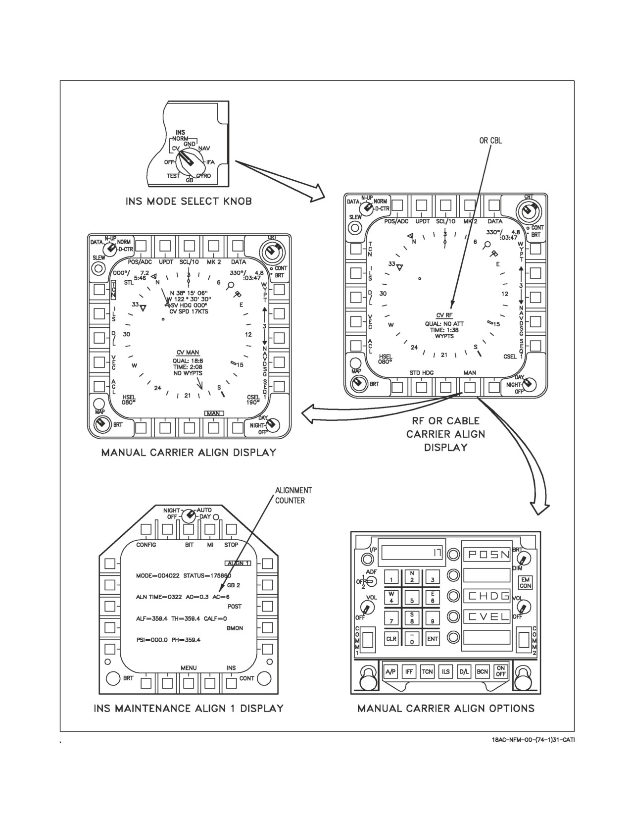
A1-F18AC-NFM-000
Figure 24-3. INS CV Align
VII-24-16
ORIGINAL
A1-F18AC-NFM-000
On the UFC -
5. POSN option - PRESS, type N/S latitude, ENT
6. Type E/W longitude, ENT
7. CHDG option - PRESS, type true heading, ENT
8. CVEL option - PRESS, type velocity, ENT
After alignment is complete -
9. INS mode selector knob - NAV (without GPS)/ - NAV or IFA (with GPS)
NOTE
On GPS equipped aircraft, selecting IFA without an OK results in
transition to IFA RDR.
24.2.3.2 GND (Ground) Alignment Mode. To perform an INS ground alignment, the parking brake
must be set, and the INS mode selector knob must be switched to GND. When this is done the INS is
turned on, and the GND align display appears on the HI/MPCD. At this point in time, the TIME
display on the GND align display begins to increment. During the first 1 to 2 minutes of alignment
(AN/ASN-130A), the INS platform is being leveled, and NO ATT is displayed to the right of QUAL:
GND align display. After the platform has leveled NO ATT is replaced with a quality number and the
INS begins to determine true north. The quality number is an estimate of present position accuracy.
The aircraft may be taxied without restarting the alignment, however; the parking brake must be reset
to complete the alignment, see figure 24-4.
NOTE
The most accurate alignment of the AN/ANS-139 and EGI is achieved
by changing aircraft heading by at least 70° (180° optimum) after OK
is displayed next to the quality number and allowing the alignment to
continue.
The MC automatically transfers waypoint zero to the INS to be used as aircraft present position.
This information appears on the GND align display. Waypoint zero position can be updated prior to
selecting GND align. However, if an error is noticed after the alignment has begun, aircraft present
position must be corrected since waypoint zero is transferred to the INS only once. If the aircraft
present position is found to be incorrect, it must be corrected or the INS will align improperly. Refer
to A/C Programming, this chapter to enter new aircraft position data.
After the INS alignment has reached an acceptable level (.5 is the lowest displayed), OK is displayed
next to the quality number and the INS may be switched to NAV. When NAV is selected, the
alignment display is removed from the HI/MPCD. If the NAV mode is not manually entered, the INS
automatically switches to NAV when groundspeed is greater than 80 knots and weight is off wheels.
24.2.3.2.1 Stored Heading (STD HDG) Alignment. If the INS has been shut down after a good
alignment, the aircraft has not been moved, and NAV has not been selected, a stored heading
alignment may be selected to reduce INS alignment time. The STD HDG option is provided on the
CV/GND align display. The STD HDG option is removed when the alignment has progressed to the
VII-24-17
ORIGINAL
A1-F18AC-NFM-000
point where selecting the STD HDG option will not reduce alignment time and during a CV alignment
when the MAN option is selected. Selecting the STD HDG option results in an alignment based on the
stored heading when the INS was shutdown. To enter stored heading alignment, set the parking brake,
place the INS mode select knob to CV/GND (This provides the CV/GND alignment display on the
HI/MPCD, see figure 24-4) and select the STD HDG option. When stored heading alignment is
entered, the alignment progresses the same as a normal ground alignment.
24.2.3.3 Incomplete Alignment Advisory (MC OFP 13C AND UP). An incomplete alignment
advisory ALGN is displayed when the INS is manually switched to NAV without a complete alignment.
24.2.3.3.1 IFA (Inflight Alignment) Mode. There are several types of IFA: a complete IFA, a
CV/GND alignment completion, or a gyro recovery. Aircraft equipped with GPS can perform an
inflight alignment using GPS position and velocity. A complete IFA may be performed when the INS
experiences a total shutdown. An IFA may be performed to complete a partial CV/GND alignment. A
gyro recovery may be performed when the INS completely shuts down, and radar or ADC data is not
available for a complete IFA, see figure 24-5.
24.2.3.4 Inflight Alignment. A complete IFA may be initiated after a total INS shutdown. During
IFA, the ADC must be available to provide magnetic heading information, and the radar must be
capable of providing continuous precision velocity update (CONT PVU) information. Once the INS
has shutdown, place the ATT/ATTD switch to STBY to verify the accuracy of HUD attitude data by
crosschecking the standby instruments. Select NAV master mode and radar altitude to HUD. Then
place the INS knob to OFF for 5 seconds for the AN/ASN-139 and EGI (AN/ASN-130A requires 3
minutes). If MSP codes 02F or 061 are present, the INS knob should remain in OFF, and select
POS/TACAN.
NOTE
• MSP codes 02F or 061 indicate that NAV data is frozen and the NAV
data provided to the HUD is not reliable. IFA is no longer possible.
• If POS/MIDS is the current aircraft position source, select POS/ADC
before commencing IFA procedures.
Bring up the A/C DATA sublevel display on the HI/MPCD to check winds aloft, present position,
and magnetic variation. If A/C data is incorrect, refer to A/C Programming (this chapter), to enter
correct aircraft data. Fly straight and level unaccelerated flight for 20 seconds, then place the INS knob
to IFA (INS has been off for 5 seconds for the AN/ASN-139 and EGI or 3 minutes for AN/ASN-130A)
and maintain straight and level unaccelerated flight for at least 30 seconds. Then fly straight and level
as much as practical.
When IFA has been selected, the radar may be commanded to the PVU mode and the alignment
display appears on the HI/MPCD, see figure 24-5. If the PVU mode is initialized, CONT PVU and SEA
options are default selected (boxed). Verify the proper radar PVU mode is selected (LAND or SEA)
and the TIME display begins to increment. During the first 10 to 25 seconds (AN/ASN-139 and EGI)
or 1 to 2 minutes (AN/ASN-130A) of the alignment while the INS platform is being leveled, NO ATT
is displayed to the right of QUAL on the Inflight Align display. Wait for 30 seconds of align time for
the platform to level, then place the ATT/ATTD switch to AUTO or INS. NO ATT is then replaced
with a quality number (which is an estimate of present position accuracy) and the INS ATT caution
clears. Selecting INS or AUTO with the ATT/ATTD switch also replaces standby attitude reference
data with INS attitude data (the waterline symbol on the HUD is replaced with a slowly flashing
VII-24-18
ORIGINAL
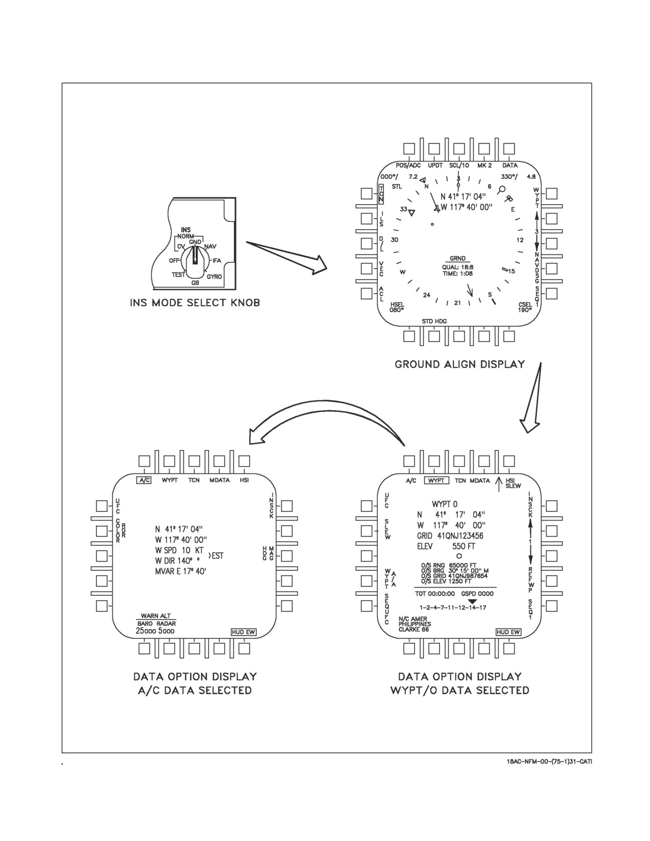
A1-F18AC-NFM-000
Figure 24-4. INS Ground Align
VII-24-19
ORIGINAL
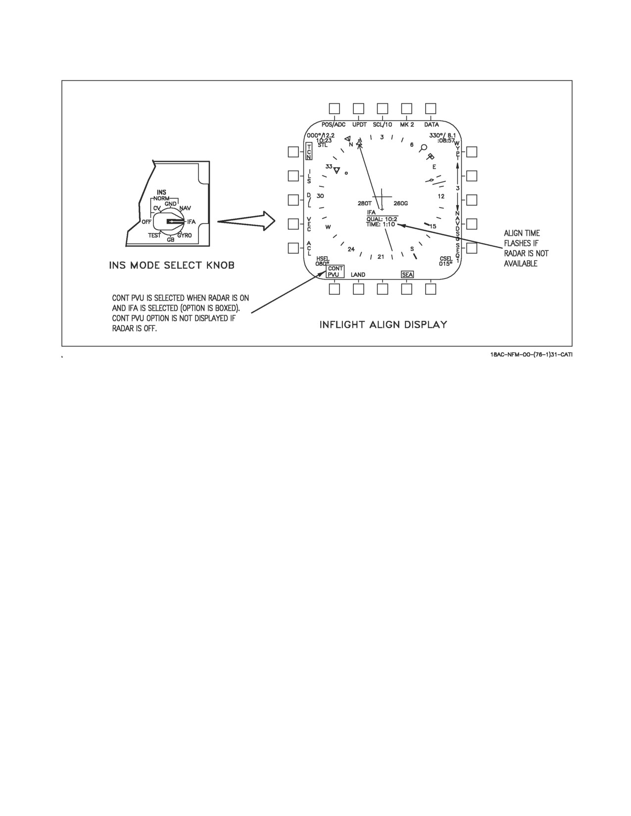
A1-F18AC-NFM-000
Figure 24-5. INS Inflight Align
velocity vector). When horizontal position becomes valid, the POS/ADC caution clears. The velocity
vector continues to slowly flash until velocities become valid (at approximately align quality of 5.0).
If MSP code 67 is present, select NOSEC on A/C DATA sublevel display.
NOTE
Selecting NOSEC reinitializes satellite acquisition, results in a MIXED
advisory, and makes EGI susceptible to spoofing. If GPS keys are not
loaded and NOSEC is not selected, the IFA may not complete.
Determine and continue to monitor alignment type during the duration of the IFA.
24.2.3.4.1
If GPS Data Available During Alignment (IFA GPS). Good satellite data for the IFA is
indicated by IFA GPS on the HSI display as shown in figure 24-6. If GPS acquires good satellite data,
perform one gentle 90° S-turn (less than 20° AOB and ±10° pitch) to facilitate GPS IFA. Then
maintain straight and level flight as much as practical. GPS IFA takes approximately 10 minutes.
When the INS achieves align complete, the IFA GPS legend is removed and the MC automatically
transitions back to AINS position keeping mode. This is indicated by the NAV display replacing the
IFA GPS align display. If good GPS satellite data is available and then lost while an IFA GPS align is
being performed, the INS goes to align hold for 65 seconds waiting to reacquire good satellite data. If
good satellite data is reacquired within 65 seconds, the INS continues to align using GPS data. If good
VII-24-20
ORIGINAL
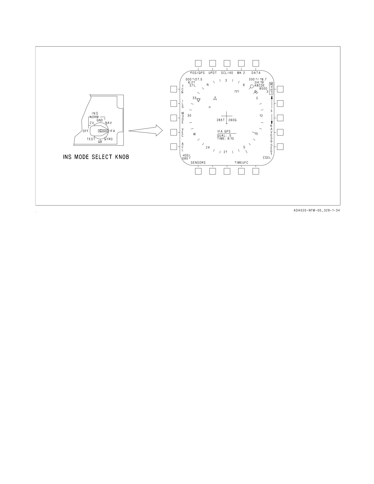
A1-F18AC-NFM-000
Figure 24-6. INS Alignment Display with GPS
satellite data is not reacquired within 65 seconds, the MC attempts to finish the INS alignment with
a radar IFA as described below.
NOTE
Monitor alignment type on HI/MPCD frequently to ensure GPS data
is available for the alignment. If GPS data is not available, the
HI/MPCD will display IFA RDR.
24.2.3.4.2
If No GPS Data Available During Alignment (IFA RDR). Fly straight and level for as
much as practical during alignment. If a turn must be made during IFA, make the turn quickly
(exceeding 30° of bank) and return to straight and level flight as soon as practical. This prevents the
INS from aligning to a false reference by placing the alignment on hold until straight and level flight
is regained. During IFA, air data dead reckoning is used for navigation and to maintain a current
present position. If GPS is acquired, finish the INS alignment with GPS IFA as described above.
When the inflight align displays an OK after the QUAL number, place the INS knob to the NAV
position.
The PVU mode may be overridden by deselecting the CONT PVU option; however, IFA quality will
be affected. Deselecting CONT PVU commands PVU for 10 seconds of each minute alternating with
the last selected radar mode. When air-to-ground ranging (AGR) mode is selected (for instance, via
HUD designation), CONT PVU is deselected, 20 seconds of AGR is commanded, then PVU is
commanded for 10 seconds of each minute alternating with AGR. In PVU mode, the radar provides
Doppler velocities for the INS alignment. The radar look-down velocities angles are optimized for land
or sea return by selection of the LAND or SEA options at the bottom of the display. PVU is inhibited
for IFA if the aircraft is not in the NAV master mode. If the radar is not operating or if it is inhibited
from operating in PVU, the time-in-alignment display flashes and the CONT PVU is not displayed
since continuous PVU cannot be commanded. Present position can be provided for the alignment by
VII-24-21
ORIGINAL
A1-F18AC-NFM-000
performing a position update using the UPDT option or by entering the aircraft data via the UFC using
the DATA option. Another very good technique is to select TACAN position keeping if a stationary
TACAN is available. Velocity updates cannot be performed during position updates during IFA. The
VEL update option is still displayed but it returns to the Inflight align top level display upon selection.
Following an IFA with RADAR, make every attempt to maintain VMC
with a discernible horizon. Residual attitude errors may be subtle and
difficult to discern without reference to a visible horizon or the standby
instruments. If velocity vector information is suspect, select STBY to the
HUD.
Crosscheck attitudes, velocities, and position, especially when entering terminal approach phase.
24.2.3.4.3 CV/GND Alignment Completion (Aircraft without GPS). An IFA may be used to
complete a partial CV/GND alignment. At takeoff with a partial alignment the INS platform should
already be leveled (no INS ATT caution). Therefore, all that needs to be done is to place the INS mode
select knob to IFA with the appropriate PVU option selected, until an OK is displayed.
24.2.3.4.4 Gyro Recovery. A Gyro recovery is actually an attitude only INS in which reliable INS
attitude data is recovered. Since only attitude information is being recovered, ADC and radar inputs
are not required. To set up for a Gyro recovery, place the ATT select switch to AUTO or INS, and
maintain straight and level unaccelerated flight. Next place the INS mode select knob to OFF for 3
minutes to allow the gyros to spin down (AN/ASN-130A). The AN/ASN-139 and EGI require 5 seconds
OFF time. Then set the INS mode select knob to the GYRO position. As the platform levels, the INS
ATT caution clears, and the INS attitude data replaces the standby reference indicator data on the
HUD. Also, the flashing velocity vector replaces the waterline symbol until GPS velocity data is valid.
At that point, the velocity vector stops flashing.
ASN-139 and EGI equipped aircraft provides a Gyro mode if the aircraft takes off before an
adequate alignment is completed.
NOTE
The flashing velocity vector will be present for the remainder of the
flight in this mode since no attempt will be made by the system to
recover valid velocities.
Another method of performing a Gyro recovery would be to select IFA after being in OFF for three
minutes, then select NAV after INS attitude becomes valid.
24.2.4 INS Check Display. The INSCK (INS check) display allows analysis of INS/GPS/ADC
functional reliability. The velocity check more readily indicates an INS vertical loop problem. INS,
GPS, and ADC vertical velocity will be periodically compared for the pilot. When an excessive
disagreement between the two is sensed, a master caution light and tone comes on and the INS VEL
caution illuminates.
The display is selected on the DATA sublevel display, by selecting the INSCK/NAVCK option. The
top portion of the display consist of INS, GPS, and ADC velocities. The bottom portion consists of
wind velocities, best available MC groundspeed (if valid) and best available MC true airspeed (if not
VII-24-22
ORIGINAL
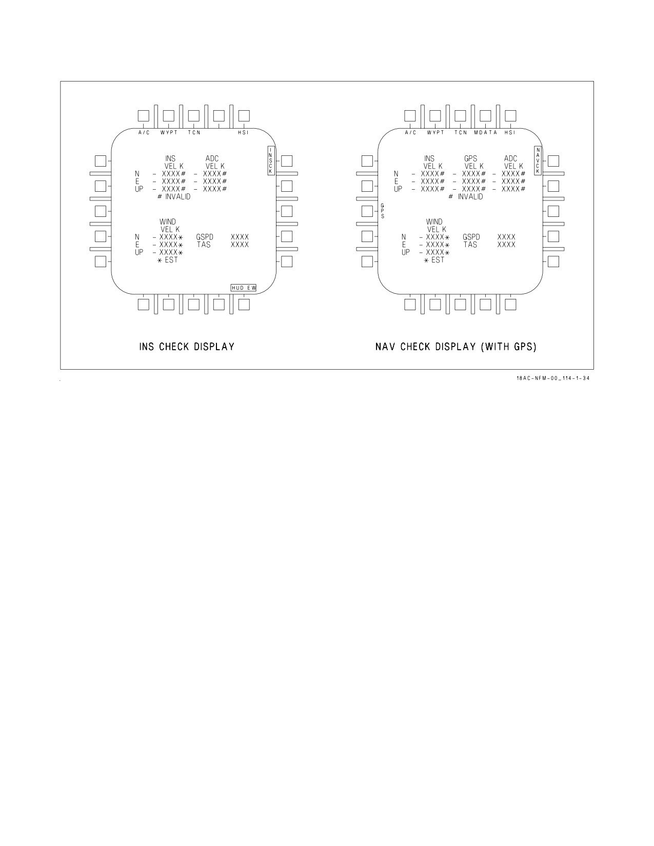
A1-F18AC-NFM-000
Figure 24-7. NAV/INS Check Display
zero). INS, GPS, and ADC velocity components are displayed on the INS Check display even if invalid.
If INS, GPS, or ADC data is invalid, a # is displayed to the right of the invalid data along with #
INVALID displayed above the wind velocity components. If wind velocity is estimated, a * is displayed
to the right of the wind velocity components along with * EST displayed at the bottom of the format,
see figure 24-7.
24.2.4.1 NAV Check Display. With MC OFP 12A, 13C AND UP, INSCK is renamed NAVCK and
the function is identical as described above.
24.2.5 Waypoints, Offset Aimpoints (OAP) and Offsets. A waypoint is a geographical point whose
latitude, longitude and elevation are stored in the MC. An OAP is a waypoint which has an offset
associated with it. An offset is a point defined by bearing and range from the OAP along with elevation
of the point (offset).
Mission data may be entered using the Data Transfer Equipment (DTE).
24.2.5.1 Waypoint/Offset Aimpoint Programming. To enter waypoint/OAP data, select the DATA
option on the HSI top level display. The waypoint data display is automatically initialized with WYPT
boxed. This display shows the current waypoint/OAP data: waypoint Lat/Long position, UTM Grid
coordinates, and elevation; offset range, GRID, bearing, and elevation (if applicable). To enter
waypoint/OAP data, select an up/down arrow to select the desired waypoint/OAP. Next, select the
UFC option to initialize the UFC for waypoint/OAP data entry. On the UFC select the POSN
pushbutton to enter lat/long data, the GRID pushbutton to enter UTM GRID data, the ELEV
pushbutton to enter elevation data, and the O/S pushbutton to enter offset data (offset range, bearing,
and elevation). Offset data is in relation to the offset aimpoint. Waypoint/OAP data is entered through
the UFC keypad. With MC OFP 10A AND UP, there is a maximum of 25 waypoints (0 to 24) available
for programming. With MC OFP 13C AND UP, there is a maximum of 60 waypoints (0 to 59) available
for programming. Waypoints may be entered and displayed to a resolution of 0.01 arc seconds. This
VII-24-23
ORIGINAL