F18. FLIGHT MANUAL (2008) - page 10
A1-F18AC-NFM-000
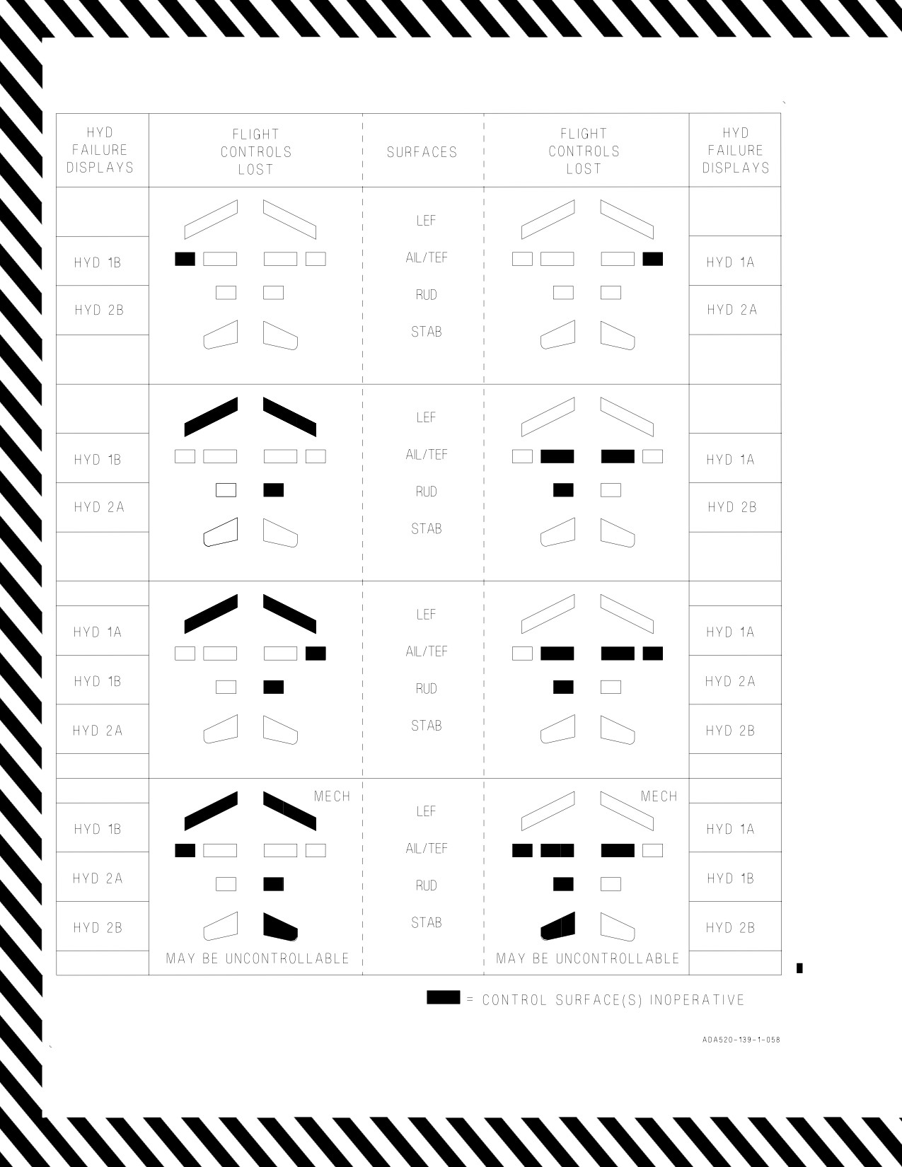
Figure 15-6. Hydraulic Subsystems Malfunction Guide
V-15-12
ORIGINAL

A1-F18AC-NFM-000
FLIGHT CONTROL EFFECTS DUE TO HYDRAULIC FAILURES
Flight Control
REMARKS
Failure1
Any Surface Off
D General Limits:
D 10° AOA for flaps AUTO
D On-speed AOA for flaps HALF/FULL
D 2g max
D Minimize sideslip
D Half lateral stick
D Loss of autopilot
AIL Xs
D Expect slightly higher approach speeds. For flaps FULL, approach speed will
increase by about 8 knots. Flaps HALF, 16 knots.
D Avoid over-controlling lateral stick inputs as it can cause lateral PIO especially
when approaching touchdown.
RUD Xs
D Full opposing rudder may not be sufficient to prevent a departure when
single engine if MAX power selected. Large single engine throttle tran-
sients can cause significant yaw and roll.
D Failure to maintain AOA below 10° and balanced flight can result in a
departure in yaw and roll that is unrecoverable.
D Rudder toe-in is removed. Bolter performance degraded.
D Counter any roll-off with rudder. Countering roll-off with lateral stick alone
increases adverse yaw and aggravates roll-off.
D Line-up control is degraded. Make slow and smooth line-up corrections (espe-
cially if single engine).
LEF Xs
D With any HYD 1B or HYD 2A failure, DO NOT RESET FCS.
D Do not exceed 7° AOA if LEF extension less than 10°.
D Opposite LEF held frozen. TEFs held frozen in flaps AUTO.
D Stall margin reduced for LEF locked above 5° LED.
D Buffet likely with LEF near 0° at lower AOAs.
D Expect slight roll-off as airspeed changes during a waveoff or bolter that is eas-
ily controllable.
D Glideslope control degradations may be more pronounced depending on frozen
LEF position. Wing stores will further degrade glideslope control.
D Power corrections will translate into an airspeed change before a rate of de-
scent change is noticed. This may lead to a tendency to over-control glideslope.
Anticipatory throttle inputs are key to glideslope control.
D Bolter/waveoff performance is degraded and climb-out attitude will appear flat-
ter than normal.
D If AUTO is selected after being in flaps HALF or FULL, the TEFs will not re-
tract except for loads alleviation (no higher than 17°). While in AUTO, mo-
mentary selection of GAIN ORIDE will command the TEFs to retract to 3°
TED. However, the operating LEF will also be commanded to move to 3° LED.
This may drive a controllable but undesirable left versus right LEF split if the
failed LEF is not near 3° LED. Therefore, only select GAIN ORIDE if TEF
retraction is essential for range or fuel considerations.
Note: (1) Surface inoperative due to lack of hydraulic pressure.
Figure 15-7. Flight Control Effects Due To Hydraulic Failure (Sheet 1 of 2)
V-15-13
ORIGINAL

A1-F18AC-NFM-000
FLIGHT CONTROL EFFECTS DUE TO HYDRAULIC FAILURES (CONT)
Flight Control Failure1
REMARKS
STAB Xs
Aircraft reverted to MECH due to stab having inadequate hydraulic power.
This can be the result of excessive, simultaneous hydraulic system demands
exceeding system capacity (e.g., landing gear activation, flap movement, and
multiple flight control inputs) combined with HYD system failure. Can be
reset if HYD pressure >1,500psi. If practical, maintain engine with operat-
ing HYD system at or above 85% rpm.
TEF Xs
Slower engine response to throttle changes may result in excessive sink
rates under high WOD conditions. The recovery WOD should be kept as
close as possible to the Aircraft Recovery Bulletin recommendations.
D TEF driven to 0°.
D Approach speeds are significantly higher and on-speed power settings are
near idle.
D Expect slower engine response.
D Aircraft response to power corrections is sluggish and small in magnitude.
Power corrections will translate into an airspeed change before a rate of
descent change is noted. Expect larger, longer, and more anticipatory
power corrections to be required in order to effect a glideslope change.
Aggressive, well-timed, and anticipatory throttle inputs are key to glides-
lope control.
D There is a tendency to over-control power due to the low approach power
setting and the longer time required to effect a change.
D Time to achieve positive rate of climb is longer during a bolter/waveoff
due to sluggish throttle response. Climb-out attitude will appear flatter
than normal.
Note: (1) Surface inoperative due to lack of hydraulic pressure.
Figure 15-7. Flight Control Effects Due To Hydraulic Failure (Sheet 2 of 2)
V-15-14
ORIGINAL
A1-F18AC-NFM-000
15.10 FUSELAGE FUEL LEAK
The possibility of fire is normally of prime concern with any fuel leak. However, with a massive leak,
the fuel loss itself must be dealt with promptly and correctly to ensure that sufficient fuel remains to
return to base. Fuel loss rates in excess of 1000 lbs/minute have been observed from failed main fuel
lines. Since leaks may occur upstream of the throttle-operated fuel shutoff valve in the fuel control,
shutting down the throttle may not correct the problem. Depressing a FIRE light closes the
airframe-mounted fuel shutoff valve for that engine at the feed tank and stops fuel flow through the
main fuel line. Depressing the good-side FIRE light may result in flameout of both engines.
The pilot may not be able to visually determine which side is leaking. Use a wingman, when
available, and check for secondary indications to determine the side of the leak. Cockpit indications
may include any or all of the following:
D L/R BOOST LO caution
D L/R AMAD caution
D FUEL LO caution
D Rapid decrease of fuel quantity in one feed tank
D Erratic engine operation at high power settings
D Abnormal fuel flow indications
Land as soon as possible. A normal landing with light braking is recommended to prevent hot brakes.
Turn the aircraft into the wind and depress both FIRE lights before shutting down the throttles.
If a fuselage fuel leak is suspected/observed -
Use of afterburner or APU may result in an engine bay fire.
1. Afterburners - DESELECT
2. Analyze Indications:
D L/R BOOST LO caution
D L/R AMAD caution
D FEED tank fuel quantities
D Engine instruments
3. FIRE light (suspect engine) - PUSH
Pressing the good engine FIRE light may result in flameout of both
engines.
If leak continues -
4. FIRE light (suspect engine) - RESET
V-15-15
ORIGINAL
A1-F18AC-NFM-000
5. Restart dead engine.
6. FIRE light (other engine) - PUSH
If leak still continues -
7. FIRE light (other engine) - RESET
8. Restart dead engine.
9. Land as soon as possible.
Hook sparks during an arrested landing may increase the probability of
fire.
After landing -
10. Turn aircraft into the wind.
11. Secure both engines using FIRE lights.
12. Throttles - OFF
15.11 FUEL TRANSFER FAILURES
15.11.1 Aircraft 161353 THRU 161519 BEFORE AFC 039. Failure of fuel transfer from either tank
1 or 4 will result in the fuel quantity in the failed tank remaining higher than normal. Fuel from the
good transfer tank will keep both engine feed tanks near full. This prevents gravity transfer from the
failed transfer tank. When the good transfer tank empties, the failed transfer tank can gravity transfer
to its feed tank. The engine on the good side is now supplied from only its feed tank while the engine
on the bad side is supplied from both its feed tank and the associated transfer tank thru gravity
transfer. This causes the feed tank on the good side to reach the FUEL LO level first unless the throttle
on the good side is reduced. Since gravity transfer from tank 1 or 4 is less than engine demand at high
power, it is possible to have as much as 700 pounds of unusable fuel for approach and landing after
failed tank 1 transfer or 2,500 pounds after failed tank 4 transfer. With 2,500 pounds remaining in tank
4, the center of gravity may be aft of the aft limit. Since fuel dump from either tank 1 or tank 4 to
correct this condition is not possible, asymmetric thrust must be used to balance fuel in the feed tanks.
1. Use higher power on engine whose feed tank has most fuel (tank 2 feeds left engine, tank 3 feeds
right engine).
Depletion of either feed tank may result in AMAD overheat and loss of
hydraulic and electrical power supplied from that engine.
V-15-16
ORIGINAL
A1-F18AC-NFM-000
15.11.2 Aircraft 161353 THRU 161519 AFTER AFC 039 AND 161520 AND UP. Failure of fuel
transfer from either tank 1 or 4 will result in the fuel quantity in the failed tank remaining higher than
normal. If tank 1 transfer fails, fuel from tank 4 will keep both engine feed tanks near full. This
prevents gravity transfer from tank 1. When tank 4 empties, the right engine is supplied only from tank
3 while the left engine is supplied from both tank 2 and tank 1 through gravity transfer. This causes
tank 3 to reach the FUEL LO level first unless the right throttle is reduced.
If tank 4 transfer fails, tank 1 will not transfer, due to CG control scheduling, until the FUEL LO
warning comes on. This will initially appear to be a failure of both tank 1 and tank 4 fuel transfer. As
the fuel level in tanks 2 and 3 drops, tanks 1 and 4 will gravity transfer to their respective feed tank.
When either feed tank reaches the FUEL LO level, tank 1 will transfer cyclically to both feed tanks as
the FUEL LO comes on and goes off. As tank 1 transfers, the CG moves aft rapidly. When tank 1
empties, tank 4 continues gravity transfer to tank 3 as the tank 3 fuel level drops.
Since gravity transfer from tank 1 or 4 is less than engine demand, it is possible to have as much as
700 pounds of unusable fuel for approach and landing after failed tank 1 transfer or 2,500 pounds after
failed tank 4 transfer. With 2,500 pounds remaining in tank 4, the center of gravity may be aft of the
aft limit. Refer to CG Travel Due To Fuel Consumption charts, Chapter 11.
If tank 1 transfer failed -
1. Right throttle - REDUCE
If tank 4 transfer failed -
2. Land as soon as practical.
Depletion of either feed tank may result in AMAD overheat and loss of
hydraulic and electrical power supplied from that engine.
15.12 FEED TANK TRANSFER FAILURE
On aircraft without boost pump pressure switches installed, a feed tank imbalance may occur at low
fuel state (feed tank fuel only). If a boost pump fails on these aircraft, an imbalance results and
afterburner operation is not available. In this condition, one feed tank empties before the other tank
begins to feed. An AMAD caution comes on when cooling fuel flow is lost to the respective heat
exchanger. AMAD caution procedure should be followed.
15.13 EXTERNAL TANK TRANSFER FAILURE
1. F/A-18A/B only: HOOK handle - CONFIRM UP
2. FUEL page/Fuel Quantity indicator/IFEI - IDENTIFY EXT TANK WITH TRAPPED FUEL
Perform the following steps while monitoring fuel transfer, tank quantities, and lateral
asymmetry -
3. EXT TANKS switch(es) - ORIDE
4. EXT TANKS switch(es) - CYCLE TO STOP AND BACK TO ORIDE
V-15-17
ORIGINAL
A1-F18AC-NFM-000
5. PROBE switch - CYCLE
6. BLEED AIR knob - CYCLE THRU OFF TO NORM
7. Apply positive and negative g.
8. F/A-18C/D ONLY: FUEL PAGE/SDC - RESET
If practical -
9. Descend below freezing level and repeat steps 4 thru 8.
10. LDG GEAR and HOOK handles - DOWN
11. LDG GEAR and HOOK handles - UP
12. Perform in-flight refueling.
If/when transfer complete but prior to landing -
13. EXT TANKS switch(es) - NORM
If external wing tank fuel trapped -
14. Ensure lateral asymmetry within limits for landing.
NOTE
On F/A-18C/D aircraft, selecting ORIDE on both EXT TANKS fuel
control switches may inhibit centerline tank transfer.
FOR CARRIER LANDING -
If centerline tank is still over 500 pounds -
15. Divert or SELECT JETT tank.
15.14 UNCOMMANDED FUEL DUMP
Refer to DUMP OPEN caution.
V-15-18
ORIGINAL
A1-F18AC-NFM-000
15.15 EMERGENCY TANKER DISENGAGEMENT
Emergency disengagement may be required if difficulties occur in either the tanker or the receiver
aircraft. Emergency breakaway signals are by radio transmission and/or turning on the lower
anti-collision lights. If the situation allows, normal, but expeditious, disconnect procedures should be
followed to minimize the possibility of aircraft damage.
The following procedures may result in damage to the tanker and/or
receiver aircraft.
1. Throttles - IDLE
2. SPEEDBRAKE switch - AFT
15.16 CSC MUX FAILURE
The following equipment is inoperative with a CSC MUX failure:
D Radar altimeter/CFIT protection
D Voice alerts/warnings
D Radio control (channel control only thru UFC backup)
D Tacan
D Radar beacon
D SDC reset function
D IFF (and inherently M4, i.e., reply, caution, etc.)
D Lock/shoot lights
D TACTS functions
D ILS control degrade (ILS can only be selected by the ILS/DL switch on the left console.)
D EMCON control (will not be able to go into EMCON)
15.17 DOUBLE GENERATOR OR DOUBLE TRANSFORMER-RECTIFIER FAILURE
Failure of both generators or both transformer-rectifiers will cause the BATT SW caution light to
come on if the battery switch is ON. Failure of both generators can be recognized by loss of all displays.
15.17.1 Double Generator Failure. Double generator failure may be caused by a fault within the
radar. In this case, the generators will not reset until the radar is turned OFF. On aircraft 163119 AND
UP, a double generator failure with WOW results in the battery switching off after 5 minutes. If a
double generator failure occurs on a catapult shot or during field takeoff that is not aborted and if the
battery switch remains ON, all electrical power is lost 5 minutes later and the flight controls revert to
MECH ON. In this case it is advisable to switch to ORIDE until commencing final approach and then
switch back to ON. The battery will then remain on for another 5 minutes. Should the battery switch
off, power can be regained for another 5 minutes by switching to OFF or ORIDE and back to ON.
Monitor the voltmeter for emergency and utility battery status.
15.17.2 Transformer-Rectifier Failure. Failure of both transformer-rectifiers can be recognized by
the loss of the HUD, bleed air system, and FCS channels 3 and 4 with an FC AIR DAT caution on the
DDIs. The loss of boosted throttles and cockpit air conditioning/pressurization provide an immediate
indication of dual transformer-rectifier failure. If the BATT SW light does not come on when the
V-15-19
ORIGINAL
A1-F18AC-NFM-000
generators or transformer-rectifiers fail, the FCS will switch to MECH ON after 7 to 10 seconds unless
the battery switch is placed to ORIDE. The utility and emergency batteries will provide limited dc
power for about 20 minutes. On aircraft 161702 AND UP with double transformer-rectifier failure,
time is not critical since the U battery and battery charging TRU will power the start and essential
buses. If either battery charge is low or the battery switch is in ORIDE, time will be less. The time may
be extended by reducing electrical load. Minimize trim actuation and UHF transmission. Consider
turning battery operated equipment off where practical. Equipment requiring ac power only will
remain operable with a double transformer-rectifier failure and need not be turned off to conserve
battery power. After setting speed between 200 to 300 knots, the FCS CHAN 1 and FCS CHAN 2
circuit breakers may be pulled. This shuts down all electrical flight control after 7 to 10 seconds and
the system reverts to MECH ON where all control is with the mechanical differential stabilators
(ailerons/rudders inoperative). Ensure FCS CHAN 1 and CHAN 2 circuit breakers are both reset prior
to landing. If system does not reset to CAS, attempt FCS reset. Higher than normal pitch attitudes
and/or high fuel consumptions results in an extremely aft CG (possibly aft of the CG limit depending
on the flight condition).
Extreme caution should be used in MECH ON with ailerons/rudders
inoperative. Flight in this configuration has not been flight tested;
however, flying qualities are significantly different from the CAS aircraft.
On aircraft 161353 THRU 161528, remaining time may be estimated as the U BATT light comes on
with about 75% of the total time remaining and the E BATT light comes on with about 25% of the
total time remaining. On aircraft 161702 AND UP, battery status is indicated on the U/E voltmeter.
External fuel does not transfer. External stores may be jettisoned. Reset FCS CHAN 1 and FCS CHAN
2 circuit breakers before landing. See Emergency Power Distribution, figure 15-8, for operative and
inoperative equipment.
If BATT SW caution light not on -
*1. BATT switch - ORIDE
2. RADAR knob - OFF
3. GEN switches - CYCLE (double generator failure)
4. Consider the following to conserve battery power:
D Minimize trim use.
D Minimize UHF transmissions (consider use of survival radio).
D If Double GEN failure on all aircraft, pull FCS CH1 and 2 (will result in MECH ON).
D If Double TR failure on aircraft 161701 and below, pull FCS CH1 and 2 (will result in MECH
ON)
D A+ aircraft - SUCURE INS
5. Land as soon as possible.
For landing -
6. If FCS CHAN 1 and 2 circuit breakers pulled - RESET CIRCUIT BREAKERS SIMULTA-
NEOUSLY - WAIT 30 SECONDS - PRESS FCS RESET BUTTON.
V-15-20
ORIGINAL
A1-F18AC-NFM-000
7. Refer to Landing Gear Emergency Extension procedure.
After emergency extension of the landing gear with a good HYD 2A
system, failure of the normal brakes should be anticipated.
8. Make a Short Field Arrested Landing (if available).
9. Use emergency brakes.
15.18 LOSS OF DC ESSENTIAL BUS
The DC essential BUS receives power through the utility battery contactor from the left 28 volt DC
BUS. A defective utility battery contactor can cause loss of power to the DC essential BUS. A loss of
the DC essential BUS is indicated by disassociated failures and
warnings of the
DC essential
equipment without loss of other AC/DC equipment. This failure is characterized by the following
indications:
D FCCA 1 and 2 Xd out
D Fire extinguisher READY light on
D L and R OIL PR cautions
D UHF 1 and 2 inoperative
D Fuel dump inoperative
D Landing gear position lights inoperative
D Hook position light inoperative
D NWS caution
D SPN RCVY light on
D FC AIR DAT caution
D BINGO caution
If a loss of the DC essential BUS is suspected -
1. BATT switch - ORIDE (Battery remains charged)
If DC essential power not restored -
2. BATT switch - ON
3. Land as soon as practical.
NOTE
APU and crossbleed are not available.
V-15-21
ORIGINAL

A1-F18AC-NFM-000
BOTH GENERATORS INOPERATIVE
BATTERIES IN HIGH STATE OF CHARGE
OPERATIVE EQUIPMENT
LIGHTING EQUIPMENT
Caution lights panel (less GEN and
FLIGHT CONTROLS
fuel level low LTS)
ENGINE
DEL (direct electrical link)
1
Emergency instrument light
vAfterburner ignition
CAS
Master caution light(s)
vAnti-icing
FCS CH 1 & 2
11
NVG floodlights
APU ready light
Flaps
Utility flood light(s)
APU start
Flap position indicator
Bleed air leak detectors
Manual flight control
NAVIGATION EQUIPMENT )
vEngine ignition
mode select actuator
6
COMM 1 R/T
9
Engine monitor indicator
(ratio changer)
IFF emergency
Engine start
Pitch trim actuator
Fire detectors and
FLIGHT INSTRUMENTS
OTHER
extinguishers
vStandby airspeed/Mach
vArresting hook extension
Fuel dump
indicator(s)
Canopy
10
IFEI (RPM
vStandby altimeter(s)
Emergency air refueling
EGT, and Fuel
Front cockpit Standby attitude
Emergency jettison
quantity with MODE
reference indicator
FCS ram air selection
button pushed)
vStandby rate-of-climb
2
Intercom
vInternal fuel transfer
indicator(s)
vLanding gear (emergency system)
Standby turn needle(s)
Landing gear position indicator
Voice alerts (APU fire, engine
fire, bleed air
INOPERATIVE EQUIPMENT
OTHER
ENGINE
Air refueling light
Anti-ice control
LIGHTING EQUIPMENT
and normal probe
Bleed air system
Approach lights
extension
External fuel transfer
Caution/advisory displays
Anti-skid
FUEL LO warning light
CK ECS caution light is not
Arresting hook retraction
Fuel tank pressure light
fully functional
17
ATARS
9
Fuel quantity
Console lights
Battery charger(s)
Inlet duct doors
Flood lights
Cabin ram air selection
Inlet ice detector
Formation lights
Cockpit DDI/HIs/MPCD
10
Integrated Fuel Engine
GEN caution lights
CPWS pressure sensing
Indicator (all functions
Instrument lights
Data link
except RPM, EGT and Fuel quantity
Landing/taxi lights
Hook warning light
with MODE button pushed)
Lights test switch
Hydraulic pressure indicator
Internal fuel tank
Position lights
JHMCS
pressurization
Strobe lights
Landing gear (normal system)
Internal wing fuel inhibit
Landing gear warning tone
NH lockup
Master caution tone
Throttle boost
NAVIGATION EQUIPMENT
Nosewheel steering
Wing diverter valves
ADF
13
OBOGS
COMM 2 R/T
13
OBOGS monitor
FLIGHT CONTROLS
11
DMS
12
Oxygen gauge
Autopilot
16
EGI
Radar
FCS CH 3 & 4
RADAR altimeter
3
ALR-67 radar warning rcvr
Speedbrake
14
GPS
Selective jettison
Speedbrake advisory light
IFF
Voice alerts (altitude, bingo, check
ILS
gear, engine, fuel low, flight
FLIGHT INSTRUMENTS
INS
computer hot, flight controls,
Aft cockpit Standby reference indicator
KY-58
mode 4 reply, power, pull up,
AOA indexer lights
Radar beacon
roll out)
HUD
TACAN
3
Video tape recorder
Left and right pitot heaters
Weapons fire/launch/release
Windshield anti-ice/rain removal
vEquipment still operative after batteries depleted.
6
Frequency selection lost. Will operate on
11
Aircraft 163985 AND UP
1
F/A-18A and FWD CKPT of F/A-18B
last selected frequency. Guard transmit
12
Aircraft 161353 THRU 164068
only
receive can be selected by COM G XMT
13
Aircraft 164196 AND UP
2
F/A-18B
switch.
14
Aircraft 165171 AND UP
3
Aircraft 161702 AND UP
9
Aircraft 161353 THRU 163175
16
Aircraft AFTER AFC 231 or AFC 232
10
Aircraft 163427 AND UP
17
Aircraft AFTER AFC 244
Figure 15-8. Emergency Power Distribution (Sheet 1 of 4)
V-15-22
ORIGINAL

A1-F18AC-NFM-000
BOTH TRANSFORMER-RECTIFIERS INOPERATIVE
BOTH GENERATORS OPERATIVE
BATTERIES IN HIGH STATE OF CHARGE
OPERATIVE EQUIPMENT
FLIGHT INSTRUMENTS
vLeft and right pitot
ENGINE
heaters
vAfterburner ignition
vStandby airspeed/Mach
vAnti-icing
indicator(s)
NAVIGATION EQUIPMENT
vvAPU ready light
vStandby altimeter(s)
5
vvCOMM I R/T
vvAPU start
vvStandby attitude
vRADAR altimeter
vvBleed air leak detectors
reference indicator(s)
vvIFF (emergency)
vEngine ignition
vStandby rate-of-climb
INS
9
vvEngine monitor indicator
indicator(s)
14
vGPS
vvEngine start
vvStandby turn needle(s)
vvFire detectors and
OTHER
extinguishers
LIGHTING EQUIPMENT
vArresting hook extension
vvFuel dump
vCaution/advisory displays
3
Battery charger
9
vFuel quantity
vvCaution lights panel (less
vvCanopy
10
Integrated Fuel Engine
GEN and FUEL level
vCockpit DDI/HI/MPCD
vInternal fuel transfer
LO lights)
vvEmergency air refueling
CABIN light may be on but is not
vvEmergency jettison
FLIGHT CONTROLS
accurate.
vvFCS ram air selection
vvCAS
CK ECS light is not fully func-
vHydraulic pressure indicator
vvDEL (direct electrical
tional.
2
vvIntercom
link)
vConsole lights
JHMCS
vvCH 1 & 2
1
vvEmergency
vLanding gear (emergency system)
vvFlaps
instrument light
vvLanding gear position indicator
vvFlap position indicator
vFlood lights
12
vOxygen gauge
vvManual flight control
vvInstrument lights
vvVoice alerts (all)
mode select actuator
vvMaster caution light(s)
(ratio changer)
(and tone)
vvPitch trim actuator
15
NVG Floodlights
vvUtility floodlight(s)
INOPERATIVE EQUIPMENT
FLIGHT INSTRUMENTS
AOA indexer lights
OTHER
HUD
Air refueling lights
ENGINE
and normal probe
Anti-ice control
LIGHTING EQUIPMENT
extention
Bleed air system
Approach lights
Anti-skid
External fuel transfer
CK ECS caution light is not fully
Arresting hook retraction
FUEL LO warning light
functional
17
ATARS
Fuel tank pressure light
Formation lights
4
Battery charger (s)
Inlet duct doors
GEN caution lights
Cabin ram air selection
Inlet ice detector
Landing/taxi lights
CPWS pressure sensing
Internal fuel tank
Lights test switch
Data link
pressurization
Position lights
Hook warning light
Internal wing fuel inhibit
Strobe lights
Landing gear (normal system)
NH lockup
Landing gear warning tone
Throttle boost
NAVIGATION EQUIPMENT
Nosewheel steering
Wing diverter valves
ADF
13
OBOGS
COMM 2 R/T
13
OBOGS monitor
FLIGHT CONTROLS
11
DMS
Radar
Autopilot
16
EGI
ALR-67 Radar warning rcvr
CH 3 & 4
IFF
Selective jettison
Speedbrake
ILS
3
Video tape recorder
Speedbrake advisory light
KY-58
Weapons fire/launch/release
Radar beacon
Windshield anti-ice/rain removal
TACAN
vEquipment still operative after batteries depleted.
vvOn 161353 THRU 161528 BEFORE AFC 049, equipment becomes inoperative with batteries depleted.
vvOn 161353 THRU 161528 AFTER AFC 049, and 161702 AND UP, equipment remains operative by action of battery charger (battery switch ON).
5
Back-up mode operative only.
1
F/A-18A and FWD CKPT of F/A-18B
14
Aircraft 165171 AND UP
9
Aircraft 161353 THRU 163175
only
15
Aircraft 161702 THRU 163427 AFTER
10
Aircraft 163427 AND UP
2
F/A-18B
AFC 209 AND 163985 AND UP
11
Aircraft 163985 AND UP
3
Aircraft 161702 AND UP
16
Aircraft AFTER AFC 231
12
Aircraft 161353 THRU 164068
4
Aircraft 161353 THRU 161528
17
Aircraft AFTER AFC 244
13
Aircraft 164196 AND UP
Figure 15-8. Emergency Power Distribution (Sheet 2)
V-15-23
ORIGINAL

A1-F18AC-NFM-000
LEFT GENERATOR INOPERATIVE - BUS TIE OPEN
Aircraft 162394
AND UP
OPERATIVE EQUIPMENT
ENGINE
FLIGHT CONTROLS
OTHER
Afterburner ignition
Autopilot
Anti-skid
Anti-ice control
CAS
Arresting hook extension
Anti-icing
DEL (direct electrical
and retraction
APU ready light
link)
17
ATARS
APU start
Flaps
Audio tones
Bleed air leak detectors
Flap position indicator
Cabin ram air selection
Bleed air system
Manual flight control
Cockpit right DDI
Canopy
Engine ignition
mode select actuator
CPWS
9
Engine monitor indicator
(ratio changer)
Data link
Engine start
Pitch trim actuator
ECS
External fuel transfer
Speedbrake
Emergency air refueling
9
Fuel quantity
Speedbrake advisory light
Emergency jettison
Fire detectors and
FCS ram air selection
extinguishers
NAVIGATION EQUIPMENT
Hook warning light
2
Intercom
Fuel dump
ADF
JHMCS
Fuel tank pressure light
COMM 1 and 2 R/T
Landing gear (emergency system)
R inlet duct door
16
EGI
Landing gear (normal system)
Inlet ice detector
IFF (less Mode 4)
Landing gear position indicator
10
Integrated Fuel Engine
IFF emergency
Landing gear warning tone
Indicator
KY-58
Master caution tone
Internal fuel tank
RADAR altimeter
Nosewheel steering
pressurization
Radar beacon
13
OBOGS monitor
Internal fuel transfer
TACAN
Selective jettison (stations 5 thru 8
Internal wing fuel inhibit
14
GPS
only)
NH lockup
Voice alerts (APU fire, engine fire
Throttle boost
LIGHTING EQUIPMENT
bleed air)
Wing diverter valves
Approach lights
Video tape recorder
Caution lights panel
Weapons launch/release (stations 5
FLIGHT INSTRUMENTS
(less FUEL LO level LT)
thru 9 only)
AOA indexer lights
1
Emergency instrument light
Windshield anti-ice/rain removal)
HUD
Fwd console, flood and
Standby airspeed/Mach indicators
instrument lights
Standby altimeter(s)
Lights test switch
Standby attitude
Master caution light(s)
reference indicator(s)
15
NVG floodlights
Standby rate-of-climb
Utility floodlight(s)
indicator(s)
Standby turn needle(s)
INOPERATIVE EQUIPMENT
ENGINE
LIGHTING EQUIPMENT
OTHER
L inlet duct door
AFT console, flood and
Air refueling light
FUEL LO warning light
instrument lights
ALR-67 radar warning rcvr
Caution/advisory display
Cockpit left DDI/HI/MPCD
FLIGHT INSTRUMENTS
Formation lights
13
OBOGS
Left AOA probe heater
Landing/taxi lights
12
Oxygen gauge
Left pitot heater
Position lights
Radar
Total temp probe heater
Strobe lights
7
Selective jettison (stations 2 thru 4)
Voice alerts (altitude, bingo, check
NAVIGATION EQUIPMENT
gear, engine, fuel low, flight
11
DMS
computer hot, flight controls, mode
ILS
4 reply, power, pull up, roll out)
INS
7
Weapons fire/launch; release (Gun
and stations 1 thru 4 only)
13
Aircraft 164196 AND UP
1
F/A-18A and FWD CKPT of F/A-18B
14
Aircraft 163427 THRU 164912 AFTER
only
9
Aircraft 161353 THRU 163175
AFC 175 PT2 and Aircraft 164945 AND
2
F/A-18B
10
Aircraft 163427 AND UP
UP
7
Failure of stations 1 thru 4 will not be
11
Aircraft 163985 AND UP
15
161702 THRU 163427 AFTER AFC 209
indicated on DDI until SMS attempts to
12
Aircraft 161353 THRU 164068
AND 163985 AND UP
communicate with failed stations.
16
Aircraft AFTER AFC 231
17
Aircraft AFTER AFC 244
Figure 15-8.
Emergency Power Distribution (Sheet 3)
V-15-24
ORIGINAL

A1-F18AC-NFM-000
RIGHT GENERATOR INOPERATIVE - BUS TIE OPEN
Aircraft 162394
AND UP
OPERATIVE EQUIPMENT
ENGINE
FLIGHT CONTROLS
OTHER
Afterburner ignition
Autopilot
Air refueling light and
Anti-ice control
CAS
normal probe extension
Anti-icing
DEL (direct electrical link)
ALR-67 radar warning rcvr
APU ready light
Flaps
Anti-skid
APU start
Flap position indicator
Arresting hook extension and
Bleed air leak detectors
Manual flight control
retraction
Bleed air system
mode select actuator
Audio tones (less Master Caution)
Engine ignition
(ratio changer)
Cabin ram air selection
Canopy
9
Engine monitor indicator
Pitch trim actuator
CPWS
Engine start
Speedbrake
Cockpit left DDI/HI/MPCD
External fuel transfer
Speedbrake advisory light
Data link
Fire detectors and
ECS (Cold cockpit, defog and
extinguishers
NAVIGATION EQUIPMENT
suit vent air flow)
Fuel dump
5
COMM 1 and 2 R/T
Emergency air refueling
FUEL LO warning light
11
DMS
Emergency jettison
Fuel tank pressure light
16
EGI
FCS ram air selection
L inlet duct door
IFF (less mode C)
Hook warning light
10
Intergrated Fuel Engine
IFF emergency
2
Intercom
Indicator
ILS
Landing gear (emergency system)
Internal fuel tank
INS
Landing gear (normal system)
pressurization
KY-58
Landing gear position indicator
Internal fuel transfer
Radar beacon
Landing gear warning tone
Internal wing fuel inhibit
Nosewheel steering
NH lockup
LIGHTING EQUIPMENT
13
OBOGS, OBOGS monitor
Throttle boost
Aft console, flood
Oxygen gauge
Wing diverter valves
and instrument lights
12
Radar
Caution lights panel
Radar coolant pump
FLIGHT INSTRUMENTS
Formation lights
8
Voice alerts (APU fire, engine
Standby airspeed/Mach
Landing/taxi lights
fire, bleed air)
indicator(s)
Lights test switch
Windshield anti-ice/rain removal
Standby altimeter(s)
Master Caution light(s)
Standby attitude reference
15
NVG floodlights
indicator(s)
Position lights
Standby rate-of-climb
Strobe lights
indicator(s)
Utility floodlight(s)
Standby turn needle(s)
INOPERATIVE EQUIPMENT
OTHER
17
ATARS
ENGINE
Battery charger(s)
LIGHTING EQUIPMENT
9
Fuel quantity
Cockpit right DDI
Approach lights
Inlet ice detector
CSC
Fwd console, flood
R inlet duct door
Interference blanker
instruments lights
Hydraulic pressure indicator
FLIGHT INSTRUMENTS
JHMCS
NAVIGATION EQUIPMENT
Master Caution tone
ADF
AOA indexer lights
Selective jettison
14
GPS
Video tape recorder
HUD
Right AOA heater
RADAR altimeter
Voice alerts (altitude, bingo, check
Right pitot heater
TACAN
gear, engine, fuel low, flight
computer hot, flight controls,
mode 4 reply, power, pull up, roll out)
Weapon fire/launch/release
14
Aircraft 163427 THRU 164912 AFTER
2
F/A-18B
AFC 175 PT2 and Aircraft 164945 AND
10
Aircraft 163427 AND UP
5
Back-up mode operative only.
UP
11
Aircraft 163985 AND UP
8
Radar cooling lost in high temp
ram
air
15
Aircraft 161702 THRU 163427 AFTER
12
Aircraft 161353 THRU 164068
flight.
AFC 209 AND 163985 AND UP
13
Aircraft 164196 AND UP
9
Aircraft 161353 THRU 163175
16
Aircraft with AFC 231
17
Aircraft with AFC 244
Figure 15-8. Emergency Power Distribution (Sheet 4)
V-15-25
ORIGINAL
A1-F18AC-NFM-000
15.18 AMAD CAUTION
An L AMAD or R AMAD caution indicates that the left or right AMAD oil is too hot. Low altitude
flight on a hot day with less than 4,000 pounds fuel may cause an AMAD caution. A climb to cooler air
may reduce AMAD oil temperature. An over-serviced AMAD, AMAD heat exchanger failure, hot fuel
recirculation system failure, or motive flow system failure will cause an AMAD caution. An empty feed
tank or BOOST LO caution will cause loss of AMAD cooling.
Prolonged operation of a hot AMAD may result in an engine bay fire.
Continued operation with an AMAD caution may cause loss of the associated generator. If an AMAD
caution is accompanied by generator loss, land as soon as practical. If a landing cannot be made within
15 minutes after an AMAD and GEN caution, consider shutting down the associated engine. The
engine may be restarted for landing, but should be shut down as soon as the aircraft is stopped. See
Warning/Caution/Advisory Displays, figure 12-1.
During ground operation after flight, an AMAD caution may occur due to the lack of ram air cooling
and low fuel state. Below 1,000 pounds fuel remaining and above 30°C, an AMAD caution will appear
almost immediately. Above 3,000 pounds of fuel remaining and below 30°C, an AMAD caution should
not occur. Between these conditions, the time before an AMAD caution will appear is a function of fuel
state and ambient temperature (15 minutes at 24°C and 2,000 pounds fuel). Lower fuel quantities and
higher ambient temperatures will reduce the time before an AMAD caution will appear. Shutting down
an engine (left engine shutdown preferred) will extend the ground operating time. If the AMAD
caution appears, shut down the associated engine.
15.19 AMAD PR CAUTION
An L AMAD PR or R AMAD PR caution indicates the left or right AMAD oil pressure is low. The
AMAD can operate 30 minutes after loss of oil without a catastrophic failure but the generator will fail
shortly after loss of oil. Although it is documented the AMAD can operate for 30 minutes after loss of
oil without catastrophic failure, pilots may want to consider shutting down the affected engine even if
within 30 minutes of landing. A L/R AMAD PR caution could be an indication of an AMAD oil leak
which may result in an engine/AMAD bay fire. See Warning/Caution/Advisory Displays, figure 12-1.
15.20 OXYGEN LEAK (Aircraft 161353 THRU 164068)
An oxygen leak can cause liquid oxygen to flow through the heat exchanger and into the cockpit. The
liquid oxygen may rapidly freeze the oxygen supply lever and prevent its use to stop the flow.
1. Emergency oxygen green ring(s) - PULL
NOTE
Emergency O2 may not be delivered to the pilot if the leak is between
the seat kit and the O2 mask.
2. OXYGEN supply lever(s) - OFF
V-15-26
ORIGINAL
A1-F18AC-NFM-000
Disconnecting the oxygen hose from the console may cause LOX to leak
onto console electrical panels increasing the potential for a cockpit fire.
NOTE
If the OXYGEN supply lever does not stop flow of O2 and/or LOX
consider use of helmet bag or suitable device to shield pilot from flow.
3. Descend below 10,000 feet cabin altitude.
15.21 HYPOXIA/LOW MASK FLOW/NO MASK FLOW
*1. Emergency oxygen green ring(s) - PULL
*2. OXY FLOW knob(s) or OXYGEN supply lever(s) - OFF
*3. Initiate rapid descent to below 10,000 feet cabin altitude.
D Under less than optimal conditions (low altitude, heavy breathing, loose
fitting mask, etc.) as few as 1.5 minutes (LOX Aircraft) or 3 minutes
(OBOGS Aircraft) of emergency oxygen may be available.
D LOX Aircraft: Emergency oxygen cannot be turned off after being
activated.
OBOGS Aircraft -
4. OBOGS control switch - OFF
All Aircraft -
5. Maintain cabin altitude below 10,000 feet prior to emergency oxygen depletion (10 to 20 minutes).
If hypoxia symptoms persist -
6. Remain on emergency oxygen as long as possible.
7. Land as soon as possible.
If hypoxia symptoms removed -
6. Land as soon as practical.
LOX Aircraft -
7. Remove mask when emergency oxygen depletes.
V-15-27
ORIGINAL
A1-F18AC-NFM-000
OBOGS Aircraft -
7. Consider removing mask and resetting emergency oxygen system or resuming normal OBOGS
operation if flow appears normal and donning of mask is desired once below 10,000 feet cabin
altitude.
15.22 OBOGS DEGRADE/FAILURE (Cautions of any duration)
An OBOGS DEGD caution indicates the oxygen concentration has fallen below acceptable levels.
This condition may indicate a failure of the OBOGS system. It may be accompanied by reduced
pressure and/or quantity of breathing gas and may result in hypoxia symptoms if corrective action is
not taken. OBOGS system failure may result from a bleed air leak, failure of the heat exchanger, high
pressure water separator, OBOGS concentrator, or electrical system interface. Any failure should be
corrected with the following steps:
GROUND
1. Check oxygen system integrity:
D Mask integrity
D Hose connections
D OBOGS monitor pneumatic BIT plunger unlocked and fully extended.
IN FLIGHT
*1. Emergency oxygen green ring(s) - PULL
*2. OXY FLOW knob(s) - OFF
*3. Initiate rapid descent to below 10,000 feet cabin altitude.
• Good flow does not equate to good oxygen concentration. An OBOGS
DEGD caution indicates that the oxygen concentration is inadequate
and hypoxia may result.
• Under less than optimal conditions (low altitude, heavy breathing,
loose fitting mask, etc.), as few as 3 minutes of emergency oxygen may
be available.
4. Check oxygen system integrity:
D Mask integrity
D Hose connections
D OBOGS monitor pneumatic BIT plunger unlocked and fully extended.
If system integrity not compromised -
5. Maintain cabin altitude below 10,000 feet.
6. OBOGS control switch - OFF
V-15-28
ORIGINAL
A1-F18AC-NFM-000
Once below 10,000 feet cabin altitude and no hypoxic symptoms present -
7. Consider removing mask and resetting emergency oxygen system or resuming normal OBOGS
operation if flow appears normal and donning of mask is desired.
8. Land as soon as practical.
If system integrity restored -
5. Resume normal OBOGS operation.
6. Reset emergency oxygen system.
15.23 COCKPIT TEMPERATURE HIGH
1. CABIN TEMP knob - FULL COLD
If the CABIN TEMP knob is full HOT with the ECS mode switch in MANUAL, cockpit
temperature can reach 190°F.
2. ECS MODE switch - MAN
If temperature still high -
3. Maintain altitude below 25,000 feet.
4. CABIN PRESS switch - RAM/DUMP
If temperature not reduced -
For OBOGS equipped aircraft (and altitude above 10,000 feet MSL) -
5. Emergency oxygen green ring(s) - PULL
6. OXY FLOW knob(s) - OFF
7. Descend below 10,000 feet MSL prior to emergency oxygen depletion.
Under less than optimal conditions (low altitude, heavy breathing, loose
fitting mask, etc.), as few as 3 minutes of emergency oxygen may be
available.
For all aircraft, if temperature not reduced -
8. BLEED AIR knob - OFF
When bleed air secured, anticipate:
a. Loss of crossbleed start capability.
b. Loss of ECS and pressurization.
V-15-29
ORIGINAL
A1-F18AC-NFM-000
c. Loss of external tank transfer. (EXT TANKS switch(es) - STOP)
d. Illumination of TANK PRESS and AV AIR HOT lights.
9. Land as soon as practical.
15.24 COCKPIT SMOKE, FUMES, OR FIRE
Consider all unidentified fumes in the cockpit as toxic. Do not confuse condensation from the ECS
with smoke. The most probable source of visible smoke or fumes in the cockpit is from the engine bleed
air or residual oil in the ECS ducts. This smoke is blue gray in color, has a characteristic pungent odor,
and may cause the eyes to sting. Another source of smoke or fumes is an electrical malfunction or
overheat of equipment located in the cockpit. In the event of an electrical short or overload condition,
this equipment may generate electrical smoke (usually white or gray in color) but should not cause an
open fire since cockpit equipment uses very little electrical current. Cockpit electrical wiring insulation
may smolder and create smoke, but will not erupt into a seriously damaging fire.
OBOGS Aircraft -
*1. Emergency oxygen green ring(s) - PULL
*2. OXY FLOW knob(s) - OFF
All Aircraft -
*3. Initiate rapid descent to below 10,000 feet cabin altitude.
*4. CABIN PRESS switch - RAM/DUMP
*5. CABIN TEMP knob - FULL COUNTERCLOCKWISE
• DCS may be experienced when operating in an unpressurized cabin
above 25,000 feet even with a working oxygen system. Symptoms of
DCS include pain in joints, tingling sensations, dizziness, paralysis,
choking, and/or loss of consciousness.
• OBOGS Aircraft: Under less than optimal conditions (low altitude,
heavy breathing, loose fitting mask, etc.) as few as 3 minutes of
emergency oxygen may be available.
6. Airspeed - Maintain 200 to 300 KCAS
LOX Aircraft -
If DCS or hypoxia symptoms not present -
7. Maintain altitude below 25,000 feet MSL.
V-15-30
ORIGINAL
A1-F18AC-NFM-000
OBOGS Aircraft -
7. OBOGS control switch - OFF
8. Maintain altitude below 10,000 MSL prior to emergency oxygen depletion (10 to 20 minutes).
9. Consider resetting emergency oxygen system once below 10,000 feet MSL.
All Aircraft -
If smoke and fumes still present -
10. BLEED AIR knob - OFF (DO NOT CYCLE.)
11. AV COOL switch - EMERG
12. EXT TANK switch(es) - STOP
If smoke and fumes persist or fire present -
13. All electrical equipment - OFF
14. UFC controlled avionics - OFF (AC power is required.)
15. Required electrical equipment - ON
Restore power to equipment one at a time. If smoke/fire starts again, secure that equipment.
If still unable to clear smoke -
16. Slow and jettison canopy. Secure all loose articles and ensure helmet visor is down. In the
FA-18B/D, the rear crewmember should lower the seat and lean as far forward as possible before
jettisoning canopy.
15.25 LOSS OF CABIN PRESSURIZATION
Decompression sickness (DCS) becomes a physiological concern at exposures to cabin altitudes in
excess of 18,000 feet. The potential for DCS increases at exposures above 25,000 feet or in the case of
a rapid decompression. Aircrew exposed to these conditions should be alert for the symptoms of DCS.
is down.
OBOGS Aircraft -
*1. Emergency oxygen green ring(s) - PULL
*2. OXY FLOW knob(s) - OFF
All Aircraft -
*3. Initiate rapid descent to below 10,000 feet cabin altitude.
4. CABIN PRESS switch - CHECK NORM
5. ECS MODE switch - CHECK AUTO or MAN
V-15-31
ORIGINAL
A1-F18AC-NFM-000
DCS may be experienced when operating in an unpressurized cabin above
25,000 feet even with a working oxygen system. Symptoms of DCS
include pain in joints, tingling sensations, dizziness, paralysis, choking,
and/or loss of consciousness.
If DCS or hypoxia symptoms present -
6. Maintain altitude below 10,000 feet MSL.
7. Land as soon as possible.
If DCS or hypoxia symptoms not present -
OBOGS Aircraft -
6. Reset emergency oxygen system and resume normal OBOGS operation.
All Aircraft -
7. Maintain altitude below 25,000 feet MSL.
8. Land as soon as practical.
15.26 DISPLAY MALFUNCTION
Turn off malfunctioning displays as they may overheat and cause a fire if not functioning correctly.
If all displays are flashing, turn MC1 and MC2 off alternately to see if the problem will clear. If one or
more displays are frozen with an accompanying MC1 or MC2 caution, turn off the failed MC. If all
displays then go blank, cycle the good MC, then back to OFF on the failed MC.
15.27 EXTERNAL STORES JETTISON
The emergency jettison button, labeled EMERG JETT, on the left edge of the instrument panel,
jettisons stores from the parent bomb racks on external stores stations 2, 3, 5, 7 and 8. Pressing the
button initiates jettison. Jettison is sequential by pairs starting with stations 2 and 8, then stations 3
and 7, and finally, station 5. The emergency jettison button is operational with either the weight off the
right main landing gear or the landing gear handle in the UP position. Selective jettison is provided.
On the F/A-18B/D, an emergency jettison button is installed in the rear cockpit on the upper edge of
the instrument panel between the left DDI and the upfront control. Operation is identical to the button
in the front cockpit. See External Stores Jettison Chart, figure 15-9, for jettison procedures.
V-15-32
ORIGINAL
A1-F18AC-NFM-000
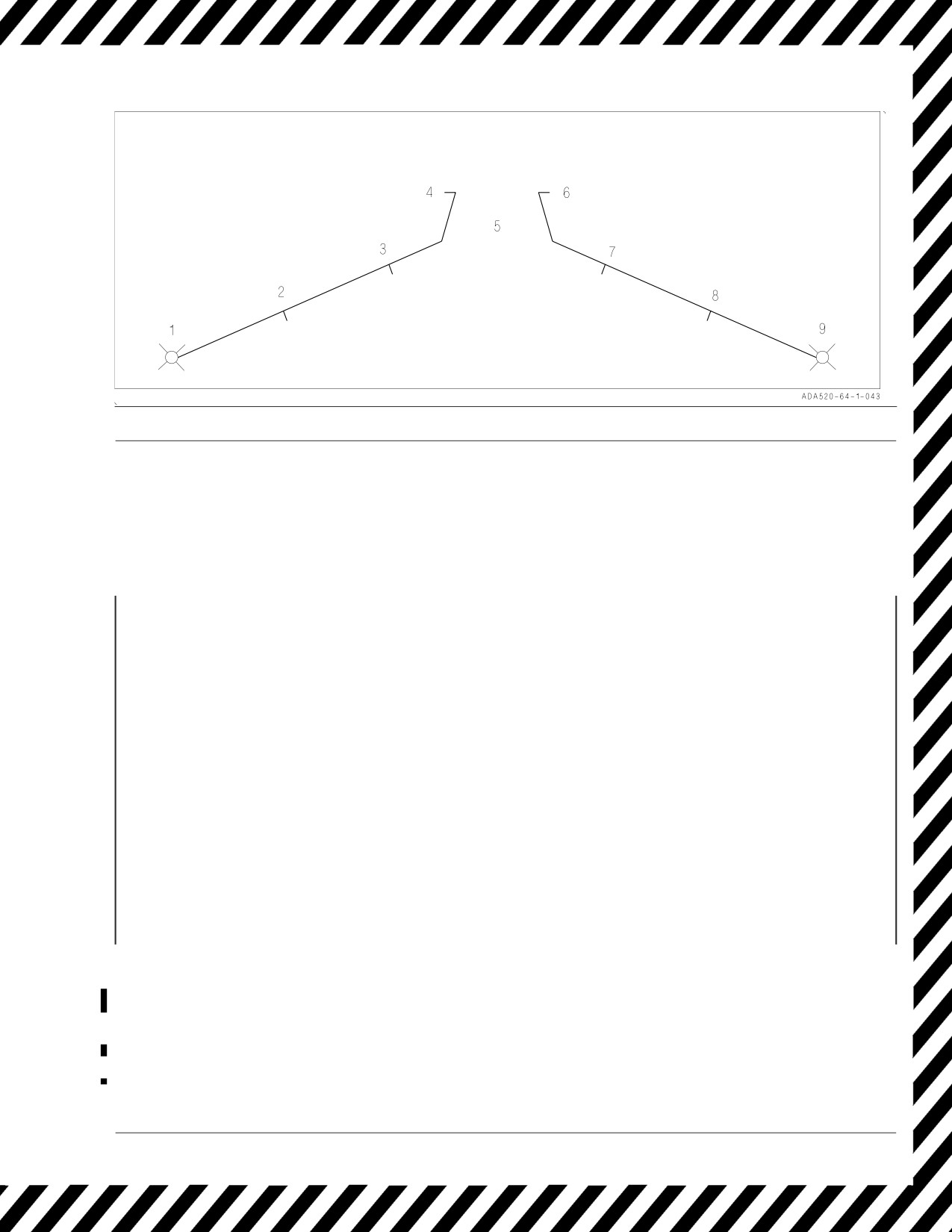
JETTISON PROCEDURES
EMERGENCY JETTISON:
HOW -
1. EMERG JETT BUTTON - PUSH
REQUIREMENTS -
WEIGHT OFF WHEELS OR GEAR HANDLE UP
WHAT -
- JETTISON ALL STORES/RACKS/LAUNCHERS FROM THE FIVE PYLON WEAPONS STATIONS RELEASED
IN PAIRS 2&8, 3&7, AND 5.
- LOCATE BUTTON PRIOR TO EVERY TAKEOFF/CAT.
SELECTIVE JETTISON:
HOW -
1. LT TEST SWITCH - TEST
2. SELECT JETT KNOB - ROTATE TO DESIRED POSITION
3. JETT STATION PUSHTILE(S) - SELECT
4. SIM - UNBOXED
5. MASTER SWITCH - ARM
6. SELECT JETT BUTTON - PUSH
REQUIREMENTS - LANDING GEAR UP AND LOCKED
WHAT -
- STORES OR STORES AND RACKS/LAUNCHERS ARE EJECTED ACCORDING TO THE POSITION OF
SELECT JETT KNOB AND PUSHTILES
AUXILARY RELEASE:
HOW -
1. LT TEST SWITCH - TEST
2. AUX REL SWITCH - ENABLE
3. SELECT JETT KNOB - ROTATE TO DESIRED POSITION
4. JETT STATION PUSHTILE(S) - SELECT
5. SIM - UNBOXED
6. MASTER SWITCH - ARM
7. SELECT JETT BUTTON - PUSH
REQUIREMENTS - LANDING GEAR UP AND LOCKED
WHAT -
- HUNG STORES OR STORES AND RACKS/
LAUNCHERS ARE GRAVITY RELEASED FROM
STATION ACCORDING TO POSITION OF SEL
JETT KNOB AND PUSHTILES
AFTER TAKEOFF:
SELECT JETT KNOB - ROTATE OUT OF SAFE TO DESIRED
POSITION
JETT STATION PUSHTILES - SELECT
WITH AN ENGAGEMENT:
MASTER ARM - ON
PUSH SELECT JETT BUTTON
HARM ANTI-COMPROMISE:
PERFORM LIGHTS TEST
SELECT JETT KNOB - ROTATE TO STORES
JETT STATION PUSHTILE(S) - SELECT
SELECT JETT BUTTON - PUSH
LIMITATIONS:
G
AIRSPEED
EMERG
0.5 TO 5.0
SEE NATIP
JETT
SELECT
SEE NATIP
SEE NATIP
JETT
(TANKS: 1.0-2.0)
(TANKS: 575/0.95)
AUX
1.0 LEVEL
SEE NATIP
RELEASE
DEGRADED SYSTEMS : USING AUX REL, PILOT IS ABLE TO RELEASE AN ARMED HARPOON.
Figure 15-9. External Stores Jettison Chart
V-15-33
ORIGINAL
A1-F18AC-NFM-000
15.28 ADC FAILURE EFFECTS
An ADC failure is recognized by the BIT advisory and the BIT page indication of ADC-MUX FAIL
(C/D), NO GO (A/B) or NOT RDY. The standby instruments indicate the correct altitude and
airspeed. The HUD airspeed, barometric altitude, vertical velocity and mach information are lost. The
landing gear warning light and aural tone are activated if the landing gear handle is up. To silence the
tone push the warning tone silence button or slow below landing gear extension speed and extend the
landing gear. E bracket data is automatically provided by the flight control computer and the ATC
mode is functional. The AOA indexers will be inoperative. The INS velocity vector is adversely
impacted by the loss of ADC data and may be inaccurate after approximately 10 minutes. See BIT
advisory, figure 12-1.
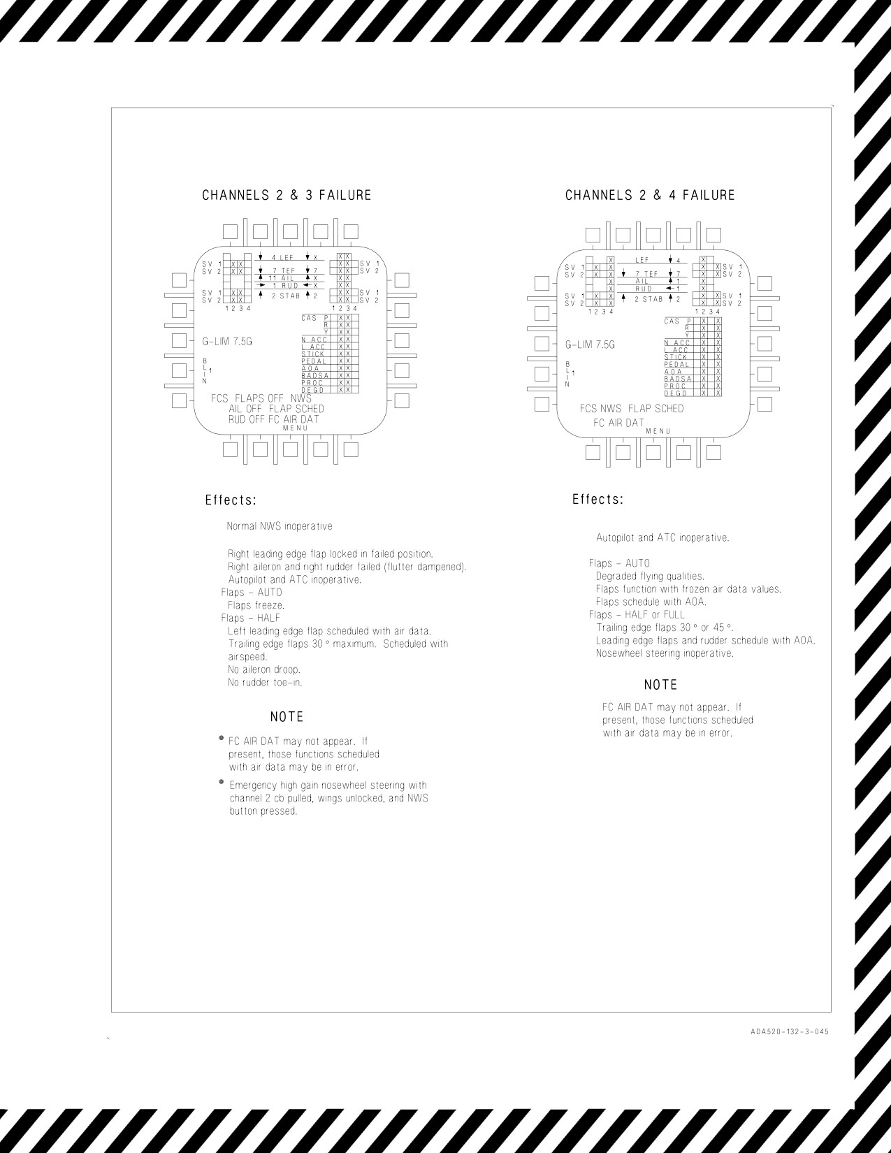
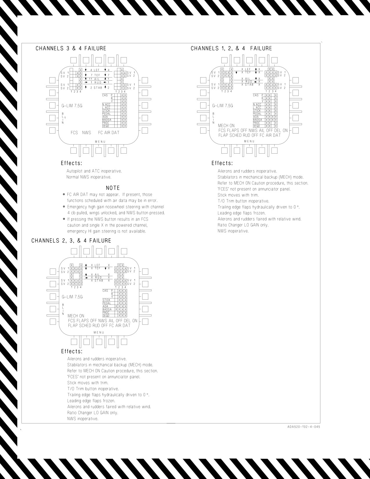
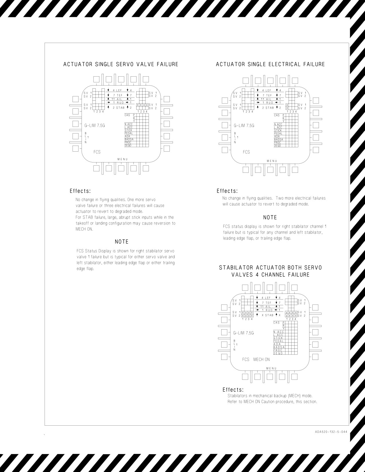
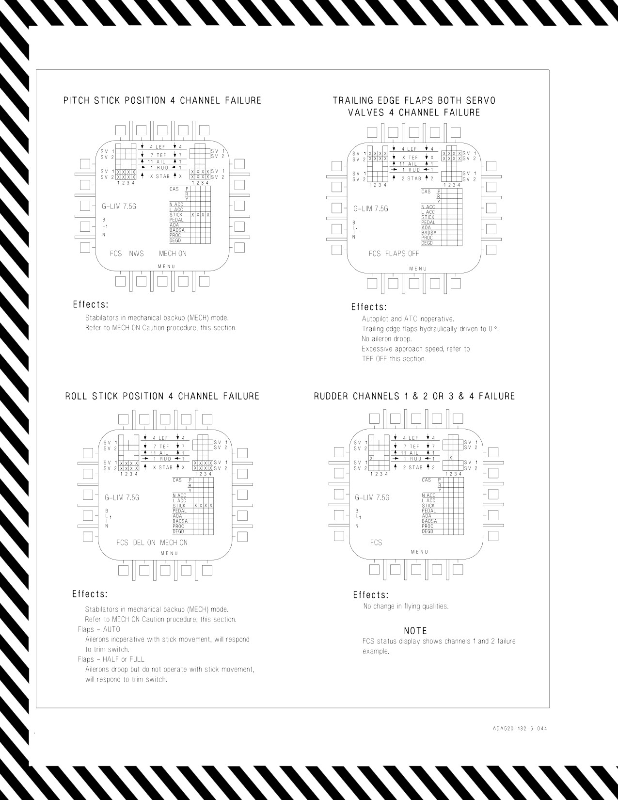
15.29 FCS FAILURE INDICATIONS AND EFFECTS
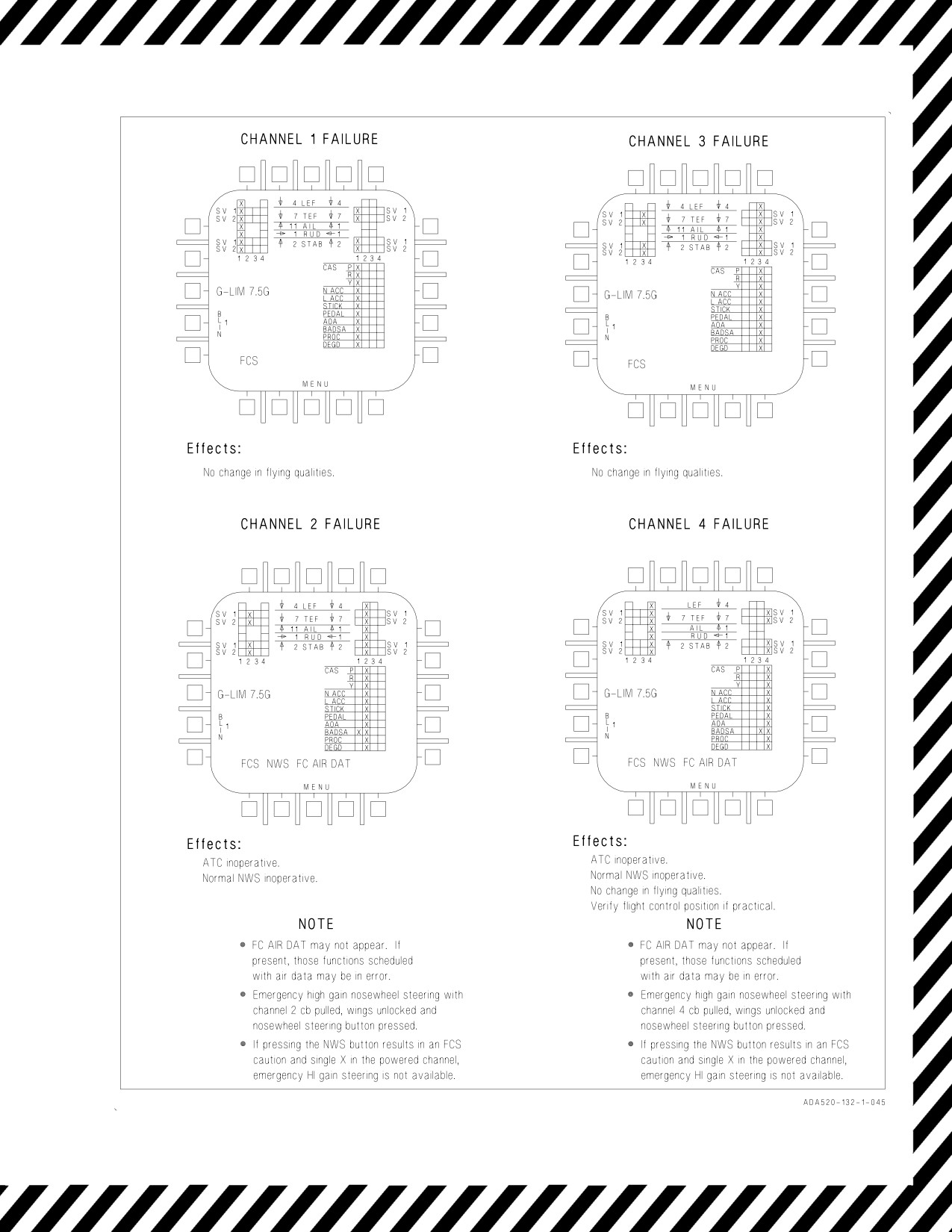
FCS failures are indicated by BLIN codes and/or various cautions and when selected, the FCS status
display on the DDI (figure 15-10). The FCS status display should be used to determine the precise
failure immediately upon indication of an FCS malfunction. BLIN codes are not always accompanied
by cautions or Xs.
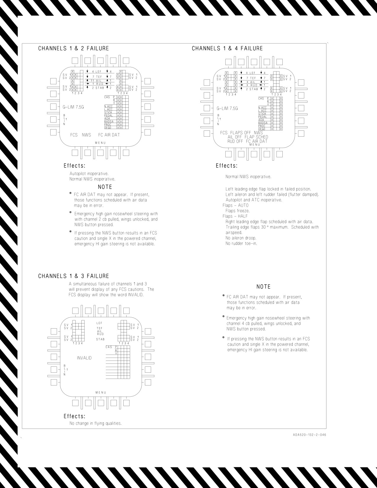
15.29.1 Invalid FCS Status Display
With the failure of channels 1 and 3, the FCS status display will show the word INVALID in place
of the G-LIM advisory. Subsequent FCS failures or resets will not be displayed. Diagnosis of failure
state can be made using the following:
If INVALID on the FCS and flying quality has degraded -
Check if stick moves with longitudinal trim. If stick movement occurs the stabilator has reverted to
mechanical control, and the ailerons and rudders are off. Refer to MECH ON caution. If FCES is
illuminated on the annunciator panel, channel 2 or 4 is still functioning. Ratio changer HI GAIN only
is available. If FCES is not illuminated on the annunciator panel, a four-channel or four-processor
failure has occurred. Ratio changer LO GAIN only is available. In both cases the T/O trim button is
inoperative.
The presence of the INVALID in place of the G-LIM advisory indicates that the FCS will stop using
INS provided data across the MUX; for this failure there is no significant degradation to flying
qualities, departure resistance or roll performance with these failure indications.
FCS status displays are shown in figure 15-10.
V-15-34
ORIGINAL
A1-F18AC-NFM-000
Figure 15-10. FCS Failure Indications and Effects (Sheet 1 of 10)
V-15-35
ORIGINAL
A1-F18AC-NFM-000
Figure 15-10. FCS Failure Indications and Effects (Sheet 2 of 10)
V-15-36
ORIGINAL
A1-F18AC-NFM-000
Figure 15-10. FCS Failure Indications and Effects (Sheet 3 of 10)
V-15-37
ORIGINAL
A1-F18AC-NFM-000
Figure 15-10. FCS Failure Indications and Effects (Sheet 4 of 10)
V-15-38
ORIGINAL
A1-F18AC-NFM-000
Figure 15-10. FCS Failure Indications and Effects (Sheet 5 of 10)
V-15-39
ORIGINAL
A1-F18AC-NFM-000
Figure 15-10. FCS Failure Indications and Effects (Sheet 6 of 10)
V-15-40
ORIGINAL
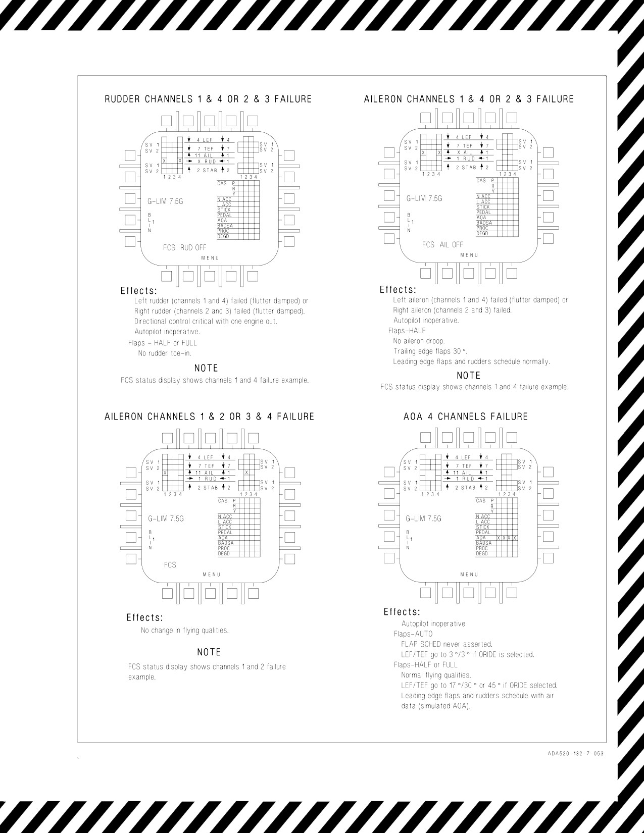
A1-F18AC-NFM-000
Figure 15-10. FCS Failure Indications and Effects (Sheet 7 of 10)
V-15-41
ORIGINAL
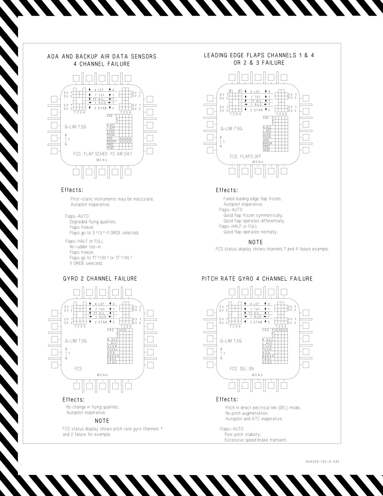
A1-F18AC-NFM-000
Figure 15-10. FCS Failure Indications and Effects (Sheet 8 of 10)
V-15-42
ORIGINAL
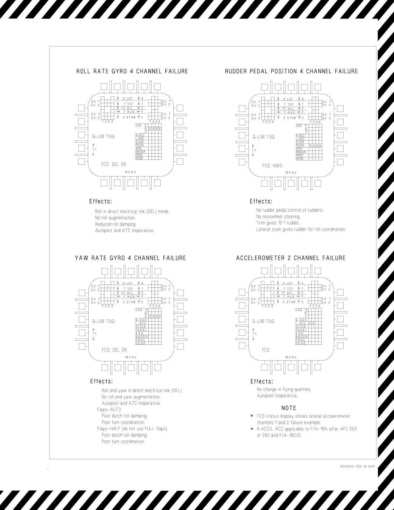
A1-F18AC-NFM-000
Figure 15-10. FCS Failure Indications and Effects (Sheet 9 of 10)
V-15-43
ORIGINAL
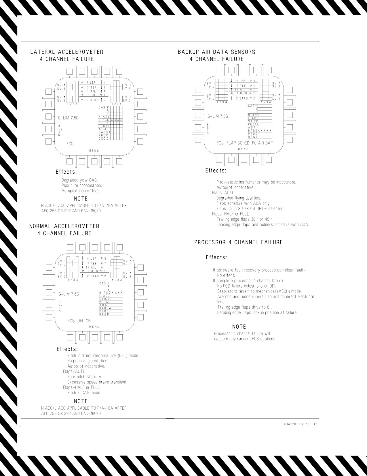
A1-F18AC-NFM-000
Figure 15-10. FCS Failure Indications and Effects (Sheet 10 of 10)
V-15-44
ORIGINAL
A1-F18AC-NFM-000
15.30 FCS FAILURE
The reliability of the FCS is very high and, when failures do occur, they usually occur singly. No
single failure will affect flying qualities. The flight control system has multiple redundancy and is
designed to fail to the least critical configuration. Two flight control computers each have two flight
control channels. Within each channel, each axis (pitch, roll, or yaw) is separate so that failure of one
axis does not affect the other two. If normal CAS functions fail, each computer also provides a digital
direct electrical link (DEL) between stick inputs and flight control surfaces. If roll or yaw digital DEL
fails, the computers provide an analog DEL to the ailerons and rudders. If pitch digital DEL fails, a
direct mechanical link from the stick to the differential stabilator actuators provides limited pitch and
roll control. When a rudder or aileron actuator fails, the actuator degrades to a failed/flutter damped
mode. The failed rudder or aileron will be slowly forced back to the faired position by aerodynamic
loads. This failed/flutter damped failure mode has not been flight tested. Depending on which failures
have occurred, flying qualities may be considerably degraded. Due to the variety of possible failure
combinations, exact guidance cannot be given to cover every possible circumstance. However, specific
procedures have been established for each FCS caution. See the Warning/Caution/Advisory Displays,
figure 12-1, for appropriate action. Each instance requires individual judgement as to the flyability of
the particular failure combination.
15.31 AOA PROBE DAMAGE
15.31.1
AOA Indications with AOA Probe Damage. Pilots should be alert for AOA probe damage
after IFR basket impact during refueling, bird strikes, or icing conditions. Damage can result in AOA
being declared invalid and AOA display inaccuracies. If AOA probe damage is ever suspected, an
AOA/airspeed crosscheck, in the landing configuration, should be made with a wingman, if possible.
Crosschecking with flaps AUTO may give a satisfactory crosscheck, but the probe can be bent in such
a way that AOA anomalies are accentuated in the landing configuration. If AOA damage is suspected,
follow the FLAP SCHED procedures. Also, with a declared AOA failure, ATC with flaps HALF or
FULL is not available and selection should not be attempted.
15.31.1.1 FCC OFP Functionality. With flaps in AUTO, the FCC uses a split of >10° true AOA
between the left and right AOA probes to declare AOA invalid. This failure in flaps-AUTO is
characterized by the following indications:
• FCS caution
• Four channels of AOA are Xd out on the FCS status display.
• HUD AOA numeric display blanked.
• L and R AOA probe values lined out.
NOTE
An AOA probe split is determined by local AOA probe measurements
and not the true AOA values provided for display on FCS status page.
True AOA values displayed on the FCS status page are approximately
0.65 times local AOA values. Therefore, a split of 15.5° between local
values approximates a 10° split between displayed true AOA values.
When flaps are HALF or FULL, there is a difference in thresholds used by the ADC and FCCs. An
AOA can be declared invalid by the FCCs for splits as low as 3.3°. The FCC’s split threshold will
increase with sideslip. However, the ADC will consistently use a split threshold of 10° before declaring
V-15-45
ORIGINAL
A1-F18AC-NFM-000
AOA invalid. As a result, HUD AOA display, E−Bracket, AOA indexer lights and approach lights will
continue to function when an AOA probe-split is less than 10°. The FCCs can still declare an AOA
failure if the split is greater than 3.3°.
In HALF or FULL, a split between the AOA probes that is >3.3° and <10° is characterized by the
following indications:
• FCS caution
• Four channels of AOA will be Xd out on the FCS status display. (Xs will latch.)
In HALF or FULL, the HUD AOA numeric display and E−bracket are normally driven by the
average of both probes but will be blanked when AOA is declared invalid by both the ADC and FCC.
This occurs when the split between the AOA probes is >10°, and is characterized by the following
indications:
• FCS caution
• Four channels of AOA will be Xd out on the FCS status display. (Xs will latch)
• HUD AOA numeric display blanked
• HUD E-bracket blanked
• AOA indexer lights and approach lights inoperative
• L and R AOA probe values lined out
Refer to figure 15−10 for a complete list of indications and effects.
15.31.1.2
ADC AOA Validity Functionality. Irrespective of flap state, the ADC will declare AOA
invalid if the AOA probes differ by >10°. Unlike FCC declared AOA failures, ADC declared AOA
failures are not latched. ADC monitored AOA values can drift in and out of validity with maneuvers
that cause the AOA probe splits to drift inside and outside the 10° threshold. As a result, the E-bracket,
AOA numeric, indexer light and approach lights may blank and re-appear as the split crosses the
threshold.
NOTE
Only when the ADC declares the AOA invalid will the indexer and
external approach lights will be blanked.
L and R AOA probe values from the ADC and the INS AOA (center) value are displayed on the FCS
status page. Whenever the ADC declares the AOA invalid, the L and R AOA values will continue to be
displayed but they will have a line through them. The INS AOA value will not be lined out and will
always be displayed irrespective of AOA anomalies.
An individual probe can be selected to drive the AOA E-bracket. Probe selection is accomplished by
selecting GAIN ORIDE and pushing the AOA pushbutton to box and select the desired probe. The
pilot can compare the INS AOA value against the L and R AOA values to determine which probe to
select. When either the L or R AOA value is boxed, the AOA DEGD caution is displayed and the
V-15-46
ORIGINAL
A1-F18AC-NFM-000
selected AOA probe drives the E-bracket. In GAIN ORIDE, the INS AOA value drives the HUD AOA
numeric value and, with Flaps HALF or FULL, the departure warning tone is inoperative.
The INS derived AOA value displayed in the center box on the FCS
status page can become inaccurate when there’s an AOA probe split.
Therefore, if the INS derived AOA value does not match either L or R
AOA value then AOA/airspeed crosscheck must be used to identify which
probe is undamaged.
NOTE
Even with one AOA probe selected, as long as the split between the
left and right AOA values is less than 10° , the ADC will continue to
drive the AOA indexer and approach lights by the average value of
both probes and will be inaccurate. Once a probe is selected, that
probe will remain selected regardless of ADC AOA validity. The HUD
E-bracket and AOA numeric will continue to be displayed as long as
GAIN ORIDE and a probe is selected. If GAIN ORIDE is not selected,
the HUD AOA numeric and E-bracket will blank when the ADC
declares AOA invalid (i.e., AOA probe splits >10°).
15.31.1.3
DAMAGED AOA PROBE PROCEDURE
The following procedure should be used for suspected AOA probe damage:
SUSPECTED AOA PROBE DAMAGE
1. FCS page - SELECT
2. Identify/confirm damaged probe.
3. Perform AOA/airspeed check before and after going dirty.
4. Refer to FLAP SCHED caution CORRECTIVE ACTION.
15.31.2 Jammed AOA Probe On Takeoff. When an AOA probe-split occurs within
12
seconds of
takeoff (WoffW), FCC AOA is set at a fixed value of 10° and flaps-transition is inhibited, regardless
of FLAP switch position, to prevent undesirable transients. The AOA probe-split threshold used by the
FCC can be as little as 3.3° depending on sideslip. Two to ten seconds after WoffW, the FCS caution
appears and all four AOA channels X-out on the FCS status display. The FCS will switch from using
the fixed AOA value of 10° to using an estimated AOA value, calculated by the FCC, when an FCS reset
V-15-47
ORIGINAL
A1-F18AC-NFM-000
is performed or flap blow−up speed is exceeded. If Auto flaps is selected after takeoff, within the
12-second window, the flaps will retract at the end of 12 seconds.
NOTE
If the AOA tone is heard during takeoff roll, it may be an indication of
dual stuck probes and the aircraft may not have sufficient pitch
authority to rotate.
AOA
Flaps HALF or FULL
Flaps Auto
Flaps HALF or FULL
Flaps Auto
Flaps HALF or FULL
Status
No Split
Split >3.3 and <10
Split >3.3 and <10
Split >10
Split >10
HUD AOA: displayed
HUD AOA: blanked
HUD AOA: blanked
HUD AOA: displayed
HUD AOA: displayed
E−bracket:
E−bracket:
E−bracket: blanked
E−bracket: displayed
E−bracket: displayed
N/A
N/A
Indexers: blanked
Indexers: displayed
Indexers: displayed
Indexers:
Indexers:
FCS AOA Xs: SET
Displays
FCS AOA Xs: not set
FCS AOA Xs: SET
N/A
N/A
FCS caution: SET
FCS caution: not set
FCS caution: SET
FCS AOA Xs: not set
FCS AOA Xs: SET
FLAP SCHED: not
FLAP SCHED: not set
FLAP SCHED: not set
FCS caution: not set
FCS caution: SET
set
L/R AOA: displayed
L/R AOA: displayed
L/R AOA: displayed
L/R AOA: lined out
L/R AOA: lined out
Indexer &
External
Operative
Will be inaccurate.
Inoperative
Approach
Lights
Figure 15-11. AOA Probe Indications and Effects
15.32 PITOT STATIC PROBE DAMAGE.
Be alert for unannunciated pitot static probe damage after IFR basket impact during refueling, bird
strikes, or icing conditions. The ADC can produce erroneous signals without any cautions or advisories
if the pitot static probes sustain damage. HUD displayed airspeed may be inaccurate without error
indications. Airspeed checks with a wingman should be made in the landing configuration if a damaged
pitot static probe is suspected. Crosschecking in the cruise configuration may give a satisfactory
crosscheck, but the probe may be bent in such a way that pitot static anomalies are accentuated in
landing configuration.
The standby airspeed indicator receives signals from the left pitot static probe, so it will be accurate
if only the right probe is damaged. If the left probe is damaged, the static source selector can be used
to select the static pressure source from the right probe. The static source lever allows selection of right
(BACKUP) or left (NORMAL) secondary static pressure to be applied to the standby indicated
airspeed indicator, standby pressure altimeter, and standby vertical velocity speed indicator. With
lever in the horizontal position, the selector valve is in NORMAL, with lever in the vertical position,
the selector valve is in BACKUP.
NOTE
A detached pitot static line may cause malfunctions similar to those
caused by a damaged pitot static probe. Selection of the secondary
static source may or may not eliminate the problem.
V-15-48
ORIGINAL
A1-F18AC-NFM-000
If the GPS fails or is not available, and only ADC inputs are being used, inaccurate pitot static
information will degrade INS performance.
If inflight damage to a pitot static probe is suspected, air data may be
unreliable and FC AIR DAT procedures should be followed.
15.33 DIRECT ELECTRICAL LINK (DEL)
See the Warning/Caution/Advisory Displays, figure 12-1. Direct electrical link (DEL) operation
results from the lack of reliable feedback data or operation within the FCS. DEL operation will usually
occur in only one axis but yaw DEL operation forces the roll channel into roll DEL. In the DEL mode,
pilot inputs position the control surfaces as a direct function of pilot input.
15.33.1 Digital DEL - DEL ON Caution. The digital roll DEL function is activated for any one of the
following conditions: three roll rate gyro failures, reversion to digital yaw DEL, or reversion to analog
yaw DEL. The digital yaw DEL function is activated for a three yaw rate gyro failure condition. The
digital pitch DEL function is activated for any one of the following conditions:
With flaps in AUTO: three pitch rate gyro failures, or three normal accelerometer failures.
With flaps in HALF or FULL: three pitch rate gyro failures.
15.33.2 Digital DEL. If the FCS reverts to pitch DEL at transonic or supersonic speed, decelerate to
400 knots/Mach 0.8 to reduce the longitudinal PIO tendency. If the FCS reverts to roll and yaw DEL
at transonic or supersonic speeds, slowly decelerate to below 400 knots/Mach 0.8 to reduce the
uncomfortable sideforce oscillations due to weak dutch roll damping.
In pitch DEL there is very little stabilator authority available. Therefore,
the g available is extremely limited.
The use of the speedbrake in pitch DEL should be avoided, since it will normally lead to moderate
longitudinal PIO. However, the speedbrake can be used for a 1 g incremental increase if required in an
extreme situation. The trim rates are noticeably slower than in CAS, but they will allow neutral
trimmed flight throughout the airspeed envelope. Damping of aircraft motion occurs only as a result
of natural aircraft stability and is not enhanced by the FCS. Pilot inputs should be gentle at higher
airspeeds since rapid inputs may aggravate the aircraft oscillations. Rapid power changes should be
minimized as they may result in aggravation of PIO tendency due to trim changes. In roll and yaw DEL
the use of the rudder is not recommended due to control sensitivity and dutch roll excitation. In pitch
DEL, lateral stick inputs will couple into the pitch axis as a nose up rotation and will require a
corresponding pitch input to correct. Normal formation flight and air refueling is possible with any axis
V-15-49
ORIGINAL
A1-F18AC-NFM-000
in DEL; however, caution must be exercised due to the reduced damping characteristics. Minimize
in-close corrections during air refueling to prevent PIO.
Roll rates are significantly reduced at airspeeds above Mach 0.94 in roll
or roll plus yaw DEL and may be as low as 65°/second.
For carrier or field landing, fly on-speed with flaps HALF. After a bolter in pitch DEL a large pitch
up will occur which can be stopped with forward stick force. A similar pitch up will occur after a field
landing and the pilot must consciously keep the aircraft on the ground; once stabilized after touchdown
normal roll-out procedures can be used. Recommend field landings be conducted using a reduced sink
rate to minimize the pitch up tendency. During approach in roll DEL the aircraft is easily excited in
roll, resulting in a constant 2 or 3° roll oscillation. There is also no roll limiting, so lateral inputs will
produce a noticeable increase in roll rates and roll response. The increased roll response may lead to
a lateral PIO if large rapid inputs are used. Do not use more than ½ lateral stick or rudder pedal in
approach configuration in roll DEL or roll plus yaw DEL, due to excessive sideslip and dutch roll;
however, small timely rudder inputs can be used to dampen directional oscillations. Minimize
maneuvering above on-speed when in roll and yaw DEL due to magnitude of sideslip generated.
Jettison asymmetric wing stores. Minimize rapid power applications during approach in roll and yaw
DEL with asymmetric stores as they will couple into the directional axis creating uncomfortable side
forces. Do not exceed +12° AOA during approach maneuvering with asymmetric stores. Recommend a
reduced sink rate landing with a short field arrestment when landing with asymmetric stores.
If a waveoff is carried out in pitch DEL, the pilot encounters a substantial
stick force change during flap retraction. Almost full aft stick is required
to maintain level flight.
For shipboard landings fly a straight-in approach with flaps HALF at on-speed AOA. The ability to
effectively fly the aircraft with degraded flight controls increases significantly with time (steep learning
curve). Consider lowering the gear and flaps (HALF flaps) early to evaluate the approach flying
qualities. The ACLS/ILS needles would be used to ensure proper lineup by the “in the middle”
positions. The LSO waveoff window should also be moved farther out such that only small
glideslope/lineup corrections are required from the “in the middle” position.
15.33.3 Analog DEL. The FCS reverts to analog roll DEL and analog yaw DEL if there are three
digital processor failures. In addition the analog roll DEL function is activated if three channels to the
ailerons are Xd out and the analog yaw DEL function is activated if three channels to the rudders are
Xd out. If the aircraft selects yaw DEL, the control laws also activate the digital roll DEL function. The
flying qualities described for digital DEL
(DEL ON caution) may or may not apply to this
configuration. There is no analog pitch DEL mode.
If yaw analog DEL is active, the pilot’s rudder pedal provides direct rudder control. If roll analog
DEL is active, the pilot’s lateral stick provides direct aileron control. Control surfaces move at a rate
directly proportional to pilot input.
V-15-50
ORIGINAL
A1-F18AC-NFM-000
In roll analog DEL, the FCS provides no roll augmentation nor roll damping. Make shallow angle of
bank turns and minimize side to side stick movements.
In yaw analog DEL, the FCS provides no roll and yaw augmentation. The aircraft will exhibit poor
Dutch roll damping and poor turn coordination. If the aircraft selects yaw DEL, the control laws also
activate the roll DEL function. Make shallow angle of bank, rudder coordinated turns and minimize
side stick movements. Rudder pedal inputs are required to provide the direct electrical link to the
rudders.
Extreme caution should be used in analog DEL. Flight in this configu-
ration has not been flight tested.
NOTE
• No air data flight control scheduling is available in analog DEL. The
aircraft is more controllable in Full or Half flaps due to the availability
of AOA information for control surface scheduling.
• The DEL ON caution is not displayed when in the analog roll DEL
mode. The DEL ON caution is displayed when in analog yaw DEL
since digital roll DEL is activated.
15.34 UNCOMMANDED PITCH AND ROLL EXCURSIONS
A stabilator simultaneous dual or four-channel feedback failure can cause uncommanded pitch and
roll excursions. Unless pilot action is taken, the stabilator will not revert to MECH ON operation and
the pitch and roll excursions will continue. Check the FCS status display. If there are two channel
indications, a dual-channel failure has occurred. If there are no failure indications, a four-channel
failure has occurred.
For a dual-channel failure, pulling one of the operating FCS channel circuit breakers causes the
stabilators to revert to MECH ON with the ailerons, rudders and flaps operating normally in CAS. This
configuration is adequate for field and shipboard landings at half flaps and onspeed AOA.
Resetting the circuit breaker causes a return to the original failure mode
with the resulting uncommanded pitch and roll excursions.
Refer to MECH ON Caution procedure for description of flight characteristics in the MECH ON
mode.
For a four-channel failure, the only way to stop pitch and roll excursions is to pull three FCS circuit
breakers to force the stabilator to MECH ON with ailerons, rudders, and flaps inoperative. This
configuration has been safely flown at altitude but has not been flight tested. The aircraft should be
trimmed, and flown as stick free as possible. Large rapid stick inputs result in extreme overshoots.
Landing in either configuration is predicted to be hazardous.
V-15-51
ORIGINAL
A1-F18AC-NFM-000
1. Speedbrake - CHECK IN
2. Decelerate slowly below 400 knots/Mach 0.8.
3. Paddle switch - PRESS
If two channel failure indications in one stabilator -
4. Pull one operating FCS channel circuit breaker. DO NOT RESET.
5. Refer to MECH ON procedure.
If no FCS failure indications -
6. Climb to safe altitude.
7. Airspeed: below 250 knots.
8. Flaps - FULL
9. Lower gear and make Controllability Check.
10. If controllability permits landing - Short Field arrestment recommended
If control unsuitable for landing -
11. Climb to safe altitude.
12. Pull FCC circuit breakers 1, 2, and 3. DO NOT RESET.
13. Refer to MECH ON procedures.
15.34.1
Uncommanded Roll Excursion with Aileron Surface Missing/Damaged. Cracks in aileron
outboard hinges may lead to failure resulting in partial or total loss of the control surface. An aileron
hinge failure may be suspected if a sudden uncommanded roll-off combined with yaw and pitch occurs
without an AIL OFF or FCS caution, a ″Flight Controls, Flight Controls″ alert or associated FCS Xs
or BLIN codes. If the hinge has failed, it is likely that a portion of or all of the aileron surface will
detach from the wing. However, aileron actuator functionality may be unaffected. The aileron position
indicator on the FCS page will indicate the position of the actuator rod-end, even though the control
surface is no longer attached. The only way to confirm this failure is a visual check of the suspected
aileron surface to determine if the aileron surface is still attached and responding to control inputs.
Aileron surface departure may result in structural damage to the wing, empennage or fuselage. If the
failed surface remains attached to the wing it may result in wing and/or aileron oscillations. If
oscillations occur, immediately reduce airspeed by decelerating at 1g until the oscillations subside or
are minimized. Maintain AOA <10°.
If aileron or wing oscillations are present, failure to immediately reduce
airspeed until oscillations subside or are minimized may result in further
structural failure.
V-15-52
ORIGINAL
A1-F18AC-NFM-000
Piloted simulation with a missing aileron has shown that flying qualities are degraded but adequate
for all flap settings below 10° AOA. Lateral stick against the roll and rudder pedal in the opposite
direction to counter side force buildup will be required for balanced flight. Aircraft response to normal
control inputs is uncoordinated and roll performance will be more sluggish when rolling away from the
detached/missing aileron. Lateral stick inputs will result in directional excursions. Lateral-directional
motion will be lightly damped. Flap transitions to AUTO at low airspeeds and high gross weights may
result in unrecoverable departure. If aileron damage occurs immediately after takeoff, selecting MAX
throttles when airspeed is less than 220 KCAS and delaying selection of flaps AUTO until the flaps
have scheduled up (above 250 KCAS) minimizes the risk of departure. Minimizing gross weight by
jettisoning stores and maximizing acceleration improves flying qualities through the flap transition
region.
Flap transition to AUTO below 250 KCAS can result in large roll and yaw
oscillations leading to unrecoverable departure, particularly at higher
gross weights. Using smooth rudder pedal and stick inputs when control-
ling roll and yaw during transition will help avoid PIO. Reducing gross
weight will reduce oscillations during transition.
Flying qualities are adequate for a shore-based landing; however, CV landings are extremely
hazardous and are not recommended.
Approaches to the ship are extremely hazardous. High rudder pedal and
lateral stick forces required to keep a nominal sight picture will increase
pilot workload and fatigue on approach. Ground loads may overstress the
landing gear on touchdown due to combined roll/yaw attitudes. Line-up
corrections in-close result in bank angle on touchdown that can result in
a wingtip engaging the arresting wire. The aircraft will tend to drift
towards the failed aileron and the LSO should expect constant line-up
corrections on approach. At touchdown, NWS will engage with WonW
and will cause large centerline excursions if rudder pedal inputs are not
removed at touchdown.
If carrier-based, divert to an appropriate airfield. When determining the divert/BINGO profile,
consider the presence of wing or aileron oscillations and flap setting and their impact on divert airspeed
and fuel management.
Bingo profile may be adversely affected due to reduced airspeed neces-
sary to avoid oscillations. Allow for a controllability check prior to
landing.
Prior to landing, conduct a Controllability Check. Consideration should be given to jettisoning stores
on failed wing to reduce lateral weight asymmetry and gross weight for landing. Determine whether
V-15-53
ORIGINAL
A1-F18AC-NFM-000
Flaps - HALF or Flaps - AUTO is appropriate based on crosswinds at the landing site. If crosswinds
at the landing site are 15 knots or less, conduct Flaps - HALF Controllability Check, otherwise conduct
FLAPS - AUTO Controllability Check.
NOTE
Flap transition from AUTO to HALF may result in roll into the failed
aileron but does not result in significant transients.
Lateral weight asymmetries with heavy wing on the failed side will aggravate the roll-off and may
preclude the aircrew’s ability to zero the roll-off with trim.
Flying qualities should be adequate for a shore-based approach to landing. Flying qualities may be
degraded such that roll inputs are sluggish and aircraft response to control stick or throttle inputs may
be coupled in roll, pitch, and yaw. Line-up corrections will be sluggish and a straight-in approach is
required to avoid late corrections.
Uncommanded Roll Excursion with Aileron Surface Missing/Damaged Procedure:
1. Reduce load factor to 1g and maintain balanced flight.
2. Do not exceed 10° AOA.
Exceeding 12° AOA may result in an uncontrollable roll-off into the
missing aileron resulting in OCF. If an uncontrollable roll-off occurs,
immediately reduce AOA. If aileron or wing oscillations are present,
failure to immediately reduce airspeed until oscillations cease can result
in further structural failure.
If FLAPS FULL -
3. FLAP switch - HALF
4. Maintain airspeed below 230 KCAS.
If carrier-based -
5. DIVERT.
If FLAPS AUTO required for divert or for high crosswind landing (>15 kts) -
6. Reduce gross weight to the maximum extent practical (SEL JETT stores).
7. Throttles - MAX for Flap transition
8. Above 250 KCAS - FLAP switch - AUTO
V-15-54
ORIGINAL
A1-F18AC-NFM-000
Flap transition to AUTO below 250 KCAS can result in large roll and yaw
oscillations leading to unrecoverable departure, particularly at higher
gross weights. Using smooth rudder pedal and stick inputs when control-
ling roll and yaw during transition will help avoid PIO. Reducing gross
weight will reduce oscillations during transition.
Bingo profile may be adversely affected due to reduced airspeed neces-
sary to avoid oscillations. Allow for a controllability check prior to
landing.
For all cases -
9. Use smooth control inputs.
10. Land as soon as practical.
FOR LANDING
1. Execute Controllability Check procedure.
D If crosswinds at field are 15 knots or less - FLAPS HALF.
D If crosswinds at field are >15 knots - FLAPS AUTO. Consider maximum groundspeed for tires
and arresting gear. If groundspeed is excessive, reduce gross weight or consider flying up to 10°
AOA approach.
D If able, SEL JETT stores on the same side as the missing aileron to reduce asymmetry on failed
wing.
NOTE
Lateral weight asymmetry with the heavy wing opposite to the missing
aileron improves flying qualities. Lateral weight asymmetries greater
than 4,000 ft-lbs with heavy wing on same side as the missing aileron
severely degrade flying qualities.
2. Fly a straight-in approach.
3. Fly a crabbed approach, taking out half the crab just before touchdown.
V-15-55
ORIGINAL
A1-F18AC-NFM-000
4. Make an arrested landing (if practical).
Expect unusually large crab angles with crosswind. If possible, land with
crosswind into the missing aileron. NWS will engage with WonW and will
cause large centerline excursions on the runway if rudder pedal inputs are
not removed at touchdown. Use rudder trim to the maximum extent.
Expect directional oscillations on touchdown when pedal is required.
15.35 MECH ON CAUTION
Refer to Warning/Caution/Advisory Displays, figure 12-1. Mechanical operation (MECH ON) can
be the result of various FCS failures (with or without ailerons and rudders operative); complete
electrical failure, including the battery (without ailerons and rudders operative); or as a deliberate pilot
selection (pulling FCC channels 1 and 2 circuit breakers) to conserve battery power for landing after
a double generator/double transformer-rectifier failure (without ailerons and rudders operative).
• Extreme caution should be exercised in MECH ON with ailerons/
rudders inoperative. This configuration has not been flight-tested.
• Reversion to MECH ON has often resulted in large pitch-up or
pitch-down transients.
• Resetting the FCS while in MECH may result in large pitch-up or
pitch-down transients.
15.36 MECH ON WITH AIL AND RUD OPERATIVE
Refer to Warning/Caution/Advisory Displays, figure 12-1. If no surface hardover failures occur,
reversions into MECH ON are normally characterized by a rapidly increasing aft stick force, stabilized
at 3 to 5 pounds for flaps AUTO and 15 to 25 pounds in the landing configuration (on-speed). Use care
at all airspeeds, especially above 400 knots/Mach 0.8, to avoid over control in pitch and resulting PIO.
The stick force per g gradient is higher than a normal CAS aircraft but will allow adequate
maneuvering performance. Do not use the speedbrake, since it will lead to severe longitudinal PIO.
Rapid power changes should be minimized as this may result in aggravation of PIO tendency due to
trim changes. Lateral stick inputs couple into the pitch axis as a nose up rotation and require a
corresponding pitch input to correct. Formation flight and air refueling is possible, even with roll plus
yaw DEL; however, pilot workload greatly increases. For air refueling ensure a good lineup and keep
all inputs to a minimum when closing on the basket as a violent longitudinal PIO may result. For
carrier or field landing, fly on-speed with flaps HALF. After a bolter in pitch MECH a large pitch up
occurs which can be stopped with forward stick force. A similar pitch up occurs after a field landing and
the pilot must consciously keep the aircraft on the ground; once stabilized after touchdown normal
V-15-56
ORIGINAL
A1-F18AC-NFM-000
roll-out procedures can be used. Recommend field landings be conducted using a reduced sink rate to
minimize the pitch up tendency. A short field arrestment is also recommended.
If a waveoff is carried out with a subsequent transition to up and away
flight, ensure that the FLAP switch is set to AUTO below 250 knots, as
the aircraft is very prone to PIO if the flaps are allowed to automatically
retract.
15.37 MECH ON WITH AIL AND RUD OFF
Refer to Warning/Caution/Advisory Displays, figure 12-1. Diagnosis of specific failure condition can
be made by referring to the FCS failure indications and effects, figure 15-9. Note that the ratio changer
may be failed to the flaps AUTO setting (low gain) or HALF/FULL setting (hi gain), independent of
FLAP switch position. Flying qualities may be similar to those described in the MECH ON WITH AIL
AND RUD OPERATIVE section. If the decision is made to land, approach speeds are much higher
than normal at on-speed AOA. Nosewheel steering is inoperative.
15.38 FLAPS OFF CAUTION
See the Warning/Caution/Advisory Displays, figure 12-1. When a LEF failure occurs, the LEF brake
locks the LEF in response to an out-of-tolerance condition. In addition, the LEF asymmetry brake
locks the LEF when a split between the inboard and outboard LEFs (on the same wing) differ by more
than 3°. Another lock out condition can occur when the difference between the commanded and actual
position differ by more than 3° and the aircraft is maneuvering below 1.5 g. When the aircraft is
maneuvering above 1.5 g, the FLAPS SCHED criteria are used to determine LEF failures.
If a HYD 1B and the left leading edge flap fail or a HYD 2A and the right
leading edge flap fail together, do not press the FCS RESET button.
Resetting the FCS with one of the above combinations may result in a
second hydraulic circuit failure.
NOTE
LEF logic does not compare left wing LEF position to right wing LEF
position.
The inboard and outboard LEF surfaces are mechanically connected by a common drive shaft. When
a LEF failure occurs, the entire flap is locked to prevent further movement. If a mechanical failure
occurs such that the inboard and outboard are split on the same wing, it has been shown that
controllability is governed only by the position of the inboard flap. Therefore, the LEF procedures
mandate visually confirming the position of the inboard LEF and is discussed in the following
paragraphs.
V-15-57
ORIGINAL
A1-F18AC-NFM-000
15.38.1 LEF FAILED (WITH INBOARD POSITION FAILED UP BEYOND 4° OVER-TRAVEL STOP)
During high g maneuvering, all elements of the LEF braking system must work to stop the LEF in
a failure mode. If the LEF back up brake system does not function properly, the LEF can move rapidly
and possibly overpower the over−travel stop, resulting in a large leading edge up deflection (beyond the
over−travel stop design maximum of 4° upward deflection). The LEF braking system is not designed
to function beyond the over−travel stop. Any deflection beyond the over−travel stop could potentially
deflect to a full structural limit of approximately 55°. With only the outboard section of the LEF failed
up beyond the design limits, it has been shown that aircraft can be controllable in the landing
configuration with HALF flaps.
Failures that result in extreme inboard LEF leading edge up deflections are highly susceptible to
departure at airspeeds below 250 KCAS. The minimum controllable airspeed depends on the severity
and configuration of the LEF failure. The only way to confirm extreme LEF failures is by visual check
as the FCS indications will be inaccurate or blanked. Use care to maintain airspeed above 300 KCAS
while assessing the LEF positions. Extreme failure of the inboard section of the LEF will result in
immediate uncommanded roll and yaw that can be controlled with pilot input (lateral stick against the
roll and rudder pedal in the opposite direction, countering side force buildup) given adequate airspeed.
As airspeed decreases, roll and yaw moments will build, leading to a departure. Flight data shows that
extreme failure of the inboard LEF, with or without the failure of the outboard section, to a position
leading edge significantly up (beyond about 45°) results in an uncontrollable aircraft below approxi-
mately 250 KCAS in flaps AUTO. With flaps HALF, limited flight data indicate high buffet loads (to
the point of not being able to read the HUD) at airspeeds of approximately 190 KIAS, and an abrupt
departure at airspeeds slightly below 190 KIAS in this configuration.
The Rolling Surface to Rudder Interconnect (RSRI) in the flight control software may complicate
an inboard LEF failure by attempting to coordinate the roll commanded by the pilot input (lateral
stick) to counter roll−off. Simulation data shows that selecting GAIN ORIDE with flaps AUTO
reduces RSRI commanded input and provides additional rudder control authority, which may allow
controlled flight to slower airspeeds. Therefore, controllability checks in GAIN ORIDE with flaps
AUTO are recommended. Reduce gross weight to the maximum extent possible prior to performing
controllability checks. Landing in GAIN ORIDE with flaps AUTO with LEF failure has not been flight
tested. Expect degraded flying qualities. Only a real−time controllability check can determine whether
the individual LEF failure experienced will be controllable all the way to touchdown. Carrier landing
is not recommended. Extreme caution is recommended because there is little to no warning of
impending departure. This failure condition has never been flight tested.
Leading edge up deflections of the inboard LEF beyond the
4°
over−travel stop may result in an uncontrollable configuration below 250
KCAS. Selecting GAIN ORIDE with flaps AUTO may provide control-
lability at slower airspeeds. There may be little warning of impending
departure as airspeed decreases. Immediate ejection may be required.
Departure will be unrecoverable.
NOTE
Any deflection beyond the over−travel stop could potentially reach a
full structural limit of approximately 55° leading edge up.
V-15-58
ORIGINAL
A1-F18AC-NFM-000
15.38.2 LEF FAILED (WITH INBOARD POSITION LESS THAN 4° UP) OR TEF FAILED
If the LEFs are locked in a more up−position than the automatic flap schedule dictates, then stall
and departure AOA are lower (as low as 10° AOA if the LEFs are at 0°). Buffet with the LEFs at 0°
is moderate at about 7° AOA. Use care to prevent AOA excursions above 10°. With the LEFs locked
at 20° to 30° down, landing−configuration handling qualities are essentially normal. Even with the
outboard section of the LEF failed up beyond the design limits, the aircraft can be controllable in the
landing−configuration with HALF flaps.
With a LEF lockout/failure, upon selecting HALF−flap position, the functional LEF as well as the
functional TEFs will extend normally. However, the failed/locked−out LEF remains frozen creating an
asymmetric flight control surface condition that can be countered with lateral stick and trim. If the
AUTO flap position is then selected, after selecting HALF or FULL, the functional LEF/TEFs do not
retract until GAIN ORIDE is selected. If fuel is a concern (as with CV cyclic operation), selecting GAIN
ORIDE with FLAP switch in AUTO allows all non−failed flaps to retract to a more fuel conserving
3°/3° position. Returning GAIN ORIDE switch to normal returns functional TEFs to normal
scheduling, but as long as there is a failed/locked LEF, the functional LEF remains in the GAIN
ORIDE position. With the GAIN switch in ORIDE above 350 knots an uncontrollable divergent pitch
PIO may occur. With the FLAP switch AUTO, ORIDE provides 3°/3° flaps.
In the event of a TEF failure, the failed TEF trails to its neutral uplock position. To prevent
asymmetry, the functional TEF is also shut off and trails to its neutral uplock position as well. With
a TEF failure, if the TEFs are more up than the automatic flap schedule dictates, the aircraft attitude
is more nose−up than normal at any given airspeed in AUTO. In the landing configuration, the
approach speed is much higher at on−speed AOA. An AOA of 10° to 11° may be used for landing, but
the over−the−nose field of view is reduced.
15.39 FLAP SCHED CAUTION
See the Warning/Caution/Advisory Displays, figure 12-1. The FLAP SCHED caution indicates the
flaps are not scheduling properly. It is always accompanied by a Master caution and FCS caution. Air
data failures will also cause the FLAP SCHED caution to be asserted.
With an air data failure, without GAIN ORIDE selected, the rudders go
to full 30° toe in at touchdown which may result in an uncommanded
nose pitch-up.
The FLAP SCHED caution is asserted if either the left or right LEF is off schedule (difference
between the LEF position/command is greater than 10° with AOA above 12 degrees). A FLAPS
SCHED caution accompanied by BLIN 221 provides a good indication that an off−schedule LEF
caused FLAPS SCHED caution. PROM 10.7 never asserts a FLAP SCHED caution for AOA probe
splits as the FCC will continue scheduling the flaps based on an AOA estimate. The FLAP SCHED
caution remains for six seconds after the failure condition clears. AOA probe splits never assert a FLAP
SCHED caution because the FCC will continue scheduling the flaps based on an AOA estimate.
For all FLAP SCHED cautions, establish straight and level flight then check handling qualities. If
the leading edge flaps are frozen in a more up position than the scheduled position, stall and departure
will occur at a lower AOA than normal. With the GAIN switch in ORIDE above 350 knots, an
V-15-59
ORIGINAL
A1-F18AC-NFM-000
uncontrollable divergent pitch PIO may occur. With the FLAP switch AUTO, ORIDE provides 3°/3°
flaps.
For all FLAP SCHED cautions, select GAIN ORIDE for landing. Transition to the landing
configuration at 200 knots, straight and level at a safe altitude, and check flying qualities. Aircraft
response may be sensitive near 200 knots but will probably be about normal at ON-SPEED AOA. If
AOA is failed, leading edge flaps and rudder toe-in are scheduled by an AOA approximation for 1 g
flight. Stalls occur at a lower AOA with GAIN ORIDE selected due to fixed flap positions.
15.40 NWS CAUTION
See the Warning/Caution/Advisory Displays, figure 12-1. The NWS caution comes on when
nosewheel steering is shut off due to detection of a failure in the system. Emergency high gain
nosewheel steering is available after an FCS channel 2 or 4 failure. To engage the emergency mode, pull
the failed channel circuit breaker, unlock the wings, and press the NWS button.
NOTE
If pressing the NWS button results in an FCS caution and single X in
the powered channel, emergency HI gain steering is not available.
The NWS remains engaged in the high gain mode after the NWS button is released. The emergency
mode can be disengaged by pressing the paddle switch. The emergency mode should be engaged only
for low speed taxi. Emergency HI gain operation prevents detection of NWS command failures so be
alert for uncommanded steering. Press the paddle switch immediately upon detection of uncom-
manded steering.
Nosewheel steering is not available with a HYD 2 failure. The NWS caution does not come on but
the NWS cue on the HUD flashes. A flashing cue does not necessarily indicate failed nosewheel
steering since the cue flashes with either an MC1 failure, or a HYD 2A and HYD 2B failure.
15.41 AILERON FAILURE/AIL OFF CAUTION
See the Warning/Caution/Advisory Displays, figure 12-1. When an aileron fails, the surface is driven
to the faired position by air loads and is damped to prevent oscillations. If the ailerons were drooped,
the functional aileron is driven to the undrooped position. With both ailerons undrooped, approach
speed will increase about 8 knots in Flaps FULL, and 16 knots in Flaps HALF. The functional aileron
continues to assist in providing control. Roll damping is noticeably less. Use care to prevent overcontrol
and resulting lateral PIO, especially when approaching touchdown.
15.42 JAMMED CONTROLS
Stick inputs are position sensed and a jammed stick prevents normal control. If the linkage to the
mechanical servo valve is jammed, an override spring cartridge allows stick motion. If the stick is
jammed, trim provides ample authority for controlled flight. The autopilot, except for control stick
steering, may also be used for aircraft control.
15.43 OUT-OF-CONTROL FLIGHT (OCF)
Departure from controlled flight can result in fully developed out−of−control flight. The basic
F/A−18 airframe exhibits four spin modes (three upright and one inverted) and two Falling Leaf modes
V-15-60
ORIGINAL
A1-F18AC-NFM-000
(upright and inverted). The control system makes spin entry difficult (within asymmetric AOA limits)
and suppresses Falling Leaf motion.
NOTE
Violent departure may cause structural damage. A wingman visual
inspection
(if available) and a controllability check should be
performed following a violent departure.
15.43.1 Departure. The aircraft has departed when it is not properly responding to control inputs.
Releasing the controls, taking feet off rudders, and retracting the speedbrake recovers
the aircraft from most departures. Continued control inputs in this situation aggravate the
situation and delay recovery. It is imperative that a departure be recognized immediately and the
Departure Recovery procedure executed. If the aircraft does not respond to released controls after
allowing 5 to 10 seconds for post-stall gyrations to cease, it may be in a Falling Leaf or spin. Reanalyze
the situation. Execute the appropriate recovery procedures.
15.43.2 Falling Leaf. The Falling Leaf mode may be encountered during departure recovery, during
the final stages of spin recovery, or following zero airspeed (vertical) maneuvers. This mode is
characterized by repeated cycles of large, uncommanded yaw/roll motions which reverse directions
every few seconds. At each reversal, the crew will sense high side-forces accompanied by near zero g.
Repeated crew observations of this sensation on both sides of the aircraft confirm the Falling Leaf
mode. The upright/positive AOA Falling Leaf mode is the most common Falling Leaf mode. Entry into
the inverted/negative AOA Falling Leaf mode is highly unlikely. It is possible to get transient spin
arrows during the Falling Leaf mode. During controls released recovery testing, average altitude loss
prior to indications of recovery was 5,000 feet with the maximum altitude loss being 12,000 feet.
Extraordinary patience is required during recovery. Positive indications that the aircraft is recovering
are an increasingly nose low attitude and increasing peak airspeed. Recovery is normally preceded by
the presence of a strong side-force coupled with an unload in a very nose low or slightly inverted
attitude.
Chasing transient spin recovery arrows will delay recovery. Do not chase
the spin arrows.
15.43.3 Spin. The spin mode is the least often encountered out-of-control mode of the F/A-18. Spin
is confirmed by the presence of a sustained yaw rate, fluctuating AOA, pegged turn needle and airspeed
less than 150 knots. Yaw rate may be difficult to determine initially due to oscillation but should
exhibit a predominant direction as spin rotation continues. When a spin has been visually confirmed,
DDIs should be checked for a command arrow, and if present, full lateral stick should be applied in the
direction of the arrow to provide anti-spin controls. The command arrow, by itself, is not confirmation
of a spin because during the most violent departures the SRM logic is met and cycling or steady spin
arrows are presented to the pilot for up to several seconds. If a spin has been confirmed with no
command arrow present, SRM logic may not be fulfilled because of an oscillatory yaw rate and the use
of the manual spin recovery switch is required for recovery. If manual spin recovery mode is used,
exercise caution during pull-out (use smooth stick inputs) since the flight controls remain in SRM until
the airspeed increases above 245 knots or the switch is placed to NORM. While in manual SRM the
aircraft is very sensitive to control inputs in all axes until the flight controls revert to CAS. The
command arrow indicates the proper control stick position for upright or inverted spin. For upright
spins, the command arrow directs the pilot to apply full lateral stick with the spin direction. For
inverted spins, the command arrow directs the pilot to apply full lateral stick opposite the spin
V-15-61
ORIGINAL
A1-F18AC-NFM-000
direction. Recovery begins immediately, but may take up to one turn to become apparent. When the
yaw rate stops, smoothly neutralize lateral stick, ensure spin recovery switch is in NORM,
and
re-analyze the situation. The aircraft may enter a Falling Leaf during recovery from a spin.
NOTE
During highly oscillatory out-of-control motion, cycling of the
command arrows may occur. Under these conditions, maintaining full
lateral stick until the command arrow disappears may delay spin
recovery and lead to excessive altitude loss
(1,000
to
2,000
feet).
If/when the pilot has confirmed that yaw rate has decreased to zero,
anti-spin controls should be neutralized even if a sustained command
arrow is present. This minimizes altitude loss during recovery.
15.43.4 OCF Recovery Procedures
*1. Controls - RELEASE, FEET OFF RUDDERS, SPEEDBRAKE IN
If still out of control -
*2. Throttles - IDLE
*3. Altitude, AOA, airspeed and yaw rate - CHECK
If command arrow present -
*4. Lateral stick - FULL WITH ARROW
When command arrow removed -
*5. Lateral stick - SMOOTHLY NEUTRAL
When recovery indicated by AOA and YAW rate tones removed, side forces subsided, and
airspeed accelerating above 180 KCAS -
*6. Recover.
Failure to ensure all criteria are met may result in departure during
recovery.
Passing 6,000 feet AGL, dive recovery not initiated -
*7. Eject.
15.43.5 Post Departure Dive Recovery
• Recovery is indicated when AOA and YAW rate tones are removed,
side forces subside, and airspeed is accelerating above 180 knots.
V-15-62
ORIGINAL
A1-F18AC-NFM-000
Failure to ensure all criteria are met may result in redeparture during
recovery.
• Limit AOA to 10° during a recovery from departure caused by a flap
system failure/malfunction (FCS/FC AIR DAT/FLAPS OFF cau-
tions) to avoid departing the aircraft. Departure warning is character-
ized by an uncommanded yaw/roll.
• Post departure dive recovery initiated below 6,000 feet AGL is not
assured. Delaying the ejection decision below 6,000 feet AGL while
departed may result in unsuccessful ejection.
1. One-g roll to the nearest horizon.
2. Throttles - MAX (MIL if altitude not critical)
3. Pull to and maintain 25° to 35° AOA until positive rate of climb established (AOA configuration
dependent).
A positive rate of climb requires wings level pitch attitude (waterline)
greater than indicated AOA.
If aircraft departs during dive recovery below 6,000 feet AGL -
4. Eject.
15.44 CONTROLLABILITY CHECK
Requirement: Malfunction, failure, or damage, which degrades approach and landing character-
istics.
Purpose (to determine):
• Whether to attempt an approach or a controlled ejection
• Safe landing configuration
• Safe final approach airspeed/AOA
1. Climb to and maintain a safe altitude in VMC.
• 15,000 feet AGL (recommended)
• At or above 5,000 feet AGL (if practical)
2. Coordinate a visual inspection (if possible).
3. Plan to configure aircraft and conduct controllability check as close to field/CV as possible
(avoid populated areas if able).
• In all cases, consider BINGO fuel requirements.
4. Reference the appropriate emergency procedure to plan the following:
• Normal or Emergency Landing Gear Extension
• Appropriate flap setting for controllability check and landing
V-15-63
ORIGINAL
A1-F18AC-NFM-000
• AOA and/or airspeed limitations
• Any controllability issues that may arise from landing gear and/or flap extension
• Desired landing gross weight and fuel dump plan
5. Consider Select Jettison stores prior to gear extension if:
• Lateral weight asymmetry is over 6,000 ft-lb to establish a more symmetric configuration
• Emergency Landing Gear extension required (i.e., no HYD 2A)
• Stated in appropriate emergency procedure
If single engine -
6. Reduce gross weight. Refer to figure 16-2.
7. Maintain operating engine above 85% RPM during flap and landing gear extension.
8. Do not exceed 15° AOB in turns (if possible).
If normal landing gear extension possible (i.e., no HYD 2A caution) -
9. Slow to below 250 KCAS.
10. LDG GEAR handle - DN
If normal landing gear extension not possible -
9. Execute Landing Gear Emergency Extension procedure.
• Do not configure flaps during Landing Gear Emergency Extension.
• Return to Controllability Check procedure once gear extended.
Once landing gear down and locked -
10.
DO NOT TRIM until minimum controllable airspeed is determined.
11.
Crosscheck AOA and airspeed during decel.
12.
FLAP switch - AUTO/HALF/FULL based on:
• Flap setting stated in appropriate emergency procedure
• If single engine, flaps HALF
• Consideration of type landing, failure/damage, engine performance, etc.
13.
Determine minimum controllable airspeed by slowing in 10 knot increments.
• If still controllable at AOA limit stated in appropriate emergency procedure or on-speed, plan
on flying appropriate AOA for approach and landing.
• If one-half stick or rudder pedal deflection required to maintain balanced flight prior to AOA
limit stated in appropriate emergency procedure or on-speed, add 10 knots for airspeed to be
used during approach and landing.
• If lateral stick required for balanced flight, plan for turns in the direction of stick displacement
(if possible).
14.
Assess:
• Controllability in a 15° AOB turn
• Throttle response and wave-off maneuver
V-15-64
ORIGINAL
A1-F18AC-NFM-000
If controllability unacceptable to attempt landing -
15. Consider a controlled ejection over an unpopulated area (if possible).
If controllability acceptable to attempt landing -
15. Fly a straight-in approach.
• Do not go slower than the minimum-controllable-airspeed-plus-10 knots, or equivalent AOA,
as determined during controllability check.
If single engine -
16. Execute Single Engine Approach and Landing procedure.
If dual engine -
16. Return to appropriate emergency procedure to ensure all corrective action steps are
completed prior to attempting approach to landing.
17. If arrested landing desired/required, consider effects of approach speed on max arresting
gear engagement speed.
18. If controllability changes or safe landing is not certain at any point on approach, execute
wave-off/missed approach immediately.
V-15-65 (Reverse Blank)
ORIGINAL
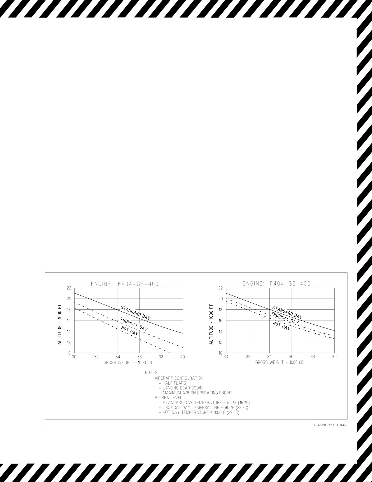
A1-F18AC-NFM-000
CHAPTER 16
Landing Emergencies
16.1 SINGLE ENGINE FAILURE IN LANDING CONFIGURATION
*1. Throttles - MIL or MAX
*2. FLAP switch - HALF
*3. Maintain on-speed AOA and balanced flight.
4. Refer to Single Engine Approach and Landing procedure.
NOTE
At some aircraft weight and high altitude conditions, and with one
engine failed, even the use of MAX thrust on the operating engine may
not provide positive rate of climb capability with half flaps and landing
gear down. Maximum pressure altitude to achieve
100
fpm single
engine rate of climb is provided in the adjacent chart, figure 16-1.
Figure 16-1. Maximum Altitude for 100 FPM Single Engine Rate of Climb
V-16-1
ORIGINAL
A1-F18AC-NFM-000
16.2 SINGLE ENGINE WAVEOFF/BOLTER
During single engine operations at MIL or MAX, loss of lateral and
directional control may occur above the following AOAs:
Flaps FULL - 10° AOA
Flaps HALF - 12° AOA
NOTE
• Best rate of climb during single engine operation occurs at or near
on-speed AOA regardless of configuration or gross weight.
• Minimal reduction in altitude loss can be obtained with selection of
MAX during single engine waveoff, but this technique is not recom-
mended due to increased pilot workload attendant with higher asym-
metric thrust.
• Single engine waveoffs and bolters with F404-GE-402 (EPE) engines
installed may require full rudder and coordinated lateral stick to
control aircraft yaw and roll produced by asymmetric thrust.
• Figure 16-2 provides recommended maximum gross weight for single
engine carrier recovery for both GE-F404-400
and -402 powered
aircraft. Adjusting gross weight at or below the recommended weight
ensures less than 50 feet altitude lost during an onspeed AOA single
engine military power waveoff from an onspeed AOA/on glideslope
condition. Maximum waveoff altitude lost for two engine operation
under identical conditions is less than 30 feet. Recommended weights
are applicable to windmilling or seized condition for the failed engine.
• With left engine failure, once positive rate of climb is achieved, raise
the landing gear to improve acceleration and climb at a low angle of
attack to a safe altitude/airspeed.
16.3
SINGLE ENGINE APPROACH AND LANDING
• Use of afterburner on the good engine above on-speed AOA aggravates
directional control problems resulting in higher single engine mini-
mum control airspeed (about 8 to 10 knots).
• With F404-GE-402 (EPE) engines installed, use of afterburner on the
good engine with full flaps selected (sudden single engine waveoff or
bolter) may put the aircraft at or below single engine minimum control
airspeed depending on gross weight. Exercise caution to avoid overro-
tation. Apply rudder and lateral stick as necessary to counter yaw
V-16-2
ORIGINAL
A1-F18AC-NFM-000
induced from asymmetric thrust until rudder control power is regained
as the aircraft accelerates.
NOTE
• In the F/A-18C/D with either engine secured, significantly lower
and/or cyclic dump rates have been experienced. When the right
engine is secured, lower dump rates follow immediately and may be
accompanied by a CG caution. When the left engine is secured, lower
dump rates are experienced as total fuel reaches 6500 pounds (when
tank 4 is empty).
• Hydraulic system capacity is dependent on respective engine rpm.
Excessive simultaneous hydraulic system demands (i.e., landing gear
activation, flap movement, and multiple flight control inputs, etc.)
combined with single engine rpm below 85% may exceed hydraulic
system capacity or result in FCS reversion to MECH. Therefore, when
practical, maintain engine with operating HYD system at or above
85% rpm.
• To prevent repeated switching valve cycling, avoid stabilized flight
where engine windmilling rpm produces hydraulic pressure fluctua-
tions between 800 to 1600 psi.
GENERAL CONSIDERATIONS -
1. Reduce gross weight.
NOTE
Recommended single engine recovery weight is depicted in figure 16-2.
2. If practical, maintain operating engine rpm at or above 85% rpm to preclude MECH reversion.
3. Consider crossbleed to provide HYD 2 pressure to extend the landing gear normally and to
preserve APU accumulator pressure for emergency braking and emergency nosewheel steering.
• Do not crossbleed if engine and/or AMAD related damage is sus-
pected.
• Extended crossbleeding of a failed engine traps feed tank fuel on that
side if the FIRE light has not been pushed, and may result in a
flameout.
• ATS exhaust may blister paint and cause possible door damage on the
aft underside of the fuselage.
V-16-3
ORIGINAL
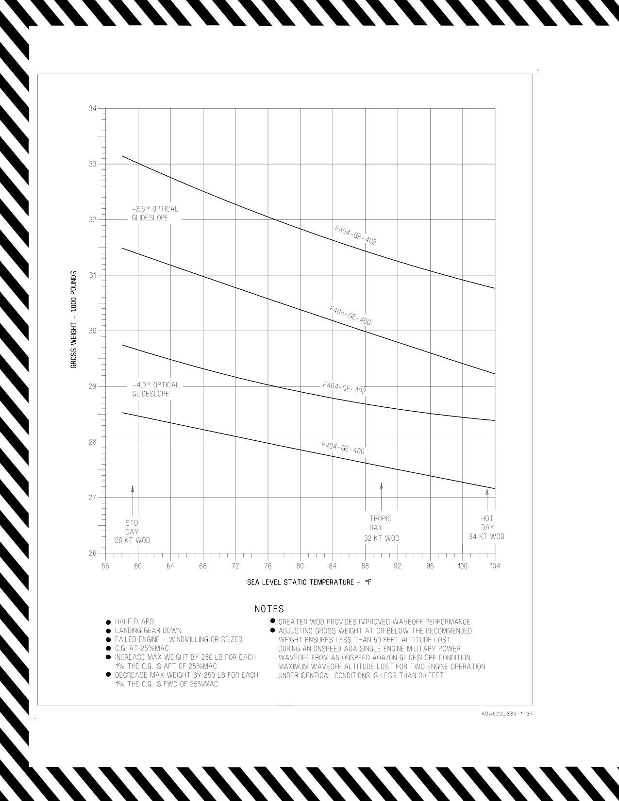
A1-F18AC-NFM-000
Figure 16-2. Recommended Maximum Single Engine Recovery Weight
V-16-4
ORIGINAL
A1-F18AC-NFM-000
Starting the APU airborne may result in a BALD shutdown due to
ingestion of exhaust gases into the APU ducting.
4. Fly a straight-in approach.
5. Plan approach to make turns using shallow bank angle (≤15°).
6. Do not exceed on-speed AOA in turns.
7. Avoid turns into inoperative engine.
LEFT ENGINE FAILED -
1. FLAP switch - HALF
2. LDG GEAR handle - DN
3. Make a normal landing or a precautionary short field arrested landing (if practical).
RIGHT ENGINE FAILED -
1. FLAP switch - HALF
2. Execute Landing Gear Emergency Extension procedure.
If short field arresting gear available -
3. Make an arrested landing.
If short field arresting gear NOT available and right engine crossbleed NOT desired/required -
3. EMERG BRK handle - VERIFY PULLED TO DETENT (anti-skid is not available)
4. Make a normal landing.
5. Consider paddle switch - PRESS after touchdown to preserve APU ACCUM pressure for braking
and slow speed NWS.
6. Use emergency brakes with steady brake pressure (DO NOT PUMP). Anti-skid is not available.
Once stopped on runway -
7. Do not taxi (even if HYD 2A caution is removed).
If short field arresting gear NOT available and right engine crossbleed IS desired/required -
If APU ACCUM caution light on (i.e., landing gear emergency extended) -
3. Recharge the APU accumulator.
a. Left throttle - ADVANCE to 85%rpm minimum
b. ENG CRANK switch - R
V-16-5
ORIGINAL