F18. FLIGHT MANUAL (2008) - page 8
A1-F18AC-NFM-000
1.
(D) Flight controls and throttles - FUNCTIONALLY CHECK
2.
(D) Emergency landing gear system - CHECK
a. Flaps - HALF
b. Slow to 160 knots if practical.
c. Pull the EMERG LDG GEAR handle until it locks in the detent. (This is to be accomplished
without any activation of the front cockpit emergency extension system.)
d. Check that gear indicates down within 30 seconds.
e. Front crewmember set the landing gear handle to DN and hold the HYD ISO switch in ORIDE
for 10 seconds or until the APU ACCUM caution is removed and the emergency brake
accumulator is recharged (gauge reads 2,750 to 3,250 psi and the needle stops moving).
To prevent damage to the main landing gear, the landing gear handle
must be outboard (down position) before resetting the handle from
emergency to normal. Wait 5 seconds following the circuit breaker or
handle reset before placing the landing gear handle up.
f. Reset the rear EMERG LDG GEAR handle, then have front crewmember raise the landing
gear.
10.5.1.8 After Landing
1.
(D) BIT - CHECK DISPLAY
2.
(D) FCF Profile - COMPLETE
III-10-48
ORIGINAL
A1-F18AC-NFM-000
PART IV
FLIGHT CHARACTERISTICS
Chapter
11 - Flight Characteristics
65
(Reverse Blank)
ORIGINAL
A1-F18AC-NFM-000
CHAPTER 11
Flight Characteristics
11.1 HANDLING QUALITIES
The flight control system (FCS) is designed to provide both stability and controllability. Stability,
the measure of the aircraft’s resistance to external disturbing forces, provides a predictable and steady
platform for accomplishing various weapons delivery tasks. Controllability, the measure of ease of
changing the aircraft’s speed, direction and acceleration provides the means for flying the aircraft
aggressively. The flight control system achieves both stability and controllability by monitoring
aircraft motion and pilot input, applying preprogrammed control laws, and then commanding control
surface movement to provide the responsiveness and maneuverability of an agile fighter and the steady
platform of a good attack aircraft.
11.1.1
Flight Control Modes. Handling qualities are dependent on the mode in which the FCS is
operating. The mode is determined by the FLAP switch position (AUTO or HALF/FULL). However,
if airspeed exceeds approximately 240 KCAS the flight controls automatically switch to the AUTO
mode regardless of the FLAP switch position. The FCS control laws are designed to minimize
transients when transitioning between modes.
11.1.2 HALF or FULL Flap Configuration. The FCS incorporates full-time AOA feedback in the
flaps HALF or FULL mode. For this reason, longitudinal trim is required when changing AOA and/or
airspeed. When the aircraft is trimmed to an AOA, it tends to maintain that AOA and some
longitudinal stick force or trim is required to fly at another AOA. The aircraft is very responsive in
pitch. Precise aircraft response is generally best achieved using small control inputs. Rapid longitu-
dinal control inputs can saturate the stabilator actuator resulting in a PIO. PIOs have occurred during
both field and carrier approaches, especially when using ATC. During the final portion of approaches
using ATC, try to make small pitch control inputs. Although lateral response is characterized by slight
adverse yaw, heading control is good.
11.1.2.1
Stalls in HALF or FULL Flaps. With flaps HALF one g stalls exhibit somewhat better lateral
directional flying qualities than with flaps FULL. Wing rock and sideslip excursions occur in the 20°
AOA region. Warning cues occur at 12° (increasing stick force gradient) and 15° (departure warning
tone). With flaps FULL, as AOA increases to 12°, buffet and the departure warning tone provide good
stall warning cues of impending high AOA. At 12° AOA, an increase in the stick force/AOA gradient
can also be felt. This provides additional stall warning. Onset of wing rock occurs in the 15° AOA
region. As AOA is further increased, aft stick requirements increase. Wing rock increases in amplitude
and is accompanied by sideslip oscillations as the aft stick stop is reached. For either flap setting,
maximum attainable AOA is about 25°. Large rates of descent may occur above the AOA limit in
HALF or FULL flaps. Immediate stall recovery is obtained by neutralizing longitudinal stick which
rapidly reduces AOA and allows the aircraft to attain the current trim value.
11.1.2.2 Takeoff and Landing Characteristics. During takeoff, stick aft of neutral should be
commanded at the computed Nose Wheel Lift Off (NWLO) speed (see Chapter 7). Commanding aft
stick too early can result in longer takeoff rolls due to the added drag of the stabilators. While the
aircraft has WOW, the flight control logic has been optimized for catapult takeoff and is designed to
anticipate flight by programming in some functions during the takeoff roll. However, during the
landing rollout, some of these functions make the aircraft sensitive to control inputs and could cause
IV-11-1
ORIGINAL
A1-F18AC-NFM-000
the pilot to overcontrol directional and lateral inputs if proper landing technique is not used. This is
particularly true during wet runway or crosswind landing. Gross misapplication of the control stick or
rudder pedals can cause lateral and directional control problems regardless of runway condition. Two
separate WOW functions control the FCS logic after touchdown. The first occurs when the aircraft
weight is on any two landing gear. When this occurs, the FCS no longer attempts to maintain trim
AOA. Stabilator position is a function of stick position and trim setting. The speedbrake can also be
extended and remain extended without having to hold the speedbrake switch aft. Additionally, the
rudder pedal to roll CAS interconnect is faded to zero. The second function occurs after aircraft weight
is on two wheels and airspeed is below 100 knots. At this time, the rolling surface to rudder interconnect
(RSRI) is faded to zero. Thus, during normal landing rollout, the RSRI is active until 100 knots. As a
result, above 100 knots a lateral stick input also commands the rudder in the same direction in
anticipation of adverse yaw that would normally occur in flight. Use of lateral stick should be
minimized during the landing roll.
11.1.2.3
Takeoff, Landing, and Catapult Launch with High Lateral Weight Asymmetries.
Acceleration during field takeoff will result in yaw in the direction of the asymmetry that is easily
controlled with appropriate NWS inputs. After field takeoff, expect a controllable roll into the heavy
wing. Setting the appropriate lateral trim minimizes roll rate after catapult launch. During dual engine
operation and at normal takeoff and landing angles of attack, sufficient lateral directional control
power is available with flaps HALF or FULL and lateral weight asymmetries up to 26,000 ft−lbs. At
asymmetries below 20,000 ft−lbs, lateral directional control does not degrade until about 18° AOA,
where the lateral directional control power becomes insufficient to counter yaw/roll rates. At
asymmetries above 20,000 ft−lbs, lateral directional control power does not degrade until about 15°
AOA, where the directional control power becomes insufficient to counter yaw rates. During single
engine operation, lateral weight asymmetry significantly increases minimum control airspeed. At high
asymmetries, exceeding 12° AOA with flaps HALF and 10° AOA with flaps FULL may generate yaw
rates that cannot be arrested with rudder unless AOA is reduced. Additionally, large lateral stick inputs
(over ½ stick deflection) during single engine, high asymmetry operation can result in adverse yaw and
compound directional controllability. As a result, countering yaw/roll in the landing or catapult launch
configuration requires aggressive rudder inputs combined with proper AOA control, timely stores
jettison, and judicious use of lateral stick (less than ½ stick deflection).
NOTE
When raising the flaps from HALF to AUTO while accelerating during
missed approach with high lateral asymmetry, large sideslip excursions
will be experienced. These excursions result in full scale deflections of
the slip indicator (SI) ball and damp out after a few seconds. Avoid
chasing the ball with rudders as that will tend to aggravate the
condition. Maintain previous rudder input until oscillations have
damped out, then use rudders as necessary to maintain balanced flight.
When landing in a crosswind, land with the heavy wing upwind if possible. Landing with the heavy
wing upwind increases lateral control power and improves lateral directional handling characteristics.
On touchdown, the light wing will rise 3 to 5°, depending on the lateral asymmetry. The greater the
asymmetry, the greater the wing rise. This wing rise is comparable to landing in a 15 knot crosswind,
and can be countered by judicious lateral stick input. The aircraft is easily controlled. Aggressive
IV-11-2
ORIGINAL
A1-F18AC-NFM-000
braking will result in yaw away from the asymmetry that can be countered with appropriate NWS
inputs.
NOTE
Due to the landing gear structural limitations, internal wing fuel and
wingtip missile lateral asymmetry must be used to calculate total
lateral weight asymmetry for landing.
11.1.3 Auto Flap Configuration. The FCS control laws create slightly different handling qualities
than those of most aircraft. The most apparent characteristic is the excellent hands-off stability.
Damping about all axes is high. Static longitudinal stability is neutral since the FCS attempts to keep
the aircraft in 1 g, zero pitch rate flight. Longitudinal trim is used to bias (adjust) the reference load
factor or pitch rate as the pilot desires. Longitudinal trimming is not required as the aircraft accelerates
or decelerates through most of the flight envelope. Once an attitude is set, the aircraft tends to hold
that attitude without further stick inputs, even through the transonic speed regime. This characteristic
reduces stick forces with changing airspeed, lowering pilot workload for most tasks. However, some
flight tasks are made more difficult because the FCS attempts to maintain 1 g flight. For example,
during a dive or steep zoom climb, a small but constant forward stick force is required to maintain a
constant attitude. Airspeed changes cannot be sensed through changing stick forces and difficulty may
be encountered when trying to maintain a desired airspeed during high workload tasks such as
instrument penetration/approach. The FCS incorporates AOA feedback above 22° AOA. To increase
AOA above the feedback AOA of 22°, aft stick must be applied. The AOA for the highest lift available
(CLmax) is approximately 35° AOA. The maximum steady state AOA with full aft stick (35 pounds
stick force) is 50 to 55°. AOA control is good up through max AOA. If the aft stick is released, the FCS
commands nose down pitch until the AOA is reduced below the feedback AOA of 22°. At this time, the
AOA feedback is removed and the FCS again seeks to maintain 1 g flight.
A constant departure warning tone is activated above 35° and below −7° AOA. With inboard tanks
and stores on outboard stations the tone is activated at 25° AOA. The warning tone provides
information that: (1) the pilot may have placed the aircraft in a departure prone region of the flight
envelope; or (2) the aircraft is near the AOA for maximum lift (CLmax). However, the departure
warning tone logic has not been updated to reflect the expanded AOA envelope provided by FCC
PROM 10.7.
11.1.4 Pitch Stability. The FCS provides artificial pitch stability in CAS that prevents significant
handling qualities variation with CG movement due to fuel transfer or stores release/delivery.
Longitudinal control effectiveness and pitch damping are satisfactory up to the AOA/CG limits listed
in Chapter 4. These limits are based on aircraft pitch stability margins and prevent the aircraft from
entering an AOA hang−up condition. During flight in a degraded FCS mode (MECH or pitch DEL)
aircraft stability is be seriously degraded aft of the CG limit and controllability is significantly reduced.
11.1.5 Stick Force. In maneuvering flight, there is a light but constant stick force per g (about 3.5 to
4.5 pounds/g). Unlike many other aircraft, maneuvering stick forces do not vary significantly over the
entire operating envelope as long as the AOA is less than AOA feedback of 22°. Where AOA feedback
is active, maneuvering stick forces are increased significantly.
IV-11-3
ORIGINAL
A1-F18AC-NFM-000
Rapid aft stick movement, with or without g limit override, commands a
very high g onset rate. This high g onset rate can cause immediate loss of
consciousness without the usual symptoms of tunnel vision, greyout, and
blackout. Consciousness may not return for more than 20 seconds after
the g level is reduced to near 1 g.
11.1.6 Pitch Up. A pitch bobble occurs during speedbrake extension/retraction especially during
high speed flight. There is a slight tendency to over control pitch during speedbrake operation in tight
formation at high speed (over 400 knots). The aircraft exhibits a moderate transonic pitch up when
decelerating rapidly through the Mach 1.0 to 0.95 while maintaining a high load factor. This pitch up
seldom is more than a 1½ g increment in load factor. This transonic pitch up is not noticeable during
1 g deceleration or slow deceleration at high load factors.
11.1.7
G−Limiter. The g−limiter function in the FCS limits commanded load factor under most
flight conditions to the symmetric load limit (NzREF) based on gross weight below 44,000 pounds gross
weight (maximum NzREF limit of 7.5 g). Above 44,000 pounds, NzREF is held constant at 5.5 g. The
negative load factor limit command is fixed at negative 3 g’s for all gross weights. At weights greater
than 32,357 pounds the g−limiter does not provide adequate negative g protection and aircraft
overstress is possible.
During rolling maneuvers, the g−limiter reduces commanded load factor up to 80% NzREF. The
additional reduction begins with 0.75 inch lateral stick up to 80% at full lateral stick input of 3 inches.
Very abrupt stick commands can exceed the capabilities of the system and result in an overstress. The
g−limiter can be disengaged during emergency situations by pressing the paddle switch to allow 33%
more load factor capability, but overstress is much more likely in this condition. During decelerations
through transonic flight conditions (0.88M - 1.04M) NzREF is decremented to account for dynamic
pitch−up transients. This FCS function, called the G−bucket, automatically unloads the aircraft to
prevent exceeding the design load limit.
11.1.8
Aircraft Stability and Dynamic Response. The aircraft roll rate is good throughout the
flight envelope. The roll response is essentially constant through 15° AOA. Rolls conducted at 15 to 20°
AOA are prone to slight residual left/right motion upon termination. Above 20° AOA, sideslip and
sideslip rate feedbacks become active to damp out sideslip oscillations and minimize left/right residual
motion. From 25 to 35° AOA, roll performance gradually decreases with increasing AOA. Above 25°
AOA, pedal and lateral stick inputs provide similar responses. Above 35° AOA and at low airspeed the
roll performance is essentially constant. If the AOA is over 35°, the yaw rate warning tone is replaced
by the departure warning tone and yaw rate warning is not available. From 35 to 55° AOA, combined
lateral stick and pedal inputs produce enhanced roll performance compared to individual control
inputs. AOA excursions into the 60s are possible with this input, which can have the consequence of
blanking the air data system and indicating 48 KCAS in the HUD. Above 40° AOA small sideforce
oscillations may occur. Full aft stick results in maximum sustained AOAs between 50 and 55°. At these
AOAs, high rates of descent (18,000 fpm) occur and the aircraft exhibits small, stable pitch oscillations.
Above 50° AOA, undesirable yaw rates can develop, particularly with imperfections on the radome.
Rates can be noticeably higher than minor yaw rate tendencies. Loud airframe and vortex rumbling
noises are heard in the cockpit in the 50 to 55° AOA region. If a yaw rate develops in the 50 to 55° AOA
region, easing the control stick forward off the aft stop should immediately reduce the AOA below 50°
and terminate the yawing motion.
IV-11-4
ORIGINAL
A1-F18AC-NFM-000
If AOA is not immediately reduced, sustained yaw rate in the 50 to 55°
AOA region can lead to the display of spin recovery command arrows and
inadvertent departure from controlled flight.
At Mach numbers greater than 0.8 at AOA greater than 20°, roll control power available to the pilot
is automatically reduced by the FCS in order to prevent nose slice departures.
Rolling at less than 1 g can cause large roll coupling tendencies and can lead to a departure. The
further the g level decreases below 1 g, the larger the coupling tendencies become and the tendency
toward departure increases. If the pilot feels the roll is starting to diverge, through lateral looseness or
rapid uncommanded pitch excursion, he should immediately neutralize controls and terminate the roll.
The flight characteristics described above combine to provide a very agile fighter throughout the
envelope. Excellent pitch pointing capabilities beyond 35° AOA and precise lift vector placement allow
rapid acquisition and fine tracking of air−to−air targets. Above 25° AOA, rudder pedal and lateral stick
inputs command very similar deflection of control surfaces and thus, similar aircraft performance for
bank angle and lift vector control. For symmetrically loaded aircraft, the excellent departure resistance
provides the capability to aggressively reposition the aircraft lift vector with stick and rudder inputs,
even while maintaining high AOA.
11.1.8.1
High AOA Flying Qualities. Use caution during low−speed overhead maneuvers as the
aircraft tends to enter a tailslide if airspeed is insufficient to complete the maneuver. Aft stick must be
increased near the top of a slow speed loop. If the controls are released or aft stick is not increased, AOA
feedback commands enough nose down stabilator (full nose down if necessary) to reduce the AOA
below feedback AOA (22°) that can result in a relatively steady, nose−high attitude. Apply sufficient
aft stick while enough airspeed is still available to establish and maintain a positive pitch rate to keep
the aircraft nose tracking through the horizon. Use maximum allowable AOA based on stores loading
and center of gravity. Maintain aft stick until the nose is below the horizon and airspeed is increasing.
Neutralizing or releasing the controls near the top of a low−speed overhead maneuver is not a good
practice because the nose does not tend to fall through due to the AOA feedback driving full nose down
stabilator, resulting in a nose high, inverted condition as described above. PROM 10.7 increases
departure resistance and improves recoverability from out−of−control flight, but it does not prevent
departures due to insufficient airspeed. If the aircraft ceases to respond to control inputs, an out of
control situation exists.
Starting overhead maneuvers with insufficient airspeed may lead to nose
high, ballistic conditions and departure. The aircraft responds to control
inputs at low airspeed with few cues to impending loss of control.
Recovery from post departure gyrations and developed out of control
motion can require considerable altitude. Entry into such a departure at
low altitudes will likely preclude recovery prior to ground impact.
The excellent controllability and maneuverability at high AOA provided by the FCS control laws
result in superior nose pointing and gun tracking at low airspeeds. Aircraft response to stick and rudder
pedal inputs is crisp and easy to manage, making lift vector control easy up to 35° AOA. Above 20°
IV-11-5
ORIGINAL
A1-F18AC-NFM-000
AOA, sideslip and sideslip rate feedback (beta and betadot feedback) provide rapid aircraft maneu-
verability with aggressive control inputs without sacrificing departure resistance. Enhanced departure
resistance allows the pilot to safely command yaw rates up to the yaw rate tone (40°/sec). Above 25°
AOA, lateral stick or rudder command the same, well controlled, aircraft rolling response. If opposite
stick and pedal are commanded the inputs will essentially cancel each other out and little to no roll
response will result.
The FCS incorporates pirouette logic to produce abrupt heading reversals at high AOA (>25°)
and low airspeed (<210 KCAS). Pirouette logic can be engaged above 25° AOA and below 210 KCAS
by applying full lateral stick and pedal in the same direction. When the criteria are met, the FCS
recognizes the pilot’s desire to rapidly reverse aircraft heading and displaces control surfaces
appropriately, resulting in a well controlled maneuver. Spin display logic is modified during a
commanded pirouette to prevent nuisance spin indications. Aircraft motion can be stopped at the
desired heading by applying full lateral stick and pedal in the direction opposite that which initiated
the maneuver.
11.1.8.2
High Speed Asymmetric FLIR Pod Handling Qualities (TFLIR, ATFLIR, NAVFLIR). Flight
of a clean aircraft with a single TFLIR/ATFLIR pod (with or without pylons) will result in a roll−off
in the direction of the pod of up to 12°/second at transonic (0.90−1.05 IMN) Mach numbers. Above
1.05 IMN, the roll−off begins to decrease, and eventually reverses direction above 1.15 IMN. Although
not individually flight tested, the NAVFLIR is considered to be aerodynamically equivalent to the
TFLIR/ATFLIR and is expected to produce similar roll−off characteristics. Above 0.90 IMN, slight
variations in Mach require large variations in both lateral and directional trim settings to reduce
roll−off and large side forces and maintain ′′hands off’’ balanced flight. The magnitude of the roll−off
at peak conditions (0.95 IMN) can be trimmed out. Additionally, lateral inputs are required under
elevated load factor to maintain the same roll attitude. This additional pilot workload should be
considered during low altitude flight where mission crosscheck time is critical.
Although an asymmetric FLIR pod produces only 1,500 ft−lb of lateral weight asymmetry, it can
result in a significant amount of lateral aerodynamic asymmetry during flight above 0.90 IMN. The
roll−off phenomenon is dominated by this aerodynamic asymmetry, not the lateral weight asymmetry.
During flight simulation, level bomb deliveries using the FLIR for target identification and refinement
were flown in a night environment with no outside visual reference. Uncommanded roll−off appeared
as a rotating FLIR image similar to what is displayed during over−flight of the designated target. It is
possible that uncommanded aircraft bank changes, seen as a rotating FLIR image through the sensor,
may be confused with the rotating image that results from target over−flight.
Uncommanded roll−off due to single FLIR pod carriage during heads-
down sensor operation may result in an unusual aircraft attitude,
disorientation, altitude loss, and possible CFIT.
11.1.9
Flying Qualities with Lateral Weight Asymmetries. The aircraft demonstrates good flying
qualities with lateral weight asymmetries up to 26,000 ft-lb. With low lateral weight asymmetries (less
than 8,000 ft-lb), flying qualities are excellent. The heavy wing tends to drop under positive g, and rise
during negative g. The greater the load factor, the greater the lateral stick deflection required to
maintain wings level. As load factor is increased, lateral stick opposite the heavy wing is required to
maintain wings level up to approximately 25° AOA, above which lateral stick into the heavy wing is
required to maintain wings level or minimize roll rate. Maneuvering flight need not be avoided;
IV-11-6
ORIGINAL
A1-F18AC-NFM-000
although, special attention to AOA and sideslip control is recommended. During aggressive aft stick
maneuvers with lateral asymmetries between 6000 and 8000 ft-lbs (no positive AOA limit for
air−to−air loadings), sideslip into the heavy wing builds notably as the aircraft rolls towards the heavy
wing. The tendency to roll into the heavy wing can be countered with either combined full lateral stick
and rudder pedal inputs or by relaxing the aft stick input to reduce AOA. Full lateral stick inputs
followed by full aft stick inputs without first centering the lateral stick
(as in guns defense
maneuvering) will result in rapid sideslip buildup and a nose-slice departure. Recovery from this
departure occurs quickly by neutralizing controls.
NOTE
Sideslip buildup into the heavy wing is typical as AOA exceeds 25°
with asymmetries near 6,000 ft−lbs, and may result in a nose slice
departure. Departure susceptibility increases above Mach 0.6, and is
most severe at Mach 0.9. Additionally, full lateral stick inputs towards
the heavy wing may increase departure susceptibility. Yaw (sideslip
buildup) can be countered with lateral stick or pedal, or by reducing
AOA.
During maneuvering flight with high lateral asymmetries (12,000 to 26,000 ft-lb), lateral control is
sufficient up to the 12° AOA limit. As 10° AOA is approached, moderate airframe buffet and vortex
rumble occur. During flight with high lateral asymmetries, sideslip must be kept to a minimum to avoid
departure. More attention than normal is required to keep the slip indicator (SI) ball centered,
especially during maneuvering flight. Maneuvering flight with high lateral asymmetries should be kept
to a minimum.
Exceeding the lateral asymmetry AOA limits may result in departure
from controlled flight and spin entry.
11.2 OUT-OF-CONTROL FLIGHT (OCF)
11.2.1 Departure Resistance. The FCS incorporates a number of features that augment the aircraft’s
natural departure and spin resistance. In CAS mode, very aggressive maneuvering is possible. The
F/A−18 is very stable and controllable throughout most of the operational flight envelope. However it
is departure prone in some flight regimes which pilots must be aware of to avoid inadvertent
departures. Factors that directly affect entry and recovery from OCF are external store loading, aft CG,
lateral asymmetry, and flight control degradations. Misapplied controls and/or overaggressive maneu-
vering in departure prone regions of the flight envelope cause nose-slice departures. Application of
excessive coordinated inputs, cross control inputs or aggressive forward stick significantly increases
risk of departure. As Mach increases, this risk further increases. Asymmetric thrust, including
Max/Idle or Max/Flameout splits does not, by itself, cause a departure. However, large thrust
asymmetry combined with aggravated pilot control inputs may cause a nose−slice departure under
otherwise benign conditions. Lower altitudes aggravate asymmetric thrust effects due to the larger
thrust differential.
Yaw stability augmentation significantly reduces the likelihood of departure throughout the
envelope. Addition of sideslip and sideslip rate feedback as well as differential stabilator for yaw rate
generation, an improved inertial coupling limiter and rudder deflection limits in the low AOA region,
IV-11-7
ORIGINAL
A1-F18AC-NFM-000
all increase the departure resistance of the aircraft. Single axis maneuvering is extremely departure
resistant. Roll or yaw inputs combined with aft stick movement are also very resistant to departure.
The aircraft is most susceptible to departure when roll or yaw inputs are combined with forward
inputs, particularly from high AOA and greater than Mach 0.6. Cross control inputs are also very
departure prone above Mach 0.6 and low AOA. Directional stability can be weakened due to carriage
of stores or lateral weight asymmetries, particularly at high g and high calibrated airspeed above 20 to
25° AOA.
Pilot awareness of NATOPS flight limitations/procedures with regard to these factors is fundamen-
tal for prevention of and recovery from OCF situations. It is also imperative that the pilot realize how
to identify a departure. The aircraft has departed when it is not properly responding to control inputs.
Continued control inputs may aggravate the departure, resulting in a prolonged out of control
situation. Releasing the controls, feet off rudders, and retracting the speedbrake recovers the aircraft
from most departures.
11.2.2 Departure Characteristics. Typical F/A−18
departures occur as a yaw divergence
(nose−slice) followed by an uncommanded roll in the same direction. The yaw rate warning tone may
not provide sufficient departure warning. Vortex rumble which occurs when sideslip is excessive or
during abrupt lateral acceleration is a good departure warning cue. However, vortex rumble may not
be noticed during aggressive maneuvering. Side force build−up is also a good indicator of an impending
departure. The initial phase of the departure is not particularly violent or disorienting unless it occurs
at high airspeed/Mach, where large cross control inputs cause rapid unloading, abrupt nose down pitch
rate and violent departure.
At AOAs below 5° and Mach 0.8 or greater, 3/4 to full cross control
application results in violent departure and possible airframe damage.
The aircraft is significantly more departure prone with large lateral asymmetry. Departures at high
airspeed with large lateral asymmetry are violent and yaw and roll away from the heavy wing.
NATOPS AOA limitations must be honored to avoid departure. Excessive sideslip, which builds with
AOA, increases departure susceptibility. Keep the slip indicator (SI) ball centered to minimize sideslip
and consider coordinating rudder pedal input to during roll maneuvers into the heavy wing. Maximum
AOA limits are significantly reduced as lateral asymmetry increases.
NOTE
Avoid aggressive roll maneuvers below 225 knots with any asymmetric
external load.
Releasing the controls, feet off rudders, and retracting the speedbrake should recover the aircraft
from most departures. If post departure oscillations continue, retard the throttles to idle to minimize
engine stall. Consider locking the harness and grasping the left and/or right canopy bow handles to help
stabilize the body. Do not use feet on rudder pedals as unintentional rudder can aggravate an
out−of−control condition. Check altitude, AOA, airspeed and yaw rate for indications of recovery or
development of a stabilized out−of−control mode. Post departure gyrations are characterized by large,
uncontrollable changes in angle of attack and indicated airspeed, accompanied by sideforces and
interchanging AOA and yaw rate tones. Post departure gyrations include uncommanded rolling and
yawing motions in the same direction. Sideforce, felt in the cockpit as a sideways push, is a reliable
IV-11-8
ORIGINAL
A1-F18AC-NFM-000
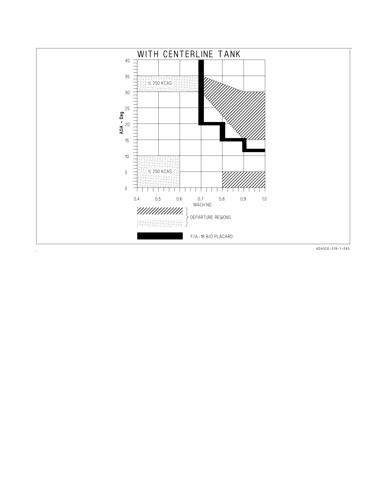
Figure 11-1. F/A-18B/D Departure Regions
indicator of continued departure and is accompanied by a vortex rumble sound as air passes sideways
over the canopy. The effects of time compression in conjunction with the rolling and yawing motions,
and the appearance of transient spin arrows often lead to a premature perception of a spin. Pilot
application of control inputs during post departure gyrations may delay recovery. Controls should
remain released until all three indications of recovery are recognized, or a spin is positively confirmed.
Indications of recovery from post departure gyrations are:
1. AOA and yaw rate tones removed.
2. Side forces subsided.
3. Airspeed accelerating above 180 knots.
The F/A−18 exhibits two Falling Leaf modes (upright and inverted), and four spin modes (three
upright and one inverted.) The most common out of control flight mode encountered is the Falling
Leaf. These modes are described in detail and summarized in the chart at the end of the section.
11.2.2.1 F/A−18 Departure Prone Flight Regions. PROM 10.7 improved recoverability from OCF
significantly over earlier software versions. Departure regions previously attributed to the two-seat
canopy are now mitigated for a symmetrically loaded aircraft. Departures have been eliminated in the
low AOA/low airspeed region. With this in mind, the improvements do not make the Hornet a
departure free aircraft. The following maneuvers and conditions may result in a departure:
IV-11-9
ORIGINAL
A1-F18AC-NFM-000
Stick Forward while applying lateral stick at high AOA above Mach 0.6 - Large amounts of sideslip
can be generated, resulting in several uncommanded residual left/right oscillations upon termination.
The departure is aggravated when combined with pedal in the same direction.
Aggressive Maneuvering with 6,000 to 8,000 ft-lbs Lateral Weight Asymmetry - Full lateral stick
inputs followed by full aft stick inputs without first centering the lateral stick (as in guns defense
maneuvering) will result in rapid sideslip buildup and a nose-slice departure. The worst-case for this
departure tendency is at 340 KCAS and 15,000 ft. Recovery from this departure occurs quickly by
neutralizing controls.
Extremely Low Airspeed Flight Conditions - Residual oscillations can occur following the recovery
from low airspeed conditions (less than 50 KCAS, typically nose-high). A low rate spin can sustain if
the aircraft enters inverted flight, but will recover immediately as the aircraft enters a high AOA
condition. Left/right oscillations are greater if the aircraft enters the low speed condition with one wing
pointed towards the ground.
High Subsonic Mach and Low AOA - At high subsonic Mach and below 5° AOA, violent nose-slice
departures occur if controls are misapplied (abrupt full coordinated control inputs combined with
forward longitudinal stick) during rolling maneuvers at less than 1g. Initial departure motion is
extremely rapid with no warning to the pilot. The departure is extremely violent and may result in
overstress or airframe damage.
High Subsonic Mach and High AOA - With lateral weight asymmetries near 6,000 foot−pounds the
F/A−18B/D has increased departure susceptibility at high subsonic Mach numbers (greater than Mach
0.7). Yaw away from the heavy wing can occur above 25° AOA and above Mach 0.7, becoming more
severe at higher Mach numbers and may be difficult to counter with opposite pedal. Aggressive roll
maneuvers into the heavy wing at greater than Mach 0.8 and greater than 25° AOA can produce
yaw/roll motion away from the heavy wing that cannot be countered with full lateral stick or pedal
inputs. The basic airframe directional stability is low in this region and aggressive high AOA
maneuvering can lead to violent departures from controlled flight. Maneuvering should be terminated
and controls neutralized immediately if yaw rate accelerates significantly or at onset of the yaw rate
warning tone to avoid departure.
11.2.3 OCF Recovery. Post departure dive recovery must be initiated at no less than 6,000 feet AGL
to assure safe ground clearance. If passing 6,000 feet AGL and dive recovery has not been initiated,
eject. There is no buffer associated with the 6,000 foot mandatory ejection altitude. The 6,000 foot
altitude addresses only altimeter errors, aircraft maximum recovery capability, and ejection seat
capability. Delaying the ejection decision below
6,000
feet AGL while departed may result in
unsuccessful ejection. Safe recovery may not be possible with flight control system failures. If safe post
departure dive recovery is in doubt, eject. All indications of recovery must be present (AOA and yaw
rate tones removed, all side forces subsided, and airspeed accelerating above 180 knots) before rolling
upright to recover. For post departure dive recovery, minimum altitude loss is achieved by advancing
throttles to MAX and maintaining 25 to 35° AOA until a positive rate of climb is established. If the
store loading configuration prescribes an AOA limit below 35°, that lower limit should be used for
recovery. If altitude loss is not critical, use less AOA and MIL power to reduce the chance of a
follow−on departure because of potential asymmetric thrust, FCS failure and/or lateral asymmetric
loading.
IV-11-10
ORIGINAL
A1-F18AC-NFM-000
• Post departure dive recovery initiated below 6,000 feet AGL is not
assured. Delaying the ejection decision below 6,000 feet AGL while
departed may result in unsuccessful ejection.
• Positive rate of climb requires wings level pitch attitude (waterline)
greater than indicated AOA.
11.2.4 Falling Leaf Mode PROM 10.7 improved departure resistance and the Falling Leaf has not
been encountered during extensive high AOA flight test. The new software improved recovery from
OCF, making recovery from vertical slow speed departures benign in the two−seat centerline tank
configured aircraft. The Falling Leaf mode is characterized by repeated cycles of large, uncommanded
roll−yaw motions which reverse direction every few seconds. At each reversal the crew will sense high
sideforce accompanied by near zero g. Entry into a sustained inverted Falling Leaf (predominately
negative AOA) mode is highly unlikely.
The F/A−18 has a weak nose−down pitching moment capability in the 45 to 55° AOA region, and
this capability is further reduced with an aft CG and/or external store loading. However, Falling Leafs
have occurred at both forward and aft CGs. Susceptibility to entering the Falling Leaf mode is also
increased with centerline tank loadings because of increased tendency for roll−yaw oscillations, which
drive the large amplitude AOA oscillations exhibited in the Falling Leaf mode. This mode may be
encountered after post departure gyrations during the final stages of spin recovery, or near zero
airspeed (vertical) maneuvers.
Flight controls should remain released until recovery from a Falling Leaf is indicated. Extraordinary
patience is required since the amount of nose−down pitch control power available for recovery is low
due to the strong nose−up inertial pitch coupling generated in this mode. The upright/positive AOA
Falling Leaf mode is the most common Falling Leaf mode. Large altitude loss may occur because of the
high rate of descent which can exceed 20,000 ft/min. Positive indications that the aircraft is recovering
are an increasing nose low attitude and an increasing peak airspeed. Recovery is normally preceded by
the presence of a strong side−force coupled with an unload in a very nose low or slightly inverted
attitude. During the Falling Leaf mode, transient spin arrows may be present. Do not chase the
transient arrows as recovery may be delayed.
Chasing transient spin recovery arrows delays recovery. Do not chase the
spin arrows.
Conditions which indicate recovery from the Falling Leaf mode are:
1. AOA and yaw rate tones removed.
2. Side forces subsided.
3. Airspeed accelerating above 180 knots.
IV-11-11
ORIGINAL
A1-F18AC-NFM-000
11.2.5 Spins. The F/A−18A/B/C/D exhibits four spin modes: low yaw rate, intermediate yaw rate,
high yaw rate and inverted.
NOTE
A clean or symmetrically loaded aircraft is very reluctant to enter any
spin mode with the FCS in CAS, but becomes extremely susceptible to
departure or autorotative spin with with asymmetric store loadings
when AOA limits are exceeded.
11.2.5.1 Low Yaw Rate Spin. The low yaw rate spin mode is characterized by AOAs in the 50 to 60°
range and a very low oscillatory yaw rate (0 to 40°/second). AOA excursions below 50° AOA may
sometimes occur. This mode can be very smooth, although some mild pitch, roll and yaw oscillations
are normally experienced. The low rate spin is not typically violent or disorienting. Low cockpit forces
and a low yaw rate make this mode difficult to recognize as a spin. An oscillatory low yaw rate spin may
be confused with a Falling Leaf. PROM 10.7 incorporated automatic anti−spin commands to protect
against low yaw rate spins.
In a low yaw rate spin, yaw rate may be too low/oscillatory for automatic
engagement of the spin recovery mode (display of spin command arrows).
Manual selection of the SRM mode (SRM switch to RCVY) may be
required for recovery.
Rate of descent for an established low yaw rate spin is approximately 20,000 feet/minute with as
much as 5,000 feet lost per turn. Entry to the spin typically occurs at AOAs between 50 and 60°.
Recovery from low yaw rate spins is very benign, predictable and repeatable with a gradual reduction
in yaw rate followed by rapid break of AOA with a nose−low, accelerating recovery.
Asymmetric thrust and/or asymmetric store loading significantly increases the aircraft’s suscepti-
bility to the low yaw rate spin. Beyond the AOA limits for lateral asymmetries, there is increased
susceptibility to entering a low yaw rate spin. Recovery characteristics are essentially the same as for
symmetrically loaded aircraft. Prompt application of full antispin lateral stick will generate spin
recovery in approximately one turn. Spins will be autorotative with the lateral asymmetries of
approximately 10,000 ft−lbs or more. If recovery controls are not promptly applied, higher yaw rates
generated by greater lateral asymmetry may result in rapid progression into the intermediate yaw rate
spin mode.
11.2.5.2 Intermediate Yaw Rate Spin. Entry into an intermediate yaw rate spin is unlikely in clean
or symmetric store loadings. Entry into this spin mode is more likely with large lateral asymmetry. Spin
motion is characterized by higher average yaw rates (20 to 80°/second). In some cases, yaw rate may
repeatedly oscillate through zero as spin rotation continues in one direction.
IV-11-12
ORIGINAL
A1-F18AC-NFM-000
In a highly oscillatory intermediate yaw rate spin, automatic engagement
of the spin recovery mode may be delayed or inhibited if yaw rate
repeatedly oscillates through zero. Manual selection of the spin recovery
mode (SRM switch to RCVY) may be required if the SRM does not
engage automatically.
The intermediate yaw rate spin is also very oscillatory in pitch and roll. AOA typically varies
between 40 and 80° with bank angle excursions of ±60° or more. Bank angle variations may increase
to the point where the aircraft executes one or more 360° rolls while continuing to spin. Rate of descent
may be as high as 21,000 feet/minute with altitude loss of approximately 1,500 feet per turn. Cockpit
side force may be as high as 1 g. While spinning, the aircraft will unload (negative g) during the 360°
rolls. Due to the highly oscillatory motions and rapid variations in cockpit forces, this spin mode may
be very disorienting, particularly if aircrew are not securely strapped in. Asymmetric store loading
intermediate yaw rate spin characteristics are essentially the same as that of a symmetrically loaded
aircraft. However, spins into the light wing are autorotative at asymmetries greater than 10,000 ft−lbs.
11.2.5.3 High Yaw Rate Spin. The high yaw rate spin mode is characterized by yaw rates in the 100
to 140°/second range and AOAs up to 80 to 90°. This mode is best described as a smooth flat spin.
Small oscillations in pitch and roll occur but are not generally perceived by the pilot. Longitudinal
forces in the cockpit can be as high as −3.5 g (eyeballs out). Consequently the pilot will be significantly
hindered in recovery unless the shoulder harness is manually locked. In the high yaw rate spin mode,
identification of the mode and turn direction is not difficult. Rate of descent for an established high
yaw rate spin averages 18,000 feet/minute (1,000−1,500 foot/turn). Entry into this mode is possible
only with sustained (more than 15 seconds) full pro−spin lateral stick with the spin recovery switch in
RCVY or with very large lateral asymmetry.
With a centerline tank, the high yaw rate spin may be much more oscillatory. Oscillations may be as
much as ±50° pitch and ±125° roll at 100 ±30°/second yaw rate. Due to the large roll rate and yaw rate
oscillations, recovery may be delayed by entry into a Falling Leaf during the final stages of spin
recovery. It is extremely important that yaw rate be reduced to near zero in order to promptly recover
from the Falling Leaf.
High yaw rate spin characteristics for symmetric and asymmetric store loadings are similar with a
few noteworthy exceptions. With lateral asymmetry of 18,000 ft−lbs or more, entry into this spin mode
may occur if AOA limits are exceeded. The spin is autorotative, but even with a 18,000 ft−lbs spin,
recovery can be obtained in less than two turns. Altitude loss is approximately 1,500 feet per turn. Spin
recovery characteristics and capability above 18,000 ft−lbs lateral asymmetry are unknown.
11.2.5.4 Inverted Spin. The F/A−18 is extremely resistant to inverted spin entry. In symmetric store
loadings, short duration SRM arrows (approximately 1 spin turn) have been encountered following
inadvertent departures, typically from slow speed vertical flight. A steady state inverted spin is highly
unlikely and requires full pro−spin controls. However, if a steady state inverted spin is encountered,
it exhibits a yaw rate of approximately 30°/second, negative 50° AOA, rate of descent of 21,000
feet/minute, and altitude loss of 3,500 feet/turn. Spin recovery requires approximately one spin turn
following application of antispin controls, stick in direction of spin recovery arrow (away from the
spin).
IV-11-13
ORIGINAL
A1-F18AC-NFM-000
11.2.5.5 Spin Recovery. Full lateral stick in the direction of the spin recovery arrow must be applied
until spin rotation rate is at or very near zero to minimize inertial pitch coupling and provide maximum
nose-down pitching moment for rapid recovery. Spin recovery lateral stick should be smoothly
neutralized when spin arrows are removed. Spin rotation should be completely stopped for rapid
recovery and to preclude redeparture.
Conditions which indicate recovery from any of the spin modes are:
1. AOA and Yaw rate tones removed.
2. Side forces subsided.
3. Airspeed accelerating above 180 knots.
11.2.5.5.1 Spin Recovery Mode (SRM). Flight characteristics in SRM differ significantly from those
of the normal CAS mode. All FCS feedbacks, interconnects, and gain schedules are removed, leaving
the FCS in essentially a three axes DEL mode. Because the artificial yaw stability features of CAS are
not available in SRM, the directional stability is weak and the nose tends to wander. Because the
lateral control surfaces are not washed out with increasing AOA as they are in CAS, lateral stick can
generate excessive yaw. The aircraft is very susceptible to nose−slice departure with even small stick
deflection. Maintaining AOA less than 20° will significantly reduce the departure potential. An aft CG
increases the possibility of entering into a Falling Leaf if departure occurs. However, holding antispin
input after yaw rate ceases may result in a redeparture.
To prevent entering a Falling Leaf, do not intentionally operate in the
spin recovery mode if the CG is aft of 25% MAC.
Recovery from any of the upright spin modes with the FCS in CAS is likely due to low yaw rate spin
protection logic. This logic feeds antispin commands to the rolling surfaces in response to uncom-
manded yaw rate. With the FCS in SRM, spin recovery characteristics may be more rapid. The
command arrow on the DDI indicates the correct stick position for recovery from either an upright or
inverted spin. Antispin controls are as follows: for upright spins, the command arrow directs the pilot
to apply full lateral stick with the spin direction (i.e., right upright spin, right lateral stick); for inverted
spins, the command arrow directs the pilot to apply full lateral stick opposite the spin direction (i.e.,
inverted left spin, use right lateral stick). In SRM, application of lateral stick in the direction of the
command arrow causes a rapid reduction of yaw rate. After the yaw rate is stopped, forward stick may
be required to reduce the AOA below stall.
With the spin recovery switch in NORM, the SRM disengages when the command arrow is removed.
The CAS automatically drives the stabilators to full trailing edge down during the final stages of spin
recovery. However, it may not be possible to reduce AOA before yaw rate is completely stopped because
of inertial pitch coupling, especially with an aft CG. Recovery from the high yaw rate spin mode
requires approximately 2½ turns. Intermediate and low yaw rate spin modes require a correspondingly
lesser number of turns for recovery. Approximately 12,000 to 14,000 feet may be required for recovery
from a fully developed spin (from application of recovery controls to bottom of dive pullout).
11.2.5.5.2 Manual SRM. If the spin switch is used for spin recovery (spin recovery switch to RCVY)
the SRM does not automatically disengage with command arrow removal. The switch must be placed
IV-11-14
ORIGINAL
A1-F18AC-NFM-000
to NORM when yaw rate ceases and before beginning the dive recovery to prevent redeparture. If the
switch not returned to NORM, a tendency to overcontrol laterally may be present until airspeed
increases above approximately 245 KCAS when the FCS reverts to CAS.
With the spin switch in RCVY (SRM engaged), departure susceptibility
is greatly increased. A departure during the dive recovery is likely if the
spin recovery switch is not returned to NORM. Both the manual and
automatic SRM provide spin recovery in less than 1½ turns (full antispin
controls) for lateral asymmetry up to 10,000 ft−lbs. However, with lateral
asymmetry of 11,500 ft−lbs or more, spin recovery becomes more diffi-
cult. At this asymmetry, premature neutralization of controls causes the
spin to reestablish itself in the original direction. Antispin controls should
be maintained until the yaw rate ceases.
11.2.5.5.3 Spin Recovery Command Arrows. During highly oscillatory post−stall gyrations, spins,
or spin recovery, the spin recovery command arrows may temporarily appear. The pilot should not
attempt to chase these transient command arrows as this may cause inadvertent application of
pro−spin controls and delay recovery. Under these conditions, the controls should be left released until
the command arrow is verified steady. If/when the direction of the command arrow becomes steady and
the pilot has visually confirmed spin type (upright or inverted) and spin direction, prompt application
of full anti−spin lateral stick should then be applied.
IV-11-15
ORIGINAL
A1-F18AC-NFM-000
LIKELY ENTRY
MODE
MODE RECOGNITION
RECOVERY
CONDITION
Falling Leaf
High AOA maneuvering
In-phase yaw/roll motions
Maintain controls released.
Inverted/nose high
which reverse direction ev-
Ballistic
ery few seconds. Repeated
Aggravated by external
sensations of high side-
stores
force accompanied by near
zero g alternating on both
sides of the cockpit. Rever-
sals in heading and
uncommanded AOA excur-
sions from -10° to +70°.
Low
Large sustained control
Lack of response to for-
Stick full with steady
Yaw Rate Spin
inputs at high AOA
ward stick with AOA
arrow, hold until yaw rate
Maneuvering above AOA
maintaining 50° to 60°
ceases.
limits for lateral weight
and low yaw rates (0 to
asymmetries > 6,000 ft-lbs
40°/sec). This mode is not
violent or disorienting.
Intermediate
Maneuvering above AOA
Oscillatory in pitch and
Stick full with steady
Yaw Rate Spin
limits for lateral weight
roll with AOA from 40° to
arrow, hold until yaw rate
asymmetries
80°and yaw rates from 20°
ceases.
to 80°/sec. Cockpit side-
forces may reach 1g and
motion can be disorienting.
May roll while spinning.
High
Maneuvering above AOA
Smooth flat spin motion
Stick full with steady
Yaw Rate Spin
limits for lateral weight
with AOA from 80° to 90°
arrow, hold until yaw rate
asymmetries > 18,000 ft-lb
and yaw rates greater than
ceases.
100°/sec. Longitudinal
force (eyeballs out) up to
3.5g. May be more oscilla-
tory with external stores.
Inverted Spin
Sustained full pro-spin
AOA approximately -50°
Stick full with arrow
controls
and yaw rates of approxi-
(away from the spin) hold
mately 30°/sec.
until yaw rate ceases.
11.3 DEGRADED MODE HANDLING QUALITIES
The reliability of the FCS is very high and when failures do occur, they usually occur singularly. No
single electrical failure effects flying qualities and multiple FCS failures are required to degrade flying
qualities. Depending on which combination of failures has occurred, flying qualities may be consider-
ably degraded. Degraded flying qualities associated with some of the more serious or more common
FCS failures are described here.
IV-11-16
ORIGINAL
A1-F18AC-NFM-000
11.3.1 Single Engine Operation.
11.3.1.1 AUTO Flaps. Engine failure or shutdown with flaps AUTO results in no degradation in
handling qualities under most circumstances at low AOA. A small amount of yaw trim may be required
to counter asymmetric thrust effects. At high AOA, engine failure results in a yaw toward the failed
engine that is controllable by quickly reducing the AOA and countering the yaw with rudder.
11.3.1.2 HALF or FULL Flap Configuration. Single Engine Minimum Control Speed (Vmc) is the
airspeed required to maintain controlled flight with only one operating engine. Because the engines are
not located on the centerline of the aircraft, if only one engine is operating, the unbalanced force of that
engine causes the aircraft to yaw. The rudders are the primary flight control surface that can be used
to counter the yaw caused by the operating engine. However, if the aircraft’s airspeed becomes too slow,
the rudders cannot generate enough control power to oppose the yaw caused by the operating engine.
The slowest airspeed at which the rudders can provide enough control power to counter the yaw
produced by the operating engine is the single engine minimum control airspeed. As AOA and lateral
weight asymmetry increase, the minimum airspeed required to ensure aircraft single engine control
also increases. In other words, for a given airspeed and configuration, lateral directional control is
ensured if AOA is maintained below a critical level. With flaps HALF, maintaining AOA at or below
12° provides sufficient control in almost all circumstances. In flaps FULL, control can be lost above 10°
AOA at light gross weights and large lateral weight asymmetries. In both cases, exceeding the critical
AOA results in large bank angle/sideslip excursions and/or inability to arrest yaw/roll rates. A slight
reduction in AOA, however, quickly restores controllability with little or no loss of altitude.
11.3.1.3 Single Engine Waveoff. During single engine waveoffs (MIL or MAX) up to full rudder may
be required to counter sideslip. Lateral stick may be required to maintain wings level flight, but inputs
should be kept under half stick deflection to avoid inducing adverse yaw. Pilots must be careful not to
over rotate and reach angles of attack where lateral directional control power is reduced. Loss of lateral
and directional control may occur above 12°AOA with flaps HALF and above 10° AOA with flaps
FULL.
11.3.2 FCS Degraded Modes (DEL/MECH). The full authority control augmentation system is
automatically backed up by the direct electrical link (DEL) flight control mode with a digital system
and an analog mode for backup aileron and rudder control. DEL operation results from the lack of
reliable feedback data or operation within the FCS. DEL operation will usually only occur in one axis
(pitch, roll, or yaw), however yaw DEL will initiate roll DEL. If DEL fails, the mechanical link (MECH)
automatically provides roll and pitch control through a direct input from control stick to the stabilator
actuators, bypassing the flight control computers and stabilator actuator servo valves. Detailed
descriptions of the causes of FCS DEL/MECH modes is contained in Chapter 15.
In digital DEL the trim rates are noticeably slower than in CAS, but should allow neutral trimmed
flight throughout the airspeed envelope. Damping of aircraft motion occurs only as a result of natural
aircraft stability so the tendency to enter PIOs is increased, especially at high speeds. Rapid control
inputs (stick, rudder and throttle) should be avoided as they may aggravate aircraft oscillations.
Normal formation flight and refueling operations are possible as long as caution is exercised with
in−close corrections to prevent oscillations from developing. In pitch DEL, use of speedbrake should
be avoided to prevent moderate longitudinal oscillations, unless required in extreme situations for g
control. In roll and yaw DEL the use of rudder is not recommended due to control sensitivity and dutch
roll excitation.
IV-11-17
ORIGINAL
A1-F18AC-NFM-000
In pitch DEL there is very little stabilator authority available. Therefore,
the g available is extremely limited.
Roll rates are significantly reduced at airspeeds above Mach 0.94 in roll
or roll plus yaw DEL and may be as low as 65°/second.
For landing, flying qualities in DEL will be degraded. Consideration should be given to lowering the
landing gear and flaps (HALF) with sufficient time to evaluate approach flying qualities. During
approach in roll DEL the aircraft is easily excited in roll, resulting in a constant 2 or 3° roll oscillation.
There is also no roll limiting, so lateral inputs will produce a noticeable increase in roll rates and roll
response that could lead to a lateral PIO if large rapid inputs are used. No more than half lateral stick
or rudder pedal is recommended due to excessive sideslip and dutch roll buildup. Excessive sideslip can
be generated with maneuvering above on−speed AOA. After a bolter in pitch DEL a large pitch up will
occur which can be countered with forward stick.
Mechanical operation (MECH ON) can be the result of FCS failure, complete electrical failure, or
as a result of pulling FCC channels 1 and 2 circuit breakers. MECH ON is possible with or without
ailerons and rudders operative. If no surface hardover failures occur, reversions into MECH ON are
normally characterized by a rapidly increasing aft stick force, stabilized at 3 to 5 pounds for flaps
AUTO, and 15 to 25 pounds in the landing configuration, and an increased control sensitivity in the
pitch axis. Aft stick force can be trimmed out, but expect stick to move and in the landing configuration
very little aft stick authority will remain. The stick force per g gradient is higher than a normal CAS
aircraft, but will allow adequate maneuvering performance. Speedbrake use can lead to severe
longitudinal PIO. Rapid power changes resulting in trim changes will aggravate the PIO tendency.
Lateral stick inputs will couple into the pitch axis as a nose up rotation that can be countered with
forward stick. For landing HALF flaps will provide better flying qualities. After a bolter in pitch
MECH a large pitch up occurs which can be countered with forward stick. Landing without aileron or
rudder operative, approach speeds are much higher than normal at on−speed AOA and nosewheel
steering is inoperative.
• Reversion to MECH ON has often resulted in large pitch-up or
pitch-down transients.
• Resetting the FCS while in MECH may result in large pitch-up or
pitch-down transients.
11.3.3 Loss of INS data to FCCs. If INS pitch and roll angles are not available due to INS or MUX
bus failures, or if the FCS detects a problem with the INS data, the sideslip rate calculation defaults
to a backup that only uses roll and yaw rates. The sideslip calculation defaults to a backup that only
uses lateral acceleration. This degraded condition is indicated by the presence of PROC Xs in channels
1 and 3 on the FCS status display. However, in this degraded condition there is no significant
IV-11-18
ORIGINAL
A1-F18AC-NFM-000
degradation in departure resistance, high AOA flying qualities, or roll performance. Recoveries from
spins and zero airspeed departures are similar to recoveries in the non-degraded condition.
11.3.4 Leading Edge Flap Failures. Leading edge flap (LEF) asymmetries can occur when one of the
LEF hydraulic drive units (HDU) stalls/fails or the mechanical interconnect between the inboard and
outboard LEF surfaces fails. The most common LEF asymmetry results from a weak LEF HDU that
stalls
(stops moving due to aerodynamic loading) during abrupt longitudinal maneuvers at high
airspeed and low altitude. When this happens, a roll-off away from the failing HDU as AOA or g is
increased followed by an abrupt roll-off in the opposite direction is typical. Failure detection logic in
the v10.7 FCS software is designed to provide advanced warning of a LEF asymmetry; however, during
extremely abrupt maneuvers, an HDU stall may not be detected in time to allow the pilot to abandon
the maneuver and avoid a large roll transient.
During landing approach, maintaining on-speed or slightly fast approach AOA results in the best
flying qualities for any off-schedule symmetric or asymmetric LEF configuration. With a LEF failure
and flaps in AUTO, the LEF and TEF symmetric commands will freeze and the differential LEF and
TEF commands will continue to be commanded. With the FLAP switch set to HALF or FULL, the
failed LEF will remain frozen while the functioning LEF, the TEF and the aileron droop commands
will schedule normally. Due to increased buffet levels with flaps FULL, HALF flap landings are
recommended with LEF failures. When transitioning from flaps AUTO to HALF, yaw/roll motion may
be encountered that can be countered with small lateral stick inputs. Roll-off may also be encountered
during AOA/pitch attitude changes.
11.3.5 Trailing Edge Flap Failures. For a trailing edge flap (TEF) failure the TEF surfaces are
hydraulically commanded to zero degrees. Dynamic pitch characteristics will be more sensitive due to
loss of flap scheduling and roll performance will be degraded. For landing, approach characteristics will
be severely degraded. Aileron droop and aileron to stabilator interconnect will not function. For
shipboard operations, a divert to field landing may be required due to excessive approach speeds.
11.3.6 Gain Override. While not a failure mode, GAIN ORIDE is prescribed for certain AOA or
pitot−static sensor failures to provide better or more predictable handling qualities. With flaps AUTO,
selecting GAIN ORIDE results in fixed gains that correspond to Mach 0.70, 35,000 feet and 2° AOA.
Longitudinal and lateral response is slightly more sluggish as airspeed is reduced below these values
and is slightly more sensitive as airspeed is increased above these values. Regardless, handling qualities
remain very good within the 10° AOA and 350 KCAS NATOPS limits for GAIN ORIDE operation. If
the airspeed limit is exceeded, self-sustaining pitch oscillations will start and aircraft will become
uncontrollable if airspeed is allowed to continue to increase. If the AOA limit is exceeded, departures
are likely since the fixed values of the air data and AOA severely reduce departure resistance.
Additionally, the aircraft will stall at a higher than normal airspeed due to the fixed position of the
LEFs. Be aware that in GAIN ORIDE, no departure warning tone is initiated at either 15° AOA with
FLAPS HALF or 12° AOA with FLAPS FULL.
Transition to or from the landing configuration should be done in level flight at 200 KCAS.
Transition should not be made while in a bank angle due to the higher than normal aft stick forces
required to maintain flight path angle. Sideslip excursions may also occur if flap transition is made in
a turn.
With the flaps HALF, GAIN ORIDE results in fixed gains that correspond to 8.1° AOA. Handling
qualities are best at these conditions and degrade slightly away from on-speed AOA. Small deviations
from 8.1° cause slight handling characteristics degradation, as the aircraft will be less sensitive to
IV-11-19
ORIGINAL
A1-F18AC-NFM-000
longitudinal inputs. Flight is not recommended above 200 KCAS with flaps HALF due to these
characteristics. LEF are fixed at 17° and will not vary with airspeed and AOA. TEFs and aileron droop
are fixed at 30°. Aircraft should remain below 15° AOA to avoid unintentional departures.
With the FLAP switch in FULL, aircraft should remain below 160 KCAS and 12° AOA. Do not
exceed 15° AOA. Flight at 8.1° AOA results in the best control characteristics. Small deviations from
8.1° cause slight handling characteristics degradation, as the aircraft is less sensitive to longitudinal
inputs. LEFs are fixed at 17°, TEFs at 43° to 45° and aileron droop at 42° and will not vary with
airspeed or AOA. With the wings unlocked, aileron droop is set to 0°.
Bolters in GAIN ORIDE require more aft stick input for rotation due to
fixed AOA feedback and zero rudder toe-in deflection. Half aft stick is
recommended for rotation from bolters in GAIN ORIDE to reduce
aircraft settle.
NOTE
• Alpha tone is disabled in GAIN ORIDE with FLAP switch HALF or
FULL.
• Aircraft must be trimmed longitudinally on-speed for approaches with
GAIN switch in ORIDE. Without significant aft stick after touchdown,
bolters in ORIDE with longitudinal trim set below on-speed AOA will
result in settle off the bow.
IV-11-20
ORIGINAL
A1-F18AC-NFM-000
11.4 CENTER OF GRAVITY (CG)
11.4.1 CG Determination. The aircraft CG in percent mean aerodynamic chord (MAC) is based on
aircraft model, external stores, and fuel quantity. Each aircraft has its own unique CG for a clean
configuration, i.e., LG down, full internal fuel, engines, crew, empty gun, and avionics including EW
equipment when installed (found on Weight and Balance form, DD 365-4). Each lot of aircraft has a
Reference CG based on sample aircraft within the lot (figure 11-2). CG Corrections for Configuration/
Stores/Ordnance are listed in figure 11-3.
LOT
MODEL
BUNO
CG (% MAC)
4-9
A
161353 THRU 163175
22.0
4-9
B
161354 THRU 163123
21.8
10 -14
C
163427 THRU 164691
21.3
15 & UP
C
164693 & UP
22.3
10 -14
D
163434 THRU 164692
20.9
15 & UP
D
164694 & UP
21.4
Figure
11-2. Reference CG
STORES
CG CHANGE % MAC
GEAR UP
0.3
AMMO
LOADED
SPENT
400 RDS
-1.4
-0.6
570 RDS
-2.0
-0.9
AIM-9
(STA 1 or 9) 0.2 EACH
AIM-7
(STA 4 or 6) 0.5 EACH
AIM-120
(STA 4 or 6) 0.3 EACH
TFLIR
0.1
NFLIR
0.05
LST/SCAM
0.0
STA 2
STA 3
STA 5
STA
7
STA
8
PYLON
0.1
0.1
-0.2
0.1
0.1
MER-7
-0.05
-0.05
-0.2
-0.05
-0.05
VER
-0.05
-0.05
-0.2
-0.05
-0.05
FUEL TANK (EMPTY)
N/A
-0.0
-0.3
-0.0
N/A
1,000 POUNDS
(Fuel or
-0.05
-0.1
-1.2
-0.1
-0.05
2,000 POUNDS Stores)
-0.1
-0.2
-2.4
-0.2
-0.1
Figure 11-3. CG Correction For Configuration/Stores/Ordnance
IV-11-21
ORIGINAL
A1-F18AC-NFM-000
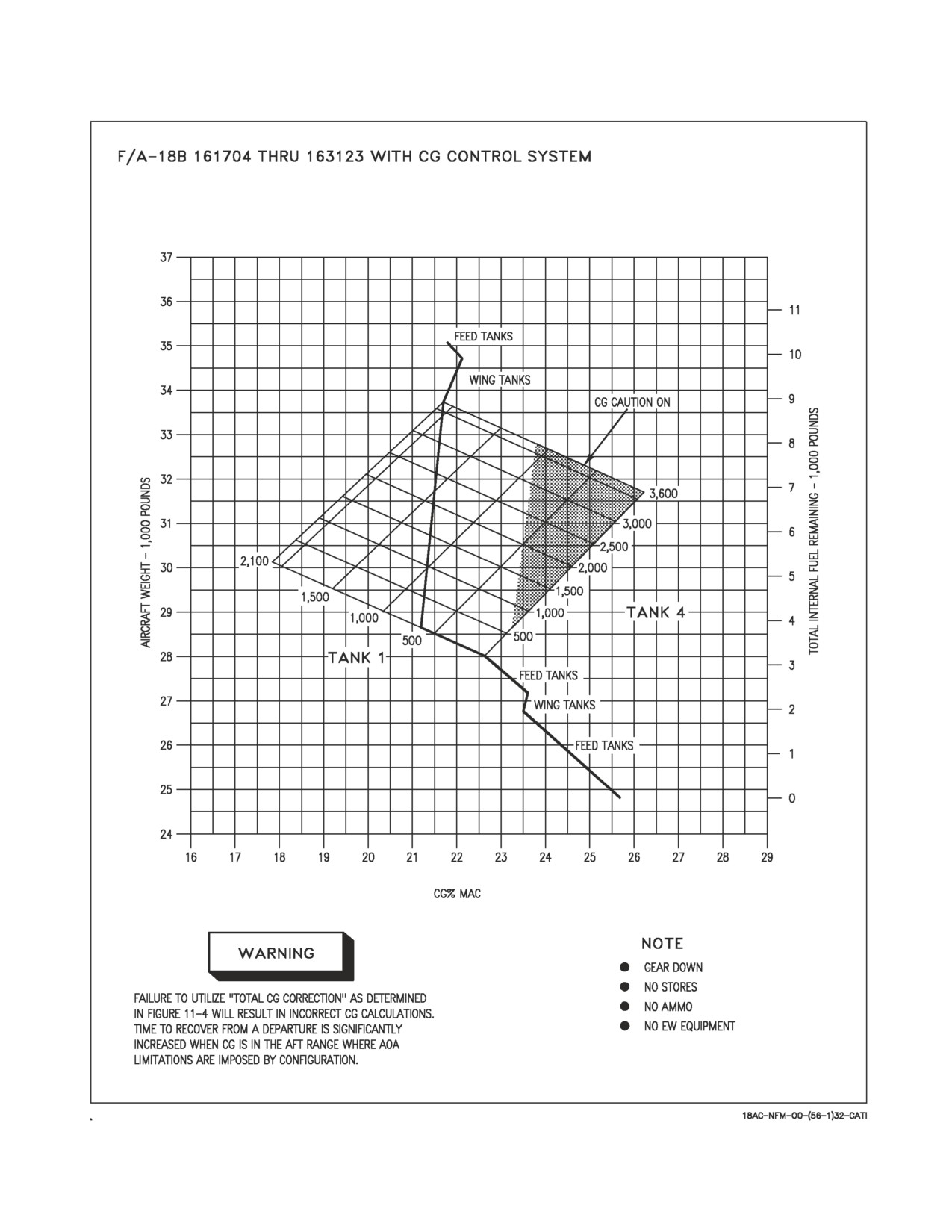
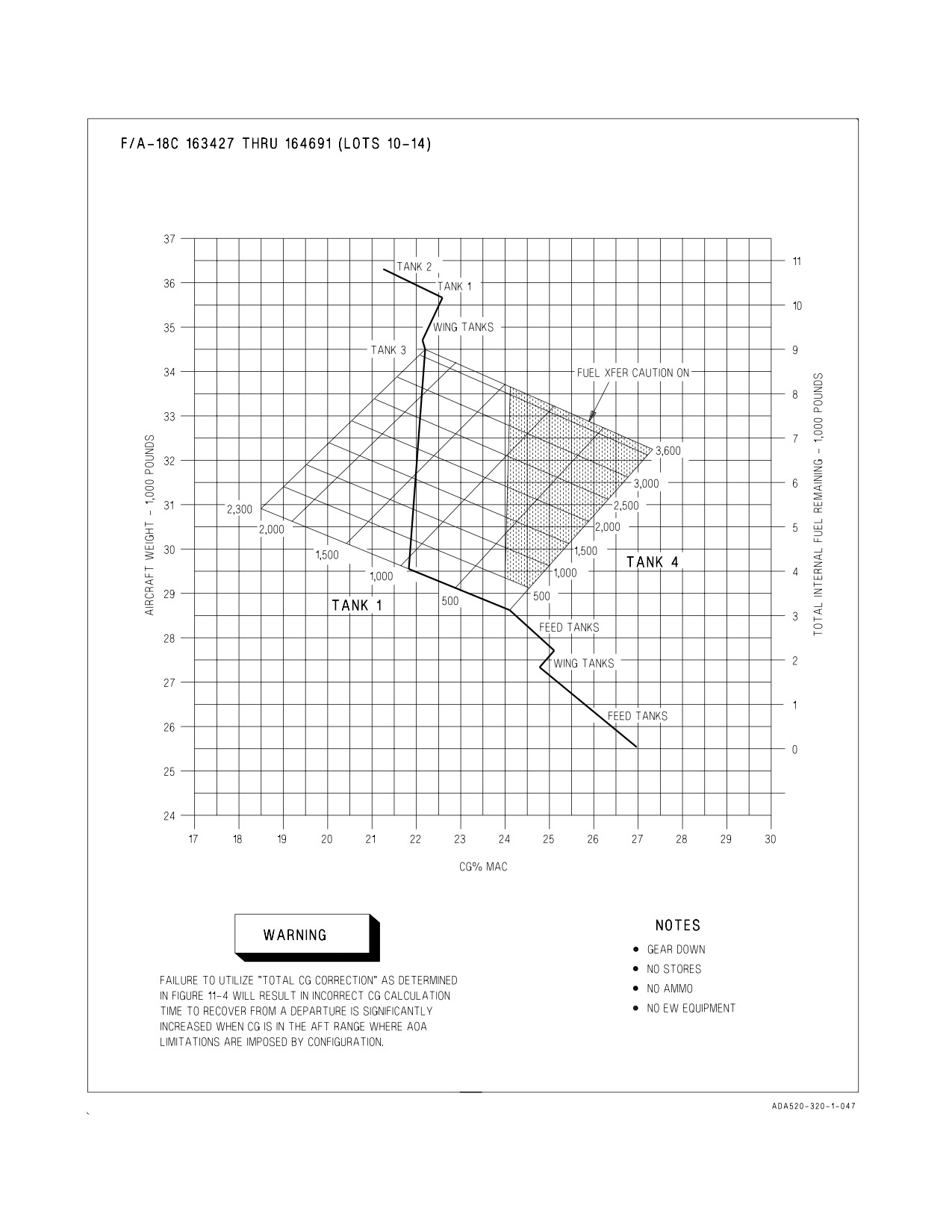
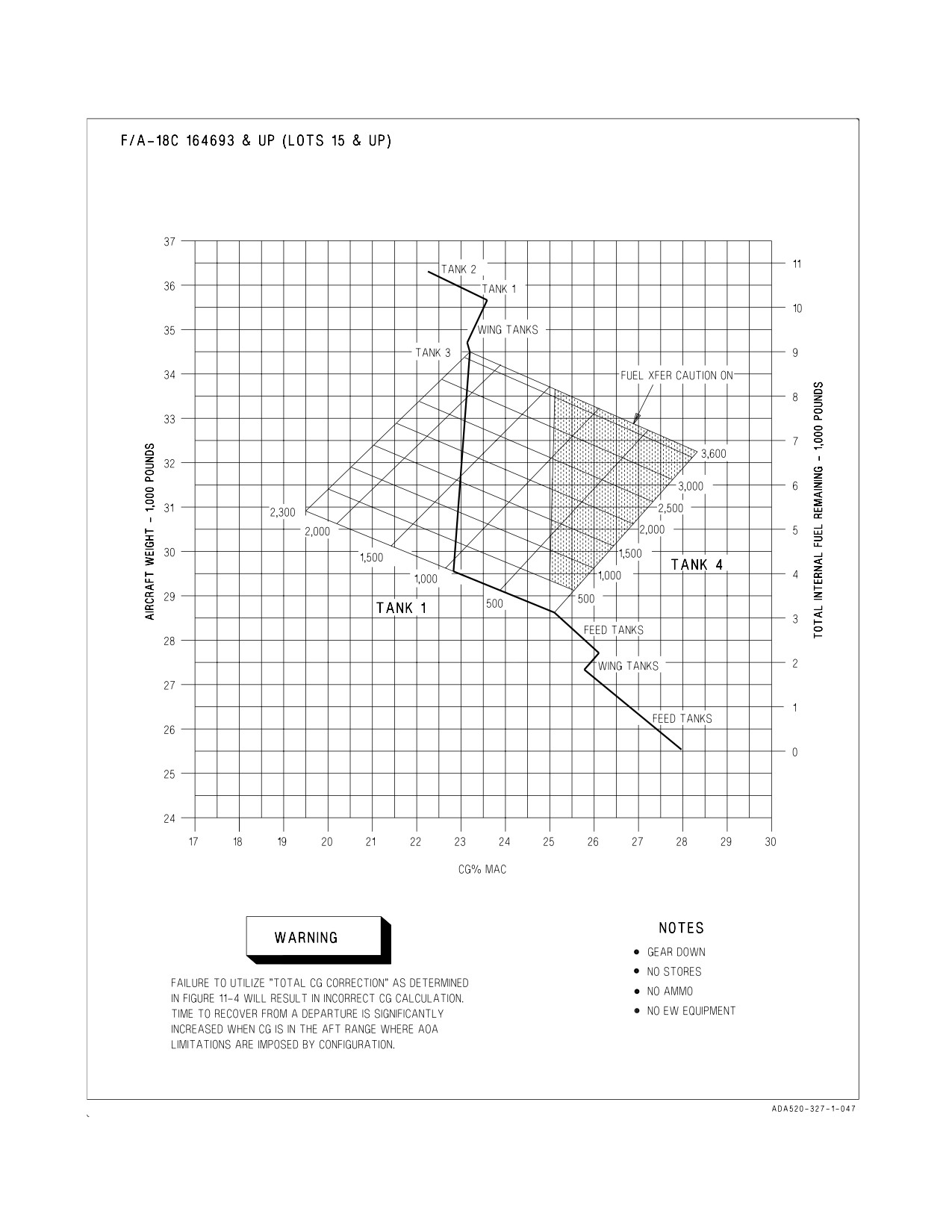
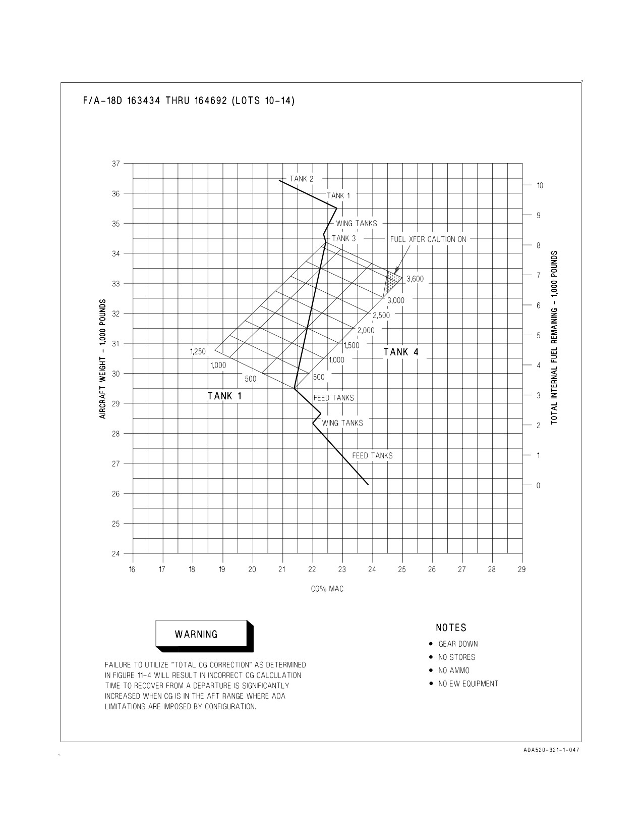
11.4.1.1 CG Worksheet. To determine the Total CG Correction (using figure 11-4 worksheet),
subtract the Reference CG (figure 11-2) from the Aircraft Unique CG (DD 365-4), and add the CG
correction (figure 11-3); then add the Total CG Correction to the CG point determined by fuel state
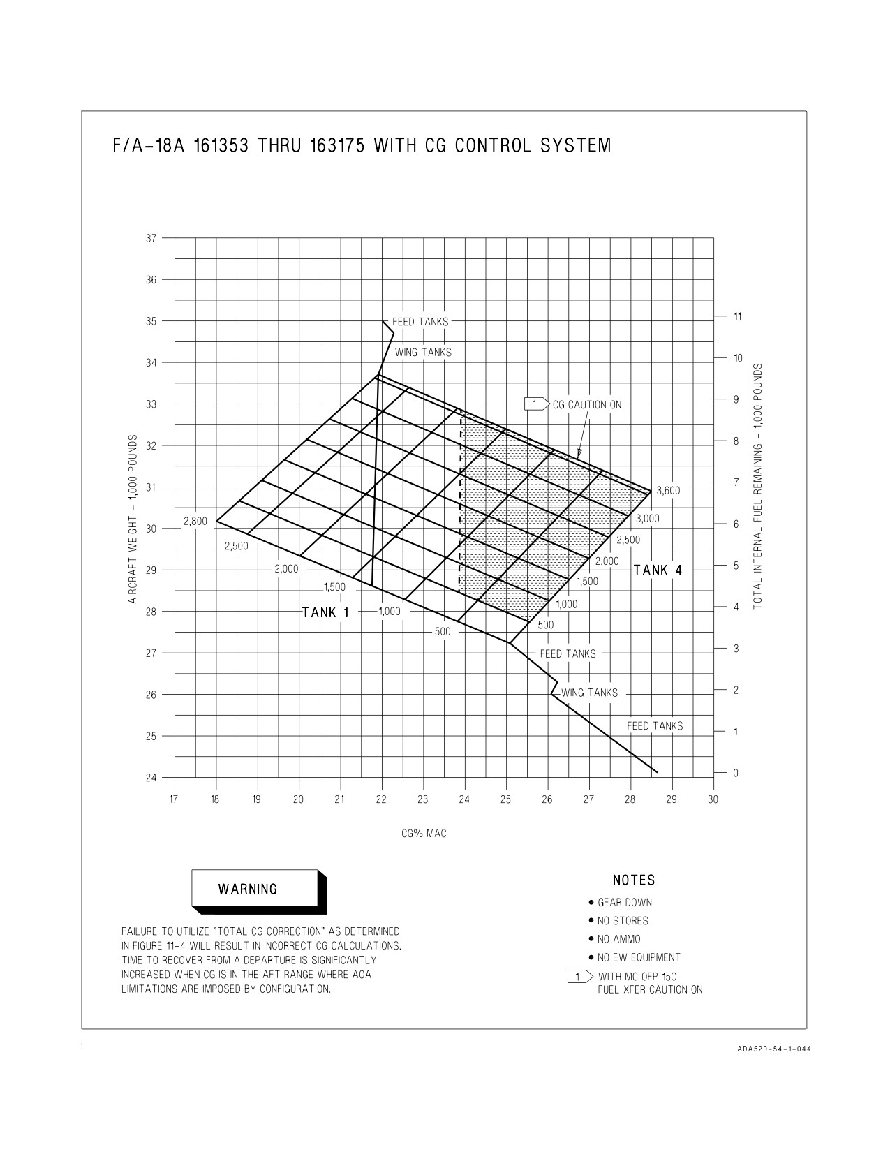
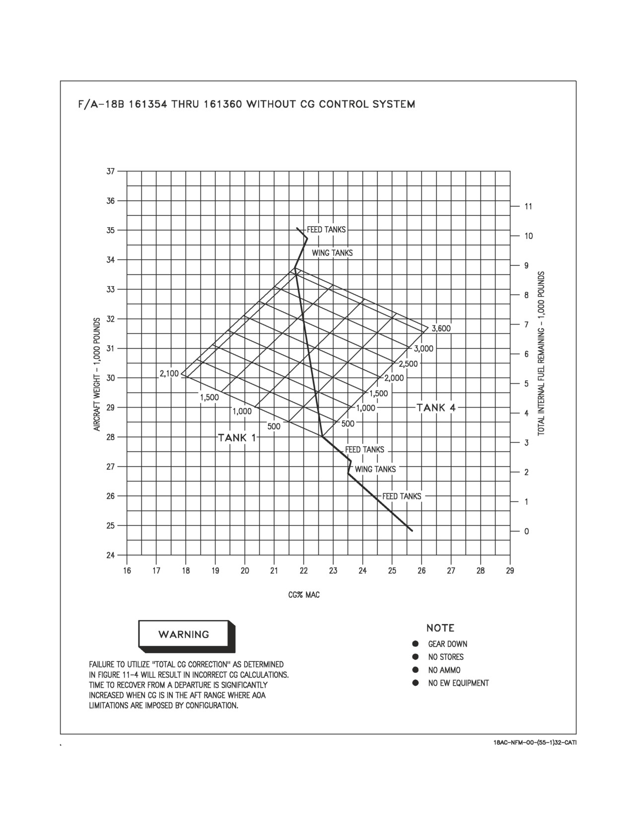
(figures 11-7 thru 11-13). See figures 11-5 and 11-6 as sample problems. Figures 11-7 thru 11-13 show
CG movement relative to a normal fuel burn reference line. Figures 11-14 thru 11-19 are tabular
presentations of figures 11-7 thru 11-13.
Aircraft Unique CG
(DD 365-4)
%MAC
Reference CG
(figure 11-2)
minus
%MAC
CG Stores Correction
(figure 11-3)
plus
%MAC
CG At Fuel State
(figures 11-7 thru 11-13,
plus
%MAC
or 11-14 thru 11-19)
Approximate CG
%MAC
Figure 11-4. CG Worksheet
Failure to utilize ‘‘Total CG Correction’’ as determined in figure 11-4 will
result in incorrect CG calculations. Time to recover from a departure is
significantly increased when CG is in the aft range where AOA limitations
are imposed by configuration.
• The CG or FUEL XFER caution does not indicate when aircraft CG is
out of limits.
• The CG or FUEL XFER caution only indicates a failure of the tank 1
and 4 fuel distribution system.
IV-11-22
ORIGINAL
A1-F18AC-NFM-000
11.4.1.2 Sample Problem CG for F/A-18C Gear Down.
Conditions:
F/A-18C (Lot 14) on the ground (gear down)
10,700 lbs internal fuel
fuel tank, station 5
2,000 lbs fuel, station 5
AIM-9s on stations 1 and 9
AIM-7s on stations 4 and 6
pylons on stations 2, 3, 5 , 7, & 8
a. Aircraft DD 365-4 CG
21.5
%MAC
b. Reference CG
C Model
minus 21.3
%MAC
(Lot 10-14)
= 21.3
(Lot 15 and UP)
= 22.3
D Model
(Lot 10-14)
= 20.9
(Lot 15 and UP)
= 21.4
c. CG Correction for Configuration/
Stores/Ordnance
fuel tank sta 5
-0.3
2,000 lbs fuel sta 5
-2.4
AIM-9 sta 1
0.2
AIM-9 sta 9
0.2
AIM-7 sta 4
0.5
AIM-7 sta 6
0.5
pylon sta 2
0.1
pylon sta 3
0.1
pylon sta 5
-0.2
pylon sta 7
0.1
pylon sta 8
0.1
plus -1.1
%MAC
d. Fuel State CG
10,700 lbs
plus 21.5
%MAC
e. Current CG (a-b+c+d)
20.6
%MAC
Figure 11-5. Sample Problem, CG for a F/A-18C Model, Lot
14
Aircraft, Gear Down
IV-11-23
ORIGINAL
A1-F18AC-NFM-000
11.4.1.3 Sample Problem CG for F/A-18 C Gear Up.
Conditions:
F/A-18C (Lot 14) in-flight (gear up)
3,000 lbs internal fuel
fuel tank, station 5
AIM-9s on stations 1 and 9
AIM-7s on stations 4 and 6
pylons on stations 2, 3, 5 , 7, & 8
a. Aircraft DD 365-4
CG
21.5
%MAC
b. Reference CG
C Model
minus 213
%MAC
(Lot 10-14)
= 21.3
(Lot 15 and UP)
= 22.3
D Model
(Lot 10-14)
= 20.9
(Lot 15 and UP)
= 21.4
c. CG Correction for Configuration/
Stores/Ordnance
gear up
0.3
fuel tank sta 5
-0.3
AIM-9 sta 1
0.2
AIM-9 sta 9
0.2
AIM-7 sta 4
0.5
AIM-7 sta 6
0.5
pylon sta 2
0.1
pylon sta 3
0.1
pylon sta 5
-0.2
pylon sta 7
0.1
pylon sta 8
0.1
plus
1.6
%MAC
d. Fuel State CG
3,000 lbs
plus
24.2
%MAC
e. Current CG (a-b+c+d)
26.0
%MAC
Figure 11-6. Sample Problem, CG for a F/A-18C Model, Lot
14
Aircraft, Gear Up
IV-11-24
ORIGINAL
A1-F18AC-NFM-000
Figure 11-7. CG Travel Due To Fuel Consumption - F/A-18A 161353 THRU 163175
With CG Control System
IV-11-25
ORIGINAL
A1-F18AC-NFM-000
Figure 11-8. CG Travel Due To Fuel Consumption - F/A-18B 161354 THRU 161360
Without CG Control System
IV-11-26
ORIGINAL
A1-F18AC-NFM-000
Figure 11-9. CG Travel Due To Fuel Consumption - F/A-18B 161704 THRU 163123
With CG Control System
IV-11-27
ORIGINAL
A1-F18AC-NFM-000
Figure 11-10. CG Travel Due To Fuel Consumption - F/A-18C 163427 THRU 164691
IV-11-28
ORIGINAL
A1-F18AC-NFM-000
Figure 11-11. CG Travel Due To Fuel Consumption - F/A-18C 164693 AND UP
IV-11-29
ORIGINAL
A1-F18AC-NFM-000
Figure 11-12. CG Travel Due To Fuel Consumption - F/A-18D 163434 THRU 164692
IV-11-30
ORIGINAL
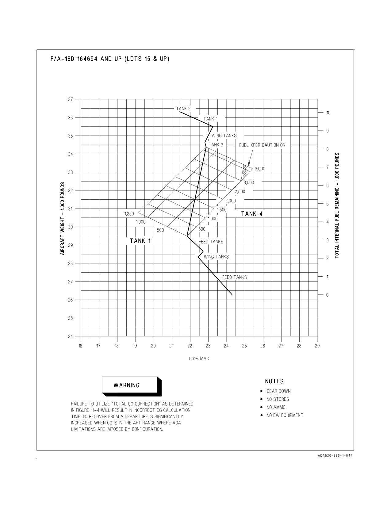
A1-F18AC-NFM-000
Figure 11-13. CG Travel Due To Fuel Consumption - F/A-18D 164694 AND UP
IV-11-31
ORIGINAL
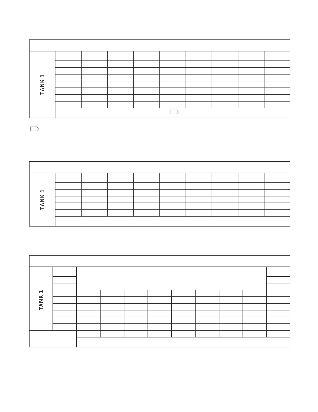
A1-F18AC-NFM-000
F/A-18A
2,800
18.0
18.5
19.1
19.6
20.2
20.7
21.3
21.9
2,500
18.7
19.3
19.8
20.3
20.9
21.5
22.0
22.6
2,000
20.0
20.5
21.1
21.6
21.9
22.7
23.2
23.8
1,500
21.3
21.8
22.3
22.8
23.3
23.9
24.4
25.0
1,000
22.6
23.1
23.6
24.1
24.6
25.1
25.6
26.2
500
23.8
24.3
24.8
25.3
25.6
26.3
26.8
27.2
0
25.1
25.6
26.1
26.5
27.0
27.5
28.0
28.5
0
500
1,000
1,500
2,000
2,500
3,000
3,500
TANK 4
(BOLD:
1
CG CAUTION ON)
1
FUEL XFER CAUTION ON with MC OFP 15C
Figure 11-14. CG vs Tanks 1 & 4 Fuel - F/A-18A
F/A-18B
2,100
17.8
18.4
19.0
19.5
20.0
20.5
21.1
21.7
1,500
19.2
19.7
20.2
20.5
21.2
21.8
22.3
23.0
1,000
20.3
20.8
21.3
21.9
22.4
22.9
23.4
24.0
500
21.5
22.0
22.5
23.0
23.5
24.0
24.5
25.1
0
22.6
21.3
23.6
24.1
24.6
25.1
25.6
26.2
0
500
1,000
1,500
2,000
2,500
3,000
3,500
TANK 4
(BOLD: CG CAUTION ON)
Figure 11-15. CG vs Tanks 1 & 4 Fuel - F/A-18B
F/A-18C 163427 THRU 164691 (Lots 10-14)
2,800
21.5
2,500
Tank 4 Full
22.1
2,300*
22.5
2,300
18.5
19.0
19.5
20.0
20.5
21.1
21.6
22.1
22.2
2,000
19.2
19.7
20.2
20.7
21.2
21.7
22.3
22.8
22.9
1,500
20.5
20.9
21.4
22.0
22.4
22.9
23.4
23.9
24.0
1,000
21.6
22.1
22.6
23.0
23.5
24.0
24.5
25.0
25.1
500
22.9
23.4
23.8
24.2
24.7
25.2
25.6
26.1
26.2
0
24.1
24.5
25.0
25.4
25.8
26.3
26.7
27.2
27.3
* Internal wing
0
500
1,000
1,500
2,000
2,500
3,000
3,500
3,600
tanks full
TANK 4
(BOLD: FUEL XFER CAUTION ON)
Figure 11-16. CG vs Tanks 1 & 4 Fuel - F/A-18C 163427 THRU 164691
IV-11-32
ORIGINAL
A1-F18AC-NFM-000
F/A-18C 164693 AND UP (Lots 15 & UP)
2,800
22.5
2,500
Tank 4 Full
23.1
2,300*
23.5
2,300
19.5
20.0
20.5
21.0
21.5
22.1
22.6
23.1
23.2
2,000
20.2
20.7
21.2
21.7
22.2
22.7
23.3
23.8
23.9
1,500
21.5
21.9
22.4
23.0
23.4
23.9
24.4
24.9
25.0
1,000
22.6
23.1
23.6
24.0
24.5
25.0
25.5
26.0
26.1
500
23.9
24.3
24.8
25.2
25.7
26.2
26.6
27.1
27.2
0
25.1
25.5
26.0
26.4
26.8
27.3
27.7
28.2
28.3
* Internal wing
0
500
1,000
1,500
2,000
2,500
3,000
3,500
3,600
tanks full
TANK 4
(BOLD: FUEL XFER CAUTION ON)
Figure 11-17. CG vs Tanks 1 & 4 Fuel - F/A-18C 164693 AND UP
F/A-18D 163434 THRU 164692 (Lots 10-14)
2,100
21.2
2,000
21.4
Tank 4 Full
1,500
22.4
1,254*
22.8
1,254
18.7
19.2
19.8
20.3
20.8
21.3
21.9
22.4
22.5
1,000
19.2
19.8
20.3
20.8
21.3
21.8
22.4
22.9
23.0
500
20.3
20.8
21.3
21.8
22.3
22.9
23.4
23.9
24.0
0
21.3
21.8
22.3
22.9
23.4
23.9
24.4
24.9
25.0
* Internal wing
0
500
1,000
1,500
2,000
2,500
3,000
3,500
3,600
tanks full
TANK 4
(BOLD: FUEL XFER CAUTION ON)
Figure
11-18. CG vs Tanks 1 &
4 Fuel - F/A-18D 163434 THRU 164692
F/A-18D 164694
AND UP (Lots 15 & UP)
2,100
21.7
2,000
21.9
Tank 4 Full
1,500
22.9
1,254*
23.3
1,254
19.2
19.7
20.3
20.8
21.3
21.8
22.4
22.9
23.0
1,000
19.7
20.3
20.8
21.3
21.8
22.3
22.9
23.4
23.5
500
20.8
21.3
21.8
22.3
22.8
23.4
23.9
24.4
24.5
0
21.8
22.3
22.8
23.4
23.9
24.4
24.9
25.4
25.5
* Internal wing
0
500
1,000
1,500
2,000
2,500
3,000
3,500
3,600
tanks full
TANK 4
(BOLD: FUEL XFER CAUTION ON)
Figure 11-19. CG vs Tanks 1 & 4 Fuel - F/A-18D 164694 AND UP
IV-11-33 (Reverse Blank)
ORIGINAL
A1-F18AC-NFM-000
PART V
EMERGENCY PROCEDURES
Chapter
12 - General Emergencies
Chapter
13 - Ground Emergencies
Chapter
14 - Takeoff Emergencies
Chapter
15 - Inflight Emergencies
Chapter
16 - Landing Emergencies
Chapter
17 - Ejection
Chapter
18 - Immediate Action
67
(Reverse Blank)
ORIGINAL
A1-F18AC-NFM-000
EMERGENCY INDEX
Conference X-ray telephone number (Inflight emergencies only)
314-232-9999 and 866-543-5444
CHAPTERS 12 THRU 17
Page
No.
Abort
V-14-2
ADC Failure Effects
V-15-34
Advisory Displays
V-12-50
Afterburner Failure
V-15-1
Aileron Failure/AIL OFF Caution
V-15-60
AMAD Caution
V-15-26
AMAD PR Caution
V-15-26
AOA Probe Damage
V-15-45
APU Restart Envelope
V-15-8
Asymmetric Thrust Effects
V-15-4
Auto Flap Landing
V-16-15
Barricade Arrestment
V-16-17
Brake Failure/Emergency Brakes
V-13-4
Cockpit Smoke, Fumes, or Fire
V-15-30
Cockpit Temperature High
V-15-29
Controllability Check
V-15-63
Crossbleed Restart Envelope
V-15-8
CSC MUX Failure
V-15-19
CV Recovery Matrix
V-16-21
Damaged AOA Probe Procedure
V-15-47
DEL ON Caution
V-15-49
Display Malfunction
V-15-32
Ditching
V-17-39
Double Generator Failure
V-15-19
Double Transformer-Rectifier Failure
V-15-19
Egress
V-13-3
Ejection Sink Rate Effect
V-17-6
Ejection
V-17-1
Emergency Brakes
V-13-4
Emergency Catapult Flyaway
V-14-1
Emergency Power Distribution
V-15-22
Emergency Tanker Disengagement
V-15-19
Engine Fails To Respond
V-15-2
Engine Fails To Start/Hung Start
V-13-1
Engine Failure
V-15-3
Engine Fire in Flight
V-15-1
Engine Stall
V-15-4
Emergency Index-1
ORIGINAL
A1-F18AC-NFM-000
Engine Stuck at MIL
V-15-1
External Stores Jettison
V-15-32
External Tank Transfer Failure
V-15-17
FCS Failure
V-15-45
FCS Failure Indications and Effects
V-15-34
Feed Tank Transfer Failure
V-15-17
Field Arresting Gear
V-16-16
Field Arrestment
V-16-16
Field Arrestment Gear Data
V-16-17
FLAPS OFF Caution
V-15-57
FLAP SCHED Caution
V-15-59
Flight Control Effects Due to Hydraulic Failures
V-15-13
Forced Landing
V-16-6
Fuel Transfer Failures
V-15-16
Fuselage Fuel Leak
V-15-15
Go Around
V-14-3
Ground Fire
V-13-1
High Altitude Ejection
V-17-4
Hook Fails To Extend
V-16-15
Hot Brakes/Brake Fire
V-13-2
Hot Start
V-13-1
Hydraulic Failure
V-15-9
Hydraulic Flow Diagram
V-15-11
Hydraulic Subsystem Malfunction Guide
V-15-12
Hypoxia/Low Mask Flow/No Mask Flow
V-15-27
Immediate Action Items
V-12-1
Inlet Ice Caution
V-12-20
Jammed Controls
V-15-60
Landing Gear Emergency Extension
V-16-9
Landing Gear Emergency Flow Chart
V-16-12
Landing Gear Fails To Retract
V-14-5
Landing Gear Malfunction-Landing Guide
V-16-13
Landing Gear Unsafe/Fails To Extend
V-16-8
Landing With Aft CG
V-16-15
LEF Failed (With Inboard Position Failed Up Beyond 4° Over-Travel Stop)
V-15-58
LEF Failed (With Inboard Position Less Than 4° UP) OR TEF Failed
V-15-59
Loss of Cabin Pressurization
V-15-31
Loss of DC Essential Bus
V-15-21
Loss of Directional Control During Takeoff or Landing (Blown Tire, NWS
Failure)
V-14-3
Loss of Thrust on Takeoff
V-14-4
Low Altitude Ejection
V-17-3
MECH ON Caution
V-15-56
MECH ON with AIL and RUD Operative
V-15-56
MECH ON with AIL and RUD Off
V-15-57
Minimum Ejection Altitude
V-17-9
NWS Caution
V-15-60
Emergency Index-2
ORIGINAL
A1-F18AC-NFM-000
OBOGS DEGD/Failure
V-15-28
OCF Flight
V-15-60
OCF Recovery
V-15-62
Oxygen Leak
V-15-26
Pitot Static Probe Damage
V-15-48
Planing Link Failure
V-16-6
Power Transmission Shaft Failure
V-15-9
Restart
V-15-5
Seawater Entry
V-17-5
Short Field Arrestment
V-16-16
Single Engine Failure in Landing Configuration
V-16-1
Single Engine Approach and Landing
V-16-2
Single Engine Waveoff/Bolter
V-16-2
Spooldown Restart Envelope
V-15-7
Stuck Throttle/Engine Fails to Respond
V-15-2
Uncommanded Fuel Dump
V-15-18
Uncommanded Pitch and Roll Excursions
V-15-51
Uncommanded Roll Excursion with Aileron Surface Missing/Damaged
V-15-52
Unresponsive Engine
V-15-1
Windmill Restart Envelope
V-15-7
WOW System Failure
V-14-7
Emergency Index-3
ORIGINAL
A1-F18AC-NFM-000
WARN/CAUT/FCS/HYD/ADVIS
Warn/Caut/FCS/Hyd/Advis
Page No
Warn/Caut/FCS/Hyd/Advis
Page No
AHMD
V-12-50
GUN GAS
V-12-19
AIL OFF
V-12-27
HIAOA
V-12-52
AIR DATA
V-12-7
HMD
V-12-52
ALGN Xd
V-12-50
HOME FUEL
V-12-19
AMAD L/R
V-12-7
HOOK
V-12-5
AMAD & PR L/R
V-12-7
HYD 1A
V-12-34
ANTI SKID
V-12-8
HYD 1B
V-12-34
AOA DEGD
V-12-8
HYD 2A
V-12-35
APU ACCUM
V-12-8
HYD 2B
V-12-36
APU FIRE
V-12-3
HYD 1A/1B
V-12-36
ASPJ DEGD
V-12-8
HYD 1A/2A
V-12-37
ATARS OVRHT
V-12-9
HYD 1A/2B
V-12-38
ATS L/R
V-12-9
HYD 1B/2A
V-12-39
AUTO PILOT
V-12-10
HYD 1B/2B
V-12-40
AV AIR DGD
V-12-10
HYD 2A/2B
V-12-41
AV AIR HOT
V-12-10
HYD 1A/1B/2A
V-12-42
BATT LO (E&U)
V-12-10
HYD 1A/1B/2B
V-12-44
BATT SW
V-12-10
HYD 1A/2A/2B
V-12-46
BINGO
V-12-11
HYD 1B/2A/2B
V-12-48
BIT
V-12-50
IFF OVRHT
V-12-19
BLD OFF L/R
V-12-11
INLET ICE
V-12-20
BLEED Dual
V-12-3
IN TEMP L/R
V-12-19
BLEED Single
V-12-4
INS ATT
V-12-21
BOOST LO L/R
V-12-12
INS DEGD
V-12-21
BRK ACCUM
V-12-12
INS VEL
V-12-21
CABIN
V-12-12
L BAR
V-12-6
CANOPY
V-12-13
L DEGD
V-12-53
CAUT DEGD
V-12-13
LADDER
V-12-21
CG
V-12-13
LEFT
V-12-53
CHECK SEAT
V-12-13
LOADX
V-12-53
CHECK TRIM
V-12-13
MC 1
V-12-21
CK ECS
V-12-13
MC 2
V-12-21
CK FLAPS
V-12-13
MC CONFIG
V-12-21
CNI
V-12-13
MECH ON
V-12-31
DECM
V-12-51
MIDS
V-12-53
DEL ON
V-12-27
MNTCD
V-12-53
DFIRS GONE
V-12-13
MSNCD
V-12-53
DISCH
V-12-51
MU LOAD
V-12-22
DL OVRHT
V-12-14
NAV FAIL
V-12-22
DTR 1/2 COLD
V-12-14
NAV HVEL
V-12-22
DTR 1/2 SHTDN
V-12-14
NAV VVEL
V-12-22
DUCT DR L/R
V-12-14
NFLR OVRHT
V-12-22
DUMP OPEN
V-12-14
NWS
V-12-32
EGT HIGH L/R
V-12-15
OBOGS DEGD
V-12-23
ENG MATCH
V-12-15
OCS
V-12-23
EXT TANK
V-12-15
OIL PR L/R
V-12-23
EXT XFER
V-12-16
OVRSPD L/R
V-12-23
FC AIR DATA
V-12-28
OXY LOW
V-12-23
FCES
V-12-29
PARK BRAKE
V-12-24
FCS
V-12-29
PITOT HT L/R
V-12-24
FCS HOT
V-12-29
POS/ADC
V-12-24
FIRE
V-12-4
PROBE UNLK
V-12-24
FLAMEOUT L/R
V-12-16
RACK UNCPL
V-12-24
FLAP SCHED
V-12-31
RADAR ALT LOW
V-12-6
FLAPS OFF
V-12-30
RC DL
V-12-54
FLIR OVRHT
V-12-17
RIGHT
V-12-54
F-QTY
V-12-51
R-LIM OFF
V-12-24
FUEL
V-12-51
RUD OFF
V-12-33
FUEL HOT L/R
V-12-17
S/W CONFIG
V-12-24
FUEL LO
V-12-17
STALL L/R
V-12-25
FUEL XFER
V-12-17
TANK PRES
V-12-25
GEAR HANDLE
V-12-5
TK PRES LO/HI
V-12-25
GEN L/R
V-12-17
VOICE/AUR
V-12-25
GEN TIE
V-12-18
WDSHLD HOT
V-12-26
G-LIM 7.5
V-12-18
WING UNLK
V-12-26
G-LIM OVRD
V-12-18
Y CODE
V-12-54
Emergency Index-4
ORIGINAL
A1-F18AC-NFM-000
CHAPTER 12
General Emergencies
12.1 GENERAL
Part V contains procedures to correct an abnormal or emergency condition. While these procedures
provide guidance in dealing with an emergency; they should be modified, as required, in case of
multiple/combined emergencies, adverse weather, or other peculiar factors. Use common sense and
sound judgment to determine the correct course of action.
Unless specifically stated in NATOPS, BLIN or MSP codes shall not be used for in-flight decision
making.
Apply the following rules to all emergencies:
1. Aviate: first and foremost, maintain aircraft control.
2. Analyze the situation and take proper action. Perform immediate action procedures without
delay; however, initially do only those steps required to manage the problem. When operating a
control, be prepared to immediately return the control to its former setting if an undesirable
response occurs.
3. Navigate: land as soon as practical, unless the situation dictates otherwise.
4. Communicate: As soon as possible, notify the flight lead, ship, ATC (air traffic control), or tower
of the emergency, aircraft position, and intended course of action. Relay emergency indications,
actions taken, flight conditions, power setting, etc., as time permits.
12.1.1 Immediate Action Items. Procedural steps preceded by an asterisk (*) are considered
immediate action items. Pilots shall be able to accomplish these steps without reference to the Pocket
Checklist (PCL).
12.1.2 Warnings, Cautions, and Advisories. Warnings, cautions, and advisories are displayed in the
cockpit on the LDDI, on the upper warning/caution/advisory lights panels, or on the lower right
caution lights panel. Certain cautions provide two indications: one on the LDDI and one on the lower
right caution lights panel.
Warnings, cautions, and advisories are categorized and are listed alphabetically by category in figure
12-1 together with cause, remarks, and corrective action. Potential cause(s) for the associated
warning/caution/advisory is indicated by a bullet (•) under the Cause/Remarks column. The categories
are as follows:
a. Warning Lights.
b. DDI Cautions and Caution Lights not associated with FCES or HYD cautions.
c. Flight Control Electronic System (FCES) Cautions.
d. Hydraulic System (HYD) Cautions.
e. DDI Advisories.
f. Advisory Lights.
g. CFIT Voice Warnings
V-12-1
ORIGINAL
A1-F18AC-NFM-000
DDI cautions and advisories are listed in CAPS. Warning, caution, and advisory lights are
distinguished by a box around the legend (e.g.,
).
Where appropriate, voice aural warnings are listed in quotation marks with their respective warning
or caution. If a DDI caution or caution light starts with a single letter (for example L, R, P, or Y) that
letter is not used to place the caution alphabetically.
V-12-2
ORIGINAL

A1-F18AC-NFM-000
*Immediate action item
v Discussion in part V
Warning Lights
INDICATOR
CAUSE/REMARKS
CORRECTIVE ACTION
• Fire/overheat condition detected in the APU bay.
APU FIRE extinguishing system operates automati-
cally with WonW and must be manually activated
with WoffW. System activation secures fuel to the
APU, arms the fire bottle, and discharges the bottle
IN FLIGHT or ON GROUND
APU
after a 10 second delay. Discharge is delayed to al-
*1. APU FIRE light - PUSH
FIRE
low the APU time to spool down before extinguish-
*2. FIRE EXTGH READY light - PUSH
ing agent is introduced.
Warning Light
GROUND
*3. Throttles - OFF
‘‘APU Fire, APU Fire’’
4. Egress.
Since the fire extinguishing system requires 28 vdc
essential bus power, the fire bottle may not be dis-
charged if the BATT switch is turned OFF during
the 10 second delay time.
• Bleed air leak or fire detected in common ducting
AND the overheat condition still exists (e.g., au-
tomatic BALD shutdown did not secure the leak).
GROUND
1. Throttles - OFF
Bleed air leak MSP code: 831
IN FLIGHT
BLD OFF cautions indicate that the corresponding
*1. Throttles - Minimum practical
primary bleed air shutoff valve has been com-
OBOGS Aircraft -
manded closed and are not an indication of actual
*2. Emergency oxygen green ring(s) - PULL
valve position. Valve(s) could still be open allowing
All Aircraft -
bleed air to leak.
*3. BLEED AIR knob - OFF (DO NOT CYCLE)
*4. Initiate rapid descent to below 10,000 feet
cabin altitude.
If both BLEED warning lights remain on, the po-
DUAL
If dual BLEED warning lights go out, ex-
tential for fire exists. Consider a HALF flap ap-
ecute DUAL BLD OFF caution procedure.
proach in preparation for a possible single engine
L BLEED
If lights remain on -
landing if practical.
5. Land as soon as possible.
and
6. Airspeed - Maintain below 325 KCAS (300 to
If hook release cable is damaged by a bleed air leak
325 KCAS optimum)
R BLEED
or fire, it may be impossible to lower the hook.
7. ECS MODE switch - OFF/RAM
8. AV COOL switch - EMERG
Warning Lights
9. CABIN PRESS switch - RAM/DUMP
(of any duration)
10. HOOK handle - DOWN
11. EXT TANKS switch(es) - STOP
″Bleed Air Left (Right),
OBOGS Aircraft -
• Under less than optimal conditions (low altitude,
Bleed Air Left (Right)″
12. OXY FLOW knob(s) - OFF
heavy breathing, loose fitting mask, etc.), as few
13. OBOGS control switch - OFF
as 3 minutes of emergency oxygen may be avail-
14. Maintain altitude below 10,000 feet MSL
able.
prior to emergency oxygen depletion (10 to 20
minutes).
• If both bleeds secured -
15. Consider removing mask and resetting emer-
- No OBOGS
gency oxygen system once below 10,000 feet
- No ECS or cabin pressurization
MSL.
- No anti-g protection
If AV AIR HOT caution appears -
- No external fuel transfer
16. Non-essential avionics equipment - OFF (e.g.,
- No crossbleed start
RADAR, UFC controlled avionics, ECM, sen-
- No throttle boost
sors, MC2)
- No windshield anti-ice/rain removal
- May get AV AIR HOT during approach
- To prevent canopy fogging, select OFF/RAM
or RAM/DUMP and move the DEFOG
handle to HIGH
Figure 12-1. Warning/Caution/Advisory Displays (Sheet 1 of 52)
V-12-3
ORIGINAL

A1-F18AC-NFM-000
*Immediate action item
v Discussion in part V
Warning Lights
INDICATOR
CAUSE/REMARKS
CORRECTIVE ACTION
• Bleed air leak or fire detected on desig-
nated side AND the overheat condition
GROUND
still exists (e.g., automatic BALD shut-
1. Throttles - OFF
down did not secure the leak).
IN FLIGHT
Bleed air leak MSP code: 831
*1. Throttle affected engine - IDLE
BLD OFF cautions indicate that the corre-
*2. BLEED AIR knob - L OFF or R OFF (DO NOT
CYCLE)
sponding primary bleed air shutoff valve
If light goes out, execute SINGLE BLD OFF cau-
has been commanded closed and are not
tion procedure.
an indication of actual valve position.
Valve(s) could still be open allowing bleed
If light still on, do the following in order until
light goes out -
SINGLE
air to leak.
*3. Throttle affected engine - OFF
OBOGS Aircraft -
L BLEED
*4. Emergency oxygen green ring(s) - PULL
All Aircraft -
or
*5. BLEED AIR knob - OFF (DO NOT CYCLE)
*6. Initiate rapid descent to below 10,000 feet cabin alti-
R BLEED
tude.
• Under less than optimal conditions (low
7. Land as soon as possible.
Warning Light
If both bleeds secured -
altitude, heavy breathing, loose fitting
(of any duration)
1. Airspeed - Maintain below 325 KCAS (300 to 325
mask, etc.), as few as 3 minutes of emer-
KCAS optimum)
″Bleed Air Left (Right),
gency oxygen may be available.
2. ECS MODE switch - OFF/RAM
Bleed Air Left (Right)″
• If both bleeds secured -
3. AV COOL switch - EMERG
4. CABIN PRESS switch - RAM/DUMP
- No OBOGS
5. EXT TANKS switch(es) - STOP
- No ECS or cabin pressurization
OBOGS Aircraft -
- No anti-g protection
6. OXY FLOW knob(s) - OFF
- No external fuel transfer
7. OBOGS control switch - OFF
8. Maintain altitude below 10,000 feet MSL prior to
- No crossbleed start
emergency oxygen depletion (10 to 20 minutes).
- No throttle boost
9. Consider removing mask and resetting emergency
- No windshield anti-ice/rain removal
oxygen system once below 10,000 feet MSL.
- May get AV AIR HOT during ap-
If AV AIR HOT caution appears -
10. Non-essential avionics equipment - OFF (e.g.,
proach
RADAR, UFC controlled avionics, ECM, sensors,
- To prevent canopy fogging, select
MC2)
OFF/RAM or RAM/DUMP and
move the DEFOG handle to HIGH
GROUND
*1. Throttles - OFF
*2. FIRE light affected engine - PUSH
*3. FIRE EXTGH READY light - PUSH
• Fire/overheat condition detected in cor-
4. BATT switch - OFF
responding engine/AMAD bay.
5. Egress.
FIRE
v Refer to Engine Fire On Ground or En-
IN FLIGHT
gine Fire In Flight.
Dual FIRE lights -
*1. Throttles - Minimum practical
Warning Light
Single FIRE light or Dual when side confirmed -
*2. Throttle affected engine - OFF
″Engine Fire Left
(Right),
The probability of extinguishing a fire
*3. FIRE light affected engine - PUSH
Engine Fire Left
and preventing relights is greatly in-
*4. FIRE EXTGH READY light - PUSH
(Right)″
*5. HOOK handle - DOWN
creased by immediately discharging the
6. Land as soon as possible.
fire extinguisher.
If F/A-18A/B and if external fuel transfer
desired -
7. HOOK circuit breaker - PULL
8. HOOK handle - UP
Figure 12-1. Warning/Caution/Advisory Displays (Sheet 2)
V-12-4
ORIGINAL
A1-F18AC-NFM-000
*Immediate action item
v Discussion in part V
Warning Lights
INDICATOR
CAUSE/REMARKS
CORRECTIVE ACTION
• Arresting hook position does not agree with
HOOK handle position.
• Hook not fully extended with the HOOK handle
down in flight.
• Hook down with WonW.
IN FLIGHT
If the mechanical hook uplatch mechanism fails, the
hook cannot be released and an arrested landing is
1. Reduce airspeed.
not possible. If the hook is unlocked (HOOK handle
If HOOK light remains on -
down) but fails to leave the up position, an arrest-
2. Get a visual inspection (if practical).
ing hook system failure may be applying HYD 2B
If the hook is in the up position -
pressure to hold the hook up. For this reason, pull-
2. HOOK circuit breaker - PULL
ing the HOOK circuit breaker deenergizes the hook
If the HOOK light remains and the hook is
HOOK
selector valve and ensures HYD 2B pressure is re-
partially extended -
moved.
3. Throttle right engine - IDLE for one minute
Warning Light
then OFF
If the arresting hook snubber is not properly
4. Reduce airspeed to drop HYD2 pressure to zero
charged, the arresting hook may not fully extend
(if practical).
due to airloads and HYD 2B back-pressure. In this
5. Restart for landing.
case, if reducing airspeed does not extinguish the
If hook still fails to extend (CV landing) -
HOOK light, shutting down the right engine re-
6. Divert.
duces HYD 2B back-pressure and should increase
If the hook is partially extended -
arresting hook extension. After engine restart, the
7. Attempt a normal carrier landing.
hook may retract at a maximum rate of 2° minute.
If the HOOK light remains on after this procedure
and a visual inspection confirms that the hook is
partially extended, a successful arrestment is pos-
sible due to g-loads at landing.
STEADY
STEADY
1. Check gear down indications.
• Landing gear in transit.
2. Refer to appropriate emergency procedures.
Landing Gear
• Landing gear unsafe.
• LDG Gear Fails to Retract
Warning Light
• Planing link failure.
• LDG Gear Unsafe/ Fails to Extend
--------------------------------------------------------------
• Planing Link Failure
(Light in LDG
FLASHING
---------------------------------------------------------------
GEAR Handle)
• Wheels warning (less than 7,500 feet, less than
FLASHING (Wheels Warning)
175 KCAS, and over 250 fpm descent rate).
1. LDG GEAR handle - DN or increase airspeed
• Loss of air data.
and/or altitude.
Figure 12-1. Warning/Caution/Advisory Displays (Sheet 3)
V-12-5
ORIGINAL

A1-F18AC-NFM-000
*Immediate action item
v Discussion in part V
Warning Lights
INDICATOR
CAUSE/REMARKS
CORRECTIVE ACTION
ON DECK
ON DECK
1. Suspend catapult launch.
• Launch bar control system malfunction (proxim-
2. LAUNCH BAR switch - RETRACT
ity switch failure).
If launch bar fails to retract -
• If launch bar is down, NWS will disengage.
3. LB circuit breaker - PULL
IN FLIGHT
• Launch bar failed to retract after catapult launch
IN FLIGHT
(Launch bar not up and locked AND weight off
1. LDG GEAR handle - LEAVE DN (if practi-
the left main gear).
RED
cal)
• Launch bar control system malfunction (proxim-
2. LAUNCH BAR switch - VERIFY RETRACT
L BAR
ity switch failure).
3. LB circuit breaker - PULL
• With the launch bar down, to engage NWS low
Warning Light
Carrier -
gain, push and hold NWS button.
4. Divert or remove cross deck pendants 1 and 4
(1 and 3 as appropriate) and make a normal
If the red L BAR light remains on, assume that the
landing. Refer to Landing Gear Malfunction
launch bar is NOT up and locked and that it may
Landing Guide.
drop to the deck during landing. The nose landing
Ashore -
gear cannot be retracted. Placing the LDG GEAR
4. Remove arresting wires and make a normal
handle UP raises the main landing gear and leaves
landing. Refer to Landing Gear Malfunction
the nose landing gear extended.
Landing Guide.
RADAR ALT LOW
• Aircraft is below the primary low altitude warn-
1. Climb above primary RALT setting or reset
LIGHT
ing (LAW) setting.
LAW setting to a lower altitude.
Refer to NTRP 3-22.2-FA18A-D (classified NATIP
THREAT WARNINGS
volume).
UNSFE
• Landing gear in transit.
Information
(rear cockpit)
Figure 12-1. Warning/Caution/Advisory Displays (Sheet 4)
V-12-6
ORIGINAL

A1-F18AC-NFM-000
* Immediate action item
v Discussion in part V
DDI Cautions and Caution Lights
INDICATOR
CAUSE/REMARKS
CORRECTIVE ACTION
GROUND
1. Do not takeoff.
• MC cannot determine which source error correc-
AIR DATA
tion (SEC) to command or ADC SEC disagrees
IN FLIGHT
with MC commanded SEC.
1. Maintain subsonic airspeed.
2. Land as soon as practical.
• Designated AMAD oil temperature high.
• May indicate a fuselage fuel leak.
• May be caused by an over-serviced AMAD,
AMAD heat exchange failure, hot fuel recircula-
tion system failure or motive flow system failure.
Low altitude flight on a hot day with less than
4,000 pounds fuel may cause an AMAD caution.
A climb to cooler air may reduce AMAD oil tem-
IN FLIGHT
perature. An empty feed tank or BOOST LO cau-
1. Throttle affected engine - IDLE
tion will cause loss of AMAD cooling. Continued
2. INTR WING switch - NORM
operation with an AMAD caution may cause loss
If accompanied by BOOST LO caution or
of the associated generator.
GEN caution and more than 5 minutes to
landing -
During ground operation after flight, an AMAD
3. Throttle affected engine - OFF
caution may occur due to the lack of ram air cooling
If more than 5 minutes to landing and no ac-
L AMAD
and low fuel state. Below 1,000 pounds fuel remain-
companied cautions -
R AMAD
ing and above 30°C, an AMAD caution will appear
3. Throttle affected engine - OFF (if practical)
almost immediately. Above 3,000 pounds of fuel re-
In both cases -
maining and below 30°C, an AMAD caution should
4. Restart for landing (if required).
not occur. Between these conditions, the time be-
5. Land as soon as practical.
fore an AMAD caution will appear is a function of
fuel state and ambient temperature (15 minutes at
GROUND
24°C and 2,000 pounds fuel). Lower fuel quantities
6. Throttle affected engine - OFF (when practi-
and higher ambient temperatures will reduce the
cal)
time before an AMAD caution will appear. Shutting
down an engine (left engine shutdown preferred)
will extend the ground operating time. If the
AMAD caution appears, shut down the associated
engine.
Prolonged operation of a hot AMAD may result in
an engine/AMAD bay fire.
• Loss of designated AMAD oil pressure.
1. GEN switch affected engine - OFF
If more than 5 minutes to landing -
Securing the GEN (ac output) greatly reduces the
2. Throttle affected engine - OFF
heat load imparted to the AMAD oil and may pre-
3. Consider restart for landing.
vent heat-related damage to the generator.
L AMAD PR
4. Land as soon as practical.
R AMAD PR
If restarting affected engine for landing -
5. GEN switch affected engine - ON
6. Affected engine - Restart
A L/R AMAD PR caution could be an indication of
After engine restarted -
an AMAD oil leak which may result in an engine
7. GEN switch affected engine - OFF
/AMAD bay fire.
Figure 12-1. Warning/Caution/Advisory Displays (Sheet 5)
V-12-7
ORIGINAL

A1-F18AC-NFM-000
* Immediate action item
v Discussion in part V
DDI Cautions and Caution Lights
INDICATOR
CAUSE/REMARKS
CORRECTIVE ACTION
• Anti-skid system failed BIT. Anti-skid protection
not available for use with normal braking.
• Use of brakes without anti-skid at high speed
GROUND
can result in blown tires resulting in loss of di-
1. ANTI SKID switch - OFF
rectional control. If practical, rollout speed
should be as slow as possible before applying
IN FLIGHT
brake pedal pressure.
If more than 30 seconds to landing -
• Do not cycle the ANTI SKID switch in response
1. ANTI SKID switch - CYCLE ONCE
to an ANTISKID caution immediately prior to
ANTI SKID
If caution reappears or if less than 30 sec-
landing for the following:
onds to landing -
a. The ANTISKID caution is removed for up to
2. ANTI SKID switch - OFF (DO NOT CYCLE.)
13.5 seconds as the system performs IBIT
3. Consider short field arrestment.
even though the anti-skid system may still be
4. If arresting gear not available or not desired,
failed.
regulate brake pedal force to prevent wheel
b. If the system is not failed, wheel motion at
skid.
touchdown or during landing rollout may
cause a false BIT failure and a dump of nor-
mal brake pressure when brakes are applied.
• If the ANTI SKID switch is not placed to OFF
with an ANTISKID caution displayed, normal
braking capability may be lost completely.
Carrier -
• A single AOA probe is selected.
AOA DEGD
1. Notify LSO approach light indications may be
AOA indexers may be inaccurate.
inaccurate.
• APU accumulator pressure low
• Possible leak in isolated HYD 2B system
The APU ACCUM caution can be expected after
APU start or after emergency gear/probe extension
If APU ACCUM caution appeared following
in flight. With WonW, the APU accumulator re-
emergency gear or probe extension -
charges automatically. With WoffW, the HYD ISOL
1. HYD ISOL switch - ORIDE (until 10 seconds
switch may need to be held for up to 10 seconds
after APU ACCUM caution removed - approxi-
APU ACCUM
following emergency gear/probe extension to remove
mately 20 seconds)
the APU ACCUM caution and 20 seconds to pro-
Otherwise, if required or desired -
APU ACC
vide a full charge (up to 40 seconds following in
1. HYD ISOL switch - ORIDE (10 seconds maxi-
flight APU start).
mum)
Caution Light
If caution remains or returns -
2. Do not select HYD ISOL ORIDE.
(To inhibit leaking out HYD 2B.)
3. Extend landing gear as soon as practical.
If the APU ACCUM caution appears in flight and
is not related to emergency gear/probe extension or
APU start, it may indicate a possible leak in the
isolated HYD 2B system.
ASPJ AMP
• BIT detected failure in Receiver RF-preamplifier
Information
ASPJ DEGD
• Continuous BIT failure detected
1. Run ASPJ IBIT.
ASPJ HI B
• BIT detected failure in ASPJ HI-band
Information
ASPJ LO B
• BIT detected failure in ASPJ LO-band
Information
Figure 12-1. Warning/Caution/Advisory Displays (Sheet 6)
V-12-8
ORIGINAL

A1-F18AC-NFM-000
* Immediate action item
v Discussion in part V
DDI Cautions and Caution Lights
INDICATOR
CAUSE/REMARKS
CORRECTIVE ACTION
ASPJ OVRHT
• Non safety-of-flight overheat in ASPJ.
Information
ASPJ OH
ASPJ RPTF
• BIT detected failure in ASPJ RF tunable filter.
Information
• ATARS subsystem is overheated.
Does not include data link pod overtemp.
GROUND
1. RADAR switch - OFF
No data link overheat reporting is provided with
ATARS OVRHT
ATARS switch OFF.
IN FLIGHT
Electrical power is available to both RADAR and
1. ATARS switch - OFF
ATARS during ground operation on aircraft
2. CLP power knob - OFF
power, however cooling is only provided to
RADAR if both systems are powered on.
GROUND
After engine start (other than momentary) -
1. APU switch - OFF
• Designated air turbine starter rpm too high (e.g.,
2. BLEED AIR knob - OFF
both sources of ATS overspeed cutout protection
3. Throttle affected engine - OFF
have failed).
4. ENG CRANK switch - VERIFY OFF
• ECS valve failures are routing engine bleed air to
rotate the corresponding ATS.
IN FLIGHT (other than momentary)
*1. Throttles - Minimum practical
OBOGS aircraft -
*2. Emergency oxygen green ring(s) - PULL
All aircraft -
*3. BLEED AIR knob - OFF (DO NOT CYCLE.)
*4. Initiate rapid descent to below 10,000 feet cabin
• Under less than optimal conditions (low alti-
altitude.
tude, heavy breathing, loose fitting mask, etc.),
If caution remains -
as few as 3 minutes of emergency oxygen may
5. Throttle affected engine - IDLE
be available.
With both bleeds secured -
• If both bleeds secured -
6. Maintain airspeed below 325 KCAS (300 to 325
L ATS
- No OBOGS
KCAS optimum).
R ATS
- No ECS or cabin pressurization
7. ECS MODE switch - OFF/RAM
- No anti-g protection
8. AV COOL switch - EMERG
- No external fuel transfer
9. CABIN PRESS switch - RAM/DUMP
- No crossbleed start
10. EXT TANKS switch(es) - STOP
- No throttle boost
11. Land as soon as practical.
- No windshield anti-ice/rain removal
OBOGS aircraft -
- May get AV AIR HOT during approach
12. OXY FLOW knob(s) - OFF
- To prevent canopy fogging, select OFF/
13. OBOGS control switch - OFF
RAM or RAM/DUMP and move the DE-
14. Maintain altitude below 10,000 feet MSL prior
FOG handle to HIGH
to emergency oxygen depletion (10 to 20 min-
utes).
15. Consider removing mask and resetting emer-
gency oxygen system once below 10,000 feet
Regardless of the engine start air source utilized,
MSL.
the corresponding GEN switch should be ON, as
If AV AIR HOT caution appears -
the generator provides primary overspeed cutout
16. Non-essential avionics equipment - OFF (e.g.,
protection for the ATS.
RADAR, UFC controlled avionics, ECM, sen-
sors, MC2)
17 Land as soon as possible.
Figure 12-1. Warning/Caution/Advisory Displays (Sheet 7)
V-12-9
ORIGINAL

A1-F18AC-NFM-000
* Immediate action item
v Discussion in part V
DDI Cautions and Caution Lights
INDICATOR
CAUSE/REMARKS
CORRECTIVE ACTION
AUTO PILOT
• Uncommanded autopilot disengage.
1. Paddle switch - PRESS
• Low avionics cooling air pressure or cabin air exit
If ECM suite is ON or needed -
AV AIR DGD
regulator controller failed.
1. ECS mode switch - MANUAL
GROUND
1. ECS MODE switch - VERIFY AUTO or MAN
2. BLEED AIR knob - CYCLE
3. ECS MODE switch - MANUAL
If conditions permit -
4. Either throttle - ADVANCE ABOVE 74% rpm
If conditions do not permit engine runup -
5. APU switch - ON
• Avionics cooling air hot or low flow.
6. BLEED AIR knob - AUG PULL
If caution on after 3 minutes -
Prolonged caution may result in loss of MC 1, MC
7. Do not takeoff.
2, INS, HUD, DDI, etc.
If caution removed prior to 3 minutes -
8. BLEED AIR knob - Push down to normal posi-
If bleed air off, see remarks under L BLEED
tion
OFF/R BLEED OFF.
9. APU switch - OFF prior to takeoff
Monitor cabin pressure. Loss of airflow to the avi-
IN FLIGHT
AV AIR HOT
onics may indicate a loss of airflow to the cockpit
1. Throttles - Maintain above IDLE
pressurization system.
If caution on after 1 minute -
2. Maintain altitude below 25,000 feet (20,000 to
25,000 feet optimum for cooling).
3. Maintain airspeed below 325 KCAS (300 to 325
On Aircraft 161353 thru 163175 BEFORE IAYC
KCAS optimum for cooling).
853, to minimize potential of APU damage due to
4. ECS MODE switch - OFF/RAM
surging, use bleed air aug only when absolutely nec-
5. AV COOL switch - EMERG
essary to maintain cooling.
6. CABIN TEMP knob - FULL COLD (cabin
pressure altitude will slowly increase)
If caution off -
7. Land as soon as practical.
If caution remains -
7. Non-essential avionics equip - OFF
(e.g., RADAR, UFCD controlled avionics, ECM,
sensors, MC2)
8. Land as soon as possible.
IN FLIGHT
E BATT LO
• Emergency battery and/ or utility battery charge
1. Avoid high speed.
U BATT LO
low.
2. Battery switch - OFF / ON FOR LANDING
If ac power on & BATT switch OFF
• BATT switch ON without ac power on aircraft.
BATT SW
or ORIDE -
1. BATT switch - ON
• BATT switch OFF with ac power on aircraft.
BATT SW
If no internal dc power & BATT switch ON
or ORIDE -
Prolonged ground operation with caution on may
Caution Light
2. Refer to Double Generator Or Double
damage battery and dc electrical system.
Transformer - Rectifier Failure.
Figure 12-1. Warning/Caution/Advisory Displays (Sheet 8)
V-12-10
ORIGINAL

A1-F18AC-NFM-000
* Immediate action item
v Discussion in part V
DDI Cautions and Caution Lights
INDICATOR
CAUSE/REMARKS
CORRECTIVE ACTION
BINGO
1. Adjust BINGO setting or execute
• Internal fuel level below BINGO setting.
″Bingo, Bingo″
BINGO profile.
IN FLIGHT - DUAL
*1. Throttles - Minimum practical
• The corresponding primary bleed air shutoff valve has been
OBOGS Aircraft -
commanded closed.
*2. Emergency oxygen green ring(s) - PULL
All Aircraft -
1. BALD system detected a leak in one or both bleed air sys-
*3. BLEED AIR knob - OFF (DO NOT
tems and the overheat condition no longer exists (L, R, or
CYCLE.)
both cautions).
*4. Initiate rapid descent to below 10,000 feet
2. Over pressurization detected in one or both systems (both
cabin altitude.
cautions).
5. MSP codes - CHECK for 831 and 833
3. BLEED AIR knob in L OFF, R OFF, or OFF (L, R, or
If 833 present without 831 (over pressur-
both cautions).
ization) -
4. ENG CRANK switch in L or R (L or R caution, respec-
6. BLEED AIR knob - NORM
tively).
If cautions do not return -
5. FIRE test switch in TEST A or TEST B (both cautions).
OBOGS Aircraft -
7. Resume normal OBOGS operation.
BLD OFF cautions are not an indication of actual valve position.
8. Reset emergency oxygen system.
Valve(s) could still be open allowing bleed air to leak.
9. Throttles as desired.
If 831 is present (BALD shutdown) or if
Bleed air leak MSP code: 831
both cautions return -
Over pressurization MSP code: 833
6. BLEED AIR knob - OFF (DO NOT
L BLD OFF
CYCLE.)
and/or
7. Airspeed - Maintain below 325 KCAS (300
R BLD OFF
to 325 KCAS optimum).
• Automatic functioning of the BALD system may extinguish the
8. ECS MODE switch - OFF/RAM
red BLEED warning light(s) prior to aircrew recognition and
(Both BLEED
9. AV COOL switch - EMERG
may not trigger the appropriate voice alerts or the voice alerts
warning lights out)
10. CABIN PRESS switch - RAM/DUMP
may be the only indication of a bleed air system leak. In this
11. EXT TANK switch(es) - STOP
case, cycling the BLEED AIR knob to remove the BLD OFF
12. Land as soon as practical.
caution(s) reintroduces hot bleed air to the leaking duct. If the
OBOGS Aircraft -
sensing element was damaged by the leak, automatic shutdown
13. OXY FLOW knob(s) - OFF
and isolation capability may be lost. Extensive damage or fire
14. OBOGS control switch - OFF
may result.
15. Maintain altitude below 10,000 feet MSL
• Under less than optimal conditions (low altitude, heavy breath-
prior to emergency oxygen depletion (10 to
ing, loose fitting mask, etc.), as few as 3 minutes of emergency
20 minutes).
oxygen may be available.
16. Consider removing mask and resetting
• If both bleeds secured -
emergency oxygen system once below 10,000
•No OBOGS
feet MSL.
•No ECS or cabin pressurization
If AV AIR HOT caution appears -
•No anti-g protection
17. Non−essential avionics equipment - OFF
•No external fuel transfer
(e.g., RADAR, UFC controlled avionics,
•No crossbleed start
ECM, sensors, MC2)
•No throttle boost
18. Land as soon as possible.
•No windshield anti-ice/rain removal
•May get AV AIR HOT during approach
IN FLIGHT − SINGLE
•To prevent canopy fogging, select OFF/RAM or RAM/
1. BLEED AIR knob - L OFF or R OFF (DO
DUMP and move the DEFOG handle to HIGH
NOT CYCLE.)
2. Land as soon as practical.
Figure 12-1. Warning/Caution/Advisory Displays (Sheet 9)
V-12-11
ORIGINAL
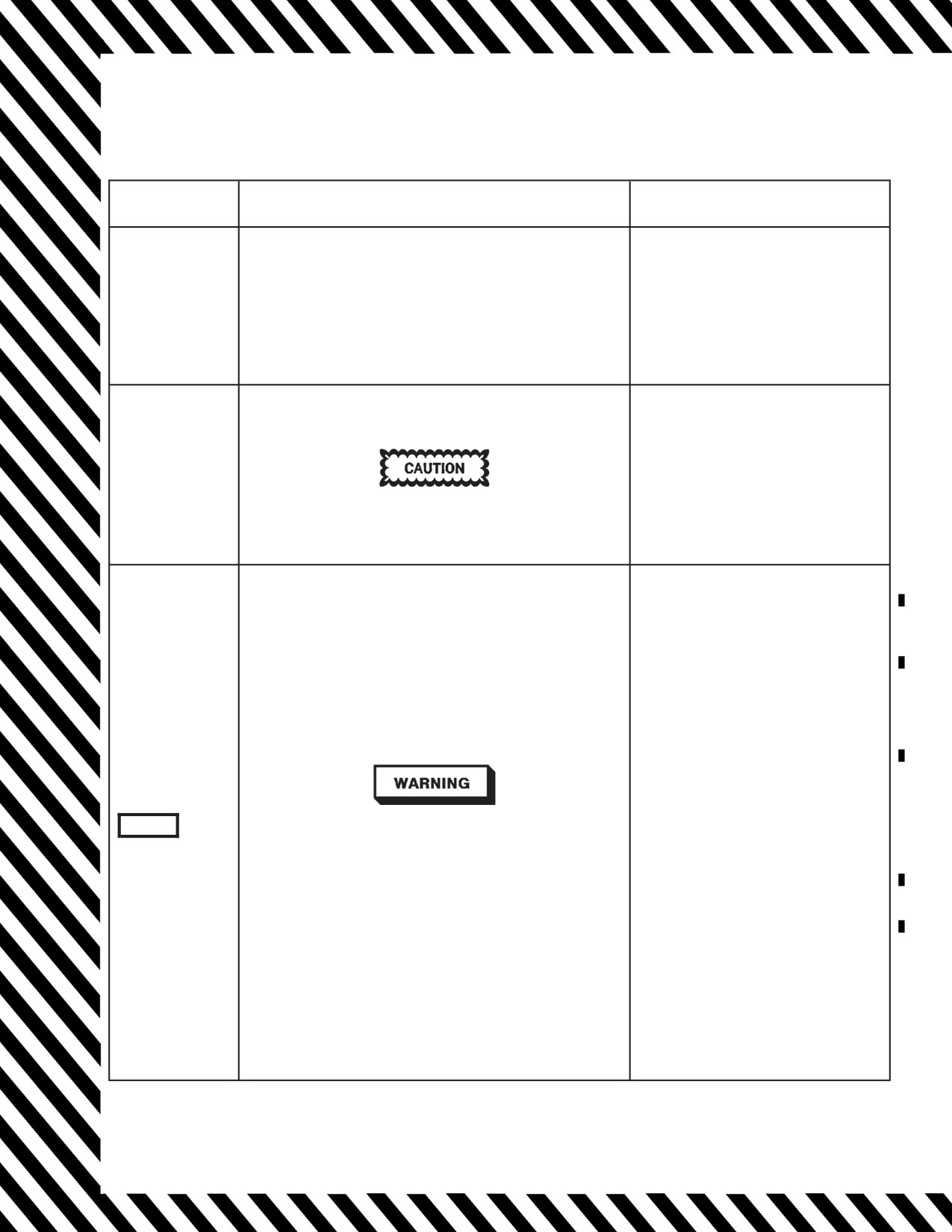
A1-F18AC-NFM-000
* Immediate action item
v Discussion in part V
DDI Cautions and Caution Lights
CORRECTIVE ACTION
INDICATOR
CAUSE/REMARKS
• Loss of fuel boost pressure to designated engine.
• May indicate fuselage fuel leak.
1. Limit corresponding afterburner usage
• May indicate fuel transfer failure.
above 30,000 feet.
• If associated with GEN, and both HYD circuit cautions, may
L BOOST LO
2. Check for indications of fuselage fuel
be a PTS failure.
R BOOST LO
leak.
• May result from prolonged transitions through zero g (greater
3. Monitor fuel transfer.
than 2 seconds).
4. Land as soon as practical.
Afterburner may not operate above 30,000 feet. The crossfeed
valves open automatically.
• Brake accumulator pressure low (below 1,750 psi)
Emergency brakes may not be available.
1. Extend landing gear as soon as prac-
BRK ACCUM
tical.
A BRK ACCUM caution in flight is not normal and may indicate
a possible leak in the isolated HYD 2B system. If the caution ap-
pears in flight, do not attempt to recharge the accumulator as
this may result in additional loss of HYD 2B fluid.
BELOW 47,000 FEET MSL
OBOGS Aircraft -
*1. Emergency oxygen green ring(s) -
PULL
*2. OXY FLOW knob(s) - OFF
All Aircraft -
*3. Initiate rapid descent to below 10,000
feet cabin altitude.
• Cabin pressure altitude above 21,000 ± 1,100 feet.
4. CABIN PRESS switch - CHECK
NORM
Cabin light may not extinguish until cabin pressure altitude is
5. ECS MODE switch - CHECK AUTO
below 16,500 feet.
or MAN
If DCS or hypoxia symptoms
present -
6. Maintain altitude below 10,000 feet
• CABIN light may appear with normal cabin pressurization
MSL.
CABIN
when aircraft altitude is above 47,000 feet MSL. If altitude is
7. Land as soon as possible.
maintained, aircrew should continuously monitor physiological
If DCS or hypoxia symptoms not
Caution Light
condition.
present -
OBOGS Aircraft -
• DCS may be experienced when operating with cabin pressure
6. Reset emergency oxygen system and
altitude above 25,000 feet even with a working oxygen system.
resume normal OBOGS operation.
Symptoms of DCS include pain in joints, tingling sensations,
All Aircraft -
dizziness, paralysis, choking, and/or loss of consciousness.
7. Maintain altitude below 25,000 feet
MSL.
8. Land as soon as practical.
ABOVE 47,000 FEET MSL
1. Continuously monitor physiological
conditions and cabin pressure altim-
eter.
Figure 12-1. Warning/Caution/Advisory Displays (Sheet 10)
V-12-12
ORIGINAL W/IC 91

A1-F18AC-NFM-000
* Immediate action item
v Discussion in part V
DDI Cautions and Caution Lights
INDICATOR
CAUSE/REMARKS
CORRECTIVE ACTION
IN FLIGHT
1. CANOPY switch - CONFIRM DOWN
2. Slow below 300 KCAS (200 KCAS in
• Canopy not down and locked.
F/A-18B/D) if practical.
3. Maintain altitude below 25,000 feet.
CANOPY
In the F/A-18B/D, rear seat occupant should lower seat and
4. CABIN PRESS switch - RAM/DUMP
lean as far forward as possible, in case the canopy departs the
5. CANOPY switch - DOWN
aircraft.
6. CABIN PRESS switch - NORM
If light stays on -
7. Land as soon as practical.
1. F/A-18C/D only: FUEL page/SDC -
• Capability to display cautions degraded.
RESET
2. MC 1 - CYCLE to 1 OFF then
Cycling MC1 with an SDC failure zeroizes all fuel indications on
NORM
CAUT DEGD
the FUEL page.
D Fuel quantity indications on FUEL
page will be zeroized.
Cautions may be false or erratic.
If caution remains or reappears -
3. Land as soon as practical.
1. Stop maneuvering.
2. Check transfer tanks 1 & 4.
CG
• Tanks 1 and 4 fuel distribution out of balance.
3. Calculate CG.
If CG aft of limit -
4. Refer to Landing With Aft CG.
1. Place FLAP switch in correct posi-
CK FLAPS
• FLAP switch in AUTO position at takeoff.
tion for takeoff.
CHECK SEAT
1. Ejection seat SAFE/ARMED
One or both ejection seats not armed with WonW and throttles
handle(s) - CHECK ARMED
CK SEAT
advanced.
If caution remains -
2. Do not takeoff.
Caution Light
1. T/O TRIM button - PRESS UNTIL
TRIM ADVISORY DISPLAYED
CHECK TRIM
• Trim incorrect for takeoff.
If carrier based -
2. TRIM - SET FOR CATAPULT
LAUNCH
1. ECS MODE/CABIN PRESS switches/
• ECS MODE switch - OFF/RAM
CK ECS
BLEED AIR knob - CHECK POSI-
• CABIN PRESS switch - DUMP or RAM/DUMP
TION
• BLEED AIR knob - OFF
Caution Light
• CNI interface failure.
1. Check BIT page.
CNI
If CSC MUX fail -
UFC may not operate in some or all modes.
2. Refer to CSC MUX FAILURE.
DFIR OVRHT
• DFIRS reporting an overtemperature condition.
Information
Unless visually confirmed intact -
DFIRS GONE
• DFIRS inadvertently deployed.
1. Land as soon as practical.
Figure 12-1. Warning/Caution/Advisory Displays (Sheet 11)
V-12-13
ORIGINAL

A1-F18AC-NFM-000
* Immediate action item
v Discussion in part V
DDI Cautions and Caution Lights
INDICATOR
CAUSE/REMARKS
CORRECTIVE ACTION
DL OVRHT
ATARS data link pod subsystem overheated.
1. CLP power knob - OFF
• ATARS tape deck is cold.
Usually occurs at startup.
1. ATARS switch - ON
Warmup takes less than 5 minutes at 32°F.
2. ATARS preflight checks - DISCON-
DTR1 COLD
TINUE
DTR2 COLD
Up to 45 min warmup may be required at -40°F.
When caution is removed -
3. ATARS preflight checks - CONTINUE
Ground - Recce mode not available until both decks are warmed
up.
In flight - Recce mode is available with one deck warmed up.
• ATARS tapedeck shutdown caused by cold, overtemp or con-
densation.
1. ATARS switch - ON
DTR1 SHTDN
If caution remains after 20 min -
Record capability is disabled.
DTR2 SHTDN
2. ATARS switch - OFF
Additional information is displayed on the BIT-ATARS-MAINT
3. CLP power knob - OFF
page, and a condensation cue advisory is displayed on RECCE
video.
• Designated duct door closed above Mach 1.33 or open below
Mach 1.23.
L DUCT DR
Drag is increased with door open.
1. Reduce speed below Mach 1.33.
R DUCT DR
At airspeeds above Mach 1.33 with door failed closed, engine inlet
pressure oscillations, ‘‘inlet buzz’’, will gradually increase with
increasing Mach, and possibly culminate in engine stall.
1. DUMP switch - CYCLE
2. BINGO setting - Set above internal
fuel state.
If dump continues (caution
remains) -
• Fuel dump valve open with DUMP switch in OFF.
3. F/A-18A/B only: INTR WING switch
- INHIBIT
If the dump valve cannot be closed, fuel continues to dump until
If external fuel also remains -
tanks 1 and 4 are empty. Selecting WING INHBIT diverts recir-
4. EXT TANKS switches - STOP
culation fuel from the wings to the feed tanks. Stopping external
5. Land as soon as possible.
DUMP OPEN
transfer may make this fuel available if the dump valve is subse-
When capacity available in feed
quently closed.
tanks -
6. EXT TANKS switches - NORM
Delaying landing until the transfer tanks are empty (3,100
If fuel continues to dump on deck -
pounds of fuel remaining) will prevent fuel from dumping onto
7. Turn aircraft into the wind.
hot exhaust nozzles and fouling of the landing area.
8. Throttles - OFF
If/when dump stops (caution re-
moved) -
3. EXT TANKS switches - CHECK
NORM
Figure 12-1. Warning/Caution/Advisory Displays (Sheet 12)
V-12-14
ORIGINAL

A1-F18AC-NFM-000
* Immediate action item
v Discussion in part V
DDI Cautions and Caution Lights
INDICATOR
CAUSE/REMARKS
CORRECTIVE ACTION
*1. Throttle affected engine - IDLE
If caution remains at IDLE or en-
L EGT HIGH
gine response is abnormal -
R EGT HIGH
2. Throttle affected engine - OFF
3. Refer to Single Engine Approach and
″Engine Left
• Designated exhaust gas temperature out of limits
Landing procedure.
(Right),
If caution clears -
Engine Left
2. Land as soon as practical.
(Right)″
3. Consider HALF flap approach for
landing.
ENG MATCH
• One engine is F404-GE-400 and other engine is F404-GE-402.
1. Abort
• A component which contains classified information has re-
ERASE FAIL
ported a critical failure which may prevent successful erasure of Information
stored classified data.
GROUND
1. EXT TANKS switch(es) - VERIFY
• External tanks pressurized on ground or tanks have overpres-
NORM
surized.
If caution remains -
EXT TANK
NOTE
2. Do not catapult.
Carrier launch prohibited with less than 1900 pounds in ex-
ternal drop tank.
IN FLIGHT
1. EXT TANKS switch(es) - STOP
(when external transfer complete)
Figure 12-1. Warning/Caution/Advisory Displays (Sheet 13)
V-12-15
ORIGINAL

A1-F18AC-NFM-000
* Immediate action item
v Discussion in part V
DDI Cautions and Caution Lights
INDICATOR
CAUSE/REMARKS
CORRECTIVE ACTION
1. F/A-18A/B only: HOOK handle -
CONFIRM UP
2. FUEL page/Fuel Quantity indicator/
IFEI - IDENTIFY EXT TANK
WITH TRAPPED FUEL
Perform the following steps while
monitoring fuel transfer, tank quan-
tities, and lateral asymmetry -
3. EXT TANKS switch(es) - ORIDE
4. EXT TANKS switch(es) - CYCLE to
STOP and back to ORIDE
5. EXT TANKS switch(es) - NORM
6. PROBE switch - CYCLE
• One or more external tanks failed/slow to transfer when com-
7. Apply positive and negative g.
manded.
8. F/A-18C/D only: FUEL page/SDC -
RESET
Icing may occur in the external fuel tank pressurization system
If practical -
inhibiting external tank transfer and refueling. Descending and
9. Descend below freezing level and re-
EXT XFER
accelerating may reduce the effects of icing.
peat steps 3 thru 8.
10. If below 10,000 feet MSL, BLEED
External fuel available but not transferring.
AIR knob - CYCLE THRU OFF TO
NORM
On F/A-18C/D aircraft, selecting ORIDE on both EXT TANKS
11. LDG GEAR and HOOK handles -
fuel control switches may inhibit centerline tank transfer.
DOWN
12. LDG GEAR and HOOK handles - UP
13. Perform in-flight refueling.
If/when transfer complete but prior
to landing -
14. EXT TANKS switch(es) - NORM
If external wing tank fuel trapped -
15. Ensure lateral asymmetry within lim-
its for landing.
FOR CARRIER LANDING
If centerline tank is still over 500
pounds -
16. Divert or SELECT JETT tank.
D Designated engine flamed out.
SINGLE ENGINE FLAMEOUT
Attempting to restart an engine that has flamed out for no appar-
*1. Throttle affected engine - IDLE
ent reason may result in an engine bay fuel leak/fire.
If rpm continues to decrease with in-
L FLAMEOUT
creasing EGT (failed auto-restart) -
R FLAMEOUT
2. Throttle affected engine - OFF
Restarting an engine that flamed out for no apparent reason may
result in an engine bay fuel leak/fire.
3. Refer to Single Engine Approach and
″Engine Left
Landing procedure.
(Right),
If an engine fails, the corresponding generator and HYD system
If engine auto-restarts -
will be lost. Either generator supplies sufficient power to operate
Engine Left
4. Check engine response at a safe alti-
all electrical items. A windmilling engine can cause repeated
(Right)″
flight control transients as the hydraulic switching valves operate.
tude.
Various FCS cautions will come on intermittently. After the rpm
5. Land as soon as practical.
has decreased to near zero, the transients will cease, the FCS cau-
6. Consider HALF flap approach for land-
tions will go off, and FCS operation will be normal. To prevent
ing.
repeated switching valve cycling, avoid stabilized flight where en-
gine windmilling rpm produces hydraulic pressure fluctuations
between 800 to 1,600 psi. If control of a surface is lost due to a
frozen or sticking switching valve, attempt to unstick the valve by
gently cycling the flight controls, and reset the FCS.
Figure 12-1. Warning/Caution/Advisory Displays (Sheet 14)
V-12-16
ORIGINAL

A1-F18AC-NFM-000
* Immediate action item
v Discussion in part V
DDI Cautions and Caution Lights
INDICATOR
CAUSE/REMARKS
CORRECTIVE ACTION
FLIR OVRHT
• Targeting FLIR internal overheat detected.
1. FLIR switch - OFF (if practical)
PRE-FLIGHT
1. Throttle affected engine - OFF
IN FLIGHT
1. Throttle affected engine - Increase fuel flow (if
• Designated engine fuel feed temperature too high.
practical)
L FUEL HOT
2. Wing fuel switch - CHECK NORM
R FUEL HOT
Fuel temperature greater than 79°C may cause
3. MENU ENG - MONITOR FUEL
AMAD to overheat with associated cautions.
TEMP(<79°C)
4. Land as soon as practical.
POST-FLIGHT
If caution remains for more than 5 minutes -
5. Throttle affected engine - OFF
1. Throttles - Reduce fuel flow (if practical)
FUEL LO
• At least one feed tank below 800 pounds.
2. Land as soon as possible.
3. Check for fuel transfer failure indications.
FUEL LO
May indicate fuselage fuel leak.
If trapped fuel indicated -
4. EXT TANK switches - CHECK
″Fuel low, Fuel low″
Sideslip may be required to transfer wing fuel.
5. Avoid negative g maneuvering.
1. Stop maneuvering.
2. Check transfer tanks 1 & 4.
FUEL XFER
• Tanks 1 and 4 fuel distribution out of balance.
3. Calculate CG.
If CG aft of limit -
4. Refer to Landing With Aft CG.
• Designated generator off line.
Either generator can support the total aircraft
L GEN
electrical load.
SINGLE GEN FAILURE
R GEN
1. Generator switch - CYCLE
With both generators offline refer to Double
If generator still failed -
L GEN
R GEN
Generator/ Double Transformer Rectifier failure.
2. Generator switch - OFF
3. Land as soon as practical.
Caution Lights
With both generators offline - No OBOGS
If associated with BOOST LO and both HYD cir-
cuit cautions, may be a PTS failure.
Figure 12-1. Warning/Caution/Advisory Displays (Sheet 15)
V-12-17
ORIGINAL