F18. FLIGHT MANUAL (2008) - page 6
A1-F18AC-NFM-000
(3) Retainer clip in place and horizontal to the deck
(4) Auxiliary cap tight
c. Navigation lights - CONDITION
d. Wingfold area - CONDITION
e. Wingfold lugs - CONDITION
f. LAU-7 - Ensure doors secure, power supply installed, and either nitrogen bottle or HiPPAG
installed.
g. AIM-9 - PREFLIGHT
h. Aileron - CONDITION, FAIRED WITH WINGS FOLDED
i. Trailing edge flap - CHECK CONDITION
13. Right aft fuselage - CHECK
a. Hydraulic reservoir gauge - CHECK
b. Vertical stabilizer and rudder - CONDITION
(1) Navigation, formation, and strobe lights - CONDITION
(2) Fuel vent port and dump mast - CLEAR
c. Stabilator - CONDITION
d. Exhaust nozzle, afterburner section, turbine blades - CONDITION
14. Arresting hook area - CHECK
a. Arresting hook - CONDITION (pin removed)
15. Left aft fuselage - CHECK
a. Exhaust nozzle, afterburner section, turbine blades - CONDITION
b. Stabilator - CONDITION
c. Vertical stabilizer and rudder - CONDITION
(1) Fuel vent port and dump mast - CLEAR
(2) Formation and strobe lights - CONDITION
d. Hydraulic reservoir gauge - CHECK
16. Aft fuselage underside - CHECK
III-7-4
ORIGINAL
A1-F18AC-NFM-000
a. APU intake and exhaust - CLEAR
b. ATS exhaust - CLEAR
17. Left wing - CHECK
a. Trailing edge flap - CHECK CONDITION
b. Aileron - CONDITION, FAIRED WITH WINGS FOLDED
c. AIM-9 - PREFLIGHT
d. LAU-7 - Ensure doors secure, power supply installed, and either nitrogen bottle or HiPPAG
installed.
e. Wingfold area - CONDITION
f. Wingfold lugs - CONDITION
g. Navigation lights - CONDITION
h. Pylons and external stores -
(1) Breech caps tight
(2) If applicable, cartridge installed indicator present (protruding from breech cap w/ext stores
loaded)
(3) Retainer clip in place and horizontal to the deck
(4) Auxiliary cap tight
i. Leading edge flap - CHECK CONDITION
18. Left main landing gear - CHECK
a. Tire - TREAD WEAR, PRESSURE 250 psi (ashore) 350 psi (afloat) (gauges on some aircraft)
b. Brake wear indicator - CHECK
c. Shrink links and planing links - CONDITION
d. Shock strut pressure - CHECK
e. Tiedown rings and springs - CONDITION
19. Left main wheelwell - CHECK
a. Doors and linkages - CONDITION
b. Landing gear downlock and retract actuators - CONDITION
c. Downlock pin - REMOVED
III-7-5
ORIGINAL
A1-F18AC-NFM-000
d. Hydraulic filter indicators - NOT POPPED
e. Main fuel line clamps secure and safety wires attached.
20. Fuel air heat exchanger intake - CLEAR AND CONDITION
21. Station 4 - PREFLIGHT
22. Chaff/flare dispenser - PREFLIGHT
(Dispenser module (chaff/flare bucket) or access cover shall be installed.)
23. Forward fuselage underside - CHECK
a. Loose fasteners and fluid leaks - CHECK
b. Centerline station/store - PREFLIGHT
c. Fuselage fuel cavity drains - CHECK
24. Left fuselage - CHECK
a. Engine intake duct - CLEAR
b. ECS intake - CLEAR
c. Total temperature probe - CONDITION
d. RLCS door - CHECK
7.1.3 Before Entering Cockpit
1. Boarding ladder - SECURE (2 points)
2. Aircraft upper surfaces - CONDITION
3. Windshield - SECURE
Push up on windshield bow to make sure the windshield is secure.
4. Canopy jettison rocket motors - Nozzles down (F/A-18A/C)
5. Ejection seat safe/arm handle - SAFE & LOCKED
6. Ejection seat - PREFLIGHT
SJU-5/6
a. Ejection seat manual override handle - Check handle full down and manual override initiator
maintenance pin removed from sear.
b. Time release mechanism trip rod - Check time release mechanism trip rod secured to bulkhead
and engaged in time release mechanism. Check red color band on trip rod not visible. Check
maintenance pin removed from sear.
III-7-6
ORIGINAL
A1-F18AC-NFM-000
c.
Right trombone assembly - Hoses connected and retaining pin installed.
d.
Ballistic gas disconnect - Check engaged and red band not visible.
e.
Survival kit release handle - Check full down.
f.
Leg restraint lines - Check lines secured to cockpit floor, lines not twisted, and line pins locked
into front of ejection seat.
g.
Ejection seat firing initiators - Check firing linkage connected to sears.
h.
Survival kit emergency oxygen - Check pressure gauge, emergency oxygen green ring stowed
inboard of left thigh cushion, and automatic emergency oxygen operating cable lanyard
connected to cockpit floor.
i.
Rocket motor initiator - Check initiator cable lanyard connected to drogue gun trip rod without
excessive cable hanging from initiator housing. Initiator sear installed with cable lever
assembly link inserted, maintenance pin removed from sear. Left trombone assembly con-
nected with quick release pin inserted.
j.
Drogue gun trip rod - Check drogue gun trip rod secured to bulkhead and engaged in drogue
gun with maintenance pin removed from sear. Check that red color band on trip rod is not
visible.
k.
Top latch mechanism - Check that top latch plunger and locking indicator is flush with the end
of the top latch mechanism housing and the main beam.
If the top latch mechanism check does not meet the outlined require-
ments, the seat could come loose on the mounting rails.
l. Catapult manifold assembly - Check hoses and manifold connected, and retaining pin installed.
m. Scissor shackle tie-down - Check drogue withdrawal line connected to the drogue slug. Check
forward flap on top of all other flaps and shackle tie routed through eyelet in top flap and
routed through both drogue shackle and extender strap. Check scissor mechanism tied securely
to top of parachute container. Check drogue shackle engaged in scissors, and scissors release
plunger extended against moveable scissor arm with plunger pin visible on top of scissors
plunger.
n. Parachute risers - Check risers routed down forward face of the parachute container and routed
behind retaining strap sensing-release secure and ease of operation, and seawater activated
release system for proper installation.
o. Radio beacon lanyard - Check lanyard secured to seat bucket.
III-7-7
ORIGINAL
A1-F18AC-NFM-000
p. Check lap belts secure. Pull up strongly on each belt to make sure bolt fittings are engaged in
seat. Check front end of survival kit secured to seat. Pull up on front end of kit to test security.
If any portion of the survival kit cushion is moved to gain access to
components underneath, unsnap cushion retaining snaps by a forward/up
motion (not back/aft) and resnap by an aft/down motion.
SJU-17 AND SJU-17A
a. Ejection seat manual override handle - full down and locked.
b. Right pitot - stowed.
c. Ballistic gas quick-disconnect - connected indicator dowel flush or slightly protruding.
d. Top latch plunger - Check that locking indicator is flush with the end of the top latch plunger.
If the top latch plunger check does not meet the outlined requirements,
the seat could come loose on the mounting rails.
e.
Catapult manifold valve - Check hoses and manifold connected, and retaining pin installed.
f.
Parachute withdrawal line - connected, secure.
g.
Parachute container lid - secure.
h.
Left pitot - stowed.
i.
Electronic sequencer - expended unit indicator (EUI) not activated. (Black sequencer - OK,
White - CHECK THERMAL BATTERIES NOT ACTIVATED).
j.
Thermal batteries - expended unit indicator (EUI) not activated. (White or pink - OK, Black
or purple - expended)
k.
Oxy/comm lines - connected secured.
l.
Survival kit -
(1) Oxy/comm lines - connected, secure.
(2) Emergency oxygen gauge - black area.
(3) Radio beacon - secured.
m. Radio beacon lanyard - Check lanyard secured to cockpit floor.
n.
Ensure that the lanyard and quick release connector are positioned forward of the underseat
rocket motor tubes.
III-7-8
ORIGINAL
A1-F18AC-NFM-000
o. Check lap belts secure. Pull up strongly on each belt to make sure bolt fittings are engaged in
seat. Check front end of survival kit secured to seat. Pull up on front end of kit to test security.
p. Negative g-strap - secure in seat bucket (SJU-17(V)1/A, 2/A, 9/A).
q. Leg restraint lines - Check lines secured to cockpit floor, lines not twisted, and line pins locked
into front of ejection seat.
r. Ejection seat firing initiators - Check firing linkage connected to sears.
s. Parachute risers - Check risers routed down forward face of the parachute container and routed
behind retaining strap, sensing-release secure and ease of operation, and SEAWARS for proper
installation.
t. Backpad adjustment handle - Set to desired position (SJU-17A(V)1/A, 2/A, 9/A).
For solo flight in F/A-18B/D -
7. Rear cockpit - SECURED
a. Check ejection seat SAFE/ARM handle in SAFE.
b. Ensure ejection seat handle pin is removed.
c. Ensure CANOPY JETT handle - OUTBOARD AND DOWN/PIN REMOVED
d. Secure all loose items, including harnessing and JHMCS QDC.
e. Standby attitude reference indicator - CAGE/LOCK
f. EMERG BRK handle - IN
Anti-skid is not available with the rear cockpit EMERG BRK handle in
the emergency position.
8. SEAT CAUT MODE switch - SOLO/PIN INSTALLED
7.1.4 Interior Check
Do not place any item on the glare shield, as scratching the windshield is
probable.
1. Harness and rudder pedals - SECURE/ADJUST
Fasten and secure leg restraint garters and lines. One garter is worn on the thigh approximately 3
inches above the knee and one garter is worn on the lower leg just above the boot top. Check leg
garters buckled and properly adjusted with hardware on inboard side of the legs. Check that lines are
III-7-9
ORIGINAL
A1-F18AC-NFM-000
secured to seat and floor and not twisted. Check that leg restraint lines are routed first through the
thigh garter ring, then through the lower garter ring, and then routed outboard of the thigh garter
ring before the lock pins are inserted into the seat just outboard of the snubber boxes. Connect
oxygen, g suit, QDC (if applicable) and communications leads. Check routing of JHMCS UHVI does
not interfere with oxygen hose. Check QDC is securely connected or stowed if not in use. Fasten and
secure leg restraint garters and lines. Check leg garters buckled and properly adjusted with hardware
on inboard side of the legs. Connect and adjust lap belt straps. Attach parachute Koch fittings to
harness buckles. Check operation of shoulder harness locking mechanism.
• The leg restraint lines must be buckled at all times during flight to
ensure that the legs are pulled back upon ejection. This enhances seat
stability and prevents leg injury by keeping the legs from flailing
following ejection.
• Failure to route the restraint lines properly through the garters and
properly position leg restraints could cause serious injury during
ejection/emergency egress.
• The JHMCS UHVI must be properly routed through the torso bundle
flue under the survival vest and the QDC secured in the QMB to
ensure that no entanglement exists with the oxygen hose. Misrouting
of the JHMCS UHVI may allow the QDC to rub against the oxygen
hose disconnect causing unintentional oxygen/communications dis-
connect in flight.
2.
Ejection control handle - CLEAR
Left console -
1.
Circuit breakers (4) - IN
2.
Manual canopy handle - STOWED
3.
Nuclear weapon consent switch - AS DESIRED
4.
MC and HYD ISOL switches - NORM
LOX Aircraft -
5.
OXYGEN supply lever - OFF
OBOGS Aircraft -
5. OBOGS control switch - OFF
a. OXY FLOW knob - OFF
III-7-10
ORIGINAL
A1-F18AC-NFM-000
b. OBOGS monitor pneumatic BIT plunger - VERIFY UNLOCKED AND FULLY EXTENDED
Inadvertent rotation of the OBOGS monitor pneumatic BIT plunger
while pressed can result in the locking of the plunger in a maintenance
position and intermittent OBOGS DEGD cautions and lead to hypoxia.
Rotation of the BIT plunger disengages the locking slot allowing the
plunger to extend and move freely when pushed.
All Aircraft -
6. COMM 1/IFF ANT SEL switches - AUTO/BOTH
7. COMM panel - SET
a. Relay, cipher, squelch and guard - OFF
b. ILS - SET FREQUENCY/UFC
c. Master, mode 4, and crypto switches - NORM/OFF/NORM
8. VOL panel - SET AS DESIRED
9. GEN TIE CONTROL switch - NORM (guard down, aircraft 162394
AND UP)
10. FCS GAIN switch - NORM
11. PROBE switch - RETRACT
12. EXT TANKS switches - NORM
13. DUMP switch - OFF
14. INTR WING switch - NORM
15. EXT LT panel - SET
16. Throttles - OFF
17. PARK BRK handle - SET
18. LDG/TAXI LIGHT switch - OFF
19. ANTI SKID switch - ON
20. FLAP switch - FULL
21. SELECT JETT knob - SAFE
22. LDG GEAR handle - DN
III-7-11
ORIGINAL
A1-F18AC-NFM-000
23. Landing gear handle mechanical stop - FULLY ENGAGED
24. CANOPY JETT handle - FORWARD
Instrument panel -
1. MASTER ARM switch - SAFE
2. FIRE and APU FIRE warning lights - NOT PRESSED IN
If the light(s) is/are pressed, approximately 1/8 inch of yellow and black stripes are visible around
the outer edges of the light(s).
3. L(R) DDI, HI/MPCD, and HUD knobs - OFF
4. Altitude source - SELECT
5. ATT switch - AUTO
6. COMM 1 and 2 knobs - OFF
7. ADF switch - OFF
8. ECM mode - OFF
9. Dispenser select knob/dispenser switch - OFF
10. AUX REL switch - NORM
11. Clock - CHECK AND SET
12. Standby attitude reference indicator - CAGE/LOCK
13. IR COOL switch - OFF
14. SPIN switch - GUARD DOWN/OFF
Right console -
1. Circuit breakers (4) - IN
2. HOOK handle - UP
3. WING FOLD handle - SAME AS WING POSITION
4. AV COOL or FCS COOL switch - NORM
5. Radar altimeter - OFF
6. GEN switches - NORM
7. BATT switch - OFF
8. ECS panel - SET
III-7-12
ORIGINAL
A1-F18AC-NFM-000
a. MODE switch - AUTO
b. CABIN TEMP knob - 10 O’CLOCK
c. CABIN PRESS switch - NORM
d. BLEED AIR knob - NORM and DOWN
e. ENG ANTI ICE switch - OFF
f. PITOT ANTI ICE switch - AUTO
9. DEFOG handle - MID RANGE
10. WINDSHIELD switch - OFF
11. INTR LT panel - AS DESIRED
12. Sensors - OFF
13. KY-58 panel - SET
14. AN/AWB-3(V) monitor control - SET
15. NVG container - SECURE/NVG STOW (if required)
7.1.5 Engine Start. With an external power start, all electrical systems except those on external
power switch 3 are operative. With a battery start, power is available to operate the APU and engine
fire warning systems, the intercom system between the pilot and the ground, the cockpit utility light
and EMI/IFEI.
For external air start, ensure that bleed air knob is OFF to avoid ATS
damage.
When the engine crank switch is moved to L or R, the air turbine starter control valve (ATSCV)
opens and the air turbine starter (ATS) rotates the engine thru the AMAD. Engine rotation is apparent
almost immediately and can be seen on the tachometer. During operation below flight idle, the nozzles
may go closed or oscillate. After the engine lights-off and accelerates to approximately 60% rpm, the
engine crank switch returns to OFF. After both generators are on the line, the APU runs for 1 minute,
and then shuts down.
The right engine is normally started first to provide normal hydraulics to the brakes. Rapid stick
movement with only the right engine running may cause the priority valve to cut off brake pressure.
• To prevent engine damage during start, if an engine was not idled for
5 minutes prior to shutdown and a restart must be made between 15
III-7-13
ORIGINAL
A1-F18AC-NFM-000
minutes and 4 hours after shutdown, the engine must be motored for
1 minute at 24% N2.
• A flashing IFEI panel during engine start is indicative of a failing SDC
or batteries that might not provide adequate power to the flight
control computers in the event of dual generator failure. Further
troubleshooting is required. Do not apply external power.
NOTE
To perform a valid battery status check, the check must be
accomplished without ground power applied or either generator on line.
Aircraft 161353 THRU 161528 -
1. Battery operation - CHECK
a. Battery switch - ORIDE
b. BATT SW caution - CHECK DISPLAYED
c. Battery switch - ON (caution removed)
Aircraft 161702 AND UP -
1. Battery status - CHECK
a. Battery switch - ORIDE
b. E BATT voltage - CHECK
After battery switch in ORIDE for minimum of 5 seconds, check for minimum voltage of
23.5
volts.
c. Battery switch - ON
d. U BATT voltage - CHECK
After battery switch in ON for minimum of 5 seconds, check for minimum voltage of 23.5 volts.
With cold weather temperatures down to -18°C a minimum of 20.5 volts on the UBATT is
acceptable.
With external electrical power -
1. EXT PWR switch - RESET
2. GND PWR switches 1, 2, and 4 - B ON (hold for 3 seconds)
3. L(R) DDI, HI/MPCD, and HUD - ON
4. COMM 1, 2, and ADF - AS DESIRED
5. Warning and caution lights - TEST
6. Inertial navigation system - ENTER WAYPOINTS DESIRED
III-7-14
ORIGINAL
A1-F18AC-NFM-000
All starts -
1.
BATT switch - ON (if not previously ON)
2.
FIRE warning test - PERFORM
a.
FIRE test switch - TEST A (hold until all lights and aural warnings indicate test has been
successfully passed)
b.
FIRE test switch - NORM (pause 7 seconds or cycle BATT switch for system reset)
c.
FIRE test switch - TEST B (hold until all lights and aural warnings indicate test has been
successfully passed)
NOTE
• During a successful FIRE warning test, ALL of the following lights
should illuminate in each TEST position: both FIRE lights (all 4
bulbs), the APU FIRE light (all 4 bulbs), and both L and R BLEED
warning lights. Additionally, the following voice aural warnings should
be heard in order: ″Engine fire left, engine fire right, APU fire, bleed
air left, bleed air right″ (each repeated twice).
• A complete FIRE warning test is performed in each TEST position
because it is difficult to recognize a single unlit bulb in a FIRE light.
Since an aural warning does not annunciate if any of the FIRE or
BALD loops are bad, lack of an aural warning is the best cue to the
aircrew of a test failure.
If APU start -
3. APU ACC caution light - OFF
a. APU switch - ON (READY light within 30 seconds)
If fire or overheat condition is detected, the APU shuts down.
• To prevent running engagements during APU coast-down and to
prevent APU exhaust torching, a minimum of 2 minutes must elapse
between APU shutdown and another APU start.
• To preclude APU/ATS damage on aircraft 161353 THRU 163175
BEFORE IAYC 853, ensure generator switches are ON and bleed air
aug is OFF.
If external air start -
3. BLEED AIR knob - OFF
III-7-15
ORIGINAL
A1-F18AC-NFM-000
All starts -
4. ENG CRANK switch - R
Uncommanded stick motion during engine start is abnormal and aircraft
shall not be flown prior to maintenance action.
Holding the engine crank switch in L or R may cause ATS damage. Shut
down the APU only when engine crank switch is OFF. On aircraft 161353
THRU 163175 BEFORE IAYC 853, shutting down the APU while
cranking the engine with the opposite engine running can cause APU
surge.
5. Right throttle - IDLE (15 % rpm minimum)
Maximum EGT during start is 815°C.
NOTE
On aircraft 161353 THRU 162889, setting any ground power switches
to ON with an engine driven generator on line activates a false MMP
code 884 (ground power circuit fail).
6. GPWS Voice Alerts - CHECK (OFP 15C AND UP: ″ROLL LEFT, ROLL LEFT″) (OFP 13C:
″ROLL OUT, ROLL OUT″)
NOTE
In aircraft with MC OFP
13C AND UP, MC1
does an ACI
configuration check after the generator comes online during a cold
start power-up. Successful completion of the check is indicated by
system initiation of a ″ROLL OUT″ (for OFP 13C) or ″ROLL LEFT″
(for 15C) voice alert. If no voice alert is heard, GPWS is disabled and
the GPWS option on the MENU/HSI/DATA/AC sublevel display will
not be present. If an incorrect voice alert is heard on startup or the
GPWS option is not present, notify maintenance and commence
troubleshooting the GPWS, ACI, and CSC system components and
wiring.
All aircraft -
7. L(R) DDI, HI/MPCD, HUD, and UFC avionics, and radar altimeter - ON
III-7-16
ORIGINAL
A1-F18AC-NFM-000
If the DDI or HI/MPCD do not come on, they may not be properly
secured to the instrument panel. Do not launch with an improperly
secured DDI or HI/MPCD.
If ATS caution is on when the DDI comes on, shut down engine to avoid
starter damage.
8. HMD switch (if applicable) - ON
9. EMI/IFEI - CHECK
a. After engine start, it may be necessary to advance power above IDLE to get the ECS turbine
started.
Ground idle -
F404-GE-400
F404-GE-402
N2
61 to 72%
63 to 70%
EGT
190° to 590°C
190° to 590°C
Fuel flow
420 to 700 pph
420 to 900 pph
Nozzle
73 to 84%
73 to 84%
Oil pressure (warm oil)
45 to 110 psi
45 to 110 psi
NOTE
For fuel temperatures in excess of 38°, the lower oil pressure can vary
as much as 10 psi.
If APU or crossbleed start -
10. BLEED AIR knob - CYCLE THRU OFF TO NORM
The bleed air shutoff valves close during the fire warning test and the BLEED AIR knob must be
cycled thru OFF to NORM with ac power on to reset the valves.
11. Warning and caution lights - TEST
For a crossbleed start, ensure APU switch is OFF and a minimum of 80% rpm and 1,900 pph fuel flow.
12. ENG CRANK switch - L
13. Left throttle - IDLE (15% rpm minimum)
14. ENG CRANK switch - CHECK OFF
If external air start -
15. BLEED AIR knob - RETURN TO NORM
III-7-17
ORIGINAL
A1-F18AC-NFM-000
All starts -
16. EMI/IFEI - CHECK
17. External electrical power - DISCONNECT (if required)
7.1.6 Before Taxi
1. Waypoint zero and magnetic variation - CHECK
NOTE
To achieve the best align quality and align complete in the minimum
time, waypoint zero should be the true position within 0.01 nautical
miles (60 feet or 0.6 seconds.)
2. INS knob - CV, GND (parking brake set) or IFA (functioning GPS)
3. RADAR knob - OPR
4. WING FOLD - SPREAD AND LOCK
• Wait 5 seconds after wings are fully spread before placing the WING
FOLD handle to LOCK. Placing the WING FOLD handle to LOCK
before the wings are fully spread removes the WING UNLK caution
even though the wings are not fully spread and could cause severe
damage to the wing fold transmission.
• The wingfold control handle should smoothly go into the LOCK
position. Forcing the handle could cause damage to the wingfold
system.
5. FCS RESET button - PUSH
If the wings are folded, verify aileron Xs are present.
To avoid damaging the flaps, ensure ailerons are not faired inboard prior
to raising the flaps, conducting IBIT, or running FCS exerciser. Proper
aileron position can be determined either visually or by verifying an
aileron position of 0 or down arrow on the FCS page.
NOTE
Xs appear in CH 1/3 of the PROC row on the FCS page with INS
ATT caution set and/or the ATT switch is placed to STBY.
If no reset -
a. T/O trim button - PUSH (note TRIM advisory)
III-7-18
ORIGINAL
A1-F18AC-NFM-000
b. FCS exerciser mode - INITIATE
Lift FCS BIT consent switch and push FCS RESET button simultaneously.
If still no reset -
c. FCS circuit breakers - PULL 4 CHANNELS
d. Wait 10 seconds.
e. FCS circuit breakers - RESET
f. FCS RESET button - PUSH
6. FLAP switch - AUTO
7. FCS RESET button and paddle switch - ACTUATE SIMULTANEOUSLY
8. FLAP switch - HALF
9. FCS INITIATED BIT - PERFORM
a. AOA warning tone - VERIFY ANNUNCIATION AT FCS IBIT COMPLETION
Flight with any PBIT BLIN other than 51, 124, 322 and 336, or IBIT
BLIN 4124, 4263, 4322, 4336, 4522, 4526, 4527, 4773, 4774, and 70261 can
result in a flight control system failure and aircraft loss. If IBIT detects
any failure other than those indicated by the IBIT BLINs listed above,
IBIT must be performed again, following an FCS reset, to ensure the
detected failure no longer exists. Pressing the FCS reset button, simul-
taneously with the paddle switch, does not correct BIT detected flight
control system failures; it simply clears the BLIN code(s) from the
display. If the second IBIT is not successful, the aircraft requires
corrective maintenance action to address the failure(s).
• If wings are folded, check both ailerons Xd out. Even with wings folded
there are aileron functions tested that may reveal problems via valid
BLIN codes.
• Auto throttle system performance is degraded if IBIT results in BLIN
code 124, 322, 336, 4124, 4322, 4336, 4522, 4526, 4527, 4773, or 4774.
These BLIN codes require no maintenance action to be taken prior to
flight, but use of the auto throttle system is prohibited.
• If BLIN 51 does not reset after airborne, wing-fold function may not be
available after landing.
III-7-19
ORIGINAL
A1-F18AC-NFM-000
10. Trim - CHECK
Check pitch, roll, and yaw trim for proper movement and then set for takeoff.
NOTE
Actuation of roll trim within
20 seconds of FCS IBIT with wings
folded inhibits roll trim. Roll trim is reactivated by pressing the T/O
Trim button with WOW.
11. T/O TRIM button - PRESS UNTIL TRIM ADVISORY DISPLAYED
If a trim advisory does not appear, abort. If takeoff trim is not set, full NU stabilator movement
may not be available and takeoff distance will increase. T/O TRIM button sets 12° NU.
12. FLAP switch - AUTO
13. Controls - CHECK
Tolerance for rudder and stabilator position is ±1°.
a. Control stick - CYCLE
Full aft:
24 NU stabilator
Full fwd:
3 NU
R/L Aileron: CHECK 20 units differential stabilator.
CHECK differential trailing edge flaps
b. FLAP switch - HALF
c. Rudder pedals - CYCLE 30° left and right
14. Trim - SET FOR TAKEOFF
If takeoff trim is not set, full leading edge down stabilator movement may not be available and
takeoff distance will increase.
15. PROBE, speedbrake, LAUNCH BAR switches, HOOK handle and pitot
heat - CYCLE
(LAUNCH BAR optional for shore based operations.)
16. Air scoop - CHECK
a. AV COOL or FCS COOL switch - EMERG
FCS ram air scoop deploys (thumbs up from plane captain).
b. Plane captain manually restows scoop.
17. APU - VERIFY OFF
18. Fuel - BIT/SET BINGO
19. Altimeter - SET
20. GPWS/TAWS - BOXED
21. Mission data - ENTER
III-7-20
ORIGINAL
A1-F18AC-NFM-000
22. BIT - NOTE DEGD/FAIL
23. Weapons/sensors - AS REQUIRED
24. STORES page - VERIFY PROPER STORE INVENTORY AND STATION STATUS
25. HMD - ALIGN (both cockpits)
NOTE
Canopy must be down and locked to align HMD/AHMD.
(CVRS record HMD if desired)
a. SUPT/HMD/ALIGN page - SELECT
b. Superimpose the HMD alignment cross on the HUD/BRU alignment cross.
c. Cage/Uncage button - PRESS and HOLD until ALIGNING turns to ALIGN OK or ALIGN
FAIL
If ALIGN FAIL -
d. Repeat steps b and c.
If ALIGN OK and HMD alignment crosses are not coincident with HUD/BRU alignment cross -
d. Perform FINE ALIGN.
(1) With FA DXDY displayed, use TDC to align azimuth and elevation HMD alignment
crosses with the HUD/BRU alignment cross.
(2) Cage/Uncage button - PRESS and RELEASE
(3) With FA DROLL displayed, use TDC to align the roll axis HMD alignment crosses with the
HUD/BRU alignment cross.
(4) Cage/Uncage button - PRESS and RELEASE
If satisfied with alignment -
e. ALIGN - UNBOX
26. Standby attitude reference indicator - UNCAGE
27. ATT switch - STBY
Verify INS attitude data is replaced by standby attitude data on HUD. Check agreement of
standby and INS data. Verify Xs appear in CH 1/3 of the PROC row on the FCS page.
28. ATT switch - AUTO
LOX Aircraft -
29. Oxygen system - CHECK
III-7-21
ORIGINAL
A1-F18AC-NFM-000
a. OXYGEN supply lever - ON/MASK ON
b. Oxygen flow - CHECK
c. OXYGEN supply lever - OFF/MASK OFF
If OXYGEN supply lever is ON and the mask is not properly donned, the
flow control valve could freeze in the open position and cryogenic burns
could result.
OBOGS Aircraft -
29. OBOGS system - CHECK
a. OBOGS control switch - ON
b. OXY FLOW knob - ON/MASK ON (both cockpits)
c. OBOGS flow - CHECK
d. OBOGS monitor electronic BIT pushbutton - PRESS AND RELEASE
e. Verify OBOGS DEGD caution set and removed within 15 seconds.
f. OXY FLOW knob - OFF/MASK OFF (both cockpits)
Continued operation and use of the OBOGS system with an OBOGS
DEGD caution may result in hypoxia.
All aircraft -
30. ID - Enter three digit Julian date and event number via UFC
31. Canopy either full up or full down during taxi.
Taxiing with canopy at an intermediate position can result in canopy
attach point damage and failure. Do not open or close the canopy with the
aircraft in motion.
7.1.7 Taxi. As aircraft starts to roll, apply brakes to check operation. When clear, check nosewheel
steering in both directions in the high mode to ensure proper operation. At high gross weight, make all
turns at minimum practicable speed and maximum practicable radius.
III-7-22
ORIGINAL
A1-F18AC-NFM-000
1. Normal brakes - CHECK
2. Nosewheel steering - CHECK
When using brakes, apply firm, steady brake pedal pressures. Use nosewheel steering whenever
possible, minimizing differential braking. Avoid dragging brakes or light brake applications
except as necessary for drying wet brakes. Wet brakes can have as much as 50% reduced braking
capacity. Hard momentary braking with wet brakes during taxi can reduce drying time.
7.2 TAKEOFF
7.2.1 Before Takeoff
1. Canopy - CLOSED
2. OXY FLOW knob or OXYGEN supply lever - ON/MASK ON
It is possible to place the OXY FLOW knob in an intermediate position
between the ON and OFF detents, which may result in a reduced flow of
oxygen. The OXY FLOW knob should always be fully rotated to the ON
or OFF detent position.
3.
IFF - ON
4.
Inertial navigation system - CHECK
On aircraft without GPS, after alignment is complete, NAV may be selected. On aircraft with
GPS or EGI, after alignment is complete, select NAV or IFA.
NOTE
On GPS equipped aircraft, selecting IFA without an OK results
in
transition to IFA RDR.
5.
PARK BRK handle - FULLY STOWED
6.
MENU checklist - COMPLETE (figure 7-1)
7.
Engines - MIL CHECK (if desired)
F404-GE-400
F404-GE-402
N2 % RPM
92 to 102
90 to 102
EGT °C
715 to 830
715 to 880
FF pph
6,000 to 9,000
6,000 to 12,500
NOZ %
0 to 57
0 to 48
OIL psi (warm oil)
95 to 180
95 to 180
AB
Check if desired
Check if desired
7.2.2 Normal Takeoff. Set takeoff trim to 12° and ensure the speedbrake is retracted. The aircraft
should be aligned with the centerline of the runway for individual takeoffs. When in position, roll
forward slightly to center the nose wheel and select low gain nosewheel steering. As the takeoff roll is
III-7-23
ORIGINAL
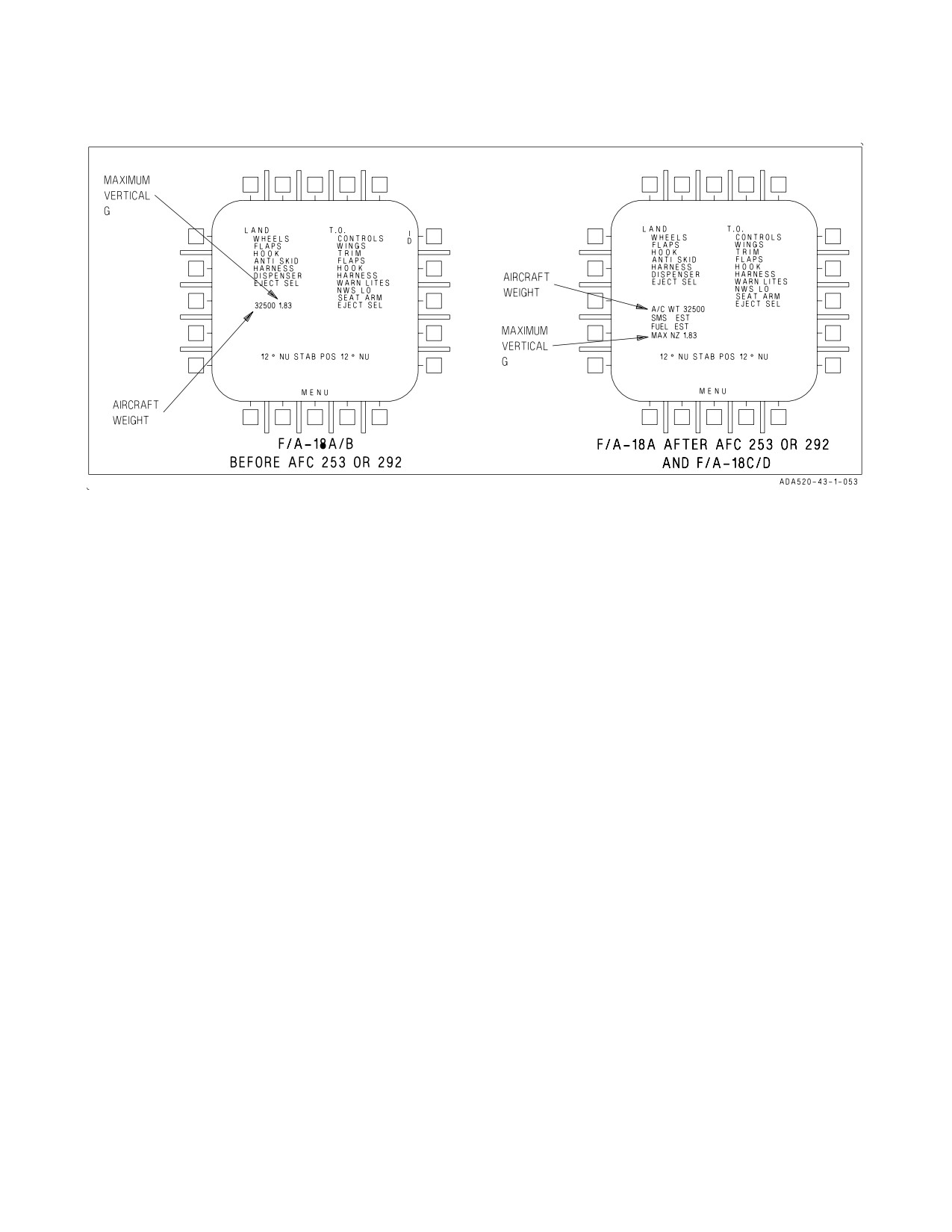
A1-F18AC-NFM-000
NOTE
D The STAB POS values represent degrees are followed by NU (nose up) or ND (nose down). The values may
range from 24 NU to 10 ND. Takeoff trim is set to 12° NU STAB POS.
D EJECT SEL is displayed on F/A-18B/D aircraft only.
D Maximum vertical g - Maximum vertical acceleration experienced during the most recent landing, rounded to
the nearest .01 g.
D Aircraft weight - The aircraft gross weight rounded to the nearest 100 lbs, or with MC OFP 13C AND UP, the
aircraft gross weight rounded to the nearest pound. If aircraft weight is invalid the weight symbology stops
being updated and flashes. When either the SDC or SMS detects a fault, the aircraft weight flashes and FUEL
INV, FUEL EST, SMS INV, or SMS EST is displayed. The MC continues to update the total aircraft weight
unless both the SDC and SMS indicate invalid, then the weight stops being updated.
D In the CV environment it is recommended that the takeoff checklist be completed from bottom to top.
Figure 7-1. Checklist Display
begun, advance throttles to MIL power and check EGT and RPM. If an afterburner takeoff is desired,
afterburner is selected by moving both throttles into the afterburner range and advancing smoothly to
MAX power. If one afterburner fails to light or blows out during takeoff, the resulting power loss is
significant. Sufficient directional control is available with the rudder and nosewheel steering to
continue the takeoff with asymmetric power. The decision to abort or continue the takeoff depends on
existing circumstances: external stores configuration, runway remaining, and the characteristics of the
afterburner failure since it may indicate problems with the basic engine. Nosewheel steering is used to
maintain directional control throughout the takeoff roll. Differential braking alone may not be
adequate to maintain directional control on takeoff. Also, the drag of the brakes increases the length
of the takeoff roll.
The location of the main landing gear well aft of the CG does not allow the aircraft to be rotated early
in the takeoff roll. The normal rotation technique is to position the stick aft of neutral approaching
nosewheel lift-off speed. Nosewheel lift-off speed depends on weight and CG, however, hold the aft
stick until 6° to 8° nose high attitude (waterline symbol) is reached. Main gear lift-off follows shortly,
and a forward adjustment of stick is necessary to maintain the desired attitude.
For a minimum run takeoff, use full afterburner power. Approaching nosewheel lift-off speed, apply
full aft stick until the aircraft begins to rotate. Adjust the stick to maintain a 10° to 12° nose high
attitude (waterline symbol). Once a positive climb rate is established, ensure the gear handle light is
out and retract the gear. Accelerate to the appropriate climb speed.
III-7-24
ORIGINAL
A1-F18AC-NFM-000
• Improper trim setting (e.g., 10° nose down vice 10° nose up) can reduce
stabilator authority to a level below that required for takeoff.
• Full stabilator (with 12° nose up trim) is not available at airspeeds
greater than approximately 180 knots.
• Takeoff with significant standing water on runway has caused water
ingestion which in extreme cases can cause engine stalls, flameouts,
A/B blowouts, and/or engine FOD. Avoid standing water in excess of
0.25 inch.
• Ensure computed nosewheel liftoff speed does not exceed nose tire
speed limitation (190 knots groundspeed) during takeoffs under cer-
tain combinations of the following conditions: high gross weight, high
pressure altitude, high temperature, or forward CG. See NATOPS
performance charts.
• Analysis has shown that an improperly serviced nose strut can increase
nosewheel liftoff speed by as much as 10 knots.
• Premature aft stick input below nose wheel liftoff speed will increase
takeoff roll.
7.2.3 Crosswind Takeoff. The initial portion of the crosswind takeoff technique is the same as the
normal takeoff. Aft stick pressure should not be applied until approaching liftoff speed.
Do not assume an immediate wing low attitude in order to counteract for wind drift; the pilot cannot
properly judge the wing tip ground clearance on a swept wing aircraft.
7.2.4 Formation Takeoff. Refer to Formation Flight, Chapter 9.
7.2.5 After Takeoff
When definitely airborne -
1. LDG GEAR handle - UP
2. FLAP switch - AUTO
7.2.6 Climb. For visibility over the nose, maintain 350 knots to 10,000 feet. For optimum climb
performance, refer to Part XI.
7.2.7 10,000 Feet
1. Cockpit altimeter - CHECK
2. Fuel transfer - CHECK
III-7-25
ORIGINAL
A1-F18AC-NFM-000
3. Radar altimeter low altitude warning system - CHECK/SET
7.2.8 Cruise. Optimum cruise and maximum endurance should be found in the Performance Data,
Part XI, and is attained by flying the correct Mach number for configuration and altitude. Maximum
range cruise is approximated by establishing 4.2°, but no faster than Mach 0.85. Maximum endurance
is approximated by establishing 5.6° AOA.
When using JP-4 fuel and ambient temperature at takeoff exceeds 85°F,
idle power decelerations between Mach 1.23 and Mach 0.9 may result in
engine flameout.
7.2.8.1
Cruise Check.
1. Cabin pressurization/temperature - MONITOR
During cruise, check cabin pressurization/temperature control. Pressurization shall remain at 8,000
feet up to 23,000 - 24,000 feet altitude. Above 23,000 to 24,000 feet altitude, cockpit pressurization
shall follow schedule in figure 2-37.
AIRCRAFT
CABIN
ALTITUDE
ALTITUDE
30,000 feet
10,000 to 12,000 feet
40,000 feet
15,000 to 17,000 feet
A slowly increasing cabin pressure altimeter may be the first or only
warning of a gradual loss of cabin pressurization.
7.3 LANDING
7.3.1 Descent/Penetration. Before descent, preheat the windshield by increasing defog air flow
(DEFOG-HIGH) and, if necessary windshield anti-ice/rain air flow (WINDSHIELD ANTI-ICE/
RAIN). Since rapid descents cannot always be anticipated, the maximum comfortable cockpit interior
temperature should be maintained to aid in defrosting the windshield. Normal instrument penetration
is 250 knots and 4,000 to 6,000 feet per minute descent. Refer to Part XI, for optimum descent profiles.
Before starting descent, perform the following:
1. ENG ANTI ICE switch - AS DESIRED
2. PITOT ANTI ICE switch - AUTO
3. DEFOG handle - HIGH
4. WINDSHIELD switch - AS DESIRED
5. Altimeter setting - CHECK
6. Radar altimeter - SET AND CHECK
III-7-26
ORIGINAL
A1-F18AC-NFM-000
7. HUD - SELECT NAV MASTER MODE, COMPARE WITH STANDBY FLIGHT INSTRU-
MENTS AND STANDBY COMPASS
8. Navaids - CROSSCHECK
9. ARA-63 (ILS) - ON AND CHANNEL SET
10. IFF - AS DIRECTED
11. Weapons/sensors - AS REQUIRED
7.3.2 Approach. See figure 7-2. Enter the pattern as prescribed by local course rules. At the break,
reduce thrust and extend the speedbrake (if required). As the airspeed decreases through 250 knots,
lower the landing gear and place the FLAP switch to FULL and ensure that speedbrake is retracted.
Retract speedbrake, if extended. Decelerate to on-speed, and compare airspeed and angle of attack.
Complete the landing checklist. Roll into the base leg and establish a rate of descent, maintaining
on-speed AOA. On-speed without external stores and 2,000 pounds of internal fuel is about 125 knots.
Add about 2.5 knots for each 1,000 pounds increase in fuel and stores. Rate of descent can be
established using the velocity vector on the HUD to set the glide-slope. Avoid overcontrolling the
throttles as thrust response is immediate. Compensate for crosswind by crabbing the aircraft into the
wind on final approach.
1. LAND checklist - COMPLETE
7.3.3 Touchdown.
Maintain approach attitude and thrust setting to touchdown using the lens or make a firm
touchdown at least 500 feet past the runway threshold. At touchdown, place the throttles to IDLE. The
aircraft tends to align itself with the runway. Small rudder corrections (NWS) may be required to keep
the aircraft tracking straight. Using a flared minimum descent rate landing, the WOW switch may not
actuate immediately. In this case, the throttles cannot be reduced to ground idle and may be
inadvertently left in the flight idle position, thereby reducing the deceleration rate and extending the
length of the landing rollout. Track down the runway centerline using rudder pedals to steer the
aircraft. Aerodynamic braking is not recommended. Getting the nosewheel on the ground and use of aft
stick (programmed in by light braking and slowly pulling the stick aft after touchdown so only the
minimum required distance to command full aft stabilator deflection by 100 knots) provides faster
deceleration from the stabilators and more directional control with use of the NWS.
Commanding full aft stick deflection with the ejection seat within 1.75
inches of the top limit can cause the lower ejection handle to snag on the
air-to-air weapon select switch and result in inadvertent ejection. In
particular, during stabilator braking after a full stop landing the control
stick should be pulled back only the minimum required distance to
command full stabilator authority. Inadvertent ejections have occurred
after stabilator braking when the pilot has released full aft stick.
7.3.4 Nosewheel Steering. The nosewheel steering (NWS) is the most effective means of direction-
ally controlling the aircraft during landing rollout. Aerodynamic control surface inputs become
III-7-27
ORIGINAL
A1-F18AC-NFM-000
ineffective below an airspeed of 75-85 knots. Differential braking requires special attention and
technique to control the aircraft below this speed. NWS is activated automatically in the low mode (16°
limit) by weight on the nose and at least one main gear. NWS inputs are commanded through force
sensors behind the minimum displacement rudder pedals allowing for precise directional control. The
NWS does not receive commands through the rolling surface to rudder interconnect (RSRI).
NOTE
Rudder and vertical tail effectiveness is significantly reduced if the
speedbrake is extended during the landing rollout and degrades
directional control during crosswind landings. Aircraft directional
stability is further reduced on a wet runway.
The aircraft can be safely landed with the nosewheel steering failed (castering) in crosswinds up to
25 knots. The aircraft tends to drift more to the downwind side of the runway and corrections are more
difficult. With the anti-skid on, directional control with differential brakes require pumping of the
upwind brake or releasing pressure from the downwind brake. To reduce the risk of blowing the tires,
landing without anti-skid on when heavy braking is anticipated is not recommended.
Engaging the high gain mode of NWS while maintaining a rudder pedal
input causes a large nosewheel transient and may cause loss of directional
control.
NOTE
Using the high gain mode of nosewheel steering (NWS HI) during the
landing rollout is not recommended and may lead to directional pilot
induced oscillations due to the increased sensitivity of the NWS to
rudder pedal inputs.
7.3.5 Landing Rollout. Track down the runway centerline using rudder pedals to steer the aircraft
directionally. Aerodynamic braking is not recommended. Use wheel braking only after the aircraft
main wheels are firmly on the runway.
7.3.6 Braking Technique. Under normal circumstances, the best results are attained by applying
moderate to heavy braking with one smooth application of increasing braking pressure as airspeed
decelerates towards taxi speed. Anti-skid is effective down to approximately 40 KGS. Below 40 KGS,
heavy brake pedal pressure should be relaxed to prevent tire skid. Below 35 KGS, steady but firm
brake pedal pressure should be applied. Steady, light brake applications should be avoided, as they
increase brake heating, do not significantly contribute to deceleration, and ultimately reduce braking
effectiveness. If desired, selecting aft stick (up to full) below 100 KCAS will increase TEU stabilator
III-7-28
ORIGINAL
A1-F18AC-NFM-000
deflection and aid in deceleration. Full aft stick increases down force on the main landing gear, as well
as significantly increasing drag due to large stabilator size.
Recommended braking speeds are based on tests conducted at sea level.
Ground speed may be significantly higher than calibrated airspeed at
airfields above sea level. Aircrew should consider available runway length
and field elevation to evaluate wheel brake usage and landing rollout
distance to avoid excessive brake heat build-up and subsequent tire
deflation or wheel assembly fire when landing at airfields above sea level.
Maximum braking performance is attained by applying full brake pedal pressure (approximately 125
lb) immediately after touchdown. Anti-skid must be on to attain maximum braking performance and
to reduce the risk of a blown tire. Longitudinal pulsing may be felt as the anti-skid cycles. Approaching
40 KCAS, full brake pedal pressure should be relaxed to prevent tire skid.
7.3.7 Crosswind Landing. The optimum technique for crosswind landing is to fly a crabbed
approach, taking out half the crab just before touchdown. For landing in a crosswind greater than 15
knots on a dry runway, the touchdown should be slightly cushioned in order to reduce landing gear
trunion loads. The wing-down top-rudder technique is ineffective in crosswinds greater than 20 knots,
creates excessive pilot workload, and should not be used. Touchdown in a full crab or with all the crab
taken out may cause large directional oscillations which can lead to excessive pilot inputs and
subsequent PIO. Taking out half the crab provides the correct amount of pedal force and resultant
NWS command to start the aircraft tracking down the runway.
When calculating crosswind components for takeoff or landing, use the
full value of any reported gusts in your calculations.
NOTE
Pilot control inputs are not required to counter slightly objectionable
directional oscillations which may occur at and immediately following
touchdown. Minimize stick and rudder pedal inputs until nose
movement is stable. If oscillations continue, execute a go-around.
Subsequent runway centerline tracking requires only small rudder inputs to initiate directional
corrections. Although lateral stick is not generally required during the landing roll, judicious inputs
may be made to counter the upwind wing rocking up. Landing rollouts in crosswinds up to 30 knots
have been accomplished with hands off the control stick with little or no objectionable roll (less than
5°) induced by crosswind or asymmetric stores.
7.3.8 Wet Runway Landing. The aircraft exhibits satisfactory handling characteristics during
landing rollouts on wet runways. However, experience indicates that landing in crosswind conditions
may increase the pilot tendency to directionally overcontrol the aircraft during the landing rollout. Wet
runways can induce hydroplaning throughout the landing rollout. As a result, the aircraft may respond
sluggishly to NWS commands and encourage the pilot to use excessively large control inputs. Rudder
III-7-29
ORIGINAL
A1-F18AC-NFM-000
pedal commands should be kept small, especially if hydroplaning is suspected. Minimum total
hydroplaning speed of the main landing gear tires inflated to 250 psi is 140 knots groundspeed and, for
nose gear tires inflated to 150 psi, is 110 knots. However, some hydroplaning can occur at much lower
speed, depending upon runway conditions. For wet (standing water) runway landings, reduce gross
weight to minimum practical. Concentrate on landing ON SPEED or slightly slow with power coming
off at touchdown. Maintain a constant attitude and sink rate to touchdown. Ensure the throttles are
in ground idle. When comfortable with directional control, use maximum anti-skid braking to minimize
landing distance. Go around if a directional control problem occurs and make an arrested landing.
Delaying the decision to abort the landing and go around can put the pilot in a situation in which he
cannot remain on the runway during the takeoff attempt.
Landing with significant standing water on runway has caused water
ingestion which in extreme cases can cause engine stalls, flameouts, A/B
blowouts, and/or engine FOD. Avoid standing water in excess of 0.25 inch.
7.3.9 Asymmetric Stores Landing. Landing with asymmetric external stores up to 12,000 foot-
pounds of lateral asymmetry requires no special considerations. Above 12,000 foot-pounds of lateral
asymmetry, AOA must be kept below 12° to prevent uncommanded sideslip.
The inboard station is 7.3 feet from the aircraft centerline and the outboard station is 11.2 feet from
the aircraft centerline. A lateral asymmetry of 12,000 foot-pounds occurs with 1,636 pounds of
asymmetry on an inboard station or 1,070 pounds of asymmetry on an outboard station.
Due to landing gear structural limitations, the weight of an asymmetric tip missile and/or internal
wing fuel asymmetry must be used in calculating total aircraft asymmetry. Asymmetry due to internal
wing fuel imbalance is calculated by multiplying the difference of fuel weight between left hand and
right hand wing by 8.0 feet. Fuel weight differences of less than 100 pounds are considered negligible.
Wingtip missile asymmetries can be calculated by multiplying missile weight by 19.5 feet (the distance
of the wingtip station from aircraft centerline.)
If lateral asymmetry exceeds
12,000
foot-pounds, do not exceed
12° AOA. Recommend fly
straight-in approach at optimum approach speed. Do not apply cross controls and make only smooth,
coordinated rudder and lateral stick inputs. In a crosswind, fly a crabbed approach to touchdown.
Field landings (flared) with asymmetries between 17,000 and 26,000
foot-pounds are authorized only at touchdown sink rates up to 500 fpm
due to structural limitations of the landing gear.
7.3.10 Waveoff. Do not delay the decision to take a waveoff to the point that control of the landing
or rollout is in jeopardy. Takeoff distances at MIL or MAX power are short provided the aircraft has
not decelerated to slow speed. Advance the throttles to MIL or MAX as required to either stop the sink
rate or takeoff and maintain angle of attack. Raise the landing gear and flaps only after a safe climb
has been established.
III-7-30
ORIGINAL
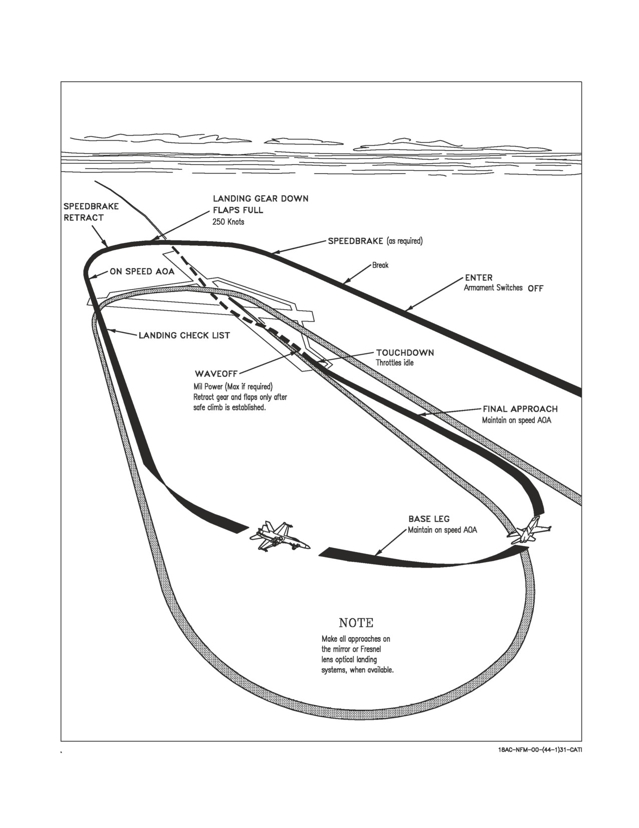
A1-F18AC-NFM-000
Figure 7-2. Field Landing Pattern Typical
III-7-31
ORIGINAL
A1-F18AC-NFM-000
7.4 POSTFLIGHT
7.4.1 After Landing. Do not taxi with the right engine shut down. With the right engine shut down,
only the accumulators provide hydraulic power for nosewheel steering and brakes.
NOTE
To prevent damage to the moving map servos, keep the HI brightness
selector knob in NIGHT or DAY and at least one DDI on whenever
the aircraft is in motion.
When clear of active runway -
1. Ejection seat - SAFE
Ensure that the SAFE/ARM handle is locked in the detent in the safe
position and that the word SAFE is completely visible on the inboard
side of the SAFE/ARM handle. If the SAFE/ARM handle does not lock
in the detent or the word SAFE is not completely visible, check to ensure
that the ejection handle is fully pushed down into its detent and attempt
to resafe the seat with the SAFE/ARM handle. Instruct line personnel to
remain clear of the cockpit until this downing discrepancy is properly
checked by qualified ejection seat maintenance personnel.
2. Landing gear handle mechanical stop - FULLY ENGAGED
3. FLAP switch - AUTO
4. T/O TRIM button - PUSH (note TRIM advisory)
5. Mask - OFF
LOX Aircraft -
6. OXYGEN supply lever - OFF
OBOGS Aircraft -
6. OXY FLOW knob - OFF
III-7-32
ORIGINAL
A1-F18AC-NFM-000
All Aircraft -
7. Canopy either full up or full down.
Taxiing with canopy at an intermediate position can result in canopy
attach point damage and failure.
NOTE
Adjusting seat height after Koch fittings are removed may result in
trombone fairing damage.
7.4.2 Hot Refueling. When refueling external tanks, the tanks refuel slowly until the internal tanks
are full. Do not hot refuel with the right engine shut down. With the right engine shut down, only the
accumulators provide hydraulic power for nosewheel steering and brakes.
The fuel quantity indicator must stabilize within 45 seconds after initiating pre-check and must not
increase more than 100 pounds in the following 60 seconds. The pre-check system may require as long
as 45 seconds to close the refueling pilot valves. Closing of the valves is indicated by a rapid decrease
in the refueling rate. An increase of more than 100 pounds fuel quantity after allowing time for the
valves to close (45 seconds maximum) indicates failure of one or more valves to close.
A failed or leaking refueling pilot valve causes rapid overfilling of the fuel
overflow/vent tank, fuel spillage from the vent mast(s), and possible fire
if fuel spills on hot engine components.
Before taxi, the plane captain/final checker shall signal confirmation that the fuel cap is properly
installed and door 8 right is closed. The signal is a cupped open hand rotated counterclockwise then
clockwise followed by a thumbs up.
7.4.3 Before Engine Shutdown.
1. PARK BRK handle - SET
2. BIT display - RECORD DEGD
3. BLIN codes - RECORD
4. Radar maintenance codes - NOTE IF PRESENT
5. INS - PERFORM POST FLIGHT UPDATE
6. INS knob - OFF (10 seconds before engine shutdown)
7. Standby attitude reference indicator - CAGE/LOCK
III-7-33
ORIGINAL
A1-F18AC-NFM-000
8. Sensors, radar, avionics and VTRS - OFF
NOTE
To prevent tapes from jamming, wait a minimum of 20 seconds after
VTRS/CVRS shutdown before removing aircraft power.
9. COMM 1 and 2 - OFF
10. EXT and INT LT knobs - OFF
For aircraft 163985 AND UP, a high voltage (100,000 volt) static electrical
charge may build up in flight and be stored in the windscreen and canopy.
To prevent electrical shock ensure that the static electricity has been
discharged.
11. CRYPTO switch - AS REQUIRED
NOTE
Ensure the MIDS terminal is ON, by ensuring L16 or TACAN is ON,
prior to any attempt to zeroize IFF Mode 4 Crypto Keys via the
CRYPTO switch.
12. Canopy - OPEN
13. QDC - DISCONNECTED AND STOWED
Failure to disconnect QDC prior to pilot egress will damage the lower IRC
connection.
7.4.4 Engine Shutdown
1. Brake gauge - 3,000 psi
2. Nosewheel steering - DISENGAGE
3. FLAP switch - FULL
4. Throttle - OFF (alternate side)
NOTE
Before engine shutdown, engine should be operated at flight or ground
idle for 5 minutes to allow engine temperatures to stabilize.
III-7-34
ORIGINAL
A1-F18AC-NFM-000
5. Monitor HYD pressure. As pressure decreases below 1,500 psi, gently pump the stick approxi-
mately ±1 inch fore and aft at approximately two cycles per second, decreasing hydraulic pressure
on shutdown engine below 800 psi. Ensure system pressure on operating engine remains above
1,500 psi.
NOTE
Pressure must remain below 800 psi on shutdown engine for valid test.
6. Continue gently pumping the stick while monitoring FCS page for FCS Xs and/or BLIN codes for
12 seconds after system pressure on shutdown engine drops below 800 psi. Record if present.
NOTE
• BLIN code 63 and/or rudder Xs indicate a malfunctioning rudder
switching valve and further maintenance action is required.
• BLIN code 66 and/or aileron Xs indicate a malfunctioning aileron
switching valve and further maintenance action is required.
• BLIN code 67 and/or LEF Xs indicate a malfunctioning LEF switch-
ing valve and further maintenance action is required.
7. L(R) DDI, HI/MPCD, and HUD - OFF
8. Throttle - OFF
When amber FLAPS light illuminates -
9. BATT switch - OFF
Turning battery switch off before the amber FLAPS light illuminates
could result in severe uncommanded flight control movement. The only
cockpit indication that hydraulics have been removed from the flight
controls, and that they are no longer powered, is the amber FLAPS light.
NOTE
If engines are not idled for 5 minutes prior to shutdown, a restart
should be avoided between 15 minutes and 4 hours after shutdown.
III-7-35
ORIGINAL
A1-F18AC-NFM-000
7.5
REAR COCKPIT PROCEDURES (F/A-18B/D)
Flight in the rear seat is limited to crewmembers with buttock-leg length
less than 48 inches and buttock-knee length less than 26.5 inches.
7.5.1 Before Entering Cockpit
1. Ejection seat safe/arm handle - SAFE & LOCKED
2. Ejection seat - PREFLIGHT PER FRONT COCKPIT CHECKLIST
7.5.2 Interior Check
1. Harness and rudder pedals - SECURE/ADJUST
Fasten and secure leg restraint garters and lines. Check leg garters buckled and properly adjusted
with hardware on inboard side of the legs. Check that lines are secured to seat and floor and not
twisted. Check that leg restraint lines are routed first through the thigh garter ring, then through
the lower garter ring, and then routed outboard of the thigh garter ring before the lock pins are
inserted into the seat just outboard of the snubber boxes. Attach parachute risers to harness
buckles. Connect and adjust lap belt straps. Connect oxygen, g suit, and communications leads.
Check operation of shoulder harness locking mechanism.
• The leg restraint lines must be buckled at all times during flight to
ensure that the legs are pulled back upon ejection. This enhances seat
stability and prevents leg injury by keeping the legs from flailing
following ejection.
• Failure to route the restraint lines properly through the garters could
cause serious injury during ejection/emergency egress.
2. EMERG BRK handle - IN
Anti skid is not available with the rear cockpit emergency brake handle in
the emergency position.
3. Ejection control handle - CLEAR
Left console -
LOX Aircraft -
1. OXYGEN supply lever - OFF
III-7-36
ORIGINAL
A1-F18AC-NFM-000
OBOGS Aircraft
1. OXY FLOW knob - OFF
All Aircraft -
2. CANOPY JETT handle - OUTBOARD AND DOWN
3. VOL panel - SET
4. Throttles (on rear stick and throttle equipped F/A-18D) - OFF
Instrument panel -
1. EMERG LDG GEAR handle - IN
2. EMERG BRK handle - IN
3. L(R) DDI/MPCD knobs - OFF
4. COMM 1 and 2 knobs - OFF
5. Clock - CHECK AND SET
6. Standby attitude reference indicator - CAGE/LOCK
Right console -
7. INTR LT panel - AS DESIRED
8. NVG container - SECURE/NVG STOW (if required)
7.5.3 Before Taxi
1. L(R) DDI/MPCD - ON
2. Fuel quantity gauge - CHECK QUANTITY
3. Altimeter - SET
4. Flight controls (on rear stick and throttle equipped F/A-18D) - CYCLE
After FCS reset in the front cockpit, cycle the flight controls.
5. Standby attitude reference indicator - UNCAGE
LOX Aircraft -
6. Oxygen system - CHECK
a. OXYGEN supply lever - ON/MASK ON
b. Oxygen flow - CHECK
III-7-37
ORIGINAL
A1-F18AC-NFM-000
c. OXYGEN supply lever - OFF/MASK OFF
If OXYGEN supply lever is ON and the mask is not properly donned, the
flow control valve could freeze in the open position and cryogenic burns
could result.
OBOGS Aircraft -
6. OBOGS system - CHECK
a. OXY FLOW knob - ON/MASK ON
b. OBOGS flow - CHECK
c. OXY FLOW knob - OFF/MASK OFF
7.5.4 Before Takeoff
1. T.O. checklist - CONFIRM COMPLETE
2. OXY FLOW knob or OXYGEN supply lever - ON/MASK ON
It is possible to place the OXY FLOW knob in an intermediate position
between the ON and OFF detents, which may result in a reduced flow of
oxygen. The OXY FLOW knob should always be fully rotated to the ON
or OFF detent position.
7.5.5 Descent/Penetration
1. Altimeter setting - CHECK
2. Standby instruments - CHECK
7.5.6 Approach
1. LAND checklist - CONFIRM COMPLETE
7.5.7 After Landing
When clear of active runway -
1. Ejection seat - SAFE
2. Mask - OFF
3. OXY FLOW knob or OXYGEN supply lever - OFF
III-7-38
ORIGINAL
A1-F18AC-NFM-000
7.5.8 Before Engine Shutdown.
1. L(R) DDI/MPCD - OFF
2. COMM 1 and 2 - OFF
3. Interior lights - OFF
4. Standby attitude reference indicator - CAGE/LOCK
7.6 NIGHT FLYING
7.6.1 External Light Management. During night operations, the external lights should be set as
follows:
1. On the line - Position and formation lights BRT, strobe light ON
2. When ready to taxi - Taxi light - AS DESIRED
3. In flight - AS REQUIRED
a. Single aircraft - BRT (or as weather conditions dictate)
b. Formations - AS REQUIRED BY WINGMAN
The last aircraft in formation should have external lights on BRT unless tactical situation
demands otherwise (actual penetrations).
III-7-39
(Reverse Blank)
ORIGINAL
A1-F18AC-NFM-000
CHAPTER 8
Carrier-Based Procedures
8.1 GENERAL
The CV and LSO NATOPS Manuals are the governing publications for the carrier-based operations
and procedures. All flight crewmembers shall be familiar with CV NATOPS procedures and Aircraft
Launch/Recovery Bulletins prior to carrier operations.
8.1.1 Carrier Electromagnetic Environment. Tests conducted in a carrier deck electromagnetic
environment (EME) have documented numerous electronic interference problems that affect aircraft
systems, displays and weapons. These electromagnetic interference problems do not occur all the time
as they are a function of operating shipboard emitters and aircraft location. The electromagnetic
interference problems are especially apparent if avionics bay doors are open on the flight deck.
With avionics bay doors open when operating in or near the carrier
electromagnetic environment a NOGO may be displayed next to MC 1 or
MC 2 on the BIT display. Checks of the computers have confirmed that
some memory alteration has occurred and the NOGO indication is valid
and should not be ignored.
NOTE
Operating in or near the carrier electromagnetic environment may
cause the following temporary effects on the aircraft systems:
DDI - streaking and strobes on display, loss of BIT status, vibration indicator on ENG page may
show a significant increase in engine vibration, unusable video picture on Walleye display,
and inoperable Walleye cage/uncage button.
HUD - altitude display to flash on/off.
TACAN - loss of range and bearing.
UHF - blanking of communications, communications relay may be unusable.
RAD/ALT - low altitude warning light flashing.
IFF - failure to reply when lower antenna is selected.
ICS - excessive background noise.
VTR - distortion during playback.
Engine Monitor Indicator - uncommanded switching of numbers.
Warning/Caution Lights - intermittent illumination of arresting hook and landing gear warning
light.
F/A-18D -
FIRE Warning Light - illumination of aft cockpit fire warning light.
DDI - loss of symbology alongside buttons of left DDI in both cockpits.
AOA - intermittent illumination of AOA indexer lights.
III-8-1
ORIGINAL
A1-F18AC-NFM-000
8.1.2 Carrier INS Environment. The CV alignment is dependent on the Ship Inertial Navigation
System (SINS). Align times are longer to achieve QUALs typical on land. Ship turns and sea-state also
affect the CV alignment. Postflight updates (closeout) cannot be performed on carriers.
NOTE
It is recommended that a waypoint zero position (SINS, PIM, etc.) be
input to reduce GPS satellite acquisition time.
8.2 DAY OPERATIONS
8.2.1 Preflight. When directed to man the aircraft, conduct a normal preflight inspection with
particular attention given to the landing gear, struts, tires, arresting hook, and underside of the
fuselage for possible arresting cable damage. Ensure sufficient clearance exists for cycling ALL control
surfaces. Interior checks are the same as shore based except anti-skid OFF. Note the relationship of the
APU exhaust port and the arresting hook to the deck edge. Do not start the APU if there is a possibility
of damage from the APU exhaust. Do not lower the hook during post start checks unless the hook point
will drop on the flight deck.
The maximum wind allowed for canopy opening is 60 knots. Attempting
canopy opening in headwinds of more than 60 knots or in gusty or
variable wind conditions may result in damage to or loss of the canopy.
8.2.2 Engine Start. When directed, start engines. APU starts should be made whenever possible.
Crossbleed starts must be approved by the Air Boss due to the relatively high power setting required,
and the potential for injury from the jet blast.
Perform the before taxi checks and be ready to taxi when directed.
8.2.3 Taxi.
• Ensure anti-skid switch is OFF for all carrier operations.
• Wait 5 seconds after wings are fully spread before placing the WING
FOLD handle to LOCK. Placing the WING FOLD handle to LOCK
before the wings are fully spread removes the WING UNLK caution
even through the wings are not fully spread and cause severe damage
to the wing fold transmission.
The wingfold control handle should smoothly go into the LOCK position.
Forcing the handle could cause damage to the wingfold system.
III-8-2
ORIGINAL
A1-F18AC-NFM-000
Due to the high wind over the deck, it is possible for the aileron locking
pin to shear at any time. This will allow the aileron to fair away from the
neutral position. Pay special attention to the aileron position with the
wings folded on the carrier deck. To avoid damaging the flaps, ensure
ailerons are not faired inboard prior to raising the flaps, conducting IBIT,
or running FCS exerciser. Proper aileron position can be determined
either visually or by verifying an aileron position of 0 or down arrow on
the FCS page.
Taxiing aboard ship is much the same as ashore, but increased awareness of jet exhaust and aircraft
directors are mandatory.
Nosewheel steering is excellent for directional control aboard ship. Taxi speed should be kept under
control at all times, especially on wet decks, in the landing area, and approaching the catapult. The
canopy should be down, oxygen mask on, and the ejection seat armed during taxi. Be prepared to use
the emergency brake should normal braking fail. In the event of loss of brakes, inform the tower and
lower the tailhook immediately to indicate brake loss to the deck personnel.
8.2.4 Hangar Deck Operation. Occasionally the aircraft is manned on the hangar deck. Follow the
same procedures as those concerning flight deck operation.
Tiedowns shall not be removed from the aircraft unless emergency brake accumulator pressure
gauge indicates at least 2,600 psi. The emergency brake shall be used for stopping the aircraft anytime
it is being moved while the engines are not running. If the aircraft is not already on the elevator, it will
be towed or pushed (with the pilot in the cockpit) into position to be raised to the flight deck. Close
the canopy, ensure tiedowns are in place, and put the parking brake on anytime the aircraft is on the
elevator.
The signal to stop an aircraft that is being towed is either a hand signal or a whistle blast. The whistle
signifies an immediate or emergency stop. Leave the canopy open and helmet off to ensure hearing the
whistle; keep the plane director in sight at all times. If unable to see the plane director, or if in doubt
of safe aircraft movement, stop the aircraft immediately.
8.2.5 Before Catapult Hook-Up. Before taxi onto the catapult, complete the takeoff checklist, set the
standby attitude reference indicator for use if the HUD fails during the launch. With flaps HALF or
FULL, the takeoff trim button should be pressed until the TRIM advisory appears and then the
horizontal stabilator trim should be manually positioned for CG location, excess end airspeed and
power setting for launch. The takeoff trim button need not be pressed between successive launches in
a single flight. With an asymmetric load, trim stabilator for normal position then trim differential
stabilator unloaded wing down. The trim settings in figure 8-1 are applicable for HALF flaps only, all
air-to-air stores, air-to-ground stores, clean aircraft, external fuel tanks, gross weights and launch CG
between 17.0 and 27.5% MAC. For normal operation, 15 knots excess end airspeed above minimum is
recommended.
Correct stabilator trim is critical to aircraft hands off fly-away performance. Stabilator trim affects
initial pitch rate and determines AOA capture. A low trim setting both lowers the initial pitch rate
below optimum and causes the aircraft to fly away in a flatter attitude due to a lower than optimum
AOA capture. This results in degraded climb performance after launch. A higher than recommended
trim setting can cause excessive AOA overshoots which can lead to loss of lateral directional control
when loaded with asymmetric stores, or in a single engine emergency.
Use of catapult 4 is restricted with certain stores loaded on station 2.
Refer to applicable launch bulletin.
III-8-3
ORIGINAL
A1-F18AC-NFM-000
The following trim settings are recommended:
Symmetrical loading -
a. Directional trim - 0°
b. Lateral trim - 0°
c. Longitudinal trim - See figure 8-1
Asymmetrical loading -
a. Directional trim - 0°
b. Longitudinal trim (first) - See figure 8-1
c. Lateral trim - See figure 8-1
Failure to input differential stabilator trim for catapult launches with
asymmetric stores can aggravate aircraft controllability.
8.2.6 Catapult Hook-Up. Before taxiing past the shuttle, aircraft gross weight should be verified,
takeoff checklist complete, and arming completed by the ordnance crew if required. Check external
fuel quantity. Approach the catapult track slowly, lightly riding the brakes, with nosewheel steering on.
Use minimum power required to keep the aircraft rolling. Close attention to the plane director’s signals
is required to align the aircraft with the catapult track entry wye. When aligned, the plane director
signals the pilot to lower the launch bar. Place the launch bar switch to EXTEND. The green
LAUNCH BAR advisory light comes on and nosewheel steering disengages. Nosewheel steering low
mode may be engaged while the launch bar is down by pressing and holding the nosewheel steering
button. This should only be done on signal from the director since catapult personnel may be in close
proximity to the launch bar. Do not use nosewheel steering once the launch bar enters the track. The
catapult crew installs the holdback bar and the aircraft may taxi forward slowly, following the signals
of the plane director. When the launch bar drops over the shuttle spreader, the aircraft will be stopped
by the holdback bar engaging the catapult buffer. On aircraft 161353 THRU 161715, upon receipt of
the “Release Brakes” signal, advance throttles to 85% to 90% rpm. Do not advance throttles to MIL
at this time since this could retract the launch bar before it is trapped by the tensioned shuttle
spreader. On aircraft 161716 AND UP, upon receipt of the “Release Brakes” signal, advance throttles
to MIL.
Check AOA when aligned on catapult. With MC OFP 13C AND UP,
check AOA on the FCS page to ensure both values are less than +10°.
With MC OFP 10A AND UP, ensure HUD AOA is less than 10°.
III-8-4
ORIGINAL
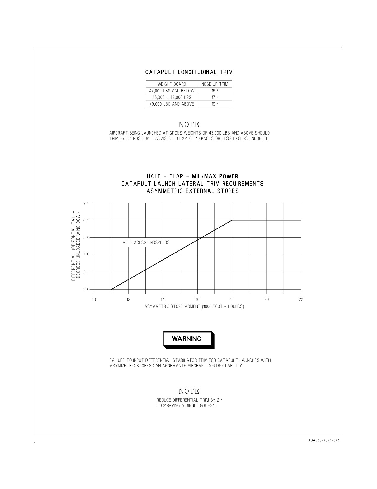
A1-F18AC-NFM-000
Figure 8-1. Launch Trim
III-8-5
ORIGINAL
A1-F18AC-NFM-000
8.2.7 Catapult Afterburner Operation. Permissible catapult launch power settings depend on
aircraft gross weight. At gross weights of 45,000 lbs and above, afterburner catapult shots are required.
At gross weights of 44,000 lbs and below, three options are provided, allowing pilots to tailor the power
settings to their needs. Military power launches minimize the impact of sustained afterburner
operation on the ship’s jet blast deflectors (JBDs) and reduce fuel consumption. Afterburner catapults
improve aircraft sink-off-bow performance and single engine flyaway performance in case of an
emergency. Stabilizing in military power while in catapult tension and selecting afterburner (MIL/
MAX setting) at holdback release provides a compromise between single engine climb capability, fuel
consumption and JBD compatibility. Performing a MIL to MAX afterburner transient results in only
a small reduction of engine stall margin. If afterburner thrust is to be selected during the catapult
stroke, advance throttles to MAX immediately following catapult holdback release. This maximizes
the available time for the engines to stabilize prior to the end of the catapult stroke. The catapult
settings for a MIL/MAX shot are identical to a MIL power shot, so there is no need for pilots to
communicate their intention to exercise the MIL/MAX option to the catapult crew.
CATAPULT THROTTLE SETTINGS
Weight Board
Engine Power
MIL
44,000 lbs and below
MIL/MAX
MAX
45,000 lbs and above
MAX
NOTE
• MIL/MAX power setting is defined as stabilizing in military power
while in catapult tension, and selecting maximum afterburner at
holdback release.
• Any engine experiencing self-clearing pop stalls due to steam ingestion
during the catapult launch indicates the engine is operating at near the
limits of available stall margin. Aircraft experiencing any pop stalls
shall be launched at a stabilized power setting (MIL or MAX) and
afterburner shall not be selected during a catapult launch, except in an
emergency.
• In certain weather conditions with high humidity and cool tempera-
ture, with heavy steam coming out the catapult track there exists the
possibility of fireballs coming out the exhaust at the end of the
catapult shot. A possible cause of the fireball is momentary fan stall
that recovers quickly and may not be detrimental to the engine.
Ensure proper engine operation.
III-8-6
ORIGINAL
A1-F18AC-NFM-000
8.2.8 Catapult Launch.
Do not catapult with partially full external fuel tank(s) less than 1,900
pounds.
When the “Final Turnup” signal is received from the catapult officer, advance throttles to MIL or
MAX. On aircraft 161353 THRU 161715, the launch bar switch automatically returns to RETRACT
and the green LAUNCH BAR advisory light goes out. On aircraft 161716 AND UP, place the launch
bar switch to RETRACT. Cycle the flight controls, wait 4 seconds then ensure all warning and caution
lights are out. If afterburners are to be used, select them on signal from the catapult officer. Check
engine instruments. When satisfied that the aircraft is ready for launch, hold throttles firmly against
the detent, place the head against the head-rest, and salute the catapult officer with the right hand.
• The close proximity of the flap and launch bar switches may result in
inadvertent selection of FLAPS UP vice launch bar up.
• Movement of the launch bar switch to RETRACT prior to the aircraft
being fully tensioned may result in a mispositioned launch bar and
subsequent launch bar/shuttle separation during catapult launch.
NOTE
Failure to place launch bar switch to retract may result in hydraulic
seal failure.
Throttle friction may be used to help prevent inadvertent retraction of the throttles during the
catapult stroke. If required, it can be overridden if afterburner is needed due to aircraft/catapult
malfunction. Immediately after the end of the catapult stroke the aircraft will rotate to capture the
trimmed AOA without control stick inputs. PIO can occur immediately after launch if the control stick
is restrained during the launch or control inputs are made immediately after launch. The pilot should
closely monitor the catapult sequence and be prepared to make corrections if required. Clearing turns
should not be made until sufficient flying speed is attained. Retract the gear and flaps when a positive
rate of climb is established.
NOTE
Engaging the ATC with throttle friction on may cause the system to
disengage.
The longitudinal flight control system is designed to rotate the aircraft to a reference or capture
AOA following catapult launch. Trim settings between 10° and 18° nose up correspond linearly to
reference AOAs between 4° and 12°. Twelve degrees AOA is the highest AOA that can be commanded
hands-off and setting trim above 18° nose up increases the initial pitch movement without changing
the reference AOA. The single engine minimum control airspeed increases as AOA increases. The
III-8-7
ORIGINAL
A1-F18AC-NFM-000
recommended trim settings of paragraph 8.2.5 are designed to minimize aircraft sink-off-bow while
maintaining AOA low enough so that lateral directional controllability is sufficient in the event of an
engine failure. Normal catapult launches are characterized by an initial rotation as high as 13° AOA
before AOA and pitch rate feedbacks reduce the AOA to the reference value. A range of 10 to 12° AOA
is the optimum compromise between minimizing sink-off-bow and ensuring controllability in the event
of an engine failure.
F/A-18 catapult launch endspeeds are determined by one of two limiting factors, single engine
minimum control airspeed and sink-off-bow. At gross weights of 45,000 lbs and above, the minimum
launch endspeed ensures that the aircraft will not sink excessively during the catapult flyaway. With
normal endspeed (11 to 20 knots above minimum) and deck conditions, 4 to 6 feet of settle can be
expected. The pilot perceives the catapult shot to be level, as the rotation of the aircraft keeps the
pilot’s eye approximately level, even though the aircraft center-of-gravity sinks. With zero excess
endspeed, up to 20 feet of settle can be expected. For heavy weight shots which are planned with 10
knots or less excess endspeed, trim settings are increased 3° to help minimize the settle that will occur.
This higher trim setting comes at the cost of reducing the margin of controllability should an engine
fail. Therefore, the higher trim settings should only be used when advised by the ship that the shot will
definitely have 10 knots or less excess endspeed. The higher trim settings bias the compromise between
aircraft controllability and minimizing settle to favor minimizing settle, because in the case of a
planned reduced endspeed shot, excessive settle is definitely going to occur, while the chance of an
engine failure is no different than any other shot.
At gross weights of 44,000 lbs and below, the minimum launch endspeed is determined by the single
engine minimum control airspeed. This endspeed is greater than the speed required to minimize
sink-off-bow for that weight range. Therefore, catapult shots in this regime are characterized by greater
climb rates than catapult shots at weights of 45,000 lbs and above. Little to no sink should be observed
for nominal endspeed and deck conditions when launched at 44,000 lbs and below.
The single engine minimum control airspeed increases as asymmetry increases. Minimum launch
endspeeds for weight boards of 37,000 lbs and above ensure sufficient airspeed to maintain aircraft
control for asymmetric loadings up to and including 22,000 ft-lbs. For weight boards of 36,000 lbs and
below, airspeed is only sufficient to guarantee controllability for up to 6,000 ft-lbs of asymmetry.
Aircraft being launched at these weights must not exceed the 6,000 ft-lb asymmetry limit.
8.2.9 Catapult Suspend. To stop the launch while tensioned on the catapult, signal by shaking the
head negatively and transmitting SUSPEND, SUSPEND on land/launch frequency. Do not use a
thumbs down signal or any hand signal that might be mistaken for a salute. The catapult officer replies
with a SUSPEND signal followed by an UNTENSION AIRPLANE ON CATAPULT signal. The
shuttle spreader is moved aft and the launch bar automatically raises clear of the shuttle spreader.
Maintain power at MIL/MAX until the catapult officer steps in front of the aircraft and signals
THROTTLE BACK. The same signals are used when a catapult malfunction exists.
8.2.10 Landing Pattern. Refer to Chapter 4, for carrier operating limitations.
Carrier landing with more than 500 pounds in the centerline fuel tank is
prohibited.
III-8-8
ORIGINAL
A1-F18AC-NFM-000
While maneuvering to enter the traffic pattern, attempt to determine the sea state. This information
will be of value in predicting problems that may be encountered during the approach and landing.
Enter the carrier landing pattern (figure 8-2) with the hook down. Make a level break from a course
parallel to the Base Recovery Course (BRC), close aboard to the starboard of the ship. Below 250 knots
lower the gear and flaps. Descend to 600 feet when established downwind and prior to the 180°
position. Complete the landing checklist and crosscheck angle-of-attack and proper airspeed. Pitch
trim is set to 8.1° AOA when autopilot is disengaged while in the PA configuration if AOA is greater
than 6.0°.
With a 30-knot wind over the deck begin the 180° turn to the final approach when approximately
abeam the LSO platform. When the meatball is acquired, transmit “Call sign, Hornet, Ball or CLARA,
fuel state (nearest 100 pounds) and auto” (if using ATC for approach). Refer to figure 8-3 for a typical
Carrier Controlled Approach.
8.2.11 ATC Approach Mode Technique. The ATC approach mode should be engaged with the
aircraft near on-speed. If fast when ATC is engaged, additional time may be required for on-speed
capture. The technique required for an ATC approach mode differs from a manual approach in that
all glideslope corrections are made by changing aircraft attitude. Since this technique violates the basic
rule that altitude/glideslope is primarily controlled by the throttle, practice is required to use ATC. For
the ATC to perform satisfactorily, smooth attitude control is essential. Large attitude changes result
in divergent glideslope oscillations or overcontrolling power response. Close-in corrections are very
critical. If large attitude correction for a high-in-close situation develops, the recommended procedures
is to stop ball motion and do not attempt to recenter it. A low-in-close condition is difficult to correct
with ATC and usually results in an over-the-top bolter. It may be necessary to manually override ATC
in order to safely recover from a low-in-close condition. The force required to manually disengage ATC
is significant and may prevent salvaging the pass. Throughout the approach the pilot should keep his
hand on the throttles in the event it is necessary to manually disconnect/override the ATC.
8.2.12 Glideslope. The technique for flying the glideslope is basically the same as FCLP except that
more power may be required to maintain glideslope, and line-up will be much harder to maintain. With
rough seas and a pitching deck some erratic ball movement may be encountered. If this is the case,
listen to the LSO’s calls and average out the balls movement to maintain a safe controlled approach.
8.2.13 Waveoff. When the waveoff signal is received, immediately apply military/afterburner power
and effect a slight nose rotation to stop the rate of descent. During an in-close waveoff, excessive
rotation by the pilot will cause a cocked-up or over-rotated attitude which can result in an inflight
engagement and possible aircraft damage.
Selecting afterburner during an ‘‘in close’’ or a technique waveoff, produces limited performance
gains. FULL flap approach airspeed is essentially the same as the single engine afterburner minimum
controllable airspeed. The asymmetric thrust from an asymmetric afterburner light-off of either the
-400 or -402 engines during a ‘‘high coming down’’ or a ‘‘slow’’ approach may result in unacceptable yaw
control and significant lineup deviations. Unintentional arrestment may result in damage to the
aircraft and arresting gear.
III-8-9
ORIGINAL
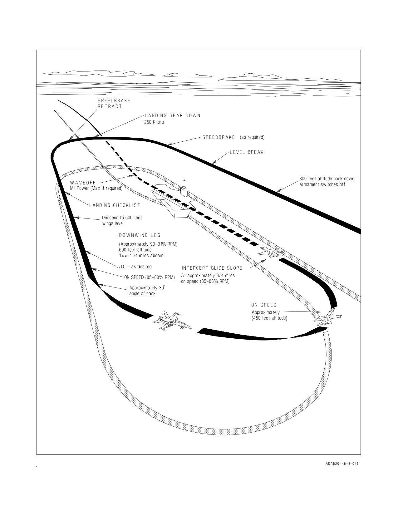
A1-F18AC-NFM-000
Figure 8-2. Carrier Landing Pattern
III-8-10
ORIGINAL
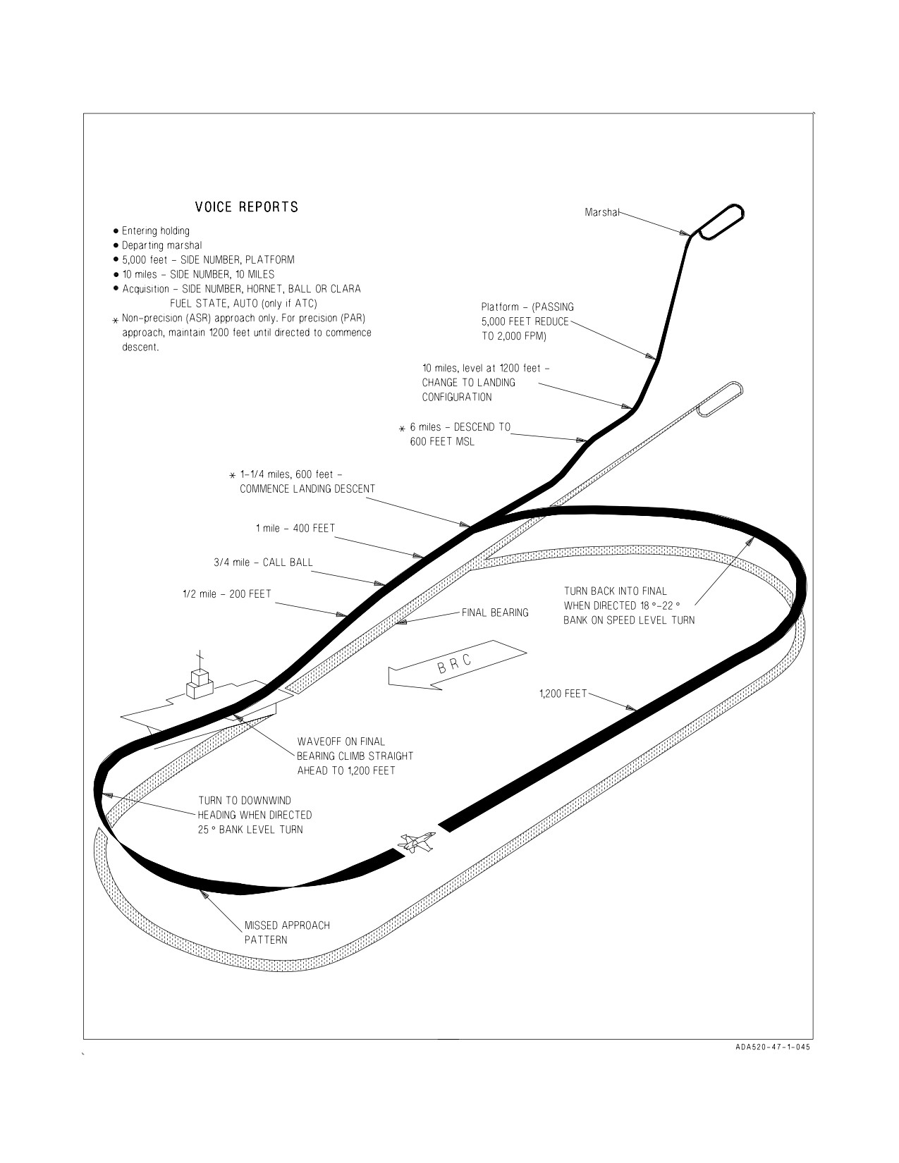
A1-F18AC-NFM-000
Figure 8-3. Carrier Controlled Approach (CCA)
III-8-11
ORIGINAL
A1-F18AC-NFM-000
An afterburner waveoff should be performed only during an extremely
low approach or when in danger of a rampstrike.
8.2.14 ACL Mode 1 and 1A Approaches. A typical Mode 1 and 1A approach is shown in figure 8-4.
The Mode 1/1A approach does not require automatic throttle control but it should be used, if available.
The following procedure is for a typical Mode 1 and 1A approach from marshal to touchdown or 0.5
mile.
1. Horizontal indicator (HI/MPCD) - PRESS ACL
The Link 4 display appears on the left DDI and ACL mode automatically starts its self test. At
this time, the ILS, data link, and radar beacon are automatically turned on (if not previously on);
IBIT is run on the data link and radar beacon systems. Also, the uplinked universal test message
is monitored for valid receipt.
2. On board ACL capability - CHECK ACL 1
ACL 1 must be displayed on the Link 4 display to accomplish a Mode 1 or 1A approach.
A degraded augmenter may lead to a significant lineup error, most often
right-of-centerline. ACL coupling with an augmenter DEGD is not
inhibited.
3.
Report departing marshal.
4.
Normal CCA - PERFORM
Descend at 4,000 feet per minute and 250 knots to 5,000 feet, (platform) then reduce rate of
descent to 2,000 feet per minute. When passing through approximately 5,000 feet, ILS steering is
automatically displayed on the HUD and must be manually deselected, if not desired.
a. At 5,000 feet, report - SIDE NUMBER, PLATFORM
b. Continue descent to 1,200 feet MSL.
c. At 10 miles, report - SIDE NUMBER, 10 MILES
5.
Landing checklist - COMPLETE AT 10 MILES
a. Slow to approach speed at 6 miles.
6.
Automatic throttle control - ENGAGE
7.
Radar altitude hold - ENGAGE (if desired)
ACL acquisition occurs at approximately 3.5 to 5 miles and is indicated by ACL RDY on the DDI
and the data link steering (TADPOLE) on the HUD. It is desired, but not required, to have ACL
coupled at least 30 seconds before tipover. T/C is replaced by MODE 1 on the link 4 display.
III-8-12
ORIGINAL
A1-F18AC-NFM-000
After ACL Acquisition -
8. On the upfront control, CPL button - PRESS TWICE
Traffic control must be decoupled by pressing CPL and then CPL must be pressed a second time
to couple ACL. When the aircraft is not coupled, ACL RDY is displayed on the HUD. ACL couple
is indicated by CMD CNT and MODE 1 on the DDI and CPLD P/R on the HUD. At this time,
the uplinked command displays of heading, airspeed, altitude, and rate of descent are removed
from the DDI and HUD.
9. When coupled, report - SIDE NUMBER, COUPLED
10. When aircraft responds to automatic commands, report - SIDE NUMBER, COMMAND
CONTROL
Mode 1A Approach -
11. At 0.5 mile, the controller or pilot may downgrade the approach to Mode 2. Continue manually
with the approach and make a visual landing.
a. Uncouple, report - SIDE NUMBER, HORNET, BALL or CLARA, FUEL STATE.
The paddle switch should be activated to ensure reversion to CAS
operation. Extreme pitch-axis PIO will result if the approach is continued
with autopilot inadvertently engaged.
Mode 1 Approach -
12. At 0.5 mile controller advises the pilot to call the ball. Report - SIDE NUMBER, HORNET,
COUPLED, BALL or CLARA, FUEL STATE.
13. At approximately 12.5 seconds before touchdown, the uplinked 10 SEC is displayed on the DDI
and HUD.
14. After touchdown, ACL and automatic throttles are disengaged.
NOTE
After Mode 1 or 1A downgrade or touch-and-go, actuate the paddle
switch to ensure complete autopilot disengagement.
8.2.15 ACL Mode 2 Approach. A typical ACL Mode 2 approach is shown in figure 8-5. For a Mode
2 approach, the HUD data link steering is used to fly a manual approach.
1. Horizontal indicator (HI) - PRESS ACL
The link 4 display appears on the left DDI and the ACL mode starts its self test. At this time, the
ILS, data link, and radar beacon are turned on (if not previously on); IBIT is run on the data link
and radar beacon systems. Also, the autopilot mode is engaged and the unlinked universal test
message is monitored for valid receipt.
III-8-13
ORIGINAL
A1-F18AC-NFM-000
2.
Onboard ACL capability - CHECK ACL OR ACL 2
Either ACL 1 OR ACL 2 may be displayed for Mode 2 approach.
3.
Normal CCA - PERFORM
Descend at 4,000 feet per minute and 250 knots to 5,000 feet, then reduce rate of descent to 2,000
feet per minute. When passing through approximately 5,000 feet, ILS steering is displayed on the
HUD and must be manually deselected, if not desired.
a. At 5,000 feet, report - SIDE NUMBER, PLATFORM
b. Continue descent to 1,200 feet MSL.
c. At 10 miles, report - SIDE NUMBER, 10 MILES
4.
Landing checklist - COMPLETE AT 10 MILES
a. Slow to approach speed at 6 miles.
5.
Automatic throttles - ENGAGE (if desired)
6.
Radar altitude hold - ENGAGE (if desired) ACL
Acquisition occurs at approximately 3.5 to 5 miles and is indicated by ACL RDY on the DDI and
data link steering (TADPOLE) on the HUD
After acquisition -
7. Report - SIDE NUMBER, NEEDLES
8. Link 4 display - CHECK MODE 1 OR MODE 2
9. At 0.75 mile, report - SIDE NUMBER, HORNET, BALL or CLARA, FUEL STATE.
8.2.16 Arrested Landing and Exit From the Landing Area. Fly the aircraft on the glideslope and
ON-SPEED all the way to touchdown. Advance the throttles to MIL as the aircraft touches down.
When forward motion has ceased reduce power to IDLE and allow the aircraft to roll aft. Apply brakes
on signal. Raise the hook when directed. If the wire does not drop free, drop the hook when directed,
and allow the aircraft to be pulled aft. Raise the hook again on signal.
When the come ahead signal is received add power, release brakes, and exit the landing area
cautiously and expeditiously. Fold the wings unless directed otherwise.
If one or both brakes fail, use the emergency brakes, advise the tower and drop the arresting hook.
Taxi the aircraft as directed. Do not use excessive power. Once spotted, keep the engines running until
the CUT signal is given by the plane director and the minimum required number of chocks or tiedown
chains are installed.
8.3 NIGHT OPERATIONS
8.3.1 General. Night carrier operations have a much slower tempo than daylight operations and it is
the pilot’s responsibility to maintain this tempo. Standard daytime hand signals from deck crew to
pilot are executed with light wands. The procedures outlined here are different from, or in addition to,
normal day carrier operations.
III-8-14
ORIGINAL
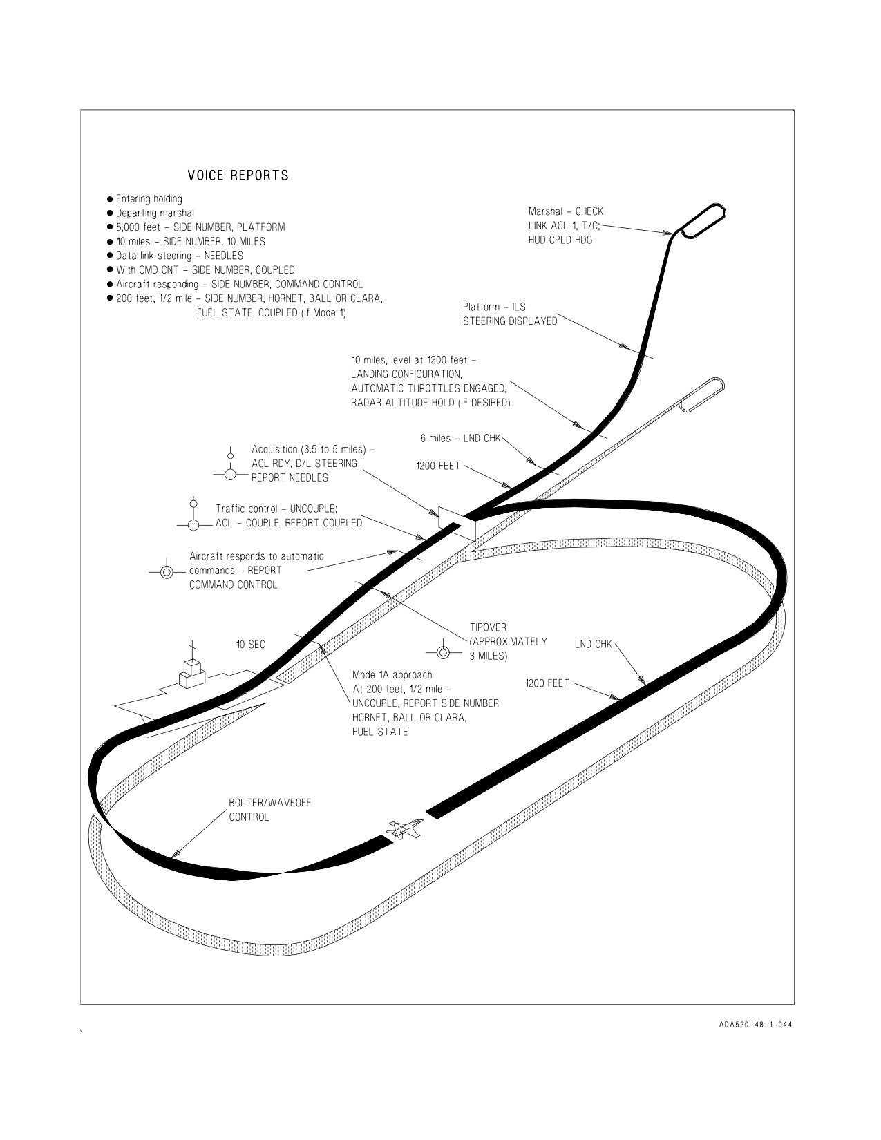
A1-F18AC-NFM-000
Figure 8-4. ACL Mode 1 and 1A Approaches
III-8-15
ORIGINAL
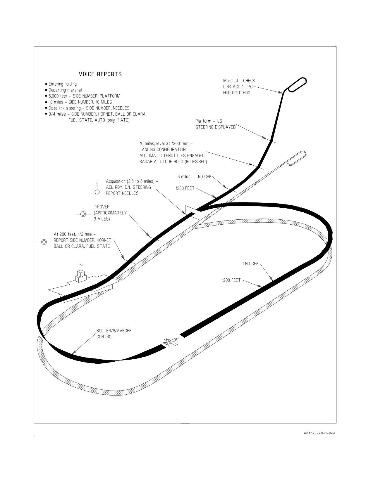
A1-F18AC-NFM-000
Figure 8-5. ACL Mode 2 Approach
III-8-16
ORIGINAL
A1-F18AC-NFM-000
8.3.2 Preflight. Conduct the exterior preflight using a white lensed flashlight. Ensure that the
exterior lights are properly positioned for launch and the external lights master switch OFF before
engine start. Ensure that instrument and console light rheostats are on. This reduces brilliance of the
warning and advisory lights when the generators come on.
8.3.3 Before Taxi. Adjust cockpit lighting as desired and perform before taxi checks.
8.3.4 Taxi. Slow and careful handling by aircraft directors and pilots is mandatory. If any doubt
exists as to the plane director’s signals, stop the aircraft. At night it is very difficult to determine speed
or motion over the deck; rely on the plane director’s signals and follow them closely.
8.3.5 Catapult Hook-Up. Maneuvering the aircraft for catapult hook-up at night is identical to that
used in day operations; however, it is difficult to determine speed or degree of motion over the deck.
8.3.6 Catapult Launch. On turn-up signal from the catapult officer, ensure throttles are in MIL or
MAX and check all instruments. Ensure that launch bar switch is in the retract position. When ready
for launch, place external lights master switch ON.
All lights should be on bright with the strobes on. If expecting to encounter instrument meteoro-
logical conditions shortly after launch, the strobes may be left off at the discretion of the pilot.
After launch, monitor rotation of the aircraft to 12° nose up crosschecking all instruments to ensure
a positive rate of climb. When comfortably climbing, retract the landing gear and flaps and proceed on
the departure in accordance with ship’s procedures. The standby attitude reference indicator should be
used in the event of a HUD failure.
8.3.7 Aircraft or Catapult Malfunction. If a no-go situation arises, do not turn on the exterior lights
and transmit SUSPEND, SUSPEND. Maintain MIL/MAX power until the catapult officer walks in
front of the wing and gives the throttle-back signal. If the external lights master switch has been placed
on prior to ascertaining that the aircraft is down, transmit SUSPEND, SUSPEND and turn off the
exterior lights and leave the throttles at MIL until signaled to reduce power.
8.3.8 Landing Pattern. Night and instrument recoveries normally are made using case III procedures
in accordance with the CV NATOPS Manual.
8.3.9 Arrestment and Exit From the Landing Area. During the approach all exterior lights should
be on with the exception of taxi/landing light. Following arrestment, immediately turn the external
lights master switch off. Taxi clear of the landing area following the plane director’s signals.
8.4 SECTION CCA
A section CCA may be necessary in the event a failure occurs affecting navigation aids, communi-
cations equipment, or other aircraft systems.
Normally, the aircraft experiencing the difficulty flies the starboard wing position during the
approach. The section leader detaches the wingman when the meatball is sighted and continues
straight ahead, offsetting as necessary to the left to determine if the wingman lands successfully. Lead
shall continue descending to not lower than 300 feet and turn on all lights to bright and strobes on. This
provides the wingman with a visual reference in the event of a bolter or waveoff. The wingman should
not detach until the meatball is in sight. If the wingman fails to arrest, the leader begins a climb to
1,200 feet or remains VFR at 150 knots during the rendezvous, but in no case should a rendezvous be
attempted below non-precision minimums. The rendezvous should be completed before any turns are
III-8-17
ORIGINAL
A1-F18AC-NFM-000
made to begin another approach. If the weather is below non-precision minimums, the wingman should
expect to climb to VFR-on-top, heading for the nearest divert field. The leader joins the wingman as
vectored by CATCC. Necessary lighting signals between aircraft are contained in Chapter 26.
NOTE
A section penetration should not be made to the ship with less than
non-precision minimums.
III-8-18
ORIGINAL
A1-F18AC-NFM-000
CHAPTER 9
Special Procedures
9.1 FORMATION FLIGHT
9.1.1 Formation Taxi/Takeoff. During section taxi, ensure adequate clearance between flight lead’s
stabilator and wingman’s wing/missile rail is maintained. For formation takeoff, all aspects of the
takeoff must be prebriefed by the flight leader. This should include flap settings, use of nosewheel
steering, power changes, power settings, and signals for actuation of landing gear, flaps, and
afterburner. The leader takes position on the downwind side of the runway with other aircraft in
tactical order, maintaining normal parade bearing. See figure 9-1. For three-aircraft formations, line up
with the lead on the downwind side, number 2 on the centerline, and number 3 on the upwind side.
Wingtip/launch rail overlap should not be required but is permitted if necessary. For four-plane
formations, line up with the lead’s section on the downwind half of the runway and other section on the
upwind half. After Before Takeoff checks are completed and the flight is in position, each pilot looks
over the next aircraft to ensure the speedbrake is retracted, the flaps are set for takeoff, all panels are
closed, no fluids are leaking, safety pins are removed, rudders are toed-in, nosewheel is straight and the
launch bar is up. Beginning with the last aircraft in the flight, a “thumbs up” is passed toward the lead
to indicate “ready for takeoff”.
9.1.1.1
Section Takeoff. Engines are run up to approximately 80%, instruments checked, and
nosewheel steering low gain ensured. On signal from the leader, brakes are released, throttles are
advanced to military power minus 2% rpm. If afterburner is desired, the leader may go into mid range
burner immediately without stopping at military power. Normal takeoff techniques should be used by
the leader, with the wingman striving to match the lead aircraft attitude as well as maintain a position
in parade bearing with wingtip separation. The gear and flaps are retracted on signal. Turns into the
wingman are not to be made at altitudes less than 500 feet above ground level. When both sections
begin takeoff roll from the same point on the runway, the second section must delay takeoff roll until
10 seconds after the first section starts the takeoff roll. When 2,000 feet of runway separation exists at
the beginning of takeoff roll, use a 5-second delay instead of 10 seconds.
9.1.2 Aborted Takeoff. In the event of an aborted takeoff, the aircraft aborting must immediately
notify the other aircraft. The aircraft not aborting should add max power and accelerate ahead and out
of the way of the aborting aircraft. This allows the aborting aircraft to steer to the center of the runway
and engage the arresting gear, if required.
III-9-1
ORIGINAL
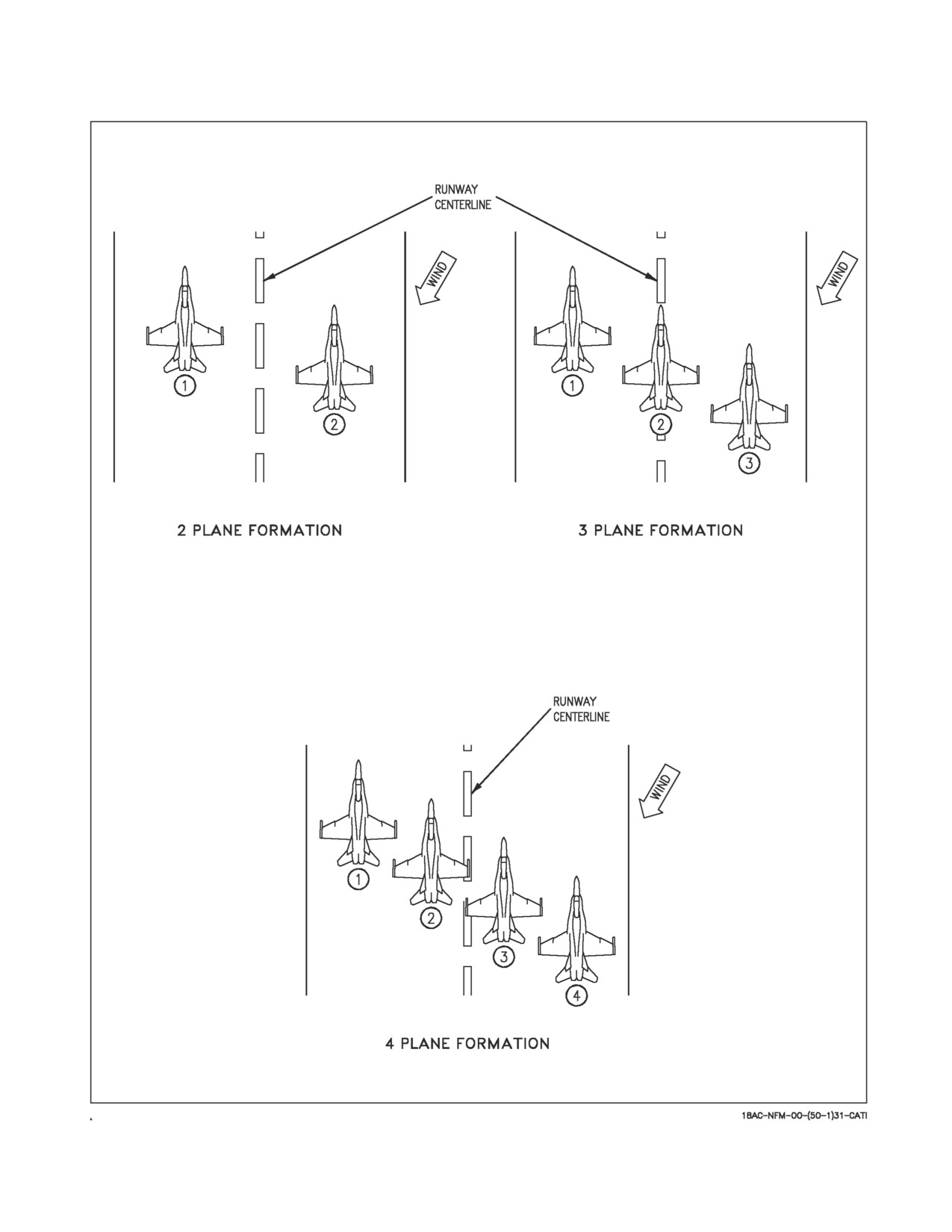
A1-F18AC-NFM-000
Figure 9-1. Formation Takeoff Runway Alignments
III-9-2
ORIGINAL
A1-F18AC-NFM-000
9.1.3 Parade. The parade position is established by aligning the bottom wingtip light (located about
in the middle of the missile rail) with the light on the LEX. Superimposing the two establishes a
bearing line and step down. Proper wingtip clearance is set by reference to the exhaust nozzles. When
the left and right nozzles are aligned so that there is no detectable curve to the nozzles, the reference
line is correct. The intersection of the reference line with the bearing line is the proper parade position.
See figure 9-2.
Parade turns are either standard (VFR) or instrument turns. During day VFR conditions, turns
away from the wingman are standard turns. To execute, when lead turns away, the wingmen roll the
aircraft about its own axis and increase power slightly to maintain rate of turn with the leader. Lateral
separation is maintained by increasing g. Proper step down is maintained by keeping the leads fuselage
on the horizon.
Turns into the wingmen and all IFR or night turns in a parade formation are instrument turns.
During instrument turns maintain a parade position relative to the lead throughout the turn.
After initially joining up in echelon, three and four-plane formations normally use balanced parade
formation. In balanced parade, number 3 steps out until the exhaust nozzles on number 2 are flush.
This leaves enough space between number 3 and lead for number 2 to cross under into echelon.
When it is necessary to enter IFR conditions with a three or four-plane formation, the lead directs
the flight to assume fingertip formation. In this formation number 3 moves up into close parade on the
lead. All turns are instrument turns.
9.1.4 Cruise Formation. The cruise position is a looser formation which allows the wingmen more
time for visual lookout. Cruise provides the wingmen with a cone of maneuver behind the leader which
allows the wingman to make turns by pulling inside the leader and requires little throttle change.
The cruise position is defined by a line from the lead pilot’s head, through the trailing edge of the
wingtip missile rail, with 10 feet of nose to tail separation. The wingmen are free to maneuver within
the 70° cone established by that bearing line on either wing. In a division formation, number 3 should
fly the bearing line, but always leave adequate room for number 2 and lead. Number 4 flies cruise about
number 3.
III-9-3
ORIGINAL
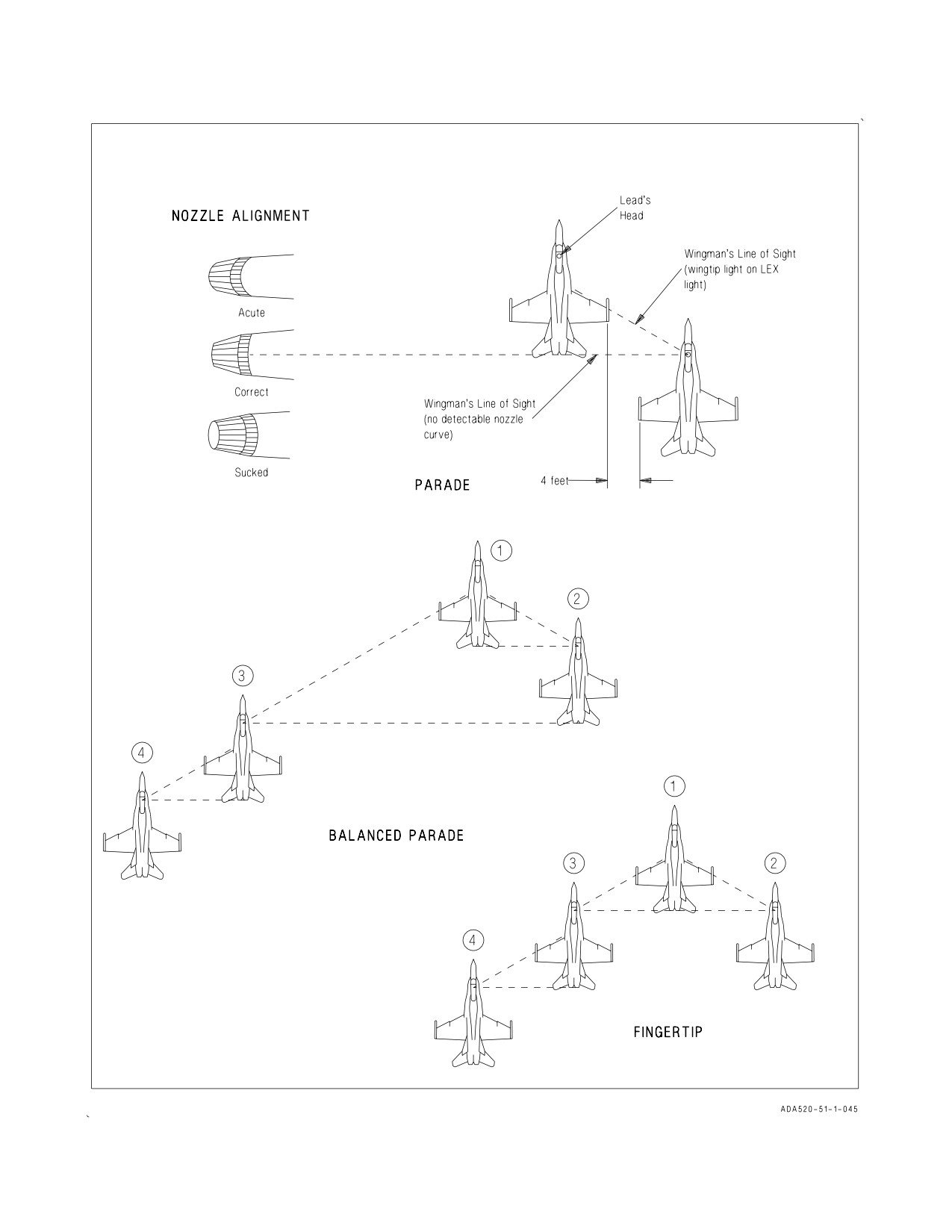
A1-F18AC-NFM-000
Figure 9-2. Formations (Sheet 1 of 2)
III-9-4
ORIGINAL
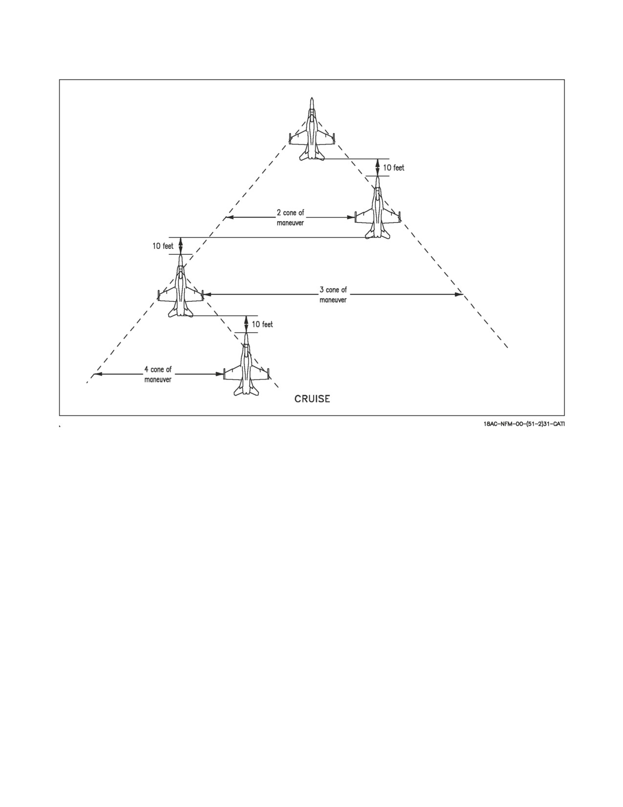
A1-F18AC-NFM-000
Figure 9-2. Formations (Sheet 2 of 2)
9.1.5 Section Approaches/Landing. The aircraft is comfortable to fly in formation, even at the low
airspeeds associated with an approach and landing. The rapid power response enhances position
keeping ability. The formation strip lighting provides a ready visual reference at night and the dual
radios generally ensure that intra-flight comm is available.
During section approaches all turns are instrument turns about the leader. When a penetration is
commenced the leader retards power to 75% rpm and descends at 250 knots. If a greater descent rate
is required the speedbrake may be used. Approximately 5 miles from the final approach fix or GCA
pickup the lead gives the signal for landing gear.
9.1.5.1
Section Landing. If a section landing is to be made, lead continues to maintain ON-SPEED
for the heavier aircraft and flies a ball pass to touchdown on the center of one side of the runway.
Wingman flies the normal parade position taking care not to be stepped up.
When “in-close”, wingman adds the runway to his scan and takes a small cut away from the lead to
land on the center of the opposite side of the runway while maintaining parade bearing. Use care to
ensure that drift away from the lead does not become excessive for the runway width. Remember,
flying a pure parade position still allows 4 feet of wingtip clearance.
III-9-5
ORIGINAL