F18. FLIGHT MANUAL (2008) - page 4
A1-F18AC-NFM-000
The RTN option (PB 15) is used to return the AMU maintenance format if a theater load is not in
progress. If a theater load is in progress, the RTN option is removed from the display.
2.13.10.5 Map Loading Format Status Information. Status information displayed on the map
loading format provides the operator with on-line instructions and associated feedback necessary to
perform a successful theater load. The information presented is grouped into several status fields;
THEATER, STATUS, CARD/STATUS, CARD, and OPER.
The THEATER status field contains; theater identification, theater update revision letter, and the
theater update version number that is stored on the map loading card currently being loaded. If at least
one card is not installed in the AMU (to initiate the load), the field is blank. After a map loading card
is loaded the theater identification information remains displayed as other cards are loaded.
The status field below the THEATER status field contains the overall status of the loading process.
This field contains one of the following status indications:
HALTED - Indicates the load process has been halted (between successive cards).
LOADING - Indicates the load process has been initiated and/or is in progress.
ABORTED - Indicates the load process has been aborted.
NO DMS COMM - Indicates HSIB communications with the DMC have failed.
DMS FULL - Indicates the DMC nonvolatile mass memory is full.
LOAD ERROR - Indicates the load process has failed.
WRONG CARD - Indicates the card installed in the AMU maintenance card receptacle is not a Map
loading card.
COMPLETE - Indicates the load process has successfully been completed.
CARD/STATUS fields contain status information regarding the PC cards used in the loading
process. The CARD field indicates the card ID number(s) in the theater load card set. The maximum
number of card IDs that can be displayed is seven. The card ID number(s) displayed is dependent on
which order the cards are loaded. The STATUS field below the CARD field contains the actual load
status of the card number directly above it. Once the card is installed and the load process initiated,
the field contains one of the following status indications:
L - Indicates the card is currently being loaded.
F - Indicates the card has failed to load properly.
C - Indicates the card has been successfully loaded.
If none of the above conditions exists, the STATUS field is blank. If any card fails to load properly
resulting in an ″F″ status, the operator has the option of reinserting the card in an attempt to obtain
a successful load.
The CARD field contains the load status of the card that is currently installed. The card ID number
is displayed followed by the percent complete (%) for the card. The percentage is displayed in 1%
increments.
I-2-118
ORIGINAL
A1-F18AC-NFM-000
The OPER field contains instructions for the operator. The field contains one of the following
instructional status indications. If any card has yet to be installed for loading, the OPER field is blank.
INIT LOAD - Indicates the AMU is ready to start the load process and the LOAD option needs to be
selected.
CLOSE DOOR - Indicates the AMU door needs to be closed.
REMOVE CARD - Indicates the installed card has been successfully loaded and needs to be removed.
INSERT CARD - Indicates another card is required to complete the load process.
2.13.10.6 Map Loading Interruptions. Interruptions to the map theater data loading process can
occur as a result of several events: loss of power to the MC, DMC, or AMU, operator aborts, or
inadvertent transfers out of AMU relay mode.
If the AMU experiences a power loss greater than five seconds, or if the DMC experiences a power
loss of any duration, or if the operator initiates an abort, the interruption in the loading process results
in a nonrecoverable abort and the load process cannot be recovered without reloading all the cards.
If power is reapplied to the AMU within five seconds, then the load process can be recovered with
minimum impacts. Once the operator reselects the map loading format, the status of the load prior to
the interruption is reflected on the format status fields. If a card was in the process of being loaded
when the interruption occurred, its status is blank indicating it has not been loaded. Selecting the
LOAD option reinitializes the load process following this type of interruption.
2.13.10.7 AMU/PC Cards Cautions and Advisories. The AMU has the ability to trigger three
caution and five advisory messages. The caution messages are: MU LOAD, ERASE FAIL, and S/W
CONFIG. The advisory messages are: Maintenance Card Advisory (MNTCD), Mission Card Advisory
(MSNCD), Classified Data Advisory (CDATA), AMU Full advisory (AMU FL), and the BIT advisory.
The MU LOAD caution is generated when the AMU door is open; if the AMU fails; if the AMU
declares a card interface fail; if the AMU is mux fail or not ready; if the mission card is improperly
formatted, not installed, or is declared failed by the AMU, if the initialization data is not downloaded,
if an incorrect checksum is calculated. The MU LOAD caution is disabled while the AMU is in relay
mode or the aircraft is in flight.
The ERASE FAIL caution is generated when the AMU has failed to erase its internal RAM memory
buffer following a classified data transfer.
The S/W CONFIG caution is generated if the AMU and MC software are not compatible. When an
AMU OFP checksum failure occurs, the AMU OFP software configuration ID displayed on the S/W
configuration BIT sublevel format indicates XXXXXXXX.
The MNTCD advisory is generated when the AMU door is open, if the maintenance card is not
installed or properly formatted, or if the AMU declares a maintenance card failure. The advisory only
displays with WonW and clears in flight.
The BIT advisory is generated when the AMU is degraded or an AMU RAM classified erase failure
occurs.
I-2-119
ORIGINAL
A1-F18AC-NFM-000
The CDATA advisory is generated when the mission card contains classified data. It is removed
when a successful classified data erase of all avionics has been performed, or a successful classified data
erase of all avionics except the mission card is performed and the ERASE (MU HOLD) option has been
selected on the MUMI format.
The MU FL advisory used for the existing MU is changed for the AMU. The MU FL advisory
indicates a data wraparound has occurred on the maintenance card and the corresponding MSP code
(809) is set. When the MC determines there is not enough memory on the maintenance card to perform
the next sequential write operation, it begins overwriting previously recorded data.
DFIRS data download requests do not cause a data wraparound to occur. If there is insufficient
memory available, based on the current sequential write address pointer, the DFIRS data download
request is not executed.
2.13.11 ALE-39 Countermeasures Dispensing Set (CMDS). The CMDS is used to dispense chaff,
flares, and jammers for self protection against enemy radars and missiles. Refer to NTRP 3-22.2-
FA18A-D NATIP.
2.13.12 ALE-47 Countermeasures Dispensing Set. The CMDS uses information from various
Electronic Warfare (EW) systems to generate countermeasures dispensing programs. Refer to NTRP
3-22.2-FA18A-D NATIP.
2.13.12.1 ALE-47 Advisories. D LOW is displayed when any of the loaded categories’ BINGO levels
are reached. The dispense misfire D BAD advisory is displayed when a misfire has occurred.
2.14 FIRE DETECTION/EXTINGUISHING SYSTEMS
The fire detection and extinguisher system is made up of three fire warning/extinguisher lights, a fire
extinguisher pushbutton, one fire extinguisher bottle, a fire test switch and dual-loop fire detection
sensors. The extinguisher bottle is in the aft fuselage between the engines. The bottle contains a
nontoxic gaseous agent which provides a one-shot extinguishing capability. Direct current electrical
power (essential 24/28 volt dc and engine start 24/28 volt dc buses) is required to operate the system.
The systems operate on battery power with the battery switch in either ON or ORIDE. The systems
provide engine/AMAD and APU fire warning, emergency shutdown and selective fire extinguishing.
2.14.1 Fire Warning/Extinguisher Lights/Voice Alert. The three fire warning/extinguisher lights
are pushbutton switch indicators which come on when a fire condition exists. Two of the fire
warning/extinguisher lights are labeled FIRE, one is mounted on the top left corner and the other on
the top right corner of the instrument panel. The two FIRE warning/extinguisher lights are guarded.
The left FIRE light indicates a fire condition in the left engine bay. The right FIRE light indicates a
fire condition in the right engine bay. The APU FIRE light is positioned inboard of the right FIRE
light. It indicates a fire condition in the auxiliary power unit bay. A voice alert warning is activated
anytime a fire warning light comes on. If the left FIRE light comes on, the ENGINE FIRE LEFT voice
alert is activated. If the right FIRE light comes on the ENGINE FIRE RIGHT voice alert is activated.
If the APU FIRE light comes on, the APU FIRE voice alert is activated. If more than one warning light
comes on at the same time, the voice alert warning priority is: ENGINE FIRE LEFT, ENGINE FIRE
RIGHT, then APU FIRE.
2.14.2 Fire Extinguisher Pushbutton. The fire extinguisher pushbutton switch is on the master arm
panel and is labeled FIRE EXTGH. The switch has two lights. A yellow light labeled READY and a
green light labeled DISCH (discharge). When READY is on, the fire extinguisher bottle is armed. The
READY light comes on when the appropriate fire warning/extinguisher light is pressed. Pressing an
I-2-120
ORIGINAL
A1-F18AC-NFM-000
engine fire warning/extinguisher light shuts off fuel to the engine at the feed tank. With READY on,
pressing the fire extinguisher pushbutton discharges the fire extinguisher bottle and turns on the
DISCH light. There is no indication of actual discharge of the fire extinguisher bottle.
2.14.3 APU Fire Extinguishing System. The APU fire extinguishing system can be either manually
or automatically actuated. To manually actuate the system, the fire extinguisher bottle is first armed
and the APU shutdown by pressing the APU FIRE warning/extinguisher light. When pressed, the APU
FIRE light stays in and a barber pole indication appears alongside the light. The extinguisher bottle
is then discharged into the APU bay by pressing the FIRE EXTGH pushbutton with the READY light
on. Discharge of the bottle is delayed 10 seconds after the light is pressed, allowing the APU time to
spool-down before the extinguishing agent is introduced. If on the ground, the APU fire extinguishing
system is actuated automatically. The result is the same as with manual actuation, with the APU
shutting down immediately after a fire is detected and the fire extinguisher discharging into the APU
bay 10 seconds later. The automatic system is prevented from operating during flight by the action of
a WOW relay.
2.14.4 Engine/AMAD Fire Extinguishing System. Actuation of the engine/AMAD fire extinguish-
ing system can only be performed manually. The system is armed by lifting the guard and pressing the
affected FIRE warning/extinguisher light. This also shuts off fuel to the engine at the engine feed
shutoff valves and closes the crossfeed valve. When pressed, the FIRE light stays in and a barber pole
indication appears in the switch guard. The extinguisher bottle is discharged into the affected engine
bay by pressing the FIRE EXTGH pushbutton with the READY light on. If more than one FIRE light
is pushed, extinguishing agent is distributed to selected bays, but concentration is insufficient to
extinguish fire.
The probability of extinguishing a fire and preventing relights is greatly
increased by immediately discharging the extinguisher.
2.14.5 Fire and Bleed Air Test Switch. Each of the three warning/extinguisher lights contains four
individual light bulbs which are simultaneously tested by actuation of the lights test switch on the
interior lights panel. Operation of the lights test switch tests only the light bulbs in the warning/
extinguisher lights and requires ac electrical power on the aircraft. The fire/bleed air leakage detection
sensors and associated circuits are tested by the fire and bleed air test switch. Operation of the fire and
bleed air test switch requires power on the essential 24/28 volt dc bus. The fire and bleed air switch is
on the fire test panel on the left console. When actuated to TEST A or TEST B, the fire warning, bleed
air leak detection and voice alert warning circuitry for the designated loop is tested. If a malfunction
exists in a fire detection loop associated with the APU FIRE warning/extinguisher light, none of the
four individual bulbs in the indicator come on. If a malfunction exists in a fire detection loop associated
with either FIRE warning/extinguisher light, only the individual bulb (or bulbs) associated with the
malfunctioning sensor do not come on. Care must be taken to detect bulbs that are not on in the FIRE
warning/extinguisher during the loop test. Switch actuation also turns on the L BLEED and R BLEED
warning lights and the L BLD OFF and R BLD OFF caution displays while the switch is activated and
closes the left and right bleed air pressure regulator and shutoff valves indicating the designated loop
bleed air detection sensors and circuitry are operational. The L(R) BLEED warning lights go out after
the switch is released to NORM. The L(R) BLD OFF caution displays remain on until the valves are
reopened. To open the valves after test, there must be ac power on the aircraft and the bleed air knob
must be rotated through OFF to NORM.
I-2-121
ORIGINAL
A1-F18AC-NFM-000
NORM
System provides normal fire and bleed air leak warning. Switch is spring loaded to
this position.
TEST A
Turns on the three fire warning/extinguisher lights, activates the voice alert, turns
on the two bleed air warning lights and two caution displays, indicating that Loop
A fire detection sensors and circuitry are operational.
TEST B
Turns on the three fire warning/extinguisher lights, activates the voice alert, turns
on the two bleed air warning lights and two caution displays, indicating that Loop
B fire detection sensors and circuitry are operational.
During TEST A or B, the ENGINE FIRE LEFT voice alert warning is activated first. If the switch
is held in the TEST position, the sequence is as follows: ENGINE FIRE LEFT, ENGINE FIRE
RIGHT, APU FIRE, BLEED AIR LEFT, then BLEED AIR RIGHT.
2.15 ENTRANCE/EGRESS SYSTEMS
2.15.1 Canopy System. The cockpit area is enclosed by a clamshell type canopy. The main
components of the canopy system are an electromechanical actuator which provides powered and
manual operation of the canopy, and a cartridge actuated thruster with associated rocket motors for
emergency jettison. Latching provisions consist of three latch hooks on the bottom of each side of the
canopy frame and two forward indexer pins on the lower leading edge of the canopy frame. When the
canopy is closed, the latch hooks and indexer pins engage fittings along the canopy sill and the canopy
actuator rotates the canopy actuation link over-center, locking the canopy. A mechanical brake in the
canopy actuator motor provides a redundant lock. An inflatable seal, installed around the edge of the
canopy frame, retains cockpit pressure when the canopy is locked. A rain seal is installed outboard of
the pressure seal to divert rain water away from the cockpit. The F/A-18A/B and F/A-18C/D
windscreens have been tested to determine their bird strike resistance. See figure 2-31 for test results.
2.15.1.1 Normal Canopy Operation. Normal canopy operation is provided by the internal canopy
control switch (figure 2-32) on the right side of the cockpit under the canopy sill. An external canopy
control switch provides powered operation of the canopy from outside the aircraft. With no generator
or external electrical power on the aircraft, battery power is available for at least five open/close cycles
of the canopy. If no electrical power is available for canopy operation, a back-up crank system is
provided to manually power the canopy actuator. Internally, the manual crank is under the left canopy
sill. Externally, manual handcrank provisions are provided by a drive socket located flush on the mold
line, outside of the internal handcrank. Internally, 70 counterclockwise crank turns are required to
fully open the canopy; externally, 35 counterclockwise crank turns are required.
I-2-122
ORIGINAL
A1-F18AC-NFM-000
For aircraft 163985 AND UP, a high voltage (100,000 volt) static electrical
charge may build up in flight and be stored in the windscreen and canopy.
To prevent electrical shock ensure that the static electricity has been
discharged.
Taxiing with the canopy at an intermediate position can result in canopy
attach point damage and failure. Do not open or close the canopy with the
aircraft in motion.
2.15.1.1.1 Internal Canopy Switch. The internal canopy switch has three positions: OPEN, CLOSE
and HOLD.
OPEN
Raises canopy to maximum position. If selected when canopy is locked, the canopy
unlocks, then moves 1.5 inches aft before rising. With WOW, the OPEN position is
solenoid held until the maximum up position is reached, after which it is spring
loaded to the HOLD position. The solenoid can be overridden at any time by plac-
ing the switch to HOLD. With weight off wheels, the switch must be held in the
OPEN position to open the canopy.
Objects/Grimes light placed in the area near the canopy
switch could inadvertently shift causing actuation of the
canopy switch airborne resulting in loss of canopy.
HOLD
Stops the canopy at any point during the open or close cycle.
CLOSE
Lowers canopy. If held after canopy reaches canopy sill, canopy moves forward 1.5
inches and then locks. Locked condition indicated by MASTER CAUTION light
and CANOPY display going out. CLOSE position is spring loaded to the HOLD
position.
2.15.1.1.2 External Canopy Switch. Electrical operation of the canopy from outside the cockpit is
provided for by the external canopy switch inside the external power receptacle door (door 9) on the
left side of the aircraft below the canopy and LEX. The door is equipped with a quick release latch. The
switch contains the same positions and operates identically to the internal canopy switch, except that
the OPEN position is not solenoid-held.
2.15.1.1.3 Internal Manual Canopy Handcrank. A manual canopy handcrank is provided to
manually open the canopy. The handcrank, under the left canopy sill, opens the canopy when the crank
handle is turned approximately 70 turns in a counterclockwise direction. Before use, the handcrank
handle must be unstowed by removing it from a stowage clip and socket and then inserted into the
crank socket immediately above the stowage clip. A cable is provided to prevent loss of the handle if
dropped. Cranking the handle clockwise closes the canopy.
I-2-123
ORIGINAL
A1-F18AC-NFM-000
2.15.1.1.4 External Manual Canopy Actuation Fitting. The external manual canopy actuation
fitting, a 3/8 inch drive socket on the left side of the aircraft below the canopy, is used to manually
operate the canopy. Inserting a 3/8 inch drive tool in the socket and then turning counterclockwise
approximately 35 turns opens the canopy. Turning the drive tool clockwise closes the canopy.
2.15.1.1.5 Canopy Caution Display. A CANOPY caution display comes on when the canopy is
unlocked. The CANOPY display comes on in conjunction with the MASTER CAUTION light.
2.15.1.2 Emergency Canopy System. For canopy jettison, a cartridge initiated thruster is utilized
to unlatch the canopy by moving it 1.5 inches rearward, after which two canopy framemounted rocket
motors fire to rotate the canopy up and aft, clear of the ejection seat path. The thruster, which provides
attachment for the canopy actuator link during normal canopy operation, is activated by pulling any
of the following: ejection seat firing handle, internal canopy jettison handle or, on aircraft 161353
THRU 162477, one of the two external canopy jettison handles (figure 2-32). The canopy can be
jettisoned closed, open, or in any intermediate position.
I-2-124
ORIGINAL
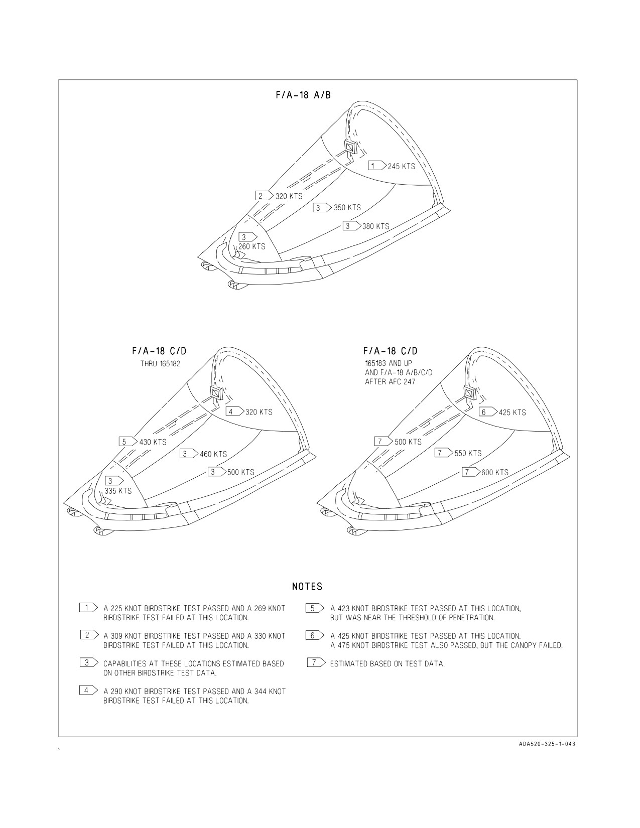
A1-F18AC-NFM-000
Figure 2-31. Canopy Birdstrike Resistance
I-2-125
ORIGINAL
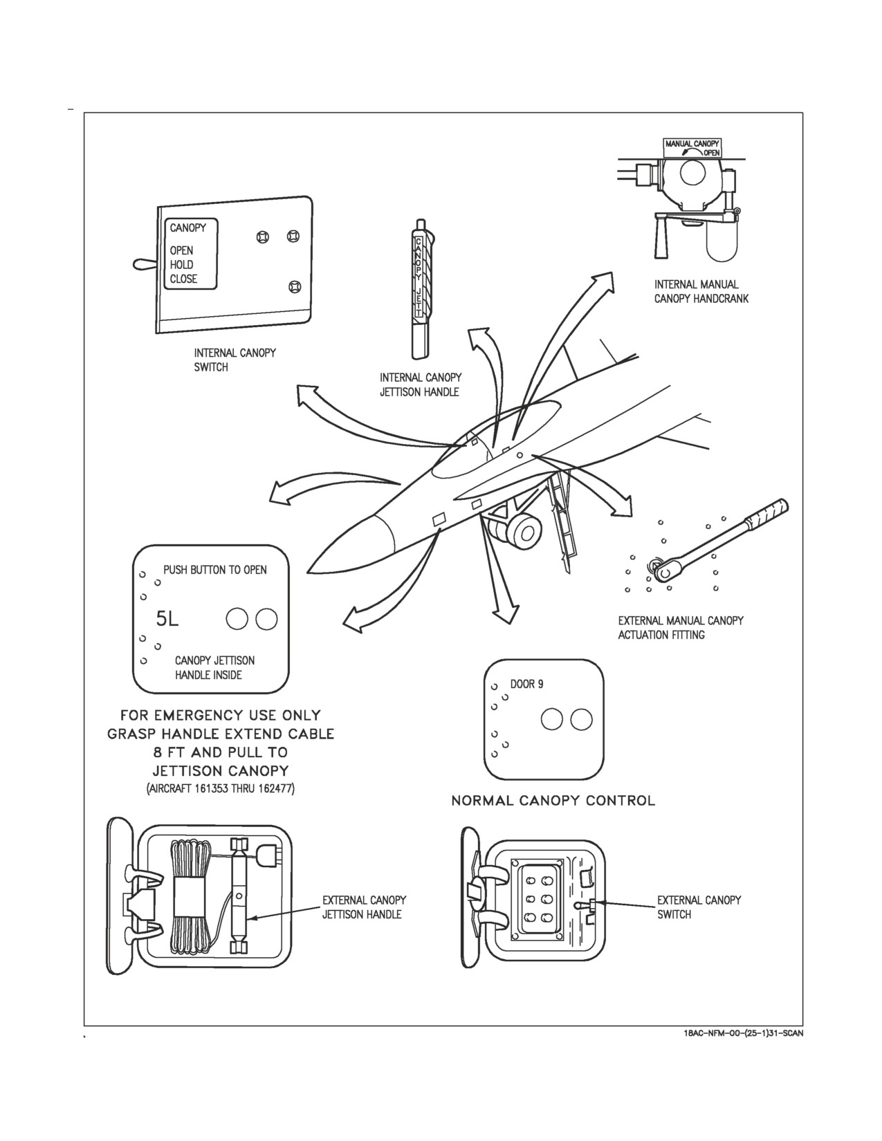
A1-F18AC-NFM-000
Figure 2-32. Canopy Controls
I-2-126
ORIGINAL
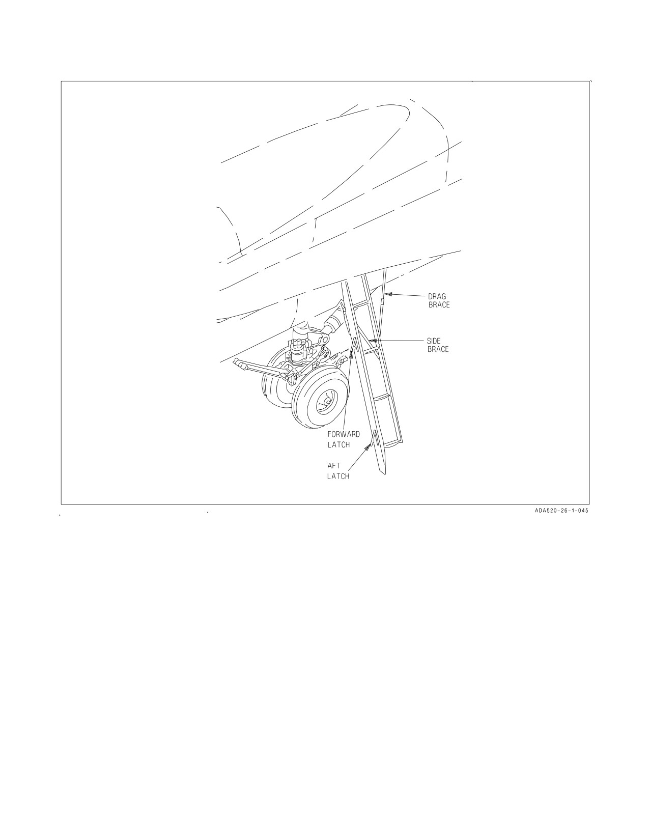
A1-F18AC-NFM-000
Figure 2-33. Boarding Ladder
2.15.1.2.1 Internal Canopy Jettison Handle. A black and yellow striped canopy jettison handle is on
the left inboard canopy sill just aft of the instrument panel. Pressing an unlock button on the tip of the
handle and pulling the handle aft fires the canopy jettison system.
2.15.1.2.2 External Canopy Jettison Handles (Aircraft 161353 THRU 162477). The external
canopy jettison handles are T-handles within door 5 on each side of the forward fuselage just below the
LEX leading edge. They jettison the canopy from outside the aircraft. After pushing a release button
to open the access door, the handle and its lanyard are played out 8 feet from the aircraft and then
pulled to fire the canopy jettison system.
2.15.2 Boarding Ladder. A boarding ladder (figure 2-33), stowed under the LEX, provides access to
the cockpit and upper aircraft area from the left side of the aircraft. Ladder extension and retraction
can only be accomplished from outside the cockpit. To extend the ladder, manually support the ladder
and release the forward and aft latches on the forward beam on the underside of the LEX, permitting
the ladder to rotate down to the extended position. The drag brace locks when extended to its full
length to provide longitudinal stability for the ladder. Lateral stability is provided for by the V-shaped
side brace attached to the side of the fuselage. To stow the ladder, remove the rigid removable side
I-2-127
ORIGINAL
A1-F18AC-NFM-000
brace connection from the fuselage. Pull the collar on the drag brace down permitting the telescoping
drag brace to unlock and compress as the boarding ladder is rotated up and aft to the stowed position.
The forward and aft latches are manually engaged and locked by pushing them full up until they are
locked flush with the forward beam. With electrical power on the aircraft, a LADDER caution display
comes on whenever the proximity switch in the aft portion of the ladder well is not actuated. With the
ladder stowed and the forward and aft latches locked, the LADDER caution display goes out.
2.15.3 Ejection Seat. The SJU-5/A and 6/A ejection seat (LOT 12 AND BELOW), the Naval Aircrew
Common Ejection Seat (NACES) SJU-17(V)1/A, 2/A, and 9/A and NACES SJU-17A(V)1/A, 2/A, and
9/A (LOT 13 AND UP, and A+ aircraft AFTER AFC 493) are ballistic catapult/rocket systems that
provide the pilot with a quick, safe, and positive means of escape from the aircraft. See Ejection Seat,
Foldout section, for ejection seat illustrations. The seat system includes an initiation system which,
after jettisoning the canopy and positioning the occupant for ejection, fires the telescopic seat catapult.
In the event of a canopy jettison failure during ejection, canopy breakers on the top of the seat give the
capability for ejection through the canopy. As the seat departs the aircraft and the catapult reaches the
end of its stroke a rocket motor on the bottom of the seat is fired. The thrust of the rocket motor
sustains the thrust of the catapult to eject the seat to a height sufficient for parachute deployment even
if ejection is initiated at zero speed, zero altitude in a substantially level attitude.
NOTE
Safe escape is provided for most combinations of aircraft altitude,
speed, attitude, and flight path within the envelope of 0 to 600 KIAS
airspeed and 0 to 50,000 ft. altitude.
2.15.3.1 SJU-5/A and 6/A Seat. Shortly after departing the aircraft a drogue gun is fired to deploy
the drogue chute. The drogue chute either remains attached to the top of the seat or is released to
deploy the main parachute, depending on altitude and the number of g’s applied on the seat. After a
delay of 1.50 seconds, an automatic time release mechanism opens the main parachute container and
releases the drogue chute to deploy the main parachute when conditions of altitude and g forces are
met. The seat operates in three modes. At high altitude, the seat is allowed to freefall to below 14,500
feet MSL before the time release mechanism activates. At medium altitude, the time release
mechanism actuates when the seat is below 13,000 and above 7,500 feet MSL and acceleration forces
are below 3 g’s. At low altitude, below 7,500 feet, g forces are not used as a condition for deploying the
main parachute. The time release mechanism also releases the lap belts, inertia reel restraint straps,
and leg restraint lines. Both the drogue gun and time release mechanism are actuated on ejection by
trip rods attached to the aircraft structure.
The main parachute is a 17-foot aeroconical canopy type, stored along with the drogue chute(s) in a
headbox container on top of the ejection seat. The parachute is steerable, and contains water deflation
pockets which aid in dumping air from the canopy after landing in water.
The seat contains controls for seat height adjustment, and for locking and unlocking the inertia reel
shoulder restraint straps. A survival kit is installed in the seat pan.
I-2-128
ORIGINAL
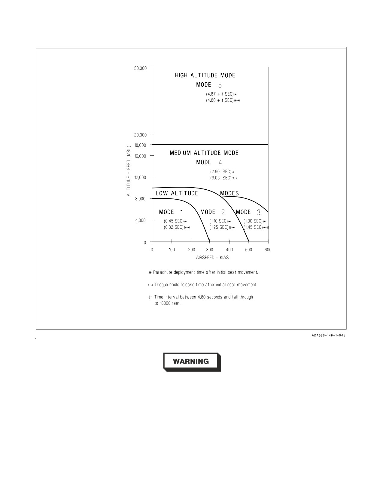
A1-F18AC-NFM-000
Figure 2-34. SJU-17 Ejection Modes
The 17-foot aeroconical parachute used in the SJU-5/A and 6/A seats can
increase the risk of injury for crewmembers with nude weights above 213
pounds because of high rates of descent.
2.15.3.2 Seat SJU-17(V)1/A, 2/A, and 9/A, and SJU-17A(V)1/A, 2/A, and 9/A. Timing of all
events after rocket motor initiation is controlled by the electronic sequencer which utilizes altitude,
acceleration and airspeed information to automatically control drogue and parachute deployment, and
seat/man separation throughout the ejection seat operational envelope. In the event of partial or total
failure of the electronic sequence, a four second mechanical delay initiates a barostatic release unit
which will free the occupant from the seat and deploy the parachute between 16,000 and 14,000 feet
I-2-129
ORIGINAL
A1-F18AC-NFM-000
MSL if the ejection occurred in or above this altitude range. The emergency barostatic unit operates
immediately after a 4-second delay if the ejection occurred below 14,000 feet MSL. An emergency
restraint release (manual override) system provides an additional back-up in the event of failure of the
barostatic release unit. The seat is stabilized and the forward speed retarded by a drogue chute that is
attached to the top and bottom of the seat. The parachute deployment rocket is automatically fired to
withdraw the parachute from its deployment bag. Full canopy inflation is inhibited until the g forces
are sufficiently reduced to minimize opening shock. There are five modes of operation. See figure 2-34
for parameters that determine the mode of operation and the corresponding parachute deployment
and drogue chute release times. At high altitude the drogue chute deploys to decelerate and stabilize
the seat. The seat falls drogue retarded to 18,000 feet MSL where the drogue is released, the main
parachute is deployed, and seat/man separation occurs. At medium altitude, between 18,000 and 8,000
feet MSL, and at low altitude below 8,000 feet MSL parachute deployment is automatically delayed
from 0.45 to 2.90 seconds (depending upon airspeed and altitude after seat first motion) to allow the
drogue chute to decelerate and stabilize the seat depending upon airspeed and altitude.
The main parachute is a 21-foot aeroconical canopy type, stored in a headbox container on top of the
ejection seat. The parachute is steerable, and contains water deflation pockets which aid in dumping
air from the canopy after landing in water. The seat drogue chute is stored in a separate container on
top of the drogue deployment catapult. The seat contains controls for adjusting seat height, and for
locking and unlocking the inertia reel shoulder restraint straps. A survival kit is installed in the seat
pan.
2.15.3.3 SEAWATER Activated Release System (SEAWARS). This is a seawater activated system
that automatically releases the parachute from the crewmember. When the sensing-release units are
immersed in seawater, cartridges are fired which allow the crewmember to separate from the
parachute.
2.15.3.4 Ejection Control Handle. The ejection control handle, between the pilot’s legs on the front
of the seat pan, is the only means by which ejection is initiated. The handle, molded in the shape of a
loop, can be grasped by one or two hands. To initiate ejection, a 20 to 40 pound pull removes the handle
from its housing, and a continued pull of 30 to 60 pounds is required to pull both sears from the dual
initiators. Either of the initiators can fire the seat. After ejection, the handle remains attached to the
seat. The ejection control handle can be safed by the ejection seat safe/armed handle.
2.15.3.5 Ejection Seat SAFE/ARMED Handle. To prevent seat ejection, an ejection seat safe/armed
handle is provided. The handle, forward on the right seat armrest, safeties the seat when rotated up
and forward, and arms the seat when it is rotated aft and down. The safe/armed handle is locked when
placed to either of these two positions and the handle must be unlocked before changing positions by
squeezing a locking lever within the handle cutout. When in the armed position the visible portion of
the handle (from the occupant’s vantage point) is colored yellow and black with the word ARMED
showing. In the safe position, the visible portion is colored white with the word SAFE showing. The seat
is safed only when the word SAFE is entirely visible on the inboard side of the SAFE/ARM handle and
the handle is locked in the detent. Placing the handle to the SAFE position causes a pin to be inserted
into the ejection firing mechanism to prevent withdrawal of the sears from the dual seat initiators.
2.15.3.5.1 CK SEAT Caution (F/A-18C/D). The CK SEAT caution light is located on the caution
light panel and repeats the DDI CHECK SEAT caution display. The caution comes on when the right
throttle is at MIL or above, weight is on wheels, and the ejection seat is not armed.
2.15.3.6 Shoulder Harness Inertia Reel. Pilot shoulder harness restraint is provided by a dual strap
shoulder harness inertia reel mounted in the seat below the parachute container. The dual inertia reel
I-2-130
ORIGINAL
A1-F18AC-NFM-000
shoulder straps connect to the parachute risers which in turn are buckled to seat occupant’s upper
harness. The inertia reel locks when the reel senses excessive strap velocity. Manual locking and
unlocking of the reel is controlled by the shoulder harness lock/unlock handle on the left side of the
seat bucket. During ejection a pyrotechnic cartridge is fired to retract the shoulder harness to position
the seat occupant for ejection.
2.15.3.7 Shoulder Harness Lock/Unlock Handle. The shoulder harness lock/unlock handle on the
left side of the seat bucket has two positions. To operate, the handle must be pulled up against spring
pressure, moved to the desired position, and then released.
FORWARD
The inertia reel prevents the reel straps from being extended and ratchets any
(locked)
slack in the straps back into the reel.
AFT
The reel allows the pilot to lean forward, but the inertia portion of the reel contin-
(unlocked)
ues to protect him by locking the reel when it senses excessive strap velocity. Once
locked, the pilot can normally lean forward again after a slight release in pressure
on the reel straps.
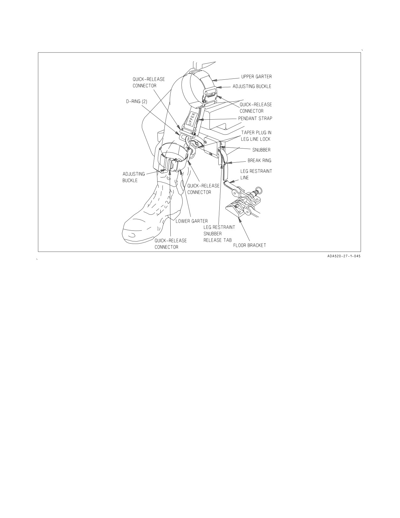
2.15.3.8 Leg Restraint System. A leg restraint system is located on the front of the ejection seat. The
function of the system is to secure the occupant’s legs to the seat during ejection. The system consists
of two adjustable leg garters, a restraint line and a snubber box for each leg. One garter is worn on the
thigh approximately 3 inches above the knee and one garter is worn on the lower leg in-line with the
snubber as illustrated in figure 2-35. The restraint lines are routed through the garter rings and the
snubber box. One end of each restraint line is secured to the cockpit floor and the other, after being
routed through the snubber box and both garter rings, is secured to the seat just outboard of the
snubber box by a releaseable pin. During ejection, inertia draws the legs in against the front of the seat
bucket and the legs are retained in this position by the leg restraint line. The restraint line is snubbed
and separates at the tension ring on each leg line. At man-seat separation, the pins on the other end
of the lines are released by the time release mechanism. The pins are also released when the manual
override handle is pulled. Both the lower garter and thigh garter contain a quick release buckle which
disconnects the ring through which the leg restraint line runs, permitting the pilot to egress from the
aircraft wearing both upper and lower garters. In addition, toe clips are installed on the tops of the
rudder pedals to prevent contact between the toes and the instrument panel during ejection.
2.15.3.8.1 Leg Restraint Snubber Release Tabs. The leg restraint lines are adjusted to give the pilot
more leg movement by pulling inboard the leg restraint snubber release tabs (figure 2-35) and
simultaneously pulling the leg restraint lines forward through the snubber box.
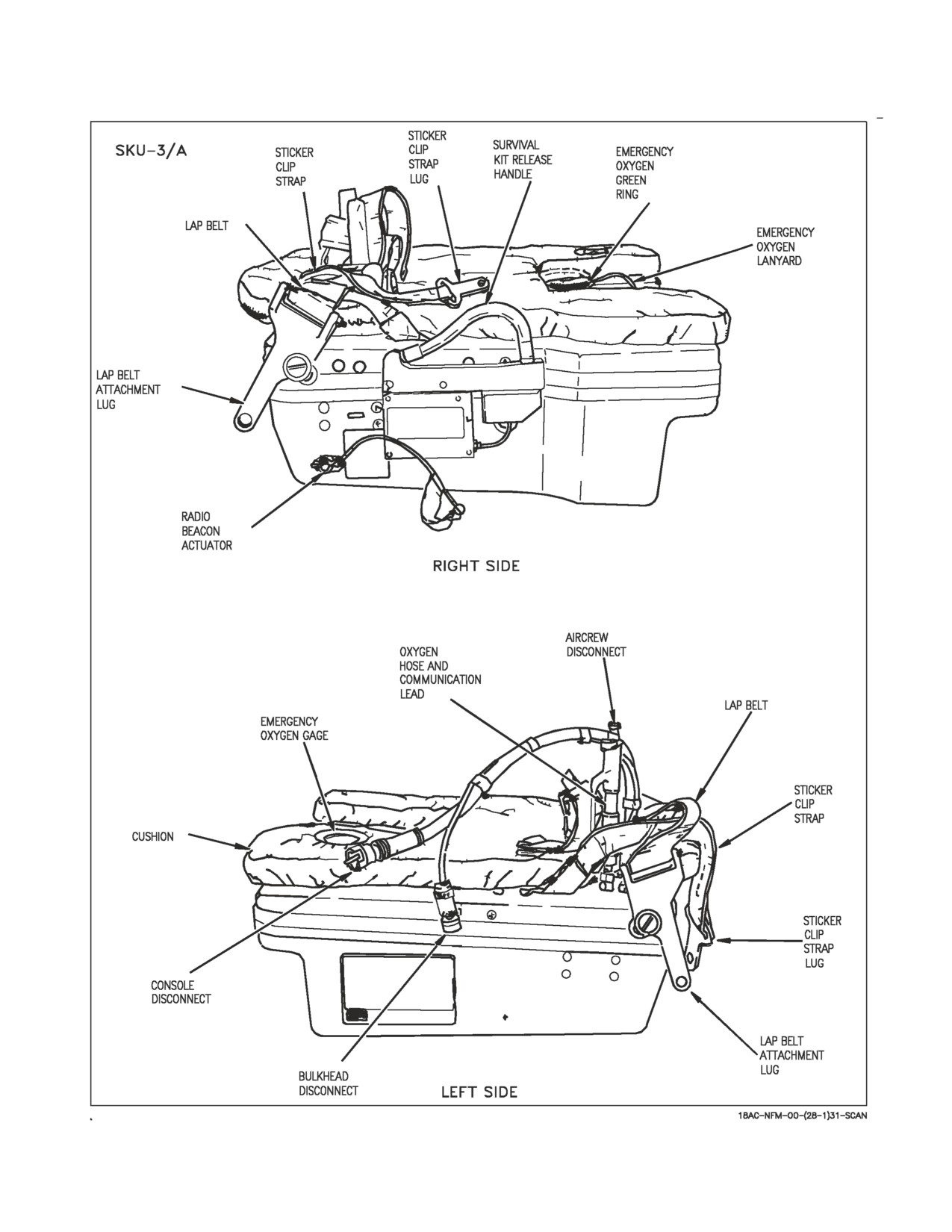
2.15.3.9 Survival Kit (SKU-3/A). The SKU-3/A survival kit is used with the SJU-5/6 ejection seat
and contains provisions for survival after ejection or ditching (figure 2-34, sheet 1). The kit is composed
of a two-piece fiberglass container. The lower portion of the kit contains emergency provisions and an
inflatable raft. The upper portion of the kit, containing a 50 cubic inch emergency oxygen supply,
serves as the kit cover and has a seat cushion attached to the top. During ejection the emergency oxygen
is tripped by an automatic oxygen operating cable lanyard attached to the cockpit floor. The kit
contains an emergency oxygen green ring on the left forward part of the upper kit. A flexible oxygen
and communications hose is installed in the left aft side of the upper kit to provide a connection to the
pilot for oxygen and communications. After ejection or after the emergency oxygen green ring is pulled,
emergency oxygen is supplied to the pilot through the hose until the emergency oxygen is exhausted.
The survival kit is secured to the seat by two lugs installed on the aft upper corners of the kit, and
a lug installed through a bracket on the front of the kit. Two adjustable lap belt straps are installed on
I-2-131
ORIGINAL
A1-F18AC-NFM-000
Figure 2-35. Leg Restraint System
the sides of the kit. These straps connect to fittings on the pilot’s lower torso harness to secure the pilot
to the kit, and thus to the seat. The restraint provided by the three lugs is released by the action of the
time release mechanism at seat-man separation after ejection, or by the action resulting from pulling
the manual override handle. Additional restraint is provided by straps which connect the survival kit
to sticker clips in the seat. The straps require a force of between 40 to 55 pounds to separate from the
sticker clips at man-seat separation after ejection or during ground egress. The kit is equipped with an
AN/URT-33A radio beacon locator which actuates during ejection at man-seat separation. The kit can
be deployed after ejection during parachute descent by pulling the survival kit release handle on the
right side of the kit. This unlocks the kit causing the lower half to fall away while remaining attached
to the upper half by a dropline. The liferaft, also attached to the dropline, falls away by gravity and
inflates. An equipment bag containing the other survival aids falls away but remains attached to the
upper kit lid by a lanyard. If the pilot lands in water before deploying the survival kit, the liferaft can
be inflated by pulling the survival kit release handle and then reaching into the kit and pulling the
actuating cable on the liferaft CO2 bottle.
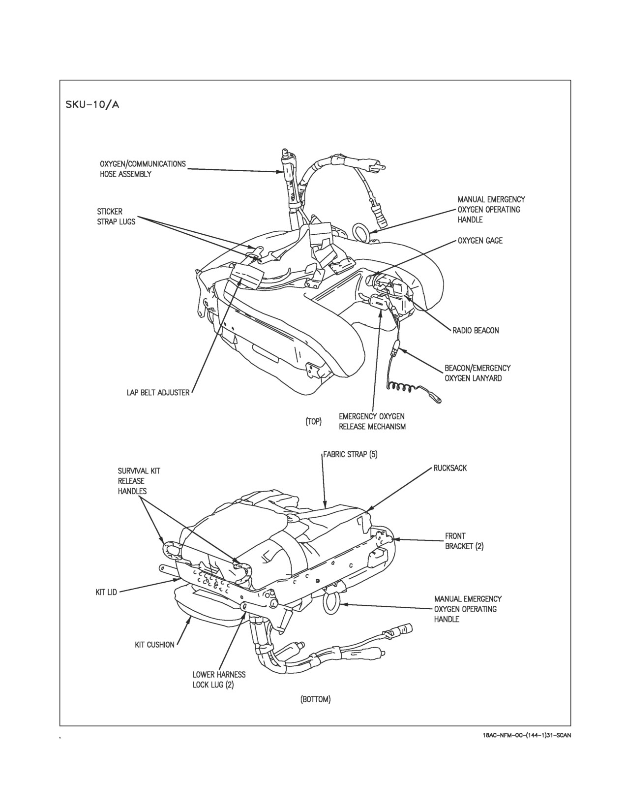
2.15.3.10 Seat Survival Kit (SKU-10/A). The SKU-10/A survival kit is used with the SJU-17
ejection seats. This survival kit, which fits into the seat bucket, is a contoured rigid platform which
contains an emergency oxygen system and a fabric survival rucksack (figure 2-36, sheet 2). A cushion
on top of the platform provides a seat for the aircrew.
The rigid platform forms a hard protective cover to the survival package and oxygen system and is
retained in position in the seat bucket by brackets at the front and lugs secured in the lower harness
locks at the rear. Attached to the lugs are two adjustable lap belts with integral quick-release fittings.
I-2-132
ORIGINAL
A1-F18AC-NFM-000
A flexible oxygen and communication hose is installed in the left aft side of the upper kit to provide
a connection to the aircrew for aircraft oxygen and communication. An emergency oxygen cylinder,
pressure reducer and associated pipework are mounted on the underside of the platform. A green
manual emergency oxygen operating handle is mounted on the left side of the platform and a pressure
gage is on the inside face of the left leg support. The emergency oxygen can be activated manually by
pulling the green emergency oxygen handle upwards. The green emergency oxygen handle can be reset,
thus shutting off the flow of emergency oxygen, by pushing downward on the button on the front end
of the emergency oxygen handle assembly. The emergency oxygen is automatically activated during
ejection by a lanyard connected between the floor and the survival kit. An AN/URT-33A locator
beacon is located in a cutout in the left leg support. The beacon is actuated during ejection by a lanyard
connected to the emergency oxygen lanyard.
The survival rucksack is retained to the underside of the rigid platform by five fabric straps and a
double cone and pin release system. The package accommodates a liferaft and survival aids. Two yellow
manual deployment handles are mounted on the aft surface of the kit and pulling either handle enables
the aircrew to deploy the raft and survival package after man/seat separation. The liferaft inflates
automatically on survival package deployment and is attached to the survival package with a line. If
the survival kit must be deployed after water entry, a snatch pull on the red manual activation handle,
near the CO2 bottle, is required to inflate the liferaft.
2.15.3.11 Manual Override Handle. A manual override handle permits releasing the pilot’s lower
harness restraints and the leg restraint lines for emergency egress, and permits resuming part of the
ejection sequence (man-seat separation and main parachute deployment) in the event of sequencing
failure during ejection. The manual override handle, on the right side of seat bucket and just aft of the
ejection seat safe/arm handle, is actuated by first pressing a thumb button on the forward part of the
handle and then rotating the handle up and aft. If the handle is actuated on the ground or in the air
before ejection, the following restraints are released: survival kit attachment lugs, inertia reel straps,
and the leg restraint lines. During ground emergency egress, after the manual override handle is pulled
and the parachute riser fittings are released, the pilot is free to evacuate the aircraft with the survival
kit still attached. On the SJU-5/6 seat, if the manual override handle is actuated after ejection before
man-seat separation occurs, the following events take place: release of same restraints as described in
the emergency ground egress, firing of the manual override initiator cartridge which fires both the time
release mechanism and drogue gun secondary cartridge (if they haven’t been fired), flaps of main
parachute pack are unlocked, and the scissor shackle on the top of the seat is released to allow the
drogue chute to deploy the main parachute. On the SJU-17 seats, if the manual override handle is
actuated after ejection before man-seat separation occurs, the following events take place: release of
survival kit attachment lugs, negative-g strap, leg restraint lines, inertia reel straps; firing of the
manual override initiator cartridge; firing of the barostatic release unit; and firing of the parachute
deployment rocket which deploys the parachute. The ejection seat safe/armed handle automatically
rotates to the SAFE position whenever the manual override handle is actuated.
Do not pull the manual override handle in flight. Pulling the handle
disconnects the survival kit attachment lugs and leg restraint lines,
inertia reel straps, and safeties the seat.
2.15.3.12 Seat Bucket Position Switch. The seat bucket position switch is on the left side of the seat
bucket, forward of the shoulder harness lock/unlock handle. The forward switch position lowers the
seat bucket, the aft position raises the seat bucket, and the center off position, to which the switch is
I-2-133
ORIGINAL
A1-F18AC-NFM-000
spring-loaded, stops the seat bucket. The maximum vertical travel of the seat bucket is 5.3 inches on
the SJU-5/A and 6/A, 5.1 inches on the SJU-17(V)1/A, 2/A, and 9/A, and 6.1 inches on the
SJU-17A(V)1/A, 2/A, and 9/A. The actuator should not be operated over 1 minute during any 8-minute
period.
• To prevent increased risk of thigh slap or leg contact injuries, aircrew
with a buttock-to-knee length greater than 25.5 inches should not use
either of the two forward backpad positions. Aircrew with buttock-to-
knee length between 24.6 and 25.5 inches should not use the full
forward backpad position.
• Actuation of the seat bucket position switch with the leg restraints
under the seat bucket may result in an inadvertent ejection.
Actuation of seat bucket position switch with lap belts, shoulder harness,
and/or leg restraints outside or under seat bucket may damage ejection
seat, leg restraints, and/or Koch fittings.
2.15.3.13 Backpad Adjustment Mechanism (SJU-17A(V)1/A, 2/A, and 9/A). The backpad adjust-
ment mechanism handle is on the seat bucket adjacent to the top left hand side of the backpad and is
connected to the backpad by a linkage. The backpad has three positions, full forward, middle, and full
aft which give a total forward/aft adjustment of 1.6 inches. When the handle is in the full up position,
the backpad is full aft and when the handle is full down, the backpad is full forward. To move the
backpad, the adjustment handle is moved within a quadrant until a spring-loaded plunger engages in
one of the three detent positions in the quadrant. Set the backpad for personal comfort and best access
to flight controls during initial strap-in and prior to flight.
I-2-134
ORIGINAL
A1-F18AC-NFM-000
Figure 2-36. Survival Kit (Sheet 1 of 2)
I-2-135
ORIGINAL
A1-F18AC-NFM-000
Figure 2-36. Survival Kit (Sheet 2 of 2)
I-2-136
ORIGINAL
A1-F18AC-NFM-000
2.16 ENVIRONMENTAL CONTROL SYSTEM
The environmental control system (ECS) provides conditioned air to the cockpit and avionics. The
ECS also provides cockpit pressurization, OBOGS source air, anti-g suit pressure, fuel tank pressur-
ization, throttle boost, windshield anti-ice and rain removal, windshield defog, canopy seal, and
waveguide pressurization. The ECS uses bleed air from the engines for operation. See Environmental
Control System, Foldout section, for environmental control system illustration.
2.16.1 Bleed Air System. Bleed air comes from the compressor section of each engine. A primary
bleed air pressure regulator and shutoff valve is mounted on each engine and controls the flow of bleed
air into the engine bay bleed air ducts. This valve can be manually commanded closed by the BLEED
AIR knob, or is automatically commanded closed by the bleed air leak detection system, system
overpressure sensor, or total loss of ac power. When the valve is commanded closed, the associated L
or R BLD OFF caution is displayed.
The engine bay bleed air ducts are routed into the keel and are tied together. This common bleed air
duct is routed through the secondary pressure regulator and shutoff valve which controls the flow of
bleed air into the rest of the ECS. This valve can be manually commanded closed by the OFF position
of the BLEED AIR knob, or is automatically commanded closed by the bleed air leak detection system
or system overpressure sensor. The common bleed air duct is then routed from the keel across the top
of the fuselage fuel tanks to the primary heat exchanger. For crossbleed engine starts, bleed air is
routed to the air turbine starters through the isolation valve. A bleed air leak detection system which
utilizes temperature-sensing elements is installed. Elements are routed on each engine bay bleed air
duct. If a leak is detected in an engine bay bleed air duct, a single L or R BLEED warning light is
illuminated, the associated ‘‘Bleed Air Left/Right’’ voice alert is annunciated, and the associated
primary bleed air pressure regulator and shutoff valve is commanded closed resulting in a single L or
R BLD OFF caution. An engine bay fire or missing engine borescope plug can also result in single bleed
air leak indications. Bleed air leak detection elements are also routed along the common bleed air
ducts. If a leak is detected in these common bleed air ducts, both L and R BLEED warning lights are
illuminated, both ‘‘Bleed Air Left and Right’’ voice alerts are annunciated, both primary bleed air
pressure regulator and shutoff valves are commanded closed resulting in both L and R BLD OFF
cautions, and the secondary pressure regulator and shutoff valve is commanded closed.
• BLD OFF cautions are based on command signals to the valves and are
not an indication of actual valve position. A valve could still be open
allowing bleed air to leak. The BLEED AIR knob should be turned to
the appropriate OFF position to backup the automatic shutoff func-
tion.
• If a single BLEED warning light does not extinguish after the
associated BLD OFF caution is displayed, a borescope plug may be
leaking or the associated shutoff valve may still be open. Shutting
down the associated engine will eliminate the leak. If both BLEED
warning lights do not extinguish after both BLD OFF cautions are
displayed, a shutoff valve may still be open. Reducing power on both
engines will reduce the temperature and flow of the leak minimizing
aircraft damage.
I-2-137
ORIGINAL
A1-F18AC-NFM-000
If a system overpressure occurs, both primary pressure regulator and shutoff valves are commanded
closed resulting in both L and R BLD OFF cautions, and the secondary pressure regulator and shutoff
valve is commanded closed. The system may be safely reset ONCE if the shutdown was due to an
overpressure condition characterized by the display of both BLD OFF cautions without the ‘‘Bleed Air
Left/Right’’ voice alerts.
The fire and bleed air test switch, described under Fire Detection/Extinguishing Systems, this
section, tests the bleed air leak detection system. When the test is executed, both L and R BLEED
warning lights are illuminated, both ‘‘Bleed Air Left and Right’’ voice alerts are annunciated, both
primary bleed air pressure regulator and shutoff valves are commanded closed resulting in both L and
R BLD OFF cautions, and the secondary pressure regulator and shutoff valve is commanded closed.
The L and R BLEED warning lights go off when the switch is released but the three pressure regulator
and shutoff valves do not open. To open the valves, the BLEED AIR knob must be rotated through
OFF to NORM with AC power on the aircraft. The L (R) BLD OFF cautions remain on until the valves
are commanded open.
2.16.1.1 Bleed Air Knob. The BLEED AIR knob, on the ECS panel on the right console, selects the
engine bleed air source for the ECS system.
OFF
Shuts off bleed air from both engines.
R OFF
Selects bleed air from the left engine only.
L OFF
Selects bleed air from the right engine only.
NORM
Supplies bleed air from both engines.
AUG
APU airflow augments engine bleed air flow for ECS operation. Position can only
PULL
be used on the ground, is solenoid held, and reverts to off if electrical power is lost,
or when both throttles are advanced to MIL power or greater. Bleed air knob must
be in any position except OFF.
2.16.1.2 L(R) Bleed Air Warning Lights. The L and R BLEED air warning lights, on the left
warning/caution/advisory lights panel, come on when a leak is detected in the left (right) bleed air
system. They also come on during test of the bleed air leakage detection system. If a leak is detected
in the common portion of bleed air ducting both warning lights illuminate.
The L/R BLEED AIR warning lights may not be seen by the pilot. The
only indication to the pilot may be the voice alert.
2.16.1.3 L(R) Bleed Off Caution Displays. The L(R) BLD OFF caution displays come on whenever
the left (right) bleed air pressure regulator and shutoff valve(s) are commanded closed. The cause of
valve closure could be a leak or overpressurization in the bleed air system, or test of the bleed air
leakage detection system. The display(s) remain on the DDI until the valve(s) are commanded open.
I-2-138
ORIGINAL
A1-F18AC-NFM-000
Figure 2-37. Cockpit Pressurization Schedules
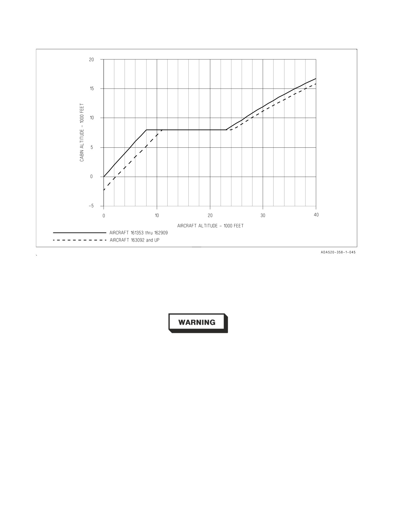
2.16.2 Cockpit Air Conditioning and Pressurization. Cockpit air conditioning and pressurization
controls are on the ECS panel. The cockpit pressure altitude is shown on the cockpit altimeter on the
lower center instrument panel. The pressurization schedules are different between aircraft 161353
THRU 162909 and aircraft 163092 AND UP. See figure 2-37.
There is no caution in the event of loss of cockpit pressurization.
2.16.2.1 Mode Switch.
AUTO
Cockpit and suit vent temperature maintained as selected by temperature knobs.
MAN
Cockpit and suit vent temperature directly controlled by temperature knobs.
Manual mode applies maximum airflow to cockpit and avionics during ground
operations. Significant airflow degradation occurs with increasing altitude.
OFF/RAM ECS shut off. Cockpit ram air valve and liquid cooling air scoop opened.
2.16.2.2 Temperature Knobs. The outer knob controls cockpit temperature as programmed by the
mode switch. The inner knob controls suit vent air temperature as programmed by the mode switch.
I-2-139
ORIGINAL
A1-F18AC-NFM-000
2.16.2.3 Cabin Pressure Switch.
NORM
Cockpit pressurized by ECS
DUMP
Cockpit unpressurized
RAM DUMP
Cockpit ram air valve opens, ECS compressor/turbine output air to cock-
pit is shut off, and cabin pressure dump valve opens. Warm air is avail-
able through the cabin add heat valve to mix with the ram air.
2.16.2.4 Cabin Pressurization Warning System (CPWS). The CPWS pressure switch monitors cabin
pressure and aircraft relays monitor related controls to warn aircrew of potentially hazardous cabin
pressurization conditions.
2.16.2.4.1 CABIN Caution Light. The yellow CABIN caution light is located on the lower right
caution lights panel. The light illuminates when cabin pressure altitude is above 21,000 +/- 1,100 feet.
The light may not extinguish until cabin pressure altitude is below 16,500 feet.
• CABIN light may appear with normal cabin pressurization when
aircraft altitude is above 47,000 feet MSL. If altitude is maintained,
aircrew should continuously monitor physiological condition.
• DCS may be experienced when operating with cabin pressure altitude
above 25,000 feet even with a working oxygen system. Symptoms of
DCS include pain in joints, tingling sensations, dizziness, paralysis,
choking, and/or loss of consciousness.
NOTE
There is no corresponding DDI caution for the CABIN caution light.
2.16.2.4.2 CK ECS Caution Light. The yellow CK ECS caution light is located on the lower right
caution lights panel. The light illuminates when the position of cabin pressurization related controls
will inhibit cabin pressurization.
NOTE
There is no corresponding DDI caution for the CK ECS caution light.
2.16.3 Defogging System. The defogging system receives a portion of the conditioned air that is
delivered to the cockpit and controlled by the mode switch and outer temperature knob as described
above. The air is directed to a defog nozzle inboard of the forward portion of the windshield. The
amount of defog air is controlled by the defog handle.
2.16.3.1 Defog Handle/Cockpit Louvers. The defog handle, on the right console outboard of the
ECS panel, controls the division of air flow between the windshield defog outlets and the cockpit air
outlets. As the handle is moved toward HIGH (forward), more air is diverted to the defog outlets. With
I-2-140
ORIGINAL
A1-F18AC-NFM-000
defog handle set within ten percent of HIGH, the air temperature increases. For maximum cockpit
cooling, pull the defog handle full aft, the side louvers should be directed towards the body with the
center louver fully closed. Care should be taken to return the handle to the normal position prior to
descending into warm, humid conditions to avoid abrupt canopy fogging.
2.16.4 Windshield Anti-Ice and Rain Removal System. The windshield anti-ice and rain removal
systems use the same air nozzle to direct warm air over the external windshield in order to improve
pilot forward visibility in icing/raining conditions. Warm air is provided by mixing engine bleed air
with output from the primary heat exchanger. Windshield air nozzle orientation is intended to affect
(in flight) an area roughly 20 inches to the left and 9 inches to the right of centerline at design eye level
and below. System operation is controlled by the WINDSHIELD switch.
2.16.4.1 Windshield Anti-Ice/Rain Switch. The windshield anti-ice/rain switch is on the right
console aft of the defog handle.
OFF
No anti-ice/rain removal air flow. This center position is lever-locked and the
switch must be pulled up before placing it to either of the other two positions.
ANTI ICE High-volume high-pressure air at 250°F is distributed across the windshield.
RAIN
Low-volume low-pressure air at 250°F is distributed across the windshield.
2.16.4.2 Windshield Hot Display. If the temperature of the air being distributed across the
windshield becomes excessive or the windshield temperature sensor fails a WDSHLD HOT caution is
displayed on the DDI.
2.16.5 Suit Ventilation System. The suit ventilation system supplies temperature controlled and
pressure regulated air to the pilot’s vent suit disconnect located on the left console. Selected vent suit
temperature is controlled by the air conditioning system controller operating the vent suit temperature
sensor and vent suit temperature valve. The system is operational with the ECS MODE switch on the
ECS panel, located on the right console, in MAN or AUTO. (See Mode Switch for operational control
of the system.) Flow rate to the vent suit can be reduced below maximum by the use of the vent suit
flow control knob on the pilot services panel located on the left console.
2.16.6 Anti-G System. The anti-g system allows air pressure into the suit proportional to the g force
experienced. A button in the valve allows the pilot to manually inflate his suit. The system incorporates
a pressure relief valve.
2.16.7 Avionics Cooling and Pressurization. Avionics cooling and pressurization is augmented by
ram air if the flow drops below the desired value. If avionics cooling is inadequate, the AV AIR HOT
caution display comes on. If the temperature in either flight control computer A or the right
transformer-rectifier is high, FCS HOT caution display and light come on. Placing the AV COOL
switch, on the lower right instrument panel, to EMERG opens a ram air scoop to supply cooling air to
these units. The scoop cannot be closed in flight. A transient (up to 3 minutes) AV AIR HOT caution
can occur in hot weather following transition from ground fan cooling at IDLE to conditioned air
cooling with high throttle setting or with the APU operating in bleed air augmentation mode.
2.16.7.1 Fan Test Switch. The fan test switch located above the aft end of the right console permits
maintenance testing of the cockpit avionics cooling fans.
I-2-141
ORIGINAL
A1-F18AC-NFM-000
2.17 EMERGENCY EQUIPMENT
2.17.1 Jettison Systems. The jettison systems consist of the emergency jettison system and the
selective jettison system.
2.17.1.1 Emergency Jettison Button. The emergency jettison system utilizes the emergency jettison
button to jettison all stores/launchers/racks from the BRU-32A racks on the five pylon weapon stations
(2, 3, 5, 7, and 8). The landing gear handle must be up or weight off wheels to enable the emergency
jettison button. The emergency jettison button, labeled EMERG JETT, is a momentary pushbutton
on the left edge of the instrument panel and is painted with alternating black and yellow stripes. The
button must be held pressed during the entire jettison sequence. Jettison is sequential by station pairs
starting with stations 2 and 8, then stations 3 and 7, and finally, station 5. The BIT advisory and an
SMS BIT status of DGD is the only enunciated indication of a stuck emergency jettison button.
NOTE
Hold EMERG JETT pressed for at least 375 msec to ensure all stores
are jettisoned.
If the EMERG JETT button is stuck, emergency jettison is activated as soon as the aircraft goes W
off W.
2.17.1.2 Selective Jettison. Selective jettison is performed using the SELECT JETT knob, in
conjunction with the JETT STATION SELECT buttons, and jettisons stores in a safe condition. The
stores or the launchers/racks (with any attached stores) can be jettisoned from the centerline and wing
stations, and the missiles can be jettisoned from the fuselage stations.
Selective jettison requires ARM conditions satisfied and all the landing gear up and locked. ARM
conditions are satisfied with WoffW, LDG GEAR handle UP, MASTER ARM switch in ARM, and
SIM mode unboxed. ARM status can be confirmed on the STORES page. All the landing gear up and
locked can be confirmed by the absence of the LDG GEAR handle warning light/landing gear warning
tone with the LDG GEAR handle UP.
Selective jettison of the centerline and wing stations requires station(s) selection by the JETT
STATION SELECT buttons and STORES or RACK/LCHR selection by the SELECT JETT knob.
Selective jettison of a fuselage station missile requires R FUS MSL or L FUS MSL selection by the
SELECT JETT knob.
With all the requirements met, selective jettison is performed by pressing the JETT center
pushbutton in the SELECT JETT knob.
2.17.1.2.1 Station Jettison Select Buttons. The station jettison select buttons are on the left edge
of the instrument panel below the emergency jettison button. The buttons are labeled CTR (center),
LI (left inboard), RI (right inboard), LO (left outboard) and RO (right outboard). Pressing a button
illuminates an internal light and selects a weapon station for jettison. The station jettison select
buttons are also used in the backup A/G weapon delivery modes for weapon selection; refer to NTRP
3-22.4-FA18A-D and NTRP 3-22.2-FA18A-D NATIP.
2.17.1.2.2 Selective Jettison Knob. The selective jettison knob on the left vertical panel has rotary
positions L FUS MSL, SAFE, R FUS MSL, RACK/LCHR, and STORES. L FUS MSL and R FUS
MSL selects the required fuselage missile for jettison. The RACK/LCHR and STORES positions select
what is to be jettisoned from the weapon stations selected by the station jettison select buttons. The
I-2-142
ORIGINAL
A1-F18AC-NFM-000
JETT center pushbutton activates the jettison circuits provided the landing gear is up and locked and
the master arm switch is in ARM. The SAFE position prevents any selective jettison.
2.17.1.2.3 Auxiliary Release Switch. The auxiliary release switch, on the lower instrument panel, is
used to enable jettison of hung stores or store and rack/launcher combinations from BRU-32/A racks
on stations 2, 3, 5, 7, and 8. A need to use the auxiliary release switch is indicated by a hung indication
on the DDI after selective jettison or a normal weapons release is attempted. Place the switch to
ENABLE to select the auxiliary release function. The master arm switch must be in ARM. Initiate
jettison by selecting RACK/LCHR or STORES on the selective jettison knob, select the hung store
station by pressing the appropriate station jettison select button, and then press the JETT center
pushbutton of the selective jettison knob. The SMS provides a jettison signal to fire the auxiliary
cartridge in the BRU-32/A rack on which the hung store or store and rack/launcher combination is
loaded. After the cartridge is fired, the store or rack/launcher is gravity dropped with the store in a safe
condition. This switch is also used with some weapons for a second normal release attempt after these
weapons have been hung during a first normal release attempt. Refer to NTRP 3-22.4-FA18A-D and
NTRP 3-22.2-FA18A-D NATIP for these weapons and procedures.
2.17.2 Warning/Caution/Advisory Lights and Displays. The warning/caution/advisory lights and
displays system provides visual indications of normal aircraft operation and system malfunctions
affecting safe operation of the aircraft. The lights are on various system instruments and control panels
in the cockpit. The red warning lights normally indicate a systems malfunction that could be a severe
hazard to further flight, and may require immediate action. Caution lights and displays normally, but
not always, indicate malfunctions that require attention but not immediate action. After the
malfunction has been corrected, warning and caution lights and caution displays go out. Advisory lights
and displays indicate safe or normal conditions and supply information for routine purposes. On
aircraft 163985 AND UP, warning, caution and advisory displays are NVG compatible. Caution and
advisory displays appear on the left, right or center DDIs, depending on the number of DDIs in
operation. The advisory displays start at the bottom of the DDI display and are preceded by ADV. The
caution displays, in larger characters than the advisory displays, appear immediately above the
advisory displays. The caution lights, located on the caution lights panel and the instrument panel, are
yellow lights. The advisory lights, scattered throughout the cockpit, are white or green. Turned on
lights on the caution lights panel flash when overheated to prevent light damage.
2.17.2.1 Master Caution. A yellow MASTER CAUTION light, on the upper left part of the
instrument panel, comes on when any of the caution lights or caution displays come on. The MASTER
CAUTION light goes out when it is pressed (reset). An audio tone is initiated whenever the MASTER
CAUTION light comes on. The tone is of 0.8 second duration. The tone consists of a 0.25-second sound
followed by a 0.15-second sound of higher pitch, followed by one repetition of these sounds. Once
sounded, the tone does not repeat unless the original condition causing the tone clears and recurs 5
seconds after the first tone, regardless of whether or not the MASTER CAUTION is reset. Additional
cautions sound the tone, regardless of whether or not the MASTER CAUTION is reset, providing
about 5 seconds have elapsed since the previous caution. Pressing the MASTER CAUTION when it is
not illuminated causes the uncorrected caution and advisory displays on the DDIs to reposition to the
left and to a lower level, provided there is available space vacated by corrected caution and advisory
displays. To restack the cautions and advisories when the MASTER CAUTION is lighted, the
MASTER CAUTION must be pressed twice: first, to turn off the MASTER CAUTION light and
second, to reposition the caution and advisory displays. A reset MASTER CAUTION light (and tone)
comes on providing there is at least one uncorrected caution present when weight is on the wheels and
both throttles are moved beyond approximately 80% rpm or, providing both throttles were below 80%
for at least 60 seconds.
I-2-143
ORIGINAL
A1-F18AC-NFM-000
2.17.2.2 Dimming and Test Functions. There are no provisions for testing the caution and advisory
displays on the DDIs, and each DDI contains its own display dimming controls. The warning/caution/
advisory lights are dimmed by the warning/caution lights knob, and they are tested by the lights test
switch. See lighting equipment, this chapter, for operation of the warning/caution lights knob and the
lights test switch. The following lights can be dimmed by the warning/caution lights knob, but once in
the dimmed lighting range cannot be varied in intensity: MASTER CAUTION light, landing gear
handle warning, L BAR warning, HOOK warning, L BLEED warning, R BLEED warning, APU FIRE
warning, left and right engine FIRE warning.
2.17.3 Voice Alert System. For certain critical warnings and cautions, voice alert transmissions are
sent to the pilot’s headset. The message is repeated twice; for example, “APU FIRE, APU FIRE”. The
voice alert requires no reset action on the pilot’s part and the alert is not repeated unless the original
condition ceases for 5 seconds or more and then recurs. The ALTITUDE voice alert, when initiated by
the primary radar low altitude warning, has a high priority for its first annunciation and is repeated
continuously at the lowest priority until reset or disabled by the pilot. For cautions with voice alert, the
voice alert replaces the master caution tone; however, the master caution tone backs up the voice alert
system, and provides a tone if the voice alert system malfunctions. FIRE, APU FIRE, L BLEED, and
R BLEED warnings are not backed up by the master caution tone. Voice alert is the only audio warning
for these problems. With dual generator failure, the following voice alert warnings operate from battery
power: APU FIRE, L(R) FIRE, and L(R) BLEED. The ALTITUDE voice alert warning, all voice alert
cautions, and the master caution tone are inoperative on battery power during dual generator failure.
Once a voice alert has been activated, it cannot be interrupted by a higher priority voice alert. All voice
alerts play until completed.
CAUTION
VOICE ALERT
IFF 4
MODE 4 REPLY
DEL ON,
MECH ON,
FLAPS OFF,
AIL OFF,
FLIGHT
RUD OFF,
CONTROLS
FLAPS SCHED,
or G-LIM 7.5 G
FCS HOT
FLIGHT
COMPUTER HOT
L(R) OVRSPD,
L(R) EGT HI,
L(R) IN TEMP,
ENGINE LEFT (RIGHT)
L(R) FLAMEOUT,
L(R) OIL PR,
or L(R) STALL
FUEL LO
FUEL LOW
BINGO
BINGO
I-2-144
ORIGINAL
A1-F18AC-NFM-000
WARNING
VOICE ALERT
ALTITUDE LOW
ALTITUDE
1
WARNING
L(R) BLEED AIR
BLEED AIR LEFT (RIGHT)
L(R) FIRE
ENGINE FIRE LEFT (RIGHT)
APU FIRE
APU FIRE
1
MC OFP 10A
2.17.4
TAWS - Terrain Awareness Warning System (SCS 17C AND UP). The terrain awareness
warning system alerts the aircrew of a controlled flight into terrain (CFIT) condition during all mission
phases. The system operates any time that the navigation mission computer (MC1) and TAMMAC
digital mapping set (DMS) are functional. TAWS functions as a safety backup system and not as a
performance aid. TAWS has been designed to eliminate false warnings, minimize nuisance warnings,
and generate consistent aircrew response in all aircraft master modes. Five possible voice warnings are
provided to indicate the correct initial response to an impending CFIT condition, and a visual cue is
provided to indicate the recovery direction of pull, or in some instances, to command an increase in
turn rate. All TAWS warnings should be treated as though an imminent flight into terrain condition
exists. Pilot response to a TAWS warning should be instinctive and immediate.
TAWS uses data from the following inputs: ADC, FCC, INS, RADALT, GPS, and digital terrain
elevation data (DTED). DTED resides in the DMS as part of TAMMAC and is used to provide the
forward-prediction capability that protects against flight into rising terrain. The TAWS option is
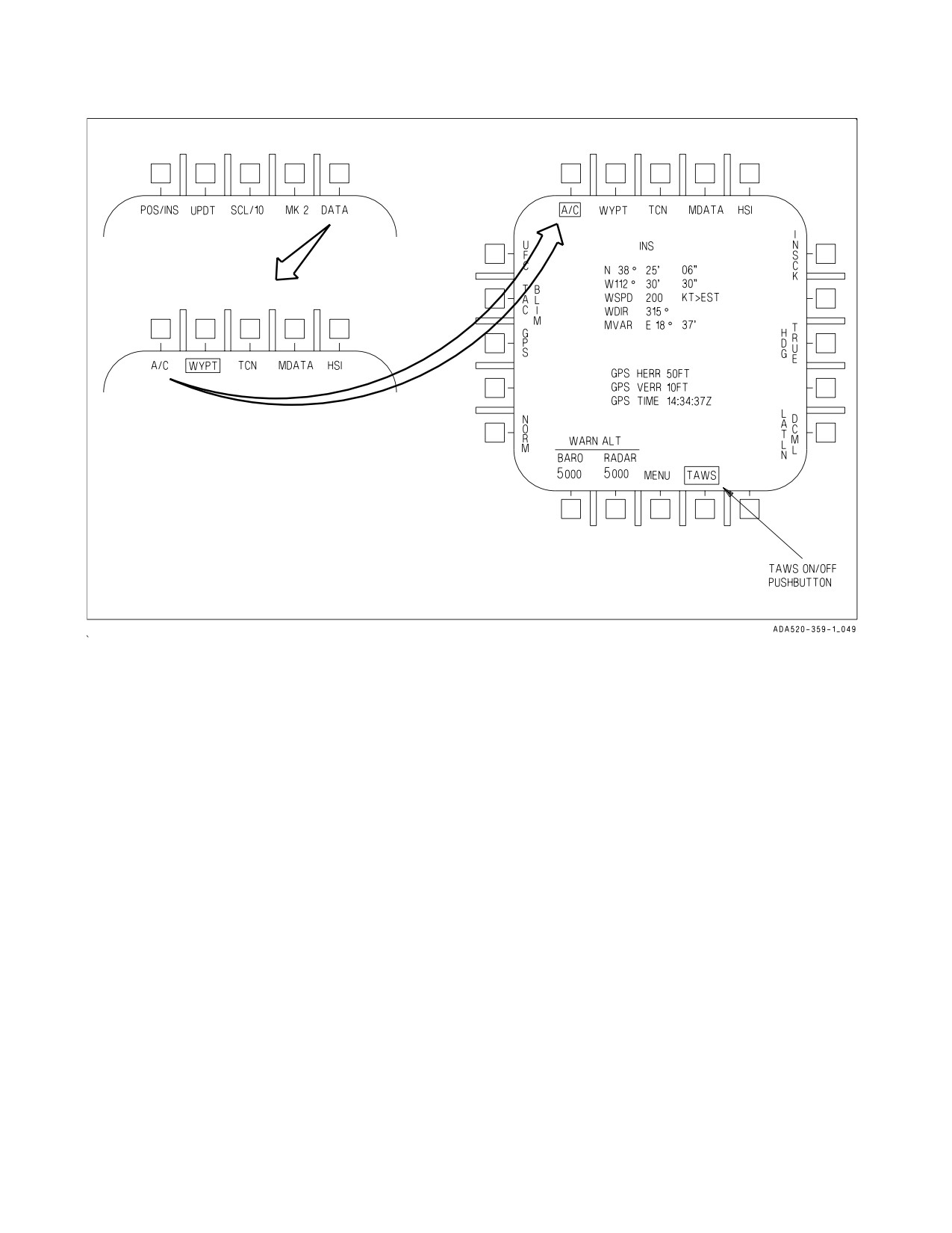
reached, by pressing MENU-HSI-DATA-A/C as shown in figure 2-38. The TAWS option boxes
automatically at start-up.
When a DMS is not installed in the aircraft or is not operational, protection from CFIT events is
provided by the Ground Proximity Warning System (GPWS). BIT may be initiated on the DMS by
pressing the appropriate pushtile of the BIT display. The BIT can take up to 185 seconds to complete.
During the BIT, TAWS is not operational. Therefore, the GPWS algorithm is used to determine the
presence of possible CFIT events. There is no capability for pilot selection of GPWS if DMS is
operational. The GPWS algorithm runs continuously with outputs being overwritten if TAWS is
operational. This prevents erroneous values during an unexpected transition from TAWS to GPWS.
I-2-145
ORIGINAL
A1-F18AC-NFM-000
Figure 2-38. TAWS ON/OFF Pushbutton
2.17.4.1 TAWS Modes. TAWS has two operational modes: TAWS-with-DTED, and TAWS- without-
DTED. These modes switch automatically depending upon the available sensor data and flight phase.
When the aircraft position (latitude and longitude) is accurately known and DTED for the local area
has been loaded onto the DMS (during the theater load process), TAWS is in the TAWS-with-DTED
mode and provides protection against varying terrain ahead of the aircraft. When the aircraft position
is not accurately known, DTED for the local area is unavailable, or TAWS determines the aircraft is
in a landing phase, TAWS transitions to the TAWS-without-DTED mode and provides protection
against flight into level or descending terrain as GPWS does.
When operating over the ocean, DTED does not exist and TAWS will be in the TAWS-without-
DTED mode. However, there is no degradation in protection because the ocean is relatively flat. As the
aircraft approaches the coast or islands, DTED may be available (depending upon the theater load)
and TAWS will automatically switch back to the TAWS-with-DTED mode.
Operation of TAWS in the TAWS-without-DTED mode is still an improvement over GPWS as
TAWS incorporates a more robust performance model and additional input sensor redundancy.
2.17.4.2 TAWS Operation. TAWS incorporates signal processing that determines a best estimate of
aircraft position and altitude (AGL and MSL). TAWS protection algorithm continuously computes
two recovery trajectories: Vertical Recovery Trajectory (VRT) and Oblique Recovery Trajectory
(ORT). VRT is the standard GPWS-like recovery: roll to wings-level, if needed, and pull to recover.
ORT assumes that you maintain the current bank angle and pull to recover (increase turn rate). Both
computed trajectories include the following assumptions:
I-2-146
ORIGINAL
A1-F18AC-NFM-000
a. Pilot Response Time is the time from issuance of a TAWS warning to the time that the pilot
actually initiates recovery. Pilot Response Time is set at 1.3 seconds.
b. Roll Recovery Phase is the time necessary to roll the aircraft to near wings-level. This assumes
at least ½ lateral stick will be used for bank angles less than 70° and at least ¾ lateral stick
will be used for bank angles ≥ 70°.
c. G-Onset Phase is the time required to pull to the target recovery g. The target recovery g is
80% of the instantaneous g available, or 5g, whichever is less. The g-onset phase assumes that
rapid aft stick motion will be used (full deflection within ¾ second). In addition, TAWS
assumes that throttles will be moved to MAX if below corner speed and to IDLE if above
corner speed.
d. Dive Recovery Phase is the remainder of the trajectory until terrain clearance is achieved.
TAWS assumes a terrain clearance of 50 ft.
When TAWS senses that the aircraft is in the landing configuration, the recovery assumptions must
change since the desire is to land. TAWS defines the landing phase as below 500 ft AGL, less than 200
KCAS, landing gear down and locked, and more than one minute since a waveoff or takeoff. In the
landing phase, TAWS protects against landings of greater than the structural limit of the landing gear
(1584 fpm). To allow this, TAWS switches to TAWS-without-DTED and provides a warning when the
landing is predicted to exceed the structural limit of the landing gear.
TAWS provides protection against gear-up landings. When the aircraft is below 200 KCAS, below
150 ft AGL, more than one minute since waveoff or takeoff, and the landing gear is not down and
locked, a TAWS warning is provided.
2.17.4.3
TAWS Warnings. TAWS provides clear, unambiguous, and directive aural and visual cues
to the aircrew. Aural warnings provide the aircrew with a wake-up call and correct initial response
while visual warnings provide the aircrew with correct follow-on recovery information.
2.17.4.3.1 Voice Warnings. TAWS uses the ACI to provide aural cues to the aircrew. The aural cues
are distinct from any other cues that the aircrew may receive. The TAWS voice alert warnings are:
″Roll−Left...Roll−Left″,
″Roll−Right
Roll−Right″,
″Pull−Up...Pull−Up″,
″Power...Power″, and
″Check Gear″. Each of these warnings is issued at a level 3−6 dB above the present voice alerts. The
TAWS voice warnings provide a wake−up call to the aircrew and indicate the most appropriate initial
response for the given aircraft state, not necessarily the only required response. The aural cue repeats
until the warning condition is cleared. TAWS aural warnings have priority over all current aural tones.
Note that TAWS requires a -1018 or greater ACI load (or MIDS equivalent) which is capable of
generating the ″Roll Left/Right″ warnings. Earlier ACI loads were only capable of generating ″Roll
Out″ warnings and are not desired for use with TAWS.
A ″Roll Right...Roll Right″ warning is issued when a roll to the right is the correct initial response.
A ″Roll Left...Roll Left″ warning is issued when a roll to the left is the correct initial response.
A ″Power...Power″ warning is issued when the roll requirement conditions have not been met and
adding power is the correct initial response. This occurs when the aircraft is below 200 KCAS, the AOA
is above 8.5° for flaps HALF or FULL (or 18° AOA for up and away configuration) and the throttle is
not already at MAX. The correct response to this warning is to select MAX afterburner.
I-2-147
ORIGINAL
A1-F18AC-NFM-000
Figure 2-39. TAWS HUD Visual Recovery Cue - Pull Up (VRT)
A ″Pull Up...Pull Up″ warning is issued when the above conditions have not been met and pulling up
is the correct response or when the ORT is the recovery trajectory.
When a warning is given to protect against a gear-up landing, the following aural cues may be heard:
″Pull Up...Pull Up″ followed two seconds later by ″Check Gear″ when the gear handle is in the UP
position and a gear-up landing condition has been assessed (repeated every 4 seconds).
″Check Gear″ repeated every 8 seconds when the gear handle is down and a gear up landing condition
has been assessed.
2.17.4.3.2
Visual Warnings. A visual recovery arrow is provided in the center of the HUD and HUD
format on the DDI. The recovery arrow indicates the direction of recovery. The visual warning is
displayed when a CFIT condition is present and is removed when the CFIT condition is cleared.
TAWS visual recovery cues are designed to be used in conjunction with TAWS voice warnings.
There are several voice warning/visual recovery cue combinations. When the arrow points UP in the
HUD (i.e., along the lift vector), a longitudinal pull is the correct response and an aural ″Pull Up...Pull
Up″ is heard. This is a VRT recovery if the aircraft is close to wings level, or it is an ORT (increased
turn rate) recovery if the aircraft is banked such that the TAWS algorithm assessed that an increased
turn rate would provide the quickest recovery from an impending CFIT condition. Figures 2-39 and
2-40 depict these two situations. Both situations require a longitudinal pull as the correct response,
however, the first case (VTR) depicts a dive recovery while the second case (ORT) depicts a recovery
requiring an increase in turn rate by increasing g when already in an established angle of bank.
When the arrow points anywhere other than UP in the HUD (i.e., not along the lift vector, but
perpendicular to the horizon), it may be accompanied by either a ″Roll Left (Right)″...″Roll Left
(Right)″ or ″Pull Up...Pull Up″ voice warning. The voice warning indicates the correct initial response,
then the aircrew should roll or pull as required to place or maintain the TAWS recovery arrow straight
up in the HUD (i.e., along the lift vector). For example, if a ″Roll Left...Roll Left″ voice warning is
issued with an accompanying HUD recovery HUD recovery arrow displayed in the HUD that is
perpendicular to the horizon, the correct response is to roll left to align the lift vector with the HUD
recovery arrow and then perform a dive recovery. If a ″Pull Up...Pull Up″ voice warning is issued with
an accompanying HUD recovery arrow displayed in the HUD that is perpendicular to the horizon, the
correct response is to apply g along the current lift vector and then, referencing the HUD recovery
I-2-148
ORIGINAL
A1-F18AC-NFM-000
Figure 2-40. TAWS HUD Visual Recovery Cue - Pull Up (ORT)
arrow, roll to align the lift vector with the HUD recovery arrow and perform a dive recovery. Figure
2-40 depicts a situation in which a roll or pull up aural warning could be issued. If a ″Roll Right...Roll
Right″ aural warning was issued, a roll to the right would be the correct initial response and then a dive
recovery would be continued with a longitudinal pull. If a ″Pull Up...Pull Up″ aural warning was issued,
a longitudinal pull would be the correct initial response and then a roll to the right to align the lift
vector with the HUD recovery arrow followed by a longitudinal pull for a dive recovery would be the
follow-on recovery procedure.
2.17.4.4
HUD Reject 1. Reject 1 is enabled on non−night attack aircraft when the HUD is
commanded to display a TAWS visual cue. In non−night attack aircraft, HUD write time limitations
occur when the TAWS visual cue is displayed on the HUD. The write time limitation causes a loss of
symbology. Enabling Reject 1 allows more important symbology to be displayed while less important
symbology is not displayed.
2.17.4.5 ACI Configuration Check. There are three different ACI configurations in the F/A-18
aircraft. Lot 9 and lower ACIs are not TAWS/GPWS compatible. Lot X and above can have either of
two TAWS software loads: -1016 and -1018. The -1016 ACIs can command these four aural cues: ″Roll
Out...Roll Out″, ″Pull Up...Pull Up″, ″Check Gear″, and ″Power...Power″. The -1018 and greater ACIs
added logic for replacing the ″Roll Out...Roll Out″ aural cue with ″Roll Left...Roll Left″ and ″Roll
Right...Roll Right″. Due to the variety of possible combinations, on cold start power-up, the MC
commands a ″Roll Left...Roll Left″ to the ACI to determine if it is in the -1018 configuration. If there
is no response, the MC commands a ″Roll Out...Roll Out″ to the ACI to determine if the ACI is in the
-1016 configuration. If no response is received the second time the MC attempts to command a ″Roll
Out...Roll Out″, the TAWS/GPWS voice warnings will not be heard with MC OFPs prior to 19C. With
MC OFP 19C, the TAWS/GPWS voice warnings will be replaced by the ″Whoop...Whoop″ warning
tone. In all cases, the visual arrow will still be present when a warning is issued. With MC OFP 19C,
the ACI advisory is displayed on the DDI when the ACI does not pass the GPWS configuration check
during MC cold start.
2.17.5 GPWS - Ground Proximity Warning System (MC OFP 10AA AND UP, 13C AND UP). GPWS
is a safety backup system that warns the aircrew of impending controlled flight into terrain (CFIT).
I-2-149
ORIGINAL
A1-F18AC-NFM-000
The GPWS is executed by an algorithm within the mission computer OFP. It operates when MC1 is
powered on. The GPWS option located on the A/C sublevel display allows the pilot to disable/enable
the system. The GPWS option is reached by pressing MENU, HSI, DATA, A/C. The GPWS algorithm
commands distinctive visual and aural cues to alert and direct recovery from an impending CFIT
condition. All GPWS warnings should be treated as imminent flight into terrain, unless reassessed
situational awareness dictates otherwise. Pilot response to a valid warning should be instinctive and
immediate, using the maximum capabilities of the aircraft to recover until safely clear of terrain. The
GPWS is inoperative with failed INS or ADC. It is recommended that the GPWS function be disabled
to prevent false GPWS warnings during landing due to inaccurate vertical velocity.
GPWS has no forward looking or predictive capability. It provides no
protection under the following conditions:
• RADALT, ADC, MC1 or INS off or failed.
• Transonic flight (0.95 to 1.04 IMN) outside the valid RADALT data
envelope.
• For 1.5 seconds after a break X is displayed.
• Less than 6 seconds after weight off wheels.
• Less than 5 seconds or greater than 120 seconds outside the valid
RADALT data envelope (± 50° pitch and AOB).
• Dives greater than 50° after 2 minutes above 5,000 feet AGL.
• After a waveoff until exceeding a 1,000 fpm climb for 5 seconds.
GPWS provides only limited protection and may not provide adequate
warning under the following conditions:
• Rising terrain of greater than 2° slope.
• Coast mode (5 to 120 seconds outside valid RADALT envelope).
With MC OFP 19C, full GPWS coverage is available when flying over
level terrain at mean sea level.
• Within GPWS defined LAT envelope (± 30° AOB, 0 to 30° dive, 450 to
560 KCAS).
• Below 150 feet AGL and 200 KCAS.
2.17.5.1 Sensors/Modes. The GPWS is a look down system with no forward look capability. GPWS
uses the RADALT, INS, and ADC, with the RADALT as the primary source of information for terrain
clearance. RADALT data is considered valid by GPWS below 4,950 feet AGL and at a pitch or angle
of bank less than 50°. Outside the valid RADALT data envelope, one of two options is used: 1) COAST
mode: for level terrain protection continues after a 5-second delay for up to 2 minutes assuming a
constant terrain elevation. With MC OFP 19C, full GPWS coverage is available when flying over level
terrain at mean sea level. 2) BYPASS mode: for uneven terrain or while in the transonic region (Mach
0.95 to Mach 1.04) GPWS is turned off to prevent nuisance cues. (Terrain with less than a 2° slope is
defined as level.) Full protection is resumed from both modes when valid RADALT data is restored.
2.17.5.2 CFIT Protection Provided - Altitude Loss During Recovery (ALDR).
Above 150 feet AGL -
GPWS provides CFIT protection by continuously calculating, at current flight conditions, the altitude
required to recover above the terrain. A warning is issued when the altitude required for recovery, plus
a variable safety buffer and an added terrain clearance altitude, is greater than the current altitude
I-2-150
ORIGINAL
A1-F18AC-NFM-000
above terrain. (The terrain clearance altitude varies between 30 feet, 50 feet, and 90 feet depending on
flight conditions.) GPWS calculates the altitude required for recovery from a pilot response time, a roll
to wings level, and a dive recovery. The allowable pilot response time varies, depending on flight
conditions, and is at a minimum (0.5 second) in the GPWS LAT envelope (±30° AOB, 0 to 30° dive,
450 to 560 knots). The altitude lost while rolling to wings level is based on a 1/2 to 3/4 lateral stick
displacement roll at 1g. The altitude loss during the dive recovery is based on a target g onset rate and
a target sustained g as shown below.
Target g Onset Rate
Target Sustained g
Airspeed<400
80% of
80% of
knots
available g
g available
or AOB > 30°
onset rate
up to 5g
up to 5g/second
Airspeed ≥400
80% of
90% of
knots
available g
g available
and AOB ≤ 30°
onset rate
up to 6g
up to 6g/second
NOTE
These g onset rates and sustained g levels require an aggressive pilot
response.
Below 150 feet AGL -
Protection is provided by warnings issued when current flight conditions could potentially result in
CFIT. The warnings are based on the time since weight-on-wheels or a waveoff and then on a
combination of landing gear position, airspeed, altitude, and sink rate. (A waveoff is defined as 1000
fpm rate of climb for more than 5 seconds while below both 500 feet AGL and 200 knots.) The following
conditions will cause a warning to be issued below 150 feet AGL:
1. When more than 60 seconds since weight-on-wheels or a waveoff:
a. Floor Altitude
Descending below 90 feet AGL with the airspeed greater than 200 knots.
b. Check Gear
Descending below 150 feet AGL with the landing gear not down and the airspeed less than 200
knots.
c. Landing Sink Rate
Descending below 150 feet AGL with the landing gear down, the airspeed less than 200 knots
and a sink rate greater than a schedule designed to prevent hard landings. The allowable sink
rate schedule varies from a maximum of 2,040 fpm to a minimum of 1,488 fpm based on
altitude and weight.
d. Bank Angle
Below 150 feet AGL, airspeed less than 200 knots and the AOB greater than 45° for 1 second.
2. When less than 60 seconds since WOW or a waveoff:
I-2-151
ORIGINAL
A1-F18AC-NFM-000
a. Floor Altitude
Descending below 90 feet AGL with the airspeed greater than 250 knots.
b. Takeoff Sink Rate
Descending below 150 feet AGL with airspeed less than 250 knots and a sink rate greater than
300 fpm.
• Below 150 feet AGL, GPWS does not directly account for the recovery
capabilities of the aircraft so recovery may not be possible following a
warning.
• At certain high speed, high gross weight conditions, overriding the g
limiter may be required for recovery from dives greater than 50° and
will likely be required for dives between 10° and 25°.
• No protection is provided for dives greater than 50° following a high
altitude ingress (greater than 2 minutes above 5,000 feet AGL).
NOTE
High speed, heavy gross weight conditions vary from around 550 knots
at 38,000 lb to about 480 knots at 48,000 lb.
2.17.5.3 GPWS Visual Cues. Once a GPWS warning is required, the visual warning cue, a steady
arrow located in the center of the HUD, is displayed. See figure 2.41. The recovery arrow is always
pointed perpendicular to the horizon in the direction of pull required for recovery. The visual warning
cue is displayed simultaneously with the voice warning and is removed when GPWS calculates a CFIT
condition no longer exists. There is no visual cue with a check gear warning.
I-2-152
ORIGINAL
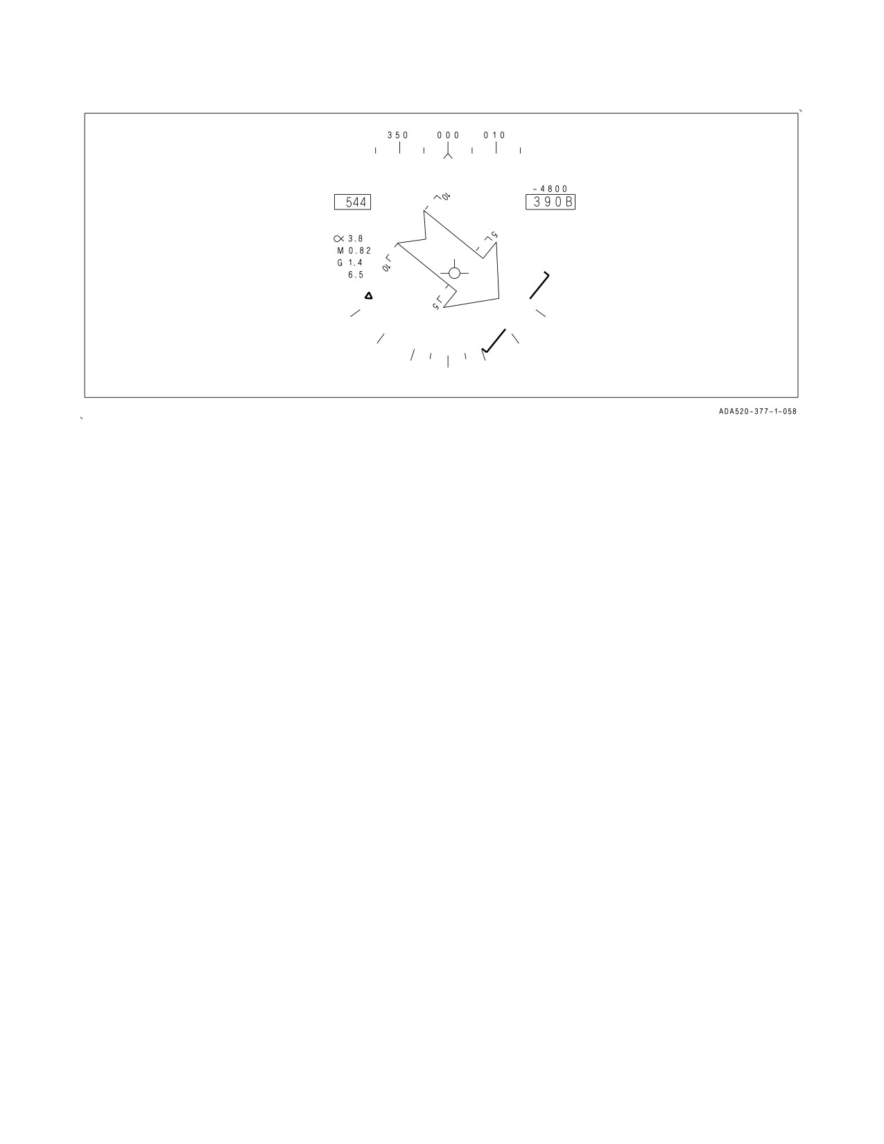
A1-F18AC-NFM-000
Figure 2-41. Visual Warning Cue
2.17.5.4 GPWS Aural Cues.
NOTE
In aircraft with MC OFP
13C AND UP, MC1
does an ACI
configuration check after the generator comes online during a cold
start power-up. Successful completion of the check is indicated by
system initiation of a ″ROLL OUT″ (for OFP 13C) or ″ROLL LEFT″
(for 15C) voice alert. If no voice alert is heard, GPWS is disabled and
the GPWS option on the MENU/HSI/DATA/AC sublevel display will
not be present. If an incorrect voice alert is heard on startup or the
GPWS option is not present, notify maintenance and commence
troubleshooting the GPWS, ACI, and CSC system components and
wiring.
Along with the visual warning cue the system issues directive voice commands as follows:
If F/A-18A/B aircraft before AFC 253 or 292 -
The aural cue ‘‘RECOVER
RECOVER’’ is used for all GPWS CFIT conditions. It has priority over
all other cues and is twice as loud as the existing cues.
If F/A-18A aircraft after AFC 253 or 292 or F/A-18C/D aircraft -
‘‘POWER
POWER’’ if the airspeed is less than 210 knots.
‘‘PULL UP
PULL UP’’ if the airspeed is greater than or equal to 210 knots.
‘‘CHECK GEAR
CHECK GEAR’’ when descending below 150 feet AGL (less than 200 knots) if the
gear is not down and locked and more than 60 seconds since a weight-on-wheels or a waveoff.
With MC OFP 11C and 13C - ‘‘ROLL OUT
ROLL OUT’’ if the (AOB) angle of bank is greater than
45°.
With MC OFP 15C AND UP - ‘‘ROLL LEFT
ROLL LEFT’’ or ‘‘ROLL RIGHT
ROLL RIGHT’’
if the (AOB) angle of bank is greater than 45°.
I-2-153
ORIGINAL
A1-F18AC-NFM-000
The voice commands are repeated every 2 seconds (every 8 sec for check gear warnings) and in the
C/D will automatically transition to the appropriate voice command for the current stage of recovery
(e.g. ‘‘ROLL OUT
ROLL OUT’’ followed by ‘‘PULL UP
PULL UP’’ when AOB is returned to less
than 45°). The voice commands are terminated when the appropriate recovery maneuver is initiated
(e.g., a pull up initiated within 0.5g of the GPWS calculated target g).
• Complying with the directive voice command but delaying other
required actions may result in an unrecoverable situation (e.g., adding
power but delaying an aft stick pull following the voice command
‘‘POWER
POWER’’).
• GPWS voice warnings are inhibited during RADALT warnings or
during system voice alerts.
2.18 OXYGEN SYSTEM
2.18.1 Normal Oxygen Supply (LOT 4-12). Normal oxygen is supplied by a 10 liter liquid oxygen
system. Oxygen is routed through a hose from the left console to the ejection seat then through the
survival kit to the pilot’s oxygen regulator connector.
2.18.1.1 OXYGEN Supply Lever. A two-position ON/OFF OXYGEN supply lever is on the pilot’s
service panel at the aft end of the left console.
If OXYGEN supply lever is ON and the mask is not properly donned, the
flow control valve could freeze in the open position and cryogenic burns
could result.
2.18.1.2 Oxygen Quantity Gage. An oxygen quantity gage is on the pilot’s service panel. It is
calibrated in liters from 0 to 10.
2.18.1.3 Oxygen Test Button. Pressing and holding the oxygen test button causes the pointer on the
oxygen gage to rotate counterclockwise.
2.18.1.4 OXY LOW Display. An OXY LOW caution comes on when the oxygen quantity indication
is below 1 liter. It also comes on when the oxygen test button is pressed and the pointer on the oxygen
gage drops below 1 liter.
2.18.2 Emergency Oxygen Supply (LOT 4-12). A 10-minute supply of gaseous oxygen is contained
in a bottle in the survival kit and is teed into the normal oxygen supply hose as it passes through the
kit. A pressure gage is visible through a hole in the left front corner of the survival kit cushion. The
emergency oxygen supply is activated automatically upon ejection. The emergency oxygen supply may
be activated manually by pulling the emergency oxygen green ring under the inside of the left thigh.
I-2-154
ORIGINAL
A1-F18AC-NFM-000
Under less than optimum conditions (low altitude, heavy breathing,
loose−fitting mask, etc.), as few as 1.5 minutes of emergency oxygen may
be available.
NOTE
If normal oxygen system is contaminated, pull the emergency oxygen
green ring, then set the OXYGEN switch to OFF.
2.18.3 On-Board Oxygen Generating System (OBOGS) (LOT 13 AND UP). OBOGS provides oxygen
rich breathing gas to the aircrew while either engine is operating. Engine bleed air is cooled and routed
through the OBOGS inlet air shutoff valve to the OBOGS concentrator. The breathing gas is routed
from the concentrator to a cockpit plenum, where the temperature is stabilized and a limited supply
is stored for peak flow demands. From the plenum, the breathing gas flows through the pilot services
panel oxygen disconnect, through the seat survival kit, to the aircrew regulators and masks.
A leak or break in the breathing gas system anywhere from the pilot
services panel oxygen disconnect to the mask will prevent either normal
OBOGS breathing gas or emergency oxygen from being delivered to the
mask in its intended concentration. Leaks and breaks may be difficult to
locate and/or verify. If hypoxic symptoms are experienced or an OBOGS
system degrade occurs, immediate descent below
10,000
feet cabin
altitude is required to prevent severe or incapacitating hypoxia.
The OBOGS concentrator is powered by the left 115 volt ac bus. Two molecular sieve beds in the
OBOGS concentrator remove most of the nitrogen from the engine bleed air. The nitrogen is dumped
overboard while the remaining output of oxygen rich breathing gas is supplied to the aircrew.
2.18.3.1 OBOGS Monitor. The CRU-99/A solid state oxygen monitor is located on the left side of
the seat bulkhead in the front cockpit and is powered by the Left 28 volt dc bus. The monitor
continuously measures oxygen concentration in the OBOGS breathing gas and provides a discrete
signal to activate the OBOGS DEGD caution if the oxygen concentration falls below a predetermined
level.
Loss of electrical power to the OBOGS monitor prevents reporting of
OBOGS DEGD conditions.
The monitor performs a power-up BIT during a 2 minute warm-up period and conducts a periodic
BIT every 60 seconds. No indication is provided if power-up or periodic BIT pass.
I-2-155
ORIGINAL
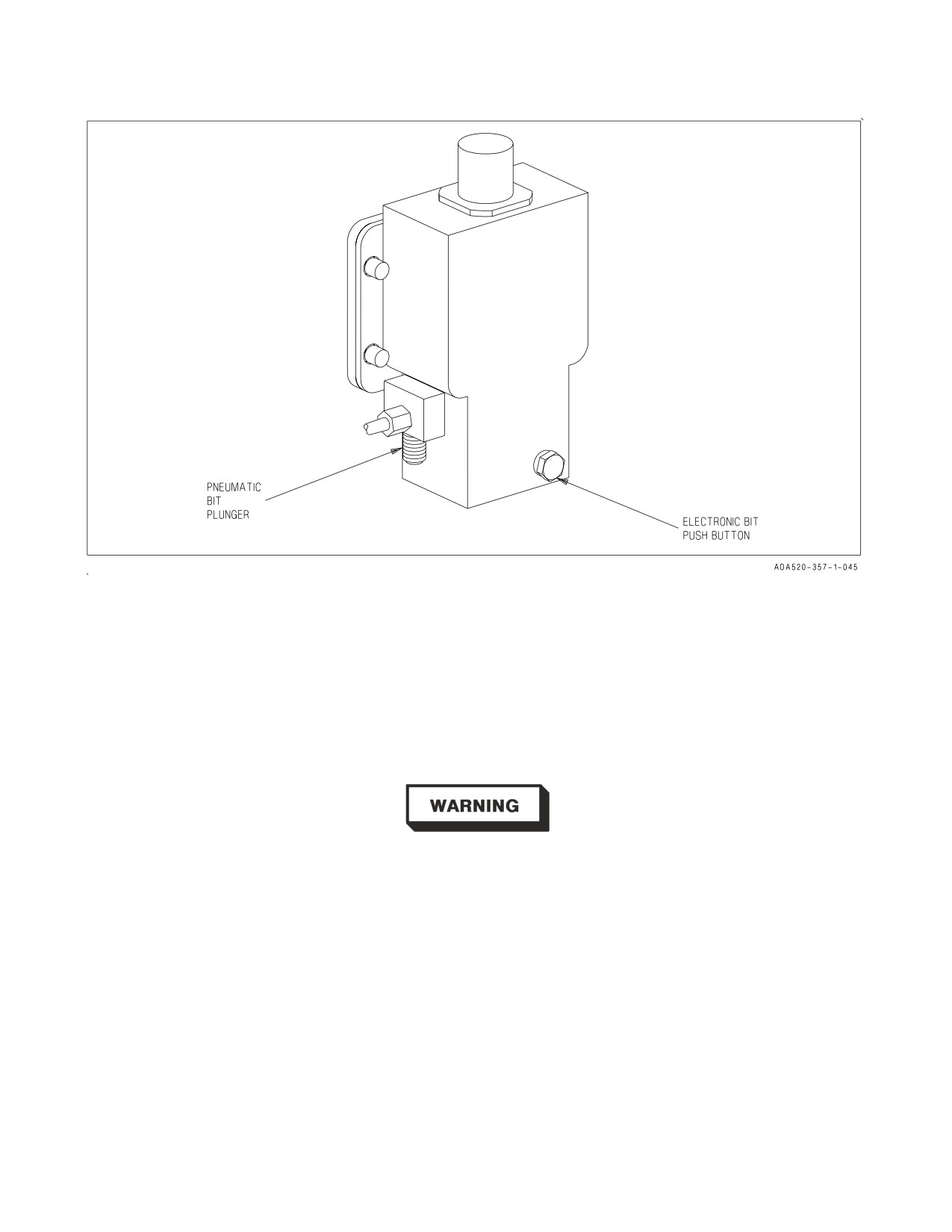
A1-F18AC-NFM-000
Figure 2-42. OBOGS Monitor
Preflight BIT of the monitor is accomplished by using either the pneumatic BIT plunger or the
electronic BIT pushbutton. Refer to figure 2-42. Pressing up and holding the pneumatic BIT plunger
for 15 to 65 seconds tests the operation of the OBOGS monitor by diverting cabin air into the monitor
to create a low oxygen concentration condition. Momentarily pressing and releasing the electronic BIT
pushbutton tests the monitor electronically. Successful completion of either test activates the OBOGS
DEGD caution, which clears automatically after BIT is complete and OBOGS resets to normal
operation.
Successful OBOGS monitor BIT is required prior to flight. A BIT failure
indicates that there is no protection against inadequate oxygen concen-
tration or hypoxia due to a degraded OBOGS monitor. Good breathing
gas flow alone does not ensure adequate oxygen concentration.
I-2-156
ORIGINAL
A1-F18AC-NFM-000
2.18.3.1.1 OBOGS DEGD Caution. An OBOGS DEGD caution is set by the OBOGS monitor when
oxygen concentration is below a predetermined level. The OBOGS DEGD caution threshold is always
above cabin air conditions, in order to provide a physiological safety margin.
NOTE
Oxygen concentration may drop below the predetermined OBOGS
DEGD level if breathing gas flow is unlimited. Removing the mask
without placing the OXY flow knob to OFF, system leaks, and/or loose
aircrew hose connections can overwhelm system capacity and may
result in an OBOGS DEGD caution.
After a total loss of bleed air, OBOGS breathing gas flow will be available until the residual gas
within the system is depleted. The residual oxygen concentration may be sufficient to keep the OBOGS
DEGD caution from illuminating, but loss of system pressure will ultimately lead to inadequate
pressure and an abrupt inability to breathe.
Low mask flow or increased breathing resistance may occur without an accompanying OBOGS
DEGD caution, which indicates a potential system degradation that may result in oxygen levels below
physiological requirements.
When cabin altitude is above 10,000
feet, OBOGS DEGD caution
procedures shall be executed for low mask flow, increased breathing
resistance, or OBOGS DEGD cautions of any duration.
A single brief appearance of the OBOGS DEGD caution immediately following placing the OBOGS
control switch to ON, turning the OXY FLOW knob to ON, or after donning or removing the mask is
normal. Certain malfunctions affecting the OBOGS system also may momentarily OBOGS DEGD
cautions. A momentary OBOGS DEGD caution may clear from the DDI so rapidly that the aircrew
may be unable to determine the cause of the MASTER CAUTION light/tone.
Repeated unexplained MASTER CAUTION lights/tones may be an
indication of OBOGS system degradation.
Even with the OBOGS DEGD caution displayed, OBOGS breathing gas under normal flow is of
higher quality (i.e., oxygen concentration, partial pressure and purity) than cabin air. Once cabin
altitude is below 10,000 feet, aircrew may elect to conserve emergency oxygen by resetting the
I-2-157
ORIGINAL
A1-F18AC-NFM-000
emergency oxygen release tab, then either removing the mask and breathing cabin air, or returning the
OXY FLOW knob and the OBOGS control switch to ON and breathing through the mask.
Pure oxygen accelerates recovery from hypoxia. Emergency oxygen shall
be used whenever hypoxic symptoms are recognized.
2.18.3.2 Breathing Regulator. The aircrew torso mounted breathing regulator reduces both normal
and emergency oxygen system operating pressures to breathing pressure levels. The regulator delivers
undiluted OBOGS breathing gas or emergency oxygen to the aircrew at positive pressure, the limits of
which increase automatically with altitude. It interfaces with the hose assembly, which connects with
the seat survival kit oxygen disconnect.
2.18.3.3 OBOGS Control Switch. The OBOGS control switch, located on the left console in the front
cockpit, is used to control electrical power to the OBOGS concentrator and the OBOGS inlet air shutoff
valve.
ON Supplies electrical power and engine bleed air to the OBOGS concentrator.
OFF OBOGS system off.
2.18.3.4 OXY FLOW Knob. The OXY FLOW knob, located on the left console in both cockpits, is
used to control the supply of OBOGS breathing gas to each aircrew’s mask.
ON OBOGS flow supplied to the mask.
OFF OBOGS flow secured.
It is possible to place the OXY FLOW knob in an intermediate posi-
tion between the ON and OFF detents, which may result in a reduced
flow of breathing gas. The OXY FLOW knob should always be fully
rotated to the ON or OFF detent position.
2.18.4 Emergency Oxygen (LOT 13 AND UP). Emergency gaseous oxygen is contained in a bottle in
the seat survival kit. The bottle is connected into the OBOGS supply hose as it passes through the kit.
From this point, the emergency oxygen and OBOGS breathing gas share a common path to the aircrew
mask.
I-2-158
ORIGINAL
A1-F18AC-NFM-000
A leak or break in the breathing gas system anywhere from the pilot
services panel oxygen disconnect to the mask will prevent either normal
OBOGS breathing gas or emergency oxygen from being delivered to the
mask in its intended concentration. Leaks and breaks may be difficult to
locate and/or verify. If hypoxic symptoms are experienced or an OBOGS
system degrade occurs, immediate descent below
10,000
feet cabin
altitude is required to prevent severe or incapacitating hypoxia.
A pressure gauge is visible on the inside left front of the survival kit. The bottle provides
approximately 10−20 minutes of oxygen. Oxygen duration decreases with lower altitude.
Under less than optimum conditions (low altitude, heavy breathing,
loose−fitting mask, etc.), as few as 3 minutes of emergency oxygen may be
available.
The emergency oxygen supply is activated automatically upon ejection. The emergency oxygen
supply may be activated manually by pulling the emergency oxygen green ring on the outside of the left
thigh. The emergency oxygen supply may be deactivated at aircrew discretion by pushing down on the
release tab immediately forward of the green ring.
With emergency oxygen selected, the OXY FLOW knob(s) shall be
placed to OFF. If not secured, OBOGS system pressure may prevent
emergency oxygen from reaching the breathing regulator. Additionally,
the OBOGS control switch should be placed to OFF to backup the OXY
FLOW knob.
2.19 AIR DATA COMPUTER (ADC)
The air data computer is a solid state digital computer which receives inputs from the angle-of-
attack probes, total temperature probe, pitot static system, standby altimeter barometric setting, air
refueling probe position, magnetic azimuth system, mission computer, and landing gear handle
position. Accurate air data and magnetic heading are computed. Computed data is supplied to the
mission computer system, altitude reporting function of the IFF, engine controls, environmental
control system, landing gear warning, and the fuel pressurization and vent system.
2.19.1 Angle-Of-Attack Probes. The left and right angle of attack probes are the airstream direction
sensing units. Case heaters are on whenever electric power is on the aircraft. Probe heaters are on when
airborne. The approach and indexer lights operate from signals from the airstream detection sensing
units. The AOA probe outputs go only to the ADC and each FCC. The outputs are electrically
independent, not mechanically independent. The probes can be damaged in such a way that they freeze
in position and continue to send signals to the ADC and FCCs. See HUD Symbology Degrades.
I-2-159
ORIGINAL
A1-F18AC-NFM-000
2.19.2 Total Temperature Probe. The total temperature probe is mounted on the lower left fuselage
aft of the nosewheel. The probe heater is on when airborne. The air data computer uses total
temperature to calculate ambient temperature.
2.20 STATUS MONITORING SUBSYSTEM
The status monitoring subsystem, figure 2-43, provides the pilot with simple displays of system
status. Most information is derived from BIT mechanizations within the avionic sets and from
nonavionic built-in tests (NABIT) implemented in the computer software for other aircraft sub-
systems.
The subsystem monitors engines and airframe operational status for unit failures and caution/
advisory conditions when the mission computer system is operating. When the mission computer
system detects a caution/advisory condition, it commands display of the applicable caution or advisory
message on one of the cockpit DDIs. If the mission computer system detects a unit failure, it commands
the subsystem to store the applicable maintenance code. Stored maintenance codes can be reviewed on
the aircraft maintenance indicator in the nose wheelwell, on the DDI MAINT BIT display in
F/A-18A/B aircraft, and on the IFEI in F/A-18C/D aircraft. The mission computer (MC) displays the
subsystem BIT results on one of the cockpit DDIs.
Non-BIT equipment status include DDI configuration display ID numbers and INS terminal data.
2.20.1 Flight Incident Recorder and Aircraft Monitoring Set
(FIRAMS) (F/A-18C/D). The
FIRAMS consists of a signal data computer, a data storage set, an integrated fuel/engine indicator and
a maintenance status panel. It functionally replaces the AN/ASM-612 Signal Data Recording Set
(SDRS), the AN/ACU-12/A engine performance indicator, and the fuel quantity indicators and fuel
intermediate device. The FIRAMS monitors selected engine, airframe, avionic, nonavionic, fuel
gauging and consumable signals. It also performs conversions of sensed measurands, provides real time
clock function, outputs discrete and analog data to associated equipment, communicates with the
mission computer, displays maintenance and status codes, and displays fuel quantities and engine
parameters, including fuel system health monitoring. FIRAMS also provides nonvolatile storage for
flight incident, maintenance, tactical and fatigue data.
2.20.2 Deployable Flight Incident Recorder Set (DFIRS) (Aircraft 164627 AND UP). The DFIRS
system consists of the Deployable Flight Incident Recorder Unit (DFIRU), the data transfer interface
unit, and the pyrotechnic release system. The SDR consists of the flight incident recorder memory,
beacon, battery, and antenna, all contained in an deployable aerodynamic airfoil located on the top on
the fuselage between the rudders. DFIRS stores up to 30 minutes of flight incident data and deploys
this data along with a rescue beacon, via the airfoil, when activated. The SDR is deployed upon pilot
ejection or ground/water impact. The data stored on the flight incident recorder (FIR) is gathered by
the mission computer from existing systems on the aircraft. DFIRS records flight data, cautions,
advisories, and spin data. The FIR memory wraps around to the beginning when the end of memory
is reached. Only the last 30 minutes of each flight is retained. The MC controls the rate and the type
of data that is stored. DFIRS data recording starts when both throttles are advanced past 90° power
lever angle (PLA), when ground speed exceeds 50 knots, or when W off W and airspeed is over 80 knots.
DFIRS recording stops 1 minute after WOW, both throttles are less than 90° PLA, and the ground
speed is less than 50 knots. All data during SPINs and MECH ON cautions are automatically recorded.
A DFIRS DWNLD option is available on the engine display. Selecting this option downloads the
DFIRS data to the MU for easier retrieval.
I-2-160
ORIGINAL
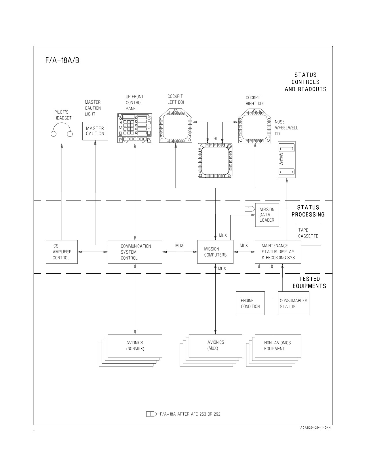
A1-F18AC-NFM-000
Figure 2-43. Status Monitoring Subsystem (Sheet 1 of 2)
I-2-161
ORIGINAL
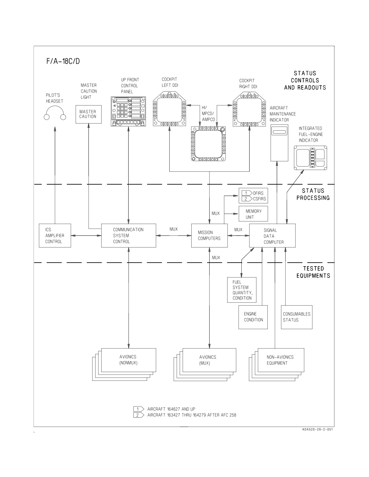
A1-F18AC-NFM-000
Figure 2-43. Status Monitoring Subsystem (Sheet 2 of 2)
I-2-162
ORIGINAL
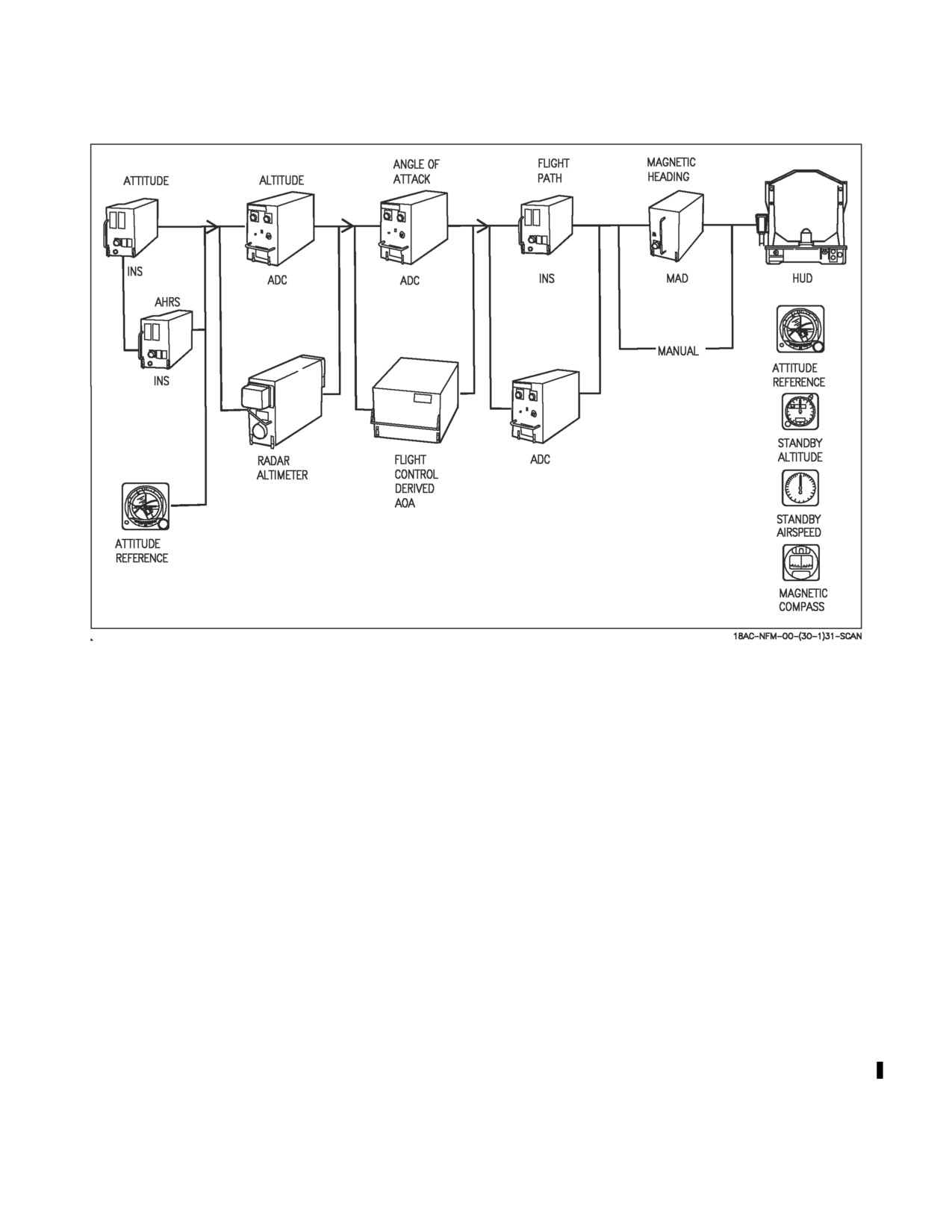
A1-F18AC-NFM-000
Figure 2-44. Flight Aids Reversion Mechanization
2.20.2.1 Crash Survivable Flight Incident Recorder System (CSFIRS) (Aircraft 163427 THRU
164279 AFTER AFC 258). The CSFIRS like the DFIRS is used to store data to aid in crash
investigation. However, the CSFIRS is not deployable. The CSFIRS is attached to the aircraft and
must be removed to retrieve crash data. CSFIRS is not installed in aircraft with DFIRS. The CSFIRS
is located in the aft bay of the R LEX. The CSFIRS software emulates the DFIRS and records the same
flight parameter data from the mission computer as the DFIRS. The CSFIRS can store up to 50 hours
of flight data which can be retrieved by removing the CSFIRS and downloading to an MLVS. The
CSFIRS also has the capability to download 30 minutes of flight data via the memory unit.
2.20.3 Avionic BIT. In most instances, two types of BIT are mechanized, periodic and initiated.
Periodic BIT begins functioning upon equipment power application. It provides a failure detection
capability that is somewhat less than that provided by initiated BIT in that it does not interfere with
normal equipment operation.
Two forms of BIT derived data are supplied to the MC. One form is validity information associated
with selected data. The second form is the equipment failure information which identifies failed
assemblies. The MC uses these two forms of BIT data to implement reversion operation and advisories
for the pilot as well as equipment status displays for both the pilot and maintenance personnel.
2.20.3.1 Reversion. When the BIT equipment determines that a function has exceeded a predeter-
mined threshold, the data derived from that function is immediately indicated as not valid. The MC,
upon receiving this indication, reverts to the next best available source which in many cases is as
I-2-163
ORIGINAL
A1-F18AC-NFM-000
accurate as the original source. This reversion is maintained as long as the data remains invalid from
the primary source.
Figure 2-44 illustrates this concept for the flight aids. For each unit in the primary path, there is at
least one alternate source of data for reversion. The pilot is provided appropriate display cuing only
when a reversion results in some loss of capability or performance. For example, if angle of attack is lost
from the ADC, the MC reverts to FCS derived angle of attack. No display change or pilot cuing is made
since the accuracy of the alternate source is equivalent to the primary source. If, however, the altitude
switch is in RDR and the radar altimeter fails, the MC removes the displayed radar altitude, replaces
it with barometric altitude, and indicates the barometric altitude display via cuing. If altitude is lost
from the ADC and the altitude switch is in the BARO, the MC removes the displayed altitude from the
HUD. These examples illustrate three forms of degraded mode advisories: (1) reversion to an alternate
data source of equivalent accuracy with no pilot cuing; (2) reversion to an alternate data source of lesser
accuracy with pilot cuing; (3) and removal of displayed data when no acceptable alternate source is
available. Refer to Part VIII for further discussion on weapon system reversions.
2.20.3.2 Equipment Status Displays. Equipment status displays (BIT, caution, and advisory)
provide the pilot with continuous status of the avionics equipment and weapons. A cue to check
equipment BIT status is the appearance of the BIT advisory display on either DDI or the
HI/MPCD/AMPCD. The display is normally on the left DDI. A MENU selectable top level BIT format
displays the status of failed, NOT RDY, or OFF systems of all avionics equipment which interface with
the MC. When the BIT control display is selected on another display, the BIT advisory is removed
until another BIT failure occurs.
Weapon and stores status is primarily displayed on the stores display (selected from the menu
display). When the BIT display indicates a stores management system (SMS) failure, the affected
stations and degree of failure are identified on the stores display as described in NTRP 3-22.4-
FA18A-D and NTRP 3-22.2-FA18A-D NATIP. The BIT advisory and an SMS BIT status of DGD is
the only enunciated indication of a stuck emergency jettison button.
Messages displayed as a function of equipment status are listed in the following table.
I-2-164
ORIGINAL
A1-F18AC-NFM-000
STATUS MESSAGE
APPLICABLE SYSTEM
MESSAGE DEFINITION
NOT RDY
All systems except MC1
Equipment OFF, not installed, or
initializing.
IN TEST
All systems except MC1, MC2, and RWR
Initiated BIT in progress.
SF TEST
ALE-47, ATARS, AWW4, DMS, FLIR,
Self test in progress (cannot be
GPS, LST, LTDR, MIDS, MPCD/AMPCD,
operator terminated).
NFLR, RALT, RDR, SMS, and WPNS
GO
All systems
Initiated BIT completed without
failure.
DEGD
All systems except MC1, MC2
Failure detected; equipment op-
eration degraded.
1
NOGO
ADC, AISI, ALE-47, APX-111(V), ASPJ,
2
MUX FAIL
ATARS, AWW4, CAM, CLC, COM1, COM2,
Equipment ON but not communi-
CSC, DFIRS, D/L, DMS, FCSA, FCSB,
cating.
FLIR, GPS, HARM, INS, LDDI, LDT, LST,
LTDR, MC2, MIDS, MU, NFLR, RDR,
RDDI, SDRS, SMS, SDC, and WPNS
1
OH
ASPJ, ATARS, CAM, CSC, DFIRS, FCSA,
Overheat.
2
OVRHT
FCSB, FLIR, INS, LDT, LST, LTDR,
MIDS, NFLR, RDR, RWR, SMS, SDRS,
1
DEGD OH
ASPJ, ATARS, CAM, CSC, DFIRS, FCSA,
Detected failure and overheat.
2
DEGD+OVRHT
FCSB, FLIR, INS, LST, LDT, LTDR,
MIDS, NFLR, RDR, RWR, and SMS
RESTRT
All systems except MC1, MC2, and RWR
Reinitialize BIT; equipment did
not respond to BIT command,
remained in BIT too long and was
terminated by MC.
1
OPRNL GO
ALE-47, ATARS, DFIRS, GPS, MDL,
SMS failure detected which does
2
OP GO
MIDS, MU, NFLR, SMS, and WPNS,
not affect capability to deliver
currently loaded weapons.
2
PBIT GO
All systems except MC1, MC2, and RWR
IBIT has not been initiated and
the system periodic BIT is not
reporting any failures.
2
OFF
ATARS, BCN, CAM, COM 1, COM 2, D/L,
System not communicating with
IFF, ILS, MIDS, RALT, RDR, and TCN
AVMUX. OFF status indication.
1
MC OFP 10A AND UP
2
MC OFP 13C AND UP
No indication (blank) adjacent to the equipment legend indicates that initiated BIT has not been
run on the equipment and that the periodic BIT has not detected any faults. LDDI, RDDI,
HI/MPCD/AMPCD, and IFEI have unique degraded messages of DEGD 1, DEGD 2 and DEGD 1/2
in the F/A-18B/D to allow distinguishing BIT status failures of front seat displays (1) from rear seat
displays (2).
I-2-165
ORIGINAL
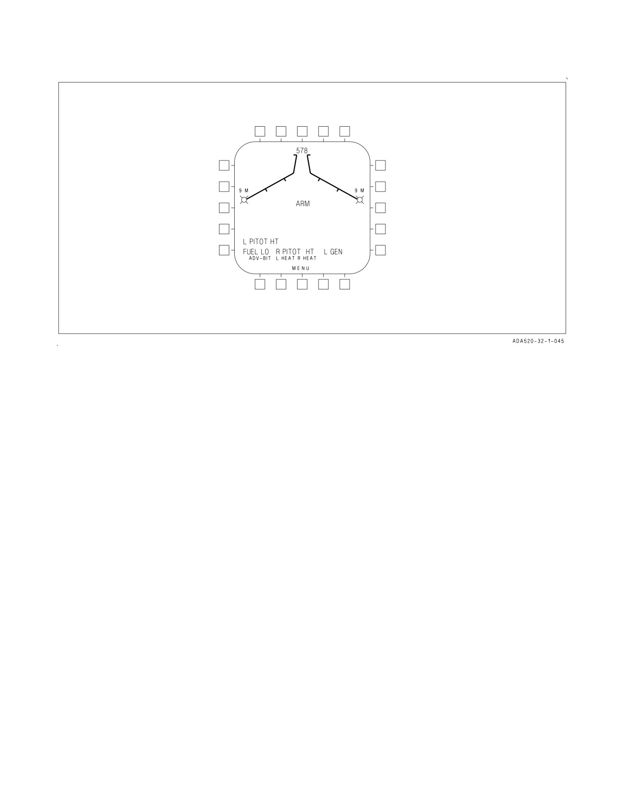
A1-F18AC-NFM-000
Figure 2-45. Caution/Advisory Indications
2.20.3.2.1 Caution/Advisory Indications. Cautions and advisories are displayed on the left DDI
except when the left DDI is used for BIT display or weapon video (figure 2-45). When the left DDI is
off or failed, or when the LDDI is used for BIT or weapon video, cautions and advisories are displayed
on the center display. If the left and center displays fail or are turned off, the right DDI displays the
cautions and advisories. With MC OFP 13C AND UP, cautions and advisories automatically move to
the center display when BIT is selected on the LDDI. Caution displays appear as 150%-size letters
compared to the normal message symbology size.
The caution displays are displayed as they occur beginning in the lower left portion of the DDI
display and sequence to the right up to three displays across. Upon occurrence of the fourth caution,
it re-indexes to the left edge above the first caution which appeared. With MC OFP 10A AND UP, this
process can continue for up to seven lines with three caution displays in each line. If that many cautions
occur, additional cautions may not be displayed until an open space is available on the right side of the
top line. The oldest non-priority caution(s) is removed and the remaining cautions are moved left and
down to display priority cautions such as: AIL ON, CAUT DEGD, DEL ON, FLAPS OFF, FLAPS
SCHED, INS ATT, L(R)AMAD, L(R)AMAD PR, MECH ON or RUD OFF caution(s). If all 21
displayed cautions are priority cautions, no further cautions can be displayed without a priority
caution being first removed. With MC OFP 13C AND UP, a dedicated caution display automatically
replaces the HSI display if the number of cautions exceed three lines. The cautions are in the lower
portion of the display with an aircraft symbol as a point of reference for the underlying map.
Advisory displays appear as 120%-size letters on a single line beneath the caution displays. The
advisories are preceded by an ADV legend and the individual advisories are separated by commas. A
caution or advisory is removed when the condition ceases. If there is a caution or advisory displayed to
the right of the removed caution or advisory, the display remains blank. Pressing the MASTER
CAUTION light when the light is out repositions the remaining cautions and advisories to the left and
down to fill the blank displays. When a caution occurs, the MASTER CAUTION light on the main
instrument panel illuminates and the MASTER CAUTION tone or a voice alert is heard in the
I-2-166
ORIGINAL
A1-F18AC-NFM-000
headset. The MASTER CAUTION light is extinguished by pressing the light. Refer to Warning/
Caution/Advisory Displays in chapter 12 for the display implications and corrective action procedures.
2.20.3.3 BIT Initiation
(F/A-18A/B BEFORE AFC 253 OR 292). In addition to displaying
equipment BIT status, the BIT control display (figure 2-46) is used to command initiated BIT. Those
avionic sets identified by the legends on the display periphery have an initiated BIT capability. The
pilot commands initiated BIT by pressing the adjacent button. The status messages are displayed as
required as each equipment set enters, performs, and completes its BIT routine. BIT may be initiated
one at a time or in any combination. In the case of the INS and FCS, additional switchology is required.
Selection of AUTO BIT causes a simultaneous BIT of all equipment except those tested by the
DSPL/EPI (IFEI)/UFC button. Performance of BIT assumes the required electrical and hydraulic
power is applied to the equipment tested. Some systems require additional pilot BIT input.
2.20.3.4 BIT Initiation (F/A-18A AFTER AFC 253 OR 292 AND F/A-18C/D). In addition to
displaying equipment BIT status, the BIT top level and eight sublevel displays (figure 2-46) are used
to command initiated BIT. Those avionic set groups identified by the legends on the top level display
periphery have an initiated BIT capability. BIT may be initiated for all operating units simultaneously
except for some BITs that cannot be performed inflight. Figure 2-46 shows which initiated BITs are
not allowed inflight. Additional steps are required to test the INS and FCS. BIT for individual units
within groups may be initiated through the BIT sublevel displays.
Pressing BIT returns to the BIT top level display. Pressing STOP or MENU when BIT is in progress
terminates initiated BIT. Performance of BIT assumes required electrical and hydraulic power is
applied to the equipment tested.
I-2-167
ORIGINAL
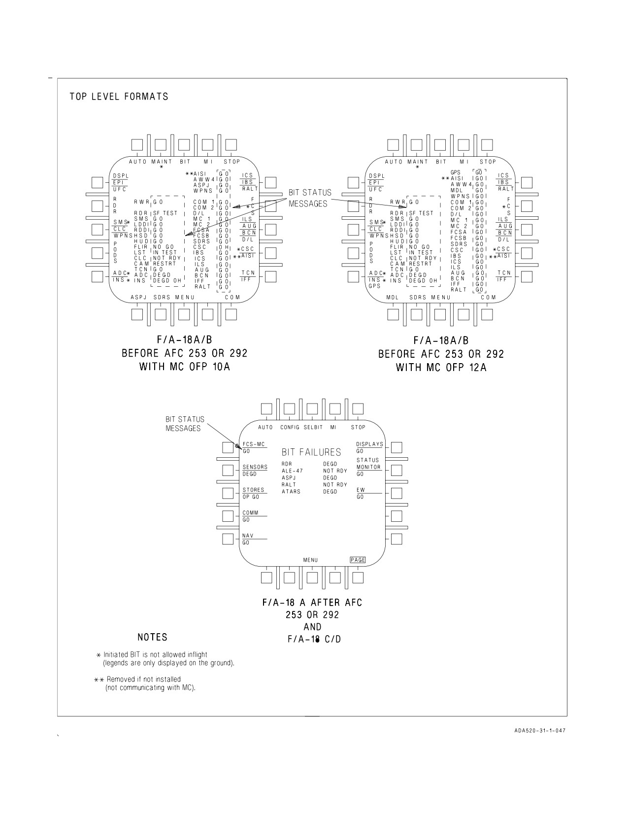
A1-F18AC-NFM-000
Figure 2-46. BIT Control Display (Sheet 1 of 3)
I-2-168
ORIGINAL
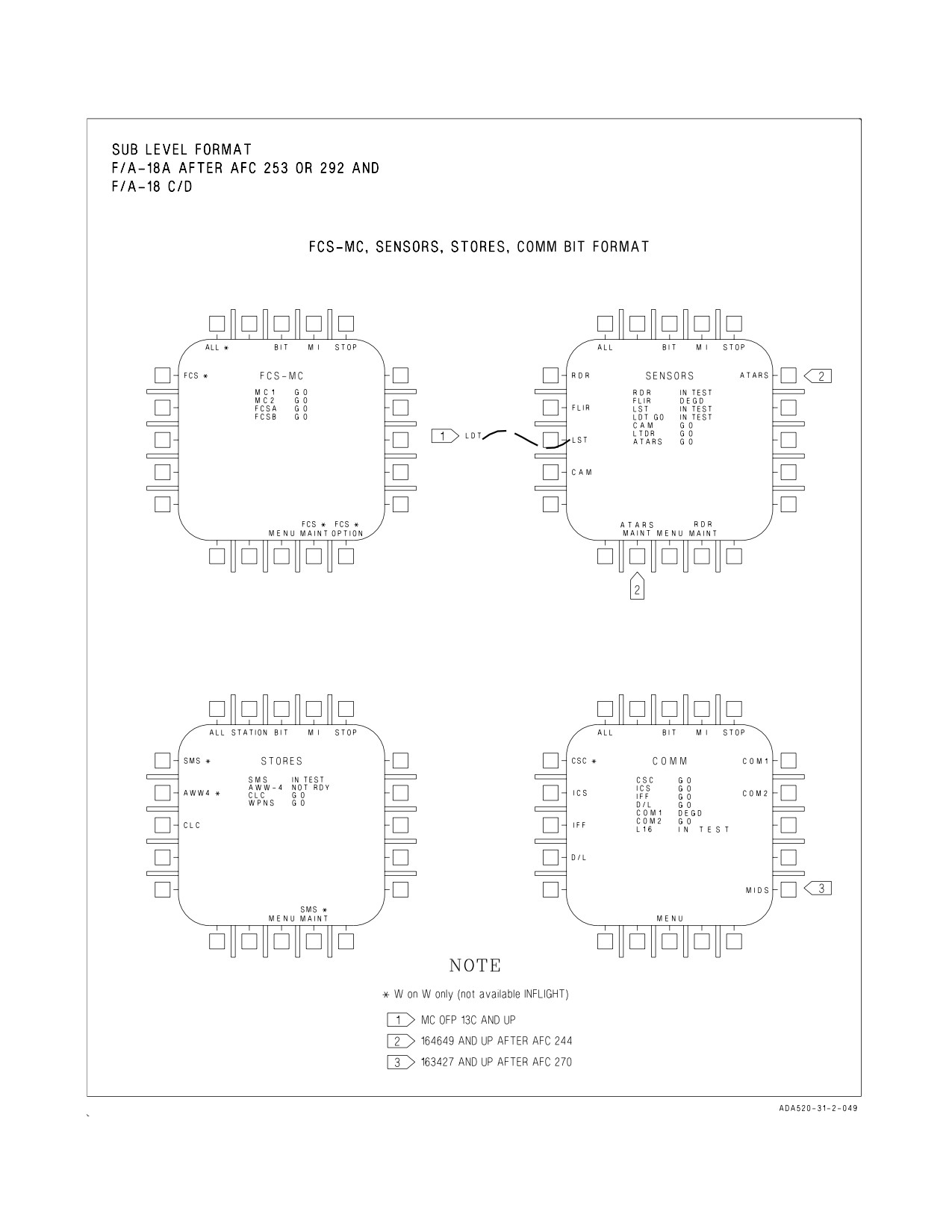
A1-F18AC-NFM-000
Figure 2-46. BIT Control Display (Sheet 2 of 3)
I-2-169
ORIGINAL
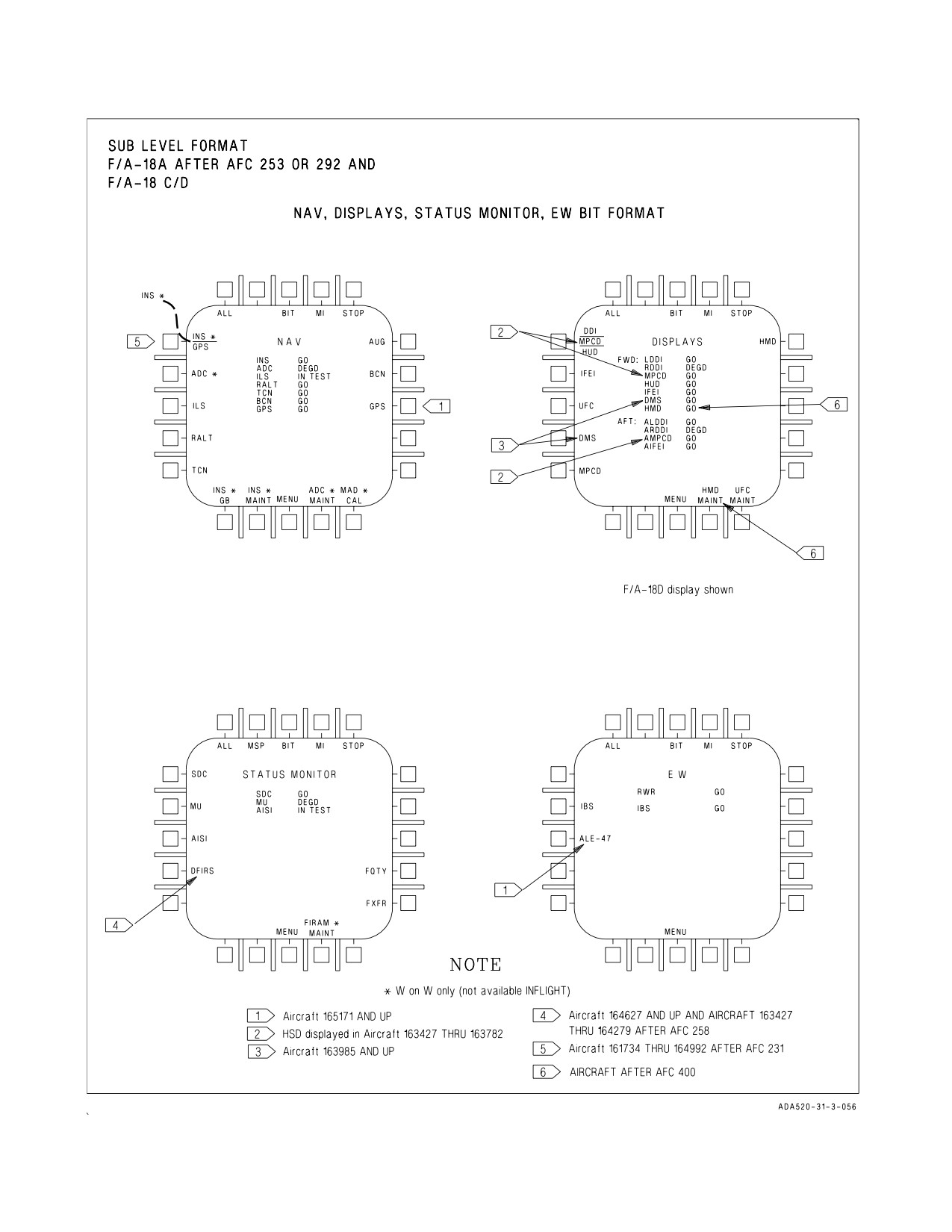
A1-F18AC-NFM-000
Figure 2-46. BIT Control Display (Sheet 3 of 3)
I-2-170
ORIGINAL
A1-F18AC-NFM-000
2.20.3.4.1 All Equipment. Simultaneous initiated BIT of all equipment installed is performed by
selecting AUTO on the BIT top level display. Equipment group, acronym and status are displayed at
the display pushbuttons. Equipment group status indicates the lowest operating status reported by any
unit in the tested group. Individual system status results other than GO, PBIT GO, IN TEST, SF
TEST, and OP GO are displayed with a system acronym in the center of the display. If the equipment
list is too long to be displayed on one page, a PAGE pushbutton is displayed. Pressing PAGE displays
the remainder of the list that is on page 2. Pressing PAGE when page 2 is displayed returns page 1.
2.20.3.4.2 Equipment Groups. Initiated BIT of entire equipment groups is performed by selecting
SELBIT (SELBIT option becomes boxed) on the BIT top level display and the desired equipment
group pushbutton. One or more groups can be selected. Another way to select a group is to press the
group pushbutton (with the SELBIT option not boxed) on the BIT top level display and then ALL on
the group sublevel display. See figure 2-46.
2.20.3.4.3 Individual Units. Initiated BIT of an individual unit is performed by pressing the
equipment group pushbutton on the BIT top level display which contains the desired unit. The display
changes to a group sublevel display. Individual units from the group can then be tested by pressing the
pushbutton adjacent to the desired acronym. System status for all systems in the group is displayed on
the center of the display. Some systems require additional pilot BIT input.
2.20.3.5 System BIT Steps. The following includes certain initiated BIT which require steps in
addition to pressing one of the buttons on the BIT display and reading the BIT status messages after
the test is complete. Figure 2-47 shows which initiated BITs are not allowed inflight.
2.20.3.5.1 FCS Initiated BIT. For the FCS, the FCS BIT consent switch, on the right essential circuit
breaker panel, must be held ON when initiated BIT is started. This prevents inadvertent initiation of
BIT on the FCS for reasons of flight safety.
Control surfaces move during initiated BIT with hydraulic power
applied. To prevent personnel injury or equipment damage, be sure
personnel and equipment are kept clear of control surfaces.
NOTE
• For initiated BIT to start, FCS BIT consent switch must be held for at
least 2 seconds. If not held for the required time, RESTRT is displayed
as the BIT display status message. If RESTRT displayed, repeat
procedure.
• Initiated FCS BIT cannot be performed if nosewheel steering is
engaged.
• For valid BIT reporting, do not operate switches or controls unless
indicated. Do not rest feet on rudder pedals or hands on control stick.
1. If wings folded, check both ailerons Xd out.
I-2-171
ORIGINAL
A1-F18AC-NFM-000
With MC OFP 10A AND UP -
2. Select MENU/BIT on right DDI.
3. While simultaneously holding FCS BIT consent switch to ON, select the FCS pushbutton on the
BIT display.
With MC OFP 13C AND UP -
2. Select SUPT MENU/BIT/FCS-MC on right DDI.
3. While simultaneously holding FCS BIT consent switch to ON, select the FCS pushbutton on the
FCS-MC sublevel display.
All aircraft -
4. Release FCS button and FCS BIT consent switch when FCSA and FCSB BIT display status
messages indicate IN TEST. At successful completion of initiated BIT, FCSA and FCSB BIT
display status messages read GO. FCS initiated BIT requires less than 2 minutes.
2.20.3.5.2 Preflight FCS initiated BIT. The F/A-18 fly-by-wire flight control system uses redundant
hardware to provide continued safe operation after component failures. The level of redundancy
designed into the system was set by component failure rates, failure mode effects, aircraft mission time,
and survivability considerations. The ability to provide safe operation is fundamentally based on the
principle that there are no undetected (i.e. latent) failures prior to flight which would compromise
system redundancy. It is not possible to have an in-flight Periodic BIT (PBIT) which can detect all
degradations in a fly-by-wire system. Many redundant pathways can only be tested by setting system
conditions that would be unsafe to establish in flight (e.g. verification of the ability to shut off an
actuator). Preflight FCS initiated BIT was designed to provide those tests and thereby ensure the full
redundancy of the flight control system is really available prior to flight. Without running Preflight
FCS initiated BIT and performing the necessary maintenance, latent failures present in the system can
result in unsafe conditions should additional failures occur in flight.
2.20.3.5.3 Preflight FCS initiated BIT Operation. Preflight initiated BIT consists of a series of tests
which verify the integrity of the flight control system processors, actuators, sensors, and cockpit
interfaces. Preflight FCS initiated BIT begins by testing lower level functions first. If preflight FCS
initiated BIT detects a fault at this level which affects higher level functions, it halts and reports the
fault(s). If preflight FCS initiated BIT did not halt at this point, false BIT Logic INspect (BLIN) codes
would be generated on higher level functions which depend upon the failed lower level function for
their operation. If preflight FCS initiated BIT detects a fault in a subsystem (e.g. left stabilator),
testing of the failed subsystem is discontinued, and testing of unrelated subsystems (e.g., rudders,
trailing edge flaps, etc.) continues.
Since testing is not complete, preflight FCS initiated BIT must be run
again after maintenance actions to complete all tests.
I-2-172
ORIGINAL
A1-F18AC-NFM-000
Flight with a BLIN code could result in a flight control system failure and
aircraft loss. Pressing the FCS reset button simultaneously with the
paddle switch does not correct BIT detected flight control system
failures, it simply clears the BLIN code from the display. IBIT must be
re-run after clearing BLIN codes to ensure the detected failures no longer
exist. If BLIN codes remain following IBIT, the aircraft requires main-
tenance to identify and correct failures in the flight control system.
2.20.3.5.4 Preflight FCS initiated BIT PASS/FAIL. A successful Preflight FCS initiated BIT results
in a GO indication on the DDI. An unsuccessful Preflight initiated BIT indicates a system degradation.
There may not be an X on the DDI FCS status page (MENU-FCS) since the degradation may be in a
backup path which is not active until after a primary system failure. Launching in a degraded state
(i.e., with BLIN codes ) places the aircraft in a situation where a portion of the flight control system
is operating without the normal redundancy.
2.20.3.5.5 Repetition of Preflight FCS initiated BIT. If an aircraft fails preflight FCS initiated BIT
(i.e. BLIN codes present after preflight FCS initiated BIT) maintenance should be called to
troubleshoot the system. After completing troubleshooting, a successful preflight FCS initiated BIT is
necessary to ensure the system is fully operational. Except for cold weather operation, preflight FCS
initiated BIT failure is indicative of a component degradation, i.e. hydraulic or electrical components
are out of tolerance, or a cable conductor is intermittent (broken wire, loose connector pin, etc.)
2.20.3.5.6 Cold Weather and FCS Exerciser Mode. In cold weather, actuator components will not
respond normally until hydraulic fluid temperature increases. Exerciser mode should be used to
expedite monitors and system warm-up. During exerciser mode, a number of PBIT actuator monitors
are ignored to prevent generation of nuisance BLIN codes. Thus in cold weather it is appropriate to
re-attempt preflight BIT after running exerciser mode. Exerciser mode should not be used as a method
to clear BLIN codes in normal start-up temperature conditions. BLINS cleared in this manner could
be associated with hydraulic contamination or sticking control valves which could appear again in
flight with catastrophic results.
Running exerciser mode in normal and hot weather environments may
lead to hydraulic system overheat.
2.20.3.5.7 Running Preflight FCS Initiated BIT After Flight. A good (no codes) preflight BIT on the
previous flight is no assurance against latent failures on the next flight. Electronic components have a
propensity to fail on power application. Damage can occur during deck handling or maintenance activity
not even associated with the flight controls. The only insurance is to run preflight BIT prior to flight.
2.20.3.6 SMS Initiated BIT. Safeguards have been built into the weapon system mechanization to
allow SMS initiated BIT to be performed on the ground with weapons loaded and cartridges installed.
During initiated BIT, weapon release signals and associated circuitry are not exercised unless all of the
following interlocks are satisfied simultaneously: master arm switch to ARM, armament safety override
in override, weapon load codes on stores processor set to zero, and no weapon ID detected on any
weapon station. SMS initiated BIT should not be attempted until the above interlocks are in a safe
condition. The SMS initiated BIT should be successfully completed within 180 seconds of initiation.
I-2-173
ORIGINAL
A1-F18AC-NFM-000
2.20.3.7 INS Initiated BIT. To perform initiated BIT in ASN-130 and 139 equipped aircraft, the INS
must be in the TEST mode and a ground/carrier selection must be made to indicate where the BIT is
being accomplished. When the ADC/INS (or AUTO) button (MC OFP 10A AND UP) or when the
BIT/SELBIT/NAV/ALL, BIT/NAV/INS, or BIT/AUTO (with MC OFP 13C AND UP) is actuated, a
status message of GND/CV? appears next to the INS legend in the status display area (figure 2-47). At
the same time, GND and CV button labels appear along the bottom of the display. These options allow
the operator to enter where the initiated BIT is to be performed, i.e., on the ground or on a carrier.
The INS BIT test is done by completing the steps below.
1. Check parking brake set.
2. For ground initiated BIT ensure waypoint zero is local latitude/longitude.
With MC OFP 10A AND UP -
3. Select MENU/BIT/ADC/INS (or AUTO) on right DDI and TEST on INS mode switch.
With MC OFP 13C AND UP -
3. Select MENU/BIT/SELBIT/NAV or MENU/BIT/NAV/INS or MENU/BIT/AUTO or MENU/
BIT/NAV/ALL on the right DDI and TEST on the INS mode switch.
ASN-130 and 139 equipped aircraft -
4. Select INS LONG (if required) and GND or CV on DDI, and start clock. At successful completion
of test BIT display status message reads GO. Maximum time for INS initiated BIT is 12 minutes
and maximum time for INS initiated BIT and platform slew test is 45 minutes.
To perform BIT in EGI equipped aircraft, an INS/GPS pushbutton is provided on the NAV BIT
display. Selecting the INS/GPS option provides BIT options for the EGI. A CV or GND INS/GPS BIT
commands the EGI to perform a short BIT on both the INS and GPS. A short EGI BIT tests system
functionality. A long CV or GND INS/GPS BIT commands the EGI to perform a short BIT on the GPS
and a long BIT on the INS. The long BIT tests INS performance in addition to system functionality.
A long EGI BIT requires approximately 4 minutes to complete.
2.20.3.8 AUTO BIT. If the AUTO button is pressed, BIT are initiated in parallel for all equipment
turned ON and whose interlocks are satisfied. The test pattern associated with the DDI and HUD is
not displayed when the AUTO option is used. Approximately 2.5 minutes are required for all AUTO
BIT except FCS and INS.
On aircraft 161353 THRU 161528, an anomaly exists which causes a COM 1 failure indication any
time an AUTO BIT is run. No maintenance code is set in the nose wheel well DDI. Judgement should
be exercised in determining when there is an actual failure, with consideration given to irregularities
such as communication difficulties during flight.
1. Check power applied to all systems requiring BIT and check required interlocks in safe condition.
2. Select MENU/BIT/AUTO on DDI.
a. All systems read GO (see figure 2-47) after required test period. Go indication is provided when
system check is complete and OK. Other messages may be displayed if malfunctions are
detected.
I-2-174
ORIGINAL
A1-F18AC-NFM-000
3. If FCS test required, perform FCS Initiated BIT above while substituting the AUTO button for
the FCS button in the procedure.
Ensure the procedural warnings and notes are observed and that the AUTO button and FCS
BIT consent switch are held simultaneously to initiate test.
4. If INS test required, perform INS initiated BIT above while substituting the AUTO button for
the ADC/INS button in the INS Initiated BIT procedure.
2.20.3.9 Cockpit Displays Initiated BIT (MC OFP 10A AND UP). Operator participation in the
detection of failures and the isolation of faults is required for the display equipment. The DSPL/
EPI(IFEI)/UFC button calls up the MC generated test pattern on the DDI, HI/MPCD/AMPCD and
HUD immediately after the BIT routine mechanized within each indicator is concluded. The test
pattern can then be compared on the four displays for similarity, and individually for concentricity,
intensity level, and alphanumeric clarity. Pushbutton tests are accomplished by actuating the button.
A circle appears adjacent to the button when the functional test is successfully completed. In addition
to displaying the DDI, HI/MPCD/AMPCD and HUD BIT test patterns, pressing the DSPL/EPI
(IFEI)/UFC button initiates engine monitor indicator (EMI) and upfront control BIT checks. See
figure 2-48.
Pressing the DSPL/EPI (IFEI)/UFC initiates BIT on three different equipment display groups. The
following procedure can be used to test all groups simultaneously, or to test one or two of the display
groups by performing the appropriate parts of the procedure. Regardless of whether the whole or a part
of the procedure is required, the total time allowed for the test should be a minimum of 25 seconds. The
EPI (IFEI) BIT display must be allowed to complete the described cycle before the BIT stop button
is pressed. The reason for this is that when the DSPL/EPI (IFEI)/UFC BIT is initiated and the STOP
button is pressed before the EPI (IFEI) BIT runs through to completion, the second half of the UFC
BIT will be altered during the next test. If an alteration of the second half of the UFC BIT occurs, the
problem might be cleared by running another EPI (IFEI) BIT to completion. The UFC would then test
good during the next BIT check. The HI must be turned off during the UFC check or disruption of the
UFC BIT results. On 161925 AND UP, running the BIT a minimum of 25 seconds and turning the HI
off are not required.
1. Turn HI power off.
2. Select MENU/BIT/DSPL/EPI/(IFEI)/UFC on DDI (see figure 2-48).
3. Upfront control - CHECK
a. All outer segments of alphanumeric displays, all segments of numeric displays, and all option
cues illuminate for 5 seconds.
b. All inner segments of alphanumeric displays, all segments of the numeric displays, and all
option cues illuminate for the next 5 seconds.
4. Engine monitor indicator - CHECK
a. RPM - 50%
b. EGT - 555°C
c. FF - 5200 PPH
I-2-175
ORIGINAL
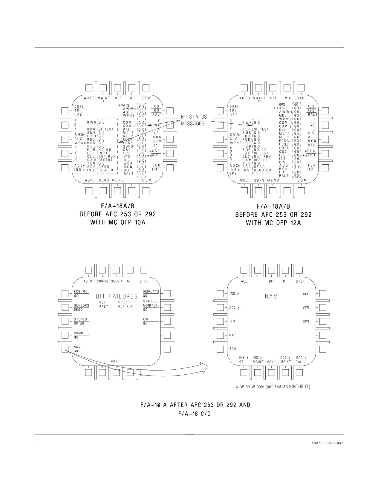
A1-F18AC-NFM-000
Figure 2-47. ADC/INS/GPS BIT - AUTO BIT Display
I-2-176
ORIGINAL
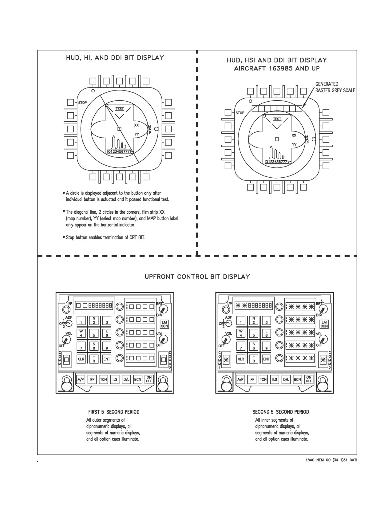
A1-F18AC-NFM-000
Figure 2-48. DSPL/EPI (IFEI)/UFC BIT Displays (Sheet 1 of 2)
I-2-177
ORIGINAL