F18. FLIGHT MANUAL (2008) - page 2
A1-F18AC-NFM-000
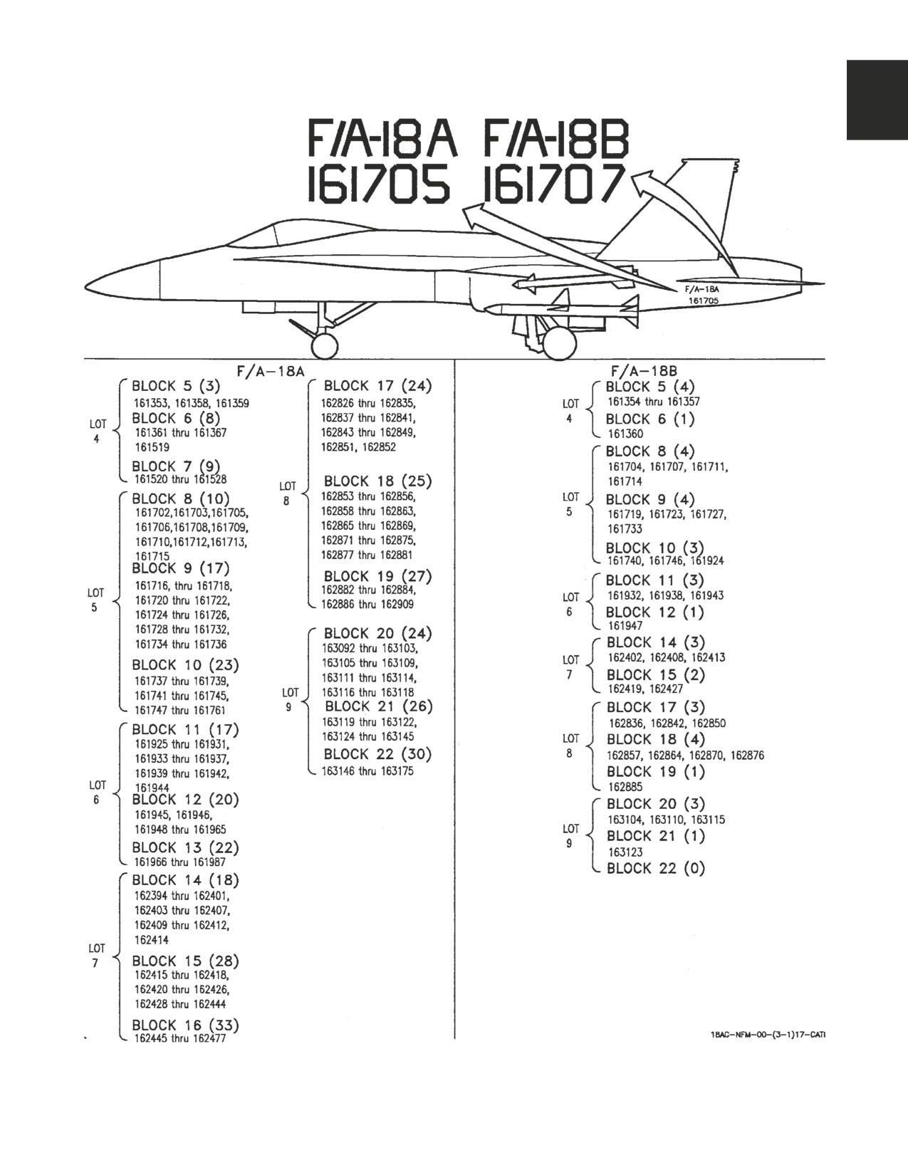
Figure 1-2. Block Numbers (Sheet 1 of 3)
I-1-3
ORIGINAL
A1-F18AC-NFM-000
F/A-18C
F/A-18D
LOT 10
LOT 13
LOT 10
LOT 14
BLOCK 23 (23)
BLOCK 32 (17)
BLOCK 23 (8)
BLOCK 35 (0)
163427 thru 163433,
164197,
163434, 163436,
BLOCK 36 (10)
163435,
164199 thru 164202,
163441, 163445,
164649 thru 164653,
163437 thru 163440,
164204 thru 164206,
163447, 163452,
164656, 164659,
163442 thru 163444,
164208 thru 164210,
163454, 163457
164662, 164665,
163446,
164212 thru 164215,
BLOCK 24 (8)
164667
163448 thru 163451,
164217, 164218
163460, 163464,
BLOCK 37 (10)
163453, 163455,
BLOCK 33 (23)
163468, 163472,
164670, 164672,
163456
164220 thru 164223,
163474, 163479,
164674, 164677,
BLOCK 24 (21)
164225 thru 164227,
163482, 163486
164679, 164683,
163458, 163459,
164229 thru 164236,
BLOCK 25 (7)
164685, 164688,
163435 thru 163463,
164234 thru 164236,
163488, 163492,
164690, 164692
163465 thru 163467,
164238 thru 164240,
163497, 163500,
LOT 15
163469 thru 163471,
164242 thru 164244,
163501, 163507,
163473,
164246 thru 164248
BLOCK 38 (4)
163510
163475 thru 163481,
164694, 164699,
BLOCK 34 (24)
LOT 11
163483 thru 163485,
164702, 164705
164250 thru 164253,
BLOCK 26 (3)
BLOCK 39 (4)
BLOCK 25 (17)
164255 thru 164258,
163700, 163707,
164711, 164714,
163487,
164260 thru 164262,
163720
164717, 164723
163489 thru 163491,
164264 thru 164266,
163493 thru 163496,
164268 thru 164271,
BLOCK 27 (2)
BLOCK 40 (4)
163498, 163499,
164273 thru 164278
163734, 163749
164726,
164729,
163502 thru 163506,
LOT 14
BLOCK 28 (3)
164735,
164738
163508, 163509
163763, 163771,
BLOCK 35 (22)
LOT 11
163778
164627 thru 164648
BLOCK 26 (25)
LOT 12
BLOCK 36 (11)
163699,
164654, 164655,
BLOCK 29 (10)
163701 thru 163706,
164657, 164658,
163986, 163989,
163708 thru 163719,
164660, 164661,
163991, 163994,
163721 thru 163726
164663, 164664,
163997, 164001,
BLOCK 27 (26)
164666, 164668,
164005, 164009,
163727 thru 163733,
164669
164011, 164014
163735 thru 163748,
BLOCK 37 (13)
BLOCK 30 (10)
163750 thru 163754
164671, 164673,
164017, 164019,
BLOCK 28 (25)
164675, 164676,
164022, 164024,
163755 thru 163762,
164678, 164680,
164026, 164028,
163762 thru 163770,
164681, 164682,
164032, 164035,
163772 thru 163777,
164684, 164686,
164038, 164040
163779 thru 163782,
164687, 164689,
BLOCK 31 (10)
LOT 12
164691
164043, 164046,
LOT 15
164049, 164051,
BLOCK 29 (20)
164053, 164056,
163985, 163987,
BLOCK 38 (12)
164058, 164061,
163988, 163990,
164693,
164064, 164068
163992, 163993,
164695 thru 164698,
163995, 163996,
164700, 164701,
LOT 13
163998 thru 164000,
164703, 164704,
BLOCK 32 (7)
164002 thru 164004,
164706 thru 164708
164196, 164198,
164006 thru 164008,
BLOCK 39 (12)
164203, 164207,
164010, 164012,
164709, 164710,
164211, 164216,
164013
164712, 164713,
164219
BLOCK 30 (16)
164715, 164716,
BLOCK 33 (7)
164015, 164016,
164718 thru 164722,
164224, 164228,
164018, 164020,
164724
164233, 164237,
164021, 164023,
BLOCK 40 (12)
164241, 164245,
164025, 164027,
164725, 164727,
164249
164029 thru 164031,
164728, 164730,
BLOCK 34 (6)
164033, 164034,
164731 thru 164734
164254, 164259,
164036, 164037,
164736, 164737,
164263, 164267,
164039
164739, 164740
164272, 164279
BLOCK 31 (18)
164041, 164042,
164044, 164045,
164047, 164048,
164050, 164052,
164054, 164055,
164057, 164059,
164060, 164062,
164063, 164065,
164066, 164067
Figure 1-2. Block Numbers (Sheet 2
of
3)
I-1-4
ORIGINAL
A1-F18AC-NFM-000
F/A-18C
F/A-18D
LOT 16
LOT 19
LOT 16
LOT 19
BLOCK 41 (9)
BLOCK 50 (24)
BLOCK 41 (9)
BLOCK 50 (0)
164865, 164867,
165207 thru 165230
164866, 164868,
LOT 20
164869, 164871,
LOT 20
164870, 164872
BLOCK 51 (8)
164873, 164875
BLOCK 51 (10)
164874, 164876,
165409 thru 165416
164877, 164879,
165399 thru 165408
164878, 164880
LOT 21
164881
LOT 21
164882
BLOCK 52 (14)
BLOCK 42 (12)
BLOCK
52
(1)
BLOCK 42 (3)
165527
thru 165532
164883, 164885,
165526
164884, 164886,
165680
thru
165687
164887, 164889,
164888
164890, 164891,
BLOCK 43 (2)
164892, 164893,
164898, 164901,
164894, 164895,
LOT 17
164896, 164897,
BLOCK 44 (8)
BLOCK 43 (13)
164945, 164947,
164899, 164900,
164949, 164951,
164902, 164903,
164953, 164955,
164904, 164905,
164957, 164959,
164906, 164907,
BLOCK 45 (6)
164908, 164909,
164961, 164963,
164910, 164911,
164965, 164967,
164912
164969, 164971
LOT 17
BLOCK 46 (0)
BLOCK 44 (7)
LOT 18
164946, 164948,
BLOCK 47 (0)
164950, 164952,
BLOCK 48 (0)
164954, 164956,
BLOCK 49 (0)
164958
BLOCK 45 (12)
164960, 164962,
164964, 164966,
164968, 164970,
164972, 164973,
164974, 164975,
164976, 164977
BLOCK 46 (15)
164978, 164979,
164980, 164981,
164982, 164983,
164984, 164985,
164986, 164987,
164988, 164989,
164990, 164991,
164992
LOT 18
BLOCK 47 (12)
165171 thru 165182
BLOCK 48 (12)
165183 thru 165194
BLOCK 49 (12)
165195 thru 165206
Figure 1-2. Block Numbers (Sheet 3 of 3)
I-1-5
(Reverse Blank)
ORIGINAL
A1-F18AC-NFM-000
CHAPTER 2
Systems
2.1 POWER PLANT SYSTEMS
2.1.1
Engines. The aircraft is powered by two General Electric engines: F404-GE-400 in Lot 13 and
below and either F404-GE-400 or F404-GE-402 in Lot 14 and up. The military thrust of each
F404-GE-400 engine is approximately 10,700 pounds with maximum afterburner thrust in the 16,000
pound class. The military thrust of each F404-GE-402 engine is approximately 10,900 pounds with
maximum afterburner thrust in the 18,000 pound class. The aircraft thrust-to-weight ratio is in the 1
to 1 class. The engine is a low bypass axial-flow turbofan with afterburner. The three-stage fan (low
pressure compressor) is driven by a single stage turbine. Approximately one-third of the fan discharge
air is bypassed to the afterburner for combustion and cooling. The seven-stage high pressure
compressor is also driven by a single stage turbine. The first and second stage compressor stators are
variable. Fourth stage compressor air is used by the engine anti-ice system. A set of variable inlet guide
vanes are mounted in front of both the fan and compressor to direct the inlet air at the best angle for
the existing engine operation. Atomized fuel and compressor discharge air is mixed and ignited in the
combustion chamber. These ignited gases then pass through the compressor and fan turbines and out
the engine exhaust. Afterburner operation uses added atomized fuel mixed with the combustion
discharge gases and the bypass fan discharge air to produce additional thrust. The electrical control
assembly, variable exhaust nozzles, main fuel control, and afterburner fuel control provide coordinated
operation of the engine through every part of its envelope. The engine accessory gearbox, driven by the
compressor rotor, powers the lubrication and scavenge oil pumps, variable exhaust nozzle power unit,
alternator, main fuel pump and control, and afterburner fuel pump and control. An aircraft-mounted
auxiliary power unit is used to start the engines.
2.1.1.1
Air Induction System. The air induction system is designed to provide compatible air to the
engine. The system uses a fixed geometry compression ramp, a fuselage boundary layer diverter system
and a ramp boundary layer bleed system. The compressor ramp provides the correct oblique shock
wave for inlet air at most Mach numbers.
NOTE
Engine inlet duct rumble may be present at Mach numbers greater
than 1.75.
The fuselage boundary layer diverter system prevents low energy air from entering the inlets. This
low energy air is diverted below the fuselage. The rear part of the compression ramp is porous to
prevent this boundary layer air from entering the inlet. Part of the boundary layer air is bled through
a fixed area outlet into the fuselage boundary layer diverter channel. The other part exits on top of the
wing through inlet duct doors, when open.
I-2-1
ORIGINAL
A1-F18AC-NFM-000
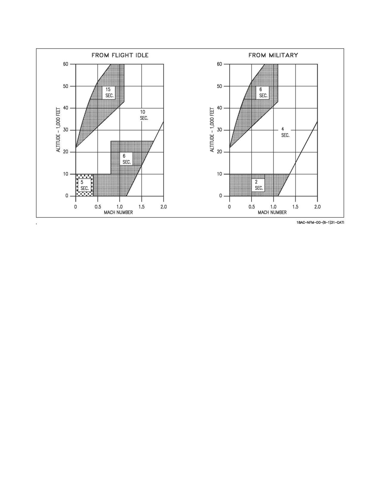
Figure 2-1. Afterburner Light-Off Time
2.1.1.1.1
Inlet Duct Doors. The electrically operated inlet duct doors (one for each inlet) automati-
cally open at Mach 1.33 (accelerating) and close at Mach 1.23 (decelerating). The doors are controlled
by the flight control computer.
2.1.1.2
Engine Control System. The engine control system consists of the throttle, main fuel control,
electrical control assembly (ECA) and afterburner fuel control. Throttle movement is mechanically
transmitted to a power lever control. The power lever control acts as a power booster and positions the
main fuel control. If the automatic throttle control is engaged, it schedules the power lever control for
existing engine power requirements and the throttle follows this movement. Below MIL power, throttle
movement and compressor inlet temperature (through the main fuel control) control the compressor
speed (rpm). At MIL and above, fan speed is controlled by the ECA as a function of inlet temperature.
At and above military power, the ECA senses engine and aircraft parameters, computes engine
schedules and maintains engine limits.
NOTE
A lockup device in the main fuel control prevents thrust reduction
below military if aircraft speed is Mach 1.23 or higher.
2.1.1.3
Afterburner Fuel Control. The afterburner fuel control schedules fuel flow to the pilot
spraybar and main spraybars. When the throttle is advanced to afterburner, ignition is turned on, the
exhaust nozzle opens slightly above the MIL position, the low pressure turbine discharge temperature
schedule is temporarily reset to a lower value, and afterburner pilot spraybar fuel flow and minimum
afterburner main fuel flow begins. When afterburner light-off is detected, ignition is turned off and
afterburner main fuel flow increases to the level selected by the throttle position. Since main fuel flow
is withheld until a positive light-off is attained, a hard light should not occur. Refer to figure 2-1 for
afterburner light-off time. A successful afterburner light-off is indicated by the exhaust nozzle opening
I-2-2
ORIGINAL
A1-F18AC-NFM-000
to a position greater than MIL (scheduled as a function of power lever angle (PLA)). Nozzle position
at MAX power is approximately 50% greater than MIL.
2.1.1.4
Ignition System. The ignition system contains an independent engine mounted alternator,
electrical control unit, ignition exciter, a main igniter and an afterburner igniter. During engine start,
moving the throttle from OFF to IDLE turns on ignition. Ignition remains on until the engine reaches
45% rpm. Engine ignition also comes on if a flame-out occurs or when afterburner is selected.
Afterburner ignition comes on when the throttle is moved into afterburner and remains on until an
afterburner light-off is sensed. If more than 50% afterburner is selected, ignition is automatically
turned on if an afterburner blowout occurs.
2.1.1.5
Lubrication System. The lubrication system is self-contained and consists of a pressure-
filled supply tank, lubrication pump, scavenge pumps, oil filter, oil cooler, gearbox, engine sumps,
scavenge screens, magnetic chip detectors, pressure transducer, pressure regulator, and interconnect-
ing piping. Oil gravity-flows from the tank to the pump. A pressure transducer, the engine oil pressure
transmitter, is located in the pump output line. The engine oil pressure transmitter is an electrical
transmitter that does not have any control authority and is used for monitoring purposes only. The
engine oil pressure transmitter sends an electrical signal to the cockpit pressure indicator. The loss of
engine oil pressure would lead to engine vibrations, RPM would decrease, and the engine would
eventually seize.
2.1.1.6
Engine Anti-Ice. A separate engine bleed air system, internal to the engine and from a
different compressor stage than the aircraft bleed air, is used for engine anti-ice.
2.1.1.6.1
Engine Anti-Ice Switch
ON
Activates the engine anti-ice system.
OFF
Deactivates the engine anti-ice system.
TEST
Checks ice detector operation and turns on INLET ICE display.
2.1.1.7
Engine Controls and Instruments
2.1.1.7.1
Engine Crank Switch. An engine crank switch is on the left console. The switch has
positions of L (left), OFF and R (right). During engine start, placing the switch to L or R starts engine
crank for the corresponding left or right engine. The switch is electrically held in the L or R position.
As the engine accelerates to a self-sustaining rpm, the switch automatically returns to OFF.
Ensure engine speed is below 30% N2 before actuating the engine crank
switch. Failure to do so may shear the air turbine starter shaft.
2.1.1.7.2
Throttles. Movement of the throttles is transmitted by mechanical linkage to the engine
mounted power lever controls. The engine mounted power lever controls convert the linear mechanical
movement from the throttles to rotary motion that moves the fuel control input arms. During manual
operation, pneumatic throttle boost actuators powered by environmental control system (ECS) air
reduce the force required to move the throttles. During automatic throttle control (ATC) operation, the
pneumatic boost actuators are disengaged. A friction adjusting lever is mounted next to the right
I-2-3
ORIGINAL
A1-F18AC-NFM-000
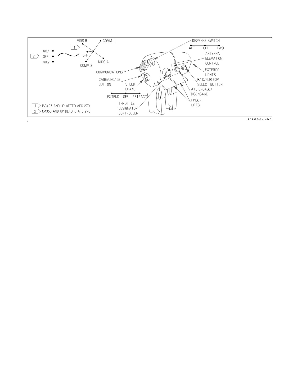
Figure 2-2. Throttle Grips
throttle. Advancing the throttles from OFF to IDLE (during engine start) opens the engine fuel control
shutoff valves and activates engine ignition. Finger lifts, on the front of each throttle, must be raised
to place the throttles OFF. With weight on the wheels, launch bar retracted and the arresting hook UP
or with weight off the wheels, afterburner operation is initiated by advancing the throttles through the
MIL detent gates into MAX. On the ground, an afterburner lockout system helps guard against
inadvertent afterburner selection. With weight on the wheels and launch bar extended or the arresting
hook DOWN, the afterburner lockout extends and the finger lifts must be raised or a force of
approximately 32 pounds must be applied before the throttles can be moved to MAX. A retractable
inflight IDLE stop extends with weight off the wheels and provides a higher IDLE rpm and reduced
acceleration time to MIL.
NOTE
During high g maneuvers when moving the throttle to idle, the flight
idle stop may retract and allow selection of ground idle.
With weight on the wheels, the inflight stop is retracted and the ground IDLE stop is used. Moving
the throttles to OFF closes the engine fuel control shutoff valves, stopping fuel flow to the engines. The
throttle grips (figure 2-2) contain switches that provide various systems control without moving the
hand from the throttles.
2.1.1.7.3
Dispense Switch. The dispense switch is located on the top inboard side of the right
throttle. The switch is used to dispense flares and chaff.
ALE-39 Countermeasure System -
Forward
CHAFF
Center
OFF
Aft
FLARE
I-2-4
ORIGINAL
A1-F18AC-NFM-000
ALE-47 Countermeasure System -
Forward
Provides semi-automatic consent. Dispenses chaff singles (C/F mode).
Center
OFF
Aft
Initiates the selected manual program. Dispenses flare singles (C/F mode).
2.1.1.7.4
Engine Monitor Indicator (EMI) (F/A-18A/B).
NOTE
If one or more of the engine parameters are blank or frozen, that
parameter may be invalid. If the parameter is invalid, the associated
engine caution will be inhibited.
The engine monitor indicator contains a left and right display for RPM %, EGT°C, FF PPH (fuel
flow), NOZ POS % (nozzle position) and OIL PSI (oil pressure).
RPM %
Displays compressor rpm. Range is 0 to 110% rpm with 1% rpm incre-
ments.
EGT °C
Displays turbine exhaust gas temperature (T5). Range is 0 to 999°C with
1°C increments.
FF PPH
Displays main engine fuel flow only (afterburner fuel flow is not dis-
played). Range is 300 to 15,000 pounds per hour with 100 pounds per
hour increments. The tens and units positions have fixed zeros. When
fuel flow is less than 350 PPH, zero is displayed.
NOZ POS %
Displays nozzle position. Range is 0 to 100% with 10% increments.
OIL PSI
Displays engine oil pressure. Range is 0 to 200 psi with 10 psi increments.
2.1.1.7.5
Integrated Fuel/Engine Indicator (IFEI) Engine Display (F/A-18C/D).
NOTE
If one or more of the engine parameters are blank or frozen, that
parameter may be invalid. If the parameter is invalid, the associated
engine caution will be inhibited.
The integrated fuel/engine indicator (IFEI) engine display, located on the lower left side of the main
instrument panel, contains a left and right liquid crystal display for RPM (N2)%, TEMP (EGT)°C, FF
(fuel flow) PPH, NOZ (nozzle position)%, and OIL (oil pressure) psi. During engine starts without
external electrical power, only RPM and TEMP are displayed by battery power until the APU comes
on line. With the APU on line or external power, all engine data is displayed. If the IFEI stops receiving
data from the signal data computer, the IFEI flashes the last data received until communication with
the signal data computer is restored.
I-2-5
ORIGINAL
A1-F18AC-NFM-000
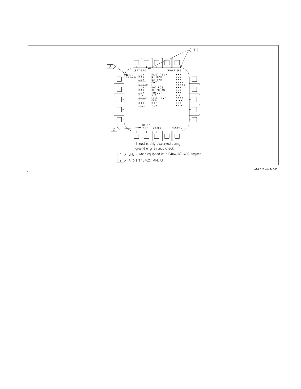
Figure 2-3. Engine Monitor Display (EMD)
RPM
Displays engine N2 rpm from 0 to 199%.
TEMP
Displays turbine exhaust gas temperature (EGT) from 0 to 1,999°C.
FF
Displays main engine fuel flow only (afterburner fuel flow is not displayed). Range
is 300 to 199,900 pounds per hour with 100 pound per hour increments. When fuel
flow is less than 320 PPH, zero is displayed.
NOZ
Displays exhaust nozzle position from 0 to 100% open in 10% increments.
OIL
Displays engine oil pressure from 0 to 195 psi in 5 psi increments.
2.1.1.7.6
Engine Monitor Display (EMD).
NOTE
If one or more of the engine parameters are blank or frozen, that
parameter may be invalid. If the parameter is invalid, the associated
engine caution will be inhibited.
The engine monitor display (figure 2-3) may be selected on either DDI by pressing MENU, then
pressing ENG. On aircraft equipped with F404-GE-402 engines, LEFT EPE and RIGHT EPE appear
at the top line of the EMD. If a malfunction exists, pressing RECORD will assist the ground crew
during troubleshooting.
I-2-6
ORIGINAL
A1-F18AC-NFM-000
INLET TEMP
Engine inlet temperature in °C.
N1 RPM
Fan speed in % rpm.
N2 RPM
Compressor speed in % rpm.
EGT
Exhaust gas temperature in °C.
FF
Fuel flow in pounds per hour.
NOZ POS
Nozzle position in %.
OIL PRESS
Oil pressure in psi.
THRUST
Thrust in %.
VIB
Engine vibration in inches per second.
FUEL TEMP
Engine inlet fuel temperature in °C.
EPR
Engine pressure ratio (ratio of exhaust pressure to ambient inlet pres-
sure). On aircraft 161925 AND UP with weight off wheels, EPR is a ratio
of exhaust pressure to ambient total inlet pressure. On all aircraft, EPR
is valid only during ground static conditions.
CDP
Compressor discharge pressure in psia.
TDP
Turbine discharge pressure in psia.
RECORD
When button is pressed, existing displays are recorded on a magnetic
tape. On aircraft 161925 AND UP, when power is first applied to the air-
craft, the RECORD option is not displayed until the mission computer
initialization is complete. When the RECORD button is pressed and
recording is in progress, the RECORD display is boxed.
DFIRS W/P
This function is not operational. (Aircraft 163427 THRU 164279 AFTER
AFC 258 and aircraft 164627 AND UP)
DFIRS DWNLD
Downloads DFIRS/CSFIRS data to MU for easier retrieval. (Aircraft
163427 THRU 164279 AFTER AFC 258 and aircraft 164627 AND UP)
2.1.1.7.7
Caution and Advisory Displays. The following engine related caution and advisory
displays may appear on the DDI:
CAUTION
ENG MATCH
One engine is F404-GE-400 and other engine is F404-GE-402.
L or R OVRSPD
Designated fan or compressor rpm high.
L or R EGT HIGH Either engine EGT over limit.
I-2-7
ORIGINAL
A1-F18AC-NFM-000
L or R IN TEMP
Designated engine inlet temperature is out of limits. Operation behind
another aircraft’s exhaust may cause a false caution. On aircraft 161925
AND UP, the L and R IN TEMP caution is inoperative on the ground
with engine rpm below approximately 76%. However, a false caution may
be displayed if rpm is above approximately 76%.
L or R STALL
Stall detected.
L or R FLAMEOUT
Designated engine failed. To prevent false cautions the system is deacti-
Aircraft 161925 AND
vated until after normal engine start and anytime the throttle is placed
UP
below IDLE.
INLET ICE
Icing condition in either engine inlet.
L or R DUCT DR
Designated inlet duct door closed above Mach 1.33 or open below Mach
1.23.
L or R OIL PR
Designated engine oil pressure out of limits.
L or R BOOST LO
Designated fuel boost pressure low.
ADVISORY
L or R HEAT
Designated engine anti-ice switch ON.
In addition, the ENGINE LEFT (RIGHT) voice alert is activated when any of the following cautions
are displayed: L or R OVRSPD, L or R EGT HIGH, L or R IN TEMP, L or R FLAMEOUT, L or R
OIL PR and L or R STALL.
2.1.2 Automatic Throttle Control (ATC). The automatic throttle control is a two mode system that
automatically maintains angle of attack (approach mode) or airspeed (cruise mode) by modulating
engine thrust in the range of flight idle through military. Automatic transition between the two modes
or single-engine engagement is not possible. When either mode is engaged, the ECS air to the torque
boosters is shut off, the throttles are initially backdriven, a stop is extended in the power lever control
(PLC) to limit throttle travel from flight idle to MIL, and an ATC advisory is displayed on the HUD.
If either mode does not engage when selected, or automatically disengages after engagement, the ATC
display flashes for 10 seconds and is then removed from the HUD. If a force of approximately 12
pounds (with friction off) is applied to either throttle the system automatically disengages. This force
is sufficient to permit the hand to follow throttle movement without causing disengagement. It is
recommended that the friction lever be in the full aft position and both throttles set between flight idle
and MIL before engaging ATC. If a mechanical failure occurs, a force of approximately 68 pounds (with
friction off) is required to override the system. When either mode is engaged, changing the FLAP
I-2-8
ORIGINAL
A1-F18AC-NFM-000
switch between AUTO and HALF or FULL automatically disengages the system. If the system is
disengaged for any reason, it remains disengaged until reengagement is initiated by the pilot.
NOTE
Momentary force applied to the throttle(s)
(throttle rap) may not
disengage the ATC system. The force must be applied and held for a
minimum of 0.10 second.
If the ATC commands the throttles to MIL, it may not be possible to
manually advance the throttles into the afterburner range without first
disengaging the ATC through momentary throttle reduction using more
than 12 pounds of force.
If the throttle(s) are being held against the flight idle or MIL stop as ATC is disengaged, the stops
may not disengage until pressure is removed from the throttle(s).
Auto throttle system performance will be degraded if preflight FCS BIT
produces BLIN code 124, 322, 336, 4124, 4322, 4336, 4522, 4526, 4527,
4773, or 4774. Do not utilize the auto throttle system. Use of ATC with
these codes could result in uncommanded throttle movements.
2.1.2.1
ATC Approach Mode. The ATC approach mode is engaged by pressing and releasing the
ATC button on the left throttle with the FLAP switch in HALF or FULL and the trailing edge flaps
extended at least 27°. When ATC is engaged in the approach mode, the flight control computer
modulates engine thrust to maintain on-speed AOA. The computer uses inputs of AOA, normal load
factor, stabilator position, pitch rate, and angle of bank to generate command signals. These signals
drive the engine mounted throttle control units which in turn command the engine fuel controls. The
computer uses AOA as the primary input to generate command signals. However, normal load factor
provides increased stability, stabilator position provides increased or decreased thrust for pilot induced
pitch changes, pitch rate provides lead during pitch maneuvers, and bank angle provides additional
thrust during banking maneuvers. Normal disengagement is accomplished by pressing the ATC button
or applying and holding force to either throttle. Automatic disengagement occurs for the following
reasons:
Flap AUTO up
AOA sensor failure
Two or more failures of either trailing edge flap
Trailing edge flap deflection less than 27°
ATC button fails
FCES channel 2 or 4 fails
WOW
FCS reversion to MECH or to DEL in any axis
Left and right throttle angles differ by more than 10° for more than 1 second
Bank angle exceeds 70°
Any internal system failure
Selection of GAIN ORIDE
I-2-9
ORIGINAL
A1-F18AC-NFM-000
2.1.2.2
ATC Cruise Mode. The ATC cruise mode is engaged by pressing and releasing the ATC
button on the left throttle with the FLAP switch in AUTO. When ATC is engaged in the cruise mode,
the existing airspeed is used by the flight control computer to modulate engine thrust to maintain this
existing airspeed. The existing airspeed is the airspeed being sent from the ADC to the flight control
computers via the mission computers. An ADC failure inhibits the ATC cruise mode of operation. The
FCC uses true airspeed from ADC via the mission computers at the time of engagement to generate a
command signal. This signal is then used as a reference to generate an error signal that drives the
engine mounted throttle control units. Normal disengagement is accomplished by pressing the ATC
button or applying and holding force to either throttle. Automatic disengagement occurs for the
following reasons:
Flaps HALF or FULL
ATC button fails
FCES channel 2 or 4 fails
FCS reversion to MECH or to DEL in any axis
Left and right throttle angles differ by more than 10° for more than 1 second
ADC true airspeed failure
ADC degrade
Any internal system failure
2.2 FUEL SYSTEM
Refer to Fuel System, Foldout Section, for fuel system illustration. Fuel is carried internally in four
interconnected fuselage tanks and two internal wing (wet) tanks. External fuel is carried in 315 or 330
gallon tanks which may be mounted on the centerline and/or inboard wing station pylons. A fuel
quantity indicating system provides fuel quantity indications in pounds. All tanks may be refueled on
the ground through a single pressure refueling point. Airborne, they can be refueled through the aerial
refueling probe. The internal wing tanks, tank 1, and tank 4 are transfer tanks. Tanks 2 and 3 are
engine feed tanks. The tanks are arranged so internal fuel gravity transfers (at a reduced rate) even if
the transfer pumps fail. Regulated engine bleed air pressure transfers fuel from the external tanks and
also provides a positive pressure on all internal fuel tanks. Float type fuel level control valves control
refueling of all tanks. These same valves are used to control transfer from the internal wing tanks to
tanks 1 and 4 in A/B aircraft, and to tank 2 from the left wing tank and to tank 3 from the right wing
tank in F/A-18C/D aircraft. Jet level sensors are used to control transfer from tanks 1 and 4 to tanks
2 and 3. All internal and external tanks except tanks 2 and 3 (and internal wing tanks in F/A-18C/D
aircraft) may be dumped overboard from an outlet in each vertical fin. All internal fuel tanks are
vented through the vent outlet in each vertical fin. The external tanks are vented through the vent
outlets in their individual tanks.
2.2.1 Survivability. The internal wing tanks contain foam for fire/explosion protection. The lower
section of the feed tanks are self sealing for “get home” protection. Fuel lines are routed inside the tanks
where possible. Fuel feed lines in the main landing gear wells are wrapped with a self-sealing protective
shell.
2.2.2 Fuel Tank Pressurization and Vent. The pressurization and vent system provides regulated
engine bleed air pressure to all internal tanks to prevent fuel boil-off at altitude and to the external
tanks for fuel transfer. The system also provides pressure relief of the fuel tanks during climbs and
vacuum relief of the fuel tanks during descent if the pressurization system fails. All tanks are
pressurized any time engine bleed air is available, electrical power is on, weight is off the main gear, the
air refueling probe is retracted, and in F/A-18A/B aircraft, the HOOK handle is UP or in F/A-18C/D
aircraft, either the HOOK handle or the LDG GEAR handle is UP. All external tanks can be
I-2-10
ORIGINAL
A1-F18AC-NFM-000
pressurized any time by placing either external tank fuel control switch to ORIDE (HOOK handle
must be up in A/B aircraft). The internal tanks vent into the fuselage vent tank which in turn is vented
through the vertical fin vent tanks to an outlet in each vertical fin. Any fuel in the vertical fin vent tank
returns to the vent tank by gravity flow. Any fuel that accumulates in the vent tank is returned to tanks
2 and 3 by scavenge pumps.
2.2.2.1
Tank Pressurization Caution Display. With MC OFP 10A AND UP, a TANK PRESS
caution indicates the internal tanks are pressurized on the ground, or low internal tank pressure
inflight above 20,000 feet. With MC OFP 13C AND UP, a TK PRES LO caution indicates low internal
tank pressure inflight above 20,000 feet and a TK PRES HI caution indicates the internal tanks are
pressurized on the ground, or high internal tank pressure inflight. TANK PRESS or TK PRES LO are
also displayed above 20,000 feet when depressurization is caused by extending the inflight refueling
probe, or moving the hook handle down (F/A-18A/B aircraft), or moving the hook handle and the
landing gear handle down (F/A-18C/D aircraft). With TANK PRESS or TK PRES LO displayed
inflight and either a low fuel state or hot fuel, fuel may boil off and be vented. A high rate of descent
may damage the fuel cells. With TK PRES HI displayed inflight, high g maneuvering may result in
structural damage.
2.2.2.2
Vent Fuel Caution Display. On aircraft 161249 THRU 161357, the VENT FUEL caution
display on the DDI indicates that fuel is in the left and/or right vertical fin vent system.
2.2.2.3
External Tank Pressurization Caution Display. An EXT TANK caution display on the DDI
indicates the external tanks are pressurized with the aircraft on the ground.
2.2.3 Internal Transfer
2.2.3.1
Internal Transfer (F/A-18A/B). Normal fuel transfer is accomplished by ejector pumps
powered by motive flow. Motive flow pressure is produced by two motive flow/boost pumps, each
driven by an airframe mounted accessory drive (AMAD). If an AMAD or pump failure occurs, the other
pump produces sufficient motive flow pressure to power all the ejector pumps. The ejector pumps in
the internal wing tanks automatically transfer fuel to tanks 1 and 4 when the fuel level control valves
in these two tanks open. The ejector pumps in tanks 1 and 4 transfer fuel to tanks 2 and 3 when the
jet level sensors in the feed tanks are uncovered, allowing their transfer control valves to open. On
aircraft 161925 AND UP AFTER AFC 039, fuel transfer from tanks 1 and 4 is shut off during negative
g flight. After tank 1, tank 4 or a wing tank empties, fuel low level floats shut off motive flow to the
ejector pump in that tank.
2.2.3.2
Internal Transfer (F/A-18C/D). Normal fuel transfer is accomplished by motive flow
powered ejector pumps in the internal wing tanks and turbine-driven pumps in tanks 1 and 4. Motive
flow pressure is produced by two motive flow/boost pumps, each driven by an airframe mounted
accessory drive (AMAD). Two separate motive flow systems exist, with the right AMAD pump
powering the transfer pumps in the right wing and tank 4 and the left AMAD pump powering the
transfer pumps in the left wing and tank 1. If an AMAD or motive flow/boost pump failure occurs, a
cross-motive valve opens, allowing the good side to power all the transfer pumps. The wings transfer
first and transfer is controlled by the feed tank fuel level control valves. The ejector pumps transfer left
wing fuel to tank 2 and right wing fuel to tank 3. When tanks 2 and 3 deplete to jet level sensor control
range, the turbine-driven pumps in tanks 1 and 4 transfer fuel to tanks 2 and 3 when the sensors are
uncovered, allowing the transfer control valves to open. Fuel transfer from tanks 1 and 4 is shut off
during negative g flight. After tank 1 or tank 4 empties, fuel low level floats shut off motive flow to the
turbine-driven pump in that tank. The ejector pumps do not shut off when the internal wing tanks are
empty.
I-2-11
ORIGINAL
A1-F18AC-NFM-000
2.2.3.3
Internal Wing Tank Fuel Control Switch. An internal wing tank fuel control switch, labeled
INTR WING is on the EXT LT panel.
NORM
Provides automatic fuel transfer of the internal wing tanks.
INHIBIT Electrically closes the wing damage control valve (F/A-18A/B) or the wing motive
flow control valves (F/A-18C/D) and the wing refuel level control valves and
switches the diverter valves to the feed tank position. The closed wing damage con-
trol valve or wing motive flow control valves prevent normal transfer of the inter-
nal wing fuel. The closed wing level control valves prevent air refueling of and
external transfer to the internal wing tanks. Gravity transfer allows transfer of
some wing fuel at a reduced rate and quantity to tank 4. The repositioned diverter
valves return recirculated fuel directly to the feed tanks.
2.2.3.4
CG Control. Aircraft 161353 THRU 161519 AFTER AFC 039 AND 161520 AND UP are
equipped with a CG control system which automatically controls tank 1 fuel transfer to maintain
proper aircraft CG. The system periodically shuts off tank 1 fuel transfer to keep tank 1 and tank 4
properly balanced. CG control operates until the FUEL LO caution comes on, or tank 4 drops below
150 pounds. When tank 4 reaches 150 pounds, tank 1 should indicate:
1,350 to 1,700 pounds (F/A-18A)
750 to 1,100 pounds (F/A-18B)
1,375 to 1,550 pounds (F/A-18C)
EMPTY (F/A-18D)
See figure 2-4. Aircraft 161353 THRU 161519 BEFORE AFC 039 are not equipped with a CG control
system; refer to figure 11-7 for normal tank 1 and tank 4 fuel levels.
NOTE
On aircraft with CG control, if tank 4 fuel transfer fails tank 1 does
not transfer fuel until the FUEL LO caution comes on. After the
FUEL LO caution comes on, tank 1 transfers fuel to both engine feed
tanks until the FUEL LO caution is removed. Tank 1 fuel transfer
then remains cyclic until it is empty.
2.2.3.5
CG Caution Display (MC OFP 10A AND UP). On Aircraft 161353 THRU 161519 AFTER AFC
039 AND 161520 AND UP, a CG caution display indicates that tank 1 and tank 4 fuel is not sequencing
properly. CG may be further aft than normal. Refer to Flight Characteristics, Chapter 11. The caution
does not come on if the air refueling probe is extended, or the fuel level in tank 4 drops below 450
pounds (F/A-18A/B/C) or 2,800 pounds (F/A-18D).
2.2.3.6
FUEL XFER Caution Display (MC OFP 13C AND UP). A FUEL XFER caution display
indicates that tank 1 and tank 4 fuel is not sequencing properly. CG may be further aft than normal.
Refer to Flight Characteristics, Chapter 11. The caution does not come on if the air refueling probe is
extended, or the fuel level in tank 4 drops below 450 pounds (F/A-18A/B/C) or 2,800 pounds
(F/A-18D).
2.2.3.7
Gravity Transfer. If any or all transfer pumps fail, internal fuel transfers by gravity. The flow
rate is dependent on the difference in the fuel level between tanks (head pressure) and most of the
transfer fuel is available. It may require sideslip to gravity transfer internal wing tank fuel. The wing
tank fuel transfers to tank 4 through gravity transfer lines. Tank 4 and tank 1 transfer to tank 3 and
I-2-12
ORIGINAL
A1-F18AC-NFM-000
tank 2, respectively, through flapper valves. A nose down attitude may be required to transfer most of
the lower portion of tank 4 fuel to tank 3.
2.2.4 External Transfer. External fuel is transferred by conditioned engine bleed air pressure. A
single regulator supplies pressurization to all installed external tanks when weight is off the wheels, the
air refueling probe is retracted, and in F/A-18A/B aircraft, the HOOK handle is up or in F/A-18C/D
aircraft, either the HOOK handle or LDG GEAR handle is UP. Once the external tanks are
pressurized, shut-off valves controlled by the external tank fuel control switches provide selection of
fuel transfer from either the external wing tanks only, the external centerline tank only or all three
external tanks at the same time. All external tanks can be pressurized any time either external tank
fuel control switch is in ORIDE (arresting hook handle must be up in F/A-18A/B aircraft). On
F/A-18C/D aircraft, selecting ORIDE also overrides any Signal Data Computer (SDC) stop transfer
command. With the external tanks pressurized, fuel transfers when the FUEL LO caution is displayed
(the air refueling probe must be retracted in F/A-18C/D aircraft), regardless of the position of the
external tank fuel control switches.
NOTE
On F/A-18C/D aircraft, selecting ORIDE on both EXT TANKS fuel
control switches may inhibit centerline tank transfer.
2.2.4.1
External Tank Fuel Control Switches. Two EXT TANKS fuel control switches, labeled
WING (for external wing tanks) and CTR (for centerline tank), are on the FUEL panel.
NORM
With the external tank(s) pressurized, external fuel transfers to any internal tank
that accepts it.
STOP
With the external tank(s) pressurized, external fuel does not transfer until FUEL
LO caution display is on.
ORIDE
Pressurization of and fuel transfer from all installed external tanks is provided
(HOOK handle must be up in F/A-18A/B aircraft). The other external tank fuel
control switch must be in STOP if fuel transfer from its tank(s) is not desired.
2.2.4.2
External Transfer Caution Display. On F/A-18C/D aircraft, an EXT XFER caution display
on the DDI indicates that external fuel is available and should have transferred. The caution is also
displayed when external fuel is available at BINGO and FUEL LO.
2.2.5 Fuel Feed System. There are two separate fuel feed systems, one for each engine; however, an
interconnecting crossfeed system provides fuel feed to both engines from a single fuel feed system if
one system fails. An AMAD driven fuel pump provides pressurized fuel flow to each engine. Each pump
is a two-stage pump. One stage supplies fuel to the engine and the other stage supplies high pressure
fuel to the motive flow system. On aircraft 161353 THRU 161924 BEFORE AFC 018, each AMAD
pump is fed from a separate feed tank by an ejector pump powered by motive flow from the AMAD
pump. On aircraft 161353 THRU 161924 AFTER AFC 018, and 161925 AND UP, each AMAD pump
is fed from a separate feed tank by a turbo pump powered by motive flow from the AMAD pump.
Motive flow from each AMAD pump is also used to cool the accessories on that side of the aircraft and
to power the transfer pumps. The left engine is normally fed from tank 2 by the left AMAD pump and
the right engine is normally fed from tank 3 by the right AMAD pump.
I-2-13
ORIGINAL
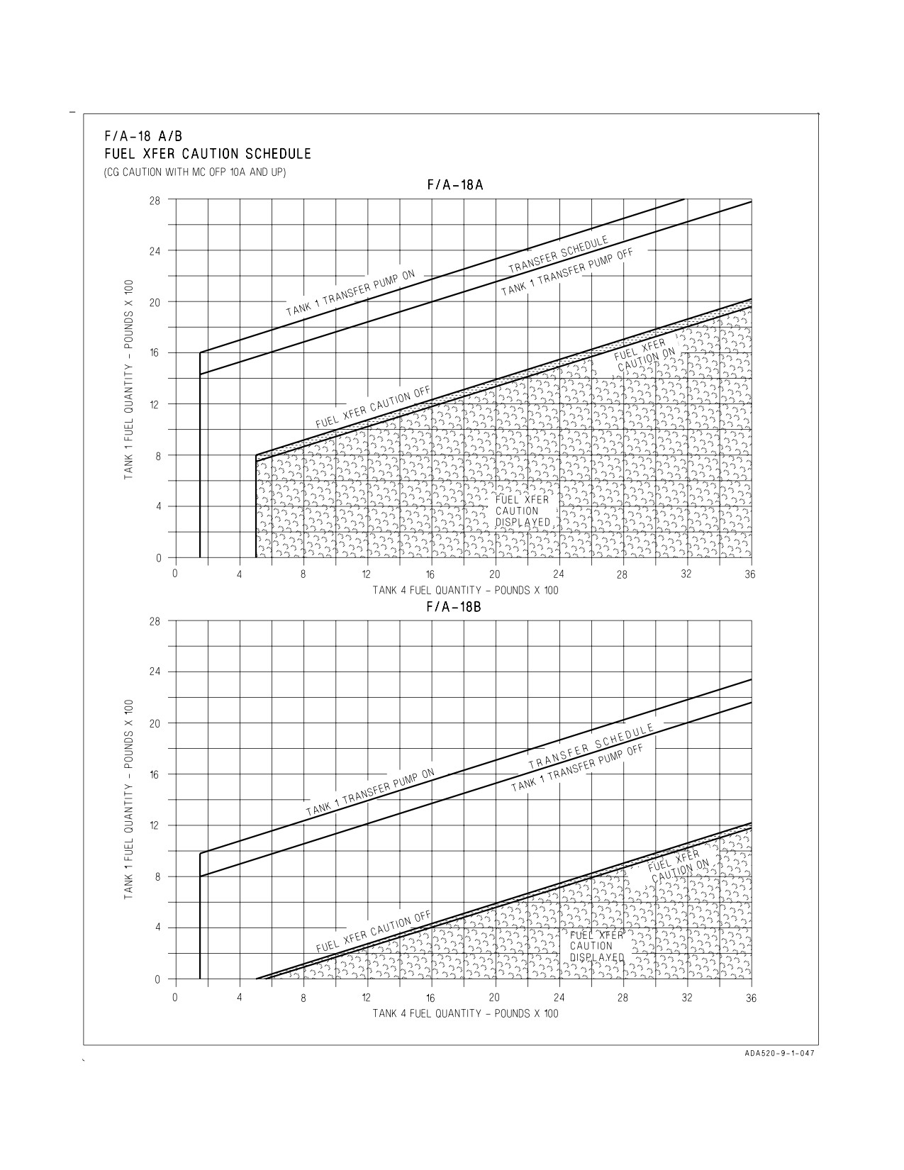
A1-F18AC-NFM-000
Figure 2-4. Tank 1 and 4 Fuel CG Control and FUEL XFER Caution Schedule (Sheet 1 of 2)
I-2-14
ORIGINAL
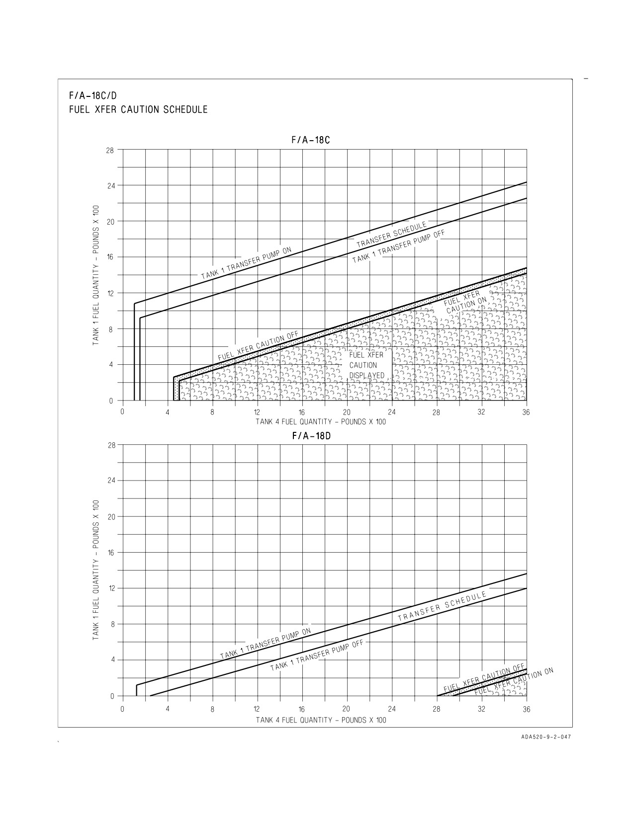
A1-F18AC-NFM-000
Figure 2-4. Tank 1 and 4 Fuel CG Control and FUEL XFER Caution Schedule (Sheet 2 of 2)
I-2-15
ORIGINAL
A1-F18AC-NFM-000
2.2.5.1
AMAD Pump BOOST LO Caution Display. An L or R BOOST LO caution is displayed on the
DDI if the AMAD pump engine feed pressure is lost on that side. With an L or R BOOST LO caution,
a normally closed crossfeed valve downstream from the AMAD pumps opens to allow the good AMAD
pump to feed both engines at rates sufficient for MIL power.
On aircraft 161353 THRU 163118 BEFORE AFC 070 and 161353 THRU 161924 AFTER IAFC 056,
the fuel boost pressure switches are removed. Without fuel boost pressure switches, the L or R BOOST
LO cautions are inoperative and the crossfeed valve is always open (unless a FIRE light is pressed).
2.2.5.2
Fuel Feed With Failed Ejector or Turbo Pump. If an ejector or turbo pump fails, fuel gravity
feeds through the inducer inlet to the AMAD driven fuel pump. In this condition, and with high feed
tank fuel temperature and high altitude flight, the fuel feed system may not supply enough fuel for the
intended power setting but the gravity system provides adequate engine fuel feed for non-afterburner
operation.
On aircraft without boost pressure switches, the crossfeed valve remains open and both engines are
supplied primarily from the feed tank with an operative ejector or turbo boost pump.
2.2.5.3
Fuel Feed With Loss Of Motive Pressure. If motive flow pressure is lost on either side, the
interconnect valve between tanks 2 and 3 opens to allow fuel from the tank with the failed pump to
gravity transfer to the other tank. The good ejector or turbo pump supplies fuel from both feed tanks
to its AMAD pump. Accessory cooling is not available on the inactive side.
2.2.5.4
Negative G Baffles. Negative g baffles in the feed tanks provide limited fuel supply during
negative g or inverted flight. No sustained zero g capability is provided. Transition from positive to
negative g may cause display of the L and/or R BOOST LO caution(s).
2.2.5.5
APU Fuel Feed. The APU receives its fuel supply from the left engine feed line upstream of
the left engine feed shutoff valve.
2.2.5.6
Left and Right Fire Warning Lights. Lifting the guard and pressing either or both fire
warning lights electrically closes the corresponding engine feed shutoff valve at the feed tanks, closes
the crossfeed valve and arms the corresponding engine fire extinguisher system. The system operates
anytime power is on the aircraft or the battery switch is not OFF.
2.2.6 Fuel Recirculation System. The fuel recirculation system cools the AMAD accessories and
HYD 1 and 2 hydraulic oil. Part of the engine motive flow fuel passes through an AMAD oil heat
exchanger to absorb heat from the AMAD accessories and through a hydraulic oil heat exchanger to
cool the hydraulic oil. On aircraft 161520 AND UP and 161353 THRU 161519 after AFC 021, this fuel
then passes through a fuel/air heat exchanger to partially dissipate the heat absorbed from the AMAD
and HYD oil heat exchangers. This partially cooled fuel then passes through a diverter valve. Fuel from
the diverter valve normally goes to the internal wing tanks where it is further cooled. Normally, as long
as fuel is being recirculated, there is as much as 200 pounds fuel in the internal wing tanks but may be
less (even zero) at high power settings. If the INTR WING switch is in INHIBIT or the FUEL LO
caution is displayed (either engine feed tank at or below 800 pounds), the diverter valves direct the fuel
into tanks 2 and 3. In F/A-18C/D aircraft, the recirculated fuel is directed to tanks 2 and 3 during idle
descent. Also, with weight on the wheels, tanks 1 and 4 not empty and engine inlet fuel temperature
above 80°C, the recirculated fuel is directed to tank 4. This improves fuel heat management.
2.2.6.1
Fuel Hot Caution Display. An L or R FUEL HOT caution display on the DDI indicates the
designated engine fuel feed temperature exceeds 79°C. Some loss of cooling occurs with the INTR
I-2-16
ORIGINAL
A1-F18AC-NFM-000
WING switch in INHIBIT. With high ambient temperature and low fuel flow (IDLE rpm) it may be
necessary to increase fuel flow to prevent a FUEL HOT display.
2.2.7 Fuel Dump System. All fuel except engine feed tank fuel (and internal wing tank fuel in C/D
aircraft) may be dumped by placing the DUMP switch, on the FUEL control panel, to ON. The DUMP
switch is spring-loaded to the lever-locked OFF position and is electrically held in the ON position
(with the BINGO caution display off, and the FUEL LO light off). Fuel can be dumped at any time by
holding the switch ON. With the dump valve open, the ejector or turbo pumps in tanks 1 and 4 force
fuel out each vertical fin dump outlet. The internal wing fuel (A/B aircraft) and external fuel (if
INHIBIT and STOP are not selected) transfers fuel into tanks 1 and 4, and is then dumped. Dump rate
is 600 to 1,000 pounds per minute. Dumping continues until:
a. OFF is selected on the DUMP switch.
b. The BINGO caution display comes on, at which time the DUMP switch automatically returns
to OFF, terminating fuel dumping.
c. Tanks 1 and 4 are empty.
d. Either engine feed tank fuel drops below the FUEL LO level regardless of total internal fuel
quantity.
Simultaneous selection of fuel dump and afterburner during high AOA
maneuvering may cause fuel to ignite with resulting fuselage damage.
NOTE
In the F/A-18C/D, with either engine secured, significantly lower and/
or cyclic dump rates have been experienced. On aircraft 163427 AND
UP, the INTR WING switch must be set to NORM to ensure adequate
fuel dumping. When the right engine is secured, lower dump rates
follow immediately and may be accompanied by a CG caution. When
the left engine is secured, lower dump rates are experienced as total
fuel reaches 6,500 pounds (when tank 4 is empty).
2.2.7.1
Dump Open Caution Display. A DUMP OPEN caution display on the DDI indicates that the
fuel dump valve is open with OFF selected.
2.2.8 Fuel Lo Level Indications. The fuel low level indicating system is completely independent of
the fuel quantity indicating system. When the fuel level in either feed tank drops to 800 ±100 pounds
a FUEL LO light on the caution lights panel comes on which activates the “FUEL LOW” voice alert,
a FUEL LO caution display on the DDI appears, and the MASTER CAUTION light comes on. Once
activated, the FUEL LO light and caution display remains on for a minimum of 1 minute even though
the activation may have been caused by a transient condition. When the fuel low warning system is
I-2-17
ORIGINAL
A1-F18AC-NFM-000
activated, external fuel (if STOP has been selected) transfers, provided the external tanks are
pressurized, and the diverter valves in the hot fuel recirculation system direct fuel to the engine feed
tanks. Fuel dumping, if selected, terminates.
If the FUEL LO caution comes on, it must be assumed that at least one
feed tank is below 800 pounds regardless of fuel gage readings.
2.2.9 Fuel Quantity Indicating System (F/A-18A/B). The fuel quantity indicating system provides
readings, in pounds, of usable internal and total fuel. See figures 2-6 and 2-54.
The system components
include the fuel quantity indicator, a built-in test (BIT) and a BINGO caution display.
The refueling system has a volumetric shutoff controlled by pilot valves in the top of each tank. The
volume of fuel with full tanks does not change. Because fuel density can vary from 6.13 pounds/gallon
at 100°F to 7.38 pounds/gallon at −40°F, the total internal fuel quantity with full tanks can vary from
9,740 pounds to 11,730 pounds for the F/A-18A or from 9,120 pounds to 10,980 pounds for the F/A-18B.
2.2.9.1
Fuel Quantity Indicator. A combination pointer-counter fuel quantity indicator is on the
lower left side of the main instrument panel. The pointer indicates usable internal fuel (with readings
multiplied by 1000). The counter indicates usable internal and external fuel. Two other counter
positions, marked LEFT and RIGHT, and a selector switch provides individual tank monitoring and
a test of the indicator. An OFF indicator is displayed if electrical power is not available. With the OFF
indicator out of view, an ID flag is displayed if inputs from an intermediate device to the fuel quantity
indicator are in error. False fuel indications occur during and immediately following maneuvering
flight.
2.2.9.2
Fuel Quantity Selector Switch.
BIT
A spring loaded position that starts BIT of the system.
FEED
Fuel remaining in the respective engine feed tank is displayed.
TRANS
Fuel remaining in tank 1 (LEFT) and tank 4 (RIGHT) is displayed.
INTER WING
Fuel remaining in the internal wing tanks is displayed.
EXT WING
Fuel remaining in the external wing tanks is displayed.
EXT CTR
Fuel remaining in the centerline tank is displayed in the LEFT counter
(RIGHT indicates zero).
2.2.9.3
Fuel Quantity BIT. The BIT system only tests the fuel quantity indicator and an interme-
diate device that receives signals from the individual tank sensor probes. It does not test the fuel tank
sensor probes or the wiring to the intermediate device. With the fuel quantity indicator OFF flag out
of view, note internal and feed tank fuel quantities. The following indications are present during BIT.
I-2-18
ORIGINAL
A1-F18AC-NFM-000
With the BINGO bug set above 6,200 pounds -
a. Internal (pointer) and total (counter) indicates 6,000 ±200 pounds.
b. LEFT and RIGHT (counters) indicate 600 ±50 pounds.
c. After pointer and counters reach the above values (must occur within 15 seconds), the ID flag
is not in view.
d. The FUEL LO, BINGO, CG (on aircraft 161520 AND UP) and G-LIM 7.5 G cautions are
displayed on the DDI and the FUEL LO and MASTER CAUTION lights come on. The
″Bingo″, ″Fuel Low″, and ″Flight Controls″ voice alerts are activated. The FUEL advisory
appears on the DDI if any of the above DDI cautions do not appear within 15 seconds after
initiating BIT with the fuel quantity selector switch.
e. When the fuel quantity selector switch is released the pointer and counters return to their
previous value, the BINGO, CG and G-LIM 7.5 G cautions are removed, the FUEL LO caution
light and accompanying MASTER CAUTION light remain on for 1 minute and then go out.
2.2.9.4
BINGO Caution. The BINGO caution appears on the DDI at a preset value controlled by the
pilot. An adjustable index (bug) on the face of the indicator may be set to any internal fuel quantity
by turning the BINGO knob. Fuel dumping, if selected, terminates when the BINGO caution is
displayed. The “Bingo” voice alert is activated when the BINGO caution comes on. With MC OFP 19C,
the ″Bingo″ voice alert sounds every 30 seconds until the BINGO fuel level is set below current fuel on
board.
2.2.9.5
Fuel Advisory. The FUEL advisory appears on the DDI if any of the following cautions do not
appear within 15 seconds after initiating BIT with the fuel quantity selector switch: FUEL LO,
BINGO, or CG (aircraft 161520 AND UP).
2.2.10 Fuel Quantity Indicating System (F/A-18C/D). The fuel quantity indicating system provides
readings, in pounds, of usable internal and total fuel. See figures 2-6 and 2-64. The system components
include the integrated fuel/engine indicator (IFEI), a BIT and the BINGO caution.
The refueling system has a volumetric shutoff controlled by pilot valves in the top of each tank. The
volume of fuel with full tanks does not change. Because fuel density can vary from 6.13 pounds/gallon
at 100°F to 7.38 pounds/gallon at −40°F, the total internal fuel quantity with full tanks can vary from
9,740 pounds to 11,730 pounds for the F/A-18C or from 9,120 pounds to 10,980 pounds for the F/A-18D.
2.2.10.1 Integrated Fuel/Engine Indicator. The IFEI fuel display window contains three digital
counters to provide dynamic fuel quantity indications (figure 2-6). The upper digital counter displays
total aircraft fuel quantity (10-pound increments). The middle digital counter displays total internal
fuel quantity (10-pound increments). A digital counter legend is displayed to the right of the upper and
middle counters (T - total fuel, I - internal fuel). The lower digital counter displays the selected BINGO
fuel quantity (100-pound increments). The UP and DOWN arrows on the IFEI provide BINGO level
adjustments from 0 to 20,000 pounds in 100 pound increments (BINGO counter scrolls if arrow keys
are depressed for more than one second). Individual fuel tank monitoring is provided by the QTY
pushbutton. False fuel indications occur during and immediately following maneuvering flight. In LOT
12 and up, the IFEI is NVG compatible.
2.2.10.2 Fuel Quantity Selector Pushbutton. The QTY pushbutton allows sequential selection of
the five sub-level fuel quantity format displays. The digital counter legends are displayed to the right
of the upper and middle digital counters to identify the format displayed.
I-2-19
ORIGINAL
A1-F18AC-NFM-000
Sub-level
Fuel Quantity Indicated
Legend
Counter
1
Left Feed Tank (#2)
FL
Upper
Right Feed Tank (#3)
FR
Middle
2
Left Transfer Tank (#1)
TL
Upper
Right Transfer Tank (#4)
TR
Middle
3
Left Wing Tank
WL
Upper
Right Wing Tank
WR
Middle
4
Left External Tank
XL
Upper
Right External Tank
XR
Middle
5
Centerline Tank
C
Upper
NOTE
When in sub-level 1 thru 5 the BINGO counter is replaced by the total
fuel counter. BINGO level is not adjustable in sub-levels 1 thru 5.
2.2.10.3 Fuel Low BIT. The built-in test FLBIT system tests the entire FUEL LO warning system.
FLBIT is initiated from the FUEL display (FLBIT pushbutton) on the DDI. A satisfactory test results
in a FUEL LO caution, voice alert, and MASTER CAUTION indication being generated within 13
seconds of FLBIT initiation. NO TEST is displayed next to tank 2 or 3 if its respective fuel quantity
is low prior to FLBIT initiation or next to tank 3 if tank 2 fails FLBIT. The FLBIT option is boxed
during the FLBIT sequence. The FUEL LOW BIT is inoperative when the FUEL LO caution is
displayed or if there is a failure in the Signal Data Computer (SDC).
2.2.10.4 Bingo Caution Display. A BINGO caution display appears on the DDI when the internal
fuel quantity reaches the preset value controlled by the pilot. In the C/D aircraft the pilot enters his
selected Bingo value with the pushbuttons on the IFEI. Fuel dumping, if selected, terminates when the
BINGO caution is displayed. The BINGO voice alert is activated when the BINGO caution comes on.
With MC OFP 19C, the ″Bingo″ voice alert sounds every 30 seconds until the BINGO fuel level is set
below current fuel on board.
2.2.10.5 DDI Fuel Display. The FUEL display (figure 2-5), which is menu selectable, is available
inflight and on the ground. Displayed is the fuel available in each tank, total internal fuel, total internal
and external fuel, and currently selected BINGO fuel. A moving caret is shown on the right side of each
tank to indicate the ratio of fuel available to tank fuel capacity. The SDC checks each fuel probe
validity and uses this data to determine system degraded performance. The loss of valid fuel quantity
information for a given tank is indicated by display of 0 pounds fuel and INV (invalid). Loss of valid
information is as follows:
a. All probes in a tank declared invalid by the SDC (except left or right feed tanks).
b. Tank 1 aft probe invalid while forward probe reads zero fuel.
c. Tank 4 forward and center probes invalid while aft probe reads zero.
An estimated (EST) fuel quantity is determined by the SDC and displayed as follows:
a. Use only the valid fuel probes in a multi-probe tank to estimate fuel available.
I-2-20
ORIGINAL
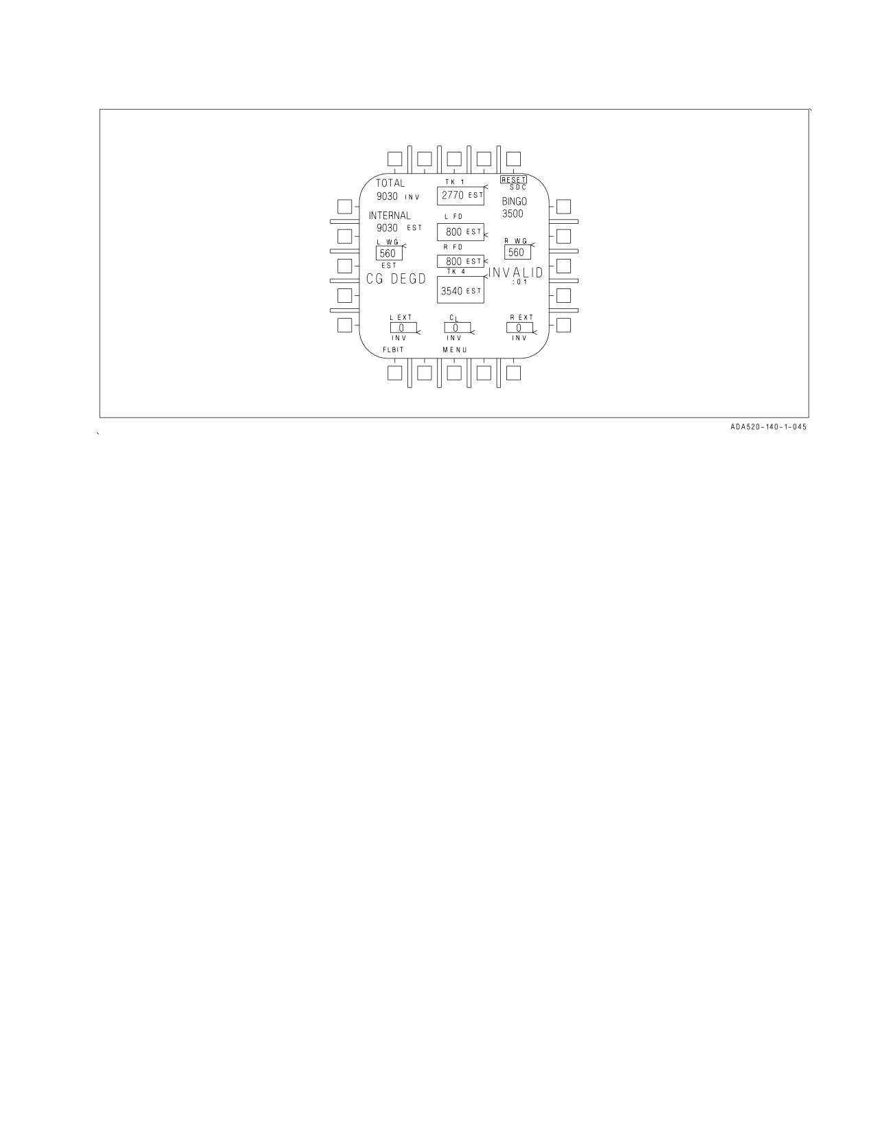
A1-F18AC-NFM-000
Figure 2-5. Fuel Display
b. Fuel probe invalid in left or right feed tank:
(1) Display 0 pounds if FUEL LO is present.
(2) Display 800 pounds if FUEL LO is not present.
The internal fuel and total fuel displays the sum of valid and/or estimated tank quantities. Each is
cued as EST or INV as determined by the appropriate tank information with INV displayed if INV and
EST both apply.
2.2.10.6 Fuel Quantity Advisory Display. A F-QTY advisory displayed on the DDI indicates SDC or
gaging system failure which affects the display of fuel quantity or center-of-gravity information. The
advisory is activated if:
a. The MC loses communication with the SDC.
b. The SDC reports an internal or gaging system failure.
c. Any tank quantity is invalid.
d. The SDC reports output discretes severed.
An F-QTY advisory, resulting from the MC loss of communication with the SDC or the SDC
reporting internal or gaging system failure, results in the following fuel display conditions:
a. All fuel quantities held at the last displayed value (valid EST or INV).
b. A flashing INVALID cue displayed along with a minutes and seconds (XX:XX) timer which
indicates the duration since the displayed fuel quantities were last updated.
2.2.11 Air Refueling System. A hydraulically operated inflight refueling probe is on the right side
of the fuselage forward of the windshield. The probe is extended and retracted by the HYD 2A system
and controlled by a guarded PROBE switch on the FUEL panel. An emergency extension system uses
I-2-21
ORIGINAL
A1-F18AC-NFM-000
APU accumulator pressure to extend the probe.
RETRACT Retracts the air refueling probe and reestablishes fuel tank pressurization.
EXTEND Extends the air refueling probe, turns on the probe light, if the exterior lights mas-
ter switch is on, and depressurizes the fuel tanks. The external tanks will not
transfer unless either external tank fuel control switch is in ORIDE.
EMERG Opens the emergency air refueling probe selector valve and the APU arming valve
EXTD
and extends the probe with APU accumulator pressure. Retains all other functions
as the EXTEND position.
2.2.11.1 Probe Unlock Caution Display. A PROBE UNLK caution display on the DDI indicates
that the probe is not fully retracted with the PROBE switch in RETRACT.
2.2.11.2 Internal Wing Tank Fuel Control Switch.
NORM
Permits refueling and transfer of the internal wing tanks.
INHIBIT Prevents refueling of the internal wing tanks, prevents fuel transfer from the
internal wing tanks except by gravity, and diverts recirculated fuel to the engine
feed tanks.
2.2.11.3 External Tank Fuel Control Switches.
NORM
Permits selected external tank(s) to be refueled.
STOP
Prevents refueling of selected external tank(s).
ORIDE
Provides pressurization of and fuel transfer from all installed external tanks during
refueling (HOOK handle must be up in F/A-18A/B aircraft). The other external
tank fuel control switch must be in STOP if fuel transfer from its tank(s) is not
desired.
2.2.12 Ground Refueling System. All fuel tanks are pressure fueled through a single point
receptacle. Refer to A1-F18AC-NFM-600 for ground fueling procedures.
I-2-22
ORIGINAL
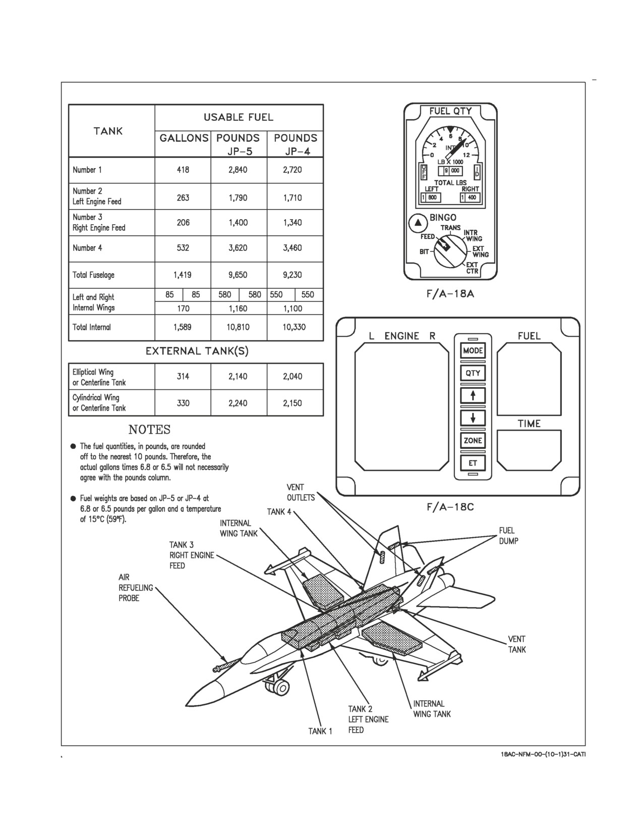
A1-F18AC-NFM-000
Figure 2-6. Fuel Quantity (F/A-18A/C)
I-2-23
ORIGINAL
A1-F18AC-NFM-000
2.3 FLIGHT PERFORMANCE ADVISORY SYSTEM
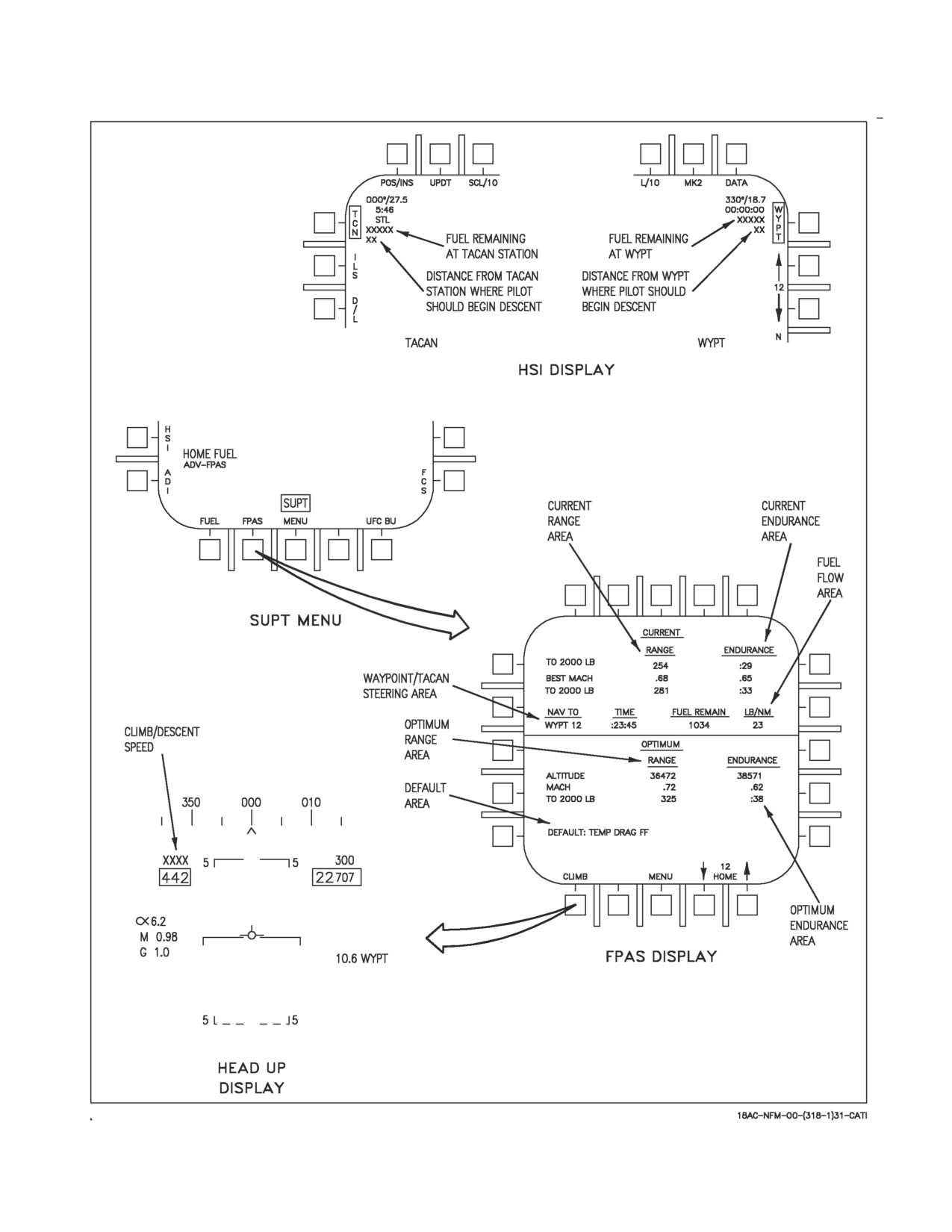
2.3.1 Flight Performance Advisory System (FPAS) (F/A-18A Aircraft AFTER AFC 253 OR 292,
and F/A-18C/D Aircraft.) The FPAS advises the pilot of the altitude and airspeed corresponding to
maximum inflight fuel efficiency based on current operating conditions. The range and airspeed
calculated by the FPAS algorithm appears on the FPAS display (figure 2-7). The FPAS display
appears when the FPAS option is selected on the SUPT MENU. The FPAS display is divided into five
areas: the current range and endurance area, the optimum range and endurance area, the Waypoint/
TACAN steering area, the fuel flow area, and the default area. With engines running and weight on
wheels (W on W), only the optimum and default areas are valid. All areas are valid with weight off
wheels (W off W). The Waypoint/TACAN steering area is valid with W off W when Waypoint or
TACAN steering is selected on the HSI display.
2.3.1.1
FPAS Display
2.3.1.1.1
Default Area. Temperature, stores drag, and fuel flow parameters, if invalid, do not have a
fatal impact on FPAS calculations. If one or more of these parameters become invalid, the invalid
parameter(s) are displayed in the default area (figure 2-7).
2.3.1.1.2
Current Range Area. The current range area on the FPAS display (figure 2-7) informs the
pilot of range to 2,000 lb fuel remaining at current altitude and Mach, the best Mach to fly at the
current altitude to maximize range, and range to 2,000 lb fuel flown at that Mach number. If total
onboard fuel goes below 2,500 lb the FPAS calculations are done to 0 lb and the TO 2000 LB legend
changes to TO 0 LB. If TAS exceeds Mach 0.9 the range at current Mach and altitude is invalid and
the word Mach is displayed under RANGE. If the parameters associated with the current range area
become invalid the current range area displays XXXX and an FPAS advisory is displayed below the
ENDURANCE legend in place of the endurance value. When any of the preconditions is not valid, the
range and endurance values display XXXX and an FPAS advisory is displayed. Fuel remaining is
monitored and a DDI caution is displayed when calculated fuel remaining on arrival is less than 2,000
pounds.
2.3.1.1.3
Current Endurance Area. The current endurance area of the FPAS display (figure 2-7)
informs the pilot of endurance to 2,000 lb (0 lb) fuel remaining at current altitude and Mach number,
the best Mach to fly at current altitude to maximize endurance, and endurance to 2,000 lb (0 lb if fuel
remaining is less than 2,500 lb) fuel at that Mach number. When TAS exceeds Mach 0.9, the
endurance at current altitude and Mach number becomes invalid and LIM is displayed under
ENDURANCE. If parameters associated with the current endurance area become invalid the current
endurance area is Xd out.
2.3.1.1.4
Optimum Range Area. The optimum range area on the FPAS display (figure 2-7) shows
the altitude and Mach number at which to fly to achieve maximum range (also displayed) to 2,000 lb
(0 lb if fuel remaining is less than 2,500 lb) of fuel. If parameters associated with optimum endurance
area become invalid the numerical display area is Xd out.
2.3.1.1.5
Optimum Endurance Area. The optimum endurance area on the FPAS display (figure 2-7)
shows the altitude and Mach number at which to fly to achieve maximum endurance (also displayed)
to 2,000 lb (0 lb if fuel remaining is less than 2,500 lb) of fuel. If parameters associated with optimum
endurance area become invalid the numerical display area is Xd out.
I-2-24
ORIGINAL
A1-F18AC-NFM-000
Figure 2-7. FPAS Display
I-2-25
ORIGINAL
A1-F18AC-NFM-000
2.3.1.1.6
Waypoint/TACAN Steering Area. If waypoint or TACAN steering is selected on the HSI
display (figure 2-7), the waypoint or TACAN station selected, the arrival time at current conditions,
and the fuel remaining at arrival is displayed on the FPAS display. The fuel remaining at arrival and
the number of miles (if greater than 99 miles, 99 miles is displayed) from the waypoint or TACAN
station to begin descent is displayed on the HSI display. If time to waypoint, fuel remaining, or
TACAN station is invalid, Xs are displayed. If fuel remaining is calculated to be less than 0 lb, 0 is
displayed. If TAS exceeds Mach 0.9 the fuel remaining is blanked.
2.3.1.1.7
Fuel Flow Area. The total fuel flow rate (both engines combined) in pounds per nautical
mile is displayed (figure 2-7) whenever the engines are running.
2.3.1.1.8
Climb Pushbutton. Pressing the climb pushbutton on the FPAS display enables the climb
air speed prompt on the HUD if the HUD reject switch is in the normal position. When selected, the
CLIMB legend is boxed. If not in the NAV master mode, the climb pushbutton is removed from the
FPAS display.
2.3.1.2
HOME FUEL Caution. When the calculated fuel remaining at the home waypoint reaches
2,000 lbs, the master caution aural tone is triggered, the master caution light is turned on, and the
caution message HOME FUEL is displayed on the DDI. The home waypoint is set to 0 at power up.
The pilot can increment/decrement the home waypoint, providing FPAS has the ability to calculate
the HOME FUEL caution, by using the up/down arrows on the FPAS display. The range for the home
waypoint is 0 to 24 (MC OFP 10A AND UP) or 0 to 59 (MC OFP 13C AND UP). The mechanization
is circular, in that if waypoint 59 is selected and the up arrow is pressed the home waypoint returns to
0. The home waypoint must be steady for 5 seconds before the HOME FUEL caution logic can begin.
If FPAS cannot calculate the HOME FUEL caution, the home waypoint is X’d out and the up and
down arrows are removed from the display. The HOME FUEL caution is not activated if weight is on
wheels, the refueling probe is extended, or for
5 seconds after the pilot selects a new home
waypoint. With MC OFP 13C AND UP, the HOME FUEL caution resets if: the refueling probe is
extended, the aircraft transitions from weight off wheels to weight on wheels, the landing gear is cycled
from up to down to up, or the HOME WAYPOINT is changed.
2.3.1.3
FPAS Advisory. The FPAS advisory is displayed on the DDI if the FPAS system loses the
capability to calculate the HOME FUEL caution.
2.3.1.4
HSI with Waypoint or TACAN Steering Selected. If waypoint or TACAN steering is selected
on the HSI display, the fuel remaining at arrival and the miles from the waypoint or TACAN station
to begin descent are displayed on the HSI display. When FPAS cannot calculate fuel remaining and the
point to begin descent, invalid Xs are displayed for these parameters. If TAS exceeds Mach 0.9, blanks
are displayed. If fuel remaining at the waypoint or TACAN station is less than the TO XXXX LB
legend, the WYPT number, the TO XXXX LB legend on the FPAS display and the fuel remaining on
both the FPAS and HSI displays is flashed.
2.4 SECONDARY POWER SYSTEM
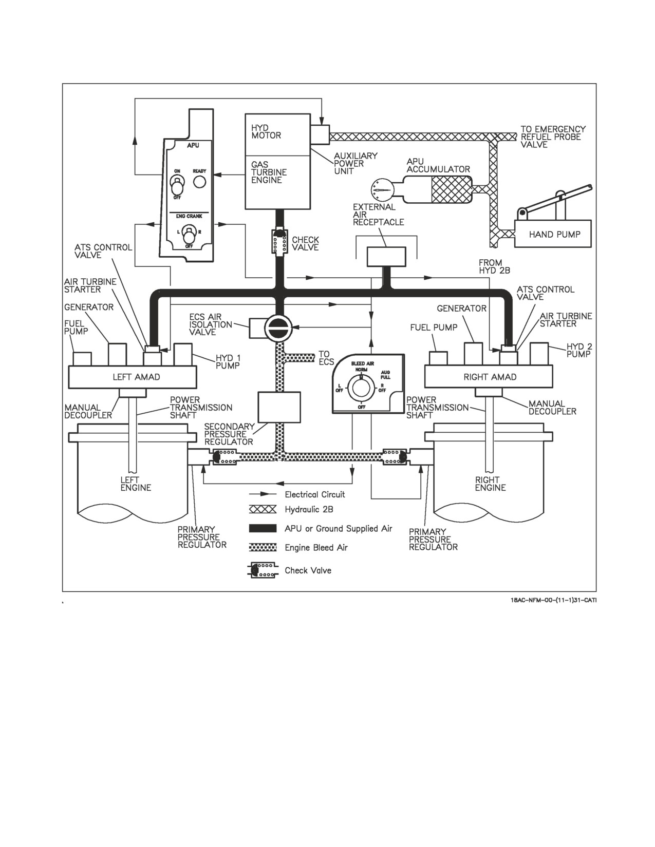
Figure 2-8 shows the major components of the secondary power system.
2.4.1 Airframe Mounted Accessory Drive (AMAD). There are two AMAD gearboxes, one for each
engine. Each AMAD is mechanically driven by its corresponding engine through a power transmission
shaft. Either AMAD (but not both at the same time) may also be driven pneumatically through an air
turbine starter (ATS) by the auxiliary power unit (APU), opposite engine bleed air (crossbleed), or an
I-2-26
ORIGINAL
A1-F18AC-NFM-000
Figure 2-8. Secondary Power Supply
external air supply. Each AMAD mechanically drives a fuel pump, an AC generator, and a hydraulic
pump.
For first engine start, the APU or external air supply drives the ATS which in turn drives the AMAD
and cranks the engine. For the second engine start, the APU, external air, or crossbleed from the first
engine may be used to drive the opposite ATS and crank the second engine.
For accessory drive only (maintenance use), either engine may be decoupled from the AMAD, and
the APU may be used to drive the decoupled AMAD and its attached accessories. On aircraft through
161519, use of external air is not authorized to drive the decoupled AMAD.
I-2-27
ORIGINAL
A1-F18AC-NFM-000
During normal engine operation, each AMAD and its accessories are driven by the corresponding
engine via the power transmission shaft.
NOTE
Failure of the power transmission shaft (PTS) will result in the display
of the associated GEN, BOOST LO, and both HYD circuit cautions.
If one engine fails and the engine core is rotating freely, crossbleed or the APU may be used to keep
the failed engine AMAD operating.
2.4.1.1
L and R AMAD Caution Display. The L or R AMAD caution display on the DDI indicates
that the corresponding AMAD oil temperature is too high.
2.4.1.2
L and R AMAD PR Caution Display. On aircraft 161925 AND UP, the L or R AMAD PR
caution on the DDI indicates that the corresponding AMAD oil pressure is low.
2.4.2 Auxiliary Power Unit (APU). The APU is a small aircraft mounted gas turbine engine used to
generate a source of air to power the air turbine starter(s) or to augment the engine bleed air supply
to the ECS. It is situated on the underside of the fuselage between the engines, with both intake and
exhaust facing downwards. A hydraulic motor powered by the APU accumulator, normally charged by
HYD 2B, is used to start the APU. A hand pump may be used to charge the accumulator. The aircraft
battery provides electrical power for the APU ignition and start control circuits. The APU uses aircraft
fuel.
Operation of the APU is automatic after the APU switch, on the left console, is placed to ON. The
APU may be shut down at any time by placing the APU switch to OFF. After the APU has completed
its start cycle a green READY light comes on. After the second generator is on line, the APU runs
approximately 1 minute then the APU switch returns to OFF.
Limited inflight testing has been performed and indicates that with at least one generator off line,
the APU will start inflight below 10,000 feet and 250 KCAS. The inflight exhaust of the APU may cause
blistering and peeling of the aft fuselage paint. To ensure sufficient accumulator pressure, HYD ISOL
ORIDE should be selected for 10 seconds prior to attempting inflight start.
2.4.2.1
APU Switch. The APU switch is a two-position switch with positions of ON and OFF.
OFF
Provides a manual shutdown for the APU.
ON
Starts the start cycle of the APU. Switch is electrically held in the ON position
and automatically returns to OFF 1 minute after the second generator comes on
the line provided the bleed air knob is not in AUG PULL.
2.4.2.2
APU ACCUM Caution Display. An APU ACCUM caution display on the DDI and caution
light panel indicates the APU accumulator pressure is low. With this display, APU start, emergency
gear extension, emergency extension of the air refueling probe and emergency nosewheel steering may
not be available.
I-2-28
ORIGINAL
A1-F18AC-NFM-000
2.4.2.3
Start Cycle.
• On Aircraft 161353 THRU 163175 BEFORE IAYC 853, to minimize
the potential of APU surge, ensure generator switches are ON, bleed
air aug is OFF, and do not shut down the APU while cranking an
engine when opposite engine is running.
• In all cases of engine start, generator switch should be on as it provides
overspeed cutout protection for the ATS.
2.4.2.3.1
Both Engines From APU. Either engine may be started first; however, starting the right
engine first provides normal hydraulic pressure to the brakes. After the APU READY light is on, place
the electrically held engine crank switch to R. This opens the right air turbine starter control valve
(ATSCV) and APU air powers the ATS. The ATS in turn cranks the right engine by way of the AMAD
gearbox and power transmission shaft. After the right generator comes on the line the engine crank
switch automatically returns to OFF. The left engine is started the same way as the right. One minute
after the second generator comes on the line the APU shuts down.
2.4.2.3.2
Cross Bleed From First Engine. The first engine should be at a minimum 80% rpm and
1,900 pph fuel flow. With the APU off, the engine crank switch controls the ATSCV and the ECS air
isolation valve. Placing the engine crank switch to the second engine permits compressor bleed air from
the operating engine to pass through the open ECS air isolation valve and the other ATSCV to crank
the second engine. After the second generator comes on the line the engine crank switch returns to off
and the ECS air isolation valve closes.
2.4.2.3.3
Air Turbine Starter Caution Display. An L or R ATS caution may be displayed on the
DDI. The L or R ATS caution indicates the starter is turning at too high an rpm.
2.4.3 External Power Start. If the APU is not used, an external air source may be used to start the
engine(s). After the bleed air knob is placed to OFF, and external air is applied in the right wheelwell,
the start procedure is the same as when using the APU.
2.4.4 Bleed Air Augmentation. On the ground, the APU may be used to augment engine bleed air
for ECS operation. The bleed air knob must be in any position except OFF (NORM preferred). With
both generators on the line and the APU running, selecting AUG PULL overrides the APU automatic
shutdown and directs APU air to the ECS to augment engine bleed air. With both generators on the
line and the APU shut down, the AUG PULL position must be selected before the APU can be
restarted. If the AUG PULL position is selected with only one engine operating, augmentation air is
terminated during the second engine start but is regained after both engines are running. Moving both
throttles to MIL or above terminates augmentation air, causes the bleed air knob to move out of the
I-2-29
ORIGINAL
A1-F18AC-NFM-000
AUG PULL position and after 1 minute shuts down the APU. Pushing the bleed air knob down also
terminates augmentation air and after 1 minute shuts down the APU.
On aircraft 161353 THRU 163175 BEFORE IAYC 853, to minimize
potential of APU damage due to surging, use bleed air aug only when
absolutely necessary to maintain cooling.
Before securing bleed air aug (by pushing center of bleed air aug switch) with engine(s) running,
slowly advance one engine to 80% N2 rpm. To secure the bleed air aug with no engines running, push
the center of the bleed air aug switch then wait 10 seconds before securing the APU.
2.5 ELECTRICAL POWER SUPPLY SYSTEM
The electrical power supply system consists of two AC generators, two transformer-rectifiers, two
batteries with integral battery chargers on aircraft 161353 THRU 161528, BEFORE AFC 049, or a
single battery charger transformer-rectifier unit (TRU) which charges both batteries on aircraft 161702
AND UP, and aircraft 161353 THRU 161528 AFTER AFC 049, and a power distribution (bus) system.
External electrical power can be applied to the bus system on the ground. In the absence of external
electrical power, battery power is provided for engine starts, whether using the onboard APU or
external air. See Electrical System, figure 2-9 and Foldout Section, for electrical system simplified
schematics.
2.5.1 AC Electrical Power. Two ac generators are the primary source of electrical power. The two
generators are connected for split bus nonsynchronized operation. This means that with both
generators operating each generator supplies power to an independent, isolated aircraft bus. If one
generator fails, it drops off the line and power from the remaining generator is automatically provided
to the bus of the failed (or turned off) generator. Either generator is capable of supplying power to the
entire system. Each generator is activated automatically when its control switch is in the NORM
position; and the generator is connected to its buses when voltage and frequency are within prescribed
limits (approximately 60% engine rpm). A protection system within the generator converter unit
(GCU) protects against damage due to undervoltage, overvoltage, over and under frequency, and feeder
faults. If a fault or malfunction occurs, the generator converter unit removes the affected generator
from its buses. Except for under speed, the control switch of the affected generator must be cycled to
bring the generator back on the line after the fault or out-of-tolerance condition occurs. For an under
speed condition, the generator comes back on the line automatically when in-tolerance speed is
restored. A generator may be removed from its buses at any time by placing the generator control
switch to OFF. On aircraft 162394 AND UP, and 161353 THRU 161987 AFTER AFC 048, in the event
that both generators become inoperative due to a bus or equipment fault the bus tie contactors and the
ac bus isolation and generator auto reset logic circuit interact isolating the ac buses. Approximately 1
second after the dual outage the logic circuit attempts to reset both generators. If the cause(s) of the
dual outage has cleared, both generators come back on line powering their respective buses. If the cause
of the outage has not cleared when automatic generator reset is attempted, the generator that normally
powers the faulted bus/failed equipment is not restored, and that bus remains unpowered. The other
generator comes on line and powers its associated bus and equipment. The ac bus isolation and
generator auto reset circuit is prevented from operating whenever the parking brake is set. Beside the
parking brake not being set, the generator tie control switch must be in NORM and the battery switch
must be ON for the circuit to operate.
I-2-30
ORIGINAL
A1-F18AC-NFM-000
2.5.1.1
Generator, GEN TIE Caution Lights, and Displays. Three caution lights, labeled L GEN, R
GEN and GEN TIE are on the caution lights panel. The L GEN and R GEN caution lights and the L
GEN and R GEN caution displays come on whenever their respective generator drops off the line. On
aircraft 162394 AND UP, the GEN TIE caution light advises the pilot that the bus tie contactors are
deenergized and the ac buses are isolated. The generator tie control switch, located outboard of the
throttles on the left console, allows the pilot to override the ac bus isolation and generator auto reset
circuitry and reenable the automatic bus tie ac circuit. These lights operate in conjunction with the
MASTER CAUTION. In event of dual generator failure, the MASTER CAUTION light comes on
(tone inoperative); however, the generator caution lights and displays and the generator tie caution
light do not come on.
2.5.1.2
Generator Control Switches. Two generator control switches, one for each generator, are on
the electrical power panel. They are two-position toggle switches with positions OFF and NORM.
Cycling of generators airborne in an attempt to regain failed/degraded
systems may result in loss of additional systems.
2.5.1.3
Generator TIE Control Switch. On aircraft 162394 AND UP, and 161353 THRU 161987
AFTER AFC 048, the generator tie control switch, outboard of the exterior lights panel on the left
console, has positions NORM and RESET. The guarded switch must be in NORM (battery switch in
ON) for the bus tie circuit and the ac bus isolation and generator auto reset circuit to operate. The
RESET position is used to reset the bus tie circuit after a fault causing the bus tie to open is cleared.
Reset is performed by placing the switch to RESET and back to NORM. A ground engine start without
the parking brake set results in illumination of the GEN TIE caution and requires cycling of the
generator tie control switch to reset the bus isolation circuitry.
2.5.2 DC Electrical Power (Aircraft 161353 THRU 161528 BEFORE AFC 049). Two transformer-
rectifiers and two batteries with integral battery chargers are provided. The output of both
transformer-rectifiers are connected in parallel, however, protection is provided so that a short on a bus
of one transformer-rectifier does not affect the other transformer-rectifier. If one transformer-rectifier
fails, the other transformer-rectifier powers the entire DC system. No cockpit warning of single
transformer-rectifier failure is provided. The batteries, designated utility or U battery, and emergency
or E battery, are used for engine start when external power or aircraft generator power is not available,
and are used to power the essential 24/28 volt dc bus when both transformer-rectifiers are lost. The U
battery also powers the maintenance 24/28 volt dc bus when both transformer-rectifiers are inopera-
tive. This allows operation of the canopy and maintenance monitor on the ground without any other
electrical power on the aircraft. The batteries are controlled by a single battery switch. The system
supplies battery power to the essential bus when both transformer-rectifiers are lost and the battery
switch is positioned to ON or ORIDE. With the battery switch ON, the essential bus is automatically
sequenced between the two batteries. The essential bus and start bus are initially powered by the
utility battery, and as the utility battery becomes depleted the essential bus (but not the start bus)
transfers to the emergency battery. An ORIDE position is provided on the battery switch to allow
selection of the emergency battery in the event the automatic sequencing system fails. In addition, the
switch is provided with an OFF position to prevent depletion of the batteries while the aircraft is
parked. The batteries charge regardless of the position of the battery switch, providing power is being
I-2-31
ORIGINAL
A1-F18AC-NFM-000
supplied to the battery chargers by the transformer-rectifiers. In addition, the E battery 24 volt dc bus
which is connected directly to the emergency battery, and the U battery 24 volt dc bus which is
connected directly to the utility battery, are powered as long as their respective battery retains a
charge.
To prevent damage to the battery bus contactors and/or batteries, do not
leave the BATT switch in ON or ORIDE for extended periods without
generators on-line or external power on the aircraft. After engine shut-
down, ensure BATT switch is OFF and the BATT SW caution light is not
ON.
2.5.2.1
Battery Switch
OFF
Batteries can be charged, but battery contactors will not energize to connect a bat-
tery to the essential bus in response to low voltage conditions.
ON
Enables control circuitry of both battery contactors so the U battery contactor will
automatically close in response to a low voltage condition on the left 28 volt dc
bus, and the E battery contactor will subsequently close in response to a low volt-
age condition from the U battery output and left 28 volt dc bus.
ORIDE
Energizes E battery contactor regardless of charge status of U battery, providing
voltage on left 28 volt dc bus is absent or low. Position can be used to connect E
battery to the essential buses in the event U battery contactor fails to energize
with switch in the ON position.
2.5.2.2
Battery Caution Lights and Displays. Three caution lights, the U BATT, E BATT and
BATT SW are associated with operation of the batteries. All three cautions are displayed on both the
DDI and caution lights panel. The MASTER CAUTION comes on in conjunction with these lights.
The U BATT and E BATT lights come on to indicate a low state of charge of their respective batteries,
and operate only with the battery switch in the ON or ORIDE position. The BATT SW light alerts the
pilot to check the position of the battery switch. The light coming on, on the ground, without ac
electrical power on the aircraft indicates (unless APU start about to be made) that batteries are being
depleted and switch should be placed to OFF. The BATT SW light coming on in the air normally
indicates that the battery switch is in the OFF or ORIDE position and should be placed to the ON
position. The BATT SW light coming on in the air with the battery switch ON indicates that the
essential bus is energized by battery power (double generator or double transformer-rectifier failure)
and that battery energy should be conserved.
I-2-32
ORIGINAL
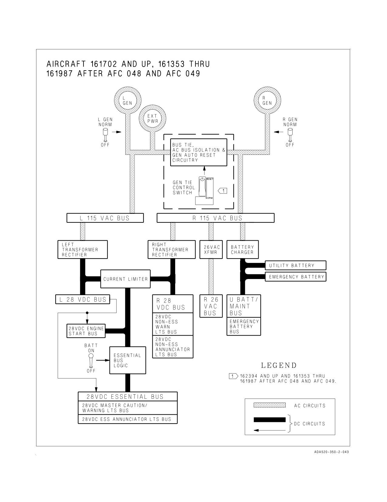
A1-F18AC-NFM-000
Figure 2-9. Electrical System (Sheet 1 of 2)
I-2-33
ORIGINAL
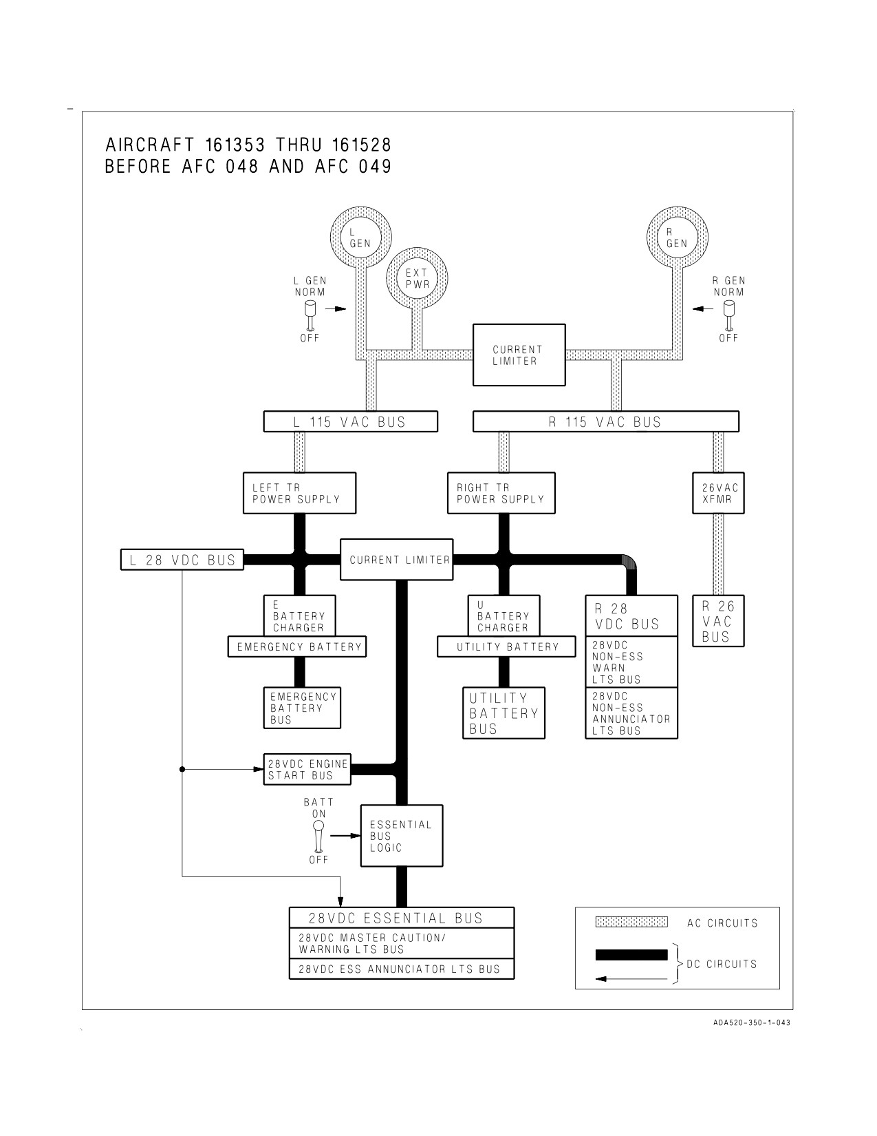
A1-F18AC-NFM-000
Figure 2-9. Electrical System (Sheet 2 of 2)
I-2-34
ORIGINAL
A1-F18AC-NFM-000
2.5.3 DC Electrical Power (AIRCRAFT 161702 AND UP AND AIRCRAFT 161353 THRU 161528
AFTER AFC 049). Two transformer-rectifiers and two 7.5 ampere-hour sealed lead acid batteries with
a single battery charger are provided. The transformer-rectifiers are connected in parallel and
protection is provided so that a short on a bus of one transformer-rectifier does not affect the other
transformer-rectifier. If one transformer-rectifier fails, the other transformer-rectifier powers the
entire DC system. No cockpit warning of single transformer-rectifier failure is provided. The batteries,
designated utility or U battery, and emergency or E battery, are used for engine starts when external
power or aircraft generator power is not available, and are used to power the essential 24/28 volt dc bus
when both transformer-rectifiers are lost. The utility battery powers the U BATT/maintenance bus
directly which allows operation of the canopy and maintenance monitor on the ground without any
other electrical power on the aircraft. In addition, the emergency battery powers the E BATT bus
directly. The E/U BATT voltmeter is used to monitor voltage on the U and E batteries. The single
battery charger supplies charging power directly to the utility battery and, through the E battery
charging contactor, to the E battery. The charger receives power from the right 115 volt ac bus and
provides charging power to the U battery whenever ac power is on the aircraft. For the E battery to
receive charge, the left 28 volt dc bus must be powered to energize the E battery charging contactor.
The batteries are controlled by a single battery switch on the electrical power panel. The system
supplies battery power to the essential bus when both transformer-rectifiers are lost and the battery
switch is in ON or ORIDE. With the switch ON, the normal flight position, and the left 28 volt dc bus
de-energized, the U battery automatically powers the essential and engine start 24/28 volt dc buses.
When the U battery depletes to 20.5 volts or below for over 0.5 second, the E battery automatically
powers the essential 24/28 volt dc bus (but not the 24/28 volt engine start bus). Placing the battery
switch to ORIDE connects the E battery to the essential 24/28 volt dc bus regardless of the status of
the left 28 volt dc bus or the U battery. The ORIDE position is provided to allow selection of the E
battery if the automatic switching circuits associated with the ON position fail. The OFF position is
provided to prevent depletion of the batteries when the aircraft is parked. The batteries charge
regardless of the position of the battery switch, provided ac power is on the aircraft.
To prevent damage to the battery bus contactors and/or batteries, do not
leave the BATT switch in ON or ORIDE for extended periods without
the generators on the line. After engine shutdown, ensure BATT switch
is OFF and the BATT SW caution light is not ON.
2.5.3.1
Battery Switch.
OFF
Batteries can be charged, but battery contactors will not energize to connect a bat-
tery to the essential bus (start bus) in response to low voltage conditions. Both
voltmeters are inoperative.
ON
Enables control circuitry of both battery contactors, so that the U battery contac-
tor will automatically close in response to a low voltage condition on the left 28
volt dc bus, and the E battery contactor will subsequently close in response to a
low voltage condition from the U battery output. U and E voltmeters indicate volt-
age on their respective batteries. On aircraft 162394 AND UP, position enables the
bus tie circuit and the ac bus isolation and generator auto reset circuit. On aircraft
163119 AND UP, an automatic battery cutoff circuit is provided which cuts off the
battery from the essential dc bus 5 minutes after internal or external ac power is
removed from the aircraft while on the ground with the battery switch ON.
I-2-35
ORIGINAL
A1-F18AC-NFM-000
ORIDE
Energizes E battery contactor, regardless of status of U battery or left 28 volt dc
bus. Position can be used to connect E battery to the essential buses in the event
U battery contactor fails to energize. With switch ON only E voltmeter is opera-
tive. On aircraft 162394 AND UP, position disables the bus tie circuit and the ac
bus isolation and generator auto reset circuit.
2.5.3.2
E/U BATT Voltmeter. The E/U BATT voltmeter, which combines a U battery voltmeter and
E battery voltmeter in one indicator, is on the electrical power panel. Voltage is indicated in 1-volt
increments from 16 to 20 volts, and in 2-volt increments from 20 to 30 volts. The scales are marked at
24 volts and 20.5 volts (the U battery voltage at which the E battery will automatically power the
essential 24/28 volt dc bus). With the battery switch OFF, the voltmeters are inoperative and the
indicator needles indicate 16 volts. With the battery switch ON both voltmeters are operative; with the
switch in ORIDE only the E voltmeter is operative.
2.5.3.3
BATT SW Caution Light/Display. The BATT SW caution light on the caution lights panel
is associated with operation of the batteries. A BATT SW caution display on the DDI (with ac power
on the aircraft) and the MASTER CAUTION comes on in conjunction with the caution light. The
BATT SW caution alerts the pilot to check the position of the battery switch. The light coming on, on
the ground, without ac power on the aircraft indicates that batteries are being depleted and switch
should be placed OFF unless APU start is about to be made. The BATT SW light coming on in the air
normally indicates that the battery switch is in OFF or ORIDE and should be placed to ON. The BATT
SW light coming on in the air with the battery switch in ON indicates that the essential bus is energized
by battery power (double generator or double transformer-rectifier failure) and that battery energy
should be conserved.
2.5.3.4
Automatic Battery Cutoff. On aircraft 161353 THRU 163118 AFTER AFC 090 and 163119
AND UP, an automatic battery cutoff circuit is provided which cuts off the battery from the essential
dc bus 5 minutes after internal or external ac power is removed from the aircraft while on the ground
with the battery switch in ON. Once the battery cutoff is activated, the battery can be reconnected to
the essential dc bus for additional 5-minute periods by either of three procedures: momentarily placing
the APU switch ON, cycling the battery switch to OFF then ON, or cycling the MMP enable switch in
the nosewheel well to RESET and back to NORM with the battery switch out of the ON position. The
automatic battery cutoff circuit has no effect on operation of the ORIDE position of the battery switch.
2.5.4 External Electrical Power. External electrical power may be connected to the aircraft bus
system through an external electrical power receptacle on the left side of the forward fuselage. The
aircraft buses are energized by external power in the same manner as if a generator were operating. On
aircraft 162394 AND UP, the aircraft buses are energized as above provided the battery switch is OFF
or the parking brake is set. If the battery switch is ON and the parking brake is not set, the ac buses
associated with the right generator are not energized. This condition is indicated by the GEN TIE
caution coming on. Some aircraft systems do not energize immediately upon application of external
power. Power can be applied to these systems through actuation of ground power switches.
2.5.4.1
External Power Switch. The external power switch, on the ground power panel on the left
console (figure 2-10), controls application of external power to the aircraft electrical buses. If the
external power is not of the proper quality (within voltage, phase and frequency limits), the external
power monitor senses this and disconnects or prevents the external power from being connected to the
aircraft.
I-2-36
ORIGINAL
A1-F18AC-NFM-000
RESET
Must be selected before external power can be applied to aircraft buses. The
RESET position is spring loaded to NORM.
NORM
Allows the aircraft electrical buses to be energized by external power if no aircraft
generators are operating, providing external power is of proper quality and this
switch is first positioned to RESET.
OFF
Disconnects external power from the aircraft.
2.5.4.2
Ground Power Switches. Four ground power switches are provided on the ground power
panel (figure 2-10) on the left console. Each controls a group of systems and/or instruments (listing is
on a placard above the panel) and prevents operation of the systems/instruments on external power,
unless the switch is placed to the ON position.
AUTO
System/instrument is automatically deenergized with external power on.
ON
System/instrument can be energized by external power for maintenance purposes.
When a generator comes on the line, the switch returns to AUTO.
NOTE
• With an overheat condition present, all ground power switches in the
ON position (solenoid held) revert to the AUTO position, and cannot
be returned to ON until the overheat condition is corrected.
• When the first ground power switch is set to ON, the avionics
under-cool warning temperature switch performs an internal BIT
(approximately 3 seconds). During BIT, the ground power switch(es)
must be held ON or it reverts to AUTO.
• On aircraft 161353 THRU 162889, setting any ground power switches
to ON with an engine driven generator on line activates a false MMP
code 884 (ground power circuit fail).
2.5.5 Circuit Breakers. Two circuit breaker panels containing essential breakers are located above
the right and left consoles. The panel above the left console contains the following breakers: FCS
CHAN 1, FCS CHAN 2, SPD BRK and LAUNCH BAR. The panel above the right console contains
the following breakers: FCS CHAN 3, FCS CHAN 4, HOOK and LG.
2.6 LIGHTING
2.6.1 Exterior Lighting. Exterior lights are controlled from the exterior lights panel, the left vertical
panel, and the left throttle grip.
I-2-37
ORIGINAL
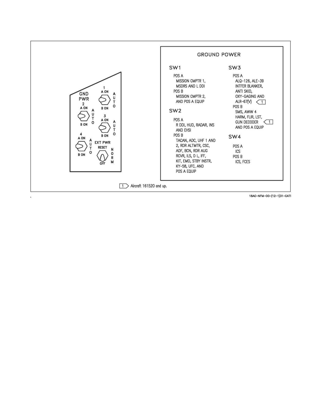
A1-F18AC-NFM-000
Figure 2-10. Ground Power Panel and Placard
2.6.1.1
Exterior Lights Master Switch. The exterior lights master switch, on the outboard left
throttle grip, provides a master control for the following exterior lights: position lights, formation
lights, strobe lights, arresting hook floodlight and refueling probe light.
OFF (AFT)
Power for lights controlled by switch is cut off.
ON (FWD)
Power is available for lights controlled by switch.
2.6.1.2
Position Lights. The position lights include a white light just below the tip of the right
vertical tail fin, three green lights on the right side of the aircraft, and three red lights on the left side
of the aircraft. The green and red lights are at the following locations on their respective sides of the
aircraft: wing tip, LEX forward of the wing root, and under the wing at the wingfold hinge. The position
lights are controlled by the POSITION lights knob on the exterior lights panel which provides variable
lighting between positions OFF and BRT. The exterior lights master switch must be ON for the
position lights knob to operate.
2.6.1.3
Formation Lights. Eight formation lights are provided. Two lights are on each wing tip and
show above and below a wing tip missile when installed, two lights are on the outboard of the vertical
tail fins, two lights are on the aft fuselage below the vertical tail fins, and two lights are on either side
of the forward fuselage just forward of the LEX. The formation lights are controlled by the
FORMATION lights control knob on the exterior lights panel which provides variable lighting between
positions OFF and BRT. The exterior lights master switch must be ON for the formation lights knob
to operate.
I-2-38
ORIGINAL
A1-F18AC-NFM-000
2.6.1.4
Strobe Lights. Two red anti-collision strobe lights, one on each outboard vertical tail fin, are
provided. The strobe lights are controlled by the STROBE lights switch on the exterior lights panel.
The exterior lights master switch must be ON for the strobe lights switch to be operative.
OFF
Lights are off.
BRT
Lights illuminate at full intensity.
DIM
Lights illuminate at reduced intensity.
2.6.1.5
Landing/Taxi Light. A combination landing and taxi light is on the nose gear strut. The light
is controlled by the LDG/TAXI light switch on the left vertical panel.
OFF
Light is off.
ON
If the landing gear handle is in DN and the landing gear is down, the light is on.
2.6.1.6
Approach Lights/Arresting Hook Floodlight. Three approach lights are on the nose gear
strut. With all landing gear down and locked, and weight off the gear, the lights come on as a function
of angle of attack. A green light indicates a high angle of attack, an amber light indicates optimum
angle of attack and a red light indicates a low angle of attack. The operating approach light flashes if
the arresting hook is not down and the HOOK BYPASS switch, on the left vertical panel, is in
CARRIER. If the HOOK BYPASS switch is in FIELD, the lights do not flash. The FIELD position is
solenoid held and reverts to CARRIER when the arresting hook is lowered or electrical power is
shutdown after flight. On aircraft 161353 THRU 162909, an arresting hook floodlight on the left
inboard landing gear door (when installed) illuminates the arresting hook area when the approach
lights are on, provided the exterior lights master switch is on. The approach lights are dimmed
whenever the warning/caution/advisory lights are dimmed. The arresting hook floodlight cannot be
dimmed. On aircraft 163092 AND UP, the arresting hook floodlight is removed.
2.6.2 Interior Lighting. Except for the utility floodlight, UFC display lighting, AOA indexer lights,
and IFEI display lighting, all controls for the interior lights are on the interior lights panel on the right
console.
2.6.2.1
Mode Switch (AIRCRAFT 163985 AND UP). The MODE switch is used to select the cockpit
lighting mode. In aircraft 163985 THRU 164740, the MODE switch has positions of NORM and NVG.
The NORM position permits the maximum brightness range for the warning, caution, and advisory
lights and the main and console panel lighting. The NVG position provides night vision goggle
compatible lighting. In aircraft 164865 AND UP, the MODE switch has positions of NVG, NITE, and
DAY. The DAY position permits the maximum brightness range for the warning, caution, and advisory
lights and the main and console panel lighting. The NITE position provides reduced brightness for the
warning, caution, and advisory lights, and normal intensity for the main and console lighting. The NVG
position provides reduced brightness for the warning, caution, and advisory lights, disables the integral
console lighting, and enables NVG compatible flood lights to illuminate the consoles.
2.6.2.2
NVG Compatible Cockpit Lighting Retrofit. On aircraft 161702 THRU 163782 AFTER AFC
209, AVCs 4525, 4526, AND 4527 the cockpit lighting system is modified to provide compatible NVG
lighting. The master arm control panel, right and left advisory and threat panels, caution light panel,
radar altimeter, and UFC panel are modified to emit less light (NVG compatible). The chart light,
I-2-39
ORIGINAL
A1-F18AC-NFM-000
utility light, eight floodlights, and lock/shoot lights are replaced with the new night attack lights. The
function of the knobs and switches on the interior lights panel is unchanged, however; the total
brightness for a given position is now reduced.
2.6.2.3
Console Lighting. Integral and light panel lighting for the left and right consoles, the
hydraulic pressure indicator, and both cockpit circuit breaker panels are controlled by the CONSOLES
knob which provides variable lighting between positions OFF and BRT.
On aircraft 163985 AND UP with the MODE knob in NORM, the CONSOLES knob provides
variable lighting between OFF and BRT. With the MODE knob in the NVG position, the CONSOLES
knob provides variable NVG floodlighting between OFF and BRT for the consoles.
2.6.2.4
Instrument Lighting. Integral and light panel lighting for the instrument panel, UFC
background, right and left vertical panels (except for the hydraulic pressure indicator) and standby
magnetic compass are controlled by the INST PNL knob which provides variable lighting between
positions OFF and BRT. The strobe shoot light does not illuminate when the instrument lights are on.
On aircraft 163985 AND UP, the INST PNL knob provides variable lighting between OFF and BRT,
with the MODE switch in either NORM or NVG.
2.6.2.5
Flood/Chart Lighting. Eight white floodlights are provided for secondary lighting. Three
console floodlights are above each console, and an instrument panel floodlight is located to either side
of the instrument panel. A chart light is installed on the canopy arch. On aircraft 161353 THRU 163782
the flood lights are controlled by the FLOOD knob and MODE switch. With the flood switch in the
COCKPIT position, the flood knob provides variable flood and chart lighting between OFF and BRT.
In the CHART position, the flood knob provides variable chart lighting between OFF and BRT. On
aircraft 163985 AND UP, the flood lights are controlled by the FLOOD knob and MODE switch. On
aircraft 163985 THRU 164740 with the MODE switch in the NORM position, or on aircraft 164865
AND UP with the MODE switch in DAY or NITE the floodlights are controlled by the FLOOD knob
which provides variable lighting between OFF and BRT. The FLOOD knob is inoperative with the
MODE switch in the NVG position. An NVG compatible chart light is controlled by the CHART knob
and rotates in two axis with variable lighting between OFF and BRT. The chart light operates
independent of the MODE switch position.
2.6.2.6
IFEI Lighting. In aircraft 164865 AND UP, the IFEI brightness control knob on the video
recorder panel provides variable IFEI lighting between OFF and BRT, with the MODE switch on the
interior light panel in either the NITE or NVG position.
2.6.2.7
Utility Flood Light. A portable utility floodlight is provided and normally stowed above the
right console: an alligator clip attached to the light may be used to fasten the light at various locations
in the cockpit at the pilot’s discretion. The light contains a knob which provides variable lighting from
off to bright, and a button which when pressed causes the light to come on at full intensity. The light
also contains a rotary selector for red or white lighting.
On aircraft 163985 AND UP, the utility floodlight is NVG compatible with white and blue/green
lenses.
2.6.2.8
Emergency Instrument Light. A white emergency instrument light on the right side of the
instrument panel comes on to illuminate the standby flight instruments when double generator or
double transformer-rectifier failure occurs. The light comes on whenever a BATT SW caution light
comes on. There is no cockpit control for the emergency instrument light.
I-2-40
ORIGINAL
A1-F18AC-NFM-000
2.6.2.9
Engine Instrument Light. The engine instrument light is a stationary non-dimmable low
intensity floodlight which provides lighting for the engine monitor indicator or integrated fuel/engine
indicator when the APU switch is in the ON position.
2.6.2.10 WARNING/CAUTION Lights Knob. A knob labeled WARN/CAUT is provided on the
interior lights control panel to vary the brightness of the warning/caution/advisory lights within the
low intensity range. On aircraft
161353 THRU 164740, warning/caution/advisory lights can be
switched to the low intensity range by placing the warning/caution lights knob momentarily to RESET,
if the INST PNL knob is out of the OFF position, and either the FLOOD knob is out of OFF but less
than 70% of BRT or the flood switch is in CHART. On aircraft 164865 AND UP, the RESET function
is performed by the MODE switch. On aircraft 163985 THRU 164740, the warning/caution lights come
on at a reduced brightness in the NVG mode. The lighting system defaults to the NORM mode with
power interruption. On aircraft 164865 AND UP, the warning/caution lights come on at a reduced
brightness in the NITE and NVG mode. Once in the low intensity range, the warning/caution/advisory
lights can be brought back to high intensity by turning the MODE switch to the DAY position. With
power interruption and the MODE switch in NVG, the lighting system remains in the NVG mode when
power is restored. With power interruption and the MODE switch in DAY or NITE, the lighting
system defaults to the DAY mode when power is restored.
2.6.2.11 Lights Test Switch. A lights test switch, labeled LT TEST, is provided to test the
warning/caution/advisory lights in addition to the AOA indexer lights and the integrated fuel/engine
indicator LCD displays on F/A-18C/D aircraft. The switch only operates with AC power on the aircraft.
F/A-18A/B aircraft -
TEST
Serviceable warning/caution/advisory lights and AOA indexer lights come on. On
F/A-18A 163146 AND UP; ALSO F/A-18A 161353 THRU 163145 AFTER IASC
030, the landing gear aural tone also comes on.
OFF
The switch is spring loaded off.
F/A-18C/D aircraft -
TEST
Serviceable warning/caution/advisory lights and AOA indexer lights come on. On
the integrated fuel engine indicator the leading 1s are displayed for RPM, TEMP,
FF and OIL, and the remainder of the LCD locations indicate 0s. On F/A-18C, the
landing gear aural tone also comes on.
OFF
The switch is spring loaded off.
2.7 HYDRAULIC POWER SUPPLY SYSTEM
Hydraulic power is supplied by two separate systems (HYD 1 and HYD 2). Each system consists of
two hydraulic circuits (circuit A and circuit B). See Hydraulic System, figure 2-11. The two hydraulic
systems are identical with the exception of the fluid supply line from the hydraulic system 2 reservoir
assembly to the APU hydraulic hand pump. The left, or system 1, provides power to the primary flight
control surface actuators exclusively. The right, or system 2, also provides power to the primary flight
control actuators and additionally supplies power to the speedbrake and non-flight control actuators.
I-2-41
ORIGINAL
A1-F18AC-NFM-000
Redundancy to the flight control actuators is achieved either by simultaneously pressurizing the
actuator from both systems or by supplying pressure to the actuator from one system while the other
system is in a back-up mode.
2.7.1 Pumps and Reservoirs. The hydraulic pump for system 1 is mounted on the left AMAD
(Airframe Mounted Accessory Drive) and the pump for system 2 is mounted on the right AMAD. The
pumps contain a pressure regulating feature which keeps the pump output at approximately 3,000 psi.
A pressure relief valve in the filter and pressure relief valve hydraulic unit prevents over pressurization
of the hydraulic system and subsystems. A transducer in each reservoir continuously relays system
pressure to a hydraulic pressure indicator on the lower right main instrument panel. Each reservoir has
a reservoir level sensing (RLS) system which shuts off a leaking branch circuit (HYD 1A, HYD 1B,
HYD 2A, or HYD 2B) when the leak reduces the fluid level below a certain level. When the RLS shuts
a branch circuit off and the circuit pressure drops below 1,500 psi, a circuit pressure switch causes the
MASTER CAUTION light and the appropriate HYD 1A, HYD 1B, HYD 2A or HYD 2B caution
display on the DDI to come on. The A circuit shuts off when the reservoir level drops to 60% of full.
The A circuit comes back on the line and the B circuit shuts off when the reservoir drops to 32% of full.
The B circuit comes back on the line and no cautions are displayed when the reservoir level drops below
4% of full.
2.7.2 Hydraulic Circuits. Before the output pressure in each of the two hydraulic systems is routed
from the reservoir to subsystems, it is divided into circuit A and circuit B. Each circuit has a circuit
shutoff feature to protect the other circuit from depletion due to leakage in the circuit. To prevent fluid
loss due to leakage, when the landing gear is up, an isolation valve in both circuit A and circuit B of
hydraulic system 2 shuts off pressure to the NWS, launch bar, anti-skid, brakes, and nose gear, as these
components are not normally utilized during flight. Circuit 2B isolation can be overridden for inflight
recharging of the APU accumulator by holding the hydraulic isolate override switch to HYD ISOL
ORIDE. Hydraulic system 2 also has a forward and aft priority valve to monitor demand on portions
of the hydraulic system and provide priority for the flight control actuators. If demands on the system
are great enough that pressure upstream of the priority valve decreases to approximately 2,200 psi or
less, the priority valve completely blocks hydraulic flow through the valve until the demands on the
system reach a point that is within the system’s capability to maintain approximately 2,200 psi
upstream of the priority valve. There are three hydraulic filter ΔP indicators in each main wheelwell.
Two are in the aft outboard corner of the wheelwell and one is in the center of the aft bulkhead. A
popped ΔP indicator indicates that the filter is clogged.
2.7.3 Valves. Aft Isolation Valve - The aft isolation valve isolates the APU start, hand pump, APU
accumulator, brake accumulator, and the emergency inflight refueling probe actuator from the
remainder of the hydraulic system while weight off wheels. This valve is open with weight on wheels.
This valve can be opened by the aircrew inflight by the activation of the HYD ISOL switch to ORIDE.
This capability allows the APU accumulator to be recharged inflight.
Forward Isolation Valve - The forward isolation valve isolates the nose landing gear, launch bar,
nosewheel steering, and brakes with the landing gear up and locked. The valve is open when the landing
gear handle is lowered.
APU Arming Valve - The APU arming valve is activated by rotating and pulling the landing gear
handle (emergency gear extension) or moving the probe switch to EMERG EXTD. This allows stored
hydraulic pressure in the APU accumulator to be used to emergency extend the inflight refueling
probe, emergency landing gear extension, emergency nosewheel steering and emergency brakes.
Aft priority Valve - The aft priority valve shuts off hydraulic pressure to the arresting hook retract
actuator and speedbrake actuator during high flight control demand. When sufficient hydraulic
I-2-42
ORIGINAL
A1-F18AC-NFM-000
pressure is available, pressure is again available to these actuators. The valve is not pilot controllable.
Forward Priority Valve - The forward priority valve shuts off hydraulic pressure to the gun, refueling
probe actuator, landing gear, launch bar, nosewheel steering, and brakes during high flight control
demand. When sufficient hydraulic pressure is available, pressure is again available to these actuators.
The valve is not pilot controllable.
Landing Gear Control Valves - Landing gear control valves isolate the landing gear from the remainder
of the hydraulic system with the landing gear up and locked.
2.7.4 Accumulators. Two accumulators are provided in the system 2 circuitry, an auxiliary power
unit (APU) accumulator and a brake accumulator. Both accumulators can be charged with a hand
pump on the ground. In flight the APU accumulator can be charged from circuit 2B by positioning the
Hydraulic Isolation Override switch (HYD ISO) to ORIDE. It is recommended that the switch be held
in ORIDE for at least 10 seconds to get a full charge.
The brake accumulator is continuously charged in flight by a trickle charge restrictor in circuit 2A. The
brake accumulator can also be charged in flight by circuit 2B if the HYD ISO switch is positioned to
ORIDE and either:
(a) Emergency landing gear extension is selected or,
(b) Emergency IFR probe extension is selected.
The APU accumulator serves to start the APU and to provide emergency back-up hydraulic power to
refuel probe extension and nosewheel steering. The brake accumulator, in conjunction with the APU
accumulator, provides emergency pressure to unlock/lock the landing gear and operate the brakes. A
brake accumulator pressure gage is provided on the lower left instrument panel. Another brake
accumulator pressure gage is provided in the nose wheelwell. Both gages receive the same signal from
a common sensor on the brake accumulator manifold. HYD 2A pressure, through a trickle charge
restrictor, compensates the brake accumulator for temperature changes and normal internal leakage
when the hydraulic isolate valve is closed.
2.8 FLIGHT CONTROL SYSTEM
2.8.1 Application. The flight control system characteristics and mechanization for aircraft described
in this manual varies between aircraft, and may vary on a particular aircraft as a result of various
modifications. While changes in characteristics and mechanization may involve structural and
mechanical differences, such changes are associated with the particular Programmable Read-Only
Memory (PROM) installed in the flight control computers.
2.8.2 Primary Flight Controls. The primary flight controls are the ailerons, twin rudders,
differential/collective leading edge flaps, differential/collective trailing edge flaps and differential/
collective stabilators. See figure 2-12, Flight Control System Functional Diagram. Hydraulic actuators
position the control surfaces. Stick and rudder feel are provided by spring cartridges. Although there
is no aerodynamic feedback to the stick and rudder pedals, the effect is simulated by flight control
computer scheduling of control surface deflection versus pilot input as a function of flight conditions.
Normally, inputs to the hydraulic actuators are provided by the two flight control computers (FCC A
and FCC B) through the full authority control augmentation system (CAS). A direct electrical link
(DEL) automatically backs up the CAS. DEL is normally a digital system but has an analog mode for
backup aileron and rudder control. If digital DEL fails, a mechanical link (MECH) automatically
provides roll and pitch control through a direct mechanical input from the stick to the stabilator
actuators. MECH bypasses both flight control computers and the stabilator actuator servo valves.
I-2-43
ORIGINAL
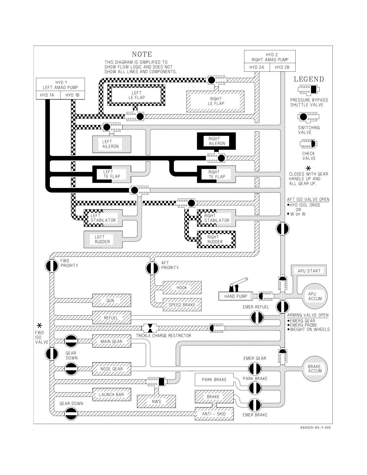
A1-F18AC-NFM-000
Figure 2-11. Hydraulic System
I-2-44
ORIGINAL
A1-F18AC-NFM-000
Multiple redundant paths ensure that single failures have no effect and multiple failures have
minimum effect on control. Figure 2-12 shows the redundancies and the inputs used to provide the
desired flight characteristics.
2.8.2.1
Hydraulic Power. Hydraulic power is supplied by HYD 1 and HYD 2 to all primary flight
control actuators (see figure 2-11). Failure of either HYD 1 or HYD 2 does not affect flight control
when configured in flaps AUTO (UP), however, failure of either HYD system when configured flaps
HALF or flaps FULL may cause an uncommanded yaw and roll transient as the switching valves cycle.
The uncommanded yaw and roll may be severe under certain situations such as single engine and high
or low speed flight. The uncommanded yaw and roll transient may last three to 6 seconds.
Avoid intentional engine shutdown while configured in flaps HALF or
FULL. An uncommanded yaw and roll may result when the switching
valves switch.
The system is arranged to minimize the probability of loss of control to any surface or the loss of
control of one surface due to catastrophic damage to the lines or actuator powering any other surface.
2.8.2.2
Pilot Controls
2.8.2.2.1
FLAP Switch. The FLAP switch selects which of the two flight control computer modes
(auto flap up or takeoff and land) is active and thus determines the flight characteristics for those
conditions.
AUTO
Flight controls in auto flap up mode.
HALF
Flight controls in takeoff and land mode below 250 knots. Flight controls in auto
flap up mode above 250 knots.
FULL
Flight controls in takeoff and land mode below 250 knots. Flight controls in auto
flap up mode above 250 knots.
2.8.2.2.2
Control Stick. The stick grip contains the pitch and roll trim switch, sensor control switch,
air-to-ground weapon release button, gun/missile trigger, air-to-air weapon select switch, undesignate/
nosewheel steering button and on aircraft 164279 AND UP, the RECCE event mark switch. An
autopilot/nosewheel steering disengage switch (paddle switch) is mounted below the stick grip (see
figure 2-13). Stick position sensors transmit an electrical signal proportional to stick displacement from
neutral to the flight control computers.
2.8.2.2.3
Rudder Pedals. Movement of the rudder pedals transmits a proportional electrical signal
to the flight control computers. The rudder pedals are also used for nosewheel steering and brakes. In
F/A-18B and F/A-18D aircraft configured as trainers, the rear cockpit pedal input can cancel front
cockpit pilot input. In F/A-18D aircraft 163986 AND UP configured for night attack, the rear cockpit
rudder pedals are fixed and disconnected from the brakes, rudder, and nosewheel steering.
2.8.2.2.4
Rudder Pedal Adjust Lever. Pressing the rudder pedal adjust lever on the main instrument
panel releases the rudder pedals. Both pedals are then forced aft by springs and pushed forward by the
pilot to the desired position. Releasing the lever locks the rudder pedals in the new position.
I-2-45
ORIGINAL
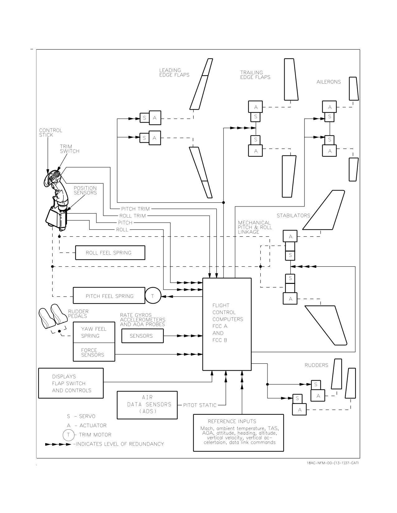
A1-F18AC-NFM-000
Figure 2-12. Flight Control System Functional Diagram
I-2-46
ORIGINAL
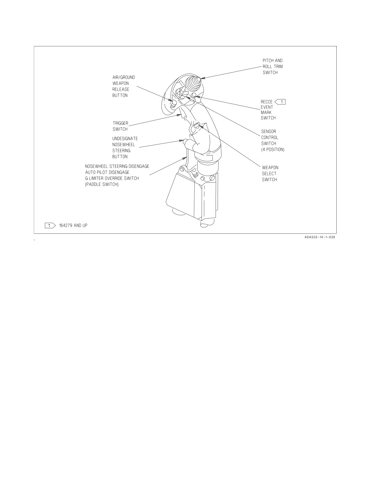
A1-F18AC-NFM-000
Figure 2-13. Control Stick
2.8.2.2.5
Pitch and Roll Trim Switch. Normally, movement of the pitch and roll trim switch
electrically biases the flight control computers and the stick does not move. Little if any pitch trim is
required in the auto flap up mode due to the automatic trimming functions within the flight control
computers. In MECH, pitch trim moves the control stick fore and aft, changing the stick neutral point.
There is no mechanical lateral trim.
2.8.2.2.6
Rudder Trim Knob. Movement of the rudder trim knob on the FCS control panel
electrically biases the flight control computers. The rudder pedals do not move.
2.8.2.2.7
T/O Trim Button. The T/O Trim button is in the center of the rudder trim knob on the
FCS panel. With WOW, holding the button pressed drives the roll and yaw trim to the neutral position,
stabilator to 12° nose up, and zeros the MECH stick position. When the roll and yaw control surfaces
are trimmed to neutral and the stabilator to 12° nose up, the TRIM advisory is displayed on the DDI
until the button is released. Actuation of roll trim within 20 seconds of FCS IBIT with wings folded
inhibits roll trim. Roll trim is reactivated by pressing the T/O Trim button with WOW. In flight and
CAS, pressing the T/O Trim button only neutralizes the MECH stick position.
2.8.2.2.8
FCS RESET Button. The FCS RESET button on the FCS panel is used to reset the flight
control computers after a transient malfunction.
2.8.2.2.9
GAIN Switch. The GAIN switch on the FCS panel is described under Secondary Flight
Controls, this section.
I-2-47
ORIGINAL
A1-F18AC-NFM-000
2.8.2.3
G Limiter. The g limiter prevents exceeding the aircraft positive g limit under most
conditions while permitting full symmetrical and unsymmetrical (rolling) maneuvering. The reference
for symmetrical pilot commands is the aircraft design load (+7.5 g at 32,357 pounds gross weight).
Unsymmetrical pilot command limits are dependent on lateral stick position and vary from the
symmetrical limit with small lateral stick displacement to 80% of the symmetrical limit with full
lateral stick displacement. A g limiter override feature allows an increase in the command limit g for
emergency use.
Below 44,000 pounds gross weight, the positive symmetrical command limit is calculated based on
fuel state and stores loading. Above 44,000 pounds gross weight, the positive symmetrical command
limit is fixed at +5.5 g. The negative symmetrical command limit is fixed at -3.0 g at all gross weights
and stores loading. Longitudinal stick displacement required to achieve command limit g varies with
airspeed and gross weight. When the command limit g is reached, additional aft stick does not increase
g. The positive command limit g is reduced when decelerating through the transonic region. This
reduction may be as much as 1.0 g providing the available g is not reduced below +5.0 g.
Rapid aft stick movement, with or without g limiter override, commands
a very high g-onset rate. This high g-onset rate can cause immediate loss
of consciousness without the usual warning symptoms of tunnel vision,
greyout, and blackout. Consciousness may not return for more than 20
seconds after the g level is reduced to near 1 g.
The g limiter may be overridden by momentarily pressing the paddle switch with the control stick
near full aft. Command limit g is then increased by 33%. A G-LIM OVRD caution is displayed and the
MASTER CAUTION light and tone come on. A code is stored in the nose wheelwell DDI when the g
limiter is overridden. Override is disengaged when the control stick is returned to near neutral.
A CG, R-LIM OFF, CAUT DEGD, MC1, or MC2 caution, stores management system failure,
FCC/MC mux bus communication failure, or invalid fuel quantity cause the positive symmetrical
command limit to be set at 7.5 g regardless of gross weight or stores loading. A G-LIM 7.5 G caution
is displayed, the MASTER CAUTION comes on and a “FLIGHT CONTROLS, FLIGHT CON-
TROLS” voice warning sounds.
G overshoot can occur under any flight conditions. G should be continuously monitored. Under the
following conditions, g should be carefully monitored:
• G-LIM 7.5 g caution displayed
• Positive g with gross weight over 44,000 pounds
• Fuel less than 3,300 pounds
• Negative g with gross weight over 32,357 pounds
• MC1 failure
2.8.2.4
Actuator Exerciser Mode. An actuator exerciser mode is incorporated to improve cold
weather start-up of the FCS. On the ground, the pilot can initiate the exerciser mode by simultaneously
holding the FCS BIT consent switch ON and pressing the FCS RESET button. When initiated, the
mode cycles the stabilators, flaps, ailerons, and rudders through 20% of full travel for 10 cycles in 20
seconds. The operation can be stopped before 20 seconds have elapsed by pressing the paddle switch.
The mode should be used in cold weather or any time an initial FCS RESET fails.
I-2-48
ORIGINAL
A1-F18AC-NFM-000
2.8.2.5
Departure Warning Tone. Departure warning tones do not indicate NATOPS limits. The
audio departure warning tone is initiated at 40°/second yaw rate. The beep frequency increases with
yaw rate up to 60°/second yaw rate. Above 60°/second yaw rate, the frequency remains constant. Above
35° AOA and below -7° AOA, the tone comes on at a constant frequency and yaw rate warning is no
longer available.
With FLAP switch in FULL, the departure warning tone is initiated at 12° AOA and becomes
constant at 32° AOA; with FLAP switch in HALF, the tone starts at 15° and becomes constant at 35°.
In GAIN ORIDE, no departure warning tone is initiated at 12° AOA
FULL flaps or 15° AOA HALF flaps. Inadvertently exceeding these
conditions could result in a departure from controlled flight.
With air-to-ground/tanks store codes loaded on the wing pylons and the rack hooks closed, a steady
tone is heard at or above 25° AOA except for aircraft 162394 AND UP, with tanks on stations 3 and
7 and no stores on stations 2, 5, or 8, where a steady tone is heard at or above 33° AOA. The tone comes
on at +35°/-7° if all stores indicate HUNG. If there are any additional stores on board that are not
HUNG, the AOA tone will still come on at +25°/-7° AOA.
The departure warning tone is enunciated at completion of FCS IBIT.
2.8.2.6
Spin Recovery System. The spin recovery system, when engaged, puts the flight controls in
a spin recovery mode (SRM). This mode, unlike CAS, gives the pilot full aileron, rudder and stabilator
authority without any control surface interconnects and all rate and acceleration feedbacks are
removed. The leading edge flaps are driven to 33° ±1° down and the trailing edge flaps are driven to
0° ±1°.
Spin recovery system engagement depends on the position of the spin recovery switch.
2.8.2.6.1
Spin Recovery Switch and Light. The spin recovery switch on the map gain/spin recovery
panel allows the pilot to select the conditions required for the flight controls to engage in the spin
recovery mode. The SPN RCVY light, adjacent to the switch, is on when the spin recovery switch is in
RCVY.
NORM
Spin recovery mode engaged when all of the following conditions are met:
1. Airspeed 120 ±15 knots.
2. Sustained, uncommanded yaw rate.
3. Stick is placed in the direction indicated on the DDI spin recovery display.
The flight controls revert to CAS anytime the stick is placed in the wrong direc-
tion (i.e. prospin), the airspeed increases above about 245 knots, or the yaw rate
decreases to less than 15°/second.
I-2-49
ORIGINAL
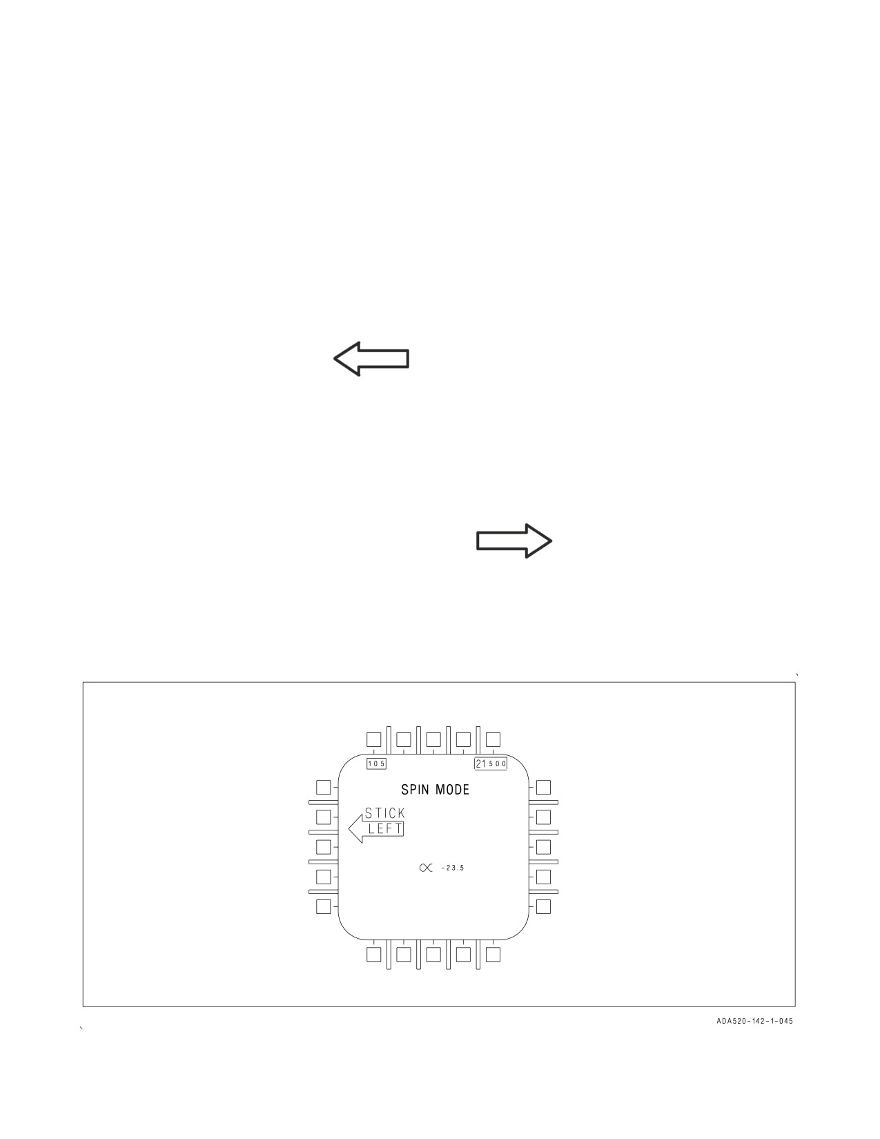
A1-F18AC-NFM-000
RCVY
Spin mode engaged when airspeed is 120 ±15 knots. The flight controls revert to
CAS when the airspeed increases above about 245 knots. Full authority prospin
controls can be applied with the switch in RCVY and spin mode engaged.
2.8.2.6.2
DDI Spin Recovery Displays
a. Spin Recovery Switch in NORM. With the airspeed at 120 ±15 knots and a sustained,
uncommanded left yaw rate with positive g or sustained, uncommanded right yaw rate with negative
g,
SPIN MODE
STICK
LEFT
appears on both DDIs (see figure 2-14).
With the airspeed at 120 ±15 knots and a sustained, uncommanded right yaw rate with positive g or
sustained, uncommanded left yaw rate with negative g,
SPIN MODE
STICK
RIGHT
appears on both DDIs.
When the stick is placed in the indicated directions, the words
SPIN MODE
Figure 2-14. SPIN Recovery Display
I-2-50
ORIGINAL
A1-F18AC-NFM-000
are replaced by
SPIN MODE
ENGAGED
When yaw rate ceases, or the airspeed increases above about 245 knots, the spin recovery display is
replaced by the MENU display.
b. Spin Recovery Switch in RCVY. When the spin recovery switch is placed to RCVY
SPIN MODE
appears on both DDIs.
If the airspeed decreases to 120 ±15 knots, the words
SPIN MODE
are replaced by
SPIN MODE
ENGAGED
If a sustained yaw rate develops, the words STICK RIGHT or STICK LEFT with an
accompanying arrow also appear on the DDI.
When the airspeed increases above about 245 knots
SPIN MODE
appears on both DDIs and the flight controls revert to CAS.
Airspeed appears in the upper left corner, altitude appears in the upper right corner, and AOA
appears in the lower center of the spin recovery display.
During highly oscillatory out-of-control motion, rapid cycling of the
command arrows may occur. Under these conditions, the stick should be
released until command arrow cycling stops. During intermediate and
high yaw rate spin mode recoveries, removal of the command arrow may
be delayed. Under these conditions, anti-spin controls should be neutral-
ized (sustained command arrow present) only if spin rate has stopped and
the AOA warning tone is no longer present.
2.8.2.7
Flight Control Computers (FCC). Two flight control computers (FCC A and FCC B) provide
the computations which determine the flight characteristics. Electrical signals generated by movement
of the stick grip and rudder pedals are transmitted (each signal on four different channels) to both
FCC. The computers use the pilot inputs and inputs from various aircraft and internal sensors to
determine proper outputs to the control actuators for desired aircraft response. The multiple channel
inputs and outputs are continuously monitored by the FCC for agreement. When there is disagree-
ment, the erroneous signal is discarded or, if this cannot be determined, the control system is
I-2-51
ORIGINAL
A1-F18AC-NFM-000
automatically switched to a degraded mode which does not use that signal. For survivability, one
channel from each computer is routed through the upper part of the aircraft and the other channel is
routed through the lower part. The stabilator and trailing edge flap servos receive four channel signals
from the FCC. The aileron, rudder, and leading edge flap servos receive two channel signals. FCC A is
powered by the essential 28 volt dc bus. FCC B is powered by the right 28 volt dc bus. Both computers
are normally cooled by avionics air but ram air can be selected for FCC A cooling. The FCCs are
provided with separate power inputs which are connected directly to the battery/charger. FCC A is
connected to the emergency battery and the FCC B is connected to the utility battery. Should a power
interruption occur on the main DC bus, sensors within the flight control computer automatically switch
to the backup power source for up to 7 seconds. This ensures the flight control computers have
uninterrupted power to maintain full FCES performance during all predictable bus switching
transients.
2.8.2.7.1
FCS HOT Caution. The FCS HOT caution light and FCS HOT caution on the DDI
indicates an overtemperature in FCC A or the right transformer-rectifier.
2.8.2.7.2
FCS or AV COOL Switch
NORM
Both FCC and both transformer-rectifiers cooled by avionics air.
EMERG FCC A and right transformer-rectifier cooled by ram air.
FCC B and left transformer-rectifier cooled by avionics air.
Once EMERG selected, selection of NORM does not switch FCC A and right
transformer-rectifier cooling back to avionics air.
2.8.2.7.3
FCC Circuit Breakers. FCS channel 1 and channel 2 (FCC A) circuit breakers are on the
left essential circuit breaker panel under the left canopy rail. FCS channels 3 and 4 (FCC B) circuit
breakers are on the right essential circuit breaker panel under the right canopy rail.
2.8.2.8
Control Augmentation System (CAS). The longitudinal control system uses air data
scheduled pitch rate, normal acceleration (NZ) and angle-of-attack (AOA) to compute stabilator
actuator commands. The aircraft response is compared to the pilot command and the stabilator
servoactuator is driven to reduce the difference to zero. Since, in the auto flaps up mode, any
uncommanded pitch rate or g is reduced to zero, the aircraft is constantly trimmed to steady state
hands-off 1 g flight and there is little or no occasion for manual trim. Pitch rate and g (NZ) feedbacks
improve pitch characteristics and g control at medium to high airspeeds. Air data scheduled pitch rate
feedback improves maneuvering characteristics and provides increasing stick-force-per-g at low to
medium airspeeds. AOA feedback provides increasing stick force with increasing AOA above 22°. In
the takeoff and land modes, AOA and pitch rate feedbacks are used to augment inherent airframe pitch
damping and stability. The computer nulls the difference between the trim AOA and actual AOA. In
turns, pitch rate feedback maintains tight pitch attitude control.
The lateral control system uses ailerons, differential trailing edge flaps, differential leading edge
flaps, differential stabilator, and rudders to achieve the desired roll characteristics. Scheduled air data
roll rate feedback is used to augment inherent airframe roll damping. At high airspeeds, aileron travel
versus stick movement is reduced and the ailerons do not deflect above 600 knots. Differential
stabilator and differential trailing edge flap travel is reduced at high speed to prevent exceeding
structural limits. The leading edge flaps deflect differentially up to ±3° when below 30,000 feet and
above Mach 0.7. Differential flaps are not used in the takeoff or land modes nor above 10° AOA in the
auto flaps up mode. At low airspeeds, aileron and differential stabilator travel are reduced with
increasing AOA to minimize adverse yaw. Differential stabilator may also be limited due to a pitch
I-2-52
ORIGINAL
A1-F18AC-NFM-000
command which has priority. With lateral stick deflection, the rolling-surface-to-rudder interconnect
(RSRI) schedules increasing rudder deflection as a function of decreasing airspeed and increasing AOA
for roll control, coordination, and to reduce adverse yaw. With wing pylon mounted air-to-ground
stores or tanks code set in the armament computer and the rack hooks for those stores closed,
maximum roll rate is automatically reduced about 33%. If all stores are shown as HUNG, roll rate
limiting is removed; however, an R-LIM OFF caution appears on the DDI.
The directional control system uses twin rudders for yaw control. The FCS nulls yaw rate to provide
yaw damping. Lateral acceleration feedback (NY) improves turn coordination. RSRI and roll-rate to
rudder crossfeed (scheduled with AOA) are used for roll coordination. At low to medium AOA, full
rudder pedal deflection provides ½ rudder deflection. At high AOA, the RSRI and rudder-to-rolling
surface interconnects combine with rudder pedal inputs to make full rudder deflection available. At
high air speeds, rudder deflection is reduced to avoid exceeding structural limits. The control system
includes specific logic to improve flying qualities above 20° AOA. Sideslip feedback to the ailerons and
differential stabilator improves the resistance to out−of−control flight. Sideslip rate feedback to the
ailerons and differential stabilator improves the damping of lateral−directional oscillations. For rolls,
the differential stabilator deflects opposite to the intended roll direction to improve roll performance
above 35° AOA. A means to temporarily boost roll performance above 30° AOA is provided when
lateral stick and pedal are applied in the same direction. Excessive pitch/roll inertial coupling is
prevented by giving temporary priority to the pitch axis during simultaneous roll and large pitch
inputs. In the takeoff and land modes, rate of change of sideslip feedback augments aerodynamic
directional damping and stability. For takeoff or land modes, rudder toe-in is used to improve the
longitudinal stability and to provide early rotation during takeoff or bolter. Rudder toe-in/toe-out is a
function of AOA with maximum toe-in (30°) at low AOA (less than 2°) or WOW and decreases
proportionally thru 0° to 15° toe-out at 11° AOA.
2.8.2.9
Direct Electrical Link (DEL). A direct electrical link in each axis provides continued electrical
operation of the flight controls after multiple system failures make CAS operation impossible. See FCS
Failure Indications and Effects, Chapter 15. In DEL, stability and control is degraded. There are two
DEL modes, digital and analog. With any axis in digital DEL, a DEL ON caution is displayed on the
DDI. The FCS reverts to analog roll DEL and analog yaw DEL if there are three digital processor
failures. In addition, the analog roll DEL function is activated if three channels to the aileron are Xd
out and the analog yaw DEL function is activated if three channels to the rudder are Xd out. If the
aircraft selects analog yaw DEL, the control laws also activate the digital roll DEL function. There is
no analog pitch DEL mode. The DEL ON caution is not displayed when in the analog roll DEL mode.
The DEL ON caution is displayed when in analog yaw DEL since digital roll DEL has been activated.
Extreme caution should be used in analog DEL. Flight in this configu-
ration has not been flight tested.
With the FLAP switch in AUTO, pitch digital DEL provides control of the stabilators after three
similar pitch rate gyro or normal accelerometer failures. With the FLAP switch in HALF or FULL,
pitch digital DEL provides control of the stabilators after three similar pitch rate gyro failures. Pitch
trim rates in digital DEL are 25% of CAS rates. There is no analog DEL mode in pitch.
Roll digital DEL provides roll control after three similar roll rate gyro failures. Trim is not affected.
RSRI provides rudder displacement for roll coordination. Roll analog DEL provides an additional path
to the ailerons for roll control after three digital processor failures. Analog DEL provides a direct
I-2-53
ORIGINAL
A1-F18AC-NFM-000
electrical path from the stick sensors to the aileron servos without an air data input. Analog DEL
provides rudder coordination through an analog stick to rudder interconnect. There is no aileron trim
capability in analog DEL.
Yaw digital DEL provides directional control after three similar yaw rate gyro failures. Rudder
displacement versus rudder pedal force is decreased with increasing airspeed. Yaw digital DEL also
reverts the roll axis to digital DEL as the roll rate feedback would be destabilizing in this condition.
Yaw analog DEL provides rudder control through rudder servo commands without airspeed correction
(feel) after three digital processor failures. There is rudder trim in both the digital and analog DEL
mode.
2.8.2.10 Mechanical Linkage (MECH). Mechanical linkage provides backup control of the stabila-
tors for pitch and roll control. A MECH ON caution is displayed on the DDI. See FCS Failure
Indications and Effects, Chapter 15. In the mechanical mode, stick movement directly controls the
stabilator actuators bypassing all force sensors, the flight control computers, all air data, all motion
feedbacks, servos, and associated electrical wiring. A mode select actuator (ratio changer) increases
stabilator movement versus stick movement when the FLAP switch is in HALF or FULL to provide
added pitch authority. Pitch trim moves the stick fore and aft, changing the stick neutral point. There
is no mechanical lateral trim.
In normal flight, the mechanical flight control command (MECH) does not exactly follow the flight
control computer commanded position. Stick movement is transmitted to the stabilator actuator
through the mechanical system to command a fixed amount of stabilator deflection. The same stick
movement transmitted through the flight control computer (FCC) is modified by many inputs to the
FCC including: g, airspeed, altitude, pitch/roll rate, trim input, etc., to command a different amount
of stabilator deflection.
If the aircraft reverts to MECH ON, the stabilator will slowly fade from the flight control computer
commanded position into the mechanical system commanded position. The fading takes place at
between 1/2° to 1° of stabilator position per second. If the FCC/MECH mismatch is relatively small,
the resulting aircraft pitch change is minimal. However, reversion transients have occurred with large
mismatches between the FCC commanded and the mechanical system commanded stabilator positions
at the time of the reversion to MECH. As the mismatch increases, so does the resulting pitch up or
down.
As the difference between the FCC commanded position and the mechanical system commanded
position is faded out, full stabilator authority is not available. The amount of mismatch is not
immediately available to the pilot. Once the mismatch is faded completely out, full mechanical system
authority is available. When the fade out is complete, the stabilator actuator responds purely to stick
position.
Pitch control is less responsive in mechanical system than with the flight control computer. Full aft
stick and nose up trim following a MECH reversion does not provide any more stabilator movement
than just full aft stick. Trim inputs will relieve some of the spring pressure on the stick while the
mismatch fades out giving full mechanical authority.
2.8.3 Secondary Flight Controls. The secondary flight controls are the collective leading edge flaps,
collective trailing edge flaps, drooped ailerons, and speedbrake.
2.8.4 Flaps. The collective leading edge and trailing edge flaps are controlled as a function of the
FCC mode to provide the desired flight characteristics throughout the flight envelope. Figure 2-15
shows representative schedules in the auto flap up mode. Maximum flap deflection is limited by Mach
I-2-54
ORIGINAL
A1-F18AC-NFM-000
number and airspeed. Leading edge flaps remain fully retracted at Mach 1.2 and above regardless of
AOA. Trailing edge flaps remain fully retracted above Mach 1.0 regardless of AOA. The flaps may not
reach the deflections shown in figure 2-15 at low altitude and high airspeed.
The LEF system incorporates a performance monitor to improve detection of marginal LEF systems
using a predicted vs. actual rate monitor. If the LEF deflection rate is slower than the expected LEF
deflection rate, the FCC asserts a BLIN 221 identifying the marginal LEF, but does not assert any
accompanying cautions.
2.8.4.1
Flap Operation
SWITCH
FLAP OPERATION
POSITION
AUTO
With weight off wheels, leading and trailing edge flaps are scheduled as a function
of AOA. With WOW, leading and trailing edge flaps and aileron droop are set to
0°.
HALF
Below 250 knots, leading edge flaps are scheduled as a function of AOA. Trailing
edge flaps and aileron droop are scheduled as a function of airspeed to a maxi-
mum of 30° at approach airspeeds. Above 250 knots, the flaps operate in the auto
flap up mode and the amber FLAPS light comes on. On the ground, the leading
edge flaps are set to 12°. The trailing edge flaps and aileron droop are set to 30°.
With the wing unlocked, aileron droop is set to 0°.
FULL
Below 250 knots, leading edge flaps are scheduled as a function of AOA. Trailing
edge flaps and aileron droop are scheduled as a function of airspeed to a maxi-
mum of 45° flaps and 42° aileron droop at approach airspeeds. Above 250 knots,
the flaps operate in the auto flaps up mode and the amber FLAPS light comes on.
On the ground, the leading edge flaps are set to 12°. The trailing edge flaps are
set to 43° to 45° and aileron droop to 42°. With the wings unlocked, aileron droop
is set to 0°.
2.8.4.2
GAIN Switch. The GAIN switch on the FCS panel allows the pilot to select a fixed value for
speed, altitude, and AOA inputs to the flight control computers and thus a fixed leading and trailing
edge flap position dependent on FLAP switch position.
SWITCH
FLAP OPERATION
POSITION
NORM
Flaps operate as described under Flap Operation.
ORIDE
With the FLAP switch in AUTO, the leading and trailing edge flaps are fixed to
3° down and will not vary with airspeed and AOA. Aileron droop is set to 0°.
The aircraft is easily controllable at normal cruise speeds. Remain subsonic and
below 350 knots to maintain control system stability. Remain below 10° AOA to
preclude departure. Transition to or from the landing configuration should be
performed at 200 knots. The FLAPS light comes on and a CRUIS advisory is
displayed on the DDI.
I-2-55
ORIGINAL
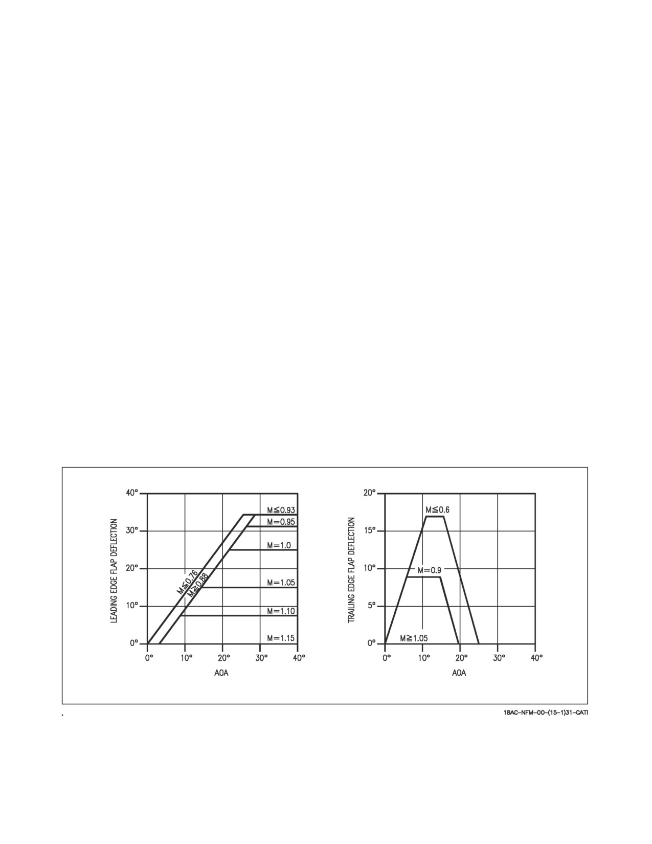
A1-F18AC-NFM-000
With the FLAP switch in HALF, remain below 200 knots and 15° AOA. Flight
at 8.1° AOA results in best control characteristics. Refer to Chapter 11 for
details. The leading edge flaps are fixed at 17° and will not vary with airspeed
and AOA. The trailing edge flaps and aileron droop are fixed at 30°. The yellow
FLAPS light comes on and a LAND advisory is displayed on the DDI. With the
wings unlocked, aileron droop is set to 0°.
After transition with the FLAP switch in FULL, aircraft should remain below
160 knots and 12° AOA. Flight at 8.1° AOA results in best control characteris-
tics. Refer to Chapter 11 for details. The leading edge flaps are fixed at 17° and
will not vary with airspeed and AOA. The trailing edge flaps are fixed to 43° to
45° and the aileron droop is set to 42°. The FLAPS light comes on and a LAND
advisory is displayed on the DDI. With the wings unlocked, aileron droop is set
to
0°.
NOTE
• Stalls occur at a lower AOA with GAIN ORIDE selected due to fixed
flap positions. Rotation following a bolter or touch and go will be
sluggish due to a fixed rudder position.
• Alpha tone is disabled with GAIN ORIDE selected with FLAP switch
in HALF or FULL.
2.8.4.3
Flap Position Lights. The HALF, FULL, and FLAPS lights are on the main instrument
panel. A green light indicates the aircraft is within flight parameters for the flight control computer to
Figure 2-15. Flap Schedules
adjust flap scheduling in accordance with the selected switch position. These lights, whether amber or
green, should not be used as an indication of flap position. Actual flap position can only be verified by
selecting the FCS display.
I-2-56
ORIGINAL
A1-F18AC-NFM-000
INDICATION
FLAP SWITCH POSITION
HALF (green)
FLAP switch in HALF and airspeed below 250 knots.
FULL (green)
FLAP switch in FULL and airspeed below 250 knots.
FLAPS (amber)
FLAP switch HALF or FULL and airspeed over 250 knots, abnormal flap
condition (any flap is off or lacks hydraulic pressure), in spin recovery
mode, or GAIN switch in ORIDE position.
2.8.4.4
CK FLAPS Caution Display. The CK FLAPS DDI caution is displayed at takeoff when the
FLAP switch is in AUTO.
2.8.4.5
FCS Cautions
2.8.4.5.1
FCES Caution Light. The FCES (flight control electronic set) caution light, on the caution
lights panel, comes on if any flight control function is lost or if there are three Xs in the same row.
2.8.4.5.2
FCS Caution Display. The FCS caution, on the DDI, is displayed anytime a failure in the
flight control system occurs. If the failure is transient and can be reset, pressing the FCS RESET
button removes the failure indication (Xs) from the FCS status page, displays the RSET advisory, and
removes the FCS caution. If the failure does not reset, the failure indication remains displayed on the
FCS status page along with the Xd out RSET advisory, and the FCS caution is removed. The FCS
caution is displayed again if another flight control system failure occurs.
2.8.4.5.3
AIL OFF Caution Display. Either aileron off.
2.8.4.5.4
AUTO PILOT Caution Display. Uncommanded autopilot disengagement.
2.8.4.5.5
CHECK TRIM Caution Display. Horizontal stabilators not trimmed for takeoff.
2.8.4.5.6
DEL ON Caution Display. Any axis in digital DEL.
2.8.4.5.7
FC AIR DAT Caution Display. Left and right air data probes disagree.
2.8.4.5.8
FCS HOT Caution Display. Flight control computer A and/or right transformer-rectifier
not receiving adequate cooling air.
2.8.4.5.9
FLAPS OFF Caution Display. Any flap off.
2.8.4.5.10 FLAP SCHED Caution Display. Flaps are not scheduling properly (see Chapter 15
discussion)
2.8.4.5.11 G-LIM 7.5 G Caution Display. G limiter set at +7.5 g symmetrical regardless of gross
weight or stores loading.
2.8.4.5.12 G-LIM OVRD Caution Display. G limiter overridden. 133% of design limit g is possible.
2.8.4.5.13 MECH ON Caution Display. Stabilator mechanically controlled.
I-2-57
ORIGINAL