F18. FLIGHT MANUAL (2008) - page 1

A1-F18AC-NFM-000
NATOPS FLIGHT MANUAL
NAVY MODEL
F/A-18A/B/C/D
161353 AND UP
AIRCRAFT
THIS PUBLICATION SUPERSEDES A1-F18AC-NFM-000 DATED
1 AUGUST 2006 CHANGED 15 JUNE 2007
THIS PUBLICATION IS INCOMPLETE WITHOUT
A1-F18AC-NFM-200 and A1-F18AC-NFM-210
DISTRIBUTION STATEMENT C. Distribution authorized to U.S. Government
agencies only and their contractors to protect publications required for official
use or for administrative or operational purposes only, determined on
1 August 2006. Other requests for this document shall be referred to
Commander, Naval Air Systems Command (PMA-265), RADM William A.
Moffett Bldg, 47123 Buse Rd, Bldg 2272, Patuxent River, MD 20670-1547.
DESTRUCTION NOTICE - For unclassified, limited documents, destroy by any
method that will prevent disclosure of contents or reconstruction of the
document.
ISSUED BY AUTHORITY OF THE CHIEF OF NAVAL OPERATIONS AND
UNDER THE DIRECTION OF THE COMMANDER
NAVAL AIR SYSTEMS COMMAND.
15
SEPTEMBER 2008
A1-F18AC-NFM-000

A1-F18AC-NFM-000
NATOPS FLIGHT MANUAL
NAVY MODEL
F/A-18A/B/C/D
161353 AND UP
AIRCRAFT
THIS PUBLICATION SUPERSEDES A1-F18AC-NFM-000 DATED
1 AUGUST 2006 CHANGED 15 JUNE 2007
THIS PUBLICATION IS INCOMPLETE WITHOUT
A1-F18AC-NFM-200 and A1-F18AC-NFM-210
DISTRIBUTION STATEMENT C. Distribution authorized to U.S. Government
agencies only and their contractors to protect publications required for official
use or for administrative or operational purposes only, determined on
15 September 2008. Other requests for this document shall be referred to
Commander, Naval Air Systems Command (PMA-265), RADM William A.
Moffett Bldg, 47123 Buse Rd, Bldg 2272, Patuxent River, MD 20670-1547.
DESTRUCTION NOTICE - For unclassified, limited documents, destroy by any
method that will prevent disclosure of contents or reconstruction of the
document.
ISSUED BY AUTHORITY OF THE CHIEF OF NAVAL OPERATIONS AND
UNDER THE DIRECTION OF THE COMMANDER
NAVAL AIR SYSTEMS COMMAND.
0801LP1087792
1
(Reverse Blank)
15 SEPTEMBER 2008
A1-F18AC-NFM-000
NATOPS Flight Manual
CONTENTS
Page
No.
PART I
THE AIRCRAFT
CHAPTER
1
The Aircraft
1.1
AIRCRAFT DESCRIPTION
I-1-1
1.1.1
Meet The Hornet
I-1-1
1.1.2
Aircraft Dimensions
I-1-1
1.1.3
Aircraft Gross Weight
I-1-1
1.1.4
Mission
I-1-2
1.2
BLOCK NUMBERS
I-1-2
CHAPTER
2
Systems
2.1
POWER PLANT SYSTEMS
I-2-1
2.1.1
Engines
I-2-1
2.1.2
Automatic Throttle Control (ATC)
I-2-8
2.2
FUEL SYSTEM
I-2-10
2.2.1
Survivability
I-2-10
2.2.2
Fuel Tank Pressurization and Vent
I-2-10
2.2.3
Internal Transfer
I-2-11
2.2.4
External Transfer
I-2-13
2.2.5
Fuel Feed System
I-2-13
2.2.6
Fuel Recirculation System
I-2-16
2.2.7
Fuel Dump System
I-2-17
2.2.8
Fuel Lo Level Indications
I-2-17
2.2.9
Fuel Quantity Indicating System (F/A-18A/B)
I-2-18
2.2.10
Fuel Quantity Indicating System (F/A-18C/D)
I-2-19
2.2.11
Air Refueling System
I-2-21
2.2.12
Ground Refueling System
I-2-22
2.3
FLIGHT PERFORMANCE ADVISORY SYSTEM
I-2-24
2.3.1
Flight Performance Advisory System (FPAS) (F/A-18A Aircraft
AFTER AFC 253 OR 292, and F/A-18C/D Aircraft.)
I-2-24
2.4
SECONDARY POWER SYSTEM
I-2-26
2.4.1
Airframe Mounted Accessory Drive (AMAD)
I-2-26
2.4.2
Auxiliary Power Unit (APU)
I-2-28
2.4.3
External Power Start
I-2-29
2.4.4
Bleed Air Augmentation
I-2-29
2.5
ELECTRICAL POWER SUPPLY SYSTEM
I-2-30
5
ORIGINAL
A1-F18AC-NFM-000
Page
No.
2.5.1
AC Electrical Power
I-2-30
2.5.2
DC Electrical Power (Aircraft 161353 THRU 161528 BEFORE AFC
049)
I-2-31
2.5.3
DC Electrical Power (AIRCRAFT 161702 AND UP AND
AIRCRAFT 161353 THRU 161528 AFTER AFC 049)
I-2-35
2.5.4
External Electrical Power
I-2-36
2.5.5
Circuit Breakers
I-2-37
2.6
LIGHTING
I-2-37
2.6.1
Exterior Lighting
I-2-37
2.6.2
Interior Lighting
I-2-39
2.7
HYDRAULIC POWER SUPPLY SYSTEM
I-2-41
2.7.1
Pumps and Reservoirs
I-2-42
2.7.2
Hydraulic Circuits
I-2-42
2.7.3
Valves
I-2-42
2.7.4
Accumulators
I-2-43
2.8
FLIGHT CONTROL SYSTEM
I-2-43
2.8.1
Application
I-2-43
2.8.2
Primary Flight Controls
I-2-43
2.8.3
Secondary Flight Controls
I-2-54
2.8.4
Flaps
I-2-54
2.9
AUTOMATIC FLIGHT CONTROL SYSTEM (AFCS)
I-2-60
2.9.1
AFCS Caution and Advisory Displays
I-2-60
2.9.2
Pilot Relief Modes
I-2-61
2.10
LANDING SYSTEM
I-2-64
2.10.1
Landing Gear System
I-2-64
2.10.2
Nosewheel Steering System
I-2-66
2.10.3
Brake System
I-2-66
2.10.4
Launch Bar System
I-2-68
2.10.5
Arresting Hook System
I-2-69
2.11
WING FOLD SYSTEM
I-2-69
2.11.1
Wing Fold Handle
I-2-70
2.12
INSTRUMENTS
I-2-71
2.12.1
Pitot-Static System
I-2-71
2.12.2
Standby Attitude Reference Indicator
I-2-71
2.12.3
Standby Airspeed Indicator
I-2-72
2.12.4
Standby Altimeter
I-2-72
2.12.5
RADAR Altimeter Set (AN/APN-194(V))
I-2-72
2.12.6
Standby Rate of Climb Indicator
I-2-74
2.12.7
Clock
I-2-74
6
ORIGINAL
A1-F18AC-NFM-000
Page
No.
2.12.8
Integrated Fuel/Engine Indicator (IFEI) Time Displays (F/A-18
C/D)
I-2-74
2.12.9
Standby Magnetic Compass
I-2-76
2.12.10
Angle-Of-Attack (AOA) Indexer
I-2-76
2.13
AVIONICS SUBSYSTEM
I-2-76
2.13.1
Mission Computer (MC) System
I-2-76
2.13.2
Master Modes
I-2-87
2.13.3
Cockpit Controls and Displays
I-2-87
2.13.4
Multipurpose Display Group
I-2-87
2.13.5
Upfront Control (UFC)
I-2-109
2.13.6
Signal Data Computer (F/A-18C/D)
I-2-112
2.13.7
Video Tape Recording System (VTRS) (Aircraft 161353 THRU
164912 BEFORE AFC 207)
I-2-112
2.13.8
Cockpit Video Recording System (Aircraft 164945 AND UP and
Aircraft 163985 THRU 164912 AFTER AFC 207)
I-2-114
2.13.9
Armpit Camera System
I-2-115
2.13.10
Tactical Aircraft Moving Map Capability (TAMMAC)
I-2-115
2.13.11
ALE-39 Countermeasures Dispensing Set (CMDS)
I-2-120
2.13.12
ALE-47 Countermeasures Dispensing Set
I-2-120
2.14
FIRE DETECTION/EXTINGUISHING SYSTEMS
I-2-120
2.14.1
Fire Warning/Extinguisher Lights/Voice Alert
I-2-120
2.14.2
Fire Extinguisher Pushbutton
I-2-120
2.14.3
APU Fire Extinguishing System
I-2-121
2.14.4
Engine/AMAD Fire Extinguishing System
I-2-121
2.14.5
Fire and Bleed Air Test Switch
I-2-121
2.15
ENTRANCE/EGRESS SYSTEMS
I-2-122
2.15.1
Canopy System
I-2-122
2.15.2
Boarding Ladder
I-2-127
2.15.3
Ejection Seat
I-2-128
2.16
ENVIRONMENTAL CONTROL SYSTEM
I-2-137
2.16.1
Bleed Air System
I-2-137
2.16.2
Cockpit Air Conditioning and Pressurization
I-2-139
2.16.3
Defogging System
I-2-140
2.16.4
Windshield Anti-Ice and Rain Removal System
I-2-141
2.16.5
Suit Ventilation System
I-2-141
2.16.6
Anti-G System
I-2-141
2.16.7
Avionics Cooling and Pressurization
I-2-141
2.17
EMERGENCY EQUIPMENT
I-2-142
2.17.1
Jettison Systems
I-2-142
2.17.2
Warning/Caution/Advisory Lights and Displays
I-2-143
7
ORIGINAL
A1-F18AC-NFM-000
Page
No.
2.17.3
Voice Alert System
I-2-144
2.17.4
TAWS - Terrain Awareness Warning System (SCS 17C AND UP). . . I-2-145
2.17.5
GPWS - Ground Proximity Warning System (MC OFP 10A+ AND
UP, 13C AND UP)
I-2-149
2.18
OXYGEN SYSTEM
I-2-154
2.18.1
Normal Oxygen Supply (LOT 4-12)
I-2-154
2.18.2
Emergency Oxygen Supply (LOT 4-12)
I-2-154
2.18.3
On-Board Oxygen Generating System (OBOGS) (LOT 13 AND UP). I-2-155
2.18.4
Emergency Oxygen (LOT 13 AND UP)
I-2-158
2.19
AIR DATA COMPUTER (ADC)
I-2-159
2.19.1
Angle-Of-Attack Probes
I-2-159
2.19.2
Total Temperature Probe
I-2-160
2.20
STATUS MONITORING SUBSYSTEM
I-2-160
2.20.1
Flight Incident Recorder and Aircraft Monitoring Set (FIRAMS)
(F/A-18C/D)
I-2-160
2.20.2
Deployable Flight Incident Recorder Set (DFIRS) (Aircraft 164627
AND UP)
I-2-160
2.20.3
Avionic BIT
I-2-163
2.20.4
Non-Avionic BIT
I-2-181
2.20.5
Status Monitoring Backup
I-2-182
2.20.6
Non-BIT Status
I-2-182
2.21
JOINT HELMET MOUNTED CUEING SYSTEM (JHMCS)
I-2-185
2.21.1
Helmet Mounted Display (HMD)/Aft Helmet Mounted Display
(AHMD)
I-2-185
2.21.2
Electronics Unit (EU)
I-2-188
2.21.3
Cockpit Unit (CU)
I-2-188
2.21.4
Magnetic Transmitter Unit (MTU)
I-2-188
2.21.5
Seat Position Sensor (SPS)
I-2-188
2.21.6
HMD/AHMD OFF/BRT Knobs
I-2-188
2.21.7
Boresight Reference Unit (BRU)
I-2-188
2.21.8
HMD Video Recording
I-2-188
2.21.9
Cautions/Advisories
I-2-188
2.21.10
Configuration Check
I-2-190
2.21.11
Built-In Test (BIT)
I-2-190
2.21.12
JHMCS Alignment
I-2-192
2.21.13
HMD/AHMD Symbology
I-2-199
2.21.14
Navigation Master Mode
I-2-200
2.21.15
Mission Computer Failure
I-2-200
2.21.16
Electronic Unit Failure
I-2-200
2.21.17
Helmet Tracker Failure
I-2-200
2.21.18
Helmet Not Installed
I-2-200
8
ORIGINAL
A1-F18AC-NFM-000
Page
No.
2.22
FIGHTER/ATTACK/TRAINER/RECCE (F/A-18B/D)
I-2-201
2.22.1
F/A-18B/D Aircraft 161354 THRU 163778
I-2-201
2.22.2
F/A-18D Aircraft 163986 AND UP
I-2-201
2.22.3
Aircraft Dimensions
I-2-201
2.22.4
Aircraft Gross Weight
I-2-201
2.22.5
Fuel Quantity
I-2-202
2.22.6
Canopy System
I-2-202
2.22.7
Ejection Seat System
I-2-202
2.22.8
Intercom Controls
I-2-204
2.22.9
Rear Cockpit
I-2-204
CHAPTER
3
Service and Handling
3.1
SERVICING
I-3-1
CHAPTER
4
Operating Limitations
4.1
AIRCRAFT
I-4-1
4.1.1
Engine Limitations
I-4-1
4.1.2
Airspeed Limitations
I-4-2
4.1.3
Prohibited Maneuvers
I-4-3
4.1.4
CG Limitations
I-4-6
4.1.5
Lateral Weight Asymmetry Limitations
I-4-6
4.1.6
Angle-of-Attack (AOA) Limitations
I-4-7
4.1.7
Weight Limitations
I-4-8
4.1.8
Acceleration Limitations
I-4-9
4.2
EXTERNAL STORES
I-4-9
4.2.1
Limitations
I-4-9
4.2.2
Banner Towing Limitations
I-4-9
4.2.3
Tow Banner Adapter Limitations
I-4-9
PART II
INDOCTRINATION
CHAPTER
5
Indoctrination
5.1
GROUND TRAINING SYLLABUS
II-5-1
5.1.1
Minimum Ground Training Syllabus
II-5-1
5.2
FLIGHT TRAINING SYLLABUS TRAINING PHASES
II-5-1
5.3
PERSONAL FLYING EQUIPMENT
II-5-1
5.3.1
Minimum Requirements
II-5-1
5.4
QUALIFICATIONS AND CURRENCY REQUIREMENTS
II-5-1
5.4.1
Minimum Flight Qualifications
II-5-1
5.4.2
Requirements For Various Flight Phases
II-5-1
9
ORIGINAL
A1-F18AC-NFM-000
Page
No.
5.4.3
Ceiling/Visibility Requirements
II-5-2
5.4.4
Ferry Squadrons
II-5-2
5.5
WAIVERS
II-5-2
5.5.1
Unit Commanders Authority
II-5-2
PART III
NORMAL PROCEDURES
CHAPTER
6
Flight Preparation
6.1
MISSION PLANNING
III-6-1
6.1.1
General
III-6-1
6.1.2
Flight Codes
III-6-1
6.2
BRIEFING/DEBRIEFING
III-6-1
6.2.1
Briefing
III-6-1
6.2.2
Debriefing
III-6-3
CHAPTER
7
Shore-Based Procedures
7.1
PREFLIGHT CHECK
III-7-1
7.1.1
Line Operations
III-7-1
7.1.2
Exterior Inspection
III-7-1
7.1.3
Before Entering Cockpit
III-7-6
7.1.4
Interior Check
III-7-9
7.1.5
Engine Start
III-7-13
7.1.6
Before Taxi
III-7-18
7.1.7
Taxi
III-7-22
7.2
TAKEOFF
III-7-23
7.2.1
Before Takeoff
III-7-23
7.2.2
Normal Takeoff
III-7-23
7.2.3
Crosswind Takeoff
III-7-25
7.2.4
Formation Takeoff
III-7-25
7.2.5
After Takeoff
III-7-25
7.2.6
Climb
III-7-25
7.2.7
10,000 Feet
III-7-25
7.2.8
Cruise
III-7-26
7.3
LANDING
III-7-26
7.3.1
Descent/Penetration
III-7-26
7.3.2
Approach
III-7-27
7.3.3
Touchdown
III-7-27
7.3.4
Nosewheel Steering
III-7-27
7.3.5
Landing Rollout
III-7-28
7.3.6
Braking Technique
III-7-28
7.3.7
Crosswind Landing
III-7-29
10
ORIGINAL
A1-F18AC-NFM-000
Page
No.
7.3.8
Wet Runway Landing
III-7-29
7.3.9
Asymmetric Stores Landing
III-7-30
7.3.10
Waveoff
III-7-30
7.4
POSTFLIGHT
III-7-32
7.4.1
After Landing
III-7-32
7.4.2
Hot Refueling
III-7-33
7.4.3
Before Engine Shutdown
III-7-33
7.4.4
Engine Shutdown
III-7-34
7.5
REAR COCKPIT PROCEDURES (F/A-18B/D)
III-7-36
7.5.1
Before Entering Cockpit
III-7-36
7.5.2
Interior Check
III-7-36
7.5.3
Before Taxi
III-7-37
7.5.4
Before Takeoff
III-7-38
7.5.5
Descent/Penetration
III-7-38
7.5.6
Approach
III-7-38
7.5.7
After Landing
III-7-38
7.5.8
Before Engine Shutdown
III-7-39
7.6
NIGHT FLYING
III-7-39
7.6.1
External Light Management
III-7-39
CHAPTER
8
Carrier-Based Procedures
8.1
GENERAL
III-8-1
8.1.1
Carrier Electromagnetic Environment
III-8-1
8.1.2
Carrier INS Environment
III-8-2
8.2
DAY OPERATIONS
III-8-2
8.2.1
Preflight
III-8-2
8.2.2
Engine Start
III-8-2
8.2.3
Taxi
III-8-2
8.2.4
Hangar Deck Operation
III-8-3
8.2.5
Before Catapult Hook-Up
III-8-3
8.2.6
Catapult Hook-Up
III-8-4
8.2.7
Catapult Afterburner Operation
III-8-6
8.2.8
Catapult Launch
III-8-7
8.2.9
Catapult Suspend
III-8-8
8.2.10
Landing Pattern
III-8-8
8.2.11
ATC Approach Mode Technique
III-8-9
8.2.12
Glideslope
III-8-9
8.2.13
Waveoff
III-8-9
8.2.14
ACL Mode 1 and 1A Approaches
III-8-12
8.2.15
ACL Mode 2 Approach
III-8-13
8.2.16
Arrested Landing and Exit From the Landing Area
III-8-14
11
ORIGINAL
A1-F18AC-NFM-000
Page
No.
8.3
NIGHT OPERATIONS
III-8-14
8.3.1
General
III-8-14
8.3.2
Preflight
III-8-17
8.3.3
Before Taxi
III-8-17
8.3.4
Taxi
III-8-17
8.3.5
Catapult Hook-Up
III-8-17
8.3.6
Catapult Launch
III-8-17
8.3.7
Aircraft or Catapult Malfunction
III-8-17
8.3.8
Landing Pattern
III-8-17
8.3.9
Arrestment and Exit From the Landing Area
III-8-17
8.4
SECTION CCA
III-8-17
CHAPTER
9
Special Procedures
9.1
FORMATION FLIGHT
III-9-1
9.1.1
Formation Taxi/Takeoff
III-9-1
9.1.2
Aborted Takeoff
III-9-1
9.1.3
Parade
III-9-3
9.1.4
Cruise Formation
III-9-3
9.1.5
Section Approaches/Landing
III-9-5
9.2
AIR REFUELING
III-9-6
9.2.1
Before Plug-in
III-9-6
9.2.2
Refueling Technique
III-9-6
9.3
BANNER TOWING SYSTEM
III-9-8
9.3.1
Banner Towed Target Equipment
III-9-8
9.3.2
Ground Procedures
III-9-8
9.3.3
Flight Procedures
III-9-8
9.3.4
Target Chase Procedures
III-9-10
9.4
NIGHT VISION DEVICE (NVD) OPERATIONS
III-9-11
9.4.1
Effects on Vision
III-9-11
9.4.2
Effects of Light
III-9-11
9.4.3
Weather Conditions
III-9-11
9.4.4
Object/Target Detection
III-9-12
9.4.5
Flight Preparation
III-9-12
9.5
SHORT AIRFIELD FOR TACTICAL SUPPORT (SATS)
PROCEDURES
III-9-12
9.5.1
Landing Pattern
III-9-12
9.5.2
Approach
III-9-12
9.5.3
Waveoff
III-9-12
9.5.4
Arrested Landing
III-9-12
9.5.5
Bolter
III-9-12
12
ORIGINAL
A1-F18AC-NFM-000
Page
No.
9.5.6
Hot Seat Procedure
III-9-13
9.5.7
Alert Scramble Launch Procedures
III-9-13
9.6
AIRBORNE HMD ACCURACY CHECKS
III-9-15
9.6.1
HMD Alignment
III-9-15
9.6.2
Airborne HMD Accuracy Check with Radar
III-9-16
9.6.3
Airborne HMD Accuracy Check with CATM/AIM-9X
III-9-16
CHAPTER
10
Functional Checkflight Procedures
10.1
GENERAL
III-10-1
10.2
FCF CHECKLIST - PROFILE A (Includes combined profiles B and
C)
III-10-2
10.2.1
F/A-18A/C (F/A-18B/D Front Cockpit)
III-10-2
10.2.2
Checkflight Requirements (Rear Cockpit)
III-10-27
10.3
FCF CHECKLIST - PROFILE B
III-10-30
10.3.1
F/A-18A/C (F/A-18B/D Front Cockpit)
III-10-30
10.4
FCF CHECKLIST - PROFILE C
III-10-37
10.4.1
F/A-18A/C (F/A-18B/D Front Cockpit)
III-10-37
10.4.2
Checkflight Requirements (Rear Cockpit)
III-10-43
10.5
FCF CHECKLIST - PROFILE D
III-10-44
10.5.1
Checkflight Requirements (Rear Cockpit)
III-10-44
PART IV
FLIGHT CHARACTERISTICS
CHAPTER
11
Flight Characteristics
11.1
HANDLING QUALITIES
IV-11-1
11.1.1
Flight Control Modes
IV-11-1
11.1.2
HALF or FULL Flap Configuration
IV-11-1
11.1.3
Auto Flap Configuration
IV-11-3
11.1.4
Pitch Stability
IV-11-3
11.1.5
Stick Force
IV-11-3
11.1.6
Pitch Up
IV-11-4
11.1.7
G−Limiter
IV-11-4
11.1.8
Aircraft Stability and Dynamic Response
IV-11-4
11.1.9
Flying Qualities with Lateral Weight Asymmetries
IV-11-6
11.2
OUT-OF-CONTROL FLIGHT (OCF)
IV-11-7
11.2.1
Departure Resistance
IV-11-7
11.2.2
Departure Characteristics
IV-11-8
11.2.3
OCF Recovery
IV-11-10
11.2.4
Falling Leaf Mode
IV-11-11
13
ORIGINAL
A1-F18AC-NFM-000
Page
No.
11.2.5
Spins
IV-11-12
11.3
DEGRADED MODE HANDLING QUALITIES
IV-11-16
11.3.1
Single Engine Operation
IV-11-17
11.3.2
FCS Degraded Modes (DEL/MECH)
IV-11-17
11.3.3
Loss of INS data to FCCs
IV-11-18
11.3.4
Leading Edge Flap Failures
IV-11-19
11.3.5
Trailing Edge Flap Failures
IV-11-19
11.3.6
Gain Override
IV-11-19
11.4
CENTER OF GRAVITY (CG)
IV-11-21
11.4.1
CG Determination
IV-11-21
PART V
EMERGENCY PROCEDURES
EMERGENCY INDEX
CHAPTER
12
General Emergencies
12.1
GENERAL
V-12-1
12.1.1
Immediate Action Items
V-12-1
12.1.2
Warnings, Cautions, and Advisories
V-12-1
CHAPTER
13
Ground Emergencies
13.1
ENGINE FAILS TO START/HUNG START
V-13-1
13.2
HOT START
V-13-1
13.3
GROUND FIRE
V-13-1
13.3.1
HOT BRAKES/BRAKE FIRE
V-13-2
13.4
EGRESS
V-13-3
13.5
BRAKE FAILURE/EMERGENCY BRAKES
V-13-4
CHAPTER
14
Takeoff Emergencies
14.1
EMERGENCY CATAPULT FLYAWAY
V-14-1
14.2
ABORT
V-14-2
14.3
GO AROUND
V-14-3
14.4
LOSS of DIRECTIONAL CONTROL DURING TAKEOFF or
LANDING (BLOWN TIRE, NWS FAILURE)
V-14-3
14
ORIGINAL
A1-F18AC-NFM-000
Page
No.
14.5
LOSS OF THRUST ON TAKEOFF
V-14-4
14.6
LANDING GEAR FAILS TO RETRACT
V-14-5
14.7
WOW SYSTEM FAILURE
V-14-7
CHAPTER
15
Inflight Emergencies
15.1
ENGINE FIRE IN FLIGHT
V-15-1
15.2
AFTERBURNER FAILURE
V-15-1
15.3
UNRESPONSIVE ENGINE
V-15-1
15.3.1
ENGINE STUCK AT MIL (AFTER DESELECTING
AFTERBURNER)
V-15-1
15.3.2
STUCK THROTTLE/ ENGINE FAILS TO RESPOND
V-15-2
15.4
ENGINE FAILURE
V-15-3
15.5
ASYMMETRIC THRUST EFFECTS
V-15-4
15.6
ENGINE STALL
V-15-4
15.7
RESTART
V-15-5
15.8
POWER TRANSMISSION SHAFT (PTS) FAILURE
V-15-9
15.9
HYDRAULIC FAILURE
V-15-9
15.10
FUSELAGE FUEL LEAK
V-15-15
15.11
FUEL TRANSFER FAILURES
V-15-16
15.11.1
Aircraft 161353 THRU 161519 BEFORE AFC 039
V-15-16
15.11.2
Aircraft 161353 THRU 161519 AFTER AFC 039 AND 161520 AND
UP
V-15-17
15.12
FEED TANK TRANSFER FAILURE
V-15-17
15.13
EXTERNAL TANK TRANSFER FAILURE
V-15-17
15.14
UNCOMMANDED FUEL DUMP
V-15-18
15.15
EMERGENCY TANKER DISENGAGEMENT
V-15-19
15.16
CSC MUX FAILURE
V-15-19
15
ORIGINAL
A1-F18AC-NFM-000
Page
No.
15.17
DOUBLE GENERATOR OR DOUBLE
TRANSFORMER-RECTIFIER FAILURE
V-15-19
15.17.1
Double Generator Failure
V-15-19
15.17.2
Transformer-Rectifier Failure
V-15-19
15.18
LOSS OF DC ESSENTIAL BUS
V-15-21
15.18
AMAD CAUTION
V-15-26
15.19
AMAD PR CAUTION
V-15-26
15.20
OXYGEN LEAK (Aircraft 161353 THRU 164068)
V-15-26
15.21
HYPOXIA/LOW MASK FLOW/NO MASK FLOW
V-15-27
15.22
OBOGS DEGRADE/FAILURE (Cautions of any duration)
V-15-28
15.23
COCKPIT TEMPERATURE HIGH
V-15-29
15.24
COCKPIT SMOKE, FUMES, OR FIRE
V-15-30
15.25
LOSS OF CABIN PRESSURIZATION
V-15-31
15.26
DISPLAY MALFUNCTION
V-15-32
15.27
EXTERNAL STORES JETTISON
V-15-32
15.28
ADC FAILURE EFFECTS
V-15-34
15.29
FCS FAILURE INDICATIONS AND EFFECTS
V-15-34
15.29.1
Invalid FCS Status Display
V-15-34
15.30
FCS FAILURE
V-15-45
15.31
AOA PROBE DAMAGE
V-15-45
15.31.1
AOA Indications with AOA Probe Damage
V-15-45
15.31.2
Jammed AOA Probe On Takeoff
V-15-47
15.32
PITOT STATIC PROBE DAMAGE
V-15-48
15.33
DIRECT ELECTRICAL LINK (DEL)
V-15-49
15.33.1
Digital DEL - DEL ON Caution
V-15-49
15.33.2
Digital DEL
V-15-49
15.33.3
Analog DEL
V-15-50
15.34
UNCOMMANDED PITCH AND ROLL EXCURSIONS
V-15-51
16
ORIGINAL
A1-F18AC-NFM-000
Page
No.
15.34.1
Uncommanded Roll Excursion with Aileron Surface
Missing/Damaged
V-15-52
15.35
MECH ON CAUTION
V-15-56
15.36
MECH ON WITH AIL AND RUD OPERATIVE
V-15-56
15.37
MECH ON WITH AIL AND RUD OFF
V-15-57
15.38
FLAPS OFF CAUTION
V-15-57
15.38.1
LEF FAILED (WITH INBOARD POSITION FAILED UP
BEYOND 4° OVER-TRAVEL STOP)
V-15-58
15.38.2
LEF FAILED (WITH INBOARD POSITION LESS THAN 4° UP)
OR TEF FAILED
V-15-59
15.39
FLAP SCHED CAUTION
V-15-59
15.40
NWS CAUTION
V-15-60
15.41
AILERON FAILURE/AIL OFF CAUTION
V-15-60
15.42
JAMMED CONTROLS
V-15-60
15.43
OUT-OF-CONTROL FLIGHT (OCF)
V-15-60
15.43.1
Departure
V-15-61
15.43.2
Falling Leaf
V-15-61
15.43.3
Spin
V-15-61
15.43.4
OCF Recovery Procedures
V-15-62
15.43.5
Post Departure Dive Recovery
V-15-62
15.44
CONTROLLABILITY CHECK
V-15-63
CHAPTER
16
Landing Emergencies
16.1
SINGLE ENGINE FAILURE IN LANDING CONFIGURATION . . V-16-1
16.2
SINGLE ENGINE WAVEOFF/BOLTER
V-16-2
16.3
SINGLE ENGINE APPROACH AND LANDING
V-16-2
16.4
FORCED LANDING
V-16-6
16.5
PLANING LINK FAILURE
V-16-6
16.6
LANDING GEAR UNSAFE/FAILS TO EXTEND
V-16-8
16.7
LANDING GEAR EMERGENCY EXTENSION
V-16-9
17
ORIGINAL
A1-F18AC-NFM-000
Page
No.
16.8
HOOK FAILS TO EXTEND
V-16-15
16.9
LANDING WITH AFT CG
V-16-15
16.10
AUTO FLAP LANDING
V-16-16
16.11
FIELD ARRESTMENT
V-16-16
16.11.1
Field Arresting Gear
V-16-16
16.11.2
Short Field Arrestment
V-16-16
16.11.3
Long Field Arrestment
V-16-17
16.12
FIELD ARRESTMENT GEAR DATA
V-16-17
16.13
BARRICADE ARRESTMENT
V-16-17
CHAPTER
17
Ejection
17.1
EJECTION
V-17-1
17.1.1
General Injury Risks
V-17-2
17.1.2
Injury Risks For Lighter Weight Crewmembers
V-17-2
17.1.3
Injury Risks For Heavier Weight Crewmembers
V-17-3
17.1.4
Low Altitude Ejection
V-17-3
17.1.5
High Altitude Ejection
V-17-4
17.1.6
Ejection Procedures
V-17-4
17.2
DITCHING
V-17-4
17.3
SEAWATER ENTRY
V-17-5
CHAPTER
18
Immediate Action
18.1
GENERAL
V-18-1
18.2
APU FIRE LIGHT
V-18-1
18.3
DUAL L BLEED and R BLEED WARNING LIGHTS / L/R ATS
CAUTION / DUAL L/R BLD OFF CAUTION
V-18-1
18.4
SINGLE L BLEED or R BLEED WARNING LIGHT
V-18-1
18.5
FIRE LIGHT
V-18-2
18.6
ENGINE CAUTIONS/ ENGINE STALL
V-18-2
18.7
OBOGS DEGD CAUTION
V-18-2
18.8
FLIGHT CONTROL CAUTIONS
V-18-3
18
ORIGINAL
A1-F18AC-NFM-000
Page
No.
18.9
FLAPS OFF CAUTION
V-18-3
18.10
HOT START
V-18-3
18.11
BRAKE FAILURE/EMERGENCY BRAKES
V-18-3
18.12
EMERGENCY CATAPULT FLYAWAY
V-18-3
18.13
ABORT
V-18-3
18.14
LOSS OF DIRECTIONAL CONTROL DURING TAKEOFF OR
LANDING (BLOWN TIRE, NWS FAILURE) / PLANING LINK
FAILURE
V-18-4
18.15
DOUBLE GENERATOR OR DOUBLE TRANSFORMER -
RECTIFIER FAILURE
V-18-4
18.16
HYPOXIA/LOW MASK FLOW/NO MASK FLOW
V-18-4
18.17
COCKPIT SMOKE, FUMES, OR FIRE
V-18-4
18.18
LOSS OF CABIN PRESSURIZATION
V-18-4
18.19
CABIN CAUTION LIGHT
V-18-5
18.20
OCF RECOVERY
V-18-5
18.21
SINGLE ENGINE FAILURE IN LANDING CONFIGURATION . . . V-18-5
PART VI
ALL WEATHER PROCEDURES
CHAPTER
19
Instrument Flight
19.1
INSTRUMENT FLIGHT
VI-19-1
19.1.1
Before Takeoff
VI-19-1
19.1.2
In Flight
VI-19-1
19.1.3
Approaches
VI-19-1
19.2
DEGRADED SYSTEMS
VI-19-1
CHAPTER
20
Extreme Weather Procedures
20.1
ICE AND RAIN
VI-20-1
20.1.1
Ground Operation
VI-20-2
20.1.2
In Flight
VI-20-2
20.2
TURBULENT AIR AND THUNDERSTORM OPERATION
VI-20-4
19
ORIGINAL
A1-F18AC-NFM-000
Page
No.
CHAPTER
21
Hot Weather Procedures
21.1
BEFORE TAKEOFF
VI-21-1
21.2
IN FLIGHT
VI-21-1
21.3
DESCENT
VI-21-1
21.4
AFTER LANDING
VI-21-1
CHAPTER
22
Cold Weather Procedures
22.1
EXTERIOR INSPECTION
VI-22-1
22.2
BEFORE ENTERING COCKPIT
VI-22-1
22.3
INTERIOR CHECK
VI-22-1
22.4
ENGINE START
VI-22-1
22.5
BEFORE TAXI
VI-22-1
22.5.1
Aircraft 164196 THRU 164912 BEFORE AFC 216
VI-22-1
22.6
TAKEOFF
VI-22-2
PART VII
COMM-NAV EQUIPMENT AND PROCEDURES
CHAPTER
23
Communication-Identification Equipment
23.1
INTERCOM SYSTEM
VII-23-1
23.1.1
Volume Control Before AFC 268
VII-23-1
23.1.2
Volume Control After AFC 268
VII-23-1
23.2
VHF/UHF AND MIDS COMMUNICATION SYSTEM
VII-23-1
23.2.1
VHF/UHF/MIDS Controls and Indicators
VII-23-3
23.2.2
Normal and Plain Operation
VII-23-6
23.3
SECURE SPEECH SYSTEM (KY-58)
VII-23-7
23.3.1
KY-58 Control Panel Assembly
VII-23-7
23.3.2
Controls and Indicators
VII-23-7
23.3.3
KY-58 Operation
VII-23-8
23.4
HAVE QUICK OPERATION AND OPTIONS (ARC-210)
(AIRCRAFT 164945 AND UP, F/A-18A AFTER AFC 253 OR 292
AND AIRCRAFT 163427 THRU 164912 AFTER AFC 185.)
VII-23-9
23.4.1
Preset Mode
VII-23-9
20
ORIGINAL
A1-F18AC-NFM-000
Page
No.
23.4.2
Using HQ Time Options
VII-23-10
23.5
SINCGARS OPERATION AND OPTIONS
VII-23-13
23.5.1
Preset Mode
VII-23-13
23.5.2
Using Time Options in SG Display
VII-23-13
23.5.3
Performing Electronic Remote Fill (ERF) with ERF Option
VII-23-14
23.6
IDENTIFICATION SYSTEM
VII-23-15
23.6.1
Combined Interrogator Transponder (Aircraft 165222 AND UP,
F/A-18A AFTER AFC 292, AND Aircraft 163985 THRU 165221
AFTER AFC 236)
VII-23-15
23.6.2
IFF Controls and Indicators
VII-23-18
23.6.3
IFF Emergency Operation
VII-23-20
23.7
COMMUNICATION-NAVIGATION-IDENTIFICATION
INTERFACE
VII-23-20
CHAPTER
24
Navigation Equipment
24.1
NAVIGATION CONTROLS AND INDICATORS
VII-24-1
24.1.1
UFC
VII-24-1
24.1.2
Moving Map - Digital Map Set (DMS) (163985 AND UP)
VII-24-1
24.1.3
HSI Display
VII-24-2
24.1.4
DDI
VII-24-6
24.1.5
HUD
VII-24-6
24.1.6
Sensor Control Panel
VII-24-6
24.1.7
Course Select Switch
VII-24-10
24.1.8
Communication Control Panel
VII-24-10
24.2
INERTIAL NAVIGATION SYSTEM (INS)/GLOBAL
POSITIONING SYSTEM (GPS)
VII-24-10
24.2.1
Inertial Navigation Unit (INU)
VII-24-11
24.2.2
INS BIT
VII-24-13
24.2.3
INS Alignment Modes
VII-24-13
24.2.4
INS Check Display
VII-24-22
24.2.5
Waypoints, Offset Aimpoints (OAP) and Offsets
VII-24-23
24.2.6
Position Keeping
VII-24-39
24.2.7
Position Updating
VII-24-40
24.2.8
NAV/TAC Bank Limit Options (MC OFP 13C AND UP)
VII-24-42
24.2.9
Steering
VII-24-42
24.2.10
Designation
VII-24-48
24.2.11
INS Updates (Not available in AINS)
VII-24-53
24.3
ADF (Automatic Direction Finder)
VII-24-54
24.4
TACAN (Tactical Air Navigation)
VII-24-55
24.4.1
TACAN BIT
VII-24-55
21
ORIGINAL
A1-F18AC-NFM-000
Page
No.
24.4.2
TACAN Mode Selection
VII-24-56
24.4.3
TACAN Programming
VII-24-56
24.4.4
TACAN Position Keeping
VII-24-56
24.4.5
TACAN Position Updating
VII-24-57
24.5
ILS (INSTRUMENT LANDING SYSTEM)
VII-24-61
24.5.1
ILS Receiver
VII-24-61
24.5.2
ILS Decoder
VII-24-61
24.5.3
ILS BIT
VII-24-61
24.5.4
ILS Initialization
VII-24-61
24.5.5
ILS Steering
VII-24-62
24.6
DATA LINK SYSTEM
VII-24-64
24.6.1
Automatic Carrier Landing Mode
VII-24-64
CHAPTER
25
Backup/Degraded Operations
25.1
MISSION COMPUTER NO. 1 FAILURE
VII-25-1
25.1.1
Status Monitoring Functions
VII-25-1
25.1.2
Navigation Functions
VII-25-1
25.1.3
Backup HUD Display
VII-25-1
25.1.4
Backup HSI Display
VII-25-1
25.2
BACKUP ATTITUDE AND NAVIGATION SYSTEM
VII-25-2
25.2.1
Standby Attitude Reference Indicator
VII-25-2
25.2.2
Static Power Inverter
VII-25-2
25.2.3
Magnetic Azimuth Detector
VII-25-2
25.2.4
Backup Attitude and Navigation System Controls and Indicators
VII-25-2
25.3
NAVIGATION BACKUP
VII-25-3
25.3.1
Navigation Controls and Indicators
VII-25-4
25.3.2
Backup Heading Mode Control
VII-25-4
25.4
BACKUP FREQUENCY CONTROL
VII-25-5
CHAPTER
26
Visual Communications
CHAPTER
27
Deck/Ground Handling Signals
PART VIII
WEAPONS SYSTEMS
PART IX
FLIGHT CREW COORDINATION
CHAPTER
28
Crew Resource Management
28.1
DEFINITION
IX-28-1
22
ORIGINAL
A1-F18AC-NFM-000
Page
No.
28.2
CRITICAL SKILLS OF CREW RESOURCE MANAGEMENT
IX-28-1
28.2.1
Decision Making
IX-28-1
28.2.2
Assertiveness
IX-28-1
28.2.3
Mission Analysis
IX-28-1
28.2.4
Communication
IX-28-1
28.2.5
Leadership
IX-28-1
28.2.6
Adaptability/Flexibility
IX-28-2
28.2.7
Situational Awareness
IX-28-2
28.2.8
Factors That Degrade Crew Resource Management
IX-28-2
28.3
FLIGHT MEMBER POSITIONS
IX-28-2
28.3.1
Mission Commander
IX-28-2
28.3.2
Pilot In Command
IX-28-3
28.3.3
Formation Leader
IX-28-3
28.3.4
Crew Member
IX-28-3
28.3.5
Weapons and Sensors Officer
IX-28-3
28.4
AIRCREW RESPONSIBILITIES BY FLIGHT PHASE
IX-28-3
28.4.1
Mission Planning and Briefing
IX-28-3
28.4.2
Pretakeoff
IX-28-3
28.4.3
Takeoff/Departure
IX-28-4
28.4.4
Enroute
IX-28-4
28.4.5
Recovery
IX-28-4
28.4.6
Mission Critique
IX-28-4
28.5
SPECIAL CONSIDERATIONS
IX-28-5
28.5.1
Functional Checkflights
IX-28-5
28.5.2
Formation Flights
IX-28-5
28.5.3
Air Combat Maneuvering (ACM)
IX-28-5
28.6
EMERGENCIES
IX-28-5
PART X
NATOPS EVALUATION
CHAPTER
29
NATOPS Evaluation
29.1
CONCEPT
X-29-1
29.1.1
Implementation
X-29-1
29.1.2
Definitions
X-29-1
29.2
GROUND EVALUATION
X-29-2
29.2.1
General
X-29-2
29.3
FLIGHT EVALUATION
X-29-3
29.3.1
Mission Planning/Briefing
X-29-3
29.3.2
Preflight/Line Operations
X-29-3
29.3.3
Taxi
X-29-4
23
ORIGINAL
A1-F18AC-NFM-000
Page
No.
29.3.4
Takeoff (*)
X-29-4
29.3.5
Climb/Cruise
X-29-4
29.3.6
Approach/Landing (*)
X-29-4
29.3.7
Communications
X-29-4
29.3.8
Emergency/Malfunction Procedures (*)
X-29-4
29.3.9
Post Flight Procedures
X-29-4
29.3.10
Mission Evaluation
X-29-4
29.3.11
Applicable Publications
X-29-4
29.3.12
Flight Evaluation Grading Criteria
X-29-5
29.3.13
Flight Evaluation Grade Determination
X-29-5
29.4
NATOPS EVALUATION QUESTION BANK
X-29-6
PART XI
PERFORMANCE DATA
APPENDIX
FOLDOUTS
24
ORIGINAL
A1-F18AC-NFM-000
LIST OF ILLUSTRATIONS
Page
No.
PART I
THE AIRCRAFT
CHAPTER 1
The Aircraft
Figure 1-1
General Arrangement (F/A-18A/C)
I-1-2
Figure 1-2
Block Numbers
I-1-3
CHAPTER 2
Systems
Figure
2-1
Afterburner Light-Off Time
I-2-2
Figure
2-2
Throttle Grips
I-2-4
Figure
2-3
Engine Monitor Display (EMD)
I-2-6
Figure
2-4
Tank 1 and 4 Fuel CG Control and FUEL XFER Caution Schedule . I-2-14
Figure
2-5
Fuel Display
I-2-21
Figure
2-6
Fuel Quantity (F/A-18A/C)
I-2-23
Figure
2-7
FPAS Display
I-2-25
Figure
2-8
Secondary Power Supply
I-2-27
Figure
2-9
Electrical System
I-2-33
Figure
2-10
Ground Power Panel and Placard
I-2-38
Figure
2-11
Hydraulic System
I-2-44
Figure
2-12
Flight Control System Functional Diagram
I-2-46
Figure
2-13
Control Stick
I-2-47
Figure
2-14
SPIN Recovery Display
I-2-50
Figure
2-15
Flap Schedules
I-2-56
Figure
2-16
FCS Status Display
I-2-59
Figure
2-17
AFCS Controls and Indicators
I-2-62
Figure
2-18
Emergency/Parking Brake Handle
I-2-68
Figure
2-19
Angle of Attack Indexer
I-2-77
Figure
2-20
Mission Computer Functions and Multiplex System
I-2-79
Figure
2-21
MUMI Display
I-2-85
Figure
2-22
Menu Display
I-2-90
Figure
2-23
Electronic Attitude Display Indicator
I-2-91
Figure
2-24
HI/MPCD/AMPCD Controls and HSI Symbology
I-2-97
Figure
2-25
HUD Controls
I-2-100
Figure
2-26
HUD Symbology
I-2-105
Figure
2-27
HUD Symbology Degrades
I-2-110
Figure
2-28
Upfront Control (UFC)
I-2-111
Figure
2-29
AMU Maintenance Format
I-2-117
Figure
2-30
Map Loading Format
I-2-117
Figure
2-31
Canopy Birdstrike Resistance
I-2-125
Figure
2-32
Canopy Controls
I-2-126
Figure
2-33
Boarding Ladder
I-2-127
Figure
2-34
SJU-17 Ejection Modes
I-2-129
25
ORIGINAL
A1-F18AC-NFM-000
Page
No.
Figure
2-35
Leg Restraint System
I-2-132
Figure
2-36
Survival Kit
I-2-135
Figure
2-37
Cockpit Pressurization Schedules
I-2-139
Figure
2-38
TAWS ON/OFF Pushbutton
I-2-146
Figure
2-39
TAWS HUD Visual Recovery Cue - Pull Up (VRT)
I-2-148
Figure
2-40
TAWS HUD Visual Recovery Cue - Pull Up (ORT)
I-2-149
Figure
2-41
Visual Warning Cue
I-2-153
Figure
2-42
OBOGS Monitor
I-2-156
Figure
2-43
Status Monitoring Subsystem
I-2-161
Figure
2-44
Flight Aids Reversion Mechanization
I-2-163
Figure
2-45
Caution/Advisory Indications
I-2-166
Figure
2-46
BIT Control Display
I-2-168
Figure
2-47
ADC/INS/GPS BIT - AUTO BIT Display
I-2-176
Figure
2-48
DSPL/EPI (IFEI)/UFC BIT Displays
I-2-177
Figure
2-49
Configuration Display (Sample)
I-2-183
Figure
2-50
INS Post Flight Data Displays
I-2-184
Figure
2-51
JHMCS Upper HVI Routing
I-2-187
Figure
2-52
HMD Controls
I-2-189
Figure
2-53
Boresight Reference Unit
I-2-190
Figure
2-54
Displays BIT Sublevel
I-2-191
Figure
2-55
HMD/AHMD Test Patterns
I-2-193
Figure
2-56
Coarse Alignment
I-2-194
Figure
2-57
Fine Alignment
I-2-197
Figure
2-58
Alignment Verification
I-2-199
Figure
2-59
General Arrangement (F/A-18B/D)
I-2-202
Figure
2-60
Fuel Quantity (F/A-18B/D)
I-2-203
Figure
2-61
Hand Controllers (F/A-18D Aircraft 163986 AND UP)
I-2-208
CHAPTER 4
Operating Limitations
Figure 4-1
Airspeed Limitations
I-4-3
Figure 4-2
System Limitations
I-4-3
Figure 4-3
Acceleration Limitations
I-4-10
Figure 4-4
External Stores Limitations
I-4-12
PART II
INDOCTRINATION
PART III
NORMAL PROCEDURES
CHAPTER 7
Shore-Based Procedures
Figure 7-1
Checklist Display
III-7-24
Figure 7-2
Field Landing Pattern Typical
III-7-31
CHAPTER 8
Carrier-Based Procedures
26
ORIGINAL
A1-F18AC-NFM-000
Page
No.
Figure 8-1
Launch Trim
III-8-5
Figure 8-2
Carrier Landing Pattern
III-8-10
Figure 8-3
Carrier Controlled Approach (CCA)
III-8-11
Figure 8-4
ACL Mode 1 and 1A Approaches
III-8-15
Figure 8-5
ACL Mode 2 Approach
III-8-16
CHAPTER 9
Special Procedures
Figure 9-1
Formation Takeoff Runway Alignments
III-9-2
Figure 9-2
Formations
III-9-4
CHAPTER 10
Functional Checkflight Procedures
Figure 10-1
EGT and N 1 Limits
III-10-15
PART IV
FLIGHT CHARACTERISTICS
CHAPTER 11
Flight Characteristics
Figure
11-1
F/A-18B/D Departure Regions
IV-11-9
Figure
11-2
Reference CG
IV-11-21
Figure
11-3
CG Correction For Configuration/Stores/Ordnance
IV-11-21
Figure
11-4
CG Worksheet
IV-11-22
Figure
11-5
Sample Problem, CG for a F/A-18C Model, Lot 14 Aircraft, Gear
Down
IV-11-23
Figure
11-6
Sample Problem, CG for a F/A-18C Model, Lot 14 Aircraft, Gear Up IV-11-24
Figure
11-7
CG Travel Due To Fuel Consumption - F/A-18A 161353 THRU
163175 With CG Control System
IV-11-25
Figure
11-8
CG Travel Due To Fuel Consumption - F/A-18B 161354 THRU
161360 Without CG Control System
IV-11-26
Figure
11-9
CG Travel Due To Fuel Consumption - F/A-18B 161704 THRU
163123 With CG Control System
IV-11-27
Figure
11-10
CG Travel Due To Fuel Consumption - F/A-18C 163427 THRU
164691
IV-11-28
Figure
11-11
CG Travel Due To Fuel Consumption - F/A-18C 164693 AND UP . . . IV-11-29
Figure
11-12
CG Travel Due To Fuel Consumption - F/A-18D 163434 THRU
164692
IV-11-30
Figure
11-13
CG Travel Due To Fuel Consumption - F/A-18D 164694 AND UP. . . IV-11-31
Figure
11-14
CG vs Tanks 1 & 4 Fuel - F/A-18A
IV-11-32
Figure
11-15
CG vs Tanks 1 & 4 Fuel - F/A-18B
IV-11-32
Figure
11-16
CG vs Tanks 1 & 4 Fuel - F/A-18C 163427 THRU 164691
IV-11-32
Figure
11-17
CG vs Tanks 1 & 4 Fuel - F/A-18C 164693 AND UP
IV-11-33
Figure
11-18
CG vs Tanks 1 & 4 Fuel - F/A-18D 163434 THRU 164692
IV-11-33
Figure
11-19
CG vs Tanks 1 & 4 Fuel - F/A-18D 164694 AND UP
IV-11-33
27
ORIGINAL
A1-F18AC-NFM-000
Page
No.
PART V
EMERGENCY PROCEDURES
CHAPTER 12
General Emergencies
Figure 12-1
Warning/Caution/Advisory Displays
V-12-3
CHAPTER 14
Takeoff Emergencies
Figure 14-1
Maximum Weight for 100 FPM Single Engine Rate of Climb
V-14-6
CHAPTER 15
Inflight Emergencies
Figure 15-1
Spooldown Restart Envelope
V-15-7
Figure 15-2
Windmill Restart Envelope
V-15-7
Figure 15-3
Crossbleed Restart Envelope
V-15-8
Figure 15-4
APU Restart Envelope
V-15-8
Figure 15-5
Hydraulic Flow Diagram
V-15-11
Figure 15-6
Hydraulic Subsystems Malfunction Guide
V-15-12
Figure 15-7
Flight Control Effects Due To Hydraulic Failure
V-15-13
Figure 15-8
Emergency Power Distribution
V-15-22
Figure 15-9
External Stores Jettison Chart
V-15-33
Figure 15-10
FCS Failure Indications and Effects
V-15-35
Figure 15-11
AOA Probe Indications and Effects
V-15-48
CHAPTER 16
Landing Emergencies
Figure 16-1
Maximum Altitude for 100 FPM Single Engine Rate of Climb
V-16-1
Figure 16-2
Recommended Maximum Single Engine Recovery Weight
V-16-4
Figure 16-3
Landing Gear Emergency Flow Chart
V-16-12
Figure 16-4
Landing Gear Malfunction - Landing Guide
V-16-13
Figure 16-5
Field Arrestment Gear Data
V-16-19
Figure 16-6
CV Recovery Matrix
V-16-21
CHAPTER 17
Ejection
Figure 17-1
Ejection Sink Rate Effect
V-17-6
Figure 17-2
Minimum Ejection Altitude
V-17-9
Figure 17-3
Ejection Procedures
V-17-15
Figure 17-4
Ditching
V-17-39
PART VI
ALL WEATHER PROCEDURES
CHAPTER 20
Extreme Weather Procedures
Figure 20-1
Icing Danger Zone
VI-20-3
28
ORIGINAL
A1-F18AC-NFM-000
Page
No.
PART VII
COMM-NAV EQUIPMENT AND PROCEDURES
CHAPTER 23
Communication-Identification Equipment
Figure 23-1
Upfront Control (UFC)
VII-23-3
Figure 23-2
UFC COMM Display
VII-23-5
Figure 23-3
KY-58 Control Panel Assembly
VII-23-7
Figure 23-4
UFC Have Quick Display
VII-23-10
Figure 23-5
UFC Manual Data Fill Display
VII-23-11
Figure 23-6
UFC SINCGARS Display
VII-23-13
Figure 23-7
UFC Electronic Remote Fill Display
VII-23-14
Figure 23-8
UFC IFF Display
VII-23-16
CHAPTER 24
Navigation Equipment
Figure
24-1
Navigation Controls and Indicators
VII-24-7
Figure
24-2
TAMMAC Mode Selections
VII-24-9
Figure
24-3
INS CV Align
VII-24-16
Figure
24-4
INS Ground Align
VII-24-19
Figure
24-5
INS Inflight Align
VII-24-20
Figure
24-6
INS Alignment Display with GPS
VII-24-21
Figure
24-7
NAV/INS Check Display
VII-24-23
Figure
24-8
GPS Point Data Display
VII-24-24
Figure
24-9
INS Programming
VII-24-31
Figure
24-10
Position Keeping
VII-24-40
Figure
24-11
Position Updating Displays
VII-24-43
Figure
24-12
Waypoint/OAP Direct Great Circle Steering
VII-24-44
Figure
24-13
Waypoint/OAP Course Line Steering
VII-24-45
Figure
24-14
AUTO Sequential Steering
VII-24-50
Figure
24-15
Navigation Designation (NAVDSG)
VII-24-51
Figure
24-16
Overfly Designation
VII-24-52
Figure
24-17
TACAN Mode Selection
VII-24-56
Figure
24-18
TACAN Programming
VII-24-58
Figure
24-19
TACAN Direct Great Circle Steering
VII-24-59
Figure
24-20
TACAN Course Line Steering
VII-24-60
Figure
24-21
ILS Initialization
VII-24-61
Figure
24-22
ILS Steering
VII-24-63
Figure
24-23
DDI Link 4 ACL Display
VII-24-65
Figure
24-24
HUD ACL Display
VII-24-69
Figure
24-25
Traffic Control Couple Display
VII-24-70
Figure
24-26
ACL Mode 1 Display
VII-24-72
Figure
24-27
ACL Mode 2 Steering Display
VII-24-73
Figure
24-28
T/C Guidance to Marshal
VII-24-74
Figure
24-29
ACL Control - Marshal to Touchdown
VII-24-77
29
ORIGINAL
A1-F18AC-NFM-000
Page
No.
CHAPTER 25
Backup/Degraded Operations
Figure 25-1
Standby Attitude Reference Indicator
VII-25-3
CHAPTER 26
Visual Communications
Figure 26-1
Visual Communications
VII-26-1
CHAPTER 27
Deck/Ground Handling Signals
Figure 27-1
Deck Ground Handling Signals
VII-27-2
PART VIII
WEAPONS SYSTEMS
PART IX
FLIGHT CREW COORDINATION
PART X
NATOPS EVALUATION
PART XI
PERFORMANCE DATA
FOLDOUTS
Figure FO-1
Front Cockpit F/A-18A/B Aircraft
FO-3
Figure FO-2
Rear Cockpit F/A-18B Aircraft
FO-7
Figure FO-3
Front Cockpit F/A-18C/D Aircraft 163427 thru 163782
FO-11
Figure FO-4
Rear Cockpit F/A-18D Aircraft 163434 thru 163778
FO-15
Figure FO-5
Front Cockpit F/A-18C/D Aircraft 163985 And Up
FO-19
Figure FO-6
Rear Cockpit F/A-18D Aircraft 163986 And Up
FO-23
Figure FO-7
Electrical Bus Power Aircraft 161353 thru 161528
FO-27
Figure FO-8
Electrical Bus Power Aircraft 161702 And Up
FO-29
Figure FO-9
Ejection Seat (SJU-5/6)
FO-31
Figure FO-10
Ejection Seat (SJU-17 (V) 1/A-2/A)
FO-33
Figure FO-11
Fuel System
FO-37
Figure FO-12
Environmental Control System
FO-43
30
ORIGINAL
A1-F18AC-NFM-000
INTERIM CHANGE SUMMARY
The following Interim Changes have been canceled or previously incorporated in this manual:
INTERIM
CHANGE
REMARKS/PURPOSE
NUMBER(S)
1 thru 88
Previously Incorporated or Canceled
The following Interim Changes have been incorporated in this Change/Revision:
INTERIM
CHANGE
REMARKS/PURPOSE
NUMBER
89
FCC v 10.7/FCF ENG Run-up
90
Uncommanded Roll Excursion with Aileron Missing/Damaged
Interim Changes Outstanding - To be maintained by the custodian of this manual:
INTERIM
CHANGE
ORIGINATOR/DATE
PAGES
REMARKS/PURPOSE
NUMBER
(or DATE/TIME GROUP)
AFFECTED
91
142001Z OCT 09
II-5-2, V-12-12,
-
Multiple changes
V-18-5
33
(Reverse Blank)
ORIGINAL
P 142001Z OCT 09
FROM COMNAVAIRSYSCOM PATUXENT RIVER MD//4.0P//
TO ALL HORNET AIRCRAFT ACTIVITIES
INFO COMNAVAIRSYSCOM PATUXENT RIVER MD//5.0F/4.1//
COMNAVAIRFOR SAN DIEGO CA//N455/N421B//
COMNAVSAFECEN NORFOLK VA//11//
PEOTACAIR PATUXENT RIVER MD//PMA265//
FLTREADCEN SOUTHWEST SAN DIEGO CA//6.2//
FLTREADCENSOUTHEAST JACKSONVILLE FL//3.3.3//
STRKFITRON ONE TWO TWO
DCMA BOEING ST. LOUIS OPS//RDOAA/RDDF/RDDP//
SECINFO/U/-//
MSGID/GENADMIN,USMTF,2008/COMNAVAIRSYSCOM AIR-4.0P//
SUBJ/FA-18A-D AIRCRAFT NATOPS PUBLICATIONS INTERIM CHANGE//
REF/A/DESC:EML/COMNAVAIRFOR/06OCT2009//
REF/B/DESC:DOC/COMNAVAIRSYSCOM/14JUL2009//
REF/C/DESC:A1-F18AC-NFM-000/COMNAVAIRSYSCOM/15SEP2008//
REF/D/DESC:A1-F18AC-NFM-500/COMNAVAIRSYSCOM/15SEP2008//
REF/E/DESC:A1-F18AC-NFM-700B/COMNAVAIRSYSCOM/15SEP2008//
REF/F/DESC:A1-F18AC-NFM-700C/COMNAVAIRSYSCOM/15SEP2008//
NARR/REF A IS COG CONCURRENCE.
REF B IS AIRS 2009-147.
REF C IS FA-18A-D NATOPS FLIGHT MANUAL (NFM-000), A1-F18AC-NFM-000,
DTD 15 SEP 2008.
REF D IS FA-18A-D NATOPS POCKET CHECKLIST (PCL-500), A1-F18AC-NFM-500,
DTD 15 SEP 2008.
REF E IS FA-18A-D FUNCTIONAL CHECKFLIGHT CHECKLIST PROFILE B (FCFCL B),
A1-F18AC-NFM-700B, DTD 15 SEP 2008.
REF F IS FA-18A-D FUNCTIONAL CHECKFLIGHT CHECKLIST PROFILE C (FCFCL C),
A1-F18AC-NFM-700C, DTD 15 SEP 2008.//
POC/VICKI CAPSTAFF/FC FACILITATOR/UNIT:PMA-265/NAME:PATUXENT RIVER
MD/TEL:301-342-0255/TEL:DSN 342-255/EMAIL:VICKI.CAPSTAFF@NAVY.MIL//
GENTEXT/REMARKS/1. THIS MESSAGE IS ISSUED IN RESPONSE TO REFS A AND
B. THIS MESSAGE ISSUES INTERIM CHANGE (IC) NUMBER 91 TO REF C, IC
NUMBER 61 TO REF D, IC NUMBER 13 TO REF E, AND IC NUMBER 12 TO REF F.
2. SUMMARY.
A. THIS MESSAGE ADDS MISCELLANEOUS CHANGES TO REFS C THRU F.
B. THIS MESSAGE REFERENCES BOTH REPLACEMENT PAGES FOR SOME OF
THE CHANGES AND DETAILS PEN AND INK CHANGES ON THE REMAINDER.
BOTH PEN AND INK AND REPLACEMENT PAGES SHALL BE INCORPORATED
TO COMPLETE THIS IC.
C. REPLACEMENT PAGES CONTAINING THESE CHANGES FOR DOWNLOADING
AND INSERTION INTO REFS C THRU F WILL BE ATTACHED TO THIS
INTERIM CHANGE MESSAGE WHEN IT IS POSTED ON THE NATEC AND
AIRWORTHINESS WEBSITES (SEE LAST PARA BELOW).
D. ENSURE IC INFORMATION IS PEN AND INKED TO REFS E AND F(FCFCL
PROFILES B AND C) IC SUMMARY PAGES AS NO REPLACEMENT PAGES
ARE PROVIDED.
3. THE REPLACEMENT PAGES IMPACT THE FOLLOWING NATOPS FLIGHT
MANUAL AND ASSOCIATED CHECKLIST. THE REPLACEMENT PAGE PACKAGE
INCLUDES THE FOLLOWING PAGES:
A. REF C (FA-18A-D NFM-000), PAGES: 33 (REVERSE BLANK), II-5-1,
II-5-2, V-12-11, V-12-12, AND V-18-5 (REVERSE BLANK).
B. REF D (FA-18A-D PCL-500), PAGES: B, C, E81 AND E82.
C. TO ENSURE THE PDF PAGES PRINT TO SCALE: SELECT PRINT
_______________________________________________________________________
NAVAIR 142001Z OCT 09
Page 1 of 4
A1-F18AC-NFM-000 IC 91
A1-F18AC-NFM-500 IC 61
A1-F18AC-NFM-700B IC 13
A1-F18AC-NFM-700C IC 12
AND VIEWING PRINT SETUP WINDOW, ENSURE "NONE" IS
SELECTED IN THE PAGE SCALING DROPDOWN.
4. MAKE THE FOLLOWING PEN AND INK CHANGES:
A. CHANGE REF C (FA-18A-D NFM-000) AS FOLLOWS:
(1) CHAPTER 10, FUNCTIONAL CHECKFLIGHT PROCEDURES; PAGE III-
10-32, PARA 10.3.1.2, ENGINE START, STEP 14:
(A) DELETE: 9 AND 10.
(B) ADD: 10 AND 11.
(2) CHAPTER 10, FUNCTIONAL CHECKFLIGHT PROCEDURES; PAGE III-
10-40, PARA 10.4.1.2, ENGINE START, STEP 19:
(A) DELETE: 14 AND 15.
(B) ADD: 15 AND 16.
(3) CHAPTER 12, GENERAL EMERGENCIES; PAGE V-12-29, FIG 12-1,
WARNINGS/CAUTIONS/ADVISORY DISPLAYS (SHEET 27), FCS
CAUTIONS, INDICATOR ROW, FCES, CAUSE/REMARKS COLUMN,
WARNING:
(A) DELETE: 190 KCAS.
(B) ADD: 160 KCAS.
(4) CHAPTER 12, GENERAL EMERGENCIES; PAGE V-12-30, FIG 12-1,
WARNINGS/CAUTIONS/ADVISORY DISPLAYS (SHEET 28), FCS
CAUTIONS, INDICATOR ROW, FCES, CAUSE/REMARKS COLUMN,
WARNING:
(A) DELETE: 190 KCAS.
(B) ADD: 160 KCAS.
(5) CHAPTER 12, GENERAL EMERGENCIES; PAGE V-12-31, FIG 12-1,
WARNINGS/CAUTIONS/ADVISORY DISPLAYS (SHEET 29), FCS
CAUTIONS, INDICATOR ROW, FCES, CAUSE/REMARKS COLUMN,
WARNING:
(A) DELETE: 190 KCAS.
(B) ADD: 160 KCAS.
(6) CHAPTER 16, LANDING EMERGENCIES; PAGE V-16-21, FIGURE
16-6, CV RECOVERY MATRIX, ENGINES SECTION, MALFUNCTION
COLUMN:
(A) DELETE: SINGLE ENGINE.
(B) ADD: SINGLE ENGINE APPROACH AND LANDING.
(7) CHAPTER 16, LANDING EMERGENCIES; PAGE V-16-21, FIGURE
16-6, CV RECOVERY MATRIX, ENGINES SECTION, PAGES -000/
-500 COLUMN:
(A) DELETE: V-16-1/E41.
(B) ADD: V-16-2/ E38.
B. CHANGE REF D (FA-18A-D PCL-500) AS FOLLOWS:
(1) EMERGENCY PROCEDURES, PAGE E38, SINGLE ENGINE APPROACH
PROCEDURE, STEP 1:
(A) DELETE: PG 51 (400 ENGINES) OR PG 75 (402 ENGINES).
(B) ADD: PG 52 (400 ENGINES) OR PG 78 (402 ENGINES).
(2) EMERGENCY PROCEDURES, PAGE E46, CV RECOVERY MATRIX,
ENGINES SECTION, MALFUNCTION COLUMN:
(A) DELETE: SINGLE ENGINE.
(B) ADD: SINGLE ENGINE APPROACH AND LANDING.
(3) EMERGENCY PROCEDURES, PAGE E46, CV RECOVERY MATRIX,
ENGINES SECTION, NATOPS PAGES NFM-000/500 COLUMN:
(A) DELETE: V-16-1/E41.
(B) ADD: V-16-2/ E38.
(4) EMERGENCY PROCEDURES; PAGE E105, FCS CAUTIONS, INDICATOR
_______________________________________________________________________
NAVAIR 142001Z OCT 09
Page 2 of 4
A1-F18AC-NFM-000 IC 91
A1-F18AC-NFM-500 IC 61
A1-F18AC-NFM-700B IC 13
A1-F18AC-NFM-700C IC 12
ROW, FCES, CAUSE/REMARKS COLUMN, WARNING:
(A) DELETE: 190 KCAS.
(B) ADD: 160 KCAS.
(5) EMERGENCY PROCEDURES; PAGE E107, FCS CAUTIONS, INDICATOR
ROW, FCES, CAUSE/REMARKS COLUMN, WARNING:
(A) DELETE: 190 KCAS.
(B) ADD: 160 KCAS.
(6) EMERGENCY PROCEDURES; PAGE E108, FCS CAUTIONS, INDICATOR
ROW, FCES, CAUSE/REMARKS COLUMN, WARNING:
(A) DELETE: 190 KCAS.
(B) ADD: 160 KCAS.
(7) EMERGENCY PROCEDURES, PAGE E127, HYD CAUTIONS, CORRECTIVE
ACTION COLUMN, IF NO X(S), STEP 8:
(A) DELETE: (-400 P 50, -402 P 75).
(B) ADD: (-400 P 52, -402 P 78).
(8) EMERGENCY PROCEDURES, PAGE E149, BINGO, 400 ENGINE, LAST
NOTE AT BOTTOM OF PAGE:
(A) DELETE: (P E172).
(B) ADD: (P E168).
(9) EMERGENCY PROCEDURES, PAGE E171, BINGO, 402 ENGINE, LAST
NOTE AT BOTTOM OF PAGE:
(A) DELETE: (P E194).
(B) ADD: (P E190).
C. CHANGE REF E (FA-18A-D FCFCL-700B) AS FOLLOWS:
(1) FUNCTIONAL CHECKFLIGHT PROCEDURES, PROFILE B; PAGE 7,
ENGINE START, STEP 14:
(A) DELETE: 9 AND 10.
(B) ADD: 10 AND 11.
D. CHANGE REF F (FA-18A-D FCFCL-700C) AS FOLLOWS:
(1) FUNCTIONAL CHECKFLIGHT PROCEDURES, PROFILE C; PAGE 8,
ENGINE START, STEP 19:
(A) DELETE: 14 AND 15.
(B) ADD: 15 AND 16.
5. POINTS OF CONTACT:
A. LT JASON DALBY, VFA-125, NATOPS PROGRAM MANAGER, TEL
DSN 949-1727 OR COMM (559) 998-1727, EMAIL:JASON.DALBY@NAVY.MIL.
B. NAVAIR POCS:
(1) MARTY SCANLON, NATOPS IC COORDINATOR, TEL DSN 757-6045
OR COMM (301) 757-6045, EMAIL: MARTIN.SCANLON@NAVY.MIL
(2) ED HOVANESIAN, F/A-18E/F CLASS DESK, TEL DSN
757-7573 OR COMM (301) 757-7573, EMAIL:
EDWIN.HOVANESIAN@NAVY.MIL.
(3) LCDR BEN KELSEY, 4.0P NATOPS OFFICER,
DSN 995-2502, COM 301-995-2505, EMAIL:BEN.KELSEY@NAVY.MIL.
(4) AIRWORTHINESS GLOBAL CUSTOMER SUPPORT TEAM,
COMM (301) 757-0187, E-MAIL: AIRWORTHINESS@NAVY.MIL.
6. THIS MESSAGE WILL BE POSTED ON THE NATEC WEBSITE,
MESSAGES MAY BE FOUND IN TWO PLACES ON THIS WEBSITE:
A. IN THE NATOPS IC DATABASE FOUND UNDER THE TMAPS OPTION.
B. IN THE AFFECTED PUBLICATIONS(S) JUST AFTER THE IC SUMMARY
PAGE. IF THE IC MESSAGE INCLUDES REPLACEMENT PAGES, THEY
WILL BE ADDITIONALLY PLACED WITHIN THE MANUAL AND REPLACED
PAGES DELETED. MESSAGES ARE NORMALLY POSTED IN THE DATABASE
BEFORE APPEARING IN THE PUBLICATION. THIS MESSAGE WILL ALSO
_______________________________________________________________________
NAVAIR 142001Z OCT 09
Page 3 of 4
A1-F18AC-NFM-000 IC 91
A1-F18AC-NFM-500 IC 61
A1-F18AC-NFM-700B IC 13
A1-F18AC-NFM-700C IC 12
BE POSTED ON THE AIRWORTHINESS WEBSITE, AIRWORTHINESS.NAVAIR.
NAVY.MIL. IF UNABLE TO VIEW THIS MESSAGE ON EITHER THE NATEC
OR AIRWORTHINESS WEBSITES, INFORM THE NATOPS GLOBAL CUSTOMER
SUPPORT TEAM AT (301) 342-0870, DSN 342-0870, OR BY EMAIL AT
NATOPS@NAVY.MIL.
C. INFORMATION REGARDING THE AIRWORTHINESS PROCESS, INCLUDING
A LISTING OF ALL CURRENT INTERIM FLIGHT CLEARANCES, NATOPS
AND NATIP PRODUCTS ISSUED BY NAVAIR 4.0P, CAN BE FOUND AT OUR
WEBSITE: AIRWORTHINESS.NAVAIR.NAVY.MIL.
D. E-POWER FOLDER NUMBER 870984. AIRWORTHINESS TRACKING NUMBER
34998.//
Xavier Prines, NATIP Deputy Division Head, 4.0P, 10/14/2009
_______________________________________________________________________
NAVAIR 142001Z OCT 09
Page 4 of 4
A1-F18AC-NFM-000 IC 91
A1-F18AC-NFM-500 IC 61
A1-F18AC-NFM-700B IC 13
A1-F18AC-NFM-700C IC 12
A1-F18AC-NFM-000
SUMMARY OF APPLICABLE TECHNICAL
DIRECTIVES
Information relating to the following technical directives has been incorporated in this manual.
Change
ECP
Number
Number
Description
Visual Identification
Effectivity
AFC
021
00033
Adds fuel/air heat exchangers
None
(R)161353
thru 161519
(P)161520
and up
AFC
027
00044
Installs differential leading edge
None
(R)161353
flaps
thru 161519
(P)161520
and up
AFC
029
00024
Installs MLG dual chamber
MLG dual chamber shock ab-
(R)161353
shock absorber
sorber installed
thru 161519
(P)161520
and up
ASC
008
00044C1
Installs 7.3 PROM
DDI configuration display
(R)161353
FCSA 75 FCSB 75
thru 161519
(P)161520
and up
ASC
015
00149
Mission Computer OFP reload
DDI configuration display
(P)161353
Removes autopilot heading hold
MC1 210; MC2 210
thru 161924
preselection
ASC
017
00155
Radar computer-power supply
DDI configuration display
(R)161353
RDR 101D
thru 161528
DDI configuration display
(R)161702
RDR 102B
thru 161924
(P)161925
thru 161987
ASC
018
00155
Armament computer OFP
DDI configuration display
(R)161353
reload
SMS 120B
thru 161824
(P)161925
thru 161987
00003
Adds AN/ALR-67(V) radar
RWR azimuth indicator
(P)161702
warning
and up
00019
INS OFP load
DDI configuration display
(P)161520
INS 300
and up
00023
330 gallon external tanks
Round tanks
00026
Adds L (R) IN TEMP caution
None
(P)161702
displays
and up
00044
AOA indexer/approach light
None
(P)161529
switch point change
and up
35
ORIGINAL
A1-F18AC-NFM-000
Change
ECP
Number
Number
Description
Visual Identification
Effectivity
00054C1
Installs 8.2.1 PROM
DDI Configuration display
(P)161702
FCSA 83, FCSB 83
thru 161987
AFC
053
00055C1
Adds tank 4 motive flow shutoff
None
(R)161353
valve to improve negative G
thru 161924
flight time
(P)161925
and up
00069
Removes external canopy jetti-
No external canopy jettison
(P)162826
son handles
handles
and up
AFC
039
00072C1
Fuel sequencing for CG control
None
(R)161353
thru 161924
(P)161520
and up
AFC
049
00074
Adds sealed lead acid battery
None
(R)161353
thru 161528
(P)161702
and up
AFC
18
00077C1,
Replaces feed tank ejector
None
(R)161353
C2
pumps with turbo pumps
thru 161924
(P)161925
and up
0090
Additional Weapon Capability
HUD air-to-air symbology
(P)162394
changes
and up
AFC
048
00121R1
Installs ac bus isolation circuits
GEN TIE light on caution lights
(R) 161353
in electrical system
panel
thru 161987
(P)162394
and up
ASC
020
00142R1/
Flight Control Computer Soft-
DDI Configuration Display:
(R) 161353
R2
ware Update 8.3.3 PROM
FCSA 99, FCSB 99
thru 161987
(P) 162394
and up
00178R1
F/A-18C/D Block Upgrade
IFEI
(P)163427
and up
AFC
070
00158R2
Installs motive flow boost pump
None
(R)161353
pressure switch
thru 163118
(P)163119
and up
00210
Installs improved landing gear
None
(P)162826
control handle assembly
and up
ACC 446
Install SEAWARS parachute
SEAWARS parachute canopy
All
harness sensing-release units
release fittings
IASC 025
00243R1
Omnibus software update
DDI configuration display:
(R)161248
IASC 026
MC1 85A+, MC2 85A+, RDR
thru 163164
IASC
85A+, INS 84B, LST 85A, SMS
(P)163165
027
85A+, FCSA 99, FCSB 99
thru 163175
36
ORIGINAL

A1-F18AC-NFM-000
Change
ECP
Number
Number
Description
Visual Identification
Effectivity
IASC 031
00252
Omnibus software update
DDI configuration display:
(R)161353
IASC 032
MC1 87X, MC2 87X, RDR 87X,
thru 163175
IASC 033
SMS 87A or 87D,
(P)163427
and up
00255
F/A- 18C/D Night Attack
Independent Aft Cockpit
(P)163985
Capability
and up
00255R3
IFEI brightness control
Video record control panel
(P)164865
and up
AFC 090
00165R1
Automatic battery cutoff
MMP ENABLE/BRCU switch
(R)161353
next to nose wheelwell DDI
thru 163118
(P)163119
and up
00249
Flight Computer Software Up-
DDI configuration display:
(P)163699
date 10.1 PROM
FCSA 107, FCSB 107
and up
AFC 081
00231
APU & ACFT Electrical Mod
None
(R)161353
IAYC 853
thru 163175
(P)163427
and up
AFC
102
00300
LEX Fence Installation
LEX Fence
(R)161353
thru 163726
(P)163727
and up
00318
Omnibus Software Update
DDI configuration display:
(R)161353
MC1 89A or 89C, MC2 89A or
thru 163982
89C, RDR 89X, MU 89C , SDC
(P)163985
89D , CSC 89X , SMS 89A
and up
00233
Naval Aircrew Common Ejec-
Ejection Seat
(P)164196
tion Seat (NACES)
and up
00288
On-Board Oxygen Generating
Oxygen Panel
(P)164196
System (OBOGS)
and up
AFC
184
00292
R2
AN/ARC-210 (V) (Have Quick
None
(P)164945
AFC
185
/SINCGARS) Radio
and up
(R)163427
thru 164912
AFC
126
00321
Deployable Flight Incident Re-
DDI configuration Display:
(R)164627
corder Set (DFIRS)
DFIRS
thru 164724
(P)164725
and up
00350
Enhanced Performance Engine
Engine Monitor Display
(P)164693
and up
00369
Oxygen Console Disconnect
Pilot’s Service Panel
(P)164196
37
ORIGINAL
A1-F18AC-NFM-000
Change
ECP
Number
Number
Description
Visual Identification
Effectivity
00379
AN/ALE-47 Chaff Dispensers
Warning Advisory Threat Panel
(P)165171
and up
00383
Omnibus Software Update
DDI configuration display:
(R)161353
MC1 91C or 92A, MC2 91C or
thru 163982
92A, RDR 91C, SMS 91C or
(P)163985
92A, FCSA 91C, FCSB 91C,
and up
SDC 91C, CSC 91C, ADC 91X
AFC 175
00405
Miniature Airborne Global Posi-
Mumi display
(R)163427
tioning Receiver (MAGR)
thru 164912
(P)164945
and up
00426
Nuclear Consent Switch
Aft Right Console
(R)163986
thru 164738
(P)164866
and up
00466
Omnibus Software Update
DDI configuration display:
(R)163427
MC1 09C , MC2 09C , RDR
thru 164897
89X, SMS 09C , SDC 09C,
(P)164898
CSC 09C or 89X, ADC 09C
and up
IASC 61
00466
Omnibus Software Update
DDI configuration display:
(R)161353
IASC 62
MC1 10A, MC2 10A, RDR 89X,
thru 163175
SMS 10A, SDC 09C, CSC 09C ,
ADC 09C
AFC
207
00468
R1
Cockpit Video Recording Sys-
Video Cameras mounted on top
(R)163985
tem Improvement
of canopy frame
thru 164912
(P)164945
and up
AFC
200
00470
6th MUX Bus
None
(R)163427
thru 163782
AFC
247
00507
Birdstrike Resistant Windshield
None
(R)161353
NI843R1
thru 163782
(P)165183
and up
AFC
236
00520
Combined Interrogator-
None
(P)165222
Transponder (CIT)
and up
(R)163985
thru 165221
AFC
231
00521
Embedded Global Positioning
None
(R)161925
AFC
232
System /INS (EGI)
thru 163175
AFC
225
00529
Addition of 5th MUX bus
None
(R)161734
thru 163175
ASC
75
00535
FCC OFP Update to V10.5.1
DDI configuration display
(R)161353
(91C*-004)
and up
AFC
244
00549
ATARS
DDI configuration display
(R) 164649
and up
38
ORIGINAL
A1-F18AC-NFM-000
Change
ECP
Number
Number
Description
Visual Identification
Effectivity
IASC 78
00557
Omnibus Software Update
DDI configuration display:
(R)163427
thru
MC1 11C, MC2 11C, RDR 11C,
thru 164992
IASC 87
SMS 11C, SDC 09C, CSC 91C,
(P)165171
ADC 91X
and up
IASC
Omnibus Software Update
DDI configuration display:
(R)161353
103
MC1 10A+, MC2 10A+
thru 163175
IASC
104
IASC 78
Omnibus Software Update
DDI configuration display:
(R)163427
REV A
MC1 11C+, MC2 11C+
and up
AFC 253
00560
Avionic Upgrade
Menu Display: MC1 15C, MC2
(R)162394
15C
thru 163175
AFC 258
00573
Crash Survivable Flight Inci-
None
(R)163427
dent Recorder Set (CSFIRS)
thru 164279
AFC 268
00575
Amplifier Control
ACI Panel
(R)163427
and up
AFC 269
00576
DCS
DDI configuration display
(R)163427
and up
AFC 270
00577
MIDS
DDI configuration display
(R)163427
and up
IASC
Omnibus Software Update
DDI configuration display: MC1
(R)161353
077
12A, MC2 12A
thru 163175
IASC 89
00578
Omnibus Software Update
DDI configuration display:
(R)163427
MC1 13C, MC2 13C, SMS 13C,
and up
SDC 13C, CSC 93C, ADC 93X
AFC 292
00583
Avionic Upgrade
Menu Display: MC1 15C, MC2
(R)162394
15C
thru 163175
AFC 493
00583R4
NACES Ejection Seat
NACES ejection seat
(R)162394
thru 163175
ASC 139
00595
FCC OFP Update to
DDI configuration display
(R)161353
V10.7(91C*-006)
and up
ASC 108
TDL 501
Omnibus Software Update
DDI configuration display:
(R)162394
MC1 15C, MC2 15C, SMS 15C,
and up
SDC 15C
ASC
TDL 701
Omnibus Software Update
DDI configuration display:
(R)162394
MC1 17C, MC2 17C, SMS 17C
and up
AFC 216
NI0826
OBOGS Solid State Monitor
Electronic BIT button
(R)164196
thru 164912
AFC 233
NI2693
ALE-39 Reset Switch
Antenna Select Panel
(R)161353
thru 164992
39
ORIGINAL

A1-F18AC-NFM-000
Change
ECP
Number
Number
Description
Visual Identification
Effectivity
AFC 209
NI0830
NVDS Compatible Cockpit
None
(R) 161702
AVCs
Lighting System
thru 163782
4525,
4526,
4527
AFC 380
NI0953
Advanced Multipurpose Color
AMPCD
(R) 163985
Display
and up
AFC 327
ECP 563
Tactical Aircraft Moving Map
None
(R) Lots 12
Capability
and up
ASC
TDL
Omnibus Software Update
DDI configuration display:
(R) 162394
MC1 19C, MC2 19C, SMS 19C
and up
AFC 400
570R1
Joint Helmet Mounted Cueing
DDI configuration display:
(R) 164197
System
HMD
and up
AFC 444
570R4
Joint Helmet Mounted Cueing
BRU mounted in aft cockpit
(R) 164196
System
and up
AFC 194
00949
XC-75 Video Camera/
Video Camera
(R) 162394
V82AFBTV-12 Video Recorder
and up
TDL
Omnibus Software Update
DDI configuration display:
(R) Lot 6
AL0202
MC1 20X, MC2 20X, SMS 20X
and up
AFC 446
6217
Cabin Pressurization Warning
Caution Lights Panel
(R)Lot 3
System
and up
(R) Retrofit
(P) Production
Information relating to the following recent technical directives will be incorporated in the future
change.
Change
ECP
Number Number
Description
Visual Identification
Effectivity
40
ORIGINAL
A1-F18AC-NFM-000
LIST OF ABBREVIATIONS/ACRONYMS
A
A/A
air-to-air
A/C
aircraft
ac
alternating current
ACCUM
accumulator
ACPT
accept
ADB
aircraft discrepancy book
ADC
air data computer
ADF
automatic direction finding
ADIZ
air defense identification zone
ADS
air data sensors
ADV
advisory
AFCS
automatic flight control system
A/G
air-to-ground
AGL
above ground level
AHRS
attitude heading reference system
AI
air interrogation
AIL
aileron
AIM
air intercept missile
AINS
aided inertial navigation system
ALDR
altitude loss during recovery
ALE-47
countermeasure dispensing set
ALM
almanac
ALR-67
radar warning receiver
AMAD
airframe mounted accessory drive
AMPCD
advanced multipurpose color display
AN/ALE-39
countermeasures dispensing set
AN/APN-194
radar altimeter set
AN/ARN-514
VOR/ILS system
AN/ASN-139
inertial navigation system
AOA
angle of attack
AOB
angle of bank
A/P
autopilot
APU
auxiliary power unit
APPR
approach
ARI
attitude reference indicator
AQ
align quality
ASL
azimuth steering line
ASPJ
airborne self protection jammer
AT SCV
air turbine starter control valve
ATARS
advanced tactical air reconnaissance system
ATC
air traffic control
ATC
automatic throttle control
ATS
air turbine starter
41
ORIGINAL
A1-F18AC-NFM-000
ATSCV
air turbine starter control valve
ATTH
attitude hold
AUG
augment
AUR
aural
AUTO
automatic
AVMUX
avionics multiplex
B
BAC1
bank angle control 1
BADSA
backup air data sensor assembly
BALT
barometric altimeter
BARO
barometric
BCN
beacon
BINGO
minimum fuel required to return to base
BIT
built-in test
BLD
bleed
BLIM
bank limit
BLIN
bit logic inspection
BNK
bank
BRCU
battery relay control unit
BRG
bearing
BRK
brake
BRT
bright
C
°C
degrees Celsius
CAS
control augmentation system
CAUT
caution
CB
circuit breaker
CD
countdown
CDP
compressor discharge pressure
CD ROM
compact disk read only memory
CFIT
controlled flight into terrain
CG
center of gravity
CHAN
channel
CHKLST
checklist
CIT
combined interrogator/transponder
CK
check
CKPT
cockpit
CLR
clear
CMDS
countermeasures dispensing set
CMPTR
computer
CNI
communication, radio navigation, and identification
COMM
communication radio
CONT PVU
continuous precision velocity update
CPL
coupled
CPLD
coupled
CPU
central processor unit
CPWS
cabin pressurization warning system
CRS
course
CRYPTO
cryptographic or coded transmission
42
ORIGINAL
A1-F18AC-NFM-000
CSEL
selected course
CSFIRS
crash survivable flight incident recorder system
CSS
control stick steering
CTR
center
CV
carrier
CVRS
cockpit video recording system
D
DBS
doppler beam sharpened
DC
designator controller
dc
direct current
DCS
digital communication system
DDI
digital display indicator
DEGD
degraded
DEL
direct electrical link
ΔP
hydraulic filter indicator
DFIRS
deployable flight incident recorder system
DISCH
discharge
D/L
data link
DMA
defense mapping agency
DME
distance measuring equipment
DMS
digital map set
DN
down
DSS
data storage set
DSU
data storage unit
DTE
data transfer equipment
E
E BATT
emergency battery
EADI
electronic attitude display indicator
EC
erase controller
ECA
electrical control assembly
ECS
environmental control system
EGI
embedded INS/GPS
EGT
exhaust gas temperature
EHPE
estimated horizontal position error
ELEV
elevation
EMCON
emission control
EMD
engine monitor display
ENG
engine
ENGL
english
ENRT
enroute
ENT
enter
EPE
enhanced performance engine
EPR
engine pressure ratio
EQUIP
equipment
EST
estimated
ET
elapsed time
EU
electronic unit
EXT
external
43
ORIGINAL
A1-F18AC-NFM-000
EXTD
extend
F
°F
degrees Fahrenheit
FCCA
flight control computer A
FCCB
flight control computer B
FCES
flight control electronic system
FCF
functional check flight
FCS
flight control system
FE
fighter escort configuration
FF
fuel flow
FIRAMS
flight incident recording and monitoring system
FLBIT
fuel low BIT
FO
foldout
FOD
foreign object damage
FPAS
flight performance advisory system
F-QTY
fuel quantity
FT
foot, feet
FUS
fuselage
G
G or g
gravity
G
guard
GB
gyro bias
GCU
generator converter unit
GEN
generator
GEN TIE
generator tie
G-LIM
g-limiter
GND
ground
GPS
global positioning system
GPWS
ground proximity warning system
GRCV
guard receive
GXMT
guard transmit
H
HARM
high-speed antiradiation missile
HDG
heading
HDG/SLV
heading slaved
HERR
horizontal error
HI
high
HMD
helmet mounted display
HOOK
arresting hook
HPWS
high pressure water separator
HSEL
heading select
HSI
horizontal situation indicator
HUD
head up display
HVC
HUD video camera
HYD
hydraulic
HYD1
hydraulic system 1
HYD2
hydraulic system 2
I
IBIT
initiated built in test
44
ORIGINAL
A1-F18AC-NFM-000
ICAO
international civil aviation organization
ICS
intercommunication control set
ID
identification
IFA
inflight alignment
IFEI
integrated fuel-engine indicator
IFF
identification friend or foe
ILS
instrument landing system
IM
inner marker
IMC
instrument meteorological conditions
IMU
inertial measurement unit
INIT
initialize or initiate
INOP
inoperative
INS
inertial navigation system
INST
instrument
INSTR
instrument
INU
inertial navigation unit
INV
invalid
I/P
identification of position
IR
infrared
ISOL
isolate
J
JETT
jettison
K
KCAS
knots calibrated air speed
KGS
knots ground speed
KIAS
knots indicated air speed
kt
knots
KTAS
knots true airspeed
L
L
left
L ACC
lateral accelerometer
LAT
latitude
lb(s)
pound(s)
LBA
limit basic aircraft
L BAR
launch bar
LDDI
left digital display indicator
LDG
landing
LED
light emitting diode
LEF
leading edge flaps
LEX
leading edge extension
LG
landing gear
LI
left inboard
LINK-16
secure, jam-resistant, nodeless data link
LMDI
left multipurpose display indicator
LO
left outboard
LO
low
LONG
longitude
LOS
line of sight
45
ORIGINAL
A1-F18AC-NFM-000
LPU
life preserver unit
LRU-23/P
liferaft
LT
light
LTOD
local time of day
M
M
manual
MAC
mean aerodynamic chord
MAD
magnetic azimuth detector
MAGR
miniaturized airborne GPS receiver
MAGVAR
magnetic variation
MAX
maximum thrust
MC
mission computer
MDC
mission data loader
MECH
mechanical link
MER
multiple ejector rack
MFS
multifunction switch
MIDS
multifunctional information distribution system
MIL
military thrust
MM
middle marker
MMP
maintenance monitor panel
MPCD
multipurpose color display
MSDRS
maintenance signal data recording set
MTRC
metric
MTRS or m
meters
MU
memory unit
MUMI
memory unit mission initialization
MUX
multiplex bus
MVAR
magnetic variation
N
N1
fan rpm
N2
compressor rpm
NH
engine compressor high pressure turbine speed
NABITS
non-avionic built in test
N ACC
normal accelerometer
NACES
navy aircrew common ejection seat
NAS
national air space
NATOPS
naval air training and operations procedures standardization
NAV
navigation
NAV CK
navigation check
ND
nose down
NM
nautical miles
NORM
normal
NOTAMS
notice to airmen
NOT RDY
not ready
NOZ
exhaust nozzle position
NU
nose up
NVD
night vision devices
NVG
night vision goggles
NWS
nosewheel steering
46
ORIGINAL
A1-F18AC-NFM-000
O
OAP
offset aim point
OBOGS
onboard oxygen generating system
OCF
out of control flight
OFP
operational flight program
OIL
engine oil pressure
OM
outer marker
ORIDE
override
OTG
operational tactical guides
OVFLY
overfly
OVRSPD
overspeed
OXY
oxygen
P
P
pitch
PCL
pocket checklist
PER
position error rate
PIO
pilot induced oscillation
PLF
parachute landing fall
PNL
panel
POS
position
pph
pounds per hour
ppm
pounds per minute
PR
pressure
PROC
processor
PROM
programmable read only memory
psi
pounds per square inch
PTS
power transmission shaft
PTTI
precise time and time interval
PVT
position, velocity, and time
PVU
precision velocity update
Q
QDC
quick disconnect connector
QTY
quantity
R
R
right
R
roll
RALT
radar altimeter
RCDR
recorder
RCVY
recovery
RDC
right designator controller
RDDI
right digital display indicator
RDR
radar
REC
radar elevator control
RECCE
reconnaissance
REJ
reject
RI
right inboard
RLG
ring laser gyro
R-LIM
roll rate limiter
47
ORIGINAL
A1-F18AC-NFM-000
RMDI
right multipurpose display indicator
RNG
range
RO
right outboard
ROC
rules of combat
ROE
rules of engagement
RPM
revolutions per minute
RSET
reset
RSRI
rolling surface to rudder interconnect
R/T
receive/transmit
RTC
real time clock
RTN
return
RUD
rudder
RWR
radar warning receiver
S
SA
situational awareness
SATS
short airfield for tactical support
SARI
standby attitude reference indicator
SCH
simplified combined harness
SCS
software configuration set
SDC
signal data computer
SDC
signal data converter
SEAWARS
seawater parachute release mechanism
SEQ
sequence
SIF
selective identification feature
SJU-17
ejection seat
SKU-10/A
seat survival kit
SMS
stores management set
SOP
standard operating procedures
SPD
speed
SPD BRK
speed brake
SPN
spin
SRM
spin recovery mode
STAB
stabilator
STBY
standby
STD HDG
stored heading
SUPT
support
S/W
software
SW
switch
T
T1
engine inlet temperature
TAC
tactical
TAMMAC
tactical aircraft moving map capability
TAS
true air speed
TAWS
terrain awareness warning system
TCN
tacan
TDC
throttle designator controller
TDP
turbine discharge pressure
TDU-32/B
aerial banner target
48
ORIGINAL
A1-F18AC-NFM-000
TEF
trailing edge flaps
TEMP
temperature
TGT
target
TK PRESS
fuel tank pressure
T/O
takeoff
TOT
time on target
TRU
transformer-rectifier unit
TTG
time to go
U
U BATT
utility battery
UFC
upfront control
UHF
ultra high frequency
UNLK
unlock
UPDT
update
UTC
universal coordinated time
UTM
universal transverse mercator
V
VDC
volts, direct current
VEL
velocity
VER
vertical ejector rack
VERR
vertical (position) error
VFR
visual flight rules
VHF
very high frequency
VIB
vibration
VMC
visual meteorological conditions
VOL
volume
VOR
VHF omnidirectional ranging
VSH
video sensor head
VTRS
video tape recording system
W
W
waterline symbol
WARN
warning
W DIR
wind direction
WDSHLD
windshield
WGS
world geodetic survey
W off W
weight off wheels
W on W
weight on wheels
WOW
weight on wheels
WOWB
weight on wheels both
WSO
weapons and sensors officer
W SPD
wind speed
WYPT
waypoint
X
X
control surface inoperative
XFER
transfer
Y
Y
yaw
YDS
yards
49
ORIGINAL
A1-F18AC-NFM-000
Z
ZTOD
zulu time of day
50
ORIGINAL
A1-F18AC-NFM-000
PREFACE
SCOPE
This NATOPS manual is issued by the authority of the Chief of Naval Operations and under the
direction of Commander, Naval Air Systems Command in conjunction with the Naval Air Training and
Operating Procedures Standardization (NATOPS) program. It provides the best available operating
instructions for most circumstances, but no manual is a substitute for sound judgment. Compound
emergencies, available facilities, adverse weather or terrain, or considerations affecting the lives and
property of others may require modification of the procedures contained herein. Read this manual
from cover to cover. It is the air crewman’s responsibility to have a complete knowledge of its contents.
APPLICABLE PUBLICATIONS
The following applicable publications complement this manual:
A1-F18AC-NFM-200 (Performance Data Supplement for aircraft with F404-GE-400 engines)
A1-F18AC-NFM-210 (Performance Data Supplement for aircraft with F404-GE-402 enhanced
performance engines)
A1-F18AC-NFM-500 (Pocket Checklist)
A1-F18AC-NFM-600 (Servicing Checklist)
A1-F18AC-NFM-700 A,B,C and D (Functional Checkflight Checklists)
NTRP 3-22.2-FA18A-D (classified NATIP volume)
NTRP 3-22.4-FA18A-D (unclassified NATIP volume)
Current F/A-18 A-D tactics, techniques and procedures sources
NTRP 3-22.5-FA18A-D (Tactical Manual Pocket Guide)
HOW TO GET COPIES
Additional copies of this manual and changes thereto may be procured through the local supply
system from NAVICP Philadelphia via DAAS in accordance with NAVSUP P−409 (MILSTRIP/
MILSTRAP), or a requisition can be submitted to Naval Supply Systems Command via the Naval
Logistics Library (NLL) website, www.nll.ahf.navy.mil. This publication is also available to view and
download from the Naval Air Technical Data and Engineering Service Command (NATEC) website,
https://www.natec.navy.mil or at the Naval Air Systems Command (NAVAIR) Airworthiness website
AUTOMATIC DISTRIBUTION (WITH UPDATES)
This publication and changes to it are automatically sent to activities that are established on the
Automatic Distribution Requirements List (ADRL) maintained by NATEC, in San Diego, CA. If there
is continuing need for this publication, each activity’s Central Technical Publication Librarian must
coordinate with the NATOPS Model Manager of this publication to ensure appropriate numbers of
this and associated derivative manuals are included in the automatic mailing of updates to this
publication.
NOTE
Activities not coordinating with the NATOPS Model Manager unit for
more than
12
months may be dropped from distribution.
51
ORIGINAL
A1-F18AC-NFM-000
UPDATING THE MANUAL
To ensure that the manual contains the latest procedures and information, NATOPS review
conferences are held in accordance with the current OPNAVINST 3710 series.
CHANGE RECOMMENDATIONS
Recommended changes to this manual or other NATOPS publications may be submitted by anyone
in accordance with OPNAVINST 3710.7 series. Change recommendations of any nature, (URGENT/
PRIORITY/ROUTINE) should be submitted directly to the Model Manager via the Airworthiness
website (https://airworthiness.navair.navy.mil) into the AIRS (Airworthiness Issue Resolution Sys-
tem) database. The AIRS is an application that allows the Model Manager and the NATOPS Office,
Naval Air Systems Command (NAVAIR) AIR−4.0P to track all change recommendations with regards
to NATOPS products. The Model Manager will be automatically notified via email when a new
recommendation is submitted. A classified side of the website is available to submit classified
information via the SIPRNET. Routine change recommendations can also be submitted directly to the
Model Manager (via your unit NATOPS Officer if applicable) on OPNAV Form 3710/6 shown on the
next page.
The address of the Model Manager of this aircraft/publication is:
Commanding Officer
VFA-125
Naval Air Station
Lemoore, CA 93246-5125
Attn: F/A-18 A-D Model Manager
DSN: 949-1727
Commercial: (559) 998-1727
52
ORIGINAL

A1-F18AC-NFM-000
NATOPS CHANGE RECOMMENDATION
OPNAV/FORM 3710/6(4-90) S/N 0107-LF-009-7900
DATE
TO BE FILLED IN BY ORIGINATOR AND FORWARDED TO MODEL MANAGER
FROM (originator)
Unit
TO (Model Manager)
Unit
Complete Name of Manual/Checklist
Revision Date
Change Date
Section/Chapter
Page
Paragraph
Recommendation (be specific)
r CHECK IF CONTINUED ON BACK
Justification
Signature
Rank
Title
Address of Unit of Command
TO BE FILLED IN BY MODEL MANAGER (Return to Originator)
FROM
Date
TO
Reference
(a) Your change Recommendation Dated
r Your change recommendation dated
is acknowledged. It will be held for action of the
review conference planned for
to be held at
r Your change recommendation is reclassified URGENT and forwarded for approval to
by my DTG
/S/
AIRCRAFT
MODEL MANAGER
53
ORIGINAL
A1-F18AC-NFM-000
YOUR RESPONSIBILITY
NATOPS manuals are kept current through an active manual change program. Any corrections,
additions, or constructive suggestions for improvement of its contents should be submitted by urgent,
priority or routine change recommendations, as appropriate.
NATOPS FLIGHT MANUAL INTERIM CHANGES
Interim changes are changes or corrections to NATOPS manuals promulgated by CNO or
COMNAVAIRSYSCOM. Interim changes are issued either as printed pages, or as a naval message.
The Interim Change Summary page is provided as a record of all interim changes. Upon receipt of a
change or revision, the custodian of the manual should check the updated Interim Change Summary
to ascertain that all outstanding interim changes have been either incorporated or canceled; those not
incorporated shall be recorded as outstanding in the section provided.
CHANGE SYMBOLS
Revised text is indicated by a black vertical line in either margin of the page, like the one printed
next to this paragraph. The change symbol shows where there has been a change. The change might be
material added or information restated. A change symbol in the margin by the chapter number and
title indicated a new or completely revised chapter.
WARNING, CAUTIONS, AND NOTES
The following definitions apply to WARNINGs, CAUTIONs, and Notes found throughout the
manual.
An operating procedure, practice, or condition, etc., that may result in
injury or death, if not carefully observed or followed.
An operating procedure, practice, or condition, etc., that may result in
damage to equipment, if not carefully observed or followed.
NOTE
An operating procedure, practice, or condition, etc., which is essential
to emphasize.
WORDING
The concept of word usage and intended meaning which has been adhered to in preparing this
manual is as follows:
″Land as soon as possible″ means to land at the first site which a safe landing can be made.
54
ORIGINAL
A1-F18AC-NFM-000
″Land as soon as practical″ means extended flight is not recommended. The landing site and
duration of flight is at the discretion of the pilot in command.
‘‘Shall’’ has been used only when application of a procedure is mandatory.
‘‘Should’’ has been used only when application of a procedure is recommended.
‘‘May’’ and ‘‘need not’’ have been used only when application of a procedure is optional.
‘‘Will’’ has been used only to indicate futurity, never to indicate any degree of requirement for
application of a procedure.
AIRSPEED
All airspeeds in this manual are in knots calibrated airspeeds unless stated in other terms.
TERMINOLOGY
To standardize terminology throughout this publication, the following guidelines should be followed:
a. When specifying a switch, handle, or knob to be actuated in an emergency procedure, the name
of the switch, handle or knob should be written as it is labeled in the cockpit (i.e. LDG GEAR
handle).
b. When referencing a position of a switch, handle, or knob, the label as shown in the cockpit
should be used (i.e. ECS MODE switch − OFF/RAM).
c. LOT numbers should be used vice BUNO numbers when the entire LOT is affected. For
multiple LOTs use LOT XX−XX or LOT XX and up as appropriate.
d. For MC OFP’s use terminology such as ″Prior to MC OFP 18E″ or ″MC OFP 18E and up″ to
avoid requiring a NATOPS change with each subsequent OFP release.
e. Procedures which are nested in other procedures such as the Emergency Oxygen Procedure
should contain only immediate action items.
f. When emergency procedures are referenced in the PCL, page numbers should be included to
facilitate quick location of the referenced procedure.
MANUAL DEVELOPMENT
This NATOPS Flight Manual was prepared using a concept that provides the aircrew with
information for operation of the aircraft, but detailed operation and interaction is not provided. This
concept was selected for a number of reasons: reader interest increases as the size of a technical
publication decreases, comprehension increases as the technical complexity decreases, and accidents
decrease as reader interest and comprehension increase. To implement this streamlined concept,
observance of the following rules was attempted:
a. The pilot shall be considered to have above-average intelligence and normal (average) common
sense.
b. No values (pressure, temperature, quantity, etc.) which cannot be read in the cockpit are stated,
55
ORIGINAL
A1-F18AC-NFM-000
except where such use provides the pilot with a value judgement. Only the information required
to fly the aircraft is provided.
c. Notes, Cautions, and Warnings are held to an absolute minimum, since, almost everything in the
manual could be considered a subject for a Note, Caution, or Warning.
d. No Cautions or Warnings or procedural data are contained in the Descriptive Section, and no
abnormal procedures (Hot Starts, etc.) are contained in the Normal Procedures Section.
e. Notes, Cautions and Warnings are not used to emphasize new data.
f. Multiple failures (emergencies) are not covered.
g. Simple words in preference to more complex or quasi-technical words are used and, unnecessary
and/or confusing word modifiers are avoided.
A careful study of the NATOPS Flight Manual will probably disclose a violation of each rule stated.
In some cases this is the result of a conscious decision to make an exception to the rule. In many cases,
it only demonstrates the constant attention and skill level that must be maintained to prevent slipping
back into the old way of doing things.
In other words, the ‘‘Streamlined’’ look is not an accident, it takes constant attention for the
NATOPS Flight Manual to keep its lean and simple concept to provide the pilot with the information
required.
56
ORIGINAL
A1-F18AC-NFM-000
PART I
THE AIRCRAFT
Chapter
1 - Aircraft and Engine
Chapter
2 - Systems
Chapter
3 - Servicing and Handling
Chapter
4 - Operating Limitations
59
(Reverse Blank)
ORIGINAL
A1-F18AC-NFM-000
CHAPTER 1
The Aircraft
1.1 AIRCRAFT DESCRIPTION
1.1.1 Meet The Hornet. The F/A-18A/C Hornet is a single-place fighter/attack aircraft built by
McDonnell Douglas Aerospace. See figure 1-1 for general arrangement and Cockpits Foldout section
for cockpit arrangement. It is powered by two General Electric F404-GE-400 or F404-GE-402
(enhanced performance) turbofan engines with afterburner. The aircraft features a variable camber
mid-wing with leading edge extensions (LEX) mounted on each side of the fuselage from the wing roots
to just forward of the windshield. The twin vertical stabilizers are angled outboard 20°from the
vertical. The wings have hydraulically actuated leading edge and trailing edge flaps and ailerons. The
twin rudders and differential stabilators are also hydraulically actuated. The speed brake is mounted
on the top side of the aft fuselage between the vertical stabilizers. The pressurized cockpit is enclosed
by an electrically operated clam shell canopy. An aircraft mounted auxiliary power unit (APU) is used
to start the engines. On the ground, the APU may be used to supply air conditioning or electrical and
hydraulic power to the aircraft systems.
1.1.2 Aircraft Dimensions. The approximate dimensions of the aircraft are as follows:
Span (Wings Spread)
with missiles
40 feet 5 inches
without missiles
37 feet 6 inches
Span (Wings Folded)
27 feet 6 inches
Length
56 feet
Height (To Top of Fins)
15 feet 3 inches
Height (To Top of Closed Canopy)
10 feet 6 inches
1.1.3 Aircraft Gross Weight. Basic aircraft gross weight varies from 24,000 to 25,000 pounds. Refer to
applicable DD 365F for accurate aircraft weight.
I-1-1
ORIGINAL
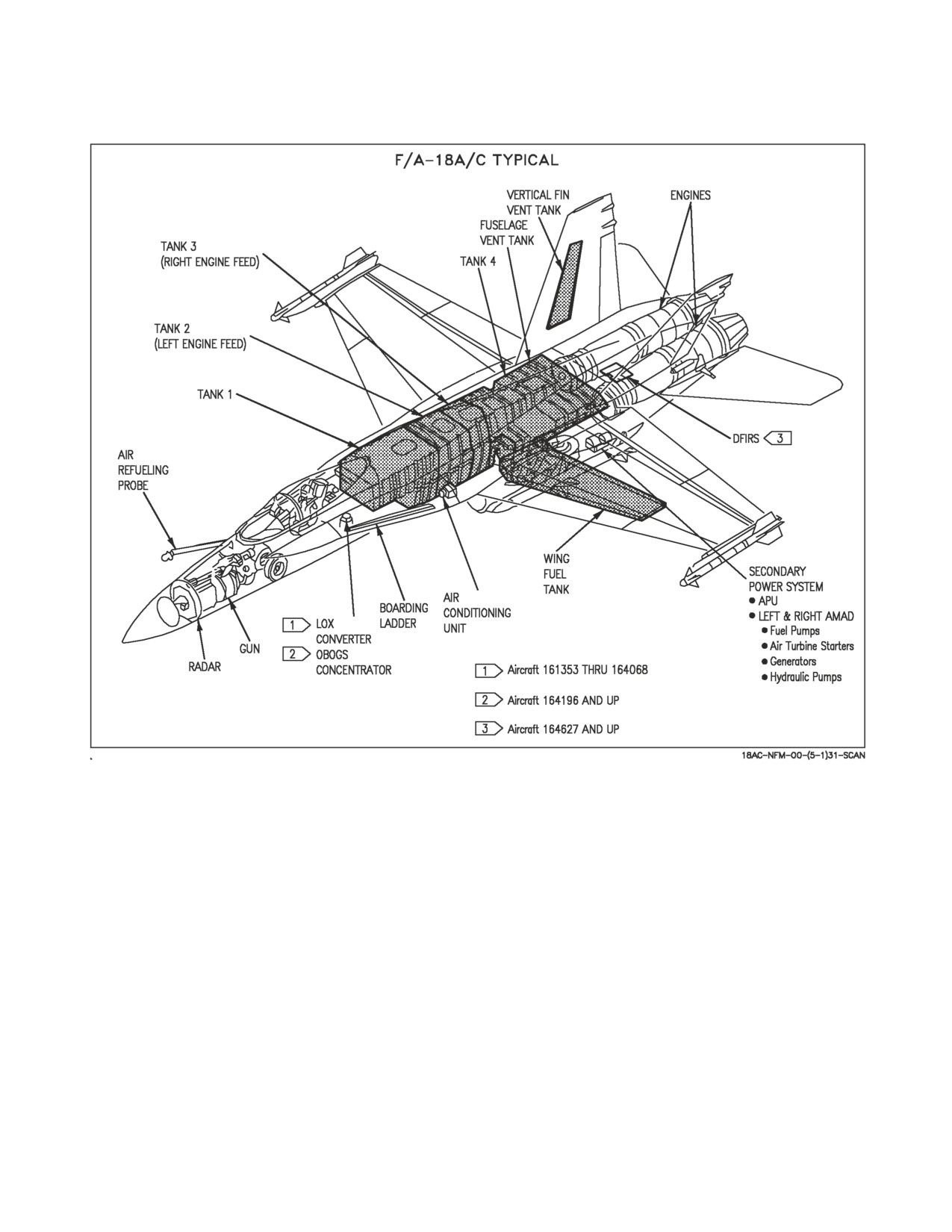
A1-F18AC-NFM-000
Figure 1-1. General Arrangement (F/A-18A/C)
1.1.4 Mission. The aircraft has an all-weather intercept, identify, destroy, and ground attack
capability. Air-to-air armament normally consists of AIM-9, AIM-7, and AIM-120 missiles and a 20
mm gun. Various air-to-ground stores may be carried. Mission range may be extended with the
addition of up to three external fuel tanks.
1.2 BLOCK NUMBERS
See figure 1-2 for block numbers which correspond to aircraft serial numbers (BUNO).
I-1-2
ORIGINAL
//////////////////////////