F18. FLIGHT MANUAL (2008) - page 3
A1-F18AC-NFM-000
2.8.4.5.14 NWS Caution Display. Flashing (on HUD) - loss or partial loss of HYD 2 pressure.
Steady (on DDI) - nosewheel steering inoperative.
2.8.4.5.15 R-LIM OFF Caution Display. Wing pylon mounted air-to-ground stores or tanks set in
armament computer with rack hooks for those stores closed or all stores HUNG and roll rate limiter
inoperative. Do not exceed 1/2 lateral stick. Roll sensitivity is increased.
2.8.4.5.16 RUD OFF Caution Display. Either rudder off.
2.8.4.6
Voice Alert. Any FCS caution except CHECK TRIM, FCS, NWS, FC AIR DAT, G-LIM
OVRD, or R-LIM OFF is accompanied by a “flight controls, flight controls” voice alert. An FCS HOT
caution is accompanied by a “flight computers hot, flight computers hot” voice alert.
2.8.4.7
FCS Status Display. An FCS status display (figure 2-16) may be selected on a DDI. At top
center, the display presents left and right leading edge flap (LEF), trailing edge flap (TEF), aileron
(AIL), rudder (RUD), and stabilator (STAB) positions in degrees with arrows which indicate the
direction from neutral. For example, the control positions shown in the figure are: left LEF 1° leading
edge down, right LEF 1° leading edge down, left TEF 5° trailing edge down, right TEF 5° trailing edge
up, left AIL 15° trailing edge down, right AIL 15° trailing edge up, both RUD 0°, left STAB 3° trailing
edge down, right STAB 4° trailing edge up. The tolerance for all control position indications is ±1°. The
numbers and arrows change as control surface deflections change. At 0° (neutral), the arrows may point
in either direction. A blank is displayed where the number is unreliable.
An X through the LEF, TEF, AIL, or RUD number, also referred to as a bold X, indicates that
control surface is no longer being commanded by the FCC. A bold X through the stab number without
a MECH ON caution indicates the FCC has detected one of the STAB’s two hydraulic power sources
has failed and the STAB may be hinge-moment limited in a small portion of the flight envelope. A bold
X through both the left and right STAB number, and the mech on caution, indicates the FCS has
reverted to MECH mode.
On either side of the position indicators are boxes which represent the FCS channels. On the left
side, reading left to right, the boxes represent channels 1 and 4 for the LEF, AIL, and RUD and 1 2 3
4 for the TEF and STAB. An X in one of these boxes indicates that the FCS is no longer using that
channel to command the actuator due to a failure. On the right side, reading left to right, the boxes
represent channels 2 and 3 for the LEF, AIL, and RUD and 1 2 3 4 for the TEF and STAB. On the lower
right side of the DDI are boxes which display the status, by channel, of the CAS pitch (P), roll (R), and
yaw (Y); the stick position sensors (STICK), the rudder pedal force sensors (PEDAL); the angle of
attack sensing (AOA); the backup air data sensor assembly (BADSA); and the processor (PROC); and
on F/A-18A AFTER AFC 253 OR 292, and F/A-18C/D, the normal accelerometer (N ACC) and lateral
accelerometer (L ACC). An X opposite one of these components indicates a failure in the channel with
the X. An X opposite degraded (DEGD) indicates a switch failure or, for the TEF and STAB, a single
shutoff valve failure. Flight controls are not affected but the FCS should be reset.
NOTE
Except for the LEFs, the control surface position may fail to match the
commanded position without indication to the aircrew.
I-2-58
ORIGINAL

A1-F18AC-NFM-000
Figure 2-16. FCS Status Display
NOTE
An X in both CH1 and CH3 of PROC row indicates INS data is not
being provided to the FCCs for sideslip and AOA estimation
calculations. There is no significant degradation to flying qualities,
departure resistance or roll performance with these failure indications.
(Above approximately 30° AOA in Flaps AUTO, the FCCs use INS
data for sideslip and sideslip−rate feedback to provide roll
coordination and departure resistance. If INS data is not available,
sideslip control, departure resistance and roll performance may be
slightly degraded). The PROC Xs in CH 1/3 may be caused by: an INS
failure, accompanied by an INS ATT caution; by placing the ATT
switch to STBY; or by an FCC−detected failure.
BLIN code display may be selected by channel. The calculated symmetrical positive g limit is
displayed at the left center. An X over the value is displayed when a G-LIM 7.5 caution is present, fuel
state is less than 3,300 pounds, or gross weight is over 44,000 pounds. The word INVALID replaces the
G-LIM display when the FCS Status Display is unreliable. With MC OFP 13C AND 15C, left, inertial
and right AOA probe readouts are presented at the bottom of the display only when AOA is valid. In
GAIN ORIDE, with MC OFP 17C AND UP, the AOA probe selection button allows L, R or Inertial
AOA readout to be boxed and selected, even when AOA has been declared invalid (if AOA is invalid
the L and R readouts have an X across them. With MC OFP 13C AND UP, the L (left) and R (right)
probe values, along with the INS (center) AOA value, are presented at the bottom of the display. In
GAIN ORIDE, as long as the ADC continues to declare the AOA value (probe split <15.5°), the AOA
probe selection button allows the L or R probe to be boxed and selected. The selected probe will drive
the HUD E-bracket display and the INS provides the HUD AOA numeric.
2.8.4.8
Speedbrake. The speedbrake is mounted between the vertical stabilizers. It is controlled by
a throttle mounted switch using left 28 volt dc bus power. It is powered by the HYD 2A system.
I-2-59
ORIGINAL
A1-F18AC-NFM-000
Airborne, when in the AUTO FLAPS UP mode, the speedbrake automatically retracts above 6.0 g or
above 28° AOA and, when not in the auto flaps up mode, below 250 knots. For aircraft 161702 AND
UP, the speedbrake extends with the flaps HALF or FULL so long as the switch is held in EXTEND.
This is not recommended. The speedbrake operates normally on the ground.
2.8.4.8.1
Speedbrake Switch. The speedbrake switch is on the right throttle grip and has three
unmarked positions.
Aft detent
Extends the speedbrake as long as the switch is held aft. Springloaded to
center detent.
Forward detent
Retracts the speedbrake or maintains the speedbrake retracted and pre-
vents creep.
Center detent
Stops the speedbrake in any position. The speedbrake may slowly creep
open.
2.8.4.8.2
SPD BRK Light. The SPD BRK light, on the main instrument panel, comes on anytime the
speedbrake is not fully retracted.
2.9 AUTOMATIC FLIGHT CONTROL SYSTEM (AFCS)
The automatic flight control system (autopilot) has two basic modes: pilot relief and data link. The
pilot relief mode consists of heading hold, heading select, attitude hold, barometric altitude hold, radar
altitude hold, control stick steering (CSS) and coupled steering. The data link mode consists of
automatic carrier landing (ACL), precision course direction, and vector approach. With MC OFP 13C
AND UP, the coupled steering consists of azimuth steering line couple (ASL), bank angle control
(BNK), coupled waypoint steering (WYPT), coupled auto sequential steering (SEQ ( )), and coupled
TACAN steering (TCN). Refer to NTRP 3-22.4-FA18A-D NATIP and NTRP 3-22.2-FA18A-D
NATIP for ASL and BNK information. Control of the automatic flight control modes is accomplished
by the switches on the up front control (UFC), heading set switches on the heading and course set
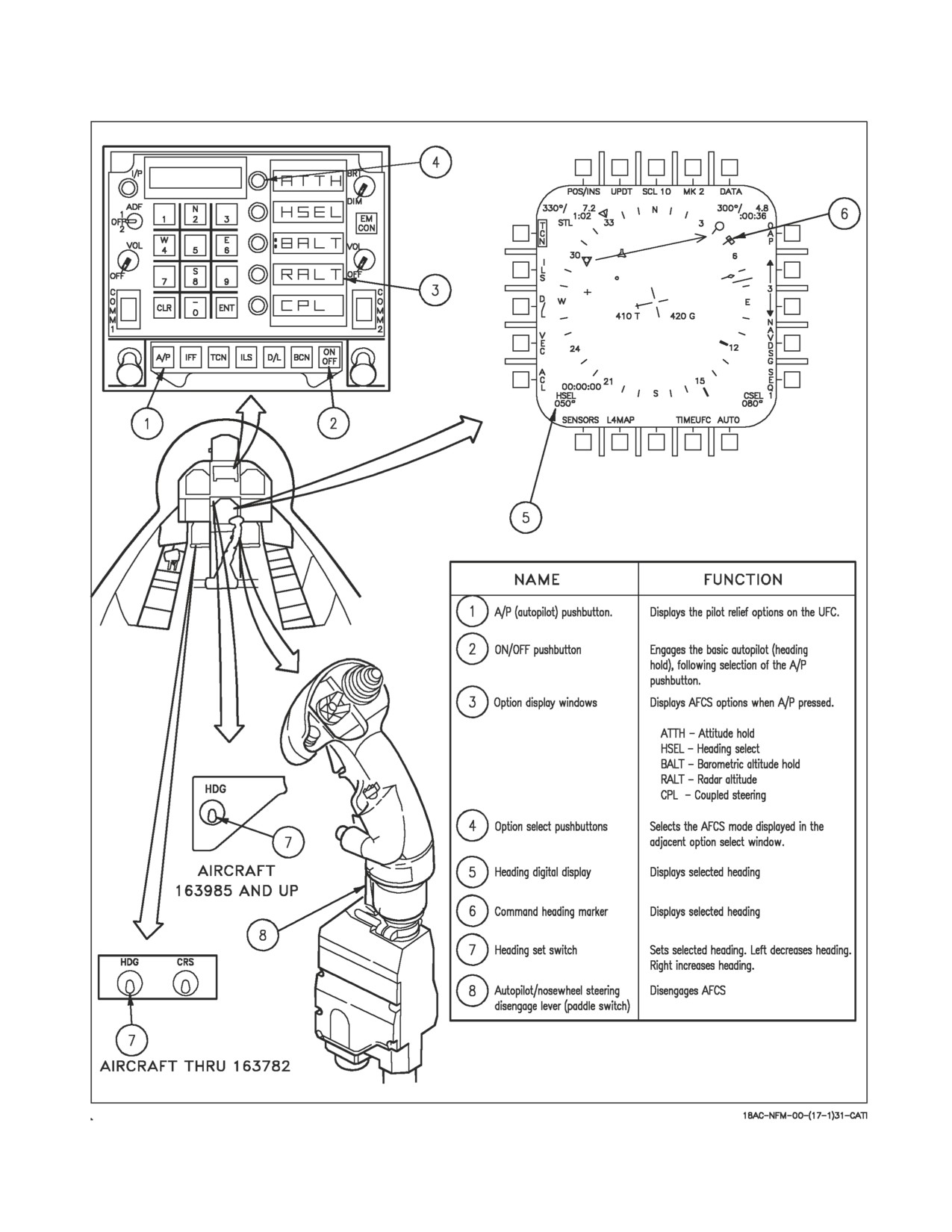
switches panel, and the autopilot disengage/nosewheel steering switch on the control stick (see figure
2-17). Before any mode can be selected bank must be less than or equal to 70°, pitch must be less than
or equal to 45°, and the A/P pushbutton must be pressed. Selection of the A/P pushbutton displays the
pilot relief options of: ATTH (attitude hold), HSEL (heading select), BALT (barometric altitude
hold), RALT (radar altitude hold), and the CPL (coupled steering) option (if available) in the UFC
option display windows. When a pilot relief option is selected via the UFC a colon (:) appears in front
of the selected display and the selected mode appears on the DDI advisory display. If an option is not
available, it is not displayed. When the CPL option is selected on the UFC, the flight controls will
couple to that steering mode (in azimuth only). A bank limit, BLIM option, is available on the A/C
DATA display. NAV BLIM sets a 30° fixed bank limit. TAC BLIM limits the bank angle between 30°
and 60°, based on airspeed. An overfly (OVFLY) option is available on the WYPT DATA display.
OVFLY is used during auto sequential steering when it is desired to overfly the waypoint, otherwise the
aircraft will turn prior to the waypoint to capture the course to the next waypoint.
2.9.1 AFCS Caution and Advisory Displays. The following autopilot related caution and advisory
displays may appear on the DDI:
I-2-60
ORIGINAL
A1-F18AC-NFM-000
CAUTION
MEANING
AUTO PILOT
Autopilot did not engage or A/P disengaged after it was selected for any
reason except pilot actuation of the paddle switch. The caution is re-
moved after 10 seconds or when the paddle switch is actuated. The auto-
pilot can be commanded out of the BALT or RALT hold mode by CSS.
ADVISORY
MEANING
A/P
An autopilot mode is selected.
ATTH
Attitude hold mode is selected.
BALT
Barometric altitude hold mode is selected.
CPLD
Coupled steering, automatic carrier landing (ACL), azimuth steering line
(ASL), or bank angle control (BNK), is selected.
HSEL
Heading select mode is selected.
RALT
Radar altitude hold mode is selected.
2.9.2 Pilot Relief Modes
2.9.2.1
Autopilot. The basic autopilot (heading hold) is engaged by selecting the A/P pushbutton (at
which time pilot relief options appear on the UFC) then selecting the ON/OFF pushbutton.
Engagement is indicated by the A/P advisory on the DDI. Selecting the ON/OFF pushbutton is not
required if ATTH, HSEL, BALT, RALT, or CPL (MC OFP 13C AND UP) option on the UFC is
desired.
Decolonizing any autopilot mode does not disengage the basic autopilot
control stick steering (CSS) function. Activating the autopilot/nosewheel
steering disengage lever (paddle switch) on the control stick with any
autopilot mode selected disengages all autopilot modes. Failure to disen-
gage autopilot modes with the paddle switch prior to landing (other than
mode 1) results in CSS remaining engaged and may cause extreme
aircraft pitch/PIO oscillations.
At this time the aircraft maintains the existing pitch attitude. If roll attitude is less than or equal to
±5° at engagement, the magnetic heading is maintained. If roll attitude at time of engagement is
greater than ±5°, the roll attitude is maintained. The pitch attitude hold reference can be changed with
pitch CSS to any value between ±45° pitch. The pitch attitude reference can also be changed with the
trim switch on the control stick at a rate of 0.5°/second. The roll attitude hold reference (if roll is
greater than ±5°) can be changed with roll CSS to any value between 5° and 70° of roll. The roll
attitude reference can also be changed using the trim switch on the stick at a rate of 2°/ second. The
I-2-61
ORIGINAL
A1-F18AC-NFM-000
Figure 2-17. AFCS Controls and Indicators
I-2-62
ORIGINAL
A1-F18AC-NFM-000
magnetic heading reference (if roll is less than or equal to ±5°) can be changed, or initially set with roll
CSS. The roll trim switch also can change the reference magnetic heading.
NOTE
Pitch trim is reset to 8.1° AOA anytime the autopilot is disengaged
while in the PA configuration, if AOA is greater than 6.0°.
2.9.2.2
Attitude Hold. Attitude hold is engaged by pressing the option pushbutton next to the option
display window displaying ATTH. Engagement is indicated by a colon in the ATTH option window.
At this time the aircraft maintains the existing pitch and roll attitude. The pitch attitude hold
reference can be changed to any value between ±45° with pitch CSS or with the trim switch on the
control stick (0.5°/second). The roll attitude hold reference can be changed to any value between ±70°
with roll CSS or with the trim switch on the stick (2°/second).
2.9.2.3
Barometric Altitude Hold. To establish barometric altitude hold, press the button next to
the option display window displaying BALT. The existing barometric altitude at time of engagement
is captured and maintained. Heading or attitude hold is maintained, depending upon which mode was
previously engaged. The operating range is 0 to 70,000 feet. ATTH, CPL (MC OFP 13C AND UP), or
HSEL can be selected with BALT to provide lateral control. CSS causes reversion to heading or
attitude hold, depending upon which was previously engaged.
2.9.2.4
Heading Select. To establish heading select mode, select the desired heading on the HSI
display by using the heading set switch, located to the left of the center DDI. Press the button next to
the option display window displaying HSEL. The aircraft turns from existing heading through the
smallest angle to the selected heading. Heading hold is reestablished after the selected heading is
captured. Existing pitch attitude is maintained. CSS is available.
2.9.2.5
RADAR Altitude Hold. To establish radar altitude hold, press the pushbutton next to the
option display window displaying RALT. Engagement is indicated by a colon appearing in the window
next to RALT. The existing radar altitude is maintained upon engagement. Radar altitude hold
coverage is from 0 to 5,000 feet. If no other mode is selected, the lateral axis control remains in heading
hold. In this configuration, either CSS or the roll trim switch can be utilized with automatic turn
coordination up to 45° with altitude maintained. ATTH, CPL (MC OFP 13C AND UP) or HSEL can
be selected with RALT to provide lateral control.
2.9.2.6
Coupled Steering (MC OFP 13C AND UP). The coupled steering options are: WYPT, OAP,
SEQ#, and TACAN range bearing. To engage coupled steering, the desired steering option must be
available and selected on the HSI display, MC1 must be communicating with the FCS, then press the
pushbutton next to the UFC option display window displaying CPL. Engagement is indicated by a
colon appearing in the window next to CPL and a CPLD advisory on the DDI. The flight controls are
coupled (azimuth only) to whatever active steering mode that has been selected (boxed) on the HSI
display. Once coupled steering is engaged attitude hold and heading select A/P options are not
available. CSS is available in pitch only. Lateral stick displacement greater than 0.5 inch causes the
autopilot to decouple from the steering mode. Great circle course can be selected to the fly-to-point, or
a selected radial (course line) through the fly-to-point. If course line is selected prior to the fly-to-point,
flight controls capture the selected radial, overfly the fly-to-point and continue on the out bound
radial. A coupled bank limit option is available on the A/C data display and allows the pilot to select
TAC or NAV bank angle limit mode. Selecting NAV limits the bank angle to a maximum of 30°.
Selecting TAC limits the bank angle to a maximum of 30° to 60° (depending on airspeed). Refer to
I-2-63
ORIGINAL
A1-F18AC-NFM-000
Chapter 24 for detailed navigation steering information under Waypoint/OAP, Auto Sequential, and
TACAN Steering.
2.10 LANDING SYSTEM
The landing system is made up of the landing gear, nosewheel steering, brakes, launch bar, and
arresting hook.
2.10.1 Landing Gear System. The landing gear system is electrically controlled and hydraulically
operated. The main gear is retracted aft into the fuselage and the nose gear is retracted forward. When
the gear is extended, all gear doors remain open.
2.10.1.1 Landing Gear Control Handle. The landing gear is controlled by a two-position, wheel-
shaped handle on the lower left side of the main instrument panel. Two conditions must be met before
the gear can be raised: the aircraft must sense that weight is off all three landing gear and the launch
bar must be retracted. When these conditions are met, the landing gear is raised by moving the handle
up. If the launch bar is extended when the handle is raised, the main gear retracts but the nose gear
remains extended. When the aircraft senses weight on any of the three landing gear, a mechanical stop
in the landing gear control panel extends preventing movement of the handle from DN to UP. Moving
the handle down lowers the gear.
2.10.1.2 Down Lock Override Button. The down lock override button is located to the left of the
landing gear control handle. If the mechanical stop remains extended after takeoff preventing
movement of the handle from DN to UP, a failure has occurred in the landing gear handle down lock
circuit. Pressing and holding the DOWN LOCK ORIDE button retracts the mechanical stop from the
landing gear control handle allowing it to be moved from DN to UP. The landing gear control handle
must be full DN to allow the mechanical stop to properly engage upon landing. If the DOWN LOCK
ORIDE button is pressed or the mechanical stop is not fully engaged in the landing gear control handle,
the handle can be moved to UP on the ground and the gear will retract.
2.10.1.3 Weight-On-Wheels
(WOW) System. Numerous aircraft systems function differently
depending upon whether the aircraft is on the ground or is airborne. The most important of these
functions include: various flight control laws, landing gear operation, master arm and stores jettison,
fuel dump operation, AOA HUD indexers and approach lights, Automatic Throttle Control (ATC) and
autopilot operation, pitot static, AOA and total temperature probe heating, fuel tank pressurization,
and the inflight IDLE and afterburner lockout throttle stops. To determine when the aircraft is on the
ground, a proximity switch on each gear indicates when there is weight on each of the wheels. There
are a variety of failure conditions which may result in false indications of WOW or weight off wheels.
These include: a misrigged landing gear WOW proximity switch, a WOW proximity switch failure, an
improperly serviced landing gear strut, a landing gear control unit failure, or a problem with the
aircraft wiring.
An uncommanded pitch up after takeoff may occur if a WOW system
failure results in the aircraft sensing weight on wheels while inflight.
The first indication of the aircraft sensing WOW while inflight is the inability to raise the landing
gear handle. Other possible indications include the CHECK TRIM caution, NWS on the HUD, and the
CK FLAPS caution if the FLAP switch is moved to AUTO. The aircraft may then quickly undergo an
I-2-64
ORIGINAL
A1-F18AC-NFM-000
uncommanded pitch up which is caused by the large stabilator deflection present at takeoff. Normally,
the stabilator deflection would be trimmed out automatically by the flight control system. As airspeed
increases, the uncommanded pitch up rate increases. Maintaining airspeed as slow as practical helps
control nose pitch up and assists in lowering the aircraft’s nose. Above 180 knots, full forward stick
alone does not stop aircraft nose up rotation, so nose down trim is required to regain control of the
aircraft. The FLAP switch should also remain in HALF since the pitch up rate increases if the FLAP
switch is moved to AUTO.
2.10.1.4 Landing Gear Warning Lights/Tone. The landing gear warning light is a red light in the
gear handle. The light comes on when the gear is in transit and remains on until all three gear are down
and locked when DN is selected, or all the gear doors are closed when UP is selected. The light remains
on with the gear down and locked if the left or right main landing gear planing link is not locked. When
the landing gear handle light has been on for 15 seconds the landing gear aural tone also comes on.
NOTE
Aircraft equipped with LGCU-01 do not provide an aural tone to the
aircrew.
In addition, the gear handle light functions as a wheel warning in conjunction with a warning tone.
The gear handle light flashes and a continuous rate beeping tone sounds when the gear handle is in the
UP position, the aircraft is below 175 knots, altitude is less than 7,500 feet and rate of descent is greater
than 250 feet per minute.
NOTE
The loss of calibrated airspeed and/or barometric altitude data results
in activation of the landing gear handle warning light and tone. First
reference the applicable standby airspeed or altitude indicator, then
silence the tone.
The warning tone may be silenced by pressing the warning tone silence button next to the gear
handle.
2.10.1.5 Landing Gear Position/Planing Link Failure Lights. There are three green landing gear
position lights marked NOSE, LEFT and RIGHT, above the landing gear control handle. The lights
indicate that the gear is down and locked, or that a planing link is not locked. The NOSE gear light
comes on steady when the nose gear is down and locked. The LEFT and RIGHT lights come on steady
when their respective gear is down and locked and flash if the gear is down and locked but a related
planing link is not locked. On F/A-18A/C/D 163146 AND UP; ALSO F/A-18A/B 161353 THRU 163145
AFTER ASC 030, the planing link failure lights is accompanied by a continuous rate beeping tone.
Visual inspection does not confirm locked gear, only obvious damage and
general position of gear.
2.10.1.6 Emergency Gear Extension. Emergency gear extension is done by rotating the gear handle
90° clockwise and pulling (approximately 1.5 inches) to the detent where the handle locks in place.
This can be done with the handle in either UP or DN; however, the handle must be rotated 90° before
I-2-65
ORIGINAL
A1-F18AC-NFM-000
it is pulled. Rotating and pulling the gear handle opens the valves for the emergency landing gear
control, the APU accumulator and the emergency brake accumulator. The nose landing gear extends
by free fall aided by airloads, and the main landing gear extends by free fall aided by the side brace
downlock actuator and the compressed shock absorber. If gear indicates unsafe following emergency
extension, it may be the result of the APU accumulator arming valve not opening. Another way to open
the APU accumulator arming valve is to emergency extend the IFR probe.
2.10.2 Nosewheel Steering System. The nosewheel steering system is a combination shimmy
damper and dual mode steering system. It is electrically controlled by two switches on the stick grip
and hydromechanically operated through inputs from the rudder pedals and flight control computers.
With the flight control computers operating, momentarily pressing the nosewheel steering button
activates and engages nosewheel steering in the low mode (±16°) and NWS is displayed on the HUD.
Holding the nosewheel steering button pressed selects the high mode (±75°) and NWS HI is displayed
on the HUD. With the wing handle unlocked and nosewheel steering in the low mode, pressing the
nosewheel steering button causes the nosewheel steering to go to the high mode where it remains
without holding the button pressed. Momentarily pressing the autopilot disengage switch (paddle
switch) disengages nosewheel steering until reengaged by the nosewheel steering button. If the launch
bar is extended, nosewheel steering is disengaged, however, the low mode may be engaged by pressing
and holding the nosewheel steering button. On the ground, nosewheel steering is disengaged when
power is removed from the aircraft. Nosewheel steering is also disengaged with weight off the nose gear.
During landing, nosewheel steering is automatically engaged in the low mode with weight on the nose
gear.
NOTE
Reversion of NWSHI to NWS (low gain) occurs within 4 to 60 seconds
after touchdown due to LGCU BIT. NWSHI can be reselected.
If the high mode is desired during taxi, press and hold the nosewheel steering button. If the
nosewheel steering system fails, NWS and FCS are displayed on the DDI as cautions, the MASTER
CAUTION light comes on, and the NWS or NWS HI display is removed from the HUD. When failed,
the nosewheel steering system reverts to a free swivelling mode.
NOTE
With a channel 2 or 4 FCS failure, normal nosewheel steering is lost.
Emergency HI gain steering can be regained by pulling the failed
channel circuit breaker, unlocking the wings, and pressing the
nosewheel steering button. When the emergency HI gain NWS mode is
entered, NWS indications may not be displayed on the HUD. If
pressing the NWS button results in an FCS caution and single X in
the powered channel, emergency HI gain is not available.
2.10.3 Brake System
2.10.3.1 Normal Brake System. The main landing gear wheels have full power brakes operated by
toe action on the rudder pedals. An anti-skid system is combined with the normal system to prevent
wheel skid. Normal brake pressure is supplied by HYD 2A. The anti-skid system modulates pilot
demanded brakes to prevent tire skid.
2.10.3.2 Anti-Skid System. The anti-skid system is electrically controlled by a two position switch
on the lower left portion of the instrument panel. The switch is lever-locked to OFF. A SKID advisory
I-2-66
ORIGINAL
A1-F18AC-NFM-000
display on the DDI is displayed if the landing gear is down and anti-skid ON is not selected. If anti-skid
fails, the DDI displays ANTI SKID as a caution and the MASTER CAUTION light comes on. A
touchdown protection circuit prevents brake application on landing until wheel speed is over 50 knots,
or if a wet runway delays wheel spin-up, 3 seconds after touchdown. A locked wheel protection circuit
releases the brakes if the speed of one main wheel is 40% of the other main wheel. The locked wheel
protection circuit is disabled at about 35 knots. The anti-skid system is totally disabled below 10 knots.
Anti-skid protection is bypassed when the ANTI SKID switch is off. Normally limited by the
anti-skid system, 3,000 psi hydraulic brake pressure is available and regulated only by pilot brake pedal
forces. When using brakes at high speed without anti-skid protection, there is a very small margin
between effective braking and blown tires. Any force greater than approximately 55 to 60 lbs applied
to the pedals (6° to 7° of pedal rotation) will likely result in blown tires with either the ANTI SKID
switch OFF or emergency brakes selected. The use of normal (anti-skid off) brakes at high speed
should be done with extreme caution. If braking without anti-skid is needed at high speeds, initially
apply very light brake pedal pressure and gradually increase as required.
Use of brakes without anti-skid at high speed can result in blown tires
resulting in loss of directional control. If practical, rollout speed should be
as slow as possible before applying brake pedal pressure.
ANTI SKID caution does not reappear and brakes may not be available
for 13.5 seconds after cycling anti-skid switch inflight or 9.5 seconds
during landing rollout, until BIT is completed.
NOTE
Hot brakes can be expected any time maximum effort braking is used
with or without anti-skid at heavy gross weights (e.g., takeoff abort, or
heavy landing).
2.10.3.3 Emergency Brake System. The emergency brake system uses normal system brakes with
independent hydraulic lines carrying emergency hydraulic pressure to the brake shuttle valve. The
system is activated by pulling the emergency/parking brake handle out to the detent. The emergency
brake system is powered by the HYD 2B system or the brake accumulator backed up by the APU
accumulator. Brake accumulator pressure is shown on a pressure gage on the lower left corner of the
main instrument panel and is redlined to indicate pressure below 2,000 psig. However, an indication of
2,000 psig does not mean the onset of degraded braking. It is a warning that there are five full brake
applications remaining before BRK ACCUM is displayed on the DDI as a caution and the MASTER
CAUTION light comes on. This caution is displayed at 1,750 psi and represents the worst condition
(maximum temperature) where the brake accumulator may be empty. When emergency brakes are
selected, anti-skid is deactivated even if normal HYD 2A braking is available. No warning/caution is
displayed for emergency brake selection. The system is deactivated by pushing the emergency/parking
I-2-67
ORIGINAL
A1-F18AC-NFM-000
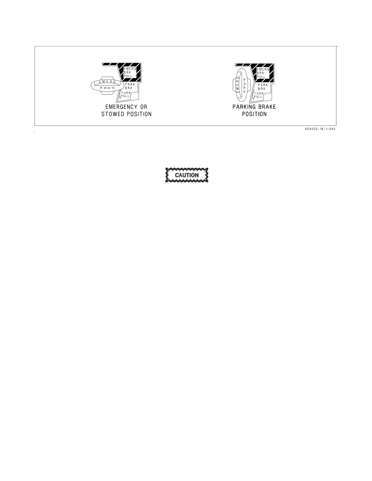
Figure 2-18. Emergency/Parking Brake Handle
brake handle back into the stowed position. The handle must be fully stowed (F/A-18B/D both
cockpits) to ensure anti-skid is available.
Due to system friction, the emergency parking brake handle may not
return to the stowed position without pilot assistance (positive push)
during the last part of its travel. If the handle is not fully stowed after
selecting emergency brakes, the emergency brake system remains
selected. Normal brakes and anti-skid protection cannot be regained
until the handle is fully stowed.
2.10.3.3.1 Emergency/Parking Brake Handle. The combination emergency/parking brake handle
(figure 2-18) is on the lower left corner of the main instrument panel. The handle is shaped such that
EMERG is visible to the pilot when the handle is in the stowed or emergency position and PARK is
visible to the pilot when the handle is rotated to the park position.
2.10.3.4 Parking Brake System. The parking brake system uses the same hydraulic lines, accumu-
lators and actuation handle as the emergency brake system. The system is activated by rotating the
emergency/parking brake handle 90° counterclockwise from the horizontal stowed position and pulling
it out to a positive locked position. If the emergency brakes have been activated, it is necessary to
reposition the handle to the stowed position then rotate it 90° counterclockwise and pull it to the
locked position to select parking brakes. This action applies non-regulated pressure to the disc brakes.
With the INS on, the parking brake set, and both throttles above about 80% rpm, the PARK BRK
caution and MASTER CAUTION come on. To release the parking brake, rotate the emergency/
parking brake handle 45° counterclockwise from the extended position. This releases the lock and
allows the handle to return to the horizontal stowed position.
2.10.4 Launch Bar System. The launch bar is hydraulically extended and retracted by redundant
springs. A locking tab mechanically locks the launch bar in the up position. A two position (EXTEND
and RETRACT) launch bar switch on the lower left corner of the main instrument panel controls
launch bar operation. As the launch bar extends the green L BAR advisory light comes on. When the
launch bar is fully extended it is held against the deck by deck load control springs. The control springs
allow vertical movement of the launch bar during taxi. As the aircraft is taxied into the launch gear the
launch bar drops over the shuttle and is held captive in the extended position as the shuttle is
tensioned. On aircraft 161353 THRU 161715, when both throttles are advanced to or above MIL, a
throttle switch is made, the green L BAR advisory light goes out and the launch bar switch returns to
I-2-68
ORIGINAL
A1-F18AC-NFM-000
RETRACT. Before AFC 081, if the launch bar switch is not deenergized to RETRACT after the
throttles are advanced to MIL, the red L BAR warning light comes on. On aircraft 161716 AND UP,
the launch bar switch does not return to RETRACT when both throttles are advanced to MIL or above.
The green L BAR advisory light goes out when the switch is placed to RETRACT. If the red L BAR
warning light is on with the switch in RETRACT, an electrical fault exists which prevents launch bar
retraction after launch. At the completion of the catapult stroke, launch bar/catapult separation occurs
and the return springs cause launch bar retraction which allows the landing gear to be retracted. If the
launch bar fails to retract after the aircraft is launched, the red L BAR warning light comes on and the
nosewheel does not retract. A launch bar circuit breaker is on the left essential circuit breaker panel
and when pulled deenergizes the launch bar electrical system.
NOTE
Failure to place launch bar switch to retract may result in hydraulic
seal failure.
2.10.5 Arresting Hook System. The arresting hook system consists of a retract actuator/damper, fail
safe manual latch and release, universal hook shank pivot and replaceable hook point. Hook control is
a manual system which automatically extends the hook in case of a failure of the release system. The
arresting hook handle and hook light are on the lower right main instrument panel. The hook light
remains on except when the hook is up and latched or is fully down. Hook extension is a free fall action
assisted by a nitrogen charge in the actuator cylinder. Hook motion is dampened laterally by a liquid
spring in the hook shank and vertically by the damper in the retract actuator cylinder which minimizes
hook bounce and provides hold down force for arresting cable engagement.
Without proper N2 pre-charge (insufficient arresting hook snubber pressure), the arresting hook
does not fully extend due to HYD 2 backpressure and airloads. If the arresting hook fails to extend as
a result of this condition, shutting down the right engine reduces HYD 2 backpressure and allows
sufficient extension (35° compared to 56°normal).
2.10.5.1 Arresting Hook Handle. To extend the arresting hook, place the arresting hook handle
down. The HOOK light comes on when the hook is in transit and goes out when the hook reaches the
selected position. The light remains on if the hook is in contact with the deck and is prevented from
reaching the hook down proximity switch. The HOOK light remains on any time the hook position does
not agree with the handle position.
2.11 WING FOLD SYSTEM
Each outer wing panel is folded upward to a vertical position by a wing fold mechanical/electrical
drive. A wing fold unlock flag in the upper surface wing fold area provides a visual indication of the
wing lock pins in the unlocked position. The wing lock control and wing fold/spread control are
combined in the wing fold handle on the lower right main instrument panel. A wing safety switch is
located so that a safety pin can be manually installed from the underside of the wing when absolute
prevention of wing fold or spread is desired. The ailerons are locked in neutral when the wings are
folded.
To avoid damaging the flaps, ensure ailerons are not faired inboard prior
to raising the flaps, conducting IBIT, or running FCS exerciser. Proper
aileron position can be determined either visually or by verifying an
aileron position of 0 or down arrow on the FCS page.
I-2-69
ORIGINAL
A1-F18AC-NFM-000
2.11.1 Wing Fold Handle. Normal folding and spreading the wings is accomplished through
operation of the wing fold handle. To fold the wings, press the detent on the underside of the wing fold
handle, pull out and rotate counterclockwise to FOLD. The MASTER CAUTION light comes on, a
WING UNLK display appears on the DDI and the wing fold unlock flag appears. To spread the wings,
rotate the wing fold handle clockwise to SPREAD. To lock the wings after they have fully spread, push
the handle in. Wait 5 seconds after wings are fully spread before placing the WING FOLD handle to
LOCK. When the lock pins are in place the WING UNLK display on the DDI disappears and the wing
fold unlock flag is down flush with the top surface of the wing. The wings can be stopped and held in
any intermediate position by placing the wing fold handle to HOLD. The ailerons must be faired prior
to folding the wings. Normally 115 volts ac operates the wingfold drive unit and hydraulic power fairs
the ailerons. However, both of these operations can be accomplished manually. The wings are unlocked
by pulling out on the wing fold handle. The drive unit can then be driven with a speed handle through
an opening in the lower wing surface just inboard of the trailing edge of the wing fold area.
• Placing the WING FOLD handle to LOCK before the wings are fully
spread removes the WING UNLK caution even though the wings are
not fully spread and also causes severe damage to the wing fold
transmission.
• With wings folded, verify that both ailerons are Xd out before
initiating any IBIT or exerciser mode tests. Lack of X’d out ailerons
indicates hydraulic pressure is still being supplied to aileron actuator
through a leaking swivel valve. IBIT testing without Xd out ailerons
can result in damage to aileron hinge. PBIT BLIN 51 or IBIT BLINs
4263 and 70261 may result following IBIT when wings are folded.
These BLIN codes do not require maintenance action prior to flight.
However, if BLIN 51 does not reset after airborne, wing-fold function
may not be available after landing.
• The wingfold control handle should smoothly go into the LOCK
position. Forcing the handle could cause damage to the wingfold
system.
• A 12 minute cool down period is required before cycling wing fold after
two cycles maximum, with or without missiles installed. Failure to
allow the cool down period may result in overheat damage to wing fold
electric drive unit.
NOTE
• Do not cycle wingfold handle to FOLD until WING UNLK caution is
observed.
• A cycle is from the spread position to the fold position and down to the
spread position.
I-2-70
ORIGINAL
A1-F18AC-NFM-000
2.12 INSTRUMENTS
Refer to foldout section for cockpit instrument panel illustration. For instruments that are an
integral part of an aircraft system, refer to that system description in this section.
2.12.1 Pitot-Static System. There are two pitot-static tubes mounted under the nose on each side
forward of the nosewheel well. Each tube contains one pitot source and two static sources.
2.12.1.1 Pitot Heater Switch. The pitot heater switch on the ECS panel has positions ON and
AUTO.
AUTO
Heaters are on when airborne.
ON
Heaters are on when ac power available.
2.12.1.2 Pitot Pressure. Pitot pressure from the right pitot tube is supplied to the air data computer
and the air data sensor channel 2. Pitot pressure from the left pitot tube is supplied to the airspeed
indicator and the air data sensor channel 1.
2.12.1.3 Static Pressure. The static sources from each pitot static tube are Td together and this
pressure is supplied to the air data computer. The air data sensor channels 1 and 2, on 161520 AND
UP, also receive static pressure from this Td static source. On 161353 THRU 161519, channel 1 receives
static pressure from the left pitot static tube second source and channel 2 receives static pressure from
the right pitot static tube second source. On all aircraft, the standby flight instruments receive static
pressure from the left pitot static tube second source when the static source lever is set to NORMAL
or from the right pitot static tube second source when set to BACKUP. The static source lever is under
the right part of the instrument panel, forward of the right console. With lever in the horizontal
position, the selector valve is in NORMAL, with lever in the vertical position, the selector valve is in
BACKUP.
2.12.1.4 L/R Pitot HT Caution Display. With pitot heater switch in ON or AUTO while airborne, or
in ON on the ground; a L PITOT HT and/or R PITOT HT caution display comes on if a malfunction
occurs in the heater circuits.
Failure of both AOA (ADSU) probe heaters in icing conditions may cause
a sharp uncommanded nose down attitude, uncontrollable by normal
stick forces or paddle switch actuation. Selection of gain override may
regain stabilator control. Care should be used during recovery above 350
KIAS.
2.12.2 Standby Attitude Reference Indicator. The standby attitude reference indicator (SARI) is a
self-contained electrically driven gyro-horizon type instrument. The right 115 volts ac bus normally
powers it. If this power fails, an inverter operating off the essential 28 volts dc bus automatically powers
it. An OFF flag appears if both power sources fail or the gyro is caged. Ideally the indicator should be
in the caged and locked condition prior to application of power. If power has been applied with the
indicator in the uncaged condition, wait at least 30 seconds after power application before caging.
During caging the gyro initially cages to 4° pitch and 0° roll regardless of aircraft attitude. Caging when
the aircraft is in a roll attitude greater than 5° cuts out the roll erection system and the gyro does not
I-2-71
ORIGINAL
A1-F18AC-NFM-000
erect properly. After 3 to 5 minutes, the indicator reads 0° in pitch and 0° in roll. Both readings assume
the aircraft is straight and level. Pitch display is limited by mechanical stops at approximately 90°
climb and 80° dive. As the aircraft reaches a near vertical orientation, the roll display experiences large
rotations. An aircraft wings level attitude in the vertical orientation may result in large errors in either
pitch or roll, or both. This is normal, and is not an indication of damage or improper function of the
indicator. After completion of vertical maneuvers the indicator most likely requires caging in the
normal cruise attitude, to eliminate the errors. Vertical maneuvers with a wing down condition of 7°
or more usually do not develop significant gyro errors. A needle and ball are at the bottom of the
instrument. A one-needle width turn is 90° per minute.
2.12.3 Standby Airspeed Indicator. The standby airspeed indicator displays airspeed from 60 to 850
knots indicated airspeed. It operates directly off left pitot pressure and left static pressure with
NORMAL selected by the static source selector lever or right static pressure with BACKUP selected.
2.12.4 Standby Altimeter. The standby altimeter is a counter-pointer type. The counter drum
indicates altitude in thousands of feet from 00 to 99. The long pointer indicates altitude in 50-foot
increments with one full revolution each 1,000 feet. A knob and window permit setting the altimeter
to the desired barometric setting. This setting is also used by the air data computer. The standby
altimeter operates directly off the left static pressure with NORMAL selected by the static source
selector lever or right static pressure with BACKUP selected.
2.12.5 RADAR Altimeter Set (AN/APN-194(V)). The radar altimeter set indicates clearance over
land or water from 0 to 5,000 feet. Operation is based on precise measurement of time required for an
electromagnetic energy pulse to travel from the aircraft to the ground terrain and return. Voice alert
and/or warning tone and visual warnings are activated when the aircraft is at or below a selectable low
altitude limit. The set consists of a receiver-transmitter, individual transmitting and receiving
antennas, and a height indicator. The receiver-transmitter produces the energy pulses, transmits the
energy to the ground, receives the reflected signal and processes this data for display as altitude by the
head-up display unit (HUD) and the height indicator. The height indicator, on the instrument panel,
consists of a calibrated scale from 0 to 5,000 feet, a push to test switch, a low altitude index pointer, an
altitude pointer, an OFF flag, a low altitude warning light, and a BIT light. Other indicators and
controls used with the radar altimeter set are the left or right digital display indicators (DDI) (for BIT
checks), an altitude switch, UFC, HI/MPCD/AMPCD (for secondary radar low altitude warning), and
the head-up display. The energized position of the emission control (EMCON) switch on the upfront
control panel inhibits operation of the radar altimeter.
2.12.5.1 Primary Radar Low Altitude Warning. If the landing gear is up and locked and the radar
altitude is less than the Low Altitude Limit index, the primary low altitude warning tone/voice alert
is heard in the pilot’s headset. With F/A-18A/B before AFC 253 or 292 a ‘‘WARNING, WARNING’’
voice alert is heard. With F/A-18A after AFC 253 or 292 and F/A-18C/D a ‘‘Whoop, Whoop’’ warning
tone is heard. The voice alert or warning tone is activated at ground power-up to familiarize the pilot
with the warning. When first activated in flight, the warning is continuously repeated until reset or
disabled. The warning is reset by setting the low altitude index to an altitude below the present altitude
or by climbing to an altitude above the low altitude index setting. The warning can be disabled by
I-2-72
ORIGINAL
A1-F18AC-NFM-000
pressing the :RALT button on the UFC or by commanding the UFC to another mode. Once disabled
it cannot be triggered until after being reset as described above.
NOTE
With an MC1 failure, the voice alert/warning tone is not sounded when
the aircraft descends below the altitude set by the low altitude index
pointer.
2.12.5.2 Secondary Radar Low Altitude Warning. A secondary radar low altitude warning function
is enabled by entering the appropriate altitude, up to a maximum of 5,000 feet on the UFC. The
secondary radar low altitude warning provides a single voice alert warning “ALTITUDE, ALTITUDE”
when the aircraft descends through the selected altitude. The warning can be disabled by entering zero
feet as the stored altitude. Power up with WOW initializes the stored altitude to zero feet. Refer to part
VII for information on entering altitude.
2.12.5.3 Barometric Low Altitude Warning. A barometric low altitude warning function is enabled
by entering the appropriate altitude, up to a maximum of 25,000 feet on the UFC. The barometric low
altitude warning provides a single voice alert warning “ALTITUDE, ALTITUDE” when the aircraft
descends through the selected altitude. The warning can be disabled by entering zero feet as the stored
altitude. Power up with WOW initializes the stored altitude to 5,000 feet. Refer to part VII for
information on entering altitude. The barometric low altitude warning function does not affect
operation of the radar altimeter low altitude warning function.
2.12.5.4 Controls and Indicators.
2.12.5.4.1 Push to Test Switch. Turning this switch clockwise applies power to the set. Further
clockwise rotation positions the low altitude index pointer to increasing altitudes. Pushing in on the
switch activates the BIT checks.
2.12.5.4.2 Altitude Pointer. This pointer indicates the altitude of the aircraft from 0 to 5,000 feet
above the terrain.
2.12.5.4.3 Low Altitude Warning Light. This red light comes on to indicate the altitude pointer
(aircraft altitude) is below the altitude set with the low altitude index pointer.
2.12.5.4.4 Low Altitude Index Pointer. This pointer sets the altitude at which the low altitude
warning light comes on and the voice alert warning is heard.
2.12.5.4.5 BIT Light. This green light comes on during initiated BIT to indicate that the altimeter
set is GO.
2.12.5.4.6 OFF Flag. The OFF flag is in view when the set is off, the pointer indication is unreliable,
or the aircraft is more than 5,000 feet above ground level.
2.12.5.4.7 Altitude Switch. The ALT switch, on the HUD control panel, is used to select either radar
altitude or barometric altitude for display on the HUD and as the primary altitude source for the
mission computer. The switch has positions of BARO and RDR. When the switch is set to RDR (radar),
the altimeter altitude followed by an R is displayed in the upper right part of the HUD display. If radar
altitude becomes invalid, such as the aircraft exceeding the 5,000 feet AGL radar altimeter limit,
barometric altitude is displayed and a B next to the altitude flashes to indicate barometric altitude is
I-2-73
ORIGINAL
A1-F18AC-NFM-000
being displayed. There is no cut-out for aircraft bank angle. Radar altitude is displayed until the
reflected signal is lost. With large angles of bank and radar selected, erroneous altitudes are displayed.
2.12.5.4.8 BIT Checks. Radar altimeter BIT checks shall be initiated from the BIT display. The
checks can also be performed using only the altimeter set height indicator. To manually start the
normal BIT from the DDI, press the MENU pushbutton to obtain the menu display and then press the
BIT pushbutton to obtain the BIT control display. With MC OFP 10A, press the ICS/IBS/RALT
pushbutton. With MC OFP 13C AND UP, BIT can be initiated via ALL, AUTO, or NAV from the top
level BIT display. At this time the BIT status message on the BIT display reads NOT RDY if the BIT
is initiated during radalt time-in. If the BIT is initiated after time-in is completed, the BIT status reads
GO indicating the radalt is operating correctly, RESTRT if the BIT is not completed within time
limits, or DEGD if a WRA fail signal exists. To BIT check the set using only the height indicator, press
the push to test switch.
BIT only tests the height indicator and receiver transmitter. The proper
installation and function of the antennas are not checked by either BIT
method. Aircraft have experienced incorrect radar altimeter readings due
to antenna and connection failures.
2.12.6 Standby Rate of Climb Indicator. The standby rate of climb indicator displays vertical speed
on a scale from 0 to ±6,000 feet. It operates directly off the left static pressure with NORMAL selected
by the static source selector lever or right static pressure with BACKUP selected.
2.12.7 Clock. A standard 8 day clock is installed.
2.12.8 Integrated Fuel/Engine Indicator (IFEI) Time Displays (F/A-18 C/D). Two time displays are
on the integrated fuel engine indicator below the left DDI. The SDC supplies the time to the IFEI. For
aircraft equipped with GPS the SDC time is equal to the GPS time. When the integrated fuel engine
indicator is in the normal mode, the upper time display line shows local or zulu time as selected by the
ZONE button. The bottom time display shows elapsed time and is controlled by the ET button. The
upper time display is a six position liquid crystal display which displays 24 hour time in hours, minutes
and seconds. Pressing the ZONE button changes the upper time display to local or zulu. When zulu
time is shown, a Z legend appears to the right of the display. The lower time display is a five position
liquid crystal (LCD) which displays elapsed time in hours, minutes and seconds. Pressing the ET
button controls the stopwatch/elapsed time function as follows:
ET button actuation
Function
a. First (momentary)
Starts elapsed time
b. Second (momentary)
Freezes display, timing continues from first ac-
tuation
c. Third (momentary)
Returns display to running time
d. Subsequent (momentary)
Repeats action of second and third actuation
e. Press and hold (2 seconds or longer)
Stops elapsed time and resets to zero
I-2-74
ORIGINAL
A1-F18AC-NFM-000
2.12.8.1 Time Set Mode. The time set mode is used to set the real time clock in the signal data
computer and to set the zulu time offset (plus or minus hours from local time). To enter time set mode
and then set in the time, zulu offset, and date, proceed as follows:
Time Set button
Function
actuation
a. Press MODE button twice within 5 seconds.
The engine displays go blank, the hours in the
Note that the displays reverts to the normal
upper time display flash and the lower time
mode unless a button is pressed during any
display goes blank. Fuel quantities and BINGO
30-second period.
are blank. A flashing H is displayed in the right
position of the lower fuel display. A T is dis-
played in the right position of the upper fuel
display for hours, minutes and seconds time
sets.
b. Press increment or decrement buttons.
Hours are set
c. Press QTY button.
Minutes flash and an M is displayed.
d. Press increment or decrement buttons.
Minutes are set, seconds go to 00 and time
freezes.
e. Press QTY button again
Zulu time delta is displayed in the upper fuel
display with (+) or (−) in the right position.
DIF is displayed in the lower fuel display.
f. Press increment or decrement button.
Zulu time offset set
g. Press QTY button again.
Time display restarts. A flashing D is displayed
in the right position of the upper fuel display
for year, month and day sets. A flashing Y is
displayed and the year is displayed in the up-
per time display.
NOTE
Pressing the ET button or MODE button also restarts time and the
system resets out of the time set mode and returns to the normal
mode.
h. Press increment or decrement button.
Year is set
i. Press QTY button again
A flashing M is displayed and the month is dis-
played in the upper time display.
j. Press increment or decrement button.
Month is set
k. Press QTY button again
A flashing D is displayed and the day is dis-
played in the upper time display.
l. Press increment or decrement button
Day is set
m. Press MODE button.
IFEI returned to normal mode
I-2-75
ORIGINAL
A1-F18AC-NFM-000
2.12.9 Standby Magnetic Compass. A conventional aircraft magnetic compass is mounted on the
right windshield arch.
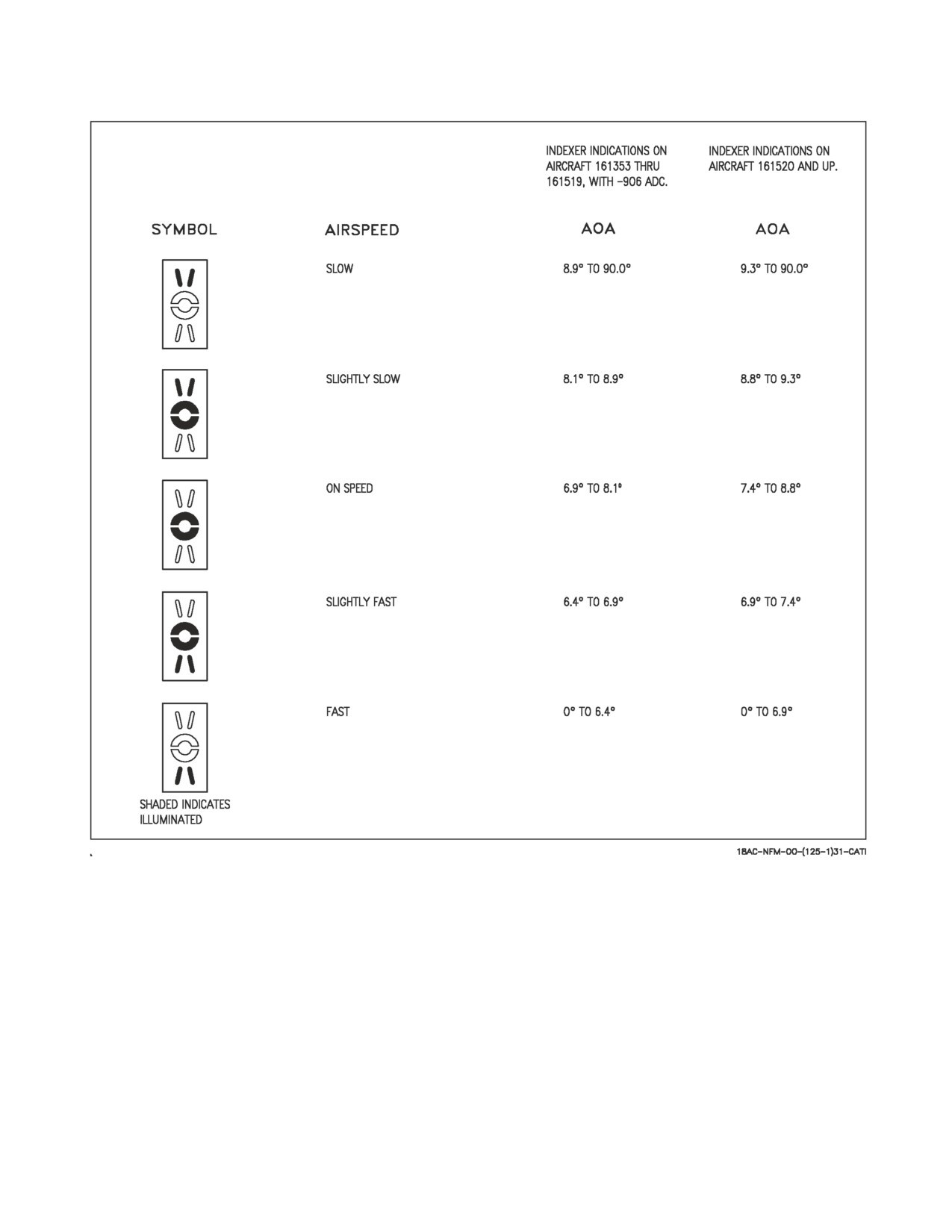
2.12.10 Angle-Of-Attack (AOA) Indexer. The AOA indexer (figure 2-19) is mounted to the left of the
HUD. It displays approach angle of attack (AOA) with lighted symbols. Corresponding AOA
indications are shown on the HUD. The indexer only operates with the landing gear down, W-off-W,
a valid ADC AOA signal and a functional ADC. The lighted symbol(s) flash if the arresting hook is up
and the hook bypass switch, on the left vertical panel, is in CARRIER. The symbols do not flash with
the arresting hook up and the hook bypass switch in FIELD. The switch is solenoid held to FIELD and
automatically goes to CARRIER when the arresting hook is lowered or aircraft power is removed. The
AOA indexer knob on the HUD controls dimming of the symbols. All symbols light when the lights test
switch on the interior lights control panel is held to TEST.
NOTE
On aircraft 161353 THRU 161519 without the latest configuration of
air data computer installed, a discrepancy exists between optimum
approach angle indications provided by the angle-of-attack bracket on
the HUD and the angle-of-attack indexer lights. Thus, flying On Speed
(velocity vector centered in AOA bracket) on the HUD produces a
Slightly Slow indication on the indexer lights. On the other hand,
flying On Speed on the indexer lights results in a slightly fast
indication by the HUD AOA bracket display. Use of either instrument
to set up the optimum approach angle is considered acceptable.
2.13 AVIONICS SUBSYSTEM
The avionics subsystem combines the integration and automation needed for one-man operability
with the redundancy required to ensure flight safety and mission success. Key features of the system
include highly integrated controls and displays; a highly-survivable quad-digital, control-by-wire
primary flight control system; inertial navigation set with carrier alignment capability; and extensive
built-in test capability. The avionic subsystems operate under the control of two mission computers
with primary data transfer between the mission computers and the other avionic equipment via the
mux buses.
2.13.1 Mission Computer (MC) System. The mission computer system consists of two digital
computers (No. 1 and No. 2) which are high speed, stored program, programmable, general purpose
computers with core memory. Computer deselection is made with the MC switch on the MC/HYD
ISOL panel. The two mission computers interconnect with the primary avionic equipment via the
avionic multiplex (mux) buses. Mission computer No. 1 referred to as the navigation computer,
performs processing for navigation, control/display management, aircraft built-in test (BIT), status
monitoring operations and backup for mission computer No. 2. MC2, referred to as the weapon delivery
computer, performs processing for air-to-air combat, air-to-ground attack, tactical control/display, and
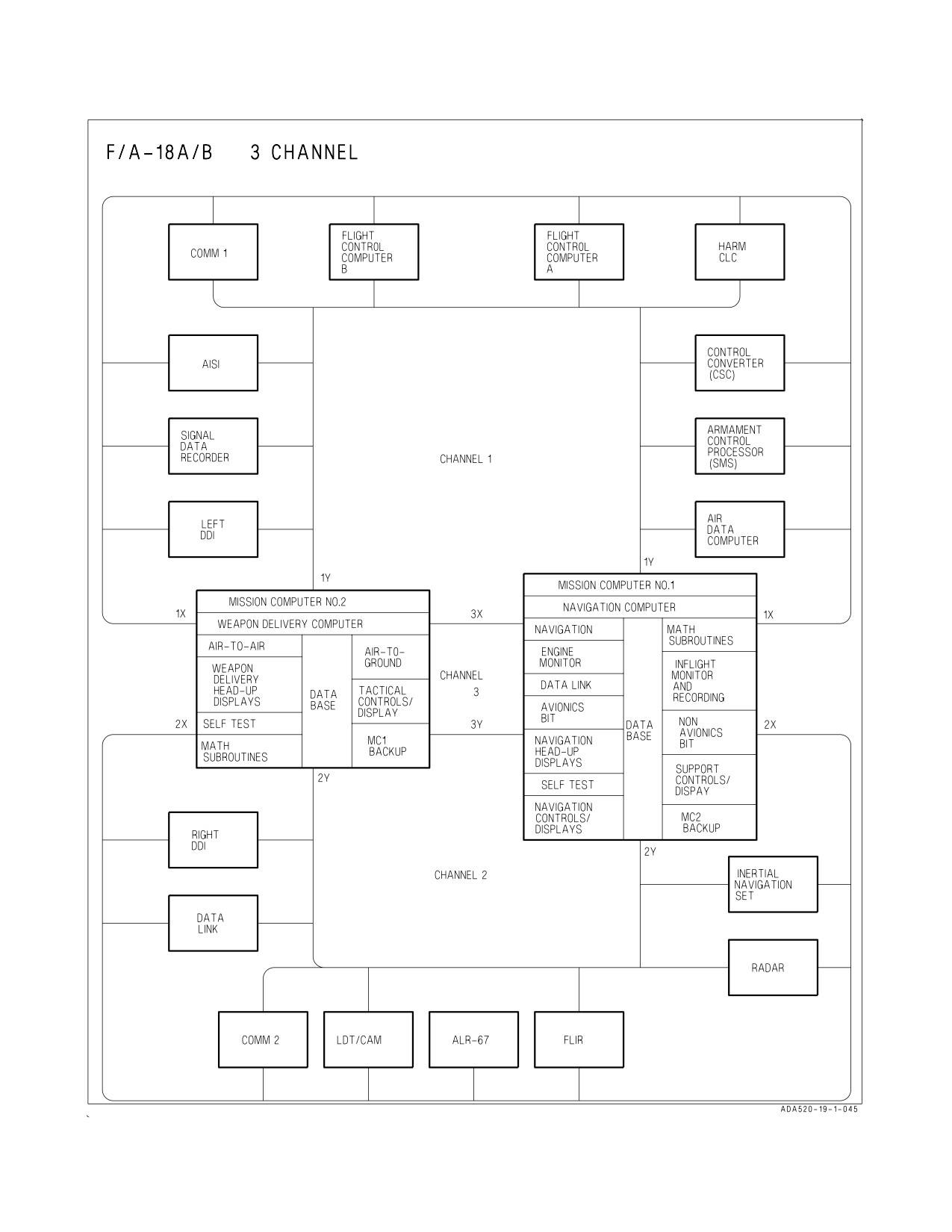
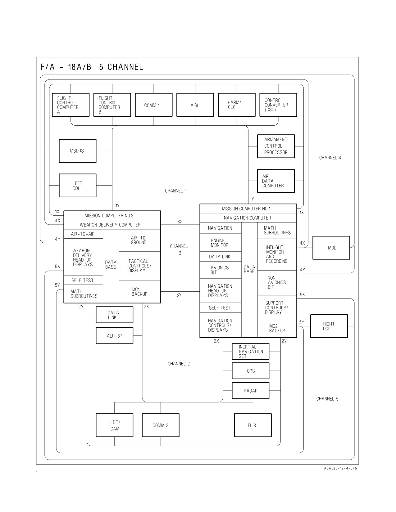
backup for MC1. On F/A-18A/B aircraft before AFC 225 there are three avionic mux bus channels
(figure 2-20) with redundant paths (X and Y) for each channel. On F/A-18A/B aircraft after AFC 225
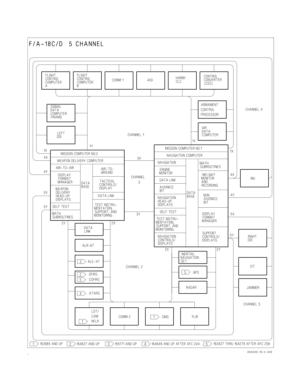
and some F/A-18C/D aircraft there are five avionic mux bus channels (figure 2-20) with redundant
paths (X and Y) for each channel. Channel 1 links the mission computers and the flight control
computers, air data computer, control converter (communication system control), armament control-
processor set (stores management set), signal data computer (F/A-18C/D), HARM command launch
computer, left digital display indicator, and one comm radio. Channel 2 links the mission computers
I-2-76
ORIGINAL
A1-F18AC-NFM-000
Figure 2-19. Angle of Attack Indexer
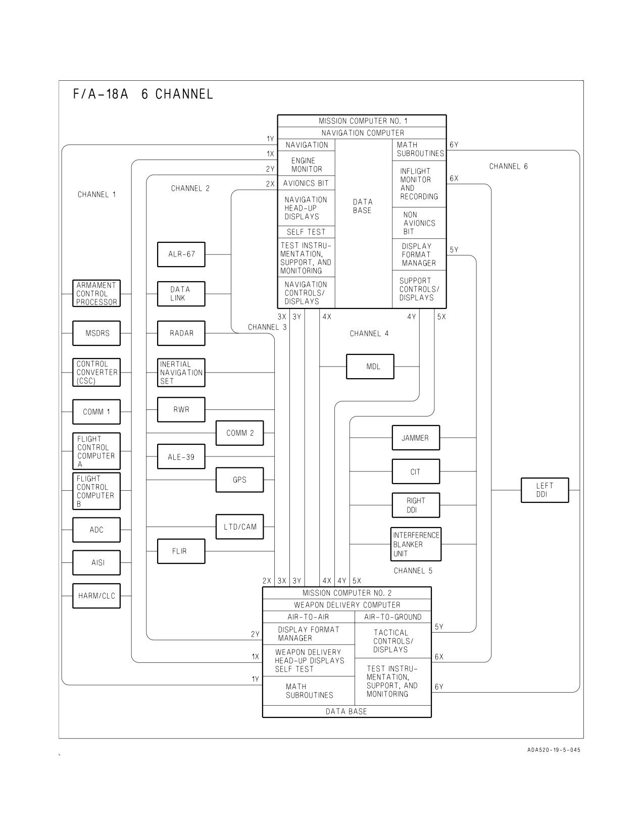
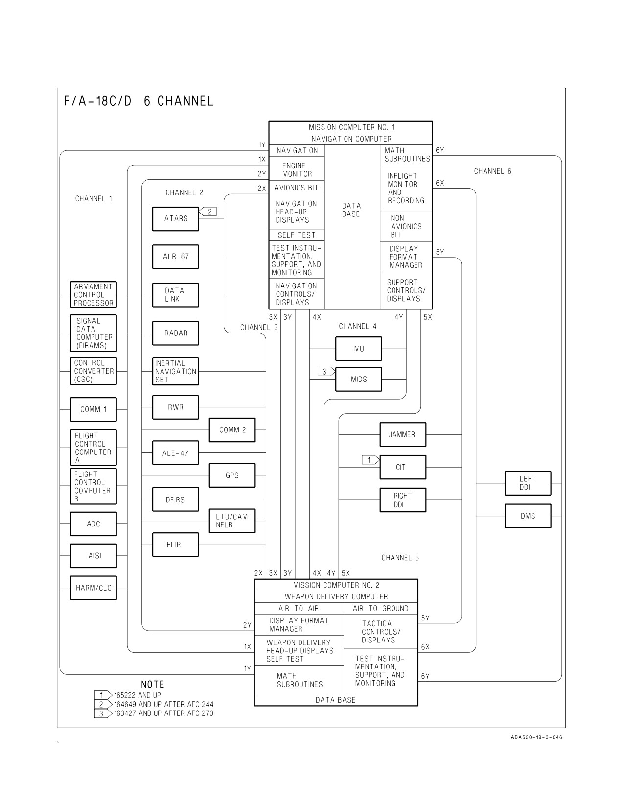
and the inertial navigation set, radar set, forward looking infrared (FLIR), laser detector tracker/strike
camera, two-way data link, right digital display indicator (F/A-18A/B before AFC 225), one comm
radio, on aircraft 163985 AND UP the navigation FLIR (NFLR) and digital map set (DMS), on aircraft
164627 AND UP the deployable flight incident recorder set (DFIRS) and GPS. Channel 3 provides
data transfer between the two mission computers. On F/A-18A/B after AFC 225 and F/A-18C/D
aircraft, channel 4 links the mission computers to the memory unit (MU), channel 5 links the mission
computers to the right DDI, and on F/A-18A aircraft after AFC 292 and aircraft 165222 AND UP,
ALSO 163985 THRU 165221 AFTER AFC 236 to the Combined Interrogator Transponder (CIT). On
aircraft 163427 AND UP after AFC 270, MIDS is added to channel 4. On F/A-18A aircraft after AFC
253 or 292 and some F/A-18C/D aircraft there are six avionic mux bus channels. Channel 6 links the
mission computers to the left DDI and the DMS.
I-2-77
ORIGINAL
A1-F18AC-NFM-000
The mission computer system performs the following:
a. Computes and controls the data sent to the multipurpose display group.
b. Uses input data to compute and generate missile launch and weapon release commands.
c. Provides for mode control and option select for various avionics systems.
d. Provides mode control and option select data from the multipurpose display group to avionic
systems for control and computation.
e. Outputs BIT initiate signals to various avionics systems.
f. Receives equipment operational status from avionic and non-avionic systems. The mission computer
system uses equipment status for multipurpose display group BIT status and advisory and caution
display generation.
The computers receive inputs for navigational data and steering command computations from the
inertial navigation system, air data computer system, electronic flight control system, multipurpose
display group, TACAN, backup attitude, the navigation system and GPS. The computers control
display symbology and information presented to the pilot by the multipurpose display group.
I-2-78
ORIGINAL
A1-F18AC-NFM-000
Figure 2-20. Mission Computer Functions and Multiplex System (Sheet 1 of 5)
I-2-79
ORIGINAL
A1-F18AC-NFM-000
Figure 2-20. Mission Computer Functions and Multiplex System (Sheet 2 of 5)
I-2-80
ORIGINAL
A1-F18AC-NFM-000
Figure 2-20. Mission Computer Functions and Multiplex System (Sheet 3 of 5)
I-2-81
ORIGINAL
A1-F18AC-NFM-000
Figure 2-20. Mission Computer Functions and Multiplex System (Sheet 4 of 5)
I-2-82
ORIGINAL
A1-F18AC-NFM-000
Figure 2-20. Mission Computer Functions and Multiplex System (Sheet 5 of 5)
I-2-83
ORIGINAL
A1-F18AC-NFM-000
2.13.1.1 Mission Data Entry. Mission data (date and flight number) is manually loaded into the
mission computer for data recorder documentation. To enter data into the mission computer perform
the following:
a. On the DDI - Press MENU, CHKLST, then ID
b. On the UFC - Enter Julian Date (Option 1)
c. On the UFC - Enter Flight (Option 2)
2.13.1.2 Mission Data Entry (MC OFP 12A, 13C AND UP). Mission Data can be manually loaded
into the mission computer through the Memory Unit Mission Initialization (MUMI) display or can be
automatically loaded. F/A-18A aircraft after AFC 253 or 292 the Mission Data Loader (MDL) is used
to automatically load and store data. In F/A-18C/D aircraft, the Data Storage Set (DSS) is used to
automatically load data. The DSS consists of the Memory Unit (MU) and the Memory Unit Mount
(MUM) and provides memory storage for aircraft parameters, maintenance data, and avionic
initialization data. The DSS receives, stores, retrieves, and transmits data with the mission computer.
2.13.1.2.1 Mission Initialization. The MDL, or MU provides the capability to load the following
mission initialization files: HARM, MU ID, RADAR, RECCE, TACAN, WYPT/OAP, sequential
steering, data link/ID, overlay controlled stores (OCS), with MC OFP 13C AND UP, bomb wind data,
(with aircraft equipped with GPS) global positioning system waypoint (GPS WYPT), global position-
ing system almanac (GPS ALM), and Fighter Link Reference Point (FLRP). On aircraft 163427 AND
UP AFTER AFC 270, COMM DCS initialization files can be loaded. Automatic loading is done at
aircraft power up or when MUX communication is lost for more than 1 second and regained. If MUX
communication is not regained, an MU LOAD caution is displayed and an AV MUX error message is
displayed on the MUMI display. Manual loading may be done using the MUMI display.
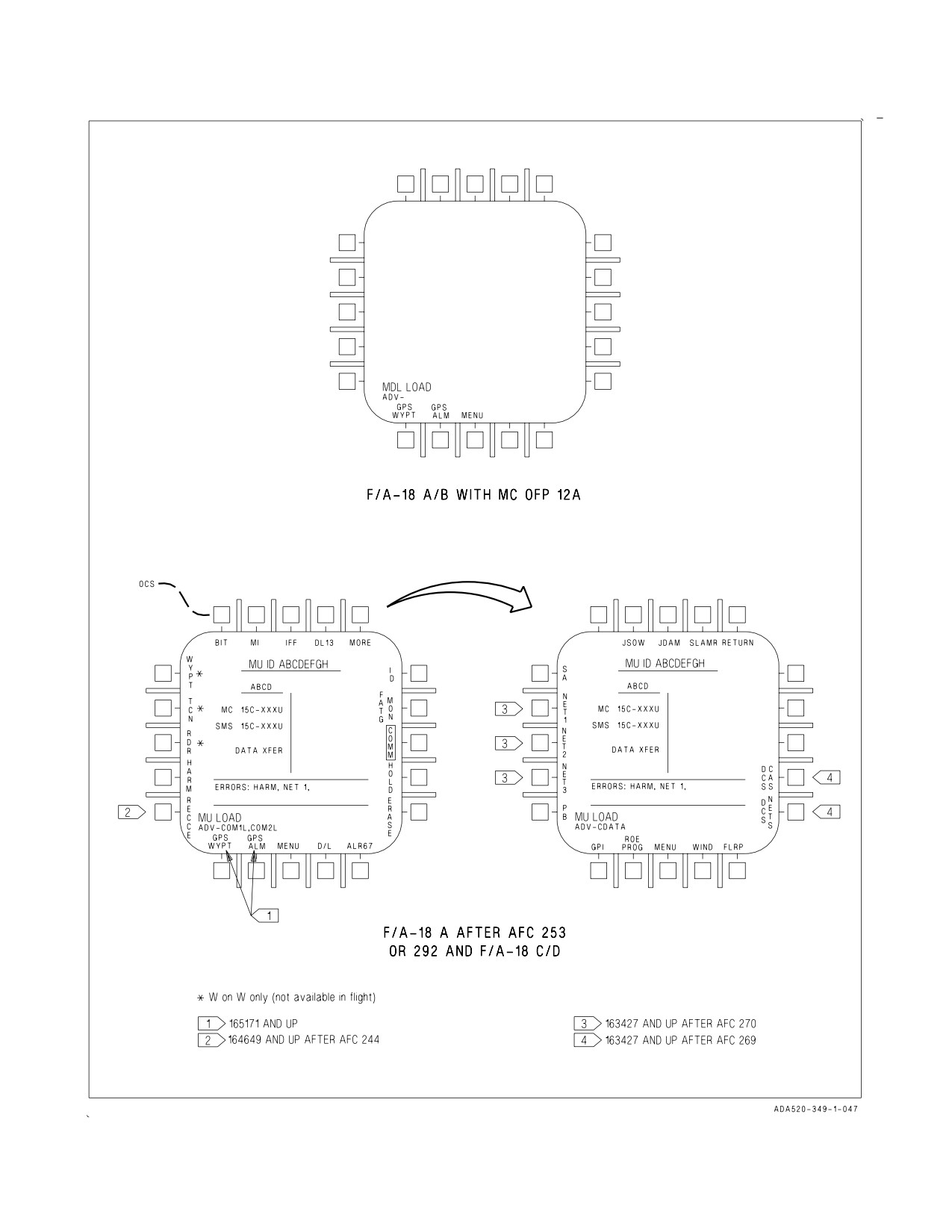
2.13.1.2.2 Memory Unit Mission Initialization (MUMI) Display. The MUMI display (see figure
2-21) is accessible from the SUPT MENU and with WOW provides a visual indication of mission
initialization files loaded from the MU/MDL. If the MU directory indicates that no user files are
present, the MU ID displays NO IDENT. When the MU directory indicates a user file is present, MC
1 displays the option at the applicable pushbutton (with MC OFP 13C AND UP, MORE provides
additional transfer options for weapons and DCS). When the pushbutton is pressed and the file is being
read by MC 1, the option is boxed. If the read is successful, the file is loaded and the option is unboxed.
When a file is present and errors have resulted from reading the file, the following occurs:
1. The MU ID displays NO IDENT.
2. The applicable load error is displayed (DL13), GPS ALM, GPS WYPT, HARM, OCS, RDR,
RECCE, TCN, WYPT S/S, or COM.
3. MC 1 sends the appropriate maintenance code to the SDC.
4. If WOW, a MU LOAD caution is displayed on the DDI.
2.13.1.2.3 Erase Data
(CRYPTO Switch). Setting the intercommunications amplifier control
CRYPTO switch to the ZERO position sends an erase signal to the MU/MDL. This causes the
MU/MDL to erase all data stored between predetermined memory locations.
I-2-84
ORIGINAL
A1-F18AC-NFM-000
Figure 2-21. MUMI Display
I-2-85
ORIGINAL
A1-F18AC-NFM-000
2.13.1.2.4 Erase and Hold Data. The erase controller (EC) within MC 1 provides the capability to
automatically and manually erase or inhibit erasing of classified data contained in the MU/MDL,
armament computer, and MC 1 and MC 2. When the EC determines classified mission initialization
files have been read from the MU/MDL, the EC classified data management system is activated. When
activated and aircraft is WOW, MC 1:
1. Displays HOLD, ERASE, and MC suspends option on the MUMI display.
2. Displays CDATA advisory.
3. Sends applicable maintenance code to SDC.
2.13.1.2.5 Automatic Erase. The MU/MDL, armament computer, MC 1, and MC 2 are automati-
cally erased when all of the following criteria are met:
1. Airspeed is less than 50 KIAS.
2. Left and right engine power lever angle is less than 29°.
3. Weight on wheels.
4. Pilot does not select erase inhibit (HOLD) or MC SUSPEND options.
Automatic erase is also initiated by pilot ejection.
Automatic erase can be inhibited by selecting the HOLD pushbutton option.
1. HOLD boxed with MU displayed prevents automatic erase of the MU.
2. HOLD boxed with ALL displayed prevents automatic erase of all units (MU/MDL, armament
computer, and MC 1 and MC 2).
The EC commands the MU/MDL, the armament computer, MC 1, then MC 2 to erase. The MC
ERASE IN XX SEC countdown timer starts (60 seconds). During the countdown the MC SUSPEND
pushbutton option cycles between boxed and unboxed. When the timer reaches zero, the decision to
continue erasing the remainder of MC 1 and MC 2 depends on the MC SUSPEND pushbutton being
deselected (unboxed). When deselected, the remaining erase of MC 1 and MC 2 is completed.
2.13.1.2.6 Manual Erase. Manual erase is initiated by pressing the ERASE pushbutton on the
MUMI display. When pressed, ERASE is boxed and erasing proceeds the same as automatic erase.
When erasing is complete, the ERASE pushbutton is unboxed. While erase is in progress one of the
following is displayed on the MUMI display:
1. ERASING - erasing of unit is in progress.
2. COMPLETE - erasing of unit is complete.
3. FAILED - unit failed to erase.
When erase fails the MC 1 retains the MUMI ERASE and HOLD pushbutton options and displays
the ERASE FAIL caution on the DDI. When erasing is complete MC 1 removes the ERASE, HOLD,
and MC SUSPEND pushbutton options from the MUMI display, removes the CDATA advisory from
the display, and resets the applicable maintenance code(s).
I-2-86
ORIGINAL
A1-F18AC-NFM-000
2.13.1.3 MC/HYD ISOL Panel. The MC switch has positions of 1 OFF, 2 OFF, and NORM. Placing
the switch to 1 OFF turns off digital computer No. 1. Placing the switch to 2 OFF turns off digital
computer No. 2. With the switch set to NORM, both No. 1 and No. 2 digital computers are turned on.
2.13.2 Master Modes. There are three master modes of operation: navigation (NAV), air-to-air
(A/A), and air-to-ground (A/G). The controls, displays, and the avionic equipment operation are
tailored as a function of the master mode which the pilot has selected. The navigation master mode is
entered automatically when power is applied to the aircraft, when the air-to-air or air-to-ground modes
are deselected, when the landing gear is lowered, when the SPIN mode activates, or when the aircraft
has weight on wheels and the throttle position (power lever angle) is greater than 56°. The A/A master
mode is entered either by pressing the A/A master mode button alongside the left DDI or by selecting
an A/A weapon with the A/A weapon select switch on the control stick. The A/G master mode is
selected by pressing the A/G master mode button. The selection is performed by the stores
management set (SMS), and the SMS identifies the selected master mode to the mission computer.
2.13.2.1 Steering Information. The sources of steering information available in the NAV master
mode are waypoint, TACAN, instrument landing system and data link. The data link modes available
in the NAV master mode are vector and automatic carrier landing. TACAN and waypoint steering are
mutually exclusive and selecting one automatically deselects the other. However, data link, ILS, and
TACAN (or waypoint) steering can be provided simultaneously. The ACL mode is selectable only in
the NAV master mode, and the vector mode is available in all master modes. With MC OFP 13C AND
UP, steering information is used by the Automatic Flight Control System to provide coupled steering
options.
2.13.3 Cockpit Controls and Displays. The cockpit controls and displays which are used for
navigation operation are on the multipurpose display group and on the upfront control (UFC).
2.13.4 Multipurpose Display Group. The multipurpose display group consists of the right digital
display indicator (DDI), the left DDI, the horizontal indicator (HI) on aircraft 161353 THRU 163782,
the multipurpose color display (MPCD) on aircraft 163985 AND UP BEFORE AFC 380, the advanced
multipurpose color display (AMPCD) on aircraft 163985 AND UP AFTER AFC 380, the digital map
set (DMS), the head-up display (HUD), the CRS (course) set switch, and the HDG (heading) set
switch. The multipurpose display group presents navigation, attack, and aircraft attitude displays to
the pilot. The multipurpose display group converts information received from the mission computer
system to symbology for display on the right and left DDIs, the HI/MPCD, and the HUD. The HUD
camera records the outside world and HUD symbology. The left and right DDIs and the HI/MPCD
contain pushbuttons for display selection and various equipment operating modes. Refer to Part VII
for the operation of each component.
2.13.4.1 Digital Display Indicators (DDI). The right and left DDIs are physically and functionally
interchangeable giving the ability to display desired information on either indicator or using either
indicator to control the HUD or horizontal indicator displays. The left indicator is used primarily for
stores status, built-in test status, engine monitor, caution, and advisory displays. The right indicator
is normally used for radar and weapon video displays.
On aircraft 163985 AND UP the DDIs are NVG compatible and display three colors (red, yellow, and
green) for stroke information. A monochrome version of the digital map can be selected on any of the
I-2-87
ORIGINAL
A1-F18AC-NFM-000
DDIs. Either DDI can provide raster generation for the HUD. A description of the various switches and
controls on the right and left DDIs follows.
NOTE
It is possible that a transient condition may cause the displays to
blank or provide an erroneous display on the left or right DDI,
HI/MPCD/AMPCD, or HUD. The problem may be cleared by
manually cycling the power to the right or left DDI.
2.13.4.1.1 Brightness Selector Knob. Placing this rotary knob to OFF prevents the indicator from
operating. Placing the knob to NIGHT provides a lower brightness control range (with three settings)
and no automatic contrast control. The knob in the AUTO position allows automatic brightness control
circuits to compensate display brightness for changes in ambient lighting. Turning the knob to DAY
provides a higher brightness control range with no automatic contrast control.
2.13.4.1.2 Brightness Control. This knob varies the intensity of the presentation.
2.13.4.1.3 Contrast Control. This knob varies the contrast between symbology and the dark
background on any level of brightness.
2.13.4.1.4 Pushbuttons. There are 20 pushbuttons on each DDI which are used to select the
function and the mode for proper indicator display.
2.13.4.1.5 Fault Indicator. The indicator displays unit operational status: white for failed and black
for normal.
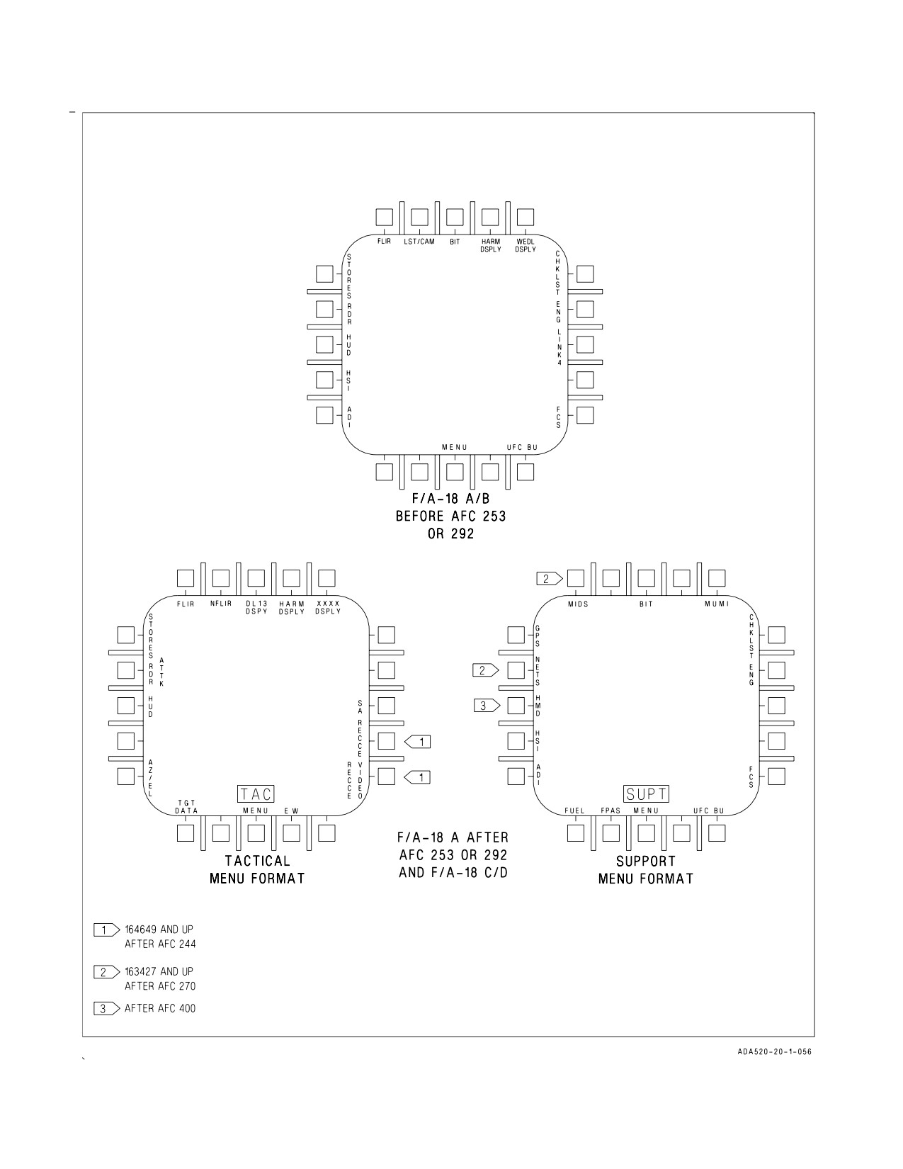
2.13.4.2 Menu Display (F/A-18A/B BEFORE AFC 253 OR 292). The menu display options (figure
2-22) are selected by pressing the MENU pushbutton (center bottom pushbutton). The desired display
can then be selected by pressing the corresponding option pushbutton. Some of the options on the
menu display are conditional and are not always displayed. FLIR, LST, and CAM are listed only if the
equipment is communicating with the mission computer. HARM DSPLY is displayed when HARM is
on board and CLC communicating. A/G missile display (WEDL DSPLY, MAV DSPLY, etc.) is
displayed when the MC has determined from the armament control processor set that a weapon station
has been selected which contains one of these weapons. LINK 4 is displayed only while an automatic
carrier landing (ACL), or vector (VEC) is displayed.
If the navigation computer (MC1) is not on, BIT, ADI, FCS, UFC BU, CHKLST, and ENG are not
displayed. If the weapon delivery computer (MC2) is not on, ADI, STORES, LST, and CAM are not
displayed. If both mission computers are off, or not communicating with the display, the DDI displays
only a flashing STANDBY in the center of the screen.
2.13.4.2.1 Menu Display (F/A-18A AFTER AFC 253 OR 292 AND F/A-18C/D). There are two
MENU displays (figure 2-22), TAC (tactical) and SUPT (support) through which display selections
can be made. On aircraft 163985 AND UP, the two menu formats can appear on any DDI or
MPCD/AMPCD. On aircraft prior to 163985 the menu displays can appear only on the DDIs.
I-2-88
ORIGINAL
A1-F18AC-NFM-000
The TAC MENU display is indicated by the word TAC appearing just above the MENU option. The
TAC MENU is selected by actuating the MENU option on any display (besides the TAC MENU
display). The SUPT MENU display is indicated by the word SUPT appearing just above the MENU
option. The SUPT MENU is selected by actuating the MENU option on the TAC MENU. With MC
OFP 19C, MENU pushbutton legend is MENU with WonW. With WoffW, in the front cockpit only,
aircraft system time is displayed in place of MENU in a four digit format of MMSS to facilitate
postflight tape debriefs. Pushbutton functionality is unchanged.
The TAC MENU allows for selection of weapons, sensors, HUD, stores displays and, on aircraft
164649 AND UP after AFC 244, RECCE displays. The SUPT MENU allows for selection of flight type
displays: ADI, HSI, HMD, BIT, MUMI, Checklist, Engines, Flight Controls, UFC backup, FPAS, and
Fuel formats. In LOT 10 and up after AFC 270, DCS NETS, MIDS, and ROE PROG options are
available. With MC OFP 17C, ROE/IFF PROG option is available.
Some of the options on the menu display are conditional and are not always displayed. NFLR, FLIR,
LST, and CAM are listed only if the equipment is communicating with the mission computer. HARM
DSPLY is displayed when HARM is on board and CLC communicating. A/G missile display (WEDL
DSPLY, MAV DSPLY, etc.) is displayed when the MC has determined from the armament control
processor set that a weapon station has been selected which contains one of these weapons.
If the navigation computer (MC1) is not on, only HSI is displayed on the SUPT menu and the TAC
menu loses the SA option. If weapon delivery computer (MC2) is not on, the SUPT menu remains
unchanged and the TAC menu loses the STORES, LST/CAM or NFLR, AWW-9/13, HARM, A/G
displays. If both mission computers are off, or not communicating with the display, the DDI displays
only a flashing STANDBY in the center of the screen.
I-2-89
ORIGINAL
A1-F18AC-NFM-000
Figure 2-22. Menu Display
I-2-90
ORIGINAL
A1-F18AC-NFM-000
Figure 2-23. Electronic Attitude Display Indicator
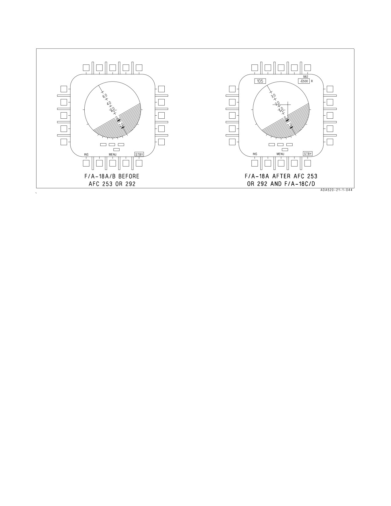
2.13.4.3 Electronic Attitude Display Indicator (EADI). The electronic attitude display indicator is
available for display on the left or right DDI as an alternative to the attitude display on the HUD
(figure 2-23). A small circle is displayed on the ball to represent the zenith and a circle with an inscribed
cross is displayed to represent the nadir. The pitch ladder is displayed in 20° increments with MC OFP
10A AND UP, or 10° increments with MC OFP 13C AND UP. A turn indicator which displays FCS yaw
rate is provided below the ball. A standard rate turn (3° per second) is indicated when the lower box
is displaced so that it is under one of the end boxes. The EADI display is selected by pressing the ADI
pushbutton on the MENU.
Selecting the INS or STBY options at the bottom of the display determines the source of attitude
information used to generate the display. Upon power-up with WOW, the EADI attitude initializes to
STBY (STBY boxed), thus using the standby attitude reference indicator for attitude source
information. With STBY boxed the EADI display should be compared to the visual display on the
standby altitude reference indicator. If the pitch and roll attitude display does not correlate on the two
instruments, the standby indicator is most likely defective, requiring maintenance. Selecting the INS
option (INS boxed) uses attitude information provided by the INS. Selection of the INS or STBY on
the EADI does not change the source of attitude data for the HUD.
With MC OFP 13C AND UP, airspeed and altitude are displayed in a box at the top left and altitude
source is displayed to the right of the altitude box and the vertical velocity is displayed above the
altitude box. When ILS is selected the deviation needles are displayed in reference to the waterline
symbol. The ILS needles are in yellow when COLOR is selected on the Attack display.
2.13.4.4 HI (Aircraft 161353 THRU 163782). During normal operation, the HI provides aircraft
heading, steering, and navigation information with a projected moving map display superimposed over
the HI display, (with the 10 nm or 40 nm scale selected). The HI receives symbol generation and control
signals from the left DDI under mission computer control. The description of the controls, pushbut-
tons, and indicator for the HI are the same as for the right and left DDIs except that the HI also has
a mode selector knob, HI brightness selector knob, slew pushbutton, map brightness knob, and the
menu option is not available.
I-2-91
ORIGINAL
A1-F18AC-NFM-000
2.13.4.4.1 Mode Selector Knob. The mode selector knob has positions of DATA, N-UP, NORM,
and D-CTR. Placing the knob to DATA selects the index frame of the moving map display and enables
the upfront control for entering the desired data frame number. The index provides a listing of data
available on each frame. After a data frame has been selected the film can be stepped to adjacent
frames by using the up arrow and down arrow pushbuttons on the HI. Selecting N-UP on the mode
selector knob rotates the map to true north up. The lubber line remains on the aircraft’s magnetic
heading and the ground track is magnetic ground track. Placing the knob to NORM position selects
track-up display. The compass rose is rotated to aircraft magnetic ground track. The aircraft symbol
and the lubber line are at the aircraft magnetic heading. With the mode selector knob in D-CTR,
decentered track-up display is selected with the aircraft symbol at the bottom of the display. The
aircraft symbol and the lubber lines are at the aircraft magnetic heading. When the decentered mode
is selected, the range scale at top center is doubled to indicate 20, 40, 80, 160, or 320, although the actual
scale is unchanged. The reason for this is that the scale number is the distance from the aircraft symbol
to the inside of the compass rose. In the decentered mode, the projected map is displayed when the
scale indicates 20 and 80 miles.
2.13.4.4.2 HI Brightness Selector Knob. The knob has positions of OFF, NIGHT, and DAY.
Placing the knob to OFF prevents the indicator from operating. Placing the knob to NIGHT provides
a lower brightness control range. The knob in the DAY position provides higher brightness control
range.
NOTE
• If the knob is in NIGHT position and the map filter is out of view or
only partially in view, switch the knob to DAY for 2 seconds and then
back to NIGHT. If the knob is in DAY position and the map filter is
in view or partially in view, switch the knob to NIGHT for 2 seconds
then back to DAY. If the knob is set to OFF and the DAY position is
desired, switch from OFF to DAY in less then 0.5 second.
• To prevent damage to the moving map servos, keep the HI brightness
selector knob in NIGHT or DAY and at least one DDI on whenever the
aircraft is in motion.
2.13.4.4.3 Slew Pushbutton. Pressing the slew pushbutton on the HI assigns the TDC to the HI
map for slewing. The map slew function is used for position updating and waypoint entry as well as to
look at off-scale regions of the map. The word SLEW is displayed in the upper right corner of the HI
while the TDC is assigned to the HI for map slewing.
When the TDC is pressed to slew the map (other than for a map position update or waypoint/OAP
data entry), the following symbology is removed from the HI: TACAN symbol, waypoint/OAP symbol
along with their respective bearing pointers and tails. The aircraft symbol is replaced with an X
indicating the slew point. When slewing is completed the map freezes. Assigning the TDC elsewhere
reverts the map to present position with the aircraft symbol displayed.
2.13.4.4.4 Map Brightness Knob. This knob varies the brightness intensity of the moving map
display.
2.13.4.5 MPCD (Aircraft 163985 AND UP BEFORE AFC 380). The MPCD is an NVG compatible
digital display capable of providing any MENU selectable format except the A/G radar display. The
MPCD is driven by either the digital map set (DMS) for HSI displays, or the LDDI for all other MENU
I-2-92
ORIGINAL
A1-F18AC-NFM-000
selectable formats. Four momentary two-position rocker switches, located on the front of the MPCD,
permit control of MPCD power, day/night viewing modes, brightness, and contrast.
NOTE
In F/A-18D (Aircraft 163986 AND UP), one of the two MPCDs must
display HSI format from the DMS. The other MPCD may display any
MENU selectable format. When one MPCD is DDI-driven, the
opposite MPCD is DMS-driven and MENU is replaced with a TAKE
option (on the DMS-driven MPCD only).
2.13.4.5.1 Night Brightness Selector. This rocker switch is located in the upper left corner of the
MPCD and is used to turn the MPCD off (OFF position selected) or to select the lower brightness
control (night) range and disable automatic contrast control (NITE position selected). If the MPCD is
off, selecting NITE also turns the unit on. When NITE is selected, the display is NVG compatible and
contrast may be manually adjusted with the contrast control.
2.13.4.5.2 Day Brightness Selector. This rocker switch is located in the upper right corner of the
MPCD and is used to select the higher brightness control (day) range (DAY position selected) or to
select the automatic brightness control to compensate the display brightness for changes in ambient
lighting (AUTO position selected). If the MPCD is off, selecting DAY or AUTO also turns the unit on.
When DAY is selected, automatic brightness control is disabled and display brightness may be
manually adjusted with the brightness control. However, if a color display (digital map) is selected, the
automatic brightness control circuits are automatically engaged.
2.13.4.5.3 Brightness Control. This rocker switch is located in the lower left corner of the MPCD.
The brightness switch is enabled only when a mono raster display from the DMS is displayed;
otherwise the brightness switch is disabled. Momentary actuations of the upper half of the switch
incrementally increase the intensity of the display. Momentary actuations of the lower half incremen-
tally decrease the intensity. If the switch is held in either position, the intensity is continuously
adjusted to the upper or lower limits. If the brightness control is actuated while disabled, an AUTO
legend appears at 200% size to the left of the display center and is removed 5 seconds after the switch
is released. If the brightness control is operating, a variable number from 0 to 9 appears at 200% size
to the right of the AUTO legend to indicate the current intensity setting and is removed 5 seconds after
the switch is released.
2.13.4.5.4 Contrast Control. This rocker switch is located in the lower right corner of the MPCD.
Momentary actuations of the upper half of the switch incrementally increase the contrast of the
display. Momentary actuations of the lower half incrementally decrease the contrast of the display. If
the switch is held in either position, the contrast is continuously adjusted to the upper or lower limits.
When the contrast control is operated, a variable number from 0 to 9 appears at 200% size to the right
of the display center to indicate the current contrast setting. Five seconds after the switch is released,
this number is removed.
2.13.4.6 AMPCD (Aircraft 163985 AND UP AFTER AFC 380). The AMPCD is an NVG compatible
digital display capable of providing any MENU selectable format except the A/G radar display. The
AMPCD is driven by either the digital map set (DMS) for HSI displays, or the LDDI for all other
MENU selectable formats. Four momentary two-position rocker switches and a rotary knob, located on
I-2-93
ORIGINAL
A1-F18AC-NFM-000
the front of the AMPCD, permit control of AMPCD off/brightness, night/day viewing modes,
symbology, gain, and contrast.
NOTE
In F/A-18D (Aircraft 163986 AND UP), one of the two AMPCDs must
display HSI format from the DMS. The other AMPCD may display
any MENU selectable format. When one AMPCD is DDI-driven, the
opposite AMPCD is DMS-driven and MENU is replaced with a TAKE
option (on the DMS-driven AMPCD only).
2.13.4.6.1 Off/Brightness Control. This rotary switch is located in the upper center of the AMPCD
and is used to turn the AMPCD off (OFF position selected) or to select the brightness level. The
brightness control is enabled only when a mono raster display from the DMS is displayed; otherwise
the brightness control is disabled. If the brightness control is actuated while disabled, an AUTO legend
appears at 200% size to the left of the display center and is removed 5 seconds after the switch is
released. If the brightness control is operating, a variable number from 0 to 9 appears at 200% size to
the right of the AUTO legend to indicate the current intensity setting and is removed 5 seconds after
the switch is released.
2.13.4.6.2 Night/Day Brightness Selector. This rocker switch is located in the upper left corner of
the AMPCD and is used to select the lower brightness control (night) range and disable automatic
contrast control (NITE position selected) or to select the higher brightness control (day) range (DAY
position selected). When NITE is selected, the display is NVG compatible and contrast may be
manually adjusted with the contrast control. When DAY is selected, automatic brightness control is
disabled and display brightness may be manually adjusted with the brightness control. However, if a
color display (digital map) is selected, the automatic brightness control circuits are automatically
engaged.
2.13.4.6.3 Symbology Control. This rocker switch is located in the upper right corner of the
AMPCD. Momentary actuations of the upper half of the switch incrementally narrows the symbology,
making it sharper and dimmer. Momentary actuations of the lower half incrementally widens the
symbology, making it brighter and less sharp. If the switch is held in either position, the symbology is
continuously adjusted to the upper or lower limits.
2.13.4.6.4 Gain Control. This rocker switch is located in the lower left corner of the AMPCD.
Momentary actuations of the upper half of the switch incrementally increases background video
brightness. Momentary actuations of the lower half incrementally decreases video brightness. If the
switch is held in either position, the gain is continuously adjusted to the upper or lower limits.
2.13.4.6.5 Contrast Control. This rocker switch is located in the lower right corner of the AMPCD.
Momentary actuations of the upper half of the switch incrementally increase the contrast of the
display. Momentary actuations of the lower half incrementally decrease the contrast of the display. If
the switch is held in either position, the contrast is continuously adjusted to the upper or lower limits.
When the contrast control is operated, a variable number from 0 to 9 appears at 200% size to the right
of the display center to indicate the current contrast setting. Five seconds after the switch is released,
this number is removed.
I-2-94
ORIGINAL
A1-F18AC-NFM-000
2.13.4.7 HSI Display Symbology. Basic HSI symbology such as the compass rose, ground track
pointer, lubber line (for magnetic heading), true airspeed readout, ADF bearing pointer, groundspeed
readout, and aircraft symbol are not described, however, they are shown in figure 2-24. The radar target
and GEO REF symbols are described in NTRP 3-22.2-FA18A-D NATIP. The following paragraphs
describe unique F/A-18 navigation symbology (figure 2-24). Refer to part VII for a description of how
these symbols are integrated in with the navigation system.
1.
Waypoint/OAP data. Data for the current steer to waypoint/OAP is displayed on the upper right
corner of the HSI. Waypoint/OAP data consists of bearing, range, and TTG (time-to-go) up to
8:59:59 based on distance and ground speed. When a waypoint/OAP or offset to the OAP is
designated (becomes a target), this data then relates to the target. When a waypoint is a waypoint
that is transferred from GPS, an ID Code is displayed under the waypoint data. When GPS is
coupled to the INS, an ID Code is displayed under the waypoint data.
2.
TACAN data. TACAN data is displayed on the upper left corner of the HSI. TACAN data
consists of bearing, range (slant range), TTG (based on distance and present ground speed), and
the station identifier.
3.
Waypoint/OAP symbology. Waypoint/OAP symbology consists of a waypoint/OAP symbol,
bearing pointer and tail. The waypoint/OAP symbol indicates the position of the selected
waypoint/OAP relative to the aircraft symbol. The waypoint/OAP bearing pointer and tail are
displayed inside the compass rose and indicate bearing to the selected waypoint/OAP. Waypoint/
OAP symbology is displayed whether or not waypoint/OAP steering is selected. When the
selected waypoint/OAP is outside the HSI range scale, the waypoint/OAP symbol is limited at the
inside of the compass rose coincident with the pointer. When a waypoint/OAP is designated, the
waypoint/OAP symbol and circle inside the pointer change to a diamond shape. The offset
symbol appears when steering is to an OAP. The offset symbol indicates the position of the offset
relative to the OAP.
4.
TACAN symbology. TACAN symbology consists of a TACAN symbol, TACAN bearing pointer
and tail. The TACAN symbol indicates the position of the TACAN station relative to the aircraft
symbol. The TACAN bearing pointer and tail are located outside of the compass rose and indicate
bearing to the TACAN station. When the TACAN station is outside the HSI range scale, the
TACAN symbol is limited at the inside of the compass rose. When TACAN range becomes invalid
the TACAN symbol is not displayed.
NOTE
TACAN symbology displayed inside of the compass rose is filtered to
prevent excessive movement of TACAN symbols due to RF
interference. However, the ″fly−to″ needle displayed in the HUD with
TACAN steering selected is not filtered and represents the raw data
received by the TACAN. As a result, for brief periods of time, the
HUD and HSI may display conflicting information regarding aircraft
position with respect to the selected TACAN course line. Aircrew
should use HUD displayed TACAN information when conducting
TACAN approaches.
5. Heading select marker and readout. The heading select marker is maneuvered along the
periphery of the compass rose using the HDG switch. The digital readout of the selected heading
I-2-95
ORIGINAL
A1-F18AC-NFM-000
is located on the lower left corner of the HSI. The heading select marker and digital readout are
part of the heading select mode of the autopilot.
6.
Course line arrow and readout. The course line arrow indicates the selected course to the
waypoint/OAP or TACAN station. The course is selected using the CRS switch. The digital
readout of the selected course is displayed on the lower right corner of the HSI. The course line
arrow is not displayed when TACAN range is invalid. With MC OFP 13C AND UP, the
perpendicular distance to the nearest 0.1 nm (up to a maximum of 99.9 nm) followed by C is
displayed above the CSEL display. If a sequence is displayed with AUTO boxed and the current
steer-to waypoint selected, then perpendicular distance to the sequence line is displayed as
described above, but followed by S.
7.
TDC assignment diamond. The TDC assignment diamond is displayed on the upper right corner
of the HSI. This diamond indicates that the TDC is assigned to the HSI. In aircraft 163986 AND
UP the TDC assignment diamond indicates control is assigned to both cockpits. Other symbols
indicate front or aft cockpit TDC control and corresponding SLEW control options by actuating
the sensor control switch AFT, while in the NAV or A/G master mode. The word SLEW is
displayed in the TDC assignment diamond position when the SLEW pushbutton is pressed.
8.
Coupled steering symbology. CPL and the source of the steering information is displayed on
either side of the aircraft symbol in the center of the HSI display whenever the flight control
system is coupled in azimuth to a steering source. Steering source can be WYPT, TCN, or SEQ#.
The couple cue flashes for 10 seconds and then is removed if the steering signal is lost or becomes
invalid.
9.
Sequential steering lines. The sequential steering lines are displayed when a sequence is entered
and when one of the sequence options (SEQ1, SEQ2, or SEQ3) is boxed. The sequential steering
lines are available for display in all HSI modes and range scales. Sequential steering lines are not
displayed at power up with WOW and are removed when magnetic heading is invalid, aircraft
position is invalid, or map slew is selected.
10. Zulu time of day (ZTOD). ZTOD is displayed on the lower left corner of the HSI. For F/A-18A/B
aircraft ZTOD must be set in order to be displayed. For F/A-18C/D aircraft that pass the
FIRAMS real time clock power up BIT, ZTOD does not need to be entered. For F/A-18C/D
aircraft that do not pass the FIRAMS real time clock power up BIT, ZTOD must be entered.
11. Groundspeed required. Groundspeed required appears below the current groundspeed readout.
Groundspeed required indicates the groundspeed required to a target based on entered ZTOD,
time on target (TOT), and the target.
12. Elapsed time (ET)/countdown (CD) time. ET and CD time are displayed on the lower right
corner of the HSI. However, only one of the timers can be displayed at a time. Either ET or CD
timer must be selected to be displayed. ET initializes to zero minutes and seconds and CD time
initializes to six minutes and zero seconds.
13. Aircraft heading. Aircraft heading is indicated on the compass rose. Aircraft heading and bearing
data can be selected as either magnetic or true. With true heading selected, the letter T appears
below the lubber line and the word TRUE appears below the selected scale readout. There is no
indication when magnetic heading is selected.
I-2-96
ORIGINAL
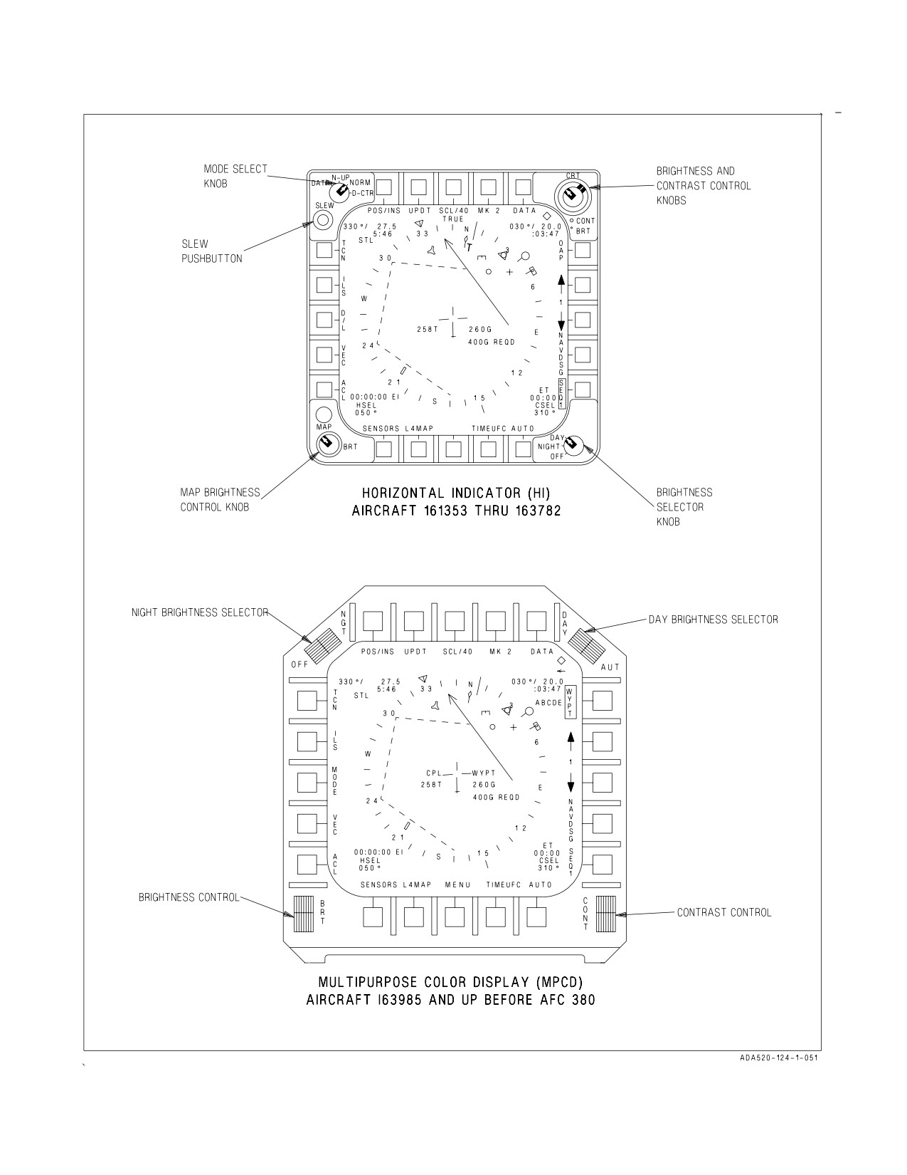
A1-F18AC-NFM-000
Figure 2-24. HI/MPCD/AMPCD Controls and HSI Symbology (Sheet 1 of 3)
I-2-97
ORIGINAL
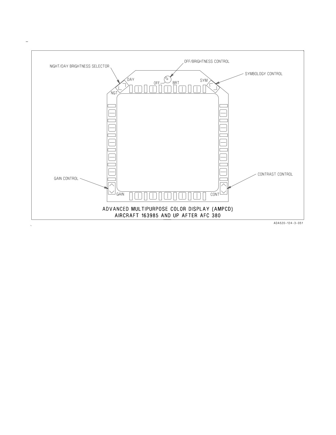
A1-F18AC-NFM-000
Figure 2-24. HI/MPCD/AMPCD Controls and HSI Symbology (Sheet 2 of 3)
I-2-98
ORIGINAL
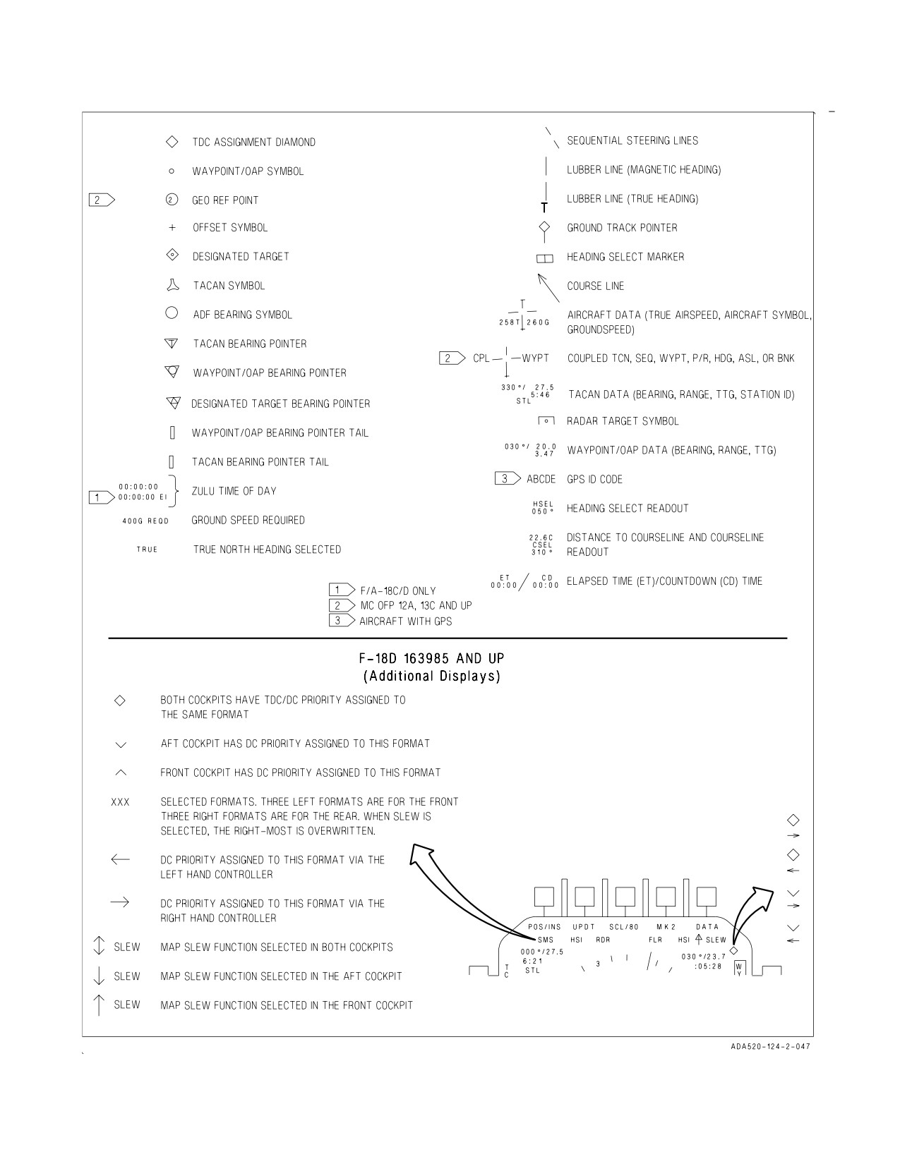
A1-F18AC-NFM-000
Figure 2-24. HI/MPCD/AMPCD Controls and HSI Symbology (Sheet 3 of 3)
I-2-99
ORIGINAL
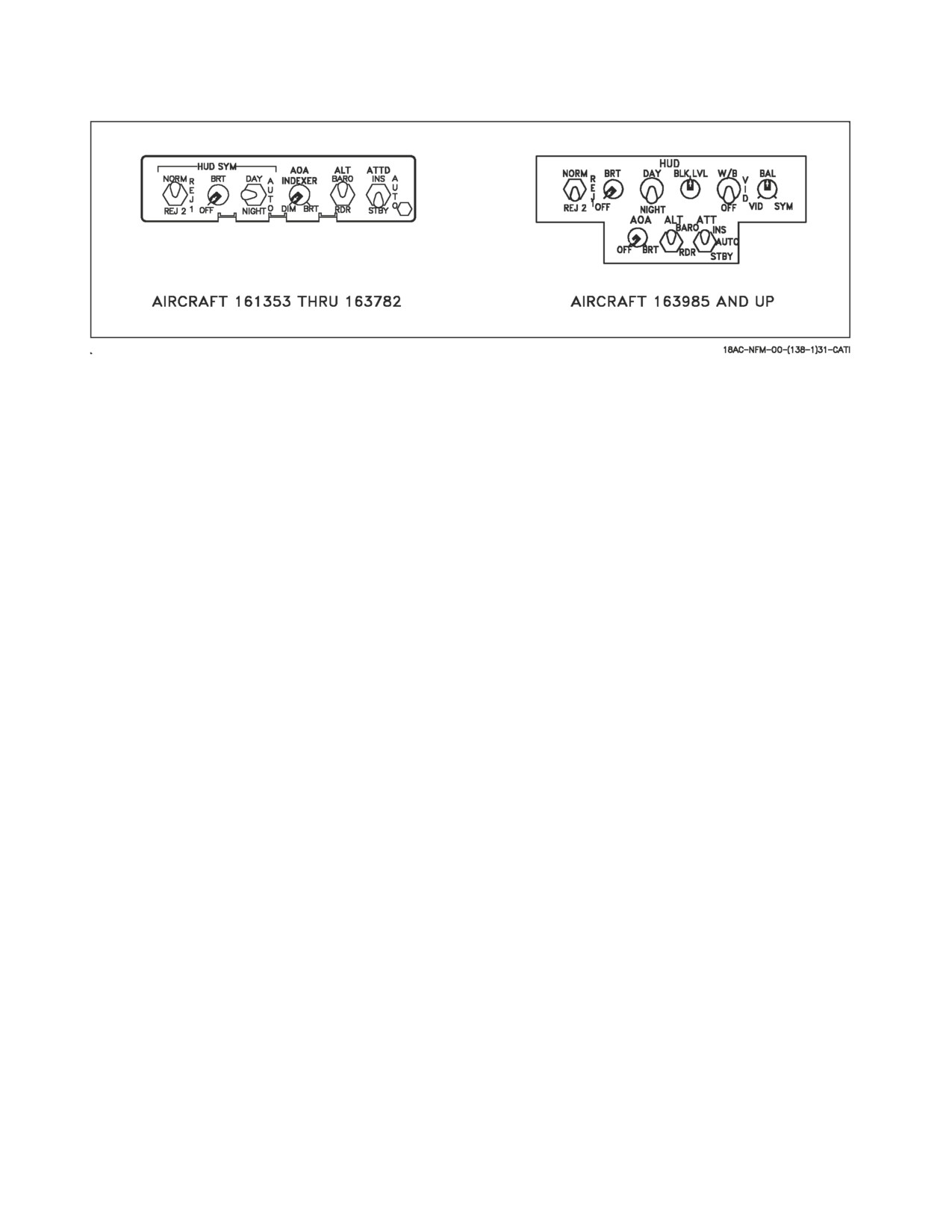
A1-F18AC-NFM-000
Figure 2-25. HUD Controls
2.13.4.8 Head-Up Display (HUD). The HUD is on the center main instrument panel. The HUD is
used as the primary flight instruments, weapon status, and weapon delivery display for the aircraft
under all selected conditions. The HUD receives attack, navigation, situation, and steering control
information from the left or right DDI symbol generators (under mission computer control), and
projects symbology on the combining glass for head-up viewing. The HUD is electrically interfaced
with the UFC. On aircraft 163985 AND UP the HUD has been enhanced by adding NVG compatible
raster display capability so as to allow it to display NFLR video. The most visible change to the HUD
can be noticed on the HUD control panel (figure 2-25) below the UFC.
2.13.4.8.1 HUD Symbology Reject Switch. This three-position toggle switch has positions of
NORM, REJ 1, and REJ 2. With the switch placed to NORM, the normal amount of symbology is
provided for all HUD displays. Placing the switch to REJ 1 removes aircraft mach number, aircraft g’s,
bank angle and pointer, airspeed box, altitude box, peak positive g, and required ground speed cue from
the HUD. Placing the switch to REJ 2 removes all REJ 1 symbology plus the heading scale, current
heading indication (caret/T), command heading marker, NAV/TACAN range, and the ET, CD, or
ZTOD timer.
2.13.4.8.2 HUD Symbology Brightness Control. This knob is used to turn on the HUD and then
varies the display intensity.
2.13.4.8.3 HUD Symbology Brightness Selector Knob. This is a three-position toggle switch with
positions of DAY, AUTO, and NIGHT. Placing the switch to DAY provides maximum symbol
brightness in conjunction with the HUD symbology brightness control. Placing the switch to AUTO
allows automatic control of the contrast by the automatic brightness control circuit. On aircraft 163985
AND UP the AUTO position is deleted. With the switch set to NIGHT, a reduced symbol brightness
is provided in conjunction with the HUD symbology brightness control.
2.13.4.8.4 HUD Video Control Switch (Aircraft 163985 AND UP). The video control switch is a
three-position switch with positions of OFF, VID, and W/B. The video control switch enables NFLR
video to be displayed on the HUD with selectable polarity (white hot/black hot).
2.13.4.8.5 Black Level Control (Aircraft 163985 AND UP). The black level control knob adjusts the
NFLR video plus or minus ½ a shade of gray per increment when rotated.
2.13.4.8.6 Balance Control (Aircraft 163985 AND UP). The balance control knob adjusts the stroke
brightness relative to the raster brightness. Rotating the knob from 12 o’clock towards the VID position
I-2-100
ORIGINAL
A1-F18AC-NFM-000
holds the brightness of the video (as set by the brightness control knob) and reduces the brightness of
the stroke symbology. The opposite is true when rotating the knob toward the SYM position.
2.13.4.8.7 AOA Indexer Control. This knob controls the brightness of the indexer lights.
2.13.4.8.8 Altitude Switch. This is a two-position toggle switch with positions of BARO and RDR.
This switch is used to select either radar altitude (RDR) or barometric altitude (BARO) for display on
the HUD, and as the primary altitude source for the mission computer.
2.13.4.8.9 Attitude Selector Switch. This three-position toggle switch has positions of INS, AUTO,
and STBY. Placing the switch to AUTO or INS selects filtered INS data as the primary source of
attitude information. With the ASN-130 installed, the INS automatically reverts to attitude heading
reference system (AHRS) using unfiltered data if its processor fails. The mission computer automati-
cally selects the standby attitude reference indicator for attitude information if the INS fails
completely. Placing the switch to STBY selects the standby attitude reference indicator as the source
of attitude information for the mission computer and displays. With the FCCs no longer receiving INS
data, Xs are set in CH 1/3 of PROC row on the FCS page. With the ASN-139 or EGI installed, the INS
automatically reverts to the standby attitude reference indicator. With the ASN-139 or EGI installed,
a partial alignment may result in the gyro mode of the INS/EGI being activated. Selecting the attitude
source on the EADI does not change the source of attitude data for the HUD.
2.13.4.8.10 Fault Indicator. The indicator displays unit operational status: white for failed and
black for normal.
2.13.4.8.11 HUD Symbology. The following paragraphs describe HUD symbology as related to basic
navigation, steering (direct great circle, courseline, and ILS), navigation target designation, advisories
and landing, see figure 2-26. Refer to part VII for a description of how these symbols are integrated into
the navigation system. Also, refer to part VII for unique ACL data link symbology. Refer to NTRP
3-22.2-FA18A-D NATIPand NTRP 3-22.4-FA18A-D NATIP for symbology concerning the A/A and
A/G master modes, weapons, RWR and the data link vector mode.
1. Heading. The aircraft magnetic/true heading is indicated by the moving 30° heading scale. The
actual aircraft heading is directly above the caret/T symbol. The moving heading scale provides
trend information during turns. As the aircraft turns right, the scale moves from right to left.
Magnetic or true heading may be selected. Magnetic heading is indicated by a caret below the
heading scale. True heading selection is indicated by a T appearing below the current heading.
2. Airspeed. Calibrated airspeed from the air data computer is provided in the box on the left side
of the HUD. The tops of the airspeed and altitude boxes are positioned at the aircraft waterline
(4° up from the optical center of the HUD).
3. Altitude. The altitude presented in the box on the right side of the HUD may be either barometric
altitude or radar altitude depending on the setting of the altitude switch on the HUD control
panel. When the altitude switch is in BARO , barometric altitude is displayed. When the altitude
switch is in RDR , radar altitude is displayed and is identified by an R next to the altitude. If the
radar altitude is invalid, barometric altitude is displayed and a B next to the altitude flashes to
indicate that barometric altitude is being displayed rather than radar altitude. With MC OFP
13C AND UP, an X displayed next to the barometric altitude indicates that the altitude value
may be inaccurate. The thousand and ten thousand digits are 150% size numbers. The hundred,
ten, and unit digits are 120% size numbers, except that below 1,000 feet they are 150% size.
I-2-101
ORIGINAL
A1-F18AC-NFM-000
4.
Barometric setting. The barometric setting used by the air data computer (ADC) is the value set
in the standby altimeter. When the barometer setting is changed on the standby altimeter, the
ADC barometric setting is presented below the altitude on the HUD to provide a head-up
baro-set capability. The display remains for 5 seconds after the change is made. In addition, the
baro-set value is displayed and flashed for 5 seconds when the aircraft descends below 10,000 feet
at an airspeed less than 300 knots.
5.
Angle of attack. True angle of attack in degrees is displayed at the left center of the HUD. The
primary source for this information is the ADC. If the ADC produces invalid AOA outputs, the
MC uses FCC information to derive the AOA display. There is no pilot queuing when the MC
switches AOA sources from ADC to FCC because both components get AOA information from the
AOA probes. For lower AOA values, HUD AOA is an average of the AOA probe readings received
by the ADC. Above 34° AOA, HUD AOA is estimated and provided by the INS.
6.
Mach number. The aircraft mach number is displayed immediately below the angle of attack.
7.
Aircraft g. Normal acceleration of the aircraft is displayed immediately below the Mach number.
8.
Peak aircraft g. A peak positive g indication is displayed on the HUD below the normal g anytime
a threshold of 4.0 g is exceeded. The peak positive g display can be removed by cycling the clutter
reject switch to one of the reject positions.
9.
Bank angle scale. A bank angle scale and pointer are displayed at the bottom of the HUD for bank
angle reference up to 45°. At bank angles in excess of 47°, the bank angle scale pointer is limited
at 45° and flashed.
10. Velocity vector. The velocity vector provides the pilot with an outside world reference with
regard to actual aircraft flight path. The velocity vector represents the point towards which the
aircraft is flying (aircraft flight path). The position of the velocity vector is limited to an 8°
radius circle centered at the HUD optical center. If the velocity vector reaches this limit during
high angle of attack flight or large yaw and/or drift angles, then it flashes rapidly to indicate that
it does not accurately indicate flight path. With GPS or EGI installed, if the INS velocity data
becomes unreliable, the mission computer utilizes the GPS information. If INS velocity data
becomes unreliable the mission computer utilizes air data computer information and the last
available wind data to compute the velocity vector and this degraded velocity vector is indicated
by a slow flashing of the symbol. In the NAV master mode, the velocity vector may be caged to
the vertical center line of the HUD by the cage/uncage switch on the throttle. When it is caged,
a ghost velocity vector is displayed at the true velocity vector position if that position is more
than 2° from the caged position. The flight path/pitch ladder and steering information are
I-2-102
ORIGINAL
A1-F18AC-NFM-000
referenced to the caged position. The ghost velocity vector flashes when limited. With MC OFP
13C AND UP, the flight path/pitch ladder is referenced to the waterline symbol when the
velocity vector is caged.
Sustained climbs and descents can result in uncued vertical velocity
placement errors and subsequent HUD velocity placement errors. Error
magnitudes increase at slower airspeeds and lower altitudes. Errors of up
to 3° have been observed in the landing configuration. Three minutes of
level flight may be required to allow the INS to correct the vertical
velocity function.
11.
Flight path/pitch ladder. The vertical flight path angle of the aircraft is indicated by the position
of the velocity vector on the flight path/pitch ladder. The horizon and flight path/pitch angle
lines represent the horizon and each 5° of angle between plus and minus 90°. Positive pitch lines
are solid and are above the horizon line. Negative pitch lines are dashed and are below the
horizon line. The outer segments of the lines point toward the horizon. Each line is numbered
and the numbers rotate with the lines so that inverted flight can easily be determined. To aid in
determining flight path angle when it is changing rapidly, the pitch lines are angled toward the
horizon at an angle half that of the flight path angle. For example, the 50° pitch line is angled
25° toward the horizon. In level flight, the pitch lines are not angled. The zenith is indicated by
a circle and the nadir is indicated by a circle with an X in it. Aircraft pitch angle can be
determined by comparing the tops of the altitude and airspeed boxes (which represent the
aircraft waterline) with the pitch ladder when the wings are level. However, since the flight
path/pitch ladder normally rotates about the velocity vector, determination of pitch angle may
be difficult at high roll angles.
12.
Vertical velocity readout. This value is displayed above the altitude box and indicates vertical
velocity in feet per minute. This is only displayed in the NAV master mode. Descent is indicated
with a minus sign.
13.
HUD landing symbology. When any two landing gear are down, the Mach number, g, and peak
g are deleted and, an AOA bracket, extended horizon bar, and waterline symbol appear. The
center of the AOA bracket represents the optimum approach AOA. The bracket moves lower
with respect to the velocity vector as AOA increases and moves higher as AOA decreases.
14.
Waypoint/OAP, mark point, TACAN, or target data. Waypoint/OAP and mark data consists of
range (horizontal), the steer to point identifier (W, O, or M), and number, located on the lower
right corner of the HUD. TACAN data consists of slant range and a morse code identifier located
on the lower right corner of the HUD. When a steer to point is designated, range remains
displayed and the steer-to point identifier changes to TGT.
15.
Coupled steering symbology. With MC OFP 13C AND UP, while coupled steering is engaged
CPL SEQ#, CPL WYPT, CPL TCN, CPL BNK or CPL ASL appear on the right side of the
HUD display above the navigation data.
16.
ILS symbology. When ILS steering is selected, an azimuth deviation bar (localizer) and elevation
deviation bar (glideslope) appear on the HUD.
I-2-103
ORIGINAL
A1-F18AC-NFM-000
17. ZTOD, ET, and CD time. The ZTOD, ET, or CD time is displayed on the lower left corner of the
HUD. These timers are mutually exclusive. Only one timer is available for display on the HUD
at a time. Selecting any one automatically deselects the others. For F/A-18A/B aircraft, ZTOD
must be set to be available for display. For F/A-18C/D aircraft, when the FIRAMS real time
clock power up BIT passes, ZTOD does not need to be entered, but when the FIRAMS real time
clock power up BIT does not pass, ZTOD must be entered. ET initializes to zero minutes and
seconds. CD initializes to six minutes and zero seconds.
18. Command heading marker. When waypoint/OAP or TACAN direct great circle steering is
selected, the command heading marker is displayed just below the heading scale.
19. Steering arrow and dots. When waypoint/OAP or TACAN course line steering is selected, the
steering arrow and dots appear on the HUD.
20. Required ground speed cue. When steering is engaged to the target in a sequence, the required
ground speed cue appears under the airspeed box.
21. Target designation symbology. When a target is designated, a target designation symbol
(diamond) appears below the heading scale indicating target heading. Another target designa-
tion symbol (diamond) appears indicating the target line of sight (LOS).
I-2-104
ORIGINAL
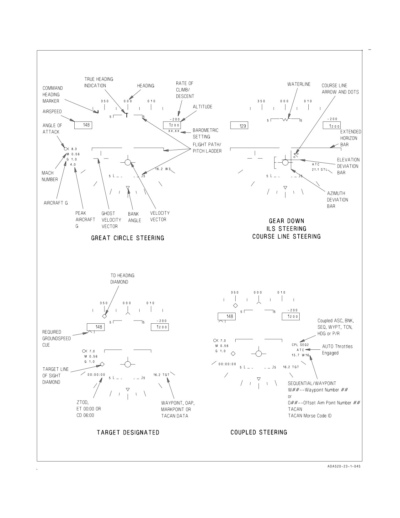
A1-F18AC-NFM-000
Figure 2-26. HUD Symbology (Sheet 1 of 2)
I-2-105
ORIGINAL
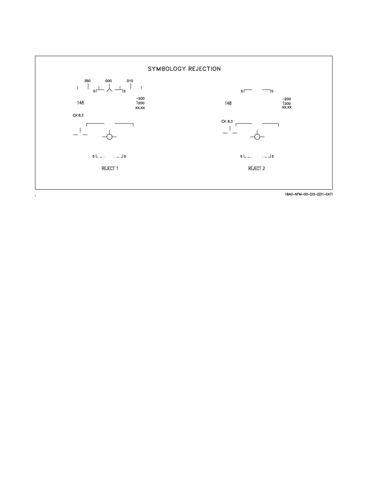
A1-F18AC-NFM-000
Figure 2-26. HUD Symbology (Sheet 2 of 2)
2.13.4.8.12 HUD Symbology Degrades. The avionics suite has built-in redundancy with two
mission computers for data management and two DDI for symbol generation. Likewise, if the attitude
select switch is in the AUTO or INS position, back-up data sources are automatically selected to
provide HUD symbology when specific failures are detected. Refer to figure 2-27, for the HUD displays
discussed below.
2.13.4.8.13 INS Failure/HUD Symbology Degrades. When a failure occurs in the INS expect HUD
bank angle, velocity vector, pitch ladder, and heading indications to be impacted. With GPS or EGI
installed, the mission computer utilizes GPS information for the velocity vector. If INS attitude is valid
but INS velocities are not valid, the mission computer automatically uses the INS attitude and GPS
velocities to position a non-flashing velocity vector. With a degradation of the ADC, calibrated
airspeed, barometric altitude, indicated Mach number, and vertical velocity indications may be
impacted.
When the ASN-130 system reverts to the attitude heading reference system (AHRS) mode, the
velocity vector flashes slowly indicating that the INS is still providing valid attitude information, but
the ADC is now the data source for the velocity vector. An AHRS reversion can be the result of an INS
BIT failure, or invalid INS velocity information. It is important to understand that AHRS is not an
independent back-up platform, but actually a degraded INS system. In the AHRS mode, a very slight
degrade in HUD attitude and velocity accuracy can be expected, warranting regular crosschecks of the
standby instrumentation. A reversion to AHRS is accompanied by the master caution light, tone, and
POS/ADC caution, provided that the INS has been selected on the HSI display as the position-keeping
source.
When the INS experiences a total shutdown (dump) with the attitude select switch in AUTO or INS,
or if the attitude switch is deliberately placed in standby, a stationary waterline symbol replaces the
velocity vector indicating that the standby attitude reference indicator is now providing attitude data.
This failure is normally accompanied by the master caution light, tone, and INS ATT caution. Place
I-2-106
ORIGINAL
A1-F18AC-NFM-000
the attitude select switch in the STBY position, crosscheck the HUD against standby instruments, and
attempt an inflight alignment.
NOTE
If an INS ATT caution is set or the ATT switch is placed to STBY, Xs
appear in CH 1/3 of the PROC row of the FCS page indicating FCCs
no longer use INS data. There is no significant degradation to flying
qualities, departure resistance or roll performance with these failure
indications.
If power to the HUD is lost, either due to a fault or by placing the HUD symbology brightness control
knob to OFF, the attitude selector switch becomes inoperative. If an insidious INS failure is followed
by a HUD failure, the only accurate source of attitude information available is the standby attitude
reference indicator. The electronic attitude display indicator can be selected as an alternative display
on the DDI. The STBY option available on the EADI operates independent of the attitude selector
switch and allows selection of the standby attitude reference indicator as the source for display attitude
information.
Due to the tendency of the standby attitude reference indicator to precess, it is suggested that flying
in instrument meteorological conditions (IMC) using the ARI as a primary attitude reference be
minimized. A partial IFA is always recommended whenever possible to recover the INS attitude
platform.
2.13.4.8.14 ADC Failure/HUD Symbology Degrades. An ADC failure results in loss of associated
data from the HUD display as shown in figure 2-27. An ADC failure also inhibits operation of cruise
flight Automatic Throttle Control and disables the altitude signal used for IFF altitude reporting. An
ADC failure may affect cabin air flow, cabin air temperature, and vent suit temperature.
Normal accurate air data and magnetic heading inputs that are supplied by the ADC to the mission
computers are lost. However, flight aids reversion mechanization provides information to the pilot
from the next best available source (figure 2-39). HUD airspeed and BARO altitude boxes are empty,
unless aircraft altitude is less than 5,000 feet AGL with RADALT to HUD, aircraft altitude AGL will
be displayed in the HUD altitude box. Failure of the air data computer provides the pilot with the
following indications:
IF GEAR UP -
1. Light in the gear handle and continuous beeping tone.
2. HUD airspeed box empty.
3. HUD altitude box empty if aircraft > 5,000 feet AGL.
4. HUD altitude box displays AGL with RADALT to HUD and aircraft < 5,000 feet AGL.
5. Standby instruments indicate correct altitude and airspeed.
6. BIT page indicates ADC - NOGO (A/B), MUX FAIL (C/D), or NOT RDY
IF GEAR DOWN -
1. HUD airspeed box empty.
2. HUD altitude box empty if aircraft > 5,000 feet AGL.
3. HUD altitude box displays AGL with RADALT to HUD.
4. AOA derived indication displayed on the HUD E-bracket.
5. Standby instruments indicate correct altitude and airspeed.
6. Internal/External AOA indexers inoperative
I-2-107
ORIGINAL
A1-F18AC-NFM-000
As the ADC degrades, loss of some or all of the following data from the HUD may occur:
1. Calibrated airspeed or barometric altitude. The loss of calibrated airspeed and/or barometric
altitude data results in activation of the landing gear handle warning light and tone. First
reference the applicable standby airspeed or altitude indicator, then silence the tone.
2. Angle of Attack. Loss of AOA requires no action on the part of the pilot, as the FCC automatically
provides data for the HUD display. In fact, there is no indication provided to the pilot when this
failure occurs.
3. Vertical velocity indicator. Upon loss of the vertical velocity indication, first check that the
aircraft is in the NAV master mode and reference the standby vertical velocity indicator.
4. Mach number. Upon loss of the Mach number indication, reference the standby airspeed
indicator.
The ADC can produce erroneous signals without cautions or advisories if the pitot or AOA probes
receive damage. ADC inputs to the MC are used by the INS to help smooth or dampen pitch ladder and
velocity vector position. A complete ADC failure does not immediately affect the pitch ladder/velocity
vector, but these displays will eventually degrade. If subtle damage to the AOA probe is suspected, the
pilot should make a crosscheck of airspeed with a wingman if possible. The standby airspeed indicator
receives signals from the left pitot static probe, so it is accurate if only the right probe is damaged. AOA
checks with a wingman should be made in landing configuration if a jammed AOA probe is suspected.
Crosschecking with flaps AUTO may give a satisfactory crosscheck, but the probe may be bent in such
a way that AOA anomalies are accentuated on landing configuration. Landing with automatic throttle
control (ATC) may be affected. If damage is suspected, ATC during landing is not recommended.
With the exception of a single AOA probe jammed on takeoff (see paragraph 15.32) if an AOA probe
becomes jammed (does not move), the ADC and FCCs continue to receive valid signals until the pilot
executes a maneuver that causes the reading between the AOA probes to differ more than 15°. The
pilot receives a master caution and FCS caution. HUD displayed airspeed may be inaccurate without
pilot error indications if a pitot tube is damaged. Be alert for unannunciated pitot tube or AOA probe
damage after bird strikes, icing conditions, or IFR basket impact during air refueling.
With MC OFP 13C AND UP. Displays of the L and R AOA probe values, and the INS AOA (center)
value, were added to the FCS status page. With MC OFP 13C and 15C, these AOA values are only
displayed when the ADC declares the AOA valid (<15.5°). With MC OFP 17C and 19C, the L and R
AOA values continue to be displayed even when the ADC declares the AOA invalid, but the values are
lined out. The center AOA value is driven by the INS and is always displayed, regardless of AOA
validity.
When the ADC declares AOA valid, the L and R AOA values can be boxed and selected, in the event
one AOA is damaged. The center (INS) AOA value allows the pilot to compare against L and R AOA
values to determine which is the good AOA probe. GAIN ORIDE must be selected to enable selection
of a single probe to drive the HUD E-bracket. Even with one AOA probe selected, AOA indexer and
approach lights are still driven by the average value to both probes and will be inaccurate. For carrier
landings, advise the LSO that the external approach light indications are inaccurate.
If the ADC declares AOA invalid, the HUD E-bracket and AOA numeric displays disappear, and the
indexer and external approach lights are inoperable.
2.13.4.8.15 HUD Advisory Data Symbology. The displays in figure 2-27 show some of the advisories
that can appear on the HUD in the NAV master mode. The advisories are associated with nose wheel
I-2-108
ORIGINAL
A1-F18AC-NFM-000
steering, and approach power compensator. Although the advisories are shown on the gear down
display, most of them can appear on the basic HUD display. Refer to Part VII for description of data
link system and advisories.
The automatic throttle control/nosewheel steering advisories are displayed above the distance
display whenever the ATC or the NWS is engaged. If the ATC is disengaged by any means other than
actuation of the ATC engage/disengage switch, the advisory is flashed for 10 seconds before it is
removed from the display or, if an attempt to engage ATC is not successful, then ATC is flashed for
10 seconds then removed.
2.13.4.8.16 HUD BIT Checks. The HUD has two methods of built-in tests: manually initiated and
automatic test. Refer to Status Monitoring Subsystem, figure 2-38 for the procedures and displays used
for the HUD BIT checks.
2.13.4.9 Course Set Switch. The course set switch manually sets the desired course on the HSI
display.
2.13.4.10 Heading Set Switch. The heading set switch manually sets the heading marker on the
desired heading on the HSI display.
2.13.5 Upfront Control (UFC). The UFC (figure 2-28) is on the main instrument panel below the
HUD. The UFC is used to select autopilot modes and control the IFF, TACAN, ILS, data link, radar
beacon, UHF radios and ADF. With AFC 270, D/L toggles between LINK 4 and LINK 16 and MIDS
is turned on/off via TACAN or LINK 16. The UFC is used in conjunction with the two DDIs and the
HI/MPCD/AMPCD to enter navigation, sensor, and weapon delivery data. UFC option selections and
inputs are primarily transmitted directly to the communication system control for discrete control of
the CNI equipment or for routing to the mission computers. In aircraft 163985 AND UP the UFC is
NVG compatible. A description of the UFC switches and displays follows. Refer to Part VII for
operating instructions for CNI equipment.
2.13.5.1 Brightness Control Knob. The knob has positions of BRT (bright) and DIM. The
brightness of the display increases as the knob is rotated clockwise toward BRT.
2.13.5.2 Emission Control Pushbutton. This pushbutton is labeled EMCON. Pushing the button
inhibits IFF, tacan, radar, radar beacon, radar altimeter, two-way data link, and Walleye from
transmitting. The letters E, M, C, O, and N are displayed in a vertical column in the five option
windows when EMCON is selected. Pushing the button again permits the transmitters to radiate.
2.13.5.3 I/P Pushbutton. Pushing this momentary pushbutton causes the IFF to respond to mode
1, 2, and 3 interrogations with identification of position response (IDENT).
2.13.5.4 ADF Function Select Switch. Actuating this switch to the 1 position selects comm 1 for
ADF operation. In the OFF position ADF is disabled. In the 2 position comm 2 is selected for ADF
operation.
2.13.5.5 Option Select Pushbuttons. The five pushbuttons select or deselect the displayed options.
2.13.5.6 Pilot Cueing. A colon (:) is displayed when an option is selected. The colon disappears when
an option is deselected.
I-2-109
ORIGINAL
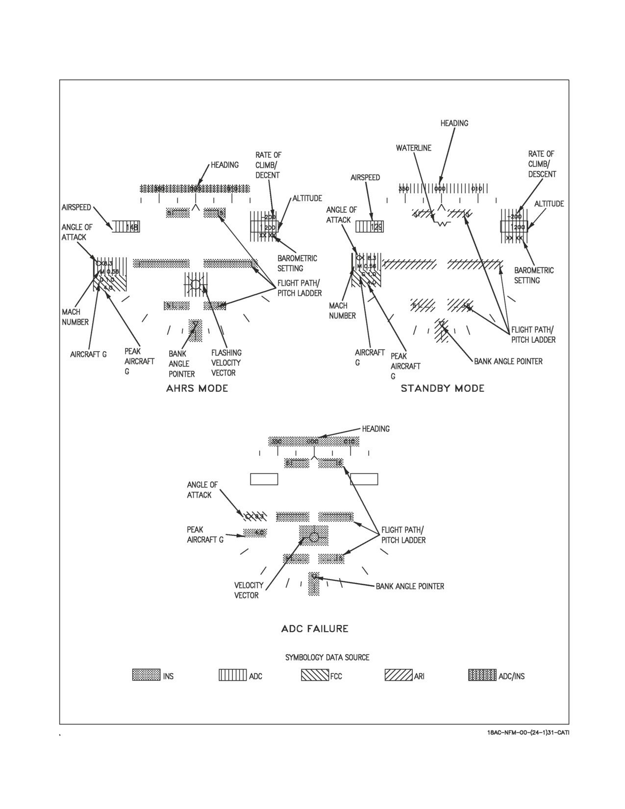
A1-F18AC-NFM-000
Figure 2-27. HUD Symbology Degrades
I-2-110
ORIGINAL
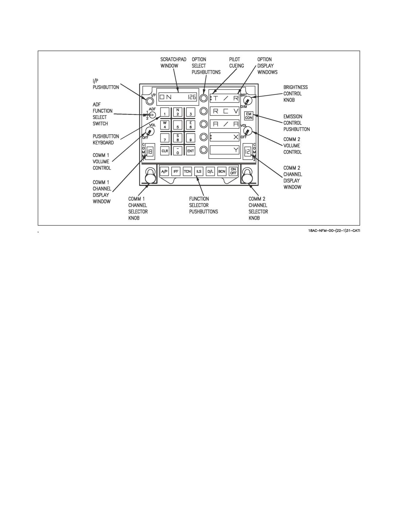
A1-F18AC-NFM-000
Figure 2-28. Upfront Control (UFC)
2.13.5.7 Option Display Windows. The option display windows display five options of four
alphanumeric characters each that are available for selection.
2.13.5.8 Scratchpad Window. The scratchpad window displays keyboard entries on a nine character
readout. The first two characters are alphanumeric and the other seven are numeric.
2.13.5.9 Pushbutton Keyboard. The pushbutton keyboard contains alphanumeric pushbuttons, a
CLR (clear) pushbutton, and an ENT (enter) pushbutton. Pressing the alphanumeric pushbutton
enters a corresponding alphanumeric as digital information into the control converter. The number or
letter of the pressed button is displayed on the right end of the scratchpad. The number or letter moves
to the left as additional numbers are entered. The decimal point or degree/minute symbols are
automatically displayed in correct position for information being entered. Trailing zeroes must be
entered. Pressing the CLR pushbutton clears the scratchpad and/or the option display windows.
Pressing the CLR pushbutton once clears the scratchpad, pressing it a second time clears the option
display windows. Pressing the ENT pushbutton causes the keyboard entry displayed in the scratchpad
to be sent to the control converter to change operation of selected equipment or to make data available
to the mission computer. If entry via the keyboard is valid, the scratchpad display blinks once. If entry
is invalid, ERROR appears and flashes in the scratchpad display until the scratchpad is cleared.
2.13.5.10 Function Selector Pushbuttons. The function selector pushbuttons for the equipment
are mutually exclusive. When a particular function selector pushbutton is pressed, the control options
for that equipment are displayed in the option windows (and in case of the autopilot switch, the
autopilot is engaged). Then the ON-OFF switch is used to turn the selected equipment (except
autopilot) on and off. When the equipment is on, the word ON is displayed in the first two
alphanumerics of the scratchpad. The first two alphanumerics are blank when the equipment is off.
Pressing the function selector pushbutton a second time clears the UFC display. The pressing of a
function selector pushbutton, the pulling of a channel selector knob, or the receipt of a UFC mode
I-2-111
ORIGINAL
A1-F18AC-NFM-000
command from the mission computer terminates all prior activity, with all previous entries retained,
and presents the options for the newly selected mode.
2.13.5.11 Volume Controls. Turning the volume control to the OFF position turns off the
corresponding radio. The comm 1 and comm 2 channel display windows illuminate if the respective
radios are on. Out of the OFF position, the knob controls the audio volume for the corresponding radio.
2.13.5.12 Channel Selector Knobs. Rotating the knob selects channel 1 thru 20, manual (M), or
guard (G). The channel is displayed in the corresponding comm 1 or comm 2 channel display window.
Pulling the spring-loaded knob causes the selected channel and its frequency to be displayed in the
scratchpad and enables the control converter to change the frequency of the selected channel via the
keyboard entry.
2.13.5.13 Channel Display Windows. When the corresponding radio is on, the selected channel
(1-20, M or G) is displayed on the 16 segment alphanumeric display window. The diagonal display
segment in the lower right quadrant of each display window illuminates whenever transmissions are
received on comm 1 and comm 2, respectively.
2.13.6 Signal Data Computer (F/A-18C/D). The signal data computer (SDC), under mission
computer control, records aircraft fatigue strain data, engine parameters when out of tolerance
conditions occur, fuel information and aircraft and target parameters when targets are designated and
weapons are delivered. It includes fuel transfer controls and gaging capabilities, incorporates ground
support equipment fuel transfer and gaging fault isolation functions, and provides interface for
multiple sensors and controls. It provides analog to digital conversion of aircraft parameters. In
addition, BIT fail indications are stored in the SDC to be displayed by the maintenance status panel
(MSP) for readout by maintenance personnel after the flight, or on the integrated fuel/engine indicator
(IFEI) for readout during the flight.
The fuel format is available on any DDI by selection of the FUEL push button from the menu
format, and the RESET SDC option is available from the fuel format. RESET SDC is used to reset the
SDC by momentarily removing power to the SDC. When the push button is first pressed, the RESET
portion of the button legend is boxed. The box is removed when the SDC reestablishes AVMUX
communication or 15 seconds after the push button was pressed. The RESET SDC legend is removed
from the fuel format if the CSC is not communicating on the AVMUX.
In aircraft equipped with GPS, it is important to manually load Zulu time as this aids in satellite
acquisition. If local time is desired, it should be set after takeoff. The aircraft signal data computer is
used to initialize GPS. At GPS power up, the SDC time and date are automatically sent to the GPS to
aid it in the acquisition of satellites. Once the satellites are acquired for the first time, the GPS obtains
a good satellite time. This time is then backloaded to the SDC, synchronizing the SDC with precise
GPS time. The GPS is loaded with GPS precise time only once per cold start. Changing the SDC time
or date with WOW reinitializes the GPS.
2.13.7 Video Tape Recording System (VTRS) (Aircraft 161353 THRU 164912 BEFORE AFC 207).
The video tape recording system (VTRS) consists of a video tape recorder and a HUD video camera.
In addition, the system utilizes other existing aircraft equipment.
2.13.7.1 DDI Video. Weapon video is provided by television or infrared sensors for display on the
DDIs and for recording on the VTRS tape. Radar video is provided from the radar receiver for display
on the DDI and for recording on the VTRS tape. The weapon and radar video recorded on the tape
does not include the mission computer system symbology displayed on the DDI.
I-2-112
ORIGINAL
A1-F18AC-NFM-000
2.13.7.2 Video Tape Recorder. The video tape recorder accepts composite video from the HUD
video camera or the left or right DDI along with headset audio, and provides a minimum of 30 minutes
recording time on removable 3/4 inch U-matic tape cartridges. The headset audio is only available for
recording when the KY-58 encryption function is inactive.
2.13.7.3 HUD Video Camera. The HUD black and white video camera (HVC) output of the HUD
display superimposed on the image of the outside world is made available to the video tape recorder.
The switches for operating the VTRS are on the HUD video camera control panel.
2.13.7.4 HUD Video Camera Control Panel. The HVC control panel contains a HUD/DDI selector
switch, a mode selector switch, a BIT initiate pushbutton, and go/no-go indicators.
2.13.7.4.1 IFEI Brightness Control Knob. On aircraft 164865 AND UP, the IFEI brightness control
knob provides variable IFEI lighting between OFF and BRT with the mode switch on the interior light
panel in either NITE or NVG position.
2.13.7.4.2 HUD/DDI Selector Switch. The HUD/DDI selector switch has positions of HUD, L DDI,
and R DDI.
HUD
Head-up display imagery superimposed on the outside world is recorded.
L DDI
The radar or weapons video supplied to the left DDI is recorded.
R DDI
Information supplied to the right DDI same as left DDI and recorded.
2.13.7.4.3 Mode Selector Switch. The mode selector switch has positions of MAN, AUTO, and
OFF.
MAN
The VTRS is recording continuously. The HUD/DDI selector switch can be set to
the desired position for recording.
AUTO
If the aircraft is operating in the A/A or A/G master mode, the HUD video camera
and the video tape recorder run continuously and record whatever is selected on
the HUD/DDI selector switch. However, if the first detent on the trigger or the
weapon release button is pressed, the VTRS automatically records the HUD dis-
play. If the A/G master mode is selected and the FLIR display is on either DDI,
the VTR does not switch to record the HUD.
OFF
The VTRS is inoperative.
When the HUD video is being recorded as a result of a trigger switch or weapon release button
actuation, the HUD video continues to be recorded for a preset overrun time after the control is
released. For Sidewinder launches and gun firing, the overrun time is 5 seconds. For Sparrow launches
and A/G weapon releases, the overrun time is 10 seconds.
2.13.7.4.4 BIT Initiate Pushbutton. The pushbutton is pressed to test the HUD video camera. The
GO and NO GO balls are normally black. If the BIT test is good, the GO ball shows green. If the BIT
test is not good the NO GO ball shows orange.
2.13.7.5 Event Mark. When the weapon release button is pressed, an event mark signal is supplied
to the HUD video camera. At that time a black box is generated by the camera and appears in the
I-2-113
ORIGINAL
A1-F18AC-NFM-000
upper left corner of the video signal going to the video tape recorder. When the trigger is actuated to
the second detent position to launch a missile, the event mark is generated and recorded until the
trigger is released.
2.13.7.6 Recorder On Light. The RCDR ON light, on the right warning/caution/advisory lights
panel comes on when the recording system is recording.
2.13.8 Cockpit Video Recording System (Aircraft 164945 AND UP and Aircraft 163985 THRU
164912 AFTER AFC 207). The Cockpit Video Recording System (CVRS) consists of three color auto
aperture cameras, two electronic units (EUs), and two 8 mm video recorders. One camera records the
HUD and the other two record the left and right DDIs in the front cockpit. One video recorder is
dedicated to the RDDI while the other is switchable between the HUD and the LDDI. The DDI
cameras, Video Sensor Heads (VSHs), are mounted on top of the canopy frame, one on each side, aft
of the DDIs. An EU is mounted directly aft of each VSH.
2.13.8.1 DDI Video. Weapon video, provided by television or infrared sensors, and radar video,
provided from the radar receiver, is available for display on the DDIs and recording on the CVRS tapes.
The weapon and radar video recorded on the tape includes the mission computer system symbology
displayed on the DDIs.
With AFC 408, selecting ENABLE on the NUC WPN switch located above the left console next to
the canopy manual handle permits raw video from the FLIR to be recorded when the HUD/LDDI
switch is in LDDI and the FLIR display is on the LDDI. With the NUC WPN switch in ENABLE, only
the LDDI will be recorded even if the mode selector switch is in AUTO.
2.13.8.2 Video Tape Recorders. One video tape recorder accepts video from the HUD color video
camera or the LDDI VSH, and the other video tape recorder accepts video from the RDDI VSH. Both
recorders accept headset audio and each provides a minimum of 120 minutes recording time on
removable video tape cartridges. The headset audio is only available for recording when the KY-58
encryption function is inactive.
2.13.8.3 HUD Video Camera. The HUD color video camera (HVC) output of the HUD display
superimposed on the image of the outside world is made available to the video tape recorder.
2.13.8.4 CVRS Control Panel. The switches for operating the CVRS are on the HUD video camera
control panel. The control panel contains an IFEI brightness control knob, a HUD/LDDI selector
switch, and a mode selector switch.
2.13.8.5 IFEI Brightness Control Knob. The IFEI brightness control knob provides variable IFEI
lighting between OFF and BRT with the Mode switch on the interior light panel in either NITE or
NVG position.
2.13.8.6 HUD/LDDI Selector Switch. The HUD/LDDI selector switch has positions of HUD and
LDDI.
HUD
Head-up display imagery superimposed on the outside world is recorded.
LDDI
The radar or weapons video supplied to the LDDI is recorded.
I-2-114
ORIGINAL
A1-F18AC-NFM-000
2.13.8.7 Mode Selector Switch. The mode selector switch has positions of MAN, AUTO, and OFF.
MAN
The CVRS is recording continuously. The HUD/LDDI selector switch can be set to
the desired position for recording.
AUTO
If the aircraft is operating in the A/A or A/G master mode, the video tape record-
ers run continuously. Selection of the first detent of the trigger, or pressing the
weapon release button, automatically records the HUD display regardless of the
HUD/LDDI switch position. If in A/G master mode with the FLIR display on
either DDI, the HUD is not recorded automatically.
OFF
The CVRS is inoperative.
When the HUD video is being recorded as a result of a trigger switch or weapon release button
actuation, the HUD video continues to be recorded for a preset overrun time after the control is
released; for Sidewinder launches and gun firing, the overrun time is 5 seconds; for Sparrow launches
and A/G weapon releases, the overrun time is 10 seconds.
2.13.8.8 BIT Initiate Pushbuttons. The pushbutton on the HUD video camera or the pushbuttons on
the EUs are pushed to BIT the HUD video camera and/or EU/VSH. The GO and NO GO Light
Emitting Diodes (LEDs) are normally not illuminated. If the BIT test is good, the GO LED shows
green. If the BIT test is not good, the NO GO LED shows amber.
2.13.8.9 Event Marker. When the weapon release button is pressed, an event mark signal is supplied
to the HUD video camera. At that time a black box is generated by the camera and appears in the
upper left corner of the video signal going to the video tape recorder. When the trigger is pressed to the
second detent position to launch a missile, the event marker is generated and recorded until the trigger
is released.
2.13.8.10 Recorder On Light. The RCDR ON light, on the right warning/caution/advisory lights
panel, comes on when the recording system is recording.
2.13.9 Armpit Camera System. The XC-75 is a monochrome video camera module. It uses a CCD
(charge coupled device) solid state image sensor. The system is mounted in the aircraft in place of the
forward night vision goggle (NVG) floodlight aft of the canopy control switch box. The camera system
measures 1 3/4 X 1 3/16 X 3 5/8 inches , weighs approximately 5 ounces and is designed to operate in
temperatures from -5 to 45 ° Celsius. The armpit camera is used to record information from the DDI.
2.13.10 Tactical Aircraft Moving Map Capability (TAMMAC)
The TAMMAC avionics subsystem provides a moving map capability to enhance operational
effectiveness and survivability and addresses supportability/obsolescence issues facing existing moving
map and data storage systems currently deployed.
TAMMAC effectively replaces three separate Weapons Replaceable Assemblies (WRAs), including
the AN/ASQ-196 DVMS which consists of two WRAs; the Digital Map Computer (DMC) and the
Digital Memory Unit (DMU), and the AN/ASQ-194 DSS which is a single WRA.
The TAMMAC subsystem consists of a new MU-1119/A Advanced Memory Unit (AMU), a new
CP-2414/A digital map computer and a High Speed Interface Bus (HSIB) which connects the two. The
DMC is a functional replacement for the existing DVMS. Data Transfer Devices (DTDs) used in
conjunction with TAMMAC for transferring data to and from ground-based stations are Personal
I-2-115
ORIGINAL
A1-F18AC-NFM-000
Computer Memory Card International Association (PCMCIA) cards or PC cards. Ground-based
stations that process data for TAMMAC include the Tactical Automated Mission Planning System
(TAMPS) and the Automated Maintenance Environment (AME). Theater data is installed on the
maploading card using TAMPS.
The AMU is a functional replacement for the existing DSS, more commonly referred to as the
Memory Unit (MU). The AMU contains two PC card receptacles, one for maintenance (ground
support) operations and one for mission (pilot) operations. This unique configuration allows mainte-
nance and mission data to be separated both pre- and post-flight which reduces logistics coordination
and facilitates operational readiness. Three types of PC cards are used in the TAMMAC subsystem
operation: 1) Mission Card, 2) Maintenance Card, and 3) Map Loading Card.
2.13.10.1 TAMMAC Status Monitoring. TAMMAC status monitoring functions are based on the
existing MU and DVMS status monitoring functionality. Some of the existing cautions, advisories, BIT
mechanizations, and MSP codes that satisfied the requirements for the MU and DVMS were not
changed. However, additional status monitoring functionality was added to accommodate changes to
the MC/AMU/DMC interfaces including, but not limited to, the PC cards and the High Speed
Interface Bus (HSIB).
All existing display references to the MU and DMC are unchanged. The TAMMAC AMU functionality
discussed here equates to the MU nomenclature on all existing displays. The TAMMAC DMC equates
to the DMC on all existing displays. The only operator change to the status monitoring BIT displays
is the addition of the AMU MAINT option.
The MC verifies the AMU and DMC software configuration IDs are compatible with the MC
software.
2.13.10.2 AMU Maintenance Format Options and Display Information. The AMU maintenance
format contains two relay mode options, MAP LOAD and MBIT. MAP LOAD provides access to
sublevel formats used to upload map theater data to the DMC. MBIT is used for troubleshooting and
fault isolation.
Information displayed on the AMU maintenance format is limited to the MU OFP configuration ID.
The OFP CONFIG identifies the OFP version currently installed in the AMU. See figure 2-29.
2.13.10.3 Map Theater Data Loading. Map theater data loading can include either updates to an
existing theater load or a new theater load. In both cases, the map loading cards are processed on
TAMPS and loaded in the DMC nonvolatile mass memory using the same procedure. The number of
map loading cards is contingent on the size of the update or new theater load. The number of map
loading cards can be as few as one or as many as seven.
Map theater data loading is controlled by the map loading format. The map loading format is
accessed by selecting the MAP LOAD option (PB 11) on the AMU maintenance format as shown in
figure 2-29. The map loading format contains three relay mode options; LOAD, ABORT, and RTN.
2.13.10.4 Map Loading Format Options. The LOAD option (PB 11) is used to initiate a theater load
when a map loading card is installed in the AMU maintenance card receptacle and the AMU door is
closed. Once the process is initiated, the LOAD option is removed from the format. Multiple card
theater loads/updates require the insertion of another map card when prompted by the DDI display.
Installing another map loading card and closing the AMU door continues the theater loading process.
This procedure is repeated until all theater data is loaded. Map loading cards can be loaded in any
sequence.
I-2-116
ORIGINAL
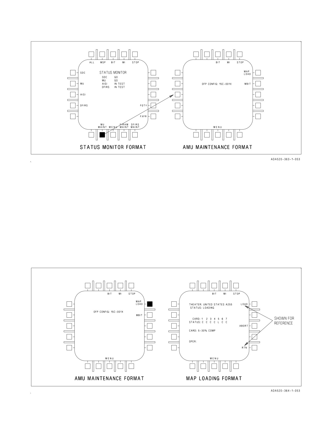
A1-F18AC-NFM-000
Figure 2-29. AMU Maintenance Format
The ABORT option (PB 13) is used to abort a theater load in progress. It is removed from the
display prior to and after completion of a load. To initiate an abort, the operator presses PB 13 which
changes the option to ABORT ENABLE. Selection of ABORT ENABLE executes the abort process.
The ABORT ENABLE legend is displayed for three seconds following selection of the ABORT option.
If the operator does not select the ABORT ENABLE option within three seconds, the ABORT legend
is redisplayed. The intent of this two-step abort process is to preclude any inadvertent operator
initiated aborts from being performed. This abort process is permanent and the entire load process will
be terminated.
Aborting a theater map load causes the aborted theater to be deleted. No maps in CHRT, DTED,
or CIB will be available if a theater load is aborted. Previous theater maps are automatically deleted
upon loading a new theater.
Figure 2-30. Map Loading Format
I-2-117
ORIGINAL