F18. FLIGHT MANUAL (2008) - page 5
A1-F18AC-NFM-000
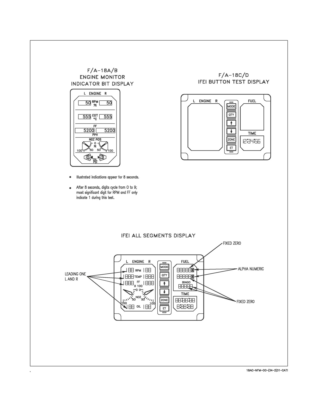
Figure 2-48. DSPL/EPI (IFEI)/UFC BIT Displays (Sheet 2 of 2)
I-2-178
ORIGINAL
A1-F18AC-NFM-000
d. NOZ POS - 40%
e. OIL - 150 PSI
5.
Turn HI/MPCD/AMPCD power on.
6.
Select MENU/BIT/DSPL/EPI/(IFEI)/UFC on DDI.
a. DDI, HI/MPCD/AMPCD and HUD displays go blank momentarily, flash STANDBY and
then display a test pattern.
b. DDIs have test pattern that is steady and in focus.
c. HUD and HSI test pattern displays flicker every 2 seconds but remain on.
7.
HUD, HI/MPCD/AMPCD, and DDI displays - CHECK
a. Display commonality.
b. Display concentricity.
c. Proper intensity.
d. Check right DDI pushbuttons starting with top left button on horizontal row. Circle appears
next to pushbutton after it is pressed.
e. On aircraft 161353 THRU 163782 press MAP pushbutton on the HI. Test circle displayed next
to MAP pushbutton and moving map filmstrip number displayed.
f. On aircraft 161353 THRU 163782 press MAP pushbutton to increment selected map number
to same value as film strip number. Continual pressing of MAP pushbutton increments
selected map number through range of three values, 01, 02, 03, and back to 01.
g. Check HI/MPCD/AMPCD pushbuttons as in 7.d. above.
h. Check left DDI pushbuttons as in 7.d. above pressing STOP button last. When STOP button
is pressed, GO BIT display status messages on left DDI for LDDI, RDDI, HI/MPCD/AMPCD
and HUD.
2.20.3.10 Cockpit Displays Initiated BIT (MC OFP 13C AND UP)
2.20.3.10.1 DDI/HI/MPCD/AMPCD/HUD Initiated BIT. Operator participation is required to
detect failures and isolate faults in the display equipment. The BIT/DISPLAYS/DDI-MPCD-HUD
pushbutton calls up the MC generated test patterns on the DDI, HI/MPCD/AMPCD and HUD
immediately after each indicator BIT is concluded. The test pattern can then be compared on the four
displays for similarity, and individually for concentricity, intensity level, and alphanumeric clarity.
Pushbuttons are tested by actuating all the buttons. A circle appears adjacent to the button when the
functional test is successfully completed.
Pressing DDI-MPCD-HUD initiates BIT on three different equipment display groups. The
following procedure can be used to test one or two of the display groups by performing the appropriate
parts of the procedure.
I-2-179
ORIGINAL
A1-F18AC-NFM-000
1. Select BIT/DISPLAYS/DDI/MPCD/HUD
a. DDI, MPCD/AMPCD, and HUD displays go blank momentarily, flash IN TEST, and then
display a test pattern.
b. Check DDI test patterns are steady and in focus.
c. HUD and MPCD/AMPCD test patterns flicker but remain on.
2. DDI, MPCD/AMPCD, and HUD displays - CHECK
a. Display commonality
b. Display concentricity
c. Proper Intensity
d. Check right DDI pushbuttons starting with the top left button on the horizontal row. Circle is
displayed next to each pushbutton after it is pressed.
e. Check MPCD/AMPCD pushbuttons as in step d. Press STOP button last.
f. Check BIT status messages for GO on the BIT displays. F/A-18D lists front and rear indicator
results separately.
2.20.3.10.2 IFEI Initiated BIT. IFEI test pattern is initiated by performing IFEI BIT using
pushbutton sequence BIT/DISPLAYS/IFEI and observing the test pattern displays following the
completion of IFEI BIT. The IFEI test pattern may be observed using the following procedure.
1. Select BIT/DISPLAYS/IFEI
2. IFEI - observe test display.
3. Select STOP to terminate test pattern
4. Engine monitor Indicator - CHECK
a. RPM- 50%
b. EGT - 555°C
c. FF - 5,200 PPH
d. NOZ POS - 40%
e. OIL - 150 PSI
UFC Test - UFC test patterns are performed by selecting BIT/DISPLAYS/UFC and observing the test
displays and performing the UFC switch functional tests. The UFC test pattern is obtained using the
following procedure.
5. Select BIT/DISPLAYS/UFC
I-2-180
ORIGINAL
A1-F18AC-NFM-000
6. Upfront control - CHECK
a. All outer segments of alphanumeric displays, all segments of the numeric displays, and all
option cues illuminate for the next 5 seconds.
b. All inner segments of alphanumeric displays, all segments of the numeric displays, and all
option cues illuminate for the next 5 seconds.
2.20.3.10.3 Stop Button. The STOP button allows the pilot to stop initiated BIT at any time. The
same effect is also achieved by pressing MENU, although MENU is not available with the DSPL/EPI
(IFEI)/UFC BIT test pattern displayed. When the STOP (or MENU) button is pressed, any test in
progress stops and the equipment returns to normal operation. Exceptions to this are the radar and
SMS power-on BIT and the COM 1/2, D/L, and tacan BIT. The radar and SMS power-on BIT cannot
be terminated and, as such, indicates SF TEST when the MC detects the system is in BIT without
having been commanded to do so. The same is true of the COM 1/2, D/L, and tacan equipment which
performs a canned non-interruptable BIT sequence. The mission computer terminates initiated BIT
for any equipment that it determined has taken too long to complete the test. For F/A-18 A/B, when
DSPL/EPI (IFEI)/UFC initiated BIT is selected, the EPI (IFEI) display must be allowed to complete
its display cycling before STOP is pressed or a UFC BIT failure is indicated.
2.20.3.11 BIT Logic Inspection (BLIN) Codes. BLIN codes are octal readouts identifying FCS
failures and can be read from the FCS status display. The following procedures may be used to display
and record BLIN codes. Channel 1 BLIN codes are displayed. Pressing BLIN button displays the next
channel (1, 2, 3 and 4) BLIN codes.
1. On DDI - PRESS MENU/FCS/BLIN
2. DDI BLIN codes - RECORD BY CHANNEL
3. Press BLIN button to view next channel BLIN codes.
2.20.4 Non-Avionic BIT. NABIT is implemented within selected hydro-mechanical subsystems
primarily for the purpose of displaying subsystem status in the cockpit (cautions and advisories)
and/or providing fault detection and fault isolation information for maintenance personnel. This status
data is provided to the status monitoring displays by the maintenance signal data recording set which
interfaces with the following hydromechanical areas:
1. Engine/secondary power
2. Electrical
3. Hydraulics and landing/arresting gear
4. Fuel
5. Environmental control system and radar liquid cooling system
6. Controls/mechanisms/miscellaneous
The hydraulic system pressure cautions are interfaced directly by both mission computers providing
redundancy for safety of flight.
I-2-181
ORIGINAL
A1-F18AC-NFM-000
2.20.4.1 Equipment Status Displays. NABIT cautions and advisories are displayed in the same
manner as avionic cautions and advisories.
2.20.5 Status Monitoring Backup. MC2 provides backup status monitoring if MC1 fails. It provides
an MC1 caution on the DDI indicating that MC1 has failed. It also provides HYD cautions.
NOTE
If MC1 fails, all DDI cautions and advisories are lost except MC1,
HYD 1A, HYD 1B, HYD 2A, and HYD 2B. With MC OFP 13C AND
UP, TAC MENU loses SA option and SUPT MENU displays only the
HSI option.
2.20.6 Non-BIT Status. Equipment status derived by means other than BIT include DDI configu-
ration display ID numbers and INS terminal data.
2.20.6.1 DDI Configuration Display Country ID Code. The country identifier code USN is displayed
underneath the CONFIG legend.
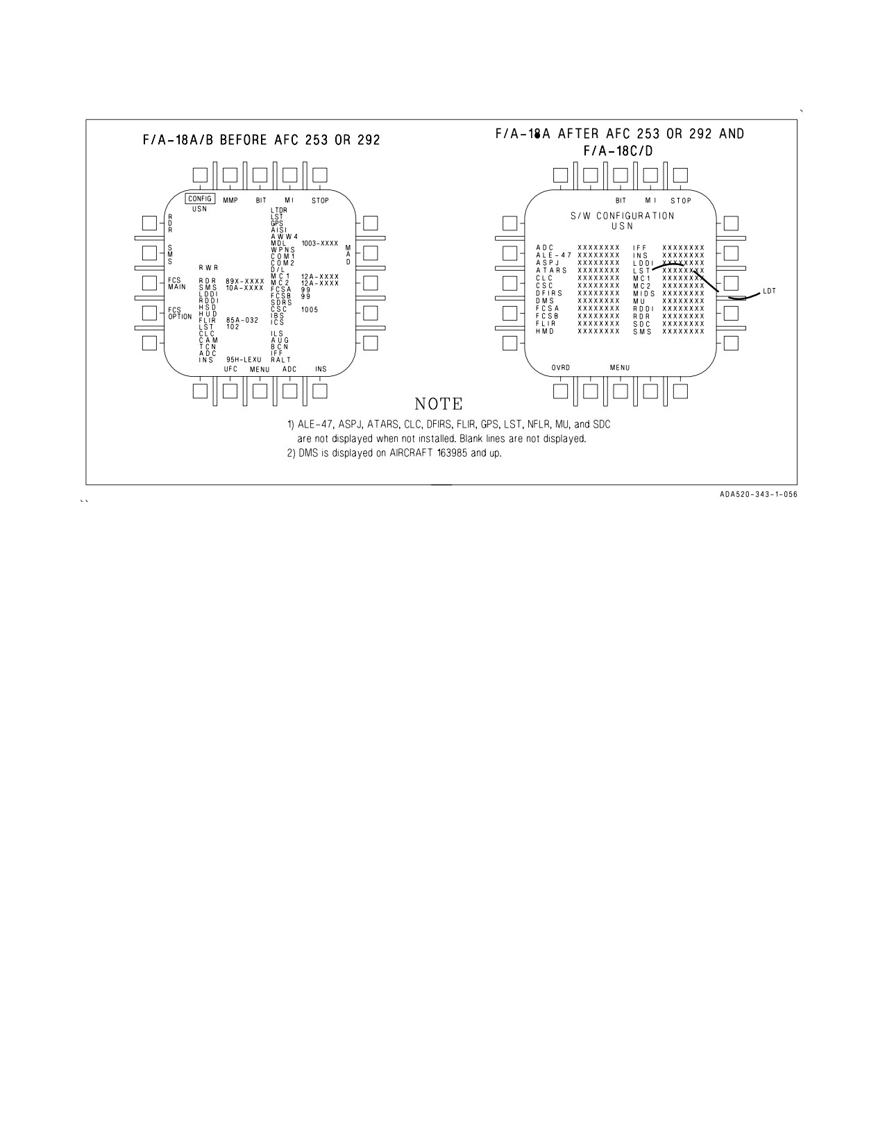
2.20.6.2 DDI Configuration Display OFP ID Numbers. The ID numbers of the current operational
flight program (OFP) loads for the radar, stores management system, INS, mission computers,
communication system control, flight control computer, FLIR, SDC (F/A-18C/D), MU (F/A-18A after
AFC 253 or 292 and F/A-18C/D), LST, and DMS and NFLR (LOT 12 and up) can be determined by
selecting the configuration display on the left or right DDI (see figure 2-49). With MC OFP 19C, DCS
and GPS ID numbers are also displayed. The configuration display is selected by the following
procedure:
If MC OFP 10A AND UP -
1. Select BIT display from MENU
2. Select MAINT from BIT display
3. Select CONFIG from MAINT
If MC OFP 13C AND UP -
1. Select BIT from the SUPT MENU
2. Select CONFIG
With the configuration display selected, the current ID numbers are displayed to the right of the
above equipment. Refer to figure 2-49 for an example.
I-2-182
ORIGINAL
A1-F18AC-NFM-000
Figure 2-49. Configuration Display (Sample)
2.20.6.2.1 MC CONFIG Caution Display. An MC CONFIG caution display indicates MC1 and MC2
OFP loads are found to be incompatible.
2.20.6.2.2 S/W CONFIG Caution Display. A S/W CONFIG caution display indicates MC1 and MC2
OFP loads are found not to be concurrent release (incompatible); MC1, MC2, RADAR, SMS, SDC
(F/A-18C/D), MU (F/A-18A after AFC 253 or 292 and F/A-18C/D), INS OFPs or CSC (F/A-18C/D) are
incompatible with MC OFPs; DMS/DMC (aircraft 163427 AND UP after AFC 270) not compatible
with MC OFPs; FCSA and FCSB are not mutually compatible or are incompatible with the throttle
modification. The incompatible OFP(s) are indicated by a line drawn thru the OFP ident. If the MC
OFPs are incompatible a line is drawn thru both MC OFP idents.
2.20.6.2.3 OVRD Button. The override option allows the pilot to override the software configuration
logic when the software country ID codes do not agree with the aircraft country ID codes.
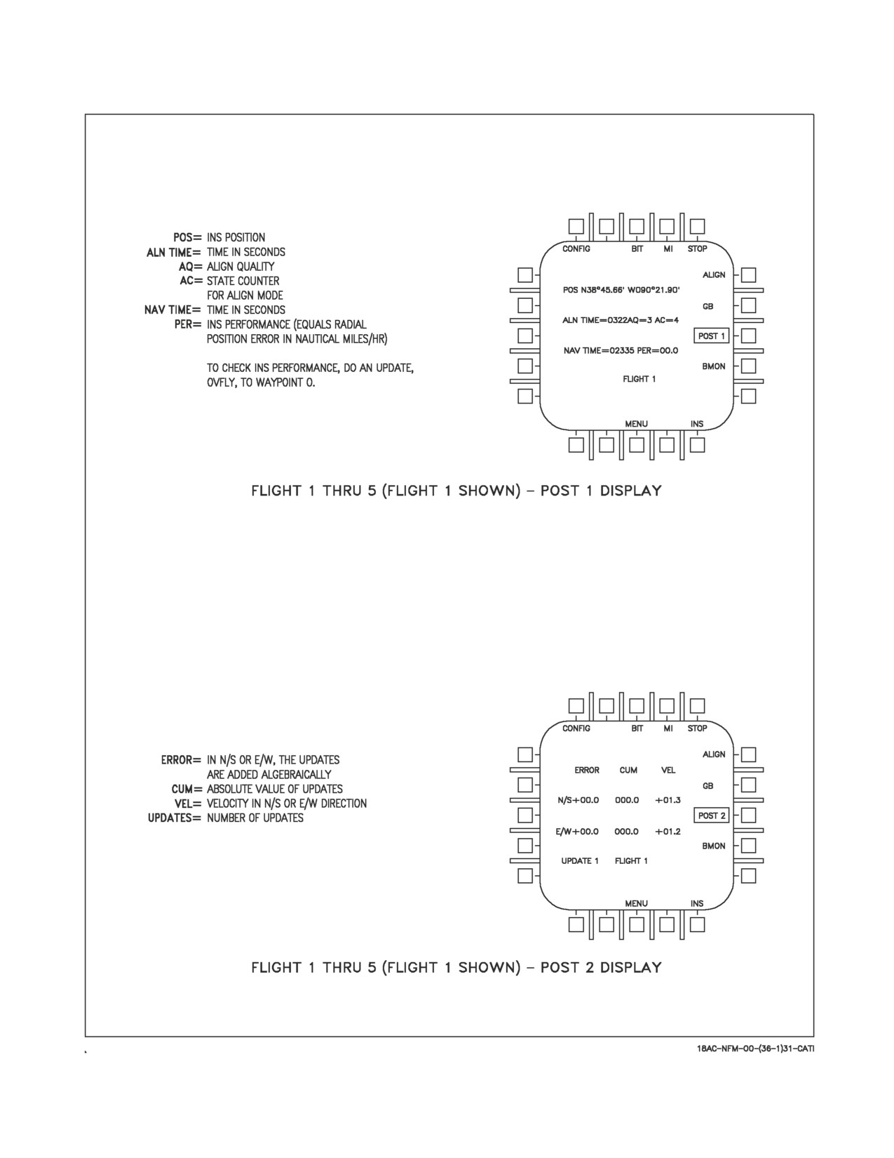
2.20.6.3 INS Terminal Data. INS terminal data can be obtained if an update has been performed
after flight with the parking brake on. With MC OFP 10A AND UP, INS terminal data is displayed by
pressing the following pushbuttons in sequence: MENU, BIT, MAINT, INS, and POST. With MC
OFP 13C AND UP, INS terminal data is displayed by pressing the following pushbuttons in sequence:
MENU (SUPT), BIT, NAV, INS MAINT, and POST. Note the PER (position error rate) and
navigation time on the FLIGHT 1, POST 1 display (see figure 2-50). Press the POST pushbutton again
and note the velocity on the FLIGHT 1, POST 2 display. Turn the INS mode selector knob to OFF,
then wait at least 10 seconds before turning off aircraft power. On aircraft with GPS, if the aircraft is
flown with IFA selected, the position error rate does not include the time flown in the AINS mode.
When an EGI is installed, the INS MAINT option provides detailed information for both the INS and
GPS. The EGI also provides additional INS information that is not available from the ASN-130 or
ASN-139.
I-2-183
ORIGINAL
A1-F18AC-NFM-000
Figure 2-50. INS Post Flight Data Displays
I-2-184
ORIGINAL
A1-F18AC-NFM-000
2.21 JOINT HELMET MOUNTED CUEING SYSTEM (JHMCS)
The JHMCS allows the aircrew to target and employ existing short range missiles SRMs and High
Off-Boresight (HOBS) weapons, such as the AIM-9X, and cue the radar, FLIR, and other sensors.
When using JHMCS to employ HOBS weapons, the aircrew can slave/acquire and shoot targets
beyond the gimbal limits of the aircraft radar and designate ground targets. The main display provides
a monocular 20° field of view that is visible in front of the pilot’s right eye.
The main components of the JHMCS include the helmet mounted displays, electronics unit,
HMD/AHMD off/brightness knobs, aft cockpit Boresight Reference Unit (BRU), cockpit units,
magnetic transmitter units, and seat position sensors in each cockpit. The JHMCS aircraft-integrated
components can be flown with or without the helmet system.
Increased weight and forward CG of the helmet will increase neck strain
during high or sustained g flight maneuvers.
NOTE
All aircrew shall receive simulator or dedicated ground training on
JHMCS helmet controls and displays prior to flight with JHMCS.
2.21.1 Helmet Mounted Display (HMD)/Aft Helmet Mounted Display (AHMD). Each HMD consists
of the helmet, Helmet Display Unit (HDU), Helmet-Vehicle Interface (HVI), and a universal connector
which connects the HDU to the helmet.
2.21.1.1 Helmet Display Unit (HDU). The HDU includes a CRT, Magnetic Receiver Unit (MRU),
camera, auto-brightness circuitry, uplook reticles, and visor. Aircrew can remove the HDU and
configure the helmet to accommodate the AN/AVS-9 night vision goggle system.
Ensure the HMD/AHMD OFF/BRT knob(s) are OFF before removing the HDU, and store the HDU
in the JHMCS stowage bag on the right bulkhead.
• To keep water out of the HDU on aircrew helmets and prevent the
possibility of electric shock, ensure the HDU cover is installed on the
helmet.
• To prevent damage to the HDU, do not expose the HDU to a
temperature exceeding 50°C (122°F) operationally or in storage.
2.21.1.2 Helmet-Vehicle Interface (HVI) Connectors. The HDU is connected to the aircraft by the
HVI, which consists of 3 connectors. These connectors are the Quick Disconnect Connector (QDC),
In-Line Release Connector (IRC), and Helmet Release Connector (HRC). The Upper HVI is the
portion of the HVI from the helmet to the QDC. The lower HVI is the portion of the HVI below the
QDC that is installed in the aircraft.
I-2-185
ORIGINAL
A1-F18AC-NFM-000
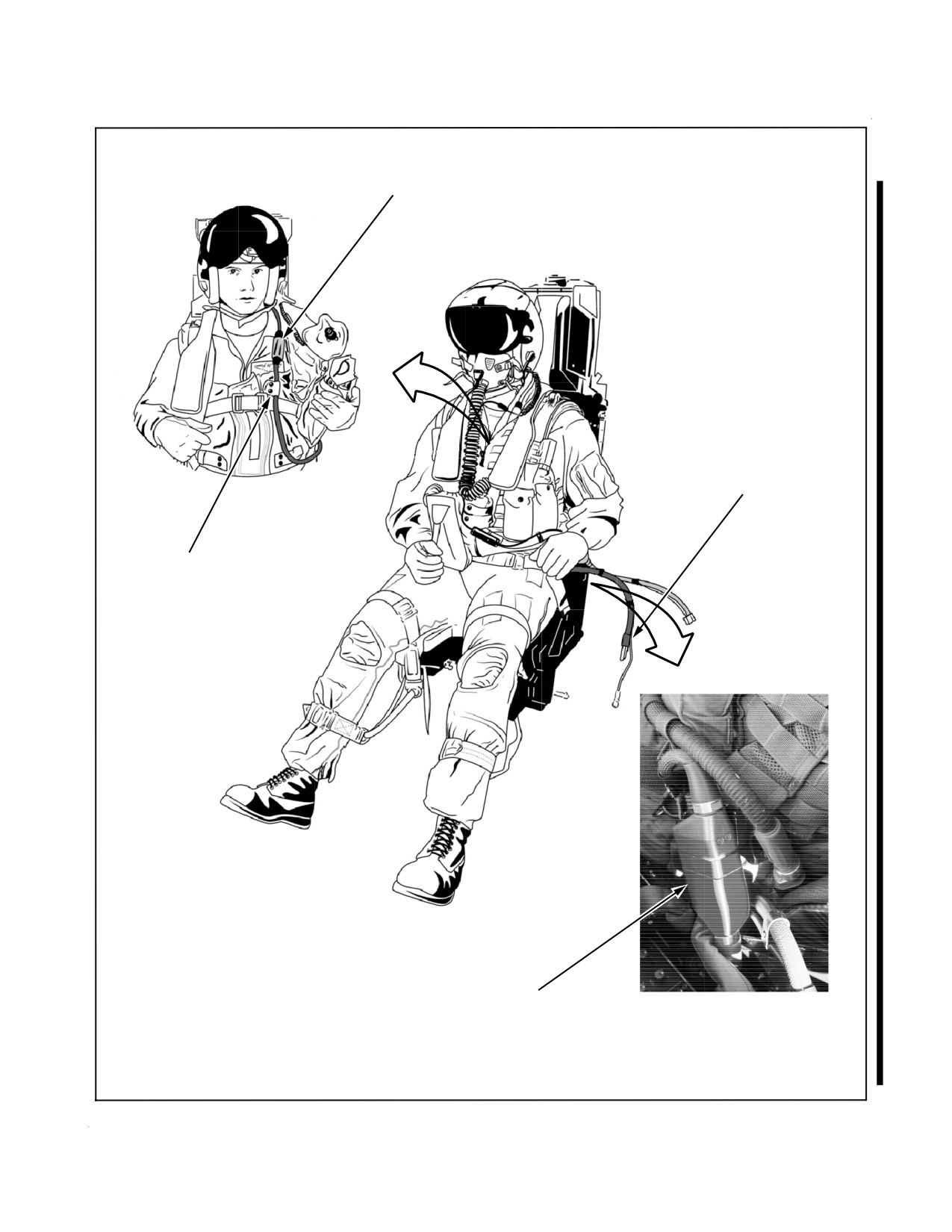
The Upper HVI is routed under the survival vest (if worn) through the JHMCS bundle flue on the
torso harness. The QDC is seated in a Quick Mounting Bracket (QMB) attached to the lower left hand
leg strap of the torso harness. See figure 2-51.
The JHMCS upper HVI (UHVI) must be properly routed through the
JHMCS bundle flue under the survival vest and the QDC secured in the
QMB to ensure that no entanglement exists with the oxygen hose.
Misrouting of the JHMCS UHVI may allow the QDC to rub against the
oxygen hose disconnect causing unintentional oxygen/communications
disconnect in-flight.
The QDC is the primary disconnect for ejection, and both normal and emergency ground egress. The
QDC can be manually disconnected for normal egress by pushing a button on top of the QDC and
separating the top half. During an ejection or emergency egress the QDC is disconnected via an aircraft
mounted lanyard when a force of 15 to 25 pounds is applied. When the QDC is not connected, the
aircraft QDC should be properly stowed in its receptacle. When the QDC is not properly connected and
the system is on, an HMD/AHMD advisory is generated.
The JHMCS QDC must be properly attached to the aircrew torso harness
quick mounting bracket to avoid possible death or severe injury during
ejection.
• Low voltage is present on the exposed QDC pins when the HMD/
AHMD OFF/BRT knob(s) are not in OFF. To prevent a minor
electrical shock from contact with exposed pins, ensure the HMD/
AHMD OFF/BRT knobs are OFF whenever the QDC is disconnected
and connected.
• To prevent damage to the QDC and aircraft components, ensure the
aircraft QDC is properly stowed in its receptacle when not mated to
the aircrews QDC.
NOTE
Ambient cockpit temperatures at or below
0°C (32°F) may cause
inadvertent HMD/AHMD advisories during preflight. Warming of the
QDC and quick mount bracket should remove the failure indication if
temperature is the cause.
The IRC is a back up disconnect which functions in the event of QDC failure. The IRC is attached
to the left aft console and requires a force of 80 to 120 pounds to disconnect.
I-2-186
ORIGINAL
A1-F18AC-NFM-000
Figure 2-51. JHMCS Upper HVI Routing
I-2-187
ORIGINAL
A1-F18AC-NFM-000
The HRC allows the cable to disconnect should the helmet be lost during ejection. The HRC
connects to the left shoulder harness and requires a force of 80 to 120 pounds to disconnect.
2.21.2 Electronics Unit (EU). The EU contains the main system CPU, LOS module, graphics
processor/display drive (one for each HMD), and low voltage power supply. The CPU controls system
bus interfacing, display list generation, BIT, and other system functions. The LOS module calculates
helmet LOS while the graphics processor/display drive processes the display list and generates the
helmet display. The MC interfaces with the EU via the MUX bus. It is located in the rear cockpit.
2.21.3 Cockpit Unit (CU). The CU contains the system high voltage power supply for helmet
displays. Both CUs are located in the aft crew station.
2.21.4 Magnetic Transmitter Unit (MTU). The MTU is used to generate a magnetic field used to
determine HMD/AHMD position/orientation by the HMD MRU receiving the magnetic field and then
sending the received signal to the EU. One MTU per cockpit is mounted on the canopy frame aft of the
pilot/WSO’s left shoulder.
The MTU is energized when the HMD/AHMD is turned on. Warm-up time for the MTU is 15 to 20
minutes. System accuracy may drift up to 0.5° if the HMD/AHMD is aligned before MTU warm-up
is completed. An additional 5 to 10 minutes should be added to the MTU warm-up time if operating
in extremely cold temperatures (e.g., -40°C).
NOTE
To maintain system accuracy, run initial HMD/AMHD alignment, or
an additional HMD/AHMD alignment, after system is warmed-up.
2.21.5 Seat Position Sensor (SPS). The SPS is a linear potentiometer which indicates ejection seat
height to the JHMCS. It is mounted to the aft right side of the ejection seat. There is one SPS for each
ejection seat. This seat position information allows the JHMCS to compensate for disruption of the
magnetic field in the cockpit as the metal in the seat changes position when the seat is raised or
lowered.
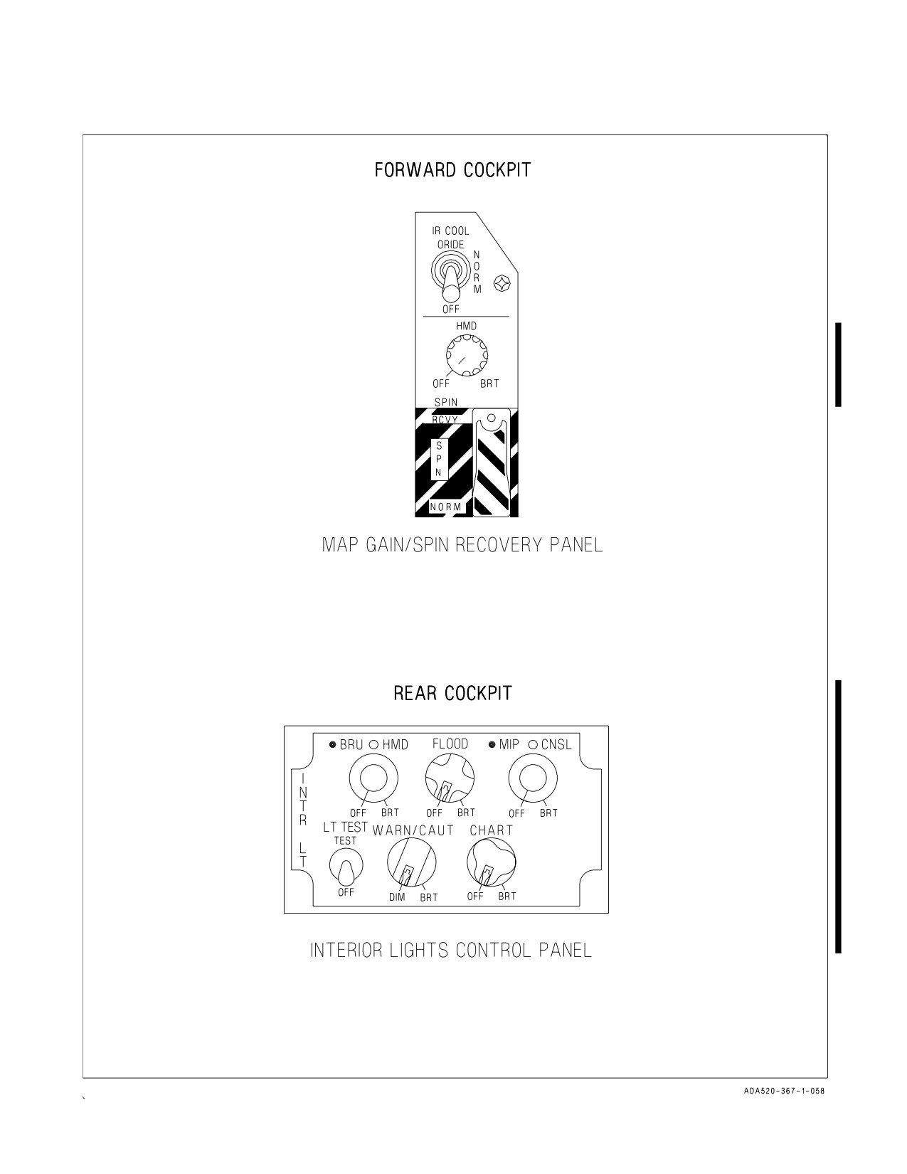
2.21.6 HMD/AHMD OFF/BRT Knobs. The front cockpit HMD OFF/BRT knob is located on the spin
recovery panel. This knob removes and applies power to the HMD, and adjusts HMD display
brightness.
A BRU/HMD OFF/BRT stacked knob, located on the aft cockpit INTR LT control panel, removes
and applies power to the BRU/AHMD, and adjusts BRU/AHMD display brightness. See figure 2-52.
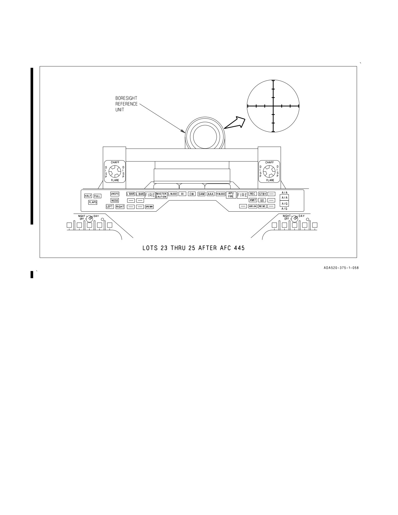
2.21.7 Boresight Reference Unit (BRU). The BRU is located on top of the rear cockpit instrument
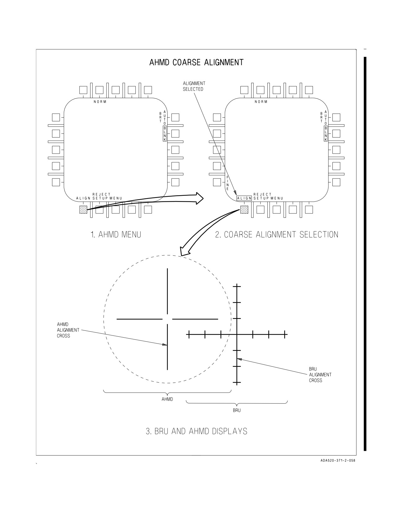
blast shield and dust cover. An alignment cross is provided inside the BRU to permit coarse and fine
alignment of the AHMD to the aircraft reference. See Figure 2-53.
2.21.8 HMD Video Recording. VTR selector switches located on the forward and aft CVRS Control
panels allow selection of HMD video recording.
2.21.9 Cautions/Advisories. When the BuNo in the Magnetic Compensation Data file does not
match the BuNo in the MC, or if the MC fails to download the initialization file to the EU, the MC sets
the SW CONFIG caution and displays a line through the HMD S/W configuration line on the
configuration display. An HMD/AHMD advisory is reported if the QDC is not properly secured to
I-2-188
ORIGINAL
A1-F18AC-NFM-000
Figure 2-52. HMD Controls
I-2-189
ORIGINAL
A1-F18AC-NFM-000
Figure 2-53. Boresight Reference Unit
Quick Mounting Bracket (QMB) or is disconnected, the HDU is not properly connected, or the coarse
alignment is invalid or has not been performed.
2.21.10 Configuration Check. When the JHMCS system is turned on, the MC provides the EU with
the aircraft make, model, and tail number.
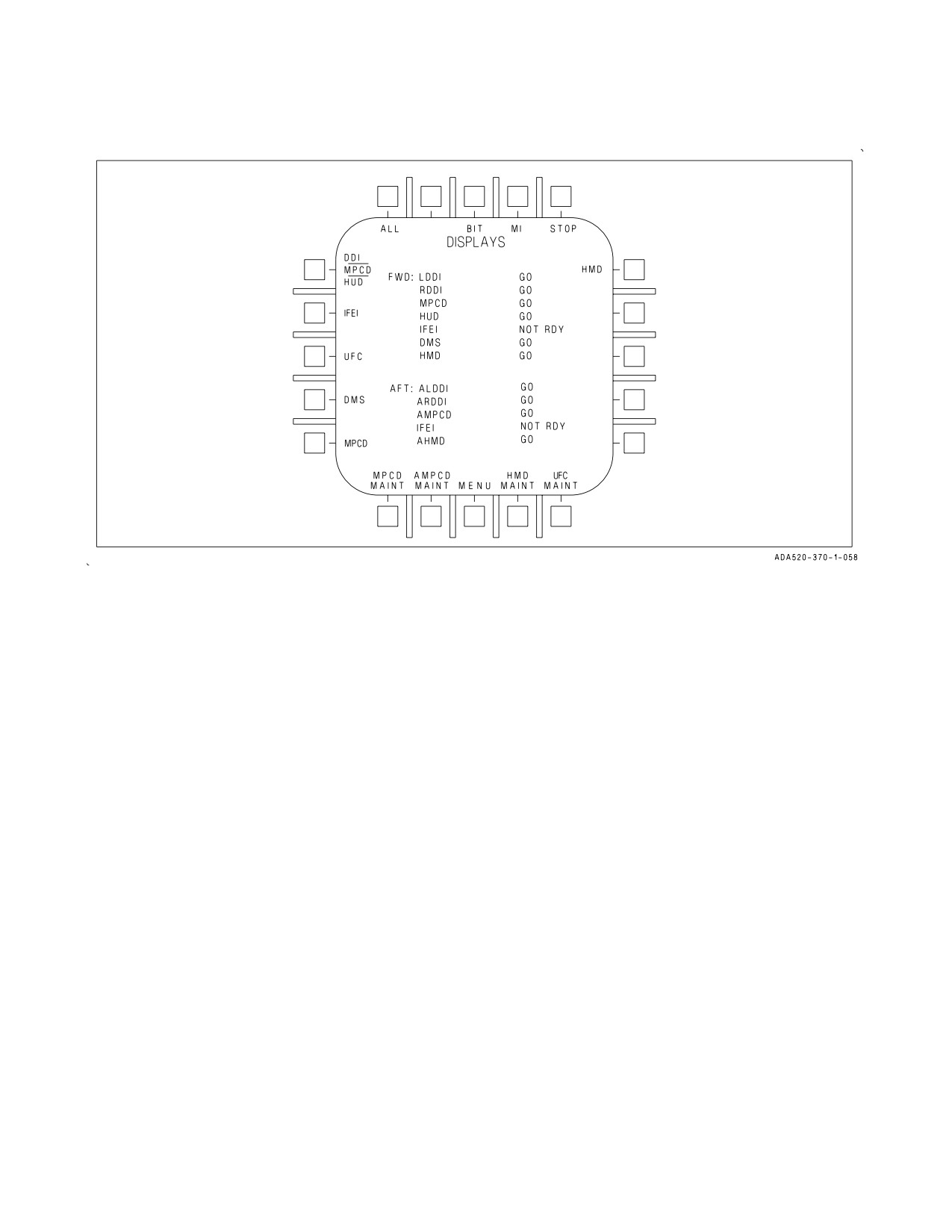
2.21.11 Built-In Test (BIT). The JHMCS BIT system includes automated start-up BIT (SBIT) and
initiated BIT (IBIT), and displays a BIT status message. See figure 2-54 for the DISPLAYS BIT
sublevel display.
2.21.11.1 Start-up BIT (SBIT). When the HMD system is turned on, SBIT starts automatically and
the internal software is loaded in the EU. SBIT cannot be stopped until it is completed. PBIT GO or
DEGD, as appropriate, is displayed when SBIT is completed.
2.21.11.2 Initiated BIT (IBIT). IBIT is performed when the HMD (PB 11) option is selected in either
cockpit on the DISPLAYS BIT sublevel display. ENTERING IBIT flashes on both HMDs, and an
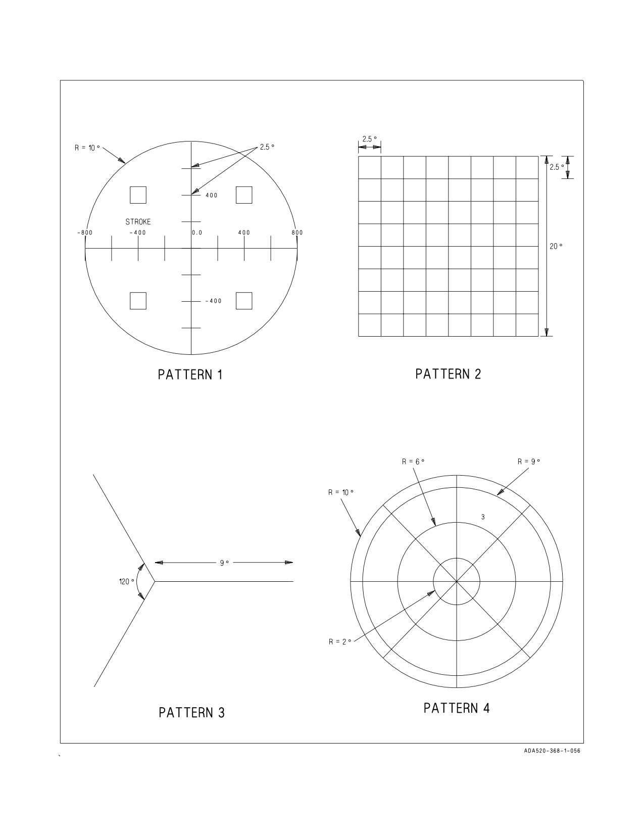
initiated BIT is performed on both helmets. When IBIT is complete, a series of four test patterns,
which are automatically changed each second, are displayed on the HMD/AHMD. See figure 2-55. The
test patterns are displayed until the STOP (PB 10) option is selected. If the ALL (PB 6) option is
selected, IBIT and HMD test patterns are performed.
I-2-190
ORIGINAL
A1-F18AC-NFM-000
Figure 2-54. Displays BIT Sublevel
2.21.11.3 Status Messages. Refer to the following for status messages and associated descriptions:
MESSAGE
STATUS
DESCRIPTION
MUX FAIL
Equipment ready discrete is high but the EU is
not communicating on either MUX bus to the
MC
NOT RDY
Equipment ready discrete is low and the EU is
not communicating on either MUX bus to the
MC
IN TEST
Initiated BIT in progress
RESTRT
Re-initiate BIT, EU did not respond to the
IBIT command or IBIT did not complete
within 30 seconds
DEGD
EU has detected a failure which degrades sys-
tem performance
OVRHT
EU has reported a component as overheated
DEGD+OVRHT
EU has detected a failure and EU has reported
a component as overheated
I-2-191
ORIGINAL
A1-F18AC-NFM-000
MESSAGE
STATUS
DESCRIPTION
GO
EU responded with no failures.
OP GO
EU has detected a failure which does not de-
grade system performance
PBIT GO
EU responded with no failures prior to per-
forming IBIT
2.21.11.4 BIT Recording On The Memory Unit. The MC records any failure or degrade reported by
the EU to the memory unit for fault reporting and isolation.
2.21.11.5 Overheat Condition. The system has the capability to detect an equipment overheat
condition. When an overheat condition is detected the system is automatically shut down to prevent
equipment damage.
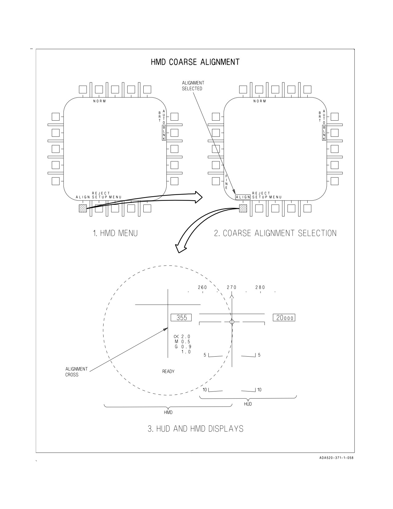
2.21.12 JHMCS Alignment. The JHMCS must be boresighted (aligned) with the aircraft prior to
every flight. Selecting the ALIGN (PB 20) option on the HMD format boxes ALIGN, selects coarse
alignment mode, and displays the FINE (PB 1) alignment option after the coarse align function is
complete. See figure 2-56.
The forward and aft helmets are aligned independently. The ALIGN option on the HMD format at
PB 20, when selected from the aft cockpit, initiates aft HMD align. When in aft coarse or fine align
mode the MC assigns the right AFT hand controller Designator Control (DC) switch to the HMD
format. Both forward and aft HMD alignments function the same with the exception that the aft
helmet is aligned to the BRU mounted on the aft main instrument panel.
2.21.12.1 Coarse Alignment. An alignment cross is displayed on the HUD/BRU and on the
HMD/AHMD. See figure 2-56. The pilot moves the HMD to superimpose the alignment cross on the
HMD over the alignment cross on the HUD. Once aligned, the cage/uncage switch is pressed and held
until ALIGN OK is displayed on the HMD. When coarse alignment is complete, fine alignment is
automatically selected. Fine alignment (PB 1) can also be manually selected.
The WSO moves the HMD to superimpose the alignment cross on the HMD over the alignment
cross on the BRU, figure 2-56, sheet 2. Once aligned, the undesignate switch on the right hand
controller is pressed and held until ALIGN OK is displayed on the HMD. When coarse alignment is
complete, fine alignment is automatically selected. Fine alignment (PB 1) can also be manually
selected.
I-2-192
ORIGINAL
A1-F18AC-NFM-000
Figure 2-55. HMD/AHMD Test Patterns
I-2-193
ORIGINAL
A1-F18AC-NFM-000
Figure 2-56. Coarse Alignment (Sheet 1 of 2)
I-2-194
ORIGINAL
A1-F18AC-NFM-000
Figure 2-56. Coarse Alignment (Sheet 2 of 2)
I-2-195
ORIGINAL
A1-F18AC-NFM-000
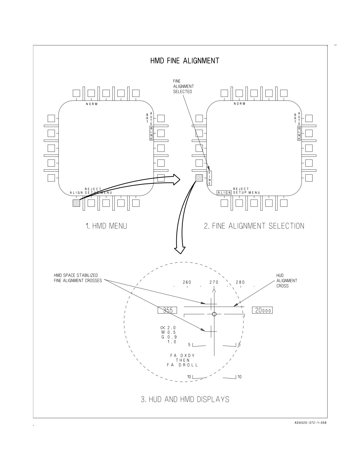
2.21.12.2 FINE Alignment. When the FINE (PB 1) option is boxed an alignment cross is displayed
in the HUD and two alignment crosses are displayed on the HMD in the vicinity of the HUD alignment
is indicated (FA DXDY), the pilot moves the TDC either left or right to align in azimuth, up or down
to align in elevation. The pilot presses and releases the cage/uncage switch when satisfied with the
quality of the azimuth and elevation alignment. This causes the display to toggle to roll alignment
mode. With the roll axis indicated (FA DROLL), TDC inputs to the left or right are used to rotate the
HMD alignment symbols to align with the HUD alignment cross. The pilot presses and releases the
cage/uncage switch when satisfied with the quality of the roll alignment. Pressing and releasing the
cage/uncage switch continues to toggle between these two modes until the pilot deselects FINE to
return to coarse alignment or exits alignment.
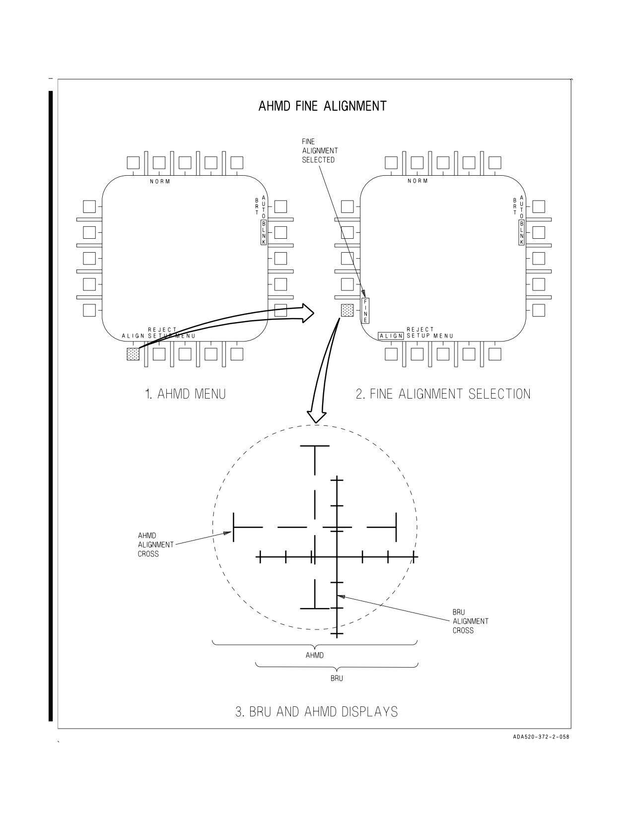
Upon entering fine alignment, automatically, or if commanded by the WSO selecting the FINE
option, the EU indicates which axis is being aligned. If the azimuth and elevation axis is indicated, the
WSO uses the DC to move the crosses up/down and left/right to align with the cross displayed on the
BRU, figure 2-57, sheet 2. When satisfied with the alignment, the WSO presses and releases the
undesignate switch on right hand controller at which time the EU automatically switches to roll
alignment. The WSO uses the DC to rotate the cross so that it aligns with the cross displayed on the
BRU. When satisfied with the quality of the alignment the WSO presses and releases undesignate
switch on right hand controller.
2.21.12.3 Alignment Exit. Alignment is exited whenever ALIGN is deselected (unboxed), an A/A
weapon is selected, MENU is selected, TDC priority is reassigned, ACM mode is selected, or the master
mode is changed. This removes the alignment cross from the HUD, removes the FINE option, unboxes
ALIGN, and returns the cage/uncage function to the previously assigned system.
I-2-196
ORIGINAL
A1-F18AC-NFM-000
Figure 2-57. Fine Alignment (Sheet 1 of 2)
I-2-197
ORIGINAL
A1-F18AC-NFM-000
Figure 2-57. Fine Alignment (Sheet 2 of 2)
I-2-198
ORIGINAL
A1-F18AC-NFM-000
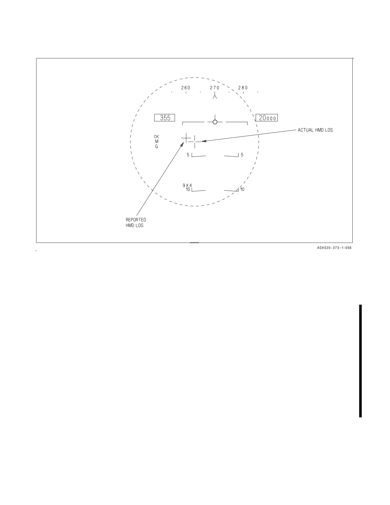
Figure 2-58. Alignment Verification
2.21.12.4 Alignment Verification. When the HMD is in normal mode a cross is displayed on the
HUD at the reported HMD LOS. See figure 2-58. If the reported HMD LOS is outside the HUD FOV,
the cross flashes at the HUD FOV limit.
2.21.13 HMD/AHMD Symbology
2.21.13.1 HUD Symbology Replicated on the HMD. The HMD layout essentially replicates the
HUD layout. Window locations, format, and occlusion level on the HMD are as identical to the HUD
locations, format, and occlusion level as practical.
2.21.13.2 HUD Symbology Not Replicated on the HMD. Some of the symbology on the HUD is
either not required on the HMD or would be disorienting if the information was presented. The
following paragraphs describe the items on the HUD which are not replicated on the HMD.
2.21.13.3 Aircraft Attitude Data. Some HUD data only provides the pilot usable information when
presented along the aircraft boresight. HMD data is not always presented along the aircraft boresight.
For this reason, the aircraft pitch ladder, horizon bar, water line indicator, and velocity vector are not
displayed on the HMD/AHMD.
I-2-199
ORIGINAL
A1-F18AC-NFM-000
The HMD/AHMD does not provide adequate attitude information and
should not be used as a primary flight instrument.
2.21.13.4 Ground Proximity Warning System. In addition to aircraft attitude data, the HMD/
AHMD does not replicate the Ground Proximity Warning System (GPWS) arrow. However, when the
GPWS is activated, ALTITUDE is displayed in the HARM window of the HMD/AHMD.
2.21.14 Navigation Master Mode. If present, the MC displays the A/A L&S with the TD box and its
associated TLL, or the A/G designation with the TD diamond and its associated TLL. However, if both
the A/A L&S and the A/G designation are present, only the A/A L&S TLL is displayed.
2.21.14.1 NAV Master Mode TDC Priority. When in NAV master mode, the TDC/DC can be
assigned priority to the HMD/AHMD by pressing the castle switch or DCA forward. This is indicated
by the display of an open aiming cross with a dot in the center. If TDC/DC priority is removed from
the HMD/AHMD, the dot is removed from the center of the aiming cross.
2.21.15 Mission Computer Failure. In the event of an MC1 failure, MC2
provides back-up
symbology for the HMD. MC2, at a minimum, provides airspeed, altitude, selected A/A weapon and
count, and the L&S and AIM-9 LOS. MC2 continues to slave the radar to the HMD LOS when in
HACQ mode. MC2 also continues to slave the AIM-9 to the HMD LOS when the AIM-9 is selected.
Activation of the uplook reticles are also maintained during back-up.
In the event of an MC2 failure, MC1 provides back-up symbology for the HMD. MC1, at a minimum,
provides airspeed, altitude, selected A/A weapon and count. Slaving of the radar and AIM-9 is
suspended.
2.21.16 Electronic Unit Failure. In the event of an EU failure which does not allow any symbology
to be displayed on the HMD, the MC provides the radar boresight symbol and AIM-9 FOV symbol on
the HUD. If the LOS is still valid, the MC continues to slave the radar or AIM-9 to the HMD LOS. If
the LOS is invalid, the MC reverts to the current no-helmet mechanization for slaving weapons,
sensors, and HOTAS.
2.21.17 Helmet Tracker Failure. If the EU reports that the helmet tracker is failed, or the helmet
LOS is no longer valid, the MC discontinues slaving sensors and weapons to the HMD LOS. The MC
replaces aircraft boresight for the helmet LOS to the radar and AIM-9. Additionally, the MC removes
any item from the HMD which is tied to the HMD LOS. The radar boresight and AIM-9 FOV symbol
are restored to the HUD. The MC also restores VACQ mode and the HOTAS function to access the
VACQ function. The MC continues to display information on the HMD which is not tied to the HMD
LOS.
2.21.18 Helmet Not Installed. When the MC determines that the HMD is not on, or the EU is not
responding to the MC via the mux bus, the MC reverts to the current no-helmet mechanization for
slaving weapons, sensors, HOTAS, and HUD display.
I-2-200
ORIGINAL
A1-F18AC-NFM-000
2.22 FIGHTER/ATTACK/TRAINER/RECCE (F/A-18B/D)
2.22.1 F/A-18B/D Aircraft 161354 THRU 163778. These aircraft are tandem configured (see figure
2-59) for performing the secondary role of a trainer without compromising the primary role of
Fighter/Attack. Using the front cockpit controls, the F/A-18B/D avionics provide equivalent naviga-
tion and weapon system capabilities as those available in the single-place F/A-18A/C. The rear cockpit
controls duplicate most front cockpit controls for navigation and weapon system control. However,
weapons cannot be launched/released/fired from the rear cockpit. The rear cockpit and the differences
relative to the single-seat version are discussed in the following paragraphs.
2.22.2 F/A-18D Aircraft 163986 AND UP.
2.22.2.1 Night Attack Configuration. These aircraft are tandem configured with a primary role of
performing the night attack mission. The rear cockpits of these aircraft have the stick and throttles
removed. The rudder pedals are fixed and disconnected from the rudder, brakes, and nosewheel
steering. Two hand controllers have been added and the rear cockpit controls and displays operate
independent of the front cockpit. Instruments and lighting are NVG compatible.
2.22.2.2 Training Configuration. Night attack aircraft may be reconfigured to a trainer aircraft by
removing the two hand controllers, adding throttles, stick, and connecting the rudder pedals. Rear
cockpit controls and displays remain independent of the front cockpit.
2.22.2.3 RECCE Configuration. The F/A-18D aircraft, when retrofitted with the reconnaissance
equipment, is designated as the F/A-18D(RC) (Reconnaissance Capable). It provides high resolution,
long range standoff and overflight reconnaissance capabilities, for day or night, for all weather and
under the weather missions. Electro-optical (EO), infrared (IR), and synthetic aperture radar (SAR)
sensors gather image data. Image data is recorded onto two onboard recorders and is available for
downlink to ground stations for subsequent dissemination and exploitation. The aircraft is converted
by installing the Advanced Tactical Reconnaissance System (ATARS) sensor suite into the nose bay
in place of the 20 mm gun. A data link pod can be loaded on the centerline to allow for the downlink
of imagery data. Refer to NTRP 3-22.2-FA18A-D NATIP for ATARS description and operating
procedures.
2.22.3 Aircraft Dimensions. The approximate dimensions of the aircraft are as follows:
Span (Wings Spread) with missiles
40 feet 5 inches
Span (Wings Spread) without missiles
37 feet 6 inches
Span (Wings Folded)
27 feet 6 inches
Length
56 feet
Height (To Top of Fins)
15 feet 3 inches
Height (To Top of Closed Canopy)
11 feet 3 inches
2.22.4 Aircraft Gross Weight. Basic aircraft gross weight varies from 24,000 to 25,000 pounds. Refer
to applicable DD 365F for accurate aircraft weight.
I-2-201
ORIGINAL
A1-F18AC-NFM-000
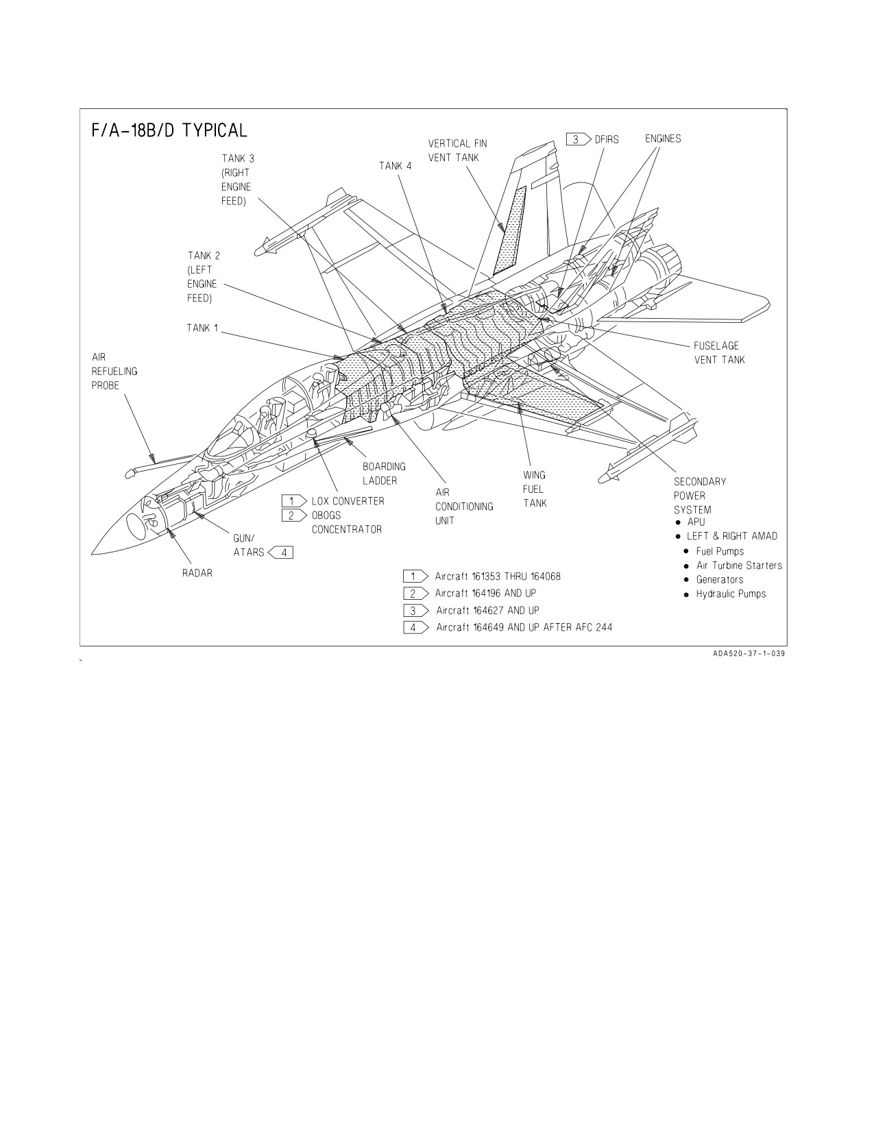
Figure 2-59. General Arrangement (F/A-18B/D)
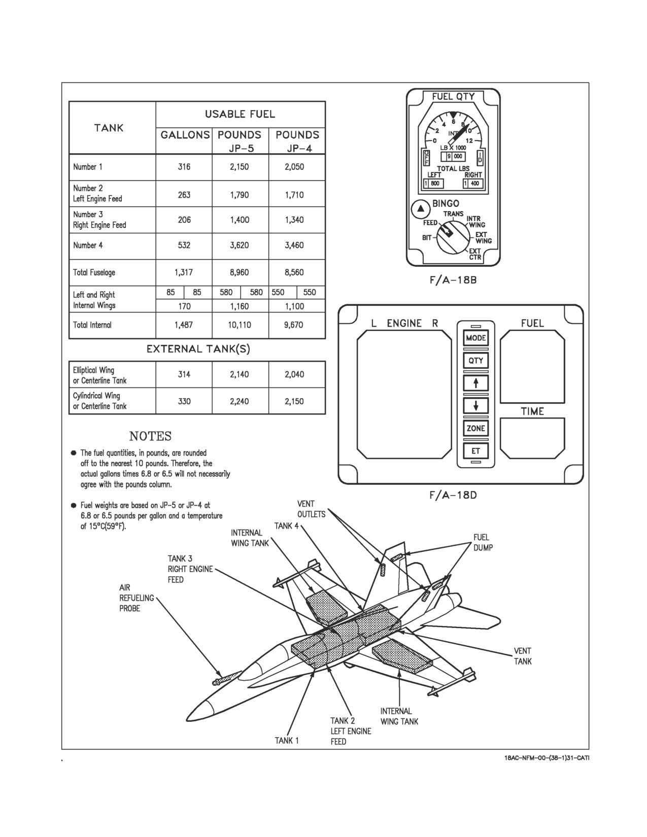
2.22.5 Fuel Quantity. To make room for the rear cockpit, the fuel capacity in tank 1 is reduced to
316 gallons (2,150 pounds JP-5 or 2,050 pounds JP-4). See figure 2-60.
2.22.6 Canopy System. The canopy system is similar to the F/A-18A/C aircraft except that an
additional internal canopy jettison handle is installed in the rear cockpit. Note that the rear cockpit
does not have an internal canopy switch or an internal manual canopy handcrank, and therefore, the
canopy must be opened from the forward cockpit (or externally) unless it is jettisoned. To manually
open the canopy using the internal manual handcrank, 224 counterclockwise manual crank turns are
required. To manually open the canopy externally using a drivesocket, 112 counterclockwise manual
crank turns are required.
2.22.7 Ejection Seat System. Ejection seats are installed in both cockpits. In addition, a sequencing
system is installed to allow dual ejection initiated from either cockpit or single (aft) seat ejection
initiated from the rear cockpit. A command selector valve is installed in the rear cockpit to control
whether ejection from the rear cockpit is dual or single.
I-2-202
ORIGINAL
A1-F18AC-NFM-000
Figure 2-60. Fuel Quantity (F/A-18B/D)
I-2-203
ORIGINAL
A1-F18AC-NFM-000
2.22.7.1 CK SEAT Caution (F/A-18D). The CK SEAT caution light is located on the caution light
panel, and repeats the DDI CHECK SEAT caution display. The caution is displayed when the right
throttle is at MIL or above, weight is on wheels, and the front cockpit ejection seat is not armed with
the rear cockpit NORM/SOLO switch set to SOLO or either ejection seat is not armed with the
NORM/SOLO switch set to NORM.
2.22.8 Intercom Controls. Intercom controls consist of two cockpit volume control knobs and an
intercom function selector switch.
2.22.8.1 Volume Control Knobs. The volume control knob on the intercommunication panel in the
front cockpit is labeled ICS. This knob varies the audio volume to the pilot’s headset. The volume
control knob in the rear cockpit is on the volume control panel on the left console. This knob is labeled
ICS and varies the audio volume to the rear cockpit headset.
2.22.8.2 Intercom Function Selector Switch. A three-position toggle switch, with positions marked
RADIO ORIDE (override), HOT MIC, and COLD MIC is on the antenna selector panel in the front
cockpit and on the volume control panel in the rear cockpit. The functions of the switch positions are
as follows:
RADIO ORIDE
Allows intercom audio to be louder than radio audio in the cockpit where
selected.
HOT MIC
Enables cockpit microphone for intercom transmission in the cockpit
where selected.
COLD MIC
Disables cockpit microphone for intercom transmission in the cockpit
where selected.
2.22.9 Rear Cockpit. The rear cockpit contains the equipment differences as described in the
following paragraphs. Refer to Rear Cockpit, Foldout section for rear cockpit arrangements.
2.22.9.1 Fire Warning Lights. The left and right engine and APU fire warning lights are advisory
only. They do not arm or discharge the extinguishing system or shut down the engines or APU.
2.22.9.2 Fuel Quantity Indicator (F/A-18B). The fuel quantity indicator has two counters. One
indicates total fuel quantity and the other indicates internal fuel only.
I-2-204
ORIGINAL
A1-F18AC-NFM-000
2.22.9.3 Command Selector Valve. A command selector valve is provided on the right vertical panel
to select the desired ejection sequence to be initiated from the rear cockpit, or provide for single
ejection for solo flight. Positioning is accomplished by pulling out while turning to the desired position.
Solo position requires use of a collar. To release from aft initiate, pull then turn clockwise.
NORM (vertical)
Single rear seat ejection when initiated from the rear cockpit. Dual ejec-
tion (rear seat first) when initiated from the front cockpit.
AFT INITIATE
Dual ejection (rear seat first) when initiated from either seat.
(horizontal)
SOLO 45° CCW
Front seat ejection only when initiated from front seat. Front seat ejec-
tion is immediate. Rear seat ejection only when initiated from the rear
seat. Rear seat ejection is immediate.
• SOLO mode shall NOT be selected when both seats are occupied. If
SOLO mode is selected when both seats are occupied, simultaneous
ejection initiation may result in a collision between seats.
• SOLO mode shall be selected when the aircraft is being flown solo.
Alternate selection when flying solo results in ejection of unoccupied
seat and possible collision with occupied seat.
• Ejection system component failure can disable the command ejection
function in an F/A-18B/D. With either AFT INITIATE or NORM
selected, each crewmember should initiate ejection independently.
When selecting NORM or SOLO from AFT INITIATE, the handle must
be pulled before rotation or damage to valve may result.
2.22.9.4 Seat Caution Mode Switch (F/A-18D). The seat caution mode switch is located in the rear
cockpit above the command selector valve. The switch position changes the operation of the CK SEAT
caution for solo or dual flight.
NORM
CK SEAT caution is activated by either seat remaining safed. Switch is spring
loaded to this position.
SOLO
CK SEAT caution is activated only by the front seat remaining safed. Switch must
be pinned to remain in this position.
2.22.9.5 Internal Canopy Jettison Handle. A black and yellow striped canopy jettison handle is
under the left canopy sill just aft of the volume control panel. Pressing an unlock button on the forward
edge of the handle and then pulling the handle up fires the canopy jettison system.
I-2-205
ORIGINAL
A1-F18AC-NFM-000
2.22.9.6 Interior Lighting. Except for the utility floodlight, all controls for the interior lights are on
the interior lights panel on the right console. There is no flood switch in the rear cockpit. The switch
logic for dimming and brightening the warning/caution lights is the same as the front cockpit but
without the flood switch.
2.22.9.7 Lights Test Switch. A lights test switch, labeled LT TEST, is provided to test the
warning/caution/ advisory lights and is independent of the front cockpit. The switch only operates with
ac power on the aircraft.
TEST
Serviceable warning/caution/advisory lights come on.
OFF
The switch is spring loaded off.
2.22.9.8 Equipment Status Displays. In the aft cockpit, BIT, cautions and advisories are normally
displayed on the left DDI. If the left DDI is unavailable, they are displayed on the right DDI.
On aircraft 163986 AND UP, if both rear cockpit DDIs are unavailable, the aft MPCD/AMPCD is
used to display cautions and advisories. Cautions and advisories are displayed at the bottom of the
display of the MPCD/AMPCD.
2.22.9.9 Master Caution Light. A yellow MASTER CAUTION light, on the upper instrument panel
comes on whenever the MASTER CAUTION light in the forward cockpit comes on. The aft MASTER
CAUTION light goes out whenever the front cockpit MASTER CAUTION is reset.
2.22.9.10 Landing Gear UNSFE Light. The red UNSFE light illuminates to indicate the landing gear
is in transit and will also stay on if the gear does not match the handle position. The light does not
indicate planing link failure, provide wheel warning, or air data computer failure indication.
2.22.9.11 Landing Gear Position Lights. There are three green landing gear position lights marked
NOSE, LEFT, and RIGHT above the landing gear control handle. The lights come on when their
respective gear is down and locked. The LEFT and RIGHT lights flash when their respective gear is
down and locked but a related planing link is not locked.
2.22.9.12 Emergency Brake Handle. The emergency brake handle, on the left vertical panel, only
provides emergency brakes. It has no parking brake function. To actuate the emergency brake system
in either trainer or night attack aircraft configuration, pull out on the handle until it locks in the
detent. The handle must be fully stowed to ensure anti-skid is available in either configuration.
2.22.9.13 Emergency Landing Gear Handle. The emergency landing gear handle, on the left vertical
panel, provides emergency landing gear extension from the rear cockpit. Emergency extension is
accomplished by pulling out on the handle until it locks in the detent. There are no provisions for
normal landing gear extension.
2.22.9.14 Digital Display Indicators. On aircraft 161354 THRU 163778 the corresponding left and
right DDI in each cockpit presents the same information. The center DDI displays the same
information as the HI, except for the moving map display. Systems and presentations controlled by
DDI/HI pushbuttons respond to the last action taken in either cockpit.
On aircraft 163986 AND UP the rear cockpit left and right DDI are independent of the front cockpit
DDIs. However, the operation of both DDIs is identical to that of the front cockpit DDIs.
I-2-206
ORIGINAL
A1-F18AC-NFM-000
2.22.9.15 MPCD/AMPCD (AIRCRAFT 163986 AND UP). The rear cockpit also contains an MPCD/
AMPCD located between the left and right DDIs and is independent of the front cockpit MPCD/
AMPCD. However, MPCD/AMPCD operation is identical to that of the front cockpit MPCD/
AMPCD.
2.22.9.16 Head-Up Display. The rear cockpit does not contain a HUD, but HUD symbology can be
selected for display from the MENU on either the left or right DDI (F/A-18B/D aircraft 161354 THRU
163778). This also selects HUD symbology on the same DDI in the front cockpit. On F/A-18D aircraft
163986 AND UP, HUD symbology can appear on either DDI independent of the front cockpit. On
F/A-18D aircraft 163986 AND UP, the HUD display is the only display not replaced by the SPIN
recovery display when the SPIN recovery switch is actuated.
2.22.9.17 Display Select Control (AIRCRAFT 161704 THRU 163778). This control is a toggle
switch with positions of HUD and NORM. Placing the switch to HUD causes the HUD display to
appear on the left DDI and removes and/or prevents caution and advisory displays on the left DDI.
With the switch set to NORM, the DDI operates normally by using the pushbuttons.
2.22.9.18 Upfront Control. The upfront control in each cockpit presents the same information. The
associated UFC systems respond to the last selection made in either cockpit.
2.22.9.19 Attitude Reference Indicator. The attitude reference indicator (ARI) in the rear cockpit
does not display azimuth and elevation steering during ILS operations.
2.22.9.20 Master Mode Buttons. The associated systems controlled by the A/A and A/G master
mode buttons respond to the last selection made in either cockpit.
2.22.9.21 Control Stick (AIRCRAFT 161354 THRU 163778 and trainer configured 163986 AND
UP). The control stick switches respond to the last crew member action taken from either cockpit. The
trigger switch and the weapon release button are non-functional.
2.22.9.21.1 A/A Weapon Select Switch. The rear cockpit weapon select switch is active only in the
A/A master mode. In the rear cockpit, the A/A master mode must be selected with A/A master mode
button.
2.22.9.22 Throttles (AIRCRAFT 161354 THRU 163778 and trainer configured 163986 AND UP).
The throttles provide engine control from IDLE through MAX. The throttles cannot be placed in OFF
from the rear seat. Systems controlled by throttle switches respond to the last crewmember action
taken from either cockpit. The ATC engage/disengage switch is non-functional, the flare/chaff switch
is not installed, and the speedbrake switch is momentary action.
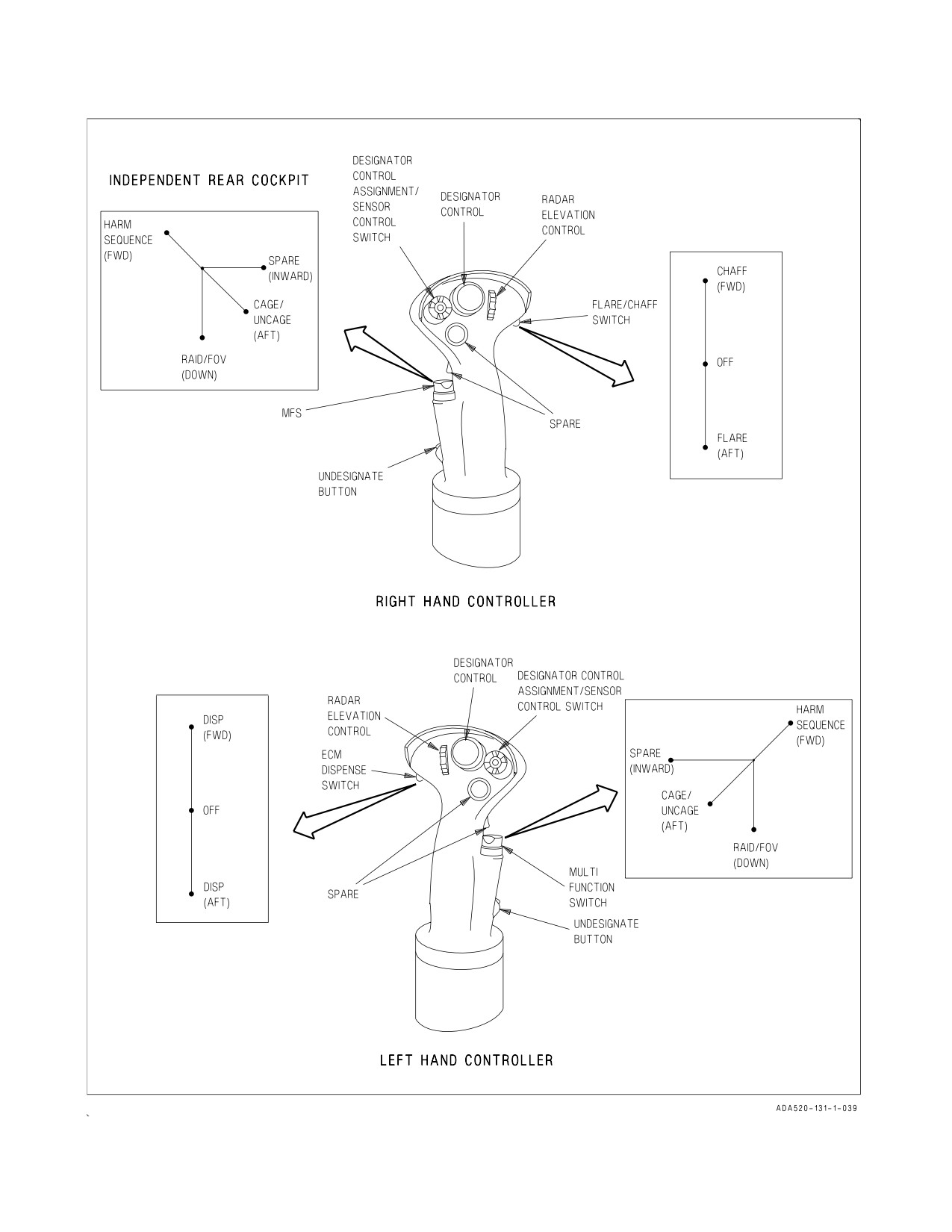
2.22.9.23 Hand Controllers (F/A-18D night attack configured AIRCRAFT 163986 AND UP). The
right and left hand controllers (figure 2-61) located on the forward inboard section of the right and left
rear cockpit consoles, are used to provide sensor/display control.
2.22.9.23.1 Designator Control Assignment (DCA)/Sensor Control. Assignment switches are used
to assign Designator Control to the DDI/MPCD/AMPCD. In the aft cockpit, Designator Control (DC)
assignment to the MPCD/AMPCD forces the opposite DC to be assigned to its corresponding DDI.
The DCA switches function independent of the aircraft master mode. In RECCE configured aircraft,
the sensor control switch (Aft position) commands manual record, opens/closes manual event marks,
opens /closes review marks in video review mode, and freezes/scrolls imagery in video review mode.
I-2-207
ORIGINAL
A1-F18AC-NFM-000
Figure 2-61. Hand Controllers (F/A-18D Aircraft 163986 AND UP)
I-2-208
ORIGINAL
A1-F18AC-NFM-000
2.22.9.23.2 Multifunction Switch (MFS). The switch is used for HARM sequence (forward),
cage/uncage (aft), and raid/FOV (down). Refer to NTRP 3-22.4-FA18A-D and NTRP 3-22.2-FA18A-D
for detailed operation.
2.22.9.23.3 TDC/DC Switch. In the aft cockpit, Designator Control (DC) priority is assigned to the
DDI/MPCD/AMPCD. The MC initially assigns hand controller DC priority to left and right DDIs. The
left DC (left hand controller) provides control of the format selected on either the left DDI or the
MPCD/AMPCD. The right DC controller provides control of the format selected on either the right
DDI or the MPCD/AMPCD. Right or left designator control of a format is based on the DC being
assigned to the DDI/MPCD/AMPCD displaying a DC-compatible format, plus other logic as
appropriate. MC inhibits right/left hand controller DC of the HUD format in the night attack aft
cockpit.
Only one hand controller DC may be used to designate at a time, however both may be used
simultaneously. TDC/DCs may be assigned to the same format in the front and rear cockpits; however,
only one TDC/DC is processed at a time. When forward and aft TDC/DCs are assigned to the same
format, both TDC/DCs must be within the deadband before a TDC/DC can become active. If a second
TDC/DC is pressed out of deadband while the other TDC/DC is active, the second TDC/DC input is
ignored. This also applies to the slew function.
The DC assignment diamond is flashed in the upper right corner of a format when a TDC/DC is
assigned to the same format in both the forward and aft cockpits, and the MC is inhibiting one or both
of the TDC/DCs from acting on the format because both TDC/DCs are pressed concurrently. SLEW
is flashed if the above conditions are met for forward and aft DCs assigned to the same slew function.
In RECCE configured aircraft, the DC slews the MAG marker and roam magnified/unmagnified
imagery, and expands/unexpands imagery.
2.22.9.23.4 Radar Elevation Control. The Radar Elevation Control (REC) switch is read by the
DDI, provided to the MC, and passed to the radar as a radar elevation rate command. The radar
processes the command and moves the radar antenna accordingly. The MC processes the hand
controller RECs identically to the REC on the throttle in the forward cockpit. The MC processes only
one REC at a time. All RECs must be within deadband before a REC can become active. If a second
REC is selected while another REC is active, the second input is ignored.
2.22.9.23.5 Undesignate Button. The undesignate button is read by a DDI and passed to the MC.
The front cockpit undesignate button is read by the FCS and passed to the MC. The switches function
identically except for HI-NWS situation with WOW. Since the front undesignate button is read and
processed directly by the FCS, special case MC processing is not required.
2.22.9.23.6 Chaff/Flare/ECM Switch. The chaff/flare switch is wired directly to the ALE-39/
ALE-47 chaff/flare set. Moving the right handcontroller chaff/flare switch forward causes a single chaff
bundle to be dispensed. Moving the switch aft dispenses a single flare. Moving the left handcontroller
ECM switch performs the countermeasures program dispense function in parallel with the dispense
switches on the grab handle and the canopy sill DISP switch.
2.22.9.23.7 Push-to-Talk Foot Pedal Switches (F/A-18D night attack configured AIRCRAFT
163986 AND UP). Comm 1 transmission is initiated by pressing the left foot pedal switch, Comm 2
transmission is initiated by pressing the right foot pedal switch. With AFC 270, the left foot pedal
switch controls Comm 1 and MIDS A, and the right foot pedal switch controls Comm 2 and MIDS B.
I-2-209
ORIGINAL
A1-F18AC-NFM-000
2.22.9.24 RECCE Control Panel. ATARS power is controlled via the ATARS ON/OFF switch.
Power for the data link pod is controlled by the Center-Line Pod (CLP) rotary knob which has the
following three positions:
OFF
The DL portion of the pod is not powered.
STBY
Power is applied to the pod. DL transmissions are attenuated.
OPR
Power is applied to pod. Full DL transmission is available.
2.22.9.25 Canopy Sill DISP Switch. On Aircraft 163986 AND UP, two additional chaff/flare
switches are located on either side of the grab handle. Each is a three-position momentary switch
spring loaded to the center position and is designed to be thumb actuated while grasping the hand hold
and looking aft. Each upward actuation of either switch commands a single chaff bundle to be
dispensed. Each downward actuation of either switch commands a single flare to be dispensed.
2.22.9.26 ALE-39 Programmer. The ALE-39 programmer is installed on the rear cockpit left
console. The programmer controls are normally preset by the ground crew. Refer to AN/ALE-39/
ALE-47 Countermeasures Dispensing Set in NTRP 3-22.2-FA18A-D for description of the program-
mer control functions.
2.22.9.27 PTT Comm Select Panel. On MIDS equipped night attack aircraft, the PTT COMM
select panel is on the left console forward of the volume control panel. Three comm options are
available: two Comm channels, two MIDS channels, or one Comm and one MIDS channel. The switch
position determines push-to-talk foot pedal switch comm or MIDS operation.
2.22.9.28 Volume Control Panel. The volume controls (TCN, ICS, ECM, WPN, RWR, and after
AFC 270 , VOX, MIDS A and B), on the volume control panel, provide the same functions for the rear
cockpit headset as the corresponding volume controls on the front cockpit intercommunication panel
provide for the front cockpit headset. The VOX control incorporates the hot and cold microphone
switch functions that enables/disables cockpit microphone for intercom transmission in the cockpit
where selected. The SAM volume control on aircraft 161354 THRU 161357 AND 161360 or the AUX
volume control on aircraft 161704 AND UP are not used at the present time.
2.22.9.29 Azimuth Indicator. The azimuth indicator presents the same information as the front
cockpit azimuth indicator.
2.22.9.30 Emergency Jettison Button. The emergency jettison button is at the top of the
instrument panel outboard of the left FIRE light. The BIT advisory and an SMS BIT status of DGD
is the only enunciated indication of a stuck emergency jettison button.
2.22.9.31 Nuclear Consent Control Panel (Aircraft 163986 THRU 164738). The nuclear consent
control panel is located on the right console forward of the right hand controller. The panel contains
the PREARM CONSENT switch and the RELEASE CONSENT switch. See A1-F18AC-TAC-series
or A1-F18AE-TAC series for switch function description.
I-2-210
ORIGINAL
A1-F18AC-NFM-000
CHAPTER 3
Service and Handling
3.1 SERVICING
Refer to A1-F18AC-NFM-600.
I-3-1
(Reverse Blank)
ORIGINAL
A1-F18AC-NFM-000
CHAPTER 4
Operating Limitations
4.1 AIRCRAFT
4.1.1 Engine Limitations.
4.1.1.1
RPM.
Compressor (N2)
1. The maximum rpm is 102%.
2. Ground idle is:
F404-GE-400
F404-GE-402
61 to 72%
63 to 70%
3. Flight idle is 68 to 73%.
4. Maximum fluctuation at stabilized power is ±1%.
Fan (N1)
5. The maximum rpm is:
F404-GE-400
F404-GE-402
106%
108%
6. Maximum fluctuation at stabilized power is ±0.5%.
4.1.1.2
EGT.
1. Maximum steady-state is:
F404-GE-400
F404-GE-402
MIL
830°C
880°C
MAX
830°C
920°C
2. Maximum transient is:
F404-GE-400
F404-GE-402
Start
815°C
815°C
MIL
852°C
902°C
MAX
852°C
942°C
3. Maximum fluctuation at stabilized power is ±8°C.
4.1.1.3
Nozzles.
Maximum fluctuation is ±3%.
I-4-1
ORIGINAL
A1-F18AC-NFM-000
4.1.1.4
Oil Pressure.
NOTE
For fuel temperatures in excess of 38°C, the lower oil pressure limit
can decrease as much as 10 psi.
Ground
1. For ambient temperatures above -18°C (0°F), oil pressure must peak below 180 psi and start to
decrease within 30 seconds after reaching idle rpm and continue to decrease to steady state limits.
2. For ambient temperatures below -18°C (0°F), maximum oil pressure 2.5 minutes after start is 180
psi.
3. Steady state ground idle oil pressure (warm oil) limit is 45 to 110 psi.
Inflight
During steady state flight, oil pressure limits are as follows:
IDLE
55 to 110 psi
MIL
95 to 180 psi
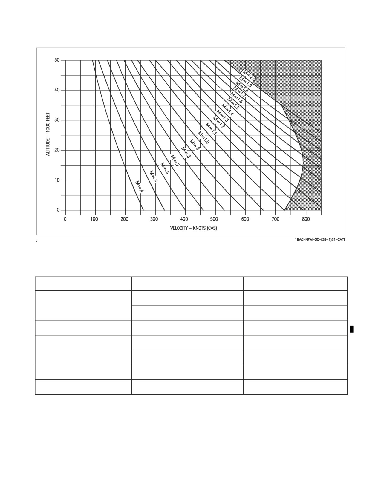
4.1.2 Airspeed Limitations. The approximate maximum permissible airspeeds in smooth or mod-
erately turbulent air with the arresting hook and landing gear retracted, flaps in AUTO, and any
combination of air-to-air missiles are shown in figure 4-1. For exact airspeed limitations, refer to the
NTRP 3-22.4-FA18A-D NATIP, Store Carriage and Release Limitations Chapter. Refer to Systems
Limitations, figure 4-2, for additional airspeed limitations.
I-4-2
ORIGINAL
A1-F18AC-NFM-000
Figure 4-1. Airspeed Limitations
Subsystem
Position/Action
Airspeed/Groundspeed
Extension/Retraction
300 Knots
REFUELING PROBE
Extended
400 Knots
LANDING GEAR
Extension/Retraction/Extended
250 Knots
Nose Gear
190 Knots groundspeed
TIRES
Main gear
210 Knots groundspeed
TRAILING EDGE FLAPS HALF/FULL
250 Knots
CANOPY
Open
60 Knots
Figure 4-2. System Limitations
4.1.3 Prohibited Maneuvers.
4.1.3.1
General.
1. Takeoff with any CAS axis failed.
I-4-3
ORIGINAL
A1-F18AC-NFM-000
2. Zero airspeed tailslide.
3. Intentional departures/spins.
4. Flight in lightning or thunderstorms.
5. Flight with yaw rate warning tone.
6. Full or partial lateral stick and/or rudder pedal input over 360° yaw/roll.
7. Dive over 45° with less than 1,900 pounds fuel.
8. Zero g except transient.
9. Negative g for more than 5 seconds for aircraft 161353 THRU 161924 BEFORE AFC 053 (10
seconds for other aircraft).
10. Negative g
a. Roll maneuvers over 180° bank angle change.
b. Over 1/2 lateral stick above 635 KCAS below 20,000 feet MSL.
11. For aircraft 161353 THRU 161924 BEFORE AFC 018 and 053, less than 1 minute between
negative g maneuvers (10 seconds for all other aircraft).
12. For aircraft 161353 THRU 161924, afterburner operation at less than +0.1 g.
13. Pulling any FCS circuit breaker in flight except as directed in NATOPS.
14. Selection of GAIN ORIDE above 350 knots/Mach 1.0 or above 10° AOA.
15. Inflight selection of RCVY on the spin recovery switch except for actual spin recovery or as
directed in NATOPS.
16. Flight without LAU-7A wing tip launcher rails (with power supply and nitrogen bottle installed).
17. Takeoff or flared landing with 90° crosswind component over 30 knots. Normal or section
landing with 90° crosswind component over 15 knots.
18. Section takeoff with any of the following conditions:
a. Crosswind over 15 knots.
b. Asymmetric load over 9,000 foot-pounds not including missiles or pods on stations 1 or 9.
c. Dissimilar loading except VERS, MERS, TERS, pylons, FLIR, LDT, fuselage AIM-7s/
AIM-120s or wing tip mounted stores.
19. Landing with autopilot engaged except for Mode 1 ACL.
20. Use of RALT hold below 500 feet AGL.
I-4-4
ORIGINAL
A1-F18AC-NFM-000
21. Negative 1g above 700 KCAS and below 10,000 feet MSL.
22. Supersonic flight
a. At or above Mach 1.4
(1) Roll maneuvers exceeding
(a) 2 g load factor, or
(b) 1/2 lateral stick, or
(c)
180° bank angle
(2) Throttles during dive pull
(a) not over MIL
b. Single seat
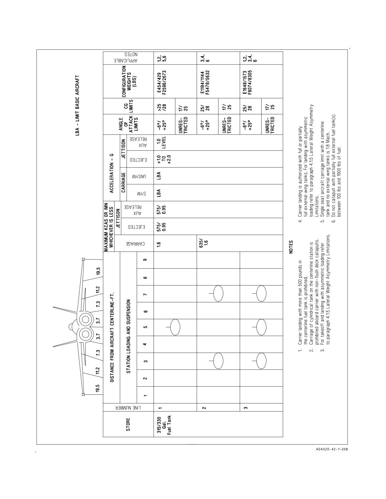
(1) Above Mach 1.8 with a centerline tank and no external wing tanks
(2) Above Mach 1.6/635 KCAS with an external wing tank
c. Two seat
(1) Above Mach 1.8 without external tanks
(2) Above Mach 1.6 with a centerline tank and no external tanks
(3) Above Mach 1.6/635 KCAS with an external wing tank
23. External fuel tank CV operations
a. Catapults with partially full external fuel tanks between 100 pounds and
1,900
pounds.
b. Landing at CV with greater than 500 pounds in centerline tank.
4.1.3.2
Flaps Half or Full.
1. Bank angle -
a. Fighter Escort (FE) configuration - over 90°
b. FE configuration with centerline tank/stores - over 60°
c. All other configurations - over 45°
2. Cross control inputs above 150 knots with flaps FULL.
I-4-5
ORIGINAL
A1-F18AC-NFM-000
4.1.4 CG Limitations.
1. The forward CG limit is 17% MAC.
NOTE
Maximum thrust field takeoffs are permissible at CG location forward
to 16% subject to air density restrictions.
2. Aft CG limit -
a. FE configuration: 28% MAC
b. All other configurations: 27-28% MAC (Refer to AOA limitations)
4.1.5 Lateral Weight Asymmetry Limitations.
1. For field takeoff, the maximum asymmetric load is 22,000 ft-lbs.
2. For catapult launches, with a weight board of 36,000 lbs and below, the maximum asymmetric
load is 6,000 ft-lbs. For catapult launches, with a weight board of 37,000 lbs and above, the
maximum asymmetric load is 22,000 ft-lbs. Pilots are responsible for ensuring that asymmetry is
within allowable limits for their aircraft gross weight.
3. For inflight conditions, the maximum authorized asymmetric load is 26,000 ft-lbs.
Asymmetric release or jettison from stations 2 or 8 of stores weighing in
excess of 2,320 lbs can exceed the lateral weight asymmetry limit without
either deviation from the normal SMS release sequence or loading of
other wing stations to counterbalance the moment generated by the first
release. Exceeding lateral weight asymmetry limits can lead to a depar-
ture from controlled flight which may be unrecoverable or have an
extended recovery period.
4. For FCLP or carrier landings, the maximum asymmetric load (including wingtip AIM-9 and wing
fuel) is 17,000 ft-lbs for gross weights of 33,000 lbs or less.
For carrier landings, the maximum asymmetric load (including wingtip AIM-9 and wing fuel) is
14,500 ft-lbs for gross weights greater than 33,000 lbs.
5. For field landing (flared), with sink rate at touchdown up to 500 fpm, the maximum asymmetric
load is 26,000 ft-lbs.
NOTE
For landing only, due to the landing gear structural limitations,
internal wing fuel and tip missile lateral asymmetry must be used to
calculate total lateral weight asymmetry.
I-4-6
ORIGINAL
A1-F18AC-NFM-000
4.1.6 Angle-of-Attack (AOA) Limitations.
4.1.6.1
Flaps Auto. With flaps AUTO, AOA limits depend upon aircraft store configuration, CG,
lateral asymmetry and Mach number. A lateral asymmetry of 0 to 6,000 foot-pounds (excluding weight
of asymmetric tip missile and/or asymmetric internal wing fuel) is considered a symmetric configura-
tion. From 6,001 ft-lbs to 8,000 ft-lbs lateral weight asymmetry, the aircraft is considered symmetric
below 0.8 IMN and with restrictions on full deflection control inputs (see Lateral Weight Asymmetry
AOA Limitations below). In any case where more than one symmetric or asymmetric limit may be
considered applicable, or if any AOA limit is conflicting, the most restrictive limit shall be used.
For all aircraft not otherwise restricted, the following tables are the symmetric AOA limits for
aircraft in the Fighter Escort (FE) configuration (F/A-18 with/without: missiles/pods on store stations
1 and/or 9, missiles on store station 4 and/or 6, and FLIR, LDT, or for empty suspension equipment
such as pylons and racks on stations 2, 3, 5, 7, and 8). Stores AOA limits are based on carriage of
Air-to-Air stores (live or captive air-to-air missiles, or any store cleared for carriage on stations 1 and/or
9) or Air-to-Ground stores (all other stores cleared for carriage not encompassed by the Air-to-Air
stores list or external tanks on stations 3, 5, or 7). For carriage of mixed stores, the most restrictive limit
shall be used.
CONFIGURATION
CG (% MAC)
AOA LIMIT (°)
FE with or without Air-to-Air
17% to 25%
Unrestricted
stores:
>25% to 28%
-6° to +25°
a) with or without external fuel
tanks in any combination on
stations 3, 5, and 7;
b) with any stores on station 5
FE plus Air-to-Ground stores on
17% to 24%
-6° to +35°
stations 3 and/or 7 (without sta-
>24% to 27.5%
-6° to +25°
tion 5 stores)
FE plus Air-to-Ground stores on
17% to 27.5%
-6° to +25°
stations 2, 3, 7, and/or 8:
a) with or without external fuel
tanks in any combination on
stations 3, 5, and 7;
b) with any stores on station 5
External fuel tanks on stations 2
17% to 27%
-6° to +20°
and/or 8 (empty)
I-4-7
ORIGINAL
A1-F18AC-NFM-000
4.1.6.1.1
Lateral Weight Asymmetry AOA Limitations. For all aircraft, the weight of an asymmetric
tip missile and/or internal wing fuel asymmetry should not be used in calculating total weight
asymmetry except for landing. Due to the landing gear structural limitations, internal wing fuel and/
or tip missile lateral asymmetry must be used to calculate total weight asymmetry.
Asymmetry (ft-lbs)1
AOA Limit
0 to <6,000
Symmetric limits
6,000 to <8,000 ≤ 0.8 IMN2
Symmetric limits
6,000 to <8,000 > 0.8 IMN2
-6° to 20°
8,000 to <12,0002
-6° to 20°
12,000 to 26,0002,3
-6° to 12°
For F/A-18B/D >0.9 IMN
6,000 to 26,0002,3
-6° to 12°
Notes:
(1) The weight of an asymmetric tip missile and/or internal wing fuel asymmetry should not be used in
calculating total weight asymmetry except for landing.
(2) Full lateral stick inputs shall be centered prior to abrupt, full aft stick inputs.
(3) For lateral weight asymmetry of 22K to 26K ft-lb:
(a) Abrupt lateral stick inputs are prohibited.
(b) Smooth inputs up to 1/2 stick for rolling maneuvers up to a maximum of 180° bank angle change are
authorized.
(c) Rudder pedal inputs are authorized only as required to maintain balanced flight (Slip indicator ball
centered).
4.1.6.2
Flaps Half or Full. The AOA limit is 0° to +15°.
During single engine operations at MIL or MAX, loss of lateral and
directional control may occur above the following AOAs:
Flaps FULL - 10° AOA
Flaps HALF - 12° AOA
4.1.7 Weight Limitations. The maximum allowable gross weights are:
Location
Pounds
Field
Takeoff
51,900
Landing (Flared)
39,000
FCLP/Touch-and-go/Barricade
Before AFC 029
30,700
After AFC 029
33,000
Carrier
Catapult
51,900
Landing
Unrestricted
33,000
Restricted
34,000
I-4-8
ORIGINAL
A1-F18AC-NFM-000
Arrestments above 33,000 pounds are subject to the following restrictions:
(1) Glideslope - 3.5° Maximum
(2) Recovery head wind (RHW) -
(a) 40 knots minimum - Half flaps allowed
(b) Less than 40 knots - Full flaps only
(3) Lateral weight asymmetry - 14,500 foot-pound maximum (external pylon stores, AIM-9 wing tips,
and wing fuel)
(4) No MOVLAS recovery
NOTE
The combination of arresting gear, glide slope, RHW, and the
asymmetry limits listed above ensure landing stresses remain within
tested landing gear strength safety margins.
4.1.8 Acceleration Limitations.
1. The permissible accelerations during landing gear extension or retraction and/or with the flaps
HALF or FULL are +0.5 g to +2.0 g symmetrical, +0.5 g to +1.5 g unsymmetrical.
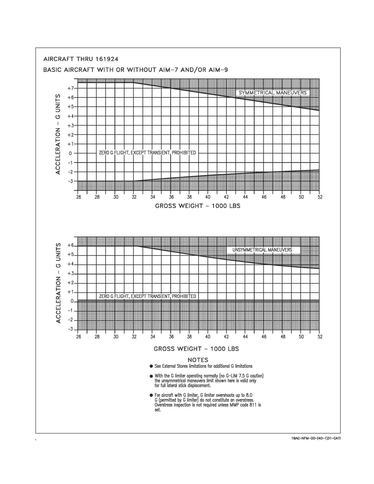
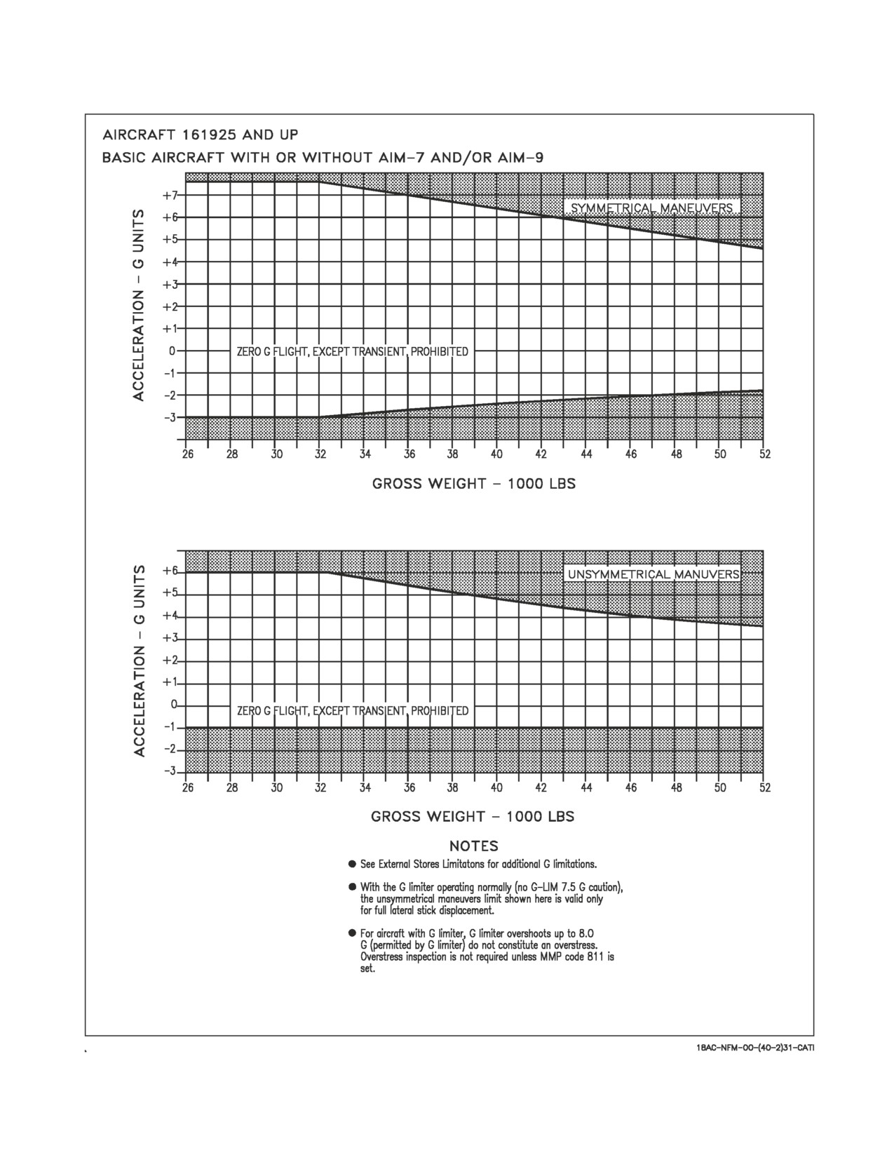
2. The maximum permissible accelerations in smooth air with the flaps AUTO are shown in figure
4-3. Avoid buffet at limit g when possible. In moderate turbulence, reduce deliberate accelerations
2.0 g below that shown in figure 4-3. Additional acceleration limits when carrying external stores
are shown in the External Stores Limitation chart, figure 4-4, and in NTRP 3-22.4-FA18A-D
NATIP, Store Carriage and Release Limitations Chapter.
4.2 EXTERNAL STORES
4.2.1 Limitations. Only the external stores shown in the External Stores Limitations chart, figure
4-4, and the Store Information table in the NTRP 3-22.4-FA18A-D NATIP, Store Carriage and
Release Limitations Chapter, may be carried and released.
4.2.2 Banner Towing Limitations.
Airspeed
220 knots maximum
Maximum bank angle
40°
Use of speedbrake
No restrictions
4.2.3 Tow Banner Adapter Limitations.
Airspeed
400 knots maximum
Acceleration
4 g maximum
I-4-9
ORIGINAL
A1-F18AC-NFM-000
Figure 4-3. Acceleration Limitations (Sheet 1 of 2)
I-4-10
ORIGINAL
A1-F18AC-NFM-000
Figure 4-3. Acceleration Limitations (Sheet 2 of 2)
I-4-11
ORIGINAL
A1-F18AC-NFM-000
Figure 4-4. External Stores Limitations
I-4-12
ORIGINAL
A1-F18AC-NFM-000
PART II
INDOCTRINATION
Chapter
5 - Indoctrination
61
(Reverse Blank)
ORIGINAL
A1-F18AC-NFM-000
CHAPTER 5
Indoctrination
5.1 GROUND TRAINING SYLLABUS
5.1.1
Minimum Ground Training Syllabus. Initial ground training shall be conducted in accordance
with the CNO approved syllabus. Follow-on ground training for each activity varies according to local
conditions, field facilities, requirements from higher authority, and the immediate Unit Commander’s
estimate of squadron readiness.
5.2 FLIGHT TRAINING SYLLABUS TRAINING PHASES
Initial flight training, up to and including first solo, shall be conducted in accordance with the CNO
approved syllabus. Follow-on flight training should include aircraft and weapon systems instruction,
normal and emergency procedures, simulators (if available), open and closed book NATOPS tests, and
evaluation of pilot performance. Local command requirements, squadron mission, and other factors
influence the actual flight training syllabus and the sequence in which it is completed.
5.3 PERSONAL FLYING EQUIPMENT
5.3.1
Minimum Requirements. Refer to OPNAVINST 3710.7, for all standard flying equipment to
be worn on every flight. All survival equipment must be secured in such a manner that it is easily
accessible and will not be lost during ejection or landing. This equipment shall be the latest available
as authorized by Aircrew Personal Protective Equipment Manual (NAVAIR 13-1-6).
5.4 QUALIFICATIONS AND CURRENCY REQUIREMENTS
5.4.1
Minimum Flight Qualifications. Minimum flight hour requirements to maintain qualification
or reestablish qualification after initial qualification in each specific phase shall be established by the
Unit Commanding Officer. Aircrew currently qualified in E-F series can gain initial A-D qualification
with 5 hours and two takeoffs/landings in A-D series within the last 90 days. Pilots who have more than
45 hours in model are considered current subject to the following criteria:
1. Must have a NATOPS evaluation check with the grade of Conditionally Qualified, or better,
within the past 12 months and must have flown 5 hours in model and made two takeoffs and landings
within the last 90 days.
2. Must have satisfactorily completed the ground phase of the NATOPS evaluation check, including
COT/WST emergency procedures check (if available), and be considered qualified by the Com-
manding Officer of the unit having custody of the aircraft.
5.4.2
Requirements For Various Flight Phases.
5.4.2.1
Solo. Not less than 5 hours first pilot time in model.
5.4.2.2
Initial NATOPS Qualification. Not less than 10 hours in model.
5.4.2.3
Night. Not less than 10 hours in model.
II-5-1
ORIGINAL
A1-F18AC-NFM-000
5.4.2.4
Cross Country.
1. Have a minimum of 15 hours in model.
2. Have a valid instrument card.
3. Have completed at least one night familiarization flight.
5.4.2.5
Carrier Qualification. Have a minimum of 50 hours in A-D series (15 hours in A-D series with
a current NATOPS in Type/Model, and FA-18 CAT1 or CAT2 transition syllabus complete), and meet
the requirements set forth in the LSO NATOPS manual.
5.4.3
Ceiling/Visibility Requirements. Prior to the pilot becoming instrument qualified in the
aircraft, field ceiling/visibility and operating area weather must be adequate for the entire flight to be
conducted in a clear air mass according to Visual Flight Rules. After the pilot becomes instrument
qualified, the following weather criteria apply:
TIME IN
CEILING (Ft)/VISIBILITY (Mi)
MODEL
(HR)
10 to 20
800/2; 900/1-1/2; 1000/1
20 to 45
500/3; 600/2; 700/1
Over 45
Field minimums or 200/1/2 whichever is higher
Where adherence to these minimums unduly hampers pilot training, Commanding Officers may
waive time-in-model requirements for actual instrument flight, provided pilots meet the following
criteria:
1. Have a minimum of 10 hours in model
2. Completed two simulated instrument sorties
3. Completed two satisfactory tacan penetrations.
Weather minimums for a replacement pilot (RP) with an instructor pilot (IP) in the rear seat of an
F/A-18B/D aircraft are 300 feet/1 mile for takeoff and landing. If the RP has over 45 hours in model,
field minimums or 200 feet/ ½ mile, whichever is higher, will apply.
5.4.4 Ferry Squadrons. Training requirements, check-out procedures, evaluation procedures, and
weather minima for ferry squadrons are governed by the provisions contained in OPNAVINST 3710.6.
5.5 WAIVERS
5.5.1 Unit Commanders Authority. Unit commanders are authorized to waive, in writing, minimum
flight and/or training requirements in accordance with OPNAVINST 3710.7 (Series).
II-5-2
ORIGINAL W/IC 91
A1-F18AC-NFM-000
PART III
NORMAL PROCEDURES
Chapter
6 - Flight Preparation
Chapter
7 - Shore-Based Procedures
Chapter
8 - Carrier-Based Procedures
Chapter
9 - Special Procedures
Chapter 10 - Functional Checkflight Procedures
63
(Reverse Blank)
ORIGINAL
A1-F18AC-NFM-000
CHAPTER 6
Flight Preparation
6.1 MISSION PLANNING
6.1.1 General. The pilot shall be responsible for the preparation of required charts, flight logs,
navigation computations including fuel planning, checking weather and NOTAMS, and for filing
required flight plans. Refer to Part XI, Performance Data, to determine fuel consumption, correct
airspeed, power settings, and optimum altitude for the intended flight mission. Planned minimum on
deck fuel should not be less than 1,500 lbs. Planning data for specialized missions is contained in the
NTRP 3-22.4-FA18A-D and NTRP 3-22.2-FA18A-D NATIP.
6.1.2 Flight Codes. The proper kind of flight classification and codes to be assigned individual
flights are established by OPNAVINST 3710.7.
6.2 BRIEFING/DEBRIEFING
6.2.1 Briefing. The flight leader is responsible for briefing all flight members on all aspects of the
mission to be flown. A briefing guide or syllabus card, as appropriate, is to be used in conducting the
briefing. Each flight member shall maintain a kneepad and record all flight numbers, call signs, and all
other data necessary to assume the lead and complete the assignment. However, this does not relieve
the flight leader of the responsibility for briefing all flight members in the operation and conduct of the
flight. The briefing guide includes the following:
6.2.1.1
General Mission Briefing Guide.
Assignments
Aircraft assigned, call sign, and deck spot when appropriate
Engine start, taxi, and takeoff times
Visual signals and rendezvous instructions
Mission
Primary
Secondary
Operating area
Control agency
Time on station or over target
Weapons
Loading
Safety
Arming, dearming
Duds
Special routes with ordnance aboard
Minimum pull-out altitude
III-6-1
ORIGINAL
A1-F18AC-NFM-000
Jettison area
Communications
Frequencies
Radio procedure and discipline
Navigational aids
Identification and ADIZ procedures
Weather
Local area
Local area and destination forecast
Weather at alternate
High altitude weather for the jet stream, temperature, and contrail band width
Navigation and Flight Planning
Takeoff speed
Takeoff distance
Abort distance
Crosswind effects
Climb out
Mission route, including ground controlling agencies
Fuel/oxygen management
Marshal
Penetration
GCA or CCA
Recovery
Emergencies
Aborts
Divert fields
Bingo and low state fuel
Waveoff pattern
Ready deck
Radio failure
Loss of visual contact with flight
Ejection
SAR procedures
System failures
Air Intelligence and Special Instructions
Friendly and enemy force disposition
Current situation
Targets
Safety precautions
ECM and ECCM
III-6-2
ORIGINAL
A1-F18AC-NFM-000
6.2.1.2
Operating Area Briefings. Prior to air operations in and around a new area, it is mandatory
that a comprehensive area briefing be given including, but not limited to, the following:
Bingo Fields
Instrument approach facilities
Runway length and arresting gear
Terrain and obstructions
Emergency Fields
Fields suitable for landing but without required support equipment
Include information under Bingo fields
SAR Facilities
Type
Frequencies
Locations
6.2.2 Debriefing. Postflight debriefing is an integral part of every flight. The flight leader should
review the entire flight from takeoff to landing, including not only errors and poor techniques, but also
the methods of correcting them. Also, the flight leader shall cover any deviations from standard
operating procedures.
III-6-3
(Reverse Blank)
ORIGINAL
A1-F18AC-NFM-000
CHAPTER 7
Shore-Based Procedures
7.1 PREFLIGHT CHECK
7.1.1 Line Operations. The yellow sheet must be checked for flight status, configuration, armament
loading, and servicing prior to manning the aircraft. At least the 10 previous B sections should be
reviewed for discrepancies and corrective action. Weight and Balance clearance is the responsibility of
the maintenance department.
7.1.2 Exterior Inspection. The exterior inspection is divided into 24 areas. The inspection begins at
the left fuselage and continues around the aircraft in a clockwise direction. Check doors secure and be
alert for loose fasteners, cracks, dents, leaks, and other general discrepancies.
1. Nose landing gear
a. Drag brace/fairing - CHECK CONDITION
b. Drag brace ground safety pin - REMOVED
c. Holdback fitting - CHECK CONDITION
d. Tires and wheels - CHECK CONDITION
e. Tire pressure - 150 psi (ashore) 375 psi (afloat) (gauges on some aircraft)
f. Ensure key washer not in direct contact with wheel hub.
g. Strut piston chrome exposed - 3 TO 4 INCHES
h. Launch bar - CHECK CONDITION
i. Nosewheel steering assembly - CHECK CONDITION
j. Tiedown rings (2) - CHECK FOLDED AGAINST STRUT
k. Taxi and approach lights - CHECK CONDITION
l. Strut pressure gauges (2) - CHECK vs. Strut Servicing Plate
m. Retract actuator - CHECK CONDITION
n. Strut - CHECK CONDITION
2. Nose wheelwell - CHECK
a. Emergency brake accumulator pressure - CHECK (2,600 psi minimum)
b. Digital display indicator - NO FLAGS
III-7-1
ORIGINAL
A1-F18AC-NFM-000
c. APU emergency shutdown switch - NORMAL
d. Doors and linkages - CONDITION
e. BRCU - CYCLE (if applicable)
3.
Nose section (left side) - CHECK
a. Gun - PREFLIGHT
b. U BATT/E BATT circuit breakers - CHECK
c. Pitot static probe - CONDITION
d. Pitot static drains (5) - CLOSED
e. AOA probe - CHECK CONDITION
(1) Smooth, concentric rotation through the full range of travel to include while gently pulling
and pushing the AOA probe.
(2) No bends, dents, dings, or other surface discrepancies.
f. Forward UHF antenna - CONDITION
g. Radome - SECURE (2 points)
4.
Nose section (top) - CHECK
a. Gun blast diffuser and gun port - CLEAR
5.
Nose section (right side) - CHECK
a. Radome - SECURE (2 points)
b. AOA probe - CHECK CONDITION
(1) Smooth, concentric rotation through the full range of travel to include while gently pulling
and pushing the AOA probe.
(2) No bends, dents, dings, or other surface discrepancies.
c. Pitot static probe - CONDITION
d. Refueling receptacle cover - INSTALLED (Door 8R)
6.
Right fuselage - CHECK
a. SMS processor/SMUG - CHECK codes, Door 14R closed/secure
b. Aft UHF antenna - CONDITION
c. Engine intake duct - CLEAR
III-7-2
ORIGINAL
A1-F18AC-NFM-000
d. ECS intake - CLEAR
e. Chaff/flare dispenser - PREFLIGHT
(Dispenser module (chaff/flare bucket) or access cover shall be installed.)
7. External fuel tank - PREFLIGHT
a. Refuel cap - DOWN, LOCKED, ARROW FORWARD
b. Precheck valve - DOWN, FLUSH, ARROW UP
8. AIM-7, AIM-120, LDT/SCAM, or NAVFLIR - PREFLIGHT
9. Fuel air heat exchanger intake - CLEAR AND CONDITION
10. Right main wheelwell - CHECK
a. Doors and linkages - CONDITION
b. APU accumulator - PRESSURE, TEMPERATURE, PISTON POSITION
c. Landing gear downlock and retract actuators - CONDITION
d. Downlock pin - REMOVED
e. Hydraulic filter indicators - NOT POPPED
f. APU accumulator pump handle - CONDITION, SECURITY, PIN
g. Main fuel line clamps secure and safety wires attached.
11. Right main landing gear - CHECK
a. Tire - TREAD WEAR, PRESSURE 250 psi (ashore) 350 psi (afloat) (gauges on some aircraft)
b. Brake wear indicator - CHECK
c. Shrink links and planing links - CONDITION
d. Shock strut pressure - CHECK
e. Tiedown rings and springs - CONDITION
12. Right wing - CHECK
a. Leading edge flap - CHECK CONDITION
b. Pylons and external stores -
(1) Breech caps tight
(2) If applicable, cartridge installed indicator present (protruding from breech cap w/ext stores
loaded)
III-7-3
ORIGINAL