F18. FLIGHT MANUAL (2008) - page 7
A1-F18AC-NFM-000
The wingman touches down first and decelerates on his half of the runway as an individual. Do not
attempt to brake in section. If lead must cross the wingman’s nose to clear the duty, the wingman calls
“clear” on comm 2 when at taxi speed and with at least 800 feet between aircraft. The lead stops after
clearing the runway and waits for the wingman to join for section taxi.
9.2 AIR REFUELING
Air refueling shall be conducted in accordance with NATO publication ATP-56, Air-To-Air Refueling
Procedures.
NOTE
The KC-10, KC-130, KC-135, F/A-18E/F, and S-3
with D-704
or
31-300 buddy stores are authorized tankers for air refueling. Maximum
refueling pressure is 55 psi.
9.2.1 Before Plug-in. Complete the air refueling checklist before plug in.
1. Radar - STBY/SILENT/EMCON
2. MASTER ARM switch - SAFE
3. Internal wing fuel switch - AS DESIRED
4. External tanks - AS DESIRED
If engine feed tank fuel level is critical, external wing and centerline transfer should be in STOP
or ORIDE to ensure the fastest transfer of fuel to the engine feed tanks.
5. Air refuel PROBE switch - EXTEND
6. Visor - RECOMMENDED DOWN
For night air refueling -
7. Exterior lights - STEADY BRIGHT
8. Tanker lights - AS DESIRED
9.2.2 Refueling Technique.
NOTE
The following procedures, as applied to tanker operation, refer to
single drogue refuelers.
Refueling altitudes and airspeeds are dictated by receiver and/or tanker characteristics and
operational needs, consistent with the tanker’s performance and refueling capabilities. This, generally,
covers a practical spectrum from the deck to 40,000 feet and 175 to 300 knots while engaged.
NOTE
For KC-135 aircraft, the following parameters are recommended:
Airspeed - 200-275 knots/Mach 0.8, whichever is less
Closure rate - 2 knots or less
III-9-6
ORIGINAL
A1-F18AC-NFM-000
9.2.2.1
Approach.
Be careful to avoid damaging the right AOA probe by contact with basket
or hose. If the probe is damaged, it will cause a 4 channel AOA failure.
Once cleared to commence an approach, refueling checklists completed, assume a position 10 to 15
feet in trail of the drogue with the refueling probe in line in both the horizontal and vertical reference
planes. Trim the aircraft in this stabilized approach position and ensure that the tanker’s (amber)
ready light is on before attempting an approach. Select a reference point on the tanker as a primary
alignment guide during the approach phase; secondarily, rely on peripheral vision of the drogue and
hose. Increase power to establish minimum closure rate on the drogue not to exceed 5 knots. An
excessive closure rate causes a violent hose whip following contact and/or increase the danger of
structural damage to the aircraft in the event of misalignment; whereas, too slow a closure rate results
in the pilot fencing with the drogue as it oscillates in close proximity to the aircraft nose. During the
final phase of the approach, the drogue has a tendency to move slightly upward and to the right as it
passes the nose of the receiver aircraft due to the aircraft-drogue airstream interaction. Small
corrections in the approach phase are acceptable; however, if alignment is off in the final phase, it is
best to immediately retire to the initial approach position and commence another approach,
compensating for previous misalignment by adjusting the reference point selected on the tanker. Make
small lateral corrections with the rudder, and vertical corrections with the stabilator. Avoid any
corrections about the longitudinal axis since they cause probe displacement in both the lateral and
vertical reference planes.
9.2.2.2
Missed Approach. If the receiver probe passes forward of the drogue basket without making
contact, initiate a missed approach immediately. If the probe impinges on the rim of the basket and
tips it, initiate a missed approach. A missed approach is executed by reducing power and backing to the
rear at a 3 to 5 knot opening rate. By continuing an approach past the basket, a pilot might hook the
probe over the hose and/or permit the drogue to contact the receiver aircraft fuselage. Either of these
hazards require more skill to calmly unravel the hose and drogue without causing further damage than
to make another approach. If the initial approach position is well in line with the drogue, the chance
of hooking the hose is diminished when last minute corrections are kept to a minimum. After executing
a missed approach, analyze previous misalignment problems and apply positive corrections to avoid a
hazardous tendency to blindly stab at the drogue.
9.2.2.3
Contact. When the receiver probe engages the basket, it seats itself into the drogue coupling
and a slight ripple is evident in the refueling hose. The drogue and hose must be pushed forward 3 to
5 feet by the receiver probe before fuel transfer can be effected. This position is evident by the tanker’s
(amber) ready light going out and the (green) fuel transfer light coming on. While plugged-in, fly a close
tail chase formation on the tanker. Although this tucked-in condition restricts the tanker’s maneu-
verability, gradual changes involving heading, altitude and/or airspeed may be made. A sharp lookout
doctrine must be maintained due to the precise flying imposed on both the tanker and receiver pilots.
In this respect, the tanker can be assisted by other aircraft in the formation.
9.2.2.4
Disengagement. Disengagement from a successful contact is accomplished by reducing
power and backing out at a 3 to 5 knot separation rate. Maintain the same relative alignment on the
tanker as upon engagement. The receiver probe separates from the drogue coupling when the hose
reaches full extension. When clear of the drogue, place the refueling probe switch in the RETRACT
III-9-7
ORIGINAL
A1-F18AC-NFM-000
position. Ensure that the PROBE UNLK caution display is out before resuming normal flight
operations.
9.3 BANNER TOWING SYSTEM
9.3.1 Banner Towed Target Equipment. The aerial banner tow target equipment consists of a tow
adapter, a standard TDU-32/B 8.5 X 40 foot aerial banner target and approximately 1,500 feet of
11/64-inch armored cable towline, fitted at both ends with a MK-8 tow ring for military takeoffs.
Afterburner operations require a 75-foot leader of 3/8 inch diameter steel cable attached to the tow
cable.
The tow adapter is installed on the hinge point assembly of the tail hook by ground crew personnel.
Pilot action is not required for banner hookup. The banner is released in flight or on deck by lowering
the tail hook.
9.3.2 Ground Procedures. The following procedures are provided for guidance. Local course rules
may dictate modifications of these steps.
1.
When tower clearance onto the duty runway is received, the tow aircraft taxis to a position as
directed by the tow hookup crew. The tow pilot holds the position until released by the tow
hookup crew. The escort pilot maintains position on the taxiway at the approach end of the
runway.
2.
When signaled to do so by the tow hookup crew, the tow pilot proceeds to taxi down the runway.
3.
Upon receipt of a visual taxi signal from the tow hookup crew to “slow down”, the escort pilot
relays this signal to the tow pilot via UHF radio.
4.
Upon receipt of a visual taxi signal from the tow hookup crew to “stop”, the escort pilot relays this
signal to the tow pilot via his UHF radio.
5.
Upon receipt of a signal from the tow hookup crew that the “tow hookup is complete”, the escort
pilot requests the tow pilot to “take up slack”.
6.
The tow pilot proceeds to taxi down the runway.
7.
When the banner moves forward onto the runway, the escort pilot transmits “tow aircraft
hold-good banner” and taxis onto the runway abeam the banner for takeoff.
8.
When ready, the tow pilot transmits “Tower, Lizard 616 for banner takeoff, escort follow on a
good banner”.
9.
After the banner becomes airborne, the escort pilot commences takeoff roll.
9.3.3 Flight Procedures. Flight tests have demonstrated no significant degradation of performance
and handling characteristics when towing a banner.
NOTE
Angle of bank should be limited to 40°.
III-9-8
ORIGINAL
A1-F18AC-NFM-000
9.3.3.1
Takeoff. Normal MIL power takeoff procedures, including rotation speeds and techniques,
are suitable when towing the banner, and are recommended except when operating in high ambient
temperatures or at high density altitude airfields. When the steel cable leader is added to the tow cable,
takeoff can be made at MAX power.
• Takeoff ground roll with banner can be estimated by adding a factor of
10% to basic aircraft takeoff performance. If aircraft lift-off does not
occur prior to crossing the long field arresting gear, the gear must be
removed to preclude the banner being torn off.
• When using afterburner, the aircraft nose should be held on deck until
10 knots past flying speed to minimize cable time in the afterburner
plume. If the crosswind component exceeds 10 knots, the takeoff roll
should be made on the upwind side of the runway centerline to prevent
the banner from drifting close to the runway edge lights on the
downwind side of the runway.
NOTE
If takeoff is aborted, basic emergency procedures are applicable. The
tow cable releases when the tailhook is lowered.
After lift-off, the initial climb attitude to 1,200 feet AGL varies with existing weather conditions.
However, an initial pitch attitude of 15 to 20° is a good starting point. Afterburner operation requires
a 5 to 10° higher pitch attitude. Do not exceed 25° of pitch attitude. Select landing gear UP and flaps
AUTO when definitely airborne. Climb out at 200 to 220 knots.
NOTE
Tow airspeeds in excess of 220 knots result in excessive banner fraying.
9.3.3.2
Cruise/Pattern. No special pilot techniques are required when towing a banner. Enroute
cruising speed of 180 to 220 knots provides adequate energy for mild maneuvering while minimizing
banner fray. ATC is effective for airspeed control. The tow aircraft must call all turns to allow the chase
to position on the outside of the turn.
Without the banner, any remaining cable flails unpredictably and could
damage the aircraft. The chase should approach the tow aircraft from
abeam to verify cable failure, avoiding a cone-shaped area defined by the
tow’s 4 to 8 o’clock positions. The tow aircraft should then lower the tail
hook as soon as practical.
9.3.3.3
Descent. Descend at 160 to 220 knots. Use speedbrake as desired to increase the rate of
descent.
III-9-9
ORIGINAL
A1-F18AC-NFM-000
9.3.3.4
Banner Drop. Banner drop speed should be accomplished at a comfortable airspeed below
200 knots. Drop the banner in wings level flight at a minimum of 500 feet AGL. The chase should
ensure adequate clearance exists between the banner and ground obstacles during approach to the drop
zone and provide calls to assist in line-up. Release is normally called by the tower when the banner is
over the center of the drop zone. Release is accomplished by lowering the tailhook. Because of the low
release altitude, crosswind has no appreciable effect on the banner impact point (i.e., the banner hits
down range of the release point). Following banner release, raise the tailhook.
9.3.3.5
Banner Release Failure. If the arresting hook fails to extend, the banner cannot be released.
In this case, the following procedure is recommended:
1. Select full afterburner while increasing AOA in an attempt to burn through the cable.
If cable remains -
2. In the gunnery range (or other cleared area), descend to lower altitude and slow to a comfortable
airspeed below 200 knots maximum and 100 to 200 feet AGL. This drags the banner off on the
ground (or water). Have the escort pilot confirm that the banner breaks off on ground collision
and determine the length of the remaining tow cable.
The escort pilot must remain well clear of the remaining cable. The last
25% of the remaining cable flails unpredictably.
3. If
100 feet or greater remaining tow cable length is confirmed by the escort pilot, plan to
touchdown 1,000 to 1,500 feet long, runway length permitting.
Every effort must be made by the tow pilot not to drag the remaining tow
cable across lines, fences, etc., due to property damage that will result.
NOTE
The long touchdown should be carefully planned because arrestment is
impossible.
9.3.4 Target Chase Procedures.
9.3.4.1
Primary Chase Responsibilities
1. Advise tow pilot of conditions of banner and tow line.
2. Provide additional visual lookout.
3. Provide additional warning to other aircraft by positioning his aircraft near the banner.
4. Provide line-up calls to tow pilot during banner drop.
III-9-10
ORIGINAL
A1-F18AC-NFM-000
9.3.4.2
Chase Position
1. Approximately 100 to 200 feet abeam the banner at an altitude equal to or greater than the
banner.
2. The chase remains on the outside of all turns to ensure clearance from the banner and prevent
loss of airspeed during turns.
3. If IMC is encountered, the chase should move forward and fly wing on tow until VMC.
9.4 NIGHT VISION DEVICE (NVD) OPERATIONS
9.4.1 Effects on Vision. Flight techniques and visual cues used during unaided night flying also
apply to flying with NVDs. The advantage of NVD is improved ground reference provided through
image intensifier systems (NVG/NAVFLIR). Dark adaptation is unnecessary for the effective viewing
through night vision goggles (NVG). In fact, viewing through the NVG for a short period of time
shortens the normal dark adaptation period. After using NVG, it takes the average individual 1 to 3
minutes to reach the 30 minute dark adaptation level. Color discrimination is absent when viewing the
NVG image. The image is seen in a monochromatic green hue and is less distinct than normal vision.
Prolonged usage may result in visual illusions upon removal of the NVG. These illusions include
complement or green after-images when viewing contrasting objects. Illusions from NVG are
temporary and normal physiological phenomena and the length of time the effects last vary with the
individual.
• Ejection wearing night vision goggles is not recommended. Severe neck
injury may result.
• Aircrew are strongly cautioned against maneuvering above 3 g with
the AN/AVS-9 in the up-locked (not in use but on helmet) position
because the NVD bracket cannot retain AN/AVS-9 under elevated g
loads.
9.4.2 Effects of Light. Any non-NVG compatible light source in the cockpit degrades the ability to
see with NVG. In aircraft 163985 AND UP, filters are used to prevent stray or scattered light from
reaching the NVG intensifiers, which would cause the automatic gain control to reduce the NVG image
intensification. Head down displays (DDI, MPCD) are filtered to allow non-electrical-optical viewing
of the display. Viewing areas illuminated by artificial light sources with NVG (runway/landing lights,
flares, or aircraft position lights) limit the ability to see objects outside of the area.
NOTE
Bright ground lights may cause loss of ground references during
landing. Avoid looking directly at bright light sources to prevent
degrading NVG vision.
The NAVFLIR however, is not affected by light sources and therefore complements NVG use.
9.4.3 Weather Conditions. NAVFLIR and NVG provide a limited capability to see through visibility
restrictions such as fog, rain, haze, and certain types of smoke. As the density of the visibility
III-9-11
ORIGINAL
A1-F18AC-NFM-000
restrictions increases, a gradual reduction in light occurs. Use of an offset scanning technique helps to
alert the pilot to severe weather conditions.
NOTE
Visibility restrictions produce a ‘‘halo’’ effect around artificial lights.
9.4.4 Object/Target Detection. Detection ranges are largely a function of the existing atmosphere
and environmental conditions. Moving targets with contrasting backgrounds or targets with a reflected
or generated light or heat sources can be identified at greater ranges when using NVD.
9.4.5 Flight Preparation. Flights with NVD require unique planning considerations that include
weather, moon phase/angle, illumination, ground terrain and shadowing effects. Tactical consideration
and procedures can be found in Volume IV of the Tactical manual.
9.5 SHORT AIRFIELD FOR TACTICAL SUPPORT (SATS) PROCEDURES
9.5.1 Landing Pattern. Approach the break point either individually or in echelon, parade
formation, at 250 knots. A 17 to 20-second break interval provides a 35 to 40-second touchdown
interval. Have the landing checklist completed, be at on-speed AOA/approach speed by the 180°
position.
9.5.2 Approach. Plan for and execute an on-speed approach. Pay particular attention to maintaining
the proper airspeed and correct lineup.
9.5.3 Waveoff. To execute a waveoff, immediately add full power and maintain optimum attitude.
Make all waveoffs straight ahead until clear of the landing area.
9.5.4 Arrested Landing. The aircraft should be on runway centerline at touchdown. Aircraft
alignment should be straight down the runway with no drift. Upon touchdown, maintain the throttle
at the approach position. When arrestment is assured, retard the throttle to idle. Allow the aircraft to
roll back to permit the hook to disengage from the pendant. When directed by the taxi director, apply
both brakes to stop the rollback and raise the hook. If further rollback is directed, release brakes and
allow the aircraft to be pulled back until a brake signal is given. Then apply brakes judiciously to
prevent the aircraft from tipping or rocking back.
Use extreme caution when taxiing on a wet SATS runway.
9.5.5 Bolter. Bolters are easily accomplished. Simultaneously apply full power and retract the
arresting gear hook. Smoothly rotate the aircraft to a lift-off attitude and fly away.
Bolters in GAIN ORIDE require more aft stick input for rotation due to
fixed AOA feedback and zero rudder toe−in deflections. Half-aft stick is
recommended for rotation from bolters in GAIN ORIDE to reduce
aircraft settle.
III-9-12
ORIGINAL
A1-F18AC-NFM-000
If landing on a runway with a SATS catapult installed, care must be
taken to prevent engagement of the dolly arrester ropes with the aircraft
tailhook. Structural damage to the aircraft and catapult will result.
9.5.6 Hot Seat Procedure.
1. Parking brake - ON
2. Nosewheel steering - OFF
3. Left throttle - OFF
4. Throttle friction - MAX
5. Avionics - AS DESIRED
9.5.7 Alert Scramble Launch Procedures.
9.5.7.1
Setting the Alert.
1.
The alert/scramble aircraft shall be preflighted in accordance with NATOPS normal procedures,
this part, every 4 hours or as local directives dictate.
2.
The pre-alert turn shall consist of full Plane Captain checks and full systems checks. Minimum
requirements are:
a. Radar - GO
b. AIM-7 - TUNED (if loaded)
c. INS - OK
d. Comm 1 and 2 - SET TO LAUNCH FREQUENCY
e. Launch trim - SET IN ACCORDANCE WITH FIGURE 8-1
3.
Before engine shutdown -
a. INS - OFF (10 seconds before engine shutdown)
NOTE
Do not switch INS to NAV during pre-alert turn so that STD HDG
option will be available for next alignment.
b. Crypto switch - HOLD THEN NORM
c. Sensors, weapon systems, and UFC avionics - ON
d. Comm 1 and 2 - ON
III-9-13
ORIGINAL
A1-F18AC-NFM-000
e. EMCON - AS DESIRED
f. Exterior and interior lights - SET
g. DDIs, HI/MPCD, and HUD - ON
Aircraft 161353 THRU 164068
h. Oxygen switch - OFF
Aircraft 164196 AND UP
h. OBOGS control switch and OXY flow knob - OFF
All aircraft-
i. Landing gear pins - REMOVED AND STOWED
4. After engine shutdown -
a. External power - CONNECTED (if applicable)
b. External power switch - RESET THEN NORM
c. Ground power switches 1, 2, 3, and 4 - OFF
d. Battery switch - CHECK OFF
e. SINS cable - CONNECTED (if required)
9.5.7.2
Alert Five Launch
If on external power -
1. Ground power switches 1B, 2B, 3B, and 4B - ON (hold
3
seconds)
2. INS - CV/GND
3. INS - STD HDG (if available)
4. BATT switch - ON
5. APU - START (READY light within 30 seconds)
6. R engine - START
7. L engine - START
8. FCS - RESET
Aircraft 161353 thru 164068 -
9. OXYGEN switch - ON
III-9-14
ORIGINAL
A1-F18AC-NFM-000
Aircraft 164196 AND UP -
9. OBOGS control switch and OXY flow knob - ON
All aircraft-
10. External power - DISCONNECTED (if applicable)
11. SINS cable - DISCONNECTED (if applicable)
12. INS - NAV or GYRO or IFA (EGI)
13. Takeoff checklist - COMPLETE
14. After launch, INS - IFA (if applicable)
9.6 AIRBORNE HMD ACCURACY CHECKS
The procedures below shall be performed to verify JHMCS accuracy at any time system accuracy is
in question, including verifying the accuracy of the cockpit magnetic map. These procedures require an
airborne target.
If performing these procedures to determine if cockpit re-mapping is needed following maintenance,
only 9.6.2 Airborne HMD Accuracy Check with Radar is required. Cockpit re-mapping is not required
if 9.6.2 Airborne HMD Accuracy Check with Radar is successful.
9.6.3 Airborne HMD Accuracy Check with CATM/AIM-9X can be performed at the aircrew’s
discretion to verify accuracy in the high off-boresight field of regard.
NOTE
If preflight HMD Alignment occurred less than
15
minutes after
system powered on, repeat 9.6.1 HMD Alignment prior to any airborne
checks.
9.6.1 HMD Alignment.
(CVRS record HMD if desired)
1. SUPT/HMD/ALIGN page - SELECT
2. Superimpose the HMD alignment cross on the HUD/BRU alignment cross.
3. Cage/Uncage button - PRESS and HOLD until ALIGNING turns to ALIGN OK or ALIGN FAIL
If ALIGN FAIL -
4. Repeat steps 2 and 3.
If ALIGN OK and HMD alignment crosses are not coincident with HUD/BRU alignment cross -
4. Perform FINE ALIGN.
III-9-15
ORIGINAL
A1-F18AC-NFM-000
a. With FA DXDY displayed, use TDC to align azimuth and elevation HMD alignment crosses
with the HUD/BRU alignment cross.
b. Cage/Uncage button - PRESS and RELEASE
c. With FA DROLL displayed, use TDC to align the roll axis HMD alignment crosses with the
HUD/BRU alignment cross.
d. Cage/Uncage button - PRESS and RELEASE
If satisfied with alignment -
5. ALIGN - UNBOX
9.6.2 Airborne HMD Accuracy Check with Radar.
1. Select STT while in trail of an airborne target.
2. Compare HMD TD Box to HUD TD Box and target’s actual position (when in HUD FOV) and
compare HMD TD Box and target’s actual position (when NOT in HUD FOV) at various
azimuth/elevation angles (up to 45° laterally left and right and 45° in elevation).
If HMD and HUD TD Boxes are not nearly coincident or portion of target is not located within
HMD and HUD TD Boxes -
3. Perform 9.6.1 HMD Alignment procedures.
4. Repeat steps 1 and 2.
If HMD Alignment does not correct -
5. Consider re-mapping the cockpit.
9.6.3 Airborne HMD Accuracy Check with CATM/AIM-9X.
1. No L&S track selected.
2. Select AIM-9X (manual mode).
• Verify AIM-9X symbology on HMD and AUTO not displayed below 9X at bottom of display.
• Verify AIM-9X slaved to HMD.
3. Perform the following steps at various azimuth/elevation angles throughout the AIM-9X field of
regard and outside the radar field of regard until aircrew are confident that the HMD and AIM-9X
are pointing properly:
a. Place aiming cross on the target.
b. Cage/Uncage button - PRESS to command AIM-9X to enter track
• Verify AIM-9X enters track on the target.
• Verify in-track seeker circle is within one 9X circle size of touching the target.
III-9-16
ORIGINAL
A1-F18AC-NFM-000
c. Cage/Uncage button - PRESS to slave AIM-9X to HMD
d. Set up next azimuth/elevation angle and repeat steps a through c.
If the in-track seeker circle is not within one 9X circle size of touching the target -
4. Perform 9.6.1 HMD Alignment procedures.
5. Repeat steps 1 through 3.
If HMD Alignment does not correct -
6. Consider re-mapping the cockpit.
III-9-17
(Reverse Blank)
ORIGINAL
A1-F18AC-NFM-000
CHAPTER 10
Functional Checkflight Procedures
10.1 GENERAL
The information contained herein describes in detail the procedures to be followed during a
functional checkflight. The checks are presented in consecutive order simulating a recommended
checkflight profile. The profile itself may be altered as required, however, the sequential steps listed
for a system/component evaluation are mandatory. Because of restricted operating areas, pilot
technique or other limiting factors, a full checkflight profile may require more than one flight.
Therefore, it is permissible to divide the recommended checkflight profile, as required, to compensate
for these conditions. If a checkflight is divided, it is permissible for another pilot to complete the
checklist, provided there is a thorough passdown, either verbal or written, between the pilots.
Requirements for functional checkflights are listed in COMNAVAIRFORINST 4790.2 Series with
the following exceptions specific to the F/A-18. An FCF is not required for the installation or
reinstallation of a known good engine provided satisfactory ground checks have been completed, unless
both engines are being installed or reinstalled. A ‘‘known good engine’’ is defined as an engine removed
and reinstalled in the same aircraft to facilitate other maintenance, or an engine in operational use
cannibalized from another aircraft. An FCF is not required for the reinstallation of a known good
movable flight control surface provided satisfactory completion of BIT checks on deck. A ‘‘ known good
movable flight control surface’’ is defined as a flap, aileron, horizontal stab, or rudder surface only (not
servocylinder). FCF checks are required under the following circumstances:
PRO A - Full Aircraft check
- Acceptance
- Down time in excess of 30 days
- If no FCF As within past year (12 months)
- Anytime requested by the Commanding Officer
PRO B - Engines
- Dual engine removal (reinstallation/replacement)
- Dual ECA change
- Dual main fuel control change
- Installation of any unknown engine
- Anytime requested by the Commanding Officer
PRO C - Flight Controls
- Anytime a flight control surface is re-rigged
- Installation of any flight control servo-cylinder or hydraulic drive unit
- Anytime requested by the Commanding Officer
III-10-1
ORIGINAL
A1-F18AC-NFM-000
PRO D - Rear Cockpit (Trainer Configuration only)
- Acceptance of a newly assigned aircraft or upon receipt of an aircraft returned from SDLM.
- Reconfigured from missionized to trainer configuration.
NOTE
Aft crewmember is required.
Functional checkflights are performed using the applicable Functional Checkflight Checklist.
Checkflight personnel must familiarize themselves with these requirements prior to the flight. FCF
requirements do not replace normal procedures. NATOPS procedures apply during the entire
checkflight. Only those pilots designated in writing by the Squadron Commanding Officer shall
perform squadron checkflights. Checkflight procedures are in accordance with the current edition of
COMNAVAIRFORINST 4790.2. Items contained in the Functional Checkflight Requirements are
coded. This coding is intended to assist the FCF pilot in determining which items pertain to the various
conditions requiring checkflights. Items coded (B) pertain to engine/fuel control maintenance as
outlined in COMNAVAIRFORINST 4790.2. Items coded (C) pertain to flight control/rigging main-
tenance as outlined in COMNAVAIRFORINST 4790.2. Items coded (L) pertain to LEF system
maintenance as outlined in COMNAVAIRFORINST 4790.2. Items coded (D) pertain to an F/A-18D
reconfigured rear cockpit with stick and throttle. Items coded (A) constitute a complete Functional
Checkflight; requirements are outlined in COMNAVAIRFORINST 4790.2. Coding shall appear
adjacent to a step.
10.2 FCF CHECKLIST - PROFILE A (Includes combined profiles B and C)
10.2.1
F/A-18A/C (F/A-18B/D Front Cockpit)
10.2.1.1 Preflight
1.
(ABC) Exterior Inspection - Perform IAW Chapter 7
D No loose or improperly installed panels.
2.
(ABC) Interior Checks - Perform IAW Chapter 7
3.
(A) External electrical power - APPLY
4.
(A) EXT PWR switch - RESET
5.
(A) GND PWR switches 1, 2, 3, and 4 - B ON (hold for 3 seconds)
D Audibly verify avionics cooling fans are on.
6.
(A) Intercom - ESTABLISH
7.
(A) Fuel quantity BIT - PERFORM (F/A-18A/B)
With the fuel quantity indicator OFF flag out of view, note internal and feed tank fuel quantities.
Set the BINGO bug above 6,200 pounds and then place and hold the fuel quantity selector switch
in BIT and check the following:
a. Internal (pointer) and total (counter) indicates 6,000 ±200 pounds.
b. LEFT and RIGHT (counters) indicate 600 ±50 pounds.
III-10-2
ORIGINAL
A1-F18AC-NFM-000
c. After pointer and counters reach the above values (must occur within 15 seconds), ensure the
ID flag is not in view.
d. A FUEL advisory display appears on the DDI if any of the following cautions do not appear
within 15 seconds after initiating BIT with the fuel quantity selector switch: FUEL LO,
BINGO, CG (Aircraft 161520 AND UP), or G-LIM 7.5.
e. Release the fuel quantity selector switch.
f. Ensure pointer and counters return to previous values, the FUEL LO, BINGO, CG and G-LIM
7.5 caution displays are removed, the MASTER CAUTION light goes out and, after 1 minute,
the FUEL LO caution light goes out.
g. Reset BINGO bug to desired fuel quantity.
8.
(A) AIR SCOOP - CHECK
a. AV COOL or FCS COOL switch - EMERG
• FCS ram air scoop deploys (thumbs up from plane captain)
b. Plane captain manually restows scoop.
9.
(A) Warning and caution lights - TEST
• All warning and caution lights properly illuminate.
10. (A) Fire detection system - CHECK AND TEST
After FIRE TEST A and B, rotate the BLEED AIR knob to OFF then back to NORM.
11. (A) EXT and INTR lights - Check for proper operation
to
extent
possible
for
ambient
conditions.
12. (A) Seat adjustment - CHECK
• Smooth through full range of travel.
• Do not hold switch against stops (no limit switches).
• Adjust rudder pedals as desired.
13. (A) DDIs and HI/MPCD - ON
10.2.1.2 Engine Start
1.
(AC) FLAP switch - AUTO
2.
(ABC) BATT switch - ON (if not previously on)
3.
(ABC) READY (Fire extgh)/DISCH light - OUT
4.
(AC) Control stick - CYCLE
5.
(ABC) APU - START
6.
(AC) ENG CRANK switch - R
Leave throttle in cutoff.
7.
(AC) Mechanical linkage - CHECK
III-10-3
ORIGINAL
A1-F18AC-NFM-000
After both stabilators fair to the neutral position -
a. Move stick slowly forward or aft and release.
• Both stabilators shall move smoothly and symmetrically with stick input and return to
neutral when stick is released.
b. Move the stick left and right.
• Ensure the corresponding stabilator trailing edge deflects up differentially higher than the
opposite stabilator trailing edge.
c. Hold the stick full aft and move the FLAP switch to HALF or FULL.
• Visually, or using the FCS status display, verify that both stabilators move to a higher trailing
edge up position.
8.
(ABC) Right engine - START
Perform engine start IAW Chapter 7.
9.
(A) External power - DISCONNECT
10. (ABC) BLEED AIR knob - ROTATE THROUGH OFF TO NORM
11. (ABC) Left engine - START
Perform engine start IAW Chapter 7.
12. (AC) On DDI FCS display - VERIFY STAB Xs (FAILED) IN CHANNELS
1
AND
2
13. (ABC) FCS - RESET
14. (ABC) FLAP switch - AUTO
15. (ABC) BLEED AIR system - CHECK
a. Throttles - IDLE
b. BLEED AIR knob - CHECK EACH POSITION INDIVIDUALLY
(1) R OFF
• R BLD OFF caution displayed.
• M ASTER CAUTION light on and tone sounds.
• Left engine TEMP increases 5° to 90°C.
(2) MASTER CAUTION light - RESET
(3) Pause 5 seconds to allow Master Caution tone to reset.
(4) OFF
• L and R BLD OFF cautions displayed.
• M ASTER CAUTION light on and tone sounds.
• Cabin airflow stops.
III-10-4
ORIGINAL
A1-F18AC-NFM-000
(5) L OFF
• R BLD OFF caution removed.
• Right engine TEMP increases 5° to 90°C.
• Cabin airflow resumes.
c. BLEED AIR knob - NORM
• L BLD OFF caution removed.
• M ASTER CAUTION light out.
d. FIRE test switch - TEST A (for at least 2 seconds)
• L and R BLEED warning lights on while switch held.
• Voice alert sequence initiated.
• L and R BLD OFF cautions displayed.
• Cabin airflow stops.
e. BLEED AIR knob - CYCLE THRU OFF TO NORM
• L and R BLD OFF cautions removed.
• Cabin airflow resumes.
f. Repeat steps d and e for the TEST B position.
16. (ABC) Engine FIRE light shutdown - PERFORM
a. Left throttle - IDLE (For 2 minutes)
b. Left FIRE light - PUSH
• FIRE EXTGH READY light on
• L BOOST LO caution on
• M ASTER CAUTION light on
• M aster Caution tone sounds
When rpm is less than 60% -
D L FLAMEOUT caution on
D ″Engine Left/Right″ voice warning sounds
D W ith engine at IDLE, it may take as long as 60 seconds before the engine shuts down.
When rpm is less than 10% -
c. Left throttle - OFF
d. Left FIRE light - RESET
D FIRE EXTGH READY light off
17. (ABC) Verify proper switching valve operation.
III-10-5
ORIGINAL
A1-F18AC-NFM-000
a. Monitor HYD pressure. As pressure decreases below 1,500 psi, gently pump the stick
approximately ±1 inch fore and aft at approximately two cycles per second, decreasing
hydraulic pressure on shutdown engine below 800 psi. Ensure system pressure on operating
engine remains above 1,500 psi.
b. Continue gently pumping the stick while monitoring FCS page for FCS Xs and/or BLIN codes
for 12 seconds after system pressure on shutdown engine drops below 800 psi. Record if
present.
c. Monitor FCS page for FCS Xs or BLIN codes. Record if present.
18.
(A) BATT switch - OFF
• L GEN, and BATT SW caution lights on
• GEN TIE caution light on (Aircraft 162394 AND UP and 161353 THRU 161987 AFTER AFC
048)
19.
(A) BATT switch - ON
• GEN TIE and BATT SW caution lights off.
20.
(ABC) APU - OFF
21. (ABC) Left engine - CROSSBLEED START
22. (ABC) Repeat steps 16 and 17 for the right engine.
23. (A) BATT switch - OFF
• R GEN and BATT SW caution lights on.
• GEN TIE caution light on (Aircraft 162394 AND UP and 161353
THRU
161987
AFTER AFC
048)
24. (A) BATT switch - ON
• GEN TIE and BATT SW caution lights off.
25. (ABC) Right engine - CROSSBLEED START
26. (ABC) Hydraulic pressure - CHECK
• Check that HYD1 and HYD2 pressures are 2,850 to 3,250 psi.
27. (AB) Generators - CHECK
a. R GEN switch - OFF
• RDDI operative
b. L GEN switch - OFF
• BATT SW caution on
• Leave both generators off for at least 10 seconds.
c. BATT switch - ORIDE
• BATT SW caution on
• ARI OFF flag out of view
• GEN TIE caution light out
III-10-6
ORIGINAL
A1-F18AC-NFM-000
d. R GEN switch - NORM
• GEN TIE caution light on
e. BATT switch - ON
• BATT SW caution off
• GEN TIE caution off
• LDDI operative
f. L GEN switch - NORM
g. FCS - CHECK DDI DISPLAY AND RESET IF REQUIRED
Aircraft 161353 THRU 164068
28. (A) OXYGEN - ON AND CHECK
A minimum of 4 liters (8 liters for F/A-18B/D) is required.
a. Press and hold the oxygen test button
• OXY LOW caution is displayed within 2 seconds of the oxygen gauge needle reaching 1
liter.
b. Release button
• Oxygen gauge needle returns to original quantity and OXY LOW display is removed.
Aircraft 164196 AND UP
28. (A) OBOGS system - CHECK
a. OBOGS control switch - ON
b. OXY FLOW knob - ON/MASK(S) (both cockpits)
• System provides oxygen on demand.
• No excessive backpressure.
c. OBOGS monitor pneumatic BIT plunger - PRESS AND HOLD (do not rotate)
• OBOGS DEGD caution displayed within 65 seconds.
• Release plunger.
• Caution removed within 30 seconds.
Inadvertent rotation of the OBOGS monitor pneumatic BIT plunger
while pressed can result in the locking of the plunger in a maintenance
position and may result in intermittent OBOGS DEGD cautions and lead
to hypoxia. Rotation of the BIT plunger disengages the locking slot
allowing the plunger to extend and move freely when pushed.
d. OBOGS electronic BIT button - PRESS AND RELEASE
• OBOGS DEGD caution displayed and removed within 15 seconds.
e. OXY FLOW knob(s) - OFF (both cockpits)
• OBOGS flow stops.
III-10-7
ORIGINAL
A1-F18AC-NFM-000
10.2.1.3 Before Taxi
1.
(ABC) Before taxi procedures - PERFORM
Perform before taxi procedures IAW Chapter 7.
2.
(A) INS - CHECK
a. Check waypoint 0 and magnetic variation.
• QUAL should be OK within 6 minutes.
b. Cycle the parking brake
• Alignment time flashes then stops flashing when parking brake is set to ON.
• On EGI equipped aircraft the alignment time does not flash when the parking brake is
released unless the aircraft moves.
3.
(A) Radar - CHECK
a. RADAR knob - OPR
• For the first 30 seconds, NOT RDY is displayed.
• After 30 seconds, TEST is displayed.
• After 3-minute time-out, transmitter radiates into the dummy load and AIM-7 missile tuning
horns for 5 seconds, then automatically shuts down.
4.
(A) Fuel system checks - PERFORM (F/A-18C/D)
On the RDDI -
a. SDC/sensor operation - CHECK
(1) SUPT/BIT/STATUS MONITOR page - SELECT
(2) SDC BIT option - SELECT
• SDC BIT status indicates GO.
(3) FXFR page - SELECT
• Do not take off with flashing parameters.
(4) FQTY page - SELECT
• Do not take off with flashing parameters.
On the LDDI -
b. Fuel quantity/cautions/advisories - CHECK
(1) SUPT/FUEL page - SELECT
• No fuel cautions or advisories displayed.
• No CG DEGD, EST, INV, INVALID, or INVALID TIMER.
• BINGO, TOTAL, and INTERNAL fuel quantities agree with IFEI.
(2) FLBIT option - SELECT
• On RDDI, TK2FL indicates GO within 2 seconds.
• On RDDI, TK3FL indicates GO within 13 seconds.
• FUEL LO caution and voice alert activated within 13 seconds.
• FUEL LO caution removed 60 seconds after it is displayed.
III-10-8
ORIGINAL
A1-F18AC-NFM-000
(3) SDC RESET option - SELECT
• CAUT DEGD caution displayed then removed after 7 seconds.
On the IFEI -
c. BINGO caution - CHECK
(1) BINGO - SET 200 lb above INTERNAL fuel
• BINGO caution and voice alert activated.
(2) BINGO - SET 200 lb below INTERNAL fuel
• BINGO caution removed.
(3) BINGO - SET AS DESIRED
5.
(AC) Flight controls - CHECK/BIT
a. If wings folded verify both ailerons Xd out.
b. Flaps - HALF
c. FCS IBIT - INITIATE
Flight with any PBIT BLIN other than 51, 124, 322 and 336, or IBIT
BLIN 4124, 4263, 4322, 4336, 4522, 4526, 4527, 4773, 4774, and 70261 can
result in a flight control system failure and aircraft loss. If IBIT detects
any failure other than those indicated by the IBIT BLINs listed above,
IBIT must be performed again, following an FCS reset, to ensure the
detected failure no longer exists. Pressing the FCS reset button, simul-
taneously with the paddle switch, does not correct BIT detected flight
control system failures; it simply clears the BLIN code(s) from the
display. If the second IBIT is not successful, the aircraft requires
corrective maintenance action to address the failure(s).
NOTE
If BLIN 51 does not reset after airborne, wing-fold function may not
be available after landing.
d. AOA warning tone - VERIFY ANNUNCIATION AT FCS IBIT COMPLETION
6.
(AC)FCC keep-alive circuitry - CHECK
a. FCC circuit breakers - Pull in sequence 1, 2, 3, and 4
b. Immediately reset in sequence 1, 2, 3, 4
• Complete within 7 seconds for valid test.
• No FCC channel completely Xd out.
III-10-9
ORIGINAL
A1-F18AC-NFM-000
7.
(AC) GAIN override switch - ORIDE
a. Check LAND advisory displayed
b. GAIN override switch - NORM
8.
(AC) SPIN recovery mode - CHECK
a. Flaps - AUTO
b. Select FCS display on MPCD (aircraft 163985 AND UP)
c. SPIN recovery switch - RCVY
d. Check both DDIs - SPIN MODE ENGAGED
e. Flaps - CHECK LEF DOWN 33° ±1° down, TEF UP 0° (±1°).
f. SPIN recovery switch - NORM
9.
(A) CHECK TRIM, PARK BRAKE, CK FLAPS and CHECK SEAT cautions - CHECK
a. Stabilator trim - less than 12° NU
b. Throttles - Advance forward momentarily. Do not allow engine rpm to exceed
75%.
D CK FLAPS caution on
D PARK BRAKE caution on
D CHECK TRIM caution on
D CHECK SEAT caution (F/A-18C/D) on
10. (ABC) Full stabilator travel verification -
Set stab trim to 4° NU and verify that:
Flaps - FULL
AFT:
24 NU
FWD: 10 ND
Wings spread - R/L AILERON: 16 differential stabilator
(Wings folded - R/L AILERON: 20 differential stabilator)
11. (ABC) Flaps - FULL
While at full flaps, cycle stick in small circular motions (1 to 2 inches diameter) at a rate slower than
one cycle per second. Stick motion should be smooth and continuous. If stick provides uncom-
manded movement, horizontal stabilator servocylinder and mechanical linkage troubleshooting is
required prior to flight.
12. (ABC) Flaps - HALF
13. (AC) Trim - CHECK
a. Trim - FULL LEFT and UP
b. T/O TRIM button - PRESS UNTIL TRIM ADVISORY DISPLAYED
• Check that ailerons and rudders return to neutral, stabilator returns to 12° NU.
III-10-10
ORIGINAL
A1-F18AC-NFM-000
14. (A) Standby altimeter - SET AND CHECK
a. Set reported barometric pressure in window.
• Verify barometric set value on HUD.
• Verify HUD display reads within ±30 feet and altimeter reads within ±60
feet
of
ramp
elevation.
15. (A) Attitude reference indicator - CHECK
• Check that attitude reference indicator levels.
16. (A) WINDSHIELD ANTI ICE/RAIN removal - CHECK
a. WINDSHIELD switch - ANTI ICE
• Verify airflow along the canopy bow.
b. WINDSHIELD switch - RAIN
• Verify reduced airflow along the canopy bow.
c. WINDSHIELD switch - OFF
• Verify airflow is secured.
17. (A) ECS system checks - PERFORM
a. DEFOG - CHECK
(1) DEFOG handle - LOW
• Minimum defog airflow and maximum cabin airflow.
(2) DEFOG handle - HIGH
• Progressively decreasing cabin airflow and increasing defog flow.
b. ECS modes - CHECK
• Signal: Punch open palm with fist.
(1) ECS MODE switch - OFF/RAM
• Cabin airflow stops.
• Cabin ram air scoop opens (thumbs up from PC).
(2) ECS MODE switch - AUTO
• Cabin airflow resumes.
• Cabin ram air scoop closes (thumbs up from PC).
c. CABIN TEMP knob - ROTATE BETWEEN COLD AND HOT
• Air temperature changes to agree with setting.
d. Cabin Pressurization - CHECK
(1) CABIN PRESS switch - DUMP
• Cabin depressurizes.
• Cabin airflow remains.
III-10-11
ORIGINAL
A1-F18AC-NFM-000
(2) CABIN PRESS switch - RAM/DUMP
• Cabin remains depressurized.
• Cabin airflow stops.
• Cabin ram air scoop opens (thumbs up from PC).
(3) CABIN PRESS switch - NORM
• Cabin pressurizes.
• Cabin airflow resumes.
• Cabin ram air scoop closes (thumbs up from PC).
18. (A) Canopy operation - CHECK
a. CANOPY switch - CLOSE (half way) THEN RELEASE
• Canopy stops when switch is released.
b. CANOPY switch - OPEN
• Canopy moves to full open position.
• Switch returns to HOLD position.
c. CANOPY switch - CLOSE
• Canopy closes and locks
• CANOPY caution off
d. Cockpit pressurization - Select NORM
19. (A) ENG ANTI ICE system - CHECK
a. ENG ANTI ICE switch - ON (after eng start)
D Verify L HEAT and R HEAT advisories present.
D If not present, reattempt check at 70% RPM.
b. ENG ANTI ICE switch - TEST
D Verify INLET ICE caution present.
20. (A) HUD - CHECK
a. Aircraft 161353 THRU 163782, with the HUD selector switch in AUTO, rotate the HUD
symbology brightness control knob from OFF to the desired brightness. Aircraft 163985 AND
UP, with the HUD symbology brightness selector switch in DAY, rotate the HUD symbology
brightness control knob from OFF to the desired brightness. Set the BLACK level control to
12:00 o’clock position.
b. Place HUD symbology reject switch to REJ 2 and check that heading scale, command heading,
heading caret, nav range (if displayed), bank angle scale and bank angle pointer, ZTOD timer
(if displayed), Mach number, aircraft g, airspeed and altitude boxes deleted from the HUD.
Place the switch to NORM and check that all symbols return.
c. Vary the symbology brightness in both the NIGHT and DAY mode.
d. Place the altitude switch to RDR and check that the HUD is displaying radar altitude (if radar
altimeter is on). Return the switch to BARO and check that barometric altitude is displayed.
III-10-12
ORIGINAL
A1-F18AC-NFM-000
e. Place the attitude selector switch to STBY, check that the velocity vector disappears and pitch
ladder is referenced to waterline symbol ( W
). Verify INS ATT caution is displayed. Check
that standby attitude reference indicator is erect and HUD pitch ladder appears. Verify Xs
appear in CH 1/3 of the PROC row on the FCS page. Return the switch to AUTO.
f. Turn right DDI off and verify HUD symbology.
21. (A) Inflight refueling probe - CYCLE
• The refueling probe extends or retracts in 6 seconds.
• Have plane captain check that the probe light is on with the probe extended.
22. (A) Speedbrake - CYCLE
• Speedbrake extends or retracts in 3 seconds maximum.
• The SPD BRK light is on any time speedbrake is not fully retracted.
23. (A) Launch bar - FUNCTIONAL CHECK
24. (A) TRIM advisory - CHECK
• Perform while launch bar extended.
a. Stabilator trim - <13° NOSE UP
b. Both throttles - CYCLE
Momentarily advance throttles forward. Do not allow engine rpm to increase above
75%.
c. CHECK TRIM caution - ON
25. (A) HOOK - CYCLE
• Hook extends in 3 seconds maximum and retracts in 6 seconds maximum.
• Ensure the HOOK light remains ON if the hook is in contact with the deck and is prevented
from contacting the hook down proximity switch.
26. (A) Mission computer operation - CHECK
a. MC switch - 1 OFF
• MC1 caution on
• BIT, CHKLST, ENG, and ADI options removed from SUPT MENU
• ACL option appears on HSI.
b. MC switch - NORM
• MC1 caution off
• SUPT MENU options return.
c. MC switch - 2 OFF
• MC2 caution on
• STORES option removed from TAC MENU.
d. MC switch - NORM
• MC2 caution off
• STORES option returns
III-10-13
ORIGINAL
A1-F18AC-NFM-000
10.2.1.4 Taxi
1.
(A) Brakes - TEST
a. ANTI SKID switch - OFF
• SKID advisory on
• Check brakes when leaving the chocks
b. ANTI SKID switch - ON
• SKID advisory off
c. Normal brakes - CHECK
• Check brakes during taxi
2.
(A) Nosewheel steering - CHECK
• NWS responds appropriately in LO and HI gain modes.
• NWS disengages when paddle switch held
3.
(AC) Emergency brakes - CHECK
• No appreciable change in performance should be observed compared to the normal system.
NOTE
Anti-skid system is inoperative during emergency brake system
operation.
10.2.1.5 Shipboard Taxi/Takeoff Checks
1.
(AB) Canopy - CHECK CLEAR/CLOSED (CANOPY caution removed)
2.
(AB) OXY FLOW knob(s) - ON/MASK(S) ON prior to tie down removal
3.
(AB) PARK BRK handle - FULLY STOWED on catapult
4.
(AB) T.O. checklist - COMPLETE from bottom to top
III-10-14
ORIGINAL
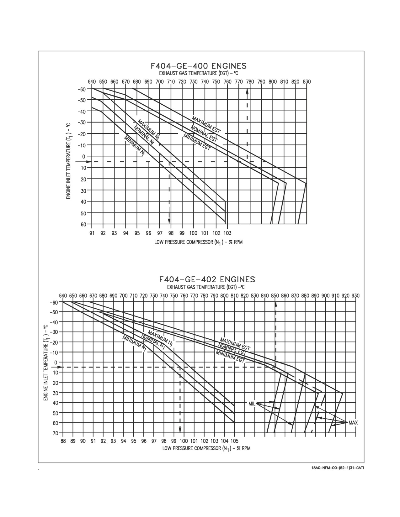
A1-F18AC-NFM-000
Figure 10-1. EGT and N1 Limits
III-10-15
ORIGINAL
A1-F18AC-NFM-000
5.
(AB) IFF - SQUAWK MODES/CODES as appropriate
6.
(AB) Heading checks −
- HSI heading matches BRC within ± 3°
- STBY magnetic compass within limits of compass card
At catapult tension signal -
7.
(AB) Engine run−ups − PERFORM (together)
a. Throttles both engines - IDLE to MIL
- Low pressure compressor (N1) rpm and EGT are scheduled as a function of engine inlet
temperature (T1) see figure 10-1.
- High pressure compressor (N2) rpm varies with N1 and EGT and should not be used to reject
an engine when N1 and EGT are within limits unless N2
is above maximum rpm (102%).
b. ENG page - CHECK ENGINES AT MIL
If F404-GE-400 Engine -
- N1 rpm - 94 to 103%
- N2 rpm - 92 to 102%
- EGT - 715° to 830°C (852°C MAX TRANSIENT)
- FF - 6,000 to 9,000 pounds per hour
- NOZ POS - 0 to 57%
- OIL PRESS - 95 to 180 psi
- VIB - Display not valid
- FUEL TEMP - 78°C maximum
If F404-GE-402 Engine -
- N1 rpm - 94 to 105%
- N2 rpm - 90 to 102%
- EGT - 715° to 880°C (902°C MAX TRANSIENT)
- FF - 6,000 to 12,500 pounds per hour
- NOZ POS - 0 to 48%
- OIL PRESS - 95 to 180 psi
- VIB - Display not valid
III-10-16
ORIGINAL
A1-F18AC-NFM-000
- FUEL TEMP - 78°C maximum
8.
(AB) Afterburners - SELECT
- Both nozzles open correctly.
- Feed tanks remain full during takeoff, climb, and immediately following climb.
10.2.1.6 Shorebased Takeoff Checks
1.
(AB) Canopy - CHECK CLEAR/CLOSED (CANOPY caution removed)
2.
(AB) OXY FLOW knob(s) - ON/MASK(S) ON
3.
(AB) T.O. Checklist - COMPLETE
4.
(AB) PARK BRK handle - FULLY STOWED in position and hold
5.
(AB) IFF - SQUAWK MODES/CODES as appropriate
6.
(AB) HEADING CHECKS -
- HSI heading within ± 3° of known runway heading.
- STBY magnetic compass within limits of compass card.
7.
(AB) Engine run-ups - PERFORM (individually)
a. Throttle affected engine - IDLE to MIL
- Low pressure compressor (N1) rpm and EGT are scheduled as a function of engine inlet
temperature (T1) see figure 10-1.
- High pressure compressor (N2) rpm varies with N1 and EGT and should not be used to reject
an engine when N1 and EGT are within limits unless N2 is above maximum rpm (102%).
b. ENG page - CHECK ENGINES AT MIL
If F404-GE-400 engine -
- N1 rpm - 94 to 103%
- N2 rpm - 92 to 102%
- EGT - 715° to 830°C (852°C MAX TRANSIENT)
- FF - 6,000 to 9,000 pounds per hour
- NOZ POS - 0 to 57%
- OIL PRESS - 95 to 180 psi
- VIB - Display not valid
- FUEL TEMP - 78°C maximum
If F404-GE-402 engine -
- N1 rpm - 94 to 105%
- N2 rpm - 90 to 102%
III-10-17
ORIGINAL
A1-F18AC-NFM-000
- EGT - 715° to 880°C (902°C MAX TRANSIENT)
- FF - 6,000 to 12,500 pounds per hour
- NOZ POS - 0 to 48%
- OIL PRESS - 95 to 180 psi
- VIB - Display not valid
- FUEL TEMP - 78°C maximum
c. Throttle affected engine − MIL to IDLE, pause 1 second, IDLE to MIL
− Engine responds with normal acceleration characteristics.
− No stall or stagnation.
d. Throttle affected engine − IDLE
e. Repeat steps a thru d for opposite engine.
When cleared for takeoff -
8.
(AB) Afterburner takeoff − PERFORM IAW chapter 7.
− Both nozzles open correctly.
− Feed tanks stay full during takeoff, climb, and immediately following climb.
10.2.1.7 Takeoff
NOTE
Autopilot modes can be used.
1.
(AB) Afterburner takeoff - PERFORM IAW Chapter 7
• Ensure nozzles open and feed tanks stay full during and immediately following the climb.
2.
(A) Landing gear - RETRACT
• The landing gear should retract in 7 seconds maximum.
3.
(A) Radar altimeter - CHECK
• Check HUD and radar altimeter indications during climb to 5,000 feet.
• Above 5,000 feet, HUD R changes to a flashing B and the radar altimeter OFF flag is in view.
4.
(AC) FCS RIG Check - 10,000 Feet
Only perform if -
• Aircraft symmetrically loaded (external/internal wing tank fuel asymmetry less than 300 lb).
a. Autopilot mode - Disengage in 1g flight
b. Check memory inspect unit 14, address 5016. If first and third lines are not between 177200 and
177777 or between 000000 and 000600, re-trim laterally until within this range.
c. Stabilize at each incremental airspeed and trim rudder, if required, to center ball prior to
roll-off check. Release controls from wings-level and record the direction of roll-off and
angle-of-bank (AOB) at the end of 6 seconds.
III-10-18
ORIGINAL
A1-F18AC-NFM-000
d. 200 KCAS
e.
300 KCAS
f.
400 KCAS
g.
500 KCAS
h. 550 KCAS
• The 550 KCAS check should not be performed if a pod is loaded on station
4
or
6.
NOTE
RIG Check fails if any AOB > 30° (> 5° per second); however,
for
diagnostics purposes, complete all applicable roll-off checks.
5.
(AB) Throttle transients - CHECK (one at a time)
D At 10,000 feet and Mach 0.75 perform the following throttle transients.
a. Throttle affected engine - IDLE to MAX
• Afterburner lights within 10 seconds.
b. Throttle affected engine - MAX to IDLE, pause 3 seconds, IDLE to MAX
• Afterburner lights within 10 seconds.
• Engine responds smoothly with no stall, stagnation, or flameout.
c. Repeat steps a and b for opposite engine
10.2.1.8 Medium Altitude (15,000 Feet)
NOTE
Altitude blocks are suggested ONLY to provide a logical sequence for
the FCF procedures. Deviations from these block altitudes
are
acceptable unless specified.
1.
(A) Fuel dump - CHECK
• Perform functional check of fuel dump.
2.
(A) Automatic dump shutoff - CHECK
• Set BINGO at internal fuel remaining level.
• Check that automatic shutoff occurs within ±400 pounds of setting.
3.
(A) COMM - CHECK
• Comm switches function normally.
• Both radios operative in transmit and receive.
• UHF and VHF preset, manual and guard frequency selection operative.
4.
(AC) Flight control damping - CHECK
a. Airspeed - Maintain 300 to 350 KCAS
III-10-19
ORIGINAL
A1-F18AC-NFM-000
b. Make small, abrupt pitch, roll, and yaw inputs.
• Aircraft response is appropriate.
• No oscillation tendencies noted.
5.
(A) Fuel transfer - MONITOR
• Periodically monitor fuel quantity during flight ensuring normal fuel transfer occurs.
6.
(A) IFF operation - CHECK
• ATC reports valid mode 3 and C.
If/when possible -
a. IFF MASTER switch - EMERG
• ATC reports valid emergency squawk (7700).
7.
(A) Cabin pressure - CHECK
• Check cabin pressure is 8,000 ±1,000 feet.
8.
(AC) AFCS - CHECK
a. A/P - At 350 knots, 15,000 feet with bank angle ≤ 5°, engage A/P switch.
• Check that aircraft maintains heading.
b. Attitude hold -
(1) Bank aircraft 45° left using CSS.
• Check that aircraft maintains attitude.
(2) Bank aircraft 45° right using CSS.
• Check that aircraft maintains attitude.
(3) Input ±10° pitch commands using CSS.
• Check that aircraft maintains heading and attitude.
c. Heading select -
(1) Select 30° left heading change with the HDG set switch. Select HSEL option.
• Check that heading hold is reestablished after selected heading is captured.
(2) Repeat with 30° right heading change.
d. Barometric altitude hold -
(1) Select BALT option during a 4,000 feet/minute climb.
• Check that altitude is captured and maintained.
(2) Repeat during 4,000 feet/minute dive.
(3) Perform 45° bank turn.
• Check that altitude is maintained within ±100 feet.
9.
(AB) ATC cruise mode - CHECK
Engage ATC cruise mode between 300 and 350 knots.
• Ensure system maintains engaged airspeed in level flight and banked turns.
III-10-20
ORIGINAL
A1-F18AC-NFM-000
10. (ABC) Perform negative G check for FOD.
10.2.1.9 High Altitude (Above 30,000 Feet)
1.
(A) Cabin pressurization/temperature - MONITOR
• During climb, check cabin pressurization/temperature control.
• Pressurization shall remain at 8,000 feet up to 23,000 - 24,000 feet altitude.
• Above 23,000 to 24,000 feet altitude refer to figure 2-37.
AIRCRAFT
CABIN
ALTITUDE
ALTITUDE
30,000 feet
10,000 to 12,000 feet
40,000 feet
15,000 to 17,000 feet
2.
(AB) Throttle transients - CHECK (one at a time)
• At 35,000 feet and 200 to 220 knots, perform the following throttle transients.
a. Throttle affected engine - IDLE to MAX
• Afterburner lights within 15 seconds.
b. Throttle affected engine - MAX to IDLE, pause 3 seconds, IDLE to MAX
• Afterburner lights within 15 seconds.
• Engine responds smoothly with no stall, stagnation, or flameout.
c. Repeat steps a and b for opposite engine.
3.
(AB) Speed run/rpm lock up - PERFORM
• Above Mach 1.23, retard the throttles to flight IDLE (one at a time).
• The rpm shall not drop more than 10% below MIL rpm with throttles at flight IDLE.
4.
(A) Tank 1 and 4 transfer - CHECK
Aircraft 161353 THRU 161519 BEFORE AFC 039 -
D Tank 4 depletes faster than tank 1 at low power settings.
D Tanks 1 and 4 deplete together at high power settings.
D Tank 4 quantity not more than 1,300 pounds (2,000 pounds for F/A-18B) greater than tank
1
quantity.
Aircraft 161353 THRU 161519 AFTER AFC 039 and 161520 AND UP -
D Tanks 1 and 4 fuel quantities fall within allowable limits.
D CG/FUEL XFER caution off.
D No more than 1,700 pounds (F/A-18A/C) 1,100 pounds (F/A-18B) remaining in tank 1 when
tank 4 reaches 150 pounds.
D On F/A-18D, tank 4 quantity should be between 0 and 600 pounds when tank 1 empties.
All aircraft -
5.
(A) Perform Static Radome Check - Above 30,000 feet
III-10-21
ORIGINAL
A1-F18AC-NFM-000
a. Verify configuration for unlimited AOA and CG not aft of 23.5% MAC.
b. Laterally and directionally trim to neutral - centered ball/ no rates.
c. Check altitude greater than 30,000 feet AGL.
d. Slow to 30-35° AOA unaccelerated flight and stabilize wings level.
e. Note initial heading
f. Continue deceleration by smoothly applying full aft stick, keeping neutral pedal and lateral
stick (approximately 2 sec from 35° AOA to full aft stick).
g. Hold full aft stick for 5 sec; do not counter roll and yaw.
If a sustained yaw rate develops in the 50 to 55° AOA region, inadvertent
departure from controlled flight and display of spin arrows may result. If
a yaw rate develops in the 50 to 55° AOA region, easing control stick
forward off the aft stop should immediately reduce the AOA below 50°
and terminate the yawing motion.
h. Observe yaw/roll rates, observe final heading.
(1) Recovery
(a) Minimum altitude for recovery initiation 25,000 feet AGL
(b) Reduce AOA with forward stick
(c) Re-establish level flight
(2) Failure criteria/Abort criteria
(a) Greater than 60° heading change in 5 seconds
(b) Rapid yaw acceleration
(c) Departure
(d) Spin arrows
NOTE
If aircraft fails radome check, the only maintenance action required is
to place a card in the ADB stating the aircraft is limited to 45° AOA.
10.2.1.10 18,000 TO 10,000 Feet
1.
(A) Radar - FUNCTIONAL CHECK
III-10-22
ORIGINAL
A1-F18AC-NFM-000
a. A/A master mode - CHECK
b. A/G master mode - CHECK
2.
(A) INS - CHECK
• Check present position error using tacan position update.
• Record and reject update.
• Functionally check designate and overfly.
3.
(A) HUD symbology - CHECK (both cockpits)
In NAV master mode with WYPT or TCN boxed -
• The following indications are present - heading, airspeed, altitude, barometric setting (for 5
seconds after set), AOA, Mach number, aircraft g, bank angle scale, velocity vector, flight
path/pitch ladder, steering arrow (TCN), and distance to WYPT or TCN.
• WYPT # displayed to right of distance when WYPT boxed.
• Three-letter identifier displayed to right of distance when TCN boxed.
• HUD and HI/MPCD distance agree.
• HUD format available on either DDI
D Check the VTR/HUD camera
4.
(A) Standby flight instruments - CHECK
a. Standby rate of climb indicator
• Indicates ±100 fpm or less during level 1g flight.
• Pointer movement smooth during climbs/descents.
b. Standby attitude reference indicator
(1) Perform a 360° roll right and left
• No gyro tumble
• Gyro indications are smooth thru bullseye.
(2) Perform a loop.
• During loop check that the HUD flight path/pitch ladder pitch lines are angled toward the
horizon.
• After completion of the loop, errors in pitch and roll may be present, particularly if the loop
is conducted in a wings level attitude. This is normal and the errors should be removed by
caging the indicator while the aircraft is in normal straight and level attitude.
c. Standby airspeed indicator
• Agrees with HUD.
• Pointer movement is smooth during airspeed changes.
d. Standby altimeter
III-10-23
ORIGINAL
A1-F18AC-NFM-000
• Agrees with barometric altitude on HUD
• Pointer and drum movement is smooth and does not hang up during thousand-foot changes.
NOTE
The HUD airspeed and altitude values are corrected by the ADC and
the standby instruments are not. Therefore, under certain flight
conditions the standby instruments may not agree with the HUD.
5.
(A) HI/MPCD - CHECK
a. HDG/TK set switch - SLEW
• Heading bug moves in correct direction.
• Digital display and bug setting agree.
b. CRS set switch - SLEW
• Steering arrow rotates in correct direction.
• Digital display and steering arrow agree.
c. Perform a course intercept using both WYPT and TCN steering.
• Steering arrow shall correspond to the steering arrow on the HUD.
• All display movement shall be smooth.
d. TCN bearing and range - CHECK
• Symbol displayed at appropriate position when compared to a waypoint or known landmark.
• Digital display and symbol agree.
6.
(A) Data link - CHECK (if possible)
7.
(AC) LEF System - CHECK
a. G-WARM - Perform
b. Stabilize at 450 knots/10,000 feet MSL. Commence a MIL power loop with a firm initial pull
to 4.5-5g. Monitor LEF position on the FCS page. Discontinue check if left-to-right split is
greater than 5 °. Any left-to-right split in flap position greater than 5° shall be recorded, and
follow-up maintenance action is required. Do not exceed 20° AOA with a split between left and
right LEF. If an HDU is weak the split should be seen during the first 90° of the loop. Greater
than 5° of left or right LEF split will likely result in uncommanded yaw/roll during
maneuvering flight.
8.
(C) FCF Profile - COMPLETE
10.2.1.11 10,000 Feet to Landing
1.
(A) Fuel transfer - MONITOR
a. Wing tanks deplete to 0 to 200 pounds before tank 1 or 4 falls below 200 pounds and wing tanks
empty following FUEL LO caution.
b. Feed tanks remain full until tanks 1 and 4 fall below 200 pounds in non-afterburner operation.
III-10-24
ORIGINAL
A1-F18AC-NFM-000
2.
(A) ADF receivers - CHECK
Check accuracy of ADF 1 and ADF 2.
• Bearing accuracy is as follows:
a. Off the nose (0° relative bearing) ±5°.
b. Off the wing tip (90° and 270° relative bearing) ±20°.
c. Off the tail (180° relative bearing) no specified accuracy.
3.
(A) Automatic speedbrake retract - CHECK
Extend the speedbrake then extend flaps.
• Ensure speedbrake retracts.
4.
(A) Landing gear warning light/warning tone - CHECK
Below 7,500 feet with the landing gear handle UP, reduce airspeed below 175 knots and establish
a rate of descent greater than 250 feet per minute.
• Check that the gear handle warning light flashes and the warning tone comes on.
5.
(AB) Emergency landing gear system - CHECK
a. Flaps - HALF
b. Slow to 160 knots if practical.
c. Pull landing gear circuit breaker.
NOTE
The rear cockpit landing gear UNSAFE lamp illuminates with the
circuit breaker pulled and the condition is normal.
d. Set gear handle to DN.
e. Rotate 90° and pull to detent.
• Gear should extend within 30 seconds.
f. Hold the HYD ISO SW in ORIDE for 10 seconds or until the APU ACCUM caution is removed
and the emergency brake accumulator is recharged.
• Gauge reads 2,750 to 3,250 psi and the needle stops moving.
g. Push handle in, rotate gear handle 90° COUNTERCLOCKWISE.
h. Reset circuit breaker.
To prevent damage to the main landing gear, the landing gear handle
must be outboard (down position) before resetting the handle from
emergency to normal. Wait 5 seconds following the circuit breaker or
handle reset before placing the landing gear handle up.
III-10-25
ORIGINAL
A1-F18AC-NFM-000
6.
(A) AOA tone - CHECK
With flaps HALF or FULL, increase AOA to 15° and check that AOA tone comes on at
12°±0.5° with FULL flaps or 15°±0.5° with HALF flaps.
7.
(A) Landing gear - RETRACT
8.
(A) Flaps auto retract - CHECK
a. Increase airspeed.
• Flaps should retract to AUTO at 250 ±10 knots (amber flap light).
b. FLAPS - AUTO
9.
(A) ILS/ACLS - FUNCTIONAL CHECK (if facility available)
• Perform a functional check of the instrument landing system and the ACLS.
10. (A) AOA indexer brightness - CHECK AND SET
• With landing gear down check brightness from DIM thru BRT then set to the desired
brightness.
11. (A) Radar altitude hold - CHECK
12. (AB) ATC approach mode - FUNCTIONAL CHECK
• Perform a functional check of the ATC mode.
13. (B) FCF Profile - COMPLETE
10.2.1.12 After Landing
1.
(A) Anti-skid - CHECK
Above 75 knots apply full brake pressure.
• Check that anti-skid action is smooth and exhibits no left or right pulling tendencies.
2.
(A) Nosewheel steering high mode - CHECK
At reduced taxi speed, unlock the wing fold and press and release the nosewheel steering button.
• Ensure nosewheel steering goes to high gain and stays in high gain.
3.
(A) Emergency HI gain NWS - CHECK
Pull FCS CHAN 2 circuit breaker, wait for the FCS channel to shut down (column of X’s on the
FCS page), unlock the wings, and press NWS button. Emergency HI gain NWS should be
available. Reset FCS CHAN 2. Repeat for FCS CHAN 4 circuit breaker.
• When the emergency HI gain NWS mode is entered, NWS indication may not be displayed on
the HUD.
4.
(A) Wingfold - CHECK
5.
(A) Parking brake - SET
6.
(A) INS terminal error - RECORD
Maximum error for a gyro compass alignment is 1.5 nm per hour of operating time.
• GPS assisted INS terminal error should be almost zero.
7.
(A) BIT/BLIN - CHECK
III-10-26
ORIGINAL
A1-F18AC-NFM-000
8.
(A) FCF Profile - COMPLETE
10.2.2 Checkflight Requirements (Rear Cockpit). This Rear Cockpit section outlines only the
additional checks to establish acceptance standards for the systems peculiar to the F/A-18B/D aircraft.
The checks and success criteria specified in the Front Cockpit section also apply to the F/A-18B/D
aircraft. Instrument and indicator reading, warning lights, and radar and navigation displays in the
rear cockpit are to be compared throughout the flight with corresponding information available from
the front cockpit. An aft crewmember is required for D profile FCFs. For A, B, or C profiles, if an aft
crewmember is available, the following checks should be made.
10.2.2.1 Before Taxi. Perform the before taxi procedures IAW Chapter 7.
1.
(A) Fuel quantity gauge - CHECK (F/A-18B)
• During front cockpit BIT, make sure the TOTAL and INTERNAL counters agree with front
cockpit indications ±200 pounds.
2.
(A) IFEI - CHECK (F/A-18D)
• During front cockpit BIT, make sure the TOTAL and INTERNAL displays agree with front
cockpit displays.
3.
(AC) Speedbrake - CYCLE
• On aft stick and throttle equipped F/A-18D check operation of the speedbrake from the rear
cockpit.
4.
(A) Attitude reference indicator - CHECK
• Check that attitude reference indicator is adjustable. Minimum adjustment is ±5°.
5.
(A) Standby altimeter - SET AND CHECK
Set reported barometric pressure in window.
• Check that altimeter reads within ±60 feet of ramp elevation.
6.
(A) Warning/caution lights - TEST
• Check for proper operation of the warning/caution lights.
7.
(A) DDIs - ON AND SET
• Set the brightness or contrast as desired.
Aircraft 164196 AND UP -
8.
(A) OXY FLOW knob - ON
• Check flow
10.2.2.2 Taxi
1.
(A) Brakes - TEST
a. ANTI SKID switch - OFF
• SKID advisory on
• Check brakes when leaving the chocks
b. ANTI SKID switch - ON
• SKID advisory off
III-10-27
ORIGINAL
A1-F18AC-NFM-000
c. Normal brakes - CHECK
• Check brakes during taxi
2.
(A) Nosewheel steering - CHECK
• NWS responds appropriately in LO and HI gain modes.
• NWS disengages when paddle switch held
3.
(AC) Emergency brakes - CHECK
NOTE
Anti-skid system is inoperative during emergency brake system
operation.
10.2.2.3 Medium Altitude (15,000 Feet)
NOTE
Altitude blocks are suggested ONLY to provide a logical sequence for
the FCF procedures. Deviations from these block altitudes are
acceptable unless specified.
1.
(A) Comm - CHECK
• Comm switches function normally.
• Both radios operative in transmit and receive.
• UHF and VHF preset, manual and guard frequency selection operative.
10.2.2.4 High Altitude (Above 30,000 Feet)
1.
(A) Cabin pressurization/temperature - MONITOR
During climb, check cabin pressurization/temperature control. Pressurization shall remain at
8,000 feet up to 23,000 - 24,000 feet altitude. Above 23,000 to 24,000 feet altitude refer to figure
2-37.
AIRCRAFT
CABIN
ALTITUDE
ALTITUDE
30,000 feet
10,000 to 12,000 feet
40,000 feet
15,000 to 17,000 feet
10.2.2.5 18,000 TO 10,000 Feet
1.
(A) Standby flight instruments - CHECK
a. Standby rate of climb indicator
• Indicates ±100 fpm or less during level 1g flight.
• Pointer movement smooth during climbs/descents.
b. Standby attitude reference indicator
D During the 360° roll right and left, no gyro tumble is permitted.
III-10-28
ORIGINAL
A1-F18AC-NFM-000
D After completion of the loop, errors in pitch and roll may be present, particularly if the loop
is conducted in a wings level attitude. This is normal and the errors should be removed by
caging the indicator while the aircraft is in normal straight and level attitude.
c. Standby airspeed indicator
• Agrees with HUD.
• Pointer movement is smooth during airspeed changes.
d. Standby altimeter
• Agrees with barometric altitude on HUD
• Pointer and drum movement is smooth and does not hang up during thousand-foot changes.
NOTE
The HUD airspeed and altitude values are corrected by the ADC and
the standby instruments are not. Therefore, under certain flight
conditions the standby instruments may not agree with the HUD.
10.2.2.6 10,000 Feet to Landing
1.
(AC) Flight controls and throttles - FUNCTIONALLY CHECK
2.
(AC) Hand controllers - CHECK
• Verify operation of hand controllers. Selection of displays in rear cockpit shall not affect display
selection in forward cockpit.
3.
(C) FCF Profile - COMPLETE
4.
(A) Emergency landing gear system - CHECK
a. Flaps - HALF
b. Slow to 160 knots if practical.
c. Pull the EMERG LDG GEAR handle until it locks in the detent. (This is to be accomplished
without any activation of the front cockpit emergency extension system.)
d. Check that gear indicates down within 30 seconds.
e. Front crewmember set the landing gear handle to DN and hold the HYD ISO switch in ORIDE
for 10 seconds or until the APU ACCUM caution is removed and the emergency brake
accumulator is recharged (gauge reads 2,750 to 3,250 psi and the needle stops moving).
To prevent damage to the main landing gear, the landing gear handle
must be outboard (down position) before resetting the handle from
emergency to normal. Wait 5 seconds following the circuit breaker or
handle reset before placing the landing gear handle up.
f. Reset the rear EMERG LDG GEAR handle, then have front crewmember raise the landing
gear.
III-10-29
ORIGINAL
A1-F18AC-NFM-000
10.2.2.7 After Landing
1.
(A) BIT - CHECK DISPLAY
2.
(A) FCF Profile - COMPLETE
10.3 FCF CHECKLIST - PROFILE B
10.3.1
F/A-18A/C (F/A-18B/D Front Cockpit)
10.3.1.1 Preflight
1.
(B) Exterior Inspection - Perform IAW Chapter
7
D No loose or improperly installed panels.
2.
(B) Interior Checks - Perform IAW Chapter 7
10.3.1.2 Engine Start
1.
(B) BATT switch - ON (if not previously on)
2.
(B) READY (Fire extgh)/DISCH light - OUT
3.
(B) APU - START
4.
(B) Right engine - START
Perform engine start IAW Chapter 7.
5.
(B) BLEED AIR knob - ROTATE THROUGH OFF TO NORM
6.
(B) Left engine - START
Perform engine start IAW Chapter 7.
7.
(B) FCS - RESET
8.
(B) FLAP switch - AUTO
9.
(B) BLEED AIR system - CHECK
a. Throttles - IDLE
b. BLEED AIR knob - CHECK EACH POSITION INDIVIDUALLY
(1) R OFF
• R BLD OFF caution displayed.
• M ASTER CAUTION light on and tone sounds.
• Left engine TEMP increases 5° to 90°C.
(2) MASTER CAUTION light - RESET
(3) Pause 5 seconds to allow Master Caution tone to reset.
III-10-30
ORIGINAL
A1-F18AC-NFM-000
(4) OFF
• L and R BLD OFF cautions displayed.
• M ASTER CAUTION light on and tone sounds.
• Cabin airflow stops.
(5) L OFF
• R BLD OFF caution removed.
• Right engine TEMP increases 5° to 90°C.
• Cabin airflow resumes.
c. BLEED AIR knob - NORM
• L BLD OFF caution removed.
• M ASTER CAUTION light out.
d. FIRE test switch - TEST A (for at least 2 seconds)
• L and R BLEED warning lights on while switch held.
• Voice alert sequence initiated.
• L and R BLD OFF cautions displayed.
• Cabin airflow stops.
e. BLEED AIR knob - CYCLE THRU OFF TO NORM
• L and R BLD OFF cautions removed.
• Cabin airflow resumes.
f. Repeat steps d and e for the TEST B position.
10. (B) Engine FIRE light shutdown - PERFORM
a. Left throttle - IDLE (For 2 minutes)
b. Left FIRE light - PUSH
• FIRE EXTGH READY light on
• L BOOST LO caution on
• M ASTER CAUTION light on
• M aster Caution tone sounds
When rpm is less than 60% -
D L FLAMEOUT caution on
D ″Engine Left/Right″ voice warning sounds
D W ith engine at IDLE, it may take as long as 60
seconds before the engine shuts down
When rpm is less than 10% -
c. Left throttle - OFF
d. Left FIRE light - RESET
D FIRE EXTGH READY light off
11. (B) Verify proper switching valve operation.
III-10-31
ORIGINAL
A1-F18AC-NFM-000
a. Monitor HYD pressure. As pressure decreases below 1,500 psi, gently pump the stick
approximately ±1 inch fore and aft at approximately two cycles per second, decreasing
hydraulic pressure on shutdown engine below 800 psi. Ensure system pressure on operating
engine remains above 1,500 psi.
b. Continue gently pumping the stick while monitoring FCS page for FCS Xs and/or BLIN codes
for 12 seconds after system pressure on shutdown engine drops below
800
psi.
Record if
present.
c. Monitor FCS page for FCS Xs or BLIN codes. Record if present.
12. (B) APU - OFF
13. (B) Left engine - CROSSBLEED START
14. (B) Repeat steps 9 and 10 for the right engine.
15. (B) Right engine - CROSSBLEED START
16. (B) Hydraulic pressure - CHECK
• Check that HYD1 and HYD2 pressures are 2,850 to
3,250
psi.
17. (B) Generators - CHECK
a. R GEN switch - OFF
• RDDI operative
b. L GEN switch - OFF
• BATT SW caution on
• Leave both generators off for at least 10 seconds.
c. BATT switch - ORIDE
• BATT SW caution on
• ARI OFF flag out of view
• GEN TIE caution light out
d. R GEN switch - NORM
• GEN TIE caution light on
e. BATT switch - ON
• BATT SW caution off
• GEN TIE caution off
• LDDI operative
f. L GEN switch - NORM
g. FCS - CHECK DDI DISPLAY AND RESET IF REQUIRED
10.3.1.3 Before Taxi
1.
(B) Before taxi procedures - PERFORM
Perform before taxi procedures IAW Chapter 7.
III-10-32
ORIGINAL
A1-F18AC-NFM-000
2.
(B) Full stabilator travel verification -
Set stab trim to 4° NU and verify that:
Flaps - FULL
AFT:
24 NU
FWD: 10 ND
Wings spread - R/L AILERON: 16 differential stabilator
Wings folded - R/L AILERON: 20 differential stabilator
3.
(B) Flaps - FULL
While at full flaps, cycle stick in small circular motions (1 to 2 inches diameter) at a rate slower than
one cycle per second. Stick motion should be smooth and continuous. If stick provides uncom-
manded movement, horizontal stabilator servocylinder and mechanical linkage troubleshooting is
required prior to flight.
4.
(B) Flaps - HALF
10.3.1.4 Shipboard Taxi/Takeoff Checks
1.
(B) Canopy - CHECK CLEAR/CLOSED (CANOPY caution removed)
2.
(B) OXY FLOW knob(s) - ON/MASK(S) ON prior to tie down removal
3.
(B) PARK BRK handle - FULLY STOWED on catapult
4.
(B) T.O. checklist - COMPLETE from bottom to top
5.
(B) IFF - SQUAWK MODES/CODES as appropriate
6.
(B) Heading checks -
- HSI heading matches BRC within ± 3°
- STBY magnetic compass within limits of compass card
At catapult tension signal -
7.
(B) Engine run-ups - PERFORM (together)
a. Throttles both engines - IDLE to MIL
- Low pressure compressor (N1) rpm and EGT are scheduled as a function of engine inlet
temperature (T1) see figure 10-1.
- High pressure compressor (N2) rpm varies with N1 and EGT and should not be used to reject
an engine when N1 and EGT are within limits unless N2 is above maximum rpm (102%).
b. ENG page - CHECK ENGINES AT MIL
If F404-GE-400 Engine -
- N1 rpm - 94 to 103%
- N2 rpm - 92 to 102%
- EGT - 715° to 830°C (852°C MAX TRANSIENT)
III-10-33
ORIGINAL
A1-F18AC-NFM-000
- FF - 6,000 to 9,000 pounds per hour
- NOZ POS - 0 to 57%
- OIL PRESS - 95 to 180 psi
- VIB - Display not valid
- FUEL TEMP - 78°C maximum
If F404-GE-402 Engine -
- N1 rpm - 94 to 105%
- N2 rpm - 90 to 102%
- EGT - 715° to 880°C (902°C MAX TRANSIENT)
- FF - 6,000 to 12,500 pounds per hour
- NOZ POS - 0 to 48%
- OIL PRESS - 95 to 180 psi
- VIB - Display not valid
- FUEL TEMP - 78°C maximum
8.
(B) Afterburners − SELECT
- Both nozzles open correctly.
- Feed tanks remain full during takeoff, climb, and immediately following climb.
10.3.1.5 Shorebased Takeoff Checks
1.
(B) Canopy - CHECK CLEAR/CLOSED (CANOPY caution removed)
2.
(B) OXY FLOW knob(s) - ON/MASK(S) ON
3.
(B) T.O. Checklist - COMPLETE
4.
(B) PARK BRK handle - FULLY STOWED in position and hold
5.
(B) IFF - SQUAWK MODES/CODES as appropriate
6.
(B) Heading checks -
- HSI heading within ± 3° of known runway heading.
- STBY magnetic compass within limits of compass card.
7.
(B) Engine run-ups - PERFORM (individually)
a. Throttle affected engine − IDLE to MIL
- Low pressure compressor (N1) rpm and EGT are scheduled as a function of engine inlet
III-10-34
ORIGINAL
A1-F18AC-NFM-000
temperature (T
1) see figure 10−1.
- High pressure compressor (N2) rpm varies with N1 and EGT and should not be used to reject
an engine when N1 and EGT are within limits unless N
is above maximum rpm (102%).
2
b. ENG page - CHECK ENGINES AT MIL
If F404-GE-400 Engine -
- N1 rpm - 94 to 103%
- N2 rpm - 92 to 102%
- EGT - 715° to 830°C (852°C MAX TRANSIENT)
- FF - 6,000 to 9,000 pounds per hour
- NOZ POS - 0 to 57%
- OIL PRESS - 95 to 180 psi
- VIB - Display not valid
- FUEL TEMP - 78°C maximum
If F404-GE-402 Engine -
- N1 rpm - 94 to 105%
- N2 rpm - 90 to 102%
- EGT - 715° to 880°C (902°C MAX TRANSIENT)
- FF - 6,000 to 12,500 pounds per hour
- NOZ POS - 0 to 48%
- OIL PRESS - 95 to 180 psi
- VIB - Display not valid
- FUEL TEMP - 78°C maximum
c. Throttle affected engine − MIL to IDLE, pause
1
second, IDLE to MIL
− Engine responds with normal acceleration characteristics.
− No stall or stagnation.
d. Throttle affected engine − IDLE
e. Repeat steps a thru d for opposite engine.
8.
(B) Afterburners − PERFORM IAW Chapter 7.
− Both nozzles open correctly.
− Feed tanks remain full during takeoff, climb, and immediately following climb.
III-10-35
ORIGINAL
A1-F18AC-NFM-000
10.3.1.6 Takeoff
NOTE
Autopilot modes can be used.
1.
(B) Afterburner takeoff - PERFORM IAW Chapter 7
• Ensure nozzles open and feed tanks stay full during and immediately following the climb.
2.
(B) Throttle transients - CHECK (one at a time)
D At 10,000 feet and Mach 0.75 perform the following throttle transients.
a. Throttle affected engine - IDLE to MAX
• Afterburner lights within 10 seconds.
b. Throttle affected engine - MAX to IDLE, pause 3 seconds, IDLE to MAX
• Afterburner lights within 10 seconds.
• Engine responds smoothly with no stall, stagnation, or flameout.
c. Repeat steps a and b for opposite engine
10.3.1.7 Medium Altitude (15,000 Feet)
NOTE
Altitude blocks are suggested ONLY to provide a logical sequence for
the FCF procedures. Deviations from these block altitudes are
acceptable unless specified.
1.
(B) ATC cruise mode - CHECK
Engage ATC cruise mode between 300 and 350 knots.
• Ensure system maintains engaged airspeed in level flight and banked turns.
2.
(B) Perform negative G check for FOD.
10.3.1.8 High Altitude (Above 30,000 Feet)
1.
(B) Throttle transients - CHECK (one at a time)
• At 35,000 feet and 200 to 220 knots, perform the following throttle transients.
a. Throttle affected engine - IDLE to MAX
• Afterburner lights within 15 seconds.
b. Throttle affected engine - MAX to IDLE, pause 3 seconds, IDLE to MAX
• Afterburner lights within 15 seconds.
• Engine responds smoothly with no stall, stagnation, or flameout.
c. Repeat steps a and b for opposite engine.
2.
(B) Speed run/rpm lock up - PERFORM
• Above Mach 1.23, retard the throttles to flight IDLE (one at a time).
• The rpm shall not drop more than 10% below MIL rpm with throttles at flight IDLE.
III-10-36
ORIGINAL
A1-F18AC-NFM-000
10.3.1.9 10,000 Feet to Landing
1.
(B) Emergency landing gear system - CHECK
a. Flaps - HALF
b. Slow to 160 knots if practical.
c. Pull landing gear circuit breaker.
NOTE
The rear cockpit landing gear UNSAFE lamp illuminates with the
circuit breaker pulled and the condition is normal.
d. Set gear handle to DN.
e. Rotate 90° and pull to detent.
• Gear should extend within 30 seconds.
f. Hold the HYD ISO SW in ORIDE for 10 seconds or until the APU ACCUM caution is removed
and the emergency brake accumulator is recharged.
• Gauge reads 2,750 to 3,250 psi and the needle stops moving.
g. Push handle in, rotate gear handle 90° COUNTERCLOCKWISE.
h. Reset circuit breaker.
To prevent damage to the main landing gear, the landing gear handle
must be outboard (down position) before resetting the handle from
emergency to normal. Wait 5 seconds following the circuit breaker or
handle reset before placing the landing gear handle up.
2.
(B) ATC approach mode - FUNCTIONAL CHECK
• Perform a functional check of the ATC mode.
10.3.1.10 After Landing
1.
(B) FCF Profile - COMPLETE
10.4 FCF CHECKLIST - PROFILE C
10.4.1
F/A-18A/C (F/A-18B/D Front Cockpit)
10.4.1.1 Preflight
1.
(C) Exterior Inspection - Perform IAW Chapter 7
D No loose or improperly installed panels.
III-10-37
ORIGINAL
A1-F18AC-NFM-000
2.
(C) Interior Checks - Perform IAW Chapter 7
10.4.1.2 Engine Start
1.
(C) FLAP switch - AUTO
2.
(C) BATT switch - ON (if not previously on)
3.
(C) READY (Fire extgh)/DISCH light - OUT
4.
(C) Control stick - CYCLE
5.
(C) APU - START
6.
(C) ENG CRANK switch - R
Leave throttle in cutoff.
7.
(C) Mechanical linkage - CHECK
After both stabilators fair to the neutral position -
a. Move stick slowly forward or aft and release.
• Both stabilators shall move smoothly and symmetrically with stick input and return to
neutral when stick is released.
b. Move the stick left and right.
• Ensure the corresponding stabilator trailing edge deflects up differentially higher than the
opposite stabilator trailing edge.
c. Hold the stick full aft and move the FLAP switch to HALF or FULL.
• Visually, or using the FCS status display, verify that both stabilators move to a higher trailing
edge up position.
8.
(C) Right engine - START
Perform engine start IAW Chapter 7.
9.
(C) BLEED AIR knob - ROTATE THROUGH OFF TO NORM
10. (C) Left engine - START
Perform engine start IAW Chapter 7.
11. (C) On DDI FCS display - VERIFY STAB Xs (FAILED) IN CHANNELS 1 AND 2
12. (C) FCS - RESET
13. (C) FLAP switch - AUTO
14. (C) BLEED AIR system - CHECK
a. Throttles - IDLE
b. BLEED AIR knob - CHECK EACH POSITION INDIVIDUALLY
III-10-38
ORIGINAL
A1-F18AC-NFM-000
(1) R OFF
• R BLD OFF caution displayed.
• M ASTER CAUTION light on and tone sounds.
• Left engine TEMP increases 5° to 90°C.
(2) MASTER CAUTION light - RESET
(3) Pause 5 seconds to allow Master Caution tone to reset.
(4) OFF
• L and R BLD OFF cautions displayed.
• M ASTER CAUTION light on and tone sounds.
• Cabin airflow stops.
(5) L OFF
• R BLD OFF caution removed.
• Right engine TEMP increases 5° to 90°C.
• Cabin airflow resumes.
c. BLEED AIR knob - NORM
• L BLD OFF caution removed.
• M ASTER CAUTION light out.
d. FIRE test switch - TEST A (for at least 2 seconds)
• L and R BLEED warning lights on while switch held.
• Voice alert sequence initiated.
• L and R BLD OFF cautions displayed.
• Cabin airflow stops.
e. BLEED AIR knob - CYCLE THRU OFF TO NORM
• L and R BLD OFF cautions removed.
• Cabin airflow resumes.
f. Repeat steps d and e for the TEST B position.
15. (C) Engine FIRE light shutdown - PERFORM
a. Left throttle - IDLE (For 2 minutes)
b. Left FIRE light - PUSH
• FIRE EXTGH READY light on
• L BOOST LO caution on
• M ASTER CAUTION light on
• M aster Caution tone sounds
When rpm is less than 60% -
D L FLAMEOUT caution on
D ″Engine Left/Right″ voice warning sounds
D W ith engine at IDLE, it may take as long as 60 seconds before the engine shuts down.
III-10-39
ORIGINAL
A1-F18AC-NFM-000
When rpm is less than 10% -
c. Left throttle - OFF
d. Left FIRE light - RESET
D FIRE EXTGH READY light off
16. (C) Verify proper switching valve operation.
a. Monitor HYD pressure. As pressure decreases below 1,500 psi, gently pump the stick
approximately ±1 inch fore and aft at approximately two cycles per second, decreasing
hydraulic pressure on shutdown engine below 800 psi. Ensure system pressure on operating
engine remains above 1,500 psi.
b. Continue gently pumping the stick while monitoring FCS page for FCS Xs and/or BLIN codes
for 12 seconds after system pressure on shutdown engine drops below 800 psi. record if present.
c. Monitor FCS page for FCS Xs or BLIN codes. Record if present.
17.
(C) APU - OFF
18. (C) Left engine - CROSSBLEED START
19. (C) Repeat steps 14 and 15 for the right engine.
20. (C) Right engine - CROSSBLEED START
21. (C) Hydraulic pressure - CHECK
• Check that HYD1 and HYD2 pressures are 2,850 to 3,250 psi.
10.4.1.3 Before Taxi
1.
(C) Before taxi procedures - PERFORM
Perform before taxi procedures IAW Chapter 7.
2.
(C) Flight controls - CHECK/BIT
a. If wings folded verify both ailerons Xd out.
b. Flaps - HALF
c. FCS IBIT - INITIATE
III-10-40
ORIGINAL
A1-F18AC-NFM-000
Flight with any PBIT BLIN other than 51, 124, 322 and 336, or IBIT
BLIN 4124, 4263, 4322, 4336, 4522, 4526, 4527, 4773, 4774, and 70261 can
result in a flight control system failure and aircraft loss. If IBIT detects
any failure other than those indicated by the IBIT BLINs listed above,
IBIT must be performed again, following an FCS reset, to ensure the
detected failure no longer exists. Pressing the FCS reset button, simul-
taneously with the paddle switch, does not correct BIT detected flight
control system failures; it simply clears the BLIN code(s) from the
display. If the second IBIT is not successful, the aircraft requires
corrective maintenance action to address the failure(s).
NOTE
If BLIN 51 does not reset after airborne, wing-fold function may not
be available after landing.
d. AOA warning tone - VERIFY ANNUNCIATION AT FCS IBIT COMPLETION
3.
(C) FCC keep-alive circuitry - CHECK
a. FCC circuit breakers - Pull in sequence 1, 2, 3, and 4
b. Immediately reset in sequence 1, 2, 3, 4
• Complete within 7 seconds for valid test.
• No FCC channel completely Xd out.
4.
(C) GAIN override switch - ORIDE
a. Check LAND advisory displayed.
b. GAIN override switch - NORM
5.
(C) SPIN recovery mode - CHECK
a. Flaps - AUTO
b. Select FCS display on MPCD (aircraft 163985 AND UP).
c. SPIN recovery switch - RCVY
d. Check both DDIs - SPIN MODE ENGAGED
e. Flaps - CHECK LEF DOWN 33° ±1° down, TEF UP 0° (±1°).
f. SPIN recovery switch - NORM
6.
(C) Full stabilator travel verification -
Set stab trim to 4° NU and verify that:
III-10-41
ORIGINAL
A1-F18AC-NFM-000
Flaps - FULL
AFT:
24 NU
FWD: 10 ND
Wings spread - R/L AILERON: 16 differential stabilator
(Wings folded - R/L AILERON: 20 differential stabilator)
7.
(C) Flaps - FULL
While at full flaps, cycle stick in small circular motions (1 to 2 inches diameter) at a rate slower than
one cycle per second. Stick motion should be smooth and continuous. If stick provides uncom-
manded movement, horizontal stabilator servocylinder and mechanical linkage troubleshooting is
required prior to flight.
8.
(C) Flaps - HALF
9.
(C) Trim - CHECK
a. Trim - FULL LEFT and UP
b. T/O TRIM button - PRESS UNTIL TRIM ADVISORY DISPLAYED
• Check that ailerons and rudders return to neutral, stabilator returns to 12° NU.
10.4.1.4 Taxi
1.
(C) Emergency brakes - CHECK
• No appreciable change in performance should be observed compared to the normal system.
NOTE
Anti-skid system is inoperative during emergency brake system
operation.
10.4.1.5 Before Takeoff
1.
(C) Before takeoff procedures - PERFORM
• Perform the before takeoff procedures IAW Chapter 7.
10.4.1.6 Takeoff
1.
(C) FCS RIG Check - 10,000 Feet
Only perform if -
• Aircraft symmetrically loaded (external/internal wing tank fuel asymmetry less than 300 lb).
a. Autopilot mode - Disengage in 1g flight
b. Check memory inspect unit 14, address 5016. If first and third lines are not between 177200 and
177777 or between 000000 and 000600, re-trim laterally until within this range.
c. Stabilize at each incremental airspeed and trim rudder, if required, to center ball prior to
roll-off check. Release controls from wings-level and record the direction of roll-off and
angle-of-bank (AOB) at the end of 6 seconds.
III-10-42
ORIGINAL
A1-F18AC-NFM-000
d. 200 KCAS
e.
300 KCAS
f.
400 KCAS
g.
500 KCAS
h. 550 KCAS
• The 550 KCAS check should not be performed if a pod is loaded on station
4
or
6.
NOTE
RIG Check fails if any AOB > 30° (> 5° per second); however,
for
diagnostics purposes, complete all applicable roll-off checks.
10.4.1.7 Medium Altitude (15,000 Feet)
NOTE
Altitude blocks are suggested ONLY to provide a logical sequence for
the FCF procedures. Deviations from these block altitudes
are
acceptable unless specified.
1.
(C) Flight control damping - CHECK
a. Airspeed - Maintain 300 to 350 KCAS
b. Make small, abrupt pitch, roll, and yaw inputs.
• Aircraft response is appropriate.
• No oscillation tendencies noted.
2.
(C) AFCS - CHECK
a. A/P - At 350 knots, 15,000 feet with bank angle ≤ 5°, engage A/P switch.
• Check that aircraft maintains heading.
b. Attitude hold -
(1) Bank aircraft 45° left using CSS.
• Check that aircraft maintains attitude.
(2) Bank aircraft 45° right using CSS.
• Check that aircraft maintains attitude.
(3) Input ±10° pitch commands using CSS.
• Check that aircraft maintains heading and attitude.
c. Heading select -
(1) Select 30° left heading change with the HDG set switch. Select HSEL option.
• Check that heading hold is reestablished after selected heading is captured.
III-10-43
ORIGINAL
A1-F18AC-NFM-000
(2) Repeat with 30° right heading change.
d. Barometric altitude hold -
(1) Select BALT option during a 4,000 feet/minute climb.
• Check that altitude is captured and maintained.
(2) Repeat during 4,000 feet/minute dive.
(3) Perform 45° bank turn.
• Check that altitude is maintained within ±100 feet.
3.
(C) Perform negative G check for FOD.
10.4.1.8 18,000 TO 10,000 Feet
1.
(C) LEF System - CHECK
a. G-WARM - Perform
b. Stabilize at 450 knots/10,000 feet MSL. Commence a MIL power loop with a firm initial pull
to 4.5-5g. Monitor LEF position on the FCS page. Discontinue check if left-to-right split is
greater than 5 °. Any left-to-right split in flap position greater than 5° shall be recorded, and
follow-up maintenance action is required. Do not exceed 20° AOA with a split between left and
right LEF. If an HDU is weak the split should be seen during the first 90° of the loop. Greater
than 5° of left or right LEF split will likely result in uncommanded yaw/roll during
maneuvering flight.
2.
(C) FCF Profile - COMPLETE
10.4.2 Checkflight Requirements (Rear Cockpit). This Rear Cockpit section outlines only the
additional checks to establish acceptance standards for the systems peculiar to the F/A-18B/D aircraft.
The checks and success criteria specified in the Front Cockpit section also apply to the F/A-18B/D
aircraft. Instrument and indicator reading, warning lights, and radar and navigation displays in the
rear cockpit are to be compared throughout the flight with corresponding information available from
the front cockpit. An aft crewmember is required for D profile FCFs. For A, B, or C profiles, if an aft
crewmember is available, the following checks should be made.
10.4.2.1 Before Taxi. Perform the before taxi procedures IAW Chapter 7.
1.
(C) Speedbrake - CYCLE
• On aft stick and throttle equipped F/A-18D check operation of the speedbrake from the rear
cockpit.
10.4.2.2 Taxi
1.
(C) Emergency brakes - CHECK
NOTE
Anti-skid system is inoperative during emergency brake system
operation.
III-10-44
ORIGINAL
A1-F18AC-NFM-000
10.4.2.3 10,000 Feet to Landing
1.
(C) Flight controls and throttles - FUNCTIONALLY CHECK
2.
(C) Hand controllers - CHECK
• Verify operation of hand controllers. Selection of displays in rear cockpit shall not affect display
selection in forward cockpit.
3.
(C) FCF Profile - COMPLETE
10.5 FCF CHECKLIST - PROFILE D
10.5.1 Checkflight Requirements (Rear Cockpit). This Rear Cockpit section outlines only the
additional checks to establish acceptance standards for the systems peculiar to the F/A-18B/D aircraft.
The checks and success criteria specified in the Front Cockpit section also apply to the F/A-18B/D
aircraft. Instrument and indicator reading, warning lights, and radar and navigation displays in the
rear cockpit are to be compared throughout the flight with corresponding information available from
the front cockpit. An aft crewmember is required for D profile FCFs. For A, B, or C profiles, if an aft
crewmember is available, the following checks should be made.
10.5.1.1 Before Taxi. Perform the before taxi procedures IAW Chapter 7.
1.
(D) IFEI - CHECK (F/A-18D)
• During front cockpit BIT, make sure the TOTAL and INTERNAL displays agree with front
cockpit displays.
2.
(D) Speedbrake - CYCLE
• On aft stick and throttle equipped F/A-18D check operation of the speedbrake from the rear
cockpit.
3.
(D) Attitude reference indicator - CHECK
• Check that attitude reference indicator is adjustable. Minimum adjustment is ±5°.
4.
(D) Standby altimeter - SET AND CHECK
Set reported barometric pressure in window.
• Check that altimeter reads within ±60 feet of ramp elevation.
5.
(D) Warning/caution lights - TEST
• Check for proper operation of the warning/caution lights.
6.
(D) DDIs - ON AND SET
• Set the brightness or contrast as desired.
Aircraft 164196 AND UP -
7.
(D) OXY FLOW knob - ON
• Check flow
8.
(D) Trim - CHECK
Trim ail full left/right and stab full nose up/down.
III-10-45
ORIGINAL
A1-F18AC-NFM-000
10.5.1.2 Taxi
1.
(D) Brakes - TEST
a. ANTI SKID switch - OFF
• SKID advisory on
• Check brakes when leaving the chocks.
b. ANTI SKID switch - ON
• SKID advisory off
c. Normal brakes - CHECK
• Check brakes during taxi.
2.
(D) Nosewheel steering - CHECK
• NWS responds appropriately in LO and HI gain modes.
• NWS disengages when paddle switch held.
3.
(D) Emergency brakes - CHECK
NOTE
Anti-skid system is inoperative during emergency brake system
operation.
10.5.1.3 Before Takeoff
1.
(D) Throttles - CHECK
• Check smooth operation:
If F404-GE-400 Engine - from idle (61 to 72% N2) to MIL (102% N2 max)
If F404-GE-402 Engine - from idle (63 to 70% N2) to MIL (102% N2 max)
10.5.1.4 Medium Altitude (15,000 Feet)
NOTE
Altitude blocks are suggested ONLY to provide a logical sequence for
the FCF procedures. Deviations from these block altitudes are
acceptable unless specified.
1.
(D) COMM - CHECK
• Comm switches function normally.
• Both radios operative in transmit and receive.
• UHF and VHF preset, manual and guard frequency selection operative.
2.
(D) Flight control damping - CHECK
a. Airspeed - Maintain 300 to 350 KCAS
III-10-46
ORIGINAL
A1-F18AC-NFM-000
b. Make small, abrupt pitch, roll, and yaw inputs.
• Aircraft response is appropriate.
• No oscillation tendencies noted.
3.
(D) A/P engaged, paddle switch - PRESS
• Check A/P disengages.
10.5.1.5 High Altitude (Above 30,000 Feet)
1.
(D) Cabin pressurization/temperature - MONITOR
During climb, check cabin pressurization/temperature control. Pressurization shall remain at
8,000 feet up to 23,000 - 24,000 feet altitude. Above 23,000 to 24,000 feet altitude refer to figure
2-37.
AIRCRAFT
CABIN
ALTITUDE
ALTITUDE
30,000 feet
10,000 to 12,000 feet
40,000 feet
15,000 to 17,000 feet
10.5.1.6 18,000 TO 10,000 Feet
1.
(D) Standby flight instruments - CHECK
a. Standby rate of climb indicator
• Indicates ±100 fpm or less during level 1g flight.
• Pointer movement smooth during climbs/descents.
b. Standby attitude reference indicator
D During the 360° roll right and left, no gyro tumble is permitted.
D After completion of the loop, errors in pitch and roll may be present, particularly if the loop
is conducted in a wings level attitude. This is normal and the errors should be removed by
caging the indicator while the aircraft is in normal straight and level attitude.
c. Standby airspeed indicator
• Agrees with HUD.
• Pointer movement is smooth during airspeed changes.
d. Standby altimeter
• Agrees with barometric altitude on HUD.
• Pointer and drum movement is smooth and does not hang up during thousand-foot changes.
NOTE
The HUD airspeed and altitude values are corrected by the ADC and
the standby instruments are not. Therefore, under certain flight
conditions the standby instruments may not agree with the HUD.
2.
(D) HOTAS - CHECK
• Check TDC all displays, RAID, A/A weapon select.
10.5.1.7 10,000 Feet to Landing
III-10-47
ORIGINAL