F18. FLIGHT MANUAL (2008) - page 9

A1-F18AC-NFM-000
* Immediate action item
v Discussion in part V
DDI Cautions and Caution Lights
INDICATOR
CAUSE/REMARKS
CORRECTIVE ACTION
GROUND
If PARK BRK released during first
engine start -
Battery Start
1. PARK BRK handle - SET
2. Operating GEN switch - CYCLE
3. Start second engine.
External Power Start
1. PARK BRK handle - SET
• Left and right 115 vac buses are isolated (bus tie open).
2. GEN TIE CONTROL switch -
• May be caused by initial engine start with the PARK BRK
CYCLE
released or by electrical fault protection circuitry.
3. Start second engine.
GEN TIE
IN FLIGHT
1. GEN TIE CONTROL switch - NORM
Caution Light
(DO NOT CYCLE.)
If the left and right buses are isolated because of a detected fault,
If both GENs operating -
cycling the GEN TIE CONTROL switch reenergizes the faulty
1. Do not attempt to reset GEN TIE.
bus/equipment and may cause further damage or loss of the re-
2. Continue mission with GEN TIE on.
maining generator.
With L or R GEN caution light -
2. GEN switch affected side - CYCLE
If GEN restored -
3. Do not attempt to reset GEN TIE.
4. Continue mission with GEN TIE on.
If GEN still failed -
3. GEN switch affected side - OFF
4. Land as soon as practical.
5. Refer to Emergency Power Distribu-
tion chart.
D Nz REF set to 7.5g regardless of gross weight.
G-limiter will not prevent an aircraft overstress at gross weights
1. Limit intentional accelerations to the
above 32,357 lb. Above 32,357 lb gross weight, pilot must limit g
following:
to prevent overstress.
G-LIM 7.5 G
GW (lb)
Acceleration (g)
≤32,357
-3.0 to +7.5
The presence of the G-LIM 7.5 caution may be an indication that
″Flight Controls,
34,000
-2.9 to +7.1
the FCC has declared MUX data failed. If this is the cause for
Flight Controls″
38,000
-2.6 to +6.4
the G-LIM 7.5 G caution, Xs will appear in CH 1/3 of the PROC
42,000
-2.3 to +5.8
row on the FCS page, as the FCS will stop using INS provided
50,000
-1.9 to +4.8
data across the MUX. There is no significant degradation to fly-
ing qualities, departure resistance or roll performance with these
failure indications.
• G-limiter overridden.
Selected by momentarily pressing the paddle switch when the
stick is near the full aft limit. Maximum allowed g-limit increased
1. Stick - Return to near neutral to dis-
G-LIM OVRD
by 33% (allows a 10g command at 7.5g Nz REF). Unless g-limiter
engage override
override is desired, control maximum g-level. If the paddle switch
has failed electrically, NWS and the autopilot may be com-
manded off without pilot action or notification.
• GPS approach flight phase and HERR exceeds 108 feet for 10
GPS DEGD
Information
seconds.
Figure 12-1. Warning/Caution/Advisory Displays (Sheet 16)
V-12-18
ORIGINAL

A1-F18AC-NFM-000
* Immediate action item
v Discussion in part V
DDI Cautions and Caution Lights
INDICATOR
CAUSE/REMARKS
CORRECTIVE ACTION
• Gun purge air pressure low.
1. Do not fire gun, even if caution
GUN GAS
clears.
Failure to purge cartridge combustion gases may result in a gun
bay explosion and significant aircraft damage.
HAND CNTRL
• One hand controller inoperative.
Information
• Fuel remaining sufficient to fly to HOME waypoint with 2,000
lbs reserve or less.
1. Change HOME waypoint (if appropri-
HOME FUEL
ate) or analyze configuration, fuel
HOME FUEL caution logic is disabled with WonW, the refueling
probe extended, the landing gear cycled down then up, or within
flow, and profile for BINGO.
5 seconds after a HOME waypoint change.
• Transponder failed to respond to a valid mode 4 interrogation
(failure or mode 4 not enabled).
IFF 4
• Failure in the KIT 1C.
• Mode 4 codes zeroized, or KIT 1C installed but not keyed with
Information
″Mode 4 reply,
crypto.
Mode 4 reply″
The IFF 4 caution and voice alert are disabled with the IFF
MODE 4 switch in the OFF position.
IFFAI
Some interrogator operations may not function.
Information
IFF OVRHT
• IFF overheat detected.
1. IFF - OFF (if practical)
L IN TEMP
R IN TEMP
*1. Throttle affected engine - IDLE
2. Land as soon as practical.
″Engine Left
• Designated engine inlet temperature out of limits.
3. Consider HALF flap approach for
(Right),
Engine Left
landing.
(Right)″
Figure 12-1. Warning/Caution/Advisory Displays (Sheet 17)
V-12-19
ORIGINAL
A1-F18AC-NFM-000
* Immediate action item
v Discussion in part V
DDI Cautions and Caution Lights
INDICATOR
CAUSE/REMARKS
CORRECTIVE ACTION .
1. ENG ANTI ICE switch - ON
2. PITOT ANTI ICE switch - ON
NO ICE VISIBLE ON LEFS -
D Engine inlet icing conditions detected.
3. Airspeed - Increase until INLET TEMP is at
least +5°C (10° preferred) on ENG format (if
The INLET ICE caution is designed to come on
possible).
when 0.025 inch of ice has accumulated on the inlet
4. AOA - Maintain less than 6° (if possible) to
ice detector, located in the left inlet. Any delay in
prevent ice accumulation on underside of LEX
activating the engine anti-ice system can result in
5. Climb or descend out of icing danger zone.
ice accumulating rapidly on the IGVs and shedding
(>25,000 feet, or below freezing level)
into the engine when the system is turned on. Ice
When clear of icing conditions and caution
accumulation on LEFs is similar to the inlet lip and
removed -
can serve as an indication of how much ice may be
6. ENG ANTI ICE switch - OFF
on the inlet. As little as 0.5 inch of ice ingested by
the engine from the inlet lip can result in compres-
ICE VISIBLE ON LEFS -
sor stalls and major FOD.
3. Throttles - Reduce below 80% N2 (if possible).
Avoid throttle transients above 90% N2
INLET ICE
With ice clearly visible on the LEFs, reducing
4. Airspeed - Maintain above 250 knots
throttle settings below 80% N2 rpm while descend-
5. AOA - Maintain less than 6° (if possible) to
ing below the freezing level should generate suffi-
prevent ice accumulation on underside of
cient inlet spillage to shed inlet ice outside the inlet
LEX.
and not into the engine. Similarly, avoiding throttle
6. Avoid abrupt maneuvers and bank angles over
transients above 90% N2 rpm, abrupt maneuvers,
20°.
and bank angles over 20° should help prevent ice
7. Descend below the freezing level.
from detaching from the inlet lip and being in-
For landing in icing conditions -
gested by the engines.
8. WINDSHIELD switch - ANTI ICE or RAIN
(as required)
With no ice visible on the aircraft, an INLET
9. Reduce airspeed and lower the landing gear at
TEMP of at least +5°C should provide sufficient
the last possible moment (minimizes ice accu-
aerodynamic heating to prevent ice accumulation on
mulation on the gear).
the LEFs and inlet lips.
If a missed approach is necessary -
10. Slowly advance throttles to the minimum
power required for a safe waveoff.
11. Raise landing gear and flaps as soon as pos-
sible.
Figure 12-1. Warning/Caution/Advisory Displays (Sheet 18)
V-12-20
ORIGINAL

A1-F18AC-NFM-000
* Immediate action item
v Discussion in part V
DDI Cautions and Caution Lights
INDICATOR
CAUSE/REMARKS
CORRECTIVE ACTION
HUD attitude supplied by the standby attitude
reference indicator.
W replaces O on the HUD.
GPS or EGI GPS function still operates.
1. ATT/ATTD switch - STBY
MSP codes 02F or 061 indicate that NAV data is frozen
2. Verify HUD pitch ladder coincides with standby
INS ATT
and NAV data provided to the HUD is not reliable. IFA
attitude reference indicator.
is no longer possible.
3. Attempt an in-flight alignment.
If an INS ATT caution is set or the ATT Switch is
placed to STBY, Xs will appear in CH 1/3 of the PROC
row of the FCS Page indicating FCCs will no longer use
INS data. There is no significant degradation to flying
qualities, departure resistance or roll performance with
these failure indications.
GROUND
1. Secure and realign INS.
INS DEGD
• Failure detected during periodic INS BIT.
IN FLIGHT if INS information is incorrect -
1. ATTD/ATT Switch - STBY
2. Position keeping source - ADC
3. Perform in-flight alignment.
1. Crosscheck HUD velocity vector, HUD digital
INS VEL
• INS and ADC vertical velocities do not agree.
vertical velocity readout and standby rate of
climb indicator.
IN FLIGHT
1. Reduce airspeed to the minimum practical.
• Boarding ladder unlocked.
2. Get a visual inspection (if practical).
LADDER
3. Consider shutting off left engine to prevent engine
May FOD left engine.
FOD.
4. Land as soon as practical.
• Mission computer 1 failed.
Only cautions available are AUTO PILOT,
MC 1, HYD 1A, HYD 1B, HYD 2A, HYD 2B.
1. MC switch - CYCLE to 1 OFF then NORM
If caution remains or reappears -
GPS or EGI GPS function inoperable.
2. Use no more than 1/2 lateral stick with tanks or
MC 1
A/G stores on the wings. Reduce acceleration be-
G-limiter and Roll-limiter functions disabled.
low 7.5 g above 32,357 pounds gross weight or if
unsymmetrical (rolling).
The presence of the MC 1 caution also indicates that
3. Land as soon as practical.
the FCS will stop using INS provided data across the
MUX. There is no significant degradation to flying
qualities, departure resistance or roll performance with
these failure indications.
D Mission computer 2 failed.
MC 2
1. MC switch - CYCLE to 2 OFF then NORM
Most weapon functionality lost.
MC CONFIG
• OFP loaded into either MC is incorrect.
1. Do not takeoff.
MDL LOAD
• MDL to MC loading failure.
Information
MIDS OVRHT
• MIDS overheat condition.
Information
Figure 12-1. Warning/Caution/Advisory Displays (Sheet 19)
V-12-21
ORIGINAL

A1-F18AC-NFM-000
* Immediate action item
v Discussion in part V
DDI Cautions and Caution Lights
INDICATOR
CAUSE/REMARKS
CORRECTIVE ACTION
For MU Aircraft -
1. Verify MU is installed and seated properly.
If caution remains -
2. Do not takeoff.
MU LOAD
• MU not communicating on AVMUX.
For AMU Aircraft -
1. Verify mission/maintenance cards installed in
proper AMU slot and AMU door is closed.
2. If accompanied by a MNTCD or MSNCD advi-
sory, refer to MNTCD or MSNCD advisory.
GROUND
1. INS knob - OFF then realign (GND, CV, or
IFA)
• Indicates functional failures of the INS, GPS,
NAV FAIL
and air data functions.
IN FLIGHT
1. Use standby instruments for altitude/airspeed/
vertical velocity.
2. Refer to In-flight Alignment.
GPS not operating -
D INS and ADC velocities disagree.
1. Crosscheck velocity vector.
• Can be caused by high wind velocity.
NAV HVEL
2. Crosscheck horizontal velocities on HSI/DATA/
GPS operating -
NAVCK sublevel.
• INS and GPS, ADC and GPS, or INS and ADC
horizontal velocities do not agree.
GPS operating -
1. Crosscheck HUD velocity vector, HUD digital
• INS and GPS vertical velocities disagree.
vertical velocity, and standby rate-of-climb in-
NAV VVEL
GPS failed or inoperative -
dicator.
• INS and air data function vertical velocities dis-
2. If vertical velocities disagree, consider using
agree.
standby attitude for landing.
NFLR OVRHT
• NAVFLIR overheat detected.
1. LST/NFLR switch - OFF (if practical)
Figure 12-1. Warning/Caution/Advisory Displays (Sheet 20)
V-12-22
ORIGINAL

A1-F18AC-NFM-000
* Immediate action item
v Discussion in part V
DDI Cautions and Caution Lights
INDICATOR
CAUSE/REMARKS
CORRECTIVE ACTION
GROUND
1. Check oxygen system integrity:
D Mask integrity
D Hose connections
D OBOGS monitor pneumatic BIT plunger un-
locked and fully extended.
• Oxygen concentration is below acceptable limits.
• Disconnected oxygen hose.
IN FLIGHT
• Removing oxygen mask without placing the OXY
*1. Emergency oxygen green ring(s) - PULL
FLOW knob to OFF.
*2. OXY FLOW knob(s) - OFF
• System gas leak (broken integrity).
*3. Initiate rapid descent to below 10,000 feet
cabin altitude.
4. Check oxygen system integrity:
OBOGS DEGD
D Mask integrity
D Hose connections
(cautions of any
D Good flow does not equate to good oxygen con-
D OBOGS monitor pneumatic BIT plunger un-
duration)
centration. An OBOGS DEGD caution indi-
locked and fully extended.
cates that the oxygen concentration is inad-
If system integrity not compromised −
equate and hypoxia may result.
5. Maintain cabin altitude below 10,000 feet.
6. OBOGS control switch - OFF
D Under less than optimum conditions (low alti-
Once below 10,000 feet cabin altitude and no
tude, heavy breathing, loose-fitting mask, etc.),
hypoxic symptoms present −
as few as 3 minutes of emergency oxygen may
7. Consider removing mask and resetting emer-
be available.
gency oxygen system or resuming normal
OBOGS operation if flow appears normal and
donning of mask is desired.
8. Land as soon as practical.
If system integrity restored −
5. Resume normal OBOGS operation.
6. Reset emergency oxygen system.
• MC or SMS overlay halted due to run time.
OCS
1. Attempt to reload overlay.
Stores that require overlay may not be available.
*1. Throttle affected engine - IDLE
If caution remains after 15 seconds -
L OIL PR
2. Throttle affected engine - OFF
R OIL PR
3. Refer to Single Engine Approach and Landing
• Designated engine oil pressure out of limits.
procedure.
″Engine left (right),
If caution clears -
Engine left (right)″
2. Land as soon as practical.
3. Consider HALF flap approach for landing.
*1. Throttle affected engine - IDLE
If caution remains at IDLE or engine re-
L OVRSPD
sponse is abnormal -
R OVRSPD
2. Throttle affected engine - OFF
• Designated fan or compressor rpm high.
3. Refer to Single Engine Approach and Landing
″Engine left (right),
procedure.
Engine left (right)″
If caution clears -
2. Land as soon as practical.
3. Consider HALF flap approach for landing.
1. Oxygen quantity - CHECK
OXY LOW
• Oxygen quantity indication below 1 liter.
If under 1 liter -
2. Maintain cabin altitude below 10,000 feet.
Figure 12-1. Warning/Caution/Advisory Displays (Sheet 21)
V-12-23
ORIGINAL

A1-F18AC-NFM-000
* Immediate action item
v Discussion in part V
DDI Cautions and Caution Lights
INDICATOR
CAUSE/REMARKS
CORRECTIVE ACTION
GROUND
• Parking brake still set when throttles are ad-
1. PARK BRK handle - RELEASE
vanced over 80% with the INS on.
IN FLIGHT
PARK BRAKE
1. PARK BRK handle - CYCLE AND CHECK
FULLY STOWED
Even if PARK BRAKE caution is extinguished in
Whether or not the caution clears -
flight, the possibility exists that the parking brake
2. Make a fly-in arrested landing with LSO assis-
may still be engaged.
tance (if available).
1. PITOT ANTI ICE switch - ON
L PITOT HT
• Designated pitot heater malfunction.
After landing -
R PITOT HT
2. PITOT ANTI ICE switch - AUTO
• EGI, GPS and INS velocity or GPS and INS un-
reliable.
1. Verify selected TCN information is loaded in
Position keeping function supplied by ADC, how-
POS/ADC
TCN Data Table on HSI/DATA/TCN page.
ever the position keeping function is unreliable.
2. Position keeping - SELECT POS/TCN
POS/ADC is not as reliable a position keeping
source as the INS or GPS.
• Air refueling probe not fully retracted with
1. Airspeed - Maintain below 300 knots
PROBE UNLK
PROBE switch in RETRACT.
2. PROBE switch - CYCLE
• BRU-32 rack(s) failed to lock or unlock during
rack test.
GROUND
RACK UNCPL
1. Do not takeoff.
Store may not be jettisonable.
1. Use no more than ½ lateral stick with tanks
R-LIM OFF
• Roll rate limiting failed.
or A/G stores on the wings.
FIRE EXTGH
If FIRE light unintentionally pressed -
• Fire extinguisher bottle armed.
READY
1. Identify affected light.
(FIRE light or APU FIRE light depressed.)
2. FIRE light - RESET
Light
1. BIT/CONFIG page - Identify lined out system.
• Software incompatible.
2. Turn on affected system if not already on.
S/W CONFIG
3. IBIT affected system.
Incompatible software is lined-out on the BIT/
If caution remains -
CONFIG page.
4. Do not takeoff.
Figure 12-1. Warning/Caution/Advisory Displays (Sheet 22)
V-12-24
ORIGINAL

A1-F18AC-NFM-000
* Immediate action item
v Discussion in part V
DDI Cautions and Caution Lights
INDICATOR
CAUSE/REMARKS
CORRECTIVE ACTION
D Engine stall detected on designated side.
Engine stalls result from conditions which exceed
the stall margin of the engine (high AOA, steam or
exhaust ingestion, etc.). Engine stalls are often indi-
* 1. Throttle affected engine - IDLE
cated by an audible bang, airframe vibration, and
If stall does not clear -
L STALL
visible flames out the exhaust and/or inlet.
2. Throttle affected engine - OFF
R STALL
3. Refer to Single Engine Approach and Landing
Pop or surge stalls do not result in L or R STALL
″Engine left (right),
caution and usually self-recover. Multiple pop or
procedure.
Engine left (right)″
surge stalls indicate the engine may not self-recover
If stall clears -
and are usually the result of engine or aircraft dam-
2. Check engine response at a safe altitude.
age.
3. Land as soon as practical.
Hung stalls result in a L or R STALL caution and
are indicated by a lack of throttle response, increas-
ing EGT, and steady or decreasing rpm. If engine
rpm continues to fall, the L or R FLAMEOUT cau-
tion may also be set.
GROUND
GROUND
• Internal fuel tank pressure high.
1. Bleed air knob - OFF
2. Do not takeoff.
Catapult may cause structural damage.
TANK PRESS
IN FLIGHT
IN FLIGHT
• Internal fuel tank pressure low above 20,000 feet
1. Bleed air knob - CYCLE
Possible fuel pump cavitation above 40,000 feet
If caution remains or reappears -
High rates of descent may damage fuel cells.
2. Do not exceed Mach 0.9 in dive.
IN FLIGHT
1. BLEED AIR knob - CYCLE THRU OFF TO
IN FLIGHT
NORM
• Internal fuel tank pressure low above 20,000 feet.
TK PRES LO
If caution remains or reappears -
Possible fuel pump cavitation above 40,000 feet
2. Do not exceed Mach 0.9 in dive.
High rates of descent may damage fuel cells
3. Altitude - Maintain below 40,000 feet (if prac-
tical).
GROUND
GROUND
1. BLEED AIR knob - OFF
D Internal fuel tank pressurized.
2. Do not takeoff.
Catapult may cause structural damage.
TK PRES HI
IN FLIGHT
IN FLIGHT
1. BLEED AIR knob - CYCLE THRU OFF TO
D Internal fuel tank pressure high.
NORM
If caution remains or reappears -
Possible exceedance of tank structural limits.
2. Maintain 0 to + 2.5g.
VEL
• INS velocity degraded or high wind velocity.
Information
• Voice alert or master caution aural tone inopera-
1. BIT page - CHECK CSC BIT status
VOICE/AUR
tive.
If CSC MUX fail -
EADI is unavailable if the cause is CSC failure.
2. Refer to CSC MUX FAILURE.
Figure 12-1. Warning/Caution/Advisory Displays (Sheet 23)
V-12-25
ORIGINAL

A1-F18AC-NFM-000
* Immediate action item
v Discussion in part V
DDI Cautions and Caution Lights
INDICATOR
CAUSE/REMARKS
CORRECTIVE ACTION
If visible moisture not present -
1. WINDSHIELD switch -OFF
If visible moisture present (ice/rain) -
1. WINDSHIELD switch - ANTI ICE or RAIN
(use the windshield anti-ice for a maximum of
5 minutes)
D Windshield temperature high or sensor failed.
If caution remains and switch OFF -
2. Throttles - Minimum practical
If caution remains with the switch in OFF, an ECS
3. Land as soon as practical.
valve failure may be directing hot air to the wind-
Consider −
shield. In this case, securing the ECS may be the
In OBOGS equipped aircraft -
only means to stop windshield airflow.
3. Emergency oxygen green ring(s) − PULL
4. OXY FLOW knob(s) − OFF
All aircraft -
5. Maintain altitude below 25,000 feet.
6. BLEED AIR knob − OFF (DO NOT CYCLE.)
Under less than optimal conditions (low altitude,
7. Maintain airspeed below 325 KCAS (300 to
WDSHLD HOT
heavy breathing, loose fitting mask, etc.), as few as
325 KCAS optimum).
3 minutes of emergency oxygen may be available.
8. ECS MODE switch − OFF/RAM
9. AV COOL switch − EMERG
10. EXT TANKS switch(es) - STOP
In OBOGS equipped aircraft -
11. Maintain altitude below 10,000 ft prior to
emergency oxygen depletion (10−20 minutes).
Do not operate the windshield anti-ice/rain removal
Once below 10,000 feet -
system on a dry windshield. If a WDSHLD HOT
12. Consider removing mask and resetting
caution appears, place the WINDSHIELD switch to
emergency oxygen.
OFF immediately to prevent heat damage to the
13. CABIN PRESS switch − RAM/DUMP
windshield.
14. OBOGS control switch − OFF
All aircraft -
If AV AIR HOT caution appears -
15. Non-essential avionics equipment - OFF (e.g.,
RADAR, UFC controlled avionics, ECM, sen-
sors, MC2)
16. Land as soon as possible.
If caution appears while in flight -
1. Wingfold handle - Push in to confirm fully
seated.
2. Wingfold unlock flag (Beer Cans) - CHECK
DOWN
3. Land as soon as practical.
WING UNLK
• Either wingfold unlocked.
FOR LANDING
If both beer cans down -
4. Make a normal landing.
If beer can(s) are up -
5. Make an arrested landing (if practical).
Figure 12-1. Warning/Caution/Advisory Displays (Sheet 24)
V-12-26
ORIGINAL
A1-F18AC-NFM-000
* Immediate action item
v Discussion in part V
FCS Cautions
INDICATOR
CAUSE/REMARKS
CORRECTIVE ACTION
D Aileron failures may be caused by an actuator fail-
ure (mechanical or two channel failure) or by a
switching valve failing to switch to the backup cir-
AIL OFF
cuit following a HYD circuit failure.
FCS
When an aileron fails, the surface is driven to the
1. Execute Controllability Check procedure.
faired position by air loads and is damped to pre-
FCES
vent oscillations. If the ailerons were drooped, the
FOR LANDING
functional aileron is driven to the undrooped posi-
2. FLAP switch - HALF or FULL
Caution Light
tion. With both ailerons undrooped, approach speed
3. Fly a straight-in approach (if practical).
will increase about 8 knots in flaps FULL, and 16
4. Fly on-speed AOA to touchdown.
″Flight Controls,
knots in flaps HALF. The functional aileron contin-
Flight Controls″
ues to assist in providing control. Roll damping is
noticeably less. Use care to prevent overcontrol and
resulting lateral PIO, especially when approaching
touchdown.
*1. Speedbrake - CHECK IN
*2. Decelerate slowly to below 400 knots/Mach
0.8.
3. If flaps full - RAISE TO HALF
4. Do not exceed +15° AOA (+12° AOA with
asymmetric wing stores).
5. MENU FCS - IDENTIFY FAILURE
If reset to CAS desired -
6. Climb to a safe altitude.
7. Airspeed:
160-180 KNOTS - flaps HALF
DEL ON
200-300 KNOTS - flaps AUTO
8. FCS - RESET
FCS
If RESET unsuccessful/not desired -
9. Execute Controllability Check procedure. (Do
FCES
• Any axis in DEL.
not exceed Flaps-HALF.)
v Refer to DEL ON Caution.
If pitch axis in DEL -
Caution Light
6. Do not extend speedbrake (unless required).
7. Flaps - HALF FOR LANDING
″Flight Controls,
8. Fly ON-SPEED AOA.
Flight Controls″
9. Reduce sink rate for field landings.
If yaw and/or roll axis in DEL -
6. External stores -
JETTISON ASYMMETRIC WING STORES
7. Rudder - MINIMIZE INPUTS, IF RE-
QUIRED USE SLOW INPUTS
8. Do not use more than ½ rudder pedal or
lateral stick in flight.
9. Flaps - HALF FOR LANDING
10. Fly ON-SPEED AOA.
11. Reduce sink rate for landing.
Figure 12-1. Warning/Caution/Advisory Displays (Sheet 25)
V-12-27
ORIGINAL

A1-F18AC-NFM-000
* Immediate action item
v Discussion in part V
FCS Cautions
INDICATOR
CAUSE/REMARKS
CORRECTIVE ACTION
• L & R pitot static probes disagree.
• Both air data sensor inputs are within an accept-
able range, but differ excessively.
Bolters in GAIN ORIDE require more aft stick
input for rotation. Half aft stick is recommended
for rotation from bolters in GAIN ORIDE to reduce
aircraft settle.
HUD OR STBY AIRSPEED MAY BE
UNRELIABLE
1. Maintain below 350 knots, minimum sideslips,
Depending on the failure, the displayed airspeed in
AOA <10°, maximum 2g.
the HUD or the standby instruments may be unre-
2. GAIN switch - ORIDE
liable. An airspeed crosscheck with AOA or with a
wingman will be your best guide.
FC AIR DAT
FOR LANDING
NOTE
3. Slow to 200 KCAS.
Alpha tone is disabled in GAIN ORIDE with
In straight and level flight (if possible) -
FLAP switch HALF or FULL and amber FLAPS
light will be lit.
4. LDG GEAR handle - DN
5. FLAP switch - HALF OR FULL
With GAIN ORIDE selected, longitudinal response
6. Fly a straight-in approach (if practical).
is more sluggish as airspeed is reduced below the set
7. Fly on-speed AOA to touchdown. (ATC is not
value and is more sensitive as airspeed is increased
above the set value. In the landing configuration
available.)
the gains are set to values which permit landing
with flaps HALF or FULL (137 KCAS and 7.6°
AOA). Remain below 200 knots and 15° AOA in
HALF and below 160 knots and 12° AOA in FULL.
At lower airspeed, aircraft response is sluggish and
takes longer to stabilize.
Flaps
Mach KCAS Feet
°AOA
AUTO
0.72
n/a
35,000
2.0
HALF n/a
137
sea level
7.6
FULL n/a
137
sea level
7.6
Figure 12-1. Warning/Caution/Advisory Displays (Sheet 26)
V-12-28
ORIGINAL

A1-F18AC-NFM-000
* Immediate action item
v Discussion in part V
FCS Cautions
INDICATOR
CAUSE/REMARKS
CORRECTIVE ACTION
D If MC1 is inoperative, the FCES caution light is
the only indication of a FCES failure. The FCS
1. Speedbrake - CHECK IN
page is not available.
2. Airspeed: 250-300 knots
3. Maintain a safe altitude in VMC -
If the FCES light remains on after an FCS RESET
- At or Above 5,000 ft AGL (if practical)
attempt, an actuator is still failed or one of the fol-
- 15,000 ft AGL recommended
lowing cautions did not reset: FLAP SCHED,
4. Do not exceed +10° AOA.
FLAPS OFF, AIL OFF, RUD OFF, MECH ON, or
5. Attempt to identify the FCS failure.
DEL ON.
If failure identified -
FCES
6. Execute the appropriate procedure.
If failure not identified and DDI warnings
Caution Light
and FCS cautions still inoperative -
Exceeding GAIN ORIDE airspeed limitations of
6. GAIN switch - ORIDE
350 KCAS (flaps AUTO), 200 KCAS (flaps
With MC1 inoperative
7. Slow below 180 KCAS at a safe altitude.
HALF), or 190 KCAS (flaps FULL) may result in
8. LDG GEAR handle - DN
an uncontrollable aircraft.
9. FLAP switch - HALF
10. Fly a straight-in approach (if practical).
NOTE
11. Fly on−speed AOA to touchdown.
(ATC is not available in GAIN ORIDE.)
The FCES light illuminates whenever an FCS,
FLAP SCHED, AIL OFF, RUD OFF, FLAPS OFF,
12. Make a precautionary short field arrestment (if
MECH ON, or DEL ON caution is set.
required).
v Refer to FCS Failure.
D One or more failures in flight controls.
1. MENU FCS - IDENTIFY FAILURE
″Like″ failures for STAB and TEF are defined as
2. FCS - RESET
Xs in 2 or more channels of the same row for the
If no reset and only second ″like″ failure is
same surface.
PROC Xs in CH 1/3 -
FCS
3. No action required.
″Like″ failure for any other item on the FCS page is
If no reset and second ″like″ failure exists -
defined as an X in the same row.
FCES
3. Maintain 200-300 knots, minimum sideslip,
AOA <10°, 2g maximum.
D May be a result of AOA failures.
Caution Light
4. FCS circuit breakers - CHECK
5. If CG aft of 24% or lateral asymmetry over
If Xs are present in CH 1/3 of the PROC row the
″Flight Controls,
12,000 foot-pounds, jettison external stores as
FCC has declared INS data invalid. There is no sig-
Flight Controls″
soon as practical.
nificant degradation to flying qualities, departure
6. Execute Controllability Check procedure.
resistance or roll performance with these failure in-
7. Land as soon as practical.
dications.
8. If 4-channel AOA failure - execute the FLAPS
v Refer to FCS Failure Indicators and Effects.
SCHED procedure.
v Refer to FCS Failure.
v Refer to Uncommanded Pitch and Roll Excur-
sions.
FCS HOT
FCS HOT
• Flight control computer A or right transformer-
rectifier overtemperature.
1. Airspeed - SUBSONIC
Caution Light
2. AV/FCS cool switch - EMERG
FCS airscoop cannot be closed in flight.
″Flight Computer Hot,
Flight Computer Hot″
Figure 12-1. Warning/Caution/Advisory Displays (Sheet 27)
V-12-29
ORIGINAL

A1-F18AC-NFM-000
* Immediate action item
v Discussion in part V
FCS Cautions
INDICATOR
CAUSE/REMARKS
CORRECTIVE ACTION
D Leading and/or trailing edge flaps inoperative.
When a LEF is shutdown, the opposite LEF and both TEF
surfaces are held frozen with Flaps−AUTO.
LEF procedures are dictated by LEF INBOARD
position only (irrespective of outboard position).
When a TEF is shutdown, the failed actuator will be hy-
draulic driven to 0°.
*1. Maintain airspeed above 300 KCAS and
wings level.
2. Visually check LEF deflections.
If inboard LEF deflection extreme leading
D Leading-edge up deflections of the inboard LEF
edge up or appear nearly vertical (beyond
beyond the 4° over−travel stop may result
4° up over-travel stop) -
in an uncontrollable configuration below 250
3. Flaps - maintain AUTO
KCAS. Selecting GAIN ORIDE with flaps AUTO
FLAPS OFF
4. Maintain below 350 KCAS, minimize
may provide controllability at slower airspeeds.
There may be little warning of impending
sideslip, AOA<10°, maximum 2g.
FCES
departure as airspeed decreases. Immediate
5. GAIN switch - ORIDE
ejection may be required. Departure will be
6. Execute Controllability Check procedure at
unrecoverable.
Caution Light
safe altitude, maintaining flaps AUTO and
D Exceeding GAIN ORIDE airspeed limitations of 350
KCAS (flaps AUTO), 200 KCAS (flaps HALF), or 190
GAIN ORIDE for remainder of flight.
FLAPS
KCAS (flaps FULL) may result in an uncontrollable air-
7. Minimize gross weight to the maximum extent
craft.
possible.
Amber
If inboard LEFs deflected less than 4° up -
3. Do not exceed 10° AOA with flaps AUTO.
″Flight Controls,
4. Execute Controllability Check procedure.
If a HYD 1B and the left leading edge flap fail or
Flight Con-
(Do not exceed flaps - HALF)
a HYD 2A and the right leading edge flap fail
trols″
5. Flaps - HALF FOR LANDING
together, do not press the FCS RESET button.
Resetting the FCS with one of the above
6. If LEF extension less than 10° down, do not
combinations may result in a second hydraulic
exceed 7° AOA for landing.
circuit failure.
If hydraulic failure or leak suspected -
7. Do not press FCS reset button if HYD 1B or
Pressing FCS RESET with failed leading
edge flaps may aggravate a split LEF condition.
HYD 2A caution is displayed.
If trailing edge flaps failed -
Selecting GAIN ORIDE will drive non−failed flaps to their
3. Execute Controllability Check procedure at safe
respective Gain Oride positions:
altitude.
- In AUTO: LEFs 3°, TEFs 3°
- In HALF: LEFs 17°, TEFs 30°
4. Flaps - FULL or HALF FOR LANDING
- In FULL: LEFs 17°, TEFs 45°
5. Use 10° - 11° AOA for landing, if required.
Depending on the position of the failed LEF, selecting
GAIN ORIDE may aggravate or reduce a LEF left/right
split condition.
Figure 12-1. Warning/Caution/Advisory Displays (Sheet 28)
V-12-30
ORIGINAL

A1-F18AC-NFM-000
* Immediate action item
v Discussion in part V
FCS Cautions
INDICATOR
CAUSE/REMARKS
CORRECTIVE ACTION
D Flaps frozen and not scheduling properly (air data) or
leading edge flap at least 10° off schedule and AOA
over 12°.
1. Maintain below 350 KCAS, minimum sideslips,
FLAP SCHED
AOA <10°, maximum 2g.
2. GAIN switch - ORIDE
FCES
If 4-channel AOA failure -
D Bolters in GAIN ORIDE require more aft stick
3. Identify and select valid AOA probe on FCS page,
Caution Light
input for rotation due to fixed AOA feedback and
using center (INS) AOA value as guide.
zero rudder toe-in deflections. Half-aft stick is
For landing -
FLAPS
recommended for rotation from bolters in
4. Slow to 200 KCAS.
GAIN ORIDE to reduce aircraft settle.
In straight and level flight (if possible) -
Amber
D Exceeding GAIN ORIDE airspeed limitations of 350
KCAS (flaps AUTO), 200 KCAS (flaps HALF), or
5. LDG GEAR handle - DN
190 KCAS (flaps FULL) may result in an uncontrol-
6. FLAP switch - HALF or FULL
″Flight Controls,
lable aircraft.
7. Fly a straight-in approach (if practical).
Flight Con-
8. Fly on-speed AOA to touchdown. (ATC is not
trols″
NOTE
available.)
Alpha tone is disabled in GAIN ORIDE with
FLAP switch HALF or FULL.
*1. Speedbrake - CHECK IN
*2. Decelerate slowly to below 400 knots/Mach 0.8.
3. If flaps full - RAISE TO HALF
4. Do not exceed 250 knots with flaps HALF.
5. Do not exceed +15°AOA (+12° AOA with asym-
metric wing stores).
6. MENU FCS - IDENTIFY FAILURE
If reset to CAS is desired -
D Stabilator has reverted to mechanical control.
7. Climb to a safe altitude.
MECH ON
8. Airspeed:
160-180 knots - flaps HALF
If aircraft experiences recurrences of MECH reversions,
200-300 knots - flaps AUTO
do not continue to reset the FCS.
FCES
9. FCS - RESET
v Refer to MECH ON Caution.
10. Takeoff trim - PUSH (recenters stick)
Caution Light
If RESET unsuccessful/not desired -
7. Fly ON-SPEED AOA.
″Flight Controls,
8. Execute Controllability Check procedure.
Flight Con-
(Do not exceed flaps - HALF.)
trols″
9. Short field arrestment recommended.
Resetting the FCS while in MECH may result
10. Reduce sink rate for field landing.
in large pitch-up or pitch-down transients.
If RESET unsuccessful/not desired and
AIL/RUD OFF -
7. Wing stores - JETTISON
8. Execute Controllability Check procedure.
(Do not exceed flaps HALF.)
9. If controllability permits landing - Short Field
Arrestment recommended
10. Reduce sink rate for field landings.
Figure 12-1. Warning/Caution/Advisory Displays (Sheet 29)
V-12-31
ORIGINAL
A1-F18AC-NFM-000
* Immediate action item
v Discussion in part V
FCS Cautions
INDICATOR
CAUSE/REMARKS
CORRECTIVE ACTION
• Steady (on DDI) - Nosewheel steering inoperative.
GROUND
If required, emergency HI gain nosewheel
Emergency high gain nosewheel steering is available
steering available on aircraft LOT 5 AND UP
after an FCS channel 2 or 4 failure. The NWS remains
engaged in the high gain mode after the NWS button is
with failed channel (2 or 4) -
released. The emergency mode can be disengaged by
1. Failed channel circuit breaker - PULL
pressing the paddle switch. The emergency mode
2. Wings - CHECK UNLOCKED
should be engaged only for low speed taxi. Emergency
NWS
3. NWS button - PRESS
HI gain operation prevents detection of NWS command
failures so be alert for uncommanded steering. Press the
If pressing the NWS button results in an FCS caution
paddle switch immediately upon detection of uncom-
and single X in the powered channel, emergency HI
manded steering.
gain steering is not available.
NOTE
If pressing the NWS button results in an FCS caution
and single X in the powered channel, emergency HI
IN FLIGHT
gain steering is not available.
1. Consider a precautionary arrested landing (if avail-
able).
Figure 12-1. Warning/Caution/Advisory Displays (Sheet 30)
V-12-32
ORIGINAL
A1-F18AC-NFM-000
* Immediate action item
v Discussion in part V
FCS Cautions
INDICATOR
CAUSE/REMARKS
CORRECTIVE ACTION
• One or both rudders inoperative.
Rudder failures may be caused by an actuator failure
(mechanical or two channel failure) or by a switching
valve failing to switch to the backup circuit following a
HYD circuit failure. (The autopilot, and rudder toe/
flare are inoperative.)
Following a rudder actuator failure, the surface is
driven to a faired position by air loads and is damped
to prevent oscillations. With one rudder failed, the roll-
ing surface to rudder interconnect (RSRI) may not have
sufficient rudder authority to coordinate lateral stick
inputs. Countering a rolloff with lateral stick alone in-
creases adverse yaw and aggravates the rolloff. The only
way to ensure balanced flight is to minimize sideslip by
the early and proper use of the operating rudder.
If a dual channel rudder actuator failure is reset, the
failure could be triggered again and reappear with se-
vere yaw, roll and pitch transients during critical flight
RUD OFF
1. Execute Controllability Check procedure. (Do not
phase(s). Transients occurring close to the ground could
exceed flaps - HALF.)
be unrecoverable. During the takeoff and landing
FCES
2. DO NOT RESET if flying qualities are acceptable
phases, any ejection decision should be made early.
for a safe recovery.
Caution Light
Once configured for landing, maintain on-speed and
FOR LANDING
balanced flight.
″Flight Controls,
3. FLAP switch - HALF
Flight Con-
4. Perform a straight-in approach (if practical).
Failure to maintain AOA below 10° and balanced flight
trols″
5. Fly on-speed AOA to touchdown. (DO NOT EX-
may result in a departure in yaw and roll that is unre-
CEED ON-SPEED AOA.)
coverable, even with full opposite rudder and stick. Be-
cause of the rate at which AOA and sideslip buildup
can occur in this configuration, the safe ejection enve-
lope can be rapidly exceeded during the takeoff and
landing phases.
If single engine, departure is probable with the use of
afterburner.
Lineup control is degraded with left or right rudder
failed. Ensure all lineup corrections are performed
slowly and smoothly.
Minimize large, rapid throttle inputs. If single engine,
large throttle transients will cause significant yaw and
roll, making heading control difficult.
Rudder toe-in or out will not be available for takeoff or
landing. Due to a lack of rudder toe-in, bolter perfor-
mance may be degraded. The autopilot will be inopera-
tive.
Figure 12-1. Warning/Caution/Advisory Displays (Sheet 31)
V-12-33
ORIGINAL
A1-F18AC-NFM-000
* Immediate action item
v Discussion in part V
HYD Cautions
INDICATOR
CAUSE/REMARKS
CORRECTIVE ACTION
• HYD circuit 1A pressure low (<1,500 psi).
1. Airspeed - Maintain below 350 KCAS
HYD 1A is the first circuit turned off during RLS
2. Land as soon as practical.
operation. If caution remains without HYD 1B, the
If right AIL Xs -
leak was successfully isolated in HYD 1A.
3. Read remarks for AIL Xs.
HYD 1A
4. Execute Controllability Check procedure.
Right AIL Xs will occur if switching valve is slow/
• Flaps HALF or FULL
fails to switch.
• DO NOT EXCEED ON-SPEED AOA.
• Aileron automatically recovers when hydraulic
If no Xs -
pressure restored.
3. Fly a straight-in approach.
• HYD circuit 1B pressure low (<1,500 psi).
If LEF Xs -
HYD 1B is the second circuit turned off during
1. DO NOT RESET FCS.
RLS operation. If caution remains without HYD
In all cases -
1A, the leak was successfully isolated in HYD 1B.
2. Airspeed - Maintain below 350 KCAS
3. Land as soon as practical.
Right RUD and/or left LEF Xs will occur if switch-
If right RUD and/or left LEF Xs -
HYD 1B
ing valve is slow/fails to switch.
4. Read remarks for RUD and/or LEF Xs.
D With left LEF Xs, DO NOT RESET FCS. If flaps
5. Execute Controllability Check procedure.
are reset, a HYD 2A failure may result.
• Flaps HALF
D Rudder automatically recovers when hydraulic
• DO NOT EXCEED ON-SPEED AOA, or
7°
pressure restored.
AOA if LEF extension less than 10°.
If no Xs -
If practical, maintain right engine at or above 85%
4. Fly a straight-in approach.
rpm to preclude MECH reversion.
Figure 12-1. Warning/Caution/Advisory Displays (Sheet 32)
V-12-34
ORIGINAL
A1-F18AC-NFM-000
* Immediate action item
v Discussion in part V
HYD Cautions
INDICATOR
CAUSE/REMARKS
CORRECTIVE ACTION
If LEF Xs -
1. DO NOT RESET FCS.
In all cases -
2. Airspeed - Maintain below 350 KCAS
3. Land as soon as practical.
D HYD circuit 2A pressure low (<1,500 psi).
4. PROBE switch - EMERG EXTD (if required)
If right LEF Xs -
HYD 2A is the first circuit turned off during RLS
5. Read remarks for LEF Xs.
operation. If caution remains without HYD 2B, the
6. Execute Controllability Check procedure.
leak was successfully isolated in HYD 2A.
• Flaps HALF
• DO NOT EXCEED ON-SPEED AOA, or 7°
With HYD 2A failed:
AOA if LEF extension less than 10°.
If no Xs -
D No landing gear retraction/normal extension
5. Consider Select Jettison unwanted stores prior
D No normal NWS (flashing NWS in HUD)
to gear extension.
HYD
2A
D No normal braking
6. Execute Landing Gear Emergency Extension
D No anti-skid
procedure.
D No probe retraction/normal extension
D No launch bar extension
FOR LANDING
D No gun
D No hook retraction
1. Fly a straight-in approach.
D No speedbrake
2. Make an arrested landing (if practical).
If arrested landing not practical -
Right LEF Xs will occur if switching valve is slow/
3. Use emergency brakes with steady brake pres-
fails to switch.
sure (DO NOT PUMP). Anti-skid is not avail-
• With right LEF Xs, DO NOT RESET FCS. If
able.
flaps are reset, a HYD 1B failure may result.
4. Consider paddle switch - PRESS after touch-
down to preserve APU ACCUM pressure for
slow speed NWS.
Once stopped on runway -
5. Do not taxi (even if HYD 2A caution is re-
moved).
Figure 12-1. Warning/Caution/Advisory Displays (Sheet 33)
V-12-35
ORIGINAL

A1-F18AC-NFM-000
* Immediate action item
v Discussion in part V
HYD Cautions
INDICATOR
CAUSE/REMARKS
CORRECTIVE ACTION
D HYD circuit 2B pressure low (<1,500 psi).
1. Airspeed - Maintain below 350 KCAS
HYD 2B is the second circuit turned off during
2. Land as soon as practical.
RLS operation. If caution remains without HYD
If left AIL and/or left RUD Xs -
2A, the leak was successfully isolated in HYD 2B.
3. Read remarks for AIL and/or RUD Xs.
4. Execute Controllability Check procedure.
HYD
2B
Left AIL and/or left RUD Xs will occur if switching
• Flaps HALF (Flaps FULL check acceptable
valve is slow/fails to switch.
if no RUD Xs)
• Aileron and rudder automatically recover when
• DO NOT EXCEED ON-SPEED AOA.
hydraulic pressure restored.
If no Xs -
3. Fly a straight-in approach.
If practical, maintain left engine at or above 85%
rpm to preclude MECH reversion.
• Dual left HYD circuit failure (<1,500 psi).
(a) Left HYD pump internal failure (needle NOT
stabilized at zero).
(b) HYD 1 leak which could not be isolated by RLS
(preceded by RLS circuit caution sequencing).
(c) Left HYD pump shaft shear (needle stabilized
at zero).
1. Throttle LEFT engine - IDLE
(d) Left power transmission shaft failure (accompa-
If LEF Xs -
nied by L GEN, L BOOST LO cautions).
2. DO NOT RESET FCS.
In all cases -
Right AIL, right RUD, and/or left LEF Xs will oc-
3. Airspeed - Maintain below 350 KCAS
cur if switching valve is slow/fails to switch.
4. Land as soon as practical.
D With left LEF Xs, DO NOT RESET FCS. If flaps
If HYD 1 needle NOT stabilized at zero
are reset, a HYD 2A failure may result.
OR
D Aileron and rudder automatically recover when
If failure was preceded by RLS circuit cau-
hydraulic pressure restored.
tion sequencing -
5. Throttle LEFT engine - OFF
If practical, maintain right engine at or above 85%
6. Consider restart for landing (if required).
rpm to preclude MECH reversion.
If right AIL, right RUD, and/or left LEF Xs -
7. Read remarks for AIL, RUD and/or LEF Xs.
HYD
1A
8. Execute Controllability Check procedure.
HYD
1B
• Flaps HALF (Flaps FULL check acceptable
D Prolonged use of a failed hydraulic pump without
if no RUD or LEF Xs)
the pump shaft shearing as indicated by the
D DO NOT EXCEED ON-SPEED AOA, or 7°
needle not stabilized at zero will generate consid-
AOA if LEF extension less than 10°.
erable heat and may result in an AMAD bay fire.
Consider restarting the engine prior to landing.
FOR LANDING
D Prolonged use of a hydraulic pump without hy-
draulic fluid as indicated by RLS circuit caution
If single engine -
sequencing will generate considerable heat and
1. Execute Single Engine Approach and Landing
may result in an AMAD bay fire. Consider restart-
procedure.
ing the engine prior to landing.
If both engines running -
D Failure of the PTS will result in the display of the
1. FLAP switch - HALF (Flaps FULL acceptable
associated GEN, BOOST LO and both HYD cir-
if no RUD or LEF Xs)
cuit cautions. If the shaft does not fail at the de-
2. Fly a straight-in approach.
sign shear point, it could be flailing. A flailing
PTS could damage flammable fluid components in
the engine bay which could result in an engine
bay fire. Consideration should be given to shutting
down the associated engine to minimize the risk of
an engine bay fire.
Figure 12-1. Warning/Caution/Advisory Displays (Sheet 34)
V-12-36
ORIGINAL
A1-F18AC-NFM-000
HYD Cautions
INDICATOR
• CAUSE / REMARKS
CORRECTIVE ACTION
D Dual HYD circuit failure (<1,500 psi).
If LEF Xs -
1. DO NOT RESET FCS.
Flight control surface affected:
In all cases -
• Right aileron lost (faired and damped)
2. Airspeed - Maintain below 350 KCAS
3. Land as soon as practical.
With HYD 2A failed:
4. PROBE switch - EMERG EXTD (if re-
• No landing gear retraction/normal extension
quired)
• No normal NWS (flashing NWS in HUD)
If right LEF Xs -
• No normal braking
5. Read adjacent remarks for AIL Xs and re-
• No anti-skid
marks for LEF Xs.
• No probe retraction/normal extension
6. Execute Controllability Check procedure.
• No launch bar extension
• Flaps HALF
• No gun
• DO NOT EXCEED ON-SPEED AOA, or
• No hook retraction
7° AOA if LEF extension less than 10°.
• No speedbrake
If only right AIL Xs -
5. Read adjacent remarks for AIL Xs.
Right LEF Xs will occur if switching valve is slow/fails to
6. Execute Controllability Check procedure.
HYD
1A
switch.
• Flaps HALF or FULL
HYD
2A
• With right LEF Xs, DO NOT RESET FCS. If flaps are re-
• DO NOT EXCEED ON-SPEED AOA.
set, a HYD 1B failure may result.
FOR LANDING
Remarks for any surface off:
• General Limits:
1. Fly a straight-in approach.
• 10° AOA for flaps AUTO
2. Make an arrested landing (if practical).
• On-speed AOA for flaps HALF/FULL
If arrested landing not practical -
• 2g max
3. Avoid longitudinal stick inputs during land-
• Minimize sideslip
ing rollout (e.g., aerobraking).
• Half lateral stick
4. Use emergency brakes with steady brake
• Loss of autopilot
pressure (DO NOT PUMP). Anti-skid is not
available.
Remarks for AIL Xs:
5. Consider paddle switch - PRESS after touch-
• Expect slightly higher approach speeds. For flaps FULL,
down to preserve APU ACCUM pressure for
approach speed will be increased by about 8 knots. Flaps
slow-speed NWS.
HALF, 16 knots.
Once stopped on runway -
• Avoid over-controlling lateral stick inputs as it can cause
6. Do not taxi (even if HYD 2A caution is re-
lateral PIO especially when approaching touchdown.
moved).
Figure 12-1. Warning/Caution/Advisory Displays (Sheet 35)
V-12-37
ORIGINAL

A1-F18AC-NFM-000
HYD Cautions
INDICATOR
• CAUSE / REMARKS
CORRECTIVE ACTION
• Dual HYD circuit failure (<1,500 psi).
Flight control surfaces affected:
• Both TEFs lost
• Left rudder lost (faired and damped)
Left and/or right AIL Xs will occur if switching valve is slow/
fails to switch.
• Aileron automatically recovers when hydraulic pressure re-
stored.
If practical, maintain left engine at or above 85% rpm to pre-
clude MECH reversion.
Remarks for any surface off:
• General Limits:
• 10° AOA for flaps AUTO
• On-speed AOA for flaps HALF/FULL
• 2g max
• Minimize sideslip
• Half lateral stick
High approach speeds will likely preclude
• Loss of autopilot
CV landing. Divert if able.
Remarks for TEF Xs:
1. Airspeed - Maintain below 300 KCAS
2. AOA - MAINTAIN BELOW 10°
3. Land as soon as practical.
4. If AIL Xs, read remarks for AIL Xs.
Slower engine response to throttle changes may result in
excessive sink rates under high WOD conditions. The
5. Read adjacent remarks for TEF and RUD
recovery WOD should be kept as close as possible to the
Xs.
Aircraft Recovery Bulletin recommendations.
6. Execute Controllability Check procedure.
• TEF driven to 0°.
• Flaps HALF
HYD
1A
• Approach speeds are significantly higher and on-speed
• DO NOT EXCEED ON-SPEED AOA.
HYD
2B
power settings are near idle.
• Expect slower engine response.
• Adjust gross weight to the minimum prac-
• Aircraft response to power corrections is sluggish and small
tical.
in magnitude. Power corrections will translate into an air-
speed change before a rate of descent change is noted. Ex-
FOR LANDING
pect larger, longer, and more anticipatory power corrections
to be required in order to effect a glideslope change. Ag-
gressive, well-timed, and anticipatory throttle inputs are
1. FLAP switch - HALF
key to glideslope control.
2. Fly a straight-in approach.
• There is a tendency to over-control power due to the low
3. Make an arrested landing (if practical).
approach power setting and the longer time required to ef-
fect a change.
If arrested landing not practical -
• Time to achieve positive rate of climb is longer during a
4. Avoid longitudinal stick inputs during land-
bolter/waveoff due to sluggish throttle response. Climb-out
ing rollout (e.g., aerobraking).
attitude will appear flatter than normal.
Remarks for RUD Xs:
• Full opposing rudder may not be sufficient to prevent
a departure when single engine if MAX power se-
lected. Large single engine throttle transients can
cause significant yaw and roll.
• Failure to maintain AOA below 10° and balanced
flight can result in a departure in yaw and roll that is
unrecoverable.
• Rudder toe-in is removed. Bolter performance degraded.
• Counter any roll-off with rudder. Countering roll-off with
lateral stick alone increases adverse yaw and aggravates roll-
off.
• Line-up control is degraded. Make slow and smooth line-up
corrections (especially if single engine).
Figure 12-1. Warning/Caution/Advisory Displays (Sheet 36)
V-12-38
ORIGINAL

A1-F18AC-NFM-000
HYD Cautions
INDICATOR
• CAUSE / REMARKS
CORRECTIVE ACTION
• Dual HYD circuit failure (<1,500 psi).
Flight control surfaces affected:
• Both LEFs frozen
• Right rudder lost (faired and damped)
• TEFs held frozen in flaps AUTO
With HYD 2A failed:
• No landing gear retraction/normal extension
• No normal NWS (flashing NWS in HUD)
• No normal braking
• No anti-skid
• No probe retraction/normal extension
• No launch bar extension
• No gun
• No hook retraction
• No speedbrake
If practical, maintain right engine at or above 85% rpm to
preclude MECH reversion.
Remarks for any surface off:
• General Limits:
• 10° AOA for flaps AUTO
1. Airspeed - Maintain below 300 KCAS
• On-speed AOA for flaps HALF/FULL
2. AOA - MAINTAIN BELOW 10°
• 2g max
• Minimize sideslip
3. Land as soon as practical.
• Half lateral stick
4. PROBE switch - EMERG EXTD (if re-
• Loss of autopilot
quired)
Remarks for LEF Xs -
5. Read adjacent remarks for LEF and RUD
Xs.
6. Execute Controllability Check procedure.
• Flaps HALF
Do not exceed 7° AOA if LEF extension less than 10°.
• DO NOT EXCEED ON-SPEED AOA, or
• Opposite LEF held frozen. TEFs held frozen in flaps
7° AOA if LEF extension less than 10°.
AUTO.
• Stall margin reduced for LEF locked above 5° LED.
• Buffet likely with LEF near 0° at lower AOAs.
FOR LANDING
HYD
1B
• Expect slight roll-off as airspeed changes during a waveoff
HYD
2A
or bolter that is easily controllable.
1. Fly a straight-in approach.
• Glideslope control degradations may be more pronounced
2. Make an arrested landing (if practical).
depending on frozen LEF position. Wing stores will further
If arrested landing not practical -
degrade glideslope control.
• Power corrections will translate into an airspeed change be-
3. Avoid longitudinal stick inputs during land-
fore a rate of descent change is noticed. This may lead to a
ing rollout (e.g., aerobraking).
tendency to over-control glideslope. Anticipatory throttle
4. Use emergency brakes with steady brake
inputs are key to glideslope control.
pressure (DO NOT PUMP). Anti-skid is not
• Bolter/waveoff performance is degraded and climb-out atti-
tude will appear flatter than normal.
available.
• If AUTO is selected after being in flaps HALF or FULL,
5. Consider paddle switch - PRESS after touch-
the TEFs will not retract except for loads alleviation (no
down to preserve APU ACCUM pressure for
higher than 17°). While in AUTO, momentary selection of
slow speed NWS.
GAIN ORIDE will command the TEFs to retract to 3°
TED. However, the operating LEF will also be commanded
Once stopped on runway -
to move to 3° LED. This may drive a controllable but unde-
6. Do not taxi (even if HYD 2A caution is re-
sirable left versus right LEF split if the failed LEF is not
moved).
near 3° LED. Therefore, only select GAIN ORIDE if TEF
retraction is essential for range or fuel considerations.
Remarks for RUD Xs -
D Full opposing rudder may not be sufficient to prevent
a departure when single engine if MAX power selected.
Large single engine throttle transients can cause sig-
nificant yaw and roll.
D Failure to maintain AOA below 10° and balanced flight
can result in a departure in yaw and roll that is unre-
coverable.
• Rudder toe-in is removed. Bolter performance degraded.
• Counter any roll-off with rudder. Countering roll-off with
lateral stick alone increases adverse yaw and aggravates roll-
off.
• Line-up control is degraded. Make slow and smooth line-up
corrections (especially if single engine).
Figure 12-1. Warning/Caution/Advisory Displays (Sheet 37)
V-12-39
ORIGINAL
A1-F18AC-NFM-000
HYD Cautions
INDICATOR
• CAUSE / REMARKS
CORRECTIVE ACTION
D Dual HYD circuit failure (<1,500 psi).
Flight control surface affected:
D Left aileron lost (faired and damped)
If LEF Xs -
Left LEF, left RUD/STAB (MECH reversion), and/or right
1. DO NOT RESET FCS.
RUD/STAB (MECH reversion) Xs will occur if switching
In all cases -
valve is slow/fails to switch.
2. Airspeed - Maintain below 350 KCAS
D With left LEF Xs, DO NOT RESET FCS. If flaps are reset,
3. Land as soon as practical.
a HYD 2A failure may result.
If any RUD and/or LEF Xs -
D Rudder automatically recovers when hydraulic pressure re-
4. Read remarks for AIL and RUD and/or LEF
stored.
Xs.
5. Execute Controllability Check procedure.
Remarks for any surface off:
D Flaps HALF
HYD 1B
D General Limits:
D DO NOT EXCEED ON-SPEED AOA, or
HYD 2B
D 10° AOA for flaps AUTO
7° AOA if LEF extension less than 10°.
D On-speed AOA for flaps HALF/FULL
If only left AIL Xs -
D 2g max
4. Read adjacent remarks for AIL Xs.
D Minimize sideslip
5. Execute Controllability Check procedure.
D Half lateral stick
D Flaps HALF or FULL
D Loss of autopilot
D DO NOT EXCEED ON-SPEED AOA.
Remarks for AIL Xs:
FOR LANDING
D Expect slightly higher approach speeds. For flaps FULL, ap-
proach speed will be increased by about 8 knots. Flaps
1. Fly a straight-in approach.
HALF, 16 knots.
D Avoid over-controlling lateral stick inputs as it can cause lat-
eral PIO especially when approaching touchdown.
Figure 12-1. Warning/Caution/Advisory Displays (Sheet 38)
V-12-40
ORIGINAL

A1-F18AC-NFM-000
HYD Cautions
INDICATOR
• CAUSE / REMARKS
CORRECTIVE ACTION
• Dual right HYD circuit failure (<1,500 psi).
(a) Right HYD pump internal failure (needle NOT stabi-
lized at zero).
1. Throttle RIGHT engine - IDLE
(b) HYD 2 leak which could not be isolated by RLS (pre-
If LEF Xs -
ceded by RLS circuit caution sequencing).
2. DO NOT RESET FCS.
(c) Right HYD pump shaft shear (needle stabilized at zero).
In all cases -
(d) Right power transmission shaft failure (accompanied by
3. Airspeed - Maintain below 350 KCAS
R GEN, R BOOST LO cautions).
4. Land as soon as practical.
5. PROBE switch - EMERG EXTD (if re-
With HYD 2A failed:
quired)
• No landing gear retraction/normal extension
If HYD 2 needle NOT stabilized at zero
• No normal NWS (flashing NWS in HUD)
OR
• No normal braking
If failure was preceded by RLS circuit
• No anti-skid
caution sequencing -
• No probe retraction/normal extension
6. Throttle RIGHT engine - OFF
• No launch bar extension
7. Consider restart for landing (if required).
• No gun
If left AIL, left RUD, and/or right LEF
• No hook retraction
Xs -
• No speedbrake
8. Read remarks for AIL, RUD, and/or LEF Xs.
9. Execute Controllability Check procedure.
Left AIL, left RUD, and/or right LEF Xs will occur if switch-
• Flaps HALF (Flaps FULL check accept-
ing valve is slow/fails to switch.
able if no RUD or LEF Xs)
• With right LEF Xs, DO NOT RESET FCS. If flaps are re-
• DO NOT EXCEED ON-SPEED AOA,
set, a HYD 1B failure may result.
or 7° AOA if LEF extension less than 10°.
HYD
2A
• Aileron and rudder automatically recover when hydraulic
If no Xs -
HYD
2B
pressure restored.
8. Consider Select Jettison unwanted stores
prior to gear extension (if single engine, con-
If practical, maintain left engine at or above 85% rpm to pre-
sider desired max gross landing weight).
clude MECH reversion.
9. Execute Landing Gear Emergency Extension
procedure.
D Flaps HALF if single engine
• Prolonged use of a failed hydraulic pump without the
FOR LANDING
pump shaft shearing as indicated by the needle not
If single engine -
stabilized at zero will generate considerable heat and
1. Execute Single Engine Approach and Land-
may result in an AMAD bay fire. Consider restarting
ing procedure.
If both engines running -
the engine prior to landing.
1. FLAP switch - HALF (Flaps FULL accept-
• Prolonged use of a hydraulic pump without hydraulic
able if no RUD or LEF Xs)
fluid as indicated by RLS circuit caution sequencing
2. Fly a straight-in approach.
3. Make an arrested landing (if practical).
will generate considerable heat and may result in an
If arrested landing not practical -
AMAD bay fire. Consider restarting the engine prior
4. Use emergency brakes with steady brake
to landing.
pressure (DO NOT PUMP). Anti-skid is not
• Failure of the PTS will result in the display of the as-
available.
5. Consider paddle switch - PRESS after touch-
sociated GEN, BOOST LO and both HYD circuit cau-
down to preserve APU ACCUM pressure for
tions. If the shaft does not fail at the design shear
slow speed NWS.
point, it could be flailing. A flailing PTS could damage
Once stopped on runway -
flammable fluid components in the engine bay which
6. Do not taxi (even if HYD 2A caution is re-
moved).
could result in an engine bay fire. Consideration
should be given to shutting down the associated en-
gine to minimize the risk of an engine bay fire.
Figure 12-1. Warning/Caution/Advisory Displays (Sheet 39)
V-12-41
ORIGINAL

A1-F18AC-NFM-000
HYD Cautions
INDICATOR
• CAUSE / REMARKS
CORRECTIVE ACTION
D Triple HYD circuit failure (<1,500 psi).
Flight control surfaces affected:
D Both LEFs frozen
D Right aileron lost (faired and damped)
D Right rudder lost (faired and damped)
D TEFs held frozen in flaps AUTO
1. Throttle LEFT engine - IDLE
With HYD 2A failed:
2. Airspeed - Maintain below 300 KCAS
D No landing gear retraction/normal extension
3. AOA - MAINTAIN BELOW 10°
D No normal NWS (flashing NWS in HUD)
4. Land as soon as possible.
D No normal braking
D No anti-skid
5. PROBE switch - EMERG EXTD (if required)
D No probe retraction/normal extension
If HYD 1 needle stabilized at zero
D No launch bar extension
OR
D No gun
If failure was NOT preceded by RLS cir-
D No hook retraction
D No speedbrake
cuit caution sequencing -
6. DO NOT secure left engine.
If practical, maintain right engine at or above 85% rpm to
If HYD 1 needle NOT stabilized at zero
preclude MECH reversion.
OR
Remarks for any surface off:
D General Limits:
If failure was preceded by RLS circuit
D 10° AOA for flaps AUTO
caution sequencing -
D On-speed AOA for flaps HALF/FULL
6. Consider securing LEFT engine.
D 2g max
D DEPARTURE IS PROBABLE IF LEFT
D Minimize sideslip
D Half lateral stick
ENGINE IS SECURED.
D Loss of autopilot
D IF SINGLE ENGINE, DEPARTURE IS
Remarks for LEF Xs:
LIKELY WITH THE USE OF AFTER-
BURNER .
7. Read adjacent remarks for LEF/AIL/RUD Xs.
8. Execute Controllability Check procedure.
HYD
1A
Do not exceed 7° AOA if LEF extension less than 10°.
D Flaps HALF
HYD
1B
D DO NOT EXCEED ON-SPEED AOA, or 7°
HYD
2A
D Opposite LEF held frozen. TEFs held frozen in flaps AUTO.
AOA if LEF extension less than 10°.
D Stall margin reduced for LEF locked above 5° LED.
D Buffet likely with LEF near 0° at lower AOAs.
FOR LANDING
D Expect slight roll-off as airspeed changes during a waveoff or
bolter that is easily controllable.
D Glideslope control degradations may be more pronounced
If single engine -
depending on frozen LEF position. Wing stores will further
1. Execute Single Engine Approach and Landing
degrade glideslope control.
procedure.
D Power corrections will translate into an airspeed change be-
fore a rate of descent change is noticed. This may lead to a
If both engines running -
tendency to over-control glideslope. Anticipatory throttle
1. Fly a straight-in approach.
inputs are key to glideslope control.
2. Make an arrested landing (if practical).
D Bolter/waveoff performance is degraded and climb-out atti-
If arrested landing not practical -
tude will appear flatter than normal.
D If AUTO is selected after being in flaps HALF or FULL, the
3. Avoid longitudinal stick inputs during landing
TEFs will not retract except for loads alleviation (no higher
rollout (e.g., aerobraking).
than 17°). While in AUTO, momentary selection of GAIN
4. Use emergency brakes with steady brake pres-
ORIDE will command the TEFs to retract to 3° TED. How-
sure (DO NOT PUMP). Anti-skid is not avail-
ever, the operating LEF will also be commanded to move to
3° LED. This may drive a controllable but undesirable left
able.
versus right LEF split if the failed LEF is not near 3° LED.
5. Consider paddle switch - PRESS after touch-
Therefore, only select GAIN ORIDE if TEF retraction is es-
down to preserve APU ACCUM pressure for
sential for range or fuel considerations.
slow speed NWS.
Remarks for AIL Xs:
Once stopped on runway -
D Expect slightly higher approach speeds. For flaps FULL, ap-
proach speed will be increased by about 8 knots. Flaps
6. Do not taxi (even if HYD 2A caution is re-
HALF, 16 knots.
moved).
D Avoid over-controlling lateral stick inputs as it can cause lat-
eral PIO especially when approaching touchdown.
CONTINUED
Figure 12-1. Warning/Caution/Advisory Displays (Sheet 40)
V-12-42
ORIGINAL
A1-F18AC-NFM-000
HYD Cautions
INDICATOR
• CAUSE / REMARKS (continued)
CORRECTIVE ACTION
Remarks for RUD Xs:
D Full opposing rudder may not be sufficient to prevent
a departure when single engine if MAX power selected.
HYD 1A
Large single engine throttle transients can cause sig-
HYD 1B
nificant yaw and roll.
HYD 2A
D Failure to maintain AOA below 10° and balanced flight
(continued)
can result in a departure in yaw and roll that is unre-
coverable.
D Rudder toe-in is removed. Bolter performance degraded.
D Counter any roll-off with rudder. Countering roll-off with
lateral stick alone increases adverse yaw and aggravates roll-
off.
D Line-up control is degraded. Make slow and smooth line-up
corrections (especially if single engine).
Figure 12-1. Warning/Caution/Advisory Displays (Sheet 41)
V-12-43
ORIGINAL

A1-F18AC-NFM-000
HYD Cautions
INDICATOR
• CAUSE / REMARKS
CORRECTIVE ACTION
High approach speeds will likely preclude
CV landing. Divert if able. Aircraft will
likely become uncontrollable below 200
KCAS. Maintain flaps AUTO.
D Triple HYD circuit failure (<1,500 psi).
Flight control surfaces affected:
1. Throttle LEFT engine - IDLE
D Both TEFs lost
If LEF Xs -
D Left aileron lost (faired and damped)
2. DO NOT RESET FCS.
D Left rudder lost (faired and damped)
D Left stabilator lost (resulting in non-resettable MECH re-
In all cases -
version)
3. Airspeed - Maintain between 200-300 KCAS
4. AOA - MAINTAIN BELOW 10°
5. Land as soon as possible.
If HYD 1 needle stabilized at zero
Maintain FLAP switch in AUTO. Aircraft will likely
OR
become uncontrollable below 200 KCAS. Transition to
If failure was NOT preceded by RLS cir-
flaps HALF will result in uncontrollable pitch-up, from
cuit caution sequencing -
which there is no recovery.
6. DO NOT secure left engine.
Remarks for any surface off:
If HYD 1 needle NOT stabilized at zero
D General Limits:
OR
D
10° AOA for flaps AUTO
If failure was preceded by RLS circuit
D On-speed AOA for flaps HALF/FULL
D
2g max
caution sequencing -
D Minimize sideslip
6. Consider securing LEFT engine.
D Half lateral stick
D DEPARTURE IS PROBABLE IF LEFT
D Loss of autopilot
ENGINE IS SECURED.
HYD
1A
Remarks for AIL Xs:
D IF SINGLE ENGINE, DEPARTURE IS
HYD
1B
D Expect slightly higher approach speeds. For flaps FULL,
LIKELY WITH THE USE OF AFTER-
approach speed will be increased by about 8 knots. Flaps
HYD
2B
BURNER .
HALF, 16 knots.
7. Read adjacent remarks for AIL/RUD/ STAB/
D Avoid over-controlling lateral stick inputs as it can cause
lateral PIO especially when approaching touchdown.
TEF Xs.
8. Execute Controllability Check procedure.
Remarks for RUD Xs:
D Flaps AUTO
D Maintain airspeed 220-230 KCAS until gear
extended.
D DO NOT EXCEED ON-SPEED AOA.
D Full opposing rudder may not be sufficient to prevent
a departure when single engine if MAX power se-
D Adjust gross weight to the minimum practi-
lected. Large single engine throttle transients can
cal.
cause significant yaw and roll.
D Failure to maintain AOA below 10° and balanced
FOR LANDING
flight can result in a departure in yaw and roll that is
unrecoverable.
If single engine -
D Rudder toe-in is removed. Bolter performance degraded.
1. Execute Single Engine Approach and Land-
D Counter any roll-off with rudder. Countering roll-off with
ing procedure.
lateral stick alone increases adverse yaw and aggravates roll-
off.
D Flaps AUTO
D Line-up control is degraded. Make slow and smooth line-up
If both engines running -
corrections (especially if single engine).
1. FLAP switch - AUTO
2. Fly a straight-in approach.
CONTINUED
3. Make an arrested landing (if practical).
If arrested landing not practical -
4. Avoid longitudinal stick inputs during land-
ing rollout (e.g., aerobraking).
Figure 12-1. Warning/Caution/Advisory Displays (Sheet 42)
V-12-44
ORIGINAL

A1-F18AC-NFM-000
HYD Cautions
INDICATOR
• CAUSE / REMARKS (continued)
CORRECTIVE ACTION
Remarks for STAB Xs:
Aircraft reverted to MECH due to stab having inad-
equate hydraulic power. This can be the result of exces-
sive, simultaneous hydraulic system demands exceeding
system capacity (e.g., landing gear activation, flap move-
ment, and multiple flight control inputs) combined with
HYD system failure. Can be reset if HYD pressure
>1,500psi. If practical, maintain engine with operating
HYD system at or above 85% rpm.
Remarks for TEF Xs:
HYD 1A
HYD 1B
HYD 2B
Slower engine response to throttle changes may result in
excessive sink rates under high WOD conditions. The
(continued)
recovery WOD should be kept as close as possible to the
Aircraft Recovery Bulletin recommendations.
D TEF driven to 0°.
D Approach speeds are significantly higher and on-speed
power settings are near idle.
D Expect slower engine response.
D Aircraft response to power corrections is sluggish and small
in magnitude. Power corrections will translate into an air-
speed change before a rate of descent change is noted. Ex-
pect larger, longer, and more anticipatory power corrections
to be required in order to effect a glideslope change. Ag-
gressive, well-timed, and anticipatory throttle inputs are
key to glideslope control.
D There is a tendency to over-control power due to the low
approach power setting and the longer time required to ef-
fect a change.
D Time to achieve positive rate of climb is longer during a
bolter/waveoff due to sluggish throttle response. Climb-out
attitude will appear flatter than normal.
Figure 12-1. Warning/Caution/Advisory Displays (Sheet 43)
V-12-45
ORIGINAL

A1-F18AC-NFM-000
HYD Cautions
INDICATOR
• CAUSE / REMARKS
CORRECTIVE ACTION
DO NOT EXCEED 10° AOA. High ap-
proach speeds will likely preclude CV
landing. Divert if able.
D Triple HYD circuit failure (<1,500 psi).
1. Throttle RIGHT engine - IDLE
Flight control surfaces affected:
If LEF Xs -
D Both TEFs lost
2. DO NOT RESET FCS.
D Right aileron lost (faired and damped)
In all cases -
D Left rudder lost (faired and damped)
3. Airspeed - Maintain below 300 KCAS
With HYD 2A failed:
4. AOA - MAINTAIN BELOW 10°
D No landing gear retraction/normal extension
D No normal NWS (flashing NWS in HUD)
5. Land as soon as possible.
D No normal braking
6. PROBE switch - EMERG EXTD (if re-
D No anti-skid
quired)
D No probe retraction/normal extension
If HYD 2 needle stabilized at zero
D No launch bar extension
D No gun
OR
D No hook retraction
If failure was NOT preceded by RLS cir-
D No speedbrake
cuit caution sequencing -
If practical, maintain left engine at or above 85% rpm to pre-
7. DO NOT secure right engine.
clude MECH reversion.
If HYD 2 needle NOT stabilized at zero
Remarks for any surface off:
OR
D General Limits:
D
10° AOA for flaps AUTO
If failure was preceded by RLS circuit
D On-speed AOA for flaps HALF/FULL
caution sequencing -
D
2g max
7. Consider securing RIGHT engine.
D Minimize sideslip
D DEPARTURE IS PROBABLE IF RIGHT
D Half lateral stick
D Loss of autopilot
ENGINE IS SECURED.
Remarks for AIL Xs:
D IF SINGLE ENGINE, DEPARTURE IS
D Expect slightly higher approach speeds. For flaps FULL,
LIKELY WITH THE USE OF AFTER-
approach speed will be increased by about 8 knots. Flaps
BURNER .
HYD
1A
HALF, 16 knots.
8. Read adjacent remarks for AIL/RUD/TEF
HYD
2A
D Avoid over-controlling lateral stick inputs as it can cause
lateral PIO especially when approaching touchdown.
Xs.
HYD
2B
9. Execute Controllability Check procedure.
Remarks for RUD Xs:
D Flaps HALF (Transition to flaps HALF
will result in controllable nose-down pitch-
ing moment)
D Full opposing rudder may not be sufficient to prevent
D DO NOT EXCEED ON-SPEED AOA.
a departure when single engine if MAX power se-
D Adjust gross weight to the minimum practi-
lected. Large single engine throttle transients can
cal.
cause significant yaw and roll.
D Failure to maintain AOA below 10° and balanced
flight can result in a departure in yaw and roll that is
FOR LANDING
unrecoverable.
D Rudder toe-in is removed. Bolter performance degraded.
If single engine -
D Counter any roll-off with rudder. Countering roll-off with
lateral stick alone increases adverse yaw and aggravates
1. Execute Single Engine Approach and Land-
roll-off.
ing procedure.
D Line-up control is degraded. Make slow and smooth line-up
If both engines running -
corrections (especially if single engine).
1. Fly a straight-in approach.
Remarks for TEF Xs:
2. Make an arrested landing (if practical).
If arrested landing not practical -
3. Use emergency brakes with steady brake
pressure (DO NOT PUMP). Anti-skid is not
Slower engine response to throttle changes may result in
available.
excessive sink rates under high WOD conditions. The
recovery WOD should be kept as close as possible to the
4. Consider paddle switch - PRESS after touch-
Aircraft Recovery Bulletin recommendations.
down to preserve APU ACCUM pressure for
slow speed NWS.
CONTINUED
Once stopped on runway -
5. Do not taxi (even if HYD 2A caution is re-
moved).
Figure 12-1. Warning/Caution/Advisory Displays (Sheet 44)
V-12-46
ORIGINAL
A1-F18AC-NFM-000
HYD Cautions
INDICATOR
• CAUSE / REMARKS (continued)
CORRECTIVE ACTION
D TEF driven to 0°.
D Approach speeds are significantly higher and on-speed
power settings are near idle.
D Expect slower engine response.
D Aircraft response to power corrections is sluggish and small
in magnitude. Power corrections will translate into an air-
speed change before a rate of descent change is noted. Ex-
HYD 1A
pect larger, longer, and more anticipatory power corrections
HYD 2A
to be required in order to effect a glideslope change. Aggres-
HYD 2B
sive, well-timed, and anticipatory throttle inputs are key to
(continued)
glideslope control.
D There is a tendency to over-control power due to the low
approach power setting and the longer time required to ef-
fect a change.
D Time to achieve positive rate of climb is longer during a
bolter/waveoff due to sluggish throttle response. Climb-out
attitude will appear flatter than normal.
Figure 12-1. Warning/Caution/Advisory Displays (Sheet 45)
V-12-47
ORIGINAL

A1-F18AC-NFM-000
HYD Cautions
INDICATOR
• CAUSE / REMARKS
CORRECTIVE ACTION
D Triple HYD circuit failure (<1,500 psi).
DO NOT EXCEED 10° AOA. High ap-
Flight control surfaces affected:
proach speeds will likely preclude CV
D Both LEFs frozen
landing. Divert if able.
D Left aileron lost (faired and damped)
1. Throttle RIGHT engine - IDLE
D Right rudder lost (faired and damped)
2. Airspeed - Maintain below 300 KCAS
D Right stabilator lost (resulting in non-resettable MECH re-
3. AOA - MAINTAIN BELOW 10°
version)
4. Land as soon as possible.
D TEFs held frozen in flaps AUTO
5. PROBE switch - EMERG EXTD (if re-
With HYD 2A failed:
quired)
D No landing gear retraction/normal extension
If HYD 2 needle stabilized at zero
D No normal NWS (flashing NWS in HUD)
OR
D No normal braking
If failure was NOT preceded by RLS cir-
D No anti-skid
cuit caution sequencing -
D No probe retraction/normal extension
6. DO NOT secure right engine.
D No launch bar extension
If HYD 2 needle NOT stabilized at zero
D No gun
OR
D No hook retraction
If failure was preceded by RLS circuit
D No speedbrake
caution sequencing -
6. Consider securing RIGHT engine.
D DEPARTURE IS PROBABLE IF RIGHT
ENGINE IS SECURED.
Handling qualities will be severely degraded. Abrupt aft
D IF SINGLE ENGINE, DEPARTURE IS
stick and trim may be required to counter the nose-
LIKELY WITH THE USE OF AFTER-
down pitching moments during failure transients. After-
BURNER .
wards, use trim and small stick adjustments when pos-
7. Read adjacent remarks for AIL/RUD/STAB/
sible to maintain control.
LEF Xs.
HYD
1B
Remarks for any surface off:
Transition to flaps HALF will result in an
HYD
2A
D General Limits:
abrupt initial pitch-up which can require
HYD
2B
D
10° AOA for flaps AUTO
full forward stick. Transition to flaps
D On-speed AOA for flaps HALF/FULL
HALF at sufficient altitude to provide a
D
2g max
safety margin for transients.
D Minimize sideslip
8. Execute Controllability Check procedure.
D Half lateral stick
D Flaps HALF
D Loss of autopilot
D DO NOT EXCEED ON-SPEED AOA, or
Remarks for AIL Xs:
7° AOA if LEF extension less than 10°.
D Expect slightly higher approach speeds. For flaps FULL,
approach speed will be increased by about 8 knots. Flaps
FOR LANDING
HALF, 16 knots.
D Avoid over-controlling lateral stick inputs as it can cause
If single engine -
lateral PIO especially when approaching touchdown.
1. Execute Single Engine Approach and Land-
Remarks for RUD Xs:
ing procedure.
If both engines running -
1. Fly a straight-in approach.
2. Make an arrested landing (if practical).
If arrested landing not practical -
D Full opposing rudder may not be sufficient to prevent
3. Use emergency brakes with steady brake
a departure when single engine if MAX power se-
pressure (DO NOT PUMP). Anti-skid is not
lected. Large single engine throttle transients can
available.
cause significant yaw and roll.
4. Consider paddle switch - PRESS after touch-
D Failure to maintain AOA below 10° and balanced
down to preserve APU ACCUM pressure for
flight can result in a departure in yaw and roll that is
slow speed NWS.
unrecoverable.
Once stopped on runway -
5. Do not taxi (even if HYD 2A caution is re-
CONTINUED
moved).
Figure 12-1. Warning/Caution/Advisory Displays (Sheet 46)
V-12-48
ORIGINAL

A1-F18AC-NFM-000
HYD Cautions
INDICATOR
• CAUSE / REMARKS (continued)
CORRECTIVE ACTION
D Rudder toe-in is removed. Bolter performance degraded.
D Counter any roll-off with rudder. Countering roll-off with
lateral stick alone increases adverse yaw and aggravates roll-
off.
D Line-up control is degraded. Make slow and smooth line-up
corrections (especially if single engine).
Remarks for STAB Xs:
Aircraft reverted to MECH due to stab having inadequate hy-
draulic power. This can be the result of excessive, simulta-
neous hydraulic system demands exceeding system capacity
(e.g., landing gear activation, flap movement, and multiple
flight control inputs) combined with HYD system failure. Can
be reset if HYD pressure >1500psi. If practical, maintain en-
gine with operating HYD system at or above 85% rpm.
Remarks for LEF Xs:
HYD 1B
HYD 2A
Do not exceed 7° AOA if LEF extension less than 10°.
HYD 2B
(continued)
D Opposite LEF held frozen. TEFs held frozen in flaps AUTO.
D Stall margin reduced for LEF locked above 5° LED.
D Buffet likely with LEF near 0° at lower AOAs.
D Expect slight roll-off as airspeed changes during a waveoff
or bolter that is easily controllable.
D Glideslope control degradations may be more pronounced
depending on frozen LEF position. Wing stores will further
degrade glideslope control.
D Power corrections will translate into an airspeed change be-
fore a rate of descent change is noticed. This may lead to a
tendency to over-control glideslope. Anticipatory throttle
inputs are key to glideslope control.
D Bolter/waveoff performance is degraded and climb-out atti-
tude will appear flatter than normal.
D If AUTO is selected after being in flaps HALF or FULL, the
TEFs will not retract except for loads alleviation (no higher
than 17°). While in AUTO, momentary selection of GAIN
ORIDE will command the TEFs to retract to 3° TED. How-
ever, the operating LEF will also be commanded to move to
3° LED. This may drive a controllable but undesirable left
versus right LEF split if the failed LEF is not near 3° LED.
Therefore, only select GAIN ORIDE if TEF retraction is
essential for range or fuel considerations.
Figure 12-1. Warning/Caution/Advisory Displays (Sheet 47)
V-12-49
ORIGINAL

A1-F18AC-NFM-000
* Immediate action item
v Discussion in part V
DDI Advisories
INDICATOR
CAUSE/REMARKS
CORRECTIVE ACTION
D An ACI configuration that is incompatible with
GPWS/TAWS is detected.
ACI
Information
CFIT voice warnings are replaced with the ″Whoop-
...Whoop″ warning tone.
Visual CFIT warnings are still available.
• Aft Quick Disconnect Connector (QDC) is not
connected.
1. Verify aft HMD properly connected.
• Aft QDC is not properly secured to Quick Mount-
2. Verify aft QDC is properly connected and
ing Bracket (QMB).
mounted in the QMB.
AHMD
• Aft coarse alignment is invalid or has not been
3. Aft HMD - ALIGN
performed.
4. Verify aft HDU is properly connected to the
• Aft Helmet Display Unit (HDU) is not connected
helmet.
to the helmet.
D INS/EGI switched to NAV without a complete
1. Complete alignment or switch to GYRO mode.
ALGN
alignment.
D Radar hardware needed to support AMRAAM
AM DL
Information
data link not installed.
A/P
D Autopilot mode selected.
Information
Refer to NTRP 3-22.2-FA18A-D (classified NATIP
ARMAMENT
volume) or NTRP 3-22.4-FA18A-D (unclassified
ADVISORIES
NATIP volume)
ATTH
D Autopilot attitude hold mode selected.
Information
BALT
D Autopilot barometric altitude hold mode selected.
Information
1. MENU BIT - CHECK
If ADC status - NOGO (A/B), MUX FAIL (C/
D), or NOT RDY -
1. Confirm airspeed box blank.
2. Confirm altitude box blank or contains radar
altitude (below 5,000 feet AGL).
D Built-in test failure.
BIT
3. During CV operations, recover early if
v Refer to ADC Failure.
practical.
4. ATT switch - STBY
5. Use AOA E bracket for AOA control.
6. Inform the LSO the indexers will be
inoperative.
7. GPWS/TAWS - Unbox
COM1H
D ARC 210 COM1 or COM2 not loaded with Have
Information
COM2H
Quick time.
COM1L
D ARC 210 COM1 or COM2 not loaded with presets
Information
COM2L
and EP.
Figure 12-1. Warning/Caution/Advisory Displays (Sheet 48)
V-12-50
ORIGINAL

A1-F18AC-NFM-000
* Immediate action item
v Discussion in part V
DDI Advisories
INDICATOR
CAUSE/REMARKS
CORRECTIVE ACTION
COM1S
D ARC 210 COM1 or COM2 not loaded with SINC-
Information
COM2S
GARS time.
CDATA
D Unit other than MU contains classified data.
Information
D GPWS/TAWS has been deselected.
Information
CFIT
Protection against CFIT is unavailable.
• All systems have not been checked for configura-
CONFG
tion compatibility because one or more of the sys-
Information
tems is not communicating.
• Autopilot coupled to WYPT, OAP, SEQ#, or
CPLD
Information
TCN.
• GAIN switch in ORIDE and FLAP switch
AUTO.
CRUIS
Leading and trailing edge flaps about 3°.
Information
Flaps optimized for 35,000 feet, Mach 0.7, and 2°
AOA.
D-BAD
• ALE-47 indicates a misfire.
Information
DCSCS
• COMSEC failure detected.
Information
• Degrade detected with either the on-board jam-
DECM
mer (either ALQ-126B or ALQ-165) or its inter-
1. BIT/EW page - CHECK
face with the RW.
DISCH
GROUND
• FIRE EXTGH pushbutton pressed.
(FIRE EXTGH)
1. Do not takeoff.
• ALE-47 indicates an expendable Bingo level
D-LOW
Information
reached.
1. Fuel DDI display - CHECK
• Failure in fuel quantity gaging system that may
If all fuel quantities invalid -
F-QTY
affect fuel or CG display.
2. Signal data computer - RESET
3. FUEL BIT - PERFORM
• Trailing edge flaps OFF, leading edge flaps OFF,
FLAPS
SPIN mode ON, GAIN ORIDE selected, or
Information
(Amber)
FLAPS HALF/FULL over 250 knots.
• Flight Performance Advisory System is unable to
FPAS
Information
calculate HOME FUEL caution.
FUEL
• FUEL LO, BINGO, or CG caution BIT failure.
1. Fuel BIT - INITIATE
FULL
• FLAP switch FULL.
Information
Figure 12-1. Warning/Caution/Advisory Displays (Sheet 49)
V-12-51
ORIGINAL

A1-F18AC-NFM-000
* Immediate action item
v Discussion in part V
DDI Advisories
INDICATOR
CAUSE/REMARKS
CORRECTIVE ACTION
• GPS NORM flight phase mode selected and
GPS
Information
EHPE exceeds 1,092 feet.
GPSLD
• GPS loading failure detected.
Information
HALF
• FLAP switch HALF.
Information
L HEAT
• Designated engine anti-ice valve open.
Information
R HEAT
• INS attitude data is not being provided to the
FCCs for sideslip and AOA estimation calculations.
May be caused by an INS failure (INS ATT
caution), by placing the ATT switch to STBY with
good INS data, or by an FCC detected failure.
Autopilot inoperative.
1. FCS RESET button − PUSH
If advisory remains −
HIAOA
Above approximately 20° AOA in flaps AUTO, the
2. Monitor any sideslip excursions above
20° AOA
FCCs use INS data for sideslip and sideslip rate
in flaps AUTO.
feedback to provide roll coordination and departure
resistance. When INS data is not available or in-
valid, the FCCs will no longer use INS data. There
is no significant degradation to flying qualities, de-
parture resistance or roll performance with this in-
dication.
• Forward Quick Disconnect Connector (QDC) is
not connected.
1. Verify forward HMD properly connected.
• Forward QDC is not properly secured to Quick
2. Verify forward QDC is properly connected and
Mounting Bracket (QMB).
mounted in the QMB.
HMD
• Forward coarse alignment is invalid or has not
3. Forward HMD - ALIGN
been performed.
4. Verify forward HDU is properly connected to
• Forward Helmet Display Unit (HDU) is not con-
the helmet.
nected to the helmet.
HSEL
Autopilot heading hold mode selected.
Information
• GAIN switch in ORIDE and FLAP switch
HALF or FULL.
LAND
Leading edge flaps 17°
Information
Leading edge flaps optimized for 8.1°AOA
Trailing edge flaps 30° or 45°
L BAR
• Launch bar extended on the deck.
Information
(Green)
Figure 12-1. Warning/Caution/Advisory Displays (Sheet 50)
V-12-52
ORIGINAL

A1-F18AC-NFM-000
* Immediate action item
v Discussion in part V
DDI Advisories
INDICATOR
CAUSE/REMARKS
CORRECTIVE ACTION
• LTD/R and/or marker degrade detected.
Laser designation/ranging and/or marking will fire
If ATFLIR installed-
due to alignment errors.
1. TAC/FLIR/SETUP page - IDENTIFY FAIL-
If ATFLIR installed-
URE
ALN DEGD - Neither LTD/R nor marker will fire
If either TFLIR or ATFLIR installed -
L DEGD
due to alignment errors.
2. FLIR IBIT - PERFORM (SUPT/BIT/
PWR DEGD - LTD/R power could be deficient for
SENSORS/FLIR or /ATFLIR)
ranging and/or designating.
If advisory remains -
RNG DEGD - Laser ranging will be invalid but des-
3. FLIR switch - CYCLE
ignating may still be possible.
MRK DEGD - Marker will either not fire or fire at
low power.
STEADY
• Left gear down and locked.
Information
LEFT
--------------------------------------------------------------
--------------------------------------------------------------
FLASHING
• Left gear planing link failed.
1. Refer to Planing Link Failure.
• Improper weapon load or codes or incompatible
LOAD
fuzing. Refer to NTRP 3-22.4-FA18A-D NATIP
1. Check SMS for proper configuration.
and NTRP 3-22.2-FA18A-D NATIP.
• ACL mode enabled and Mode 2 code differs from
M2ID
Information
Link 4 value.
M4 OK
• Mode 4 valid interrogation reply.
Information
MIDS
• MIDS function status change.
1. Select MIDS from the SUPT menu.
D AMU/maintenance card problem.
1. Verify maintenance card installed in proper
MNTCD
AMU slot and AMU door is closed.
Advisory is disabled in flight.
2. If advisory remains - Do not takeoff
D AMU/mission card problem.
1. Verify mission card installed in proper AMU
MSNCD
slot and AMU door is closed.
Advisory is disabled in flight.
2. If advisory remains - Pilot discretion
D Memory unit memory full.
MU FL
Information
Oldest stored data will be overwritten.
NOSE
• Nose gear down and locked.
Information
NOSEC
• GPS operating in non-secure mode.
Information
• Keys are incorrect.
PCODE
• Parity error detected.
Information
• Keys not loaded.
Figure 12-1. Warning/Caution/Advisory Displays (Sheet 51)
V-12-53
ORIGINAL

A1-F18AC-NFM-000
* Immediate action item
v Discussion in part V
DDI Advisories
INDICATOR
CAUSE/REMARKS
CORRECTIVE ACTION
D Satellite communication lost.
P/INS
Information
INS not being updated with GPS data.
RALT
• Autopilot radar altitude hold mode selected.
Information
1. ATARS switch - ON
If advisory remains -
RC DL
• Data link pod installed and ATARS not powered.
2. ATARS power switch - OFF
3. CLP power knob - OFF
RCDR
• MU turned off.
Information
READY (APU)
• APU on line and ready.
Information
RSET
• Reset cleared FCS failure.
Information
RSET
• Reset did not clear FCS failure.
Information
STEADY
• Right gear down and locked.
Information
RIGHT
-------------------------------------------------------
-------------------------------------------------------
FLASHING
• Right gear planing link failed.
1. Refer to Planing Link Failure.
SKID
• Gear down and ANTI SKID switch - OFF
Information
SPD BRK
• Speedbrake not fully retracted.
Information
• Control surfaces trimmed: roll and yaw neutral,
TRIM
Information
stabilator 12° NU; MECH stick position zero.
• GPS not accurate enough to aid HUD velocity
VVEL
Information
vector.
• Bulk data transfer error or JSOW overheat condi-
WPNS
Information
tion.
YCODE
• GPS not tracking in secure mode.
1. Select NOSEC GPS if required.
Figure 12-1. Warning/Caution/Advisory Displays (Sheet 52)
V-12-54
ORIGINAL
A1-F18AC-NFM-000
CHAPTER 13
Ground Emergencies
13.1 ENGINE FAILS TO START/HUNG START
If no EGT rise within 20 seconds after throttle advanced or rpm stabilizes below IDLE -
1. Throttle affected engine - OFF
2. Continue cranking for 3 minutes.
3. Throttle affected engine - IDLE
If still no start -
4. Throttle affected engine - OFF
After 3 minutes -
5. ENG CRANK switch - OFF
6. APU switch - OFF
13.2 HOT START
If EGT climbs rapidly thru 750°C -
*1. Throttle affected engine - OFF
2. Engine - CRANK UNTIL EGT BELOW
200°C. If starter has cut out, reengage when rpm below
30%.
If 815°C not exceeded -
3. Throttle affected engine - IDLE
If 815°C exceeded or second hot start -
3. Throttle affected engine - OFF
4. Engine - CRANK FOR 3 MINUTES
If starter has cut out, reengage when rpm below 30%.
5. ENG CRANK switch - OFF
6. APU switch - OFF
13.3 GROUND FIRE
Several fire conditions exist that may be detected and signalled by ground crew without correspond-
ing cockpit FIRE indications. These may include, for example, APU exhaust torching, ignition of fuel
or other flammable liquids exposed to hot surfaces, or brake fires. Aircraft location and the nature of
V-13-1
ORIGINAL
A1-F18AC-NFM-000
the fire condition will determine the course of action. In most cases, if ground crew signal a fire
condition, the aircraft should be stopped and shut down immediately. If a fire occurs during hot
refueling, the pilot must decide whether to taxi clear or shut down immediately.
13.3.1 HOT BRAKES/BRAKE FIRE. Hot brakes and/or melted wheel assembly fuse plugs can be
expected any time maximum effort braking is used at heavy gross weights with or without anti-skid,
e.g., aborted takeoff or heavy weight landing with high taxi brake usage.
There are basically two types of fires related to the brake system: flash fires and fires due to
continuous hydraulic fluid leakage onto hot brakes.
Brake flash fires are normally short in duration and self-extinguish. They can occur if excess grease
or residual/leaking hydraulic fluid have built up in the wheel brake assembly or on the carbon discs.
These materials may ignite at normal post-landing brake temperatures. Visible flames may extend
from the wheel assembly while flammable material is being consumed and smoke may be visible for a
short time after the fire goes out.
Continuous hydraulic fluid leakage coming into contact with hot brakes may result in a fire which
will not immediately self-extinguish. Setting the parking brake increases the rate of heat transfer from
the brakes to the wheel assembly which may lead to continuous hydraulic fluid leakage.
• Avoid setting the parking brake with hot brakes until the brake
assembly has cooled to prevent damage by heat and/or fire to the
brakes, wheel, tire, and landing gear components.
• If fire occurs with the parking brake set, the parking brake may
become non-operational and the aircraft may need to be chocked.
If hot brakes are suspected -
1. Continue to taxi to cool brakes (if practical).
2. DO NOT set parking brake.
3. Chock nosewheel (do not chock main wheels).
4. Park into the wind (if practical).
5. Cool brake assembly with ground cooling fan (if available).
If brake fire occurs -
1. Shut down both engines.
2. Chock nosewheel or PARK BRK handle - SET
3. Egress.
4. Ensure unnecessary ground personnel remain well clear of the aircraft.
V-13-2
ORIGINAL
A1-F18AC-NFM-000
13.4 EGRESS
The canopy jettison system uses rocket thrusters to separate the canopy. These rockets produce
considerable flame directed down over the fuselage and present a hazard to the ground crew in the
immediate vicinity. The rocket flame provides an ignition source for spilled fuel or hydraulic fluid. The
canopy control switch should be used to open the canopy unless there are overriding considerations.
The jettison handle is the only means of opening the canopy from the F/A-18B/D rear cockpit.
1. Canopy - OPEN (CANOPY switch, CANOPY JETT handle, or canopy handcrank)
CANOPY JETT rocket thrusters may ignite spilled fuel or hydraulic
fluid and may injure ground crew in the immediate vicinity.
NOTE
• The CANOPY switch should be used to raise the canopy unless there
are overriding circumstances. If weight is not on the left main gear
(e.g., gear up landing), the CANOPY switch must be held to raise the
canopy.
• If electrical power is not available, the canopy must be jettisoned or
raised with the handcrank.
2.
Harness and leg restraints - RELEASE
NOTE
Several options exist for releasing the harness and leg restraints. (1) All
four harness buckles and all four leg restraints can be manually
released. (2) The upper Koch fittings can be manually released and the
manual override handle can be pulled to release the leg restraints and
the survival kit. The survival kit will be retained and may hamper
egress. (3) All four harness buckles can be manually released, and the
manual override handle can be pulled to release the leg restraints.
3.
Oxygen/comm lead - DISCONNECT
4.
EXIT THE COCKPIT
NOTE
If the boarding ladder has not been lowered, aircrew have several
alternatives, i.e., jump from the LEX (an approximately 8 ft drop),
slide down an extended TEF, or step down from the wing to an
installed wing tank/store.
V-13-3
ORIGINAL
A1-F18AC-NFM-000
13.5 BRAKE FAILURE/EMERGENCY BRAKES
The emergency brake system is powered by the brake accumulator or HYD 2B. Anti-skid protection
is bypassed when emergency brakes are selected or when the ANTI SKID switch is OFF. Normally
limited by the anti-skid system, 3,000 psi hydraulic brake pressure is available and regulated only by
pilot brake pedal forces. When using emergency brakes at high speed, initially apply very light brake
pedal pressure and gradually increase as required. There is a very small margin between effective
emergency braking and blown tires. If practical, rollout speed should be as slow as possible before
applying emergency brakes. The use of emergency brakes at high speeds should be considered a last
resort.
If detected after touchdown and flyaway airspeed available -
*1. Go Around.
If brake failure occurs at slow speed or flyaway airspeed not available -
*1. Brakes - RELEASE
*2. EMERG BRK handle - PULL TO DETENT
*3. Brakes - APPLY gradually
V-13-4
ORIGINAL
A1-F18AC-NFM-000
CHAPTER 14
Takeoff Emergencies
14.1
EMERGENCY CATAPULT FLYAWAY
Off the catapult, several emergencies may cause the aircraft to settle and/or lose lateral directional
control. Aircraft settle may be the result of insufficient catapult endspeed or loss of thrust by the
engines. Lateral directional control may be degraded by FCS malfunctions or engine thrust asymmetry.
Accordingly, a single engine malfunction may be characterized by settle and reduced controllability.
Priorities during emergency catapult flyaway are to establish control of aircraft, arrest settle, and
accelerate for climbout. Establishing control of the aircraft is predicated on arresting roll and yaw
rates. Full rudder pedal input opposite yaw/roll may be required to do so. Rudders are the only means
of controlling yaw, and are effective in countering roll, therefore they should be used as the initial
control input. If rudders are not sufficient to control roll, judicious lateral stick inputs can be used to
supplement the rudders and will help control bank angle. However, large lateral stick inputs may
produce adverse yaw and exacerbate controllability.
Angle of attack is critical to maintaining aircraft control and arresting settle. AOA must be high
enough to minimize altitude loss, while low enough to ensure controllability. An AOA range of 10-12°
provides the best compromise, although at the high endspeeds associated with launches at and above
49,000 lbs gross weight, momentary excursions of up to 13° do not endanger controllability. The
recommended catapult stabilator trim settings correspond to reference AOAs between 10° and 12°. For
catapult launches at or below 48,000 lbs gross weight, a ″hands off″ rotation will result in peak AOAs
of about 12° followed by a reduction toward 10° to 11°. For catapult launches at and above 49,000 lbs
gross weight, peak AOAs of about 13° will occur followed by a rapid reduction to 12°. Thus, the aircraft
will seek a desirable flyaway AOA without pilot input. In most cases, proper AOA control is
automatically provided by the flight control system, however several scenarios (mis-trimmed aircraft,
AOA system failure, flight control malfunction) require the pilot to actively set the flyaway attitude.
Pilot cues are insufficient to enable precise AOA control during flyaway, so pitch attitude becomes the
primary means to prompt longitudinal inputs. Maintaining the waterline symbol 10° above the horizon
results in acceptable AOA control. If lateral directional control effectiveness is lost at this nose
attitude, a slight reduction in pitch of approximately one degree should result in immediate recovery
of control effectiveness and restore aircraft control.
Stores jettison is crucial to emergency catapult flyaway. Timely emergency jettison minimizes
altitude loss and improves controllability by reducing weight and lateral asymmetry in many
configurations.
If flyaway airspeed available -
*1. Throttles - MAX
*2. Rudder pedal - FULL AGAINST YAW/ROLL
V-14-1
ORIGINAL
A1-F18AC-NFM-000
*3. EMERG JETT button - PUSH
*4. Maintain 10° pitch attitude with W symbol.
D Do not exceed half lateral stick.
• Inputs in excess of ½ lateral stick deflection may result in adverse yaw
departure.
• Exceeding 10° pitch attitude may result in rapid loss of lateral-
directional control.
• Raising flaps will increase aircraft settle.
If unable to arrest yaw/roll or stop settle -
*5. EJECT.
Delay in determining controllability will likely place aircraft outside the
ejection envelope.
14.2 ABORT
The decision to abort or continue takeoff depends on many items specific to the emergency. No rule
can be made which fits every situation. Items to be considered include the following:
Emergency condition
Weight
Speed
Runway remaining
Braking conditions
Arresting gear availability
Wind
Weather
Normally, the abort is accomplished by placing the throttles to IDLE, extending the speedbrake, and
applying the brakes. If speed is above the computed maximum abort speed from part XI and an
arrestment must be done in order to stop, the seriousness of the emergency and good judgement will
control whether to abort or continue the takeoff. The ejection seat provides safe escape at ground level.
If a safe aborted takeoff cannot be made and takeoff is impossible, eject. Make an arrestment if there
is any stopping problem. Lower the hook in time for it to extend fully (normally 1,000 feet before wire),
tell the tower of the intention to arrest, and line up on runway centerline. At high speed, avoid large
pitch control inputs.
*1. Throttles - IDLE
V-14-2
ORIGINAL
A1-F18AC-NFM-000
*2. Speedbrake - AS DESIRED
*3. Brakes - APPLY
*4. Stick - AFT below 100 knots (if required)
*5. HOOK handle - DOWN (if required)
14.3
GO AROUND
Several procedures cover emergencies such as settle off the catapult and planing link failure.
However it is impossible to write procedures to cover every possibility. The go around procedure
provides a quick simple way to safely get airborne if a situation arises which requires immediate action
and is not covered by another procedure. Use military or maximum power while considering the
current configuration (asymmetry) and the time/distance available to get airborne. If large control
inputs (rudder or aileron) are used prior to liftoff, be prepared to adjust them once airborne. Jettison
of external stores may enhance single engine performance. Once airborne, follow on emergency
procedures may be required.
1. Throttles - MIL or MAX
2. Maintain ON-SPEED AOA and balanced flight
3. EMERG JETT button - PUSH (if required)
14.4 LOSS of DIRECTIONAL CONTROL DURING TAKEOFF or LANDING (BLOWN TIRE, NWS
FAILURE)
A directional control problem on takeoff or landing may be caused by a NWS, brake, landing gear
component failure, planing link failure or a blown tire. Directional control problems may be
compounded by wet or icy runways, crosswinds, hydroplaning, high lateral weight asymmetries, or
single-engine operations. It may be difficult to identify the source of the problem, and time is usually
critical. The decision whether to continue a takeoff or to abort, or on landing, to continue rollout
depends on the speed at the time the directional control problem is detected, the stopping distance
required, and the availability of arresting gear.
Loss of brakes may be caused by a brake or anti-skid system failure. A brake system failure may
cause a locked brake and/or blown tire, resulting in ineffective braking and/or loss of directional
control. A blown tire may cause engine FOD or flap and gear door damage. If decision to stop is made,
the primary danger is loss of directional control. For Planing Link Failure procedures, refer to chapter
16.
If the decision to takeoff is made, nose rotation and/or takeoff may be
delayed by abnormal aircraft attitudes due to failures, increased drag,
and lack of or reduced rudder toe due to rudder deflection to counter
directional motion.
If detected after touchdown and flyaway airspeed available -
*1. Go Around
V-14-3
ORIGINAL
A1-F18AC-NFM-000
If flyaway airspeed not available -
*1. Select emergency brakes (if appropriate)
*2. HOOK handle - DOWN (if required)
If NWS failure suspected -
3. Paddle switch - PRESS
If takeoff is continued and blown tire suspected -
2. LDG GEAR handle - DO NOT CYCLE
3. Engine instruments - MONITOR FOR FOD INDICATIONS
4. ANTI SKID switch - OFF
5. Make a short field arrestment.
If decision to stop is made and blown tire suspected -
3. Do not retract flaps.
4. Do not taxi once stopped.
14.5 LOSS OF THRUST ON TAKEOFF
A loss of thrust on takeoff requires consideration of several factors. If it occurs early enough to
permit a safe abort, abort. If it occurs after committed to takeoff, consider:
•
Single engine minimum control airspeed varies significantly with configuration and
gross weight. To avoid the loss of directional control do not exceed the following AOAs:
Flaps FULL - 10° AOA
Flaps HALF - 12° AOA
•
Best rate of climb during single-engine operation occurs at or near on-speed AOA
regardless of configuration or gross weight. See figure 14-1.
•
Jettison of external stores to reduce gross weight.
V-14-4
ORIGINAL
A1-F18AC-NFM-000
Exceeding 12° AOA (half flaps) or 10° AOA (full flaps) with the good
engine in MAX afterburner may lead to loss of lateral and directional
control.
When airborne, raise the landing gear to improve acceleration and climb at a low angle of attack to
a safe altitude/airspeed.
NOTE
With one engine failed, at heavy weight, hot day conditions, even the
use of maximum A/B thrust on the operating engine may not provide
sufficient rate of climb capability to safely continue the takeoff. Unless
external stores can be safely jettisoned, takeoffs at these conditions, as
determined from the adjacent charts, should be aborted.
14.6 LANDING GEAR FAILS TO RETRACT
If LDG GEAR handle cannot be moved from the DN position -
1. LDG GEAR handle - LEAVE DN (DO NOT USE OVERRIDE)
NOTE
May be an indication of a WOW system failure. Refer to WOW System
Failure for additional system effects.
If landing gear warning light and warning tone on with the LDG GEAR handle UP -
1. LG circuit breaker - CHECK IN
2. LDG GEAR handle - DN (DO NOT CYCLE)
If three down and locked indications -
3. Land as soon as practical.
4. Consider an arrested landing (normal braking and NWS may not be available).
If any gear indicates unsafe -
3. Refer to Landing Gear Unsafe/ Fails to Extend procedure.
V-14-5
ORIGINAL
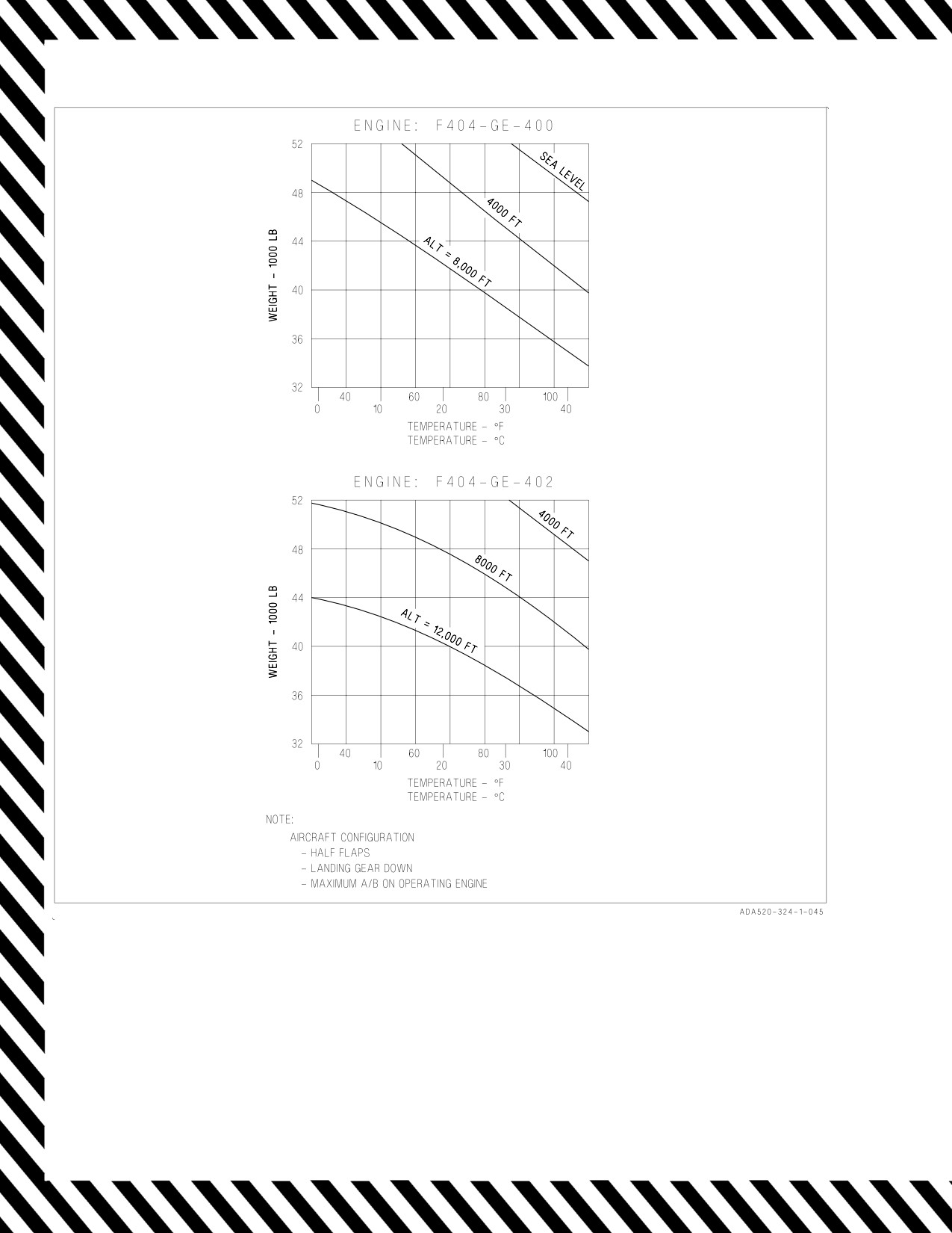
A1-F18AC-NFM-000
Figure 14-1. Maximum Weight for 100 FPM Single Engine Rate of Climb
V-14-6
ORIGINAL
A1-F18AC-NFM-000
14.7 WOW SYSTEM FAILURE
An uncommanded pitch up after takeoff may occur if a WOW system
failure results in the aircraft sensing weight on wheels while inflight.
Above 180 knots, full forward stick alone will not stop aircraft nose up
rotation, so nose down trim will be required to regain control of the
aircraft.
A WOW system failure resulting in the aircraft sensing weight on wheels while inflight may also
result in the following conditions:
• Emergency and selective store jettison may be disabled.
• The FUEL DUMP switch may have to be manually held on to dump fuel.
• NWS may be active airborne. Ensure NWS is removed from HUD and deselect for landing.
• AOA indexer lights and approach lights may be disabled.
• Automatic throttle control may be disabled.
• The internal and external fuel tanks may be depressurized. External fuel transfer can be
initiated by selecting ORIDE on the EXT TANKS switches.
• Autopilot may be disabled.
• The inflight idle throttle stop may be retracted, allowing the throttles to be moved to the
ground idle position.
• The speedbrake may not automatically retract with flaps HALF or FULL.
• Pitot-static and AOA probe heating may be disabled unless PITOT ANTI ICE is selected
ON.
• Total temperature probe heating may be disabled.
V-14-7 (Reverse Blank)
ORIGINAL
A1-F18AC-NFM-000
CHAPTER 15
Inflight Emergencies
15.1 ENGINE FIRE IN FLIGHT
See FIRE light in the Warning/Caution/Advisory Displays, figure 12-1. If an engine fire is indicated
by a FIRE warning light, throttle affected engine OFF. A fire may be confirmed if the FIRE warning
light stays on with the throttle OFF, or the light goes off and the system checks bad. For dual FIRE
light cases where the pilot is unable to discern which FIRE light came on first, throttle left and right
engine to as low as practical for flight and check engine instruments for engine condition. Once affected
engine is determined, throttle affected engine OFF. Prior indications of high fuel flow, high EGT,
rough running, or smoke and fumes may also confirm a fire. If engine stall is indicated, immediately
place the throttle to OFF. Do not press the FIRE light again, as this will reopen the fuel shutoff valve.
With an engine fire, lower hook as soon as possible. Excessive heat on hook release cable may make it
impossible to lower the hook. On F/A-18A/B aircraft only, external transfer can be regained by pulling
the HOOK circuit breaker and placing the HOOK handle UP. The hook will remain down and the
HOOK light will be on.
15.2 AFTERBURNER FAILURE
Afterburner failure can be recognized by nozzle position. This may be the only symptom that is
immediately recognizable. The afterburner has continuous ignition and attempts to light any time the
throttle is above 50% afterburner and the afterburner is not lit. If afterburner does not light after
selection or blowout, reduce throttle to MIL and reselect afterburner when in a better environment.
15.3 UNRESPONSIVE ENGINE
A unresponsive engine may remain at high or low power or the power may vary randomly. There may
be uncommanded throttle movement, the throttle may freeze, or throttle movement may have no
effect. In the landing pattern, be prepared for an unexpected single-engine waveoff, landing, or bolter.
If the engine fails to MIL after deselecting afterburner, the MIL power lockup system may be the
cause. Slowing to 250 knots and lowering the landing gear may allow normal engine operation.
If the cause of loss of engine control is a severed throttle cable, control may be gained via ATC. For
ATC to engage, the PLA of each engine must match within 10 °, and both throttles must be less than
MIL and greater than IDLE. Aircrew can approximate the parameters required by matching engine N2
RPM.
If thrust is too high to permit landing, shut down the engine with the throttle. If the engine cannot
be shut down with the throttle, press the FIRE light.
15.3.1 ENGINE STUCK AT MIL (AFTER DESELECTING AFTERBURNER)
RIGHT ENGINE
1. SLOW below 250 KCAS
2. LDG GEAR handle - DOWN
V-15-1
ORIGINAL
A1-F18AC-NFM-000
If normal engine operation is restored -
3. LDG GEAR handle - UP (if required)
4. Land as soon as practical.
If engine remains stuck at MIL -
3. Right throttle - OFF
4. Right FIRE light - PUSH
5. Refer to Single Engine Approach and Landing procedure.
LEFT ENGINE
1. LG circuit breaker - PULL
If normal engine operation is restored, for landing -
2. Slow below 250 KCAS.
3. LDG GEAR handle - DOWN
4. LG circuit breaker - RESET
5. Land as soon as practical.
If engine remains at MIL -
2. Left throttle - OFF
3. Left FIRE light - PUSH
4. Refer to Single Engine Approach and Landing procedure.
15.3.2 STUCK THROTTLE/ ENGINE FAILS TO RESPOND
Advancing throttle may cause engine to remain at high power with high
fuel consumption rates.
1. Throttle affected engine - IDLE (if possible)
If throttle stuck at high power setting and continued operation not desired -
2. Throttle affected engine - OFF (if possible)
3. FIRE light affected engine - PUSH
4. Refer to Single Engine Approach and Landing procedure.
V-15-2
ORIGINAL
A1-F18AC-NFM-000
If continued engine operation is desired or required -
2. Consider use of ATC to attempt reduction of affected engine RPM.
NOTE
ATC will not engage with either RPM near MIL or IDLE.
a. Adjust good engine throttle to match RPM.
b. ATC - ENGAGE
c. Initiate descent to reduce engine RPM via ATC.
Once affected engine RPM reduced to desirable level -
d. ATC - DISENGAGE
3. Fly precautionary half-flap approach if practical.
4. Make arrested landing if practical. Refer to Arresting Gear Data Table.
If arresting gear not available or airspeed is difficult to control -
5. Consider shutting down affected engine.
a. Throttle affected engine - OFF (if possible)
b. FIRE light affected engine - PUSH
c. Refer to Single Engine Approach and Landing procedure.
15.4 ENGINE FAILURE
If an engine fails, the corresponding generator and HYD 1 (left engine) or HYD
2
(right engine)
system will be lost. Either generator supplies sufficient power to operate all electrical items. A
windmilling engine can cause repeated flight control transients as the hydraulic switching valves
operate. Various FCS cautions will come on intermittently. After the rpm has decreased to near zero,
the transients will cease, the FCS cautions will go off, and FCS operation will be normal. To prevent
repeated switching valve cycling, avoid stabilized flight where engine windmilling rpm produces
hydraulic pressure fluctuations between 800 to 1,600 psi. If control of a surface is lost due to a frozen
or sticking switching valve, attempt to unstick the valve by gently cycling the flight controls, and reset
the FCS. If the failed engine core is rotating freely and rpm is below 30%, use the APU or engine
crossbleed to retain both HYD systems. If the right engine is being rotated with crossbleed to provide
normal systems operation and fuel flow on the left engine is reduced below 2,000 pph (as during
landing), the right engine hydraulic pump may not provide sufficient flow for nosewheel steering and
normal brakes. Refer to Hydraulic Failure, this chapter, for results of loss of a hydraulic system. During
engine crossbleed, the feed tank of the failed engine may not gravity transfer to the operating engine
feed tank. To prevent this, gravity transfer from the inoperative feed tank may be initiated by
discontinuing crossbleed if the failed engine AMAD operation is not required or interrupting fuel feed
to the failed engine system by pressing the failed engine FIRE button. Extended operation with the
FIRE button pressed may result in a corresponding L or R AMAD caution.
V-15-3
ORIGINAL
A1-F18AC-NFM-000
If both engines fail, both generators will drop off line as rpm decays through 60%. Refer to Double
Generator Failure, this chapter, for results and procedures. A minimum of 12%N2 is required for
ignition. At least 350 knots is required to maintain 12% rpm. If rpm has decayed below 12%, airspeeds
significantly greater than 350 knots may be required to regain 12% rpm especially at lower altitudes.
If conditions do not allow for a 350 knot descent, APU restart is the last alternative. Refer to Restart
procedures, this chapter.
15.5 ASYMMETRIC THRUST EFFECTS
During single engine flight with external stores, consideration should be given to dump fuel and
stores jettison to reduce gross weight, reduce drag and/or alleviate an aggravating asymmetrical
loading. Close attention to airspeeds is required in all loadings to maintain airspeed at or above single
engine maximum endurance speed (5.6 to 5.8° AOA). Maneuvering should be limited to that required
to return to base using shallow bank angles and avoiding turns into the failed engine. In straight and
level flight at zero bank angle, some amount of rudder deflection and/or trim will be required to offset
the yawing moment from asymmetrical thrust. A slight (up to 5°) bank into the good engine should
reduce this rudder requirement. A straight-in half-flap approach should be performed.
NOTE
• Failure of the variable exhaust nozzle in the full open position
adversely affects single and dual engine performance. No cautions are
available to the pilot except for VEN position indications on the
EMI/IFEI.
• Single engine waveoffs and bolters with F404-GE-402 (EPE) engines
installed may require full rudder and coordinated lateral stick to
control aircraft yaw and roll produced by asymmetric thrust.
15.6 ENGINE STALL
An engine stall is a disruption of airflow that has resulted from mechanical damage to the engine or
adverse flight conditions. Adverse flight conditions that can cause stalls include high altitude, low
airpeeds, high sideslip or high angle of attack, usually in combination with throttle transients,
especially, the throttle chop/re-advance combination. Stalls may occur in the engine fan or high
pressure compressor and are one of two types: pop or surge stalls, and hung stalls.
Pop or surge stalls - The majority of stalls are pop or surge stalls. These are usually indicated by
airframe vibration, engine surges, engine noises such as loud banging, or momentary exhaust fireballs.
The engine almost always recovers on its own within 2 seconds without any pilot corrective action.
Hung stalls - Hung stalls occur infrequently. They may initiate from a pop stall and are detectable
as a lack of response to throttle movement and/or rpm rollback and EGT increase. Without corrective
action, engine rpm may eventually stabilize near or below idle rpm.
Due to inadequate turbine cooling during the stall, a prolonged hung stall
(over 1 minute) can result in turbine overtemperature damage without
indicating an EGT overtemperature.
V-15-4
ORIGINAL
A1-F18AC-NFM-000
Engine stalls may also be indicated by the ‘‘Engine Left (Right)’’ voice alert, L/R IN TEMP, L/R
FLAMEOUT, and/or L/R STALL
Dual engine hung stalls have occurred requiring individual engine shut-
down to regain normal engine operation. With both engines in a stalled
condition, one or both generators may be inoperative. With one generator
inoperative, shut down and restart the engine with the inoperative
generator first.
If the stall does not clear itself, a prompt chop to IDLE may clear it. Checking for stall clearing at
idle involves observing a drop in EGT with the NOZ position opening to the idle position, followed by
normal response to the throttle. If the stall cleared at idle, the likelihood of engine damage is extremely
remote, and the affected engine may be used for approach and landing as required.
*1. Throttle affected engine - IDLE
If the stall does not clear -
2. Throttle affected engine - OFF
3. Refer to Single Engine Approach and Landing procedure.
If the stall clears -
2. Check engine response at a safe altitude.
3. Land as soon as practical.
15.7 RESTART
Ignition is on with throttle at IDLE or above and rpm between 12% and 45% with engine flamed
out. At least 350 knots is required to maintain 12% rpm. Continuing automatic restart attempts at high
altitude or high AOA may cause the engine to overtemp. In this case, place the throttle OFF until in
a better start environment. The optimum restart envelope is below 25,000 feet. If the engine is shut
down from a high power setting and rpm decays to 0%, temporary rotor binding may occur. In this
case, engine rotation will not be regained until the engine cools evenly (about 10 to 15 minutes). If
crossbleed is not used, airspeeds significantly greater than 350 knots may be required to regain 12%
rpm especially at lower altitudes. APU restart is the last alternative.
NOTE
Windmill restart attempts made after rpm has degraded to 0% may
require up to 450 knots to obtain 12% rpm for ignition.
If APU restart is required, HYD ISOL ORIDE should first be selected for 10 seconds prior to APU
start, assuming good HYD 2B. With the APU switch ON and the green READY light on, the engine
crank switch may then be used to crank the engine for restart. The APU restart envelope is below 250
knots, below 10,000 feet. See figures 15-1 thru 15-4.
Attempting to restart an engine that has flamed out for no apparent
reason may result in an engine bay fuel leak/fire.
V-15-5
ORIGINAL
A1-F18AC-NFM-000
If rpm above 30% -
1. Throttle affected engine - IDLE or above
If rpm below 30% -
1. Throttle good engine - 80% MINIMUM AND FUEL FLOW 1,900 PPH MINIMUM (Recom-
mended above 85% to avoid MECH reversion)
2. ENG CRANK switch - L or R (affected side)
3. Throttle affected engine - IDLE or above
4. Monitor EGT during start (815°C maximum).
V-15-6
ORIGINAL
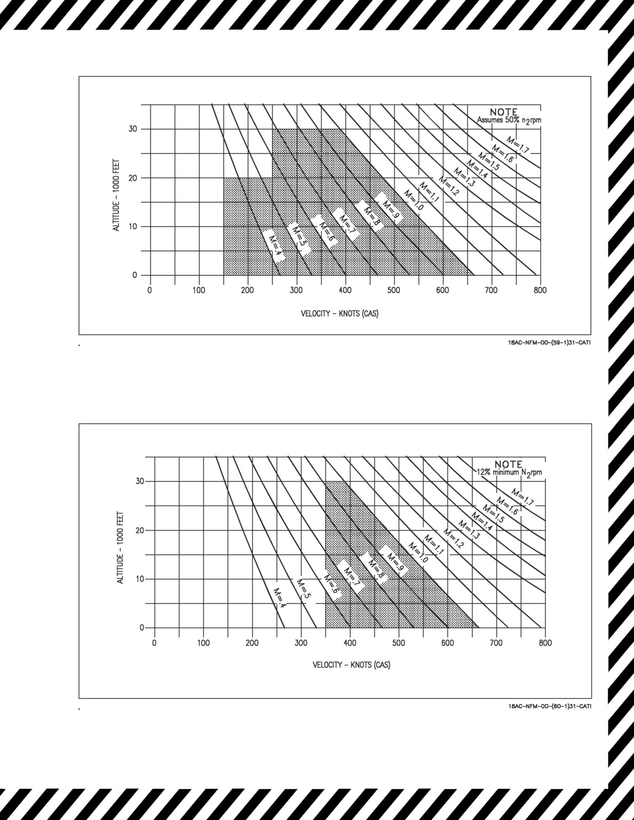
A1-F18AC-NFM-000
Figure 15-1. Spooldown Restart Envelope
Figure 15-2. Windmill Restart Envelope
V-15-7
ORIGINAL
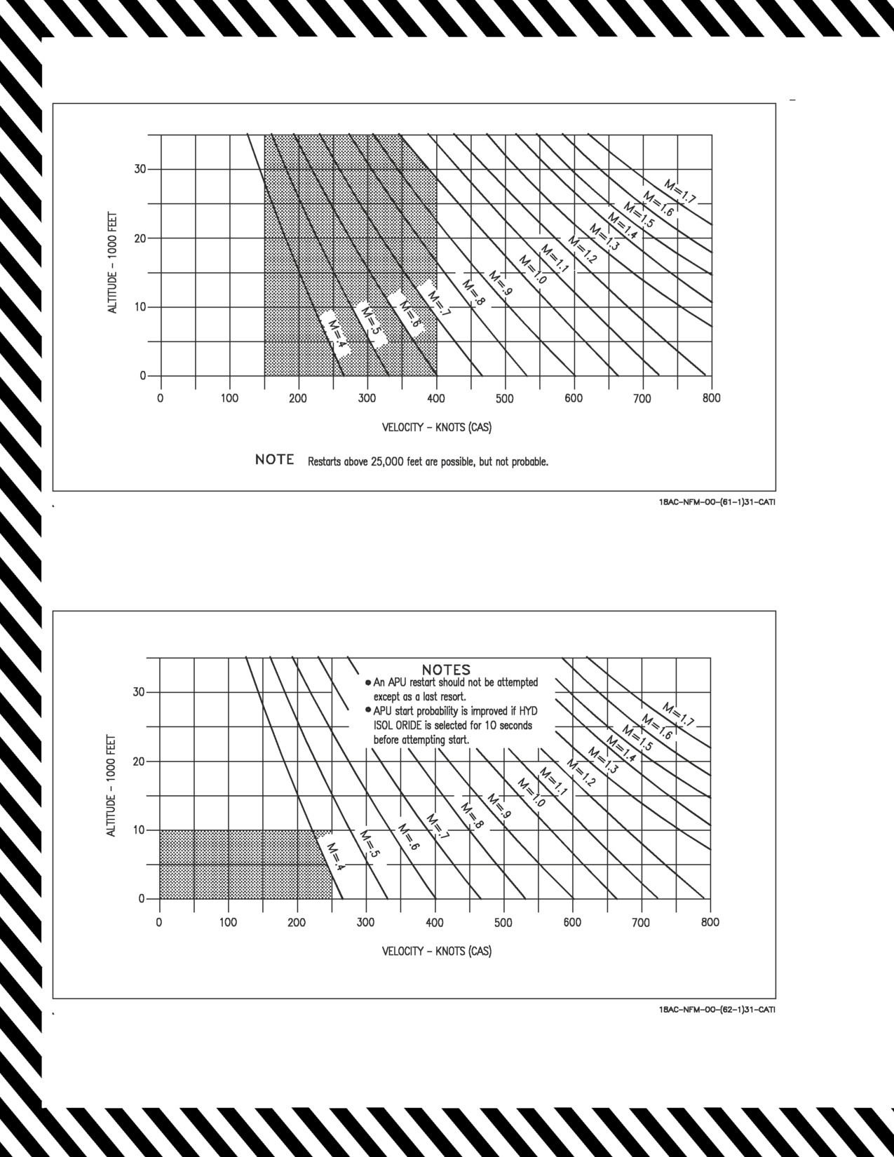
A1-F18AC-NFM-000
Figure 15-3. Crossbleed Restart Envelope
Figure 15-4. APU Restart Envelope
V-15-8
ORIGINAL
A1-F18AC-NFM-000
15.8 POWER TRANSMISSION SHAFT (PTS) FAILURE
Failure of the PTS will result in the display of the associated GEN, BOOST LO and both HYD
circuit cautions. If the shaft does not fail at the design shear point, it could be flailing. A flailing PTS
could damage flammable fluid components in the engine bay which could result in an engine bay fire.
Consideration should be given to shutting down the associated engine to minimize the risk of an engine
bay fire.
15.9 HYDRAULIC FAILURE
Hydraulic failures are indicated by displaying HYD 1A, 1B, 2A, 2B circuit cautions either singly or
in combinations. Failure effects can be analyzed by referring to figure 15-5, Hydraulic Flow Diagram,
and figure 15-6, Hydraulic Subsystems Malfunction Guide. Failures which affect flight controls may
also cause an FCS caution. Remarks regarding the flight control effects due to hydraulic failures are
shown in figure 15-7.
Dual circuit cautions in the same system may indicate a pump failure or reservoir depletion. Refer
to the hydraulic system pressure gage to determine if pressure fluctuations are present. If system
pressure has decreased to zero with no fluctuations, the pump shaft has probably sheared from the
AMAD and no further action is required.
Stabilized system pressure below 2,000 psi or fluctuations in system pressure is indicative of a failing
hyd pump that has yet to shear. This may result in overheating the pump and a subsequent AMAD bay
fire. Securing the associated engine will minimize the potential for pump overheat.
Dual circuit cautions in the same system preceded by circuit caution sequencing is probably an
indication of a fluid leak in a part of the system not protected by reservoir level sensing (RLS). This
leak can not be isolated and all the hydraulic fluid in that system will be lost. If this occurs, the circuit
A caution comes on and, sometime later, goes off and the circuit B caution comes on. As the fluid
continues to leak, the circuit B caution goes off and for a relatively short time (less than 7% of the time
since the circuit A caution first appeared), both circuits A and B operate and hydraulic pressure
indicates normal since there is a small amount of fluid remaining in the reservoir. When pressure drops
below approximately 1,500 psi, both circuit A and B cautions come on. To summarize, the sequence of
indications during an unisolated hydraulic fluid leak is: (1) only HYD 1A (2A) on, (2) only HYD 1B
(2B) on, (3) both off, and (4) HYD 1A (2A) and HYD 1B (2B) on. Prolonged flight following display
of both cautions may result in overheating the pump and subsequent AMAD bay fire. Securing the
associated engine if prolonged flight is anticipated minimizes the potential for pump overheat.
NOTE
When an engine is secured in flight, the corresponding HYD 1 (left
engine) or HYD 2 (right engine) system is lost and the associated
hydraulic cautions HYD 1A 1B (left engine) and HYD 2A 2B (right
engine) appear as rpm decreases to near zero. If the hydraulic cautions
were not present prior to securing the engine and a failure or leak in
the associated hydraulic system is not suspected, the FCS may be reset
to attempt to regain a failed control surface and unstick a frozen or
sticking valve.
V-15-9
ORIGINAL
A1-F18AC-NFM-000
NOTE
• Hydraulic system capacity is dependent on respective engine rpm.
Excessive simultaneous hydraulic system demands (i.e., landing gear
activation, flap movement, and multiple flight control inputs, etc.)
combined with HYD system failure may exceed system capacity or
result in FCS reversion to MECH. If practical, maintain engine with
operating HYD system at or above 85% rpm.
• With a HYD 2A and HYD 2B failure, consider disengaging nosewheel
steering (paddle switch) after touchdown to conserve APU accumula-
tor pressure. This would reserve pressure for slower speeds (less than
30 knots) where differential braking is not as effective.
• With a hydraulic leak downstream from the brake valve, the HYD 2
cautions may only appear when brakes are applied. Once brakes are
released, all cautions may disappear. If this occurs, do not taxi.
Continual use of brakes or emergency brakes will lead to total loss of
HYD 2 fluid.
V-15-10
ORIGINAL
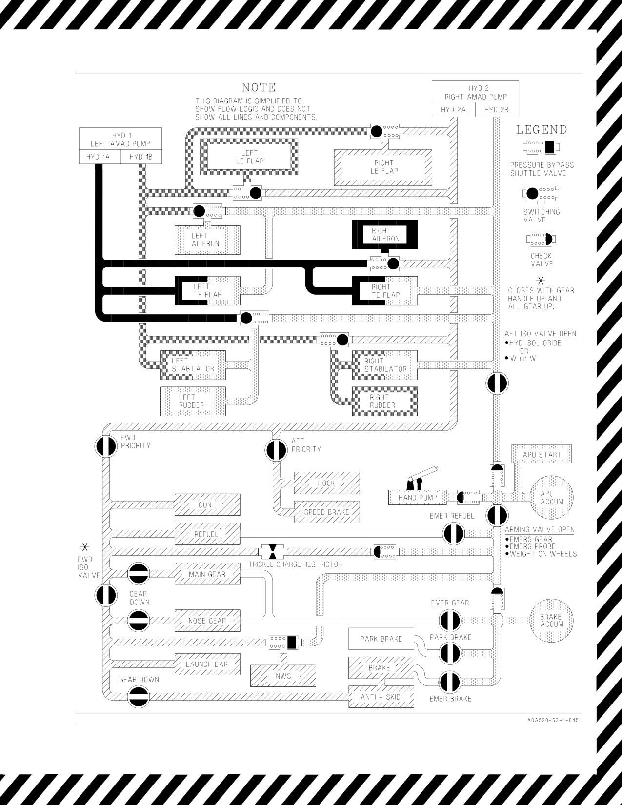
A1-F18AC-NFM-000
Figure 15-5. Hydraulic Flow Diagram
V-15-11
ORIGINAL