F18. FLIGHT MANUAL (2008) - page 13
A1-F18AC-NFM-000
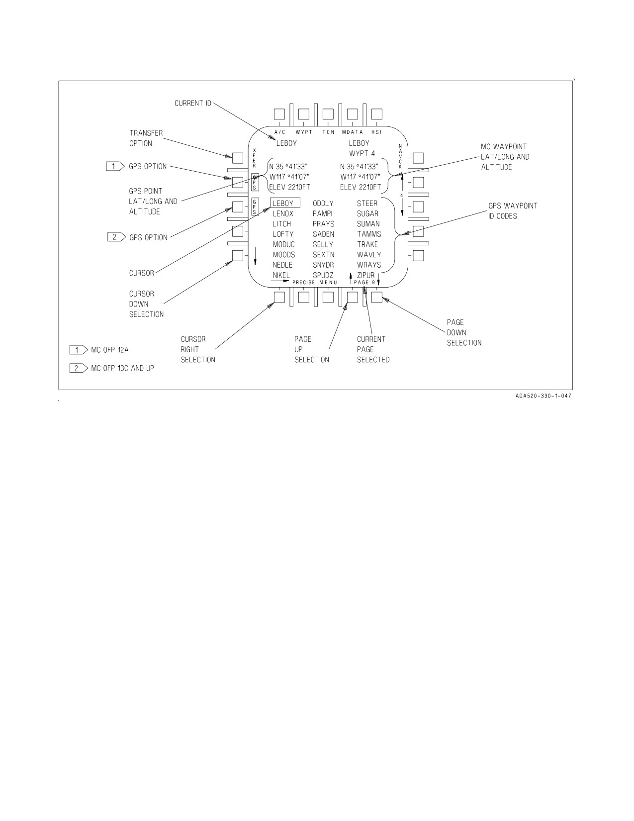
Figure 24-8. GPS Point Data Display
corresponds to a resolution of less than one foot.
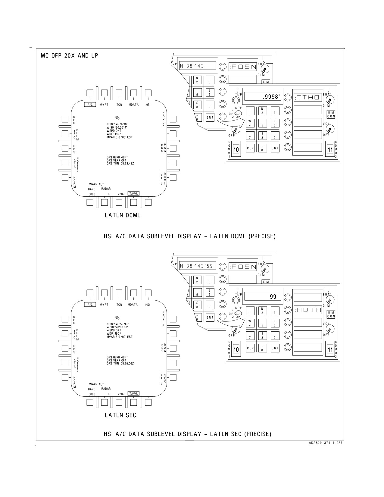
The PRECISE option on the HSI/DATA/WYPT sublevel enables precise lat-long data display and
entry. Before MC OFP 20X with PRECISE unboxed, pressing LATLN DCML displays a precision of
thousandths of a minute and pressing LATLN SEC (cold start default) displays a precision of seconds.
With PRECISE boxed, lat-long precision is hundredths of a second in LATLN SEC and not available
in LATLN DCML. After MC OFP 20X with PRECISE unboxed, lat-long precision is hundredths of
a minute in LATLN DCML (cold start default) and seconds in LATLN SEC. With PRECISE boxed,
lat-long precision is ten thousandths of a minute in LATLN DCML and hundredths of a second in
LATLN SEC.
NOTE
For GND alignment, waypoint 0 should be within .01 NM (60 feet or .6
seconds) of the true position.
Waypoint position latitude is entered on the UFC in degrees, minutes, and seconds. If PRECISE
option is boxed, select :HDTH on the UFC to enter hundredths of arc seconds or :TTHO to enter
thousandths of a second. After latitude data is entered, the scratchpad initializes to the position
(:POSN) format for longitude entry. See figure 24-9.
VII-24-24
ORIGINAL
A1-F18AC-NFM-000
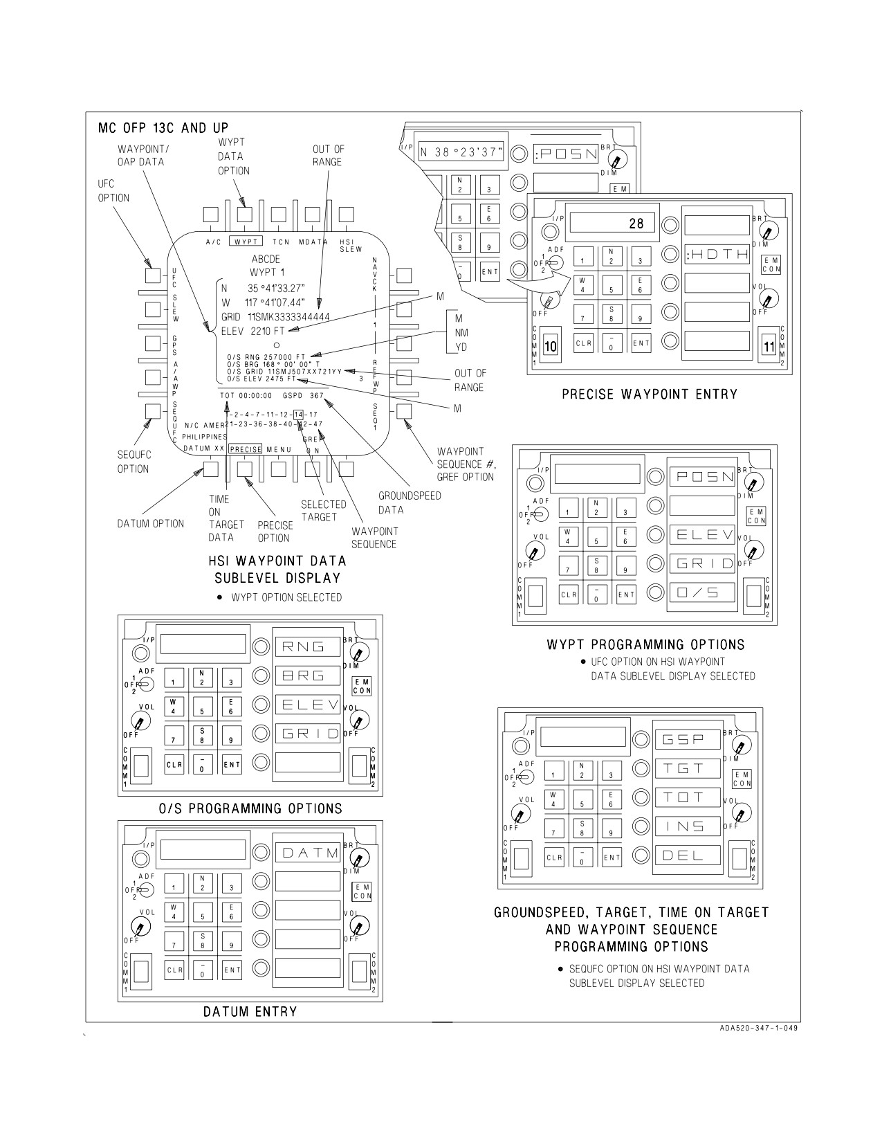
With MC OFP 13C AND UP, waypoint data can also be entered using the map slew method. To do
this, select WYPT on the DATA option display, then actuate the SLEW button. Now press the TDC
and slew the map to the desired lat/long position under the waypoint symbol.
NOTE
Lat/long and elevation data on the HI/MPCD reflect the current map
position under the waypoint symbol as the map is being slewed.
Upon release of the TDC the current waypoint data is entered for the map position under the
waypoint symbol. Select the next waypoint number as required (via the waypoint increment/
decrement option buttons) for further waypoint data entry.
With MC OFP 13C AND UP, another map slew method may be used to enter waypoint data. To do
this, select WYPT on the DATA option display, then actuate the SLEW button. Now press and hold
the TDC to slew the map to the desired lat/long position under the waypoint symbol. This position is
entered by selecting another waypoint (via the waypoint increment/decrement option buttons).
Continue to hold the TDC, slew the map as required, and select the next waypoint for further waypoint
data entry.
Offset aimpoints may also be entered using the map slew method, however, the associated offset
must be entered through the UFC.
24.2.5.1.1 GPS Waypoint Programming. Aircraft with GPS can utilize the GPS to store up to 200
waypoints. GPS points are loaded into the GPS from the MU or MDL. GPS points can be displayed
and/or transferred into the MC waypoint data base via the HSI/DATA/GPS display. With MC OFP
12A, the GPS LOAD option, available on the GPS display, commands the MC to load the GPS
Almanac Data file, Point data, and Point ID files from the MDL.
A GPS point can be transferred into any MC waypoint by pressing the XFER option on the GPS
point data display. When GPS option is selected the first 24 GPS points are displayed in alphanumeric
order. Selection of points to load is accomplished via the right and down arrows and page selection
arrows. Repeated selection of these arrows causes the cursor to wrap around. It may take as long as
three seconds to retrieve selected position data and display it on the GPS point data display. See figure
24-8. To transfer GPS waypoints to the MC, select the desired waypoint number with the up/down
arrows on the HSI/DATA/GPS sublevel, then move the cursor down/right and/or page up/down to the
desired waypoint ID code, and press XFER. At this time the GPS LAT/LONG, GPS altitude, and
current ID code displays are blanked and the XFER option is removed. The selected ID code is
displayed in the ‘‘Current ID’’ position indicating that waypoint is requested. After approximately 3
seconds, the requested GPS LAT/LONG and GPS altitude is displayed and the XFER option is
returned for transfer selection. If a GPS ID code is requested and is not available, the selected ID code
is displayed with a line through it. Once a GPS waypoint has been transferred from the GPS to the MC
it becomes an MC waypoint. The waypoint ID code is retained and is displayed on the top level HSI
and HSI/DATA/WYPT formats when the waypoint is selected as the current waypoint.
24.2.5.1.2 UTM WYPT Data Entry. Data for all waypoints and OAPs may be entered as universal
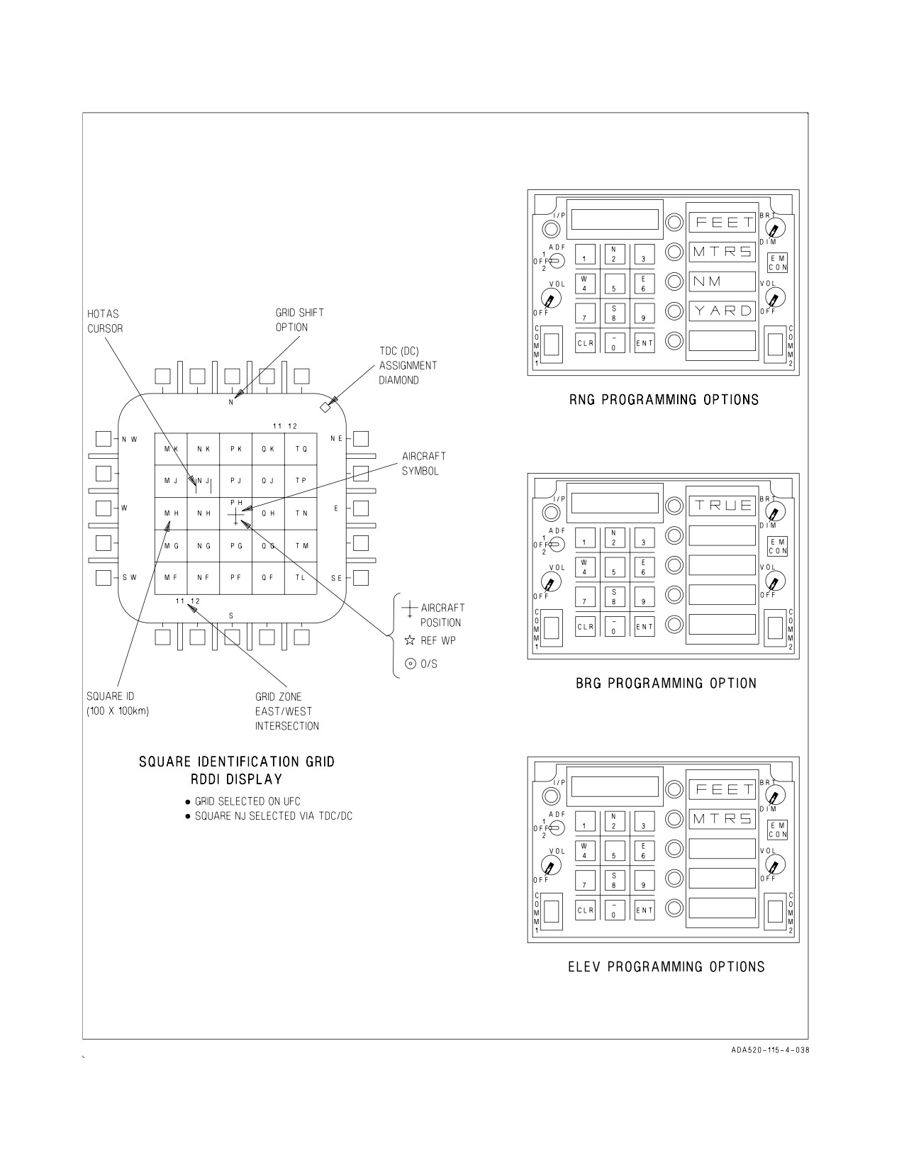
transverse mercator (UTM) coordinates. See figure 24-9, sheet 2. UTM Grid Coordinates are defined
by a Spheroid or DATUM, Grid Zone Designation, Square Identification, and Easting/Northing. Grid
zone designation divides the world area between N84° and S80° into 100 km squares. At power up with
WOW the MC initializes waypoint elevation, O/S range and elevation, and TACAN elevation in FEET,
and O/S bearing to TRUE. With MC OFP 12A, 13C AND UP, the PRECISE option on the DATA
display allows the pilot to select either 100 meter or 1 meter accuracy. With PRECISE unboxed,
VII-24-25
ORIGINAL
A1-F18AC-NFM-000
entering 3 easting and 3 northing digits provides accuracy up to 100 meters. With PRECISE boxed,
entering 5 easting and 5 northing digits provides accuracy up to 1 meter. To enter UTM data for
waypoints, perform the following:
1. Select DATA/WYPT on the HSI top level display.
If MC OFP 10A -
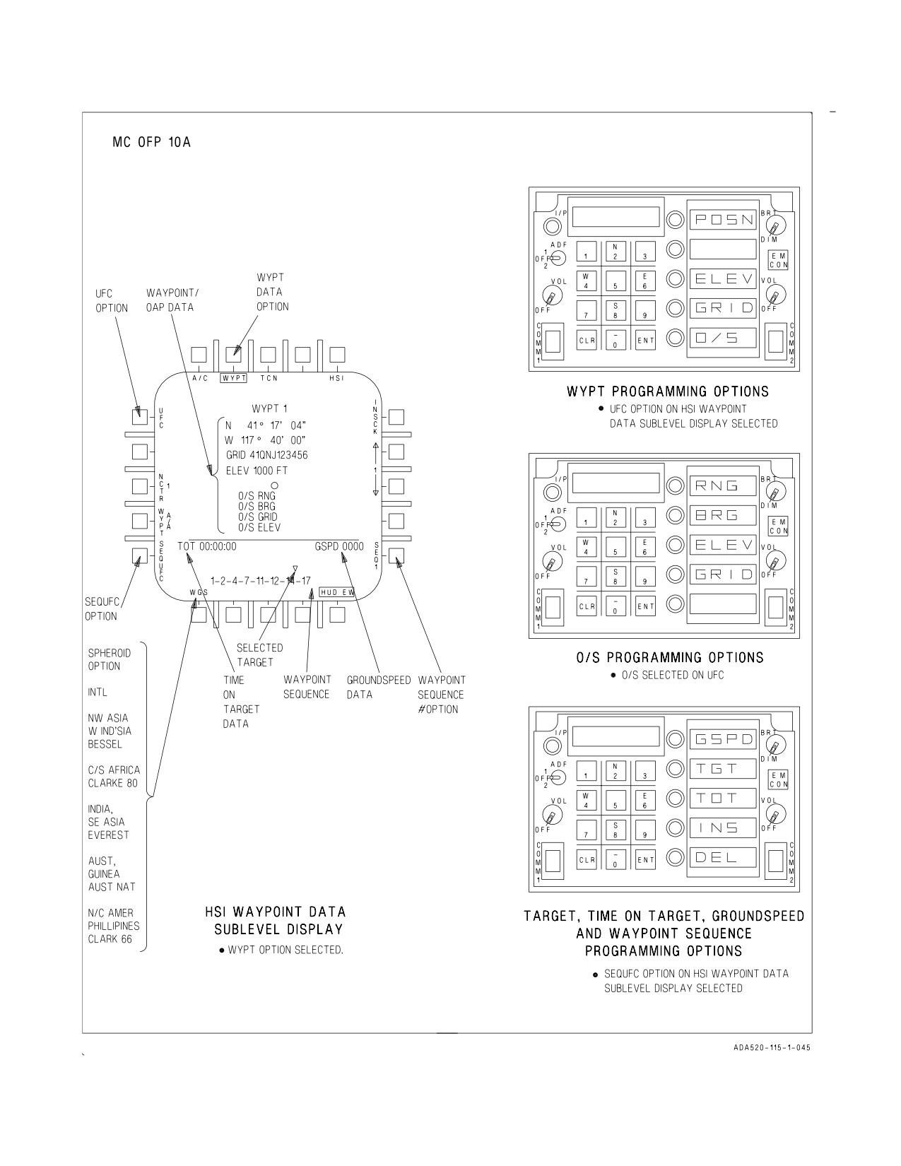
2. Select the desired spheroid by depressing the spheroid pushbutton.
If MC OFP 12A, 13C AND UP -
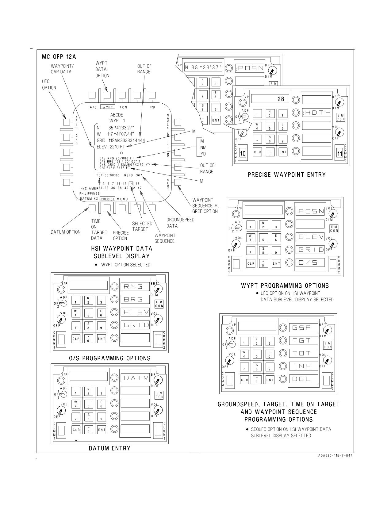
2. Select the desired DATUM by pressing the DATUM XX option pushbutton. Pressing the button
momentarily increments the DATUM by one. Pressing and holding the DATUM button enables
the UFC DATM format. The Datum number can be entered directly from 1 to 47. The MC selects
the spheroid for the DATUM selected. The selected DATUM and corresponding spheroid are
displayed above the button.
3. Select PRECISE option if 1 meter resolution is desired.
All aircraft -
4. Select UFC on the HSI. The first cockpit to select UFC has control of Grid data entry and has the
GRID display on the RDDI.
5. Select GRID on the UFC. The MC determines the Grid Zone Designation and 100 km square ID
of the reference position and construct a five by five Square Identification Grid (SIG) centered
about the reference position and displayed on the RDDI. Reference position is either the A/C
present position or the referenced waypoint position (REF WP Boxed).
6. Slew the acquisition cursor into the desired square, press and release the TDC.
7. On the UFC enter the six or ten digit Easting/Northing and press ENT. Leading zeros do not have
to be input for Easting/Northing. The UTM coordinates are displayed on the HSI under the
lat/long provided the latitude is within the N84° to S80° limits.
To enter UTM data for O/S, perform the following:
8. Select DATA/WYPT on the HSI top level display.
9. Select UFC on the HSI.
10. Select O/S on the UFC.
11. Select Grid on the UFC.
12. Slew the HOTAS cursor into the desired square, press and release the TDC.
13. Enter O/S Easting/Northing in the UFC.
The MC converts the UTM Grid coordinates to latitude/longitude and then to a range and
bearing. O/S coordinates more than 400,000 feet from the OAP cause the UTM coordinates to
flash in the O/S Grid field on the HSI. The UTM coordinate is displayed in the O/S field on the
HSI.
VII-24-26
ORIGINAL
A1-F18AC-NFM-000
SIG Square blanking must be checked any time the SIG is built. If the latitude is out of UTM range
(above N84°or below S80°) the entire row is blanked. At certain latitudes, due to longitudinal line
convergence, individual squares are blank.
Grid shift options are provided to view and select grid squares in the eight adjacent grid squares
whenever the A/C or Waypoint symbol is in the center square of the SIG and the adjacent SIGs exist.
See figure 24-9. N, S, E, W, SE, SW, NE, or NW can be selected by pressing the grid shift pushbuttons
on the HSI, or by depressing and releasing the TDC when the HOTAS cursor is over a grid shift
pushbutton legend. The MC determines a new center position about which to construct a new SIG.
Selecting the A/C or waypoint symbol returns the SIG to the original position.
Units can be input as FEET or MTRS for elevation; FEET, MTRS, NM or YARD for range; and
TRUE or MAG for heading. The MC tests that all bearing, range and elevation data input through the
UFC are within their valid range.
Unit
Valid Range
Easting/
0 - 9999999999
Northing
Bearing
0 - 359° 59’ 59’’
Offset
0 - 400,000 FT
0 - 122,000 MTRS
0 - 66 NM
0 - 133,000 YDS
When data is outside the valid range, the CSC causes the word ERROR to flash in the UFC
scratchpad and requires the data be reinput.
24.2.5.2 TGT (Target) Programming. A target must be entered in a waypoint/OAP sequence so the
MC can calculate the groundspeed required to arrive on target at the appropriate time. Only one
waypoint/OAP can be designated as a target for all three sequences. With MC OFP 10A, a
waypoint/OAP is identified as a target on the waypoint data sublevel display by an inverted triangle
above the waypoint/OAP number (in the waypoint/OAP sequence). With MC OFP 13C AND UP, a
target is identified by a box around the waypoint/OAP number. At power up with WOW the previous
target waypoint/OAP is cleared.
To designate a waypoint/OAP as a target in a waypoint/OAP sequence, first select the DATA option
on the HSI top level display. Then select the SEQUFC option on the waypoint data sublevel display
to initialize the UFC. Now select the TGT option on the UFC, enter the waypoint/OAP number via the
UFC keypad and select the ENT pushbutton. To undesignate the current target waypoint/OAP either
enter the current target waypoint/OAP a second time or enter an invalid waypoint/OAP. See figure
24-9, sheets 1, 2, and 3.
24.2.5.3 TOT (Time On Target) Programming. TOT pertains to the programmed target waypoint/
OAP, and is relative to the programmed ZTOD (zulu time of day). ZTOD must be programmed before
TOT can be entered. TOT is programmed from 00:00:00 to 23:59:59 and is displayed on the waypoint
data sublevel display.
VII-24-27
ORIGINAL
A1-F18AC-NFM-000
To enter TOT select the DATA option on the HSI top level display. Then select the SEQUFC option
on the waypoint data sublevel display to initialize the UFC. Now select the TOT option on the UFC,
enter the desired TOT value via the UFC keypad and select the ENT pushbutton. See figure 24-9,
sheets 1, 2 and 3.
24.2.5.4 Groundspeed Programming. Groundspeed pertains to the desired groundspeed for the
final leg to the target waypoint in the sequence. Groundspeed values up to 999 knots may be entered.
However, if groundspeed values exceed 999 knots, 999 knots is entered as the groundspeed.
To enter groundspeed, select the DATA option on the HSI top level display. Then select the
SEQUFC option on the waypoint data sublevel display to initialize the UFC. Now select the GSPD
option on the UFC; enter the desired GSPD value via the UFC keypad and select the ENT pushbutton.
See figure 24-9, sheets 1, 2, and 3.
24.2.5.5 Waypoint/OAP Sequence Programming. A total of three waypoint/OAP sequences are
available for waypoint/OAP sequence programming and a maximum of fifteen waypoint/OAPs may be
programmed in each sequence. These sequences are used for AUTO sequential steering and time on
target groundspeed cuing.
The waypoint data sublevel display on the HSI display must be used along with the UFC to allow
the pilot to program a waypoint/OAP sequence. The SEQ # option on the lower right corner of the
display indicates the waypoint/OAP sequence currently in use and initializes to the sequence selected
on the HSI top level display. This option selects the sequence to be programmed (SEQ1, SEQ2 or
SEQ3). Selecting the SEQUFC option on the lower left corner of the display, initializes the UFC for
waypoint sequence programming. A waypoint/OAP cannot appear more than once in sequence,
however, a waypoint/OAP may be entered in more than one sequence. Mark points cannot be
programmed in a sequence. Each waypoint/OAP entered is placed to the right of the last waypoint/
OAP in the sequence. If nine waypoints/OAPs are programmed, the first waypoint in that sequence is
deleted and the remaining waypoints/OAPs move to the left one space. Data for the current
waypoint/OAP inserted/deleted in the sequence is provided on the waypoint data level display.
To program a new waypoint/OAP sequence select: 1) the waypoint data sublevel display using the
DATA option, 2) the desired sequence route number using the SEQ # option, 3) the SEQUFC option
to initialize the UFC for sequence programming, 4) the INS option on the UFC, 5) the desired
waypoint/OAP number via the UFC keypad, 6) the ENT pushbutton on the UFC keypad. Repeat steps
4 thru 6 for each waypoint/OAP in the sequence. See figure 24-9, sheets 1, 2, and 3.
To insert waypoints/OAP into an existing sequence select: 1) the waypoint data sublevel display
using the DATA option, 2) the desired sequence route number using the SEQ # option, 3) the SEQUFC
option to initialize the UFC for programming, 4) the INS option on the UFC, 5) the number of the
waypoint/OAP to the left of the desired insertion point via UFC keypad, 6) the ENT pushbutton on
the UFC keypad, 7) number of the waypoint/OAP to be inserted via the UFC keypad, 8) the ENT
pushbutton via the UFC keypad.
To delete waypoints from a sequence select: 1) the waypoint data sublevel display using the DATA
option, 2) the desired sequence route number using the SEQ # option, 3) the SEQUFC option to
initialize the UFC for programming,
4) the DEL option on the UFC, 5) the number of the
waypoint/OAP to be deleted via the UFC keypad, 6) the ENT pushbutton via the UFC keypad. When
a waypoint/OAP is deleted from a sequence all waypoints/OAPs to the right of the deleted
waypoint/OAP shift left one space.
VII-24-28
ORIGINAL
A1-F18AC-NFM-000
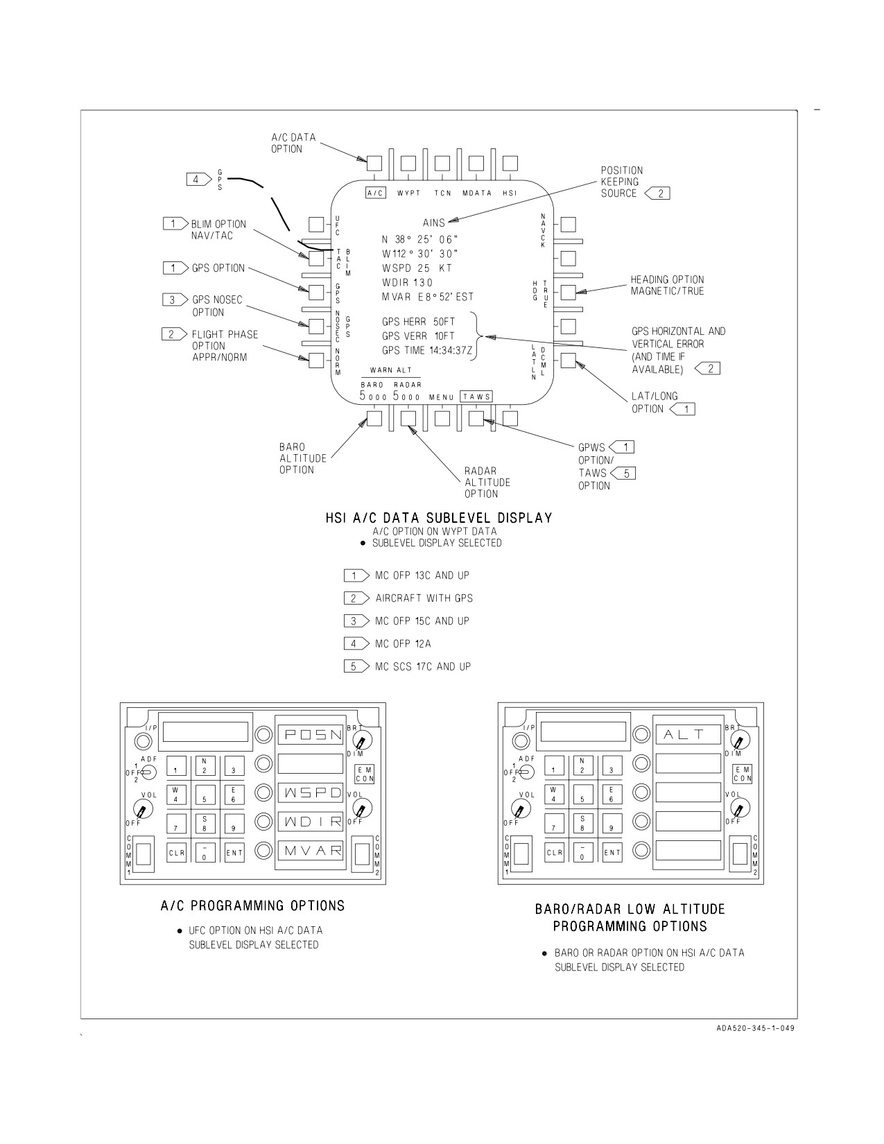
24.2.5.6 Aircraft (A/C) Data Programming. To enter aircraft data, select the DATA option on the
HSI display. WYPT is automatically the selected option when DATA is pressed. Then, select the A/C
option to bring up the A/C data sublevel display. This display shows the current position keeping
source, present position (lat-long) of the aircraft, current windspeed and direction, magnetic variation,
and magnetic/true heading selection. Aircraft data is entered through the UFC keypad. See figure 24-9.
BEFORE MC OFP 20X, lat/long is entered as Degrees/Minutes/Thousandths of minutes (LATLN
DCML), or Degrees/Minutes/Seconds (LATLN SEC). With MC OFP 20X AND UP and PRECISE
unboxed, lat-long is entered either as Degrees/Minutes/ Hundredths of minutes (LATLN DCML) or
Degrees/Minutes/Seconds (LATLN SEC). With MC OFP 20X AND UP and PRECISE boxed, lat-long
is entered either as Degrees/Minutes/Ten Thousandths of minutes (LATLN DCML) or Degrees/
Minutes/Seconds/Hundredths of seconds (LATLN SEC). Actuating the LATLN XXXX option
toggles between the selection of LATLN DCML and LATLN SEC. The selected LATLN format is
reflected on all displays and UFC formats throughout the cockpit. After MC OFP 20X non-PRECISE
DCML is the cold start default. If EGI or GPS is installed and the aircraft is tracking satellites the GPS
estimated vertical error (GPS VERR), estimated horizontal error (GPS HERR) and time (GPS TIME)
are displayed. To enter wind speed, wind direction or magnetic variation data, select the UFC option
to initialize the UFC for aircraft data entry. On the UFC select: the WSPD pushbutton to enter wind
speed data, the WDIR pushbutton to enter wind direction, and MVAR to enter magnetic variation.
24.2.5.7 True/Magnetic Heading Selection. Heading indications that appear in the HUD and HSI
display can be referenced to either true north or magnetic north. The capability to select a true north
heading is useful in extreme northern operations. With true north heading selected, the HSI display,
A/A and A/G radar displays, Link 4 display, and the HUD are all referenced to true north. The true
north indication on the HUD is a T displayed below the current heading. True north indications on the
HSI display consist of TRUE being displayed below the current heading readout and a T being
displayed below the lubber line. The true heading indications on the HSI display also appear on the
Link 4 display. No indications of true north selection appear on the A/A or A/G radar display. Since
aircraft magnetic variation is used as the best available magnetic variation source, the heading
reference should not be changed when navigating a selected course. With true heading selected,
TACAN symbology is also referenced to true north if the TACAN station is in the TACAN data table.
If the TACAN station is not in the TACAN data table, magnetic is used. There is no indication when
magnetic heading is selected. When INS true heading becomes invalid, magnetic heading is used. If
MC1 fails, heading selection is not available. At power up with WOW the system initializes with
magnetic heading selected. To select the desired reference heading, first select DATA in the HSI
display. Then select the A/C option to access the A/C data sublevel display. Actuating the HDG XXX
option toggles between the selection of HDG TRUE and HDG MAG.
24.2.5.7.1 Barometric (BARO)/Radar Low Altitude Warning Programming. The BARO/RADAR
altitude warning can be set up to a maximum of 25,000 feet for BARO and 5,000 feet for RADAR.
Setting the RADAR at a value greater than 5,000 feet results in 5,000 feet being used. Passing through
the BARO/RADAR programmed altitude from above results in the ALTITUDE voice alert. Setting
the BARO/RADAR altitude warning to 0 feet disables this function. At power up with WOW, RADAR
altitude warning initializes to 0 feet and BARO altitude warning initializes to 5,000 feet.
To set the BARO/RADAR low altitude warning function, first select the DATA option on the top
level HSI display. Then select the A/C option to bring up the A/C data sublevel display. The
BARO/RADAR altitude functions are located on the lower left corner of the display. Select BARO or
RADAR to initialize the UFC for altitude entry. Then select the ALT option on the UFC and enter the
desired altitude through the UFC keypad. The entered altitude appears on the A/C data sublevel
display below BARO/RADAR as appropriate. See figure 24-9, sheet 5.
VII-24-29
ORIGINAL
A1-F18AC-NFM-000
24.2.5.7.2 NOSEC GPS Option. The mixed mode satellite function has two modes of operation. The
two selectable modes are secure (encrypted code only) and non secure (encrypted and/or non-
encrypted) operation. The NO SEC GPS legend is available as long as there is communication between
the GPS receiver and the satellites. If communication is lost, the NOSEC legend is removed. The
secure mode of operation is the default mode upon power up. The secure mode of operation is indicated
by an unboxed NOSEC GPS legend, on the A/C DATA sublevel. In this mode, the MAGR/EGI tracks
the encrypted GPS code only and is not susceptible to spoofing. Remaining in secure operation with
a YCODE advisory can cause the aircraft to lose the ability to use GPS data.
The non secure mode of operation is selectable by boxing the NOSEC GPS legend. In this mode, the
MAGR/EGI tracks either encrypted or non-encrypted GPS code and is susceptible to spoofing, and the
NO SEC advisory is displayed. Typically, non secure operation should only be selected when the
YCODE advisory is displayed in the secure mode and the pilot believes there is no danger of spoofing.
Selecting NOSEC GPS in a spoofing environment makes the aircraft susceptible to erroneous GPS
signals.
VII-24-30
ORIGINAL
A1-F18AC-NFM-000
Figure 24-9. INS Programming (Sheet 1 of 7)
VII-24-31
ORIGINAL
A1-F18AC-NFM-000
Figure 24-9. INS Programming (Sheet 2 of 7)
VII-24-32
ORIGINAL
A1-F18AC-NFM-000
Figure 24-9. INS Programming (Sheet 3 of 7)
VII-24-33
ORIGINAL
A1-F18AC-NFM-000
Figure 24-9. INS Programming (Sheet 4 of 7)
VII-24-34
ORIGINAL
A1-F18AC-NFM-000
Figure 24-9. INS Programming (Sheet 5 of 7)
VII-24-35
ORIGINAL
A1-F18AC-NFM-000
Figure 24-9. INS Programming (Sheet 6 of 7)
VII-24-36
ORIGINAL
A1-F18AC-NFM-000
Figure 24-9. INS Programming (Sheet 7 of 7)
VII-24-37
ORIGINAL
A1-F18AC-NFM-000
24.2.5.7.3 Flight Phase. If GPS is installed a flight phase option is available on the A/C display. The
flight phase alternates between normal (NORM) flight and approach (APPR). When NORM is
selected and the position keeping mode is POS/GPS a GPS advisory is displayed when the GPS
estimated horizontal position error (EHPE) exceeds 333 meters. When APPR is selected and the
position keeping mode is POS/GPS a GPS DEGD caution is displayed when the GPS estimated
horizontal position error (EHPE) exceeds 33 meters for 10 seconds or more.
24.2.5.7.4 Zulu Time Of Day (ZTOD). For F/A-18A/B aircraft an MC internal counter is used to keep
Zulu time. Therefore, ZTOD must be set to initialize the MC internal counter. Also, ZTOD must be set
in order for ZTOD to be displayed on the HUD and HI/MPCD, and before the MC is able to calculate
MC required groundspeed and TOT. In other words ZTOD must be set every time following aircraft
power up.
For F/A-18C/D aircraft the FIRAMS Real Time Clock (RTC) is used to keep ZTOD. Therefore, the
only time ZTOD would need to be set is if the FIRAMS RTC failed power up BIT. In this case the MC
internal counter would be used which requires the MC internal clock to be set, exactly like F/A-18A/B
aircraft. ZTOD is displayed on the HUD and HSI display and is needed to calculate MC required
groundspeed and TOT. ZTOD may also be set using the IFEI, refer to Chapter 2.
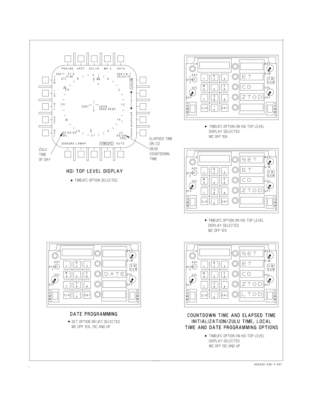
To enter ZTOD, select the TIMEUFC option on the HSI top level display to initialize the UFC for
ZTOD programming. Now select the ZTOD option on the UFC, enter ZTOD via the UFC keypad and
select the ENT pushbutton. After entering ZTOD, it is displayed on the HUD and HSI display.
Successive depressions of the ZTOD option displays/blanks ZTOD from the HUD. ZTOD is displayed
on the lower left corner of the HUD and HSI display. ZTOD is not displayed on the HUD when either
the ET or CD is selected for display. See figure 24-9, sheet 6.
24.2.5.7.5 Elapsed Time (ET). ET starts incrementing in minutes and seconds from 00:00 to 59:59.
When 59:59 is reached ET resets and begins incrementing again from 00:00. ET is displayed on the
lower left corner of the HUD and on the lower right corner of the HSI display. ET is not displayed on
the HUD or HSI display when either ZTOD or CD is selected.
To activate ET, select the TIMEUFC option on the HSI top level display to initialize the UFC for
ET selection. Now select the ET option on the UFC to display ET 00:00 on the HUD and HSI display.
Successive depressions of the ET option displays/blanks ET from the HUD and HSI display. Then
select the ENT pushbutton to start ET. Successive depressions of the ENT pushbutton start/stop the
timer. See figure 24-9, sheet 6.
24.2.5.7.6 Countdown Time (CD). CD starts decrementing in minutes and seconds from its default
value of 06:00. When 00:00 is reached, the CD timer is removed from the HUD and HI/MPCD displays.
CD is displayed on the lower left corner of the HUD and on the lower right corner of the HI/MPCD.
CD is not displayed on the HUD or HI/MPCD when either ZTOD or CD selected. The CD timer
initializes to the default value at power up with WOW.
To activate CD, select the TIMEUFC option on the HI/MPCD top level display to initialize the UFC
for CD selection. Now select the CD option on the UFC to display CD 06:00 on the HUD and HSI
display. Successive depressions of the CD option displays/blanks CD from the HUD and HSI display.
Press the ENT pushbutton to start CD. Successive depressions of the ENT pushbutton start/stop the
timer. See figure 24-9, sheet 6.
The CD default value can also be reset by entering in a value between 00:00 and 59:59. To do this,
select the TIMEUFC option on the HSI top level display to initialize the UFC for CD programming.
Now enter in the reset value through the UFC keypad and press the ENT pushbutton. The reset value
VII-24-38
ORIGINAL
A1-F18AC-NFM-000
must be less than or equal to 59:59 so that when the ENT pushbutton is pressed the CD timer begins
to decrement. If the reset value is greater than 59:59, depression of the ENT pushbutton sets the reset
value to 59:59 and freezes the CD timer.
24.2.5.8 Local Time Of Day Programming (LTOD). For F/A-18C/D aircraft, to set LTOD, select the
TIMEUFC option on the HSI display to initialize the UFC for LTOD programming. Now select the
LTOD option on the UFC, enter LTOD via the UFC keypad, then select the ENT pushbutton. LTOD
may also be entered using the IFEI, see Chapter 2. The LTOD option is displayed only if the FIRAMS
passes power up BIT. See figure 24-9, sheet 6.
24.2.5.9 Date Programming (SET). For F/A-18A/B aircraft with MC OFP 12A and F/A-18C/D
aircraft, to set the date, select the TIMEUFC option on the HSI display to initialize the UFC for date
programming. Select the SET option on the UFC to allow the DATE option to appear on the UFC.
Enter the date via the UFC keypad, and select the ENT pushbutton. The date must be entered as two
digit values in the following order: month, day and year. See figure 24-9, sheet 6.
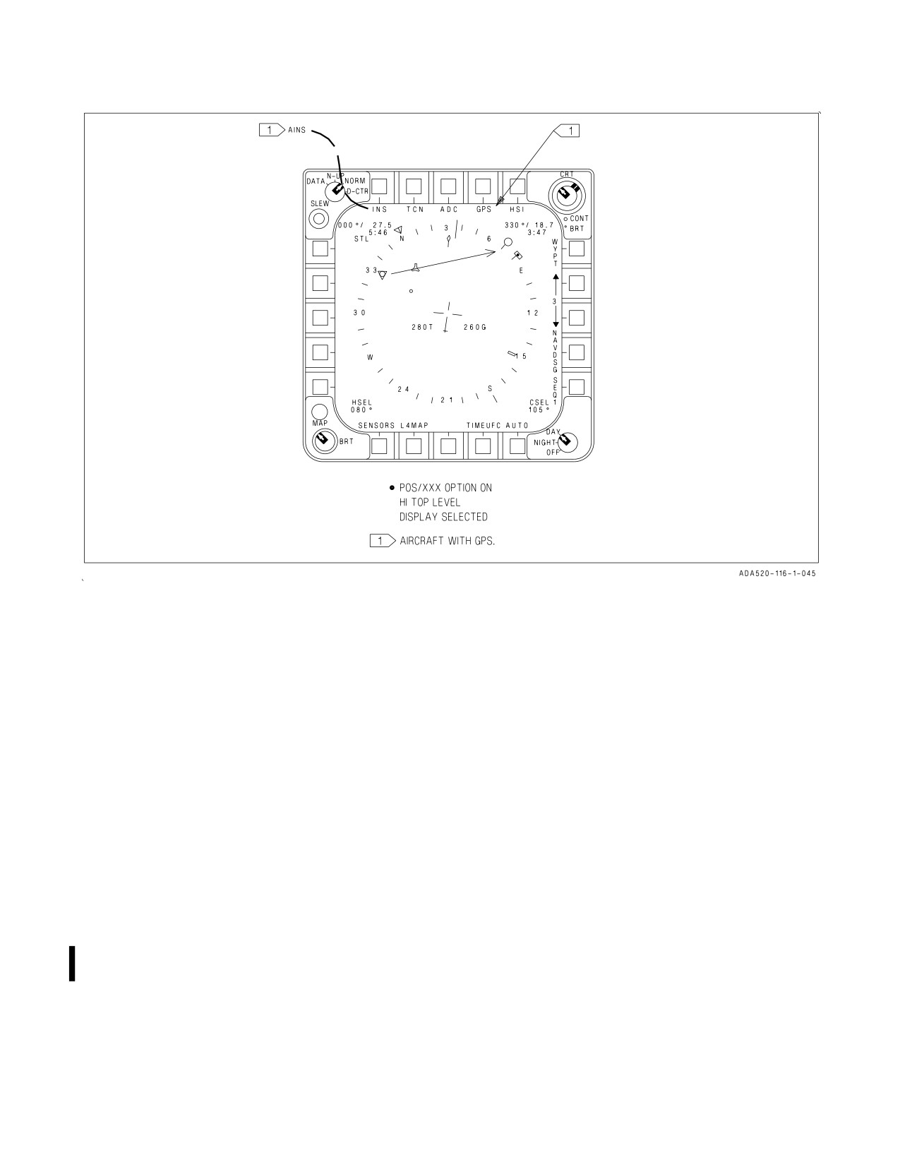
24.2.6 Position Keeping. Selection of the POS/XXX option on the HSI display provides the position
keeping option display, see figure 24-10. This display allows inflight selection of POS/INS, POS/MIDS
(if installed), POS/ADC or POS/TCN as the position keeping source. In aircraft with EGI or GPS two
additional sources, POS/AINS and POS/GPS can be selected as the position keeping source. Selecting
one of these options returns the HSI display with the appropriate position keeping source selected. In
aircraft without GPS, INS position keeping is automatically selected during ground operations when
INS data is valid. Should the INS fail, the mission computer automatically begins ADC position
keeping from the last valid INS position, however it is unreliable.
AINS and GPS position keeping is not available unless good GPS data is available. GPS data is good
when the GPS vertical error (GPS VERR) and GPS estimated horizontal error (GPS HERR), as shown
on the HSI A/C Data display, are each less than 100 feet.
MIDS precise participant location and identification (PPLI) altitude
shall not be used as an altitude reference for determining safe separation
of aircraft or terrain avoidance.
NOTE
It may take up to 12 minutes for satellite acquisition and valid GPS
position data.
In aircraft with GPS, AINS position keeping is selected by placing the INS mode switch to the IFA
position. Automatic position keeping reversion with a hierarchy of AINS, INS, GPS, MIDS (if
installed) and ADC is provided in case of an INS and/or GPS failure. TACAN position keeping
VII-24-39
ORIGINAL
A1-F18AC-NFM-000
Figure 24-10. Position Keeping
provides distance data from one of the previously stored TACAN stations. The desired TACAN station
is selected via the UFC. See TACAN position keeping this section.
NOTE
MIDS position keeping is the default position keeping mode if GPS
and INS are not available. Because MIDS alone is unreliable as a
position keeping source, POS/ADC should be selected if INS and GPS
fail or become unreliable as position keeping sources. Flight crews will
be unable to enter data parameters required for an INS or radar
inflight alignment (IFA) if POS/MIDS is the position keeping source.
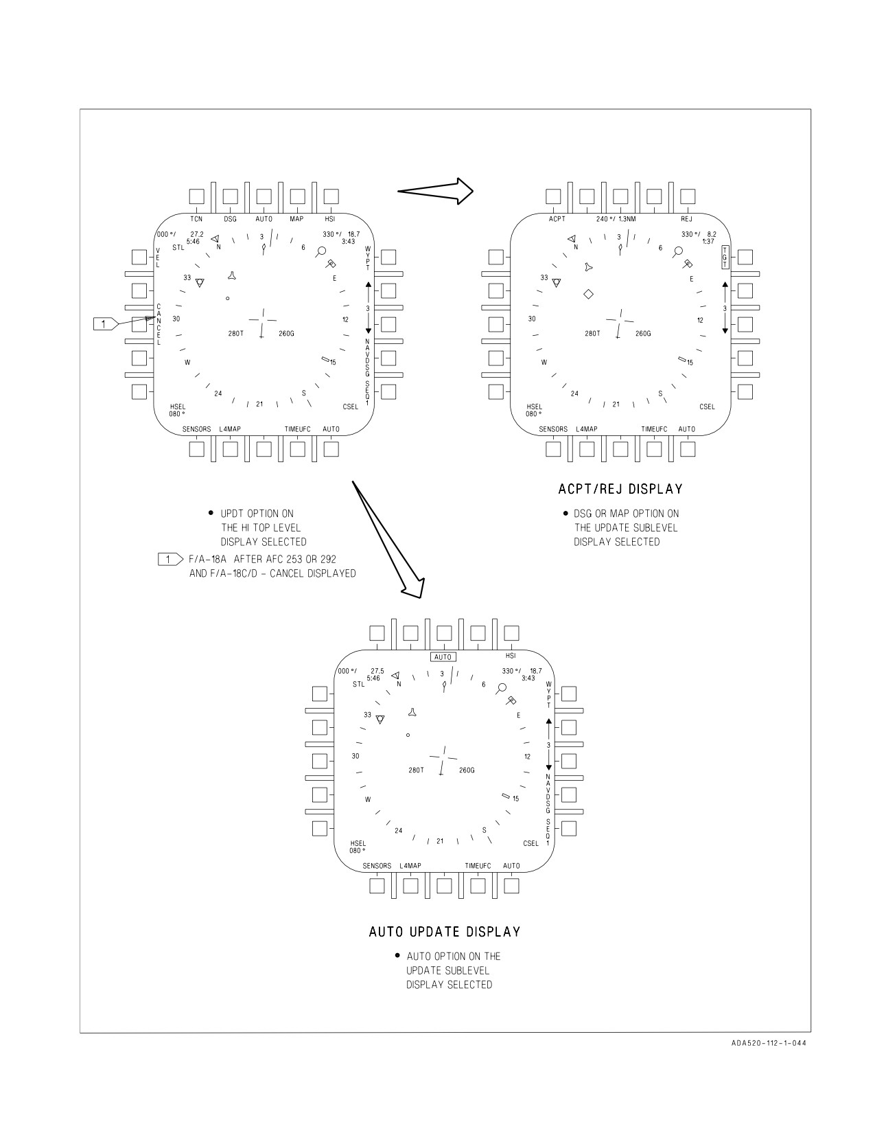
24.2.7 Position Updating. Selecting the UPDT (update) option on the HSI display provides the
update sublevel display, see figure 24-11. This display allows inflight selection of: VEL (velocity), TCN
(TACAN), GPS, DSG (designate), AUTO (automatic), and MAP as the update options. These options
provide position/velocity updating to the INS/ADC during NAV or IFA modes. All updates must be
performed while in the NAV or A/G master modes, unless noted otherwise. TCN position updating is
described in the TACAN section, and VEL updating is described in the NTRP 3-22.2-FA18A-D
NATIP.
VII-24-40
ORIGINAL
A1-F18AC-NFM-000
NOTE
Normally, position updates are not required. Erroneous updates will
degrade an otherwise good INS even if corrected back to a known
correct position. The update option is not available in AINS position
keeping.
On F/A-18A after AFC 253 or 292 and F/A-18 C/D aircraft, after an update is performed, the
CANCEL option is displayed on the HSI UPDATE option display. Pressing the CANCEL option
cancels the previous update and removes the CANCEL option. The INS then updates the aircraft
position using the last accepted position update. The CANCEL option is also removed upon
touchdown or when present position is changed using the UFC.
24.2.7.1 Designation (DSG) Update. To perform a designation update press the UPDT option on the
HSI display. Select the DSG option on the UPDT sublevel display. Designate a waypoint/OAP with a
sensor (radar, FLIR, NFLR or LDT), a HUD designation, or an overfly designation. The DSG option
may be selected before or after waypoint designation. When the designation has been performed and
DSG option selected, sensor ranging components to the target are added to the previously entered
waypoint position to give an aircraft computed position. The difference between the computed aircraft
position and the onboard aircraft position produces the position error readout in bearing and range on
the ACPT/REJ display. Selecting the ACPT option accepts the position update and returns the HSI
display. Selecting the REJ option rejects the update and returns the HSI display. A DSG update may
be performed in the A/A master mode if the designation was performed in A/G prior to entering A/A.
With MC OFP 13C AND UP, the selection of UPDT/DSG suspends auto sequential steering and
disengages coupled steering.
24.2.7.2 Post Flight Update. The INS post flight update collects terminal INS maintenance data.
The post flight update is performed using the overfly designation update method. The INS determines
the overfly designation update is a post flight update using the WOW transition. The aircraft must be
completely stopped (parking brake engaged) to prevent erroneous terminal velocity data. The post
flight update is not performed onboard ship.
The INS post flight update may be performed when: the parking brake is set, and the aircraft is
within .01 NM (60 feet or .6 seconds) of the appropriate waypoint entered in the system (the update
waypoint need not be waypoint 0). If the waypoint position is known but not programmed in the
system, the position may be entered and used for the update. If no waypoints are available, no update
should be attempted.
24.2.7.3 MAP Update. To perform a MAP update select the UPDT option on the HSI display. Now
designate a waypoint/OAP with a sensor (radar, FLIR or LDT), a HUD designation or an overfly
designation. Next select the MAP option on the update sublevel display. When this is done the word
SLEW appears in the upper right corner of the HSI and the TDC is automatically assigned to the HSI
(for map slewing). The map can now be slewed so the target on the map is under the designation symbol
(diamond). The difference between the target position and the designated position produces the
position error readout in bearing and range on the ACPT/REJ display. Selecting the ACPT option
accepts the position update and returns the HSI display. Selecting the REJ option rejects the position
update and returns the HSI display. The MAP option is not available if a map is not installed.
24.2.7.4 AUTO Update. To perform an AUTO update select the UPDT option on the HSI display.
Now select the AUTO option on the UPDT sublevel display. When this is done the AUTO option is
boxed and the VEL, TCN, DSG and MAP options are removed. The pilot must then assign the TDC
VII-24-41
ORIGINAL
A1-F18AC-NFM-000
to the HI/MPCD, overfly the waypoint/OAP then press the TDC while over the waypoint/OAP. When
this is done the MC enters the waypoint/OAP as the aircraft present position, and the HSI display is
returned. Also, the next waypoint in succession becomes designated or, in the case of an OAP, the offset
becomes designated. There is no ACPT/REJ display in the AUTO update mode.
24.2.8 NAV/TAC Bank Limit Options (MC OFP 13C AND UP). Bank angle control 1 (BAC1) is
engaged when any coupled steering mode is engaged. BAC1 provides aircraft steering commands and
limits and maintains the aircraft on course to the selected waypoint(s), offset aim point(s), or TACAN
station. BAC1 also provides steering to capture and hold a course line through the current WYPT,
OAP, or TACAN station. The maximum bank limit (BLIM) is selectable on the A/C data display. TAC
BLIM is used for tactical missions and limits the bank angle between ±30° and ±60° with a bank rate
between 10° and 30° per second based on airspeed. NAV BLIM is used for general navigation and sets
bank angle to a fixed ±30° limit with a maximum bank angle rate of 10° per second.
24.2.9 Steering. There are several types of waypoint/OAP steering described here: direct great circle,
course line, auto sequential and target.
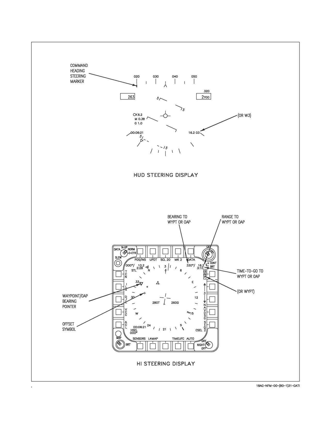
24.2.9.1 Waypoint/OAP Direct Great Circle Steering. Direct great circle steering is available in all
master modes and is selected/deselected by actuating the WYPT/OAP option on the HI/MPCD.
Selecting waypoint/OAP steering deselects ILS, D/L and TACAN steering. When steering is selected,
the option is boxed and direct great circle steering is provided on the HUD as shown in figure 24-12.
To follow a direct great circle path to the waypoint/OAP, the aircraft is turned so that the command
heading steering pointer under the heading scale is centered in the heading caret. The steering
provided by the steering pointer is corrected for wind drift. When the steering pointer is within ±5° of
the caret as measured on the heading scale, it provides a direct indication of steering error. Between
±5° and the ends of the heading scale (±15°), the steering pointer moves non-linearly so that it is at the
end of the heading scale when the steering error is 30°. The steering pointer is displayed at the end of
the heading scale when the steering error is greater than 30° during a turn, the steering pointer begins
to move to provide anticipation for rolling out of the turn, and then the actual steering error is
indicated when within 5°. Waypoint/OAP range, identification and number is displayed on the lower
right side of the HUD.
On the HI/MPCD, the position of the waypoint/OAP is indicated by the waypoint/OAP symbol as
shown on figure 24-12. If the selected steer to point is an OAP, the position of the offset is indicated
by the offset symbol. Bearing to the waypoint/OAP is indicated by the pointer inside the compass rose.
The waypoint/OAP symbol and pointer are displayed whether or not direct great circle steering is
selected. They provide a navigation situation display only. Steering (corrected for drift) is provided
only on the HUD. A digital readout of bearing and range to the waypoint/OAP is provided on the upper
right corner of the HI/MPCD. Time to go to the waypoint/OAP in minutes and seconds, based upon
range and present groundspeed, is provided under the bearing and range readout.
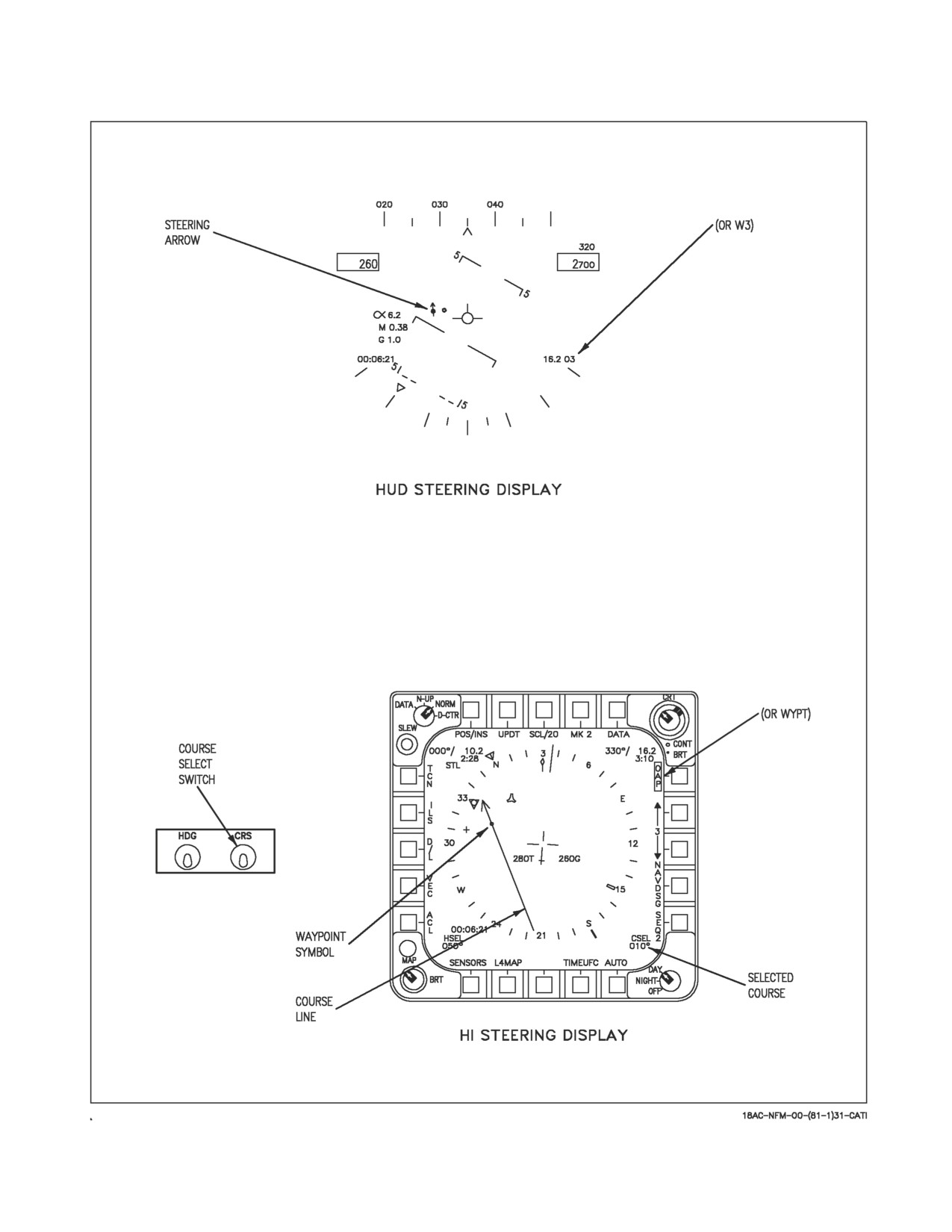
24.2.9.2 Waypoint/OAP Course Line Steering. Course line steering is used when it is desired to fly
a selected course to the waypoint/OAP. To select course line steering first select direct great circle
steering, then actuate the course select switch. When the course select switch is actuated, the course
line appears through the waypoint/OAP symbol as shown in figure 24-13, sheet 1. The course line
rotates clockwise while the course select switch is held to the right and counterclockwise while it is held
to the left. A digital readout of the selected course is provided in the lower right corner of the
HI/MPCD. When the waypoint/OAP symbol is beyond the range of the selected HI/MPCD scale, the
waypoint/OAP symbol is limited at the inside of the compass rose coincident with the head of the
pointer. The course line then rotates about the head of the pointer. It does not then overfly its correct
VII-24-42
ORIGINAL
A1-F18AC-NFM-000
Figure 24-11. Position Updating Displays
VII-24-43
ORIGINAL
A1-F18AC-NFM-000
Figure 24-12. Waypoint/OAP Direct Great Circle Steering
VII-24-44
ORIGINAL
A1-F18AC-NFM-000
Figure 24-13. Waypoint/OAP Course Line Steering (Sheet 1 of 2)
VII-24-45
ORIGINAL
A1-F18AC-NFM-000
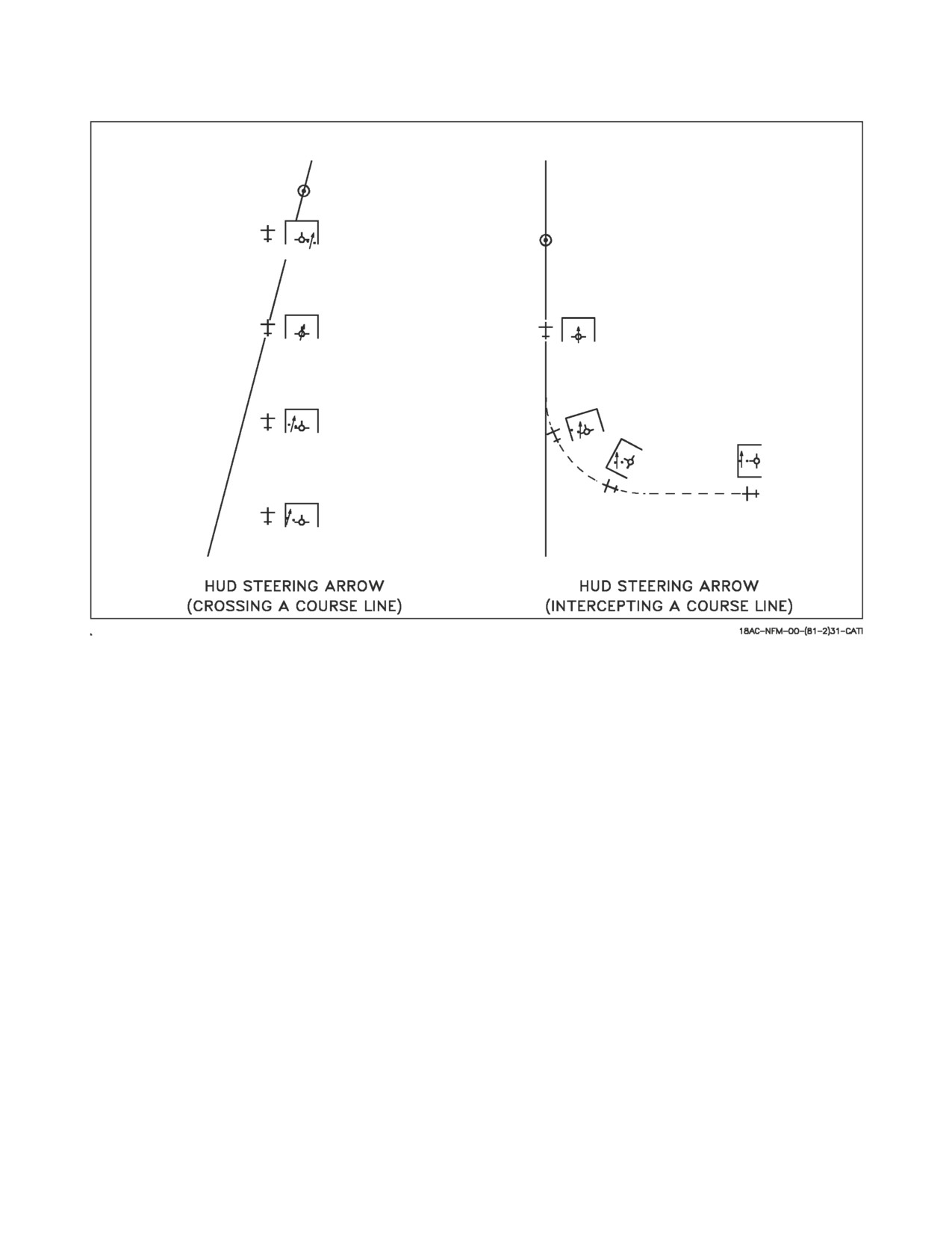
Figure 24-13. Waypoint/OAP Course Line Steering (Sheet 2 of 2)
position on the map. However, it does correctly indicate to which side of the aircraft the course lies and
the intercept angle is correctly represented.
When a course line is selected, the steering on the HUD is as shown on figure 24-13, sheet 1. The
arrow provides a horizontal situation indication relative to the velocity vector. As shown, the aircraft
is to the right of the selected course, but is converging toward it. Two dots are displayed on the side of
the velocity vector toward the steering arrow and in a line perpendicular to it. The outermost dot
represents full scale deflection of the arrow (8°) and the innermost dot indicates half scale deflection
(4°). If the arrow moves to the other side of the velocity vector, the dots appear on that side. The dots
are not displayed when within approximately 1.25° of being on course. Figure 24-13, sheet 2 shows an
example of the HUD steering arrow display as the aircraft crosses a course line. Figure 24-13, sheet 2,
also shows the display as the aircraft turns to intercept a course line. The HUD situation arrow display
is available only in NAV master mode, although waypoint/OAP steering can be selected and the course
arrow can be displayed and used on the HI/MPCD in any master mode. However, only waypoint/OAP
direct great circle steering is available on the HUD when designated. Also, course line steering can be
deselected either by deselecting waypoint/OAP direct great circle steering, or by selecting a new
waypoint/OAP, thus initializing direct great circle.
24.2.9.3 Coupled Waypoint/OAP Steering (MC OFP 13C AND UP). When waypoint steering is
coupled CPL WYPT is displayed on the HUD and HSI display, and a CPLD advisory appears on the
DDI. The aircraft steers to intercept the desired course line, or flies to the point if no course line is
selected. Bank angle is limited by NAV or TAC Bank Limit option as selected on the A/C sublevel
display and described in chapter 2. As the aircraft gets close to the desired course, the bank angle is
VII-24-46
ORIGINAL
A1-F18AC-NFM-000
reduced to maintain the aircraft on the desired course. If course line steering is not selected, once the
aircraft reaches the waypoint or offset aim point (OAP), WYPT steering uncouples. If course line
steering is selected, the aircraft remains coupled and flies an outbound radial. Heading hold, and
RALT or BALT (if selected) remain engaged when the aircraft passes the waypoint. If a ground point
is designated, WYPT steering will not couple, or uncouples if previously coupled. If waypoint steering
does not engage or disengages without being commanded, an AUTOPILOT caution is displayed on the
DDI, and CPL WYPT flashes for 10 seconds on the HUD and HSI displays. The caution can be cleared
with the paddle switch.
24.2.9.4 AUTO Sequential Steering. Before AUTO sequential steering can be selected a waypoint/
OAP sequence must be programmed.
AUTO sequential steering is selected by actuating the AUTO option (AUTO boxed) on the
HI/MPCD. When selected, other steering modes not compatible with AUTO sequential are deselected.
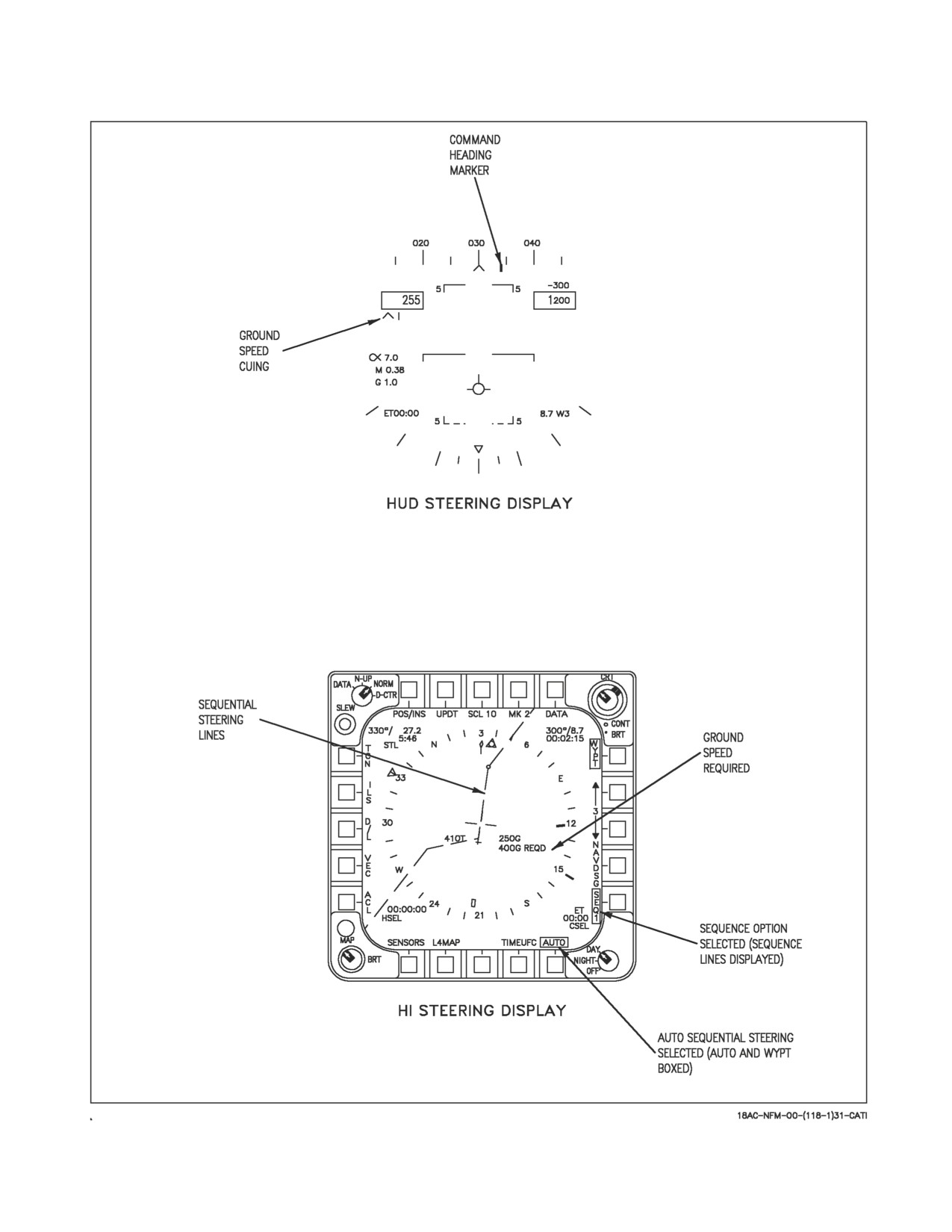
With AUTO sequential steering engaged, great circle steering is provided to the first waypoint/OAP
in the selected sequence, see figure 24-14. When range to the steer to waypoint/OAP is less than 5 NM
and bearing is greater than 90°, the next waypoint/OAP in the sequence is automatically selected.
Great circle steering is automatically provided for each new steer to waypoint/OAP in the sequence.
During AUTO sequential steering course line steering is available, however course line is deselected
when the steer to waypoint/OAP is within the range and bearing mentioned above. The waypoint/OAP
up/down arrows provide manual selection for steering to the desired waypoint/OAP in the sequence.
With AUTO sequential steering engaged, selecting the SEQ # option provides dashed lines on the
HSI connecting the waypoint/OAPs of the chosen sequence, see figure 24-14.
AUTO sequential steering is deactivated when any of the following occur: the AUTO option
deselected (unboxed), the last waypoint/OAP in the sequence is within the parameters mentioned
above, selection of another steering mode, the FCS is coupled to the D/L, AUTO update is selected, a
ground point is designated, magnetic heading is invalid, aircraft present position is invalid, aircraft
ground track is invalid, or steering waypoint/OAP range/bearing is invalid.
With MC OFP 13C AND UP, auto sequential steering is suspended if UPDT/DSG is selected to
perform an overfly designation. The automatic transition to the next waypoint does not take place until
the update is either accepted or rejected and the sequence criteria is satisfied.
24.2.9.5 Coupled Auto Sequential Steering (MC OFP 13C AND UP). When auto sequential steering
is coupled CPL SEQ #( ) (current sequence number: 1, 2, or 3 replaces the parenthesis) is displayed on
the HUD and HSI display and a CPLD advisory appears on the DDI. The aircraft steers to intercept
the desired course of the current WYPT/OAP in the sequence. Bank angle is limited by NAV or TAC
mode as described in Chapter 2. As the aircraft gets close to the desired course, the bank angle is
reduced to maintain the aircraft on the desired course. An OVFLY( ) option is available on the WYPT
data option display. When this option is selected (boxed), the aircraft overflies the current WYPT/
OAP in the sequence before intercepting the course of the next one. When OVFLY( ) is not selected,
the aircraft performs a lead turn to intercept the course of the next WYPT/OAP just prior to reaching
the current point. Once the aircraft reaches the last point in the sequence, auto sequential steering
uncouples. Heading hold and RALT or BALT (if selected) remain engaged when the aircraft passes the
final point. If auto sequential steering does not engage or disengages without being commanded, an
AUTOPILOT caution is displayed on the DDI, and CPL SEQ( ) flashes for 10 seconds on the HUD and
HSI displays. The caution can be cleared with the paddle switch.
VII-24-47
ORIGINAL
A1-F18AC-NFM-000
Coupled AUTO sequential steering is selected as described above in the Auto Sequential Steering
paragraph.
Coupled AUTO sequential steering is deactivated as described above in the Auto Sequential
Steering paragraph.
Coupled auto sequential steering is disengaged if UPDT/DSG is selected to perform an overfly
designation. The automatic transition to the next waypoint does not take place. When auto disengage
from coupled steering occurs, autopilot cautions occur. Coupled steering does not automatically
re-engage after the update is complete.
24.2.9.6 Groundspeed Cuing. Before groundspeed cuing is available for display, certain criteria
must be meant: a waypoint/OAP sequence must be entered, a target waypoint/OAP in the sequence
must be selected, time of day must be entered (ZTOD or LTOD), and TOT must also be entered. With
waypoint/OAP great circle steering engaged to the target waypoint/OAP, the MC calculates the
groundspeed required to arrive at the target based on a direct path to the target and the entered TOT.
With AUTO sequential engaged, the MC calculates the groundspeed required to arrive at target
waypoint/OAP taking the sequential path to the target. The MC calculates the necessary groundspeed
based on the pilot entered groundspeed, providing there is enough time to travel the final leg at the
entered groundspeed and arrive at the target at the TOT. However, if there is not enough time to travel
the final leg at the pilot entered groundspeed, the MC ignores the pilot entered groundspeed and
calculate a groundspeed to arrive at the target on time.
NOTE
• Programming a required groundspeed is not necessary for ground-
speed cuing calculations.
• The designated target waypoint/OAP must be in the waypoint/OAP
sequence in order for the required groundspeed cueing function to
operate.
If the target is an OAP the groundspeed required calculation includes the distance from the OAP to
the offset. If the target is NAV designated the MC uses the NAV designation location in the calculation
of groundspeed required for TOT. Also, once the target waypoint/OAP is NAV designated, any other
designation means may be used to adjust the designation and the groundspeed calculation continues
to be calculated to the adjusted designation.
HUD cuing of required groundspeed consists of a tick mark and arrow head located under the
airspeed box. The arrow head is referenced to the tick mark, to indicate if the aircraft is traveling too
fast or too slow to reach the target on time. The arrow head is displayed to the left of the tick mark
when the aircraft is traveling too slow and displayed to the right of the tick mark when the traveling
too fast. Full displacement of the arrow head left or right of the tick mark indicates a difference of 30
knots between actual and required groundspeed. The aircraft is traveling the correct speed when the
arrow head is centered on the tick mark. The required groundspeed readout is displayed on the
HI/MPCD under the present ground speed readout. See figure 24-14 for an example of HUD and
HI/MPCD groundspeed cuing.
24.2.10 Designation. Designation of a waypoint/OAP is the action by which the pilot identifies a
waypoint/OAP position to the MC so that position can be used for sensor slaving, steering or position
updating. Navigation and overfly designations are discussed here, while sensor designations are
VII-24-48
ORIGINAL
A1-F18AC-NFM-000
described in the NTRP 3-22.2-FA18A-D NATIP. Designating a waypoint/OAP instigates the following
changes on the HI/MPCD: the NAVDSG option is removed/replaced with the O/S option, WYPT/
OAP is replaced with a boxed TGT/OAP legend, the waypoint symbol is replaced with the target
diamond, the waypoint symbol inside the waypoint steering pointer is also replaced with the target
diamond and the steering information in the upper right corner now relates to the target. Designating
a waypoint/OAP also provides the following changes on the HUD: a target diamond appears below the
heading scale to provide target heading information, another target diamond also appears indicating
the target line of sight (LOS) and the WYPT data (range) on the lower right corner is replaced with
TGT data. HUD target steering operates the same as described for waypoint/OAP great circle steering.
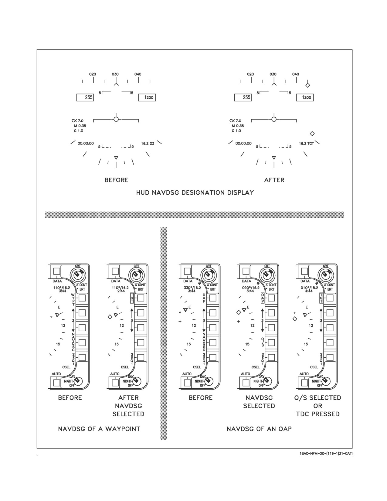
24.2.10.1 NAVDSG (Navigation) Designation. Selecting the NAVDSG option designates the way-
point as a target, with the changes mentioned above appearing at designation, see figure 24-15.
To NAVDSG an OAP the procedure is slightly different. When the NAVDSG option is selected the
OAP is designated and all data for the designated target on the HI/MPCD and HUD operates the same
as described above, except for the following: the NAVDSG legend is replaced with the O/S option, and
the OAP option is boxed. The O/S option must now be selected to add the offset data to the OAP
position which completes the designation. Another method of adding the offset data to the OAP
position (completing the designation) is to assign the TDC to the HI/MPCD then actuate the TDC.
When this occurs, the O/S legend is removed, the boxed OAP legend is replaced with a boxed TGT
legend, the offset symbol is replaced with the target diamond and the designated aimpoint reverts to
the aimpoint symbol. A NAVDSG cannot be performed if a waypoint/OAP is already designated, see
figure 24-15.
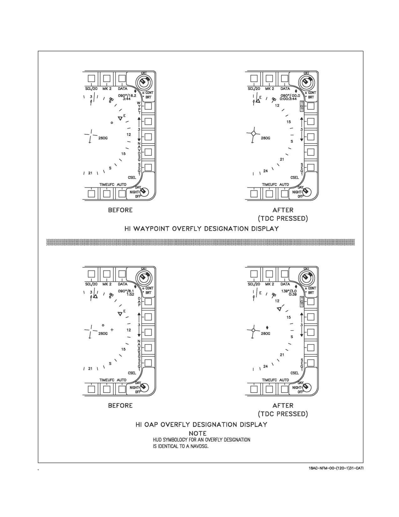
24.2.10.2 Overfly Designation. An overfly designation is performed on a waypoint/OAP by pressing
the TDC while it is assigned to the HI/MPCD and the aircraft is overflying the waypoint/OAP. When
this happens the MC assumes that the aircraft is over the waypoint/OAP and the aircraft present
position at that time is designated as the waypoint/OAP position. In the case of an OAP the offset data
is automatically added to the aircraft present position to complete the designation. When an overfly
designation is performed the changes mentioned above occur, see figure 24-16.
VII-24-49
ORIGINAL
A1-F18AC-NFM-000
Figure 24-14. AUTO Sequential Steering
VII-24-50
ORIGINAL
A1-F18AC-NFM-000
Figure 24-15. Navigation Designation (NAVDSG)
VII-24-51
ORIGINAL
A1-F18AC-NFM-000
Figure 24-16. Overfly Designation
VII-24-52
ORIGINAL
A1-F18AC-NFM-000
24.2.11 INS Updates (Not available in AINS)
Radar
1.
Master mode - NAV (RADAR SURF) or A/G
2.
Radar mode - EXP 1, EXP 2, EXP 3, or MAP
3.
WYPT - SELECT
4.
NAV DSG - PRESS
5.
TDC/DC - ASSIGN TO RADAR
6.
UPDT - PRESS
7.
DSG - PRESS
8.
Slew cursor over waypoint and release TDC
9.
Accept or reject
HUD
1.
WYPT - SELECT
2.
NAV DSG - SELECT
3.
TDC/DC - ASSIGN TO HUD
4.
UPDT - PRESS
5.
DSG - PRESS
6.
Slew HUD diamond over waypoint and release TDC/DC
7.
Accept or reject
Overfly
1. WYPT - SELECT
2. TDC/DC - ASSIGN TO HI/MPCD
3. UPDT - PRESS
4. DSG - PRESS
5. Actuate TDC/DC when aircraft is over waypoint
6. Accept or reject
VII-24-53
ORIGINAL
A1-F18AC-NFM-000
AUTO
1. WYPT - SELECT
2. TDC/DC - ASSIGN TO HI/MPCD
3. UPDT - PRESS
4. AUTO - PRESS
5. Actuate TDC/DC when aircraft is over waypoint
Map
1. WYPT - SELECT
2. UPDT - PRESS
3. MAP - PRESS (automatically assigns TDC/DC to HI/MPCD)
4. Overfly desired geographical reference and actuate TDC/DC
5. Select slew and slew map reference under aircraft symbol, release TDC/DC
6. Accept or reject
TACAN
(1 of 10 available TACAN stations must be in reception range)
1. UPDT - PRESS
2. TCN - PRESS
3. Accept or reject
Velocity
1. UPDT - PRESS
2. VEL - PRESS
3. Accept or reject
24.3 ADF (Automatic Direction Finder).
The OA-8697/ARD ADF is a VHF/UHF direction finder operating in the 100 to
400 MHz frequency
range. The system has two sections: the antenna section which receives and modulates rf signals, and
the audio processing section which resolves bearing in the ADF audio received from the VHF/UHF
receiver-transmitter. Bearing information received by the ADF is sent to the MC where the data is
processed to position the ADF bearing pointer on the HI/MPCD. The channel to the station to which
ADF bearing is required is selected on the comm 1 or comm 2 radio.
VII-24-54
ORIGINAL