F18. FLIGHT MANUAL (2008) - page 15
A1-F18AC-NFM-000
29.3.3 Taxi
29.3.4 Takeoff (*)
1. ATC Clearance
2. Takeoff
29.3.5 Climb/Cruise
1. Departure
2. Climb and Level-Off
3. Procedures Enroute
29.3.6 Approach/Landing (*)
1. Tacan, GCA, ILS/ACLS, Radar, ADF
2. Landing
29.3.7 Communications
1. R/T Procedures
2. Visual Signals
3. IFF Procedures
29.3.8 Emergency/Malfunction Procedures (*).
In this area, the pilot will be evaluated only in the
case of actual emergencies, unless evaluation is conducted in the OFT/WST or TF/A-18.
29.3.9 Post Flight Procedures
1. Taxi
2. Shutdown
3. Inspection and Records
4. Flight Debriefing
29.3.10 Mission Evaluation. This area includes missions covered in the NATOPS Flight Manual,
F/A-18 Tactical Manual, and NWP NWIPs for which standardized procedures/techniques have been
deployed.
29.3.11 Applicable Publications. The NATOPS Flight Manual contains the standard operations
criteria for F/A-18 aircraft. Publications relating to environmental procedures peculiar to shorebased
and shipboard operations and tactical missions are F/A-18
Tactical Manual, NWPs, NWIPs,
ATC/CATCC Manual, Local Air Operations Manual, and Ship Air Operations Manual.
X-29-4
ORIGINAL
A1-F18AC-NFM-000
29.3.12 Flight Evaluation Grading Criteria. Only those sub-areas provided or required will be
graded. The grades assigned for a sub-area shall be determined by comparing the degree of adherence
to standard operating procedures with adjectival ratings listed below. Momentary deviations from
standard operating procedures should not be considered as unqualifying provided such deviations do
not jeopardize flight safety and the evaluee applies prompt corrective action.
29.3.13 Flight Evaluation Grade Determination. The following procedure shall be used in deter-
mining the flight evaluation grade: A grade of Unqualified in any critical area/sub-area will result in
an overall grade of Unqualified for the flight. Otherwise, flight evaluation (or area) grades shall be
determined by assigning the following numerical equivalents to the adjective grade for each sub-area.
Only the numerals 0, 2 or 4 are to be assigned in sub-area. No interpolation is allowed.
Unqualified
0.0
Conditionally qualified
2.0
Qualified
4.0
To determine the numerical grade for each area and the overall grade for the flight, add all the points
assigned to the sub-areas and divide this sum by the number of sub-areas graded. The adjective grade
shall then be determined on the basis of the following scale.
0.0 to 2.19 - Unqualified
2.2 to 2.99 - Conditionally Qualified
3.0 to 4.0 - Qualified
EXAMPLE: (Add Sub-area numerical equivalents)
(4+2+4+2+4) ÷ 5 =3.20 Qualified
29.3.13.1 Final Grade Determination. The final NATOPS evaluation grade shall be the same as the
grade assigned to the flight evaluation. An evaluee who receives an Unqualified on any ground
examination or the flight evaluation shall be placed in an Unqualified status until he achieves a grade
of Conditionally Qualified or Qualified on a reevaluation.
29.3.13.2 Records and Reports. A NATOPS Evaluation Report (OPNAV Form 3510-8) shall be
completed for each evaluation and forwarded to the evaluee’s commanding officer only. This report
shall be permanently filed in the individual NATOPS Flight Personnel Training/Qualification jacket.
29.3.13.3 Critique. The critique is the terminal point in the NATOPS evaluation and is given by the
Evaluator/Instructor administering the check. Preparation for the critique involves processing,
reconstructing data collected, and oral presentation of the NATOPS Evaluation Report. Deviations
from standard operating procedures will be covered in detail using all collected data and worksheets as
a guide. Upon completion of the critique, the pilot will receive the completed copy of the NATOPS
Evaluation Report for certification and signature. The completed NATOPS Evaluation Report is then
presented to the Unit Commanding Officer.
29.3.13.4 NATOPS Evaluation Question Bank. The following bank of questions is intended to assist
the unit NATOPS Instructor/Evaluator in the preparation of ground examinations and to provide an
abbreviated study guide. The questions from the bank may be combined with locally originated
questions in the preparation of ground examinations. The closed book exam shall consist of no less
than 50 questions. The time limit for the closed book exam is 1 hour and 30 minutes. The requirements
for the open book exam are the same as those for the closed book exam, except there is no time limit.
X-29-5
ORIGINAL
A1-F18AC-NFM-000
29.4 NATOPS EVALUATION QUESTION BANK
1.
What is military thrust of the F404-GE-400/402 engine?
2.
What is afterburner thrust of the F404- GE-400/402 engine?
3.
When will you get engine ignition?
a.
b.
c.
d.
4.
When will you get afterburner ignition?
a.
b.
5.
How is a limited amount of fuel provided for negative G or inverted flight?
6.
True/False: The F/A-18’s IDLE rpm is the same on the ground as inflight.
7.
Which one of the following caution and advisory displays will not activate the “engine left (right)”
voice alert?
a. L or R OVRSPD
b. L or R EGT HIGH
c. L or R BOOST LO
d. L or R OIL PR
8.
What are the modes of operation of the automatic throttle control (ATC)?
a.
b.
9.
What conditions must be met to engage the approach mode of the automatic throttle control?
a.
10. What conditions must be met to engage the cruise mode of the automatic throttle control?
a.
b.
X-29-6
ORIGINAL
A1-F18AC-NFM-000
11. Which fuel tanks are transfer tanks?
a.
b.
c.
12. Which fuel tanks are feed tanks?
a.
b.
13. What does a TANK PRESS HI caution display on the DDI indicate?
a. On the ground -
b. Inflight -
14. Normal internal fuel is transferred using
15. External fuel is transferred by
16. True/False: With external tank control switch in stop transfer and hook handle down, fuel will
transfer when FUEL LO caution display comes on.
17. What two fuel valves close when an engine fire light is pressed?
a.
b.
18. List four events which individually will cause fuel dump to stop.
a.
b.
c.
d.
19. True/False: The fuel low level indicating system is completely independent of the fuel quantity
indicating system.
20. What fuel state illuminates the FUEL LO light, MASTER CAUTION light, and activates fuel
low voice alert?
21. True/False: There is no voice alert associated with BINGO fuel.
X-29-7
ORIGINAL
A1-F18AC-NFM-000
22.
Either AMAD may be driven pneumatically through an
by the APU, opposite engine bleed
air, or external air.
23.
Each AMAD mechanically drives a
,
, and
24.
True/False: Operation of APU is totally automatic after the APU switch is placed ON.
25.
What provides electrical power for APU ignition and start control circuits?
26.
What is used to start the APU?
27.
True/False: If ATS caution is on when a DDI comes on, shut down the affected engine to avoid
starter damage.
28.
What is the cockpit warning of a single transformer-rectifier failure?
29.
What is indicated by the BATT SW light coming on in the air with the battery switch on?
30.
What eight circuit breakers are located in the cockpit?
31.
True/False: The exterior lights master switch must be on for operation of the position and
formation lights, but not for the strobe lights.
32.
What failure(s) will illuminate the emergency instrument light and the BATT SW caution light?
33.
The right or HYD system 2 provides power to:
34.
What are the primary and two backup modes of the flight control system?
a.
b.
c.
35. What are the primary flight controls?
36. What does pressing the T/O trim button in flight do?
37. What is the FCS reset button used for?
38. With the spin switch in NORM, when will the spin recovery mode be activated?
39. What does having the flight controls in a spin recovery mode do for you as a pilot?
40. What position are the flaps in when the flight controls are in a spin recovery mode?
a.
b.
X-29-8
ORIGINAL
A1-F18AC-NFM-000
41. On takeoff, accelerating with the FLAP switch in HALF, at what speed will the flaps begin
AUTO scheduling?
42. True/False: Once EMERG has been selected on FCS COOL switch, selection of NORM will
switch FCC A and right TR cooling back to avionics air.
43. Rudder toe-in is a function of FLAP switch position and . . . with maximum toe-in being
44. True/False: An AIL OFF caution display indicates that the roll axis is now in the direct electrical
link mode.
45. True/False: Stabilator position on the FCS status display on the DDI shows a (+) for trailing
edge up (or nose up), and a (-) for trailing edge down (or nose down).
46. What occurs with gear handle UP, airspeed below 175 knots, altitude less than 7,500 feet, and
rate of descent greater than 250 feet per minute?
a.
b.
47. True/False: Pressing and holding the nosewheel steering button a second time will select the
high mode (±75°) and NWS HI is displayed on the HUD.
48. True/False: The hook light remains on except when the hook is up and latched.
49. Normally, what kind of power is needed to fold or spread the wings?
50. Is it normal to have L PITOT HT and R PITOT HT advisories displayed on the DDI while on
the ground with pitot heat switch in AUTO?
51. What will the standby attitude indicator be powered by if the right 115 volt ac bus fails?
52. The APU fire detection/extinguishing systems operates from
power, provided the
switch is ON.
53. The bleed air shutoff valves are closed when the fire and bleed air test switch is placed to TEST
A and TEST B positions. How do you get the valves back open?
a.
b.
54. True/False: The canopy can be jettisoned in the closed position only.
55. Why would you not pull the manual override handle in flight before ejection?
56. What conditions must be met to utilize the emergency jettison button?
a.
b.
X-29-9
ORIGINAL
A1-F18AC-NFM-000
57. The
switch must be in the
position to use the selective jettison system.
58. What occurs when the unlighted MASTER CAUTION light is pressed?
59. True/False: For cautions with voice alert, the master caution tone comes on after the voice alert.
60. What two ways can you stop any BIT test in progress and return the equipment to normal
operation?
a.
b.
61. What two systems require additional switchology other than pressing the associated button
when performing initiated BIT checks?
a.
b.
62.
How much has the fuel quantity in tank 1 been reduced in the F/A-18B/D aircraft?
63.
True/False: The aft cockpit does not have an internal canopy switch or an internal manual
canopy handcrank.
64.
True/False: There are provisions for normal landing gear extension from the rear cockpit.
65.
The leg restraint lines must be buckled at all times during flight to ensure
and to
enhance
66.
Failure to route the restraint lines properly through the garters could cause:
67.
True/False: High gain nosewheel steering should be used on takeoff roll up to 50 knots.
68.
On a section takeoff, turns into the wingman will not be made at altitudes less than
feet
AGL.
69.
True/False: The second section may commence the takeoff roll after the first section has rolled
1,000 feet.
70.
True/False: Before descent it is necessary to preheat the windshield by increasing defog airflow.
71.
True/False: For optimum braking above 40 knots, with anti-skid, full brake pressure should be
used.
72.
True/False: Ensure anti-skid is OFF for all shipboard operations.
73.
Nosewheel steering low mode (may/may not) be engaged while the launch bar is down (circle
correct answer).
74.
A carrier landing pattern starts with a level break at
feet, on the
bow of the ship.
X-29-10
ORIGINAL
A1-F18AC-NFM-000
75. True/False: The seat rocket thrusters may ignite spilled fuel or hydraulic fluid and may injure
ground crew in the immediate vicinity.
76. True/False: If you must land with the launch bar extended, you should request that the field
arresting gear cables be removed.
77. A time critical situation exists if you have directional control problems during takeoff. If you
suspect nosewheel steering failure, the first thing you should do is:
1.
78. If the aircraft begins to settle after a catapult launch and the settling cannot be stopped you
must
79. What are the emergency procedures if you have lost thrust on takeoff?
80. True/False: It is unlikely that a blown nose tire will FOD an engine.
81. During flight brief consideration of takeoff abort possibilities, the following items should be
considered.
a. Weight
b. Speed
c. Runway length remaining
d. All of the above
82. When making an arrested abort, allow time for the arresting hook to extend; as a guide, lower
the hook
feet before the cable.
83. If the landing gear fails to retract you should perform the following:
a. Pull the landing gear control circuit breaker.
b. Cycle the gear and pull negative g’s.
c. Put the landing gear handle down and do not cycle
d. Press on - its probably a false light.
84. What two methods may be used to retain both hydraulic systems if the engine core is rotating?
a.
b.
85. True/False: If the right engine is being rotated with crossbleed to provide normal systems
operation and fuel flow on the left engine is reduced below 2,000 pph (as during landing) the
right engine hydraulic pump may not provide sufficient flow for nosewheel steering and normal
brakes.
X-29-11
ORIGINAL
A1-F18AC-NFM-000
86. True/False: Most engine stalls are self clearing.
87. True/False: Engine stalls may produce audible bangs.
88. True/False: If a stalled engine will not clear, you may shut down the engine and attempt a
restart.
89. What airspeed may be required to maintain 12% windmilling rpm?
90. True/False: Engine crossbleed may not be used to achieve a 12% rpm for engine restart.
91. With one engine windmilling below 12%, the remaining engine should be operated at or
above
% rpm and
PPH fuel flow to utilize the crossbleed airstart capability.
92. True/False: Hydraulic system 2A failure is the only single hydraulic system failure
which
requires pilot action.
93. Hydraulic system 1A does not power which of the following?
a. Right Aileron
b. Right Trailing Edge Flap
c. Leading Edge Flaps
d. Left Trailing Edge Flaps
94. True/False: With HYD 2A failure, anti-skid is available.
95. With HYD 2A failure what type of landing should be considered?
a. Normal landing
b. Formation landing
c. Long field arrestment
d. Short field arrestment if practical
96. The aircraft is uncontrollable on what single hydraulic circuit?
97. True/False: Gravity fuel flow is sufficient to sustain minimum afterburner operation.
98. True/False: You are in the spooldown restart envelope at 450 knots, 23,000 feet and N2
50%.
99. True/False: You are in the windmill restart envelope at Mach 0.75, 25,000 feet and 14%N2.
100. True/False: A crossbleed restart is recommended at Mach 0.68 and 10,000 feet.
101. True/False: You may attempt an APU restart below 250 knots and 10,000 feet.
X-29-12
ORIGINAL
A1-F18AC-NFM-000
102.
True/False: If tank 1 fails to transfer, as much as 1,100 pounds of fuel may not be usable for
approach and landing.
103.
True/False: One generator is insufficient to carry the total aircraft electrical load.
104.
The utility and emergency batteries will provide limited dc power for approximately
minutes.
105.
True/False: During a dual generator failure, do not turn off any of the flight control systems in
an attempt to conserve battery power.
106.
Remaining battery life may be estimated as the U BATT LO light comes on when approxi-
mately
percent of the total time remains (Aircraft 161353 THRU 161528).
107.
If the cabin temperature knob is full clockwise with the cabin temperature switch in MAN,
cockpit temperature can reach as high as
°F.
108.
True/False: The most probable source of visible smoke or fumes in the cockpit is from the
engine bleed or residual oil in the ECS ducts.
109.
True/False: With both generators inoperative and good batteries your landing gear position
indicator will function normally.
110.
True/False: With both generators inoperative and good batteries your hydraulic pressure
indicator will be inoperative.
111.
True/False: Pressing the emergency jettison button, simultaneously jettisons stores from the
parent bomb racks on external stores stations 2, 3, 5, 7, and 8.
112.
True/False: Weight must be off the main landing gear or landing gear handle must be up for
the emergency jettison system to be operational.
113.
True/False: Failure of FCS channels 1 and 3 will not affect the flying qualities of the aircraft.
114.
True/False: If the trailing edge flaps are failed in the 0° position, final approach airspeed is not
significantly affected.
115.
True/False: A single-engine landing is made at HALF flaps.
116.
With 1,000 feet per minute sink rate, at 130 to 150 knots, with a 2 second reaction time, the
minimum altitude for a successful ejection is
feet in the F/A-18B at 0° angle of bank.
117.
With 30° nose down and 90° angle of bank, and 200 knots, the minimum altitude for a safe
ejection is
feet in the F/A-18.
118.
The correct procedure for an APU ACCUM caution airborne is:
119.
List the steps for an out-of-control recovery (all aircraft).
120.
Thunderstorm penetration should be made between optimum cruise and
knots below
35,000 feet, and no less than
knots above 35,000 feet.
X-29-13
ORIGINAL
A1-F18AC-NFM-000
121. What precautions must be observed when using the windshield rain removal?
122. The COM-NAV functions not available when MC 1 has failed are:
123. True/False: The right and left DDIs are physically and functionally interchangeable.
124. The bank angle scale pointer, on the HUD, is limited at ... and ...when the limit is exceeded.
125. The velocity vector represents:
126. True/False: Do not lock the gyro in the caged position with the pull to cage knob if the gyro is
spinning.
Using Stall Speed chart:
Mil power
Gross weight - 28,000 pounds
Gear/flaps - DOWN
127. Determine - Stall Speed 0° Bank =
128. Determine - Stall Speed 45° Bank =
Using Landing Approach Speed chart:
Gross weight - 28,000 pounds
Flaps - 30°
129. Determine - Recommended Approach Speed =
130. What action must the pilot take in order to slew the moving map with the TDC?
a.
b.
131. The GYRO position on the INS mode selector switch:
a. Connects the gyros to the attitude heading reference system in order to complete an inflight
alignment
b. Enables the mission computer to use the gyros in computations for air-to-air weapons delivery
c. Is the attitude mode where the INS operates only as an attitude heading reference system
d. All of the above
132. REJ 1 removes what from the HUD display?
X-29-14
ORIGINAL
A1-F18AC-NFM-000
133.
If you see the following in the upper left corner of the HI, what does it tell you?
237/108
18:00
NLC
a.
Your aircraft is 108 miles from Lemoore TACAN on the 237° radial
b.
Your aircraft is 108 miles from Lemoore TACAN on the 057° radial
c.
Your aircraft is 18 miles from Lemoore TACAN on the 057° radial, 108° magnetic heading
d.
Your aircraft is 18 miles from Lemoore TACAN on the 108° radial, 237° magnetic heading
134.
During a data link ACLS (SPN-42) approach the HUD displays:
a.
A TD box overlying the touchdown point
b.
A fly-to tadpole symbol
c.
Fly-to needles (similar to ILS)
d.
A course arrow and elevation steering bar
135.
True/False: During an ILS approach the standby attitude indicator displays the ILS needles.
136.
What is the internal fuel capacity of the F/A-18A/C
pounds, F/A-18B/D:
pounds.
137.
State the following limitations:
400
402 as applicable
a.
Maximum steady state EGT -
b.
Maximum start EGT -
c.
Maximum EGT fluctuation (stabilized power) -
d.
Maximum rpm fluctuation (stabilized power) -
e.
Maximum transient rpm (N2)Maximum nozzle fluctuation -
X-29-15
ORIGINAL
A1-F18AC-NFM-000
138. State the ranges for the following:
400
402 as applicable
a. Ground idle rpm -
b. Flight idle rpm -
c. Maximum oil pressure (2½ minutes after start with ambient temperature below -18°C,
0°F)
Minimum oil pressure (ground idle) -
d. Inflight oil pressure:
(1) Idle -
(2) Military -
139. The maximum speeds of the following are:
a. Refueling probe -
b. Gear retraction/extension -
c. Gear emergency extension -
d. Trailing edge flaps -
e. Canopy open -
140. State the following limitations:
a. Maximum gross weight field takeoff -
b. Maximum landing weight (field landing - flared) -
c. Carrier landing
(1) Aircraft 161353 THRU 163782 -
(2) Aircraft 163985 AND UP -
d. Maximum air refueling altitude -
e. Maximum closure on refueling drogue -
f. Maximum time at negative g -
(1) Aircraft THRU 161924 -
(2) Aircraft 161925 AND UP -
g. Minimum time between negative g maneuvers (Aircraft THRU
161924) -
X-29-16
ORIGINAL
A1-F18AC-NFM-000
141.
If the velocity vector begins to flash slowly but is not HUD limited:
a.
Selected ordnance has been released.
b.
The mission computer may be displaying a degraded velocity vector
c.
The waterline symbol is HUD limited
d.
STBY attitude indicator is providing HUD attitude information
142.
The HUD landing display (elongated horizon bar, AOA bracket, waterline symbol, steering
display) will be presented
a.
When selected through the HUD control panel
b.
When selected on the right DDI
c.
When gear is down and NAV master mode is selected
d.
Any time that the gear is down
143.
True/False: While using NAV master mode, the pilot has the option to cage or uncage the
velocity vector on the HUD.
144.
At what altitude will the cockpit begin to pressurize?
145.
What action should be taken if FCS HOT caution light comes on in flight?
a.
b.
146.
When the G XMT switch is placed to COMM 1 or COMM 2 the:
a.
Selected radio will receive/transmit on 243.0 only
b.
Selected radio will receive only 243.0
c.
Selected radio will transmit only 243.0
147.
The hydraulic pumps are located on the
and maintain hydraulic pressure between
psi.
148.
The HYD 2 priority valves close at approximately
psi.
149.
Placing the HI mode selector switch to NORMAL displays compass rose aligned with the
aircraft
a.
Magnetic ground track
b.
Magnetic heading
150.
By what method are external tanks pressurized on the ground?
X-29-17
ORIGINAL
A1-F18AC-NFM-000
151.
What indication does the pilot have to indicate low or lost motive flow pressure?
152.
Fuel is transferred from external tanks by:
a.
The passing of motive flow fuel through an ejector pump which utilizes the venturi principle
to induce fuel flow.
b.
Bleed air to pressurize each external tank.
c.
Electrically powered boost pumps located inside each tank.
d.
AMAD driven boost pumps that utilize the venturi principle to induce the flow from each tank.
153.
True/False: In the F/A-18B/D there is no provision to lower the landing gear from the rear
cockpit.
154.
With a failure of hydraulic system 2A, what alternate method exists for extending the air
refueling probe?
155.
Fuel dump is accomplished by:
a.
Motive flow (ejector pumps)
b.
Electrical pump powered by essential bus
c.
AMAD driven boost pump
d.
Variable displacement pumps driven by hydraulic system 2A
156.
Normal brake system pressure is provided by hydraulic system
157.
What optical indications of NWS failure will the pilot have available besides the MASTER
CAUTION light?
a.
b.
158.
What should occur when the oxygen test button is pressed?
159.
Where is the manual canopy crank handle located inside the F/A-18 cockpit?
160.
Depending on aircraft attitude and power setting, the fuel dump rate is about
pounds/minute.
161.
True/False: During single engine operations, significantly lower fuel boost pump rates have
been experienced in the F/A-18C/D.
162.
True/False: Mechanical linkage will allow normal retraction of the nose gear even with the
launch bar extended.
X-29-18
ORIGINAL
A1-F18AC-NFM-000
163.
After emergency extension of the air refueling probe, how is the probe retracted? (With loss of
2A system)
164.
What is the meaning of an OFF flag in the fuel gauge?
165.
How many low fuel indications does the pilot receive?
What are they?
166.
Switching to RDR position on the HUD altitude switch will:
a.
Cause radar altimeter information to be displayed at all times, until BARO is reselected.
b.
Cause radar altimeter information to be displayed when at or below 5,000 feet AGL and valid.
c.
Cause radar altimeter information to be displayed on the HUD while barometric altitude
continues to be displayed on the DDI.
d.
Cause radar altimeter information to be displayed just below the boxed barometric altitude
display.
167.
When data link information has been lost during an ACL mode 1 or 2 approach, the HUD
indication will be:
a.
TILT cue
b.
Break X
c.
Flashing velocity vector
d.
Both a and b
168.
While using the A/A master mode the velocity vector on the HUD will be:
a.
Caged
b.
Uncaged
169.
True/False: With an air-to-ground store or tank on a wing station, maximum roll rate is
automatically reduced about 33%.
X-29-19 (Reverse Blank)
ORIGINAL
A1-F18AC-NFM-000
PART XI
PERFORMANCE DATA
Refer to Supplemental Flight Manual(s) A1-F18AC-NFM-200/210.
79
(Reverse Blank)
ORIGINAL
A1-F18AC-NFM-000
APPENDIX
SYSTEM ORGANIZATIONAL MAINTENANCE MANUALS.
The list below contains the publication numbers and titles of the manuals that provide organizational
maintenance data by system.
This list does not include
supplements. The respective manual
introduction has information on supplements.
Principles of Operation
System Schematics
System Title
A1-F18A()
A1-F18A()
-120-100
-120-500
Seat, Canopy, Survival Equip-
ment, and Bording Ladder
-130-100
-130-500
Landing Gear and Related Sys-
tems
-240-100
-240-500
Secondary Power System
-270-100
-270-500
Power Plant and Related Systems
-410-100
-410-500
Environmental Control Systems
-420-100
-420-500
Electrical System
-440-100
-440-500
Lighting System
-450-100
-450-500
Hydraulic System
-460-100
-460-500
Fuel System
-510-100
-510-500
Instrument Systems
-560-100
-560-500
Air Data Computer System
-570-100
-570-500
Integrated Flight Controls
-580-100
-580-500
Maintenance System Display and
Recording System or Flight Inci-
dent Recorder and Monitoring
System
-600-100
-600-500
Communication, TACAN, ADF,
Electronic Altimeter, IFF, and
MIDS Systems
-630-100
-630-500
Data Link, Instrument Landing,
and Radar Beacon Systems
-710-100
-710-500
Embedded GPS/INS (EGI) Sys-
tem or Global Positioning System
A-1
ORIGINAL
A1-F18AC-NFM-000
Principles of Operation
System Schematics
System Title
A1-F18A()
A1-F18A()
-730-100
-730-500
Inertial Navigation, Backup Alti-
tude, and Navigation Systems
-731-100
-731-500
Digital Mapset/TAMMAC Digital
Map System
-740-100
-740-500
Weapon Control System
-741-100
-741-500
Mission Computer System
-742-100
-742-500
Radar System
-743-100
-743-500
Laser Detector Tracker and
Strike Camera Systems
-744-100
-744-500
Forward Looking Infrared System
-745-100
-745-500
Multipurpose Display Group
-746-100
-746-500
Advanced Targeting Forward
Looking Infrared System or Navi-
gation Infrared Receiving System
-750-100
-750-500
Gun System
-760-100
-760-500
Tactical Electronic Warfare Sys-
tems
-770-100
-770-500
Video Recording and Reconnais-
sance Systems
A-2
ORIGINAL
A1-F18AC-NFM-000
ALPHABETICAL INDEX
Page
No.
1
10,000 Feet
III-7-25
10,000 Feet to Landing
III-10-24, III-10-29, III-10-36, III-10-44, III-10-47
18,000 TO 10,000 Feet
III-10-22, III-10-28, III-10-43, III-10-46
A
A/A Weapon Select Switch
I-2-207
ABORT
V-14-2, V-18-3
Aborted Takeoff
III-9-1
AC Electrical Power
I-2-30
Acceleration Limitations
I-4-9
Accumulators
I-2-43
ACI Configuration Check
I-2-149
ACL Mode 1
VII-24-71
ACL Mode 1 and 1A Approaches
III-8-12
ACL Mode 1A
VII-24-73
ACL Mode 2
VII-24-73
ACL Mode 2 Approach
III-8-13
ACL Mode Displays
VII-24-65
ACL Mode Operation
VII-24-68
ACL Option
VII-24-6
Actuator Exerciser Mode
I-2-48
Adaptability/Flexibility
IX-28-2
ADC AOA Validity Functionality
V-15-46
ADC FAILURE EFFECTS
V-15-34
ADC Failure/HUD Symbology Degrades
I-2-107
ADF (Automatic Direction Finder)
VII-24-54
ADF Function Select Switch
I-2-109, VII-23-4
AFCS Caution and Advisory Displays
I-2-60
After Landing
III-7-32, III-7-38, III-10-26, III-10-30, III-10-37, III-10-47
AFTER LANDING
VI-21-1
After Takeoff
III-7-25
AFTERBURNER FAILURE
V-15-1
Afterburner Fuel Control
I-2-2
Aided INS (AINS) Mode
VII-24-12
AIL OFF Caution Display
I-2-57
AILERON FAILURE/AIL OFF CAUTION
V-15-60
Air Combat Maneuvering (ACM)
IX-28-5
AIR DATA COMPUTER (ADC)
I-2-159
Air Induction System
I-2-1
AIR REFUELING
III-9-6
Air Refueling System
I-2-21
Air Turbine Starter Caution Display
I-2-29
Airborne HMD Accuracy Check with CATM/AIM-9X
III-9-16
Index-1
ORIGINAL
A1-F18AC-NFM-000
Page
No.
Airborne HMD Accuracy Check with Radar
III-9-16
AIRBORNE HMD ACCURACY CHECKS
III-9-15
AIRCRAFT
I-4-1
Aircraft 161353 THRU 161519 AFTER AFC 039 AND 161520 AND UP
V-15-17
Aircraft 161353 THRU 161519 BEFORE AFC 039
V-15-16
Aircraft 164196 THRU 164912 BEFORE AFC 216
VI-22-1
Aircraft (A/C) Data Programming
VII-24-29
Aircraft Attitude Data
I-2-199
AIRCRAFT DESCRIPTION
I-1-1
Aircraft Dimensions
I-1-1, I-2-201
Aircraft Gross Weight
I-1-1, I-2-201
Aircraft or Catapult Malfunction
III-8-17
Aircraft Stability and Dynamic Response
IV-11-4
AIRCREW RESPONSIBILITIES BY FLIGHT PHASE
IX-28-3
Airframe Mounted Accessory Drive (AMAD)
I-2-26
Airspeed Limitations
I-4-2
ALE-39 Countermeasures Dispensing Set (CMDS)
I-2-120
ALE-39 Programmer
I-2-210
ALE-47 Advisories
I-2-120
ALE-47 Countermeasures Dispensing Set
I-2-120
Alert Five Launch
III-9-14
Alert Scramble Launch Procedures
III-9-13
Alignment Exit
I-2-196
Alignment Verification
I-2-199
All Equipment
I-2-171
Altitude Pointer
I-2-73
Altitude Switch
I-2-73, I-2-101
AMAD CAUTION
V-15-26
AMAD PR CAUTION
V-15-26
AMAD Pump BOOST LO Caution Display
I-2-16
AMPCD (Aircraft 163985 AND UP AFTER AFC 380)
I-2-93
AMU Maintenance Format Options and Display Information
I-2-116
AMU/PC Cards Cautions and Advisories
I-2-119
Analog DEL
V-15-50
Angle-Of-Attack (AOA) Indexer
I-2-76
Angle-of-Attack (AOA) Limitations
I-4-7
Angle-Of-Attack Probes
I-2-159
Anti-G System
I-2-141
Anti-Skid System
I-2-66
AOA Indexer Control
I-2-101
AOA Indications with AOA Probe Damage
V-15-45
AOA PROBE DAMAGE
V-15-45
Applicable Publications
X-29-4
Application
I-2-43
Approach
III-7-27, III-7-38, III-9-7, III-9-12
Approach Lights/Arresting Hook Floodlight
I-2-39
Approaches
VI-19-1
Approach/Landing (*)
X-29-4
Index-2
ORIGINAL
A1-F18AC-NFM-000
Page
No.
APU ACCUM Caution Display
I-2-28
APU Fire Extinguishing System
I-2-121
APU FIRE LIGHT
V-18-1
APU Fuel Feed
I-2-16
APU Switch
I-2-28
Area
X-29-2
Armpit Camera System
I-2-115
Arrested Landing
III-9-12
Arrested Landing and Exit From the Landing Area
III-8-14
Arresting Hook Handle
I-2-69
Arresting Hook System
I-2-69
Arrestment and Exit From the Landing Area
III-8-17
Assertiveness
IX-28-1
Asymmetric Stores Landing
III-7-30
ASYMMETRIC THRUST EFFECTS
V-15-4
ATC Approach Mode
I-2-9
ATC Approach Mode Technique
III-8-9
ATC Cruise Mode
I-2-10
Attitude Heading Reference System (AHRS) Mode
VII-24-13
Attitude Hold
I-2-63
Attitude Reference Indicator
I-2-207
Attitude Selector Switch
I-2-101
AUTO BIT
I-2-174
Auto Flap Configuration
IV-11-3
AUTO FLAP LANDING
V-16-16
AUTO Flaps
IV-11-17
AUTO Option
VII-24-5
AUTO PILOT Caution Display
I-2-57
AUTO Sequential Steering
VII-24-47
AUTO Update
VII-24-41
Automatic Battery Cutoff
I-2-36
Automatic Carrier Landing Mode
VII-24-64
Automatic Disabling
VII-23-17
Automatic Erase
I-2-86
AUTOMATIC FLIGHT CONTROL SYSTEM (AFCS)
I-2-60
Automatic IFF Mode/Code Updates
VII-23-17
Automatic Throttle Control (ATC)
I-2-8
Autopilot
I-2-61
Auxiliary Power Unit (APU)
I-2-28
Auxiliary Release Switch
I-2-143
Avionic BIT
I-2-163
Avionics Cooling and Pressurization
I-2-141
AVIONICS SUBSYSTEM
I-2-76
Azimuth Indicator
I-2-210
B
Backpad Adjustment Mechanism (SJU-17A(V)1/A, 2/A, and 9/A)
I-2-134
BACKUP ATTITUDE AND NAVIGATION SYSTEM
VII-25-2
Index-3
ORIGINAL
A1-F18AC-NFM-000
Page
No.
Backup Attitude and Navigation System Controls and Indicators
VII-25-2
BACKUP FREQUENCY CONTROL
VII-25-5
Backup Heading Mode Control
VII-25-4
Backup HSI Display
VII-25-1
Backup HUD Display
VII-25-1
Balance Control (Aircraft 163985 AND UP)
I-2-100
Banner Drop
III-9-10
Banner Release Failure
III-9-10
Banner Towed Target Equipment
III-9-8
Banner Towing Limitations
I-4-9
BANNER TOWING SYSTEM
III-9-8
Barometric Altitude Hold
I-2-63
Barometric (BARO)/Radar Low Altitude Warning Programming
VII-24-29
Barometric Low Altitude Warning
I-2-73
BARRICADE ARRESTMENT
V-16-17
BATT SW Caution Light/Display
I-2-36
Battery Caution Lights and Displays
I-2-32
Battery Switch
I-2-32
Battery Switch
I-2-35
Before Catapult Hook-Up
III-8-3
Before Engine Shutdown
III-7-33, III-7-39
Before Entering Cockpit
III-7-6, III-7-36
BEFORE ENTERING COCKPIT
VI-22-1
Before Plug-in
III-9-6
Before Takeoff
III-7-23, III-7-38, III-10-42, III-10-45 , VI-19-1
BEFORE TAKEOFF
VI-21-1
Before Taxi
III-7-18, III-7-37 , III-8-17 , III-10-8 , III-10-27 , III-10-32, III-10-40 , III-10-44
BEFORE TAXI
VI-22-1
BINGO Caution
I-2-19
Bingo Caution Display
I-2-20
BIT Checks
I-2-74
BIT Initiate Pushbutton
I-2-113
BIT Initiate Pushbuttons
I-2-115
BIT Initiation (F/A-18A AFTER AFC 253 OR 292 AND F/A-18C/D)
I-2-167
BIT Initiation (F/A-18A/B BEFORE AFC 253 OR 292)
I-2-167
BIT Light
I-2-73
BIT Logic Inspection (BLIN) Codes
I-2-181
BIT Recording On The Memory Unit
I-2-192
Black Level Control (Aircraft 163985 AND UP)
I-2-100
Bleed Air Augmentation
I-2-29
Bleed Air Knob
I-2-138
Bleed Air System
I-2-137
BLOCK NUMBERS
I-1-2
Boarding Ladder
I-2-127
Bolter
III-9-12
Boresight Reference Unit (BRU)
I-2-188
Both Engines From APU
I-2-29
BRAKE FAILURE/EMERGENCY BRAKES
V-13-4, V-18-3
Index-4
ORIGINAL
A1-F18AC-NFM-000
Page
No.
Brake System
I-2-66
Braking Technique
III-7-28
Breathing Regulator
I-2-158
Briefing
III-6-1
BRIEFING/DEBRIEFING
III-6-1
Brightness Control
I-2-88, I-2-93
Brightness Control Knob
I-2-109, VII-23-6
Brightness Selector Knob
I-2-88
Built-In Test (BIT)
I-2-190
C
CABIN Caution Light
I-2-140
CABIN CAUTION LIGHT
V-18-5
Cabin Pressure Switch
I-2-140
Cabin Pressurization Warning System (CPWS)
I-2-140
Canopy Caution Display
I-2-124
Canopy Sill DISP Switch
I-2-210
Canopy System
I-2-122, I-2-202
Carrier Electromagnetic Environment
III-8-1
Carrier INS Environment
III-8-2
Carrier Qualification
II-5-2
Catapult Afterburner Operation
III-8-6
Catapult Hook-Up
III-8-4, III-8-17
Catapult Launch
III-8-7, III-8-17
Catapult Suspend
III-8-8
Caution and Advisory Displays
I-2-7
Caution/Advisory Indications
I-2-166
Cautions/Advisories
I-2-188
Ceiling/Visibility Requirements
II-5-2
CENTER OF GRAVITY (CG)
IV-11-21
CFIT Protection Provided - Altitude Loss During Recovery (ALDR)
I-2-150
CG Caution Display (MC OFP 10A AND UP)
I-2-12
CG Control
I-2-12
CG Determination
IV-11-21
CG Limitations
I-4-6
CG Worksheet
IV-11-22
Chaff/Flare/ECM Switch
I-2-209
Channel Display Windows
I-2-112
Channel Selector Knobs
I-2-112
Chase Position
III-9-11
CHECK TRIM Caution Display
I-2-57
Checkflight Requirements (Rear Cockpit)
III-10-27, III-10-43, III-10-44
Ciphered Reception
VII-23-7
Ciphered Relay Mode
VII-23-7
Ciphered Transmission
VII-23-7
Circuit Breakers
I-2-37
CK ECS Caution Light
I-2-140
CK FLAPS Caution Display
I-2-57
Index-5
ORIGINAL
A1-F18AC-NFM-000
Page
No.
CK SEAT Caution (F/A-18C/D)
I-2-130
CK SEAT Caution (F/A-18D)
I-2-204
Climb
III-7-25
Climb Pushbutton
I-2-26
Climb/Cruise
X-29-4
Clock
I-2-74
Closed Book Examination
X-29-2, X-29-3
Coarse Alignment
I-2-192
Cockpit Air Conditioning and Pressurization
I-2-139
Cockpit Controls and Displays
I-2-87
Cockpit Displays Initiated BIT (MC OFP 10A AND UP)
I-2-175
Cockpit Displays Initiated BIT (MC OFP 13C AND UP)
I-2-179
COCKPIT SMOKE, FUMES, OR FIRE
V-15-30, V-18-4
COCKPIT TEMPERATURE HIGH
V-15-29
Cockpit Unit (CU)
I-2-188
Cockpit Video Recording System (Aircraft 164945 AND UP and Aircraft 163985 THRU 164912
AFTER AFC 207)
I-2-114
Cold Weather and FCS Exerciser Mode
I-2-173
Combined Interrogator Transponder (Aircraft 165222 AND UP, F/A-18A AFTER AFC 292, AND
Aircraft 163985 THRU 165221 AFTER AFC 236)
VII-23-15
Comm 1 and Comm 2 Channel Display Windows
VII-23-4
Comm 1 and Comm 2 Channel Selector Knobs
VII-23-3
Comm 1 and Comm 2 Volume Controls
VII-23-3
Comm Relay Switch
VII-23-8
Command Selector Valve
I-2-205
Communication
IX-28-1
Communication Control Panel
VII-23-18, VII-24-10
COMMUNICATION-NAVIGATION-IDENTIFICATION INTERFACE
VII-23-20
Communications
X-29-4
CONCEPT
X-29-1
Conditionally Qualified
X-29-1
Configuration Check
I-2-190
Console Lighting
I-2-40
Contact
III-9-7
Contrast Control
I-2-88, I-2-93, I-2-94
Control Augmentation System (CAS)
I-2-52
Control Stick
I-2-45
Control Stick (AIRCRAFT 161354 THRU 163778 and trainer configured 163986 AND UP). .I-2-207
CONTROLLABILITY CHECK
V-15-63
Controls and Indicators
I-2-73, VII-23-7
Countdown Time (CD)
VII-24-38
Coupled Auto Sequential Steering (MC OFP 13C AND UP)
VII-24-47
Coupled Steering (MC OFP 13C AND UP)
I-2-63
Coupled TACAN Steering (F/A-18A after AFC 253 or 292 and F/A-18C/D)
VII-24-57
Coupled Waypoint/OAP Steering (MC OFP 13C AND UP)
VII-24-46
Course Select Switch
VII-24-10
Course Set Switch
I-2-109
Index-6
ORIGINAL
A1-F18AC-NFM-000
Page
No.
Crash Survivable Flight Incident Recorder System (CSFIRS) (Aircraft 163427 THRU 164279
AFTER AFC 258)
I-2-163
Crew Member
IX-28-3
Critical Area/Sub-area
X-29-2
CRITICAL SKILLS OF CREW RESOURCE MANAGEMENT
IX-28-1
Critique
X-29-5
Cross Bleed From First Engine
I-2-29
Cross Country
II-5-2
Crosswind Landing
III-7-29
Crosswind Takeoff
III-7-25
Cruise
III-7-26
Cruise Check
III-7-26
Cruise Formation
III-9-3
Cruise/Pattern
III-9-9
Crypto Switch
VII-23-19
CSC MUX FAILURE
V-15-19
Cue Channel Selection
VII-23-14
Current Endurance Area
I-2-24
Current Range Area
I-2-24
CV Alignment Mode
VII-24-13
CV MAN (Manual) Alignment
VII-24-14
CV/GND Alignment Completion (Aircraft without GPS)
VII-24-22
CVRS Control Panel
I-2-114
D
DAMAGED AOA PROBE PROCEDURE
V-15-47
DATA LINK SYSTEM
VII-24-64
DATA Option
VII-24-4
Date Programming (SET)
VII-24-39
Day Brightness Selector
I-2-93
DAY OPERATIONS
III-8-2
DC Electrical Power (Aircraft 161353 THRU 161528 BEFORE AFC 049)
I-2-31
DC Electrical Power (AIRCRAFT 161702 AND UP AND AIRCRAFT 161353 THRU 161528
AFTER AFC 049)
I-2-35
DDI
VII-24-6
DDI Configuration Display Country ID Code
I-2-182
DDI Configuration Display OFP ID Numbers
I-2-182
DDI Fuel Display
I-2-20
DDI Spin Recovery Displays
I-2-50
DDI Video
I-2-112, I-2-114
DDI/HI/MPCD/AMPCD/HUD Initiated BIT
I-2-179
Debriefing
III-6-3
Decision Making
IX-28-1
Default Area
I-2-24
DEFINITION
IX-28-1
Definitions
X-29-1
Defog Handle/Cockpit Louvers
I-2-140
Defogging System
I-2-140
Index-7
ORIGINAL
A1-F18AC-NFM-000
Page
No.
DEGRADED MODE HANDLING QUALITIES
IV-11-16
DEGRADED SYSTEMS
VI-19-1
DEL ON Caution Display
I-2-57
Departure
V-15-61
Departure Characteristics
IV-11-8
Departure Resistance
IV-11-7
Departure Warning Tone
I-2-49
Deployable Flight Incident Recorder Set (DFIRS) (Aircraft 164627 AND UP)
I-2-160
Descent
III-9-9, VI-19-1
DESCENT
VI-21-1
Descent/Penetration
III-7-26 , III-7-38
Designation
VII-24-48
Designation (DSG) Update
VII-24-41
Designator Control Assignment (DCA)/Sensor Control
I-2-207
Digital DEL
V-15-49
Digital DEL - DEL ON Caution
V-15-49
Digital Display Indicators
I-2-206
Digital Display Indicators (DDI)
I-2-87
Dimming and Test Functions
I-2-144
Direct Electrical Link (DEL)
I-2-53
DIRECT ELECTRICAL LINK (DEL)
V-15-49
Disengagement
III-9-7
Dispense Switch
I-2-4
DISPLAY MALFUNCTION
V-15-32
Display Select Control (AIRCRAFT 161704 THRU 163778)
I-2-207
DITCHING
V-17-4
D/L Option
VII-24-6
DMS Map Range Scales
VII-24-1
Double Generator Failure
V-15-19
DOUBLE GENERATOR OR DOUBLE TRANSFORMER - RECTIFIER FAILURE
V-18-4
DOUBLE GENERATOR OR DOUBLE TRANSFORMER-RECTIFIER FAILURE
V-15-19
Down Lock Override Button
I-2-64
DUAL L BLEED and R BLEED WARNING LIGHTS / L/R ATS CAUTION / DUAL L/R BLD
OFF CAUTION
V-18-1
Dump Open Caution Display
I-2-17
E
Effects of Light
III-9-11
Effects on Vision
III-9-11
EGRESS
V-13-3
EGT
I-4-1
EJECTION
V-17-1
Ejection Control Handle
I-2-130
Ejection Procedures
V-17-4
Ejection Seat
I-2-128
Ejection Seat SAFE/ARMED Handle
I-2-130
Ejection Seat System
I-2-202
Elapsed Time (ET)
VII-24-38
Index-8
ORIGINAL
A1-F18AC-NFM-000
Page
No.
ELECTRICAL POWER SUPPLY SYSTEM
I-2-30
Electronic Attitude Display Indicator (EADI)
I-2-91
Electronic Unit Failure
I-2-200
Electronics Unit (EU)
I-2-188
EMERGENCIES
IX-28-5
Emergency
X-29-2
Emergency Brake Handle
I-2-206
Emergency Brake System
I-2-67
Emergency Canopy System
I-2-124
EMERGENCY CATAPULT FLYAWAY
V-14-1, V-18-3
EMERGENCY EQUIPMENT
I-2-142
Emergency Gear Extension
I-2-65
Emergency Instrument Light
I-2-40
Emergency Jettison Button
I-2-142, I-2-210
Emergency Landing Gear Handle
I-2-206
Emergency Oxygen (LOT 13 AND UP)
I-2-158
Emergency Oxygen Supply (LOT 4-12)
I-2-154
EMERGENCY TANKER DISENGAGEMENT
V-15-19
Emergency/Malfunction Procedures (*)
X-29-4
Emergency/Parking Brake Handle
I-2-68
Emission Control Pushbutton
I-2-109, VII-23-20
Engine Anti-Ice
I-2-3
Engine Anti-Ice Switch
I-2-3
ENGINE CAUTIONS/ ENGINE STALL
V-18-2
Engine Control System
I-2-2
Engine Controls and Instruments
I-2-3
Engine Crank Switch
I-2-3
ENGINE FAILS TO START/HUNG START
V-13-1
ENGINE FAILURE
V-15-3
ENGINE FIRE IN FLIGHT
V-15-1
Engine Instrument Light
I-2-41
Engine Limitations
I-4-1
Engine Monitor Display (EMD)
I-2-6
Engine Monitor Indicator (EMI) (F/A-18A/B)
I-2-5
Engine Shutdown
III-7-34
ENGINE STALL
V-15-4
Engine Start
III-7-13, III-8-2 , III-10-3, III-10-30, III-10-37
ENGINE START
VI-22-1
ENGINE STUCK AT MIL (AFTER DESELECTING AFTERBURNER)
V-15-1
Engine/AMAD Fire Extinguishing System
I-2-121
Engines
I-2-1
Enroute
IX-28-4
ENTRANCE/EGRESS SYSTEMS
I-2-122
ENVIRONMENTAL CONTROL SYSTEM
I-2-137
Equipment Groups
I-2-171
Equipment Status Displays
I-2-164, I-2-182, I-2-206
Erase and Hold Data
I-2-86
Erase Data (CRYPTO Switch)
I-2-84
Index-9
ORIGINAL
A1-F18AC-NFM-000
Page
No.
Erasing All Net Data
VII-23-12
Erasure of Auto-IFF Data
VII-23-18
E/U BATT Voltmeter
I-2-36
Event Mark
I-2-113
Event Marker
I-2-115
Exterior Inspection
III-7-1
EXTERIOR INSPECTION
VI-22-1
Exterior Lighting
I-2-37
Exterior Lights Master Switch
I-2-38
External Canopy Jettison Handles (Aircraft 161353 THRU 162477)
I-2-127
External Canopy Switch
I-2-123
External Electrical Power
I-2-36
External Light Management
III-7-39
External Manual Canopy Actuation Fitting
I-2-124
External Power Start
I-2-29
External Power Switch
I-2-36
EXTERNAL STORES
I-4-9
EXTERNAL STORES JETTISON
V-15-32
External Tank Fuel Control Switches
I-2-13 , I-2-22
External Tank Pressurization Caution Display
I-2-11
EXTERNAL TANK TRANSFER FAILURE
V-15-17
External Transfer
I-2-13
External Transfer Caution Display
I-2-13
F
F/A−18 Departure Prone Flight Regions
IV-11-9
F/A-18A/C (F/A-18B/D Front Cockpit)
III-10-2, III-10-30, III-10-37
F/A-18B/D Aircraft 161354 THRU 163778
I-2-201
F/A-18D Aircraft 163986 AND UP
I-2-201
Factors That Degrade Crew Resource Management
IX-28-2
Falling Leaf
V-15-61
Falling Leaf Mode
IV-11-11
Fan Test Switch
I-2-141
Fault Indicator
I-2-88, I-2-101
FC AIR DAT Caution Display
I-2-57
FCC Circuit Breakers
I-2-52
FCC OFP Functionality
V-15-45
FCES Caution Light
I-2-57
FCF CHECKLIST - PROFILE A (Includes combined profiles B and C)
III-10-2
FCF CHECKLIST - PROFILE B
III-10-30
FCF CHECKLIST - PROFILE C
III-10-37
FCF CHECKLIST - PROFILE D
III-10-44
FCS Caution Display
I-2-57
FCS Cautions
I-2-57
FCS Degraded Modes (DEL/MECH)
IV-11-17
FCS FAILURE
V-15-45
FCS FAILURE INDICATIONS AND EFFECTS
V-15-34
FCS HOT Caution
I-2-52
Index-10
ORIGINAL
A1-F18AC-NFM-000
Page
No.
FCS HOT Caution Display
I-2-57
FCS Initiated BIT
I-2-171
FCS or AV COOL Switch
I-2-52
FCS RESET Button
I-2-47
FCS Status Display
I-2-58
FEED TANK TRANSFER FAILURE
V-15-17
Ferry Squadrons
II-5-2
Field Arresting Gear
V-16-16
FIELD ARRESTMENT
V-16-16
FIELD ARRESTMENT GEAR DATA
V-16-17
FIGHTER/ATTACK/TRAINER/RECCE (F/A-18B/D)
I-2-201
Fill Select Knob
VII-23-8
Final Grade Determination
X-29-5
FINE Alignment
I-2-196
Fire and Bleed Air Test Switch
I-2-121
FIRE DETECTION/EXTINGUISHING SYSTEMS
I-2-120
Fire Extinguisher Pushbutton
I-2-120
FIRE LIGHT
V-18-2
Fire Warning Lights
I-2-204
Fire Warning/Extinguisher Lights/Voice Alert
I-2-120
Fixed Frequency Preset
VII-23-6
Flap Operation
I-2-55
Flap Position Lights
I-2-56
FLAP SCHED CAUTION
V-15-59
FLAP SCHED Caution Display
I-2-57
Flap Switch
I-2-45
Flaps
I-2-54
Flaps Auto
I-4-7
Flaps Half or Full
I-4-5, I-4-8
FLAPS OFF CAUTION
V-15-57, V-18-3
FLAPS OFF Caution Display
I-2-57
Flight Codes
III-6-1
FLIGHT CONTROL CAUTIONS
V-18-3
Flight Control Computers (FCC)
I-2-51
Flight Control Modes
IV-11-1
FLIGHT CONTROL SYSTEM
I-2-43
FLIGHT EVALUATION
X-29-3
Flight Evaluation Grade Determination
X-29-5
Flight Evaluation Grading Criteria
X-29-5
Flight Incident Recorder and Aircraft Monitoring Set (FIRAMS) (F/A-18C/D)
I-2-160
FLIGHT MEMBER POSITIONS
IX-28-2
FLIGHT PERFORMANCE ADVISORY SYSTEM
I-2-24
Flight Performance Advisory System (FPAS) (F/A-18A Aircraft AFTER AFC 253 OR 292, and
F/A-18C/D Aircraft.)
I-2-24
Flight Phase
VII-24-38
Flight Preparation
III-9-12
Flight Procedures
III-9-8
FLIGHT TRAINING SYLLABUS TRAINING PHASES
II-5-1
Index-11
ORIGINAL
A1-F18AC-NFM-000
Page
No.
Flood/Chart Lighting
I-2-40
Flying Qualities with Lateral Weight Asymmetries
IV-11-6
FORCED LANDING
V-16-6
FORMATION FLIGHT
III-9-1
Formation Flights
IX-28-5
Formation Leader
IX-28-3
Formation Lights
I-2-38
Formation Takeoff
III-7-25
Formation Taxi/Takeoff
III-9-1
FPAS Advisory
I-2-26
FPAS Display
I-2-24
Fuel Advisory
I-2-19
Fuel Dump System
I-2-17
Fuel Feed System
I-2-13
Fuel Feed With Failed Ejector or Turbo Pump
I-2-16
Fuel Feed With Loss Of Motive Pressure
I-2-16
Fuel Flow Area
I-2-26
Fuel Hot Caution Display
I-2-16
Fuel Lo Level Indications
I-2-17
Fuel Low BIT
I-2-20
Fuel Quantity
I-2-202
Fuel Quantity Advisory Display
I-2-21
Fuel Quantity BIT
I-2-18
Fuel Quantity Indicating System (F/A-18A/B)
I-2-18
Fuel Quantity Indicating System (F/A-18C/D)
I-2-19
Fuel Quantity Indicator
I-2-18
Fuel Quantity Indicator (F/A-18B)
I-2-204
Fuel Quantity Selector Pushbutton
I-2-19
Fuel Quantity Selector Switch
I-2-18
Fuel Recirculation System
I-2-16
FUEL SYSTEM
I-2-10
Fuel Tank Pressurization and Vent
I-2-10
FUEL TRANSFER FAILURES
V-15-16
FUEL XFER Caution Display (MC OFP 13C AND UP)
I-2-12
Function Selector Pushbuttons
I-2-111
Functional Checkflights
IX-28-5
FUSELAGE FUEL LEAK
V-15-15
G
G Limiter
I-2-48
Gain Control
I-2-94
Gain Override
IV-11-19
Gain Switch
I-2-47, I-2-55
General Injury Risks
V-17-2
General Mission Briefing Guide
III-6-1
Generator Control Switches
I-2-31
Generator, GEN TIE Caution Lights, and Displays
I-2-31
Generator TIE Control Switch
I-2-31
Index-12
ORIGINAL
A1-F18AC-NFM-000
Page
No.
Glideslope
III-8-9
G-LIM 7.5 G Caution Display
I-2-57
G-LIM OVRD Caution Display
I-2-57
G−Limiter
IV-11-4
Global Positioning System (GPS) (Aircraft 163427 THRU 164912 AFTER AFC 175 PT2, Aircraft
164945 AND UP, and aircraft with EGI)
VII-24-12
GND (Ground) Alignment Mode
VII-24-17
GO AROUND
V-14-3
GPS Waypoint Programming
VII-24-25
GPWS - Ground Proximity Warning System (MC OFP 10A+ AND UP, 13C AND UP)
I-2-149
GPWS Aural Cues
I-2-153
GPWS Visual Cues
I-2-152
Grading Instructions
X-29-2
Gravity Transfer
I-2-12
GROUND EVALUATION
X-29-2
GROUND FIRE
V-13-1
Ground Operation
VI-20-2
Ground Power Switches
I-2-37
Ground Procedures
III-9-8
Ground Proximity Warning System
I-2-200
Ground Refueling System
I-2-22
GROUND TRAINING SYLLABUS
II-5-1
Groundspeed Cuing
VII-24-48
Groundspeed Programming
VII-24-28
Guard Channel Selection
VII-23-6
Gyro Recovery
VII-24-22
H
HALF or FULL Flap Configuration
IV-11-1, IV-11-17
Hand Controllers (F/A-18D night attack configured AIRCRAFT 163986 AND UP)
I-2-207
HANDLING QUALITIES
IV-11-1
Hangar Deck Operation
III-8-3
HAVE QUICK OPERATION AND OPTIONS (ARC-210) (AIRCRAFT 164945 AND UP, F/A-18A
AFTER AFC 253 OR 292 AND AIRCRAFT 163427 THRU 164912 AFTER AFC 185.). VII-23-9
Heading Select
I-2-63
Heading Set Switch
I-2-109
Head-Up Display
I-2-207
Head-Up Display (HUD)
I-2-100
Helmet Display Unit (HDU)
I-2-185
Helmet Mounted Display (HMD)/Aft Helmet Mounted Display (AHMD)
I-2-185
Helmet Not Installed
I-2-200
Helmet Tracker Failure
I-2-200
Helmet-Vehicle Interface (HVI) Connectors
I-2-185
HI (Aircraft 161353 THRU 163782)
I-2-91
HI Brightness Selector Knob
I-2-92
High Altitude (Above 30,000 Feet)
III-10-21, III-10-28, III-10-36, III-10-46
High Altitude Ejection
V-17-4
High AOA Flying Qualities
IV-11-5
Index-13
ORIGINAL
A1-F18AC-NFM-000
Page
No.
High Speed Asymmetric FLIR Pod Handling Qualities (TFLIR, ATFLIR, NAVFLIR)
IV-11-6
High Yaw Rate Spin
IV-11-13
HI/MPCD
VII-25-2
HI/MPCD Display
VII-25-4
HMD Alignment
III-9-15
HMD Video Recording
I-2-188
HMD/AHMD OFF/BRT Knobs
I-2-188
HMD/AHMD Symbology
I-2-199
Holding
VI-19-1
HOME FUEL Caution
I-2-26
HOOK FAILS TO EXTEND
V-16-15
HOT BRAKES/BRAKE FIRE
V-13-2
Hot Refueling
III-7-33
Hot Seat Procedure
III-9-13
HOT START
V-13-1, V-18-3
HSI Display
VII-24-2
HSI Display Symbology
I-2-95
HSI Option (After AFC 327)
VII-24-2
HSI with Waypoint or TACAN Steering Selected
I-2-26
HUD
VII-24-6
HUD ACL Display
VII-24-67
HUD Advisory Data Symbology
I-2-108
HUD BIT Checks
I-2-109
HUD Reject 1
I-2-149
HUD Symbology
I-2-101
HUD Symbology Brightness Control
I-2-100
HUD Symbology Brightness Selector Knob
I-2-100
HUD Symbology Degrades
I-2-106
HUD Symbology Not Replicated on the HMD
I-2-199
HUD Symbology Reject Switch
I-2-100
HUD Symbology Replicated on the HMD
I-2-199
HUD Video Camera
I-2-113, I-2-114
HUD Video Camera Control Panel
I-2-113
HUD Video Control Switch (Aircraft 163985 AND UP)
I-2-100
HUD/DDI Selector Switch
I-2-113
HUD/LDDI Selector Switch
I-2-114
Hydraulic Circuits
I-2-42
HYDRAULIC FAILURE
V-15-9
Hydraulic Power
I-2-45
HYDRAULIC POWER SUPPLY SYSTEM
I-2-41
HYPOXIA/LOW MASK FLOW/NO MASK FLOW
V-15-27 , V-18-4
I
ICE AND RAIN
VI-20-1
IDENTIFICATION SYSTEM
VII-23-15
If GPS Data Available During Alignment (IFA GPS)
VII-24-20
If No GPS Data Available During Alignment (IFA RDR)
VII-24-21
IFA (Inflight Alignment) Mode
VII-24-18
Index-14
ORIGINAL
A1-F18AC-NFM-000
Page
No.
IFEI Brightness Control Knob
I-2-113, I-2-114
IFEI Initiated BIT
I-2-180
IFEI Lighting
I-2-40
IFF 4 Caution/Voice Alert
VII-23-19
IFF Antenna Selector Switch
VII-23-20
IFF BIT Check
VII-23-20
IFF Controls and Indicators
VII-23-18
IFF Emergency Operation
VII-23-20
IFF Function Selector Pushbutton
VII-23-18
IFF OVRHT Caution
VII-23-19
IFFAI Caution
VII-23-19
Ignition System
I-2-3
ILS BIT
VII-24-61
ILS Channel Thumbwheels
VII-24-10
ILS Decoder
VII-24-61
ILS Initialization
VII-24-61
ILS (INSTRUMENT LANDING SYSTEM)
VII-24-61
ILS Option
VII-24-6
ILS Receiver
VII-24-61
ILS Steering
VII-24-62
ILS UFC/MAN Switch
VII-24-10
Immediate Action Items
V-12-1
Implementation
X-29-1
In Flight
VI-20-2, VI-19-1, VI-21-1
Incomplete Alignment Advisory (MC OFP 13C AND UP)
VII-24-18
Individual Units
I-2-171
Inertial Measurement Unit (IMU) (AN/ASN-130A)
VII-24-11
Inertial Measurement Unit (IMU) (AN/ASN-139 and EGI)
VII-24-11
Inertial Navigation (NAV) Mode
VII-24-12
INERTIAL NAVIGATION SYSTEM (INS)/GLOBAL POSITIONING SYSTEM (GPS) . VII-24-10
Inertial Navigation Unit (INU)
VII-24-11
Inflight Alignment
VII-24-18
Initial NATOPS Qualification
II-5-1
Initialization
VII-24-68
Initiated BIT (IBIT)
I-2-190
Injury Risks For Heavier Weight Crewmembers
V-17-3
Injury Risks For Lighter Weight Crewmembers
V-17-2
Inlet Duct Doors
I-2-2
INS Alignment Modes
VII-24-13
INS BIT
VII-24-13
INS Check Display
VII-24-22
INS CV Alignment (Manual Procedures)
VII-24-15
INS CV Alignment (RF OR CBL) (SINS Procedures)
VII-24-14
INS Failure/HUD Symbology Degrades
I-2-106
INS Initiated BIT
I-2-174
INS Mode Select Knob
VII-24-6
Index-15
ORIGINAL
A1-F18AC-NFM-000
Page
No.
INS Signal Data Converter
VII-24-13
INS Terminal Data
I-2-183
INS Updates (Not available in AINS)
VII-24-53
INSTRUMENT FLIGHT
VI-19-1
Instrument Lighting
I-2-40
INSTRUMENTS
I-2-71
Integrated Fuel/Engine Indicator
I-2-19
Integrated Fuel/Engine Indicator (IFEI) Engine Display (F/A-18C/D)
I-2-5
Integrated Fuel/Engine Indicator (IFEI) Time Displays (F/A-18 C/D)
I-2-74
Intercom Controls
I-2-204
Intercom Function Selector Switch
I-2-204
INTERCOM SYSTEM
VII-23-1
Interior Check
III-7-9, III-7-36
INTERIOR CHECK
VI-22-1
Interior Lighting
I-2-39, I-2-206
Intermediate Yaw Rate Spin
IV-11-12
Internal Canopy Jettison Handle
I-2-127, I-2-205
Internal Canopy Switch
I-2-123
Internal Manual Canopy Handcrank
I-2-123
Internal Transfer
I-2-11
Internal Transfer (F/A-18A/B)
I-2-11
Internal Transfer (F/A-18C/D)
I-2-11
Internal Wing Tank Fuel Control Switch
I-2-12
Internal Wing Tank Fuel Control Switch
I-2-22
Interrogator Mode/Code Selection on the UFC
VII-23-17
Interrogator Operation
VII-23-17
Invalid FCS Status Display
V-15-34
Inverted Spin
IV-11-13
I/P Pushbutton
I-2-109, VII-23-18
J
Jammed AOA Probe On Takeoff
V-15-47
JAMMED CONTROLS
V-15-60
Jettison Systems
I-2-142
JHMCS Alignment
I-2-192
JOINT HELMET MOUNTED CUEING SYSTEM (JHMCS)
I-2-185
K
KY-58 Cipher Mode
VII-23-9
KY-58 Control Panel Assembly
VII-23-7
KY-58 Operation
VII-23-8
KY-58 Relay Mode
VII-23-9
L
L and R AMAD Caution Display
I-2-28
L and R AMAD PR Caution Display
I-2-28
Index-16
ORIGINAL
A1-F18AC-NFM-000
Page
No.
L4MAP Option (F/A-18A/B)
VII-24-5
LANDING
III-7-26
Landing Gear Control Handle
I-2-64
LANDING GEAR EMERGENCY EXTENSION
V-16-9
LANDING GEAR FAILS TO RETRACT
V-14-5
Landing Gear Position Lights
I-2-206
Landing Gear Position/Planing Link Failure Lights
I-2-65
Landing Gear System
I-2-64
LANDING GEAR UNSAFE/FAILS TO EXTEND
V-16-8
Landing Gear UNSFE Light
I-2-206
Landing Gear Warning Lights/Tone
I-2-65
Landing Pattern
III-8-8, III-8-17, III-9-12
Landing Rollout
III-7-28
LANDING SYSTEM
I-2-64
LANDING WITH AFT CG
V-16-15
Landing/Taxi Light
I-2-39
Lateral Weight Asymmetry AOA Limitations
I-4-8
Lateral Weight Asymmetry Limitations
I-4-6
Launch Bar System
I-2-68
Leadership
IX-28-1
Leading Edge Flap Failures
IV-11-19
LEF FAILED (WITH INBOARD POSITION FAILED UP BEYOND 4°
OVER-TRAVEL STOP)
V-15-58
LEF FAILED (WITH INBOARD POSITION LESS THAN 4° UP) OR TEF FAILED
V-15-59
Left and Right Fire Warning Lights
I-2-16
Leg Restraint Snubber Release Tabs
I-2-131
Leg Restraint System
I-2-131
LIGHTING
I-2-37
Lights Test Switch
I-2-41, I-2-206
Limitations
I-4-9
Line Operations
III-7-1
Link 4/SA Display
VII-24-66
Loading an Operational Day
VII-23-13
Local Time Of Day Programming (LTOD)
VII-24-39
Long Field Arrestment
V-16-17
LOSS OF CABIN PRESSURIZATION
V-15-31, V-18-4
LOSS OF DC ESSENTIAL BUS
V-15-21
LOSS of DIRECTIONAL CONTROL DURING TAKEOFF or LANDING
(BLOWN TIRE, NWS FAILURE)
V-14-3
LOSS OF DIRECTIONAL CONTROL DURING TAKEOFF OR LANDING
(BLOWN TIRE, NWS FAILURE) / PLANING LINK FAILURE
V-18-4
Loss of INS data to FCCs
IV-11-18
LOSS OF THRUST ON TAKEOFF
V-14-4
Low Altitude Ejection
V-17-3
Low Altitude Index Pointer
I-2-73
Low Altitude Warning Light
I-2-73
Low Yaw Rate Spin
IV-11-12
L(R) Bleed Air Warning Lights
I-2-138
Index-17
ORIGINAL
A1-F18AC-NFM-000
Page
No.
L(R) Bleed Off Caution Displays
I-2-138
L/R Pitot HT Caution Display
I-2-71
Lubrication System
I-2-3
M
Magnetic Azimuth Detector
VII-25-2
Magnetic Transmitter Unit (MTU)
I-2-188
Malfunction
X-29-2
Manual Erase
I-2-86
Manual Frequency Mode Selection
VII-23-6
Manual Override Handle
I-2-133
Manual SRM
IV-11-14
Manually Loading Mission Planned Automatic IFF Data
VII-23-17
Map Brightness Knob
I-2-92
Map Data (163985 AND UP)
VII-24-3
Map Loading Format Options
I-2-116
Map Loading Format Status Information
I-2-118
Map Loading Interruptions
I-2-119
MAP Modes/Data Products
VII-24-2
Map Option
VII-24-1
Map Orientation Option
VII-24-3
Map Theater Data Loading
I-2-116
MAP Update
VII-24-41
Maritime Mode Selection
VII-23-6
Master Caution
I-2-143
Master Caution Light
I-2-206
Master Mode Buttons
I-2-207
Master Modes
I-2-87
MC CONFIG Caution Display
I-2-183
MC/HYD ISOL Panel
I-2-87
MECH ON CAUTION
V-15-56
MECH ON Caution Display
I-2-57
MECH ON WITH AIL AND RUD OFF
V-15-57
MECH ON WITH AIL AND RUD OPERATIVE
V-15-56
Mechanical Linkage (MECH)
I-2-54
Medium Altitude (15,000 Feet)
III-10-19, III-10-28, III-10-36, III-10-42, III-10-46
Meet The Hornet
I-1-1
Memory Unit Mission Initialization (MUMI) Display
I-2-84
Menu Display (F/A-18A AFTER AFC 253 OR 292 AND F/A-18C/D)
I-2-88
Menu Display (F/A-18A/B BEFORE AFC 253 OR 292)
I-2-88
MENU Option (163985 AND UP)
VII-24-5
Minimum Flight Qualifications
II-5-1
Minimum Ground Training Syllabus
II-5-1
Minimum Requirements
II-5-1
Missed Approach
III-9-7
Mission
I-1-2
Mission Analysis
IX-28-1
Mission Commander
IX-28-2
Index-18
ORIGINAL
A1-F18AC-NFM-000
Page
No.
Mission Computer Failure
I-2-200
Mission Computer (MC) System
I-2-76
MISSION COMPUTER NO. 1 FAILURE
VII-25-1
Mission Critique
IX-28-4
Mission Data Entry
I-2-84
Mission Data Entry (MC OFP 12A, 13C AND UP)
I-2-84
Mission Evaluation
X-29-4
Mission Initialization
I-2-84
MISSION PLANNING
III-6-1
Mission Planning and Briefing
IX-28-3
Mission Planning/Briefing
X-29-3
Mixed Mode Satellite Selection (MC OFP 15C AND UP)
VII-24-12
MK Option
VII-24-4
Mode 4 Switch
VII-23-19
MODE Backup (Aircraft 163985 AND UP)
VII-24-2
MODE Option (Aircraft 163985 AND UP)
VII-24-2
Mode Select Knob
VII-23-8
Mode Selector Knob
I-2-92
Mode Selector Switch
I-2-113, I-2-115
Mode Switch
I-2-139
Mode Switch (AIRCRAFT 163985 AND UP)
I-2-39
Moving Map - Digital Map Set (DMS) (163985 AND UP)
VII-24-1
MPCD (Aircraft 163985 AND UP BEFORE AFC 380)
I-2-92
MPCD/AMPCD (AIRCRAFT 163986 AND UP)
I-2-207
Multifunction Switch (MFS)
I-2-209
Multipurpose Display Group
I-2-87
N
NAMT Systems Check
X-29-2
NATOPS Evaluation
X-29-1
NATOPS Evaluation Question Bank
X-29-5
NATOPS EVALUATION QUESTION BANK
X-29-6
NATOPS Reevaluation
X-29-1
NAV Check Display
VII-24-23
NAV Master Mode TDC Priority
I-2-200
NAVDSG (Navigation) Designation
VII-24-49
NAVDSG, O/S Option
VII-24-5
NAVIGATION BACKUP
VII-25-3
NAVIGATION CONTROLS AND INDICATORS
VII-24-1
Navigation Controls and Indicators
VII-25-4
Navigation Functions
VII-25-1
Navigation Master Mode
I-2-200
NAV/TAC Bank Limit Options (MC OFP 13C AND UP)
VII-24-42
Negative G Baffles
I-2-16
Night
II-5-1
Night Attack Configuration
I-2-201
Night Brightness Selector
I-2-93
NIGHT FLYING
III-7-39
Index-19
ORIGINAL
A1-F18AC-NFM-000
Page
No.
NIGHT OPERATIONS
III-8-14
NIGHT VISION DEVICE (NVD) OPERATIONS
III-9-11
Night/Day Brightness Selector
I-2-94
Non-Avionic BIT
I-2-181
Non-BIT Status
I-2-182
Non-Precision
VI-19-1
Normal and Plain Operation
VII-23-6
Normal Brake System
I-2-66
Normal Canopy Operation
I-2-122
Normal Oxygen Supply (LOT 4-12)
I-2-154
Normal Takeoff
III-7-23
NOSEC Advisory (MC OFP 15C AND UP)
VII-24-12
NOSEC GPS Option
VII-24-30
Nosewheel Steering
III-7-27
Nosewheel Steering System
I-2-66
Nozzles
I-4-1
Nuclear Consent Control Panel (Aircraft 163986 THRU 164738)
I-2-210
NVG Compatible Cockpit Lighting Retrofit
I-2-39
NWS CAUTION
V-15-60
NWS Caution Display
I-2-58
O
Object/Target Detection
III-9-12
OBOGS Control Switch
I-2-158
OBOGS DEGD Caution
I-2-157
OBOGS DEGD CAUTION
V-18-2
OBOGS DEGRADE/FAILURE (Cautions of any duration)
V-15-28
OBOGS Monitor
I-2-155
OCF Recovery
IV-11-10 , V-18-5
OCF Recovery Procedures
V-15-62
OFF Flag
I-2-73
Off/Brightness Control
I-2-94
OFT/WST Procedures Evaluation
X-29-2
Oil Pressure
I-4-2
On-Board Oxygen Generating System (OBOGS) (LOT 13 AND UP)
I-2-155
On/Off Selector Pushbutton
VII-23-18
Open Book Examination
X-29-2, X-29-3
Operating Area Briefings
III-6-3
Optimum Endurance Area
I-2-24
Optimum Range Area
I-2-24
Option Display Windows
I-2-111, VII-23-5
Option Select Pushbuttons
I-2-109, VII-23-5, VII-23-18
Oral Examination
X-29-2
Oral Examination and OFT Procedure Check (If Conducted)
X-29-3
OUT-OF-CONTROL FLIGHT (OCF)
IV-11-7, V-15-60
Overfly Designation
VII-24-49
Overheat Condition
I-2-192
Index-20
ORIGINAL
A1-F18AC-NFM-000
Page
No.
OVRD Button
I-2-183
OXY FLOW Knob
I-2-158
OXY LOW Display
I-2-154
OXYGEN LEAK (Aircraft 161353 THRU 164068)
V-15-26
Oxygen Quantity Gage
I-2-154
OXYGEN Supply Lever
I-2-154
OXYGEN SYSTEM
I-2-154
Oxygen Test Button
I-2-154
P
Parade
III-9-3
Parking Brake System
I-2-68
Performing Electronic Remote Fill (ERF) with ERF Option
VII-23-14
Performing ERF with CST Option
VII-23-14
PERSONAL FLYING EQUIPMENT
II-5-1
Pilot Controls
I-2-45
Pilot Cueing
I-2-109
Pilot In Command
IX-28-3
Pilot Relief Modes
I-2-61
Pitch and Roll Trim Switch
I-2-47
Pitch Stability
IV-11-3
Pitch Up
IV-11-4
Pitot Heater Switch
I-2-71
Pitot Pressure
I-2-71
PITOT STATIC PROBE DAMAGE
V-15-48
Pitot-Static System
I-2-71
PLANING LINK FAILURE
V-16-6
POS Option Display
VII-25-4
Position Keeping
VII-24-39
Position Lights
I-2-38
Position Updating
VII-24-40
Post Departure Dive Recovery
V-15-62
Post Flight Procedures
X-29-4
Post Flight Update
VII-24-41
POSTFLIGHT
III-7-32
POS/XXX Option
VII-24-3
Power Knob
VII-23-8
POWER PLANT SYSTEMS
I-2-1
POWER TRANSMISSION SHAFT (PTS) FAILURE
V-15-9
Precision
VI-19-1
Preflight
III-8-2, III-8-17 , III-10-2, III-10-30, III-10-37
PREFLIGHT CHECK
III-7-1
Preflight FCS initiated BIT
I-2-172
Preflight FCS initiated BIT Operation
I-2-172
Preflight FCS initiated BIT PASS/FAIL
I-2-173
Preflight/Line Operations
X-29-3
Preset Mode
VII-23-9, VII-23-13
Index-21
ORIGINAL
A1-F18AC-NFM-000
Page
No.
Pretakeoff
IX-28-3
Primary Chase Responsibilities
III-9-10
Primary Flight Controls
I-2-43
Primary Radar Low Altitude Warning
I-2-72
Probe Unlock Caution Display
I-2-22
Programming Automatic IFF Data
VII-23-17
Prohibited Maneuvers
I-4-3
PTT Comm Select Panel
I-2-210
Pumps and Reservoirs
I-2-42
Push to Test Switch
I-2-73
Pushbutton Keyboard
I-2-111
Pushbuttons
I-2-88
Push-to-Talk Foot Pedal Switches (F/A-18D night attack configured AIRCRAFT
163986 AND UP)
I-2-209
Q
QUALIFICATIONS AND CURRENCY REQUIREMENTS
II-5-1
Qualified
X-29-1
R
RADAR Altimeter Set (AN/APN-194(V))
I-2-72
RADAR Altitude Hold
I-2-63
Radar Elevation Control
I-2-209
Rear Cockpit
I-2-204
REAR COCKPIT PROCEDURES (F/A-18B/D)
III-7-36
RECCE Configuration
I-2-201
RECCE Control Panel
I-2-210
Recorder On Light
I-2-114, I-2-115
Records and Reports
X-29-5
Recovery
IX-28-4
Refueling Technique
III-9-6
Repetition of Preflight FCS initiated BIT
I-2-173
Requirements For Various Flight Phases
II-5-1
RESTART
V-15-5
Reversion
I-2-163
RF/CBL (SINS) Alignment
VII-24-13
R-LIM OFF Caution Display
I-2-58
RPM
I-4-1
RUD OFF Caution Display
I-2-58
Rudder Pedal Adjust Lever
I-2-45
Rudder Pedals
I-2-45
Rudder Trim Knob
I-2-47
Running Preflight FCS Initiated BIT After Flight
I-2-173
S
Sample Problem CG for F/A-18 C Gear Up
IV-11-24
Index-22
ORIGINAL
A1-F18AC-NFM-000
Page
No.
Sample Problem CG for F/A-18C Gear Down
IV-11-23
SCL Option
VII-24-4
Scratchpad Window
I-2-111, VII-23-4
Seat Bucket Position Switch
I-2-133
Seat Caution Mode Switch (F/A-18D)
I-2-205
Seat Position Sensor (SPS)
I-2-188
Seat SJU-17(V)1/A, 2/A, and 9/A, and SJU-17A(V)1/A, 2/A, and 9/A
I-2-129
Seat Survival Kit (SKU-10/A)
I-2-132
SEAWATER Activated Release System (SEAWARS)
I-2-130
SEAWATER ENTRY
V-17-5
Secondary Flight Controls
I-2-54
SECONDARY POWER SYSTEM
I-2-26
Secondary Radar Low Altitude Warning
I-2-73
Section Approaches/Landing
III-9-5
SECTION CCA
III-8-17
Section Landing
III-9-5
Section Takeoff
III-9-1
SECURE SPEECH SYSTEM (KY-58)
VII-23-7
Selective Jettison
I-2-142
Selective Jettison Knob
I-2-142
Sensor Control Panel
VII-24-6
SENSORS Option
VII-24-5
Sensors/Modes
I-2-150
SEQ # Option
VII-24-5
SERVICING
I-3-1
Setting the Alert
III-9-13
Shipboard Taxi/Takeoff Checks
III-10-14, III-10-32
Shorebased Takeoff Checks
III-10-17, III-10-34
SHORT AIRFIELD FOR TACTICAL SUPPORT (SATS) PROCEDURES
III-9-12
Short Field Arrestment
V-16-16
Shoulder Harness Inertia Reel
I-2-130
Shoulder Harness Lock/Unlock Handle
I-2-131
Signal Data Computer (F/A-18C/D)
I-2-112
SINCGARS OPERATION AND OPTIONS
VII-23-13
SINGLE ENGINE APPROACH AND LANDING
V-16-2
SINGLE ENGINE FAILURE IN LANDING CONFIGURATION
V-16-1, V-18-5
Single Engine Operation
IV-11-17
Single Engine Waveoff
IV-11-17
SINGLE ENGINE WAVEOFF/BOLTER
V-16-2
SINGLE L BLEED or R BLEED WARNING LIGHT
V-18-1
Situational Awareness
IX-28-2
SJU-5/A and 6/A Seat
I-2-128
SLEW Option (163985 AND UP)
VII-24-3
Slew Pushbutton
I-2-92
SMS Initiated BIT
I-2-173
Solo
II-5-1
SPD BRK Light
I-2-60
SPECIAL CONSIDERATIONS
IX-28-5
Index-23
ORIGINAL
A1-F18AC-NFM-000
Page
No.
Speedbrake
I-2-59
Speedbrake Switch
I-2-60
Spin
V-15-61
Spin Recovery
IV-11-14
Spin Recovery Command Arrows
IV-11-15
Spin Recovery Mode (SRM)
IV-11-14
Spin Recovery Switch and Light
I-2-49
Spin Recovery System
I-2-49
Spins
IV-11-12
Stalls in HALF or FULL Flaps
IV-11-1
Standby Airspeed Indicator
I-2-72
Standby Altimeter
I-2-72
Standby Attitude Reference Indicator
I-2-71, VII-25-2
Standby Attitude Reference Indicator Controls and Indicators
VII-25-2
Standby Magnetic Compass
I-2-76
Standby Rate of Climb Indicator
I-2-74
Start Cycle
I-2-29
Start-up BIT (SBIT)
I-2-190
Static Power Inverter
VII-25-2
Static Pressure
I-2-71
Station Jettison Select Buttons
I-2-142
Status Messages
I-2-191
Status Monitoring Backup
I-2-182
Status Monitoring Functions
VII-25-1
STATUS MONITORING SUBSYSTEM
I-2-160
Steering
VII-24-42
Steering Information
I-2-87
Stick Force
IV-11-3
Stop Button
I-2-181
Stored Heading (STD HDG) Alignment
VII-24-17
Strobe Lights
I-2-39
STUCK THROTTLE/ ENGINE FAILS TO RESPOND
V-15-2
Sub-area
X-29-2
Suit Ventilation System
I-2-141
Survivability
I-2-10
Survival Kit (SKU-3/A)
I-2-131
S/W CONFIG Caution Display
I-2-183
Symbology Control
I-2-94
System BIT Steps
I-2-171
T
TACAN BIT
VII-24-55
TACAN Mode Selection
VII-24-56
TACAN Position Keeping
VII-24-56
TACAN Position Updating
VII-24-57
TACAN Programming
VII-24-56
TACAN Steering
VII-24-57
TACAN (Tactical Air Navigation)
VII-24-55
Index-24
ORIGINAL
A1-F18AC-NFM-000
Page
No.
TACAN Volume Control Knob
VII-24-10
TACTICAL AIRCRAFT MOVING MAP CAPABILITY (TAMMAC)
I-2-115
TAKEOFF
III-7-23 , III-9-9 , III-10-18, III-10-35, III-10-42 , VI-22-2
Takeoff (*)
X-29-4
Takeoff and Landing Characteristics
IV-11-1
Takeoff, Landing, and Catapult Launch with High Lateral Weight Asymmetries
IV-11-2
Takeoff/Departure
IX-28-4
TAMMAC Status Monitoring
I-2-116
Tank Pressurization Caution Display
I-2-11
Target Chase Procedures
III-9-10
TAWS - Terrain Awareness Warning System (SCS 17C AND UP)
I-2-145
TAWS Modes
I-2-146
TAWS Operation
I-2-146
TAWS Warnings
I-2-147
Taxi
III-7-22, III-8-2, III-8-17 , III-10-14, III-10-27, III-10-41, III-10-44, III-10-45, X-29-4
TCN Option
VII-24-6
TCN/AC MGVAR Option (MC OFP 13C AND UP)
VII-24-56
TDC/DC Switch
I-2-209
Temperature Knobs
I-2-139
TGT (Target) Programming
VII-24-27
Throttles
I-2-3
Throttles (AIRCRAFT 161354 THRU 163778 and trainer configured 163986 AND UP)
I-2-207
Time Set Mode
I-2-75
TIMEUFC Option
VII-24-5
T/O Trim Button
I-2-47
TOT (Time On Target) Programming
VII-24-27
Total Temperature Probe
I-2-160
Touchdown
III-7-27
Tow Banner Adapter Limitations
I-4-9
Traffic Control Couple
VII-24-69
Trailing Edge Flap Failures
IV-11-19
Training Configuration
I-2-201
Transformer-Rectifier Failure
V-15-19
Transmission or Reception of Hopset or Lockout Set
VII-23-14
Transmitting or Receiving Time Using UFC HQ Display
VII-23-10
Transmitting, Receiving, or Restarting Time Using Fixed Frequency Menu Format
VII-23-10
Transponder Control Via the UFC
VII-23-15
Transponder Operation
VII-23-15
True/Magnetic Heading Selection
VII-24-29
TURBULENT AIR AND THUNDERSTORM OPERATION
VI-20-4
Typical ACL Approach
VII-24-73
U
UFC
VII-23-3, VII-23-18, VII-24-1
Index-25
ORIGINAL
A1-F18AC-NFM-000
Page
No.
UNCOMMANDED FUEL DUMP
V-15-18
UNCOMMANDED PITCH AND ROLL EXCURSIONS
V-15-51
Uncommanded Roll Excursion with Aileron Surface Missing/Damaged
V-15-52
Undesignate Button
I-2-209
Unit Commanders Authority
II-5-2
Unqualified
X-29-1
UNRESPONSIVE ENGINE
V-15-1
UPDT Option
VII-24-4
Upfront Control
I-2-207
Upfront Control (UFC)
I-2-109
Using HQ Time Options
VII-23-10
Using Manual Data Fill Mode
VII-23-11
Using Time Options in SG Display
VII-23-13
Using Training Net
VII-23-12
Utility Flood Light
I-2-40
UTM WYPT Data Entry
VII-24-25
V
Valves
I-2-42
VEC Option
VII-24-6
Vent Fuel Caution Display
I-2-11
VHF/UHF AND MIDS COMMUNICATION SYSTEM
VII-23-1
VHF/UHF/MIDS Controls and Indicators
VII-23-3
Video Tape Recorder
I-2-113
Video Tape Recorders
I-2-114
Video Tape Recording System (VTRS) (Aircraft 161353 THRU 164912 BEFORE AFC 207). .I-2-112
Visual Warnings
I-2-148
Voice Alert
I-2-58
Voice Alert System
I-2-144
Voice Warnings
I-2-147
Volume Control After AFC 268
VII-23-1
Volume Control Before AFC 268
VII-23-1
Volume Control Knob
VII-23-8
Volume Control Knobs
I-2-204
Volume Control Panel
I-2-210
Volume Controls
I-2-112
W
WAIVERS
II-5-2
WARNING/CAUTION Lights Knob
I-2-41
Warning/Caution/Advisory Lights and Displays
I-2-143
Warnings, Cautions, and Advisories
V-12-1
Waveoff
III-7-30, III-8-9, III-9-12
Waypoint, OAP, Mark Point Selection
VII-24-5
Waypoint/OAP Course Line Steering
VII-24-42
Waypoint/OAP Direct Great Circle Steering
VII-24-42
Waypoint/OAP Sequence Programming
VII-24-28
Index-26
ORIGINAL
A1-F18AC-NFM-000
Page
No.
Waypoint/Offset Aimpoint Programming
VII-24-23
Waypoints, Offset Aimpoints (OAP) and Offsets
VII-24-23
Waypoint/TACAN Steering Area
I-2-26
Weapons and Sensors Officer
IX-28-3
Weather Conditions
III-9-11
Weight Limitations
I-4-8
Weight-On-Wheels (WOW) System
I-2-64
Wet Runway Landing
III-7-29
Windshield Anti-Ice and Rain Removal System
I-2-141
Windshield Anti-Ice/Rain Switch
I-2-141
Windshield Hot Display
I-2-141
Wing Fold Handle
I-2-70
WING FOLD SYSTEM
I-2-69
WOW SYSTEM FAILURE
V-14-7
WYPT, OAP Option
VII-24-4
Y
YCODE Advisory (MC OFP 12A, 15C AND UP)
VII-24-12
Z
Zulu Time Of Day (ZTOD)
VII-24-38
Index-27 (Reverse Blank)
ORIGINAL
A1-F18AC-NFM-000
FOLDOUTS
TABLE OF CONTENTS
PAGE NO
Figure FO-1. Front Cockpit F/A-18A/B
FO-3
Figure FO-2. Rear Cockpit F/A-18B
FO-7
Figure FO-3. Front Cockpit F/A-18C/D Aircraft 163427 thru 163782
FO-11
Figure FO-4. Rear Cockpit F/A-18D Aircraft 163434 thru 163778
FO-15
Figure FO-5. Front Cockpit F/A-18C/D Aircraft 163985 And Up
FO-19
Figure FO-6. Rear Cockpit F/A-18D Aircraft 163986 And Up
FO-23
Figure FO-7. Electrical System (Bus Power) Aircraft 161353 thru 161528
FO-27
Figure FO-8. Electrical System (Bus Power) Aircraft 161702 And Up
FO-29
Figure FO-9. Ejection Seat (SJU-5/6)
FO-31
Figure FO-10. Ejection Seat (SJU-17 (V) 1/A-2/A)
FO-33
Figure FO-11. Fuel System
FO-37
Figure FO-12. Environmental Control System
FO-43
FOLDOUT SECTION
The purpose of the Foldout Section is to make these illustrations available for ready reference while
reading the associated text. The illustrations are referenced from several sections of the manual and are
referred to in the text as (see figure FO-, foldout section).
The System Foldouts are extremely simplified to provide a general understanding of very
complicated systems. They do not contain all components, circuits, etc. For a complete diagram(s) of
a system, refer to the applicable maintenance publication.
FO-1 (Reverse Blank)
ORIGINAL
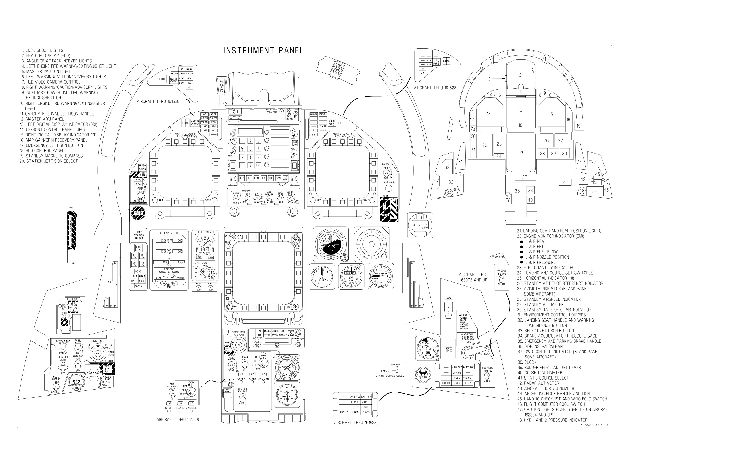
A1-F18AC-NFM-000
Figure FO-1. Front Cockpit F/A-18A/B Aircraft
(Sheet 1 of 2)
FO-3 (Reverse Blank)
ORIGINAL
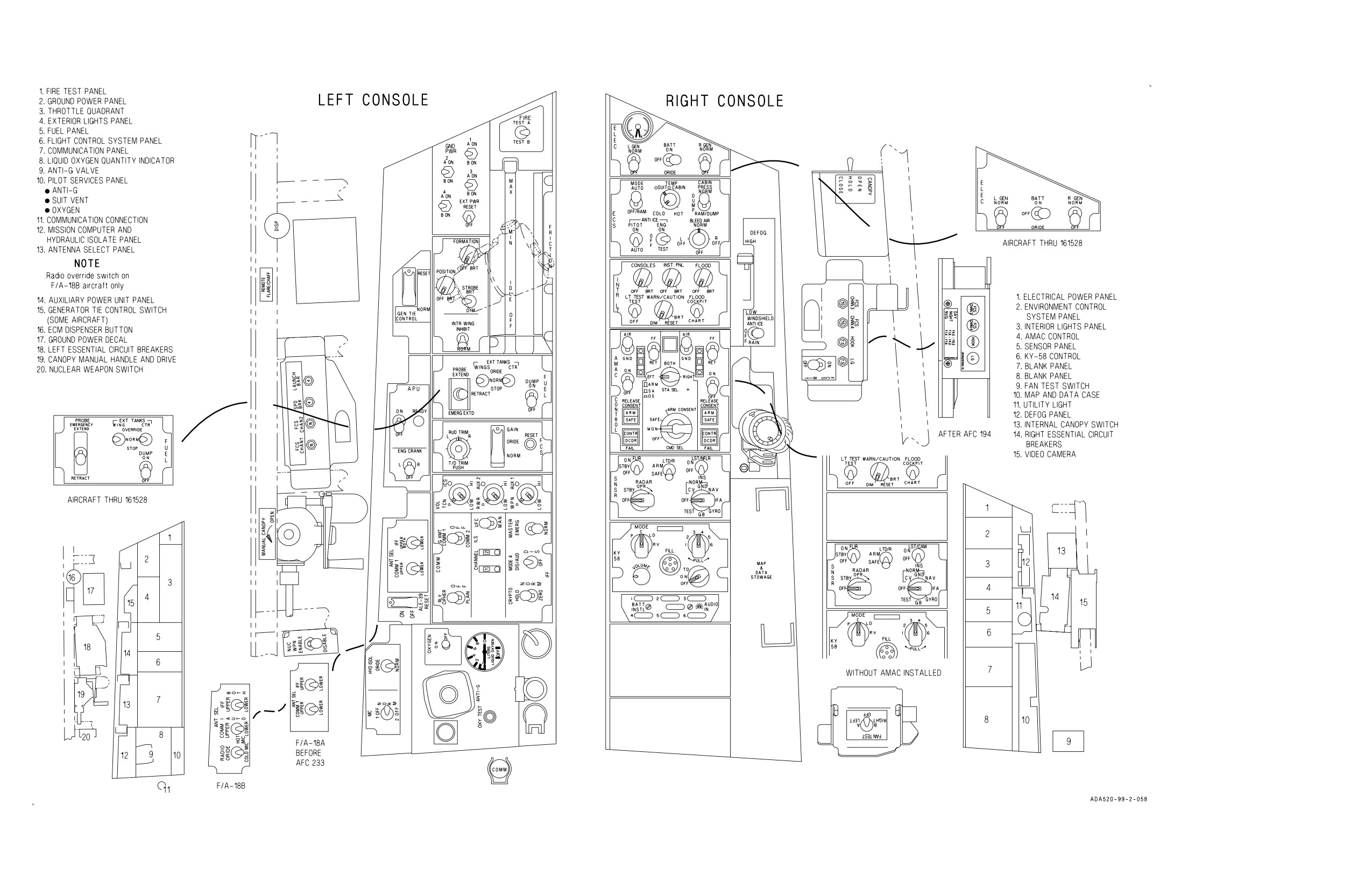
A1-F18AC-NFM-000
Figure FO-1. Front Cockpit F/A-18A/B Aircraft
(Sheet 2 of 2)
FO-5 (Reverse Blank)
ORIGINAL
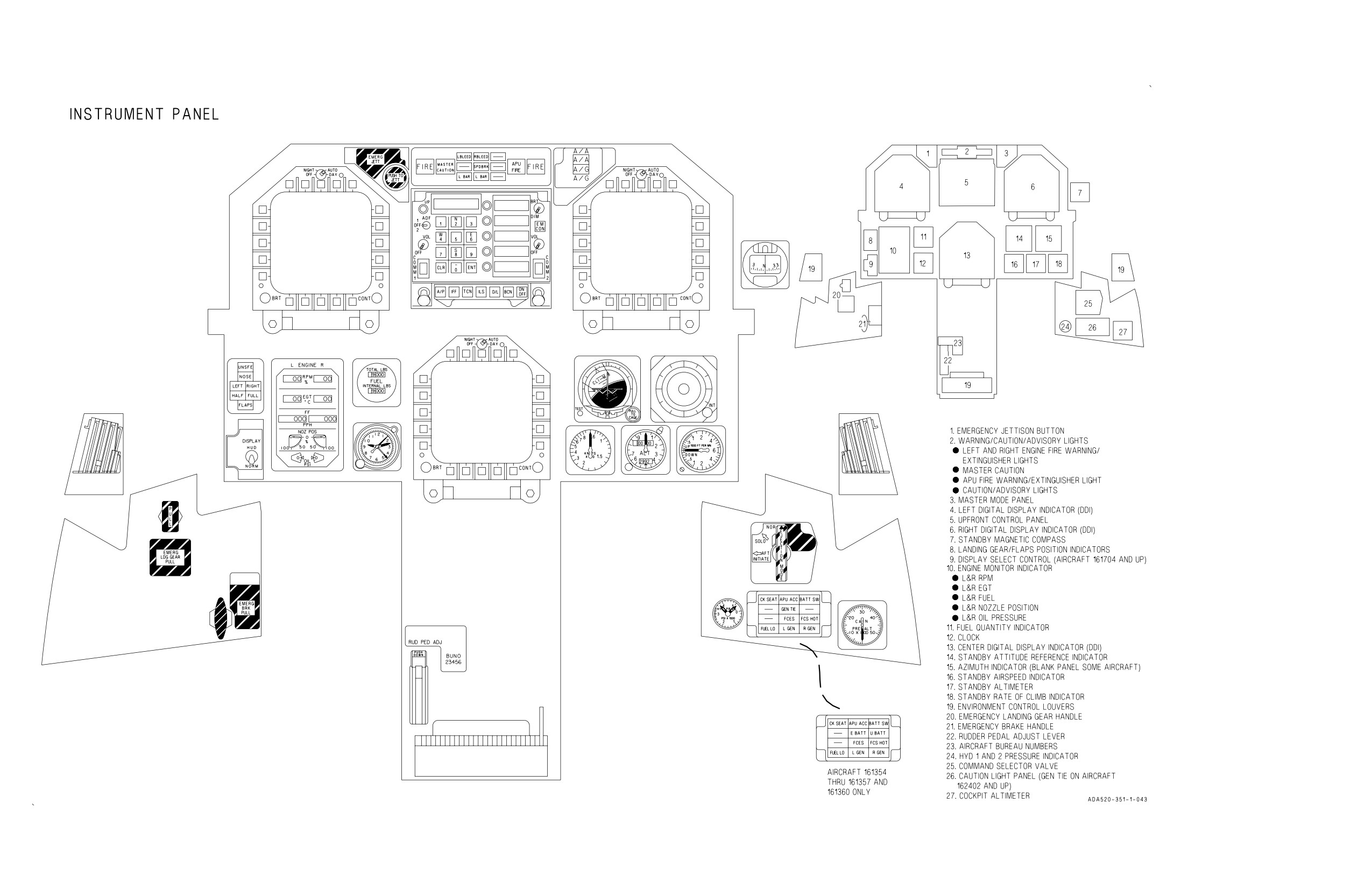
A1-F18AC-NFM-000
Figure FO-2. Rear Cockpit F/A-18B Aircraft
(Sheet 1 of 2)
FO-7 (Reverse Blank)
ORIGINAL
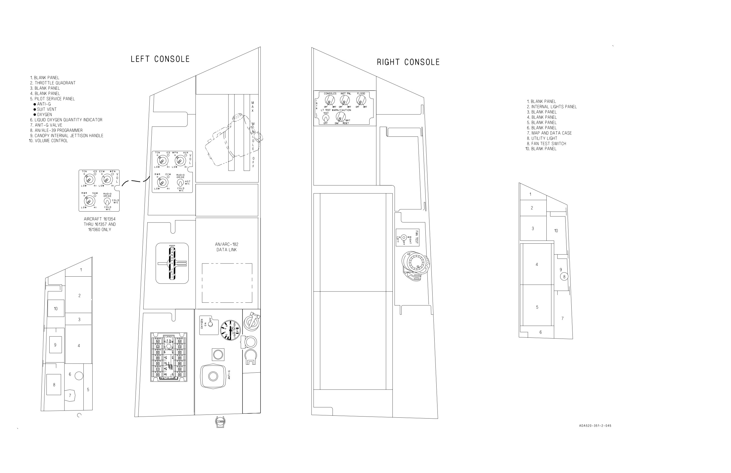
A1-F18AC-NFM-000
Figure FO-2. Rear Cockpit F/A-18B Aircraft
(Sheet 2 of 2)
FO-9 (Reverse Blank)
ORIGINAL
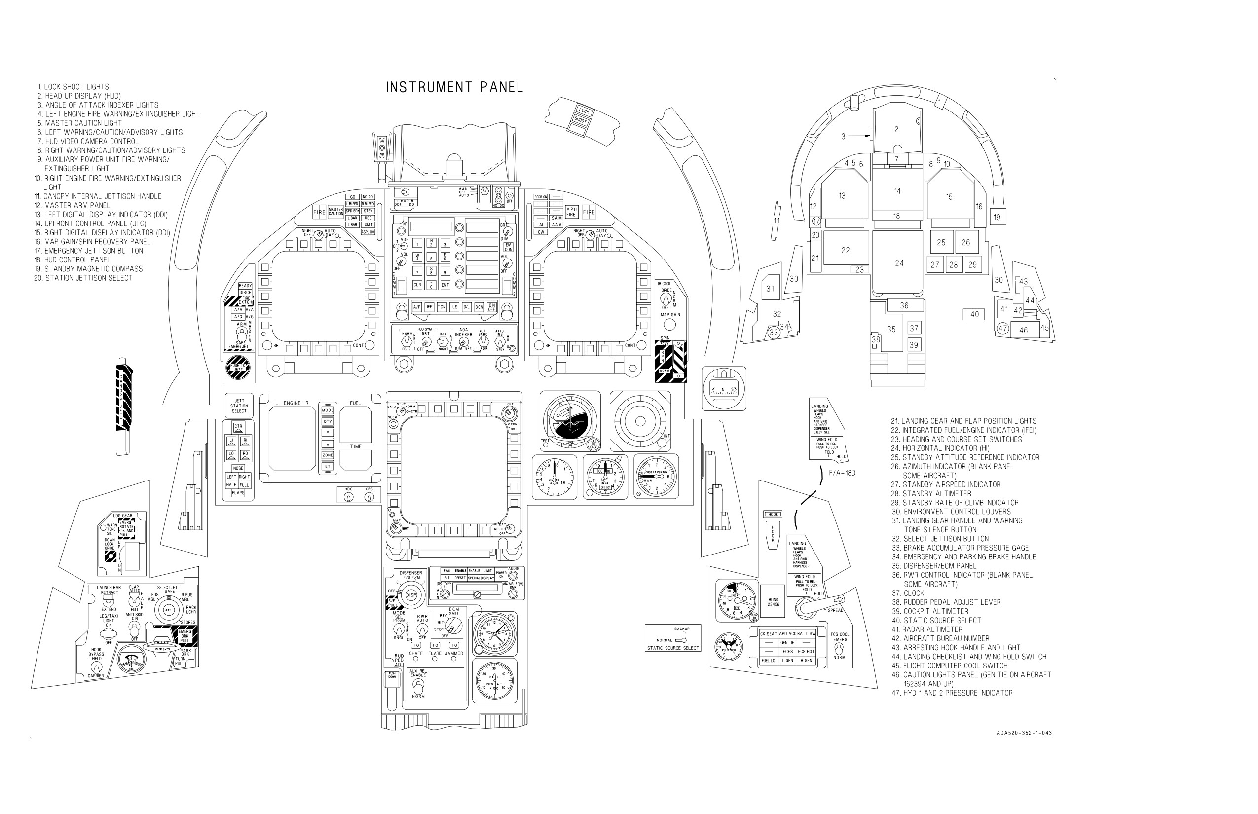
A1-F18AC-NFM-000
Figure FO-3. Front Cockpit F/A-18C/D Aircraft 163427 thru 163782
(Sheet 1 of 2)
FO-11 (Reverse Blank)
ORIGINAL
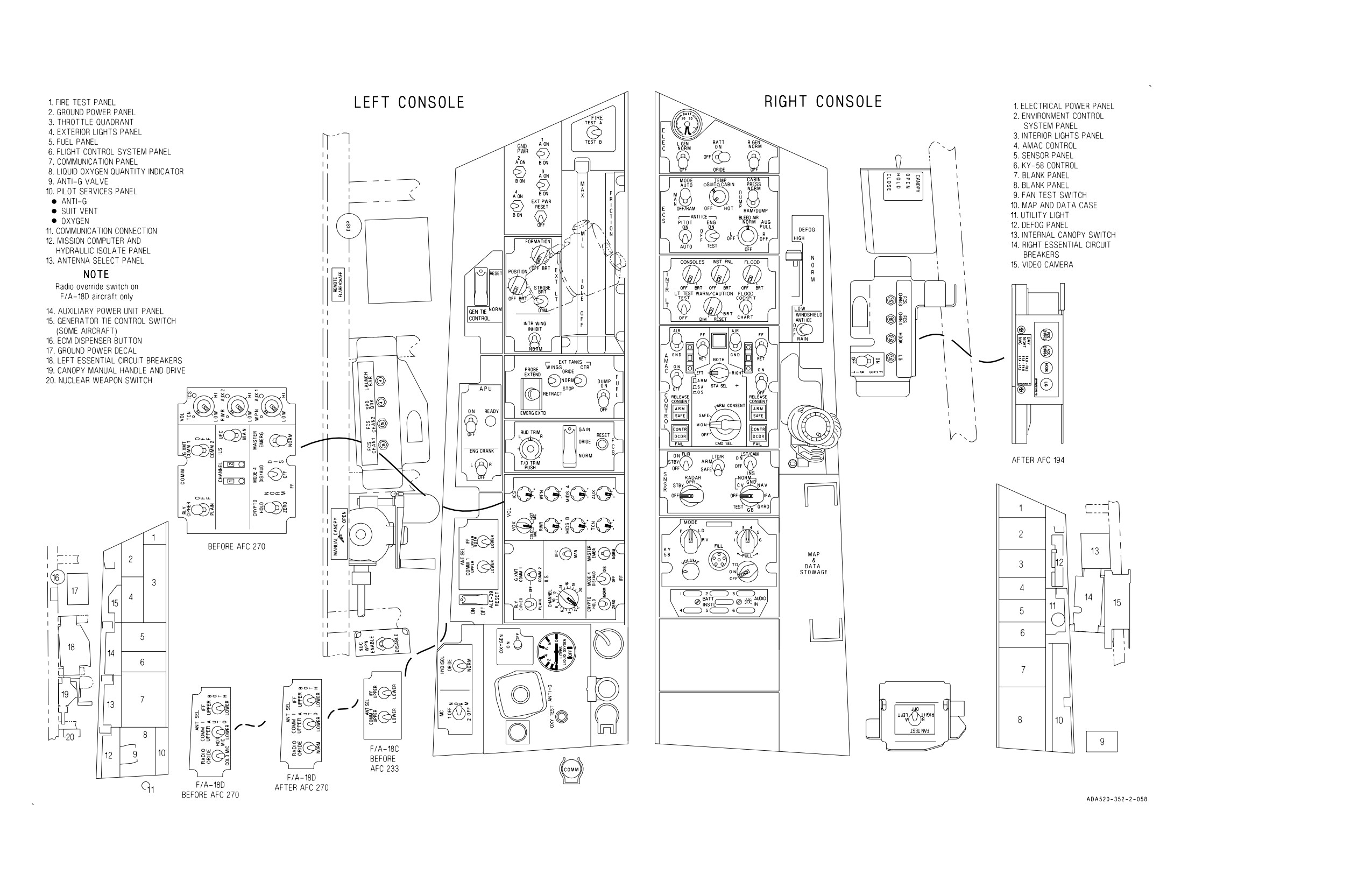
A1-F18AC-NFM-000
Figure FO-3. Front Cockpit F/A-18C/D Aircraft 163427 thru 163782
(Sheet 2 of 2)
FO-13 (Reverse Blank)
ORIGINAL
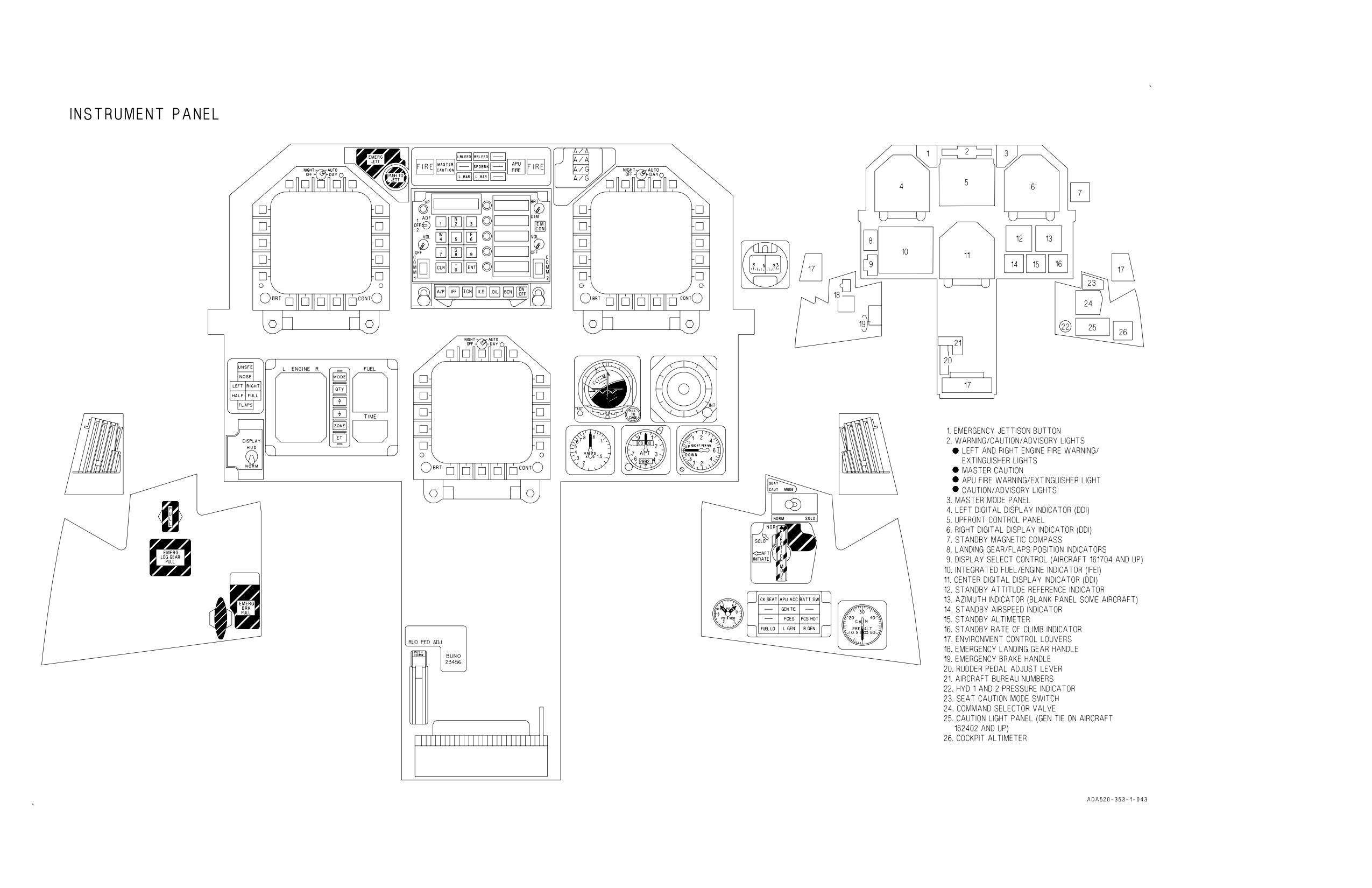
A1-F18AC-NFM-000
Figure FO-4. Rear Cockpit F/A-18D Aircraft 163434 thru 163778
(Sheet 1 of 2)
FO-15 (Reverse Blank)
ORIGINAL
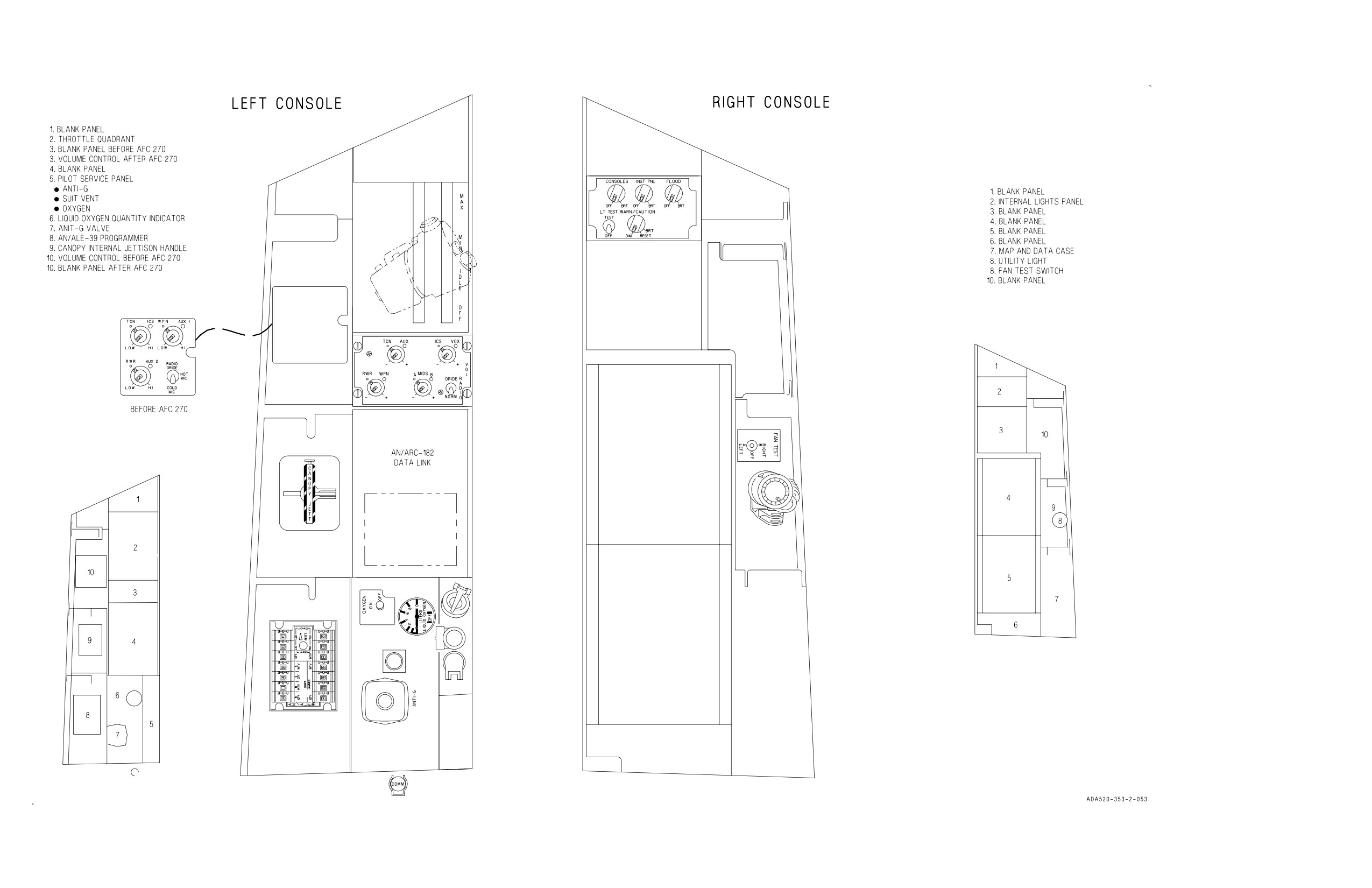
A1-F18AC-NFM-000
Figure FO-4. Rear Cockpit F/A-18D Aircraft 163434 thru 163778
(Sheet 2 of 2)
FO-17 (Reverse Blank)
ORIGINAL
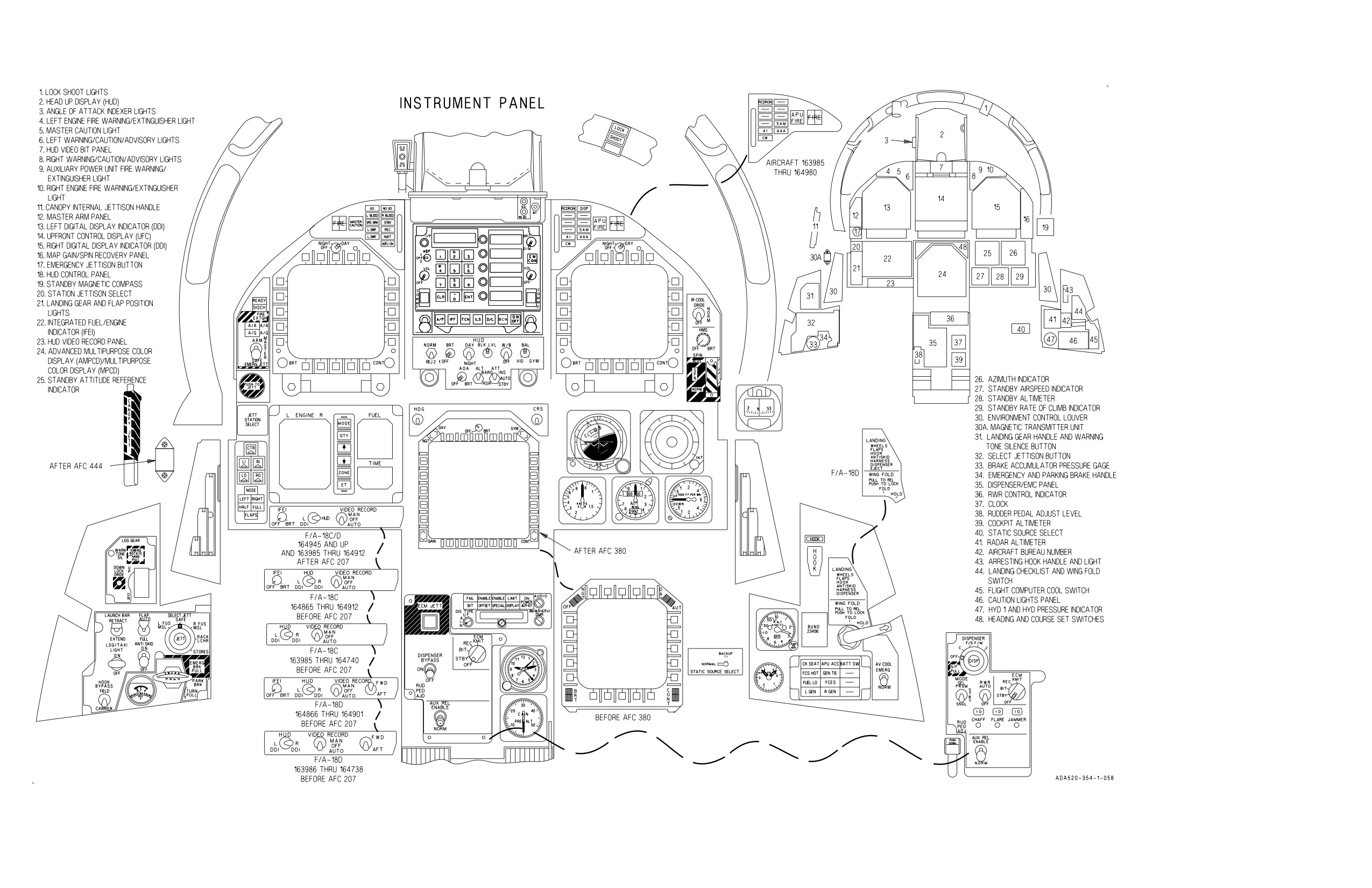
A1-F18AC-NFM-000
Figure FO-5. Front Cockpit F/A-18C/D Aircraft 163985 And Up
(Sheet 1 of 2)
FO-19 (Reverse Blank)
ORIGINAL
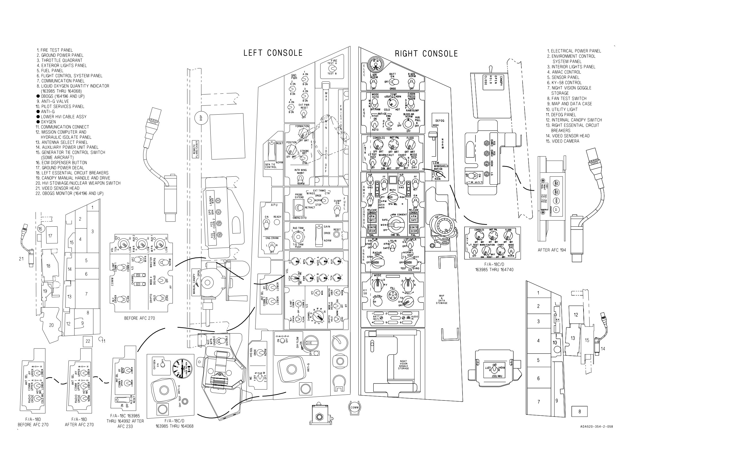
A1-F18AC-NFM-000
Figure FO-5. Front Cockpit F/A-18C/D Aircraft 163985 And Up
(Sheet 2 of 2)
FO-21 (Reverse Blank)
ORIGINAL
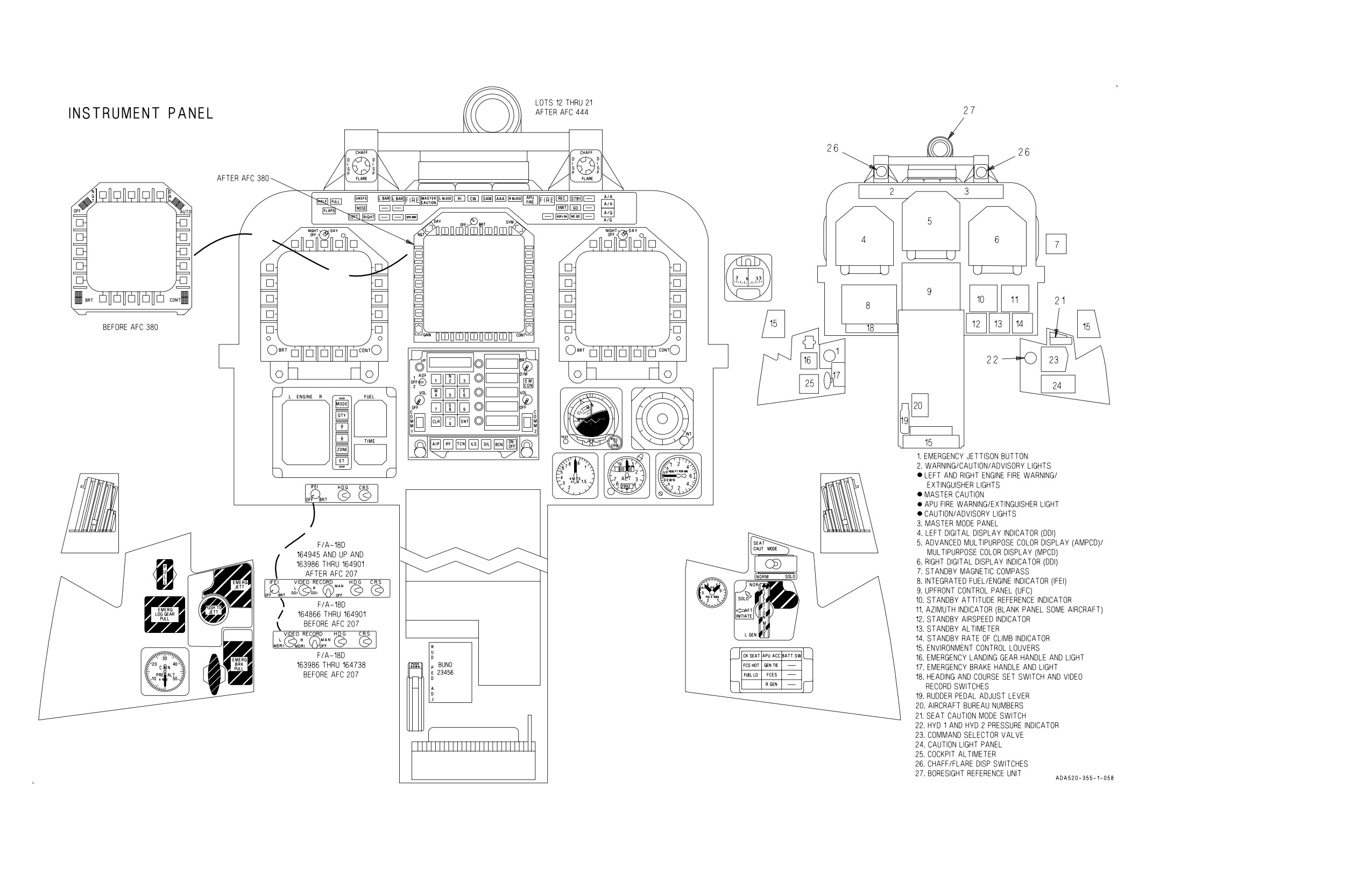
A1-F18AC-NFM-000
Figure FO-6. Rear Cockpit F/A-18D Aircraft 163986 And Up
(Sheet 1 of 2)
FO-23 (Reverse Blank)
ORIGINAL
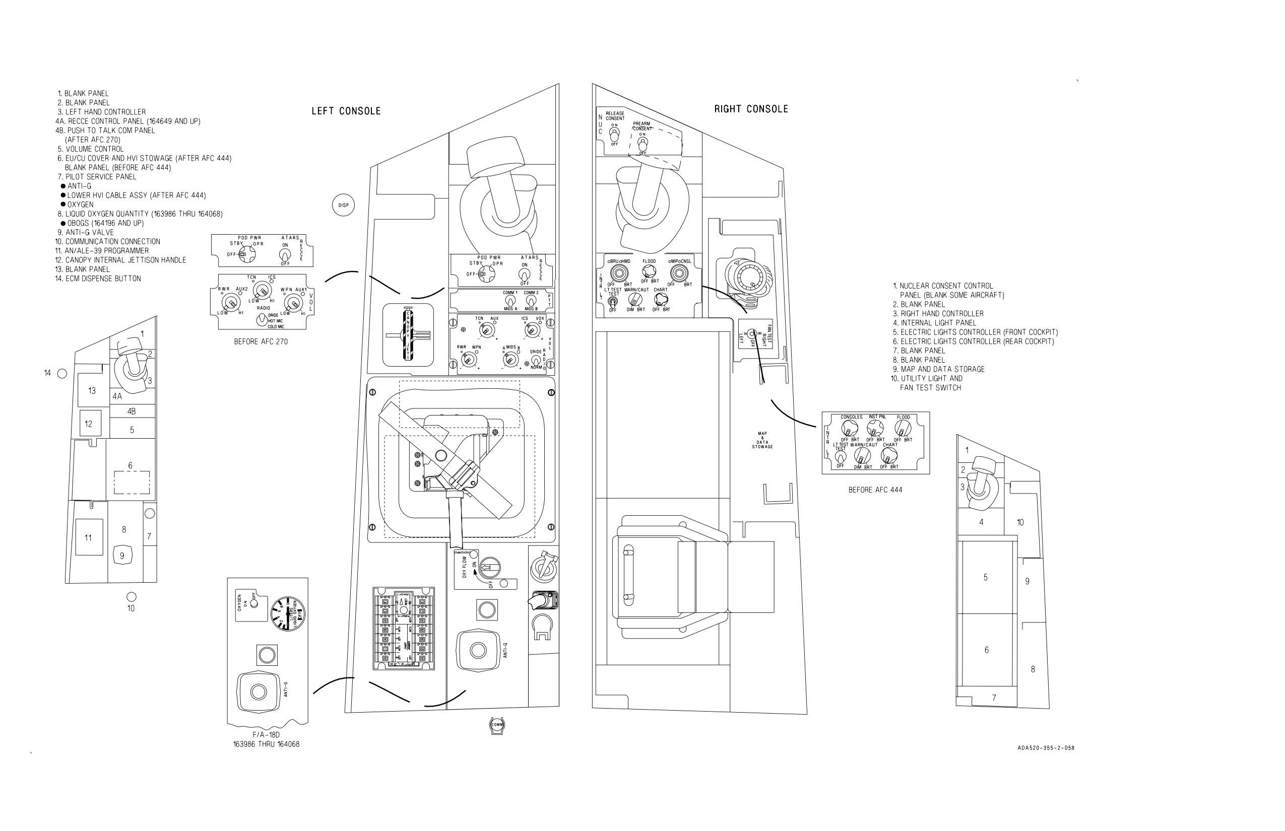
A1-F18AC-NFM-000
Figure FO-6. Rear Cockpit F/A-18D Aircraft 163986 And Up
(Sheet 2 of 2)
FO-25 (Reverse Blank)
ORIGINAL