EA-18G. FLIGHT MANUAL (2008) - page 4
A1-E18GA-NFM-000
the outside world and HUD symbology. The left and right DDIs, MPCD and the AMPCD contain
pushbuttons for display selection and selection of various equipment operating modes. The UFCD is
an active matrix liquid crystal display with an infrared (IR) touchscreen for operator inputs. Refer to
Part VII for the operation of each component.
2.19.4.1 CRS Set Switch. The course set switch, located on the main instrument panel on the video
record panel, manually sets the desired course on the HSI display.
2.19.4.2 HDG/TK Set Switch. The heading/ground track set switch located on the main instrument
panel on the video record panel, manually sets the heading marker on the desired heading/ground track
on the HSI display.
2.19.4.3 DDIs. The left and right DDI (LDDI/RDDI) are physically and functionally interchange-
able, giving the ability to display desired information on either indicator. The left indicator is used
primarily for stores status, built in test status, engine monitor, caution, and advisory displays. The
right indicator is normally used for radar and weapon video displays. The DDIs have full color
capability in all display modes and are NVG compatible.
NOTE
It is possible that a transient condition may cause the displays to
blank or provide an erroneous display on the left or right DDI, or
HUD. The problem may be cleared by manually cycling the power to
the left or right DDI.
2.19.4.3.1 Brightness Knob. Placing this rotary knob to OFF prevents the DDI from operating.
When turned on, rotating the knob clockwise increases display brightness, while rotating the knob
counterclockwise decreases display brightness.
2.19.4.3.2 GAIN Control. This three-position rocker switch affects the existing gray-scale, shifting
the background brightness up or down, with no impact on displayed symbology. The center position is
off, while the up arrow increases background brightness and the down arrow decreases background
brightness. The up and down arrows have momentary and scroll functionality, depending on how long
they are held. Current values are temporarily displayed when switches are pressed.
2.19.4.3.3 CONT Control. This three-position rocker switch varies the contrast between symbology
and the dark background on any level of brightness. When the contrast rocker is pressed, a graphical
and numeric representation of the current setting is momentarily displayed on the DDI.
2.19.4.3.4 DDI Pushbuttons. There are 20 pushbuttons on each DDI which are used to select the
function and the mode for proper indicator display.
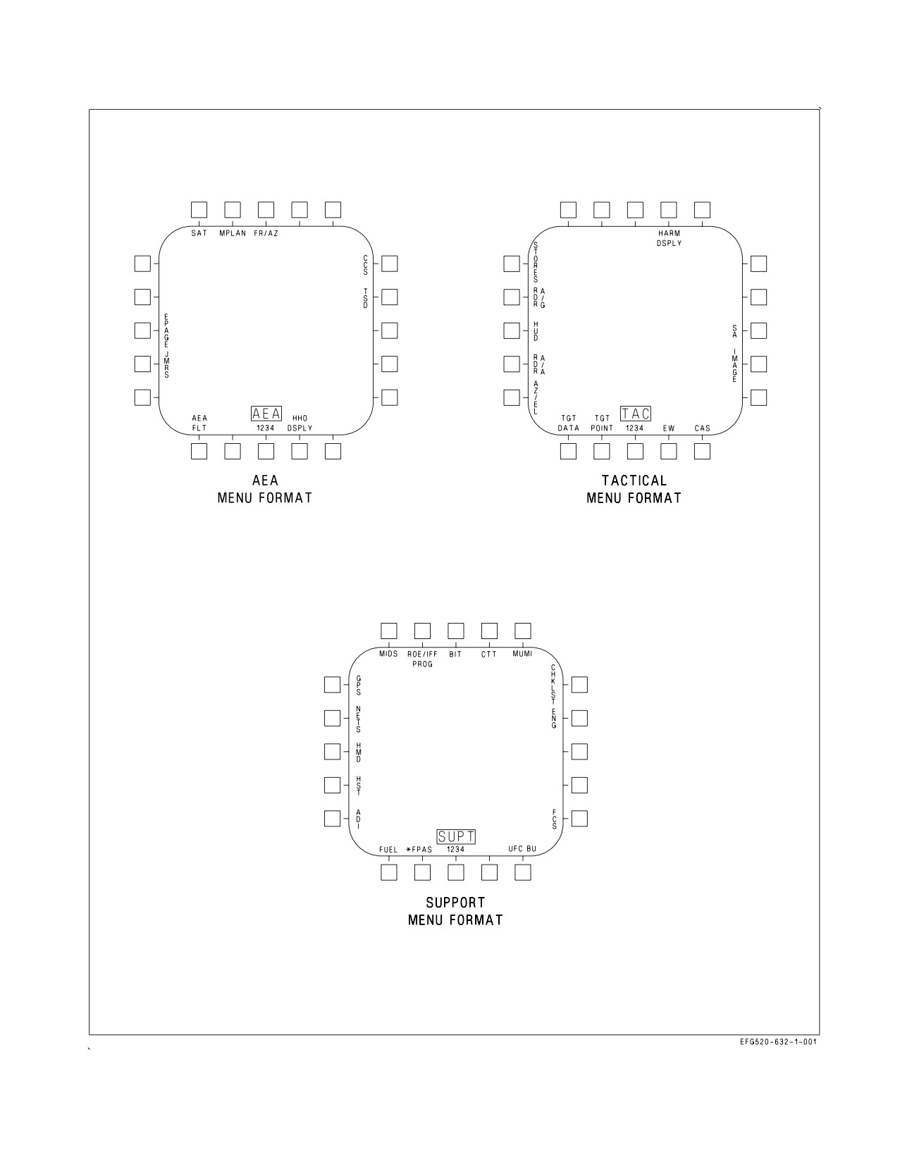
2.19.4.3.5 Menu Formats. There are three MENU formats (figure 2-48); airborne electronic attack
(AEA), tactical (TAC), and support (SUPT), through which display selections can be made. The three
menu formats can appear on either the DDI, the UFCD, MPCD or AMPCD.
The MENU pushbutton cycles through the airborne electronic attack (AEA), tactical (TAC), and
support (SUPT) menus in the following order: AEA - TAC - SUPT. The current time of day, consisting
of two minute digits and two second digits appear below AEA/TAC/SUPT MENU legend (cold start
default). Time of day is also turned on/off with the TISM option on the Engine Format.
I-2-147
ORIGINAL
A1-E18GA-NFM-000
The AEA MENU provides access to the following formats: Jammers (JMRS), Emitter Page
(EPAGE), SATCOM (SAT), Mission Planning (MPLAN), Frequency/Azimuth (FR/AZ), Communi-
cations Countermeasures Set (CCS), Tactical Situation Display (TSD), and HARM Handoff format,
(HHO DSPLY).
The TAC MENU allows selection of the following formats: AZ/EL, HUD, RDR ATTK, STORES,
HARM, SA, IMAGE, CAS, EW, and TGT DATA.
The SUPT MENU allows selection of the following formats: ADI, HSI, HMD, NETS, GPS, MIDS,
ROE/IFF PROG, BIT, CTT, MUMI, CHKLST, ENG, FCS, UFC BU, FPAS, and FUEL.
Some of the options on the MENU formats are conditional and are not always displayed. LST, and
CAM are listed only if the equipment is communicating with the mission computer. HARM DSPLY
is displayed when HARM is on board and CLC communicating. A/G missile display (WEDL DSPLY,
MAV DSPLY, etc.) is displayed when the MC has determined from the armament control processor set
that a weapon station has been selected which contains one of these weapons.
If either mission computer is off or failed (MC Backup Mode), the options available on the displays
are the same regardless of which computer is failed. If MC1 is failed or not communicating, the left
DDIs in both cockpits will either flash STANDBY or have a green square present in the middle of the
displays. If MC2 is failed or not communicating with the display, the right DDIs in both cockpits will
either flash STANDBY or have a green square present in the middle of the displays. The AMPCD will
not be capable of displaying format symbology or video. The following options are available in MC
Backup mode: HUD, EW, MIDS, MUMI, ENG, UFC BU, FUEL, ADI, and HSI. If A/A master mode
is selected, the RDR ATTK, SA, and AZ/EL formats are available as well. No A/G displays are
supported in MC Backup mode. If both mission computers are off or failed, a backup HUD format
(driven by the SDC) is displayed on the UFCD and MPCD in the front cockpit.
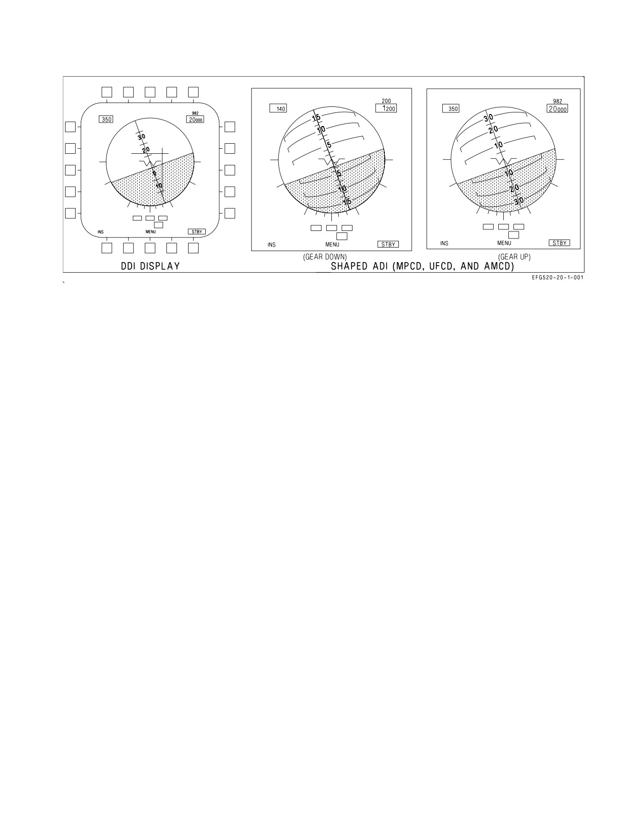
2.19.4.3.6 Electronic Attitude Display Indicator (EADI). The electronic attitude display indicator is
available for display on the left or right DDI as an alternative to the attitude display on the HUD
(figure 2-49). The EADI display is selected by selecting the ADI option on the SUPT MENU. The pitch
ladder is displayed in 10° increments. A small circle is displayed on the ball to represent the zenith and
a circle with an inscribed cross is displayed to represent the nadir. A turn indicator which displays FCS
yaw rate is provided below the ball. A standard rate turn (3°/second) is indicated when the lower box
is displaced so that it is under one of the end boxes.
Selecting the INS or STBY options at the bottom of the display determines the source of attitude
information used to generate the display. Upon power-up with WonW, the EADI attitude initializes to
STBY (STBY boxed), thus using the standby attitude reference indicator for attitude source
information. Selecting the INS option (INS boxed) uses attitude information provided by the INS.
Selection of INS or STBY on the EADI does not change the source of attitude data for the HUD.
Airspeed and altitude are displayed in boxes at the top left and right. Altitude source is displayed
to the right of the altitude box and the vertical velocity is displayed above the altitude box. When ILS
is selected the deviation needles are displayed in reference to the waterline symbol. The ILS needles
are yellow when COLOR is selected on the Attack display.
2.19.4.3.7 Shaped Attitude Display Indicator. When the ADI option is selected on the SUPT menu,
a shaped attitude display indicator is available on the MPCD, UFCD, or DDI and AMPCD. The pitch
ladder is displayed in 10° increments, with ±30° in pitch being displayed when the gear is up. With the
gear down, the pitch ladder is displayed in 5° increments with ±15° in pitch being displayed. A turn
I-2-148
ORIGINAL
A1-E18GA-NFM-000
Figure 2-48. MENU Format
I-2-149
ORIGINAL
A1-E18GA-NFM-000
Figure 2-49. Electronic Attitude Display Indicator
indicator is provided below the ball. A standard rate turn (3°/second) is indicated when the lower box
is displaced so that it is under one of the end boxes.
On the MPCD and AMPCD, the shaped ADI is black above the horizon to represent sky, and green
below the horizon to represent the ground. On the UFCD, the shaped ADI is unshaded above the
horizon (sky) and shaded green below the horizon (ground).
Selecting the INS or STBY options at the bottom of the display determines the source of attitude
information used to generate the display. Upon power-up with WonW, the ADI attitude initializes to
STBY (STBY boxed), thus using the standby attitude reference indicator for attitude source
information. Selecting the INS option (INS boxed) uses attitude information provided by the INS.
Selection of INS or STBY on the ADI does not change the source of attitude data for the HUD.
Airspeed and altitude are displayed in boxes at the top, altitude source is displayed to the right of
the altitude box and vertical velocity is displayed above the altitude box. When ILS is selected the
deviation needles are displayed in reference to the waterline symbol. The ILS needles are yellow when
COLOR is selected on the attack display.
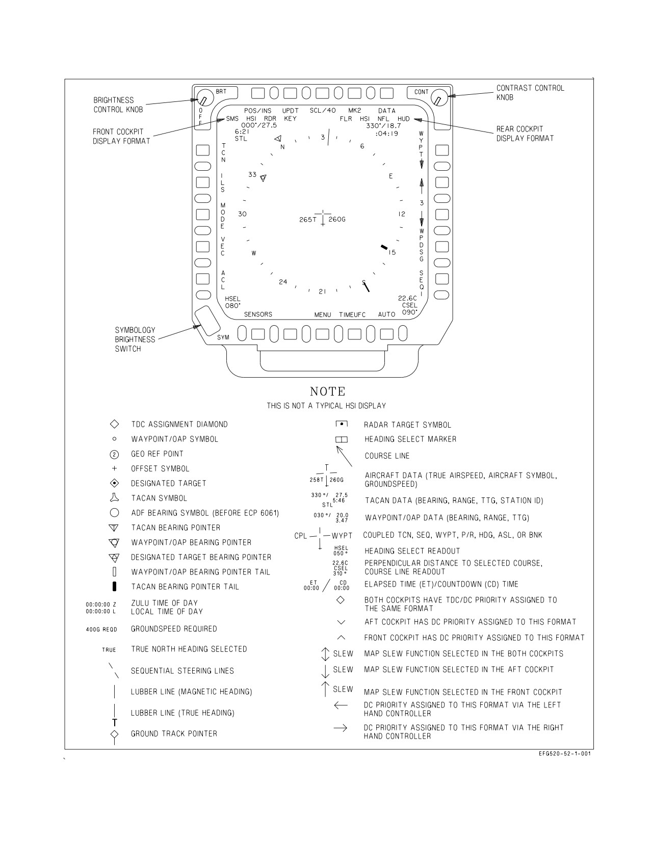
2.19.4.4 Multipurpose Color Display (MPCD). The MPCD is an NVG compatible digital display
capable of providing any MENU selectable format except the video on the A/G radar display (figure
2-51). The MPCD drives itself using information received on the MUX.
The BRT knob controls the overall video and symbology brightness and also acts as the power
control for the MPCD and UFCD; a detented OFF position at the extreme counterclockwise position.
The CONT knob adjusts the video contrast of the MPCD display. The day/night mode is controlled
by the day/night/NVG switch on the interior lights panel.
2.19.4.4.1 Standby Indication. A flashing STANDBY indication is provided in the center of the
display on initial power-up and when there is invalid mux communication with the MC. If the
STANDBY condition persists for a few seconds, cycling power to the MPCD may return the MPCD
and UFCD to normal operation.
2.19.4.4.2 Brightness and Contrast Controls. The brightness control is used to adjust the overall
brightness of the MPCD display surface, allowing symbology and video to be adjusted. The full
I-2-150
ORIGINAL
A1-E18GA-NFM-000
counterclockwise position of the brightness control knob shuts off power to both the MPCD and the
UFCD. Selecting ON powers both the MPCD and the UFCD.
The contrast control is used to adjust video contrast.
2.19.4.4.3 Symbology Rocker Switch. The symbology (SYM) brightness rocker switch is used to
adjust the brightness of the symbology without affecting the brightness of the MPCD video.
Symbology change feedback in provided in the left center of the display by a digit from 0 to 9. This
feedback is provided while the rocker switch is pressed and for 5 seconds after the rocker switch is
released.
2.19.4.4.4 DDI Formats on MPCD. Every display format is available on the L or R DDI. A/G radar
symbology and monochrome video is available on the MPCD. A/G video is not available.
2.19.4.4.5
MPCD Formats. If two different formats are requesting MAP video underlay, only one
displays the video underlay; the other provides only symbology. MAP video display priority is
determined by two things: 1) which display surface is requesting the MAP underlay and 2) which
format is requesting the MAP underlay. Highest display surface priority is given to the MPCD followed
by the DDIs. The SA format is given the highest priority, followed by the HSI format, for formats
requesting the MAP underlay. Once the MAP is displayed for any format, (SA, HSI), any display
surface with that same format selected will also have the MAP underlay displayed. The MAP underlay
is only supported on the SA or HSI formats.
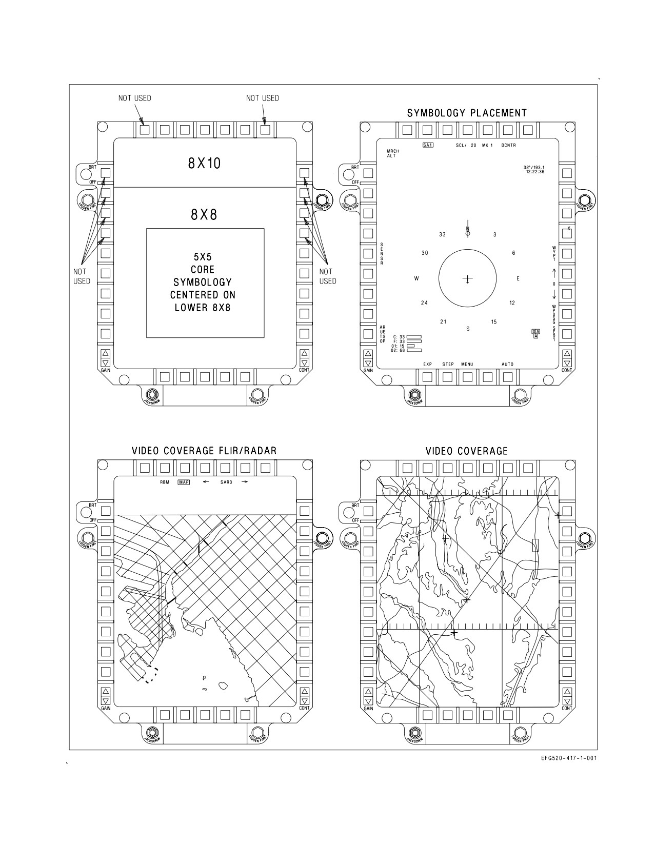
2.19.4.4.6 AMPCD. The AMPCD has a full color Active Matrix Liquid Crystal Display surface and
30 pushbuttons used for operator inputs. Only 20 buttons are functional, and they duplicate the
MPCD/DDI menu layouts. The top row outboard buttons and top four buttons on each side are not
used. The brightness control switch adjusts the video brightness. The full counterclockwise position, a
detented OFF position, removes power from the AMPCD and the aft cockpit UFCD. Two rocker
switches provide Gain and Contrast control. A numeric value displayed near the switches is used to
adjust the gain and/or contrast to a desired level. Pushbuttons are backlit, controlled by the INST
PNL knob on the aft cockpit interior lights panel. The following formats and related sublevel formats
are available: AEA Menu, TAC Menu, SUPT Menu, HSI, EW, SA, and BIT. Figure 2-50 shows
symbology placement and map coverage for the AMPCD. See foldout section for aft cockpit
arrangement.
The AMPCD is connected directly to MC2. When MC2 is offline or during initialization, the
AMPCD does not show a format or process bezel inputs. A flashing STANDBY indication is provided
in the center of the AMPCD when MC2 is not communicating properly with the AMPCD. A standby
display pattern (approximately a one inch by one inch green square) is present when the Image
Transfer Bus (ITB) has lost symbology, video, or a combination, and the selected format is affected.
When interface between MC2 and AMPCD is lost, only symbology is displayed (via ITB). There is no
pushbutton feedback, video control, or BIT reporting when interface is degraded. The day/night mode
of the AMPCD (and rear UFCD) is set via the DAY/NITE/NVG switch on the forward cockpit interior
lights panel through MC2.
In the Situational Awareness (SA) format, the cursor (captains bars) may be slewed over the entire
AMPCD surface. Because this area is larger than the DDIs/MPCD, if another display is showing the
same format and the cursor on the AMPCD is slewed beyond the center area, the cursor on the
DDI/MPCD is limited. When this happens, the cursor on the DDI/MPCD displays flashes continu-
ously. When a SA format has DC priority assigned, the initial cursor position is determined by the
cockpit that initiates the slewing action.
I-2-151
ORIGINAL
A1-E18GA-NFM-000
2.19.4.5 HSI Display Symbology. Basic HSI symbology such as the compass rose, ground track
pointer, lubber line (for magnetic heading), true airspeed readout, groundspeed readout, and aircraft
symbol are not described. These symbols are shown in figure 2-51.
Display format lines, just below the top row of pushbutton labels, indicate the formats being
displayed on the left, center, right and UFCD displays in both the cockpit (left side of HSI display) and
rear cockpit (right side of HSI display).
Radar target and GEOREF symbols are described in NTRP 3-22.2-EA-18G (EA-18G Classified
Manual). The following paragraphs describe unique navigation symbology. Refer to part VII for a
description of how these symbols are integrated with the navigation system:
1. Waypoint/OAP data. Data for the current steer to waypoint/OAP is displayed on the upper right
corner of the HSI. Waypoint/OAP data consists of bearing, range, and TTG (time-to-go) up to
8:59:59 based on distance and ground speed. When a waypoint/OAP or offset to the OAP is
designated (becomes a target), this data relates to the target. When a waypoint is a waypoint that
was transferred from the GPS, an ID code is displayed under the waypoint data.
2. TACAN data. TACAN data is displayed on the upper left corner of the HSI. TACAN data
consists of bearing, range (slant range), TTG (based on distance and present ground speed), and the
station identifier.
3. Waypoint/OAP symbology. Waypoint/OAP symbology consists of a waypoint/OAP symbol and a
bearing pointer and tail. The waypoint/OAP symbol indicates the position of the selected
waypoint/OAP relative to the aircraft symbol. The waypoint/OAP bearing pointer and tail are
displayed inside the compass rose and indicate bearing to the selected waypoint/OAP. Waypoint/
OAP symbology is displayed whether or not waypoint/OAP steering is selected. When the selected
waypoint/OAP is outside the HSI range scale, the waypoint/OAP symbol does not appear, but the
bearing pointer and tail appears. When a waypoint/OAP is designated, the waypoint/OAP symbol
and circle inside the pointer change to a diamond shape. The offset symbol appears when steering
is to an OAP. The offset symbol indicates the position of the offset relative to the OAP.
4. TACAN symbology. TACAN symbology consists of a TACAN symbol, and TACAN bearing
pointer and tail. The TACAN symbol indicates the position of the TACAN station relative to the
aircraft symbol. The TACAN bearing pointer and tail are located outside of the compass rose and
indicate bearing to the TACAN station. When the TACAN station is outside the HSI range scale, the
TACAN symbol does not appear but the bearing pointer and tail appear. When TACAN range
becomes invalid the TACAN symbol is not displayed.
5. Heading select/ground select marker and readout. The heading select/ground select marker is
maneuvered along the periphery of the compass rose using the HDG/TK switch. The digital readout
of the selected heading is located on the lower left corner of the HSI. The heading select/ground
select marker and digital readout are part of the heading select/ground track select mode of the
autopilot.
Course line arrow and readout. The course line arrow indicates the selected course to the
waypoint/OAP or TACAN station. The course is selected using the CRS switch. The digital readout
of the selected course is displayed on the lower right corner of the HSI. The course line arrow is not
displayed when TACAN range is invalid.
I-2-152
ORIGINAL
A1-E18GA-NFM-000
Figure 2-50. AMPCD
I-2-153
ORIGINAL
A1-E18GA-NFM-000
Figure 2-51. MPCD Controls and HSI Symbology
I-2-154
ORIGINAL
A1-E18GA-NFM-000
6. TDC assignment symbol. The TDC assignment diamond is displayed on the upper right corner
of the HSI. This symbol indicates that the TDC is assigned to the HSI. The TDC assignment
diamond indicates control is assigned to both cockpits. Other symbols indicate cockpit (d) or rear
cockpit (e) TDC control and SLEW control. SLEW is done by actuating the sensor control switch
AFT while in the NAV or A/G master mode. The word SLEW is displayed in the TDC assignment
diamond position when the SLEW option is active.
7. Coupled steering symbology. CPL and the source of the steering information is displayed on
either side of the aircraft symbol in the center of the HSI display whenever the flight control system
is coupled in azimuth to a steering source. Steering source can be WYPT, TCN, or SEQ#. The couple
cue flashes for 10 seconds and is removed if the steering signal is lost or becomes invalid.
8. Sequential steering lines. The sequential steering lines are displayed when a sequence is entered
and when one of the sequence options (SEQ1, SEQ2, SEQ3, or SEQL) is boxed. The sequential
steering lines are available for display in all HSI modes and range scales. Sequential steering lines
are not displayed at power up with WonW and are removed when: magnetic heading is invalid,
aircraft position is invalid, or map slew is selected.
9. Time of day. Zulu time of day (ZTOD) or local time of day (LTOD) are displayed on the lower left
corner of the HSI. For aircraft that pass the FIRAMS real time clock power up BIT, ZTOD does not
need to be entered. For aircraft that do not pass the FIRAMS real time clock power up BIT, ZTOD
must be entered.
10. Groundspeed required. Groundspeed required appears below the current groundspeed readout.
Groundspeed required indicates the groundspeed required to a target based on entered ZTOD, time
on target (TOT), and the target.
11. Elapsed time (ET)/countdown (CD) time. ET and CD time are displayed on the lower right
corner of the HSI, however, only one of the timers can be displayed at a time. ET or CD timer must
be selected to be displayed. ET initializes to zero minutes and seconds and CD time initializes to six
minutes and zero seconds.
12. Aircraft heading. Aircraft heading is indicated on the compass rose. Aircraft heading and bearing
data can be selected as either magnetic or true. With true heading selected, the letter T appears
below the lubber line and the word TRUE appears below the selected scale readout. There is no
indication when magnetic heading is selected.
2.19.4.6 Head-Up Display (HUD). The HUD is on the center main instrument panel. The HUD is
used as the primary flight instrument, weapon status, and weapon delivery display for the aircraft
under all conditions. The HUD receives all symbology from MC1 or MC2. The HUD is electrically
interfaced with the UFCD. The HUD has NVG compatible raster display capability to allow it to
display NFLR video. The controls for the HUD are below the UFCD and are described in the following
paragraphs. See figure 2-52.
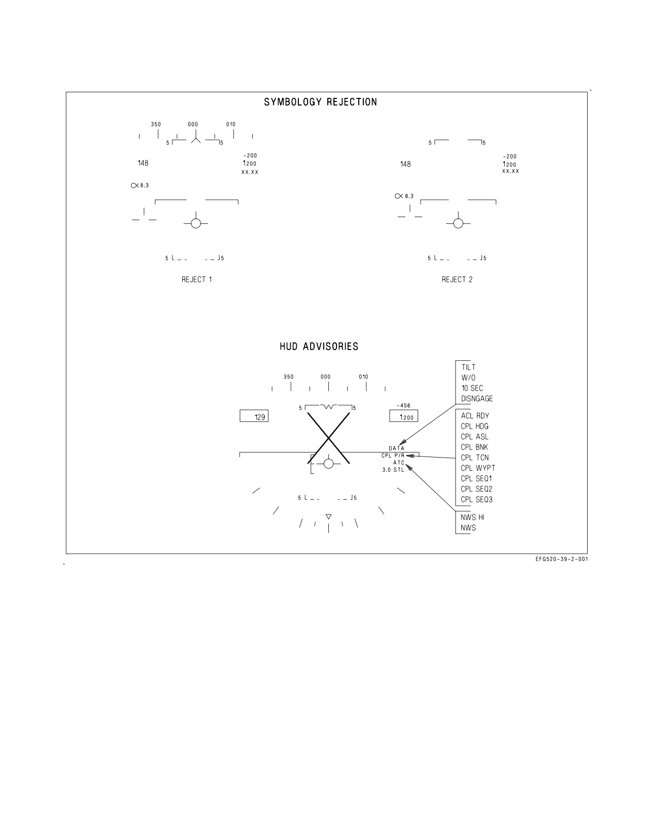
2.19.4.6.1 HUD Symbology Reject Switch. The HUD reject switch is located on the HUD control
panel on the center main instrument panel. This switch is used to control the amount of symbology
displayed on the HUD.
I-2-155
ORIGINAL

A1-E18GA-NFM-000
Figure 2-52. HUD Controls
NORM Displays full HUD symbology.
REJ 1
Removes the Mach, g, and peak-g indications, the bank angle scale and pointer, the air-
speed and altitude boxes, energy caret (landing gear down), and the ground speed
required cue.
REJ 2
Removes REJ 1 symbology and the heading scale, current heading caret, command
heading marker, NAV/TCN range, and the ET, CD, LTOD or ZTOD timer.
2.19.4.6.2 HUD Symbology BRT Control Knob. This knob is used to turn on the HUD and then
varies the display intensity.
2.19.4.6.3 HUD Symbology Brightness Selector Switch. This is a two-position toggle switch with
positions of DAY and NIGHT. Placing the switch to DAY provides maximum symbol brightness in
conjunction with the HUD symbology brightness control. With the switch set to NIGHT, a reduced
symbol brightness is provided in conjunction with the HUD symbology brightness control.
2.19.4.6.4 Black Level Control Knob. The black level control knob, located on the HUD control
panel, adjusts the NFLR video plus or minus ½ a shade of gray per increment when rotated.
2.19.4.6.5 HUD Video Control Switch. The video control switch, located on the HUD control panel,
enables NFLR video display on the HUD with selectable polarity (white hot/black hot).
W/B Selects white hot/black hot polarity.
VID
Displays NFLR video in the HUD, if available.
OFF NFLR video off.
2.19.4.6.6 BAL Control Knob. The balance control, located on the HUD control panel, adjusts the
stroke brightness relative to the raster brightness. Rotating the switch from 12 o’clock towards the VID
position holds the brightness of the video (as set by the brightness control switch) and reduces the
brightness of the stroke symbology. The opposite is true when rotating the switch toward the SYM
position.
2.19.4.6.7 AOA Indexer Control Knob. This knob controls the brightness of the indexer lights.
2.19.4.6.8 ALT Selector Switch. The ALT selector switch, located on the HUD control panel, is used
to select the primary altitude source for display on the HUD and for use in the mission computer
I-2-156
ORIGINAL
A1-E18GA-NFM-000
(weapon systems calculations).
BARO Selects barometric altitude.
RDR Selects radar altitude.
2.19.4.6.9 ATT Selector Switch. The ATT selector switch, located on the HUD control panel, is used
to select the primary attitude source used for display in the HUD and in MC and FCC computations.
INS
Functions identically to the AUTO position.
AUTO Selects filtered INS data as the primary attitude source. The INS automatically reverts
to gyro mode, using unfiltered data if its processor fails. The MC automatically selects
the standby attitude reference indicator for attitude information if the INS fails com-
pletely.
STBY Selects the standby attitude reference indicator. The FCCs no longer use INS data and
the HIAOA advisory is displayed.
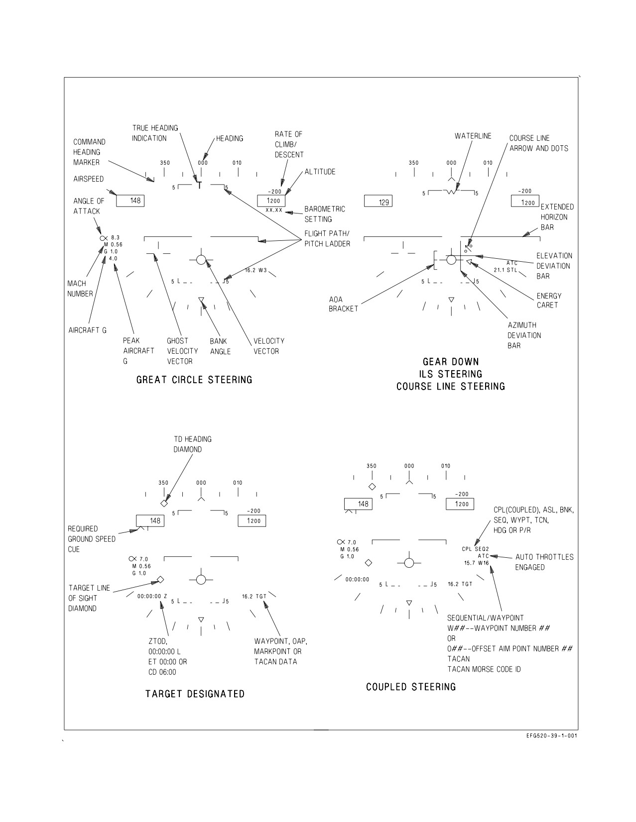
2.19.4.6.10 HUD Symbology. The following paragraphs describe HUD symbology as related to basic
navigation, steering (direct, great circle, courseline, and ILS), navigation target designation, advisories
and landing, see figure 2-53. Refer to part VII for a description of how these symbols are integrated into
the navigation system. Also, refer to section VII for unique ACL data link symbology. Refer to NTRP
3-22.2-EA-18G (EA-18G Classified Manual), for symbology concerning the A/A and A/G master
modes, weapons, RWR and the data link vector mode.
1. Heading. The aircraft magnetic/true heading is indicated by the moving 30° heading scale. The
actual aircraft heading is directly above the caret/T symbol. The moving heading scale provides
trend information during turns. As the aircraft turns right, the scale moves from right to left.
Magnetic or true heading may be selected. Magnetic heading is indicated by a caret below the
heading scale. True heading selection is indicated by a T appearing below the current heading.
2. Airspeed. Calibrated airspeed from the FCC is provided in the box on the left side of the HUD.
The tops of the airspeed and altitude boxes are positioned at the aircraft waterline, which is 4° up
from the optical center of the HUD.
HUD airspeed should normally read less than 50 knots while sitting still
on the ground. A reading of more than 50 knots on the ground may
indicate an Air Data failure.
3. Altitude. The altitude presented in the box on the right side of the HUD may be either barometric
altitude or radar altitude depending on the setting of the altitude switch on the HUD control panel.
When the altitude switch is in the BARO position, barometric altitude is displayed. When the
altitude switch is in the RDR position, radar altitude is displayed and is identified by an R next to
the altitude. If the radar altitude is invalid, barometric altitude is displayed and a B next to the
altitude flashes to indicate that barometric altitude is being displayed rather than radar altitude.
The ten thousand and thousand digits are 150% size numbers. The hundred, ten, and unit digits are
I-2-157
ORIGINAL
A1-E18GA-NFM-000
120% size numbers, except that below 1,000 feet they are 150% size.
4. Barometric setting. The barometric setting used by the air data function in the FCC is the value
set in the standby altimeter. When the barometer setting is changed on the standby altimeter, the
barometric setting is presented below the altitude on the HUD to provide a head-up baro-set
capability. The display remains for 5 seconds after the change is made. In addition, the baro-set
value is displayed and flashed for 5 seconds when the aircraft descends below 10,000 feet at an
airspeed less than 300 KCAS.
5. Angle of Attack. True angle of attack in degrees is displayed at the left center of the HUD. AOA
values displayed on the HUD are filtered and may slightly lag actual true AOA. Therefore, it may
be possible to trigger the AOA tone with the flaps in HALF or FULL slightly prior to seeing 14.0°
AOA in the HUD.
The HUD AOA is generally driven by the FCS using the AOA probes. However, around 42° AOA
(and -9°), the HUD reverts to an MC-computed AOA based on INS data and winds. The HUD AOA
flashes indicating that the displayed HUD AOA may be inaccurate because the INS computed winds
have not been updated in the past three minutes. Low AOA, small bank angles, and small rates are
required to update the wind.
The pitch trim AOA value is displayed next to the ATC HUD advisory location while trimming and
for two seconds after trimming with WoffW and flaps HALF or FULL. The value is displayed with
or without ATC engaged but is not displayed with autopilot engaged.
6. Mach number. The aircraft Mach number is displayed immediately below the angle of attack.
7. Aircraft g. Normal acceleration of the aircraft is displayed immediately below the Mach number.
8. Peak aircraft g. A peak positive g indication is displayed on the HUD below the normal g when
a threshold of 4.0 g is exceeded. The peak positive g display can be removed by cycling the clutter
reject switch to one of the reject positions.
I-2-158
ORIGINAL
A1-E18GA-NFM-000
Figure 2-53. HUD Symbology (Sheet 1 of 2)
I-2-159
ORIGINAL
A1-E18GA-NFM-000
Figure 2-53. HUD Symbology (Sheet 2 of 2)
I-2-160
ORIGINAL
A1-E18GA-NFM-000
9. Bank angle scale. A bank angle scale and pointer are displayed at the bottom of the HUD for bank
angle reference up to 45°. At bank angles in excess of 47°, the bank angle scale pointer is limited at
45° and flashes.
10. Velocity vector. The velocity vector provides an outside world reference with regard to actual
aircraft flight path. The velocity vector represents the point towards which the aircraft is flying
(aircraft flight path). With a functioning INS, the velocity vector is driven by INS attitude and
velocities. If GPS data is valid, a ″hybrid″ GPS vertical velocity correction is used to correct errors
in the INS vertical velocity loop regardless of the INS mode switch position (CV, GND, NAV, or
IFA). If GPS data is not available for use in the hybrid correction, a VVEL advisory is displayed.
With a VVEL advisory displayed, sustained climbs and descents, such as
penetration from the marshal stack, can result in uncued (no cautions)
vertical velocity errors and a possible inaccurate velocity vector position.
Error magnitudes increase at slower airspeeds and lower altitudes. Errors
of up to 3° (actual flightpath 3° below the displayed velocity vector) have
been observed in the landing configuration. Three minutes of level flight
may be required to allow the INS to correct the vertical velocity errors.
NOTE
The VVEL advisory will be displayed if a GPS is not installed or if
masking prevents GPS positioning of a sufficient quality to ″aid″ the
INS vertical velocity loop.
The position of the velocity vector is limited to an 8° radius circle centered at the HUD optical
center. If the velocity vector reaches this limit during high angle of attack flight or large yaw and/or
drift angles, it flashes rapidly to indicate that it does not accurately indicate flight path (velocity vector
is HUD limited).
With GPS operating, if the INS velocity data becomes unreliable, the mission computer utilizes GPS
information. If INS velocity data becomes unreliable the mission computer utilizes FCC air data
function information and the last available wind data to compute the velocity vector and this degraded
velocity vector is indicated by a slow flashing of the symbol. In the NAV master mode, the velocity
vector may be caged to the vertical center line of the HUD by the cage/uncage switch on the throttle.
When it is caged, a ghost velocity vector is displayed at the true velocity vector position if that position
is more than 2° from the caged position. The flight path/pitch ladder and steering information are
referenced to the caged position. The ghost velocity vector flashes when limited. The flight path/pitch
ladder is referenced to the waterline symbol when the velocity vector is caged.
The velocity vector is automatically fixed at the horizon with WonW and ground speed less than 80
knots, and its status cannot be changed until WoffW. However, the velocity vector’s selected
caged/uncaged status does not change during touch-and-go landings if the ground speed remains above
80 knots.
11. Flight path/pitch ladder. The vertical flight path angle of the aircraft is indicated by the position
of the velocity vector on the flight path/pitch ladder. The horizon and flight path/pitch angle lines
represent the horizon and each 5° of angle between ±90°. Positive pitch lines are solid and are above
I-2-161
ORIGINAL
A1-E18GA-NFM-000
the horizon line. Negative pitch lines are dashed and are below the horizon line. The outer segments
of the lines point toward the horizon. Each line is numbered and the numbers rotate with the lines
so that inverted flight can easily be determined. To aid in determining flight path angle when it is
changing rapidly, the pitch lines are angled toward the horizon at an angle half that of the flight path
angle. For example, the 50° pitch line is angled 25° toward the horizon. In level flight, the pitch lines
are not angled. The zenith is indicated by a circle and the nadir is indicated by a circle with an X
in it. Aircraft pitch angle can be determined by comparing the tops of the altitude and airspeed
boxes (which represent the aircraft waterline) with the pitch ladder when the wings are level, but the
flight path/pitch ladder normally rotates about the velocity vector and determination of pitch angle
may be difficult at high roll angles.
12. Vertical velocity readout. This value is displayed above the altitude box and indicates vertical
velocity in feet per minute. This is displayed in the NAV master mode only. Descent is indicated by
a minus sign.
13. HUD landing symbology. When any two landing gear are down, the Mach number, g, and peak
g are deleted and an AOA bracket, extended horizon bar, waterline symbol, and energy caret appear.
The center of the AOA bracket represents the optimum approach AOA. The bracket moves lower
with respect to the velocity vector as AOA increases and moves higher as AOA decreases. When the
energy state of the aircraft is in equilibrium, the energy caret points to the ″right wing″ of the
velocity vector and the aircraft neither accelerates or decelerates. With an energy deficit, the energy
caret moves lower with respect to the velocity vector and the aircraft decelerates; with excess energy,
the energy caret moves higher and the aircraft accelerates.
14. Waypoint/OAP, mark point, TACAN, or target data. Waypoint/OAP and mark data consists of
range (horizontal), and the steer-to point identifier (W, O, or M) and number located on the lower
right corner of the HUD. TACAN data consists of slant range and a Morse code identifier located
on the lower right corner of the HUD. When a steer-to point is designated, range remains displayed
and the steer-to point identifier changes to TGT.
15. Coupled steering symbology. While coupled steering is engaged CPL SEQ#, CPL WYPT, CPL
TCN, CPL BNK, CPL ASL, CPL HDG, or CPL P/R appears on the right side of the HUD display
above the navigation data.
16. ILS symbology. When ILS steering is selected, an azimuth deviation bar (localizer) and elevation
deviation bar (glideslope) appear on the HUD.
17. ZTOD, LTOD, ET, and CD time. The ZTOD, LTOD, ET, or CD time is displayed on the lower
left corner of the HUD. These timers are mutually exclusive. Only one timer is available for display
on the HUD at a time. When the FIRAMS real time clock power up BIT passes, ZTOD does not need
to be entered, but when the FIRAMS real time clock power up BIT does not pass, ZTOD must be
entered. ET initializes to zero minutes and seconds. CD initializes to six minutes and zero seconds.
18. Command heading marker. When waypoint/OAP or TACAN direct great circle steering is
selected, the command heading marker is displayed just below the heading scale.
19. Steering arrow and dots. When waypoint/OAP or TACAN course line steering is selected, the
steering arrow and dots appear on the HUD.
I-2-162
ORIGINAL
A1-E18GA-NFM-000
20. Required ground speed cue. When steering is engaged to the target in a sequence, the required
ground speed cue appears under the airspeed box.
21. Target designation symbology. When a target is designated, a target designation symbol
(diamond) appears below the heading scale indicating target heading. Another target designation
symbol (diamond) appears indicating the target line of sight (LOS).
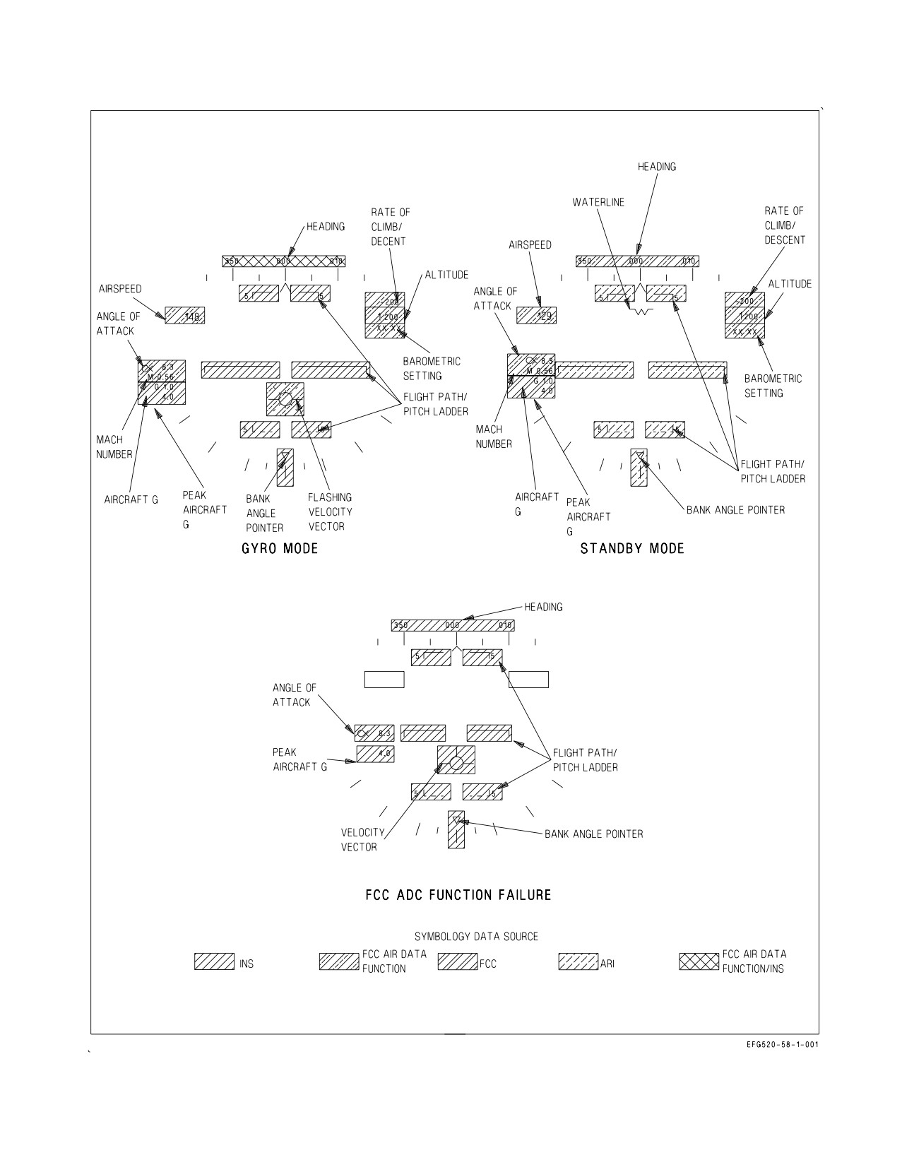
2.19.4.6.11 HUD Symbology Degrades. The avionics suite has built in redundancy with two mission
computers for data management and two MCs, for symbol generation. Likewise, if the attitude select
switch is in the AUTO or INS position, back up data sources are automatically selected to provide
HUD symbology when failures are detected. Refer to figure 2-54, for the HUD displays discussed
below.
a.
HUD Symbology Degrades with INS Failure. When a failure occurs in the INS, HUD
bank angle, velocity vector, pitch ladder, and heading indications can be expected to be
impacted. With GPS operating, the mission computer utilizes GPS information for the velocity
vector. If INS attitude is valid but INS velocities are not valid the mission computer
automatically uses the INS attitude and GPS velocities to position a non-flashing velocity
vector. With a degradation of the air data function (probe or pressure transmitter set damage
or failure) calibrated airspeed, barometric altitude, indicated Mach number, and vertical
velocity indications may be impacted.
When the INS experiences a total shutdown (dump) with the attitude select switch in AUTO
or INS, or if the attitude switch is deliberately placed in standby, a stationary waterline symbol
replaces the velocity vector indicating that the standby attitude reference indicator is now
providing attitude data. This failure is normally accompanied by the MASTER CAUTION
light, tone, and INS ATT caution. Place the attitude select switch in the STBY position,
crosscheck the HUD against standby instruments, and attempt an in-flight alignment.
Due to the tendency of the standby attitude reference indicator to precess, it is suggested that
flying in instrument meteorological conditions (IMC) using the ARI as a primary attitude
reference be minimized. A partial IFA (In-Flight Alignment) is always recommended whenever
possible to recover the INS attitude platform.
b.
HUD Symbology Degrades with Air Data Function Failure. An air data function
failure in the FCC results in loss of associated data from the HUD display as shown in figure
2-54. Such a failure also inhibits operation of cruise flight Automatic Throttle Control and
disables the altitude signal used for IFF altitude reporting. An air data function failure may
affect cabin air flow and cabin air temperature.
The pressure transmitter set can produce erroneous signals without cautions or advisories if
the pitot tube or AOA probes receive damage. As the air data function degrades, loss of some
or all of the following data from the HUD may occur:
(1) Calibrated airspeed or barometric altitude. The loss of calibrated airspeed and/or baro-
metric altitude data results in activation of the landing gear handle warning light and tone
with the gear UP. Aircrew action is to reference the applicable standby airspeed or altitude
indicator and then silence the tone.
I-2-163
ORIGINAL
A1-E18GA-NFM-000
Figure 2-54. HUD Symbology Degrades
I-2-164
ORIGINAL
A1-E18GA-NFM-000
(2) Angle of Attack. Loss of AOA in three or more FCC CHs causes AOA to be removed from
the HUD.
(3) Vertical velocity indicator. Pilot action on loss of the vertical velocity indication is to check
that the aircraft is in the NAV master mode and to reference the standby vertical velocity
indicator.
(4) Mach number. Pilot action on loss of the Mach number indication is to reference the
standby airspeed indicator.
If an AOA probe becomes jammed (does not move), the FCC continues to receive valid signals until
the pilot executes a maneuver that causes the reading between the AOA probes to differ more than 15°
with flaps AUTO or 5.5 to 15° with flaps HALF or FULL, depending on sideslip. HUD displayed
airspeed may be inaccurate without annunciation if a pitot tube is damaged.
A jammed, blocked, or damaged pitot tube/AOA probe may not be
annunciated if system errors are not large enough to set a caution. Be
alert for unannunciated pitot static and AOA errors during flight in icing
conditions or if damage is suspected after a bird strike or IFR basket
impact during inflight refueling.
Air data inputs from the MC are used by the INS to help smooth or dampen pitch ladder and
velocity vector position. A complete air data function failure does not immediately affect the pitch
ladder/velocity vector, but these displays eventually degrade. If subtle damage to the AOA probe is
suspected, the pilot should make a cross check of airspeed with a wingman if possible. The standby
airspeed indicator receives signals from the left pitot static probe, so it is accurate if only the right
probe is damaged. AOA checks with a wingman should be made in landing configuration if a jammed
AOA probe is suspected. Cross checking in cruise configuration may give a satisfactory cross check, but
the probe may be bent in such a way that AOA anomalies are accentuated on landing configuration.
Landing with automatic throttle control (ATC) may be affected. If damage is suspected, ATC during
landing is not recommended.
When AOA is declared invalid (e.g., AOA Four Channel failure), the HUD AOA display and AOA
bracket are removed and the AOA indexer lights and approach lights are inoperative. GAIN ORIDE
provides fixed gains to the FCS and allows the pilot to select, through the FCS status display, either
the left or right probe. The center (INS) AOA value allows the pilot to compare AOA values to select
the undamaged probe. Once selected, this probe drives the HUD AOA display, AOA bracket, AOA
indexer, and approach lights. If the incorrect probe is selected, the information provided to the pilot
and LSO may be in error but has no impact on the flight control system as the gains are fixed. Notify
the LSO that a single probe has been selected.
2.19.4.6.12 HUD Advisory Data Symbology. The displays in figure 2-53 show some of the advisories
that can appear on the HUD in the NAV master mode. The advisories are associated with nosewheel
steering and approach power compensator. Although the advisories are shown on the gear down
display, most of them can appear on the basic HUD display. Refer to Part VII for description of data
link system and advisories.
The automatic throttle control/nosewheel steering advisories are displayed above the distance
display whenever the ATC or the NWS is engaged. If the ATC is disengaged by any means other than
I-2-165
ORIGINAL
A1-E18GA-NFM-000
actuation of the ATC engage/disengage switch, the advisory is flashed for 10 seconds before it is
removed from the display or, if a pilot attempt to engage ATC is not successful, ATC is flashed for 10
seconds and removed.
2.19.4.6.13 HUD BIT Checks. The HUD has two methods of built-in tests: manually initiated and
automatic test. Refer to BIT-Status Monitoring Subsystem for the procedures and displays used for
the HUD BIT checks.
2.19.4.7 CRS Set Switch. The course set switch manually sets the desired course on the HSI display.
2.19.4.8 HDG/TK Set Switch. The heading/ground track set switch manually sets the heading
marker on the desired heading/ground track on the HSI display.
2.19.5 Up Front Control Display (UFCD). The UFCD is on the main instrument panel below the
HUD in the front cockpit. In the rear cockpit, the UFCD is located above the AMPCD. The UFCD is
an active matrix liquid crystal display with an IR touchscreen used for data entry inputs consisting of
digits or NEWS, and control of the CNI systems (data link/radar beacon/ILS, autopilot modes,
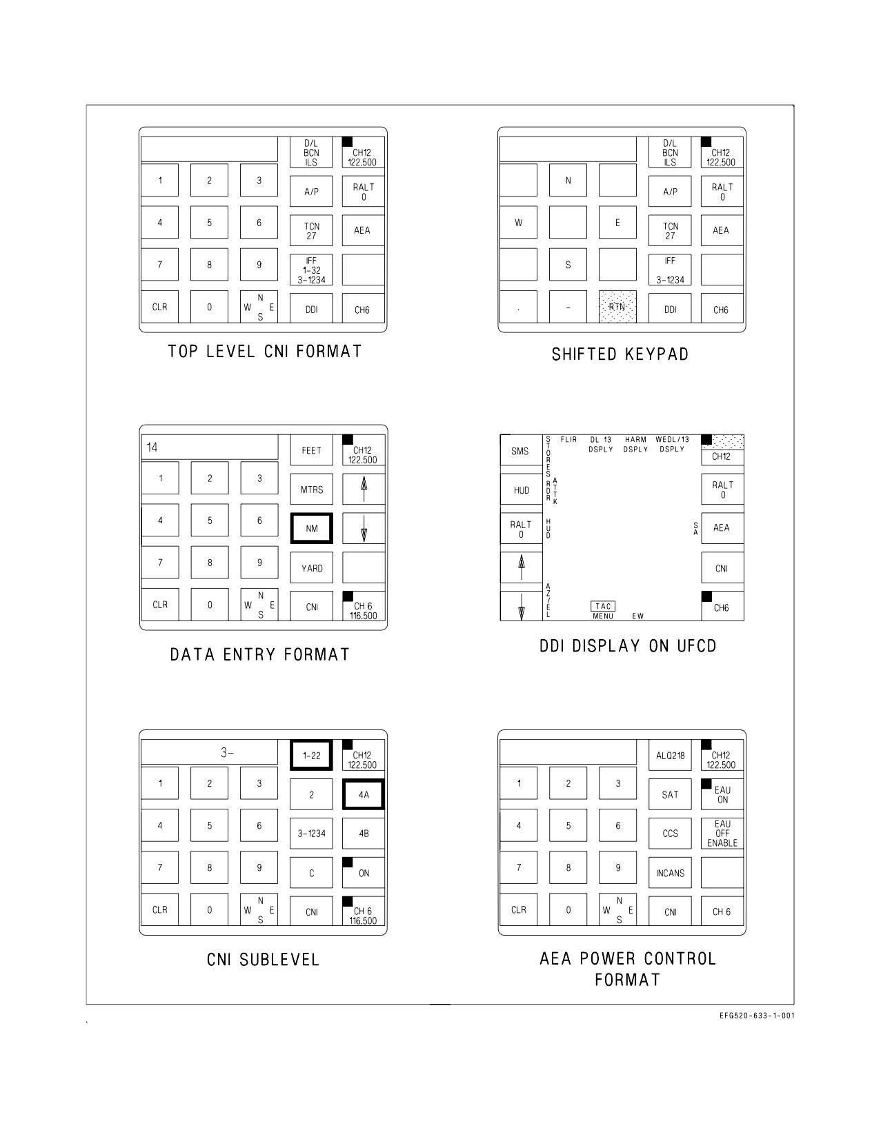
TACAN, IFF, UHF/VHF radios, radar altimeter, and AEA. See figure 2-56. In addition, the
touchscreen can be used as a multi-function display for display formats, including video. The UFCD
is used in conjunction with the two DDIs, the AMPCD and the MPCD to enter navigation, sensor,
electronic attack, and weapon delivery data. UFCD option selections and inputs are transmitted
directly to the MPCD and on to the mission computers. (The mission computers pass these inputs to
the control converter (CC) for CNI equipment control). The UFCD is NVG compatible. The front and
rear cockpit UFCDs operate independently. When different formats are being displayed, the only data
common to both UFCDs is radio channel and frequency information. Both cockpit UFCDs present the
results of changes to radio channels or frequencies at the same time, regardless of which cockpit
performed the change. The cockpit not performing data entry does not see touch highlights as the data
is entered, only the result of the data entry. If both pilot and EWO enter digits on the keypad for the
same option, both entries are accepted, with the second entry overwriting the first. When pilot and
EWO are on the same data entry or CNI format, asterisks are provided in the top left and right of the
scratch pad.
The aft UFCD is electrically controlled through the AMPCD Off/On/Brightness knob. The aft
UFCD flashes STANDBY when the MC1 communication to the UFCD is disrupted. A standby display
pattern in the the center of the UFCD display surface, similar to the DDI pattern, indicates degraded
image processing from MC1. When the Mono video connection from the AMPCD is lost or degraded,
the aft UFCD will not display anything. When video synchronization is lost or degraded, the aft UFCD
may display symbology that is not coordinated with the video. If the interface between MC1 and the
aft UFCD is lost, the touch screen capability and brightness/contrast control will not work. When MC1
is inoperative, the aft UFCD is not capable of displaying format symbology or analog video.
When the pilot or EWO touch a keypad option on the touch screen a highlight appears indicating
that the option has been selected. Figure 2-56 shows an example of a selected option. When a new
format is selected on the touchpad, the highlight does not remain on the new format.
Keypad options use a first finger in mechanization. Only one option can be selected at a time. If two
or more selections are attempted at one time, none of them are considered valid.
Some formats initialize with data in the scratchpad, e.g., the COMM sublevel of the CNI format
initializes with the comm frequency in the scratchpad. When data entry is started, the digits in the
scratchpad are blanked, allowing data entry. If a comm frequency is being entered the decimal remains
displayed, allowing frequency entry in relation to the decimal point to be viewed.
I-2-166
ORIGINAL
A1-E18GA-NFM-000
Uncommanded option selections may occur with a malfunctioning
UFCD. This can include uncommanded autopilot selection or deselec-
tion. In order to reduce the flight safety risk, a UFCD that self-selects
uncommanded options should be secured in flight and only turned on if
required for safety-of-flight functions (radio, IFF or navigation selec-
tions). The malfunction may or may not be present when turned back on,
but can be expected to reoccur during flight if operational. An unaffected
UFCD may remain on and in use with no adverse effect. A frozen
unresponsive display is the result of another unrelated failure mode that
may occur and can be corrected by cycling power to the MPCD.
NOTE
Securing the UFCD will reset the MPCD and cause a transitory
display loss.
2.19.5.1 UFCD Data Entry. All data are entered into the scratchpad using the digit, shifted, or
alphanumeric keypad followed by selecting the option directly. In some cases, the entered data is
displayed below the option legend. The scratchpad is cleared following valid data entry.
Various types of error checking are performed on entered data. If an error is detected, ″ERROR″ is
flashed in the scratchpad, alternating with the scratchpad data. The ″ERROR″ message is removed by
a single selection of the CLR keypad option, resulting in the display of the scratchpad data as it existed
before the error occurred.
2.19.5.1.1 Data Entry Using the Keypad. Digits 0 - 9 can be entered through the keypad.
1. Clear (CLR) Option. The UFCD uses a double clear mechanism. The first selection of the CLR
keypad option removes the last digit that was entered in the scratchpad. The second selection of the
CLR option removes all the digits which have been entered in the scratchpad. If the scratchpad is
flashing due to the 10 second timer (no entries in the previous 10 seconds), selecting CLR stops the
flashing and performs the previously described CLR function. If the scratchpad is flashing due to an
error, selecting CLR stops the flashing and removes the ″ERROR″ message.
2.19.5.1.2 Data Entry Using the Shifted Keypad. The shifted keypad is entered by selecting the
N−E−W−S option and provides the ability to enter a negative sign, a decimal point, degrees, minutes,
and seconds symbols, and North (N), East (E), West (W), and South (S) entries for latitude and
longitude entries.
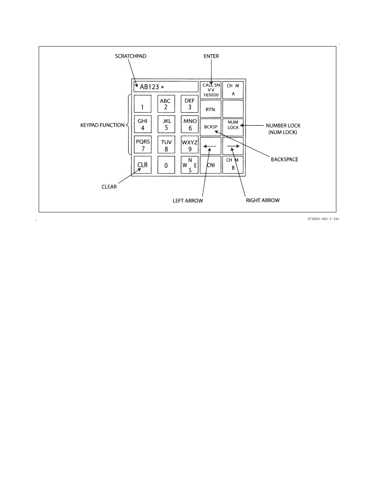
2.19.5.1.3 Data Entry Using the Alphanumeric Keypad. Certain UFCD options require the
alphanumeric keypad.See figure 2-55
1. Scratchpad. With the alphanumeric keypad, a flashing asterisk (*) indicates the current cursor
location if the location is blank. If the cursor location contains a character, that character is flashed
as an indication of the current cursor location. Once the desired character is selected, the cursor can
be moved to the next location either manually (right arrow) or automatically. There are two different
events that cause the cursor to automatically step to the next location:
a. The cursor automatically advances 2 seconds after the last selection of a single keypad option.
I-2-167
ORIGINAL
A1-E18GA-NFM-000
Figure 2-55. Alphanumeric Entry Format
b. If, before the 2 seconds has elapsed, the user selects a different keypad option, the cursor
advances to the next position before beginning to cycle through the available selections of the
second keypad option. For example, if the user selects A, then immediately selects D, the
scratch pad then reads AD as opposed to just D.
The user can manually advance the cursor by selecting the right arrow option. The right and left
arrow selections also allow the user to move the cursor to any position in the string for editing purposes.
Editing of characters is performed in insert mode (as opposed to an overwrite mode). For example,
adding a character in the middle of a string results in every character under and to the right of the
cursor being moved right one position and the new character being inserted into the empty space.
2. Keypad. Characters are entered into the scratchpad by selecting various keypad options. The
keypad options function similar to the multi−press text entry mechanization of most cell phones;
multiple selections of the same button cycles through a small set of available alphanumeric
characters. Keypad options 2 through 9 cycle through the alphanumeric characters displayed in the
option; alpha characters first, then the numeric character. Keypad option 1 cycles through the
following characters, in order listed: one (1), period (.), comma (,), minus (−), question mark (?),
colon (:). Keypad option 0 always enters the zero (0). There are no other alphanumeric characters
assigned to this keypad option.
3. Clear (CLR). There are 3 different results on the first, second and third subsequent selections of
the CLR keypad option. The selection of any other keypad option before the second or third
selection of CLR resets the CLR function back to the first selection state.
a. First Selection of CLR − If there is a flashing ″ERROR″ message, the first selection of the CLR
keypad option clears out the flashing message, leaving the last entered data intact. Otherwise,
I-2-168
ORIGINAL
A1-E18GA-NFM-000
if the cursor is at the end of the data, it deletes the last entered character and moves the cursor
back one position. Alternatively, if there is no flashing ″ERROR″ message and the cursor is
positioned somewhere other than the end of the data, the first selection of the CLR keypad
option deletes the character currently under the cursor and shifts all characters to the right of
the cursor left one position.
b. Second Selection of CLR − The second subsequent selection of the CLR keypad option deletes
a whole word and shifts the characters to the right of the deleted word left. If the cursor is
positioned within a word, that word is deleted. If the cursor is positioned over a space, the first
word to the left of the cursor is deleted. If there is no word to the left of the cursor, no action
is taken. For this function, any contiguous sequence of characters situated between spaces is
considered a word.
c. Third Selection of CLR − The third subsequent selection of the CLR keypad option removes
all the characters which have been entered in the scratchpad and positions the cursor at the
first location.
4. Back Space (BCKSP). BCKSP selection deletes the character to the left of the cursor and shifts
the cursor. All characters under and to the right of the cursor move left, one position. If the cursor
is at the first position in the string, no action is taken.
5. Number Lock (NUMLOCK). NUMLOCK selection toggles number locking on and off. When on,
the NUMLOCK option is bordered (highlighted) and selection of the keypad options enters
numbers only (the letters are still displayed on the keypad options).
6. Left Arrow. Selection of the left arrow will move the cursor one position to the left. If the cursor
is already in the first position of the scratchpad, but is not at the beginning of the string, the string
will be scrolled right and the cursor is placed in the appropriate character position. If the cursor is
already at the first position in the string, no action is taken. A solid box will be displayed in the upper
left corner of the left arrow to indicate that more characters exist to the left of those currently being
displayed in the scratchpad.
7. Right Arrow. Selection of the right option arrow moves the cursor one position to the right. If the
cursor is already in the last position of the scratchpad, but is not at the end of the string, the string
will be scrolled left and the cursor is placed in the appropriate character position. If the cursor is
already at the last position in the string, no action is taken. A solid box will be displayed in the upper
right corner of the right arrow to indicate that more characters exist to the right of those currently
being displayed in the scratchpad.
2.19.5.2 UFCD CNI Function. The aircraft powers up with all CNI systems off and the top level CNI
format as the default UFCD display. See figure 2-56. This format is the central point for controlling all
CNI systems. The MAN option is used to turn to a previously entered manual radio frequency. For
Communication-Identification Equipment, see Chapter 23. For Navigation Equipment, see Chapter
24.
2.19.5.3 UFCD NON-CNI Functions. The following top level options are not related to CNI systems:
DDI, and AEA. The DDI option provides the last selected DDI display on the UFCD. The AEA option
provides the specified display format on the UFCD.
2.19.5.3.1 AEA Power Control. Selecting AEA option displays the AEA power control format. EAU,
SAT, CCS, and INCANS options are displayed when the functions are available.
I-2-169
ORIGINAL
A1-E18GA-NFM-000
Figure 2-56. Up Front Control Display (UFCD)
I-2-170
ORIGINAL
A1-E18GA-NFM-000
2.19.5.3.2 EAU Power Control. The mission computers default the EAU power to on if the MCs are
powering up after a cold start and if the power up is not after an erase. A single selection of the EAU
OFF option on the AEA Power Control format applies power to the EAU. EAU power on is indicated
by a corner highlight in the upper left corner of the EAU option pushtile, and the legend changes to
EAU ON. When the EAU is powered up and communicating with the MCs, options to power up the
ALQ-218, CCS, and the ALQ-99 Pods are available. Once the EAU is on, pressing EAU ON causes an
EAU OFF ENABLE option to appear. Pressing the EAU OFF ENABLE option (within 3 seconds)
removes power from the EAU. Turning off power to the EAU also removes power from the ALQ-218,
CCS, and all ALQ-99 Pods. The EAU automatically shuts down when overheated.
2.19.5.3.3 INCANS Power Control. Pressing the AEA option and then the INCANS option turns on
the INCANS system and places it in the STBY mode. Pressing the INCANS pushbutton again turns
off the INCANS system.
2.19.5.3.4 MATT Power Control. Pressing the AEA option and then the SAT option turns on the
MATT system. Pressing the INCANS pushbutton again turns off the INCANS system.
2.19.5.4 UFCD STANDBY Indication. A flashing STANDBY indication is provided just above the
center of the UFCD display surface when there is no valid mux communication between the MC and
MPCD. The STANDBY indication is superimposed over any display format. When the STANDBY
indication is displayed, power to the MPCD should be cycled to attempt a reset. If the STANDBY
condition clears before power can be recycled, the UFCD screen blanks and the previously displayed
format reappears.
2.19.5.4.1 Aft UFCD MUX FAIL. The aft UFCD generates a MUX FAIL BIT indication when MC1
loses communication with the UFCD. This message occurs only when the AMPCD is turned on and
powering the aft UFCD. Using periodic BIT monitoring, the MC1 tries to reset the aft UFCD through
the AMPCD communication if an error is detected.
2.19.5.5 Radar Altimeter (RALT) Function. The RALT function indicates clearance over land or
water from 0 to 5,000 feet. Operation is based on precise measurement of time required for an
electromagnetic energy pulse to travel from the aircraft to the ground and return. A warning tone and
visual warnings are activated when the aircraft is at or below a selectable primary or secondary low
altitude limit. The primary/secondary radar low altitude warnings are reset by setting the low altitude
index (primary), or UFCD selected altitude (secondary) to an altitude below the present altitude or by
climbing above the previously set limit. The warning tone can be disabled in either cockpit by pressing
the flashing RALT option on the UFCD Low Altitude Warnings format or UFCD DDI format, turning
off the radar altimeter, setting the warning value below current radar altitude, or by climbing above the
warning altitude. When disabled, the tone cannot be triggered until after being reset as described.
The radar altimeter consists of a receiver-transmitter and individual transmitting and receiving
antennas. The receiver-transmitter produces the energy pulses, transmits the energy to the ground,
receives the reflected signal, and processes the data for display as altitude by the head-up display unit
(HUD).
Indicators and controls used with the electronic altimeter set are the left or right DDI on the
instrument panel (for BIT checks), the ALT switch, UFCD (for secondary low altitude warning), and
the head-up display. Radar altimeter BIT is initiated from the BIT display.
Pressing the emission control (EMCON) switch on the UFCD inhibits operation of the radar
altimeter. EMCON is toggled on or off each time the EMCON switch is pressed. When EMCON is on
I-2-171
ORIGINAL
A1-E18GA-NFM-000
the letters E, M, C, O, N are displayed either in the left side option boxes (DDI display) or in the
scratchpad of the top level CNI display and on the HUD.
2.19.5.5.1
Low Altitude Warning Tone. When the aircraft descends below the primary low altitude
set in the UFCD, a ‘‘Whoop, Whoop’’ warning tone is heard in the aircrew’s headset and the word
ALTITUDE is displayed on the HUD. The warning tone, when initiated by the primary radar low
altitude warning, is repeated at the lowest priority until reset or disabled.
Numbers ending in zero are valid entries for both the Low Altitude
Warning and COMM 1. Due to the close proximity of the COMM 1 and
RALT options, it is possible to inadvertently change the low altitude
warning setting for the radar altimeter when attempting to use COMM 1
fast data entry.
A barometric low altitude and secondary radar low altitude warning function are enabled by entering
the appropriate altitude, up to a maximum of 25,000 (BARO) and 5,000 (RADAR), on the UFCD. The
barometric low altitude and secondary radar low altitude warning provide a single voice alert warning
“ALTITUDE, ALTITUDE” when the aircraft descends through the selected altitude. Refer to Part VII
for information on entering altitude. The barometric low altitude warning function does not affect the
operation of the radar altimeter low altitude warning function.
2.19.5.6 UFCD Controls. A description of UFCD switches follows. Refer to Part VII for operating
instructions for CNI equipment.
2.19.5.6.1 COMM 1 and 2 Channel Knobs. The COMM 1 and 2 channel knobs permit independent
selection of up to 20 preset channels on radios 1 and 2. Guard (G), Manual (M), Ship Maritime (S), and
SINCGARS Cue (C) channels are also available on the continuously rotatable knobs.
2.19.5.6.2 COMM VOL Knobs. The VOL knobs independently control radio volume for COMM 1 and
2. The OFF position (detent) is at the full counterclockwise position. Both sets of knobs must be in the
OFF position for power to be removed from the radios. When a radio is powered, the respective COMM
option is corner highlighted. When a radio is actively receiving, a half intensity highlight is shown on
the upper half of the COMM option (figure 2-56).
2.19.5.6.3 ID (IDENT) Pushbutton. The ID pushbutton commands an IFF identification/position
squawk (IDENT), for modes 1, 2, and 3 (if enabled).
2.19.5.6.4 UFCD BRT Knob. The BRT knob adjusts the overall brightness of the UFCD display, both
symbology and video. Turning the knob counterclockwise to the OFF position removes power from the
UFCD.
2.19.5.6.5 UFCD CONT Knob. The CONT knob adjusts video contrast on the UFCD.
2.19.5.6.6 UFCD SYM Knob. The SYM knob is used to adjust the brightness of the UFCD symbology
without affecting the brightness of the UFCD video.
I-2-172
ORIGINAL
A1-E18GA-NFM-000
2.19.5.6.7 EMCON Pushbutton. If the UFCD is displaying a DDI format the letters E M C O N are
displayed in the left side option boxes. If the UFCD is displaying the top level CNI format, EMCON
is displayed in the scratch pad.
2.19.6 Signal Data Computer (SDC). The signal data computer (SDC) operates under mission
computer control and records aircraft fatigue strain data, engine parameters when out of tolerance
conditions occur, fuel information, and aircraft and target parameters when targets are designated and
weapons are delivered. It includes fuel transfer controls and gaging capabilities, incorporates ground
support equipment fuel transfer and gaging fault isolation functions, and provides interface for
multiple sensors and controls. It provides analog-to-digital conversion of aircraft parameters. In
addition, BIT fail indications are stored in the SDC to be displayed by the maintenance status panel
(MSP) for readout by maintenance personnel after the flight, or on the EFD for readout during the
flight.
The RESET SDC option is available from the SUPT MENU/FUEL format. This option is used to
reset the SDC by momentarily removing power. When selected, the RESET portion of the option
legend is boxed, and remains boxed until the SDC reestablishes AVMUX communication or 15 seconds
after the option was selected. The RESET SDC option is removed from the FUEL format if the CSC
is not communicating on the AVMUX.
The SDC is used to compensate for periods of blank cockpit displays and interrupted avionics
multiplex (AVMUX) bus communication occurring when both advanced MCs are off-line or in
initialization. The SDC will take temporary control of AVMUX busses 1 and 6 during the ground start
and inflight conditions. While acting as the backup bus controller, the SDC transmits to the forward
MPCD and forward UFCD a limited HUD display of essential flight information. Refer to chapter 25.
Additional data transfers to the left and right Full Authority Digital Engine Controllers (FADECs) and
the Environmental Control System (ECS) Controller sustains standard operation. The SDC also
enables display of the Left and Right Air Turbine Starter (L ATS and R ATS) cautions.
2.19.7
Cockpit Video Recording System (CVRS).
The system has the capability to direct record various combinations of either front DDI, aft DDI,
MPCD, AMPCD, the HMD, and the HUD in color. Headset audio is also recorded as long as the
KY−58 encryption function is inactive. The switches to operate the CVRS are located on the VIDEO
RECORD panel in each cockpit.
The CVRS consists of one SSR with removable memory module (RMM).
2.19.7.1 Solid State Recorder (SSR). The SSR is located in the avionics bay behind behind the rear
cockpit ejection seat. The SSR provides a minimum of 3 hours recording time on a removable memory
module (RMM).
2.19.7.1.1 SSR Advisories. The RMMCD and RMMFL advisories are described in the Warning/
Caution/Advisory Displays in part V.
2.19.7.2 HUD Camera. The HUD camera, positioned immediately in front of the HUD, records a
color image similar to what the pilot sees through the HUD, e.g., symbology superimposed on a picture
of the outside world. This combined image is made available for recording.
2.19.7.2.1 HUD Event Marker. The HUD event marker is a small black marker generated by the
HUD camera and positioned in the upper left corner of the video signal sent to the VTR for recording.
The event marker is displayed when the weapon release pickle button is pressed or the trigger is
I-2-173
ORIGINAL
A1-E18GA-NFM-000
squeezed to the second detent and remains displayed until pickle button/trigger release. When
reviewing CVRS video post−flight, the event marker is a useful training aid, used to determine the
timing and duration of pickle button and trigger actuations (e.g., shot validation).
2.19.7.2.2 HUD Camera BIT Button. The BIT button, located on the front face of the HUD
assembly, is used to initiate a BIT of the HUD camera. The GO and NO GO BIT status balls, normally
black, are used to determine the BIT status of the HUD camera. When the BIT button is pressed, BIT
status is indicated by a green GO ball or an orange NO GO ball.
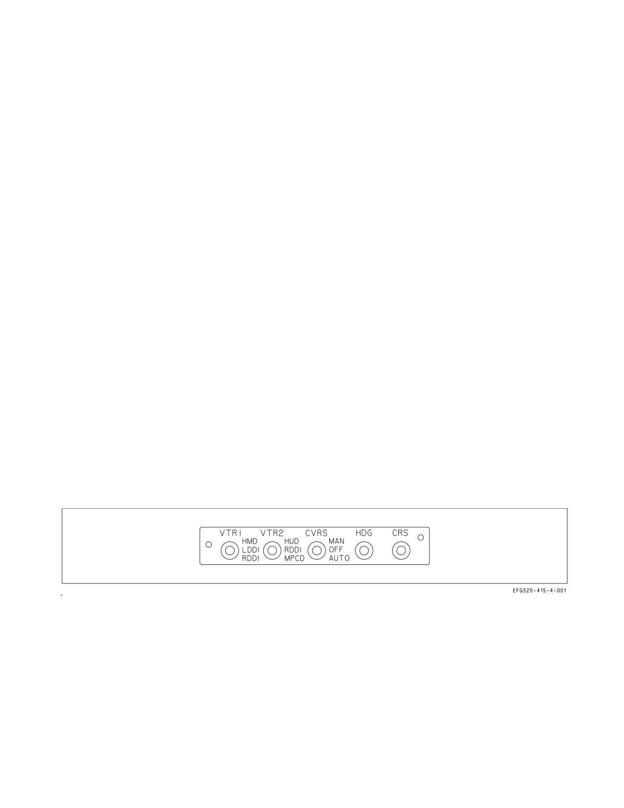
2.19.7.3 CVRS Control Switches. The switches used to operate CVRS are located on the VIDEO
RECORD panel on the lower left instrument panel in the forward cockpit, and below the center display
in the aft cockpit. The aft cockpit switches override the front cockpit switches for any selection. The
VTR 1 and VTR 2 sources are grouped to nominally allow front cockpit recording on VTR 2 (includes
HUD) and allow aft cockpit recording on VTR 1 (includes AMPCD).
2.19.7.3.1 CVRS Mode Switch. The CVRS mode switch is used to select manual or automatic video
recording.
MAN
CVRS records continuously (according to the inputs
selected by the two VTR selector switches).
OFF
CVRS recording off.
AUTO
CVRS records automatically only when in the A/A or A/G master modes (accord-
ing to the inputs selected by the two VTR selector switches).
2.19.7.3.2 CVRS RDCR ON Light. The green RDCR ON light, located on the left warning/caution/
advisory lights panel on the upper left instrument panel, comes on when CVRS power is on. An
illuminated light does not mean that the VTR or SSR is recording.
2.19.7.3.3 VTR Selector Switches . The VTR selector switches are used to select the video input
source for recording on the two VTRs. See figure 2-57.
Figure 2-57. Forward CVRS Control Panel
For the forward cockpit:
VTR1 switch controls selection of video to VTR1:
HMD
Selects HMD video camera (VTR1).
LDDI
Selects LDDI direct video (VTR1).
RDDI
Selects RDDI direct video (VTR1).
I-2-174
ORIGINAL
A1-E18GA-NFM-000
VTR2 switch controls selection of video to VTR2:
HUD
Selects HUD video camera (VTR2).
RDDI
Selects RDDI direct video (VTR2).
MPCD
Selects MPCD direct video (VTR2).
NOTE
When both VTR 1 and VTR 2 have RDDI selected, the actual
recording occurs on VTR 2 only.
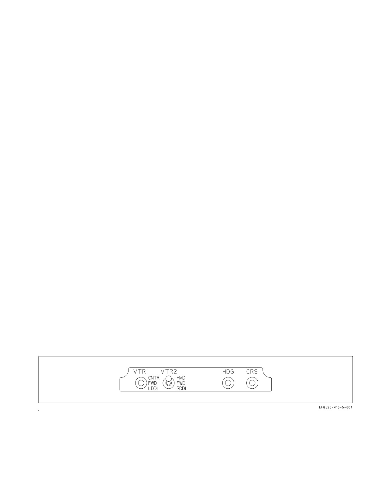
For the aft cockpit:
VTR1 switch controls selection of video to VTR1. Out of the FWD position overrides the forward
cockpit selection and turns CVRS on if the system is off. The switch automatically returns to FWD
when aircraft power is removed. See figure 2-57.
CNTR
Selects center display direct video (VTR1). Electrically held in this position.
FWD
Selects front cockpit video (VTR1). Default start−up position.
LDDI
Selects LDDI direct video (VTR1). Electrically held in this position.
VTR2 switch controls selection of video to VTR2. Out of the FWD position overrides the forward
cockpit selection and turns CVRS on if the system is off. The switch automatically returns to FWD
when aircraft power is removed.
HMD
Selects HMD video camera (VTR1).
FWD
Selects front cockpit video (VTR1). Default start−up position.
RDDI
Selects RDDI direct video (VTR2). Electrically held in this position.
Figure 2-58. Aft CVRS Control Panel
2.19.7.4 VTR 2 Override Function. CVRS incorporates a VTR 2 override function designed to make
sure that HUD camera video is recorded when an A/G weapon is released, or an A/A missile is
launched. In A/A or A/G master modes, when the pickle button is pressed or the trigger is squeezed to
I-2-175
ORIGINAL
A1-E18GA-NFM-000
the second detent, VTR 2 automatically switches from the selected VTR2 source to the HUD camera.
VTR 2 records HUD video from pickle button/trigger actuation to pickle button/trigger release plus a
set overrun time before reverting to the video source selected by the VTR 2 selector switch. Overrun
times are 10 seconds for AIM−120 launch and A/G weapon release.
2.20 TACTICAL AIRCRAFT MOVING MAP CAPABILITY (TAMMAC)
The TAMMAC avionics subsystem provides a moving map capability to enhance operational
effectiveness and survivability and addresses supportability/obsolescence issues facing existing moving
map and data storage systems currently deployed.
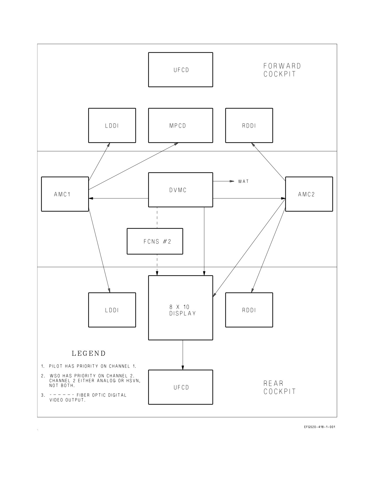
Independent maps and related formats are available in both cockpits with Digital Video Map
Computer (DVMC) installed, allowing independent map functionality and video routing. The DVMC
provides five outputs through two channels to various aircraft displays; however, each map channel
output is not available on every display. DVMC Channel 1 (using MC1) has two analog video outputs.
One output is viewable on the front LDDI, MPCD and rear LDDI. The other channel 1 output is used
for the aft UFCD. DVMC Channel 2 (using MC2) has two analog video outputs and one digital color
fiber optic output. One of the analog outputs is viewable on the front and rear RDDIs, and AMPCD.
The other analog output is used for Wrap-Around-Test (WAT) and removes video capability from the
front UFCD. Channel 2 digital (fiber optic) is only available on the AMPCD. When the Channel 2
digital output is in use on the AMPCD, the analog outputs are disabled. The DVMC only produces
digital or analog on Channel 2 at any time, not both simultaneously.
The AMPCD processes analog video (via MC1 or MC2) or digital video, via Fiber Channel Network
Switch (FCNS) 2 along with the symbology received from MC2 to create a composite format display
image. Map mono video (Wrap-Around-Test only) is the only analog videos routed to the AMPCD.
The aft UFCD video displays are routed through the AMPCD for processing, and include sensor,
weapon, and TAMMAC DVMC. Digital color map video on the AMPCD is routed from the TAMMAC
DVMC via the High Speed Video Network (HSVN) and FCNS2. If FCNS2 fails, no digital color video
is available on the AMPCD. Map video routing is shown in figure 2-59.
The TAMMAC subsystem consists of the Digital Memory Device (DMD), the CP-2414/A digital
map computer and a High Speed Interface Bus (HSIB) which connects the two. Data Transfer Devices
(DTDs) used in conjunction with TAMMAC for transferring data to and from ground-based stations
are Personal Computer Memory Card International Association (PCMCIA) cards or PC cards.
Ground-based stations that process data for TAMMAC include the Joint Mission Planning System
(JMPS) and the Automated Maintenance Environment (AME). Theater data is installed on the map
loading card using JMPS.
The DMD contains two PC card receptacles, one for maintenance (ground support) operations and
one for mission (pilot) operations. This configuration allows maintenance and mission data to be
separated both pre- and post-flight which reduces logistics coordination and facilitates operational
readiness. Three types of PC cards are used in the TAMMAC subsystem operation: 1) Mission Card,
2) Maintenance Card, and 3) Map Loading Card.
2.20.1 TAMMAC Status Monitoring. Status monitoring functionality accommodates changes to the
MC/DMD/DMC interfaces including, but not limited to, the PC cards and the High Speed Interface
Bus (HSIB).
I-2-176
ORIGINAL
A1-E18GA-NFM-000
Figure 2-59. Video Display Routing
I-2-177
ORIGINAL
A1-E18GA-NFM-000
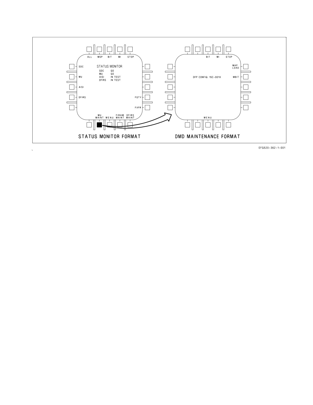
Figure 2-60. DMD Maintenance Format
The MC verifies the DMD and DMC software configuration IDs are compatible with the MC
software.
2.20.2 DMD Maintenance Format Options and Display Information. The DMD maintenance
format contains two relay mode options, MAP LOAD and MBIT. MAP LOAD provides access to
sublevel formats used to upload map theater data to the DMC. MBIT is used for troubleshooting and
fault isolation.
Information displayed on the DMD maintenance format is limited to the MU OFP configuration ID.
The OFP CONFIG identifies the OFP version currently installed in the DMD. See figure 2-60.
2.20.3 Map Theater Data Loading. Map theater data loading can include either updates to an
existing theater load or a new theater load. In both cases, the map loading cards are processed on JMPS
and loaded in the DMC nonvolatile mass memory using the same procedure. The number of map
loading cards is contingent on the size of the update or new theater load. The number of map loading
cards can be as few as one or as many as seven.
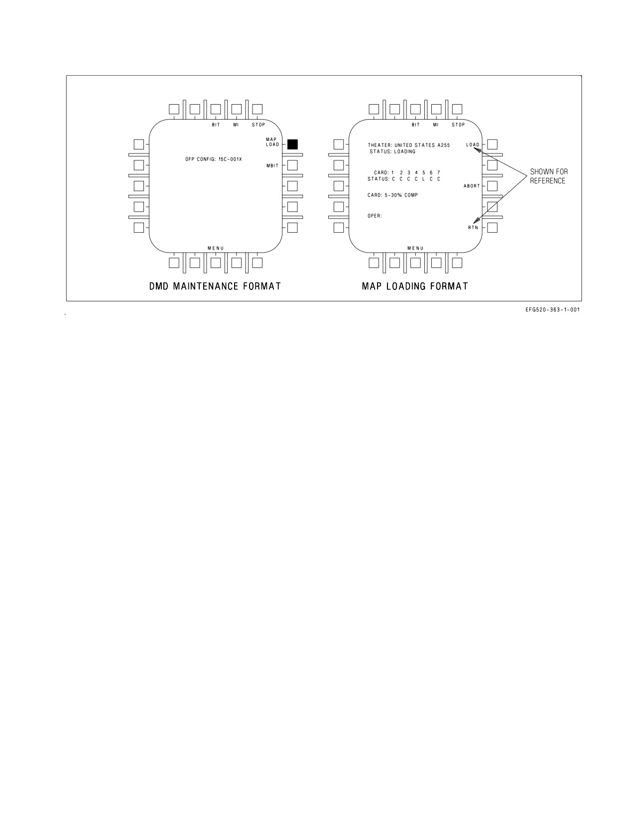
Map theater data loading is controlled by the map loading format. The map loading format is
accessed by selecting the MAP LOAD option (PB 11) on the DMD maintenance format as shown in
figure 2-60. The map loading format contains three relay mode options; LOAD, ABORT, and RTN.
2.20.4 Map Loading Format Options. The LOAD option (PB 11) is used to initiate a theater load
when a map loading card is installed in the DMD maintenance card receptacle and the DMD door is
closed. Once the process is initiated, the LOAD option is removed from the format. Multiple card
theater loads/updates require the insertion of another map card when prompted by the DDI display.
I-2-178
ORIGINAL
A1-E18GA-NFM-000
Figure 2-61. Map Loading Format
Installing another map loading card and closing the DMD door continues the theater loading process.
This procedure is repeated until all theater data is loaded. Map loading cards can be loaded in any
sequence.
The ABORT option (PB 13) is used to abort a theater load in progress. It is removed from the
display prior to and after completion of a load. To initiate an abort, the operator presses PB 13 which
changes the option to ABORT ENABLE. Selection of ABORT ENABLE executes the abort process.
The ABORT ENABLE legend is displayed for three seconds following selection of the ABORT option.
If the operator does not select the ABORT ENABLE option within three seconds, the ABORT legend
is redisplayed. The intent of this two-step abort process is to preclude any inadvertent operator
initiated aborts from being performed. This abort process is permanent and the entire load process will
be terminated.
Aborting a theater map load causes the aborted theater to be deleted. No maps in CHRT, DTED,
or CIB will be available if a theater load is aborted. Previous theater maps are automatically deleted
upon loading a new theater.
The RTN option (PB 15) is used to return the DMD maintenance format if a theater load is not in
progress. If a theater load is in progress, the RTN option is removed from the display.
2.20.5 Map Loading Format Status Information. Status information displayed on the map loading
format provides the operator with on-line instructions and associated feedback necessary to perform a
successful theater load. See figure 2-61. The information presented is grouped into several status fields;
THEATER, STATUS, CARD/STATUS, CARD, and OPER.
The THEATER status field contains; theater identification, theater update revision letter, and the
theater update version number that is stored on the map loading card currently being loaded. If at least
one card is not installed in the DMD (to initiate the load), the field is blank. After a map loading card
is loaded the theater identification information remains displayed as other cards are loaded.
The status field below the THEATER status field contains the overall status of the loading process.
This field contains one of the following status indications:
I-2-179
ORIGINAL
A1-E18GA-NFM-000
HALTED - Indicates the load process has been halted (between successive cards).
LOADING - Indicates the load process has been initiated and/or is in progress.
ABORTED - Indicates the load process has been aborted.
NO DMS COMM - Indicates HSIB communications with the DMC have failed.
DMS FULL - Indicates the DMC nonvolatile mass memory is full.
LOAD ERROR - Indicates the load process has failed.
WRONG CARD - Indicates the card installed in the DMD maintenance card receptacle is not a Map
loading card.
COMPLETE - Indicates the load process has successfully been completed.
CARD/STATUS fields contain status information regarding the PC cards used in the loading
process. The CARD field indicates the card ID number(s) in the theater load card set. The maximum
number of card IDs that can be displayed is seven. The card ID number(s) displayed is dependent on
which order the cards are loaded. The STATUS field below the CARD field contains the actual load
status of the card number directly above it. Once the card is installed and the load process initiated,
the field contains one of the following status indications:
L - Indicates the card is currently being loaded.
F - Indicates the card has failed to load properly.
C - Indicates the card has been successfully loaded.
If none of the above conditions exists, the STATUS field will be blank. If any card fails to load
properly resulting in an ″F″ status, the operator has the option of reinserting the card in an attempt to
obtain a successful load.
The CARD field contains the load status of the card that is currently installed. The card ID number
will be displayed followed by the percent complete (%) for the card. The percentage will be displayed
in 1% increments.
The OPER field contains instructions for the operator. The field contains one of the following
instructional status indications. If any card has yet to be installed for loading, the OPER field will be
blank.
INIT LOAD - Indicates the DMD is ready to start the load process and the LOAD option needs to be
selected.
CLOSE DOOR - Indicates the DMD door needs to be closed.
REMOVE CARD - Indicates the installed card has been successfully loaded and needs to be removed.
INSERT CARD - Indicates another card is required to complete the load process.
2.20.6 Map Loading Interruptions. Interruptions to the map theater data loading process can occur
as a result of several events: loss of power to the MC, DMC, or DMD, operator aborts, or inadvertent
transfers out of DMD relay mode.
I-2-180
ORIGINAL
A1-E18GA-NFM-000
If the DMD experiences a power loss greater than five seconds, or if the DMC experiences a power
loss of any duration, or if the operator initiates an abort, the interruption in the loading process results
in a nonrecoverable abort and the load process cannot be recovered without reloading all the cards.
If power is reapplied to the DMD within five seconds, then the load process can be recovered with
minimum impacts. Once the operator reselects the map loading format, the status of the load prior to
the interruption is reflected on the format status fields. If a card was in the process of being loaded
when the interruption occurred, its status is blank indicating it has not been loaded. Selecting the
LOAD option reinitializes the load process following this type of interruption.
2.20.7 DMD/PC Cards Cautions and Advisories. The DMD has the ability to trigger three caution
and five advisory messages. The caution messages are: MU LOAD, ERASE FAIL, and S/W CONFIG.
The advisory messages are: Maintenance Card Advisory (MNTCD), Mission Card Advisory (MSNCD),
Classified Data Advisory (CDATA), DMD Full advisory (MU FL), and the BIT advisory.
The MU LOAD caution is generated when the DMD door is open; if the DMD fails; if the DMD
declares a card interface fail; if the DMD is mux fail or not ready; if the mission card is improperly
formatted, not installed, or is declared failed by the DMD, if the initialization data is not downloaded,
if an incorrect checksum is calculated. The MU LOAD caution is disabled while the DMD is in relay
mode or the aircraft is in flight.
The ERASE FAIL caution is generated when the DMD has failed to erase its internal RAM memory
buffer following a classified data transfer.
The S/W CONFIG caution is generated if the DMD and MC software are not compatible. When an
DMD OFP checksum failure occurs, the DMD OFP software configuration ID displayed on the S/W
configuration BIT sublevel format indicates XXXXXXXX.
The MNTCD advisory is generated when the DMD door is open, if the maintenance card is not
installed or properly formatted, or if the DMD declares a maintenance card failure. The advisory only
displays with WonW and clears in flight.
The MSNCD advisory is generated when the DMD door is open, or if there is an DMD/PC card
interface fail, or if a down load of data is incorrect, or there is a checksum failure with the data
downloaded, or if the mission card is not installed, or if the mission card is not properly formatted, or
if there is a mission card failure. The advisory only displays with WonW and clears in flight.
The BIT advisory is generated when the DMD is degraded or an DMD RAM classified erase failure
occurs.
The CDATA advisory is generated when the mission card contains classified data. It is removed
when a successful classified data erase of all avionics has been performed, or a successful classified data
erase of all avionics except the mission card is performed and the ERASE (MU HOLD) option has been
selected on the MUMI format.
The MU FL advisory indicates a data wraparound has occurred on the maintenance card and the
corresponding MSP code (809) is set. When the MC determines there is not enough memory on the
maintenance card to perform the next sequential write operation, it begins overwriting previously
recorded data.
DFIRS data download requests do not cause a data wraparound to occur. If there is insufficient
memory available, based on the current sequential write address pointer, the DFIRS data download
request is not executed.
I-2-181
ORIGINAL
A1-E18GA-NFM-000
2.21 COUNTERMEASURES DISPENSING SYSTEM
2.21.1 ALE-47 Countermeasures Dispensing Set. The ALE-47 countermeasures dispensing set is
manually actuated. Refer to NTRP 3-22.2-EA-18G (EA-18G Classified Manual) for details on ALE-47
operation and displays.
2.21.1.1 DISPENSER Switch. The DISPENSER switch, located on the center pedestal, is used to
control power to the ALE-47 system and to enable the BYPASS dispensing mode.
BYPASS Selects the BYPASS mode for ALE-47 operation.
ON
Powers ALE-47. Enables the ALE-47 sublevel on the EW format.
OFF
ALE-47 off
2.21.1.2 ALE-47 Advisories. The D LOW advisory is displayed when expendable loadouts drop to the
BINGO level set on the ALE-47 sublevel of the EW format. The D BAD advisory is displayed when a
dispense misfire occurs.
2.22 BIT-STATUS MONITORING SUBSYSTEM
The BIT/status monitoring subsystem, provides the aircrew with a simple display of system status.
Most information is derived from BIT mechanizations within the avionics sets and from non-avionic
built in tests implemented in the computer software for other aircraft subsystems.
The subsystem monitors engine and airframe operational status for unit failures and caution/
advisory conditions when the mission computer system is operating. When the mission computer
system detects a caution/advisory condition, it commands display of the applicable caution or advisory
message on one of the DDIs. If the mission computer system detects a unit failure, it commands the
subsystem to store the applicable maintenance code. The mission computer displays the subsystem
BIT results on one of the DDIs.
Non-BIT equipment status includes configuration ID numbers and INS terminal data.
2.22.1 Flight Incident Recorder and Aircraft Monitoring Set (FIRAMS). The FIRAMS consists of a
signal data computer, a data storage set, an engine fuel display, and a maintenance status panel. The
FIRAMS monitors selected engine, airframe, avionic, non-avionic, fuel gauging and consumable
signals. It also performs conversion of sensed measurements, provides real time clock function, outputs
discrete and analog data to associated equipment, communicates with the mission computer, displays
fuel quantities and engine parameters, and performs fuel system health monitoring. FIRAMS also
provides nonvolatile storage for flight incident, maintenance, tactical and fatigue data, and bulk data
input of tactical mission planning data.
2.22.2 Deployable Flight Incident Recorder Set (DFIRS). The DFIRS system consists of the signal
data recorder (SDR), the data transfer interface unit, and the pyrotechnic release system. The SDR
consists of the flight incident recorder memory, beacon, battery, and antenna. DFIRS is contained in
a deployable aerodynamic airfoil located on the top of the fuselage between the rudders. The DFIRS
system stores up to 30 minutes of flight data and, when activated, deploys the SDR along with a rescue
beacon in an airfoil. The SDR is deployed upon pilot ejection or on ground impact. The data stored on
the flight incident recorder (FIR) is gathered by the mission computer from aircraft systems. DFIRS
records flight data, cautions, advisories, and spin data. The FIR memory wraps around to the
beginning when the end of memory is reached. Only the last 30 minutes of each flight is retained. The
MC controls the rate and the type of data that is stored. DFIRS data recording starts when both
I-2-182
ORIGINAL
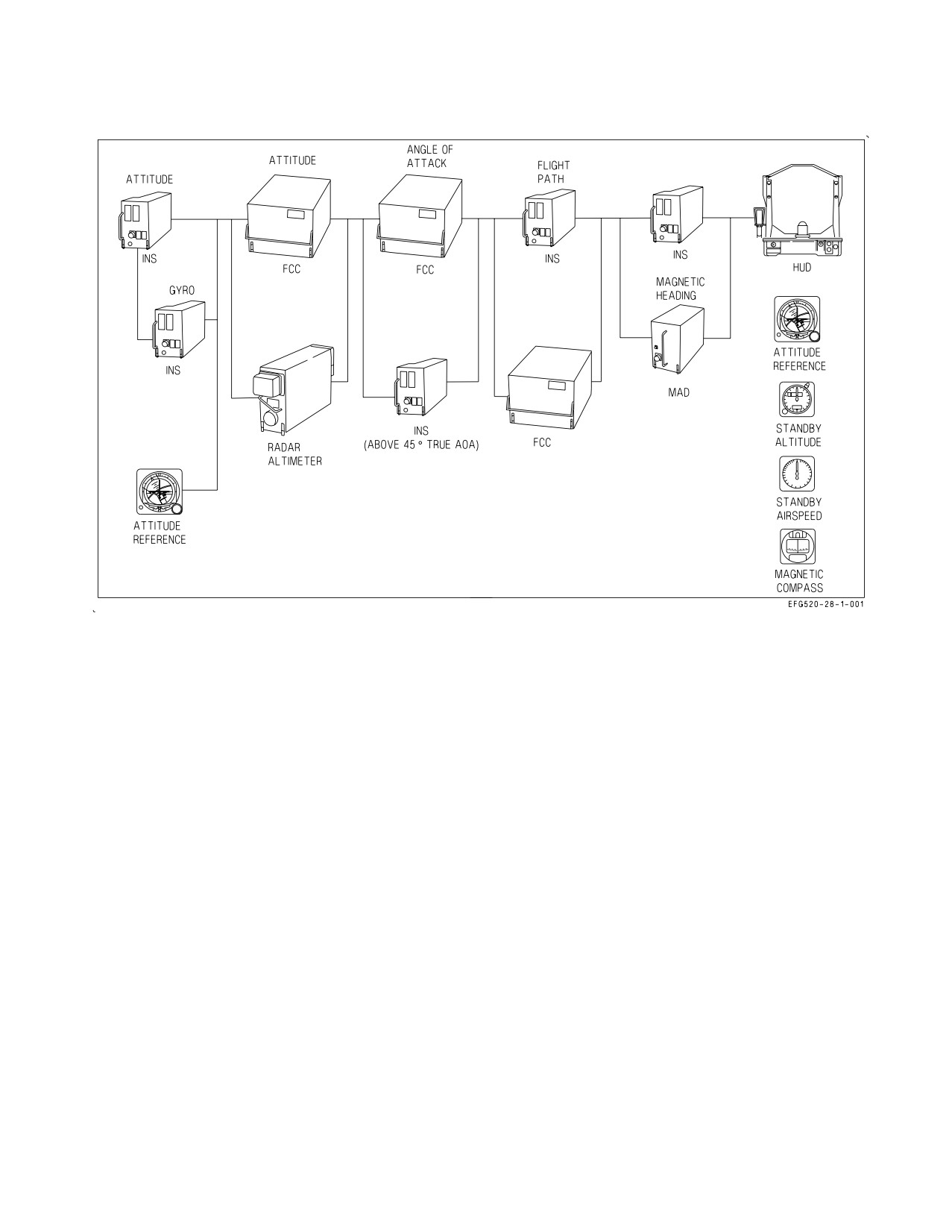
A1-E18GA-NFM-000
Figure 2-62. Flight Aids Reversion Mechanization
throttles are advanced past the vertical, launch bar is lowered, ground speed exceeds 50 knots, or
WoffW and airspeed is over 80 knots. DFIRS recording stops 1 minute after WonW, both throttles less
than the vertical, and the ground speed less than 50 knots. All data with SPIN mode activated are
automatically recorded. A DFIRS DWNLD option is available on the engine display with WonW.
Selecting this option downloads the DFIRS data to the MU for easier retrieval.
2.22.3 Avionics BIT. In most instances, two types of BIT are mechanized, periodic and initiated.
Periodic BIT begins functioning at equipment power application. It provides a failure detection
capability that is somewhat less than that provided by initiated BIT in that it does not interfere with
normal equipment operation.
Two forms of BIT derived data are supplied to the MC. One form is validity information associated
with selected data. The second form is equipment failure information which identifies failed
assemblies. The MC uses these two forms of BIT data to implement reversion operation and advisories
for the aircrew as well as equipment status displays for both the aircrew and maintenance personnel.
2.22.3.1 Reversion. When the BIT equipment determines that a function has exceeded a predeter-
mined threshold, the data derived from that function is immediately indicated as not valid. The MC,
upon receiving this indication, reverts to the next best available source. This source is, in many cases,
as accurate as the original source. This reversion is maintained as long as the data remains invalid from
the primary source.
Figure 2-62 illustrates this concept for the flight aids. For each unit in the primary path, there is at
least one alternate source of data for reversion. The aircrew is provided appropriate display cueing only
when a reversion results in some loss of capability or performance. If the ALT switch is in RDR and
I-2-183
ORIGINAL
A1-E18GA-NFM-000
the radar altimeter fails, the MC removes the displayed radar altitude, replaces it with barometric
altitude, and replaces the ″R″ cue with a flashing ″B″ cue. If altitude is lost from the FCC and the
altitude switch is in BARO, the MC removes the displayed altitude from the HUD. These examples
illustrate three forms of degraded mode advisories: (1) reversion to an alternate data source of
equivalent accuracy with no cueing; (2) reversion to an alternate data source of lesser accuracy with
cueing; (3) and removal of displayed data when no acceptable alternate source is available. Refer to
Part VIII for further discussion on weapon system reversions.
2.22.3.2 Equipment Status Displays. Equipment status displays (BIT, caution, and advisory)
provide the aircrew with continuous status of the avionics equipment and weapons. A cue to check
equipment BIT status is the appearance of the BIT advisory display on the caution/advisory. The
display is normally on the left DDI. A MENU selectable top level BIT format displays the status of
failed, NOT RDY, or OFF systems of all avionics equipment that interface with the MC. When the BIT
control display is selected on another display, the BIT advisory is removed until another BIT failure
occurs. The AMPCD messages appear as ACNTR. Messages displayed as a function of equipment
status are listed in figure 2-63.
Weapon and stores status is displayed primarily on the stores display (selected from the menu
display). When the BIT display indicates a stores management system (SMS) failure, the affected
stations and degree of failure are identified on the stores display as described in NTRP 3-22.2-EA-18G
(EA-18G Classified NATIP).
I-2-184
ORIGINAL
A1-E18GA-NFM-000
STATUS
APPLICABLE SYSTEM
MESSAGE DEFINITION
MESSAGE
NOT RDY
All systems except MC1
Equipment OFF, not installed, or initializ-
ing.
OFF
ALQ-99, ALQ-218, CCS, EAU, INCANS,
Equipment OFF.
MATT, RDR, MPCD, ACNTR, UFCD,
CAM, IFF, RALT, BCN, ILS, TCN, COM1,
COM2, D/L
IN TEST
All systems except MC1, MC2, RWR
Initiated BIT in progress.
SF TEST
ALQ-99, ALQ-218, CCS, EAU, INCANS,
Self test in progress (cannot be operator ter-
MATT, SMS, RDR, MPCD, ACNTR,
minated).
UFCD, RALT, WPNS, LTDR, DFIRS, GPS
ALE-47, DBFS, ECS, FADEC
GO
All systems
Initiated BIT completed without failure.
DEGD
All systems except MC1, MC2
Failure detected; equipment operation de-
graded.
DEGD
ALQ-99, ALQ-218, CCS, EAU, DMD,
Detected failure and overheat.
+
INCANS, MATT, LDT, SMS, MPCD,
OVRHT
ACNTR, UFCD, CAM, CSC, FCSA, FCSB,
INS, ASPJ, RWR, LTDR, DFIRS, FADEC
OVRHT
ALQ-99, ALQ-218, CCS, DMD, EAU,
Overheat.
INCANS, MATT, LDT, SMS, MPCD,
ACNTR, UFCD, CAM, CSC, FCSA, FCSB,
INS, ASPJ, RWR, LTDR, DFIRS, FADEC
MUX FAIL
ALQ-99, ALQ-218, CCS, DMD, EAU,
Equipment is not communicating on
INCANS, MATT, CLC, SMS, RDR, LDDI,
AVMUX and on/off discrete is set to on.
RDDI, MPCD, ACNTR, CSC, MC2, FCSA,
FCSB, INS, COM1, COM2, D/L, ASPJ,
AISI, SDC, MU, LTDR, DMC, DFIRS,
GPS, ALE-47, ECS, FADEC, UFCD (Aft)
RESTRT
All systems except MC1, MC2, RWR,
Reinitiate BIT; equipment did not respond
FADEC
to BIT command, remained in BIT too long
and was terminated by MC.
OP GO
ALQ-99, ALQ-218, CCS, EAU, DMD,
Non critical BIT failure detected.
INCANS, MATT, SMS, COM1, COM2,
WPNS, MU, DFIRS, GPS, ALE-47, FADEC
PBIT GO
All systems except MC1, MC2, RWR,
Initiated BIT has not been run since ground
FADEC
power-up and PBIT is not reporting any
failures.
No indication (blank) adjacent to the equipment legend indicates that initiated BIT has not been run on the
equipment and that the periodic BIT has not detected any faults. LDDI, RDDI, MPCD, and EFD have
unique degraded messages of ALDDI, ARDDI, ACNTR, AEFD, and AUFCD to allow distinguishing BIT
status failures for aft cockpit displays.
Figure 2-63. Equipment Status Messages
I-2-185
ORIGINAL
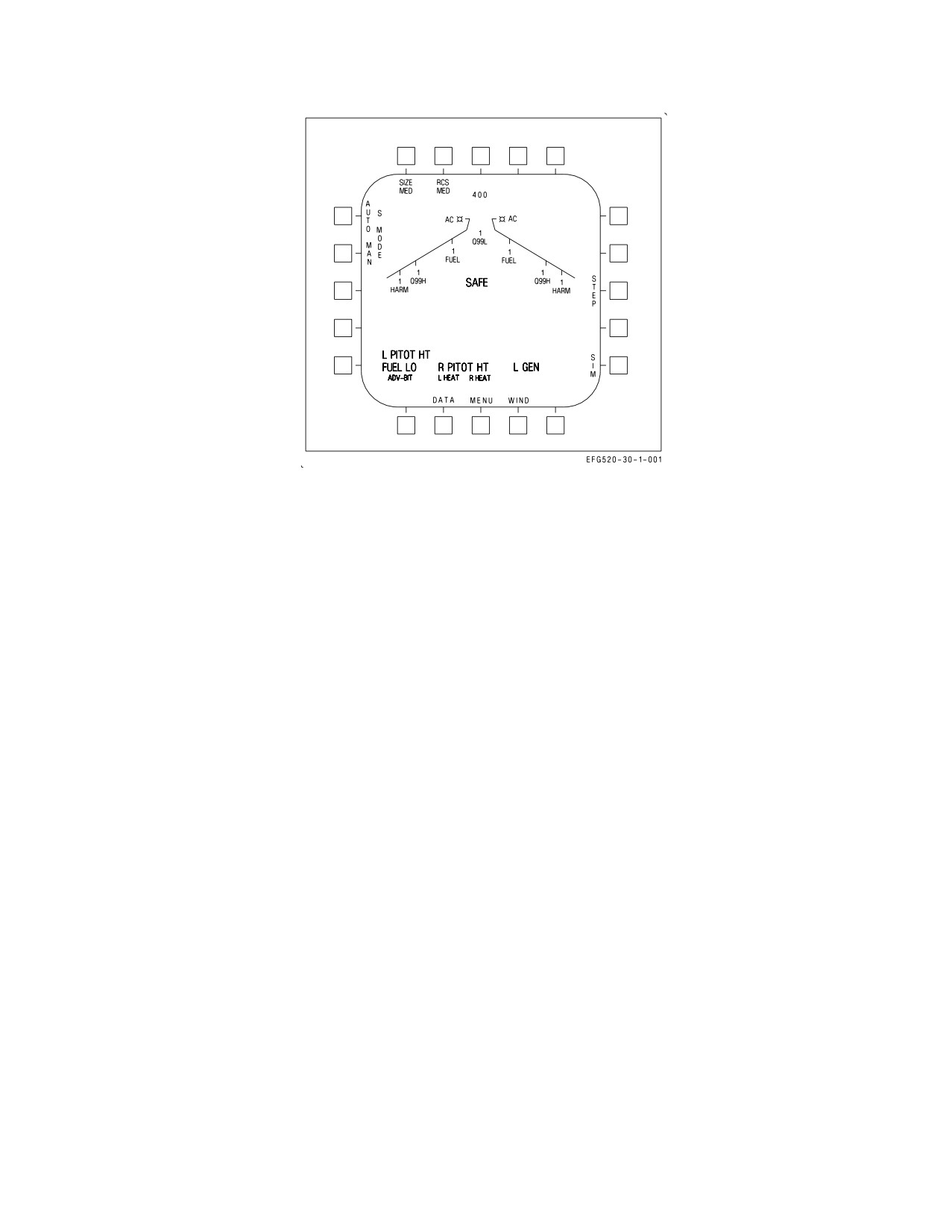
A1-E18GA-NFM-000
Figure 2-64. Caution/Advisory Displays
2.22.3.2.1 Cautions and Advisories. Cautions and advisories are displayed (figure 2-64) on the left
DDI except when the left DDI is used for BIT display or weapon video. When the left DDI is off or
failed, or when the LDDI is used for BIT or weapon video, cautions and advisories are displayed on the
center display. If the left and center displays fail or are turned off, the right DDI displays the cautions
and advisories. Cautions and advisories automatically move to the center display when BIT is selected
on the LDDI. Caution displays appear as 150%-size letters compared to the normal message symbology
size. Cautions are displayed as they occur beginning in the lower left portion of the DDI display and
sequence to the right up to three displays across. The fourth caution reindexes to the left edge above
the first caution. A dedicated caution display automatically replaces the HSI display if the number of
cautions exceeds 3 lines. Advisory displays appear as 120%-size letters on a single line beneath the
caution displays. The advisories are preceded by an ADV- legend and the individual advisories are
separated by commas. A caution or advisory is removed when the condition ceases. If there is a caution
or advisory displayed to the right of the removed caution or advisory the display remains blank.
Pressing the MASTER CAUTION light when the light is out repositions the remaining cautions and
advisories to the left and down to fill the blank displays. When a caution occurs, the MASTER
CAUTION light on the main instrument panel illuminates and the MASTER CAUTION tone or a
voice alert is heard in the headset. The MASTER CAUTION light is extinguished by pressing the light.
Refer to Warning/Caution/Advisory Displays in chapter 12 for the display implications and corrective
action procedures.
2.22.3.3 BIT Initiation. In addition to displaying equipment BIT status, the BIT top level and ten
sublevel displays (figure 2-65) are used to command initiated BIT. Those avionics set groups identified
by the legends on the top level display periphery have an initiated BIT capability. BIT may be initiated
for all operating units simultaneously except for some BIT that cannot be performed in flight. Figure
2-65 shows which initiated BIT are not allowed in flight. Additional steps are required to test the INS
and FCS. BIT for individual units within groups may be initiated through the BIT sublevel displays.
Pressing BIT returns to the BIT top level display. Pressing STOP or MENU when BIT is in progress
terminates initiated BIT. Performance of BIT assumes that the required electrical and hydraulic
power is applied to the equipment tested.
I-2-186
ORIGINAL
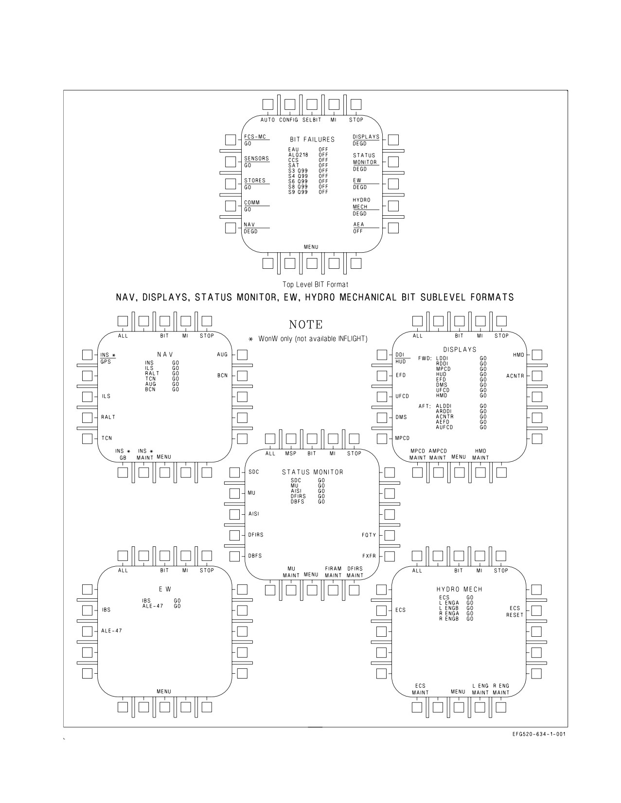
A1-E18GA-NFM-000
Figure 2-65. BIT Control Display (Sheet 1 of 2)
I-2-187
ORIGINAL
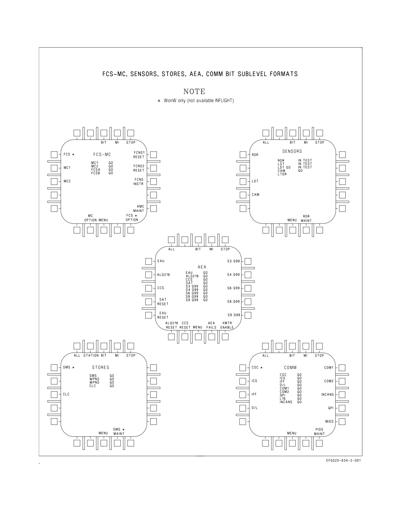
A1-E18GA-NFM-000
Figure 2-65. BIT Control Display (Sheet 2 of 2)
I-2-188
ORIGINAL
A1-E18GA-NFM-000
2.22.3.3.1 All Equipment. Simultaneous initiated BIT of all equipment installed is performed by
selecting AUTO on the BIT top level display. Equipment group, acronym and status are displayed at
the display options. Equipment group status indicates the lowest operating status reported by any unit
in the tested group. Individual system status results other than GO, PBIT GO, IN TEST, SF TEST,
and OP GO are displayed with a system acronym in the center of the display. If the equipment list is
too long to be displayed on one page, a PAGE pushbutton is displayed. Pressing PAGE displays the
remainder of the list that is on page 2. Pressing PAGE when page 2 is displayed returns page 1.
2.22.3.3.2 Equipment Groups. Initiated BIT of entire equipment groups is performed by selecting
SELBIT (SELBIT option becomes boxed) on the BIT top level display and the desired equipment
group pushbutton. One or more groups can be selected. Another way to select a group is to press the
group pushbutton (with the SELBIT option not boxed) on the BIT top level display and then ALL on
the group sublevel display. See figure 2-65.
2.22.3.3.3 Individual Units. Initiated BIT of an individual unit is performed by pressing the
equipment group pushbutton on the BIT top level display which contains the desired unit. The display
changes to a group sublevel display. Individual units from the group can then be tested by pressing the
pushbutton adjacent to the desired acronym. System status for all systems in the group is displayed on
the center of the display. Some systems require additional aircrew BIT input.
2.22.3.4 System BIT Steps. The following includes certain initiated BIT which require steps in
addition to pressing one of the buttons on the BIT display and reading the BIT status messages after
the test is complete. Figure 2-65 shows which initiated BIT are not allowed in flight.
2.22.3.4.1 FCS Initiated BIT (IBIT). For the FCS to enter IBIT the FCS BIT consent switch must be
held ON. This action prevents inadvertent IBIT initiation inflight for reasons of flight safety.
Control surfaces move during FCS IBIT with hydraulic power applied.
To prevent personnel injury or equipment damage, make sure personnel
and equipment are kept clear of control surfaces.
NOTE
• With the wings folded, both ailerons are Xd out, but no aileron BLIN
codes should be displayed. Even with wings folded, there are aileron
functions tested that may reveal FCS failures via valid BLIN codes.
• For FCS IBIT to start, the FCS BIT consent switch must be held for
at least 2 seconds. If not held for the required time, FCS A and FCS B
will indicate RESTRT on the BIT status line. If RESTRT is dis-
played, select STOP on the FCS-MC sublevel display and then repeat
the initiation procedure.
• The FCS will not enter IBIT if the throttles are above 14° THA or
NWS is engaged.
I-2-189
ORIGINAL
A1-E18GA-NFM-000
NOTE
• Do not operate any FCS related switches or move the stick or rudder
pedals while FCS IBIT is running, as this may produce false failure
indications
• With the wings folded, a BIT status of GO will only be displayed for
approximately 2 seconds before reverting to a DEGD indication. BIT
status will return to GO when the wings are spread and locked.
• If the FCS IBIT fails, FCS A and FCS B will indicate DEGD on the
BIT status line. Note surface Xs and/or BLIN codes and contact
maintenance personnel for disposition.
1. Select MENU-SUPT/BIT/FCS-MC on right DDI.
2. While simultaneously holding FCS BIT consent switch to ON, select the FCS pushbutton on the
FCS-MC sublevel display.
3. Release FCS button and FCS BIT consent switch when FCSA and FCSB BIT status indicates IN
TEST. FCS IBIT requires approximately 1 minute.
NOTE
If IN TEST remains on the FCS BIT display longer than 2 minutes,
select STOP and actuate the paddle switch to exit FCS IBIT.
2.22.3.4.2 Preflight FCS Initiated BIT. The fly-by-wire flight control system uses redundant
hardware to provide continued safe operation after component failures. The level of redundancy
designed into the system was set by component failure rates, failure mode effects, aircraft mission time,
and survivability considerations. The ability to provide safe operation is fundamentally based on the
principle that there are no undetected (e.g., latent) failures prior to flight which would compromise
system redundancy. It is not possible to have an in-flight periodic BIT (PBIT) which can detect all
degradations in a fly-by-wire system. Many redundant pathways can be tested only by setting system
conditions that would be unsafe to establish in flight (e.g., verification of the ability to shut off an
actuator). Preflight FCS initiated BIT was designed to provide those tests and ensure the full
redundancy of the flight control system is available prior to flight. Without running preflight FCS
initiated BIT and performing the necessary maintenance, latent failures present in the system can
result in unsafe conditions should additional failures occur in flight.
2.22.3.4.3 Preflight FCS Initiated BIT Operation. Preflight FCS initiated BIT consists of a series of
tests which verify the integrity of the flight control system processors, actuators, sensors, and cockpit
interfaces.
Preflight FCS initiated BIT begins by testing lower level functions. If preflight FCS initiated BIT
detects a fault at this level which affects higher level functions, it halts and reports the fault(s). If
preflight FCS initiated BIT did not halt at this point, false BLIN codes would be generated on higher
level functions which depend upon the failed lower level function for their operation. If preflight FCS
I-2-190
ORIGINAL
A1-E18GA-NFM-000
initiated BIT detects a fault in a subsystem (e.g., left stabilator) testing of the failed subsystem is
discontinued, and testing of unrelated subsystems (e.g., rudders, trailing edge flaps, etc.) continues.
Since testing is not complete, preflight FCS initiated BIT must be run again after maintenance actions
in order to complete all tests.
2.22.3.4.4 Preflight FCS Initiated BIT PASS/FAIL. A successful preflight FCS initiated BIT results
degradation. A preflight FCS initiated BIT never sets an X on the DDI FCS status page (MENU-FCS)
since preflight FCS initiated BIT only sets BLIN codes. Launching in a degraded state (e.g., with BLIN
codes) places the aircraft in a situation where a portion of the flight control system is operating without
the normal redundancy.
2.22.3.4.5 Repetition of Preflight FCS Initiated BIT. If an aircraft fails preflight FCS initiated BIT
(e.g., BLIN codes present after preflight FCS IBIT) maintenance should be called to troubleshoot the
system. After completing troubleshooting, a successful preflight FCS IBIT is necessary to make sure
the system is fully operational. Except for cold weather operation, preflight FCS IBIT failure is
indicative of a component degradation, e.g., hydraulic or electrical components are out of tolerance, or
a cable conductor is intermittent (broken wire, loose connector pin, etc.).
2.22.3.4.6 FCS Exerciser Mode. In cold weather, actuator components do not respond normally until
hydraulic fluid temperature increases. Exerciser mode should be used to expedite system warm-up.
During exerciser mode, a number of PBIT actuator monitors are ignored to prevent generation of
nuisance BLIN codes. In cold weather it is appropriate to re-attempt preflight BIT after running
exerciser mode. Exerciser mode should not be used as a method to clear BLIN codes in normal start-up
temperature conditions. BLIN codes cleared in this manner could be associated with hydraulic
contamination or sticking control valves which could appear again in flight with catastrophic results.
Repeatedly running exerciser mode in normal and hot weather environ-
ments may lead to hydraulic system overheat.
2.22.3.4.7 Running Preflight FCS Initiated BIT After Flight. A good (no codes) preflight FCS IBIT
on the previous flight is no assurance against latent failures on the next flight. Electronic components
have a propensity to fail on power application. Damage can occur during deck handling or maintenance
activity not associated with the flight controls. The only insurance is to run preflight FCS initiated BIT
prior to flight.
2.22.3.5 SMS Initiated BIT. Safeguards have been built into the weapon system mechanization to
allow SMS initiated BIT to be performed on the ground with weapons loaded and cartridges installed.
During initiated BIT, weapon release signals and associated circuitry are not exercised unless all of the
following interlocks are satisfied simultaneously: MASTER ARM switch to ARM, armament safety
override in override, weapon load codes on stores processor set to zero, and no weapon ID detected on
any weapon station. SMS initiated BIT should not be attempted until the above interlocks are in a safe
condition. The SMS initiated BIT should be successfully completed within 180 seconds of initiation.
2.22.3.6 INS Initiated BIT. To perform initiated BIT, the INS must be in the TEST mode and a
ground/carrier selection must be made to indicate where the BIT is being accomplished. When the
BIT/SELBIT/NAV/ALL, BIT/NAV/INS, or BIT/AUTO is actuated, a status message of GND/CV?
appears next to the INS legend in the status display area. At the same time, GND and CV button labels
appear along the bottom of the display. These options allow entry of where the initiated BIT is
I-2-191
ORIGINAL
A1-E18GA-NFM-000
performed, e.g., on the ground or on a carrier. A third option, INS LONG (INS long test), identifies if
the platform slew portion of the INS test is desired. The platform slew test, which adds an additional
26 minutes to the normal 12 minutes INS BIT time, is only performed when the INS exhibits degraded
navigation performance during a flight and normal BIT routines do not detect any malfunction. This
option should be selected prior to selecting the ground or carrier option.
1. Check parking brake set.
2. For ground initiated BIT insure waypoint zero is local latitude/longitude.
3. Select MENU/BIT/SELBIT/NAV or MENU/BIT/NAV/INS or MENU/BIT/AUTO or MENU/
BIT/NAV/ALL on the right DDI and TEST on the INS mode switch.
4. Select INS LONG (if required) and GND or CV on DDI, and start clock. At successful completion
of test BIT, display status message reads GO. Maximum time for INS initiated BIT is 12 minutes
and maximum time for INS initiated BIT and platform slew test is 45 minutes.
2.22.3.7 AUTO BIT. If the AUTO button is pressed, BIT are initiated in parallel for all equipment
turned ON and whose interlocks are satisfied. The test pattern associated with the DDI and HUD is
not displayed when the AUTO option is used. Approximately 2½ minutes are required for all AUTO
BIT except FCS and INS.
1. Check power applied to all systems requiring BIT and check required interlocks in safe condition.
2. Select MENU/BIT/AUTO on DDI.
a. All systems read GO after required test period. GO indication is provided when system check
is complete and OK. Other messages may be displayed if malfunctions are detected.
3. If FCS test required, perform FCS Initiated BIT above while substituting the AUTO button for
the FCS button in the procedure. Insure the procedural warnings and notes are observed and that
the AUTO button and FCS BIT consent switch are held simultaneously to initiate test.
4. If INS test required, perform INS initiated BIT above while substituting the AUTO button for
the INS button in the INS Initiated BIT procedure.
2.22.3.8 Cockpit Displays Initiated BIT.
2.22.3.8.1 DDI/HUD Initiated BIT. Operator participation is required to detect failures and isolate
faults in the display equipment. The BIT/DISPLAYS/DDI-HUD option starts the MC generated test
patterns on the DDI and HUD immediately after each indicator BIT is concluded. The test pattern can
be compared on the three displays for similarity and individually for concentricity, intensity level, and
alphanumeric clarity. Options are tested by actuating all the buttons. A circle appears adjacent to the
button when the functional test is successfully completed.
IBIT takes approximately 20 to 90 seconds to complete (MC allows a maximum of 200 seconds).
During this interval, the displays cycle through a series of raster test patterns (i.e., small square of
raster, full screen of raster, small square again, and then a larger square of raster). Immediately after
I-2-192
ORIGINAL
A1-E18GA-NFM-000
the BIT for each display is concluded, the MC generated test pattern is displayed on each of the
displays. See figure 2-66. The STOP option on the test pattern terminates the CRT test. The DDIs
alternate color of the test pattern between green, red, and yellow.
Pressing DDI-HUD initiates BIT on two different equipment display groups. The following
procedure can be used to test one or both of the display groups by performing the appropriate parts
of the procedure.
1. Select BIT/DISPLAYS/DDI-HUD
a. DDI and HUD displays go blank momentarily, flash IN TEST, and display a test pattern.
b. Check DDI test patterns are steady and in focus. See figure 2-66.
c. HUD test pattern flickers but remains on.
2. DDI and HUD displays - CHECK
a. Display commonality
b. Display concentricity
c. Proper intensity
d. Check right DDI pushbuttons (20) starting with the top left button on the horizontal row.
Circle is displayed next to each pushbutton after it is pressed.
e. Check BIT status messages for GO on the BIT displays. Front and rear indicators list results
separately.
I-2-193
ORIGINAL
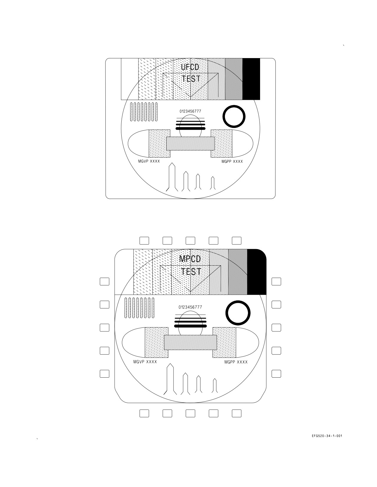
A1-E18GA-NFM-000
Figure 2-66. MPCD and UFCD Test Patterns
I-2-194
ORIGINAL
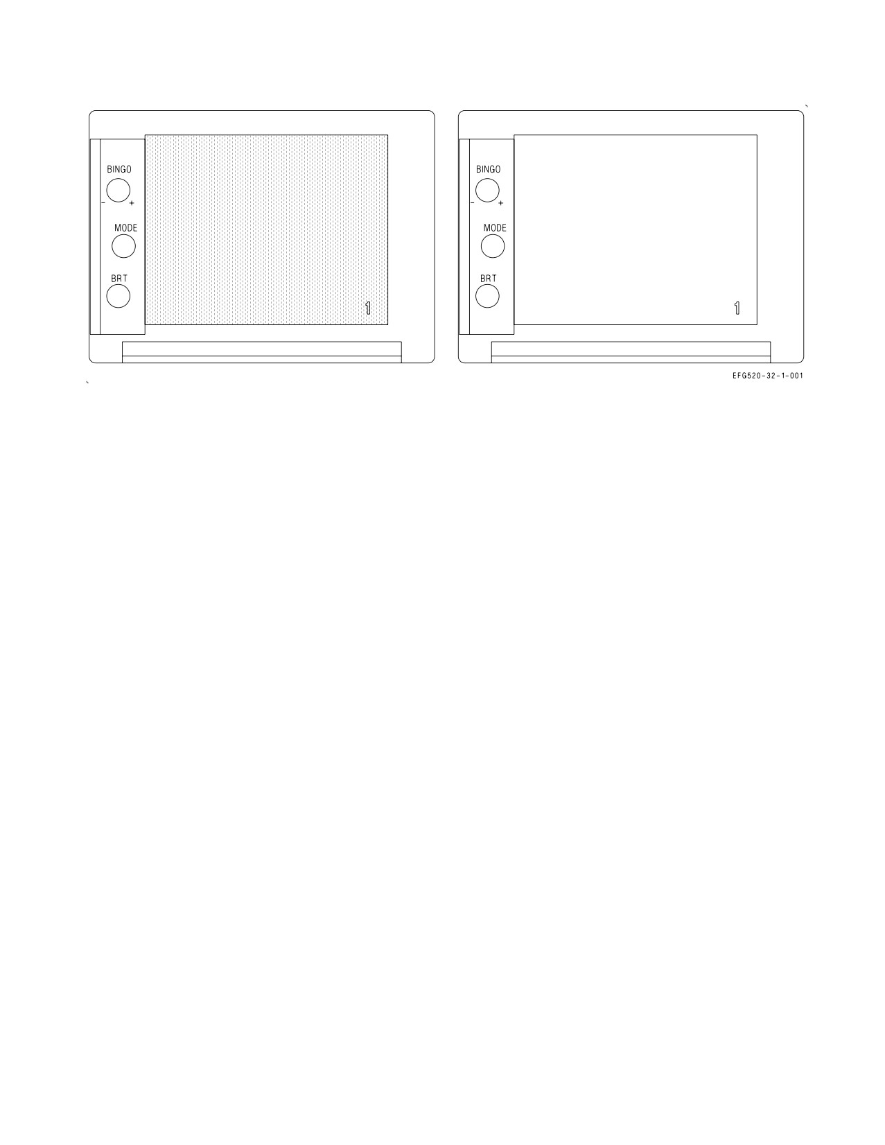
A1-E18GA-NFM-000
Figure 2-67. EFD Test Pattern
2.22.3.8.2 EFD Initiated BIT. The EFD test pattern is initiated by performing EFD BIT using
pushbutton sequence BIT/DISPLAYS/EFD and observing the test pattern display following the
completion of EFD BIT. The EFD test pattern may be observed using the following procedure.
1. Select BIT/DISPLAYS/EFD
2. EFD - observe test display
3. Select STOP or MENU to terminate test pattern
While the test pattern is displayed, selecting the MODE button or pulling the BINGO knob toggles
between the two test patterns displayed in figure 2-67. Rotating the BRT knob does not change display
intensity. Rotating the BINGO knob increments or decrements the number displayed in the lower
right corner from 1 to 12, depending on the rotation direction (clockwise or counterclockwise).
2.22.3.8.3 MPCD Initiated BIT. The MPCD receives information directly from the MC for display
and also processes the information provided for display on the UFCD. The MPCD test pattern is
initiated by doing MPCD BIT using pushbutton sequence BIT/DISPLAYS/MPCD and observing the
test pattern display following the completion of MPCD BIT. The MPCD test pattern may be observed
using the following procedure.
1. Select BIT/DISPLAYS/MPCD
2. MPCD and UFCD - observe test displays
3. Select STOP or MENU to terminate test pattern
The BIT format can be displayed on the MPCD or UFCD during DDI/HUD BIT and on the DDI
during MPCD BIT. The MPCD option initiates BIT on both the cockpit and rear cockpit MPCD.
During MPCD BIT the message MPCD IN TEST is displayed on both the MPCD and UFCD. When
IBIT is completed, the test pattern (figure 2-66) is displayed on both the MPCD and UFCD.
2.22.3.8.4 AMPCD Initiated BIT. The AMPCD executes initiated BIT by selecting ACNTR on the
Display BIT format. When selected, the AMPCD completes IBIT and displays a test pattern on both
I-2-195
ORIGINAL
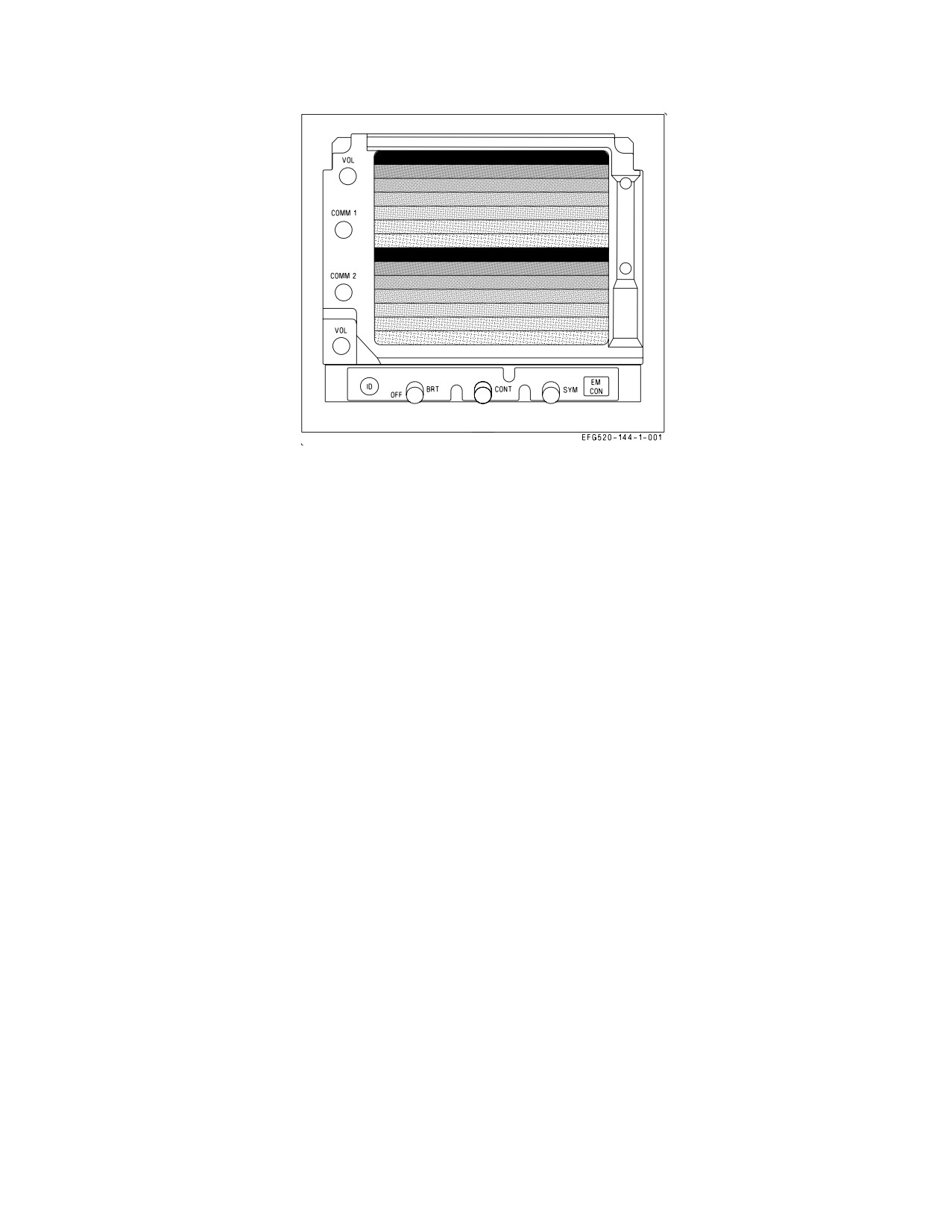
A1-E18GA-NFM-000
Figure 2-68. UFCD Test Pattern
the AMPCD and the aft UFCD. The AMPCD test pattern is the same as the DDI test pattern. The
mission computer removes the IBIT command after 10 seconds to allow viewing of the test pattern on
both displays.
2.22.3.8.5 UFCD Initiated BIT. UFCD test patterns are initiated by selecting BIT/DISPLAYS/
UFCD and observing the test pattern display following the completion of UFCD BIT. The UFCD test
pattern (figure 2-68) is obtained using the following procedure.
1. Select BIT/DISPLAYS/UFCD
2. UFCD - Observe test display
3. Select STOP or MENU to terminate test pattern
When BIT is initiated, UFCD IN TEST is displayed until BIT is completed. Selecting UFCD
initiates BIT on both cockpit displays. The UFCD test pattern is not displayed if IBIT is not initiated
on the UFCD option.
2.22.3.8.6 Radar Altimeter Initiated BIT. If BIT is initiated during RADALT time-in, the status on
the BIT display is NOT READY. If the BIT is initiated after time-in is complete, the display is GO
(indicating the radar altimeter is operating correctly), RESTRT (the BIT was not completed within
the design time limits), or DEGD (a WRA fail signal exists).
2.22.3.8.7 STOP Button. The STOP button allows the aircrew to stop initiated BIT at any time. BIT
is also stopped by pressing MENU, although MENU is not available with the DSPL/EPI/EFD/UFCD
BIT test pattern displayed. When the STOP (or MENU) button is pressed, any test in progress stops
and the equipment returns to normal operation. Exceptions to this are the radar and SMS power-on
BIT and the COMM 1/2, D/L, and TACAN BIT. The radar and SMS power-on BIT cannot be
terminated and indicate SF TEST when the MC detects the system is in BIT without having been
commanded to do so. The same is true of the COMM 1/2, D/L, and TACAN equipment which does a
canned non-interruptable BIT sequence. The mission computer terminates initiated BIT for any
equipment that it determines has taken too long to complete the test.
I-2-196
ORIGINAL
A1-E18GA-NFM-000
2.22.3.9 Hydro-mechanical (HYDRO MECH) Initiated BIT. With SELBIT boxed on the top level
BIT format, selecting HYDRO MECH initiates ECS BIT if aircraft is WonW.
FADEC status is also provided on the HYDRO MECH display by L and R ENG A and B status
indications.
2.22.3.10 BLIN Codes. BIT Logic INspection (BLIN) codes are octal readouts identifying FCS
failures and can be read from the FCS status display. The following procedures may be used to display
and record BLIN codes. Channel 1 BLIN codes are displayed. Pressing the BLIN button displays the
next channel (1, 2, 3 and 4) BLIN codes.
1. On DDI - PRESS MENU-SUPT/FCS/BLIN
2. DDI BLIN codes - RECORD BY CHANNEL
3. Press BLIN button to view next channel BLIN codes
2.22.4 Non-Avionic BIT. Non-Avionic BIT is implemented in selected hydro-mechanical subsystems
primarily for the purpose of displaying subsystem status in the cockpit(s) (cautions and advisories)
and/or providing fault detection and fault isolation information for maintenance personnel. This status
data is provided to the status monitoring displays by the signal data computer which interfaces with
the following hydro-mechanical areas:
1. Engine/Secondary Power
2. Electrical
3. Hydraulics and landing/arresting gear
4. Fuel
5. Environmental control system and liquid cooling system
6. Controls/mechanisms/miscellaneous
The hydraulic system pressure cautions are interfaced directly by both mission computers, providing
redundancy for safety of flight.
2.22.4.1 Equipment Status Displays. NABIT cautions and advisories are displayed in the same
manner as avionics cautions and advisories.
2.22.5 Status Monitoring Backup. MC2 provides backup status monitoring if MC1 fails. It provides
an MC1 caution on the DDI indicating that MC1 has failed.
NOTE
If MC1 fails, all DDI cautions and advisories are available.
2.22.6 Non-BIT Status. Equipment status derived by means other than BIT include DDI configu-
ration display ID numbers and INS terminal data.
2.22.6.1 CONFIG Display Country ID Code. The country identifier code USN is displayed under the
CONFIG legend.
I-2-197
ORIGINAL

A1-E18GA-NFM-000
Figure 2-69. CONFIG Display (Sample)
2.22.6.2 CONFIG Display. The ID numbers of the current operational flight program (OFP) loads for
the radar, stores management system, CLC, INS, mission computers, communication system control,
flight control computer, HMD, SDC, MU, LDT, DMC, MPCD, DDI, EW equipment, DFIRS,
FADECs, and ECS controller can be determined by selecting the configuration display (see figure
2-69). The configuration display is selected by the following procedure:
1. Select BIT from the SUPT MENU.
2. Select CONFIG.
With the configuration display selected, the current ID numbers are displayed to the right of the
equipment acronym. Refer to figure 2-69 for an example.
2.22.6.2.1 MC CONFIG Caution. An MC CONFIG caution indicates MC1 and MC2 OFP loads are
incompatible.
2.22.6.2.2 S/W CONFIG Caution. With the exception of JHMCS, a S/W CONFIG caution indicates
MC1 and MC2 OFP loads are not concurrent releases (incompatible) or an avionic equipment
processor OFP is incompatible with MC OFPs. The incompatible OFP(s) are indicated by a line drawn
through the OFP ident. If the MC OFPs are incompatible a line is drawn through both MC OFP idents.
For JHMCS, a S/W CONFIG caution and a line through the HMD S/W configuration line on the
configuration display indicates a mismatch in the BUNO in the Magnetic Compensation Data file and
the BUNO in the MC, or failure to load the initialization file into the EU.
2.22.6.2.3 OVRD Button. The override option allows the pilot to override the software configuration
logic when the software country ID codes do not agree with the aircraft country ID codes.
I-2-198
ORIGINAL
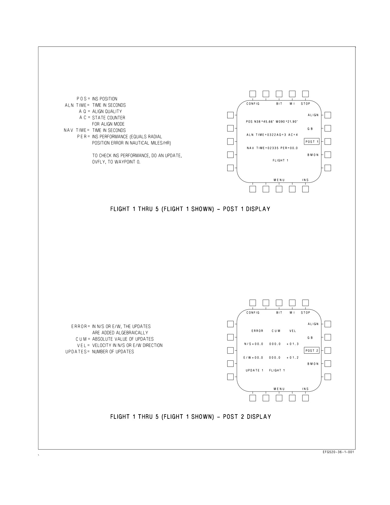
A1-E18GA-NFM-000
Figure 2-70. INS Postflight Data Display
I-2-199
ORIGINAL
A1-E18GA-NFM-000
2.22.6.4 INS Terminal Data. INS terminal data can be obtained if at least one update has been
performed after flight with the parking brake on. Terminal data is displayed by selecting the following
options in sequence: MENU, BIT, MAINT, INS, and POST. Note the PER (performance error rate)
and navigation time on the FLIGHT 1, POST 1 display (see figure 2-70). Select the POST option again
and note the velocity on the FLIGHT 1, POST 2 display. Turn the INS mode selector knob to OFF.
With GPS operating, if the aircraft is flown with IAF selected, the performance error rate does not
include the time flown in the AINS mode.
2.23 JOINT HELMET MOUNTED CUEING SYSTEM (JHMCS)
The JHMCS allows the aircrew to target and employ existing SRMs and High Off-Boresight
(HOBS) weapons, such as the AIM-9X, and cue the radar, and other sensors. When using JHMCS to
employ HOBS weapons, the aircrew can slave/acquire and shoot targets beyond the gimbal limits of the
aircraft radar and designate ground targets. The main display provides a monocular 20° field of view
that is visible in front of the pilot’s right eye.
The main components of the JHMCS include the helmet mounted displays, electronics unit,
HMD/AHMD off/brightness controls, aft cockpit Boresight Reference Unit (BRU), and cockpit units,
magnetic transmitter units, and seat position sensors in each cockpit. The JHMCS aircraft-integrated
components can be flown with or without the helmet system.
Increased weight and forward CG of the helmet will increase neck strain
during high or sustained g flight maneuvers.
NOTE
All aircrew shall receive simulator or dedicated ground training on
JHMCS helmet controls and displays prior to flight with JHMCS.
2.23.1 Helmet Mounted Display (HMD)/Aft Helmet Mounted Display (AHMD). Each HMD consists
of the helmet, Helmet Display Unit (HDU), Helmet-Vehicle Interface (HVI), and a universal connector
which connects the HDU to the helmet.
2.23.1.1 Helmet Display Unit (HDU). The HDU includes a CRT, Magnetic Receiver Unit (MRU),
camera, auto-brightness circuitry, uplook reticles, and visor. Aircrew can remove the HDU and
configure the helmet to accommodate the AN/AVS-9 night vision goggle system.
Make sure the HMD OFF/BRIGHTNESS switch is OFF before removing the HDU, and store the
HDU in the JHMCS stowage bag on the right bulkhead.
To prevent damage to the HDU, do not expose the HDU to a temperature
exceeding 50°C (122°F) operationally or in storage.
2.23.1.2 Helmet-Vehicle Interface (HVI) Connectors. The HDU is connected to the aircraft by the
HVI, which consists of three connectors. These connectors are the Quick Disconnect Connector (QDC),
In-Line Release Connector (IRC), and Helmet Release Connector (HRC). The Upper HVI is the
I-2-200
ORIGINAL
A1-E18GA-NFM-000
portion of the HVI from the helmet to the QDC. The lower HVI is the portion of the HVI that is
installed in the aircraft.
The Upper HVI is routed under the survival vest (if worn) through the JHMCS bundle flue on the
Torso Harness. The QDC is seated in a Quick Mounting Bracket (QMB) attached to the lower left hand
leg strap of the Torso Harness. See figure 2-71.
The JHMCS Upper HVI (UHVI) must be properly routed through the
JHMCS bundle flue under the survival vest and the QDC secured in the
QMB to ensure that no entanglement exists with the oxygen hose.
Misrouting of the JHMCS UHVI may allow the QDC to rub against the
oxygen hose disconnect causing unintentional oxygen/communications
disconnect in-flight.
The QDC is the primary disconnect for ejection, and both normal and emergency ground egress. The
QDC can be manually disconnected for normal egress by pushing the plunger button on top of the QDC
and separating the top half. During an ejection or emergency egress the QDC is disconnected via the
QDC reset mounted lanyard when a force of 18 to 25 pounds is applied. When the QDC is not
connected, the aircraft QDC should be properly stowed in its receptacle. When the QDC is not properly
connected and the system is on, an HMD/AHMD advisory is generated.
The JHMCS QDC must be properly attached to the aircrew torso harness
quick mounting bracket to avoid possible death or severe injury during
ejection.
• Low voltage is present on the exposed QDC pins when the front HMD
control knob and/or the rear cockpit AHMD brightness control knobs
are not in OFF. To prevent a minor electrical shock from contact with
exposed pins, ensure the HMD control or AHMD brightness control
knobs are OFF whenever the QDC is disconnected and connected.
• To prevent damage to the QDC and aircraft components, ensure the
aircraft Lower HVI is properly stowed in its receptacle when in use.
NOTE
Ambient cockpit temperatures at or below
0°C (32°F) may cause
inadvertent HMD/AHMD advisories during preflight. Warming of the
QDC and quick mount bracket should remove the failure indication if
temperature is the cause.
The IRC is a back up disconnect which functions in the event of QDC failure. The IRC is attached
to the left aft console and requires a force of 100 ± 20 pounds to disconnect.
I-2-201
ORIGINAL
A1-E18GA-NFM-000
Figure 2-71. JHMCS Upper HVI Routing
I-2-202
ORIGINAL
A1-E18GA-NFM-000
The HRC allows the cable to disconnect should the helmet be lost during ejection. The HRC requires
a force of 100 ± 20 pounds to disconnect.
2.23.2 Electronics Unit (EU). The EU contains the main system CPU, LOS module, graphics
processors and display drive, and low voltage power supply. The CPU controls system bus interfacing,
display list generation, BIT, and other system functions. The LOS module calculates helmet LOS while
the graphics processor and display drive processes the display list and generates the helmet display. It
is located in the rear cockpit.
2.23.3 Cockpit Unit (CU). The CU contains the system high voltage power supply for helmet
displays. Both CUs are located in the rear cockpit.
2.23.4 Magnetic Transmitter Unit (MTU). The MTU is used to generate a magnetic field used to
determine HMD/AHMD position/orientation. It is mounted on the canopy frame aft of the pilot/
EWO’s left shoulder.
The MTU is energized when the HMD/AHMD is turned on. Warm-up time for the MTU is 15 to 20
minutes. System accuracy may drift up to 0.5° if the HMD/AHMD is aligned before MTU warm-up
is completed. An additional 5 to 10 minutes should be added to the MTU warm-up time if operating
in extremely cold temperatures (e.g., -40°C).
NOTE
To maintain system accuracy, run initial HMD/AHMD alignment, or
an additional HMD/AHMD alignment, after system is warmed-up.
2.23.5 Boresight Reference Unit (BRU). The BRU is located on top of the rear cockpit instrument
blast shield and dust cover. The BRU provides a reference cross inside the BRU to permit coarse and
fine alignment of the AHMD to the aircraft reference. See Figure 2-72.
2.23.6 Seat Position Sensor (SPS). The SPS is a linear potentiometer which indicates ejection seat
height to the JHMCS. It is mounted to the aft right side of the ejection seat. This seat position
information allows the JHMCS to compensate for disruption of the magnetic field in the cockpit as the
metal in the seat changes position when the seat is raised or lowered.
2.23.7 HMD/AHMD Off/Brightness Control. The front cockpit HMD off/brightness control is
located on the spin recovery panel. This rotary knob removes and applies power to the HMD, and
adjusts helmet CRT display brightness.
A BRU/HMD stacked rotary knob, located on the aft cockpit INTR LT control panel, controls the
aft Boresight Reference Unit (BRU)/HMD brightness. This rotary knob removes and applies power to
the BRU and AHMD, and adjusts helmet CRT display brightness. See figure 2-73.
2.23.8 HMD Video Recording. VTR selector switches located on the forward and aft CVRS Control
panels allow selection of HMD video recording.
2.23.9 Cautions/Advisories. When the BUNO in the Magnetic Compensation Data file does not
match the BUNO in the MC, or if the MC fails to download the initialization file to the EU, the MC
sets the SW CONFIG caution and displays a line through the HMD S/W configuration line on the
configuration display. An HMD/AHMD advisory is reported if the QDC is not properly secured to
Quick Mounting Bracket (QMB) or is disconnected, or the coarse alignment is invalid or has not been
performed.
I-2-203
ORIGINAL
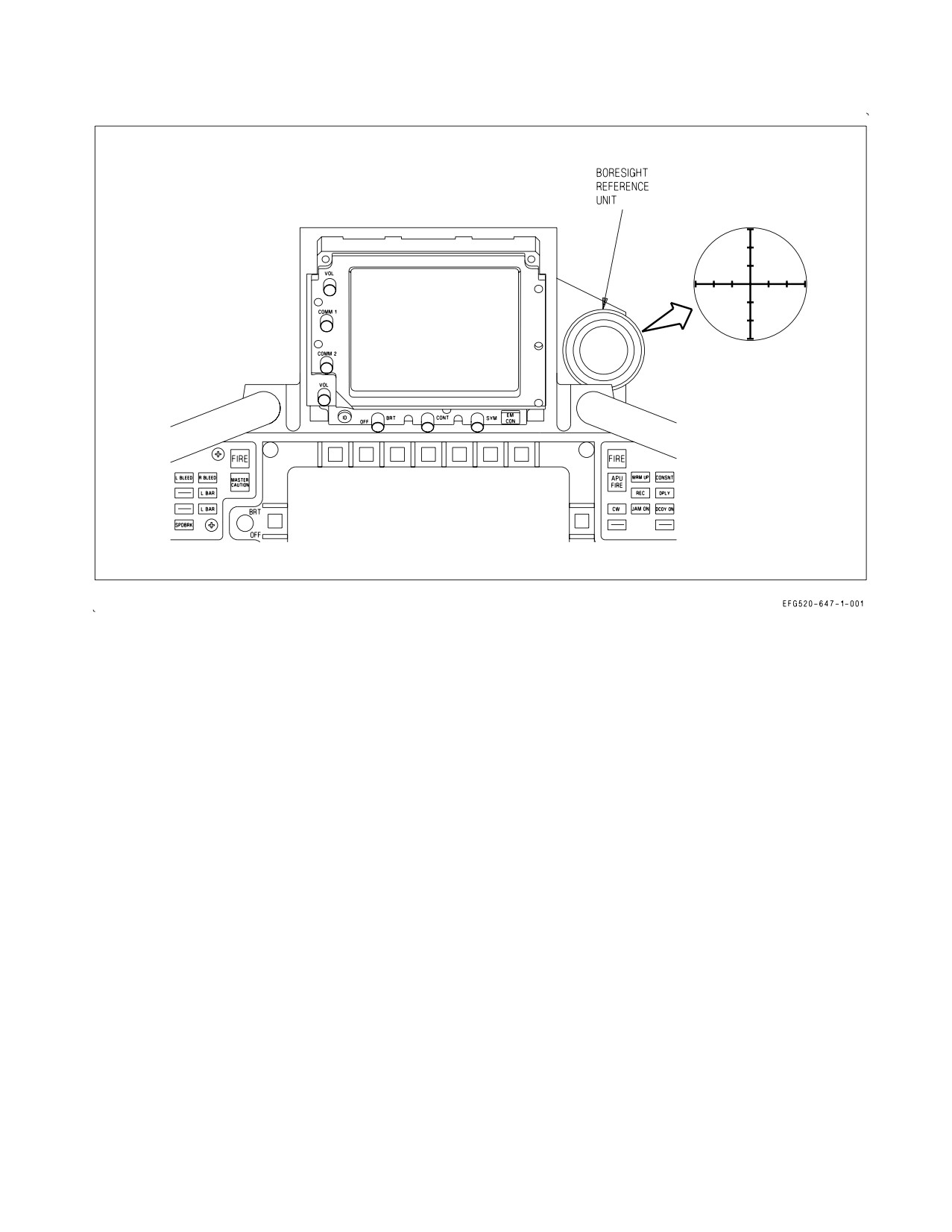
A1-E18GA-NFM-000
Figure 2-72. Boresight Reference Unit
2.23.10 Configuration Check. When the JHMCS system is turned on, the MC provides the EU with
the aircraft make, model, and tail number.
2.23.11 Built-In Test (BIT). The JHMCS BIT system includes automated start-up BIT (SBIT) and
initiated BIT (IBIT), and displays a BIT status message. See figure 2-74 for the DISPLAYS BIT
sublevel display.
2.23.11.1 Start-up BIT (SBIT). When the HMD system is turned on, SBIT starts automatically and
the internal software is loaded in the EU. SBIT cannot be stopped until it is completed. PBIT GO or
DEGD, as appropriate, is displayed when SBIT is completed.
2.23.11.2 Initiated BIT (IBIT). When the HMD (PB 11) option is selected in either cockpit on the
BIT DISPLAYS sublevel display, ENTERING IBIT flashes on both HMDs, and an initiated BIT is
performed on both helmets. When IBIT is complete a series of four test patterns, which are
automatically changed each second, are displayed on the HMD/AHMD. See figure 2-75. The test
patterns are displayed until the STOP (PB 10) option is selected. If the ALL (PB 6) option is selected,
IBIT and HMD test pattern are performed.
I-2-204
ORIGINAL
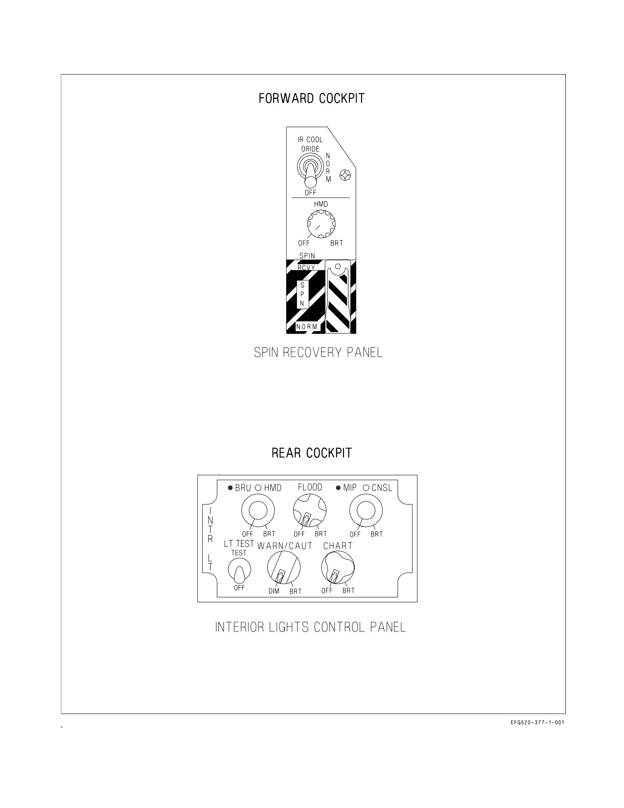
A1-E18GA-NFM-000
Figure 2-73. HMD Controls
I-2-205
ORIGINAL
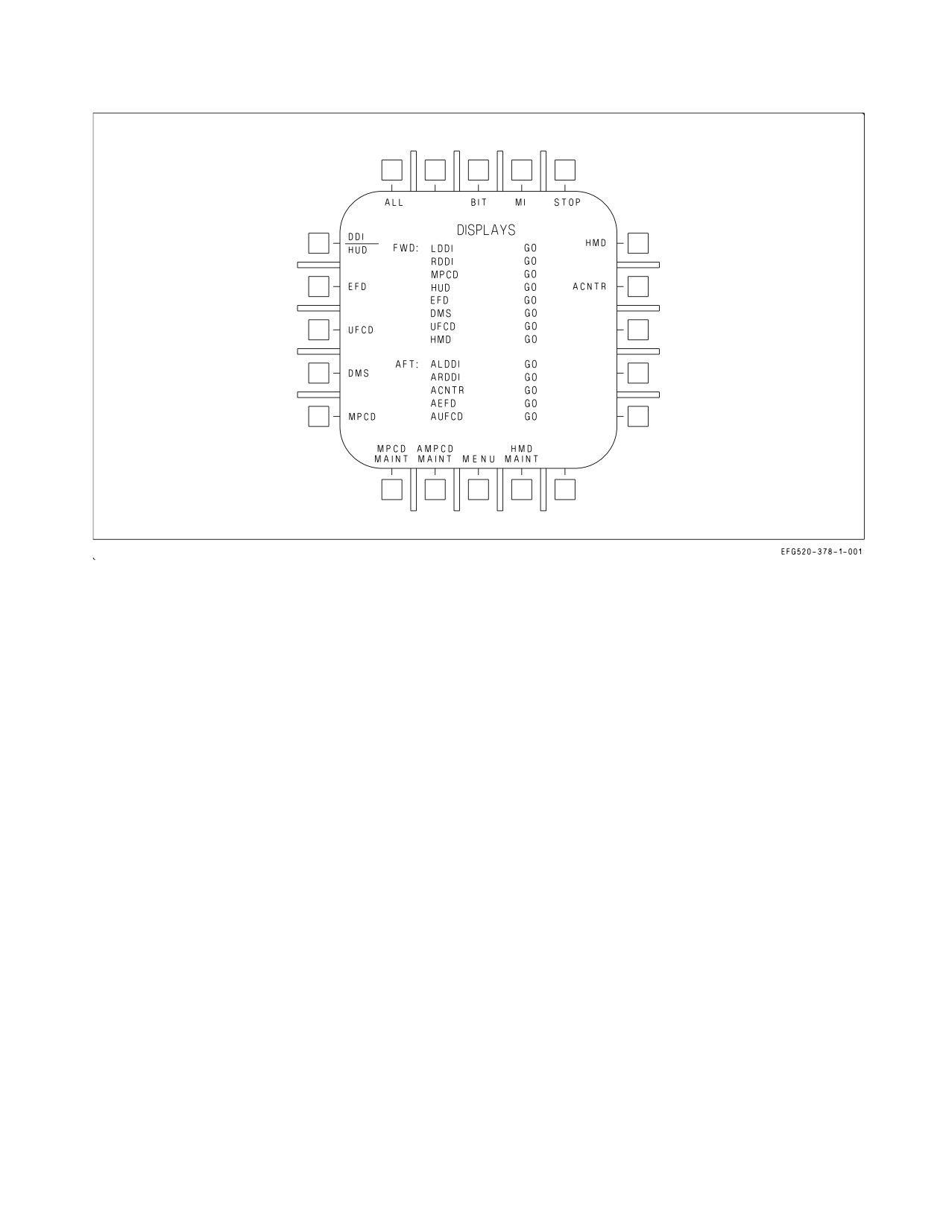
A1-E18GA-NFM-000
Figure 2-74. Displays BIT Sublevel
I-2-206
ORIGINAL
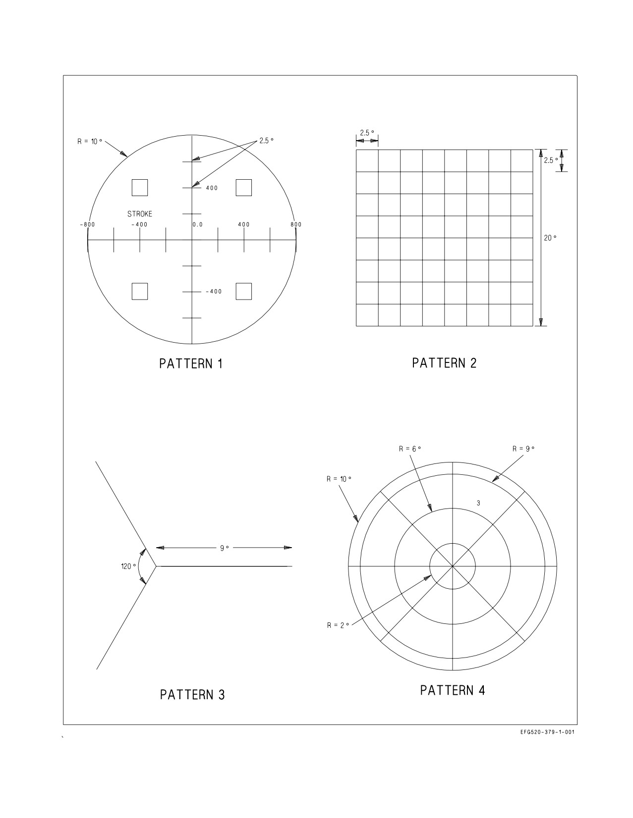
A1-E18GA-NFM-000
Figure 2-75. HMD/AHMD Test Patterns
I-2-207
ORIGINAL
A1-E18GA-NFM-000
2.23.10.3 Status Messages. Refer to the following for status messages and associated descriptions:
MESSAGE
STATUS
DESCRIPTION
MUX FAIL
Equipment ready discrete is high but the EU is
not communicating on either MUX bus to the
MC
NOT RDY
Equipment ready discrete is low and the EU is
not communicating on either MUX bus to the
MC
IN TEST
Initiated BIT in progress
RESTRT
Re-initiate BIT, EU did not respond to the
IBIT command or IBIT did not complete
within 30 seconds
DEGD
EU has detected a failure which degrades sys-
tem performance
OVRHT
EU has reported a component as overheated
DEGD+OVRHT
EU has detected a failure and EU has reported
a component as overheated
GO
EU responded with no failures.
OP GO
EU has detected a failure which does not de-
grade system performance
PBIT GO
EU responded with no failures prior to per-
forming IBIT
2.23.10.4 BIT Recording On The Memory Unit. The MC records any failure or degrade reported by
the EU to the memory unit for fault reporting and isolation.
2.23.10.5 Overheat Condition. The system has the capability to detect an equipment overheat
condition. When an overheat condition is detected the system is automatically shut down to prevent
equipment damage.
2.23.11 HMD Maintenance. The HMD MAINT option is displayed at PB 17 of the DISPLAYS BIT
sublevel display. See figure 2-76. Pressing PB 17 boxes the option and displays STEP PAGE and STEP
LINE at PBs 14 and 15 respectively. Selecting either STEP PAGE or STEP LINE sends the
appropriate BIT data to the EU. With HMD MAINT boxed, pressing PB 17 removes the STEP PAGE
and STEP LINE displays and unboxes the HMD MAINT option.
I-2-208
ORIGINAL
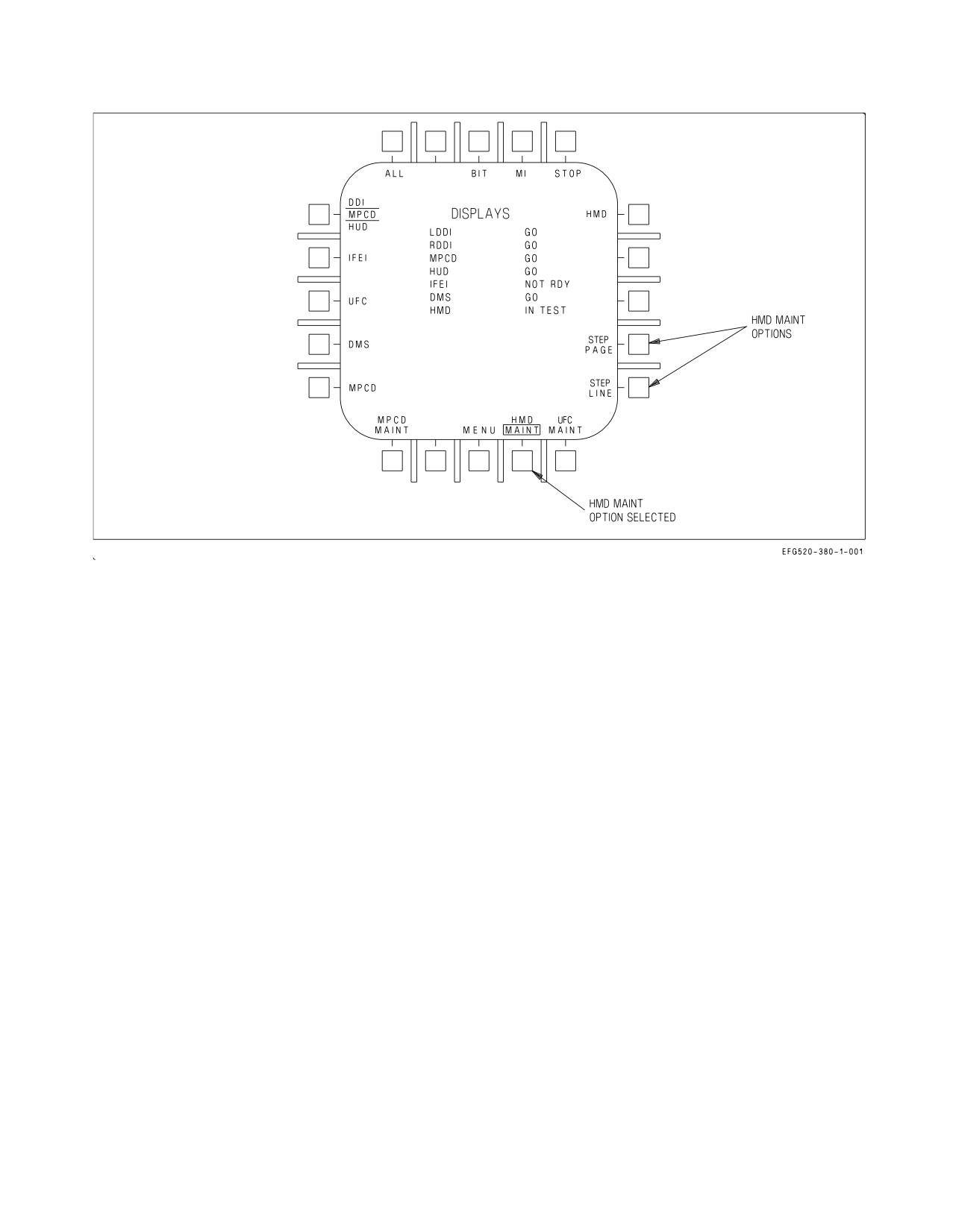
A1-E18GA-NFM-000
Figure 2-76. HMD Error Log Display
2.23.12 JHMCS Alignment. The JHMCS must be boresighted (aligned) with the aircraft prior to
every flight. Selecting the ALIGN (PB 20) option on the HMD format boxes ALIGN, selects coarse
alignment mode, and displays the FINE (PB 1) alignment option after the coarse align function is
complete. See figures 2-77 and 2-78.
The forward and aft helmets are aligned independently. The ALIGN option on the HMD format at
PB 20, when selected from the aft cockpit, initiates aft HMD align. When in aft coarse or fine align
mode the MC assigns the right AFT hand controller Designator Control (DC) switch to the HMD
format. Both forward and aft HMD alignments function the same with the exception that the aft
helmet is aligned to the BRU mounted on the aft main instrument panel.
2.23.12.1 Coarse Alignment. An alignment cross is displayed on the HUD and in the HMD. See
figure 2-77. The pilot moves the HMD to superimpose the alignment cross on the HMD over the
alignment cross on the HUD. Once aligned, the cage/uncage switch is pressed and held until ALIGN
OK is displayed in the HMD. When coarse alignment is complete, fine alignment is automatically
selected. Fine alignment (PB 1) can also be manually selected.
To perform a coarse align the EWO moves the HMD alignment cross on the HMD over the BRU
alignment reticle, figure 2-77, sheet 2. Once the crosses are aligned the EWO presses and holds the
undesignate switch on the right hand controller until an ALIGN OK status is provided on the HMD.
When the coarse alignment is complete, fine alignment is automatically selected. Fine alignment (PB
1) can also be manually selected.
I-2-209
ORIGINAL
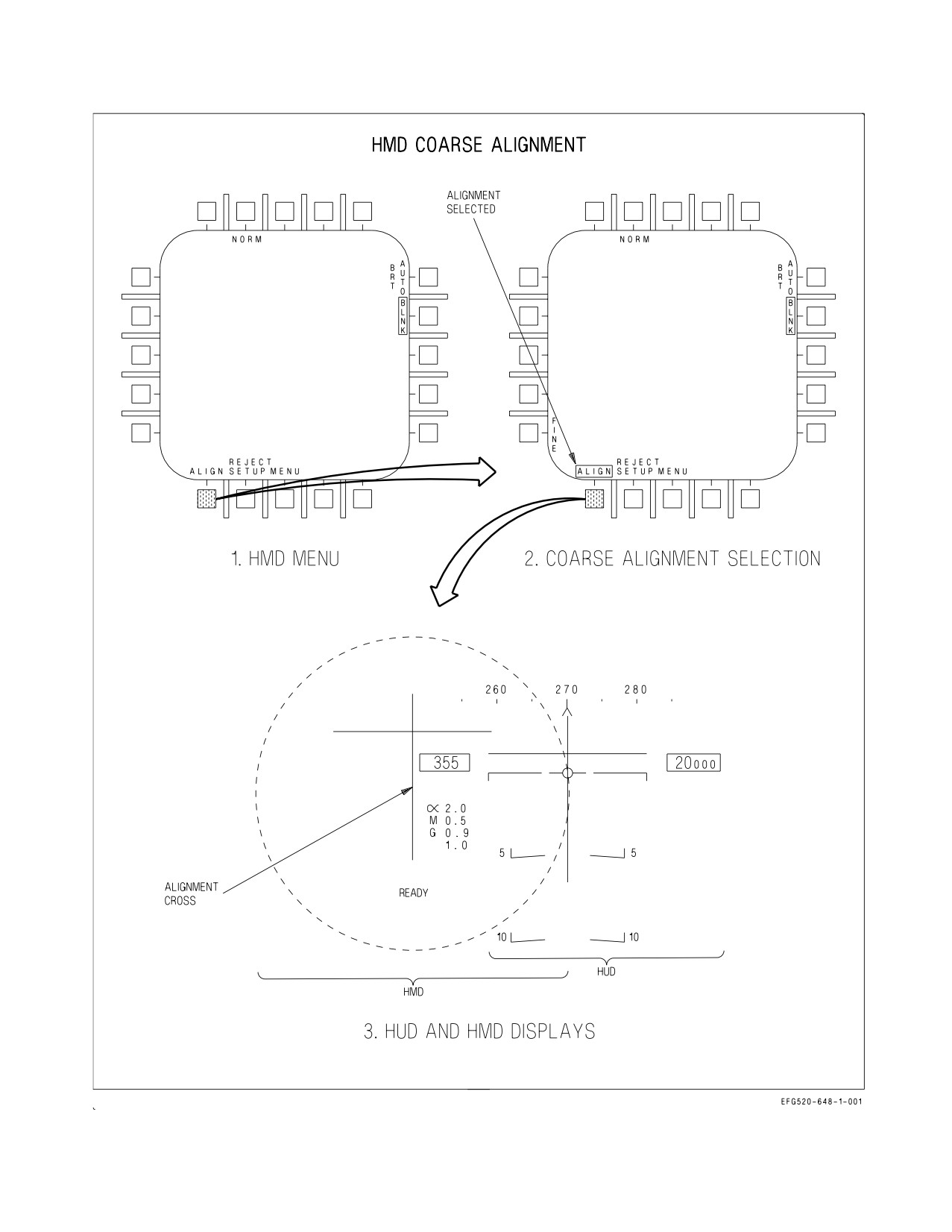
A1-E18GA-NFM-000
Figure 2-77. Coarse Alignment (Sheet 1 of 2)
I-2-210
ORIGINAL
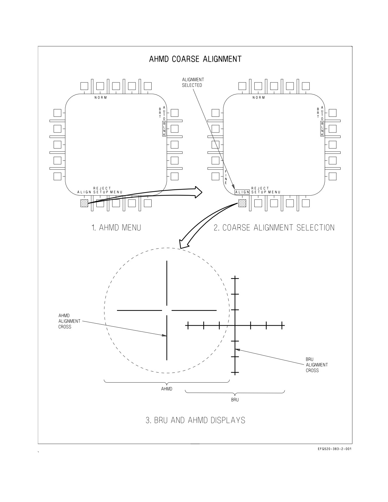
A1-E18GA-NFM-000
j
Figure 2-77. Coarse Alignment (Sheet 2 of 2)
I-2-211
ORIGINAL
A1-E18GA-NFM-000
2.23.12.2 FINE Alignment. When the FINE (PB 1) option is boxed an alignment cross is displayed
in the HUD and two alignment crosses are displayed on the HMD in the vicinity of the HUD alignment
cross, figure 2-78, sheet 1. The display indicates which axis is being aligned. If azimuth and elevation
is indicated (FA DXDY), the pilot moves the TDC either left or right to align in azimuth, up or down
to align in elevation. The pilot presses and releases the cage/uncage switch when satisfied with the
quality of the azimuth and elevation alignment. This causes the display to toggle to roll alignment
mode. With the roll axis indicated (FA DROLL), TDC inputs to the left or right are used to rotate the
HMD alignment symbols to align with the HUD alignment cross. The pilot presses and releases the
cage/uncage switch when satisfied with the quality of the roll alignment. Pressing and releasing the
cage/uncage switch continues to toggle between these two modes until the pilot deselects FINE to
return to coarse alignment or exits alignment.
Upon entering fine alignment, automatically, or if commanded by the EWO selecting the FINE
option, the EU indicates which axis is being aligned. If the azimuth and elevation axis is indicated, the
EWO uses the DC to move the crosses up/down and left/right to align with the cross displayed on the
BRU, figure 2-78, sheet 2. When satisfied with the alignment, the EWO presses and releases the
undesignate switch on right hand controller at which time the EU automatically switches to roll
alignment. The EWO uses the DC to rotate the cross so that it aligns with the cross displayed on the
BRU. When satisfied with the quality of the alignment the EWO presses and releases undesignate
switch on right hand controller.
2.23.12.3 Alignment Exit. Alignment is exited whenever ALIGN is deselected (unboxed), an A/A
weapon is selected, MENU is selected, TDC priority is reassigned, ACM mode is selected, or the master
mode is changed. This removes the alignment cross from the HUD, removes the FINE option, unboxes
ALIGN, and returns the cage/uncage function to the previously assigned system.
I-2-212
ORIGINAL
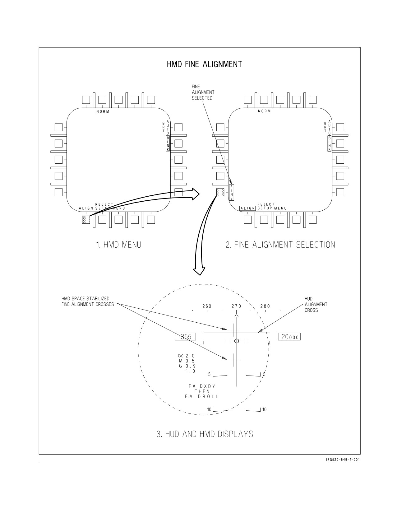
A1-E18GA-NFM-000
Figure 2-78. Fine Alignment (Sheet 1 of 2)
I-2-213
ORIGINAL
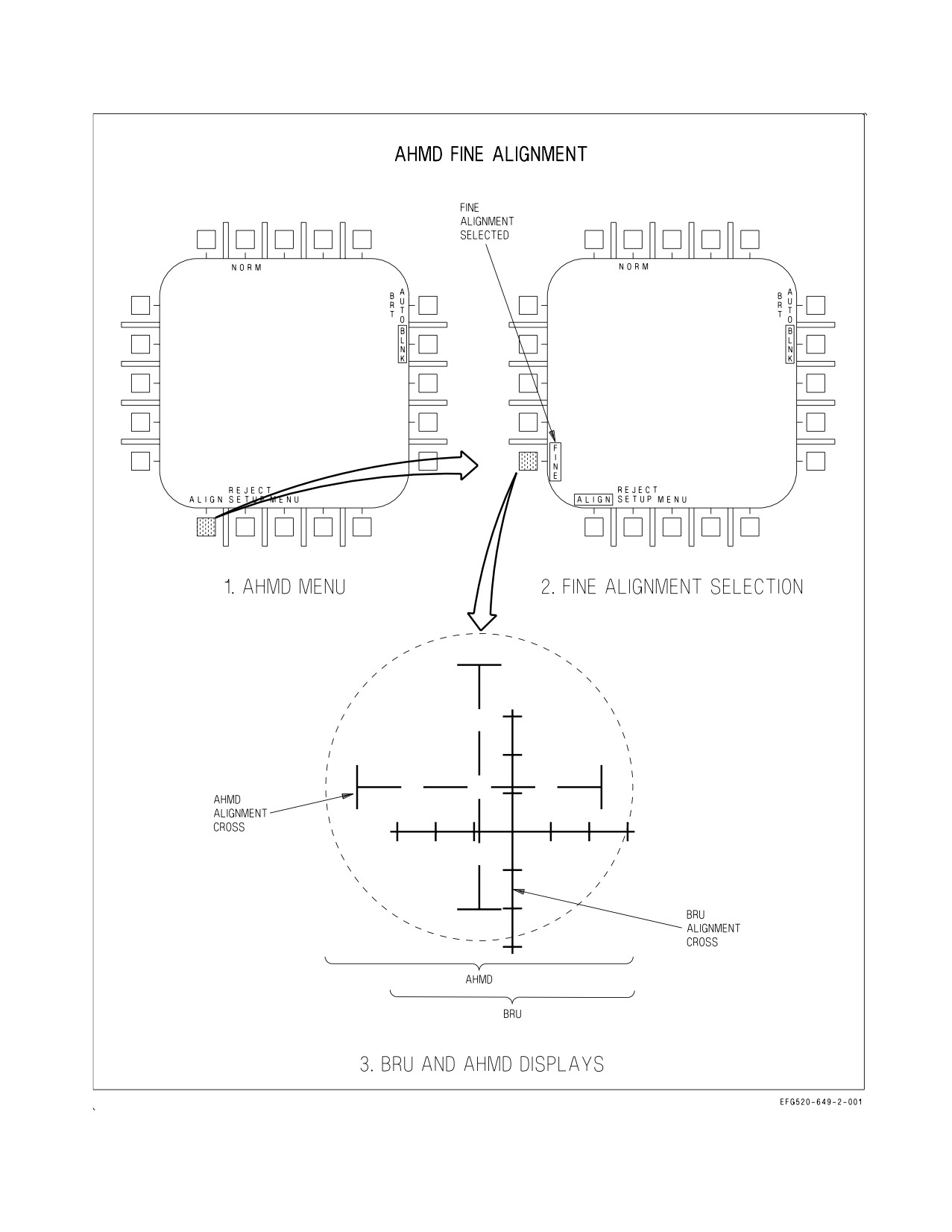
A1-E18GA-NFM-000
Figure 2-78. Fine Alignment (Sheet 2 of 2)
I-2-214
ORIGINAL
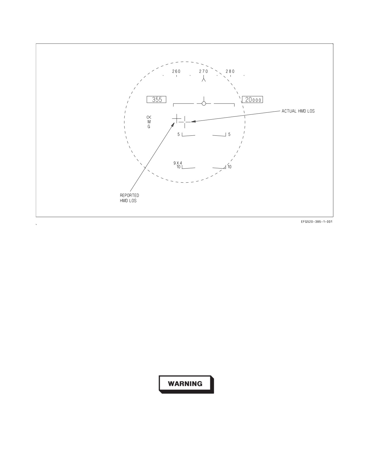
A1-E18GA-NFM-000
Figure 2-79. Alignment Verification
2.23.12.4 Alignment Verification. When the HMD is in normal mode a cross is displayed on the
HUD at the reported HMD LOS. See figure 2-79. If the reported HMD LOS is outside the HUD FOV,
the cross flashes at the HUD FOV limit.
2.23.12.5 HUD Symbology Replicated on the HMD. The HMD layout essentially replicates the
HUD layout. Window locations, format, and occlusion level on the HMD are as identical to the HUD
locations, format, and occlusion level as practical.
2.23.12.6 HUD Symbology Not Replicated on the HMD. Some of the symbology on the HUD is
either not required on the HMD or would be disorienting if the information was presented. The
following paragraphs describe the items on the HUD which are not replicated on the HMD.
2.23.12.7 Aircraft Attitude Data. Some HUD data only provides the pilot usable information when
presented along the aircraft boresight. HMD data is not always presented along the aircraft boresight.
For this reason, the aircraft pitch ladder, horizon bar, water line indicator, and velocity vector are not
displayed on the HMD/AHMD.
The HMD/AHMD does not provide adequate attitude information and
should not be used as a primary flight instrument.
I-2-215
ORIGINAL
A1-E18GA-NFM-000
2.23.12.8 Ground Proximity Warning System. In addition to aircraft attitude data, the HMD/
AHMD does not replicate the Ground Proximity Warning System (GPWS) arrow. However, when the
GPWS is activated, ALTITUDE is displayed in the HARM window of the HMD/AHMD.
2.23.13 Navigation Master Mode. If present, the MC displays the A/A L&S with the TD box and its
associated TLL, or the A/G designation with the TD diamond and its associated TLL. However, if both
the A/A L&S and the A/G designation are present, only the A/A L&S TLL is displayed.
2.23.13.1 NAV Master Mode TDC Priority. When in NAV master mode, the TDC/DC can be
assigned priority to the HMD/AHMD by pressing the castle switch or DCA forward. This is indicated
by the display of an open aiming cross with a dot in the center. If TDC/DC priority is removed from
the HMD/AHMD, the dot is removed from the center of the aiming cross.
2.23.14 Mission Computer Failure. If either MC fails, no symbology is displayed on either helmet
and the remaining operating MC functions as if no helmets are installed.
2.23.15 Electronic Unit Failure. In the event of an EU failure which does not allow any symbology
to be displayed on the HMD, the MC provides the radar boresight symbol and AIM-9 FOV symbol on
the HUD. If the LOS is still valid, the MC continues to slave the radar or AIM-9 to the HMD LOS. If
the LOS is invalid, the MC reverts to the current no-helmet mechanization for slaving weapons,
sensors, and HOTAS.
2.23.16 Helmet Tracker Failure. If the EU reports that the helmet tracker is failed, or the helmet
LOS is no longer valid, the MC discontinues slaving sensors and weapons to the HMD LOS. The MC
replaces aircraft boresight for the helmet LOS to the radar and AIM-9. Additionally, the MC removes
any item from the HMD which is tied to the HMD LOS. The radar boresight and AIM-9 FOV symbol
are restored to the HUD. The MC also restores VACQ mode and the HOTAS function to access the
VACQ function. The MC continues to display information on the HMD which is not tied to the HMD
LOS.
If the EU reports the aft helmet tracker is failed or the aft helmet LOS is no longer valid, the MC
discontinues slaving sensors and weapons to the aft HMD LOS and reverts to non-helmet mechani-
zation in the aft cockpit. Additionally, the MC removes any item from the aft HMD that is tied to the
aft HMD LOS and continues to display information on the aft HMD that is not tied to the aft HMD
LOS.
2.23.17 Helmet Not Installed. When the MC determines that the HMD is not on, or the EU is not
responding to the MC via the mux bus, the MC reverts to the current no-helmet mechanization for
slaving weapons, sensors, HOTAS, and HUD display.
When the MC determines that the AHMD is not on, the MC reverts to the current aft seat
mechanization for slaving weapons and sensors, and HOTAS. If the forward HMD is installed and
operating the forward helmet functions as described in previous paragraphs. If the EU is not
communicating, both cockpits revert to no helmet status.
I-2-216
ORIGINAL