EA-18G. FLIGHT MANUAL (2008) - page 3
A1-E18GA-NFM-000
2.10.12.1 Spin Recovery Displays. When the spin recovery system detects an upright left spin or an
inverted right spin, a left spin arrow appears on both DDIs to indicate the proper direction of the
anti-spin lateral stick input.
SPIN MODE
STICK
LEFT
When the spin recovery system detects an upright right spin or an inverted left spin, a right spin
arrow appears on both DDIs to indicate the proper direction of the anti-spin lateral stick input.
SPIN MODE
STICK
RIGHT
When lateral stick is placed in the direction of the arrow, the word ″ENGAGED″ appears below the
words ″SPIN MODE″ on both DDIs to indicate that ASRM has been successfully engaged.
SPIN MODE
is replaced by
SPIN MODE
ENGAGED
When the SPIN MODE formats appear on the DDIs, airspeed is always displayed in the upper left
corner, with altitude in the upper right and AOA in the lower center. See figure 2-25.
2.10.12.2 SPIN Switch. The SPIN switch is located on the right side of the main instrument panel.
The switch is guarded to prevent actuation. The SPIN switch was designed to allow for activation of
a manual spin recovery mode (MSRM). However, with all CAS feedback and control surface
interconnects removed, flight in MSRM will result in a departure and, once departed, will prevent
departure and/or spin recovery. SPIN arrow logic and ASRM functionality have been optimized and
thoroughly flight tested to produce accurate spin mode detection and positive spin recovery.
RCVY
Prohibited.
NORM
ASRM available when a spin is detected.
Selection of manual spin recovery mode (SPIN switch in RCVY) seri-
ously degrades controllability, will prevent recovery from any departure
or spin, and is prohibited.
2.10.13 Stabilator Failure Control Law Reconfiguration. Stabilator reconfiguration consists of
additional control laws which augment baseline CAS control laws to compensate for the complete loss
I-2-77
ORIGINAL

A1-E18GA-NFM-000
of a single stabilator. Stabilator reconfiguration is automatically enabled following the detection of a
complete stabilator failure (3 or more FCS Xs in a single stabilator or a dual HYD circuit failure - HYD
1B/2A or 1A/2B). If hydraulics are intact, the failed stabilator is driven to 2° TEU and locked.
Following a dual HYD circuit failure, the failed stabilator must be driven to the locked position by
aiding airloads. If unaiding airloads are applied, actuator mechanization prevents the stabilator from
moving further away from the locked position.
The reconfigured control laws are designed to compensate for the loss of the pitch and roll
contribution of the failed stabilator. In the pitch axis, pitch commands to the remaining stabilator are
doubled to produce more pitching moment. With flaps HALF or FULL, rudder toe-in and rudder flare
are also used to aid the pitching moment capability of the remaining stabilator. In the roll axis,
differential stabilator commands are disabled. A stabilator-to-rolling-surface interconnect is used to
compensate for the roll generated by single stabilator movement. With flaps HALF or FULL, this
interconnect is stabilator to aileron. With flaps AUTO, it is stabilator to aileron and differential TEF.
At high airspeed with flaps AUTO, differential LEFs are also used. In the yaw axis, the baseline
differential stabilator portion of the RSRI continues to be used to counter the yaw generated by single
stabilator movement.
2.10.14 GAIN ORIDE. GAIN ORIDE allows the pilot to select a set of fixed CAS gains when an FCS
malfunction prevents normal CAS gain scheduling (e.g., loss of AOA or pitot-static data). With the
GAIN switch in ORIDE, the FCCs use fixed values for speed, altitude, and AOA depending on the
position of the FLAP switch. These fixed gains cause the LEFs, TEFs, and aileron droop to be driven
to the fixed positions shown in figure 2-26. GAIN ORIDE should generally provide acceptable handling
qualities at flight conditions which approximate the fixed gains. At flight conditions that deviate from
the fixed gains, a slight degradation in handling qualities should be expected. Refer to chapter 11 for
details. The aircraft stalls at a lower than nominal AOA since the LEFs are fixed. Transition to or from
the landing configuration should be performed at 180 KCAS. For best results, maintain on-speed AOA
during the approach and landing.
Flight with GAIN ORIDE selected is prohibited above 10° AOA or above 350 KCAS (flaps AUTO),
above 200 KCAS (flaps HALF), or above 190 KCAS (flaps FULL) to ensure control system stability
and to reduce the potential for departure. When GAIN ORIDE is selected, the amber FLAPS light
comes on along with either the CRUIS advisory (flaps AUTO) or the LAND advisory (flaps HALF or
FULL). Alpha tone is disabled in GAIN ORIDE.
Fixed Gains
LEF
TEF
AIL Droop
FLAP Switch
(°LED)
(°TED)
(°TED)
Mach
KTAS
Feet
°AOA
AUTO
5
4
2
0.80
459
39,000
3.5
HALF
21
30
30
0.23
151
500
8.1
8.1
FULL
21
40
40
0.21
139
500
Figure 2-26. GAIN ORIDE Flap Positions and Gain Schedules
I-2-78
ORIGINAL
A1-E18GA-NFM-000
2.10.14.1 GAIN Switch. The GAIN switch, located on the FCS panel on the left console, is used to
select GAIN ORIDE. The switch is guarded in the NORM position to prevent inadvertent actuation.
ORIDE
Selects fixed CAS gains according to FLAP switch position.
NORM
Selects normal CAS gain scheduling.
2.10.15 FCS Failures. The FCS detects failures through three types of BIT: initiated (IBIT), periodic
(PBIT), and maintenance (MBIT). FCS IBIT is performed during Before Taxi Checks to run a
thorough test of the system prior to flight. PBIT is a less thorough test of the FCS and runs
continuously when other BITs are not running. MBIT is typically run by maintenance personnel and
is the most comprehensive test of the FCS.
FCS failures are annunciated by any or all of the following indications: the FCS caution, the FCES
caution light, the ″Flight controls, Flight controls″ voice alert, FCS format Xs, and/or BIT Logic
Inspection (BLIN) codes. FCS format Xs and BLIN codes identify the location and type of failure.
However, not all FCS related components/functions are covered by Xs on the FCS format matrix. For
such components/functions, valid BLIN codes may be the only indication of the location of the failure.
Therefore, until the nature of the failure is determined, BLIN codes that appear without Xs should be
treated with the same level of concern as those that do.
Typically, BLIN codes that have three digits or less are generated by PBIT, e.g., 341. Four digit and
five digit BLIN codes are generated by FCS IBIT, e.g. 4573 and 10165.
2.10.15.1 FCES Caution Light. The Flight Control Electronic Set (FCES) caution light is located on
the lower right caution lights panel. The primary purpose of the FCES caution light is to alert aircrew
of critical FCS related failures when MC1 is failed. When MC1 is failed, the normal DDI FCS related
cautions are not generated and the FCS format is not available for troubleshooting. When MC1 is
operative, the FCES caution light is merely a secondary indication of an FCS related failure. The
specific FCS cautions which also trigger the FCES caution light are listed in figure 2-27.
2.10.15.2 FCS RESET Button. The FCS RESET button is located on the FCS panel on the left
console. This button is used to perform several FCS related functions. Following detection of FCS
related hardware and/or software failures (e.g., FCS Xs and/or BLIN codes), pressing the FCS RESET
button commands a reset of FCC failure detection circuitry. If the FCS related failure was momentary
and no longer exists, an FCS RESET (a) restores the failed actuator/component, (b) removes all FCS
failure indications (FCS caution, FCES caution light, and Xs; preflight BLIN codes only), and (c)
displays the RSET advisory for 10 seconds to indicate a successful reset. If the failure remains (a) the
failed actuator/component is not restored, (b) the FCS failure indications return, and (c) the RSET
advisory is displayed for 10 seconds to indicate an unsuccessful reset. In other words, the FCS
RESET button does not fix a detected failure; it merely allows components to be
restored and failure indications to be removed, if and only if the failure no longer exists.
Prior to takeoff (cycle to WoffW), a successful FCS RESET automatically clears all BLIN codes.
Inflight or post-flight, however, BLIN codes are not automatically cleared with a successful FCS
RESET in order to preserve this data for maintenance troubleshooting. Inflight and post-flight BLIN
codes can be cleared, if desired, by pushing the FCS RESET button simultaneously with the paddle
switch.
Additionally, the FCS RESET button is used in conjunction with the FCS BIT consent switch to
enter the FCS exerciser mode.
I-2-79
ORIGINAL
A1-E18GA-NFM-000
2.10.15.3 FCS Exerciser Mode. The FCS exerciser mode is incorporated to aid hydraulic system
warming during cold weather starts. The exerciser mode allows hydraulic fluid and hydraulic seals to
warm towards normal operating temperatures without making large surface movements. Large surface
movements with a cold hydraulic system can result in hydraulic seal damage, leaks, and loss of fluid.
On the ground, the FCS exerciser mode is initiated by simultaneously holding the FCS BIT consent
switch in the ON position while pressing the FCS RESET button. When initiated, the mode cycles the
stabilators, flaps, ailerons, and rudders through 20% of full travel for 10 cycles in 20 seconds. The
operation can be stopped prior to 20 seconds by pressing the paddle switch.
During cold weather starts, avoid activating any hydraulic actuated system for two minutes after
both engines are online. This allows hydraulic fluid to warm both systems and prevents hydraulic seal
damage and potential hydraulic leaks. If the aircraft has not flown within 4 hours with ambient
temperatures below -18°C (0°F), up to three selections of the FCS exerciser mode may be required in
order to obtain a successful FCS RESET (after the initial 2 minute warmup).
In standard or warm conditions, do not initiate the FCS exerciser mode
multiple times in an attempt to get a successful FCS RESET. In such
conditions, multiple initiations may excessively elevate hydraulic system
temperatures, increasing actuator and hydraulic pump seal wear and
potentially decreasing component life.
2.10.15.4 FCS BIT Consent Switch. The FCS BIT consent switch is located above the right console
beneath the right canopy sill. The switch is used in conjunction with the FCS BIT option or the FCS
RESET button to initiate FCS IBIT or the FCS exerciser mode, respectively. See the FCS Initiated
BIT (IBIT) section at the end of chapter 2 for details.
ON
When held (for at least 2 seconds) during selection of the FCS option, initiates
FCS IBIT. When held during a press of the FCS RESET button, initiates FCS
exerciser mode.
OFF
FCS IBIT and FCS exerciser mode not selected.
2.10.15.5 FCS Related Cautions. FCS related cautions shown in figure 2-27 are described in the
Warning/Caution/Advisory Displays in Part V.
I-2-80
ORIGINAL

A1-E18GA-NFM-000
Associated Cockpit Indications
Caution
″Flight Controls,
Master Caution
Master Caution
Flight Controls″
Light
Tone
FCES Light
Voice Alert
AOA
X
X
X
Air Data
X
X
ATC Fail
X
X
X
AUTO PILOT
X
X
P CAS
X
X
X
R CAS
X
X
X
Y CAS
X
X
X
CHECK TRIM
X
X
CK FLAPS
X
X
FC AIR DAT
X
X
X
FCS
X
X
X
Note
2
FCS HOT
X
Note
1
Note
1
FLAPS OFF
X
X
X
FLAP SCHED
X
X
X
G-LIM 7.5G
X
X
G-LIM OVRD
X
X
HYD 5000
X
X
X
NWS
X
X
X
R-LIM OFF
X
X
RIG
X
S/W CONFIG
X
X
NOTES
1. The FLIGHT COMPUTER HOT, FLIGHT COMPUTER HOT voice alert and FCS HOT light on the
caution lights panel are activated when the FCS HOT caution is set.
2. Also displayed when any aileron, stabilator, or rudder actuator failed off (Xd out and a ″bold X″ over
the surface position on FCS Status Display).
Figure 2-27. FCS Related Cautions and Cockpit Indications
I-2-81
ORIGINAL
A1-E18GA-NFM-000
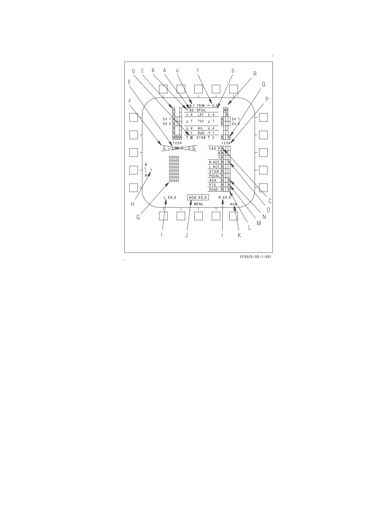
Figure 2-28. FCS Status Display
2.10.16 FCS Status Display. When an FCS failure has occurred, the FCS status display (figure 2-28)
can be used to determine the location and type of failure. The FCS status display is selected by the FCS
option on the SUPT MENU. For FCS components/functions which are displayed in the matrix, an ″X″
is displayed in the failed channel(s) along with a corresponding BLIN code. For FCS components/
functions which are not displayed in the matrix, BLIN codes are the only indication of failure location.
A. Surface Position: In degrees from streamline for all surfaces. Tolerance is ±1° for all surfaces.
B. Surface Arrow: Direction of surface deflection relative to the surface hinge point except for
stabilators. For stabilators, surface arrow indicates trailing edge position.
C. Column of Xs: An entire FCC channel is failed due to a processor fault or loss of power.
D. Bold X across surface position: Surface failed; FCCs are no longer commanding movement of
that surface in any channel.
E. G-LIMX.XG: ″X.X″ is the current Nz REF value as calculated by the MC. This value is
decremented if in the transonic g-bucket. INVALID is displayed in this position if the interface
between FCC CH 1, FCC CH 3, and the MC is invalid. In this case, all data on the display is invalid.
During FCS IBIT, G-LIM0.0G is displayed in this position.
F. Bold X over G-LIMX.XG: Nz REF data from the MC is invalid or out of range, and Nz REF has
defaulted to +7.5g. This X also appears when gross weight is above 57,405 lb, indicating that Nz REF
has been set to +5.5 g even though this may result in an overstress.
I-2-82
ORIGINAL
A1-E18GA-NFM-000
G. BLIN Codes. Up to eight FCC BLIN codes are displayed in octal format for each channel. The
codes are displayed in the order of occurrence. If the list exceeds eight, additional codes may be viewed
with a memory inspect of unit 14 or 15 with address 2253.
H. BLIN Code Channel: The FCC channel corresponding to the list of BLIN codes. The channel is
incremented from 1 thru 4 and back to 1 by selecting the BLIN option.
I. L/R XX.X: FCC air data function corrected true AOA for the left and right AOA probes (see AOA
Select in paragraph K below).
J. AOA XX.X: True AOA based on INS data. INS true AOA is displayed for reference only to aid the
pilot in determining which AOA probe is valid when one is damaged. INS true AOA is normally boxed,
indicating that an average of the left and right probes has been selected for display in the HUD and
for use by the AOA indexer lights and approach lights.
K. AOA Select: The AOA option is displayed only when GAIN ORIDE is selected. If one AOA probe
is damaged, the AOA option can be used to select output from the good probe for display in the HUD
and for use by the AOA indexer lights and approach lights. AOA probe selection does not affect the
fixed gains used by the FCCs in GAIN ORIDE.
NOTE
If a single probe is declared invalid (a two channel AOA failure), and
that probe is selected, the AOA indexer lights and the HUD AOA are
blanked immediately.
L. DEGD Xs: An FCC failure has occurred in the Xd channel that is not covered by other matrix Xs.
BLIN codes should be used to determine the degraded FCC channel function.
M. PTS Xs: The static or total pressure data is failed in the Xd channel. If a three channel PTS
failure occurs (three Xs), the FCC control laws use data from the remaining PTS channel. If a total
PTS failure occurs (four Xs), the FCCs use fixed PTS values. If a PTS failure clears, PTS Xs are
removed automatically with or without an FCS RESET attempt.
NOTE
With a four channel PTS failure, HUD airspeed and altitude are
blanked.
N. AOA Xs: AOA data failed in the Xd channel. A three or four channel AOA failure sets four Xs
(AOA Four Channel failure). With flaps AUTO, P CAS uses the AOA estimator for control law
scheduling. If a flaps AUTO failure clears, AOA Xs are removed automatically with or without an FCS
RESET attempt. With flaps HALF or FULL, P CAS uses a fixed 8.1° AOA value, and R CAS uses the
AOA estimator for control law scheduling. If a flaps HALF or FULL failure clears, AOA Xs are not
removed until an FCS RESET is attempted.
O. Sensor Xs (CAS P, R, or Y; N ACC, L ACC, STICK, or PEDAL): The corresponding sensor
(rate gyros, normal or lateral accelerometers, stick or pedal position) is failed in the Xd channel. A
three or four channel sensor failure sets four Xs (total sensor failure). However, for a three channel
failure, the FCCs average the remaining channel with the last channel that failed. For N ACC and L
ACC only, the FCCs use a single channel if the signal from the third failed channel exceeds 90% of full
I-2-83
ORIGINAL
A1-E18GA-NFM-000
range. A single X for CAS P, CAS R, or CAS Y is not possible. Any single gyro failure in P, R, or Y sets
Xs in CAS P, CAS R, and CAS Y for that channel. Similarly, an AHRS acceleration failure sets Xs in
the N ACC and L ACC for that channel. A failed AHRS sets Xs in all five rows for that channel.
P. 1 2 3 4: Column legends for each FCC channel. FCC A contains channels 1 and 2 while FCC B
contains channels 3 and 4.
Q. Actuator Xs: The actuator is no longer commanded by the FCC in the Xd channel due to a
detected failure (for all actuators except spoilers). The actuator is still commanded by the other
operating channel(s).
R. SPOIL Xs: A single X is caused by a difference between commanded and actual position or by a
SOV over-current. If a two channel failure (two Xs) was caused by a difference between commanded
and actual position, the FCCs will continue to command the spoilers in both channels. This condition
is indicated by two Xs, a blanked surface position, and no bold surface position X.
S. Blank Surface Position: FCCs and/or MCs unable to report actuator position.
T. ROLL TRIM: Roll trim is displayed in the right column with WoffW. Arrows indicate trim
direction. The roll trim value is dimensionless. Roll trim effects for the same trim value are different
at different airspeeds. The roll trim value provides a qualitative measure of how much roll trim has
been commanded.
U. PITCH TRIM: Pitch trim is displayed in the left column with WoffW. Arrows indicate trim
direction. The pitch trim value is degrees AOA with flaps in HALF or FULL and g-level with flaps in
AUTO.
2.11 AUTOMATIC FLIGHT CONTROL SYSTEM (AFCS)
The AFCS or autopilot provides three basic functions: pilot relief, coupled steering, and data link
control.
Different pilot relief modes are provided for the pitch and roll axes. Pitch-axis pilot relief modes
include barometric altitude hold (BALT), radar altitude hold (RALT), and flight path angle hold
(FPAH). Roll-axis pilot relief modes include roll attitude hold (ROLL), ground track hold (GTRK),
ground track select (GSEL), heading hold (HDG), and heading select (HSEL).
Coupled steering modes allow the roll-axis to be coupled to a TACAN station (CPL TCN), to a
waypoint (CPL WYPT), to the azimuth steering line (CPL ASL), or to bank angle (CPL BNK).
Data link control modes include automatic carrier landing (ACL) and vector (VEC).
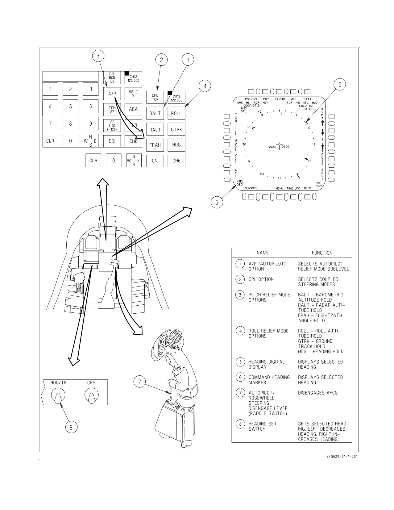
2.11.1 AFCS Mode Selection. Selection of the various autopilot (A/P) modes is accomplished from
the A/P sublevel of the CNI format on the UFCD. Before any autopilot mode can be selected, bank
angle must be less than 70°, pitch attitude must be less than 45°, and the A/P sublevel must be
displayed on the UFCD. The left column of the A/P sublevel displays the couple (CPL) option and the
pitch-axis pilot relief mode options: BALT, RALT, and FPAH. The right column displays the roll-axis
pilot relief mode options: ROLL, GTRK, and HDG. See figure 2-29.
An autopilot mode is enabled by selecting the corresponding option on the UFCD. Once selected, a
highlighted box appears around the option and the corresponding autopilot advisory appears on the
LDDI. If an option is not available, it is not displayed.
I-2-84
ORIGINAL
A1-E18GA-NFM-000
Figure 2-29. AFCS Controls and Indicators
I-2-85
ORIGINAL
A1-E18GA-NFM-000
Once in the GTRK mode, subsequent selection of the GTRK option enables the GSEL mode (GSEL
replaces GTRK on the UFCD). Once in the HDG mode, subsequent selection of the HDG option
enables the HSEL mode (HSEL replaces HDG on the UFCD).
2.11.2 Basic Autopilot. The basic or default autopilot mode is FPAH/HDG. When any autopilot
mode is requested from the UFCD, the AFCS first engages FPAH/HDG and then engages the
requested mode. This makes sure that the AFCS is controlling both the pitch and roll axis whenever
an autopilot mode is engaged.
2.11.3 AFCS Mode Deselection. Autopilot modes can be disengaged by either reselecting (unboxing)
the UFCD option or by actuating the paddle switch. If an autopilot mode is unboxed on the UFCD, the
AFCS reverts to the basic autopilot mode in that axis. This is true for all modes except when
disengaging the ACL mode by unboxing the CPL P/R option. In that case, the AUTO PILOT caution
is displayed and all autopilot modes disengage. If the stick is moved longitudinally with BALT or
RALT engaged or laterally with CPL engaged, the AFCS reverts to the basic autopilot mode in that
axis and the AUTO PILOT caution is displayed. If the stick is moved either longitudinally or laterally
with CPL P/R engaged, the AUTO PILOT caution is displayed and all autopilot modes disengage. The
basic autopilot mode cannot be disengaged (unboxed) from the UFCD and must, therefore, be
disengaged with the paddle switch. Paddle switch actuation is the only means to make sure that all
autopilot modes have been completely disengaged.
2.11.4 Pitch-Axis Pilot Relief Modes. Any of the pitch-axis pilot relief modes can be engaged in
conjunction with any coupled steering mode (except ACL) or with any roll-axis pilot relief mode.
However, only one pitch-axis mode can be selected at a time. If one pitch-axis mode is requested while
another is engaged, the AFCS switches to the requested mode.
2.11.4.1 Barometric Altitude Hold (BALT). When BALT is engaged, the baro-inertial altitude at the
time of engagement is captured and maintained. While the mode is engaged, this reference altitude
cannot be changed. Longitudinal stick inputs or trim changes disengage BALT, and the AFCS reverts
to FPAH and the selected roll-axis mode.
2.11.4.2 Radar Altitude Hold (RALT). RALT is not available above 5,000 feet AGL. When RALT is
engaged, the radar altitude at the time of engagement is captured and maintained. While the mode is
engaged, this reference altitude cannot be changed. Longitudinal stick inputs or trim changes
disengage RALT, and the AFCS reverts to FPAH and the selected roll-axis mode.
2.11.4.3 Flight Path Angle Hold (FPAH). When FPAH is engaged, the flight path angle at the time
of engagement is captured and maintained. This reference flight path angle can be changed by
longitudinal stick inputs (stick sensitivity similar to CAS) or by pitch trim changes (2°/sec in flaps
AUTO or 0.5°/second in flaps HALF or FULL). When pilot inputs cease, the flight path angle at
release is captured and maintained.
2.11.5 Roll-Axis Pilot Relief Modes. Any of the roll-axis pilot relief modes can be engaged in
conjunction with any pitch-axis pilot relief mode. However, only one roll-axis mode can be engaged at
a time. If one roll-axis mode is requested while another is engaged, the AFCS switches to the requested
mode.
2.11.5.1 Roll Attitude Hold (ROLL). When ROLL is engaged, the roll attitude at the time of
engagement is captured and maintained. This reference roll attitude can be changed by lateral stick
inputs or roll trim changes (stick and trim sensitivity similar to CAS). When pilot inputs cease, the roll
attitude at release is captured and maintained.
I-2-86
ORIGINAL
A1-E18GA-NFM-000
2.11.5.2 Ground Track Hold (GRTK). When GTRK is engaged, aircraft response depends on the roll
attitude at the time of engagement. If roll attitude is less than ±5°, ground track is captured and
maintained. If roll attitude is greater than or equal to ±5°, roll attitude is captured and maintained.
While in GTRK, the aircraft responds to lateral stick or roll trim inputs (stick and trim sensitivity
similar to CAS). When pilot inputs cease, GTRK holds roll attitude (if greater than or equal to ±5°)
or ground track (if less than ±5°).
2.11.5.3 Ground Track Select (GSEL). The desired ground track angle is selected by slewing the
command heading marker with the HDG/TK switch, located to the left of the MPCD. When GSEL is
engaged, the aircraft turns from the existing ground track through the smallest angle to the selected
ground track. While in GSEL, the aircraft responds to lateral stick inputs. However, the selected
ground track angle is not changed by stick inputs, so the aircraft returns to the selected ground track
angle upon stick release.
2.11.5.4 Heading Hold (HDG). When HDG is engaged, aircraft response depends on the roll attitude
at the time of engagement. If roll attitude is less than ±5°, magnetic heading is captured and
maintained. If roll attitude is greater than or equal to ±5°, roll attitude is captured and maintained.
While in HDG, the aircraft responds to lateral stick or roll trim inputs (stick and trim sensitivity
similar to CAS). When pilot inputs cease, HDG holds roll attitude (if greater than or equal to ±5°) or
magnetic heading (if less than ±5°).
2.11.5.5 Heading Select (HSEL). The desired heading is selected by slewing the command heading
marker with the HDG/TK switch, located to the left of the MPCD. When HSEL is engaged, the
aircraft turns from the existing heading through the smallest angle to the selected heading. While in
HSEL, the aircraft responds to lateral stick inputs. However, the selected heading is not changed by
stick inputs, so the aircraft returns to the selected heading upon stick release.
2.11.6 Coupled Steering Modes (CPL). The coupled steering modes couple the aircraft in the
roll-axis only. If the CPL option is selected, the AFCS disengages any currently engaged roll-axis pilot
relief mode. The AFCS has the ability to couple to the following sources: a waypoint, waypoint
courseline, or offset aimpoint (CPL WYPT); to a TACAN station or TACAN courseline (CPL TCN);
or to an auto sequence (CPL SEQ#). Refer to chapter 24 for detailed navigation steering information
on waypoint/OAP, auto sequential, and TACAN steering.
2.11.7 Coupled Data Link Modes. The AFCS can couple to data link commands in one of two modes:
ACL and VEC. With ACL boxed on the HSI format, the CPL P/R option appears on the A/P sublevel
when pitch/roll couple capability is available. Selecting the CPL P/R option couples the aircraft to
pitch and roll commands for a Mode 1 carrier approach. With VEC boxed on the HSI format, selecting
the CPL option couples the aircraft (roll-axis only) to data link steering commands. Refer to chapter
24 and the NTRP 3-22.2-EA-18G (EA-18G Classified Manual) for detailed information on the ACL
and VEC modes.
2.11.8 AFCS Related Caution and Advisories. The AUTO PILOT caution and the following AFCS
related advisories are described in the Warning/Caution/Advisory Displays in Part V:
• BALT
• GSEL
• HSEL
• CPLD
• GTRK
• RALT
• FPAH
• HDG
• ROLL
I-2-87
ORIGINAL
A1-E18GA-NFM-000
2.12 WEAPON SYSTEMS CONTROLS
All of the primary controls for the aircraft’s weapon systems (weapons, sensors, and displays) are
located on the front cockpit throttles and stick, or the rear cockpit hand controllers. This concept,
hands on throttles and stick (HOTAS), allows the aircrew to manipulate the weapon systems without
removing the hands from the aircraft’s primary flight controls. Additionally, the canopy sill DISP
switch(es) and the rear cockpit grab handle switches provide secondary controls for dispensing
expendables from the ALE-47 self-protect system.
Detailed descriptions of the functionality of the weapon systems controls are contained in the NTRP
3-22.2-EA-18G (EA-18G Classified Manual).
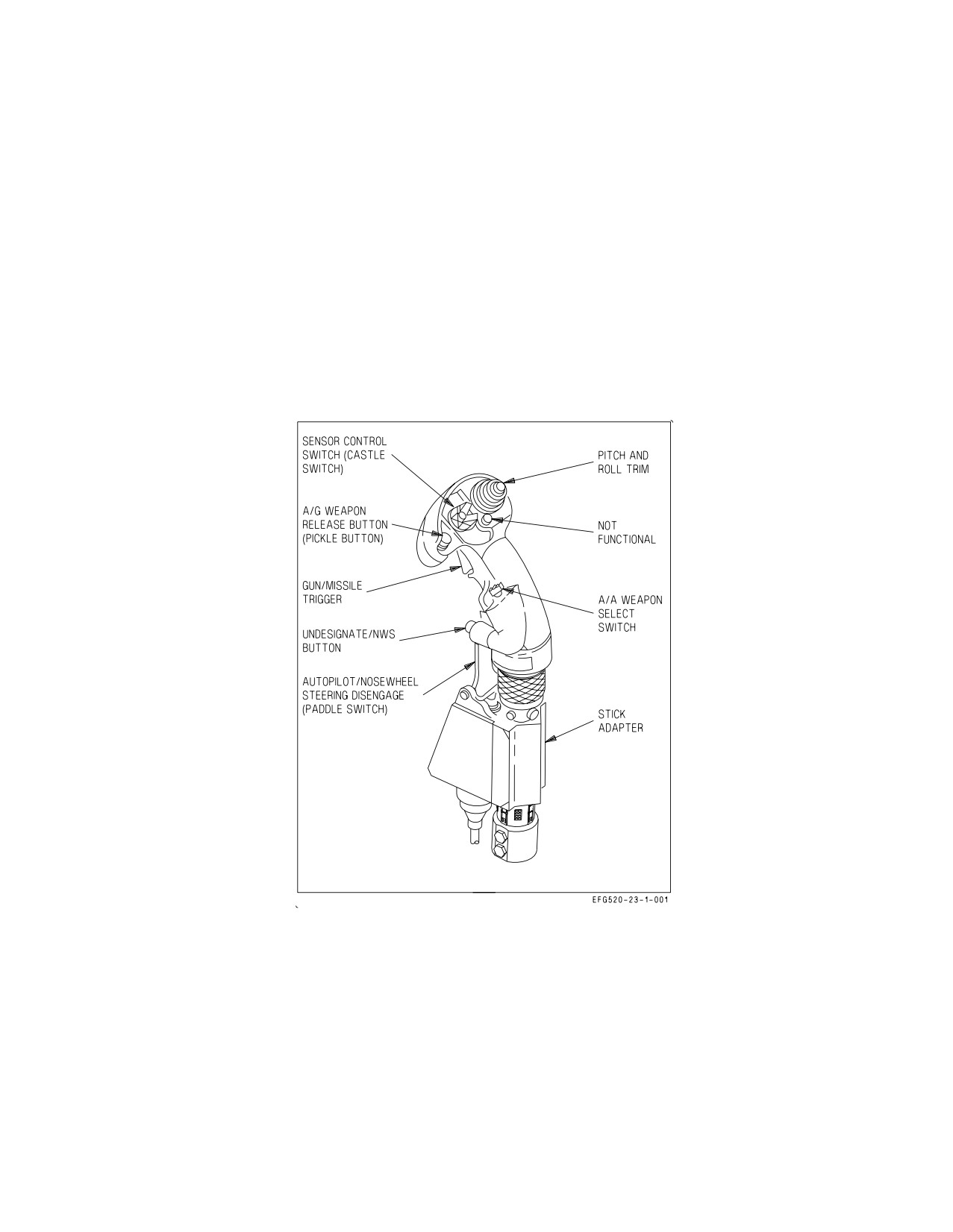
2.12.1 Stick Grip Switches/Controls (Front Cockpit). The weapon systems controls located on the
front cockpit stick grip are the A/A weapon select switch, the sensor control switch, the missile trigger,
the A/G weapon release button, and the undesignate/NWS button. See figure 2-30.
Figure 2-30. Stick Grip Switches/Controls
2.12.1.1 A/A Weapon Select Switch. The A/A weapon select switch, located on the left side of the
stick grip, is spring loaded to the center/up position. The weapon select switch is used to select the
desired A/A weapon and can be used to enter A/A master mode. When the weapon select switch is
actuated while in NAV or A/G master mode, the A/A master mode is automatically entered, the RDR
ATTK format is automatically displayed on the RDDI, and the appropriate A/A weapon/radar format
is selected. Once in the A/A master mode, actuating the weapon select switch merely changes the
selected A/A weapon/radar format.
I-2-88
ORIGINAL
A1-E18GA-NFM-000
Center
Neutral
Forward
Selects AIM-7 and the corresponding radar format.
Down
Selects AIM-9 and the corresponding radar format.
Aft
Selects A/A GUN and the gun acquisition mode (GACG).
Inward
Selects AIM-120 and the corresponding radar format.
Selection of an A/A missile initiates launch preparation of the priority missile, if more than one is
carried and brings up the corresponding radar format (e.g., scan volume presets). Subsequent selection
steps to the next available missile in the priority sequence.
2.12.1.2 Sensor Control Switch. The sensor control switch, commonly called the ″castle″ switch, is
located on the top center of the stick grip and is spring loaded to the center/up position. The castle
switch is used to assign throttle designator controller (TDC) priority to a particular cockpit display or,
once air combat maneuvering (ACM) mode functionality is enabled, to select a particular ACM mode.
Center
Neutral
Forward
Assigns TDC priority to the HUD in NAV or A/G master mode. In A/A
master mode, selects the boresight acquisition mode (BST) and enables
ACM mode functionality.
Forward (twice
Selects/deselects EMCON.
within 0.5 seconds)
Depress/release then
Assigns TDC priority to the UFCD in all master modes. If the top level
forward (within 1
CNI, a CNI sublevel, or a data entry format is displayed, selects the last
second)
displayed DDI format.
Left
Assigns the TDC to the LDDI in all master modes. With ACM mode
functionality enabled in A/A master mode, selects the wide acquisition
mode (WACQ).
Right
Assigns the TDC to the RDDI in all master modes. With ACM mode
functionality enabled in A/A master mode, selects the automatic acquisi-
tion mode (AACQ).
Aft
Assigns the TDC to the MPCD in all master modes. With ACM mode
functionality enabled in A/A master mode, selects the vertical acquisition
mode (VACQ).
When the TDC is assigned to a display which cannot accept TDC priority, automatic format
initialization occurs, typically selecting the format which is most commonly used on that particular
display (e.g., RDR ATTK on the RDDI). With TDC assignment, certain displays (e.g., RDR ATTK,
etc.) perform a specific action (e.g., track, break track, etc.) when the castle switch is subsequently
bumped toward that display.
I-2-89
ORIGINAL
A1-E18GA-NFM-000
2.12.1.3 Trigger. The missile trigger, located on the front of the stick grip, has two detented
positions.
First
Initiates strike camera automatic mode operation (based on the selected A/G
Detent
weapon) and if CVRS is running, commands HUD recording.
Second
In A/A master mode, fires the selected A/A missile. Activates AGI protection. In
Detent
A/G master mode, fires the laser, if either is selected. Commands the HUD event
marker.
2.12.1.4 A/G Weapon Release Button. The A/G weapon release button, commonly called the
″pickle″, is located on the top center of the stick grip to the left of the castle switch. The pickle is used
to command weapon release while in A/G master mode. The pickle also initiates AGI protection, strike
camera automatic mode operation, and, if CVRS is running, commands HUD recording and the HUD
event marker.
2.12.1.5 Undesignate/NWS Button. The undesignate/NWS button is located on the lower front of
the stick grip. In NAV or A/G master mode, the undesignate button undesignates all A/G designated
targets and commands the radar to break lock, if it is tracking. In A/A master mode, the undesignate
button creates a launch and steering (L&S) target designation. Subsequent actuation steps target
designation to the next priority trackfile or to a second designated trackfile (DT2), if one exists.
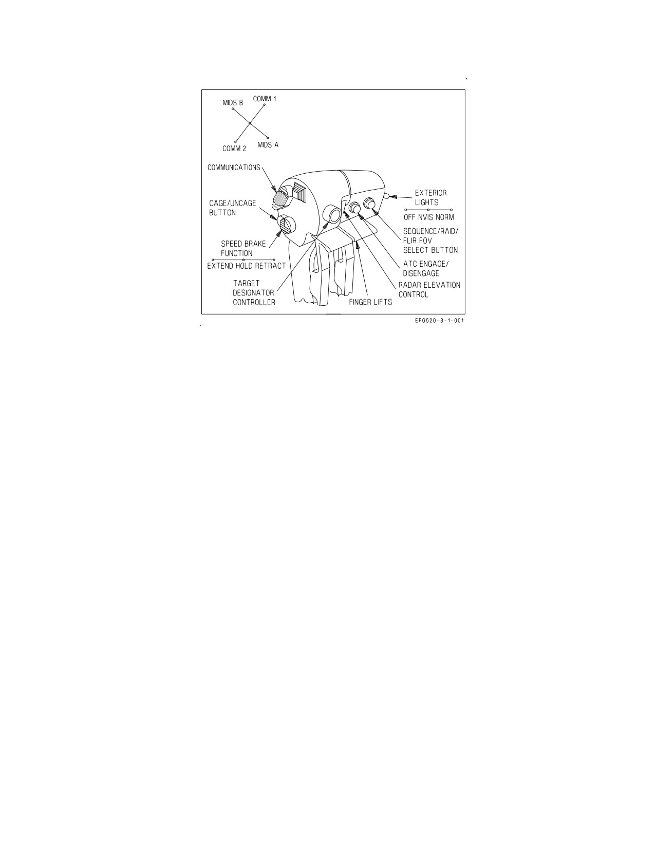
2.12.2 Throttle Grip Switches/Controls. The weapon systems controls located on the front cockpit
throttle grips are the chaff/flare/ALE-50
dispense switch, the cage/uncage button, the throttle
designator controller (TDC), the radar elevation control, and the raid button. See figure 2-31.
2.12.2.1 Chaff/Flare/ALE-50 Dispense Switch. The chaff/flare/ALE-50 dispense switch is located
on the top inboard side of the right throttle.
2.12.2.2 Cage/Uncage Button. The cage/uncage button is located on the rear inboard side of the
right throttle. In NAV master mode and A/G master mode (AUTO delivery), the cage/uncage button
is used to cage and uncage the velocity vector. Depending on master mode and TDC priority
assignment, the cage/uncage button can be used to (1) cage/uncage weapons, (2) toggle between
weapon modes, or (3) reset sequenced HARM targets.
2.12.2.3 Throttle Designator Controller (TDC). The TDC is located on the front right side of the
right throttle. It is used to control the positioning of the acquisition cursor or the slewing of a particular
sensor or weapon. The TDC can be pressed for target designation. When held pressed (action slew) or
released (no-action slew), the fore-aft and left-right movement of the TDC sends X-Y slew commands
to the display or to the sensor/weapon to which TDC priority is assigned. If in ACM mode, pressing
TDC will exit the radar from ACM mode.
I-2-90
ORIGINAL
A1-E18GA-NFM-000
Figure 2-31. Throttle Grip Switches/Controls
2.12.3.4 Radar Elevation Control. The radar elevation control is located on the front left side of the
right throttle. Momentary actuation changes the elevation of the radar antenna in
1,000
foot
increments at the range where the cursor is positioned on the RDR ATTK format. Press and hold
produces a faster elevation change.
Up
Raises the radar antenna/scan volume.
Center
Neutral
Down
Lowers the radar antenna/scan volume.
When display priority assigned to TSD, the elevation control switch changes the range scale. When
display priority is assigned to other AEA formats with a selection box, the elevation switch provides a
page up and down feature.
2.12.3.5 RAID Button. The RAID button is located on the left side of the left throttle. Depending on
master mode and TDC priority assignment, the RAID button can be used to (1) sequence between
available HARM targets, or (2) toggle between narrow and wide field of view (FOV).
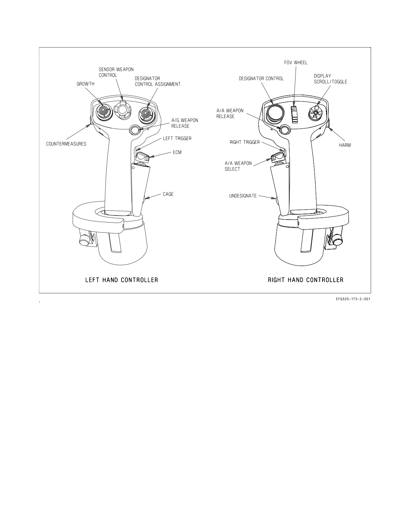
2.12.4 Hand Controllers. The functions of the left and right hand controllers are not identical. The
left hand controller contains the following switches: Countermeasures, Growth, Sensor Weapons
Control, Designator Control Assignment, A/G Weapon Release, Left Trigger, ECM, and Cage. The
right hand controller contains the following switches: HARM, Display Scroll/Toggle, FOV Wheel,
Designator Control, A/A Weapon Release, A/A Weapon Select, Undesignate, and Right Trigger. See
figure 2-32. Refer to NTRP 3-22.2-EA-18G (EA-18G Classified Manual) for complete Hand controller
Switch description.
I-2-91
ORIGINAL
A1-E18GA-NFM-000
2.12.4.1 Multi-Function Switch (MFS). The MFS is located on the lower inboard side of each hand
controller. The MFS provides the same functionality as the front cockpit RAID and cage/uncage
buttons.
Forward
Sequences between available HARM targets.
Aft
Cages/uncages an A/G weapon.
Down
Selects RAID.
Forward
Not functional.
2.12.4.2 Designator Controller (DC) Assignment Switch. The DC assignment switch is located on
the top inboard side of each hand controller. It is used to assign left and right DC priority to the
displays in the rear cockpit. ACM modes cannot be selected by the rear cockpit DC assignment
switches.
Forward
Commands FLIR track/break lock if opposite DC is assigned to the FLIR format.
Aft
Assigns DC priority to the AUFCD.
Inboard
Assigns DC priority to the AMPCD
Outboard
Assigns DC priority to the outboard ADDI. Following DC assignment, commands
track/break lock on the outboard format.
Each DC is initially assigned to its corresponding ADDI. One but not both DCs can be assigned to
one of the center displays, AUFCD or AMPCD. If one DC is assigned to the AMPCD, the other is
forced back to its corresponding ADDI.
2.12.4.3 Designator Controller (DC). The DC is located on the top center of each hand controller.
The track and slew functions of the rear cockpit DCs are identical to the front cockpit TDC. While only
one hand controller DC can be used to designate at a time, both DCs may be used simultaneously on
their assigned formats.
If the front cockpit TDC and the rear cockpit DC are both assigned to the same format, control is
captured by the first controller actuated. If one controller is active when another is selected, the second
input is ignored. If both front and rear TDC/DCs are pressed simultaneously, the TDC/DC assignment
diamond, located in the upper right corner of the specific format, flashes. If both front and rear
TDC/DCs are being slewed simultaneously, the SLEW cue is displayed and flashed.
2.12.4.4 Radar Elevation Control. The radar elevation control is located on the top outboard side of
each hand controller. The front and rear cockpit radar elevation controls are functionally identical.
Control of the radar antenna is captured by the first elevation control actuated from either cockpit. If
one control is active when another is selected, the second input is ignored.
2.12.4.5 Chaff/Flare Dispense Switch. The chaff/flare dispense switch is located on the outboard
side of each hand controller. Dispense switch functionality differs between the left and right hand
controllers.
I-2-92
ORIGINAL
A1-E18GA-NFM-000
Figure 2-32. Hand Controllers
Left Hand Controller -
Forward
Initiates manual program 6. Dispenses chaff and flare singles (C/F mode)
Aft
Initiates manual program 6. Dispenses chaff and flare singles (C/F mode)
Right Hand Controller -
Forward
Provides semi-automatic consent. Dispenses chaff singles (C/F mode)
Aft
Initiates the selected manual program. Dispenses flare singles (C/F mode)
2.12.4.6 Undesignate Button. The undesignate button is located on the lower front of each hand
controller. The front and rear undesignate buttons are functionally identical, except the rear cockpit
buttons do not command NWS.
I-2-93
ORIGINAL
A1-E18GA-NFM-000
2.12.5 ALE-47 DISP Switch. An ALE-47 DISP switch is located on the left canopy sill in both front
and rear cockpits. Either switch can be used to initiate manual program 6 or to dispense chaff and flare
singles (C/F mode).
2.12.6 Grab Handle Chaff/Flare Dispense Switches. The grab handle dispense switches are located
on the left and right ends of the center grab handle in the rear cockpit. These switches provide a
secondary means to dispense expendables from the ALE-47 self-protect system.
Forward
Provides semi-automatic consent. Dispenses flare singles (C/F mode)
Aft
Initiates the selected manual program. Dispenses flare singles (C/F mode)
Inboard
Initiates manual program 6. Dispenses chaff and flare singles (C/F mode)
Outboard
Initiates manual program 6. Dispenses chaff and flare singles (C/F mode)
2.13 ENVIRONMENTAL CONTROL SYSTEM (ECS)
The environmental control system (ECS) utilizes engine bleed air to provide pressurization, heating
and cooling air to various aircraft systems. Warm air is provided for external fuel tank pressurization,
canopy seal inflation, g-suit operation, radar waveguide pressurization, windshield anti-ice and rain
removal, and on-board oxygen generating system (OBOGS) operation. Cold, dry conditioned air is
provided for avionics cooling, and supplied to the Airborne Electronic Attack (AEA) pallet for
ALQ-218(V)2 system precooling or extended maintenance. Warm and cold air are mixed to provide
temperature controlled air for cabin heating, cooling, and pressurization and windshield defog.
A liquid cooling system (LCS) is used to cool the radar transmitter. A digital ECS controller is used
to schedule ECS output, regulate system temperatures, monitor system health, and detect and isolate
faults. See foldout section for a schematic of the ECS. Items numbers, listed in ( ) next to ECS valves,
are for component identification.
2.13.1
Airborne Electronic Attack (AEA) pallet Cooling.
2.13.1.1 Nose wheelwell AEA PRECOOL TEST switch. A two position switch, TEMP CHECK and
LAMP TEST, and a light emitting diode PRECOOL are located in the nose wheelwell and are used
during preflight inspection to determine if AEA pallet pre cooling is required.
2.13.1.2 Cockpit AEA Precool switch. This two position switch is located on the forward cockpit
right hand console. With weight on wheels, operating the switch to ON diverts cool air from the cockpit
to the AEA pallet to precool the ALQ-218 components. This switch is magnetically held ON. When
Precooling is no longer required, returning the switch to OFF terminates AEA precooling, and cockpit
cooling resumes. The switch automatically reverts to OFF at weight off wheels. It may take as long as
20 minutes for Precool to end. Cockpit Cooling is unavailable during Precool if the precool switch was
used.
2.13.1.3 UFCD/CNI-AEA power control format. ALQ218 PRECOOL REQD is displayed on the
ALQ-218 pushtile when AEA precooling is required. When precool is initiated by placing the
I-2-94
ORIGINAL
A1-E18GA-NFM-000
PRECOOL switch ON, the ALQ-218 pushtile changes to PRCOOL ON. When precool is no longer
required, PRCOOL ON clears.
2.13.1.4 AEA Pallet Ground Cooling Mode. The AEA PRECOOL switch energizes relays that: opens
the cabin air pressure emergency relief valve, opens the cabin/defog ram air valve, and closes the cabin
flow valve. This enables maximum airflow through the avionics cooling system to the EAU on the AEA
pallet as well as into the pallet bay. The AEA Ground cooling mode continues until either the AEA
PRECOOL switch is set to OFF, or it is deenergized by the right weight-off-wheels relay. ECS Related
Warnings, Cautions, and Advisories.
2.13.2 Bleed Air Shutoff Valves. Engine bleed air is tapped from the final (seventh) stage of the
engine high pressure compressor. A primary bleed air pressure regulator and shutoff valve (Item 1), one
on each engine, is used to regulate bleed air output pressure as well as to control flow application/
shutoff.
Both valves are electrically controlled by the BLEED AIR knob and are pneumatically actuated.
The primary bleed air shutoff valves failsafe to the closed position if either electrical power or air
pressure is lost. If an engine is shut down before placing the BLEED AIR knob to OFF, the
corresponding primary bleed air shutoff valve may not fully close, resulting in residual engine fumes
in the cabin on subsequent start of that engine.
Bleed air from each engine passes through a check valve, which prevents reverse flow, and is mixed
through a Y-junction prior to the secondary bleed air pressure regulator and shutoff valve (Item 2).
This valve is electrically controlled by the OFF and AUG PULL positions of the BLEED AIR knob and
is pneumatically actuated. The secondary bleed air shutoff valve fails to the open (safe) position if
either electrical power or air pressure is lost.
All three valves can be automatically commanded to the closed position by the bleed air leak
detection (BALD) system.
2.13.2.1 BLEED AIR Knob. The BLEED AIR knob, located on the ECS panel on the right console, is
used to select the engine bleed air source for the ECS system.
NORM Commands both primary bleed air shutoff valves open, selecting bleed air from both
engines.
L OFF Commands the left primary bleed air shutoff valve closed, selecting bleed air from the
right engine only.
R OFF Commands the right primary bleed air shutoff valve closed, selecting bleed air from the
left engine only.
OFF Commands all three bleed air shutoff valves closed, isolating the ECS. Closes the ECS
auxiliary duct doors.
AUG Commands the secondary bleed air shutoff valve closed, opens the ECS air isolation
PULL valve, and allows APU compressor air to operate the ECS.
2.13.2.2 L or R BLD OFF Cautions. The L or R BLD OFF cautions indicate that the corresponding
primary bleed air shutoff valve(s) are commanded closed. The cautions are not an indication of actual
valve position. The L and/or R BLD OFF cautions are displayed in the following circumstances:
I-2-95
ORIGINAL
A1-E18GA-NFM-000
a. BLEED AIR knob in L OFF, R OFF, or OFF (L, R, or both cautions).
b. ENG CRANK switch in L or R (L or R caution, respectively).
c. BALD system detects a leak in one or both bleed air systems (L, R, or both cautions).
d. FIRE switch in TEST A or TEST B (both cautions).
e. Over pressurization in one or both bleed air systems (both cautions).
If a bleed air shutoff valve has been commanded closed other than by ENG CRANK, the BLEED
AIR knob must be cycled to OFF and back to NORM to reopen the valve(s).
2.13.3 Bleed Air Subsystem. Engine bleed air downstream of the secondary bleed air shutoff valve
is routed to the primary heat exchanger and three valves. The primary heat exchanger is used for first
stage cooling of hot engine bleed air. The ECS air isolation valve directs bleed air to the air turbine
starter control valves (ATSCV) for crossbleed start and accepts air from the APU compressor for
alternate (AUG PULL) ECS operation. On the ground and during slow speed flight, the ejector shutoff
valve is opened to direct bleed air to the ram air ejectors to induce cooling airflow through the primary
and secondary heat exchangers. The warm air temperature control valve is used to mix uncooled engine
bleed air with primary heat exchanger output air to regulate the temperature of air in the warm air
manifold.
2.13.4 Primary Heat Exchanger. The primary heat exchanger is located near the base of the right
vertical tail and is used to reject heat from engine bleed air to ram air from one of two inlets.
During medium to high speed flight, ram air cooling is provided by the main ram inlet which draws
air from the engine intake. During slow speed flight and ground operations, ram air cooling is provided
by an auxiliary ram inlet which draws free stream air from the top of the fuselage. A ram air ejector in
the ram air exhaust duct is used to induce more airflow when required, such as on the the ground,
during slow speed flight, and during windshield anti-ice operation with either throttle above IDLE.
2.13.4.1 ECS Auxiliary Duct Doors. Two ECS auxiliary duct doors are located on the upper surface
of the fuselage forward of the base of the vertical tails and immediately in front of the primary and
secondary heat exchangers. The ECS auxiliary duct doors are electrically actuated and open into the
free stream, closing the main ram air inlets and exposing the auxiliary ram air inlets.
On the ground, the ECS auxiliary duct doors are open with the BLEED AIR knob in any position
except OFF. Inflight, the doors are positioned based on Mach number and throttle setting. The doors
are always open below 0.33 Mach and are always closed above 0.40 Mach. Between 0.35 and 0.40 Mach,
the doors are open if either throttle is near MIL (THA greater than 25°).
The ECS auxiliary duct doors should operate symmetrically. If either ECS auxiliary duct door is not
in the commanded position for greater than 8 seconds, an ECS DR advisory is displayed along with an
ECS BIT indication of DEGD. If the door(s) return to the commanded position, the ECS DR advisory
is removed.
2.13.4.2 Ram Air Exhausts. The ECS ram air exhausts are located on the upper fuselage just aft of
the leading edge of the vertical tails. There is one exhaust for the primary heat exchanger (right side)
and one for the secondary heat exchanger (left side). These exhausts discharge the heated ram air
overboard. The exhausts have been redesigned to a five swept stack configuration to prevent
overheating of the aft fuselage structure.
2.13.5 Warm Air Subsystems. Air leaves the primary heat exchanger at a greatly reduced tempera-
ture. Warm air from the primary heat exchanger is routed directly to the following systems: external
fuel tank pressurization, canopy seal, g-suit, radar waveguide pressurization, and OBOGS.
I-2-96
ORIGINAL
A1-E18GA-NFM-000
The ECS controller modulates the warm air temperature control valve (see FO-29 Item 21) to mix
air from the primary heat exchanger with uncooled engine bleed air to regulate the temperature in the
warm air manifold. The warm air manifold supplies air for windshield anti-ice and rain removal, ECS
turbine anti-ice, and cabin heating.
2.13.6 Air Conditioning System (ACS) Pack. The ACS pack provides cold, dry conditioned air for
cabin, and avionics cooling. The primary components of the ACS pack are a compressor, turbine,
condenser, reheater and water extractor.
The ECS controller modulates airflow through the ECS flow modulator valve (Item 4) to control
ECS flow and the speed of the ECS compressor and turbine. Compressor discharge air is directed to
the secondary heat exchanger for additional cooling. Cooled air from the secondary heat exchanger is
directed to the ECS turbine and is used as another source of OBOGS air inflight.
Expansion through the ECS turbine drives the compressor and greatly reduces the temperature of
the airflow, typically to below freezing. The ECS controller regulates the ECS turbine output
temperature and prevents ECS icing by adding warm air through the anti-ice add heat valve (Item 51).
Output temperature is regulated during low altitude operations where ECS icing would be likely.
The condenser, reheater and water extractor remove water from the cold conditioned air. With the
large heat load of the APG-79 radar, the condenser can run at sub−freezing conditions. During
prolonged operation of the APG-79 in high humidity conditions with warm fuel temperatures, periodic
automatic deicing of the condenser occurs. During de-icing, a short term increase in cabin supply air
temperature may be noticed.
At altitudes above 40,000 feet the water removal system may be bypassed by opening the water
extractor bypass valve (Item 171) in order to improve ECS operating efficiency. If this valve fails to
close after descending below 37,000 feet, water removal capability is degraded. Water or ice pellets may
be blown into the cabin and erratic system behavior (flow/pressure surges) may result. An ECS ICING
caution may also occur.
2.13.7 Secondary Heat Exchanger. The secondary heat exchanger is located near the base of the left
vertical tail and is used to reject heat from ECS compressor air to ram air. Operation of the secondary
heat exchanger is identical to operation of the primary heat exchanger. However, excess ECS system
moisture is sprayed onto the secondary heat exchanger to increase system cooling. This moisture may
be seen exiting the secondary heat exchanger exhaust duct when the throttles are advanced during
ground operations.
2.13.8 Avionics Cooling Fans. Two avionic cooling fans augment ECS cooling of avionics. The
avionics ground cooling fan is located in the nose wheelwell. The aft avionics cooling fan is located in
door 108. These fans normally provide primary avionics cooling on deck, and also provide contingency
avionics cooling in flight. Fan activation is a function of bleed air pressure, which varies with engine N2
rpm (i.e. throttle position). Fan operation is described in the individual ECS mode descriptions.
2.13.8.1 Aft Cooling Fan Shutoff Valve. The aft cooling fan shutoff valve, when closed, secures flow
from the aft avionics cooling fan into the ECS and also prevents ECS backflow to the aft avionics
cooling fan. If this valve fails (indicated by MSP 863) while in the open position then, depending on
system pressure, ECS backflow can overspeed the fan in the wrong direction. This may cause a
structural failure of the fan and result in collateral fragment damage to adjacent systems. ECS
backflow is most likely to occur when ECS MAN mode is selected and ECS flow is commanded by
default to maximum.
I-2-97
ORIGINAL
A1-E18GA-NFM-000
Selection of ECS MAN mode is prohibited. Selecting ECS MAN mode
while the aft cooling fan shutoff valve is open may cause the fan to
overspeed, resulting in a catastrophic fan failure and potential loss of
OBOGS.
2.13.9 ECS Operating Modes. The ECS has three operating modes: AUTO, MAN (manual), and
OFF/RAM. Each mode is selected by the corresponding position of the ECS MODE switch. On the
ground only, APU compressor air may be used instead of engine bleed air to run the ECS and cool the
avionics (BLEED AIR knob in AUG PULL).
2.13.9.1 ECS AUTO Mode. ECS AUTO mode is the normal operating mode of the ECS. The ECS
controller modulates ECS output to provide the required airflow to the cabin and the avionics. Cabin
airflow is scheduled as a function of ram air temperature and throttle setting, with the highest flow
delivered at hot and cold temperature extremes. Cabin flow may decrease at IDLE. ECS flow to the
avionics is dependent on WonW status, throttle setting, Lot number, and radar configuration. For all
aircraft configurations, more air is provided to avionics inflight.
With WonW and both throttles at IDLE, only the avionics ground cooling fan energizes. The fan(s)
provide the primary source of avionics cooling on deck. The ECS provides a second source of ground
avionics cooling but at a fixed, low flow rate with the remainder of the flow going to the cabin.
With WonW and at least one throttle advanced to approximately 74% N2 rpm, or with WoffW, the
fan(s) secure. Once secured, the fan(s) will not reenergize until both throttles are retarded below
approximately 70% N2 rpm. With WonW and fans secured, the ECS provides all avionics cooling and
controls to the cabin and avionics airflow schedules. If AEA precool is required, advance one throttle
to 76% until precool indication is no longer present. The ECS controller schedules avionics airflow
based on the temperature of the air being delivered (warmer air requires higher flow to maintain
constant cooling).
The ECS controller modulates airflow output to meet scheduled airflow requirements. ECS output
temperature is scheduled by the ECS controller to meet avionics cooling requirements and to prevent
ECS turbine icing. Temperature is regulated by adding warm air as required. The controller divides the
airflow between the cabin and avionics. Inflight, if ECS output is inadequate for demand, cabin airflow
is normally given priority. The avionics typically receive that portion of the ECS output which is not
used by the cabin cooling system.
Cabin temperature is controlled by gradually mixing warm air with cold conditioned air, according
to the position of the CABIN TEMP knob. Cabin temperature is normally selectable in the range of
35 to 135° F between the CABIN TEMP knob positions of COLD and HOT, respectively (60 to 160°
F with the DEFOG handle in the HIGH position).
NOTE
In ECS AUTO mode, cabin temperature may take 1 to 2 minutes to
stabilize following a large movement of the CABIN TEMP knob.
I-2-98
ORIGINAL
A1-E18GA-NFM-000
2.13.9.2 ECS MAN Mode.
Selection of ECS MAN mode is prohibited. Selecting ECS MAN mode
while the aft cooling fan shutoff valve is open may cause the fan to
overspeed, resulting in a catastrophic fan failure and potential loss of
OBOGS.
The ECS MAN mode is a degraded operating mode. At high power settings, ECS MAN mode can
significantly increase the amount of bleed air drawn from the engines, resulting in higher turbine
temperatures and reduced engine life. Therefore, the ECS MAN mode should only be used when the
ECS AUTO mode is degraded and temperatures are out of limits (e.g., cabin temperature high or AV
AIR HOT caution inflight).
ECS AUTO mode should be selected unless ECS performance is
degraded, cabin temperature control is lost, or an AV AIR HOT caution
occurs. Extended ECS MAN mode operation, particularly at high power
settings, significantly reduces engine life.
ECS valves are configured to produce maximum ECS flow. The division of airflow between the cabin
and the avionics is dependent on WonW status and throttle setting.
Avionics cooling fan operation is identical to ECS AUTO mode.
Cabin temperature is no longer automatically controlled. The CABIN TEMP knob manually
controls addition of heated air according to the CABIN TEMP knob. Temperature control in between
the full COLD and full HOT positions is difficult and imprecise, and ECS response to commanded
temperature changes is slow and nonlinear.
NOTE
In ECS MAN mode, changes in the position of the CABIN TEMP
knob should be held for
30 seconds due to a slower temperature
response.
With the CABIN TEMP knob not in full COLD, cabin temperature varies with throttle position and
flight condition. System flow/temperature cycling can be expected with the CABIN TEMP knob in full
HOT since overtemperature protection operates intermittently.
I-2-99
ORIGINAL
A1-E18GA-NFM-000
2.13.9.3 ECS OFF/RAM Mode. ECS OFF/RAM mode is used to terminate normal ECS operation
following a major ECS malfunction. Conditioned ECS air is terminated, the cabin ram air scoop is
deployed, and if inflight the aft avionics cooling fan energizes.
NOTE
If ECS OFF/RAM mode is selected inflight, the AV COOL switch
should be placed in EMERG to deploy the FCS emergency ram air
scoop and maximize the emergency avionics cooling available.
Partial cabin pressurization is provided, but only if the CABIN TEMP knob is above the full COLD
position. Cabin airflow and pressurization is provided by ram air from the cabin ram air scoop. Ram
air supply varies with inflight dynamic conditions (airspeed and altitude), and cabin airflow and
pressurization vary similarly.
In ECS OFF/RAM mode, avoid operations above 25,000 feet MSL in
order to prevent decompression sickness (DCS). Normal cabin pressur-
ization is not provided. Partial cabin pressurization is available under
certain circumstances, but may be lost insidiously without warning.
Inflight, cabin temperature control is identical to ECS MAN mode.
With WonW and both throttles at IDLE, the avionics ground cooling fan and the aft avionics cooling
fan provide the only source of avionics cooling. Above approximately 74% N2 rpm, both fans secure,
and avionics equipment is deprived of all cooling (AV AIR HOT caution).
NOTE
During ground operations in the ECS OFF/RAM mode, the throttles
should be kept below 70% N2 rpm whenever possible in order to
preserve avionics cooling. If either throttle must be advanced above
approximately 74% N2 rpm more than momentarily or if an AV AIR
HOT caution is present, placing the BLEED AIR knob to OFF
reenergizes both fans and provides avionics cooling.
Inflight, the aft avionics cooling fan and the FCS emergency ram air scoop (with AV COOL in
EMERG) provide emergency avionics cooling.
NOTE
With the FCS emergency ram air scoop extended, avionics cooling
inflight is maximized by maintaining altitude below 25,000 feet MSL
and airspeed between 200 to 300 KCAS.
I-2-100
ORIGINAL
A1-E18GA-NFM-000
2.13.9.4 AUG PULL. With both generators online and the APU running, selecting AUG PULL (up
on the BLEED AIR knob):
a. Overrides APU automatic shutdown.
b. Closes the secondary bleed air shutoff valve.
c. Opens the ECS air isolation valve.
d. Shuts down the aft avionics cooling fans.
e. Directs APU air to the ECS for cabin and avionics cooling.
2.13.9.5 ECS MODE Switch. The ECS MODE switch, located on the ECS panel on the right console,
is used to select the ECS operating mode.
AUTO
Selects ECS AUTO mode, the normal ECS operating mode. Provides automatic
cabin and avionics airflow, automatic temperature scheduling, and full cabin pres-
surization.
MAN
Selects ECS MAN mode, a degraded backup ECS operating mode. Provides full,
fixed cabin and avionics airflow, manual temperature control, and full cabin pres-
surization.
Selection of ECS MAN mode is prohibited. Selecting ECS MAN mode
while the aft cooling fan shutoff valve is open may cause the fan to
overspeed, resulting in a catastrophic fan failure and potential loss of
OBOGS.
OFF/RAM Selects ECS OFF/RAM mode, which terminates conditioned ECS airflow. Provides
ram air for cabin airflow and pressurization depending on flight conditions, and
manual temperature control.
2.13.9.6 CABIN TEMP knob. The CABIN TEMP knob, located on the ECS panel on the right
console, is used to control the temperature of air delivered to the cabin. In ECS AUTO mode, clockwise
rotation of the CABIN TEMP knob linearly increases cabin temperature. In ECS MAN or OFF/RAM
modes, the CABIN TEMP knob controls the cabin add heat valve directly, producing a nonlinear
temperature response.
NOTE
D In ECS AUTO mode, cabin temperature may take 1 to 2 minutes to
stabilize following a large movement of the CABIN TEMP knob.
D In ECS MAN mode, changes in the position of the CABIN TEMP
knob should be held for 30 seconds due to a slower temperature
response.
2.13.9.7 Cabin Louvers/Foot Air Outlet. Three sets of louvers are provided to direct airflow within
the cabin, one on either side of the main instrument panel and one at the base of the center console
behind the control stick. The left and right louvers have controls for elevation and azimuth. The center
louver has a single control for elevation and can be closed completely by moving the lever to the full
aft position. When the center louver is closed, airflow through the left and right louvers is increased.
I-2-101
ORIGINAL
A1-E18GA-NFM-000
Maximum aircrew cooling is provided by pulling the DEFOG HANDLE full aft, closing the center
louver, and directing the side louvers towards the body. A fixed foot air outlet directs airflow to the
base of the cabin.
2.13.9.8 Windshield Defog Outlets Fixed windshield defog outlets direct cabin air onto the inner
windshield to remove and inhibit fog. Windshield fogging can occur during rapid environmental
changes, such as high rates of descent and high humidity.
2.13.9.9 DEFOG Handle. The DEFOG handle, located on the right console outboard of the ECS
panel, controls the division of airflow between the windshield defog outlets, the three cockpit louvers,
and the foot air outlet. The DEFOG handle mechanically controls the position of the cabin air/defog
diverter valve.
HIGH Directs all cabin airflow to the windshield defog outlets to maximize defog, and
increases the temperature range controlled by the CABIN TEMP knob in ECS AUTO
mode.
NORM Equally divides cabin airflow between the cabin louvers/foot air outlet and the wind-
shield defog outlets. Provides adequate windshield defog for most conditions.
LOW Directs all cabin airflow to the cabin louvers and the foot air outlet to maximize cabin
cooling.
2.13.10 Cabin Pressurization. The cabin is pressurized using airflow from the cabin heating and
cooling system. Cabin pressurization is controlled by the CABIN PRESS switch and automatic
operation of the cabin pressure regulator. Cabin pressure altitude is displayed on a cabin pressure
altimeter.
Cabin pressure is controlled by the cabin pressure regulator which regulates exit airflow to maintain
a pressure/altitude schedule. The cabin is unpressurized from sea level to an aircraft altitude of 8,000
feet. Between 8,000 and 24,500 feet aircraft altitude, cabin pressure is maintained at a constant 8,000
feet. Above 24,500 feet, cabin altitude increases slowly to approximately 14,500 feet at 35,000 feet
aircraft altitude and 20,000 feet at 50,000 feet aircraft altitude. A rule of thumb for cabin altitude above
24,500 feet aircraft altitude is aircraft altitude x 0.4.
A cabin safety and dump valve is incorporated to limit cabin pressure if the pressure regulator fails.
When the CABIN PRESS switch is placed to DUMP or RAM/DUMP, the cabin safety and dump valve
opens to release pressure to the cabin pressure regulator, reducing cabin pressure to ambient.
In ECS OFF/RAM mode, avoid operations above 25,000 feet MSL in
order to prevent decompression sickness (DCS). Normal cabin pressur-
ization is not provided. Partial cabin pressurization is available under
certain circumstances, but may be lost insidiously without warning.
I-2-102
ORIGINAL
A1-E18GA-NFM-000
2.13.10.1 CABIN PRESS Switch. The CABIN PRESS switch, located on the ECS panel on the right
console, is used to control cabin pressurization. The switch is lever-locked in the NORM position.
NORM Automatically regulates cabin pressurization according to the cabin pressure schedule
using the cabin pressure regulator (ECS AUTO and MAN modes).
DUMP Dumps cabin pressurization. Normal ECS airflow to the cabin and the avionics is not
affected.
RAM/ Dumps cabin pressurization. Terminates all ECS airflow to the cabin by closing the
DUMP cabin flow valve (Item 9). Cabin airflow is provided by the cabin ram air scoop. Avion-
ics airflow is provided by a simplified control scheme.
2.13.10.2 Cabin Pressure Altimeter. A cabin pressure altimeter, located on the center console in the
front cockpit and the lower left instrument panel in the rear cockpit, displays the current cabin
pressure altitude.
2.13.10.3 Cabin Pressurization Warning System (CPWS). The CPWS pressure switch monitors
cabin pressure and aircraft relays monitor related controls to warn aircrew of potentially hazardous
cabin pressurization conditions.
2.13.10.3.1 CABIN Caution Light. The yellow CABIN caution light is located on the lower right
caution lights panel. The light illuminates when cabin pressure altitude is above 21,000 +/- 1,100 feet.
The light may not extinguish until cabin pressure altitude is below 16,500 feet.
• CABIN light may appear with normal cabin pressurization when
aircraft altitude is above 47,000 feet MSL. If altitude is maintained,
aircrew should continuously monitor physiological condition.
• DCS may be experienced when operating with cabin pressure altitude
above 25,000 feet even with a working oxygen system. Symptoms of
DCS include pain in joints, tingling sensations, dizziness, paralysis,
choking, and/or loss of consciousness.
NOTE
There is no corresponding DDI caution for the CABIN caution light.
2.13.10.3.2 CK ECS Caution Light. The yellow CK ECS caution light is located on the lower right
caution lights panel. The light illuminates when the position of cabin pressurization related controls
will inhibit cabin pressurization.
NOTE
There is no corresponding DDI caution for the CK ECS caution light.
I-2-103
ORIGINAL
A1-E18GA-NFM-000
2.13.11 Windshield Anti-ice and Rain Removal. The windshield anti-ice and rain removal systems
use the same air nozzle to direct warm air over the external windshield in order to improve pilot
forward visibility in icing/raining conditions. Warm airflow is provided by mixing engine bleed air with
output from the primary heat exchanger. Windshield air nozzle orientation is intended to affect (in
flight) an area roughly 20 inches to the left and 9 inches to the right of centerline at design eye level
and below. System operation is controlled by the WINDSHIELD switch.
2.13.11.1 WINDSHIELD Switch. The WINDSHIELD switch, located on the right console outboard of
the ECS panel, is used to select either windshield anti-ice or rain removal. The switch is lever-locked
to the OFF position.
ANTI Delivers a high flow rate of 290 ±20°F air to the external surface of the windshield.
ICE
OFF Terminates anti-ice/rain removal airflow.
RAIN Delivers a low flow rate of 270 ±20°F air to the external surface of the windshield.
2.13.12 Anti-g System. The anti-g system delivers air pressure to the g-suit proportional to sensed
load factor. A button in the anti-g valve allows the aircrew to test system operation by manually
inflating the anti-g suit. The system incorporates a pressure relief valve to prevent over-pressurization.
2.13.13 ECS RESET and AV COOL Switch.
2.13.13.1 ECS RESET. If the ECS is DEGD, selecting the ECS RESET option from the BIT/
HYDRO-MECH display commands an ECS controller software reset and may restore normal
functionality following a transient fault.
Resetting the ECS controller at mid to high power settings may cause
uncomfortable cabin pressure surges and ear pain.
Resetting the ECS controller results in the loss of system over-
temperature protection for 10 to 70 seconds.
2.13.13.2 AV COOL Switch. The AV COOL switch, located on the lower right instrument panel,
extends the spring−loaded FCS ram air scoop located on the right side of the forward fuselage for
emergency cooling of FCC A, the right TR, and one AHRS unit. The AV COOL switch should be placed
in EMERG if an FCS HOT caution is displayed or during ECS OFF/RAM mode operation as a
preventative measure. Once extended, the FCS emergency ram air scoop cannot be retracted in flight.
EMERG Extends the FCS emergency ram air scoop to provide direct ram air cooling of FCC A,
the right TR, and one AHRS unit, and supplemental cooling to other avionics.
NORM FCS emergency ram air scoop not extended. The switch is spring−loaded to the NORM
position.
I-2-104
ORIGINAL
A1-E18GA-NFM-000
2.13.14 Liquid Cooling System (LCS). The LCS is a closed loop system normally used to transfer
heat from the radar transmitter to fuel and/or ambient air. When fuel temperatures are warmer than
the liquid coolant (typically at low fuel levels and high ambient temperatures), the LCS is used to
transfer heat from the fuel to ambient air. The LCS contains a liquid coolant pump, a liquid coolant/air
heat exchanger, and an LCS ground cooling fan (all three located in the left LEX) and two liquid
coolant/fuel heat exchangers, and two liquid coolant/ECS air heat exchangers.
The LEX liquid coolant/air heat exchanger has one air inlet located on the bottom of the LEX, and
two air exhausts. Only one exhaust path is commanded open at any given time. During LCS ground
cooling fan operation, the exhaust on the bottom of the LEX is commanded open. Inflight, only the air
exhaust on the top of the LEX can be commanded open.
LCS ground cooling fan air is the primary cooling source for liquid coolant on deck. During ground
operations, the liquid coolant pump and LCS ground cooling fan are commanded on when power is
applied to the radar (RADAR knob in STBY, OPR, or EMERG).
During ground operations, when feed tank fuel temperatures exceed 30°C, the liquid coolant pump
and LCS ground cooling fan may also be commanded on if the RADAR knob is in OFF in order to
provide LCS cooling of the fuel system. T ECS controller will only allow liquid coolant to the liquid
coolant/fuel heat exchanger if the RADAR knob is in OFF.
NOTE
The RADAR knob must be in OFF in order to provide any postflight
LCS fuel cooling.
Placing the RADAR knob to OFF removes the radar as a heat source and should extend ground
operating time.
Inflight, the LCS ground cooling fan secures, the lower air exhaust path closes, and the upper air
exhaust path is controlled by the mission computer. The upper air exhaust path opens when feed tank
fuel temperatures exceed 30°C, ram air is cooler than fuel, and AOA is below 15°C. Heat not removed
by the LEX liquid coolant/air heat exchanger is removed by a combination of the liquid coolant/fuel
and liquid coolant/ECS air heat exchangers.
Provisions have been incorporated to limit the risk of fire following a major liquid coolant leak.
When LCS low pressure is detected, the liquid coolant pump secures and check valves limit coolant
leakage. Since the SDC controls the liquid coolant pump, an SDC reset secures the pump, resulting in
a radar LOFLOW indication, and the radar stops transmitting.
NOTE
An SDC reset temporarily secures the liquid coolant pump. Before
selecting SDC RESET, the RADAR knob should be set to STBY until
the SDC reset is complete and normal radar cooling capability is
restored.
I-2-105
ORIGINAL
A1-E18GA-NFM-000
2.13.15 ECS Related Warnings, Cautions, and Advisories. The following ECS related warnings,
cautions, and advisories are described in the Warning/Caution/Advisory Displays in Part V:
D EAU OVRHT caution
D AV AIR HOT caution
D ECS ICING caution
D L BLEED and R BLEED warning lights
D ECSDR advisory
D BLEED AIR LEFT (RIGHT) voice alert
D EXT TANK caution
D L or R BLD OFF cautions
D FCS HOT caution
D CABIN caution light
D WDSHLD HOT caution
D CK ECS caution light
2.14 OXYGEN SYSTEMS
2.14.1 On Board Oxygen Generating System (OBOGS). OBOGS provides oxygen rich breathing gas
to the aircrew while either engine is operating. Engine bleed air is cooled and routed through the
OBOGS inlet air shutoff valve to the OBOGS concentrator. The breathing gas is routed from the
concentrator to a cockpit plenum, where the temperature is stabilized and a limited supply is stored for
peak flow demands. From the plenum, the breathing gas flows through the pilot services panel oxygen
disconnect, through the seat survival kit, to the aircrew regulators and masks.
A leak or break in the breathing gas system anywhere from the pilot
services panel oxygen disconnect to the mask will prevent either normal
OBOGS breathing gas or emergency oxygen from being delivered to the
mask in its intended concentration. Leaks and breaks may be difficult to
locate and/or verify. If hypoxic symptoms are experienced or an OBOGS
system degrade occurs, immediate descent below
10,000
feet cabin
altitude is required to prevent severe or incapacitating hypoxia.
The OBOGS concentrator is powered by the left 115 volt ac bus. Two molecular sieve beds in the
OBOGS concentrator remove most of the nitrogen from the engine bleed air. The nitrogen is dumped
overboard while the remaining output of oxygen rich breathing gas is supplied to the aircrew.
2.14.1.1 OBOGS Monitor. The CRU-99/A solid state oxygen monitor is located on the left side of the
seat bulkhead in the front cockpit and is powered by the left 28 volt dc bus. The monitor continuously
measures oxygen concentration in the OBOGS breathing gas and provides a discrete signal to activate
the OBOGS DEGD caution if the oxygen concentration falls below a predetermined level.
I-2-106
ORIGINAL
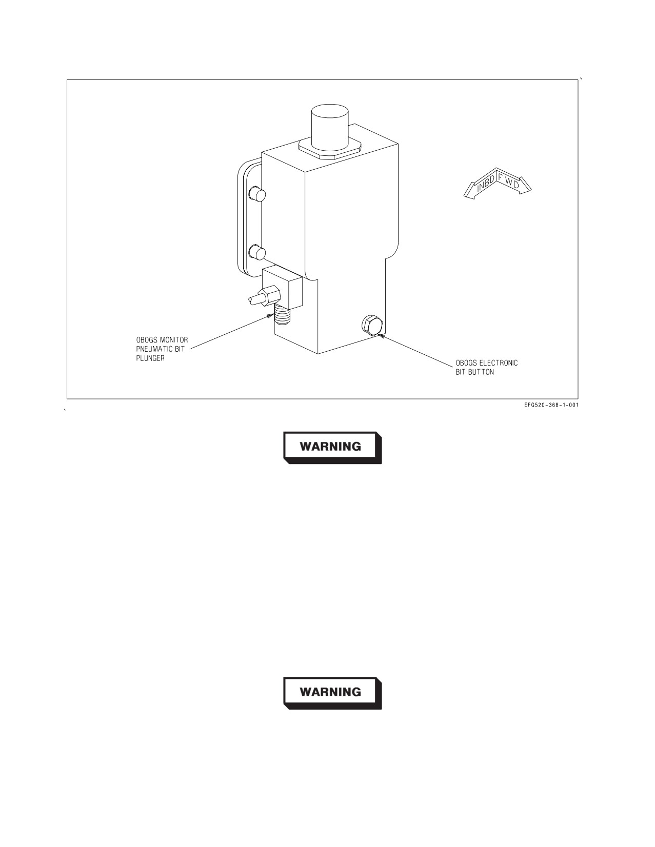
A1-E18GA-NFM-000
Figure 2-33. OBOGS Monitor
Loss of electrical power to the OBOGS monitor prevents reporting of
OBOGS DEGD conditions.
The monitor performs a power-up BIT during a 2 minute warm-up period and conducts a periodic
BIT every 60 seconds. No indication is provided if power-up or periodic BIT pass.
Preflight BIT of the monitor is accomplished by using either the pneumatic BIT plunger or the
electronic BIT pushbutton. Refer to figure 2-33. Pressing up and holding the pneumatic BIT plunger
for 15 to 65 seconds tests the operation of the OBOGS monitor by diverting cabin air into the monitor
to create a low oxygen concentration condition. Momentarily pressing and releasing the electronic BIT
pushbutton tests the monitor electronically. Successful completion of either test activates the OBOGS
DEGD caution, which clears automatically after BIT is complete and OBOGS resets to normal
operation.
Successful OBOGS monitor BIT is required prior to flight. A BIT failure
indicates that there is no protection against inadequate oxygen concen-
tration or hypoxia due to a degraded OBOGS monitor. Good breathing
gas flow alone does not ensure adequate oxygen concentration.
I-2-107
ORIGINAL
A1-E18GA-NFM-000
2.14.1.1.1 OBOGS DEGD Caution. An OBOGS DEGD caution is set by the OBOGS monitor when
oxygen concentration is below a predetermined level. The OBOGS DEGD caution threshold is always
above cabin air conditions, in order to provide a physiological safety margin.
NOTE
Oxygen concentration may drop below the predetermined OBOGS
DEGD level if breathing gas flow is unlimited. Removing the mask
without placing the OXY flow knob to OFF, system leaks, and/or loose
aircrew hose connections can overwhelm system capacity and may
result in an OBOGS DEGD caution.
After a total loss of bleed air, OBOGS breathing gas flow will be available until the residual gas
within the system is depleted. The residual oxygen concentration may be sufficient to keep the OBOGS
DEGD caution from illuminating, but loss of system pressure will ultimately lead to inadequate
pressure and an abrupt inability to breathe.
Low mask flow or increased breathing resistance may occur without an accompanying OBOGS
DEGD caution, which indicates a potential system degradation that may result in oxygen levels below
physiological requirements.
When cabin altitude is above 10,000
feet, OBOGS DEGD caution
procedures shall be executed for low mask flow, increased breathing
resistance, or OBOGS DEGD cautions of any duration.
A single brief appearance of the OBOGS DEGD caution immediately following placing the OBOGS
control switch to ON, turning the OXY FLOW knob to ON, or after donning or removing the mask is
normal. Certain malfunctions affecting the OBOGS system also may momentarily cause OBOGS
DEGD cautions. A momentary OBOGS DEGD caution may clear from the DDI so rapidly that the
aircrew may be unable to determine the cause of the MASTER CAUTION light/tone.
Repeated unexplained MASTER CAUTION lights/tones may be an
indication of OBOGS system degradation.
Even with the OBOGS DEGD caution displayed, OBOGS breathing gas under normal flow is of
higher quality (i.e., oxygen concentration, partial pressure and purity) than cabin air. Once cabin
altitude is below 10,000 feet, aircrew may elect to conserve emergency oxygen by resetting the
I-2-108
ORIGINAL
A1-E18GA-NFM-000
emergency oxygen release tab, then either removing the mask and breathing cabin air, or returning the
OXY FLOW knob and the OBOGS control switch to ON and breathing through the mask.
Pure oxygen accelerates recovery from hypoxia. Emergency oxygen shall
be used whenever hypoxic symptoms are recognized.
2.14.1.2 Breathing Regulator. The aircrew torso mounted breathing regulator reduces both normal
and emergency oxygen system operating pressures to breathing pressure levels. The regulator delivers
undiluted OBOGS breathing gas or emergency oxygen to the aircrew at positive pressure, the limits of
which increase automatically with altitude. It interfaces with the hose assembly, which connects with
the seat survival kit oxygen disconnect.
2.14.1.3 OBOGS Control Switch. The OBOGS control switch, located on the left console in the front
cockpit, is used to control electrical power to the OBOGS concentrator and the OBOGS inlet air shutoff
valve.
ON Supplies electrical power and engine bleed air to the OBOGS concentrator.
OFF OBOGS system off.
2.14.1.4 OXY FLOW Knob. The OXY FLOW knob, located on the left console in both cockpits, is
used to control the supply of OBOGS breathing gas to each aircrew’s mask.
ON OBOGS flow supplied to the mask.
OFF OBOGS flow secured.
It is possible to place the OXY FLOW knob in an intermediate posi-
tion between the ON and OFF detents, which may result in a reduced
flow of breathing gas. The OXY FLOW knob should always be fully
rotated to the ON or OFF detent position.
2.14.2 Emergency Oxygen. Emergency gaseous oxygen is contained in a bottle in the seat survival
kit. The bottle is connected into the OBOGS supply hose as it passes through the kit. From this point,
the emergency oxygen and OBOGS breathing gas share a common path to the aircrew mask.
A leak or break in the breathing gas system anywhere from the pilot
services panel oxygen disconnect to the mask will prevent either normal
OBOGS breathing gas or emergency oxygen from being delivered to the
mask in its intended concentration. Leaks and breaks may be difficult to
locate and/or verify. If hypoxic symptoms are experienced or an OBOGS
system degrade occurs, immediate descent below
10,000
feet cabin
altitude is required to prevent severe or incapacitating hypoxia.
I-2-109
ORIGINAL
A1-E18GA-NFM-000
A pressure gauge is visible on the inside left front of the survival kit. The bottle provides
approximately 10−20 minutes of oxygen. Oxygen duration decreases with lower altitude.
Under less than optimum conditions (low altitude, heavy breathing,
loose−fitting mask, etc.), as few as 3 minutes of emergency oxygen may be
available.
The emergency oxygen supply is activated automatically upon ejection. The emergency oxygen
supply may be activated manually by pulling the emergency oxygen green ring on the outside of the left
thigh. The emergency oxygen supply may be deactivated at aircrew discretion by pushing down on the
release tab immediately forward of the green ring.
With emergency oxygen selected, the OXY FLOW knob(s) shall be
placed to OFF. If not secured, OBOGS system pressure may prevent
emergency oxygen from reaching the breathing regulator. Additionally,
the OBOGS control switch should be placed to OFF to backup the OXY
FLOW knob.
2.15 FIRE DETECTION, FIRE EXTINGUISHING, AND BLEED AIR LEAK DETECTION SYSTEMS
The fire detection system contains dual-loop fire detectors and three FIRE warning lights. The fire
extinguishing system contains a READY/DISCH light and a fire extinguisher bottle. The two systems
provide engine bay, AMAD bay, and APU bay fire warning, engine and APU emergency shutdown, and
selective fire extinguishing capability. The fire extinguisher bottle is located in the aft fuselage
between the engines. The bottle contains a nontoxic gaseous agent which provides a one-shot
extinguishing capability.
Electrical power from the 28 vdc essential bus is required to operate the fire detection and
extinguishing systems. The systems can operate on battery power alone with the BATT switch ON.
A separate dry bay fire suppression (DBFS) system is incorporated to automatically detect and
extinguish a fire or explosion in the dry bays below fuel tanks 2, 3, and 4.
2.15.1 FIRE Lights. Two FIRE warning lights, one for each engine/AMAD bay, are located on the
upper left and right sides of the main instrument panel. The warning lights come on when a fire
condition is detected in the respective engine/AMAD bay. The left FIRE light indicates a fire condition
in the left engine/AMAD bay. The right FIRE light indicates a fire condition in the right engine/
AMAD bay.
I-2-110
ORIGINAL
A1-E18GA-NFM-000
Each light is a pushbutton, which is guarded to prevent inadvertent actuation. Pushing the left or
right FIRE light arms the fire extinguisher bottle (FIRE EXTGH READY light on) and closes the
corresponding feed tank shutoff valve, the crossfeed valve, and the crosscooling valve.
Because the engine VEN/start pumps are fuel lubricated, pushing a FIRE
light prior to throttle OFF may damage the corresponding pump. To
reduce the likelihood of damage, FIRE lights should only be pressed as
directed by NATOPS (following throttle OFF for actual emergencies or
as specifically delineated for an FCF A profile).
If a FIRE light is pressed, the pushbutton stays in and approximately 1/8 inch of yellow and black
stripes is visible around the outer edges of the light.
2.15.2 APU FIRE Light. The APU FIRE warning light is located on the main instrument panel
inboard of the right FIRE light. The APU FIRE light comes on when a fire condition is detected in the
APU bay. The APU FIRE light is also a pushbutton. Pushing the APU FIRE light arms the fire
extinguisher bottle (FIRE EXTGH READY light on) and secures fuel to the APU. If the APU FIRE
light is depressed, the pushbutton stays in and approximately 1/8 inch of yellow and black stripes is
visible around the outer edges of the light.
2.15.3 FIRE Warning Voice Alerts. When the left, right, and/or APU FIRE lights are illuminated, the
ENGINE FIRE LEFT, ENGINE FIRE RIGHT, or APU FIRE voice alerts, respectively, are also
activated. If more than one FIRE light comes on at the same time, the voice alert priority is LEFT,
RIGHT, then APU.
2.15.3.1 FIRE Warning Lights (Rear Cockpit). The rear cockpit left, right, and APU FIRE warning
lights are advisory only. These lights are not pushbuttons, and they do not arm the fire extinguisher
bottle or shut down the engines or APU.
2.15.4 FIRE EXTGH READY/DISCH Light. The FIRE EXTGH READY/DISCH light is located on
the MASTER ARM panel on the left side of the main instrument panel. The top half of the light is
yellow and is labeled READY. The bottom half of the light is green and is labeled DISCH. When the
fire extinguisher bottle is armed (left, right, or APU FIRE light pressed), the yellow READY light is
illuminated.
The FIRE EXTGH READY/DISCH light is also a pushbutton. When the READY light is on,
pushing the light discharges the fire extinguisher bottle into the selected engine/AMAD/APU bay(s).
The FIRE EXTGH READY/DISCH light does not latch like the FIRE lights, which means a signal is
sent to discharge the fire extinguisher bottle ONLY when the light is held in the fully pressed position.
When the fire extinguisher bottle has discharged or pressure has been lost, the green DISCH light
comes on. Therefore, it is good practice with an engine/AMAD bay fire to hold the READY/DISCH
light pressed until the green DISCH light comes on. The fire extinguisher bottle should discharge
within 5 seconds.
I-2-111
ORIGINAL
A1-E18GA-NFM-000
For an inflight APU fire, discharge of the fire extinguisher bottle is delayed approximately 10
seconds from when the APU FIRE light is pushed. It is not necessary to hold the READY/DISCH light
for those 10 seconds. However, if the DISCH light does not come on 10 seconds after the APU FIRE
and READY/DISCH lights have been pushed, the READY/DISCH light should be pushed and held
until the DISCH light does come on.
If more than one FIRE light is pressed, the fire extinguisher bottle may not discharge and, if it does,
the concentration of the extinguishing agent sent to the selected bays may be insufficient to extinguish
both fires.
2.15.5 APU Fire Extinguishing System. The APU fire extinguishing system is automatically acti-
vated with WonW and must be manually activated with WoffW. If an APU fire condition is detected
with WonW, the automatic function secures fuel to the APU, arms the fire extinguisher bottle, and
after 10 seconds discharges the fire bottle. Discharge of the bottle is delayed for 10 seconds to allow the
APU time to spool down before extinguishing agent is introduced.
Manual activation is accomplished by pushing the APU FIRE light and then the FIRE EXTGH
READY light. Like automatic activation, discharge of the bottle is delayed for 10 seconds after the
APU FIRE light is pushed. If an APU FIRE condition is detected with WonW, manual activation
should be performed to backup the automatic system.
Since the fire extinguishing system requires 28 vdc essential bus power,
the fire extinguisher bottle may not be discharged if the BATT switch is
turned off during the 10 second delay time.
2.15.6 Engine/AMAD Fire Extinguishing System. The engine/AMAD fire extinguishing system
must be manually activated. Manual activation is accomplished by lifting the guard and pressing the
corresponding FIRE light and then the FIRE EXTGH READY light. Pushing the FIRE light secures
fuel to the engine at the feed tank shutoff valve and isolates the left and right fuel systems by closing
the crossfeed and crosscooling valves. When the FIRE EXTGH READY light is pushed, the fire
extinguisher bottle is discharged without delay into the corresponding engine/AMAD bay.
Fire testing indicates that the probability of extinguishing a fire and
preventing relights is greatly increased by immediately discharging the
fire extinguisher.
2.15.7 FIRE Detection System Test. Each of the three FIRE warning lights contains four individual
light bulbs. Light bulb integrity can be tested during a LT TEST with ac power applied. If a
malfunction exists in a fire detection loop associated with the APU FIRE light, the APU FIRE voice
alert does not annunciate and none of the four individual bulbs in the light illuminate. If a malfunction
exists in a fire detection loop associated with either FIRE light, the corresponding ENGINE FIRE
LEFT/RIGHT voice alert does not annunciate and only the individual bulb (or bulbs) associated with
the malfunctioning sensor does not come on. Care must be taken to detect bulbs that are not on in the
FIRE lights during the loop test.
I-2-112
ORIGINAL
A1-E18GA-NFM-000
A successful test of the FIRE detection system should illuminate all four bulbs in each of the three
FIRE lights and should annunciate the ENGINE FIRE LEFT, ENGINE FIRE RIGHT, and APU
FIRE voice alerts.
2.15.8 Bleed Air Leak Detection (BALD) System. The BALD system is designed to protect the
aircraft from damage resulting from a bleed air leak. The system contains a BALD controller and 11
detector sensing elements routed along the bleed air distribution lines (ducts, valves, and heat
exchangers). If a bleed air leak is detected, the system attempts to isolate the affected ducting by
automatically closing the appropriate bleed air shutoff valve(s). A leak detected upstream of the
secondary bleed air shutoff valve closes only the appropriate primary bleed air shutoff valve. A leak
detected downstream of the secondary bleed air shutoff valve closes all three valves (secondary and
both primaries).
When a leak is detected, the BALD system sends commands directly to the appropriate bleed air
shutoff valves, to the BLEED warning lights, and to the ACI, triggering the BLEED AIR LEFT
(RIGHT) voice alerts. When the bleed air shutoff valve(s) are commanded closed, the appropriate L
and/or R BLD OFF caution is displayed. The L BLEED and/or R BLEED warning lights extinguish
as soon as bleed air is removed from the leaking duct and may not be on long enough to be recognized
by the aircrew.
Automatic functioning of the BALD system may extinguish the L(R)
BLEED warning lights prior to aircrew recognition and may not trigger
the appropriate voice alerts. In this case, cycling the BLEED AIR knob to
remove the L and/or R BLD OFF cautions reintroduces hot bleed air to
the leaking duct. If the sensing element was damaged by the leak,
automatic shutdown and isolation capability may be lost. Extensive
damage and/or fire may result.
The BALD controller also sends a separate command to the SDC which sets an MSP code for the
appropriate sensing element.
A bleed air leak can be verified by MSP codes 953, 954, 955, 956, 957, 958, 959, 960 or 961 (code
determines leak location). An overpressure condition is indicated by MSP code 833 with no bleed air
leak codes.
2.15.8.1 Bleed Air Leak Detection System Test. The BALD system is tested by the FIRE test switch
in conjunction with the FIRE detection system. Actuation of the FIRE test switch tests the BALD
system sensors and circuitry. The BALD controller turns on the L and R BLEED warning lights,
annunciates the BLEED AIR LEFT/RIGHT voice alerts, and commands the bleed air shutoff valves
closed setting the L and R BLD OFF cautions. The warnings and cautions indicate that the test has
successfully passed.
The L BLEED and R BLEED warning lights go out when the FIRE test switch is released to NORM,
but the L and R BLD OFF cautions remain until the BLEED AIR knob is cycled through OFF to
NORM with ac power applied.
I-2-113
ORIGINAL
A1-E18GA-NFM-000
2.15.8.2 FIRE Test Switch. The FIRE test switch, located on the forward left console, is used to
initiate a test of the FIRE detection and BALD systems. Operation of the FIRE test switch requires
28 vdc essential bus power. The switch is spring-loaded to the NORM position.
TEST A
Initiates a test of loop A of the fire detection and BALD systems.
NORM
Provides normal fire and bleed air leak detection.
TEST B
Initiates a test of loop B of the fire detection and BALD systems.
A successful test of the FIRE detection and BALD systems should illuminate all four bulbs in the
left, right, and APU FIRE lights, both L BLEED and R BLEED warning lights, and should annunciate
all of the following voice alerts in order: ″ENGINE FIRE LEFT, ENGINE FIRE RIGHT, APU FIRE,
BLEED AIR LEFT, BLEED AIR RIGHT″ (each repeated twice).
The BALD controller is sensitive to the duration of FIRE test switch actuation. If the switch is not
held in the TEST A or TEST B position for at least two seconds, the BALD controller may set a false
MSP code. Additionally, the BALD controller requires 3 seconds between TEST A and TEST B to
successfully reset. If the switch does not remain in NORM for at least 3 seconds, the BALD controller
may not successfully initiate the bleed air warnings and may set a false MSP code.
2.15.9 Dry Bay Fire Suppression System (DBFS). An active DBFS system is incorporated in the
center dry bays under fuel tanks 2, 3, and 4 to automatically extinguish any fires or explosions which
are detected in these areas. The system consists of fourteen optical fire detectors, seven extinguishing
units and a control unit. The control unit integrates system operation and performs BIT. If the DBFS
system fails BIT, a BIT advisory appears, and DBFS BIT status indicates DEGD.
The DBFS system is totally automatic and requires no aircrew action. The system is armed and
capable of suppressing a fire/explosion in the dry bays when the LDG GEAR handle is up and at least
one generator is on line. If a fire/explosion is detected, the controller discharges all extinguishers,
flooding all dry bays with an inert gas (BAY DISCH caution set). If a fire condition is still detected
after 3 seconds, a BAY FIRE caution is set to alert the aircrew that the fire was not extinguished. If
the fire condition ceases, the BAY FIRE caution resets. With the LDG GEAR handle down, the system
still gives a fire warning (BAY FIRE caution) but is not capable of extinguishing a dry bay fire.
2.16 ENTRANCE/EGRESS SYSTEMS
2.16.1 Canopy System. The cockpit is enclosed by a clamshell type canopy. The main components
of the canopy system are an electromechanical actuator, which provides powered and manual operation
of the canopy, and a cartridge actuated thruster with associated rocket motors, which provides
emergency jettison. When closed, the canopy is latched in place by three hooks on the bottom of each
side of the canopy frame and two forward indexer pins on the lower leading edge of the canopy frame.
When the canopy is closed, the latch hooks and indexer pins engage fittings along the canopy sill, and
the canopy actuator rotates the canopy actuation link over-center, locking the canopy. A mechanical
brake in the canopy actuator motor provides a redundant lock. An inflatable seal, installed around the
edge of the canopy frame, retains cockpit pressure when the canopy is locked. A rain seal is installed
outboard of the pressure seal to divert rain water away from the cockpit. See figure 2-34.
I-2-114
ORIGINAL
A1-E18GA-NFM-000
A high voltage (100,000 volt) static electrical charge may build up in flight
and be stored on the windshield and canopy. If possible, ensure that
ground crew discharge the static electricity prior to egress. Otherwise,
avoid direct contact with the outside of the windshield and canopy to
prevent electrical shock.
Taxiing with the canopy at an intermediate position can result in canopy
attach point damage and failure. Do not open or close the canopy with the
aircraft in motion.
2.16.1.1 Canopy Operation. During normal operation, the canopy is electrically actuated using
either the internal CANOPY switch or external canopy switch. The canopy actuator is powered by the
maintenance bus, which is powered directly by the battery in the absence of ac power (BATT switch
ON or OFF). On battery power, at least five open/close cycles should be available. With the canopy
open, the CANOPY switch must be held to lower the canopy to the rails, slide it approximately 1.5
inches forward, and lock it in place. With the canopy closed and locked, selecting OPEN on the
CANOPY switch (WonW) automatically unlocks and opens the canopy to the full up position. The
switch does not have to be held. Whether the canopy is opening or closing, selecting HOLD stops the
canopy at its present position.
If electrical power is not available, the canopy can be manually operated using either an internal or
external crank system. The canopy can also be jettisoned using one of the internal CANOPY JETT
handles or the external canopy jettison handle.
2.16.1.1.1 CANOPY Switch (Internal). The internal CANOPY switch is located beneath the right
canopy sill in the front cockpit. The rear cockpit CANOPY switch is located on the lower right portion
of the instrument panel. The CANOPY switch is spring loaded to the HOLD position and is
solenoid-held in the OPEN position only with WonW. The solenoid can be overridden at any time by
placing the switch to HOLD. With WoffW, the switch must be held in the OPEN position to raise the
canopy. Opposing position control commands between the front cockpit and rear cockpit switches
result in a fail-safe OPEN command.
OPEN
Unlocks and/or raises the canopy.
HOLD
Stops the canopy at any point during the open or close cycle.
CLOSE
Lowers and, if held, closes and locks the canopy (CANOPY caution out when
closed and locked).
2.16.1.1.2 Canopy Switch (External). The external canopy switch is located inside the external
power receptacle door (door 9) on the left side of the aircraft below the canopy and LEX. The switch
provides electrical operation of the canopy from outside the cockpit. The switch has the same positions
and operates identically to the internal CANOPY switch, except that the OPEN position is not
solenoid held. The switch is guarded to prevent inadvertant actuation.
I-2-115
ORIGINAL
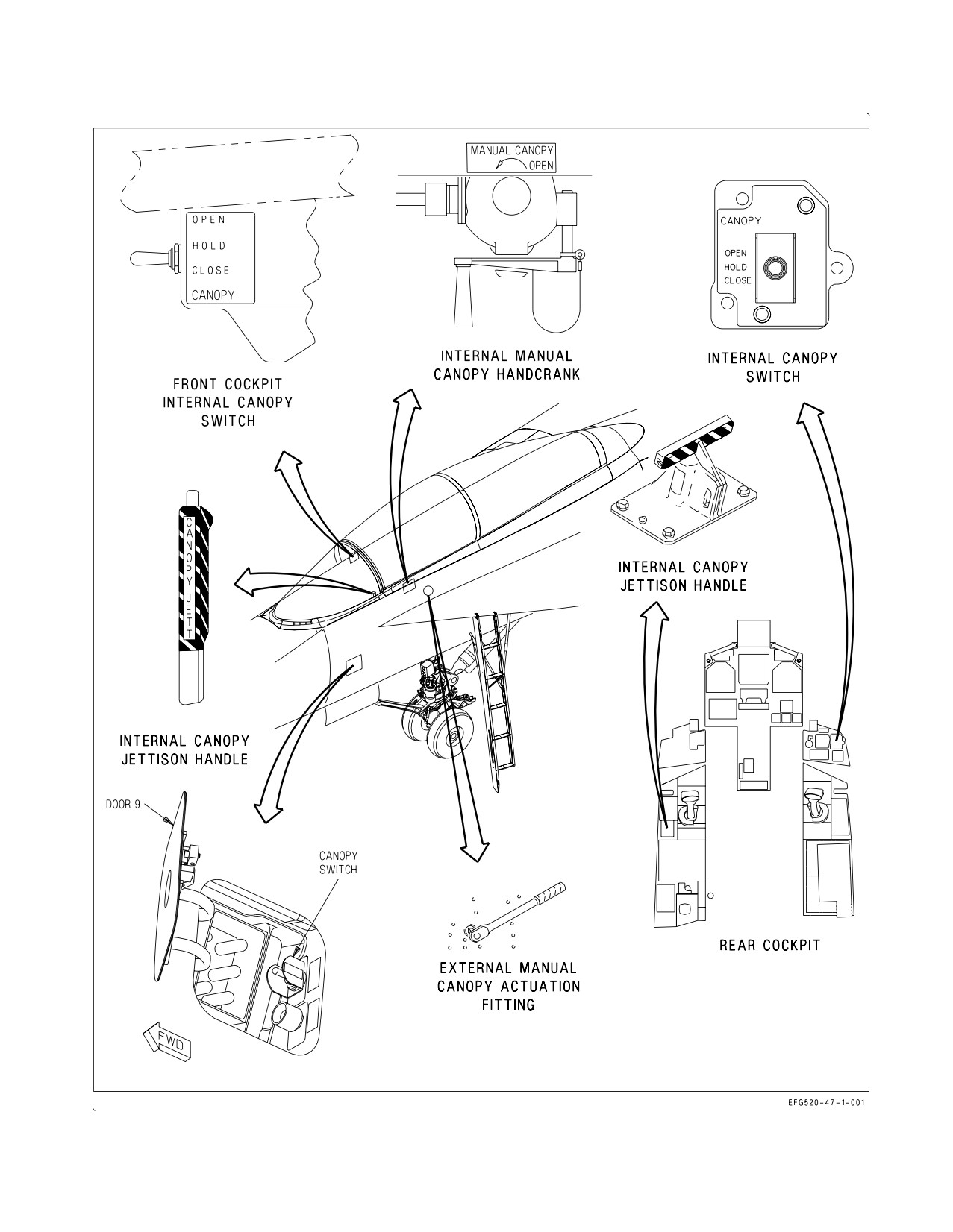
A1-E18GA-NFM-000
Figure 2-34. Canopy Controls
I-2-116
ORIGINAL
A1-E18GA-NFM-000
2.16.1.1.3 Manual Canopy Handcrank (Internal). The internal manual canopy handcrank is stowed
in a clip beneath the left canopy sill. The canopy can be manually opened or closed by inserting the
handcrank into the crank socket immediately above the stowage clip. Approximately 70 counterclock-
wise turns are required to fully open the canopy. Clockwise cranking closes the canopy. A cable is
provided to prevent loss of the handle if dropped.
2.16.1.1.4 Manual Canopy Actuation Fitting (External). The external manual canopy actuation
fitting, a 3/8 inch drive socket on the left side of the aircraft below the canopy, is used to manually
operate the canopy. Inserting a 3/8 inch drive tool in the socket and then turning counterclockwise
approximately 35 turns opens the canopy. Turning the drive tool clockwise closes the canopy.
2.16.1.2 Canopy Jettison System. For canopy jettison, a cartridge initiated thruster is utilized to
unlatch the canopy by moving it 1½ inches rearward, after which two canopy frame mounted rocket
motors fire to rotate the canopy up and aft, clear of the ejection seat path. The thruster, which provides
attachment for the canopy actuator link during normal canopy operation, is activated by pulling the
ejection seat firing handle or internal canopy jettison handle(s) (figure 2-34). The canopy can be
jettisoned closed, open, or in any intermediate position.
2.16.1.2.1 CANOPY JETT Handle (Front Cockpit). The CANOPY JETT handle is black and yellow
striped and is located on the left inboard canopy sill just aft of the instrument panel in the front
cockpit. Pressing the button on the tip of the handle unlocks the handle. Pulling the handle aft initiates
the canopy jettison sequence. A REMOVE BEFORE FLIGHT pin is used to manually secure the
CANOPY JETT handle between flights.
2.16.1.2.2 CANOPY JETT Handle (Rear Cockpit). The rear cockpit CANOPY JETT handle is black
and yellow striped and is located on the left console. Pressing the button on the forward tip of the
handle unlocks the handle. Pulling the handle up initiates the canopy jettison sequence. A REMOVE
BEFORE FLIGHT pin is used to manually secure the CANOPY JETT handle between flights.
2.16.2 Boarding Ladder. A five-step boarding ladder (figure 2-35), stowed under the left LEX,
provides access to the cockpit and the top of the aircraft. Ladder extension and retraction can be
accomplished only from outside the cockpit, either manually or by the ladder remote release button.
The ladder is extended manually by releasing the latch on the stow assist handle on the ladder’s left
rail (allowing it to drop slightly) and while supporting the ladder, rotating the stow assist handle to
vertical (releasing the remaining two mechanical uplocks on the underside of the LEX). The ladder
rotates down to the extended position. The stow assist handle is then secured. The drag brace locks
when extended to its full length to provide longitudinal stability for the ladder. Lateral stability is
provided by the V-shaped side brace attached to the side of the fuselage.
The LEX is narrow and highly sloped. Use caution to avoid loss of
footing.
NOTE
The ladder is not visible from the cockpit.
I-2-117
ORIGINAL
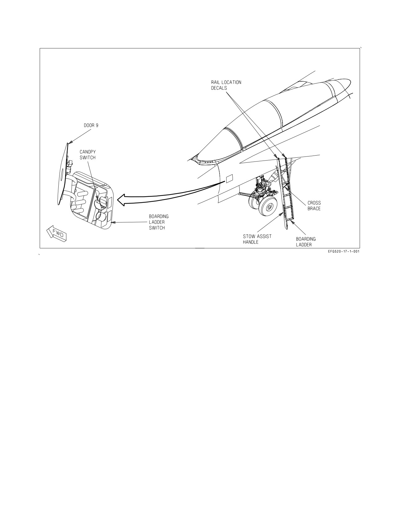
A1-E18GA-NFM-000
Figure 2-35. Boarding Ladder
Normal cockpit egress is accomplished by grasping the canopy sill firmly with both hands, leaning
outboard and, using the ladder marking decals as a guide, stepping over the LEX toward the ladder.
The first step is approximately 15 inches below the leading edge of the LEX.
The ladder is stowed by detaching the rigid side brace connection from the fuselage. Pulling the
collar on the drag brace down permits the telescoping drag brace to unlock and compress as the
boarding ladder is rotated up and aft to the stowed position. The latches are manually engaged and
locked by pushing them full up until locked flush with the forward beam. If necessary, the stow assist
handle can be used to assist in stowing the ladder by releasing the handle and pushing the ladder to
the stowed position and pushing the stow assist handle to the closed (stowed) position and releasing it.
With electrical power on the aircraft, a LADDER caution comes on whenever the proximity switch in
the aft portion of the ladder well is not actuated. With the ladder stowed and the 3 latches locked, the
LADDER caution goes out.
The ladder is extended remotely by opening the external power receptacle door and pressing and
holding the guarded ladder remote release button. The three latches are opened by a battery powered
actuator. The ladder drops to the open position while being restrained from free falling by a dampening
strut (drop time approximately 3 to 4 seconds). All other procedures for securing the ladder are the
same as manual opening.
I-2-118
ORIGINAL
A1-E18GA-NFM-000
2.16.2.1 Ladder Remote Release Button. The guarded external ladder remote release button is
located inside the external power receptacle (door 9) on the left side of the aircraft below the canopy
and LEX. Pressing and holding the button applies electrical power to the boarding ladder actuator
which unlocks the three uplock latches so the ladder can free fall.
Due to the close proximity of the ladder remote release button and the
external canopy switch, positive switch identification is required to
prevent inadvertently lowering the canopy and injuring personnel egress-
ing the aircraft.
2.16.3 Ejection Seat. The SJU-17B(V) 2/A and 9/A NACES (Navy Aircrew Common Ejection Seat)
are ballistic catapult/rocket systems that provide the pilot with a quick, safe, and positive means of
escape from the aircraft. See Ejection Seat, foldout section, for ejection seat illustrations. The seat
system includes an initiation system which, after jettisoning the canopy and positioning the occupant
for ejection, fires the telescopic seat catapult. Canopy breakers on the top of the seat give capability of
ejecting through the canopy. As the seat departs the aircraft and the catapult reaches the end of the
stroke, a rocket motor on the bottom of the seat is fired. The thrust of the rocket motor sustains the
thrust of the catapult to eject the seat to a height sufficient for parachute deployment even if ejection
is initiated at zero speed, zero altitude in a substantially level attitude.
NOTE
Safe escape is provided for most combinations of aircraft altitude,
speed, attitude, and flight path within the envelope of 0 to 600 KCAS
airspeed and 0 to 50,000 feet.
Timing of all events after rocket motor initiation is controlled by the electronic sequencer which
utilizes altitude, acceleration, and airspeed information to automatically control drogue and parachute
deployment and seat/man separation throughout the ejection seat’s operational envelope. In the event
of partial or total failure of the electronic sequencer, a 4-second mechanical delay initiates a barostatic
release unit which frees the occupant from the seat and deploys the parachute between 14,000 and
16,000 feet MSL if the ejection occurred in or above this altitude range. The emergency barostatic
release unit operates immediately after the 4-second delay if the ejection occurred below 14,000 feet
MSL. An emergency restraint release (manual override) system provides a backup in the event of
failure of the barostatic release unit. The seat is stabilized and the forward speed retarded by a drogue
chute attached to the top and bottom of the seat. The parachute deployment rocket is automatically
fired to withdraw the parachute from the deployment bag. Full canopy inflation is inhibited until the
g forces are sufficiently reduced to minimize opening shock. There are five modes of operation. See
figure 2-36 for parameters that determine the mode of operation and the corresponding parachute
deployment and drogue chute release times. At high altitude the drogue chute deploys to decelerate
and stabilize the seat. The seat falls drogue retarded to 18,000 feet MSL where the drogue is released,
the main parachute is deployed, and seat/man separation occurs. At medium altitude (between 18,000
and 8,000
feet MSL), and at low altitude
(below
8,000
feet MSL) parachute deployment is
automatically delayed from 0.45 to 2.90 seconds (depending upon airspeed and altitude) after first seat
motion to allow the drogue chute to decelerate and stabilize the seat.
The main parachute is a 21 foot aeroconical canopy type, stored in a headbox container on top of the
ejection seat. The parachute is steerable and contains water deflation pockets which aid in dumping air
I-2-119
ORIGINAL
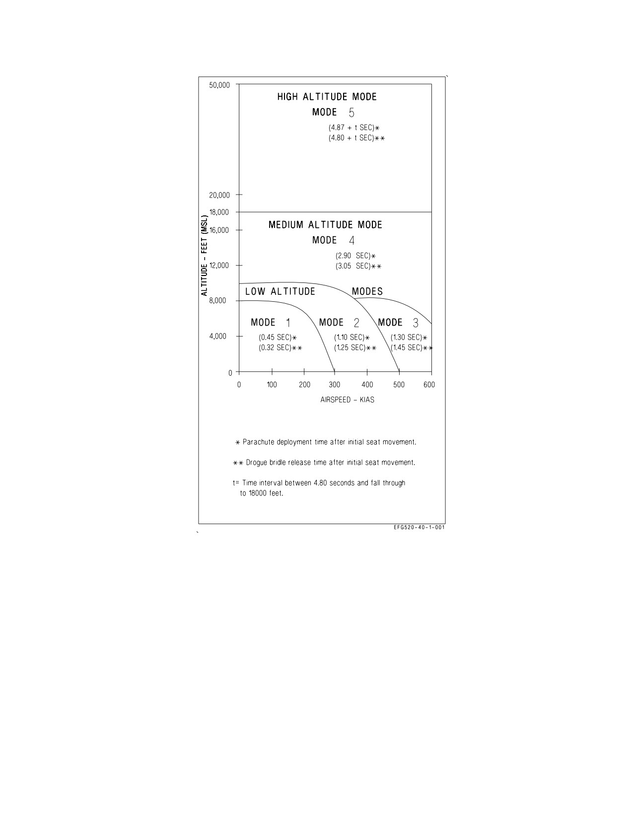
A1-E18GA-NFM-000
Figure 2-36. SJU-17B Ejection Modes
from the canopy after landing in water. The seat drogue chute is stored in a separate container on top
of the drogue deployment catapult. The seat contains controls for adjusting seat height and for locking
and unlocking the inertia reel shoulder restraint straps. A survival kit is installed in the seat pan.
2.16.3.1 SEAWARS - SEAWATER Activated Release System. SEAWARS is a seawater activated
system that automatically releases the parachute from the crew member. When the sensing-release
units are immersed in seawater, cartridges are fired which allow the crew member to separate from the
parachute.
2.16.3.2 Ejection Control Handle. The ejection control handle, located between the crewman’s legs
on the front of the seat pan, is the only means by which ejection is initiated. The handle, molded in the
shape of a loop, can be grasped by one or two hands. To initiate ejection, a 20 to 40 pound pull removes
the handle from its housing, and a continued pull of 30 to 60 pounds is required to pull both sears from
I-2-120
ORIGINAL
A1-E18GA-NFM-000
the dual initiators. Either of the initiators can fire the seat. After ejection, the handle remains attached
to the seat. The ejection control handle safes the ejection seat safe/armed handle.
2.16.3.3 Ejection Seat SAFE/ARMED Handle. To prevent inadvertant seat ejection, an ejection seat
safe/armed handle is provided. The handle, forward on the right seat armrest, safeties the seat when
rotated up and forward, and arms the seat when it is rotated aft and down. The safe/armed handle is
locked when placed to either of these two positions and the handle must be unlocked by squeezing a
locking lever within the handle cutout before changing positions. When in the armed position the
visible portion of the handle (from the occupant’s vantage point) is colored yellow and black with the
word ARMED showing. In the safe position, the visible portion is colored white with the word SAFE
showing. The seat is safe only when the word SAFE is entirely visible on the inboard side of the
SAFE/ARM handle and the handle is locked in the detent. Placing the handle to the SAFE position
causes a pin to be inserted into the ejection firing mechanism to prevent withdrawal of the sears from
the dual seat initiators.
2.16.3.3.1 CK SEAT Caution. The CK SEAT caution light is located on the caution light panel and
repeats the DDI CHECK SEAT caution. The caution comes on when the right throttle is at MIL or
above, weight is on wheels, and the ejection seat is not armed.
2.16.3.4 Shoulder Harness Inertia Reel. Pilot shoulder harness restraint is provided by a dual strap
shoulder harness inertia reel mounted in the seat below the parachute container. The dual inertia reel
shoulder straps connect to the parachute risers which in turn are buckled to the seat occupant’s upper
harness. The inertia reel locks when the reel senses excessive strap velocity. Manual locking and
unlocking of the reel is controlled by the shoulder harness lock/unlock handle on the left side of the
seat bucket. During ejection a pyrotechnic cartridge is fired to retract the shoulder harness to position
the seat occupant for ejection.
2.16.3.5 Shoulder Harness Lock/Unlock Handle. The shoulder harness lock/unlock handle on the
left side of the seat bucket has two positions. To operate, the handle must be pulled up against spring
pressure, moved to the desired position, and released.
FORWARD The inertia reel prevents the reel straps from being extended and ratchets any
(locked)
slack in the straps back into the reel.
AFT
The reel allows the pilot to lean forward, but the inertia portion of the reel contin-
(unlocked)
ues to protect by locking the reel when it senses excessive strap velocity. Once
locked, the pilot can normally lean forward again after a slight release in pressure
on the reel straps.
2.16.3.6 Leg Restraint System. A leg restraint system is located on the front of the ejection seat. The
function of the system is to secure the occupant’s legs to the seat during ejection. The system consists
of two adjustable leg garters, a restraint line, and a snubber box for each leg. One garter is worn on the
thigh and one on the lower leg. The restraint lines are routed through the garter rings and the snubber
box as shown in figure 2-37. One end of each restraint line is secured to the cockpit floor and the other,
after being routed through the snubber box and both garter rings, is secured to the seat just outboard
of the snubber box by a releaseable pin. During ejection, the slack in each line is taken up and the
tension builds up to finally separate the lines at the tension rings in the leg lines. At man/seat
separation, the pins on the other end of the lines are released by the time release mechanism. The pins
are also released when the manual override handle is pulled. Both the lower garter and thigh garter
contain a quick release buckle which disconnects the ring through which the leg restraint line runs,
I-2-121
ORIGINAL
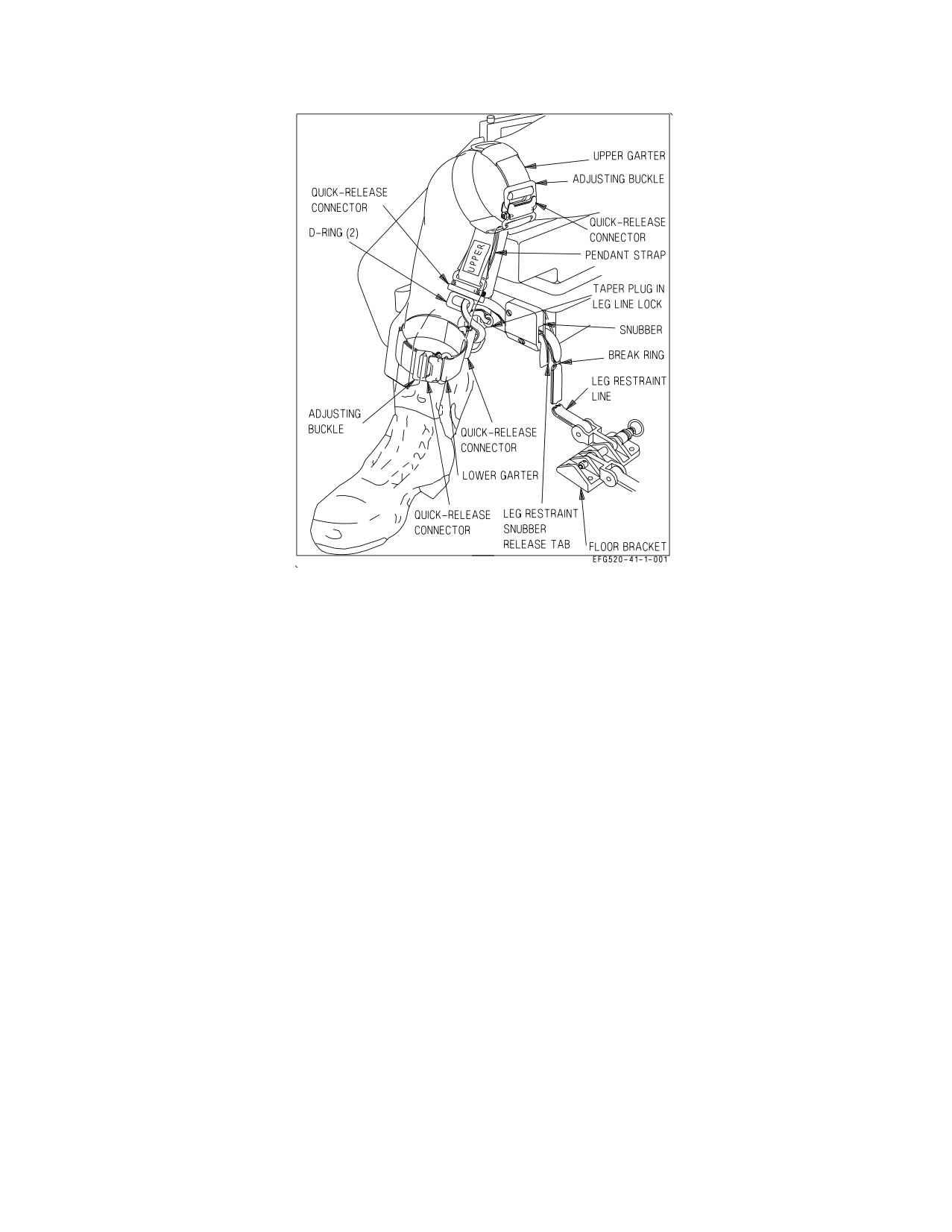
A1-E18GA-NFM-000
Figure 2-37. Leg Restraint System
permitting the pilot to egress from the aircraft wearing both upper and lower garters. In addition, toe
clips are installed on the tops of the rudder pedals to prevent contact between the toes and the
instrument panel during ejection.
2.16.3.6.1 Leg Restraint Snubber Release Tabs. The leg restraint lines are adjusted to give the pilot
more leg movement by pulling inboard the leg restraint snubber release tabs (figure 2-37) and
simultaneously pulling the leg restraint lines forward through the snubber box.
2.16.3.7 Seat Survival Kit (SKU-10/A). The SKU-10/A survival kit is used with the SJU-17B
ejection seat. This survival kit, which fits into the seat bucket, is a contoured rigid platform which
contains an emergency oxygen system and a fabric survival rucksack (figure 2-38). A cushion on top of
the platform provides a seat for the aircrew.
The rigid platform forms a hard protective cover to the survival package and oxygen system and is
retained in position in the seat bucket by brackets at the front and lugs secured in the lower harness
locks at the rear. Attached to the lugs are two adjustable lap belts with integral quick release fittings.
A flexible oxygen and communication hose is installed in the left aft side of the upper kit to provide
a connection to the aircrew for aircraft oxygen and communication. An emergency oxygen cylinder,
pressure reducer, and associated pipe work are mounted on the underside of the platform. A green
manual emergency oxygen operating handle is mounted on the left side of the platform and a pressure
gage is on the inside face of the left leg support. The emergency oxygen can be activated manually by
pulling the green emergency oxygen handle upwards. The green emergency oxygen handle can be reset,
shutting off the flow of emergency oxygen, by pushing downward on the button on the front end of the
emergency oxygen handle assembly. The emergency oxygen is automatically activated during ejection
by a lanyard connected between the floor and the survival kit. An AN/URT-33A locator beacon is
I-2-122
ORIGINAL
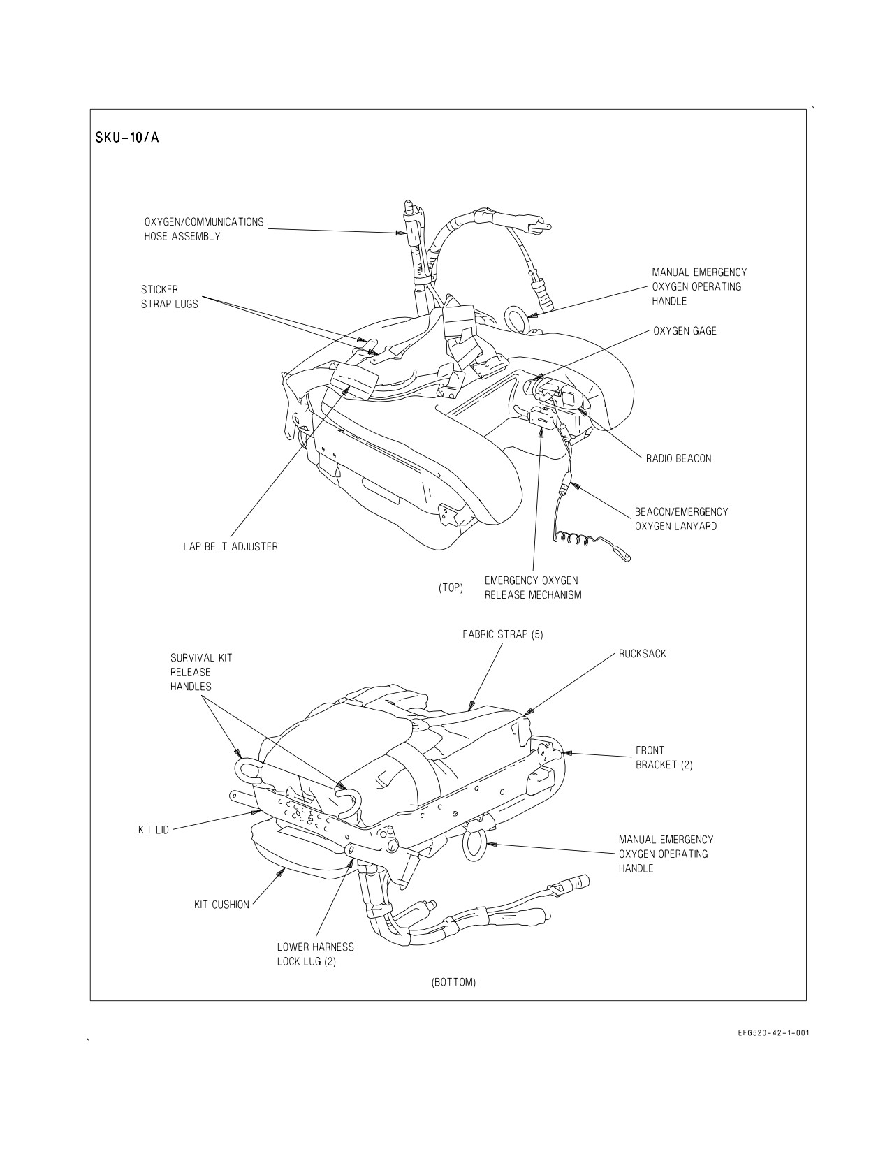
A1-E18GA-NFM-000
Figure 2-38. Survival Kit
I-2-123
ORIGINAL
A1-E18GA-NFM-000
located in a cutout in the left leg support. The beacon is actuated during ejection by a lanyard
connected to the emergency oxygen lanyard.
The survival rucksack is retained to the underside of the rigid platform by five fabric straps and a
double cone and pin release system. The package accommodates a life raft and survival aids. Two
yellow manual deployment handles are mounted on the aft surface of the kit. Pulling either handle
enables the aircrew to deploy the raft and survival package after man/seat separation. The life raft
inflates automatically on survival package deployment and is attached to the survival package with a
line. If the survival kit must be deployed after water entry, a snatch pull on the red manual activation
handle near the CO2 bottle is required to inflate the life raft.
2.16.3.8 Manual Override Handle. A manual override handle permits releasing the pilot’s lower
harness restraints and the leg restraint lines for emergency egress and permits resuming part of the
ejection sequence (man/seat separation and main parachute deployment) in the event of sequencing
failure during ejection. The manual override handle, on the right side of seat bucket and just aft of the
ejection seat safe/arm handle, is actuated by pressing a thumb button on the forward part of the handle
and rotating the handle up and aft. If the manual override handle is actuated on the ground or in the
air before ejection, survival kit attachment lugs and leg restraint lines are released, the inertia reel is
unlocked, and the ejection seat safe/armed handle automatically rotates to the SAFE position. During
ground emergency egress, after the manual override handle is pulled and the parachute riser fittings
are released, the pilot is free to evacuate the aircraft with the survival kit still attached. If the manual
override handle is actuated after ejection but before man/seat separation occurs, the following events
take place: release of survival kit attachment lugs, negative-g strap, leg restraint lines, and inertia reel
straps; firing of the manual override initiator cartridge; firing of the barostatic release unit; and firing
of the parachute deployment rocket, which deploys the parachute. The ejection seat safe/armed handle
automatically rotates to the SAFE position whenever the manual override handle is actuated.
Pulling the manual override handle automatically rotates the ejection
seat safe/armed handle to the SAFE position, releases the survival kit
attachment lugs and leg restraint lines, and unlocks the inertia reel. If
this is done inflight, the aircrew will be unable to eject.
2.16.3.9 Seat Bucket Position Switch. The seat bucket position switch is on the left side of the seat
bucket, forward of the shoulder harness lock/unlock handle. The forward switch position lowers the
seat bucket, the aft position raises the seat bucket. The center off position, to which the switch is spring
I-2-124
ORIGINAL
A1-E18GA-NFM-000
loaded, stops the seat bucket. The maximum vertical travel of the seat bucket is 6.1 inches. The
actuator should not be operated over 1 minute during any 8 minute period.
• To prevent increased risk of thigh slap or leg contact injuries, aircrew
with a buttock-to-knee length greater than 25.5 inches should not use
either of the two forward backpad positions. Aircrew with buttock-to-
knee length between 24.6 and 25.5 inches should not use the full
forward backpad position.
• Actuation of the seat bucket position switch with the leg restraints
under the seat bucket may result in an inadvertent ejection.
Actuation of seat bucket position switch with lap belts, shoulder harness,
and/or leg restraints outside or under seat bucket may damage ejection
seat, leg restraints, and/or Koch fittings.
2.16.3.10 Backpad Adjustment Mechanism. The backpad adjustment mechanism handle is on the
seat bucket adjacent to the top left hand side of the backpad and is connected to the backpad by a
linkage. The backpad has three positions, full-forward, middle, and full-aft, which give a total
forward/aft adjustment of 1.6 inches. When the handle is in the full-up position, the backpad is full-aft,
and when the handle is full-down, the backpad is full-forward. To move the backpad, the adjustment
handle is moved within a quadrant until a spring-loaded plunger engages in one of the three detent
positions in the quadrant. Set the backpad for personal comfort and best access to flight controls
during initial strap-in and prior to flight.
2.16.4 Ejection Seat System. The ejection seats are ejected at opposite divergent angles to one
another. The rear seat diverges to the left while the forward seat diverges to the right. The amount of
divergence is influenced by the weight of the aircrew and the speed of the ejection. The heavier the
aircrew and the faster the speed, the less the resulting divergent angle. In addition, a sequencing system
is installed to allow dual ejection initiated from either cockpit or single (aft) seat ejection initiated from
the rear cockpit. A command selector valve is installed in the rear cockpit to control whether ejection
from the rear cockpit is dual or single.
2.16.4.1 EJECT MODE Handle. The EJECT MODE handle is located on the right side of the main
instrument panel in the rear cockpit. The EJECT MODE handle is used to select the desired ejection
sequence to be initiated from the rear cockpit, or provide for single ejection for solo flight. Positioning
is accomplished by pulling out while turning to the desired position. The SOLO position requires the
use of a collar to hold the handle in that position. To release from AFT INITIATE, pull then turn
clockwise.
NORM
Single rear seat ejection when initiated from the rear cockpit. Dual ejection (rear
(vertical)
seat first) when initiated from the front cockpit.
I-2-125
ORIGINAL
A1-E18GA-NFM-000
AFT
Dual ejection (rear seat first) when initiated from either cockpit.
INITIATE
(horizontal)
SOLO
Front seat ejection only when initiated from the front cockpit. Front seat ejection
(45° CCW)
is immediate. Rear seat ejection only when initiated from the rear seat. Rear seat
ejection is immediate.
• SOLO mode shall NOT be selected when both seats are occupied. If
SOLO mode is selected when both seats are occupied, simultaneous
ejection initiation may result in a collision between seats.
• SOLO mode shall be selected when the aircraft is being flown solo.
Alternate selection when flying solo results in ejection of unoccupied
seat and possible collision with the front cockpit seat.
When selecting NORM or SOLO from AFT INITIATE, the handle must
be pulled before rotation or damage to the command selector valve may
result.
2.16.4.2 SEAT CAUT MODE Switch. The SEAT CAUT MODE switch is located in the rear cockpit
above the EJECT MODE handle. The switch position changes the operation of the CK SEAT caution
for solo or dual flight.
NORM
CK SEAT caution is activated by either seat remaining safed. Switch is spring
loaded to this position.
SOLO
CK SEAT caution is activated only by the front seat remaining safed. Switch must
be pinned to remain in this position.
2.16.4.3 CK SEAT Caution. The CK SEAT caution light is located on the caution light panel, and
repeats the DDI CHECK SEAT caution display. The caution is displayed when the right throttle is at
MIL or above, weight is on wheels, and the front seat is not armed with the SEAT CAUT MODE switch
set to SOLO or either seat is not armed with the SEAT CAUT MODE switch set to NORM.
2.17 EMERGENCY EQUIPMENT
2.17.1 Jettison Systems. The jettison systems consist of the emergency jettison system and the
selective jettison system.
2.17.1.1 Emergency Jettison. Emergency jettison is performed by pushing the EMERG JETT
button with either the LDG GEAR handle UP or with WoffW. When activated, the emergency jettison
system jettisons all stores, launchers, and racks from the BRU-32 racks on the six wing pylon stations
I-2-126
ORIGINAL
A1-E18GA-NFM-000
(2, 3, 4, 8, 9, and 10) and the centerline station (6). Emergency jettison is sequential by station pairs:
3 and 9, 2 and 10, 4 and 8, then 6. There is a 100 msec, ±25 msec, delay before the first set of stations
is jettisoned and in between each subsequent set.
2.17.1.2 EMERG JETT Button. The EMERG JETT button is located on the left side of the main
instrument panel and is black and yellow striped. The button must be pressed and held during the
entire jettison sequence. The EMERG JETT button is used to initiate emergency jettison with the
LDG GEAR handle UP or with WoffW.
The EMERG JETT button must be pressed for 500 msec to make sure all
stores are jettisoned.
If the EMERG JETT button has been pushed on the ground prior to
takeoff and remains stuck in, emergency jettison is activated as soon as
the aircraft goes WoffW. The only cockpit indication of this condition is
SMS BIT status DEGD and MSP 082 (Emergency Jettison Switch Failed
On).
2.17.1.3 Selective Jettison. Selective jettison is performed using the SELECT JETT knob, in
conjunction with the JETT STATION SELECT buttons, and jettisons stores in a safe condition. The
stores or the launchers/racks (with any attached stores) can be jettisoned from the centerline and wing
stations, and the missiles can be jettisoned from the fuselage stations.
Selective jettison requires ARM conditions satisfied and all the landing gear up and locked. ARM
conditions are satisfied with WoffW, LDG GEAR handle UP, MASTER ARM switch in ARM, and
SIM mode unboxed. ARM status can be confirmed on the STORES page. All the landing gear up and
locked can be confirmed by the absence of the LDG GEAR handle warning light/landing gear warning
tone with the LDG GEAR handle UP.
Selective jettison of the centerline and wing stations requires station(s) selection by the JETT
STATION SELECT buttons and STORES or RACK/LCHR selection by the SELECT JETT knob.
Selective jettison of a fuselage station missile requires R FUS MSL or L FUS MSL selection by the
SELECT JETT knob.
With all the requirements met, selective jettison is performed by pressing the JETT center
pushbutton in the SELECT JETT knob.
2.17.1.3.1 JETT STATION SELECT Buttons. The JETT STATION SELECT buttons are on the left
edge of the instrument panel below the emergency jettison button. The buttons are labeled CTR, LI,
RI, LM, RM, LO and RO. Pressing a button turns on an internal light and selects a weapon station for
jettison. The JETT STATION SELECT buttons are also used in the backup A/G weapon delivery
modes for weapon selection; refer to NTRP 3-22.2-EA-18G (EA-18G Classified Manual).
2.17.1.3.2 SELECT JETT Knob. The SELECT JETT knob on the left vertical panel has rotary
positions L FUS MSL, SAFE, R FUS MSL, RACK/LCHR, and STORES. L FUS MSL and R FUS
MSL select either fuselage missile for jettison. The RACK/LCHR and STORES positions select what
I-2-127
ORIGINAL
A1-E18GA-NFM-000
is to be jettisoned from the weapon station(s) selected by the JETT STATION SELECT buttons. The
JETT center pushbutton activates the jettison circuits provided ARM conditions are satisfied and all
the landing gear are up and locked. The SAFE position prevents any selective jettison.
2.17.2 Warnings/Cautions/Advisories. The warning/caution/advisory system provides visual indi-
cations of normal aircraft operation and system malfunctions affecting safe operation of the aircraft.
The lights are on various system instruments and control panels in the cockpit. Red warning lights
indicate system malfunctions requiring immediate action. Caution lights and displays indicate
malfunctions requiring attention but not immediate action. After the malfunction has been corrected,
warning and caution lights and caution displays go out. Advisory lights and displays indicate safe or
normal conditions and supply information for routine purposes. Warning, caution and advisory
displays are NVG compatible. Caution and advisory displays appear on the left or right DDI and the
MPCD, depending on the number of displays in operation. The advisory displays start at the bottom
of the display and are preceded by ADV. The caution displays, in larger characters than the advisory
displays, appear immediately above the advisory displays. The caution lights, located on the caution
lights panel and the instrument panel, are yellow lights. The advisory lights, scattered throughout the
cockpit(s), are green. Lights that have been lit on the caution lights panel flash when overheated to
prevent light damage.
2.17.2.1 MASTER CAUTION Light. A yellow MASTER CAUTION light, on the upper left part of the
instrument panel, comes on when any of the caution lights or caution displays come on. The MASTER
CAUTION light goes out when it is pressed (reset). An audio tone is initiated whenever the MASTER
CAUTION light comes on. The tone is of 0.8 second duration and consists of a 0.25 second sound
followed by a 0.15 second sound of higher pitch, followed by one repetition of these sounds. The tone
does not repeat unless the original condition causing the tone clears and recurs 5 seconds after the first
tone, regardless of whether or not the MASTER CAUTION is reset. Additional cautions sound the
tone, regardless of whether or not the MASTER CAUTION is reset, providing about 5 seconds have
elapsed since the previous caution. Pressing the MASTER CAUTION when it is unlighted causes the
uncorrected caution and advisory displays to reposition to the left and to a lower level, provided there
is available space vacated by corrected caution and advisory displays. To restack the cautions and
advisories when the MASTER CAUTION is lighted, the MASTER CAUTION must be pressed twice:
first, to turn off the MASTER CAUTION light and second, to reposition the caution and advisory
displays. A reset MASTER CAUTION light (and tone) comes on if there is at least one uncorrected
caution present when weight is on the wheels and both throttles are moved beyond approximately 80%
rpm if both throttles were below 80% for at least 60 seconds.
2.17.2.2 MASTER CAUTION Light (Rear Cockpit). A yellow MASTER CAUTION light, on the
upper instrument panel comes on whenever the MASTER CAUTION light in the front cockpit comes
on. The rear cockpit MASTER CAUTION light goes out whenever the front cockpit MASTER
CAUTION is reset.
2.17.2.3 Dimming and Test Functions. There are no provisions for testing the caution and advisory
displays and each DDI contains its own display dimming controls. The warning/caution/advisory lights
are dimmed by the warning/caution lights knob and are tested by the lights test switch. The following
lights can be dimmed by the warning/caution lights knob, but once in the dimmed lighting range
cannot be varied in intensity: MASTER CAUTION light, landing gear handle warning, L BAR
warning, HOOK warning, L BLEED warning, R BLEED warning, APU FIRE warning, left and right
engine FIRE warning.
2.17.3 Voice Alert System. For certain critical warnings and cautions, voice alert transmissions are
sent to the aircrew’s headset. The message is repeated twice; for example, APU FIRE, APU FIRE. The
I-2-128
ORIGINAL
A1-E18GA-NFM-000
voice alert requires no reset action on the pilot’s part and the alert is not repeated unless the original
condition ceases for 5 seconds or more and then recurs. For cautions with voice alert, the voice alert
replaces the master caution tone; however, the master caution tone backs up the voice alert system and
provides a tone if the voice alert system malfunctions. FIRE, APU FIRE, L BLEED, and R BLEED
warning lights are not backed up by the master caution tone. Voice alert is the only audio warning for
these problems. With dual generator failure, the following voice alert warnings operate from battery
power: APU FIRE, ENGINE FIRE LEFT (RIGHT), and BLEED AIR LEFT (RIGHT). All voice alert
cautions, and the master caution tone are inoperative on battery power during dual generator failure.
Once a voice alert has been activated, it cannot be interrupted by a higher priority voice alert. All
voice alerts play until completed. The primary radar low altitude warning (WHOOP, WHOOP), is
repeated at the lowest priority until reset or disabled by the pilot. The BINGO voice alert is repeated
every 30 seconds until the BINGO setting is adjusted.
CAUTION
VOICE ALERT
IFF 4
MODE 4 REPLY
FCS
FLIGHT CONTROLS
FCS HOT
FLIGHT COMPUTER HOT
L (R) OVRSPD
L (R) EGT HIGH
L (R) FLAMEOUT
ENGINE LEFT (RIGHT)
L (R) OIL PR
L (R) STALL
L (R) ENG
L (R) ENG VIB
FUEL LO
FUEL LOW
BINGO
BINGO
WARNING
VOICE ALERT
ALTITUDE
ALTITUDE
L (R) BLEED AIR
BLEED AIR LEFT (RIGHT)
L (R) FIRE
ENGINE FIRE LEFT (RIGHT)
APU FIRE
APU FIRE
2.17.4
Terrain Awareness Warning System (TAWS).
The terrain awareness warning system alerts
the aircrew of a controlled flight into terrain (CFIT) condition during all mission phases. The system
operates any time that the navigation mission computer (MC1) and TAMMAC digital mapping set
(DMS) are functional. TAWS functions as a safety backup system and not as a performance aid.
TAWS has been designed to eliminate false warnings, minimize nuisance warnings, and generate
consistent aircrew response in all aircraft master modes. Five possible voice warnings are provided to
indicate the correct initial response to an impending CFIT condition, and a visual cue is provided to
indicate the recovery direction of pull, or in some instances, to command an increase in turn rate. All
I-2-129
ORIGINAL
A1-E18GA-NFM-000
TAWS warnings should be treated as though an imminent flight into terrain condition exists. Pilot
response to a TAWS warning should be instinctive and immediate.
TAWS uses data from the following inputs: FCC, INS, RADALT, GPS, and digital terrain elevation
data (DTED). DTED resides in the DMS as part of TAMMAC and is used to provide the
forward-prediction capability that protects against flight into rising terrain. The TAWS option is
reached by pressing MENU-HSI-DATA-A/C as shown in figure 2-39. The TAWS option boxes
automatically at start-up.
When a DMS is not installed in the aircraft or is not operational, protection from CFIT events is
provided by the Ground Proximity Warning System (GPWS). BIT may be initiated on the DMS by
pressing the appropriate pushtile of the BIT display. The BIT can take up to 185 seconds to complete.
During the BIT, TAWS is not operational. Therefore, the GPWS algorithm is used to determine the
presence of possible CFIT events. There is no capability for pilot selection of GPWS if DMS is
operational. The GPWS algorithm runs continuously with outputs being overwritten if TAWS is
operational. This prevents erroneous values during an unexpected transition from TAWS to GPWS.
2.17.4.1 TAWS Modes. TAWS has two operational modes: TAWS-with-DTED, and TAWS- without-
DTED. These modes switch automatically depending upon the available sensor data and flight phase.
When the aircraft position (latitude and longitude) is accurately known and DTED for the local area
has been loaded onto the DMS (during the theater load process), TAWS is in the TAWS-with-DTED
mode and provides protection against varying terrain ahead of the aircraft. When the aircraft position
is not accurately known, DTED for the local area is unavailable, or TAWS determines the aircraft is
in a landing phase, TAWS transitions to the TAWS-without-DTED mode and provides protection
against flight into level or descending terrain as GPWS does.
When operating over the ocean, DTED does not exist and TAWS will be in the TAWS-without-
DTED mode. However, there is no degradation in protection because the ocean is relatively flat. As the
aircraft approaches the coast or islands, DTED may be available (depending upon the theater load)
and TAWS will automatically switch back to the TAWS-with-DTED mode.
Operation of TAWS in the TAWS-without-DTED mode is still an improvement over GPWS as
TAWS incorporates a more robust performance model and additional input sensor redundancy.
I-2-130
ORIGINAL
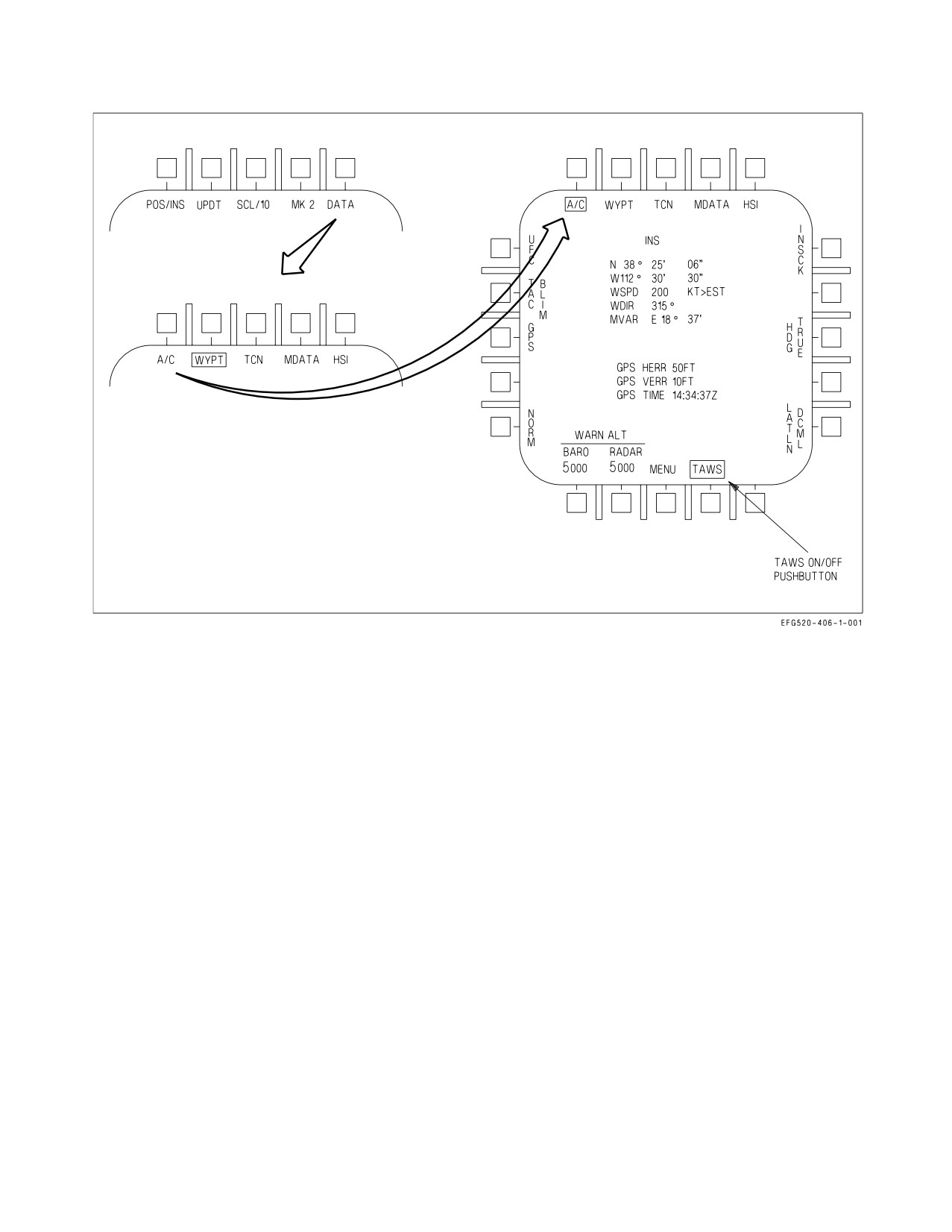
A1-E18GA-NFM-000
Figure 2-39. TAWS On/Off Pushbutton
2.17.4.2 TAWS Operation. TAWS incorporates signal processing that determines a best estimate of
aircraft position and altitude (AGL and MSL). TAWS protection algorithm continuously computes
two recovery trajectories: Vertical Recovery Trajectory (VRT) and Oblique Recovery Trajectory
(ORT). VRT is the standard GPWS-like recovery: roll to wings-level, if needed, and pull to recover.
ORT assumes that you maintain the current bank angle and pull to recover (increase turn rate). Both
computed trajectories include the following assumptions:
a. Pilot Response Time is the time from issuance of a TAWS warning to the time that the pilot
actually initiates recovery. Pilot Response Time is set at 1.3 seconds.
b. Roll Recovery Phase is the time necessary to roll the aircraft to near wings-level. This assumes
at least ½ lateral stick will be used for bank angles less than 70° and at least ¾ lateral stick
will be used for bank angles ≥ 70°.
c. G-Onset Phase is the time required to pull to the target recovery g. The target recovery g is
80% of the instantaneous g available, or 5g, whichever is less. The g-onset phase assumes that
rapid aft stick motion will be used (full deflection within ¾ second). In addition, TAWS
assumes that throttles will be moved to MAX if below corner speed and to IDLE if above
corner speed.
d. Dive Recovery Phase is the remainder of the trajectory until terrain clearance is achieved.
TAWS assumes a terrain clearance of 50 ft.
I-2-131
ORIGINAL
A1-E18GA-NFM-000
When TAWS senses that the aircraft is in the landing configuration, the recovery assumptions must
change since the desire is to land. TAWS defines the landing phase as below 500 ft AGL, less than 200
KCAS, landing gear down and locked, and more than one minute since a waveoff or takeoff. In the
landing phase, TAWS protects against landings of greater than the structural limit of the landing gear
(1584 fpm). To allow this, TAWS switches to TAWS-without-DTED and provides a warning when the
landing is predicted to exceed the structural limit of the landing gear.
TAWS provides protection against gear-up landings. When the aircraft is below 200 KCAS, below
150 ft AGL, more than one minute since waveoff or takeoff, and the landing gear is not down and
locked, a TAWS warning is provided.
2.17.4.3
TAWS Warnings. TAWS provides clear, unambiguous, and directive aural and visual cues
to the aircrew. Aural warnings provide the aircrew with a wake-up call and correct initial response
while visual warnings provide the aircrew with correct follow-on recovery information.
2.17.4.3.1 Voice Warnings. TAWS uses the ACI to provide aural cues to the aircrew. The aural cues
are distinct from any other cues that the aircrew may receive. The TAWS voice alert warnings are:
″Roll−Left...Roll−Left″,
″Roll−Right
Roll−Right″,
″Pull−Up...Pull−Up″,
″Power...Power″, and
″Check Gear″. Each of these warnings is issued at a level 3−6 dB above the present voice alerts. The
TAWS voice warnings provide a wake−up call to the aircrew and indicate the most appropriate initial
response for the given aircraft state, not necessarily the only required response. The aural cue repeats
until the warning condition is cleared. TAWS aural warnings have priority over all current aural tones.
A ″Roll Right...Roll Right″ warning is issued when a roll to the right is the correct initial response.
A ″Roll Left...Roll Left″ warning is issued when a roll to the left is the correct initial response.
A ″Power...Power″ warning is issued when the roll requirement conditions have not been met and
adding power is the correct initial response. This occurs when the aircraft is below 200 KCAS, the AOA
is above 8.5° with flaps HALF or FULL (or 18° AOA for flaps AUTO) and the throttle is not already
at MAX. The correct response to this warning is to select MAX afterburner.
A ″Pull Up...Pull Up″ warning is issued when the above conditions have not been met and pulling up
is the correct response or when the ORT is the recovery trajectory.
When a warning is given to protect against a gear-up landing, the following aural cues may be heard:
″Pull Up...Pull Up″ followed two seconds later by ″Check Gear″ when the gear handle is in the UP
position and a gear-up landing condition has been assessed (repeated every 4 seconds).
″Check Gear″ repeated every 8 seconds when the gear handle is down and a gear up landing condition
has been assessed.
2.17.4.3.2
Visual Warnings. A visual recovery arrow is provided in the center of the HUD and HUD
format on the DDI. The recovery arrow indicates the direction of recovery. The visual warning is
displayed when a CFIT condition is present and is removed when the CFIT condition is cleared.
TAWS visual recovery cues are designed to be used in conjunction with TAWS voice warnings.
There are several voice warning/visual recovery cue combinations. When the arrow points UP in the
HUD (i.e., along the lift vector), a longitudinal pull is the correct response and an aural ″Pull Up...Pull
I-2-132
ORIGINAL
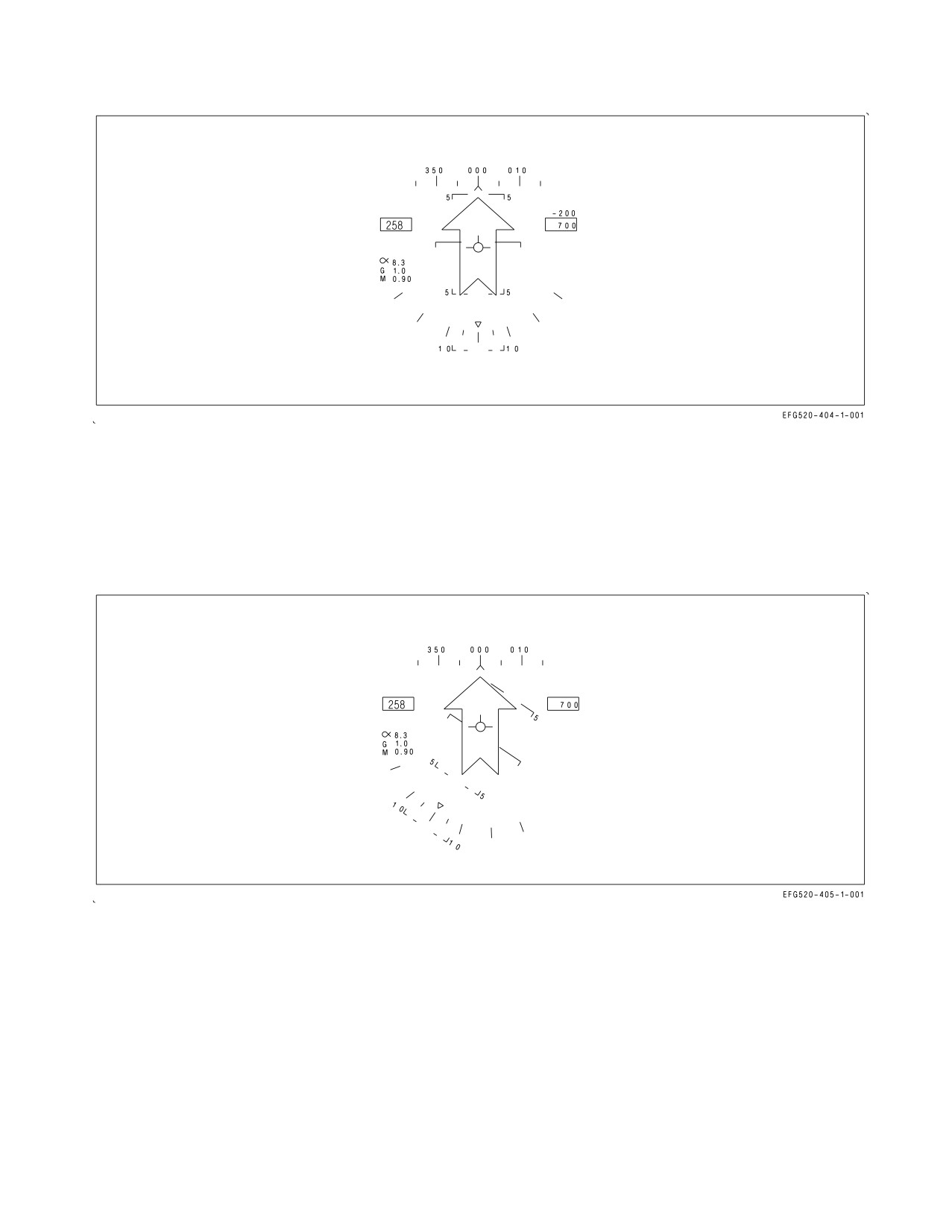
A1-E18GA-NFM-000
Figure 2-40. TAWS HUD Visual Recovery Cue - Pull Up (VRT)
Up″ is heard. This is a VRT recovery if the aircraft is close to wings level, or it is an ORT (increased
turn rate) recovery if the aircraft is banked such that the TAWS algorithm assessed that an increased
turn rate would provide the quickest recovery from an impending CFIT condition. Figures 2-40 and
2-41 depict these two situations. Both situations require a longitudinal pull as the correct response,
however, the first case (VRT) depicts a dive recovery while the second case (ORT) depicts a recovery
requiring an increase in turn rate by increasing g when already in an established angle of bank.
Figure 2-41. TAWS HUD Visual Recovery Cue - Pull Up (ORT)
When the arrow points anywhere other than UP in the HUD (i.e., not along the lift vector, but
perpendicular to the horizon), it may be accompanied by either a ″Roll Left (Right)″...″Roll Left
(Right)″ or ″Pull Up...Pull Up″ voice warning. The voice warning indicates the correct initial response,
then the aircrew should roll or pull as required to place or maintain the TAWS recovery arrow straight
up in the HUD (i.e., along the lift vector). For example, if a ″Roll Left...Roll Left″ voice warning is
issued with an accompanying HUD recovery arrow displayed in the HUD that is perpendicular to the
horizon, the correct response is to roll left to align the lift vector with the HUD recovery arrow and then
I-2-133
ORIGINAL
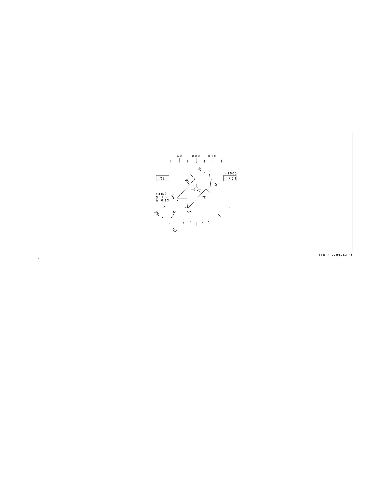
A1-E18GA-NFM-000
perform a dive recovery. If a ″Pull Up...Pull Up″ voice warning is issued with an accompanying HUD
recovery arrow displayed in the HUD that is perpendicular to the horizon, the correct response is to
apply g along the current lift vector and then, referencing the HUD recovery arrow, roll to align the lift
vector with the HUD recovery arrow and perform a dive recovery. Figure 2-42 depicts a situation in
which a Roll or Pull Up aural warning could be issued. If a ″Roll Right...Roll Right″ aural warning was
issued, a roll to the right would be the correct initial response and then a dive recovery would be
continued with a longitudinal pull. If a ″Pull Up...Pull Up″ aural warning was issued, a longitudinal pull
would be the correct initial response and then a roll to the right to align the lift vector with the HUD
recovery arrow followed by a longitudinal pull for a dive recovery would be the follow-on recovery
procedure.
Figure 2-42. TAWS Visual Recovery Cue (Arrow displayed perpendicular to actual horizon)
Figure 2-43 contains the ACI aural cue priorities.
I-2-134
ORIGINAL
A1-E18GA-NFM-000
1
Pull-Up (TAWS/GPWS)
MC
2
Roll-Left (TAWS/GPWS)
MC
3
Roll-Right (TAWS/GPWS)
MC
4
Roll-Out (Not Used)
MC
5
Check gear (TAWS/GPWS)
MC
6
Power (TAWS/GPWS)
MC
7
Engine Fire Left
Hardware Discrete
8
Engine Fire Right
Hardware Discrete
9
APU Fire
Hardware Discrete
10
Bleed Air Left
Hardware Discrete
11
Bleed Air Right
Hardware Discrete
Hardware Discrete (primary)
12
Deedle (Master Caution)
MC (backup)
13
Missile (Not Used)
MC
14
Fuel Low
MC
15
Bingo
MC
16
Altitude
MC
17
Whoop (LAW Tone)
MC
18
Flight Computer Hot
MC
19
Flight Controls
MC
20
Mode 4 Reply
MC
21
Engine Left
MC
22
Engine Right
MC
23
HF Comm
MC
24
Reserved (Climb (TLAS))
MC
25
Reserved (Sink Rate (TLAS))
MC
26
Reserved (Guide Slope (TLAS))
MC
27
Whoop (continuous)
MC
NOTE: Once a voice alert has been activated, it cannot be interrupted by a higher priority voice alert.
All voice alerts play until completed.
Figure 2-43. ACI Aural Cue Priorities
I-2-135
ORIGINAL
A1-E18GA-NFM-000
2.17.4.4 DFIRS Record Code 8. TAWS data is sent to DFIRS and MU maintenance card each time
TAWS/GPWS detects a potential CFIT condition. The data, which is sent as record 8, consists of:
1. TAWS/GPWS pushbutton state.
2. Intended aural warning.
3. Operational state of TAWS.
4. TAWS elevation source (DTED, flat earth).
5. TAWS operational mode.
6. Recovery arrow axis.
7. Ground intercept point latitude, longitude and altitude.
Only data items 1 and 2 are valid when TAWS is not operational.
2.17.4.5 TAWS and MSP code 11A. An MSP code of 11A indicates an incorrect configurable
parameters file for TAWS has been loaded onto the mission card. 11A MSP code indicates a DMC
software degrade. When this code appears, TAWS is no longer operational, and MC logics has switched
to the GPWS algorithm hosted in MC1.
2.17.5 Ground Proximity Warning System (GPWS). GPWS is designed to backup the pilot by
providing an alert of impending controlled flight into terrain (CFIT). GPWS provides warnings of
potentially unsafe maneuvering flight conditions such as excessive bank angles, excessive sink rates,
gear up landings, floor altitude violations, and altitude loss during recovery. The system is operational
as long as MC1, radar altimeter, and air data systems are ON and functional. The GPWS algorithm
operates in the background of the OFP with no cockpit indications until an actual CFIT warning is
required. The system provides distinctive aural and visual warning cues only, to alert and direct
recovery from an impending CFIT condition. The pilot maintains full control of the aircraft for
recovery.
2.17.5.1 GPWS Sensors/Modes. GPWS is a look-down system with no forward-looking capability.
GPWS uses the radar altimeter as the primary source of terrain clearance information and the FCC air
data function, GPS, and INS as backup altitude sources when radar altitude is invalid. Radar altitude
is considered invalid by GPWS above 4,950 feet AGL or at a pitch or angle of bank greater than 50°.
With valid radar altitude data, GPWS calculates terrain slope from inputs from the INS and the radar
altimeter. Over descending terrain, GPWS assumes the terrain descends indefinitely (until the system
senses a change in terrain slope). This mechanization allows for maximum protection while minimizing
nuisance warnings.
For the first 5 seconds after radar altitude becomes invalid (as indicated by a flashing ″B″ in the
HUD or RALT Xd out on the UFCD), GPWS provides no CFIT protection. After 5 seconds, the system
enters ″COAST″ mode for a period of up to 2 minutes. While in COAST mode, GPWS calculates an
estimate of the aircraft current height above terrain. COAST mode can only be enabled while the
aircraft is not transonic and was over flat terrain (defined as slope less than 2°). CFIT warnings can still
be generated while in COAST mode. If the aircraft was transonic or was not over flat terrain when
radar altitude data was lost, GPWS transitions into the BYPASS mode. In the BYPASS mode, no
I-2-136
ORIGINAL
A1-E18GA-NFM-000
CFIT warnings are generated. Full protection is resumed from both modes when valid radar altitude
data is restored.
2.17.5.2 Altitude Required For Recovery Calculations. GPWS calculations for altitude required for
recovery include the loss of altitude due to persistency timers, pilot reaction time, time to roll wings
level, target g-onset rate, and steady state dive recovery time. GPWS pilot reaction time varies
depending on flight conditions but is a minimum of 0.5 second in the GPWS LAT envelope (±30° AOB,
0 to 30° dive, 450 to 560 KCAS). Pilot reaction time is reduced in the GPWS LAT envelope, where pilot
situational awareness is typically good, in order to reduce false warnings. Time to roll wings level is
based on a ½ to ¾ lateral stick displacement roll at 1g. Target g-onset rate is 80% of the available
g-onset rate up to (1) 5g/sec (less than 400 KCAS or greater than 30° AOB) or (2) 6g/sec (greater than
400 KCAS and less than 30° AOB). Steady state dive recovery time is based on a target sustained-g of
80% of g-available up to (1) 5g (less than 400 KCAS or greater than 30° AOB) or (2) 6g (greater than
400 KCAS and less than 30° AOB). Regardless of which category applies, these g-onset
rates and sustained-g levels require an aggressive pilot response.
2.17.5.3 CFIT Protection Provided.
Above 150 feet AGL -
Above 150 feet AGL, GPWS continuously calculates the altitude required to recover. A CFIT
warning is issued if the altitude required to recover plus a variable safety buffer and an added terrain
clearance altitude is greater than the current altitude above terrain. The terrain clearance altitude
varies between 30, 50, and 90 feet, depending on flight conditions.
Below 150 feet AGL -
Below 150 feet AGL, GPWS transitions to provide warnings of CFIT conditions related to takeoff
and landing. These warnings are based on (1) the time since a WoffW transition (takeoff or T&G) or
a waveoff and then (2) a combination of landing gear position, airspeed, altitude, and sink rate. GPWS
defines a waveoff as 1000 fpm rate of climb for more than 5 seconds while below both 500 feet AGL and
200 KCAS. If the following sets of conditions are valid for greater than 0.3 seconds when the aircraft
altitude is less than 150 feet, a CFIT warning is provided. The CFIT warning is cancelled when the
condition no longer exists for 0.3 seconds.
1. Less than 60 seconds after WoffW or a waveoff:
a. Floor Altitude - less than 90 feet AGL and greater than 250 KCAS.
b. Takeoff Sink Rate - less than 150 feet AGL, less than 250 KCAS, greater than 300 fpm sink.
2. More than 60 seconds after WoffW or a waveoff:
a. Floor Altitude - less than 90 feet AGL and greater than 200 KCAS.
b. Check Gear - less than 150 feet AGL, less than 200 KCAS, descending, and landing gear not
down.
c. Landing Sink Rate - less than 150 feet AGL, less than 200 KCAS, landing gear down, and an
excessive sink rate. The allowable sink schedule varies from a maximum of 2,040 fpm to a
minimum of 1,488 fpm based on altitude and GW.
I-2-137
ORIGINAL
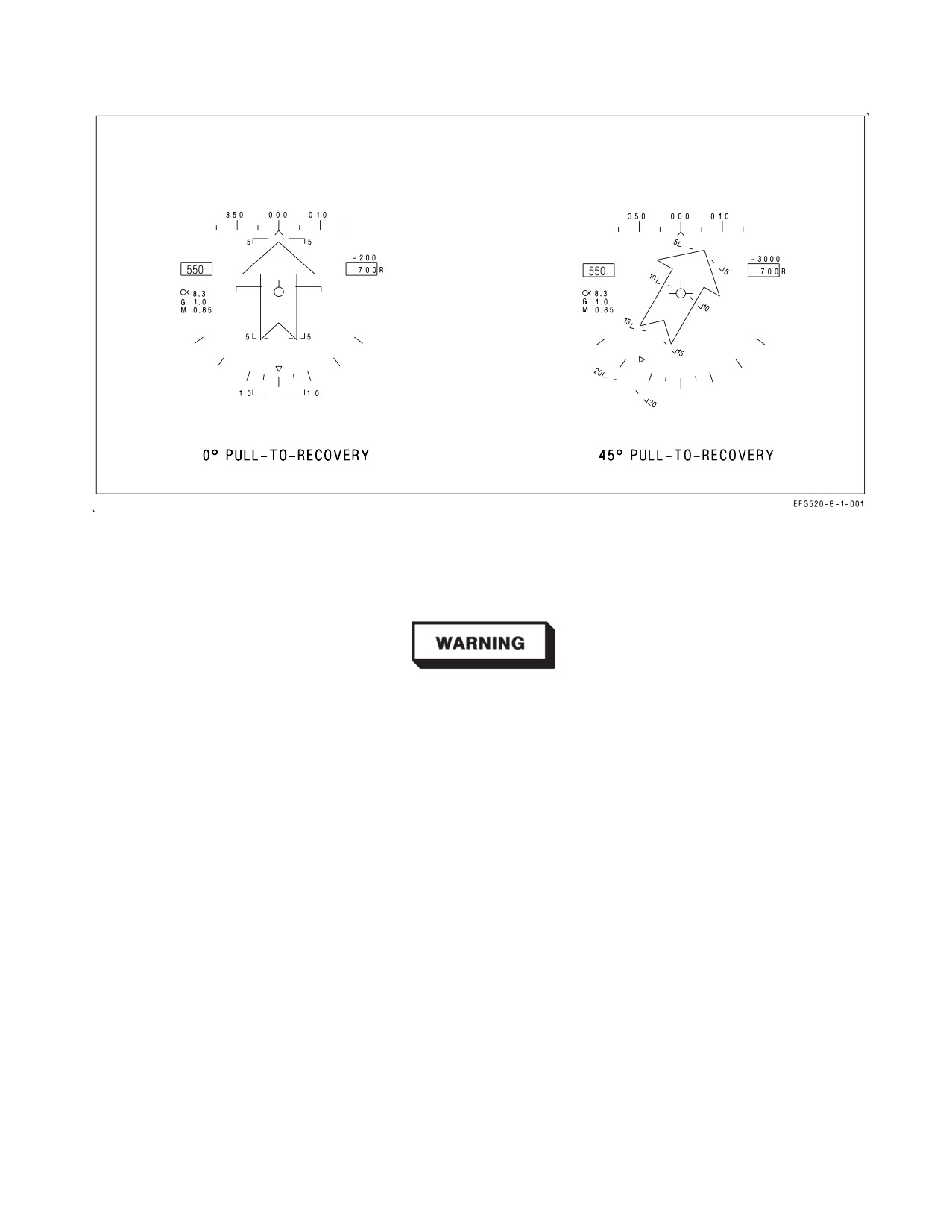
A1-E18GA-NFM-000
Figure 2-44. GPWS HUD Roll Warning Cues
d. Bank Angle - less than 150 feet AGL, less than 200 KCAS, greater than 45° AOB for one
second.
Below 150 feet AGL, GPWS does not directly account for the recovery
capabilities of the aircraft. Therefore, recovery may not be possible
following a warning under extreme flight conditions.
2.17.5.4 GPWS Warning Cues. GPWS provides distinctive, clear, unambiguous and directive visual
and aural cues to the aircrew for each potential CFIT condition.
2.17.5.4.1 GPWS HUD Recovery Arrow. The GPWS visual warning cue is a steady arrow located in
the center of the HUD. See figure 2-44. The HUD recovery arrow is always perpendicular to the horizon
and points in the direction of pull required for recovery. The HUD recovery cue is displayed
simultaneously with all voice warnings except CHECK GEAR. The HUD recovery arrow remains
displayed until GPWS calculates that a CFIT condition no longer exists.
2.17.5.4.2 GPWS Voice Commands. Refer to figure 2-45 for GPWS aural warning cues.
I-2-138
ORIGINAL
A1-E18GA-NFM-000
GPWS Warning
Aural Cue
Repetition Rate
Condition
Excessive bank angle
″ROLL LEFT (RIGHT), ROLL LEFT (RIGHT)″
2 seconds
Excessive takeoff
″POWER, POWER″
2 seconds
sink rate
Excessive landing
″POWER, POWER″
2 seconds
sink rate
Gear-up landing
″CHECK GEAR″
8 seconds
ALDR or floor
″POWER, POWER″ for airspeed <210 KCAS and
2 seconds
altitude
AOB ≤45°
″ROLL LEFT (RIGHT), ROLL LEFT (RIGHT)″
2 seconds
for AOB >45°
″PULL UP, PULL UP″ for all other flight
2 seconds
conditions
Figure 2-45. GPWS Aural Cues
Voice commands automatically transition to the appropriate command for the current stage of
recovery (e.g., ROLL OUT transitions to PULL UP when AOB becomes less than 45°). The voice
commands are terminated when the appropriate recovery maneuver is initiated (e.g., a PULL UP is
initiated within 0.5 g of the GPWS calculated target-g).
• In addition to following the voice commands, additional pilot action
may be required to avoid an unrecoverable situation (e.g., aft stick
with a POWER call or power addition/subtraction with a PULL UP
call.)
• GPWS voice alerts are delayed if other voice alerts are currently being
transmitted.
2.17.5.5 Areas of Limited CFIT Protection. Areas where CFIT protection is considered limited are
as follows:
1. In the COAST mode (5 to 120 seconds outside the valid RALT envelope).
2. Over rising terrain of greater than 2° slope (GPWS is inhibited to prevent nuisance warnings).
I-2-139
ORIGINAL
A1-E18GA-NFM-000
3. Within the GPWS LAT envelope where allowable pilot reaction times have been reduced (±30°
AOB, 0 to 30° dive, 450 to 560 KCAS).
4. Below 150 feet AGL in the landing phase (less than 200 KCAS) where warnings are designed only
to prevent hard landings.
At certain high speed, high gross weight conditions, overriding the
g-limiter may be required for recovery from dives greater than 50° and
will likely be required for dives between 10 and 25°.
2.17.5.6 Areas of No CFIT Protection. Areas of no protection are as follows:
1. Loss of air data or RALT, INS, or either MC1 or MC2 failed or off.
2. Less than 6 seconds after WonW.
3. Less than 5 seconds or greater than 120 seconds outside the valid RALT envelope.
4. Transonic flight (0.95 to 1.04 Mach) outside the valid RALT envelope.
5. For 1.5 seconds after a break X is displayed.
6. After a waveoff until exceeding 1,000 fpm for 5 seconds.
7. Dives greater than 50° after 2 minutes above 5,000 feet AGL.
2.18 INSTRUMENTS
Refer to foldout section for cockpit instrument panel illustration. For instruments that are an
integral part of an aircraft system, refer to that system description in this section.
2.18.1 Standby Attitude Reference Indicator. The standby attitude reference indicator is a self-
contained electrically driven gyro-horizon type instrument. It is normally powered by the right 115
volts ac bus. If this power fails it is automatically powered by an inverter operating off the essential 28
volts dc bus. An OFF flag appears if both power sources fail or the gyro is caged. During caging the gyro
initially cages to 4° pitch and 0° roll regardless of aircraft attitude. After 3 to 5 minutes, the indicator
reads 0° pitch and 0° roll. Power should be applied for at least 1 minute before caging. The indicator
displays roll through 360°. Pitch display is limited by mechanical stops at approximately 90° climb and
80° dive. As the aircraft reaches either stop, the gyro tumbles 180° in roll. A needle and ball are at the
bottom of the instrument. A one needle width turn is 90° per minute.
2.18.2 Standby Airspeed Indicator. The standby airspeed indicator displays airspeed from 60 to 850
KIAS. It operates directly from left pitot and static pressure.
I-2-140
ORIGINAL
A1-E18GA-NFM-000
2.18.3 Standby Altimeter. The standby altimeter is a counter-pointer type. The counter drum
indicates altitude in thousands of feet from 00 to 99. The long pointer indicates altitude in 50-foot
increments with one full revolution each 1,000 feet. A knob and window permit setting the altimeter
to the desired barometric setting. This setting is also used by the flight control computers. The standby
altimeter operates directly from left static pressure.
2.18.4 Standby Rate of Climb Indicator. The standby rate of climb indicator displays vertical speed
on a scale from 0 to ±6,000 fpm and operates directly from left static pressure.
2.18.5 Standby Magnetic Compass. A conventional aircraft magnetic compass is mounted on the
right windshield arch in the front cockpit.
2.18.6 Angle Of Attack Indexer. The angle of attack indexer is mounted to the left of the HUD. It
displays approach angle of attack (AOA) with lighted symbols; corresponding AOA indications are
shown on the HUD (see figure 2-46). The indexer operates with the landing gear down and locked and
weight off the gear. The lighted symbol(s) flash if the arresting hook is up and the hook bypass switch,
on the left vertical panel, is in CARRIER. The symbols will not flash with the arresting hook up and
the hook bypass switch in FIELD. The switch is solenoid held to FIELD and automatically goes to
CARRIER when the arresting hook is lowered or aircraft power is removed. The AOA indexer knob on
the HUD controls dimming of the symbols. All symbols light when the lights test switch on the interior
lights control panel is held to TEST.
2.19 AVIONICS SUBSYSTEM
The avionics subsystem combines the integration and automation needed for operability with the
redundancy required to ensure flight safety and mission success. Key features of the system include
highly integrated controls and displays, inertial navigation set with carrier alignment capability, and
extensive built in test capability. The avionics subsystems operate under the control of two mission
computers with primary data transfer between the mission computers and the other avionics
equipment including the EAU via the mux buses and the high speed data network.
2.19.1 Mission Computer System. The mission computer system consists of two digital computers
(MC1 and MC2) which are high speed, stored program, programmable, general purpose computers
with core memory. Both MCs are capable of providing the same basic navigation and weapon delivery
back up should the other MC fail.
There are six avionics mux bus channels with redundant paths (X and Y) for each channel.
The mission computer:
1. Computes and controls the data sent to the cockpit displays,
2. Computes missile launch and weapon release commands,
3. Provides mode control and options for various avionics systems,
4. Generates BIT initiate signals to and equipment operational status from various avionics
systems.
The front and rear DDIs are driven directly by the MC over a high speed interface bus, not by
avionics mux bus commands. The HUD is driven directly by redundant connection to either MC. MC1
drives the front and rear LDDIs and HUD while MC2 drives the front and rear RDDIs and HUD.
I-2-141
ORIGINAL
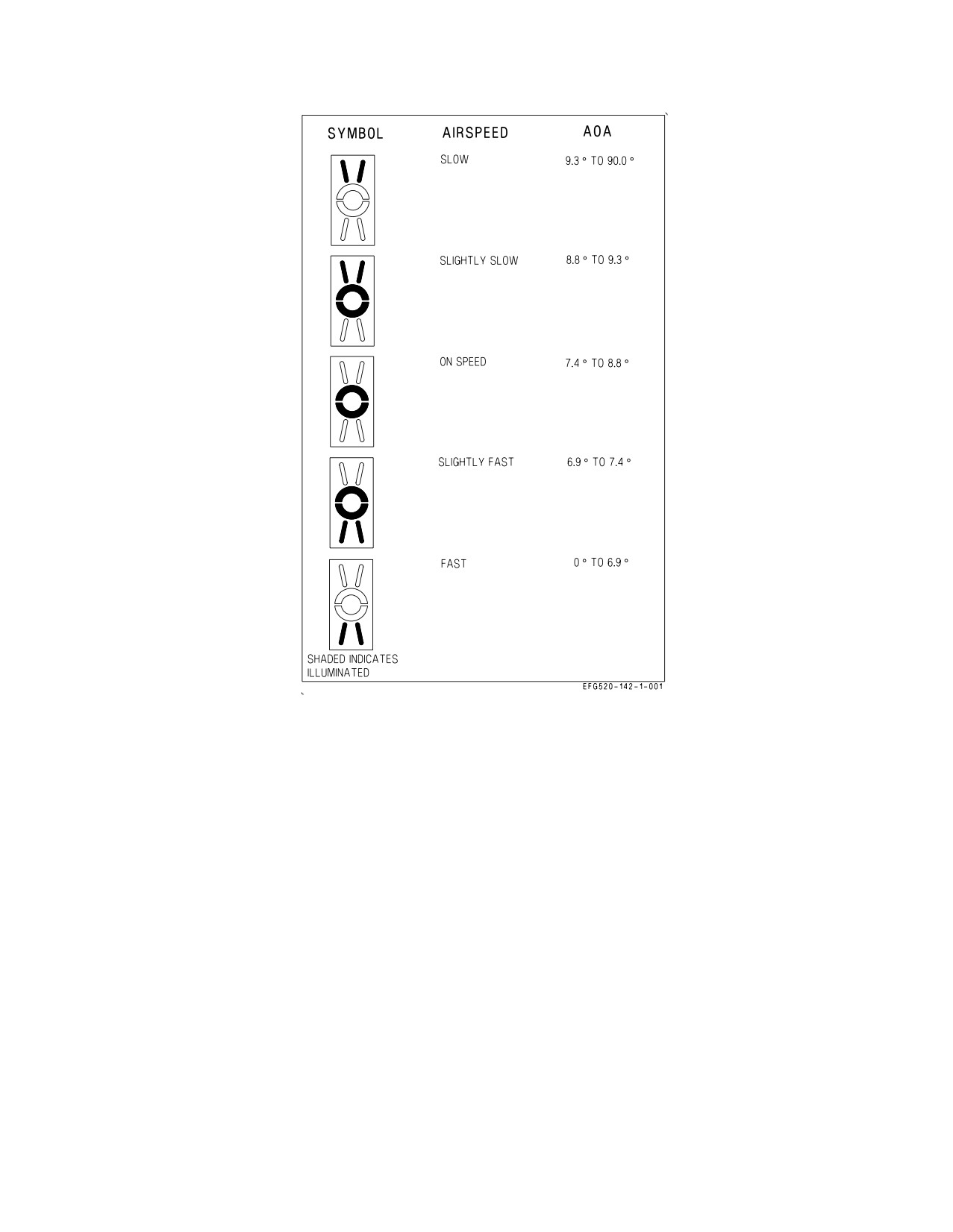
A1-E18GA-NFM-000
Figure 2-46. Angle of Attack Indexer
When an MC is off or non-functional, the displays driven by that MC show a green square in the center
of the display. Each MC provides the same level of functionality in the single MC backup mode of
operation.
With both MCs inoperative and the left generator operative, the SDC provides a limited HUD
format on the front MPCD/UFCD, prevents the FADEC and ECS controller from going into default
mode operation, and provides left/right ATS cautions when necessary. See Chapter 25 Backup/
Degraded Operations for a description of SDC Backup Mode.
MC2 provides digital video color capability to the AMPCD via the Fiber Channel Network Switch
(FCNS) and High Speed Video Network (HSVN).
The computers receive inputs for navigational data and steering command computations from the
inertial navigation system, electronic flight control system, multipurpose display group, TACAN, and
backup attitude and the navigation system. The computers control display symbology and information
presented to the pilot by the multipurpose display group.
2.19.1.1 MC Switch. The MC switch, located on the aft outboard edge of the left console, is used to
manually turn OFF either of the two mission computers, MC1 or MC2.
I-2-142
ORIGINAL
A1-E18GA-NFM-000
1 OFF Removes power to MC1.
NORM Both MC1 and MC2 are powered with ac electrical power available.
2 OFF Removes power to MC2.
2.19.1.2 Electronic Attack Unit (EAU). The EAU provides the primary interface between the AEA
subsystems and the AMC. Within the AEA suite, the EAU interfaces with the ALQ−218, CCS,
ALQ−99 Pod suite and the MATT. The interface between the EAU and AMC consists of a High Speed
Data Network (HSDN) and MIL−STD−1553 bus interface. The EAU provides jammer management
logic, manages AEA libraries, provides power control, and interfaces Built In Test (BIT) for the AEA
subsystems. The EAU coordinates aircraft navigation data with the AEA systems, provides EW track
files for display and recording, and provides the audio interface between the AEA subsystems and the
avionics suite.
2.19.1.3 Mission Data Entry. Mission data (date and flight number) can be manually loaded into the
mission computer for data recorder documentation. Data is entered by performing the following:
1. On the DDI - Press MENU, MUMI, then ID.
2. On the UFCD - Enter Julian Date (DATE).
3. On the UFCD - Enter Flight Information (FLT).
Mission data can be manually loaded into the mission computer through the Memory Unit Mission
Initialization (MUMI) display or automatically loaded into the mission computer through the Data
Storage Set (DSS). The DSS consists of the Memory Unit (MU) and the Memory Unit Mount (MUM)
and provides memory storage for aircraft parameters, maintenance data, and avionics initialization
data. The DSS receives, stores, retrieves, and transmits data with the mission computer.
2.19.1.3.1 Mission Initialization. The MU provides the capability to load the following mission
initialization files: HARM, RADAR, MU ID, TACAN, WYPT/OAP, Combined Interrogator Tran-
sponder (CIT), Sequential Steering (S/S), data link/ID, Overlay Controlled Stores (OCS), and bomb
wind data. The S/S file can have a 15 point sequence consisting of Geographic Reference Points
(GEOREF), GPS waypoints, and almanac data initialization files. Loading is done at aircraft power up
or when MUX communication is lost for more than 1 second and regained. If MUX communication is
not regained, a MU LOAD caution is displayed and an AV MUX error message is displayed on the
MUMI display. Manual loading may be done using the MUMI display.
2.19.1.3.2 Memory Unit Mission Initialization (MUMI) Format. The MUMI format (see figure
2-47) is accessible from the SUPT MENU and with WonW provides a visual indication of mission
initialization files loaded from the MU. If the MU directory indicates that no user files are present, the
MU ID displays NO IDENT. When the MU directory indicates a user file is present, MC1 displays the
option. When the option is selected and the file is being read by MC1, the option is boxed. If the read
is successful, the file is loaded and the option is unboxed. When a file is present and errors have
resulted from reading the file, the following occurs:
1. The MU ID displays NO IDENT.
2. The applicable load error is displayed (HARM, RDR, TCN, WYPT, S/S, OCS, GPS WYPT, GPS
ALM, ALR 67, WIND, DL13, or CIT).
I-2-143
ORIGINAL
A1-E18GA-NFM-000
Figure 2-47. MUMI Display
3. MC 1 sends the appropriate maintenance code to the SDC.
4. If WonW, an MU LOAD caution is displayed on the DDI.
2.19.1.4 Mission Data Erase. There are three methods to manually and two methods to automati-
cally declassify aircraft mission data.
2.19.1.4.1 Manual Erase - SECURE ERASE Button. The SECURE ERASE button is guarded and
located on the right hand forward vertical console. Pressing the SECURE ERASE button erases the
information stored in all systems and the mission card.
2.19.1.4.2 Manual Erase - ACI CRYPTO Switch. Setting the intercommunications amplifier control
CRYPTO switch to the ZERO position sends an erase signal to the MU. This causes the MU to erase
all data stored between predetermined memory locations.
2.19.1.4.3 Erase and Hold Data. The erase controller (EC) within MC 1 provides the capability to
automatically or manually erase, or inhibit erasing, of classified data contained in the MU, SMS, MC1,
and MC2.
NOTE
During an ERASE, the DDI controlled by the MC undergoing the
erase will flash STANDBY, then briefly display a green square, then
flash STANDBY until the erase is complete.
When the EC determines classified mission initialization files have been read from the MU, the EC
classified data management system is activated. When activated, MC1:
1. Displays the HOLD and ERASE options on the MUMI display.
I-2-144
ORIGINAL
A1-E18GA-NFM-000
2. Displays the CDATA advisory.
3. Sends applicable maintenance code(s) to the SDC.
2.19.1.4.4 Manual Erase - MUMI ERASE option. Manual erase is a two pushbutton process and is
initiated by pressing the ERASE pushbutton on the MUMI display. When the ERASE pushbutton is
pressed, the option to proceed with the erasure (ERASE) and the option to cancel the erase (CNX)
replaces the HOLD and ERASE options. Selecting the second ERASE option initiates erasure. While
erase is in progress, ERASE is boxed and erasing proceeds the same as automatic erase. When erasing
is complete, the ERASE pushbutton unboxes. While erase is in progress one of the following is
displayed on the MUMI display:
1. ERASING - erasing of unit is in progress.
2. COMPLETE - erasing of unit is complete.
3. FAILED - unit failed to erase.
NOTE
During an ERASE, the DDI controlled by the MC undergoing the
erase will flash STANDBY, then briefly display a green square, then
flash STANDBY until the erase is complete.
When erase fails, the MC 1 retains the MUMI ERASE and HOLD pushbutton options and displays
the ERASE FAIL caution on the DDI. When erasing is complete, MC1 removes the ERASE, HOLD,
and MC SUSPEND pushbutton options from the MUMI display, removes the CDATA advisory from
the display, and resets the applicable maintenance code(s).
2.19.1.4.5 Automatic Erase. The MU, SMS, MC1, and MC2 automatically erase classified data
when all of the following criteria are met.
1. Airspeed is less than 80 KCAS.
2. Left and right engine THA less than 29°.
3. Transition from WoffW to WonW.
4. Pilot does not select erase inhibit (HOLD) or MC SUSPEND options.
NOTE
Automatic erase can be inhibited by selecting the HOLD pushbutton
option.
5. HOLD boxed with MU displayed prevents automatic erase of the MU.
6. HOLD boxed with ALL displayed prevents automatic erase of all units (MU, armament
computer, MC1, and MC2).
The EC commands the MU and the armament computer, then MC1 and MC2 to erase. The MC
ERASE IN XX SEC countdown timer starts (60 seconds). During the countdown, an MC SUSPEND
pushbutton option is displayed. The MC SUSPEND option may be toggled between boxed (selected)
I-2-145
ORIGINAL
A1-E18GA-NFM-000
and unboxed (deselected). When the timer reaches zero and the MU and armament computer have
finished erasing, the decision to continue erasing the remainder of MC1 and MC2 depends on the MC
SUSPEND option being deselected (unboxed); when deselected, the remaining erase of MC2 and MC1
is completed.
NOTE
During an ERASE, the DDI controlled by the MC undergoing the
erase will flash STANDBY, then briefly display a green square, then
flash STANDBY until the erase is complete.
Automatic erase is also initiated by pilot ejection. The state of the HOLD options is ignored during
pilot ejection.
2.19.1.4.6 Backup Erase Controller. If MC1 fails, backup erase capability is provided by MC2 by
providing an ERASE option on the HSI format. When the ERASE pushbutton is depressed, the option
to proceed with the erasure (ERASE) and the option to cancel the erasure (CNX) are provided.
Selecting the second ERASE option initiates erasure. While ERASE is in progress, the ERASE option
is boxed; however, additional cuing is not provided. In backup mode, pilot ejection is the only
automatic erase provided. The MUMI display for the MC being erased disappears while the erase is in
progress.
2.19.2 Master Modes. There are three master modes of operation: navigation (NAV), air-to-air
(A/A), and air-to-ground (A/G). Controls, displays, and the avionics equipment operation are tailored
as a function of the master mode selected. The navigation master mode is entered automatically when
power is applied to the aircraft, when the air-to-air or air-to-ground modes are deselected, when the
landing gear is lowered, when the SPIN mode activates, or when the aircraft has WonW and the THA
is greater than 27°. The A/A master mode is entered either by pressing the A/A master mode button
alongside the left DDI or by selecting an A/A weapon with the A/A weapon select switch on the control
stick. The A/G master mode is selected by pressing the A/G master mode button. The selection is
performed by the stores management set (SMS), and the SMS identifies the selected master mode to
the mission computer.
2.19.2.1 Steering Information. The sources of steering information available in the NAV master
mode are waypoint, TACAN, instrument landing system, and data link. The data link modes available
in the NAV master mode are vector and automatic carrier landing. TACAN and waypoint steering are
mutually exclusive; selecting one automatically deselects the other. Data link, ILS, and TACAN (or
waypoint) steering can be provided simultaneously. The ACL mode is selectable only in the NAV
master mode and the vector mode is available in all master modes. Steering information is used by the
Automatic Flight Control System to provide coupled steering options.
2.19.3 Cockpit Controls and Displays. The cockpit controls and displays which are used for
navigation operation are on the multipurpose display group.
2.19.4 Multipurpose Display Group. The multipurpose display group consists of the right and left
digital display indicators (DDIs), the multipurpose color display (MPCD), the aft multipurpose color
display (AMPCD), the digital map set (DMS), the head-up display (HUD), the CRS (course) set
switch, the up front control display (UFCD) and the HDG/TK (heading/ground track) set switch. The
multipurpose display group presents navigation, attack, and aircraft attitude displays to the pilot. The
multipurpose display group converts information received from the mission computer system to
symbology for display on the DDIs, the MPCD, the UFCD, and the HUD. The HUD camera records
I-2-146
ORIGINAL