EA-18G. FLIGHT MANUAL (2008) - page 1
A1-E18GA-NFM-000
PRELIMINARY NATOPS
FLIGHT MANUAL
NAVY MODEL
EA-18G
166855 AND UP AIRCRAFT
THIS PUBLICATION IS INCOMPLETE WITHOUT
A1-E18GA-NFM-200
DISTRIBUTION STATEMENT C. Distribution authorized to U.S. Government
agencies only and their contractors to protect publications required for official
use or for administrative or operational purposes only, determined on
15 May 2008. Other requests for this document shall be referred to
Commander, Naval Air Systems Command (PMA-265), RADM William A.
Moffett Bldg, 47123 Buse Rd, Bldg 2272, Patuxent River, MD 20670-1547.
DESTRUCTION NOTICE - For unclassified, limited documents, destroy by any
method that will prevent disclosure of contents or reconstruction of the
document.
ISSUED BY AUTHORITY OF THE CHIEF OF NAVAL OPERATIONS AND
UNDER THE DIRECTION OF THE COMMANDER
NAVAL AIR SYSTEMS COMMAND.
15
MAY 2008
A1-E18GA-NFM-000
PRELIMINARY NATOPS
FLIGHT MANUAL
NAVY MODEL
EA-18G
166855 AND UP AIRCRAFT
THIS PUBLICATION IS INCOMPLETE WITHOUT
A1-E18GA-NFM-200
DISTRIBUTION STATEMENT C. Distribution authorized to U.S. Government
agencies only and their contractors to protect publications required for official
use or for administrative or operational purposes only, determined on
15 May 2008. Other requests for this document shall be referred to
Commander, Naval Air Systems Command (PMA-265), RADM William A.
Moffett Bldg, 47123 Buse Rd, Bldg 2272, Patuxent River, MD 20670-1547.
DESTRUCTION NOTICE - For unclassified, limited documents, destroy by any
method that will prevent disclosure of contents or reconstruction of the
document.
ISSUED BY AUTHORITY OF THE CHIEF OF NAVAL OPERATIONS AND
UNDER THE DIRECTION OF THE COMMANDER
NAVAL AIR SYSTEMS COMMAND.
PRELIMINARY
1
(Reverse Blank)
15 MAY 2008
A1-E18GA-NFM-000
NATOPS Flight Manual
CONTENTS
Page
No.
PART I
THE AIRCRAFT
CHAPTER
1
The Aircraft
1.1
AIRCRAFT DESCRIPTION
I-1-1
1.1.1
Meet The Growler
I-1-1
1.1.2
Aircraft Gross Weight
I-1-3
1.2
BLOCK NUMBERS
I-1-3
CHAPTER
2
Systems
2.1
POWER PLANT SYSTEMS
I-2-1
2.1.1
Engines
I-2-1
2.1.2
Automatic Throttle Control (ATC)
I-2-10
2.2
FUEL SYSTEM
I-2-11
2.2.1
Engine Feed System
I-2-12
2.2.2
Fuel Transfer System
I-2-13
2.2.3
Fuel Tank Pressurization and Vent
I-2-16
2.2.4
Thermal Management System
I-2-16
2.2.5
Refueling System
I-2-18
2.2.6
Fuel Dump System
I-2-18
2.2.7
Fuel Quantity Indicating System
I-2-19
2.2.8
Fuel Low Level Indicating System
I-2-23
2.2.9
Fuel System Related Cautions
I-2-24
2.3
FLIGHT PERFORMANCE ADVISORY SYSTEM (FPAS)
I-2-24
2.3.1
FPAS Display
I-2-24
2.3.2
FPAS CLIMB Option
I-2-25
2.3.3
FPAS HOME Waypoint Selection
I-2-25
2.3.4
FPAS HOME FUEL Caution
I-2-25
2.4
SECONDARY POWER SYSTEM
I-2-27
2.4.1
Airframe Mounted Accessory Drive (AMAD)
I-2-27
2.4.2
Auxiliary Power Unit (APU)
I-2-28
2.4.3
APU Switch
I-2-28
2.4.4
ATS Air Sources
I-2-28
2.4.5
AUG PULL
I-2-29
2.4.6
AMAD Related Cautions
I-2-29
2.5
ELECTRICAL POWER SUPPLY SYSTEM
I-2-30
2.5.1
Electrical RESET Button
I-2-30
3
ORIGINAL
A1-E18GA-NFM-000
Page
No.
2.5.2
AC Electrical Power
I-2-30
2.5.3
DC Electrical Power
I-2-32
2.5.4
External Electrical Power
I-2-34
2.5.5
Circuit Breakers
I-2-36
2.5.6
Electrical System Cautions and Caution Lights
I-2-36
2.6
LIGHTING
I-2-36
2.6.1
Exterior Lighting
I-2-36
2.6.2
Interior Lighting
I-2-40
2.6.3
Interior Lighting (Rear Cockpit)
I-2-42
2.7
HYDRAULIC POWER SUPPLY SYSTEM
I-2-42
2.7.1
Hydraulic System
I-2-42
2.7.2
Hydraulic Accumulators
I-2-45
2.7.3
Hydraulic System Related Cautions and Caution Light
I-2-46
2.8
UTILITY HYDRAULIC FUNCTIONS
I-2-46
2.8.1
Landing Gear System
I-2-46
2.8.2
NWS - Nosewheel Steering System
I-2-49
2.8.3
Wheel Brake System
I-2-50
2.8.4
Launch Bar System
I-2-56
2.8.5
Arresting Hook System
I-2-57
2.9
WING FOLD SYSTEM
I-2-58
2.9.1
Wingfold Mechanism
I-2-58
2.9.2
Wingfold Operation
I-2-58
2.9.3
WINGFOLD Switch
I-2-59
2.9.4
Wingfold Overheat Cutout Protection
I-2-59
2.10
FLIGHT CONTROL SYSTEM (FCS)
I-2-59
2.10.1
Flight Control Surfaces
I-2-60
2.10.2
Flight Control Computers (FCCs)
I-2-62
2.10.3
FCS Redundancy and Survivability
I-2-63
2.10.4
CAS Operating Modes
I-2-63
2.10.5
Control Augmentation System (CAS)
I-2-64
2.10.6
Speedbrake Function
I-2-66
2.10.7
G-Limiter Considerations
I-2-68
2.10.8
Air Data Function
I-2-71
2.10.9
Flight Controls
I-2-72
2.10.10
Yaw Rate Warning Tone
I-2-75
2.10.11
AOA Warning Tone
I-2-75
2.10.12
Spin Recovery System
I-2-75
2.10.13
Stabilator Failure Control Law Reconfiguration
I-2-77
2.10.14
GAIN ORIDE
I-2-78
2.10.15
FCS Failures
I-2-79
2.10.16
FCS Status Display
I-2-82
4
ORIGINAL
A1-E18GA-NFM-000
Page
No.
2.11
AUTOMATIC FLIGHT CONTROL SYSTEM (AFCS)
I-2-84
2.11.1
AFCS Mode Selection
I-2-84
2.11.2
Basic Autopilot
I-2-86
2.11.3
AFCS Mode Deselection
I-2-86
2.11.4
Pitch-Axis Pilot Relief Modes
I-2-86
2.11.5
Roll-Axis Pilot Relief Modes
I-2-86
2.11.6
Coupled Steering Modes (CPL)
I-2-87
2.11.7
Coupled Data Link Modes
I-2-87
2.11.8
AFCS Related Caution and Advisories
I-2-87
2.12
WEAPON SYSTEMS CONTROLS
I-2-88
2.12.1
Stick Grip Switches/Controls (Front Cockpit)
I-2-88
2.12.2
Throttle Grip Switches/Controls
I-2-90
2.12.4
Hand Controllers
I-2-91
2.12.5
ALE-47 DISP Switch
I-2-94
2.12.6
Grab Handle Chaff/Flare Dispense Switches
I-2-94
2.13
ENVIRONMENTAL CONTROL SYSTEM (ECS)
I-2-94
2.13.1
Airborne Electronic Attack (AEA) pallet Cooling
I-2-94
2.13.2
Bleed Air Shutoff Valves
I-2-95
2.13.3
Bleed Air Subsystem
I-2-96
2.13.4
Primary Heat Exchanger
I-2-96
2.13.5
Warm Air Subsystems
I-2-96
2.13.6
Air Conditioning System (ACS) Pack
I-2-97
2.13.7
Secondary Heat Exchanger
I-2-97
2.13.8
Avionics Cooling Fans
I-2-97
2.13.9
ECS Operating Modes
I-2-98
2.13.10
Cabin Pressurization
I-2-102
2.13.11
Windshield Anti-ice and Rain Removal
I-2-104
2.13.12
Anti-g System
I-2-104
2.13.13
ECS RESET and AV COOL Switch
I-2-104
2.13.14
Liquid Cooling System (LCS)
I-2-105
2.13.15
ECS Related Warnings, Cautions, and Advisories
I-2-106
2.14
OXYGEN SYSTEMS
I-2-106
2.14.1
On Board Oxygen Generating System (OBOGS)
I-2-106
2.14.2
Emergency Oxygen
I-2-109
2.15
FIRE DETECTION, FIRE EXTINGUISHING, AND BLEED AIR
LEAK DETECTION SYSTEMS
I-2-110
2.15.1
FIRE Lights
I-2-110
2.15.2
APU FIRE Light
I-2-111
2.15.3
FIRE Warning Voice Alerts
I-2-111
2.15.4
FIRE EXTGH READY/DISCH Light
I-2-111
2.15.5
APU Fire Extinguishing System
I-2-112
2.15.6
Engine/AMAD Fire Extinguishing System
I-2-112
5
ORIGINAL
A1-E18GA-NFM-000
Page
No.
2.15.7
FIRE Detection System Test
I-2-112
2.15.8
Bleed Air Leak Detection (BALD) System
I-2-113
2.15.9
Dry Bay Fire Suppression System (DBFS)
I-2-114
2.16
ENTRANCE/EGRESS SYSTEMS
I-2-114
2.16.1
Canopy System
I-2-114
2.16.2
Boarding Ladder
I-2-117
2.16.3
Ejection Seat
I-2-119
2.16.4
Ejection Seat System
I-2-125
2.17
EMERGENCY EQUIPMENT
I-2-126
2.17.1
Jettison Systems
I-2-126
2.17.2
Warnings/Cautions/Advisories
I-2-128
2.17.3
Voice Alert System
I-2-128
2.17.4
Terrain Awareness Warning System (TAWS)
I-2-129
2.17.5
Ground Proximity Warning System (GPWS)
I-2-136
2.18
INSTRUMENTS
I-2-140
2.18.1
Standby Attitude Reference Indicator
I-2-140
2.18.2
Standby Airspeed Indicator
I-2-140
2.18.3
Standby Altimeter
I-2-141
2.18.4
Standby Rate of Climb Indicator
I-2-141
2.18.5
Standby Magnetic Compass
I-2-141
2.18.6
Angle Of Attack Indexer
I-2-141
2.19
AVIONICS SUBSYSTEM
I-2-141
2.19.1
Mission Computer System
I-2-141
2.19.2
Master Modes
I-2-146
2.19.3
Cockpit Controls and Displays
I-2-146
2.19.4
Multipurpose Display Group
I-2-146
2.19.5
Up Front Control Display (UFCD)
I-2-166
2.19.6
Signal Data Computer (SDC)
I-2-173
2.19.7
Cockpit Video Recording System (CVRS)
I-2-173
2.20
TACTICAL AIRCRAFT MOVING MAP CAPABILITY
(TAMMAC)
I-2-176
2.20.1
TAMMAC Status Monitoring
I-2-176
2.20.2
DMD Maintenance Format Options and Display Information
I-2-178
2.20.3
Map Theater Data Loading
I-2-178
2.20.4
Map Loading Format Options
I-2-178
2.20.5
Map Loading Format Status Information
I-2-179
2.20.6
Map Loading Interruptions
I-2-180
2.20.7
DMD/PC Cards Cautions and Advisories
I-2-181
2.21
COUNTERMEASURES DISPENSING SYSTEM
I-2-182
2.21.1
ALE-47 Countermeasures Dispensing Set
I-2-182
6
ORIGINAL
A1-E18GA-NFM-000
Page
No.
2.22
BIT-STATUS MONITORING SUBSYSTEM
I-2-182
2.22.1
Flight Incident Recorder and Aircraft Monitoring Set (FIRAMS)
I-2-182
2.22.2
Deployable Flight Incident Recorder Set (DFIRS)
I-2-182
2.22.3
Avionics BIT
I-2-183
2.22.4
Non-Avionic BIT
I-2-197
2.22.5
Status Monitoring Backup
I-2-197
2.22.6
Non-BIT Status
I-2-197
2.23
JOINT HELMET MOUNTED CUEING SYSTEM (JHMCS)
I-2-200
2.23.1
Helmet Mounted Display (HMD)/Aft Helmet Mounted Display
(AHMD)
I-2-200
2.23.2
Electronics Unit (EU)
I-2-203
2.23.3
Cockpit Unit (CU)
I-2-203
2.23.4
Magnetic Transmitter Unit (MTU)
I-2-203
2.23.5
Boresight Reference Unit (BRU)
I-2-203
2.23.6
Seat Position Sensor (SPS)
I-2-203
2.23.7
HMD/AHMD Off/Brightness Control
I-2-203
2.23.8
HMD Video Recording
I-2-203
2.23.9
Cautions/Advisories
I-2-203
2.23.10
Configuration Check
I-2-204
2.23.11
Built-In Test (BIT)
I-2-204
2.23.11
HMD Maintenance
I-2-208
2.23.12
JHMCS Alignment
I-2-209
2.23.13
Navigation Master Mode
I-2-216
2.23.14
Mission Computer Failure
I-2-216
2.23.15
Electronic Unit Failure
I-2-216
2.23.16
Helmet Tracker Failure
I-2-216
2.23.17
Helmet Not Installed
I-2-216
2.24
TRAINER CONFIGURATION
I-2-217
2.24.1
Throttles (Trainer Configured)
I-2-217
2.24.2
Speedbrake Switch
I-2-217
2.24.3
Stick (Trainer Configured)
I-2-217
2.24.4
Rudder Pedals
I-2-217
2.24.5
Wheel Brake Operation
I-2-217
CHAPTER
3
Service and Handling
3.1
SERVICING
I-3-1
CHAPTER
4
Operating Limitations
4.1
LIMITATIONS OF THE BASIC AIRCRAFT
I-4-1
4.1.1
Engine Operation Limitations
I-4-1
4.1.2
CG Limitations
I-4-1
4.1.3
Airspeed Limitations
I-4-1
7
ORIGINAL
A1-E18GA-NFM-000
Page
No.
4.1.4
Gross Weight and Lateral Weight Asymmetry Limitations
I-4-3
4.1.5
AOA Limitations - Flaps AUTO
I-4-5
4.1.6
Acceleration Limitations
I-4-5
4.1.7
Limitations with Flaps HALF or FULL
I-4-9
4.1.8
Refueling Limitation
I-4-9
4.1.9
Prohibited Maneuvers
I-4-9
4.2
EXTERNAL STORES LIMITATIONS
I-4-12
PART II
INDOCTRINATION
CHAPTER
5
Indoctrination
5.1
INITIAL QUALIFICATION
II-5-1
5.1.1
Minimum Ground Training Requirements
II-5-1
5.1.2
Minimum Flight Training Requirements
II-5-1
5.2
FOLLOW-ON TRAINING
II-5-1
5.3
CURRENCY REQUIREMENTS
II-5-2
5.3.1
Regaining Currency
II-5-2
5.4
REQUIREMENTS FOR VARIOUS FLIGHT PHASES
II-5-2
5.4.1
Instrument Evaluation Flights
II-5-2
5.4.2
Instrument Qualification
II-5-2
5.4.3
Ceiling/Visibility Requirements
II-5-3
5.5
WAIVERS
II-5-4
5.6
PERSONAL FLYING EQUIPMENT
II-5-4
PART III
NORMAL PROCEDURES
CHAPTER
6
Flight Preparation
6.1
MISSION PLANNING
III-6-1
6.1.1
General
III-6-1
6.1.2
Flight Codes
III-6-1
6.2
BRIEFING/DEBRIEFING
III-6-1
6.2.1
Briefing
III-6-1
6.2.2
Debriefing
III-6-4
CHAPTER
7
Shore-Based Procedures
7.1
PREFLIGHT CHECKS
III-7-1
7.1.1
In Maintenance Control
III-7-1
8
ORIGINAL
A1-E18GA-NFM-000
Page
No.
7.1.2
Inspection of RCS Reduction Features
III-7-1
7.1.3
Exterior Inspection
III-7-2
7.1.4
Before Entering Cockpit
III-7-9
7.1.5
Interior Checks - Pilot
III-7-11
7.1.6
Interior Checks - EWO
III-7-16
7.2
ENGINE START
III-7-18
7.2.1
Intercockpit Communications
III-7-18
7.2.2
Engine Start Checks
III-7-18
7.3
BEFORE TAXI CHECKS
III-7-22
7.4
TAXI CHECKS
III-7-28
7.5
TAKEOFF
III-7-29
7.5.1
Before Takeoff Checks
III-7-29
7.5.2
Normal Takeoff
III-7-32
7.5.3
Crosswind Takeoff
III-7-33
7.5.4
After Takeoff Checks
III-7-34
7.6
AIRBORNE CHECKS
III-7-34
7.6.1
Climb
III-7-34
7.6.2
10,000 Foot Checks
III-7-34
7.6.3
Cruise
III-7-34
7.7
LANDING CHECKS
III-7-35
7.7.1
Descent/Penetration
III-7-35
7.7.2
VFR Landing Pattern Entry
III-7-36
7.7.3
VFR Landing Pattern and Approach
III-7-38
7.7.4
Pattern Adjustments
III-7-38
7.7.5
Final Approach
III-7-38
7.7.6
ATC Approaches
III-7-39
7.7.7
FPAH/ROLL - ATC Approaches
III-7-39
7.7.8
Full Stop Landings
III-7-40
7.7.9
Braking Technique
III-7-40
7.7.10
Heavy Gross Weight Landings
III-7-41
7.7.11
Crosswind Landings
III-7-42
7.7.12
Wet Runway Landings
III-7-43
7.7.13
Asymmetric Stores Landings
III-7-43
7.8
POST-FLIGHT CHECKS
III-7-44
7.8.1
After Landing
III-7-44
7.8.2
Hot Refueling
III-7-45
7.8.3
Before Engine Shutdown Checks
III-7-46
7.8.4
Engine Shutdown Checks
III-7-47
9
ORIGINAL
A1-E18GA-NFM-000
Page
No.
CHAPTER
8
Carrier-Based Procedures
8.1
GENERAL
III-8-1
8.2
DAY OPERATIONS
III-8-1
8.2.1
Preflight Checks
III-8-1
8.2.2
Hangar Deck Operation
III-8-1
8.2.3
Engine Start
III-8-2
8.2.4
Catapult Trim
III-8-4
8.2.5
Taxi
III-8-9
8.2.6
Takeoff Checks
III-8-9
8.2.7
Catapult Launch
III-8-10
8.2.8
Landing Pattern
III-8-12
8.3
ACL MODE 1 AND 1A APPROACHES
III-8-16
8.4
ACL MODE 2 APPROACH
III-8-18
8.5
ARRESTED LANDING AND EXIT FROM THE LANDING
AREA
III-8-20
8.6
SECTION CCA
III-8-21
8.7
NIGHT OPERATIONS
III-8-21
8.7.1
General
III-8-21
8.7.2
Preflight
III-8-21
8.7.3
Before Taxi
III-8-21
8.7.4
Taxi
III-8-21
8.7.5
Catapult Hook-Up
III-8-21
8.7.6
Catapult Launch
III-8-21
8.7.7
Catapult Suspend
III-8-23
8.7.8
Night Landings
III-8-23
8.7.9
Arrestment and Exit From the Landing Area
III-8-23
CHAPTER
9
Special Procedures
9.1
FORMATION FLIGHT
III-9-1
9.1.1
Formation Taxi/Takeoff
III-9-1
9.1.2
Aborted Takeoff
III-9-1
9.1.3
Parade
III-9-1
9.1.4
Balanced Cruise Formation
III-9-4
9.1.5
Section Approaches/Landing
III-9-4
9.2
AIR REFUELING (RECEIVER)
III-9-5
9.2.1
Air Refueling Checklist
III-9-5
9.2.2
Refueling Technique
III-9-6
10
ORIGINAL
A1-E18GA-NFM-000
Page
No.
9.3
NIGHT VISION DEVICE (NVD) OPERATIONS
III-9-9
9.3.1
Effects on Vision
III-9-9
9.3.2
Effects of Light
III-9-10
9.3.3
Weather Conditions
III-9-10
9.3.4
Object/Target Detection
III-9-10
9.3.5
Flight Preparation
III-9-10
9.4
SHORT AIRFIELD FOR TACTICAL SUPPORT (SATS)
PROCEDURES
III-9-10
9.4.1
Landing Pattern
III-9-10
9.4.2
Approach
III-9-11
9.4.3
Waveoff
III-9-11
9.4.4
Arrested Landing
III-9-11
9.4.5
Bolter
III-9-11
9.5
HOT SEAT PROCEDURE
III-9-11
9.6
ALERT SCRAMBLE LAUNCH PROCEDURES
III-9-12
9.6.1
Setting the Alert
III-9-12
9.6.2
Alert Five Launch
III-9-13
9.7
AIRBORNE HMD ACCURACY CHECKS
III-9-13
9.7.1
HMD Alignment
III-9-13
9.7.2
Airborne HMD Accuracy Check with Radar
III-9-14
CHAPTER
10
Functional Checkflight Procedures
10.1
GENERAL
III-10-1
10.1.1
Engine Functional Checks
III-10-1
10.1.2
Flight Control System Functional Checks
III-10-1
10.1.3
Landing Gear Functional Checks
III-10-2
10.2
FCF REQUIREMENTS
III-10-2
10.3
FCF QUALIFICATIONS
III-10-2
10.4
FCF PROCEDURES
III-10-2
10.5
FCF CHECKLIST - PROFILE A
III-10-4
10.5.1
Plane Captain Brief
III-10-4
10.5.2
Preflight Checks
III-10-4
10.5.3
Pre-Start Checks
III-10-5
10.5.4
Engine Start Checks
III-10-6
10.5.5
Post-Start Checks
III-10-7
10.5.6
Before Taxi Checks
III-10-15
10.5.7
Taxi Checks
III-10-19
10.5.8
Shipboard Taxi/Takeoff Checks
III-10-19
11
ORIGINAL
A1-E18GA-NFM-000
Page
No.
10.5.9
Shore-Based Takeoff Checks
III-10-20
10.5.10
After Takeoff Checks
III-10-21
10.5.11
Medium Altitude Checks (above 10,000 feet)
III-10-21
10.5.12
10,000 Feet Checks
III-10-24
10.5.13
High Altitude (above 30,000 feet)
III-10-26
10.5.14
10,000 Feet to Landing
III-10-27
10.5.15
Landing Checks
III-10-27
10.5.16
After Landing Checks
III-10-27
10.5.17
Before Engine Shutdown Checks
III-10-28
10.5.18
Engine Shutdown Checks
III-10-29
10.6
FCF CHECKLIST - PROFILE C
III-10-29
10.6.1
10,000 Feet Checks
III-10-30
10.7
FCF CHECKLIST - PROFILE D (REAR COCKPIT)
III-10-31
10.7.1
Preflight Checks
III-10-31
10.7.2
Before Taxi Checks
III-10-31
10.7.3
Taxi Checks
III-10-31
10.7.4
Medium Altitude (above 10,000 feet)
III-10-31
10.8
FCF CHECKLIST - PROFILE E
III-10-32
10.8.1
10,000 Feet Checks
III-10-32
PART IV
FLIGHT CHARACTERISTICS
CHAPTER
11
Flight Characteristics
11.1
HANDLING QUALITIES
IV-11-1
11.1.1
Flight Control Mode Effects on Handling Qualities
IV-11-1
11.1.2
Handling Qualities with Flaps HALF or FULL
IV-11-1
11.1.3
Flaps AUTO Handling Qualities
IV-11-3
11.2
DEFENSIVE COMBAT MANEUVERING
IV-11-5
11.2.1
Over-the-Top Maneuvering
IV-11-5
11.2.2
Slow Speed Maneuvering
IV-11-5
11.3
OCF - OUT-OF-CONTROL FLIGHT
IV-11-6
11.3.1
Departure Resistance
IV-11-6
11.3.2
Departure Characteristics
IV-11-6
11.3.3
Spin Characteristics
IV-11-7
11.4
DEGRADED MODE HANDLING QUALITIES
IV-11-8
11.4.1
Single Engine Operation
IV-11-8
11.4.2
Leading Edge Flap Asymmetry
IV-11-9
11.4.3
Trailing Edge Flap Failure
IV-11-11
11.4.4
Stabilator Failure
IV-11-12
11.4.5
GAIN ORIDE
IV-11-13
12
ORIGINAL
A1-E18GA-NFM-000
Page
No.
11.4.6
AHRS Failure Flying Qualities
IV-11-14
PART V
EMERGENCY PROCEDURES
EMERGENCY INDEXConference X-ray telephone number (In-flight emergencies only)
314-232-9999
and 866-543-5444
CHAPTER
12
General Emergencies
12.1
GENERAL
V-12-1
12.1.1
Immediate Action Items
V-12-1
12.1.2
Warnings, Cautions, and Advisories
V-12-1
CHAPTER
13
Ground Emergencies
13.1
LOSS OF DC ESSENTIAL BUS
V-13-1
13.2
ENGINE FAILS TO START/HUNG START
V-13-1
13.3
HOT START
V-13-1
13.4
GROUND FIRE
V-13-2
13.5
EMERGENCY EGRESS
V-13-2
13.6
BRAKE FAILURE/EMERGENCY BRAKES
V-13-3
CHAPTER
14
Takeoff Emergencies
14.1
EMERGENCY CATAPULT FLYAWAY
V-14-1
14.2
ABORT
V-14-2
14.3
GO AROUND
V-14-3
14.4
LOSS OF DIRECTIONAL CONTROL DURING TAKEOFF OR
LANDING (BLOWN TIRE, NWS FAILURE)
V-14-4
14.5
LANDING GEAR FAILS TO RETRACT
V-14-6
CHAPTER
15
Inflight Emergencies
15.1
AFTERBURNER FAILURE
V-15-1
15.2
RESTART
V-15-1
15.3
FUSELAGE FUEL LEAK
V-15-4
13
ORIGINAL
A1-E18GA-NFM-000
Page
No.
15.4
HYDRAULIC FAILURES
V-15-5
15.5
DOUBLE TRANSFORMER-RECTIFIER FAILURE
V-15-8
15.6
COCKPIT TEMPERATURE HIGH
V-15-13
15.7
COCKPIT SMOKE, FUMES, OR FIRE
V-15-14
15.8
HYPOXIA/LOW MASK FLOW
V-15-15
15.9
LOSS OF CABIN PRESSURIZATION
V-15-16
15.10
DISPLAY MALFUNCTION
V-15-16
15.11
DUAL MISSION COMPUTER (MC) FAILURE
V-15-16
15.12
OCF - OUT-OF-CONTROL FLIGHT
V-15-17
15.12.1
Departure from Controlled Flight
V-15-17
15.12.2
Spin
V-15-17
15.12.3
OCF Recovery Procedures
V-15-18
15.12.4
Post Departure Dive Recovery
V-15-19
15.13
CONTROLLABILITY CHECK
V-15-19
15.14
EXTERNAL STORES JETTISON
V-15-20
15.15
EMERGENCY TANKER DISENGAGEMENT
V-15-20
15.16
FCS FAILURE INDICATIONS AND EFFECTS
V-15-22
15.17
AILERON HINGE FAILURE - SUSPECTED, INBOARD
V-15-39
15.17.1
Suspected Inboard Aileron Hinge Failure Corrective Action
V-15-40
15.18
ALQ-99 POD FIRE/MECHANICAL MALFUNCTION
V-15-41
15.19
ALQ-99 POD RAT FAILURE
V-15-41
CHAPTER
16
Landing Emergencies
16.1
SINGLE ENGINE FAILURE IN LANDING CONFIGURATION . . V-16-1
16.2
SINGLE ENGINE APPROACH AND LANDING
V-16-1
16.3
SINGLE ENGINE WAVEOFF/BOLTER
V-16-3
16.4
FORCED LANDING
V-16-4
14
ORIGINAL
A1-E18GA-NFM-000
Page
No.
16.5
LANDING GEAR UNSAFE/FAILS TO EXTEND
V-16-4
16.6
LANDING GEAR EMERGENCY EXTENSION
V-16-5
16.7
PLANING LINK FAILURE
V-16-12
16.8
ARRESTMENT - FIELD
V-16-13
16.8.1
Arresting Gear Types
V-16-13
16.8.2
Arrestment Decision
V-16-14
16.8.3
Arrestment - Short Field
V-16-14
16.8.4
Arrestment - Long Field
V-16-14
16.9
BARRICADE ARRESTMENT
V-16-14
16.10
CV RECOVERY MATRIX
V-16-15
CHAPTER
17
Ejection
17.1
EJECTION
V-17-1
17.1.1
Ejection Seat Restrictions
V-17-1
17.1.2
Low Altitude Ejection
V-17-3
17.1.3
High Altitude Ejection
V-17-4
17.1.4
Ejection Procedures
V-17-4
17.2
DITCHING
V-17-4
17.3
SEAWATER ENTRY
V-17-4
CHAPTER
18
Immediate Action
18.1
GENERAL
V-18-1
18.2
APU FIRE LIGHT
V-18-1
18.3
DUAL L BLEED and R BLEED WARNING LIGHTS//L/R ATS
CAUTION
V-18-1
18.4
SINGLE L BLEED or R BLEED WARNING LIGHT
V-18-1
18.5
FIRE LIGHT
V-18-2
18.6
ENGINE CAUTIONS
V-18-2
18.7
L/R FUEL INLT CAUTION
V-18-2
18.8
HYD1 (2) HOT CAUTION
V-18-2
15
ORIGINAL
A1-E18GA-NFM-000
Page
No.
18.9
OBOGS DEGD CAUTION//HYPOXIA/LOW MASK FLOW//LOSS
OF CABIN PRESSURIZATION/CABIN CAUTION LIGHT
BELOW 47,000 FEET
V-18-2
18.10
HOT START
V-18-3
18.11
BRAKE FAILURE/EMERGENCY BRAKES
V-18-3
18.12
EMERGENCY CATAPULT FLYAWAY
V-18-3
18.13
ABORT
V-18-3
18.14
LOSS OF DIRECTIONAL CONTROL DURING TAKEOFF OR
LANDING/ PLANING LINK FAILURE
V-18-3
18.15
COCKPIT SMOKE, FUMES, OR FIRE
V-18-4
18.16
OCF RECOVERY
V-18-4
18.17
SINGLE ENGINE FAILURE IN LANDING CONFIGURATION . . V-18-4
18.18
POD FIRE/MECHANICAL MALFUNCTION
V-18-4
PART VI
ALL WEATHER PROCEDURES
CHAPTER
19
Instrument Flight
19.1
INSTRUMENT FLIGHT
VI-19-1
19.1.1
Before Takeoff
VI-19-1
19.1.2
Inflight
VI-19-1
19.1.3
Approaches
VI-19-1
19.2
DEGRADED SYSTEMS
VI-19-1
CHAPTER
20
Extreme Weather Procedures
20.1
ICE AND RAIN
VI-20-1
20.1.1
Ground Operation
VI-20-1
20.1.2
Inflight
VI-20-1
20.1.3
Landing in Heavy Rain
VI-20-3
20.2
TURBULENT AIR AND THUNDERSTORM OPERATION
VI-20-4
CHAPTER
21
Hot Weather Procedures
21.1
GENERAL
VI-21-1
16
ORIGINAL
A1-E18GA-NFM-000
Page
No.
21.2
GROUND OPERATIONS
VI-21-1
21.3
INFLIGHT
VI-21-1
21.4
DESCENT/RECOVERY
VI-21-2
21.5
AFTER LANDING
VI-21-2
CHAPTER
22
Cold Weather Procedures
22.1
EXTERIOR INSPECTION
VI-22-1
22.2
BEFORE ENTERING COCKPIT
VI-22-1
22.3
INTERIOR CHECK
VI-22-1
22.4
ENGINE START
VI-22-1
22.5
BEFORE TAXI
VI-22-1
22.6
TAKEOFF
VI-22-2
PART VII
COMM-NAV EQUIPMENT AND PROCEDURES
CHAPTER
23
Communication-Identification Equipment
23.1
Multifunction Information Distribution System (MIDS)
VII-23-1
23.2
ICS - INTERCOM SYSTEM
VII-23-1
23.2.1
ICS Function Selector Switch
VII-23-2
23.3
VHF/UHF COMMUNICATION SYSTEM
VII-23-2
23.3.1
VHF/UHF Controls and Indicators
VII-23-3
23.3.2
COMM 1 AND 2 OPERATION
VII-23-8
23.3.3
Anti-Jam Operation
VII-23-13
23.4
HAVE QUICK SYSTEM
VII-23-14
23.4.1
Have Quick Menu From AJ Menu Fixed Frequency COMM
Sublevel
VII-23-14
23.4.2
SINCGARS Menu From AJ Menu Fixed Frequency COMM
Sublevel
VII-23-17
23.4.3
COMM Sublevel - Presets 1 Thru 20 (Anti-Jam)
VII-23-18
23.4.4
AJ MENU From Have Quick COMM Sublevel
VII-23-20
23.5
SINCGARS SYSTEM
VII-23-20
23.5.1
AJ MENU From SINCGARS COMM Sublevel
VII-23-21
17
ORIGINAL
A1-E18GA-NFM-000
Page
No.
23.5.2
Guard Transmit on Top Level CNI Format
VII-23-24
23.6
KY-58 - SECURE SPEECH SYSTEM
VII-23-24
23.6.1
KY-58 Control Panel Assembly
VII-23-24
23.6.2
KY-58 Controls and Indicators
VII-23-25
23.6.3
KY-58 Operation
VII-23-26
23.7
DIGITAL COMMUNICATION SYSTEM (DCS)
VII-23-27
23.7.1
VHF/UHF Communication System - DCS
VII-23-27
23.7.2
DCS Communications Security (COMSEC)
VII-23-28
23.7.3
UFCD - DCS
VII-23-29
23.7.4
Relay Mode Of Operation
VII-23-29
23.7.5
DCS - Avionics Subsystem
VII-23-31
23.8
IDENTIFICATION FRIEND OR FOE (IFF)/COMBINED
INTERROGATOR TRANSPONDER (CIT)
VII-23-33
23.8.1
IFF Transponder
VII-23-33
23.8.2
IFF Interrogator
VII-23-43
23.8.3
IFF BIT
VII-23-43
23.8.4
IFF Programming (IFF PROG) Page
VII-23-43
23.8.5
IFF Controls
VII-23-45
23.8.6
IFF Related Cautions and Advisories
VII-23-47
23.9
COMMUNICATION-NAVIGATION-IDENTIFICATION
INTERFACE
VII-23-47
23.10
COMMUNICATION-IDENTIFICATION DATA ENTRY
VII-23-47
23.10.1
Data Entry
VII-23-47
23.10.2
Data Entry Using the Shifted Keypad
VII-23-47
CHAPTER
24
Navigation Equipment
24.1
NAVIGATION CONTROLS AND INDICATORS
VII-24-1
24.1.1
UFCD Navigation Controls
VII-24-1
24.1.2
Moving Map - Digital Map Set (DMS)
VII-24-1
24.1.3
HSI Format
VII-24-2
24.1.4
HSI Format on a DDI
VII-24-9
24.1.5
HUD - Navigation Information
VII-24-9
24.1.6
CRS Select Switch
VII-24-9
24.1.7
ILS Control Panel
VII-24-9
24.2
INERTIAL NAVIGATION SYSTEM (INS)/GLOBAL
POSITIONING SYSTEM (GPS)
VII-24-10
24.2.1
Inertial Navigation System (INS)
VII-24-10
24.2.2
Global Positioning System (GPS)
VII-24-10
24.2.3
INS Alignment Modes
VII-24-11
18
ORIGINAL
A1-E18GA-NFM-000
Page
No.
24.2.4
ANAV BIT
VII-24-20
24.2.5
NAVCK Page
VII-24-20
24.2.6
GPS Page
VII-24-21
24.2.7
INS Knob
VII-24-21
24.2.8
INS/GPS Related Cautions and Advisories
VII-24-22
24.2.9
Waypoints, Offset Aimpoints (OAP), and Offsets
VII-24-22
24.2.11
Aircraft (A/C) Programming
VII-24-31
24.2.12
Position Keeping
VII-24-33
24.2.13
Position Updating
VII-24-34
24.2.14
NAV/TAC Bank Limit Options
VII-24-35
24.2.15
Steering
VII-24-35
24.2.16
Designation
VII-24-42
24.2.17
INS Updates (not available in AINS)
VII-24-44
24.3
TACTICAL AIR NAVIGATION (TACAN)
VII-24-48
24.3.1
TACAN BIT
VII-24-48
24.3.2
TACAN Mode Selection
VII-24-48
24.3.3
TACAN Programming
VII-24-49
24.3.4
TACAN Position Keeping
VII-24-49
24.3.5
TACAN Position Updating
VII-24-49
24.4
ICLS - INSTRUMENT CARRIER LANDING SYSTEM
VII-24-50
24.4.1
ICLS Receiver
VII-24-50
24.4.2
ICLS Decoder
VII-24-50
24.4.3
ICLS BIT
VII-24-50
24.4.4
ICLS Initialization
VII-24-50
24.4.5
ICLS Steering
VII-24-54
24.5
DATA LINK SYSTEM
VII-24-54
24.5.1
Automatic Carrier Landing (ACL) Mode
VII-24-56
24.6
NAVIGATION DATA ENTRY
VII-24-65
CHAPTER
25
Backup/Degraded Operations
25.1
MISSION COMPUTER FAILURE
VII-25-1
25.1.1
Mission Computer Failure
VII-25-1
25.2
BACKUP ATTITUDE AND NAVIGATION SYSTEM
VII-25-1
25.2.1
Standby Attitude Reference Indicator
VII-25-1
25.2.2
Static Power Inverter
VII-25-1
25.2.3
Magnetic Azimuth Detector
VII-25-2
25.2.4
Backup Attitude and Navigation System Controls and Indicators
VII-25-2
25.3
NAVIGATION BACKUP
VII-25-3
25.3.1
Navigation Controls and Indicators
VII-25-4
19
ORIGINAL
A1-E18GA-NFM-000
Page
No.
25.3.2
Backup Heading Mode Control
VII-25-4
25.4
BACKUP FREQUENCY CONTROL
VII-25-5
CHAPTER
26
Visual Communications
CHAPTER
27
Deck/Ground Handling Signals
PART VIII
WEAPONS SYSTEMS
PART IX
FLIGHT CREW COORDINATION
CHAPTER
28
Aircrew Coordination
28.1
DEFINITION
IX-28-1
28.2
CRITICAL SKILLS OF AIRCREW COORDINATION
IX-28-1
28.2.1
Situation Awareness
IX-28-1
28.2.2
Assertiveness
IX-28-1
28.2.3
Decision-Making
IX-28-1
28.2.4
Communication
IX-28-1
28.2.5
Leadership
IX-28-1
28.2.6
Adaptability/Flexibility
IX-28-1
28.2.7
Mission Analysis
IX-28-2
28.2.8
Factors That Degrade Aircrew Coordination
IX-28-2
28.3
FLIGHT MEMBER POSITIONS
IX-28-2
28.3.1
Mission Commander
IX-28-2
28.3.2
Pilot In Command
IX-28-2
28.3.3
Formation Leader
IX-28-2
28.3.4
Weapon Systems Operator (WSO)
IX-28-3
28.4
AIRCREW RESPONSIBILITIES BY FLIGHT PHASE
IX-28-3
28.4.1
Mission Planning and Briefing
IX-28-3
28.4.2
Pretakeoff
IX-28-3
28.4.3
Takeoff/Departure
IX-28-3
28.4.4
Enroute
IX-28-3
28.4.5
Recovery
IX-28-4
28.4.6
Mission Critique
IX-28-4
28.5
SPECIAL CONSIDERATIONS
IX-28-4
28.5.1
Functional Checkflights
IX-28-4
28.5.2
Formation Flights
IX-28-4
28.6
EMERGENCIES
IX-28-4
20
ORIGINAL
A1-E18GA-NFM-000
Page
No.
CHAPTER
29
Crew Coordination Standards
29.1
PHILOSOPHY
IX-29-1
29.2
MISSION PLANNING
IX-29-1
29.3
CREW BRIEFING
IX-29-1
29.4
COMMUNICATIONS
IX-29-1
29.4.1
Intra-Cockpit Communications (ICS)
IX-29-1
29.4.2
Guidelines for Effective Communications
IX-29-2
29.5
PRE-FLIGHT
IX-29-2
29.6
FLIGHT PHASES
IX-29-2
29.6.1
Start/Taxi/Takeoff
IX-29-2
29.6.2
Departure
IX-29-3
29.6.3
Rendezvous and Formation
IX-29-3
29.6.4
Cruise
IX-29-4
29.6.5
Inflight Refueling
IX-29-4
29.6.6
Approach
IX-29-5
29.6.7
Landing
IX-29-6
29.6.8
Post Flight
IX-29-7
29.7
DEBRIEFING
IX-29-7
29.8
SPECIAL CONSIDERATIONS
IX-29-7
29.8.1
Functional Check Flights
IX-29-7
29.8.2
Emergencies
IX-29-7
29.9
STANDARD ICS TERMS
IX-29-8
PART X
NATOPS EVALUATION
CHAPTER
30
NATOPS Evaluation
30.1
CONCEPT
X-30-1
30.1.1
Implementation
X-30-1
30.1.2
Definitions
X-30-1
30.2
GROUND EVALUATION
X-30-2
30.2.1
General
X-30-2
30.3
FLIGHT EVALUATION
X-30-3
30.3.1
Mission Planning/Briefing
X-30-3
30.3.2
Preflight/Line Operations
X-30-3
30.3.3
Taxi
X-30-4
21
ORIGINAL
A1-E18GA-NFM-000
Page
No.
30.3.4
Takeoff (*)
X-30-4
30.3.5
Climb/Cruise
X-30-4
30.3.6
Approach/Landing (*)
X-30-4
30.3.7
Communications
X-30-4
30.3.8
Emergency/Malfunction Procedures (*)
X-30-4
30.3.9
Post Flight Procedures
X-30-4
30.3.10
Mission Evaluation
X-30-4
30.3.11
Applicable Publications
X-30-4
30.3.12
Flight Evaluation Grading Criteria
X-30-5
30.3.13
Flight Evaluation Grade Determination
X-30-5
30.4
NATOPS EVALUATION QUESTION BANK
X-30-6
PART XI
PERFORMANCE DATA
APPENDIX A
FOLDOUTS
22
ORIGINAL
A1-E18GA-NFM-000
LIST OF ILLUSTRATIONS
Page
No.
PART I
THE AIRCRAFT
CHAPTER 1
The Aircraft
Figure 1-1
General Arrangement
I-1-1
Figure 1-2
Approximate Dimensions
I-1-2
Figure 1-3
LOT NUMBER / BuNo
I-1-3
CHAPTER 2
Systems
Figure
2-1
Throttle Grips (Front Cockpit)
I-2-7
Figure
2-2
Engine Fuel Display (EFD) - Engine Parameters
I-2-8
Figure
2-3
Engine Display
I-2-10
Figure
2-4
Tank 1 and 4 Fuel CG Control and FUEL XFER Caution Schedule . I-2-15
Figure
2-5
Fuel Quantity
I-2-20
Figure
2-6
Engine Fuel Display (EFD) - Fuel Parameters
I-2-21
Figure
2-7
FUEL Display
I-2-23
Figure
2-8
FPAS Displays
I-2-26
Figure
2-9
Secondary Power Supply
I-2-27
Figure
2-10
Simplified Electrical Schematic
I-2-31
Figure
2-11
FCC Electrical Redundancy
I-2-34
Figure
2-12
Ground Power Panel and Placard
I-2-35
Figure
2-13
Circuit Breaker Panels
I-2-36
Figure
2-14
Exterior Lights
I-2-37
Figure
2-15
ID Strobe Patterns
I-2-39
Figure
2-16
Hydraulic Flow
I-2-43
Figure
2-17
Wheel Brake and Anti-skid System
I-2-52
Figure
2-18
Emergency/Parking Brake Handle
I-2-54
Figure
2-20
Flight Control System Functional Diagram
I-2-61
Figure
2-21
Flap Schedules
I-2-66
Figure
2-22
G-Limiter G-Bucket Reductions in Maximum Commandable
G-Level
I-2-70
Figure
2-23
Stick and Pedal Travel Limits
I-2-73
Figure
2-24
Stick Grip FCS Controls
I-2-74
Figure
2-25
SPIN Recovery Display
I-2-76
Figure
2-26
GAIN ORIDE Flap Positions and Gain Schedules
I-2-78
Figure
2-27
FCS Related Cautions and Cockpit Indications
I-2-81
Figure
2-28
FCS Status Display
I-2-82
Figure
2-29
AFCS Controls and Indicators
I-2-85
Figure
2-30
Stick Grip Switches/Controls
I-2-88
Figure
2-31
Throttle Grip Switches/Controls
I-2-91
Figure
2-32
Hand Controllers
I-2-93
Figure
2-33
OBOGS Monitor
I-2-107
23
ORIGINAL
A1-E18GA-NFM-000
Page
No.
Figure
2-34
Canopy Controls
I-2-116
Figure
2-35
Boarding Ladder
I-2-118
Figure
2-36
SJU-17B Ejection Modes
I-2-120
Figure
2-37
Leg Restraint System
I-2-122
Figure
2-38
Survival Kit
I-2-123
Figure
2-39
TAWS On/Off Pushbutton
I-2-131
Figure
2-40
TAWS HUD Visual Recovery Cue - Pull Up (VRT)
I-2-133
Figure
2-41
TAWS HUD Visual Recovery Cue - Pull Up (ORT)
I-2-133
Figure
2-42
TAWS Visual Recovery Cue (Arrow displayed perpendicular to
actual horizon)
I-2-134
Figure
2-43
ACI Aural Cue Priorities
I-2-135
Figure
2-44
GPWS HUD Roll Warning Cues
I-2-138
Figure
2-45
GPWS Aural Cues
I-2-139
Figure
2-46
Angle of Attack Indexer
I-2-142
Figure
2-47
MUMI Display
I-2-144
Figure
2-48
MENU Format
I-2-149
Figure
2-49
Electronic Attitude Display Indicator
I-2-150
Figure
2-50
AMPCD
I-2-153
Figure
2-51
MPCD Controls and HSI Symbology
I-2-154
Figure
2-52
HUD Controls
I-2-156
Figure
2-53
HUD Symbology
I-2-159
Figure
2-54
HUD Symbology Degrades
I-2-164
Figure
2-55
Alphanumeric Entry Format
I-2-168
Figure
2-56
Up Front Control Display (UFCD)
I-2-170
Figure
2-57
Forward CVRS Control Panel
I-2-174
Figure
2-58
Aft CVRS Control Panel
I-2-175
Figure
2-59
Video Display Routing
I-2-177
Figure
2-60
DMD Maintenance Format
I-2-178
Figure
2-61
Map Loading Format
I-2-179
Figure
2-62
Flight Aids Reversion Mechanization
I-2-183
Figure
2-63
Equipment Status Messages
I-2-185
Figure
2-64
Caution/Advisory Displays
I-2-186
Figure
2-65
BIT Control Display
I-2-187
Figure
2-66
MPCD and UFCD Test Patterns
I-2-194
Figure
2-67
EFD Test Pattern
I-2-195
Figure
2-68
UFCD Test Pattern
I-2-196
Figure
2-69
CONFIG Display (Sample)
I-2-198
Figure
2-70
INS Postflight Data Display
I-2-199
Figure
2-71
JHMCS Upper HVI Routing
I-2-202
Figure
2-72
Boresight Reference Unit
I-2-204
Figure
2-73
HMD Controls
I-2-205
Figure
2-74
Displays BIT Sublevel
I-2-206
Figure
2-75
HMD/AHMD Test Patterns
I-2-207
Figure
2-76
HMD Error Log Display
I-2-209
Figure
2-77
Coarse Alignment
I-2-210
Figure
2-78
Fine Alignment
I-2-213
24
ORIGINAL
A1-E18GA-NFM-000
Page
No.
Figure 2-79
Alignment Verification
I-2-215
CHAPTER 4
Operating Limitations
Figure 4-1
Engine Operation Limitations
I-4-1
Figure 4-2
Basic Aircraft Airspeed Limitations
I-4-2
Figure 4-3
Subsystem Airspeed Limitations
I-4-2
Figure 4-4
Gross Weight and Lateral Weight Asymmetry Limitations
I-4-3
Figure 4-5
Asymmetric Stores Limitations
I-4-4
Figure 4-6
AOA Limitations - Flaps AUTO
I-4-5
Figure 4-7
Acceleration Limitations - Basic Aircraft (with or without empty
pylons)
I-4-6
Figure 4-8
Limitations with Flaps HALF or FULL
I-4-9
PART II
INDOCTRINATION
CHAPTER 5
Indoctrination
Figure 5-1
Requirements for Various Flight Phases During Initial Training
II-5-2
Figure 5-2
Pilot Ceiling and Visibility Restrictions Prior to Instrument
Qualification
II-5-3
PART III
NORMAL PROCEDURES
CHAPTER 7
Shore-Based Procedures
Figure 7-1
Exterior Inspection
III-7-2
Figure 7-2
Checklist Display
III-7-29
Figure 7-3
Typical Field Landing Pattern
III-7-37
CHAPTER 8
Carrier-Based Procedures
Figure 8-1
Launch Trim
III-8-4
Figure 8-2
Carrier Landing Pattern
III-8-13
Figure 8-3
Carrier Controlled Approach
III-8-15
Figure 8-4
ACL Mode 1 and 1A Approaches
III-8-19
Figure 8-5
ACL Mode 2 Approach
III-8-22
CHAPTER 9
Special Procedures
Figure 9-1
Formation Takeoff Runway Alignments
III-9-2
Figure 9-2
Formations
III-9-3
CHAPTER 10
Functional Checkflight Procedures
Figure 10-1
Functional Checkflight Requirements
III-10-3
25
ORIGINAL
A1-E18GA-NFM-000
Page
No.
PART IV
FLIGHT CHARACTERISTICS
CHAPTER 11
Flight Characteristics
Figure 11-1
AHRS Channel Failure Indication and Effects
IV-11-15
PART V
EMERGENCY PROCEDURES
CHAPTER 12
General Emergencies
Figure 12-1
Warning/Caution/Advisory Displays
V-12-3
CHAPTER 14
Takeoff Emergencies
Figure 14-1
Maximum Weight for 100 fpm Single Engine Rate of Climb
V-14-5
CHAPTER 15
Inflight Emergencies
Figure
15-1
Spooldown Restart Envelope
V-15-2
Figure
15-2
Windmill Restart Envelope
V-15-2
Figure
15-3
Crossbleed Restart Envelope
V-15-3
Figure
15-4
APU Restart Envelope
V-15-3
Figure
15-5
Hydraulic Flow Diagram (Aircraft on Deck)
V-15-6
Figure
15-6
Hydraulic Subsystems Malfunction Guide
V-15-7
Figure
15-7
Emergency Power Distribution
V-15-9
Figure
15-8
External Stores Jettison Chart
V-15-21
Figure
15-9
FCS Failure Indications and Effects
V-15-22
Figure
15-10
FCS Failure Indications and Effects - Channel 2
V-15-23
Figure
15-11
FCS Failure Indications and Effects - Channel 3
V-15-23
Figure
15-12
FCS Failure Indications and Effects - Channel 4
V-15-24
Figure
15-13
FCS Failure Indications and Effects - Channels 1 and 2
V-15-24
Figure
15-14
FCS Failure Indications and Effects - Channels 1 and 3
V-15-25
Figure
15-15
FCS Failure Indications and Effects - Channels 1 and 4
V-15-25
Figure
15-16
FCS Failure Indications and Effects - Channels 2 and 3
V-15-26
Figure
15-17
FCS Failure Indications and Effects - Channels 2 and 4
V-15-27
Figure
15-18
FCS Failure Indications and Effects
V-15-28
Figure
15-19
FCS Failure Indications and Effects
V-15-28
Figure
15-20
FCS Failure Indications and Effects
V-15-29
Figure
15-21
FCS Failure Indications and Effects
V-15-29
Figure
15-22
FCS Failure Indications and Effects
V-15-30
Figure
15-23
FCS Failure Indications and Effects
V-15-30
Figure
15-24
FCS Failure Indications and Effects
V-15-31
Figure
15-25
FCS Failure Indications and Effects
V-15-31
Figure
15-26
FCS Failure Indications and Effects
V-15-32
Figure
15-27
FCS Failure Indications and Effects
V-15-32
Figure
15-28
FCS Failure Indications and Effects
V-15-33
Figure
15-29
FCS Failure Indications and Effects
V-15-33
26
ORIGINAL
A1-E18GA-NFM-000
Page
No.
Figure 15-30
FCS Failure Indications and Effects - Aileron Channels 1 and 2 or 3
and 4
V-15-34
Figure 15-31
FCS Failure Indications and Effects - Aileron Channels 1 and 4 or 2
and 3
V-15-34
Figure 15-32
FCS Failure Indications and Effects - LEF Channels 1 and 4 or 2
and 3
V-15-35
Figure 15-33
FCS Failure Indications and Effects - AOA Channel 4
V-15-35
Figure 15-34
FCS Failure Indications and Effects
V-15-36
Figure 15-35
FCS Failure Indications and Effects
V-15-36
Figure 15-36
FCS Failure Indications and Effects
V-15-37
Figure 15-37
FCS Failure Indications and Effects
V-15-37
Figure 15-38
FCS Failure Indications and Effects
V-15-38
Figure 15-39
FCS Failure Indications and Effects
V-15-38
Figure 15-40
FCS Failure Indications and Effects
V-15-39
CHAPTER 16
Landing Emergencies
Figure 16-1
Maximum Single Engine Recovery Weight - Military Thrust
V-16-7
Figure 16-2
Maximum Single Engine Recovery Weight - Maximum Thrust
V-16-8
Figure 16-3
Landing Gear Emergency Flow Chart
V-16-9
Figure 16-4
Landing Gear Malfunction - Landing Guide
V-16-10
Figure 16-5
Field Arresting Gear Data
V-16-16
Figure 16-6
CV Recovery Matrix
V-16-18
CHAPTER 17
Ejection
Figure 17-1
Sink Rate Effects on Minimum Ejection Altitude
V-17-5
Figure 17-2
Airspeed and Bank Angle Effects on Minimum Ejection Altitude
V-17-6
Figure 17-3
Airspeed and Dive Angle Effects on Minimum Ejection Altitude
V-17-7
Figure 17-4
Ejection Procedures
V-17-8
Figure 17-5
Ditching Procedures
V-17-21
PART VI
ALL WEATHER PROCEDURES
CHAPTER 20
Extreme Weather Procedures
Figure 20-1
Icing Danger Zone
VI-20-2
PART VII
COMM-NAV EQUIPMENT AND PROCEDURES
CHAPTER 23
Communication-Identification Equipment
Figure 23-1
Aft Cockpit Rudder Pedal Switches
VII-23-3
Figure 23-2
Top Level CNI Format on Up Front Control Display (UFCD)
VII-23-5
Figure 23-3
COMM Sublevel - Ship Maritime Preset
VII-23-9
Figure 23-4
COMM Sublevel - Guard and Cue Presets
VII-23-10
27
ORIGINAL
A1-E18GA-NFM-000
Page
No.
Figure
23-5
COMM Sublevel - Manual Preset
VII-23-11
Figure
23-6
COMM Sublevel - Presets 1 Thru 20 (Fixed Frequency)
VII-23-12
Figure
23-7
AJ MENU From Fixed Frequency COMM Sublevel
VII-23-13
Figure
23-8
Have Quick Fixed Frequency Sublevel
VII-23-15
Figure
23-9
Have Quick WOD Loading
VII-23-16
Figure
23-10
Have Quick TNET Loading
VII-23-17
Figure
23-11
Single Channel Ground and Airborne Radio System (SINCGARS)
MENUFixed Frequency Sublevel
VII-23-18
Figure
23-12
COMM Sublevel - Presets 1 to 20 (Anti-Jam)
VII-23-19
Figure
23-13
AJ MENU From Have Quick COMM Sublevel
VII-23-20
Figure
23-14
AJ Have Quick Menu Sublevel
VII-23-21
Figure
23-15
AJ MENU From SINCGARS COMM Sublevel
VII-23-22
Figure
23-16
AJ SINCGARS ERF Sublevel
VII-23-22
Figure
23-17
Guard Transmit on Top Level CNI Format
VII-23-23
Figure
23-18
Guard Transmit on COMM Sublevel
VII-23-24
Figure
23-19
KY-58 Control Panel Assembly
VII-23-25
Figure
23-20
DCS Frequencies Conversions
VII-23-27
Figure
23-21
DCS KEY Display
VII-23-30
Figure
23-22
Relay Bandwidth Limitations
VII-23-31
Figure
23-23
MUMI Displays
VII-23-32
Figure
23-24
BIT Displays
VII-23-34
Figure
23-25
IFF Transponder UFCD Sublevel
VII-23-35
Figure
23-26
Mode 3 and Mode C Selection
VII-23-36
Figure
23-27
Electronic Boresight Constant (EBC) Display with W on W
VII-23-38
Figure
23-28
XPOND Format Selection to Enable Mode S Enhanced and
Squitter
VII-23-39
Figure
23-29
Return to XPOND Format with Squitter Disabled
VII-23-40
Figure
23-30
Mode S UFCD Sublevel
VII-23-41
Figure
23-31
Mode S Address Not Available on XPOND Sublevel
VII-23-42
Figure
23-32
Mode S A/C Call Sign Sublevel
VII-23-42
Figure
23-33
IFF PROG EDIT Sublevel - POS Data
VII-23-44
Figure
23-34
Communication-Identification Data Entry
VII-23-48
CHAPTER 24
Navigation Equipment
Figure 24-1
Navigation Controls and Indicators
VII-24-3
Figure 24-2
TAMMAC Mode Selections
VII-24-5
Figure 24-3
GPS Page
VII-24-12
Figure 24-4
INS CV Alignment
VII-24-14
Figure 24-5
INS Ground Alignment
VII-24-16
Figure 24-6
INS In-Flight Alignment
VII-24-19
Figure 24-7
NAVCK Page
VII-24-20
Figure 24-8
GPS Waypoint Display
VII-24-24
Figure 24-9
INS Programming
VII-24-27
Figure 24-10
Position Keeping
VII-24-33
Figure 24-11
Position Updating Displays
VII-24-36
28
ORIGINAL
A1-E18GA-NFM-000
Page
No.
Figure 24-12
Waypoint/OAP Direct Great Circle Steering
VII-24-38
Figure 24-13
Waypoint/OAP Course Line Steering
VII-24-39
Figure 24-14
AUTO Sequential Steering
VII-24-43
Figure 24-15
Navigation Designation (WYPT DSG)
VII-24-45
Figure 24-16
Overfly Designation
VII-24-46
Figure 24-17
TACAN Mode Selection
VII-24-49
Figure 24-18
TACAN Programming
VII-24-51
Figure 24-19
TACAN Direct Great Circle Steering
VII-24-52
Figure 24-20
TACAN Course Line Steering
VII-24-53
Figure 24-21
ICLS Initialization
VII-24-54
Figure 24-22
ICLS Steering
VII-24-55
Figure 24-23
DDI SA ACL Display
VII-24-57
Figure 24-24
HUD ACL Display
VII-24-61
Figure 24-25
Traffic Control Couple Display
VII-24-62
Figure 24-26
ACL Mode 1 Display
VII-24-63
Figure 24-27
ACL Mode 2 Steering Display
VII-24-66
Figure 24-28
T/C Guidance to Marshal
VII-24-67
Figure 24-29
ACL Control - Marshal to Touchdown
VII-24-70
CHAPTER 25
Backup/Degraded Operations
Figure 25-1
SDC Backup HUD Display
VII-25-2
Figure 25-2
Standby Attitude Reference Indicator
VII-25-4
CHAPTER 26
Visual Communications
Figure 26-1
Visual Communications
VII-26-1
CHAPTER 27
Deck/Ground Handling Signals
Figure 27-1
Deck Ground Handling Signals
VII-27-2
PART VIII
WEAPONS SYSTEMS
PART IX
FLIGHT CREW COORDINATION
CHAPTER 29
Crew Coordination Standards
Figure 29-1
Approach Briefs
IX-29-6
Figure 29-2
Standard ICS Terms
IX-29-8
PART X
NATOPS EVALUATION
PART XI
PERFORMANCE DATA
29
ORIGINAL
A1-E18GA-NFM-000
Page
No.
FOLDOUTS
Figure FO-1
Forward Cockpit
FO-3
Figure FO-2
Rear Cockpit
FO-7
Figure FO-3
Electrical Bus Power
FO-11
Figure FO-4
Ejection Seat
FO-13
Figure FO-5
Fuel System
FO-17
Figure FO-6
Environmental Control System
FO-21
30
ORIGINAL
A1-E18GA-NFM-000
RECORD OF CHANGES
Change No. and
Page Count Verified by
Date of Entry
Date of Change
(Signature)
31
(Reverse Blank)
ORIGINAL
A1-E18GA-NFM-000
INTERIM CHANGE SUMMARY
The following Interim Changes have been canceled or previously incorporated in this manual:
INTERIM
CHANGE
REMARKS/PURPOSE
NUMBER
The following Interim Changes have been incorporated in this Change/Revision:
INTERIM
CHANGE
REMARKS/PURPOSE
NUMBER
Interim Changes Outstanding - To be maintained by the custodian of this manual:
INTERIM
CHANGE
ORIGINATOR/DATE
PAGES
REMARKS/PURPOSE
NUMBER
(or DATE/TIME GROUP)
AFFECTED
1
242001Z Sep 08
III-7-36, III-
Multi-subject IC
8-4 thru 8-9,
III-8-12, 13,
14, 14A 8-20,
8-20A, IV-11-9
thru 11-14,
V-12-40,-42,-
44,-45, -48,
V-15-19-
20A,V-16-1, -3,
-7, -16, V-18-4
33
(Reverse Blank)
ORIGINAL
P 242001Z SEP 08
FROM COMNAVAIRSYSCOM PATUXENT RIVER MD//4.0P//
TO COMNAVAIRFOR SAN DIEGO CA//N83/N421/N421B//
AIRTEVRON TWO THREE PATUXENT RIVER MD//55SA10AFA18//
AIRTEVRON THREE ONE CHINA LAKE CA//51J000D/51J00MD//
AIRTEVRON NINE CHINA LAKE CA//JJJ//
DCMA BOEING SAINT LOUIS MO//RDOAA/RDDF/RDDP//
INFO PEOTACAIR PATUXENT RIVER MD//PMA265//
COMVAQWINGPAC WHIDBEY ISLAND WA//N4/N3/N00/N42//
COMNAVAIRSYSCOM PATUXENT RIVER MD//5.0D/4.1.1.1/4.0P//
COMNAVAIRWARCENACDIV PATUXENT RIVER MD//4.11.3//
COMNAVAIRWARCENWPNDIV CHINA LAKE CA//47HE00D//
NAVTESTWINGPAC PT MUGU CA//51000ME/40P000D//
NAVTESTWINGLANT PATUXENT RIVER MD//55TW3AA//
VAQRON ONE TWO NINE
MSGID/GENADMIN,USMTF,2007/COMNAVAIRSYSCOM AIR-4.0P//
SUBJ/EA-18G AIRCRAFT NATOPS PUBLICATIONS INTERIM CHANGE//
REF/A/DESC:EML/VAQRON ONE TWO NINE/23SEP2008//
REF/B/DESC:DOC/COMNAVAIRSYSCOM/09SEP2008//
REF/C/DESC:A1-E18GA-NFM-000/COMNAVAIRSYSCOM/15MAY2008//
REF/D/DESC:A1-E18GA-NFM-200/COMNAVAIRSYSCOM/15MAY2008//
REF/E/DESC:A1-E18GA-NFM-500/COMNAVAIRSYSCOM/15MAY2008//
NARR/REF A IS MMU CONCURRENCE.
REF B IS AIRS 2008-164.
REF C IS A1-E18GA-NFM-000, PRELIMINARY NATOPS FLIGHT MANUAL NAVY
MODEL EA-18G 166855 AND UP AIRCRAFT, DTD 15 MAY 2008.
REF D IS A1-E18GA-NFM-200, PRELIMINARY NATOPS FLIGHT MANUAL
PERFORMANCE DATA NAVY MODEL EA-18G 166855 AND UP AIRCRAFT,
DTD 15 MAY 2008.
REF E IS A1-E18GA-NFM-500, PRELIMINARY NATOPS POCKET CHECKLIST,
NAVY MODEL EA-18G 166855 AND UP AIRCRAFT, DTD 15 MAY 2008.//
POC/LINDA HOWE/FC FACILITATOR/UNIT:PMA-265/NAME:PATUXENT RIVER MD
/TEL:301-342-0275/TEL:DSN 342-0275/EMAIL:LINDA.HOWE@NAVY.MIL//
GENTEXT/REMARKS/1. THIS MESSAGE IS ISSUED IN RESPONSE TO REFS A AND B.
THIS MESSAGE ISSUES INTERIM CHANGE (IC) NUMBER 01 TO REF C, IC NUMBER
01 TO REF D, AND IC NUMBER 01 TO REF E.
2. SUMMARY.
A. THESE CHANGES TO REFS C, D AND E PROVIDE UPDATES DUE TO SHIP
FLIGHT TESTING.
B. REPLACEMENT PAGES CONTAINING THESE CHANGES FOR DOWNLOADING
AND INSERTION INTO REFS C, D AND E WILL BE ATTACHED TO THIS
INTERIM CHANGE MESSAGE WHEN IT IS POSTED ON THE NATEC AND
AIRWORTHINESS WEBSITES (SEE LAST PARA BELOW).
3. THE REPLACEMENT PAGES IMPACT THE FOLLOWING NATOPS FLIGHT MANUAL AND
ASSOCIATED CHECKLIST. THE REPLACEMENT PAGE PACKAGE INCLUDES THE
FOLLOWING PAGES:
A. REF C (EA-18G PRELIMINARY NFM), PAGES: 33 (REVERSE BLANK),
III-7-35, III-7-36, III-8-3 THRU III-8-14A(REVERSE BLANK),
III-8-19, III-8-20, III-8-20A (REVERSE BLANK), AND IV-11-9
THRU IV-11-14.
B. REF D (EA-18G PRELIMINARY NFM), PAGES: 15 (REVERSE BLANK),
XI-4-41 THRU XI-4-46, XI-9-1 THRU XI-9-6.
C. REF E (EA-18G PRELIMINARY PCL), PAGES: B/(C BLANK), 33 THRU
38, 47, 48, 51, 52, E29, E30, E33, E34, E39 THRU E42B, E103,
E104, E107 THRU E112, E115 AND E116.
4. POINTS OF CONTACT:
NAVAIR 242001Z SEP 08
Page 1 of 2
A1-E18GA-NFM-000 IC 1
A1-E18GA-NFM-200 IC 1
A1-E18GA-NFM-500 IC 1
A. LT RICHARD WINSTEAD, VAQ-129, NATOPS PROGRAM MANAGER, TEL
DSN 820-5942 OR COMM (360) 257-5942, EMAIL:
RICHARD.WINSTEAD@NAVY.MIL.
B. NAVAIR POCS:
(1) MARTY SCANLON, NATOPS IC COORDINATOR, TEL DSN 757-6045
OR COMM (301) 757-6045, EMAIL: MARTIN.SCANLON@NAVY.MIL
(2) CDR C. WILLIAMS, NAVAIR 4.1.1.1, EA-18G CLASS DESK, TEL
(301) 757-7562, EMAIL: CHRISTOPHER.K.WILLIAMS@NAVY.MIL.
(3) KRISTIN SWIFT, AIR-4.0P NATOPS CHIEF ENGINEER, TEL
DSN 995-4193 OR COMM (301)995-4193,
EMAIL: KRISTIN.SWIFT@NAVY.MIL.
(4) AIRWORTHINESS GLOBAL CUSTOMER SUPPORT TEAM,
TEL: 301-757-0187, E-MAIL: AIRWORTHINESS@NAVY.MIL.
5. THIS MESSAGE WILL BE POSTED ON THE NATEC WEBSITE, WWW.NATEC.NAVY.MIL
WITHIN 48 HOURS OF RELEASE. NEW NATOPS IC MESSAGES MAY BE FOUND IN TWO
PLACES ON THIS WEBSITE:
A. IN THE NATOPS IC DATABASE FOUND UNDER THE TMAPS OPTION.
B. IN THE AFFECTED PUBLICATIONS(S) JUST AFTER THE IC SUMMARY
PAGE. IF THE IC MESSAGE INCLUDES REPLACEMENT PAGES, THEY
WILL BE ADDITIONALLY PLACED WITHIN THE MANUAL AND REPLACED
PAGES DELETED. MESSAGES ARE NORMALLY POSTED IN THE DATABASE
BEFORE APPEARING IN THE PUBLICATION. THIS MESSAGE WILL ALSO
BE POSTED ON THE AIRWORTHINESS WEBSITE,AIRWORTHINESS.NAVAIR.
NAVY.MIL. IF UNABLE TO VIEW THIS MESSAGE ON EITHER THE NATEC
OR AIRWORTHINESS WEBSITES, INFORM THE NATOPS GLOBAL CUSTOMER
SUPPORT TEAM AT (301) 342-0870, DSN 342-0870, OR BY EMAIL TO
NATOPS(AT)NAVY.MIL.
C. INFORMATION REGARDING THE AIRWORTHINESS PROCESS, INCLUDING
A LISTING OF ALL CURRENT INTERIM FLIGHT CLEARANCES, NATOPS
AND NATIP PRODUCTS ISSUED BY NAVAIR 4.0P, CAN BE FOUND ON THE
4.0P WEBSITE: AIRWORTHINESS.NAVAIR.NAVY.MIL.
D. E-POWER FOLDER NUMBER 841616. AIRWORTHINESS TRACKING NUMBER
32165.//
Tim Gowen, AIR 4.0P Deputy Director, 4.0P, 09/24/2008
NAVAIR 242001Z SEP 08
Page 2 of 2
A1-E18GA-NFM-000 IC 1
A1-E18GA-NFM-200 IC 1
A1-E18GA-NFM-500 IC 1
A1-E18GA-NFM-000
SUMMARY OF APPLICABLE TECHNICAL
DIRECTIVES
Information relating to the following technical directives has been incorporated in this manual
Change
ECP
Number Number
Description
Visual Identification
Effectivity
(R) Retrofit
(P) Production
35
ORIGINAL
A1-E18GA-NFM-000
Information relating to the following recent technical directives will be incorporated in the future
change.
Change
ECP
Number Number
Description
Visual Identification
Effectivity
36
ORIGINAL
A1-E18GA-NFM-000
GLOSSARY
Abbre-
Abbre-
Term
Term
viation
viation
A
AIM
air intercept missile
A/A
air-to-air
AINS
aided INS
AACQ
automatic acquisition mode
ALDDI
aft left digital display indicator
AB
afterburner
ALR-67
radar warning receiver
AB LIM
afterburner limiting
ALT
altitude
A/C
aircraft
AMAD
airframe mounted accessory drive
ac
alternating current
AMCD
advanced mission computers and
displays
ACCUM
accumulator
AMPCD
aft multipurpose color display
ACI
amplifier control intercommunica-
tion
AMPD
advanced multipurpose display
ACLS
automatic carrier landing system
ANAV
accurate navigation
ACM
air combat maneuvering
AN/
countermeasures dispensing set
ALE-47
ACNTR
aft center (8 x 10) display
AN/APN-
radar altimeter set
AEA
airborne electronic attack
194
AESA
active electronically scanned array
AN/ASN-
inertial navigation
139
system
ADB
aircraft discrepancy book
AOA
angle of attack
ADF
automatic direction finding
AOB
angle of bank
ADV
advisory
A/P
autopilot
AFCS
automatic flight control system
APU
auxiliary power unit
A/G
air-to-ground
AQ
align quality
AGI
armament gas ingestion
ARDDI
aft right digital display indicator
AGL
above ground level
ARI
attitude reference indicator
AHRS
attitude heading reference set
ARS
air refueling store
AIL
aileron
37
ORIGINAL
A1-E18GA-NFM-000
Abbre-
Abbre-
Term
Term
viation
viation
ASL
azimuth steering line
CAS
control augmentation system
ASRM
automatic spin recovery mode
CAUT
caution
ATARS
advanced tactical air reconnaissance
CB
circuit breaker
system
CCS
communications countermeasures set
ATS
air turbine starter
CCW
counterclockwise
ATSCV
air turbine starter control valve
CD
countdown
ATTH
attitude hold
CDP
compressor discharge pressure
AUFCD
aft upfront control display
C/F
chaff/flare
AUG
augment
CFIT
controlled flight into terrain
AUR
aural
CG
center of gravity
AUTO
automatic
CH or
channel
AVMUX
avionics multiplex
CHAN
B
CHKLST
checklist
BALT
barometric altimeter
CIT
combined interrogator/transponder
BCN
beacon
CK
check
BIT
built in test
CKPT
cockpit
BLD
bleed
CLR
clear
BLIM
bank limit
CNI
communication, navigation, and
identification
BLIN
BIT logic inspection
COMM
communication radio
BNK
bank
CONT
continuous precision velocity update
BRG
bearing
PVU
BRK
brake
CPL
couple
BRT
bright
CPLD
coupled
BST
boresight acquisition mode
CPWS
cabin pressurization warning system
C
CRS
course
°C
degrees Celsius
CSC
communication system control
38
ORIGINAL
A1-E18GA-NFM-000
Abbre-
Abbre-
Term
Term
viation
viation
CSEL
course select
ΔP
hydraulic filter indicator
(Delta P)
CV
carrier
E
CVRS
cockpit video recording system
EADI
electronic attitude display indicator
D
EAU
electronic attack unit
DA
density altitude
EBB
essential bus backup
DBS
doppler beam sharpening
ECS
environmental control system
DBFS
dry bay fire suppression
EFD
engine fuel display
DC
designator controller
EFT
external fuel tank
dc
direct current
EGT
exhaust gas temperature
DCS
decompression sickness
EMCON
emission control
DDI
digital display indicator
EMIS
electro magnetic interference shield
DECD
digital expandable color display
ENG
engine
DEGD
degraded
ENT
enter
DF
direction finding
EPR
engine pressure ratio
DFIRS
deployable flight incident recorder
set
ERF
electronic fill remote
DISCH
discharge
EST
estimated
D/L
data link
ET
elapsed time
DMD
digital memory device
EWO
electronic warfare officer
DME
distance measuring equipment
EXT
external
DMS
digital map set
EXTD
extend
DN
down
F
DSU
data storage unit
°F
degrees Fahrenheit
DTED
digital terrain elevation data
FADEC
full authority digital engine control
DT2
second designated target
FCC
flight control computer
DVMC
digital video map computer
FCCA
flight control computer A
39
ORIGINAL
A1-E18GA-NFM-000
Abbre-
Abbre-
Term
Term
viation
viation
FCCB
fight control computer B
GACQ
gun acquisition mode
FCES
flight control electronic system
GB
gyro bias
FCF
functional checkflight
GCU
generator converter unit
FCLP
field carrier landing practice
GEN
generator
FCNS
fiber channel network switch
GEN TIE
generator tie
FCS
flight control system
G-LIM
g-limiter
FE
fighter escort configuration
G-LOC
g-induced loss of consciousness
FF
fuel flow
GND
ground
FIP
form-in-place
GPS
global positioning system
FIRAMS
flight incident recording and moni-
GPWS
ground proximity warning system
toring system
GRCV
guard receive
FLBIT
fuel low BIT
GW
gross weight
FLIR
forward looking infrared
GXMT
guard transmit
FO
foldout
H
FOD
foreign object damage
HDG
heading
FOV
field of view
HDG/SLV
heading slaved
FPAH
flight path angle hold
HI
high
FPAS
flight performance advisory system
HMD
helmet mounted display
fpm
feet per minute
HOBS
high off-boresight
FPT
first pilot time
HOTAS
hands on throttle and stick
F-QTY
fuel quantity
HQ
have quick
FRS
fleet replacement squadron
HRC
helmet release connector
ft
foot, feet
HSEL
heading select
FUS
fuselage
HSI
horizontal situation indicator
G
HSIB
high speed interface bus
G or g
gravity
40
ORIGINAL
A1-E18GA-NFM-000
Abbre-
Abbre-
Term
Term
viation
viation
HSVN
high speed video network
I/P
identification of position
(IDENT)
HUD
head up display
IR
infrared
HYD
hydraulic, hydraulic system
IRC
in-line release connector
HYD1
hydraulic system 1
ISOL
isolate
HYD2
hydraulic system 2
ITB
image transfer bus
I
J
IAF
initial approach fix
JETT
jettison
IBIT
initiated built in test
JHMCS
joint helmet mounted cueing system
ICLS
instrument carrier landing system
K
ICS
intercockpit communication system
KCAS
knots calibrated air speed
ID
identification
KGS
knots ground speed
IDECM
integrated defensive electronic coun-
termeasures
kt
knots
IFA
inflight alignment
KTAS
knots true airspeed
IFF
identification friend or foe
L
IFR
instrument flight rules
L
left
ILS
instrument landing system
lb(s)
pound(s)
IMC
instrument meteorological conditions
L&S
launch & steering target
IMN
indicated mach number
L ACC
lateral accelerometer
IMU
inertial measurement unit
LAMPD
left advanced multipurpose display
INCANS
interference cancellation system
LATLN
latitude longitude
INOP
inoperative
LBA
limit basic aircraft
INS
inertial navigation system
L BAR
launch bar
INST
instrument
LCS
liquid cooling system
INV
invalid
LDC
left designator controller
IP
instructor pilot
LDDI
left digital display indicator
41
ORIGINAL
A1-E18GA-NFM-000
Abbre-
Abbre-
Term
Term
viation
viation
LDG
landing
MFS
multifunction switch
LED
leading edge down
MIDS
multifunctional information distribu-
tion system
LEF
leading edge flaps
MIL
military thrust
LEU
leading edge up
min
minimum, minutes
LEX
leading edge extension
MMP
maintenance monitor panel
LG
landing gear
MNTCD
maintenance card
LI
left inboard
MPCD
multipurpose color display
LM
left midboard
MSL
mean sea level
LO
left outboard
MSNCD
mission card
LO
low
MSRM
manual spin recovery mode
LON
limit of NATOPS
MRAD
master radiate
LPU
life preserver unit
MTRS or
meters
LSO
landing signal officer
m
LT
light
MU
memory unit
LTOD
local time of day
MUMI
memory unit mission initialization
M
MUX
multiplex bus
MAC
mean aerodynamic chord
MVAR
magnetic variation
MAD
magnetic azimuth detector
N
MAN
manual
N1
fan rpm
MATT
multi-mission advanced tactical ter-
N2
compressor rpm
minal
N ACC
normal accelerometer
MAX
maximum afterburner thrust
NACES
navy aircrew common ejection seat
MC
mission computer
NATOPS
naval air training and operations
MC1
mission computer 1
procedures standardization
MC2
mission computer 2
NAV
navigation
MER
multiple ejector rack
ND
nose down
42
ORIGINAL
A1-E18GA-NFM-000
Abbre-
Abbre-
Term
Term
viation
viation
nm
nautical miles
PLF
parachute landing fall
NORM
normal
PMG
permanent magnet generator
NOTAMS
notice(s) to airmen
PNL
panel
NOZ
nozzle
POS
position
NU
nose up
pph
pounds per hour
NVD
night vision devices
ppm
pounds per minute
NVIS
night vision imaging system
PR
pressure
NWS
nosewheel steering
PROC
processor
Nz REF
reference load factor
psi
pounds per square inch
O
PTS
power transmission shaft
OAP
offset aim point
PTS
pressure transmitter set
OAT
outside air temperature
Q
OBOGS
onboard oxygen generating system
QDC
quick disconnect connector
OFP
operational flight program
QTY
quantity
ORIDE
override guide
R
OVFLY
overfly
R
right
OVRSPD
overspeed
RALT
radar altimeter
OXY
oxygen
RAM
radar absorbing material
P
RAMPD
right advanced multipurpose display
PA
powered approach
RAT
ram air turbine
PBIT
periodic BIT
RATS
reduced authority thrust system
PC
plane captain
R CAS
roll control augmentation system
P CAS
pitch control augmentation system
RCDR
recorder
PCL
pocket checklist
RCS
radar cross section
PIO
pilot induced oscillation
RCVY
recovery
43
ORIGINAL
A1-E18GA-NFM-000
Abbre-
Abbre-
Term
Term
viation
viation
RDC
right designator controller
SA
situational awareness
RDDI
right digital display indicator
SAT
satellite
RDR
radar
SCT
special crew time
REC
radar elevation control
SDC
signal data computer
REC
record or receive
SDCR
signal data computer replacement
RECCE
reconnaissance
SEC
source error correction
REJ
reject
SEA-
seawater parachute release mecha-
WARS
nism
RI
right inboard
SEQ
sequence
RLG
ring laser gyro
SMS
stores management set
R-LIM
roll rate limiter
SOP
standard operating procedures
RM
right midboard
SPD
speed
RMM
removable memory module
SPD BRK
speedbrake
RNG
range
SPN
spin
RO
right outboard
SRM
spin recovery mode
ROE
rules of engagement
SSR
solid state recorder
ROMA
removable optics module assembly
STAB
stabilator
RP
replacement pilot
STBY
standby
rpm
revolutions per minute
STD HDG
stored heading
RSET
reset
STT
single target track
RSRI
rolling-surface-to- rudder intercon-
nect
SUPT
support
RTN
return
S/W
software
R/T
receive/transmit
SW
switch
RUD
rudder
RWR
radar warning receiver
S
44
ORIGINAL
A1-E18GA-NFM-000
Abbre-
Abbre-
Term
Term
viation
viation
T
UFCD
upfront control display
T1
engine inlet temperature
UHF
ultra high frequency
TAC
tactical
UNLK
unlock
TAMMAC
tactical aircraft moving map capabil-
UPDT
update
ity
UTM
universal transverse mercator
TAS
true air speed
V
TAWS
terrain awareness warning system
vac
volts alternating current
TBD
to be determined
VACQ
vertical acquisition mode
TCN or
tactical air navigation
TACAN
vdc
volts direct current
TCV
thermal control valve
VEL
velocity
TDC
throttle designate controller
VER
vertical ejector rack
TDP
turbine discharge pressure
VFR
visual flight rules
TED
trailing edge down
VHF
very high frequency
TEF
trailing edge flaps
VIB
vibration
TEU
trailing edge up
VMC
visual meteorological conditions
TEMP
temperature
VOL
volume
T&G
touch and go
VTR
video tape recorder
THA
throttle handle angle
VVSLV
velocity vector slave
TK
fuel tank pressure
W
PRESS
W
waterline symbol
T/O
takeoff
WACQ
wide acquisition mode
TOT
time on target
WAT
warning, advisory, threat
TR
transformer rectifier
W DIR
wind direction
TTG
time to go
W SPD
wind speed
U
WARN
warning
UA
up-AUTO
45
ORIGINAL
A1-E18GA-NFM-000
Abbre-
Abbre-
Term
Term
viation
viation
WDSHLD windshield
Y
WoffW
weight off wheels
Y CAS
yaw control
augmentation system
WonW
weight on wheels
yd
yards
WYPT waypoint
Z
X
ZTOD
zulu time of day
XFER
transfer
46
ORIGINAL
A1-E18GA-NFM-000
PREFACE
SCOPE
The NATOPS Flight Manual is issued by the authority of the Chief of Naval Operations and under
the direction of Commander, Naval Air Systems Command in conjunction with the Naval Air Training
and Operating Procedures Standardization (NATOPS) Program. This manual contains information on
all aircraft systems, performance data, and operating procedures required for safe and effective
operations, however, it is not a substitute for sound judgment. Compound emergencies, available
facilities, adverse weather or terrain, or considerations affecting the lives and property of others may
require modification of the procedures contained herein. Read this manual from cover to cover as it is
each aircrew’s responsibility to have a complete knowledge of its contents.
APPLICABLE PUBLICATIONS
The following applicable publications complement this manual:
• A1-E18GA-NFM-200 (Performance Data Charts)
• A1-E18GA-NFM-500 (Pocket Checklist)
• A1-E18GA-NFM-600 (Servicing Checklist)
• A1-E18GA-NFM-700 (Functional Checkflight Checklist)
• NTRP 3-22.2-EA-18G (EA-18G Classified NATIP)
• NTRP 3-22.4-EA-18G (EA-18G Unclassified NATIP)
HOW TO GET COPIES
Additional copies of this manual and changes thereto may be procured through the local supply
system from NAVICP Philadelphia via DAAS in accordance with NAVSUP P−409 (MILSTRIP/
MILSTRAP), or a requisition can be submitted to Naval Supply Systems Command via the Naval
Logistics Library (NLL) website, https://nll.ahf.nmci.navy.mil. This publication is also available to
view and download from the NATEC website, www.natec.navy.mil or at the NAVAIR Airworthiness
AUTOMATIC DISTRIBUTION (WITH UPDATES).
This publication and changes to it are automatically sent to activities that are established on the
Automatic Distribution Requirements List (ADRL) maintained by Naval Air Technical Data and
Engineering Service Command (NATEC), in San Diego, CA. If there is continuing need for this
publication, each activity’s Central Technical Publication Librarian must coordinate with the
NATOPS Model Manager of this publication to ensure appropriate numbers of this and associated
derivative manuals are included in the automatic mailing of updates to this publication.
NOTE
Activities not coordinating with the NATOPS Model Manager unit for
more than 12 months may be dropped from distribution.
UPDATING THE MANUAL
To ensure that the manual contains the latest procedures and information, NATOPS review
conferences are held in accordance with OPNAVINST 3710.7 series.
47
ORIGINAL
A1-E18GA-NFM-000
CHANGE RECOMMENDATIONS
Recommended changes to this manual or other NATOPS publications may be submitted by anyone
in accordance with OPNAVINST 3710.7 series. Change recommendations of any nature, (URGENT/
PRIORITY/ROUTINE) should be submitted directly to the Model Manager via the Airworthiness
website (https://airworthiness.navair.navy.mil) into the AIRS (Airworthiness Issue Resolution Sys-
tem) database. The AIRS is an application that allows the Model Manager and the NATOPS Office,
Naval Air Systems Command (NAVAIR) AIR−4.0P to track all change recommendations with regards
to NATOPS products. The Model Manager will be automatically notified via email when a new
recommendation is submitted. A classified side of the website is available to submit classified
information via the SIPRNET. Routine change recommendations can also be submitted directly to the
Model Manager (via your unit NATOPS Officer if applicable) on OPNAV Form 3710/6 shown on the
next page.
The address of the Model Manager of this aircraft/publication is:
Commanding Officer
VAQ−129
3740 North Charles Porter Ave.
Oak Harbor, WA 98278−6200
Attn: EA−18G NATOPS Model Manager
48
ORIGINAL

A1-E18GA-NFM-000
NATOPS/TACTICAL CHANGE RECOMMENDATION
OPNAV/FORM 3710/6(4-90) S/N 0107-LF-009-7900
DATE
TO BE FILLED IN BY ORIGINATOR AND FORWARDED TO MODEL MANAGER
FROM (originator)
Unit
TO (Model Manager)
Unit
Complete Name of Manual/Checklist
Revision Date
Change Date
Section/Chapter
Page
Paragraph
Recommendation (be specific)
r CHECK IF CONTINUED ON BACK
Justification
Signature
Rank
Title
Address of Unit of Command
TO BE FILLED IN BY MODEL MANAGER (Return to Originator)
FROM
Date
TO
Reference
(a) Your change Recommendation Dated
r Your change recommendation dated
is acknowledged. It will be held for action of the
review conference planned for
to be held at
r Your change recommendation is reclassified URGENT and forwarded for approval to
by my DTG
/S/
AIRCRAFT
MODEL MANAGER
49
ORIGINAL
A1-E18GA-NFM-000
YOUR RESPONSIBILITY
NATOPS Flight Manuals are kept current through an active manual change program. Any
corrections, additions, or constructive suggestions for improvement of content of the manual should be
submitted by routine or urgent change recommendation, as appropriate, at once.
NATOPS FLIGHT MANUAL INTERIM CHANGES
Interim changes are changes or corrections to NATOPS manuals promulgated by CNO or
COMNAVAIRSYSCOM. Interim changes are issued either as printed pages, or as a naval message.
The Interim Change Summary page is provided as a record of all interim changes. Upon receipt of a
change or revision, the custodian of the manual should check the updated Interim Change Summary
to ascertain that all outstanding interim changes have been either incorporated or canceled; those not
incorporated shall be recorded as outstanding in the section provided.
CHANGE SYMBOLS
Revised text is indicated by a black vertical line in either margin of the page, adjacent to the affected
text, like the one printed next to this paragraph. The change symbol identifies the addition of either
new information, a changed procedure, the correction of an error, or a rephrasing of the previous
material.
WARNING, CAUTIONS, AND NOTES
The following definitions apply to ‘‘WARNINGS’’, ‘‘CAUTIONS’’, and ‘‘NOTES’’ found throughout
the manual.
An operating procedure, practice, or condition, etc., which may result in
injury or death if not carefully observed or followed.
An operating procedure, practice, or condition, etc., which may result in
damage to equipment if not carefully observed or followed.
NOTE
An operating procedure, practice, or condition, etc., which is essential
to emphasize.
WORDING
The concept of word usage and intended meaning which has been adhered to in preparing this
50
ORIGINAL
A1-E18GA-NFM-000
manual is as follows:
″Land as soon as possible″ means to land at the first site which a safe landing can be made.
″Land as soon as practical″ means extended flight is not recommended. The landing site and
duration of flight is at the discretion of the pilot in command.
‘‘Shall’’ has been used only when application of a procedure is mandatory.
‘‘Should’’ has been used only when application of a procedure is recommended.
‘‘May’’ and ‘‘need not’’ have been used only when application of a procedure is optional.
‘‘Will’’ has been used only to indicate futurity, never to indicate any degree of requirement for
application of a procedure.
AIRSPEED
All airspeeds in this manual are in knots calibrated airspeed (KCAS) unless stated in other terms.
TERMINOLOGY
To standardize terminology throughout this publication, the following guidelines should be followed:
a. When specifying a switch, handle, or knob to be actuated in an emergency procedure, the name
of the switch, handle or knob should be written as it is labeled in the cockpit (i.e. LDG GEAR
handle).
b. When referencing a position of a switch, handle, or knob, the label as shown in the cockpit
should be used (i.e. ECS MODE switch − OFF/RAM).
c. LOT numbers should be used vice BUNO numbers when the entire LOT is affected. For
multiple LOTs use LOTs XX−XX or LOT XX and up as appropriate.
d. For MC OFP’s use terminology such as ″Prior to MC OFP 18E″ or ″MC OFP 18E and up″ to
avoid requiring a NATOPS change with each subsequent OFP release.
e. Procedures which are nested in other procedures such as the Emergency Oxygen Procedure
should contain only immediate action items.
f. When emergency procedures are referenced in the PCL, page numbers should be included to
facilitate quick location of the referenced procedure.
MANUAL DEVELOPMENT
This NATOPS Flight Manual was prepared using a concept that provides the aircrew with
information for operation of the aircraft, but detailed operation and interaction is not provided. This
concept was selected for a number of reasons: reader interest increases as the size of a technical
publication decreases, comprehension increases as the technical complexity decreases, and accidents
decrease as reader interest and comprehension increase. To implement this streamlined concept,
observance of the following rules was attempted:
51
ORIGINAL
A1-E18GA-NFM-000
a. Aircrew shall be considered to have above-average intelligence and normal (average) common
sense.
b. No values (pressure, temperature, quantity, etc.) which cannot be read in the cockpit are stated,
except where such use provides the pilot with a value judgment. Only the information required
to fly the airplane is provided.
c. Notes, Cautions, and Warnings are held to an absolute minimum, since almost everything in the
manual could be considered a subject for a Note, Caution, or Warning.
d. No procedural data are contained in the Descriptive Section, and no abnormal procedures (Hot
Starts, etc.) are contained in the Normal Procedures Section.
e. Notes, Cautions and Warnings are not used to emphasize new data.
f. Multiple failures (emergencies) are not covered.
g. Simple words in preference to more complex or quasi-technical words are used and unnecessary
and/or confusing word modifiers are avoided.
A careful study of the NATOPS Flight Manual will probably disclose a violation of each rule stated.
In some cases this is the result of a conscious decision to make an exception to the rule. In many cases,
it only demonstrates the constant attention and skill level that must be maintained to prevent slipping
back into the old way of doing things.
In other words, the ‘‘Streamlined’’ look is not an accident, it takes constant attention for the
NATOPS Flight Manual to keep the lean and simple concept and to provide the aircrew with the
information required.
52
ORIGINAL
A1-E18GA-NFM-000
54
(Obverse Blank)
ORIGINAL
A1-E18GA-NFM-000
PART I
THE AIRCRAFT
Chapter
1 - Aircraft and Engine
Chapter
2 - Systems
Chapter
3 - Servicing and Handling
Chapter
4 - Operating Limitations
55
(Reverse Blank)
ORIGINAL
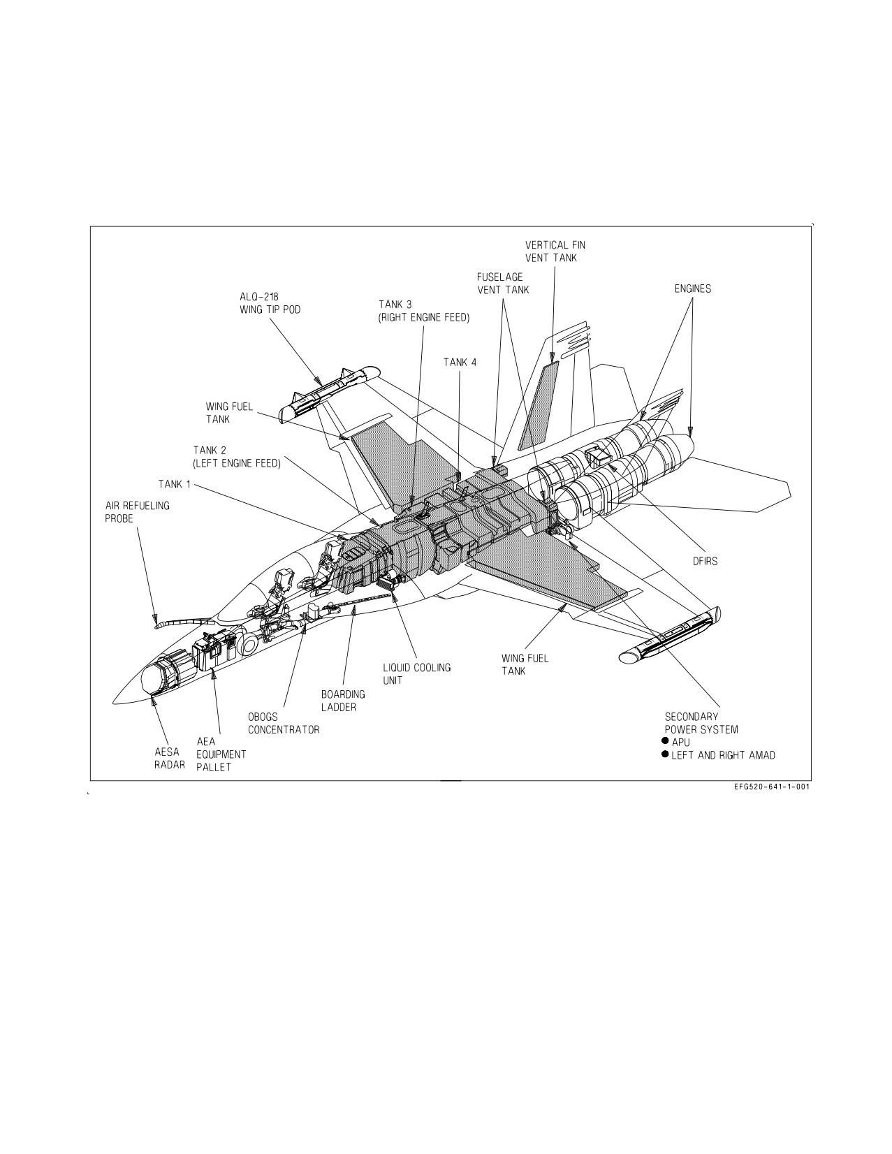
A1-E18GA-NFM-000
CHAPTER 1
The Aircraft
Figure 1-1. General Arrangement
1.1 AIRCRAFT DESCRIPTION
1.1.1 Meet The Growler. The EA-18G Growler is a carrier based electronic attack aircraft built by
McDonnell Douglas Corporation, a wholly owned subsidiary of the Boeing Company. The general
arrangement, approximate dimensions, and cockpit layout are shown in Figure 1-1, Figure 1-2, and the
Foldout section, respectively.
The purpose of the Airborne Electronic Attack (AEA) system for the EA-18G is to provide electronic
surveillance and electronic attack capabilities. The AEA system incorporates the Electronic Attack
Unit (EAU) as the AEA system controller, the ALQ-218(V)2 receiver system, the ALQ-227B
Communications Countermeasures Set (CCS), the Multimission Advanced Tactical Terminal Block 3
(MATT), and the ALQ-99 jamming pods. The Digital Memory Device (DMD) and Interference
Cancellation Unit (INCANS) have also been added to achieve the needs of the EA-18G.
I-1-1
ORIGINAL
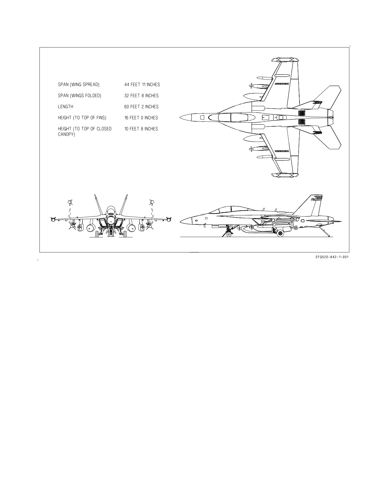
A1-E18GA-NFM-000
Figure 1-2. Approximate Dimensions
The Mission of the EA−18G is the Suppression of hostile Search, Acquisition, Tracking, and
Guidance Radar Systems, and RF Communications that might be employed against ownship and other
friendly (specifically the protected entity) aircraft. This Mission encompasses protection of friendly
aircraft as they enter and depart a battlefield region, as well as during the friendly aircrafts’ Mission
(Strike Fighter) in that battlefield region. The Mission is accomplished through means of Electronic
Attack, and/or Weapons delivery, to the Threat. This new Mission is for the protection of multiple
friendly aircraft in a multiple hostile threat environment. The Electronic Attack portion of this
Mission is accomplished via the Crew Vehicle Interface (CVI) with the AEA Subsystem functionality
controlled through the mission computers (MCs). This interface includes both Display of Threat
Situational Awareness (SA) provided by AEA Subsystem Threat detection Trackfile information
processed in the AMCs, and a Command and Control Interface of the AEA Subsystem through the
AMCs via options on the Display Formats, and Cockpit Hand Controls that provide Hands On
Throttle And Stick (HOTAS) switches. The EA−18G employs EW tactics as offensive measures.
Offensive jamming is the primary function of the EA−18G.
The aircraft is powered by two General Electric F414-GE-400 turbofan engines utilizing Full
Authority Digital Engine Control (FADEC). The aircraft features a variable camber mid-wing with
leading edge extensions (LEX) mounted on each side of the fuselage. Twin vertical tails are angled
outboard 20 degrees from the vertical.
The aircraft is designed with relaxed static stability to increase maneuverability and to reduce
approach and landing speed. The aircraft is controlled by a digital fly-by-wire Flight Control System
I-1-2
ORIGINAL
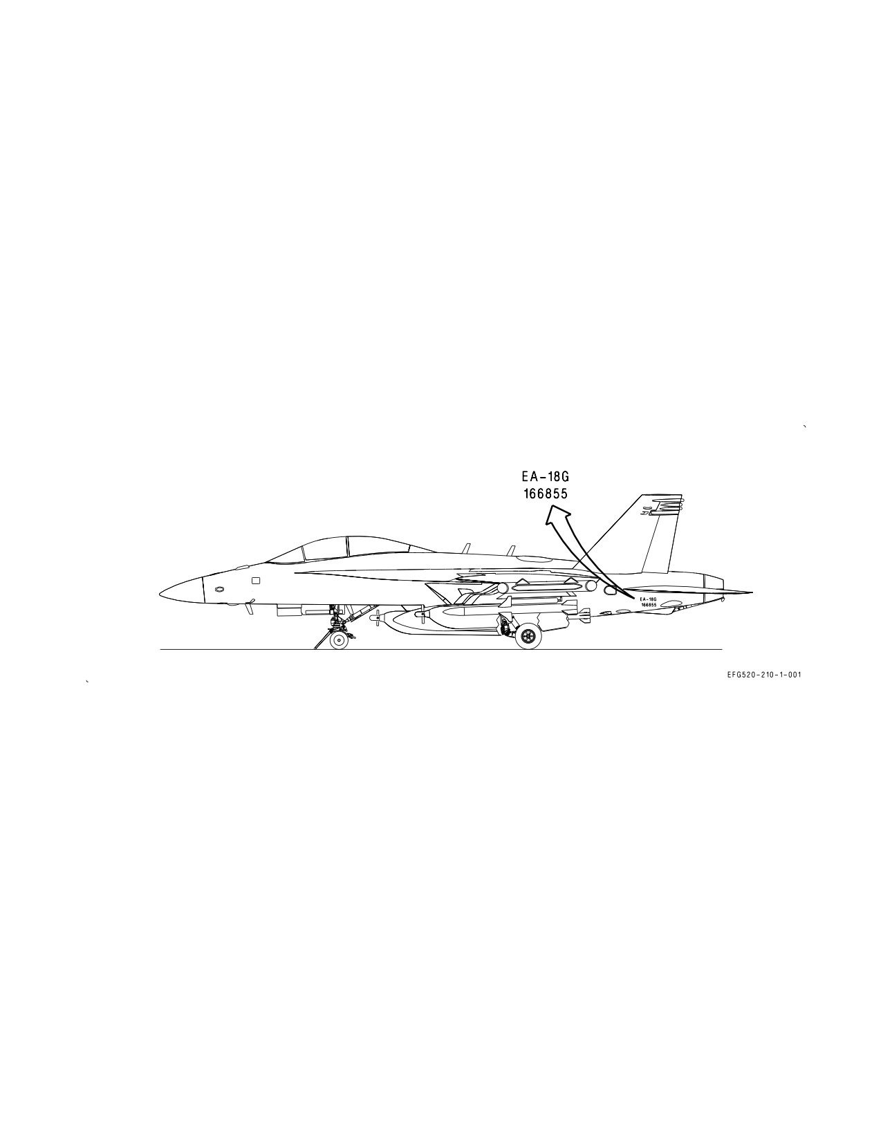
A1-E18GA-NFM-000
through hydraulically actuated flight control surfaces: ailerons, twin rudders, leading edge flaps,
trailing edge flaps, LEX spoilers, and differential stabilators. The leading edge of the wing incorporates
a ‘‘snag,’’ which increases outboard wing area and increases roll authority in the approach and landing
configuration. The upper surface of the wing incorporates a solid wing-fold fairing cover and
partial-span fence to improve transonic handling qualities at elevated AOA. A speedbrake function is
provided by differential deflection of the primary flight control surfaces.
The pressurized cockpit is enclosed by an electrically operated clamshell canopy. An aircraft
mounted auxiliary power unit (APU) provides self-contained start capability for the engines.
1.1.2 Aircraft Gross Weight. Basic weight is approximately 33,733 pounds. The basic weight includes
all AEA subsystems except for the ALQ-99 pod. Refer to applicable DD 365-3 for accurate aircraft
weight.
1.2 BLOCK NUMBERS
See figure 1-3 for block numbers and bureau numbers for each lot of aircraft.
LOT
BuNo
LOT 30
166855 - 166858
Figure 1-3. LOT NUMBER / BuNo
I-1-3
(Reverse Blank)
ORIGINAL
A1-E18GA-NFM-000
CHAPTER 2
Systems
2.1 POWER PLANT SYSTEMS
2.1.1 Engines. The aircraft is powered by two General Electric F414-GE-400 engines. The engines
are low bypass, axial-flow, twin-spool turbofans with afterburner. The three stage fan (low pressure
compressor) and the seven stage high pressure compressor are each driven by a single stage turbine.
The basic functions are supported by the engine driven accessory gearbox which drives the engine fuel
pump, variable exhaust nozzle (VEN/start) fuel pump, lubrication and oil scavenge pump, engine fuel
control, and alternator. Fuel flow from the VEN/start pump is used to drive the VEN actuator and to
provide initial fuel pressure for main engine start.
The uninstalled military thrust (MIL) of each F414-GE-400 engine is approximately 13,900 pounds
with maximum afterburner thrust (MAX) in the 20,700 pound class.
An inlet device is installed in each engine intake to reduce the aircraft radar signature and to
improve survivability.
2.1.1.1
FADEC - Full Authority Digital Engine Control. Engine operation is controlled by a full
authority digital engine control (FADEC), mounted on the engine casing. Each FADEC computer has
two central processor units, channel A (CH A) and channel B (CH B), and is integrated with the
Mission Computers (MCs), flight control computers (FCCs), and throttles. Normally, both FADEC
channels monitor engine and control system operation with one channel in control and the other in
standby. The channel currently in control is boxed on the SUPT MENU/ENG display.
In the event of a control system failure, the FADEC automatically selects the channel with better
capability. Manual FADEC channel transfer can be commanded by selecting the CH A or CH B
pushbutton on the ENG display. When the throttle is at or above IDLE, the FADEC transfers control
to the other channel only if the requested channel’s health is no worse than the channel in control.
FADEC software implements the engine control schedules by modulating fuel flow and engine
geometry for the current flight conditions and the ″requested″ throttle setting. With the throttles
matched, engine parameters may vary significantly between the engines as control schedules are
adjusted for optimum performance. Therefore, a mismatch between engine parameters is not a sign of
degraded performance as long as ENG STATUS is NORM. FADEC cooling is provided by the fuel
system.
2.1.1.1.1
FADEC Power Sources. Prior to first engine start, the battery is used to power CH A of
both FADECs. When N2 reaches 10% rpm during start, the engine driven alternator comes online and
powers both channels of its corresponding FADEC. When an aircraft generator comes online (N2
greater than 60%), the aircraft’s electrical system provides power to both channels of the other FADEC
as well. With both engines operating, each engine driven alternator is the primary source of FADEC
power with the aircraft’s 28 vdc essential bus as backup. When both channels of a FADEC are powered
after initial start, the FADEC automatically switches operation to the channel which was not in control
during the last flight/engine run.
I-2-1
ORIGINAL
A1-E18GA-NFM-000
Ten seconds after reaching idle power, the FADEC attempts to switch to the 28 vdc essential bus to
verify that backup power is available. If backup power is inadequate/inoperative, the FADEC declares
a channel degrade (dual channel lineout) and sets a 6A8 or 6C8 MSP code (L or R FADEC/aircraft 28V
fail). These degrade indications appear if the first engine is started with the corresponding GEN switch
OFF, and requires a FADEC reset to restore normal engine indications.
2.1.1.1.2
Engine Status. Engine status is reported by the FADEC and appears on the ENG
STATUS line of the ENG display. The levels of engine performance capability, listed in descending
order, are:
NORM
Engine performance is normal.
PERF90
10% or less thrust loss and/or slower engine transients. Afterburner is not
inhibited.
AB FAIL
No afterburner capability.
THRUST
Engine thrust is limited to between 40% and 90% and significantly slower
transients.
IDLE
Engine is limited to idle power only.
SHUTDOWN Engine automatically shut down.
2.1.1.1.3
FADEC/Engine Degrades. FADEC/engine degrades fall into two categories: minor failures
which do not affect engine operability and significant failures that do affect engine operability.
Due to a high level of FADEC redundancy, most minor control system failures do not cause any
degradation in engine performance (ENG STATUS remains NORM). Cockpit indications for these
types of failures are slightly different depending on whether the aircraft is inflight or on the ground.
Inflight -
a. FADEC and BIT advisories.
b. ENG STATUS - NORM.
c. OP GO indication for the affected engine channel on the BIT/HYDRO MECH display.
On the ground or below 80 KCAS after landing -
a. FADEC and BIT advisories.
b. ENG STATUS - NORM.
c. DEGD replaces OP GO for the affected engine channel on the BIT/HYDRO MECH display.
d. Both CH A and CH B lined out on the ENG display.
A FADEC OP GO or DEGD with an ENG STATUS of NORM is an indication of a loss of control
system redundancy and not of a loss of engine operability. Therefore, a FADEC OP GO inflight should
be considered informative and should not mandate a mission abort. However, on the ground, the
I-2-2
ORIGINAL
A1-E18GA-NFM-000
FADEC DEGD and dual channel lineout indications are intended to prevent takeoff with a known loss
of redundancy and maintenance action is required. Therefore, takeoff with a FADEC DEGD indication
(dual channel line out) is prohibited.
Significant failures which do cause degradation in engine performance have the following indications
both inflight and on the ground:
a. L or R ENG caution and voice alert.
b. FADEC and BIT advisories.
c. ENG STATUS change on the ENG display.
d. DEGD indication for the affected engine channel on the BIT/HYDRO MECH display.
e. Both CH A and CH B lined out on the ENG display.
2.1.1.1.4
FADEC Reset. When a throttle is OFF, the corresponding FADEC uses a channel change
request as a FADEC software reset. FADEC reset capability is provided to clear a DEGD indication
which was caused by a momentary FADEC fault (e.g., startup power transient). A FADEC reset should
only be performed for DEGD indications which occur on the ground and which do not result in a
change of ENG STATUS. For a FADEC OP GO inflight, engine shutdown and FADEC reset is not
recommended as the engine is functioning normally. In all other circumstances, a FADEC reset should
not be attempted, particularly airborne, as any degrade in ENG STATUS is most likely indicative of
the failure of a mechanical component. Under these conditions, the engine may fail to restart following
a shutdown and FADEC reset attempt.
2.1.1.1.5
Ignition System. The FADEC provides simultaneous control of the main and afterburner
igniters via the engine driven alternator and ignition exciter. Ignition
(both main engine and
afterburner) is commanded whenever:
a. N2 rpm is between 10% and 45% during engine start.
b. Flameout occurs.
c. Throttle is advanced into afterburner, remaining on until afterburner light off is sensed.
d. Any wing pylon mounted A/A or forward firing A/G weapon is launched. Ignition remains on
for 5 seconds.
2.1.1.1.6
Oil Pressure Sensing System. The oil pressure sensing system utilizes an oil pressure
transducer and a separate oil pressure switch. The transducer provides an oil pressure value for display
in the cockpit. The oil pressure switch provides an additional source to confirm the presence of oil
pressure if the oil pressure transducer fails.
If a L or R OIL PR caution is set with a valid cockpit readout, actual engine oil pressure is below
scheduled limits. If the cockpit readout is zero with no caution set, the oil pressure transducer has
failed and the pressure switch is inhibiting the caution.
2.1.1.1.7
Engine Idle Schedules. Each FADEC modifies engine idle schedules based on weight on
wheels (WonW) status, aircraft flight condition, engine bleed demand, and environmental control
system (ECS) mode of operation. The purpose of idle scheduling is to ensure that engine bleed output
I-2-3
ORIGINAL
A1-E18GA-NFM-000
is always sufficient to run the ECS, particularly the aircrew onboard oxygen generating system
(OBOGS).
Baseline idle schedules are used during normal engine operation and moderate environmental
conditions, and are set as a function of pressure altitude and WonW status. With WonW and airspeed
below 80 knots, the FADEC commands ground idle by reducing the engine compressor discharge
pressure (CDP) (typically a slight decrease in N2 rpm) from the inflight idle setting. The throttle
handle angle (THA) for ground and inflight idle are identical.
Alternate idle schedules are used when engine bleed demands are high
(e.g., hot ambient
temperatures, high ECS output, engine or windshield anti-ice operation, or ECS OFF/RAM mode).
When an alternate idle schedule is requested, the FADEC increases the minimum CDP that is
commanded at idle power (typically a slight increase in N2 rpm), which may also result in a noticeable
decrease in throttle response at the lower end of the throttle range. With the throttles near flight idle,
a small engine transient may be noticed when an alternate idle schedule is activated or when a
transition between alternate idle schedules occurs.
Alternate idle schedules are deactivated with WonW, when spin recovery mode is engaged, or when
the inflight refueling probe or landing gear are extended. When alternate idle schedules are
deactivated, a small noticeable engine transient may occur with the throttle near flight idle.
2.1.1.1.8
Fan Speed Lockup. The fan speed lockup system prevents inlet instability (buzz) at high
Mach by holding engine speed and airflow at military power levels when the throttle(s) are retarded
below MIL. Speed lockup is activated when the aircraft accelerates above 1.23 Mach and deactivated
when the aircraft decelerates below 1.18 Mach.
2.1.1.1.9
Supersonic Engine Thrust Limiting (SETLIM). SETLIM minimizes the potential for an
aircraft departure due to asymmetric thrust following an engine stall or flameout at certain supersonic
(Mach greater than 1.8) or high-q conditions equivalent to approximately 700 KCAS at sea level or 750
KCAS at 25,000 feet. If the FADEC detects a stall or flameout condition, this function terminates
afterburner operation in both engines. Normal afterburner operation is restored 12 seconds after
engine recovery or immediately when airspeed drops below 1.7 Mach and q-conditions are equivalent
to approximately 650 KCAS at sea level or 710 KCAS at 25,000 feet.
2.1.1.1.10 Reduced Authority Thrust System (RATS). The reduced authority thrust system (RATS)
reduces the wind-over-deck required for carrier landings by rapidly reducing thrust at the beginning
of a successful arrestment, reducing the energy absorbed by the arresting gear. RATS logic, only
resident in MC1, declares a successful arrestment if the landing gear and arresting hook are down and
longitudinal deceleration is more than 1.0 g (a typical arrestment is approximately 3 g). MC1 sends a
″set RATS on″ signal to the FADECs, which reduce thrust to approximately 70% of MIL power. RATS
logic also senses WonW, wheel speed (less than 20 knots), and THA to prevent the engines from
spooling back to MIL power at the end of cable pullout. RATS operation is canceled when the throttles
are reduced to IDLE (THA less than 10°). RATS operation is inhibited during single engine operation.
RATS operation can be overridden by advancing the throttles to full afterburner (THA within 2° of
the MAX stop). With RATS enabled, afterburner operation is inhibited if the throttles are
subsequently advanced to afterburner (below the MAX stop). If the throttles are in afterburner (below
the MAX stop) during an arrested landing, RATS functions normally, rolling back both the main
engine and the afterburner.
2.1.1.1.11 Armament Gas Ingestion (AGI) Protection. AGI protection provides preemptive engine
ignition in case armament gas ingestion causes an engine flameout. As mechanized, AGI protection is
I-2-4
ORIGINAL
A1-E18GA-NFM-000
a backup to the FADEC’s inherent flameout detection and relight logic. While flight test data indicates
that the system may not be needed, AGI protection remains functional.
The AGI signal is sent by the Stores Management Set (SMS) to the FADECs and is used to initiate
engine ignition (both engines) for 5 seconds. The signal is sent when any wing pylon mounted A/A or
forward firing A/G weapon is launched. AGI is functional in the SIM mode as well as the tactical mode.
2.1.1.1.12 Increased Bleed Usage (IBU) Signal During high bleed flow rates, the mission computers
may send the FADECs an IBU signal to prevent engine turbine overheating.
2.1.1.1.13 Afterburner Limiting (ABLIM) Function. The ABLIM function limits engine power to
half afterburner with the throttles at MAX to prevent engine stalls due to exhaust gas ingestion. The
system is only to be used during carrier-based operations. The function is pilot selectable with WonW.
The system defaults to disabled (unboxed) after engine start. The ABLIM function is activated by
selecting (boxing) the ABLIM option on the CHKLIST format with the FLAP switch in HALF or
FULL. The ABLIM advisory is set to confirm that the function has been activated on both engines.
With the function activated, only half afterburner power is available with the throttles at MAX.
Indicated fuel flows are reduced from 35,000 to 45,000 pph to about 25,000 pph. The function is
automatically deactivated with acceleration due to a catapult launch, at 80 KCAS, or with WoffW. The
ABLIM function is disabled with a FCC CH 1, FCC CH 2, FCC CH 4, MC1, or FADEC failure.
2.1.1.2
Engine Related Cautions and Advisories. The following engine related cautions and adviso-
ries are described in the Warning/Caution/Advisory Displays in Part V:
D L or R EGT HIGH
D L or R OIL HOT (engine or AMAD)
D L or R ENG
D L or R OIL PR
D L or R ENG VIB
D L or R OVRSPD
D FADEC HOT (ground only)
D L or R STALL
D L or R FLAMEOUT
D ABLIM advisory
D NO RATS
D FADEC advisory
2.1.1.3
Engine Anti Ice. Each engine supplies its own bleed air for engine and inlet device anti-ice.
The engine anti-ice system is normally controlled by the ENG ANTI ICE switch. However, after engine
start (initial FADEC power-up or following a FADEC reset), the engine anti-ice system automatically
turns on 45 seconds after the engine reaches idle power and remains on for 30 seconds, provided the
throttle remains at IDLE. The appropriate LHEAT or RHEAT advisory is displayed during this
anti-ice functional test.
With the ENG ANTI ICE switch ON, anti-ice air flows as long as INLET TEMP is between -40 and
+15°C. Outside of these limits, anti-ice airflow is terminated immediately if airborne, or after 60
seconds with WonW. When anti-ice air is flowing, N2 rpm increases approximately 2%, and EGT
increases approximately 5°C.
The inlet device has an anti-ice leak detection system. The system detects hot air leaks from the
device air manifold or in the cavity between the device and the airframe and sets the L or R DEVC
BLD caution. A hot air leak into the cavity reduces device anti-ice capability and may structurally
damage the device and surrounding structure.
2.1.1.3.1
ENG ANTI ICE Switch. The ENG ANTI ICE switch is located on the ECS panel on the right
console.
I-2-5
ORIGINAL
A1-E18GA-NFM-000
ON Activates the engine anti-ice system
OFF Deactivates the engine anti-ice system
TEST Checks ice detector operation and displays the INLET ICE caution (indicating proper
operation).
2.1.1.3.2
Engine Anti-Ice Advisories. The L HEAT and R HEAT advisories are displayed when the
engine anti-ice system is activated (ENG ANTI ICE switch ON or anti-ice functional test) and no
system failures are detected. If an engine anti-ice failure occurs with the system turned on, the HEAT
FAIL caution is displayed and the corresponding L HEAT or R HEAT advisory is removed.
If an engine anti-ice failure occurs with the ENG ANTI ICE switch OFF, the HEAT advisory is
displayed. This advisory indicates that anti-ice operation is degraded or not available if selected.
2.1.1.3.3
Engine Anti-Ice Related Cautions and Advisories. The following engine anti-ice related
cautions and advisories are described in the Warning/Caution/Advisory Displays in Part V:
D L or R ANTI ICE caution
D INLET ICE caution
D L or R DEVC BLD caution
D L HEAT or R HEAT advisory
D HEAT FAIL caution
D HEAT advisory
2.1.1.4
Engine Controls and Displays.
2.1.1.4.1
ENG CRANK Switch. The ENG CRANK switch is described in the Secondary Power
System section.
2.1.1.4.2
Throttles. Two throttles, one for each engine, are located on the left console. Throttle
movement is transmitted electrically to the corresponding FADEC for thrust modulation and to the
FCCs for autothrottle operation. There is no mechanical linkage between the throttles and the engines.
During engine start, advancing the throttles from OFF to IDLE opens the engine fuel control shutoff
valves and, when commanded by the FADEC, provides fuel flow to the engines.
Afterburner operation is initiated by advancing the throttles through the MIL detent into the
afterburner range. During catapult launch or carrier touchdown (WonW and launch bar or arresting
hook extended), an afterburner lockout mechanism extends to preclude inadvertent afterburner
selection. In such cases, the throttles can be moved to the afterburner range by raising the finger lifts
on the front of each throttle or by applying a force of approximately 30 pounds.
During engine shutdown, the finger lifts must be raised to move the throttles to OFF, closing the
engine fuel control shutoff valves. The throttle grips (figure 2-1) contain switches that allow control of
various systems without moving the hand from the throttles.
2.1.1.4.3
Engine Fuel Display (EFD), Engine Parameters. The EFD, located on the main instrument
panel below the left digital display indicator (LDDI), is a night vision imaging system (NVIS)
compatible, monochromatic, liquid-crystal, grey/black display powered by the Signal Data Computer
(SDC).
The EFD normally displays critical engine parameters in the bottom half of the display and fuel
quantities in the top half. The fuel portion of the EFD is described in the Fuel System section. Invalid
parameters are usually displayed as 999 or 9999 in inverse video; out of limit parameters are always
highlighted by inverse video. Nozzle position is displayed both graphically and digitally in percent
open.
I-2-6
ORIGINAL
//////////////////////////