EA-18G. FLIGHT MANUAL (2008) - page 2
A1-E18GA-NFM-000
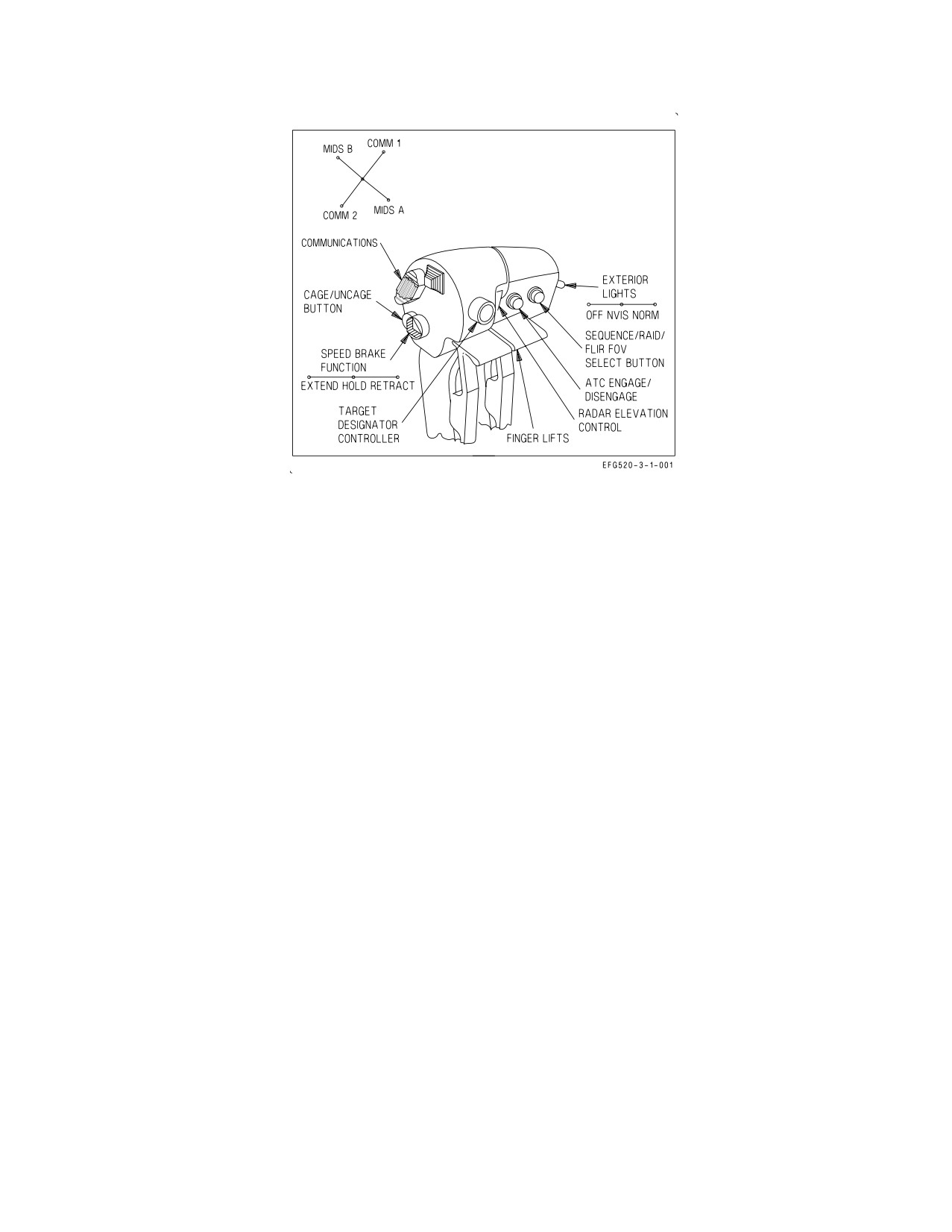
Figure 2-1. Throttle Grips (Front Cockpit)
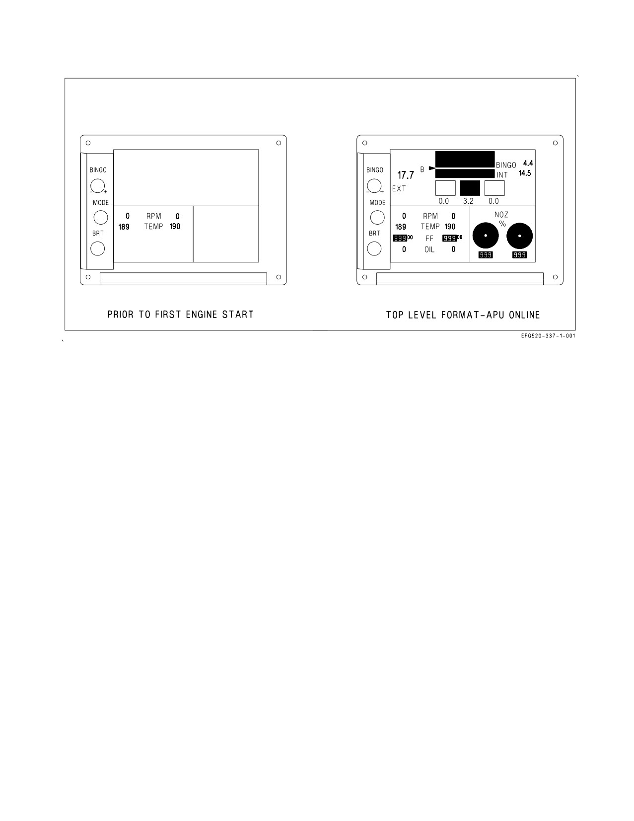
On battery power prior to APU start, the EFD displays only RPM and TEMP (figure 2-2). When the
APU switch is selected ON, the entire top level format is displayed but only RPM, TEMP, and OIL
pressure are valid. When the first engine alternator comes online at 10% N2 rpm, the FF parameter
also becomes valid. When the first generator comes online at 60% N2 rpm, all parameters for both
engines become valid. If the EFD locks up or blanks completely during engine start power transients,
the display can be reset by selecting the SDC RESET option from the SUPT MENU/FUEL display.
The EFD displays the following engine parameters within the listed display tolerances:
RPM Compressor rpm (N2 ) (0 to 127%) - Displays RPM in inverse video format above
102%
TEMP Compensated turbine exhaust gas temperature (EGT) (186 to 1,088°C) - Displays 9999
in inverse video above 1,100°C
FF
Total commanded fuel flow including afterburner (0 or 400 to 65,000 pph in 100 pph
increments).
NOTE
Engine fuel flow is calculated from commanded engine fuel metering
valve position. In failure modes, fuel flow can be indicated on the EFD
even though no actual fuel is flowing.
OIL
Oil pressure (0 to 200 psi)
NOZ VEN position (0 to 101% open)
I-2-7
ORIGINAL
A1-E18GA-NFM-000
Figure 2-2. Engine Fuel Display (EFD) - Engine Parameters
During first engine battery start, the EFD RPM indication typically jumps from 0 to either 5% or
10%, and lightoff is indicated by TEMP rising from a minimum reported value of approximately
190°C. Each engine has three sources of N2 rpm: two engine alternator sensors and one accessory
gearbox sensor. The accessory gearbox sensor can provide rpm readings down to only 5% and is the
initial source of engine RPM. Readings from the alternator sensors are not available until the
alternator comes online above 10% N2 rpm. Input for the TEMP parameter is provided by a
compensated EGT algorithm in the FADEC. When actual EGT is below accuracy tolerances (e.g.,
engine shutdown), the FADEC limits the minimum reported TEMP (approximately 190°C). The FF
parameter is a calculated number based on metering valve position, not an actual measurement of fuel
flow. Consequently, an indication of fuel flow may be present when there is no flow, such as when the
throttle is above IDLE with the engine off.
I-2-8
ORIGINAL
A1-E18GA-NFM-000
2.1.1.4.4
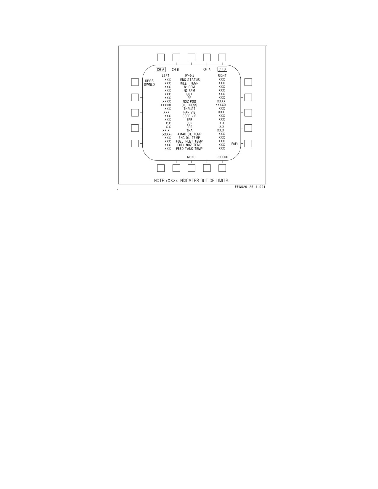
ENG Display. The ENG display (figure 2-3) is selected by pushing the ENG option from the
SUPT MENU. The ENG display shows the following engine and thermal management system
parameters:
ENG STATUS
The current level of engine performance provided by the control system
INLET TEMP
Engine inlet temperature (°C)
N1 RPM
Fan speed (% rpm)
N2 RPM
Compressor speed (% rpm)
EGT
Exhaust gas temperature (°C)
FF
Total commanded fuel flow (pph)
NOZ POS
Nozzle position (% open)
OIL PRESS
Engine oil pressure (psi)
THRUST
Takeoff thrust (%), referenced to hot day MIL power (blanked inflight)
FAN VIB
Fan vibration (inches/second)
CORE VIB
Core vibration (inches/second)
EPR
Engine pressure ratio (exhaust pressure to engine inlet pressure).
CDP
Compressor discharge pressure (psia)
CPR
Compressor pressure ratio
THA
Throttle handle angle (deg)
AMAD OIL TEMP
AMAD oil temperature (°C)
ENG OIL TEMP
Engine oil temperature (°C)
FUEL INLET
Engine inlet fuel temperature (°C)
TEMP
FUEL NOZ TEMP
Engine nozzle fuel temperature (°C)
FEED TANK
Feed tank fuel temperature (°C)
TEMP
When an engine or thermal management system related caution appears, the MENU option at the
bottom of each DDI is replaced with the ENG option, providing one pushbutton access to the ENG
display. The value of the out of limit parameter which triggered the caution is displayed in red and
highlighted by carets on either side. The CH A and CH B options at the top of the display are used to
command a manual FADEC channel transfer, and the active FADEC channel for each engine is boxed.
I-2-9
ORIGINAL
A1-E18GA-NFM-000
Figure 2-3. Engine Display
The selected fuel grade is displayed top center and also on the takeoff side of the CHKLIST display.
The FUEL option enables the JP-5, 8, and JP-4 options, each of which must be selected twice to change
the fuel grade. The fuel grade selected should reflect the majority of fuel in the aircraft. JP-5, -8 should
be selected when using JET-A, A+, or A1. The engines can be started and operated at ground idle with
either fuel grade selected; however, for operations above IDLE, the correct fuel grade must be selected
to ensure proper engine operation and to avoid engine combustor rumble. The fuel grade selected is
also used by the FADEC to control the thermal control valve (TCV) setting and determines the
maximum fuel temperature to be sent to the engines. Incorrect fuel grade selection can adversely
impact the fuel thermal management system and result in a premature FUEL HOT caution. The
RECORD option, boxed when selected, saves a 30 second record of display and engine data (15 seconds
pre- and 15 seconds post-event) to the memory unit (MU). The DFIRS DWNLD option downloads
DFIRS data to the MU.
2.1.2 Automatic Throttle Control (ATC). The ATC system has two operating modes: approach and
cruise. The system automatically modulates engine thrust between flight IDLE and MIL power in
order to maintain on-speed angle of attack (AOA) in the approach mode or calibrated airspeed
(existing at the time of engagement) in the cruise mode.
During ATC operation, engine commands are sent to the FADEC directly from the FCCs instead of
the throttles. FCC generated engine commands are limited to a range slightly above idle to slightly
below MIL. The throttles are continuously positioned by an FCC commanded backdrive unit to match
the throttles with the current engine command and to provide feedback to the pilot.
2.1.2.1
ATC Engagement. Pressing and releasing the ATC button on the left throttle engages the
approach mode with the FLAP switch in HALF or FULL and the cruise mode with the FLAP switch
in AUTO. When either mode is engaged, an ATC advisory is displayed on the HUD. Because ATC
mode engagement and ATC HUD advisories are not commanded until release of the ATC button, the
pilot may need to deliberately pause after press and release to avoid inadvertant ATC disengagement/
re-engagement. Automatic transition between the two modes or engagement during single engine
operation is not possible. Engaging ATC with the friction lever in the full aft position and with the
I-2-10
ORIGINAL
A1-E18GA-NFM-000
throttles at mid-range power provides optimum pilot feedback with the smallest engagement power
transients.
2.1.2.2
ATC Disengagement. If either mode does not engage when selected, or automatically
disengages after engagement, the ATC advisory flashes for 10 seconds and is removed from the HUD.
Disengagement for any reason requires reengagement to restore ATC operation. Normal disengage-
ment is accomplished by re-actuation of the ATC button or by applying a force of approximately 12
pounds (friction off) to either throttle for greater than 0.20 seconds. This force is sufficient to permit
the pilot’s hand to follow throttle movement without causing disengagement. Holding the throttles
against the MIL or IDLE stop during ATC disengagement commands a rapid acceleration or
deceleration to the commanded power setting instead of a smooth transition.
2.1.2.3
ATC Automatic Disengagement. The ATC system automatically disengages for the following
reasons:
Either mode -
• Any ATC system internal failure
• ATC button failure
• FADEC failure
• FCC CH 2 or CH 4 failure
• Backdrive failure
• THA split greater than 3° for more than 1 second
• FLAP switch position change between AUTO and HALF or FULL
Approach mode only -
• AOA, pitch rate, or Nz sensor failure
• Bank angle in excess of 70°
• Flap blowup at 250 KCAS
• Gain ORIDE selection
• Weight on wheels
Cruise mode only -
• FCC calibrated airspeed failure
2.1.2.4
ATC Related Cautions. The ATC FAIL caution is described
in
the
Warning/Caution/
Advisory Displays in Part V.
2.2 FUEL SYSTEM
The aircraft is fitted with four internal fuselage tanks (Tanks 1 through
4), two internal wing tanks
(left and right), two fuselage vent tanks, and two vertical vent tanks. Tanks 2 and 3 are engine feed
tanks while Tanks 1, 4, and the wing tanks are transfer tanks. Total fuel can be increased by the
carriage of up to four 480 gallon external fuel tanks on the centerline, inboard, and midboard pylons.
All tanks, internal and external, may be refueled on the ground through a single-point refueling
receptacle or inflight through the inflight refueling probe.
I-2-11
ORIGINAL
A1-E18GA-NFM-000
The aircraft’s fuel system is composed of the following subsystems: engine feed, motive flow, fuel
transfer, tank pressurization and vent, thermal management, refueling, fuel dump, fuel quantity
indicating, and fuel low level indicating. Refer to Fuel System, Foldout Section, for simplified
schematics.
2.2.1 Engine Feed System. Each engine feed system contains an airframe mounted accessory drive
(AMAD) driven motive flow/boost pump, a feed tank with an internal motive flow powered turbo
pump, and an engine feed shutoff valve. For survivability, the left and right feed systems are normally
separated but can be interconnected by a normally closed crossfeed valve and a normally closed feed
tank interconnect valve.
2.2.1.1
Motive Flow/Boost Pumps. Each AMAD drives a two-stage motive flow/boost pump. The
first stage supplies low pressure fuel to its respective engine mounted fuel pump, while the second stage
supplies high pressure fuel to the motive flow system. Fuel from the motive flow system is used to cool
accessories, power the feed tank turbo pumps and certain transfer/scavenge pumps, and control certain
transfer valves.
2.2.1.2
Feed Tanks. During normal operation, each engine receives fuel from separate fuel feed lines.
Tank 2 supplies fuel to the left engine; Tank 3 to the right. A motive flow powered turbo pump in each
feed tank supplies fuel to its respective motive flow/boost pump.
Each feed tank has a horizontal baffle which traps fuel, providing a minimum of 10 seconds of
negative g flight at MAX power. No sustained zero g capability is provided, and prolonged transitions
through zero g (greater than 2 seconds) may produce a L and/or R BOOST LO caution.
If a feed tank turbo pump fails, fuel is suction fed to the motive flow/boost pump. In this case, flight
at high altitude with high feed tank fuel temperatures may not supply enough fuel for high power
settings.
2.2.1.3
Feed Shutoff Valves. In the event of a fire or fuselage fuel leak, engine feed shutoff valves
provide the capability to isolate a fuel feed system immediately downstream of the feed tank. Pressing
the L or R FIRE warning light electrically closes the corresponding engine feed shutoff valve, isolating
that fuel feed system.
2.2.1.4
Crossfeed Valve. The crossfeed valve, normally closed, allows a single motive flow/boost
pump to feed both engines when boost pressure is lost on one side (e.g., single engine shutdown, a leak,
motive flow/boost pump failure, or feed tank depletion). A loss of boost pressure downstream of the
motive flow/boost pump sets the L or R BOOST LO caution and opens the crossfeed valve. An open
crossfeed valve allows the output from the good motive flow/boost pump to supply fuel to the opposite
engine at rates sufficient for at least MIL power.
Pressing the L or R FIRE warning light electrically closes (inhibits opening) the crossfeed valve,
isolating the two fuel feed systems.
2.2.1.5
Interconnect Valve. A feed tank interconnect valve, installed between Tanks 2 and 3, is used
to control gravity transfer/balancing between the two feed tanks. During normal operation, the dual
flapper-type valve is held closed by motive flow pressure on either side (left motive flow on the Tank
2 side and right motive flow on the Tank 3 side), and no fuel gravity transfers.
If motive flow is lost on one side (e.g., single engine shutdown), the valve opens to make sure that
feed tank fuel is available to the opposite engine. For instance, if motive flow is lost on the right side,
the Tank 3 side of the valve opens, allowing fuel to gravity transfer to Tank 2 anytime the Tank 3 fuel
I-2-12
ORIGINAL
A1-E18GA-NFM-000
level is higher. If Tank 3 has a fuel leak (e.g., battle damage), motive flow pressure on the Tank 2 side
of the valve prevents Tank 2 fuel from gravity transferring into the leak.
2.2.1.6
Feed Tank Balancing. The SDC incorporates feed tank balancing logic, designed to keep
Tanks 2 and 3 within 100 lb of each other. With a normally operating fuel system, balancing begins
after Tank 4 is effectively empty (less than about 300 lb) and the feed tanks begin to deplete below full.
If a feed tank imbalance reaches 100 lb, the SDC shuts off the corresponding Tank 4 scavenge pump
until the imbalance is 50 lb in the opposite direction. With WoffW, feed tank balancing continues until
either feed tank reaches FUEL LO level (approximately 1,125 lb). Feed tank balancing stops at FUEL
LO to make sure tank 4 fuel is transferred to both feed tanks in case one feed tank is damaged and is
leaking. After transitioning to WonW, balancing is reinitiated and continues until either feed tank is
below 300 lb.
In the event of a fuel transfer failure (e.g., a feed tank begins to deplete with fuel in Tank 4), feed
tank balancing begins when either feed tank drops below approximately 2,100 lb for 1 minute. This
mechanization attempts to minimize the effect of the fuel transfer failure by reducing the resulting
feed tank split.
2.2.1.7
Feed Tank Imbalance with One Engine at Idle. If one engine is intentionally reduced to
idle/low power or is commanded to IDLE by the FADEC, a higher rate of fuel depletion can be
expected from the ″good″ engine’s feed tank. At internal fuel weights below approximately 4,900 lb
(transfer fuel depleted), a fuel split can be expected to develop between the feed tanks (interconnect
valve is closed). If fuel burn continues to approximately 2,450 lb, the good engine feed tank depletes
and runs dry. The motive flow/boost pump output pressure on the good side drops, sets the L or R
BOOST LO caution, and opens the crossfeed valve. The good engine feeds from the opposite feed tank
through the crossfeed valve.
When driven by an idling engine, a motive flow/boost pump can support fuel flow up to 28,000 pph
through the crossfeed valve (MIL power fuel flow is approximately 12,000 pph at sea level, standard
day). If the fuel flow demand on the usable engine exceeds 28,000 pph (midrange afterburner), motive
flow/boost pump output pressure drops, setting the other BOOST LO caution, closing the crossfeed
valve, and starving the good engine. MAX power, single engine fuel flow is approximately 38,500 pph
at sea level, 0.2M, standard day (approach conditions).
Selecting afterburner on the good engine with its feed tank reading empty
results in engine flameout if fuel flow exceeds 28,000 pph.
The only way to balance a growing feed tank split is to shutdown the idling engine. This opens both
the interconnect and crossfeed valves. The risk of balancing is a loss of hydraulic and electrical
redundancy provided from the engine if left at idle.
2.2.2 Fuel Transfer System. The fuel transfer system, controlled by the SDC, is designed to keep the
feed tanks full or near full during normal engine operation. Fuel is routed from Tanks 1 and 4, the
internal wing tanks, and external fuel tanks, if installed, through three independent sets of transfer
lines. Additionally, the SDC schedules Tank 1 and 4 transfer to control fuel center of gravity (CG).
2.2.2.1
Fuel Transfer - Tanks 1 and 4. Fuel is transferred from Tanks 1 and 4 to the feed tanks by
two dual-speed electric transfer pumps, one in each tank. The low speed setting is used for normal
I-2-13
ORIGINAL
A1-E18GA-NFM-000
transfer. The high speed setting is used during high fuel flow conditions such as afterburner operation,
ARS replenishment, or fuel dump. The one exception to this is that the Tank 1 transfer pump remains
in low speed setting during afterburner operation. During normal operation, each pump pressurizes the
Tank 1 and 4 transfer line as long as its tank has transfer fuel available. The SDC shuts down the
electric transfer pumps when the respective tanks are dry (Tank 1 empty, Tank 4 approximately 300
lb).
Jet level sensors (JLS) in the feed tanks control the flow of transfer fuel from the Tank 1 and 4
transfer line. For instance, Tank 2 does not accept fuel until its fuel quantity drops to approximately
2,100 lb, uncovering the JLS and opening the transfer valve. Tank 2 accepts fuel until its fuel quantity
reaches approximately 2,450 lb, covering the JLS and closing the transfer valve. Therefore, during
normal operation, Tank 2 fuel level cycles between 2,100 and 2,450 lb as long as transfer fuel is
available (JLS cycling).
Flapper valves in Tanks 1 and 4 provide a backup gravity transfer capability in certain circum-
stances. The flapper valve in Tank 4 is free flowing, gravity transferring to Tank 3 any time the Tank
4 fuel level is higher. Therefore, Tank 4 tends to keep Tank 3 full (near 2,600 lb) until the Tank 4 fuel
level drops below that of Tank 3 (wing tank fuel depleted). The flapper valve in Tank 1 is controlled
by left motive flow. The valve can be opened by the SDC following a Tank 1 transfer pump failure or
by loss of motive flow (left engine shutdown).
Since the Tank 4 transfer pump is not located on the bottom level of the tank, two motive flow
powered scavenge pumps, one routed to Tank 2 and the other to Tank 3, are installed to transfer the
last 300 lb of Tank 4. With empty transfer tanks, an excessive feed tank fuel split following symmetric
engine operation may indicate a Tank 4 scavenge pump failure. There is no SDC monitoring of the
Tank 4 scavenge pumps.
The Tank 1 and 4 transfer pumps are also used to dump fuel through the dump valve.
2.2.2.1.1
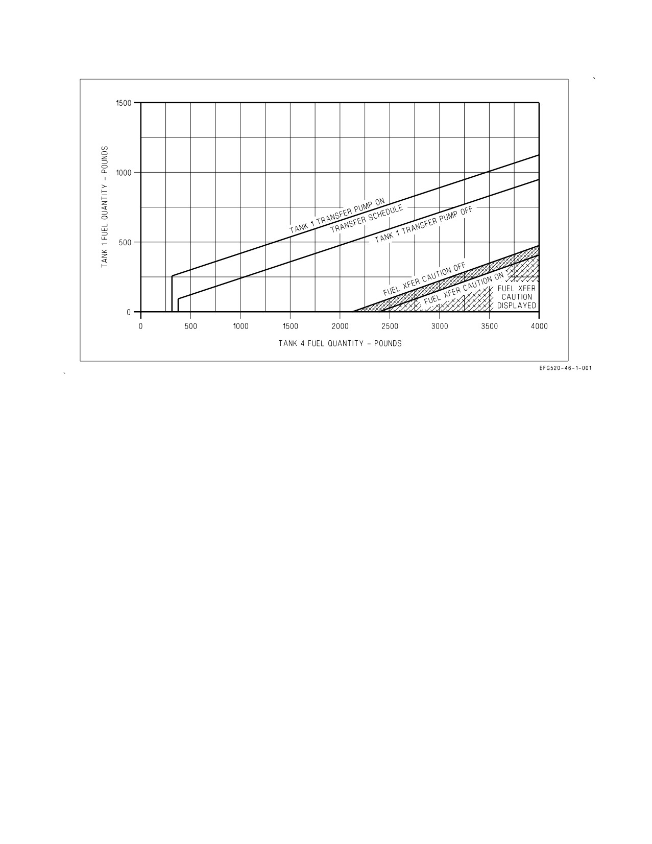
Fuel Transfer Schedule/CG Control. The SDC implements a fuel transfer schedule (figure
2-4) designed to keep aircraft CG at an optimum location. The system periodically shuts off the Tank
1 transfer pump to keep Tank 1 and Tank 4 properly balanced. Fuel transfer scheduling operates until
Tank 4 drops below 300 lb or the FUEL LO caution comes on. When Tank 4 reaches 300 lb, Tank 1
should indicate 250 lb or below.
The FUEL XFER caution is set when Tank 1 and 4 fuel is not scheduling properly or wing tank
imbalance exceeds 350 lb. The caution is inhibited when the inflight refueling probe is extended.
2.2.2.2
Fuel Transfer - Internal Wing Tanks. Fuel is transferred from the wing tanks to Tank 4 by
two motive flow powered ejector pumps, one in each tank. When Tank 4 is less than full, the SDC opens
both wing motive flow control valves, which direct motive flow to the ejector pumps and transfer fuel
from the wing tanks to Tank 4. When Tank 4 is full, the motive flow control valves are closed and
normal wing transfer is inhibited.
If motive flow is lost on one side (single engine shutdown), the cross-motive shutoff valve opens so
that one motive flow system can power the ejector pumps in both wing tanks. If both motive flow
systems are lost, the wing tanks gravity transfer to Tank 4. Bank angle changes or a steady sideslip may
be required to gravity transfer all available wing fuel.
2.2.2.2.1
Wing Tank Balancing. The SDC incorporates wing tank balancing logic designed to keep
wing tank asymmetry below 200 lb. If wing tank asymmetry exceeds 200 lb, the SDC shuts off fuel
I-2-14
ORIGINAL
A1-E18GA-NFM-000
Figure 2-4. Tank 1 and 4 Fuel CG Control and FUEL XFER Caution Schedule
transfer from the lower tank by closing its wing motive flow control valve. If wing tank asymmetry
exceeds 350 lb for 15 seconds, the FUEL XFER caution appears.
Wing tank balancing also occurs during refueling, where the SDC alternately opens/closes the wing
refuel valves attempting to keep the wing tanks within 200 lb. The FUEL XFER caution is not set
during refueling. If SDC balancing logic cannot keep the wings from refueling asymmetrically (greater
than 350 lb), the FUEL XFER caution is set when the inflight refueling probe is retracted.
2.2.2.2.2
INTR WING Control Switch. The INTR WING control switch, located on the EXT LT
panel on the left console, is used to isolate the wing tanks (e.g., following battle damage).
INHIBIT Prevents normal transfer and refueling of the wing tanks (closes both wing motive
control valves, both wing refuel valves, and switches both diverter valves, located
in Tank 3, from the wing tanks to the feed tanks).
NORM
Permits normal transfer and refueling of the internal wing tanks.
2.2.2.3
External Fuel Transfer. External fuel is transferred by regulated engine bleed air pressure
applied to all installed external tanks with WoffW. External tank pressurization is terminated for
inflight refueling (PROBE switch in EXTEND) and for arrested landing (both HOOK and LDG
GEAR handles down). With pressurization applied, external fuel transfer is controlled by the three
EXT TANKS transfer switches.
During external transfer, fuel is routed through the aircraft’s refuel/defuel line. Refuel valves in each
tank open only if commanded by the SDC and space is available. At MIL power and below, the SDC
I-2-15
ORIGINAL
A1-E18GA-NFM-000
only allows external fuel to transfer to Tank 1 and the wing tanks. In afterburner, the SDC allows
external fuel to transfer to any internal tank that can accept it.
2.2.2.3.1
EXT TANKS Transfer Switches. The three EXT TANKS transfer switches are located on
the FUEL panel on the left console and are labeled LM/RM, LI/RI, and CTR (left and right midboard,
left and right inboard, and centerline tanks, respectively). With the external tanks pressurized, fuel
transfers when the FUEL LO caution is displayed regardless of the position of the EXT TANKS
transfer switches.
ORIDE Applies pressurization and transfers fuel from all external tanks whose switches are not
in STOP. May be used to transfer external fuel during extended ground operations
(EXT TANK caution). Overrides any SDC stop transfer command.
NORM Permits normal transfer and refueling of controlled external tank(s).
STOP Prevents transfer and refueling of controlled external tank(s) except with a FUEL LO
caution.
2.2.3 Fuel Tank Pressurization and Vent. The internal fuel tank pressurization system provides ram
air from the vertical tail vents to all internal tanks to prevent fuel boil-off at altitude.
The vent system provides over-pressure and over-fill relief for the internal tanks. Pressurization is
applied to the vent lines in the two fuselage vent tanks. The vent lines connect all internal tanks and
are ported through the fuselage and vertical tail vent tanks to outlets located on the side of the vertical
tail. Normally, the vent lines contain only pressurized air; however, if a refuel valve failure overfills an
internal tank, fuel flows through the vent lines to the fuselage vent tanks. Two motive flow powered
vent tank scavenge pumps return this fuel from the fuselage vent tanks to the feed tanks.
Additionally, the vent system provides pressure relief of the internal fuel tanks during climbs and
vacuum relief during descents.
2.2.4 Thermal Management System. The thermal management system uses fuel from the high
pressure fuel stage of the motive flow/boost pump to cool the FADECs, liquid coolant, and AMAD and
hydraulic oils. The high pressure motive flow output of the pump has four branches.
The first branch is used to run motive flow powered pumps and valves in the fuel system. The second
branch directs cooling flow to the FADEC and exits into the fuel recirculation return line.
The third branch runs through the liquid coolant/fuel heat exchanger and the combined AMAD oil
and hydraulic oil/fuel heat exchanger in order to cool those fluids. A hot fuel diverter valve in the third
branch either directs fuel away from the engine and into the fuel recirculation return line or directs fuel
to the engines where it is combined with fuel feed from the motive flow/boost pump and burned.
I-2-16
ORIGINAL
A1-E18GA-NFM-000
Recirculated fuel first passes through a fuel/air heat exchanger bypass valve, which either directs the
fuel through or around the fuel/air heat exchanger. When sufficient recirculation fuel flow is present,
the SDC may open the heat exchanger bypass valve (Mach greater than approximately 0.35) to direct
hot fuel through the fuel/air heat exchanger. Then, the fuel passes through a diverter valve, located in
Tank 3, which either directs the fuel to the wing tanks or the feed tanks. Fuel directed to the wing tanks
then flows to Tank 4 for additional cooling. When Tank 4 is below 300 lb, recirculation fuel is returned
to the feed tanks by the Tank 4 scavenge pumps. When recirculation fuel is diverted to the wing tanks,
modulation of wing fuel quantities on cockpit fuel displays is noticeable at lower wing fuel levels.
The engine thermal control valve (TCV), located in the engine fuel control unit, maintains engine
combustor nozzle, engine lube oil, and aircraft accessories within their temperature limits. When the
system determines that more cooling is required (typically due to hot weather or low fuel levels), the
TCV opens, directing feed fuel into the recirculation return line. With the TCV open, greater cooling
flow is induced through the engine lube oil and aircraft accessory heat exchangers, and the FADEC,
ultimately reducing system temperatures.
The fourth branch runs to the cross cooling valve which opens following a motive flow system failure,
allowing one motive flow system to cool both FADECs and both engines’ accessories.
During ground operations, when temperatures exceed 30°C, the liquid coolant pump and Liquid
Cooling System (LCS) ground cooling fan may be commanded on (if not already on) to provide LCS
cooling of the fuel system. The ECS controller will only direct liquid coolant to the liquid coolant/fuel
heat exchanger if the RADAR knob is in OFF.
NOTE
The RADAR knob must be in OFF in order to provide any postflight
LCS fuel cooling.
Placing the RADAR knob to OFF removes the radar as a heat source and should extend ground
operating time.
2.2.4.1
Fuel/Air Heat Exchanger. A fuel/air heat exchanger is located above each engine inlet, near
the leading edge. When the heat exchanger bypass valve is open, the heat exchanger uses inlet air to
provide additional fuel cooling. Air is drawn from the inlet through several banks of small pin holes
(bleed plates) and is exhausted through the spoiler opening on the upper surface of the LEX/fuselage.
2.2.4.2
Fuel/Air Heat Exchanger Leak Detection. Since a leak in the fuel/air heat exchanger can
result in engine fuel ingestion through the bleed plates, a leak detection system is incorporated. If a fuel
leak is detected during fuel/air heat exchanger operation, the SDC closes the heat exchanger bypass
valve and isolates the heat exchanger.
Leak detection logic is only capable of detecting a leak greater than approximately 400 pph in the
fuel air heat exchanger. Fuel flow through the heat exchangers is inhibited below approximately 0.35
Mach and anytime the ECS auxiliary scoops are deployed to guard against potential for engine inlet
fuel ingestion.
A leak of less than 400 pph can, however, be discovered during the post-flight switching valve checks.
Following engine shutdown, the SDC opens the cross cooling valve and the heat exchanger bypass valve
on the non-operating side for 20 seconds. If ground crew observe fuel exiting from the fuel/air heat
exchanger drainage ports (bottom, inboard edge of the inlet), a leak exists.
I-2-17
ORIGINAL
A1-E18GA-NFM-000
2.2.5 Refueling System. The aircraft can be refueled on deck through a single point refueling
receptacle or inflight through a hydraulically actuated inflight refueling probe. The refueling
receptacle is located behind door 8R on the forward right fuselage. The refueling probe is located on
the upper right side of the fuselage forward of the windshield. A fuel pressure regulator/surge
suppressor is installed downstream of the refueling probe in order to control pressure spikes associated
with inflight refueling. Fuel from the single point receptacle or the refueling probe enters the
refuel/defuel line and is routed to all internal and external tanks. During refueling, the SDC opens all
refuel valves, allowing fuel to transfer into all internal tanks. External tank pressurization is
terminated when the probe is extended, allowing the refuel/defuel line to fill all installed external tanks
(EXT TANKS switch(es) not in STOP).
2.2.5.1
PROBE Switch. The guarded PROBE switch, located on the FUEL panel on the left console,
is used to extend and retract the inflight refueling probe.
EXTEND Extends the inflight refueling probe using HYD 2A pressure, energizes the probe
light (external lights master switch in NORM), and depressurizes all internal and
external tanks.
RETRACT Retracts the inflight refueling probe using HYD 2A pressure, deenergizes the probe
light, and repressurizes the internal and external tanks. The probe cannot be
retracted if HYD 2A pressure is not available.
EMERG Emergency extends the inflight refueling probe using either HYD 2B or APU accu-
EXTD mulator pressure, energizes the probe light (external lights master switch in NORM),
and depressurizes all internal and external tanks.
2.2.6 Fuel Dump System. The fuel dump system allows all fuel except feed tank fuel to be dumped
overboard. The dump valve, controlled by the DUMP switch, is located in the Tank 1 and 4 transfer
line. With the dump valve open, the Tank 1 and 4 transfer pumps (high-speed setting) force fuel out
the dump outlet, located on the trailing edge of each vertical tail. Wing tank fuel is dumped by
transferring to Tank 4 with the INTR WING switch in NORM. External fuel is dumped by
transferring to Tanks 1 and 4 only with the EXT TANKS switch(es) in NORM or ORIDE.
NOTE
Anytime four external fuel tanks are loaded on wing stations (3, 4, 8,
and 9), selecting ORIDE on LI/RI external transfer switch will improve
dump performance and external transfer rate by commanding
simultaneous transfer of all external tanks vs. normal transfer sequence
(tanks on Stations 3/9 must be empty prior to tanks on Stations 4/8
transferring). Performing this function imposes airspeed limitations
defined in Figure 4-12.
Dump rate is typically in excess of two engine MAX power fuel flow, approximately 1,300 lb per
minute (78,000 pph). Fuel dumping continues until:
a. The DUMP switch is placed to OFF.
b. The BINGO caution comes on.
c. Tanks 1 and 4 are empty and all available fuel from internal wing and external tanks has been
depleted.
I-2-18
ORIGINAL
A1-E18GA-NFM-000
d. The FUEL LO caution comes on.
Simultaneous selection of fuel dump and afterburner during high AOA
maneuvering may ignite fuel and cause fuselage damage.
2.2.6.1
Fuel DUMP Switch. The lever locked fuel DUMP switch, located on the FUEL panel on the
left console, is spring loaded to the OFF position and electrically held in the ON position.
ON Opens the dump valve, allowing transfer tank and external tank fuel to be dumped.
The switch reverts to OFF with a BINGO or FUEL LO caution. With either caution,
holding the switch in the ON position with Tank 1 and/or 4 fuel available reinitiates
fuel dump.
OFF Dump valve closed
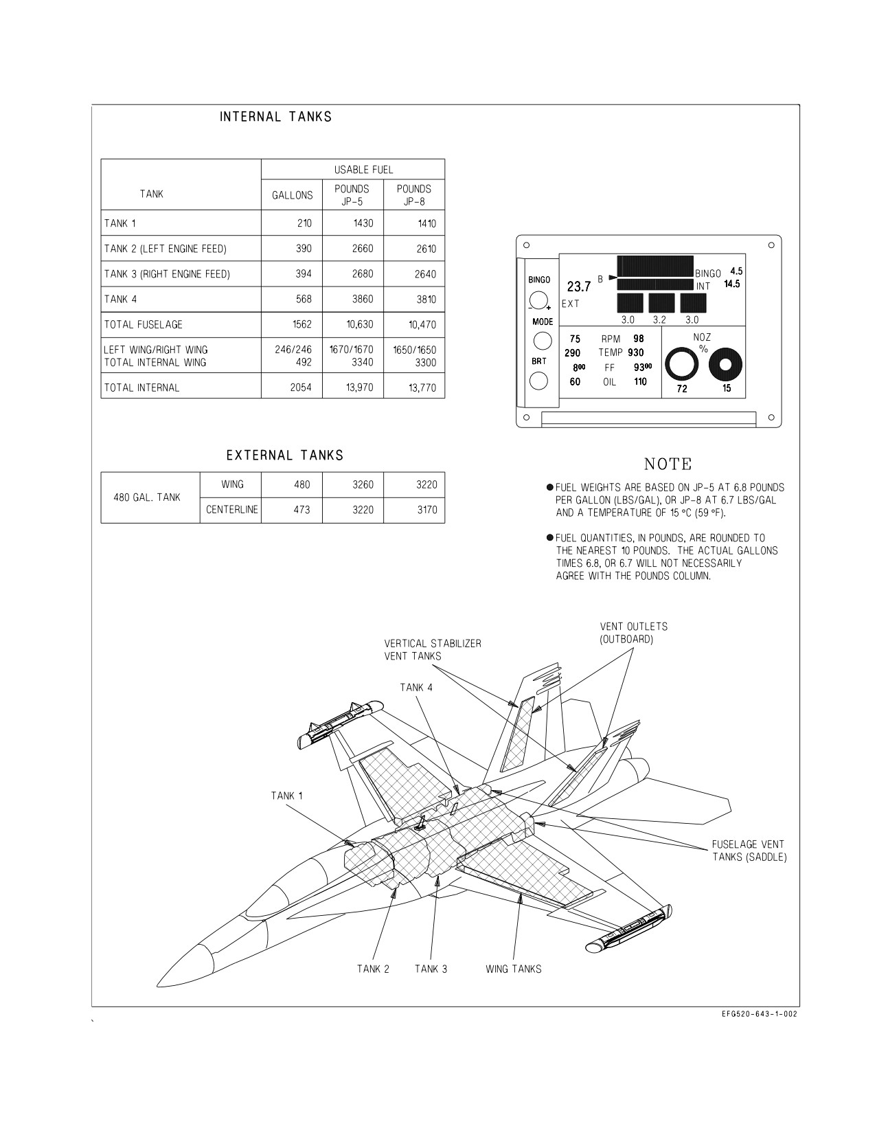
2.2.7 Fuel Quantity Indicating System. The fuel quantity indicating system measures the individual
fuel quantities in all internal and external fuel tanks and provides cockpit readouts for individual
tanks, total internal fuel, and total fuel onboard. Quantities are displayed on the EFD and the FUEL
display, rounded to the nearest 10 pounds (figure 2-5). Actual fuel tank probe readings are displayed
on the FUEL QTY display selected from the SUPT MENU/BIT/STATUS MONITOR display.
While the volume of fuel with full tanks does not change, the fuel quantities listed in pounds vary
with changes in temperature and fuel density. Full internal fuel quantity can vary from 12,870 to 14,730
lb at fuel temperatures of 100° and -40°F, respectively. Figure 2-5 lists standard day fuel quantities for
JP-5 and JP-8.
I-2-19
ORIGINAL
A1-E18GA-NFM-000
Figure 2-5. Fuel Quantity
I-2-20
ORIGINAL
A1-E18GA-NFM-000
Figure 2-6. Engine Fuel Display (EFD) - Fuel Parameters
2.2.7.1
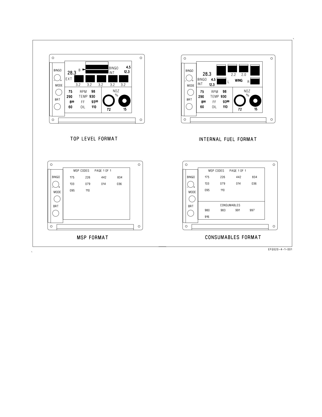
Engine Fuel Display (EFD), Fuel Parameters. The EFD displays fuel, maintenance code, and
consumables information in green digits on a black background (figure 2-6). The front EFD is
independent of the rear EFD. The top level EFD format graphically displays total internal fuel, bingo
level, and fuel quantities for up to five external fuel tanks. The shaded regions of each graphic display
the ratio of fuel available to fuel capacity. Digital readouts of total fuel (large numbers), total INT fuel,
external fuel tank quantities, and current BINGO setting are also provided but are truncated to 100 lb
increments.
The internal fuel format graphically displays only internal fuel tank quantities. Digital readouts of
feed tank fuel quantities are also provided, truncated to 100 lb increments.
During battery start of the engines, the EFD defaults to display three external fuel tanks (centerline
and inboard pylons) if one or more external fuel tanks are installed. For instance, if a full centerline
tank is installed, the EFD displays a full centerline graphic and 3.2 lb fuel. The inboard tanks appear
empty reading 0.0 lb fuel. When the SMS completes startup BIT and initial inventory, the EFD
displays only the installed tank(s).
I-2-21
ORIGINAL
A1-E18GA-NFM-000
The aircraft fuel load can be checked on battery power by placing the ENG CRANK switch to L or
R, by starting the APU, or by resetting the MSP codes in the nose wheelwell. The total fuel load will
appear 200 to 400 lb high, and the Tank 1 graphic (as displayed on the internal format) will indicate
approximately two-thirds when Tank 1 is, in fact, full. When the MCs become operative with ac power
applied, the total fuel load will be correct, and the EFD will show the correct Tank 1 fuel ratio.
Bingo level is adjusted in hundred pound increments by rotation of the BINGO knob and thousand
pound increments by pull and rotation (clockwise is increasing). The MODE button toggles the EFD
between the top level and internal fuel formats. Pressing the MODE button for greater than 1.5
seconds selects the MSP format. With the MSP format displayed, the BINGO knob cycles between
MSP code pages if more than one is present. Pressing the MODE button again for greater than 1.5
seconds runs and displays the results of a consumables test. Subsequent actuation for less than 1.5
seconds returns to the last displayed top level or internal fuel format. Clockwise rotation of the BRT
knob increases the display’s brightness.
2.2.7.2
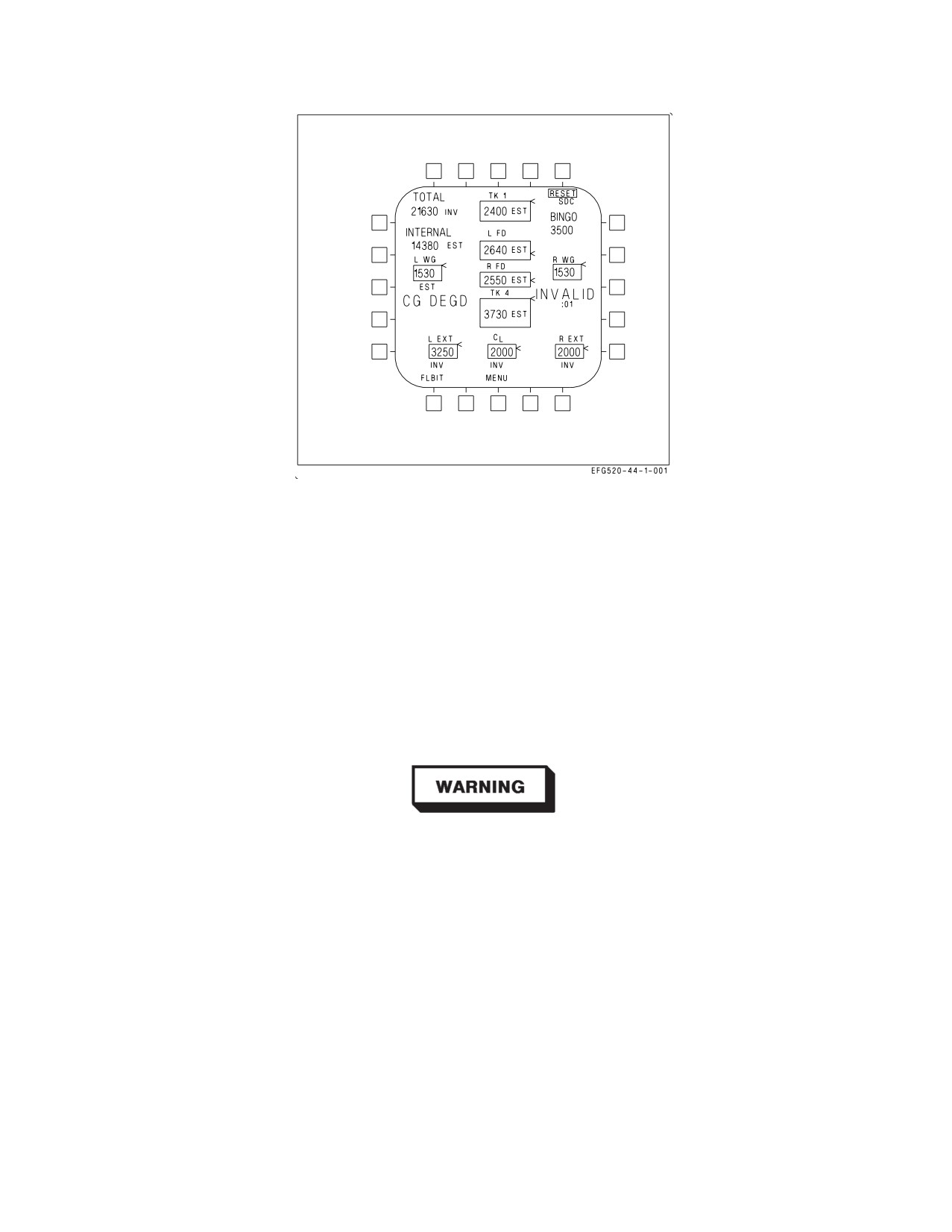
FUEL Display. The FUEL display (figure 2-7) is selected by the FUEL option on the SUPT
MENU. The FUEL display lists TOTAL fuel (internal and external), total INTERNAL fuel, the
available fuel in each tank, and the current BINGO setting. A moving caret is shown on the right side
of each tank, indicating the ratio of fuel available to tank capacity.
The SDC continuously monitors the validity of the fuel probes installed in each tank. If all probes
in a tank (except the feed tanks) are declared invalid, the SDC displays 0 lb fuel and the INV (invalid)
cue next to the tank. If one or more probes in a multi-probe tank are declared invalid, the SDC displays
the total of the valid probes only and the EST (estimated) cue next to the tank. If a feed tank fuel probe
is invalid, the SDC displays 1,125 lb (0 lb if the FUEL LO caution is set) and the EST cue. The TOTAL
and INTERNAL fuel values indicate the sum of all valid and estimated tank quantities with EST cues
(INV cues if any tank is INV).
The FLBIT option on the FUEL display is used to initiate a BIT of the fuel low level indicating
system. The FLBIT option remains boxed during BIT. A satisfactory test results in a FUEL LO
caution within 30 seconds of BIT initiation. FLBIT cannot be initiated with a FUEL LO caution set
or an SDC failure. An SDC RESET option is provided to command an SDC software reset.
2.2.7.3
F-QTY Advisory. The F-QTY advisory indicates an SDC or fuel quantity indicating system
failure which affects the accurate display of fuel quantity or CG information. The advisory is activated
when:
a. The MC loses communication with the SDC.
b. The SDC reports an internal or gauging system failure.
c. Any tank quantity is INV.
d. The SDC reports its output discretes are not working.
If a F-QTY advisory results from loss of MC communication with the SDC or the SDC reporting an
internal or gauging system failure, the MC is unable to report actual fuel quantities and the following
are displayed on the FUEL display (GLIM 7.5G caution):
a. All fuel quantities (except TOTAL) are held at their last displayed value.
I-2-22
ORIGINAL
A1-E18GA-NFM-000
Figure 2-7. FUEL Display
b. TOTAL fuel is estimated by the MC based on the last valid fuel quantity and engine fuel flow.
c. A flashing ESTIMATED cue is displayed along with a minutes and seconds (XX:XX) timer
which indicates the duration since the displayed fuel quantities were last updated.
2.2.8 Fuel Low Level Indicating System. The fuel low level indicating system is completely
independent of the fuel quantity indicating system. When the fuel level in either feed tank drops to
approximately 1,125 lb, a FUEL LO caution, caution light, and voice alert are activated, and the
affected fuel tank quantity is displayed in inverse video on the EFD. If a low level indication was set
by a transient condition, such as prolonged negative g flight, the cautions remain on for 1 minute after
the low level indication is removed.
If the FUEL LO cautions are set, assume that at least one feed tank is
below approximately 1,125
lb regardless of displayed fuel quantity
indications.
I-2-23
ORIGINAL
A1-E18GA-NFM-000
2.2.9 Fuel System Related Cautions. The following fuel system related cautions are described in the
Warning/Caution/Advisory Displays in Part V:
D L or R BOOST LO
D FADEC HOT (WonW, IDLE or above)
D L or R FUEL HOT
D PROBE UNLK
D L or R FUEL INLT
D REFUEL DR
D FUEL XFER
D DUMP OPEN
D EXT XFER
D FUEL LO caution, caution light, and voice alert
D EXT TANK
D BINGO caution and voice alert
D L or R THERMAL
2.3 FLIGHT PERFORMANCE ADVISORY SYSTEM (FPAS)
The flight performance advisory system (FPAS) is provided to aid the pilot in making time, fuel, and
distance calculations. Readouts for maximum range and maximum endurance are provided for three
flight conditions: current mach and altitude, optimum mach at the current altitude, and optimum
mach and altitude. These three readouts can be used to adjust the aircraft flight profile to meet mission
requirements. Additionally, FPAS provides fuel remaining at arrival and recommended distance to
begin descent from the selected waypoint or TACAN station. Range, time, altitude, Mach, and fuel are
calculated by the FPAS algorithm and appear on the FPAS display.
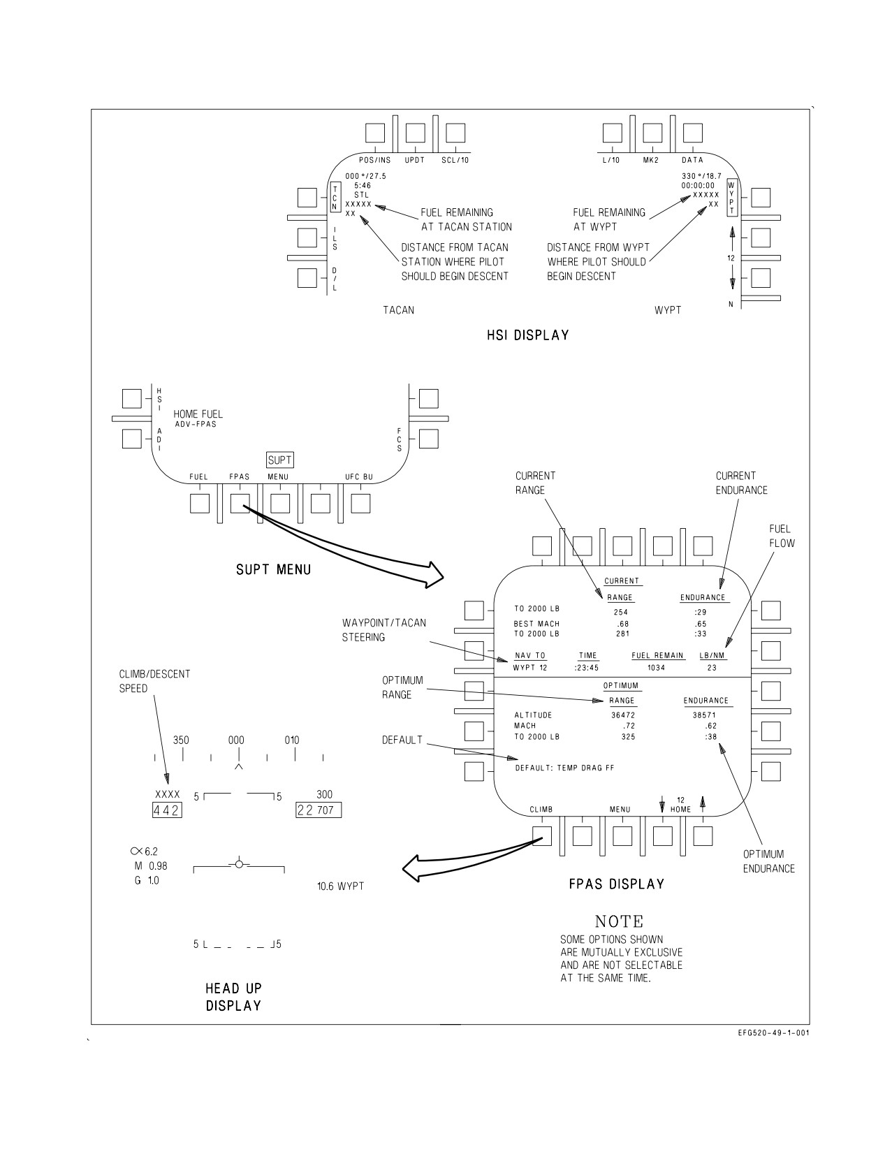
2.3.1 FPAS Display. The FPAS display (figure 2-8) appears when the FPAS option is selected from
the SUPT MENU. The display is divided into five areas: the current range and endurance area, the
waypoint/TACAN steering area, the fuel flow area, the optimum range and endurance area, and the
default area. With engines running and WonW, only the optimum and default areas are valid. With
WoffW, all five areas are valid. Waypoint/TACAN steering information is provided with WoffW and
waypoint or TACAN steering selected (boxed) on the HSI display.
2.3.1.1
FPAS CURRENT RANGE and ENDURANCE. The CURRENT RANGE area displays three
calculations: the range in nautical miles TO 2000 LB fuel remaining at the current altitude and Mach,
the BEST MACH to fly at the current altitude to maximize range, and the range TO 2000 LB fuel
remaining if the BEST MACH is flown. If parameters used to calculate current range become invalid,
X’s replace the current range value, and an FPAS advisory replaces the current endurance value.
The CURRENT ENDURANCE area displays three calculations: the time in hours and minutes TO
2000 LB fuel remaining at the current altitude and Mach, the BEST MACH to fly at the current
altitude to maximize endurance, and the endurance TO 2000 LB fuel remaining if the BEST MACH
is flown. If parameters used to calculate current endurance become invalid, X’s replace the current
endurance value.
If IMN exceeds 0.9 Mach, a MACH advisory replaces the current range value, and a LIM advisory
replaces the current endurance value. When total fuel drops below 2,500 lbs, the FPAS calculations
shift to 0 lbs remaining, and the TO 2000 LB legend changes to TO 0 LB.
2.3.1.2
FPAS Waypoint/Tacan Steering and the HSI Display. If waypoint or TACAN steering is
selected (boxed) on the HSI display, the selected waypoint or TACAN station is displayed under the
NAV TO legend, and the arrival time and fuel remaining at arrival (at the current flight conditions)
are displayed under the TIME and FUEL REMAIN legends, respectively.
I-2-24
ORIGINAL
A1-E18GA-NFM-000
Fuel remaining at arrival and recommended distance to begin descent from the selected steering
source are displayed on the HSI display. If the recommended distance to begin descent is greater than
99 miles, 99 is displayed.
If FPAS waypoint/TACAN steering parameters become invalid, X’s replace the fuel remaining and
descent distance values. If IMN exceeds 0.9 Mach, fuel remaining values are blanked. If fuel remaining
at the selected steering source is less than the TO 2000 LB or TO 0 LB legend, the WYPT number, the
TO 2000 (0) LB legend, and the fuel remaining value flash on the FPAS display and the fuel remaining
value flashes on the HSI display. If fuel remaining is calculated to be less than 0 lbs, 0 is displayed.
2.3.1.3
FPAS Fuel Flow. The total fuel flow rate (both engines) is displayed in pounds per nautical
mile under the LB/NM legend whenever the engines are running.
2.3.1.4
FPAS OPTIMUM RANGE and ENDURANCE. The OPTIMUM RANGE area displays three
calculations: the optimum ALTITUDE and MACH to fly to achieve the displayed maximum range TO
2000 LB. If parameters used to calculate optimum range become invalid, X’s replace the altitude,
mach, and range values.
The OPTIMUM ENDURANCE area displays three calculations: the optimum ALTITUDE and
MACH to fly to achieve the displayed maximum endurance time TO 2000 LB. If parameters used to
calculate optimum range or optimum endurance become invalid, X’s replace the altitude, mach, range,
and time values.
When total fuel onboard drops below 2,500 lbs, the FPAS calculations shift to 0 lbs remaining, and
the TO 2000 LB legend changes to TO 0 LB.
2.3.1.5
FPAS Default Area. If outside air temperature, stores drag, or fuel flow become invalid, the
TEMP, DRAG, or FF advisories are displayed next to the DEFAULT legend. These parameters, if
invalid, do not have a fatal impact on FPAS calculations.
2.3.2 FPAS CLIMB Option. The CLIMB option is available for selection in the NAV master mode.
Pressing the CLIMB option on the FPAS display enables the climb airspeed prompt, displayed above
the airspeed box in the HUD (HUD reject switch in the NORM position). When selected, CLIMB is
boxed and the climb airspeed prompt indicates the desired calibrated airspeed for an optimum climb
profile.
2.3.3 FPAS HOME Waypoint Selection. The HOME option arrows are used to increment/decrement
the home waypoint for use in FPAS fuel-on-deck (HOME FUEL caution) calculations. The selected
home waypoint is displayed above the HOME legend on the FPAS display. The home waypoint
defaults to 0 at power up and must be changed if another waypoint is desired (0 to 59). Decrementing
the home waypoint from 0 selects 59. If invalid parameters prevent FPAS from calculating the HOME
FUEL caution, the FPAS DDI advisory is displayed, the home waypoint is X’d, and the option arrows
are removed.
2.3.4 FPAS HOME FUEL Caution. When FPAS calculated fuel remaining at the selected home
waypoint reaches 2,000 lbs, the HOME FUEL caution is displayed. HOME FUEL caution logic is
disabled with WonW, the refueling probe extended, the landing gear cycled down then up, or within
5 seconds after a home waypoint change.
I-2-25
ORIGINAL
A1-E18GA-NFM-000
Figure 2-8. FPAS Displays
I-2-26
ORIGINAL
A1-E18GA-NFM-000
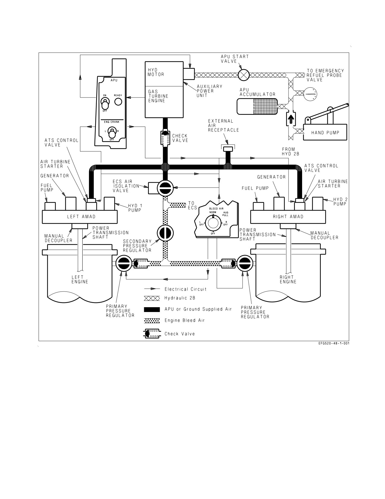
Figure 2-9. Secondary Power Supply
2.4 SECONDARY POWER SYSTEM
The aircraft secondary power system contains two airframe mounted accessory drives (AMAD) and
a single auxiliary power unit (APU). Figure 2-9 shows the major components of the secondary power
system.
2.4.1 Airframe Mounted Accessory Drive (AMAD). During normal operation, each AMAD is
mechanically driven by its corresponding engine through a power transmission shaft and is used to
drive a fuel boost/motive flow pump, an ac/dc electrical generator, and a 3000/5000 psi hydraulic pump.
Pneumatic pressure is used to rotate an air turbine starter (ATS) on each AMAD for engine crank/start
capability.
For ground maintenance use, either AMAD can be decoupled from its engine, allowing pneumatic
I-2-27
ORIGINAL
A1-E18GA-NFM-000
pressure to drive the AMAD and its accessories.
NOTE
Failure of the power transmission shaft (PTS) results in the display of
the associated GEN, BOOST LO, and both HYD circuit cautions.
2.4.2 Auxiliary Power Unit (APU). The APU is a small gas turbine engine used to generate a source
of air to power the ATS for normal engine start or to provide an alternate air source for the
environmental control system (ECS). The APU is located between the engines, with intake and exhaust
facing downwards.
The aircraft battery provides electrical power for APU ignition and start. A hydraulic motor powered
by the APU accumulator is used to start the APU. The APU receives fuel from the left engine feed line
upstream of the left engine feed shutoff valve. During normal operation, the APU shaft turns a
separate compressor which supplies air for main engine start or alternate ECS operation.
If an APU fire or overheat condition is detected on the ground, the APU fire extinguishing system
automatically shuts the APU down and, after 10 seconds, discharges the extinguisher bottle.
2.4.3 APU Switch. The APU switch, located on the left console, is spring loaded to the OFF position
and is electrically held in the ON position.
ON Automatic start and normal APU operation. The switch returns to OFF 1 minute after
the second aircraft generator comes online (BLEED AIR knob not in AUG PULL).
OFF Manual APU shutdown.
To prevent an APU running engagement and to prevent APU exhaust
torching, a minimum of 2 minutes must elapse between APU shutdown
and another APU start.
2.4.3.1
APU READY Light. The APU READY light, located on the left console adjacent to the APU
switch, comes on when the APU has completed the start cycle and is capable of supporting engine
crank.
2.4.4 ATS Air Sources. Pneumatic pressure from one of three sources can be used to power the ATS
for engine crank/start: APU compressor air, opposite engine bleed air (crossbleed), or external air.
The APU compressor is the primary engine crank air source. With the APU online, the ECS air
isolation valve is closed and the ENG CRANK switch opens the desired air turbine starter control valve
(ATSCV), allowing APU compressor output to turn the ATS, AMAD, and engine core.
A crossbleed start can be utilized when one engine is operating and the APU is shutdown. The
operating engine should be set to a minimum of 80% N2 rpm to make sure bleed air output is sufficient
to crank the opposite engine. For a crossbleed start, the ENG CRANK switch opens the ECS air
isolation valve and the ATSCV, allowing compressor bleed air pressure to turn the ATS, AMAD, and
engine core. If one engine fails inflight and the engine core is rotating freely, crossbleed air may be used
I-2-28
ORIGINAL
A1-E18GA-NFM-000
to rotate the AMAD and retain some fuel, electrical, and hydraulic system output.
ATS exhaust may blister paint and cause possible door damage on the aft
underside of the fuselage during extended crossbleed operation of a failed
engine.
An external air source may also be used to start one or both engines. External air is applied to the
aircraft through a connection in the right main wheelwell. Both engine bleed air valves must be closed
(BLEED AIR knob OFF) to make sure that external air is the sole air source for engine start. For an
external air start, the ENG CRANK switch opens the ATSCV, allowing external air pressure to turn
the ATS, AMAD, and engine core.
2.4.4.1
ATS Protection. Each ATS has two sources of overspeed cutout protection. The primary
source is the corresponding generator, and the backup source is the frequency sensing relay (FSR). The
FSR monitors ATS speed and provides the signal which electrically holds the ENG CRANK switch.
When the generator comes on the line at 60% N2 rpm, it removes power from the ATSCV and the FSR,
which releases the ENG CRANK switch. If the primary cutout does not function (GEN switch OFF or
major generator malfunction), the FSR releases the ENG CRANK switch when it senses 63% N2 rpm.
Regardless of the engine start air source utilized, the corresponding GEN
switch should be ON, as the generator provides primary overspeed cutout
protection for the ATS.
2.4.4.2
ENG CRANK Switch. The ENG CRANK switch, located on the left console, is spring loaded
to the OFF position and is electrically held in the L or R position.
L
Opens the left ATSCV and/or the ECS air isolation valve to direct pneumatic pressure
to the ATS for left engine crank.
OFF Closes both ATSCVs and the ECS air isolation valve. When the left or right generator
comes online following engine start, the switch automatically returns from L or R to the
OFF position.
R
Opens the right ATSCV and/or the ECS air isolation valve to direct pneumatic pressure
to the ATS for right engine crank.
2.4.5 AUG PULL. During extended ground operations, APU compressor air may be used instead of
engine bleed air to run the ECS and cool the avionics (BLEED AIR knob in AUG PULL). AUG PULL
operation is discussed in the ECS section.
2.4.6 AMAD Related Cautions. The following AMAD related cautions are described in the Warning/
Caution/Advisory Displays in Part V:
• L or R OIL HOT
• L or R AMAD PR
• L or R ATS
I-2-29
ORIGINAL
A1-E18GA-NFM-000
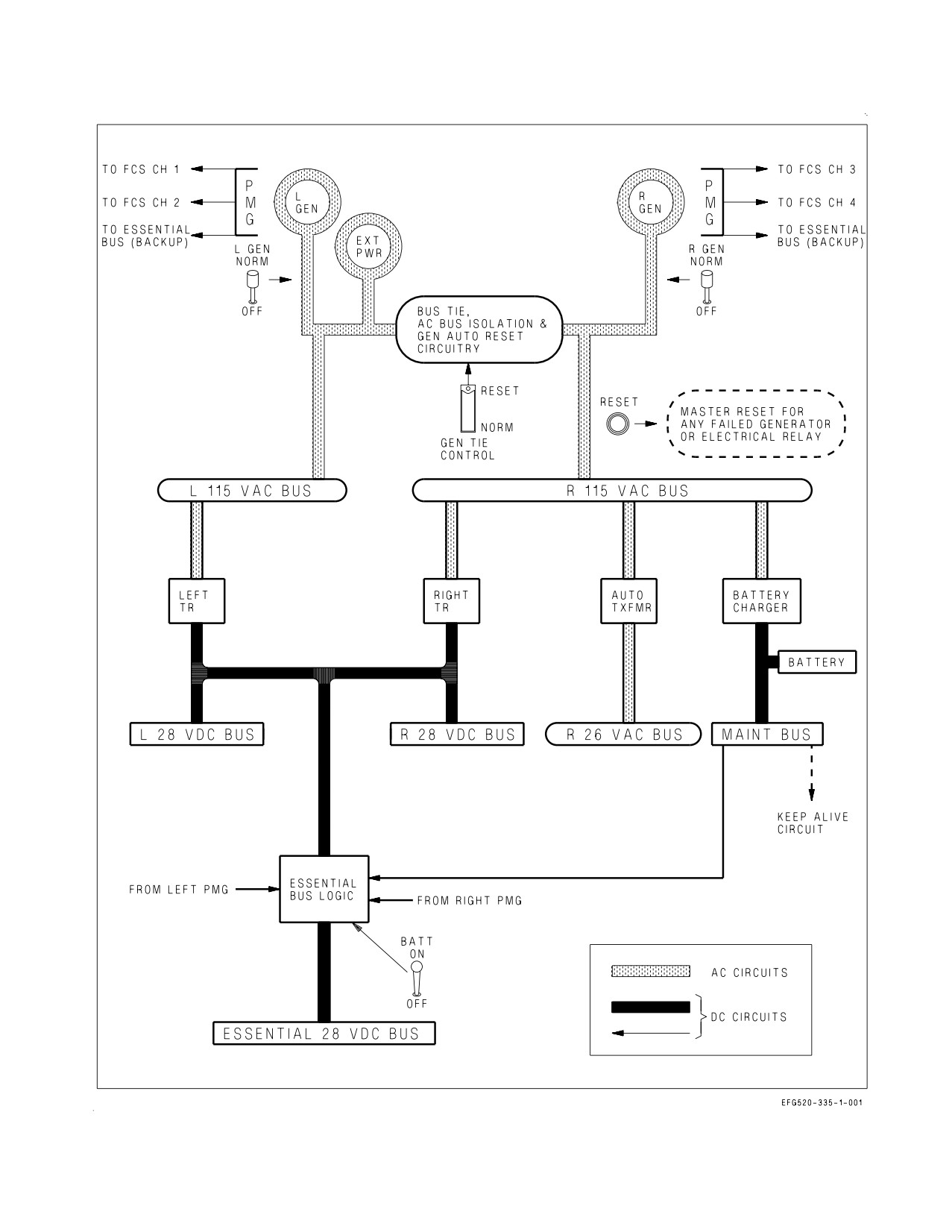
2.5 ELECTRICAL POWER SUPPLY SYSTEM
The electrical power supply system consists of two generators, two transformer-rectifiers (TR), one
battery with dedicated battery charger, and a power distribution (bus) system (figure 2-10). Each
generator provides a primary ac source and three isolated dc sources from a permanent magnet
generator (PMG). During normal operation, the left generator powers only the left buses while the
right generator powers only the right buses. If one generator fails, the other generator is capable of
carrying the entire electrical load of the aircraft. Battery power is provided for normal engine start.
External electrical power can be applied to power the entire system on the ground. The bus system
consists of the left and right 115 vac buses, right 26 vac bus, left and right 28 vdc buses, 28 vdc essential
bus and a 28 vdc maintenance bus. See figure 2-10 for a simplified schematic and Electrical System,
foldout section, for the specific systems powered by each bus.
2.5.1 Electrical RESET Button. The electrical system RESET button is located on the electrical
power panel on the right console. This button provides master reset capability for any failed generator
or electrical system relay without interrupting operational circuits.
2.5.2 AC Electrical Power. The two generators are the primary source of ac electrical power. With the
GEN switch in NORM, each generator comes online at approximately 60%N2 rpm as long as voltage
and frequency are within limits. Each generator supplies ac power to an independent 115 vac bus. In
addition, the right 115 vac bus powers a 26 vac bus through a dedicated transformer.
2.5.2.1
GEN Switches. Two generator control switches, labeled L GEN and R GEN, are located on
the electrical power panel on the right console.
NORM
Provides normal generator operation.
OFF
Removes the generator ac source from the bus system.
2.5.2.2
Electrical Fault Protection Circuitry. The electrical system provides fault protection with
generator isolation, bus tie, generator automatic reset, and ac bus isolation circuitry.
If a generator fault occurs, generator isolation circuitry removes the affected generator from its buses
(L or R GEN caution and caution light). All generator faults except N2 underspeed require manual
generator reset (GEN switch cycled to OFF then NORM or RESET button pressed). Generator reset
is successful only if the out-of-tolerance or fault condition has cleared. If the generator fault remains,
bus tie circuitry allows the remaining generator to power all electrical buses. During an N2 underspeed
condition, the affected generator is automatically restored when rpm returns to normal range.
If a short or overload condition (bus or equipment fault) occurs on a bus (the R 115 vac bus, for
instance), the following sequence is initiated. The right generator attempts to power through the short
and, if unsuccessful, trips offline. The left generator is then connected to the right buses by the bus tie
circuitry, attempts to power through the short, and, if unsuccessful, also trips offline. Approximately
1 second after the dual generator outage, the generator automatic reset logic resets both generators. If
the bus or equipment fault has cleared, both generators remain online to power their respective buses.
If the bus or equipment fault remains, the right generator trips offline again, but bus isolation circuitry
now prevents the left generator from picking up the right buses (GEN TIE caution light). The left
generator remains online to power the left buses and the R 28 vdc bus. The R 115 vac bus, R 26 vac bus,
and battery charger are unpowered, and the battery runs the maintenance bus. This entire process may
take as long as 16 seconds.
I-2-30
ORIGINAL
A1-E18GA-NFM-000
Figure 2-10. Simplified Electrical Schematic
I-2-31
ORIGINAL
A1-E18GA-NFM-000
For the ac bus isolation and generator automatic reset circuits to operate, the GEN TIE switch must
be in NORM, the BATT switch must be ON and the PARK BRK handle must not be set. With the
PARK BRK handle set, the generators do not reset following a dual outage.
2.5.2.3
GEN TIE Caution Light. During initial engine start (battery or external power) GEN TIE
circuitry requires a set PARK BRK handle to properly function. If the PARK BRK handle is not set
during right (first) engine start, a GEN TIE caution light comes on when the right generator comes
online. For a battery start, setting the PARK BRK handle and cycling the R GEN switch reties the left
and right buses and clears any avionics faults that would otherwise occur. For an external power start,
setting the PARK BRK handle, disconnecting external power, and cycling the GEN TIE switch reties
the left and right buses.
2.5.2.4
GEN TIE Switch. The red-guarded GEN TIE switch is located on the left console outboard of
the exterior lights panel.
RESET
Resets the bus tie circuitry. Reset is accomplished by cycling the switch to RESET
then NORM.
NORM
With the BATT switch ON, enables the bus tie, ac bus isolation and generator
automatic reset circuits.
If the left and right buses are isolated because of a detected fault (e.g., R
GEN caution and GEN TIE caution light), cycling the GEN TIE switch
reenergizes the faulty bus/equipment and may cause further damage or
loss of the remaining generator.
2.5.3 DC Electrical Power. DC electrical power is provided by two TRs, three dc outputs from each
PMG, the battery, and the battery charger.
2.5.3.1
Transformer-rectifiers (TR). While each TR is powered by its respective 115 vac bus, the
output of each TR is connected in parallel, powering both the left and right 28 vdc buses and providing
primary power for the essential bus. If one TR fails, the other powers the entire dc system. There is no
cockpit warning of a single TR failure (no caution and no MSP code). TR operation is checked on
maintenance phase inspections.
2.5.3.2
Permanent Magnet Generator (PMG). The PMG in each generator provides three dc
sources, two for FCC channels and one for essential bus backup. The left PMG provides the primary
power source for FCC A (channels 1 and 2), while the right PMG provides the primary power source
for FCC B (channels 3 and 4). Regardless of generator control switch position, the PMGs come online
when the engine reaches approximately 50% N2 rpm on spool up and remain on until 20% N2 rpm on
spool down.
2.5.3.3
Battery. The primary operational use of the battery is engine start. The battery powers the
maintenance bus directly, allowing operation of the canopy, ladder, and maintenance monitor in the
absence of ac electrical power. With the BATT switch ON (first engine start), the battery also powers
the essential bus. In the unlikely event of a total ac/dc failure inflight, the battery provides the last
level of essential bus backup capability, providing about 5 to 10 minutes of power for the FCCs, after
which aircraft control is lost.
I-2-32
ORIGINAL
A1-E18GA-NFM-000
Regardless of BATT switch position, the battery charger supplies charging power to the battery
anytime the right 115 vac bus is energized.
2.5.3.4
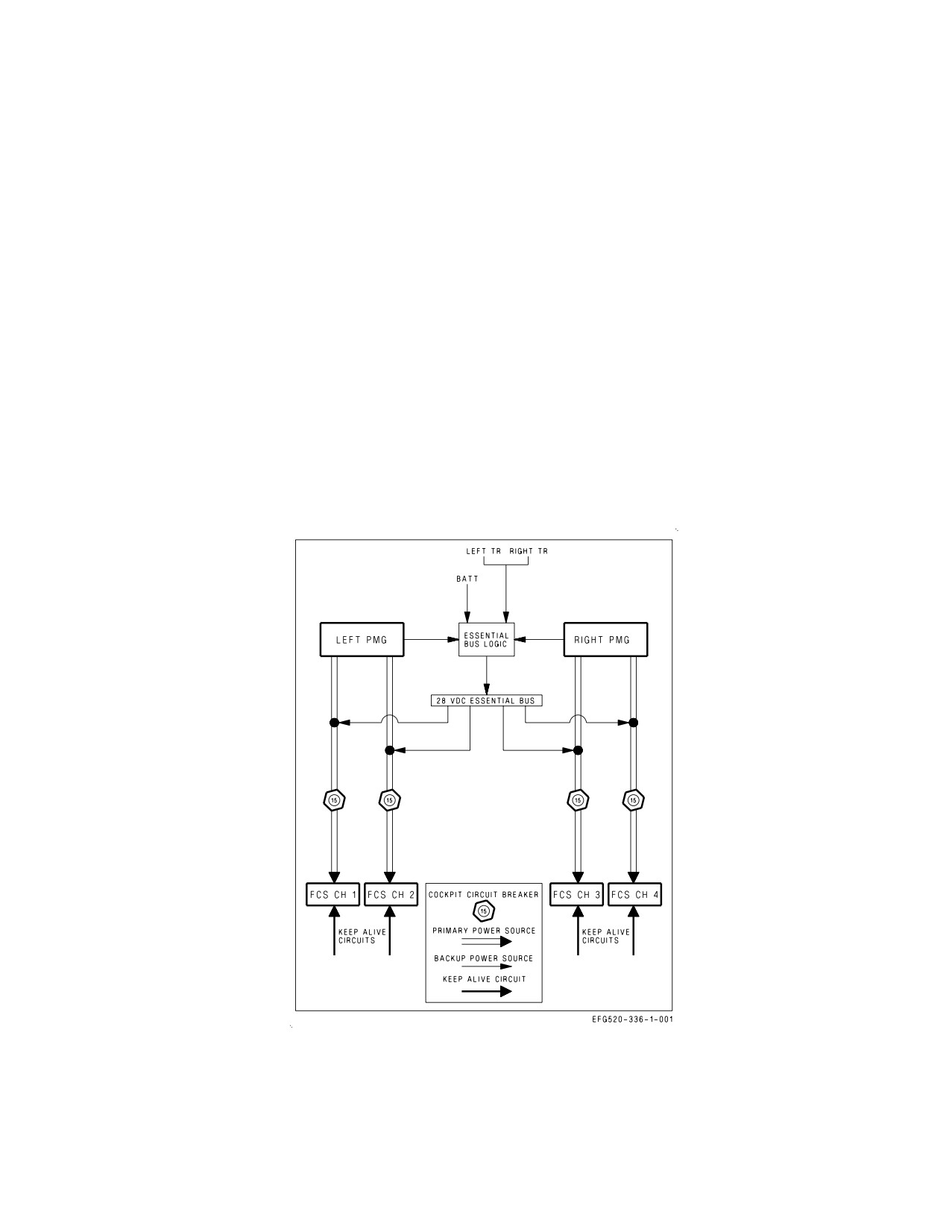
FCC Electrical Redundancy. FCC electrical redundancy is provided by several sources of dc
power (figure 2-11). The primary dc source for each FCC channel is its respective PMG output. If a
PMG output should fail, that FCC channel is powered by the essential bus, which also has several
sources of redundancy (the TRs, the PMGs, and the battery). The BATT switch must be ON for either
a PMG or the battery to power the essential bus. Additionally, ‘‘keep alive’’ circuits connected directly
to the maintenance bus provide each FCC channel with an uninterrupted backup power source during
normal bus power transients.
2.5.3.5
BATT Switch. The BATT switch is located on the electrical power panel on the right console.
ON
Allows the battery or either PMG to power the essential bus when TR power is not
available.
OFF
Prevents the battery or either PMG from powering the essential bus when TR
power is not available.
2.5.3.6
Automatic Battery Cutoff. The automatic battery cutoff circuit is provided to conserve
battery power. On the ground with the BATT switch ON, the circuit disconnects the battery from the
essential bus and returns the BATT switch to OFF 2 minutes after ac power is removed from the
aircraft. When battery cutoff is activated, the battery can be reconnected to the essential bus by
reselecting the BATT switch ON. The automatic battery cutoff circuit is disabled when the APU comes
online.
2.5.3.7
Battery Gauge. A battery gauge is installed on the electrical power panel on the forward right
console in the front cockpit only. Depending on generator status, the battery gauge provides an
indication of either essential bus voltage (both GENs offline) or maintenance bus voltage (either GEN
online).
With both GENs offline and the BATT switch ON (e.g., prior to first engine start), the battery gauge
is connected to the essential bus and indicates battery voltage. Nominal voltage for a ″good″ battery
should be 23 to 24 vdc. Minimum battery voltage is that which provides a successful engine start (e.g.,
APU remains online and the EFD remains powered to provide indications of RPM and TEMP). EFD
blanking and/or uncommanded APU shutdown should be anticipated with battery voltage at or below
18 vdc.
With at least one GEN online, the battery gauge is connected to the maintenance bus and indicates
28 vdc output of the battery charger. If the battery gauge fails to jump to approximately 28 vdc with
one GEN online, a battery charger malfunction has occurred which requires maintenance action prior
to flight.
If a dual GEN failure occurs, the battery gauge is reconnected to the essential bus and must be
referenced to determine the essential bus power source. If the battery gauge remains at approximately
28 vdc, an EBB PMG is powering the essential bus, and FCC operating time is not limited. However,
if the battery gauge indicates 24 vdc or below, the battery is powering the essential bus, and FCC
operating time is limited to about 5 to 10 minutes. The FCCs should continue to operate down to a
battery gauge voltage of approximately 18 vdc.
2.5.3.8
BATT SW Caution and Caution Light. The BATT SW caution and caution light are only set
to alert the aircrew of an improperly placed BATT switch. The battery gauge must be referenced to
I-2-33
ORIGINAL
A1-E18GA-NFM-000
determine whether an EBB PMG or the battery is powering the essential bus following a dual GEN
failure. These cautions are set in only two circumstances.
1. The BATT switch is ON on the ground in the absence of ac power (e.g., first engine start). The
battery is depleting and the switch should be placed to OFF unless APU start is about to be made.
2. The BATT switch is OFF inflight and should be placed to ON to provide essential bus backup
capability from the PMGs and the battery.
2.5.4 External Electrical Power. External electrical power may be connected to the aircraft bus
system through an external power receptacle located on the left forward fuselage. If external power is
not of the proper quality, the external power monitor prevents application of power to the aircraft.
Actuation of 1 to 4 ground power switches is required to energize certain aircraft systems following
application of external power.
The aircraft buses are energized by external power in the same manner as if a generator were
operating provided the BATT switch is OFF or the parking brake is set.
2.5.4.1
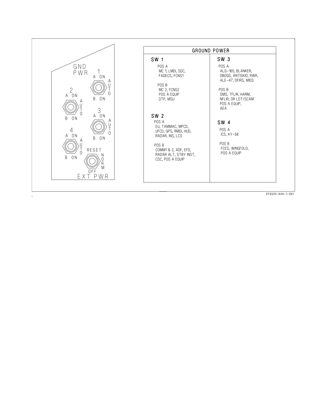
External Power Switch. The external power switch, located on the ground power panel on the
left console, is spring loaded to the NORM position (figure 2-12).
Figure 2-11. FCC Electrical Redundancy
I-2-34
ORIGINAL
A1-E18GA-NFM-000
Figure 2-12. Ground Power Panel and Placard
RESET
Momentary actuation allows external power to be applied.
NORM
Aircraft buses are energized by external power, provided the switch was first posi-
tioned to RESET. The switch returns to OFF when external power is disconnected.
OFF
Disconnects external power from the aircraft.
2.5.4.2
Ground Power Switches. The four ground power switches are located on the ground power
panel on the left console (figure 2-12). Each switch controls a group of systems and/or instruments, as
listed on a placard above the panel.
A ON
Only systems/instruments listed for the A position are energized by external
power.
AUTO
All controlled systems/instruments are deenergized with external power on the air-
craft. When a generator comes online, the switch(es) automatically revert to
AUTO.
B ON
All controlled systems/instruments (both A and B) are energized by external
power.
The first ground power switch placed to ON must be held for 3 seconds to complete an avionics
overheat BIT. If an avionics overheat condition is present, the switch(es) revert to AUTO and cannot
be returned to ON until the condition is corrected.
I-2-35
ORIGINAL
A1-E18GA-NFM-000
Figure 2-13. Circuit Breaker Panels
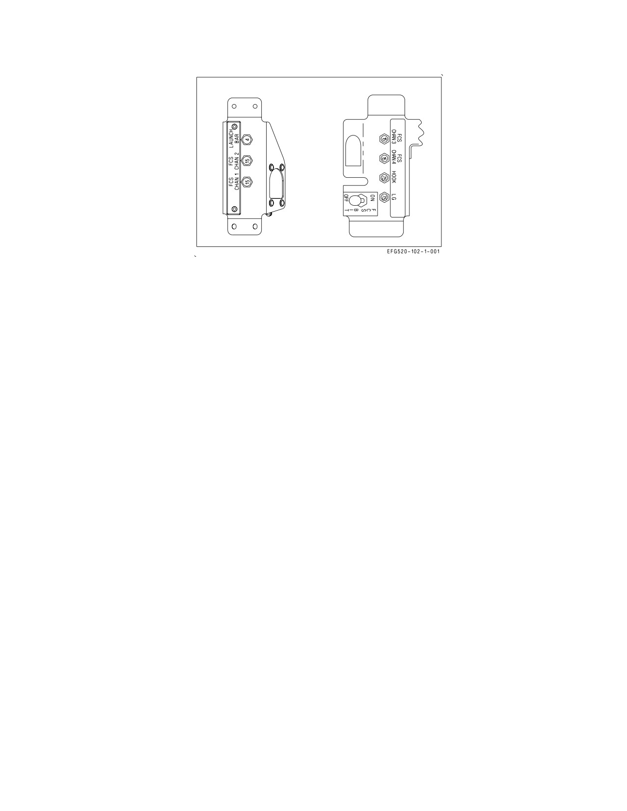
2.5.5 Circuit Breakers. The circuit breaker panels (figure 2-13), located under each side of the
canopy sill outboard of the left and right consoles, contain the following circuit breakers:
Left Side
Right Side
LAUNCH BAR
FCS CHAN 3
FCS CHAN 2
FCS CHAN 4
FCS CHAN 1
HOOK
LG
2.5.6 Electrical System Cautions and Caution Lights. The following electrical system cautions and
caution lights are described in the Warning/Caution/Advisory Displays in Part V:
• L or R GEN caution and caution light
• BATT SW caution and caution light
• GEN TIE caution light
• L or R DC FAIL caution
2.6
LIGHTING
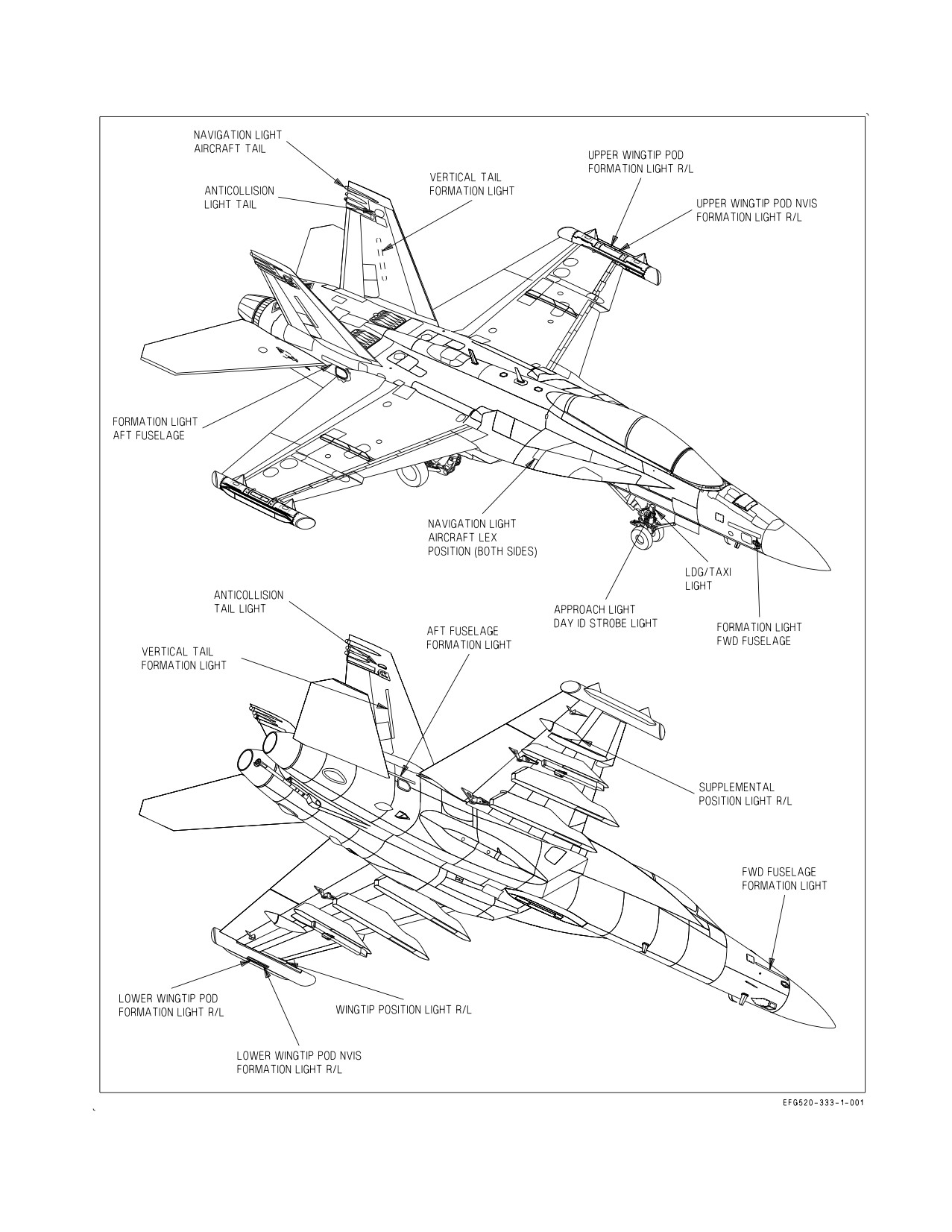
2.6.1 Exterior Lighting. Exterior lighting is utilized to highlight aircraft position and aspect to other
aircraft, to provide AOA indications to a landing signal officer (LSO), to light the aircraft path for
in-flight refueling, landing or taxi, and to distinguish the EA-18G from other F/A-18 models. The
following exterior lights are provided: strobe lights, position lights, formation lights, approach lights,
refueling probe light, and landing/taxi light (figure 2-14).
Strobe lights and formation lights have two operating modes, normal and NVIS.
2.6.1.1
Exterior Lights Master Switch. The exterior lights master switch, located on the outboard
side of the left throttle grip, provides master control of all exterior lighting except the approach and
landing/taxi lights.
I-2-36
ORIGINAL
A1-E18GA-NFM-000
Figure 2-14. Exterior Lights
I-2-37
ORIGINAL
A1-E18GA-NFM-000
NORM
Power is available for controlled lighting (strobe and formation lights in normal
(Forward)
mode)
NVIS
Power is available only to the strobe and formation lights in NVIS mode
(Center)
OFF
Power is removed from all controlled lighting. Required position for Day ID light
(Aft)
strobe power ON.
2.6.1.2
Pattern Strobe Lights. Two red anti-collision strobe lights, one on each outboard vertical tail,
are provided to highlight aircraft position during both day and night operations. Each strobe light
contains two bulbs, one normal and one infrared (IR). The external lights master switch determines
which pair of bulbs are powered by the STROBE switch.
2.6.1.2.1
STROBE Switch. The STROBE switch, located on the EXT LT panel on the left console,
is used to apply power and control the brightness of the strobe lights.
BRT Strobe lights on at full intensity (normal or NVIS mode)
OFF Strobe lights off
DIM Strobe lights on at reduced intensity (normal or NVIS mode)
2.6.1.2.2
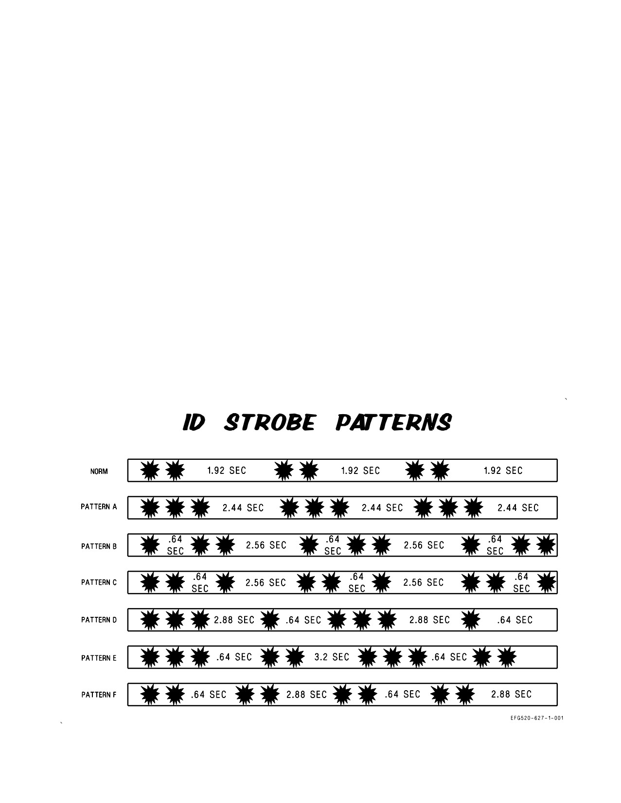
IDENT Knob. Pattern selection is controlled by the IDENT knob on the exterior lights
panel. The IDENT knob can be set to select strobe patterns of NORM, or A thru F. For night carrier
landings the IDENT knob should be in the NORM position. Refer to figure 2-15 for possible strobe
patterns. Possible strobe patterns are as follows:
NORM Strobe light flashes two times, pauses for 1.92 seconds, then repeats pattern
A
Strobe light flashes three times, pauses 2.44 seconds, then repeats pattern
B
Strobe light flashes once, pauses 0.64 seconds, flashes two times, pauses 2.56 seconds,
then repeats pattern
C
Strobe light flashes two times, pauses 0.64 seconds, flashes once, pauses 2.56 seconds,
then repeats pattern
D
Strobe light flashes three times, pauses 2.88 seconds, flashes once, pauses 0.64 seconds,
then repeats pattern
E
Strobe light flashes three times, pauses 0.64 seconds, flashes two times, pauses 3.2 sec-
onds, then repeats pattern
F
Strobe light flashes two times, pauses 0.64 seconds, flashes two times, pauses 2.88 sec-
onds, then repeats pattern
2.6.1.3
Position Lights. The position lights are provided to highlight the aircraft aspect during night
or reduced visibility operation. There are seven position lights, three red, three green, and one white.
The white position light is on the tail. Three red position lights are installed on the left side. One on
I-2-38
ORIGINAL
A1-E18GA-NFM-000
the wingtip, one on the LEX just forward of the wing root and one under the wing at the aileron hinge.
Green position lights are installed at the same locations on the right side.
2.6.1.3.1
POSITION Lights Knob. The POSITION lights knob, located on the EXT LT panel on the
left console, is used to apply power and control the brightness of the position lights (external lights
master switch NORM). The knob provides variable lighting intensity between the OFF and BRT
positions.
2.6.1.4
Formation Lights. Ten formation ″strip″ lights, five on each side of the aircraft, are provided
to highlight the aircraft aspect during night or low visibility formation flight. Strip lights are located
on the forward fuselage forward of the LEX, on the wingtip upper and lower surfaces of the
ALQ-218(V)2 wingtip pods, on the aft fuselage below the vertical tail, and on the vertical tail. Each
formation light contains two lighting strips, one normal and one IR. The external lights master switch
determines which set of strips are powered by the FORMATION lights knob.
2.6.1.4.1
FORMATION Lights Knob. The FORMATION lights knob, located on the EXT LT panel
on the left console, is used to apply power and control the brightness of the formation strip lights. The
knob provides variable lighting intensity between the OFF and BRT positions in either the normal or
NVIS mode.
2.6.1.5
Approach Lights. The approach lights, located on the nosegear strut, provide AOA indica-
tions to an LSO during carrier landings. Three approach lights are provided to indicate a fast (red),
on-speed (amber), or slow (green) AOA condition. The approach lights are powered with WoffW and
all landing gear down and locked. Therefore, the approach lights are an external indication that the
Figure 2-15. ID Strobe Patterns
I-2-39
ORIGINAL
A1-E18GA-NFM-000
landing gear are down and locked. The approach lights flash when the HOOK BYPASS switch is in the
CARRIER position and the arresting hook is not down, indicating to an LSO that the hook must be
lowered for a carrier arrestment. The approach lights are dimmed by the WARN/CAUT lights knob.
2.6.1.6
HOOK BYPASS Switch. The HOOK BYPASS switch, located on the lower left main
instrument panel, is spring loaded to the CARRIER position and is electrically held in the FIELD
position.
FIELD
Approach lights and AOA indexers do not flash regardless of hook position. The
switch reverts to the CARRIER position if the hook is lowered.
CARRIER Approach lights and AOA indexers flash if the hook is not down
2.6.1.7
Landing/Taxi Light. A landing/taxi light, located on the nosegear strut, is used to light the
flightpath during landing or a taxiway/runway during ground operations.
2.6.1.7.1
LDG/TAXI Light Switch. The LDG/TAXI light switch is located on the lower left main
instrument panel.
ON Landing/taxi light on with the LDG GEAR handle DN and the nosegear down and
locked
OFF Landing/taxi light off
2.6.1.8
Day ID Light. A high intensity white strobe light provides a double flash pattern and is
mounted below the approach light on the nose gear strut. The strobe light operates with the landing
gear down and locked, WoffW, and the exterior lights master switch in the OFF (aft) position.
2.6.1.8.1
Day ID Test Switch. A day ID test switch, located in the nose wheelwell, is provided to test
the day ID strobe light. The switch operates only with ac power applied to the aircraft.
TEST The day ID strobe light comes on, ID LT is displayed on the LDDI, and the master
caution light and aural tone come on.
OFF The switch is spring loaded to the OFF position.
2.6.2 Interior Lighting. Interior lighting is utilized to provide adjustable cockpit lighting for the main
instrument panel and consoles during night or low light operations. All controls for interior lighting are
located on the INTR LT panel on the right console, except for the utility flood light, the AOA indexers,
and the five cockpit displays.
2.6.2.1
MODE Switch. The MODE switch, located on the INTR LT panel, is used to select one of
three cockpit lighting modes; allowing the pilot to optimize interior lighting for current ambient light
conditions.
I-2-40
ORIGINAL
A1-E18GA-NFM-000
NVG Reduces the brightness range for the warning, caution, and advisory lights, the UFCD,
MPCD, AMPCD, and the EFD. This disables the integral console lights and the white
floodlights; and enables six NVG compatible floodlights to illuminate the consoles.
NITE Reduces the brightness range for the warning, caution, and advisory lights, the UFCD,
MPCD, AMPCD, and the EFD.
DAY Provides the maximum brightness range for all interior lighting.
The UFCDs, MPCD, AMPCD, and the EFD reset to DAY mode brightness after aircraft shutdown.
Following electrical power interruption, these displays reset to DAY mode brightness with the mode
switch in DAY or NITE positions, and to NITE mode brightness with the mode switch in NVG
position.
2.6.2.2
CONSOLES Lighting Knob. The CONSOLES lighting knob, located on the INTR LT panel,
is used to control the brightness of the integral lighting for the left and right consoles, the hydraulic
pressure gauge, and both circuit breaker panels. Clockwise rotation of the knob increases console
lighting intensity from the OFF to BRT positions. The CONSOLES knob and integral console lighting
are disabled in the NVG mode.
2.6.2.3
INST PNL Lighting Knob. The INST PNL lighting knob, located on the INTR LT panel, is
used to control the brightness of the integral lighting for the main instrument panel and the standby
magnetic compass. Clockwise rotation of the knob increases main instrument panel lighting intensity
from the OFF to BRT positions. The strobe function of the SHOOT light is disabled when the
instrument lights are on.
2.6.2.4
FLOOD Lights Knob. The FLOOD knob, located on the INTR LT panel, is used to control the
brightness of the white cockpit floodlights. Eight floodlights are provided for secondary lighting; three
above each console and one on either side of the main instrument panel. Clockwise rotation of the knob
increases floodlight intensity from the OFF to BRT positions. The FLOOD knob and all white
floodlights are disabled in the NVG mode. There is no brightness control for the six NVG floodlights.
2.6.2.5
CHART Light Knob. The CHART light knob, located on the INTR LT panel, is used to
control the brightness of the NVG compatible chart light. The chart light is located on the canopy bow
at the 10:30 position and rotates in two axes. Clockwise rotation of the knob increases chart light
intensity from the OFF to BRT positions.
2.6.2.6
Utility Floodlight. The utility floodlight, normally stowed above the right console, provides a
portable source of secondary lighting. An attached alligator clip allows the light to be fastened at
various locations in the cockpit. The light contains a knob which provides variable lighting intensity
from off to bright and a button which, when pressed, illuminates the light at full intensity. The light
also contains a rotary selector for white or NVG compatible green lighting.
2.6.2.7
Emergency Instrument Lights. The emergency instrument lights, located on the left and
right sides of the main instrument panel, illuminate the EFD and standby flight instruments in the
absence of ac electrical power. The lights come on anytime the PMGs or the battery are powering the
essential bus. There is no separate cockpit control for the emergency instrument lights.
I-2-41
ORIGINAL
A1-E18GA-NFM-000
2.6.2.8
Engine Instrument Light. The engine instrument light, located on the left side of the main
instrument panel, provides lighting for the EFD during battery start of the first engine. The light
comes on when the APU switch is placed to ON.
2.6.2.9
WARN/CAUT Lights Knob. The WARN/CAUT knob, located on the INTR LT panel, is used
to control the brightness of the warning, caution, and advisory lights in the reduced brightness range.
Clockwise rotation of the knob increases warning, caution, and advisory light intensity from the OFF
to BRT positions. The brightness is maximum in the DAY mode and in the reduced brightness range
in the NITE and NVG modes.
Following a power interruption in either the DAY or NITE mode, the warning, caution, and advisory
lights default to the maximum brightness range. Following a power interruption in the NVG mode, the
warning, caution, and advisory lights remain in the reduced brightness range.
2.6.2.10 LT TEST Switch. The LT TEST switch, located on the INTR LT panel, is spring loaded to
the OFF position. The switch is used to test important cockpit lighting to verify bulb integrity prior to
flight. The switch requires ac electrical power to operate.
TEST Powers all operating warning, caution, and advisory lights, the AOA indexer lights, the
integral background lighting on the EFD (BINGO, MODE, and BRT), changes MENU
to ENG on the DDIs, provides a CHECK SEAT caution, and annunciates the landing
gear warning tone.
OFF Lights test off.
2.6.3 Interior Lighting (Rear Cockpit). All controls for the interior lights of the rear cockpit are
located on the INTR LT panel on the right console. The controls operate in the same manner as those
in the front cockpit with two exceptions. There is no MODE switch on the rear cockpit INTR LT panel,
and the rear cockpit LT TEST switch does not illuminate the AOA indexer lights or annunciate the
landing gear warning tone.
2.7 HYDRAULIC POWER SUPPLY SYSTEM
The hydraulic power supply system is a dual pressure system (3,000 and 5,000 psi). The aircraft uses
hydraulic power to actuate primary flight control surfaces and to run the following utility hydraulic
functions: landing gear, wheel brakes and anti-skid, hook, launch bar, refueling probe, nosewheel
steering (NWS), and parking brake. Two hydraulic accumulators provide emergency hydraulic power
for critical utility functions.
2.7.1 Hydraulic System. The hydraulic power supply system incorporates two independent hydrau-
lic systems, HYD 1 and HYD 2 (figure 2-16). Each system is divided into two branches providing four
independent hydraulic circuits identified as 1A and 1B for the left system and 2A and 2B for the right
system. HYD 1 circuits are dedicated solely to flight controls. HYD 2A powers both flight controls and
most utility hydraulic functions. HYD 2B powers the flight controls and arresting hook and pressurizes
both the APU and emergency brake accumulators.
All flight control surface actuators are powered by one HYD 1 circuit and one HYD 2 circuit, either
simultaneously or through hydraulic switching valves.
The utility system operates at 3,000 psi only. Two pressure reducers, one on HYD 2A and one on
HYD 2B reduce utility circuit pressure to 3,000 psi when pump output is 5,000 psi.
I-2-42
ORIGINAL
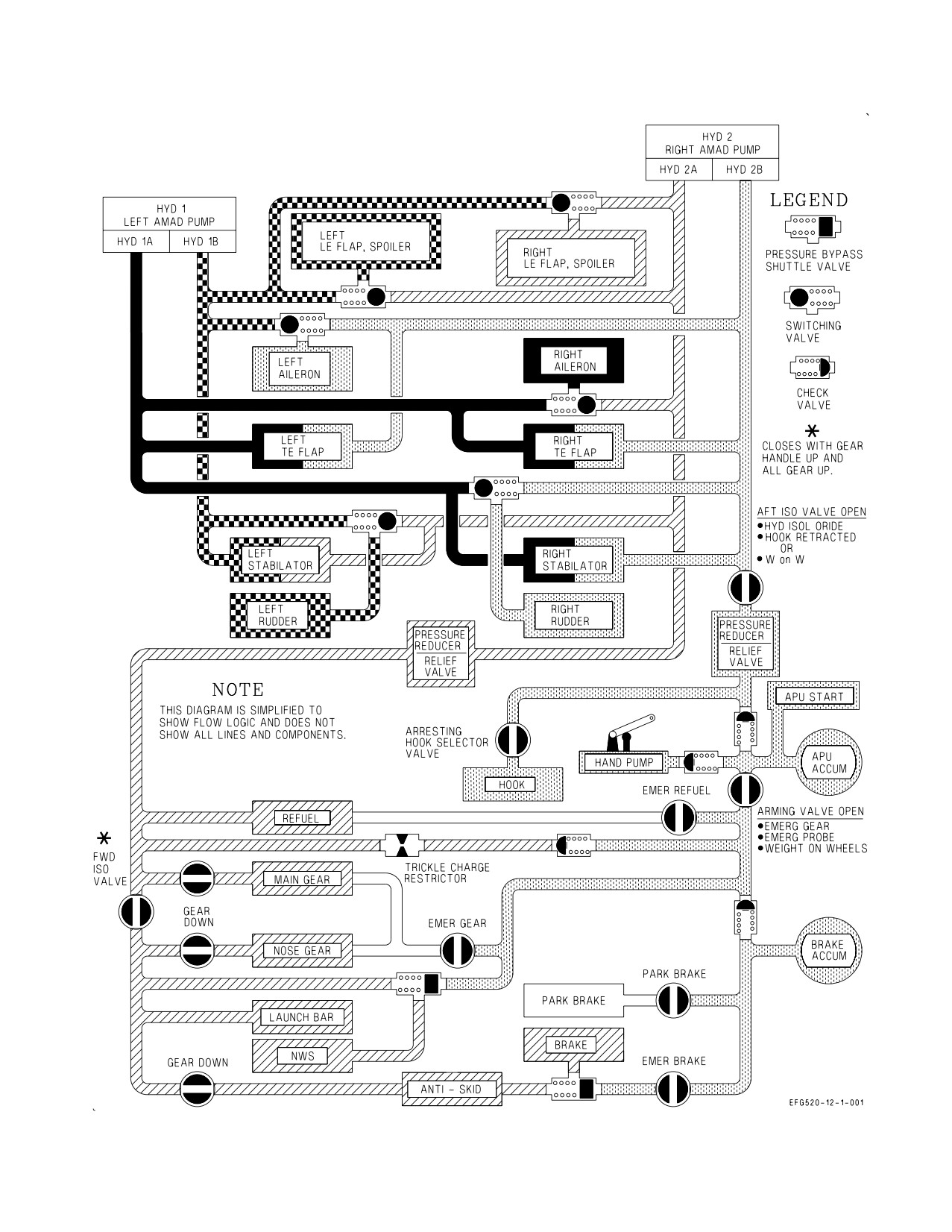
A1-E18GA-NFM-000
Figure 2-16. Hydraulic Flow
I-2-43
ORIGINAL
A1-E18GA-NFM-000
2.7.1.1
Hydraulic Pumps. Each system is pressurized by a single, dual pressure (3,000 and 5,000 psi),
variable displacement pump mounted on an AMAD. Pump output pressure is commanded by the
FCCs based on aircraft flight condition; with 5,000 psi utilized during high-speed flight when air loads
are high. One pump is capable of powering the entire flight control system in the event of a single
system failure. A hydraulic pressure transducer relays system pressure to a hydraulic pressure gauge
in the cockpit. Hydraulic cautions (HYD 1A, HYD 1B, HYD 2A, HYD 2B) are set when individual
hydraulic pressure switches detect circuit pressure below 1,400 psi.
2.7.1.1.1
Hydraulic Pressure Gauge. The hydraulic pressure gauge is located on the lower right main
instrument panel. The gauge has individual needles for indicating HYD 1 and HYD 2 system pressure.
Tick marks for 3,000 and 5,000 psi are provided. Two white bands indicate the range of acceptable
operation pressure (2,600 to 3,300 psi and 4,500 to 5,400 psi). Since the gauge is ac powered, actual
hydraulic readings are not provided until the first generator is online following engine start. During
shutdown, pressure readings freeze when the last generator drops offline.
2.7.1.2
Hydraulic Reservoirs. Hydraulic fluid is supplied to each system by a separate hydraulic
reservoir. The HYD 2 reservoir is larger than the HYD 1 reservoir in order to accommodate the utility
system.
2.7.1.2.1
Reservoir Level Sensing (RLS) System. Each reservoir incorporates an RLS system,
designed to isolate a leak in either system circuit. When reservoir fluid level drops to approximately
50%, RLS shuts off circuit A (HYD 1A or HYD 2A caution). If fluid level continues to deplete to
approximately 30%, RLS restores circuit A and shuts off circuit B (HYD 1B or HYD 2B caution). If
alternate circuit shutdown fails to isolate the leak, RLS restores circuit B (no cautions) at approxi-
mately 15%, providing hydraulic pressure to both systems until fluid depletion (both cautions).
2.7.1.3
Switching Valves. Hydraulic switching valves are utilized to provide backup hydraulic power
to actuators that are not powered simultaneously by both systems. Two hydraulic circuits, a primary
and a backup, provide power to each switching valve.
2.7.1.3.1
Switching Valve Operation. Following a drop in primary circuit pressure (less than 900
(±100 psi)), the switching valve automatically shuts off the primary circuit and tests downstream
pressure to make sure its actuator(s) was not the leakage source which caused the primary circuit loss.
Concurrently, FCC monitoring detects the pressure loss and inhibits FCC actuator failure detection
logic for 10 seconds to allow the switching valve time to function.
If the actuator(s) passes this leak detection test, the switching valve allows the backup circuit to
provide hydraulic power. If the actuator(s) fails the test, the switching valve isolates both circuits to
prevent additional loss of the backup circuit. At the expiration of the 10 second timer, the FCCs no
longer inhibit actuator failure detection logic. With both circuits isolated, this logic Xs LEF actuators
immediately and rudder or aileron actuators only when the actuator is subsequently commanded to
move. It is for this reason that the flap switch is cycled during the post-flight switching valve check.
Switching valve operation is completely hydro-mechanical, separate from electrical inputs or FCS
reset commands. As mechanized, there is no hazard associated with multiple reset attempts to regain
an Xd surface following a hydraulic circuit failure.
Preference is given to the primary circuit at all times. The switching valve transfers to the primary
circuit any time primary circuit pressure recovers above 2,000 psi, regardless of the valve position or the
backup circuit pressure level.
I-2-44
ORIGINAL
A1-E18GA-NFM-000
NOTE
If the leak detection test failed due to cavitation in the actuator, the
switching valve resets, runs another test, and completes the switch to
the backup circuit. This self-resetting feature may require several
minutes to complete depending on surface loading, hydraulic system
pressure, and system temperature. In this case, an FCS reset restores
an X’d surface if and when the switching valve successfully transfers to
the backup circuit.
2.7.1.4
Hydraulic Isolation Valves. HYD 2 utility functions that are required only during takeoff,
landing, and ground operations are downstream of isolation valves. The forward isolation valve is
closed when the LDG GEAR handle is UP and all three landing gear are up and locked; isolating the
nosegear, NWS, launch bar, wheel brakes, and anti-skid. The aft isolation valve and the arming valve
are open with WonW and are normally closed inflight; isolating arresting hook retraction, parking
brake, and emergency brakes. The aft isolation valve is manually opened inflight by hook retraction or
by holding the HYD ISOL switch in ORIDE. The arming valve is manually opened inflight by
emergency gear or emergency probe extension.
2.7.2 Hydraulic Accumulators. Two hydraulic accumulators are provided in the HYD 2B circuit; the
auxiliary power unit (APU) accumulator and the brake accumulator.
The APU accumulator provides hydraulic pressure to start the APU. With a HYD 2 failure, pressure
from the APU accumulator can be used to:
a. Emergency extend the landing gear or refueling probe inflight.
b. Provide emergency nosewheel steering on the ground.
c. Aid the brake accumulator with emergency braking.
On the ground with engines shutdown, the brake accumulator provides hydraulic pressure to set the
parking brake. With a HYD 2 failure, pressure from the brake accumulator can be used to provide
emergency braking. A fully charged brake accumulator provides a minimum of ten full brake
applications.
The APU and brake accumulator charges are maintained against normal leakage and temperature
fluctuations by a trickle-charge restrictor connected to HYD 2A. Additionally, both accumulators may
be manually recharged inflight using HYD 2B pressure by placing the HYD ISOL switch to ORIDE.
This procedure recharges the brake accumulator if and only if the arming valve is open (emergency gear
or emergency probe extension previously selected). Both accumulators can be charged on the ground
by a hand pump located in the right main landing gear wheelwell.
2.7.2.1
Brake Accumulator Pressure Gauge. The brake accumulator pressure gauge is located on
the lower left main instrument panel and is redlined to indicate pressure below 2,000 psi. The BRK
ACCUM caution is displayed when brake accumulator pressure drops below 2,000 psi. The caution and
redlined pressure indication are warnings that approximately five full brake applications remain before
the brake accumulator is empty. When ac power is not applied, power to the gauge is controlled by the
BRK PRESS switch.
I-2-45
ORIGINAL
A1-E18GA-NFM-000
2.7.2.1.1
BRK PRESS Switch. The BRK PRESS switch, located on the forward left console, is spring
loaded to the aft position.
Forward
Applies maintenance bus power to the brake accumulator pressure gauge when ac
(unmarked)
power is not applied.
Aft
Brake accumulator pressure gauge unpowered when ac power is not applied.
(unmarked)
2.7.2.2
HYD ISOL Switch. The HYD ISOL switch, located on the aft left console, is spring loaded to
the NORM position.
ORIDE
Opens the aft isolation valve in flight allowing HYD 2B pressure to recharge the
brake and/or APU accumulators. Following emergency landing gear extension, the
switch may need to be held for up to 20 seconds to remove the APU ACCUM cau-
tion and provide a full charge (up to 40 seconds following an in-flight APU start).
NORM
Allows normal aft isolation valve functioning.
If an APU ACCUM caution appears in flight and is not related to
emergency gear/probe extension or APU start, it may indicate a possible
leak in the isolated HYD 2B system. A BRK ACCUM caution in flight is
not normal and may indicate a possible leak in the isolated HYD 2B
system.
2.7.3 Hydraulic System Related Cautions and Caution Light. The following hydraulic system
related cautions and caution light are described in the Warning/Caution/Advisory Displays in Part V:
D HYD 1A, HYD 1B, HYD 2A, HYD 2B
D BRK ACCUM
D HYD 5000
D APU ACCUM caution and caution light
D HYD 1 HOT, HYD 2 HOT
2.8 UTILITY HYDRAULIC FUNCTIONS
The utility hydraulic functions are powered by HYD 2 and include landing gear extension and
retraction, nosewheel steering, wheel braking and anti-skid, launch bar extension, arresting hook
retraction, and in-flight refueling probe extension and retraction. Operation of the in-flight refueling
probe is described in the Fuel System section.
2.8.1 Landing Gear System. The landing gear is a tricycle design and includes a nose landing gear
with steerable nosewheel and two fixed main landing gear. The nose landing gear retracts forward,
while the main landing gear retract aft and inwards. When the landing gear is extended, all landing gear
doors remain open.
2.8.1.1
Planing Links. Each main landing gear assembly incorporates a planing link, which is
designed to properly align the main wheels after landing gear extension. The joint which connects the
wheel to the main landing gear lever is designed to rotate off-axis, so that the wheel fits properly into
the main landing gear wheelwell. The planing link rotates the main wheel from its stowed orientation,
I-2-46
ORIGINAL
A1-E18GA-NFM-000
aligns it with the longitudinal axis of the aircraft, and locks over-center. A planing link proximity
switch is used to verify proper planing link position and thereby proper wheel alignment. A flashing
main landing gear position light is used to provide an indication of a planing link failure.
2.8.1.2
Normal Landing Gear Extension and Retraction. Normal landing gear extension and
retraction is electrically controlled by the LDG GEAR handle and uses hydraulic pressure from HYD
2A. With weight off the nosegear and the launch bar retracted, moving the LDG GEAR handle to the
UP position sends an electrical signal to the landing gear selector valves to initiate normal landing gear
retraction. Likewise, moving the LDG GEAR handle to the DN position sends an electrical signal to the
landing gear selector valves to initiate normal landing gear extension
If the launch bar does not return to the up and locked position after catapult launch or the nose gear
indicates WonW, the nose landing gear cannot be retracted. In either case, placing the LDG GEAR
handle UP will raise the main landing gear and leave the nose landing gear extended.
2.8.1.3
Emergency Landing Gear Extension. Emergency landing gear extension is mechanically
controlled by the LDG GEAR handle and uses hydraulic pressure provided by the APU accumulator.
The handle is mechanically connected to the landing gear emergency selector valves by a series of levers
and cables. Emergency extension is mechanically activated by rotating the LDG GEAR handle 90°
clockwise and pulling to detent (approximately 1.5 inches).
Emergency landing gear extension opens the hydraulic arming valve and directs APU accumulator
pressure to the emergency selector valves. APU accumulator pressure is used to unlock the doors,
release the landing gear uplocks, and is applied to the drag brace locking actuator and sidebrace
downlock actuator. The nose landing gear extends by freefall aided by airloads and the drag brace
locking actuator. The main landing gear extends by freefall aided by the sidebrace downlock actuator.
Emergency extension can be performed with the LDG GEAR handle either UP or DN (DN is
recommended).
2.8.1.4
LDG GEAR Handle. The wheel-shaped LDG GEAR handle, located on the lower left main
instrument panel in the front cockpit, is used to control landing gear extension and retraction. A
downlock solenoid in the LDG GEAR handle assembly prevents gear retraction with WonW by
preventing movement of the handle from the DN position.
UP
With WoffW and the launch bar retracted, electrically initiates normal
landing gear retraction.
DN
Electrically initiates normal landing gear extension.
Emergency
Mechanically initiates emergency landing gear extension.
(Rotate handle 90°
clockwise and pull
to the detent)
2.8.1.5
DOWNLOCK ORIDE Button. The DOWNLOCK ORIDE button, located on the lower left
main instrument panel outboard of the LDG GEAR handle, is used to override the downlock solenoid.
If the downlock solenoid does not retract with WoffW (LDG GEAR handle cannot be moved from the
DN position), a failure has occurred in the downlock circuitry (Landing Gear Control Unit). If the
landing gear indicate three down and locked, cycling the landing gear handle is not recommended, as
proper landing gear functioning is questionable. However, if dictated by an emergency situation,
I-2-47
ORIGINAL
A1-E18GA-NFM-000
pressing and holding the DOWNLOCK ORIDE button will retract the mechanical stop and allow the
LDG GEAR handle to be moved to the UP position.
The LDG GEAR handle must be in the full down position for the mechanical stop to properly engage
after landing (WonW).
If the DOWNLOCK ORIDE button is pressed or the mechanical stop is
not fully engaged, the LDG GEAR handle can be raised on the ground,
and the main landing gear will retract. The nosegear will not retract with
weight on the nose gear.
2.8.1.6
Landing Gear Control Unit (LGCU). The LGCU monitors the position of the landing gear and
launch bar systems, provides cockpit indications of gear/launch bar position, and provides outputs to
various aircraft systems which are dependent on gear position (e.g., FCC A and B, the SMS, and the
SDC). The LGCU does not control landing gear extension and retraction.
The LGCU receives inputs from the LDG GEAR handle, the LAUNCH BAR switch, and the
following proximity switches: launch bar, landing gear uplocks, landing gear downlocks, planing links,
and WonW. The LGCU controls the red and green L BAR warning/advisory lights, the landing gear
position lights, the light in the gear handle, the landing gear warning tone, the downlock solenoid, and
all inputs to the FCCs and the SMS. The LGCU also performs a self-BIT and a functional check of all
proximity switches, providing MSP code input to the SDC.
2.8.1.7
Landing Gear Warning Light and Warning Tone. The landing gear warning light is a red light
located inside the LDG GEAR handle. The landing gear warning tone is a beeping tone heard in the
headset. The landing gear warning light and warning tone serve three purposes: to indicate a mismatch
between LDG GEAR handle position and actual gear position, to warn of a planing link failure, and to
provide a ″wheels warning.″
A steady warning light comes on whenever the landing gear is in transit and remains on until all
three gear are down and locked (LDG GEAR handle DN) or all gear doors are closed and locked (LDG
GEAR handle UP). If the landing gear is unsafe, the landing gear warning light remains on. The
warning tone is inhibited for 15 seconds to allow for normal landing gear extension and retraction. If
the warning light remains on for 15 seconds, the warning tone is annunciated to provide an aural
indication of unsafe landing gear position.
If a left or right planing link failure occurs with the landing gear down and locked (planing link
proximity switch not properly activated), the landing gear warning light will come on immediately
accompanied by the warning tone.
Lastly, when the LDG GEAR handle is UP, a flashing warning light accompanied by the warning
tone will be activated when airspeed is below 175 KCAS, altitude is less than 7,500 feet, and rate of
descent is greater than 250 fpm. This ″wheels warning″ is provided as a cue to check the position of the
landing gear at flight conditions where the LDG GEAR handle should normally be DN. The wheels
warning is also activated if calibrated airspeed and/or barometric altitude data are lost. In this case, the
standby airspeed and/or altitude indicators should be referenced prior to silencing the warning tone.
2.8.1.7.1
WARN TONE SIL Button. The WARN TONE SIL button, located to the left of the LDG
GEAR handle, is used to silence the landing gear warning tone.
I-2-48
ORIGINAL
A1-E18GA-NFM-000
2.8.1.7.2
Landing Gear UNSAFE Light (Rear Cockpit). The landing gear UNSAFE light is a red light
located on the upper left main instrument panel in the rear cockpit. The light indicates a mismatch
between LDG GEAR handle position and actual gear position (e.g., gear in transit). The light does not
illuminate for a planing link failure, wheels warning, or loss of air data.
2.8.1.8
Landing Gear Position Lights. Three green landing gear position lights, located on the lower
left main instrument panel, are labeled NOSE, LEFT, and RIGHT. When the LDG GEAR handle is
DN, steady lights indicate that the corresponding landing gear is down and locked. The LEFT and
RIGHT landing gear position lights are also used to indicate a planing link failure. If the main landing
gear are down and locked but a planing link proximity switch is not properly activated, the
corresponding position light will flash.
A landing gear position of three down and locked is indicated by three steady green position lights
with the landing gear warning light out. Additionally, when illuminated inflight, the approach lights
provide an external indication that the landing gear is down and locked.
If a landing gear position light is out with the LDG GEAR handle DN and the landing gear warning
light out, a LT TEST should be performed to test the integrity of the position light bulb. If the bulb
tests bad, it is safe to assume that the gear is down and locked. During day operations, if all three
position lights appear to be out/dim, make sure the interior lights MODE switch is in the DAY position.
A landing gear position of three up and locked is indicated by the landing gear warning light out with
all three position lights out.
If one or more landing gear indicates unsafe, a visual inspection can only
confirm general position and obvious damage. There is no external
indication of a locked landing gear.
2.8.1.8.1
Landing Gear Position Lights (Rear Cockpit). Three green landing gear position lights,
labeled NOSE, LEFT, and RIGHT, are located on the upper left main instrument panel in the rear
cockpit. These lights have the same functionality as those in the front cockpit.
2.8.2 NWS - Nosewheel Steering System. The NWS system is used to provide directional control
and shimmy damping during ground operations. The NWS hydraulic power unit, attached to the nose
landing gear strut, is electrically controlled by commands from the FCCs and is hydraulically actuated
by pressure from HYD 2A (primary) or HYD 2B/ APU accumulator (backup). In the event of a HYD
2A failure, a pressure-biased shuttle valve routes HYD 2B pressure (if available), or APU accumulator
pressure to the NWS unit for backup operation. The FCCs accept input from the rudder pedals to
provide NWS commands.
The NWS system has two modes, NWS (low) and NWS HI. In the low mode (NWS cue in the HUD),
full rudder pedal deflection commands approximately 22.5° of nosewheel deflection. In the high mode
(NWS HI cue in the HUD), full rudder pedal deflection commands approximately 75° of nosewheel
deflection. The NWS system (low gain) incorporates a yaw rate feedback input from the FCCs, which
I-2-49
ORIGINAL
A1-E18GA-NFM-000
is designed to suppress directional PIO tendencies by increasing directional damping during takeoff
and landing roll.
With loss of yaw rate information to the FCCs, directional PIO may occur
during aggressive ground tracking.
If the NWS system fails, the NWS caution is displayed and the NWS or NWS HI cue is removed
from the HUD. When failed, the NWS system reverts to a 360° free-swiveling mode.
2.8.2.1
NWS Engagement/Disengagement. With WonW, manual NWS engagement is provided by
actuation of the NWS/undesignate button. The method required to engage each of the two NWS
modes (low and high) is dependent on wing lock/unlock status.
With the wings spread and locked and NWS disengaged, the first momentary press and release of the
NWS button engages full-time NWS (low). NWS HI is engaged by subsequent press and hold of the
NWS button. With NWS disengaged, press and hold for greater than 1 second also engages NWS HI.
If the NWS button is released, the system reverts to NWS (low).
With the wings unlocked and NWS disengaged, the first momentary press and release of the NWS
button still engages full-time NWS (low). However, subsequent press and release engages full-time
NWS HI, providing hands-free NWS HI capability for operations in the carrier environment. If the
wings are subsequently spread and locked, NWS reverts to the low mode.
During landing, full-time NWS (low) is automatically engaged when the nose landing gear and at
least one main landing gear transition to WonW. If NWS is engaged with both HYD 2A and 2B failures,
the NWS or NWS HI cue will flash in the HUD as an indication that APU accumulator pressure is
depleting.
NWS is manually disengaged by pressing the paddle switch. NWS is automatically disengaged for
catapult launch, when the launch bar is extended. With the launch bar extended, NWS (low) can be
momentarily engaged to position the launch bar by press and hold of the NWS button. Additionally,
NWS is automatically disengaged when the nose landing gear transitions to WoffW during takeoff or
when power is removed from the FCCs.
2.8.2.2
Emergency High Gain NWS. With a FCS CH 2 or FCS CH 4 failure, normal nosewheel
steering is lost. Emergency high gain NWS can be regained by pulling the failed channel circuit
breaker, unlocking the wings, and momentarily pressing the nosewheel steering button.
When emergency high gain NWS mode is entered, NWS indications may
not be displayed on the HUD. As a result, inadvertent nosewheel steering
actuation may injure ground personnel.
2.8.3 Wheel Brake System. The aircraft’s wheel brake system provides normal braking, anti-skid,
emergency braking, a parking brake, and main wheel anti-spin. Normal braking utilizes HYD 2A
I-2-50
ORIGINAL
A1-E18GA-NFM-000
pressure and is capable of functioning with a separate anti-skid system. The anti-skid system, when
enabled, provides maximum braking effectiveness on wet runways or during heavy braking by
preventing wheel skid. When selected, emergency braking utilizes HYD 2B pressure, if available, or
brake and APU accumulator pressure to provide backup braking capability following a HYD 2A
failure. The anti-spin function stops main landing gear wheel rotation prior to landing gear retraction.
2.8.3.1
Wheel Brake Assembly. Each main landing gear wheel is fitted with hydraulically actuated
multiple disk brakes. There are two independent sets of brake lines running to each wheel brake
assembly: the normal brake line pressurized by HYD 2A and the emergency brake line pressurized by
HYD 2B or the brake and APU accumulators. See figure 2-17. Only one set of brake lines can be
pressurized at any given time. A shuttle valve on each wheel brake assembly switches from normal to
emergency brake pressure, depending on which is applied.
Each wheel brake assembly has a brake wear indicator pin, located on the inboard side of the wheel.
When the brakes are applied and the indicator pin is flush or below flush with the brake housing, the
brake pads require changing.
Each wheel assembly incorporates a fuse plug which is designed to melt and deflate the tire at
temperatures below those which would result in a catastrophic tire blowout.
2.8.3.2
Wheel Brake Operation. Each main wheel brake is controlled by a separate brake pedal,
integrated into the rudder/brake pedal mechanism. Pilot applied force to the top of each brake pedal
is transmitted by a series of cables and pulleys directly to the brake control hydraulic servovalves,
located in the nose wheelwell. The amount of hydraulic pressure applied to the wheel brakes by the
servovalves is directly proportional to brake pedal force. Dual brake pedal action provides symmetric
braking, while individual brake pedal action provides differential braking.
2.8.3.3
Normal Braking. Normal braking is enabled when HYD 2A is operable and the EMERG
BRK handle is in the stowed position. The emergency brake valve is closed and the emergency brake
lines are unpressurized. During normal braking, HYD 2A pressure is applied through the left and right
servovalves proportional to the amount of pilot applied brake pedal force and is routed to the main
wheel brakes. When the ANTI SKID switch is ON, the anti-skid system modulates pilot applied brake
pressure in order to prevent wheel skid. When the ANTI SKID switch is OFF, the pilot must regulate
brake pedal force to prevent wheel skid.
2.8.3.4
Anti-skid System. The anti-skid system performs 4 basic functions which are designed to
maximize braking effectiveness during landing rollout: touchdown protection, wheel spin-up override,
skid control, and locked wheel protection. The anti-skid system is enabled when the ANTI SKID
switch is ON and the LDG GEAR handle is DN.
I-2-51
ORIGINAL
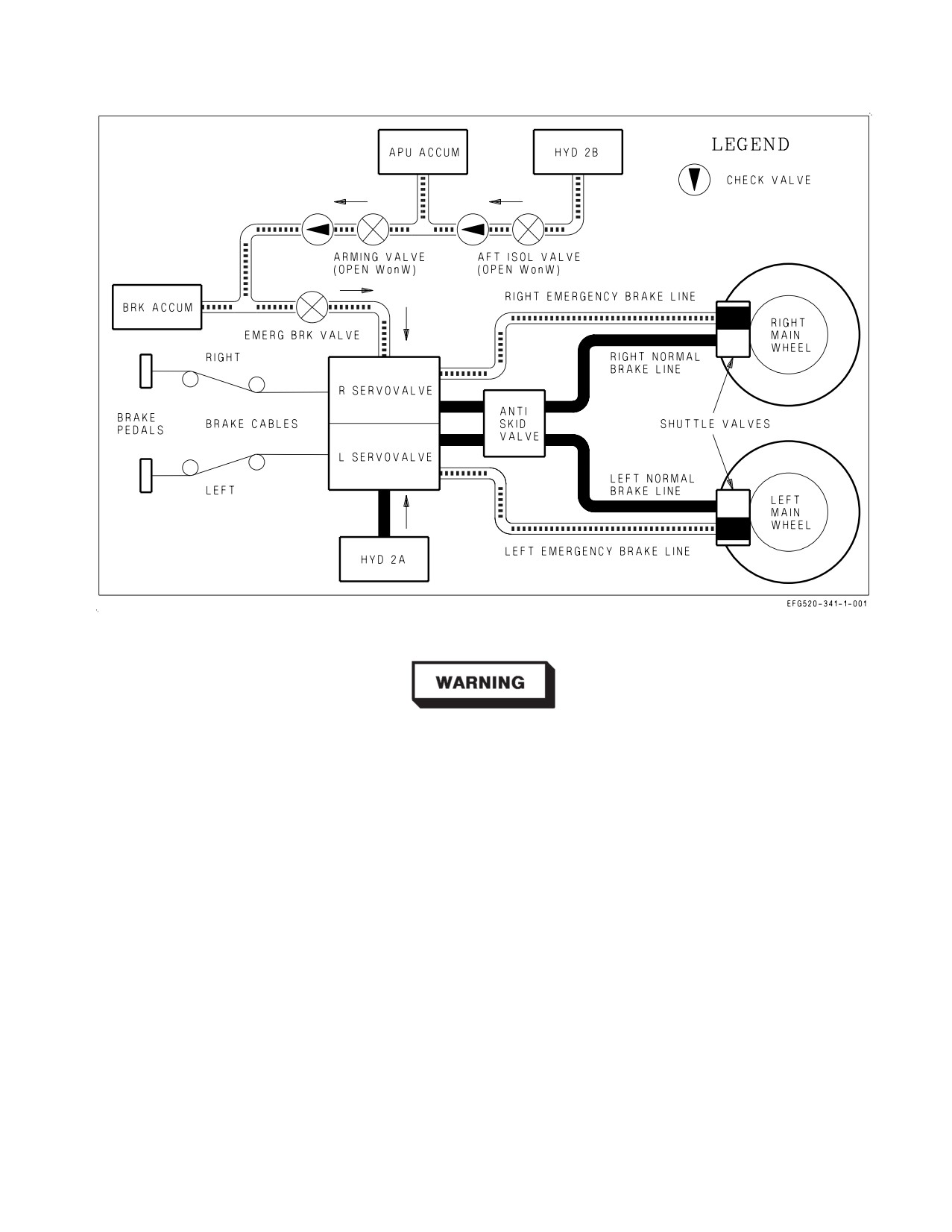
A1-E18GA-NFM-000
Figure 2-17. Wheel Brake and Anti-skid System
Failure of either wheel speed sensor can lead to an anti−skid failure,
resulting in a complete loss of brakes. Placing the ANTI SKID switch to
the OFF position or pulling the EMERG BRK handle will bypass the
faulty system and restore braking ability. Judicious braking must be
used, as the anti−skid system is not available. Refer to the BRAKES
FAILURE/EMERGENCY BRAKES procedure.
The system contains two wheel speed sensors, an anti-skid control unit, and an anti-skid control
valve. The anti-skid control unit senses wheel speed and operates by electronically limiting the amount
of HYD 2A pressure that is applied to the wheel brakes through the anti-skid control valve and the
normal brake lines. Anti-skid is not available when emergency brakes are selected.
Touchdown protection delays initial brake application on landing by completely dumping brake
pressure until (1) weight is on the right main landing gear and wheel speed is over 50 knots or (2), if
a wet runway delays wheel spin-up, for 3 seconds after landing. This function prevents landing with
locked main wheels (tire blowouts) even if full brake pedal force is applied at touchdown.
Wheel spin-up override is activated at 50 knots wheel speed to allow normal braking if the right
WonW switch fails.
I-2-52
ORIGINAL
A1-E18GA-NFM-000
Skid control is enabled when sensed wheel speed differs from what the anti-skid control unit
determines it should be (e.g., hydroplaning is detected). If the system detects wheel skid, anti-skid
limits the amount of HYD 2A pressure applied to both brakes as required to prevent skidding. If no
skid exists, full pilot-applied brake pressure is routed to the brakes.
If the speed of one wheel drops 40% below the other wheel, locked wheel protection dumps brake
pressure to both wheels until the speed of the slower wheel returns above 40% of the other. Locked
wheel protection is removed below 35 knots, so that full braking performance (including locking a tire)
is available for taxi and turning operations. Below 14 knots, anti-skid is completely disabled. Below 35
knots, judicious braking is required to avoid flat spotting tires.
NOTE
Hot brakes and/or melted wheel assembly fuze plugs can be expected
any time maximum effort braking is used at heavy gross weights with
or without anti-skid, e.g., aborted takeoff or heavy weight landing
(above 46,000 lb GW) with high taxi brake usage.
2.8.3.4.1
ANTI SKID Switch. The ANTI SKID switch, located on the lower left main instrument
panel, is used to manually disable the anti-skid system, e.g., for carrier operations or following an
anti-skid failure (ANTISKID caution displayed). The switch is lever-locked in the OFF position.
ON
Anti-skid system enabled for use with normal braking.
OFF
Anti-skid system disabled (SKID advisory displayed when the landing gear is
down).
2.8.3.4.2
Anti-skid BIT and the ANTISKID Caution. The anti-skid control unit performs two types of
BIT: initiated and periodic. IBIT is performed when power is initially applied to the anti-skid system:
(1) when the landing gear is lowered, (2) when the ANTI SKID switch is selected from OFF to ON
inflight, or (3) on the ground with the parking brake set. IBIT performs a complete test of the anti-skid
system 9 seconds after power is applied and runs for 4.5 seconds. With WonW, IBIT is inhibited with
the parking brake released, as wheel motion will cause a false BIT failure and brake pressure would be
dumped if brakes were applied. PBIT only performs a partial anti-skid test and runs whenever power
is applied and IBIT is not running.
If an anti-skid failure is detected by either BIT, the ANTISKID caution will be displayed at BIT
completion. If an anti-skid failure is detected by PBIT, cycling the ANTI SKID switch will command
an IBIT and a more complete test of the system. When IBIT is running, the ANTISKID caution is
inhibited or is removed if previously displayed. If the ANTISKID caution returns after IBIT, the
ANTI SKID switch must be placed to OFF in order to isolate the failure and make sure that normal
braking (without anti-skid) is available.
For instance, assume the right wheel speed sensor has failed and an ANTISKID caution is displayed.
If the ANTI SKID switch is left ON during landing, touchdown protection circuitry will dump and
never restore brake pressure to both wheels. Normal braking will be lost. In this case, placing the ANTI
SKID switch to OFF will restore normal braking (without anti-skid), or pulling the EMERG BRK
handle will enable emergency braking (bypassing anti-skid).
I-2-53
ORIGINAL
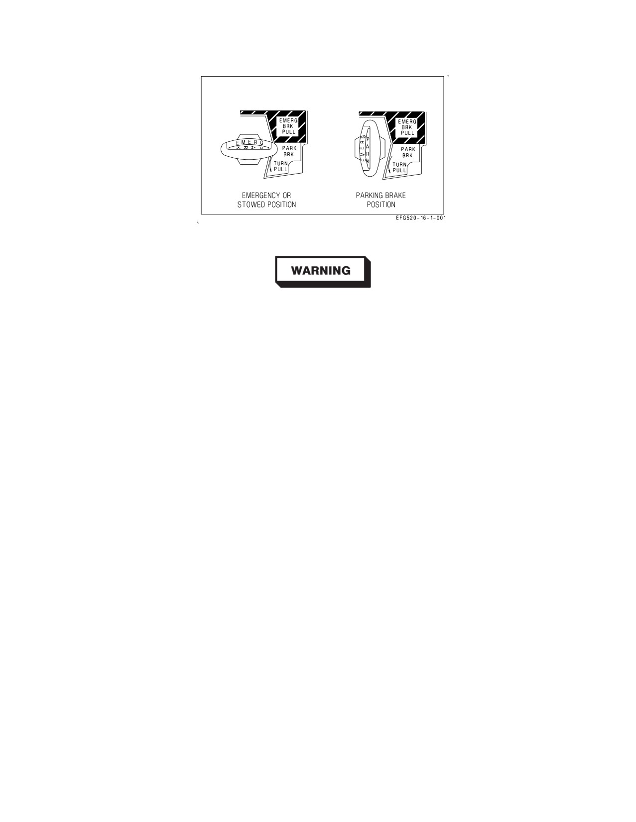
A1-E18GA-NFM-000
Figure 2-18. Emergency/Parking Brake Handle
• Do not cycle the ANTI SKID switch in response to an ANTISKID
caution immediately prior to landing. Cycling the ANTI SKID switch
removes the ANTISKID caution for up to 13.5 seconds as the system
performs IBIT even though the anti-skid system may still be failed
and, if the system is not failed, wheel motion at touchdown may cause
a false BIT failure and a dump of normal brake pressure when brakes
are applied.
• If the ANTI SKID switch is not placed to OFF with an ANTISKID
caution displayed, normal braking capability may be lost completely.
2.8.3.5
Emergency Braking. Emergency braking is enabled when the EMERG BRK handle is pulled
to detent. This action opens the emergency brake valve and applies backup hydraulic pressure to the
hydraulic servovalves. If available, backup pressure from HYD 2B is utilized through the aft isolation
and arming valves, which are open with WonW. If HYD 2 is failed completely, backup pressure from
both the brake and APU accumulators is used. Check valves are incorporated to prevent the loss of
accumulator pressure if HYD 2B is failed. With backup pressure applied, the servovalves isolate HYD
2A pressure, if still available, so that the normal brake lines are unpressurized.
During emergency braking, backup pressure is applied through the left and right servovalves
proportional to the amount of pilot applied brake pedal force and is routed to the main wheel brakes
through the emergency brake lines. These lines bypass the anti-skid control valve, so the pilot must
regulate brake pedal force to prevent wheel skid.
Hydraulic accumulators and the brake accumulator pressure gauge are discussed in the Hydraulic
Power Supply System section.
2.8.3.5.1
EMERG BRK Handle. The EMERG BRK handle is combined with the PARK BRK handle
and is located on the lower left main instrument panel in the front cockpit. When the handle is in the
stowed, emergency position (horizontal), the ‘‘EMERG’’ label appears upright. See figure 2-18. To
select emergency brakes, the handle must be pulled to the detent while in the horizontal position.
I-2-54
ORIGINAL
A1-E18GA-NFM-000
Stowed
Emergency brake valve closed. Normal braking selected.
(unmarked)
PULL
Emergency brake valve open. Emergency braking selected.
(to detent)
The position of the EMERG BRK handle is the only indication that
emergency braking is selected: no warning or caution is displayed. The
EMERG BRK handle must be fully stowed to make sure that normal
braking with anti-skid is available.
Due to friction in the EMERG BRK handle mechanism, the handle may
not return to the fully stowed position unless positively pushed.
2.8.3.6
Parking Brake System. The parking brake is used to lock the main landing gear wheels when
the aircraft is parked. The parking brake is activated when the PARK BRK handle is rotated and
pulled to the locked position. This action places the emergency brake valve in the parking brake mode.
Backup hydraulic pressure from HYD 2B or the brake and APU accumulators is applied to the wheel
brake hydraulic servovalves and routed to the main wheel brakes through the emergency brake lines.
The PARK BRAKE caution will come on to alert the pilot that the parking brake is still set when
both throttles are advanced above about 80% N2 rpm (INS on).
2.8.3.6.1
PARK BRK Handle. The PARK BRK handle is combined with the EMERG BRK handle
and is located on the lower left main instrument panel in the front cockpit. From the stowed
(horizontal) position, the handle must be rotated 90° counterclockwise and pulled to the locked
position, in order to activate the parking brake. When the handle is in the vertical position, the
‘‘PARK’’ label appears upright. See figure 2-18. If emergency brakes are selected, the handle must be
returned to the stowed position before the parking brake can be activated. Rotating the handle 45°
counterclockwise releases the lock and allows the handle to return to the stowed (horizontal) position.
Stowed
Parking brake released. Normal braking selected.
(unmarked)
TURN/
Parking brake set.
PULL
Several aircraft systems utilize parking brake activation to enable or disable logic. A set parking
brake is used to enable anti-skid BIT logic, GEN TIE logic, and INS alignment and is used to trigger
the PARK BRAKE caution.
2.8.3.7
Main Wheel Anti-Spin. The anti-spin function stops main landing gear wheel rotation prior
to landing gear retraction. When the LDG GEAR handle is moved to the UP position, main landing
gear retract pressure is supplied to the anti-skid control valve. Normal brake pressure is blocked and
this anti-spin pressure is routed to the wheel brakes through the normal brake lines. Unlock and
I-2-55
ORIGINAL
A1-E18GA-NFM-000
retraction of the main landing gear is delayed until anti-spin pressure is applied and main wheel
rotation has stopped.
2.8.4 Launch Bar System. The launch bar is electrically controlled, hydraulically extended, and
mechanically retracted. With weight on the nosegear, placing the LAUNCH BAR switch to EXTEND
energizes the launch bar control valve and routes HYD 2A pressure to unlock, lower, and hold down the
launch bar. The green L BAR advisory light indicates that the launch bar has been extended.
With the launch bar extended, returning the LAUNCH BAR switch to RETRACT deenergizes the
launch bar control valve, isolates HYD 2A pressure, and allows dual retract springs to mechanically
return the launch bar to the up and locked position. A launch bar proximity switch is energized when
the launch bar is fully retracted.
When the launch bar is fully extended it is held against the deck by HYD 2A pressure. Deck load
springs allow vertical movement of the launch bar during taxi over the catapult shuttle. When the
aircraft is placed in tension on the catapult, the launch bar is held captive in the extended position by
the shuttle. Once in tension, the LAUNCH BAR switch should be placed to RETRACT in order to
remove HYD 2A pressure from the launch bar. When the LAUNCH BAR switch is placed to
RETRACT, the green L BAR light should go out.
Failure to place the LAUNCH BAR switch to RETRACT prior to
catapult launch may result in launch bar hydraulic seal failure and
possible loss of HYD 2A.
At the end of the catapult stroke, launch bar/shuttle separation occurs and allows the retract springs
to return the launch bar to the up and locked position. When engaged, the launch bar uplock prevents
the launch bar from dropping to the deck due to g-loads during landing.
If the launch bar does not return to the up and locked position after catapult launch (launch bar
proximity switch not energized), the nose landing gear cannot be retracted. In this case, placing the
LDG GEAR handle UP will raise the main landing gear and leave the nose landing gear extended.
2.8.4.1
LAUNCH BAR Switch. The LAUNCH BAR switch, located on the lower left main instrument
panel in the front cockpit, is used to control the position of the aircraft’s launch bar. The switch is
spring loaded to the RETRACT position and is electrically held in the EXTEND position only if
weight is on the nose gear.
RETRACT Launch bar control valve deenergized. Launch bar up.
EXTEND Launch bar control valve energized. Launch bar unlocked and extended by HYD
2A pressure. Green L BAR advisory light on.
2.8.4.2
LB Circuit Breaker. The LB circuit breaker is located on the left-hand circuit breaker panel
above the left console. The LB circuit breaker provides a secondary means to raise the launch bar
following a launch bar malfunction. When pulled, the circuit breaker manually deenergizes the launch
bar control valve, removing HYD 2A pressure and allowing the retract springs to raise the launch bar.
I-2-56
ORIGINAL
A1-E18GA-NFM-000
Typically, this action would be required only if (1) the LAUNCH BAR switch failed in the EXTEND
position with weight on the nosegear or (2) the nose gear failed WonW after launch and the pilot failed
to place the LAUNCH BAR switch to RETRACT.
2.8.4.3
L BAR Warning/Advisory Lights. Two L BAR lights, one green and one red, are located on
the left warning, caution, and advisory lights panel. Both lights are controlled by the landing gear
control unit (LGCU), based on inputs from the LAUNCH BAR switch, the launch bar proximity
switch, and various landing gear proximity switches.
The green L BAR advisory light is used to indicate that the launch bar has been extended. The
LGCU illuminates the green L BAR light when all of the following conditions are met: weight on the
nose gear, the LAUNCH BAR switch in EXTEND, the launch bar not up (launch bar proximity switch
not energized), and the red L BAR warning light not on.
The red L BAR warning light is used to indicate failure of the launch bar to retract after catapult
launch or a failure in the launch bar control system (proximity switch failure). The LGCU illuminates
the red L BAR light when one of the following sets of conditions are met:
1. Launch bar not up and weight off the left main gear.
2. Launch bar not up and left main gear not down.
3. LAUNCH BAR switch in EXTEND and weight off the left main gear.
4. LAUNCH BAR switch in EXTEND and left main gear not down.
The first set of conditions is the primary L BAR warning, e.g., the launch bar does not retract fully
after catapult launch. The other three sets of conditions provide a backup L BAR warning if one or
more of the proximity switches which control launch bar functioning fail.
2.8.5 Arresting Hook System. The arresting hook is always down-loaded by a nitrogen-charged
accumulator (arresting hook snubber) contained in the arresting hook retract actuator. Arresting hook
extension is therefore accomplished by mechanically releasing the arresting hook uplatch mechanism
(HOOK handle down) and allowing snubber pressure and gravity to extend the hook. The hook should
extend in less than 2 seconds. At touchdown, the arresting hook snubber controls hook bounce and
provides a hold down force for arresting cable engagement.
Arresting hook retraction is accomplished by raising the HOOK handle. This electrically opens the
aft isolation valve and the arresting hook selector valve, routing HYD 2B pressure to the arresting hook
retract actuator. HYD 2B pressure overcomes the snubber down-load pressure and raises the hook. The
arresting hook uplatch mechanism captures and locks the hook in the up position. The hook should
retract in less than 4 seconds. If HYD 2B pressure is lost, the arresting hook cannot be retracted.
2.8.5.1
HOOK Handle. The HOOK handle, located on the lower right main instrument panel in the
front cockpit, is used to control arresting hook extension and retraction.
Up
Retracts the arresting hook utilizing HYD 2B pressure.
(unmarked)
Down
Unlocks the arresting hook uplatch mechanism and allows arresting hook snubber
(unmarked)
pressure and gravity to extend the hook.
2.8.5.2
HOOK Light. The red HOOK light is located on the lower right main instrument panel
directly above the HOOK handle. The HOOK light comes on any time hook position does not agree
I-2-57
ORIGINAL
A1-E18GA-NFM-000
with HOOK handle position. The light comes on when the hook leaves the up and locked position and
remains on until the hook is fully extended (hook proximity switch energized). With WonW, the hook
will strike the ground before it reaches full extension, so the HOOK light will remain on.
The green HOOK light is located in the rear cockpit on the left warning, caution, and advisory panel.
This HOOK light illuminates when the hook is down.
2.9 WING FOLD SYSTEM
The aircraft’s outer wing panels are designed to fold vertically to reduce the amount of deck space
occupied by the aircraft in the carrier environment. Each wing contains an independent wingfold
mechanism, which consists of two electric motors (one to lock/unlock the wings and one to spread/fold
the wings). During normal operation, the wings are spread, locked, unlocked, and folded in unison.
2.9.1 Wingfold Mechanism. Each wingfold mechanism contains a dc electric motor, which locks and
unlocks the wings, and an ac electric drive unit, which spreads and folds the wings. When the wings are
spread and locked, a locking bolt is electrically driven through the wingfold hinge, holding it in place.
When the wings are unlocked, a wing unlock flag (commonly called a beer can) protrudes from the
upper surface of the wing near the leading edge of the wingfold hinge, indicating that the locking bolt
is unstowed. The shaft of each beer can is painted red for easy identification. When the wings are
locked, the top of the beer can should be flush or near flush with the upper surface of the wing, and no
red should be showing.
Additionally, when the wings are folded, the ailerons are mechanically locked in the faired position
by a hook on the inboard aileron hinge, which engages an aileron locking pin. The aileron locking pin
is mechanically extended as the wings fold. The hook and locking pin are designed to prevent the
ailerons from blowing inboard over the TEFs when hydraulic power is not applied. If an aileron locking
pin should break, it is possible for the aileron to blow inward over the TEF. If this condition exists
during engine start, the TEF will retract into the aileron, damaging both surfaces.
If the wings are folded, note the position of the ailerons during the
preflight walk-around. If the aileron locking pins do not restrain the
ailerons in the faired position, make sure the ailerons are moved to a
faired or outboard position prior to engine start to preclude damaging the
ailerons and TEFs.
Each wingfold mechanism also contains a wing safety switch, which electrically prevents wingfold
movement. The safety switch is activated by a ″remove before flight″ pin inserted in the underside of
the wing near the wingfold hinge.
For ground crew operations, each wing can be manually unlocked, folded, or spread. The beer cans
can be manually extended by inserting a screwdriver into the wing unlock motor (underside, leading
edge). Once unlocked, the wings can be folded or spread by inserting a speed handle into the electric
drive unit (underside, trailing edge).
2.9.2 Wingfold Operation. With the wings folded, wing spread and lock is commanded by placing the
WINGFOLD switch to SPREAD. The SPREAD command is sent directly to the electric drive units to
spread the wings (there are no WonW or FCC interlocks). When each wing reaches the completely
spread position, power is removed to that electric drive unit, and that wing is automatically
I-2-58
ORIGINAL
A1-E18GA-NFM-000
commanded to lock. The WING UNLK caution will not be removed until both wings are locked (both
beer cans down). Once the wings are spread and locked, the ailerons will droop to the position
scheduled by the FCCs based on FLAP switch position.
The wings can be stopped in an intermediate position by placing the WINGFOLD switch to HOLD.
If the wings are spread, selecting HOLD unlocks the wings without folding, allowing full time NWS HI
to be engaged for operations in the carrier environment. This function is useful when NWS HI is
desired but wingfold is not.
With the wings spread and locked, wingfold is commanded by placing the WINGFOLD switch to
FOLD. In order for the wings to unlock, ground power must be applied or the aircraft must be WonW
(left main). The initial FOLD command electrically unlocks the wings (beer cans extended, WING
UNLK caution displayed) and fairs the ailerons. When the FCCs determine that (1) weight is on
wheels, (2) airspeed is less than 100 KCAS accelerating or 66 KCAS decelerating, (3) the ailerons are
faired, and (4) both wings are unlocked, the FOLD command is sent to the electric drive units to fold
the wings. When each wing reaches the completely folded position, power is removed to that electric
drive unit.
2.9.3 WINGFOLD Switch. The WINGFOLD switch, located on the lower right main instrument
panel, is lever-locked in all three positions. The switch has a barrier guard to prevent inadvertent
actuation.
FOLD
Unlocks the wings (WING UNLK caution displayed), fairs the ailerons, and, when
(& unlock)
allowed by the FCCs, folds the wings.
HOLD
Stops wing movement in an intermediate position. If spread, unlocks the wings.
(& unlock)
SPREAD
Spreads and locks the wings. (WING UNLK caution removed when both wings are
(& lock)
locked).
Ensure the WINGFOLD switch is lever-locked in the SPREAD position
during takeoff checks. If the wings are commanded to unlock or fold
during a catapult shot, the wings will unlock, the ailerons will fair, the
wings may fold partially, and the aircraft will settle.
2.9.4 Wingfold Overheat Cutout Protection. The wingfold electric drive units are designed to meet
the following duty cycle requirements: two (2) fold-spread cycles followed by a twelve (12) minute
cooldown period. If wingfold operation exceeds this duty cycle, overheat cutout protection may
shutdown wingfold operation to prevent actuator damage. Once overheat cutout protection has been
activated, normal wingfold operation is not restored until actuator temperature drops within limits;
however, the wings can still be unlocked, folded, or spread manually.
2.10 FLIGHT CONTROL SYSTEM (FCS)
The flight control system (FCS) is a fly-by-wire, full authority control augmentation system (CAS).
The FCS provides four basic functions: aircraft stability, aircraft control, departure resistance, and
structural loads management. Since the basic airframe is statically neutral to slightly unstable, a
primary function of the FCS is to maintain aircraft stability at all flight conditions. The FCS also
I-2-59
ORIGINAL
A1-E18GA-NFM-000
provides full authority control of the aircraft by implementing the basic flight control laws which
determine aircraft response to pilot inputs. Pilot inputs from the stick and rudder pedals send
electrical commands to two quad-redundant, digital flight control computers (FCC A and FCC B).
There is no mechanical linkage between the stick and rudder pedals and the flight control surfaces.
FCC software determines what commands are sent to the various flight control surfaces to exercise
pitch, roll, and yaw control of the aircraft. Additionally, the FCS provides departure resistance by
either refusing to accept or by tailoring pilot inputs that would otherwise lead to an aircraft departure.
Lastly, the FCS provides structural loads management by limiting g-available to prevent an aircraft
overstress or by retracting flight control surfaces at airspeeds that would otherwise exceed the
structural limits of the airframe. See figure 2-20 for a functional diagram of the flight control system.
2.10.1 Flight Control Surfaces. The aircraft has 12 primary flight control surfaces including leading
edge flaps (LEFs), trailing edge flaps (TEFs), ailerons, twin rudders, horizontal stabilators, and
spoilers. LEFs, TEFs, ailerons, and stabilators can be moved both symmetrically or differentially for
pitch and roll control. Flight control surface deflection limits are shown in figure 2-19.
Pitch control is accomplished with symmetric stabilators and, in some conditions, with rudder toe-in
or rudder flare. Roll control is accomplished with combinations of ailerons, differential stabilators,
differential LEFs, and differential TEFs dependent on flight condition and CAS operating mode. The
twin rudders deflect symmetrically for directional control. There is no dedicated speedbrake surface.
Instead, a ″speedbrake function″ is provided by partial deflection of several of the primary flight
control surfaces.
Hydraulic power to all flight control surface actuators is supplied by HYD 1 and HYD 2. Stabilator
and TEF actuators are powered simultaneously by one HYD circuit from each system. All other
actuators are powered by a single primary HYD circuit, with backup hydraulic power available through
a hydro-mechanical switching valve. See the Hydraulic System section, specifically the Hydraulic Flow
Diagram, to determine which HYD circuits power each flight control surface actuator.
Surface
Deflection limits *
Aileron
25° TEU to 42° TED
Rudder
40° left or right
Stabilator
24° TEU to 20° TED
LEF
5° LEU to 34° LED
TEF
8° TEU to 40° TED
LEX Spoilers
0° or 60° TEU
* Tolerance ±1°, or ±3° for spoilers.
Figure 2-19. FCS Surface Deflections
2.10.1.1 Spoilers. The spoilers are mounted on top of the fuselage near the aft end of the LEX. The
spoilers are controlled by the FCCs and have two fixed positions: 0° (down) or 60° TEU. The 60° TEU
position is activated by the speedbrake function or when more than 15° TED stabilator is commanded
(forward stick) above 22° AOA to aid in recovery from high AOA.
I-2-60
ORIGINAL
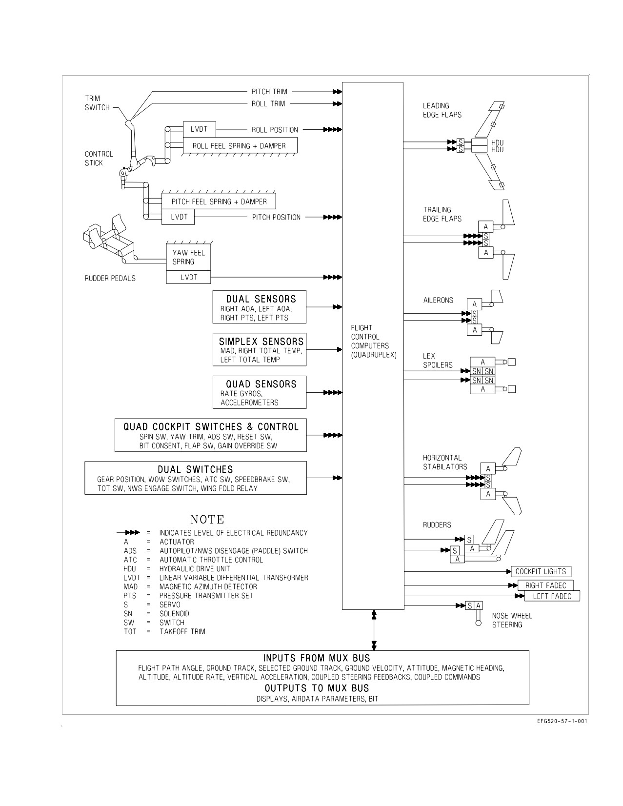
A1-E18GA-NFM-000
Figure 2-20. Flight Control System Functional Diagram
I-2-61
ORIGINAL
A1-E18GA-NFM-000
2.10.2 Flight Control Computers (FCCs). Two flight control computers (FCC A and FCC B) provide
the computations which implement the aircraft’s flight control laws. A four-channel architecture is
used to provide FCS redundancy. Each FCC contains two individual central processing units (CPUs),
which each run one channel of the FCS. CH 1 and CH 2 are resident in FCC A, with CH 3 and CH 4
in FCC B.
Most inputs to the FCCs (rate gyros, accelerometers, air data sensors, stick and rudder pedal
position sensors) are quad-redundant, one input for each channel. Each of the four CPUs runs
independent and parallel flight control computations. Sensor inputs as well as CPU outputs are
continuously monitored by the FCCs for agreement. When there is disagreement, the erroneous signal
is discarded, if possible.
Rate and acceleration data are provided by two independent Attitude and Heading Reference Sets
(AHRS), one for each FCC. Each AHRS has two sets of ring laser rate gyros and two sets of
accelerometers, which provide four independent sources of pitch, roll, and yaw rate information, and
four independent sources of normal and lateral acceleration. The AHRS units have the capability to
provide attitude, heading, and longitudinal acceleration data, but it is not currently utilized. The
physical rate and acceleration sensors in each AHRS channel are not aligned with the aircraft’s pitch,
roll, and yaw axis. This raw sensor data is converted to the aircraft’s pitch, roll, and yaw axis by
microprocessors internal to each AHRS. As a result of this architecture, a single rate gyro failure in one
channel results in all three axis rates being unusable in that same channel (CAS P, R, Y in one channel
Xd out). Similarly, if any of the accelerometers fail, all acceleration data from that AHRS channel is
unusable (N ACC and L ACC in one channel will both be Xd out).
FCC channel outputs are transmitted to the appropriate flight control actuators and to other aircraft
systems such as the MCs. While FCC computations run in all four channels, all flight control actuators
are not commanded in all four channels. The stabilators and TEF actuators do receive command
signals from all four FCC channels. However, each aileron, rudder, spoiler, and LEF actuator only
receives command signals from two FCC channels, one from FCC A and one from FCC B. The
2-channel actuators on the left side of the aircraft receive inputs from CH 1 and CH 4 while the
2-channel actuators on the right side receive inputs from CH 2 and CH 3. This channel distribution can
be seen on the FCS format.
2.10.2.1 FCC Temperature Monitoring. FCC A contains a thermocouple which monitors the
temperature within the computer and provides a signal to FCC CH 1 and CH 2. If an over-temperature
condition is detected, the FCS HOT caution and caution light come on, and the ″Flight computer hot,
Flight computer hot″ voice alert annunciates. Additionally, FCC A indicates OVRHT on the BIT
status line. In this case, placing the AV COOL switch to EMERG provides emergency ram air cooling
to FCC A and the right TR via a dedicated FCS ram air scoop. FCC B also contains a thermocouple,
but does not set the FCS HOT cautions. The only indication of an over-temperature condition in FCC
B is a BIT status indication of OVRHT.
2.10.2.2 AV COOL Switch. The AV COOL switch is located on the lower right main instrument panel
outboard of the caution light panel.
NORM
FCS ram air scoop retracted.
EMERG Deploys the FCS ram air scoop for emergency ram air cooling of FCC A, the right
TR, and other essential avionics.
Once deployed, the FCS ram air scoop cannot be retracted inflight.
I-2-62
ORIGINAL
A1-E18GA-NFM-000
2.10.3 FCS Redundancy and Survivability. Hydraulic redundancy is provided by distributing flight
control actuators among the four HYD circuits. This arrangement minimizes the probability of losing
multiple actuators due to catastrophic damage to any single actuator or its hydraulic lines. Following
a single HYD system failure, the other HYD system is capable of powering the entire FCS. Loss of
HYD 1 or HYD 2 in up and away flight does not affect aircraft control. However, in the takeoff and
landing configuration, small but controllable roll and/or yaw excursions may be expected as hydraulic
switching valves cycle to their backup circuits.
The primary electrical power source for each FCC channel is a dedicated output from one of two
permanent magnet generators (PMGs). See the Electrical System section for FCC Electrical Redun-
dancy. Should a power interruption occur to any single FCC channel, the FCC power supply
automatically switches to a ″keep alive″ circuit connected directly to the maintenance bus for 7 to 10
seconds. This makes sure that the FCCs have uninterrupted power to maintain full operation during
all predictable electrical bus switching transients.
For survivability, wiring for one channel from each computer is routed through the upper part of the
aircraft with wiring for the other through the lower part of the aircraft. This routing minimizes the
possibility of loss of any one flight control surface due to system failures or battle damage. If a
stabilator actuator fails due to multiple FCS or hydraulic failures, the FCS automatically reconfigures
to maintain 3-axis control and acceptable handling qualities by using the remaining surfaces. There is
no mechanical FCS reversion mode.
2.10.4 CAS Operating Modes. The control augmentation system (CAS) operates in two basic modes:
Powered Approach (PA) and Up-AUTO (UA). Mode selection is controlled by FLAP switch position
and airspeed. With the FLAP switch in HALF or FULL and with airspeed below approximately 240
KCAS, CAS implements flight control laws tailored for the takeoff and landing configuration (PA).
With the FLAP switch in AUTO, CAS implements flight control laws tailored for up and away flight
(UA). If the FLAP switch is left in HALF or FULL, the aircraft automatically transitions from PA to
UA when airspeed increases above approximately 240 KCAS. This is known as ″auto flap retract.″ In
this case, the amber FLAPS light comes on to alert the pilot to check FLAP switch position. The flight
control laws utilized in each mode are tailored to provide maximum maneuverability while maintaining
predictable handling qualities and departure resistance.
2.10.4.1 FLAP Switch. The FLAP switch, located on the lower left main instrument panel, is used to
select the CAS operating mode and to position the TEFs and aileron droop for takeoff and landing.
AUTO
Selects UA operating mode for up and away flight.
HALF
Selects PA operating mode for the takeoff and landing configuration. Sets TEF
deflection and aileron droop to 30° TED (WonW or at approach speed).
FULL
Selects PA operating mode for the takeoff and landing configuration. Sets TEF
deflection and aileron droop to 40° TED (WonW or at approach speed).
2.10.4.2 Flap Position Lights. Three flap position lights, two green and one amber, are located on the
lower left main instrument panel. The green HALF and FULL flap lights are used to indicate FLAP
switch position and are not indications of actual TEF/aileron position. The FCS format should be
referenced to determine actual LEF, TEF, and aileron position.
I-2-63
ORIGINAL
A1-E18GA-NFM-000
FLAPS
FLAP switch in HALF or FULL and airspeed above 240 KCAS (auto flap retract),
(amber)
abnormal flap condition (any flap is off or lacks hydraulic pressure), spin detected
by Spin Recovery System, or GAIN switch in ORIDE.
HALF
FLAP switch in HALF and airspeed below 240 KCAS.
(green)
FULL
FLAP switch in FULL and airspeed below 240 KCAS.
(green)
2.10.5 Control Augmentation System (CAS).
2.10.5.1 Pitch CAS. Pitch CAS (P CAS) utilizes normal acceleration, pitch rate, and AOA feedback,
each scheduled based on aircraft flight conditions, to tailor aircraft response to pilot stick inputs and
to provide stabilator actuator commands. P CAS operates by comparing aircraft response to the pilot’s
longitudinal stick input, driving the stabilator actuators symmetrically until the difference is reduced
to zero.
With flaps AUTO and neutral longitudinal stick, comparing pilot input to aircraft response has the
effect of constantly trimming the aircraft to steady-state, hands-off 1g flight, essentially removing the
requirement for manual trim. In maneuvering flight, P CAS modifies aircraft response to stick inputs
creating the effect of changing stick forces to provide pilot cueing. Actual stick forces for a given stick
displacement do not change with flight condition. At high airspeeds, P CAS is a g-command system
requiring 3.5 pounds of stick-force-per-g. At medium airspeeds, P CAS acts as a hybrid pitch rate and
g-command system. Pitch rate feedback is used to increase apparent stick-force-per-g (heavier stick
forces) to cue the pilot that airspeed is decreasing and less g is available. At low airspeed, P CAS is
primarily an AOA command system using AOA feedback above 22° AOA to provide increasing stick
forces with increasing AOA. With large forward stick inputs, P CAS augments nose-down pitch rates
by flaring the rudders and raising the spoilers.
With flaps HALF or FULL, AOA and pitch rate feedbacks are used to augment inherent airframe
pitch damping and stability. P CAS nulls the difference between the commanded AOA and actual
AOA. With neutral longitudinal stick, P CAS maintains trim AOA. Unlike with flaps AUTO, pitch trim
is required with flaps HALF or FULL to trim the aircraft on-speed. Rudder toe-in is used to improve
longitudinal stability and to aid aircraft rotation during takeoff or bolter. Rudder toe-in is a function
of AOA. At 0° AOA or with WonW, the rudders are toed-in 40°. Rudder toe-in decreases linearly to 0°
of toe at 12° AOA. Additional AOA feedback is provided above 12° AOA which increases stick forces
with increasing AOA to provide stall warning. Pitch rate feedback helps maintain tight pitch attitude
control during turns. With large forward stick inputs, P CAS augments nose-down pitch rates by
flaring the rudders and moving the TEFs trailing edge up.
2.10.5.2 Roll CAS. Roll CAS (R CAS) schedules aileron, differential LEF, differential TEF, and
differential stabilator commands in response to lateral stick inputs to achieve the desired roll
characteristics. Roll rate feedback, scheduled based on aircraft flight conditions, is used to augment
inherent airframe roll damping. Differential LEFs and TEFs are only used with flaps AUTO. The
LEFs deflect differentially up to 5° when below 25,000 feet and above 0.6 Mach. Differential TEFs are
not used above 10° AOA or below -5° AOA. At high airspeeds, aileron, differential stabilator and
differential TEF travel are reduced to provide consistent roll rate response and to aid in preventing
structural loads exceedances. At low airspeeds, aileron and differential stabilator travel are reduced
with increasing AOA to minimize adverse yaw. Differential stabilator may also be limited due to pitch
commands which have priority over lateral commands.
I-2-64
ORIGINAL
A1-E18GA-NFM-000
Without any tanks, A/G stores, or ALQ-99 pods loaded on the wing, maximum roll rate is limited to
approximately 225°/second. With A/G store, ALQ-99 pods, or external fuel tank codes set in the
armament computer for any wing station and the pylon rack hooks closed for those stations, maximum
roll rate is limited to approximately 150°/second to avoid exceeding pylon structural load limits. If all
stores are shown as HUNG, roll rate limiting is removed; however, an R-LIM OFF caution appears on
the DDI.
R CAS incorporates two features to reduce pitch-roll inertial coupling induced departures. Based on
pitch rate and Mach number, the first feature reduces the roll command when the pilot applies an
excessive combined lateral/longitudinal stick input. The second feature limits the roll command when
the aircraft is already rolling and longitudinal stick is moved rapidly. This second feature is removed
at low altitude and high speed since available pitch rate does not result in significant pitch-roll inertial
coupling.
2.10.5.3 Yaw CAS. Yaw CAS (Y CAS) uses yaw rate and lateral acceleration feedback to provide
directional axis damping and to augment pilot commands to the twin rudder actuators. A rolling-
surface-to-rudder interconnect (RSRI) adjusted by roll-rate-to-rudder crossfeed (scheduled with
AOA), and lateral acceleration feedback are used to minimize sideslip for roll coordination. To provide
departure resistance and enhanced maneuverability at high AOA, directional stability is augmented
utilizing INS pitch and roll attitudes along with the FCS sensors to synthesize sideslip and sideslip rate
feedback to the ailerons and differential stabilators. These lateral surfaces are used in this sense as
directional controllers by taking advantage of the strong yawing moments they produce at high AOA.
Below 13° AOA, rudder pedal deflections provide yaw by symmetric rudder deflection. At 25° AOA
and above, rudder pedal deflections no longer provide yaw control inputs but instead act entirely as a
roll controller (identical to lateral stick input) by commanding aileron and differential stabilator with
the RSRI commanding the required rudder deflection for roll coordination. Rudder pedal inputs are
summed with lateral stick inputs and this combined input is limited to a value equal to a maximum
lateral stick input. Therefore, applying pedal opposite to lateral stick cancels lateral stick inputs
proportional to the pedal input, e.g., full opposite pedal cancels a full lateral stick command resulting
in zero roll rate. Between 13° and 25° AOA, rudder pedal deflection gradually changes from pure yaw
control to pure roll control. This method of control provides enhanced departure resistance at high
AOA.
Some traditional directional control capability is returned at low airspeed and high AOA only when
the pilot applies lateral stick and rudder in the same direction. This feature starts becoming effective
only at airspeeds below approximately 225 KCAS, from 20° to 40° AOA, but is most effective at
approximately 170 KCAS and 34° AOA. Enabling this feature outside of these conditions would
compromise departure resistance. When this feature is enabled, the sum of lateral stick and rudder
pedal command is no longer limited to a value equal to a full lateral stick input. The excess roll
command is fed to the directional axis to command sideslip. For example, adding full rudder pedal with
a full lateral stick input provides a maximum roll and yaw command. Alternatively, adding lateral stick
to an existing full rudder pedal input has the same effect. The resulting aircraft motion is a highly
controllable nose-high to nose-low reversal.
At high airspeeds, symmetric rudder deflection is reduced and the rudders are toed in to avoid
exceeding vertical tail structural limits.
With flaps HALF or FULL, synthesized sideslip rate feedback augments aerodynamic directional
damping and stability.
2.10.5.4 Flap Scheduling. With flaps AUTO, LEFs, TEFs, and aileron droop are scheduled as a
function of AOA and air data to optimize cruise and turn performance, to improve high AOA
I-2-65
ORIGINAL

A1-E18GA-NFM-000
characteristics, and to provide load alleviation (when required). In general, LEFs start to deflect as
AOA increases above approximately 3°, reaching full deflection (34° LED) by about 25° AOA. In
general, TEFs start to deflect above 2 to 3° AOA, are at full scheduled deflection (approximately 10 to
12° TED) from approximately 6 to 15° AOA, and begin to retract as AOA increases further. In other
words, TEFs are deflected in the heart of the maneuvering envelope to produce more lift and are
retracted at high AOA. With flaps AUTO, aileron droop is scheduled to 50% of TEF deflection at low
AOA and to 0° at high AOA.
With flaps AUTO, flap scheduling is altered slightly based on the presence of a wing tank on station
4 or 8. With at least one wing tank installed on station 4 or 8, TEF deflection is slightly lower at most
flight conditions. LEFs and TEFs typically begin to deflect at slightly slower Mach but follow the same
trends as those mentioned above.
With flaps HALF or FULL, LEFs are scheduled as a function of AOA to maximize lift. TEFs are
scheduled as a function of airspeed for load alleviation but should be at maximum scheduled deflection
at approach speed. With flaps HALF or FULL, aileron droop is scheduled with TEF deflection.
Following field takeoff or catapult launch, TEF/aileron droop is latched for 10 seconds after the
transition to WoffW. This feature is designed to improve catapult launch characteristics by ensuring
the flaps do not retract immediately after launch. However, if approximately 190 KCAS is exceeded
prior to expiration of the 10 second timer, the TEFs and aileron droop do begin to retract for loads
alleviation. LEF, TEF, and aileron droop scheduling are shown in figure 2-21.
FLAPS
Configuration
Status
LEF Position TEF Position AIL Droop
WonW
3° LED
2° TED
1° TED
50% of TEF
Scheduled
No Wing Tanks
Scheduled
(<10° AOA),
WoffW
with M, AOA,
with M, AOA
0°
Alt
(>15° AOA)
AUTO
WonW
3° LED
4° TED
2° TED
50% of TEF
Scheduled
Wing Tanks
Scheduled
(<10° AOA),
WoffW
with M, AOA,
with M, AOA
0°
Alt
(>15° AOA)
WonW
15° LED
30° TED
30° TED
Flaps HALF
Scheduled
30° TED
30° TED
WoffW
HALF or
with AOA
(on-speed)
(on-speed)
FULL
WonW
15° LED
40° TED
40° TED
Flaps FULL
Scheduled
40° TED
40° TED
WoffW
with AOA
(on-speed)
(on-speed)
Figure 2-21. Flap Schedules
2.10.6 Speedbrake Function. The aircraft is not fitted with independent speedbrake surfaces. A
″speedbrake function″ is provided to increase drag by partial deflection of several of the aircraft’s
primary flight control surfaces: ailerons, rudders, TEFs, and spoilers. The stabilators are commanded
to counter pitch transients during speedbrake extension and retraction. The full speedbrake function
can only be commanded with flaps AUTO.
I-2-66
ORIGINAL
A1-E18GA-NFM-000
At subsonic speeds with flaps AUTO, the speedbrake function flares the rudders and symmetrically
raises the ailerons TEU to approximately 95% of the capability of each surface at the given flight
conditions. This makes sure approximately 5% of surface authority is available for yaw and roll
control. If needed, rudder and aileron priority is given to yaw and roll commands. TEFs are also
symmetrically lowered to further increase drag and to counter the loss of lift caused by deflecting the
ailerons TEU. The spoilers are raised to the full up 60° position only when the speedbrake command
reaches 75%. At subsonic speeds, the stabilator is used to offset any pitch transients that occur due to
the deflection of all speedbrake surfaces except the spoiler. Delaying spoiler deflection until 75%
allows the pilot to use partial speedbrakes for speed modulation, while avoiding minor spoiler induced
pitch transients.
At supersonic speeds with flaps AUTO, speedbrake surface deflections are changed. The rudders are
not deflected above 1.05 M due to vertical tail loads. The ailerons and TEFs are not deflected above
1.1 M due to a lack of effectiveness. The spoilers are therefore deflected immediately upon speedbrake
actuation, since they are the only effective surface at these conditions. At supersonic speeds, the
stabilator is used to counter spoiler deployment. The speedbrake function is completely disabled above
1.5 IMN.
With flaps AUTO, the speedbrake function is ramped out above 16° AOA or below -9° AOA to
preserve lateral-directional stability and between -3.0 to -1.5g for airframe loads.
With flaps HALF or FULL, the speedbrake function is disabled with WoffW. With WonW and the
FLAP switch in HALF or FULL, the speedbrake function only deploys the spoilers. While the spoilers
can be deployed during landing rollout or aborted takeoff, the drag increase is minimal, and rollout
distance is not appreciably decreased. With WonW and the FLAP switch in AUTO, full extension of
the speedbrake function commands 20° of rudder flare, 23° of TEU aileron, 7° of TED TEF, 60° of
spoiler, and a 2° TED stabilator change.
2.10.6.1 Speedbrake Switch. The speedbrake switch, located on the inboard side of the right throttle
grip, is used to enable/disable the speedbrake function, e.g., extend/retract the speedbrake surfaces.
The forward and center positions are detented, while the aft position is spring-loaded back to center
and must be held.
Forward
Retracts speedbrake surfaces (full retraction in 2 seconds).
(unmarked)
Center
Stops speedbrake surfaces at an intermediate position.
(unmarked)
Aft
Extends speedbrake surfaces (full extension in 2 seconds).
(unmarked)
NOTE
• If the speedbrake switch is held or fails in the aft position for more
than 5 minutes, the speedbrake switch is declared failed, and the FCS
caution is set. If the switch is failed or is held in the aft position when
the FCS RESET button is pushed, the speedbrake surfaces are
retracted, Xs are set on the DEGD row of the FCS page, and the
speedbrake function is disabled for the remainder of the flight.
I-2-67
ORIGINAL
A1-E18GA-NFM-000
NOTE
If the speedbrake switch is held in the aft position during any FCS
RESET attempt, the speedbrake switch is declared failed; the
speedbrake surfaces are retracted; and the speedbrake function is
disabled for the remainder of the flight. This allows the speedbrake
surfaces to be retracted before the 5 minute timer expires, if the front
cockpit switch is stuck in the aft position.
2.10.6.2 SPD BRK Light. The green SPD BRK light is located on the left warning, caution, and
advisory panel on the main instrument panel. The SPD BRK light comes on anytime the speedbrake
surfaces are not fully retracted.
2.10.7 G-Limiter Considerations. In order to understand what protection the aircraft’s g-limiter
provides, pilots must understand the difference between ″design limit-g″ and ″reference load factor (Nz
REF).″ See the Acceleration Limitations chart in the Operating Limitations chapter for a plot of Nz
REF versus gross weight, for g-limiter specifics, and for gross weight related g-restrictions.
2.10.7.1 Design Limit-g. The aircraft was designed to sustain a limit-g of +7.5g or -3.0g (symmetric)
only at or below its fighter design gross weight of 42,097 lb. At higher gross weights, design limit-g is
reduced to keep from exceeding the structural limitations of the airframe. An ″overstress″ is defined as
a g-level that exceeds the design limit-g at the aircraft’s current gross weight. Above 42,097 lb gross
weight, design limit-g is reduced by the aircraft’s relative gross weight (42,097/GW), such that the
positive design limit is +7.5g * (42,097/GW) and the negative design limit is -0.4 * (positive limit-g). At
the aircraft’s maximum gross weight (66,000 lb), design limit-g is only +4.8g or -1.9g.
Due to the increased airframe and pylon loads that accompany high-g rolling maneuvers, the aircraft
also has a design limit-g for abrupt full-stick rolls (FSR). Abrupt FSRs are defined as full lateral stick
in less than 1 second. The positive design FSR limit is +6.0g below 42,097 lb GW and 80% of the
symmetric design limit-g above 42,097 lb. The negative design FSR limit is -1.0g at all gross weights.
At 66,000 lb GW, the positive design FSR limit is only +3.8g.
2.10.7.2 Reference Load Factor (Nz REF). Reference load factor (Nz REF) is the value that the MC
uses to set the g-limiter when outside of the transonic g-bucket (described below). With increasing
gross weight, Nz REF is the same as design limit-g until the gross weight where +5.5g (-2.2g) is
available (57,405 lb GW). Above 57,405 lb GW, Nz REF is held fixed at +5.5g (-2.2g) in order to assure
that the pilot always has those g-levels available even if they would result in an overstress. Since the
g-limiter will not prevent an overstress at gross weights above 57,405 lb, the pilot must be responsible
for preventing an overstress in this gross weight region.
2.10.7.3 G-Limiter. The g-limiter essentially limits the amount of positive and negative g that can be
commanded by the pilot at a particular gross weight in order to prevent an aircraft overstress. Once the
pilot reaches the stick displacement required to attain the Nz REF g-limit, further stick inputs do not
increase g. This is commonly called ″being on the limiter.″ Once the stick is relaxed to the limit
displacement, g-control below Nz REF is regained. The g-limiter functions to maintain both the
positive and negative Nz REF limits.
I-2-68
ORIGINAL
A1-E18GA-NFM-000
During abrupt longitudinal stick inputs, g-limiter overshoots are not uncommon. G-limiter over-
shoots of up to +0.5g or -0.2g are allowed and do not constitute an over-g. An ″over-g″ is defined as a
g-level which exceeds the overshoot thresholds and sets MSP code 811 (positive exceedance) or 925
(negative exceedance). An over-g condition requires a postflight inspection to determine if an
″overstress″ occurred.
For rolling maneuvers commenced above the positive FSR limit, the g-limiter also provides some
protection. In this region, the g-limiter attempts to reduce commanded-g towards the positive FSR
limit to prevent an overstress. However, if the rate of lateral stick input exceeds the capability of the
g-limiter, an actual rolling overstress may result without setting an 811 MSP code (set only if the
symmetric over-g threshold is exceeded). The g-limiter treats rolling maneuvers with less than ¾ inch
lateral stick as symmetric maneuvers.
A G-LIM 7.5G caution, accompanied by the FLIGHT CONTROLS, FLIGHT CONTROLS voice
alert, is set for any of the following: FUEL XFER, CAUT DEGD, MC2, SMS failure, or an invalid fuel
quantity. A G-LIM 7.5G caution indicates that the positive symmetrical command limit has been set
to +7.5g regardless of gross weight or stores loading. If the G-LIM 7.5G caution is set, the pilot must
limit commanded g-level to prevent an overstress.
Very high g-onset rates are possible with rapid aft stick movement, with
or without g-limiter override. A very high g-onset rate can cause imme-
diate loss of consciousness (G-LOC) without the usual warning symptoms
of tunnel vision, greyout, and blackout. The effects of G-LOC may last 20
seconds or longer after the g level is reduced to near 1.0g.
2.10.7.4 G-Bucket. Due to the aerodynamic phenomenon known as transonic pitch-up, the g-limiter
incorporates a g-bucket designed to prevent an aircraft positive over-g during transonic deceleration.
In the g-bucket, the g-limiter reduces the positive command g-limit below Nz REF (figure 2-22). This
reduction is a maximum of 1.0g above 20,000 feet, and 1.7g below 15,000 feet. For example, if Nz REF
is +7.5g and altitude is ≤15,000 feet, the g-limiter only allows +5.8g to be commanded while in the
g-bucket. The symmetrical command limit is never reduced below +4.5g.
NOTE
• G-bucket reduction reduces maximum commandable-g.
• Magnitude of transonic pitch-up increases as rate of Mach change
increases. High drag loadings with idle power settings generally have
the largest transonic pitch-ups. High drag loadings (e.g., A/G stores)
have a g-bucket that extends into a lower Mach range.
• Largest measured transonic pitch-up was 2.2g for <15,000 feet. This
magnitude pitch-up was seen on both A/A and A/G loadings.
The 0.2g deep mini-g-bucket extension in the 0.85 to 0.94 Mach range protects against over-g in that
region.
I-2-69
ORIGINAL
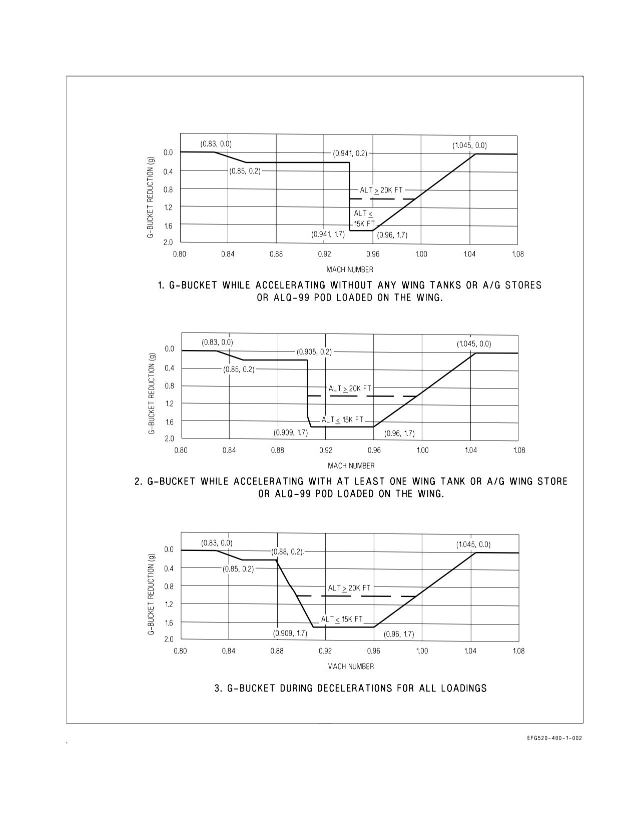
A1-E18GA-NFM-000
Figure 2-22. G-Limiter G-Bucket Reductions in Maximum Commandable G-Level
I-2-70
ORIGINAL
A1-E18GA-NFM-000
The Mach range for the deeper part of the g-bucket is dependent on external stores configuration.
The deeper part of the g-bucket is entered at 0.905 Mach accelerating with at least one wing tank, A/G
store, or ALQ-99 pod loaded on the wing or at 0.941 Mach accelerating without any tanks, A/G stores,
or ALQ-99 pods loaded on the wing. Regardless of stores loading, when decelerating, the g-bucket is
entered at 1.045 Mach and is exited at 0.83 Mach.
Full stick roll (FSR) limits are reduced in the g-bucket to 80% of (Nz REF minus no more than a
1.0g reduction). For example, if Nz REF is +7.5g, Mach is 0.95, and altitude is ≤15,000 feet, the
g-limiter sets the FSR limit to 80% of (Nz REF minus 1.0) even though the bucket depth is 1.7g.
If the pilot wants to have maximum-g available during a turning maneuver (e.g., the merge), or avoid
the deeper part of the g-bucket, Mach should be 0.905 or less with at least one tank, A/G store, or
ALQ-99 pod loaded on the wing, or 0.941 or less without any tanks, A/G stores, or ALQ-99 pods loaded
on the wing. Note that even though the 0.2g mini-g-bucket might be active, flight testing has shown the
g-level will be at or slightly above Nz REF.
2.10.7.5 G-Limiter Override. A g-limiter override feature can be enabled to allow a 33% increase in
the command g-limit for emergency use (allows a 10g command at 7.5g Nz REF). G-limiter override is
selected by momentarily pressing the paddle switch when the stick is near the full aft limit. When
g-limiter override is selected, a G-LIM OVRD caution is set along with a 927 MSP code. Override is not
disengaged until the stick is returned to near the neutral position.
2.10.7.6 Roll Rate Limiting. Roll rate limiting is enabled in R CAS when external wing tanks,
ALQ-99 pods, or A/G stores are mounted on wing pylons (hooks closed). If any A/G store indicates
HUNG, a R-LIM OFF caution is set and roll rate limiting is removed. In this case, higher than normal
roll rates are possible and may exceed the structural limitations of the airframe/pylons if pilot-imposed
lateral stick limits are not applied.
2.10.8 Air Data Function. The air data function is provided by the FCCs and not a separate
computer. The FCCs receive input from pitot-static sensors, total temperature sensors, the angle of
attack probes, the standby altimeter barometric setting, and the mission computers. The FCC air data
function applies appropriate source error corrections to the air data sensor inputs and calculates
accurate true altitude, airspeed, Mach number, AOA, and outside air temperature (OAT). Computed
air data is used internally by the FCC control augmentation system (CAS) and is also supplied to the
MCs for IFF altitude reporting, weapon system calculations, and landing gear wheels warning, to the
FADECs for engine control, and to the ECS controller for ECS scheduling and fuel tank pressurization
and vent.
2.10.8.1 Pitot-Static/Total Temperature Probes. Two combined pitot-static/total temperature
probes are mounted on the left and right forward fuselage. Each probe contains one pitot pressure
source, two static pressure sources, and a total temperature sensor. One of the static pressure sources
from each probe is connected together and pneumatically averaged. This average static source is
provided to the left and right pressure transmitter sets along with the corresponding pitot pressure
source. The left pressure transmitter set provides pitot-static input to FCC CH 1 and 4 with the right
providing input to FCC CH 2 and 3. The FCC air data function corrects sensed pitot and static
pressures for position error to provide accurate true air data for FCC calculations, MC calculations, and
display in the HUD. The pitot pressure source and the second static pressure source from the left probe
are used to drive the standby flight instruments (altitude, airspeed, and VSI). The second static
pressure source from the right probe is unused.
Each pitot-static probe also contains an integral total temperature sensor. Each total temperature
sensor converts sensed temperature to an electrical signal. The output of the left total temperature
I-2-71
ORIGINAL
A1-E18GA-NFM-000
sensor is sent to FCC CH 2, with the right to FCC CH 4. The FCCs use total temperature to calculate
OAT. Each pitot-static/total temperature probe is electrically heated to prevent icing.
2.10.8.2 AOA Probes. Two AOA probes are mounted on the left and right forward fuselage. Each
probe mechanically measures local AOA by aligning with the airstream. An integral AOA transmitter
set converts the mechanical input to a two-channel electrical signal which is sent to the FCCs. The left
AOA transmitter set provides input to FCC CH 1 and 4 with the right to FCC CH 2 and 3. The FCC
air data function corrects the sensed local AOA to a true AOA and provides the output to the MC for
display on the HUD. FCS CH 4 supplies the AOA signal which drives the AOA indexer lights and the
approach lights.
It is possible to damage and jam an AOA probe such that it continues to send signals to the FCCs.
FCC software is designed to minimize flying qualities degradation in the event of a stuck/jammed AOA
probe. The FCCs incorporate an AOA estimator which is used to identify the good AOA probe if one
is damaged. If an AOA probe split is transient, the estimator is used to identify the good probe and no
cautions are set. If the AOA probe split persists, an FCS caution is set, AOA is Xd in all four channels,
and the estimator is used for FCC calculations. See the HUD Symbology Degrades with Air Data
Function Failure paragraph and Part V for more details on AOA failures. Each AOA probe and AOA
probe cover are electrically heated to prevent icing.
2.10.8.3 PITOT ANTI ICE Switch. The PITOT ANTI ICE switch is located on the ECS panel on the
right console. This switch is used to power the electric heaters for the pitot-static/total temperature
probes, the AOA probes, and the AOA probe covers. All heaters are thermostatically controlled to
prevent damage to their corresponding sensors. With WonW, the thermostat set points are reduced to
prevent damage when cooling airflow is not provided.
ON
Pitot and AOA heaters on manually (WonW or WoffW).
AUTO
Pitot and AOA heaters on automatically with WoffW. Heaters off with WonW.
Failure of both AOA probe heaters in icing conditions may cause a sharp
uncommanded nose-down attitude, uncontrollable by normal stick forces
or paddle switch actuation.
2.10.9 Flight Controls.
2.10.9.1 Stick. A traditional center mounted control stick is used to provide pitch and roll inputs to
the FCS. Since there is no mechanical linkage between the stick and the FCCs or the flight control
surfaces, stick feel is provided by two feel-spring assemblies and two eddy current dampers. The feel
spring assemblies provide a linear stick force versus stick displacement gradient in each axis. Two
4-channel position sensors, one in each axis, measure stick displacement and send longitudinal and
lateral stick commands to the FCCs proportional to stick displacement. Stick force and displacement
are listed in figure 2-23 for full stick travel. The eddy current dampers provide stick motion damping
in each axis. Additionally, the control stick is mass balanced to minimize longitudinal stick movement
resulting from accelerations normally experienced during catapult launch.
I-2-72
ORIGINAL
A1-E18GA-NFM-000
Displacement Force
Flight Control
Direction
(in)
(lbs)
Forward
2.5
20
Stick
Aft
5.0
37
Left/Right
3.0
13
Pedal
Left/Right
1.0
100
Figure 2-23. Stick and Pedal Travel Limits
2.10.9.2 Rudder Pedals. Two rudder pedals (left and right) are used to provide directional inputs to
the FCS for yaw/roll control inflight or NWS control with WonW. Since there is no mechanical linkage
between the rudder pedals and the FCCs or the flight control surfaces, rudder pedal feel is provided
by two feel-spring assemblies. The feel spring assemblies provide a linear pedal force versus
displacement gradient. Two 4-channel position sensors, one on each pedal, measure pedal displace-
ment and send directional commands to the FCCs proportional to pedal displacement. Rudder force
and displacement are listed in figure 2-23 for full pedal travel. The rudder pedals are also used to
provide NWS commands and to actuate toe-operated wheel brakes.
2.10.9.2.1 RUD PED ADJ Lever. A RUD PED ADJ lever, located on the center pedestal in each
cockpit, is spring loaded to the up and locked position. When the lever is held down, the rudder pedals
are unlocked and can be moved forward and aft in ½ inch increments. Both pedals are spring loaded
to move aft and must be pushed forward to the desired position. Releasing the RUD PED ADJ lever
locks the pedals in the new position.
• Restrain the rudder pedals during adjustment. Unrestrained rudder
pedals may damage the rudder pedal mechanism.
• Ensure the rudder pedals are locked in position after adjustment.
Failure to lock the rudder pedals may result in uncommanded forward
rudder pedal movement inflight.
2.10.9.3 Stick Grip FCS Controls. The FCS controls located on the stick grip include the pitch and
roll trim switch, the NWS button, and the autopilot/NWS disengage switch. See figure 2-24.
I-2-73
ORIGINAL
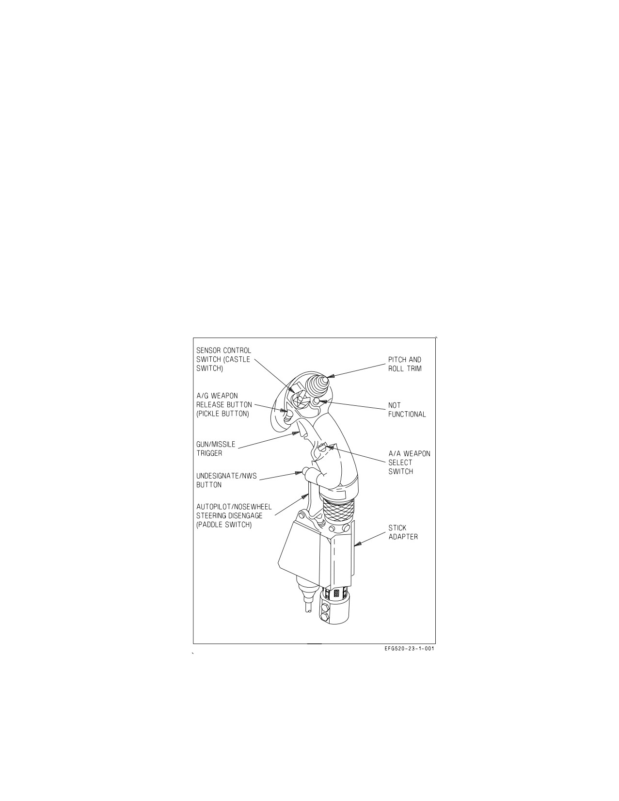
A1-E18GA-NFM-000
2.10.9.3.1 Pitch and Roll Trim Switch. The pitch and roll trim switch is located on the top right of
the stick grip. Movement of the pitch and roll trim switch electrically biases the FCCs and does not
reposition the stick.
Forward
Trims nose-down.
Aft
Trims nose-up.
Left
Trims left-wing-down.
Right
Trims right-wing-down.
Pitch and roll trim inputs can be made incrementally or held for faster trim rates. With flaps AUTO,
little if any pitch trim is required due to the automatic trimming function provided by P CAS. With
flaps HALF or FULL, pitch trim is required to trim for on-speed AOA. Lateral trim is typically only
required immediately after takeoff or following changes in lateral weight asymmetry (fuel and/or
stores). Pitch trim is not monitored for runaway trim. However, roll trim is monitored for a stuck
switch. If the trim switch is held or is stuck in the left or right position for more than 40 seconds, the
FCS caution is set and the roll trim function of the switch is disabled for the remainder of the flight.
Roll trim can be faded to zero by pushing and holding the FCS RESET button or TO/TRIM button
for approximately 4 seconds.
Figure 2-24. Stick Grip FCS Controls
2.10.9.3.2 NWS Button. The undesignate/nosewheel steering button is located on the front of the
stick grip. The NWS button is used to engage NWS modes, as described in the NWS System
paragraphs in the Utility Hydraulic Functions section. The undesignate function of the NWS button
is described in the Weapon Systems Controls section.
I-2-74
ORIGINAL
A1-E18GA-NFM-000
2.10.9.3.3 Paddle Switch. The autopilot/NWS disengage switch, commonly called the ″paddle
switch,″ is located on the lower front of the stick grip. The paddle switch is used to disengage NWS with
WonW, to disengage all autopilot modes with WoffW, and to enable g-limiter override with WoffW. To
enable g-limiter override, the paddle switch must be momentarily pressed with the stick near the aft
limit.
2.10.9.4 RUD TRIM Knob. The RUD TRIM knob is located on the FCS panel on the left console in
the front cockpit only. Movement of the RUD TRIM knob electrically biases the FCCs and does not
reposition the rudder pedals. Rudder trim authority is ±10° and ±22.5° of rudder surface deflection
with flaps AUTO and with flaps HALF or FULL, respectively. With flaps HALF or FULL, rudder trim
authority is set to allow zero pedal forces during a HALF flap, single engine approach. Yaw trim is
zeroed by mechanically centering the RUD TRIM knob when the T/O TRIM button is pushed with
either WonW or WoffW.
2.10.9.5 T/O TRIM Button. The T/O trim button is located in the center of the RUD TRIM knob on
the FCS panel on the left console. With WonW, holding the T/O TRIM button pressed drives pitch
trim to 4° TEU stabilator, roll trim to neutral, and yaw trim to neutral by mechanically centering the
RUD TRIM knob. Depending on initial trim position the T/O TRIM button may need to be pressed
for up to 4 seconds. When these takeoff trim settings are reached, the TRIM advisory is displayed on
the LDDI for as long as the T/O TRIM button is held depressed. With WoffW, pressing the T/O TRIM
button for as long as 4 seconds drives roll trim to neutral, centers the RUD TRIM knob, but does not
affect pitch trim.
2.10.10 Yaw Rate Warning Tone. With flaps AUTO (flaps AUTO), a yaw rate warning tone is
provided to alert the pilot of excessive yaw rate that may lead to an aircraft departure. The yaw rate
warning tone is generated by the FCCs and is initiated at 40°/second yaw rate with a 1 Hz pulse rate.
The tone pulse rate increases linearly as yaw rate approaches 60°/second, where the pulse rate remains
constant at 10 Hz. There is no yaw rate warning tone with flaps HALF or FULL.
2.10.11 AOA Warning Tone. An AOA warning tone is provided to alert the pilot of excessive AOA
that may lead to aircraft settle and/or departure.
With flaps HALF or FULL, the AOA warning tone is triggered at 14° AOA with a 1 Hz pulse rate.
The tone pulse rate increases linearly as AOA approaches 35°, where the pulse rate remains constant
at 10 Hz.
With flaps AUTO, the AOA warning tone is triggered when the AOA limits corresponding to the
FLY lateral weight asymmetry are exceeded. A 500 ft-lb buffer is applied to the lateral weight
asymmetry threshold when triggering the tone to account for fuel slosh. If there is an AOA failure, or
more than one fuel quantity is invalid and/or weapon station indicates HUNG on stations 2 − 10 (FLY
value removed), the tone will not be triggered and the AOA TONE caution will be displayed.
2.10.12 Spin Recovery System. The aircraft incorporates an automatic spin detection and recovery
system. A spin is declared when both of the following conditions are met: (1) airspeed is below
approximately 120 ±15 KCAS and (2) the yaw rate threshold is exceeded. The yaw rate threshold is
exceeded, for example, if a 15 to 20°/second yaw rate persists for approximately 15 seconds or a 50 to
60°/second yaw rate persists for approximately 2 seconds. For cases where the pilot is intentionally
I-2-75
ORIGINAL
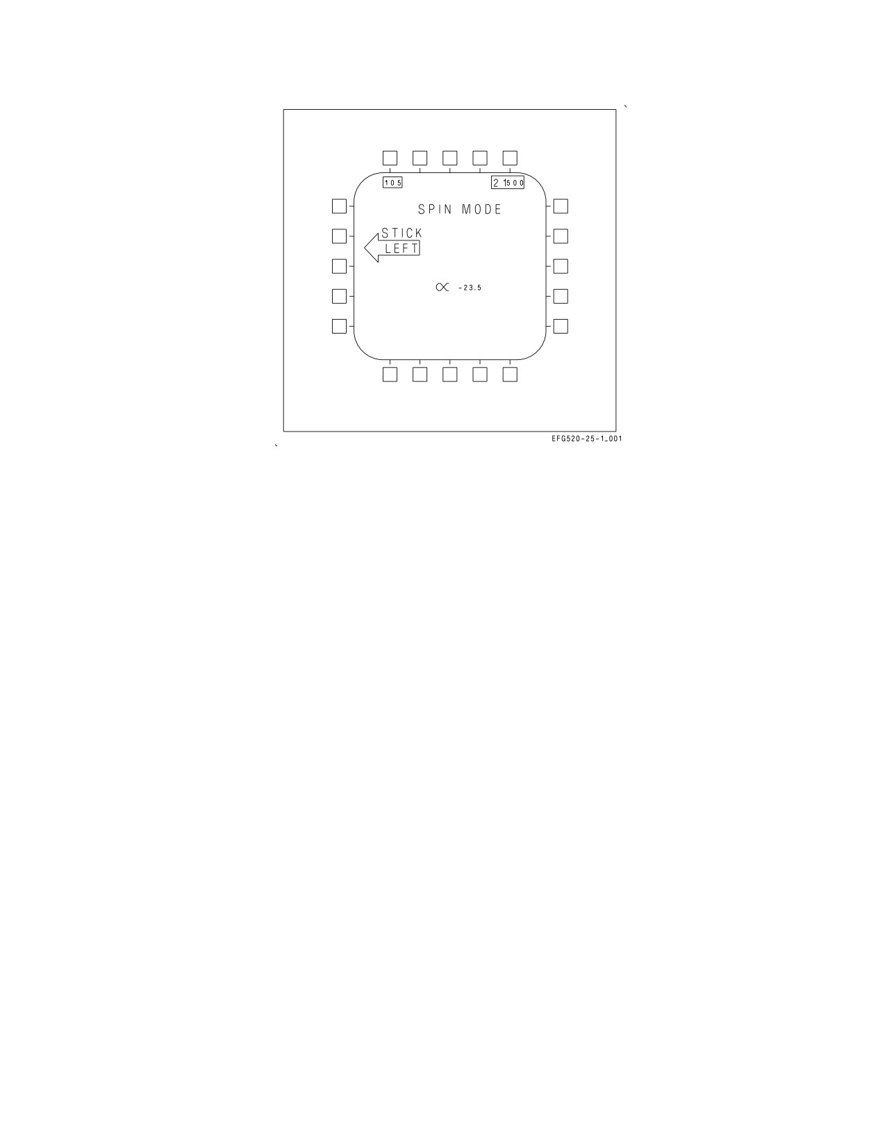
A1-E18GA-NFM-000
Figure 2-25. SPIN Recovery Display
commanding a high AOA roll (e.g., pirouette) the yaw rate threshold persistence is increased from 15
seconds to 25 seconds.
Immediately following a low-speed maneuver less than 77 KCAS (e.g., tail-slide), airspeed limits for
SPIN logic are opened to 180 KCAS or 12 seconds, whichever comes first. During this time, the normal
acceleration feedback gain is removed to avoid excess coupling, and spin mode arrows will be displayed
to aid recovery if yaw rate exceeds the threshold.
Once a spin has been detected, the spin recovery system places the SPIN MODE recovery displays
on both DDIs (figure 2-25), illuminates the amber FLAPS light, and drives the LEFs to 34° LED and
the TEFs to 4° TED. The displayed spin recovery arrow always indicates the proper direction for
anti-spin lateral stick inputs whether the spin is upright or inverted. Anti-spin lateral stick inputs are
aileron-into for upright spins and aileron-opposite for inverted spins. When lateral stick is placed with
the arrow, automatic spin recovery mode (ASRM) is engaged. With ASRM engaged, all CAS feedback
and control surface interconnects are removed, providing full aileron, rudder, and stabilator authority
for spin recovery. If the stick is neutral or is moved in the wrong direction, the SPIN MODE formats
remain displayed, the LEFs and TEFs remain deflected, but the FCS remains in CAS, and ASRM is
not engaged.
If ASRM is engaged during spin recovery, the spin arrow is removed and the FCS automatically
reverts to CAS when either of the following conditions are met: (1) airspeed is above approximately 245
KCAS or (2) the yaw rate threshold is no longer exceeded. After recovery, LEFs and TEFs return to
normal scheduling, and the SPIN MODE formats are replaced with the MENU page after 2 seconds.
NOTE
During highly oscillatory spins or spins that transition from upright to
inverted or from inverted to upright, the SPIN MODE displays may
disappear momentarily.
I-2-76
ORIGINAL