F-14D. FLIGHT MANUAL (2004) - page 12
NAVAIR 01−F14AAD−1
PARAMETER
RANGES
REMARKS
5
ALMANAC
GO
The status of the MDL almanac data available to the MAGR.
NO DATA
GO indicates that the valid MDL almanac data is available. All
MDL NOT READY
other conditions indicate that valid almanac data is unavailable.
MDL FAIL
NO DATA indicates that almanac data is not present on the MDL or
is more than one month old. MDL NOT READY indicates that
there is either no data bus communication or no cartridge in the
MDL. MDL FAIL indicates that an MDL failure is preventing access
to almanac data.
Note
If valid almanac data is not available, either within MAGR memory
or on the MDL, the MAGR will initiate a cold start sky search for
visible satellites. Search and acquisition may take over 20 minutes.
Once satellites are received, the MAGR will extract the Almanac
from the GPS navigation message and store it in volatile memory
for future use.
6
ZTOD
HH:MM:SS
In NAVIGATE mode, indicates Zulu Time of Day. In the INITIALIZE
mode, momentarily indicates the time of MAGR initialization. A
blank field is displayed if no valid time is
available.
7
DATE
MM/DD/YY
In the NAVIGATE mode, indicates the current date. MM/DD/YY
is displayed if no valid date is available or the MAGR is not in
NAVIGATE mode.
8
DATA (PB 1)
Returns the OWN A/C Basic format with DEU slaved for Own A/C
data entry.
9
NAV (PB 2)
Returns the Navigation format.
10
RCV TOD
Depressing RCV TOD pushtile provides time to the ARC−182
(PB 3)
Have Quick II" radios.
11
PWR (PB 4)
Selecting PWR pushtile toggles MAGR power ON or OFF.
Default is power on.
12
CRYPTO KEY
VERIFIED
The status of the GPS crypto keys. VERIFIED indicates that the
UNVERIFIED
loaded key matches that used by the satellites. UNVERIFIED
INCORRECT
indicates that the loaded key has not yet been verified through
PARITY ERROR
comparison with the satellites. INCORRECT indicates that the
NO KEYS
loaded key is incorrect. PARITY ERROR indicates that the
[BLANK]
MAGR detected a parity error in the loaded key ć the key should
be reloaded. NO KEYS indicates that no key is loaded. The crypto
key is BLANK until NAVIGATE mode is entered.
Figure 20−11. GPS Status Format (Sheet 2 of 3)
20−25
ORIGINAL
NAVAIR 01−F14AAD−1
PARAMETER
RANGES
REMARKS
13
SATELLITES
0, 1, 2, 3, 4
The number of satellites being tracked with maximum available
precision. Four satellites are normally needed for navigation. If
altitude is available from the MCS, a three satellite solution will
provide horizontal position and velocities.
14
RECEPTION
GOOD
GOOD indicates clear GPS reception of four satellites.
DEGRADE
DEGRADE indicates partial track of at least one satellite.
[BLANK]
If degraded reception persists, MAGR FOM and estimated
Horizontal and Vertical GPS position errors will increase. The
RECEPTION field is blank if the MAGR is not in NAVIGATE
mode.
15
FOM
9 to 1
MAGR Figure of Merit. FOM is a numerical indicator of receiver
accuracy and system integrity. It should not be used for decisions
concerning position accuracy (use the Horizontal and Vertical
Error estimates on the Own A/C format). FOM is based on a
number of factors that contribute to the overall system including,
and tends to be conservative with regard to system accuracy:
D MAGR receiver state (e.g., code tracking, carrier
tracking, acquisition, etc.)
D Carrier to noise ratio
D Satellite geometry (GDOP)
D Satellite range accuracy
D Ionospheric measurement or modeling error
D MAGR aiding
D MAGR Position Error estimates
16
MODE
TEST
With PWR ON, TEST appears for about 30 seconds as the
INITIALIZE
MAGR self−test is run (provided MAGR was off for at least 30
NAVIGATE
seconds). INITIALIZE then appears for about five seconds, then
[BLANK]
NAVIGATE appears. With PWR OFF, this field is BLANK.
Note
When a commanded BIT is run from the OBC NAV format,
TEST will appear for up to 3 minutes during the Initiated BIT.
17
JTOD XFER
Enables synchronization of JTIDS using GPS time. Available
only when JTIDS is operational and GPS is in NAVIGATE".
Note: 1. The battery is used to maintain GPS Almanac and Crypto Keys in volatile memory when the primary
power is off.
Figure 20−11.ăGPS Status Format (Sheet 3 of 3)
ORIGINAL
20−26
NAVAIR 01−F14AAD−1
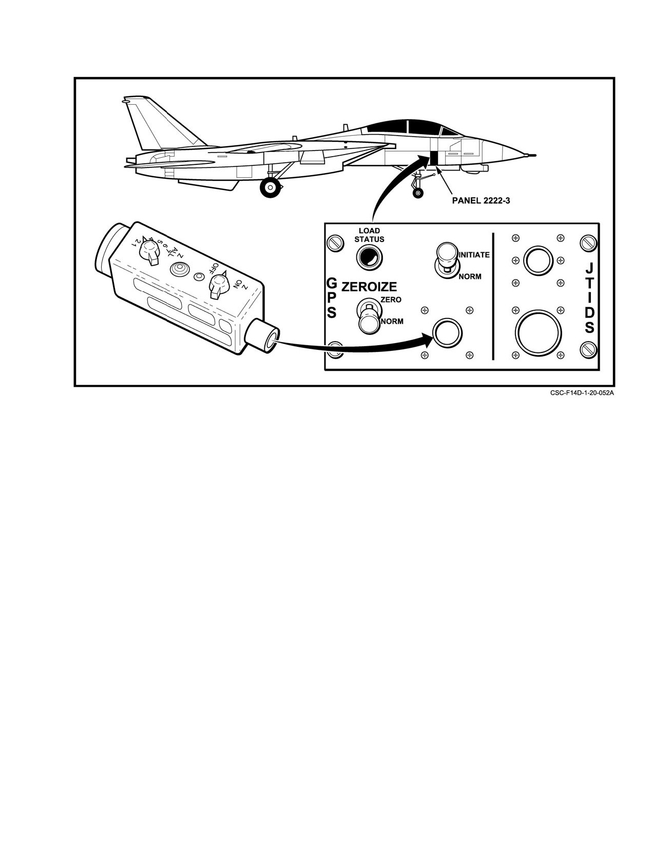
Figure 20Ć12.ĄCrypto Loading Panel Location
20.3.1.3
GPS Crypto Keys
overridden by manual aircrew selections. Navigation sensors
used are listed in the lower center legend of the NAV (NaviĆ
The MAGR crypto key is loaded by maintenance
gation) System Aid format (see Figure 20Ć14). With a fully
personnel via the Crypto Load Panel on the right−hand side
operational system, this legend should read INS/GPS".
of the aircraft (Figure 20−12). The required codes are changed
daily, but multiple codes may be loaded into the MAGR at
Manual selections are made via the INS, SAHR, and
one time. If the codes do not match the keys in the satellite,
GPS legends on the OWN A/C or NAV System Aid format.
the MAGR will still operate, but in SPS mode only.
Manual selection of INS or SAHRS is indicated by an M"
on the OWN A/C or NAV System Aid format, adjacent to the
20.3.2
Navigation Modes
sensor legends. The absence of an M" indicates automatic
mode selection is available. Normally INS will be automatĆ
The navigation system can operate in four basic states
ically selected. Automatic deselection of GPS is indicated by
(primary, secondary, tertiary and backup), depending on the
a dash−boxed GPS legend on the OWN A/C or NAV System
selection of navigation sensors. A summary of these states
Aid formats (Figure 20Ć8 and Figure 20Ć14), indicating that
and the navigation sensor data used for the various modes is
automatic reselection is available. The inability to box a
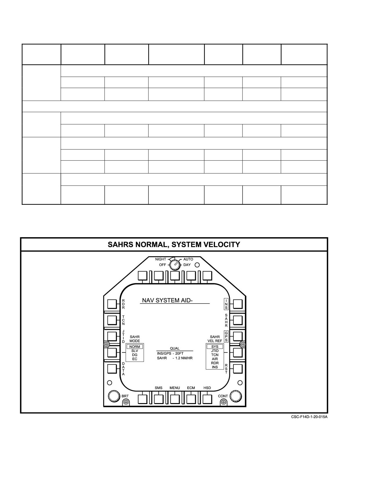
provided in Figure 20−13. The primary mode couples the
legend corresponding to a specific navigation sensor
MAGR and the INS to derive an extremely accurate naviĆ
indicates that the sensor is unavailable for selection.
gation solution. In all other modes, if GPS information is
available, it is used directly to update the NSV position in the
Note
MCS due to its inherent accuracy. Navigation State Vector
velocity and heading are updated by INS, SAHRS, GPS, or
D During aircraft start, GPS should automatiĆ
cally box once a FOM of 4 is achieved. GPS
external sources, in order of priority. Either the INS or
will be boxed (dashed) on start up.
SAHRS provides attitude, accelerations, and angular rates
for NSV computations. In all modes, the functions and
D If the MAGR degrades to a FOM of 8 or 9, it
outputs normally provided by the navigation system are
will declare its output invalid to the MCS,
made available to the maximum extent possible.
resulting in automatic deselection of GPS
(dashed box) and downgrading of the
The navigation system automatically selects the best
navigation mode.
operating mode based on available sensors, unless
20−27
ORIGINAL
NAVAIR 01−F14AAD−1
MODE
HSD
NAV MODE
OWN AC
POSITION
VELOCITY
ATTITUDE
SWITCH
DATA PAGE
SOURCE
SOURCE
SOURCE
Primary
Provides superior navigation under all flight conditions.
INS/GPS
lFA
INS & GPS boxed
INS
INS
INS
INS*
INS
INS boxed
INS
INS
INS
*For non−GPS equipped aircraft or GPS powered off or unboxed.
Secondary
Provides satisfactory navigation in maneuvering flight
GPS/INS
INS
INS & GPS boxed
GPS
INS
INS
Tertiary
Provides adequate navigation in non−maneuvering flight.
GPS/SAHRS
Ċ
GPS boxed
GPS
SAHRS
SAHRS
GPS/IMU
ATT
GPS boxed
GPS
IMU
IMU
Backup
Provides marginal navigation for emergency purposes. Heading based on GPS N & E Velocity.
GPS
OFF
GPS boxed
GPS
GPS
NA
Figure 20Ć13.ĄNavigation Modes and Navigation Sensor Data
Figure 20Ć14.ĄNAV System Aid Format
ORIGINAL
20−28
NAVAIR 01−F14AAD−1
20.3.2.1
Primary Navigation
updates, and an ALIGN SUSPENDED computer message
will be displayed. However, INS information will continue
20.3.2.1.1
INS/GPS Mode Operation
to be sent to the MAGR for GPS aiding. If the MAGR
sufficiently recovers for at least 8 seconds, INS/GPS mode
INS/GPS mode is the primary navigation mode. This
will be reselected automatically, provided the NAV MODE
mode is the default selection when the system achieves an
switch remains in the IFA position.
alignment with the NAV MODE switch in IFA (In Flight
Alignment) with valid GPS information available. This is
Whenever INS/GPS mode is available but not selected,
the recommended mode when all systems are operating
GPS/INS mode will be displayed on the OWN A/C page as
normally, as it provides the most accurate navigation solution
the current NAV mode. This will occur if the INS has
available. In this mode, the INS uses GPS horizontal position
completed alignment and the MAGR is in NAVIGATE mode
and velocity information, combining it with its own naviĆ
and is boxed but INS, vice IFA, is selected using the NAV
gation solution for the best combination of the two. INS/GPS
MODE switch.
mode horizontal position accuracy typically is within 20 feet
when the MAGR has achieved a FOM of 1, and remains
In flight, if IFA is selected on the NAV MODE switch,
extremely stable during dynamic maneuvering flight.
but the MAGR is not available or deselected, the INS will
align to the external velocity reference source selected on
In INS/GPS mode, the INS horizontal channel is
the IFA format, with considerably reduced quality
(see
continually updated using GPS information. The MAGR
paragraph 20.3.2.3).
provides GPS position, velocity, and quality data directly to
the INS, bypassing the MCS. The INS uses GPS information
20.3.2.1.3
SAHRS Velocity Referencing
in its Kalman filter to correct and optimize its own horizontal
navigation solution, which is then sent to the MCS for
Once the SAHRS is aligned, it generates its own
Navigation State Vector (NSV) computations. GPS inforĆ
velocity outputs similar to the INS. However, SAHRS
mation is not used directly for NSV updates. In turn, the INS
velocities are not as accurate as INS velocities, with errors in
provides its own position and velocity coordinates to the
each axis ranging between 5 and 10 feet per second. FurtherĆ
MAGR, which allows it to extrapolate aircraft and satellite
more, these errors are subject to additional drift over time.
positions more accurately during maneuvering flight,
Poor SAHRS alignment and/or performance will cause the
antenna masking, signal dropouts, and jamming. NSV
NSV attitude and heading and SAHRS velocities to degrade
attitude and heading are provided directly by the INS.
quickly. An indication of poor SAHRS performance may be
the appearance of an ATTITUDE, VELOCITY or
During INS/GPS operations on deck, the parking brake
POSITION CAW (Caution/Advisory/Warning).
may be released and the aircraft taxied without interrupting
an alignment in progress. In flight, an alignment can be
SAHRS performance is improved by referencing it to
accomplished with align quality similar to that possible with
a velocity source external to the SAHRS. However, GPS is
a ground alignment. The only restriction is that the aircraft
unavailable as an external velocity reference source.
should not be maneuvered in a manner that masks the GPS
Although NSV velocities may be modified with available
antenna from available satellites for more than a few seconds
GPS information within the MCS, the SAHRS itself does not
early in the alignment.
couple with nor is it directly aided by the MAGR. By default,
if no external velocity source is selected, SAHRS will use its
Because of the high degree of position accuracy in the
own inertially derived velocity.
INS/GPS mode, one−fix INS position updates are
unavailable.
Note
20.3.2.1.2
INS/GPS Mode Selection
D A SAHRS external velocity reference source
should always be selected, even when a good
The INS/GPS mode is entered when the INS and GPS
INS alignment has been achieved and the INS
legends are automatically selected (boxed) on the OWN A/C
is known to be operating satisfactorily.
or NAV System Aid format, and IFA is selected on the NAV
D After a system reset, SAHRS velocity
MODE switch. Selection of this mode is verified with the
reference becomes unboxed. Reselection of a
display of INS/GPS" on the lower left of the HSD format,
SAHRS velocity reference following a
OWN A/C format, and NAV System Aid format.
system reset is highly recommended to
maintain the best possible SAHRS navigation
If a GPS QUAL CAW is posted, the INS/GPS mode
solution in case of degraded navigation mode
will be automatically deselected after a 30−second delay. The
operation.
INS will then operate in its inertial mode without GPS
20−29
ORIGINAL
NAVAIR 01−F14AAD−1
Available external velocity sources are selected by
output invalid to the MCS (FOM > 7), GPS/INS mode will be
depressing SAHR VEL REF on the NAV System Aid format.
automatically deselected and the boxed GPS legend on the
The listed sources are:
OWN A/C or NAV System Aid format will appear dashed.
The navigation system will then operate in the inertial−only
INS mode (see paragraph 20.3.2.2). If the MAGR recovers to
SAHRS VELOCITY SOURCES
FOM ≤ 7, GPS/INS mode will be reselected automatically,
SYS
System NSV velocity, computed using all valid
provided that GPS was not deselected manually.
velocity sources. SYS is recommended if GPS
is selected, since it is the only source that
20.3.2.2.2
INS Mode
includes GPS information
TCN
TACAN−relative computed velocity
The INS mode provides the most accurate navigation
solution if GPS information is unavailable, and is the default
JTID
JTIDS computed velocity.
non−GPS navigation mode. INS mode operation is the same
AIR
True airspeed, computed by the SCADC and
as that in previous F−14D configurations without GPS, with
compensated for winds.
a performance typically within 1 nm per hour. Navigation
State Vector updates are derived from weighted mixes of INS
RDR
Radar−relative computed velocity.
and SAHRS inputs.
INS
INS inertial velocity. If GPS is not selected,
INS provides the best reference velocity.
The INS mode is entered at the completion of an INS
alignment when the NAV MODE switch is placed in INS, or
automatically if the aircraft becomes airborne and the NAV
MODE switch is still in an align position, provided sufficient
20.3.2.2
Secondary Navigation
alignment quality has been achieved. Selection of this mode
is verified with the display of INS" on the lower left of the
20.3.2.2.1
GPS/INS Mode
HSD format.
GPS/INS is the next best mode. GPS/INS is selected
Note
with the NAV MODE switch in INS after achieving a comĆ
plete alignment, and then boxing GPS. This mode does the
Selection of INS on the NAV MODE switch with
filtering of GPS with INS information in the MC. The main
a displayed alignment quality of 5.0 or higher
difference between GPS/INS and INS/GPS is that in the latĆ
will result in entry into the IMU
(Inertial
ter, the velocities input to the NSV are more accurate and the
Measurement Unit) mode
(see paragraph
INS is continuously updated by the MAGR. Good long−term
20.3.2.4.2).
navigation performance may be expected in GPS/INS. HowĆ
ever, dynamic response will not be as precise as with the
20.3.2.2.3
INS Velocity−Aided IFA Mode
prime INS/GPS mode, and with extensive dynamic maneuĆ
vering this accuracy will degrade. Navigation accuracy in
The INS Velocity−Aided IFA mode aligns the INS in
GPS/INS mode is nevertheless superior to an inertial−only
flight without GPS velocity or position information, using a
mode.
selectable external velocity reference source. Since INS IFA
mode uses the current system position information, a one−fix
In GPS/INS mode, the NSV position is derived directly
position update is recommended before selecting INS IFA
from GPS information. Navigation State Vector velocity, attiĆ
mode.
tude, and heading are provided directly by the INS. There is
no direct transfer of data between the INS and the MAGR.
GPS/INS mode is entered when INS and GPS are
selected on the OWN A/C or NAV System Aid format, and
the NAV MODE switch is placed in INS. Selection of this
INS performance following a non−GPS in−flight
mode is verified with the display of GPS/INS" on the lower
alignment depends on the accuracy of the
left of the HSD format. These conditions will also generate
selected velocity reference source. Therefore,
an IFA AVAILABLE computer message.
INS IFA mode is recommended only if mission
accomplishment is otherwise jeopardized.
If the MAGR FOM increases, the MCS will continue
to use GPS position information. If the MAGR declares its
ORIGINAL
20−30
NAVAIR 01−F14AAD−1
Available external velocity sources are JTID, SYS, and
5. Place the NAV MODE switch to INS when the INS
AIR. The preferred velocity sources, in order of priority, are:
ALGN CMPLT computer message is displayed, or
if the aircraft is to be maneuvered dynamically.
EXTERNAL VELOCITY SOURCES
Note
JTID
JTIDS information, available to the MCS
only when operating in a JTIDS network.
Because of the extensive time required for an
INS lEA with quality JTIDS information
INS IFA (up to 35 minutes), the NAV MODE
typically requires 12 to 15 minutes. The
switch may be placed to INS before the INS
quality of a JTIDS INS lEA will increase
ALGN CMPLT message is displayed. Either
with the number of JTIDS participants.
the INS mode or IMU mode will be selected
automatically, depending on the quality of the
SYS
System velocity represents a weighted
alignment when INS is selected on the NAV
mix of all available velocity sources. It is
MODE switch.
subject to errors in any of the involved
velocity sources.
6. Verify the navigation mode legend on the lower left
AIR
Air data provided by the SCADC.
of the HSD format.
Accuracy depends on that of the computed
or entered winds. Because of the potential
Note
for poor accuracy, the INS ALGN CMPLT
Selection of INS on the NAV MODE switch
computer message may never be
with a displayed alignment quality of 5.0 or
displayed. AIR should be selected only
higher will result in entry into the IMU mode
as a last choice and only when the INS
(see paragraph 20.3.2.4.2).
is degraded enough to prevent mission
accomplishment. This takes up to
20.3.2.3
Tertiary Navigation
35 minutes.
20.3.2.3.1
GPS/SAHRS Mode
The INS IFA mode is entered if INS is selected on
The GPS/SAHRS mode provides reasonable navigaĆ
the OWN A/C or NAV System Aid format, the NAV
tion in non−maneuvering flight due primarily to the use of
MODE switch is placed in IFA, and GPS is not available.
GPS position information. However, it is not as accurate as
In INS IFA mode, INS" is displayed on lower left of the HSD
the primary or secondary navigation modes, and substantial
format, so selection of this mode must be verified by
errors may accrue during extended maneuvering flight using
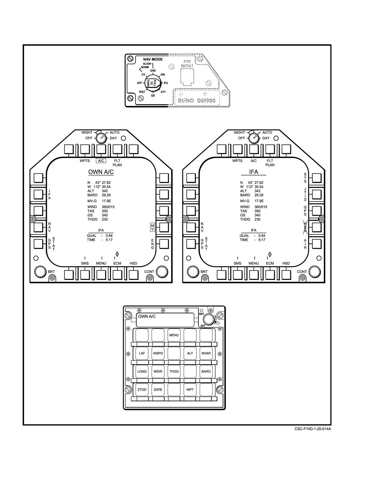
referencing the IFA format. See Figure 20Ć15. Specific INS
SAHRS inputs.
IFA procedures are:
In GPS/SAHRS mode, there is no direct transfer of
1. From the OWN A/C format, select SAHR as a valid
information between the MAGR and the SAHRS. NSV
source of true heading. If reasonable SAHRS
position is derived directly from GPS information, and
heading information is not available, then enter the
NSV velocities, attitude, and heading information are
best estimated true heading from the DEU OWN
derived from SAHRS.
A/C format.
The GPS/SAHRS mode is entered when GPS and
2. Select IFA on the NAV MODE switch. The IFA
SAHR are selected on the OWN A/C or NAV System Aid
format will appear.
format. Selection of this mode is verified with the display of
GPS/SAHRS" on the lower left of the HSD format.
Note
If the MAGR FOM increases, the MCS will continue
To ensure good initial alignment, straight and
to use GPS position information. If the MAGR declares its
level flight should be maintained from 1 to 5
output invalid to the MCS (FOM > 7), then GPS/SAHRS
minutes after IFA is selected on the NAV
mode will be automatically deselected and the boxed GPS
MODE switch.
legend on the OWN A/C or NAV System Aid format will
appear dashed. The navigation system will then operate in the
3. From the IFA format, select a velocity source from
inertial−only SAHRS mode (see paragraph 20.3.2.3.3). If the
JTID, SYS, or AIR selections.
MAGR recovers to FOM ≤7, GPS/SAHRS mode will be
reselected automatically, provided that GPS was not
4. Observe the alignment progress on the IFA format.
deselected manually.
20−31
ORIGINAL
NAVAIR 01−F14AAD−1
Figure 20Ć15.ĄINS In−Flight Align Formats
ORIGINAL
20−32
NAVAIR 01−F14AAD−1
20.3.2.3.2
GPS/IMU Mode
If the MAGR FOM increases, the MCS will continue
to use GPS position information. If the MAGR declares its
The GPS/IMU mode provides reasonable navigation in
output invalid to the MCS (FOM > 7), GPS/IMU mode will
non−maneuvering flight due primarily to the use of GPS
be automatically deselected and the boxed GPS legend
position information. However, substantial errors will accrue
(PB 13) on the OWN AC or NAV System Aid format will
during extended maneuvering flight.
appear dashed. The navigation system will then operate in
the attitude−only IMU mode (see paragraph 20.3.2.4.2). If the
Navigation State Vector position is derived directly
MAGR recovers to FOM ≤7, GPS/IMU mode will be
from GPS information. If SAHRS velocity is valid, it is used.
reselected automatically, provided that GPS was not
If not, NSV velocity is derived by mixing GPS and other
deselected manually.
available system velocities, which could include JTIDS and
Air Data. Attitude and heading are derived from inertial
20.3.2.3.3
SAHRS Normal Mode
angles provided by the IMU.
The SAHRS Normal mode uses dynamic inputs sensed
The GPS/IMU mode is entered when INS and GPS are
by the SAHRS in its normal mode, with the same functionĆ
selected on the OWN A/C and NAV System Aid format, the
ality as INS mode. The Normal mode provides reasonable
SAHRS is unavailable, and the NAV MODE switch is placed
short−term inertial navigation. NSV position, velocity,
to ATT, or to INS with only the IMU sub−mode available.
attitude, and heading are updated directly by the SAHRS.
Availability of the IMU sub−mode of the INS is verified by
However, because of the reduced sensitivity and precision
the display of IMU" in the center legend of the NAV System
within the SAHRS, performance typically is between 2 and
Aid format, which depicts available sensors. Selection of this
10 nm per hour, depending upon the quality of the initial
mode is verified with the display of GPS/IMU" on the lower
SAHRS alignment.
left of the HSD format.
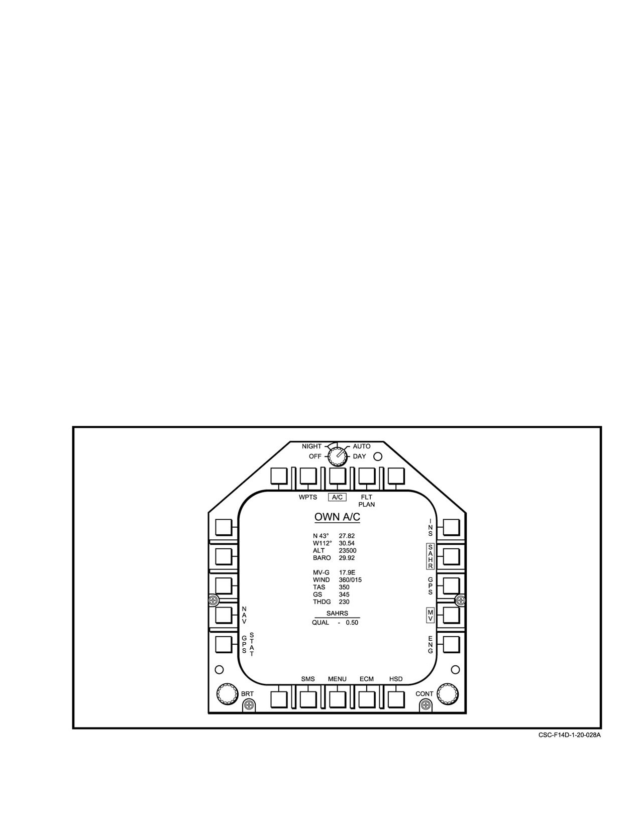
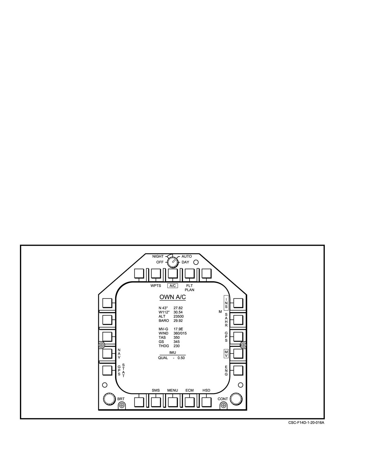
The SAHRS Normal mode is entered when SAHR (PB
Note
12) is selected as the sole navigation aid source on the OWN
If the INS degrades to the IMU sub−mode, the
A/C or NAV System Aid format (Figure 20Ć16). An M" will
be displayed adjacent to the SAHR legend if the selection is
SAHRS will be selected automatically for
manual, indicating that automatic sensor selection is not
navigation reference, if it is available. The IMU
available. Selection of this mode is verified with the display
will be selected if the SAHRS is not available.
of SAHRS" on the HSD format.
Figure 20Ć16.ĄSecondary Navigation Mode Manually Selected
20−33
ORIGINAL
NAVAIR 01−F14AAD−1
20.3.2.4
Backup Navigation
adjacent to the altitude display to alert the pilot that a backup
altitude source is selected.
20.3.2.4.1
GPS Mode
If the MAGR FOM increases, the MCS will continue
GPS mode provides minimal navigation information to
to use GPS position information. If the MAGR declares its
the aircrew, all of which is derived directly from MAGR
output invalid to the MCS (FOM >7), GPS mode will be
outputs and available external velocity reference sources.
automatically selected and the boxed GPS legend (PB 13) on
True airspeed and altitude, as computed by the SCADC, are
the OWN AC or NAV System Aid format will dash. All
sent continually to the MAGR to improve its dynamic
navigation information except available air data will be lost.
response. Due to the absence of aircraft−sensed inertial data
If the MAGR recovers to an FOM ≤ 7, GPS mode will be
to stabilize the MAGR, increased errors may be expected in
reselected automatically, provided that GPS was not
maneuvering flight or if L−band jamming is encountered.
deselected manually.
In GPS mode, NSV position is derived directly from
20.3.2.4.2
IMU Backup Mode
GPS information. The NSV velocities are derived by mixing
Inertial Measurement Unit mode provides minimal
GPS and other valid velocities. Attitude data is not available
safety−of−flight information to the aircrew but no inertial
(except from the standby attitude indicators) and will not be
navigation capability. All navigation information is derived
displayed on the HUD or the VDI. Heading is computed by
directly from the IMU outputs of the INS and from available
the MCS using GPS north and east velocities, and will be in
external velocity references.
error due to the drift caused by wind. Wind speed and
direction may be entered manually via the DEU OWN A/C
In the IMU mode, aircraft attitude is derived directly
format.
from IMU inertial angles. Initial true heading is also
calculated, but may not be accurate. Heading also will be in
GPS mode is entered when GPS is selected as the sole
error by drifts caused by winds. True heading, wind speed and
navigation aid source on the OWN A/C or NAV System Aid
wind direction may be entered manually via the DEU OWN
format. Selection of this mode is verified with the display of
A/C format.
GPS" on the HSD format.
The IMU mode is selected when INS is selected as the
If SCADC air data is lost and the radar altimeter is
sole navigtion aid source on the OWN A/C and NAV System
invalid or turned off, GPS altitude will be displayed on the
Aid format (Figure 20Ć17), the SAHRS and MAGR are
HUD and VDI. This will be indicated by a G" acronym
Figure 20Ć17.ĄIMU Backup Navigation Mode Selection
ORIGINAL
20−34
NAVAIR 01−F14AAD−1
unavailable or deselected, and either the NAV MODE switch
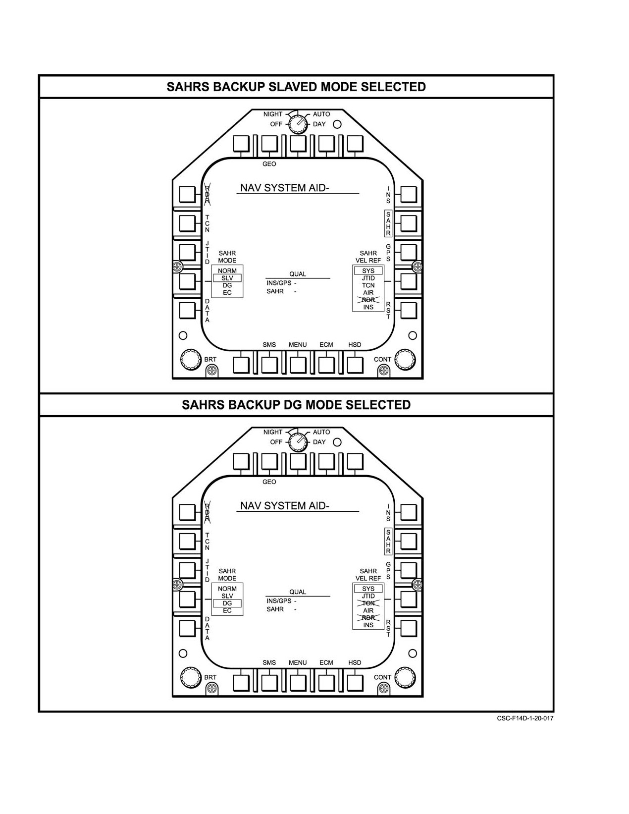
In addition to automatic selection, SAHRS submode
is placed to ATT or to INS with only the IMU sub−mode of
operation may be manually selected via the NAV SYSTEM
the INS available. Availability of the IMU sub−mode of the
AID MFD format shown in Figure 20−18. This is done by first
INS is verified by the display of IMU" in the center legend
selecting SAHRS by depressing the SAHRS pushbutton on
of the NAV System Aid format, which depicts available
the upper right portion of the NAV SYSTEM AID MFD
sensors.
format and verifying that SAHRS is boxed. A SAHRS
submode may be selected by depressing the SAHR MODE
If the INS degrades to the IMU sub−mode, SAHRS will
pushtile on the lower left of the same MFD format until the
be selected automatically (if it is available). If SAHRS is not
desired submode is boxed.
available, IMU will be selected. If the INS was selected
manually
(i.e., an M adjacent to the INS legend), then
automatic sensor selection will not be available and IMU will
be selected even if SAHRS is available.
Selection of this mode is verified with the display of
Do not attempt this on deck. A weight−on−wheels
IMU" on the lower left of the HSD format.
interlock for the in−flight restart will freeze the
SAHRS in the restart mode until weight off
wheels. There will be no attitude information
available from the SAHRS when this situation
occurs
If ATT has been selected manually, the INS will
Note
degrade from an inertial mode to an attitude
Although it is possible to cycle through the SLV,
reference mode, and reversion to viable INS
DG, EC submodes, reversion to NORM requires
function may be difficult or impossible unless
an in−flight restart. In−flight restart will automatiĆ
GPS is available. A GPS−aided IFA (via prime
cally be initiated when the selection pushbutton
INS/GPS mode) will produce results similar to
is depressed to roll from EC to NORM or can be
alignments attainable on the ground. An IFA
accomplished by depressing the in−flight RST
using other velocity sources will perform less
pushbutton.
predictably.
Considerable degradation in accuracy from the
20.3.2.4.3
SAHRS Backup Mode
primary and secondary and even the IMU backup modes can
be expected when the SLV and DG modes are selected. The
The SAHRS Backup mode provides minimal safety−
SAHRS EC submode will not provide navigation parameters
of−flight information to the aircrew, but no inertial navigation
to the system although some air data parameters will be
capability. All information is derived directly from angles
available.
provided by the SAHRS and available external velocity refĆ
erence sources.
Selection of the slaved submode will result in magnetic
heading information derived from the magnetic azimuth
The SAHRS Backup mode operates in one of three
detector (flux valve) and true heading computed from this
sub−modes, based on the heading reference source. These
source plus magnetic variation. Attitude information is
sub−modes are selected via SAHR MODE on the NAV
derived from SAHRS using first−order leveling and,
System Aid format. In order of desirability, they are:
therefore, may be subject to certain dynamic errors.
SAHRS BACKUP SUB−MODES
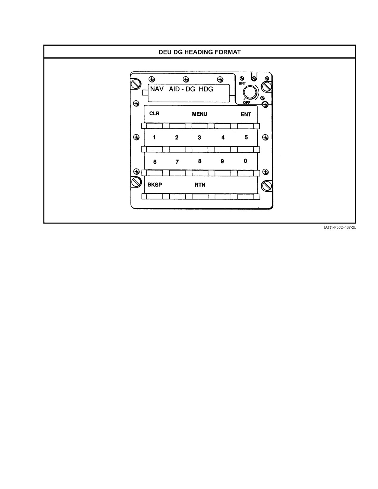
Selection of the DG submode will allow entry of a
desired grid heading via the DEU, using the DEU NAV
SLV
(Slaved) Magnetic heading is sensed by the magĆ
AID−DG HDG format
(Figure
20−18). This entered
netic azimuth detector (flux valve) and converted to
parameter will be the initial heading reference until a new
true heading using computed or manually entered
DG heading entry is made. In the system, it is treated as a
magnetic variation. Attitude is derived directly from
SAHRS angles.
magnetic−referenced parameter. Attitude information is
derived from the SAHRS using first−order leveling and, like
DG
(Directional Gyro) Magnetic heading is entered
the SLV mode, is subject to dynamic errors.
manually via the DG HDG selection on the DEU
NAV Aid format. Attitude is derived directly from
The SAHRS EC sub−mode provides only magnetic
SAHRS angles.
heading outputs using the magnetic azimuth detector as the
EC
(Emergency Compass) Magnetic heading is
input source. It is not a navigation mode, and only magnetic
sensed directly by the flux valve, without
heading and certain air data parameters will be available
compensation. Attitude is not available.
when it is selected.
20−35
ORIGINAL
NAVAIR 01−F14AAD−1
Figure 20Ć18.ĄSAHRS Backup SLV and DG Modes (Sheet 1 of 2)
ORIGINAL
20−36
NAVAIR 01−F14AAD−1
Figure 20−18.ăSAHRS Backup SLV and DG Modes (Sheet 2 of 2)
The SAHRS Backup mode is entered when SAHR is
of the SAHRS to its normal mode. The data to which the
selected as the sole navigation aid source on the OWN A/C
SAHRS is reinitialized is the current value of the navigation
or NAV System Aid format, with only the SAHRS backup
system position and velocity.
sub−modes available. A degraded SAHRS is verified by the
selection of a SAHRS heading source other than NORM on
It is also possible to perform an in−flight restart from
the NAV System Aid format. (Figure 20−18). Selection of this
the SAHRS normal mode. This should be done only if serious
mode is verified with the display of SAHRS" on the lower
SAHRS degradation is suspected.
left of the HSD format.
20.3.3
MAGR Initialization
20.3.2.4.4
SAHRS In−Flight Restart
Before the MAGR can be used for navigation, it must
acquire signals from at least four satellites. To accelerate the
If the SAHRS is operating in a degraded submode, it
signal acquisition, the MAGR uses stored almanac data. The
may be possible to revert to the normal mode of operation via
data is stored in non−volatile memory supported by the
an in−flight restart. Prior to attempting an in−flight restart, the
receiver’s internal batteries. If these batteries are removed or
selection of SYS as the SAHRS velocity reference is
are low, the MAGR requests almanac data from the MCS.
recommended. In addition, aircraft position data should be
The MCS loads the almanac data from the MDL if it is
evaluated and a position update should be performed if large
available on the cartridge.
position errors exist. An in−flight restart may now be initiated
by selecting NORM as the SAHRS mode by depressing the
Note
indicated pushbutton on the lower left portion of the NAV
SYS AID MFD format; or by depressing the RST pushbutton
If a valid almanac is not available; the MAGR
on the right center of the same MFD format (Figure 20−18).
will initiate a cold start, wherein the receiver
The subsequent boxing of the NORM legend in the SAHR
does a sky search for visible satellites. Search
MODE selector box on this format indicates a reinitialization
and acquisition can take over 20 minutes.
20−37
ORIGINAL
NAVAIR 01−F14AAD−1
Note
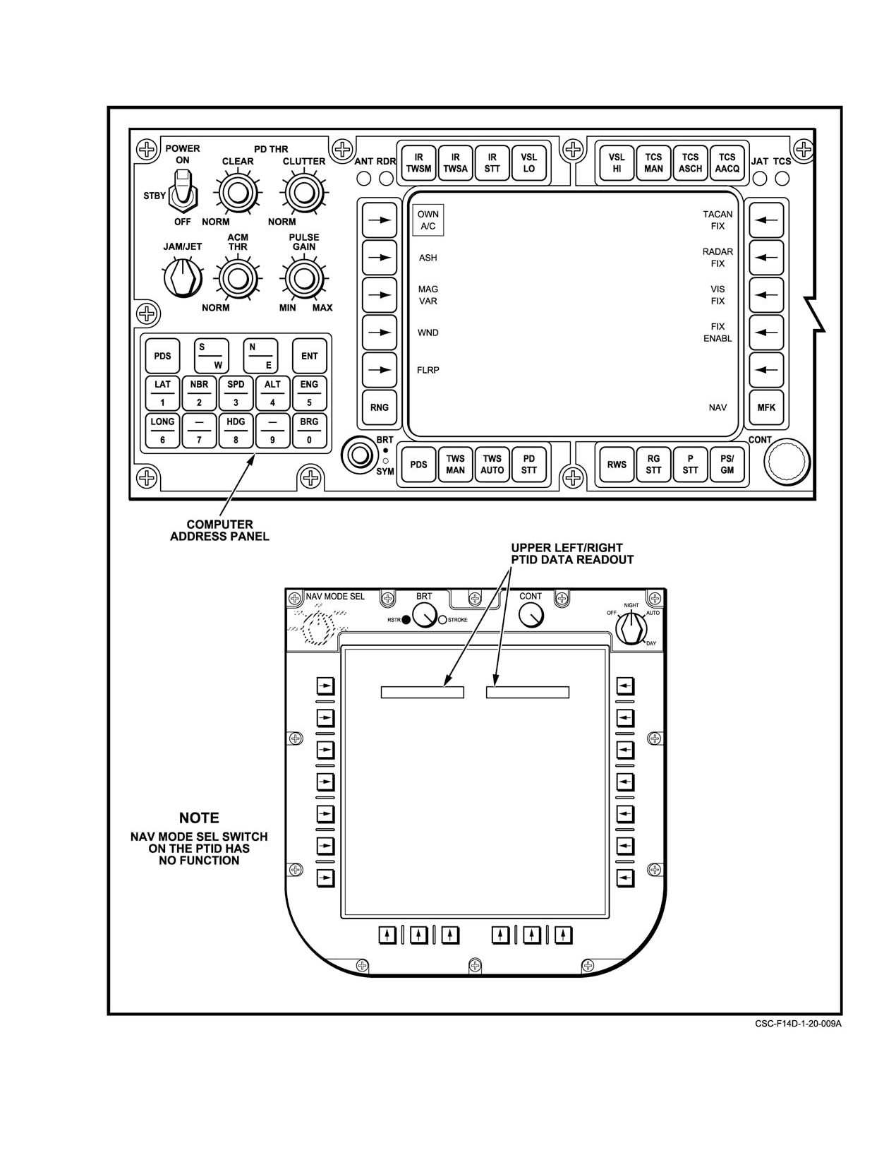
nearest 0.1 arc minute. Longitude entries on the DD
below 100_ do not require a 0 prior to entering the
GPS satellite acquisition time can be affected by
numerals.
a number of conditions, particularly L−band RF
interference and line of sight obstructions, as
3.
Verify parking brake is set.
well as the currency of the almanac data. On the
ground, aircraft proximity to large structures
4.
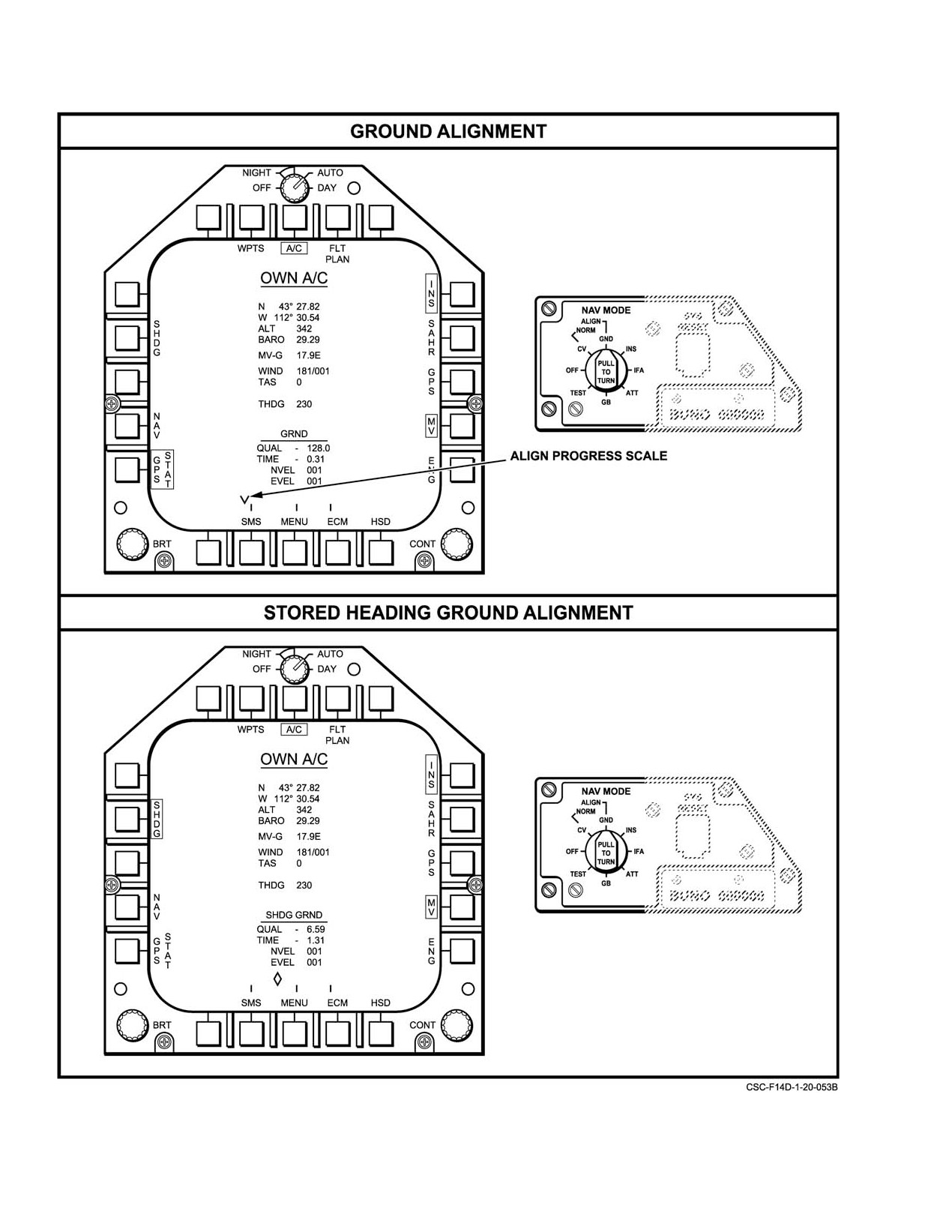
Set NAV MODE switch to GND. The OWN A/C
such as a hangar or an aircraft carrier island may
GRND format will be displayed on the MFD
delay or prevent satisfactory satellite acquisition
(Figure 20Ć22).
until the aircraft is moved.
5.
Verify that SHDG is not boxed. If it is, press the
Besides almanac data, the MAGR requires an estimate
SHDG pushbutton to unbox SHDG.
of current position, date, and time to speed acquisition. If any
of these quantities are in error, the speed of acquisition will
Note
decrease. Generally, a position error of a few miles and a time
Unboxing of SHDG must be performed within
error of a few minutes will not degrade acquisition perĆ
17 seconds of selecting GND ALIGN on the
ceptibly. The aircrew should verify that the correct data is
NAV MODE switch or the boxed SHDG will
available from the MCS by checking the OWN A/C MFD
be selected and unboxed by the system and
format (for position) and GPS Status MFD format (for date
deselection will not be available.
and time) during the GPS startup, and correct any significant
errors.
6.
Verify latitude and longitude and enter correct
values if necessary. If new entries are required at this
20.3.4
INS and SAHRS Concurrent Alignment
time, the alignment time may be extended, dependĆ
ing on the differences between the newly entered
In all modes of concurrent alignment, both the INS and
values and those displayed when alignment was iniĆ
the SAHRS are aligned in the mode selected on the NAV
tiated.
MODE switch (Figure 20−2). The system will always align
to WPT 1 unless manual entries are made. Normal operation
7.
Alignment progress can be monitored by observing
of the MCS and MFD is required for any alignment.
the QUAL and TIME acronyms and the alignment
scale on the MFD OWN A/C format. The indicator
20.3.4.1
Normal Concurrent Ground Alignment
on the alignment progress scale changes from a V"
to a diamond symbol at the first tic mark. This
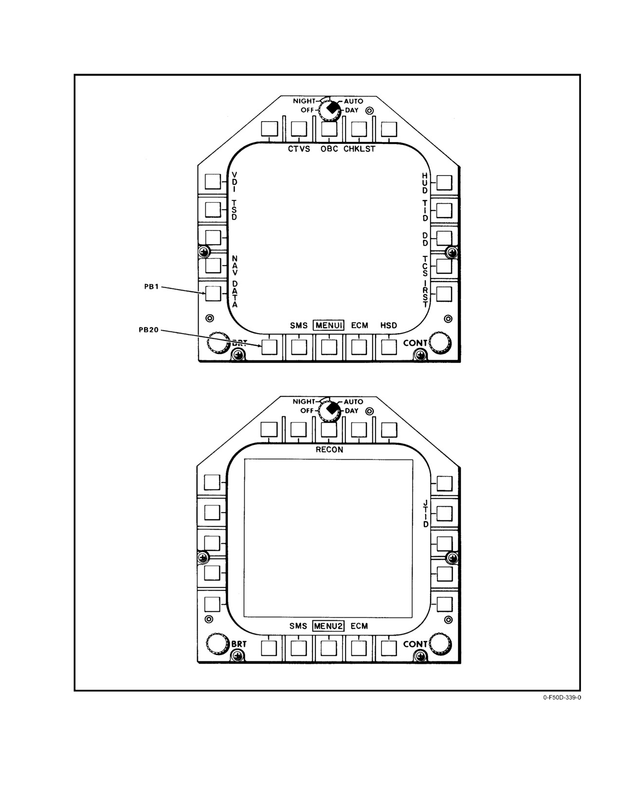
1. Select own−aircraft MFD format, (Figure 20Ć8 ) by
represents an 8 nm per hour estimated navigation
depressing DATA" pushtile on the MFD MENU1
quality. The second tic mark represents an estimated
page (Figure 20−19).
2 nm per hour quality and the third an estimated 0.8
nm per hour quality. At this point a dot appears in the
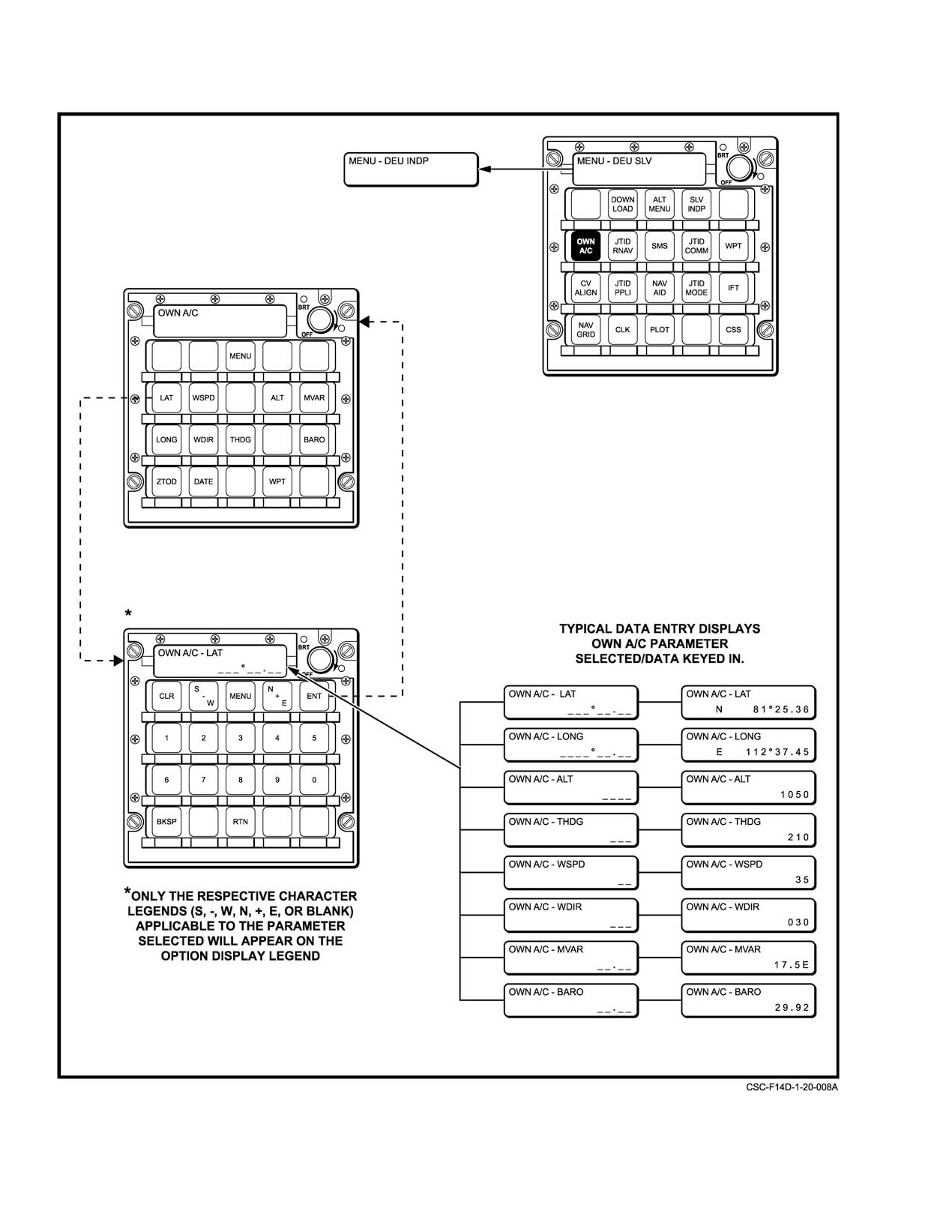
2. Verify displayed latitude and longitude. If incorrect,
diamond. An INS ALIGN COMPLETE message
enter correct coordinates via the DEU or DD. For
normally appears at the top of the MFD display in
DEU data entry, the DEU OWN A/C page is
4 minutes. At this time the QUAL acronym is near
selected and the latitude and longitude coordinates
or slightly below 1 nm per hour and the pointer on
may be entered to 0.01 arc minute using the LAT and
the align scale should be near the last tic mark.
LONG pushtiles and the proper hemisphere numerĆ
als (Figure 20−20). On the DEU, longitude entries
8.
During concurrent alignment, it is advisable to
less than 100_ require a 0 be entered prior to the
monitor the SAHRS alignment progress by pressing
value. For DD data entry the DD control panel is
the SAHR pushbutton on the MFD. The OWN A/C
used with the NAV category selected using the MFK
MFD format will show SAHR boxed; and the
pushtile (Figure 20−21). The OWN A/C acronym is
QUAL and TIME acronyms and the align scale now
then boxed by depressing the corresponding pushĆ
refer to the SAHR. A SAHRS ALIGN COMPLETE
tile and the coordinates are entered via the LAT,
message normally appears in approximately 2.5 to
LONG, hemisphere, and numeric pushtiles shown
3 minutes from the time when the parking brake was
on the computer address panel on the lower left
set. The QUAL will be approximately 10 (nm per
portion of the DD control panel. Latitude and longiĆ
hour) at this time.
tude coordinates may be entered via the DD to the
ORIGINAL
20−38
NAVAIR 01−F14AAD−1
Figure 20Ć19.ĄMFD MENU1 and MENU2 Displays
20−39
ORIGINAL
NAVAIR 01−F14AAD−1
Figure 20Ć20.ĄDEU Own−Aircraft Data Entry (Typical)
ORIGINAL
20−40
NAVAIR 01−F14AAD−1
Figure 20Ć21.ĄDD/PTID Own−Aircraft Data Entry
20−41
ORIGINAL
NAVAIR 01−F14AAD−1
Figure 20Ć22.ĄMFD Ground Alignment Formats
ORIGINAL
20−42
NAVAIR 01−F14AAD−1
9.
Alignment may be continued after the appearance
Perform a reference alignment by following the normal
of the INS ALIGN COMPLETE message if time
ground align procedure in paragraph 20.3.4.1. When the INS
permits. This will provide only slight improvement
ALIGN COMPLETE message appears on the HUD and/or
in alignment quality but will provide some gyro
VDI format, return the NAV MODE switch to OFF. The
biasing and eliminate unnecessary drift in the INS
aircraft heading should now be stored in the INS and should
mode. If the parking brake is released during
be available for the next alignment as long as the aircraft has
alignment, the INS and SAHRS will go to a
not been moved.
SUSPEND ALIGN state as indicated by the
Note
computer message on the OWN A/C MFD format.
Alignment will be resumed upon application of the
Selecting the SAHR pushbutton on the
parking brake. The numerical alignment quality
OWN A/C or NAV DATA MFD formats
displayed will never be lower than 0.50. Actual
before the diamond reaches the second tic
INS/SAHRS drift rate is normally less than 0.50 nm
mark will inhibit a subsequent stored heading
per hour.
alignment.
10. The RIO may take the alignment anytime the QUAL
1. Repeat steps
1 through
4 for normal ground
reaches 1.0 nm per hour. The NAV MODE switch
alignment.
should be rotated to the IFA position once IFA
2. Verify that SHDG is boxed on the OWN A/C MFD
AVAILABLE" is displayed. This places the
format (Figure 20Ć22). Do not depress the SHDG
navigation system in the INS/GPS mode of
pushbutton.
operation. If GPS is available when the switch is in
the INS position, the GPS INTLKćSEL IFA"
3. Repeat steps 6 through 9 as in normal ground align
message will post to remind the aircrew that a better
procedure.
navigation mode exists.
20.3.4.3
GPS On−Deck IFA
11. If GPS is not available, INS performance may be
improved by performing the following procedure.
This method of alignment normally takes
3 to
4
minutes longer than a normal ground alignment, but requires
a. Initiate a standard alignment.
only that the NAV MODE switch be placed in IFA and a GPS
solution be available. It can be used ashore or aboard a CV.
b. Allow alignment to continue until an INS
The aircraft can be moved during a GPS IFA alignment, so
ALIGN COMPLETE message appears on the
taxi and take−off may take place while the alignment is underĆ
MFD.
way. GPS satellite acquisition normally takes from 30 secĆ
c. Without changing the NAV MODE switch
onds to 3 minutes, depending on the initial estimates of posiĆ
tion, date, and time; satellite position; and LOS
position, taxi the aircraft to a convenient
(line−of−sight) blockage by hangars, carrier island, etc.
location, changing the heading by at least 70_,
with 180_ heading change being optimal.
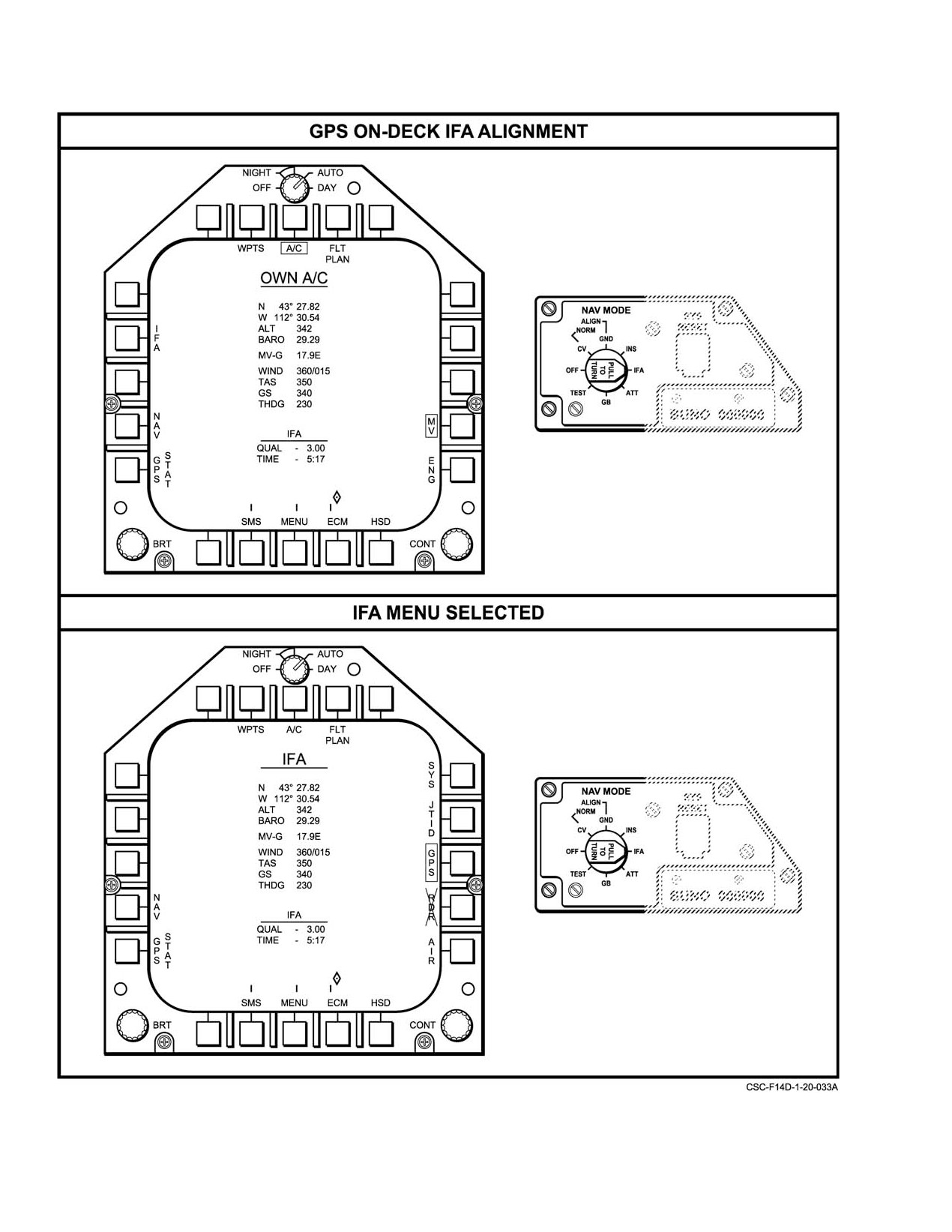
To get an IFA Alignment on the ground, perform the
following steps:
d. Reapply the parking brake and allow the INS to
continue alignment for a minimum of 1 minute
1. Place the NAV MODE switch in IFA at application
(7 to 8 minutes desired).
of aircraft power (see Figure 20Ć23).
Note
2. Verify correct date and time on the GPS Status page.
If satellites have been acquired, the OWN A/C data
The latitude and longitude of waypoint 1 will
page will show own aircraft position based on GPS,
be updated to current aircraft position when
if GPS is boxed.
the NAV MODE switch is placed to INS.
3. Monitor the GPS Status page to ensure satellites are
20.3.4.2
Stored Heading Concurrent INS/SAHRS
acquired within a few minutes of moving the NAV
Alignment
MODE switch out of the OFF position to IFA. IFA
alignment will not commence until satellites are
Stored heading alignment is performed when rapid
acquired. If satellites are not acquired after a few
system reaction is operationally required. Under normal
minutes, transition to a normal ground alignment
conditions, stored heading alignment can reduce ground
(on the NAV Mode Switch, select OFF then GND).
align time by
1 minute. This procedure requires that a
4. When the QUAL gets to 1.0, the system will autoĆ
previous reference alignment be performed and that the
matically take the alignment and display the INS
aircraft remain stationary until the subsequent stored heading
ALIGN COMPLETE message.
alignment is completed.
20−43
ORIGINAL
NAVAIR 01−F14AAD−1
Figure 20Ć23.ĄGPS On−Deck IFA Alignment
ORIGINAL
20−44
NAVAIR 01−F14AAD−1
Note
procedure is used, after verifying proper operation of the
MCS and MFD.
D The pilot will not have a FPM (Flight Path
1.
Ensure SAHRS A, B, C, and DC circuit breakers
Marker) until a dot appears in the diamond.
(1I3, 1I5, 1I6, 9I3) pulled prior to application of
D If GPS data is lost during alignment, the
electrical power.
navigation system will align to waypoint 1.
Therefore, aircrew should always ensure
2.
DATA LINK power switch Ċ ON.
waypoint
1 coincides with actual aircraft
location.
3.
DATA LINK MODE switch Ċ CAINS/WPT.
D The NAV MODE switch must remain in the
4.
Verify parking brake is set.
IFA position to remain in the primary
navigation mode, INS/GPS. This mode can
Note
also be obtained by conducting a normal
ground alignment, followed by moving the
Application of SAHRS power prior to
NAV MODE switch from INS to IFA. GPS
selecting CV ALIGN will not allow SAHRS
FOM ≤ 4 to be effective.
to properly align.
D INS alignment to GPS data via the INS/GPS
5.
NAV MODE switch CV ALIGN.
mode is not always optimum from a cold start.
It may require up to 10 minutes (plus up to 2
6.
Reset SAHRS cb’s.
minutes for MAGR initialization), compared
to only 4 or 5 minutes for a normal alignment.
7.
Select OWN A/C MFD format by depressing DATA
If movement of the aircraft during alignment
pushbutton on MFD MENU1 display. The CV SINS
is not anticipated, a normal concurrent ground
DATA format will appear (Figure 20Ć24).
or CV alignment followed by placing the
NAV MODE switch to INS momentarily, then
8.
Verify that SHDG is not boxed. If it is, depress the
selecting IFA (In−Flight Alignment) may be
SHDG pushbutton to unbox it.
more expeditious and will yield the same sysĆ
tem accuracy.
9.
Monitor the progress of alignment by observing the
QUAL and TIME acronyms and the align scale on
20.3.5
Concurrent Carrier Alignment
the MFD OWN A/C format. The SINS (ship’s)
latitude, longitude, and INS north and east
Carrier alignment of the INS and the SAHRS requires
velocities can also be evaluated on the MFD OWN
knowledge of the carrier motion and position. This
A/C format. An INS ALIGN COMPLETE message
information is best provided by the SINS. A stored heading
will normally occur in 7 minutes. At this time the
carrier alignment is also available using SINS inputs, after a
align quality should be below 1 nm per hour.
reference alignment has been performed. For SINS stored
carrier alignment, the stored parameter is actually the
Note
aircraft’s spotting angle on the carrier.
Do not select SAHR during CV ALIGN to
In the event that SINS data is unavailable, carrier
check alignment progress. Wait until INS
alignment can take place by manual entry of ship’s position,
alignment is complete and INS has been
speed, and heading. This procedure is called manual carrier
selected on the NAV MODE switch before
align. Because of the entry of fixed parameters, its real values
selecting SAHR.
may be changing and extended alignment time with lesser
alignment quality can be expected for manual carrier
10. SAHRS alignment progress may be monitored at
alignment.
this time by selecting the NAV page.
20.3.5.1
Concurrent SINS RF or Cable Carrier
Note
Alignment
D The SAHRS alignment process will initiate
Carrier alignment using SINS data from the ASW−27C
after the INS determines a valid true heading
D/L can be implemented by either cable or RF transmission,
(approximately at INS quality value of 5).
depending on whether the SINS cable from the deck−edge
SAHRS quality value should reinitiate to
box to the nose wheelwell connector is plugged in. For either
approximately 31.2 at that time.
mode of data transmission, the following alignment
20−45
ORIGINAL
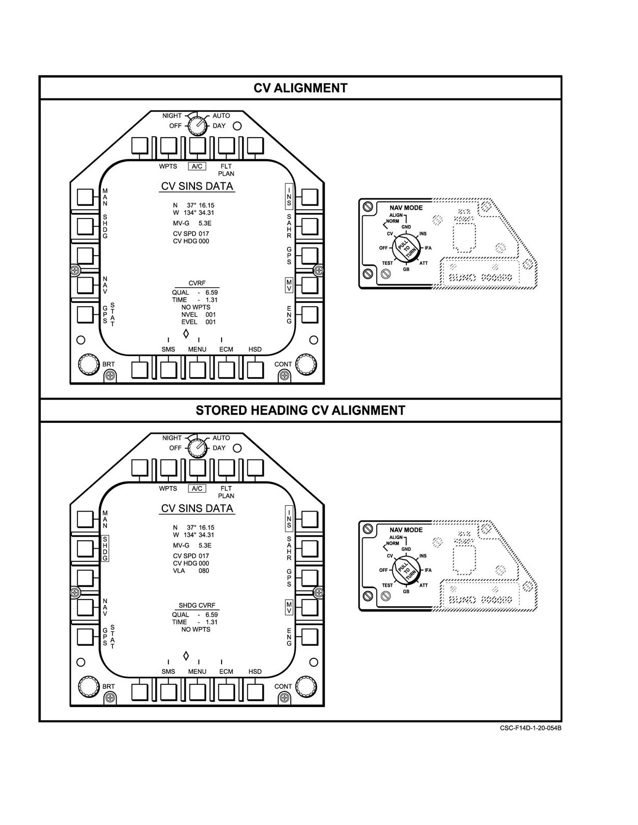
NAVAIR 01−F14AAD−1
Figure 20Ć24.ĄCV Alignment Formats Ċ SINS
ORIGINAL
20−46
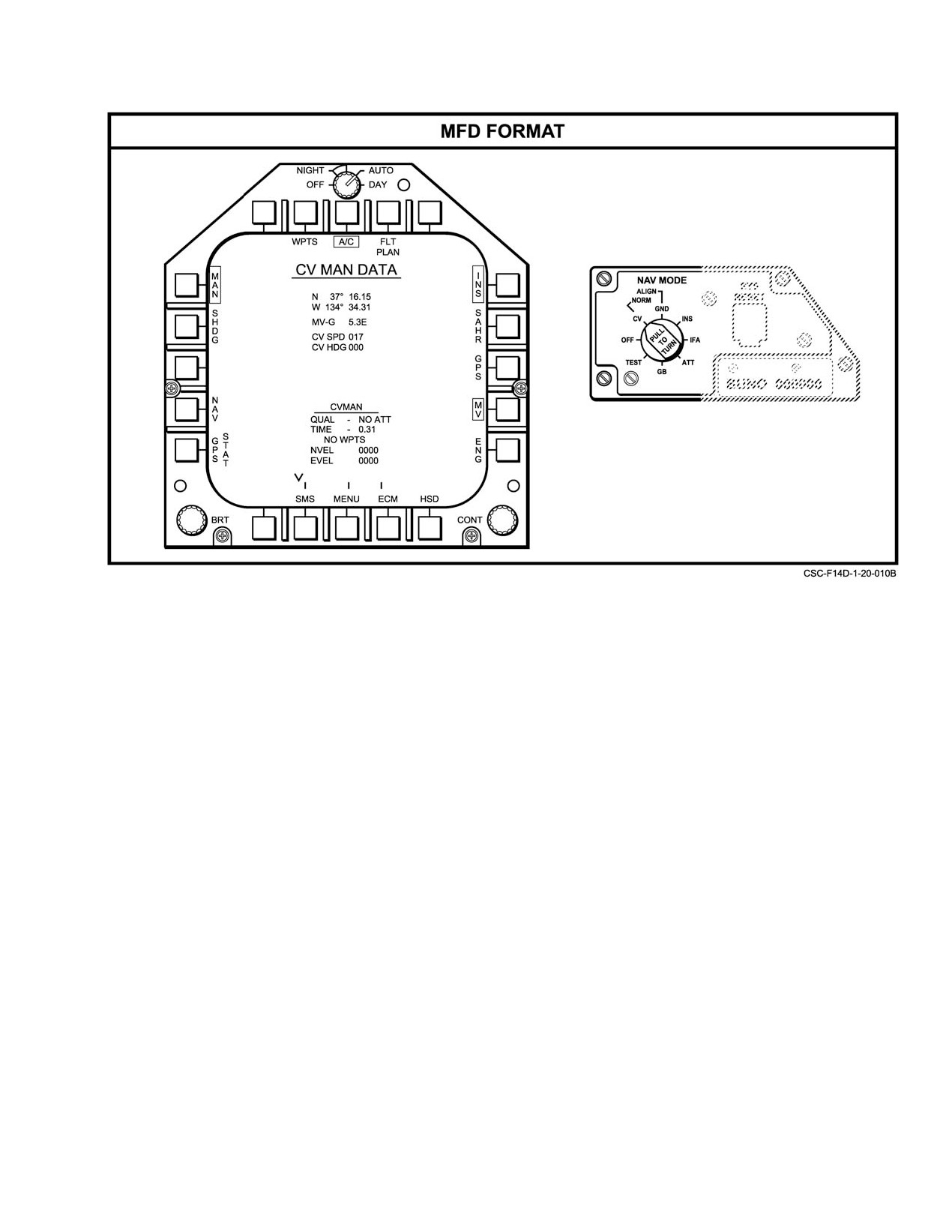
NAVAIR 01−F14AAD−1
Figure 20Ć25.ĄCV Alignment Formats Ċ Manual (Sheet 1 of 2)
D If power has been applied to the aircraft for an
Note
extended period of time prior to INS CV align
Although SINS carrier alignment normally
being initiated, the SAHRS may complete a
requires no entry of data, if a SINS alignment
ground align
(NORM) and a SAHRS
takes place at any carrier location other than the
complete message appears on the MFD. After
flight deck, then it is advisable to enter the
the INS CV align is initiated, the SAHRS will
correct vertical lever arm via the DEU. This is the
initiate a concurrent CV align normally, but
height in feet of the aircraft INS above the
another SAHRS align complete message may
carrier’s SINS location. This entry can be made
not appear.
only via the DEU by calling up the DEU CV
ALIGN page and depressing the VLA pushtile
11. It is advisable to continue alignment after appearĆ
shown in Figure 20Ć25.
ance of the INS ALIGN COMPLETE message if
20.3.5.2
Concurrent SINS Stored Heading
time permits. When ready to take the alignment, the
Carrier Alignment
inertial navigation mode may be selected by setting
the NAV MODE switch to INS. The RIO may take
Carrier alignment time can be reduced by 1 minute by
the alignment anytime the QUAL reaches 1.0 nm
performing a stored heading carrier alignment. This
per hour. The NAV MODE switch should be rotated
procedure requires that a reference alignment be performed
to the IFA position once the IFA AVAILABLE"
using SINS data and that the aircraft’s position on the carrier
message appears. This places the navigation system
remain stationary until the completion of the subsequent
in the INS/GPS mode of operation.
stored alignment.
Perform a reference alignment by following the SINS
carrier align procedure in paragraph 20.3.5.1. When the INS
ALIGN COMPLETE message appears on the HUD/VDI
formats, return the NAV MODE switch to OFF.
20−47
ORIGINAL
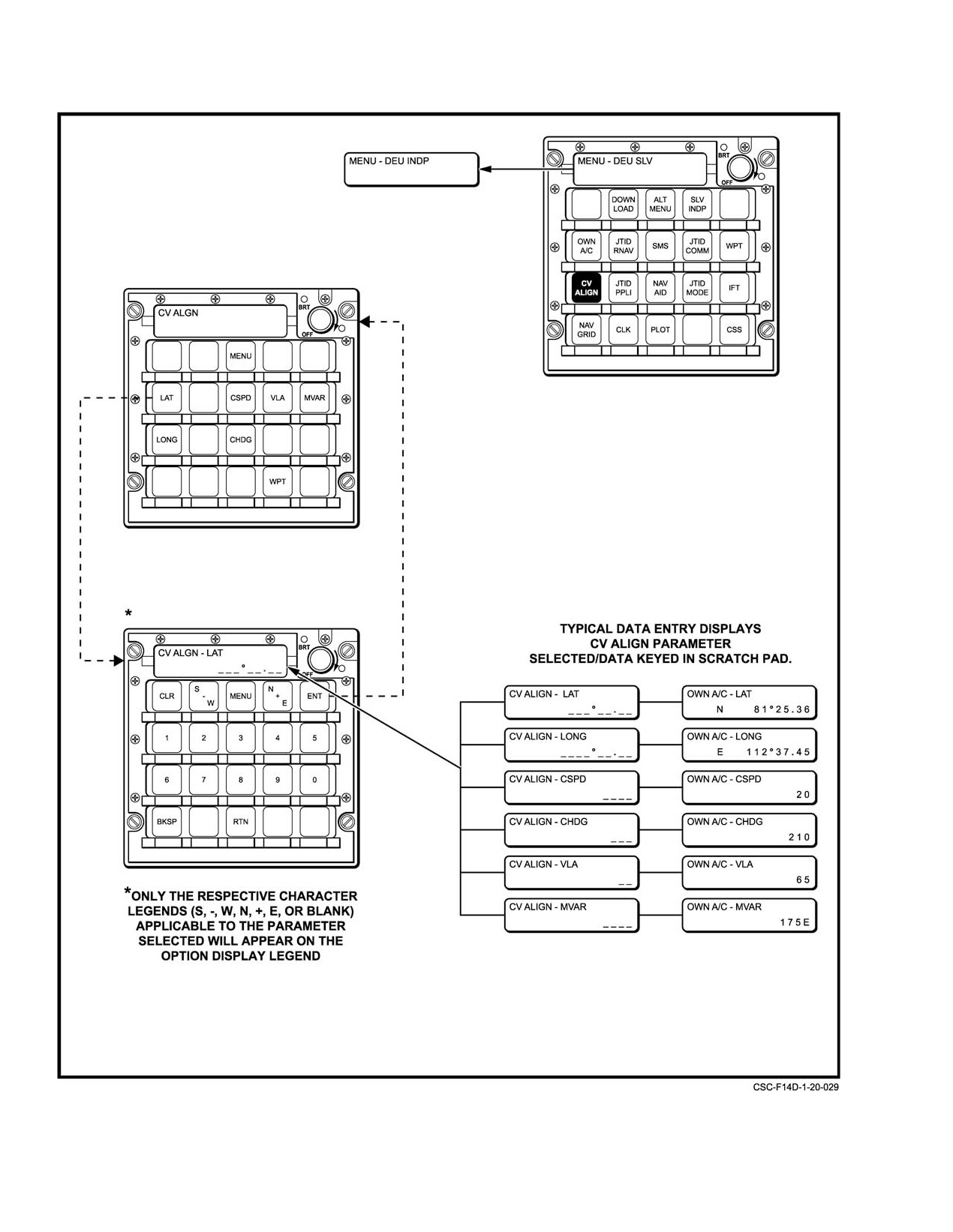
NAVAIR 01−F14AAD−1
Figure 20−25. CV Alignment Formats Manual (Sheet 2 of 2)
ORIGINAL
20−48
NAVAIR 01−F14AAD−1
Note
entering the carrier latitude and longitude via
the DD LAT, LONG, quadrant and numeral
pushtiles, as shown in Figure 20−26. This is
D Do not box SAHR on the DATA or NAV
done in a similar manner as described in
formats during the reference alignment. This
paragraph
20.3.4.1 and shown in Figure
will prevent the reference alignment and
20−21. Entry of carrier speed and heading via
SHDG will not be boxed when alignment is
the DD requires the boxing of the WIND acroĆ
initiated.
nym prior to using the DD SPD, HDG and
D Do not cycle the parking brake during the
numeric pushtiles as shown in Figure 20−26.
reference alignment. This will prevent the
reference alignment and SHDG will not be
3. Repeat steps 9 through 11 for concurrent SINS
boxed when alignment is initiated.
carrier align (paragraph 20.3.5.1).
1. Repeat steps 1 through 7 of concurrent SINS carrier
Note
align.
In concurrent manual carrier align, the INS
2. Verify that SHDG is boxed on CV SINS DATA MFD
ALIGN COMPLETE computer message may
format (Figure 20Ć24).
take
15 minutes or longer to appear. The
navigation quality at this time may not be
3. Repeat steps 9 and 10 of concurrent SINS carrier
better than 3 nm per hour. Because of the
align.
extensive alignment time, it may be necessary
to launch prior to the receipt of the INS
20.3.5.3
Concurrent Manual Carrier Alignment
ALIGN COMPLETE computer message.
The INS and SAHRS will initiate ground alignments if
20.3.5.4
INS Standalone Alignment
there is no SINS data. The CV MANUAL format will be
displayed after the ship’s data is entered.
When the SAHRS is not available or has failed, the
1.
Repeat steps 1 through 8 of concurrent SINS carrier
alignment procedure for the INS is exactly the same as for
align.
concurrent alignment described above in paragraph 20.3.4.
A SAHRS failure is indicated by the inability to box SAHRS
Note
on the MFD OWN A/C and align formats as well as its
appearance in the failure history file and in the MFD OBC−
If the SINS or data link is not operating or if
NAV format as described in Chapter 27.
a manual carrier alignment is desired, skip
steps 2 and 3.
20.3.5.5
SAHRS Standalone Alignment
2.
Enter best knowledge of ship’s latitude, longitude,
When the INS has failed or is not available or if a
speed, and heading via the DEU or DD. When the
SAHRS alignment mode other than that of the INS is desired,
DATA pushbutton on the MFD is depressed, the CV
then a SAHRS standalone alignment can be selected from the
MANUAL DATA format, shown on Figure 20Ć25
MFD SAHRS ALIGN format (Figure 20−27). This format
appears.
will appear by depressing the NAV pushbutton on the OWN
A/C MFD format. An INS failure is indicated by the inability
Note
to box INS on the MFD align or OWN A/C formats as well
D If SINS is restored, MAN must be unboxed on
as its appearance in the failure history file and in the MFD
OBC−NAV format as described in Chapter 27.
the CV DATA format in order to return to a CV
RF alignment.
As shown in Figure
20−27, the possible SAHRS
D Entry of VLA is never required for manual
standalone alignment modes include normal ground align
carrier alignment.
(NORM), stored heading ground align (SHDG), magnetic
D When using the DEU, data entry is made via
initiated ground align (MAG), and carrier align (CV). These
the DEU CV ALIGN format, using the LAT,
are described below.
LONG, CSPD and CHDG pushtiles, and the
appropriate quadrant and numerals shown in
20.3.5.5.1
SAHRS Standalone Normal Ground
Figure 20Ć25.
Alignment
D Data entry using the DD requires selection of
SAHRS normal ground alignment is the recommended
the NAV category from the MFK pushtile and
mode for SAHRS standalone alignment and it will be
the boxing of the OWN A/C acronym prior to
20−49
ORIGINAL
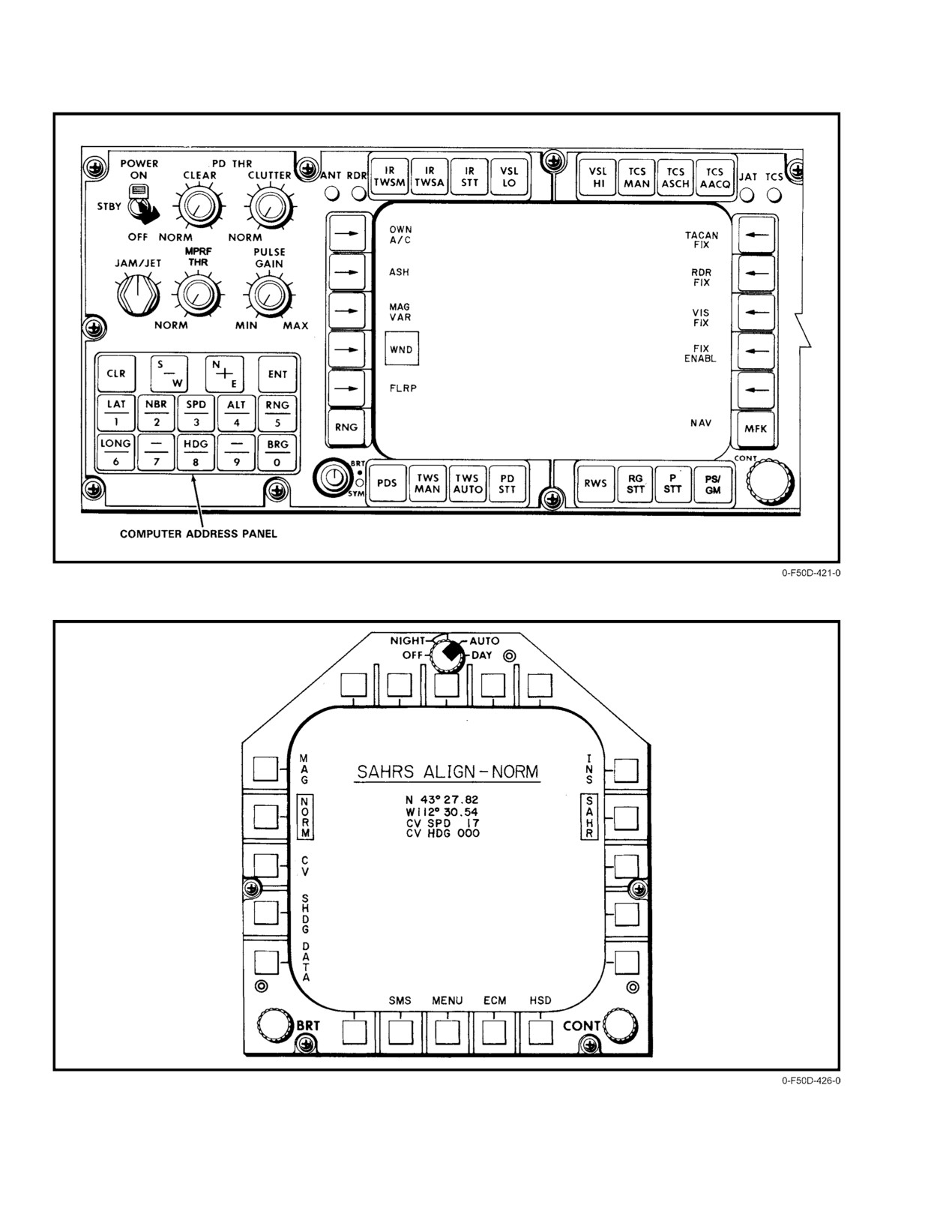
NAVAIR 01−F14AAD−1
Figure 20Ć26.ĄDD Align Data Entry
Figure 20Ć27.ĄSAHRS Standalone Align MFD Format
ORIGINAL
20−50
NAVAIR 01−F14AAD−1
automatically selected as the default mode when the INS is
20.3.5.5.4
SAHRS Standalone Carrier Alignment
not available. This can be ascertained by selecting the
SAHRS ground align MFD format and observing that the
The SAHRS standalone CV alignment mode is
NORM legend is boxed. Verification of own−aircraft latitude
manually selected via the SAHRS ALIGN MFD format by
and longitude should be made by observing the values
depressing the SAHR and then CV pushbutton shown in
displayed on the SAHRS ALIGN MFD format, and, if
Figure 20−27. There are two SAHRS standalone align modes.
necessary, new values should be entered via the DEU or
Which mode obtained depends on when CV is selected. If CV
DD control panel as described in Normal Concurrent Ground
is selected prior to the INS determining true heading
Alignment procedures, paragraph
20.3.4.1. The SAHRS
(approximately INS quality of 5) and initiating the SAHRS
ALIGN COMPLETE message will usually appear in less
CV concurrent align, a SAHRS standalone align is
than 3 minutes, with an align quality of less than 10 nm
commanded when the SAHRS has no heading information.
per hour.
Note
20.3.5.5.2
SAHRS Standalone Stored Heading
Currently there is no indication on the MFD
Ground Alignment
displays that the SAHRS has gone into the
standalone mode except the SAHRS quality
The SAHRS stored heading align mode is always
value will remain 10.0, the timer will be 00,
available subsequent to a previous alignment to a SAHRS
SAHRS concurrent CV align will not initiate,
ALIGN COMPLETE. However unlike an INS stored
and there will be no attitude information
alignment, the SHDG pushbutton on the SAHRS ALIGN
available from the SAHRS for up to 6 minutes or
MFD format must be depressed to select this mode
more. Reinitiating the INS alignment will allow
(Figure 20−27). As for all stored heading alignments, no data
a concurrent alignment to occur.
entries are required and the aircraft must not be moved subseĆ
quent to SAHRS power down. Since this alignment mode
The SAHRS has no true standalone carrier align mode
uses predetermined heading, the alignment process will be
like the INS. During concurrent INS/SAHRS carrier align
shortened. SAHRS stored heading alignment should
modes, the SAHRS depends on the INS to provide an initial
normally provide a SAHRS ALIGN COMPLETE message
input of true heading. Since this is not available in SAHRS
in less than 1 minute. The navigation quality value at this
standalone carrier alignment, when the SAHRS CV pushĆ
time will exceed 10 nm per hour, and, if time permits,
button is depressed in SAHRS standalone operation, it is
additional alignment is recommended and will take place as
commanded to a DG mode. Once the parking brake is
long as the parking brake is set.
released a DG heading can be entered via the DEU. When
the aircraft is airborne, the slaved mode can be selected or
20.3.5.5.3
SAHRS Standalone Magnetic Initiated
if a system velocity source is present, in−flight restart can
Ground Alignment
be selected to bring the SAHRS to a normal operational
mode. This is described in SAHRS Backup Modes,
The SAHRS magnetic initiated ground alignment
paragraph 20.3.2.4.3.
mode is manually selected from the SAHRS ALIGN MFD
format by depressing the MAG pushbutton shown in
If CV is selected after the INS has initiated the SAHRS
Figure 20−27. Verification of own−aircraft latitude and longiĆ
CV concurrent alignment, the SAHRS alignment proceeds
tude on the above MFD format should be made, and, if necesĆ
but is no longer receiving updated position and velocity
sary, correct values entered as described in SAHRS StandaĆ
information from the INS. The alignment will be considerĆ
lone Normal Ground Alignment, paragraph 20.3.5.5.1. Since
ably slower than concurrent alignment. The SAHRS is
this alignment mode uses system magnetic heading to initialĆ
commanded to NORM mode. An in−flight restart may or may
ize heading, the alignment process will be shortened. A
not be required depending on the SAHRS alignment quality.
SAHRS ALIGN COMPLETE message should normally
occur within 1 minute, although the navigation quality value
SAHRS cannot be commanded to a CV mode unless
at this time may exceed 10 nm per hour. If time permits,
the INS is in CV. If the INS is unavailable, the SAHRS will
additional alignment is recommended and will take place as
attempt a normal ground align.
long as the parking brake is set. In this mode of alignment,
magnetic heading inputs from the magnetic azimuth detector
20.3.5.5.5
NGS In−Flight MAD Align
(flux valve) are used for initializing the SAHRS heading.
AN/USN−180(V)
It should be selected only in areas where no magnetic interĆ
ference or anomalies exist.
Whenever the Fluxgate Magnetometer is replaced, an
in−flight alignment must be performed. The procedure for an
in−flight alignment is as follows:
20−51
CHANGE 1
NAVAIR 01−F14AAD−1
1.
Prestart:
c.
400 Knots
d. Maintain Constant Speed
a. Have Ground Crew in Preflight Verify: NORM
Ċ INIT BIT/ALIGN SWITCH Ċ S1 ON NGS
e. TWO FULL 360 degree turns
(SSA) PLACED IN UP POSITION (INIT BIT/
f. Maneuver complete in 2 minutes
ALIGN))
j. Maneuver Complete, Check SAHRS Light:
b. Pull SAHRS (NGS) C.B.’s (PHA, PHB, PHC,
DC)
(1) Flashes 3 seconds ON/3 seconds OFF. CalĆ
ibration Successful
c. NMS: OFF
(2) SAHRS Light Solid ON. Calibration NOT
d. Parking Brake: SET
Successful
2.
Post Start (After one or both engines are on line)
Note
a.
Reset SAHRS (NGS) C.B.s
Another attempt can be made by cycling the
SAHRS mode out of EC TO NORM WITH
b.
NMS GND
SAHRS VEL REF: SYS BOXED. Repeat
Steps h−j.
(1) INS ALGN CMPLT
(2) SAHR ALGN CMPLT
k. MFD: NAV AID: SAHR MODE BOX NORM
(1) VERIFY: SAHR VEL REF: SYS BOXED
c.
NMS: INS
(2) SAHRS CAUTION LIGHT OUT
d.
PB RELEASED
3.
Post Flight
(1) MFD: NAV AID PAGE
(2) SAHR MODE: NORM BOXED
a. Have ground crew set NORM Ċ INIT BIT/Align
switch S1 on NGS SSA in the down position
(3) SAHR VEL REF: SYS BOXED
NORM.
e.
Take off Straight and Level Flight
20.3.6
Initially Entered Navigation Parameters
f.
Airspeed Ċ CHECK (400 Knots)
Prior to takeoff; either during or after alignment, it may
g.
Altimeter Ċ CHECK 10,000 ± 5,000 Feet
be desirable to enter certain initial navigation−related
parameters, in addition to those noted above that are required
h.
NAV SYSTEM AID PAGE
for alignment. It may also be possible to enter some of these
parameters at any time during flight. They include the
(1) VERIFY: SAHR MODE: NORM BOXED
following and are discussed below:
(2) SAHR VEL REF: SYS BOXED
1. Barometric setting
i.
SAHRS MODE Ċ BOX EC
2. Waypoint data
(1) Verify SAHRS caution light flashes at a 2
second rate Ċ 1 sec on/1 sec off.
3. Wind speed and direction
Note
4. Magnetic variation.
SOLID SAHRS LIGHT Ċ OCCURS, NGS
20.3.6.1
Barometric Setting
TEST CANNOT BE RUN
(2)
(MUST START WITHIN 15 SECONDS OF
The barometric setting is normally made by the pilot
BOXING EC)
using his
2−inch barometric altimeter setting knob. The
setting range is from 28.10 to 30.99 inches of Hg. This will
a. Perform
ONE FIGURE EIGHT
provide system altitude corrections to within a maximum
Maneuver
error of 16 feet. When the setting is changed, the new setting
b. 70 Degree Bank
will be displayed momentarily in the HUD beneath the
CHANGE 1
20−52
NAVAIR 01−F14AAD−1
barometer (Figure 20−6). A small difference between the
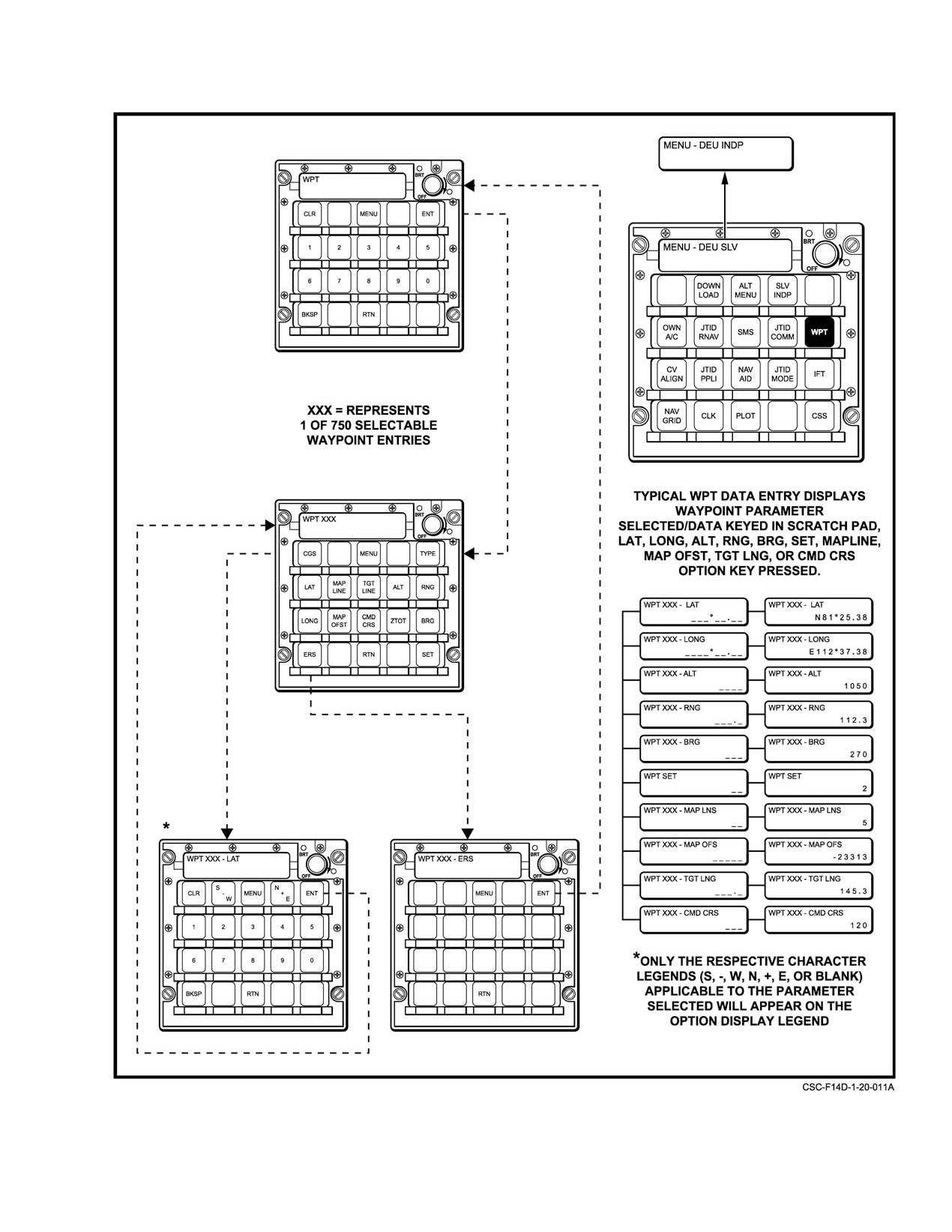
The waypoint type is selectable from the DEU WPT
HUD and instrument values may be expected. This will
menu, TYPE pushtile. The waypoint number for which the
usually be less than
0.01 inch of Mercury but may on
type is being set is displayed in the DEU input window at the
occasion be 0.02 inch. If any difference is present, adjust the
top. When a selection is made, it appears in the input window
altimeter so that the correct value is displayed on the lower
as a selection in progress until the ENT button is pressed to
right side of the HUD. Barometric settings may also be made
accept the change. If TGT is selected for a flight plan
by the RIO via the DEU. To do this, the altimeter must be
waypoint, any previously designated target waypoint within
locked out by turning the setting knob to the minimum value
the same flight plan will be changed back to type GEN. To
(28.10 in Hg). The DEU OWN A/C page can now be used to
remove a selection and enter another one, press CLR. RTN
enter the required value after depressing the BARO pushtile
will abort the change and return to the WPT menu, and
and the proper numeric values.
MENU will abort changes and return to the main menu.
20.3.6.2
Waypoint Data Entry
In addition to the above primary waypoint parameters,
four other parameters relating to the reconnaissance steering
Up to 100 tactical waypoints can be stored in the MCS
function may also be entered when the specified waypoint is
waypoint file at any time. These can be entered manually, or
to be used as a reconnaissance target point. These parameters,
downloaded from the MDL in accordance with procedures
however, can only be entered via the DEU using the DEU
listed in paragraph 20.3.7, Navigation Database. The primary
WPT page. They are as follows:
parameters that may be entered for each tactical waypoint are
latitude, longitude, altitude and flight plan. These may be
RECONNAISSANCE
RANGE
entered manually via the DEU by selecting the DEU WPT
STEERING PARAMETER
page (Figure 20−28) and depressing the desired waypoint
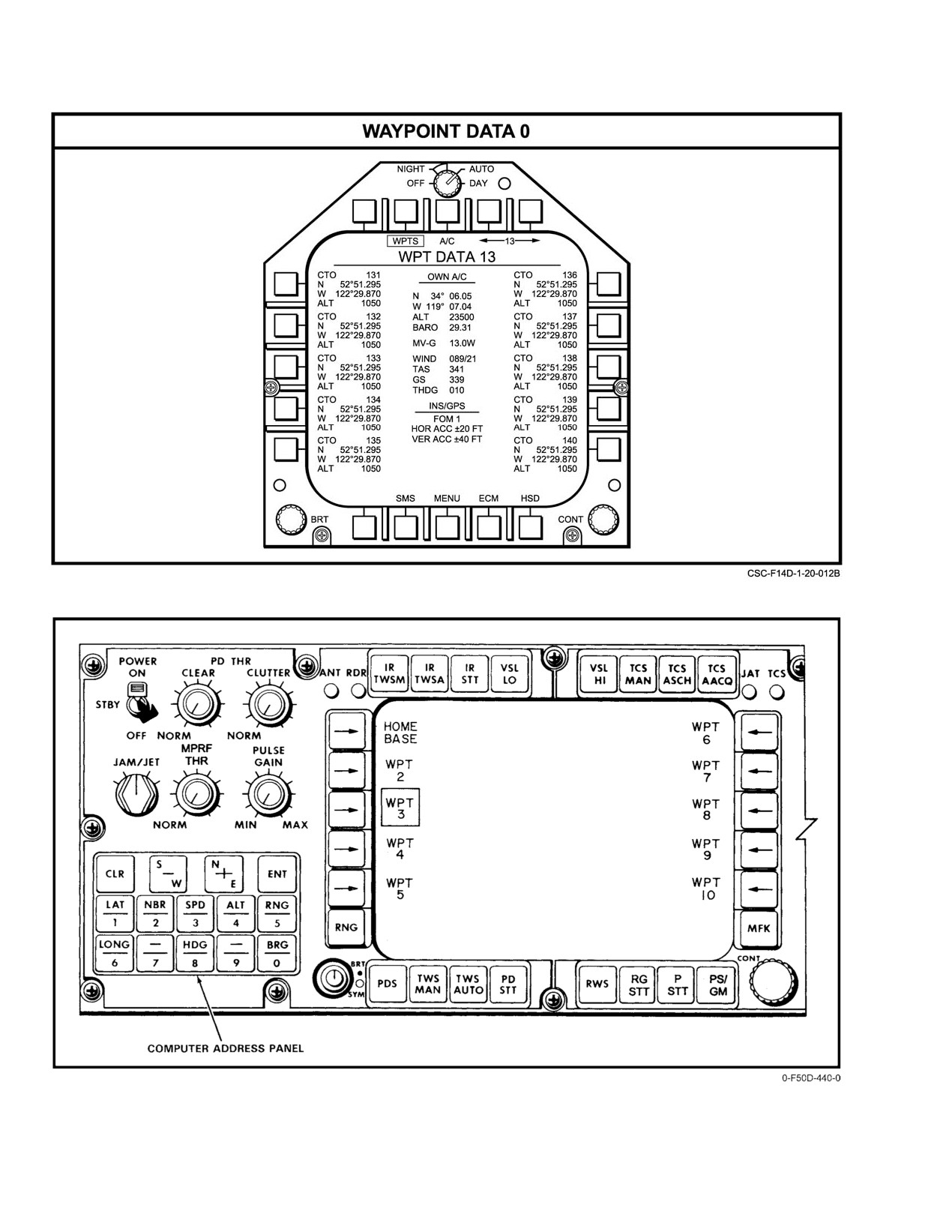
number prior to entering the coordinates. Verification of
Command course
0 to 360
correct entry can be made by examining the MFD WPT
Map lines
1 to 99
DATA format, selectable by depressing WPTS (PB7) on the
Target length
0 to 2048 nm
MFD OWN A/C format and shown in Figure 20Ć29.
Map offset
131,072 feet
The DD control panel may also be used for entering
these parameters for waypoints 1 to 20. When the DD control
panel is used, on the main menu, press the WP 1−10 or WP
During on−deck carrier operations, some waypoint data
can be automatically provided from the D/L if provisions on
11−20 pushtile and then box the desired waypoint. The
coordinates are entered using the quadrant and numeric
the carrier have been made. This is called waypoint insertion.
The D/L must be operating with the reply panel MODE
pushtiles on the lower left portion of the DD control panel,
switch in CAINS/WPT. The NAV MODE switch should be
as indicated on Figure 20−30.
in any position other than CV. For these conditions, the
latitude and longitude of up to the first 16 waypoints may be
The primary waypoint parameters and their ranges are
received.
as follows:
20.3.6.2.1
Zulu Time On Target
WPT PRIMARY
RANGE
PARAMETER
Zulu time on target (ZTOT) can be entered for the
active TGT waypoint within flight plan. Selecting ZTOT
Longitude
E/W 180
switches to a numeric entry format which allows 6−digit
Latitude
N/S 90_
ZTOT. Entering ZTOT within a flight plan maintains that
Altitude
−5000 to 99,996 feet
ZTOT for the route even if the target waypoint is changed.
Type
TGT, TCN, SAM, GEN
20−52a (20−52b blank)
CHANGE 1
NAVAIR 01−F14AAD−1
Figure 20Ć28.ĄData Entry Unit Waypoint Pages (Typical)
20−53
ORIGINAL
NAVAIR 01−F14AAD−1
Figure 20Ć29.ĄMFD Waypoint Data Format
Figure 20Ć30.ĄDD Waypoint Data Entry
ORIGINAL
20−54
NAVAIR 01−F14AAD−1
20.3.6.3
Wind Speed and Direction
Entered values of magnetic variation can be made
using either the DEU or the DD control panel. When the
Wind parameters are normally generated by the
DEU is used (Figure 20−20), the MVAR pushtile on the
navigation system using air data and INS or SAHRS
OWN A/C or CV ALGN format is selected and the value
velocities. When the navigation system cannot compute
is entered to the nearest tenth degree, preceded by an E or W
wind because of unavailability of the required velocity
for east or west, respectively. When the DD control panel is
inputs, it will accept manual entries of wind from the DEU
used (Figure 20Ć31), the NAV category is selected and the
or the DD control panel. Entry of wind can be made prior to
MAG VAR pushtile is depressed. Entry is made via the
takeoff with no sensor failure since SCADC true airspeed is
numerics on the computer address panel on the lower left
not set valid until it reaches approximately 60 knots.
portion of the DD by first depressing the HDG pushtile,
followed by the appropriate E or W, and the value to the
Wind is entered with the DEU (Figure 20−20) by
nearest tenth degree.
selecting the OWN A/C DEU format and depressing the
WSPD and WDIR pushtiles and then the proper numerics.
20.3.7
Navigation Database
Wind is entered with the DD control panel (Figure
The navigation database consists of MDL tactical
20−26) by selecting NAV and then boxing WIND and using
waypoints, MDL flight plan waypoints, MDL reversionary
the proper numeric pushtiles on the lower left portion of the
waypoints, flight plan routes, and target steering data. This
DD control panel.
data is stored on the MDL cartridge using a TAMPS station
(TAMPS version 6.1 or later) and is selectively loaded into
Note
the MCS. Controls are provided to the aircrew to display, edit
and assign steering functions to information in the navigation
For both DEU and DD entries, wind direction is
database.
the direction from which the wind is blowing.
All Waypoint Data is displayed by selecting the WPT
20.3.6.4
Magnetic Variation
(Waypoint) Data format from the WPT (PB7) on the Own
Aircraft format. Multiple pages are available on this format,
MAG VAR is available from the navigation system
each page containing ten waypoints. Pages 0 through 9
from a prestored table in the MAGR using aircraft coordiĆ
display tactical waypoints 1 to 100. Pages 10 through 19
nates. This value, when displayed on the MFD OWN A/C
show data for Flight Plan 1 (FP1), etc. From page 10 through
format, is labeled MV−G. It may also be computed using the
74, the pages that would display waypoints reserved for MCS
difference between system true heading and magnetic headĆ
use (Figure 20−32) between flight plans are omitted. For
ing from magnetic azimuth detector (labeled MV−C). In addiĆ
example, the page jumps from 14 to 20, 24 to 30, and so on,
tion to this, the navigation system will accept and use a manuĆ
up to 74, jumps to 80. Then from 80 to 99 pages continuously,
ally entered value of magnetic variation from either the DEU
providing access to MDL Waypoints 801 through 999. The
or the DD control panel (labeled MV−E). If only SAHRS is
page numbers scroll rapidly if the pushbutton is held
available, an MV−S will be displayed.
depressed over the left or right arrows.
Magnetic variation from the MAGR table is the default
In other words, to find the waypoint you want, go to the
value and will be automatically selected and displayed to the
page equal to the waypoint number with only the hundreds
nearest tenth degree. This is the recommended value and,
and tens place displayed (i.e., waypoint 9 = 009 = page 0;
unless aircraft position is unknown, will usually be the most
waypoint 126 = page 12; waypoint 889 = page 88, etc). Figure
accurate.
20−32 depicts the waypoint numbering scheme.
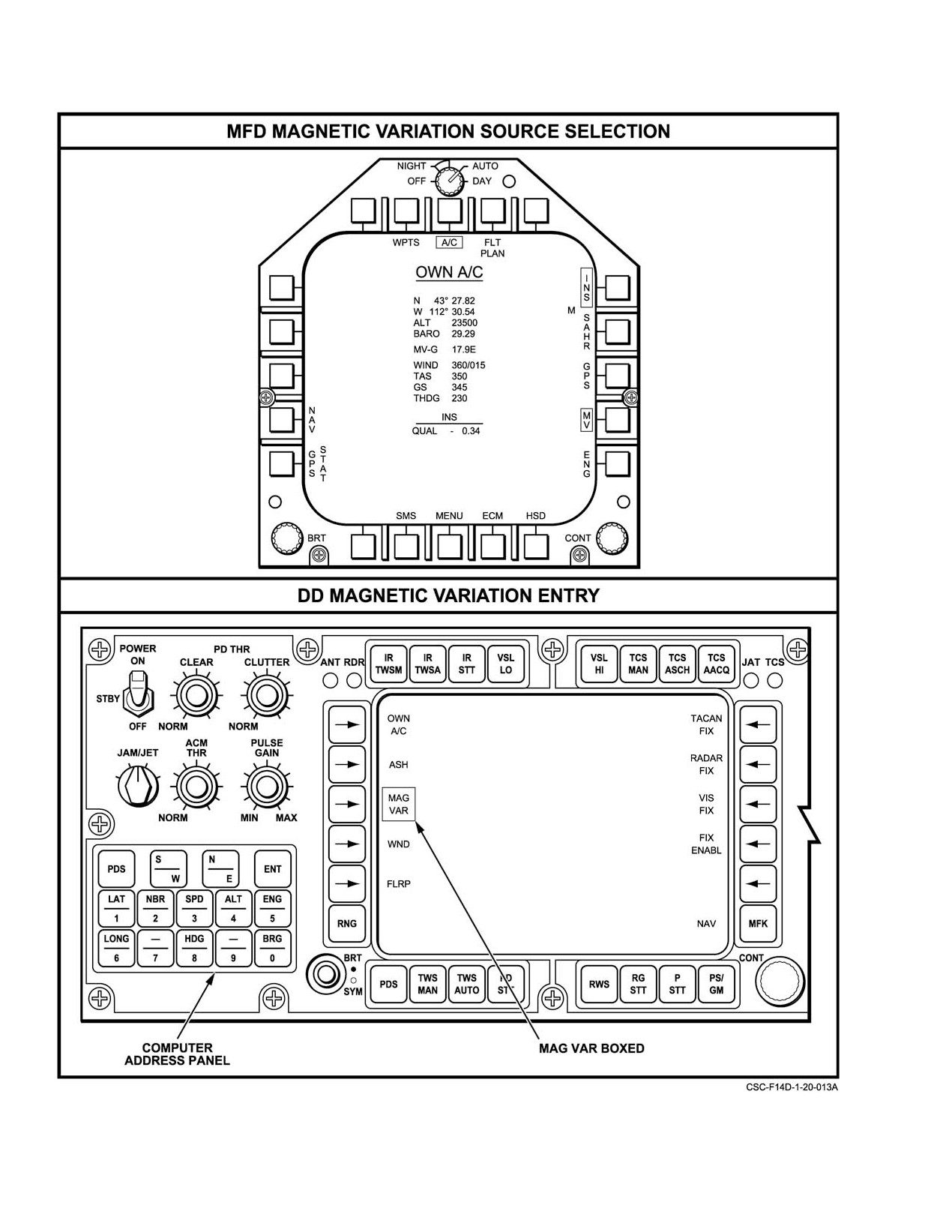
Selection of computed or entered magnetic variation is
made by depressing the boxed MV pushbutton on the lower
right side of the MFD OWN A/C format or the DD
(Figure 20Ć31). When this is done the MV−G legend in the
center of the format will cycle to MV−C, to MV−E, and back
to MV−G, indicating the source and value of magnetic
variation used by the navigation system. If GPS is not availĆ
able and SAHRS is available, MV−S will be the default.
20−55
ORIGINAL
NAVAIR 01−F14AAD−1
Figure 20Ć31.ĄMagnetic Variation Source Selection and DD Entry
ORIGINAL
20−56
NAVAIR 01−F14AAD−1
20.3.7.1
MDL Tactical Waypoints
Waypoints 2 to 16 and 21 to 100 are general waypoints
and are used as required by the mission. The data of these
The MDL can store up to 100 tactical waypoints,
points are retained after use.
numbered
1 through
100. MDL tactical waypoints are
available for GPS and destination steering, and navigation
20.3.7.2
MDL Flight Plan Waypoints
waypoints may be displayed in the data buffers on the HSD
format. Each consists of a latitude, longitude, altitude,
The MDL can store seven flight plans of up to 50
number, and type.
waypoints each, numbered as 101 through 150 up to 701
through 750 in blocks of 50. The waypoint numbers in
Tactical waypoints are listed on the WPT Data format
between (151 to 200, 251 to 300, etc.) are used internally by
in blocks of 10, on pages 0 through 9. Tactical waypoint data
the MCS and MDL for preflight planned flight plan storage
may be changed manually via the Waypoint format of the
and cannot be addressed directly.
DEU or via hooking and then depressing SET (PB 12) or
UPDT (PB 13) on the HSD format, and by transferring
waypoints from the flight plan or MDL waypoints formats.
Waypoint type may be modified manually via the Waypoint
Type format of the DEU (Figure 20−33). Available types on
the DEU for tactical waypoints are GEN (General), TAC
D All seven flight plans must be loaded via
(TACAN), and SAM (Surface−to−Air Missile). Changes to
tactical waypoints in the MCS are recorded onto the MDL
TAMPS with at least one waypoint. System
instabilities will result when trying to access
cartridge immediately, so depressing RLD (PB 2) on the
Flight Plan format has no effect on tactical waypoints.
a blank flight plan for the first time.
Waypoint types and associated symbols are shown in
D When loading any MDL waypoints via
Figure 20−34.
TAMPS, only uppercase alphanumerics
should be used for waypoint descriptions.
20.3.7.1.1
Waypoint Data File Use
D Potential exists for an MC crash if Flight Plan
Data or Waypoint Data formats are displayed
In general the 100 tactical waypoints can be used in
while updating waypoints via the DEU.
any manner described in paragraph
20.3.9, Tactical
Navigation, for destination steering or for the one−fix
Flight plan waypoints are treated as a sequence in order
updating functions. Usually, however, certain of these points
from the first waypoint in the flight plan to the last waypoint
are reserved for special functions.
defined, without any blank waypoints in between, up to a
maximum of 50 waypoints per flight plan.
Waypoint 1 is usually reserved for homebase coorĆ
dinates. Its data is retained after use.
Note
Waypoint 17 is used as a dynamic steering point when
a reconnaissance steering mode is selected using the MFD
D Trying to add flight plan waypoints more than
RECON DATA format. At this time any previously stored
one waypoint number beyond the last flight
data in waypoint 17 become invalid and must be reentered.
plan waypoint using the DEU will put the
waypoint in the next consecutive flight plan
Waypoint 18 is used for the coordinates of an agreed
location in consecutive order.
point for data−link one−fix position update. Its data are still
D Attempting to access a waypoint number that
valid after update usage.
is inaccessible (i.e., 151 to 200, 251 to 300,
etc.) for flight plan modification results
Waypoint 19 is used for the coordinates of the fighter
display of a WAYPOINT INVALID message.
link reference point, as described in the Supplemental
NATOPS Flight Manual, NAVAIR 01−F14AAD−1A. Its data
Each MDL flight plan waypoint, consisting of an
are still valid after usage for FLRP."
alphanumeric label, latitude, longitude, altitude, number,
and type, can be displayed on the waypoint data format. The
Waypoint 20 is usually reserved for the approximate
waypoint type is assigned by default or from the preflight
location and altitude of a hostile area. Its data are retained
planned type, but may be modified manually via the WPT
after use.
TYPE format of the DEU. Only one flight plan waypoint per
flight plan may be designated a TGT type for the purposes of
target steering and navigation.
20−57
ORIGINAL
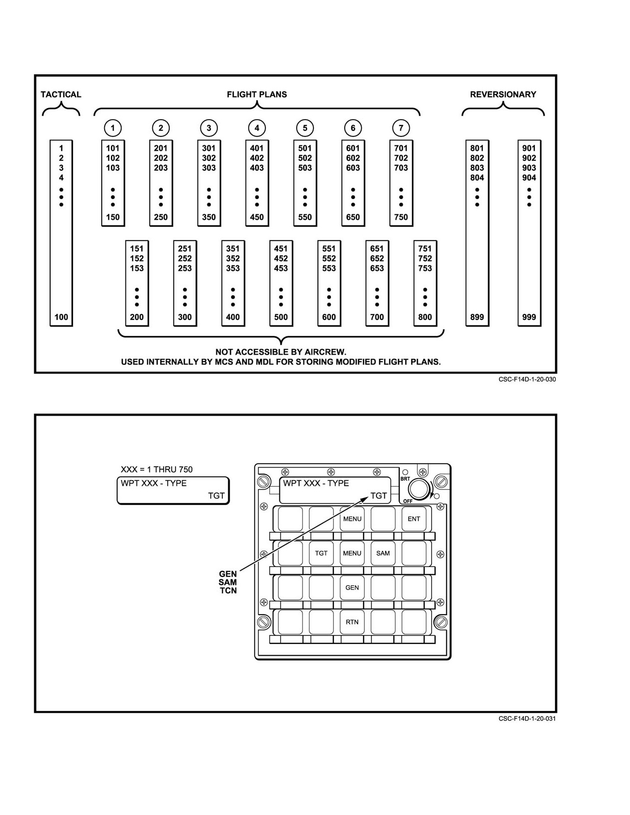
NAVAIR 01−F14AAD−1
Figure 20Ć32.ĄWaypoint Numbering Scheme.
Figure 20Ć33.ĄDEU Waypoint Type Format.
ORIGINAL
20−58
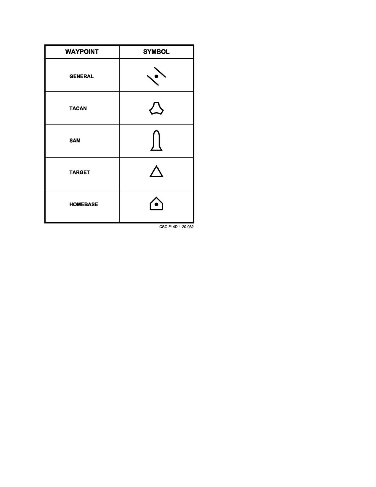
NAVAIR 01−F14AAD−1
20.3.8
Flight Plan Management
Preplanned flight plan information is available for
display and navigation when an MDL cartridge is present.
Only one flight plan may be active in the MCS at any given
time. Active flight plan waypoints are available for
destination, GPS, or auto−waypoint sequence steering.
Navigation information for flight plan waypoints may be
displayed in the data buffers on the HSD format. Flight plan
management consists of:
1. Accessing flight plan data on the MDL
2. Viewing flight plan contents
3. Activating a specific flight plan for use by the
navigation system
4. Editing the contents of any flight plan
5. Plotting waypoints in a flight plan as a flight plan
route
6. Specifying various parameters for the purpose of
flight plan route target steering
20.3.8.1
Flight Plan Data
Figure 20Ć34.ĄWaypoint Types and Associated Symbols.
Flight plan waypoints are numbered starting with the
flight plan number in the hundreds position and the position
in the flight plan as the next two numbers (i.e. 101 to 150, 201
to 250, 301 to 350, ... 710 to 750). Flight plans are treated as
20.3.7.3
MDL Reversionary Waypoints
a continuous block of waypoints, so no blank (or erased)
waypoints are allowed in the middle of a flight plan. Blanks
The MDL can store up to 199 reversionary waypoints,
will be closed up automatically.
numbered
801 through
999. Mission Data Loader
reversionary waypoints are not available directly for display,
Up to seven flight plans of 50 waypoints each are
steering, or modification; but their data may be transferred
stored on the MDL and can be preflight planned (using
into flight plan or tactical waypoints and thereafter
TAMPS 6.1 or later). Both an original and a modified copy
manipulated. Since their data is not stored in the MCS and
are stored on the MDL. The original flight plan can never be
cannot be modified directly, depressing RLD (PB 2) on the
used directly. It is only used if RLD (PB 2) on the flight plan
Flight Plan format has no effect on reversionary waypoints.
format is selected to overwrite changes to the modified flight
However, reversionary waypoint data may be transferred into
plan. When a flight plan is viewed or made active, it is the
flight plan waypoints through the ADD (PB 12) or RPLA
modified copy that is used. Any manual changes are recorded
(PB 13) functions on the flight plan format, or tactical
onto the modified copy on the MDL, which are retained for
waypoints through the XFER (PB 14) function and thereafter
future use. The modified copies are retained across system
manipulated.
resets, between flights or with the removal of the MDL
cartridge. However, depressing RLD (PB 2) on the Flight
Each MDL reversionary waypoint consists of an
Plan format reloads the original MDL flight plan into the
alphanumeric label, latitude, longitude, attitude, and number
modified copy and into the MCS (if it is active), overwriting
and can be displayed from the waypoint data format or by
all manual changes permanently. The data in the original
selecting MDL WPT from the flight plan menu. The
MDL flight plan may only be altered via a TAMPS station,
waypoint type is assigned by default but may be modified via
which will automatically update the modified copy in the
the Waypoint Type format of the DEU after the waypoint is
loading process.
transferred into the tactical or flight plan databases in the
MCS.
20−59
ORIGINAL
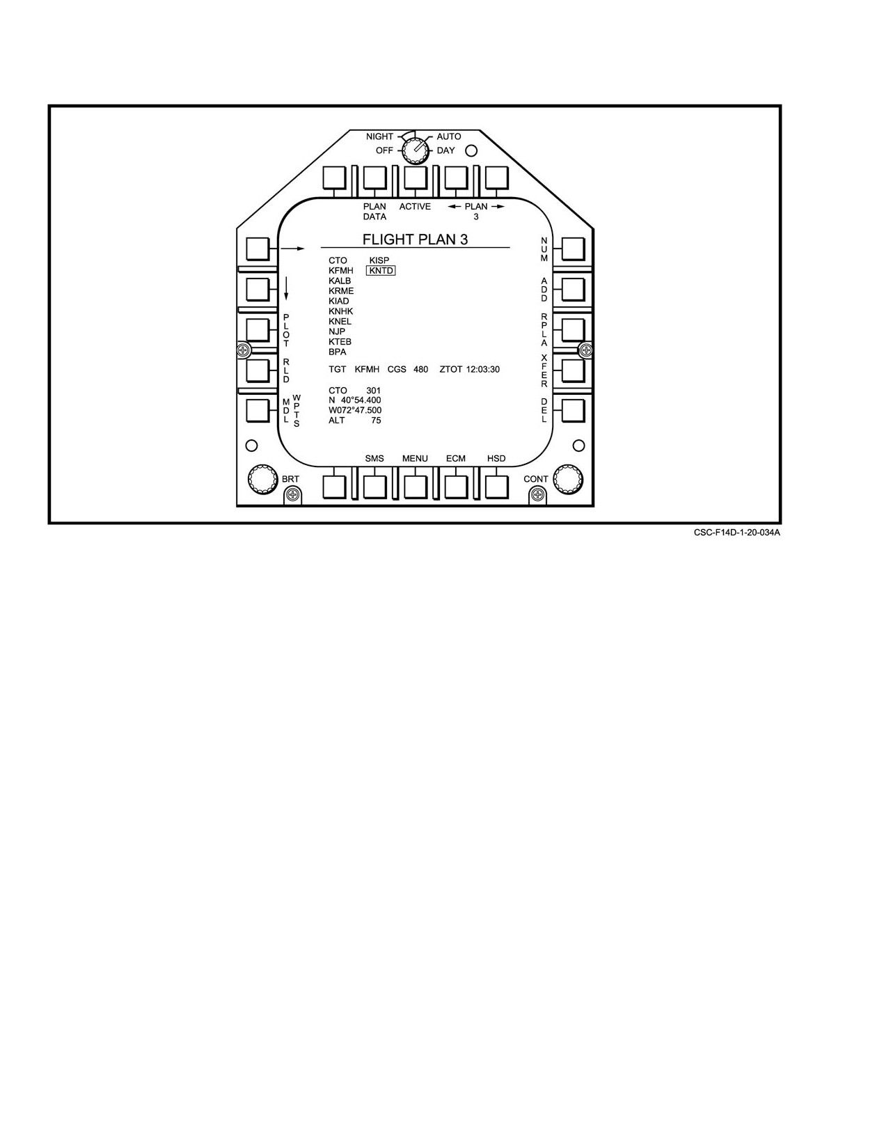
NAVAIR 01−F14AAD−1
Figure 20Ć35.ĄMFD Flight Plan Format
20.3.8.2
Flight Plan Menu
can be used in flight. The waypoints in the database are
selected using a TAMPS station during preflight planning,
The Flight Plan Format is illustrated in Figure 20−35.
and can be either added to a flight plan or used to replace an
The menu buttons and their functions are described in the
existing flight plan waypoint. They can also be transferred to
legend. The flight plan menu is selected via FLT PLAN
a tactical waypoint.
(PB 2), on the HSD format or PB 9 on the Own Aircraft
format. This is the primary display of flight plan data, listing
Movement through the four pages of MDL waypoints
waypoints in an individual flight plan by name or number.
is done with the page left and right buttons on PB 9 and
NUM (PB 11) toggles the list between numeric and alphaĆ
PB 10. The current page is shown by the range of waypoint
numeric labels. The default format is alphanumeric (NUM
numbers displayed in the title bar on the page (i.e. MDL
legend not boxed). This is the only MFD format that displays
WPTS 801−850).
flight plan route and target steering selections, and provides
The aircrew can preview information in a given
flight plan editing controls. Detailed waypoint data is also
waypoint in the bottom left buffer on the page using the
displayed for selected waypoints during editing operations.
cursor box in a manner similar to that used to view flight plan
Only those waypoints in a flight plan that have been defined
waypoints. Or, the cursor can be positioned over a waypoint
will be displayed.
to transfer it to a tactical waypoint, in exactly the same way
20.3.8.2.1
MDL Reversionary Waypoint Menu
used for a flight plan transfer.
Two menu items on the MDL Waypoints format were
The MDL Waypoint format is very similar to the Flight
Plan format, and can only be reached from the Flight Plan
carried over from the Flight Plan format, and do not function
in an intuitive manner. The RLD (PB 2) legend has no
format by selected MDL WPTS (PB 1) (Figure 20−36).
Instead of displaying one of the seven flight plans, the MDL
function on MDL waypoints since there is only one copy of
Waypoints format displays one of four pages of reversionary
MDL waypoints on the MDL, and these cannot be modified.
waypoints from 801−999.
The second item is the PLAN DATA pushtile (PB 7).
Selecting PLAN DATA will call up the PLAN DATA format,
These waypoints are stored on the MDL and cannot be
but unboxing the legend while on that format always returns
edited or deleted. They are stored with waypoint names, like
you to the Flight Plan format. It does not return you to the
the flight plans, and represent a navigation aid database that
MDL WPTS format.
ORIGINAL
20−60
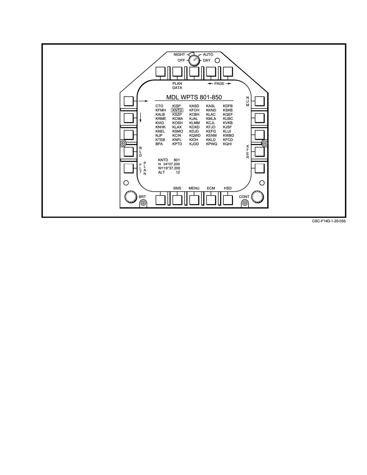
NAVAIR 01−F14AAD−1
Figure 20Ć36.ĄMDL Reversionary Waypoint Format
20.3.8.2.2
Flight Plan Data Format
of waypoints per flight plan. If there are no waypoints defined
in the number range for the page you are on for the selected
Selecting PLAN DATA from the flight plan format
flight plan (e.g., FP 6, 641−650 undefined) the page will have
(or the MDL WPT format) takes you to the plan data format
no waypoint information deployed. Successive selections of
(Figure 20Ć37), which displays detailed information on 10
the PAGE button will toggle through the 5 pages, eventually
waypoints. The Own Aircraft Data format is displayed
bringing you to the desired page.
between two columns of waypoint data, just like the WPT
DATA format. The difference is that it starts on the pages
20.3.8.3
Flight Plan Activation
corresponding to the flight plan that was displayed on the
flight plan format when PLAN DATA was boxed (even if it
Flight plans are activated on the Flight Plan format.
was boxed on the MDL WPTS format).
A flight plan is selected for activation via the increment−
decrement arrows adjacent to the PLAN legend (PB 9 and
Each flight plan has five pages corresponding to its
PB 10). Depressing ACTIVE (PB 8) causes the selected flight
fifty waypoints, whether they are defined or not. There is no
plan to be loaded into the MCS and made available to the
direct indication of which page within a flight plan you are
navigation system. Activation of a flight plan is verified by
on, other than the waypoint numbers of displayed waypoints,
a box around the ACTIVE legend when that flight plan
if there are any defined in the number range for the page you
number is displayed under the PLAN legend. A flight plan is
are on. There may be blank pages.
deactivated by activating a different flight plan, or by
unboxing ACTIVE. The latter will result in no flight plan
A particular flight plan is selected with the left and
being active in the MCS. An active flight plan is retained in
right arrows on PB 9 and PB 10, similar to the flight plan
the MCS across a system reset. The default at system power
format. The PAGE button (PB 8) pages between the 5 pages
up is no active flight plan.
20−61
ORIGINAL
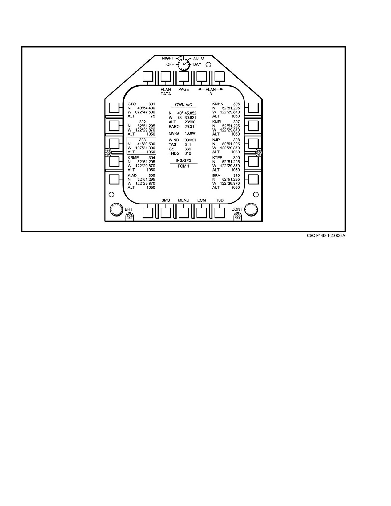
NAVAIR 01−F14AAD−1
Figure 20Ć37.ĄFlight Plan Data Format
Upon selection of an MDL flight plan for activation,
transfer buffers display the waypoint name, number, latitude,
the MCS checks the number of waypoints listed in the flight
longitude, and altitude.
plan. If the number exceeds 50, or the number is negative, the
MCS commands an MFD1 and MFD3 computer message
A rectangular box is displayed over the currently
INVALID MDL FORMAT" and returns without further
selected waypoint on each flight plan page. This box is called
processing of the discrepant flight plan or flight plan
the flight plan cursor, and can be controlled through either the
waypoints.
cursor right (→) and cursor down (↓) arrows on PB 5 and
PB 4, respectively, or with the SHC (Sensor Hand Control)
The format consists of a list of the waypoints defined
cursor or TDC (Throttle Designator Controller).
in the flight plan, in columns of 10, starting in the upper left
of the list display with the first waypoint in the flight plan.
The flight plan menu provides the means to change
The 11th waypoint in the flight plan will be displayed in the
flight plan pages, reload the original flight plan over the
first position in the next column and so on. The flight plan
modified version, or go to the MDL Waypoints format. It also
waypoints are displayed by default by their name (if no name
provides a way to move the flight plan cursor box, display
is defined, the waypoint number is displayed instead). A
flight plan waypoint data, activate a flight plan, page through
NUM button is available to toggle between waypoint names
the 7 flight plan pages, and add, replace, transfer, or delete
and numbers.
waypoints from a flight plan.
Flight plans are displayed one at a time as separate
20.3.8.4
Flight Plan Editing
pages. Depression of left or page right buttons (PB 9 and 10)
allow switching between pages. The current flight plan page
Waypoints may be added, replaced, transferred or
is displayed between the left and right arrows, as well as on
deleted within a flight plan via the Flight Plan format and its
the title bar above the waypoint list.
various sub−formats. The Flight Plan format may be selected
on more than one MFD, and up to three separate flight plans
At the bottom of the display are two waypoint transfer
(one per MFD) may be edited at any time. If the same flight
buffers that display the currently selected waypoint on the
plan is selected simultaneously on more than one MFD, then
left at all times, and the on the right when in edit modes. The
any edit operation on one MFD will lock out all edit
ORIGINAL
20−62
NAVAIR 01−F14AAD−1
commands on the remaining MFDs until the edit operation is
To add a waypoint to a flight plan, perform the
completed or canceled. Once an edit operation is completed
following steps:
or canceled, the MFD automatically returns to the Flight Plan
format. Exiting an edit operation by any other means, such
1. Select FLT PLAN format (PB 2 on HSD).
as selecting HSD (PB 15), will suspend that edit operation
2. Position the flight plan cursor box where you are
and that flight plan will be locked out for editing on any other
inserting a waypoint (following waypoints will be
MFD.
scrolled down) using either the MFD bullseye
cursor, or the right/down arrows (PB 4/5).
Notes
3. Press ADD (PB12).
D Editing Flight Plan Waypoints via the DEU
will not be possible if the Waypoint Data
4. Enter the waypoint you wish to insert (leading zeros
page format (Figure 20−29) or Flight Plan
are required, e.g., 004, 021, 053, etc.).
Data format (Figure 20−35) is displayed on
any MFD.
5. Check the waypoint information that appears in
bottom right buffer to ensure that this is the desired
D Manually−entered waypoints are specified
waypoint. If you entered a waypoint number that is
with
3 digits. Specification of waypoints
undefined, a WPT INVALID message is displayed.
1 through 99 require leading zeroes
(e.g.,
0−0− 4, vice 4).
Select ENTER (PB 8) to accept, CANC (PB 9) to abort
D The cursor box may be positioned over any
the addition operation, or BKSP (PB 7) to modify the entered
waypoint of interest or the first empty
waypoint number.
waypoint on the Flight Plan format either
sequentially via the down (↓) and right (→)
The process for waypoint addition is demonstrated in
cursor arrows
(PB 4 and PB 5) or non−
Figure 20−38.
sequentially via the manual cursor (TDC or
SHC).
20.3.8.4.2
Waypoint Replacement
(Flight Plan Replace Mode)
20.3.8.4.1
Waypoint Addition
(Flight Plan Add Mode)
A tactical, flight plan, or reversionary waypoint may
be substituted anywhere in a flight plan. The technique is
A tactical, flight plan, or reversionary waypoint may be
identical to that of adding a waypoint, except RPLA (PB 13)
inserted anywhere in a flight plan except past the end of a
is depressed (see paragraph 20.3.8.4.1). The only distinction
flight plan. There are no embedded blanks. The cursor box is
of the Replace Waypoint format is that the flight plan
placed over the desired entry point. When ADD (PB 12) is
waypoints are not shifted down from the selected entry point,
depressed, the Add Waypoint format is selected (Figure
and the left buffer will display the waypoint information for
20−38). All waypoints in the flight plan are shifted down one
the waypoint that will be overwritten. The original data in
location in order, and a blank waypoint is added at the cursor.
the selected entry waypoint is lost when replacement is
The waypoint to be added is specified by a 3−digit numeric
completed.
label. A numeric entry format is displayed and BKSP (PB 7)
is provided to erase individual keystrokes.
To replace a waypoint in a flight plan with another
waypoint, perform the following steps:
The insertion waypoint number is displayed in the left
buffer at the bottom of the Add Waypoint format. Once a
1. Select the FLT PLAN format (PB 2 on HSD).
valid waypoint number has been entered, data associated
with the waypoint to be added is also displayed in the right
2. Position the flight plan cursor box over the waypoint
you are replacing, using either the MFD bullseye
buffer. Depress ENTER
(PB 8) to insert the specified
waypoint into the flight plan. If all 50 waypoints in the flight
cursor or the right/down arrows (PB 4/5).
plan were previously defined, the last waypoint will be lost
3. Press RPLA (PB 13).
once ENTER is depressed. Depressing CANC (PB 9) cancels
the addition operation, and no waypoint data will be lost.
4. Enter the waypoint that will replace the highlighted
waypoint (leading zeros are required, e.g., 004, 021,
053, etc.).
20−63
ORIGINAL
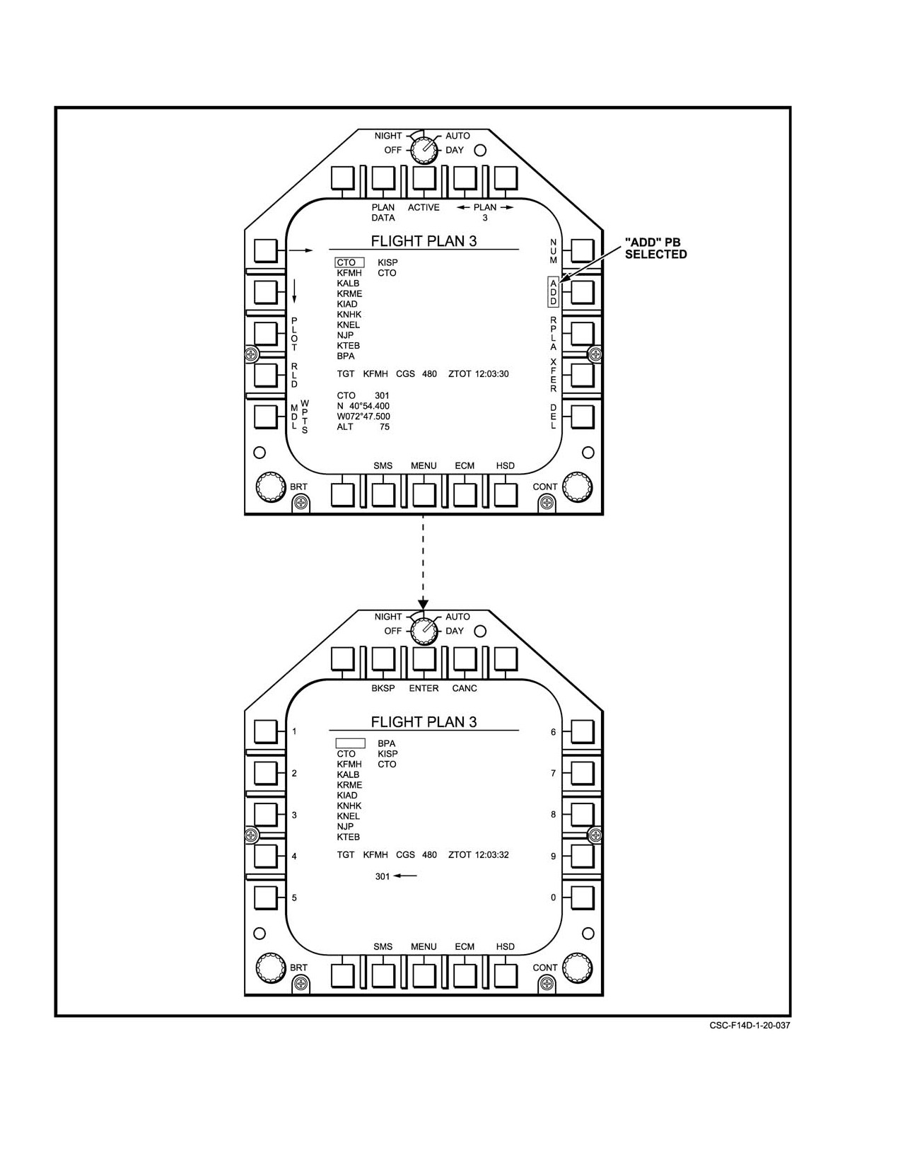
NAVAIR 01−F14AAD−1
Figure 20Ć38.ĄFlight Plan Format ć Waypoint Add Page (Sheet 1 of 2)
ORIGINAL
20−64
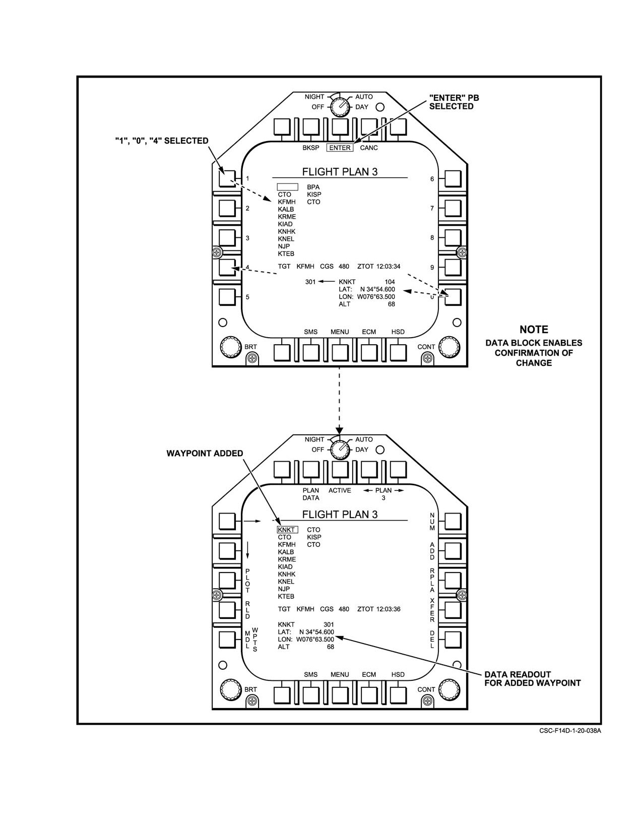
NAVAIR 01−F14AAD−1
Figure 20−38. Flight Plan Format ć Waypoint Add Page (Sheet 2 of 2)
20−65
ORIGINAL
NAVAIR 01−F14AAD−1
5. Check the waypoint information that appears in
waypoint you want to overwrite with the waypoint
bottom right buffer to ensure that this is the
information in the left buffer. If you entered a
waypoint desired. If you entered a waypoint number
waypoint number that is undefined, a WPT
that is undefined, a WPT INVALID message is
INVALID message will be displayed.
displayed.
6. Select ENTER (PB 8) to accept, or CANC (PB 9) to
6. Select ENTER (PB 8) to accept, CANC (PB 9) to
abort the addition operation.
abort the addition operation, or BKSP (PB 7) to
modify the entered waypoint number.
The process for transferring tactical waypoints is
demonstrated in Figure 20−40 and Figure 20−41.
The process for waypoint replacement is demonstrated
in Figure 20−38.
To transfer an MDL waypoint to a tactical waypoint,
perform the following steps:
20.3.8.4.3
Waypoint Transfer
(Flight Plan Transfer Mode)
1. Select the MDL Waypoints format (PB 1 on FLT
PLAN format).
A flight plan or reversionary waypoint may be
2. Position the MDL WPT cursor box over the
transferred into a tactical waypoint. The cursor box is
positioned over the flight plan or reversionary waypoint to be
waypoint to be transferred using either the MFD
bull’s eye cursor, or the right/down arrows (PB 4/5).
transferred. When XFER (PB 14) is depressed, the Transfer
Waypoint format is selected. Increment
(PB
12) and
The cursor position can be changed anytime during
the transfer operation.
Decrement (PB 13) controls are provided to select a tactical
waypoint destination, which is displayed adjacent to these
3. Press XFER (PB 14)
controls. At the bottom of the Transfer Waypoint format, the
selected transfer waypoint is displayed by number with its
4. Scroll the waypoint number to the tactical waypoint
data in the left transfer buffer. The destination tactical
number into which the MDL waypoint will be
waypoint data is also displayed in the right transfer buffer,
transferred using the increment/decrement arrows
and updated as the tactical waypoint number is scrolled using
(PB 13/14). The existing content of the selected
the increment and decrement pushbuttons. Depressing
waypoint will be shown in the bottom right buffer.
ENTER (PB 8) completes the transfer. The existing tactical
waypoint is overwritten with the waypoint information of the
5. Check the waypoint information that appears in the
selected flight plan. Depressing CANC (PB 9) cancels the
bottom right buffer to ensure that this is the
transfer operation. Flight plan and reversionary waypoints
waypoint that will be overwritten. If an undefined
are never affected by the transfer operation.
waypoint is entered, a WPT INVALID message will
appear.
To transfer a flight plan or reversionary waypoint into
a tactical waypoint, perform the following steps:
6. Select ENTER (PB 8) to accept, or CANC (PB 9) to
abort the transfer operation.
1. Select the FLT PLAN or reversionary format (PB 2
on HSD).
The process for transferring an MDL waypoint is
illustrated in Figure 20−41.
2. Position the flight plan cursor box over the waypoint
you are transferring using either the MFD bullseye
20.3.8.4.4
Waypoint Deletion
cursor, or the right/down arrows (PB 4/5). You can
(Flight Plan Delete Mode)
change the cursor position at any time during the
transfer operation.
To delete a flight plan waypoint, the cursor box is posiĆ
3. Press XFER (PB 14).
tioned over the flight plan waypoint to be deleted. Depressing
DEL (PB 15) selects the Delete Waypoint format, which
4. Scroll the waypoint number to the tactical waypoint
blanks the selected waypoint. All subsequent waypoints
number you would like to transfer into on the
selected using the cursor are also blanked. At the bottom of
increment/decrement arrows on PB
12/13. The
the Delete Waypoint format, data is displayed for both blank
existing content of the selected waypoint will be
and non−blank waypoints selected via the cursor box.
shown in the bottom right buffer.
Depressing ALL (PB 1) will blank all waypoints in the flight
5. Check the waypoint information that appears in
plan.
bottom right buffer to ensure that this is the
ORIGINAL
20−66
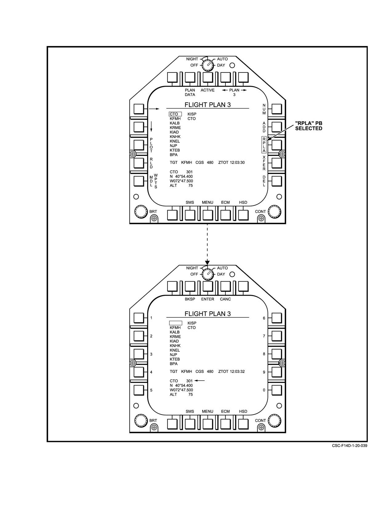
NAVAIR 01−F14AAD−1
Figure 20Ć39.ĄFlight Plan Format ć Waypoint Replacement Page (Sheet 1 of 2)
20−67
ORIGINAL
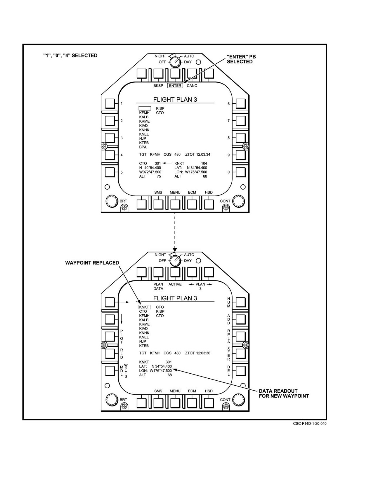
NAVAIR 01−F14AAD−1
Figure 20−39. Flight Plan Format ć Waypoint Replacement Page (Sheet 2 of 2)
ORIGINAL
20−68
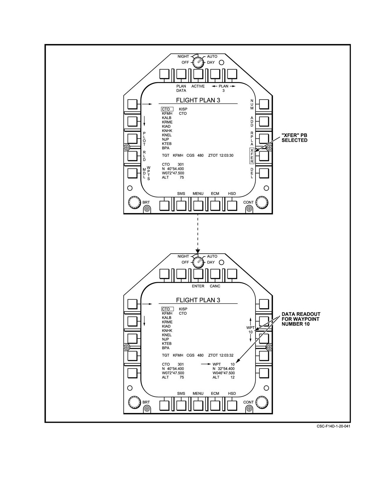
NAVAIR 01−F14AAD−1
Figure 20Ć40.ĄFlight Plan Format ć Waypoint Transfer Page (Sheet 1 of 2)
20−69
ORIGINAL
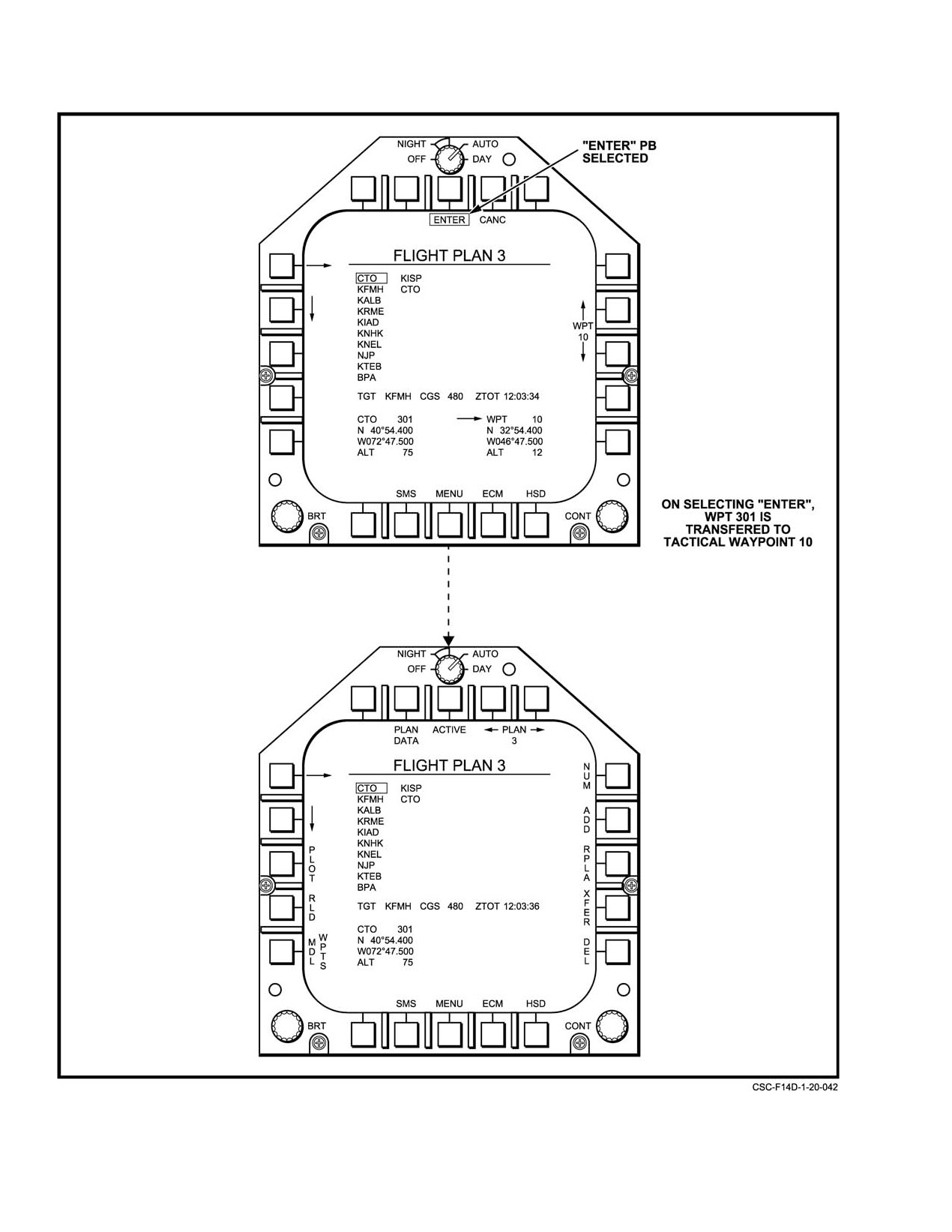
NAVAIR 01−F14AAD−1
Figure 20−40.ăFlight Plan Format ć Waypoint Transfer Page (Sheet 2 of 2)
ORIGINAL
20−70
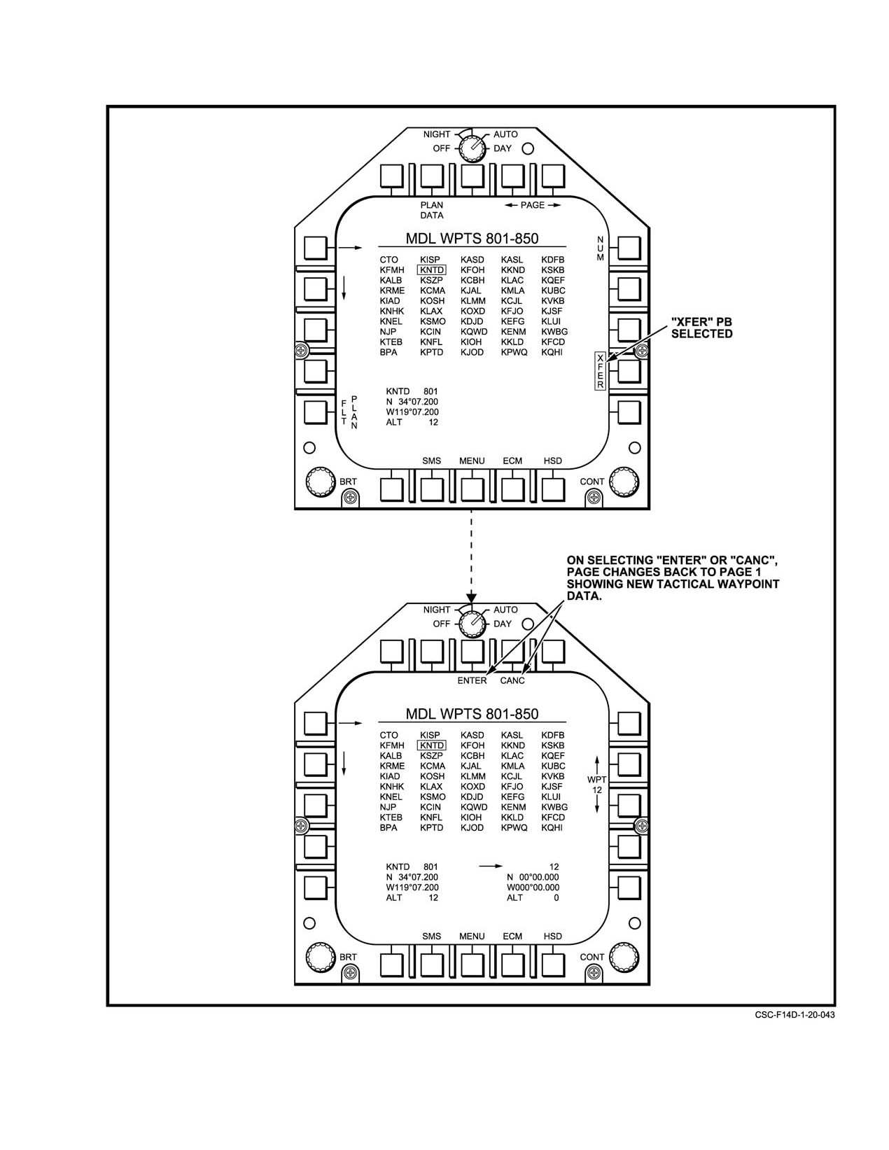
NAVAIR 01−F14AAD−1
Figure 20Ć41.ĄMDL Reversionary Waypoint Format ć MDL Waypoint Transfer
20−71
ORIGINAL
NAVAIR 01−F14AAD−1
Depressing ENTER
(PB
8) deletes all blanked
Routes are saved with the flight plan modified copies
waypoints. Depressing CANC (PB 9) cancels the delete
on the MDL cartridge, so that they are retained across system
operation and no waypoint data is lost.
resets, between flights, and with the removal of the MDL
cartridge.
To delete a waypoint, or several waypoints from a
flight plan, perform the following steps:
20.3.9
Tactical Navigation
1. Select the FLT PLAN format (PB 2 on HSD).
The following paragraphs describe the procedures to
be used for tactical navigation. This includes a description of
2. Position the flight plan cursor box over a waypoint
various navigation information, display steering modes,
to be deleted using either the MFD bull’s eye cursor,
autopilot steering, all−weather landing, position updating,
or the right/down arrows (PB 4/5).
continuous position updating, and surface waypoint
determination position.
3. Press DEL (PB 15).
4. The waypoint under the cursor will blank. The
20.3.9.1
Range, Bearing, and Time To Go to
cursor can be moved with either the HSD bull’s eye
Waypoints and TACAN Stations
cursor or the right/down arrows (PB 4/5), and every
waypoint over which the cursor moves will blank.
Range and bearing, and various time remaining
readouts available to any valid waypoint or TACAN station.
Note
Paragraph
20.2.1 describes most of this information. In
addition, a number of specialized readouts and displays are
The waypoints are not actually deleted until
provided, and are described below.
ENTER is selected.
20.3.9.1.1
HSD Commanded Ground Speed
5. Press DEL ALL if the entire flight plan is to be
emptied.
At times Commanded Ground Speed (CGS) replaces
6. Select ENTER (PB 8) to accept, or CANC (PB 9) to
TAS at the top of the HSD (Figure 20−9). This occurs if the
abort the operation.
steer point is a route waypoint, the steering mode is DEST or
AUTO, a target has been entered for the active flight plan,
The process for deleting a waypoint is illustrated in
and a ZTOT has been entered for that target on the DEU. The
Figure 20−42.
value is computed by the mission computer and represents
the ground speed required to achieve the ZTOT (Zulu Time
20.3.8.5
Flight Plan Routes
On Target) by following the route.
If a CGS has been entered for the target using the DEU,
Any or all waypoints in a flight plan may be linked
the computed CGS is based on flying at the entered CGS from
together into a flight plan route. Only one route may be
specified in each flight plan. Flight plan routes are presented
the route waypoint prior to the target. For example, assume
that a CGS of 500 was entered for the target, waypoint 105.
on the HSD format as a series of flight plan waypoints linked
by plotlines if PLOT (PB 14) is selected on the HSD format
If waypoints 101 to 104 are all route waypoints, then the
computed CGS enroute between waypoints 101 and 104
(see paragraph 20.3.9, Tactical Navigation).
would be the ground speed required to fly from 104 to 105 at
500, and achieve the entered ZTOT. If ground speed matches
Routes are specified on the Flight Plan format. The
CGS on the HSD, then the ETA on the HSD should match the
cursor box is positioned over a flight plan waypoint.
ZTOT for the TGT.
Depressing PLOT (PB 3) brightens the selected waypoint,
indicating that it has been included in the flight plan route.
The PLOT legend is also boxed, indicating that any other
20.3.9.1.2
HSD Steering Aids
waypoint that is subsequently selected using the cursor will
also be included in the route, until PLOT is unboxed.
The following paragraphs define some of the HSD
Waypoints selected as part of the flight plan route are
format steering aids: Course Line Functionality, TACAN
displayed brightened on the Flight Plan format. If the cursor
Needle Display, Waypoints and Plotlines, CDI (Course DeviĆ
box is placed over a flight plan waypoint that is part of the
ation Indicator) Functionality, and Cross Track Error IndicaĆ
route, PLOT will not box. In order to deselect that waypoint
tion. Figure 20−9 lists some of the display items relevant to
as part of the route, PLOT must be depressed twice, once to
these steering aids.
box the menu item, and a second time to deselect the point
as part of the route.
ORIGINAL
20−72
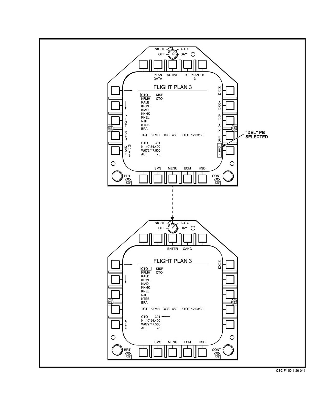
NAVAIR 01−F14AAD−1
Figure 20Ć42.ĄFlight Plan Format ć Waypoint Delete Page (Sheet 1 of 2)
20−73
ORIGINAL
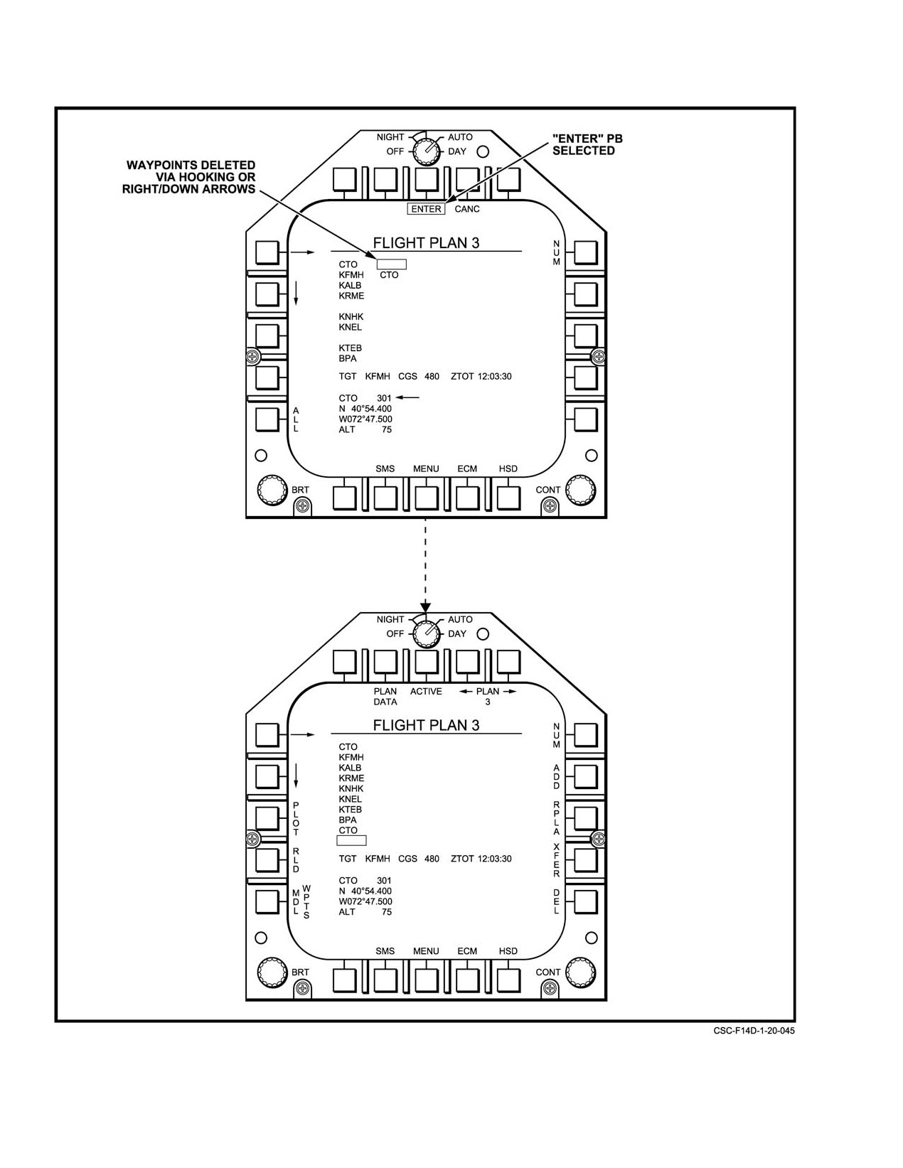
NAVAIR 01−F14AAD−1
Figure 20−42. Flight Plan Format ć Waypoint Delete Page (Sheet 2 of 2)
ORIGINAL
20−74
NAVAIR 01−F14AAD−1
20.3.9.1.2.1
HSD Course Line Functionality
As with TACAN CDI, the scaling of the CDI offset dots
is based on gear up/gear down status. With the gear up, the
two dots on each side represent 2 and 4 nm offsets from the
The course line on the HSD is drawn through the
selected course. With the gear down, they represent 0.5 and
current steer point or TACAN station and rotates with the
1 nm offsets.
selected course (CRS knob) while in GPS or TCN steering
(Figure 20−45).
Note
20.3.9.1.2.2
HSD TACAN Needle Display
GPS CDI is a fixed horizontal deviation where
the TACAN CDI deviation is an angular offset
The HSD TACAN needle is displayed as a cross−
that corresponds to greater horizontal deviation
hatched head and tail pointer on the inside of the compass
at greater range. The TACAN CDI actually gives
rose. In all steering modes, except GPS, it is displayed if valid
finer resolution steering cues than the GPS CDI;
TACAN bearing is available and the head of the needle
and the GPS CDI gives better accuracy at range.
always points to the station. In GPS steering modes, the
At very short ranges from the waypoint or station
TACAN needle points to the selected steer point as if it were
(i.e., less than 0.5 miles), the TACAN gives you
a TACAN station.
more accurate cues and is more sensitive to small
deviations. The GPS is much more stable and is
20.3.9.1.2.3
HSD Waypoints and Plotlines
not subject to swings" due to poor reception.
Waypoints and plotlines are displayed on the HSD.
20.3.9.1.2.5
HSD Cross Track Error Indication
Plotlines connect waypoints that are defined as route
waypoints (assuming more than one) within a flight plan.
Cross Track Error is the perpendicular horizontal
deviation from a selected course to a waypoint (in GPS
There is a display limit of
32 plotlines and
30
steering) or from the route centerline (in DEST or AUTO
waypoints on the HSD. The current steer point will always be
steering). Cross Track Error is displayed with accuracy to
displayed, along with the next closest 29 waypoints in range
tenths of a nm. If the following conditions are met, Cross
to the aircraft. Plotlines are displayed independent of
Track Error is displayed on the HSD just above the compass
waypoints. If a plotline does not appear to go to a waypoint,
rose to the right:
it may be that the waypoint is not one of the closest 30.
D GPS, DEST, or AUTO steering
There is a capability in TAMPS to create a tactical
D Current steer point is part of route beyond first
waypoint on the MDL with a blank" type associated with it.
route waypoint for DEST and AUTO.
This allows the use of plotlines to box out operating areas
without having displayed waypoints at every point defining
20.3.9.2
Display Steering Modes
that area cluttering the display. However, these blank
waypoints count as part of the displayed" 30.
Several steering modes, optimized for specific
missions and phases of flight, are available to the aircrew.
A route waypoint is one which is part of an active flight
These steering modes, with their associated controls and
plan, and which has been brightened on the flight plan format
displays, are summarized in Figure 20−43. Steering modes
with the PLOT" button. It will be displayed with a plotline
may be selected by cycling through modes using STR (PB 9)
through it on the HSD if PLOT is boxed on the HSD.
on the HSD format, or by making individual selections from
the menu presented on the VDI format. Although partial
The steer point is the waypoint that is currently selected
steering cues may be presented on the HUD A/A and A/G
for waypoint steering in DEST, AUTO, or GPS steering
formats, complete steering cues are always presented on the
modes. Its number is displayed next to the steering mode in
TLN format.
the lower right of the HSD.
In most modes, the aircrew selects the navigation
20.3.9.1.2.4
HSD CDI Functionality
steering waypoint manually via the HSD format, by the
following method:
When the steering mode is GPS and CDI (PB 14) is
boxed, the Course Deviation Indicator (CDI) is displayed in
1. Depress the decrement (PB 4) or increment (PB 5)
place of the course line. The differences between this and the
arrows until the desired waypoint is displayed
TACAN CDI are that the reference point is the selected steer
between them. Navigation data for each waypoint is
point and the scaling is based on a horizontal distance from
displayed in the boxed (left or right) data buffer as
the centerline of the selected course to that waypoint.
it is selected.
20−75
ORIGINAL
NAVAIR 01−F14AAD−1
SELECTION
HSD RIGHT
STEERING
SOURCE
BUFFER DISPLAY
MODE
AVAILABLE STEERING CUES AND CLOCKS
(LABEL)
HSD
VDI
WPT
TCN
(HUD/VDI/HSD)
Destination
X
X
X
Command heading markers
(DEST)
Destination bearing pointer (Course Line)
Destination bearing marker1
WPT range readout
Time−to−go to waypoint readout
Cross−track error if route waypoint selected
TACAN station bearing pointer (To and From)2
TACAN (TACAN)
X
X
Course deviation markers
Course deviation indicator
TACAN station bearing pointer (To and From)2
Selected course line (through station)
TACAN range readout
Time−to−go to station readout
GPS Pseudo−
X
X
Command heading markers
TACAN (GPS)
Course deviation markers
Destination bearing marker1
Selected course line (through steer point)
GPS range readout
Time−to−go to waypoint readout
Cross−track error from course line readout
Auto−Waypoint
X
X
Command heading markers
3
Sequenc
ing
Destination bearing pointer (Course Line)
(AUTO)
Destination bearing marker1
WPT range readout
Time−to−go to waypoint readout
Cross−track error from route line readout
TACAN station bearing pointer (To and From)2
Commanded
X
X
Command heading markers
GroundSpeed3
Destination bearing pointer (Course Line)
(AUTO)
Destination bearing marker1
WPT range readout
Time−to−target readout
Commanded ground speed readout
Ground speed error caret
Cross−track error from route line readout
TACAN station bearing pointer (To and From)2
NOTES:
1.
Displayed in all steering modes if a valid destination steer point is entered in the MCS
2.
Displayed in all steering modes if a valid TACAN signal is being received.
3.
Automatically changes to DEST steering inbound to the target waypoint or once the last
waypoint on the flight plan route is overflown.
Figure 20Ć43.ĄSteering Mode Summary
ORIGINAL
20−76
NAVAIR 01−F14AAD−1
2. Select ENT (PB 15) to make the displayed waypoint
20.3.9.2.2
TACAN Steering
the navigation steer−point. The waypoint number
will be displayed in the lower right corner of the
In the TACAN steering mode (Figure 20−45), the pilot
HSD format along with the current steering mode.
may steer to a selected TACAN radial using the various
course deviation displays on the HUD and MFD. The
In other modes, the navigation steer−point may be
TACAN deviation is the angular difference between the bearĆ
selected automatically by the MCS or is calculated from
ing to the TACAN station (TACAN radial) and the command
encoded digital data link or analog RF signals, such as data
course (TACAN course) selected by the pilot on the course/
link or TACAN.
heading control panel.
Internal navigation calculations are computed using
To enter the TACAN steering mode, the pilot depresses
the NAV State Vector, which is updated with INS, SAHRS
the TCN pushbutton on the MFD VDI display format or
and/or GPS information, and is updated if any one of these
selects TACAN by the STR pushbutton. After selection of a
constituent sources is valid.
TACAN course, the TACAN deviation symbols are
displayed on the HUD, MFD VDI TACAN, and two possible
20.3.9.2.1
Destination Steering
HSD TACAN formats. On the HSD TACAN format, the CDI
display mode may be selected by depressing the CDI
In the destination steering mode, the pilot maintains
pushbutton. With CDI selected, the TACAN deviation is disĆ
a great circle route from the aircraft present position to a
played in the form of a deviation bar whose offset is scaled
designated waypoint by steering to the command heading
along a row of deviation tics. The arrowhead on the bar is
marker on the HUD and VDI.
changed on the displays to indicate whether the TACAN
course is toward or away from the TACAN station. If the
The pilot selects the destination waypoint for steering
TACAN deviation is less than 90°, a to" indication is shown
by depressing the up or down arrow pushbuttons on the HSD
and, if greater than 90°, a from" indication. The TACAN
basic format and then pressing the ENTER push−button. This
deviation bars on the HUD, MFD VDI TACAN display
results in the HSD format in Figure 20−44. The mission
format and MFD HSD TACAN display format are solid bars
computer calculates range, bearing, and time to go from the
when going to and dashed bars when coming from. The
aircraft position. This data is shown in the upper left data
separation between deviation tics is 4°.
block on the HSD format. The destination display steering
mode may then be initiated by depressing the DEST
If the CDI display is not selected, then the second HSD
pushbutton on the MFD VDI display format or by selecting
format in Figure 20−45 is displayed. On this format the
DEST from the STR pushbutton on the HSD. The mission
TACAN radial is still displayed passing through the aircraft
computer then calculates the command great circle course to
symbol but instead of the deviation indication, the command
the selected waypoint and the command heading to fly to
course pointer is shown passing through the station symbol.
make it good by considering drift angle.
TACAN steering provides course, bearing, range and
DEST steering provides bearing, range and time
time information for navigation to a TACAN station either
information for navigation direct to or from a waypoint. All
direct or along a specified course. Bearing and range to
navigation parameters are computed internally from inertial
station are decoded from external analog RF TACAN signals.
coordinates (see Figure 20−44).
TACAN steering requires an operative JTIDS receiver with
TACAN.
The command heading markers in the HUD heading
scale and along the HSD format compass rose provide a
Note
wind−corrected heading cue direct to the destination
Digital TACAN information is only available in
waypoint via Great Circle route. The HSD course line and
the upper right HSD buffer while steering mode
destination bearing marker provide non−wind−corrected
is TACAN or BLANK. The TACAN station bearĆ
bearing to the destination waypoint. The selected heading
ing pointer and symbol are available in all steerĆ
and course functions (HSEL [Heading Selected] and CSEL
ing modes except GPS pseudo−TACAN.
[Course Selected]) are not operable. The HSD left and right
hand data buffers display waypoint information.
20.3.9.2.3
GPS Steering (Pseudo−TACAN)
Note
GPS steering provides pseudo−TACAN" course,
The destination bearing marker on the HSD
bearing, range and time information for navigation to a
format is displayed in all steering modes,
waypoint either direct or along a specified course. The GPS
including steering off, if a valid destination
steering emulates TACAN steering using precise GPS
waypoint is entered as the destination steer point.
position information and requires an operative MAGR .
20−77
ORIGINAL
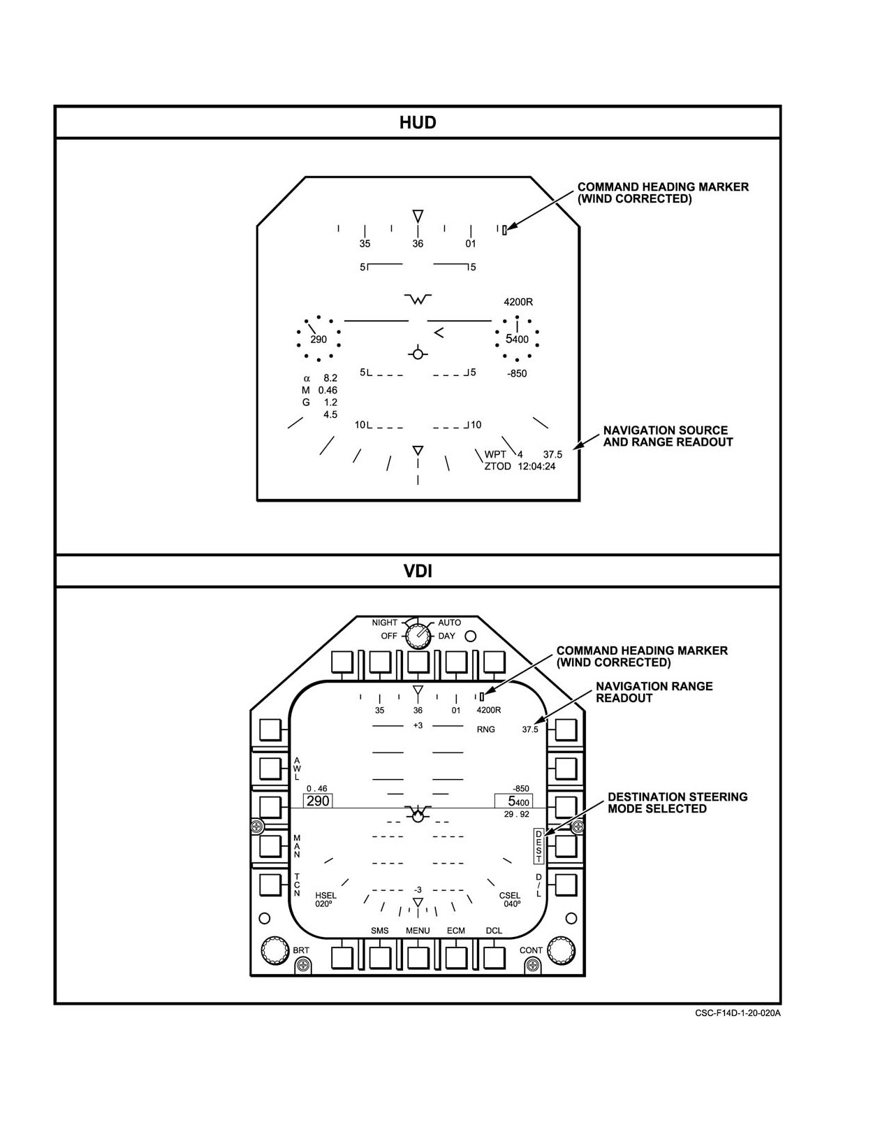
NAVAIR 01−F14AAD−1
Figure 20Ć44.ĄDestination Steering Displays (Sheet 1 of 2)
ORIGINAL
20−78
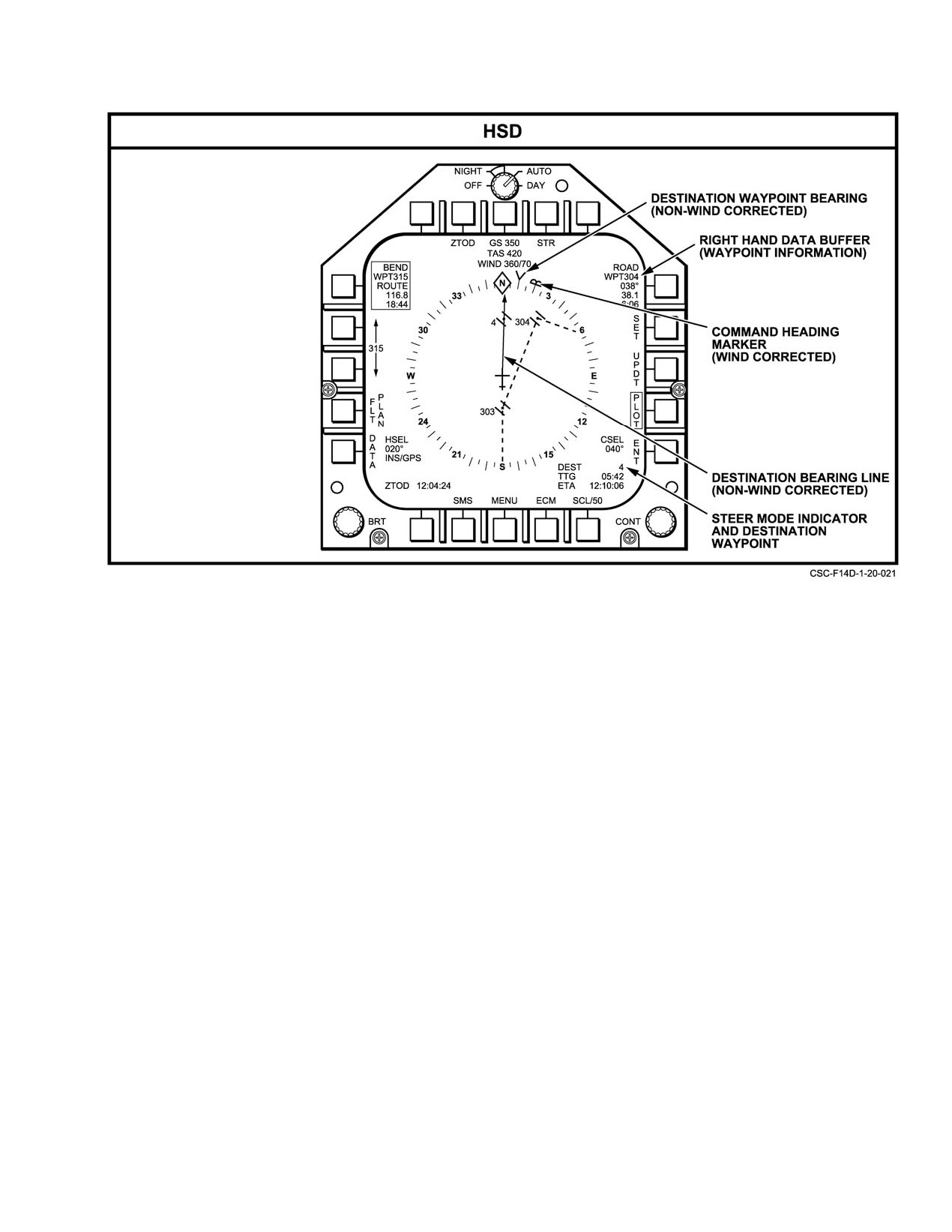
NAVAIR 01−F14AAD−1
Figure 20−44. Destination Steering Displays (Sheet 2 of 2)
Steering cues are similar to those in TACAN steering.
AUTO steering is replaced with DEST steering
However, on the HUD and the VDI format the course
automatically when any of the following conditions occur:
deviation marker scale is such that each dot represents a
1. The navigation steerpoint steps to the Target
2 nm deviation for a maximum deflection of 4 nm with the
waypoint
landing gear handle up, and 0.5 nm deviation for a maximum
deflection of
1 nm with the landing gear handle down.
2. A waypoint not on the flight plan route is selected
Additionally, a cross−track error digital readout is displayed
as the navigation steerpoint
on the HSD format, which provides actual lateral deviation
from the selected course line. The HSD left and right hand
3. The final waypoint on the flight plan route is
data buffers display waypoint information. Typical GPS
reached
steering formats are illustrated in Figure 20−46.
4. The flight plan is deactivated or changed
20.3.9.2.4
Automatic Waypoint Sequence
AUTO steering may be reselected once any other
Steering
waypoint on the route is selected as the steerpoint. Cues for
AUTO steering are similar to those for DEST steering
(see paragraph 2 ). Additionally, a cross−track error digital
AUTO steering provides the functionality of DEST
readout on the HSD format provides actual lateral deviation
steering, with the additional MCS feature of automatic
from the centerline of the current route leg. The HSD left and
stepping to successive waypoints along a fight plan route.
right hand data buffers display waypoint information. The
AUTO steering is only available with an active flight plan
changeover point for automatic waypoint sequencing and
route, and may be selected only if the current destination
typical AUTO steering displays are illustrated in
waypoint is included on that route but is not the designated
Figureă20−47.
Target waypoint or the last waypoint in the selected
sequence. All navigation parameters are computed internally
Automatic sequencing occurs when the current
from inertial coordinates.
AUTO steering point is passed (90º or greater off the nose)
within 5ănm.
20−79
ORIGINAL
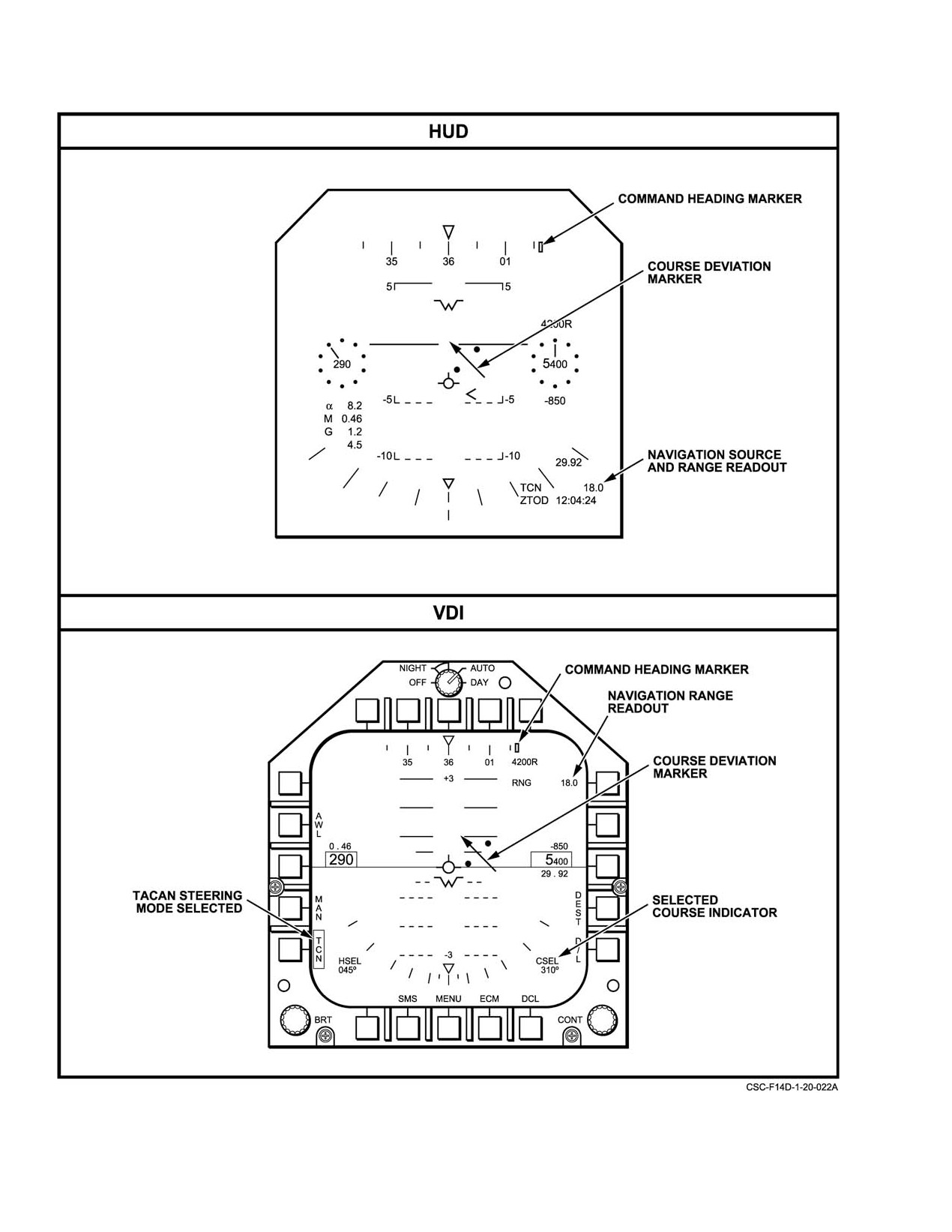
NAVAIR 01−F14AAD−1
Figure 20Ć45.ĄTACAN Steering Mode Formats (Sheet 1 of 2)
ORIGINAL
20−80
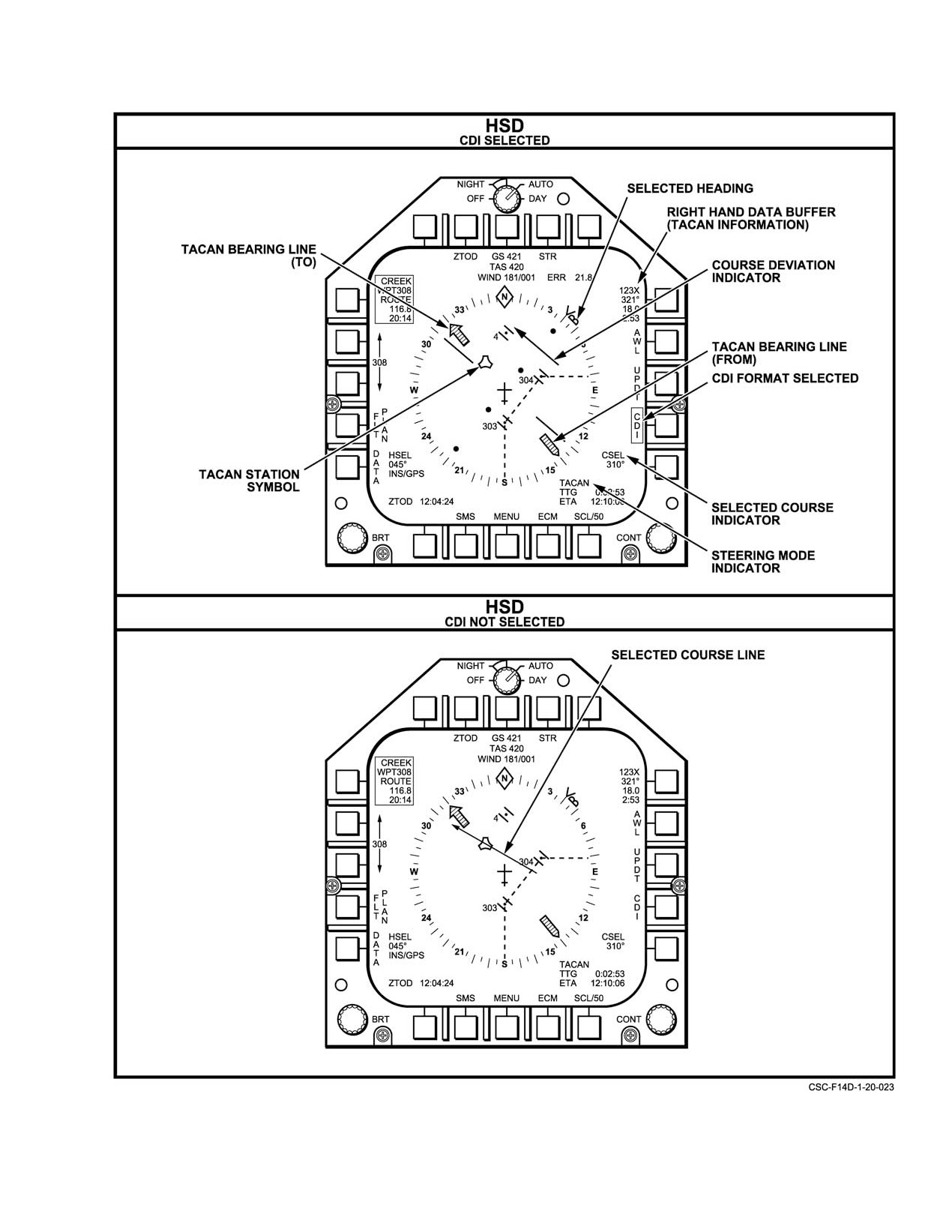
NAVAIR 01−F14AAD−1
Figure 20−45. TACAN Steering Mode Formats (Sheet 2 of 2)
20−81
ORIGINAL
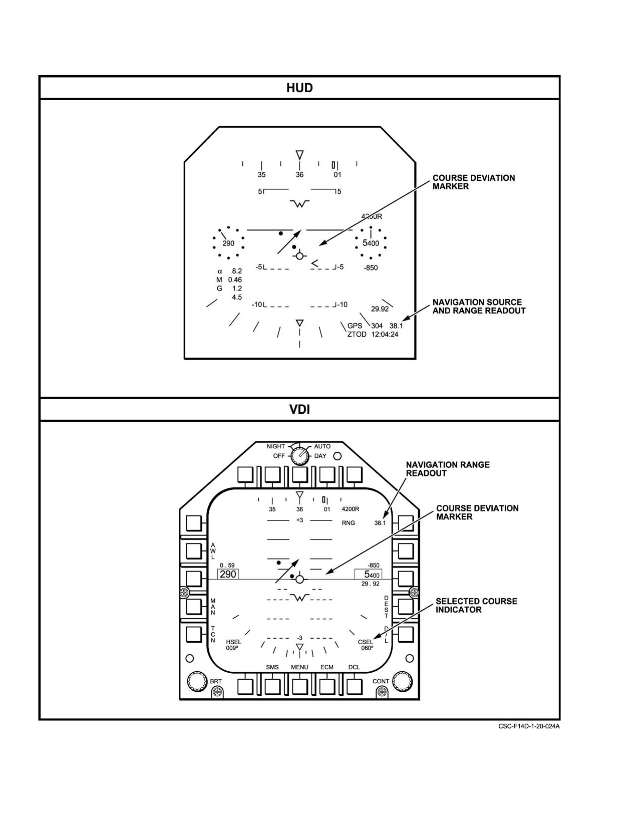
NAVAIR 01−F14AAD−1
Figure 20Ć46.ĄTypical GPS Steering Formats (Sheet 1 of 2)
ORIGINAL
20−82
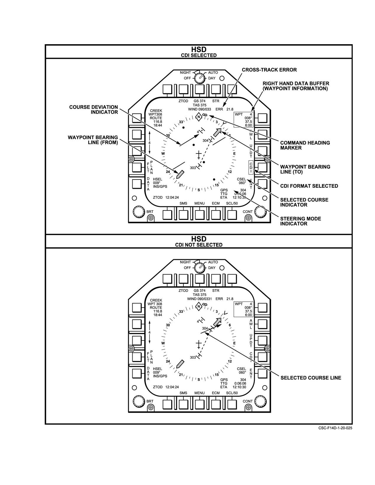
NAVAIR 01−F14AAD−1
Figure 20−46. Typical GPS Steering Formats (Sheet 2 of 2)
20−83
ORIGINAL
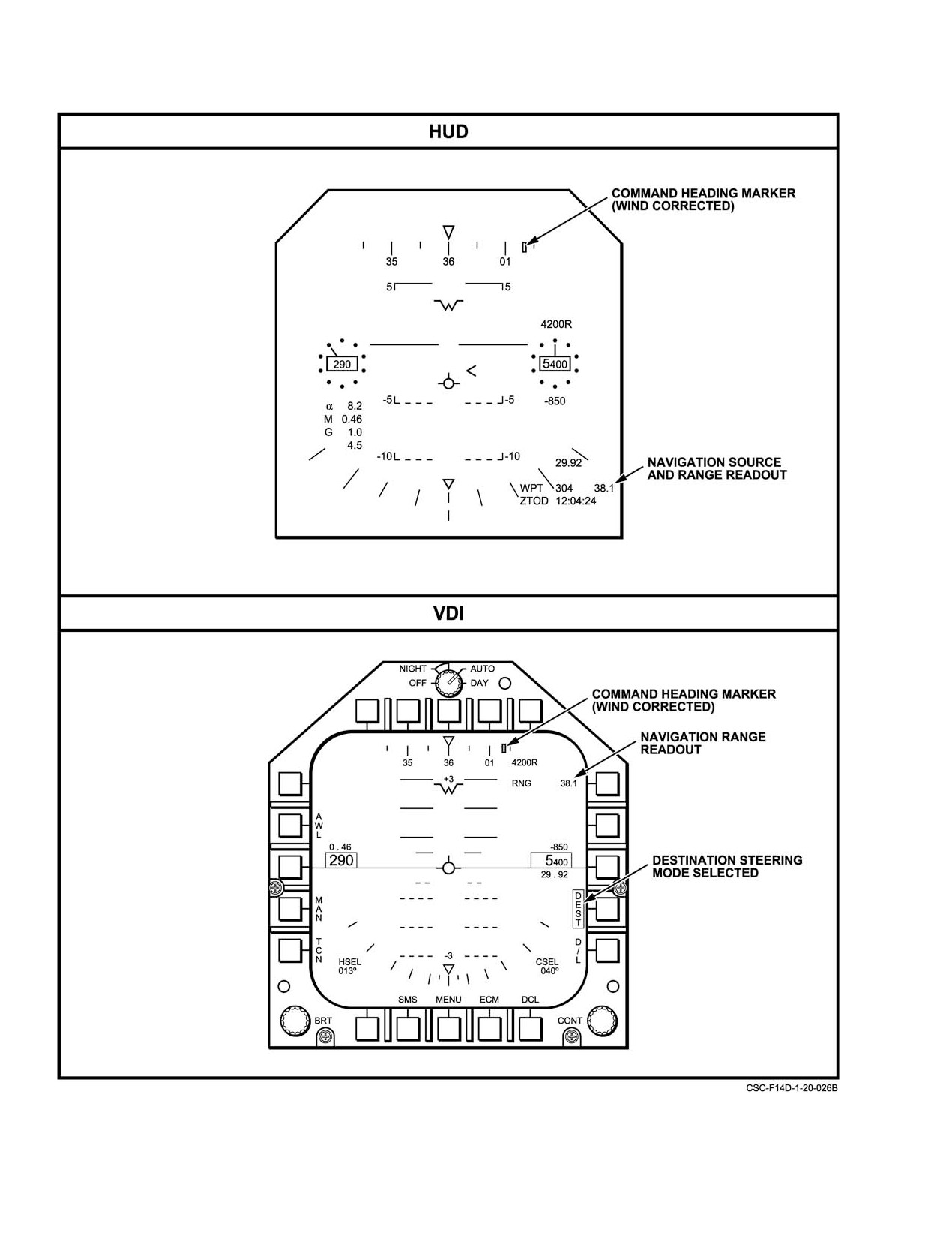
NAVAIR 01−F14AAD−1
Figure 20Ć47.ĄAuto Waypoint Steering Displays (Sheet 1 of 2)
ORIGINAL
20−84
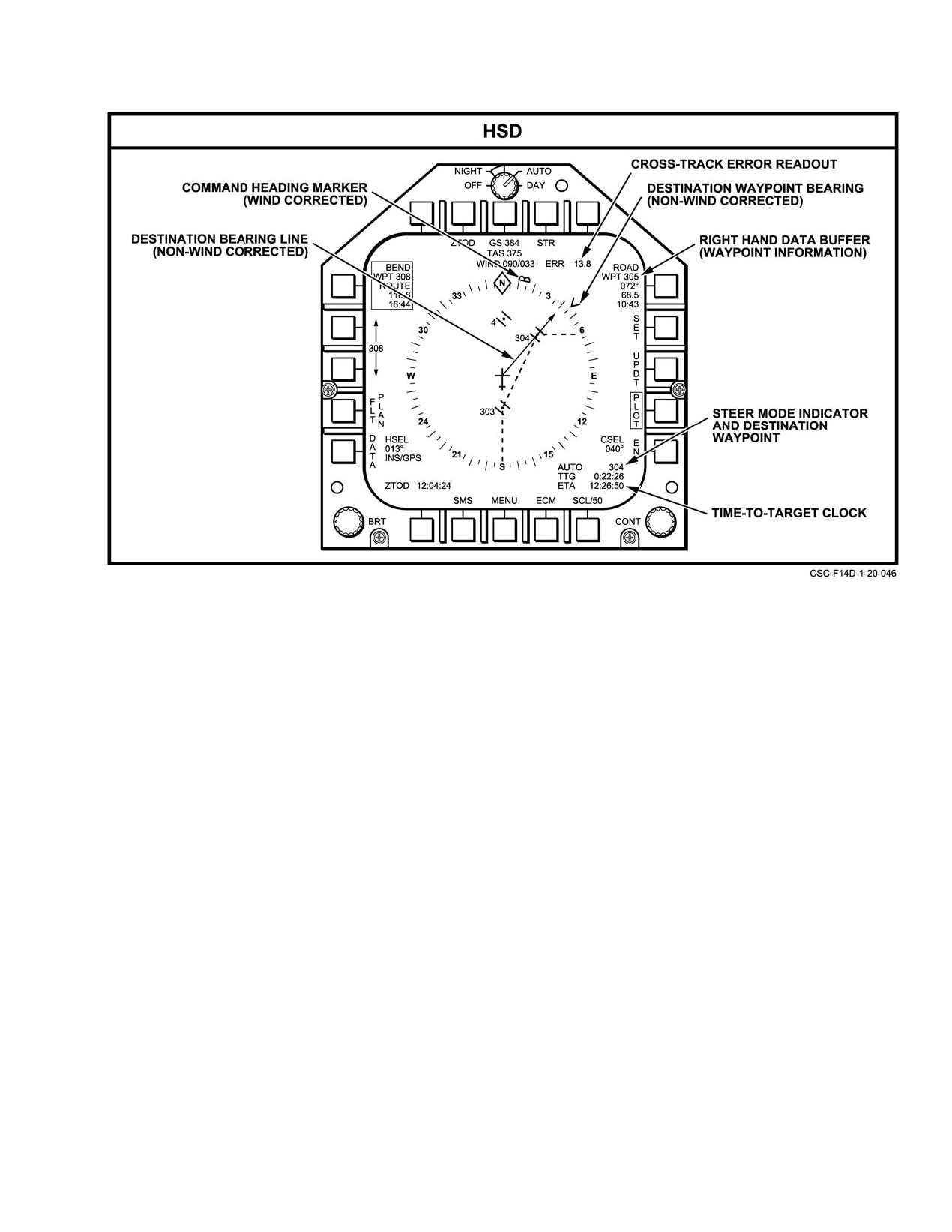
NAVAIR 01−F14AAD−1
Figure 20−47. Auto Waypoint Steering Displays (Sheet 2 of 2)
20.3.9.2.5
Commanded Ground Speed Steering
The TGT, ZTOT and CGS parameters are entered via
the DEU as follows:
Commanded Ground Speed steering is a special subĆ
1. From the main menu, select WPT.
mode of AUTO steering which provides additional airspeed
cues for precise timing of arrival over a defined flight plan
2. Enter the desired TGT waypoint number and select
Target waypoint. Existing AUTO steering cues are still
ENTER.
available, and the steering mode buffer of the HSD format
will display the AUTO legend. (See paragraph 20.3.9.2.4.)
3. Select TYPE, and from this submenu select TGT
and ENTER.
To enable CGS steering, the aircrew must specify the
4. Select CGS, enter the desired ground speed in knots
following parameters for a flight plan route: TGT (Target
for the terminal inbound leg to the TGT and
Waypoint), CGS, and ZTOT. The MCS will attempt to
ENTER.
calculate and display on the HUD and the HSD format
airspeed cues to achieve the specified time and airspeed over
5. Select ZTOT, enter the desired Zulu time on target
the TGT if the following conditions are met:
and ENTER.
1. A flight plan with a defined route is active.
In CGS steering, the MCS continually calculates the
ground speed required to cover the distance from the current
2. The current destination waypoint is on the flight
aircraft location to the TGT along the active flight plan route,
plan route.
and also accounts for the CGS specified for the final leg
3. AUTO steering is selected.
inbound to the TGT. The difference between the aircraft’s
ground speed and the CGS is presented graphically on the
4. The TGT and ZTOT have been specified for the
HUD and digitally on the HSD format. Commanded Ground
flight plan.
Speed steering provides the aircrew with cues for airspeed
control to meet the timing requirements specified by CGS
5. Valid ZTOD from the MAGR is available.
20−85
ORIGINAL
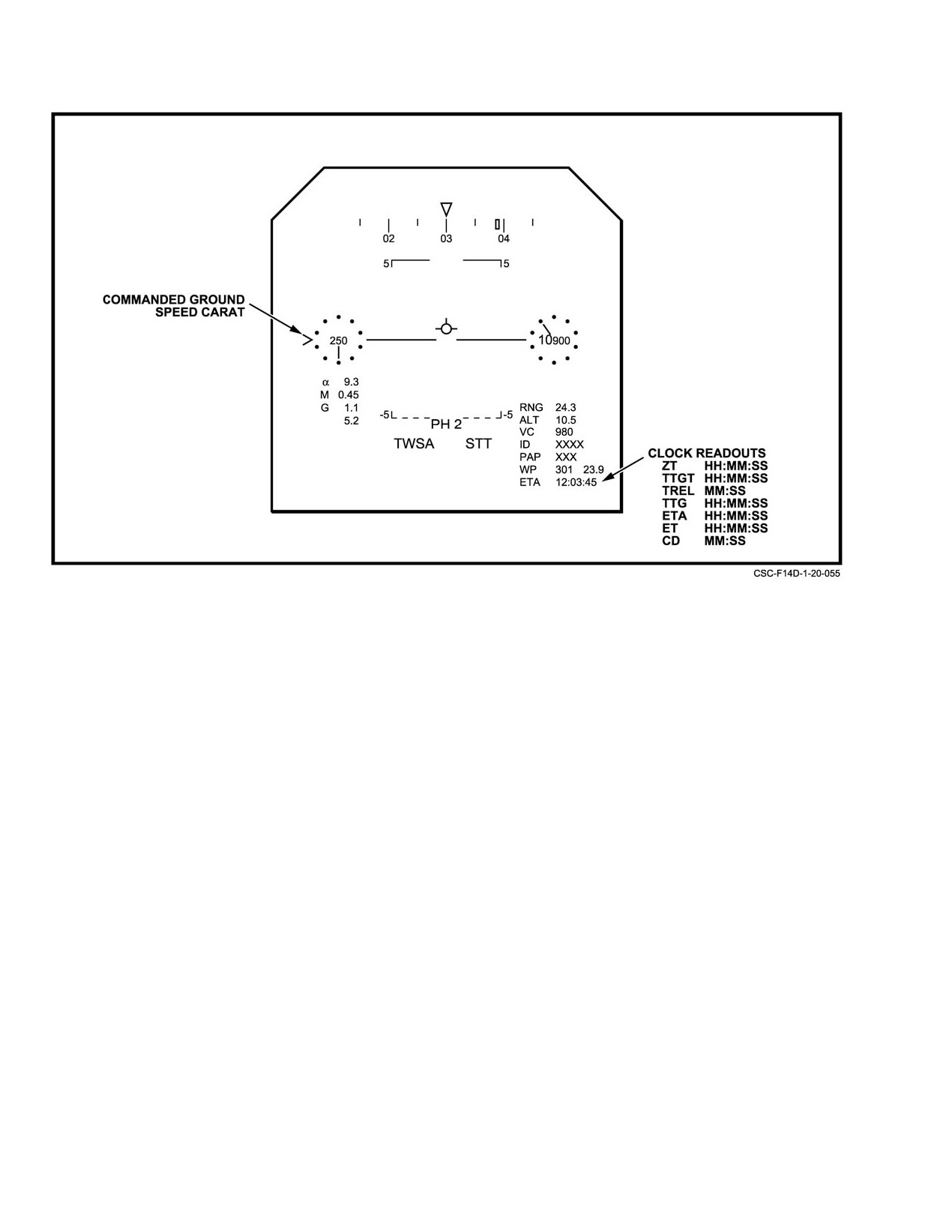
NAVAIR 01−F14AAD−1
Figure 20Ć48.ĄCommanded Ground Speed Indication
and ZTOT. The CGS cuues are displayed to the aircrew
20.3.9.2.6
Manual Steering
whenever valid, and are determined by the following criteria:
In the manual display steering mode, the pilot
1. CGS exceeds 133 knots
maintains a command magnetic course by steering the
aircraft to the command heading marker on the HUD or MFD
2. The specified ZTOT can be met.
VDI format.
When valid, CGS steering cues are displayed on all
Initially the pilot selects a command course for manual
HUD master modes. In addition to normal AUTO steering
display steering with the course select control (FO−3); this
cues, a caret is presented along the HUD airspeed dial edge
results in the display of command course and a course line
that provides a fly−to" cue for airspeed (see Figure 20−48).
pointer on the horizontal situation display MFD format. The
When the airspeed tic and the caret are aligned, specified
manual display steering mode is initiated when the MAN
ZTOT and CGS requirements over the TGT will be met. If
pushbutton on the MFD VDI display format is depressed.
the current ground speed differs from CGS by more than 30
When this is done, the mission computer calculates
knots, the caret becomes fixed at a preset angular limit
command heading by offsetting command course for any
(three dots), and rotates with the airspeed tic until the
wind drift that may be present.
difference becomes less than 30 knots. CGS also replaces the
TAS display under PB 8 on the HSD format.
Figure
20−49 shows the display formats used for
manual steering. Manual steering mode can be selected as
Note
follows:
Whenever CGS steering is valid, the HUD
1. Call the VDI MFD format.
analog airspeed dial and tic will be displayed
along with the HUD airspeed caret, regardless of
2. Using the pilot’s CRS select knob on the course/
the position of the HUD Format switch (ANLG,
heading panel (FO−3), select a course.
BOTH or DGTL).
ORIGINAL
20−86
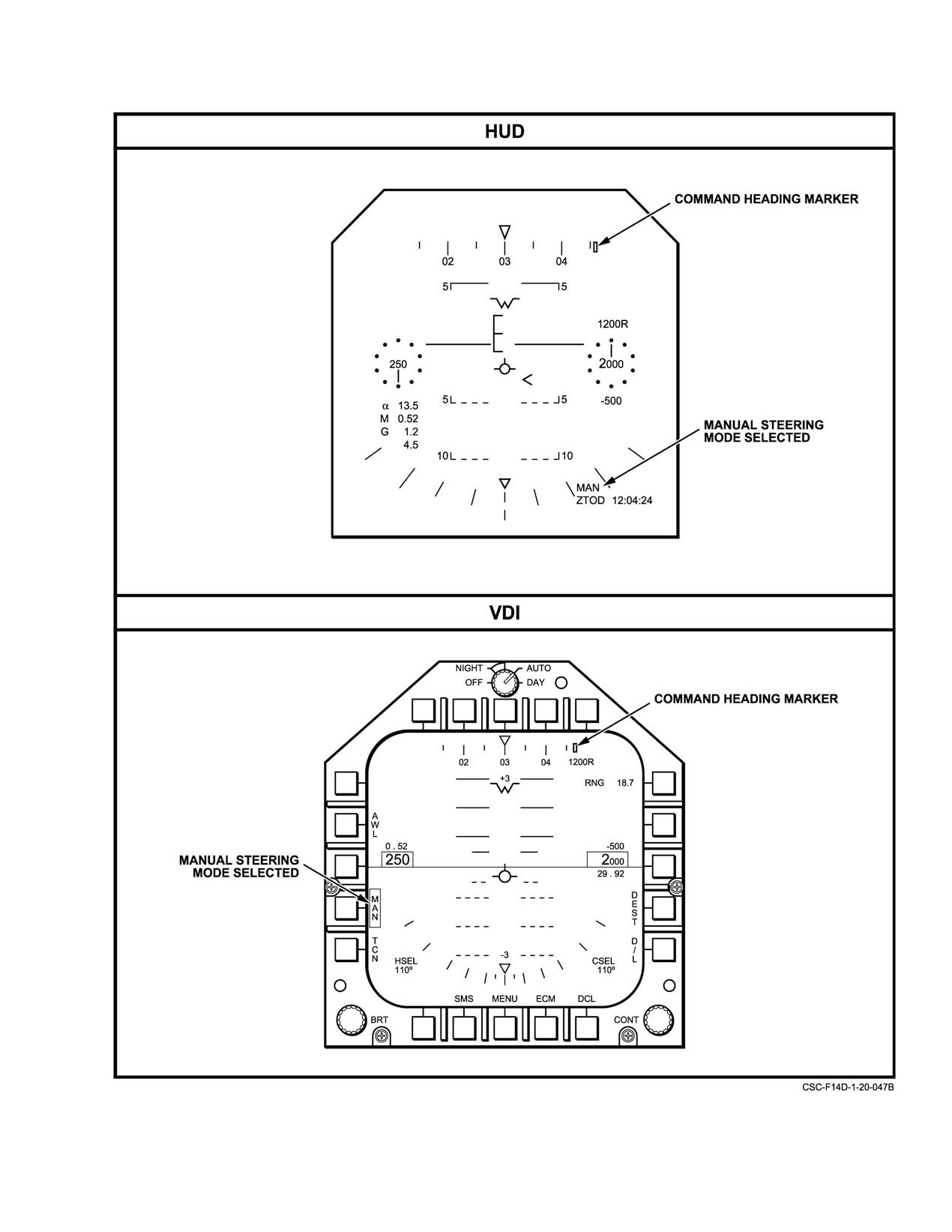
NAVAIR 01−F14AAD−1
Figure 20Ć49.ĄManual Steering Mode Formats (Sheet 1 of 2)
20−87
ORIGINAL
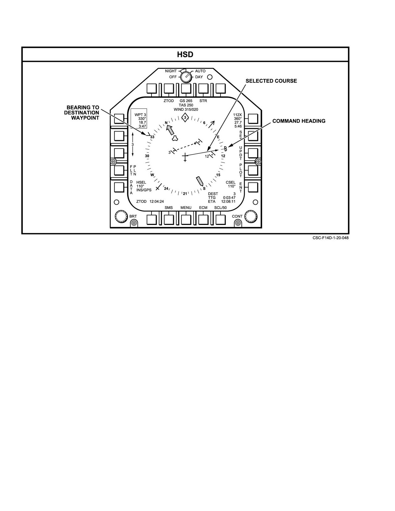
NAVAIR 01−F14AAD−1
Figure 20−49.ăManual Steering Mode Formats (Sheet 2 of 2)
3. Verify the selected course value under CSEL on the
supplies command altitude and command speed that are
VDI MFD format.
displayed on the MFD VDI D/L format. Command course is
displayed on the MFD HSD D/L format as a course line
4. Depress the MAN pushbutton on the VDI format.
pointer.
Steer aircraft to the command heading marker on the
Data−link steering using the ASW−27C or URC−107
HUD or VDI.
JTIDS can be performed as follows:
20.3.9.2.7
Data Link Steering
1. Call the VDI and HSD display formats on the pilot
center and right MFDs, respectively.
In the data−link display steering mode (Figure 20−50),
the pilot maintains a command course, commanded by
2. Depress the D/L pushbutton on the center MFD VDI
external inputs from the ASW−27C data link or AN/URC−107
format.
JTIDS data link, by steering the aircraft to the command
3. Maintain the command altitude indicated on the
heading marker on the HUD, VDI, or HSD format. The pilot
right side of the center MFD VDI format.
also adjusts aircraft altitude and speed in accordance with
commanded values appearing on the VDI D/L MFD format.
4. Maintain the command speed indicated on the left
The ASW−27C must be in its tactical mode (TAC selected on
side of the center MFD VDI format.
the DATA LINK panel) or JTIDS must be in AIC and its
5. Steer the aircraft to the command heading marker on
tactical mode (JTIDS on the DATA LINK panel).
the HUD or center MFD VDI format.
The data−link steering mode is selected by depressing
6. A comparison between the command course
the D/L pushbutton on the MFD VDI display format. When
received from the data link and the drift−
this is done, the mission computer then calculates command
compensated command heading can be observed on
heading to be flown to make good the D/L supplied command
the right−hand MFD HSD D/L format. Command
course by correcting for any wind drift. The resulting
course is in the form of a course line pointer, and the
command heading marker appears on the MFD VDI D/L,
command heading to be flown is indicated by
MFD HSD D/L, and HUD D/L formats. The D/L also
captain’s bars.
ORIGINAL
20−88
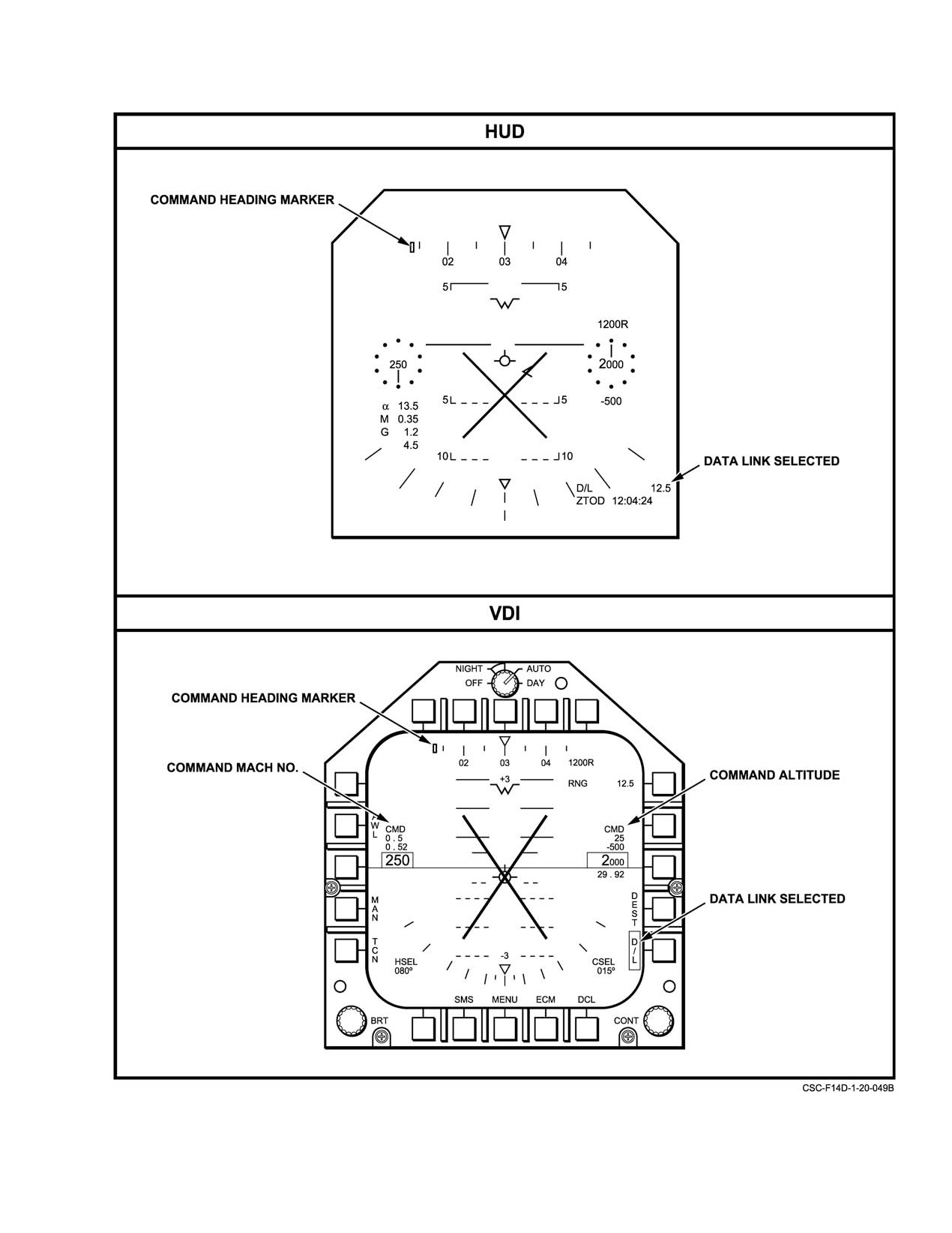
NAVAIR 01−F14AAD−1
Figure 20Ć50.ĄData−Link Steering Mode Formats (Sheet 1 of 2)
20−89
ORIGINAL
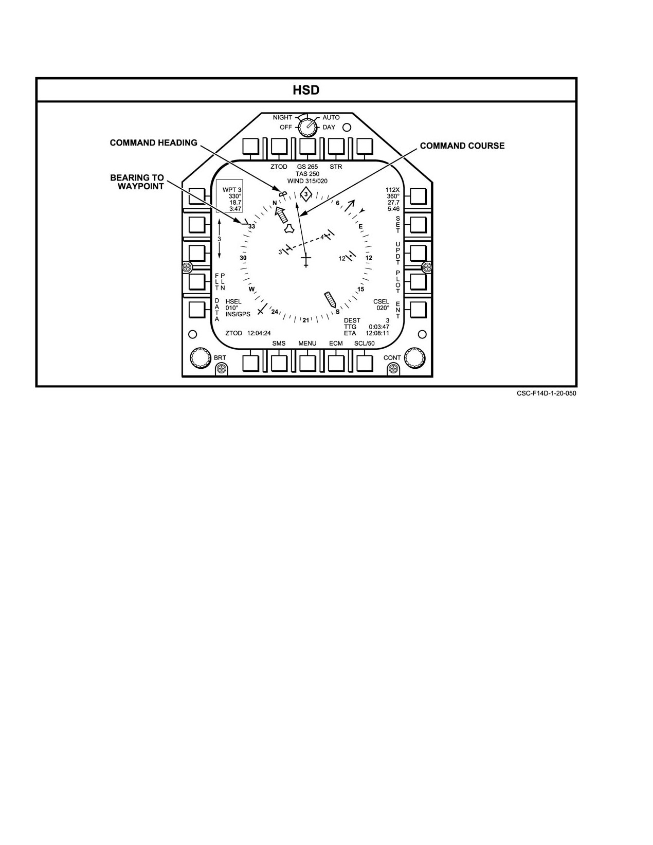
NAVAIR 01−F14AAD−1
Figure 20−50. Data−Link Steering Mode Formats (Sheet 2 of 2)
20.3.9.2.8
All−Weather Landing Steering
Note
The mission computer provides the appropriate
The autopilot data−link vector hold steering
steering information to the aircraft displays for a requested
mode is not supported using JTIDS vector
AWL mode. This is derived from data supplied by the ILS
steering data.
and ACLS. AWL information is available from either the
data link
(AN/ASW−27C (ACL)) or the ILS receiver
20.3.9.2.10
No Steering Selected
(AN/ARA−63) or both. The AWL steering modes operate
Steering is turned off if STR (PB 9) on the HSD format
continuously in the A/C landing phase to monitor and
respond to pilot AWL requests. The pilot steers to glidepath
is cycled until the steering mode buffer displays a blank, or
if a boxed steering selection (other than AWL) is unboxed on
situation displays (both ACL and ILS) and flight director
displays during the approach and descent phases of the
the VDI format. The selected heading and course functions
(HSEL and CSEL) are not operable. The HSD right hand data
landing phase. Chapter 2 describes the DFCS ACL function,
and Chapter 17 provides ACLS description and procedures.
buffer displays TACAN information ( TO" the station). No
steering is the default steering mode on aircraft power up.
Note
20.3.9.3
Navigation System Updates
The AWL function is not supported by the
JTIDS.
Occasionally, when GPS is unavailable, the small
errors in the navigation system build up to a point that
20.3.9.2.9
Autopilot Steering
requires position updating. The following paragraphs
provide a description of the procedures for performing
The mission computer provides the DFCS autopilot
navigation system updates.
with a set of steering validity discretes and a computed
steering error for its engaged steering mode. The available
All updates, except JTIDS, determine aircraft position
autopilot steering modes are: heading hold, ground track
one time by computing its location with respect to a known
hold/destination hold, and data−link vector hold. Refer to
waypoint. JTIDS updates use the navigation correction data
Chapter 2 for a description of these DFCS functions.
computed by the JTIDS. The difference in the computed
ORIGINAL
20−90
NAVAIR 01−F14AAD−1
position and the navigation system’s present position are
boxed at this time, and delta LAT and delta LONG
displayed on the MFD or the DD as differences (deltas) in
will appear as shown in Figure 20−51. Optimum
latitude and longitude. If these differences are reasonable,
results will be obtained with low and slow flight
the operator may elect to update the navigation system,
conditions.
including the INS and the SAHRS, by depressing the MFD
4. Verify that the delta LAT/LONG corrections are reaĆ
FIX ENABLE pushbutton.
sonable.
Note
5. If the delta LAT/LONG corrections appear
Because of the high degree of accuracy available
reasonable and a correction is required, press the
when in INS/GPS mode, one fix position updates
FIX ENABLE pushbutton on the INS UPDATE
are not available while in that mode. GPS must
MFD format. The corrections will be incorporated
be unboxed to do a navigation update.
into the system and sensors and the correct latitude
and longitude will be displayed on the OWN A/C
A navigation update is performed by calling up the INS
MFD format.
UPDATE MFD format shown in Figure 20−51 that will
appear when the UPDT pushbutton is depressed on the HSD
20.3.9.3.2
TACAN One−Fix Update
basic MFD format, shown Figure 20−9. The available types
of updates consist of visual, TACAN, radar, HUD/designate,
TACAN one−fix update computes aircraft position
data link, and JTIDS. If a particular update type is not
using TACAN measurements of range and bearing from a
available, an X" will appear over the acronym as shown in
TACAN station whose coordinates are known and stored in
Figure
20−51. Since all updates except JTIDS use the
the waypoint file. The procedure requires that the TACAN be
coordinates of a selected prestored waypoint, the coordinates
operating and the station selected correspond to the waypoint
of the selected waypoint should be verified prior to
that will be called up and whose coordinates will be used in
performing all updates except JTIDS. This is done by calling
the updating process. The procedure can be performed by
up the WPT DATA MFD format containing the point as
either the pilot or RIO as follows:
shown in Figure 20−29 that is available from the OWN A/C
1.
With the TACAN operating, select a TACAN
basic format. The procedures for each of the types of updates
channel whose latitude and longitude coordinates
are provided below.
correspond to the referenced TACAN location
stored in the waypoint file.
20.3.9.3.1
Visual One−Fix Update
2.
Verify that the coordinates of the TACAN station are
Visual one−fix update computes the aircraft’s position
the same as those of the waypoint to be selected for
using the coordinates of a point selected and stored in
updating by calling up the appropriate WPT DATA
waypoint file and substituted for the aircraft’s position at the
MFD format Figure 20−29. If incorrect, enter the
instant of direct flyover. This requires that entry, selection,
correct values via the DEU or DD.
and verification of the waypoint be made prior to flying over
the point and that the VIS pushbutton on the INS UPDATE
3.
Call up the INS UPDATE format, Figure 20−51.
MFD format be depressed at the time of flyover. When this
Select the correct waypoint corresponding to the
is done, the INS UPDATE FORMAT shall display the
coordinates of the TACAN station using the inĆ
computed latitude and longitude differences for evaluation.
crease/decrease pushbuttons on the right side of the
The procedure can be performed by either pilot or RIO as
INS UPDATE MFD format.
follows:
4.
Depress the TCN pushbutton. The legend will be
1. Verify the coordinates of the waypoint to be
boxed and the computed delta LAT and delta LONG
overflown by calling up the appropriate WPT DATA
will appear, as shown in Figure 20−51.
MFD format (Figure 20−29). If incorrect, enter the
correct coordinates for the point via the DEU or
5.
Verify that the delta LAT/LONG corrections are reaĆ
the DD.
sonable.
2. Call up the INS UPDATE MFD format, Figure
6.
If the delta LAT/LONG corrections appear
20−51. Select the correct waypoint corresponding to
reasonable and a correction is required, depress the
coordinates of the visual update point via the
FIX ENABLE pushtile on the INS UPDATE MFD
increase/decrease pushbuttons on the right side of
format. The corrections will be incorporated into
the INS UPDATE MFD format.
the system and sensors, and the correct latitude and
longitude will be displayed on the OWN A/C MFD
3. At the instant of direct flyover of the visual point
format.
depress the VIS pushbutton. The VIS legend will be
20−91
ORIGINAL