F-14D. FLIGHT MANUAL (2004) - page 11
NAVAIR 01−F14AAD−1
TONE
POSITION
CONTROLS
FUNCTION
CHARACTERISTICS
SIDEWINDER
Pilot
TONE, VOLUME/
Missile acquisition
High frequency.
TACAN CMD panel
Changes to indicate missile
self−track.
ALR−67
Pilot and
TONE VOLUME/ TAĆ
Indicates a missile
Low to high frequency,
RIO
CAN panel
alert, missile launch,
determined by scan rate and
(PILOT) RADAR
critical threat, and/or
PRF of threat radar.
WARNING RCVR
status change.
Low− to high−frequency
panel (RIO)
warble when missile
launch is detected.
Radar Altimeter
Pilot and
Radar altimeter
Low−altitude
1,000 Hz tone, modulated at
RIO
indicator (pilot)
warning
2 pulses per second, lasting
5 seconds or until altitude is
increased/limit bug is
lowered.
Low−altitude landing
Continuous tone below
gear up warning
low−altitude index setting
with landing gear handle up.
Tone terminates 5 seconds
after landing gear handle is
placed in down position.
APX−100
RIO
IFF control panel
Valid mode 4
PRF of interrogation pulse
interrogation
2,000 and 6,000 Hz.
TACAN
Pilot and
TACAN control panel
Station identification
International morse code
RIO
with three−letter designation.
AN/ARC−182
Pilot and
V/UHF control panel
Other aircraft
International morse code,
RIO
direction find (DF)
voice.
reception.
ENGINE STALL/
Pilot
None
Engine stall
Modulated 320 Hz for
OVERTEMPERATURE
detection and/or
10 seconds maximum or
EGT
until fault is removed,
over−temperature
whichever comes first.
warning.
Figure 19Ć4.ĄGlossary of Tones
ORIGINAL
19−6
NAVAIR 01−F14AAD−1
19.2.2
Pilot Tone Volume/TACAN Command
6. Frequency mode control Ċ LOAD (frequency is
Panel
stored in memory for CH 1).
The TONE VOLUME/TACAN CMD panel (Figure
7. Frequency mode control Ċ READ, Verify
19−5) on the pilot left console has two volume controls for
Frequency Display.
regulating audio signals from the ALR−67 and Sidewinder
missile lock−on.
8. Enter frequency in quick reference directory for
CHĂ1 (if desired).
19.3
V/UHF RADIO (AN/ARC−182)
9. Repeat steps 2 through 8 for subsequent channels.
The ARC−182 radio provides multimode, multiĆ
channel, air−to−air/air−to−surface voice, tone, and antijam
19.3.2
Built−In Test (BIT)
(Have Quick) communications. The ARC−182 control panel
(Figure 19−6) is located on the pilot and RIO left console.
BIT isolates faults in the RT to one module, two
Frequency range extends in four bands from 30 to 87.975,
modules, and three modules. BIT should be initiated anytime
108 to 155.975, 156 to 173.975, and 225 to 399.975 MHz on
the FREQ/(CHAN) display blanks or indicates an erroneous
any of 11,960 channels (separated by 25 kHz). Transmission
readout. Proceed as follows:
and reception are available in AM or FM bands. The
modulation is selected automatically by the radio except in
1. MODE selector Ċ TEST.
the 225 to 399.975 band, which is reserved for antijam use.
2. RT control Ċ As Required.
There are 40 preset channels available. Channels 1 through
30 are used for normal voice communications. Channels 31
3. BIT requires approximately 10 seconds; observe
through 40 are used for antijam Have Quick communicaĆ
FREQ/(CHAN) display.
tions. Guard frequency of each band may be monitored
simultaneously with any other frequency selected. The radio
a. No fault is indicated by 888.888.
is used with the OA−8697/ARO to provide automatic
direction finding to the transmitting station. The ARC−182
b. Faults are indicated by a number that identifies
operates with secure voice equipment (KY−58). Upper and
the module or modules at fault.
lower antenna installations provide reliable line−of−sight
communications to
200 nm (depending on altitude and
Note
atmospheric conditions). A radio frequency/channel indicaĆ
tor
(Figure 19−7) on the pilot and RIO instrument panel
If readouts
061 or 651 display, select other
displays the frequency or channel selected. A separate
antenna and key transmitter for 5 seconds, thenĆ
VOLUME control panel (Figure 19−8) for the pilot is located
repeat steps 1 through 3.
on the pilot left console.
Figure 19Ć9 lists the most common BIT fault codes and
their respective module failures.
Note
Transmissions on both V/UHF 1 and V/UHF 2
19.3.3
Have Quick (Antijam) Mode
radios, while operating on the same frequency,
Have Quick is a tactical antijam system that utilizes
may result in a squeal. This is a normal condition
frequency hopping, a method where frequencies are changed
caused by RF interaction between the two
many times per second. The frequency hopping patterns,
radios operating on the same frequency in close
stored in memory and frequency tables, are selected by
proximity to each other.
word−of−day, net numbers, and a given date. The antijam
mode of the ARC−182 is enabled by selecting a net number
19.3.1
Preset Channel(s) Load
and by placing the NORM/AJ switch to AJ once all the
variables have been entered into the radio. For two or more
1. MODE selector Ċ T/R or T/R&G.
radios to successfully communicate on a Have Quick net,
each radio must have the same TOD, WOD, and operating
2. Frequency mode control Ċ Reset.
net.
3. CHAN SEL switch Ċ Select Channel 1.
The ARC−182’s Have Quick II system is compatible
with older Have Quick I systems.
4. Frequency mode control Ċ Read.
5. Frequency select switches Ċ Slew to Desired
Frequency.
19−7
ORIGINAL
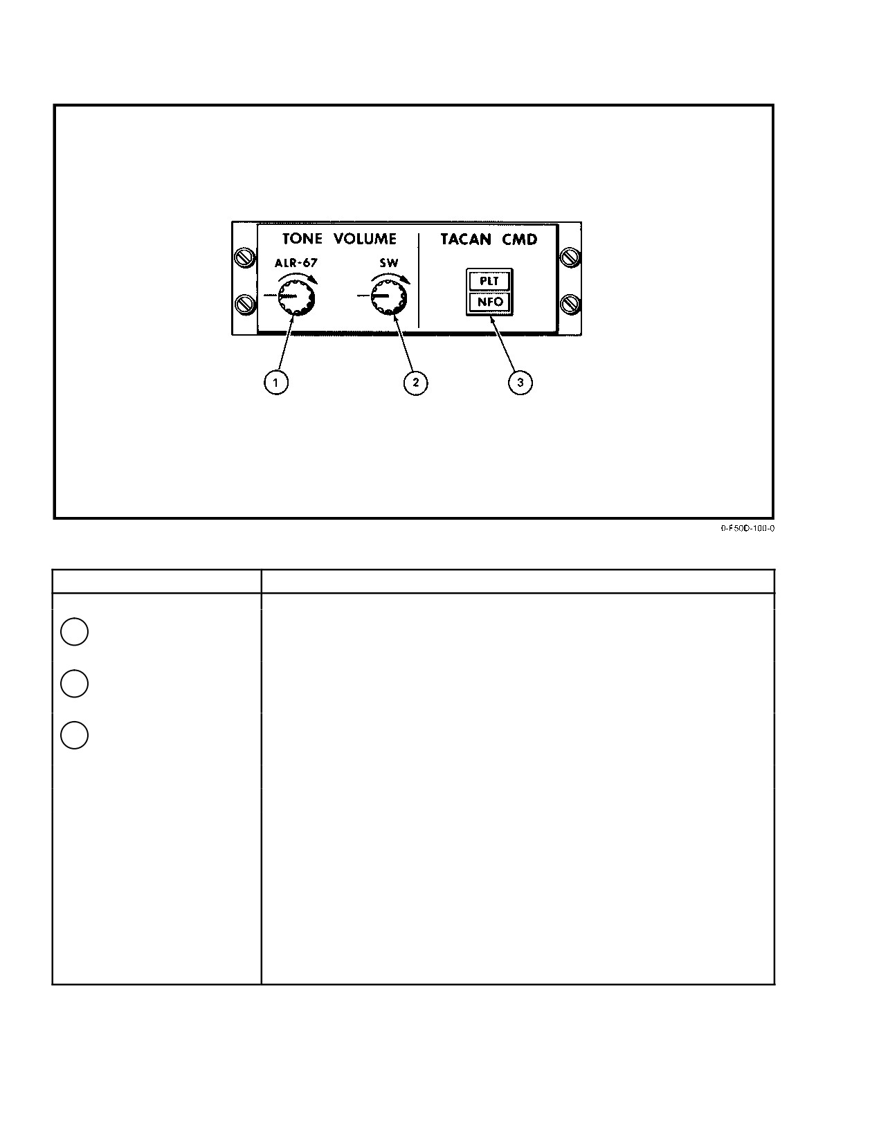
NAVAIR 01−F14AAD−1
NOMENCLATURE
FUNCTION
1
ALR−67 volume control
Clockwise rotation increases tone in pilot’s headset. Provides threat alert,
status and warning tones representing received threat radar signals.
2
SW (Sidewinder)
Clockwise rotation increases missile tone in pilot’s headset.
volume control
Counterclockwise rotation turns tone to low.
3
TACAN CMD control
Illuminates when selected PLT or NFO, indicating crewman in command
switch/indicator
of TACAN.
Figure 19Ć5.ĄPilot TONE VOLUME/TACAN CMD Panel
ORIGINAL
19−8
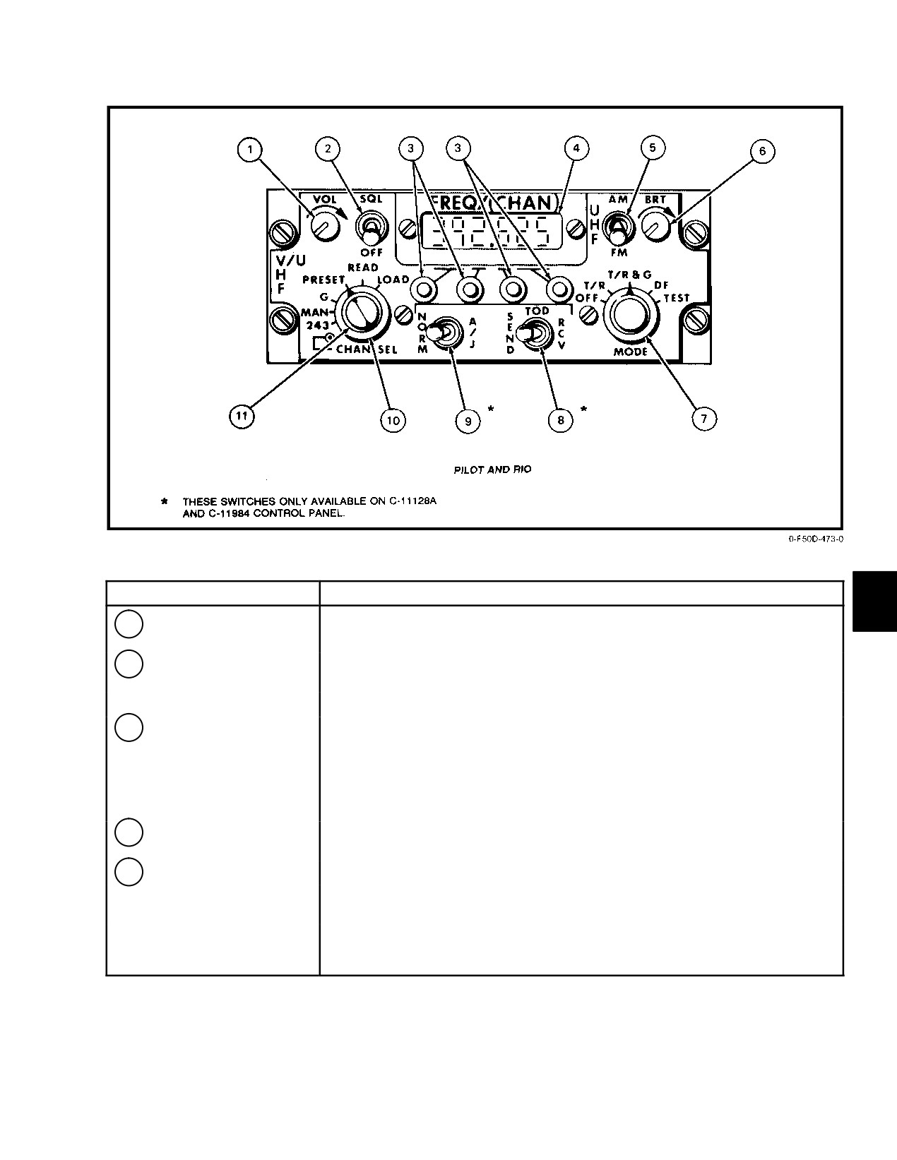
NAVAIR 01−F14AAD−1
NOMENCLATURE
FUNCTION
1
VOL control
Adjusts level of audio signal. Clockwise rotation increases audio level. RlO’s
adjustments made only via the RFCI.
2
Squelch switch
SQL Ċ Squelch circuit is operational and backg0round noise is removed by
reducing receiver gain.
OFF Ċ Disables squelch circuit restoring receiver to full gain.
3
Frequency select
Four frequency tuning switches are used to tune transceiver when the tuning
switches (spring return)
selector switch is set to MAN (manual). The spring−loaded switches increase the
frequency in the up position and decrease frequency in the down position. The left
switch controls the hundreds and tens digits, the second switch controls units, the
third switch controls tenths, and the right switch controls hundredths and
thousandths.
4
FREQ/(CHAN) display
Displays incandescent digital readouts of selected frequency or channel.
In TEST mode indicates receiver transmitter fault locations.
5
UHF mode selector
Operational when tuned to frequencies in the 225.000 to 399.000 MHz band.
AM Ċ Selects amplitude modulation signals. Varies with atmospheric
conditions, susceptible to electromagnetic interference.
FM Ċ
Selects frequency modulation signals. Reduces electromagnetic
interference.
Figure 19Ć6.ĄAN/ARC−182 V/UHF Control Panel (Sheet 1 of 2)
19−9
ORIGINAL
NAVAIR 01−F14AAD−1
NOMENCLATURE
FUNCTION
6
BRT control
Varies the FREQ/(CHAN) display light intensity. Clockwise maximum
intensity.
7
MODE switch
OFF Ċ Secures V/UHF radio, unless frequency mode switch is set to 243.
T/R Ċ
Energizes transmitter and main receiver.
T/R&G Ċ Energizes transmitter main, and guard receivers.
DF Ċ Provides automatic direction finding from 108 to 399.975 MHz.
TEST Ċ Indicates built−in−test (BIT) RT; displayed on FREQ/(CHAN)
indicator. Refer to Built−In−Test this chapter. Generates 1020 Hz unĆ
attenuated tone.
8
TOD switch
RCV Ċ Allows reception of TOD messages on preset channel selected.
SEND Ċ Allows transmission of TOD messages on preset channel selected.
9
NORM/AJ switch
NORM Ċ Used for normal V/UHF communications.
A/J Ċ
Provides jam resistant communications.
10
CHAN SEL mode
243 Ċ
Turns on the receiver−transmitter (takes precedence over
switch (outer dial)
operational mode control) and causes the transmitter main receiver,
and guard receiver to tune to 243.000 MHz (UHF guard frequency).
All functions except VOL, SQL and BRT are disabled.
MAN Ċ Permits manual selection of an operating frequency using the
frequency tuning switches. Transmitter and receiver are disabled
during a frequency change.
G Ċ
Tunes the receiver−transmitter to the guard frequency in the band to
which the RT was last tuned.
PRESET Ċ Allows selection of any 1 of 40 present operating frequencies
with CHAN SEL switch. Selected channel is displayed in the two
center digit readouts of the FREQ/(CHAN) display. Channels 31
through 40 are for Have Quick (antijam) use.
READ Ċ Displays the frequency (rather than channel) of preset channel
selected.
LOAD Ċ Automatically places the displayed frequency into the memory for
the selected preset channel.
11
CHAN SEL switch
Enables any 1 of 40 preset channels when the frequency mode switch is set to
(inner dial)
PRESET.
Figure 19−6. AN/ARC−182 V/UHF Control Panel (Sheet 2 of 2)
ORIGINAL
19−10
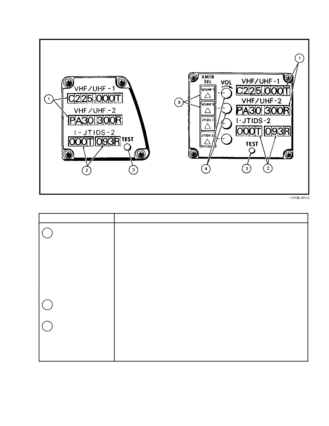
NAVAIR 01−F14AAD−1
NOMENCLATURE
FUNCTION
1
VHF/UHF−1 and −2
Displays information for each radio (pilot and RIO) as follows:
frequency/channel
indicator
• Left most LCD indicates secure voice selection : C (cypher) or P (plain)
• Right most LCD indicates whether radio is in use for transmission (T) or
reception (R)
• Displays frequency, channel number, or WOD channel number
• With anti−jam selected, the net number is prefixed by an A
• F is displayed if the RFCI fails periodic BIT
• If there is bad or no V/UHF data for 3 seconds, displays only a decimal point.
2
1−JTIDS−2 channel
Displays channel selected (0 − 127) for JTIDS−1 and JTIDS−2 voice links
indicator
(pilot and RIO) with alpha designator indicating transmit (T) or receive (R) for
radio in use.
3
TEST button
Activates 10−second maximum internal test of the RFCI. On successful
completion of the test, the LCDs show the test display. If the TEST button is
held for more than 10 seconds the display will automatically return to the disĆ
play prior to test.
Figure 19Ć7.ĄRadio Frequency/Channel Indicator (Sheet 1 of 2)
19−11
ORIGINAL
NAVAIR 01−F14AAD−1
NOMENCLATURE
FUNCTION
4
VOL control
Enable RIO to adjust level of audio signal. Clockwise rotation increases audio
level.
5
XMTR SEL buttons
Enables RIO to select desired radio for voice communications (V/UHF or
JTIDS).
Note
When JTIDS voice communications is selected V/UHF plain voice
communications are inhibited. If V/UHF encrypted voice communication is seĆ
lected, both V/UHF (encrypted) and JTIDS will transmit simultaneously.
Figure 19−7. Radio Frequency/Channel Indicator (Sheet 2 of 2)
19.3.4
Have Quick Load Instructions
2. TRAINING
Have Quick antijam voice communications entry uses
a.
00 Ċ Have Quick I Training.
preset channel
40. The contents of preset channel
40
designates the loading mode in which the unit is operating.
b. 25 Ċ Have Quick II Training.
The following loading codes are used to operate and load in
Have Quick II:
c.
50/75 Ċ Not Used.
The 1,000 combat nets range from 000 to 999. The
1. 220.000 Ċ Operate in Have Quick II.
variables in these net numbers refer the radio to specific
2. 220.025 Ċ MWOD load mode.
frequencies and algorithms within the radio’s memory. There
are five Have Quick I training nets displayed as A00.X00,
3. 220.050 Ċ MWOD erase mode.
where X is 0 to 4. There are 16 Have Quick II training nets
displayed as A0X.X25, where X.X is 0.0 to 1.5. The variables
4. 220.075 Ċ FMT load mode.
in these training net numbers tell the radio the training
frequency on which to begin hopping. Training nets are
If the aircrew desires to enter Have Quick without
activated by a special WOD (300.0XX) in segment one of the
loading or verifying, 220.000 should be loaded into preset
WOD used for that day. The last two digits determine the hop
channel
40 using the procedures in paragraph 19.3.4.13.
rate. The same applies to the last two digits of the first
Otherwise, Have Quick I processing is used.
segment of combat WODs.
19.3.4.1
Net Selection
19.3.4.2
Word of Day/Multiple Word of Day
Have Quick I and II use the same method of net
(WOD/MWOD)
selection. A net is a six−digit number that selects the
A WOD/MWOD is a transmission security variable.
frequency table that will be hopped on. Net numbers are in
Have Quick I radios use a WOD consisting of six segments
the form of AXX.XYY, where A indicates a Have Quick net,
of six digits each. Have Quick I radios use a MWOD that adds
X is a number from 0 to 9 defining the net, and YY is either
a seventh segment containing a two−digit date tag and five
00, 25, 50, or 75, which determines the combat or training
more MWODs for 6 days of operation without reloading
operational mode. The operational modes are
WODs. The WOD/MWOD is loaded into the radio to key the
Have Quick system to the proper hopping pattern, dwell time,
1. COMBAT
and hop rate. The hop rate is included in the first segment of
a.
00 Ċ Operate in Have Quick I.
each WOD/MWOD, XXX.XYY, where YY is 00, 25, 50, 75,
denoting slow to fast hop rates. When operating with Have
b. 25 Ċ Have Quick II NATO.
Quick I systems, only one of the six MWODs is used. See
Figure 19−10.
c.
50 Ċ Have Quick II Non−NATO.
d. 75 Ċ Not Used.
ORIGINAL
19−12
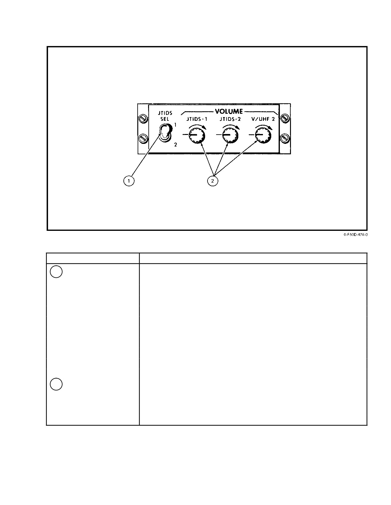
NAVAIR 01−F14AAD−1
NOMENCLATURE
FUNCTION
1
JTIDS SEL switch
Selects JTIDS 1 or 2 voice channel for pilot’s voice transmissions.
Both channels are always selected to receive.
2
JTIDS−1, JTIDS−2,
Clockwise rotation increases audio level of received transmission (Pilot only).
V/UHF−2 volume
control
Figure 19Ć8.ĄPilot VOLUME Control Panel
19−13
ORIGINAL
NAVAIR 01−F14AAD−1
MODE
DISPLAY
FAULT
INTERPRETATION
RCV
•
RMT or RT
SELECT TEST MODE
XMT
•
LOW PWR
SELECT TEST MODE
TEST
•
RMT CTRL
DEFECTIVE CONTROL
TEST
888.888
NONE
RT AND CTRL OK
TEST
4 6 5
RT
MODULES 4, 5, OR 6 BAD
TEST
0 6 1
VSWR
RT OR ANTENNA SYSTEM
TEST
6 5 1
FWD PWR
RT OR ANTENNA SYSTEM
TEST
1 5 7
RT
MODULES 1, 5, OR 7
TEST
3 3 3
RT
MODULE 3 BAD
Figure 19Ć9.ĄCommon BIT Indications
1.1
289.950
2.1
295.850
3.1
290.450
4.1
275.950
5.1
270.450
6.1
300.050
1.2
299.000
2.2
289.600
3.2
279.000
4.2
269.300
5.2
259.000
6.2
249.000
1.3
298.100
2.3
288.000
3.3
278.600
4.3
268.000
5.3
258.600
6.3
248.900
1.4
297.000
2.4
287.900
3.4
277.400
4.4
267.000
5.4
257.800
6.4
247.100
1.5
296.000
2.5
286.300
3.5
276.500
4.5
266.700
5.5
256.000
6.5
246.100
1.6
295.000
2.6
285.300
3.6
275.100
4.6
265.500
5.6
255.500
6.6
245.200
1.7
11
2.7
12
3.7
13
4.7
14
5.7
15
6.7
16
8.1 = OPERATIONAL DAY
1.1 through 1.6 are WOD 1 segment numbers.
1.7 is the date tag for WOD 1.
2.1 through 2.6 are WOD 2 segment numbers
2.7 is the date tag for WOD 2.
3.1 through 6.7 is the same as above for WODs 3 through 6.
8.1 is the current Operational Day, which should match one of the date tags.
Note:
(1) If the current operational day was 11 (MWOD location 1), Have Quick II Combat net would be used with a hop rate
of 50 (included in the last two digits of segment 1.1). An appropriate Have Quick II operational net should be chosen.
(2) If the current operational day was 16, Have Quick II Training Net would be used because the first segment of
MWOD location 6 (6.1) is the special training segment. The hop rate would be 50 (last two digits of first segment).
An appropriate Have Quick II Training Net number should be chosen.
Figure 19Ć10.ĄExample of an ARC−182 Have Quick II MWOD Fill
ORIGINAL
19−14
NAVAIR 01−F14AAD−1
19.3.4.3
Time of Day
6. Repeat steps
1 through
5 to load remaining
MWODs.
TOD is a signal that synchronizes Have Quick radios
to a common time for antijam operation. There are two ways
Note
to enter TOD. One method involves receiving UTC over the
air on a manually selected UHF frequency after power up.
D The desired frequencies are loaded in segĆ
The second method involves using the self−start (emergency
ments 1 through 6 of each MWOD. The date
time start) mode, which is used when acting as master clock
tag for each MWOD is loaded into the seventh
to transmit that time to other Have Quick systems. Within this
segment and is a two−digit number correĆ
TOD signal is the operational day. This is transmitted with
sponding to the operational day on which that
the TOD or loaded manually as in the self−start procedure.
MWOD is to be used. It can be loaded or
Refer to paragraph 19.3.4.12, TOD Load. The codeword for
changed using the two middle frequency
TOD is Mickey."
select switches and the MWOD segment
loading procedures above.
19.3.4.4
MWOD Load Entry
D The crew may not enter an out−of−range WOD
1. Frequency mode control Ċ Preset.
frequency, segment, or date tag. When two
identical date tags are loaded, the last date
2. CHAN SEL switch Ċ Select Channel 40.
entered is valid and the old date is set to zero.
If the old date is viewed, 00 will be displayed.
3. Frequency mode control Ċ READ.
D The MWOD is not entered into the memory of
4. Frequency select switches Ċ Select 220.025.
the unit until the date tag is loaded. Thus, if a
segment of an MWOD has been changed after
5. Frequency mode control Ċ LOAD.
the MWOD was initially entered, the date tag
must be reentered to accept the MWOD
Note
change.
If MWODs are being loaded to replace existing
19.3.4.6
MWOD Load Exit
ones, the old MWODs should be erased using the
procedures in paragraph 19.3.4.9. This proceĆ
1. Frequency mode control −MAN (ready to receive
dure will erase all MWODs in the radio’s
TOD).
memory.
Note
19.3.4.5
MWOD Load
When manual is selected on the frequency mode
1. Frequency mode control Ċ Preset (1.1 will be
control to exit a load mode, the code to operate
displayed).
in Have Quick II antijam without entering a load
mode (220.000) will automatically be loaded
2. Frequency select switches Ċ Select Desired WOD
into preset channel 40.
and MWOD Segment Using Middle Two Frequency
Select Switches.
19.3.4.7
Operational Date Load
3. Frequency mode control Ċ READ (display shows
The operational date is the calendar date of the mission
frequency indicating desired WOD segment).
day. The range is 1 through 31. The MWOD that is used by
the unit for frequency hopping is the MWOD whose date tag
Note
matches the operational day. Thus, if an operational day is
entered or received via TOD transmission and no date tag
If the MWODs were erased using the MWOD
exists for that operational day, an error will occur and be
erase procedure in paragraph 19.3.4.9, the disĆ
displayed. The operational day is loaded as follows:
play will show 000.000 indicating that they had
been erased.
1. Perform steps 1 through 5 of paragraph 19.3.4.4.
Step 1 is not required if already in MWOD Load.
4. Frequency select switches Ċ Select Desired
Frequency WOD Segment.
2. Frequency mode control Ċ PRESET (last WOD
and segment selected will be displayed).
5. Frequency mode control Ċ LOAD
(desired
frequency loaded into memory).
19−15
ORIGINAL
NAVAIR 01−F14AAD−1
3. Frequency select switches Ċ Select 8.1.
accessed with the FMT load code loaded into preset channel
40. Once the 16 training frequencies (7.01 through 7.16) are
4. Frequency mode control Ċ READ (last operational
loaded, it is not necessary to reload them. Additionally, it is
date or 00 is displayed).
not necessary to reload the special FMT MWOD segment
once it is loaded, as long as the date tag used is within the
5. Frequency select switches Ċ Selected Desired
same MWOD as the special FMT segment. If using the
Date.
self−start method of TOD, the operational day as well as the
date tag must be loaded into segments 8.1 and 1.7 (or the
6. Frequency mode control Ċ LOAD (Operational
seventh segment of whichever MWOD is being used),
date is loaded into memory).
respectively. Thus, combat Have Quick II and FMT can be
used interchangeably simply by loading one or more of the
Note
MWOD first segments with the special training WOD
segment. On every day that the operational day matches the
Out of range (<1 or >31) operational dates may
date tag of the MWOD with the special FMT segment loaded
not be entered.
into its first segment, the unit will hop on the FMT training
frequencies, regardless of the contents of the other segments
19.3.4.8
MWOD Verify
within that MWOD. See Figure 19−10, Note 2.
The aircrew may view the MWODs at any time for
1. Frequency mode control Ċ PRESET.
verification by reading the MWOD locations by using steps
1 through 3 in paragraph 19.3.4.5.
2. CHAN SEL switch Ċ Select Channel 40.
3. Frequency mode control Ċ READ.
19.3.4.9
MWOD Erase
4. Frequency select switches Ċ Select 220.075
The following procedure enables the aircrew to erase
all MWODs stored in the nonvolatile memory. This proceĆ
5. Frequency mode control ĊLOAD.
dure is recommended before reloading all MWODs with new
6. Frequency mode control Ċ PRESET (first FMT
frequencies.
frequency segment 7.01 is displayed).
1. Frequency mode control Ċ PRESET.
7. Frequency select switch Ċ Select Desired FMT
Segment.
2. CHAN SEL switch Ċ Select Channel 40.
8. Frequency mode control Ċ READ.
3. Frequency mode control Ċ READ.
9. Frequency select switches Ċ Select Desired FMT
Training Frequency.
4. Frequency select switches Ċ Select 220.050 To
Initiate MWOD Erase Function.
10. Frequency mode control Ċ LOAD (desired FMT
training frequency is stored in memory).
5. Function mode control Ċ LOAD (display will go
blank indicating MWODs have been erased).
11. Repeat steps 6 through 10 to load remaining desired
FMT training frequencies. The load function is
exited by placing the frequency mode control to
19.3.4.10
FMT Training Frequency Load
MAN.
The Have Quick II FMT training net operates similar
to combat Have Quick II, as both the date tag and operational
19.3.4.11
FMT Net Operation
day functions are used. The FMT net, however, hops on its
own set of 16 frequencies loaded into a separate training
Once the training frequencies have been loaded or
verified, Have Quick II FMT net can be operated as follows:
WOD. Additionally, a special MWOD segment for FMT
(300.0XX, where XX is the hop rate) is loaded into the first
1. Perform steps 1 through 5 of paragraph 19.3.4.4.
segment of the MWOD being used (usually 1.1, but any of
the six MWODs can be used as long as the date tag for the
2. Frequency mode control Ċ PRESET.
MWOD whose first segment contains 300.0XX matches
the operational day). The frequencies actually hopped on,
3. Frequency select switches Ċ Select Segment 1 of
however, are loaded into a separate FMT WOD that can be
Desired MWOD To Be Used (1.1, 2.1, 3.1, etc.).
ORIGINAL
19−16
NAVAIR 01−F14AAD−1
4. Frequency mode control Ċ READ (display shows
19.3.4.12.1
To synchronize and load Time/Date
frequency indicating desired WOD segment).
from GPS system, perform the
following steps:
5. Frequency select switch Ċ Select Special FMT
Segment With Desired Hop Rate (300.0XX XX =
1. Select OWN A/C format and verify GPS is fully
00, 25, 50, 75).
aligned (FOM = 1), GPS is boxed and navigation
mode is INS/GPS.
6. Frequency mode control Ċ LOAD (desired freĆ
quency loaded into memory).
2. Select GPS Status Format and verify RCV TOD is
not boxed.
7. Frequency mode control Ċ PRESET.
3. On the VHF/UHF ARC−182 Control Panel:
8. Frequency select switches Ċ Select Segment 7
Mode Switch
T/R
(date tag) of the Same MWOD Used Above (1.7,
Frequency Select Switch
300.025
2.7, 3.7, etc.).
NORM/AJ
NORM
TDD switch
MAN
9. Frequency mode control Ċ READ (display shows
two−digit date tag previously loaded or 00).
WAIT 10 SECONDS
10. Frequency select switches Ċ Select Desired Date
4. On the GPS Status Page select RCV TOD. Verify it
Tag.
remains boxed for 5 SECONDS.
11. Frequency mode control Ċ LOAD (desired date tag
5. On VHF/UHF ARC−182 Control Panel:
loaded into memory)
NORM/AJ Switch
AJ
Verify Frequency Indicator
A00.25
12. Frequency mode control Ċ MAN (ready to receive
TOD).
If a ? is displayed, lockup has not occurred.
19.3.4.12
TOD Load
19.3.4.13
Antijam Mode Selection
TOD may be loaded in any of the following ways.
If entering Have Quick II from a previous load mode,
selecting MAN from that mode will automatically perform
1.
Emergency or forced start entry of time/date is perĆ
steps 1 through 5 below. In this case, proceed to step 6.
formed by holding the TOD switch in receive
(RCV) position until decimal point flashes, then
Note
momentarily setting TOD switch to SEND. SelectĆ
TOD can be received from power up. It is not
ing the operational day is performed using steps in
necessary to enter any other load or operate mode
paragraph 19.3.4.7.
first.
2.
To receive time/date over air (broadcast) in normal
1. Frequency mode control Ċ PRESET.
mode, momentarily push TOD switch to RCV when
TOD is transmitted over manually selected UHF
2. CHAN SEL switch Ċ Select Channel 40.
frequency. This will allow acceptance of TOD for
3. Frequency mode control Ċ READ.
1 minute.
4. Frequency select switches Ċ Select 220.00.
3.
To transmit time/date over air (broadcast) in normal
mode, momentarily push TOD switch to SEND
5. Frequency mode control Ċ LOAD (the radio is now
while on a manually selected UHF frequency. At
prepared to operate in Have Quick II).
this time, TOD signal is sent and a tone will be
heard.
6. Frequency mode control Ċ MAN.
4.
To receive new time in A/J mode or to update clock,
7. TOD Ċ Received.
momentarily push TOD switch to RCV. This will alĆ
8. Frequency select switches Ċ Select Desired Net
low acceptance of TOD for 1 minute.
Frequency.
5.
To transmit time/date over air (broadcast) in A/J
9. NORM/A/J switch Ċ Select A/J on Command to
mode, momentarily push TOD switch to SEND.
GO ACTIVE" (first digit of net frequency will
This will send TOD signal to all units that are in A/J
display as A").
and using the same net.
19−17
ORIGINAL
NAVAIR 01−F14AAD−1
19.3.4.14
Have Quick II Error Codes
5. Invalid net error code Ċ Verify that the correct net
is being used.
The Have Quick II radio generates different error
displays for three possible entry errors. If the radio has been
6. No TOD error code Ċ Attempt to receive another
initialized properly, an
(A) will display in the left−most
TOD from the master. If still unable to receive TOD,
display segment.
use the self−start method and attempt to transmit
TOD to other net participants if practical.
If a question mark (?) displays, the net number is
invalid. If a backward question mark
(
) displays, the
19.3.5
Radio Frequency Control/Indicators (RFCI)
MWOD or operational data is invalid. If the display does not
change when A/J is selected, then TOD has not been received
Two RFCIs (Figure 19−7) are provided. Each has LCDs
or entered. The error display for each error is shown in
that show the frequency or channel selected for V/UHF 1 and
Figure 19−11.
2 and JTIDS 1 and 2, their transmit/receive status, and
antijam and sure voice selection. The RFCIs are tested by
pressing the TEST button on the panel. An indication is
FREQUENCY
ERROR
CONTROL
provided if the RFCI fails BIT.
MODE
DISPLAY
ERROR
CONTROL
The RIO RFCI also contains transmit select buttons for
V/UHF 1 and 2 and JTIDS 1 and 2 as well as volume controls
XX.XXX
MAN
Invalid MWOD and
for adjusting their audio level.
Date
Note
?XX.XXX
MAN
Invalid Net
Number
D The RIO volume control knob on the
XXX.XXX
MAN
No TOD
ARC−182 control panel is not functional. The
Invalid MWOD and
volume control knob on the RIO RFCI is used
X.X
PRESET
Date
to control volume.
X X
PRESET
Invalid Net Number
D When JTIDS vice communication is selected,
V/UHF plain voice communications are
?X, XĄ
PRESET
No TOD
inhibited. If V/UHF encrypted voice commuĆ
The X"s in the error display column
nication is selected and JTIDS voice commuĆ
represent digits 0 to 9.
nication is selected, both V/UHF (encrypted)
and JTIDS will transmit simultaneously.
Figure 19Ć11.ĄHave Quick II Error Codes
19.4
V/UHF AUTOMATIC DIRECTION FINDER
(OA−8697)
19.3.4.15
Have Quick Basic Troubleshooting
Procedures.
The V/UHF automatic direction finder is used with the
ARC−182 radio in the AM mode (voice is suppressed). ADF
1. Broken communications when A/J is selected Ċ
provides relative bearings to transmitting ground stations or
Verify all segments of the current WOD or all the
other aircraft. It can receive signals on any 1 of 30 preset
FMT frequencies are correct.
channels or on any manually set frequencies in the 108 to
399.975 MHz range.
2. Lack of an A" in the first digit of the net frequency
displayed on the radio Ċ Receive another TOD
The system has a line−of−sight range, varying with
altitude. Operating power is 115 Vac from the essential No.Ă2
transmission to resynchronize the radio.
bus, 28 Vdc from the essential No. 2 bus, and 26 Vac through
3. Broken communications after time, once good
the RIO circuit breaker panels. The system requires a
communications have been established Ċ Receive
5−minute warmup period. During the warmup time, failure
another TOD transmission either in A/J or normal
indications should be disregarded. The system uses a
mode to resynchronize the radio.
solid−state segment rotation ADF antenna. Bearing to
transmitting stations is displayed on the pilot/RIO BDHI
4. Invalid MWOD or date tag error code Ċ Verify all
(No.Ă1 needle), and on the HSD format of any MFD. The
MWOD segments for the current day.
ADF signal is interrupted during voice transmissions.
CHANGE 1
19−18
NAVAIR 01−F14AAD−1
19.5
UHF VOICE SECURITY EQUIPMENT
7. After a 2−minute warmup period on the cipher seĆ
(TSEC/KY−58)
lected radio, listen for a steady, unbroken tone in the
headset followed by a double−pitched broken tone.
The security equipment is integrated, and operates,
with the V/UHF 1 and 2 communications sets to permit UHF
8. Key the appropriate radio selected for transmission,
secure voice in a hostile environment. It shall be operated as
hold for approximately
2 seconds, and release.
directed by appropriate authority. Theory of operation and
Double−pitched broken tone will cease and no sound
practical application are covered in the KY−58 operation
will be heard.
manual.
9. Key radio and hold. A single beep tone will be heard
The KY MODE switch and the KY−58 control panel
in approximately 1½ seconds, if delay is selected;
(Figure 19−12) on the RIO left side console are the only
otherwise, beep is immediate. When this tone is
cockpit controls for operating the KY−58 in either cipher or
heard, the equipment is ready for cipher
plain language. Electrical power is from the dc essential bus
transmission.
No. 1 with circuit protection on the RIO dc essential No. 1
circuit breaker panel, KY−58/Z−AHP circuit breaker (7C3).
10. After beep tone is heard, establish two−way cipher
The KY−58 has two states of operation: plain and
radio communications with a cooperating ground
cipher (C). Plain is used during normal UHF communicaĆ
station and check for readability and signal strength.
tions. Cipher is used when secure voice communications are
desired. There are two cipher modes: BB (baseband) for use
11. Set power and radio selector switches in accordance
with FM transmissions and DP (diphase) for use with AM.
with the tactical situation.
The radio sets must be ON to attain secure operation. The
receiving station must be properly equipped to receive
Note
transmissions in the proper cipher mode.
If a ground check of the equipment is not practiĆ
cal, the above procedures may be used to perform
Note
an in−flight check of the equipment.
D Do not transmit plain voice on one radio
19.5.3
Postlaunch
during cipher receptions or while transmitting
on the other radio.
The speech security equipment shall be operated as
directed by appropriate authority.
D Communications between KY−28 and KY−58
voice security equipment is not possible.
19.5.4
After Landing
19.5.1
KY−58 Operation
1. ZEROIZE switch Ċ ZEROIZE (as briefed).
Zeroize the code as directed by appropriate authority.
19.5.2
Prelaunch
2. Power switch Ċ OFF.
1.
Determine that proper code has been set by personĆ
nel qualified in voice security equipment.
19.6
JOINT TACTICAL INFORMATION
DISTRIBUTION SYSTEM
2.
V/UHF radios Ċ ON.
The JTIDS is a high−capacity communications system
3.
Power switch Ċ ON.
providing jam−resistant, secure digital voice and data. This
system also provides voice and data relay, dual navigation
4.
Cypher switch Ċ C/RAD 1 or C/RAD 2.
grid operation, and TACAN data.
The JTIDS digital voice function provides two secure,
5.
KY MODE switch Ċ As Required.
jam−resistant, separate (J1 and J2) 16 KBS voice channels.
6.
If a ground test of equipment is desired, establish
These are integrated into both the pilot and RIO cockpits.
two−way plain text radio communications on the
plain voice radio with a suitable ground station and
request an equipment check.
19−19
ORIGINAL
NAVAIR 01−F14AAD−1
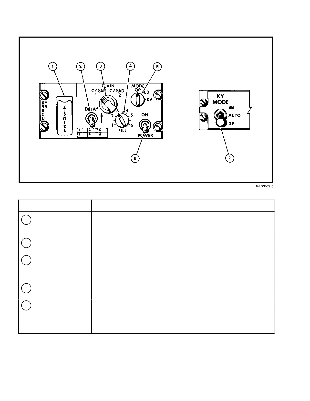
NOMENCLATURE
FUNCTION
1
ZEROIZE switch
ZEROIZE Ċ Guard lifted. The preset codes are erased and must be reset on
the ground by qualified personnel before the cipher mode can
be used.
2
DELAY switch
DELAY Ċ Provides a time delay between push−to−talk and actual
transmit.
3
Cipher switch
C/RAD−2 Ċ Selects V/UHF 2 for secure voice.
PLAIN Ċ Enables plain audio to pass through without encryption.
C/RAD−1 Ċ Selects V/UHF 1 for secure voice.
4
FILL switch
Selects the position to be loaded with data. MODE switch must be in LD
to load.
5
MODE switch
OP Ċ
Enables KY−58 operation after unit is loaded.
LD Ċ
Used for loading data into KY−58 control panel.
RV Ċ
Receiver variable is not operational at this time.
Figure 19Ć12.ĄKY−58 Controls (Sheet 1 of 2)
ORIGINAL
19−20
NAVAIR 01−F14AAD−1
NOMENCLATURE
FUNCTION
6
POWER switch
ON Ċ Applies operating power to KY−58 system.
7
KY MODE switch
BB Ċ Normal mode for FM transmission.
(operational only with
AUTO Ċ Provides automatic selection of BB/FM and DP/AM. Changes as
KY−58 installed)
the frequency on the V/UHF is changed.
DP Ċ Normal mode for AM transmission.
Figure 19−12. KY−58 Controls (Sheet 2 of 2)
The JTIDS data communications function provides a
When installed, the JTIDS receiver/transmitter
two−way data transfer between the F−14D and other JTIDS
replaces the AN/ARN−118 TACAN system. Within the
users for position and identification, air intercept control, and
JTIDS terminal (DPG and R/T), the equivalent functionality
fighter−to−fighter functions. Identification is accomplished
of the AN/ ARN−118 TACAN system exists.
among participants, Navy (CVs, CGs, DDGs, E−2Cs, and
F−14Ds) and other services (E−3s, F−15s etc.) by the PPLI
19.6.1
JTIDS Terminal
message. The AIC function provides the exchange of
The JTIDS AN/URC−107 Class 2 terminal consists of
command and control information and own−ship sensor
the following WRAs:
tracks/ stats between the F−14D and a control platform (E−2C
or ship). Fighter−to−fighter functions provide the direct
1. Data processor group (interface unit and digital data
exchange of fighter tracks and status among fighters.
processor)
The relay function provides the capability for JTIDS to
transmit voice or data messages for extended−range commuĆ
2. Secure data unit
nications. This function provides expanded battle group
3. JTIDS receiver transmitter
operations by expanding communication ranges
(voice,
PPLI, etc.) beyond line of sight, greater than 300 nm, air to
4. Battery assembly.
air.
JTIDS operates in both the geodetic and relative
5. Circuit breaker protection is provided through the
navigation modes simultaneously. JTIDS also provides the
28−Vdc essential and 115−Vac essential buses.
MCS corrections to the own−ship navigation position, which
is calculated using data received from the link, and own−ship
19.6.1.1
Digital Data Processor (DDP)
INS or SAHRS data. See Chapter 20 for additional explanaĆ
The DDP is part of the JTIDS data processor group and
tion of JTIDS navigation functions.
the heart of the JTIDS Link−16 operation. It contains the net
The JTIDS communication system utilizes three major
interface computer program. The DDP is common among all
tactical modes: surveillance, two−way AIC, and F/F. These
Navy and most non−Navy JTIDS platforms. The DDP
modes are integrated into the aircraft controls and displays
performs the following functions.
utilizing the PTID, DD, MFDs (TSD, VDI, and HSD formats)
and DEU. Refer to NAVAIR 01−F14AAD−1A for the detailed
1. TDMA and message management.
operation of the PTID, DD, and TSD. The JTIDS terminal
2. Network synchronization and relative navigation
interfaces with the various aircraft systems via 1553 mission
processing.
bus No. 2 and MCS. The majority of JTIDS processing is
performed by mission computer 1. In the event of a mission
3. Receiver/transmitter control.
computer failure, the other computer will support TACAN
operation and provide own−ship position for the PPLI
4. Signal decoding and decryption.
message. JTIDS BIT function is provided via the OBC page
on the MFD.
19−21
ORIGINAL
NAVAIR 01−F14AAD−1
19.6.1.2
JTIDS Interface Unit
19.6.1.3.2
Data Transfer Device (DTD)
The IU is part of the JTIDS DPG and is unique for the
The AN/CZY−10 DTD is a handheld keyboard device
Navy air platforms (F−14D and E−2C). The IU provides all the
used to control the loading of the crypto variables into the
unique interfaces for the aircraft. A 1553 digital mux bus
KGV−8B SDU or KGV−8 (E2) SDU. The use of the DTD
connects the IU to the MCS via mission bus 2. The IU
eliminates the need for KYK−13 and LCU when used with the
performs the following functions.
KGV−8B SDU. With the KGV−8 (E2), the DTD eliminates
the KYK−13 but requires the addition of the LCU. The DTD
1. TADIL−J (Link 16) message generation and recepĆ
interfaces directly with the KGV−8 (E2) or KGV−8B via a
tion processing.
cable that connects to the remote fill assembly. The remote
2. System control
(TDMA Ċ OFF/STBY/NORM,
fill assembly is located behind the aircraft crypto access
TACAN Ċ OFF/ON).
panel. The DD can then be used to select the SDU location
and load and verify the crypto variables. Refer to the
3. Navigation data conversion.
AN/CZY−10 DTD Users Manual NSA ON477340, and the
4. JTIDS initialization.
User’s Guide To Link−16/JTIDS Crypto, OPNAVINST
C3120.43, Annex D.
5. Voice conversions
(analog/digital and digital/
analog) and processing.
19.6.1.4
JTIDS Receiver−Transmitter
6. TACAN data (BDHI and 1553) and control panel inĆ
The JTIDS R/T provides RF detection and frequency
terface.
translation between the L−band RF at the antennas and the
7. Aircraft interfaces
(1553 and hardwired discrete
75−MHz IF at the DDP. The R/T also contains an RF power
signals).
amplifier that provides 100 watts to each of two antenna ports
or 200 watts to one antenna port. Frequency tuning control
19.6.1.3
Secure Data Unit (SDU)
for the R/T is provided from the DDP based on a pseudo
random sequence generated by the SDU. The JTIDS R/T also
There are two types of KGV−8 SDUs currently in use:
performs most of the JTIDS TACAN processing. It provides
the KGV−8(E2) for lot 1 JTIDS systems and the KGV−8B for
TACAN data (range and bearing) in digital format to the
lot
2 and newer systems. The KGV−8B will eventually
DPG.
replace the older KGV−8(E2) SDU. The KGV−8 SDU is
bolted to the front of the IU and provides MSEC and TSEC
19.6.1.5
Battery Assembly
for JTIDS operations. Up to eight crypto variables can be
loaded into the KGV−8 and are addressable on a time
A battery assembly containing lithium and nickel−
slot−to−time slot basis by the DDP. The eight locations are
cadmium cells is used to maintain the following:
split into two groups of four locations. This allows loading
and storage of crypto variables for 2−day operation. This
1. NICAD
provides uninterrupted JTIDS operation through roll−over
a. Crypto variables
(STBY Ċ up to 48 hours,
(00: 00: 00 Zulu). The JTIDS initialization loads are set up
DATA SIL/NORM Ċ during power transients).
to use locations 0, 2, 4, and 6 for crypto period (day) 0 and
locations 1, 3, 5, and 7 for crypto period 1. Refer to the Users’
b. Initialization
(STBY Ċ 5 minutes, DATA SIL/
Guide to Link−16/JTIDS Crypto, OPNAVINST C3120.43,
NORM − during power transients).
Annex D, to determine the correct crypto period for the day.
2. LITHIUM
19.6.1.3.1
Load Control Unit (LCU)
a. JTIDS chronometer (all modes).
The LCU issued to control the loading of the crypto
variables into the KGV−8(E2) SDU. The LCU and KYK−13
Note
are connected to the remote fill assembly located in the
aircraft crypto access panel. The remote fill assembly
The battery assembly maintains terminal
provides access to the JTIDS terminal on the crypto access
memory during switchover from ground power
panel. This access allows the loading of JTIDS crypto
to engine power but does not maintain terminal
variables without opening the avionics bay containing
synchronization or communication.
JTIDS. To load variables, the KYK−13 fill device (containing
the crypto variables) and LCU are connected at the crypt
access panel. The LCU is then used to select the SDU
location, load the variable, and verify the load.
ORIGINAL
19−22
NAVAIR 01−F14AAD−1
19.6.2
JTIDS Controls
During alignment, the PPLI message will be
transmitted with position set to no statement.
The JTIDS control panel and DATA LINK MODE
panel are shown in Figure 19−13. In addition to the basic
The following steps are required to power−up and
panels (ANT SEL, VOLUME, and the RFCIs), the MFD
initialize JTIDS.
(TSD formats), PTID, DD, MDL, and DEU enable the crew
to interface with the aircraft weapon system to support JTIDS
19.6.4.1
Powerup
functions.
1. Verify STBY is selected on the JTIDS control panel
19.6.3
Mission Data Loader (MDL)
and crypto has been loaded.
The MDL replaces the DSS in the rear cockpit and the
2. Verify/install the MDL cartridge.
DSS is installed in the nosewheel well. It consists of a
Note
receptacle that is mounted in the aircraft and a removable
data transfer module (DTM) cartridge. The DTM cartridge
D With aircraftpower ON, the MDL 28 VDC
provides storage for the navigational database, including
C/B
(9G3) should be disengaged before
tactical waypoints, flight plan waypoints, reversionary
installing or removing the MDL from its
waypoints, GPS almanac data, and JTIDS initialization data.
receptacle. Failure to remove the power can
The DTM cartridge is loaded via Tactical Aircraft Mission
erase or damage the MDL cartridge.
Planning System (TAMPS).
D JTIDS manually initiated BIT shall not be
19.6.3.1
Navigational Database Operation
performed without a fault indication by either
The MDL navigational data and GPS almanac data are
backg0round BIT or startup BIT. Manual BIT
automatically loaded on power up. Any changes to the
operation with no posted fault(s) can give
tactical waypoints and flight plan waypoints will be recorded
false indications of JTIDS WRA/SRA
on the DTM cartridge. The flight plan data can be reloaded
failures.
via the RLD pushbutton on the Flight Plan format; however,
any manual changes to the flight plans will be lost. Once
3. Select JTIDS mode Ċ DATA SIL or NORM. This
updated tactical waypoints are permanently changed in the
will power up the JTIDS part of the system.
MDL DTM if it is in place.
19.6.4.2
Initialization
19.6.3.2
JTIDS Initialization Data
Upon selection of DOWNLOAD on the DEU, the
1. MFD3 Ċ Select JTIDS own−aircraft data page and
mission computer requests the JTIDS initialization data
ACK all computer messages.
stored on the DTM, processes it, and transfers it to the JTIDS
terminal. The exchange of JTIDS initialization data is
2. DEU Ċ Select DOWNLOAD, then load 1/2/3, then
execute the load, then ENTR (initiates MCS downĆ
performed between the MDL, mission computer, and JTIDS
load of MDL JTIDS load to the JTIDS system).
via the
1553 bus and takes approximately 5 seconds to
complete. Without initialization data, JTIDS TACAN and
3. MFD3 Ċ Verify MDL LOAD on own−aircraft data
BIT functions will operate, but JTIDS synchronization,
page changes to IN PROG (2 to 3 seconds) and finalĆ
navigation and communications functions will not be
ly to OK (6 to 8 seconds). Verify none of the
available.
following JTIDS computer messages are displayed.
19.6.4
JTIDS System Operation
a. JTIDS NOT AVAIL Ċ Verify JTIDS is powered
Procedures for the operational use of the JTIDS system
up and communicating on the bus.
are provided in the following paragraphs. These paragraphs
include power−up, initialization, and synchronization. These
b. NO LOAD − NEED MDL Ċ Verify MDL
procedures are normally performed on the ground during
installed and powered up.
aircraft startup; however, they can be performed anytime
power is applied to the aircraft and the MCS is in full−up
c. NO LOAD − MDL FAIL Ċ MDL fail; try to clear
operation.
failure.
Note
d. LOAD ERROR−JTIDS Ċ Bad JTIDS load; net
For other participants to display the F−14D PPL,
operations will be affected.
the INS or SAHRS has to complete alignment.
19−23
ORIGINAL
NAVAIR 01−F14AAD−1
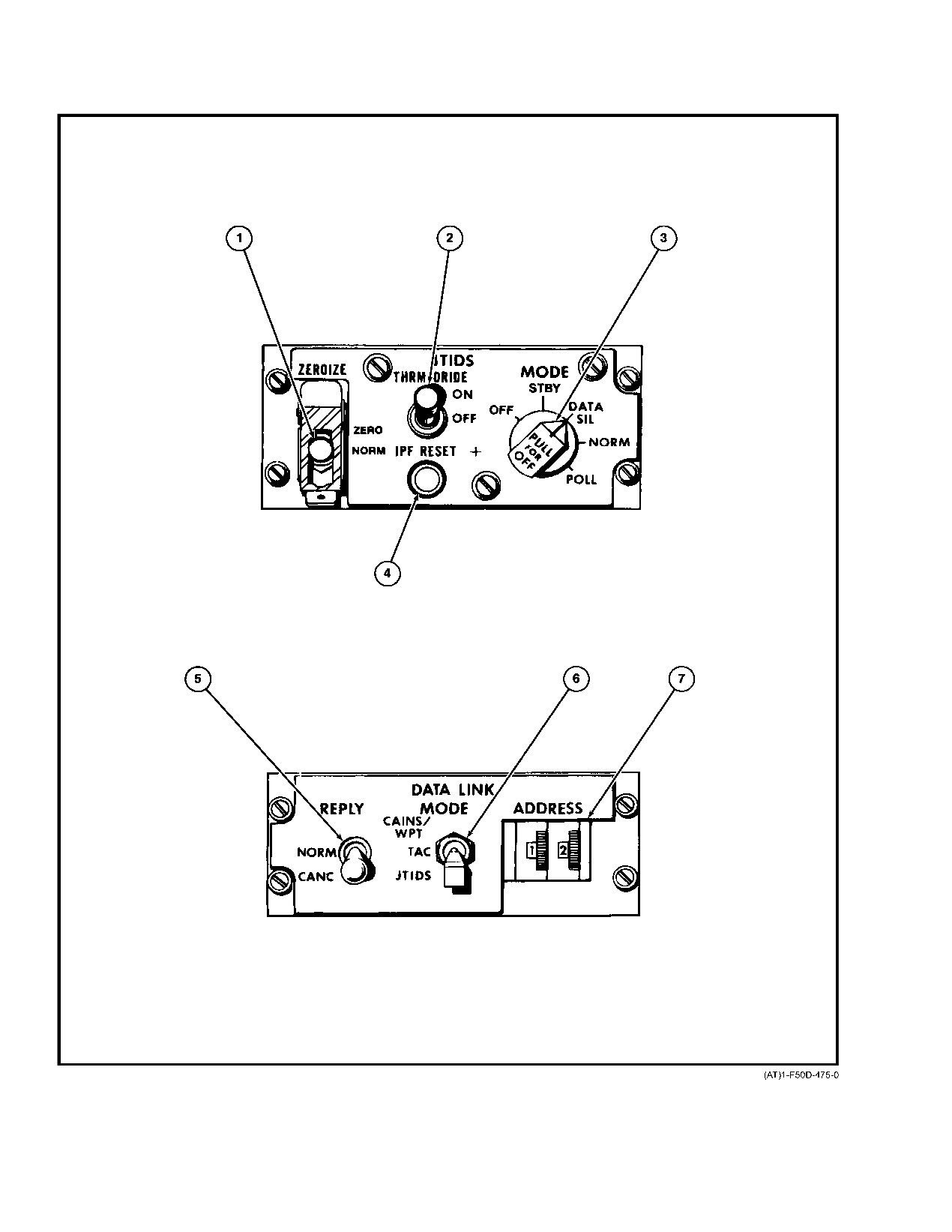
Figure 19Ć13.ĄJTIDS Control Panels (Sheet 1 of 3)
ORIGINAL
19−24
NAVAIR 01−F14AAD−1
NOMENCLATURE
FUNCTION
1
ZEROIZE switch
ZERO Ċ
Zeroizes the crypto variables in the interface unit and the MDL
JTIDS initialization load.
NORM Ċ
Normal switch position (spring loaded).
2
THRM ORIDE switch
ON/OFF Ċ
Enables manual override of thermal shutdown. Indicated by a
JTIDS HOT on the MFD caution advisory window.
3
JTIDS MODE switch
OFF Ċ
Removes all power from the JTIDS/Link−16 functions of the
JTIDS terminal and zeroizes the crypto. To power down the
JTIDS terminal, both JTIDS and TACAN have to be off.
STBY Ċ
The JTIDS/Link−16 functions are off, the battery will hold crypt for
up to 48 hours and initialization data for 5 minutes.
DATA SIL Ċ The JTIDS/Link−16 is on but will not transmit except during BIT
and voice. Net Entry will perform passive sync and, once sync is
achieved, voice will transmit when keyed. TACAN transmissions
are not affected by this selection. Digital TACAN is available for
display on the MFDs and HUD.
NORM Ċ
The JTIDS/Link−16 is on. Net Entry will perform active
synchronization and, once sync is achieved, all Link−16 transmit
functions are available. TACAN transmissions are unaffected by
this selection. Digital TACAN is available for display on the MFDs
and HUD.
POLL Ċ
This mode is currently not used; however, if selected JTIDS/
Link−16 is on and digital TACAN is available for display
on the MFDs and HUD.
4
IPF RESET switch
Re−enables Link−16 transmission when they are shut down by an IPF
detected failure.
5
REPLY switch
NORM Ċ Enables Link−4 reply message transmission (no JTIDS function)
CANC Ċ Inhibits Link−4 reply message transmission (no JTIDS function)
6
DATA LINK MODE
TAC Ċ
Selects Link−4 (AN/ASW−27C) as the primary link system.
switch
The following JTIDS functions operate in this mode.
• Synchronization
• Ownship PPLI messages are transmitted (Ownship System Status
messages are inhibited)
• JTIDS voice (transmit and receive)
• JTIDS navigation updates
• TACAN
JTIDS Ċ Selects Link−16 (AN/URC−107) as the primary link system.
All Link−4 functions are disabled.
Figure 19−13. JTIDS Control Panels (Sheet 2 of 3)
19−25
ORIGINAL
NAVAIR 01−F14AAD−1
NOMENCLATURE
FUNCTION
CAINS/
WPT ć Enables Link−4 carrier alignment and waypoint data to be received
every 16 ms with no reply data. The same JTIDS functions operate in
this mode as when TAC is selected.
Note
The status of this switch is sent to the MCS by the DEU. In the
event the DEU is not ready (No 1553 communications) the
mode will default to Link−4 (D/L). This will prevent loss of the
ACLS function in the event of a failure.
7
ADDRESS thumbwheel
Selects fourth and fifth least significant octal digit for Link−4 address.
Figure 19−13. JTIDS Control Panels (Sheet 3 of 3)
4. MFD3 (own−aircraft data page) Ċ Verify correct
c. On the DEU, select DOWNLOAD for JTIDS.
crypto period. To change crypto period:
d. OWN A/C format on MF03, select JTIDS.
a. DEU Ċ Select JTIDS COMM page, toggle
e. On DEU, set RLY/NTR to ON.
CRYPTO option switch to 0 or 1, then press
ENTR.
f. Set NET ENTR: ENT
b. MFD3 (own−aircraft data page) Ċ Verify crypto
This may take several minutes to accomplish.
period selected.
Confirm on MFD : MENU : JTIDS that time
c. JTIDS MODE switch Ċ Cycle MODE switch
synched to UTC and a G prefix appears. If
from NORM or DATA SIL to STBY then back to
ineffective, proceed to step 4.
NORM or DATA SIL.
4.
DEU (time entry, JTIDS COMM page, TIME pushĆ
button) Ċ Enter hours, minutes, seconds, and select
Note
ENT.
Cycling the JTIDS MODE switch is required to
5.
MFD3 (own−aircraft data page) Ċ Verify correct
direct the DPG to access the desired crypto variĆ
time.
ables. If the MODE switch is not cycled, the DPG
6.
MFD3 (own−aircraft data page) Ċ Verify NET
will continue to access the previous crypto variĆ
ENTR ć NS (net entry not started), IN PROG
ables while displaying the desired crypto period
(attempting sync or course achieved), OK (synchroĆ
on the own−aircraft data page and net entry will
nization complete/fine synchronization achieved).
not occur.
7.
DEU (net entry, JTIDS MODE page) Ċ Press
19.6.4.3
Synchronization
NET ENTR pushbutton and ENT.
The following steps are required to synchronize JTIDS
8.
MFD3
(own−aircraft data page) Ċ Verify
with the network.
NET ENTR ć IN PROG. Changes to OK synchroĆ
nization complete (3 to 5 minutes normal mode,
1. Verify/select desired JTIDS antenna.
7 to 10 minutes data−silent mode).
2. MFD3 (own−aircraft data page) Ċ Verify JTIDS
time is ±6 seconds of net time (GOES time, NTR, or
Note
any participant in the net).
Course sync can be verified by verifying the disĆ
3. Time synchronization from GPS
play of PPLI messages on TSD, PTID, JTIDS
data readout pages, or IRST summary page.
a. Verify GPS is boxed and FOM = 1 on OWN A/C
JTIDS must be selected on the DATA LINK conĆ
format.
trol panel to process PPLI messages.
b. On the JTIDS control panel, mode selection =
9. DATA LINK control panel Ċ Verify/select JTIDS
NORM.
for JTIDS tactical functions.
ORIGINAL
19−26
NAVAIR 01−F14AAD−1
19.6.4.4
JTIDS Shutdown
19.7
IN−FLIGHT VISUAL COMMUNICATIONS
If network operations are anticipated within 24 hours:
Communications between aircraft are visual whenever
practicable. Flight leaders shall ensure that all pilots in the
1. JTIDS MODE switch Ċ STBY.
formation receive and acknowledge signals when given. The
visual communication chapters of NAVAIR 00−80T−113, the
If network operations are not anticipated within 24 hours:
Aircraft Signals NATOPS Manual, should be reviewed and
practiced by all pilots and RIOs. Common visual signals
2. JTIDS MODE switch Ċ OFF.
applicable to flight operation are listed in Figure 19−14.
Note
19.8
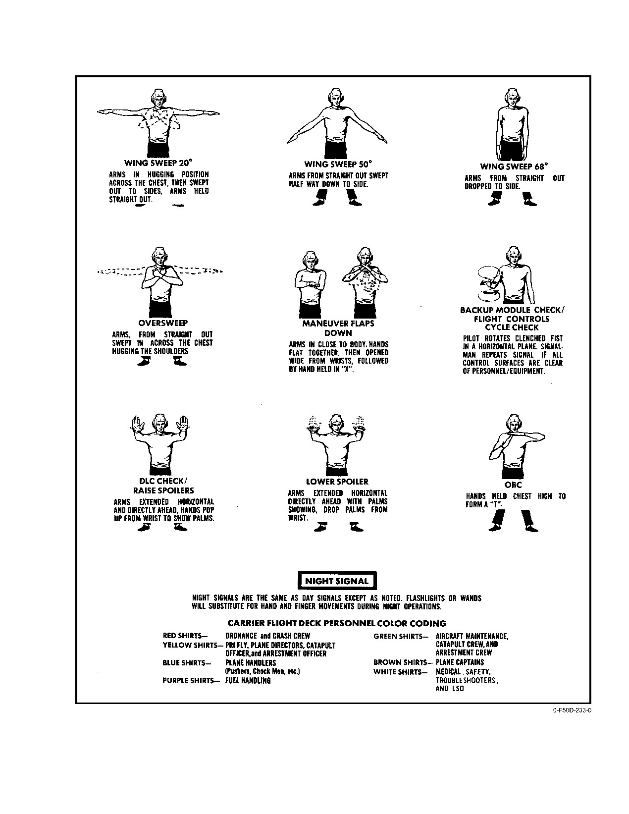
GROUND HANDLING SIGNALS
Under no circumstances should the JTIDS
Communications between aircraft and ground personĆ
MODE switch be left in DATA SILENT or
nel are visual whenever practicable, operations permitting.
NORM for greater than 90 seconds without elecĆ
The visual communication chapters of NAVAIR 00−80T−113
trical power on the aircraft. Doing this will deĆ
should be reviewed and practiced by all flightcrew and
plete the battery and require it to be charged by
groundcrew personnel. For ease of reference, visual signals
maintenance personnel. Crypto variables cannot
applicable to F−14 deck/ground handling are listed on Figure
be accepted or maintained if
the battery is
19−15. During night operations, flashlights or wands shall be
depleted.
substituted for hand and finger movements. Refer to
NAVAIR 00−80T−103 for aircraft arming and safing hand
signals.
MEANING
SIGNAL
RESPONSE
GENERAL CONVERSATION
Affirmative (I understand.)
Thumb up, or nod of head.
Negative (I do not know.)
Thumb down, or turn of head from
side to side.
Question (repeat); used in
Hand cupped behind ear as if
As appropriate.
conjunction with another signal, this
listening.
gesture indicates that the signal is
interrogatory.
Wait
Hand held up in a fist with palm
outward.
Ignore last signal
Hand waved in an erasing motion in
front of face, with palm forward.
Perfect, well done
Hand held up, with thumb and forefinĆ
ger forming an O and remaining three
fingers extended.
Numerals, as indicated
With forearm in vertical position,
Nod of head (I understand).
employ fingers to indicate desired
To verify numerals, addressee
numerals 1 through 5. With forearm
repeats. If originator nods, interĆ
and fingers horizontal, indicate
pretation is correct.
number which, added to 5, gives deĆ
If originator repeats numerals,
sired number from 6 through 9.
addressee should continue to verify
A clenched fist indicates zero.
them until they are understood.
Take over communications.
Tap earphones, followed by lead
Execute.
change signal.
Figure 19Ć14.ĄIn−Flight Communications (Sheet 1 of 4)
19−27
ORIGINAL
NAVAIR 01−F14AAD−1
MEANING
SIGNAL
RESPONSE
CONFIGURATION CHANGES
Lower or raise landing gear
Rotary movement of hand (flashlight
Execute when hand/flashlight drops.
at night) in cockpit, as if cranking
wheels, pause, drop below canopy
rail.
Speed brakes
Open and close four fingers rapidly
Execute on head nod/light out.
and repeatedly. Flashlight at nightća
series of flashes followed by a steady
light; light out for execution.
Lower or raise flaps.
Rotary movement of hand (flashlight
Execute when hand/flashlight drops.
at night) in cockpit, as if cranking
wheels, pause, drop below canopy
rail.
FUEL AND ARMAMENT
Sweep wings aft.
Hand held up, palm aft, and swept aft
Execute on head nod/light out.
along canopy rail; at night, flashlight
swept aft along canopy rail.
Sweep wings forward.
Hand held up, palm forward, and
Execute on head nod/light out.
swept forward along canopy rail;
at night, flashlight swept forward
along canopy rail.
How much fuel have you?
Raise fist with thumb extended in a
Indicate fuel in tens of gallons or
drinking position.
hundreds of pounds by finger
numbers.
Arm or safety missiles and ordnance.
Pistol cocking motion with either
Execute and return signal.
hand.
FORMATION
OK
Section leader gives thumbs−up
Stands by for reply from wingman,
signal.
holding thumbs−up until answered.
Commence take off power
Leader gives a two−finger
Wingman returns two−finger
turn−up.
turn−up signal.
signal and executes.
I have completed my takeoff
Section takeoff leader raises arm
Wingman gives thumbs−up indicatĆ
checklist and am, in all respects,
overhead and waits for response from
ing checklist complete, and ready in
ready for (section) takeoff.
wingman.
all respects for takeoff then lowers
arm and stands by for immediate
section takeoff.
Figure 19−14. In−Flight Communications (Sheet 2 of 4)
ORIGINAL
19−28
NAVAIR 01−F14AAD−1
MEANING
SIGNAL
RESPONSE
FORMATION (continued)
Takeoff path is clear. I am
Section takeoff leader lowers arm.
Wingman executes section takeoff.
commencing takeoff.
Take combat cruise.
Leader holds up open hand palm out
Execute.
towards his wingman and pushes out
and in.
Leader shifting lead to wingman.
Leader pats self on head and points
Wingman pats head and assumes
to wingman. At night, leader aircraft
lead. At night, wingman puts external
switches lights to bright, and turns
lights on dim, and turns anti−collision
anti−collision light on.
light off when he accepts the lead.
If an external light failure, leader
If an external light failure, wingman
shines flashlight on helmet, then
shines flashlight at leader, then on
shines light on wingman.
his helmet.
Leader shifting lead to division
Leader pats self on head, points to
Wingman relays signal; designated
designated by numerals.
wingman, and holds up two or more
division leader assumes lead.
fingers.
Take cruising formation.
Thumb waved backward over the
Execute.
shoulder.
I am leaving formation.
Any pilot blows kiss.
Nod (I understand.)
Aircraft pointed out, leave formation.
Leader blows kiss and points to
Execute.
aircraft.
Directs plane to investigate object or
Leader beckons wing plane, then
Wingman indicated blows kiss and
vessel.
points to eye, then to vessel or object.
executes.
Refers to landing of aircraft,
Landing motion with open hand:
Execute.
generally used in conjunction with
1. Pats head.
Alternate signal ć Lower gear.
another signal:
2. Points to another aircraft.
1. I am landing
2. Directs indicated aircraft to land.
1. Join up or break up, as
Flashing terminal lights.
1. Comply.
appropriate
2. Wingman continues approach in
2. On GCA/CCA final: Leader has
accordance with standard
runway/ship in sight.
operating procedures.
Wingman cross under.
Leader raises forearm vertically.
Execute.
Section cross under.
Leader raises forearm vertically and
Execute.
moves arm in pumping motion.
Refers to CV Case I/Case II
1. Leader gives a two finger turnup
1. Execute
Pattern:
signal.
2. Counting from last aircraft in flight
1. Spin whole flight.
2. Turnup signal followed by
specified number of aircraft
2. Indicated aircraft spin.
number of aircraft to spin.
execute spin.
Figure 19−14. In−Flight Communications (Sheet 3 of 4)
19−29
ORIGINAL
NAVAIR 01−F14AAD−1
MEANING
SIGNAL
RESPONSE
AIR REFUELING
Extend Drogue
Form conećshape with hand, and
Tanker execute.
move hand aft.
Retract Drogue
Form conećshape with hand, and
Tanker execute.
move hand forward.
Secure Turbine
One finger turnćup signal followed by
Tanker execute.
cut signal.
FORMATION SIGNALS MADE BY AIRCRAFT MANEUVER (COMBAT OR FREE CRUISE)
Single aircraft cross under in
Single wing dip
Execute.
direction of wing dip.
Section cross under
Double wing dip
Execute.
Close up.
Series of small zooms
Execute.
Join up; join up on me.
Porpoise aircraft
Expedite joinćup.
Figure 19−14. In−Flight Communications (Sheet 4 of 4)
ORIGINAL
19−30
NAVAIR 01−F14AAD−1
Figure 19Ć15.ĄDeck/Ground Handling Signals
19−31 (Reverse Blank)
ORIGINAL
NAVAIR 01−F14AAD−1
CHAPTER 20
Navigation System
20.1 NAVIGATION SYSTEM
parameters can also be entered on the RIO digital display
keyboard. Flight planning and waypoint information can also
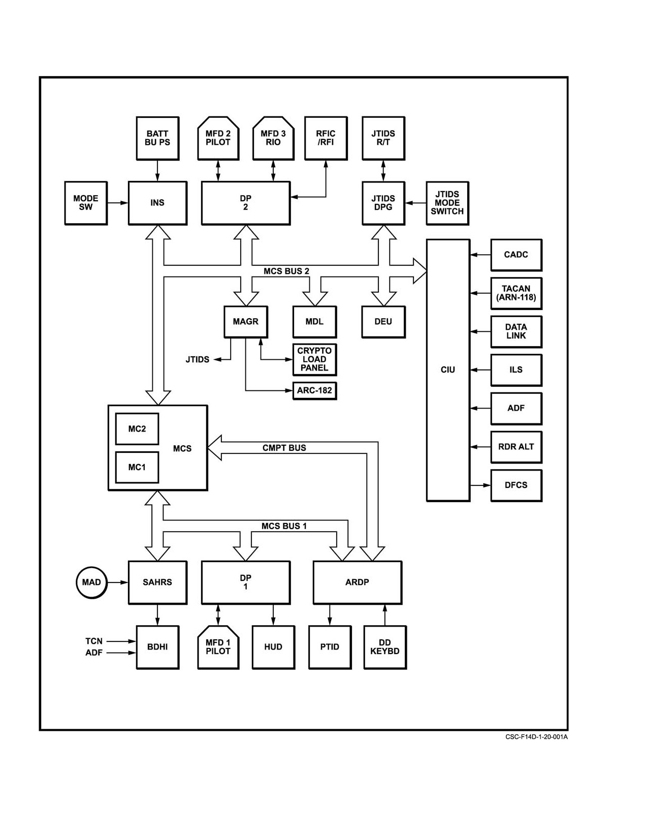
The navigation system (Figure 20−1) combines inputs
be downloaded from the Mission Data Loader in the RIOs
from various on−board sensors with inputs entered by the
cockpit. Navigation and steering displays are provided to the
crew and provides the following outputs of aircraft position:
pilot and RIO by means of various formats on the three MFDs
velocity, attitude, heading, accelerations, and angular rates.
and to the pilot on the HUD. The PTID can also provide most
This information is displayed to the crew and also used by the
navigation displays to the RIO. A BDHI in each cockpit can
weapons system and other aircraft functions. The system also
display aircraft heading from the SAHRS, TACAN range and
provides steering and control commands for display to the
bearing, and UHF/ADF bearing.
crew as required.
Navigation information from equipment not on the
The AN/ASN−139 inertial navigation set is the primary
standard data bus is converted to the proper format by the
navigation sensor. It provides inertial information to the
CIU. These units and the information they provide are as
MCS via a standard data bus. As a backup to the INS, the
follows:
AN/USN−2 (V) SAHRS can provide similar, but somewhat
1. Standard central air data computer Ċ Altitude,
degraded inertial information. Selection of SAHRS data is
airspeed, and other air related data.
either automatic on failure of the INS or by operator
selection. The MCS processes inertial data along with
2. AN/ARN−118 TACAN Ċ Range and bearing from
information from other navigation aids to provide smoothed
tuned TACAN station.
and optimized outputs for display or for use by other aircraft
systems and functions.
3. AN/ASW−27C data link Ċ Ship inertial navigation
system data for carrier alignment, waypoint
The Miniaturized Airborne GPS Receiver (MAGR)
coordinates, automatic carrier landing system
provides precise position information to the ASN−139 and the
commands, and vector steering commands.
MCS. It uses the Global Positioning System (GPS) constelĆ
lation of satellites to very accurately fix the aircraft’s position
4. Instrument landing system Ċ SPN−42 course and
in three dimensions, and provides a source of velocity
glideslope deviation inputs.
information that can be used for in−flight alignments of the
INS. Under normal circumstances, the MAGR provides
5. UHF/ADF Ċ Relative bearing to the tuned station.
position and velocity updates to the ASN−139 and MCS at
6. AN/APN−194 radar altimeter Ċ Height above the
one second intervals. Position accuracy can be maintained to
surface.
within approximately 16 meters (spherical error probability)
under the most severe dynamic conditions.
The CIU also converts MCS steering command outputs
and roll and pitch attitude information from the INS into
The AN/URC−107 JTIDS provides navigation
analog form for the DFCS.
correction data for use in updating the navigation system and
velocity data for aligning the INS in flight. When installed,
20.1.1
AN/ASN−139 Inertial Navigation Set
the JTIDS receiver/transmitter replaces the AN/ARN−118
TACAN. With JTIDS installed, the CIU is not used to convert
The INS is the primary navigation sensor. It is a self−
the TACAN data to a 1553 format; the data goes directly from
contained system that includes an inertial measurement unit,
JTIDS to the MCS on the 1553 bus.
processing equipment, and the supporting electronics and
Navigation information that requires data entry is
power supply. It provides inertial navigation inputs to the
normally inserted by the RIO using the DEU; however, most
MCS.
20−1
ORIGINAL
NAVAIR 01−F14AAD−1
Figure 20Ć1.ĄNavigation System
ORIGINAL
20−2
NAVAIR 01−F14AAD−1
The IMU is an all−attitude strapdown navigation
20.1.2
Miniature Airborne GPS Receiver (MAGR)
set that mounts three laser gyros for angular rate sensing
and three single−axis accelerometers for acceleration
The MAGR is a 5−channel GPS receiver and data
measurement.
processor, located in the MC2/ASPJ Bay. The MAGR uses
the signals from four satellites to provide navigation inforĆ
Note
mation. The fifth channel is used to sequentially monitor all
of the satellites in view to ensure that the best four are always
The DFCS uses IMU data to monitor the pitch
used in the solution. Each MAGR channel precisely tracks
and roll rate gyros. An IMU invalid signal, or
one satellite’s signals and demodulates the navigation
selection of the NAV MODE selector to OFF will
message. This message includes timing and satellite position
result in a DFCS PQVM fault. The indications
information, as well as diagnostic information about satellite
of this fault are the FCS CAUTION light
health. The MAGR measures the signal transmission time to
accompanied by AFC PS and RS acronyms. This
obtain pseudo−range and the Doppler shift of the carrier
is a redundancy degrade only, no functionality is
signal to measure delta−range. Pseudo−range is the calculated
lost. Depressing MASTER RESET will clear
distance to a satellite uncorrected for errors due to MAGR
fault indications once the IMU valid signal is
clock bias, atmospheric delays, and receiver noise. Delta−
restored and the NAV MODE selector is not in
range is a measure of the relative velocity between the
the OFF position.
satellite and the GPS antenna. The MAGR filters the pseudo−
range and delta−range measurements to obtain true position,
In the strapdown configuration, the sensor assembly is
velocity, and time information.
not isolated from the airframe by gimbals and senses aircraft
angular rate and accelerations directly. However, local level
Radio Frequency signals
(L−Band) from the GPS
and wander angle (the difference between initial pointing
satellites are sensed by the AS/4336A Dual−Frequency GPS
angle and true north) must be established by alignment for the
Antenna, which is located on the turtleback. A splitter−
INS to provide useful information. After alignment, the INS
amplifier in the GPS antenna line provides GPS signals to
processor keeps track of the sensor assembly’s orientation
weapon station B for LANTIRN pod use.
with respect to local level and true north by integrating the
sensed angular rates. The sensed accelerations are resolved
To accelerate the satellite acquisition process, the
into north, east, and down components; corrected for coriolis
MAGR uses stored almanac data. The almanac data is stored
and other factors; and integrated to provide velocity and
in the MAGR in nonvolatile memory, supported by an
position information.
internal battery. If this battery is removed or is low, the
MAGR requests almanac data from the MCS.
This information as well as accelerations, body rates,
attitude, and time tagging data is provided in digital form to
Note
the MCS. Analog outputs of roll and pitch are provided to the
DFCS via the CIU.
D If valid almanac data is not available, the
MAGR will initiate a cold−start sky search for
The INS is controlled by the NAV MODE switch
visible satellites. Search and acquisition may
(Figure 20−2) on the RIO right console. This switch controls
take over 20 minutes. With valid almanac
power to the INS and selection of modes of alignment and
data, search time may be reduced to as little as
navigation. This switch is also used to control SAHRS
30 seconds. If a cold start is performed, the
alignment mode during concurrent alignment when both the
almanac is downloaded from the satellite
INS and SAHRS are being aligned in the same mode to the
navigation message and stored for future use.
same data source. Data entry and selection of INS submodes
are by means of the MFD and DEU.
D GPS satellite acquisition time may be affected
by a number of conditions, particularly
The INS uses 115 VAC from ac essential No. 2 bus
L−band RF interference and line of sight
through INS PH A, B, and C circuit breakers (3C7, 4C1, and
obstructions, as well as the currency of the
4C2). Refer to Chapter 2 for the alphanumeric listing of
almanac data. On deck, aircraft proximity to
circuit breakers.
large structures as a hangar or an aircraft
carrier island superstructure may delay or
The INS backup power supply is a separate unit that
prevent satisfactory satellite acquisition until
provides 28−VDC power to the INS for transient protection
the aircraft is moved.
for up to 20 seconds in flight and to 2 seconds on the ground.
Battery charging power is provided by the ac left main bus
through the INS BATT PWR circuit breaker 1I7.
20−3
ORIGINAL
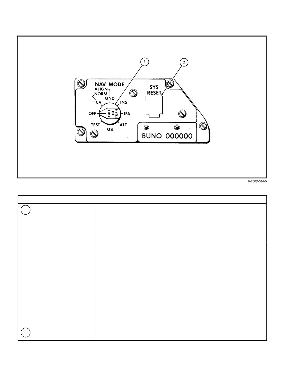
NAVAIR 01−F14AAD−1
NOMENCLATURE
FUNCTION
1
NAV MODE selector
NORM CV Ċ Initiates alignment with or without ships inertial navigation
system (SINS) data. Without SINS data, manual entry of the ships latitude,
longitude, true heading, and speed is required.
ALIGN GND Ċ Initiates alignment for shore base operations. Own aircraft
latitude and longitude required for initialization.
INS Ċ Selects GPS/INS navigation or INS navigation if GPS unavailable.
IFA Ċ Selects INS/GPS navigation. Can be used to align the INS using GPS
or other valid source of true heading.
ATT Ċ Selects the IMU backup navigation mode. May require entry of
aircraft true heading at least one time, via the DEU Own Aircraft format.
GB Ċ Gyro Bias mode, not functional.
TEST Ċ Provides Built−In−Test for installation and functional verification
(on deck only).
OFF Ċ Secures system function.
2
SYS RESET switch
Resets transient failures in the data processor and mission computers.
Figure 20Ć2.ĄNAV MODE Select/Computer Reset Panel
ORIGINAL
20−4
NAVAIR 01-F14AAD-1
The MAGR provides a UTC synchronization signal to
for direct use by the DFCS, and magnetic heading for the
JTIDS and ARC-182 “Have Quick II” radio sets. The JTIDS
BDHI. The SAHRS is controlled by MFD formats. During
receives the UTC via data bus message. The JTIDS
concurrent alignment with the INS, the NAV MODE select
references it to a precise 1-Hertz discrete sent by the MAGR.
switch also controls the SAHRS. In its normal operating
The “Have Quick II” radios receive the UTC (“mickey”) as
mode, the SAHRS is an inertial system with velocity aiding
a serial input on separate, direct-wired lines when RCV TOD
selectable. It can also operate as a conventional attitude
(PB 3) is depressed on the GPS Status format.
heading reference system having slaved, directional gyro, or
emergency compass modes available. The SAHRS receives
The MAGR is powered by 115 VAC through the GPS
magnetic heading from the magnetic azimuth detector;
circuit breaker (3E2). MAGR power is software controlled
provides compensation for aircraft magnetic errors; and
through the DPs via PB 4 (PWR ON/OFF) on the GPS Status
provides magnetic heading to the BDHI using the best source
Format. The MAGR is energized on either internal or
available as determined by the navigation system.
external power, and is energized by default if both DPs are
failed. The MAGR also uses three C-cell equivalent alkaline
The SAHRS uses 115 VAC from the ac left main bus
batteries to support power-off memory storage and internal
through SAHRS A, B, and C circuit breakers (1I3, 1I5, and
time keeping.
1I6). It may also use 28-VDC power from the interrupt-free
bus via SAHRS DC circuit breaker (9I3) if ac power is not
20.1.3
AN/USN-2(V) Standard Attitude Heading
available. Refer to Chapter 2 for the alphanumeric circuit
Reference System (SAHRS)
breaker listing.
20.1.4
Mission Computer System (MCS)
Aircraft with AFC 919 incorporated utilize the Naviga-
tion Guidance System (NGS) SAHRS. It is a self-contained
The navigation system includes the navigation
strapdown all-attitude INS that uses a single monolithic laser
computations performed by the MCS. The computations of
gyro to sense angular rates for all three axis and three single-
inertial parameters are performed respectively in the INS and
axis accelerometers for acceleration measurements. It uses
SAHRS processing modules that interface with the MCS.
an improved SSA (502A6) and replaces the flux valve with
The MCS processes this inertial data as well as initial entered
a Magnetic Azimuth Detector
(MAD) (502A5). NGS
data and navigation aiding inputs. Processing includes
SAHRS interfaces in the same manner to other systems as the
generating other navigation parameters, filtering, time
existing SAHRS system.
tagging, storing, and distributing data to the displays and
other system functions.
In the strapdown configuration, the sensor assembly is
not isolated from the airframe by gimbals and senses aircraft
The MCS consists of two AN/AYK-14 (XN-6) tactical
angular rate and accelerations directly. However, local level
computers: MC1
and MC2. Normally MC2
performs
and wander angle must be established by alignment for
navigation system processing and computations. Should
SAHRS to provide useful information. After alignment, the
MC2 fail, MC1 will perform virtually all navigation system
SAHRS processor keeps track of the sensor assembly’s
functions with the exception of data link, JTIDS and radar
orientation with respect to local level and true north by
position updates, JTIDS continuous position update,
integrating the sensed angular rates. The sensed accel-
JTIDS in-flight align, and surface waypoint position
erations are resolved into north, east, and down components;
determination.
corrected for coriolis and other factors; and integrated to
provide velocity and position information.
The MCS is the data bus controller; it accepts INS,
MAGR, and SAHRS data. It accepts navigation initialization
Note
data from the DEU or the DD and sub-mode selections from
the MFDs, providing this information to the INS, MAGR,
The DFCS uses SAHRS as a backup for the INS
and SAHRS in the required formats. It also provides JTIDS
data to provide autopilot capability in the event
the INS or SAHRS data and accepts navigation correction
of a failed IMU. Any SAHRS invalid signal
and TACAN data from JTIDS. Inputs from the various
airborne will be detected and logged on the DCP
navigation aids are provided to the MCS via the data bus after
following flight. In addition to an actual SAHRS
formatting in the CIU.
failure, this may be caused by selection of SAHR
MODE of SLV, DG, or EC via the NAV SYSTEM
Based on crew mode selection, equipment availability
and input data received, the MCS determines the mode of
AID MFD format shown in Figure 20-18.
operation and the parameters to be computed. It processes
and stores these values, using them for other functions within
Outputs to the MCS include velocity, heading, attitude,
the MCS as well as distributing them to the displays and other
linear accelerations, angular rates, and time tagging data.
aircraft functions.
The SAHRS also generates synchro outputs of roll and pitch
20-5
CHANGE 1
NAVAIR 01−F14AAD−1
20.1.5
Navigation Data Initialization
the pilot and the three MFDs for both crewmembers. In
addition, certain MFD formats provide pushbutton legends
Initial manual entry of required navigation information
that permit submode selection and selection of other related
is accomplished by the RIO. Either the DEU or the DD
display formats. These include HUD, VDI, HSD, OWN A/C,
control panel can be used.
NAV AID, SURFACE WPT, INS UPDATE, and several
alignment formats. A description of the outputs available and
20.1.5.1
Data Entry Unit (DEU)
the use of these outputs can be found in paragraph 20.2,
Navigation System Data Distribution, and paragraph 20.3,
The DEU allows the RIO to manually enter the initial
Navigation System Operation. The displays are discussed in
detail in Chapter 2.
navigation information required for INS and SAHRS
alignments, GPS initialization, and for waypoint location.
Such required data inputs include latitude, longitude,
20.1.7
Programmable Tactical Information
altitude, waypoint type, date, time, carrier speed and
Display (PTID)
heading, directional gyro magnetic heading, aircraft true
heading, and surface waypoint range and bearing. The
The PTID provides the RIO an alternate means of
various DEU formats used are shown in Figure 20−3. This
display for many of the alphanumeric and graphic outputs of
figure shows the DEU MENU display and the five DEU
the navigation system. Information is transmitted from the
formats used for entry of initial data and navigation related
MCS to the APG−71 and then to the PTID. Selection of
information. Use of these formats is discussed in paragraph
display data is made via the DD.
20.3, Navigation System Operation. Refer to Chapter 2 for
detailed information on the DEU.
20.1.8
Converter Interface Unit (CIU)
20.1.5.2
Digital Display (DD)
The CIU accepts all non−data, bus−compatible naviĆ
gation aid inputs and converts them to the proper format. The
The APG−71 DD provides the RIO with an alternate
CIU also converts the steering error commands generated by
means of entering most initial navigation data into the system
the MCS into the required analog signals for the DFCS. These
except for SAHRS DG heading, barometric altimeter setting,
navigation aids, as they pertain to the navigation system, are
date, and time; and control of JTIDS navigation functions.
described in the following paragraphs.
Use of the DD for entry of navigation is provided in
paragraph 20.3, Navigation System Operation.
20.1.9
Standard Central Air Data Computer
20.1.5.3
GPS Initialization
(SCADC)
MAGR initialization is improved when aircraft
The SCADC is a single processor digital computer that
position, velocity, Zulu Time of Day (ZTOD), and date are
gathers, stores, and processes pitot pressure, static pressure,
provided by the MCS. The correct time and date may also be
total airstream temperature, and angle−of−attack data from
entered manually via the DEU OWN A/C format. Once the
aircraft airstream sensors. In addition to performing wing
GPS begins navigation, ZTOD and date are provided to the
sweep, flap and slat schedule computations, and limit
MCS by the MAGR and the ZTOD and date buttons on the
controls for the flight control systems, the SCADC provides
DEU are removed. The MAGR maintains ZTOD and date
air data related parameters to the MCS via the CIU. This
with its internal batteries when aircraft power is removed.
information includes pressure altitude, pressure altitude rate
of change, true and calibrated airspeed, angle of attack, and
Note
Mach number. True and calibrated airspeed, angle of attack,
and Mach number are displayed directly to the crew on the
Incorrect ZTOD or date values can delay or
HUD and VDI format of the MFDs. Pressure altitude is
prevent satisfactory satellite acquisition. Correct
corrected for nonstandard day conditions and then displayed
values should be verified on the GPS Status
as system altitude. True airspeed may also be used in the
format and manually entered via the DEU if
computation of wind. Wind provides a reference velocity
necessary.
source for the INS or SAHRS for in−flight alignment and is
a component of system velocity during backup navigation
20.1.6
Displays Subsystem
modes. A description of the pitot−static system and the
SCADC is provided in Chapter 2.
Navigation information is provided to the pilot and
RIO in both graphic and alphanumeric formats via HUD for
ORIGINAL
20−6
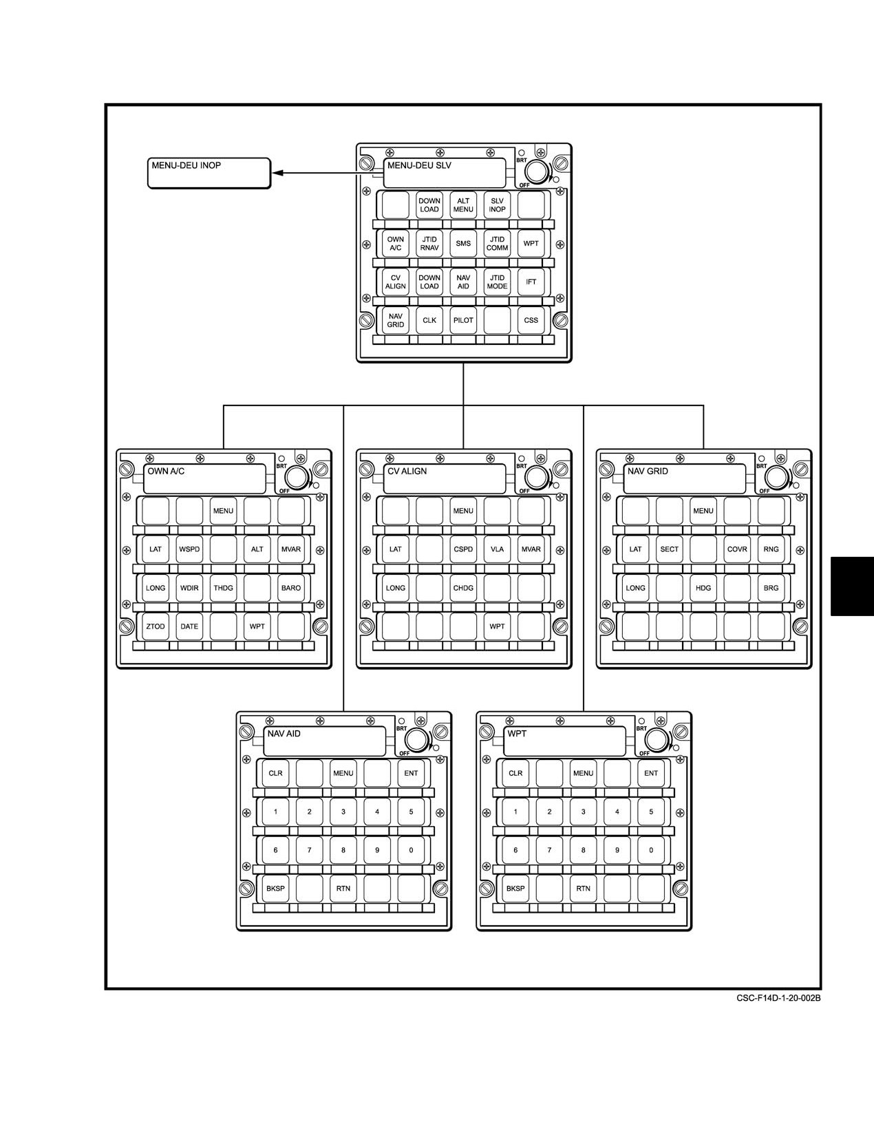
NAVAIR 01−F14AAD−1
Figure 20Ć3.ĄDEU Navigation Formats
20−7
ORIGINAL
NAVAIR 01−F14AAD−1
20.1.10 AN/ARN−118 Tactical Air Navigation
Note
(TACAN) System or AN/URC−107 Joint
JTIDS TACAN has shown reduced receiver
Tactical Information Distribution System
sensitivity on channel 83. Use of channel 83Y
(JTIDS)
(G/A and A/A) and 83X (A/A only) may not
receive accurate information outside 40 miles.
The TACAN system is a UHF navigation receiver−
transmitter that is used to provide navigation information by
The TACAN has a memory feature that allows tracking
determining slant range and bearing to a selected TACAN
to continue uninterrupted by momentary loss of received
station. Operating range is line of sight to approximately 300
signals. A range signal that has been tracked for at least 10
nm. Accuracies are 0.1 nm in range and 0.5_ in bearing. The
seconds will be retained in memory for 13 to 17 seconds after
TACAN station can be surface (land based or shipborne) or
signal loss; a bearing signal tracked for at least 15 seconds is
airborne. Surface stations can be either TACAN or VORTAC.
retained for 2 to 4 seconds after signal loss. This feature
When operating in the REC or T/R modes, the system is
allows for automatic antenna switching without loss of
capable of receiving signals from a ground station simultaĆ
TACAN outputs.
neously with 99 other aircraft. When in the A/A mode, the
system is capable of transponding with each of five cooperatĆ
If the signal from a TACAN station becomes unreliable
ing aircraft, providing slant range information to each; howĆ
or is lost for more than memory time, then the TACAN
ever, the system will interrogate and lock on to only one. In
switches to self−test automatically. This may cause the BDHI
A/A mode, the second aircraft must be 63 channels apart. An
relative bearing to be 270_ for 2 to 4 seconds. If the signal is
airborne station provides only slant range distance unless the
not acquired during the self−test, the BDHI bearing pointer
aircraft is equipped with a bearing transmitter and a rotating
will continuously slew in a counterclockwise direction and
antenna. The AN/ARN−118 or AN/URC−107 are not able to
the TEST light on the TACAN control panel will light. If
transmit bearing information but can receive it from a speĆ
the light remains on, a failure is indicated and TACAN
cially equipped aircraft.
information should be disregarded. As in all TACAN sets,
undetected failures can occur, so information provided by the
TACAN should be cross−checked with other available
Available TACAN range and bearing information is
navigation information.
always displayed on the pilot and RIO BDHIs and can be
selected for display on the HUD and MFDs. The TACAN
The AN/ARN−118 TACAN uses 115 VAC from the ac
data supplied to the MCS can be used for a one−fix update of
essential No. 2 bus through JTIDS RT PH A circuit breaker
the INS and SAHRS, continuous update of the system
(3D5), 28 VDC from dc essential bus No. 2 via BDHI/ JTIDS
navigation solution, or for steering. The AN/URC−107
DPG circuit breaker (8E7), and 26 VAC from the 26−volt
(JTIDS) TACAN requires the selection of DATA SIL,
essential bus through JTIDS
/ DPG
/ BDHI INST PWR
NORM, or POLL on the JTIDS control panel (Figure 20−4)
circuit breaker (3D4). In addition to the power and circuit
to supply digital TACAN information to the MCS. This is
breakers used by the AN/ARN−118, the AN/URC−107
required for TACAN displays on the MFD, navigation
TACAN also requires 115 VAC from essential No. 2 bus
updates, and TACAN steering. Refer to paragraphs 20.3.9.3,
through JTIDS RT PH B and C circuit breakers (4D3 and
Navigation System Updates, 20.3.9.4, Continuous Position
4D4). Refer to Chapter 2 for the alphanumeric circuit breaker
Updating, and 20.3.9.2, Display Steering Modes.
listing.
The TACAN has 126 X channels and 126 Y channels
20.1.10.1
TACAN Controls and Indicators
available
1 MHz apart. The TACAN uses two aircraft
antennas, automatically switching between the two at
Two identical TCN control panels (Figure 20−4), one in
5−second intervals until a threshold signal is received. The
each cockpit, are provided to permit either crewmember to
AN/ARN−118 requires approximately 2 minutes for warmup;
operate the TACAN. To determine which crewmember conĆ
AN/URC−107 (JTIDS) is operational once TACAN self−test
trols the TACAN, each cockpit has an alternate action
is complete. If stable range and bearing indications are not
TACAN CMD pushbutton that illuminates either PLT or
available after this time, tune another station or check circuit
NFO to show which cockpit has command. Both buttons
breakers.
allow each crewmember to either give or take command of
the TACAN. A BDHI in each cockpit provides range and
bearing to a tuned TACAN station. Other TACAN displays
may be selected.
ORIGINAL
20−8
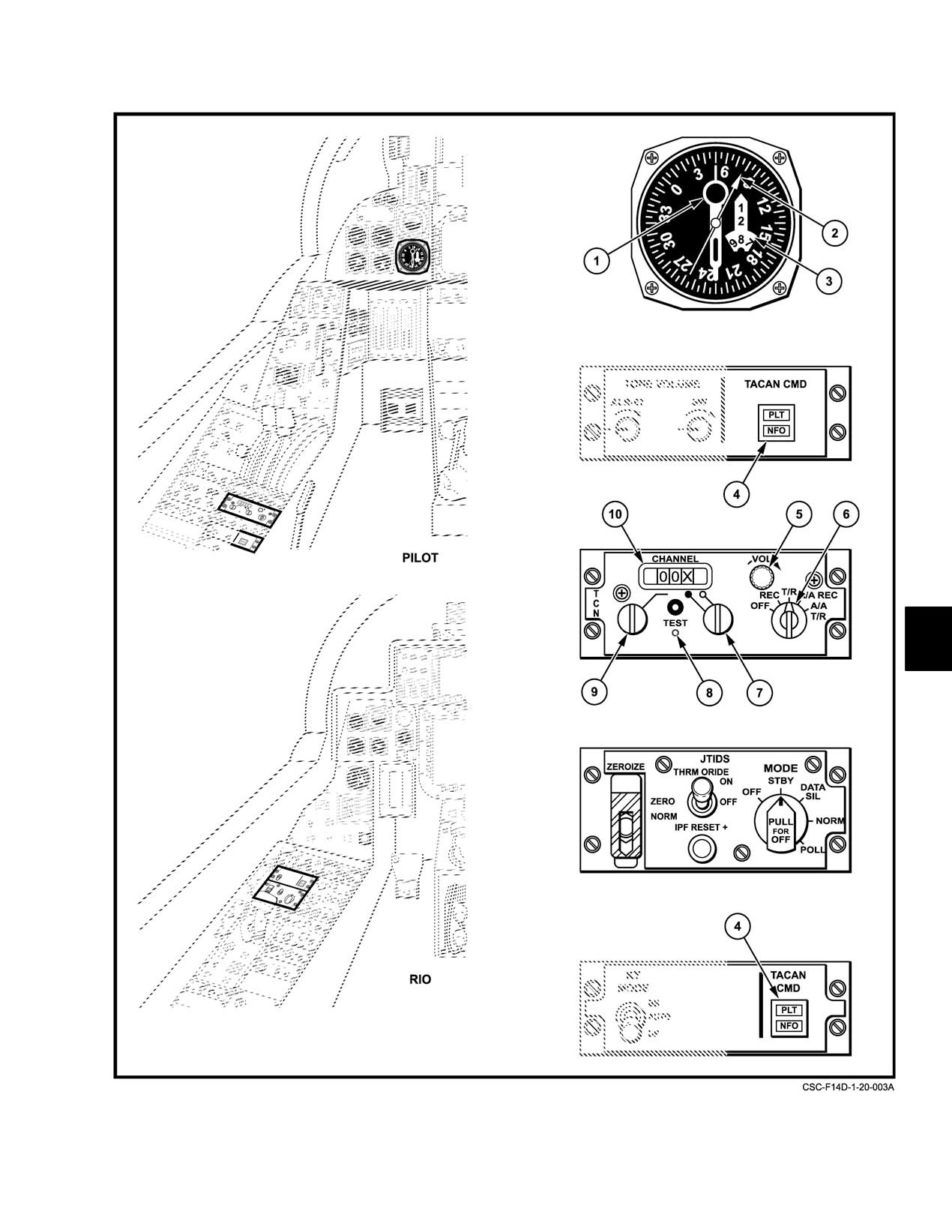
NAVAIR 01−F14AAD−1
Figure 20Ć4.ĄTACAN Controls and Indicators (Sheet 1 of 3)
20−9
ORIGINAL
NAVAIR 01−F14AAD−1
NOMENCLATURE
FUNCTION
1
BDHI TACAN needle
Displays relative bearing to the selected TACAN station
2
BDHI UHF/ADF needle
Displays relative bearing to a tuned UHF transmitter.
3
BDHI TACAN range
Displays slant range to a selected TACAN station.
window
4
TACAN CMD buttons
Selects pilot/RIO TACAN control for BDHI display. Alternate action lighted pushĆ
(Pilot and RIO)
button that lights PLT or NFO to indicate which cockpit has command of the
TACAN. Pressing the button cycles command to the other cockpit and changes
light indication.
5
TACAN VOL control
Varies level of the TACAN audio signal to the headsets. Clockwise rotation
increases volume.
6
TACAN mode switch
OFF Ċ
Power not applied to TACAN
REC Ċ
Receive:
TACAN determines bearing from aircraft to selected TACAN
station. Bearing displayed on BDHI; available for MFD, HUD.
Station identifier is received, no range is calculated.
T/R Ċ
Transmitćreceive:
In addition to the REC functions, TACAN determines slant range
to selected TACAN station. Distance displayed on BDHI;
available for MFD, HUD.
A/A REC Ċ Air−to−air receive:
TACAN receives bearing information from a suitably equipped
cooperating aircraft and calculates the relative bearing to the coopĆ
erating aircraft. No distance information is available.
A/A T/R Ċ
Air−to−air transmitćreceive mode:
TACAN receives both distance and bearing information from a
suitably equipped cooperating aircraft and calculates the slant
range distance and relative bearing of the aircraft. If the aircraft
is not equipped with bearing transmitting capabilities, only slant
range is available.
Note
• Air−to−air TACAN operation requires a
63 channel
separation between cooperating aircraft. Channel use
should be prearranged. Air−to−air TACAN between F−14s
is limited to slant range, no bearing is provided.
• When the AN/URC−107 (JTIDS) is installed, TACAN data
on the HUD and MFD requires the selection of DATA SIL,
NORM, or POLL on the JTIDS control panel.
7
Right hand channel
The inner knob sets the channel number units digit. The outer knob sets
knob
X and Y channels.
Figure 20−4. TACAN Controls and Indicators (Sheet 2 of 3)
ORIGINAL
20−10
NAVAIR 01−F14AAD−1
NOMENCLATURE
FUNCTION
8
TEST button/light
Initiates self−test. The light illuminates to indicate failure of continuous monitor
test or either manually or automatically initiated self−test.
9
Left hand channel knob
Sets channel number hundreds and tens digits.
10
CHANNEL window
Displays selected channel number and X or Y.
Figure 20−4. TACAN Controls and Indicators (Sheet 3 of 3)
20.1.10.2
TACAN Testing
TEST light goes on at any time during flight, it indicates a
failure of automatic self−test and all TACAN information
TACAN testing includes continuous monitoring and
should be disregarded.
commanded self−test. Continuous monitoring checks certain
internal functions of the TACAN on a continuous basis.
20.1.11
AN/ASW−27C Data Link (D/L)
Failure of one of these checks causes the TEST light on the
TCN panel to illuminate. Commanded self−test is either
During carrier alignment, D/L provides SINS data to
manually or automatically initiated. The TEST button is a
the INS via the CIU. This data is also provided to the SAHRS
momentary action pushbutton switch that is pressed to place
during concurrent carrier alignment. Before takeoff the D/L
the TACAN into the commanded self−test mode manually.
can be used to provide waypoint coordinates to the MCS via
The test may be accomplished in all operating modes.
the CIU for later use in steering and position updating. After
Commanded self−test interrupts normal operation for a
takeoff, the D/L provides control and steering commands that
22−second cycle and provides a high−confidence test of the
are available for display or may be coupled to the autopilot
TACAN except for the antennas. When TEST is selected in
during vector steering or ACL operation.
T/R, a power check is initiated for the transmitter, receiver,
distance, and bearing circuits. The BDHI bearing pointer
Refer to NAVAIR 01−F14AAD−lA for a complete
should swing to 270_ in 2 to 7 seconds and the range OFF flag
discussion of data link.
should appear. After approximately 7−seconds, the BDHI
bearing pointer should swing to 180_ and the OFF flag should
20.1.12 UHF Automatic Direction Finder (ADF)
disappear. The distance indicator should read 000.0 nm. The
BDHI should return to its original bearing and distance
The UHF/ADF provides the relative bearing to a UHF
readings after 15 seconds. The TEST light will momentarily
transmitting station from the aircraft. This information is
flash when the test is initiated. If the light goes on and stays
displayed directly on the BDHI and on the MFD HSD format.
on during test, a malfunction is indicated. In addition, the
OBC CNI format on the MFD displays a TACAN NO−GO or
20.1.13 Bearing Distance Heading Indicator (BDHI)
NOT READY indication if there is a test failure. If a self−test
in the T/R mode results in a failure indication, select REC and
A BDHI is on the left side of the pilot and RIO instruĆ
perform the test again. If the failure indication is removed,
ment panels (Figure 20−4). The BDHI is a remote heading
bearing information is still valid. The AN/URC−107
indicator that displays aircraft magnetic heading, TACAN
performs all the same TACAN tests as the AN/ARN−118.
and UHF/ADF bearings, and TACAN slant range. The
It also performs a commanded self−test when a JTIDS
rotating compass card receives its heading reference from the
OBC is selected on the MFD OBC page. JTIDS OBC
SAHRS. Aircraft heading is read against a fixed index mark
provides TACAN fail data on the JTIDS fail data page. Refer
at the 12−o’clock position. The two servo−driven needles are
to JTIDS self−test Chapter 27. The following will cause the
positioned by relative bearing information provided by the
TACAN lock to break for 4 seconds: the power up or down
UHF/ADF to the single bar (No. 1) needle and by the TACAN
of JTIDS, going from OFF or STBY to DATA SIL, NORM,
to the double bar (No. 2) needle. Magnetic bearing to the
or POLL or back to STBY or OFF on the JTIDS control panel.
station is read under the head of the needle. Relative bearing
The range off flag will appear and bearing will swing to 270_
can be determined by comparing the bearing reading with
for 2 seconds then reacquire lock to the station.
magnetic heading. The range window on the right side of the
indicator displays TACAN slant range. When the TACAN is
Whenever a signal becomes unreliable (loss exceeds
off or range is unreliable, an OFF flag covers the window.
memory time), self−test is initiated automatically. If the
20−11
ORIGINAL
NAVAIR 01−F14AAD−1
20.1.14 AN/URC−107 Joint Tactical Information DisĆ
The navigation update function has to be manually
tribution System (JTIDS)
selected. These selections are JTIDS one−fix, continuous
position, and INS in−flight alignment. The aircrew has the
JTIDS is a jam−resistant communication system that
ability to select either of the JTIDS grids via the NAV
provides the F−14D with two−way secure data and digital
SYSTEM AID page. This selection determines which data
voice communication. In addition to the JTIDS commuĆ
the MCS will use to perform the track conversion and
nication functions, it also provides the F−14D with navigation
continuous position updates. Independent of this selection,
and TACAN data.
JTIDS one−fix and INS in−flight alignments will always be
performed using the geodetic data.
The JTIDS system internally computes relative naviĆ
Internal to the JTIDS system is the equivalent of an
gation and position location information. All participants
AN/ARN−118 TACAN system. Installation of JTIDS in the
(JTIDS terminals) in the same net determine their position
relative to each other. This is referred to as the JTIDS relative
aircraft replaces the AN/ARN−118 with the JTIDS receiver/
transmitter. Refer to 20.1.10 for JTIDS TACAN operation.
navigation function. The basis of this function is the TDMA
architecture and precise synchronization of all participants to
20.2 NAVIGATION SYSTEM DATA DISTRIBUTION
a common time base (net time reference). This allows each
JTIDS system to accurately determine the time a message
The navigation system provides data to other systems
was transmitted and its TOA, and then compute the range
and functions as well as for display to the crew. In general,
from the source of the message. JTIDS computes an estimate
this is similar to displayed data, but such parameters as
of its own relative position coupled with the position and
aircraft angular rates, accelerations, and time tag data are
navigation quality contained in each participants PPLI
also included. Figure 20−5 summarizes navigation system
message. With data from multiple participants with equal or
outputs.
better position plus the navigation data from the INS, GPS,
or SAHRS, JTIDS can compute an excellent estimate of
20.2.1
Navigation Data Display
own−ship position and velocities. JTIDS will automatically
update the own−ship position in the PPLI message with its
Navigation information is displayed to the aircrew in
estimated position. It also provides an estimated quality
graphic form on the HUD and MFD and in tabular form on
(accuracy) of the position it computed. This quality is
the MFD.
provided to the MCS and included in the PPLI message.
When the DISPLAYS panel TLN (takeoff, landing,
JTIDS is a dual grid system utilizing a geodetic and an
navigation) MODE button is selected, both the HUD and the
independent relative grid. JTIDS can operate in both grids
MFD VDI format show navigation information graphically
simultaneously, but the MCS is limited to operating in one
in the vertical plane. The MFD can also show a HSD format
grid at a time. The relative mode requires a coordinated grid
that provides graphic navigation information in the
origin (latitude and longitude) and the selection of NAV conĆ
horizontal plane.
troller (a high−quality navigation source). The geodetic grid
is the F−14D default mode and, unlike the relative grid,
Tabular information relating to alignment, waypoints,
requires no special coordination. Refer to NAVAIR
GPS status, flight plans, and own aircraft can be displayed on
the MFDs.
01−F14AAD−1A for the MFD displays of JTIDS navigation
parameters.
The navigation information provided by the various
display selections is described in the paragraphs that follow.
JTIDS receives navigation sensor data from the MCS
and returns navigation corrections. The sensor data is used by
20.2.1.1
HUD TLN Basic
JTIDS in its relative navigation calculations, own−ship
position in the PPLI message, and for calculating navigation
The HUD provides primary flight and navigation
corrections.
information in graphic and numeric form in a portion of the
pilot’s field of view through the windscreen encompassing
The JTIDS navigation correction data sent back to the
±10_ in azimuth and elevation (Figure 20−6). A repeat of this
MCS is used to perform track conversions and navigation
information can be displayed on the MFD by selecting the
updates. The JTIDS correction data will only be used for
HUD pushbutton on the MENU1 format, or on DD by
track conversions and navigation updates when it is valid and
depressing MFK and RPTSPL then HUD.
has a quality ≤ 3 (≤ 18,080 feet in error). The track conversion
function uses the JTIDS delta navigation corrections to pad
In addition to the information in Figure 20−6, other
all received and transmitted tracks on the JTIDS link into the
HUD formats provide indications of glideslope and centerĆ
JTIDS navigation reference. This function is performed
line errors for ACL and ILS steering modes as well as flight
automatically by the MCS.
director steering information and commanded heading.
ORIGINAL
20−12
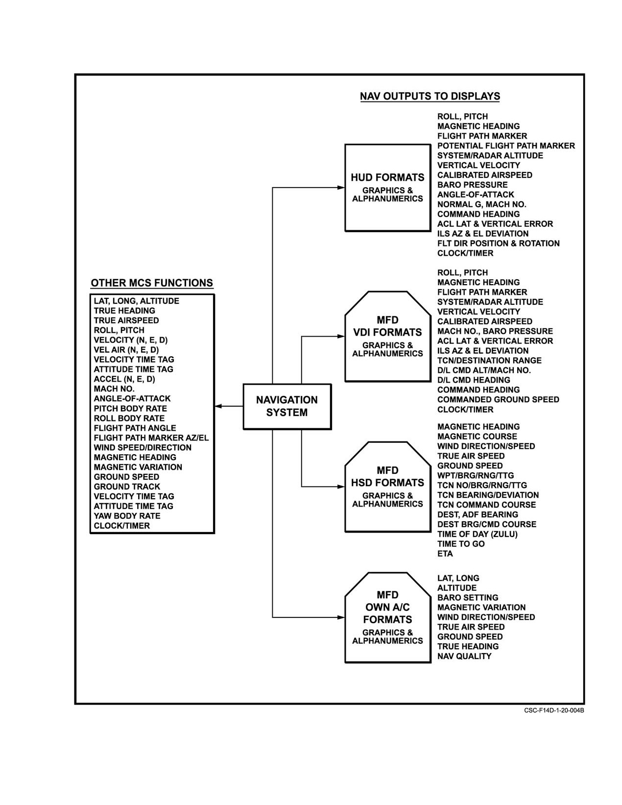
NAVAIR 01−F14AAD−1
Figure 20Ć5.ĄNavigation System Data Distribution
20−13
ORIGINAL
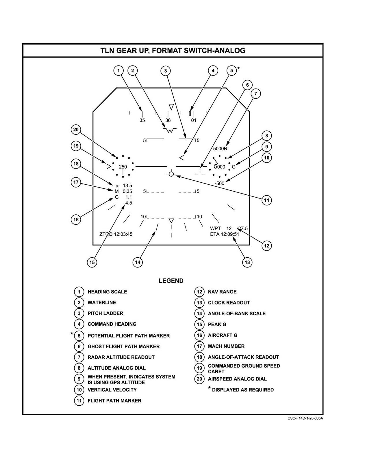
NAVAIR 01−F14AAD−1
Figure 20Ć6.ĄHUD Navigation Outputs (TLN Basic)
ORIGINAL
20−14
NAVAIR 01−F14AAD−1
20.2.1.2
MFD VDI (Basic) Format, TLN Mode
20.2.1.4.1
HSD Waypoint Data Buffers
The MFDs provide a VDI format that is a represenĆ
Both the left and right data buffers behave differently
tation in the vertical plane of a field of view of ±45_ in
depending on the choice of steering mode. The left data
azimuth and elevation. In the TLN basic mode (Figure 20−7),
buffer (next to PB 5) always displays waypoint information.
the VDI format displays the same information as the HUD
This waypoint information changes slightly based on
except for the airspeed and altitude dials, angle of attack, and
steering mode and the waypoint displayed. The right data
g readouts.
buffer displays either TACAN information or another
waypoint buffer.
This format also provides readouts of the course and
heading selected using the CRS and HDG knobs on the pilot
The data buffers will only display waypoint
center instrument panel (FO−3). Pushbutton legends permit
information for the 100 tactical waypoints and any defined
selection of destination (DEST), data link (D/L), TACAN
waypoints in the active flight plan. If a flight plan is active,
(TCN), manual (MAN), GPS, AUTO, or all−weather landing
when the inky−dink (increment−decrement) scrolls upward
(AWL) steering.
through 100, it will jump to the first waypoint in the active
flight plan (i.e., 101, 201, 301, etc.). When scrolling down
In addition to the information in Figure 20−7, other
through 1, it will jump to the last defined waypoint in the
MFD formats provide indications of ACL glideslope and
active flight plan (i.e., 115, 237, 524, etc.).
centerline errors, glideslope and centerline errors from
ILS, flight director glideslope and centerline steering
If both data buffers are displaying waypoint
information, commanded heading, commanded speed and
information, the inky−dink arrow’s focus is assigned to the
altitude information, and HUD flight director declutter.
desired buffer by pressing the pushbutton next to that buffer
(i.e., PB 5 or PB 11). The buffer with the inky−dink focus will
20.2.1.3
MFD Own−Aircraft (Basic) Data Format
be displayed with a box around it, and the waypoint number
displayed in that buffer will be displayed between the
inky−dink arrows. If the steering mode is changed to one
The MFD own−aircraft
(basic) data format
which displays TACAN information on the right, the
(Figure 20Ć8) furnishes navigational data in tabular form.
inky−dink and box will be automatically assigned to the left
This format can be called up from several of the MFD formats
buffer, since they have no meaning for a TACAN station.
by selecting the DATA pushbutton legend.
Note
In addition to the parameters shown in Figure 20Ć8,
other own−aircraft MFD formats are available. During
A box around a waypoint buffer merely shows
alignment, these provide indications of alignment progress
where the inky−dink is assigned. It is unrelated to
in both numeric and graphic form and INS north and east
which waypoint is selected for steering.
velocities.
If a waypoint is desired as the steer point (DEST, GPS,
20.2.1.4
MFD HSD (Basic) Format, TLN Mode
or AUTO steering), that waypoint should be selected with the
inky−dink arrows in one of the data buffers, and ENT (PB 15)
The MFDs provide a HSD format (Figure
20−9)
selected. The waypoint selected with ENT will always be the
showing an aircraft centered representation of the situation
one with the inky−dink focus.
in the horizontal plane. In the TLN basic mode, it furnishes
information on the position of waypoints, TACAN stations,
20.2.1.4.1.1
Left Buffer Behavior
and destination points with respect to the aircraft. The
distance scale from the aircraft symbol to the inner edge of
The left data buffer always shows waypoint inforĆ
the compass rose can be set at 200, 100, 50, 25, or 10 miles.
mation. Normal display information includes waypoint
Numeric displays of range, bearing, and time−to−go to
number, bearing, range, and time to go to the waypoint. AddiĆ
selected waypoints or to a selected TACAN station are
tionally, if a flight plan waypoint is selected, and that wayĆ
provided.
point has a valid name defined, the waypoint name will
appear above the waypoint number (up to five characters).
In addition to the information shown in Figure 20−9,
other HSD formats provide AUTO, GPS, TACAN, data−link,
If the steering mode is DEST or AUTO, and a route
destination, and manual steering displays (see paragraph
waypoint is selected, the bearing will be replaced with the
20.3.9.2, Display Steering Modes).
word ROUTE, and the range and time−to−go indications will
be shown along the route information to the route target
(if defined) or to the end of the route.
20−15
ORIGINAL
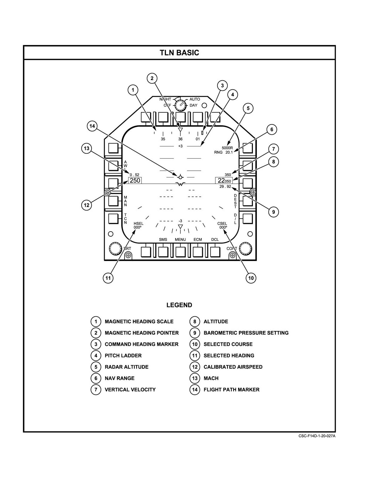
NAVAIR 01−F14AAD−1
Figure 20Ć7.ĄMFD VDI (TLN Basic) Navigation Outputs
ORIGINAL
20−16
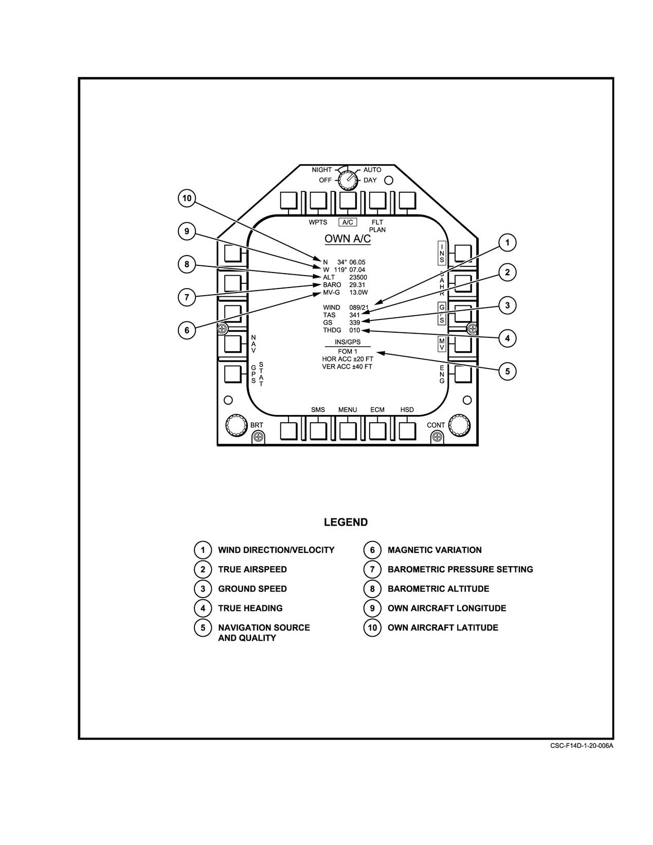
NAVAIR 01−F14AAD−1
Figure 20Ć8.ĄOwn−Aircraft Basic Data Format
20−17
ORIGINAL
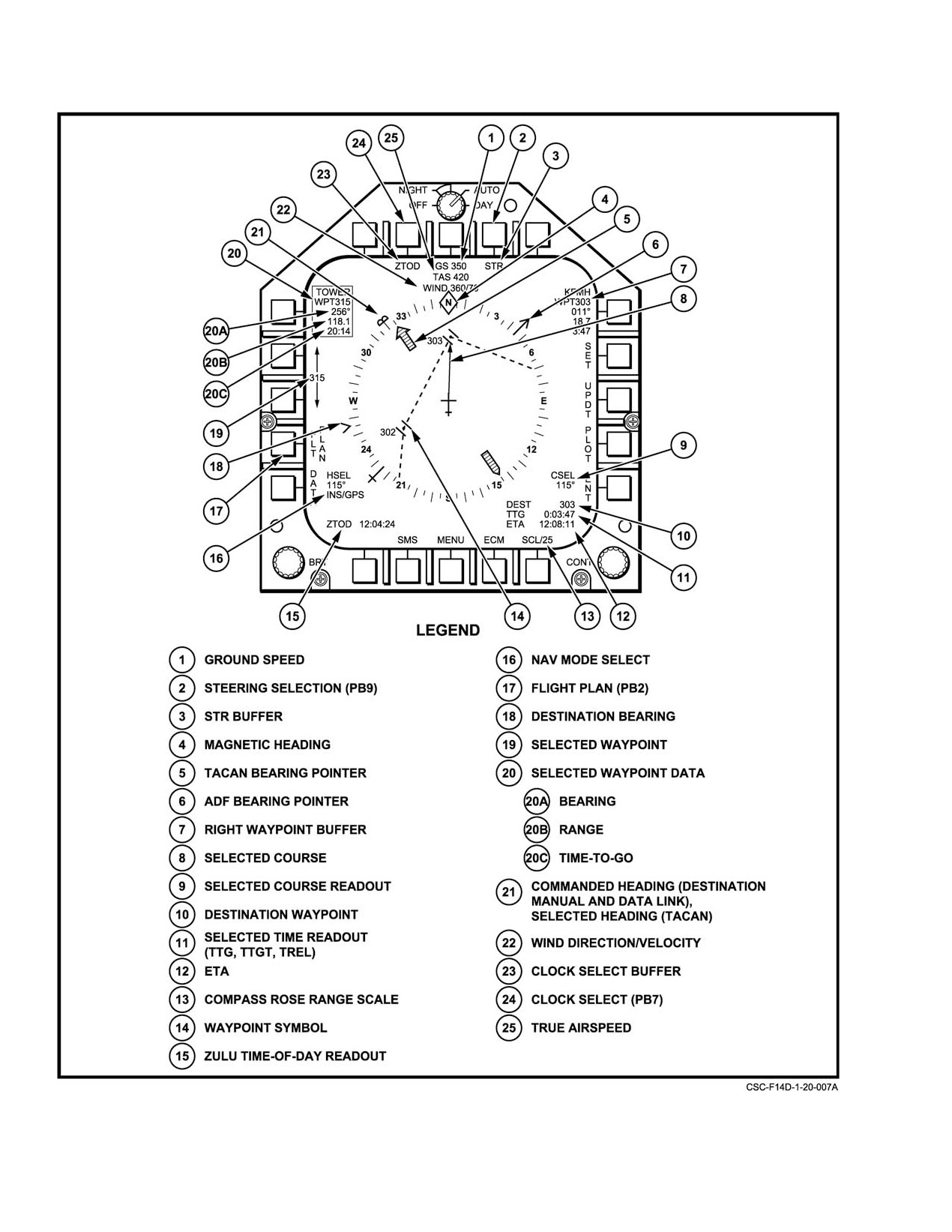
NAVAIR 01−F14AAD−1
Figure 20Ć9.ĄMFD HSD Format Navigation Outputs
ORIGINAL
20−18
NAVAIR 01−F14AAD−1
20.2.1.4.1.2
Right Buffer Behavior
the steering mode selected, information available and phase
of flight. The three modes are defined in the following table:
The right data buffer either displays direct steering
waypoint information (waypoint number, bearing, range,
Function
Description
time to go, and name if a flight plan waypoint), or it displays
TACAN steering information (channel, bearing, range, time
TTG
Time−to−Go represents
(in an HH:MM:SS
to go), depending on steering mode.
format) the time remaining to reach the
current steerpoint at the current ground speed.
In DEST, GPS, or AUTO steering, the right buffer disĆ
Time−to−Go is the default time remaining
plays waypoint information. In all other steering modes, the
function and the default display for the clock
right buffer displays TACAN steering information.
buffer of the HSD format. It is displayed on
the HUD and the HSD format when the Clock
Select legend is TTG". It does not account
20.2.1.5
Navigation Clocks and Timers
for time to turn to a direct heading.
To facilitate navigational timekeeping and sequencing,
TTGT
Time−to−Target is available when navigating
several clock and timer displays are available to the aircrew
along an active flight plan with a defined route
on the HSD format and HUD Display. Figure 20−9 illustrates
and a target waypoint. Time−to−Target
the HSD clock readout. The HSD format clock and timer
represents (in an HH:MM:SS format) the time
displays are reconfigured automatically to coincide approĆ
remaining to reach the designated target
priately with the HUD clock selection. One clock or timer
waypoint along the flight plan route at the
may be displayed on the HUD, and all options are selected via
current ground speed. When TTGT is
Clock Select (PB 7) on the HSD format. All clock functions
available, it automatically replaces TTG as
that reference a time of day require ZTOD (Zulu Time Of
the time remaining selection. It is displayed
Day) information provided by the GPS if available or by
on the HUD and the HSD format when the
manual entry via the DEU.
Clock Select legend is TTGT".
TREL
Time−to−Release is available when an air−to−
Note
ground weapon is selected and a target has
In the prime INS/GPS navigation mode, the
been designated via CTGT, CWPT, or
MAGR updates ZTOD in the MCS only once per
COAP mode (see Weapon Attack Modes
second. Including typical latencies to receive,
section of the F−14D A/G Tactical
transfer, format and display ZTOD, the value
Manual, NWP
55−5−F−14, Vol. II,
presented to the aircrew may lag the true ZTOD
NAVAIR
01−F14AAD−1T−1). Time−to−
transmitted by GPS (i.e., run slow") by 1 to 2
Release represents
(in an HH:MM:SS
seconds.
format) the time remaining until an automatic
bomb release point is reached. When TREL is
20.2.1.5.1
Zulu Time of Day (ZTOD)
available, it automatically replaces TTG and
TTGT as the time remaining selection. It is
Zulu Time of Day is an actual time−of−day reference in
displayed on the HUD and the HSD format
when the Clock Select legend is TREL".
an HH:MM:SS format. ZTOD is always displayed in the
lower left corner of the HSD format and is the default clock
display on the HUD. It is displayed on the HUD when the
Clock Select legend is ZTOD".
20.2.1.5.3
Estimated Time of Arrival (ETA)
20.2.1.5.2
Time Remaining Functions
Estimated Time of Arrival represents
(in an
HH:MM:SS format) the ZTOD at which a specific steerpoint
Three time remaining functions are provided to present
will be reached. When TTGT is the available time remaining
a cue of the time required to reach a specific steerpoint: Time
function, ETA is calculated by adding TTGT to ZTOD and
to Go (TTG), Time to Target (TTGT), and Time to Release
represents time over target following the active flight plan
(TREL). These three functions are mutually exclusive; that
route. Otherwise, ETA is calculated by adding TTG to
is, only one of the three will be displayed or made available
ZTOD, and represents time over waypoint if you went
for selection by the aircrew. The available time remaining
present position, direct to waypoint. ETA is the default
function is selected automatically by the MCS, depending on
display for the timer buffer of the HSD format. It is displayed
on the HUD when the Clock Select legend is ETA".
20−19
ORIGINAL
NAVAIR 01−F14AAD−1
20.2.1.5.4
Elapsed Timer (ET)
20.3 NAVIGATION SYSTEM OPERATION
The ET represents (in a MM:SS format) the time
Procedures for operational use of the navigation
elapsed since the MCS timer was started. It is displayed on
system are provided in the paragraphs that follow including
the HUD and the HSD format when the Clock Select legend
display formats and control selections for alignment, data
is ET". While ET is running, other clock and timer modes
initialization, flight plan management, in−flight navigation,
still may be selected on the HUD and the HSD format.
sensor selection, degraded mode operation, and tactical
Conversely, if ET is not running, it may still be selected for
navigation. Tactical navigation includes: range and bearing
display.
to selected waypoints; display of TACAN, GPS, destination,
and automatic waypoint steering; autopilot steering; AWL
The ET timer is controlled via the DEU as follows:
aircraft control; position updating; and surface waypoint
position determination. These procedures are normally
1. From the main menu format, depress CLK to select
performed in the TLN mode; however navigation outputs are
the Clock format.
available to other aircraft functions and displays in all modes.
2. Depress ET to select the ET mode.
20.3.1
GPS Operation
3. To start the ET timer depress STRT and ENT.
4. To stop the ET timer, depress STOP and ENT.
The Navigation Satellite Timing and Ranging
(NAVSTAR) Global Positioning System (GPS) is a radio
5. To reset the ET timer, depress ET, ENT, then
navigation system using satellites in twelve hour orbits to
STOP, ENT
provide timing signals derived from onboard atomic clocks.
These signals can be used to triangulate a three dimensional
20.2.1.5.5
Countdown (CD) Timer
position near the earth using an appropriate receiver. The
receiver detects the timing signals, compares them to its own
The CD timer represents (in a MM:SS format) the time
clock then converts the time obtained into a distance to the
to go to zero since the MCS timer was started from a preset
satellite using the speed of light as a conversion factor. By
value. It is displayed on the HUD and the HSD format when
obtaining signals from four satellites, the receiver can
the Clock Select legend is CD". While CD is running, other
determine position in three dimensions plus identify its own
clock and timer modes still may be selected on the HUD and
small clock error.
the HSD format. Conversely, if CD is not running, it may still
be selected for display. The default value for the CD timer is
The satellites transmit two different GPS signals in
06:00.
combination on two different frequencies. C/A−code
The CD timer is controlled via the DEU as follows:
(Coarse/Acquisition code) is used to help the receiver acquire
the GPS signal and provide hand−over information to the
1. From the main menu format, depress CLK to select
primary navigation signal, the P−Code. GPS signals use two
the Clock format.
frequencies, L1 (1575.42 MHz) and L2 (1227.60 MHz); C/A−
Code is normally transmitted only on L1, and P−Code (or
2. Depress CD to select the CD mode.
Y−Code, see below) is transmitted on both L1 and L2. Dual
frequencies allow the receiver to make an estimate of ionoĆ
3. To enter a CD time value, depress CD TIME to
select the CD Time Entry format. Use the numeric
spheric refraction, and help to improve overall GPS jamming
tolerance.
keypad and other control keys to enter the desired
count−down time value.
Both the C/A−Code and P−Code contain a navigation
4. To start the CD timer, depress STRT and ENT.
message with information about satellite position, time, the
health of the satellite, and the complete constellation
5. To stop the CD timer, depress STOP and ENT.
almanac. A Hand−Over Word is included in the navigation
6. To reset the CD timer to the previous timer start
message that tells a receiver tracking C/A−Code which part
value, depress STOP and ENT a second successive
of the P−Code sequence the satellite is currently transmitting.
time.
The theoretical accuracy of both C/A−Code and P−Code
signals is similar. The advantage of P−Code is derived from
20.2.1.6
Navigation Data Display Summary
its transmission on two frequencies, and the subsequent
ionospheric refraction estimate that is possible thereby.
Figure 20−10 summarizes the navigation data available
on HUD and MFD formats.
ORIGINAL
20−20
NAVAIR 01−F14AAD−1
DISPLAY
NAVIGATION DATA DISPLAYED
Own Aircraft Inflight
Latitude
Longitude
Altitude
Barometric Setting
Magnetic Variation
Wind Direction/Speed
True Airspeed
Groundspeed
True Heading
GPS Figure of Merit
Horizontal and Vertical of Current Navigation Mode
Own Aircraft Ground Align
Latitude
Longitude
Altitude
Barometric Setting
Magnetic Variation
Groundspeed
True Heading
Align Time/Quality
North/East Velocities
GPS Figure of Merit
Aircraft Carrier (CV) Alignment
Latitude
Longitude
Magnetic Variation
CV Speed
CV Heading
Vertical Lever Arm
Align Time/Quality
SAHRS Alignment
Latitude
Longitude
CV Speed
CV Heading
HUD Display
Roll (Symbols)
Pitch (Symbols)
Magnetic Heading (Symbol)
Flight Path Marker (Symbol)
Potential Flight Path Marker (Symbol)
System Altitude
Radar Altitude
Vertical Velocity
Calibrated Airspeed
Barometric Setting
Figure 20Ć10.ĄNavigation Data Display Summary (Sheet 1 of 2)
20−21
ORIGINAL
NAVAIR 01−F14AAD−1
DISPLAY
NAVIGATION DATA DISPLAYED
Flight Director Position and Rotation
AnglećofćAttack
Mach Number
Normal Acceleration (g)
ACL Lateral & Vertical Errors (Symbol)
ILS Azimuth & Elevation Deviation (Symbols)
Command Heading (Symbol)
Clock/Timer
Fly−To Caret
MFD VDI Format
Roll (Symbols)
Pitch (Symbols)
Magnetic Heading (Symbol)
Flight Path Marker (Symbol)
System Altitude
Radar Altitude
Vertical Velocity
Calibrated Airspeed
Barometric Setting
Mach Number
ACL Lateral & Vertical Errors (Symbol)
ILS Azimuth & Elevation Deviation (Symbols)
Command Heading (Symbol)
Range to TACAN/Destination
D/L Command Alt/Mach No
D/L Command Heading (Symbol)
MFD HSD Format
Magnetic Heading (Symbol)
Magnetic Course (Symbol)
Wind Direction/Speed
True Airspeed
Groundspeed
Way Point No/Brg/Range/TTG
TACAN Sta No/Brg/Range/TTG
TACAN Brg/Deviation (Symbols)
TACAN Command Course (Symbol)
Destination No
Destination Brg/Cmd Course (Symbols)
ADF Bearing (Symbol)
Command Heading
Course Select
Heading Select
Figure 21−10. Navigation Data Display Summary (Sheet 2 of 2)
ORIGINAL
20−22
NAVAIR 01−F14AAD−1
The GPS utilizes a cryptographic scheme to convert
System. Nor does receipt of P−Code guarantee
the P−Code signal into a Y−Code signal. By encrypting
that PPS is in use. C/A−Code contains all the
the primary navigation signal, GPS can be rendered
information required to provide a PPS solution.
impervious to spoofing" ć the intentional transmission of a
All that is necessary is that the appropriate
false signal to mislead recipients. This function is termed
crypto−codes be loaded into the receiver so that
Anti−Spoof"
(A−S), and its use is mandated for all US
the error message can be decrypted.
military GPS users. The MAGR will automatically switch to
this mode if the appropriate crypto−codes are loaded (see
The receiver outputs a Figure of Merit (FOM) that
paragraph 20.3.1.3).
provides, in a single digit number, a rough indication of the
overall quality of the navigation solution. FOM ranges from
Note
1 to 9, and includes estimates of signal quality and GDOP. A
properly operating GPS receiver, in PPS mode, will normally
The MAGR is unclassified even when the
display a FOM of 1, an operating SPS receiver (i.e., the
crypto−keys are loaded.
MAGR when the crypto−codes are not loaded) will display a
FOM of 4, and a functional receiver without a navigation
20.3.1.1
GPS Accuracy
solution will display a FOM of 9. Intermediate values will
appear, especially when the receiver first begins to track
The quality of the received signals and the orientation
satellites, and when degradation due to jamming or signal
of the satellites determine the actual quality of the position
loss occurs. The MCS receives the FOM from the MAGR and
estimate provided by GPS. Jamming, obstructions, and
outputs it for display on OWN A/C format of the MFD. The
multipath can degrade the quality of the received signal,
MCS and INS use FOM to assign appropriate weighting to
while satellite constellation geometry can introduce position
the GPS solution in the overall NSV.
errors (termed Geometric Dilution of Precision ć GDOP).
The MAGR is designed to minimize these errors.
20.3.1.2
GPS Status Format
The GPS system provides two levels of accuracy. The
The GPS Status format displays the GPS parameters as
Precise Positioning System (PPS) is capable of accuracy
depicted in Figure 20Ć11. All readouts (except MODE) will
better than 16 meters Spherical Error Probable (SEP) (i.e.,
be blanked while the GPS is performing a commanded BIT.
50% of the time the calculated position will be within a
MODE will show TEST". MAGR power, transmission of
sphere 16 meters in radius centered on the actual position).
UTC synchronization to the HAVE QUICK radios, and
It is intended for military use only. PPS also provides time
display of the MAGR status are controlled from the GPS
with an error of less than 100 nanoseconds.
Status format.
Standard Positioning System
(SPS) accuracy is
The MAGR power is toggled on and off by depressing
variable. When the satellites transmit their timing signals,
PWR (PB 4) on the GPS Status format. The appropriate ON
small, continuously varying errors are injected into the
or OFF status legend is also displayed. The default selection
navigation message of both the C/A−Code and the P/Y−Code
is PWR ON.
signals to reduce the position and time accuracy a receiver
calculates. The size of the errors are encrypted and also sent
Note
as part of the satellite transmission. A PPS receiver requires
that the matching crypto−codes be loaded to resolve the error.
The PWR ON legend only indicates that the
These are the same crypto−codes used for the Anti−Spoof
MAGR has been energized. Boxing the GPS
function.
legend (PB 13) on the OWN A/C or NAV System
Aid format makes GPS data available to the
The injected errors, termed Selective Availability
navigation system.
(SA)", are controlled by the US Air Force on behalf of the
Department of Defense (DoD) so that, in a conflict, an enemy
The UTC time of day is made available to the ARC−182
will not be able to use the system. In peacetime, the DoD
Have Quick II" radios by momentarily depressing RCV
guarantees SPS precision will not exceed
100 meters
TOD (PB 3) while the MAGR is in the NAVIGATE mode.
horizontally with
95% confidence
(i.e., the horizontal
RCV TOD is inoperative in the TEST and INITIALIZE
position will be within 100 meters at least 95% of the time).
modes, and is not available with MAGR power off (see
In peace, SA is turned off; thus, SPS and PPS solutions have
Chapter 19 for radio time sync operation).
the same accuracy.
When the MAGR is operating at its peak performance,
Note
the GPS Status format will look like the display in
Figure 20Ć11. The figure legend contains the possible ranges
It is not necessary to receive P−Code (or Y−Code)
for the GPS Status Format Parameters.
in order to make use of the Precise Positioning
20−23
ORIGINAL
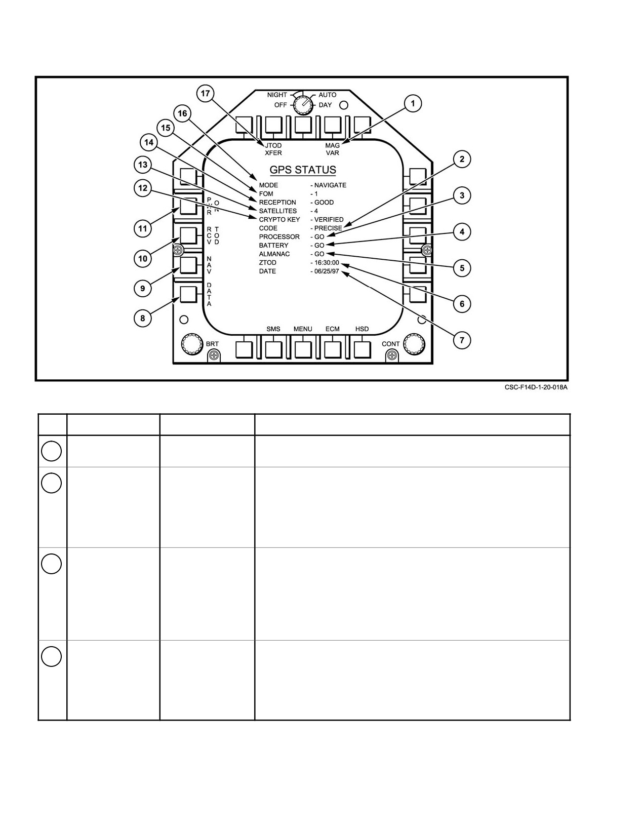
NAVAIR 01−F14AAD−1
PARAMETER
RANGES
REMARKS
1
MAG VAR
Not operable in D03B.
2
CODE
PRECISE
Type of code the MAGR is tracking. PRECISE indicates that the
COARSE
MAGR is using P or Y Code, COARSE indicates that the MAGR is
using C/A Code. COARSE will not be observed, or observed very
briefly as the receiver acquires satellites, if the receiver is operating
normally.
3
PROCESSOR
GO
The operational status of the MAGR processor. GO indicates that
NO GO
data bus communication between the MAGR and the MCS exists
NOT READY
and the processor is operating properly. NO GO indicates that the
processor failed a start−up or commanded BIT or a continuous
self−test. NOT READY indicates that data bus communication
between the MAGR and the MCS has not been established.
4
BATTERY1
GO
MAGR battery operational status. GO indicates a satisfactory
LOW
battery power level. LOW indicates that the battery has failed or
has a marginal power level. Battery power is only required to
maintain MAGR memory when the MAGR is powered off.
Report any LOW indications to maintenance.
Figure 20Ć11.ĄGPS Status Format (Sheet 1 of 3)
ORIGINAL
20−24