F-14D. FLIGHT MANUAL (2004) - page 9
NAVAIR 01−F14AAD−1
BOLDFACE PROCEDURES
ENGINE FIRE ON THE DECK
BLOWN TIRE DURING TAKEOFF; TAKEOFF
CONTINUED OR AFTER LANDING GO−AROUND
*1. Both FUEL SHUT OFF handles .
Pull
*1. Throttles
As Required
*2. Both throttles
OFF
*2. Landing gear and flaps .
Leave as Set
UNCOMMANDED ENGINE ACCELERATION
for Takeoff
ON DECK
GROUND ROLL BRAKING FAILURE
*1. Paddle switch .
Depress and Hold
*1. ANTI SKID SPOILER BK switch . .. Check
*2. Throttle(s)
As Desired
*2. MASTER RESET pushbutton . .. Depress
*3. ENG MODE SELECT
SEC
*4. THROTTLE MODE switch
MAN
FIRE LIGHT AND/OR FIRE IN FLIGHT
BRAKE FAILURE AT TAXI SPEED
*1. Throttle (affected engine) .
IDLE
*1. ANTI SKID SPOILER
*2. AIR SOURCE pushbutton
OFF
BK switch .
SPOILER BK or OFF
*3. OBOGS master switch .
BACKUP
ABORTED TAKEOFF
If light goes off (and no other secondary
*1. Throttles
IDLE
indications):
*2. Speedbrakes
EXT
*4. MASTER TEST switch . .. FIRE DET TEST
*3. Stick
AFT
If light remains illuminated, FIRE DET test fails, or
other secondary indications:
*4. Hook .
DN (1,000 feet before wire)
*5. FUEL SHUT OFF handle
*5. Brakes
As Required
(affected engine)
Pull
*6. Right engine
OFF (if required)
*6. Throttle (affected engine)
OFF
SINGLE−ENGINE FAILURE FIELD/
*7. Climb and decelerate.
CATAPULT LAUNCH/WAVEOFF
*8. Fire extinguisher pushbutton . .. Depress
*1. Set 10° pitch attitude on the waterline
(14 units AOA maximum).
COMPRESSOR STALL
*2. Rudder
Opposite Roll/yaw
*1. Unload aircraft (0.5g to 1.0 g).
. . . . . . . . . . . . . . . . . . . . . . Supplemented by
If greater than 1.1 Mach:
Lateral Stick
*2. Both throttles
MIL
*3. Both throttles
As Required for
Positive Rate of Climb
When 1.1 Mach or less:
*4. Landing gear
UP
*3. Both throttles .
Smoothly to IDLE
*5. Jettison
If Required
If EGT above 935_C and/or engine response
abnormal:
BLOWN TIRE DURING TAKEOFF; TAKEOFF
ABORTED OR AFTER LANDING TOUCHDOWN
*4. Throttle (stalled engine)
OFF
*1. Nosewheel steering
Engaged
ENGINE FLAMEOUT
*2. ANTI SKID SPOILER BK
*1. Throttle
IDLE or Above
switch
SPOILER BK
(affected engine)
*2. BACK UP IGNITION switch .
ON
ORIGINAL
68
NAVAIR 01−F14AAD−1
If hung start or no start:
UPRIGHT DEPARTURE/FLAT SPIN
*3. Throttle
Cycle OFF, Then IDLE
*1. Stick
Forward/Neutral
(affected engine)
Lateral, Harness−Lock
If still hung or no start:
*2. Throttles
Both IDLE
*4. ENG MODE SELECT
SEC
*3. Rudder
Rudder−Opposite
If one engine is operable, perform a crossbleed
Turn Needle/Yaw/Spin Arrow
airstart.
If no recovery:
If both engines flamed out/inoperative or
crossbleed not possible:
*4. Stick
Into Turn Needle
*5. Airspeed
450 Knots
(altitude permitting)
If yaw rate is steady/increasing, spin arrow
RAMPS LIGHT/INLET LIGHT
flashing, or eyeball−out g is sensed:
*1. Avoid abrupt throttle movements.
*5. ROLL SAS On; Stick Full Into Turn
Needle and Aft.
*2. Decelerate to below 1.2 TMN.
*3. Affected INLET RAMPS switch .
STOW
If recovery indicated:
ELECTRICAL FIRE
*6. Controls
NEUTRALIZE
*1. L and R generators
OFF
*7. Recover at 17 units AOA, thrust as
If uncommanded SAS or spoiler inputs present:
required.
*2. PITCH, ROLL, and
YAW STAB AUG switches
OFF
If flat spin verified by flat attitude, increasing Yaw
ECS LEAKS/ELIMINATION OF
rate, increasing eyeball−out g, and lack of pitch
SMOKE AND FUMES
and roll rates:
*1. AIR SOURCE pushbutton
OFF
*8. Canopy
Jettison
*2. OBOGS master switch .
BACKUP
*9. EJECT
(RIO Command Eject)
*3. If smoke or fumes present:
a. Altitude Below 35,000 Feet
INVERTED DEPARTURE/SPIN
b. CABIN PRESS switch DUMP
*1. Stick
Full Aft/Neutral
*4. RAM AIR switch
OPEN
Lateral, Harness Lock
LAD/CANOPY LIGHT WITH RIO’S CANOPY LIGHT/
*2. Throttles
Both IDLE
CANOPY LOSS
*3. Rudder
Rudder−Opposite
*1. Canopy
BOOST CLOSE
Turn Needle/Yaw/Spin Arrow
(canopy remaining)
UNCOMMANDED ROLL AND/OR YAW
If recovery indicated:
*1. If flap transition:
*4. Controls
Neutralize
FLAP handle .
Previous Position
*2. Rudder and stick .
Opposite Roll/Yaw
*5. Recover at 17 units AOA, thrust as
required.
*3. AOA
Below 12 Units
*4. Downwing engine .
MAX THRUST
If spinning below 10,000 feet AGL:
(if required)
*6. EJECT
(RIO Command Eject)
*5. MASTER RESET
Depress
69
CHANGE 2
NAVAIR 01−F14AAD−1
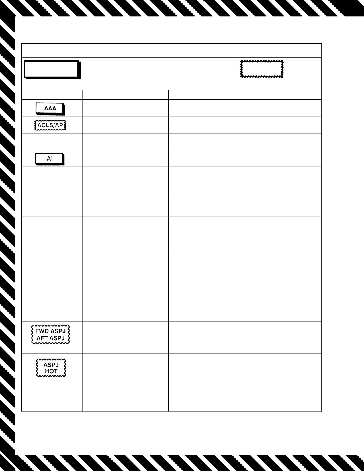
WARNING/CAUTION/ADVISORY LIGHTS/DISPLAY LEGENDS
WARNING
*WARNING LIGHT AND/OR DISPLAY LEGEND
CAUTION
(HUD HUD/MFD, MFD) DISPLAY LEGEND
ADVISORY
LIGHT/LEGEND
CAUSE
ACTION
AAA tracking radar detected.
As briefed.
ACLS or autopilot
Take control for manual landing approach.
disengagement.
AAI ZERO (MFD)
Improper IFF interrogator
As briefed.
operation.
Airborne interceptor tracking
As briefed.
detected.
L A/ICE
Designated engine anti−ice
If INLET ICE light on, perform appropriate procedure.
R A/ICE
is on or anti−ice valve has
If INLET ICE light off, inlet ice may be on though not
(MFD)
failed opposite commanded
commanded. Report to maintenance.
position.
A/P REF (MFD)
Selected A/P reference is not
Depress autopilot reference pushbutton to engage AP
engaged.
reference mode.
ARI DGR
Indicates degraded ARI
1. MASTER RESET Ċ Depress.
performance.
2. If light remains illuminated, aggressive
maneuvering should be terminated.
3. Remain below 1.0 TMN.
ARI/SAS OUT
Loss of ROLL or YAW SAS,
1. Ensure ROLL and YAW STAB AUG switches Ċ
and all ARI functions
ON.
2. MASTER RESET Ċ Depress.
If light remains illuminated:
3. Leave STAB AUG switches Ċ ON.
To take advantage of any remaining capability
that the DFCS may be able to provide.
Terminate aggressive maneuvering and remain
below 1.0 TMN.
Improper ALQ−165 position.
As briefed.
(MFD)
ALQ−165 self−protection jamĆ
Secure ALQ−165.
mer overheated.
(MFD)
L AUG
AB is not available and oppoĆ
No immediate action required; assess operational
R AUG
site engine is limited to MIN
impact.
(MFD)
AB if ATLS is on.
Warning, Caution, Advisory Lights/Displays (Sheet 1 of 15)
ORIGINAL
70
ąNAVAIR 01−F14AAD−1
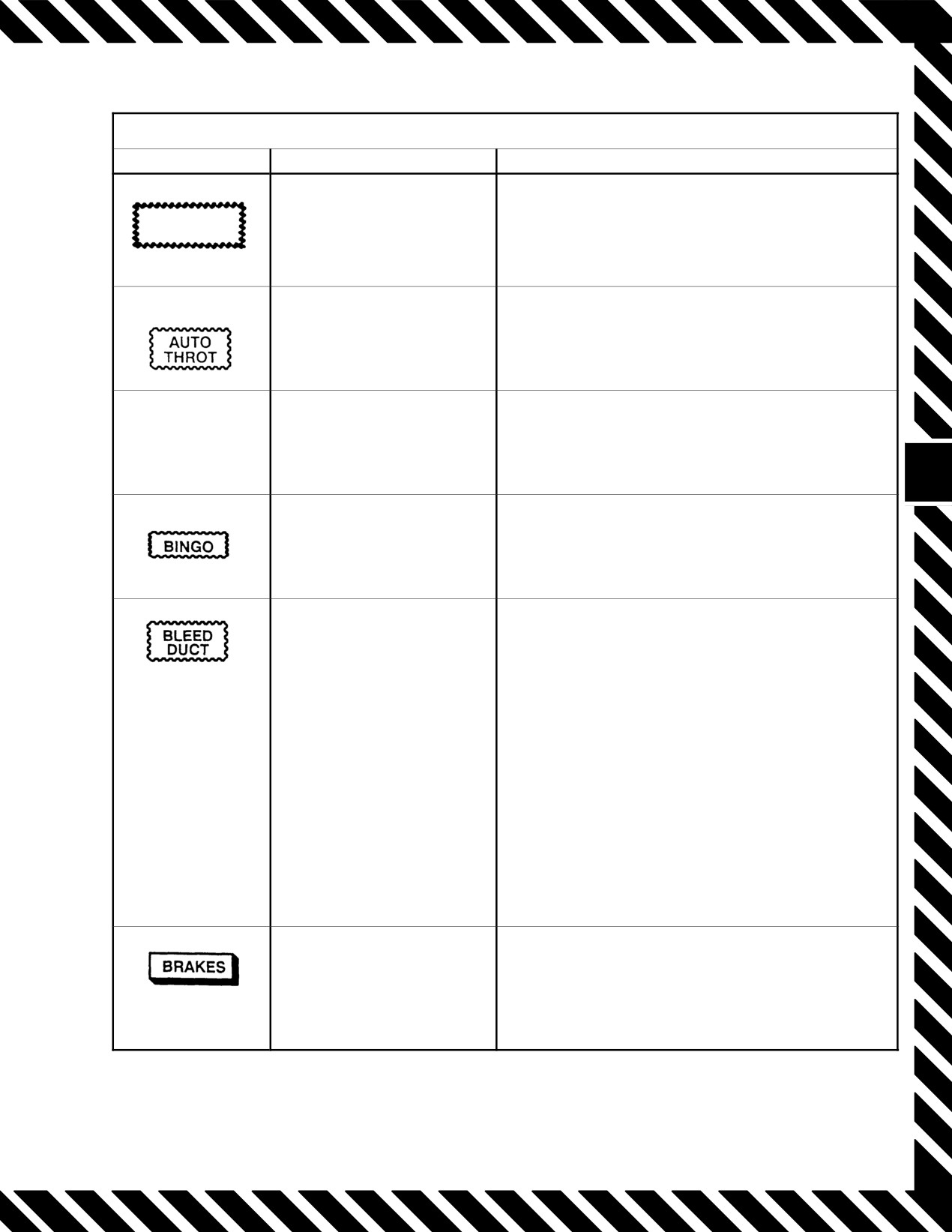
WARNING/CAUTION/ADVISORY LIGHTS/DISPLAY LEGENDS
LIGHT/LEGEND
CAUSE
ACTION
AUTOPILOT
Autopilot or reference failure.
1. MASTER RESET pushbutton Ċ Depress.
1. Assume manual/boost control.
Autothrottle has been
2. Satisfy APC interlocks.
disengaged.
3. Reengage APC AUTO.
AUX FIRE EXT
Low−extinguisher agent
Report to maintenance.
pressure.
(MFD)
Totalizer less than preset
Pilot option.
value.
Bleed duct overheat
*1. AIR SOURCE OFF.
condition or ECS regulating
*2. OBOGS BACKUP.
failure.
*3. If smoke or fumes present:
a. Altitude Below 35,000 feet.
b. CABIN PRESS DUMP.
*4. RAM AIR OPEN.
5. Airspeed <300 Knots/0.8 Mach.
6. Nonessential electrical Secure.
7. CANOPY DEFOG/CABIN AIR lever
CANOPY DEFOG.
8. Land as soon as possible.
If electrical fire:
9. Follow electrical fire procedures.
Operating in auxiliary brake
1. Turn antiskid off.
mode, antiskid failure, or
2. Cautious brake application.
parking brake set.
3. Release emergency brake.
Warning, Caution, Advisory Lights/Displays (Sheet 2 of 15)
71
ORIGINAL

NAVAIR 01−F14AAD−1
WARNING/CAUTION/ADVISORY LIGHTS/DISPLAY LEGENDS
LIGHT/LEGEND
CAUSE
ACTION
Backup oxygen less than 200 psi.
B/U OXY LOW light (both cockpits):
1. BACKUP OXY PRESS Check.
If BACKUP OXY PRESS < 200 PSI:
2. Cabin alt Less than 10,000 Feet.
3. Oxygen supply OFF.
4. Oxygen masks Release One Side.
Before landing:
5. Oxygen masks and supply ON.
6. Emergency oxygen Activate.
If BACKUP OXY PRESS > 200 psi:
2. BACKUP OXY PRESS Monitor.
B/U OXY LOW light (pilot only):
1. BOS CONTR/B/U
OXY LOW cb Check In (7A4).
2. BACKUP OXY PRESS Check.
B/U OXY LOW Light (RIO Only):
2. BACKUP OXY PRESS Check.
Cabin pressure failure.
1. Oxygen mask ON.
If below 15,000 feet.
2. CABIN PRESS Cycle.
CADC failure.
1. MASTER RESET Depress
2. CADC cb’s (LA2, LB2, LC2, LD2) Cycle.
3. MASTER RESET Depress.
If light still remains illuminated:
4. Remain below 1.5 Mach.
Canopy not locked.
*1. Canopy BOOST CLOSE (canopy
remaining).
*2. EJECT CMD PILOT.
3. Airspeed and altitude Below 200
Knots/15,000 Feet.
4. Seats and visors DOWN.
5. If canopy has departed aircraft,
perform controllability check.
6. Land as soon as possible.
Controls and displays hot.
1. Select cabin air.
2. WCS switch OFF.
Improper operation of converter−
Expect loss of CIU inputs/outputs.
interface unit.
(MFD)
Warning, Caution, Advisory Lights/Displays (Sheet 3 of 15)
ORIGINAL
72

ąNAVAIR 01−F14AAD−1
WARNING/CAUTION/ADVISORY LIGHTS/DISPLAY LEGENDS
LIGHT/LEGEND
CAUSE
ACTION
CIU HOT
Converter−interface unit overĆ
Pull cb’s 3E7, 4E1, 4E2.
(MFD)
heated.
CLSN
RIO has collision steering
Pilot option.
(HUD)
selected.
COOLING
Indication of possible bleed duct
1. AIR SOURCE OFF.
AIR
failure forward of the pressure
2. OBOGS BACKUP.
(IN FLIGHT)
primary heat exchanger and
If associated with any other direct or indirect
400°F modulating valve.
indication of ECS malfunction:
3. Perform ECS Leak/Elimination of Smoke
and Fumes Procedure.
If not associated with any other direct or indirect
indication of ECS malfunction and operational
requirements dictate temporary reselection of ram
to regain lost service systems:
3. AIR SOURCE RAM.
4. RAM AIR door FULLY OPEN.
5. AIR SOURCE OFF.
6. Land as soon as practicable.
COOLING
Inadequate cooling.
1. AIR SOURCE Check L ENG, R ENG, or
AIR
BOTH ENG.
(ON DECK)
2. Throttles Advance Without Closing
Nozzles.
3. CANOPY DEFOG/CABIN AIR lever
CANOPY DEFOG.
4. ECS MAN/FULL HOT (CONT).
If light goes out:
5. Throttles IDLE.
6. ECS As Desired.
If light remains illuminated
7. Secure systems.
Continuous−wave emitter
As briefed.
detected.
DEU HOT (MFD)
Data entry unit overheated.
Expect loss of DEU.
DP1 HOT
Display processor overheated.
Pull cb’s 1G2, 1G4, 1G6, 3F4, 4F3, 4F6.
DP2 HOT (MFD)
DSS HOT
Data storage set overheated.
Expect loss of DSS.
(MFD)
Warning, Caution, Advisory Lights/Displays (Sheet 4 of 15)
73
ORIGINAL

NAVAIR 01−F14AAD−1
WARNING/CAUTION/ADVISORY LIGHTS/DISPLAY LEGENDS
LIGHT/LEGEND
CAUSE
ACTION
EMERG JETT
When depressed with weight
None.
PUSHBUTTON/
off wheels, activates emerĆ
ACK LIGHT
gency stores jettison signal
to the SMS and illuminates
light for 5 seconds. Jettison
function is disabled with
weight on wheels.
ENG
Low−extinguisher agent
Report to maintenance.
FIRE EXT
pressure.
(MFD)
Engine mode control in
If engine transfers to sec mode:
secondary.
1. Throttle Less Than MIL.
2. ENG MODE SELECT Cycle.
If PRI mode restored.
3. Maintain constant subsonic airspeed in level
flight.
4. Affected L or R AICS cb Cycle.
If engine remains in SEC:
3. ENG MODE SELECT SEC.
4. Avoid abrupt throttle movements.
5. Land as soon as practicable.
Fire/overheat condition in
If HUD/MFD message:
engine nacelle.
Message is a repeat of a discrete from the fire detect
system. If FIRE warning light is off and FIRE DET
TEST checks 4.0, then assume message was incorrect
(HUD/MFD)
and keep engine on line.
If FIRE warning light and message:
*1. Throttle (affected engine) IDLE.
*2. AIR SOURCE OFF.
*3. OBOGS BACKUP.
If light goes OFF and no secondary indications:
*4. MASTER TEST FIRE DET TEST.
If light remains illuminated, FIRE DET TEST fails, or
other secondary indications:
*5. FUEL SHUT OFF Pull.
*6. Throttle OFF.
*7. Climb and decelerate.
*8. Fire extinguisher Depress.
*9. Refer to Single−Engine Cruise Operations.
10. Land as soon as possible.
11. If fire persists Eject.
Warning, Caution, Advisory Lights/Displays (Sheet 5 of 15)
ORIGINAL
74
ąNAVAIR 01−F14AAD−1
WARNING/CAUTION/ADVISORY LIGHTS/DISPLAY LEGENDS
LIGHT/LEGEND
CAUSE
ACTION
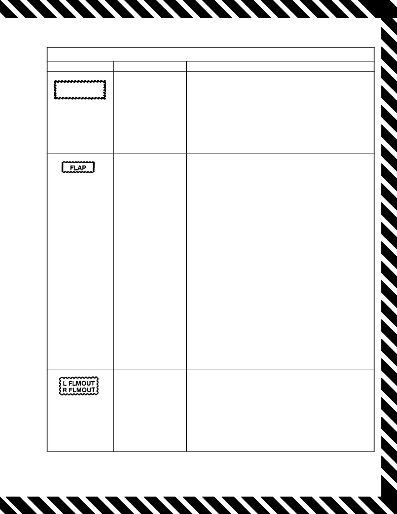
DFCS failure has
1. MASTER RESET Ċ Depress.
FCS CAUTION
occurred. With no
If light remains illuminated:
other lights, indicates
2. Airspeed Ċ Remain below 600 knots or 1.3 TMN and
loss of redundancy
adhere to the following limitations:
only.
a. Above 0.5 TMN, no cross control inputs permitted
above 10 units AOA.
b. With maneuvering devices retracted, coordinate all
lateral stick inputs above 0.6 TMN and 15 units AOA.
Flap position disparity
1. Airspeed Below 225 Knots.
with a commanded
2. FLAP handle Ensure Full Up.
position or flap/slat
3. MASTER RESET Depress.
asymmetry.
4. While holding MASTER RESET pushbutton depressed,
maneuver flap thumbwheel Full Forward.
5. Check FLAP light out.
If after landing/takeoff flap transition, or reillumination after
above procedures:
1. MASTER RESET Depress.
2. If light still illuminated, check FLAP handle and indicator
position, then proceed with appropriate steps below.
Flap handle up and flaps not fully retracted
1. Flap handle EMER UP.
Flap handle up and flaps indicating full up:
1. Flaps Cycle.
Flap handle down and flaps not fully extended:
1. Wing−sweep Ensure at 20°.
Flap handle down and flaps down:
1. Wing−sweep Ensure at 20°.
2. MASTER RESET Depress.
Flap and slat asymmetry:
Refer to Chapter 14.
Engine flameout.
Check engine gauges.
If invalid, report anomaly to maintenance.
(MFD)
If valid, perform the following:
*1. Throttle IDLE or Above.
*2. BACKUP IGNITION switch ON.
If hung start or no start:
*3. Throttle Cycle OFF, Then IDLE.
Warning, Caution, Advisory Lights/Displays (Sheet 6 of 15)
75
ORIGINAL
NAVAIR 01−F14AAD−1
WARNING/CAUTION/ADVISORY LIGHTS/DISPLAY LEGENDS
LIGHT/LEGEND
CAUSE
ACTION
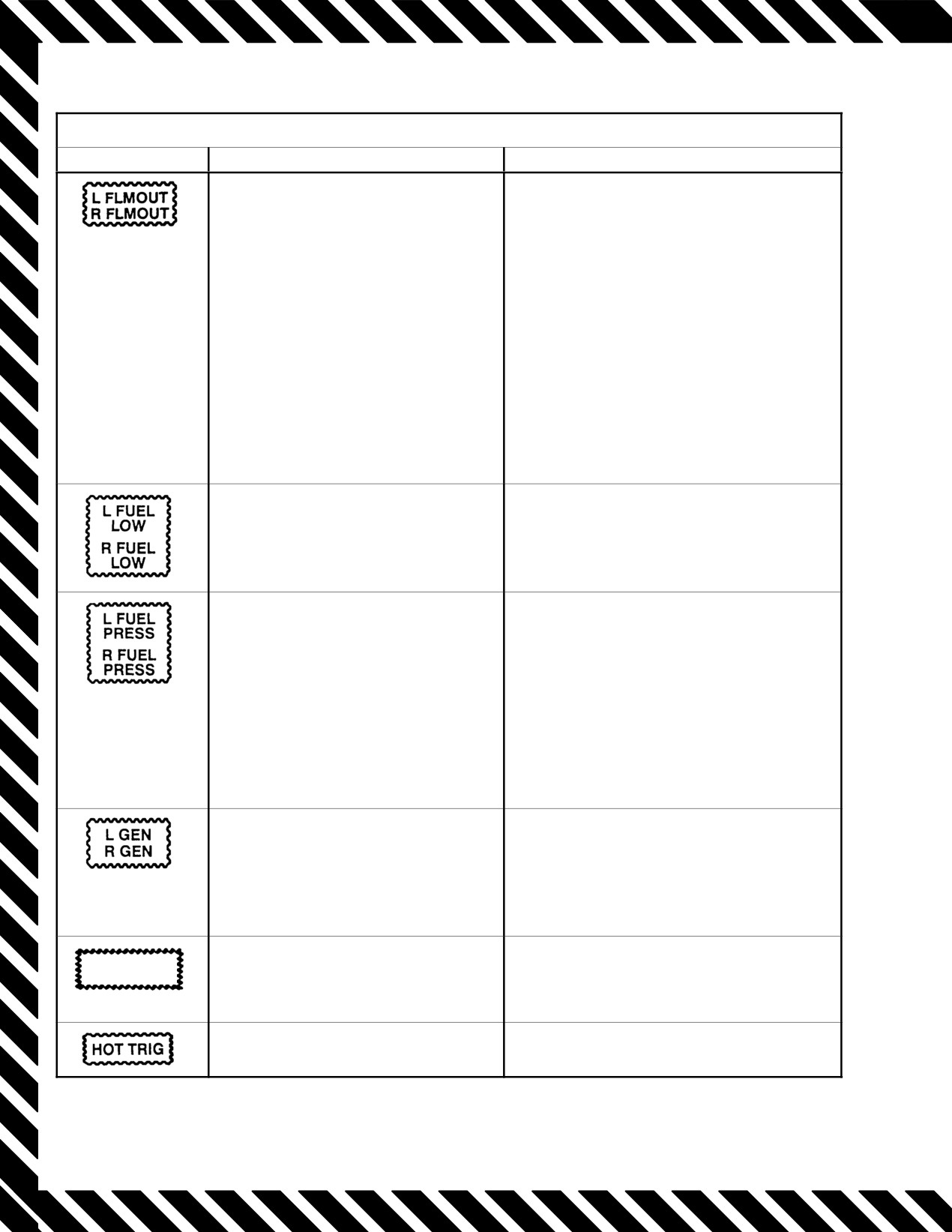
Engine flameout.
If still hung or no start:
*4. ENG MODE SELECT SEC.
If one engine is operable, perform a crossĆ
(MFD)
bleed airstart.
If both engines flamed out/inoperative or
crossbleed not possible:
*5. Airspeed 450 Knots.
6. OBOGS BACKUP.
When start complete:
7. BACKUP IGNITION OFF.
8. ENG MODE SELECT PRI.
9. OBOGS ON.
When primary mode restored:
10. Maintain constant subsonic Mach in
level flight.
11. Affected AICS cb Cycle.
Usable fuel in L and AFT or R and
1. DUMP switch OFF.
FWD fuselage tanks 1,000 pounds.
2. Fuel distribution Check.
If wing and/or external fuel remaining:
3. WING/EXT TRANS ORIDE.
4. Land as soon as practicable.
Sump tank boost pump discharge less
1. Both throttles MIL Power or Less.
than 9 psi.
2. Restore aircraft to 1.0g flight.
If both lights remain on:
3. Increase positive g’s to > 1.0g.
4. Descend below 25,000 feet.
5. Maintain cruise power settings or less.
6. Land as soon as possible.
If one light remains on:
3. No afterburner above 15,000 feet.
4. Fuel distribution Monitor.
5. Land as soon as practicable.
Generator failure and/or disconnected
1. Generator OFF/RESET,
from its ac bus.
Then NORM.
If generator does not reset:
2. Generator TEST.
a. GEN light off Ċ distribution system.
b. GEN light illuminated Ċ IDG or GCU.
GPS failure.
Non−GPS primary navigation modes in use
GPS FAIL
(INS navigation mode).
(MFD)
Firing logic met. Pilot’s trigger will fire
Pilot option.
weapon when squeezed.
Warning, Caution, Advisory Lights/Displays (Sheet 7 of 15)
ORIGINAL
76
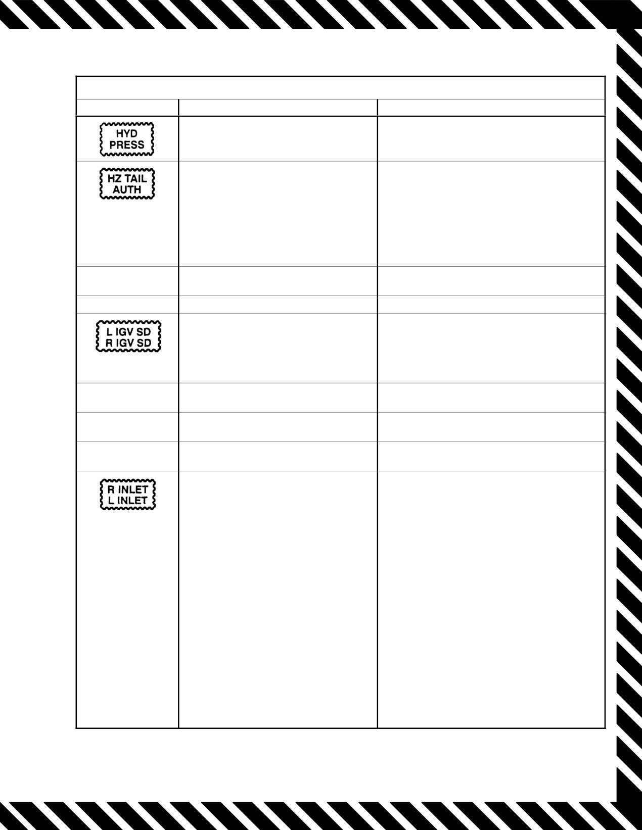
ąNAVAIR 01−F14AAD−1
WARNING/CAUTION/ADVISORY LIGHTS/DISPLAY LEGENDS
LIGHT/LEGEND
CAUSE
ACTION
Combined or flight pump discharge
Refer to Chapter 14 for appropriate
pressure 2,100 psi or less.
procedure.
CADC failure or failure of actuators to
1. MASTER RESET Depress.
follow schedule.
If light remains illuminated:
2. ROLL STAB AUG OFF.
3. Above 400 knots, restrict lateral control
to one−quarter throw.
4. ROLL STAB AUG ON for Landing.
5. Do not select OV SW after landing.
IFF
Mode 4 interrogation received; no reply
As briefed.
generated.
IFF ZERO (MFD)
Improper IFF transponder operation.
As briefed.
Inlet guide vanes off schedule.
AICS fail operation mode in use.
Stall margin may be very slightly reduced but
still remains satisfactory and greater than that
(MFD)
in SEC mode.
High−power thrust may be reduced.
IMU
Improper operation of inertial measureĆ
Secondary navigation mode is in use.
(MFD)
ment unit.
INS
Improper operation of inertial navigaĆ
Secondary navigation mode is in use.
(MFD)
tion system.
INTEG
Power loss or discrepancy between
MASTER RESET.
TRIM
input signal and position.
Computer malfunction or ramp misĆ
*1. Avoid abrupt throttle movements.
positioning.
*2. Decelerate below 1.2 TMN.
*3. Affected INLET RAMPS STOW.
If RAMPS light remains illuminated:
4. Throttle 80 percent or Less.
5. Affected AICS cb Pull.
6. Affected INLET RAMPS AUTO.
7. Land as soon as practicable.
If INLET light only illuminated, attempt AICS
program reset:
4. Decelerate below 0.5 TMN.
5. Affected AICS cb Cycle.
If INLET light goes off:
6. Affected INLET RAMPS AUTO.
If INLET LIGHT remains illuminated:
6. Affected AICS cb Pull.
7. Affected INLET RAMPS AUTO.
8. Remain below 1.2 TMN.
Warning, Caution, Advisory Lights/Displays (Sheet 8 of 15)
77
ORIGINAL

NAVAIR 01−F14AAD−1
WARNING/CAUTION/ADVISORY LIGHTS/DISPLAY LEGENDS
LIGHT/LEGEND
CAUSE
ACTION
Icing condition exists in inlet or ENG/
1. Select ORIDE/ON.
PROBE ANTI−ICE switch is on.
When clear of icing conditions:
2. ANTI−ICE AUTO/OFF.
IPF
JTIDS is failed, a momentary glitch,
Select IPF RESET on JTIDS control panel.
or 20−percent duty cycle has been
exceeded.
IRSTS HOT
Infrared search and track system
Secure system.
(MFD)
overheated.
JTID HOT
Possible loss of cooling air or a high
Secure system.
(MFD)
JTIDS transmit duty cycle.
With RIO CANOPY light, canopy
*1. Canopy BOOST CLOSE.
unlocked.
*2. EJECT CMD PILOT.
3. Airspeed and altitude Below 200 Knots/
15,000 Feet.
4. Seats and visors DOWN.
5. If canopy has departed aircraft, perform
controllability check.
6. Land as soon as possible.
Without RIO CANOPY light, ladder
1. Airspeed minimum.
not stowed.
2. Obtain in−flight visual check if possible.
3. Land as soon as practicable.
LAUNCH
Launch bar unlocked, engines less
As appropriate.
BAR
than MIL thrust.
(Ground)
LAUNCH
Launch bar not locked in up position or
1. Landing gear Leave Down.
BAR
cocked nosegear.
2. Obtain visual inspection.
If nosegear cocked, refer to Landing Gear
(Flight)
Malfunction guide.
If launch bar down or visual inspection not
available:
3. Request removal of arresting cables for
field landing.
4. Request removal of crossdeck pendants
1 and 4 for CV landing.
L LO THR
Designated engine may be producĆ
If associated with RATS check, monitor engine
R LO THR
ing less than expected thrust.
gauges and FEMS engine data for normal rpm,
FF, and temperatures. If no anomalies, message
(MFD)
is false alarm triggered by the hook.
If not associated with a RATS check, record
FEMS data and abort.
Warning, Caution, Advisory Lights/Displays (Sheet 9 of 15)
ORIGINAL
78
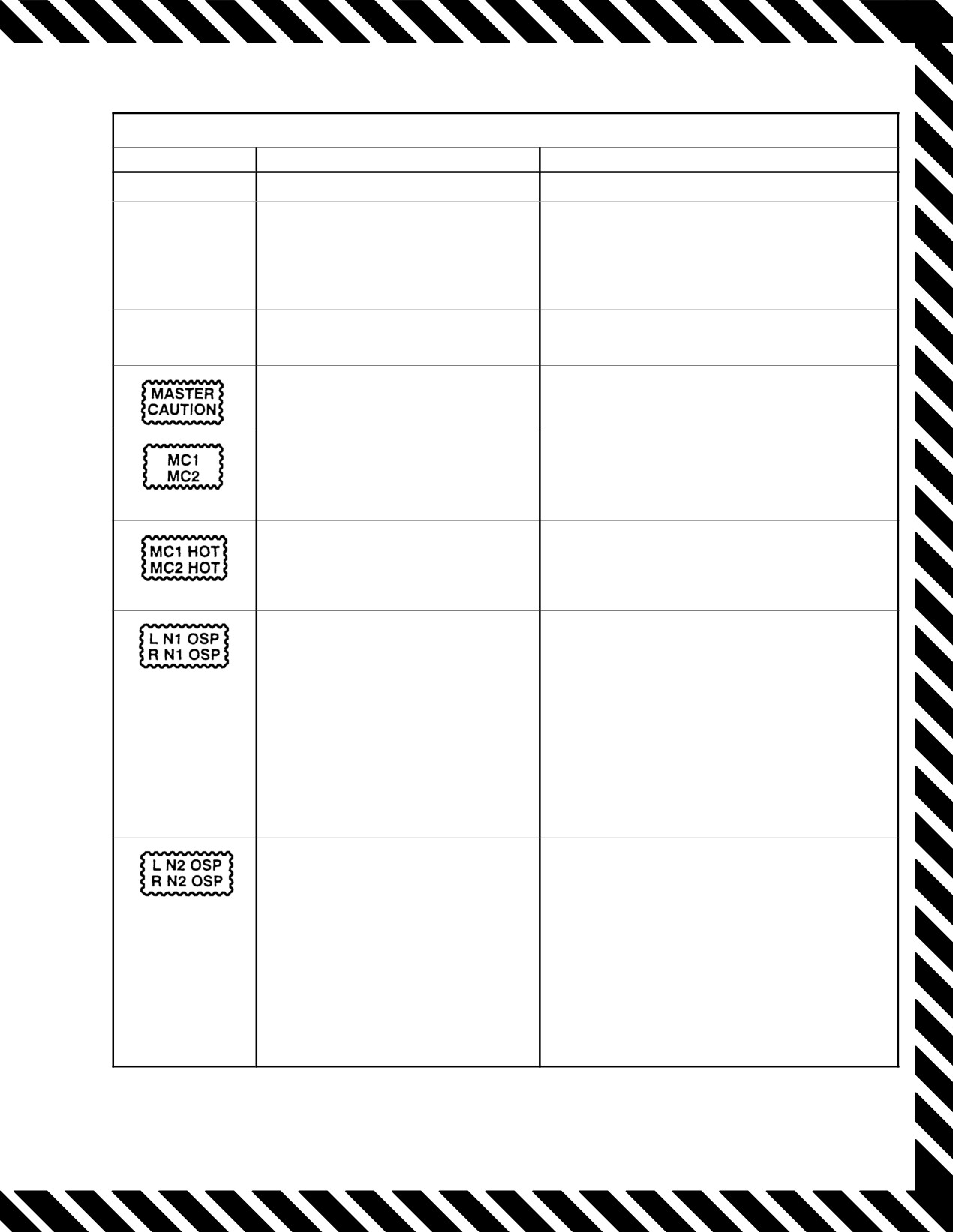
ąNAVAIR 01−F14AAD−1
WARNING/CAUTION/ADVISORY LIGHTS/DISPLAY LEGENDS
LIGHT/LEGEND
CAUSE
ACTION
LOCK
Radar locked on target.
Pilot option.
L MACH #
Mach number signal to designated
In flight Remain below 1.1 TNM.
engine has failed.
Small throttle reductions below MIL at
R MACH #
high Mach can result in engine stall.
(MFD)
On deck Assess operational impact of speed
restriction for mission.
MACH TRIM
Failure of Mach trim actuator to folĆ
1. MASTER RESET.
low program.
2. Retrim manually.
(MFD)
Actuated by any caution light on
Push to reset after discrete MSG noted.
caution panel.
Improper operation of mission
Backup operation selected automatically.
computer.
(MFD)
Mission computer overheated.
Backup operation selected automatically.
(MFD)
Engine fan rpm exceeds 106 perĆ
1. Throttle IDLE.
cent.
Check rpm gauge for N2 and FEMS
engine data on MFD for N1 to determine
(MFD)
validity of overspeed message.
If overspeed continues:
2. ENG MODE SELECT SEC.
If overspeed condition persists:
3. Throttle OFF.
4. Refer to Single−Engine Cruise Operations.
5. Land as soon as practicable.
Engine core rpm exceeds
1. Throttle IDLE.
107.7 percent.
Check rpm gauge for N2 and FEMS engine data
on MFD for N1 to determine validity of overspeed
(MFD)
message.
If overspeed continues:
2. ENG MODE SELECT SEC.
If overspeed condition persists:
3. Throttle OFF.
4. Refer to Single−Engine Cruise Operations.
5. Land as soon as practicable.
Warning, Caution, Advisory Lights/Displays (Sheet 10 of 15)
79
ORIGINAL

NAVAIR 01−F14AAD−1
WARNING/CAUTION/ADVISORY LIGHTS/DISPLAY LEGENDS
LIGHT/LEGEND
CAUSE
ACTION
Nosewheel steering is engaged.
Disengage when appropriate.
Engine oil temperature limits
On deck:
exceeded or high scavenge oil
1. Throttle OFF.
temperature.
In flight:
1. Oil pressure Check.
2. Throttle 85−percent rpm.
3. If after 1 minute, light still illuminated
Throttle OFF.
4. Land as soon as practicable.
5. Refer to Single−Engine Cruise Operations.
6. Relight engine for landing if necessary.
L/R OIL LO
Designated engine oil level is
Alert ground personnel; servicing required.
approximately 2 quarts low
(MFD)
Postflight, engine at idle.
L or R oil press <11 psi.
1. Throttle (affected engine) IDLE.
If oil pressure below 15 psi, above 65 psi, or
engine vibration:
If shutdown feasible:
2. Throttle (affected engine) OFF.
3. Refer to Single−Engine Cruise Operation
(Chapter 14).
If shutdown not feasible:
2. RPM Set Minimum Rpm.
3. Avoid high−g or large throttle movements.
4. Land as soon as practicable.
Low percent oxygen.
1. BACKUP OXY PRESS Check.
Indicates inoperative pitch channel
1. MASTER RESET Depress.
PITCH SAS
or PITCH SAS failure.
2. If light remains illuminated
No limitations.
Warning, Caution, Advisory Lights/Displays (Sheet 11 of 15)
ORIGINAL
80
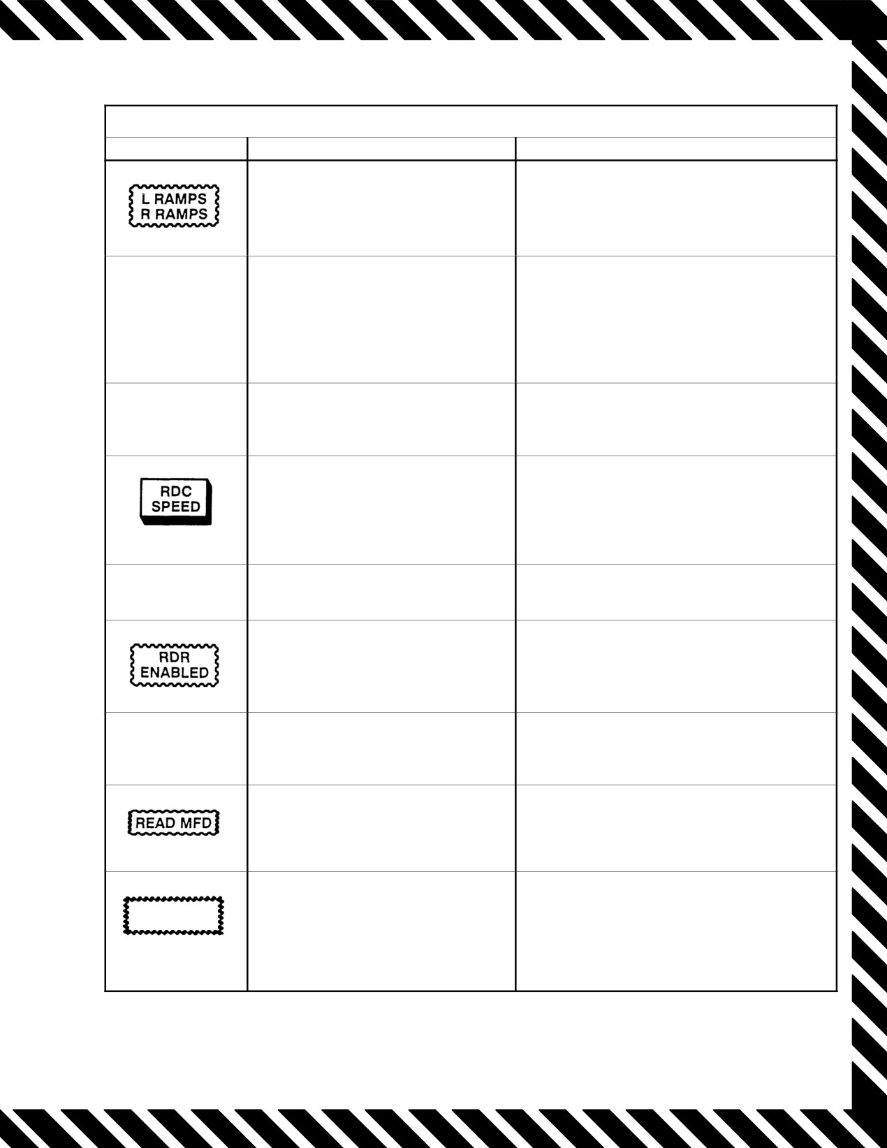
ąNAVAIR 01−F14AAD−1
WARNING/CAUTION/ADVISORY LIGHTS/DISPLAY LEGENDS
LIGHT/LEGEND
CAUSE
ACTION
Computer/mechanical malfunction or
Refer to INLET light.
RAMPS ramp mispositioning.
RATS
RATS operation enabled.
1. Tailhook DOWN.
If conditions permit:
2. ANTI ICE CONTR HOOK CONT/
WSHLD/AIR cb Pull (8C2).
RCV
ALQ−165 is receiving threat
As briefed.
identification signal.
Airspeed >225 KIAS with flaps down.
1. Reduce speed.
Airspeed >2.4 M.
2. Check FLAP handle.
Total temperature >388° F.
3. MASTER RESET.
(HUD/MFD)
RDP FAN
Radar data processor fan failure.
Expect overheat.
Radar operation on ground is posĆ
Radar POWER switch to STBY
sible.
(as applicable).
RDR HOT
Radar system overheated.
Select STBY.
(MFD)
Warning or caution message(s) being
As appropriate to displayed message(s).
displayed on MFD.
Indicates inoperative roll channel and
1. MASTER RESET Depress.
ROLL DGR
degraded roll authority.
2. If light remains illuminated, aggressive
maneuvering should be terminated.
3. Remain below 1.0 TMN.
Warning, Caution, Advisory Lights/Displays (Sheet 12 of 15)
81
ORIGINAL
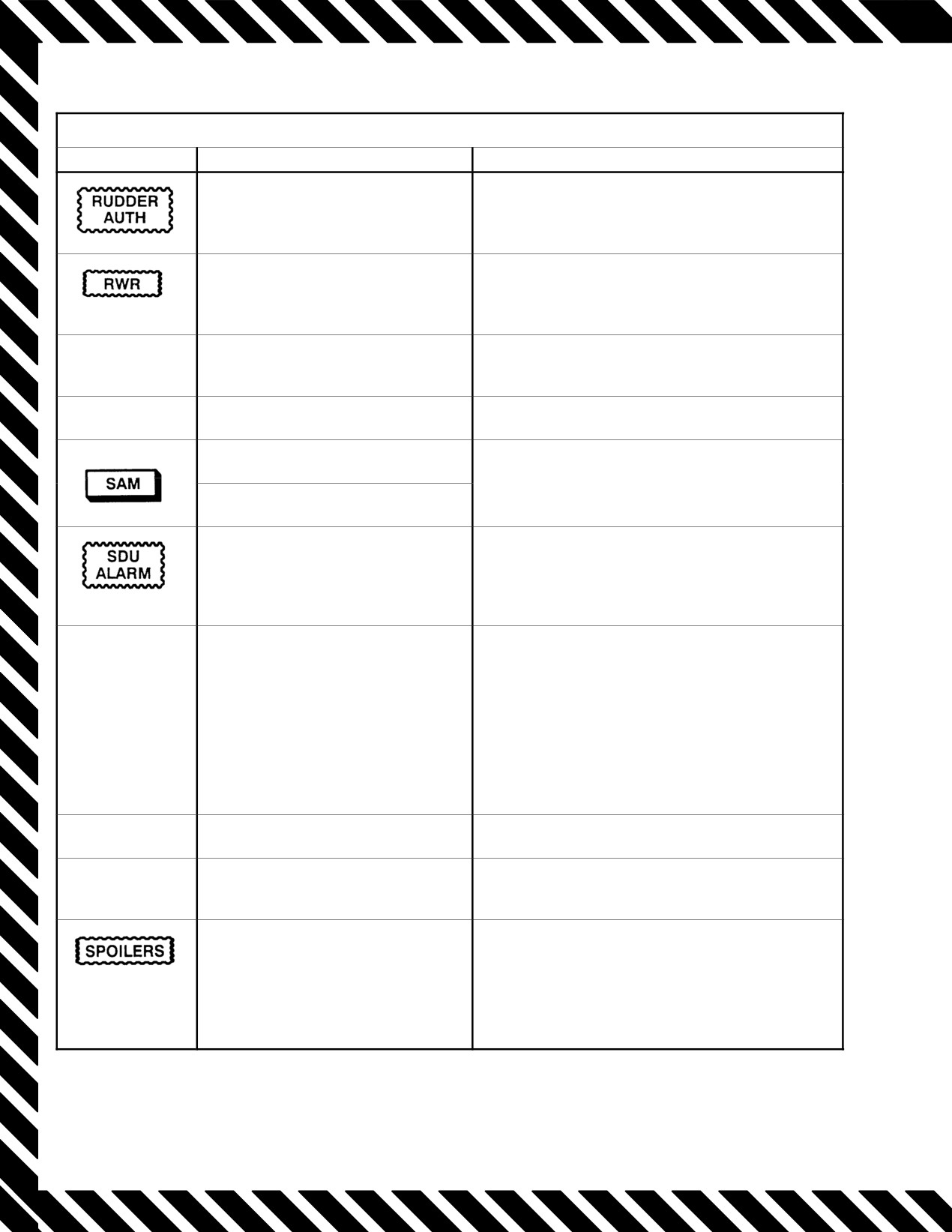
NAVAIR 01−F14AAD−1
WARNING/CAUTION/ADVISORY LIGHTS/DISPLAY LEGENDS
LIGHT/LEGEND
CAUSE
ACTION
CADC failure or failure of actuator
1. MASTER RESET Depress (10 seconds).
to follow schedule.
2. If light remains illuminated Above 250
Knots, Restrict Rudder Inputs to < 10°.
Improper ALR−67 radar warning
As briefed.
receiver operation.
(MFD)
RWR
ALR−67 overheated.
Secure ALR−67.
HOT
SAHRS
SAHRS not available.
Avoid IFR flight if INS is degraded.
Steady Tracking radar detected.
As briefed.
Flashing Missile launch detected.
Improper operation of KY−58,
As briefed.
JTIDS not keyed.
(MFD)
SENSOR
Overheat or pump loss in radar
1. RADAR COOLING OFF.
COND
coolant loop.
2. RDR OFF.
3. APG−71 PUMP PH A, B, C cb Pull.
If other conditions exist that may indicate an ECS
malfunction, either directly or indirectly, perform
ECS leak/elimination of smoke and fumes
procedures:
4. Land as soon as practicable.
SHOOT
Target meets LAR requirements.
As briefed.
SMS HOT
Store management system (MFD)
Expect loss of SMS.
(MFD)
overheated.
Symmetric spoiler detector has
If associated with abnormal roll and/or yaw:
locked down spoilers.
1. Counter roll with at least 1 inch of lateral
stick.
2. Visually check spoiler position/operation.
Refer to Chapter 14.
Warning, Caution, Advisory Lights/Displays (Sheet 13 of 15)
ORIGINAL
82
ąNAVAIR 01−F14AAD−1
WARNING/CAUTION/ADVISORY LIGHTS/DISPLAY LEGENDS
LIGHT/LEGEND
CAUSE
ACTION
Starter solenoid air valve open after
1. Ensure ENG CRANK OFF.
engine start.
2. AIR SOURCE OFF.
If on deck:
3. Throttle OFF.
If airborne:
3. ENG START cb Pull (RF1).
4. OBOGS BACKUP.
Engine stall and/or overtemperature.
*1. Unload aircraft (0.5g to 1.0g).
If greater than 1.1 Mach:
*2. Both throttles MIL.
(HUD/MFD)
When 1.1 Mach or less:
*3. Both throttles Smoothly to IDLE.
Check EGT and FEMS engine data for
TBT to determine validity of stall message.
If EGT above 935°C and/or engine response
abnormal:
*4. Throttle (stalled engine) OFF.
If EGT normal and/or airstart successful:
5. Perform engine operability check.
Turbine blade overtemperature.
1. Throttle IDLE.
Check EGT gauge and FEMS engine data
on MFD for TBT to determine validity of
(MFD)
overtemperature message.
If still overtemperature:
2. Throttle OFF.
TRANS/RECT
Lack of dc output from either or
1. Generator OFF/RESET, Then NORM.
both T/R.
2. If both lights remain illuminated, select
EMERG GEN on MASTER TEST panel.
3. Land as soon as practicable.
Landing gear not down with flaps
Lower gear.
down and either throttle ≤ 85 percent.
Warning, Caution, Advisory Lights/Displays (Sheet 14 of 15)
83
ORIGINAL

NAVAIR 01−F14AAD−1
WARNING/CAUTION/ADVISORY LIGHTS/DISPLAY LEGENDS
LIGHT/LEGEND
CAUSE
ACTION
Failure of both wing−sweep chanĆ
Advisory light only, no loss of normal control:
nels or spider detent disengaged.
1. MASTER RESET Depress.
(MFD)
WING SWEEP light and W/S legend, no automatic
or manual control:
1. Airspeed Decelerate to 0.9 or Less.
2. Check spider detent engaged.
3. MASTER RESET Depress.
If WING SWEEP light and W/S caution legend
illuminate again:
4. WING SWEEP DRIVE NO. 1 and WG SWP
DR NO. 2 MANUV FLAP cb Pull.
5. Emergency WING SWEEP handle −
Comply With Schedule.
Refer to Chapter 14.
WING
Failure of one wing−sweep channel.
Advisory light only:
SWEEP
1. MASTER RESET Depress.
WSHLD HOT
Center windshield temperature
1. WSHLD AIR OFF.
300_F.
If light remains illuminated:
2. AIR SOURCE OFF.
3. OBOGS BACKUP.
4. RAM AIR OPEN.
5. Reduce airspeed < 300 knots or 0.8 Mach.
6. Land as soon as practicable.
Indicates inoperative yaw channel
1. MASTER RESET Depress.
YAW DGR
and degraded yaw authority.
2. If light remains illuminated, aggressive
maneuvering should terminated.
3. Remain below 1.0 TMN.
Warning, Caution, Advisory Lights/Displays (Sheet 15 of 15)
ORIGINAL
84
NAVAIR 01−F14AAD−1
CHAPTER 12
Ground Emergencies
12.1
ON−DECK EMERGENCIES
Note
12.1.1
Engine Fire on the Deck
D If hot start on deck, windmill engine until EGT
is below 250 °C before attempting restart.
PILOT
D If wet start, continue cranking until tailpipe is
*1. Both FUEL SHUT OFF handles Pull.
clear of fuel.
*2. Both throttles OFF.
12.1.3
START VALVE Light After Engine Start
3. If conditions permit Windmill Engine.
4. BACK UP IGNITION switch Check OFF.
1.
Ensure ENG CRANK switch OFF.
2.
AIR SOURCE pushbutton OFF.
3.
Throttle (affected engine) OFF.
Excessive windmilling of engine with oil system
failure may increase combustion/smoking (blue/
white) and result in greater difficulty extinguish-
ing, causing further damage to engine.
D If the starter valve does not close during engine
acceleration to idle rpm, continued airflow
If FIRE light and/or other secondary indications:
through the air turbine starter could result in
5. Fire extinguisher pushbutton (affected engine)
catastrophic failure of the starter turbine.
Depress.
D If the START VALVE caution light illumi-
6. Egress.
nates after the ENG CRANK switch is off, or
if the ENG CRANK switch does not automati-
RIO
cally return to the off position, ensure that the
1. Notify ground and/or tower.
ENG CRANK switch is off by 60−percent rpm
2. Egress.
and select AIR SOURCE to OFF to preclude
starter overspeed.
12.1.2
Abnormal Start
1. Throttle (affected engine) OFF.
12.1.4
Uncommanded Engine Acceleration
2. BACK UP IGNITION switch Check OFF.
on Deck
Uncommanded engine acceleration may or
may
not be associated with throttle movement. Uncommanded
throttle(s) are characterized by increased or decreased throttle
settings caused by failures of the throttle control system.
A catastrophic Hot Start will occur if the affected
Uncommanded engine acceleration without throttle
throttle is not immediately secured following a
movement is a result of an AFTC or MEC failure normally
loss of electrical power during an engine start
associated with one engine. Selection of either L or R ENG
with the RPM below forty percent. Air flow will
select switch to SEC may restore throttle authority.
be cut off and fuel will continue to be scheduled
to the engine with the ignitors firing, causing a
rapid and severe rise in EGT that will not be
observed on the EIG due to power loss.
12−1
CHANGE 2
NAVAIR 01−F14AAD−1
*1. Paddle switch Depress and Hold.
required to minimize risk of injury. Spacing of pitot static
probes along both sides of the forward fuselage will allow for
*2. Throttle(s) As Desired.
an unobstructed egress.
*3. ENG MODE SELECT SEC.
Note
In SEC mode, nozzle is commanded fully closed.
D Standing and jumping from the cockpit or
attempting to slide down the nose of the airĆ
*4. THROTTLE MODE switch MAN.
craft during ground egress can result in severe
injury.
If engine(s) still uncommanded and aircraft is not in catapult
tension:
D If the ENG/PROBE ANTI−ICE switch is in
the ORIDE position, touching the pitot probes
5.
Throttle(s) OFF.
with bare skin will cause burns.
6.
FUEL SHUT OFF handle(s) Pull.
1. Kneel aircraft (if possible).
2. Canopy OPEN or JETTISON
Note
D Approximately 50 pounds of force must be
3. Parking brake Pull.
applied to the throttles to override the boost
system to ensure disengagement of APC BIT
4. Ejection seat SAFE.
self−test.
(Safe by raising the SAFE/ARMED handle)
D The quickest and most reliable method to
5. All fittings (Restraint fittings and oxygen hose)
secure uncommanded throttles is to revert the
Release.
throttle system to the manual mode and secure
the throttle(s). Since manual is, by design, a
Note
backup mode, the throttle rigging may not be
the same as the boost mode. It may take a hard
To retain survival kit, do not release lapbelt
snapping motion to position the throttle into
restraint fittings.
OFF. If throttle(s) are misrigged in manual
mode, the OFF position may not secure fuel
12.1.6
Emergency Entrance
flow to the engine.
D Both throttles cannot be secured simultaĆ
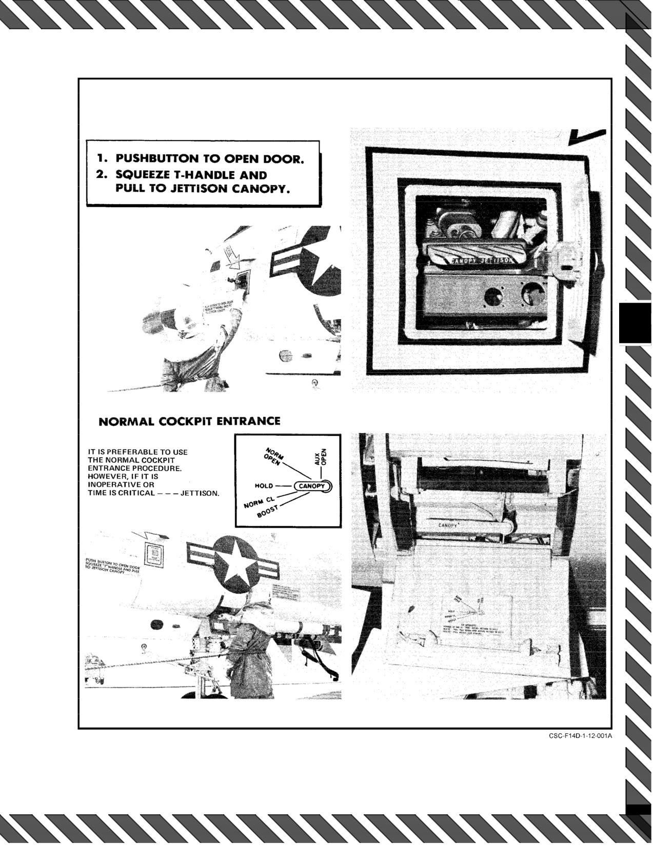
See Figure 12Ć1 for procedures for entering the cockpit
neously; however, reverting to manual mode
for emergency rescue.
will allow both throttles to be repositioned to
IDLE simultaneously.
12.1.7
Weight On−Off Wheels Switch Malfunction
12.1.5
Ground Egress Without Parachute and
There are WOW switches on the left and right main
Survival Kit
gear that interact with many aircraft subsystems to provide
safety interlocks. The interlocks prevent operation of various
Methods and routes of ground egress will vary with the
components or systems on deck or in flight, as appropriate.
situation. In all cases, kneeling the aircraft (conditions perĆ
mitting) via the nose strut switch will facilitate a safer exit for
the aircrew. If sufficient time does not exist for ground perĆ
sonnel to deploy the boarding ladder, aircrew should egress
to the rear of the aircraft, over the horizontal stabilizers or
wings, or directly to the deck from the cockpit if the tail is
Failure of the left or right WOW switches to the
over water. In the case of fire, the location and intensity of the
in−flight mode can cause loss of engine ejector
fire will dictate the safest escape route. If electing to egress
air to the IDGs and hydraulic heat exchangers
directly from the cockpit, aircrew should grasp the canopy
causing thermal disconnect and/or heat damage
rail with both hands, hang to full body extension, and drop to
to the generators and aircraft hydraulic systems.
the ground. A parachute−landing fall maneuver may be
ORIGINAL
12−2
NAVAIR 01-F14AAD-1
Figure 12-1. Emergency Entrance
12-3
ORIGINAL
NAVAIR 01−F14AAD−1
12.1.7.1
Failure Of Weight On−Off Wheels to
a. Radar can scan and radiate.
In−Flight Mode
b. ALQ−165 can transmit.
INDICATIONS:
c. Probe heaters will be on in AUTO.
1. WOW acronym displayed.
d. ALQ−167 can radiate (TARPS).
2. Approach indexers illuminated.
e. BOL chaff can dispense.
3. Nozzles may be partially closed at idle rpm.
4. Nosewheel steering inoperative.
12.1.8
Binding/Jammed Flight Controls On Deck
5. Launch bar light illuminated (if nosegear turned
1. Hold light pressure against binding/restriction to
>10_).
facilitate maintenance troubleshooting procedures.
6. Ground−roll braking inoperative.
7. Wing−sweep MASTER TEST disabled.
8. Oversweep disabled.
Do not attempt to free controls by force, as furĆ
9. Outboard spoiler module on with FLAP handle UP
ther damage to flight control system may result.
(wings less than 62°).
10. Aircraft will not kneel.
2. Abort mission.
If two or more of the preceding anomalies are detected,
12.1.9
Brake Failure at Taxi Speed
the following action should be taken:
*1. ANTISKID SPOILER BK switch SPOILER BK
or OFF.
PILOT
1. Clear runway (if applicable).
2. NWS Verify Engaged.
2. Generators OFF.
3. Parking brake
PULL (if required) (applying
parking brake will lock both main wheels.)
3. Throttles OFF (after downlocks are in place).
Normal brakes are not available with parking
Failure of the left or right WOW switches to the
brake handle pulled. If parking brake accumulaĆ
in−flight mode can cause loss of engine ejector
tor pressure is depleted, aircraft brakes are isoĆ
air to the IDGs and hydraulic heat exchangers
lated from brake pedal master cylinders. Parking
causing thermal disconnect and/or heat damage
Brake handle must be pushed in to restore normal
to the generators and aircraft hydraulic systems.
brake operation.
RIO
1. RDR switch OFF.
Complete loss of hydraulic fluid through the
wheelbrake hydraulic lines will render the parkĆ
ing brake ineffective.
With failure of the WOW switch to the in−flight
If brakes still inoperative:
mode, the following functions are enabled:
4. Hook DN.
ORIGINAL
12−4
NAVAIR 01−F14AAD−1
After lowering the hook, NWS will automatiĆ
cally center and will remain centered until NWS
is cycled.
5. Lights ON.
6. Notify ground and/or tower.
7. Both throttles OFF (If required).
If collision imminent, DO NOT delay step 7.
During shipboard operations, aircrew should not
delay ejection decision if aircraft departure from
flight deck is imminent.
12−5 (Reverse Blank)
ORIGINAL
NAVAIR 01−F14AAD−1
CHAPTER 13
Takeoff Emergencies
13.1
ABORTED TAKEOFF
Emergencies during takeoff are extremely critical and
require fast analysis and quick decision by the pilot. The
decision to abort should not be delayed just because
Rolling over an arresting wire with brake presĆ
emergency arresting gear is available at the end of the
sure applied may result in blown tires.
runway. Whether to abort or continue the takeoff depends on
the length of runway remaining, refusal speed, best single−
If arresting gear is available, use it to avoid rolling off
engine climb speed, and the arresting gear available. Failure
the runway. Always inform the control tower of your
of either engine, a fire warning light or a blown tire during
intention to abort the takeoff and engage the arresting gear,
takeoff dictates an immediate abort if enough runway is
so that aircraft landing behind you can be waved off. Lower
available. The ejection seats will provide safe escape at
the hook in sufficient time for it to fully extend (normally
ground level and low airspeeds. Therefore, if a safe aborted
1,000 feet before engagement). Use nosewheel steering to
takeoff cannot be performed and takeoff is impossible, eject.
maintain directional control and aim for the center of the
runway. At night, use the taxi light to see the arresting gear.
In an aborted takeoff, aerodynamic ground−roll brakĆ
If off center just before engaging the arresting gear, do not
ing is assisted by simultaneous deflection of all spoilers (flaps
turn the aircraft but continue straight ahead, parallel to the
down) or inboard spoilers only (flaps up) to 55_ when both
centerline.
throttles are retarded to IDLE.
If aborting with a blown nosewheel tire, it is likely that
Note
either or both engines have FOD. In the event of any blown
Moving flap handle down activates outboard
tire during an aborted takeoff, the flaps should not be moved
spoilers to assist in aerodynamic ground−roll
until they can be inspected for FOD.
braking.
Aircraft control following loss of an engine during the
When securing the starboard engine, use caution to
takeoff roll is a function of thrust setting and airspeed. In most
prevent inadvertent shutdown of both engines. If both
cases, an aborted takeoff will be required. Refer to paragraph
engines are shut down, hydraulic pressure is lost along with
11.8 for additional discussion of takeoff configuration,
antiskid, nosewheel steering, spoiler braking, and normal
asymmetric thrust flight characteristics.
braking. Full aft stick is used to augment aerodynamic
braking. Care should be taken while positioning the stick aft
13.1.1
Aborted Takeoff Checklist
to avoid any nose rotation. The aircraft’s tendency to rotate
*1. Throttles IDLE.
is accentuated with the flaps up because of increased
longitudinal control effectiveness, and aft stick must be
*2. Speedbrakes EXT.
applied at a slower rate to avoid rotation.
*3. Stick AFT.
Note
The stick should be positioned fully aft at a rate
that will not cause any nose rotation.
Maximum braking effort in aborts initiated near
*4. Hook DN (1,000 feet before wire)
rotation speed at takeoff gross weights may result
in blown tires even with antiskid engaged.
*5. Brakes As Required.
13−1
ORIGINAL
NAVAIR 01−F14AAD−1
*6. Right engine Ċ OFF (if required).
13.2.2
Rate of Climb Consideration
Rate of climb may be increased by selecting afterburnĆ
er with ASYM LIMITER switch in ON. Only minimum AB
is available. The most adverse drag condition is with the
wings level on a constant heading, but techniques used by
traditional multiengine aircraft
(such as raising the dead
Aircrew should expect hot brakes following
engine with 5° angle of bank) are applicable for the F−14.
heavy gross weight, high speed aborts. ApplicaĆ
Airspeed and angle of bank control will also greatly affect
tion of the parking brake could cause the brake
rate of climb (refer to NAVAIR 01−F 14AAP−1.1 for all of
assembly to fail and result in a brake fire.
these effects).
Note
Under normal circumstances, 180 knots is used as the
If performing no flap/maneuvering flap takeoff,
flaps up speed. However, if during a single−engine takeoff the
lowering the flap handle slightly during an abort
aircraft has achieved a safe flying speed and a positive rate
will deploy all spoilers for ground−roll braking if
of climb but has difficulty achieving flap speed, moving the
SPOILER BRAKE or BOTH is selected, assistĆ
flaps up in increments prior to
180 knots will enhance
ing in decelerating the aircraft.
acceleration and climb capabilities.
13.2
SINGLE−ENGINE FAILURE
13.2.3
Stores Jettison Considerations
FIELD/CATAPULT LAUNCH/WAVEOFF
If an acceptable rate of climb cannot be maintained or
deceleration cannot be countered by thrust alone, jettison
Initial aircraft controllability is highly dependent on
should be selected. The benefits of an instantly lighter
timely and proper rudder usage. Rudder is the primary
control for countering yaw caused by asymmetric thrust since
aircraft and lower drag configuration always produce
lateral stick inputs alone will induce adverse yaw in an
positive effects on performance. Separation characteristics
already critical flight regime. Compounding the situation,
of the external tanks in this configuration, however, have
never been verified by flight tests and consequently may
visual cues for ascertaining yaw excursions may be absent at
night. While roll caused by yaw will always be apparent, yaw
result in stores−to−aircraft collision with unknown conseĆ
quences. The use of ACM jettison, which will selectively
excursions during night/IFR conditions may be first indiĆ
cated by the turn and slip indicator and heading indicator if
bypass nonselected stores, could be utilized but does not offer
the same gross weight reduction and requires the additional
in near wings−level flight. The pilot should be prepared to
apply up to and including full rudder at the first indication of
interlocks of gear handle plus ACM guard up.
an engine failure. Do not rotate aircraft below 130 knots
in any configuration. Refer to NAVAIR 01−F14AAP−1.1,
13.2.4
Aircrew Coordination
Chapter 26 for higher rotation speeds. Additional areas for
Each launch must be made with the aircrew prepared
consideration are discussed below.
for the worst case. Even when mentally prepared to handle
this emergency the F−14 crew faces a difficult task in
13.2.1
Angle−of−Attack/Endspeed Consideration
executing a safe flyaway. Of paramount importance is a
Failure to limit AOA will place the aircraft in a regime
knowledgeable understanding by both pilot and RIO of what
to expect when confronted with an engine failure during
to reduce directional stability, rudder control, and rate of
climb. The aircraft may be uncontrollable at AOA above 20
launch. Both must have already determined during a preflight
briefing the points to be considered, that is, controllability,
units. Smoothly rotating to 10° pitch attitude on the waterline
and approximately 14 units indicated AOA provides the best
AOA/pitch attitude, engine, rate of climb, and jettison
considerations. The pilot will probably be the only one to
compromise between controllability, good initial flyaway
attitude, and adequate single−engine performance. For
know if an engine fails during launch. The RIO will probably
be the only one in a position to successfully initiate ejection
compromise, normal
15−knot excess endspeed catapult
prior to departing the ejection envelope.
launches
(mandatory from catapult No.
4 and highly
recommended from catapult No. 3) will place the aircraft in
the approximate 14−unit AOA regime. Zero excess endspeed
launches on hot days, where single−engine performance is
marginal, will place the aircraft in the approximate 18−unit
AOA regime and will require the pilot to precisely fly the
aircraft away from the water, avoiding sudden pitch control
inputs.
ORIGINAL
13−2
NAVAIR 01−F14AAD−1
13.2.5
Single−Engine Failure Field/Catapult
*2. ANTI SKID SPOILER BK switch SPOILER
Launch/Waveoff
BK.
*1. Set 10° pitch attitude on the waterline (14 units
AOA maximum).
CAUTION
*2. Rudder Opposite Roll/Yaw Supplemented By
Lateral Stick
D Do not delay engaging nosewheel steering in
*3. Both throttles As Required for Positive Rate of
order to center rudder pedals.
Climb
D Aircraft should have ground locks installed
and engines secured before moving aircraft.
*4. Landing gear UP.
Note
*5. Jettison If Required.
Antiskid will sense a constant release on a dragĆ
6. If banner tow, hook Ċ DOWN.
ging blown tire.
7. If unable to control aircraft Ċ Eject.
13.3.2
Blown Tire During Takeoff; Takeoff ContinĆ
ued or After Landing Go−Around
8. Establish 10−unit AOA climb.
*1. Throttles As Required.
9. Climb to safe altitude.
*2. Landing gear and flaps Leave As Set for Takeoff.
10. Flaps Ċ UP.
11. Refer to Single−Engine Cruise Operations,
CAUTION
Chapter 14.
13.3
BLOWN TIRE DURING TAKEOFF
Blown tire(s) can cause engine FOD and/or strucĆ
tural damage.
If a tire blows during the takeoff roll and an abort is
impossible, do not raise the landing gear or flaps. Leave the
3. HYD ISOL switch Ċ FLT.
landing gear down to avoid fouling the blown tire in the
Note
wheelwell. Leave the flaps down; they may be damaged by
pieces of ruptured tire. Also, climbing with the gear and flaps
This will require bending the cam on the gear
down is an optimum flight attitude for emergency fuel
handle in order to move the HYD ISOL switch to
dumping.
FLT.
13.3.1
Blown Tire During Takeoff; Takeoff
4. Refer to BLOWN TIRE LANDING procedures
Aborted or After Landing Touchdown
paragraph 15.5.
*1. Nosewheel steering Engaged.
13−3 (Reverse Blank)
ORIGINAL
NAVAIR 01−F14AAD−1
CHAPTER 14
In−Flight Emergencies
14.1
COMMUNICATIONS FAILURE
3. Attempt home base location by radar mapping or
DR to best known position. Attempt marshal pattern
1. Check mikes and earphone plugs.
location by APX−76 interrogation.
2. Check oxygen mask connections and oxygen hose
4. Drop four bundles of chaff at 2−mile intervals, then
disconnect.
complete series of four standard left−hand 360_
turns at 20−second intervals.
3. RIO check console connector adjacent to shoulder
harness control lever. Pilot check console connector
5. If no chaff, fly minimum of two triangular patterns
aft of g valve.
to left with 1−minute legs.
4. Increase ICS volume and attempt B/U and EMERG
positions.
6. Repeat patterns at 20−minute intervals.
5. Attempt intercommunications with VHF/UHF
7. Conserve fuel throughout and facilitate radar
transceiver.
pickup by maintaining highest feasible altitude conĆ
sistent with situation.
6. If cockpit altitude is safe, oxygen mask can be
removed so that when helmet earmuff is held open,
8. Be alert for aircraft attempting to join.
verbal communications can be maintained. Pilot
may need to turn off ECS briefly to effectively
9. After joining, communicate with appropriate hand
communicate.
or light signals.
14.1.1
Flightcrew Attention Signals
14.1.2.2
Lost (Without Navigation Aids But With
Radio Receiver)
When no other method of communicating exists, the
following signals should be used:
1. Same as without radio, but make turns to right.
1. Pilot will attract RIO by rocking of wings.
14.1.2.3
No Radio (With Navigation Aids)
2. RIO will attract pilot by shouting.
1. Proceed to alternate marshal.
3. Attempt to pass notes.
2. Energize ID function at least once each minute.
4. Acknowledgment will be thumbs−up, high on left−
3. Commence penetration or letdown at EAC. If not
hand side of cockpit, and future communications
will be conducted by visual hand signals using
given EAC, commence approach at estimated time
of arrival.
HEFOE code.
4. Be alert for aircraft vectored to join.
14.1.2
COMM−NAV Emergency Procedures
14.2
PITOT−STATIC SYSTEM FAILURES
14.1.2.1
Lost (Without Navigation Aids or Radio
Receiver)
If the altimeter and Mach airspeed indicators are erroĆ
1. Pilot select running lights on FLASH.
neous, pitot pressure, static pressure, and total temperature
inputs to the central air data computer may also be inaccurate.
2. RIO squawk mode 3 Code 7600.
14−1
CHANGE 1
NAVAIR 01−F14AAD−1
Placing the ANTI−ICE switch in ORIDE/ON or
AUTO/OFF may restore operation if the malfunction was
EMERG STORES JETT PUSHBUTTON
ANGLE−
DEPRESS.
OF−
caused by icing.
ATTACK
Note
FLIGHT CONDITION
UNITS
D Pitot−static system failures because of icing
CATAPULT (15 KNOTS EXCESS)
may input an erroneous Mach number to the
Transition From Catapult
MRT
14.0
AICS programmer, which will result in
AB
13.0
the ramps being in the wrong position for the
MILITARY POWER CLIMB
actual Mach number (engine stall may result).
If this erroneous Mach number is outside 0.3
All Drag Index
Sea Level
6.0
to 0.9 band, the AICS anti−ice positioning feaĆ
Combat Ceiling
9.5
ture will be overridden.
MAXIMUM POWER CLIMB
D With known or suspected pitot−static malĆ
All Drag Indexes
Sea Level
5.0
functions, do not exceed 0.9 TMN.
Combat Ceiling
8.0
D Pitot−static failures will generally be detected
CRUISE AT ALTITUDES BELOW
by the DFCS and may result in an FCS CAUĆ
20,000 FEET (All Gross Weights)
TION light as another secondary indication. If
Drag Index = 8
8.0
the condition causing the failure is resolved,
Drag Index = 100
9.0
the fault may be cleared with a MASTER
RESET.
CRUISE AT OPTIMUM ALTITUDE
All Drag Index
8.0
If it is apparent that icing is not the problem, use the
AOA indicator in place of airspeed for flight conditions
MAXIMUM ENDURANCE
as shown in Figure 14−1. Descend to an altitude below 23,000
All Drag Indexes, All Altitudes
10.0
feet. When cabin altitude stabilizes at 8,000 feet, aircraft
IDLE DESCENT
altitude will be approximately 23,000 feet. Below 23,000
250 KCAS
9.0
feet, aircraft altitude can be determined by dumping cabin
Maximum Range
10.0
pressure and using the cabin altitude indicator above 5,000
feet. Below 5,000 feet, use the radar altimeter.
GEAR AND FLAPS EXTENSION
Safe Gear Extension (Flaps UP) at
Reduce airspeed and set wing sweep to 20_ using the
280 KIAS
6.5
emergency wing−sweep mode. The landing should be
Safe Flap Extension (Gear DN) at
without the autothrottle engaged. If the mission computer
225 KIAS
9.0
computations are affected, the RIO can manually enter
estimated wind direction and velocity through the computer
APPROACH
address panel or the DEU.
CCA/GCA Pattern; 220 KCAS; Gear
UP; Flaps UP; 54,000 pounds.
9.0
14.3
EMERGENCY JETTISON
Final ON SPEED Approach (Gear DN):
Two Engines (All Flap Configurations)
15.0
All stores including external fuel tanks
(stations
2
and 7), but excluding Sidewinder missiles (AIM−9), are
Single Engine/PRI:
FULL FLAP, DLC ENGAGED
15.0
jettisoned in a fixed interval between sequenced stations to
avoid store−to−aircraft collision. See Figure 14−2 for external
FULL FLAP, DLC STOWED
14.0
14.0
stores jettison table.
NO FLAP
Single Engine/SEC:
FULL FLAP (CV ONLY)
13.0
NO FLAP (FIELD ONLY)
15.0
DRAG INDEX
CONFIGURATION
D With landing flaps and slats down, do not fire
Sidewinder missiles.
8
(4) AIM−7
100
(6) AIM−54
D If jettisoned during takeoff emergency, exterĆ
(2) 267−gallon external tanks
nal fuel tanks may collide with the aircraft
because of their unstable characteristics.
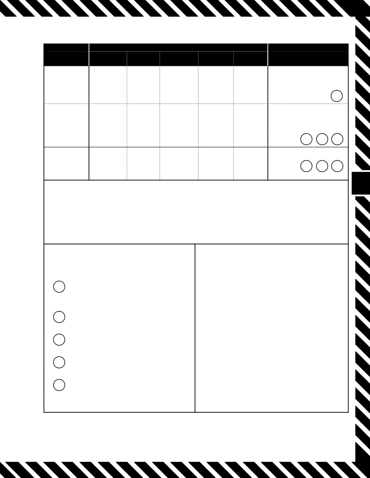
Figure 14Ć1.ĄAirspeed Indicator Failure
1. EMERG STORES JETT pushbutton Ċ Depress.
ORIGINAL
14−2
NAVAIR 01−F14AAD−1
TYPE OF STORES
JETTISON
EXTERNAL
SIDE−
AIR TO
MODE
TANKS
PHOENIX
SPARROW
WINDER
GROUND
REMARKS
VERIFY ON DURING
EMERGENCY
(i)
LTS CHECK
4
4
4
4
(PILOT)
PRESTART − PILOT
1
SEQUENCE
JETTISON
(i)
ACM
SELECTED
4
4
4
4
(PILOT)
STATIONS
2
4
5
SELECTIVE
4
4
4
4
(RIO)
2
3
5
NOTE
• FUZING SAFED IN ALL JETTISON MODES. (DOES NOT PREĆ
CLUDE INADVERTENT ARMING OF MECHANICAL FUZES.)
• SIDEWINDER CANNOT BE JETTISONED.
INTERLOCKS
(i) JETTISON SEQUENCE
STATIONS
1B, 8B, 2, 7, −4D, −5D, −4A, −5A, −4C,
1
WEIGHT OFF WHEELS (EITHER RIGHT OR
−5C, 4B, −5B, −3D, −6D, −3A, −6A, −3C,
LEFT MAIN GEAR)
−6C, −3B, −6B
NOTE
2
LANDING GEAR HANDLE UP
• THE TIME INTERVAL BETWEEN STATIONS
INDICATED BY (−) IS 100 MS.
3
MASTER ARM SWITCH ON
• SUBSTATIONS A, B, C, AND D OF RAIL ARE
NUMBERED CLOCKWISE, LOOKING DOWN
4
ACM COVER UP
AT RAIL WITH A THE LEFT REAR STATION
ON EACH RAIL.
5
STATION SELECT
• STATIONS 1B, 8B, 2, AND 7 ARE
JETTISONED SIMULTANEOUSLY.
Figure 14Ć2.ĄExternal Stores Jettison
14−3
ORIGINAL
NAVAIR 01−F14AAD−1
Note
2. Intermittent bursts of white sparks in the vicinity of
the aft edge of the overwing fairing.
D The EMERG STORE JETT function is disĆ
abled with weight on wheels.
3. Sparks turning to flames.
D The EMERG STORES JETT and ACK lights
4. Continuous yellow sparks in an area of increasing
illuminate when emergency jettison is actiĆ
size.
vated.
D A weight−off−wheels signal from the left or
5. Flames and/or smoke spreading forward to wing
right main wheel is sufficient to enable emerĆ
pivot point and encompassing the area of the overĆ
gency jettison.
wing fairing.
D A complete emergency store jettison
6. Flames, smoke, and/or heat crossing the centerline
sequence can take 1.7 seconds.
of aircraft and exiting in the other overwing fairing
area.
If step 1 fails, proceed with ACM jettison.
These indications may or may not be accompanied by
ACM jettison will release all stores selected except
a FIRE light and a HUD/MFD legend. This midship passage
Sidewinder missiles.
of heat and flames could be through the area containing the
flight control system control rods, which run fore and aft
1. LDG GEAR handle UP.
through the back of the aircraft. Heat and flames progressing
through this area would impinge on the longitudinal and
2. Station select switches As Required.
lateral directional control rods causing possible distortion or
failure. Loss of aircraft may follow. The flightcrew faced
3. ACM guard UP (cover up).
with this type of fire in flight must react immediately.
4. ACM JETT
Depress and Hold
(at least
2 seconds).
Note
If the FIRE warning light is off and a HUD/MFD
Note
legend is displayed, verify FIRE DET TEST
D ACM jettison follows the same sequence as
checks 4.0. Assume message was incorrect and
emergency jettisoning but requires individual
keep engine on line. The legend is a repeat of a
selection of stations to be released. Station not
discrete from the fire detection system.
selected is skipped.
*1. Throttle (affected engine) IDLE.
D When jettisoning bombs from stations 3, 4, 5,
and 6, the interval between sequenced stations
*2. AIR SOURCE pushbutton OFF.
is automatically designated at 100 millisecĆ
onds to avoid store−to−store and store−to−airĆ
*3. OBOGS master switch BACKUP.
craft collision.
14.4
FIRE LIGHT AND/OR FIRE IN FLIGHT
Fire may be accompanied by other indications such as
explosion, vibration, smoke, or fumes in the cockpit, trailing
Oxygen breathing time on BACKUP is limited
smoke, or abnormal engine instrument indications.
and requires immediate mission planning. See
OBOGS emergency procedure. See Figure 2Ć84
A fire in flight precipitated by a failure in the engine
for oxygen breathing time remaining.
can be catastrophic in an extremely short period of time.
The shrapnel generated by the engine can rupture fuel
Note
and/or hydraulic lines, resulting in a raging fire. The seĆ
When ECS service air to the OBOGS concentraĆ
quence of events for the failure could include all or some of
tor is shut off, the aircrew has approximately 30
the following:
seconds before depleting residual OBOGS presĆ
sure and mask collapse.
1. A low−amplitude vibration and noise.
ORIGINAL
14−4
NAVAIR 01−F14AAD−1
Note
b. Rapid yaw or nose slice
Restoration of service air (selecting RAM) will
c. Increasing EGT
return OBOGS to operation.
d. Rpm rollback and/or thrust loss
If light goes off (and no other secondary indications):
e. Lack of throttle response
Note
f. Inlet buzz (supersonic only)
Fire detection test is not available on the emerĆ
g. Fireball emanating from the exhaust and/or
gency generator.
intake.
*4. MASTER TEST switch FIRE DET TEST.
*1. Unload aircraft (0.5g to 1.0g).
If light remains illuminated, FIRE DET test fails, or
If greater than 1.1 Mach:
other secondary indications:
*5. FUEL SHUT OFF handle (affected engine) Pull.
*2. Both throttles MIL.
*6. Throttle (affected engine) OFF.
When 1.1 Mach or less:
*7. Climb and decelerate.
*3. Both throttles Smoothly to IDLE.
*8. Fire extinguisher pushbutton Depress.
Note
Note
If above 1.1 Mach, monitor minimum rpm to
ensure proper functioning of idle lockup to avoid
Ensure BACK UP IGNITION switch is OFF.
inducing a stall.
9. Refer to Single−Engine Cruise Operations, paraĆ
If EGT is above 935°C and/or engine response is
graph 14.5.3.2.
abnormal:
10. Land as soon as possible.
*4. Throttle (stalled engine) OFF.
11. If fire persists Eject.
If EGT normal and/or airstart successful:
14.5
ENGINE EMERGENCIES
5. Perform engine operability check.
14.5.1
Compressor Stall
Note
A compressor stall is an aerodynamic disruption of the
After any stall, throttle movement should be miniĆ
airflow through the compressor. Compressor stalls may occur
mized until engine operability checks are perĆ
at any altitude/airspeed combination, including supersonic,
formed. Engines should be exercised at 10,000
and can be identified by any one or a combination of the
feet in cruise and then at approach speeds, one at
following indications.
a time, to ensure stall−free performance is availĆ
able for landing. If engine performance is abnorĆ
Note
mal, set power as necessary and avoid further
throttle movement. Land as soon as practical.
The loss of Mach number signal from the CADC
results in the loss of both airflow limiting and idle
Flight test operations have not produced any fully
lockup functions of the AFTC. This may result in
developed engine stalls. Pop stalls have been observed and
pop stalls at supersonic speeds (on a cold day) at
were self−clearing with no adverse operational impact.
high power and inlet buzz, resulting in pop stalls
Engine ground testing has shown that a hard stall (characterĆ
at idle power.
ized by loud bang) can result in substantial damage to the
IGV system. The damage resulted in complete detachment of
a. Loud bangs or vibrations
the IGV from the external linkage. There was no FOD.
14−5
ORIGINAL
NAVAIR 01−F14AAD−1
When the IGV linkage breaks, the IGVs assume a fixed
Step 1:
Unload the aircraft (0.5g to 1.0g) Unloading the
aerodynamic trailing position. This position is near normal
aircraft reduces the likelihood of a departure, while
for MIL or AB power settings, but is too far open at lower
providing a more normal engine inlet airflow. It is
throttle positions. This reduces fan stall margin with the
not intended that the pilot push full forward stick or
greatest reduction halfway between IDLE and MIL. AirĆ
induce negative g, but merely that any g load on the
borne, a hard stall may result in similar damage and will
aircraft be reduced to as near 1.0g as possible. In
likely have been the result of an AICS malfunction and/or
the nose−high, slow−airspeed case, the pilot may
fuels/engine control system failure. If a stall occurs during
temporarily lose control effectiveness. This should
AB operation, the asymmetric thrust limiting circuit should
not be cause for alarm and the pilot should be able
reduce the good engine to minimum AB. Asymmetric thrust
to expeditiously establish a wings−level, nose−low
may produce adverse flying qualities under low airspeed
attitude as long as step 2 is followed immediately.
and/or high AOA conditions.
Step 2:
If speed is 1.1 Mach or greater, both throttles
MIL. Setting the throttles to MIL will both help
reduce the asymmetric thrust developed during the
stall and potentially help the engine recover from
the stall. It is not recommended to retard the
Do not delay securing an overtemped engine.
throttle to below MIL until the aircraft is below 1.1
Undue delay will greatly increase the likelihood
Mach. The engine may automatically switch to
of severe turbine damage and decrease the
SEC mode, and a throttle setting below MIL may
chance for a successful airstart. If both engines
result in inlet buzz (idle speed lockup is lost in SEC
are overtemped, one engine must be secured
mode) compounding the stall problem and potenĆ
immediately to provide maximum potential for
tially inducing a stall in the operating engine.
a successful airstart.
Step 3:
Throttle(s) If speed is 1.1 Mach or less, retard
Note
smoothly to IDLE. During a departure, retarding
both throttles to IDLE will help recover the aircraft
Airspeed and altitude will determine whether
by minimizing the asymmetric thrust. In the case of
both engines can be safely shut down (with dual
a violent slicing departure involving asymmetric
compressor stalls), or whether one should be
thrust, reduction of throttles to IDLE is the most
secured and relit prior to shutting down the other.
critical step and must be done immediately. If conĆ
If airspeed is insufficient to provide windmill
trol of the aircraft is not in question, there is no
rpm for hydraulic pressure, one engine should be
need to retard the throttle on the operating engine.
left in hung stall.
Retarding only the stalled engine throttle reduces
the remote probability of inducing a dual−engine
There is a threefold danger present when one engine
stall. In addition, thrust from the operating engine
has experienced a compressor stall. The most serious danger
may be required during low−altitude emergencies.
manifests itself at slow airspeeds and high power settings,
Minimizing asymmetric thrust at high AOA and
where the sudden thrust asymmetry (a stalled engine yields
low airspeed shall be accomplished whenever posĆ
negligible thrust) will induce or aggravate a departure and
may produce sufficient yaw rate to cause a flat spin if proper
sible. Obviously, there are situations (landing patĆ
tern, catapult launch, low altitude, and airspeed)
recovery controls are not used.
where idle power is unacceptable, and emergency
procedures must be tempered by pilot judgment.
The other two dangers from a compressor stall are that
the stalled engine may suffer overtemperature damage and
Step 4:
Stalled engine, throttle off When an engine
that the good engine might also stall. Although the emerĆ
stalls, the combustor flame does not extinguish.
gency procedures are designed to address all three dangers,
Airflow through the engine and cooling flow to the
the pilot must understand that aircraft controllability takes
turbine blades are severely reduced, and the turĆ
priority over engine considerations and involves both throttle
bine blades may suffer overtemperature damage.
position and flight controls. Reference to the engine instruĆ
Securing the stalled engine to OFF extinguishes
ments will probably be required to determine the stalled
the combustor flame, thereby reducing the turbine
engine. If the aircraft has departed controlled flight, this
blade temperature.
should not be attempted until the pilot has ensured that thrust
asymmetry has been minimized and that yaw rate and AOA
are under control. The rationale for each individual step in the
emergency procedure is as follows:
ORIGINAL
14−6
NAVAIR 01−F14AAD−1
14.5.1.1
Supersonic Airspeed
stall minimizes the likelihood of total loss of hydraulic and
electrical power (emergency generator).
Supersonic compressor stalls will produce inlet buzz.
This results in a rough, bumpy ride (+2.5g to −1g at six cycles
per second). The proper technique to recover from a superĆ
sonic compressor stall is to smoothly retard throttles to MIL,
keep feet on the deck, and control any wing−drop tendencies
Leaving one engine in hung stall may catastrophĆ
with lateral stick.
ically damage the turbine. It is, therefore,
imperative that the pilot expeditiously secure
14.5.1.2
Dual Compressor Stall
and relight one engine to prevent turbine damĆ
age. Attention should be given to the remaining
stalled engine as soon as possible.
14.5.2
Airstarts
D During recovery from a dual−engine compresĆ
The most likely reasons to perform an airstart are that
sor stall (with both engine−driven generators
the engine has shut down because of control system failure,
having dropped offline), flight control inputs
hardware failure, fuel feed failure, FOD, or engine stall. The
may temporarily reduce the combined
augmenter fan temperature control contains diagnostic logic
hydraulic system pressure. If combined
to identify primary (PRI) engine mode failures and automatiĆ
hydraulic system pressure drops to between
cally transfers to secondary (SEC) mode when required. If
2,000 and 1,100 psi, the emergency generator
the shutdown was not pilot commanded, the engine may
will automatically shift to the 1−kVA mode
switch to SEC mode automatically. The first airstart attempt
and power only the essential No. 1 buses. If
should be made in the engine mode selected by the AFTC
the combined hydraulic pressure continues to
(either PRI or SEC). If an initial PRI mode airstart is unsucĆ
fall, the essential No. 1 buses will drop offline,
cessful, the ENG MODE SELECT switch should be in SEC
resulting in a total electrical failure.
for any subsequent airstart attempts.
D Complete loss of electrical power will result
in loss of ICS, OBOGS, backup oxygen
If an engine flames out, the automatic relight feature
(below
10,000 feet MSL), engine instruĆ
will attempt to restart the engine immediately; however, if
ments, spin direction indicators (spin arrow
rpm is decaying below the throttle−commanded level, spoolĆ
and turn needle), and displays.
down airstart procedures should be initiated immediately. If
engine flames out because of an automatic shutdown caused
D If combined hydraulic system pressure recovĆ
by an overspeed greater than 110 percent, there will be no
ers, the emergency generator should automatĆ
automatic relight. To regain fuel flow, the throttle must be
ically reestablish 1−kVA power to the essenĆ
cycled to OFF then to IDLE.
tial No. 1 buses. The emergency generator
switch must be cycled through OFF/RESET
Note
to NORM to regain the 5−kVA mode to the
An overspeed condition in excess of 110 percent
essential No. 2 buses.
will result in momentary loss of rpm indication
D Engine instruments are powered by the essenĆ
until N2 rpm falls below 110 ±.5 percent. EGT
tial No. 1 bus but may not be automatically
and FF indicators will continue to function
restored with the 1−kVA mode. It may be necĆ
normally.
essary to cycle the emergency generator
switch through OFF/RE−SET to NORM to
There are three airstart phases: spooldown, crossbleed,
regain lost engine instruments.
and windmill. Spooldown is the first phase and provides the
best opportunity for a rapid start. Windmill is the last phase
If both engines are stalled after retarding throttles to
and is available only in very high−energy conditions.
IDLE, at least one engine must be immediately secured to
prevent turbine damage and provide maximum potential for
Spooldown airstarts should be initiated immediately
an airstart. If possible, secure the engine that did not initiate
when it is apparent that an engine has lost thrust and that rpm
the event (the second engine to stall). The cause of the first
will decay below the throttle−commanded level. High rpm,
engine stall may not be known at this point; however, it is
possible that the second stall may have been induced during
the throttle transient to IDLE. Leaving one engine in hung
14−7
ORIGINAL
NAVAIR 01−F14AAD−1
high airspeed, and low altitude increase the likelihood of a
Once established at 450 knots, approximately 20_ nose
successful spooldown start. See Figure
14−3. The best
down is required to maintain constant airspeed. While
conditions for both PRI and SEC mode spooldown starts are
attempting airstarts, flight control authority is critical. As
below 30,000 feet, above 300 knots, and with rpm greater
rpm decreases, sufficient hydraulic pressure for smooth flight
than 30 percent. Spooldown airstarts that light−off with rpm
control inputs should be available with one engine windmilĆ
as low as 30 percent can take up to 90 seconds to accelerate
ling above 18 percent or two engines windmilling above 11
to idle and 20 seconds when initiated at 50 percent or greater.
percent. At 450 knots, 15_ dive, a 2g pullup should be initiĆ
ated at 2,000 feet. Once the windmill airstart is considered to
When initiating a spooldown airstart to clear a stall,
be unsuccessful, the aircraft shall be decelerated to less than
cycle the throttle OFF then to IDLE with the engine in either
350 knots and ejection performed before controllability is
PRI or SEC mode. EGT and rpm indications should rapidly
lost.
decrease when the throttle is OFF confirming throttle posiĆ
tion. If OFF is selected to clear an engine stall, the throttle
should remain in OFF for a few seconds until the stall clears.
Typically, airstarts are characterized by a rapid light−off and
initial EGT rise with a slow initial increase in rpm. In the
D When advancing both throttles from OFF,
low−rpm range, it may take up to 10 seconds to observe an
cycle the right throttle first to a position above
apparent increase in rpm. The rpm display should be flashing
IDLE, to avoid the throttle quadrant locking
if the rpm is increasing.
pin feature.
Hung starts are characterized by the rpm stagnating
D Main generators drop off at 55−percent rpm.
below idle. The current engine indicating system (EIG) will
The emergency generator will drop off at 11
stop flashing if the next higher segment is not reached within
to 12−percent rpm. Engine ignition will not be
10 seconds. A low−range (less than 45 percent) hung start can
available below 10 percent.
be overcome with the assistance of crossbleed air. A
D Oxygen breathing time on BACKUP is limĆ
midrange hung start at subidle rpm (50 to 60 percent) can be
ited and requires immediate mission planĆ
corrected by cycling the throttle OFF then to IDLE. Above
ning. See OBOGS emergency procedure. See
45 percent, the starter will not engage. At the completion of
Figure 2Ć84 for oxygen breathing time
the start sequence the engine corresponds to actual throttle
remaining.
position.
Note
14.5.2.1
Dual−Engine Airstart (Or Airstart of One
D When ECS service air to the OBOGS concenĆ
Engine With the Other Engine Secured)
trator is shut off, the aircrew has approxiĆ
mately 30 seconds before residual OBOGS
Dual−engine redundancy and automatic relight makes
pressure and mask collapse.
this situation extremely unlikely. Dual engine windmill airĆ
start procedures after unsuccessful automatic and manual
D Airstart can be performed on both engines
spooldown airstart attempts should be considered tertiary and
simultaneously.
performed with serious consideration given to airspeed altiĆ
tude and safe ejection limitations. Flight test data indicate
14.5.2.2
Engine Flameout
nominal windmill airstart airspeed requirements to be in the
vicinity of 450 knots. Depending on airspeed and altitude
*1. Throttle IDLE or Above (affected engine).
available at windmill aircraft profile commencement, a dive
angle of up to 45_ may be required to achieve nominal airstart
*2. BACK UP IGNITION switch ON.
airspeeds.
Note
Spooldown airstarts can take up to 90 seconds to
reach idle rpm if light−off occurs at low rpm, low
airspeed, and high altitude.
Dive angle should not exceed 45_. At 7,500 feet
AGL and less than 450 knots, commence a
If hung start or no start:
smooth, 2g pull converting airspeed to altitude
*3. Throttle
(affected engine)
Cycle OFF, Then
and eject when less than 350 knots.
IDLE.
ORIGINAL
14−8
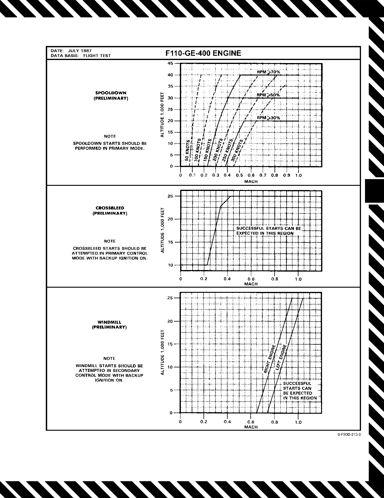
NAVAIR 01−F14AAD−1
Figure 14Ć3.ĄAirstart Envelope
14−9
ORIGINAL
NAVAIR 01−F14AAD−1
If still hung or no start:
9. OBOGS master switch ON.
*4. ENG MODE SELECT SEC.
If one engine is operable, perform a crossbleed airstart,
paragraph 14.5.2.3.
Ensure ECS service air is available to OBOGS
If both engines flamed out/inoperative or crossbleed
prior to selecting the OBOGS master switch ON.
not possible:
When primary mode is restored:
10. Maintain constant subsonic Mach in level flight.
11. Affected L or R AICS cb Cycle (LF1, left or LG1,
right).
D A dual−engine compressor stall may result in
a total electrical failure, rendering the ICS,
OBOGS, backup oxygen (below 10,000 feet
MSL), engine instruments, spin direction
indicators (spin arrow and turn needle), and
displays inoperative.
If WING SWEEP advisory light is illuminated,
D If sufficient hydraulic pressure restores the
cycling L AICS circuit breaker (LF1) may cause
1−kVA mode of the emergency generator, it
unintentional wing sweep unless WING SWEEP
may be necessary to cycle the emergency gen-
DRIVE NO. 1 (LD1) and WG SWP DR NO. 2/
erator switch through OFF/RESET to NORM
MANUV FLAP (LE1) cb’s are pulled.
to regain lost engine instruments.
14.5.2.3
Crossbleed Airstart
D Ejection above 350 knots is hazardous; the
decision to exceed 350 knots rests with the air-
1. Throttle (bad engine) OFF.
crew.
D Sufficient hydraulic pressure for smooth
2. FUEL SHUT OFF handle Check In.
flight control inputs should be available with
3. Throttle
(good engine)
80−Percent
Rpm
one engine windmilling at 18−percent rpm or
(minimum).
two engines at 11 percent.
D Dive angles should not exceed 45°. At 7,500
4. BACK UP IGNITION switch ON.
feet AGL minimum, commence a smooth 2g
pullup to a 20° dive, maximum. At 2,000 feet
5. ENG MODE SELECT PRI.
AGL minimum, pull up to level flight. If the
6. ENG CRANK switch (bad engine) ON.
airstart is unsuccessful, convert airspeed to
altitude and eject at 350 knots or less before
7. Throttle (bad engine) IDLE Immediately.
controllability is lost.
*5.
Airspeed 450 Knots (altitude permitting).
Note
Quickest light−offs are achieved with throttle to
6.
OBOGS master switch BACKUP.
IDLE at less than 10−percent rpm. Light−offs can
take as long as 45 seconds.
When start is completed:
If hung start:
7. BACK UP IGNITION switch OFF.
8. ENG MODE SELECT PRI.
8. Throttle (bad engine) OFF Then IDLE.
If still hung:
9. ENG MODE SELECT SEC.
CHANGE 2
14−10
NAVAIR 01−F14AAD−1
When start is completed:
Turbine failure for example, may appear only as an
apparent loss of thrust and/or the inability to obtain a success-
10. BACK UP IGNITION switch OFF.
ful airstart. For confirmed mechanical failures, the engine
should be secured and the FUEL SHUT OFF handle pulled.
11. ENG MODE SELECT PRI.
When primary mode is restored:
12. Maintain constant subsonic Mach in level flight.
If an engine fails or a mechanical malfunction
13. Affected L or R AICS cb Cycle (LF1, left or LG1,
has been determined, the respective FUEL
right).
SHUT OFF handle shall be pulled immediately
after engine shutdown to reduce the possibility of
fire or fuel migration.
Note
If WING SWEEP advisory light is illuminated,
ECS service air pressure may be inadequate for
cycling L AICS circuit breaker (LF1) may cause
OBOGS when operating on a single engine at
unintentional wing sweep unless WING SWEEP
idle. Increasing the throttle position for the oper-
DRIVE NO. 1 (LD1) and WG SWP DR NO. 2/
ating engine above IDLE will increase pressure.
MANUV FLAP (LE1) cb’s are pulled.
This will also close the nozzle, increasing
descent range.
14.5.3
Single−Engine Flight Characteristics
14.5.3.2
Single−Engine Cruise Operations
Single−engine flight characteristics are dependent on
gross weight, configuration, angle of attack, wing sweep, and
1. FUEL SHUT OFF handle Pull (inoperative
maneuvering requirements. In the cruise configuration, with
engine).
one engine operating at military/high power settings, rudder
deflection and/or trim is required to prevent yaw toward the
2. If on final approach or landing, refer to single engine
failed engine. However, single−engine performance capabili-
landing procedures, paragraphs 15.2 and 15.3.
ties can be significantly restricted by adverse flying qualities
in approach power configuration, particularly at high gross
When either fuselage tape reaches 4,500 pounds of fuel
weights in turning flight because of the effects of thrust asym-
or less:
metry at normal approach speed. This degrades with turns
into the failed engine such that rudder requirements to main-
3. WING/EXT TRANS switch OFF.
tain level flight can exceed available rudder control. Flight
in this configuration should be planned to avoid turns into the
Note
failed engine with bank angles limited to 20 degrees maxi-
The WING/EXT TRANS switch automatically
mum and AOA limited to 12 units. The aircraft design is such
returns to AUTO if the REFUEL PROBE switch
that no one system (flight control, pneumatic, electrical, etc.)
is placed to ALL EXTEND, DUMP is selected,
depends on a specific engine. Therefore, loss of an engine
or there is 2,000 pounds remaining in the low
does not result in loss of any complete system as long as the
side. The WING/EXT TRANS switch can be
HYD TRANSFER PUMP is operative. Refer to NAVAIR
reselected to OFF after a 5−second delay, the
01−F14AAP−1.1 for single−engine performance data.
REFUEL PROBE is retracted, or DUMP is
secured.
14.5.3.1
Single−Engine Failure During Flight
4. FEED switch Operating Engine Side.
It is uncommon to encounter compressor stalls that
require immediate engine shutdown. Occasionally, mechani-
When pilot workload permits close monitoring of fuel
cal failure of F110 engine components results in engine fail-
distribution:
ure. These failures may be obvious as when accompanied by
severe engine vibration or may be subtle as indicated by a
5. FEED switch Inoperative Engine Side.
lack of engine response to throttle changes.
14−11
CHANGE 2
NAVAIR 01−F14AAD−1
If the fuselage quantity on the inoperative engine side
14.5.5
Engine START VALVE Light
begins to increase:
1. Ensure ENG CRANK switch OFF.
6. FEED switch Immediately Move to Operating
Engine Side.
2. AIR SOURCE pushbutton OFF.
Note
If operational necessity dictates, AIR SOURCE
L ENG or R ENG may be selected provided the
START VALVE light remains out. Crossbleed
An increase in fuel quantity on the inoperative
airstarts may not be available to the affected
engine side indicates that the sump tank interconĆ
engine after a START VALVE light illuminates,
nect valve is not open. Fuel available is limited
because of possible overspeed damage.
to the quantity on the operating engine side.
If on deck:
If the fuselage fuel quantity on the inoperative engine
side begins to decrease:
3. Throttle (affected engine) OFF.
6. FEED switch Remain On Inoperative Engine.
If airborne:
7. WING/EXT TRANSFER switch AUTO.
3. ENG START cb Pull (RF1).
8. Refer to appropriate hydraulic system failure.
4. OBOGS master switch BACKUP.
14.5.4
Engine Overspeed (N1 or N2 OSP Legend)
1. Throttle (affected engine) IDLE.
If overspeed continues:
Oxygen breathing time on BACKUP is limited
2. ENG MODE SELECT SEC. Verify ENG SEC
and requires immediate mission planning. See
light illuminated.
OBOGS emergency procedure. See Figure 2Ć84
for oxygen breathing time remaining.
If overspeed condition persists:
Note
3. Throttle (affected engine) OFF.
D When ECS service air to the OBOGS concenĆ
Note
trator is shut off, the aircrew has approxiĆ
mately 30 seconds before depleting residual
D Fuel flow is automatically secured when rpm
OBOGS pressure and mask collapse.
reaches 110 percent. To regain fuel flow, the
D Restoration of service air (selecting RAM)
throttle must be cycled OFF then to IDLE.
will return OBOGS to operation.
D An overspeed condition in excess of 110 perĆ
cent will result in temporary loss of rpm indiĆ
14.5.6
Engine Transfer to SEC Mode
cation until N2 falls below 110 ±.5 percent.
EGT and FF indicators will continue to funcĆ
tion normally.
4. Refer to Single−Engine Cruise Operations, paraĆ
graph 14.5.3.2.
In SEC mode, idle lockup protection is lost
Decelerate below
1.1 TMN before retarding
5. Land as soon as practicable.
throttle to IDLE to avoid supersonic inlet buzz
and possible compressor stall.
ORIGINAL
14−12
NAVAIR 01−F14AAD−1
Note
14.5.6.1
Transfer to SEC Mode Results
D Engine ac generator failure, indicated by loss
1.
SEC mode transfer from AB may result in pop stalls.
of rpm and nozzle gauge indications, will shift
the engine into SEC mode without illuminatĆ
2.
Nozzle fully closed (higher taxi thrust).
ing the SEC light. Main high−energy ignition
will be inoperative. Backup ignition is
3.
Stall warning is inoperative (engine overtemp warnĆ
required for airstarts.
ing still available).
D SEC mode transfer while in AB may result in
4.
No nozzle position indication.
pop stalls. Nonemergency manual selection
of SEC mode airborne should be performed in
5.
No AB capability.
basic engine with the power set above 85−perĆ
cent rpm.
6.
Decrease stall margin at low rpm.
If engine transfers to SEC mode:
7.
65 to 116 percent basic engine thrust available (see
Figure 14Ć4).
1. Throttle (affected engine) Less Than MIL.
8.
Main engine ignition continuously energized.
2. ENG MODE SELECT Cycle.
9.
No idle lockup protection.
If PRI mode is restored:
10. IGV fixed full open (lower windmill airspeed).
3. Maintain constant subsonic airspeed in level flight.
11. RATS inoperative.
14.5.7
Uncommanded SEC Mode Rpm Decay
If WING SWEEP advisory light is illuminated,
cycling L AICS circuit breaker (LF1) may cause
unintentional wing sweep unless WING SWEEP
DRIVE NO. 1 (LD1) and WG SWP DR NO. 2/
Engine will flameout if transfer is delayed to
MANUV FLAP (LE1) cb’s are pulled.
below 59−percent rpm.
4. Affected L or R AICS cb Cycle (LF1, left or LG1,
1. ENG MODE SELECT
PRI (greater than
right).
59−percent rpm).
If engine remains in SEC:
If PRI mode is restored:
3. ENG MODE SELECT SEC.
2. Maintain constant subsonic airspeed in level flight.
4. Avoid abrupt throttle movements.
5. Land as soon as practicable.
If WING SWEEP advisory light is illuminated,
cycling L AICS circuit breaker (LF1) may cause
unintentional wing sweep unless WING SWEEP
DRIVE NO. 1 (LD1) and WG SWP DR NO. 2/
Landing in SEC mode may increase landing roll
MANUV FLAP (LE1) cb’s are pulled.
because of loss of nozzle reset. If runway length
or braking conditions warrant, make an arrested
3. Affected L or R AICS cb Cycle (LF1, left or LG1,
right).
landing.
14−13
ORIGINAL
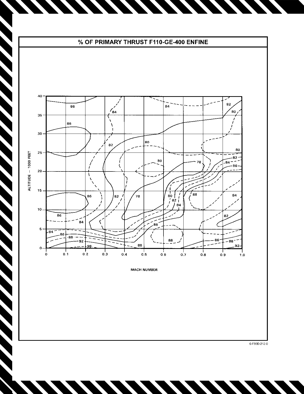
NAVAIR 01−F14AAD−1
Figure 14Ć4.ĄSecondary Mode Thrust Levels
ORIGINAL
14−14
NAVAIR 01−F14AAD−1
14.5.8
Uncommanded Engine Acceleration
Note
Airborne (No Throttle Movement)
In SEC mode, nozzle indicator is inoperative.
Uncommanded engine acceleration is characterized by
4. Obtain visual inspection.
an increase in thrust without throttle movement as a result of
an AFTC or MEC failure normally associated with one
If nozzle is open in SEC mode or abnormal response:
engine. Selection of the ENG MODE SELECT switch(es) to
5. ENG MODE SELECT PRI.
SEC may restore throttle authority.
6. Assume mechanical failure and land as soon as
1. ENG MODE SELECT SEC.
practicable.
If dual engine uncommanded acceleration is associated
If nozzle is closed or a visual inspection is not possible:
with CADC failure, normal primary mode may be regained
5. ENG MODE SELECT Remain in SEC.
by reselecting PRI mode with the gear handle down.
6. Assume electrical failure and land as soon as practiĆ
If engine is still uncommanded and engine shutdown is
cable.
necessary:
14.5.10
Stuck/Jammed Throttle(s)
2. Throttle (affected engine) OFF.
One or both throttles may become jammed in the
3. Refer to Single−Engine Cruise Operations, paraĆ
afterburner range because of misadjustments or FOD within
graph 14.5.3.2.
the throttle quadrant. Selection of SEC mode may be required
to control rapid fuel consumption and airspeed and/or
14.5.9
Exhaust Nozzle Failed (No Nozzle
altitude. If the problem cannot be corrected, engine shutdown
Response to Throttle Movement)
with the fuel shutoff handle may be necessary to abort a
takeoff, to control a stalled engine, or to effect a safe landing.
Nozzle position is hydraulically operated by engine oil
If the afterburner detent lever is misadjusted, the right throttle
from a separate compartment in the oil storage tank. A rupĆ
may not move inboard through the AB detent into the basic
ture in this system could render the nozzles inoperative and
engine range.
would generally cause the nozzles to blow open. This could
An additional failure mode has been identified that
result in engine mislight, AB blowout, and low thrust.
may cause one or both throttles to become stuck in the basic
Exhaust nozzles failed closed could result in engine stalls if
engine range. If a large idler bearing in either electromechanĆ
afterburner is selected, and excess residual thrust will be
ical rotary actuator fails, it can jam the gear train and create
present on landing rollout. An exhaust nozzle electrically
side loads on the mechanical clutch sufficient to lock it and
failed open may be closed by selecting SEC mode.
prevent further throttle movement. Failure may occur at any
power setting between idle and military and is more likely to
1. Monitor engine oil pressure/rpm.
be observed when throttles are retarded. While failure will
prevent the affected throttle from being retarded any further,
2. Throttles
Basic Engine Only (use minimum
it may be possible to move it forward.
power required).
Note
14.5.10.1
Stuck or Jammed Throttle(s)
in Afterburner
D SEC mode transfer while in AB may result in
Note
pop stalls. Nonemergency manual selection of
SEC mode should be performed in basic engine
D Spoiler brake will be inoperative with either
with the power set above 85−percent rpm.
throttle stuck above idle.
D If the fan speed limiter circuit has failed,
D Speedbrake and DLC will be inoperative with
engine rollback may occur with the selection
either throttle stuck above military.
of SEC mode. In the event of engine rollback,
1. L ENG MODE SELECT and/or R ENG MODE
PRI mode must be reselected above 59−percent
SELECT SEC.
rpm or flameout will occur and an airstart will
not be possible.
2. Apply maximum inboard force on throttles and
retard as required.
3. ENG MODE SELECT SEC.
14−15
ORIGINAL
NAVAIR 01−F14AAD−1
If throttle(s) will not retard below minimum AB:
6. Affected L or R AICS cb Pull (LF1, left or LG1,
right).
3. Match throttles.
Note
4. Relax aft pressure on throttles.
Pulling the AICS cb while airborne may illumiĆ
5. While forcing throttles apart laterally:
nate the FCS CAUTION and ARI DGR lights.
Above about 600 knots, the PITCH SAS and
a. Pull throttles straight aft to MIL detent.
ROLL DGR lights will also be illuminated.
b. Move throttles inboard and aft.
These should clear with a MASTER RESET folĆ
lowing a programmer reset.
6. Do not reselect afterburner.
7. Affected INLET RAMPS switch AUTO.
If right throttle will not retard:
8. Land as soon as practicable.
7. Right FUEL SHUT OFF handle
Pull (if
required).
If INLET light only is illuminated, attempt AICS proĆ
grammer reset:
8. Right throttle MAX AB (after shutdown).
4. Decelerate below 0.5 TMN.
Note
5. If WING SWEEP advisory light is illuminated:
Failure to move the right throttle full forward
Wing sweep drive cb’s Ċ Pull (LD1 and LE1).
may limit the left throttle to 88 percent or less
after it is retarded below the MIL stop.
9. Refer to single−engine procedures (Chapter 15).
If left throttle will not retard:
If WING SWEEP advisory light is illuminated,
10. Left FUEL SHUT OFF handle Pull (if required).
cycling L AICS circuit breaker (LF1) may cause
unintentional wing sweep unless WING SWEEP
11. Refer to single−engine procedures (Chapter 15).
DRIVE NO. 1 (LD1) and WG SWP DR NO. 2/
MANUV FLAP (LE 1) cb’s are pulled.
14.5.11
AICS Malfunctions
6. Affected L or R AICS cb Cycle (LF1, left or LG1,
14.5.11.1
RAMPS Light/INLET Light
right).
*1. Avoid abrupt throttle movements.
Note
*2. Decelerate to below 1.2 TMN.
Pulling the AICS cb while airborne may illumiĆ
nate the FCS CAUTION and ARI DGR lights.
*3. Affected INLET RAMPS switch STOW.
Above about 600 knots, the PITCH SAS and
Note
ROLL DGR lights will also be illuminated.
These should clear with a MASTER RESET folĆ
A RAMPS light should always be accompanied
lowing a programmer reset.
by INLET light when the landing gear handle is
UP.
If INLET light goes off:
If RAMPS light remains illuminated:
7. Affected INLET RAMPS switch AUTO.
4. Throttle (bad engine) 80 Percent or Less.
If INLET light remains illuminated:
5. If WING SWEEP advisory light is illuminated Ċ
Wing sweep drive cb’s Ċ Pull (LD1 and LE1).
If WING SWEEP advisory light is illuminated,
pulling L AICS circuit breaker (LF1) may cause
unintentional wing sweep unless WING SWEEP
If WING SWEEP advisory light is illuminated,
DRIVE NO. 1 (LD1) and WG SWP DR NO. 2/
pulling L AICS circuit breaker (LF1) may cause
MANUV FLAP (LE1) cb’s are pulled.
unintentional wing sweep unless WING SWEEP
DRIVE NO. 1 (LD1) and WG SWP DR NO. 2/
7. Affected L or R AICS cb Pull (LF1, left or LG1,
MANUV FLAP (LE1) cb’s are pullled.
right).
ORIGINAL
14−16
NAVAIR 01−F14AAD−1
Note
14.5.13.1
OIL PRESS Light and/or
Abnormal Oil Pressure
Pulling the AICS cb while airborne may illumi-
nate the FCS CAUTION and ARI DGR lights.
1. Throttle (affected engine) Ċ IDLE.
Above about 600 knots, the PITCH SAS and
ROLL DGR lights will also be illuminated.
If oil pressure is below 15 psi, above 65 psi, or engine
These should clear with a MASTER RESET fol-
vibration:
lowing a programmer reset.
If shutdown is feasible:
8. Affected INLET RAMPS switch Ċ AUTO.
2. Throttle (affected engine) Ċ OFF.
9. Remain below 1.2 TMN.
3. Refer to Single Engine Cruise Operations, para-
graph 14.5.3.2.
When AICS programmer reset attempts are completed:
If shutdown is not feasible:
12. Wing sweep drive cb’s Ċ Reset (LD1 and LE1).
4. Rpm Ċ Set Minimum Rpm.
14.5.12
INLET ICE Light
5. Avoid high−g or large throttle movements.
1. ANTI−ICE switch Ċ ORIDE/ON.
6. Land as soon as practicable.
When clear of known icing conditions:
14.5.13.2
L or R OIL HOT Light
2. ANTI−ICE switch Ċ AUTO/OFF.
Illumination of an OIL HOT caution light may be
Ice may form on inlet and ramp surfaces without
an indication of above normal gearbox scavenge
any other visual indications, which may cause
oil temperature or high supply temperature. Con-
compressor stalls and/or FOD.
tinuous engine operation will result in reduced
gearbox life and lubrication degradation.
Note
On deck, OIL HOT light may be caused by
The formation of ice on pitot−static sensors may
underservicing or by excessive temperature on
result in DFCS detected failures that may not
deck. In the event of OIL HOT light on deck posi-
clear with a MASTER RESET.
tion throttles to OFF.
1. Oil pressure Ċ Check.
14.5.13
Oil System Malfunction
2. Throttle (affected engine) Ċ 85−Percent Rpm.
Malfunctions in the oil system are indicated by an L or
R OIL HOT light, OIL PRESS light, or by oil pressure below
If after 1 minute light is still illuminated:
or above normal.
3. Throttle (affected engine) Ċ OFF.
If oil pressure is over 65 psi, retard power until pressure
4. Refer to Single−Engine Cruise Operations, para-
is within the normal range. If pressure cannot be reduced, the
graph 14.5.3.2.
engine should be shut down to avoid rupturing oil lines. If oil
5. Relight engine for landing, if necessary.
pressure is less than 15 psi, bearing wear can be minimized
by maintaining a constant throttle setting and avoiding
6. Land as soon as possible.
unnecessary aircraft maneuvers. Bearing failure is normally
If light goes out, land as soon as practicable.
characterized by vibration, increasing in intensity with
bearing deterioration. When vibration becomes moderate to
14.5.14 RATS Operation In Flight
heavy, engine seizure is imminent if engine is not shut down.
Continued operation of an engine with oil pressure less than
1. Tailhook Ċ DOWN.
15 psi is likely to result in illumination of OIL HOT light or
If conditions permit:
an engine seizure. If conditions permit it is advisable to shut
down the engine to reduce damage and to save it for
2. ANTI ICE CONTR HOOK CONT/WSHLD/AIR
emergency use.
cb Ċ Pull (8C2).
14−17
CHANGE 2
NAVAIR 01−F14AAD−1
6. Land as soon as possible.
D Pulling the ANTI ICE CONTR HOOK
CONT/ WSHLD/AIR cb
(8C2) disables
D Illumination of both lights and the warning
RATS. Inform CV of increased wind−over−
tone may be indicative of a total motive−flow
deck requirements and gross weight settings
failure. Zero− or negative−g flight should be
for a non−RATS arrestment.
avoided.
D With the circuit breaker in and RATS operat-
D Complete loss of motive flow will result in the
ing, there is reduced thrust available for
sump tank interconnect and the engine feed
approach and use of afterburner may be
crossfeed valve remaining in the closed posi-
required to arrest sink rate.
tion, isolating the forward and aft systems. Con-
sequently, single−engine operation will cause
fuel on the opposite side to be unavailable.
If one light and the warning tone remains on:
3. No afterburner above 15,000 feet.
ANTI ICE CONTR HOOK CONT/WSHLD/
4. Fuel distribution Monitor (balance if required).
AIR circuit breaker (8C2) must be in prior to
5. Land as soon as practicable.
hook transition. Avoid icing conditions and rain
with circuit breaker pulled.
If migration occurs after balancing, as indicated by a
100 to 300 PPM increase on the inoperative side or a 100 to
Note
300 PPM decrease on the operative side above expected burn
D If RATS secures when the hook is raised with
rate according to indicated fuel flow:
no other weight−on−wheels indication, failure
is internal to the RATS circuitry.
6. FUEL PRESS ADVSY CB − PULL (8F1).
D With ANTI ICE CONTR HOOK CONT/
Note
WSHLD/AIR cb (8C2) pulled, approach
Pulling the FUEL PRESS ADVSY CB will cause
indexers will flash.
the engine crossfeed valve to close and the in-
operative side fuselage motive flow shutoff valve
14.6
FUEL SYSTEM MALFUNCTIONS
to open. This will reduce the amount of fuel
transfer from the operative side to the inoperative
14.6.1
Fuel Pressure Caution Lights/Low Fuel
side.
Pressure Warning Tone
Note
The L or R FUEL PRESS light and warning tone
Afterburner operations place an extreme demand on the
will extinguish when the FUEL PRESS ADVSY
engine fuel feed system. Aircraft maneuvers in the zero to
CB is pulled.
negative 0.5g flight regime aggravate the effect and may gen-
erate a situation where afterburner blowout and engine flame-
7. Maintain cruise power or less.
out occur. The first indication of this condition may be a fuel
8. Fuel distribution − monitor (balance if required).
pressure light or an aural tone (engine stall warning tone).
14.6.1.1
L and/or R FUEL PRESS Light(s) and
Warning Tone
1. Both throttles Ċ MIL Power or Less.
If the sump tank interconnect valve has failed,
selecting AFT or FWD on the FEED SWITCH
2. Restore aircraft to 1.0g flight.
could result in fuel migration to the inoperative
side. If fuel migration occurs after selecting AFT
If both lights and warning tone remain on:
or FWD on the FEED SWITCH (as indicated by
3. Increase positive g’s to greater than 1.0g.
a 100 to 300 PPM increase on the inoperative
side), immediately return the feed switch to
4. Descend below 25,000 feet.
NORM.
5. Maintain cruise power settings or less.
9. Land as soon as possible.
CHANGE 2
14−18
NAVAIR 01−F14AAD−1
14.6.2
L or R FUEL LOW Light
1. DUMP switch OFF.
2. Fuel distribution Check (balance if required).
CV arrestment, CV touch and go, or normal field
If wing and/or external fuel remaining:
landings with full or partial fuel in the external
tanks is not authorized because of overload of the
3. WING/EXT TRANS switch ORIDE.
nacelle backup structure. Only minimum descent
rate landings are authorized.
4. Land as soon as practicable.
14.6.3.3
Wings Do Not Accept Fuel With Switch
14.6.3
Fuel Transfer Failures
in ALL EXTD Position
1. REFUEL PROBE switch FUS EXTD.
2. WING/EXT TRANS switch OFF.
14.6.3.4
Wings Accept Fuel With Switch in
Wing and external fuel will not transfer with
FUS EXTD Position
refuel probe switch in ALL EXTD. If probe exten-
1. WING/EXT TRANS switch ORIDE.
sion required, select FUS EXTD to enable transfer.
Note
Note
With AIR SOURCE OFF pushbutton selected,
external fuel tanks will not transfer.
Fuel management panel will be inoperative if
FUEL MGT PNL cb (RD1) is out.
14.6.4
Uncommanded Dump
1. Fuel Management Panel cbĊCheck in (RD1).
1. DUMP switch Check OFF.
2. FUEL FEED/DUMP cb Pull (RE1).
14.6.3.1
Wing Fuel Fails To Transfer
If wing fuel fails to transfer:
1. WING/EXT TRANS switch ORIDE.
Pulling the FUEL FEED/DUMP circuit breaker
One wing still does not transfer:
(RE1) isolates the right and left fuel systems. It
also deactivates the function of the feed switch,
2. FEED switch Select High Fuselage Tape Side.
the automatic balance functions, and the fuel
dump system. Should single engine operation
If wing fuel does not decrease after 2 minutes or wing
subsequently become necessary, useable fuel
fuel transfer complete:
will be limited to only what is available on the
3. FEED switch NORM.
operating side.
14.6.5
Fuel Leak
14.6.3.2
External Tanks Fail To Transfer or
Transfer Slowly
In the absence of actual visual detection, a fuel leak
Note
resulting from a malfunction or failure of a fuel system
component will usually result in a split in the fuel quantity
Descending below freezing level may thaw
possible frozen valves.
tapes or feeds. The flightcrew must determine from available
instruments (fuel flow and total fuel quantity) whether the
1. WING/EXT TRANS switch ORIDE.
aircraft is losing more fuel than the engines indicate they are
using. Corrective steps are based on confirmation of the leak.
If fuel continues to transfer improperly or does not
transfer:
Upon confirmation of abnormal decrease in fuel quantity:
1. Land as soon as possible.
2. REFUEL PROBE switch All Extend, Then
Retract.
3. Apply cyclic positive or negative g’s.
4. AIR SOURCE pushbutton OFF then RAM then
Use of afterburner with fuel leak should be lim-
ON (below 35,000 feet, less than 300 knots).
ited to emergency use only.
14−19
CHANGE 2
NAVAIR 01−F14AAD−1
2. WING/EXT TRANS switch OFF.
Note
If abnormal fuel quantity decrease ceases, fuel leak is
With a high quantity in the FWD/RT Fuel sys-
tem, the greater static head pressure, particularly
in wing/wing pivot or attachment points for auxiliary tanks:
in nose−up attitudes, can cause overfilling of the
Note
AFT/LT fuel system. To prevent this, the feed
This cannot be determined until the fuel level has
switch should be returned to NORM before the
decreased to below the source of the leak. Do not
AFT/LT tape reaches 6,200 pounds.
proceed until the wings are empty.
1. Both throttles − MIL power or less.
If leak is not stopped, it is in engine/nacelle area, pro-
ceed immediately with next step.
2. FEED SWITCH − select high fuselage tape side.
3. FUEL FEED/DUMP cb Pull (RE1).
Aircraft attitude will have a significant influence
Pulling the FUEL FEED/DUMP circuit breaker
on the direction of fuel movement if FWD or
(RE1) isolates the right and left fuel systems. It
AFT is selected. A nosedown attitude will cause
also deactivates the function of the feed switch,
fuel to transfer forward, and a noseup attitude
the automatic balance functions, and the fuel
will cause fuel to transfer aft.
dump system. Should single engine operation
subsequently become necessary, useable fuel
If fuel imbalance increases:
will be limited to only what is available on the
operating side.
3. FEED SWITCH − NORM
Note
Enough time should be allowed for quantity
tapes/ feeds to develop split so that leak can be
isolated to left or right feed group. Affected side
If the sump tank interconnect valve has failed
will be low side.
closed, selecting AFT or FWD on the FUEL
4. Throttle (affected side) OFF.
FEED SWITCH could result in rapid increase of
5. Conditions permitting, allow rpm to decelerate to
the fuel imbalance. If this occurs (as indicated by
windmill rpm.
an imbalance increase of 100 to 300 PPM) imme-
6. FUEL SHUT OFF handle (affected side) Pull.
diately return the FEED SWITCH to NORM.
7. Refer to Single−Engine Cruise Operations, para-
4. Determine useable fuel and land as soon as possible.
graph 14.5.3.2.
14.7
ELECTRICAL FAILURE
Setting the WING/EXT TRANS switch to OFF stops
motive flow to the wings and inhibits external tank transfer
14.7.1
Generator Failure
and fuselage tank pressurization. Pulling the FUEL FEED/
DUMP circuit breaker (RE1) isolates the right and forward
A mechanical generator failure or an overheating
system and the left and aft fuel system. This aids in determin-
automatically causes the CSD unit of the generator transmis-
ing the location of the leak and prevents loss of fuel from the
sion to decouple from the engine. Once disengaged, the CSD
good side via the fuel system interconnects. The circuit
cannot be reconnected in flight.
breaker also deactivates the function of the FEED switch, the
automatic balance functions, and the fuel dump system.
Either generator by itself is capable of supplying the
Securing the engine and, if necessary, pulling the FUEL
electrical requirements of the aircraft. Even double generator
SHUT OFF handle should stop most engine leaks.
failure will not cause total loss of electrical power; the 5−kVA
emergency generator will automatically pick up the load for
14.6.6 Fuel Imbalance/Fuel Quantity Balancing
the essential ac and dc buses No. 1 and No. 2, and the DFCS
bus.
If the bidirectional pump is operating and pressure
drops to between 2,000 and 1,100 psi (dependent upon the
load placed on the generator), the emergency generator will
During AB operations, NORM shall be selected.
automatically shift to the 1−kVA mode and power only the
FWD or AFT could deplete the sump tanks.
CHANGE 2
14−20
NAVAIR 01−F14AAD−1
essential ac and dc No. 1 buses. If combined system hydraulic
14.7.2
Double Generator Failure
pressure subsequently recovers, the emergency generator
switch must be cycled through OFF/RESET to NORM to
1. Both generator switches Cycle.
regain the essential No. 2 ac and dc buses. Figure 14−5 lists
the equipment available with only the emergency generator
If operating on emergency generator, the following
operating.
important systems are inoperative:
1. Emergency flight hydraulics.
With both engines inoperative, windmilling engine(s)
provide(s) hydraulic pressure for both the flight controls and
2. Outboard spoiler module and emergency flap
the emergency generator. However, the flight controls have
activation.
first priority and may cause the emergency generator to loiter
when low airspeeds reduce engine windmilling rpm. Approx-
3. OBOGS concentrator heater (OBOGS may still
imately 450 knots must be maintained to ensure adequate
function at a reduced but adequate level).
engine windmilling rpm for hydraulic pressure.
If temporary loss of combined system pressure causes
14.7.1.1
L or R GEN Light
emergency generator to shift to 1 kVA mode (to drop No. 2
essential bus):
1. Generator
(affected generator switch)
OFF/
RESET, Then NORM.
2. EMERG generator switch Cycle.
Note
If the generator fault is corrected, the generator will
be reconnected and the caution light will go off.
If generator does not reset:
A shift to 1 kVA mode will cause loss of all DFCS
functions and spoilers without illumination of
2. Generator (affected generator switch) TEST.
caution lights. If the 5 kVA mode is regained, a
MASTER RESET will be required to regain
If the light goes off with the switch in TEST, the
SAS, spoiler, authority stop, and ARI functions.
fault is in the respective electrical distribution sys-
tem. If light remains illuminated, the generator has
Note
been disconnected automatically and the fault is in
DFCS synchronization can take up to 2 seconds
IDG or generator control unit.
following a power interrupt. If the MASTER
RESET pushbutton is depressed during the syn-
14.7.1.2
L or R GEN and TRANS/RECT Lights
chronization time, an additional depression of
the MASTER RESET pushbutton will be
1. Generator
(affected generator switch)
OFF/
RESET, Then NORM.
required to restore spoiler functionality.
4. Land as soon as practicable.
2. If L GEN and TRANS/RECT lights remain illumi-
nated, select EMERG GEN on MASTER TEST panel.
Note
With R GEN and TRANS/RECT lights illumi-
nated, ac essential power is supplied by the L
GEN. Selecting EMER GEN on the MASTER
TEST panel (with R GEN and TRANS/RECT
lights) will not provide any additional power but
may cause an interrupt as the supply is trans-
ferred from the L GEN to the EMER GEN.
3. Land as soon as practicable.
14-20a (Reverse Blank)
CHANGE 2
NAVAIR 01−F14AAD−1
ESSENTIAL BUSES NO. 1 (1 KVA MODE)
AICS RAMP STOW
FIRE EXTINGUISHING
PILOT LCD LIGHTS
ANGLE OF ATTACK IND
FLOOD LIGHTS
PITCH/ROLL TRIM
ALTITUDE LOW WARNING
FUEL QUANTITY INDICATOR
PROBE LIGHT
BACKUP CONTR/B/U OXY LOW
HYDRAULIC PRESSURE
RADAR ALTIMETER
INDICATION
BACKUP IGNITION
RUDDER TRIM
ICS
BACKUP OXY PRESSURE IND
STANDBY ATTITUDE
IFF/SIF
BAROMETRIC ALTIMETER
STORE MANAGEMENT
INSTRUMENT BUS FEEDER
PROCESSOR
CONSOLE LIGHTS (PILOT)
INSTRUMENT LIGHTS
TAIL/RUDDER/FLAP INDICATOR
DC ESSENTIAL NO. 1 FEEDER
JETTISON (EMERGENCY)
TURN AND SLIP INDICATOR
DC TEST
MAIN LANDING GEAR SAFETY
VHF/UHF RADIO 1 & 2
ENGINE INSTRUMENT GROUP
RELAYS
VOICE SECURITY EQUIPMENT
ENGINE INSTRUMENT GROUP
OBOGS CONTR
WHITE LIGHTS
WHEELS POSITION
OBOGS CONCENTRATOR
INDICATIONS
ENGINE START
PANEL FLOODLIGHTS
WING POSITION INDICATIONS
FIRE DETECTION
ESSENTIAL BUSES NO. 2
AICS
CABIN PRESSURE
ENGINE STALL TONE
AICS LOCKUP POWER
CADC
EXHAUST NOZZLE
AIR SOURCE CONTROL
CANOPY LIGHT
EXTERIOR LIGHTS CONTROL
ALPHA COMPUTER
CIU
FLAP/SLAT CONTROL SHUTOFF
ALPHA HEATER
CURSOR CONTROL
FLIGHT CONTROL AUTHORITY
ANNUNCIATOR PANEL POWER
DC ESSENTIAL NO. 2 FEEDER
FUEL DUMP
ANTI−ICE CONTROL
DEKI LIGHTS
FUEL FEED
ANTI−ICE PROBE
DFCS
FUEL MANAGEMENT PANEL
ANTI−SKID POWER
DFCS BUS FEEDER
FUEL PRESSURE LIGHT
ARMAMENT GAS
DISPLAY PROCESSOR
FUEL TRANSFER OVERRIDE
ARRESTING HOOK CONTROL
ECS TEMPERATURE CONTROL
FUEL VENT VALVE
AUTOMATIC DIRECTION
EJECTION COMMAND
FUEL LOW LIGHT
FINDER
INDICATOR
GENERATOR LIGHTS
AUXILIARY FLAP/FLAP
EMERGENCY GENERATOR TEST
GPS
CONTROL
ENGINE AFTC
GROUND ROLL BRAKING
BDHI
ENGINE ANTI−ICE
INDICATOR
BINGO POWER
ENGINE ANTI−ICE VALVES
HUD
BLEED AIR LIGHT
ENGINE OIL COOLING
BLEED DUCT
ENGINE SECONDARY MODE
Figure 14Ć5.ĄEmer gency Generator Distribution (Sheet 1 of 2)
14−21
ORIGINAL
NAVAIR 01−F14AAD−1
ESSENTIAL BUSES NO. 2 (continued)
HYDRAULIC PUMP SPOILER
MISSION COMPUTER NO. 2
ROLL COMPUTER
CONTROL
MOTIVE FLOW ISOLATION
RUDDER TRIM
HYDRAULIC VALVE CONTROL
NOSE GEAR STRUT LAUNCH
SENSOR CONTROL
INBOARD SPOILER CONTROL
BAR LIGHT
SPEED BRAKES ENABLE
INSTRUMENT LANDING
NOSE WHEEL STEERING
SPOILER INDICATOR
SYSTEMS (ARA−63)
OIL HOT LIGHTS
STARTER VALVE LIGHT
INS
PEDAL SHAKER
TAXI/FORMATION LIGHTS
INS SYNCH
PILOT ANNUNCIATOR PANEL
TRANSFORMER/RECTIFIER
JTIDS
(AUX POWER)
LIGHTS
LADDER LIGHT
PITCH COMPUTER
UTILITY LIGHTS
MACH TRIM
PITCH−ROLL TRIM ENABLE
WINDSHIELD AIR
MAIN LANDING GEAR RELAYS
PITOT HEAT
WINDSHIELD DEFOG
MFD NO. 1
RADAR BEACON
CONTROL
(AN/APN−154)
MISSILE POWER HUD TEST
YAW COMPUTER
Figure 14−5. Emergency Generator Distribution (Sheet 2 of 2)
14.7.3
Double Transformer−Rectifier Failure
transfer pump is operating and pressure drops to between
2,000 and 1,100 psi (dependent upon the load placed on the
The 5−kVA emergency generator will automatically
generator), the emergency generator will automatically shift
activate and power the essential ac and dc No. 1 and No. 2 and
to the 1−kVA mode and power only the essential ac and dc
DFCS buses. See Figure 14Ć6 for listing of inoperable
No. 1 buses. If combined hydraulic pressure subsequently
dc−powered equipment.
recovers, the EMERG generator switch must be cycled
through OFF/RESET to NORM to regain the essential ac and
14.7.4
TRANS/RECT Light
dc No. 2 and DFCS buses.
The TRANS/RECT light will illuminate if either or
both T/R malfunction. If one T/R fails, the operating T/R will
14.7.5
Electrical Fire
assume the dc load. If both T/Rs fail, the emergency
Electrical fires may be indicated by visual or audible
generator will go on the line and tie to essential dc buses
arcing or an ozone odor in the cockpit and popping circuit
No. 1 and No. 2. Land as soon as practicable.
breakers. Electrical fires produced by 400°F air leaks can
Popped circuit breakers should not be reset more than
result in any one or combination of the following:
once or be held depressed unless the associated equipment is
1. Pinballing caution/advisory lights and instrument
absolutely an operational necessity. A popped circuit breaker
indications.
indicates an equipment malfunction or an overload condiĆ
tion. Repeated resets or forced depressions of popped circuit
2. CADC associated caution/advisory lights.
breakers can result in equipment damage and/or serious
3. Uncommanded movement of electrically controlled
electrical fire.
components (SAS, spoilers, wing sweep, throttles).
The loss of one generator and/or failure to tie the ac main
4. Complete electrical failure.
buses will illuminate the affected GEN light. The TRANS/
RECT light will also illuminate because the affected generaĆ
5. Smoke, fumes, and/or heat in the cockpit.
tor’s associated T/R is not receiving ac power to convert. Upon
The most effective method to extinguish an electrical
observing a TRANS/RECT light, the pilot can check that the
fire is to secure all electrical power. However, some
aircraft is actually experiencing a T/R failure and not a bus
conditions may not permit securing the emergency generator
tie failure. If the seat adjust, white floods, or instrument lights
after both main generators are secured. Night/IFR flight or
are still operative with the R GEN light illuminated, the bus
ECS−duck−leak−induced electrical fires are cases where
is tied. If the throttles are operating on the boosted mode with
securing all electrical power is not feasible.
a L GEN light illuminated, the bus is tied.If the hydraulic
ORIGINAL
14−22
NAVAIR 01−F14AAD−1
ACM LIGHT
EMERGENCY GENERATOR
MONITOR BUS CONTROL
AIRBORNE SELF−PROTECTION
CONTROL
MULTI−FILTER ASSEMBLY
JAMMER
FLIGHT HYDRAULIC BACKUP
MULTI−FUNCTIONAL DISPLAYS 2
AIR SOURCE CONTROL
GROUND POWER COOLING
AND 3
ALE−39 CHAFF/FLARE
INTERLOCK
NFO CONSOLE LIGHT
ALR−67
GROUND TEST
OUTBOARD SPOILER
AMC BIT
GUN POWER
CONTROL AND PUMP
AN/AWW−4
HUD CAMERA
POSITION LIGHTS
ANNUNCIATOR PANEL DIM
HV POWER SUPPLY
RADAR COMPONENTS
CONTROL
IFF AIR−TO−AIR
RECONNAISSANCE EQUIPMENT
ANTENNA HYDRAULIC SERVO
INS BATTERY POWER
RIGHT DC TEST
ANTENNA LOCK
INTERFERENCE BLANKER
RIGHT MAIN TRANSFORMER
ANTI−COLLISION LIGHT
INTEGRATED TRIM
RECTIFIER
ASW 27
INTERRUPTION FREE
SAHRS
AUTO THROTTLE
DC BUS
SEAT ADJUST
BEAM PS
IRST
SOLENOID POWER SUPPLY
BOL CHAFF DISPENSERS
JTIDS DATA PROCESSOR AND
STATION 1, 1A, AND 8 AIM−9
BRAKE ACCUMULATOR
BATTERY HEATER
COOLING POWER
SHUTOFF VALVE
LEFT/RIGHT AICS HEATER
STATION 1, 3, 4, 5, 6, AND 8
COUNTING ACCELERATOR
LEFT MAIN
DECODER RELAY POWER
DATA LINK
TRANSFORMER/RECTIFIER
STEADY POSITION LIGHTS
DATA PROCESSORS
LIQUID COOLING
STORES MANAGEMENT
DATA STORAGE SET
MASTER ARM
PROCESSOR
DEHYDRATOR
MASTER TEST
STORM FLOOD LIGHTS
DEU
MDL
SUPPLEMENTAL POSITION
DIGITAL DISPLAY ENABLE
MISSILE POWER RELAY UNIT
LIGHTS
ELECTRONIC COOLING
MISSION COMPUTER NO. 1
TELEVISION CAMERA SET
Figure 14Ć6.ĄFailure of Both Transformer−Rectifiers Equipment Inoperative List
*1. L and R generators OFF.
If conditions permit:
Note
OBOGS concentrator heater power will be lost.
OBOGS may still function at a reduced but adeĆ
quate level.
OBOGS will shut down if all electrical power is
lost. BOS will be activated above 10,000 feet MSL
If uncommanded SAS or spoiler inputs are present:
but will not be available below 10,000 feet MSL.
*2. PITCH, ROLL and YAW STAB AUG switches Ċ
OFF.
If associated with any other direct or indirect indication
of ECS malfunction, perform ECS Leak/Elimination of
Oxygen breathing time on BACKUP is limited
Smoke and Fumes procedure, paragraph 14.8.1.
and requires immediate mission planning. See
OBOGS emergency procedure. See Figure 2Ć84
for oxygen breathing time remaining.
3. EMERG generator switch OFF.
Note
An electrical fire may affect the CADC and
Securing all electrical power while airborne
AICS systems causing random movements of the
causes the ECS to go full cold.
wings and ramps.
14−23
ORIGINAL
NAVAIR 01−F14AAD−1
If cause of fire can be isolated:
2. Attempt to contact radar facilities or other aircraft
by handheld survival radio.
4. Pull cb’s of affected equipment.
3. Make arrested landing as soon as possible.
5. All generators NORM.
The following systems are still available:
If cause of fire cannot be isolated:
a. Airspeed indicator.
6. Secure all unnecessary equipment.
b. Altimeter (STBY mode).
7. EMERG generator switch NORM.
c. Cabin pressure altimeter.
8. Land as soon as possible.
d. Vertical velocity indicator.
e. Arresting hook (emergency extension only).
f. Standby attitude gyro (3 minutes).
g. Emergency wing sweep.
Do not operate engines on the ground without
electrical power. Ground cooling fans are shut
h. Landing gear.
off, causing hot bleed air to cook off oil and
i. Main flaps/slats.
hydrocarbons in the ECS ducting, resulting in
smoke in the cockpit and possible damage to the
j. Standby compass.
ECS turbine compressor.
k. Backup oxygen system
(above
10,000 feet
14.7.6
Total Electrical Failure
MSL).
1. Descend or climb to known VFR conditions.
Ground engine operation without electrical
power supplied by either the generators or exterĆ
nal power may cause 20−mm ammunition detoĆ
All DFCS functions and spoilers will be lost.
nation because of excessive heat in the gun
This will have an adverse effect on flying qualiĆ
ammunition drum.
ties. Terminate aggressive maneuvering immeĆ
diately and remain subsonic. Expect minimal
damping of oscillations in pitch and yaw and
severely degraded roll control with flaps
extended. Perform controllability check.
D OBOGS will shut down if all electrical power
Note
is lost. BOS will be activated above 10,000
feet MSL but will not be available below
10,000 feet MSL.
D The standby attitude gyro is capable of providĆ
ing reliable attitude information (within 9°) for
D Oxygen breathing time on BACKUP is limĆ
up to 3 minutes after a complete loss of power.
ited and requires immediate mission planĆ
ning. See OBOGS emergency procedure. See
D Cabin pressure will be lost and ECS will go
Figure 2Ć84 for oxygen breathing time
full cold.
remaining.
D Do not operate engines on the ground without
electrical power. Ground cooling fans are shut
off, causing hot bleed air to cook off oil and
hydrocarbons in the ECS ducting, resulting in
smoke and possible damage to the ECS turĆ
bine compressor.
ORIGINAL
14−24
NAVAIR 01−F14AAD−1
Note
If warning or caution systems do not function, the first
indication of an ECS leak can vary. The presence and order
of appearance of indications depend on the size and location
D Total electrical failure will cause the sump
of the leak.
tank interconnect, engine crossfeed, and
motive flow isolation valves to close, fully
isolating both tank systems. Wing and exterĆ
Direct and indirect indications are listed below in a
representative order of appearance; however, they can appear
nal fuel will transfer into the fuselage.
in any sequence. The presence of any one direct indication or
D If possible, a section IFR descent should be
any two indirect indications shall be treated as an ECS leak.
conducted to VFR conditions for landing.
Direct indications:
All other normal system and cockpit cues are not
available.
1. BLEED DUCT caution light.
When all electrical power is shut off, the cockpit dump
2. FIRE warning light.
valve closes and the environmental control system supplies
only cold air to the cockpit and forced air cooled avionics.
3. Smoke or fumes in the cockpit.
Pressurization will slowly bleed off. If operational necessity
4. Heat emanating from behind aft right corner of RIO
prohibits immediate descent, maintain cockpit altitude at the
cockpit.
highest practicable level to conserve BOS. Otherwise,
descend to a cabin altitude less than 10,000 feet. If the system
5. Complete loss of ECS airflow.
failure occurs in the day or night VFR environment, immediĆ
ate return to base and an emergency landing shall be accomĆ
Indirect indications:
plished. In the day or night IFR environment, ascend or
descend to known VFR conditions. (Extreme care should be
6. Audible pop or squeal from ECS.
exercised because of partial panel environment.) Reduce
power setting to maximum endurance. Contact nearest
7. Rapid drop in cockpit airflow.
ground facility by handheld survival radio. Once positive
radar identification is made, follow controllers’ directions to
8. Electrical fire indications.
landing.
9. Any ECS advisory light
(SENSOR COND or
14.8
ECS MALFUNCTIONS/FAILURES
COOLING AIR).
14.8.1
ECS Leak/Elimination of Smoke
When an ECS duct leak is indicated or ECS turbine
and Fumes
whine is heard, AIR SOURCE should be immediately
selected OFF. ECS leaks may melt wiring splice junctions
Bleed air leaks, hot air leaks, and ECS turbine failures
and create conditions that may induce an electrical fire. If an
have similar indications and results and shall be treated as
associated electrical fire occurs, smoke, fumes, heat, and
one failure, ECS leaks. All can cause unsurvivable damage
damage to the surrounding aircraft structure may intensify.
when not recognized and corrected expeditiously. Bleed air
Since electrical fire procedures are not compatible with meaĆ
leaks in the engine compartment illuminate the appropriate
sures to eliminate smoke and fumes, canopy jettison may
FIRE warning light, and FIRE light procedures apply. Bleed
become necessary as a last ditch procedure.
air leaks outside the engine compartment and other hot air
leaks illuminate the BLEED DUCT caution light. IlluminaĆ
tion of the appropriate caution/warning light should be the
first indication of an ECS leak. ECS turbine failures can
cause hot air leaks. After a compressor−side failure, cataĆ
strophic thermal damage can be caused by heat generated
Failure to immediately select AIR SOURCE
during turbine winddown. Wire bundles, flight control rods,
OFF upon indication of an ECS leak may result
and SMDC lines are in the vicinity of the ECS turbine and hot
in severe aircraft damage and loss of aircraft.
air manifold. Both turbine and compressor−side failures may
cause a whining noise emanating from below and behind the
right side of the RIO cockpit, and other indications of an ECS
air leak follow.
14−25
ORIGINAL
NAVAIR 01−F14AAD−1
Note
Ram air door may take up to 50 seconds to fully
open.
Selection of AIR SOURCE to RAM allows bleed
5. Airspeed Below 300 knots/0.8 Mach.
air to circulate throughout the 400° F manifold
system.
6. Nonessential electrical equipment Secure.
7. CANOPY DEFOG/CABIN AIR lever CANOPY
DEFOG.
8. Land as soon as possible.
Oxygen breathing time on BACKUP is limited
and requires immediate mission planning. See
If electrical fire:
OBOGS emergency procedure. See Figure 2Ć84
for oxygen breathing time remaining.
9. Follow Electrical Fire procedures, paragraph 14.7.5.
Note
D When ECS service air to the OBOGS concenĆ
trator is shut off, the aircrew has approxiĆ
mately 30 seconds before depleting residual
The EMERG generator switch should be left in
OBOGS pressure and mask collapse.
NORM unless there are overriding considerations
D Restoration of service air (selecting RAM)
that mandate turning the emergency generator off.
will return OBOGS to operation.
Note
*1. AIR SOURCE pushbutton OFF.
D Selecting AIR SOURCE OFF eliminates
*2. OBOGS master switch BACKUP.
pressurization to the service system (canopy,
g−suit, external fuel tanks, pressure/ventilaĆ
tion suit, and airbag seals). Rain removal,
defog, OBOGS, and heating systems are also
eliminated. Judicious reselection of AIR
SOURCE to BOTH or RAM to regain critical
support/ service systems is predicated on
Oxygen breathing time on BACKUP is limited
severity of ECS malfunction and operational
and requires immediate mission planning. See
requirements.
OBOGS emergency procedure. See Figure 2Ć84
for oxygen breathing time remaining.
D If ECS airflow continues, ensure AIR
SOURCE CONTROL cb (RD2) is in. If cb
Note
RD2 has popped, ECS control is lost.
D When ECS service air to the OBOGS concenĆ
D Securing all electrical powerwhile airborne
trator is shut off, the aircrew has approxiĆ
closes cockpit dump valve and cabin hot air
mately 30 seconds before depleting residual
valve, opens bleed air shutoff valves and dual
OBOGS pressure and mask collapse.
pressure regulator, and the ram air door
remains at its last commanded position (ram
D Restoration of service air (selecting RAM)
air door takes up to 50 seconds to open). This
will return OBOGS to operation.
results in full cold air to the cockpit, unconĆ
trolled bleed air to circulate, and the loss of
*3. If smoke or fumes are present:
normal cabin dump capability. Minimize lowĆ
a. Altitude Below 35,000 Feet.
speed
(less than
0.25 Mach) and ground
operations as the heat exchanger cooling fan
b. CABIN PRESS switch DUMP.
will be inoperative and ECS overheat condiĆ
tion will result.
*4. RAM AIR switch OPEN.
ORIGINAL
14−26
NAVAIR 01−F14AAD−1
Note
Elimination of smoke or fumes without electrical
power may be accomplished by ECS airflow. To
obtain maximum smoke/fume removal capabilĆ
Oxygen breathing time on BACKUP is limited
ity under this condition, fly below 8,000 feet
and requires immediate mission planning. See
MSL and set the throttle to maximum practical
OBOGS emergency procedure. See Figure 2Ć84
position. This will open the cabin regulator valve
for oxygen breathing time remaining.
for maximum ECS airflow. If smoke or fumes are
not eliminated, it is most probable that smoke/
Note
fumes are being regenerated by an ECS air leak.
As a last resort, jettison the canopy.
D When ECS service air to the OBOGS concenĆ
trator is shut off, the aircrew has approxiĆ
14.8.2
COOLING AIR Light
mately 30 seconds before depleting residual
OBOGS pressure and mask collapse.
14.8.2.1
On Deck
D Restoration of service air (selecting RAM)
1. AIR SOURCE pushbutton Check L ENG, R
will return OBOGS to operation.
ENG, or BOTH ENG.
If associated with any other direct or indirect indication
2. Throttles Advance Without Closing Nozzles.
of ECS malfunction:
3. CANOPY DEFOG−CABIN AIR lever CANOPY
3. Perform ECS Leak/Elimination of Smoke and
DEFOG.
Fumes procedure, paragraph 14.8.1.
4. ECS MAN/FULL HOT.
If not associated with any other direct or indirect indiĆ
cation of ECS malfunction and operational requirements dicĆ
If light goes out:
tate temporary reselection of RAM to regain lost service
systems (external fuel transfer, OBOGS, cabin pressure, rain
5. THROTTLES IDLE.
removal, engine anti−ice, etc.):
6. ECS As Desired.
3. AIR SOURCE pushbutton RAM.
If light remains illuminated:
4. RAM AIR door switch Full Increase.
7. Secure systems.
5. AIR SOURCE pushbutton OFF (when service
system is no longer required).
14.8.2.2
In Flight
6. Land as soon as practicable.
1. AIR SOURCE pushbutton OFF.
14.8.3
TARPS ECS Lights Illuminate
1. TARPS sensors OFF.
2. SYSTEM switch OFF.
Failure to immediately select AIR SOURCE
pushbutton OFF upon indication of an ECS leak
3. Pull TARPS cb’s:
(bleed air or hot air leak indication) or upon hearĆ
ing ECS turbine whine may result in an unconĆ
a. RECON ECS/LANTIRN POD CONT (9E1)
trollable electrical fire, catastrophic ECS comĆ
ponent failure, and/or loss of flight controls.
b. RECON ECS CONT AC (2G4)
2. OBOGS master switch BACKUP.
c. RECON HTR/LANTIRN PWR 3 PH (2C3)
14−27
ORIGINAL
NAVAIR 01−F14AAD−1
d. RECON POD (1E2)
4. AIR SOURCE pushbutton RAM (below 35,000
feet).
e. RECON CONTR/LANTIRN POD PWR (9E2)
5. RAM AIR switch OPEN (select amount of ram
f. RECON POD DC PWR NO 2 (9E3)
air desired for flightcrew comfort).
g. RECON POD DC PWR NO 1 (9E4)
4. Ask for visual check of pod by wingman.
5. Land as soon as practicable.
High−cockpit temperature and smoke during
14.8.4
SENSOR COND Light Illuminated and/or
ground operation indicates ECS cooling fan shutĆ
down. This will occur with an external air source
PUMP Phase Circuit Breakers Popped
(start cart) without electric power on the aircraft.
or APG−71 PM Acronym
This results in an overtemperature condition
caused by operating without ground cooling fans.
1. RADAR COOLING switch OFF.
2. RDR switch OFF.
14.8.6
Cockpit Overpressurization on Deck
3. APG−71 PUMP PH A, B, and C cb’s Pull (2G3,
Cockpit overpressurization is sensed by the aircrew
2G6, 2G7).
and verified by lower than normal cockpit altitude on the
cabin pressure altimeter This condition could be caused by
If other conditions exist that may indicate an ECS
a faulty cabin pressure controller or regulator.
malfunction, either directly or indirectly, perform ECS
Leak/Elimination of Smoke and Fumes procedure,
1. AIR SOURCE pushbutton OFF.
paragraph 14.8.1.
2. CABIN PRESS switch DUMP.
4. Land as soon as practicable.
3. Canopy OPEN (when cockpit pressure altimeter
14.8.5
Cockpit Temperature Control Malfunction
equals the field elevation).
1. TEMP mode switch MAN.
2. TEMP thumbwheel As Desired.
If temperature control is not regained:
The canopy may explosively leave the aircraft
upon unlocking of the canopy sill locks if cockpit
3. VENT AIRFLOW thumbwheel OFF.
overpressure is not reduced.
14.8.7
CABIN PRESS Light
1. Oxygen mask ON.
Reduce airspeed to
350 knots or 1.5 Mach,
If below 15,000 feet:
whichever is lower, to prevent ram air at temperĆ
2. CABIN PRESS switch Cycle.
ature above 110°F from entering aircraft. After
ram air flow is stabilized, airspeed may be
14.8.8
WSHLD HOT Light
increased as required for flightcrew comfort or to
increase flow to electronic equipment.
1. WSHLD AIR switch OFF.
If light remains illuminated:
2. AIR SOURCE pushbutton OFF (below 35,000
feet).
ORIGINAL
14−28
NAVAIR 01−F14AAD−1
Note
If light remains illuminated after air source is off,
the indication is faulty. Turn ECS on and land as
soon as practicable.
The aircrew will not have any indication of a failĆ
ure of the monitor. If the aircrew suspects the
3. OBOGS master switch BACKUP.
onset of hypoxia at any time, immediately select
BACKUP. The monitor may be tested once the
aircraft has descended to a cabin altitude of
10,000 feet or less and the ON position on the
OBOGS master switch has been reselected.
Oxygen breathing time on BACKUP is limited
and requires immediate mission planning. See
OBOGS emergency procedure. See Figure 2Ć84
for oxygen breathing time remaining.
Oxygen breathing time on BACKUP is limited
Note
and requires immediate mission planning. See
Figure 2Ć84 for oxygen breathing time remaining.
D When ECS service air to the OBOGS concenĆ
trator is shut off, the aircrew has approxiĆ
14.9.1
OBOGS Light
mately 30 seconds before depleting residual
OBOGS pressure and mask collapse.
1. BACKUP OXY PRESS Check.
D Restoration of service air (selecting RAM)
will return OBOGS to operation.
4. RAM AIR switch OPEN.
5. Reduce airspeed to less than 300 knots or 0.8 Mach.
Oxygen breathing time on BACKUP is limited
6. Land as soon as practicable.
and requires immediate mission planning. See
Figure 2Ć84 for oxygen breathing time remaining.
14.9
OXYGEN SYSTEM FAILURE
2. OBOGS concentrator and OBOGS control cb’s Ċ
Check in (3C4, 7A1).
If operational necessity prohibits immediate descent,
maintain cockpit altitude at the highest practicable level to
14.9.2
B/U OXY LOW Light (Both Cockpits)
conserve BOS. Depressurizing the cabin will increase the
duration of the backup and emergency oxygen supply. If fuel
1. BACKUP OXY PRESS Check.
is not a problem and flight conditions permit, descend below
10,000 MSL. BOS will not be available; therefore, it will be
If BACKUP OXY PRESS is less than 200 psi:
necessary to release one side of the oxygen mask in order to
breathe unless emergency oxygen is used. Emergency oxyĆ
Note
gen can be shut off and reactivated as required. It is recomĆ
mended that emergency oxygen be reserved for final
Prepare for mask collapse. Breathing time can
approach, permitting the aircrew to refasten oxygen masks.
vary from 2 to 4 minutes, depending upon cabin
altitude.
2. Cabin altitude Less Than 10,000 Feet.
3. OXYGEN SUPPLY valves OFF.
4. Oxygen masks Release One Side.
14−29
ORIGINAL
NAVAIR 01−F14AAD−1
Before landing:
nications will probably be impossible above
200 knots,
although the pilot will be able to effectively utilize V/UHF
5. Oxygen masks and OXYGEN SUPPLY valves
at airspeeds up to approximately 400 knots. After lowering
ON.
the seat, the RIO should lean forward to take advantage of the
wind blast protection provided by the detail data display and
6. Emergency oxygen Activate.
instrument panel, while the pilot decelerates the aircraft by
utilizing idle power, speedbrakes, and moderate g. The RIO
If BACKUP OXY PRESS is greater than 200 psi:
should deselect HOT MIC ICS to prevent interference with
V/UHF communications caused by wind blast across the oxyĆ
Note
gen mask microphone. Helmet loss will result in severe disĆ
orientation because of a total loss of communications and
Failure of the B/U OXY LOW pressure relay will
vision impairment caused by wind blast.
illuminate both pilot and RIO B/U OXY LOW
light. BACKUP OXY PRESS indicator remains
If canopy loss is experienced at high speed, or if helmet
functional and displays true BOS reserve.
loss appears to be possible because of wind blast or buffeting,
retain the helmet by pulling down on the visor cover (keeping
2. BACKUP OXY PRESS Monitor.
arms close to the body).
Note
The pilot LAD/CANOPY caution light may be actiĆ
Emergency oxygen can be shut off and reactiĆ
vated by a mispositioning of either the boarding ladder or the
vated as required.
canopy. If both the pilot LAD/CANOPY and the RIO CANĆ
OPY lights are illuminated, then the problem is with the
14.9.3
B/U OXY LOW Light (Pilot Only)
canopy system. If the RIO CANOPY light is working but not
illuminated, then the problem is with the boarding ladder.
1. BOS CONTR/B/U OXY LOW cb Check In
(7A4).
2. BACKUP OXY PRESS Check.
Note
If both the pilot and RIO caution lights are illumiĆ
nated, indicating a canopy problem, a later probĆ
Failure of the BOS CONTR/B/U OXY LOW cirĆ
lem with the boarding ladder will not activate the
cuit breaker will illuminate only the pilot B/U
LAD/ CANOPY or the MASTER CAUTION
OXY LOW light. BACKUP OXY PRESS indiĆ
lights.
cator remains functional and displays true BOS
reserve.
Note
14.9.4
B/U OXY LOW Light (RIO Only)
If the RIO CANOPY light is not illuminated,
ensure that it is operating by selecting IND LT on
3. BACKUP OXY PRESS Check.
the RIO TEST panel before assuming a boarding
ladder problem.
14.10 LAD/CANOPY LIGHT AND/OR
LOSS OF CANOPY
14.10.1
LAD/CANOPY Light With RIO
CANOPY Light/Canopy Loss
In the event of canopy loss in flight, the pilot will be
adequately shielded by the forward windscreen to maintain
*1. Canopy Boost Close (canopy remaining).
control of the aircraft. Vision may be impaired briefly by dust
in the cockpit, and moderate head buffet may occur, which
2. Airspeed and altitude Below 200 Knots/15,000
can be alleviated by lowering the seat and/or leaning forward.
Feet.
The RIO will be exposed to a significantly more hazardous
and disorienting environment, which will include vision
3. Seats and visors Down.
impairment, loss of communications, wind blast injury, and
breathing difficulties. The degree to which these will be expeĆ
4. If canopy has departed aircraft, perform controlĆ
lability check.
rienced is directly related to airspeed and seat height. In addiĆ
tion, the possibility of helmet loss becomes greater as airspeed
5. Land as soon as possible.
increases above 300 knots. ICS and RIO VHF/UHF commuĆ
ORIGINAL
14−30
NAVAIR 01−F14AAD−1
14.10.2
LAD/CANOPY Light Without
6. L INLET RAMPS switch AUTO.
RIO CANOPY Light
7. DLC Do Not Engage.
1. Airspeed Minimum Safe Operating.
8. EMERG FLT HYD switch HIGH (on final, comĆ
2. Obtain in−flight visual check if possible.
mitted to landing).
3. Land as soon as practicable.
9. Land as soon as possible.
14.11 HYDRAULIC SYSTEM MALFUNCTIONS
14.11.1
Combined Pressure Approximately 2,400
to 2,600 Psi
D Loss of combined pressure may indicate
impending fluid loss. Without fluid in the
combined system return line, the in−flight
If hammering (cavitation) is experienced in the
refueling probe will not extend with the handĆ
hydraulic system, component rupture is immiĆ
pump. Early extension of the refueling probe
nent. Turn the hydraulic transfer pump switch Ċ
at the first indication of a combined system
OFF.
malfunction is recommended in a carrier
1. HYD ISOL switch FLT.
environment.
D Monitor remaining hydraulic system pressure
Note
since the MASTER CAUTION and HYD
Monitor AUX BRAKE PRESSURE gauge. Tap
PRESS lights will not illuminate if the
wheelbrakes to seat priority valve if pressure is
remaining systems fail.
decreasing.
Note
2. In−flight refuel PROBE switch EXTD (in carrier
environment).
To extend or retract the refueling probe using the
hydraulic handpump requires the landing gear
handle to be in the up position, combined system
fluid in the system return line, and essential dc
No. 2 electrical power. Extension of the in−flight
Wing and external fuel will not transfer with
refueling probe requires approximately 25 cycles
refuel probe switch in ALL EXTD. If probe
of the pump handle.
extension required, select FUS EXTD to enable
transfer.
14.11.2
Flight Pressure Approximately 2,400 to
2,600 Psi
3. Wing sweep Set at 20_.
4. L INLET RAMPS switch STOW (less than 1.2
Mach).
If hammering (cavitation) is experienced in the
hydraulic system, component rupture is imminent.
Turn the hydraulic pump switch (BI−DI) OFF.
If WING SWEEP advisory light is illuminated,
pulling L AICS cb (LF1) may cause unintenĆ
1. Wing sweep Set at 20°.
tional wing sweep unless WING SWEEP DRIVE
2. R INLET RAMPS switch STOW (less than 1.2
NO. 1 (LD1) and WG SWP DR NO. 2/MANUV
Mach).
FLAP (LE1) cb’s are pulled.
5. Left AICS cb Pull (LF1).
3. Right AICS cb Pull (LG1).
Note
Note
Pulling the AICS cb while airborne may illumiĆ
Pulling the AICS cb while airborne may illumiĆ
nate the FCS CAUTION and ARI DGR lights.
nate the FCS CAUTION and ARI DGR lights.
Above 600 knots, the PITCH SAS and ROLL
Above 600 knots, the PITCH SAS and ROLL
DGR lights will also be illuminated. These
DGR lights will also be illuminated. These
should clear with a MASTER RESET following
should clear with a MASTER RESET following
programmer reset.
programmer reset.
14−31
CHANGE 1
NAVAIR 01−F14AAD−1
4. R INLET RAMPS switch AUTO.
operated in conjunction with zero combined
pressure, some backup module fluid will be
5. EMERG FLT HYD switch HIGH (on final, comĆ
expelled by thermal expansion. The module
mitted to landing).
will remain fully serviced and operate norĆ
mally as long as elevated temperatures are
maintained. Once operating, the module
should not be turned off in flight without comĆ
bined system pressure available to reservice
Monitor remaining hydraulic system pressure
it. Doing so would result in fluid contraction
since the MASTER CAUTION and HYD PRESS
and an underserviced condition that could
lights will not illuminate if the remaining sysĆ
prevent subsequent pump operation.
tems fail.
The following important equipment is inoperative:
a. NORMAL HOOK Restored by weight on
wheels. Hook handle restowed.
Note
D Loss of combined pressure with landing flaps
Arrested landing will require emergency hook
down may allow the auxiliary flaps to cycle,
extension.
causing moderate pitch oscillations.
6. Land as soon as possible.
D Monitor remaining hydraulic system pressure
14.11.3
Combined Pressure Zero
since the MASTER CAUTION and HYD
PRESS lights will not illuminate if the
1. HYD ISOL switch FLT.
remaining systems fail.
2. HYD TRANSFER PUMP switch SHUTOFF.
Note
3. REFUEL PROBE EXTD (in CV environment).
Complete loss of combined hydraulic pressure
will result in the following caution lights due to
the loss of a single channel SAS actuator funcĆ
tion: PITCH SAS, ROLL DGR, YAW DGR, ARI
DGR, and SPOILERS lights.
Wing and external fuel will not transfer with refuel
probe switch in ALL EXTD. If probe extension
required, select FUS EXTD to enable transfer.
The following important equipment is inoperative:
4. Wing sweep Set at 20°.
a. L AICS.
5. EMERG FLT HYD switch LOW.
b. Nosewheel steering.
c. Gun drive.
d. Inboard spoilers.
e. Hook extend (emergency actuation available).
D If the INLET RAMPS switch is not placed in
STOW prior to the pressure reaching zero, do
f. Flaps and slats (emergency actuation available).
not place it in STOW after complete loss of
g. Landing gear (emergency actuation available).
pressure. Trapped fluid may be the only thing
holding the affected ramp in position.
h. Wheelbrakes (emergency actuation available).
D An outboard spoiler module failure with flaps
i. Refueling probe (emergency actuation available
extended, below 180 knots, and with a comĆ
if fluid remains in return line).
bined hydraulic failure rendering the inboard
j. Emergency generator.
spoilers inoperative, can result in asymmetric
spoiler float such that the aircraft may not be
k. Auxiliary flaps.
flyable at normal approach airspeeds. A small
l. DLC.
amount of spoiler float can significantly
increase approach speeds.
m. Speedbrakes.
D Do not return to AUTO (LOW) mode once
n. Normal hook.
module is selected on (HIGH or LOW) with
o. One−half authority of SAS/ARI actuators in
operating flight hydraulic system. When
pitch, roll, and yaw.
ORIGINAL
14−32
NAVAIR 01−F14AAD−1
6. LDG GEAR Emergency lower. Refer to Landing
The following important equipment is inoperative:
Gear Emergency Lowering, paragraph 15.4.1
a. One−half authority of SAS/ARI actuators in
7. Hook Emergency down. Refer to Arresting Hook
pitch, roll, and yaw.
Emergency Down, paragraph 15.11.
b. ACLS.
8. AUX FLAP/FLAP CONTR cb Pull (8G3).
c. R AICS.
9. Flaps (no auxiliary flaps) DN.
d. Normal hook Restored by weight on wheels.
Hook handle restowed.
10. Brake accumulator (handpump) Check.
4. EMERG FLT HYD switch HIGH (on final, comĆ
11. ANTI SKID SPOILER BK switch SPOILER BK
mitted to landing).
(OFF for CV).
5. Land as soon as possible.
12. EMERG FLT HYD switch HIGH (on final comĆ
Note
mitted to landing).
Arrested landing will require emergency hook
extension.
14.11.5
Both Combined and Flight Pressure Zero
Do not return to AUTO (LOW) mode once modĆ
1. EMERG FLT HYD switch LOW.
ule is selected on (HIGH or LOW) with operating
2. Do not attempt CV recovery. Divert if possible.
flight hydraulic system.
13. Make arrested landing as soon as possible.
After landing:
14. Do not taxi out of arresting gear.
D If any undesirable motions or oscillations
occur, immediately release the stick and perĆ
15. Engines OFF.
mit the motions to dampen before resuming
14.11.4
Flight Pressure Zero
active control.
D Do not attempt IMC or close night formation
1. HYD TRANSFER PUMP switch SHUTOFF.
flight while in the LOW mode.
2. Wing sweep Set at 20°.
D Operations of more than 8 minutes total in
3. EMERG FLT HYD switch LOW.
HIGH mode may fail the BFCM motor. The
LOW mode should be selected as soon as pracĆ
ticable following a waveoff or bolter and the
HIGH mode reselected on the subsequent
approach.
If the INLET RAMPS switch was not placed in
D Inboard spoilers can be expected to float, causĆ
STOW prior to pressure reaching zero, do not
ing uncomfortable lateral stick requirements
place it in stow after complete loss of pressure.
for level flight. Do not trim out lateral forces.
Trapped fluid may be the only thing holding the
3. Reduce airspeed below 250 knots if practicable.
affected ramp in position.
Note
Airspeeds less than 250 knots while operating in
LOW mode will reduce susceptibility of exceedĆ
ing maximum stabilizer deflection rate.
Monitor remaining hydraulic system pressure
The following important equipment is operative
in
since the MASTER CAUTION and HYD PRESS
flight:
lights will not illuminate if the remaining sysĆ
a. Horizontal stabs (significantly reduced rate, no
tems fail.
SAS/ARI).
Note
b. Rudders (slightly reduced rate, no SAS/ARI).
Complete loss of flight hydraulic pressure will
result in the following caution lights due to the
c. Main flaps and slats (reduced rate, via thumbĆ
loss of a single channel SAS actuator function:
wheel or flap handle).
PITCH SAS, ROLL DGR, YAW DGR, and ARI
d. Outboard spoilers.
DGR lights.
14−33
ORIGINAL
NAVAIR 01−F14AAD−1
e. Hydraulic handpump.
13. Hook EMERG DN.
f. Landing gear (emergency actuation available).
14. Brake accumulator Check.
g. Hook extend (emergency actuation available).
Established on final, committed to landing:
h. Refuel probe (emergency actuation available, if
fluid remains in return line).
15. EMERG FLT HYD switch HIGH.
i. Wheelbrakes (emergency actuation available).
If in−flight refueling required:
4. Decelerate with tanker to 180 knots.
D Aggressive nose movement in close can rate
limit the stabilizers, resulting in low altitude
5. Maneuver flaps Extend.
loss of control. Do not use APCS.
D Inboard spoilers can be expected to float, causĆ
6. EMERG FLT HYD switch HIGH (prior to movĆ
ing uncomfortable lateral stick requirements
ing to precontact).
for level flight. Do not trim out lateral forces.
7. Avoid abrupt control inputs during contact.
D Waveoff performance from low power setĆ
tings is very poor. Carrying extra speed during
D Any abrupt control input to affect engagement
IMC approach will improve waveoff perforĆ
can rate limit the stabilizers and result in loss
mance by permitting smooth rotation to 15
of control. The pilot must resist spotting the
units AOA to break the rate of descent while
basket and rely on RIO commentary to perĆ
the engines are accelerating.
form the engagement.
D Prolonged operation of the BFCM in the
D Extended LOW operation (greater than 30
HIGH mode may cause failure of the module.
minutes) after in−flight refueling will permit
The LOW mode should be selected as soon as
several additional minutes in HIGH mode for
practicable following a waveoff or bolter and
subsequent landing.
the HIGH mode reselected on the subsequent
approach.
D Tanking from large body tankers (KC−130,
KC−10, KC−135) is hazardous and should not
If wings are 20°:
be attempted.
16. Fly straight−in approach at
15 units AOA
and
Note
180 knots.
If the air refueling store does not adequately
transfer fuel at 180 knots, once engaged, the airĆ
If wings are greater than 20°:
speed can be safely increased to 200 knots to
17. Fly straight−in approach at 15 units AOA.
improve fuel transfer rate.
Note
8. EMERG FLT HYD switch LOW (immediately
Control in LOW mode is satisfactory for perĆ
once clear of tanker).
forming transition to dirty configuration. PitchĆ
ing moment because of flap transition is easily
9. Maneuver flaps Retract.
countered with electrical trim caused by very
slow extension rate.
Field recovery:
18. Make arrested landing as soon as possible.
10. LDG GEAR handle EMERG DN.
After landing:
11. Maneuver flaps Extend With Thumbwheel.
19. Do not taxi out of arresting gear.
12. MANEUVER FLAPS cb Pull (LE1).
20. Throttles OFF.
ORIGINAL
14−34
NAVAIR 01−F14AAD−1
14.11.6
Backup Flight Module Malfunction
14.12 FLIGHT CONTROL FAILURES
OR MALFUNCTIONS
There are a myriad of possible causes to binding flight
controls. Unfortunately, unless the cause is a foreign object
jammed in the cockpit controls and visible to the pilot, it may
be impossible for the aircrew to determine the true cause. If
Prolonged use of the backup flight control modĆ
the aircraft is in a controllable state, execute the ControllabilĆ
ule in the high mode may result in a failure of the
ity Checklist. If the aircraft is uncontrollable, an attempt
module.
should be made to release pressure on the flight controls so
that any potential foreign objects may be dislodged. If the
1. FLT HYD BACKUP PH A, B, and C cb’s In
controls are still inhibited, apply negative g, flight conditions
(2A1, 2C1, 2E1).
permitting, to forcefully dislodge the object. In the low
altitude environment, applying negative g may not be
2. Land as soon as possible.
possible. As always, the aircrew must decide if such an action
will further jeopardize the aircraft. Finally, the pilot should
14.11.7
Low Brake Accumulator Pressure
use whatever force necessary in the direction of the bind in
order to break any jamming foreign object. If unsuccessful,
In flight:
the aircrew should conduct a controllability check using
alternative means to maneuver the aircraft to determine
1. HYD ISOL switch T.O./LDG.
suitability for a safe landing. Consider using different axes to
coordinate aircraft movement. Yaw through rudder displaceĆ
If pressure does not recover:
ment or asymmetric thrust can be substituted for roll
commands via lateral stick and vice versa. Aircraft configuĆ
2. LDG GEAR handle DN.
ration (flap setting, wing sweep), airspeed/ thrust, or sideslip
3. HYD HAND PUMP Recharge Accumulator.
may assist in inducing pitch commands in the event of
inhibited control stick. The aircrew should thoroughly
investigate all possible alternative control methods at a
Note
sufficient altitude to allow safe ejection should the aircraft
D Monitor AUX BRAKE PRESSURE gauge.
depart controlled flight. Do not delay eject decision if
Tap wheelbrakes to seat priority valve if presĆ
approaching edge of the ejection envelope. If the aircraft is
sure is decreasing.
suitable for landing with restricted rudder pedal authority,
consider an arrested landing.
D Approximately
13 to 14 differential pedal
applications of auxiliary brakes are available.
14.12.1
Controllability Check
If accumulator cannot be recharged:
There are several malfunctions that may significantly
affect the handling characteristics in the cruise and landing
4. Make arrested landing as soon as practicable.
configurations. These malfunctions include, but are not
limited to:
5. Parking brake Pull (to lock wheels).
1. Spoiler malfunction*
2. Flap/slat asymmetry*
3. Structural damage
Complete loss of hydraulic fluid through the
4. Uncommanded SAS inputs*
wheelbrake hydraulic lines will render parking
brake ineffective.
5. Rudder malfunction (hardover)*
6. Wing−sweep asymmetry*
7. Jammed flight controls
8. ARI failure*
Maximum airspeed for wheelbrake application is
*These malfunctions, which have unique NATOPS
165 knots at a gross weight of 46,000 pounds and
procedures specific to a particular failure mode, should be
145 knots at 51,000 pounds.
performed before beginning a controllability check.
14−35
ORIGINAL
NAVAIR 01−F14AAD−1
NATOPS procedures cannot account for every potenĆ
D A controllability check requires the total
tial malfunction. It is absolutely imperative that the aircrew
attention and awareness of the aircrew. The
thoroughly and safely evaluate the degraded handling charĆ
aircrew must be prepared to encounter
acteristics of the damaged or malfunctioning aircraft prior to
unusual handling characteristics, since the
continued flight and landing. This check does not take priorĆ
aerodynamic properties of the aircraft may be
ity over existing emergency procedures.
significantly changed. Stall speed, as well as
flight and ground handling characteristics,
Upon encountering a problem that alters the handling
may be drastically different from normal.
qualities of the aircraft, the aircrew should realize that the
aircraft may no longer be a stable airframe, especially in the
Note
landing configuration. In addition, the flight characteristics
If flight control malfunction is due to uncomĆ
may rapidly degrade or even become uncontrollable when
manded stab aug transients, spoiler malfunction,
normal configuration changes are introduced or during
flap/slat asymmetry, rudder malfunction (hardĆ
airspeed changes. Increased awareness of flight parameters
over), and/or wingsweep malfunctions; perform
should prevail following a malfunction until the aircraft is
applicable emergency procedure(s) as necessary
safely on deck.
before beginning a controllability check.
Even though the aircraft may possess significantly
different or even hazardous flying qualities, the pilot and RIO
1. Climb to 10,000 feet AGL minimum.
have numerous cues available to them to warn of potential
2. Obtain visual check if possible.
problems. Some of these cues include:
1. Turn needle and ball position.
3. Decelerate gradually to 200 knots if feasible.
2. AOA.
4. Dirty aircraft One configuration change at a time,
3. Buffet.
while flying straight and level.
4. Yaw string position.
Note
5. Flight control positions.
Landing gear should be lowered before flaps. Do
not lower arresting hook until landing gear is
6. Trim settings.
confirmed down and locked.
7. Roll−off.
5.
If flaps are lowered, do so incrementally and be alert
8. Rate of descent.
for a flap/slat asymmetry.
All cues should be very closely monitored, since they
6.
If maneuver flaps are used for landing approach:
tell the pilot what the aircraft is doing or is about to do.
wing sweep drive no. 1 and WG SWP DR No. 2/
Stall/departure recovery procedures and ejection
MANUV FLAP cb’s Ċ pull (LD1 and LE1).
should be discussed prior to any controllability check. In the
Note
event of a stall/departure, NATOPS procedures should be
applied immediately. If during flap/slat transition, follow
D Failure to pull wing sweep drive circuit breakĆ
uncommanded roll/yaw procedures. A rapid increase in
ers (LD1 and LE1) could result in inadvertent
airspeed can be attained through judicial use of forward stick
maneuver device retraction or wing sweep
and military power.
during approach.
After a thorough controllability check
(to include
D Wingsweep warning, wingsweep advisory,
approach and waveoff/bolter performance and flight characĆ
and flap caution lights will illuminate with
teristics), the aircrew must make the decision as to whether
both wing sweep drive circuit breakers pulled
the aircraft can be safely landed aboard the carrier or should
(LD1 and LE1).
be diverted.
7.
Use differential thrust, if required, to achieve
acceptable flight characteristics.
8.
Slow−fly aircraft to determine approach handling
D If aircraft stalls or departs in dirty configuraĆ
characteristics, including turns.
tion, immediately unload and place throttles
at military. Do not raise flaps until recovered.
(If during flap/slat transition, follow uncomĆ
manded roll/yaw procedures.)
ORIGINAL
14−36
NAVAIR 01−F14AAD−1
9. Fly simulated approach to evaluate lineup correcĆ
c. Asymmetric flaps and/or slats.
tions, power changes, and waveoff/bolter perforĆ
mance and flight characteristics.
d. Uncommanded differential stabilizer and/or rudĆ
der automatic flight control system inputs caused
10. For landing, use minimum safe control speed, but no
by abnormal power transients.
slower than optimum AOA.
e. Rudder hardover.
11. If performance and flight characteristics dictate that
a CV landing is not possibledivert.
*1. If flap transition: FLAP handle Previous Position.
12. If diverting with a flight control malfunctionĊ
*2. Rudder and stick Opposite Roll/Yaw.
make an arrested landing, if possible.
Note
Note
For spoiler malfunction, use lateral stick as priĆ
mary lateral control and rudder only as needed to
If normal landing rollout is attempted, flap hanĆ
maintain balanced flight.
dle should be checked down on deck with spoiler
brake selected to enable full ground roll braking
*3. AOA Below 12 Units.
authority.
*4. Downwing engine MAX THRUST (if required).
13. If directional controllability is in question:
*5. MASTER RESET pushbutton Ċ Depress.
a. A shorebased arrested landing should be flown to
touchdown at or just prior to arresting gear.
Note
b. Use a landing signal officer if possible.
DFCS synchronization can take up to 2 seconds
c. If arresting gear not engaged and performance
following a power interrupt. If the MASTER
and flight characteristics permit, execute waveĆ
RESET pushbutton is depressed during the synĆ
off/touch−and−go, if possible.
chronization time, an additional depression of
the MASTER RESET pushbutton will be
d. Expect directional excursions during waveoff/
required to restore spoiler functionality.
bolter, arrested landing, or landing rollout.
6. ROLL SAS ON.
e. Nosewheel steering should not be engaged if rudĆ
der pedal authority is restricted.
7. Roll trim Opposite Stick (if required).
f. Use rudder, lateral stick, and/or differential brakĆ
8. Out of control below 10,000 feet Eject.
ing to oppose any directional excursions during
normal landing rollout.
9. Control regained, climb and investigate for the
g. Brief runway departure prior to landing and idenĆ
following:
tify any obstructions in close proximity to runway.
a. Flap and slat asymmetry.
14.12.2
Uncommanded Roll and/or Yaw
b. SAS malfunction.
Note
Note
D If uncommanded roll and/or yaw occurs durĆ
SAS failure may cause uncommanded roll and/or
ing high AOA maneuvering (above 15 unit),
yaw, even without illumination of the associated
assume departure from controlled flight and
lights.
apply appropriate departure and/or spin
recovery procedures.
c. Spoiler malfunction.
D Failures that may cause uncommanded roll
d. Hardover rudder.
and/or yaw include, but are not limited to:
e. Structural damage.
a. Engine failure.
10. Slow−fly aircraft to determine controllability at
b. Stuck up spoiler.
10,000 feet AGL minimum.
14−37
ORIGINAL
NAVAIR 01−F14AAD−1
14.12.3
DFCS Flight Control Failures
aggressive maneuvering should be terminated. Departure
or Malfunctions
resistance and landing characteristics may be significantly
degraded. Refer to Chapter 11 for high AOA flight characterĆ
Figure of DFCS caution lights:
istics. Consideration should be given to performing a straight
in approach to a landing.
PITCH SAS
ROLL DGR
YAW DGR
In the pitch axis, it is not always possible to resolve
FCS CAUTION
ARI DGR
ARI/SAS OUT
whether the loss is partial or total. Regardless, the difference
in flying qualities is small and no flight restriction is applied
DFCS caution lights fall into 3 levels of severity.
due to PITCH SAS degrades.
Loss of redundancy Ċ The FCS CAUTION light indiĆ
14.12.3.1
FCS CAUTION Light
cates some loss of DFCS redundancy. If FCS CAUTION is
on alone, then no DFCS authority or function has been lost.
Note
It indicates that some sensor or function has been determined
faulty but that other sensors or functions are redundantly
Verify maintenance file fault reporting acronyms
providing all the input necessary to enable the DFCS to use
(RIO) to troubleshoot system for maintenance
full authority to provide all designed functions. The AFC
debrief.
acronyms in continuous monitoring (CM) will also give some
indication of which axis or sensor has been declared invalid.
1. MASTER RESET pushbutton Ċ Depress
Emergency procedures recommend limited supersonic
operations and adhering to high angle of attack maneuvering
If light remains illuminated:
limitations (Figure 4Ć8) because a subsequent sensor failure
may abruptly restrict DFCS authority at a point that it is
needed for departure resistance or supersonic stability.
Loss of some authority Ċ The failure of certain sensors
or control surface actuators will cause some loss of authority
D The DFCS has lost redundancy, but has not
in part of the DFCS. If enough sensors or actuators become
lost any authority.
faulty, then a light in addition to the FCS CAUTION light will
illuminate. The light will indicate which axis or function has
D The DFCS is potentially one failure away
become degraded. Loss of some authority will illuminate one
from losing authority and may degrade to
of the caution lights in the top row or the ARI DGR light. The
ROLL SAS OFF or YAW SAS OFF characterĆ
basic SAS and primary features of the system are operating
istics with a subsequent failure
with some loss of authority. Some failures may not be readily
apparent to the aircrew until particular parts of the envelope
2. Airspeed Ċ Remain below 600 knots or 1.3 TMN
are reached. Check of acronyms in CM can help to define the
and adhere to the following limitations:
exact nature of the degrade. For degraded authority in roll,
a. Above 0.5 TMN, no cross control inputs perĆ
yaw or ARI, aggressive maneuvering should be terminated
mitted above 10 units AOA.
and speed reduced to subsonic if the lights do not clear with
MASTER RESET.
b. With maneuvering devices retracted, coordinate
all lateral stick inputs above 0.6 TMN and 15
Complete loss of SAS in an axis or ARI Ċ A complete
units AOA.
loss of authority in the roll or yaw axis or in the ARI will be
accompanied by the ARI/SAS OUT light. Determination of
14.12.3.2
PITCH SAS degrade
which axis or function is lost depends upon what additional
lights are illuminated. For example, complete loss of ARI
PITCH SAS failures do not significantly degrade perĆ
function is indicated by illumination of both ARI lights (the
ARI DGR and ARI/SAS OUT). Selecting roll or yaw STAB
formance in the longitudinal axis, and incur no flight enveĆ
lope restrictions. It is possible that the spoilers may be inopĆ
AUG switches off will disable all ARI but will illuminate
erative with a complete failure of the pitch axis.
only the ARI/SAS OUT light. Adhere to SAS OFF limits.
14.12.3.2.1
PITCH SAS Light
Similarly in roll and yaw axis, illumination of both
lights in an axis (i.e., ROLL DGR and ARI/SAS OUT) indiĆ
1. MASTER RESET pushbutton Ċ Depress.
cates complete loss of authority in the associated axis (Roll
axis). With the complete loss of ROLL or YAW SAS or ARI,
ORIGINAL
14−38
NAVAIR 01−F14AAD−1
2. If light remains illuminated Ċ No limitations.
14.12.3.4
ROLL SAS, YAW SAS, or ARI failure
More serious failures that shut down all inputs in the
roll or yaw axis will light the ARI/SAS OUT light along with
the ROLL DGR or YAW DGR light. If all ARI functions are
lost then both ARI DGR and the ARI/SAS OUT light will
D The spoilers may be inoperative (ground roll
illuminate. Failure of both roll or yaw series actuators will
braking) with a complete failure of the pitch
also illuminate the ARI/SAS OUT light. The ROLL STAB
computer.
AUG switch will remain in the ON position. In the DFCS, the
switch is over center".
D If spoilers are inoperative the degradation in
the roll axis may be severe and a careful slow
Complete ROLL SAS failures create a very significant
flight should be conducted to determine
loss of the DFCS capabilities. CV landings with ROLL SAS
whether a CV approach should be attempted.
failures can be accomplished with moderate effort provided
Refer to spoiler failure procedure.
all spoilers are operating. If spoilers are inoperative the degĆ
radation in the roll axis may be severe and a careful slow
Note
flight should be conducted to determine whether a CV
approach should be attempted. Refer to spoiler failure proceĆ
D The PITCH SAS light will illuminate with any
dures, section 14.12.6.
degrade to authority. Additional failures or a
complete loss of SAS functions in the pitch
A second yaw series failure or a complete loss of yaw
axis may not provide any further warning.
axis authority is indicated when the ARI/SAS OUT light
D The autopilot will not be operational with a
illuminates in addition to the YAW DGR light. The YAW
complete PITCH SAS failure.
STAB switch is not automatically positioned to OFF. CV
landings with total YAW SAS failure require increased attenĆ
14.12.3.3
ROLL SAS, YAW SAS, or ARI degrade
tion to control of directional oscillations especially in turbuĆ
lence and/or during lineup corrections. Severely decreased
When the roll or yaw axes become degraded, the
yaw damping will be evident throughout the envelope.
affected axis and ARI will operate with reduced authority.
Single series actuator failure or any other degrade to authorĆ
14.12.3.4.1
ARI/SAS OUT Light (with ROLL DGR,
ity is indicated by the ROLL DGR or YAW DGR light in
YAW DGR or ARI DGR Light)
conjunction with the ARI DGR light. This indicates that
affected axis and ARI has less than normal authority. This
1. Ensure ROLL and YAW STAB AUG switches
may not be readily apparent to the pilot at all flight condiĆ
Ċ ON.
tions. However, since the control system has malfunctioned
and lost authority, departure resistance may be significantly
2. MASTER RESET pushbutton Ċ Depress.
reduced. Certain air data failures can cause the ARI to
degrade without loss of authority in either the roll or yaw
If lights remain illuminated:
axis. For all Roll, Yaw and ARI degrades, supersonic flight
and aggressive maneuvering should be terminated. PrecauĆ
3. Leave STAB AUG switches Ċ ON
tionary flight restrictions are imposed as listed below.
To take advantage of any remaining capa−
14.12.3.3.1
ROLL DGR Light, YAW DGR Light
bility that the DFCS may be able to provide.
and/or ARI DGR Light
Terminate aggressive maneuvering and remain
below 1.0 TMN.
1. MASTER RESET pushbutton Ċ Depress.
2. If light remains illuminated, aggressive maneuverĆ
ing should be terminated.
3. Remain below 1.0 TMN.
Maneuvering with YAW SAS OFF or inoperative
shall not be conducted above 15 units AOA with
Note
landing gear retracted.
Rudder pedal shakers inop if YAW B fail.
14−39
ORIGINAL
NAVAIR 01−F14AAD−1
4. Perform Controllability Check procedure.
14.12.4
Rudder Authority Failure
Scheduling of allowable rudder deflection is computed
in the CADC as a function of dynamic pressure. If the
command signals and position feedback do not agree, power
is removed, stopping further movement and the RUDDER
AUTH light illuminates. Directional authority is never less
D If spoilers are inoperative the degradation in
than 9.5° of rudder.
the roll axis may be severe and a careful slow
flight should be conducted to determine
14.12.4.1
RUDDER AUTH Light
whether a CV approach should be attempted.
Refer to spoiler failure procedure.
1. MASTER RESET pushbutton
Depress
(10 seconds).
D CV landings with total YAW SAS failure
require increased attention to control of direcĆ
2. If light remains illuminated Above 250 Knots,
tional oscillations especially in turbulence
restrict rudder inputs to less than 10°.
and/or during lineup corrections.
D Rudder pedal shakers inop if YAW B fail.
Note
D With rudder authority stops failed open,
ROLL DGR and ARI/SAS OUT lights may autoĆ
excess rudder authority is available and could
matically extinguish upon selection of gear hanĆ
result in structural damage above 250 knots.
dle down. This is indicative of a DFCS dual air
D After landing, nosewheel steering authority
data failure (AOA or Mach sensor inputs). These
may be restricted to 10° (with neutral direcĆ
failures inhibit ROLL SAS and ARI functions in
tional trim) and differential braking is
cruise configuration, but not in the landing conĆ
required coming out of the arresting gear.
figuration.
14.12.4.2
Rudder Hardover
14.12.3.5
STAB AUG Transients
A rudder hardover will result in a single fully deflected
1. MASTER RESET pushbutton Ċ Depress
(over 30 degrees, pegged on cockpit indicator) inboard or
outboard rudder with possible restricted opposing good"
2. Airspeed Ċ Decelerate below 400 knots or 1.0 TMN.
rudder authority and a flight hydraulic failure. Rudder trim
and rudder pedal authority may also be restricted. This
3. STAB AUG switches Ċ All OFF.
procedure only applies to a true rudder hardover failure, not
a YAW SAS hardover failure which will be manifested by both
Note
rudders being deflected up to 9.5 degrees with mechanical
With ROLL or YAW STAB AUG OFF, the ARI/
rudder authority still available. A YAW SAS hardover should
SAS OUT light will be illuminated.
be easily controlled with rudder trim and the available
mechanical rudder. In cruise configuration above 15 units
4. STAB AUG switches Ċ Reset (reset individually to
angle of attack, a departure from controlled flight may occur
isolate failure).
with a rudder hardover. Upright departure/spin recovery
procedures may not fully recover the airplane, and it may be
5. Perform Controllability Check procedure.
necessary to perform uncommanded roll/yaw procedures.
14.12.3.6
Single PITCH or ROLL STAB Light
1. MASTER RESET pushbutton Depress.
With zero flight hydraulic pressure, ensure
hydraulic transfer pump is secured as soon as
possible. In the event of hydraulic malfunction
refer to appropriate hydraulic emergency proceĆ
dure and execute appropriate steps in parallel as
required.
ORIGINAL
14−40
NAVAIR 01−F14AAD−1
After completion of uncommanded roll/yaw procedures:
Note
1. Confirm rudder hardover via cockpit indicator
Recommend practice approach to cv, fuel
and/or RIO/wingman visual inspection.
permitting.
6. If no suitable divert available and controlled cv
Note
approach is in question, perform a controlled ejection.
Restriction of authority, if any, of opposing
Prior to landing:
good" rudder may be determined by reference
to the cockpit indicator.
2. If carrier−based, divert to an airfield with short field
arresting gear.
Controllability of a rudder hardover airborne is
3. Perform controllability check procedure.
no indication of the ability to maintain direcĆ
tional control on deck. Upon touchdown, expect
Note
the aircraft to experience uncontrollable direcĆ
tional excursions potentially departing the landĆ
D Expect roll and yaw oscillations during
ing area/runway.
throttle and control movements. Undesirable
Note
airspeed increase may occur due to differenĆ
tial thrust. Airspeed control may also be
D Ensure familiarity with landing considerĆ
influenced by flap position and pilot workĆ
ations of controllability check procedures.
load. Specifically, evaluate the effects of any
D Simulation indicated that bank angle control
required differential thrust on lineup correcĆ
was enhanced by leading lateral stick inputs
tions, waveoff/bolter performance, and flight
with differential thrust.
characteristics.
7. Lateral trimĊNeutralize.
D Simulation has indicated that full flap setting
combined with severely restricted opposing
Note
rudder results in more pronounced roll and
The use of lateral trim to reduce stick forces durĆ
yaw oscillations.
ing actual approach and landing should be
avoided as this reduces the spoiler deflection
4. During cruise, use differential thrust, rudder, lateral
available for roll control.
stick, and rudder trim to relieve pilot workload and
control forces. Use lateral trim as necessary.
8. ASYM thrust limiter SWĊOff (if required).
If jettison is required, consideration should be
Asymmetric thrust limiter should only be disĆ
given to keeping the wing stations symmetric and
abled if required to assist/maintain control.
avoiding aft cg. conditions.
9. Perform arrested landing.
Note
It is unknown what the fuel consumption will be
in this configuration. Therefore, fuel quantity
must be closely monitored. Recommend using
Use only opposing throttle for waveoff/bolter.
gear up, flaps down, single engine bingo charts.
Fuel imbalance may occur during prolonged
flight with higher demands on one engine. Use
feed switch to minimize fuel split.
5. If no suitable divert available and aircraft suffiĆ
If rudder pedal authority is restricted, nosewheel
ciently controllable for cv approach, attempt cv
steering should not be engaged upon landing
arrested landing.
rollout.
14−41
ORIGINAL