F-14D. FLIGHT MANUAL (2004) - page 8
NAVAIR 01−F14AAD−1
PROFILE
ABC
39.
Speedbrake switch.
a. EXT−RET.
b. Verify stabilizers shift 1° nosedown (clean) or 3° nosedown (AIM−54 rails) on extension and
opposite on retraction (ITS).
ABC
40.
Flaps down.
a. Verify stabilizer shifts 3° nose up (ITS).
ABC
41.
Flight controls Ċ Trim.
Verify full range of trim authority in all axes and power approach spoiler gearing with full left/right
lateral trim and corresponding full left/right lateral stick (spoiler deflection should be reduced to
35° deployment with full trim into stick displacement). Careful attention should be given to the
operation and accuracy of the control surface position indicator during this test. This gauge is
utilized routinely to determine DFCS flight control functionality airborne and any inaccuracies
or friction in the indicator will impact the ability to resolve DFCS operation. A useful technique
is to trim full authority in one direction, observe the position indicator and then move the control
stick/rudder pedals slightly in the same direction of trim and release and note any change in the
position indicator due to inaccuracy/friction in the gauge.
a. Trim Ċ Full Nose Down, check 9° TED.
b. Stick full aft Ċ Check for free movement.
c. Trim Ċ Full nose up, check greater than 18° TEU (17 to 19 seconds).
d. Stick full forward Ċ Check for free movement.
e. Yaw trim Ċ 7° Left to 7° Right (12 to 14 seconds).
f. Trim Ċ Full Left, check 6° differential tail split.
g. Stick full left Ċ Check power approach spoiler gearing and uniform 35° to 55° spoiler extenĆ
sion.
h. Trim Ċ Full right; check 6° differential tail split (16 to 18 seconds).
i. Stick full right Ċ Check power approach spoiler gearing and uniform 35° to 55° spoiler extenĆ
sion.
ABC
42.
Flight controls Ċ Cycle.
Verify full range of control surface authority. As above identify the operation and accuracy of the
control surface position indicator. Note the 0.1 inch lateral stick deflection spoiler breakout in
the power approach (PA) configuration. Spoiler breakout in the gear up configuration is 0.5 inch.
Observe the following:
a. Longitudinal Ċ 36° TEU to 9° TED horizontal tail (33° to 12° without ITS).
b. Lateral Ċ 24° total differential tail.
c. Directional Ċ 30° rudder.
ORIGINAL
10−10
NAVAIR 01−F14AAD−1
PROFILE
d. Longitudinal/Lateral combined Ċ 35° TEU to 15° TED.
e. Spoilers Ċ 55° extension.
Note
A stabilizer vibration may occur when the control sysĆ
tem linkage is held in contact with the tail stops fully
engaged during stick cycling checks. This vibration is
acceptable, provided it damps when the control stick
is moved to clear the stop in contact. Clearance from
the stop can best be verified by movement of the
matching stabilizer indicator needle away from its
maximum travel position.
ABC
43.
Spoiler checks.
a.
DLC Ċ Check.
Verify DLC engagement/operation and stabilizer shift upon engagement and subsequently
upon up" DLC commands via the thumbwheel.
(1) DLC Ċ Engage. Verify stabilizer shifts 2¾° below trim. Inboard spoilers extend to 17½°.
(2) Full up DLC. Verify stabilizer returns to trim. Inboard spoilers go to −4½°.
(3) Full down DLC. Verify stabilizer remains 2¾° below trimmed position and inboard
spoilers extend to 55°.
(4) Stick 2 inches left (check spoiler gearing). Left wing outboard +30° and inboard +55°.
Right wing both inboard/outboard −4½°.
(5) Stick 2 inches right (check spoiler gearing). Right wing outboard +30° and inboard 55°.
Left wing both inboard/outboard −4½°.
(6) DLC Ċ Disengage.
b.
SPOILER BK Ċ Select.
SPOILER BK selection to verify ground roll braking operation.
c.
SPOILER BK/Throttle interlocks Ċ Check.
(1) SPOILER BK Ċ Deselect.
(2) Pull O/B SPOILER PUMP cb 2B3 (coordinate with RIO).
Pulling the O/B SPOILER PUMP cb will de−energize the outboard spoiler module.
The SPOILERS caution light will not illuminate until a lateral stick sweep is performed
which will be detected by the DFCS as a failure of the outboard spoiler actuators and result
in isolation of both left and right outboard spoilers. The DCP will only report fault codes
in the FAIL group of the left or right outboard spoiler pair in the direction of initial stick
displacement. MASTER RESET will reset the spoiler control logic and a subsequent initial
stick displacement in the opposite direction will result in the DCP reporting FAIL codes
for the other side. Reset cb and a MASTER RESET will extinguish the SPOILERS caution
light and remove DCP FAIL codes.
(a) Verify no SPOILERS caution light.
10−11
ORIGINAL
NAVAIR 01−F14AAD−1
PROFILE
(b) Perform lateral stick sweep. Observe SPOILERS caution light, verify DCP FAIL fault
codes SP3 and SP4 (L or R on initial lateral stick input).
(c) Reset cb and perform MASTER RESET. Verify light and DCP fault codes removed.
A
44.
Radar altimeter Ċ Test.
A
45.
Displays Ċ CHECK.
A
46.
TACAN Ċ BIT.
A
47.
ARA−63 Ċ BIT.
A
48.
Gunsight Ċ Check (manual mode).
a. Select A/A mode, Weapon select switch Ċ GUN.
b. Select manual mode via CAGE/SEAM switch.
c. Set +34 mils. Verify the manual reticle is positioned over the HUD heading tick.
d. Weapon select switch Ċ OFF.
AB
49.
Emergency disengage paddle.
The emergency disengage paddle will not disengage SAS operation nor will it deselect any STAB
AUG switches.
a. Paddle switch Ċ Hold Depressed.
b. Verify throttles in manual mode.
c. Engines revert to SEC mode.
A
50.
OXYGEN Monitor Ċ TEST.
Release the TEST button as soon as the OBOGS light is illuminated. Verify OBOGS light is out
within 20 seconds.
The monitor will fail without any indication to the airĆ
crew. For this reason, it is essential that the pilot test
the monitor function prior to launch and prior to
ascending above 10,000 feet MSL. If the aircrew susĆ
pects the onset of hypoxia at any time, immediately
select BACKUP. The monitor may be tested once the
aircraft has descended to a maximum cabin altitude
of 10,000 feet by reselecting ON on the OBOGS
MASTER switch.
Note
The monitor can take up to 2 minutes to warm up,
depending on the ambient temperature. The OBOGS
light will not be illuminated during the warmup
period.
ORIGINAL
10−12
NAVAIR 01−F14AAD−1
PROFILE
10.3.4
Taxi
ABC
51. Turn needle/slip indicator Ċ Check.
10.3.5
Engine Runup
AB
52. Engine runup Ċ Check at MIL, Read out to RIO.
Engine checks shall not be performed in tension and
shall be performed with the shuttle forward of the
launch bar.
D Shipboard use of MRT and minimum AB is restricted
to a maximum of 30 seconds to prevent damage to the
holdback bar and the JBD. JBD cooldown requires
both throttles at IDLE for 30 seconds and may be necĆ
essary during these checks.
D Shipboard use of excessive asymmetric thrust may
damage the holdback.
Left
Right
Limits
NOZ position
3 to 10 nominal (closed)
OIL (psi)
25 to 65
RPM (%)
95 to104 nominal (107.7 maximum)
EGT (_C)
935_
FF (pph)
9,000 to 12,000
Note
Ashore engine checks must be performed with opposĆ
ing engine at IDLE for the brakes to hold.
a. Verify hook stowed and RATS light out.
b. Both engines MODE Ċ SEC.
c. Both throttles Ċ MIL.
Note acceleration time (less than 10 seconds).
d. Both engines MODE Ċ PRI.
Record engine parameters.
e. Hook handle Ċ DOWN.
Verify RATS light and 3 to 6−percent rpm decay.
10−13
ORIGINAL
NAVAIR 01−F14AAD−1
PROFILE
f. Right throttle Ċ MIN AB.
Verify rpm increases 3 to 6 percent.
g. Right throttle Ċ MIL.
h. Left throttle Ċ MIN AB.
Verify rpm increases 3 to 6 percent.
i. Left throttle Ċ MIL.
j. THROTTLE MODE switch Ċ MAN.
k. Both throttles Ċ IDLE.
l. THROTTLE MODE switch Ċ BOOST.
m. Hook handle Ċ UP.
Verify hook stowed and RATS light out.
n. Perform AICS programmer reset.
o. Throttles Ċ MIL.
p. Flight control wipeout.
10.3.6
Takeoff and Climb
A
53.
Landing gear Ċ Retract (9 to 15 seconds nominal).
A
54.
Servo and radar altimeters Ċ Check below 5,000 feet.
A
55.
REFUEL PROBE switch Ċ EXT−RET.
AB
56.
AFTC Ċ Check.
Note
D SEC mode transfer while in minimum AB may result
in pop stalls. Non−emergency manual selection of SEC
mode airborne should be performed in basic engine
with the power set above 85−percent RPM.
D If the fan speed limiter circuit has failed, engine rollĆ
back may occur with the selection of SEC mode. In the
event of engine rollback, PRI mode must be reselected
above 59−percent rpm or flameout will occur and an
airstart will not be possible.
a. L ENG mode switch Ċ SEC.
b. Left throttle Ċ Check basic engine power response.
c. L ENG mode switch Ċ PRI.
d. R ENG MODE switch Ċ SEC.
ORIGINAL
10−14
NAVAIR 01−F14AAD−1
PROFILE
e. Right throttle Ċ Check basic engine power response.
f. R ENG MODE switch Ċ PRI.
g. Cycle AICS cb’s at a constant subsonic Mach.
Note
Cycling AICS cb’s while airborne may illuminate the
FCS CAUTION and ARI DGR lights.
10.3.7
Ten Thousand Foot Checks
AB
57. OXYGEN monitor Ċ TEST.
Release the TEST button as soon as the OBOGS light is illuminated. Verify OBOGS light is out
within 20 seconds.
The monitor will fail without any indication to the airĆ
crew. For this reason, it is essential that the pilot test
the monitor function prior to launch and prior to ascendĆ
ing above 10,000 feet MSL. If the aircrew suspects the
onset of hypoxia at any time, immediately select
BACKUP. The monitor may be tested once the aircraft
has descended to a maximum cabin altitude of 10,000
feet by reselecting ON on the OBOGS master switch.
Note
The monitor can take up to 2 minutes to warm up,
depending on the ambient temperature. The OBOGS
light will not be illuminated during the warmup
period.
AB
58. ECS check (Airspeed 250 KCAS).
In CV environment, ensure external tanks are empty
prior to ECS checks.
ECS check should be performed at altitudes above 8,000 feet so cabin pressurization can be
checked, but low enough to prevent large cockpit pressure changes when cockpit air is secured.
a. Cabin altitude approximately 8,000 feet.
b. Air distribution Ċ CANOPY DEFOG/CABIN AIR.
c. WCS switch Ċ STBY (coordinate with RIO).
d. AIR SOURCE pushbutton Ċ OFF.
Cockpit pressurization will quickly bleed off and cabin pressure altimeter should indicate
aircraft altitude.
10−15
ORIGINAL
NAVAIR 01−F14AAD−1
PROFILE
e. CABIN PRESS switch Ċ DUMP.
Cockpit will completely depressurize.
f. RAM AIR switch Ċ INCR (35 to 50 seconds to fully open ram air door).
As ram air door opens (up to 50 seconds to open fully), there will be an increase in cockpit
airflow.
g. AIR SOURCE pushbutton Ċ RAM.
With RAM selected, 400° manifold is re−pressurized, which maintains canopy seal, airbags,
and antenna waveguides pressurization. As canopy seal re−inflates, cockpit pressurization
available from ram air will be much more apparent.
h. RAM AIR switch Ċ DECR/CLSD.
Observe reduction in cockpit airflow.
i. CABIN PRESS switch Ċ NORM.
j. AIR SOURCE pushbutton Ċ BOTH ENG.
k. WCS switch Ċ XMT (Coordinate with RIO).
10.3.8
Fifteen Thousand Foot Checks
ABC
59.
Fuel transfer Ċ Check.
AC
60.
Basic SAS checks (Airspeed 300 KCAS).
Deselection of the ROLL and/or YAW SAS switch should result in an ARI/SAS OUT caution light.
Deselection of the PITCH SAS switch should not illuminate any caution lights.
a. Pitch pulse forward and aft Ċ PITCH SAS OFF/ON.
Pitch pulse is executed with a partial fwd/aft motion and release of the control stick followed
by observation of resultant aircraft motion. Observe increased damping of aircraft response
with PITCH SAS ON.
b. Full stick roll Ċ ROLL SAS OFF/ON.
Note ARI/SAS OUT light when ROLL SAS OFF. Note full extension of down wing spoilers.
Check for 14° of differential stab split with ROLL SAS OFF, and >20° of stabilizer split with
ROLL SAS ON. Full stick roll acceleration with ROLL SAS OFF will be significantly less than
with ROLL SAS ON because of reduced horizontal tail authority. In addition residual aircraft
motion will be less dampened with the ROLL SAS OFF. Observe slight reduction in differential
tail at high roll rates with ROLL SAS ON due to roll rate feedback limiting.
c. Rudder pulse left and right Ċ YAW SAS OFF/ON.
Note ARI/SAS OUT light when YAW SAS OFF. Rudder pulse is executed with a partial
left/right motion and release of the rudder pedals followed by observation of resultant aircraft
motion. Observe Dutch roll response with YAW SAS OFF. Yaw excursions should cease
immediately upon engagement of YAW SAS ON.
ORIGINAL
10−16
NAVAIR 01−F14AAD−1
PROFILE
AC
61.
Wing−sweep and maneuver devices check (airspeed 0.5 Mach).
a.
Lateral trim check. Observe <2° differential tail split.
Trim aircraft for hands off level flight turn needle/ball and yaw string centered. Observe normal
lateral trim requirement. Do not retrim during subsequent wing sweep checks. Aircraft
horizontal stabilizer rigging should require <2° differential tail split to maintain wings level
flight throughout wing program schedule. (<500 lb wing fuel split or wings empty).
b.
Maneuver devices Ċ EXT.
c.
WING SWEEP MODE switch Ċ AFT (check that wings stop at 50°).
d.
Maneuver flaps partial up with thumbwheel. Ensure that devices retract.
e.
WING SWEEP MODE switch Ċ BOMB.
(1) Verify maneuver devices automatically retract and then wings sweep to 55°.
f.
WING SWEEP MODE switch Ċ MAN FULL AFT.
(1) Note whether aircraft requires retrim of rudder or differential stab to remain wings level/
no sideslip.
(2) Release controls and measure elapsed time to 30° bank angle. If <6 seconds, reattempt
check with wing fuel cells empty.
g.
WING SWEEP MODE switch Ċ AUTO.
h.
EMERGENCY WING SWEEP handle Ċ Cycle 22_, 68_, 22_.
(1) Verify spider detent is engaged, emergency WING SWEEP warning light out.
(2) MASTER RESET pushbutton Ċ Depress, check WING SWEEP advisory light out.
i.
Maneuver devices Ċ EXT.
j.
Accelerate to >0.79 Mach and check maneuver devices remain retracted (maneuver devices
start automatic retraction at 0.68
$0.02 Mach).
k.
Decelerate to <0.68 Mach and check maneuver devices remain retracted.
l.
WING SWEEP MODE switch Ċ AUTO. Verify wings are in AUTO mode.
ABC
62.
ASYM LIMITER switch Ċ Check (airspeed 300 KCAS).
a. Throttles Ċ MIL or Less.
b. ASYM LIMITER switch Ċ OFF.
c. Left throttle Ċ MAX AB.
Observe full AB available.
d. ASYM LIMITER switch Ċ ON.
Observe reduction to min AB (12−percent).
e. Repeat steps a through d for right engine.
ABC
63.
High AOA Mach lever/AUTO MAN devices.
a. Throttles Ċ IDLE.
10−17
ORIGINAL
NAVAIR 01−F14AAD−1
PROFILE
b. Slowly increase aircraft AOA and allow aircraft to stabilize; maneuver devices extended at
10.5 units AOA.
This is the first comparison of ARI alpha nose−probe (radome) and ADD AOA side−probe
(left fuselage) AOA inputs and any disparity could indicate potential limited DFCS
functionality.
Note
The maneuver device AOA signal from the ARI alpha
nose−probe to the CADC has a faster response rate
than the signal from the ADD AOA side−probe to the
AOA indicator, causing a low reading (error) on the
indicator. This error is directly proportional to the airĆ
craft AOA maneuver rate. Therefore, to determine
when maneuver device extension occurs, perform the
high−AOA maneuver device check by slowly increasĆ
ing/decreasing aircraft AOA and allowing aircraft to
stabilize.
c. Recover to <8 units AOA. Verify maneuver devices retract at 8 units AOA.
Maneuver devices should retract at 2 units less than extension to provide a deadband" to
reduce stress associated with automatic extension/retraction commands on the maneuver
flaps/slats.
ABC
64.
UA−ARI checks. Approaches to stalls.
a.
Clean stall with maneuvering devices extended.
(1) Stabilize in level flight, speedbrakes out, 15 units AOA.
(2) Verify maneuvering devices extended.
(3) Slowly decelerate to buffet onset. Note AOA (light airframe buffet at 13 to 14 units AOA).
(4) Differential Tail Fadeout (DTF) / Lateral Stick−to−Rudder Interconnect (LSRI) check.
DTF/LSRI functionality is active between approximately 10 to 28 units AOA. The
functionality reduces full lateral stick differential tail authority from a 24° to 4° split as
aircraft AOA and Mach increase.
(a) Stabilize at 10−12 units AOA. Make full lateral stick input, note no initial rudder
deflection in direction of lateral stick and full differential tail available (>20° split).
(b) Continue deceleration to stabilize at 25−28 units AOA. Make full lateral stick input,
note initial 19° rudder deflection in direction of stick input and reduced differential
tail authority (10
$ 4° total split). Observe roll in direction of stick input.
(5) Wing Rock Suppression (WRS) check.
WRS functionality is active between approximately 20 to 30 units AOA. The functionality
is designed to prevent wing rock from starting and may only be marginally effective at
reducing an established wing rock.
(a) Stabilize at 22−25 units AOA.
(b) Observe no wing rock.
ORIGINAL
10−18
NAVAIR 01−F14AAD−1
PROFILE
(c) Select ROLL SAS switch Ċ OFF, initiate mild wing rock with small stick and rudder
inputs.
(d) Select ROLL SAS switch Ċ ON, hold stick/rudder centered and observe reduction or
elimination of wing rock.
(6)
Low Speed Cross Control (LSXC) check.
LSXC functionality is effective above 30 units AOA and below 0.4 Mach. During this
maneuver the pilot should slowly continue to decelerate to full aft stick with the nose less
than 30° pitch attitude. The pilot should then input full left lateral stick and observe the
4° differential tail fadeout and full 19° rudder in the direction of stick. When the pilot
inputs full right rudder pedal the differential tail fadeout will be overridden and allow a 20°
differential tail split LWD and a full 30° right rudder as commanded. The low speed cross
control functionality will provide for a sluggish right roll/yaw response with rudder at high
AOA.
(a) Continue deceleration to full aft stick, <30° pitch attitude (>30 units AOA).
(b) Lateral stick Ċ Full left. Observe 4° differential tail split LWD and 19° left rudder.
(c) Rudder pedal Ċ Full right (with full aft/left stick). Observe sustained 20° differential
tail split LWD, 30° right rudder, and aircraft right roll/yaw response.
Note
Reduction to original authorities can occur if AOA
falls below 30 units or yaw rate exceeds 20 deg/sec as
the LSXC functionality is overridden.
(7)
Recover to <15 units AOA, retract maneuvering devices when proper DFCS control inputs
and right roll/yaw response observed or when aircraft <30° nose down pitch attitude.
b.
Clean stall with maneuvering devices retracted.
(1) Stabilize in level flight, speedbrakes out, 15 units AOA.
(2) Ensure maneuver devices retracted using thumbwheel, maintain power setting.
(3) Slowly decelerate to buffet onset and note AOA (light airframe buffet at 12 to 13 units,
increasing to moderate intensity at 15 units AOA).
(4) Continue deceleration to 28 units AOA. Note any abrupt or significant rolloff tendencies.
10.3.9
Ten Thousand Foot Checks
ABC
65.
Structural integrity check (airspeed 0.9 Mach at 10,000 feet).
a. High−speed dash Ċ MIL THRUST.
b. High−g turn.
c. Anti−g valve operation.
d. Accelerometer Ċ Check.
10−19
ORIGINAL
NAVAIR 01−F14AAD−1
PROFILE
10.3.10 Airstarts (Twenty Thousand Feet)
AB
66.
Radar power switch Ċ OFF (coordinate with RIO).
AB
67.
Spooldown airstart.
a. Stabilize at 300 KCAS.
b. Right throttle Ċ OFF, then IDLE at 60−percent rpm.
Note
Sub−idle stall can be cleared by cycling the throttle to
OFF and immediately returning it to IDLE.
c. Stabilize at 300 KCAS.
d. Left throttle Ċ OFF, then IDLE at 60−percent rpm.
Note
D Sub−idle stall can be cleared by cycling the throttle to
OFF and immediately returning it to IDLE.
D A left generator transient may cause a Mach fault illuĆ
minating the FCS CAUTION, ARI DGR, HZ TAIL
AUTH, RUD AUTH and MACH TRIM lights. This
should clear with a MASTER RESET.
AB
68.
Radar power switch Ċ XMT (coordinate with RIO).
10.3.11
Climb to Thirty−Five Thousand Feet
AB
69.
Fuel management.
Left
Right
FEED
FUS
WING
EXT
TOTAL
AB
70. ECS check
a. Automatic cabin temperature control.
b. Manual cabin temperature control.
c. Cabin altitude schedule (approximately 14,000 feet at 35,000 feet).
AB
71. Afterburner light−off Ċ Check (airspeed 210 KCAS).
a. ASYM LIMITER switch Ċ OFF.
b. Throttles Ċ MAX AB (verify AB light−off within 10 seconds).
ORIGINAL
10−20
NAVAIR 01−F14AAD−1
PROFILE
c. Throttles Ċ Less than MIL.
d. ASYM LIMITER switch Ċ ON.
AB
72. Wing sweep Ċ Verify program.
Mach
Wingsweep
0.4
20_
0.7
21_
0.8
40_
0.9
60_
>0.93
68_
AB
73. Engine instruments (engine MIL power at 0.9 Mach) Ċ Monitor and read out to RIO.
Left
Right
Limits
OIL (psi)
25 to 65
RPM (%)
107.7 maximum
EGT (_C)
935_
10.3.12 High−Speed Dash (Thirty−Five Thousand Feet)
AB
74. Idle lockup Ċ Check.
a. Jam throttles Ċ MAX AB.
b. Both throttles to IDLE at 1.1 Mach. Verify less than 2−percent rpm decay.
Monitor rpm decay while retarding throttles to idle to
ensure proper idle lockup operation. Discontinue idle
lockup check if rpm decays more than 2 percent above
1.1 Mach. Place throttles to MIL and decelerate.
c. Jam throttles Ċ MAX AB. Accelerate to 1.5 Mach.
d. Engine instruments Ċ Monitor and read out to RIO.
Left
Right
Limits
NOZ position (%)
50 to 60 (open)
OIL (psi)
25 to 65
RPM (%)
107.7 maximum
EGT (_C)
935_
e. Mach trim compensation Ċ Check.
10−21
ORIGINAL
NAVAIR 01−F14AAD−1
PROFILE
f. Compare pitot−static instruments (pilot and RIO). Pilot should report Mach in increments of
0.1 Mach. RIO should indicate 0.1 Mach less than pilot’s Mach indication.
Pilot STBY
RIO STBY
Calibrated
Altitude
Airspeed
Note
A significant difference between front and rear airĆ
speed indications may result in compressor stalls
because of inlet ramp mispositioning.
g. Throttles Ċ IDLE (MIL if idle−lockup check failed).
Monitor rpm decay while retarding throttles to idle to
ensure proper idle lockup operation. Discontinue idle
lockup check if rpm decays more than 2 percent above
1.1 Mach. Place throttles to MIL and decelerate.
10.3.13 Zoom Climb (Forty Thousand Feet)
AB
75. Pitch up to Flight level 400.
AB
76. Cabin pressurization and ECS Ċ Check (approximately 17,000 feet at 40,000 feet).
10.3.14 Twenty Thousand Foot Checks
A
77. Autopilot modes check (airspeed 250 to 350 KCAS).
a. Attitude hold.
(1) Autopilot Ċ Engage. Verify no transient.
(2) Check for smooth operation in CSS.
b. Heading hold.
(1) Heading hold Ċ Engage.
(2) Left and right pedal sideslip Ċ Check return to reference heading.
(3) CSS left or right to 5° bank angle Ċ Aircraft should return to 0° bank angle.
c. Altitude hold.
(1) ALT hold Ċ Select. Verify A/P REF legend appears.
(2) A/P REF/NWS pushbutton Ċ Depress. Verify A/P REF legend goes out.
(3) Check for altitude control.
(a)
$30 feet in level flight.
(b)
$60 feet in 30° of bank angle.
(4) Check for stick force breakout function.
ORIGINAL
10−22
NAVAIR 01−F14AAD−1
PROFILE
d. Ground track hold.
(1) GT hold Ċ Select. Verify A/P REF legend appears.
(2) A/P REF Ċ NWS pushbutton Ċ Depress. Verify A/P REF legend goes out.
(3) Check A/P establishes crab into wind to hold selected track.
e. Emergency disengage paddle Ċ Depress. Verify autopilot disengages, AUTOPILOT caution
light illuminates, and clears with a MASTER RESET.
A
78.
Air−to−air check (coordinate with RIO).
a.
Radar modes Ċ Check.
b.
PDCP Ċ A/A, MASTER ARM switch − TNG.
c.
Weapon select switch Ċ PH (IFT).
(1) Attack steering Ċ LAR Ċ Vc.
(2) Collision steering.
d.
Weapon select switch Ċ SP (IFT).
(1) Attack steering Ċ LAR Ċ Vc.
(2) Collision steering.
(3) TCS HUD/VDI display.
e.
Weapons select switch Ċ SW (IFT).
(1) Attack steering Ċ LAR Ċ Vc.
(2) Collision steering.
f.
WCS checks against suitable airborne target.
(1) VSL high.
(2) VSL low.
(3) Pilot VSL.
(4) MRL.
(5) PLM.
(6) PAL.
g.
Gunsight Ċ Check.
(1) Weapon select switch Ċ GUN.
(2) Observe proper HUD display.
(3) Uncage gunsight.
(4) Fly level coordinated turn pulling enough g’s to place the center of reticle 15 mils from
the center of the ADDITIONAL along the horizontal line of the ADL.
(5) Results should be 3 g turn in 45
$ 6 seconds with reticle displaced 15 mils horizontally.
(6) Weapon select switch Ċ OFF.
10−23
ORIGINAL
NAVAIR 01−F14AAD−1
PROFILE
AB
79. Negative alpha/FOD check (airspeed 300 KCAS)
It is imperative that the procedures in this check be folĆ
lowed exactly and negative−g maneuvering at high
gross weight (over 56,000 pounds) should be avoided
because of the high probability of engine stalls and/or
aircraft departures.
a. Throttles Ċ MIL.
b. Raise nose to 10 degrees above horizon, roll inverted (ensure wings level).
c. Smoothly apply forward stick pressure (not to exceed ć1.0 g).
d. Check for normal engine operation and FOD or loose gear.
e. Release forward stick and perform a coordinated roll to upright wings level attitude.
A
10.3.15 Fifteen Thousand Foot Checks
A
80.
Fuel dump check.
a. Speedbrake switch Ċ EXT.
b. DUMP switch Ċ DUMP (observe no fuel dump)
c. Speedbrake switch Ċ RET (observe fuel dump).
d. DUMP switch Ċ OFF (observe no fuel dump).
A
81.
Fuel system transfer check (total fuel less than 8,000 pounds).
a. WING/EXT TRANS switch Ċ OFF.
b. FUEL FEED switch Ċ FWD/R.
Monitor 500 pound split, AFT/L high.
c. FUEL FEED switch Ċ AFT/L.
Monitor 500 pound split, FWD/R high.
d. FUEL FEED switch Ċ NORM.
Verify FWD/R high split remains constant.
ABC
82.
PA−ARI checks. DLC, autothrottles, and dirty stall.
a. Approach configuration check.
(1) Perform landing checklist.
(2) DLC Ċ Engage.
(a) Observe no significant lateral trim requirements.
(b) Observe no significant pitching with DLC commands.
(c) Observe proper stab motion with up" DLC commands.
ORIGINAL
10−24
NAVAIR 01−F14AAD−1
PROFILE
(3) AUTO THROTTLE/DLC.
(a) Response to longitudinal stick.
(b) Response to turn entry, steady rollout.
(c) Response to DLC (should be minimal).
(d) Response in HOT/NORM/COLD.
(e) AUTO THROT light.
1) Manual override.
2) CAGE/SEAM pushbutton.
b.
Dirty Stall, 15,000 feet.
(1) Slowly decelerate in level flight to 16.5 to 17.0 units AOA.
(2) Throttles Ċ MIL.
(3) Continue to decelerate to a maximum of 25 units AOA (NATOPS limit is 25.6 units above
5,000 ft AGL). Check lateral control effectiveness at 2 unit intervals up to 20 units AOA.
(4) Note pedal shaker at 20.5
$ 1.5 units AOA.
(5) Note any abrupt or significant rolloff tendencies.
c.
Attempt speedbrake extension at MIL power.
Verify throttle interlock does not permit speedbrake extension at MIL power.
AăC
83. PA−ARI checks. LSRI, yaw damping, and spiral mode stability.
a. Lateral Stick−to−Rudder Interconnect check.
(1) Input lateral stick, ROLL SAS Ċ ON;
Observe initial coordinating rudder in direction of lateral stick input.
(2) Input lateral stick, ROLL SAS Ċ OFF;
Observe no initial rudder in direction of lateral stick input.
(3) ROLL SAS Ċ ON.
b. Yaw Damping check.
(1) Perform rudder pulse, YAW SAS Ċ ON;
Observe deadbeat yaw damping (no overshoot).
(2) Perform rudder pulse, YAW SAS Ċ OFF;
Observe decreased yaw damping (approximately one overshoot).
(3) YAW SAS Ċ ON.
c. Spiral Mode Stabilization check.
Trim airplane to stabilized wings level with ROLL SAS OFF to neutralize SAS actuators.
Re−engage ROLL SAS switch to activate lateral stick roll rate command functionality. Stabilize
in a
10° bank angle and release stick. Aircraft should maintain this bank angle and
10−25
ORIGINAL
NAVAIR 01−F14AAD−1
PROFILE
not deviate to double or half original bank angle in <20 seconds. This functionality will be
degraded at steeper bank angles.
(1) Trim laterally wings level, ROLL SAS Ċ OFF.
(2) Select ROLL SAS Ċ ON and smoothly stabilize left and right 10° bank angle, hands off
stick.
(3) Observe approximately neutral spiral stability (test valid if time to double or half amplitude
>20 sec).
A
84. Air−to−Ground check (coordinate with RIO).
Recovery from 30° dive delivery profiles should be a
5 g pull, started no later than 4,000 ft AGL.
a.
Select PDCP Ċ A/G, Weapon select switch Ċ OFF.
b.
RIO select COMPTR/TGT attack mode and MK−84L.
(1) Verify symbology.
(2) Execute 30° dive 12,000 foot AGL roll−in.
(3) Designate target, verify solution.
(4) Maneuver, verify designator remains on target.
(5) Complete 30° dive.
c.
RIO selects COMPTR/PILOT attack mode.
(1) Verify symbology.
(2) Execute 30° dive 12,000 foot AGL roll−in.
(3) Fly impact point over target.
(4) Complete 30° dive.
d.
Air−to−ground GUN sight Ċ COMPTR/PILOT check.
(1) Weapon select switch Ċ GUN.
(2) RIO select A/G GUN switch Ċ OFF.
(3) Dive angle greater than 10°.
(4) Verify symbology when in range (gun Ċ 6,000 feet) diamond disappears.
e.
RIO select MANUAL attack mode.
(1) Verify symbology.
f.
Exit A/G.
ORIGINAL
10−26
NAVAIR 01−F14AAD−1
PROFILE
10.3.16 Approach and Landing
ABC
85.
Landing Checklist complete.
ABC
86.
ACLS/ARA−63 Ċ Check.
ABC
87.
Airspeed and AOA (15 units AOA) Ċ Check.
a. AOA, INDEXER, HUD.
D Gross weight _____________ pounds.
D Airspeed _______ KCAS
121 KCAS $ 4 KCAS at 42,000−pounds gross weight. Add 3 KCAS per 2,000 pounds over
42,000 pounds.
ABC
88.
Approaches.
a. Perform normal landing approaches followed by lateral offset or overshooting approaches that
require centerline correction to verify proper function of DFCS PA−ARI control laws.
ABC
89.
Exhaust nozzle check.
a. Verify less than 26 percent.
b. Three to seven seconds after touchdown, nozzles 100 percent.
ABC
90.
Walkaround inspection Ċ Complete.
10.4
FUNCTIONAL CHECKFLIGHT PROCEDURES (RIO)
10.4.1
Prestart
A
1.
ICS.
a. Normal.
b. Backup.
c. Emergency.
ABC
2.
IND LT Ċ TEST.
A
3.
Seat adjustment Ċ Check.
A
4.
Canopy rigging.
a. Both cockpit handles same position during operation.
b. BOOST not required to close.
ABC
5.
NAV MODE switch Ċ ALIGN.
a. After displays are on, verify and/or enter alignment coordinates.
10.4.2
Poststart
A
6.
Multifunction display.
a. Verify navigation display.
A
7.
ALR−67 Ċ BIT.
10−27
ORIGINAL
NAVAIR 01−F14AAD−1
PROFILE
A
8. Altimeter Ċ Set and Check; Record Error _______________.
When the local barometric pressure is set, all altimeters should agree within 75 feet at field
elevation in both modes, and the primary or standby readings should agree within 75 feet. In
addition, the allowable difference between primary mode readings of altimeters is 75 feet at all
altitudes..
10.4.3
Taxi
A
9. BDHI Ċ Cross−Check Heading With HUD.
A
10. NSV Ċ Check (at takeoff end of runway).
Groundspeed
Time
10.4.4
Takeoff and Climb
AB
11. Engine runup Ċ Check at MIL.
Left
Right
Limits
NOZ position (%)
nominal 3 to 10
OIL (psi)
25 to 65
95 to 104 nominal
RPM (%)
107.7 maximum
EGT (_C)
935_
FF (PPH)
9,000 to 12,000
A
12. Airspeed Ċ Check (200 knots).
Pilot Standby
RIO Standby
HUD
____________KIAS
____________KIAS
____________KCAS
A
13. Altimeter Ċ Check.
INS/SAHRS
ALTIMETER
A
14. TACAN and NSV position Ċ Cross−Check.
A
15. INS navigation and radar mapping check.
a. Radar map Ċ Check All Range Scales.
10.4.5
Ten Thousand Foot Checks
AB
16. ECS check.
a. Set radar power switch Ċ STBY (prior to ECS check).
10.4.6
Fifteen Thousand Foot Checks
ABC
17. Structural integrity check.
a. Anti−g valve operation.
ORIGINAL
10−28
NAVAIR 01−F14AAD−1
PROFILE
10.4.7
Twenty−Five Thousand Foot Checks
AB
18.
Radar power switch Ċ OFF (prior to airstarts).
AB
19.
Radar power switch Ċ XMIT (airstarts complete).
10.4.8
Climb to Thirty−Five Thousand Feet
AB
20.
Engine instruments Ċ Record (MIL power/0.9 mach).
Left
Right
Limits
OIL (psi)
25 to 65
RPM (%)
107.7 maximum
EGT (_C)
935_
A
21.
D/L Ċ Check.
A
22.
Select assigned frequency and ADDRESS.
A
23.
Receive D/L messages.
a. Steering symbols.
b. TBD target data.
c. Data−link messages.
10.4.9
High−Speed Dash (Thirty−Five Thousand Feet)
AB
24.
Engine instruments Ċ Record.
Left
Right
Limits
NOZ position (%)
50 to 60 (open)
OIL (psi)
25 to 65
RPM (%)
107.7 maximum
EGT (_C)
935_
10.4.10 Descent/Twenty Thousand Foot Checks
A
25. Air−to−air check
a. Radar modes
(1) PULSE.
(2) PD SRCH.
(3) RWS.
(4) TWS AUTO.
10−29
ORIGINAL
NAVAIR 01−F14AAD−1
PROFILE
(5) TWS MAN.
(6) HRWS.
b. MLC switch Ċ OUT−AUTO−IN (PD SRCH).
c. MASTER ARM (training mode check).
(1) Pilot select PH and TNG, RIO select missile preparation (coordinate with pilot).
(2) RIO verify weapons loadout on SMS after PREP timeout.
d. Weapon systems checks against suitable airborne targets.
(1) Intercept targets, check operation in PD SRCH, RWS, and TWS MAN.
(a) Observe transition to PULSE STT.
(b) Return to PULSE SRCH.
(c) Close to visual range and verify DD display.
(2) VSL mode Ċ HI−LO LOCK−ON.
(3) MRL mode Ċ Check LOCK−ON.
e. IFF Ċ Check Modes 1, 2, 3, and 3C.
ABC
26.
Negative alpha/FOD check (20,000 feet, 300 KIAS)
It is imperative that the procedures in this check be folĆ
lowed exactly and negative−g maneuvering at high
gross weight (over 56,000 pounds) should be avoided
because of the high probability of aircraft departures.
a. Confirm throttles Ċ MIL.
b. After pilot raises nose to 10 degrees above horizon and rolls inverted wings level (not to exceed
−1.0 g), check for FOD or loose gear.
ORIGINAL
10−30
NAVAIR 01-F14AAD-1
PROFILE
A
27.
Air-to-ground check — coordinate with pilot.
a.
Select A/G.
b.
Select CTGT mode.
(1) Verify symbology.
(2)
30
dive 12,000-foot roll-in.
(3) Designate target.
(4) Verify solution.
(5) Maneuver-designator remains on target.
(6) Complete 30
dive.
c.
Select CCIP mode.
(1) Verify symbology.
(2)
30
dive 12,000-foot roll-in.
(3) Fly impact point over target.
(4) Complete 30
dive.
d.
Air-to-ground GUN sight.
(1) Select GUN.
(2) Dive angle greater than 15 .
(3) Check symbology.
e.
Exit A/G.
f.
HRM check.
ABC
28.
Perform radar IBIT and record results.
A
29. NSV — SAHRS.
a. Pilot check HUD and VDI display and maneuver aircraft.
b. Radar antenna scan — Check.
10.4.11 Approach
A
30. Airspeed
a. Compare with pilot airspeed at 15 units AOA; record error _________ knots.
10-31
CHANGE 1
NAVAIR 01−F14AAD−1
PROFILE
10.4.12 Landing
ABC
31. Radar Ċ PS, or power switch Ċ STBY.
10.4.13 In Chocks
ABC
32. INS/SAHRS and visual Ċ Check and Update in Chocks (Vis Fix disabled if GPS is boxed).
a. Record closeout error.
n Latitude
n Latitude
n Time
Groundspeed
INS
SAHRS
b. Initiate fix enable.
c. Observe aircraft symbol shift on PTID.
ABC
33. Call up maintenance current failures.
Record
10.4.14 Postflight
ABC
34. Walkaround inspection Ċ Complete.
ORIGINAL
10−32
NAVAIR 01−F14AAD−1
PART IV
Flight Characteristics
Chapter 11 Ċ Flight Characteristics
61 (Reverse Blank)
ORIGINAL
NAVAIR 01−F14AAD−1
CHAPTER 11
Flight Characteristics
11.1 PRIMARY FLIGHT CONTROLS
11.1.3
Directional (Yaw) Control
Primary flight controls are devices that change the
Twin rudders furnish directional control. Through
flightpath of the aircraft. They consist of the differential
strong dihedral effect (roll because of sideslip), good roll
horizontal stabilizer for pitch and roll control, the spoilers for
control is also available from rudder inputs at medium and
supplementary roll control, and the rudders for directional
high AOA. Rudder power is sufficient to provide adequate
control. A stability augmentation system is provided for the
control under all asymmetric store loading conditions.
three axes of aircraft motion.
11.1.4
Stability Augmentation System
11.1.1
Pitch Control
PITCH SAS increases damping of the longitudinal,
The horizontal tail is effective from under 100 KIAS to
short−period dynamic response, but the aircraft can be
over Mach 2. Its effectiveness gives the aircraft several
operated safely throughout the flight envelope without it.
capabilities not enjoyed by other fighters, including low
ROLL SAS increases roll acceleration during the
takeoff rotation speeds and the ability to reach or exceed limit
initial lateral stick input. The SAS reduces differential tail
load factor over much of the subsonic and supersonic
deflection to limit maximum roll rate to less than 200 deg/sec
envelope; it is also an excellent drag device below 100 KIAS
to reduce aft fuselage loads and to prevent roll coupling in the
on landing rollout. The major disadvantages of the large
transonic speed range. The DFCS ROLL SAS differential tail
horizontal stabilizer authority are that the pilot can generate
authority has been tailored to reduce structural loads and
high enough pitch rates
(particularly in the nosedown
provide expanded, simplified rolling maneuver envelopes
direction) to cause coupling under certain conditions, and
defined in Chapter 4. ROLL SAS differential tail inputs
that a pitch attitude sufficient to scrape tailpipes and ventral
are automatically faded out over the airspeed range from
fins can be attained on landing rollout or takeoff rotation.
approximately 400 to 500 KIAS. An undesirable byproduct
11.1.2
Roll Control
of the roll−rate limiting is an oscillatory roll rate perceived
as a nonlinear roll response encountered in aggressive
Differential deflection of the horizontal tail surfaces
rolling maneuvers at medium subsonic speeds and higher.
provides primary roll control throughout the flight envelope
Because ROLL SAS provides structural protection, flight
and is the only roll control when the wings are swept beyond
above 1.0 TMN is prohibited without ROLL SAS with
62_ (disabling the spoilers).
wing−mounted AIM−54 (loadings 3B5, 3B6, 3C5, 3C6).
Note
Should tactical considerations necessitate violating this
restriction, restrict rolls to less than full lateral stick
Spoilers are activated to
62° of wing sweep,
deflection and to not more than 180_ of bank angle change
reducing aft fuselage structural loads during roll
at one time. This minimizes the possibility of aircraft
maneuvers.
damage. Initial roll acceleration is slower without ROLL
Spoilers are very effective at low to medium AOA for
SAS. High AOA handling qualities are significantly imĆ
roll control, and reduce the aft fuselage torsional loads
proved by keeping ROLL SAS on (see paragraph 11.6).
induced by the differential tail. The spoilers are also the
Over the majority of the flight envelope, YAW SAS is
primary mechanism for direct lift control and spoiler braking.
the most critical of the stability augmentation functions.
With flaps down, the spoilers provide the majority of
Directional dynamic response (yaw oscillations or dutch roll)
available roll control power.
11−1
ORIGINAL
NAVAIR 01−F14AAD−1
is poorly damped without it. In regions of reduced directional
means to slow the aircraft is to reduce thrust while applying
stability above 24 units AOA or when supersonic, the SAS
g, since the speedbrakes are marginally effective at moderate
dampens yaw rates that might otherwise cause loss of control,
to low speeds. Extension and retraction of the speedbrakes
or structural damage. Below 1.0 TMN,with YAW SAS OFF,
results in a pitch trim change that varies with flight conditions.
normal maneuvering can be accomplished if extra care is
In general, this change is not objectionable except at higher
taken to control yaw and sideslip excursions with rudder
airspeeds where the rapidity of the change (1.5 seconds for
(maintain coordinated flight), but high AOA maneuvering
full extension) may prevent fine (± 3 mil) gunsight tracking
(above approximately 15 units AOA) should be avoided due
and possibly lead to a minor case of pilot−induced oscillation.
to increased probability of departure from controlled flight.
11.3 GENERAL FLIGHT CHARACTERISTICS
At high AOA flight conditions, both the ROLL and
11.3.1
Static Longitudinal Stability
YAW SAS are required to provide automatic rudder interconĆ
nect
(ARI) functions which significantly improve the
Static longitudinal stability indicates the direction of
handling qualities, departure resistance, and recovery capaĆ
longitudinal stick force required with changing airspeed
bility of the aircraft.
from a trim condition. At slow speeds where the wings are not
sweeping, static longitudinal stability is slightly positive
11.2 SECONDARY FLIGHT CONTROLS
(forward stick is required for increasing speeds, aft stick is
Secondary flight controls affect the flightpath of the
required for decreasing speeds). At speeds where the wings
aircraft although they have other primary purposes, such as
are automatically sweeping aft, static stability becomes
increasing lift or drag. Secondary flight controls of the
neutral to slightly negative.
aircraft include main, auxiliary, and maneuver flaps, leading
In the transonic region, from Mach 0.8 to 1.5, static
edge slats, speedbrakes, DLC, and the variable sweep wing.
longitudinal stability is essentially neutral. There is, howevĆ
11.2.1
Maneuver Flaps and Slats
er, a minor reversal in the stick force gradient (forward stick
force may have to be relaxed to maintain level flight when
Maneuver flaps and slats provide increased turn
accelerating) at approximately Mach 0.95. Above Mach 1.5,
performance
(increased turn rate/decreased turn radius)
the stick force gradient becomes neutral. Since the engine
when extended. Additionally, the extension of the maneuver
line of thrust is below the aircraft cg, reducing power causes
slats decreases departure susceptibility by increasing posiĆ
a slight nosedown pitch; power addition causes a noseup
tive dihedral effect (roll because of sideslip). The longitudiĆ
pitch.
nal trim change upon extension and retraction of the devices
is slight
(2 to 4 pounds aft on extension, approximately
11.3.2
Dynamic Longitudinal Response
2 pounds forward on retraction).
Characteristics
11.2.2
Landing Flaps, Slats, and DLC
The initial response of the aircraft to a longitudinal
stick input is greatly dependent on the dynamic longitudinal
Trim changes during extension and retraction of
response or short period" characteristics. Dynamic longituĆ
flaps/slats are significant. During extension of flaps/slats at
dinal response to pilot inputs is somewhat sluggish in cruise
200 KIAS, an initial push force of approximately 5 pounds
and approach configurations when compared to most other
is required followed by a pull force of up to 15 pounds.
modern day fighters. In cruise configuration this may not be
Engagement of DLC at approach speeds causes essentially
evident until high gain, close coupled tasks, such as fine
no trim change. Forces during retraction of the flaps/slats are
gunsight tracking, are attempted. Here, the pilot’s tendency
generally opposite and of approximately the same magniĆ
is to overdrive the aircraft with the control stick resulting in
tude. The force required during retraction of flaps/slats may
a slight porpoising of the nose. This can be avoided by
be less objectionable than those during extension, as the flaps
applying a longitudinal stick input and waiting for a nose
are generally raised at a slower airspeed and, therefore,
response before applying a further correction.
require less opposing force.
In approach configurations, the sluggish nose response
Note
will be most noticeable during approaches without DLC, as
Retracting the flaps with DLC engaged may
more nose movement must accompany the larger power
require up to 30 pounds push force to maintain
adjustments required to maintain onspeed AOA when flying
pitch attitude when the DLC automatically
the ball.
disengages as the flaps pass 25_.
11.3.3
Maneuvering Stick Force
11.2.3
Speedbrakes
Maneuvering stick force, or stick force per g of the
aircraft, is predictable throughout most of the flight
The speedbrakes provide some deceleration capability
envelope.
throughout the flight envelope. However, the most effective
ORIGINAL
11−2
NAVAIR 01−F14AAD−1
That is, an increase in force commands a corresponding
at high airspeeds. Smoother and/or smaller lateral stick
increase in g (approximately 4 pounds per g). The stick force
inputs will reduce or eliminate this oscillatory roll response
per g generally changes very little with altitude, airspeed,
at these flight conditions.
loading, or cg position.
At high angles of attack, the up−and−away
(UA)
Stick displacements required during maneuvering are
UA−ARI control functions dramatically improve the roll
relatively large and may be uncomfortable to some pilots.
response of the aircraft. The roll reversal characteristic
While the stick forces are not especially high, the stick must
experienced without ARI is eliminated throughout the
be placed relatively close to the pilot’s torso to attain a given
majority of the available AOA range. Roll response is in the
g. This gives the pilot less leverage with his arm and is more
direction of commanded lateral stick up to and beyond 30
tiring, especially at lower airspeeds and higher AOA, where
units AOA. Some variation in normal roll response may be
stick force per g can be as high as 10 pounds per g.
seen due to aircraft control system and/or wing sweep and
flap rigging tolerances, external store loading, or wing fuel
11.3.4
Roll Performance
imbalance. Maximum roll rate commanded by lateral stick
The roll performance (maximum roll rate attainable) is
decreases as AOA increases, decreasing to near zero above
generally satisfactory, particularly at high airspeeds. At
30 units AOA, without pilot commanded coordinating rudder
lower speeds, however, the high−aspect ratio and roll inertia
inputs. Proper sense roll response can be attained at
of the aircraft restrict its time to roll to considerably less than
increasingly higher AOA through use of pilot coordinating
that of smaller, more nimble tactical aircraft (A−4, F−16).
rudder. At very low airspeed and high AOA conditions (less
than 0.4 Mach and above 30 units AOA), the Low Speed
Note
Cross Control feature (LSXC) can be safely utilized to obtain
Although DFCS improves maximum roll rate caĆ
a transient roll maneuvering capability. This feature is
pability at low airspeed and high AOA, these
enabled by applying rudder in the desired roll direction,
flight conditions are definite tactical limitations.
while applying an opposite lateral stick input. Peak roll rate
of approximately 60 deg/sec is available through the use of
Large aft stick inputs applied with lateral stick during
LSXC. If long duration inputs are utilized, the roll response
supersonic rolling maneuvers result in increased adverse
may become oscillatory, with hesitations in bank angle and
sideslip and should be avoided. High Mach number, high−alĆ
roll rate. Precise bank angle control is typically not possible
titude rolling maneuvers may result in oscillatory sideslip
with LSXC, but the feature can be effectively utilized during
and roll ratcheting during aggressive maneuvering with
sustained slow speed / high AOA maneuvering such as a flat
ROLL SAS off. Depending on the phasing of these dynamics,
scissors engagement.
centering lateral stick may be insufficient to stop the rolling
motion and opposite lateral stick may be required in order to
In the landing configuration, the power approach
(PA−ARI) control functions and modified spoiler gearing
terminate roll.
provide a crisp roll response to pilot lateral stick inputs.
Control gains are scheduled with AOA to provide a linear roll
response of approximately 20 deg/sec roll rate per inch of
lateral stick deflection. This responsiveness may lead to a
tendency to overcontrol bank angle if large amplitude stick
Large sideslip angles generated during full laterĆ
inputs are utilized. Therefore, relatively small stick deflecĆ
al stick supersonic rolling maneuvers at high altiĆ
tions are required to perform these corrections. Once
tudes may result in engine stalls.
accustomed to the increased roll response in the landing
11.3.5
Roll Response
configuration, pilot workload to perform lateral corrections
and precisely maintain lineup will be significantly reduced,
In the cruise configuration, the roll response to lateral
allowing the pilot to devote valuable time to controlling both
stick inputs is generally satisfactory throughout the flight
glideslope and AOA.
envelope. The increased roll acceleration and peak roll rate
attainable with ROLL SAS on significantly improves the
11.3.6
Dutch Roll
tactical maneuvering capability. However, at high airspeeds,
Dutch roll is characterized by a wallowing, snaky
the roll command augmentation (CAS) and roll rate limiting
motion of the nose that severely degrades heading and/or
feature of the ROLL SAS can cause high roll accelerations
lineup control. Large lateral stick inputs can excite the Dutch
and marked variations in roll rate during aggressive rolling
roll mode of the aircraft in the cruise configuration, but the
maneuvers with large lateral stick inputs. This effect is most
most severe degradation in flying qualities from the Dutch
pronounced at high subsonic airspeeds (from approximately
roll is in the approach configuration. The period of this
0.7 to
0.93 Mach) and medium to low altitudes (below
motion is quite long and has the unfortunate result that the
approximately 20,000 feet). This characteristic may lead to
pilot perceives a heading error when referenced to centerline,
bank angle overshoots during maximum roll rate maneuvers
11−3
ORIGINAL
NAVAIR 01−F14AAD−1
when in fact the flightpath is correct. In the landing
via directional yaw trim first then followed by lateral stick
configuration, the PA−ARI control functions provide a nearly
roll trim.
deadbeat directional response. Precise lineup control is
exhibited due to the increased Dutch roll damping and the
automatic stick to rudder interconnect function which
provides coordinating rudder inputs with lateral stick
deflection. Additional pilot coordinating rudder inputs are
Excessive lateral trim requirements will result in
typically not required during approach, but may be used for
increased roll rates and structural loads during
aggressive bank and/or lineup corrections if desired.
rolling maneuvers opposite the direction of trim.
11.3.7
Trim Characteristics
This is particularly evident at transonic and suĆ
personic flight conditions. For this reason, trim
The trim rate in pitch is slow. During acceleration runs
yaw first, then roll.
in MAX power at low altitude, trim may have to be run nearly
continuously to maintain longitudinal stick force at or near
Changes in thrust settings normally require a trim
zero. Lateral control authority and roll rates at slow speeds
change, particularly in the approach configurations. A
will be reduced by almost one−half with full stick deflection
reduction in power causes a slight nosedown pitch.
in the direction of full lateral trim because of decreased spoiler
In the landing configuration, the DFCS includes a roll
deflection
(see spoiler gearing schedules in Figure 2Ć63).
rate command function. Pilot lateral stick deflection comĆ
Therefore, when maximum lateral control authority is
mands a desired roll rate, which is provided through
required, such as during an asymmetric flap condition, trim
differential tail and spoiler inputs. Once this commanded roll
in the direction of stick displacement should be avoided.
rate is achieved, ROLL SAS inputs will stabilize the aircraft
Runaway trim in any axis is controllable. During field
at the commanded rate. Likewise, any roll rate not commandĆ
landings, the aircraft can be recovered safely with runaway
ed by lateral stick deflection
(gust, turbulence, lateral
trim; however, carrier approaches with full runaway pitch
asymmetry, etc.) is sensed as a roll rate error. The ROLL SAS
trim may be difficult.
will automatically provide inputs through the roll series
servos to stop this uncommanded rate. Sufficient gain exists
Trimming the aircraft to level flight can be broken
in this control function to essentially provide an auto−trim"
down into two areas. At airspeeds slower than those using
capability in the roll axis for many lateral asymmetry
automatic wing−sweep programming, the aircraft is relativeĆ
situations. Because of this characteristic, precise lateral trim
ly easy to trim to level flight because it has positive
may be slightly more difficult to achieve in the landing
longitudinal static stability. At airspeeds where the wings
configuration. In some cases, it may be possible to slowly
automatically move with a change in airspeed, it becomes
move lateral stick trim from left to right with no appreciable
very difficult to achieve a hands−off trim. Because of the
change in aircraft bank angle or roll rate. Because much of
change in aircraft pitching moment caused by movement of
the lateral trim is now being provided through biasing of the
the wings, the nose tends to pitch further down with each
roll series servos in one direction, the aircraft may subseĆ
increase in speed or further up with each decrease in speed.
quently exhibit an asymmetric roll rate in response to pilot
Trimming the aircraft laterally/directionally may be
lateral stick inputs. Should this bias become objectionable,
required to compensate for lateral asymmetry resulting from
the aircraft can be trimmed both laterally and directionally
either asymmetric stores, wing fuel imbalance, or control
with the ROLL SAS OFF, reselecting ROLL SAS ON once
surface rigging tolerances. Lateral trim requirements will
trim is established. This action should eliminate any bias
result in a stick displacement and a corresponding differential
present in the roll series servos and provide symmetric roll
tail split that will reduce the amount of effective differential
response.
tail authority in the direction of trim and increase the amount
of effective differential tail authority opposite trim. As a
11.4 ASYMMETRIC THRUST FLIGHT
result, aircraft response will be reduced for lateral stick
CHARACTERISTICS IN COMBAT
deflections in the direction of trim and increased for lateral
AND CRUISE CONFIGURATION
stick deflections opposite the direction of trim. The comĆ
bined effects of lateral trim and any CG displacement
11.4.1
General
associated with the asymmetry may result in increased
With one engine inoperative, flight characteristics are
departure susceptibility and severity. In addition, excessive
considerably affected by the thrust asymmetry generated by
lateral trim requirements will result in increased roll rates and
the operating engine. The distance of the engines from the
structural loads during rolling maneuvers opposite the
aircraft centerline produces flight control requirements and
direction of trim. This is particularly evident at transonic
flying qualities not present in centerline thrust aircraft. Flight
and supersonic flight conditions. For this reason, lateral/
control requirements are a function of the thrust setting on the
directional trim requirements should be managed primarily
ORIGINAL
11−4
NAVAIR 01−F14AAD−1
operating engine. The thrust required to maintain flight, and
should be engaged from startup to shutdown. ATLS can be
therefore the magnitude of the thrust asymmetry, is a function
turned off if required for tactical considerations such as a
of the following.
single−engine ACM bugout.
11.4.1.1
Gross Weight
11.5 ENGINE STALLS AND FLAMEOUT
Heavier gross weights require higher thrust settings to
The F110 engines demonstrate exceptional operability
maintain level flight and, therefore, larger control deflections
throughout the flight envelope. No hung stalls" (similar to
to counter the greater asymmetric thrust.
the classic TF−30 stall) have been observed in flight tests.
Self−clearing pop" stalls, which may produce an audible
11.4.1.2
Configuration
bang," may occur above 35,000 feet when below 100 knots
in MAX power and usually occur in conjunction with an
Aircraft configuration varies the amount of thrust
afterburner blowout. To date these stalls have resulted in no
required at a particular flight condition. At cruise configuraĆ
tion airspeeds, control requirements will be significantly
engine damage, are self−clearing in approximately 1 second,
and have required no pilot action for engine recovery.
reduced compared to landing configurations, which will
However, throttles should be reduced to idle when subsonic
require significantly higher thrust settings and in turn larger
(MIL when over 1.1 Mach) to minimize the possibility of
control forces to maintain desired flightpath.
engine damage during all engine stalls. A supersonic stall
11.4.1.3
Airspeed
may cause inlet buzz resulting in a rough, bumpy ride (+2.5
to −1g at 6 cycles per second). Inlet buzz should subside when
At maximum endurance airspeeds, minimum thrust is
decelerating below 1.2 Mach. When supersonic, any wing
required to maintain level flight; therefore, the smallest
drop tendencies should be controlled with lateral stick alone.
asymmetric moment is produced. Higher or lower airspeeds
will require higher power settings and, therefore, increased
11.5.1
Medium and High−Subsonic Airspeed
control forces. At airspeeds above maximum endurance, the
Above approximately 100 knots, sufficient controllaĆ
greater asymmetry will be offset largely by the additional
bility exists to control a maximum AB/stalled engine thrust
control power available. Minimum control speed is reached
asymmetry with operative ATLS. Aircraft response to an
at the point when maximum rudder deflection is no longer
engine failure is generally mild and is characterized by slow
sufficient to maintain directional control.
buildup in yaw rate followed by slowly increasing rolloff in
11.4.1.4
Altitude
the same direction as yaw. This response is insidious since the
aircrew will only notice the roll as it masks the yaw rate.
Net thrust is strongly dependent on altitude. For
Rudder is the primary control to offset yawing moment from
a constant throttle setting, the asymmetric thrust is conĆ
asymmetric thrust. Higher airspeeds provide more rudder
siderably higher at sea level than at higher altitudes. The
effectiveness and increase pilot ability to control yaw caused
F110 produces considerably more thrust than the TF−30
by asymmetric thrust.
powered F−14A. At maximum afterburner, the F110’s thrust
at 10,000 feet is equivalent to that of the TF−30 at sea level.
11.4.1.5
Bank Angle
Bank angle increases induced drag and, therefore,
The use of lateral stick to offset the uncommanĆ
requires higher thrust settings to maintain level flight. The
ded roll caused by yaw from asymmetric thrust
higher thrust setting demands increased rudder deflection in
at high AOA will generate adverse yaw and agĆ
a turn compared to that required in level flight at the same
gravate the yaw caused by asymmetric thrust.
airspeed. Turn direction into or away from the failed engine
The result may be a yawing, rolling departure.
significantly affects rudder requirements. In straight−line
Although DFCS reduces this effect due to differĆ
flight, some amount of rudder deflection will be required to
ential tail fadeout and automatic stick−to−rudder
offset the yawing moment from asymmetric thrust at zero
interconnect functions reduce this effect, deparĆ
bank angle. A five degree bank angle into the good engine
ture could still result.
will introduce a side force component countering the thrust
Yaw rate increase after an engine stall or failure may be
asymmetry and thereby reducing the rudder requirement.
completely masked by roll if the pilot does not recognize that
11.4.1.6
Asymmetric Thrust Limiting System
the engine malfunction has occurred and that aircraft motion
(ATLS)
is the result of that malfunction. Therefore, when any
uncommanded rolloff or yaw rate occurs during maneuverĆ
With operative ATLS, the magnitude of any asymmetĆ
ing flight with maximum thrust, the pilot should reduce
ric thrust in MAX power will be reduced, thereby reducing
AOA, reduce thrust, counter with rudder, and avoid the use
the control requirements to maintain the flight condition or
of lateral stick alone.
reducing time to recover if a departure has occurred. ATLS
11−5
ORIGINAL
NAVAIR 01−F14AAD−1
11.5.2
Low Subsonic Airspeed
11.6.2
Dihedral Effect
As aircraft speed approaches zero, flight control
Dihedral effect is the tendency of the aircraft to roll in
effectiveness also approaches zero and maximum thrust
reaction to sideslip being generated. The F−14 exhibits
asymmetry could generate a rapid yaw rate buildup if
positive dihedral effect throughout the positive−AOA enveĆ
corrective action is not taken. If thrust asymmetry is
lope
(tending to roll away from sideslip) but negative
encountered, the pilot should immediately retard both
dihedral effect at negative AOA. This tendency is borne out
throttles smoothly to IDLE, while maintaining neutral
by the aircraft response from a rudder input. When right
control.
rudder is applied from a straight−and−level flight condition,
the aircraft sees sideslip from the left and so rolls to the right
These actions should prevent yaw rate buildup and
or away from the sideslip. Positive dihedral effect is a
allow the aircraft nose to fall through and regain flying speed.
stabilizing influence in the area of reduced directional
After throttles are reduced, the pilot should lock his harness
stability
(high−AOA flight). At negative AOA, dihedral
in anticipation of a possible departure.
effect is negative such that a right rudder input will produce
a left roll. In the PA configuration, negative AOA can be
encountered at 1 g flight at the higher limit airspeeds for the
configuration.
Loss of thrust on one engine while maneuvering
11.6.3
External Stores
at low airspeed must be dealt with immediately
As external stores are added to the aircraft, the
since flight control effectiveness may be insuffiĆ
high−AOA flying qualities degrade because of a decrease in
cient to counter the yaw rate generated by asymĆ
directional stability. Flight tests have shown that no one store
metric thrust.
is significant by itself. Rather, each store causes a small
If both engines are stalled after retarding throttles to
decrease in directional stability that accumulates as additionĆ
IDLE, at least one engine must be secured immediately to
al stores are loaded. In addition to degrading directional
prevent turbine damage and provide maximum potential for
stability, external stores increase aircraft basic weight. As
an airstart. If possible, secure the engine that did not stall
aircraft weight is increased, more AOA is required to produce
initially (the second engine to stall). The cause of the first
the same normal acceleration or g. As AOA increases above
engine stall may not be known at this point; however, it is
12 to 14 units AOA, directional stability decreases. ThereĆ
possible that the second stall may have been induced during
fore, external stores may have a twofold effect on directional
the throttle transient to IDLE. Leaving one engine in hung
stability. High AOA flight tests with all SAS on have shown
stall minimizes the likelihood of total loss of hydraulic and
that no higher AOA maneuvering limits are imposed with a
electrical power (emergency generator). See Chapter 14 for
fully operational DFCS system. No significant change in
a detailed discussion of compressor stall and airstart
flying qualities occurs because of aft cg location.
emergency procedures.
11.6 HIGH ANGLE OF ATTACK FLIGHT
CHARACTERISTICS
Several characteristics of the F−14 affect its behavior in
Maneuvering with significant external store
high AOA flight. Among these are directional stability,
loadings should be approached with caution if
dihedral effect, stores loading, the stability augmentation
the pilot is used to maneuvering the clean or nearĆ
system, and maneuver flaps/slats.
ly clean aircraft, since the high−AOA flying qualĆ
ities will be degraded from the clean aircraft.
11.6.1
Directional Stability
11.6.4
DFCS Stability Augmentation System
Directional stability is the tendency of the aircraft to
The effect of the SAS on aircraft high AOA flight
return to trimmed, zero sideslip when disturbed. At low
characteristics ranges from minor to very significant. With
AOA, the aircraft exhibits positive directional stability and,
the PITCH SAS OFF, the nose will be slightly more sensitive
if sideslip is generated by a control input or turbulence, the
during close controlled tasks such as gunsight tracking.
aircraft will return to the trimmed, zero−sideslip condition.
During large amplitude maneuvers, slightly higher AOA may
As AOA increases, directional stability begins to drop
be reached. In general, PITCH SAS ON or OFF will not
and, for a clean aircraft, becomes negative at approximately
significantly influence departure characteristics or recovery
20 to 22 units AOA. At high AOA with negative directional
and no limitations concerning its use are necessary. With the
stability, the aircraft becomes more difficult to fly because
ROLL SAS OFF, or with a complete ROLL SAS failure as
the pilot or stability augmentation system must control
indicated by illumination of the ROLL DGR, ARI DGR, and
sideslip with rudder inputs.
ARI/SAS OUT caution lights, maximum differential tail
ORIGINAL
11−6
NAVAIR 01−F14AAD−1
authority commanded by lateral stick is ±7°. High AOA
with automatic flaps/slats, since the high−
maneuvering should always be conducted with both the
AOA flying qualities will be degraded from
ROLL and YAW SAS ON, as control functions in both axes
the automatic flap/slat aircraft. If maneuverĆ
are required to provide a fully operational UA−ARI. DeparĆ
ing flaps/slats are inoperative, maintain coorĆ
ture inducing differential tail inputs are faded out at high
dinated flight with lateral inputs and rudder.
AOA, while beneficial coordinating rudder inputs are
D Inoperative maneuver flaps/slats could be inĆ
automatically provided with lateral stick deflection to
dicative of a malfunctioning primary AOA
preserve proper sense roll response throughout the majority
source.
of the available AOA range. Roll rate feedback is provided
11.6.6
Lateral Control Reversal
to the roll and yaw axes to damp divergent wing rock above
20 units AOA and improve air−to−air tracking capability.
Since roll control is provided by wing−mounted
Finally, yaw rate feedback to the differential stabilizer and
spoilers and differential stabilators, the aircraft exhibits
rudders provides an enhanced departure/spin recovery capaĆ
proverse yaw throughout the flight envelope (yaw in the
bility by automatically commanding these control surfaces to
direction of the lateral stick input). The DFCS fades out
oppose yaw rate buildup. Thus, above 30 units AOA and
differential tail inputs at high AOA while providing autoĆ
greater than 20o per second yaw rate, 19o rudder opposite and
matic coordinating rudder inputs through the lateral stick−to−
± 5o differential tail into the turn needle are commanded.
rudder interconnect function (LSRI). Essentially, the DFCS
Unless otherwise noted, the high AOA flight characteristics
uses lateral stability (dihedral effect) to roll the aircraft at
discussion assumes both ROLL and YAW SAS are ON.
high AOA. Proper sense roll response to lateral stick is
generally exhibited up to and beyond 30 units AOA. Other
11.6.5
Maneuvering Flaps and Slats
factors such as external store loading, lateral asymmetry, and
control surface rigging tolerances may degrade system
Maneuver flaps and slats extension delays buffet onset
performance enough to cause neutral to slightly adverse roll
below 0.7 Mach, reduces the intensity of the buffet, reduces
response (i.e. roll reversal) above 30 units AOA. Additional
the effects of adverse yaw at high AOA through increased
pilot coordinating rudder inputs at high AOA can reduce this
positive dihedral effect (roll caused by sideslip), and inĆ
tendency and improve roll response.
creases the sustained g available. Above 0.7 Mach, buffet
Note
onset occurs prior to the maneuver flap/slat extension threshĆ
Through use of pilot coordinating rudder inputs,
old, but once the maneuver flaps/slats are fully extended,
it is possible to command rudder deflection in exĆ
buffet is reduced. Maneuver flaps/slats will not extend above
cess of total control surface authority. If this ocĆ
0.85 Mach because of the wing−sweep interlocks. Although
curs, the rudder pedal will kick back" to reduce
maneuver flaps/slats may increase the severity of the wing
the pilot’s input while maintaining maximum
rock between 20 and 28 units AOA, overall departure resistĆ
rudder authority.
ance of the aircraft is greatly improved (Figure 11−1). This
wing rock may be damped with rudders, but greater difficulty
At extremely high AOA and low airspeed conditions
may be encountered with maneuver flaps and slats extended,
(above 30 units AOA and less than 0.4 Mach), where rudder
particularly at low airspeeds. Damping of the wing rock
effectiveness is significantly reduced due to fuselage blankĆ
mode is provided by the DFCS. However, in some cases
ing effects, adequate roll rate may not be available through
minor wing rock may still develop during sustained high
the combination of lateral stick and coordinating rudder. In
AOA maneuvering, particularly above 30 units AOA. If this
this region, the low speed cross control (LSXC) feature can
occurs, the wing rock may be damped by neutralizing the
be utilized to cross control the aircraft (rudder in direction of
lateral and the directional controls and momentarily reducing
roll, lateral stick opposite) and obtain a transient roll
AOA to below 20 units. Since maneuver flaps and slat extenĆ
maneuvering capability. The LSXC permits up to
10°
sion and retraction is fully automatic, no changes in high−
differential tail deflection by overriding the AOA scheduled
AOA flying techniques are required. Maneuver flaps/ slats
differential tail fadeout and LSRI functions. It should be
should be utilized in the automatic mode from takeoff to
understood that a LSXC maneuver is basically an intentional
landing.
departure from controlled flight and should not be utilized
unless insufficient roll response is obtained with proper
sense" lateral stick and coordinating rudder. However, at
these flight conditions the airspeed is low enough that rapid
yaw rate buildup is not experienced. If the LSXC input is
maintained for a long duration (more than about 3 seconds),
D Maneuvering with inoperative maneuvering
a ratcheting roll response will occur causing hesitations in roll
flaps/slats should be approached with caution
rate, bank angle, and yaw rate.
if the pilot is used to maneuvering the aircraft
11−7
ORIGINAL
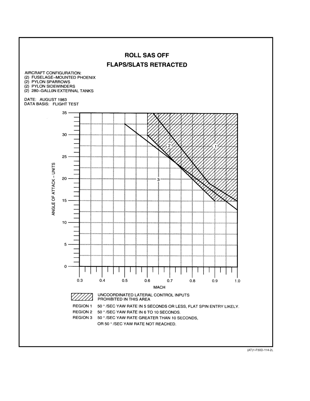
NAVAIR 01−F14AAD−1
Figure 11Ć1.ĄLateral−Control−Induced Departure Areas
ORIGINAL
11−8
NAVAIR 01−F14AAD−1
11.6.7
Miscellaneous
may be accompanied by large random yawing and/or rolling
motions that will generally dampen without pilot action as
Speedbrake position has no effect on high−AOA flight
the aircraft accelerates.
characteristics. Wing−sweep angles aft of the AUTO sched-
ule reduce buffet intensity, but departure resistance is
reduced and more altitude is required for dive pullout when
recovering after a departure. Therefore, the AUTO sweep
schedule is best for high−AOA maneuvering.
The use of lateral stick to offset the random yaw-
11.6.8
Stall Characteristics
ing and/or rolling motion may generate enough
adverse yaw to cause a yawing/rolling departure.
The 1g level stall
(maneuver flaps/slats retracted)
The controls should be released below 100 knots
is characterized by the onset of light airframe buffet at 12
during the vertical stall to prevent inadvertent
to 13 units AOA. This increases to moderate intensity at
inputs that may lengthen recovery and/or cause
15 units AOA with essentially no change in intensity at AOA
a departure.
as high as 60_. Buffet is not a satisfactory cue to determine
airspeed or AOA during high−AOA maneuvering. If decel-
Control inputs should not be applied until the aircraft
eration is continued to full aft stick deflection, AOA will
is nose down and accelerating through 100 knots. Rudder and
stabilize at approximately 35° to 45° depending upon stores
lateral stick are also effective in damping oscillations once
loading. The cockpit AOA indicator pegs at 30 units AOA,
the aircraft is nose low and accelerating. The aircraft is very
which is equivalent to approximately 25_ true AOA. Pitch
responsive to longitudinal stick inputs at all AOAs at speeds
attitude at stall is between 10_ to 20_ above the horizon with
above 100 knots.
no external stores and
10_ to
15_ below the horizon
Refer to paragraph 11.5.2, Low−Subsonic Airspeed for
with maximum external load. Some longitudinal porpoising
procedures to follow in the event of an engine stall. Refer to
may occur at full aft stick.
Chapter 14 for vertical stall recovery procedures.
Maneuver flaps and slats delay buffet onset to 13 to
During flight tests, vertical stalls in maximum after-
14 units AOA and reduce the magnitude of buffet in
burner power sometimes resulted in afterburner blowouts on
high−AOA flight.
one or both engines possibly followed by pop stalls that may
The clean stall is defined as the application of full aft
or may not be audible to the pilot. All the stalls were self
stick combined with rates of descent up to 9,000 fpm. As
clearing with no tendency for EGT to rise out of limits. As the
much as 5,000 feet is required for recovery from the fully
aircraft recovered and airspeed increased, the afterburner
developed stall.
relit if the throttle remained in the afterburner detent. When
practicing vertical stalls, basic engine power settings are
Satisfactory lateral and directional control is main-
recommended to avoid inducing engine afterburner tran-
tained beyond the AOA where the basic airframe directional
sients that have an unknown effect on engine life. Maximum
stability becomes negative. Lateral stick and rudder inputs
engine stall margin for the F110 is obtained at IDLE power.
can be used to adjust and maintain desired bank angle
throughout the stall. Control inputs are provided to suppress
11.6.10 DFCS Degraded Control Modes
wing rock motion up to 30 units AOA, but some mild wing
The DFCS has the capability to function in several
rock may still occur. Above 30 units AOA, the wing rock
degraded modes of operation. Air sensor data failures,
suppression feature is inhibited and rudder effectiveness
actuator failures, or DFCS computer failures can all affect the
decreases sharply. Large rudder or lateral stick inputs
high AOA flying qualities of the aircraft. Failure modes
produce an increase in AOA as sideslip increases.
which would significantly affect high AOA flight character-
11.6.9
Vertical Stalls
istics are discussed below. It should be understood that the
failures listed do not comprise all possible failure modes, but
If the aircraft is allowed to decelerate to zero airspeed
are examples of those types which would have the most
in a vertical or near vertical attitude, it will slide backwards
significant effect on high AOA flight.
momentarily, then pitch over (usually backwards) to a near
vertical dive. Aircraft motions during the initial fall will be
11.6.10.1
Air Data Failures
predominantly inertial with random pitching and yawing as
the aircraft accelerates. After the initial nosedown pitch, the
Actual air data failures could occur at any point in the
aircraft may pass through the vertical to near level flight
flight envelope due to associated failures of the SCADC,
attitude, yaw in one direction, and then return to a vertical
AICS, or AOA computer inputs to the DFCS. However,
dive attitude. This may occur more than once. This tendency
transient or nuisance air data sensor failures due to input
is more pronounced at aft wing sweeps, but can usually be
miscompares (Mach number or AOA inputs) are more likely
controlled with longitudinal control inputs. Some recoveries
11−9
CHANGE 2
NAVAIR 01−F14AAD−1
to be experienced during maneuvering flight at high AOA
11.6.10.3
DFCS Computer Failures
than at low AOA or high airspeed conditions. In general,
Each of the three DFCCs contains two distinct
single failures of the air data sensors have negligible or only
computer processors called computing segregations, one A"
minor effects on high AOA flying qualities.
segregation and one B" segregation in each axis. Each
Failure of a single AOA input does not result in a
segregation commands different series servo and/or spoiler
functional downgrade, only a loss of redundancy, since the
sets. If a computing segregation fails, all actuators command-
AOA input is triplex. Single failure of the Mach number
ed by that segregation are rendered inoperative. Similarly, all
inputs (SCADC or AICS) will downgrade the UA−ARI to a
sensor information associated with that segregation is
fixed gain Mach control mode. In this mode, the wing rock
declared invalid. Functionality loss associated with each of
suppression and LSXC control functions are inoperative.
the segregations, and effect on high AOA flying qualities, are
Therefore, wing rock tendency will be increased and the
discussed below.
aircraft will be difficult to roll above 30 units AOA. The
differential tail fadeout, LSRI, and spin recovery functions
Pitch A − Half authority PITCH SAS, no inboard spoilers,
single AOA failure, single Mach failure. Inoperative
remain operational.
wing rock suppression and LSXC functions.
Dual failure of either the Mach or AOA inputs causes
loss of all UA−ARI functions except the spin recovery
Pitch B − Half authority PITCH SAS, no outboard
function. This will cause the aircraft to be more prone to wing
spoilers, single Mach failure. Inoperative wing rock
rock and less resistant to all types of control−induced and
suppression and LSXC functions.
asymmetric thrust induced departures. DFCS spin recovery
Roll A − Half authority ROLL SAS/ARI, no inboard
capability is retained.
spoilers, single AOA failure. Degraded UA−ARI
performance due to loss of the roll A series servo.
11.6.10.2
Actuator Failures
Roll B − Half authority ROLL SAS/ARI, single Mach
Failure of the pitch series servos or any of the spoiler
failure. Degraded UA−ARI performance due to loss
actuators has little effect on high AOA flight characteristics.
of the roll B series servo. Inoperative wing rock sup-
Single failure of any roll or yaw series servo will result in
pression and LSXC functions.
degraded UA−ARI performance (i.e., decreased departure
resistance, increased wing rock tendency) in the associated
Yaw A − Half authority YAW SAS/ARI, single AOA fail-
axis due to the decreased control authority, however all
ure. Degraded UA−ARI performance due to loss of
UA−ARI functions are retained.
the yaw A series servo.
Dual failure of both roll or both yaw series servos
Yaw B − Half authority YAW SAS/ARI, no outboard
results in a complete loss of all UA−ARI functions, and
spoilers, single AOA failure. Degraded UA−ARI
significantly degrades the high AOA flying qualities. With a
performance due to loss of the yaw B series servo.
dual roll series servo failure, all roll axis functions are
inhibited and the yaw axis downgrades to basic SAS" mode
Combined failure of any two segregations results in
(loss of ARI functionality). In the event of a DFCS dual roll
combined loss of all associated functions, actuators, and in
series servo failure or manually selecting the ROLL STAB
most cases, additional failures. High AOA flying qualities
AUG switch to OFF, the maneuvering limits described in
are significantly degraded in all multiple segregation failure
Chapter 4 Maneuvering Limits" must be observed. Failure
cases.
of both yaw series servos, or manually selecting the YAW
STAB AUG switch to OFF, inhibits all yaw and roll axis
11.7 DEPARTURE FROM CONTROLLED FLIGHT
UA−ARI and SAS functions, resulting in a severe degradation
in high AOA flying qualities.
11.7.1
General
Although the F−14 is an honest aircraft with moderate
departure resistance, departures can be induced by large or
sustained control inputs that generally feel unnatural to the
pilot. Since the aircraft has an essentially unrecoverable
flat−spin mode, yaw rate must be controlled before it can
Maneuvering with YAW SAS OFF or inoperative
build and the aircraft transitions to the flat−spin mode. In
shall not be conducted above 15 units AOA with
general, departures are characterized by increasing yaw rate
landing gear retracted. The aircraft will be prone
with oscillations in roll and yaw. Yaw rate is masked by the
to departure from controlled flight.
CHANGE 2
11−10
NAVAIR 01−F14AAD−1
roll rate and is not evident to the pilot until approximately
In an upright departure at approximately
50_ per
90_ per second yaw rate (2 eyeball−out" g) is reached.
second yaw rate or less, if full forward stick is applied to
reduce AOA, the aircraft will generally recover. At over 50_
A predominant stability characteristic of the F−14 is
per second yaw rate, lateral/directional control inputs (rudder
positive dihedral effect, which is the tendency for the aircraft
opposite yaw, lateral stick into yaw) are required to recover
to roll to reduce sideslip. This effectively serves to delay yaw
rate buildup associated with loss of directional stability at
high AOA.
11−10a (Reverse Blank)
CHANGE 2
NAVAIR 01−F14AAD−1
the aircraft. If these inputs are not made, the yaw rate will
itself. Rather, each store causes a small degradation in flying
continue to build and the aircraft may enter the flat spin. DFCS
qualities that accumulates as additional stores are added. In
will significantly enhance these recovery characteristics.
general, fuselage−mounted stores have less effect than pylon−
or nacelle−mounted stores.
The time to reach 50_ per second yaw rate after control
input or engine failure is very critical. If 50_ per second yaw
11.7.1.4
Asymmetric Fuel/Stores
rate is reached in 5 seconds or less, the pilot may not have
enough time to neutralize, analyze, and apply recovery
Flying qualities with asymmetric stores are most
controls before the aircraft enters a flat spin depending on
affected by the store weight imbalance which results in a
type and severity of departure, altitude and AOA at entry,
redistribution of lateral control power (differential tail) due
and aircraft configuration. The time to reach 50_ per second
to the trim required. There are no significant differences due
yaw rate for various aircraft configurations as a result of
to aerodynamic asymmetries at high AOA. Therefore, rudder
lateral stick, rudder, or cross−control inputs is presented in
inputs generate similar aircraft response both into and away
Figure 11−1 and Figure 11Ć2. The figures are applicable to
from the store(s). However, the aircraft response to large
DFCS with ROLL SAS OFF or a complete roll axis failure
lateral stick inputs, at AOAs where lateral stick generates a
as indicated by illumination of the ROLL DGR, ARI DGR,
roll response opposite to the direction of the input (roll
and ARI/SAS OUT caution lights. Generally, the most severe
reversal AOA), can vary significantly from the symmetric
departures are induced through the differential tail, which is
stores case depending on the amount of store asymmetry.
commanded by lateral stick. Rudder inputs, asymmetric
The maximum asymmetry which has been flight tested
thrust, and inertia coupling can cause or contribute to the
thus far is 189,000 in−lbs, which resulted in a lateral trim bias
severity of departures.
of 40 − 90% of available trim authority, depending on trim
In addition to the enhanced departure resistance, the
airspeed. This asymmetry is equivalent to a 900 lb wing fuel
DFCS automatically provides anti−spin rudder and differenĆ
split.
tial tail inputs to the maximum ROLL and YAW SAS
Due to the lateral trim required to offset the asymmetry,
authority limits as a function of yaw rate. This increases
the amount of lateral stick displacement
(and therefore
aircraft spin resistance. Flight tests indicate that the aircraft
differential tail) which can be commanded from the trimmed
will recover from high yaw rates without pilot−commanded
stick position is greater into the store asymmetry than away
lateral/directional control inputs, due to these automatic
from the asymmetry. Aircraft response to large lateral stick
rudder and differential tail inputs. Refer to
11.7.8 for
inputs is thus amplified for stick deflections into the stores
discussion of departure recovery characteristics.
and reduced for stick deflections away from the stores.
11.7.1.1
Mach and AOA Effects
Lateral stick−induced departures are caused by the
inadvertent application of differential tail at high AOA.
As Mach number increases, flight−control−induced
The greater the amount of differential tail commanded, the
departure susceptibility and severity increases. Generally, as
greater the aircraft response, and potentially the more severe
AOA increases, the severity of the departure increases. For
the departure. Since the direction of a laterally induced
example, a lateral stick input at 0.9 Mach, 30 units AOA, will
departure is opposite to the direction of the lateral stick input,
produce a more violent departure than the same input at 0.9
departures away from the store asymmetry can be more
Mach, 20 units AOA. The one exception is rudder−induced
severe. For example, a right−wing heavy aircraft will depart
departures. As AOA is increased to about 30_ (over 30 units
faster in the nose−left direction. The degree of this asymĆ
AOA), rudder effectiveness decreases as the rudder is washed
metric response varies in proportion to the amount of
out and rudder−induced departures become less severe.
asymmetry, and also the magnitude and duration of the
control input. This same effect is present during the use of
11.7.1.2
Maneuver Flaps/Slats
cross controls
(rudder in direction of roll, lateral stick
Extended maneuver flaps and slats significantly deĆ
opposite) to further augment roll response of the aircraft at
crease departure susceptibility and severity through inĆ
high AOA and can lead to potentially more severe depar−
creased dihedral effect.
tures. Caution should be exercised when cross−controlling
to increase high AOA roll response away from the store
11.7.1.3
External Stores
asymmetry. Use of cross controls to roll into the
store asymmetry will be less effective than normal.
As external stores are added, departure susceptibility
and severity increase. No one store is significant in and of
11−11
ORIGINAL
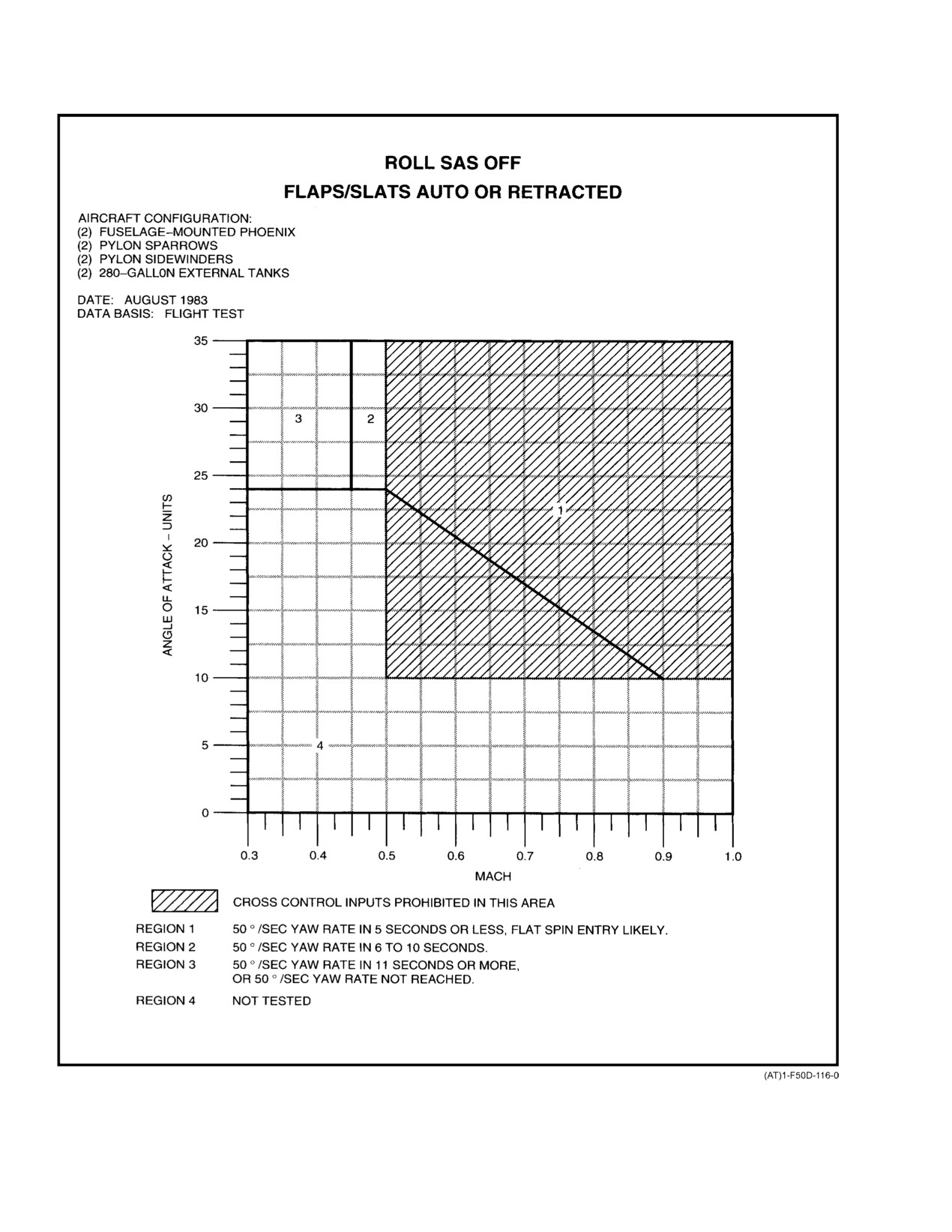
NAVAIR 01−F14AAD−1
Figure 11Ć2.ĄCross−Control−Induced Departure Areas
ORIGINAL
11−12
NAVAIR 01−F14AAD−1
11.7.2
Lateral Stick−Induced Departures
11.7.4
Multi−Axis Control−Induced Departures
Roll and yaw in direction of lateral stick command is
Combined lateral stick and rudder control inputs can
typically retained up to 30 units AOA, due to the combined
produce oscillatory aircraft response and high yaw rates at
effects of differential tail fadeout and lateral stick−to−rudder
some flight conditions.
interconnect functions provided by DFCS. Maximum roll
rate commanded by lateral stick decreases as AOA increases,
11.7.4.1
Cross Control−Induced Departures
decreasing to near zero above 30 units AOA without pilot
Sustained cross control inputs produce oscillatory roll
commanded coordinated rudder inputs. Some variation in
and yaw rates in the direction of the rudder input. The
AOA at which neutral roll response occurs and/or mild roll
amplitude of the oscillations decreases as AOA increases.
reversal may be expected due to effects of external stores,
Differential tail fadeout and lateral stick to rudder interconĆ
wing fuel state, or flight control system rigging tolerances.
nect functions limit maximum control authorities to ±2°
During flight tests, only mild roll reversal departures were
differential tail and ±11° rudder, causing maximum yaw rate
experienced. These departures were characterized by a mild
to remain below 50 deg/sec at all flight conditions. At very
roll and yaw opposite the lateral stick command. With
low airspeed and high AOA flight conditions (less than 0.4
maneuver flaps retracted, there was no appreciable degradaĆ
Mach and above 30 units AOA), the low speed cross control
tion in departure resistance. No high AOA maneuvering
function (LSXC) is enabled to provide a transient roll and
restrictions regarding lateral stick inputs are required for
yaw maneuvering capability. LSXC permits the pilot to
flight with a fully operational UA−ARI.
command up to ±10° differential tail and
±30° rudder
11.7.3
Rudder−Induced Departures
deflection during cross control maneuvers. Peak roll rate of
approximately 60° per second is available through the use of
Full rudder inputs at high AOA produce a roll and yaw
LSXC. If long duration inputs are utilized, the roll response
rate in the direction of the rudder input. At moderate AOA
will become oscillatory, with hesitations in bank angle and
(approximately 15 to 25 units), this response is oscillatory
roll rate. Precise bank angle control is typically not possible
and a definite hesitation in roll and yaw rate will be noted
with LSXC, but the feature can be effectively utilized during
for long duration inputs. Inertia coupling effects will also
sustained slow speed / high AOA maneuvering such as a flat
cause pitch rate and AOA oscillations. As AOA increases to
scissors engagement. The spin recovery function will start to
30 units, the response is less oscillatory but remains in the
reduce these control authorities at approximately 20° per
direction of the rudder input. Above 30 units AOA, rudder
second yaw rate and will apply the maximum reduction in
effectiveness is significantly reduced and little response is
control authority back to the ±2° differential tail / ±11° rudder
obtained from a full rudder input. The departure resistance
limits at approximately 25° per second yaw rate to preserve
features of the UA−ARI limit maximum yaw rate to less
departure resistance.
than
50 deg/sec over the majority of the high AOA
flight envelope. However, at airspeeds above approximately
11.7.4.2
Coordinated Control−Induced
250 knots and low to moderate AOA (less than 25 units),
Departures
rapid yaw acceleration can occur in response to a sustained
full rudder input such that 50 deg/sec yaw rate can be initially
During flight tests, full sustained coordinated lateral
exceeded. Flight test data indicate that yaw rates decreased
stick and rudder inputs produced high roll and yaw rates in
to less than 50 deg/sec even when sustained full rudder inputs
the medium to high airspeed regime (above 250 knots) at low
were maintained for 10 sec. Roll response using lateral stick
to moderate AOA (less than 25 units). However, no tested
alone in this airspeed and AOA range is typically sufficient,
condition resulted in sustained yaw rate above
50° per
such that large rudder inputs should not be required to obtain
second. The roll and yaw rates are in the direction
desired roll performance.
commanded and produce highly oscillatory, potentially
disorienting motion with significant nose up coupling in the
pitch axis. At these flight conditions, roll response due to a
pure lateral stick input (no pilot−commanded coordinating
rudder) is satisfactory and additional coordinating rudder
should not be required to obtain desired roll performance.
Sustained large rudder inputs at high airspeeds
At lower airspeeds and/or increased AOA, coordinated
(above 250 knots) can cause high yaw acceleraĆ
lateral stick and rudder inputs produced a smoother, less
tion and yaw rate.
11−13
ORIGINAL
NAVAIR 01−F14AAD−1
oscillatory roll and yaw response. In this flight regime,
11.7.6
Accelerated Departures
coordinating rudder can be used to supplement lateral stick
Accelerated departures are initially characterized by a
for increased roll rate.
rapid increase in lateral acceleration but may become
violently oscillatory about all three axes. Flight tests with
legacy SAS (pre−DFCS) have shown aircraft rates in excess
of 120° per second in roll and 70° per second in yaw. Pitch
rates oscillate up to ±30° per second and lateral acceleration
oscillates up to ±0.8g. These oscillations may cause pilot
Sustained large rudder inputs at high airspeeds
disorientation, and proper recovery controls may not be
(above 250 knots) can cause high yaw acceleraĆ
obvious. If this occurs, the proper response would be to
tion and yaw rate.
neutralize rudders and lateral stick, apply forward longitudiĆ
11.7.5
Asymmetric−Thrust−Induced Departures
nal stick, and lock the shoulder harness. Recovery indications
should become apparent within two turns.
Asymmetric−thrust−induced departures are similar to
11.7.7
Inertia Coupling
those induced by the flight controls. At high altitude (greater
than
20,000 feet), asymmetric thrust results in a mild
Coupling occurs when motions in more than one axis
departure characterized by mild roll and yaw rates into the
interact. Combined motion on two axes will always result in
dead engine if the airspeed is above 100 knots. The yaw rate
motion in the third axis. The F−14, like all high−performance
is usually masked by the roll rate. If no pilot action is taken,
aircraft capable of producing high−rate, multiple−axis motion,
the aircraft usually stabilizes at some moderate yaw rate from
is susceptible to coupling. High−rate, multiple−axis motions,
which recovery is easily accomplished. On occasion, the yaw
particularly at high AOA, can produce violent coupled
rate will continue to increase slowly, taking 20 seconds or
departures. In flight tests with legacy SAS (pre−DFCS), a
more to reach 50_ per second. At lower altitudes (15,000
guns−defense/collision−avoidance maneuver using full rudĆ
feet) yaw rate may reach 50_ per second in 10 seconds
der followed by full coordinated lateral and aft stick produced
because of increased thrust asymmetry. Departures induced
violent coupled departures with up to 66° per second yaw rate
by asymmetric thrust alone below 100 knots or when airspeed
in less than 2 seconds. Yaw rates of this magnitude require
drops below 100 knots in the departure are characterized by
prompt positive recovery inputs by the pilot. External stores
mild roll and a smooth gradual increase in yaw rate that will
contribute to the severity of the departure by decreasing
attain values well over 50_ per second. The DFCS spin
directional stability and increasing inertia. Most coupled
recovery function automatically commands recovery differĆ
departures in the F−14 are induced by combined high pitch and
ential tail and rudder inputs to oppose yaw rate buildup and
roll rates (causing a rapid departure in yaw). Typically, these
reduces the severity of asymmetric thrust induced departures.
departures are initiated at comparatively low AOA (below 15
These inputs are most effective if airspeed remains above 100
units) where the aircraft is capable of generating both high
knots. Departures induced by asymmetric thrust are still
pitch and roll rates. It should be noted that since the ROLL
capable of reaching
50°/sec yaw rate at low altitudes,
SAS will remain on, this will provide increased roll control
however, the yaw rate onset is much less severe, allowing the
authority, throughout the flight envelope.
pilot more time to counter rate.
Note
In flight tests, the DFCS did not prevent coupled
departures from occurring. However, the DFCS
spin recovery function prevented excessive yaw
The pilot’s natural tendency is to oppose uncomĆ
rate buildup.
manded roll with lateral stick, but this can aggraĆ
No DFCS flight test departure maneuvers exceeded
vate the departure.
70° per second yaw rate, and progression into the flat spin
During maneuvering flight, uncommanded roll should
mode following this type of departure.
be countered by rudder and a reduction in AOA. DFCS
automatically provides coordinating rudder with lateral stick
deflection which decreases departure susceptibility. See
additional discussions on asymmetric thrust flight characterĆ
istics in this chapter.
Avoid high−rate, multiple−axis motion because
of possible violent departures.
ORIGINAL
11−14
NAVAIR 01−F14AAD−1
11.7.8
Departure Recovery
ment indication of yaw direction is the roll direction. In an
upright departure, the aircraft yaw rate is the same direction
Before recovery controls are applied, the crew must
as the roll rate. Typically, roll rate is much more evident to
analyze flight conditions to determine the departure mode
the pilot than yaw rate. The turn needle and PTID spin arrow
entered. The turn needle indicates only the direction of yaw
may be backed up by referencing the roll direction.
and not magnitude of yaw rate, since it pegs at 4_ per second
yaw rate. An upright departure is indicated by AOA pegged
Reducing thrust asymmetry during recovery by retardĆ
at
30 units; an inverted departure by AOA of 0 units.
ing the throttles to IDLE removes any possible thrust
Generally, increasing airspeed and AOA sustained between
asymmetry, places the engines in the region of greatest stall
0 and 30 units is indicative of a recovery in progress, as is
margin, and reduces time to recover. Maintaining a thrust
positive aircraft reaction to pilot control inputs.
asymmetry, particularly with the good engine in MAX A/B,
will delay recovery at high altitudes and may prevent
11.7.9
Upright Departure Recovery
recovery at lower altitudes since flight controls may not be
Recovery from upright departures is positive and
powerful enough to overcome asymmetric thrust. AsymmetĆ
generally rapid. The high control power that allows the pilot
ric thrust has its greatest effect upon upright departure
to depart the aircraft also enables the pilot to recover when
recovery at low airspeed, where flight controls are not as
the controls are properly applied and sufficient altitude is
effective, and low altitude, where asymmetric engine thrust
available for recovery.
is the largest.
Successful upright departure recovery depends on
recognition of the departure from controlled flight, applicaĆ
tion of appropriate recovery control inputs, and subsequent
recognition of when the aircraft has recovered. Departure
Retarding throttles to idle during a departure or
from controlled flight is usually characterized by an uncomĆ
high AOA maneuvering may induce a compresĆ
manded roll/yaw or an abrupt nose slice or pitch. Common
sor stall on the operating engine. If both engines
examples of these motions are lateral control reversal at high
are stalled, one engine must be immediately seĆ
AOA, or uncommanded roll and yaw resulting from asymĆ
cured (while maintaining the correct departure/
metric thrust. When appropriate recovery controls are
spin recovery inputs) to prevent turbine damage
applied and maintained as discussed in detail below, recovery
and provide maximum potential for a successful
from an upright departure will be indicated by decreasing
airstart.
yaw rate, decreasing AOA, and increasing airspeed. The
decrease in AOA and increase in airspeed during recovery
Recovery from slightly higher yaw rates (approximateĆ
will be evident to the pilot by the aircraft response to control
ly
60 to 70 deg/sec) is possible with forward stick and
inputs. The aircraft may stop rolling because of sideslip and
opposite rudder alone, due to the automatic anti−spin
begin to roll because of differential tail commanded by the
differential tail and rudder inputs provided by the spin
pilot or DFCS for recovery from higher yaw rate departures.
recovery function. Above these yaw rates, additional pilot−
A nose drop and associated unload may occur, and the roll
commanded lateral stick into yaw rate/turn needle will likely
rate may increase under these conditions.
be required to recover the aircraft. Yaw rates of 100_ per
Note
second or more can be identified by sustained eyeball−out g.
During recovery from departures where yaw rates of 50_ to
The most important action of any upright deparĆ
100_ per second are experienced, the aircraft may stop
ture recovery is reducing the AOA. This is enĆ
rolling because of sideslip and begin to roll because of
hanced by timely application of forward stick
differential tail commanded by the pilot or DFCS for
and countering the yawing motion of the aircraft
recovery. A nose drop and an associated unload may occur.
with rudder.
These are indications of a positive recovery in progress.
If the AOA is pegged at 30 units or increasing rapidly,
During flight tests with DFCS, a sustained mild
smoothly apply forward stick as required to reduce AOA.
auto−roll" tendency was exhibited during recovery from
Full forward stick may be required. In an upright departure
some intentional departure maneuvers. This motion typically
where less than 50_ per second yaw rate is observed, if full
occurred when the pilot failed to input enough forward stick
forward stick is applied to reduce AOA, throttles retarded to
to reduce and maintain AOA below 20 units. With neutral
idle, and rudder is applied opposite the yaw direction, the
controls or slightly forward stick only (no pilot rudder or
aircraft will generally recover, as shown in Figure 11−3.
lateral stick input), the aircraft can continue to roll and yaw
Cockpit indications of yaw direction are the pilot’s turn
mildly in the direction of the original departure. These rates
needle and the spin arrow displays on the PTID and MFD
are approximately 40 deg/sec in roll and 20 deg/sec in yaw.
(Figure 11−4). Refer to paragraph 11.7.9.1 for a detailed
AOA is sustained between 20 and 25 units. Aircrew should
discussion of spin arrow displays. An additional noninstruĆ
11−15
ORIGINAL
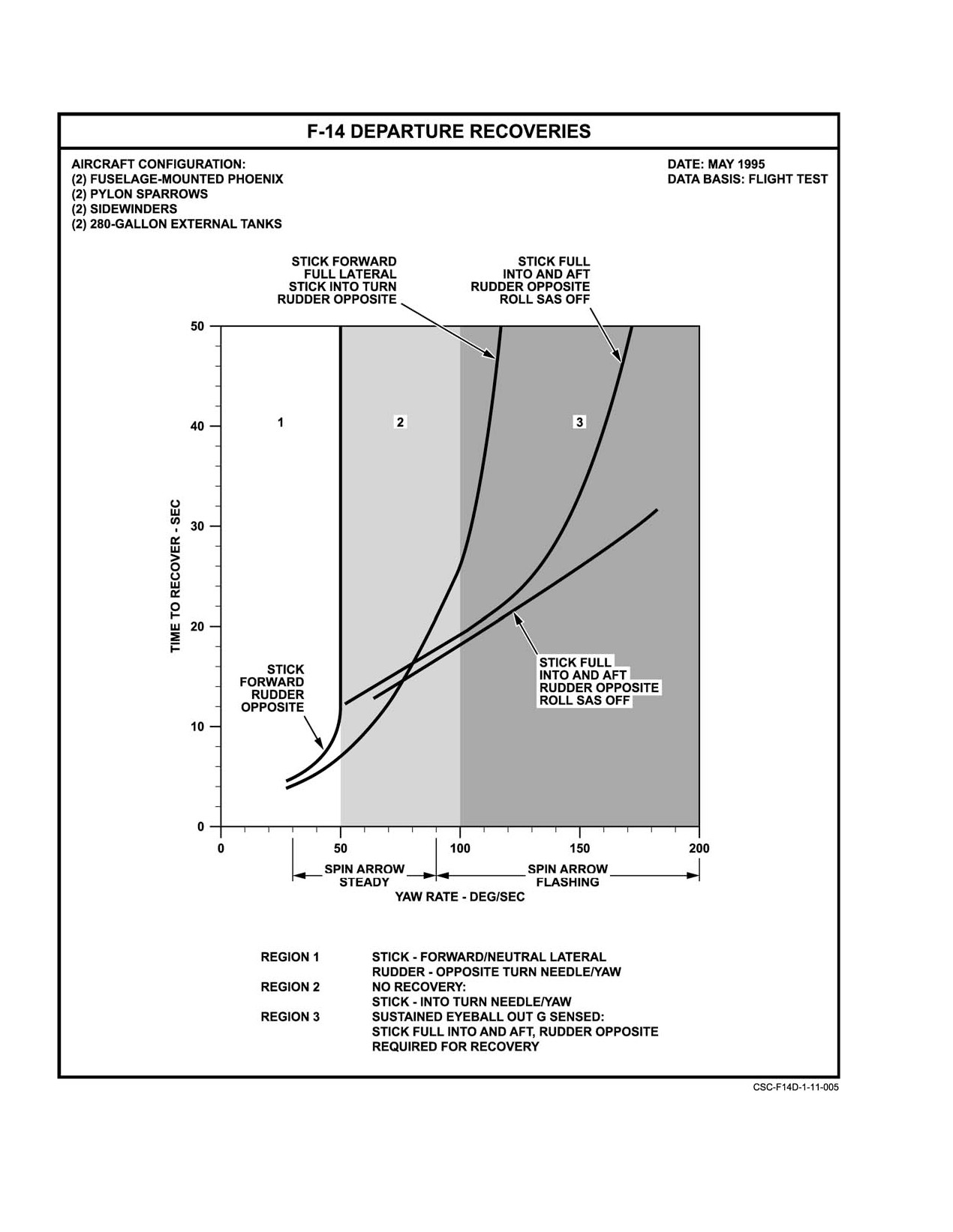
NAVAIR 01−F14AAD−1
Figure 11Ć3.Ą F−14 Departure Recovery Diagram
ORIGINAL
11−16
NAVAIR 01−F14AAD−1
recognize that the departure is substantially recovered at this
point, as indicated by the sustained AOA below 30 units,
blanked spin arrow, and a nose low attitude with increasing
airspeed. Any subsequent positive pilot control input will
cause the aircraft to cease the auto−roll motion. This can be
Maintaining aft and lateral stick recovery conĆ
accomplished by applying enough forward stick to reduce
trols below approximately 100_ per second yaw
and maintain AOA below 20 units, applying opposite rudder
rate can result in large AOA excursions and osĆ
and/or lateral stick, or a combination of any of these three
cillations in roll and pitch, which may compliĆ
inputs.
cate recognition of recovery from an upright deĆ
parture and delay recovery. Maintaining these
Once recovery indications from a low yaw−rate
controls below approximately 80_ per second
departure (less than 50_ per second) are verified, the forward
will delay recovery and increase the potential for
longitudinal stick should be relaxed to maintain 17 units
yaw rate reversal and progressive departure in
AOA, which will minimize altitude loss for recovery and
the opposite direction.
avoid negative g as airspeed builds. Rudders should be
neutralized as rotation stops. As recovery from higher
11.7.9.1
Spin Arrow Displays
yaw−rate departures is indicated, the lateral stick that was
At yaw rates greater than 30_ per second, the spin
held into the turn direction should be neutralized, and the
arrow displays (Figure 11−4) have priority and override all
forward longitudinal stick should be relaxed to minimize
other display formats on the MFD1 and the PTID. MFD2 and
altitude loss for recovery and avoid negative g as airspeed
MFD3 display the VDI format. When a yaw rate exceeding
builds. The aircraft is very responsive to longitudinal stick
30_ per second is detected, the current format on these
inputs at all AOA at speeds above 100 knots. Pullout should
displays is overridden by the spin indicator format. In this
be accomplished at 17 units AOA. Lateral stick and rudder
format, the spin arrow points in the direction of the spin.
may be used to counter any remaining roll and yaw
Above the spin arrow in the MFD format, vertical tape
oscillations.
displays provide airspeed, altitude, and AOA indications. If
Centrifuge tests indicate the pilot begins to sense
required, an indication of left or right engine stall is provided.
eyeball−out g at about 2g, which occurs at approximately 90_
A moving caret shows yaw rate from 30_ to 180_ per second.
to 100_ per second yaw rate. If sustained eyeball−out g is
If the yaw rate exceeds 180_ per second, the caret is pegged.
sensed, it is likely that 100_ per second yaw rate has been
exceeded and optimum recovery controls are full rudder
Note
opposite the yaw rate/turn needle, full lateral stick into the
D If MFD1 is not operating, the spin indicator
turn needle, as much aft stick as possible (while maintaining
format is displayed on MFD2.
full lateral stick. The DFCS provides the capability to
command full ROLL SAS ON differential tail authority for
D If INS and SAHRS failures occur while the
recovery as a basic feature of the UA−ARI. Refer to
spin arrow format is displayed, the pointer on
Chapter 14 for upright departure/flat spin emergency proceĆ
the yaw rate scale is removed from the MFD,
dures. Recovery controls should be applied and maintained
the spin arrow is frozen, and an X" is superĆ
until recovery is indicated, ejection altitude is reached, or
imposed over the spin arrow. The airspeed,
increasing eyeball−out g threatens aircrew incapacitation.
AOA, and altimeter scales are not obscured
As yaw rate decreases during recovery from very high
(Figure 11−5).
yaw−rate departures
(above 100_ per second, or where
At yaw rates over 30_ per second, the PTID display is
sustained eyeball−out g is sensed), the aft stick and full lateral
blanked and the spin arrow appears pointed in the direction
stick recovery controls result in some−what different recovĆ
of yaw. If the yaw rate exceeds 90_ per second, the spin arrow
ery characteristics. If these recovery controls are maintained
will flash at a 4−times−per−second rate. A fixed scale from
below a yaw rate of approximately 100_ per second, large
30_ to 110_ per second increasing in the direction of yaw in
AOA oscillations may be experienced as well as oscillations
increments of 20_ will be displayed below the spin arrow.
in roll and pitch. The overall recovery may feel very rough
A diamond will be positioned above the numbers to indicate
and oscillatory. If these recovery controls are maintained
the existing yaw rate. For yaw rates in excess of 110_ per
below approximately
80_ per second, recovery will be
second, the diamond will travel past 110 and be positioned
delayed and the potential for yaw rate reversal and progresĆ
over a + sign.
sive departure in the opposite direction is greatly increased.
For these reasons, the control stick that was maintained aft
Note
and into the turn should be moved forward and into the turn
when sustained eyeball−out g is no longer sensed or spin
D The primary reference for the spin arrow, the
arrow yaw rate has decreased below 100 deg/sec. Further
INS, is valid for yaw rates up to 300_ per
recovery can then be accomplished as previously described.
11−17
ORIGINAL
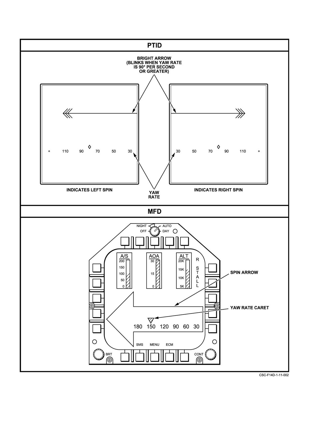
NAVAIR 01−F14AAD−1
Figure 11Ć4.ĄSpin Arrow Displays
ORIGINAL
11−18
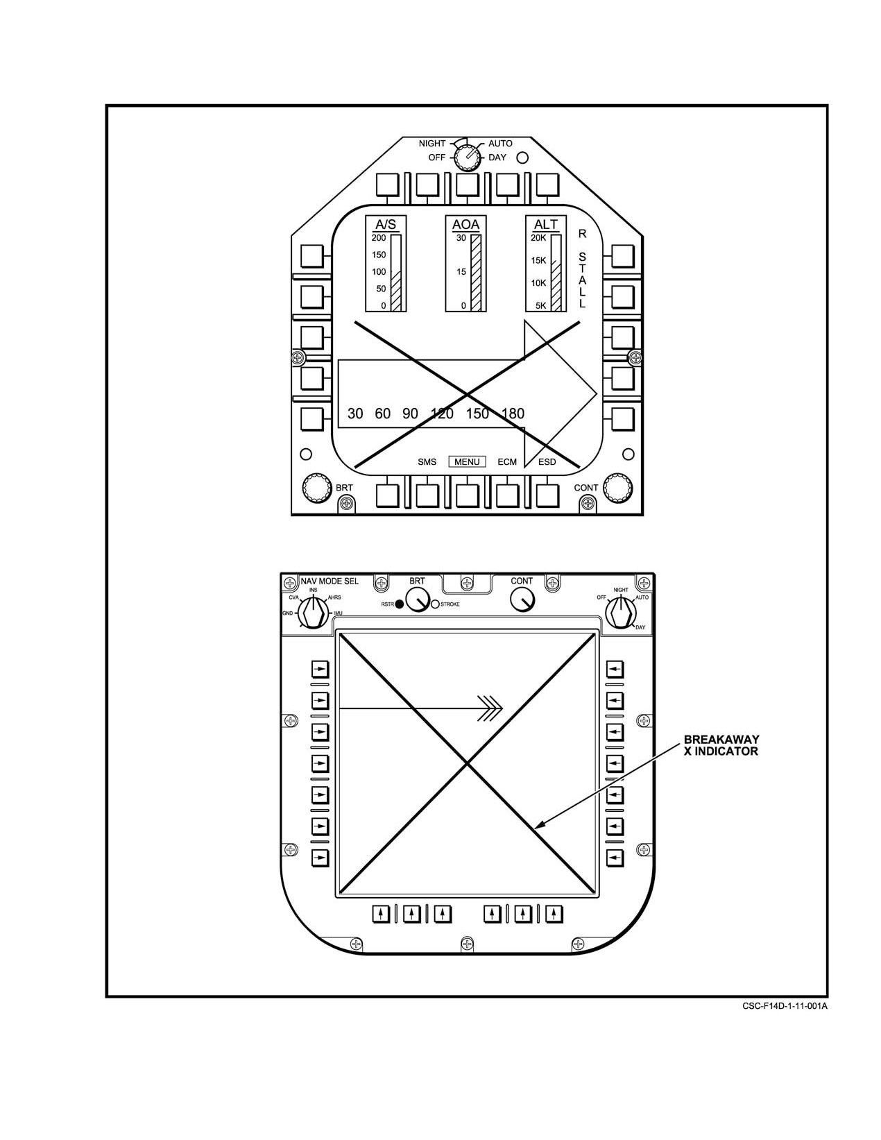
NAVAIR 01−F14AAD−1
Figure 11Ć5.ĄMFD−1/PTID Right Spin Display (INS and SAHRS Failed)
11−19
ORIGINAL
NAVAIR 01−F14AAD−1
second; the backup reference, the SAHRS, is
departure, low−speed stalled engine, etc.). The time between
valid for the same yaw rates.
recognition of a flat spin and buildup of incapacitating
longitudinal−g forces is dependent upon aircraft loading,
D If INS and SAHRS failures occur while the
thrust asymmetry, flight control position during spin entry,
spin arrow format is displayed, the pointer on
locked or unlocked harness, tightness of the lap restraints,
the yaw rate scale is removed from the PTID
and flightcrew physical condition and stature. Test data
and a breakaway X is super−imposed over the
indicate that following recognition of a flat spin, the pilot
spin arrow display (Figure 11−5).
may be able to maintain antispin controls for 15 to 20 seconds
The algorithm that provides yaw rate and direction of
(approximately 7 to 10 turns) but may severely jeopardize his
turn information for the spin arrow display has not been flight
ability to eject because of the incapacitation that occurs as the
test validated at all aircraft attitudes and rates. Hence, the
g forces build. Consistent successful F−14 flat spin recovery
spin arrow may not operate properly at extreme aircraft
procedures have not been demonstrated; therefore, once the
attitudes and rates. The spin arrow has operated properly,
aircraft is confirmed to be in a flat spin, the flightcrew should
providing accurate yaw rate and direction information to the
eject. This decision should not be delayed once the flat spin
aircrew, during flight test where nominal aircraft departures
is recognized.
were encountered.
It is important to understand that longitudinal g forces
11.7.10
Flat Spin
can be present in accelerated departures from controlled
flight and ejection initiated solely because of longitudinal g
The only true upright, fully developed spin in the F−14
forces is premature.
is the flat spin. It is recognized by the flat aircraft attitude
(approximately
10_ nose down with no pitch or roll
To preclude premature ejection from a recoverable
oscillations), steadily increasing yaw rate, and high−longituĆ
aircraft, verify that the aircraft is not rolling or oscillating in
dinal acceleration (eyeball−out g). It may develop within two
pitch or is not in a coupled departure. If any of these
to three turns following a departure if yaw is allowed to
characteristics are evident, then a flat spin has not developed
accelerate without rapid, positive steps to effect recovery.
and departure recovery procedures should be continued.
High yaw−rate departures are usually induced by aerodynamĆ
11.7.11
Negative AOA Departures
ic controls, resulting in inertia coupling and possibly
aggravated by a thrust asymmetry. The aircraft may first
During flight test, a negative AOA departure mode has
enter an erect oscillatory spiral as airspeed rapidly decreases.
been experienced. Cross−control inputs in the low to medium
Frequent hesitations in yaw and roll may occur as yaw rate
Mach (less than 0.6 Mach) and low to medium AOA (AOA
increases. The turn needle and the spin arrow are the only
less than 25 units) area resulted in rapid transition to negative
valid indications of yaw and spin direction as they always
AOA with up to 2.5 negative g. Inertia coupling effects will
indicate turn direction correctly, whether erect or inverted.
cause a nose down pitch and AOA decrease any time roll and
AOA will peg at 30 units, and airspeed will oscillate between
yaw rates are generated in opposite directions. A cross
0 and 100 knots. The aircraft may also depart by entering a
control input at low AOA, where the aircraft still rolls in the
coupled roll where yaw rate may build up without being
direction of lateral stick, is capable of producing this type of
noticed, to the point that when roll stops, yaw rate is sufficient
motion. The motion was very disorienting, uncomfortable,
to sustain a flat spin. A large sustained thrust asymmetry at
and confusing. Neutralizing controls would produce a
low airspeed (particularly at low altitude), may also produce
recovery from this departure; use of aft stick would speed
sufficient yaw rate to drive the aircraft into a flat spin if
recovery.
proper recovery controls are not used. In all instances,
recovery should be accomplished by prompt application of
departure recovery procedures to reduce AOA and control
yaw rate.
Regardless of the method of entry, once the flat spin has
Use of cross−control in the low to medium Mach
developed, the flat aircraft attitude (10_ nose down), steadily
(less than 0.6) and low to medium AOA (AOA
increasing yaw rate, and buildup of longitudinal−g forces not
less than
25 units) may result in negative−g
accompanied by roll and/or pitch rates will be apparent to the
departures.
flightcrew. AOA will be pegged at 30 units, yaw rate will be
fast (as high as 180_ per second) and altitude loss will be
11.7.12 Inverted Stall/Departure
approximately 700 feet per turn. Longitudinal acceleration
(eye−ball−out g) at the pilot’s station will be 5.5 to 6.5g and
As in normal stall approaches, there is no clearly
at the RIO’s station, 3.5 to 4.5g. Time between aircraft
defined inverted stall. A moderate rate application of full
departure and flightcrew recognition of a fully developed flat
spin depends upon the nature of the entry
(accelerated
ORIGINAL
11−20
NAVAIR 01−F14AAD−1
forward stick in inverted flight results in a negative AOA of
combination through 360_ of roll. Pro spin controls need not
about −30_.
be held to maintain the aircraft in a spin. The inverted spin
is primarily identified from cockpit instruments by less than
zero g and an AOA of zero units. Since the inverted spin is
quite disorienting, spin direction must be determined by
observing the turn needle deflection and spin arrow. Altitude
loss during the inverted spin is 800 to 1,800 feet per turn and
time per turn is 3 to 6 seconds. Nose attitude in the inverted
Dynamic forward stick inputs of moderate rate
spin is approximately 25_ below the horizon. Warning of
may exceed the negative−g limit of −2.4g. IndiĆ
possible inverted spin usually occurs sufficiently in advance
cated AOA will show zero beyond about −5_ true
AOA.
for the aircrew to take corrective action. Warning is usually
very noticeable in the form of a nosedown pitch (negative g)
Dihedral effect is negative at negative AOA. ThereĆ
with a yawing and possible rolling motion that is quite
fore, a right rudder input produces right yaw, but left roll.
uncomfortable to the aircrew. In the fully developed inverted
This feels natural to the pilot in inverted flight, and enables
spin, rudder opposite yaw/turn needle is the strongest
raising a wing with opposite rudder when inverted. At
antispin control. Aft stick is a strong antispin control during
negative AOA, oil pressure will indicate zero and illuminate
the incipient spin phase and a weak antispin control in the
the OIL PRESS caution light and MASTER CAUTION light.
inverted spin. In the absence of asymmetric thrust, the
antispin control inputs will recover a fully developed
inverted spin within one turn. Lateral stick opposite yaw is
an antispin control, however, it is not included in the recovery
procedures because opposite rudder recovers the aircraft so
effectively. If opposite rudder and lateral stick were used, the
Zero− or negative−g flight in excess of 10 seconds
recovery would occur very rapidly and a postrecovery
in afterburner or 20 seconds in military power or
departure in the direction of stick and rudder would be highly
less depletes fuel feed tanks (cells 3 or 4), causing
probable. Refer to Chapter 14 for inverted departure/spin
flameout of both engines.
emergency procedures.
Recovery from an inverted stall is performed by
11.8 TAKEOFF AND LANDING CONFIGURATION
applying full aft stick, while neutralizing lateral stick, to
FLIGHT CHARACTERISTICS
return to positive−g flight. Recovery from negative−g condiĆ
tions will usually occur immediately. Return to level flight
11.8.1
Baseline Flight Characteristics
can then be performed from the resultant nosedown attitude
by rolling erect with rudder and/or lateral stick and pulling
The aircraft exhibits a sluggish pitch response to
out at 17 units AOA.
longitudinal stick inputs. Frequent power adjustments are
required in conjunction with longitudinal stick inputs to
Excessive negative−g maneuvering can also exceed the
properly maintain glideslope on approach. DLC is very
aircraft lift limit and cause departure. Aircraft motion
effective for making glideslope corrections while at the same
following departure will be very erratic and disorienting; any
time minimizing the need for nose movement and/or power
induced yaw rate can result in upright or inverted spin entry.
corrections. During full flap takeoffs, more longitudinal stick
Aircraft at high gross weights with external tanks and stores
is required to rotate the aircraft as compared to either the flaps
require a relatively minor negative load to induce this type of
up or maneuver flap takeoff configurations. Pitch sensitivity
departure.
and over−rotation tendency is more pronounced with maneuĆ
ver flaps or flaps up, particularly with aft CG locations.
The PA−ARI control functions combine to provide a
crisp roll response and essentially deadbeat dutch roll
damping. Additionally, the PA spoiler gearing relationship is
Negative−g maneuvering at high gross weights
modified to eliminate the non−linear roll response by moving
should be avoided because of a high probability
the spoiler breakout point to only one−tenth inch lateral stick
of departure.
deflection. The aircraft is very responsive to lateral inputs
and some tendency to overcontrol bank may be experienced.
11.7.13 Inverted Spin
The DFCS also provides automatic coordinating rudder
An inverted spin may be encountered if the aircraft
inputs with lateral stick deflection such that the vast
unloads while there is a yaw rate present. In flight tests, the
majority of lateral corrections can be made with feet
inverted spin has been caused by holding full forward stick
on the floor." An undesirable by−product of this improved
while inverted, applying full rudder, and holding this
11−21
ORIGINAL
NAVAIR 01−F14AAD−1
coordination is a minor pitch up in response to moderate to
wing rock at 26 units AOA. Figure 11−6 shows stall speeds for
aggressive lateral inputs, which requires pilot compensation
standard day temperature at sea level with slats/flaps
to maintain constant AOA. This effect is more pronounced
extended and gear down.
with DLC off. Finally, the spiral mode is neutrally dampened,
such that the aircraft will tend to hold a constant bank angle
Note
once established in a turn.
Maximum allowable AOA gear down is 20.6
11.8.2
Crosswind Landings
units below 5,000′ AGL and 25.5 above 5,000′
AGL.
Crosswind landings may be accomplished using either
the sideslipped or crabbed technique, up to the crosswind
11.8.4
Stall Recovery
limit (20 knots). The PA−ARI roll rate command function and
revised spoiler gearing affect crosswind landing flight
Stall recovery is easily accomplished by relaxing aft
stick force and easing the stick forward, if necessary, to
characteristics. The DFCS commands ROLL SAS inputs to
decrease AOA to less than 16 units. Maintain 15 to 16 units
achieve a commanded roll rate which is proportional to the
pilot’s lateral stick input. During a sideslipped approach
AOA and stabilized military or afterburner thrust during
recovery to level flight. Recovery to level flight requires
( wing down, top rudder"), the pilot applies a constant lateral
stick input which is not intended to command roll rate, in
about 1,000 feet of altitude.
order to hold the aircraft in a steady slip. To accommodate
this technique, ROLL SAS inputs are faded out as the pilot
applies rudder pedal. However, the spoiler gearing schedule
results in nearly immediate spoiler breakout with lateral stick
deflection from trim (one−tenth inch lateral stick input). This
spoiler breakout may result in an unpredictable or overly
Avoid high−rate, multiple−axis motion because
of possible violent departures and engine stalls.
sensitive roll response during tightly controlled tasks such as
fine lineup corrections late in the approach. Because crabbed
approaches are flown without this offset lateral stick input
and do not exhibit this characteristic, pilots may find this
technique easier. Method of crosswind approach is pilot’s
option.
Use of cross−control in the low to medium Mach
11.8.3
Normal Stalls
(less than 0.6) and low to medium AOA (AOA
During deceleration in a level, 1g stall approach, light
less than
25 units) may result in negative−g
buffet starts at about
19 units AOA. Buffet does not
departures.
significantly change thereafter as the AOA is increased and
11.8.5
Asymmetric Thrust Flight Characteristics
provides no usable stall warning. For this reason, with the
landing gear handle down, DFCS incorporates rudder pedal
11.8.5.1
Takeoff Configuration
shaker beginning at approximately 21 units AOA to alert the
pilot. A reduction in stick force is felt between 24 and 28 units
Afterburner takeoffs are prohibited specifically beĆ
AOA. At 25 units AOA, divergent wing rock and yaw
cause of controllability concerns in the event of an engine
excursions define the stall. Sideslip angle may reach 25_, and
failure during takeoff. An engine failure during a MIL power
bank angle 90_ within 6 seconds if the AOA is not lowered.
takeoff with the F110 engine will produce significant thrust
Lateral stick inputs result in significantly reduced adverse
asymmetry. The high compression ratio of the compressor
yaw and continue to provide excellent roll response up to 25
section will result in very rapid spooldown during an engine
units AOA. Above 25 units AOA, the ARI is disabled and
failure and rotor lock can be anticipated within several
DFCS control laws revert to basic SAS in each axis.
seconds of the engine failure. An engine failure in the takeoff
Extending the speedbrakes slightly aggravates the stick force
configuration produces rapid nose movement in the direction
lightening at 24 units AOA but improves directional stability
of the failed engine. The pilot’s first impression is usually
significantly, reducing the wing rock and yaw tendency at 25
that the aircraft will depart the runway. Even if the aircraft’s
units AOA. Stall approaches should not be continued beyond
heading swerve is corrected, the aircraft may continue to skid
the first indication of wing rock. When wing rock occurs, the
sideways across the runway. The wing on the side of the
nose should be lowered and no attempt should be made to
failed engine may rise 10_ to 15_. This is noticeable to the
counter the wing rock with lateral stick or rudder. Stalls with
pilot, but easily corrected with lateral stick. If the airspeed is
the landing gear extended and flaps up are similar to those
high enough to allow correction of the heading swerve, all
with flaps extended. Buffet starts at 16 to 18 units AOA and
lateral drift can be stopped.
ORIGINAL
11−22
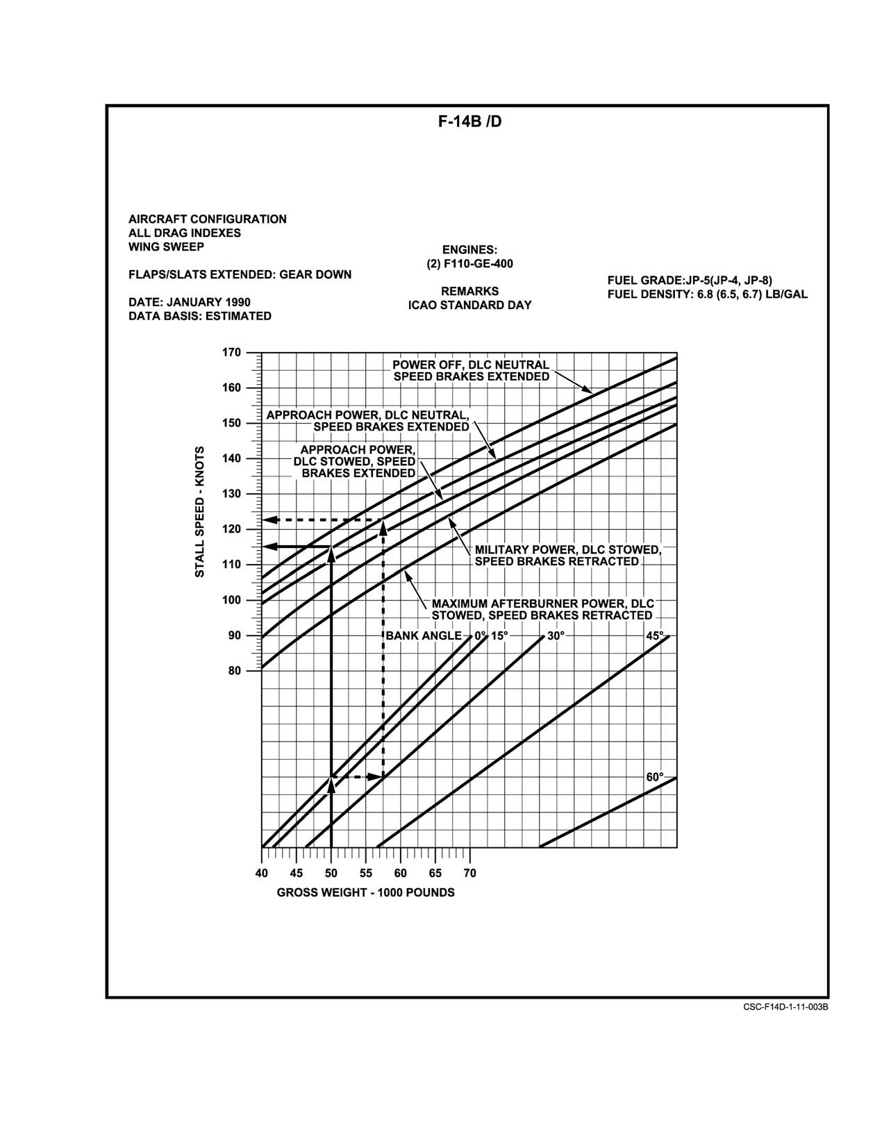
NAVAIR 01−F14AAD−1
Figure 11Ć6.ĄStall Speeds for Wing Rock at 25 Units AOA
11−23
ORIGINAL
NAVAIR 01−F14AAD−1
Aircraft controllability during asymmetric thrust takeĆ
off emergencies is influenced by rudder position, thrust
asymmetry, airspeed, nosewheel steering, and pilot reaction
time, with pilot reaction time being the most critical factor.
During the takeoff roll, rudder control power increases as the
Failure to limit pitch attitude will place the airĆ
airspeed increases, thus improving the pilot’s ability to
craft in a regime of reduced directional stability,
control an asymmetric thrust condition. Below minimum
rudder control, and rate of climb. The aircraft
control groundspeed
(VMCG), insufficient rudder control
may be uncontrollable at AOA above 20 units.
power will be available (nosewheel steering OFF), and large
Smooth rotation to 10_ pitch attitude (approxiĆ
lateral runway deviations will be experienced if the takeoff
mately 14 units AOA) will provide good initial
is continued. The lower the airspeed at which the asymmetry
flyaway attitude, ensure single−engine acceleraĆ
occurs, the larger the lateral deviation. Longer pilot reaction
tion, and generate adequate rate of climb. See
times result in dramatically larger lateral deviations. VMCG
Chapter 13 for single−engine takeoff emergency
speeds (takeoff continued) for the F−14B/D are presented in
procedures, and NAVAIR 01−F14AAP−1.1 for
Figure 11−7. Even if the takeoff is aborted, significant runway
single−engine performance data.
lateral deviations may occur before the aircraft is brought
back under control.
11.8.5.2
Landing Configuration Ċ General
Asymmetric thrust flight in the landing configuration
VMCG SPEEDS
must be approached with caution. Gross weight should be
MAXIMUM 50 FT
reduced prior to landing in order to improve waveoff
THRUST
FLAP
LATERAL
performance. Rudder trim, augmented as necessary by
ASYMMETRY
POSITION
DEVIATION
additional rudder pedal deflection, should be used to counter
thrust asymmetry.
Military − IDLE
Extended
132 to 138 knots
Speedbrakes should remain retracted during actual
Military − IDLE
Retracted
135 to 140 knots
single−engine approaches. A straight−in approach should be
flown. Avoid turns into the dead engine. Steep angle of bank
turns into the dead engine reduce climb performance and may
Figure 11Ć7.ĄMinimum Control Speed, Ground (VMCG)
result in rudder requirements exceeding available control
deflection causing loss of control. The pilot may have to
Use of the nosewheel steering up to 100 knots will
reduce the thrust on the operating engine to regain control,
reduce the amounts of deviation during the abort. For
which may not be feasible at low altitude. By performing
example, if the engine fails at 90 knots, the lateral deviation
turns away from the failed engine, both thrust and rudder
will be 10 to 15 feet with nosewheel steering engaged, and
requirements will be reduced. Any maneuvering required
approximately 50 feet with nosewheel steering disengaged.
prior to final approach should be accomplished using a
If the single−engine failure occurs during or after
maximum of 20_ angle of bank in turns away from the failed
lift−off or catapult launch, the aircraft is controllable if proper
engine.
aircrew techniques are employed. Airborne rudder effectiveĆ
ness is presented in Figure 11−8. Rudder is the primary
Note
control for countering yaw because of asymmetric thrust.
The role of the RIO is critical in this regime. He
Beneficial coordinating rudder is automatically applied with
should closely monitor airspeed, bank angle, and
a lateral stick input and helps to limit yaw rate and sideslip
AOA throughout the approach.
buildup. However, pilot commanded rudder remains the
required recovery control for the DFCS. At the first
Refer to Chapter 15 for single−engine landing emerĆ
indication of an engine failure, the pilot should not hesitate
gency procedures and NAVAIR 01−F14AAP−1.1 for single−
to apply up to full rudder to counter roll and yaw. Above 100
engine performance data. For additional discussion of
knots, rudder effectiveness without nosewheel steering is
landing configurations and techniques, see paragraphs
sufficient to control this deviation adequately. In addition,
11.8.5.3 and 11.8.5.4. For additional discussion of asymmetĆ
use of nosewheel steering is undesirable above 100 knots
ric thrust flight characteristics, see paragraph 11.8.5.
because of a directional pilot induced oscillation tendency
and the potential for a cocked nosegear if takeoff is
11.8.5.3
Landing Configuration Ċ
continued.
Engine in Primary
DLC will not be available with the left engine secured.
With the left engine operating in primary mode and 3,000 psi
ORIGINAL
11−24
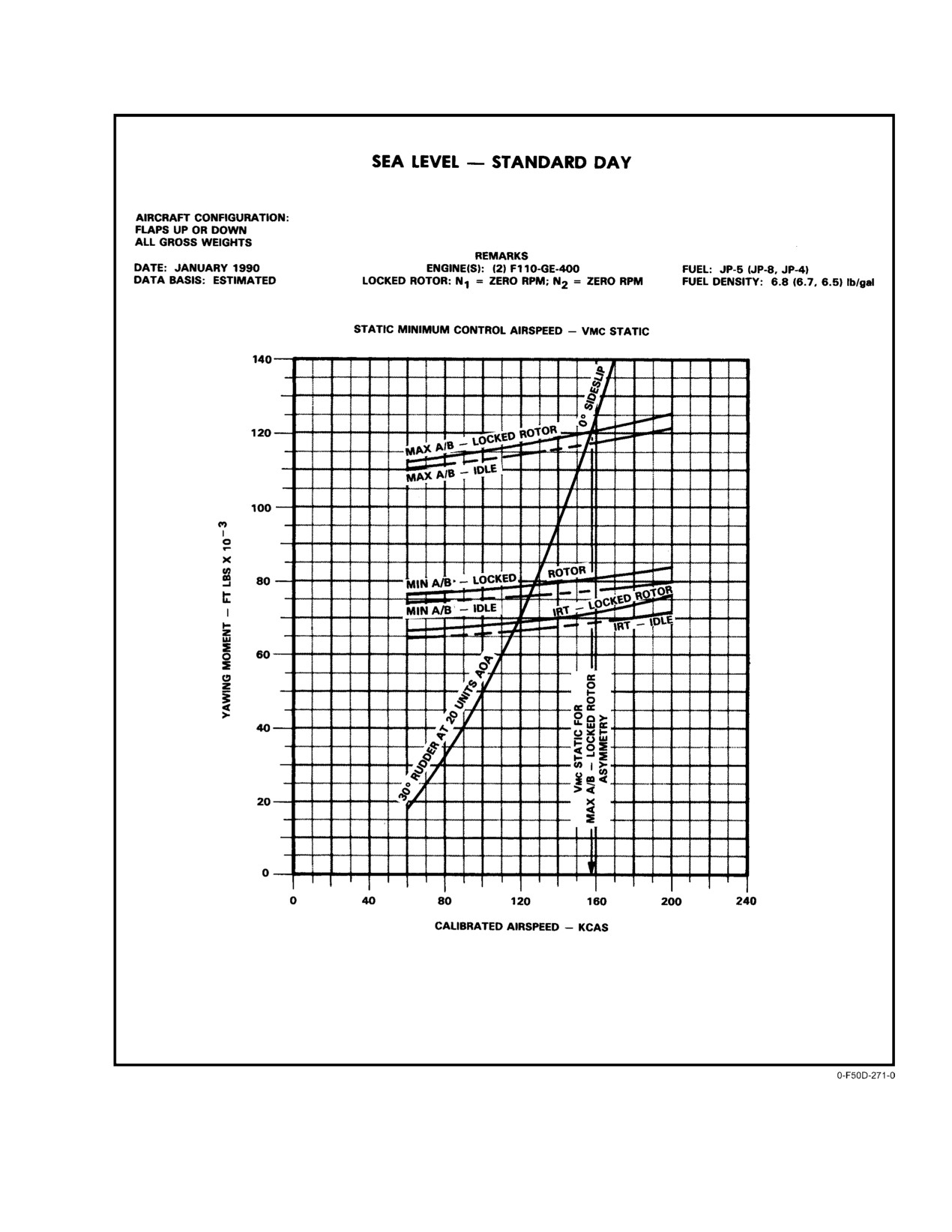
NAVAIR 01−F14AAD−1
Figure 11Ć8.ĄRudder Effectiveness
11−25
ORIGINAL
NAVAIR 01−F14AAD−1
combined hydraulic pressure, DLC should be engaged when
and is prohibited. The aircraft is extremely difficult to control
established on final approach. Any maneuver required prior
in MAX A/B and large bank angles into the operating engine
to rolling out on final approach should be accomplished using
are required to maintain centerline. Late or inadequate
12 units AOA or less. Once established on final approach, fly
control inputs during a MAX A/B waveoff can result in large
15 units or faster (DLC engaged) or 14 units or faster (no
lateral flightpath deviations. If unable to control yaw rate
DLC) to provide additional control power.
during A/B waveoff (possible ATLS failure), immediately
reduce power to MIL.
Note
11.8.5.4
Landing Configuration Ċ
While shipboard recoveries mandate the use of
Engine in Secondary
the minimum recommended approach airspeed
because of aircraft and arresting gear structural
Approaches in single−engine SEC mode are considered
limitations, field recoveries benefit from slightly
extremely hazardous. Thrust response in secondary mode is
faster airspeeds because of the increased control
nonlinear and very sluggish. At military power, thrust in
power and reduced apparent thrust asymmetry.
secondary mode can vary from as little as 65 percent to as
much as 116 percent of primary mode thrust at MIL power.
Airspeed control for a 14−unit approach is difficult,
Although the majority of engines produce greater than
therefore, there may be a tendency to overcontrol power. An
90 percent of primary mode thrust (at MIL power), the
effective technique is to have the RIO provide airspeed calls
possibility exists that in the full flap configuration, a
(i.e.,
2 knots slow/fast") to the pilot during final approach.
low−thrust engine will not provide enough thrust for level
With DLC engaged, minimize use of the throttle in close and
flight. Engine acceleration times can also vary and can be as
use DLC for fine glideslope corrections. Decreasing the
much as three times longer than in primary mode. Aircraft
amount of throttle activity will limit excitation of the dutch
should recover ashore. Shipboard landings should only be
roll. RATS will engage on touchdown, but does not
attempted as a last resort and only if performance is adequate.
significantly affect CV bolter performance. MIN A/B (ATLS
See Chapter 15 for performance check and specific emergenĆ
on) may be used if required. During a bolter, apply rudder
cy procedures.
simultaneously with power addition to maintain centerline.
Adequate directional control power exists to prevent drift on
DLC should not be engaged for any single−engine SEC
bolter.
mode approaches. Any maneuver required prior to rolling out
on final approach should be accomplished using 10 units
Military thrust waveoff performance in primary mode
AOA or less. Once established on final approach, fly 13 units
is good, averaging 30 to 40 feet of altitude loss from a
or faster to improve waveoff capability and provide additionĆ
nominal 600−fpm sink rate. Waveoff performance from high
al control power.
sink rates is improved using MIN A/B (ATLS on). Altitude
loss is minimized by maintaining approach AOA (slight,
Note
gradual pitch rotation required).
While shipboard recoveries mandate the use of
the recommended approach AOA because of airĆ
Note
craft and arresting gear structural limitations,
field recoveries benefit from slightly faster airĆ
Altitude loss during a single−engine waveoff is
speeds because of the increased control power
minimized by maintaining approach AOA until
and reduced apparent thrust asymmetry.
a positive rate of climb is established. Avoid
overrotating in close as this will increase the
Airspeed control for a 13−unit approach is difficult,
chance of an in−flight engagement. MIN A/B
therefore, there may be a tendency to overcontrol power. An
(ATLS on) may improve waveoff performance
effective technique is to have the RIO provide air−speed calls
from high sink rates.
(i.e.,
2 knots fast") to the pilot during final approach.
Extreme care should be used when working off a high and/
Sufficient rudder control power exists to maintain
or fast condition as any large power reduction could result in
control of the aircraft during MIL and MIN A/B single−enĆ
a situation requiring military power for correction. Use small
gine waveoffs, provided AOA is not allowed to increase
throttle movements and small attitude adjustments for
above 18 units. Simultaneously add rudder (approximately
glideslope corrections. Avoid nosedown attitude changes just
two−thirds to three−fourths deflection) with power to counter
prior to touch−down as this will minimize the chance of a
the asymmetric thrust and track centerline. If a yaw rate
hook skip bolter. In the event of a bolter, rotate to a 10_ pitch
develops into the failed engine, immediately apply full
attitude, not to exceed 14 units AOA. During a bolter, apply
opposite rudder to arrest the yaw rate and then reduce rudder
rudder simultaneously with power addition to maintain
as required to track center−line. Rudder may be supplemented
centerline. Adequate directional control power exists to
by small lateral stick inputs. The use of MAX A/B offers little
prevent drift on bolter.
or no improvements in single−engine waveoff performance
ORIGINAL
11−26
NAVAIR 01−F14AAD−1
Waveoff performance in secondary mode may be poor
dation in approach handling characteristics and is generally
and high sink rates must be avoided. The poor engine
only apparent when large bank angle changes are commandĆ
acceleration in SEC mode makes engine rpm at waveoff
ed, such as during roll into and out of the approach turn. If the
initiation a major factor in waveoff performance. Grossly
outboard spoiler module fails when the flaps and slats are
underpowered conditions must be avoided. During single−
down, the spoilers may float up and lock at some position
engine waveoffs in secondary mode, rotate the aircraft
above neutral. This may be accompanied by trim changes in
slightly to capture/maintain 14 to 15 units AOA as this will
all three axes, which can be trimmed out. Approach speed
help to break the rate of descent.
will increase slightly if a spoiler float occurs. If the failure
occurs when the flaps are up, spoiler float is minimized.
WARNING
Single−engine waveoff performance with operatĆ
ing engine in SEC mode will be severely deĆ
In the event of outboard spoiler module failure,
graded. Extreme care should be used to avoid an
do not engage DLC or ACLS.
underpowered, high rate−of−descent situation.
11.8.8
SAS Off
11.8.6
Degraded Approach Configuration
Approach characteristics with either ROLL or YAW
Refer to Chapter 15 for degraded approach emergency
SAS OFF will be significantly degraded compared to the
procedures.
baseline PA−ARI flying qualities. Failure of either ROLL or
YAW SAS (or selecting either ROLL or YAW STAB AUG
11.8.6.1
No Flaps, No Slats, and Wings at 20_
switch OFF) will revert the DFCS from the PA−ARI control
If a no−flap, no−slat landing is anticipated, a straight−in
mode to basic SAS" control mode (loss of ARI functionalĆ
approach should be performed because of the narrow margin
ity). Directional damping and roll response to lateral stick
afforded between 15 units AOA and the onset of airframe
inputs will both be significantly reduced compared to
buffet. The approach is flown at 15 units AOA. Airframe
baseline performance.
buffet will occur at 16 to 17 units AOA with wing drop
11.8.9
Aft Wing−Sweep Landings
(5_Ăto 10_) and/or an increase in sink rate occurring at 16.5
to 17.5 units AOA. Spoiler effectiveness is slightly degraded
The aircraft may be safely landed with the wings as far
because of the absence of the aerodynamic slot formed when
aft as 40_ (CV) and 68_ (field). If the wings fail to respond
the flaps are extended. Precise airspeed control is essential
to command, the emergency wing−sweep handle should be
for a no−flap/no−slat approach. Fast or high/ fast approaches
used to match the captain bars (commanded position) with
result if timely throttle adjustments are not made throughout
the wing−sweep position tape. Matching the captain bars with
the approach. The pilot must wave off approaches that result
the position tape ensures the commanded position is the same
in large throttle reductions (to near idle) in close.
as the actual position, removing hydraulic pressure from the
wing−sweep motors (hydraulic pressure will still remain
present at the wing−sweep control servo valve/four way
valve). This reduces the likelihood of hydraulic failure or
asymmetric wing sweep because of the failure of the
crossover shaft. Optimum AOA for shipboard aft wing sweep
Nose attitude control is more sensitive during a
approaches is 15 units. AOA may be increased up to 17 units
no−flap approach, and care must be exercised not
maximum for field landings to minimize approach airspeed
to overcontrol nose corrections in close. Cocked−
for normal field landings or remain within published
up, high−sink landing can result in damage to
arresting gear limitations for short−field arrested landings.
ventral fins and/or afterburners.
At wing−sweep angles of ≥ 51_, each 1−unit increase in
11.8.7
Outboard Spoiler Module Failure
approach AOA reduces approach airspeed by approximately
5 knots. Airspeeds for various configurations are shown in
When the wings are forward of 62_, loss of outboard
Figure 11−9.
spoilers results in a decrease in roll authority and in lateral
control effectiveness. Such loss causes no significant degraĆ
11−27
ORIGINAL
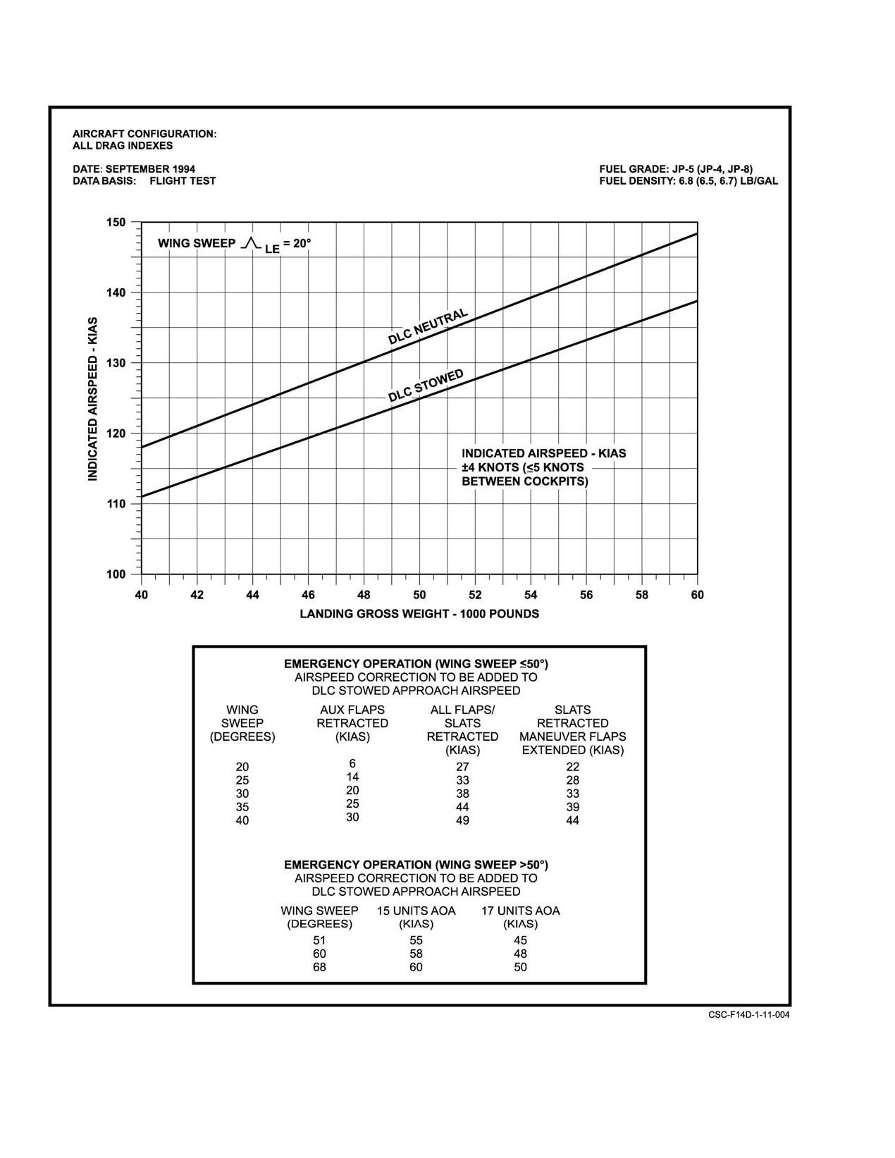
NAVAIR 01−F14AAD−1
Figure 11Ć9.ĄLanding Approach Airspeed (15 Units AOA)
ORIGINAL
11−28
NAVAIR 01−F14AAD−1
With the wings frozen forward of 50_, the main flaps/
aircraft rate of descent during a waveoff. Single−engine
slats should be used. A normal 15−unit approach should be
approaches with aft wing sweep have not been tested and
used in this configuration and approach speeds will remain
rudder control power may be limited in this condition. Fuel
within field arresting gear limitations. If main flaps/slats are
permitting, aircraft handling and stall characteristics as well
not available, maneuvering flaps should be used. Extension
as waveoff performance should be evaluated at altitude prior
of the main flaps/slat only will result in a flap light with the
to commencing an aft wing−sweep approach.
wings aft of 20_.
If using an approach AOA greater than 15 units, nozzle
clearance at touchdown is reduced. Additionally, the high
rate of descent
(approximately
1,000 fpm on a
3.25_
glideslope) and high touchdown speed place high stress on
the main landing gear tires. The recommended technique for
If maneuvering flaps are used, ensure that the
field landings is to maintain a maximum of 17 units AOA
maneuver flap thumbwheel is not actuated durĆ
while attempting to minimize the rate of descent just prior to
ing the approach.
touchdown. Do not attempt to flare the landing and do not
Note
aerobrake.
Main flaps/slats extension with the wings aft of
20_ will result in a large nosedown pitch tranĆ
sient.
DLC should not be engaged as it increases final
approach speeds. APC gains are not optimized for wing
Nozzle clearance is reduced at elevated approach
sweeps other than 20_ and, therefore, APC should not be
AOA. Ensure that a maximum of 17 units AOA
used. Reducing gross weight will reduce approach speed by
is maintained at touchdown.
about 3.5 knots for each 2,000−pound reduction in gross
Aft wing−sweep touch−and−go performance has not
weight at the 68_ wing−sweep position. Pilot over−the−nose
been flight tested; however, rotation speeds approaching or
visibility is adequate at both 15 and 17 units AOA. The RIO
possibly exceeding tire limitations should be expected. Nose
will lose sight of the ball because of the higher pitch attitude
tire limitations, runway remaining, status of long−field
at 16 to 17 units AOA on the standard 3.25_ field glideslope.
arresting gear, and tire pressurization must all be factored
Flying characteristics in aft wing−sweep configurations
into a decision to go around following a hook skip. If
are dependent on wing−sweep angle and AOA. As wing−
committed to landing following a hook skip with operative
sweep angle increases, trimmed stick position moves aft. At
hydraulics, consideration should also be given to securing the
68_ sweep, roll performance is sluggish but adequate at up
starboard engine in order to reduce residual thrust.
to 17 units AOA with ROLL SAS engaged. At up to 62_ wing
Engagement speeds listed in the emergency field
sweep, differential tail is augmented with spoiler for roll
arrestment guide are groundspeeds. Headwind may be
control. The aircraft exhibits a very strong dihedral effect
subtracted from final approach airspeed, tailwinds must be
with the wings swept aft, enabling rudder to be used to
added, and compensation must be made for field elevation
augment roll performance, if desired. Crosswind landings
(add approximately 10 knots to arresting gear limit for a field
have not been evaluated at or near the aircraft crosswind
elevation of 4,000 feet).
limit, but a crabbed approach is recommended vice the
wingdown, top−rudder technique. Ensure that the fuselage is
If speedbrakes are not available, thrust requirements on
aligned with the runway prior to touchdown.
glideslope are decreased and judicious throttle management
is more critical.
Although pitch control is adequate, maintaining trim
airspeed is increasingly difficult with increasing sweep angle
because of low stick force cues for airspeed deviations. This
necessitates close monitoring of airspeed by the aircrew since
the approach indexers are unusable above 16 units AOA. As
wing sweep progresses further aft, stall becomes less clearly
If maneuver flaps are used, the pilot must ensure
defined. There is no strong aircraft buffet when AOA is
that the maneuver flap thumbwheel is not actuĆ
increased beyond 17 units. Aircraft waveoff performance is
ated during the approach.
adequate at both 15 and 17 units AOA. During single−engine
operation, up to maximum power may be required to arrest
11−29
ORIGINAL
NAVAIR 01−F14AAD−1
11.8.10
DFCS Degraded Control Modes
A normal landing approach can be flown with any
single segregation failure. Combined failure of any two
The DFCS is capable of operation in numerous
segregations results in combined loss of all associated
degraded mode control configurations. Description of all
functions, actuators, and in most cases, additional failures.
possible degraded modes is not practical; however, several of
Failure of both pitch or both roll segregations results in loss
these modes are listed below with a description of resulting
of all spoilers and severely degraded roll performance.
functionality and effect on approach flying qualities.
Failure of both roll or both yaw segregations results in loss
of PA−ARI and downgrade to basic SAS" mode in the
11.8.10.1
DFCS Computer Failures
remaining axes. This will be manifested by significantly
Each of the three DFCCs contains two distinct
decreased roll performance and significantly decreased
computer processors called computing segregations, one
directional damping. A straight−in approach with as little
A" segregation and one B" segregation in each axis. Each
crosswind as possible is recommended. Lateral stick inputs
may require coordinating rudder to obtain adequate roll
segregation commands different series servo and/or spoiler
sets. If a computing segregation fails, all actuators commandĆ
response and to minimize dutch roll disturbances.
ed by that segregation are rendered inoperative. FunctionalĆ
ity loss due to failure of each of the segregations and effect
11.8.10.2
DFCS Air Data Failures
on takeoff and landing flight characteristics are as follows:
Failure of the Mach number or AOA inputs to the
DFCS results in degraded mode operation for several
Pitch A
− Half authority PITCH SAS, no inboard
PA−ARI control functions. These control modes still provide
spoilers, no DLC. Slightly decreased pitch dampĆ
excellent flying qualities such that a normal approach can be
ing, decreased roll performance.
flown, but are somewhat degraded from the fully operational
PA−ARI performance.
Pitch B − Half authority PITCH SAS, no outboard
spoilers, no DLC. Slightly decreased pitch dampĆ
A DFCS Mach failure will always occur due to failure
ing, decreased roll performance.
of the SCADC, but may also occur independently from a
SCADC failure. Mach failure results in a nearly transparent
Roll A − Half authority ROLL PA−ARI/SAS, no inboard
degrade in directional damping, which may become noticeĆ
spoilers, no DLC. Decreased roll performance.
able at conditions slower than on−speed. A single AOA
failure results in no degradation in flying qualities, only a loss
Roll B − Half authority ROLL PA−ARI/SAS. Slightly
of redundancy, since the input is triplex. Dual AOA failure
decreased roll performance.
results in decreased directional damping, decreased roll
performance, and decreased spiral mode damping.
Note
Note
Autopilot control modes, including ACLS, are
not available with any pitch or roll segregation
Significant PA−ARI functionality is retained with
failed.
dual Mach or dual AOA failures as compared to
UA−ARI. For this reason, ROLL DGR and ARI/
Yaw A − Half authority YAW PA−ARI/SAS. Decreased
SAS OUT caution lights will be automatically
directional damping. This may only be apparent
extinguished upon selection of the landing gear
during moderate to aggressive maneuvering, since
handle from the up to the down position.
the gain in the yaw channel B is doubled to comĆ
pensate for the loss of the yaw A series servo. Full
11.8.10.3
Series Servo Failures
YAW SAS performance is thus retained up to the
authority limit of the remaining yaw series servo
Reduced authority and rate damping performance will
(+9.5_ rudder).
be experienced in the affected axis. Failure of both roll or
both yaw series servos results in loss of PA−ARI and
Yaw B − Half authority YAW PA−ARI/SAS, no outboard
downgrades the DFCS to the basic SAS" control mode in the
spoilers, no DLC. Decreased directional damping,
remaining axes. Decreased roll performance and decreased
but only for aggressive maneuvers as previously deĆ
directional damping will be exhibited. A normal approach
scribed for the yaw A segregation. Decreased roll
can be flown with any single failure, a dual pitch, or a dual
performance.
roll series servo failure. In case of dual failure of the yaw
series servos, recommend a straight−in approach using
smooth lateral inputs with coordinating rudder to minimize
dutch roll disturbances.
ORIGINAL
11−30
NAVAIR 01−F14AAD−1
11.8.10.4
Spoiler Failures
Rudder Pedal Position − No pedal fadeout for lateral stick
to rudder interconnect or roll rate command funcĆ
As described under DFCC computer failures, failure of
tions in the PA−ARI control mode. These pedal fadeĆ
four of the six segregations will result in loss of a spoiler set
out features are incorporated to improve the pilot’s
(inboard or outboard) and associated decreased roll perforĆ
ability to command a steady sideslip condition durĆ
mance. DLC is not functional with any inboard spoiler
ing a slipped (i.e., wing−down−top−rudder) crossĆ
failure, but is available with any or all outboard spoilers
wind approach. With a pedal position failure, preĆ
failed. Failure of any single spoiler panel will result in
cisely controlling bank angle during a slipped
mirror−image" spoiler operation of the remaining spoilers,
approach is more difficult than with the baseline
as long as the failed spoiler responds to the automatic
system. A crabbed technique is recommended.
isolation command (returns to stowed position). For examĆ
ple, failure and successful isolation of the Left #4 spoiler
Landing Gear Handle Position − No PA−ARI, downmode
panel also results in automatic isolation of the Right #4
to UA−ARI control mode for all flight configuraĆ
spoiler panel. Symmetric, but slightly degraded roll perforĆ
tions. During normal operation, mode switching beĆ
mance will be evident. A normal approach can be flown in
tween the PA−ARI and UA−ARI control modes is
this case. If a spoiler failure results in a stuck−up spoiler,
controlled by sensing of the landing gear handle
normal control of the mirror−image" panel will be automatiĆ
position. If a dual failure of this triplex input fails,
cally restored to provide maximum roll control power to
the DFCS can no longer accurately determine the
counter the rolling moment induced by the stuck−up spoiler.
actual gear handle position. The fail−safe condition
Refer to Spoiler Malfunction emergency procedures for
in this case is to revert to the UA−ARI (i.e., gear up)
landing in this configuration.
control mode. This results in decreased roll perforĆ
mance and decreased directional damping. A norĆ
11.8.10.5
Sensor Failures
mal approach can be flown.
Single failure of any DFCS sensor input does not result
in a flying qualities downgrade, only a loss of redundancy,
Note
since all sensor inputs are triplex. Dual failure of a sensor
input causes loss of the functions associated with that sensor.
If a dual failure of the landing gear handle posiĆ
A list of these sensor inputs and associated dual failure
tion input to the DFCS occurs, the ARI/SAS
functionality loss are as follows:
OUT caution light will illuminate when flaps are
lowered past the 25° position. This indicates loss
Pitch Rate − No PITCH SAS. Decreased pitch damping.
of normal PA−ARI function.
A normal approach can be flown.
11.9 ASYMMETRIC WING SWEEP
Roll Rate − No ROLL SAS, no PA−ARI. Decreased roll
11.9.1
Wing−Sweep Design Limitations
performance and decreased directional damping.
A normal approach can be flown.
An understanding of the wing−sweep design limitaĆ
tions is necessary to cope successfully with an in−flight
Yaw Rate − No YAW SAS, no PA−ARI. Decreased roll
asymmetric wing condition to avoid the possibility of
performance and significantly decreased directionĆ
structural damage and to minimize the possibility of loss of
al damping. Recommend straight−in approach using
aircraft control. The following discussion is therefore
smooth lateral inputs with coordinating rudder to
offered.
minimize dutch roll disturbances.
The wing−sweep feedback position and interlock
functions for the auxiliary flaps, main flaps/slats, and spoiler
Lateral Acceleration − No YAW SAS, no PA−ARI. DeĆ
creased roll performance and significantly deĆ
cutout are controlled by the left wing−sweep actuator.
Cockpit wing−sweep position indication is controlled by the
creased directional damping. Recommend straight−
in approach using smooth lateral inputs with
right wing−sweep actuator.
coordinating rudder to minimize dutch roll disturĆ
The existence of wing−sweep position feedback on the
bances.
left wing only can have a definite impact during a jammed
wing−sweep actuator/failed synchronizing shaft condition. A
Lateral Stick Position − No ROLL SAS, no PA−ARI, no
jammed right wing−sweep actuator will result in normal left
spoilers. Severely degraded roll performance and
wing operation because wing−sweep commands are nulled
decreased directional damping. Recommend
out by the left wing−sweep actuator position. A jammed left
straight−in approach with as little crosswind as posĆ
wing−sweep actuator in an intermediate position, in conjuncĆ
sible. Lateral stick inputs may require coordinating
tion with a wing−sweep command, will result in a constant
rudder to obtain adequate roll response.
11−31
ORIGINAL
NAVAIR 01−F14AAD−1
command to the right wing−sweep actuator that cannot be
Note
nulled, since the right wing has no position feedback. In this
Extending the main flaps with the auxiliary flaps
case, the right wing will travel to the overtravel stop (19_ or
inhibited will result in a large nosedown trim
69_) in the direction of the last command. The right wing can
change.
be positioned in either the 19_ or 69_ position only, but not
in any intermediate position since there is no way to null out
The wing−sweep control drive servo is powered
the command. A condition similar to a jammed wing−sweep
through WING SWEEP DRIVE NO. 1 (LD1) and WG SWP
actuator occurs when one hydraulic system has failed in
DR NO. 2/MANUV FLAP (LE1) circuit breakers. Pulling
conjunction with a synchronizing shaft failure.
these circuit breakers inhibits all electrical command paths
to the wing−sweep control valve. Manual commands to the
A temporary actuator jam on one side while the wings
valve are available through the emergency WING SWEEP
are sweeping, in conjunction with a broken synchronizing
handle. Pulling the WG SWP DR NO. 2/MANUV FLAP
shaft, will result in resumption of operation with asymmetriĆ
(LE1) circuit breaker removes power from the maneuver
cal wing positions. Symmetrical wing position, within 1_,
devices and inhibits automatic retraction of the maneuver
can be achieved again by commanding the wings full forward
devices with landing gear handle extension. The maneuver
or full aft (20_ or 68_). The direction to command the wing
devices should be commanded up prior to pulling the WG
is dependent on whether the right wing is forward or aft of the
SWP DR NO. 2/MANUV FLAP circuit breaker. It may also
left position. The right wing position is displayed by the wing
be necessary to utilize emergency up on the flap handle to
position tape on the cockpit wing−sweep indicator. If for
achieve full flap and slat retraction.
example, the right wing is forward of the left wing, the wings
should be commanded full forward to 20_. The right wing
11.9.2
Asymmetric Wing−Sweep Flight
will drive to the 19_ overtravel stop and remain there until the
Characteristics
left wing reaches 20_, nulls the command, and hydraulic
power is shut off. If the right wing is aft of the left wing, the
Asymmetric wing−sweep failures will be manifested as
wings could be commanded full aft to 68_. The right wing
a wing heaviness accompanied by a WING SWEEP advisory
will drive to the 69_ overtravel stop and remain there until the
light, indicating a failure of the primary wing−sweep channel.
left wing reaches 68_, nulls the command, and hydraulic
A subsequent failure of the backup wing−sweep channel will
power is shut off.
illuminate the WING SWEEP warning light.
Normal symmetrical wing−sweep operation, within 1_,
Flight tests have shown that the aircraft may be safely
should follow. Some jeopardy exists during aft command
landed with asymmetric wing sweep as long as spoiler
operation since spoiler control will be lost when the left wing
control is retained following the wing−sweep failure.
obtains 62_.
The aircraft is not controllable for landing with a wing
asymmetry such as the left wing aft of the spoiler cutout angle
Note
(62_) and the right wing forward at 20_. The maximum
asymmetry demonstrated for landing was 20_/60_, although
A mechanical jam in the wing−sweep system may
tests of 20_/68_ at altitude indicate that this configuration is
prevent the wings from being resynchronized.
landable if spoilers are operational (that is, the left wing is at
This may be because of the failed synchronizing
20_ and the right wing is at 68_). The high approach speeds
shaft jamming an actuator.
coupled with reduced lateral control authority obtained with
The auxiliary flaps/main flap interlocks are controlled
asymmetric sweep become limiting factors for aircraft
by the left wing−sweep actuator. This means that during
carrier
(CV) operations. If at all possible, the flightcrew
asymmetric wing conditions, it is possible to satisfy the
should attempt to divert for a field landing. In−flight refueling
interlock requirements with the left wing and damage aircraft
was not evaluated during flight tests. Cruise configuration
structure with the off−schedule right wing. For example, if the
flying qualities in the normal refueling airspeed range
left wing is at 20_ and the right wing is at 35_, the 21_
(approximately 250 knots) were qualitatively assessed to be
interlock in the auxiliary flap system is satisfied by the left
suitable for the task. The effects of asymmetric sweep are
wing. Lowering the flaps without inhibiting auxiliary flaps
diminished as airspeed increases
(decreasing angle of
will drive the auxiliary flaps through the fuselage in the
attack), so that using a higher than normal tanking speed may
vicinity of the flight hydraulic system. Pulling the AUX
decrease pilot workload. Lateral and directional trim should
FLAP/FLAP CONTR circuit breaker (8G3) will remove
be utilized to decrease lateral stick force during refueling and
electrical power to the auxiliary flaps and prevent auxiliary
cruise flight.
flap deployment.
ORIGINAL
11−32
NAVAIR 01−F14AAD−1
Note
the existence of significant pitch−roll coupling. This is
especially critical with flaps up. In general, the aircraft tends
The use of lateral trim to reduce stick force durĆ
to increase angle of attack when rolling toward the forward
ing approach and landing should be avoided,
wing and decrease angle of attack when rolling toward the aft
however, because it reduces the amount of spoilĆ
wing. In order to provide adequate maneuvering margin
er available for roll control.
below the stall buffet region, recommended approach AOA
is 14 units for all flap−up, asymmetric wing configurations
Asymmetric wing sweep is primarily a lateral control
up to 40_ differential split (Figure 11−10). A landing with
problem, increasing in severity as angle of attack increases
the maximum possible asymmetry of 20_/68_ will require
and as flap deflection increases. The aircraft will roll toward
13 to 14 units AOA to provide adequate control for approach
the aft wing and yaw toward the forward wing. For example,
right wing forward of left wing causes left−wing−down roll
and landing as long as spoilers are available (left wing at
20_, right wing at 68_). Recommended approach AOA is
and nose−right yaw. The resultant sideslip angle is favorable
15 units for all flap−down, asymmetric wing configurations
from a controllability standpoint and should be removed with
(Figure 11−10).
rudder only if it is uncomfortable to the pilot. Rudder trim
into the forward wing may be utilized, if desired, to increase
If the left wing is positioned aft of the spoiler cutout
sideslip angle and generate a restoring rolling moment via
sweep angle (62_) the spoilers are inoperative and lateral
dihedral effect (right rudder trim for right wing forward of
control is limited to differential tail only. Flight tests indicate
left, and vice versa). Lateral stick force will be accordingly
that the maximum controllable asymmetry at 14 units AOA
reduced.
in this configuration is a 15_ differential split. The preferable
action in this case is to attempt to move the left wing forward
Main flaps should be utilized to decrease approach
of the spoiler cutout angle to regain spoiler control. If this is
airspeed for asymmetric sweep landings if both wings are
forward of 50_ sweep. During flight tests, a flap setting of
not possible, an attempt should be made to command the
right wing as far aft as possible in order to minimize the wing
20_ to 25_ was found to provide the best flying qualities in
asymmetry, and then perform a slow flight check at altitude
comparison to the other flap settings tested (0_, 10_, 35_).
to determine the minimum control speed. The pilot must then
Safe landings may be performed, however, with all the flap
determine if the configuration provides a reasonable apĆ
configurations evaluated. In the flaps−up configuration,
proach airspeed.
undesirable prestall buffet is experienced at 16 to 16.5 units
AOA for all wing asymmetries.
Sideslip−induced pitot static system errors may be
experienced with all asymmetric wing−sweep configuraĆ
Stall−induced buffet is not experienced in flaps−down
tions. Accurate airspeed/AOA indications may be obtained
configurations because the leading edge slat delays wing
by bringing the aircraft to a zero−sideslip condition. A
stall. Airframe buffet may occur, however, because of the
wingman may provide an airspeed check prior to landing.
turbulent airflow that passes through the auxiliary flap hole
that impinges on the horizontal tails. This buffet increases
with increasing flap deflection and is significantly worse
11.10
DUAL HYDRAULIC FAILURES BACKUP
with 35_ flaps as compared to 10_ or 20_. In addition to
FLIGHT CONTROL MODULE FLIGHT
increased buffet levels, the 35_ flap configuration is prone to
CHARACTERISTICS
lateral PIO during high−gain tasks such as close−in lineup
11.10.1 General
corrections. This is primarily because of the increased spoiler
effectiveness obtained with power approach spoiler gearing.
Several factors work in concert to affect the handling
The PIO tendency is eliminated by selecting flaps 25_ or less,
qualities of the F−14 when operating with a dual−hydraulic
which causes a switch to cruise spoiler gearing. Raising the
failure. The first is the total loss of the SAS in all three axes.
flaps only causes the spoilers to move from the drooped"
Since the bare airframe is lightly damped in both pitch and
position to the zero position, retaining power approach
yaw, gusts and small control inputs result in uncommanded
spoiler gearing. This configuration is not flight tested in
responses or oscillations. The pilot’s general impression is
DFCS.
that the aircraft is sloppier in all axes and precise control is
more difficult. The pilot does have some control over these
All asymmetric wing configurations require precise
characteristics as they are very dependent on configuration
monitoring of AOA during lateral maneuvering because of
and airspeed.
11−33
ORIGINAL
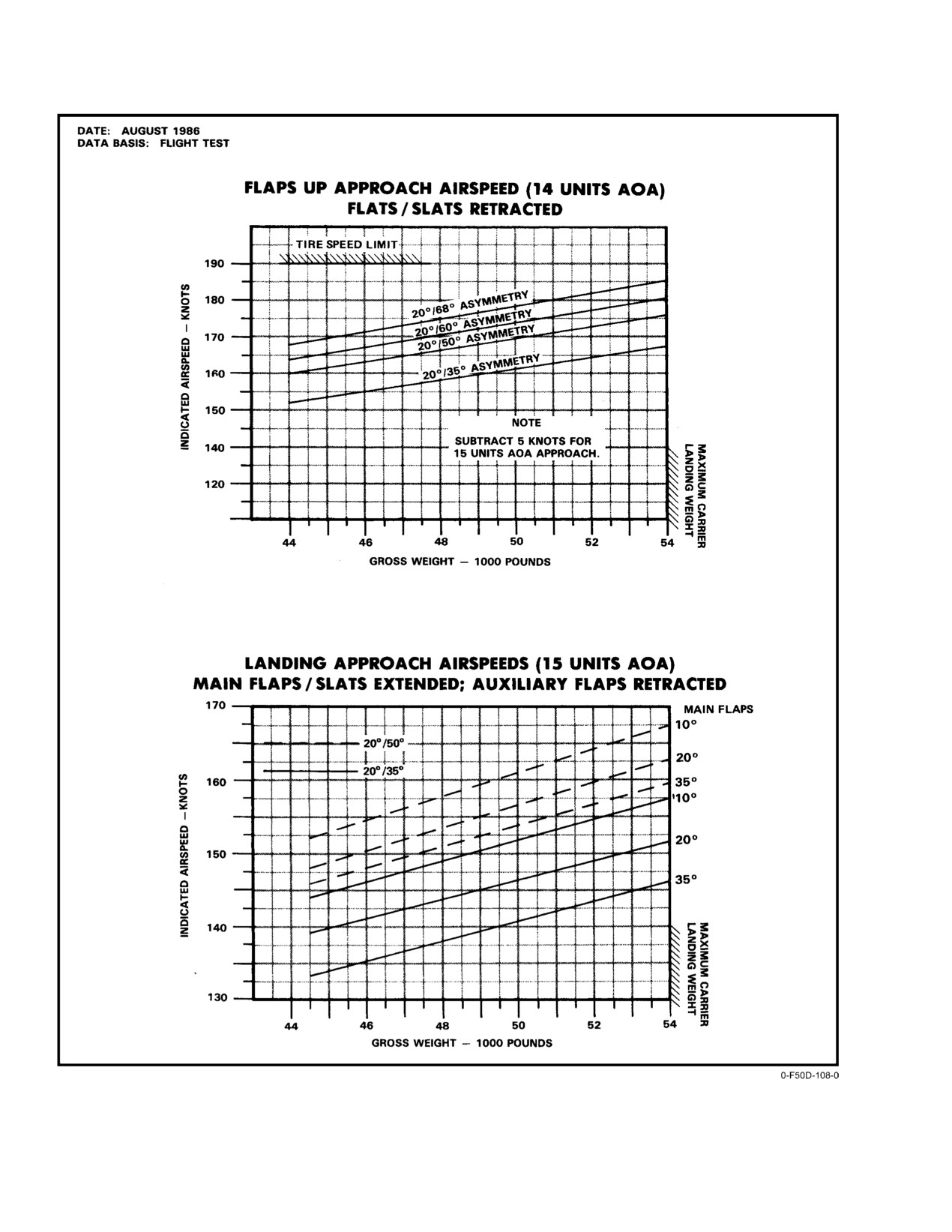
NAVAIR 01−F14AAD−1
Figure 11Ć10.ĄAsymmetric Wing−Sweep Landing Approach
ORIGINAL
11−34
NAVAIR 01−F14AAD−1
The second factor is the capabilities of the remaining
available, but may be aggravated by large lateral or
flight control system. The inboard spoilers, speed−brakes,
directional flight control inputs that further reduce the flow
and auxiliary flaps are inoperative, and the in−board spoilers
available to command the stabilizer and, therefore, increase
and speedbrakes can be expected to float. The degree of
the susceptibility to rate limiting in pitch. LOW mode is
spoiler float will be a function of airspeed, AOA, sideslip,
extremely limited in its ability to accommodate rapid control
flap setting, and the mechanical condition of individual
inputs, while the HIGH mode can accommodate moderate
spoiler actuators. During flight test, changes in float are very
pilot control inputs.
slow and do not generate any abrupt rolling moments but do
The abrupt degradation that occurs with rate limiting
impose significant lateral trim changes. Outboard spoilers
makes the handling qualities hazardous. The handling
remain fully functional because of the independent nature of
qualities of the aircraft while operating with the BFCM in
the outboard spoiler module, which also serves to power the
HIGH are generally good for moderate gain tasks, and it is
main flaps and slats via the flap handle or the maneuver flap
virtually transparent to the pilot that the flight control system
thumbwheel. Lastly, only the rudders and horizontal stabilizĆ
is degraded. However, when operating near the rate limit of
ers are powered by the BFCM. Because of the low output of
the system, very small increases in pilot gain will result in an
the BFCM, the stabilizers are dramatically reduced in their
abrupt and dramatic loss of control and the task being
ability to respond to pilot commands. The stabilizers are rate
performed must be aborted
(i.e., the aircraft cannot be
limited to 10_ per second in HIGH and 5_ per second in LOW
controlled adequately to continue the task). Uncontrollable
as opposed to a normal rate of 36_ per second. This can be
pitch attitude oscillations of +10_ can develop in less than
a severe limitation to the pilot’s ability to control the aircraft,
3 seconds. Regaining control is simply a matter of loosely
depending on the abruptness of the pilot commands.
releasing the stick, permitting the oscillations to dampen, and
Each of these factors influences the handling qualities
then smoothly reapplying control to restore the aircraft to the
in different regions of the flight envelope. Handling qualities
desired flight condition. In summary, if the system is not rate
at speeds in excess of 200 KCAS are primarily constrained
limited, the handling qualities are good; if the system is rate
by the absence of PITCH SAS and the limitations of the
limited, the aircraft rapidly becomes uncontrollable.
BFCM. At approach speeds, the handling qualities are
primarily affected by floating spoilers and the loss of YAW
11.10.1.2
Task Performance
SAS, although rate limiting of the stabilizer can occur.
There are four variables that the aircrew can control to
maximize the probability of successfully completing mission
11.10.1.1
Rate Limiting
tasks. Selection of an appropriate motor speed is the first
The pilot will observe rate limiting both in the feel of
controllable variable. Tightly controlled tasks such as
the control stick and in the response of the aircraft. In the F−14
landing, close formation, and in−flight refueling require the
flight control system, the stick is mechanically connected to
control rates available with HIGH mode. Judicious selection
the stabilizer. With normal hydraulics, there is virtually no
of airspeed can also influence successful task performance.
time delay between the pilot’s command and the stabilizer
With SAS OFF, the sensitivity of the aircraft increases
moving in response to the command. With the BFCM
significantly with airspeed. The slower the airspeed, the
providing significantly less hydraulic flow, at a substantially
slower the response. For tightly controlled tasks, the flight
reduced pressure, the stabilizer moves so slowly that it is
control system must be capable of responding faster than the
possible for rapid pilot inputs to exceed the stabilizer
natural dynamic character of the aircraft, or the pilot must
maximum deflection rate. When this happens, the pilot will
accept undesirable overshoots and oscillations. The flight
feel an abrupt increase in stick force until the stabilizer
control system capabilities with the BFCM in either LOW or
catches up to the pilot’s command. If the pilot feels an abrupt
HIGH are very restricted. Part of the solution is to slow down
increase in stick forces, the stabilizer is operating on its rate
the aircraft and its response as much as is practicable to give
limit. This can be observed during the prestart BFCM checks
the flight control system the best chance of keeping ahead of
and is most severe in LOW.
the aircraft. The third variable is configuration, some of
which is more suited to specific tasks. Lastly, pilot technique
The pilot’s perception of the aircraft response is
may limit the ability of the aircraft to perform some tasks.
likewise affected by rate limiting because of slower response
The slower and smoother the input, the less likely rate
of the stabilizer to deflection commands. If slow control
limiting will be encountered. Flight tests performing each of
inputs are made, the delay is insignificant, aircraft response
the following tasks have revealed the mixture of the above
appears normal, and control is unaffected. If control inputs
variables whereby successful recovery of the aircraft can best
are abrupt, however, with many reversals in direction (such
be ensured.
as might be required to tank, land, or fly close formation), the
pilot and the stabilizers can be out of phase with one another,
and a divergent PIO will develop that results in loss of
control. This occurs in pitch caused by larger deflections
11−35
ORIGINAL
NAVAIR 01−F14AAD−1
11.10.2 Low Mode Cruise and Formation
technique. The best success can be expected at 180 KCAS
with maneuvering flaps and a smooth technique. There are
Cruise handling qualities in LOW mode are degraded
two reasons for the strong influence of airspeed. First of all,
but satisfactory. Roll response is very sluggish and some
tanking is easier to perform at slower speeds because the
over−shoots can be expected when trying to establish a bank
aircraft is much less sensitive, the bow wave is considerably
angle. In pitch, any abrupt pitch input at 250 KCAS or faster
reduced, and the probe position can be more predictably and
will result in multiple oscillations when trying to precisely set
smoothly controlled, reducing the necessity for aggressive
a pitch attitude. Flying very loose formation is fairly easy,
plays to seat the probe. Secondly, the BFCM has an easier job
provided tight control is not attempted. Any attempt to finely
keeping up with aircraft dynamics, decreasing the likelihood
control vertical elevation relative to a lead aircraft (≤ 2 feet)
of rate limiting. Any attempt to tank faster than 200 KCAS
will result in rate limiting the stabilizers and loss of control.
will result in loss of control. Tanking handling qualities are
Control can be reestablished by relaxing the grip on the stick,
unaffected by landing gear position and are improved with aft
allowing the oscillations to dampen, and then smoothly
wing sweeps in the event that the wings are trapped aft. Flaps
reapplying control. Slower airspeeds (200 KCAS) provide
should be selected to 10_ with the maneuver flap thumbĆ
for more predictable control as discussed in paragraph
wheel, which still functions normally with outboard spoiler
11.10.1. Do not attempt IMC formation, close night formaĆ
module power. Lastly, the influence of technique is that the
tion, in−flight refueling, or landing while in LOW mode.
rate limiting is caused by abrupt control inputs and counter
LOW mode control is satisfactory for the performance of
corrections. The
2 seconds surrounding contact are the
configuration changes such as lowering gear and flaps.
critical phase since the controls can be three times more
active than during the approach or stabilized refueling.
While spotting the basket is common throughout the
F−14 community, it is the surest way to place excessive
demands on the flight control system during the second or
A pitch PIO will develop if any tight longitudinal
two prior to contact and provoke a loss of control. The best
control is attempted. Control can easily be reĆ
way to avoid abrupt inputs is for the pilot to resist spotting the
gained by relaxing the grip on the stick, allowing
basket and instead rely on the RlO’s directive commentary.
any oscillations to dampen, and then smoothly
Since the stabilized refueling is easy and requires only
reapplying longitudinal stick to reestablish the
moderate flight control activity, the airspeed can safely be
desired flight condition. Do not attempt IMC
increased to 200 KCAS once engaged if additional airspeed
formation or close night formation while in LOW
is required to obtain proper store operation (as might be
mode.
required with ram−powered buddy stores such as the D−704
or D−301). While not flight tested, a very low gain technique
Note
must be used at the minimum airspeed attainable by the
Airspeeds less than 250 KCAS while operating in
tanker if the only resource is a large body tanker such as the
LOW mode will reduce the susceptibility to rate
KC−10, for which 180 KCAS might be impossible. The pilot
limiting.
must respond to any undesired motion by loosely releasing
11.10.3 High Mode Cruise and Formation
the stick and allowing the aircraft to dampen itself
Up and away flying qualities in HIGH mode are
generally excellent, with the only noticeable degradation
being a slight sluggishness in roll response. Cruise and
formation tasks are very easy, provided that very tight
D Any abrupt control input to effect engagement
tolerances are not attempted (< ±1 foot). Higher speeds (>
can rate limit the stabilizers and result in
250 KCAS) will increase the probability of rate limiting
loss of control. To avoid rate limiting, the
during parade formation. Close IMC or night formation is
pilot should resist spotting the basket and
possible but not advisable because the divergent PIO occurs
instead rely on RIO commentary to perform
very abruptly with no warning. The F−14 with the hydraulic
engagement.
failure should lead any formation flight except as required for
D If any undesirable motions or oscillations ocĆ
in−flight refueling.
curs during or after engagement, the pilot
11.10.4 In−Flight Refueling
must immediately release the stick and permit
the motions to dampen before resuming active
In−flight refueling can be safely performed but is very
control.
dependent on flight condition, configuration, and pilot
ORIGINAL
11−36
NAVAIR 01−F14AAD−1
ommended range. Smoothly rotate nose to
flyaway attitude on bolter.
D Carrier landings with a dual−hydraulic failure
are very hazardous and should not be attempted
Do not attempt in−flight refueling from wing−
because of the abrupt and unpredictable nature
mounted stores of large−body tankers (VC−10
of rate limiting. Control would most probably
Canberra) where nose−to−tail overlap is present.
be lost between the in−close and at−the−ramp
The basket does trail adequately aft of the tail for
positions when the pilot or LSOs could not
KC−130 and airwing assets.
avert a catastrophic flight deck mishap.
Note
If the air refueling store does not adequately
transfer fuel at 180 KCAS once engaged, the airĆ
speed can safely be increased to 200 KCAS to
improve the transfer rate.
Waveoff performance from low power settings is
very poor. Carrying extra speed during approach
11.10.5 Landing
will improve waveoff performance by permitting
smooth rotation to 15 units AOA to break the rate
Landing handling qualities are primarily affected by the
of descent while engines are spooling up.
loss of SAS, inboard spoilers, speedbrakes, auxiliary flaps,
and DLC, rather than limitations of the BFCM itself.
11.10.6 BFCM Thermal Durability
Longitudinal control is generally good provided no large
The thermal behavior of the BFCM and its isolated
abrupt pitch changes are attempted. Lateral control is
hydraulic loop determine the durability of the system. With
degraded by virtue of the inoperative SAS and inboard
the motor operating in LOW, the temperature of the motor
spoilers. Spoiler float and its impact on lateral control is
and the fluid will stabilize and the motor can run indefinitely.
considerably aggravated by slower airspeeds and increased
In HIGH, however, the motor can heat up within 8 minutes
flap deflections. Consequently, field landings should be
to temperatures at which it might fail. The motor should be
performed with the maneuver flaps down, and the MANUV
selected to HIGH only after the aircraft is on final with intent
FLAP/WG SWP DR NO. 2 circuit breaker pulled to lock them
to land, unless tanking is required. The motor should be
down (LE1). Airspeed control is degraded because of the
selected to LOW once safely airborne following waveoff,
dramatically decreased drag and low approach power setting.
missed approach, or bolter and then HIGH reselected on
Any airspeed from 15 units AOA to 180 KCAS should be
final. The elapsed time on HIGH must be closely monitored
considered acceptable with the wings at
20_; waveoff
if in−flight refueling is required. Once disengaged, LOW
performance is dramatically improved if some additional
must be immediately selected.
speed is carried. Fifteen units should be used if the wings are
trapped significantly aft. Speeds in excess of 180 KCAS on
final should otherwise be avoided because of the increased
susceptibility to rate limiting. Lateral control is degraded but
satisfactory, and a straight−in approach to an arrested landing
D Operations of more than 8 minutes total in
should be performed. The very low drag, runway length, long
HIGH may fail the BFCM motor. Extended
field gear, and length of time while operating on the BFCM
LOW operation (> 30 minutes) after in−flight
must all be considered in choosing a game plan for handling
refueling will permit several additional minĆ
bolters. The nose must smoothly be rotated to the flyaway
utes of use for subsequent landing.
attitude if a go−around is elected. Flaps can be selected to full
D Do not return to the AUTO (LOW) mode once
once on deck to obtain the additional drag from the outboard
module is selected on (HIGH or LOW) with
flap panels and ground roll braking from the outboard spoilers.
operating flight hydraulic system. When operĆ
ated in conjunction with zero combined presĆ
sure, some backup module fluid will be
expelled by thermal expansion. The module
will remain fully serviced and operate norĆ
D Aggressive nose movement in close or on
mally as long as elevated temperatures are
bolter can rate limit the stabilizer resulting in
maintained. Once operating, the module
low altitude loss of control. Do not use APCS.
should not be turned off in flight without comĆ
Glideslope is satisfactorily controlled with
bined system pressure available to reservice it.
appropriate use of power and smooth pitch inĆ
Doing so would result in fluid contraction and
puts, allowing airspeed to vary within the recĆ
an underserviced condition that could prevent
subsequent pump operation.
11−37
ORIGINAL
NAVAIR 01−F14AAD−1
11.11
FLIGHT CHARACTERISTICS WITH
wing sweep, 250 KCAS, and a zero fuel gross weight cg of
AFT CG LOCATIONS
18.6 percent, the aircraft exhibits some reduction in static
stability and is slightly more responsive to pitch inputs,
11.11.1
Store Effects on Cg Location
although this increase in responsiveness may not be signifiĆ
cant enough to be noticed during normal flight operations.
The normal NATOPS cg limits are expressed relative
Wing−mounted stores or external tanks have no adverse
to a reference condition known as zero fuel gross weight.
effects on aft cg flying qualities.
This configuration is defined as wings at 20_, gear and flaps
down, zero fuel on board. Adding fuel or raising the gear
11.11.4 Takeoff and Landing Configuration Flight
and/or flaps will move the cg position forward from the zero
Characteristics with Aft Cg
fuel gross weight position. The limit for zero fuel gross
With the gear and flaps lowered and 20_ of wing sweep
weight cg locations with tunnel−mounted stores is 17.0−perĆ
with a zero fuel gross weight cg location of 18−percent MAC
cent MAC. On a typical fleet aircraft, one Mk
84
or greater, the static margin is greatly reduced from normal
2,000−pound bomb placed on station 4 or 5 results in a zero
and can be negative for the extremely aft cg locations
fuel gross weight cg aft of 17.0−percent MAC, possibly as far
produced by 4,000 pounds of bombs on the aft weapon
aft as 18.5 to 19−percent MAC. Two aft hung Mk 84s can
stations. The aircraft is extremely susceptible to pilot−inĆ
produce a zero fuel gross weight cg of up to 22−percent MAC.
duced oscillations during closely controlled tasks such as
Aft wing sweep can be used to move the neutral point of the
close formation or flying the ball. Loss of control is likely.
F−14 aft and restore normal static longitudinal stability
With a wing sweep of 26_ for zero fuel gross weight cg
margin and normal flying qualities even with extremely aft
locations up to 18.6−percent MAC, normal static margin is
cg locations. In−flight actual cg location varies as fuel is
restored and normal flying qualities are regained. For zero
burned but remains relatively constant at its most forward
fuel gross weight cg location greater than 18.6−percent MAC,
position between
5,000 to 10,000 pounds. Below 5,000
30_ of wing sweep is sufficient for normal handling qualities
pounds, the cg moves aft toward the zero fuel gross weight
to be regained.
position. Wing−mounted AIM−7/9s move the zero fuel gross
weight cg location slightly forward, while external tanks
Wing−mounted stores and external tanks reduce laterĆ
have no effect on the cg location.
al−directional stability in the takeoff and landing configuraĆ
tion slightly, although the difference in flying qualities is not
11.11.2 Wing−Sweep Effects on Stability
significant and may not be noticeable. Once established in
Static stability of an aircraft is determined by the
the optimum wing−sweep configuration appropriate for the
difference in location of the neutral point, where the lift
amount of ordnance hung on the aft stations, normal
component can be assumed to act, and the cg position. A
approach techniques can be used. However, a straight−in
positive static margin exists as long as the neutral point
approach should be flown as power requirements in a turn
remains aft of the cg location. As the wings of the F−14 sweep
with aft wing−sweep are significantly different than normal
aft, the cg location also moves slightly aft but the greatest
and could produce a severely underpowered approach. No
change is in the neutral point position that moves further aft
abnormalities in aircraft response or performance are
as well. Aft wing sweep can be used in conjunction with an
apparent during landing approaches at 15 units, even with
aft cg position to restore the normal margin between the
4,000 pounds of aft hung ordinance. APC is not optimized for
neutral point and the cg, producing the same level of stability
aft wing−sweep landings and should not be used. DLC should
and normal flying qualities.
not be used as it adds 8 knots to recovery WOD requirements
and has improper pitch trim response at aft wing−sweep.
11.11.3 Cruise and Combat Flight Characteristics
Expect on−speed airspeed for 25_ of wing−sweep to increase
With Aft Cg
6 knots over the normal DLC on 20_ of wing−sweep approach
speed, and 12 knots increase if wings are at 30_. For CV
Flying qualities at aft cg locations up to 22−percent
arrestments, the appropriate recovery bulletin should be
MAC with gear and flaps up are only slightly degraded. This
consulted.
degradation will probably not be apparent to the pilot. No
change in flying qualities is noted during dive recoveries
Ashore, a field arrestment is recommended with
between 400 and 500 KCAS. Stick force per g remains
spoiler brakes dearmed because of the large noseup pitch
relatively nominal even with
4,000 pounds of aft hung
occurring at spoiler deployment. If a field arrestment is not
bombs. No degradation to any aspect of flying qualities is
possible, expect to use full forward stick to counter the
noted above 300 KCAS as the wings remain sufficiently aft
noseup pitching moment and to maintain forward stick until
on the normal wing−sweep schedule to produce a positive
below 80 KCAS with a resultant longer rollout.
static margin for even the most aft cg locations. At 20_ of
ORIGINAL
11−38
ąNAVAIR 01−F14AAD−1
PART V
Emergency Procedures
READ
AND
HEED
INTRODUCTION
b. Land as soon as practicable − Extended flight is
not recommended. The landing site and duration
Part V consists of Chapter 12, Ground Emergencies;
of flight is at the discretion of the pilot in comĆ
Chapter
13, Takeoff Emergencies; Chapter
14, In−Flight
mand.
Emergencies; Chapter 15, Landing Emergencies; and ChapĆ
ter 16, Ejection. These chapters cover the recommended proĆ
Note
cedures for coping with emergencies and malfunctions that
may be encountered during aircraft operations. Knowledge
D The ground, takeoff, in−flight, and landing
emergency procedures are sequenced as outĆ
of the aircraft systems and emergency procedures must be
lined in the Emergency Procedures Table of
reviewed on a regular basis to ensure that the flightcrew will
Contents.
take the correct course of action under adverse conditions.
D Decision factors ( if" statements) are provided
Each emergency presents a different problem that
as a guide in selecting certain procedures.
requires positive, specific, remedial action in accordance
with recommended procedures and good airmanship. JudgĆ
Critical Procedures (Boldface Procedures)
ment, precision, and teamwork are essential during emergenĆ
cies. The flightcrew must weigh all the factors of a given
Procedures marked with asterisks (*) are considered
situation and then take appropriate action. This section disĆ
critical and are referred to as boldface" procedures. The
cusses the preplanned, likely courses of action and recomĆ
boldface procedures in this part are provided as a study referĆ
mended procedures for certain emergencies. As soon as posĆ
ence and are not intended to be used as an alternate to the
sible, the pilot should notify the RIO, flight leader, flight, and
amplified procedures contained in Chapters 12, 13, 14, 15,
ground station in as much detail as possible of the existing
and 16 or the abbreviated procedures contained in NAVAIR
emergency and of the intended action. When an emergency
01−F14AAD−1B. Flight crewmembers should be able to
occurs, three basic rules are established that apply to airborne
accomplish boldface procedures without reference to the
emergencies. They should be thoroughly understood by all
NFM or PCL.
flightcrew.
1. Maintain aircraft control.
Warning, Caution, Advisory Lights/Displays
2. Analyze the situation and take proper action.
The warning, caution, advisory lights/displays are
3. Land as the situation dictates.
listed together with the cause and corrective action.
a. Land as soon as possible − Land at the first site at
which a safe landing can be made.
63
ORIGINAL
NAVAIR 01−F14AAD−1
EMERGENCY PROCEDURES
TABLE OF CONTENTS
Page
No.Ă
CHAPTER 12 GROUND EMERGENCIES
12.1
ON−DECK EMERGENCIES
12−1
12.1.1
Engine Fire on the Deck
12−1
12.1.2
Abnormal Start
12−1
12.1.3
START VALVE Light After Engine Start
12−1
12.1.4
Uncommanded Engine Acceleration on Deck
12−1
12.1.5
Ground Egress Without Parachute and Survival Kit
12−2
12.1.6
Emergency Entrance
12−2
12.1.7
Weight−On−Off Wheels Switch Malfunction
12−2
12.1.8
Binding/Jammed Flight Controls On Deck
12−4
12.1.9
Brake Failure at Taxi Speed
12−4
CHAPTER 13 TAKEOFF EMERGENCIES
13.1
ABORTED TAKEOFF
13−1
13.1.1
Aborted Takeoff Checklist
13−1
13.2
SINGLE−ENGINE FAILURE FIELD/CATAPULT LAUNCH/WAVEOFF
13−2
13.2.1
Angle−of−Attack/Endspeed Consideration
13−2
13.2.2
Rate of Climb Consideration
13−2
13.2.3
Stores Jettison Considerations
13−2
13.2.4
Aircrew Coordination
13−2
13.2.5
Single−Engine Failure Field/Catapult Launch/Waveoff
13−3
13.3
BLOWN TIRE DURING TAKEOFF
13−3
13.3.1
Blown Tire During Takeoff; Takeoff Aborted or After Landing Touchdown
13−3
13.3.2
Blown Tire During Takeoff; Takeoff Continued or After Landing Go−Around
13−3
CHAPTER 14 IN−FLIGHT EMERGENCIES
14.1
COMMUNICATIONS FAILURE
14−1
14.1.1
Flightcrew Attention Signals
14−1
14.1.2
COMM−NAV Emergency Procedures
14−1
14.2
PITOT−STATIC SYSTEM FAILURES
14−1
14.3
EMERGENCY JETTISON
14−2
14.4
FIRE LIGHT AND/OR FIRE IN FLIGHT
14−4
14.5
ENGINE EMERGENCIES
14−5
14.5.1
Compressor Stall
14−5
14.5.2
Airstarts
14−7
14.5.3
Single−Engine Flight Characteristics
14−11
14.5.4
Engine Overspeed (N1 or N2 OSP Legend)
14−12
14.5.5
Engine START VALVE Light
14−12
ORIGINAL
64
NAVAIR 01-F14AAD-1
Page
No.
14.5.6
Engine Transfer to SEC Mode
14-12
14.5.7
Uncommanded SEC Mode Rpm Decay
14-13
14.5.8
Uncommanded Engine Acceleration Airborne (No Throttle Movement)
14-15
14.5.9
Exhaust Nozzle Failed (No Nozzle Response to Throttle Movement)
14-15
14.5.10
Stuck/Jammed Throttle(s)
14-15
14.5.11
AICS Malfunctions
14-16
14.5.12
INLET ICE Light
14-17
14.5.13
Oil System Malfunction
14-17
14.5.14
RATS Operation In Flight
14-17
14.6
FUEL SYSTEM MALFUNCTIONS
14-18
14.6.1
Fuel Pressure Caution Lights/Low Fuel Pressure Warning Tone
14-18
14.6.2
L or R FUEL LOW Light
14-18
14.6.3
Fuel Transfer Failures
14-18
14.6.4
Uncommanded Dump
14-19
14.6.5
Fuel Leak
14-19
14.6.6
Fuel Imbalance/Fuel Quantity Balancing
14-20
14.7
ELECTRICAL FAILURE
14-20
14.7.1
Generator Failure
14-20
14.7.2
Double Generator Failure
14-20
14.7.3
Double Transformer-Rectifier Failure
14-22
14.7.4
TRANS/RECT Light
14-22
14.7.5
Electrical Fire
14-22
14.7.6
Total Electrical Failure
14-24
14.8
ECS MALFUNCTIONS/FAILURES
14-25
14.8.1
ECS Leak/Elimination of Smoke and Fumes
14-25
14.8.2
COOLING AIR Light
14-27
14.8.3
TARPS ECS Lights Illuminate
14-27
14.8.4
SENSOR COND Light Illuminated and/or PUMP Phase Circuit Breakers Popped
or APG-71 PM Acronym
14-28
14.8.5
Cockpit Temperature Control Malfunction
14-28
14.8.6
Cockpit Overpressurization on Deck
14-28
14.8.7
CABIN PRESS Light
14-28
14.8.8
WSHLD HOT Light
14-28
14.9
OXYGEN SYSTEM FAILURE
14-29
14.9.1
OBOGS Light
14-29
14.9.2
B/U OXY LOW Light (Both Cockpits)
14-29
14.9.3
B/U OXY LOW Light (Pilot Only)
14-30
14.9.4
B/U OXY LOW Light (RIO Only)
14-30
14.10
LAD/CANOPY LIGHT AND/OR LOSS OF CANOPY
14-30
14.10.1
LAD/CANOPY Light With RIO CANOPY Light/Canopy Loss
14-30
14.10.2
LAD/CANOPY Light Without RIO CANOPY Light
14-31
14.11
HYDRAULIC SYSTEM MALFUNCTIONS
14-31
14.11.1
Combined Pressure Approximately 2,400 to 2,600 Psi
14-31
14.11.2
Flight Pressure Approximately 2,400 to 2,600 Psi
14-31
14.11.3
Combined Pressure Zero
14-32
14.11.4
Flight Pressure Zero
14-33
14.11.5
Both Combined and Flight Pressure Zero
14-33
14.11.6
Backup Flight Module Malfunction
14-35
14.11.7
Low Brake Accumulator Pressure
14-35
65
CHANGE 2
NAVAIR 01-F14AAD-1
Page
No.
14.12
FLIGHT CONTROL FAILURES OR MALFUNCTIONS
14-35
14.12.1
Controllability Check
14-35
14.12.2
Uncommanded Roll and/or Yaw
14-37
14.12.3
DFCS Flight Control Failures or Malfunctions
14-38
14.12.4
Rudder Authority Failure
14-40
14.12.5
Horizontal Tail Authority Failure
14-42
14.12.6
Spoiler Malfunction
14-42
14.12.7
FLAP Light
14-45
14.12.8
Flap and Slat Asymmetry
14-46
14.12.9
WING SWEEP Lights
14-47
14.12.10
Unscheduled Wing Sweep
14-47
14.12.11
CADC Light
14-47
14.12.12
AUTOPILOT Light
14-48
14.12.13
Weight On-Off Wheels Switch Malfunction
14-48
14.13
DEPARTURE/SPIN
14-49
14.13.1
Vertical Recovery
14-49
14.13.2
Upright Departure/Flat Spin
14-49
14.13.3
Inverted Departure/Spin
14-50
CHAPTER
15
LANDING EMERGENCIES
15.1
DUAL-ENGINE LANDING, ONE OR BOTH ENGINES
IN SECONDARY MODE
15-1
15.2
SINGLE-ENGINE LANDING PRIMARY MODE
15-1
15.3
SINGLE-ENGINE LANDING SECONDARY MODE
15-3
15.3.1
Single-Engine Landing SEC Mode
15-4
15.4
LANDING GEAR EMERGENCIES
15-6
15.4.1
Landing Gear Emergency Lowering
15-6
15.4.2
Landing Gear Malfunctions
15-8
15.4.3
LAUNCH BAR Light
15-9
15.5
BLOWN-TIRE LANDING
15-10
15.6
FLAP AND SLAT LANDING EMERGENCIES
15-10
15.6.1
No-Flaps and No-Slats Landing
15-10
15.6.2
Auxiliary Flap Failure
15-10
15.7
WING-SWEEP EMERGENCIES
15-11
15.7.1
Aft Wing-Sweep Landings
15-11
15.7.2
Asymmetric Wing Sweep
15-11
15.8
AFT HUNG ORDNANCE LANDINGS
15-16
15.8.1
Landing with Aft Hung Ordnance
15-17
15.9
FIELD ARRESTMENTS
15-17
15.9.1
Field Arresting Gear
15-17
15.9.2
Short-Field Arrestment
15-18
15.9.3
Long-Field Arrestment
15-18
15.9.4
Engaging Speeds
15-18
ORIGINAL
66
ąNAVAIR 01−F14AAD−1
Page
No.ā
15.10
BARRICADE ARRESTMENT
15−18
15.11
ARRESTING HOOK EMERGENCY DOWN
15−21
15.12
FORCED LANDING
15−21
15.13
GROUND ROLL BRAKING FAILURE
15−21
CHAPTER 16 EJECTION
16.1
EJECTION
16−1
16.1.1
Ejection Envelope
16−1
16.1.2
Ejection Preparation
16−5
16.1.3
Ejection Initiation
16−6
16.2
MANUAL BAILOUT
16−6
16.3
SURVIVAL/POSTEJECTION PROCEDURES
16−6
16.3.1
Manual Man/Seat Separation
16−7
16.3.2
Survival Kit Deployment
16−7
16.3.3
Parachute Steering
16−9
16.3.4
Parachute Landing Preparation
16−9
16.3.5
Raft Boarding
16−9
67
ORIGINAL