F-14D. FLIGHT MANUAL (2004) - page 6
NAVAIR 01−F14AAD−1
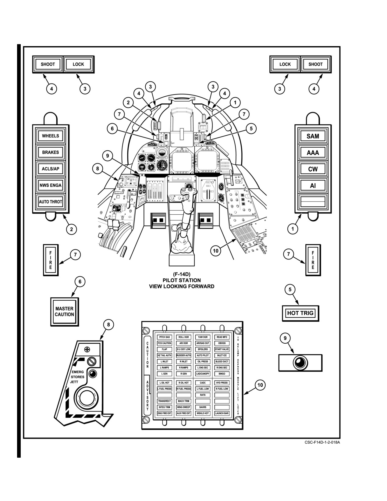
Figure 2-131. Pilot Indicator Lights (Sheet 1 of 5)
CHANGE 2
2−270
NAVAIR 01−F14AAD−1
NOMENCLATURE
FUNCTION
1
SAM
Steady illumination when a surface−to−air missile tracking radar is
(warning)
detected. Flashing for missile launched condition.
AAA
Steady illumination when an anti−aircraft artillery tracking radar is
(warning)
detected.
Flashing when AAA radar firing signal is detected.
CW
Indicates continuous wave emitter detected.
(warning)
AI
Steady illumination indicates airborne interceptor tracking condition is
(warning)
detected.
2
WHEELS
Flashes with flaps down more than 10_, either throttle below approxi-
(warning)
mately 85%, and any landing gear not down and locked.
BRAKES
Indicates antiskid failure or failure of priority valve in the brake power
(warning)
module to switch to combined hydraulic system (operating in AUX brake
mode). Illuminates when parking brake is pulled.
ACLS/AP
Auto pilot and automatic carrier landing system mode disengaged.
(caution)
NWS ENGA
Indicates nosewheel steering is engaged and will respond as a function of
(caution)
rudder pedal displacement.
AUTO THROT
Indicates APC has been disengaged by means other than the
(caution)
THROTTLE MODE switch.
3
LOCK
Indicates radar locked on target.
(advisory)
4
SHOOT
Indicates target meets specified LAR requirements.
(advisory)
5
HOT TRIG
Indicates that firing logic conditions are available. Pilot’s trigger or bomb
(warning)
button and RlO’s launch button will fire or release ordnance when
actuated.
6
MASTER CAUTION
Flashes when any light on the pilot’s CAUTION ADVISORY panel
(caution)
illuminates.
7
FIRE
Fire/overheat condition in engine nacelle.
(warning)
8
EMERG STORES
Indicates EMERG STORES pushbutton is activated.
JETT/ACK
(warning)
9
LOW ALTITUDE
Illuminates NVIS Green to indicate that the aircraft has descended below
WARNING LIGHT
the altitude set by the low altitude limit bug.
Figure 2−131. Pilot Indicator Lights (Sheet 2 of 5)
2−271
CHANGE 2
NAVAIR 01−F14AAD−1
NOMENCLATURE
FUNCTION
Note
The following lights on the CAUTION ADVISORY
panel are in alphabetical order.
10
ARI DGR
Indicates degraded ARI performance. If caused by loss of a Mach number
signal, LSXC and wing rock suppression functions will be inoperative.
ARI/SAS OUT
Indicates loss of either ROLL or YAW SAS and all ARI functions.
Will be illuminated if either the ROLL STAB AUG or YAW STAB AUG
switches are selected OFF.
AUTO PILOT (caution)
Indicates failure of one or more pilot relief modes.
AUX FIRE EXT (advisory)
Indicates low pressure (approximately 90 psi below the nominal 600 psi)
in the auxiliary fire extinguishing agent container.
BINGO (caution)
Indicates total fuel quantity indicator is less than BINGO preset value.
BLEED DUCT
Indicates bleed air leak sensing elements detect temperatures greater
(caution)
than 575_F between engine and primary heat exchanger. Also indicates
hot air leak detection (excess of 255_F) between primary heat exchanger
and ECS turbine compressor.
B/U OXY LOW (caution)
Indicates backup oxygen system pressure is 200 psi or less.
CADC (caution)
Indicates failure associated with central air data computer.
ENG FIRE EXT
Indicates low pressure (approximately 90 psi below the nominal 600 psi)
(advisory)
in the fire extinguishing agent container.
L ENG SEC
Indicates augmenter fan temperature controller (AFTC) is in secondary
R ENG SEC
mode. Afterburner is inoperative and thrust levels can vary from as little
(caution)
as 65% to as much as 116% of primary mode MIL thrust.
FCS CAUTION
Indicates DFCS failure has occurred. If no other lights are illuminated,
indicates loss of redundancy only (subsequent failure may result in loss of
significant DFCS functionality).
FLAP (caution)
Indicates: Disagreement between main and/or auxiliary flap position;
asymmetry lockout; CADC failure; WG SWP DR NO. 2/MANUV FLAP
(LE1) circuit breaker pulled; or, landing flaps down and airspeed greater
than 225 knots.
L FUEL LOW
Indicates fuel thermistors uncovered in aft and left or forward and right
R FUEL LOW
fuel feed group (approximately 1,000 pounds remaining in individual fuel
(caution)
feed group).
L FUEL PRESS
Indicates insufficient discharge pressure (less than 9 psi) from respective
R FUEL PRESS
turbine driven boost pump.
(caution)
L GEN
Indicates that corresponding generator is inoperative because of fault in
R GEN
generator, control unit, or electrical distribution system.
(caution)
Figure 2−131. Pilot Indicator Lights (Sheet 3 of 5)
ORIGINAL
2−272
NAVAIR 01−F14AAD−1
NOMENCLATURE
FUNCTION
10
HYD PRESS
Indicates hydraulic pressure from either engine−driven pump is less than
(caution)
2,100 psi.
HZ TAIL AUTH
Indicates failure of lateral tail authority actuator to follow schedule or
(caution)
CADC failure.
R INLET
Indicates AICS programmer and/or system failure.
L INLET
(caution)
INLET ICE
Indicates ice accumulated on ice detector in left inlet with ENG/PROBE/
(caution)
AICS ANTI−ICE switch in AUTO/OFF or ORIDE/ON selected.
INTEG TRIM
Indicates a discrepancy between input command signal and actuator
(advisory)
position, or an electrical power loss within the computer.
LAD/CANOPY
Advises that the boarding ladder is not in an up and locked position or
(caution)
that canopy is not in down and locked position.
LAUNCH BAR
Weight−on−Wheels:
(advisory)
• Aircraft kneeled, either throttle less than MIL, launch bar not up
and locked (normal indication until MRT checks).
Weight−off−Wheels:
• Launch bar not up and locked.
• Launch bar not within ±15_ of center, cocked nosegear.
• Nose strut not fully extended.
MACH TRIM
Indicates failure of Mach trim actuator to follow schedule.
(advisory)
OBOGS
Indicates a switchover to backup oxygen or OBOGS switch OFF.
(caution)
L OIL HOT
Indicates oil temperature too high. May be an indication of the
R OIL HOT
high−scavenge oil temperature; continued engine operation will result
(caution)
in reduced gearbox life and lubrication degradation.
OIL PRESS
Indicates left or right engine oil pressure is 11 psi or less.
(caution)
PITCH SAS
Indicates inoperative pitch channel or PITCH SAS failure.
L RAMPS
Indicates ramps are neither positioned in stow nor trail locks during
R RAMPS
critical flight conditions. (See Figure 2−5.)
(caution)
RATS
RATS operation is enabled.
(advisory)
Figure 2−131. Pilot Indicator Lights (Sheet 4 of 5)
2−273
ORIGINAL
NAVAIR 01−F14AAD−1
NOMENCLATURE
FUNCTION
10
READ MFD
Indicates any or all of the following warning/caution legends that appear
(caution)
on the upper left corner of the MFD.
L N2 OSP
R N2 OSP
L N1 OSP
R N1 OSP
L TBT OT
R TBT OT
L FLMOUT
R FLMOUT
L IGV SD
R IGV SD
W/S
ROLL DGR
Indicates inoperative roll channel and degraded roll authority.
RUDDER AUTH
Indicates disagreement between position and command failure of rudder
(caution)
authority actuators to follow schedule, or CADC.
SAHRS
Indicates attitude or heading information from SAHRS is unreliable.
(advisory)
SPOILERS
Indicates spoiler failure causing a set of spoilers to be locked down.
(caution)
START VALVE
Starter solenoid air valve open after start. Starter overspeed and/or
(caution)
destruction possible.
TRANS/RECT
Indicates one operable transformer−rectifier is powering the total dc load,
(advisory)
or dual transformer−rectifier failure.
WING SWEEP
Indicates failure of a single channel in the system.
(advisory)
WSHLD HOT
Indicates center windshield is overheated.
(advisory)
YAW DGR
Indicates inoperative yaw channel and degraded yaw authority.
Figure 2−131. Pilot Indicator Lights (Sheet 5 of 5)
ORIGINAL
2−274
NAVAIR 01−F14AAD−1
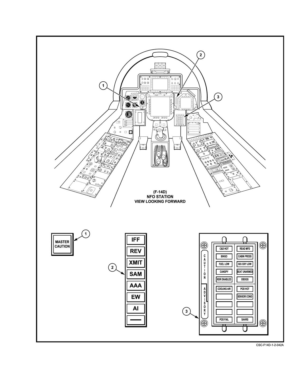
Figure 2Ć132.ĄRIO Indicator Lights (Sheet 1 of 3)
2−275
ORIGINAL
NAVAIR 01−F14AAD−1
NOMENCLATURE
FUNCTION
1
INS status indicators
Not operational.
2
IFF
Indicates mode 4 interrogation was received, but system has not
(advisory)
generated reply.
RCV
Indicates ALQ−165 is receiving a threat identification signal.
(advisory)
XMIT
Indicates ALQ−165 is transmitting.
(advisory)
SAM
Steady illumination when a surface−to−air missile tracking radar is
(warning)
detected. Flashing when a missile has been launched.
AAA
Steady illumination when an anti−aircraft artillery tracking radar
(warning)
is detected. Flashing when an AAA radar firing signal is detected.
CW
Indicates a continuous wave emitter is detected.
(warning)
Al
Steady illumination indicates an airborne interceptor tracking is detected.
(warning)
3
MASTER CAUTION
Flashes when any caution light on the RIO’s CAUTION ADVISORY panel
(caution)
illuminates.
4
C&D HOT
Indicates DD and/or PTID controls and displays are overheating.
(caution)
CABIN PRESS
Indicates aircraft cabin pressure has dropped below 5−psi pressure differĆ
(caution)
ential or cockpit altitude is above 27,000 feet.
FUEL LOW
Indicates fuel thermistors uncovered in aft and left or forward and right
(caution)
fuel feed group (approximately 1,000 pounds) remaining in individual fuel
feed group.
B/U OXY LOW
Indicates backup oxygen system pressure is 200 psi or less.
(caution)
CANOPY
Indicates that canopy is not in down and locked position.
(caution)
POD HOT
Indicates LANTIRN pod overheat condition exists.
(caution)
POD FAIL
Indicates a failure with the LANTIRN pod.
(caution)
Figure 2−132. RIO Indicator Lights (Sheet 2 of 3)
ORIGINAL
2−276
NAVAIR 01−F14AAD−1
NOMENCLATURE
FUNCTION
4
SEAT UNARMED
Indicates either seat is in the SAFE position.
(caution)
RDR ENABLED
Indicates that radar operation on the ground is possible or failure of right
(caution)
main landing gear safety switch or wiring.
READ MFD
Indicates any or all of the following warning, caution, or advisory legends
(caution)
that appear on the upper left corner of the MFD.
SDU ALARM
IMU
ASPJ HOT
CIU HOT
JTID HOT
DP1 HOT
RWR
DP2 HOT
FWD ASPJ
SMS HOT
AFT ASPJ
AFT CG
MC1
HUD HOT
MC2
RWR HOT
MC1 HOT
DSS HOT
MC2 HOT
DEKI HOT
CIU
IRST HOT
INS
MDL HOT
GPS FAIL
BINGO
Indicates total fuel quantity indicator is less than BINGO preset value.
(caution)
SENSOR COND
Indicates coolant temperature exiting heat exchanger is 104_F, radar
(advisory)
coolant pump output pressure is below 60 psi, or the overtemperature
switch has shut down the coolant pump.
COOLING AIR
Indicates an overtemperature condition exists in the electronic forced air
(advisory)
cooling system. With degraded cabin pressure or flow, indicates possible
bleed duct failure forward of primary heat exchanger and 400° modulating
valve.
OBOGS
Indicates a switchover to backup oxygen or OBOGS switch OFF.
(caution)
SAHRS
Indicates attitude or heading information from SAHRS is unreliable.
(advisory)
Figure 2−132. RIO Indicator Lights (Sheet 3 of 3)
2−277
ORIGINAL
NAVAIR 01−F14AAD−1
2.39.3.2
Indicator Lights Test
The RIO caution and advisory lights are tested in the
same manner on the TEST panel on the right console.
A check of all indicator lights can be performed while
airborne or during on−deck operations. The pilot caution and
2.40 STORES MANAGEMENT SYSTEM/
advisory lights, the MASTER CAUTION light, and all
JETTISON
associated circuitry are tested through the MASTER TEST
panel. The test is initiated by selecting LTS and pressing the
The SMS is the interface between aircraft stores and the
master test knob. Electrical power is routed through the
mission computer system. It provides signal processing and
circuitry to provide simulated failure signals to the caution
logic control required for inventory and identification of all
and advisory lights. Illumination of each warning, caution,
stores; preparation and test of missiles; and weapon select,
and advisory light verifies proper continuity of the indicator
arm, and launch functions. The emergency generator (1 kVA
lights. A malfunction is indicated by failure of a light to
mode) provides backup power
(28 Vdc essential) for
illuminate.
emergency jettison. The SMS has extensive self−test capabilĆ
ities and reports failures to the MCS for display to the crew.
Illumination of any caution light causes the MASTER
CAUTION light to flash. If the MASTER CAUTION light
2.40.1
SMS Weapons Replaceable Assemblies
illuminates steadily during the LTS test, it indicates a failure
of the MASTER CAUTION light primary power failure,
The SMS consists of the following WRAs:
failure of the flasher module, or that failure has been detected
1. Stores management processor
by the BIT circuits.
2. Fuel tank jettison unit
The following indicator lights are also illuminated by
the LTS test through the MASTER TEST panel:
3. Type 1 decoders
1.
ACLS/AP
4. Type 2 decoders
2.
Approach indexer
5. Gun control unit
3.
AUTO THROT
6. Missile power relay unit
4.
BRAKES
7. Missile power supply
5.
EMER STORES
8. AWW−4.
6.
FIRE
2.40.1.1
Stores Management Processor (SMP)
7.
GO/NO GO
The SMP is a programmable, digital computer that
8.
HOOK light
provides the central processing and command functions of
the SMS. It operates as a remote terminal on MBUS−2. The
9.
HOT TRIG
SMP communicates with the SMS WRAs and acts as the bus
10. LDG GEAR transition light
controller on the armament bus. The SMP controls emerĆ
gency jettison, the gun, and some AIM−9 functions via
11. LOCK
discretes that are independent of the ARMBUS. The SMP
12. NWS ENGA
also controls weapon select, SMS and weapon BIT, monitors
aircraft safety interlocks, and controls the launch−to−eject
13. RATS
sequence.
14. JETT
2.40.1.2
Fuel Tank Jettison Unit (FTJU)
15. Refueling probe transition light
Two FTJUs, one each for stations 2 and 7, are located
16. SAM
in the engine nacelles. The FTJUs provide eject pulses to the
17. SHOOT
squibs in the jettison release mechanism for emergency,
ACM, or selective jettison of the fuel tanks.
18. WHEELS.
For a description of Type 1 decoders, Type 2 decoders,
gun control unit, missile power relay unit missile power
Note
supply, AWW−4, and SMS functions, refer to NAVAIR
01−F14AAD−1A.
The DATA LINK power switch must be on to
check the DDI lights.
ORIGINAL
2−278
NAVAIR 01−F14AAD−1
2.40.2
Multistatus Indicator (MSI)
External fuel tanks, Phoenix, and Sparrow missiles can
be released in EMERG, ACM, and SEL jettison modes only.
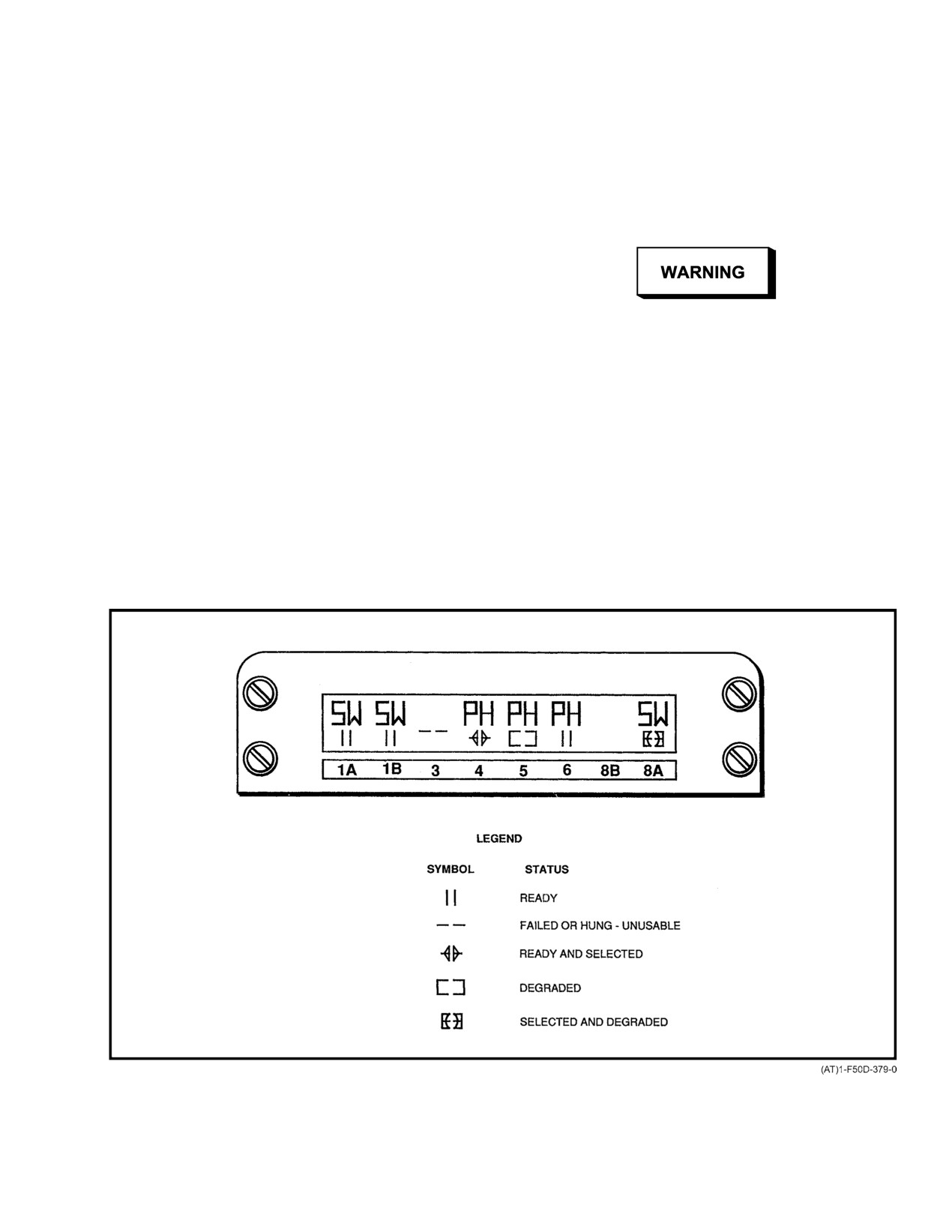
The MSI (Figure 2Ć133) is a liquid crystal display
Air−to−ground (A/G) weapons loaded on BRU−32 bomb racks
located below MFD 1. The MSI is powered by the HUD
can be released in all four jettison modes. ITERs and
subsystem. MSI displays are dependent on the MCS. When
weapons loaded on ITERs cannot be released from their
the HUD PWR switch is set to TEST, all LCD segments on
parent BRU−32 bomb racks in any of the jettison modes.
the MSI are displayed. The MSI displays weapon type and
Sidewinder missiles (rail launched) cannot be jettisoned.
status of each store station. The upper row of the display
identifies the weapon. The lower row displays weapon status.
Two horizontal dashed lines at a store station indicate that the
missile at that station has FAILED or is HUNG. A blank
display on a station indicates no weapon is loaded or the
D Stores shall be jettisoned above the minimum
weapon loaded is not recognized.
fragmentation clearance altitude, when posĆ
sible, even though weapon arming and fuzing
2.40.3
Stores Jettison Modes
is safed/disabled in all jettison modes.
Four jettison modes are available:
D Jettisoning A/G stores during a normal release
train may result in store−to−store collision in
1. Emergency (EMERG)
near proximity to the aircraft.
2. Air combat maneuver (ACM)
D If jettisoned during a takeoff emergency,
external fuel tanks may collide with the airĆ
3. Selective (SEL)
craft because of their unstable characteristics.
4. Auxiliary (AUX).
D If a jettison or delivery condition existed such
Weapon arming and fuzing and missile motor ignition
that A/G stores were released from stations 3
are safed/disabled during all jettison release modes.
and 6 and not from stations 4 and 5, an AFT
CG advisory on the MFDs will not be posted.
Figure 2Ć133.ĄMultistatus Indicator
2−279
ORIGINAL
NAVAIR 01−F14AAD−1
2.40.3.1
Emergency Jettison
Note
ACM JETT selections are retained in SMP nonĆ
Emergency jettison is used to separate all jettisonable
volatile memory. This allows selections to be
stores from the aircraft as fast as possible. The only interlock
retained and enables ACM JETT without an
requirement for jettisonable stores is weight off wheels. The
operable MCS. However, ACM JETT designaĆ
emergency jettison circuit is electrically isolated from all
tions must be reselected after performing system
other release functions of the SMP and has a separate electriĆ
reset to restore ACM JETT symbology on the
cal path to each jettisonable store station. The mode is iniĆ
MFD SMS format.
tiated by depressing the EMER STORES JETT pushbutton
on the landing gear control panel with weight off wheels
ACM jettison is initiated by the pilot raising the ACM
(Figure 2Ć134). Emergency jettison has priority over all other
guard (Figure 2Ć134) and depressing the ACM JETT pushĆ
SMS functions. This momentary, nonlatching pushbutton
button. For single stores loaded on a station, stores will be
and the EMERG STORES JET (ACK) light are illuminated
jettisoned at
100−millisecond intervals in the following
for 5 seconds by the SMP to indicate emergency jettison has
sequence:
been commanded. For single stores loaded on a station, stores
1. Stations 2 and 7 simultaneously
will be jettisoned at 100−millisecond intervals in the followĆ
ing sequence:
2. Stations 1B and 8B simultaneously
1. Stations 2 and 7 simultaneously
3. Station 4
4. Station 5
2. Stations 1B and 8B simultaneously
5. Station 3
3. Station 4
6. Station 6.
4. Station 5
After the release attempt is completed, the SMS up−
5. Station 3
dates the stores inventory. Unlike emergency jettison, a store
that is not released is declared HUNG. Such stores are not
6. Station 6.
eligible for launch but are still eligible for emergency or
selective jettison. Additionally, A/G stores loaded on
After the release sequence is completed, the SMS
BRU−32s will still be eligible for auxiliary jettison.
updates the stores inventory. Unlike other jettison modes or
launch attempts, a store that is not released is not declared a
2.40.3.3
Selective Jettison
HUNG store and is eligible for subsequent jettison or launch.
Selective jettison is used to separate single jettisonable
stores station−by−station and also allows simultaneous jettiĆ
2.40.3.2
ACM Jettison
son of both fuel tanks. The RIO selects the desired station(s)
for selective jettison.
ACM jettison provides for rapid release of any preseĆ
lected combination of jettisonable stores. In addition to RIO
Selective jettison is accomplished by placing the MA
selection of those stations to be separated, the only ACM
ARM switch to ON, the LDG GEAR handle UP, the
jettison interlock is the LDG GEAR handle UP.
JETTISON STA SEL knob set to the desired station, and the
SEL JETT switch to JETT. After the release attempt is
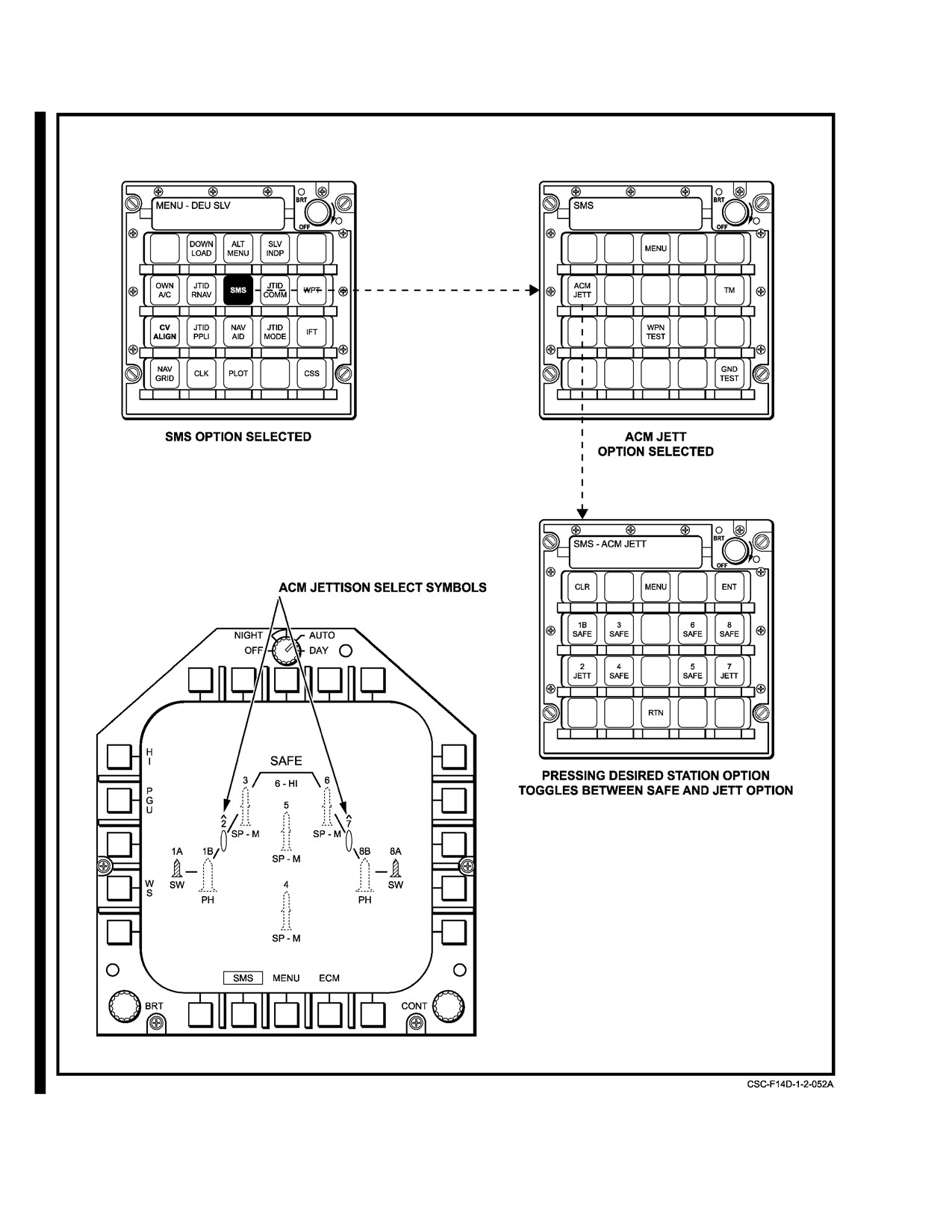
Stations are selected for jettison via the DEU.
completed, the SMS updates the stores inventory. Unlike
Figure 2Ć134 and Figure 2Ć135 illustrates selection and disĆ
emergency jettison, a store that is not released is declared
play of external fuel tanks for ACM jettison. Only those
HUNG. Such stores are not eligible for launch, but are still
stations having a jettisonable store loaded that have not been
eligible for emergency or selective jettison. A/G stores
declared failed are available for ACM jettison selection.
loaded on BRU−32s will still be eligible for auxiliary jettison.
Each depression of a station button causes that button
display to toggle between JETT and SAFE. The DEU selecĆ
tions are not forwarded to the SMS until the enter button is
depressed. Selected stations are indicated on the MFD SMS
Do not attempt jettison of external fuel tanks
format with an inverted V" above the station number. The
until wing fuel tanks are depleted. Wing fuel may
symbol is removed if deselected by the RIO and upon
be lost if the external tank quick−disconnect
completion of an ACM jettison attempt or successful jettison.
valve sticks in the open position.
ORIGINAL
2−280
NAVAIR 01-F14AAD-1
NOMENCLATURE
FUNCTION
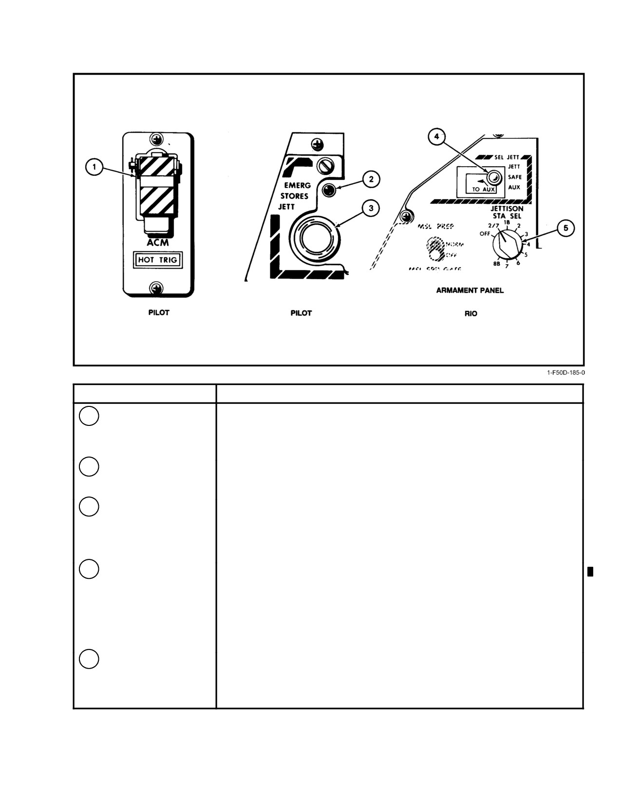
1
ACM JETT pushbutton
Enables ACM jettison. Pushbutton is under ACM switch cover.
When pressed, only those stores selected via the DEU are jettisoned.
To ensure release of all selected stores, the ACM JETT pushbutton must
be depressed and held for at least 2 seconds.
2
ACK light
Redundant indicator for emergency jettison activation. Illuminates for
5 seconds, indicating the SMP has acknowledged the emergency
stores jettison command.
3
EMERG STORES JET
Enables the separation of all jettisonable stores. When depressed with
pushbutton/light
weight off wheels, activates emergency stores jettison signal to the SMS
and illuminates light for 5 seconds, indicating the SMP has acknowledged
the emergency stores jettison command. Jettison function is disabled with
weight on wheels.
4
SEL JETT switch
With Master Arm on and gear up, allows RIO to jettison from selected sta-
tion(s). It is a three-position, lever-locked switch with guarded positions.
JETT Actuates normal selective jettison of the store(s) located at the
station(s) designated by the JETTISON STA SEL switch.
SAFE Normal operating position. Inhibits jettison in selective mode.
AUX Releases all A/G stores loaded on BRU-32s from the station selected
on the JETTISON STA SEL switch with a single switch movement.
5
JETTISON STA SEL
Allows selective jettison of Phoenix or Sparrow missiles and auxiliary tanks.
switch
Allows selective or auxiliary jettison of air-to-ground stores.
OFF Inhibits selective and auxiliary jettison.
Station Selects store(s) for jettison.
Figure 2-134. Jettison Controls
2-281
CHANGE 1
NAVAIR 01-F14AAD-1
Figure 2-135. ACM Jettison Selection and Display
CHANGE 1
2-282
NAVAIR 01−F14AAD−1
2.40.3.4
Auxiliary Jettison
clearance of 16 feet is required when opening the radome.
The radar antenna must be stowed before opening the
Auxiliary jettison is a nonejection release mode for
radome. Antenna stow position is 0_ azimuth and 60_ tilted
single A/G stores loaded on BRU−32s (Figure 2Ć134). Like
down.
selective jettison, this mode requires the MA ARM switch to
be set to ON and the LDG GEAR handle UP. This mode is
Note
activated by the RIO selecting the station to be jettisoned via
After the nose radome is raised and the jury strut
the jettison STA SEL switch and then selecting AUX on the
fastened in position, release hydraulic pressure to
SEL JETT switch. Auxiliary jettison of an A/G store loaded
take the load off the hydraulic system.
directly on a BRU−32 is via gravity force only.
2.41.3
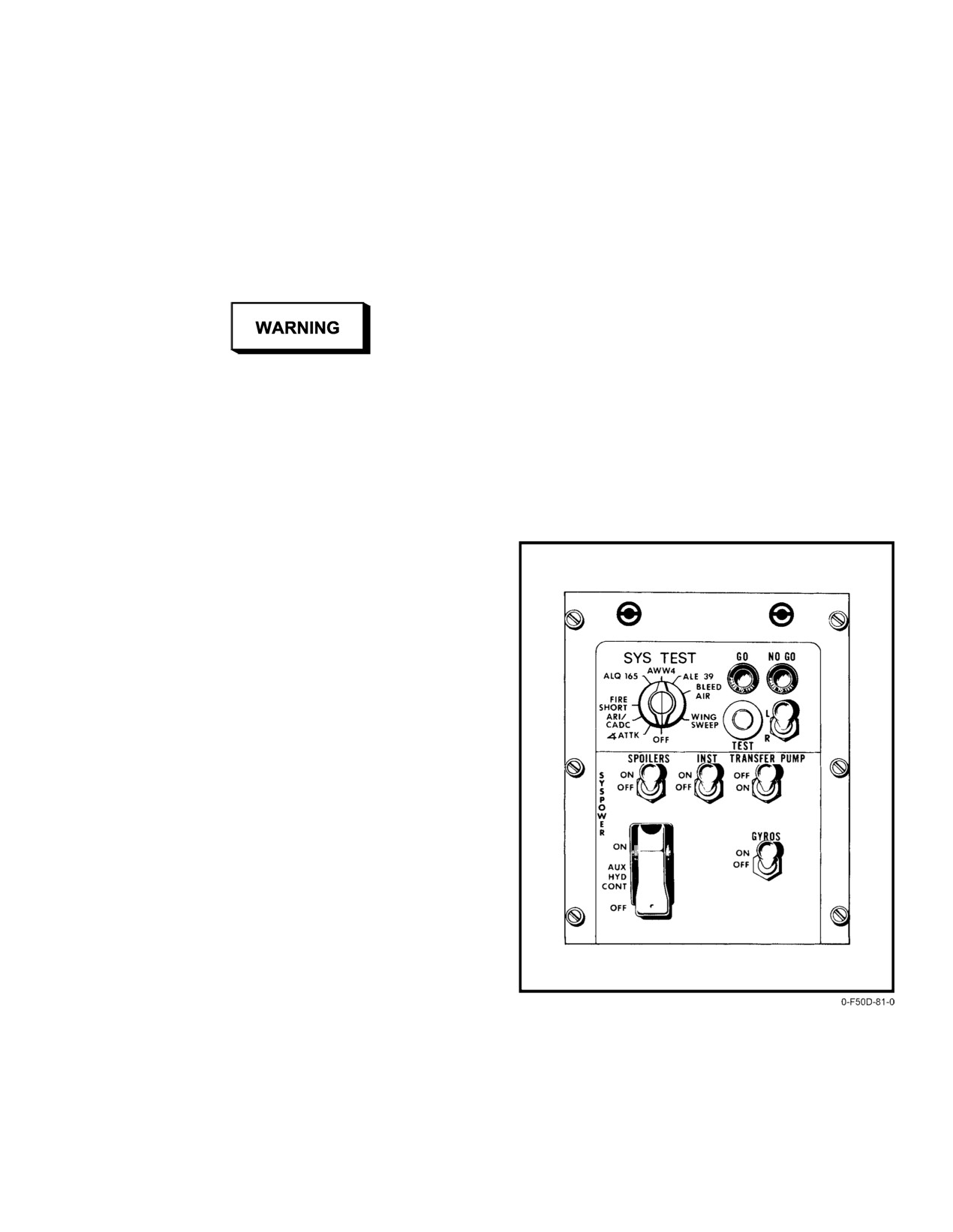
Systems Test and System Power
Ground Panel
The SYS TEST and SYS PWR ground check panel
(Figure 2Ć136) is on the RIO right console panel (accessible
Since auxiliary jettison for single A/G stores
from the boarding ladder with the canopy open) for
loaded directly on BRU−32s is a gravity drop
controlling the activation of electrical circuits using ground
rather than an ejection separation, the aircraft
external power. The panel cover is designed so that, when it
will be restricted in its flight envelope when jettiĆ
is closed, the switches inside are in the proper position for
soning through this mode.
flight. In addition, when the landing gear handle is in UP, all
switches are deactivated. The panel serves a maintenance
2.41 MISCELLANEOUS EQUIPMENT
and preflight purpose and is not intended for use by the
flightcrew.
2.41.1
Boarding Ladder
A boarding ladder consisting of three folding sections
is housed in the left fuselage between the two cockpits. It is
held in the closed position by two mechanical locking pins
actuated by the ladder control handle in the face of the
boarding ladder. The ladder must be manually released or
stowed from the ground level. Unfolding the remaining two
sections places the ladder in a fully extended position. The
bottom rung of the ladder is approximately 26 inches above
the deck when in a fully extended position, with the nosegear
unkneeled, and 12 inches above the deck if the nosegear is
kneeled. A LAD/CANOPY caution light on the pilot caution
advisory panel advises the pilot that the boarding ladder is not
in a full up−and−locked position.
2.41.1.1
Boarding Steps and Handhold
There are two positive locking board steps, one on
either side of the boarding ladder directly below each
cockpit. They may be opened or closed from either cockpit
or while standing on the boarding ladder. A single handhold
is directly above the boarding ladder. It is a spring−loaded
door that fairs with the fuselage when released.
2.41.2
Nose Radome
The nose radome is attached to the aircraft by a top
hinge and bottom mounted latches, permitting it to be rotated
up for access and maintenance. A jury strut attached to the
Figure 2Ć136.ĄSystems Test and System Power
lower part of the dome can be fastened to the aircraft
Ground Panel
bulkhead to hold the dome open. A minimum overhead
2−283
ORIGINAL
NAVAIR 01−F14AAD−1
2.41.4
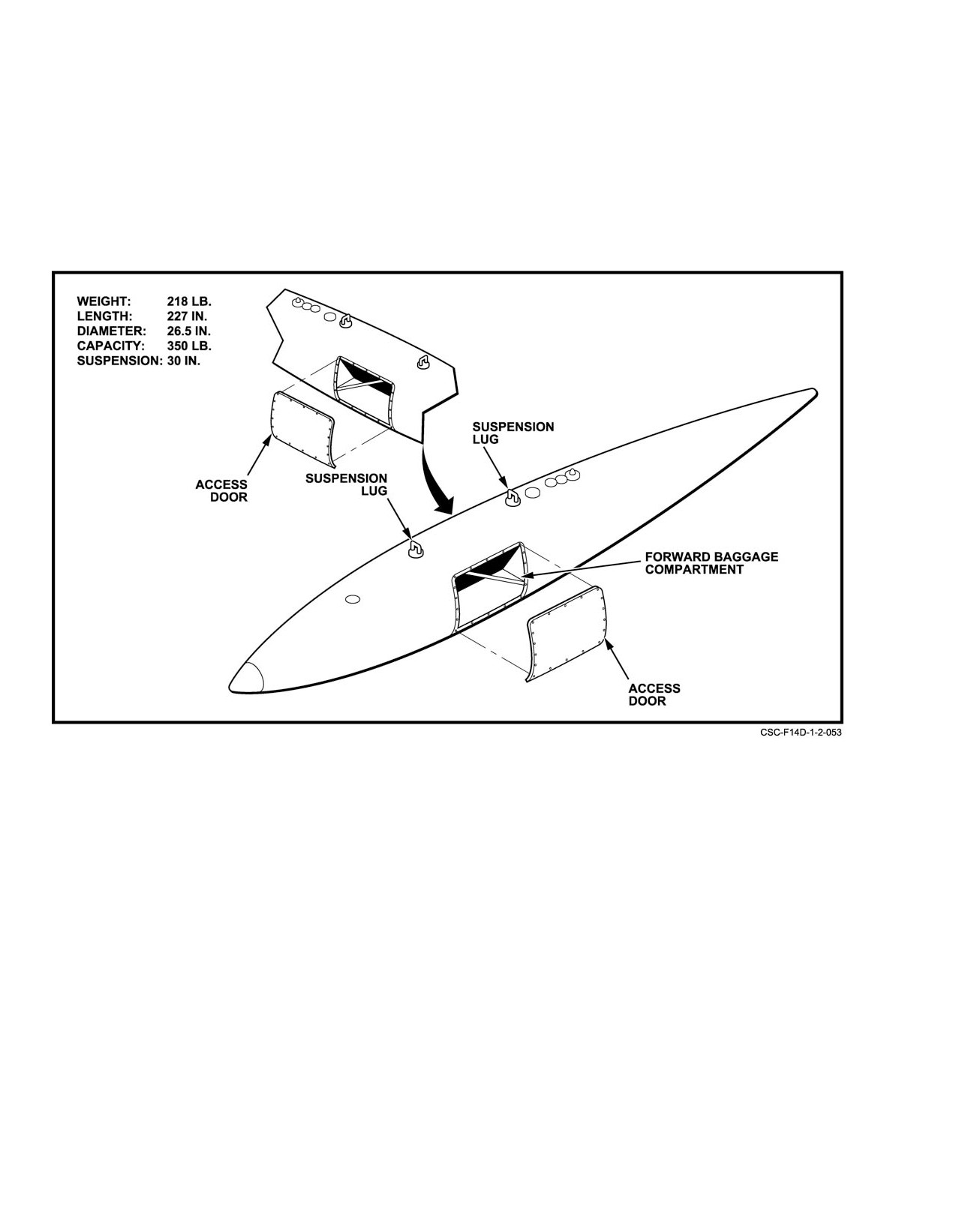
External Baggage Container (CNU−188/A)
of two sets of seatbelt straps that form a crossover pattern to
secure baggage to the shelf. The external baggage container
The external baggage container (Figure 2Ć137) is a
may be loaded with any equipment that fits within the
modified Aero ID 300−gallon fuel tank that incorporates
confines of the shelf, does not exceed the shelf weight, and
forward and aft baggage compartments. Each compartment
maintains the cg limits. Locate baggage as near the center of
has an access door (forward, left side, aft, right side), a shelf
the shelf as possible. Care should be taken to ensure that
and abaggage tiedown harness. The tiedown harness consists
straps are tight to preclude any significant shift of cargo.
Figure 2Ć137.ĄCNU−188/A External Baggage Container
ORIGINAL
2−284
NAVAIR 01−F14AAD−1
CHAPTER 3
Servicing and Handling
3.1
SERVICING DATA
refueling is controlled by two precheck selector valves and
the vent pressure gauge adjacent to the refuel receptacle on
The following servicing data is for use by the flightĆ
the ground refuel and defuel panel. Positioning of these
crew and maintenance crews who are unfamiliar with servicĆ
valves can be used for selective ground refueling of either the
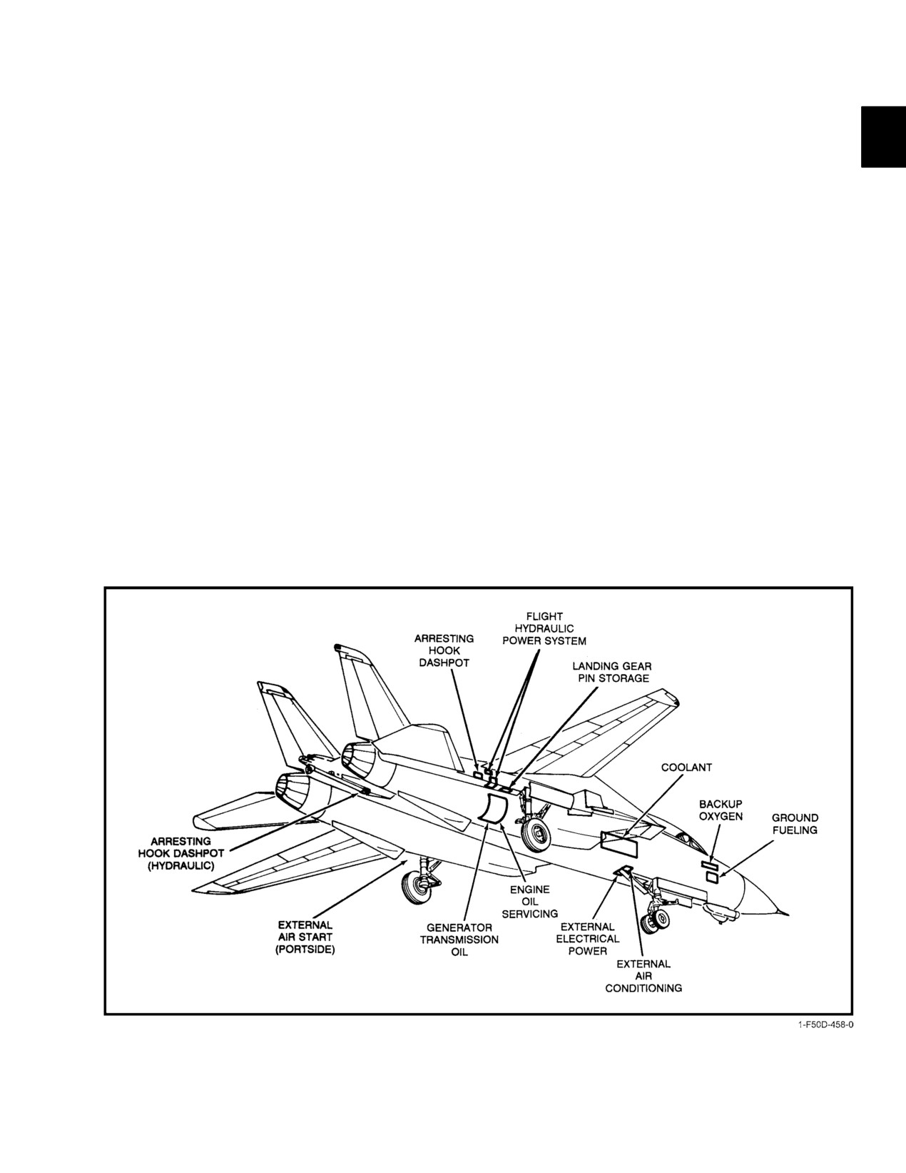
ing the aircraft (Figure 3Ć1). When operating in and out of
fuselage or wing and drop tanks. The direct reading vent
military airfields, consult the current DOD IFR Supplement
pressure gauge indicates pressure in the system vent lines.
for compatible servicing units, fuel, etc. Figure 3Ć2 provides
When aircraft fuel tanks are full, fueling stops automatically.
a tabulation of servicing data and power units required to
For hot refueling procedures, refer to paragraph 7.6. For
support the aircraft.
defueling procedures, refer to NAVAIR 01−F14AAD−2−1.
3.1.1
Ground Refueling
The maximum refueling rate is approximately
500Ăgpm at a pressure of 50 psi. Nominal and minimum
Single−point refueling is provided for pressure filling
pressure is approximately
15 psi; maximum pressure is
of all aircraft fuel tanks through a standard refueling recepĆ
50Ăpsi.
tacle on the lower right side of the forward fuselage. Ground
Figure 3Ć1.ĄAircraft Servicing Locations
3−1
ORIGINAL
NAVAIR 01−F14AAD−1
DOD IFR
DESIGNATION
NATO
COMMERCIAL
SUPPLEMENT
ITEM
SPECIFICATION
CODE
EQUIVALENT
CODE
REMARKS
FUEL
MIL−T−5624 (JP−5)
F−44
Jet A
JP−5
Selector (main engine
MIL−T−5624 (JP−4)
F−40
Jet B
JP−4
control) on both engines
MIL−T−83133 (JP−8)
F−34
Jet A−1
JP−8
should be set for
type fuel in use.
(JP−8 is equivalent
to JP−5.)
Engine oil
MIL−L−23699
0−156
None
0−156
Use MIL−L−7808 when
MIL−L−7808
0−148
None
0−148
ground temperature is
−40_F (−40_C).
Integrated Drive
MIL−L−23699
0−156
None
0−156
Use MIL−L−7808 when
Generator (IDG)
MIL−L−7808
0−148
None
0−148
ground temperature is
Transm
iss
ion oil
−40_F (−40_C).
Hydraulic fluid
MIL−H−83282
None
None
None
Oxygen
MIL−O−27210 Type I
None
None
HPOX LPOX
Survival kit shall be
(Gaseous)
removed from aircraft
for servicing emergency
oxygen bottle.
Nitrogen
BB−N−411
None
None
None
Use clean, oil−free
(Type I, Grade A)
filtered dry air,
if nitrogen
is no
t
available.
Liquid Coolant
Coolant 25, 25R
None
NA
None
Either coolant may be
(Monsanto
mixed without adverse
Chem ica l Co)
reaction.
Chevron Flo−Cool
None
NA
None
180
(Chevron
Chemical Co)
Wipe On Rain
MIL−W−6882
None
None
None
Clean and dry
Repellant Fluid
windshield.Apply with
cloth using overlapping
wipes. Aft
er
1−m
inu
te
drying, w
ipe c
lean with
sof
t cloth.
Figure 3Ć2.ĄAircraft Servicing Data (Sheet 1 of 2)
ORIGINAL
3−2
NAVAIR 01−F14AAD−1
POWER
PNEUMATIC
ELECTRICAL
AIR
STARTING
POWER
CONDITIONING
HYDRAULIC
Acceptable USN
ASHORE:
NC8A
NR 5C (Electrical)
AHT−63/64
Units
NCPP−105
MD−3
NR 8 (Diesel)
TTU-228/E (AHT-73)
RCPT−105
MD−3A
MA−1
MJ−3
A/M47A−4
MD−3M
MA−1A
MA−3MPSU
A/M32C−5
AFLOAT:
A/M32A−60
A/M32C−6
A/S47A−1
A/M32A−60A
Ground Support
200 lb/min at 75 ± 3psi
115 ± 20 V ac,
70 lb/min at 3 psi
50 gal/min maximum
Equipment
(STD. DAY)
400 ± 25 Hz,
and 60_F
at 3,000 psi
Requirements
60 kVA, 3 phase
rotation
PNEUMATIC PRESSURE
TIRES
SYSTEM
PRESSURE
TYPE
OPERATION
PRESSURE
Emergency Landing Gear
3,000 psi at
70_F
Nose (2)
Ashore
105 psi
22 × 6.6−10
Combined Hydraulic
1,800 psi at
70_F
20 Ply
Afloat
350 psi
Flight Hydraulic
1,800 psi at
70_F
Main (2)
Ashore
245 psi
37 × 11.50−16
Canopy Normal
3,000 psi at
28 Ply
Afloat
350 psi
(1,200 psi Minimum)
70_F
Canopy Auxiliary
3,000 psi at
(800 psi Minimum)
70_F
Note
Wheel brake accumulators (2)
1,900 psi at 70_F
Dry nitrogen, specification BB−N−411, Type 1,
Arresting Hook Dashpot
800 ± 10 psi
Grade A is preferred for tire inflation and chargĆ
ing pneumatic systems since it is inert, and thereĆ
Main Gear Shock Struts (2)
980 psi
fore will not support combustion.
Nose Gear Shock Strut
1,300 psi
Figure 3−2. Aircraft Servicing Data (Sheet 2 of 2)
3−3
ORIGINAL
NAVAIR 01−F14AAD−1
Ensure that both the fueling unit and the aircraft
D Lubricating oil (MIL−L−23699) is toxic and
are properly grounded, bonding cable is conĆ
flammable. Protection includes chemical
nected between aircraft and refueling source, and
splashproof goggles, gloves, and good venĆ
that fire extinguishing equipment is readily
tilation; keep sparks, flames, and heat away.
available.
Keep lubricating oil off skin, eyes, and
clothes; do not breathe vapors. Wash hands
thoroughly after handling.
D Do not overservice oil storage tank. OverĆ
servicing can cause scavenge pump failure
During ground refueling operations, the direct−
and subsequent engine failure.
reading vent pressure indicator shall be observed
and refueling stopped if pressure indication is in
Note
the red band (above 4 psi).
Engine oil level should be checked within
Note
30Ăminutes of engine shutdown, otherwise run
engine at 80 percent or greater for 10 minutes to
D If the aircraft is being regularly serviced with
ensure proper servicing.
JP−4 type fuel, the main fuel−control, fuel−
grade (specific gravity adjustment) selector
3.1.3
Integrated Drive Generator Oil
on each engine should be reset to the JP−4
position. If the aircraft is being regularly serĆ
The IDG has a filter bypass indicator at the bottom of
viced with JP−8 or JP−5 fuel, the fuel−control,
fuel−grade
(specific gravity adjustment)
the filter bowl (Figure 3Ć3, sheet 2). Extension of the indicaĆ
tor indicates contamination of the filter and the need for filter
selector on each engine should be reset to the
JP−8 or JP−5 position. Satisfactory engine perĆ
element replacement. Refer to NAVAIR 01−F14AAD−2−1 for
IDG oil filter replacement and servicing.
formance depends upon trimming of the
engine fuel controls to ensure rated thrust to
prevent exceeding engine temperature limits,
IDG oil level is checked at the IDG mounted on the
and to ensure airflow compatibility with the
forward right side of the forward accessory gearbox of each
air inlet duct opening.
engine. It is serviced at the pressure fill port on the right side.
D Removal of JP−8 type fuel from the aircraft is
3.1.4
Hydraulic Systems
not required before refueling with JP−5. If
removal of JP−8 from the aircraft aboard ship
The main hydraulic systems are serviced at the flight
is necessary, it shall not be defueled into the
and combined hydraulic system ground servicing panels. A
storage tanks containing JP−5.
hydraulic pressure filling cart is required to service the sysĆ
tems with fluid, and an air−nitrogen cart is required to preload
3.1.2
Engine Oil
the reservoirs. The outboard spoiler backup module is serĆ
viced at the servicing panel on the outboard nacelle of the
Engine oil level is proper when overflow oil starts to
port engine. Additional hydraulic servicing is required at the
exit the discharge port during servicing. For normal servicĆ
main landing gear shock strut (Figure 3Ć3, sheet 2), the noseĆ
ing, the sight gauge on the oil storage tank is the primary
wheel shock strut (Figure 3Ć3, sheet 2), and the arresting
indicator determining when servicing is required. During
hook dashpot (Figure 3Ć3, sheet 1).
servicing, overflow oil exits the overflow discharge port
when the tank is properly serviced (Figure 3Ć3, sheet 2).
The flight reservoir fill and ground hydraulic power
Servicing is accomplished using PON−6 servicing cart.
access panel and the flight system filter module (Figure 3Ć3,
Normal oil consumption is 0.03 gallon per hour with the
sheet 1) are on the starboard side. The combined hydraulic
maximum being 0.1Ăgallon per hour. For oil servicing proĆ
system reservoir fill and filter module (Figure 3Ć3, sheet 3)
cedures,ărefer to NAVAIR 01−F14AAD−2−1. The protrusion
are on the port side of the aircraft. Indication of hydraulic
of a bypass indicator underneath the oil scavenge pump indiĆ
system fluid contamination can be detected by the position
cates a clogged filter element and requires replacement.
of the buttons on the Delta−P type filter units.
ORIGINAL
3−4
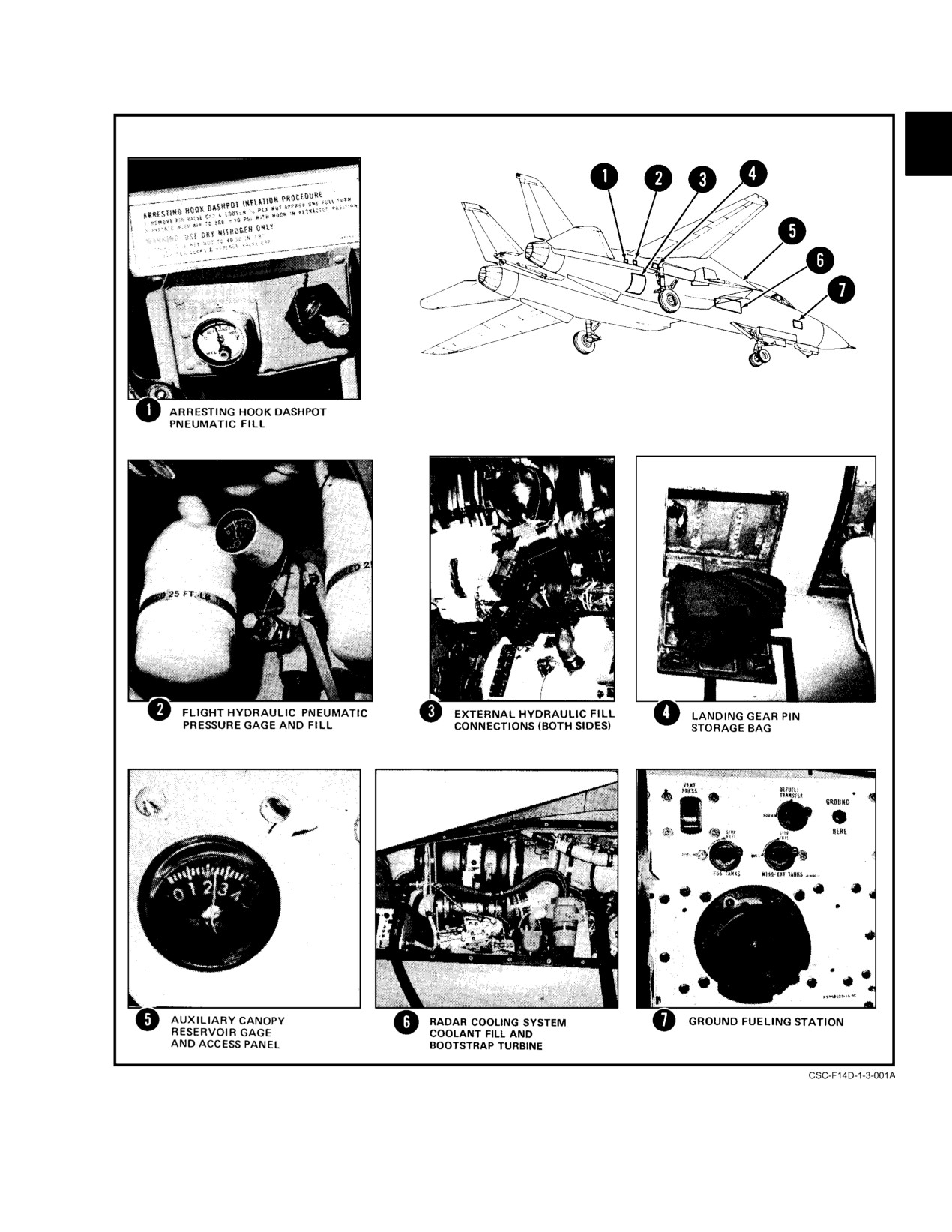
NAVAIR 01−F14AAD−1
Figure 3Ć3.ĄAircraft Servicing (Sheet 1 of 3)
3−5
ORIGINAL
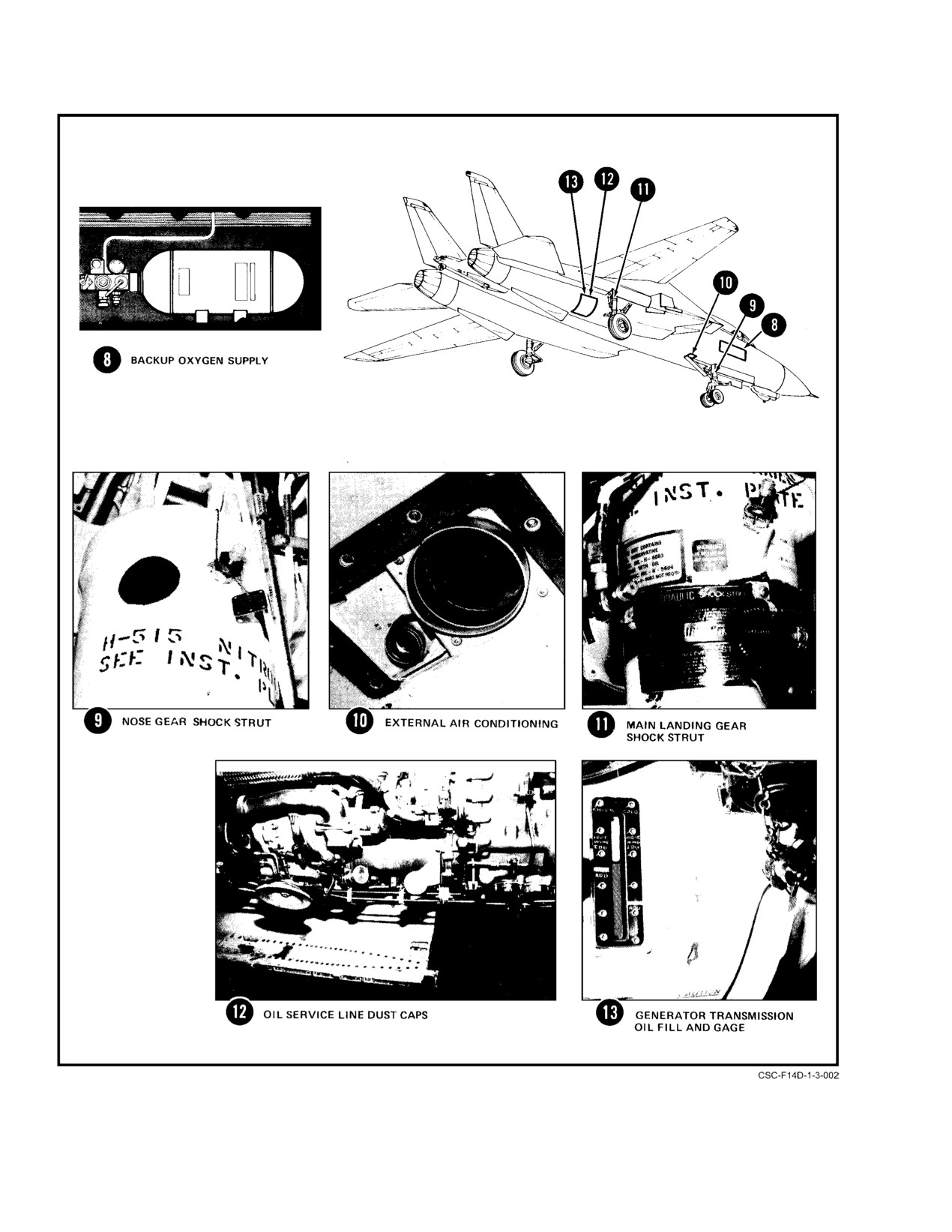
NAVAIR 01−F14AAD−1
Figure 3−3. Aircraft Servicing (Sheet 2 of 3)
ORIGINAL
3−6
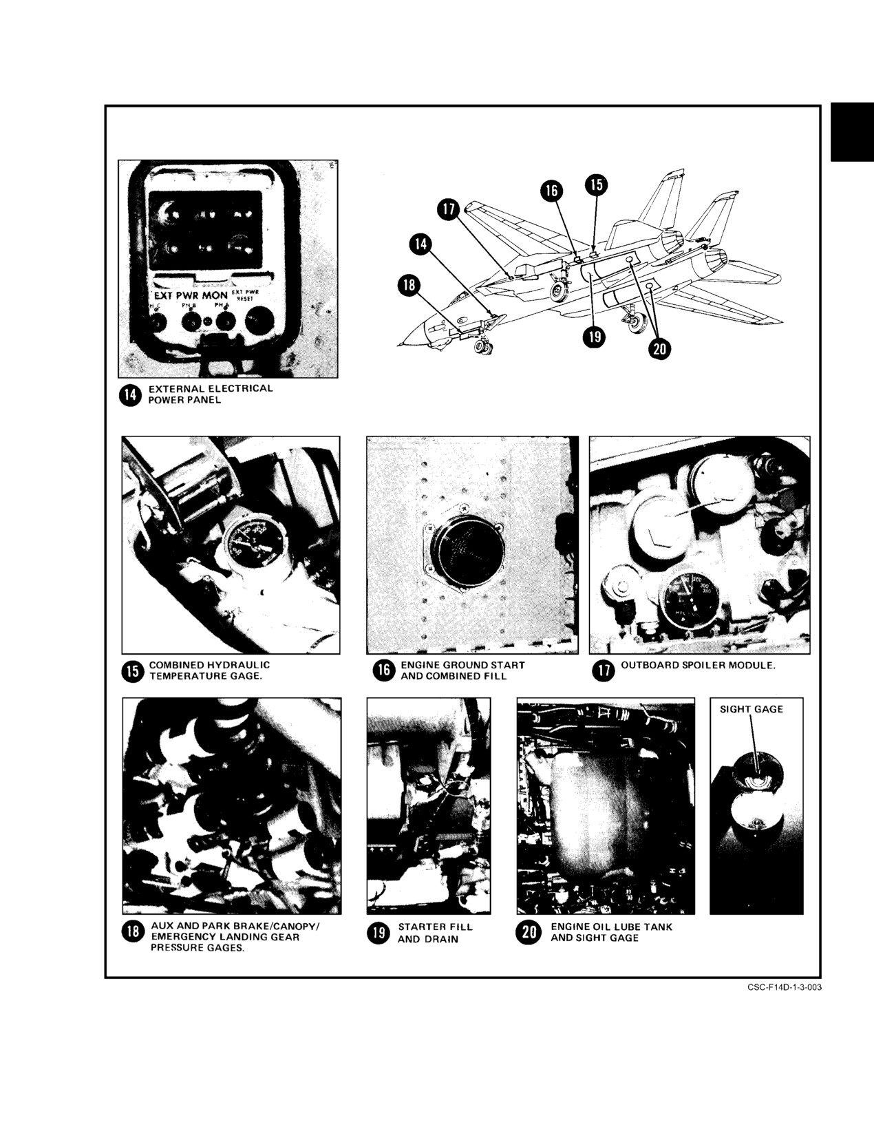
NAVAIR 01−F14AAD−1
Figure 3−3. Aircraft Servicing (Sheet 3 of 3)
3−7
ORIGINAL
NAVAIR 01−F14AAD−1
Temperature recording gauges at the filter modules
D Suction at the air intake is strong enough to
indicate the maximum temperature attained by the hydraulic
kill or seriously injure personnel by drawing
fluid during the last turnup or flight. After a reading has been
them into or against the inlet.
taken, the temperature gauges must be reset prior to the next
D All personnel in the immediate area shall
turnup.
wearăear protection whenever an engine is
operating.
3.1.5
Pneumatic Systems
Note
The pneumatic power supply systems, which provide
for normal operation of the canopy and for emergency extenĆ
D If engines are run up in front of a blast deflecĆ
sion of the landing gear, are ground charged through a comĆ
tor, exhaust jet wake is deflected up and to the
mon filler in the nose wheelwell (Figure 3Ć3, sheet 3). The
sides resulting in distortion of the patterns
auxiliary canopy open pneumatic bottle is in the turtleback
shown.
behind the cockpit (Figure 3Ć3, sheet 1). Additional pneuĆ
D At maximum afterburner power, nozzles are
matic servicing points are at both hydraulic systems servicing
nearly fully open; at military power, the
panels, brake systems, and arresting hook.
nozzles are nearly fully closed.
Individual pneumatic servicing point and pressure
gauges are provided for the auxiliary and parking brake
3.2.2
Radar Radiation Areas
systems.
The following paragraphs describe the hazards to perĆ
Note
sonnel, hazards of electromagnetic radiation to ordnance
Dry nitrogen, specification BB−N−411, Type 1,
(HERO), and fuel ignition hazards generated during AN/
Grade A, is preferred for tire inflation and for
APG−71 radar operation.
charging pneumatic systems since it will not supĆ
port combustion.
3.1.6
Backup Oxygen Supply
The backup gaseous oxygen supply is serviced to a
Illumination of RDR ENABLE caution light on
maximum of 2,100 psi from an access in the forward right
RIO CAUTION ADVISORY panel indicates
side of the fuselage. Servicing pressure can be observed on
possible radar radiation on deck.
a gauge in the pilot’s cockpit.
3.2.2.1
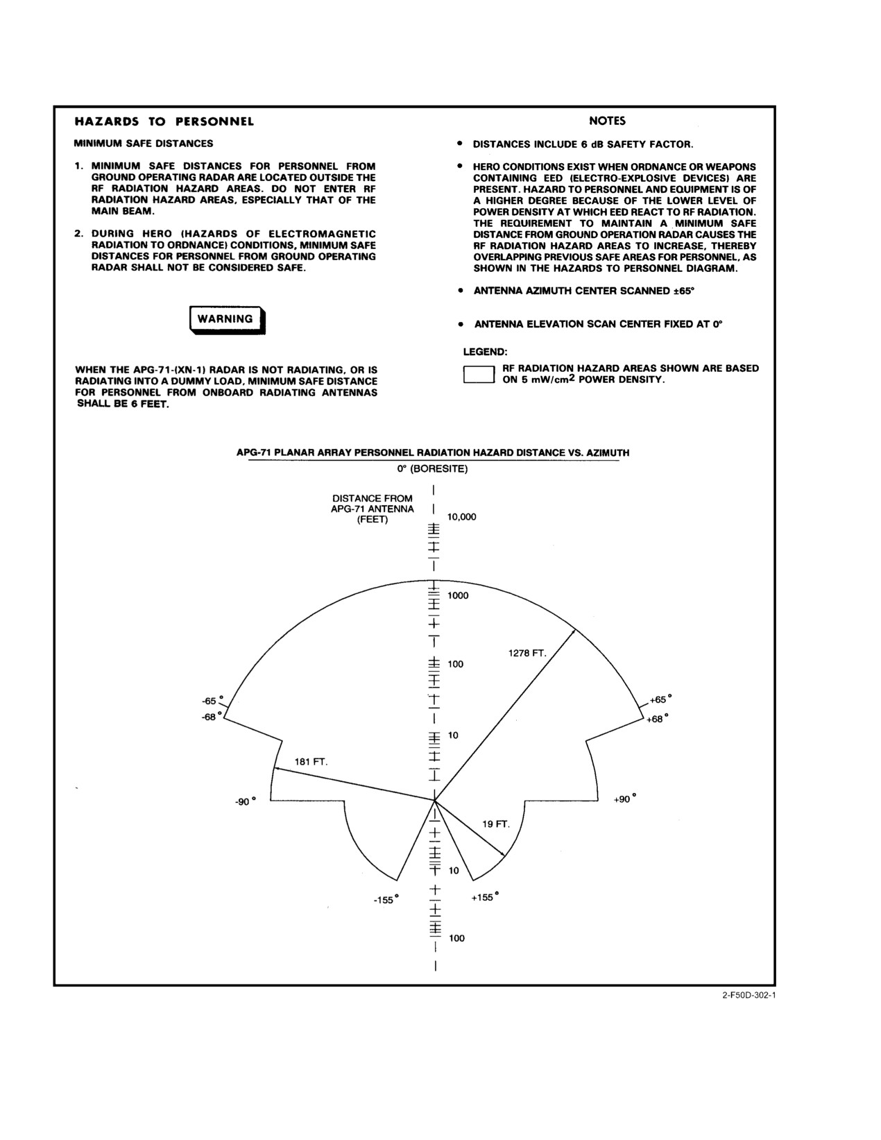
Hazards to Personnel
3.2
GROUND HANDLING
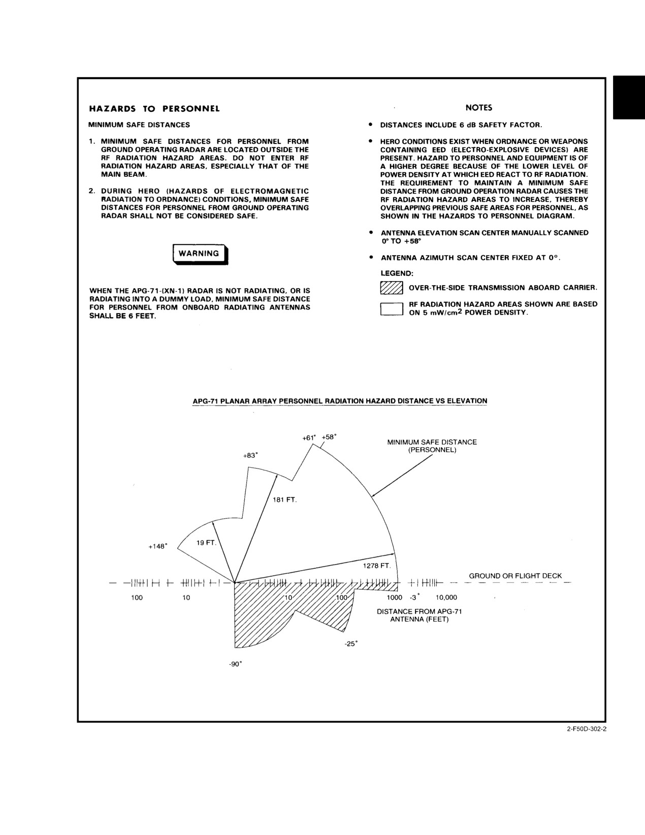
Minimum safe distances for personnel from ground
3.2.1
Danger Areas
operating radar are indicated in Figure 3Ć5, sheets 1 and 2.
When the planar array radar antenna is not radiating, miniĆ
Engine exhaust and intake danger areas are shown in
mum safe distance from other radiating antennas is 6ăfeet.
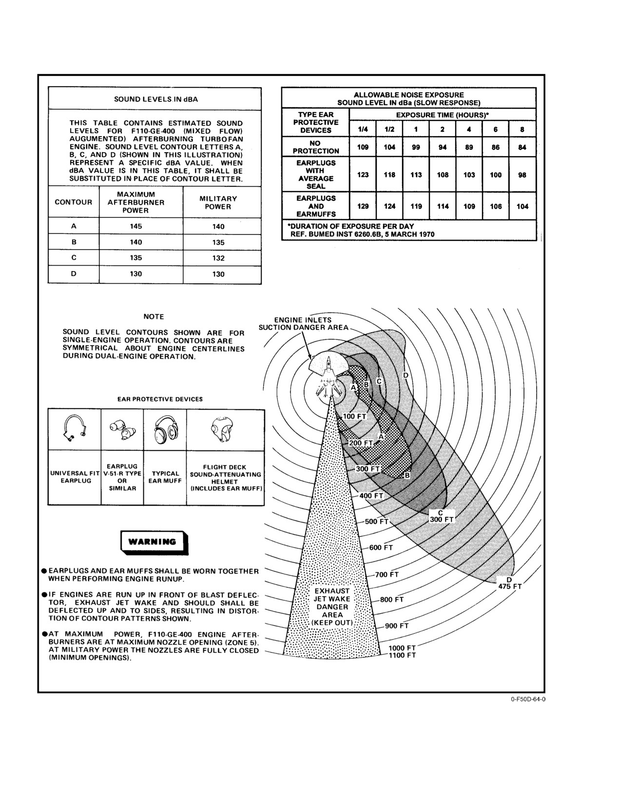
Figure 3Ć4. Noise danger areas are shown in Figure 3Ć6.
(Figure 3Ć4 shows temperature distribution with afterburners
3.2.2.2
HERO Condition
at maximum nozzle opening for idle, military, and maximum
power.) Figure 3Ć4 shows exhaust jet wake velocity distribuĆ
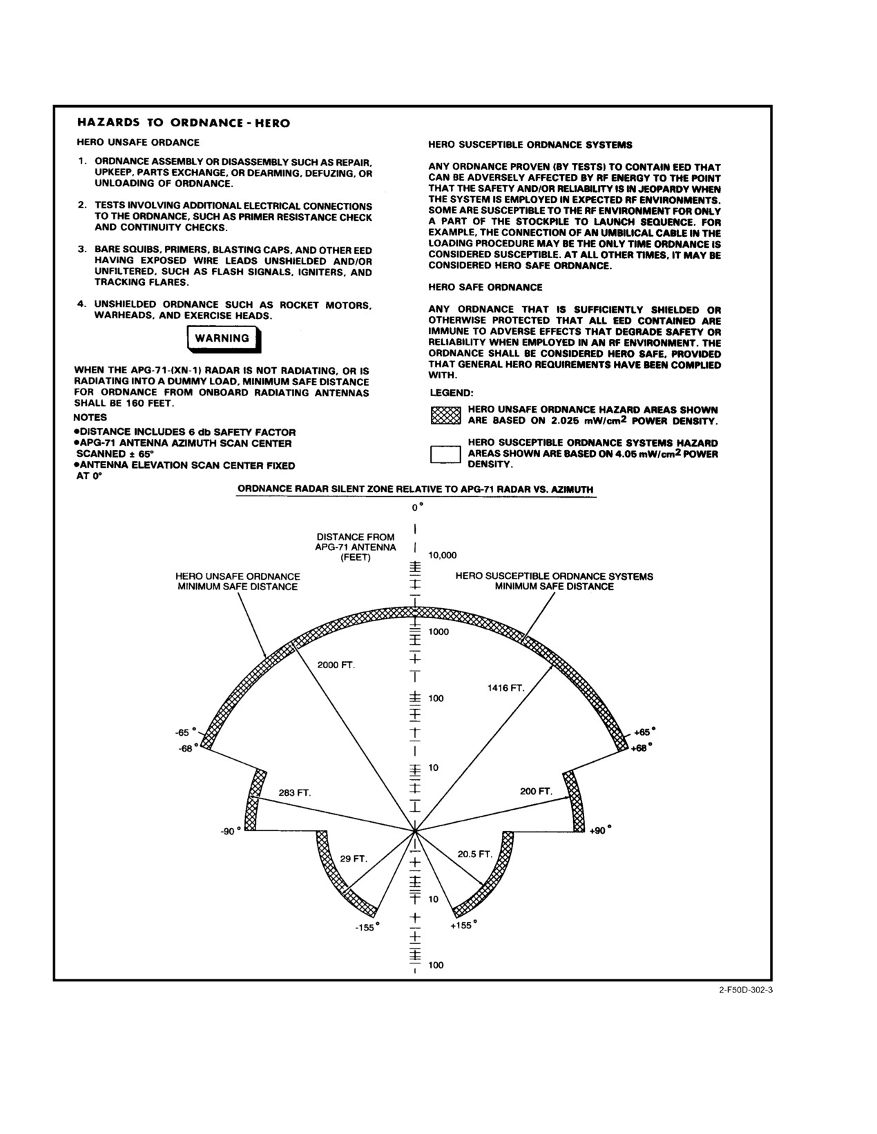
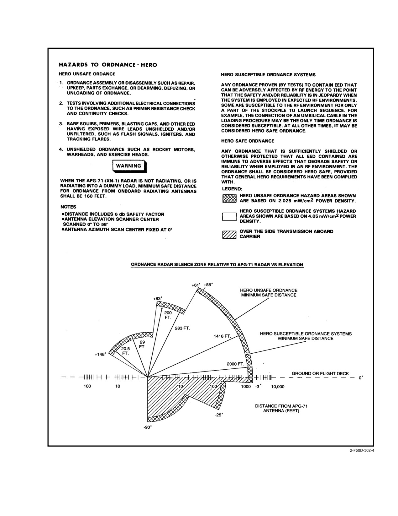
HERO conditions exist when ordnance or weapons
tion with afterburner at maximum nozzle opening for idle,
containing electroexplosive devices (EED) are present. HazĆ
military, and maximum power.
ard to personnel and equipment is greater because of the
lower power density level at which EED react to radio freĆ
quency radiation. The requirement to maintain a minimum
safe distance from ground operating radar causes the RF
radiation hazard area to increase in size, thereby overlapping
into previously safe areas for personnel. During HERO conĆ
ditions, minimum safe distances (personnel) from ground
D The high temperature and velocity of the
operating radar (Figure 3Ć5, sheets 1 and 2) shall not be conĆ
engine exhaust is extremely dangerous.
sidered safe. Minimum safe distances during HERO condiĆ
Stayăoutside engine exhaust area included
tions are shown in Figure 3Ć5, sheets 3 and 4.
within a 90_ cone extending 900 feet behind
the aircraft.
ORIGINAL
3−8
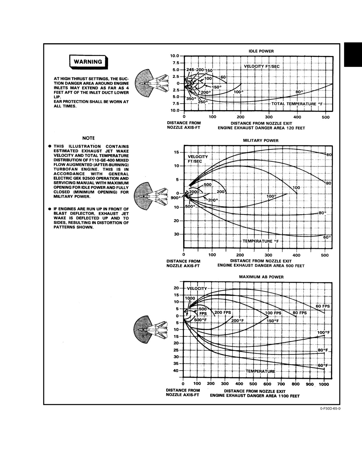
NAVAIR 01−F14AAD−1
Figure 3Ć4.ĄRunup Danger Areas Exhaust Jet Wake Velocity and Temperature
3−9
ORIGINAL
NAVAIR 01−F14AAD−1
Figure 3Ć5.ĄRadar Radiation Hazard Areas (Sheet 1 of 4)
ORIGINAL
3−10
NAVAIR 01−F14AAD−1
Figure 3−5. Radar Radiation Hazard Areas (Sheet 2 of 4)
3−11
ORIGINAL
NAVAIR 01−F14AAD−1
Figure 3−5. Radar Radiation Hazard Areas (Sheet 3 of 4)
ORIGINAL
3−12
NAVAIR 01−F14AAD−1
Figure 3−5. Radar Radiation Hazard Areas (Sheet 4 of 4)
3−13
ORIGINAL
NAVAIR 01−F14AAD−1
Figure 3Ć6.ĄNoise Danger Areas
ORIGINAL
3−14
NAVAIR 01−F14AAD−1
HERO unsafe ordnance conditions include assembly/
3.2.2.4
Transmission Aboard Carrier
disassembly of ordnance systems, tests involving electrical
connections to the ordnance, such as primer resistance check,
Radar transmission aboard carrier shall be limited to
continuity checks, bare squibs, primers, blasting caps, and
over−the−side operation at the discretion of the commander.
other EED having exposed wire leads and unshielded
The aircraft shall be spotted so the nose radome overhangs
ordnance subassemblies such as rocket motors, warheads,
the side of the carrier. All necessary safety precautions shall
and exercise heads.
be enforced to prevent injury to personnel and damage to
equipment aboard the carrier and on adjacent ships that may
HERO susceptible ordnance systems are any ordnance
accidentally stray into the main beam of the radar.
systems proven
(by tests) to contain EED that can be
adversely affected by RF energy to the point that the safety
3.2.3
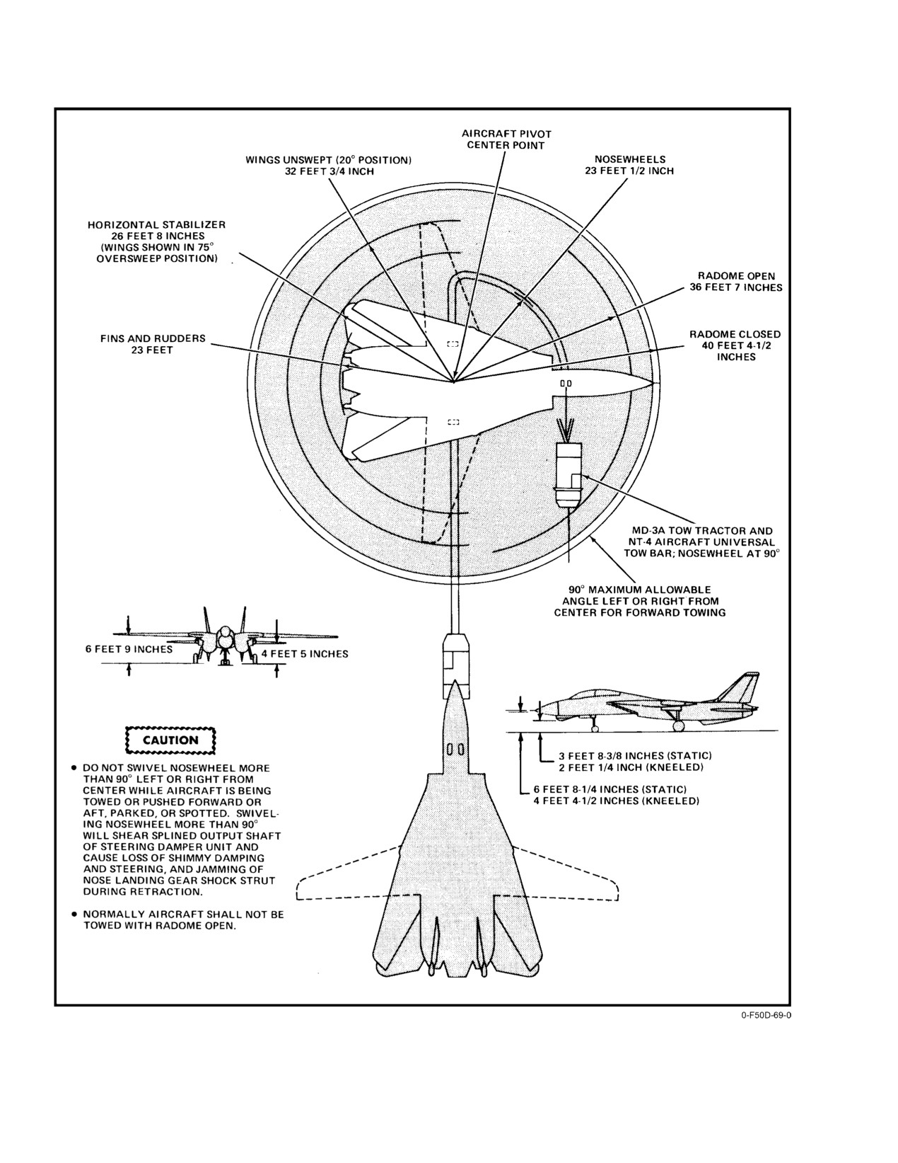
Towing Turn Radii and Ground Clearances
and/or reliability of the system is in jeopardy when the
system is employed in expected RF environments. Some
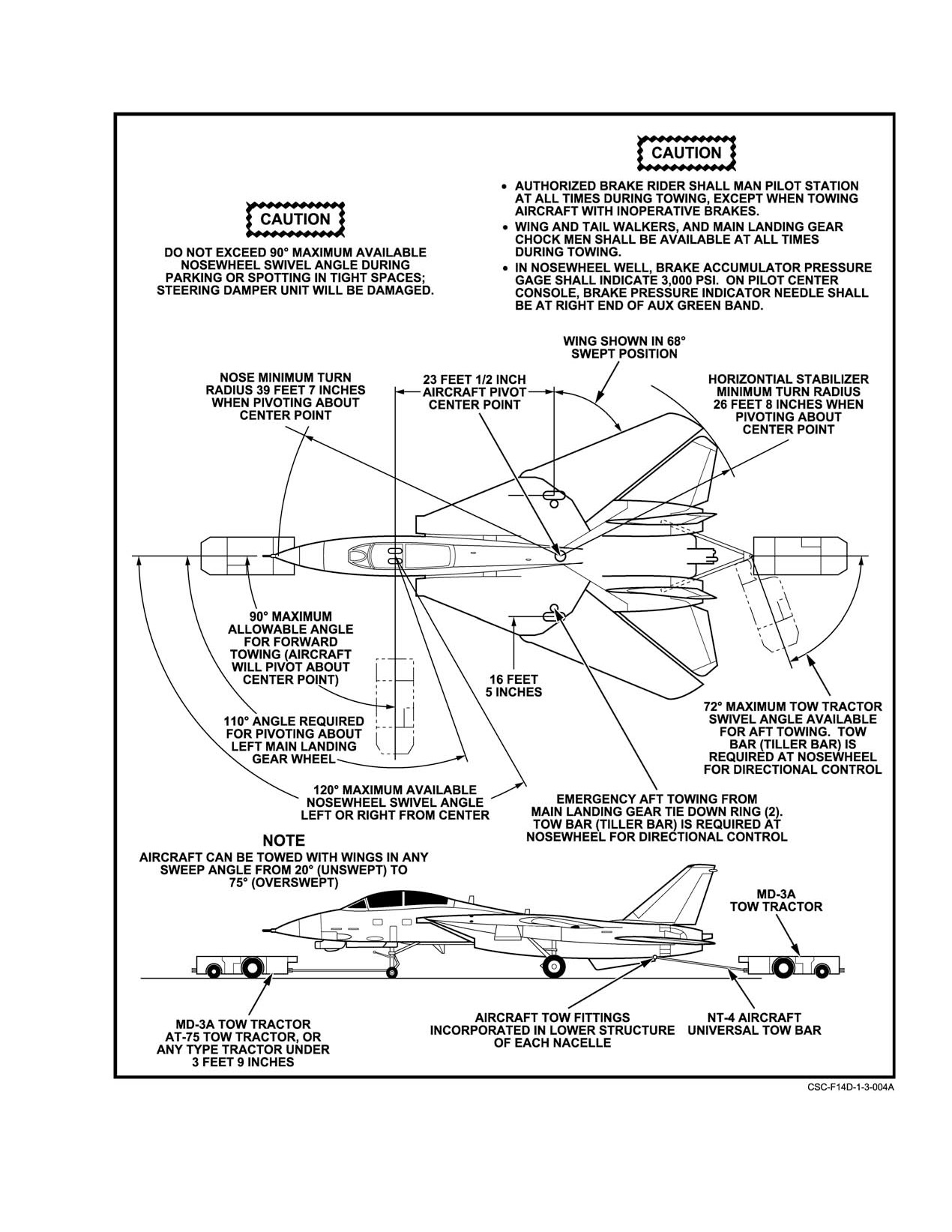
Forward and rearward towing
(Figure 3Ć7 and
systems are susceptible to the RF environment for only a
Figure 3Ć8) can be accomplished with a standard tow bar
small part of the stockpile−to−launch sequence. For example,
(NT−4 aircraft universal tow bar) and the tow tractor. The
the connection of an umbilical cable in the loading procedure
pilot cockpit shallăbe manned with qualified personnel durĆ
may be the only time the system is considered susceptible. At
ing towing operations.
all other times in the system’s life, it may be considered
HERO safe ordnance. HERO safe ordnance are any ordnance
sufficiently shielded or protected that all EED contained by
the item are immune to adverse effects that degrade safety or
reliability when employed in its expected RF environment
(provided that general HERO requirements have been comĆ
Before and during towing, ensure that the
plied with).
needle(s) in the AUX/PARK brake pressure
gauge(s) remains in the green band to ensure sufĆ
3.2.2.3
Fuel Ignition Hazard
ficient pressure to lock the wheels.
When performing fueling or defueling operations, use
3.2.4
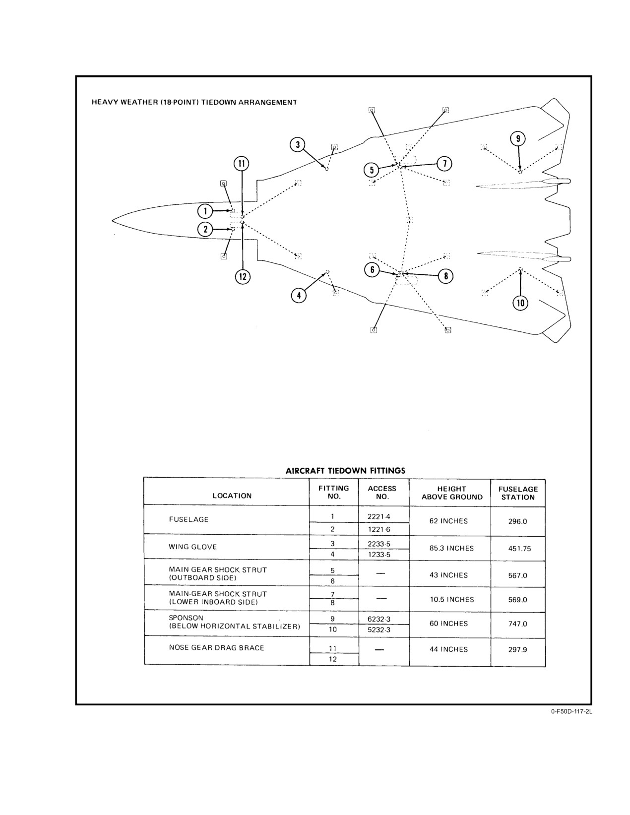
Tiedown Points
minimum safe distances outside of radiation hazard areas.
Fuel ignition hazard occurs within 90 feet of the aircraft
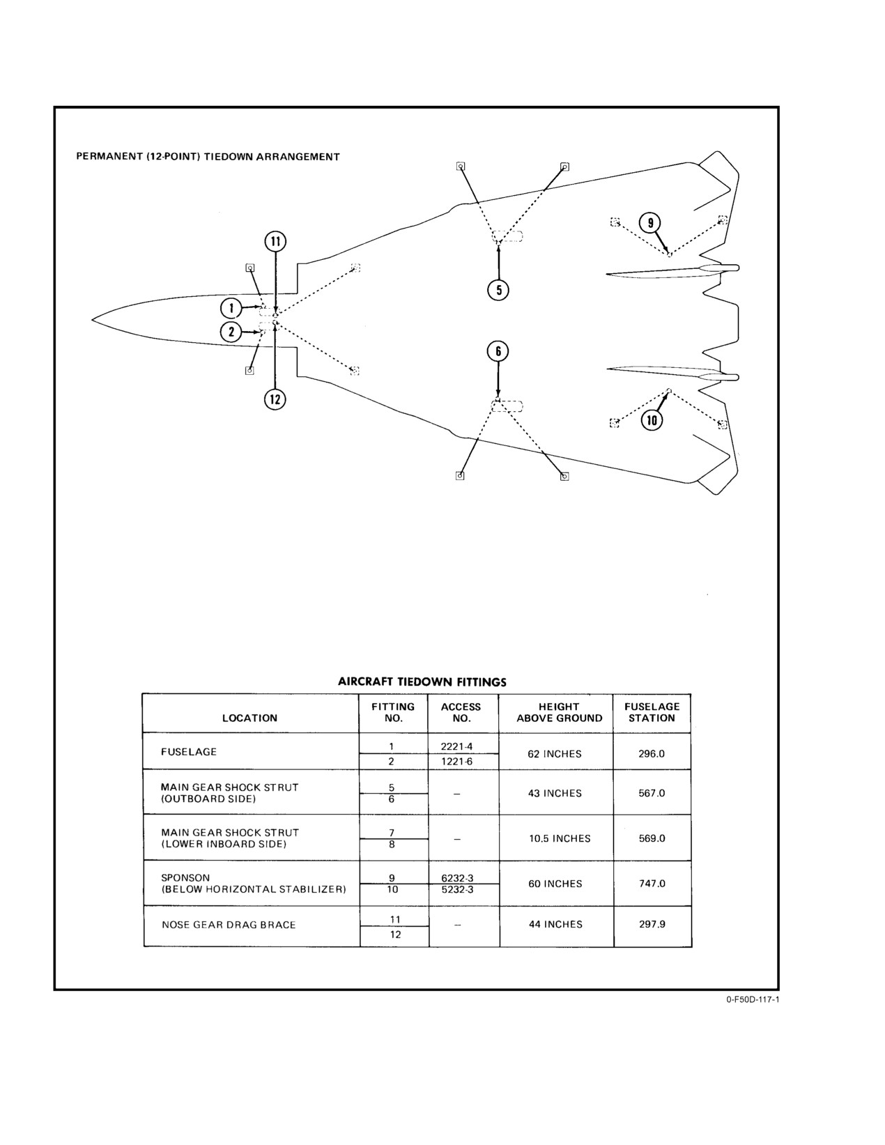
Aircraft tiedown points are illustrated in Figure 3Ć9.
where RF radiation induced sparks could ignite flammable
When mooring a parked aircraft, do not depend upon chocks
vapors of fuels. Fuel ignition hazard is based on 5W/cm2
alone to hold the aircraft in position. Tiedowns shall be
peak power density.
installed in a symmetrical pattern being careful not to chafe
against the aircraft structure.
Good housekeeping operations are of utmost imporĆ
tance in areas where radar transmission is anticipated. RF
The normal six−point tiedown (Figure 3Ć9, sheet 1)
radiation may cause steelwool to be set afire or metallic chips
locations permit all maintenance servicing, including engine
to produce sparks, which in turn may ignite spilled fuels or
removal, jacking, and weapons loading. Standard chain−type
oils around aircraft and buildings. Keep all areas clean and
tiedowns are used for an 18−point symmetrical tiedown durĆ
refuse in approved containers.
ing heavy weather (Figure 3Ć9, sheet 2).
3−15
ORIGINAL
NAVAIR 01−F14AAD−1
Figure 3Ć7.ĄTowing Turn Radii
ORIGINAL
3−16
NAVAIR 01−F14AAD−1
Figure 3Ć8.ĄTowing
3−17
ORIGINAL
NAVAIR 01−F14AAD−1
Figure 3Ć9.ĄTiedown Arrangement (Sheet 1 of 2)
ORIGINAL
3−18
NAVAIR 01−F14AAD−1
Figure 3−9. Tiedown Arrangement (Sheet 2 of 2)
3−19 (Reverse Blank)
ORIGINAL
NAVAIR 01-F14AAD-1
CHAPTER 4
Operating Limitations
4.1
LIMITATIONS
2. Maximum canopy open speed
60 knots.
This section includes the aircraft and engine limita-
tions that must be observed during normal operations. The
aerodynamic and structural limitations in this section apply
only to F-14D aircraft for the store station configurations
shown in Figure 4-1. Engine limitations apply to all aircraft
Use of antiskid must be in accordance with the
with the F110-GE-400 engine.
following procedures:
D Select antiskid while stopped on the runway
4.1.1
Engine Limits
in the takeoff position; after landing, turn
antiskid off once slowed below 15 knots
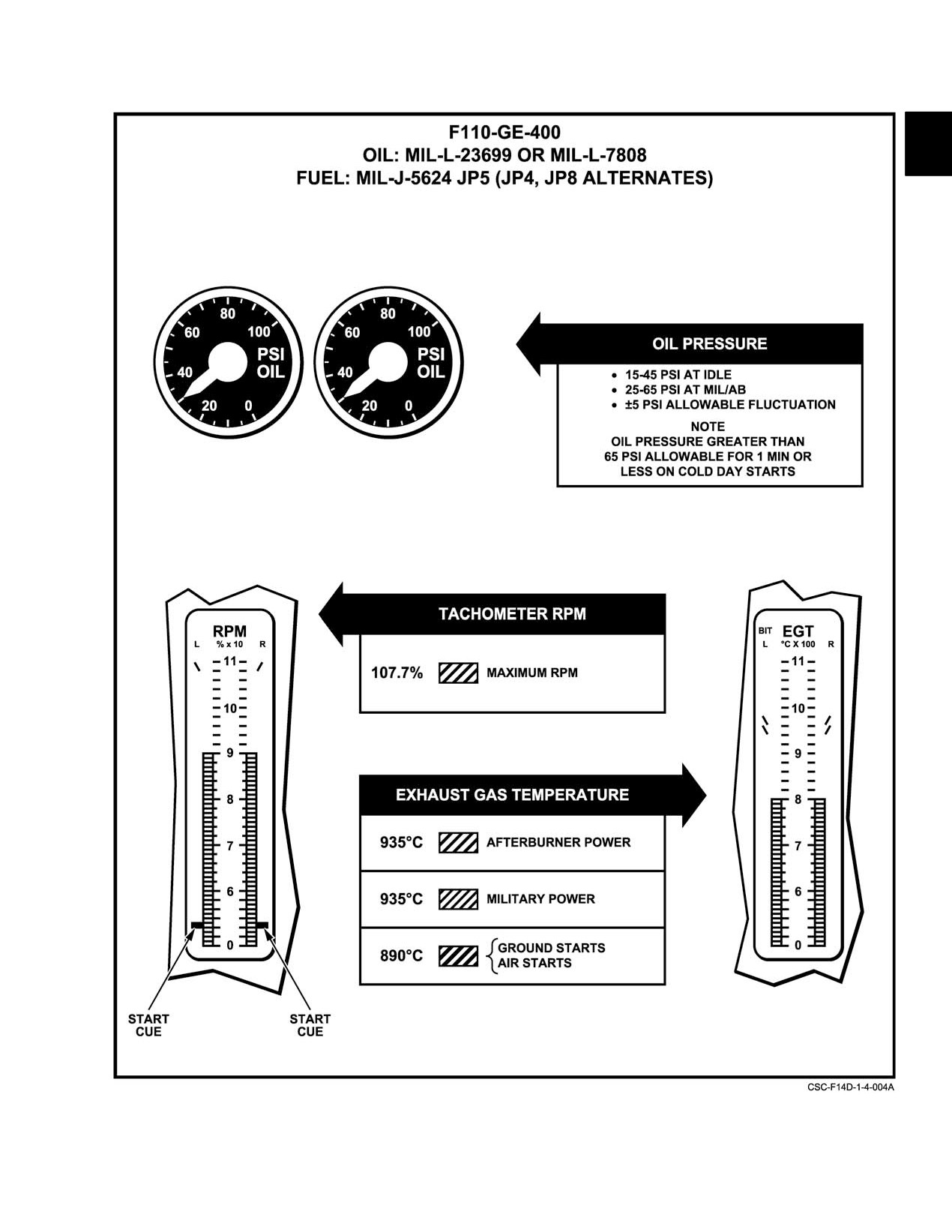
Engine instrument markings for various operation lim-
prior to clearing the runway.
itations are shown in Figure 4-2. Engine operating limita-
tions are shown in Figure 4-3.
D Use only during landing or aborted takeoff.
D Do not use antiskid while taxiing.
The engine secondary (SEC) mode may be intention-
ally selected in flight only under the following conditions:
4.1.6
Ejection Seat Operation Limits
1. Engine operating between 85-percent rpm and mili-
See ejection envelope curves, Chapter 16, Figure 16-1.
tary power.
1. Maximum speed (seat)
600 knots.
2. Airspeed less than 1.0 IMN.
4.1.2
Starter Limits
The starter cranking limits are as follows:
Ejection above 350 knots is hazardous, the deci-
1. Cross bleed
2 minutes.
sion to exceed 350 knots rests with the aircrew.
2. Start cart
5 minutes.
4.1.7
Autopilot Limits
When the time limit is reached, 10 minutes cooling is
required between cranking.
Autopilot should not be used under the following
conditions:
4.1.3
Airstart Envelope
1. Airspeeds greater than 400 KCAS/0.9 IMN.
The engine spooldown andwindmill airstart envelopes
2. Altitude above 42,500 feet.
are shown in Chapter 14, Figure 14-3.
4.2
AIRSPEED LIMITATIONS
4.1.4
Crosswind Limits
The limits and restrictions in this part represent the
Crosswind takeoffs and landings are permitted with a
maximum capability of the aircraft commensurate with safe
crosswind component not to exceed 20 knots at 90 .
operations. Aerodynamic and structural excesses of these
limits shall be entered on the maintenance action form for
4.1.5
Ground Operations Limits
appropriate maintenance action.
1. Maximum tire speed
190 knots.
4-1
CHANGE 1
NAVAIR 01−F14AAD−1
AIRCRAFT STORE STATION
STORE
CONFIGURATION
1A
1B
2
3, 4, 5, & 6
7
8B
8A
1A(*)
−
−
−
−
−
−
−
1B1
AIM−9
AIM−9
−
−
−
AIM−9
AIM−9
1B2
AIM−9
−
−
−
−
−
AIM−9
1C
−
−
TANK
−
TANK
−
−
2A(*)
−
−
−
4 AIM−7
−
−
−
2B1
AIM−9
AIM−9
−
4 AIM−7
−
AIM−9
AIM−9
2B2
AIM−9
−
−
4 AIM−7
−
−
AIM−9
2B3
AIM−9
AIM−7
−
4 AIM−7
−
AIM−7
AIM−9
2B4
−
AIM−7
−
4 AIM−7
−
AIM−7
−
2C(*)
−
−
TANK
4 AIM−7
TANK
−
−
2C1
AIM−9
AIM−9
TANK
4 AIM−7
TANK
AIM−9
AIM−9
2C2
AIM−9
−
TANK
4 AIM−7
TANK
−
AIM−9
2C3
AIM−9
AIM−7
TANK
4 AIM−7
TANK
AIM−7
AIM−9
2C4
−
AIM−7
TANK
4 AIM−7
TANK
AIM−7
−
3A(*)
−
−
−
4 AIM−54
−
−
−
3B1
AIM−9
AIM−9
−
4 AIM−54
−
AIM−9
AIM−9
3B2
AIM−9
−
−
4 AIM−54
−
−
AIM−9
3B3
AIM−9
AIM−7
−
4 AIM−54
−
AIM−7
AIM−9
3B4
−
AIM−7
−
4 AIM−54
−
AIM−7
−
3B5
AIM−9
AIM−54
−
4 AIM−54
−
AIM−54
AIM−9
3B6
−
AIM−54
−
4 AIM−54
−
AIM−54
−
3C(*)
−
−
TANK
4 AIM−54
TANK
−
−
3C1
AIM−9
AIM−9
TANK
4 AIM−54
TANK
AIM−9
AIM−9
3C2
AIM−9
−
TANK
4 AIM−54
TANK
−
AIM−9
3C3
AIM−9
AIM−7
TANK
4 AIM−54
TANK
AIM−7
AIM−9
3C4
−
AIM−7
TANK
4 AIM−54
TANK
AIM−7
−
3C5
AIM−9
AIM−54
TANK
4 AIM−54
TANK
AIM−54
AIM−9
3C6
−
AIM−54
TANK
4 AIM−54
TANK
AIM−54
−
D
(*) These store configuration limits also apply when multipurpose stub pylons are carried at stations 1 and 8.
D
Flight operating limitations applicable to the above configurations are also applicable to down loadings, except down load of external
tank to MXU−776/777 which shall be considered as a clean store station for limitation purposes.
D
For captive carriage of inert or live AIM−54, installation of ejector cartridges in LAU−132 is mandatory in order to provide jettison
capability.
D
For captive carriage of inert or live AIM−7, installation of ejector cartridges in LAU−92 is mandatory in order to provide jettison
capability. Thisădoes not apply to CATM−7F−2 missiles used for ballast (refer to NAVAIR 01−F14AAD−75 Weapon Stores Loading
Manual).
D
For shore−based operations all CATM−7F−1 (Sparrow training rounds) shall be configured with a modified shear wafer to preclude
inadvertent activation of the guidance and control unit, and subsequent ejection of the missile.
D
Simultaneous loading of AIM−7 on store station 4 and AIM−54 on store stations 3 and 6 is an authorized configuration. Limitations of
fuselage AIM−54 apply for carriage, individual missile limitations apply for launch/jettison.
D
AIM−9 configurations include both LAU−7 and LAU−138 carriage.
D In all cases the center of gravity position must remain within limits. The aft limit can be easily exceeded
if stations 3 and 6 are not loaded.
D With MA ARM ON and all conditions satisfied for AIM−54 launch, an ATM−54 (training round) will be
ejected if the trigger or launch button is depressed.
D With MA ARM ON and all other conditions satisfied for AIM−7 launch, a CATM−7F−1 (Sparrow training
round) will be ejected when the trigger or launch button is pressed unless a modified shear wafer is
installed. Emergency/selective jettison of a CATM−7F−1 is still possible with a modified shear wafer
installed.
Figure 4Ć1.ĄStore Station Configuration
ORIGINAL
4−2
NAVAIR 01−F14AAD−1
Figure 4Ć2.ĄInstrument Markings
4−3
ORIGINAL
NAVAIR 01−F14AAD−1
F110−GE−400
OIL:
MIL−L−23699 OR MIL−L−7808
FUEL: MIL−J−5624 (JP−5)(JP−4, JP−8 ALTERNATES)
OPERATING CONDITIONS
OPERATING LIMITS
MAXIMUM MEASURED
NORMAL OIL PRESSURE
THRUST SETTING
EXHAUST GAS TEMP (_C)
(PSIG)
MAXIMUM
935
25 TO 65
(AFTERBURNING)
MILITARY
935
25 TO 65
IDLE STABILIZED
935
15 TO 45
STARTING
890
(GROUND)
890
(AIRSTART)
NOTE
D OIL PRESSURE WILL INCREASE PROPORTIONATELY WITH RPM.
D UNDER COLD CONDITIONS, OIL PRESSURE MAY EXCEED 65 PSI FOR
1 MINUTE.
RPM LIMITS
ANY EXCEEDED LIMIT SHOULD BE REPORTED AS A DISCREPANCY
AND MAXIMUM RPM, EGT, AND TIME NOTED.
OPERATING CONDITIONS
OPERATING LIMITS
STEADY STATE OR TRANSIENT
107.7% RPM
Figure 4Ć3.ĄEngine Operating Limits
ORIGINAL
4−4
NAVAIR 01−F14AAD−1
4.2.1
Maximum Airspeeds
4.2.1.3
In−Flight Refueling
Maximum speeds are presented in calibrated knots and
1. Refueling probe 400 KCAS/0.8 TMN.
true Mach number. These values are derived from the posiĆ
2. In−flight refueling (cruise configuration) 200 to
tion error−correction curves of the production pitot−static−
300 KCAS/0.8 TMN.
operated airspeed and altitude system. AOA is presented
utilizing the conventional indicated units AOA while sideslip
3. In−flight refueling (approach configuration) 170
angle limits are presented in terms of degrees of rudder
to 200 KCAS.
deflection.
4.3
ACCELERATION LIMITS
Note
Note
Unless otherwise specified, the limits presented
herein pertain to flight with the stability
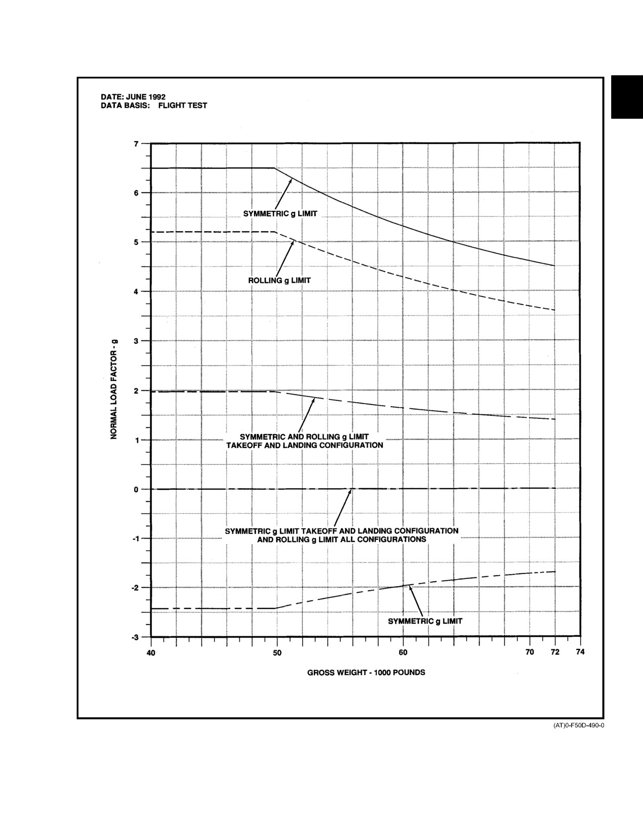
D Limits are based on a gross weight of 49,548
augmentation system on.
pounds. See Figure 4Ć5 for the variation of
maximum load factor with gross weights
4.2.1.1
Cruise Configuration
greater than 49,548 pounds.
D Coordinated turns with small rudder and latĆ
With wing sweep in the MANUAL or AUTO mode, the
eral stick inputs are defined as symmetrical
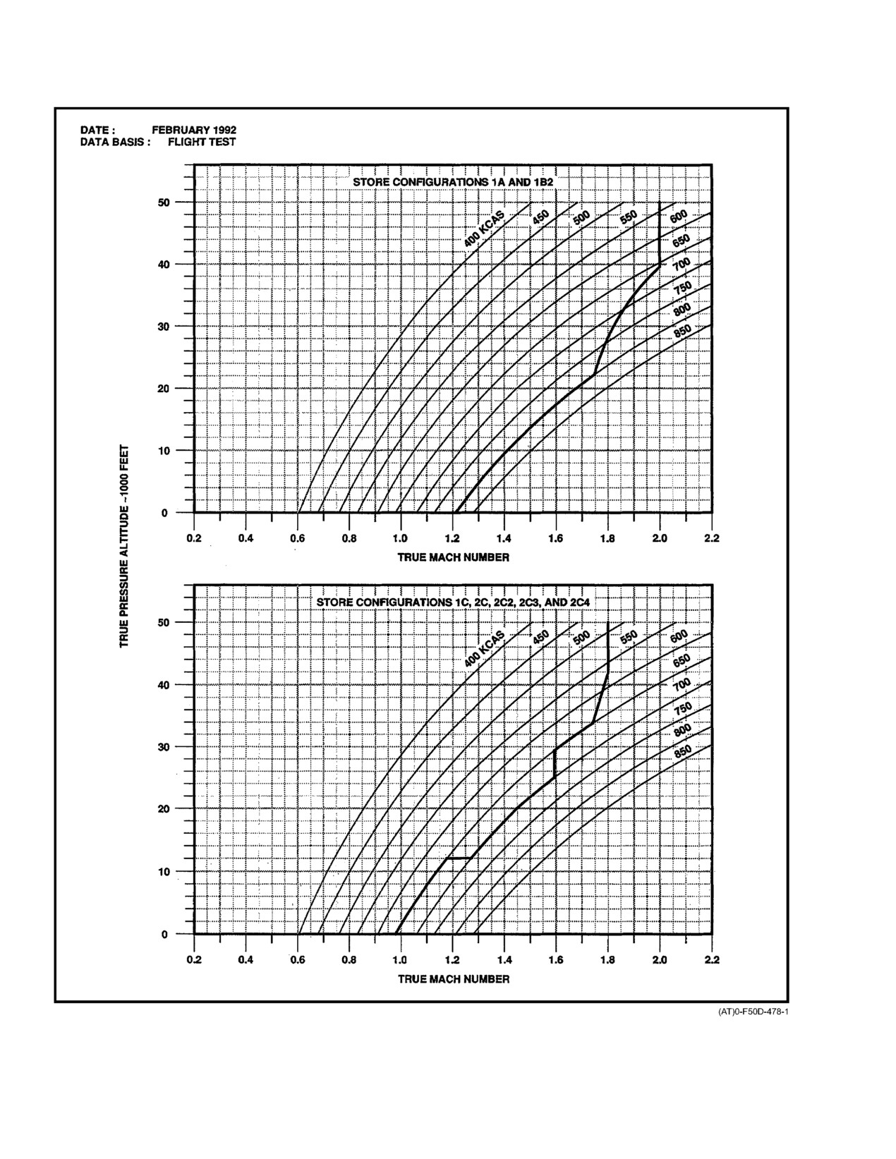
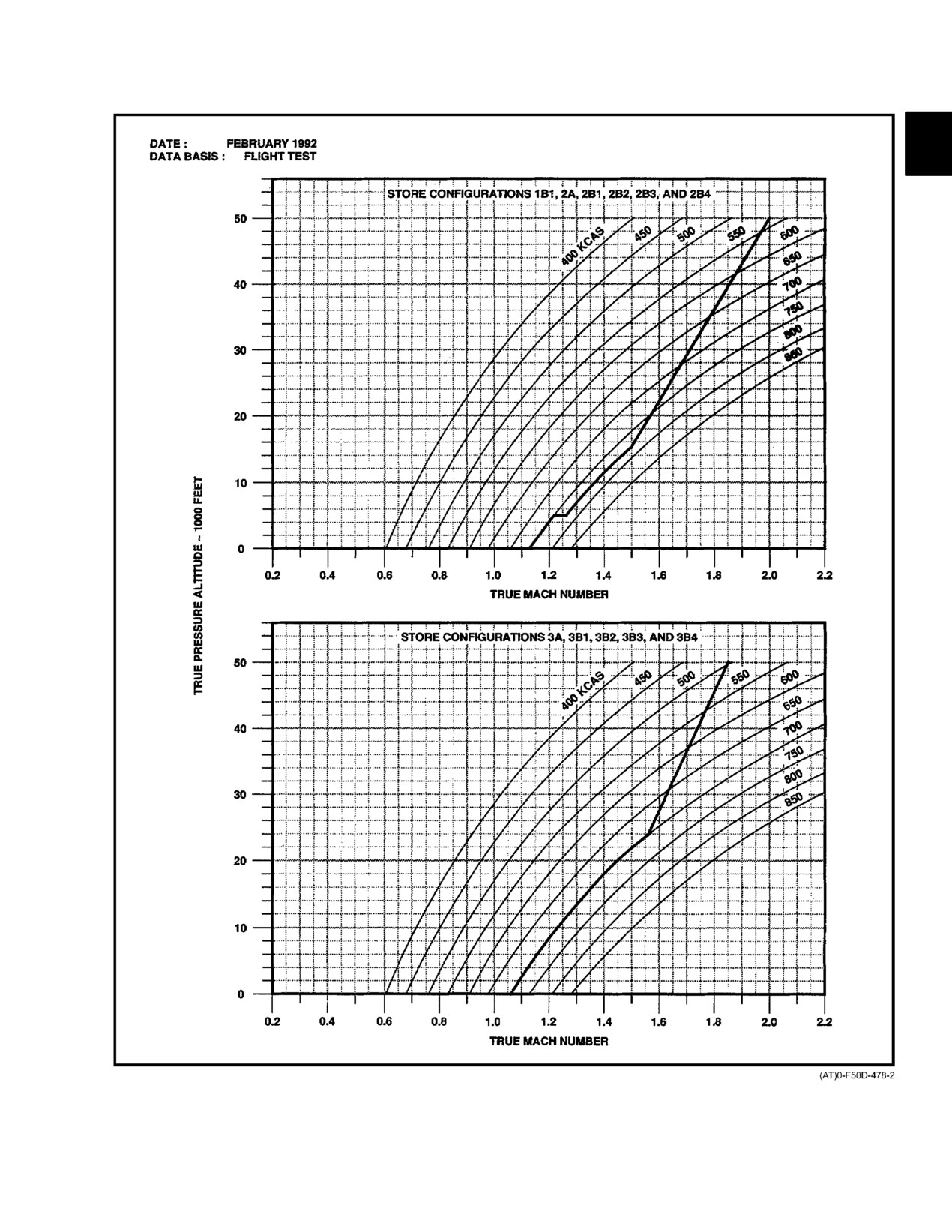
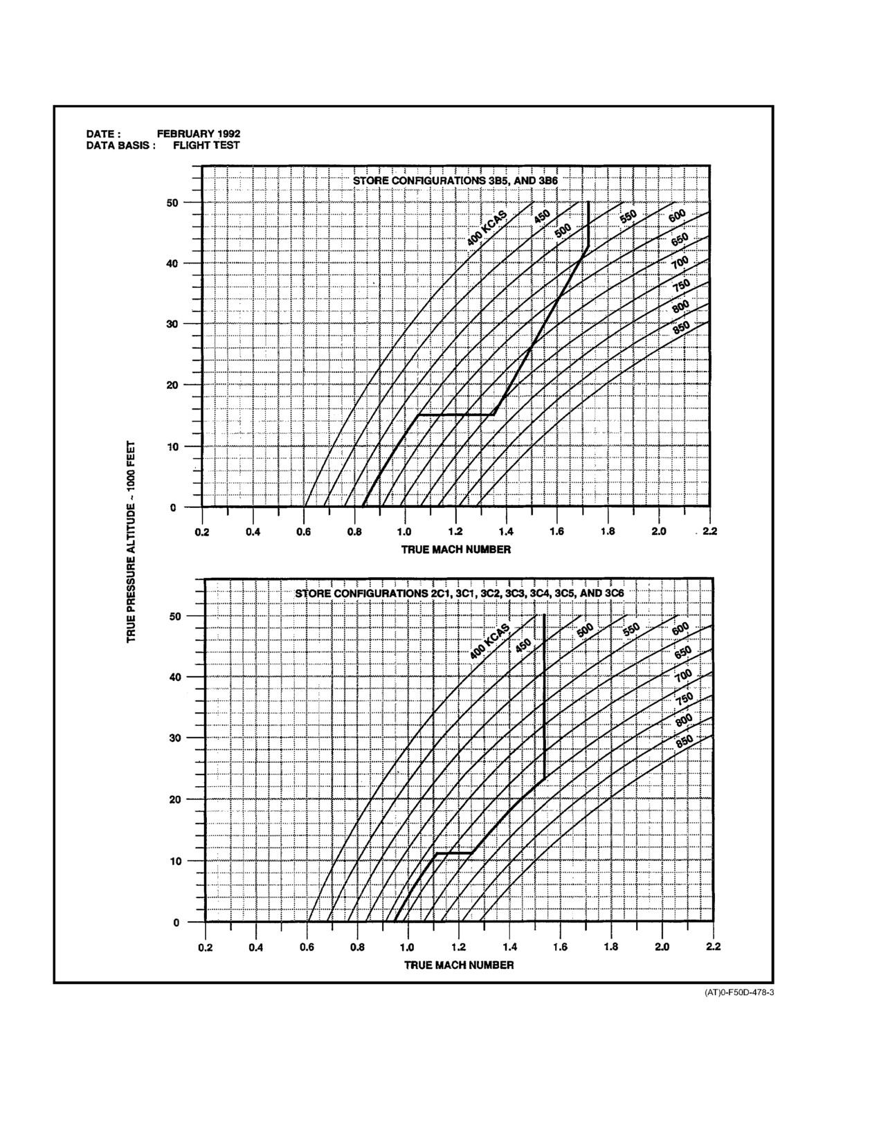
maximum allowable airspeeds are shown in Figure 4Ć4.
flight.
In emergency wing−sweep mode, the following comĆ
4.3.1
Cruise Configuration
bination of Mach and wing−sweep schedule must be used:
See Figure 4Ć5 and Figure 4Ć8.
1.
≤ 0.4 TMN 20°.
4.3.2
Approach Configuration
2.
≤ 0.7 TMN 25°.
1. Landing gear and/or landing flaps and slats
3.
≤ 0.8 TMN 50°.
extended 0 to 2.0g (symmetrical or rolling).
4.
≤ 0.9 TMN 60°.
4.4
ANGLE−OF−ATTACK LIMITS
5.
> 0.9 TMN 68_.
4.4.1
Cruise Configuration
4.2.1.2
Approach Configuration
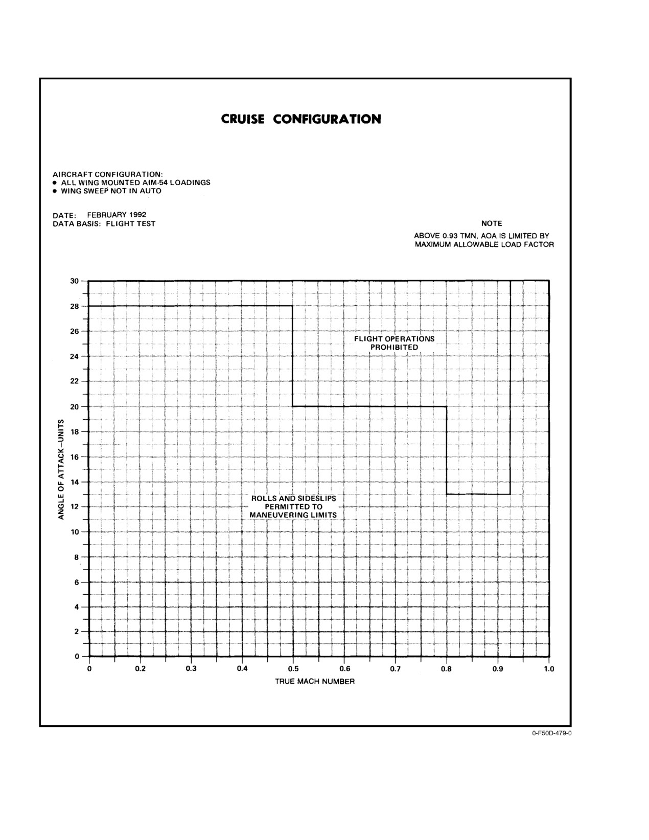
AOA is limited by the maximum allowable load factor
1.
Landing gear 280 KCAS.
of Figure 4Ć5. For wing sweep not in AUTO, AOA limits of
Figure 4Ć7 still apply. Since ROLL SAS now increases deparĆ
2.
Landing flaps and slats 225 KCAS.
ture resistance at higher AOA, it should be left on for all flight
conditions. With operating ARI, subsonic pilot control inputs
with landing gear retracted are not limited by AOA or sideĆ
slip and therefore Figure 4Ć8 applies only with ROLL SAS
OFF or a Degraded DFCS condition.
D With the landing gear extended or in transit,
abrupt rolls or uncoordinated turns above 225
KCAS can cause structural failure of the landĆ
ing gear doors.
D Aircraft has significantly improved roll rate
capability with ROLL SAS ON, which
D After takeoff, move the FLAP handle to the
increases susceptibility to inertia coupled
UP position passing 180 KCAS to ensure flap
departures due to overly aggressive multi−axis
and slat airspeed limits are not exceeded.
control inputs.
D With ROLL SAS ON, departure resistance is
increased because of DFCS ARI functionality
and therefore should remain on at all times.
4−5
ORIGINAL
NAVAIR 01−F14AAD−1
Figure 4Ć4.ĄMaximum Allowable Airspeeds (Sheet 1 of 3)
ORIGINAL
4−6
NAVAIR 01−F14AAD−1
Figure 4−4. Maximum Allowable Airspeeds (Sheet 2 of 3)
4−7
ORIGINAL
NAVAIR 01−F14AAD−1
Figure 4−4. Maximum Allowable Airspeeds (Sheet 3 of 3)
ORIGINAL
4−8
NAVAIR 01−F14AAD−1
Figure 4Ć5.ĄVariation of Maximum Allowable Normal Load Factor With Gross Weight
4−9
ORIGINAL
NAVAIR 01−F14AAD−1
4.4.2
Approach Configuration
D If outboard spoilers fail with airspeed greater
than 400 KCAS and wing sweep less than 62°,
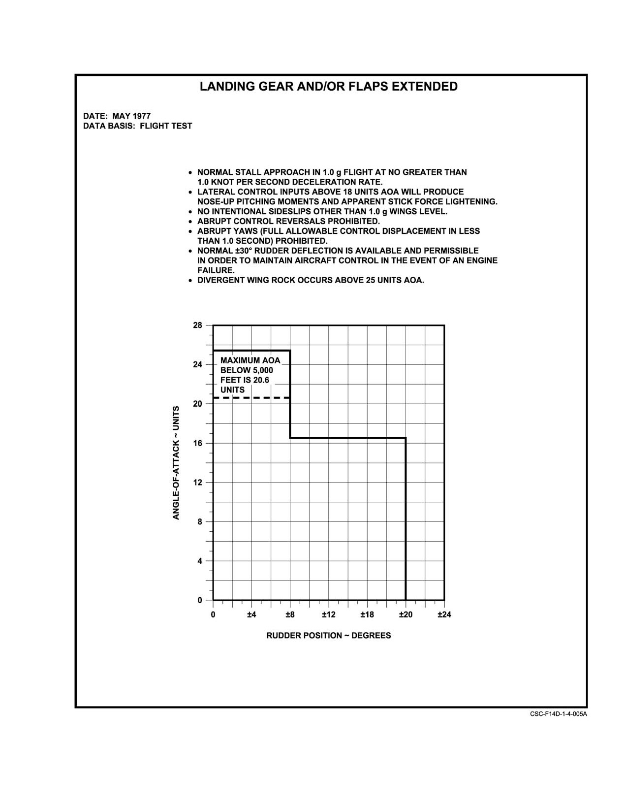
Maximum allowable AOA and rudder deflection with
limit lateral stick deflection to one−half pilot
landing gear and flaps extended is shown in Figure 4Ć6.
authority.
4.5
MANEUVERING LIMITS
Note
AOA limitations shown in Figure 4Ć7 apply to
4.5.1
Approach Configuration
designated configurations (wing sweep not in
AUTO, pylon mounted AIM−54).
With landing gear and/or landing flaps and slats
extended, abrupt yaws are prohibited. Refer to Figure 4Ć6 for
4.5.4
Sideslip Limits
approach configuration sideslip limits.
4.5.4.1
All External Store Configurations
With landing gear extended or in transit, abrupt
rolls and uncoordinated turns shall not be performed above
1. Below 0.7 TMN Rudder inputs as required to
225 KCAS.
maneuver aircraft at high AOA.
4.5.2
Cruise Configuration
2. Above 1.7 TMN Intentional sideslips prohibited.
With maneuver slats/flaps extended, maximum allowĆ
able load factor is 6.5g or the limits of Figure 4Ć5, whichever
is less. No additional g and/or AOA limits are placed on
ROLL SAS ON maneuvering, or cross control inputs.
If a supersonic engine stall and/or failure occurs,
arrest roll rate with lateral stick only. Yaw SAS
will maintain sideslip angle within acceptable
limits.
Maneuvering with YAW SAS OFF or inoperative
Note
shall not be conducted above 15 units AOA with
landing gear retracted.
Use of full available rudder is permitted at all
airspeeds if required to counteract adverse yaw
Since inoperative auto−maneuvering devices may
encountered in maneuvering flight.
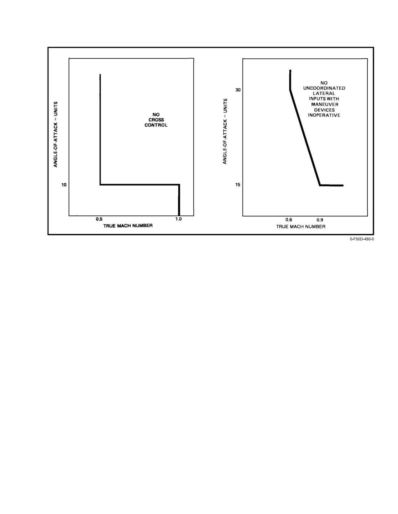
signal improper operation of DFCS primary AOA input,
uncoordinated lateral control inputs shall not be used in the
4.5.5
Prohibited Maneuvers
area of the flight envelope indicated in Figure 4Ć8 when auto−
maneuvering flaps/slats are not operating.
The following additional maneuvers are prohibited:
4.5.3
Rolling Limits
1. Intentional spins.
2. During afterburner operations:
With maneuver slats and flaps extended, maximum
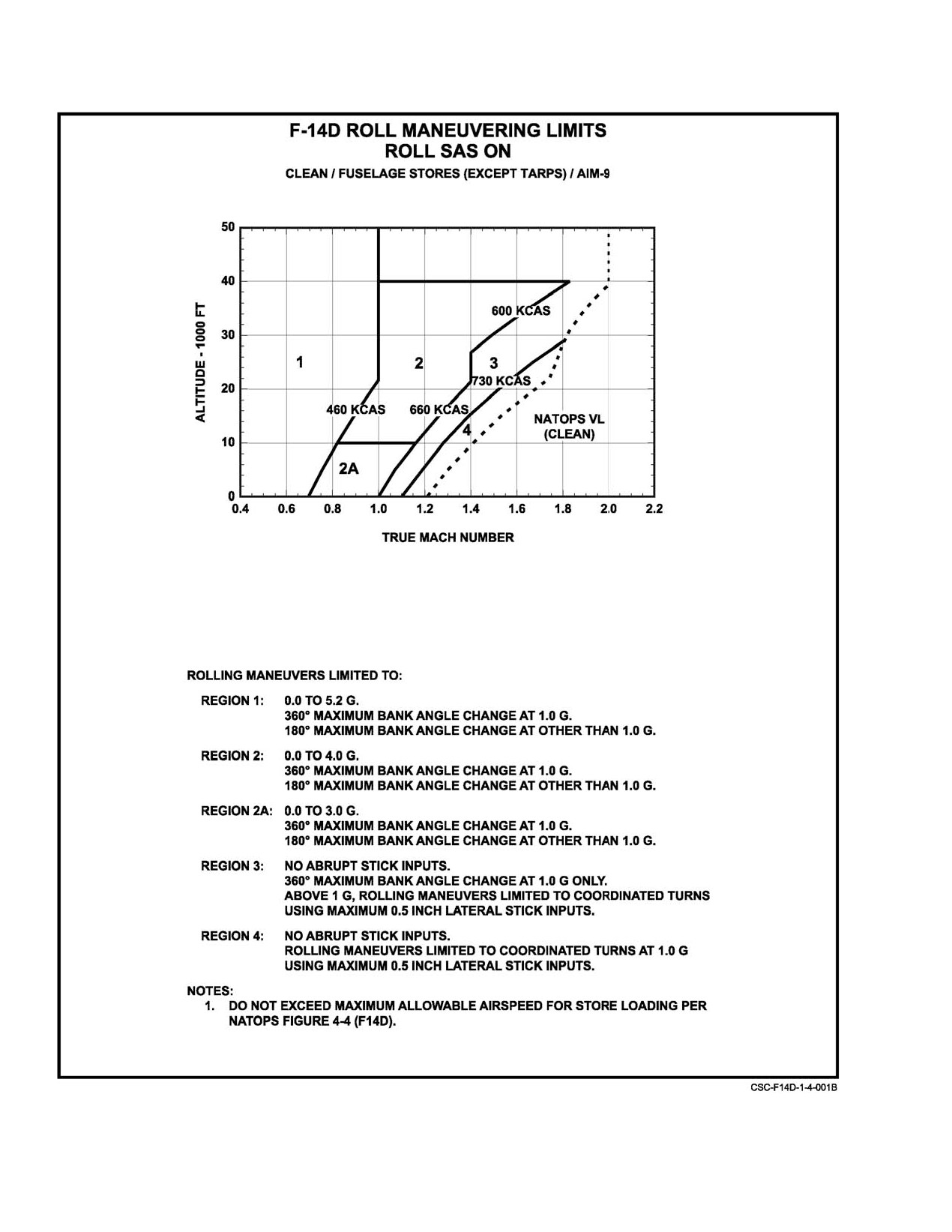
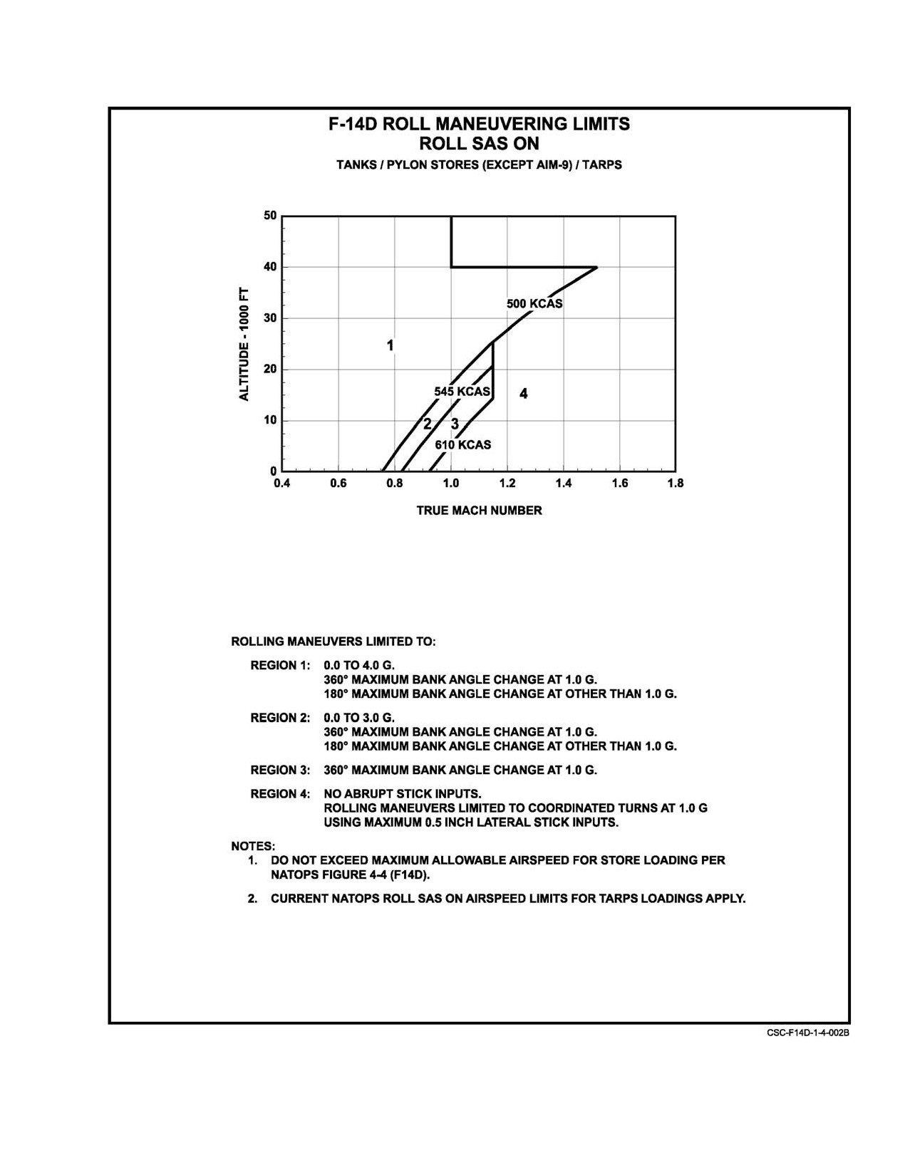
allowable load factor is 5.2g or the limits of Figure 4Ć9
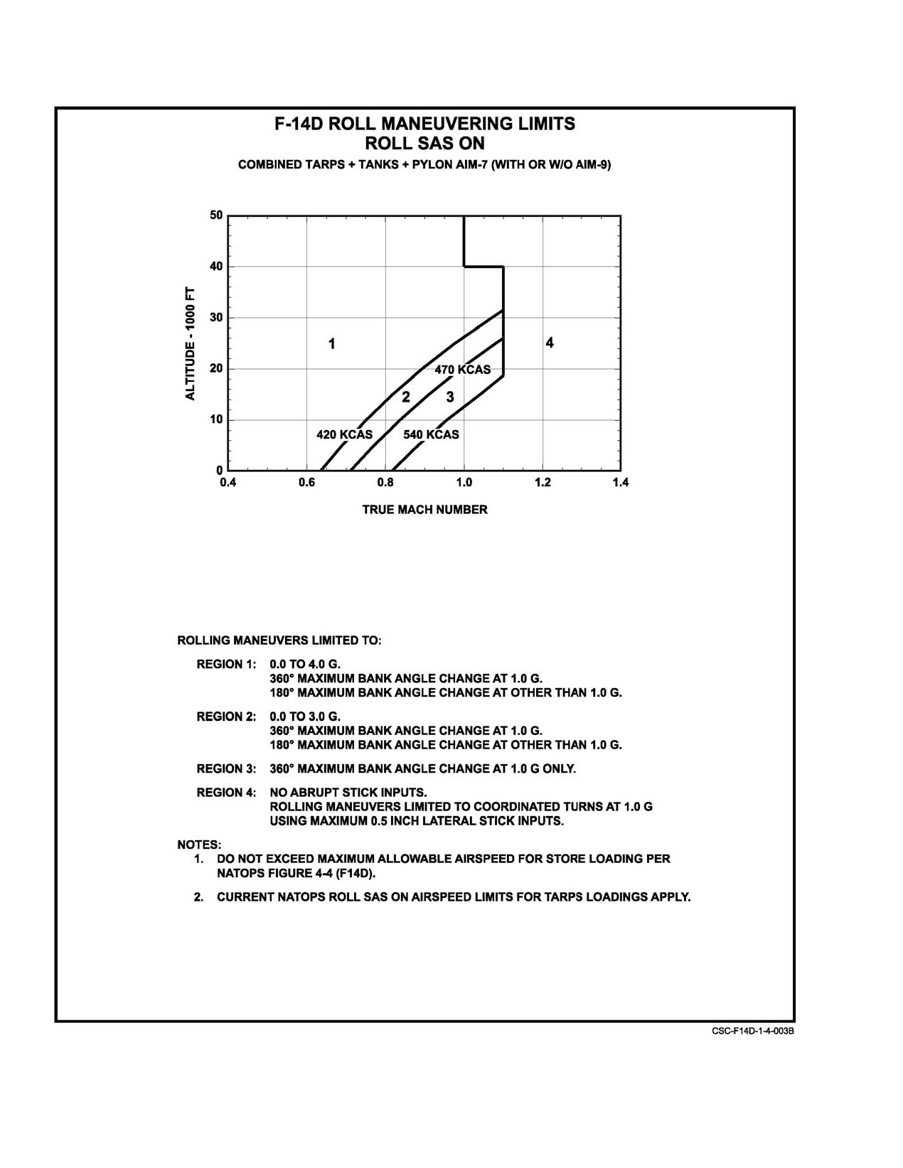
e. Sustained 0 to −0.5g flight.
whichever is less. Rolling limits are shown in Figure 4Ć9.
f. Flight from
−0.5g to
−2.4g’s for more than
10 seconds.
3. At MIL power or less: zero or negative−g flight for
more than 20 seconds.
D Do not initiate full lateral stick inputs above
4.5g if a 5.2g limit applies or above 3.5g if a
4.0g limit applies. Control system dynamics
may cause load factor to increase beyond
limits.
ORIGINAL
4−10
NAVAIR 01−F14AAD−1
Figure 4Ć6.ĄMaximum Allowable Angle of Attack Rudder Deflections
4−11
ORIGINAL
NAVAIR 01−F14AAD−1
Figure 4Ć7.ĄAngle−of−Attack Limits
ORIGINAL
4−12
NAVAIR 01−F14AAD−1
Figure 4Ć8.ĄManeuvering Limits Cruise Configuration (Roll SAS Off or Degraded DFCS)
4. AIM−9 launch with landing flaps and slats extended.
4.7
TAKEOFF AND LANDING FLAP AND SLAT
AND TRANSITION LIMITS
5. Fuel dumping with afterburner operating or with
speedbrakes extended.
4.7.1
Clean and Symmetric Stores Loading
6. Dual−engine afterburner takeoffs, waveoffs, bolters,
or catapult launches.
See Figure 4Ć10.
7. Use of maximum AB in event of engine failure durĆ
1. All transitions will be made in less than 45° bank
ing takeoff, catapult launch, waveoff or bolter.
angle, ROLL SAS ON.
8. Rolling maneuvers with AOB change greater than
2. All normal (flaps and slats fully down) takeoff
360° are prohibited.
transitions will be initiated at a minimum altitude of
200 feet AGL.
4.6
SAS LIMITS
3. All other transitions will be made at standard field
FCS CAUTION
Airspeed < 600 kts/1.3TMN
operating altitudes, but no less than 800 feet AGL.
> 0.5TMN/10 units AOA
4. All flap and slat extensions and retractions will be
− No cross controls
made at a maximum of 12 units AOA.
> 0.6TMN/15 units AOA
− Coordinate all lateral stick
PITCH SAS
No Limitations
ROLL DGR/YAW DGR
and/or ARI DGR
Airspeed <1.0TMN
ARI/SAS OUT
Airspeed <1.0TMN
− AOA: max 15 units
− No aggressive maneuvering
4−13
ORIGINAL
NAVAIR 01−F14AAD−1
Figure 4Ć9.ĄManeuvering Limits Ċ Rolling (Sheet 1 of 3)
ORIGINAL
4−14
NAVAIR 01−F14AAD−1
Figure 4−9. Maneuvering Limits Rolling (Sheet 2 of 3)
4−15
ORIGINAL
NAVAIR 01−F14AAD−1
Figure 4−9. Maneuvering Limits Rolling (Sheet 3 of 3)
ORIGINAL
4−16
NAVAIR 01−F14AAD−1
STORE
FLAP LIMITATIONS (INCH−POUNDS)
ORDNANCE/STATION
1A
1B
3
6
8B
8A
2
7
SIDEWINDER
27,220
24,820
−
−
24,820
27,220
−
−
SPARROW
−
63,000
10,500
10,500
63,000
−
−
−
PHOENIX
−
126,000
15,000
15,000
126,000
−
−
−
TANKS (EMPTY)
−
−
−
−
−
−
14,260
14,260
TANKS (FULL)
−
−
−
−
−
−
126,852
126,852
WING FUEL
WINGS 20° ONE WING FULL, OTHER EMPTY
431,405
Note
Do not attempt shipboard landing with inoperative ROLL SAS and greater than
170,000 in−lbs asymmetry unless divert field unavailable.
FLAP TRANSITIONS:
UP TO 66,000 IN−LBS
GREATER THAN 66,000 IN−LBS
CLEAN OR SYMMETRICAL
ASYMMETRY
ASYMMETRY
1. Less than 45° angle of bank
1. Wings level
1. Wings level
2. ROLL SAS ON
2. ROLL SAS ON
2. ROLL SAS ON
3. Minimum 200 feet AGL on
3. Minimum 200 feet AGL
3. Minimum altitude of 1,200 feet AGL for
takeoff
takeoff and landing
4. Dirty−up altitude minimum
4. Dirty−up at minimum
4. Minimum 180 knots.
800 feet AGL
800 feet AGL
5. Minimum 180 knots
5. Minimum 180 knots
Available roll control will be marginal
to inadequate in event of asymmetric
flap/slats without lockout.
Note
Incompatibility of flap transition limit
with existing Case I procedures recĆ
ognized. Although improvement of
flap/slat system reliability has been
accomplished, not enough data is
available concerning failure mode/
rate of improved asymmetry sensor.
Minimum flap transition altitude may
be waived in cases of operational
necessity.
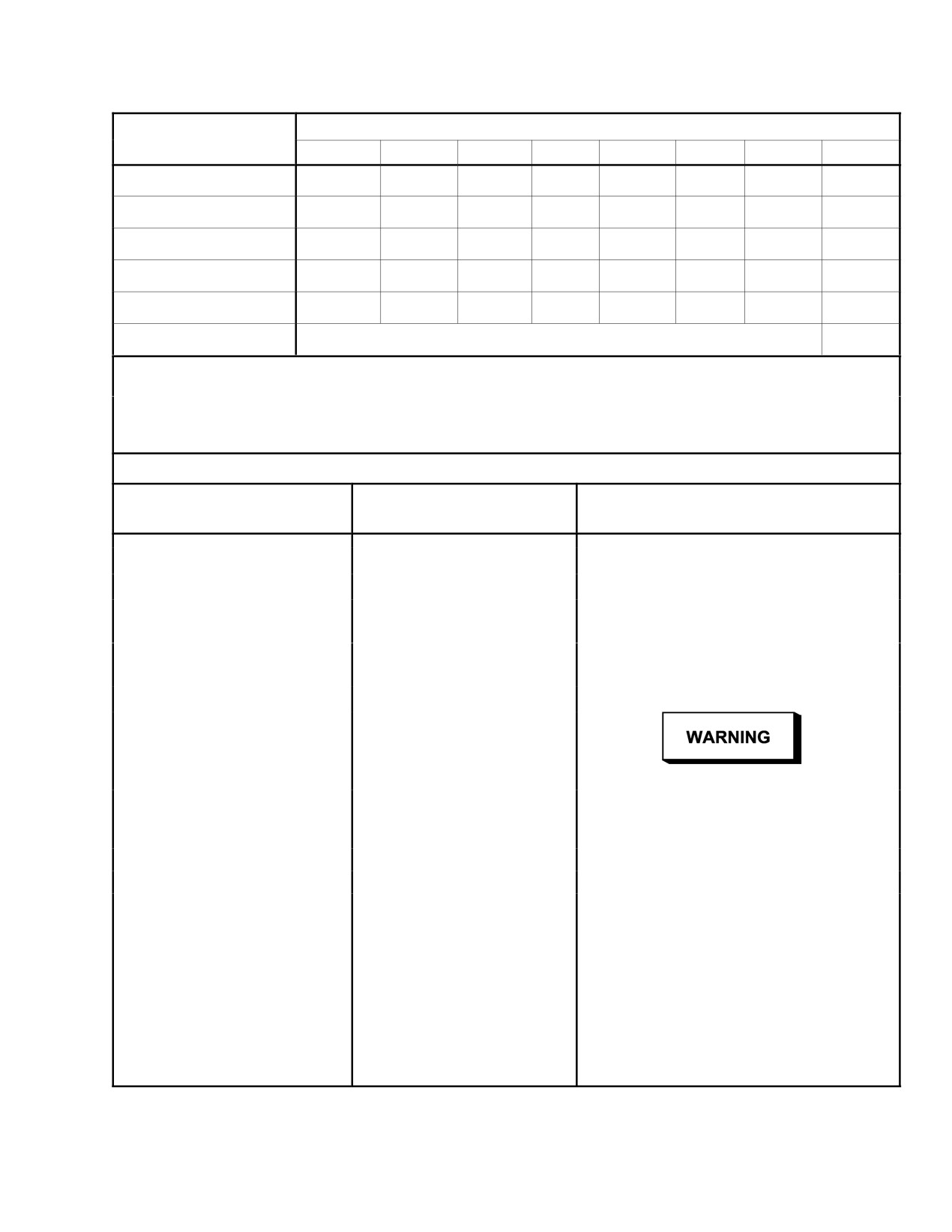
Figure 4Ć10.ĄFlap Limitations
4−17
ORIGINAL
NAVAIR 01−F14AAD−1
4.7.2
External Stores Loading With Up to
4. Only normal minimum descent rate landings are
66,000 Inch−Pounds (5,500 Foot−Pounds)
permitted while carrying AIM−7E/F and/or AIM−9
Asymmetry (AIM−7 on Stations 1B or 8B
on the multipurpose pylon, or AIM−7E/F missiles on
equals 63,000 inch−pounds)
fuselage stations until the following AAC are incorĆ
porated:
1. All transitions will be made in wings−level flight
with ROLL SAS ON.
a. AAC 618 Modifies multipurpose pylon.
2. All normal (flaps and slats fully down) takeoff tranĆ
b. AAC 673 Modifies fuselage backup structure.
sitions will be initiated at a minimum altitude of 200
c. AAC 688 Modifies pylon−mounted swayĆ
feet AGL.
braces.
3. All flap and slat extensions and retractions will be
made at a maximum of 12 units AOA.
4.9
BARRICADE ENGAGEMENT LIMITS
1. Wings at full forward sweep angle (20°) 51,800
4.7.3
External Stores Loading With Greater
pounds (maximum).
Than 66,000 Inch−Pounds (5,500
Foot−Pounds) Asymmetry
a. Flaps and slats extended or retracted.
1. All transitions will be made in wings−level flight
b. No external stores except AIM−7 or AIM−54 on
with ROLL SAS ON at a minimum altitude of 1,200
fuselage stations only.
feet and at a maximum of 12 units AOA.
c. Empty external fuel tanks permitted only for
4.8
GROSS WEIGHT LIMITS Ċ TAKEOFF,
landing gear malfunction.
LAUNCH, AND LANDING
2. Wing−sweep angle greater than 20° up to 35_
1. Catapult launch 76,000 pounds.
46,000 pounds (maximum).
a. Flaps and slats extended or retracted.
b. No external stores, except empty external fuel
tanks for landing gear malfunction.
Single−engine rate of climb at
76,000−pound
gross weight using optimum flight control
3. Wing−sweep angle greater than 35° Not perĆ
technique is predicted to be between 300 and 600
mitted.
fpm. Emergency jettison of stores may be
required to establish adequate rate of climb.
4.10
CENTER OF GRAVITY POSITION LIMITS
1. Field takeoff and emergency landing (minimum rate
Unless otherwise stated, the following cg limits apply:
of descent only) 72,000 pounds.
2. Field landings 60,000 pounds.
MAXIMUM
MAXIMUM
STORE CONFIGURATIONS
FORWARD
AFT
3. Carrier landings 54,000 pounds
Field carrier landing practice 54,000 pounds.
1A, 2A
6.3% MAC
18.5% MAC
Note
1B1, 1B2, 1C, TARPS,
6.3% MAC
17.5% MAC
2B1−4, 2C, 2C1−4
Landing approaches to touchdown should not
All other
6.3% MAC
17.0% MAC
exceed 17 units AOA to avoid nozzle/ventral fin
configurations
damage.
ORIGINAL
4−18
NAVAIR 01−F14AAD−1
Throughout these flight operating limits, all cg posiĆ
4.11.2
External Baggage Container (CNU−188/A)
tions are quoted at the following reference conditions:
The external baggage container (blivet) may be carried
1. Zero fuel gross weight (includes weight of stores
on station 4 or 5 with all loadings authorized for the TARPS
carried on flight).
pod. Simultaneous carriage of a blivet and a TARPS pod or
two blivets is not authorized. The blivet must be configured
2. Wing−sweep angle equals 20°.
with a long tail cone and no fins.
3. Landing gear and flaps extended.
1. Maximum airspeed 520 KCAS/0.90 TMN.
2. Acceleration limit LBA.
WARNING
3. AOA limit Figure 4Ć7.
The aft cg limit will be exceeded if all stations are
4. Jettison Not authorized.
configured for AIM−54 missiles or MK 83/84
bombs and only stations 4 and 5 are loaded or
5. Carrier operations Authorized.
remain as a result of firing, dropping, or jettison
of stations 1, 3, 6, and 8. If the aft cg limit is
6. Maximum load:
exceeded, airspeed/AOA control may be diffiĆ
200 pounds maximum forward shelf
cult. Fuel states of 5,000 to 6,000 pounds result
150 pounds maximum aft shelf
in the most favorable cg position. Slightly aft
350 pounds total.
wing−sweep positions of 25_to 30_ will move the
neutral point aft and should restore normal
4.11.3
Gun Burst Limits
longitudinal stability.
1. Burst limit 200 rounds.
4.11 EXTERNAL STORES AND GUN LIMITS
If two consecutive
200−round bursts are
fired, a
4.11.1
280−Gallon External Fuel Tank Limits
30−second cooldown period is required.
1. Catapult launch with a partially filled external
4.11.4
Launch Limits
tank is not authorized because of surge load
considerations.
Maximum flight conditions for launch of
external
stores are listed in the following paragraphs.
2. Carriage of external tanks not incorporating AYC
598 is limited to 300 KCAS/0.72 TMN.
4.11.4.1
AIM−7F/M
Note
Missiles with K−9 autopilot are identified by a
segmented black line under the missile serial
CV arrestment, CV touch and go, or normal field
number or letters POP" after the serial number.
landings with full or partial fuel in the external
tanks is not authorized because of overload of the
1. Stations 1B and 8B Vmin to 1.3 TMN, all altiĆ
nacelle backup structure. Only minimum descent
tudes, +1g to limits of basic aircraft for non−zero
rate landings are authorized.
bank angles and limits of basic aircraft for zero bank
angle.
2. Stations 3 and 6 Vmin to Vmax for 0g to +2g, Vmin
to 1.4 TMN for +2g to +4g, and Vmin to 1.2 TMN
greater than +4g, all altitudes, +1g to limits of basic
Dive angles in excess of 10_ nose down with
aircraft for non−zero bank angles and 0g to limits of
900 pounds or more fuel in an external tank will
basic aircraft for zero bank angle.
result in fuel venting (dumping).
4−19
ORIGINAL
NAVAIR 01-F14AAD-1
3. Station 4
Vmin to 0.9 TMN for less than 15,000
4.11.5.1
AIM-7F/M
feet MSL for 0g to +1g, Vmin to Vmax greater than
15,000 feet MSL for 0g to +1g, and Vmin to Vmax
1. Stations 1 and 8
Vmin to Vmax, all altitudes, +1g
greater than +1g, all altitudes, +1g to limits of basic
to limits of basic aircraft for non-zero bank angles
aircraft for non-zero bank angles, and 0gto limitsof
and 0g to limits of basic aircraft for zero bank angle.
basic aircraft for zero bank angle.
2. Stations 3 and 6
Vmin to 350 KCAS, all altitudes,
4. Station 5
Vmin to 650 KCAS less than 30,000 feet
+1g for straight and level flight.
MSL for 0g to +1g, Vmin to Vmax greater than 30,000
feet MSL for 0g to +1g, and Vmin to Vmax greater
3. Stations 4 and 5
Vmin to 400 KCAS, all altitudes,
+1g for straight and level flight.
than+1g, all altitudes, +1gtolimitsofbasic fornon-
zero bank angles, and 0g to limits of basic aircraft
for zero bank angle.
4.11.4.2
AIM-9L/M
1. All stations
AIM-7 on stations 3 and 6 exhibit pronounced
Vmin to Vmax, all altitudes, -1.0g to
limits of basic aircraft.
outboard movement when jettisoned.
4.11.5.2
AIM-54C
1. Stations 1B and 8B Vmin to Vmax, all altitudes,
+ 1g to +6g for non-zero bank angles and 0g to +6g
for zero bank angle.
AIM-9 launch is prohibited with landing flaps
and slats extended.
2. Stations 3 and 6
Vmin to 1.4 TMN, all altitudes,
Note
+1g for non-zero bank angles and 0g to +1g for zero
Engine stall may result from firing of AIM-9
bank angle.
missiles. Engine exhaust gas temperature should
be monitored after each firing.
3. Stations 4 and 5
Vmin to Vmax, all altitudes, +1g
for non-zero bank angles and 0g to +1g for zero bank
angle.
4.11.4.3
AIM-54C
Note
1. Stations 1B and 8B — Vmin to Vmax, all altitudes,
For zero bank angle, limit Vmin to Vmax, all alti-
+1g to limits of basic aircraft for non-zero bank
tudes, 0g to limits of basic aircraft.
angles, 0g to limits of basic aircraft for zero bank
angle.
4.11.5.3
Capped 280-Gallon External Fuel Tank
2. Stations 3 and 6 — Vmin to Vmax 0g to +2g and Vmin
(Landing Gear and Flaps Retracted)
to 1.4 IMN +2g to +6g, all altitudes, +1g to +6g for
1. Full, partial, or empty tanks - Less than 0.90 TMN,
non-zero bank angles and 0g to +6g for zero bank
all altitudes, +1g to +3g.
angle.
2. Landing gear and/or flaps extended (emergency
3. Stations 4 and 5 — Vmin to Vmax, all altitudes, +1g
only) Less than 225 KCAS, all altitudes, +1g for
to +5g for non-zero bank angles and 0g to +5g for
straight and level flight.
zero bank angle.
4.12 BANNER TOWING RESTRICTIONS
4.11.5
Jettison Limits
1. Airspeed
220 KCAS maximum recommended.
Flight conditions for jettison
(emergency only) of
external stores are listed in the following paragraphs.
2. Maximum angle of bank
30 , 20_ throttles at idle
below 5,000 feet.
3. Use of speedbrakes Prohibited in flight.
CHANGE 1
4-20
NAVAIR 01−F14AAD−1
Note
D During takeoff, adequate clearance exists to
use speedbrakes for takeoff abort without conĆ
tacting tow cable.
MACH TRIM circuit breaker should be reset
prior to landing. Attempt reset below 0.6 TMN
D The maximum aircraft gross weight for a shipĆ
above 5,000 feet, if possible, to minimize trim
board banner launch is 67,000 pounds.
change transients. Failure to reset circuit breaker
may result in reduced nosedown longitudinal
4.13 TACTICAL AIR RECONNAISSANCE POD
control authority. Reduced authority may deĆ
SYSTEM LIMITATIONS
grade the pilot’s ability to counter pitchup during
waveoffs with aft cg.
See F14A/B/D A/G Tactical Manual (NWP 3−22.5−
F14A/B/D, Volume III, NAVAIR 01−F14AAD−1T−2) for airĆ
5. AIM−54 carriage/launch is not authorized at any
speed limits and store loadings authorized with TARPS pod.
station.
4.13.1
Authorized Stores Loading
6. Special weight and balance information for TARPS
pod configuration is available. Refer to handbook of
1. Downloading is authorized for store stations 1, 2, 7,
weight and balance (NAVAIR 01−1B−40).
and 8 only. Stations 3 and 6 must remain loaded for
cg control.
4.13.2
Interim AIM−7 as Ballast
2. Carrier and field arrestment operations are
TARPS−equipped aircraft are authorized to use
authorized.
specially configured interim AIM−7 missiles as ballast.
AIM−7 missiles specially configured for TARPS use will be
3. Aft cg limit is 17.5−percent MAC, nonjettisonable
designated as CATM−7E−2 or CATM−7F−2. Until then,
(captive carry) AIM−7 missiles, specially configĆ
R40293, R40268, R40302, R40264, R40144, R40298,
ured interim AIM−7 missile or AIM−54 rails and
R40674, R40297, R40274, R40267, and R40235 are
fairings on stations 3 and 6 shall be carried for cg
authorized as TARPS ballast, and weight and balance
control
(see Interim AIM−7 as ballast). Full
information provided for AIM−7F missiles shall be used to
ammunition pod, ALQ−100/126 or other authorized
determine weight and balance of aircraft.
equipment substitution may be required along with
AIM−7 missiles or AIM−54 fairings and rails to
1. CATM−7E−2 360 pounds per missile located at
maintain cg within aft limit. Individual weight and
aircraft station 381.7.
balance calculations shall be performed to ensure cg
limits are not exceeded.
2. CATM−7F−2 440 pounds per missile located at
aircraft station 381.7.
4. Pulling MACH TRIM circuit breaker will eliminate
stick force requirement during low−altitude, high−
speed flight.
4−21 (Reverse Blank)
ORIGINAL
NAVAIR 01−F14AAD−1
PART II
Indoctrination
Chapter 5 Ċ Indoctrination
57 (Reverse Blank)
ORIGINAL
NAVAIR 01−F14AAD−1
CHAPTER 5
Indoctrination
5.1
GROUND TRAINING SYLLABUS
5.1.1.5
Field Carrier Landing Practice/Carrier
Qualification Flight Support Lectures
5.1.1
Minimum Ground Training Syllabus
1. Mirror and Fresnel lens optical landing system
The ground training syllabus sets forth the minimum
2. Day landing pattern and procedures
ground training that must be satisfactorily completed prior to
operating the F−14D. If the aircrewmember has a current
3. Night landing pattern and procedures
F−14A/B NATOPS qualification, the ground syllabus will
consist of the F−14D unique systems. The ground training
4. Shipboard procedures and landing patterns
syllabus for each activity will vary according to local condiĆ
tions, field facilities, requirements from higher authority, and
5. CCA/ACLS procedures
the immediate unit commander’s estimate of squadron readiĆ
ness. The minimum ground training syllabus for the pilot and
6. In−flight refueling (day/night).
the RIO is set forth in the following paragraphs.
5.1.2
Waiving of Minimum Ground Training
5.1.1.1
Familiarization
Requirements
1.
Flight physiological training as appropriate
All F−14D flight crewmembers shall be instructed on
the differences from model in which qualified and comply
2.
F−14D flightcrew academic course
with those items listed below, as directed by the unit comĆ
manding officer.
3.
F−14D MFT/WST (within 5 days).
Where recent crewmember experience in similar airĆ
5.1.1.2
Flight Support Lectures
craft models warrant, unit commanding officers may waive
the minimum ground training requirements provided the
1.
F−14D flightcrew academic course.
flight crewmember meets the following mandatory
qualifications:
5.1.1.3
5.1.1.1 Intercept Flight Support
1. Has obtained a current medical clearance
1.
F−14D flightcrew academic course.
2. Is currently qualified in flight physiology
5.1.1.4
Weapons Firing Flight Support Lectures
3. Has satisfactorily completed the NATOPS flight
1.
Weapons preflight procedures
manual open− and closed−book examinations
2.
Arming/dearming procedures
4. Has completed at least one emergency procedure
period in the MFT/WST (within 10 days)
3.
Firing procedures
5. Has received adequate briefing on normal and
4.
Safety procedures
emergency operating procedures
5.
Jettison/dump areas.
6. Has received adequate instructions on the use and
operation of the ejection seat and survival kit.
5−1
ORIGINAL
NAVAIR 01−F14AAD−1
5.2
FLIGHT TRAINING SYLLABUS
5.2.2.3
Weapons System Employment
5.2.1
Flightcrew Flight Training Syllabus
Qualification is in accordance with existing training
and readiness directives.
Before flight, all flight crewmembers will have com-
pleted the familiarization and flight support lectures pre-
5.2.2.4
Field Carrier Landing Practice and
viously prescribed. A qualified FRS instructor pilot will
Carrier Qualifications
occupy the rear seat for the first familiarization flight. A
qualified FRS instructor RIO can occupy the rear seat if the
Qualification is in accordance with existing training
pilot in command has been previously NATOPS qualified in
and readiness directives.
the F−14A/B. The geographic location, local command re-
quirements, squadron mission, and other factors will influ-
5.3
OPERATING CRITERIA
ence the actual flight training syllabus and the sequence in
which it is completed. The specific phases of training are
5.3.1
Ceiling/Visibility Requirements
listed in the following paragraphs.
Before the pilot becomes instrument qualified in the
5.2.2
Flightcrew Flight Training Phases
aircraft, field ceiling, visibility, and operating area weather
must be adequate for the entire flight to be conducted in a
5.2.2.1
Familiarization
clear airmass according to visual flight rules. After the pilot
becomes instrument qualified, the following weather criteria
1.
Military power takeoffs
apply:
2.
Buffet boundary investigation
CEILING AND VISIBILITY
F−14D HOURS
(FEET) (MILES)
3.
Approach to stalls
Less than 10
VFR
4.
Slow flight
10 to 20
800 and 2; 900 and 1½;
1,000 and 1
5.
Acceleration run to Mach 1.3
20 to 45
700 and 1; 600 and 2;
500 and 3
6.
Subsonic and supersonic maneuvering
45
and above
Field minimums or 200
and
7.
Investigate all features of the DFCS/stab aug
½, whichever is higher.
8.
Formation flight
F−14A/B FLEET
9.
Aerobatics
EXPERIENCED
AIRCREW
CEILING AND VISIBILITY
10. Single−engine flight at altitude and airstarts
(F−14D HOURS)
(FEET) (MILES)
11. Simulated single−engine landings
Less than 10
VFR
10 to 30
700 and 1; 600 and 2;
12. Landing with full and with no flaps
500 and 3
13. Acceleration runs at various altitudes.
30 and above
Field minimums or 200 and
½, whichever is higher.
5.2.2.2
Instruments
Where adherence to these minimums unduly hampers
1.
Basic instrument work
pilot training, commanding officers may waive time−in−
2.
Penetration and approaches
series requirements for actual instrument flight, provided
pilots meet the following criteria:
3.
Local area round−robin (day and night) flights.
1. Have a minimum of 10 hours combined time in the
An F−14D pilot is considered instrument qualified if
F−14A/B/D
currently instrument qualified in the F−14A/B.
2. Completed two simulated instrument sorties
CHANGE 2
5−2
NAVAIR 01−F14AAD−1
3. Completed two satisfactory TACAN penetrations
5.3.2.3
NATOPS Currency
4. Completed five satisfactory ground−controlled
Flight crewmembers who have more than 45 hours in
approaches.
F−14A/B/D aircraft model are considered current in aircraft
series, provided they continue to satisfy the following
5.3.2
NATOPS Qualification and Currency
requirements:
Requirements
1. Have satisfactorily completed the ground phase of
F−14 NATOPS qualifications are for a specific aircraft
the NATOPS evaluation check, including OFT/
series. The following terms are defined for use in interpreting
COT/WST/MFT emergency procedures check (if
the F−14 qualification and currency requirements.
available) and have completed a NATOPS evaluaĆ
tion check with a grade of Conditionally Qualified
1. Aircraft type The broadest classification of airĆ
or better within the past 12 months.
craft as to its physical characteristics (e.g., fixed
wing or rotary wing).
2. Have flown 10 hours in aircraft model, 5 hours of
which shall be in aircraft series, and made five
2. Aircraft model The basic mission symbol and deĆ
takeoffs and landings in aircraft model within the
sign number of an aircraft (e.g., P−3, F−14, H−3).
last 90 days.
3. Aircraft series The specific version of an aircraft
3. Are considered qualified by the commanding offiĆ
model (e.g., F−14A, F−14B, or F−14D).
cer of the unit having custody of the aircraft.
5.3.2.1
Initial NATOPS Qualification in Aircraft
Flight crewmembers who are current in the F−14A and
Series
F−14D are considered current in the F−14B. NATOPS requaliĆ
fication for the F−14A, and F−14B can be accomplished
Initial F−14 NATOPS qualification in series shall inĆ
during the same evaluation check, provided the NATOPS
clude satisfactory completion of the following requirements:
open, closed, boldface, and currency requirements are met
for each series.
1. Formal ground phase training.
5.3.2.4
Currency Renewal
2. The NATOPS open−book, closed−book, and boldĆ
face exams.
Flight crewmembers who have not remained current
shall complete the following requirements in order to
3. A flight syllabus at a fleet replacement squadron.
reestablish currency:
The syllabus shall include 10 flight hours under
instruction,
4 hours of which may be flown in a
1. Fight crewmembers who have not maintained
CNO−approved flight simulator for the same aircraft
10 hours in model, 5 hours of which shall be in
series.
aircraft series, and five takeoffs and landings in
aircraft model within the last 90 days, shall do the
4. A NATOPS evaluation check in a CNO approved
following:
flight simulator by an FRS instructor. If a simulator
is not available, a separate NATOPS evaluation
a. Complete a safe−for−flight simulator check with
checkflight is required.
a squadron NATOPS instructor.
5. Fleet replacement squadron commanding officers
b. Be considered qualified by the commanding offiĆ
may waive the flight hour requirement for radar
cer of the unit having custody of the aircraft.
intercept officers.
2. Flight crewmembers who are current in series exĆ
5.3.2.2
Continued NATOPS Qualification
cept for a NATOPS evaluation check within the last
12 months shall do the following:
To maintain a continued NATOPS qualification after
initial qualification in aircraft series until currency is estabĆ
lished, pilots and RIOs shall comply with the minimum flight
hour requirements in each specific phase as determined by
the unit commanding officer.
5−3
ORIGINAL
NAVAIR 01−F14AAD−1
a. Complete a NATOPS evaluation check (includĆ
2.
Have a valid instrument card.
ing emergency procedures simulator check,
NATOPS open−book, closed−book and boldface
3.
Have completed at least one night familiarization
examinations) with the squadron NATOPS
flight in the F−14A/B/D or fly with a qualified
instructor.
instructor RIO.
b. Be considered qualified by the commanding offiĆ
4.
Have completed maintenance checkout for servicĆ
cer having custody of the aircraft.
ing aircraft.
3.
Flight crewmembers without a current NATOPS
5.3.3.4
Cross Country RIO
evaluation check and who have not maintained
10 hours in model, 5 hours in aircraft series, and five
1.
Have completed at least one night familiarization
takeoffs and landings in aircraft model within the
flight in the F−14A/B/D or fly with a qualified
last 90 days shall do the following:
instructor pilot.
a. If 6 months or less since last flight:
5.3.3.5
Air−to−Air Missile Firing Pilot
(1) Perform an emergency procedures and
1.
Have a minimum of 15 hours combined time in the
safe−for−flight check in a CNO−approved
F−14A/B/D, 5 of which must have been flown in
simulator.
the F−14D.
(2) Fly one flight with squadron NATOPS
2.
Be considered qualified by the commanding officer.
instructor.
5.3.3.6
Air−to−Air Missile Firing RIO
(3) Complete a NATOPS evaluation check
(including NATOPS open−book, closed−
1.
Have a minimum of 25 hours combined time in the
book, and boldface examinations).
F−14A/B/D as crewmember, 10 of which must be in
the F−14D.
(4) Be considered qualified by the commanding
officer of the unit having custody of the
2.
Have satisfactorily completed a minimum of two inĆ
aircraft.
tercept flights during which simulated firing runs
were conducted utilizing the voice procedures and
b. If greater than
6 months since last flight, a
clear−to−fire criteria to be utilized in live firing.
repeat of the initial NATOPS qualification
requirements is required at the fleet replacement
3.
Be considered qualified by the commanding officer.
squadron.
5.3.3.7
Carrier Qualifications
5.3.3
Requirements for Various Flight Phases
Each crewmember will have a minimum of 50 hours
5.3.3.1
Night Pilot
combined time in the F−14A/B/D (15 hours minimum in
F−14D), of which 15 hours is night time (5 night hours
1. Combined time in F−14A/B/D not less than
in F−14D) and meet the requirements set forth in the CV
10 hours.
NATOPS manual. Minimum hour requirement for radar
intercept officers may be waived by the commanding
5.3.3.2
Night RIO
officer based upon individual experience level and crew
composition.
1. Combined time not less than 3 hours in the F−14A/
B/D as crewmember.
5.3.4
Mission Commander
5.3.3.3
Cross Country Pilot
The mission commander shall be a NATOPS−qualified
pilot or RIO, qualified in all phases of the assigned mission,
1. Have a minimum of 15 hours total in the F−14A/B/D
and designated by the unit commanding officer.
as first pilot or fly with a qualified instructor RIO.
ORIGINAL
5−4
NAVAIR 01−F14AAD−1
5.3.5
Minimum Flightcrew Requirements
5.
Steel−toed flight safety boots
6.
Life preserver
The pilot and the RIO (or two pilots) constitute the
normal flightcrew for performing the assigned mission for all
7.
Harness assembly
flights. Unit commanders may authorize rear−seat flights for
personnel other than qualified pilots and RIOs provided such
8.
Shroud cutter
personnel have received thorough indoctrination in the use of
the ejection seat and oxygen equipment and in the execution
9.
Sheath knife
of rear−seat functions and emergency procedures. Where opĆ
erational necessity dictates, unit commanders may authorize
10. Flashlight (for all night flights)
flights with the rear seat unoccupied provided the requireĆ
ment for such flight clearly overrides the risk involved and
11. Strobe light
justifies the additional burden placed on the pilot. In no case
is solo flight authorized for shipboard operations, combat, or
12. Pistol with tracer ammunition or approved flare gun
combat training missions.
13. Fire−retardant flight gloves
5.4
FLIGHT CREWMEMBER FLIGHT EQUIPMENT
14. Identification tags
REQUIREMENTS
15. Antiexposure suit in accordance with OPNAVINST
In accordance with OPNAVINST 3710.7, the flying
3710.7
equipment listed below will be worn or carried, as applicable,
by flight crewmembers on every flight. All survival
16. Personal survival kit
equipment shall be secured in such a manner that it will be
easily accessible and will not be lost during ejection or
17. Other survival equipment appropriate to climate of
landing. All equipment shall be the latest available as
the area
authorized by the Aircrew Personal Protective Manual,
NAVAIR 13−1−6.
18. Full pressure suit and Mk 4 life preserver on all
flights above 50,000 feet MSL
1. Protective helmet
19. Pocket checklist
2. Oxygen mask
20. Navigation packet.
3. Anti−g suit
4. Fire−retardant flightsuit
5−5 (Reverse Blank)
ORIGINAL
NAVAIR 01−F14AAD−1
PART III
Normal Procedures
Chapter 6 Ċ Flight Preparation
Chapter 7 Ċ Shore−Based Procedures
Chapter 8 Ċ Carrier−Based Procedures
Chapter 9 Ċ Special Procedures
Chapter 10 Ċ Functional Checkflight Procedures
59 (Reverse Blank)
ORIGINAL
NAVAIR 01−F14AAD−1
CHAPTER 6
Flight Preparation
6.1
PREFLIGHT BRIEFING
7.
Ordnance and stores carried/preflight/restrictions
on use
Preflight briefings shall be conducted immediately
8.
Communications plan
before the launch of scheduled flights and must be carried out
in an expeditious but thorough manner. Ample time should
9.
Area/NOTAMs
be given for briefing with external assets as well as for
conducting internal element briefs. When scheduling a brief,
10. Clearance/NAVAIDs
consideration should be made to ensure that enough time is
given for the aircrew to finish briefing, don all flight gear,
11. Ground/deck procedures
check out any special items required for the mission
12. Takeoff/departure/rendezvous
(authenticators, cameras, guns), read the aircraft discrepancy
book, and man up the aircraft in order to make the scheduled
13. En route/formation
launch time. For this reason, it is imperative that all pilots and
RIOs be in flightsuits ready for the brief at the designated
14. Tanking plan
time.
15. Combat checks/alpha check
The brief should optimally be conducted in a desigĆ
nated briefing room, free of distractions, with a white dry
16. Recovery procedures (VFR/IFR)
erase board and 1/72 scale aircraft models. A briefing board
should be put up prior to the brief, depicting applicable admin
17. Joker/bingo fuel
items, mission objectives, flight conduct, special instrucĆ
tions, and necessary diagrams. Aircrew should utilize apĆ
18. NORDO procedures
propriate tactical manuals and current weapon school manuĆ
19. Emergencies/diverts/SAR/birdstrike
als and journals for mission planning. The brief shall include,
but not be limited to, the following.
20. Training rules
6.1.1
Administration
21. Contingencies.
The following items should be covered for each flight,
6.1.2
Missions
regardless of the mission.
1. Event number
Aircrew should brief each section that applies to their
expected mission. Missions not specifically discussed in this
2. Launch/recovery times/recovery order
chapter should be covered using the appropriate tactical
manual.
3. Lineup/call signs/avionics plan
6.1.2.1
Low−Level/Strike Ingress
4. Mission assigned/alternate missions
1. Time hack
5. External assets/call signs
2. Controlling agency route brief
6. Weather
a. Restrictions/hot areas
a. Base, en route, target, area, divert
b. Water/air temperature, sea state
6−1
ORIGINAL
NAVAIR 01−F14AAD−1
3.
Current charts/Chart Update Manual
8.
Weaponeering/switchology
4.
Entry/exit times
a. Target type
5.
Formation/altitude/airspeed
b. Weapon
6.
Navigation mode/plan
c. Attack/delivery mode
a. Waypoint LAT/LONG
d. Fuze/delay
7.
Communications
e. Functioning delay
8.
Checkpoints/turnpoints
f. Interval
9.
Timing/corrections
g. Stick length
10. Radar plan/search contracts
h. Frag pattern
11. Threat awareness (SAM, AAA, A/A)
i. Manual MIL setting
12. DECM/RWR/expendables
j. Stations selected
13. Target area ingress Ċ Initial point/target
k. Laser codes
14. Abort criteria/procedures
9.
Release conditions
15. Safety.
a. Dive angle
6.1.2.2
Air−to−Ground Strike
b. Airspeed/Mach
c. Release/recovery altitude
1.
Time hack
2.
A/G checklist complete
d. Heading
e. Slant range
3.
Range/area
4.
Time on target
f. Time of fall
10. Off−target rendezvous/egress/RTF
5.
Communications
11. Hung ordnance/jettison
6.
Swing fighter consideration
7.
Target area tactics
12. Abort criteria/procedures
13. Safety.
a. SEAD window
b. Target ID/acquisition
6.1.2.3
Air−to−Air
c. Tactic/backup tactic
1.
Mission type/objectives/strike integration/friendly
assets
d. Aircraft interval/sequence
2.
Threat awareness (A/A, SAM, AAA)
e. Aim points/backup aim points
3.
ROE/PID criteria
f. Threat awareness (SAM, AAA, A/A)
4.
GCI/control/bullseye
g. DECM/RWR/expendables
ORIGINAL
6−2
NAVAIR 01−F14AAD−1
5.
Precommit
9.
Postmerge/egress
a. Position/time/CAP management
a. Target area considerations/frag
b. Formation/visual lookout
b. Flow/new ROE
c. Radar gameplan
c. Radar gameplan
d. Defense in depth
d. Visual lookout doctrine/commit
6.
Commit
e. Rendezvous
a. Authority/criteria
10. Defensive considerations
b. Abort/reset
a. Communications
7.
Intercept
b. Threat/nose position/RWR
a. Geometry/flow
c. Missile/guns defense
b. Formation/altitude/airspeed
d. E−pole.
c. Communications (cadence/priority)
6.1.2.4
TARPS
d. Radar search responsibilities
1.
Mission type
e. Meld/targeting
a. SSC/mapping/standoff/point target
f. Sort/lock range/no sort
2.
Pod checks on deck/airborne
g. Missile employment
3.
Operating area/route/TOT
h. Crank/expendables
4.
Navigation mode/plan primary/secondary
i. Drop criteria/factor bandit range
a. INS/GPS/visual/DR
j. Degrades
b. Checkpoint
k. Float/split
c. Post target IPs
l. Preplanned coordinated maneuvers
d. Topography/terrain
m. Radar warning receiver
5.
Target acquisition/ID/placement
n. Abort/reset
6.
Sensors
8. Approaching the merge/merge
a. Primary/secondary/tertiary
a. Fuel package
b. Vg/H settings
b. IRCM
c. Troubleshooting
c. Section/division maneuvering
d. Engage/blowthrough
6−3
ORIGINAL