F-14D. FLIGHT MANUAL (2004) - page 4
NAVAIR 01-F14AAD-1
2.24.6.1
Current Faults
message for 3 seconds followed by a flashing “CLR” mes-
sage for 4 seconds. Once all FLT fault codes are cleared, all
On the ground, currently existing faults are indicated
center segments “----” will be illuminated and the INC and
by a combination of caution/advisory lights and acronyms.
DEC pushbuttons can then be released. IBIT faults can only
After momentary depression of the INC or DEC pushbutton,
be cleared by the completion of a successful IBIT “PASS,”
the current fault codes will be listed following the “FAIL”
a power on reset, or loss of system power. Current FAIL faults
header. The current faults are logged in volatile memory and
can be cleared from the display by depressing MASTER
will be lost following removal of system power. If faults exist
RESET once the fault no longer exists or loss of system
when the aircraft goes weight off wheels, they are added to
power.
the in-flight fault listing.
2.24.6.2
In-Flight Detected Faults
In-flight faults will be logged and stored in chronologi-
cal order. During the normal startup or shutdown sequence,
Following an IBIT, a MASTER RESET will
depressing the INC or DEC pushbuttons will indicate if any
clearthe IBIT caution/advisorylight failureindi-
in-flight faults were logged. In-flight faults will be listed
cations, but will not clear the FAULT DISPLAY
following the “FLT” header. Each particular fault code will
IBIT codes. This does not indicate that the fail-
only be displayed once regardless of the number of failures
ures detected during IBIT are resolved. The
recorded during the flight, unless a POR is recorded in which
DFCS should not be considered fully opera-
case the sequence is allowed to repeat previously listed
tional. Onlythe successfulcompletionofanother
codes. In-flight faults remain in memory until manually
IBIT can verify proper system operation.
cleared by the pilot or ground crew. To avoid confusion,
in-flight faultsshouldbeclearedjustpriortoeachflight.Loss
2.25 LANDING GEAR SYSTEMS
of system power does not remove FLT faults from memory
to enable reference by maintenance personnel during post-
The aircraft has fully retractable, tricycle landing gear
flight troubleshooting.
operated by combined hydraulic pressure in the normal mode
of operation and a stored source of pressurized nitrogen for
2.24.6.3
IBIT Detected Faults
emergency extension. The landing gear retract forward so
that airloads and gravity assist on emergency extension. Air-
Successful completion of IBIT is indicated by the
oil shock struts with oil metering pins reduce landing loads
absence of caution/advisory lights and acronyms. A “PASS”
transmitted to the airframe, and the struts are fully extended
indication will also be displayed on the DCP. Depressing
with the gear in the wells. All landing gear doors remain open
MASTER RESET will then blank the display (or will return
with the gear extended. Design limit landing sink speed for
to alternating “IBIT” and “ARM” if all IBIT interlocks are
the aircraft is 1,520 feet per minute (nominal landing sink
still valid). IBIT detected faults are indicated by the appropri-
speed is about 650 feet per minute).
ate caution/advisory lights and acronyms, and a “NOGO”
indication on the DCP. After momentary depression of the
2.25.1
Landing Gear Handle
INC or DEC pushbutton, fault codes from the most recent
IBIT run will be listed following the “IBIT” header. The IBIT
The landing gear handle mechanically positions the
faults are logged in volatile memory and will be lost follow-
landing gear valve for normal operation. Pulling the handle
ing removal of system power.
mechanically selects emergency extension of the gear using
the pneumatic backup source. Both modes of gear operation
2.24.6.4
Clearing Fault Indications
can be accomplished without electrical power except for the
gear position indication, which requires dc essential No. 2
Simultaneous and continuous depression of the INC
bus power. Gear downlock actuators incorporate internal
and DEC pushbuttons for 7 sec will clear any logged FLT
mechanical finger locks that maintain the downlock inserted
fault codes. This will be indicated by a steady
“CLR”
CHANGE 1
2-132
NAVAIR 01-F14AAD-1
position in the absence of hydraulic pressure. The landing
gear handle contains other interlocks that are discussedunder
their respective systems such as weapons firing, jettison
systems, APC, maneuvering flaps, and ground power system
test panel.
z Illumination of indexer lights does not indi-
cate that the main landing gear are clear of the
Normal and emergency controls and displays associated
runway. Raising the gear before a positive rate
with operation of the landing gear are shown in Figure 2-72.
of climb is established will result in blown
main tires.
2.25.2
Main Landing Gear
z Illumination of indexer and approach lights is
Each main landing gear shock strut consists of anupper
not an indication of gear down and locked.
outer cylinder and a lower internal piston, which has a maxi-
mum stroke of 25 inches. A hard step (31,000 pounds
2.25.3
Nose Landing Gear
required for further compression) in the strut air curve pro-
vides a consistent 4-inch stroke remaining in the ground
The dual-wheel nose landing gear has a shock strut
static condition. A side-brace link is mechanically extended
consisting ofan outer cylinder anda lowerinternal pistonthat
from the inboard side of the strut outer cylinder to engage in
has a maximum stroke of 18 inches. During normal ground
a nacelle fitting and thus provides additional side load
operations, the strut is fully extended. Pilot control is pro-
support for ground operations.
vided to kneel the strut (4 inches stroke remaining) for cata-
pult operations (see Figure 2-77). During retraction, the fully
The path of the wheel assembly is controlled by the
extended nose strut is rotated forward by the retract actuator
drag brace as it folds (jackknifes upwards)during gear retrac-
into the well and enclosed by two forward and two aft doors.
tion and unfolds during extension. The fully extended shock
The forward doors are operated by a separate actuator that
strut and jackknifed drag brace retracts forward and rotates
also engages the gear uplock, whereas the two aft doors are
the wheel assembly 90
to lie flat in the wheelwell. Inboard,
mechanically linked to the shock strut. An uplock hook
outboard and aft main gear doors are individually actuated
actuator engages a roller on the lower piston to hold the gear
closed in sequence to provide fairing for the retracted gear.
and doors in the retracted position. During extension, the
An uplock hook on the shock strut engages a roller in the
telescoping drag brace compresses so that a downlock actua-
wheelwell to hold the gear in the retracted position. The main
tor mechanically locks the inner and outer barrel to form a
landing gear actuator on the inboard side of the shock strut
rigid member for transmission of loads to the airframe.
retracts and extends the gear assembly.
Note
The gear downlock actuator, mounted at the drag brace
knee pin, extends to prevent unlocking (jackknifing) of the
z There is no foolproof visual check of the nose
drag brace. Hydraulic pressure must be supplied to the
landing gear locked-down status. Neither the
downlock actuator in order to retract it against the spring
downlock mechanism, which is concealed in
action of the integral locking mechanism. A paint stripe
the fuselage nor insertion of the ground lock
across the drag brace knee pin provides an external visual
pin will provide a positive indication of
indication of the drag brace locked condition. A ground lock
gear-locked status. In flight, the pilot must
device clamps onto the downlock actuator rod for safetying
normally rely on his indicator. Visual deter-
the main gear.
mination of nose landing gear unlocked status
is assisted by a red band painted on the nose
Maximum strut extension and wheel alignment are
landing gear drag brace. If red is visible, the
controlled by torque arms that incorporate cam-operated
nosegear is not locked.
microswitches to detect a weight-on-wheels condition
(greater than
5 inches of strut compression). The single
z An additional sequencing switch in series with
split-type wheel assembly incorporates thermal fuse blow
the existing down-and-locked switch provides
plugs and a pressure relief device to prevent overinflation of
the pilot with a positive indication of nosegear
the tire.
2-133
ORIGINAL
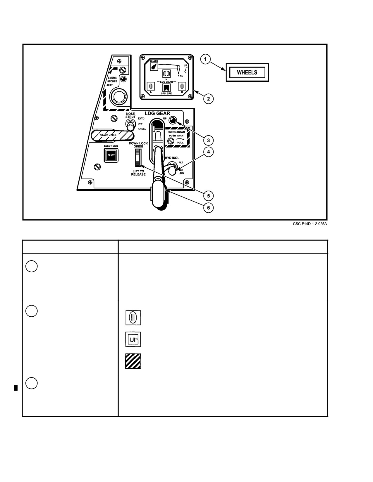
NAVAIR 01-F14AAD-1
NOMENCLATURE
FUNCTION
1
WHEELS warning light
Light flashes with flaps greater than 10_ deflection and either or both
throttles less than approximately 85% rpm, and all landing gear not down
and locked. Approach lights and indexer will illuminate when the LDG
GEAR handle is placed in the down position, but this is not an indication
of gear down and locked.
2
LDG GR indicator
— Landing gear down and locked (except main landing gear
sidebrace actuator).
— Landing gear retracted and doors closed.
— Unsafe gear or power off indication.
3
Landing gear transition
On whenever gear and door positions (including main landing gear
light
sidebrace actuators) do not correspond to handle position. Off when gear
and doors are locked in position selected by handle.
Figure 2-72. Landing Gear Controls and Indicators (Sheet 1 of 2)
CHANGE 1
2-134
NAVAIR 01-F14AAD-1
NOMENCLATURE
FUNCTION
4
HYD ISOL switch
FLT —
Combined system hydraulic pressure is shut off to the
landing gear, nosewheel steering and wheel brakes.
T.O./LDG — Switch is automatically placed in this position with gear
handle down. Combined hydraulic pressure is available to
all components.
5
DOWN LOCK ORIDE
Down —
Weight-on-wheels indication, prevents gear handle being
lever
retracted without pilot override (raising lever).
Up —
Weight-off-wheels indication, does not inhibit pilot raising
gear handle. Automatic operation by electrical solenoid.
6
LDG GEAR handle
Normal — Up and down overcenter action provides normal retraction
and extension by the combined hydraulic system.
Emergency — Down-push-turn-clockwise pull action provides emergency
extension of all gear by a compressed nitrogen charge.
Figure 2-72. Landing Gear Controls and Indicators (Sheet 2 of 2)
position. If the nose landing gear is unsafe in
locked in the down position with weight on wheels to
the down position because of premature
prevent inadvertent gear retraction. Pilot override of the
deployment of the nose landing gear locking
solenoid-operated handle lock can be effected by lifting the
pin, the nosegear indicator will indicate
downlock lever next to the gear handle. Vertical movement
unsafe and the transition light will illuminate.
of the gear handle causes a corresponding up and downselec-
tion of the landing gear with the combined hydraulic system
Maximum strut extension and wheel steering angle are
pressurized. Three flip-flop indicators provide a position
controlled by torque arms interconnecting the steering collar
display for each of the landing gear, and a gear transition light
and the lower piston (see Figure 2-77). The split-type wheel
on the control panel illuminates anytime the gear position
assembly incorporates a tire pressure relief device to prevent
and handle do not correspond. In addition, a WHEELS
overinflation of the tire. Additional hardware on the nose
warning light alerts the pilot if the landing gear is not down
landing gear include the launch bar, holdback fitting,
with flaps deflected greater than 10
and either or both
approach lights, nosewheel steering actuator, and taxi light.
throttles set for less than approximately 85-percent rpm.
The wheel axles incorporate recessed holes for attachment of
a universal tow bar with maximum steering angle of ± 120 .
z Unless attempting fast-cycle troubleshooting
for gear that indicates unsafe nosegear down,
transition light illuminated, wait for gear to
Restrict nosewheel deflection to ±90
to prevent
completely transition
(15
seconds with
structural damage to the nosewheel steering unit.
normal hydraulic pressure) before recycling
the landing gear handle. When fast cycling the
2.25.4
Landing Gear Normal Operation
gear handle, the pilot must immediately
return the gear handle to the down position to
The landing gear handle is mechanically connected to
avoid damaging the main landing gear doors
the landing gear valve that directs combined hydraulic fluid
and inducing a possible combined hydraulic
into the gear-up and gear-down lines and provides a path for
or brake system failure.
return flow. In the down position, the handle mechanically
sets the hydraulic isolation switch to provide hydraulic pres-
z Maximum landing gear tire speed is 190 knots.
sure for gear operation. The handle is electromechanically
2-135
ORIGINAL
NAVAIR 01-F14AAD-1
2.25.4.1
Landing Gear Handle Up
The emergency landing gear nitrogen bottle is located
in the nose wheelwell. Normal preflight bottle pressure is
Placement of the landing gear handle to UP actuates the
3,000 psi at 70_ F. Minimum bottle pressure for accomplish-
landing gear valve that ports hydraulic pressure to the down-
ing emergency extension to the down-and-locked position is
lock actuators, gear retract actuators, and, in sequence, to the
1,800 psi.
door and uplock actuators. The gear shock strut and door
uplocks are hydraulically operated into a mechanical over-
Pneumatic pressure is directed by separate lines to
center position. An UP indication is displayed on the gear
power open the gear door actuators in sequence, release the
position indicators when the gear are in the uplock and all
gear uplock actuators, pressurize the nosegear actuator to
doors closed.
extend the gear (main gear free fall), and pressurize the
downlock actuators. A normal gear-down indication is
2.25.4.2
Landing Gear Handle Down
achieved upon emergency gear extension. Following emer-
gency gear extension, nosewheel steering is disabled. Once
Placement of the LDG GEAR handle to DN actuates
the landing gear is extended by emergency means, it cannot
the gear control module to port hydraulic pressure to the door
be retracted while airborne and must be reset by maintenance
uplocks, door actuators, and the strut uplocks. The landing
personnel.
gear are hydraulically extended and assisted by gravity and
airloads. A gear-down symbol (wheel) is displayed on the
gear position indicators when the gear downlocks are in the
locked position. The gear transition light will go out when the
main gear side-brace links are engaged.
D Emergencyextensionofthelandinggearshall
Note
be logged in the Maintenance Action Form
(OPNAV Form 3760-2).
With the main gear downlock inserted but the
side-brace link not engaged, landing sink speed
D To facilitate in-flight refueling probe exten-
is restricted to 480 feet per minute. Minimize
sion when the landing gear has been blown
yaw and sideslips on touchdown and rollout.
down, raise the landing gear handle to give
priority to the refueling probe system.
2.25.5
Emergency Gear Extension
2.26 WHEELBRAKE SYSTEM
Although emergency gear extension can be initiated
with the landing gear control handle in any position, it is
The wheelbrake system provides power boost hydrau-
preferable that the LDG GEAR handle be placed in DN
lic control of the multiple disk-type main wheelbrakes using
before actuating the emergency extension system.
pressurized fluid in the landing gear down line from the
combined hydraulic system. Individual or collective wheel-
brake control can be modulated by depression of the rudder
toe pedals, or collective, unmodulated brake control is avail-
able with the parking brake. An antiskid system is provided
to operate electrohydraulically in conjunction with the
The landing gear handle must be held in the fully
normal wheelbraking mode. Wheelbrake controls are shown
extended emergency position for a minimum of
in Figure 2-73.
1 second to ensure complete actuation of the air
release valve. Approximately 55 pounds pull
Brake pedal and parking brake control motions are
force is required to fully actuate the emergency
mechanically transmitted to the power brake module
nitrogen bottle. The pulling motion should be
together with the antiskid valve. Separate hydraulic lines
rapid and continuous to ensure the air release
transmit normal and emergency fluid pressure from the
power brake module to the left and right wheelbrake
valve goes completely overcenter to the locked
position. The landing gear handle will be loose
assemblies. At each brake assembly, the normal and
emergency lines input fluid to the brake shuttle valve, which
(fore and aft) in its housing as an indication of
complete extension of the handle. An incomplete
applies brakes as a function of normal or emergency line fluid
pressure. Two wear-indicator pins on the brake piston
handle motion could cause partial porting of
gaseous fluid, initiating the emergency dump
housing measure lining wear for preflight inspection. For
new brakes, these pins extend approximately one-half inch
sequence. Interruption of handle motion without
completing the overcentering action of the valve
above the piston housing. When the pin is flush with the
could cause the extending gears to contact and
piston housing with the parking brake applied, the brake
damage the strut doors.
assembly is worn to the point of replacement.
CHANGE 1
2-136
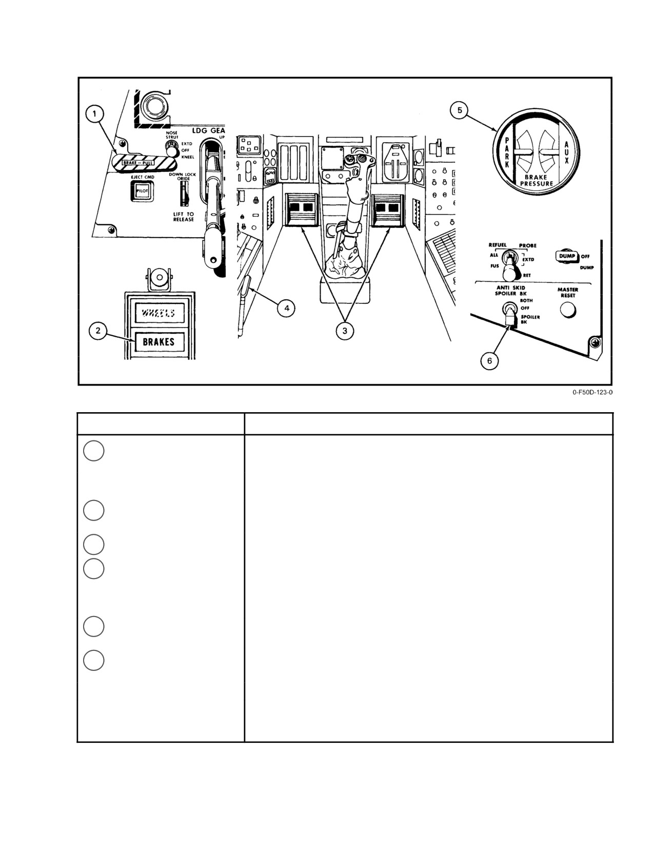
NAVAIR 01-F14AAD-1
NOMENCLATURE
FUNCTION
1
Parking brake handle
Forward —
Parking brake released. Modulated braking action avail-
able with brake pedal depression.
Aft —
Parking brake set. No modulation of control, locks both
main wheel brakes.
2
BRAKES warning light
Indicates parking brake handle is pulled, antiskid has failed, or operation is
in auxiliary brake mode when brake pedals are depressed.
3
Brake Pedals
Press top of rudder pedals to command normal or auxiliary braking.
4
Hand pump
Recharges auxiliary and parking brake accumulators with gear handle
down. With REFUEL PROBE switch in FUS or ALL EXTD, provides
emergency extension or retraction of refueling probe regardless of gear
handle position.
5
BRAKE PRESSURE
Provides pilot indication of brake accumulator pressure remaining which is
gage
indicative of auxiliary and emergency brake cycles remaining.
6
ANTI SKID SPOILER BK
BOTH —
Antiskid activated. Spoiler brakes operative with weight
switch
on wheels and both throttles in IDLE.
OFF —
Antiskid deactivated, spoiler brakes inoperative.
SPOILER BK — Spoiler brakes operate with weight on wheels and both
throttles IDLE. Antiskid is deactivated.
Figure 2-73. Wheelbrake Controls and Indicators
2-137
ORIGINAL
NAVAIR 01-F14AAD-1
Four thermal relief plugs are mounted in each main
2.26.2
Normal Braking
wheel assembly to relieve tire pressure and thus avert a blow-
In the normal mode of operation, wheelbrake applica-
out because of hot brakes if the local wheel temperature
tion is modulated by brake pedal depression using pressur-
exceeds 428
F.
ized fluid from the combined hydraulic system through the
brake module and through the normal brake line to the brake
The capacities of the wheelbrake assemblies are suffi-
assembly. In the normal mode of operation, the brake
cient to restrain the aircraft in a static condition on a dry
pressure gauge indication should continue to indicate a full
surface with MIL power set on both engines. The minimum
charge on the brake accumulators since this fluid energy is
hydroplaning speed for the main tires on a wet runway is
maintained by the combined hydraulic system. Normal
approximately 90 knots.
combined-system operations can result in pressure excur-
sions that will be trapped in the brake system. This can cause
2.26.1
Brake Characteristics
the brake pressure indicators to read beyond the full range of
the gauges. This will not affect system performance.
Because carbon brakes contain solid disk-shaped
carbon rotors and stators, they cannot shingle. The thermal
characteristics prevent them from fusing together during or
following heavy braking.
z After heavy or repeated braking or if hot
Carbon brakes may produce a sudden increase in brake
brakes are suspected, allow a 5 to 10-minute
torque as brake pedal force is smoothly increased. This can
cooling period with the gear extended before
produce grabbing at low brake pedal force inputs. This grab-
retracting the gear.
bing is caused by excessive air in the combined hydraulic
z If heavy braking is used during landing or
system. Open-loop bleeding of the combined hydraulic sys-
taxiing followed by application of the parking
tem by maintenance personnel will reduce the amount of air
brake, normal brake operation may not be
in the system and should eliminate any associated grabbing.
available following release of the parking
If grabby brakes are experienced, smooth modulation to
brake if the brakes are still hot. Check for nor-
higher braking forces is easily accomplished after the initial
mal brake operation after releasing the park-
grabbing. The sudden increase in torque is most noticeable
ing brake and prior to commencing taxiing.
at moderate to slow taxi speeds. As groundspeed increases,
the kinetic energy of the aircraft increases and the effect of
2.26.3
Antiskid
the sudden torque increase is significantly reduced. Normal
braking technique should be used during normal rollout.
The antiskid system operates electrohydraulically in
conjunction with the normal mode of wheelbrake operation
The pilot must apply maximum pressure on the brake
to deliver maximum wheelbraking upon pilot command
pedals to hold the aircraft static at MIL. If carbon brakeshave
without causing a skid. Essential No. 2 bus dc power for
been heated up by a full-stop landing, and for about 45 min-
antiskid operation is supplied through the ANTI SKID/R
utes thereafter, they will probably not hold the aircraft static
AICS LKUP PWR circuit breaker (8E1) and controlled by
with military power set on both engines even with the parking
the ANTI SKID SPOILER BK switch (Figure 2-73). When
brake set. In this case, 75 to 100 pounds of pedal force will
energized, approximately 200 milliseconds are required for
hold the aircraft static with afterburner set on one engine and
antiskid system warmup. Individual wheel rotational veloc-
idle power set on the other. In all cases, holding the aircraft
ity is sensed by skid detectors mounted in the wheel hubs and
static at high power settings depends on adequate runway and
transmitted to the skid control box. The control box detects
tire conditions. Degraded conditions such as wet runways or
changes in wheel deceleration and reduces fluid pressure in
worn tires may result in tire skid at high power settings.
the normal brake lines to both wheels, simultaneously, to
prevent a skid.
With the antiskid system armed in flight, the touch-
down circuit in the control box prevents braking until weight
is on both main gear and the wheels have spun up, regardless
of brakepedal application. The antiskid system isinoperative
When the antiskid system becomes inoperative
at groundspeeds of less than 15 knots. During maximum-
at
15
knots during a maximum-effort stop,
effort antiskid braking, expect a rough, surging deceleration.
carbon brakes can lock the wheels and pedal
When the ANTI SKID SPOILER BK switch is in BOTH
pressure should be relaxed as the aircraft deceler-
during low-speed taxi (less than 10 knots for more than a few
ates through 15 knots during a maximum effort
seconds), subsequent acceleration of the aircraft through
antiskid stop.
approximately 15 knots will cause a temporary loss of brakes
ORIGINAL
2-138
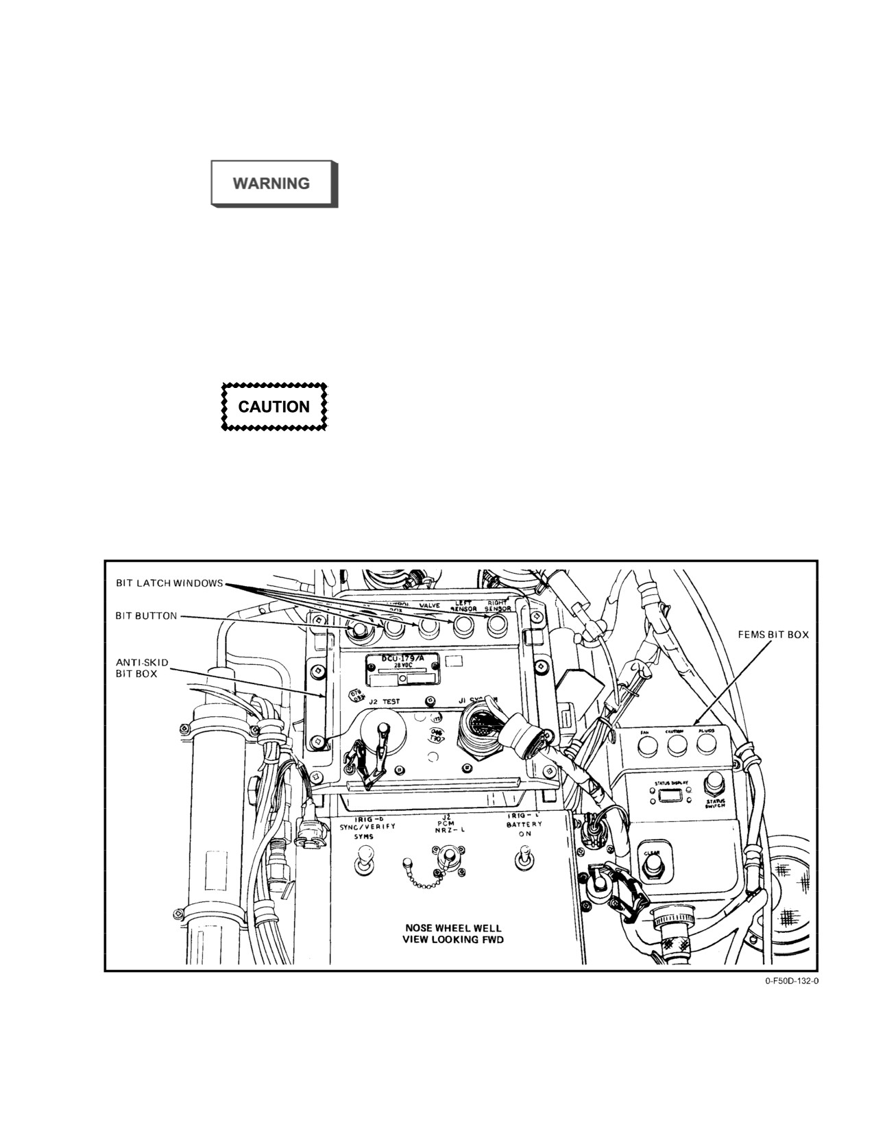
NAVAIR 01-F14AAD-1
lasting from 2 to 10 seconds. Should this happen, use of the
electrical failure occurs in the antiskid system or if hydraulic
brakes can be regained instantly by turning antiskid OFF. To
pressure is withheld from either brake for greater than 1.2
preclude this possibility, antiskid must be OFF during taxi.
secondsbythecontrolbox,thesystemautomatically becomes
inoperative and illuminates the BRAKES warning light with
the ANTI SKID SPOILER BK switch in BOTH.
2.26.3.1
Antiskid Ground Test
z Failure of the weight-on-wheels switch
During ground operation, a self-test of the antiskid
results in continuous release signal with anti-
system can be initiated on the face of the control box with the
skid selected. Normal braking is available
system energized, parking brake handle released, and the
with antiskid off.
aircraft in a ground static condition. Before taxiing (chocks
z If the antiskid system fails, allowing antiskid
in place), but after releasing the parking brake and while the
to operate below 15 knots, place the ANTI
pilot presses the toe pedal brakes, the plane captain should
SKID SPOILER BK switch in OFF; otherwise
press the antiskid test pushbutton on the control box in the
the aircraft cannot be stopped using normal
nose wheelwell. Approximately 10 seconds is required for
braking.
self-test, which checks the operational status of the control
box, brake valve, and wheel sensors. Any discrepancies
detected will be displayed by the BIT flags on the face of the
control box (Figure 2-74).
Failure to release brakes prior to deselecting
A valid BIT test requires that three criteria be met: the
ANTI SKID may result in blown tires.
BIT flags on the face of the control box must check good,
the pilot must feel both brakes release during BIT test, and
The antiskid system is inoperative when the wheel-
the BRAKES warning light must not remain illuminated. A
brakes are in the auxiliary or parking modes of operation
flash of the BRAKES light coinciding with brake pedal
since the emergency brake lines bypass the brake valve. If an
thumps during the antiskid BIT check is acceptable.
Figure 2-74. Antiskid BIT Box
2-139
ORIGINAL
NAVAIR 01-F14AAD-1
Before initiating antiskid self-test by pressing the
D Even though braking action is available at
antiskid pushbutton on the control box, ensure
accumulator pressures less than 3,000 psi,
that the aircraft chocks are in place. Initiation of
braking force is proportional to pressure
antiskid self-test will release aircraft brakes.
remaining. Red band pressure (1,900 psi) is
sufficient to hold the brakes locked with the
2.26.4
Auxiliary Brake
aircraft stationary in all deck conditions;
Two different auxiliary brake systems are presently
however, rolling motion greatly increases
incorporated in the aircraft. Entry into the auxiliary brake
pressure requirements. Accumulator pressure
mode is the same for both systems. Transfer of normal brake
of up to 2,100 psi may be required to stop a
operation to the auxiliary mode is automatic without the
moving aircraft in a 4_ deck roll. In deck rolls
requirement for pilot action upon the loss of combined
greater than 6_, 3,000 psi may not be suffi-
hydraulic system pressure. Both auxiliary braking systems
cient to stop a moving aircraft.
have two brake accumulators that provide pressure for
D Complete loss of hydraulic fluid through the
auxiliary and parking brake modes of operation when
wheelbrake hydraulic lines will render
combined hydraulic system is not available. Accumulators
parking brake ineffective.
deliver
3,000 psi when fully charged by the combined
hydraulic system or hydraulic handpump (with the gear
2.26.5
BRAKES Warning Light
handle down only). When the combined hydraulic system
pressure decreases below 1,425 psi, the shuttle valve in the
The BRAKES warning light will illuminate whenever
power brake module shifts the brake system to the auxiliary
auxiliary brake pressure is applied to the brakes via the brake
brake mode.
pedals, indicating the combined hydraulic system pressure is
Approximately 13 to 14 full dual-brake applications
not available to the brakes and cautioning the pilot to monitor
are available in the auxiliary mode. Dual pneumatic BRAKE
brake application with the auxiliary brake pressure indicator.
PRESSURE gauges on the front cockpit center pedestal show
A postlight is installed above the BRAKE PRESSURE gauge
auxiliary and parking brake accumulator pressures. Full
to illuminate the dial.
capability operations of the brake accumulators in the
auxiliary modes of operation is predicated on the system
Note
serviced with a nitrogen precharge of 1,900
50 psi. The
green band of the dial indicates pneumatic pressure between
The postlight requires electrical power. Brake-
3,000 psi at the top of the band to 2,150 psi; the red band
riders on carrier night respot must use a flashlight
indicates pneumatic pressures between 2,150 and 1,900 psi
to check the cockpit brake pressure gauge.
at the bottomoftheband. Approximatelyfive auxiliarybrake
applications are available in the red band. Once the auxiliary
2.26.6
Parking Brake
braking system is depleted, braking must be accomplished by
the emergency/parking brake. Three applications of the
The parking brake mode provides a means for collec-
parking brake are available.
tive locking of the wheelbrakes to maintain a ground static
position during normal operations or during emergency con-
With either auxiliary brake system, additional braking
ditions. Aft movement of the parking brake handle provides
can be achieved only by pulling the parkingbrake handle aft.
for unmodulated porting of accumulator fluid pressure
If the shuttle valve in the power brake modules does not
through emergency lines to the shuttle valve at the wheel-
return to the normal position with combined hydraulic
brake assembly. In the parking brake mode, the brake pedals
pressure greater than 2,000 psi, the BRAKES warning light
have no effect on wheelbrake operation. Pushing the parking
will illuminate when a brake pedal is depressed. In this
brake handle forward releases wheelbrake pressure and the
instance the wheelbrake accumulators can be recharged only
power brake module reverts to the normal and auxiliary
by the hydraulic handpump with the landing gear handle
braking mode. When auxiliary mode braking action is no
down. Pilot manual isolation, or system automatic isolation
longer available by depression of the brake pedals, sufficient
of the combined hydraulic system, cuts off the supply of
accumulator fluid pressure remains for a minimum of three
combined hydraulic pressure to the power brake module so
parking brake applications.
that depression of the brake pedals will cause depletion of the
brakes’ accumulator charge.
CHANGE 1
2-140
NAVAIR 01−F14AAD−1
damping, and nosewheel centering. The power unit is located
on the lower portion of the nose landing gear strut outer
cylinder, which, through a ring gear, controls the directional
alignment and damping of the lower piston assembly.
For shipboard operations, before breaking down
and moving an aircraft without combined
Combined hydraulic system pressure is the motive power
hydraulic pressure, the parking brake handle
used for steering and centering. Electrical power is supplied
should be cycled and the toe brakes should be
from the essential dc bus with circuit protection by the NOSE
tested for effectiveness.
(The AUX and PARK
WHEEL STEER/AFCS circuit breaker (RC2) on the pilot right
brake needles should drop slightly after brake
knee panel. Hydraulic pressure is derived from the gear−down
application.) The brake pressure indicator should
line such that steering control is disabled subsequent to
then be pumped back up to the top of the green
emergency extension of the landing gear (Figure 2-75).
band with the cockpit handpump. The indicator
Note
should be maintained in the green band until the
If nosewheel steering is inoperative, the emer-
aircraft is secured. Full
3000 psi pressure is
gency gear extension air release valve may be
required if conditions are severe (greater than
tripped, which will prevent gear retraction.
4 degree roll, wet brakes, etc.).
2.27.1
Nosewheel Steering Control
Nosewheel steering control during ground operations
is energized by momentarily pressing the autopilot reference
and nosewheel steering pushbutton on the lower forward side
Normal brakes are not available with parking
of the pilot stick grip (see Figure 2-75). The system cannot
brake handle pulled. If parking brake accumula-
be engaged without weight on wheels. The system will
tor pressure is depleted, aircraft brakes are iso-
remain engaged until weight is off wheels, electrical power
lated from brake pedal master cylinders. Parking
is interrupted, or the pushbutton switch is pressed again.
Brake handle shall be pushed in to restore normal
Engagement of nosewheel steering is indicated by illumina-
brake operation.
tion of the NWS ENGA caution light. An automatic
In the absence of a pressurized combined hydraulic
nosewheel steering system disengage feature is provided. If
system, the wheelbrake accumulators can only be recharged
this feature has been activated by cycling the hook on deck
by the pilot hydraulic handpump with the landing gear handle
with the throttles at idle, then the nosewheel steering will be
in the down position.
disengaged and the NWS ENGA light extinguished when the
launch bar is lowered. The nosewheel steering automatic
disengage feature is deactivated if the nosewheel steering
button is depressed.
With the system engaged, nosewheel steering is
Complete loss of hydraulic fluid through the
controlled by rudder pedal position. Centering is unaffected
wheelbrake hydraulic lines will render parking
by directional trim displacement. Maximum steering author-
brake ineffective.
ity is 70_ either side of neutral, and the nosewheel can swivel
2.26.7
Wheel Antirotation
a maximum of 120_ about the centered position. With greater
weight on the nosewheel (wings forward, high gross weight,
During the initial phase of the landing gear retraction
cycle, pressurized fluid from the gear−up lines is directed to
etc.) the steering torque can only turn the nosewheel ± 5_
the power brake module to displace the normal metering
with the aircraft static. However, only a slight forward
valves to stop main wheel rotation before the wheels enter the
movement will provide the pilot with full−power steering
wells. This feature is not provided for the nosewheels.
authority. In a full pedal−deflection turn using nosewheel
steering, the aircraft pivots about a point between the main
gear such that the inboard main wheel rolls backward. Under
this condition, application of either main wheelbrake will
only serve to increase the radius of turn. Because of the
Illumination of indexer lights is not a positive indi-
outboard location of the engines, the application of thrust in
cation that the main landing gear is clear of the run-
tight turns should be made on the outboard engine to
way. Raising the gear before a positive rate of
efficiently complement the turning movement of the nose-
climb is established will result in blown main tires.
gear. Nosewheel centering is enabled by the same latching
relay that enables nosewheel steering automatic disengage-
2.27 NOSEWHEEL STEERING SYSTEM
ment with launch bar lowering. Therefore, if the nosewheel
The electrohydraulic nosewheel steering system provides
steering is automatically disengaged when the launch bar is
for on−deck aircraft directional control, nosewheel shimmy
lowered, the nosewheels will be hydraulically centered.
2−141
CHANGE 2
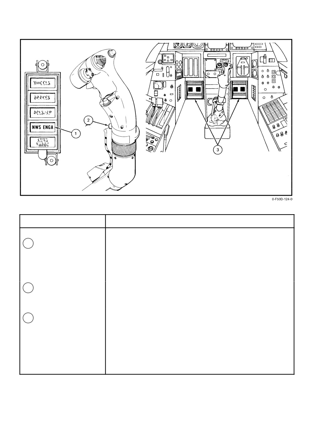
NAVAIR 01-F14AAD-1
NOMENCLATURE
FUNCTION
1
NWS ENGA caution light
Illumination when nosewheel steering engaged and will respond as a
function of rudder pedal displacement. Nosewheel steering automatically
centers with hook down. Nosewheel centering requires throttles at IDLE
and weight-on-wheels with hook down.
2
Autopilot reference and
Press to engage and disengage nosewheel steering.
nosewheel steering
Requires weight-on-wheels.
pushbutton
3
Rudder pedals
Controls nosewheel steering position with system engaged.
Figure 2-75. Nosewheel Steering Controls
ORIGINAL
2-142
NAVAIR 01-F14AAD-1
2.27.2
Nosewheel Centering
2.28.1
Nose Strut Kneel
The nosewheel is automatically centered during gear
Prior to catapult hookup, the nose strut is compressed
retraction before the nosewheel enters the wheelwell. During
14 inches. Control of the nose strut kneel function isprovided
gear retraction with weight off wheels, hydraulic pressure
by the NOSE STRUT switch on the landing gear control
from the combined system bypasses the steering unit shutoff
panel (see Figure 2-76.) The three-position (EXTD, OFF,
valve to center the nosewheel independent of rudder pedal
and KNEEL) toggle switch is spring-loaded to return to the
movement. If the nosewheel iscocked beyond15
either side
center detent position of OFF. The position of the strut
of center after takeoff, the nosewheel is automatically
remains in the last commanded position independent of
prevented from retracting and the LAUNCH BAR advisory
electrical or hydraulic power interruptions. In both cases, the
light illuminates.
transfer control valve source of electrical power is the
essential No 2 bus and combined hydraulic system fluid is
During carrier arrestment, the nosewheel is centered
used as the transfer medium. With external electrical power
with weight on wheelsand hookdownwhenboth throttles are
on the aircraft, the combined hydraulic system must be
retarded to IDLE to prevent castoring during rollback. After
pressurized (>500 psi) before the control switch can com-
arrestment and rollback, the nosewheel will remain centered
mand a position change of the transfer control valve. The
until nosewheel steering is engaged.
control switch need only be held momentarily to effect a
change in transfer control valve position.
Selection of KNEEL releases hydraulic fluid from the
shock strut transfer cylinder to the combined hydraulic sys-
tem return line, causing the weight of the aircraft to compress
Nosewheel centering can contribute to launch bar
the shock strut 14 inches. Stroking of the nose strut causes the
misalignment in the catapult shuttle, which could
aircraft to rotate about the main wheels. The aircraft may be
result in premature launch bar separation during
taxied or towed in the strut-kneeled position except for the
launch. The nosewheel centering latching relay
nuisance trip of the launch bar at greater than 10
steering
must be deactivated by depressing thenosewheel
angle; this is the position used for taxiing onto the catapult
steering button after the hook check and prior to
and enhances accessibility to the forward fuselage compart-
entering the catapult. As this will also deactivate
ments during ground maintenance. Since the nose strut is
the nosewheel steering automatic disengagement
bottomed during the catapult launch stroke, the energy stored
function, the nosewheel steering must be manu-
in the last 4 inches of strut-piston stroke is released upon
ally disengaged when entering the catapult.
shuttle release at the end of the catapult stroke to impart a
noseup pitching moment to rotate the aircraft to the fly-away
2.27.3
Shimmy Damping
attitude without any control required by the pilot. All the
Shimmy damping is provided in the steering actuator.
stored energy is expended before the nosewheels leave the
Increased shimmy damping action is obtained with NWS
deck edge.
disengaged.
Note
Under certain launch conditions (high wind over
deck and light aircraft gross weights) the nose
strut will not be fully compressed during the cata-
If excessive nosewheel shimmy is encountered,
pult stroke. Subsequent nose rotation following
disengage nosewheel steering.
shuttle release will be at a less than normal rate.
Aircraft launch bulletins for the aircraft are
2.28 NOSEGEAR CATAPULT SYSTEM
written to ensure that catapult launch pressures
Catapult connection components on the nose landing
are sufficient to provide safe launch pitch rates
gear shock strut piston provide nosegear catapult capability.
and fly-away capability.
A launch bar attached to the forward face of the nosegear
steering collar guides the aircraft onto the catapult track and
Full extension of the nose strut after launch and weight
serves as the tow link that engages the catapult shuttle. A
off wheels provides a redundant and automatic transfer of the
holdback fitting secures the holdback restraint prior to
control valve to the extend position. With weight off wheels,
launch. The two-piston nose strut uses the stored energy
the NOSE STRUT switch is inoperative.
catapult principle to impart a positive pitch rotation move-
ment to the aircraft at shuttle release, thus providing for a
hands-off launch fly-away technique.
2-143
ORIGINAL
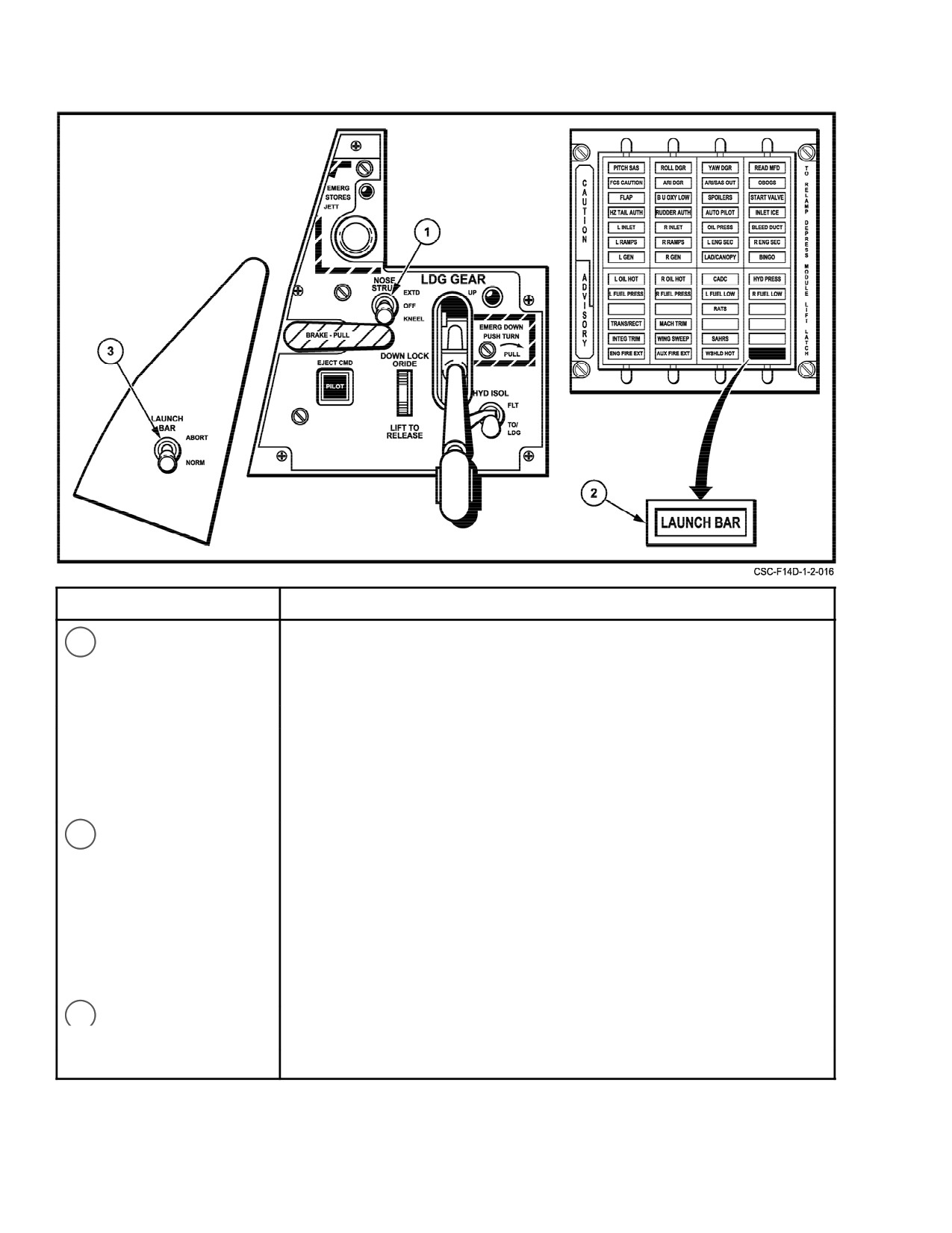
NAVAIR 01-F14AAD-1
NOMENCLATURE
FUNCTION
1
NOSE STRUT switch
EXTD — Hydraulic pressure causes strut to extend. Combined hydraulic
system must be pressurized before switch is activated on external
power. Launch bar is lifted into the up-lock position by torque arms
as strut extends 14 inches.
OFF — Spring-loaded return position.
KNEEL — Nose strut transfer control valve releases pressure in the shock
strut, which strokes 14 inches. Combined hydraulic system must
be pressurized before switch is active on external power. Launch
bar uplock can be released manually to allow bar to lower to deck,
or by turning nosewheel ± 10 .
2
LAUNCH BAR
Illuminates under the following conditions:
advisory light
Weight On Wheels
D Aircraft kneeled, throttles less than MIL (goes out when throttles are
advanced to MIL to provide lights out criterion for catapult launch).
D Launch bar not up and locked (normal operation)
Weight Off Wheels (inhibits nosegear retraction)
D Launch bar not up and locked
D Nosewheel not within ± 15
of center
D Nose strut not fully extended
3
LAUNCH BAR switch
ABORT — Enables pilot to disengage the launch bar from the catapult while
remaining at MIL power and in the kneel position.
NORM — Allows launch bar to be lowered.
Figure 2-76. Launch Bar Controls
ORIGINAL
2-144
NAVAIR 01-F14AAD-1
2.28.2
Launch Bar
deck-secured fittings. Prior to the application of single-
engine high power, the nose strut should be kneeled and slack
The launch bar is attached to the nosegear and serves
taken out of the holdback mechanism, otherwise dynamic
as the tow link for catapulting the aircraft (see Figure 2-77).
loads may exceed mechanism design strength conditions.
With the nose strut extended, the launch bar is held in the
retracted position. The launch bar can be lowered by kneeling
2.29 ARRESTING HOOK SYSTEM
the aircraft and turning the nosewheel greater than ±10
from
the centered position. The launch bar can also be lowered by
The arresting hook installation consists of a stinger
the deck crew with no pilot action after the aircraft has been
tailhook and associated control mechanism mounted to the
kneeled. A proximity sensing switch on the uplock detects
underside of the center fuselage. The hook shank is free to
the latch out of the locked position and illuminates the
pivot up and down at its attachment point. A pneumatic
LAUNCH BAR advisory light (see Figure 2-76). Ears on the
dashpot preloads the hook downto minimize hook bounce on
head of the launch bar engage under the lip of the catapult
contact with the deck. The hook shank is free to pivot left or
lead-in track and the head serves as a guide to steer the
right within a ± 26
sway angle with positive centering
nosewheel on the catapult track and engage the shuttle. For
action provided by a pneumatic damper housed inside the
an abort, the launch bar cannot be raised until the shuttle is
tailhook shank. The trail angle of the arresting hook provides
disengaged.
for hookpoint-deck contact even with the nose landing gear
strut fully compressed.
2.28.2.1
LAUNCH BAR Light
2.29.1
Arresting Hook Operation
The LAUNCH BAR advisory light is interlocked to go
off when both throttles are at MIL even though the launch bar
Normal operation of the arresting hook requires
position and mechanism remain unchanged; this action is
combined and flight hydraulic system pressure, dashpot
effected to establish a “lights out” criterion for launch. The
charged, and dc essential No. 2 electrical power. Because of
light circuit is disabled with nosegear up and locked. A
a redundant means of pilot control (electrical and mechani-
pilot-controlled LAUNCH BAR switch is installed that
cal), emergency extension of the arresting hook can be
enables the pilot to disengage the launch bar from the
accomplished without these sources of power.
catapult while remaining at MIL power and in the kneel
position. This switch is on the pilot left vertical console.
Note
Hookretraction requires electrical andcombined
hydraulic power.
2.29.1.1
Normal Operation
To avoid damage to the launch bar retract mech-
Normal operation
(Figure 2-78) on the pilot hook
anism, do not set the LAUNCH BAR switch to
control consists of a straight down-up movement of the
ABORT with the nosewheel deflected off center.
HOOK handle. This action actuates switches that provide
electrical command signals to the hook control valve. For
After the catapult launch stroke, extension of the strut
lowering the hook, the uplock is released and the lift cylinder
mechanically cams the launch bar up to the retracted-and-
is vented. Flight hydraulic pressure is the medium that
locked position. If the launch bar is not engaged in the uplock
disengages the hook uplock actuator. When flight hydraulic
with weight off wheels, the LAUNCH BAR advisory light
pressure drops below 2,100 psi with weight off wheels, the
will illuminate and nosegear retraction will be electrically
hook/auxiliary flap isolation relay circuit is energized. This
inhibited.
disables the arresting hook control valve and, therefore,
disallows normal hook extension. This condition remains
2.28.3
Holdback Fitting
until either the starboard engine-driven hydraulic pump
The holdback fitting is provided on the nose strut for
(flight) produces greater than 2,400 psi or weight on wheels
insertion of the holdback bar. Groundcrew must manually
is restored.
attach the bar before the aircraft is taxied into the catapult
lead track. The holdback bar is reusable and provides for
Note
repeated releases at a tow force of 76,000 pounds. Force
greater than this on launch causes the holdback bar to release
If emergency hook extension is inoperative in
the aircraft holdback fitting.
conjunction with a flight hydraulic failure,
cycling the HYD VALVE CONTR circuit
Single-engine, high-power turnup operations can use
breaker (8E5) with the hook handle down will
the holdback fitting to attach aircraft restraining hardware to
permit hook extension.
2-145
ORIGINAL

NAVAIR 01-F14AAD-1
Figure 2-77. Nosewheel Strut and Launch Bar Positions
ORIGINAL
2-146
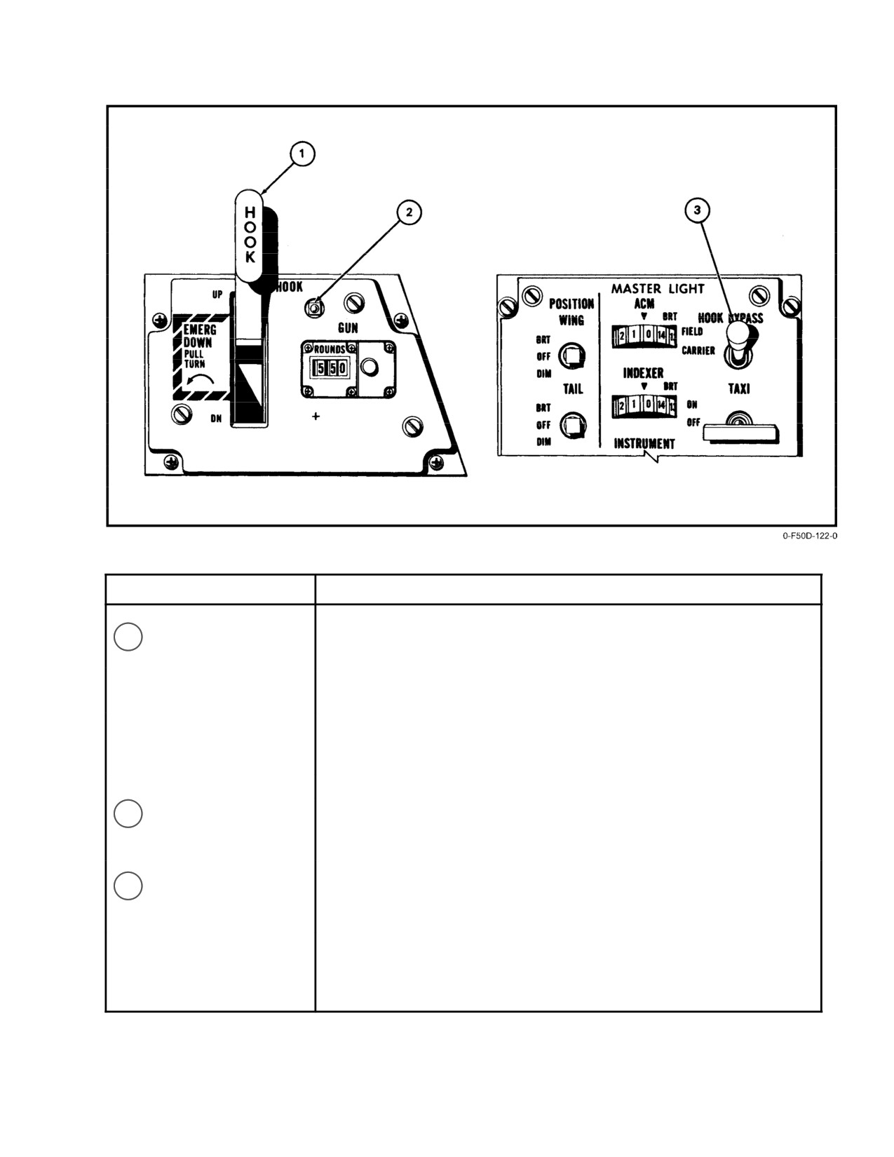
NAVAIR 01-F14AAD-1
NOMENCLATURE
FUNCTION
1
Arresting HOOK
UP —
Electrically energizes hydraulic retract actuator to raise
handle
hook into uplock.
DN —
Electrically releases hydraulic uplock actuator and allows
hook to extend by dashpot pressure and gravity.
EMERG
DOWN —
(Pull-twist) mechanically releases uplock actuator and
allows hook to extend by gravity and dashpot pressure.
2
Hook transition light
Illuminates whenever arresting hook position does not correspond with
handle position. Light will not go out in down position until hook is in full
trail angle.
3
HOOK BYPASS
FIELD —
Used for nonarrested landings. Bypasses the flashing fea-
switch
ture of the approach lights and indexer when landing gear is
down and hook retracted.
CARRIER — Used for arrested landings. Approach lights and indexer
flash when landing gear is down and the hook retracted.
Figure 2-78. Arresting Hook Controls
2-147
ORIGINAL
NAVAIR 01-F14AAD-1
2.29.1.2
Hook Retraction
3. Cockpit pressurization
For hook retraction, the control valve pressurizes the
4. Canopy seals
retract side of the lift cylinder and the lock side of the
actuator.
5. Windshield and canopy defogging
6. Windshield ant-ice
7. Anti-g suit inflation
Do not attempt to raise the hook when the hook
8. Wing airbag seals
is engaged in the arresting gear.
9. Gun-gas purging
When the arresting hook roller engages the uplock
10. Electronic equipment cooling and pressurization
mechanism, the lift cylinder is depressurized. On deck, hook
retraction time is approximately 3 seconds. The hook transi-
11. Temperature control of liquid coolant supplied to
tion light is illuminated as long as a discrepancy exists
APG-71radar control system, television camera set,
between the hook and cockpit handle positions. On-deck
and infrared search and track.
extension requires approximately 1 second. The transition
light will remain illuminated, unless the aircraft is kneeled,
2.30.1
ECS Air Sources
as contact with the deck precludes full hook extension.
2.30.1.1
Bleed Air
Note
The hook transition light may remain illuminated
The normal source of ECS air is ninth-stage bleed air
when the hook handle is lowered at airspeeds
from both engines. Through a series of manifolds and valves,
greater than300knotsbecauseofhookblowback.
this air is cooled and mixed to reduce temperature and pres-
sure to usable levels. The primary valves are the two engine
2.29.1.3
Emergency Hook Extension
bleed air shutoff valves, the dual pressure regulating and
shutoff valve, and the turbine compressor modulating and
The emergency control system lowers the hook by
shutoff valve, which are all controlled by the AIR SOURCE
mechanically (cable) tripping the uplock and venting the
selector pushbuttons: L ENG, R ENG and BOTH ENG
hook lift actuator pressure. Emergency extension of the hook
(Figure 2-79.)
may be initiated when the handle is in either UP or DN. In
either case, the hook handle is pulled aft (approximately
4 inches) and turned 90
counterclockwise. Rotation 90
2.30.1.2
RAM AIR Source
counterclockwise will lock the handle in the extended
position. With the handle locked, the hook will not retract
If either the RAM or OFF pushbutton is selected by the
regardless of the handle position (UP or DN).
pilot, the cooling turbine compressor is shut down and emer-
gency ram air can be used to ventilate the cockpits and pro-
Note
vide cooling air to the service and suit heat exchanger and
Afteremergency hookextension, thehook can be
those electronic subsystems requiring forced air cooling.
retracted airborne or on deck provided that the
However, if OFF is selected, pressurization to the service
handle is rotated
90
clockwise, pushed full
systems (canopy seal, anti-g suit, external fuel tank, wing
forward, and placed in UP. Combined and flight
airbag seal, OBOGS), and 400
F air supply to the windshield
hydraulic system pressures are required toretract
air defog and heating systems is lost. Selecting AIR
the hook while airborne. On deck, only combined
SOURCE RAM will provide air to the service systems and
hydraulicsystempressureisrequiredtoretractthe
400
F manifold air to the defog and heating systems.
hook.
2.30 ENVIRONMENTAL CONTROL SYSTEM
The ECS regulates the environment of flightcrew and
electronic equipment. The system provides temperature-
Selection of the AIR SOURCE pushbutton to
controlled, pressure-regulated air for the following systems.
RAM with a failure of the 400
F temperature
1. External drop tank pressurization
manifold will continue to circulate
400 F air
throughout the system surrounding aircraft
2. OBOGS
components and may cause a fire.
ORIGINAL
2-148

NAVAIR 01-F14AAD-1
NOMENCLATURE
FUNCTION
1
TEMP mode selector
AUTO — Cockpit and pressure suit temperature is automatically
switch
maintained at that comfort level selected on the temperature
control selector.
MAN — Cockpit temperature and air flow must be manually selected
as airspeed and altitude change to maintain a desired
temperature.
2
CABIN PRESS switch
NORM — Cockpit pressure will be maintained at an altitude of
Lever-lock switch which
8,000 feet up to 23,000 feet, above which the regulator
must be lifted to be
maintains a 5-psi pressure differential. (See Figure 2-81).
moved to DUMP.
DUMP — The cockpit safety valve Is opened, depressurizing the
cockpit.
3
RAM AIR switch
OPEN/
CLOSE — Manually modulates the ram air door and regulates the
amount of ram air supplied to the cabin and electronics bay
after the AIR SOURCE pushbutton is selected to RAM or
OFF (Approximately 50 seconds to full open.)
Figure 2-79. Air-Conditioning and Pressurization Controls and Indicators (Sheet 1 of 2)
2-149
CHANGE 1
NAVAIR 01−F14AAD−1
NOMENCLATURE
FUNCTION
4
AIR SOURCE selector
RAM Ċ
Closes the bleed air flow modulator pressure regulator
pushbuttons
and shutoff valve, thereby securing the cooling bootstrap
turbine compressor. Inhibits gun firing. The RAM AIR
switch is enabled. Combined ram air and regulated 400_
F bleed air are available to the cockpits and air cooled
electronic equipment for temperature control. When
either BOTH ENG, L ENG or R ENG are selected, the
ram air door automatically closes.
L ENG Ċ
The left engine is the source of bleed air for the environĆ
mental control system and the right engine bleed air shutĆ
off valve is closed.
R ENG Ċ
The right engine is the source of bleed air for the environĆ
mental control system and the left engine bleed air shutoff
valve is closed.
BOTH ENG Ċ The right and left engine bleed air shutoff valves are open
and both supply bleed air to the environmental control
system. This is the normal position. Automatically closes
ram air door.
OFF Ċ
Both the left and right engine bleed air shutoff valves
and the dual pressure regulator valve are closed. Inhibits
gun firing. Pressurization and air conditioning are not
available. Enables the RAM AIR switch.
5
TEMP thumbwheel control
Selects cockpit and suit air temperature. It can be rotated through a 300_
arc (0 to 14) with mechanical stops at each end placarded COOL and
WARM. A midposition temperature (7) is approximately 70_ĂF in the
automatic mode. With the TEMP mode selector switch in AUTO the
temperature selected is automatically maintained by the modulating
temperature control valves. In MAN, the TEMP control thumbwheel must
be repositioned to maintain cockpit and suit air temperature. Air flow and
temperature will not change as a function of airspeed and altitude.
6
CABIN PRESS ALT
Displays cabin pressure altitude in 1,000−foot increments from
indicator
0 to 50,000 feet.
7
BLEED DUCT caution light
Indicates overheating (575° F or greater) along the high−temperature
bleed air duct routing forward of the engine fire wall past the primary heat
exchanger and then up to the right diverter area. An additional sensor,
detecting temperatures of 255° F or greater, senses from the right diverter
area, along the 400° F manifold and into the bootstrap turbine
compartment.
8
CABIN PRESS caution
Indicates cabin pressure is less than 5−psi absolute pressure or cockpit
light (RIO’s cockpit)
altitude is above 27,000 feet.
Figure 2−79. Air−Conditioning and Pressurization Controls and Indicators (Sheet 2 of 2)
ORIGINAL
2−150
NAVAIR 01-F14AAD-1
Interconnects inhibit gun firing with RAM or OFF
remainder is further cooled by the turbine compressor. Here
selected. The emergency ram-air door is on the lower right
the air is compressed, run through the secondary heat
side of the fuselage, inboard of the right glove. To activate the
exchanger, and then expanded in the turbine section,
ram air door, either the OFF or RAM AIR SOURCE
resulting in cold air that is mixed with 340_ F air to obtain
pushbutton must be depressed and the RAM AIR switch on
any temperature desired. The primary and secondary heat
the air-conditioning control panel must be moved to OPEN.
exchangers are between the left and right engine inlets and
the fuselage. At speeds above 0.25 Mach, ram air across the
heat exchangers is used for cooling. During ground opera-
tions and at airspeeds less than 0.25 Mach, airflow across the
heat exchanger is augmented by air-powered turbine fans.
Note
D Before opening the ram air door, reduce air-
With the system in MAN to increase airflow to
speed to 350 knots or 1.5 Mach, whichever is
forced-air-cooled equipment, place CANOPY
lower, to prevent ram air temperatures above
DEFOG-CABIN AIR control lever in CANOPY
110_ F from entering the system. After ram air
DEFOG.
flow is stabilized, airspeed may be varied as
The third heat exchanger is the service air-to-air heat
required for crew comfort or to increase flow
exchanger. This normally uses cold air from the cold-air
to electronic equipment.
manifold as a heat sink but can use emergency ram air if the
D With AIR SOURCE OFF selected, limit air-
cold-air manifold is not operating. Air from the service heat
speed to less than 300 knots/0.8 Mach to pre-
exchanger is used by the pressure suit, anti-g suit, canopy
vent damage to the deflated wing airbag seals.
seal, OBOGS, servo air, and for pressurization of wave-
guides, the radar liquid cooling loop tank, and the television
For maximum cockpit ram-air flow, the cockpit
camera set.
pressurization must be dumped. Pressing either L ENG, R
ENG or both ENG pushbuttons automatically closes the
2.30.2.1
Temperature Management
ram-air door if it is open.
The pilot can control cockpit temperature by selecting
2.30.1.3
External Air
either a manual (MAN) mode or automatic (AUTO) mode
with the TEMP mode selector switch (Figure 2-79). In the
The adapter for connecting a ground air-conditioning
AUTO mode, temperature (60_ F to 80_ F) is selected by
unit is under the fuselage, aft of the nose wheelwell. An
the pilot with the TEMP thumbwheel control. This desired
additional provision for connecting an external source of
temperature is maintained by a cabin temperature sensor in
servo air is in this same area.
the forward left side of the cockpit. In the MAN mode, the
External electrical power is automatically inhibited
TEMP thumbwheel control maintains airflow and tempera-
from AYK-141, IRST, TR1, TR2, and the CIU if external
ture. If cockpit inlet airflow temperature (in either AUTO or
air-conditioning is not connected to the aircraft. A pressure
MAN) exceeds 250_ F, a cockpit overtemperature switch
switch interrupts electrical power to the above forced-air-
closes the hot-air-modulating valve.
cooled equipment.
The conditioned air entering the cockpit is divided
forward and aft, with 50 percent of the air going to each
2.30.2
Cockpit Air-Conditioning
cockpit. A CANOPY air diffuser lever on the right console
ECS manifolding consists of:
in each cockpit individually controls the percentage of
airflow through the cockpit diffusers and the canopy defog
1. The high-temperature (bleed air) manifold
nozzles. When the lever is in CABIN AIR (full aft), 70
2. The 400_ manifold
percent of the air is directed through the cockpit diffusers and
30 percent through the canopy defog nozzles. In DEFOG, 100
3. The cold-air manifold.
percent of the air is directed through the canopy defog
High-temperature engine bleed air is routed through
nozzles.
the primary heat exchanger. The cooled output of this heat
exchanger is split and a portion is mixed with hot engine
2.30.2.2
Vent Airflow Thumbwheel
bleed air to a temperature of approximately 340_ F; the
This control has no function.
2-151
CHANGE 1
NAVAIR 01−F14AAD−1
2.30.2.3
Anti−G Suit
2.30.3.1.2
Ground Operation
Each anti−g suit is connected to the aircraft pressurizaĆ
During ground operation with electrical power, exterĆ
tion system by an anti−g suit hose that delivers pressurized air
nal air−conditioning, and servo air available to the aircraft
to the suit control valve and then to the suit through a
and the GND CLG switch in RADAR, the cockpit low−flow
composite disconnect. Below 1.5g, the suit remains deflated.
sensor is overridden. The OFF position of the GND CLG
A spring−balanced anti−g valve automatically opens when
switch enables cockpit air priority. With engines running on
g forces exceed 1.5g. Operation of the anti−g suit valve may
the ground, select OFF on the ground cooling switch.
be checked by depressing the test button marked G VALVE
on each flightcrew’s left console.
2.30.3.2
Cockpit Air Priority Function
2.30.3
Electronic Equipment Cooling
The cockpit air priority function is operational during
all engine−on operations (FO−14). It provides the cockpit with
Ambient cooled equipment in the electronic bays is
priority over the radar liquid−cooling loop in the event there
cooled by the air exhausted from the cockpits. Equipment
is a shortage of conditioned air. On engine power the GND
incapable of being cooled by free convection is cooled from
CLG switch (Figure 2Ć80.) should always be in OFF and the
the cold−air manifold.
canopy locked to enable the cockpit air priority function.
A schematic of the radar and electronic equipment
There is no indication to the flightcrew that the cockpit
cooling is shown in FO−14. Controls and lights are shown in
priority action is taking place unless it progresses to the point
Figure 2Ć80.
that the SENSOR COND advisory light illuminates. Even
then, it is only one of several problems that could have
2.30.3.1
Radar Liquid Cooling
triggered the light.
Radar equipment is cooled by liquid coolant (FO−14).
The heat is rejected in the ram air heat exchanger. This is
2.30.4
Pressurization
accomplished by circulating coolant fluid through the
electronics and ram−air heat exchanger and/or the radar heat
2.30.4.1
Cockpit Pressurization
exchanger. The cooling loop is also used for automatic
From sea level to 8,000 feet altitude the cockpit is
warmup of the radar using 400_F manifold.
unpressurized. Between altitudes of 8,000 feet to 23,000 feet
The radar liquid cooling loop incorporates a separate
the system maintains a constant cockpit pressure altitude of
ram−air liquid−heat exchanger. A ram−air door is located
8,000 feet. At altitudes above
23,000 feet, the cockpit
under the right glove, forward of the primary heat exchanger
pressure regulator maintains constant 5−psi pressure differenĆ
inlet. There are no cockpit controls for this ram−air door. It
tial greater than ambient pressures. An illustration of the
is controlled by the radar controller and is independent of the
cabin pressure schedule is shown in Figure 2Ć81.
air−conditioning and pressurization system. The radar system
ram−air heat exchanger automatically maintains the liquid
2.30.4.1.1
Cockpit Pressure Indicators
temperature within operating limits when ram air is used for
A cockpit pressure altimeter (Figure 2Ć79) is provided
cooling.
for the pilot. The rear cockpit has a CABIN PRESS light on
the CAUTION and ADVISORY panel. The CABIN PRESS,
2.30.3.1.1
Controls and Lights
light illuminates when cockpit pressure drops below 5 psi
Figure 2Ć80 shows the controls and lights associated
absolute pressure or cockpit altitude is above 27,000 feet.
with the radar cooling loop. The radar cooling loop is
activated by the RADAR COOLING switch on the RIO left
2.30.4.1.2
Cockpit Pressure Malfunctions
outboard console. In ON, the radar cooling loop is activated
If the cockpit pressure regulator malfunctions, the
for airborne operation. A temperature sensor in the heat
cockpit safety valve will open to prevent a cockpit pressure
exchanger outlet illuminates the SENSOR COND advisory
differential from exceeding a positive 5.5−psi or a negative
light when the liquid temperature goes above 104_F. In
differential of 0.25 psi. The cockpit pressure regulator and
addition, a pressure switch in the radar pump illuminates the
the safety valve are pneumatically operated and function
SENSOR COND advisory light when pump output pressure
independently through separate pressure sensing lines.
is too low.
If the coolant pump temperature rises to 230 ± 5_F, the
thermal switch opens, shutting down the pump to prevent
pump failure and illuminating the SENSOR COND advisory
light.
ORIGINAL
2−152
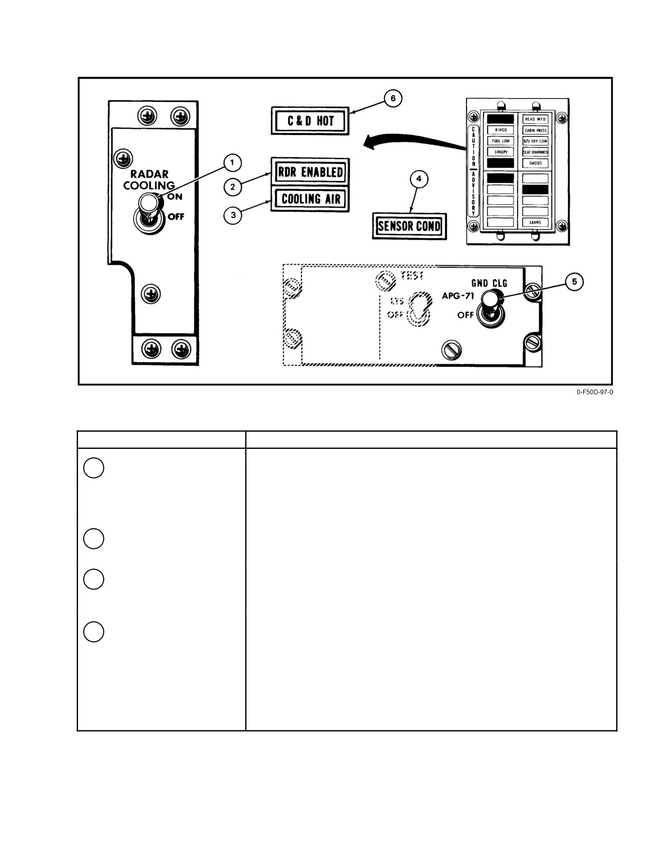
NAVAIR 01−F14AAD−1
NOMENCLATURE
FUNCTION
1
RADAR COOLING switch
OFF Ċ Deactivates the radar cooling pumps.
ON Ċ Activates the radar cooling pump for ground and airborne thermal
conditioning.
2
RADAR ENABLE
Indicates that radar operation on the ground is possible.
caution light
3
COOLING AIR
Illuminates after a delay of 25 to 40 seconds when insufficient cooling is
advisory light
provided to the electronic forced air cooling system. Degraded cooling
may result from cooling system failure, turbine failure, or ECS duct failure.
4
SENSOR COND
Illuminates when coolant exiting the heat exchanger is greater than 104° F,
advisory light
or pump output pressure is too low, or when the overtemperature switch
shuts down the radar, television camera set (TCS), and the infrared
search and track (IRST).
Figure 2Ć80.ĄAvionic Equipment Liquid Cooling Controls and Lights (Sheet 1 of 2)
2−153
ORIGINAL
NAVAIR 01−F14AAD−1
NOMENCLATURE
FUNCTION
5
GND CLG switch
APG−71 Ċ Cockpit low flow sensor is overridden.
CAUTION
• Servo air required to actuate servo operated valves.
• Use RADAR only when engines are shut down.
OFF Ċ Cockpit low flow interlock is operational. OFF shall be selected
when engines are operating.
6
C & D HOT caution light
Indicates DD or PTID overheat condition.
Figure 2−80. Avionic Equipment Liquid Cooling Controls and Lights (Sheet 2 of 2)
2.30.4.1.3
Cockpit Pressure Dump
D Extended operations in clear air with the
windshield air on may cause windshield
Cockpit pressurization can be dumped by the pilot by
cracking and discoloration.
selecting DUMP with the CABIN PRESS switch. When
2.30.6
Gun−Gas Purging
DUMP is selected the safety valve is immediately opened
and the cockpit is depressurized.
External airflow is used to ventilate the gun compartĆ
ment for gun−gas purging. A flush air inlet on the fuselage
2.30.4.2
Canopy Seal Pressurization
gun bump and an aft louvered door containing a FOD screen
provide a continual flow of air to purge gun gases.
Pressurized air from the air−conditioning system is
ducted through the cockpit to the canopy seal. The seal is
2.30.7
Degraded ECS Operation
automatically inflated when the canopy actuator is moved to
There are various temperature and pressure safeguard
the closed position. A check valve in the canopy pressure
systems that cause the ECS system to shut down if an unsafe
regulating valve prevents the loss of canopy seal pressurizaĆ
situation is detected. A complete failure of the dual valve will
tion if the conditioned air manifold is depressurized. Initial
cause it to shut down the pressurization and air−conditioning
movement of the canopy actuator automatically deflates the
system. Should that fail to close, a pressure switch will
seal.
close both engine bleed air shutoff valves if an overpressure
(155 psi) situation exists in the outlet of the primary heat
2.30.5
Windshield Air and Anti−Ice
exchanger. A shutdown of the bleed air supply duct, either
automatically or pilot−selected AIR SOURCE OFF pushĆ
Compressor bleed air at approximately 340_ĂF and at
button, will cause total ECS air shutdown.
high pressure is directed over the outside of the windshield
through a fixed−area nozzle. This blast of hot air over the
windshield will evaporate rain and ice and prevent its further
accumulation. It is activated by selecting ON with the
WSHLD AIR switch. A temperature overheat sensor at the
base of the windshield protects the windshield from overĆ
Failure of the left or right weight−on−wheels
heating. When the sensor detects overheating (300_ĂF), a
switches to the in−flight mode can cause loss of
signal closes the pressure regulating valve and illuminates
engine ejector air to the IDGs and hydraulic heat
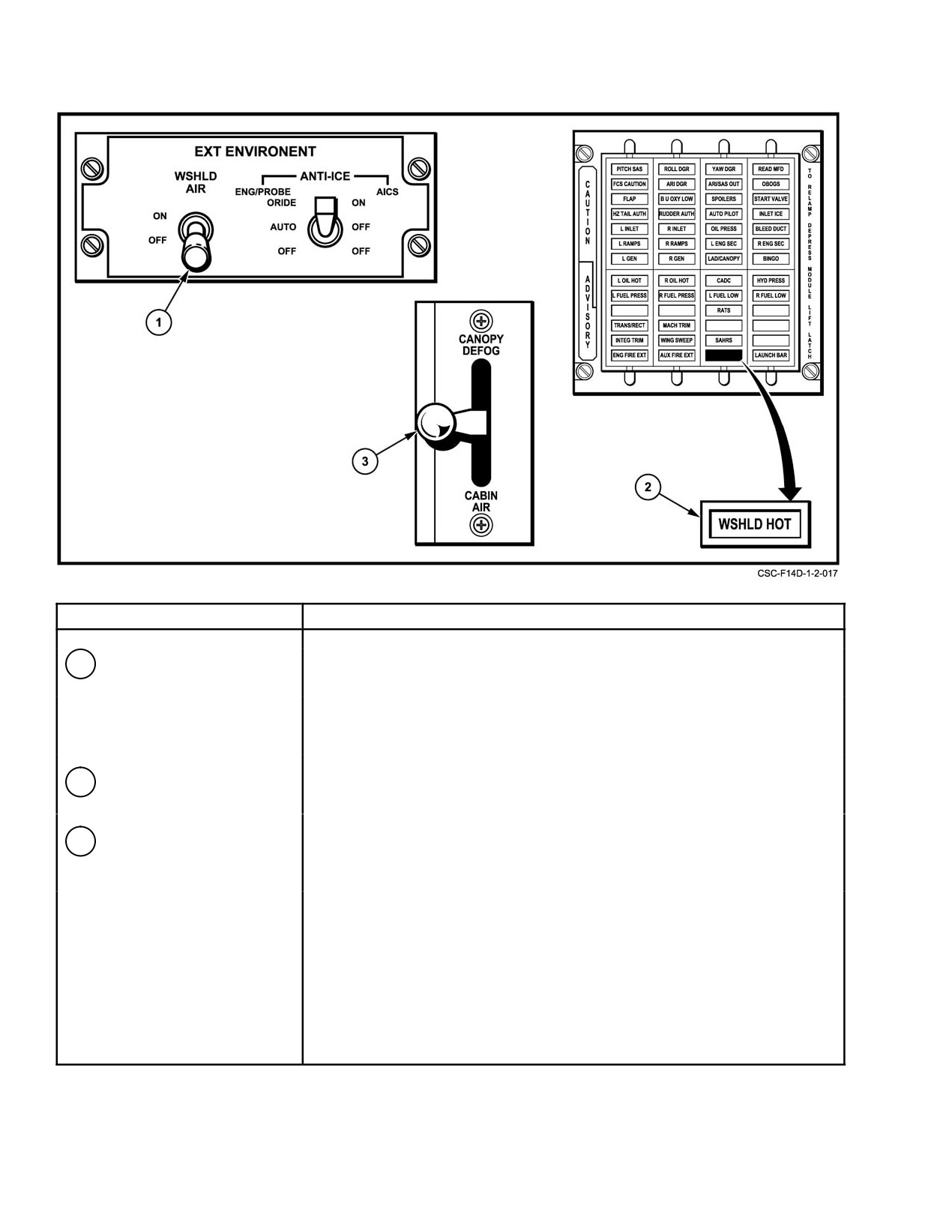
the WSHLD HOT advisory light on the pilot CAUTION
exchangers causing thermal disconnect and/or
ADVISORY light panel (Figure 2Ć82).
heat damage to the generators and aircraft
hydraulic systems.
Note
After an automatic shutdown of the system, the
pilot should select either OFF or RAM AIR
D Selecting WSHLD AIR ON prior to entering
SOURCE to enable the emergency ram−air door
rain or icing conditions may cause windshield
and then hold ram air switch to OPEN for approxĆ
cracking because of the rapid cooling effects
imately 50 seconds to provide ram−air cooling to
of precipitation.
electronic equipment and to the cabin.
ORIGINAL
2−154
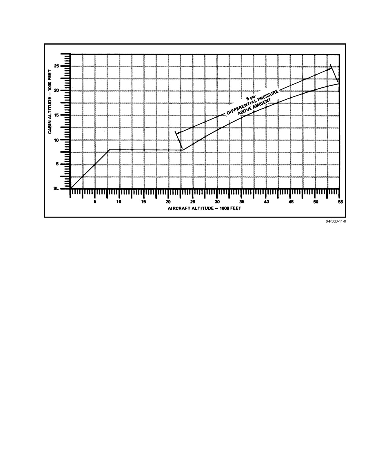
NAVAIR 01−F14AAD−1
Figure 2Ć81.ĄCabin Pressure Schedule
Note
1. No cockpit airflow.
2. RIO COOLING AIR advisory light illuminated.
D Loss of electrical power with bleed air still
operating will result in smoke entering the
3. RIO SENSOR COND advisory light illuminated.
cockpit through the ECS when the aircraft is
on the deck. In flight only cold air will be supĆ
4. If ram−air cooling is not selected, extended flight
plied to the cabin and suit. Icing of the water
with AIR SOURCE OFF could cause an overĆ
separator may occur, causing reduced flow to
heating condition of the converter interface unit and
the cabin. Since the ECS panel is dependent
a subsequent loss of primary attitude and navigaĆ
on electrical power, selector pushbuttons will
tional indications
(i.e., multifunction displays,
be inoperative.
HUD, NAVAIDs).
D Retarding throttles to IDLE above 30,000 feet
The pilot should press the AIR SOURCE RAM
may result in a considerable reduction in ECS
pushbutton and set the RAM AIR switch to OPEN to open the
airflow, leading to a loss of cockpit pressurĆ
ram−air door to provide forced−air cooling to the electronic
ization, SENSOR COND light, and/or
equipment and to the cabin.
COOLING AIR light.
ECS duct failures may be indicated by diminishing
If the 400_ manifold reaches 475_ F, a 400_ĂF shutoff
cabin cooling airflow and/or cabin pressurization with or
valve closes, stopping the flow of unconditioned engine
without COOLING AIR advisory light illumination. Duct
bleed air to the 400_ F manifold. If either compressor inlet
failures may additionally be indicated by pressurization loss
or turbine inlet temperature becomes excessive, the refrigĆ
to the service systems and airflow loss to rain removal, defog,
eration unit will shut down. Cockpit indications will be as
and heating systems. This cannot be verified if the system is
follows:
2−155
ORIGINAL
NAVAIR 01−F14AAD−1
NOMENCLATURE
FUNCTION
1
WSHLD AIR switch
ON Ċ
Provides a continuous blast of hot air (340°) over the
exterior windshield. Used for windshield anti−ice.
OFF Ċ
Closes the shutoff valve after a 5−second delay.
The system is deenergized.
2
WSHLD HOT advisory light
Light illuminates when a sensor in the warm air nozzle to the center
windshield indicates overheat (300° F).
3
CANOPY air diffuser lever
CABIN AIR Ċ 70% of the conditioned air directed through the cockpit
(both cockpits)
air diffusers and 30% is through the canopy defog rails.
This is normal position.
DEFOG Ċ Air flow is directed through the canopy defog rails only.
Figure 2Ć82.ĄCanopy Defog Controls and Windshield Air
ORIGINAL
2−156
NAVAIR 01−F14AAD−1
not in use. Selection of AIR SOURCE OFF and RAM AIR
concentrator and the monitor continue to function as long as
OPEN is appropriate when any indication of duct failure
the OBOGS switch is in the ON position. The monitor will
exists. ECS malfunctions that are not caused by duct failure
automatically shift back to the OBOGS supply source when
are usually indicated by loss of temperature control without
it detects adequate concentrator output.
a cabin or system airflow/pressurization degradation. Failure
Power to the monitor is provided by 28 Vdc OBOGS
of the 400_F modulating valve or duct should not cause
control power from the essential dc bus No. 1 when the
illumination of the cooling air light. Any duct failure in this
OBOGS master switch is in the ON position. The sensor in
area associated with the COOLING AIR light is strictly
the monitor is heated for proper operation. Upon initial
coincidental. However, the duct failure between the primary
selection of the OBOGS master switch to ON, the OBOGS
heat exchanger and the turbine compressor assembly, or
is powered and functioning but the monitor will not be
between the secondary heat exchanger and the turbine
accurately detecting oxygen concentration until the sensor is
compressor assembly, could cause degraded cooling airflow
warmed up. This can take up to 2 minutes, depending on the
and a COOLING AIR light to illuminate.
ambient temperature. The OBOGS light will not be illumiĆ
Actuation of the overtemperature switch results in
nated during the warmup period. The pilot may test operation
cycling of the 400_F valve. During this period the heating
of the monitor via the press−to−vent TEST button. The button
capacity of the 400_ F manifold would be degraded.
actuates a valve that must be held for up to 1 minute to vent
oxygen sensor. Laboratory testing has demonstrated that the
2.31 OXYGEN SYSTEM
test can normally be completed in approximately 15 seconds.
Once vented, the monitor will sense insufficient oxygen,
Breathing oxygen is provided to each crewmember by
illuminating the cockpit caution lights and shifting the
the OBOGS. A backup oxygen system provides a supply of
oxygen supply source to BOS. The monitor will automatiĆ
gaseous oxygen sufficient for a maximum range descent in
cally shift back to OBOGS operation and extinguish the
the event of a failure of the OBOGS. In addition, emergency
caution light after release of the TEST button. Testing has
oxygen is available to each crewmember through a high−
demonstrated this occurs within 5 to 7 seconds, but may take
pressure, gaseous oxygen bottle located in the ejection seat
up to 20 seconds.
survival kit.
2.31.1
On−Board Oxygen Generating System
(OBOGS)
The OBOGS provides 95−percent pure pressure− and
The aircrew will not have any indication of a failĆ
temperature−regulated oxygen to each crewmember. The
ure of the monitor. If the aircrew suspects the
system includes an oxygen concentrator, an oxygen monitor,
onset of hypoxia at any time, immediately select
and two regulators. Controls and indicators for the OBOGS
BACKUP. The monitor may be tested once the
are shown in Figure 2Ć83.
aircraft has descended to a cabin altitude of
The oxygen concentrator is in the right side of the
10,000 feet or less and the ON position on the
fuselage adjacent to and beneath the forward cockpit.
OBOGS master switch has been reselected.
Filtered and cooled ECS service air is directed to the oxygen
The OBOGS regulators are chest−mounted, pressure−
concentrator when ON is selected on the OBOGS master
demand type through which pressure−and temperature−
switch on the pilot cockpit panel. A molecular sieve in the
regulated oxygen is provided to each crewman. Pressure
concentrator removes the nitrogen from the compressed air,
breathing is activated above 34,000−foot cabin altitude.
leaving a breathing gas equivalent in concentration to
95−percent oxygen at 34,000 feet. The oxygen concentrator
When the OBOGS master switch is on, filtered, cooled
receives 115−Vac motor power from the pilot ac essential bus
engine bleed air is directed to the oxygen concentrator where
No. 1 and heater power from the ac right main bus. OBOGS
a molecular sieve removes the nitrogen from the compressed
28−Vdc control power is provided by essential dc bus No. 1
air, leaving a breathing gas consisting of 95−percent oxygen.
via the OBOGS CONTR circuit breaker (7A1).
The oxygen monitor checks system operation to ensure that
a sufficient concentration of oxygen is being generated,
The oxygen monitor is on the pilot right console. It
provides a cockpit indication, and brings the backup gaseous
constantly monitors the oxygen concentrator output to ensure
supply on line as required. A test button on the monitor
a sufficient concentration of oxygen is being generated.
enables the pilot to verify that the monitor and the backup
When the monitor detects an oxygen partial pressure less
oxygen system are functioning. When pressed, the OBOGS
than 182 mm Hg, it generates an alarm signal that illuminates
advisory light illuminates indicating the system is in backup.
the OBOGS caution lights, shuts off output from the
concentrator and enables the backup oxygen system. The
2−157
ORIGINAL
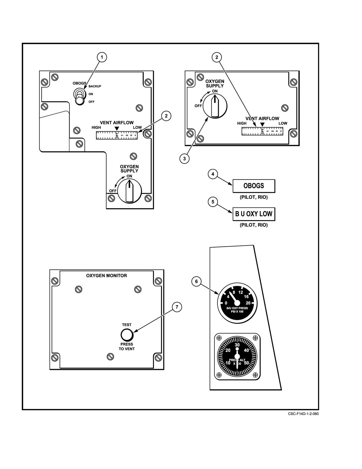
NAVAIR 01−F14AAD−1
Figure 2Ć83.ĄOxygen System Controls and Indicators (Sheet 1 of 2)
ORIGINAL
2−158
NAVAIR 01−F14AAD−1
NOMENCLATURE
FUNCTION
1
OBOGS master switch
BACKUP Ċ Deenergizes oxygen concentrator and Process Air Shutoff
Valve. Enables Backup Oxygen.
ON Ċ
Applies power to oxygen generator and oxygen monitor.
Opens solenoid valve providing ECS Service Air to Oxygen
Concentrator.
OFF Ċ
Removes power from OBOGS and BOS. Process air shutoff
valve closes.
2
VENT AIRFLOW
NOTă FUNCTIONAL.
3
OXYGEN SUPPLY valve
ON Ċ
Opens oxygen supply permitting OBOGS or BOS oxygen flow
to crewmember.
OFF Ċ
Secures OBOGS and BOS oxygen flow to crewmember.
4
OBOGS caution light
Illuminates when OBOGS has failed or OBOGS master switch is in OFF
or BACKUP
5
B/U OXY LOW caution
Illuminates when pressure remaining in BOS assembly oxygen cylinder
lights
is below 200 psi.
6
BACKUP OXY PRESS
Indicates pressure remaining in BOS assembly oxygen cylinder.
Indicator
7
OXYGEN MONITOR
Provides functional test of the oxygen monitor, BOS, and OBOGS control
TEST Button
systems.
Figure 2−83. Oxygen System Controls and Indicators (Sheet 2 of 2)
2.31.2
Backup Oxygen System (BOS)
The BOS assembly consists of an oxygen cylinder,
pressure gauge, pressure regulator, fill port, pressure transĆ
The BOS consists of a BOS assembly, BOS controller,
ducer, low−pressure switch, manual shutoff valve, and quick
B/U OXY LOW caution light, and a BACKUP OXY PRESS
disconnect on a palletized assembly that is removable for
indicator. This system was designed to provide only enough
servicing and maintenance. A 200−cubic−inch, high−pressure
oxygen for maximum−range descent. In the event of an
cylinder containing 500 to 590 liters of gaseous oxygen at
OBOGS failure, the aircrew must take immediate action to
1,800 to 2,100 psi, respectively, provides a backup oxygen
conserve backup oxygen.
supply to the OBOGS. The BOS assembly is located on the
Switching to the backup system can be accomplished
right forward side of the fuselage, just below the forward end
three ways:
of the pilot cockpit.
1. Automatically upon monitor detection of an
The BOS controller enables flow from the BOS assemĆ
OBOGS failure or loss of OBOGS control power
bly via a diaphragm valve. This diaphragm valve is conĆ
2. Manually via direct selection of BACKUP on the
trolled by two solenoid valves and an aneroid valve. The BOS
OBOGS master switch
controller is in the BOS assembly compartment. Power for
automatic operation of the BOS controller is provided by
3. Automatically with total loss of electrical power or
28 Vdc essential bus No. 1 via the OBOGS CONTR circuit
selection of OFF on the OXYGEN system master
breaker (7A1). Alternate power is provided via the BOS
switch, when the aircraft is above 10,000 feet MSL.
CONTR/B/U OXY LOW circuit breaker (7A4) for automatic
Backup oxygen cannot be disabled above 10,000 feet
activation of backup oxygen in the event of a failure of the
MSL by turning the OXYGEN system master switch
OBOGS control relay and when BACKUP is manually
off. Therefore, the individual OXYGEN SUPPLY valves
selected.
(Figure 2Ć83.) in both cockpits must be used to turn off
oxygen flow to the personnel regulators.
2−159
ORIGINAL
NAVAIR 01−F14AAD−1
The B/U OXY LOW caution light is actuated by the
The pitot−static system is composed of two separate
BOS assembly low−pressure switch when the BACK UP
systems with individual pitot−static probes, one on each side
OXY PRESS gauge reads less than 200 psi, or when BOS
of the forward fuselage.
CONTR/B/U OXY LOW power is lost. Figure 2Ć84 provides
The left pitot pressure (PT) probe supplies the pilot
backup oxygen breathing time for two crewmembers for
standby airspeed indicator and the left AICS programmer.
various cabin altitudes based upon BOS oxygen cylinder
The right pitot pressure (PT) probe supplies the RIO standby
pressure.
airspeed indicator, the right AICS programmer, and the
CADC with airspeed indications. An electrical PT input from
2.31.3
BOS Pressure Indicator
the left AICS programmer is supplied to the CADC backup
The BACK UP OXY PRESS indicator (Figure 2Ć83.),
channel as airspeed indications for wing sweep.
on the right side of the pilot right knee panel, shows the
The left and right forward static ports
(PS1) are
pressure in the BOS assembly oxygen cylinder. The indicator
manifolded to provide static pressure to the pilot standby
will not function unless the BOS manual shutoff valve on the
airspeed indicator, standby altimeter, vertical speed indicaĆ
BOS assembly is open.
tor, and the CADC. Static pressure from the right aft (PS2)
static ports supply the RIO standby airspeed indicator,
2.31.4
Emergency Oxygen Supply
standby altimeter, and the right AICS programmer. The static
The 50−cubic−inch oxygen cylinder in the survival kit
pressure from the left aft (PS2) static ports supply the static
of each ejection seat provides a limited supply of gaseous
pressure to the left AICS PS sensor. An electrical PS input
oxygen. This oxygen cylinder can be manually activated in
from the left AICS programmer is supplied to the CADC
the event of a failure of the OBOGS and depletion of the
backup channel for wing sweep. Static pressure from the left
backup supply. The cylinder is charged to 1,800 to 2,100 psi
aft (Ps2) static ports supply the left AICS programmer.
and a pressure gauge is visible on the inside face of the
The CADC and AICS programmers provide Mach
left−thigh support. Flow from the emergency cylinder is
number information to the digital flight control computers
routed through a pressure reducer and a shuttle valve, then
(DFCCs). The alpha computer, angle of attack probe (used
follows the path of the normal oxygen system, flowing
for displaying angle of attack to the pilot), and the AICS
through the oxygen regulator to the face mask. The supply of
programmers provide angle of attack information to the
oxygen available in the emergency cylinder is adequate for
DFCCs. Electrical interfaces are shown on Figure 2Ć85.
up to 8 to 10 minutes, depending upon altitude. The manual
actuation handle is a green ring under the left side of the
Note
survival kit cushion.
D With the in−flight refueling probe extended,
the pilot and RIO standby altimeters and airĆ
speed indicators show erroneous readings
because of changes in airflow around the
pitot−static probes.
Turn the OXYGEN supply valve to OFF before
pulling the emergency oxygen manual actuating
D The RUDDER AUTH caution light may illuĆ
handle if contamination of the normal system is
minate when the in−flight refueling probe is
suspected. Failure to do so will inhibit seatpan
extended. Press the MASTER RESET button
shuttle valve operation, preventing flow of emerĆ
to reset the light.
gency oxygen.
2.32.1
Pitot−Static Heat
Note
Each pitot−static probe is equipped with electrical
Flow of oxygen from the emergency cylinder can
heating elements to prevent icing. Pitot−static heat is
be stopped by reseating the manual actuation
controlled by the pilot through the ANTI−ICE switch on the
handle.
pilot right console. In AUTO/OFF, pitot probe heat is
available only with weight off wheels. ORIDE/ON activates
2.32 PITOT−STATIC SYSTEM
the probe heat elements independently of the weight−on−
wheels switch and illuminates the INLET ICE caution light
The pitot−static pressure system supplies impact (pitot)
on the CAUTION ADVISORY panel. OFF/OFF removes
and atmospheric (static) pressure to the pilot and RIO flight
heat from the probes.
instruments, to the CADC, and to the engine AICS programĆ
mers. Some systems require static pressure only; others
require static and pitot pressure (see Figure 2Ć85).
ORIGINAL
2−160
NAVAIR 01−F14AAD−1
BACK−UP OXYGEN PRESSURE
CABIN ALTITUDE
2000
1600
1200
800
400
200
35 & ABOVE
100
80
60
40
20
10
30
72
58
43
29
14
7
25
52
42
31
21
10
5
20
41
33
24
16
8
4
15
32
26
19
13
6
3
10
27
22
16
10
5
2.9
8
24
19
14
9
4
2.5
5
21
17
12
8
4
2.2
SL.
17
14
10
7
3
1.8
Minutes remaining based on two−man consumption.
Duration data should be used as a guide
Consumption rate based on 13.1 liters per minute per man.
Figure 2Ć84.ĄBackup Oxygen Duration Chart
1. Calligraphic or stroke writing is displayed on the
HUD, MFDs, and the DD.
2. Raster video (for example, radar, and television)
The ANTI−ICE switch should normally be in
generated internally (VDI formats) or provided by
AUTO/OFF during takeoff and landing. Engine
an external sensor, with or without a stroke overlay,
anti−icing has adverse effects on engine stall marĆ
is displayed on the MFDs and the DD.
gin.
3. Alphanumeric data is displayed on the multistatus
indicator and the radio frequency and radio frequenĆ
2.33
CONTROL AND DISPLAY SYSTEM
cy/control indicators.
The control and display system (Figure 2Ć86) provides
the crew with navigation, aircraft status, and flight tactical
Displays presented on the HUD and MFDs are
information. The control and displays system consists of two
identified as formats. The formats are categorized as display
display processors
(DP1 and DP2), three multifunction
format groups.
displays (pilot center MFD1, pilot right MFD2, and RIO
MFD3), and a heads−up display system, cockpit television
HUD format groups consist of takeoff/landing/
sensor, HUD−VIDEO panel, pilot displays control panel, and
navigation (TLN), air−to−air (A/A), air−to−ground (A/G), and
a multistatus indicator.
multimode formats that can be overlaid on the other three.
The HUD also displays a manual reticle and a test pattern.
The control and display system also sends display
information to the digital display, the radio frequency
MFD display format groups are shown in Figure 2Ć87.
indicator, radio frequency/control indicator, and the mission
The HUD and MFD VDI format groups are basically the
video recorder.
same; however, HUD symbology is scaled to be overlaid on
The data entry unit is a remote terminal that communiĆ
the real world, and certain differences, such as symbol
cates with the mission computers via the multiplex buses.
location, addition, and deletion occur between the HUD and
MFD VDI formats. MFDs also display repeats of the PTID
2.33.1
Display Types
and DD as well as TCS and CCTVS video.
The following types of display information are proĆ
vided by the MFD system:
2−161
ORIGINAL
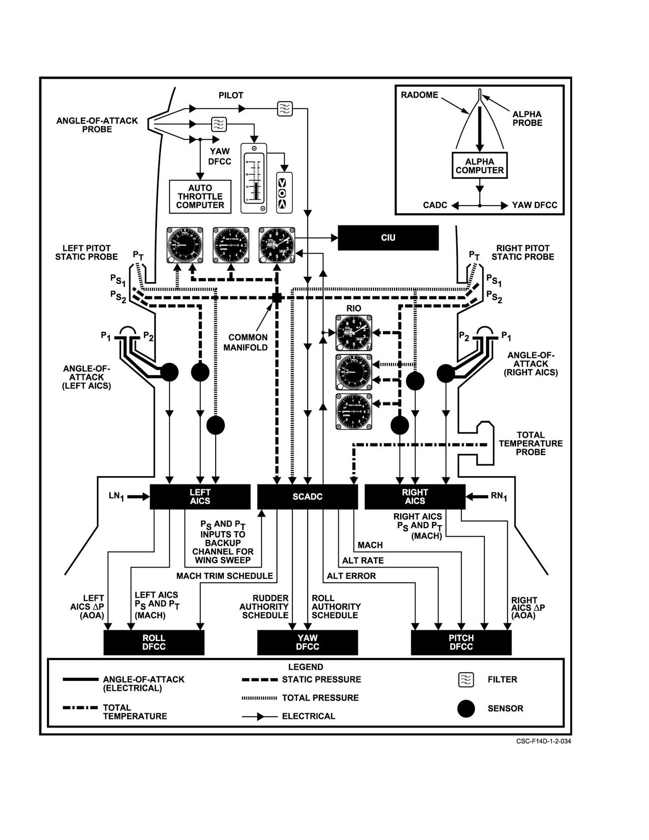
NAVAIR 01−F14AAD−1
Figure 2Ć85.ĄAirstream Sensors
ORIGINAL
2−162
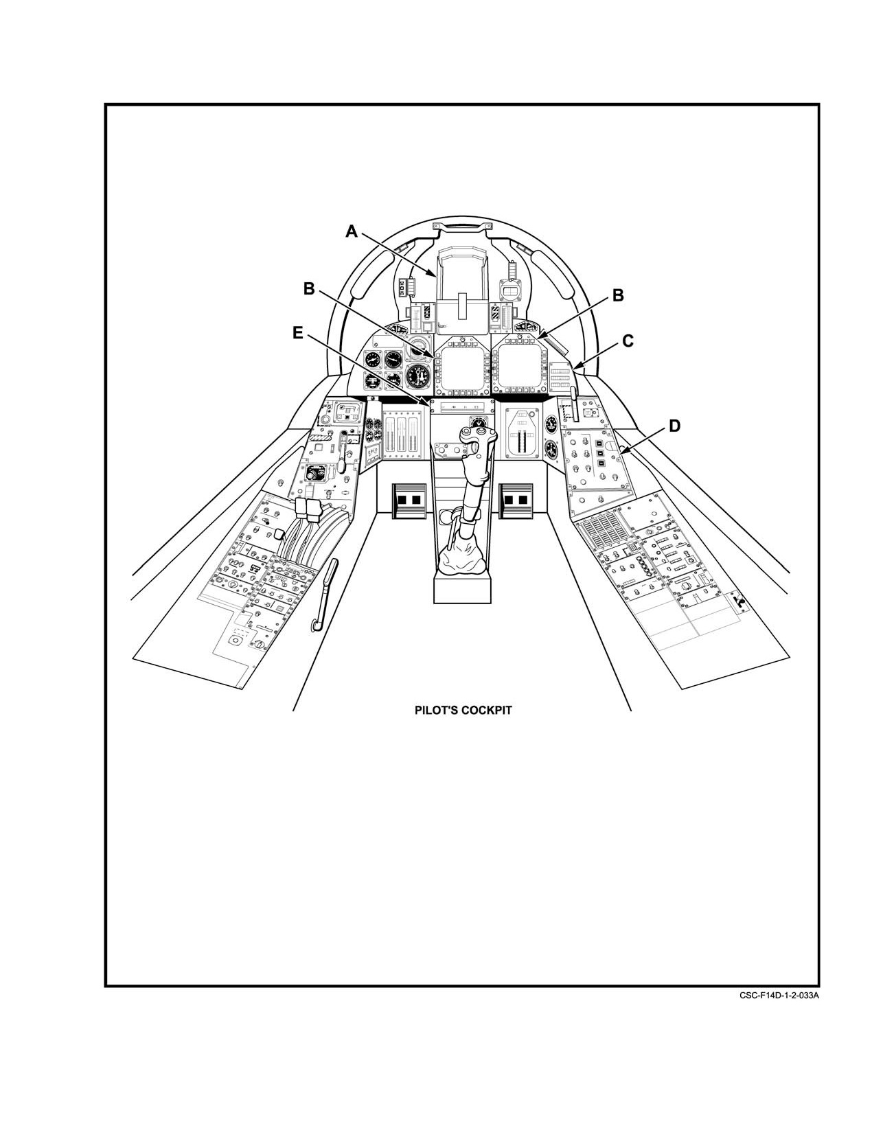
NAVAIR 01−F14AAD−1
Figure 2Ć86.ĄDisplay Systems Controls and Indicators (Sheet 1 of 4)
2−163
ORIGINAL
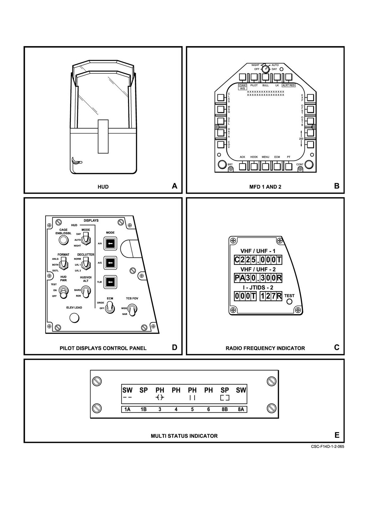
NAVAIR 01−F14AAD−1
Figure 2−86. Display Systems Controls and Indicators (Sheet 2 of 4)
ORIGINAL
2−164
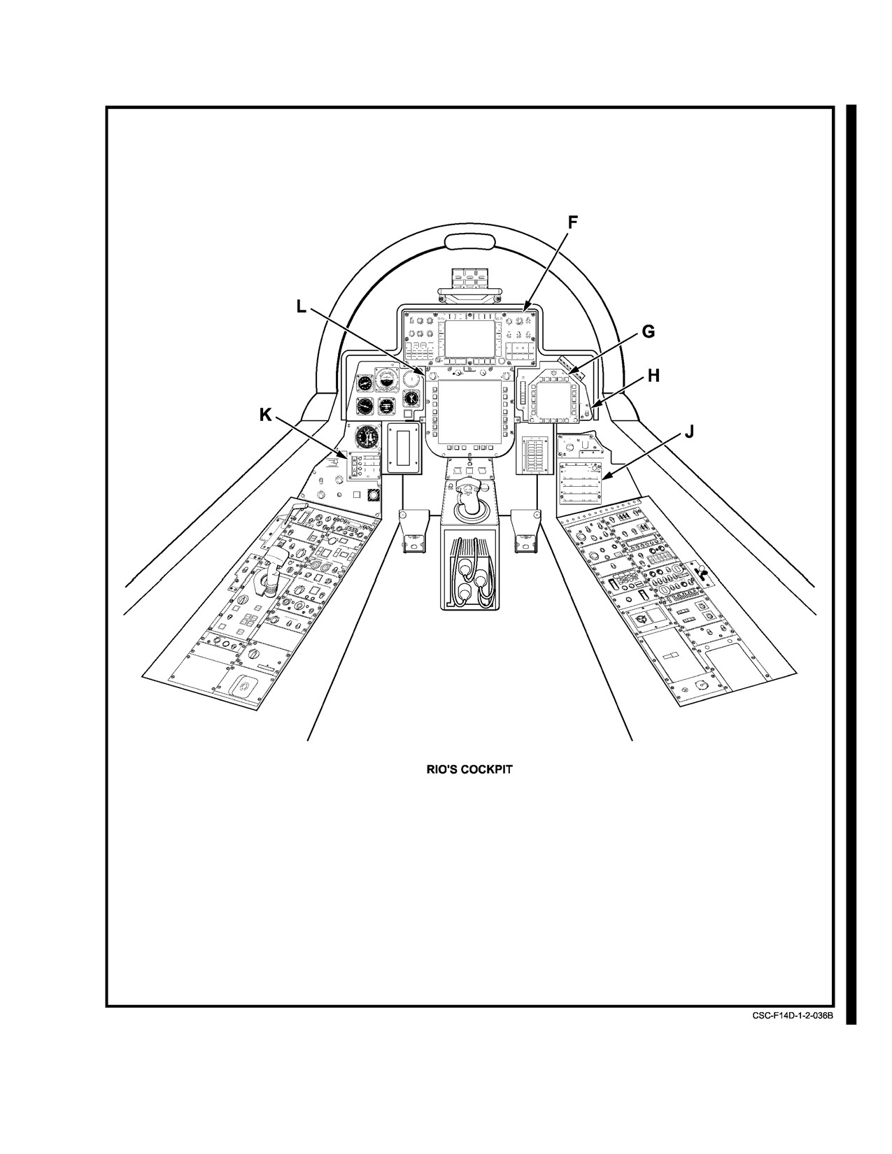
NAVAIR 01-F14AAD-1
Figure 2-86. Display Systems Controls and Indicators (Sheet 3 of 4)
2-165
CHANGE 1
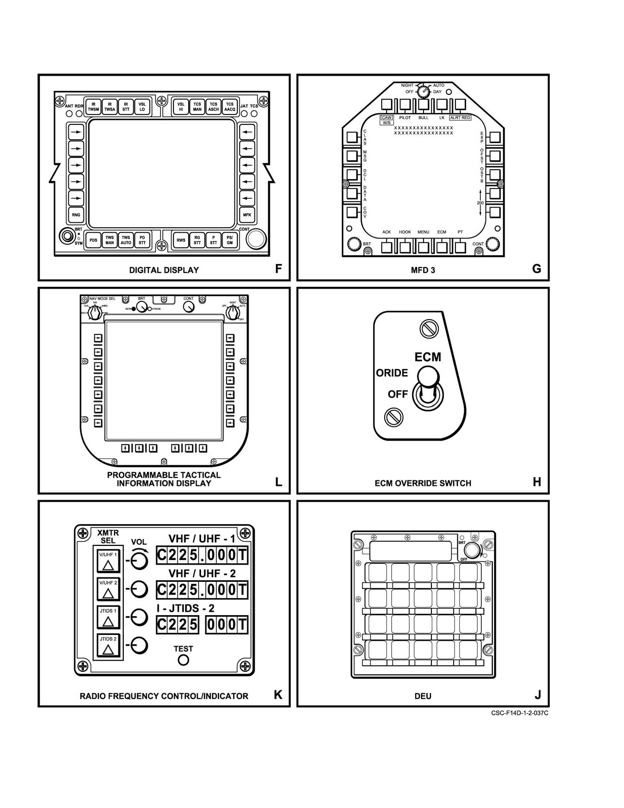
NAVAIR 01−F14AAD−1
Figure 2−86. Display Systems Controls and Indicators (Sheet 4 of 4)
ORIGINAL
2−166
NAVAIR 01−F14AAD−1
DISPLAY FORMAT
FORMATS WITHIN GROUP
MFD Vertical Display Indictor (VDI) /HUD Formats
TLN BASIC (TLN−GU, TLN−GD)
TLN DESTINATION
TLN MANUAL
TLN TACAN
TLN DATA LINK
AWL (All Weather Landing)
A/A BASIC
A/A SPARROW SEARCH
A/A PHOENIX SEARCH
A/A SIDEWINDER SEARCH
A/A PHOENIX TRACK
A/A SPARROW TRACK
A/A SIDEWINDER TRACK
A/A TRACK WHILE SCAN
A/A MULTIPLE MODE GUN SIGHT (MMGS)
A/A GUN BACKUP
A/G BASIC
A/G CCIP
A/G MANUAL
RECON
IRSTS TWS
MFD Horizontal Situation Display (HSD) Formats
WAYPOINTS
TACAN
CDI TACAN
GPS
AUTO
OWN A/C and WAYPOINT Formats
OWN A/C BASIC
OWN A/C GROUND
OWN A/C CVA
OWN A/C IFA
WAYPOINT DATA 0ć99
Figure 2Ć87.ĄDisplay Format Groups (Sheet 1 of 2)
2−167
ORIGINAL
NAVAIR 01-F14AAD-1
DISPLAY FORMAT
FORMATS WITHIN GROUP
NAV Align Formats
CV MAN DATA
CV Ships Inertial Navigation System (SINS) DATA
IFA
Standard Attitude Heading Reference System (SAHRS)
(Norm Mag SHDG)
SAHRS CV
Inertial Navigation System (INS) UPDATE Format
Continuous Update Formats
NAV AID CORRECTIONS
NAV AID ENABLED
NAV AID OPTIONS
SURFACE WAYPOINT POSITION Format
Stores Management System (SMS) Format
SPIN INDICATOR Format
ENGINE MONITOR Format
On Board Checkout (OBC) Formats
OBC BASIC
OBC Groups: CD, CNI, FLT, NAV, AUX, TAC, EW,
SMST, and SNSR
OBC Failed Data: CADC, CIU, SAHRS, DINS, GPS,
DEU, DP1, DP2, MC1, MC2, MDL/DSS, APC, EMSP1,
EMSP2, IFX, SMS, SWITCHES, RWR, and RDR/TCS
MAINT Format
Failure History Format (FHF)
Cooperative Support Software (CSS) Format
Missile Status Readout Formats
MISSILE SUBSYSTEM 1
MISSILE SUBSYSTEM 2
Electronic Counter Measures (ECM) Format
Recon Formats
RECON DATA
RECON WPT DATA1
RECON WPT DATA2
Tactical Situation Display (TSD)
TSD MENU
TSD PRIORITY
TSD DECLUTTER 1
TSD DECLUTTER 2
TSD COMMAND
TSD REPLY
TSD TARGET MODIFIER
JTIDS Data Readouts (JDR)
OWN AIRCRAFT PPLI
AIR PPLI
NON-AIR PPLI
INDIRECT PPLI
Infrared Search and Track (IRST) Formats
IRSTS NORMAL
IRSTS CSCAN
IRSTS SUMMARY
Figure 2-87. Display Format Groups (Sheet 2 of 2)
CHANGE 1
2-168
NAVAIR 01−F14AAD−1
2.33.2
Display Processors
is on the PDCP and the MFD power switches are on each
MFD as a part of the DAY/AUTO/NIGHT switch.
Two display processors
(DP1 and DP2) drive the
display system. The DPs receive various signal inputs from
After a short warmup (under 2 minutes), the default
the aircraft systems. These signals are processed and
formats appear on the displays. The default formats, with
converted to display information for the HUD, MSI, MFDs,
weight on wheels, are as follows:
DD, RFI, RFCI, and the mission video recorder.
1. HUD Ċ TLN basic
2.33.2.1
Normal Operation
2. MFD Ċ VDI TLN basic
During normal operation, DP1 drives the HUD and
MFD1, while DP2 drives MFD2 and MFD3. Should either
3. MFD2 Ċ OBC basic
DP fail, the mission computer commands backup operation,
4. MFD3 Ċ OWN A/C basic.
where the remaining DP provides limited functions.
If the mission computers are not in communication,
2.33.2.2
DP Backup Operation
test patterns will appear on all four displays.
During backup operation, the remaining DP drives the
Format selection for the HUD is made by use of the
HUD, and MFD1. Should one of these three displays be OFF
MODE pushbuttons on the PDCP and by the type of steering
or subsequently selected off, then MFD2 will operate. If both
selected. MFD format families are selected by pressing the
stroke generators in the remaining DP are in use, an MFD
pushbutton adjacent to a menu legend or by cursor designaĆ
format that is normally produced by stroke writing may be
tion of the legend. Every MFD format (except repeats) has
generated in raster. With the following exception, either DP
MENU select as the center pushbutton on the lower edge of
can perform any display function: Mission video record is not
the display. Also appearing on all formats for immediate
performed during backup operation.
selection are SMS to the left of MENU and ECM to the right
of MENU. Other selections vary according to format
2.33.2.3
Data Failure Modes
requirements. When a repeat format (HUD, DD, or PTID) is
being displayed on the MFD, no legends are available for
In addition to the backup mode, there are other failure
format selection. To change formats from a repeat, press any
modes. Some examples are as follows.
pushbutton. This returns MENU1 to the MFD, permitting
If the DPs fail to receive pitch and roll data, the
other format selections to be made. Cursor designation of
message PITCH/ROLL FAIL will appear on the MFDs and
legends cannot be used with repeat displays.
all pitch/roll−related symbols are removed from the displays.
The symbols are returned if pitch and roll information is
2.33.4
Heads−Up Display (HUD)
restored.
The HUD (Figure 2Ć88) provides a combination of
If the DPs lose communication with the MCS, a manual
real−world cues and flight direction symbology, projected
reticle will appear on the HUD and the MFDs will display
directly on a combining glass assembly. The flight informaĆ
only the message DP−MC COMM FAIL and MENU1. The
tion on an optical combiner is projected in the pilot forward
lighted MODE pushbuttons also turn off with a loss of MCS
field of view. The display is focused at infinity, thereby
communication. Should communications be restored, the
creating the illusion that the symbols are superimposed on the
DP−MC COMM FAIL message is removed and the MODE
real world (and so that visual cues received from outside the
buttons are lighted again. If the MC performed a cold start or
aircraft are not obscured). The pilot usually steers based on
a system reset, default formats are presented on the displays.
interpretation of the visually observed real world. The HUD
can be selected to be the primary flight reference for all flight
2.33.3
System Operation
regimes displaying navigation and weapon delivery informaĆ
tion. The HUD symbol brightness control is on the HUD; all
The display system requires 115 V, 400 Hz electrical
other HUD controls are on the PDCP.
power DP1, HUD, and MFD1 receive power from ac
essential No. 2 bus and DP2, MFD2, and MFD3 are on the ac
2.33.4.1
Pilot Displays Control Panel (PDCP)
left main bus. All displays and DPs are electrically protected
by circuit breakers. There are no power switches for the DPs.
The PDCP on the pilot right console (Figure 2Ć89)
Each of the displays has a power switch that is normally
provides control of the mode and display presentation of the
turned off at the conclusion of flight. The HUD power switch
2−169
ORIGINAL
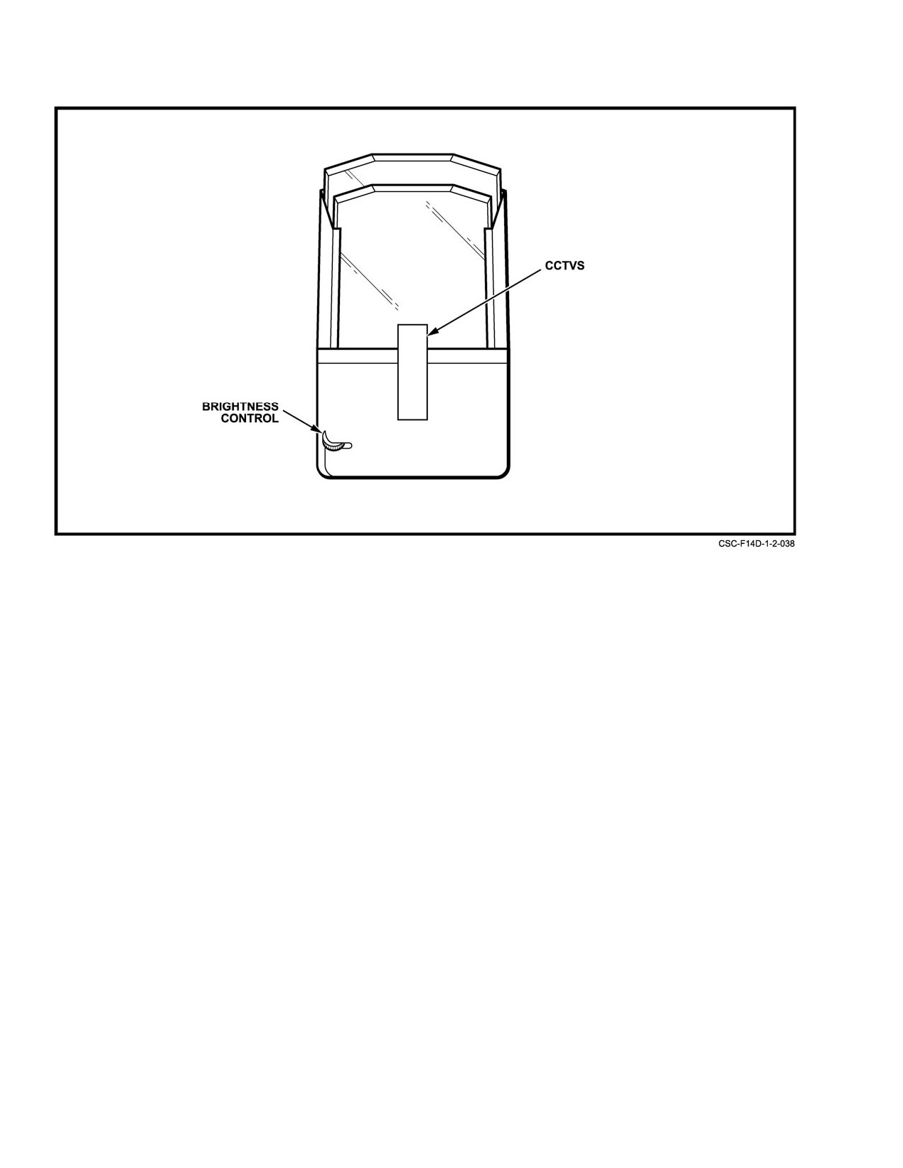
NAVAIR 01−F14AAD−1
Figure 2Ć88.ĄHeads−Up Display
HUD, VDI, ECM, and TCS formats. Display informaĆ
an MFD, or is being recorded, bright white flashes of video
tion is dependent on the mode selected with the A/A, A/G,
will be displayed or recorded. This is normal for BIT
and TLN pushbuttons.
operation.
2.33.4.2
Color Cockpit Television Sensor
2.33.5
Multistatus Indicator (MSI)
(CCTVS)
The MSI is an LCD panel on the lower center
The CCTVS is an electro−optical system that images
instrument panel below the center MFD
(MFD1)
symbology present on the HUD combiner and outside world
(Figure 2Ć86). The MSI displays the weapon type and status
information as well. The unit consists of a video sensor head
on each store station.
on the HUD and an electronic unit in the HUD−VIDEO panel
The lower row displays weapon status: ready,
(Figure 2Ć86)). The sensor signal can be fed to the mission
degraded, ready/selected or degraded/selected. The selected
video recorder and can be displayed on the MFDs. Operation
symbol never appears alone; it is always superimposed over
of the CCTVS is controlled by the VIDEO CONTROL
the ready or degraded symbol. Figure 2Ć90 provides a
switch on the HUD−VIDEO control panel.
representative display of available MSI symbols along with
their meanings.
2.33.4.3
HUD−VIDEO Control Panel
The upper row of the display identifies the weapon.
Operation of the CCTVS is controlled by the HUD−
Two dashed lines at a store station indicate that the missile at
VIDEO control panel (Figure 2Ć86)). The panel contains the
that station has failed or is hung. A blank display on a station
two−position VIDEO CONTROL toggle switch, a BIT
indicates no weapon is loaded or the weapon loaded is not
button, a green GO light, and a yellow NO GO light. Setting
recognized.
the VIDEO CONTROL switch to ON provides power to the
CCTVS; selecting OFF removes power. Depressing the BIT
There are no controls on the MSI. Power to the MSI is
button initiates a CCTVS self−test. A good test results in a
provided by the HUD subsystem. The MCS must be
momentary flash of the yellow NO GO light followed by a
transmitting data for a display to be presented. Selecting
steady green GO light. A failure results in a steady yellow NO
TEST on the HUD PWR switch causes all LCD segments on
GO light. During BIT, if CCTVS video is being displayed on
the MSI to be displayed.
ORIGINAL
2−170
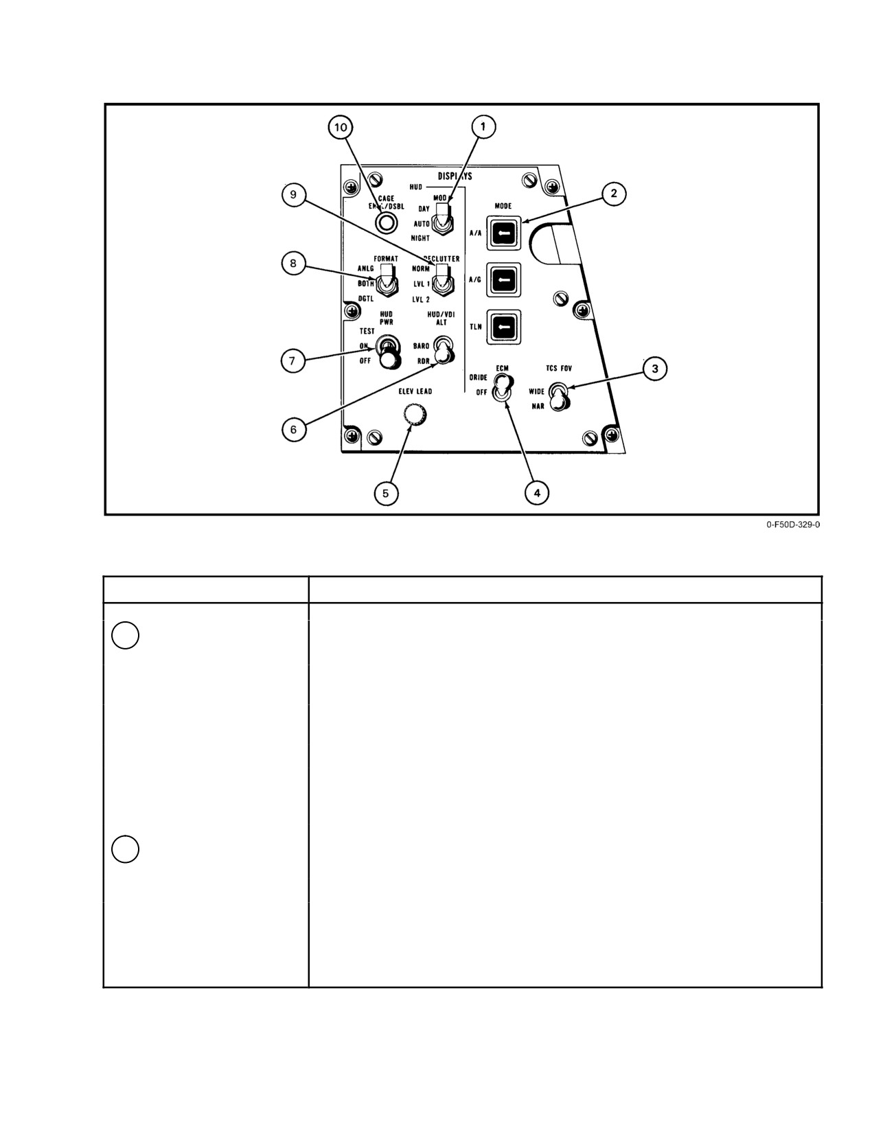
NAVAIR 01−F14AAD−1
NOMENCLATURE
FUNCTION
1
MODE Switch
DAY Ċ Provides a full range of HUD symbol brightness control: 0 to 100%.
Disables automatic brightness control.
AUTO Ċ Provides automatic symbol brightness operation superimposed on
the level selected with the symbol brightness control.
NIGHT Ċ Provides a HUD symbol brightness control range of 0 to 1.0% of
DAY level.
Note
When switching from NIGHT to DAY, the brightness
level gradually increases until it reaches the level
established for DAY.
2
Display MODE
A/A Ċ Provides selection of air−to−air display mode.
Pushbuttons
A/G Ċ Provides selection of air−to−ground display mode.
TLN Ċ Provides selection of takeoff/landing/navigation mode.
Figure 2Ć89.ĄPilot Displays Control Panel (Sheet 1 of 3)
2−171
ORIGINAL
NAVAIR 01−F14AAD−1
NOMENCLATURE
FUNCTION
3
TCS FOV (Television
NAR Ċ Selects TCS narrow field of view for display on pilot’s MFD1.
Camera Field of View)
WIDE Ċ Selects TCS wide field of view for display on pilot’s MFD1.
4
ECM switch
ORIDE Ċ Enables ECM display to override whatever is being displayed on
MFD2 for as long as the threat is being reported.
OFF Ċ ECM display override not enabled.
5
ELEV LEAD Control
A continuous rotary control that provides a range of elevation positions for the
HUD manual reticle with the 0 mr setting coincident with the armament datum
line (ADL). Clockwise rotation increases elevation lead.
6
HUD/VDI ALT source
BARO Ċ Selects barometric altimeter as source for display of altitude on
switch
HUD and VDI.
RDR Ċ
Selects radar altimeter as source for display of altitude on HUD
and VDI. Radar altitude is displayed as follows:
• Below 5000 feet AGL
• Radar altitude valid
• AOB ≤ 45_
7
HUD PWR switch
TEST Ċ
(Momentary) Presents an intersecting vertical and horizontal line at
(lever lock)
the center of the HUD field of view, and illuminates all segments of
the multistatus indicator (MSI).
ON Ċ
Provides power to HUD and MSI.
OFF Ċ
Removes power from HUD and MSI.
8
FORMAT switch
ANLG Ċ
Selects analog dial format for HUD display of airspeed and
altitude.
BOTH Ċ Selects a combination of analog dial and digital readout for HUD
display of airspeed and altitude.
DGTL Ċ
Selects digital readout format for HUD display of airspeed and
altitude.
9
DECLUTTER switch
NORM Ċ Normal display symbology is presented.
LVL 1 Ċ
Depending on MODE selected, the following symbols are
removed:
TLN ć GEAR UP
(AOA bracket and target pointer/AON are not displayed)
•
Vertical velocity
•
AOB scale
•
Peak G
Figure 2−89. Pilot Displays Control Panel (Sheet 2 of 3)
ORIGINAL
2−172
NAVAIR 01−F14AAD−1
NOMENCLATURE
FUNCTION
9
DECLUTTER switch
TLNć GEAR DOWN
(continued)
(Target pointer/AON and Mach are not displayed)
• Peak G (displayed as required in normal mode only)
• AOB scale
• Radaraltitude
A/A
• Radar altitude readout
A/A and A/G
(Vertical velocity, AOB
scal
e, and AOA bracket
are not displayed)
• AOA
eadout
• Potential flight path marker (PFPM)
LVL 2 − Depending on MODE selected, the following additional symbols are
removed:
TLN ć GEAR UP
• AOA
• Mach
• Nav range
• PFPM
• Radar altitude readout
• Digital boxes
• Clock/Timer readout
• Steering Mode
/WPT #/
Range
TLN ć GEAR DOWN
• AOA
• Digital boxes
• PFPM
• Vertical velocity
• Clock/Timer readout
• Steering Mode/WPT #/Range
A/A
• Nav range
A/G
(Closure and target pointer/AON are not displayed)
• Radar altitude readout
A/A and A/G
(AOB scale, AOA bracket, and vertical velocity are not displayed)
• Mach number
• Peak G
• Digital boxes
• Heading sca
le
• Gho st FPM
• Clock/Timer readout
• Steering Mode/WPT #/Range
10
CAGE ENBL/DSBL
Momentary contact pushbutton used to enable/disable HUD CAGE option.
Pushbutton
Caging restricts pitch ladder and flight path marker symbols in azimuth to the
center of the HUD display.
Figure 2−89. Pilot Displays Control Panel (Sheet 3 of 3)
2−173
ORIGINAL
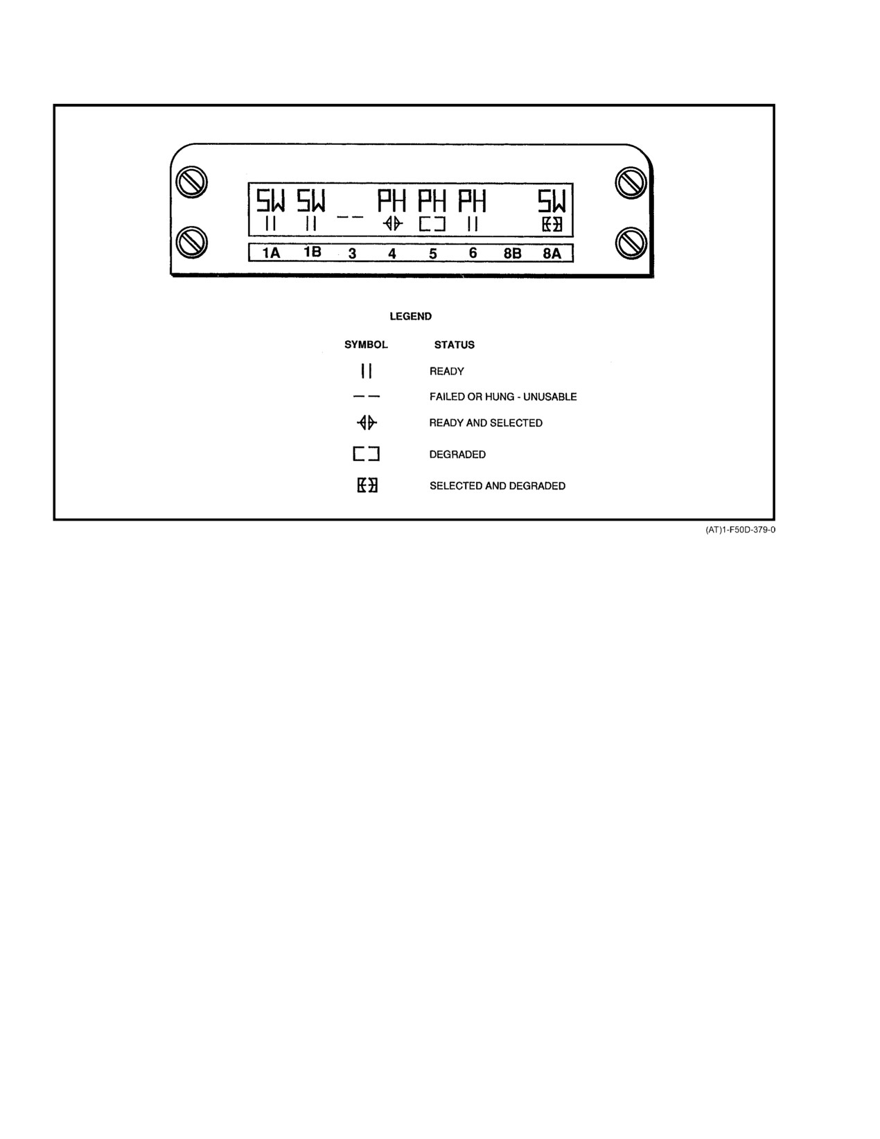
NAVAIR 01−F14AAD−1
Figure 2Ć90.ĄMultistatus Indicator Symbols/Meanings
An MFD displays tactical and flight command situaĆ
Normally the pilot uses the MFD below the HUD
tions, navigation, and discrete information either separately
on the aircraft centerline as the primary in−the−cockpit flight
or simultaneously with radar and TV data. There is also a
instrument.
power/brightness select switch above the display screen
Attitude information is displayed on the MFD VDI
(Figure 2Ć91).
format by an aircraft reticle, a horizon line, and a calligraphic
pitch ladder. The aircraft reticle is fixed at the center of the
2.33.6
Multifunction Displays (MFD)
display, and the horizon line and pitch ladder move about it
The three identical MFDs are CRT displays with 20
in accordance with the aircraft pitch and roll attitudes.
pushbuttons around the perimeter of the display screen. The
The flight parameters displayed include magnetic
MFD pushbuttons with adjacent legends are used for menu
heading, data link
(D/L), commanded airspeed
(Mach
selection, data entry/readout, and system test and/or status
number), airspeed, altitude, and vertical velocity.
indications. The three programmable MFDs, two in the pilot
instrument panel and one in the RIO instrument panel
Note
provide display flexibility such that either crewmember is
able to select any display available, allowing the pilot and
If pitch or roll data is not updated within 240
RIO to monitor and back up each other. The HUD format may
milliseconds, the pitch ladder and roll marker
be repeated on any MFD by depressing pushbutton No. 11
will be blanked and the horizon, sky, and ground
from the MENU1 format.
plane will darken.
Multifunction pushbuttons with adjacent CRT legends
2.33.7
Cursor Controls
located around the perimeter of the MFD are used for menu
selection, data entry/readout, and system test and/or status
Both the pilot and RIO have cursor controls
indications. An MFD displays tactical and flight command
(Figure 2Ć92) that permit the remote selection of MFD
situations, navigation, and discrete information either sepaĆ
pushbutton options as well as symbol and spot hooking. A
rately or simultaneously with radar and TV data.
symbol is hooked when the cursor is placed over a format
ORIGINAL
2−174
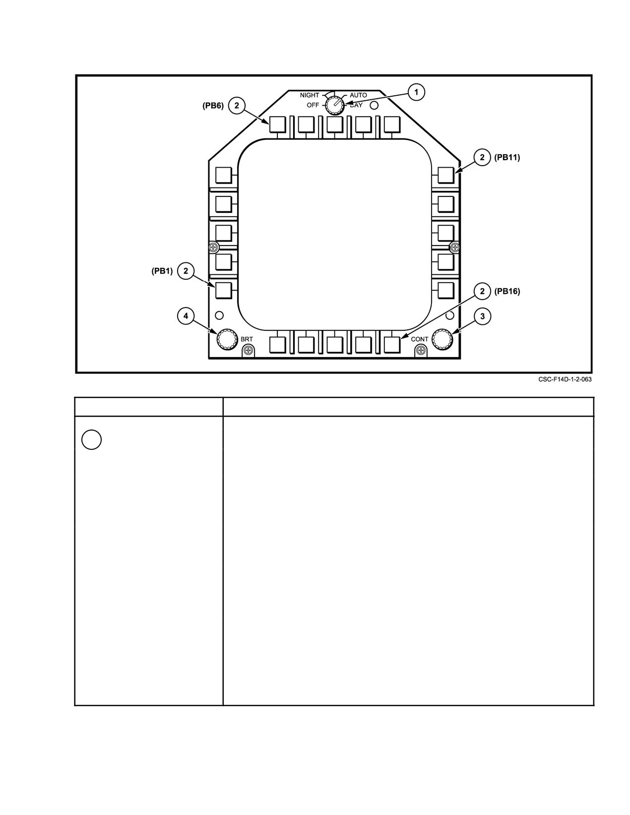
NAVAIR 01−F14AAD−1
NOMENCLATURE
FUNCTION
1
Power switch
OFF Ċ Power removed from MFD.
Note
Selecting NIGHT AUTO, or DAY applies power to the
MFD, however a DP must be on and providing data to
the MFD for a format to be displayed.
NIGHT Ċ Disables automatic contrast adjustment and limits automatic
brightness adjustment to a small percentage of the DAY range.
AUTO Ċ Automatic adjustment of brightness and contrast to compensate
for changing light conditions as seen by sensors above the BRT
and CONT controls.
DAY Ċ Full range of manual brightness and contrast control. Disables
automatic brightness and contrast adjustment.
Figure 2Ć91.ĄMultifunction Display (Sheet 1 of 2)
2−175
ORIGINAL
NAVAIR 01−F14AAD−1
NOMENCLATURE
FUNCTION
2
Pushbuttons
20 momentary contact pushbuttons that provide for selection of display,
operating modes, and system parameters. A selected legend is normally
enclosed by a rectangular box. A dashed rectangular box indicates that a
legend has been selected but is not available.
3
CONT control
Varies the amplitude of the shades of gray. Effects are most visible when
viewing video or raster graphics.
4
BRT (brightness)
Varies intensity of overall display. As brightness is decreased, fewer shades
control
of gray are discernable.
Figure 2−91. Multifunction Display (Sheet 2 of 2)
symbol and cursor designate is activated. Hooking is used to
2.33.7.3
Cursor Hooking Functions
set waypoints on the HSD waypoint format and to select
Spot, symbol, and MFD pushbutton hooks can be
tracks and other symbols, for the purpose of obtaining
performed by the pilot on the HUD or MFD by activation
information, or identifying symbols of interest on the TSD
of the TDC or on the PTID or MFD by the RIO through use
format. The cursor symbol is a small circle inside a larger
of the sensor hand control.
circle when displayed on the MFDs and a circle with four tic
marks extending from the circle inward at 0_, 90_, 180_, and
Normal symbol hooking is accomplished by placing
270_ when displayed on the HUD.
the cursor over the desired symbol using either the TDC or
the SHC and activating the appropriate cursor designate
2.33.7.1
Throttle Designator Controller (TDC)
switch. The hooked symbol brightens and the previously
hooked symbol returns to normal intensity. Symbol hooks are
The pilot controls cursor position with the throttle desĆ
used to display additional information about those symbols
ignator controller. The TDC is a circular disk that is a comĆ
or to designate tracks for functions that are format dependent.
bination fourway force sensor and momentary switch on the
Only HUD, PTID, TSD, and IRST normal format support
outboard throttle grip. Finger pressure on the outer edges of
symbol hooking.
the control will move the cursor in the direction selected.
MFD pushbutton hooks permit remote activation of
When cursor movement exceeds the limit of a display that is
MFD pushbutton functions through the TDC or SHC. They
adjacent to another display (e.g., the right edge of MFD1 or
are accomplished by positioning the cursor over the desired
the bottom of the HUD), the cursor will move to the adjacent
MFD menu choice and activating the cursor designate
display. If the cursor symbol reaches a display limit that is not
switch.
adjacent to another display (e.g., the right edge of MFD2),
the cursor remains at that limit. Depressing and releasing the
2.33.8
Displays, Formats, and Symbology
TDC designates the cursor position.
The paragraphs that follow describe the HUD and MFD
2.33.7.2
RIO Cursor Control
displays. Sample formats from format families are illusĆ
trated, symbols associated with these families are identified
The RIO cursor control is on the sensor hand control.
and defined, and format selection is described.
It consists of a four−position select switch, a two−position
Many symbols are common to more than one format
(half−full action) trigger switch, and a handgrip. When the
family. Once a symbol has been defined for a format family,
top, bottom, or right edge of the select switch is pressed, the
the definition is not repeated when describing other format
DD, PTID, or MFD3, respectively, is selected for cursor disĆ
families. Certain features, such as changes in scaling
play. Pressing the left edge toggles sensor control between
between formats, that are obvious when viewing the display
radar and infrared. The cursor symbol becomes visible when
are not covered.
the trigger switch is pressed to the half−action position. Full
trigger depression designates the cursor position. Cursor
All symbols available to a format are illustrated;
symbol movement is controlled by handgrip movements.
however, they will rarely be displayed at the same time. Not
all formats are illustrated. Where only minor differences
exist, they will be noted. Formats that contain only alphaĆ
numerics are described but are not illustrated.
ORIGINAL
2−176
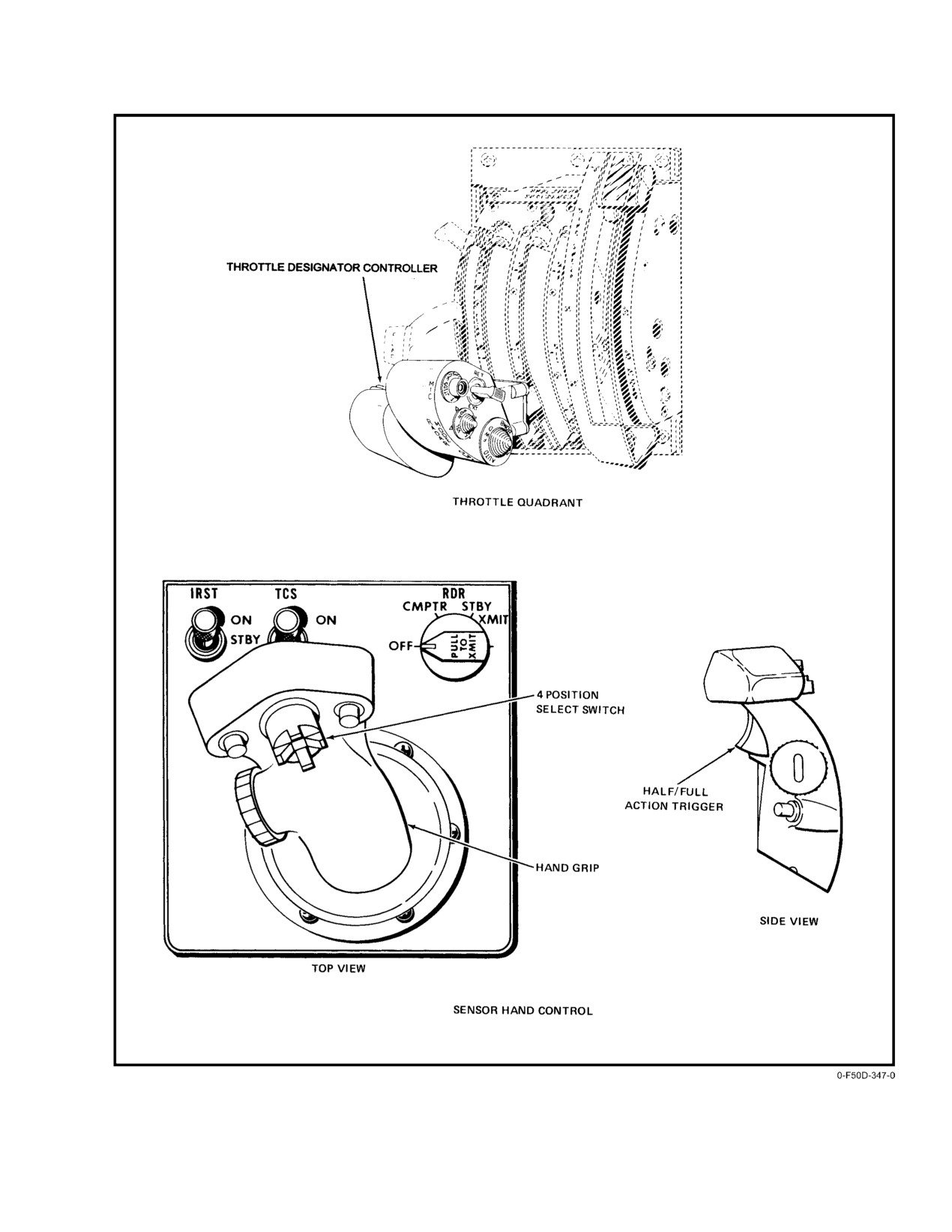
NAVAIR 01−F14AAD−1
Figure 2Ć92.ĄCursor Controls
2−177
ORIGINAL
NAVAIR 01−F14AAD−1
2.33.8.1
Warning, Caution, Advisory Indicators
Note
The large cross that appears on the HUD when
Warnings are displayed on the lower center of the HUD
the HUD PWR switch is set to TEST is generated
viewing area. These warnings are: L FIRE, R FIRE, L
by the HUD, independent of the DP, and is used
STALL, R STALL, and RDC SPD. The CLSN advisory is
to check HUD operation.
also displayed on the HUD. If there are more than two warnĆ
ings, then they will scroll up at the rate of one warning per
The HUD and MFD test patterns also momentarily
second.
appear during IBIT and following a system reset. Both test
patterns are written in stroke and are used to check stroke
On the MFDs, warning/caution/advisory indications
accuracy.
are shown in a viewing window that appears on all formats
except repeats. This window is displayed in the upper left of
The MFD/KROMA test pattern (a future−growth color
the MFD and is referred to as the CAW (Caution Advisory
display) includes an MFD TEST legend, used to select the
Warning) window or CAW box. The message window allows
MFD RASTER test pattern.
up to four CAWs to be displayed at one time. If more than four
The MFD RASTER test pattern allows for testing of
CAWs are to be displayed, they scroll up from the bottom of
individual pushbuttons. When a button is pressed, a solid−line
the window at a rate of one per second. Warning, caution,
box appears around the PRESS legend; pressing the button
advisory legends are independent of format and may be
again removes the box. The diamond and blinking breakĆ
directed to a specific crewmember. Figure 2Ć93 lists specific
away symbol are used to check RASTER accuracy. Numerics
CAWs and the crewmember to whom they are directed.
0 through 7 check RASTER shades of gray. Selecting EXIT
returns the display to MFD/KROMA test pattern.
When warning, caution, or advisories are displayed,
pressing the pushbutton above the CAW window (PB6) will
2.33.8.3
HUD Formats
remove the window and replace it with a boxed CAW legend.
Pressing the CAW pushbutton when the legend is boxed
HUD format category (TLN, A/A, A/G) is normally
returns the window and indications to the display and
selected by use of MODE buttons on the PDCP. However,
removes the box from the legend.
air−to−air formats are selected automatically if the pilot
selects a weapon using the weapon select switch on the stick
Note
grip; selects RDR PLM/PAL, IR PLM/PAL (all with gear up)
with the sensor mode switch; lifts the ACM guard; or if VSL
If a repeat format is on MFD1, the CAW window
HI/VSL LO is selected with the sensor mode switch or DD.
is shifted to MFD2 in its current state, open or
Air−to−ground formats are automatically selected when an
closed (acknowledged). New CAWs continue to
air−to−ground weapon is selected on the SMS format. The
be displayed on MFD2 until the repeat format is
HUD default format is the TLN basic format (Figure 2Ć95).
removed from MFD1. If a repeat format is disĆ
This format is displayed on power−up and if DP1 experiences
played on both MFD1 and MFD2 or on MFD3,
a cold start (power outage of over 1 second).
receipt of CAW data removes the repeat format
from MFD1 and/or MFD3 and displays a new
The amount of information displayed on HUD formats
format with the CAW in the appropriate window.
is pilot selectable by means of the FORMAT and DECLUTĆ
Receipt of a data−link advisory removes the
TER switches on the PDCP. Symbols are also added or
repeat format from MFD1 (if appropriate) and
deleted by the mission computer depending on aircraft status,
MFD3 and displays the menu format with data−
steering mode, and weapon selection. When the FORMAT
link advisories.
(DD and PTID displays are
switch is set to BOTH, airspeed and altitude information are
repeats on MFD1; HUD, DD, and PTID displays
displayed as boxed digital readouts with analog dials. In the
are repeats on MFD2 and MFD3).
ANLG position, the boxes are removed from the digital
readouts. In the DGTL position, only the boxed digital
2.33.8.2
Test Patterns
readout is presented and the analog dials are removed.
The test patterns (Figure 2Ć94) appear on the HUD and
The position of the HUD/VDI ALT switch on the PDCP
MFD when the display system is turned on with the MCs off
selects the type of altitude data that is to be displayed, either
during ground tests and are generated by the DP.
radar or barometric. If radar is selected and a valid
ORIGINAL
2−178
NAVAIR 01−F14AAD−1
ACRONYM
TYPE
AIRCREW
DISPLAY
FUNCTION
L STALL
W
BOTH
HUD/MFD
Warns of left engine stall.
R STALL
W
BOTH
HUD/MFD
Warns of right engine stall.
L FIRE
W
BOTH
HUD/MFD
Warns of fire in left engine.
R FIRE
W
BOTH
HUD/MFD
Warns of fire in right engine.
RDC SPEED
W
PILOT
HUD/MFD
Safe Mach number exceeded for current
position of flaps.
W/S
C
PILOT
MFD
Indicates failure of wingsweep system.
L N2 OSP
C
PILOT
MFD
Indicates overspeed of left rotor N2.
R N2 OSP
C
PILOT
MFD
Indicates overspeed of right rotor N2.
L N1 OSP
C
PILOT
MFD
Indicates overspeed of left rotor N1.
R N1 OSP
C
PILOT
MFD
Indicates overspeed of right rotor N1.
L TBT OT
C
PILOT
MFD
Indicates overtemp of left turbine blade.
R TBT OT
C
PILOT
MFD
Indicates overtemp of right turbine blade.
L FLMOUT
C
PILOT
MFD
Indicates left engine flameout.
R FLMOUT
C
PILOT
MFD
Indicates right engine flameout.
L IGV SD
C
PILOT
MFD
Indicates left inlet guide vane adjust schedule
is not correct.
R IGV SD
C
PILOT
MFD
Indicates right inlet guide vane adjust schedule
is not correct.
A/P REF
A
PILOT
MFD
Indicates autopilot mode is selected but not
engaged.
CLSN
A
PILOT
HUD
Indicates collision course steering to target has
been selected.
IFF ZERO
A
RIO
MFD
Indicates the identification friend or foe
transponder is not operating correctly.
Figure 2Ć93.ĄWarning, Caution, Advisory Functions (Sheet 1 of 3)
2−179
ORIGINAL
NAVAIR 01−F14AAD−1
ACRONYM
TYPE
AIRCREW
DISPLAY
FUNCTION
AAI ZERO
A
RIO
MFD
Indicates the air to air intercept interrogator is
not operating correctly.
SDU ALM
C
RIO
MFD
Indicates the JTIDS Secure Data Unit is not
operating properly or does not contain valid
JTIDS crypto keys. Under certain conditions the
display of this alarm is normal.
ASPJ HOT
C
RIO
MFD
Indicates an overtemp condition of the airborne
self−protection jammer.
JTID HOT
C
RIO
MFD
Indicates an overtemp condition of the JTIDS
R/T.
RWR
C
RIO
MFD
Indicates the radar warning receiver is not
operating correctly.
FWD ASPJ
C
RIO
MFD
Indicates the forward ASPJ is not operating
correctly.
AFT ASPJ
C
RIO
MFD
Indicates the aft ASPJ is not operating corĆ
rectly.
AFT CG
C
BOTH
MFD
Indicates that stores station status has shifted
center of gravity to preclude landing without
correction.
MC 1
C
RIO
MFD
Indicates mission computer 1 is not operating
correctly.
MC 2
C
RIO
MFD
Indicates mission computer 2 is not operating
correctly.
CIU
C
RIO
MFD
Indicates the computer interface unit is not
operating correctly.
MC1 HOT
C
RIO
MFD
Indicates an overtemp condition of the mission
computer #1.
MC2 HOT
C
RIO
MFD
Indicates an overtemp condition of the mission
computer #2.
INS
A
RIO
MFD
Indicates the inertial navigation system is not
operating correctly.
IMU
A
RIO
MFD
Indicates the inertial measurement unit is not
operating correctly.
GPS FAIL
A
RIO
MFD
Indicates the MAGR unit is failed or turned off.
POSITION
A
RIO
MFD
Position differs. Will be displayed if:
D GPS and INS differ by more than 4 nm.
D GPS and SAHRS differ by more than 11 nm.
D SAHRS and INS differ by more than 13 nm.
Figure 2−93. Warning, Caution, Advisory Functions (Sheet 2 of 3)
ORIGINAL
2−180
NAVAIR 01−F14AAD−1
ACRONYM
TYPE
AIRCREW
DISPLAY
FUNCTION
GPS QUAL
A
RIO
MFD
Degradation of GPS occurred so GPS output
is invalid.
VELOCITY
A
RIO
MFD
Feet/second.
CIU HOT
A
RIO
MFD
Indicates an overtemp condition of the CIU.
DP1 HOT
A
RIO
MFD
Indicates an overtemp condition of display
processor 1.
DP2 HOT
A
RIO
MFD
Indicates an overtemp condition of display
processor 2.
SMS HOT
A
RIO
MFD
Indicates an overtemp condition of the stores
management system.
RDR HOT
A
RIO
MFD
Indicates an overtemp condition of the radar
system.
HUD HOT
A
PILOT
MFD
Indicates an overtemp condition of the HUD.
RWR HOT
A
RIO
MFD
Indicates an overtemp condition of the radar
warning receiver.
DSS HOT
A
RIO
MFD
Indicates an overtemp condition of the data
storage system.
DEU HOT
A
RIO
MFD
Indicates an overtemp condition of the data
entry unit.
MPS HOT
A
RIO
MFD
Indicates an overtemp condition of the missile
power supply.
IRSTS HOT
A
RIO
MFD
Indicates an overtemp condition of the infrared
search and track system.
TARPS
A
RIO
MFD
Indicates the tactical air reconnaissance pod
system is not operating correctly.
IPF
A
RIO
MFD
Indicates a failure in the JTIDS R/F output
detected by the JTIDS Interference Protection
Feature.
JTID
A
RIO
MFD
Indicates the joint tactical information distribution
system is not operating correctly.
SAHR HOT
A
RIO
MFD
Indicates an overtemp condition of the standard
attitude heading reference set.
Figure 2−93. Warning, Caution, Advisory Functions (Sheet 3 of 3)
2−181
ORIGINAL
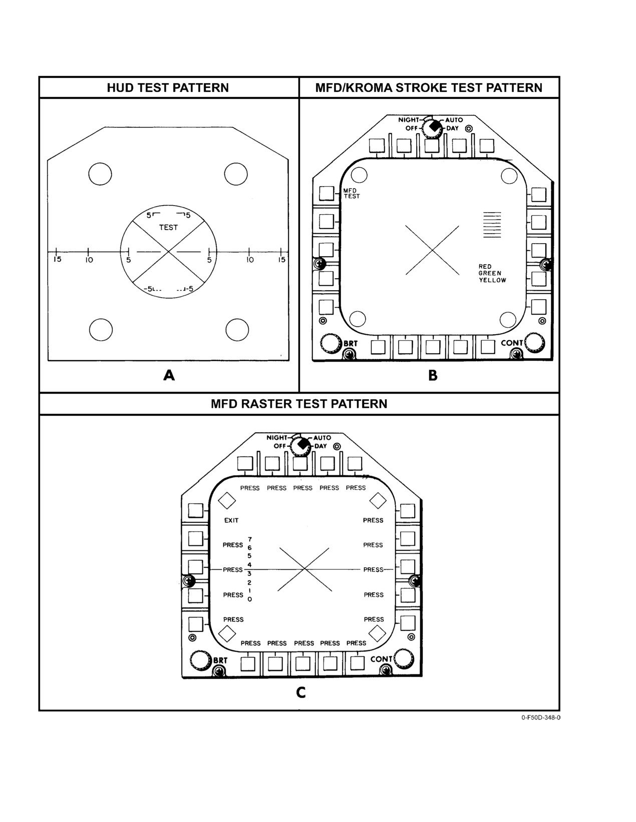
NAVAIR 01−F14AAD−1
Figure 2Ć94.ĄTest Patterns
ORIGINAL
2−182
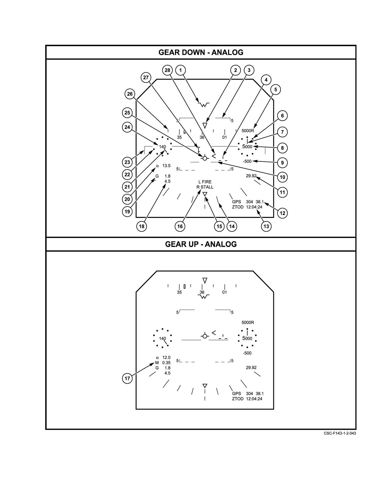
NAVAIR 01−F14AAD−1
Figure 2Ć95.ĄHUD TLN Basic Format (Sheet 1 of 4)
2−183
ORIGINAL
NAVAIR 01−F14AAD−1
SYMBOL
FUNCTION
1
Water line
Indicates fuselage reference line (FRL). Displayed when attitude information
is not valid. Also displayed when gear down or the flight path marker is at,
or beyond the HUD’s full field of view.
2
Heading pointer
Actual aircraft heading is displayed below the stationary heading pointer.
3
Pitch/flight path ladder
Ladder displays aircraft climb/dive angle and roll angle. Aircraft vertical flight
path angle is indicated by the position of the flight path marker on the pitch/
flight path ladder. Positive pitch lines are solid and negative pitch lines are
dashed. To aid in determining flight path angle when it is changing rapidly,
the pitch lines are angled toward the horizon at an angle half that of the
flight path angle. For example, in a 40_ climb, the pitch lines are angled 20_
toward the horizon. "Up" appears at +90_ and "down" appears at −90_.
4
Ghost flightpath marker
Displayed at the true velocity vector position when the flight path marker is
caged and the true velocity vector position differs from the caged position in
azimuth. When the true flight path marker position is actually outside the
HUD total field of view, the symbol will be pegged at the edge of the total
FOV and flash.
5
Radar altitude indicator
Displays radar altitude when the aircraft is below 5000 feet AOL and bank
angle is less than 45_. If RDR is selected as the altimeter source and valid
radar altitude exists, the radar altitude is displayed within the dial, replacing
the barometric altitude. An R is displayed to the right of dial to indicate radar
altitude. If BARO is selected and a valid radar altitude exists, radar altitude
is displayed above the altitude dial or box.
6
Altitude analog dial
The HUD analog altimeter consists of ten dots encircling the altitude readĆ
out. Each dot indicates altitude in hundreds of feet with the zero mark
located at the top center of the dial.
7
Altitude pointer
An analog pointer indicating altitude moves uniformly around the inside of
the altitude dial based on indicated altitude. Increasing altitude is indicated
by clockwise rotation of this pointer.
8
Digital altitude readout
Digital barometric, radar, or GPS altitude is displayed depending on the
source of the data. When the ALT switch is in the BARO position, baroĆ
metric altitude is displayed. When the ALT switch in the RDR position and
if aircraft altitude is 5000 feet or lower, radar altitude is displayed within the
dial and is identified by an R to the right of the least significant digit. If the
radar altitude becomes invalid by exceeding 5000 feet or 45_ AOB, baroĆ
metric altitude is substituted and a B will flash to indicate that barometric
altitude is being displayed rather than radar altitude. A G is only displayed
when SCADC altitude becomes invalid and the GPS altitude is used. The
G acronym will flash if RADALT is selected and both SCADC and radar
altitude are invalid.
9
Vertical velocity readout
The vertical velocity readout consists of a maximum of five digits for a posiĆ
tive vertical velocity indication and a maximum of four digits with a leading
minus sign for a negative vertical velocity indication. If the limit 32,999 or
−9,999 is exceeded, a minus sign with four X’s (−XXXX) is displayed. It is
displayed below the six o’clock dot of the altitude dial.
Figure 2−95. HUD TLN Basic Format (Sheet 2 of 4)
ORIGINAL
2−184
NAVAIR 01−F14AAD−1
SYMBOL
FUNCTION
10
Negative three degree
Indicates the negative 3 degree position on the pitch ladder.
marks
11
Barometric pressure
The barometric pressure setting used by the display system and the weapon
setting
system is the value set on the pilot’s barometric altimeter.
The setting will be displayed for up to 5 seconds on the HUD and VDI
in the TLN mode when the setting is changed. At 18,000 feet, if it is off,
the symbol comes on and blinks for 5 seconds.
12
Navigation source and
WPT, GPS or TCN; waypoint number, range.
range readout
13
Clock/timer readout
Derived from the GPS clock. Default time is ZTOD. Options selectable from
the HSD ZTOD pushbutton are ZTOD, TTG, TTGT, TREL, ETA, ET and CD.
14
Bank scale
Provides indication of bank angle to ±45_. Tick marks are provided at 0_,
±10_, ±20_, ±30_ (slightly larger) and ±45_.
15
Bank angle pointer
Moving pointer provides indication of aircraft bank angle. At bank angles in
excess of ±45_, the pointer will be pegged at ±50_ and will flash.
16
Warning/caution/
The warnings L STALL, R STALL, L FIRE, R FIRE, and RDC SPEED and the
advisory readout
CLSN advisory will appear on the HUD in the steady condition. Up to two
indications may be displayed at any one time. When more than two indicaĆ
tions are present, they scroll up from the bottom at the rate of one
per second.
17
Mach number
Indicates speed of the aircraft in mach.
18
Peak aircraft g
Peak Aircraft g is displayed on the HUD as follows;
TLN Gear Down: If aircraft g falls below +0.0 or exceeds +2.0.
TLN Gear Up, A/A, A/G: If aircraft g falls below −2.0 or exceeds +4.5.
Peak g indication is displayed until a declutter mode is cycled.
19
Aircraft g
Aircraft g is displayed on the HUD as follows;
TLN Gear Down: If aircraft g falls below +0.5 or exceeds +1.5.
TLN Gear Up, A/A, A/G: If aircraft g falls below −2.0 or exceeds +4.5.
20
Angle of attack
Indicates angle of attack in units.
Note
When the TLN gear down format is displayed, the AOA readout is
removed when AOA is between 14 and 16 units. If AOA is greater than
14 units and decreasing, the readout remains off until AOA decreases
below 13 units. If AOA is less than 16 units and increasing, the readout
remains off until AOA increases above 17 units.
21
Airspeed pointer
An analog pointer indicating airspeed moves uniformly around the inside
of the airspeed dial based on indicated airspeed. Increasing airspeed is
indicated by clockwise rotation of the pointer.
22
Airspeed dial
The HUD analog airspeed dial consists of ten dots encircling the airspeed
readout. Each dot indicates airspeed in tens of knots with the zero mark
located at the top center of the dial.
23
Extended horizon line
Represents the horizon with respect to the aircraft and changes orientation
with any change in aircraft pitch or roll.
Figure 2−95. HUD TLN Basic Format (Sheet 3 of 4)
2−185
ORIGINAL
NAVAIR 01−F14AAD−1
SYMBOL
FUNCTION
24
Digital airspeed readout
Provides digital readout of calibrated airspeed.
25
Flight path marker
The flight path marker is displaced in azimuth and elevation to present
computed flight path. Aircraft vertical flight path angle is indicated by the
position of the flight path marker on the pitch/flight path ladder. In the caged
mode, the flight path marker is caged in azimuth and the true flight path
marker position is indicated by the display of the ghost flight path marker
when the true position is more than 2_ from the caged position. The flight path
marker can be caged or uncaged by alternately pressing the CAGE/SEAM
switch. On selection of TLN or A/A, the flight path marker is initially caged;
selection of A/G presents the uncaged mode initially.
26
Heading scale
Aircraft magnetic heading is indicated by the moving 360_ heading scale.
In TLN, the major divisions are numbered every 10 degrees. In A/A, the major
divisions are numbered every 20 degrees.
Note
When the aircraft is in the TLN mode with the gear handle down, the
heading scale remains 2 degrees above the position of the flight path
marker. The lowest point of the heading scale, including the numbers,
will never rise above the normal (gear up) position. The heading scale is
occluded by the altitude and airspeed dials and readout.
27
Angle of attack
The AOA bracket is a pitch related variable that indicates the deviation of the
bracket
current AOA from a desired value and is vertically referenced to the left wing
of the flight path marker symbol. The center of the bracket represents the optiĆ
mum AOA. The bracket moves lower with respect to the flight path marker as
AOA increases and it moves higher as AOA decreases.
28
Potential flight path
Indicates the acceleration along the flight path marker. Provides a graphical
marker (PFPM)
representation of the ability to change the flight path angle by varying the
thrust acceleration and/or angle of attack. Deceleration is indicated by the
PFPM below the flight path marker and acceleration by the PFPM above the
flight path marker.
Figure 2−95. HUD TLN Basic Format (Sheet 4 of 4)
radar altitude exists (altitude < 5,000 feet and AOB < 45_),
2.33.8.3.1
Takeoff/Landing/Navigation Formats
radar altitude is displayed in the center of the altitude dial. If
TLN formats are categorized by the selected steering
the aircraft’s altitude exceeds 5,000 feet or the radar altitude
mode and landing gear position. TLN basic, the HUD default
becomes invalid, the system automatically substitutes baroĆ
format, does not display steering information. Refer to
metric altitude and a B" will flash to the right of the analog
Figure 2−95 for the location and description of TLN basic
dial to indicate radar altitude is not being used. Switching
symbology.
HUD/VDI ALT to BARO removes the flashing B."
Steering mode selection is made through MFD pushĆ
The symbols removed by the DECLUTTER switch
button or cursor designate action on the VDI AWL formats.
vary with formats and are discussed in the applicable paraĆ
TCN, DEST and GPS steering mode selections are also
graphs. Refer to Figure 2Ć96 for declutter information in
available on the HSD by boxing the TACAN data buffer or
TLN−GD, TLN−GU, A/A, and A/G modes.
waypoint data buffer. Making a steering mode selection
changes TLN basic to TLN TCN (TACAN), MAN (manual),
DEST (destination), GPS, D/L (data link), or AWL (all−
weather landing).
ORIGINAL
2−186
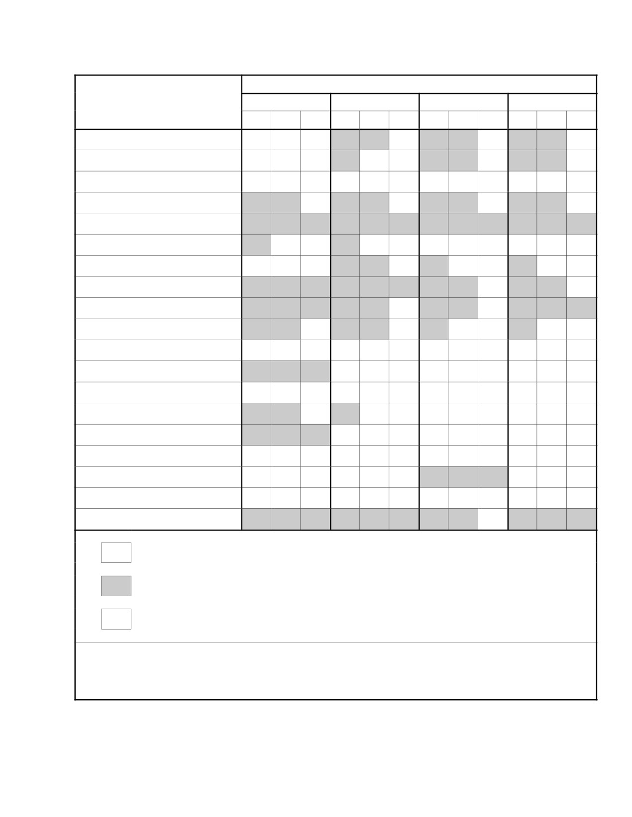
NAVAIR 01−F14AAD−1
HUD MODES/DECLUTTER SWITCH SELECTION
SYMBOL NAME
TLN−GD
TLN−GU
A/A
A/G
N
1
2
N
1
2
N
1
2
N
1
2
MACH*
ÏÏÏÏÏÏ ÏÏÏÏ
ÏÏ
ÏÏÏ
AIRCRAFT G
ÏÏÏÏÏÏÏÏÏÏÏÏÏÏÏÏÏÏÏÏÏÏÏ
PEAK G
ÏÏ
ÏÏÏ
ÏÏÏÏ
ÏÏÏÏÏ
DIGITAL BOXES
Ï
Ï
ANALOG DIALS
AOB SCALE
AOA READOUT
ÏÏÏÏ
HEADING SCALE
NAV RANGE
PFPM
ÏÏÏÏÏÏÏÏÏÏÏÏÏÏÏ
ÏÏÏÏÏ
GHOST FPM
ÏÏÏÏÏÏÏÏÏÏÏÏÏÏÏ
ÏÏÏÏÏ
AOA BRACKET
ÏÏ
ÏÏÏÏÏ
ÏÏÏ
ÏÏÏÏÏ
RADAR ALTITUDE READOUT
ÏÏ
ÏÏÏÏÏ
ÏÏÏ
ÏÏÏÏÏ
Ï
ÏÏ
ÏÏÏ
ÏÏÏÏÏ
VERTICAL VELOCITY
ÏÏÏÏÏÏÏÏÏÏÏÏÏÏÏÏÏÏ
WATERLINE
ÏÏÏÏÏÏÏÏÏÏÏÏÏÏÏÏÏÏÏÏÏÏÏ
A/A RANGE
ÏÏÏÏÏÏ
ÏÏÏ
ÏÏÏÏ
ÏÏÏÏ
ÏÏÏÏÏÏÏÏÏÏÏ
CLOSURE
ÏÏÏÏÏÏÏÏÏÏÏÏÏÏÏÏÏ
TARGET POINTER/AON
ÏÏÏÏÏÏ
PITCH LADDER
*
NOT PRESENT
PRESENT
ÏÏÏ
AS REQUIRED
ÏÏÏ
*Pitch ladder replaced on Spin
Figure 2Ć96.ĄHUD Declutter Levels
2−187
ORIGINAL
NAVAIR 01−F14AAD−1
Steering mode is identified on the HUD by a legend in the
2.33.8.3.2
Air−to−Air Formats
data readout display area. Steering modes are described in
A/A formats (Figure 2Ć99 and Figure 2Ć100) are preĆ
Chapter 20.
sented when the pilot selects the A/A pushbutton on the pilot
displays control panel, when a weapon is selected, the radar
1.
TCN selection adds a course−steering arrow and
hot modes are selected, or when the ACM guard is lifted. The
course−deviation dots. Distance to the TACAN staĆ
A/A formats provide target acquisition, weapon status, and
tion is displayed to the right of the TCN legend.
shoot prompts as well as primary flight information. Target
2.
MAN steering selection adds a commanded heading
data and the selection legends A/A, PH, SP, SW, and G are
marker to the heading scale. The commanded headĆ
displayed. Quantity of the selected weapons is also shown.
ing marker also appears on destination, datalink,
When GUN is selected, the quantity number indicates rounds
and AWL formats.
remaining in hundreds. A large X" through a weapon
selection legend indicates that the master arm switch is
3.
DEST steering selection adds the waypoint destinaĆ
SAFE.
tion range to TLN basic format.
Refer to the Supplemental NATOPS Flight Manual,
NAVAIR 01−F14AAD−1A, for a description of air−to−air
4.
D/L selection displays the range to the data−link
attack.
destination. A large flashing X" will appear in the
center of the display when a data−link waveoff
2.33.8.3.3
Sensor Mode Indications
command is received.
Radar modes are indicated on the HUD via alphaĆ
5.
AWL steering selection provides for the display of
numerics. The radar mode alphanumerics are removed when
ACL and ILS, ACL only, ILS only, or no ACL and
the radar is off or in the computer mode. An X" overlays the
ILS glidepath situation displays. The display of the
mode indication if the IRST is failed (Figure 2Ć99). The radar
HUD flight director glideslope and centerline steerĆ
mode alphanumerics are as follows:
ing can also be independently controlled. Selections
are made via MFD pushbutton activation on the VDI
1.
Hot range while search (HRWS)
AWL format. A large, flashing X" will appear in
the center of the display when a waveoff command
2.
Manual rapid lock−on (MRL)
is received. Distance to the TACAN station is disĆ
played as is the TCN legend.
3.
Pilot automatic lock−on (PAL)
When the landing gear handle is placed in the down
4.
Pilot lock−on mode (PLM)
position, the HUD cage/uncage function is enabled on the
CAGE/SEAM switch located on the inboard throttle, the
5.
Pulse Doppler search (PDS)
system transitions to TLN−GD mode, and all weapon
selections are cleared. In TLN−GD mode, the Mach number
6.
Pulse Doppler single−target track (PDSTT)
is removed and aircraft g is displayed if the g’s fall below
+0.5 or exceed +1.5; peak g is displayed in normal declutter
7.
Pulse search (PS)
mode if aircraft g falls below 0.0 or exceeds +2.0; the horizon
line is extended across the HUD field of view and a flying
8.
Pulse single−target track (PSTT)
W" (waterline) symbol is added at the fuselage reference
9.
Range while search (RWS)
line.
10. Range while search velocity (RWSV)
Note
11. Sniff (SNIFF)
The waterline symbol is also added in other HUD
formats when the flight path marker is at or
12. Standby (STBY)
beyond the HUD field of view or when altitude
data is lost.
13. Track while scan automatic (TWSA)
Figure 2Ć97 shows the symbols that are added during
14. Track while scan manual (TWSM)
TACAN and AWL flight director steering modes, landing
gear down, with digital or analog display selection. Refer to
15. Vertical scan lock−on high (VSLHI)
Figure 2Ć98 for a description of the symbols that are available
for TLN formats.
16. Vertical scan lock−on low (VSLLO).
ORIGINAL
2−188
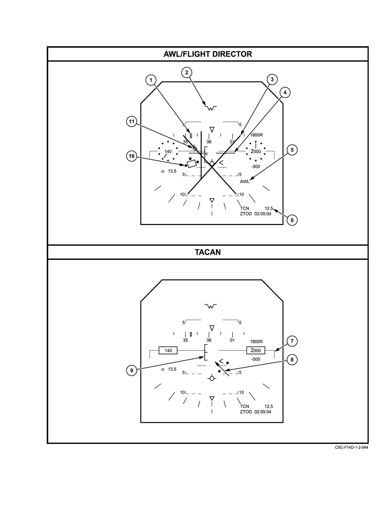
NAVAIR 01−F14AAD−1
Figure 2Ć97.ĄHUD Added Symbology (Sheet 1 of 2)
2−189
ORIGINAL
NAVAIR 01−F14AAD−1
SYMBOL
FUNCTION
1
Command heading
This symbol indicates the heading required to achieve the selected course.
marker
Course selection may be manual, data link commanded, or waypoint destination.
Where commanded heading is beyond display scale limits, the symbol will be
pegged at the nearest edge to the commanded heading. This symbol does not
appear on the basic or TACAN formats.
2
Waterline
Indicates fuselage reference line (FRL). Displayed when attitude information is not
valid. Also displayed when gear down or TLN Gear Up, or the flight path marker is at
or beyond the HUD’s full field of view.
3
Breakaway, waveoff
A large flashing X will appear in both D/L and AWL steering modes if a
WAVEOFF command has been received.
4
ILS precision course
Consists of two independent needles (vertical and horizontal) which form a cross
needles
pointer. The horizontal needle responds to ILS glide slope error and the vertical
needle responds to ILS localizer error. Null/center indications are provided to enable
the pilot to null the error and keep the vertical and horizontal needles centered.
5
AWL legend
This message indicates that the all weather landing steering mode has been
selected.
6
Range
Depending on the format, this message will indicate either the range to the TACAN
station, data link destination or distance to waypoint destination. The legends TCN,
D/L, or WPT may also appear. When in the manual steering mode no range appears
but the MAN legend is displayed.
7
Extended horizon line
Indicates the horizon with respect to the aircraft with landing gear down. Changes
orientation with any change in aircraft pitch and roll.
8
Course arrow and
The course arrow represents the selected course to the TACAN station. Two dots
deviation dots
will appear on the side of the flight path marker toward the course arrow and perpenĆ
dicular to the arrow. The dot closest to the flight path marker represents a half scale
deflection of 4_ off course, while the outermost dot represents full scale deflection
of 8_ off course. When the aircraft crosses the selected course, the arrow moves to
the opposite side of the flight path marker and the dots would appear on that side.
For deviations of more than 9_, the arrow pegs. If the arrow is centered on course,
the dots disappear. Flight path marker centered over the course arrow indicates
being on course. For TACAN bearings aft of ±90_, the arrow will be dashed.
9
Angle−of−attack
The AOA bracket is a pitch−related variable that indicates the deviation of the current
bracket
AOA from a desired value and is vertically referenced to the left wing of the flight
path marker symbol. The center of the bracket represents the optimum AOA.
The bracket moves lower with respect to the flight path marker as AOA increases
and it moves higher as AOA decreases.
10
Flight director
The flight director symbol provides glide slope and centerline steering information
computed by the mission computer using navigation system parameters and
Data Link information from the SPN−42/46 ACLS system. The box with the three
dots will provide the pilot with optimal glide path intercept and following when the
flight path marker is inside the flight director box and the three dots are aligned with
the wings and the tail of the flight path marker. The same procedures are used
whether the flight path marker is caged or uncaged. The flight director symbol is
removed from the HUD when the FLT DIR pushbutton on the VDI is unboxed.
11
ACL steering indicator
Provides ACL steering commands driven by the ASW−27C data link.
Figure 2−97. HUD Added Symbology (Sheet 2 of 2)
ORIGINAL
2−190
NAVAIR 01−F14AAD−1
FORMAT
SYMBOL
DATA
BASIC
AWL
LINK
DESTINATION
MANUAL
TACAN
Aircraft G Readout
(On all formats except GEAR DOWN & DECLUTTERć2)
Airspeed Dial
(On all formats except DIGITAL)
Airspeed Readout Box
(On all formats except ANALOG or DECLUTTERć2)
Airspeed Readout
(On all formats)
Altitude Dial
(On all formats except DIGITAL)
Altitude Readout Box
(On all formats except ANALOG or DECLUTTERć2)
Altitude Readout
(On all formats)
AnglećofćAttack Readout
(On all formats except DECLUTTERć2)
Bank Scale
(On all formats except DECLUTTERć1 and 2)
Baro Setting Readout (5 sec)
+
+
+
+
+
+
Ghost flight path marker
+
+
+
+
+
+
Extended Horizon Line
(On all formats when GEAR DOWN)
Heading Scale
+
+
+
+
+
+
Horizon
(On all formats when GEAR UP)
Reference Markers
+
+
+
+
+
+
Mach Readout
(On all formats except GEAR DOWN and GEAR UP DECLUTTERć2)
Peak A/C G Readout
(On all formats except DECLUTTERć1 and 2)
Pitch Ladder ć TLN
+
+
+
+
+
+
Radar Altitude Readout
(On all formats except GEAR DOWN DECLUTTERć1 & 2 and GEAR UP
DECLUTTERć2)
Flight Path Marker
+
+
+
+
+
+
Vertical Velocity Readout
(On all formats except DECLUTTERć1 & 2 in GEAR UP and DECLUTTERć2
in GEAR DOWN)
Clock/Timer Readout
(On all formats except DECLUTTERć2)
Figure 2Ć98.ĄHUD Symbology Available on TLN Formats (Sheet 1 of 2)
2−191
ORIGINAL
NAVAIR 01−F14AAD−1
FORMAT
SYMBOL
DATA
BASIC
AWL
LINK
DESTINATION
MANUAL
TACAN
Waterline
(On all formats or when flight path marker pegged or altitude data invalid)
Altitude Source ć B, R, or G
+
+
+
+
+
+
HUD Cursor
+
+
+
+
+
+
Potential Flight Path Marker
(On all formats except DECLUTTERć2)
Angle of Attack Bracket
(On GEAR DOWN only. All formats)
IRST Pointer
+
+
+
+
+
+
TCS Pointer
+
+
+
+
+
+
Caution/Advisory/Warning
+
+
+
+
+
+
Breakaway Symbol
o
+
+
o
o
o
Command Heading Marker
o
+
+
+
+
o
HUD Steering Legend ć AWL
o
+
o
o
o
o
HUD Steering Legend ć TCN
o
+
o
o
o
+
HUD Steering Legend ć D/L
o
o
+
o
o
o
HUD Steering Legend ć MAN
o
o
o
o
+
o
HUD Steering Legend ć WPT
o
o
o
+
o
o
ILS Precision Course Needles
o
+
o
o
o
o
Range Readout
o
+
+
+
o
+
ACL Steering Indicator Tadpole
o
+
o
o
o
o
Flight Director
o
+
o
o
o
o
Course Arrow & Deviation Dots
o
o
o
o
o
+
Notes:
+ indicates that the symbol is available for display on the selected format.
o indicates that the symbol is not available for display on the selected format.
Figure 2−98. HUD Symbology Available on TLN Formats (Sheet 2 of 2)
ORIGINAL
2−192
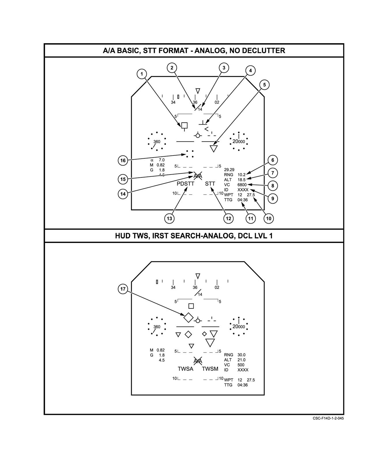
NAVAIR 01−F14AAD−1
Figure 2Ć99.ĄHUD A/A Search Formats (Sheet 1 of 2)
2−193
ORIGINAL
NAVAIR 01−F14AAD−1
NOMENCLATURE
FUNCTION
1
Radar target
Indicates the radar line of sight (LOS) to the target. Symbol is displayed on all
designator and target
A/A weapon modes when radar is tracking a target. The symbol is positionable
aspect
over the total HUD field of view (FOV). When the target moves beyond the
FOV limits of the HUD, the symbol will peg and flash. In STT, target aspect is
represented by a pointer which points in the direction of the aspect angle.
Zero target aspect is straight down.
2
Target pointer
Indicates the direction of the target designator (TD) box position on the HUD.
The target pointer is present when pointing to a TD box under the following
conditions: 1) FONO 1 track is outside the IFOV (Instantaneous Field of View).
2) PTID hooked track is outside the IFOV with no FONO 1 present. 3) Closest
TMA is outside the IFOV and there is no FONO 1 PTID hooked track.
3
Angle−off−the−nose
The angle−off−the−nose (AON) indicator defines the angle between the FRL
indicator
and the target line of sight that the target pointer is pointing to, in the plane
described by the FRL and the target pointer. When the target designator is
being pointed to by the target pointer, a three digit readout is displayed
indicating the AON of that target. The AON indicator is not earth stabilized.
The AON readout is centered below the origin of the target pointer and is
given in degrees.
4
Steering tee
Provides azimuth steering only, in search mode. Provides elevation and
azimuth steering in track mode.
5
IRST symbol
Indicates IRST target location. Up to four displayed.
6
Target range
Range of closest radar target in nautical miles and tenths. Numeric is disĆ
played only when range is valid.
7
Target altitude
Altitude of closest radar target in thousands of feet. Displayed only when
information is valid.
8
Target closing velocity
Displays closing rate to radar target. A minus sign indicates an opening
velocity.
9
Target ID
Target ID display.
10
Navigation data
Displays steering mode, waypoint selected or range (DEST or D/L).
11
Clock/timer readout
TTG is selected from the HSD ZTOD pushbutton, and indicates time−to−go to
read designated waypoint.
12
IRST mode indicator
Displays current IRST mode.
13
Radar mode indicator
Displays current radar mode.
14
Weapon select legend
Displays missile type and quantity, if selected, or gun and rounds remaining,
in hundreds. If no weapon is selected, displays A/A.
15
Master arm safe cue
A large X through the A/A or weapon select legend indicates the Master Arm
Switch is in SAFE.
16
TCS pointer
Indicates TCS track location.
17
NCTR
Indicates non−cooperative target recognition is available.
Refer to NAVAIR 01−F14AAD−1A.
Figure 2−99. HUD A/A Search Formats (Sheet 2 of 2)
ORIGINAL
2−194
NAVAIR 01−F14AAD−1
FORMAT
PHOENIX
SPARROW
SIDEWINDER
GUN
BASIC
SEARCH
TRACK
SEARCH
TRACK
SEARCH
TRACK
SYMBOL
MMGS
BACKUP
Aircraft G Readout
+
+
+
+
+
+
+
+
+
Airspeed Dial
(On all formats except DIGITAL)
Airspeed Readout Box
(On all formats except ANALOG & DECLUTTERć2)
Airspeed Readout
(On all formats)
Altitude Dial
(On all formats except DIGITAL)
Altitude Readout Box
(On all formats except ANALOG & DECLUTTERć2)
Altitude Readout
(On all formats)
Angle of Attack Readout
(On all formats except DECLUTTERć2)
Baro Setting Readout
+
+
+
+
+
+
+
+
+
Clock/Timer Readout
(On all formats except DECLUTTERć2)
Ghost Flight Path Marker
(On all formats except DECLUTTERć2)
Heading Scale
(On all formats except DECLUTTER 1 & 2)
Horizon
+
+
+
+
+
+
+
+
+
Reference Markers
+
+
+
+
+
+
+
+
+
Mach Readout
(On all formats except DECLUTTERć2)
Peak A/C G Readout
(On all formats except DECLUTTERć2)
+
+
+
Pitch Ladder
(On all formats except DECLUTTERć1 & 2)
Radar Altitude Readout
(On all formats except DECLUTTERć1 & 2)
Flight Path Marker
+
+
+
+
+
+
+
+
+
Waterline
(On all formats when flight path marker pegged, gear is down, or altitude information is
invalid.)
Altitude Source ć B or R
+
+
+
+
+
+
+
+
+
HUD Cursor
+
+
+
+
+
+
+
+
+
IRST Pointer
+
+
+
+
+
+
+
+
+
TCS Pointer
+
+
+
+
+
+
+
+
+
Caution/Advisory/Warning
+
+
+
+
+
+
+
+
+
Breakaway Symbol
+
+
+
+
+
+
+
+
+
Command Heading Marker
+
+
+
+
+
+
+
+
+
Select Legends,
A/A
PH#
PH#
SP#
SP#
SW#
SW#
G#
G#
Weapon ć Qty
Figure 2Ć100.ĄHUD Symbology Available on A/A Formats (Sheet 1 of 2)
2−195
ORIGINAL
NAVAIR 01−F14AAD−1
FORMAT
PHOENIX
SPARROW
SIDEWINDER
GUN
SEARCH
TRACK
SEARCH
TRACK
SEARCH
TRACK
SYMBOL
BASIC
MMGS
BACKUP
Master Arm Switch Safe
+
+
+
+
+
+
+
+
+
Cue
Target Range ć RNG, #
+
o
+
o
+
o
+
o
+
Target Range Indicator
+
o
+
o
+
o
+
o
o
Waypoint Select
o
+
o
+
o
+
o
o
o
Steering Tee
+
o
+
o
+
o
+
o
o
Target Designator
+
o
+
o
+
o
+
+
o
Target Closing Velocity
+
o
+
o
+
o
+
o
o
Target Altitude
+
o
+
o
+
o
+
o
o
Target ID
+
o
+
o
+
o
+
o
o
TACAN Digital Readout
o
+
o
+
o
+
o
o
o
Flood Illumination Pattern
o
o
o
+
o
o
o
o
o
Sidewinder Seeker Circle
o
o
o
o
o
+
+
o
o
SHOOT Cue
o
o
+
o
+
o
+
o
o
Reticle
o
o
o
o
o
o
o
+
o
Reticle A
o
o
o
o
o
o
o
+
o
Reticle B
o
o
o
o
o
o
o
+
o
Target Range Tape
o
o
o
o
o
o
o
+
o
Target Lead Cue
o
o
o
o
o
o
o
+
o
BATR Symbol
o
o
o
o
o
o
o
+
o
Gun Mode
o
o
o
o
o
o
o
o
+
Indication ć MAN
Reticle Depression ć #
o
o
o
o
o
o
o
o
+
A/A Gun/Backup Mode
o
o
o
o
o
o
o
o
+
Reticle
Notes:
+ indicates that the symbol is available for display on the selected format.
o indicates that the symbol is not available for display on the selected format.
Figure 2−100. HUD Symbology Available on A/A Formats (Sheet 2 of 2)
ORIGINAL
2−196
NAVAIR 01−F14AAD−1
IRST modes are indicated on the HUD via alphaĆ
format (Figure 2Ć104) allowing gun aiming by displaying the
numerics. The IRST mode alphanumerics are removed when
A/A gun/backup mode reticle. The reticle depression angle,
the IRST is failed. The IRST alphanumerics are as follows:
adjusted by the ELEV LEAD knob on the PDCP is shown in
the lower right corner of the HUD along with the MAN
1. Cooldown (COOL)
gun−mode indication.
2. Hot IR (HOTIR)
2.33.9
MFD Formats
3. Pilot automatic lock−on (PAL)
Initial turn on or a cold start (defined as a system reset
or a MCS power outage of at least 300 milliseconds) causes
4. Pilot lock−on mode (PLM)
the following default formats to be displayed: With gear
down and weight on wheels, VDI/TLN basic on MFD1, OBC
5. Single−target track (STT)
basic on MFD2, and OWN A/C on MFD3; with gear down
and weight off wheels, VDI/TLN basic on MFD1, HSD on
6. Standby (STBY)
MFD2, and HSD on MFD3; and with gear up and weight off
wheels, TSD on MFD1, HSD on MFD2, and HSD on MFD3.
7. Track while scan automatic (TWSA)
The actual format displayed on MFD3 depends on the
navigation mode selected and the conditions existing at the
8. Track while scan manual (TWSM).
time. If the NAV MODE switch is at OFF, the OWN A/C
basic format is displayed.
2.33.8.3.4
Air−to−Ground Formats
MFD3 may also act as a controller of the DEU in that,
Pushbutton selection on the PDCP or selection of an
when certain formats are being displayed on MFD3, the DEU
air−to−ground weapon places the A/G basic format on the
is commanded to display corresponding slaved formats.
HUD (Figure
2Ć101 and Figure 2Ć102). The A/G basic
Refer to Figure 2Ć105 for a listing of MFD3/DEU slaved
format can display waypoint and TACAN information. A/G
control conditions.
DECLUTTER and ANLG and DGTL displays are similar to
A/A formats. Refer to the Supplemental NATOPS Flight
With the exception of high−priority formats (ECM and
Manual, NAVAIR 01−F14AAD−1A.
spin), which appear when required, most MFD formats are
selectable by means of MFD pushbutton or cursor designaĆ
2.33.8.4
Overlay Symbology
tion. The actual format that will appear may depend on other
factors, however, such as master mode selection, aircraft
Symbology (Figure 2Ć103) may be overlaid on disĆ
state (TLN, A/A, or A/G), steering mode selection, and the
played HUD formats when additional information is
alignment condition. The MENU legend appears on every
required. These include RECON, TWS, and IRST TWS.
MFD format except for HUD, DD, and PTID repeats. These
RECON, used with the TARPS pod, is selected as an
repeat formats do not display selections; pressing any
overlay from the MFD RECON formats. This overlay adds
pushbutton when in a repeat mode will place MENU1 on the
the RECON command heading marker, command ground−
MFD. The MENU legend is located above the center
track line, RECON steering symbol, target−designator hexaĆ
pushbutton on the lower edge of the MFDs. Also appearing
gon, and camera selection legend.
on every MFD format are the SMS and ECM pushbutton
legends (Figure 2Ć106).
Radar track while scan adds up to four radar target
diamonds that indicate the four closest targets. Size of the
Repeated depressions of the ECM or SMS pushbuttons
symbols indicates relative proximity (i.e., the largest is the
toggle between these formats and the previously selected
closest). The four symbols are of preset sizes, not scaled to
display. This permits the crew to quickly check ECM or SMS
reflect actual distances.
conditions without having to reselect previous formats.
The infrared search and tracking system TWS adds up
Selecting MENU places menu 1 on the display. The
to four triangular IRST symbols to existing formats. Unlike
legend reads MENU1 and is enclosed by a rectangular box.
TWS, these symbols are all the same size. Both IRST and
Selecting MENU1 when it is boxed places menu 2 on the
TWS symbols are added automatically when a target is being
display with the legend MENU2 displayed in the box. The
tracked.
MENU pushbutton toggles between MENU1 and MENU2.
Menu selection changes the pushbutton legend but does not
2.33.8.5
Manual Reticle
alter the display being presented.
If the mission computer loses communication with
both DPs, the DP driving the HUD provides a manual reticle
2−197
ORIGINAL
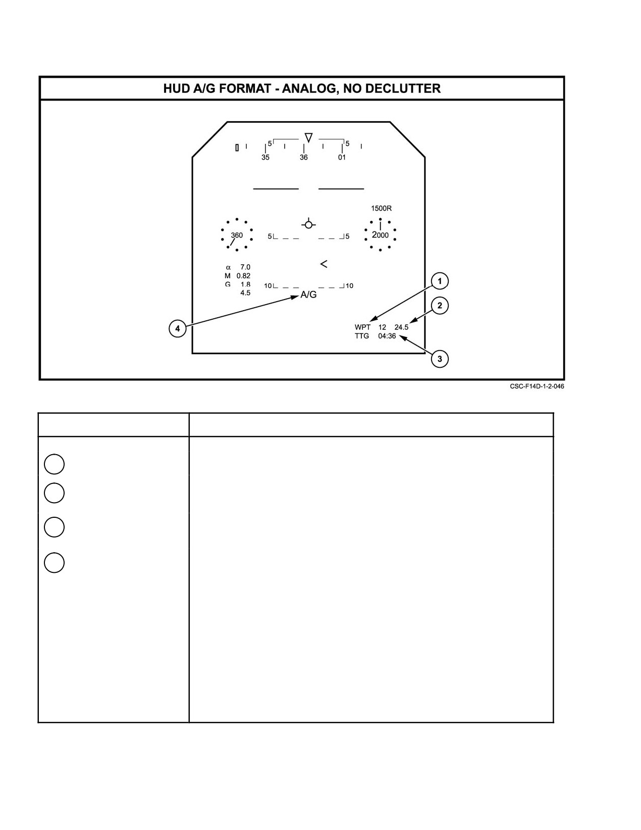
NAVAIR 01−F14AAD−1
NOMENCLATURE
FUNCTION
1
Waypoint select
Displays destination waypoint selection.
2
Range to waypoint
Displays range to selected waypoint.
readout
3
Clock/timer readout
TTG to reach designated waypoint (based on HSD format clock/timer
select [PB7]).
4
Select legend
Displays mode/weapon selected. Will display A/G If no weapon has been
selected.
Figure 2Ć101.ĄHUD A/G Basic Format
ORIGINAL
2−198
NAVAIR 01−F14AAD−1
FORMAT
SYMBOL
BASIC
CCIP
MANUAL
Aircraft G Readout
o
o
o
Airspeed Dial
(On all formats except DIGITAL)
Airspeed Readout Box
(On all formats except ANALOG & DECLUTTER − 2)
Airspeed Readout
(On all formats)
Altitude Dial
(On all formats except DIGITAL)
Altitude Readout Box
(On all formats except ANALOG & DECLUTTER − 2)
Altitude Readout
(On all formats)
Angle of Attack Readout
(On all formats except DECLUTTER − 1 & 2)
Baro Setting Readout
+
+
+
Clock/Timer Readout
(On all formats except DECLUTTER − 2)
Ghost flight path marker
(On all formats except DECLUTTER − 2)
Heading Scale
(On all formats except DECLUTTER − 2)
Horizon
+
+
+
Reference Markers
+
+
+
Mach Readouts
(On all formats except DECLUTTER − 2)
Peak A/C G Readout
(On all formats except DECLUTTER − 2)
Pitch Ladder
(On all formats)
Radar Altitude Indicator
(On all formats except DECLUTTER − 2)
Flight Path Marker
+
+
+
Altitude Source−B or R
+
+
+
HUD Cursor
+
+
+
Figure 2Ć102.ĄHUD Symbology Available on A/G Formats (Sheet 1 of 2)
2−199
ORIGINAL
NAVAIR 01−F14AAD−1
FORMAT
SYMBOL
BASIC
CCIP
MANUAL
IRST Pointer
+
+
+
TCS Pointer
+
+
+
Caution/Advisory/Warning
+
+
+
Breakaway Symbol
o
+
o
Command Heading Marker
+
+
+
Select Legends, Weapon ć Qty
A/G
G
G
Master Arm Switch Safe Cue
+
+
+
Pull Up Cue
o
+
o
Waypoint Select
+
+
+
Steering Tee
+
+
+
TACAN Digital Readout
+
+
+
Gun Mode Indication
o
CCIP
MAN
Gun Rounds Remaining (100’s)
o
+
+
Max. Gun Firing Range
o
+
o
Reticle
o
+
+
Target Range Tape
o
+
o
Reticle Depression Numerics
o
o
+
Notes:
+ indicates the symbol is available for display on the selected format.
o indicates that the symbol is not available for display on the selected format.
Figure 2−102. HUD Symbology Available on A/G Formats (Sheet 2 of 2)
ORIGINAL
2−200
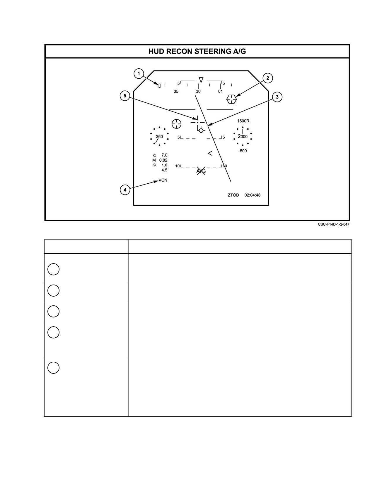
NAVAIR 01−F14AAD−1
SYMBOL
FUNCTION
1
Recon command
Indicates the magnetic heading to the dynamic steering point or commanded
heading marker
heading in the 90 deg − 270 deg maneuver during map steering.
2
Target designator,
Displays target position. Positioned by on−board sensors or data link.
hexagon
3
Command ground
Displays the path of the command ground track.
track line
4
Camera selection
Displays the camera operational mode. First letter indicates frame position:
legend
V = vertical, forward, or blank. Second letter indicates pan position:
C = center, R = right, L = left, or blank. Third letter indicates IRLS position:
N = narrow field of view, W = wide field of view, S = standby, or blank.
5
Recon steering
Provides elevation and azimuth steering information.
symbol
Figure 2Ć103.ĄHUD Overlay Formats
2−201
ORIGINAL