F-14D. FLIGHT MANUAL (2004) - page 2
NAVAIR 01−F14AAD−1
CHAPTER 1
Aircraft and Engine
1.1
AIRCRAFT
areăcarried on the movable portion of the wing. The fuel
system incorporates both in−flight and single−point ground
The F−14D aircraft is a supersonic, two−place, twin−
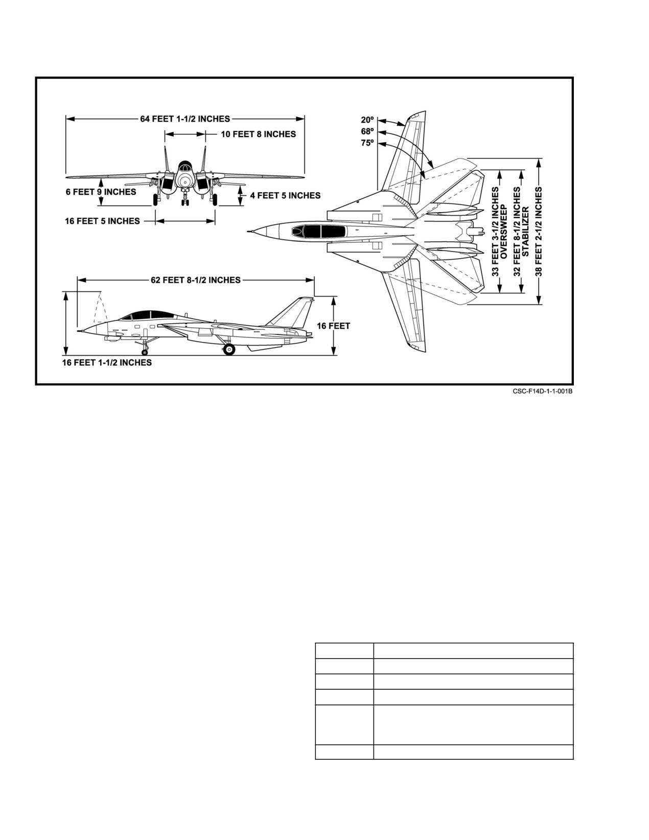
refueling capabilities. Aircraft general dimensions are shown
engine, swing−wing, air−superiority fighter designed and
in Figure 1Ć1. FO−1 shows the general placement of comĆ
manufactured by Grumman Aerospace Corporation. In addiĆ
ponents within the aircraft. A summary of aircraft limitaĆ
tion to its primary fighter role, carrying missiles (Sparrow
tionsăand characteristics are shown in Figure 1Ć2. Refer to
and/or Sidewinder) and an internal 20−mm gun, the aircraft
Chapter 4 for detailed information on operating limitations.
is designed for fleet air defense
(Phoenix missiles) and
ground attack
(general purpose and precision ordnance)
1.1.1
Aircraft Weight
missions. Armament and peculiar auxiliaries used only durĆ
ing secondary missions are installed in low−drag, external
The basic weight of the aircraft is approximately
configurations. Mission versatility and tactical flexibility are
43,735 pounds, which includes trapped fuel, oil, gun, and
enhanced through independent operational capability or
pylons. Consult the applicable Handbook of Weight and
integration under existing tactical data systems.
Balance (NAVAIR 01−1B−40) for the exact weight of any
series aircraft.
The forward fuselage, containing the flightcrew and
electronic equipment, projects forward from midfuselage
1.1.2
Cockpit
and wing glove. Outboard pivots in the highly swept wing
glove support the movable wing panels, which incorporate
The aircraft accommodates a pilot and RIO in a tandem
integral fuel cells and full−span leading−edge slats and
seating arrangement. To maximize external field of view,
trailing−edge flaps for supplemental lift control. In flight, the
stations within the tandem cockpit are prominently located
wings may be varied in sweep, area, camber, and aspect
atop the forward fuselage and enclosed by a single clamshell
ratioăby selection of any leading−edge sweep angle between
canopy. Integral boarding provisions to the cockpit and
20_ and 68_. Wing sweep can be automatically or manually
aircraft top deck are on the left side of the fuselage. Each
controlled to optimize performance and thereby enhance airĆ
crewăstation incorporates a rocket ejection seat that is
craft versatility. Separate variable−geometry air inlets, offset
vertically adjustable. A single environmental control system
from the fuselage in the glove, direct primary airflow to two
provides conditioned air to the cockpit and electronic bays
F110−GE−400 dual−axial compressor, turbofan engines
for pressurization and air−conditioning. Oxygen for breathĆ
equipped with afterburners for thrust augmentation. The disĆ
ing is supplied to the crew under pressure from an on−board
placed engine nacelles extend rearward to the tail section,
oxygen generating system with stored gaseous oxygen as
supporting the twin vertical tails, horizontal tails, and venĆ
backup. The cockpit arrangement provides minimum dupliĆ
tralăfins. The middle and aft fuselage, which contains the
cation of control capability, thereby necessitating two airĆ
main fuel cells, tapers off in depth to the rear where it
crew for safe flight.
accommodates the speedbrake surfaces and arresting hook.
All control surfaces are positioned by irreversible hydraulic
1.1.2.1
Pilot Cockpit
actuators to provide desired control effectiveness throughout
the flight envelope. Stability augmentation features in the
The forward station of the cockpit is arranged and
flight control system enhance flight characteristics and
equipped for the pilot (FO−3). In addition to three electronic
thereby provide a more stable and maneuverable weapons
displays for viewing tactical, flight, navigational, and ECM
delivery platform. The tricycle−type, forward−retracting
data, the pilot instrument panel also contains armament conĆ
landing gear is designed for nosegear catapult launch and
trols, flight and engine instruments. Engine controls, fuel
carrier landings. Missiles and external stores are carried from
management, auxiliary devices, autopilot, and communicaĆ
eight hardpoint stations on the center fuselage between the
tion control panels are on the left console. Display, power,
nacelles and under the nacelles and wing glove; no stores
lighting, and environmental controls are on the right console.
1−1
ORIGINAL
NAVAIR 01−F14AAD−1
Figure 1Ć1.ĄAircraft Dimensions
1.1.2.2
RIO Cockpit
tions. The following are types of technical directives used in
this manual:
The aft station of the cockpit is equipped for the RIO
AAC
Aviation Armament Change
(FO−4). This instrument panel contains controls and three
electronic displays for the radar, tactical, and navigational
ACC
Aircrew System Change
flight instruments. Armament controls, sensor controls, and
AFC
Airframe Change
communication panels are on the left console. The right
console contains a navigational display, data entry unit,
AVB
Avionics Bulletin
ECMăcontrols, data−link controls, lighting controls, and the
AVC
Avionics Change
IFF panel.
AYC
Accessories Change.
1.1.3
Electronic Nomenclature
1.1.5
Block Numbers
Figure 1Ć3 is an alphabetical listing of the tactical,
The following production block numbers include the
communication, navigation, flight control, and instruments
indicated aircraft serial numbers (BuNo). Selected aircraft in
in the aircraft.
blocks 85 and 110 have been updated to create the F−14D/
block 170 configuration.
1.1.4
Technical Directives
Block No.
Serial No. (BuNo)
As technical changes are made to the aircraft, those that
160
163412 − 163418
affect aircraft operation or pilot and RIO need−to−know
165
163893 − 163904
operation will be incorporated in the appropriate sections and
listed in the Summary of Applicable Technical Directives in
170
164341 − 164351 and 164599 − 164604
the front of this manual. In some instances, technical
85
159592, 159595, 159600, 159603,
directives may be incorporated in the aircraft while it is still
159610, 159613, 159618, 159619,
on the production line. Check the Technical Directives
159628 − 159630
Section of the Aircraft Log Book for applicable modificaĆ
110
161159, 161163, 161166.
ORIGINAL
1−2
NAVAIR 01−F14AAD−1
F−14D AIRCRAFT CHARACTERISTICS AND LIMITATIONS
Aircraft Dimensions
Starter Cranking Limits
Length
62′
8.5″
Cross bleed
2 min continuous then 10 min off
Height (Tail)
16′
0″
Start Cart
5 min continuous then 10 min off
Wingspan @ 20_ wingsweep
64′
1.5″
Wingspan @ 68_ wingsweep
38′
2.5″
Idle
Wingspan in oversweep
33′
3.5″
Wing Area
565 sq/ft
RPM = 62
− 78%
OIL PRESS = 15
− 45 psi
EGT = 350
− 650_C
NOZ POS = 100%
Gross Weights
FF = 950 − 1400 PPH
HYD PRESS = 3000 psi
Empty A/C (w/crew & trapped fuel)
43,735 lbs
MIL (and above)
Catapult
76,000 lbs
Field takeoff
72,000 lbs
RPM = 95 − 104%
OIL PRESS = 25 − 65 psi
Min descent rate landing (350 fpm)
72,000 lbs
EGT = 780− 935_C
NOZ POS INFLIGHT:
Field landing (max 500 fpm ROD)
60,000 lbs
MIL = 3 − 10%
Carrier/FCLP land
54,000 lbs
Min AB = 5 − 12%
Max AB = 60 − 90%
T/O & Land Flap/Slat Transition Limits
Ground Start Malfunctions
AOB < 45_
HOT START:
890_C (will normally peak
ROLL SAS ON
@ 30 − 40% RPM)
Min 200′ AGL for flaps/slats up on takeoff
HUNG START: Hung RPM below 63% with rising EGT
Min 800′ AGL for dirty−up
WET START: No lightoff within 20 sec of
Min 180 kts for retraction of flaps
throttle to IDLE
12 units AOA for all transitions
225 kts
max flap/slat speed
INST Test
280 kts
max landing gear speed
RPM
=
96%
Landing & Braking
EGT
=
950 ± 10_C
(initiates engine overtemp alarm)
15 kts
min speed for antiskid operation
FF
=
10,500 pph
145 kts
max wheel braking (51.0 k A/C)
AOA
=
18 ± 0.5 UNITS
165 kts
max wheel braking (46 k A/C)
W/S
=
45 ± 2.5
190 kts
max tire speed
FUEL
=
2,000 ± 200# (all tapes and windows)
145 kts
max E 5 engagement speed (69.8 k A/C)
LIGHTS:
L and R FUEL LOW
175 kts
max E−28 engagement speed
20 kts
max 90_
crosswind
component
60 kts
max canopy open
Oil System
Engine Speeds (RPM)
Normal Range
25− 65 psi
10% Ignition system becomes operative
Min (stabilized idle)
15 psi
30 − 46% Engine crank switch will not engage
Oil pressure light
on
@
11 psi decreasing
20% Min RPM with throttle at idle
off @ 14 psi increasing
30% Max RPM with pneumatic starter
30% RPM must fall below for generator
Pneumatic Pressure
auto−reset
50% Engine crank switch automatically shuts off
60% Generator comes on line
Min auxiliary canopy (3000 psi)
800 psi
50% Generator light illuminates (if RPM falling)
Min normal canopy (3000 psi)
1200 psi
60% Ensure engine crank off (osp/valve)
CHS
accumulator
1800 psi
62
− 78% Normal idle
FHS accumulator
1800 psi
Min emergency gear preflight
3000
psi
75 − 90% Auto throttle range
95
− 104% MIL & above
Min emergency gear extension
1800 psi
Wheel brake accumulat
or (2
gages)
1900
± 50
psi
107.7% Overspeed (chevrons flash)
Arresting hook dashpot
800 ± 10 psi
110.0% Engine secures (f
uel shutoff)
Figure 1Ć2.ĄCharacteristics and Limitations (Sheet 1 of 2)
1−3
ORIGINAL
NAVAIR 01−F14AAD−1
F−14D AIRCRAFT CHARACTERISTICS AND LIMITATIONS (CONTINUED)
Fuel System
In−Flight Refueling
Aft−Left Tank Group Capacity
5900 − 6200 lbs
170 − 200
Approach configuration
Fwd−Right Tank Group Capacity
6300 − 6600 lbs
200 − 300/0.8 TMN
Cruise configuration
Max split between cockpit totals
300 lbs
400/0.8 TMN
Max IFR probe speed
Fuel dump rate
1500 lbs/min
Fuel dump au
to shutoff with
4000 lbs remaini
ng
Ground refuel rate @ 50 psi
450 gal/min
SAS Stability Augmentation System
In−flight refuel rate @ 57 psi
475 gal/min
FCS CAUTION:
Airspee
d
< 600 kts/1.3 TMN
Hydraulic System
> 0.5 TMN/10 units No cross controls
> 0.6/15 units AOA coordinate all
lateral stick
Normal Hyd. system operating press
3000 ± 100 psi
BIDI activates when one system is
< 2100 psi
PITCH SAS:
No Limitations
BIDI output w/3000 psi on good side
2400 − 2600 psi
BIDI shuts off when failed system is
< 500 psi for
ROLL DGR/YAW DGR Airspeed <1.0 TMN
10
sec
and/or ARI DGR
Emer. Flt. Hyd. on if both systems
< 2100 psi
Outb’d Spoiler Module
ARI/SAS OUT:
Airspeed <1.0 TMN,
electrically inhibited @
62_ W/S
AOA
− max 15
units
Outb’d Spoiler Module
No aggressive maneuvering
depressurized @
65_ W/S
Miscellaneous
Prohibited Maneuvers
450
Windmill airstart airspeed required
1. Intentional Spins.
300
Spooldown airstart airspeed required
2. During AB operations; sustained 0 to −0.5 g flight;
250
With RUDDER AUTH, limit inputs to <10_
−0.5 g to −2.4 g’s for more than 10 seconds.
400
Rudder authority limits inputs to < 9.5_
3. At MIL power or less; zero or negative g flight for more
400/0.9
With HZ TAIL AUTH, limit lateral stick<1/4 throw
than 20 seconds.
400
Speedbrake blowback
4. AIM−9 launch with flaps/slats extended.
300
Hook blowback in transit
5. Fuel dump while in AB or with S/Bs extended.
300/0.8 TMN Max speed w/ airsource off (overwing fairing)
350/1.5 TMN Max ramdoor open airspeed − heat from
6. Dual eng AB takeoff, waveoffs, bolters or cat launches.
friction
7. Single eng MAX AB takeoff, waveoff, bolter, or
> 0.7 TMN Coordinate stick and rudder input
cat launches.
> 0.5 TMN No cross controls above
8. Rolling maneuvers with bank angle changes in excess
2.4 TMN
Reduce speed light (airframe limit)
of 360 degrees.
Ejection
G Limits
Zero − 250 KIAS
Ejection Safe
250
− 600 KIAS
Ejection Hazardous
> 600 KIAS
Ejection Extremely Hazardous
Gear Down Symmetric Limit
0 − 2.0
GearDown Rolling
External Tank Limits
(coordinated turns only 225 − 280 KTS)
0 − 2.0
Flaps/Slats Down
0
− 2.0
68,000 lb aircraft symmetric limit
4.6
650
Max below 12,000 ft
58,000 lb aircraft symmetric limit
5.5
700
Max 12
− 25,000 ft
53,000 lb aircraft
symmetric limit
6.0
650
Max 25 − 34,000 ft
50,000 lb aircraft symmetric limit
6.5
1.75 TMN
Max above 34,000 ft
1.6 TMN
Max with ROLL SAS OFF
Figure 1−2. Characteristics and Limitations (Sheet 2 of 2)
ORIGINAL
1−4
NAVAIR 01−F14AAD−1
TACTICAL
CHAFF DISPENSING SET
AN/ALE−39
DIGITAL DATA LINK
AN/ASW−27B/C
ELECTRONIC COUNTERMEASURES SET
AN/ALQ−165
FUZE FUNCTION CONTROL SET
AN/AWW−4
GUN CONTROL UNIT
C−11414/AYQ−15
IFF INTERROGATOR SET
AN/APX−76C
IFF TRANSPONDER SET
AN/APX−100(V)
INTERFERENCE BLANKER
MX−10666/A
IRSTS
AN/AAS−429XN−1
JOINT TACTICAL INFORMATION DISTRIBUTION SYSTEM
AN/URC−107
MISSILE LAUNCHER/BOL CHAFF DISPENSER
LAU−138A/A
MISSILE POWER SUPPLY
PP−8043/A
MISSION COMPUTERS
AN/AYK−14 9XN−60 PMM
PANORAMIC CAMERA
KA−99A
RADAR SYSTEM
AN/APG−71 (XN−1)
RADAR WARNING SET
AN/ALR−67(V)
SERIAL FRAME CAMERA
KS−87B
STANDARD CENTRAL AIR DATA COMPUTER
CPU−175/A
STORES MANAGEMENT SET
AN/AYQ−15
TARPS POD
LA−610
TELEVISION CAMERA SET
AN/AXX−1
COMMUNICATION
CRYPTOGRAPHIC SYSTEM
TSEC/KY−58
INTERCOMMUNICATIONS SYSTEM
LS−460B/AIC
VHF/UHF COMMUNICATIONS SET
AN/ARC−182
NAVIGATION
AUTOMATIC DIRECTION FINDER
OA−8697/ARD
INERTIAL NAVIGATION SYSTEM
AN/ASN−139
MAGNETIC AZIMUTH DETECTOR SET
DSU−4A/A
MINIATURIZED AIRBORNE GPS RECEIVER
R−2512
MISSION DATA LOADER
MU−1053/A
RADAR ALTIMETER
AN/APN−194(V)
RADAR BEACON AND AUGMENTOR SET
AN/APN−154(V) and R−1623/APN
RECEIVER DECODER GROUP
AN/ARA−63
STANDARD ATTITUDE HEADING REFERENCE SYSTEM
AN/USN−2(V)
TACTICAL NAVIGATION SET
AN/ARN−118(V)
FLIGHT CONTROL AND INSTRUMENTS
AIR INLET CONTROL PROGRAMMER
C−8684B/A
APPROACH POWER COMPENSATOR SET
AN/ASN−146
DIGITAL FLIGHT CONTROL SET
AN/ASW−59
BEARING DISTANCE HEADING INDICATOR
ID−663D/U
STANDBY AIRSPEED INDICATOR
AVU−30/A
STANDBY COCKPIT ALTIMETER
AAU−39/A
STANDBY COMPASS
AQU−5/A
VERTICAL VELOCITY INDICATOR
AAU−8/A
Figure 1Ć3.ĄElectronic Nomenclature
1−5 (Reverse Blank)
ORIGINAL
NAVAIR 01−F14AAD−1
CHAPTER 2
Systems
2.1
AIR INLET CONTROL SYSTEM (AICS)
2.1.1.1
Ground and Low−Speed Operation
The purpose of the AICS is to decelerate supersonic air
During ground static and low−speed (Mach < 0.35)
and to provide even, subsonic airflow to the engine
operation, the inlet ramps are mechanically restrained in the
throughout the aircraft flight envelope. The AICS consists of
stowed
(retracted) position. The predominant airflow is
two variable−geometry intakes, one on each side of the
concentrated about the lower lip of the inlet duct and is
fuselage at the intersection of the wing glove and fuselage.
supplemented by reverse airflow through the fixed bleed
Intake inlet geometry is varied by three automatically
door, around the forward lip of the third ramp. As flight speed
controlled hinged ramps on the upper side of the intakes. The
is increased to 0.35 Mach, hydraulic power is ported to the
ramps are positioned to decelerate supersonic air by creating
ramp actuators but the ramps are not scheduled out of the
a compression field outside the inlet and to regulate the
stowed position until Mach 0.5 (see Figure 2Ć4). The fixed
amount and quality of air going to the engine. The
bleed door bleeds low−energy, boundary layer air from the
rectangular intakes are separated from the fuselage to
movable ramps.
minimize boundary layer ingestion and are highly raked to
optimize operation at high angle of attack.
2.1.1.2
Subsonic and Transonic Speeds
Inlet ramps are positioned by electrohydraulic actuaĆ
tors that respond to fixed schedules in the AICS programĆ
At airspeeds greater than 0.5 Mach, the ramps program
mers. Separate programmers, probes, sensors, actuators, and
primarily as a function of Mach for optimum AICS perforĆ
hydraulic power systems provide completely independent
mance. At transonic speeds, a normal shock wave attaches to
operation of the left and right air inlet control systems.
the second movable ramp. The third ramp deflects above
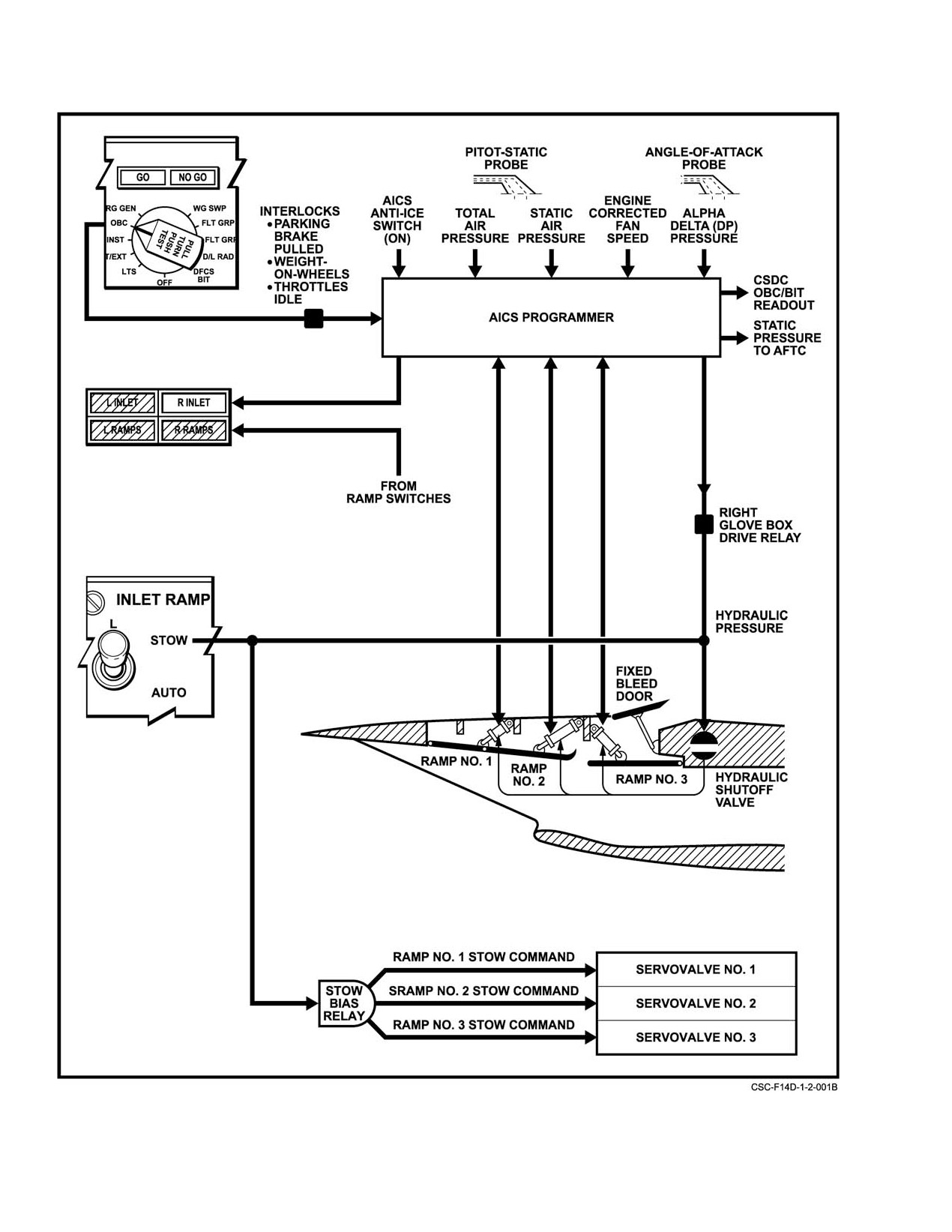
Figure 2Ć1 shows the basic elements of AICS mechanization.
0.9ĂMach to maintain proper bleed slot height (∆h) for
transonic and low−supersonic flight.
Electrical power for the AICS programmers is proĆ
vided by the ac and dc essential No. 2 buses. The ramp stow
At supersonic speeds, four shock waves compress and
function is powered by the dc essential No. 1 bus. Hydraulic
decelerate the inlet air. The bleed slot removes boundary
power is supplied individually to the left AICS from the
layer air and stabilizes the shock waves. This design results
combined hydraulic system and to the right AICS from the
in substantially higher performance above Mach
2 than
flight hydraulic system. The left AICS programmer also
simpler inlet designs.
functions as a wing−sweep backup computer.
2.1.2
AICS Test
2.1.1
Normal AICS Operations
No pilot control is required during the normal (AUTO)
Two types of AICS tests are provided to check the
mode of operation. Electronic monitoring in the AICS
general condition of the AICS and to pinpoint system comĆ
detects failures that would degrade system operation and
ponents causing detected failures: AICS built−in test and
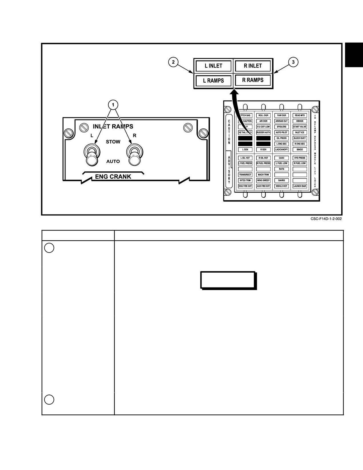
performance (refer to AICS BIT). AICS caution lights (L and
on−board check.
R INLET, L and R RAMPS) and INLET RAMPS switches
are shown in Figure 2Ć2.
2.1.2.1
AICS Built−In Test
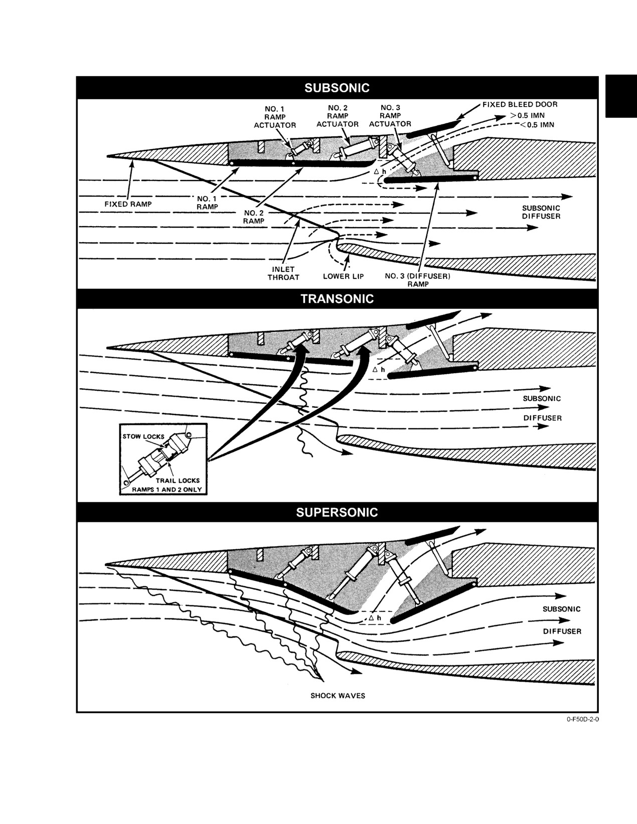
Sectional side views of representative variable geomeĆ
try inlet configurations scheduled by AICS programmers and
BIT in the AICS computer programmer is automatiĆ
cally and continually initiated within the programmer to
descriptive nomenclature are shown in Figure 2Ć3.
check AICS components when the programmer is energized.
2−1
ORIGINAL
NAVAIR 01−F14AAD−1
Figure 2Ć1.ĄAir Inlet Control System
ORIGINAL
2−2
NAVAIR 01−F14AAD−1
NOMENCLATURE
FUNCTION
1
INLET RAMPS
AUTO − Inlet ramp position is determined by the AICS programmer.
switches
STOW − Electrically commands the respective inlet ramp actuator to the stow
position; opens the appropriate hydraulic shutoff valve.
WARNING
• DO NOT take off with the INLET RAMPS switches in STOW.
Hydraulic power is on and may drive the ramps out of the stow locks
during certain servocylinder failure modes causing an engine stall.
• If wing−sweep advisory light illuminates, cycling L AICS circuit
breaker (LF1) may cause unintentional wing sweep unless WING
SWEEP DRIVE NO. 1 (LD1) and WG SWP DR NO. 2/ MANUV
FLAP (LE1) circuit breakers are pulled.
Note
Cycling either AICS circuit breaker while airborne may result in
DFCS air data failures, illuminating the FCS CAUTION and ARI
DGR lights, and cause degraded control system capability.
MASTER RESET should restore normal operation once the
cb(s) are reset.
2
RAMPS caution
Indicates ramps not positioned in either stow or trail locks during critical flight
light
conditions (see Figure 2Ć5).
Figure 2Ć2.ĄAICS Control and Indicators (Sheet 1 of 2)
2−3
ORIGINAL
NAVAIR 01−F14AAD−1
NOMENCLATURE
FUNCTION
3
INLET caution light
Indicates AICS programmer/system failure: Reduce airspeed to Mach 1.2 and
check AICS acronym for failure indication.
AICS failure
Less than Mach 0.5: Ramps should be restrained by actuator stow locks.
Greater than Mach 0.5: Ramp movement is restrained by trapped hydraulic
pressure and mechanical locks, depending on Mach when INLET light illuminates.
Greater than Mach 0.9: Ramp movement is minimized by actuator spool valves and
the aerodynamic load profile in this Mach range and a RAMP light should illuminate.
Figure 2−2. AICS Control and Indicators (Sheet 2 of 2)
The operational status of the AICS depends on
hydraulic power. Detected AICS failures are indicated by
BIT−detected failures in AICS components. Failures of static
AICS acronyms or AIC acronym(s) with associated INLET
or total pressure sensors; ramp No. 1, 2, or 3 positioning;
caution light(s) displayed after completion of OBC.
programmer continuous end−to−end BIT; or hydraulic presĆ
sure to any of the ramp actuators would seriously degrade
Note
AICS performance. Detected failures of these items cause the
D With INLET RAMP switches in STOW, AICS
AICS to automatically transfer to a significantly degraded
OBC will fail test and INLET lights will illuĆ
fail−safe mode of operation, indicated by illumination of an
minate.
INLET caution light.
D If the engine enters secondary mode during
Detected failures of angle of attack, engine fan speed,
OBC, the ramps will stow and fail OBC. To
or out−of−calibration detection of the difference between P1
reinitiate OBC, select primary mode and reset
and P2 (∆P), Ps or Pt sensors will cause the AICS to revert to
the AICS.
the slightly degraded fail−operational mode of operation.
D An S4 acronym indicates the AICS programĆ
Nominal values of angle of attack, total temperature, or
mers may be operating on the REV 4 (TF−30/
engine fan speed are substituted for the failed values in the
F14A) schedule. As a result, below 25,000 feet
AICS programmer, without illumination of an INLET
at airspeeds greater than 1.1 Mach, unloading
caution light.
the aircraft to less than 1g will reduce inlet staĆ
In both fail modes of operation, detected failures are
bility and may result in inlet buzz and possibly
continuously registered by the in−flight performance moniĆ
an engine stall. Cycling AICS circuit breakers
toring system and displayed with air inlet control acronyms
at a constant subsonic Mach number should
on the multifunction display and the programmable tactical
eliminate the S4 acronym and reset the proĆ
information display (Figure 2Ć5 and Figure 2Ć6).
grammer to the REV 5 (F−110) schedules.
2.1.2.2
AICS On−Board Check
2.1.3
AICS Failure Modes of Operation
OBC, initiated by the pilot during poststart or ground
AICS mode of operation following a BIT−detected
maintenance checks, performs a dynamic check of the left
failure may be either fail−operational mode (Figure 2Ć5) or
and right AICS. In addition to the regular AICS BIT program,
fail−safe mode (Figure 2Ć6).
sensor calibration checks are made. The status of the proĆ
grammer electronics and the ramp actuators are checked
2.1.3.1
Fail−Operational
throughout an altitude and airspeed schedule as psuedoĆ
pneumatic inputs to the programmer are varied to simulate a
Failures in the AICS are detected by the AICS proĆ
flight sequence of maximum airspeed condition and back to
grammer, which automatically initiates appropriate corĆ
static sea level conditions within 65 seconds. This cycles the
rective action. Mode entry is indicated by the display of a
ramp actuators through their full range, illuminates the ramp
fail−operational AIC acronym. The fail−operational mode
lights, exercises the complete AICS for preflight failure
results in no significant degradation in AICS operation, and
detection, and ensures the ramps are in their stow locks. OBC
the mission can be continued without any flight restrictions
is the only way to ensure stow lock integrity since it verifies
or corrective action by the pilot.
the ramps are in the stowed position and then removes ramp
ORIGINAL
2−4
NAVAIR 01−F14AAD−1
Figure 2Ć3.ĄVariable−Geometry Inlet Configuration
2−5
ORIGINAL
NAVAIR 01−F14AAD−1
ACTUATOR POSITION
HYDRAULIC POWER
FLIGHT CONDITION
RAMP ACTUATORS
RAMP NO. 1
RAMP NO. 2
RAMP NO. 3
M < 0.35
OFF
Mechanically restrained by stow locks in stowed position;
electrical stow commands output from AICS programmer.
M > 0.35 to < 0.5
ON
Electrical stow commands output from AICS programmer.
M > 0.5 to < 2.2
ON
Variable position scheduled by AICS programmer as a
function of mach number, corrected engine fan speed, and
angle−of−attack. Ramps no. 1 and no. 2 begin positioning
at Mach 0.5; ramp no. 3 begins at Mach 0.9.
M > 2.2
ON
Variable position scheduled by AICS programmer as a
function of Mach number.
Figure 2Ć4.ĄAICS Normal Operating Mode
PTID FAILURE
MAINTENANCE
DETECTED
READOUT ACRONYM
FAILURE
CAUSE
RESULT
AIC S1
Ps, Pt or
Limits exceeded.
Ramps may not program during
(Possible only
programmer out of
OBC. Reset AICS L and R circuit
during OBC)
calibration
breakers (LF1, LG1) prior to
attempting another OBC.
NONE
Engine fan speed
Loss of engine fan
Substitutes 7,300 rpm. Ramps do not
rpm from AFTC.
speed signal.
program during OBC.
AIC S3
None
None
Mask continuous monitor (CM) so
that subsequent AIC acronyms are
displayed.
AIC S4
Angle−of−attack or
Limits exceeded.
IN FLIGHT: Substitutes +2_
engine fan speed.
angle−of−attack or 7,300 rpm.
AIC S4
Alpha delta pressure
Limits exceeded.
• Substitutes +2_ angle−of−attack
(During OBC)
sensor out of
Augmenter fan
value until reset.
calibration or engine
temperature
fan speed.
controller (AFTC) may
• Substitutes 7,300 rpm.
be in secondary mode.
AIC A4
Open wire
Open wire
None
Note
AIC symbol has L or R appended (AICL, AICR) to
identify on which side failure was detected.
Figure 2Ć5.ĄFail−Operational Mode No INLET Light
ORIGINAL
2−6
NAVAIR 01−F14AAD−1
RESULT
FAILURE MAINTENANCE
DETECTED
MACH < 0.5
MACH > 0.5
READOUT ACRONYM
FAILURE
CAUSE
AIC P
AICS programmer
Failed end−to−end
Hydraulic shutoff
Ramp movement is
(P)
BIT
valve remains closed.
restrained by actuator
Ramp actuators
mechanical locks if
AIC S1
remain mechanically
failure occurred with
Static pressure (Ps)
Minimum or
restrained within stow
ramps within locks.
maximum limits
AIC S2
locks, provided they
Otherwise ramp(s)
Total pressure (Pt )
exceeded
failed within stow
move slowly with
locks.
aerodynamic loads.
AIC A1
Ramp No. 1
Sustained command
and feedback
error
AIC A2
Ramp No. 2
AIC S3
Ramp No. 3
AIC A1,
Hydraulic pressure
Sustained error due
Ramp(s) may move
AIC A2, or
loss of ramp No. 1,
to loss of hydraulic
if failure occurred
AIC A3
No. 2, or No. 3
pressure
with ramp(s) out of
(INLET caution light
mechanical locks.
eventually illuminates
RAMP light will
> 0.5 Mach)
illuminate.
NONE (No INLET caution
Loss of hydraulic
light < 0.5 Mach)
pressure
Note
AIC symbol has L or R appended (AICL, AICR) to identify on which side failure was detected.
Figure 2Ć6.ĄFail−Safe Mode INLET Light Illuminated
Note
Note
Transferring to SEC mode will revert the AICS
Fail−safe operations result in a slight degradation
programmers to the REV 4 (TF−30/F14A) schedĆ
of cruise and excess thrust performance because
ule because of the loss of the AFTC N1 speed
of the off−optimum configuration.
signal and will display an S4 acronym. Below
If the hydraulic shutoff valve closes above Mach 0.9,
25,000 feet and at airspeeds greater than 1.1
the ramps are normally in an unsafe configuration and the
Mach, unloading the aircraft to less than 1g will
appropriate RAMPS caution light will accompany the
reduce inlet stability and may result in inlet buzz
INLET caution light (Figure 2Ć7). Above Mach 0.9, the
and possible engine stall. To restore full REV 5
No. 3 ramp normally begins programming below the actuator
(F110/F14B/D) schedule and eliminate S4 acroĆ
stow lock. When the fail−safe mode is entered above Mach
nym following an airborne engine mode reset to
0.9, the unpowered No. 3 ramp will eventually move and may
PRI, recycle AICS circuit breakers at constant
cause compressor stalls at higher power settings. The aircraft
subsonic Mach number.
shall be decelerated below 1.2 Mach, and the appropriate
2.1.3.2
Fail−Safe Mode
INLET RAMPS switch shall be selected to STOW.
The fail−safe mode results in significantly degraded
AICS operation. Mode entry is indicated by the display of a
fail−safe AIC acronym and illumination of the appropriate
INLET caution light. Under these conditions, the AICS
Do not select STOW at speeds greater than
programmer provides a shutoff signal to close the ramps’
1.2 Mach. Compressor stalls may occur because
hydraulic shutoff valve. If the hydraulic shutoff valve closes
of ramp mispositioning.
below Mach 0.9, the ramps are normally in a safe configuraĆ
tion (No. 1 and No. 2 ramp within trail locks and No. 3 ramp
2.1.3.3
Stow Mode of Operation
in stow locks are restrained by trapped hydraulic pressure).
The STOW position of the INLET RAMPS switch
Engine operations may be successful below 1.2 Mach in this
commands the appropriate hydraulic shutoff valve to open
configuration; however, corrective procedures shall be
performed.
2−7
ORIGINAL
NAVAIR 01−F14AAD−1
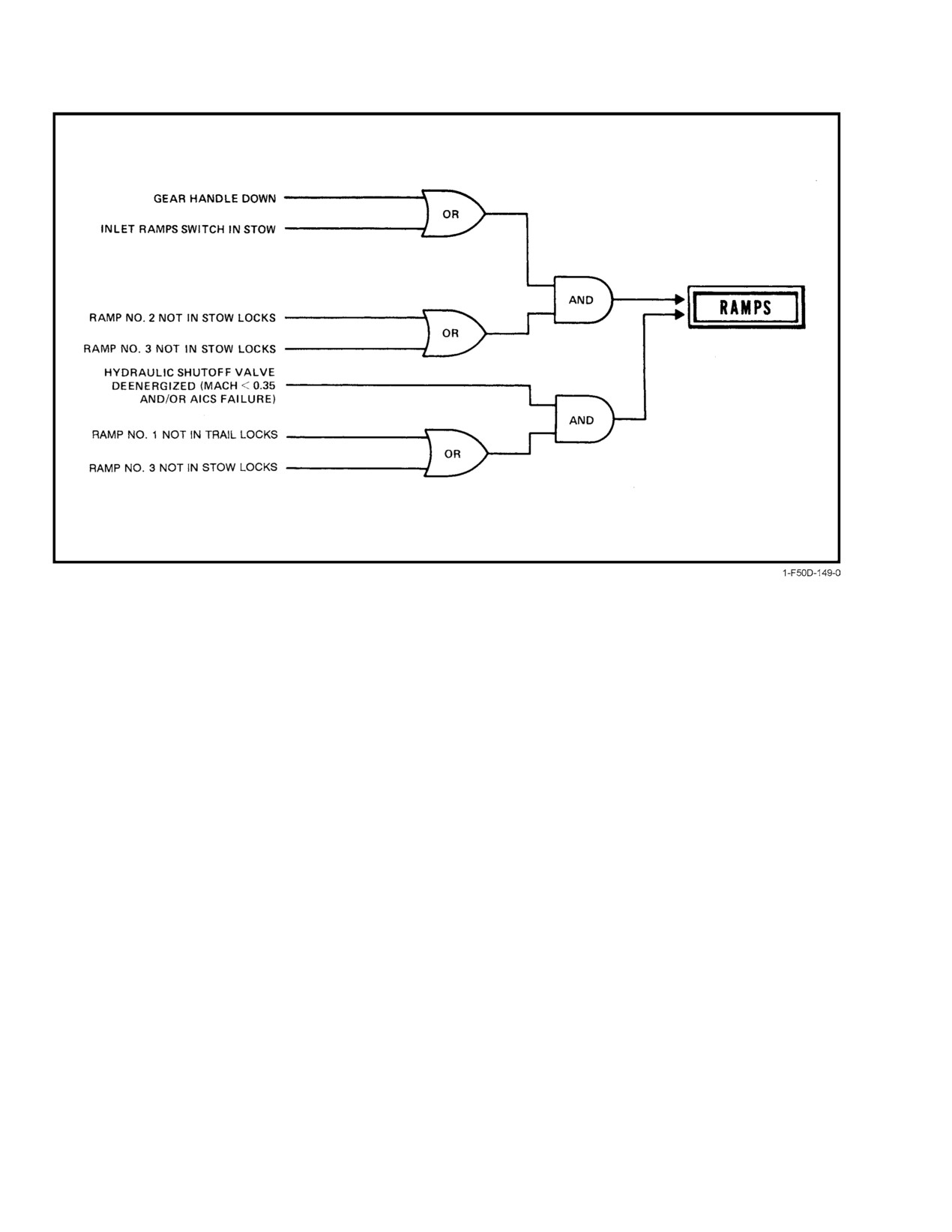
Figure 2Ć7.ĄRamp Monitor Logic
and provides a direct electrical signal to the ramp actuators,
Whenever the hydraulic shutoff valve closes (i.e., fail−
porting hydraulic pressure directly to the retract side of the
safe mode entry), hydraulic spool valves in the ramp actuaĆ
actuator. When the ramps are retracted to the stow position,
tors sense the absence of pressure and block the actuator
the RAMPS light will extinguish and the stow locks should
pressure and return ports, causing a hydraulic lock (dump
remain engaged even if hydraulic power is subsequently lost.
inhibit). This feature reduces ramp movement when an AICS
Once in STOW, AICS programmer−detected electronic
failure occurs and the ramps are not being restrained by
failures may be reset below Mach 0.5.
mechanical actuator locks. Although dump inhibit prevents
the ramp from rapidly extending and causing an engine stall,
2.1.3.4
Hydraulic Shutoff and Dump Inhibit
the ramps will still slowly move. Under normal circumĆ
The AICS hydraulic systems include a hydraulic shutoff
stances, the pilot will have sufficient time to select STOW
valve to control hydraulic system pressure. The hydraulic
and prevent an engine stall. F−14A flight test results show that
shutoff valve is normally controlled by the AICS programmer,
with dump inhibit, the time interval between illumination of
which removes the hydraulic−on signal below 0.35M or in the
a RAMPS caution light and engine stall following an AICS
event of a programmer failure. The STOW position of the
failure is 15 to 40 seconds on the ground at military power,
INLET RAMPS switch bypasses the AICS programmer to
and approximately 50 seconds at 10,000 feet at military
energize the hydraulic shutoff valve, providing pressure for
power.
ramp motion. To ensure hydraulic pressure is shut off, the
respective AICS programmer must be deenergized by pulling
2.1.3.5
Ramp Actuator Mechanical
the circuit breaker (LF1, left or LG1, right) and the INLET
Locks/Positioning
RAMPS switch placed in the AUTO position.
In addition to the actuator stow locks, the first and
Note
second ramp actuators have another set of latches (trail locks)
Cycling either AICS circuit breaker while airĆ
that prevent further ramp actuator extension after a failure
borne may result in DFCS air data failures, illuĆ
within these trail locks. The actuator stow and trail locks
minating the FCS CAUTION and ARI DGR
restrain actuator movement in tension only. Hydraulic
lights, and cause degraded control system capaĆ
pressure (500 psi) is required to disengage the lock finger
bility. MASTER RESET should restore normal
latches.
operation once the cb(s) are reset.
ORIGINAL
2−8
NAVAIR 01−F14AAD−1
Safe positioning of the ramp actuators is monitored
fail−safe operation. In flight, the No. 1 and 2 ramps tend to
by the ramp monitor logic shown in Figure 2Ć7. A RAMPS
blow back to the stow position or are restrained within the
light should always be accompanied by an INLET light with
trail locks because of aerodynamic loads. The hydraulic
the landing gear handle UP. With the landing gear handle
restriction of all ramps during loss of hydraulic power and
DOWN, a RAMPS light can be illuminated without an
after fail−safe mode entry should prevent rapid ramp
INLET light. The emergency procedure in any case is the
movement. Internal failure of an actuator especially the
same. RAMPS lights will extinguish when a safe configuraĆ
No. 3 ramp actuator, may allow rapid ramp extension and
tion is attained.
cause engine stall. Additionally, failure to stow the ramps in
a reasonable amount of time after INLET light illumination
Note
or inability to stow following a hydraulic system failure may
D Following an AICS programmer/ramps failĆ
result in compressor stalls at high power settings. Engine start
ure, the safest configuration results when the
attempts may not be successful unless the ramps are stowed
(RAMPS caution light extinguished).
ramps are in the stowed position. The proĆ
grammers are disabled by pulling the affected
AICS circuit breaker and returning the INLET
2.1.4
AICS Anti−Ice
RAMPS switch to AUTO.
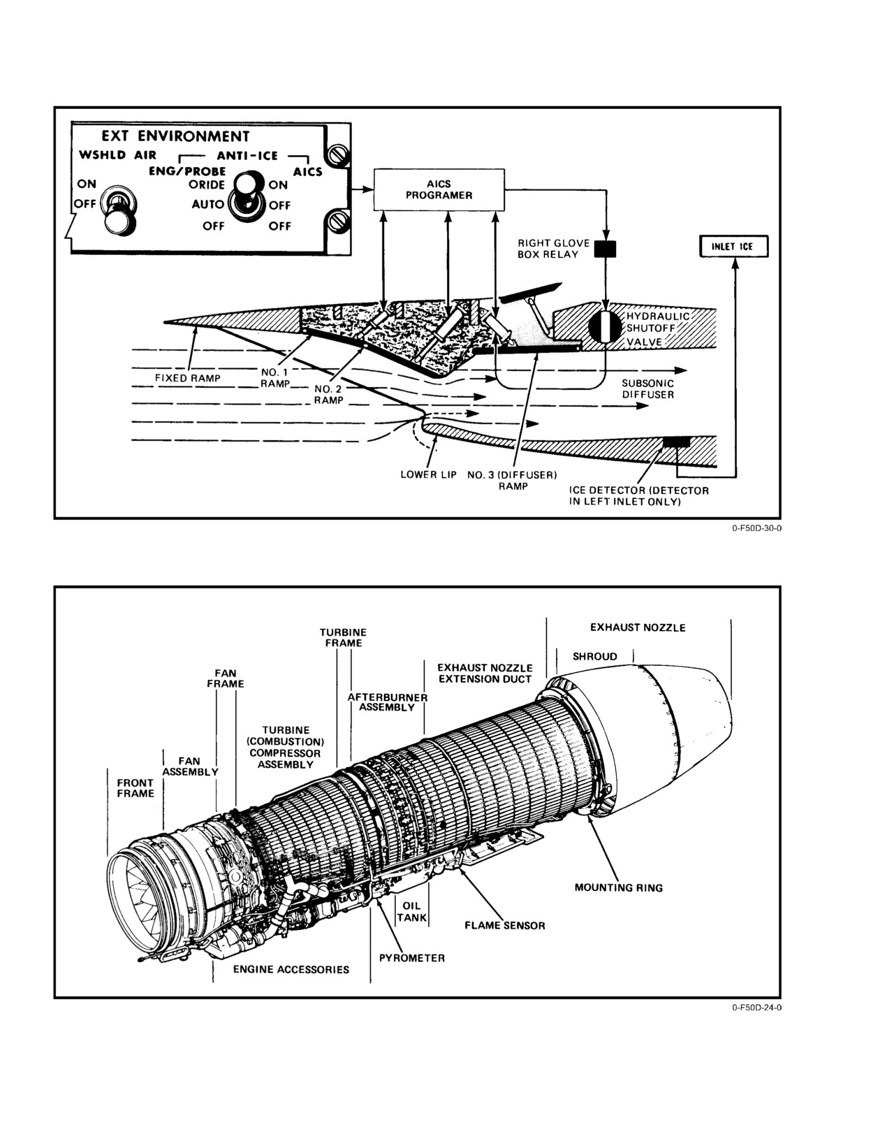
AICS anti−ice is activated only by selecting ORIDE/
D Cycling either AICS circuit breaker while airĆ
ON with the AICS ANTI−ICE switch and airspeed between
borne may result in DFCS air data failures, illuĆ
0.35 to 0.9 Mach (hydraulic power is available at 0.3 Mach).
minating the FCS CAUTION and ARI DGR
Above and below these airspeeds the AICS anti−ice is
lights, and cause degraded control system
disabled. When the ENG/PROBE anti−ice switch is in
capability. MASTER RESET should restore
AUTO, the AICS anti−ice is off. When AICS anti−ice is
normal operation once the cb(s) are reset.
activated, the AICS programmer repositions the No. 1 and
No. 2 ramps to positions below the No. 3 ramp (Figure 2Ć8)
In the event of an engine or hydraulic failure, the
so that ice will not form above the No. 3 ramp.
following conditions exist with respect to AICS reset:
2.2
ENGINE
1.
If hydraulic pressure is zero, there is no need to safe
the ramps (by stowing ramps, pulling AICS circuit
The aircraft is powered by two F110−GE−400 turbofan
breakers, and returning to AUTO) since selecting
engines (Figure 2−9) with variable exhaust nozzles and AB
STOW will have no effect without hydraulic
augmentation. They are dual−rotor engines consisting of a
pressure.
three−stage fan driven by a two−stage, low−pressure turbine
and a mechanically independent, aerodynamically balanced,
2.
If airspeed is less than .35 Mach, there is no need to
nine−stage, high−pressure compressor driven by a single−
safe the ramps since hydraulic pressure has already
stage, air−cooled high−pressure turbine. Engine operation is
been removed and ramps should be in the stow
automatically regulated and maintained electrically by the
locks. If the ramps are not in the stow locks, the
augmenter fan temperature control unit and by throttle inputs
RAMPS light will illuminate when the landing gear
to the main engine control.
handle is lowered. If the RAMPS light does illumiĆ
nate, then the ramps should be stowed and the AICS
Each engine is slung in a nacelle with the thrust axis
programmer reset. (Depressing MASTER RESET
laterally offset approximately
4½ feet from the aircraft
following an AICS programmer reset should restore
centerline. The installed static engine thrust at military power
normal DFCS operation.)
is
13,800 pounds and, at maximum AB power, thrust is
3.
If hydraulic pressure is greater than zero and airĆ
23,600 pounds. Installed engine thrust at maximum AB at
speed is greater than .35 Mach, then the ramps
0.9M at sea level is 30,200 pounds. Acceleration time from
should be stowed and, if time allows, the programĆ
idle to military power is approximately 4 seconds.
mer reset after engine failure or a low hydraulic
pressure situation. This will ensure that if the ramp
During operation, air entering the engine is directed
is out of the stow lock (as is normal above .5 Mach),
into the fan, which initially compresses the air and directs
it will be returned to the stow lock and kept there for
its flow into the engine core compressor and fan bypass duct.
landing regardless of subsequent hydraulic or
Direction of airflow into the fan is optimized by variable−
electrical malfunctions.
geometry inlet guide vanes (IGV) and into the compressor by
variable geometry stator vanes. The high−pressure compresĆ
2.1.3.6
AICS Failure In−Flight Operation
sor further compresses the air through the nine−stage comĆ
pressor before discharging it into the annular combustion
Most AICS failures occurring in flight do not require
chamber to mix with fuel from the fuel nozzles. This fuel−air
rapid pilot response because of system design features for
2−9
ORIGINAL
NAVAIR 01−F14AAD−1
Figure 2Ć8.ĄAICS Anti−Ice System
Figure 2Ć9.ĄF110−GE−400 Engine
ORIGINAL
2−10
NAVAIR 01−F14AAD−1
mixture is initially ignited by the main spark igniter in the
Note
combustion chamber. As a result of this combustion,
SEC mode transfer while in AB may result in pop
expanding gases drive the high− and low−pressure turbines.
stalls. Nonemergency manual selection of SEC
Power to drive the two accessory gearboxes is obtained from
mode on the ground should be performed in basic
the high−pressure rotor.
engine. Nonemergency manual selection of SEC
mode airborne should be performed in basic
From the turbine section, the exhaust gases pass into
engine with power set above 85−percent rpm.
the afterburner section and are mixed with air from the fan
bypass duct. During AB operation, fuel is sprayed into this
Transferring to SEC mode will revert the AICS proĆ
mixed airflow and ignited for additional thrust.
grammers to the REV 4 (TF−30/F14A) schedule because of
the loss of the AFTC N1 speed signal and will display an
OBC AICS − LEFT (RIGHT) and ANGLE OF ATTACK
acronym. Below 25,000 feet and at airspeeds greater than 1.1
TMN, unloading the aircraft to less than 1g will reduce inlet
stability and may result in inlet buzz and possible engine
During night and/or IFR conditions, the
stall. To restore the full REV 5 (F110/F14B/D) schedule and
increased acceleration during AB use will result
eliminate the OBC acronym following an airborne engine
in inner ear disturbances. In addition, the large
mode reset to PRI, cycle AICS circuit breakers at constant
amount of light generated by the AB exhaust
subsonic Mach number.
reflecting around the aircraft will compound this
condition. These factors may result in severe
2.2.1.1
Main Engine Control
aircrew disorientation/vertigo.
The MEC is a hydromechanical control that provides
2.2.1
Engine Control
fuel shutoff, variable stator vane scheduling, and main fuel
metering in both primary and secondary modes. The MEC
The engine is controlled by three units: the hydroĆ
controls fuel flow until
59−percent rpm and provides
mechanical main engine control, the electronic augmenter
high−pressure compressor rotor overspeed protection autoĆ
fan temperature control, and the AB fuel control. There are
matically by securing fuel flow to the engine when an
two modes of operation: primary (electronic) and secondary
overspeed condition of 110 percent is reached.
(mechanical), with provisions for automatic and manual
switchover to secondary. Manual selection is controlled
Note
through the ENG MODE SELECT panel (Figure 2Ć10).
D To regain engine operation following an autoĆ
Automatic or manual selection of the secondary mode illuĆ
matic engine overspeed shutdown, the throttle
minates an ENG SEC caution light. When one engine reverts
must be cycled to OFF then IDLE.
to secondary mode, the other engine continues in primary
mode. Cycling the ENG MODE SELECT switch may reset
D An overspeed condition in excess of
110
the AFTC if the faults are temporary. If the change back to
percent will result in momentary loss of rpm
primary mode is successful, the ENG SEC light will go out.
indication until N2 rpm falls below 110 ± .5
Automatic or manual selection of secondary mode is possible
percent. EGT and FF indicators will continue
throughout the flight envelope. Selection of secondary mode
to function normally.
will cause a loss of fan speed signal to the AICS.
2.2.1.2
Augmenter Fan Temperature Control
The AFTC is a modular solid−state electronic device
that performs control schedule computations, integration and
logic functions, limit control, failure detection, and provides
engine core speed (N2) signal for instrument display and
SEC mode transfers with throttles in AB above
engine fan speed (N1) signal to the AICS. It also controls the
450 KCAS could result in pop stalls and damage
distribution of electrical power to the entire engine electrical
to the IGV linkage.
and monitoring systems. Figure 2Ć11 shows the various
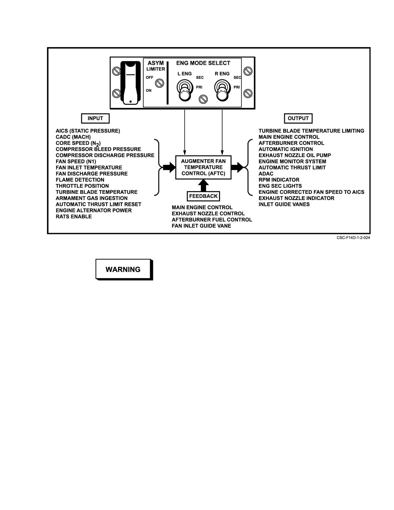
interface signals used by the AFTC. Normally the CADC
supplies Mach number value to the AFTC. If this signal is
erroneous, the AFTC assumes a default Mach number value
in order to continue operation.
2−11
ORIGINAL
NAVAIR 01−F14AAD−1
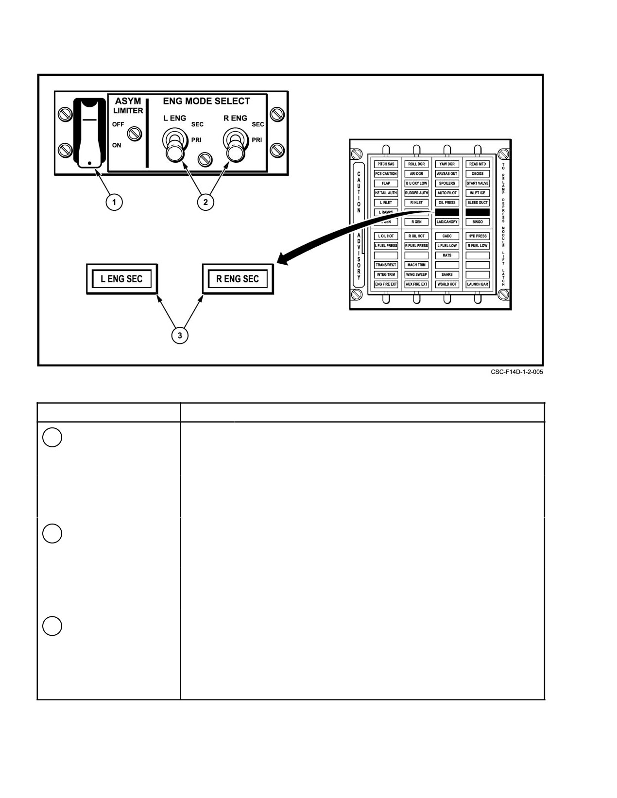
NOMENCLATURE
FUNCTION
ON Ċ Reduces AB thrust asymmetry in the event of AB blowout or if
1
ASYM LIMITER
(guarded) one engine fails to light when commanded to AB. Limits operating
switch
engine to minimum AB until other engine attains minimum AB.
OFF Ċ Either engine may operate at any AB power setting independently
of the other engine.
2
L/R ENG MODE
PRI Ċ
Primary mode, AFTC controls main and AB fuel flow, fan inlet
guide vanes, nozzle area, and ignition.
SELECT switch
SEC Ċ Secondary mode, main fuel flow is scheduled hydromechanically
by the MEC. AB is inhibited.
Illuminates when the engine is in secondary mode. AB operation is inhibited
3
L/R ENG SEC caution
for engine with light illuminated. AICS on affected engine side reverts to REV 4
light
(TF−30/F−14A) schedule.
Figure 2Ć10.ĄENG MODE SELECT Panel and ENG SEC Lights
ORIGINAL
2−12
NAVAIR 01−F14AAD−1
Figure 2Ć11.ĄAFTC Functional Relationships
engine operation with unrestricted throttle movement
throughout the flight envelope. The AFTC computations are
used to control basic engine and AB fuel flow, IGV, and AB
nozzle positioning; VSV positioning is controlled by the
The loss of Mach number signal from the CADC
MEC. The AFTC incorporates independent control schedĆ
results in the loss of both airflow limiting and idle
ules that are prioritized so that the optimum amount of fuel
lockup functions of the AFTC. This may result in
flow is provided to the main combustor. At any given time,
pop stalls while supersonic on a cold day, or at
only one of these schedules is actually in control of fuel flow.
high power settings, or at idle. Inlet buzzing may
The remaining schedules are always active and are calculatĆ
also result at high power settings. If occurring
ing the change in fuel flow required (if any) to attain the
while supersonic and at high power settings,
desired value of their assigned parameter. The selection of
decelerate at military power until subsonic.
the schedule in control is accomplished by a series of
minimum and maximum selectors. These selectors control
2.2.1.3
Afterburner Fuel Control
scheduling of the following:
The AFC is controlled by the AFTC for afterburner
1. Acceleration/deceleration
operation. The AFTC computes AB fuel flow ratios and
provides them to the AFC. The AFC converts ratio comĆ
2. Minimum/maximum compressor discharge
mands to metered fuel flows into local, core, and fan AB fuel
pressure
manifolds. When staging up the AB, local fuel flow is
initiated first, followed by core and fan flow last. When
3. Minimum/maximum rpm
staging down, the reverse sequence occurs. Thrust changes
are smooth when staging up or down.
4. Fan speed limiting
2.2.1.4
Primary Mode
5. Maximum turbine blade temperature limiting
In the primary mode, the AFTC controls the MEC,
6. Idle lockup speed.
AFC, and AB nozzle hydraulic pump to provide optimum
2−13
ORIGINAL
NAVAIR 01−F14AAD−1
Other AFTC functions include engine start control,
asymmetric thrust limiting, reduced arrestment thrust, autoĆ
matic relight, and fault detection. Fault detection automatiĆ
cally switches the engine control to the secondary mode in
the event of core overspeed, fan speed signal loss, nozzle full
SEC mode transfers with throttles in AB above
open when engine is not at idle or maximum AB, AFTC
450 KCAS could result in pop stalls and damage
power deviations, fuel flow demand mismatch with throttle
to the IGV linkage.
settings, fan speed greater than 800 rpm and not accelerating,
or throttle signal error.
Note
D SEC mode transfer from AB may result in pop
2.2.1.4.1
AB Operation (Primary Mode)
stalls. Nonemergency manual selection of
SEC mode on the ground should be performed
For AB operational characteristics, refer to Figure 2Ć12.
in basic engine. Nonemergency manual selecĆ
Unrestricted throttle operation into and out of AB is per−
tion of SEC mode airborne should be perĆ
mitted throughout the flight envelope. During AB operation,
formed in basic engine with power set above
rpm, EGT, fuel flow, and nozzle position vary with altitude
85−percent rpm.
and airspeed. The nozzle position will also increase as the
throttle is transitioned from minimum AB to maximum AB.
D If the fan speed limiter circuit has failed, engine
If an AB blowout occurs, the autorelight feature attempts to
rollback may occur with selection of SEC
reinitiate AB without throttle movement. The engine has
mode. In the event of engine rollback, PRI
reduced AB region of operation at high altitudes and low airĆ
mode must be reselected above 59−percent rpm
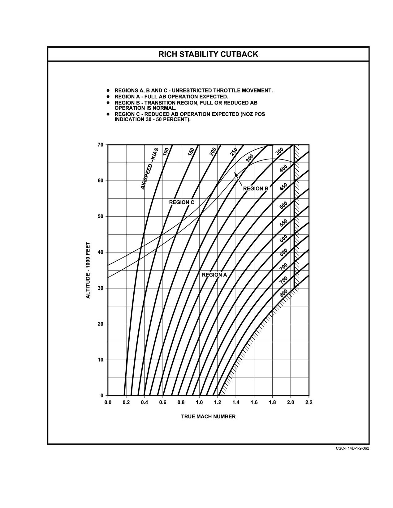
speeds. An AFTC automatic rich stability cutback" feature
or flameout will occur and airstart will not be
reduces or limits maximum AB fuel flow at high
possible.
altitudes and low airspeeds to prevent AB instabilities
(Figure 2Ć12). Indication of rich stability cutback is a nozzle
2.2.1.6
Engine Alternator
position of approximately 30 to 50 percent at maximum AB
rather than the normal 60 to 70 percent. Also, because of airĆ
Each engine’s electrical system is powered by an alterĆ
flow and temperature characteristics, AB light−off characterĆ
nator mounted on the engine aft gearbox. The alternator
istics are slower at high altitudes and low airspeeds.
consists of four windings. Two windings are redundant in
providing power to the AFTC and its components. A third
2.2.1.5
Secondary Mode
winding provides power for both main high−energy ignition
and AB ignition. The fourth winding provides power to the
Basic engine operation in SEC mode is extremely reliĆ
engine monitoring system processor (for FEMS), and a signal
able. In the secondary mode, the electronic functions perĆ
for the rpm gauge. The last winding is also an alternate source
formed by the AFTC are eliminated. The MEC provides
of power for the fan speed limiting circuit. The fan speed
complete control of the engine with the exception of fan
limiting circuit may be powered by either the essential
speed limiting. SEC mode is manually selected via the
No. 2 dc bus or the engine−driven alternator winding, dependĆ
ENG MODE SELECT switch or the autopilot emergency
ing on which source has the highest stable output.
disengage paddle switch, or via automatic default. In
SEC MODE, the exhaust nozzle is commanded full closed,
If engine alternator power output drops below a preset
the nozzle position indicator goes to the not−powered
value, engine control will automatically transfer to SEC
position (subzero indication), the IGVs are fixed full open,
mode, illuminating the respective engine SEC light. If the
high−energy ignition is continuously energized, AB is
engine reverts to SEC mode as a result of a sheared alternator
inhibited, and idle lockup protection is lost.
shaft, engine high−energy ignition will not be available and
the engine SEC light will not illuminate. Cockpit indications
In SEC mode, engine stall margin is decreased at low
are loss of engine rpm and nozzle position indicating below
rpm because of IGV positioning. The FEMS engine stall
zero. In failure modes, redundant aircraft electrical power
detection circuit is inoperative, but overtemperature warning
will be available for fan overspeed protection.
is still available. A low−level vibration/rumble may be sensed
in ground idle operation when in secondary mode. This
The engine is completely operable should the aircraft
vibration/rumble has no adverse affect on the engine and
experience a complete electrical failure. The engine operates
disappears when the throttle is advanced slightly (5−percent
in either PRI or SEC mode, which can be selected automatiĆ
rpm increase or less). Maximum thrust available at military
cally or manually. In case of a complete electrical failure all
power in SEC mode is depicted in Chapter 14, Figure 14Ć4.
engine lights and indicators are inoperative.
ORIGINAL
2−14
NAVAIR 01−F14AAD−1
Figure 2Ć12.ĄRich Stability Cutback F110−GE−400 Engine
2−15
ORIGINAL
NAVAIR 01−F14AAD−1
2.2.1.7
Turbine Blade Temperature (Pyrometer)
gear with the hook handle down or the hook out of the stowed
position. The RATS light, located on the pilot’s advisory
The pyrometer is a fuel−cooled, photodiode, optical
panel, illuminates when the aircraft circuit is activated but it
unit that measures infrared radiation from the metal surface
is not an indication that the engines are operating at reduced
of the high−pressure turbine blades. This temperature signal
thrust.
is transmitted to the AFTC and is used to regulate engine fuel
flow, which maintains turbine blade temperature within
Note
limits. Cockpit indications of turbine blade temperature
The RATS light will be illuminated anytime the
appear on the MFD.
aircraft circuit is enabled, even if the engines are
operating in SEC mode or the engine circuit has
2.2.1.8
Flame Sensor
been overridden by selection of AB.
The flame sensor is an ultraviolet radiation sensing unit
in the AB duct. During AB operation, ultraviolet rays
2.2.2
Variable Exhaust Nozzle
detected through a quartz window activate a gas filled sensor
Engine exhaust gases at higher thrust settings are
that electrically transmits a flame−present signal to the
discharged through the nozzle throat at sonic velocity and
AFTC. Without this signal, only minimum AB fuel flow is
are accelerated to supersonic velocity by the controlled
available. AB will be inhibited if the flame sensor fails on.
expansion of the gases. Varying nozzle throat area controls
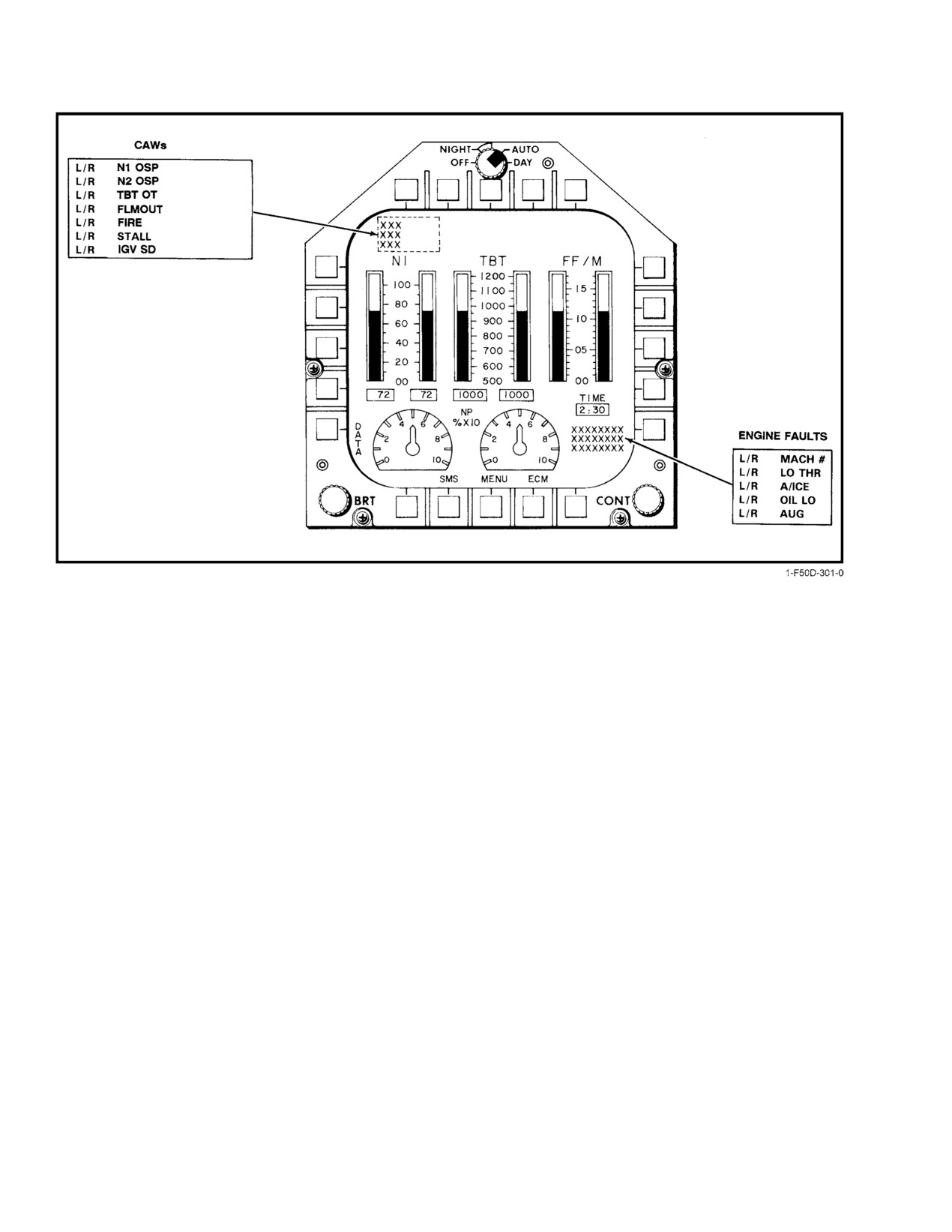
A L/R AUG acronym is displayed in the ENGINE FAULTS
fan stall margin, which optimizes performance.
block of the MFD engine page.
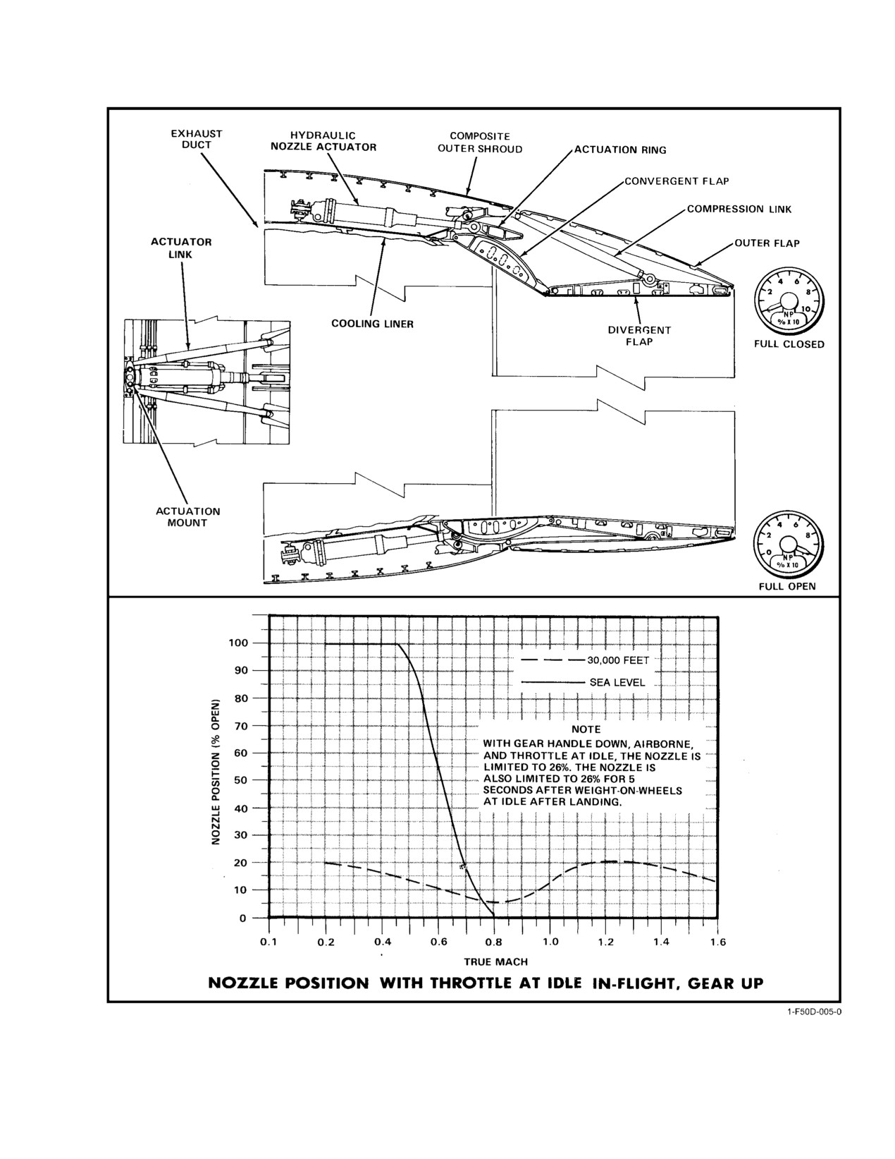
The variable exhaust nozzle is a three−flap, convergent−
2.2.1.9
Asymmetric Thrust Limiting
divergent−type nozzle. Nozzle variation is accomplished by
The asymmetric thrust limiting circuit is designed to
axial movement of four hydraulic actuators mechanically
hold both engines to minimum AB until both ABs are lit off.
synchronized for geometric stability. These hydraulic actuaĆ
The AFTC releases the hold on the AB when both engine AB
tors use oil from a separate compartment in the engine oil
pumps are on and both engine flame sensors are on. Selecting
storage tank and are operated by a hydraulic pump that
the ASYM LIMITER switch to OFF (guard cover up)
responds to AFTC signals. A failed open nozzle may be
overrides the comparison of left and right AB status and
caused by an oil leak, but if the leak is in the nozzle system,
allows each AB to operate independently.
only a portion of the main engine lube oil will be lost. During
basic engine operation, the nozzle area is modulated to a near−
closed position, and, in AB, the nozzle area is infinitely variĆ
able to a full−open position. The nozzle will go full open
airborne with the throttle at IDLE at low altitude and airspeeds
(Figure 2Ć13). A gauge for each engine on the pilot instrument
A malfunctioning or deselected ATLS can
panel next to the engine instruments indicates nozzle position
greatly increase the magnitude of asymmetric
in percentage from 0 to 100. Normal indication for maximum
thrust because of engine stall or failure.
AB is approximately 70 percent.
2.2.1.10
Reduced Arrestment Thrust System
Note
The RATS is a feature of the AFTC provided to reduce
When AFTC is operating in secondary mode, the
thrust for carrier landings to a level consistent with carrier
nozzle is commanded closed and the exhaust
(CV) wind−over−deck operations. When activated, the AFTC
nozzle indicator is inoperative.
automatically reduces the military power core speed (N2)
by approximately 4.5 percent. This results in an approximate
With the landing gear handle down, engine at IDLE,
20 to 25−percent decrease in thrust.
and weight off wheels, the nozzle is restricted to a near closed
position (maximum 26 percent) to prevent exhaust nozzle
RATS employs two enabling circuits: an engine circuit
flap contact with the deck/hook during landing. Five seconds
incorporated within each engine’s AFTC, and an aircraft
after weight on wheels, the nozzle resets to full open to
circuit. The engine circuit is enabled by the aircraft circuit via
reduce idle power during landing rollout and while taxiing.
switch closure. Since the engine circuit is a function of the
On deck in PRI mode with throttle above IDLE detent, nozzle
AFTC, it is not available in SEC mode and can be overridden
position varies linearly with throttle position.
in PRI mode with selection of AB. The aircraft circuit is
enabled when weight is placed on either or both main landing
ORIGINAL
2−16
NAVAIR 01−F14AAD−1
Figure 2Ć13.ĄVariable Area Exhaust Nozzle
2−17
ORIGINAL
NAVAIR 01−F14AAD−1
Figure 2Ć14.ĄFEMS Multifunction Display Configuration
2.3
FATIGUE ENGINE MONITORING SYSTEM
The FEMS consists of the following components (see
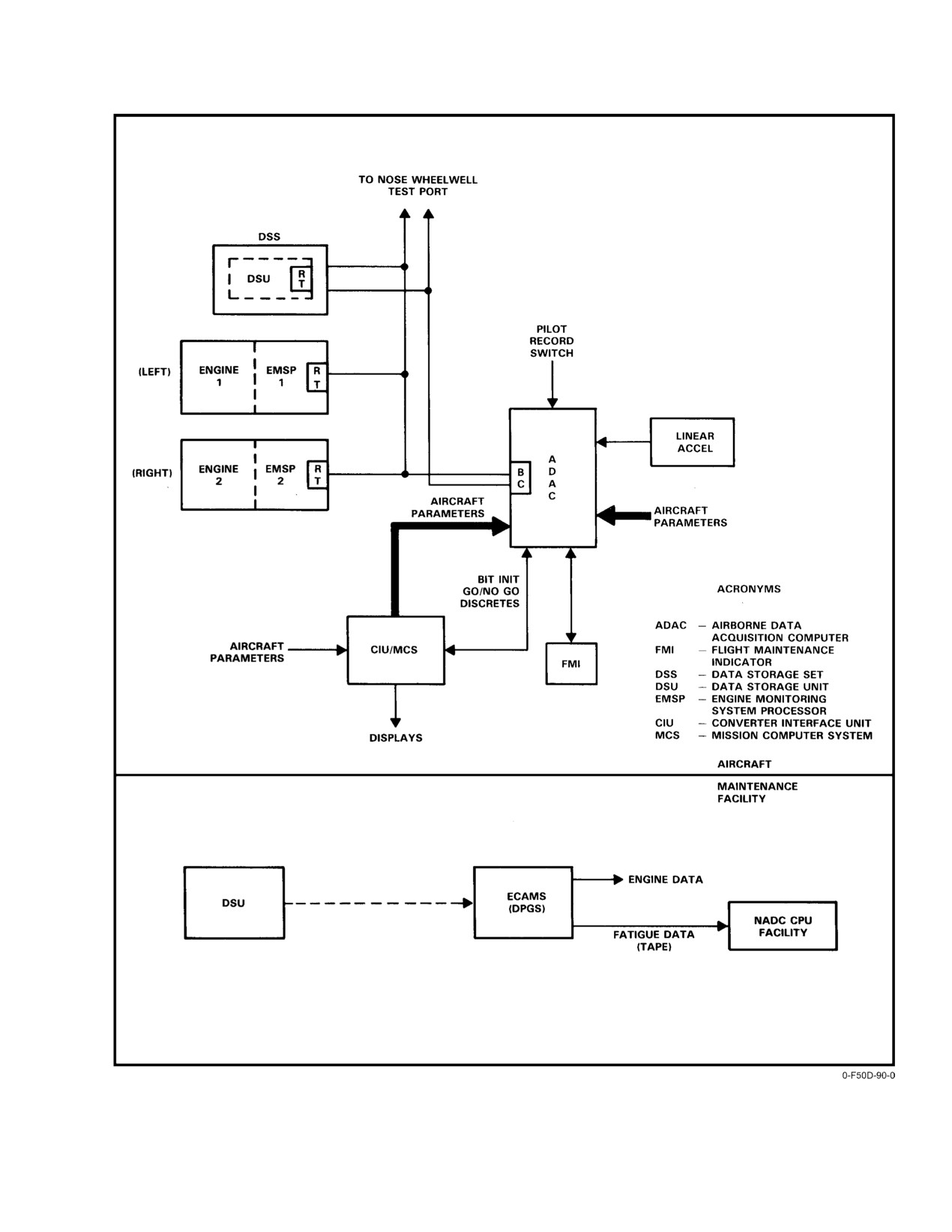
Figure 2Ć15).
2.3.1
FEMS Functional Description
2.3.1.1
Engine Monitoring System Processor
The FEMS is a solid−state electronic system that
The EMSP is engine−mounted, engine−powered, and
provides data acquisition, processing, and storage. FEMS
converts control system electrical signals from the AFTC
information is displayed on the MFDs (Figure 2Ć14). The
into digital format for transmission to the ADAC. It also
system accumulates airframe stress and fatigue data and
receives and digitizes other noncontrol system−related data
relevant engine performance data, both in flight and on deck,
such as anti−icing system status, lube oil level, and lube temĆ
from the engine monitoring system processors. Engine faults
perature data for transmission to the ADAC. In addition, the
are isolated to the appropriate WRA or combinations of
EMSP calculates and stores engine cycle count data, making
WRAs and recorded for later transfer to the DPGS for
this data readily available for each serial−numbered engine
diagnostic analysis, troubleshooting, and appropriate mainĆ
even when the engine is not installed in an aircraft.
tenance. The DPGS also computes and stores engine parts
life tracking and failure−trending data. This tracking of
Note
engine data extends the life and safety of fleet aircraft by
EMSP is only operational with the engines in
permitting maintenance routines at periodic intervals. FEMS
primary mode.
also provides a signal to the stall warning system that initiates
2.3.1.2
Airborne Data Acquisition Computer
a 10−second warning tone (identical to overtemperature tone)
and illuminates the L or R STALL warning legend on the
The ADAC is the central processor of FEMS and
MFD/HUD indicating an engine stall. FEMS will record
executes airframe and engine fatigue algorithms. The ADAC
aircraft overstress when it determines that normal acceleraĆ
acquires aircraft data by direct analog and digital inputs.
tion has exceeded:
Additional aircraft data received by the ADAC from the CIU
1. 7.5g with landing gear UP and Mach greater
to be stored as a result of structural, engine, or other mission
events are transferred to the DSS for postflight analysis. In
than .24
addition, ADAC stores fault code messages, in nonvolatile
2. 4.5g with landing gear DOWN (as in hard landing)
memory, for display on the FMI. ADAC is powered by the
3. 4.5g when Mach is .24 or less.
28−Vdc right main bus.
ORIGINAL
2−18
NAVAIR 01−F14AAD−1
Figure 2Ć15.ĄFatigue Engine Monitoring System Diagram
2−19
ORIGINAL
NAVAIR 01−F14AAD−1
2.3.1.3
Data Storage Set
The DSS, located in the nosewheel well has a removĆ
able DSU that provides in−flight recording of engine and CSS
data for analysis. In flight, the MCS transfers engine−related
data via the 1553 bus to the DSU for postflight analysis. This
data is collected for engine diagnostic purposes and compiled
for long−term maintenance records. A fault code on the FMI
will alert the maintenance crew when the DSU has reached
80 percent of its capacity for engine data recording. If the
DSS is inoperative or is not loaded with a DSU, engine part−
life tracking data is maintained only by the EMSP.
2.3.1.4
Flight Maintenance Indicator
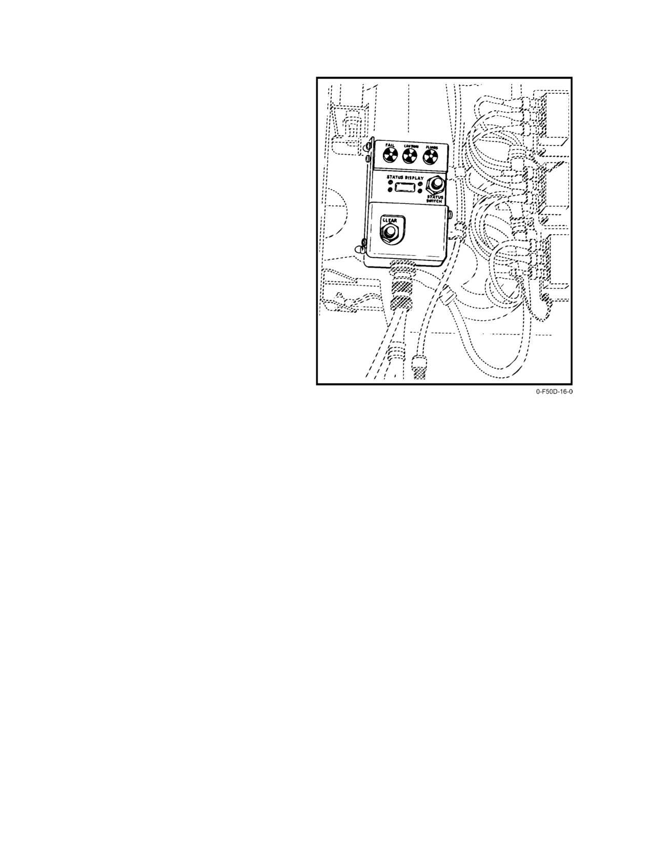
The FMI (Figure 2Ć16) displays to the maintenance
crew ADAC data for engine/airframe status. It is mounted in
an easily accessible location on the forward bulkhead in
the nose wheelwell. After each flight, the FMI FAIL,
CAUTION, and/or FLUIDS fault trip indicators will be
either black, signifying the absence of a FEMS−detected failĆ
ure, or white, indicating FEMS detected a failure. The indicaĆ
tors should normally be reset by maintenance personnel prior
to flight. With electrical power applied to the aircraft, pressĆ
ing the STATUS SWITCH button displays either a fault code
(if a fault is present) or NONE in the STATUS window. All
fault codes may be scrolled line by line by pressing the
STATUS SWITCH button once for each line. When no more
Figure 2Ć16.ĄFlight Maintenance Indicator
fault codes are displayed, the display will read END*. When
END* is displayed, pressing and holding the CLEAR button
changes the display from END* to CLR for approximately
5.
Exhaust nozzle off schedule or signal out of range
5 seconds followed by NONE, erasing all fault codes.
6.
Fan inlet guide vanes off schedule or signal out of
Note
range
The FMI is designed to be a maintenance tool
7.
AB fuel valve operation (dry power)
only and should not be used as a go/no−go device
by aircrew on preflight. Likewise, aircrew
8.
AB fuel schedule fault or signal out of range
should not take it upon themselves to reset the
device. Do not press both CLEAR and STATUS
9.
AB signal on but not selected
SWITCH at the same time. Failure to comply
will result in the FEMS onboard clock being
10. No AB light−off signal
altered.
11. AB blowout
The following is a composite listing of the data autoĆ
12. Secondary mode operation
matically recorded in memory for maintenance and disĆ
played in numeric code on the FMI:
13. Pilot−initiated EMS data
1. Fan/core overspeed
14. Anti−icing fault
2. Decay in core speed or signal out of range
15. Low oil quantity or signal out of range
3. Compressor stall
16. Oil overtemperature
4. Turbine blade temperature limit exceeded or signal
17. AFTC power out of limits
out of range
ORIGINAL
2−20
NAVAIR 01−F14AAD−1
18. Throttle/AFTC signal fault
2.4.1
Motive Flow Fuel Pump
The motive flow fuel pump is a gear−driven centrifugal
19. Mach signal to AFTC fault
pump on each engine accessory gearbox that returns
20. Aircraft 28−volt supply to AFTC fault
high−pressure fuel to the fuselage and wing tanks to effect
normal fuel transfer. Motive flow is used to power the boost
21. EMSP fault
pump in the respective sump tank. This fuel continues
through control valves to ejector pumps in the fuselage and
22. ADAC/EMSP interface fault
wing fuel tanks. There is no cockpit control for the motive
flow fuel pumps. Failure of one pump illuminates the R or L
23. ADAC BIT fault and system failure
FUEL PRESS caution light and reduces the rate of fuel
transfer but does not inhibit the transfer of fuel from any tank.
24. ADAC battery low
Motive flow pump failures cause the engine to draw fuel
through suction feed. Higher altitudes and decreased ambient
25. Data storage set memory full and requires service
pressure result in reduced fuel flow, which may cause engine
flameout because of fuel starvation. With a single motive
26. Aircraft overstress
flow fuel pump failure, AB selection above 15,000 feet MSL
may cause engine flameout. With failure of both motive flow
27. System DSS
fuel pumps, high power settings in basic engine may cause
28. ADAC A−6 failure
flameout above 25,000 feet MSL. If a dual motive flow fuel
pump failure occurs, wing fuel will not be available.
29. RATS failure.
2.4.2
Engine Fuel Boost Pump
2.3.2
FEMS Operation
The engine
(total flow) fuel boost pump is an
FEMS data acquisition for monitoring engine perforĆ
engine−driven centrifugal pump on the aft accessory gearbox
mance is automatic. However, the pilot may encounter
that provides boosted pressure and flow from the fuel supply
unusual engine behavior of a nature that does not automatiĆ
system to meet main and AB fuel requirements. The pump
cally initiate data recording. This data is valuable for
receives fuel at aircraft boost pressure and boosts fuel
diagnosis of the cause of unusual behavior and should be
pressure to levels adequate to operate the engine at all power
recorded by the pilot by depressing the ENG RCD button on
settings
(maximum 40−psi pressure rise). During non−AB
the fuel management panel. Pressing the ENG RCD button
operation, some fuel is circulated between AB fuel control
momentarily causes
21 seconds of engine data to be
and the engine fuel boost pump so that fuel pressure is readily
recorded:
6 seconds before and 15 seconds after switch
available to the spray bars for AB light−off.
initiation. It is important to remember that if a transient
problem is to be recorded by FEMS, the ENG RCD button
2.4.3
Main Fuel Pump
must be activated quickly so the actual event is not missed.
The main fuel pump is a two−stage pump that receives
Manual recording will not interfere with data automatically
fuel flow from the engine fuel boost pump. It provides
saved by the FEMS.
additional fuel pressurization and transmits mechanical−
gear−driven power to the MEC from the gearbox.
2.3.3
FEMS and OBC
FEMS is checked during OBC preflight and in flight
2.4.4
Main Engine Control
(Class III). It is designated by a FEM acronym. This acronym
The MEC is a fuel−operated, hydromechanical fuel
is displayed at the completion of OBC if FEMS fails its BIT
flow regulator that operates in tandem with the main fuel
during OBC. Engine−life tracking data is still available
pump and is capable of operating in two modes. In the
through EMSP if FEMS is lost.
primary mode, it meters main fuel flow as commanded by the
AFTC and provides VSV scheduling. The secondary mode
2.4
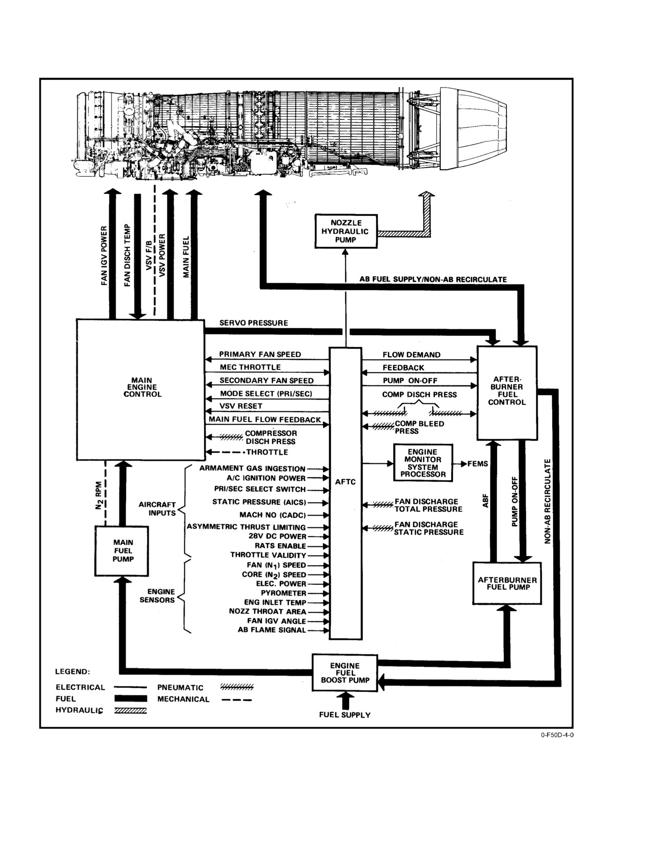
ENGINE FUEL SYSTEM
hydromechanically meters main fuel flow to govern N2 speed
The engine fuel system, which is identical for each
based on pilot throttle commands and provides basic engine
engine, provides motive flow fuel to effect fuel transfer and
control except for AFTC fan speed limiting.
metered fuel for combustion as a function of pilot throttle
commands and numerous engine parameters (Figure 2Ć17).
2−21
ORIGINAL
NAVAIR 01−F14AAD−1
Figure 2Ć17.ĄEngine Fuel System
ORIGINAL
2−22
NAVAIR 01−F14AAD−1
VSVs aerodynamically match high− and low−pressure
2.5
THROTTLES
compressor stages by changing the angle at which airflow
enters the compressor rotor blades. The MEC contains the
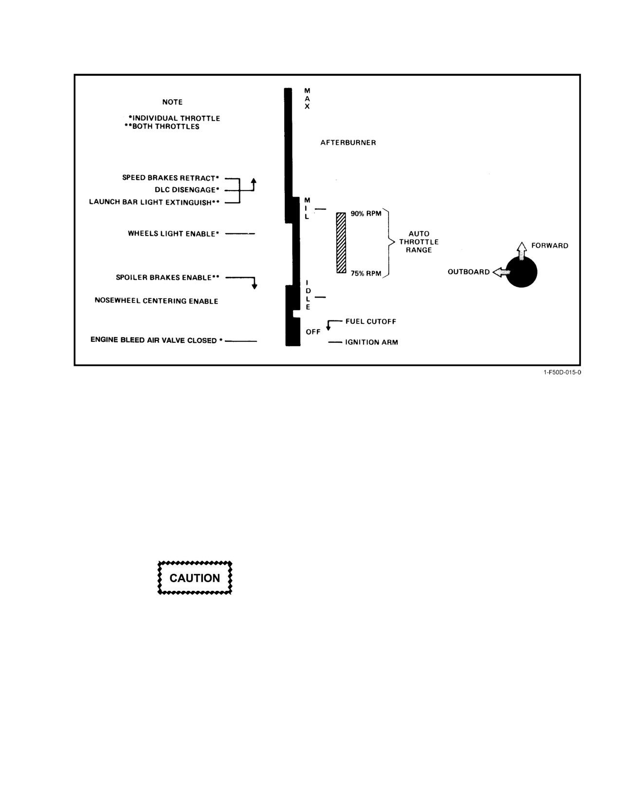
Two throttle levers for regulating engine thrust are on
scheduling mechanism and provides fuel pressure to vary
the left console of the forward cockpit. Unrestricted engine
VSV positioning. A flexible mechanical cable provides feedĆ
operation under independent control is afforded; however,
back from the compressor stator to the MEC.
normal symmetric thrust control is provided by collective
movement of the throttle levers. Numerous engine control
2.4.5
Afterburner Fuel Pump
and subsidiary functions are performed by movement of the
throttle levers within the full range of travel as shown in
The AB fuel pump is a centrifugal gear−driven pump
Figure 2Ć19. The forward and aft throw of each throttle lever
that receives fuel from the engine boost pump, increases
in the quadrant is restricted by hard detents at the OFF, IDLE,
pressure, and delivers fuel to the AB fuel control. During
MIL, and MAX (AB) positions. At the OFF and IDLE detĆ
non−AB operation, fuel is circulated between the AB fuel
ents, the throttles are spring loaded to the inboard position.
control and the engine boost pump; the AB fuel pump
At the MIL detent, the throttles can be shifted outboard to the
impeller runs dry with the bearings lubricated by the engine
AB sector or inboard to the basic engine sector of operation
oil system. Failure of an AB fuel pump will result in an AB
by merely overcoming a lateral breakout force. Lateral shiftĆ
blowout.
ing of the throttles at the MIL detent does not affect engine
2.4.6
Afterburner Fuel Control
control. Thus, placement of the throttle outboard at MIL
provides a natural catapult detent to prevent unintentional
The AB fuel control is a fuel−operated, electrohydroĆ
retarding of the throttles during the launch. This, however,
mechanical unit that regulates fuel flow in response to AFTC
does not inhibit the selection of afterburner. The friction
scheduling and compressor discharge pressure. Fuel pressure
control lever on the outboard side of the quadrant permits
from the AB fuel control provides on−off signals to the AB
adjustment of throttle friction to suit individual requireĆ
fuel pump.
ments. With the friction lever in the full aft position, no
throttle friction is applied at the quadrant; increased throttle
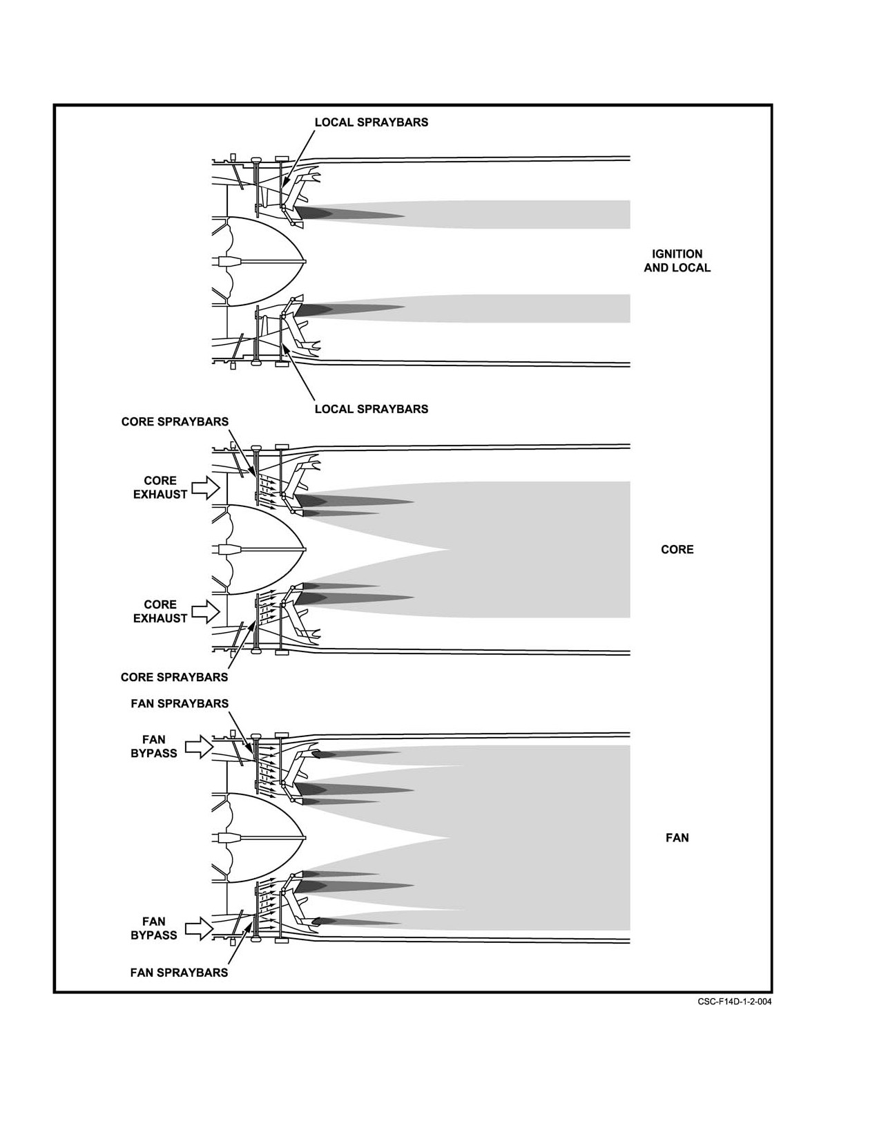
The AB fuel control splits fuel flow into three metered
friction is obtained by forward movement of the lever.
streams (local, core, and fan) on a sequential basis into the
AB manifolds for distribution through spraybars in the AB
A locking pin device prevents the left throttle from
duct. Throttle commands initiate local fuel flow and AB
moving into the cutoff position when the right throttle is
ignition (minimum AB). Once local fuel flow and flame are
either traversing or at rest on the face of the right−hand idle
established, core fuel flow commences. As maximum core
stop block.
fuel flow is established, fan fuel flow commences and
increases until maximum AB is achieved. The transitions
between local, core, and fan fuel flow are smooth and
2.5.1
Throttle Control Modes
unnoticed
(Figure 2Ć18). During non−AB operation, fuel
flow is circulated through the AB manifolds to prevent thrust
Manual, boost, and automatic are the three modes of
lags and surges when AB is initiated.
throttle control over engine operation selectable by the
THROTTLE MODE switch located outboard of the quadrant
on the pilot console. The toggle switch must be lifted out of
a detent to select MAN from BOOST or BOOST from MAN.
The switch is solenoid held in AUTO upon successful
D Zero− or negative−g flight longer than 10 secĆ
engagement of the automatic mode. A functional schematic
onds in AB or 20 seconds in MIL or less will
of throttle control modes, including system major compoĆ
deplete the fuel sump tanks (cells 3 and 4),
nents, is shown in Figure 2Ć20. Except for the autothrottle
resulting in flameout of both engines.
computer and mode control switch, the throttle control
system for each engine is completely redundant. Independent
D To prevent engine instability and/or flameout,
engine operation is possible in the manual or boost mode of
avoid holding zero or negative g when doing
throttle control; however, full system operation is necessary
a low−altitude, maximum−thrust acceleration.
in the automatic mode since operation under single−engine
D With fuel in feed group below 1,000 pounds,
control is impracticable because of asymmetric thrust
AB operation could result in AB blowout.
considerations.
Note
Fuel dump operations with either engine in AB
are prohibited. The fuel dump mast can be
torched.
2−23
ORIGINAL
NAVAIR 01−F14AAD−1
Figure 2Ć18.ĄAfterburner Fuel Sequencing
ORIGINAL
2−24
NAVAIR 01−F14AAD−1
Figure 2Ć19.ĄThrottle Interlocks
2.5.1.1
Manual Throttle Mode
electric clutch in the throttle servoactuator, which is also
mounted to the power lever shaft, is disengaged in the manual
The manual throttle is a degraded mode of operation
mode to reduce operating forces.
and was designed as a backup system. Because of hysteresis
With the throttle friction lever in OFF, approximately
and friction in the manual system, engine rpm may vary from
8 pounds of force per throttle must be applied at the grip to
the boost mode at a given throttle position. If an engine fails
operate the throttles in the IDLE to MAX range.
to secure when the throttle is moved to the OFF position, the
throttles have probably reverted to the manual mode and are
2.5.1.2
Boost Throttle Mode
slightly out of rig. Cycling the throttle switch to MAN and
back to BOOST may allow engine shutdown. If shutdown is
The boost mode of throttle is used for normal
unsuccessful, then the engine may be secured with the FUEL
operations. A force of 2 to 3 pounds at the grip is required to
SHUTOFF handle.
move each throttle throughout its range with the throttle
friction lever off. Essentially, the boost mode provides
electric throttle operation, with the push−pull cables serving
as a backup control path. Throttle movement is detected by
the throttle position sensor. The signal is resolved in the
amplifier to provide positional followup commands to the
D Engine shutdown at high power settings using
actuator. Movement of the actuator rotates the engine power
the FUEL SHUTOFF handle may result in
lever shaft, which drives the push−pull cable.
damage to the aircraft fuel system.
If a boost system malfunctions, applying approxiĆ
D Engine startup in manual mode may cause
mately 17 pounds at the throttle grip automatically reverts the
tailpipe fires as fuel flow may not be secured.
throttle control to the manual mode by disengaging the
In the manual mode of operation, movement of each
actuator electric clutch. The throttle control reverts to
throttle is mechanically transmitted to the respective engine
manual mode in 0.25 second. In the event of a boost system
by a push−pull cable and a rack and sector mechanism
malfunction, the throttle mode switch will remain in the
mounted to the main engine control power lever shaft. An
BOOST detent. By manually placing the throttle mode
2−25
ORIGINAL
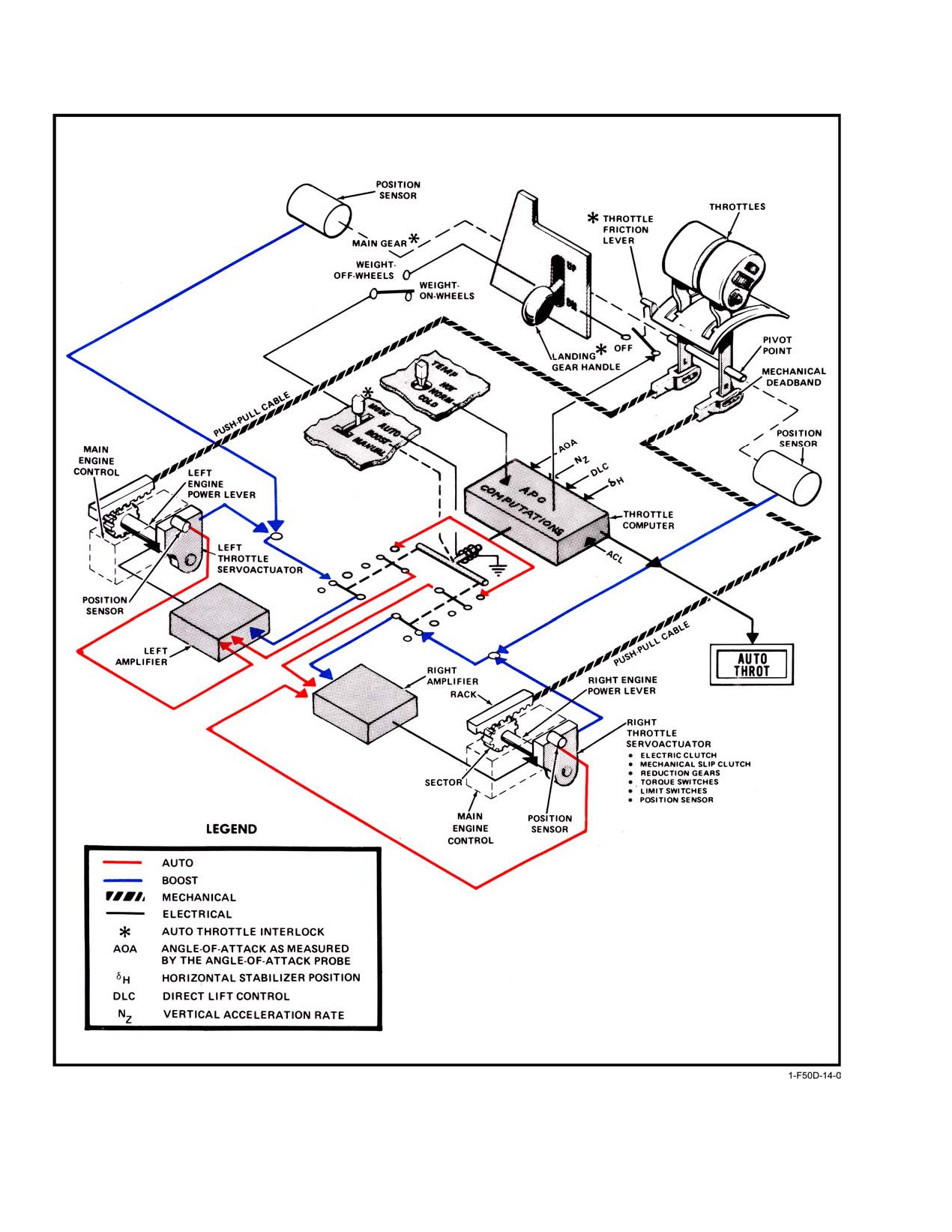
NAVAIR 01−F14AAD−1
Figure 2Ć20.ĄThrottle Control
ORIGINAL
2−26
NAVAIR 01-F14AAD-1
switch in MAN and then back to BOOST, transient failures
selecting AUTO to ensure a valid test. Once AUTO is
in the boost mode can be reset. Additionally, if an actuator
engaged, the control stick should be programmed fore and aft
seizes, a mechanical clutch in the actuator will slip when a
to check for the appropriate power response.
force of approximately 50 pounds is applied at the throttle
grip. This permits the pilot to override an actuator seizure.
There is no visible warning of these anomalies only the
noticeable increase in the forces required to manipulate the
affected throttle.
High-power settings may result during aft stick
2.5.1.3
Approach Power Compensator
deflection.
(Automatic Throttle Mode)
If the THROTTLE MODE switch does not remain
The automatic mode of throttle control is a closed-loop
engaged or the APC does not respond properly to indicated
system that automatically regulates basic engine thrust to
AOA and longitudinal stick movements, a malfunction exists
maintain the aircraft at 15 units angle of attack for landing.
in the autothrottle system.
All components of the throttle control system except the
throttle position sensor are used in the automatic mode of
Depressing and holding the autopilot emergency dis-
control. The AOA signal from the AOA probe on the left side
engage paddle switch with weight on wheels causes the
of the forward fuselage is the controlling parameter within
throttle control system to be placed in the manual mode. If the
the autothrottle computer. Additional parameters are inte-
automatic mode was selected before depressing the paddle
grated within the computer to improve response. The air
switch, the THROTTLE MODE switch will automatically
temperature switch on the pilot left console effects a
move to BOOST. The THROTTLE MODE switch must be
computer gain change to compensate for pilot-preferred
moved from BOOST to MAN while holding the paddle
reaction rate. In order to engage the autothrottle, throttles
switch depressed if the manual mode is desired after the
must be between 75 to 90-percent rpm with weight off
paddle switch is released.
wheels, gear handle down, and throttle friction off. With all
conditions met, the throttle mode switch will be held by an
2.6
ENGINE BLEED AIR
electrical solenoid when placed in AUTO. The throttle
control mode automatically reverts to the boost mode upon
Bleed air is extracted from the high-pressure compres-
interruption of any interlock in the system or by manually
sor to perform engine-associated services and to supply hot,
overriding the throttles with a force of approximately
high pressure air for operation of auxiliary equipment.
11 pounds per throttle in either direction. The throttle
Fifth-stage bleed air supplies hot air for the engine anti-icing
mode switch automatically returns to BOOST and the
system and is used to draw cooling air through the aircraft
AUTO THROT caution light illuminates for 10 seconds.
hydraulic heat exchangers to cool flight and combined
See Figure 2-21 for autothrottle controls.
fluids and to ventilate the nacelle when weight is on wheels
(Figure 2-22). Ninth-stage bleed air supplies hot air to the
The pilot can revert from automatic to boost mode by
environmental control system, provides air for crossbleed
selecting the CAGE/BRST (UP) position on the CAGE/
engine starts, and draws air through the integrated drive
SEAM switch located on the inboard throttle grip. This pro-
generator heat exchanger (ventral fin) when weight is on
vides a smooth throttle override for an automatic-to-boost
wheels.
mode approach, while maintaining a grip on both throttles.
2.6.1
Engine Anti-Ice
2.5.1.3.1
Autothrottle Test
The fan IGV and nosedome are susceptible to icing
An automatic check of the autothrottle control system
undera widerrange ofconditions,particularlyatstatic orlow
while on deck is accomplished during OBC. Signals to the
speed with high engine rpm, than that which cause ice to form
servoactuators are inhibited during the OBC autothrottle test
on external surfaces of the airframe. Ice formation at the fan
so that the engines remain at idle thrust. A malfunction is
face can restrict engine maximum airflow, which results in a
indicated by an APC acronym at the conclusion of OBC.
thrust loss, decreased stall margin, and dislodgment of ice,
which can damage the compressor. The engine anti-icing
Rotating the MASTER TEST switch to FLT GR DN
system is designed to prevent the formation of ice rather than
and depressingit bypassesthe autothrottle weight-on-wheels
de-ice the IGV and nose dome. Hot bleed air (5th stage) is
interlock and an end-to-end check of the autothrottles may be
passed through the hollow IGV to the nose dome and is
performed on deck. The throttles should be placed at about
discharged into the engine along the vanes and at the rotor
80-percent rpm and the throttle mode switch placed in
hub. Cockpit control of the engine anti-icing system is
AUTO. The throttles must be positioned above idle before
effected through the ANTI-ICE switch (Figure 2-23).
2-27
CHANGE 1
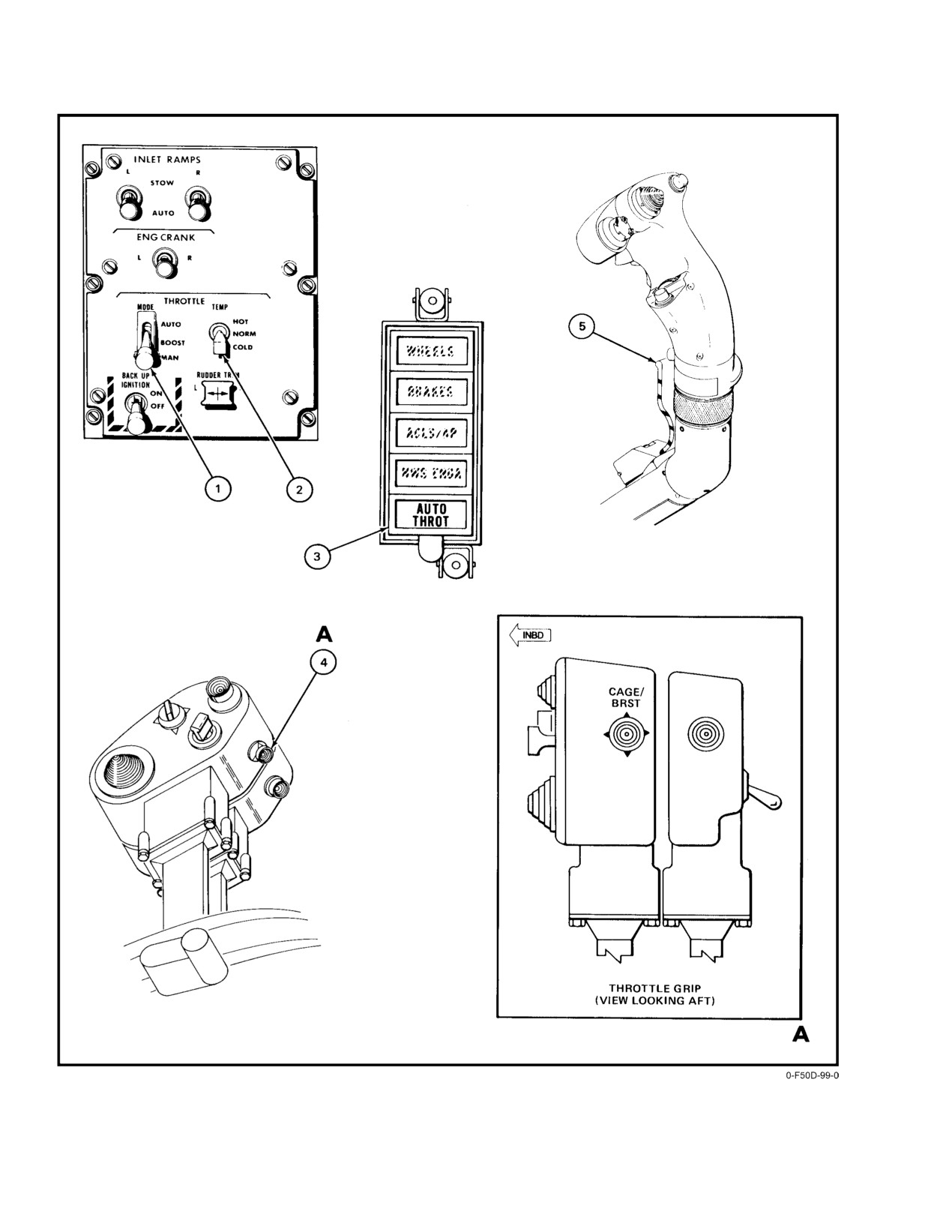
NAVAIR 01−F14AAD−1
Figure 2Ć21.ĄAutothrottle Controls and Indicators (Sheet 1 of 2)
ORIGINAL
2−28
NAVAIR 01−F14AAD−1
NOMENCLATURE
FUNCTION
1
THROTTLE MODE switch
AUTO Ċ Engine thrust is automatically regulated by the throttle control computer
to maintain optimum angle of attack for landing.
BOOST Ċ Normal operating mode. Reduces effort required to move throttles
manually with friction control aft.
MAN Ċ Movement of each throttle is mechanically transmitted to the respective
engine cross−shaft by a push−pull cable.
2
THROTTLE TEMP switch
Used with the AUTO throttle mode to effect throttle computer gain changes to
compensate for air temperature.
HOT Ċ Increases normal throttle computer gain.
NORM Ċ Normal throttle computer gain.
COLD Ċ Decreases normal throttle computer gain.
3
AUTO THROT caution light
Auto throttle mode is disengaged. During preflight check, remains illuminated for
10 seconds, then goes off and throttle mode switch automatically returns to BOOST.
Note
If the auto throttle is disengaged by deselecting the throttle
mode switch, the AUTO THROT light will not illuminate.
4
CAGE/SEAM switch
When in TLN master mode with the throttle mode switch in AUTO, selecting the
CAGE/BRST position on the CAGE/SEAM switch reverts the throttles to the
BOOST mode.
5
Autopilot emergency paddle
Reverts throttle system from AUTO or BOOST mode to MAN mode only while
disengage depressed and with weight on wheels.
Figure 2−21. Autothrottle Controls and Indicators (Sheet 2 of 2)
Note
from 520° to 1,180_ F inside the bleed air portion of the
ECS, and from 400_ to 500_ F inside the hot air portion
Because of its adverse effects on engine perforĆ
(400_ F manifold).
mance, the engine anti−icing system should be
used only when icing conditions exist or are
The entire bleed air portion of the ECS, from engine
anticipated.
bleed air shutoff valves to the primary heat exchanger, is monĆ
During engine start, the engine anti−ice valve remains
itored by two detection systems. Fire detection circuits moniĆ
open to bleed the compressor to prevent engine stall. The
tor the bleed air system from each engine to its respective
valve closes when the engine approaches idle rpm. In flight,
firewall. When a fire detection circuit in an engine compartĆ
the valve is normally closed unless the ANTI−ICE switch is
ment senses temperatures above threshold, the appropriate
in ORIDE/ON, or AUTO/OFF, when the ice detector probe
L or R FIRE warning light illuminates (refer to fire detection
in the left inlet is activated. Ice accumulation on the ice
system). The remainder of the bleed air system, from engine
detector illuminates the INLET ICE caution light. The
firewalls to the primary heat exchanger, is monitored by bleed
engine anti−icing control valve on the engine is powered
air leak−sensing elements. When the bleed air leak−detection
closed (fails open) from the essential dc No. 2 bus through the
circuit detects temperatures in excess of 575_ F, the BLEED
ENG/PROBE/ANTI−ICE circuit breaker (RG2).
DUCT caution light illuminates.
2.6.2
Environmental Control System
The hot air portion of the ECS is monitored by hot air
Leak Detection
leak−sensing elements. The hot air system extends from the
primary heat exchanger through the 400_ manifold to the
Thermal detection circuits are routed in proximity to
cockpit floor. When the hot air detection circuit detects
ECS ducts and components to provide cockpit indications of
temperatures in excess of 255_ F, the BLEED DUCT caution
high−temperature air leaks. Normal air temperatures range
light illuminates.
2−29
ORIGINAL
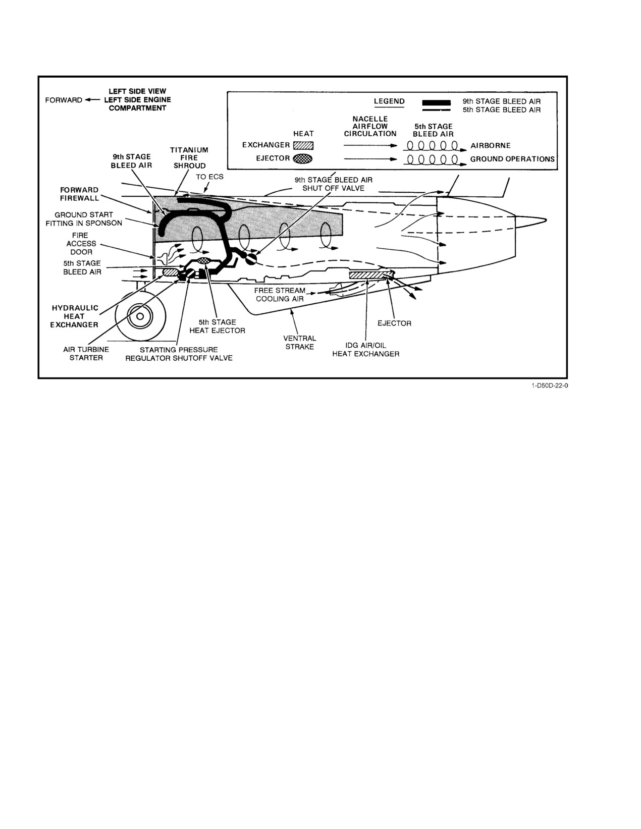
NAVAIR 01−F14AAD−1
Figure 2Ć22.ĄEngine Bleed Air/Compartment Ventilation
2.7
ENGINE COMPARTMENT VENTILATION
2.7.2
Engine Ground Ventilation
With weight on wheels, cooling airflow through the
Each engine compartment is completely isolated from
engine compartment is induced by the hydraulic heat
the primary air inlet, and the efficiency and cooling of the
exchanger ejector in the forward end of the compartment. Air
variable−area exhaust nozzle are not dependent upon nacelle
enters through the nacelle ram−air scoop on the left side, passes
airflow. Therefore, within the bounds of the forward firewall
through the hydraulic heat exchanger and is discharged into
(landing gear bulkhead) and the nozzle shroud, the cooling
the engine compartment. The air flows through the full length
system for each engine compartment is a separate entity.
of the nacelle to discharge overboard through a louvered port
Cooling requirements for the turbofan engine are mini−
atop the nacelle on the outboard side of the vertical tail.
mized by the annular fan bypass duct. Figure 2Ć22 shows
cooling airflow patterns through the engine compartment
2.8
ENGINE IGNITION SYSTEM
during ground and flight operations. Two air−cooled heat
exchangers are also shown; however, only the hydraulic
There are three electrical ignition circuits, each utilizing
heat exchanger cooling airflow is associated with engine
a dedicated igniter, for each engine: main high energy, afterĆ
nacelle cooling. Fire access doors are on the outboard side
burner, and backup.
of the nacelles at the forward end to permit application of
fire suppressing agents by ground personnel in event of an
2.8.1
Main High−Energy Ignition
engine compartment fire.
The main high−energy ignition provides ignition in the
2.7.1
Engine In−Flight Ventilation
combustion chamber for ground and air starts. It is powered
by one of the four windings in the engine−driven ac alternator.
In−flight cooling of the engine compartment is accomĆ
The AFTC provides logic to control main high−energy igniĆ
plished by nacelle ram−air scoops, circulating boundary−
tion automatically. Ignition is available when N2 rpm is 10
layer air through the length of the compartment and expelling
percent or greater and is automatically provided from 10−to
the air overboard through louvered exits, just forward of the
59−percent rpm when the throttle is above cutoff. Ignition
engine nozzle shroud.
ORIGINAL
2−30
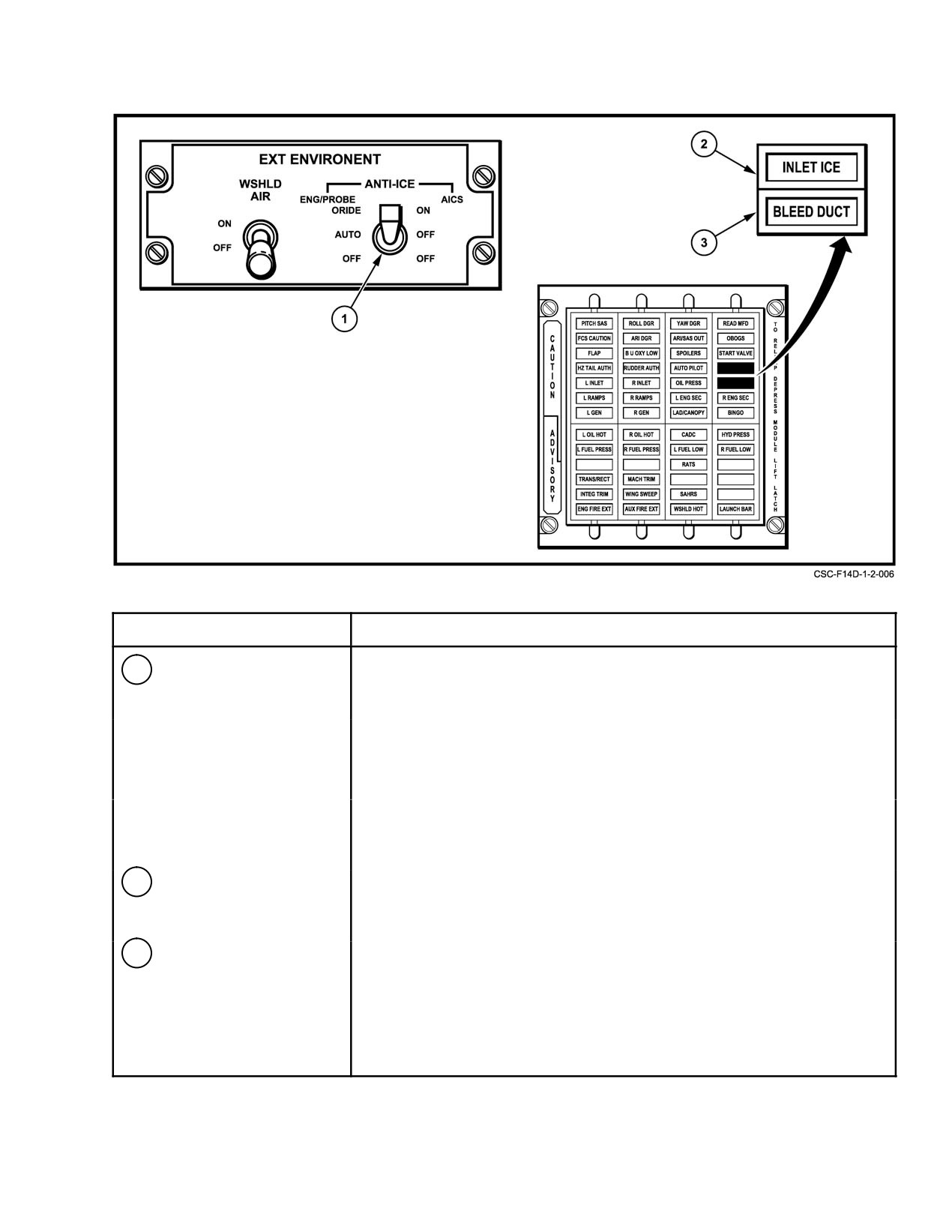
NAVAIR 01−F14AAD−1
NOMENCLATURE
FUNCTION
1
ANTI−ICE switch
ORIDE/ON Ċ Overrides ice detector system to turn on INLET ICE caution
light, and activate external probe heaters and engine anti−ice.
Commands the anti−ice mode to the AICS programmers.
AUTO/OFF Ċ When icing is sensed, ice detector activates engine anti−ice
system, turns on INLET ICE caution light, activates external
probe heaters with weight off wheels, and disables anti−ice
mode to AICS programmers.
OFF/OFF Ċ Engine anti−ice system and probe heaters shut off. INLET
ICE caution light disabled. Disables anti−ice mode to AICS
programmers.
2
INLET ICE caution light
Illuminates when ice accumulates on ice detector with ANTI−ICE switch in
AUTO/OFF or if ORIDE/ON is selected. Does not illuminate with switch
in OFF/OFF.
3
BLEED DUCT caution light
Illuminates when bleed air leak sensing elements detect temperatures
greater than 575_ F between the left and right firewalls, past the primary
heat exchanger and up to the right diverter area. Also illuminates when an
additional sensor detects temperatures of 255_ or greater from the right
diverter area, along the 400_ manifold and into the bootstrap turbine
compartment.
Figure 2Ć23.ĄAnti−Ice Control
2−31
ORIGINAL
NAVAIR 01−F14AAD−1
is secured 0.5 second after N2 rpm rises above 59 percent. At
The air hose is connected to the aircraft fitting in the
rpm above 59 percent, ignition is provided if N2 deceleration
left sponson area, behind the main gear strut. Ground start air
exceeds a 5 percent rpm per second rate. Ignition continues
is ducted into a central bleed air (9th stage) manifold, which
for 20 seconds after N2 deceleration falls below the 5 percent
interconnects the air turbine starters on both engines.
rpm per second rate. Main high−energy ignition is provided
The air supply to each air turbine starter is pressure reguĆ
continuously when the engine is in the secondary (SEC) mode.
latedĂ(52.5 psi) and controlled by a shutoff and regulating
valve at the turbine. Each pneumatic starter is composed of
2.8.2
Afterburner Ignition
a turbine, gear train, sprag clutch with a speed−sensing
device, and an overspeed disengagement mechanism with a
The AB ignition ignites AB fuel flow for AB light−offs
shear section. Shutoff valves in the bleed air manifold selecĆ
and relights (in the event of an AB blowout). The AB ignition
tively isolate the other starter, subsidiary bleed lines, and the
is powered by the same winding in the engine−driven alternaĆ
environmental control system air supply. Maximum engine
tor that powers the main energy ignition. The AFTC provides
motoring speed with the pneumatic starter is approximately
logic to control AB ignition automatically and prevents
30−percent rpm.
simultaneous powering of the main high−energy and AB igniĆ
tions. In the event of an AB blowout, relight is normally
2.9.2
Engine Crank
provided within 1.5 seconds. AB ignition is not powered if
the engine is in SEC mode.
Placing the ENG CRANK switch in either L or R opens
the corresponding starter pressure shutoff valve to allow
2.8.3
Backup Ignition
pressurized air to drive the turbine. The ENG CRANK switch
energizes the appropriate shutoff valves to configure the
The backup ignition provides ignition in the combusĆ
bleed manifold for starting.
tion chamber for ground and air starts when the BACK UP
IGNITION switch on the THROTTLE CONTROL panel is
2.9.2.1
Engine Crank Switch
set to ON. It is powered by the essential No. 1 ac bus and
provides less power than main high−energy ignition. After
The ENG CRANK switch is held in L or R by a holding
use, the BACK UP IGNITION switch should be set to OFF.
coil. At approximately 50−percent rpm, a centrifugal cutoff
To allow ground checkout of backup ignition, main high−
switch closes the turbine shutoff valve and returns the ENG
energy ignition is disabled when the BACK UP IGNITION
CRANK switch to the center or off position. A START
switch is ON and weight is on wheels.
VALVE caution light illuminates if the starter valve remains
in the open position after the ENG CRANK switch automatiĆ
cally returns to the center (off) position.
The BACK UP IGNITION switch shall be
selected to OFF prior to applying external elecĆ
trical power to prevent ignition of fuel puddled
D If the starter valve does not close during
in the engine.
engine acceleration to idle rpm, continued airĆ
flow through the air turbine starter could
2.9
ENGINE STARTING SYSTEM
result in catastrophic failure of the starter
turbine.
Each engine is provided with an air turbine starter that
D If the START VALVE caution light illumiĆ
may be pressurized from an external ground starting cart or
nates after the ENG CRANK switch is off,
by crossbleeding high−pressure bleed air from the other
select AIR SOURCE to OFF to preclude
engine. Figure 2Ć24 shows the components associated with
starter overspeed.
the engine start system.
D If the ENG CRANK switch does not automatiĆ
cally return to the OFF position by 50 percent,
2.9.1
External Airstart
ensure that the ENG CRANK switch is off by
60−percent rpm to avoid starter turbine failure
A high−pressure (75 psi) air source and 115 volt, 400 Hz
as a result of an inoperative automatic starter
ac power are required for engine start on the deck.
cutout.
ORIGINAL
2−32
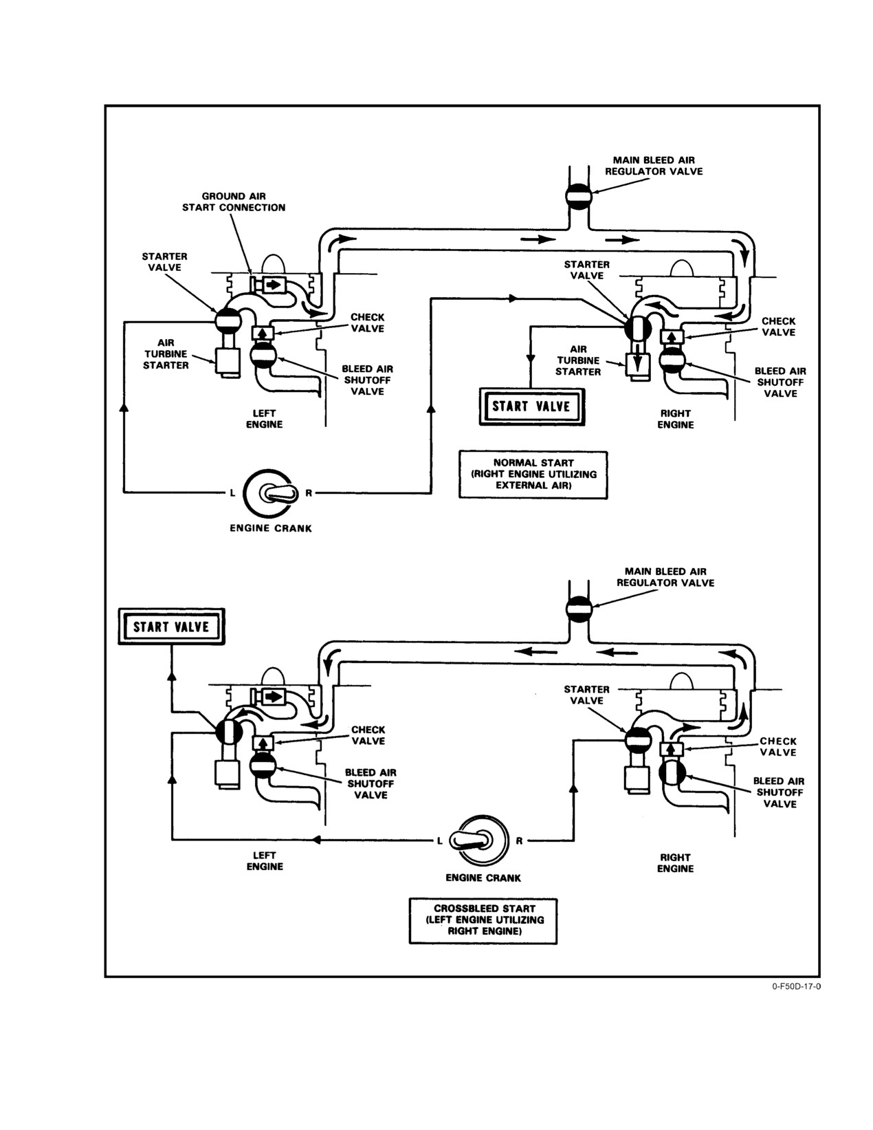
NAVAIR 01−F14AAD−1
Figure 2Ć24.ĄEngine Start System
2−33
ORIGINAL
NAVAIR 01−F14AAD−1
Return of the ENG CRANK switch to the center or off
D When attempting a crossbleed or normal
position resets the bleed air manifold valves to permit 9th−
ground start, do not attempt to reengage the
stage bleed air to flow to the environmental cooling system
ENG CRANK switch if the engine is spooling
and ejectors in the engine compartment.
down and rpm is greater than 46 percent. At
rpm’s of 30 to 46−percent rpm, the ENG
Starter cranking limits:
CRANK switch may not stay engaged
because of normal variations in starter cutout
1. Crossbleed
2 minutes continuous then
10
speed.
minutes OFF.
D The ENG CRANK switch should automatiĆ
cally disengage between 49 to 51−percent rpm
2. Start cart 5 minutes continuous then 10 minutes
OFF.
during a crossbleed or normal ground start.
2.9.4
Airstarts
2.9.3
Crossbleed Start
AFTC logic provides main high−energy ignition autoĆ
Engine cranking procedures during a crossbleed start
matically during automatic and manual spooldown, crossĆ
are the same as with a ground start cart. Engine crossbleed
bleed, and windmill airstarts. Selecting the BACKUP
start on the ground can be accomplished with the throttle on
IGNITION switch to ON provides continuous backup
the operating engine at or above idle rpm. When high−
ignition to both engines, and backs up main high−energy
residual EGT (remains from a hot start) and/or throttles are
ignition during manual spooldown, crossbleed, and windmill
advanced from OFF to IDLE prior to 20−percent rpm, higher
airstarts.
than normal EGT readings may occur.
2.10 ENGINE OIL SYSTEM
When initiating crossbleed starts with ambient temperĆ
ature less than
40° F (4° C), the starter torque load is
increased. Above 80° F (27° C), engine bleed air provides
Each engine has a self−contained, dry sump non−
less energy potential to the starter turbine. Either extreme can
pressure regulated oil system that provides filtered oil for
affect engine starting acceleration rates, resulting in hotter−
lubricating and cooling engine main shaft bearings, oil seals,
than−normal starts. When crossbleed starting with an operatĆ
gearboxes, accessories, and provides a hydraulic medium to
ing engine at idle, the operator should be aware of either
operate the engine exhaust nozzles (FO−5).
condition and increase the operating engine rpm in 5−percent
increments until normal starting acceleration rate is
A storage tank feeds oil to an oil pump that supplies oil
achieved. Low percentage rpm−to−EGT ratio can increase
under pressure to the forward sump in the engine front hub,
turbine distress without necessarily exceeding the EGT limit.
the mid sump in the fan hub, the aft sump in the turbine hub,
and the inlet and accessory gearboxes. Oil is recovered from
When performing an idle crossbleed start, advance the
the sumps and accessory gearboxes, pumped past a chip
throttles from OFF to IDLE at 20−percent rpm or greater
detector, and cooled in a fuel/oil heat exchanger before
while monitoring EGT. If EGT rises rapidly, advance the
returning to the storage tank.
operating engine rpm to slightly above idle. The exhaust
nozzles start to close when rpm is slightly above idle.
A separate compartment in the storage tank provides
oil to the exhaust nozzle hydraulic system. Oil returning from
Note
the nozzle to the tank provides auxiliary oil supply to the
No. 3 bearing when normal supply is interrupted or during
engine spooldown.
D To prevent possible engine overtemperature
during crossbleed and backup ignition start
The oil system permits engine operation under all flight
attempts, select AIR SOURCE for the operĆ
conditions. During zero− or negative−g flight, oil pressure may
ating engine and return to BOTH after rpm
decrease to zero but will return to normal when positive−g
stabilizes at idle or above.
flight is resumed. Normal oil consumption is 0.03 gallon per
D If attempting a ground restart after a hot start,
operating hour with the maximum being 0.1 gallon per operĆ
windmill the engine until EGT is below
ating hour. Capacity of the oil storage tank is 3.7 gallons,
250° C prior to advancing the throttle from
with 2.9 gallons usable. A sight gauge on the side of the
OFF to IDLE to avoid a subsequent hot start.
ORIGINAL
2−34
NAVAIR 01−F14AAD−1
storage tank indicates down to a 2−quart−low oil level. The
300° F during a temperature increase and go out at 280° F
protrusion of a bypass indicator underneath the oil scavenge
minimum during a temperature decrease. The caution lights
pump indicates a clogged filter element.
also illuminate when respective forward engine gearbox
scavenge temperature exceeds 375° F during a temperature
Note
increase, and go out at 345° F minimum during a temperature
decrease.
D Engine oil level must be checked within
2.11 ENGINE INSTRUMENTS
30Ăminutes of engine shutdown, otherwise the
engine must be run at 80−percent rpm or greater
Instruments for monitoring engine operation are on the
for 10 minutes to ensure proper servicing.
pilot left knee panel (Figure 2Ć25). Engine operating parameĆ
D A failed−open nozzle may indicate an oil leak;
ters are displayed on the engine instrument group which is a
however, if the leak is in the nozzle hydraulic
single WRA with LCD readouts. The display provides white
circuit, only that portion of the main engine
readout segments and scales on a dark backg0round and is red
lube oil will be lost.
backlighted for night operations. Left and right engine comĆ
pressor speed (rpm), EGT, and fuel flow are displayed on the
2.10.1
Oil Cooling
EIG. Adjacent to the EIG are circular instruments for both
engines’ oil pressure and nozzle position. Takeoff checks at
Filtered and scavenged oil is cooled by a fuel/oil heat
military (MIL) thrust should display evenly matched tapes on
exchanger. This oil is then used in a heat exchanger to cool
corresponding vertical scale instruments and all pointers on
the exhaust nozzle oil. A cold−oil bypass valve opens when
the circular instruments should be at the 9−o’clock position.
the heat exchanger pressure differential is 44 psi, because of
Data on engine operating limits are provided in Chapter 4.
reduced oil temperature or exchanger blockage, allowing oil
flow to bypass the heat exchanger (for example, during cold
2.11.1
Engine RPM Indicator
engine starts).
The RPM indicators (Figure 2Ć25) have a range of 0 to
2.10.2
Oil Pressure Indicators
110 percent. The tape display steps in 5−percent increments
and the upper segment flashes to indicate rpm increasing at
An oil pressure transducer in each engine’s oil supply
more than 0.4 percent per second from 0 to 60−percent rpm.
line provides a continuous signal to the oil pressure indicator.
The tape steps in 1−percent increments when greater than
Another, independent oil pressure switch in each oil supply
60−percent rpm. Nominal indications are 62 to 78 percent at
line activates the OIL PRESS light when either engine’s oil
idle and 95 to 104 percent at military and above. At 107.7
pressure decreases to 11 psi. The oil pressure switches and
percent and above, the affected engine’s exceeded portions
lights receive electrical power from the essential No. 2 ac
of the chevrons will flash at a rate of 2 to 3 flashes per second.
bus. The OIL PRESS light and oil pressure indicator are
At 20−percent rpm a horizontal segment will illuminate
independent of each other.
giving an indication of proper motoring speed to start the
engine. There is an rpm reading for each engine.
Note
Note
D During cold starts, oil pressure may exceed
An overspeed condition in excess of 110 percent
65 psi. The 65 psi oil pressure limit should not
will result in momentary loss of rpm indication
be exceeded for more than 1 minute.
until N2 rpm falls below 110 ± 0.5 percent. EGT
D Maneuvers that result in zero or negative−g on
and fuel flow indicators will continue to function
the engine (such as rapid rolls, pushovers, or
normally.
bugout maneuvers) may cause oil pressure
fluctuations and momentary illumination of
2.11.2
Exhaust Gas Temperature Indicator
the low oil−pressure light.
The EGT indicators (Figure 2Ć25) provide a nonlinear
2.10.3
OIL HOT Caution Lights
vertical scale with a range of 0 to 1,100° C. The compressed
lower portion has a range of 0 to 600° C. The expanded
The L or R OIL HOT caution light may be illuminated
upper portion of the scale has a range of 600 to 1,100° C.
by either high engine oil temperature or by high forward−
The display moves in 50° increments in the compressed
engine gearbox scavenge oil temperature. The caution lights
portion and 10° increments in the expanded portion of the
illuminate when respective engine oil temperature exceeds
2−35
ORIGINAL
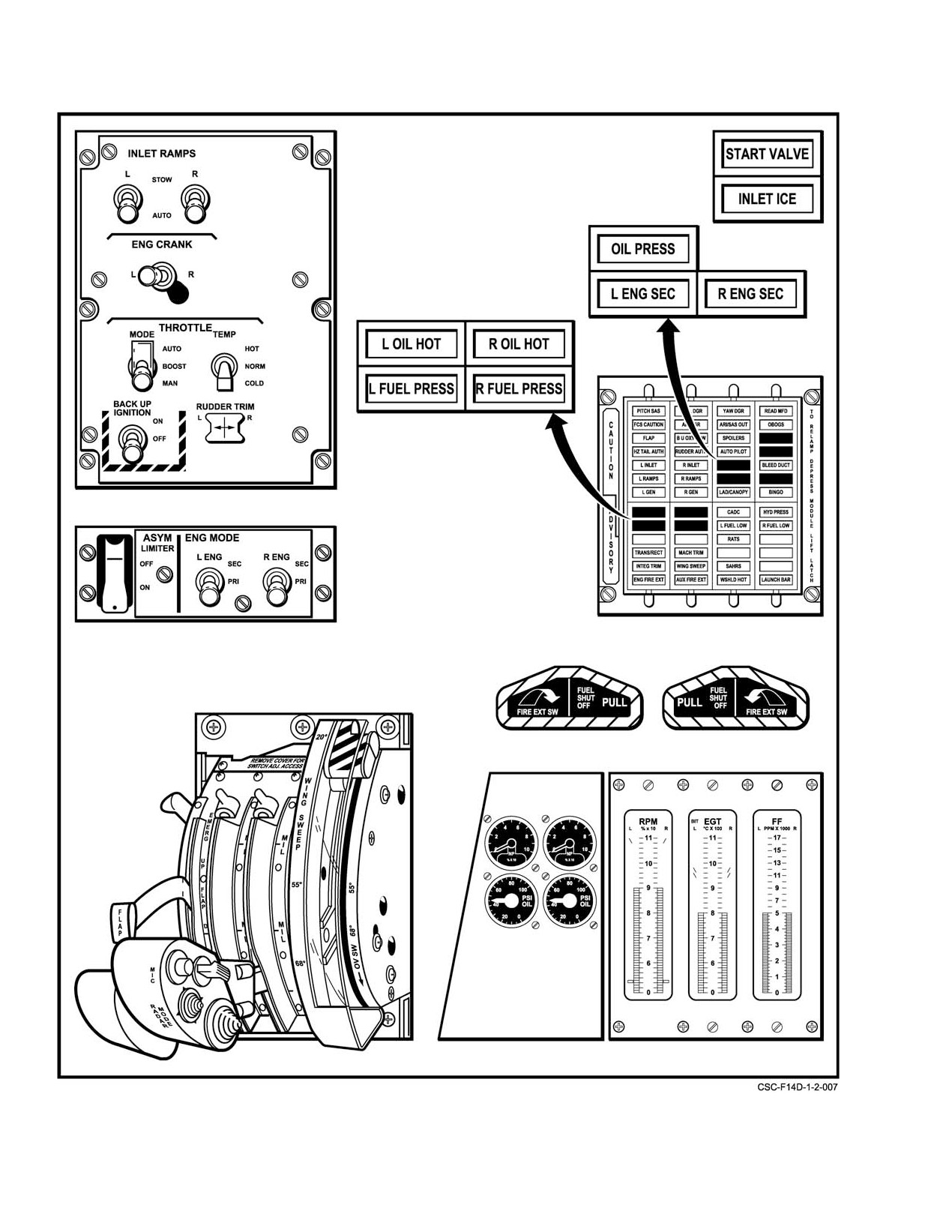
NAVAIR 01−F14AAD−1
Figure 2Ć25.ĄEngine Instruments (F110−GE−400)
ORIGINAL
2−36
NAVAIR 01−F14AAD−1
display. The normal indications are 350 to 650° C at idle and
2.11.6
Engine Oil Pressure Indicator
780 to 935° C at MIL and above. Above 940° C, the affected
engine’s exceeded portions of the chevrons flash. With a
The engine oil pressure indicators display oil pressure
reading of 940° C, the stall warning light and the aural
from 0 to 100 psi. Normal oil pressure is 25 to 65 psi and
warning tone will be activated signifying an engine overĆ
increases in proportion to engine rpm within the pressure
temperature condition. The tone is present for a maximum of
limit range. Stabilized idle oil pressure may be a minimum
10 seconds unless the fault clears sooner. There is an EGT
of 15 psi. The OIL PRESS caution light illuminates at 11 psi
reading for each engine.
with decreasing oil pressure and extinguishes at 14 psi with
increasing oil pressure. Maximum allowable oil pressure
2.11.3
Fuel Flow Indicator
fluctuation is ± 5 psi.
The fuel flow indicators have a nonlinear vertical scale,
2.11.7
Exhaust Nozzle Position Indicator
with a range of 0 to 17,000 pph. The expanded lower portion
of the scale has a range of 0 to 5,000 pph. The compressed
The nozzle position indicators
(Figure 2Ć25) have
upper portion of the scale ranges from 5,000 to 17,000 pph.
a range of
0 to
100−percent open. Normal indications
The display moves in 100 pph increments in the expanded
(Figure 2Ć13) are l00 percent at idle with WOW and vary in
portion and in 500 pph increments in the compressed portion
flight:
3 to 10 percent at MIL thrust, 5 to 12 percent at
of the display. Normal indications on deck are 350 pph
MIN AB, and 60 to 90 percent at MAX AB.
starting, 950 to 1,400 pph at idle, and approximately 10,100
pph at military and above. The fuel flow reading for each
Note
engine indicates only basic engine consumption and does not
indicate AB fuel flow.
When operating engine in SEC mode, the nozzle
position indicator is inoperative and indicates
2.11.4
Engine Instrument Group BIT
below zero. No nozzle position indication is
available in SEC mode.
A degraded mode of EIG operation is indicated if the
2.11.8
Engine Monitor Display Format
BIT segment on the top left side of the EGT indicator illumiĆ
nates. This means that either the primary or backup microĆ
processors, or the primary or backup power supply channels
A display of engine parameters (Figure 2Ć26) can be
(internal to the EIG), have failed. An automatic switch to the
selected on the MFD by pressing the pushbutton adjacent to
operative microprocessor/channel takes place if a failure is
the ENG legend on the own−aircraft menu. The display preĆ
detected. The instrument still monitors engine operation and
sents N1 (fan speed), TBT (turbine blade temperature), FF/M
accurately reflects rpm, EGT, and fuel flow. If the input
(fuel flow main engine) or FF/T (fuel flow total, main engine
processing circuit fails, the affected scale reading goes to zero.
and AB), and NP (exhaust nozzle position). FF/M scale indiĆ
cates main engine fuel flow and is similar to the fuel flow
2.11.5
Engine Instrument Group Self−Test
displayed on the EIG. NP is the same as the nozzle position
indicators. Numerical readouts below the N1 and TBT vertiĆ
cal scales digitize the indicated value. The TIME readout
EIG self−test is selected by the MASTER TEST switch
below the FF/M vertical scale indicates time in hours and
in INST. When master test is selected, all display segments
minutes that fuel will last based on current consumption
illuminate, scales drive to maximum readings, and warning
rates. Directly below the TIME readout, engine faults are
chevrons (stripes) flash for 5 seconds. BIT segment on the top
displayed based on current engine operating conditions of
left side of EGT indicator illuminates. L and R STALL
both engines processed by FEMS. If more than three faults
warning acronyms appear on the HUD and MFD and stall
exist at the same time, the acronyms will continuously scroll
warning/overtemp tone is present in pilot earphones for
upward. The ten possible acronyms and their definitions are:
10 seconds. After 5 seconds, all EIG scales decrease to preĆ
determined values of equal height that correspond to an EGT
1. L MACH # or R MACH # Mach number signal
reading of 950 ± 10° C. If BIT segment remains illuminated,
to designated engine has failed.
EIG has failed self−test and BIT remains illuminated until
self−test is reinitiated. Total self−test time is 15 seconds. If
2. L LO THR or R LO THR Designated engine may
master test is deactivated prior to this, EIG returns to normal
be producing less than expected thrust.
mode after the 15−second test. If the MASTER TEST switch
remains in INST for more than 15 seconds, the EIG retains
3. L A/ICE or R A/ICE Designated engine anti−ice
equal height readings until master test is deselected.
is on or anti−ice valve has failed opposite comĆ
manded position.
2−37
ORIGINAL
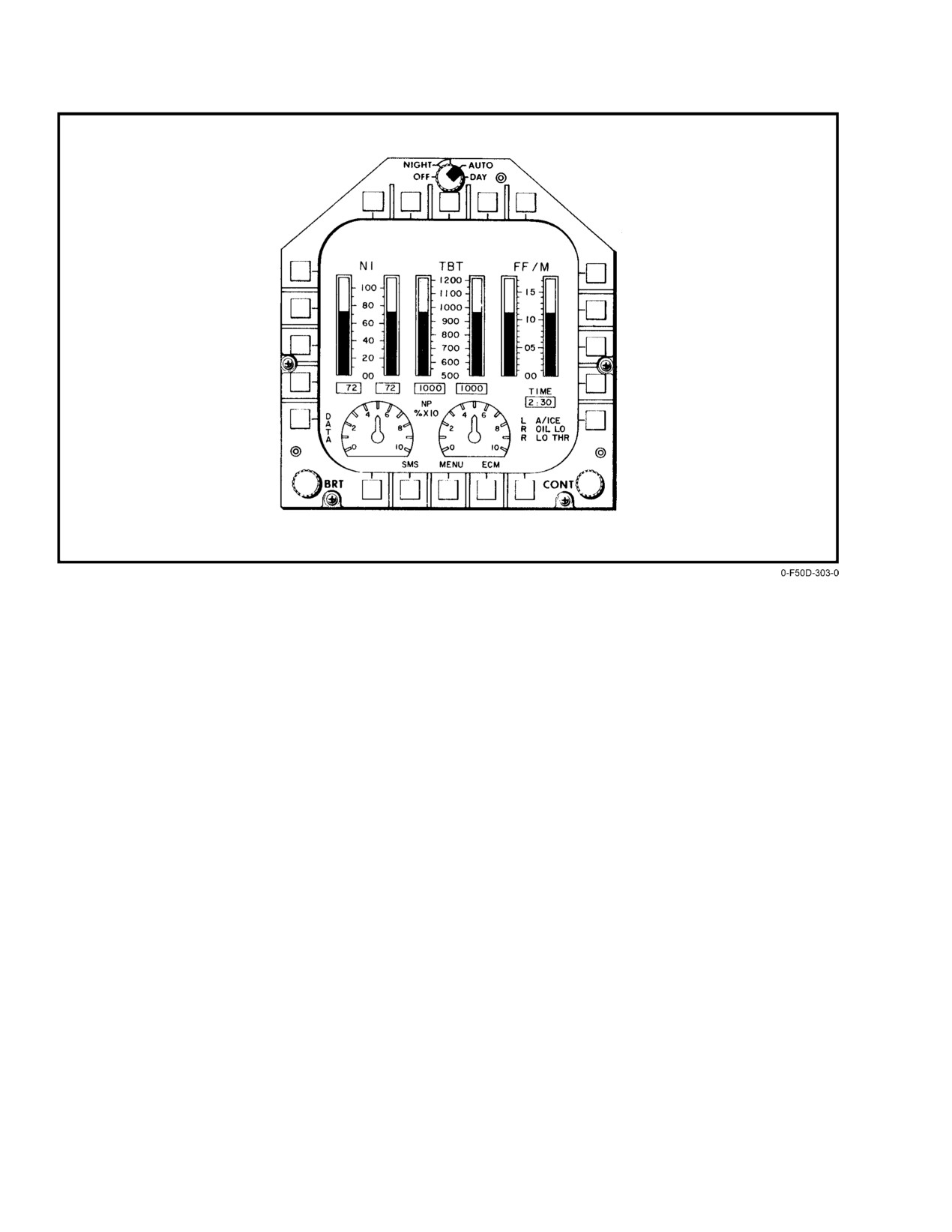
NAVAIR 01−F14AAD−1
Figure 2Ć26.ĄMFD Engine Monitor Display
4. L OIL LO or R OIL LO Designated engine oil
4. L FLMOUT or R FLMOUT Designated engine
level is approximately two quarts low. Postflight,
flameout.
engine at idle.
5. L IGV SD or R IGV SD Designated engine inlet
5. L AUG or R AUG Designated AB control system
guide vane off schedule.
has failed. AB is not available.
6. L STALL or R STALL Designated engine stall
Refer to Chapter
12, WARNING/CAUTION/
detected (also on HUD).
ADVISORY LIGHTS/DISPLAY LEGENDS for the
appropriate pilot/RIO response.
7. L FIRE or R FIRE Designated engine fire/
overheat condition in engine nacelle (also on HUD).
2.11.9
MFD Engine Caution Legends
Refer to Chapter
12, WARNING/CAUTION/
In addition to the engine caution lights on the pilot
ADVISORY LIGHTS/DISPLAY LEGENDS for the apĆ
CAUTION/ADVISORY panel, illumination of the READ
propriate pilot/RIO response.
MFD caution light indicates that one or more of the following
caution legends on the upper left quadrant of the MFD is
2.11.10
Engine Stall/Overtemperature Warning
activated:
An engine stall detection circuit in FEMS monitors
1. L N2 OSP or R N2 OSP Designated engine N2
each engine. When a stall condition is detected, a L or R
overspeed condition.
STALL warning legend is displayed on the HUD and MFD
until the condition is cleared. In addition, an aural warning
2. L N1 OSP or R N1 OSP Designated engine N1
tone is activated through the pilot ICS for up to 10 seconds.
overspeed condition.
There is no pilot check of the FEMS engine stall detection
3. L TBT OT or R TBT OT Designated engine
system.
turbine blade overtemperature.
ORIGINAL
2−38
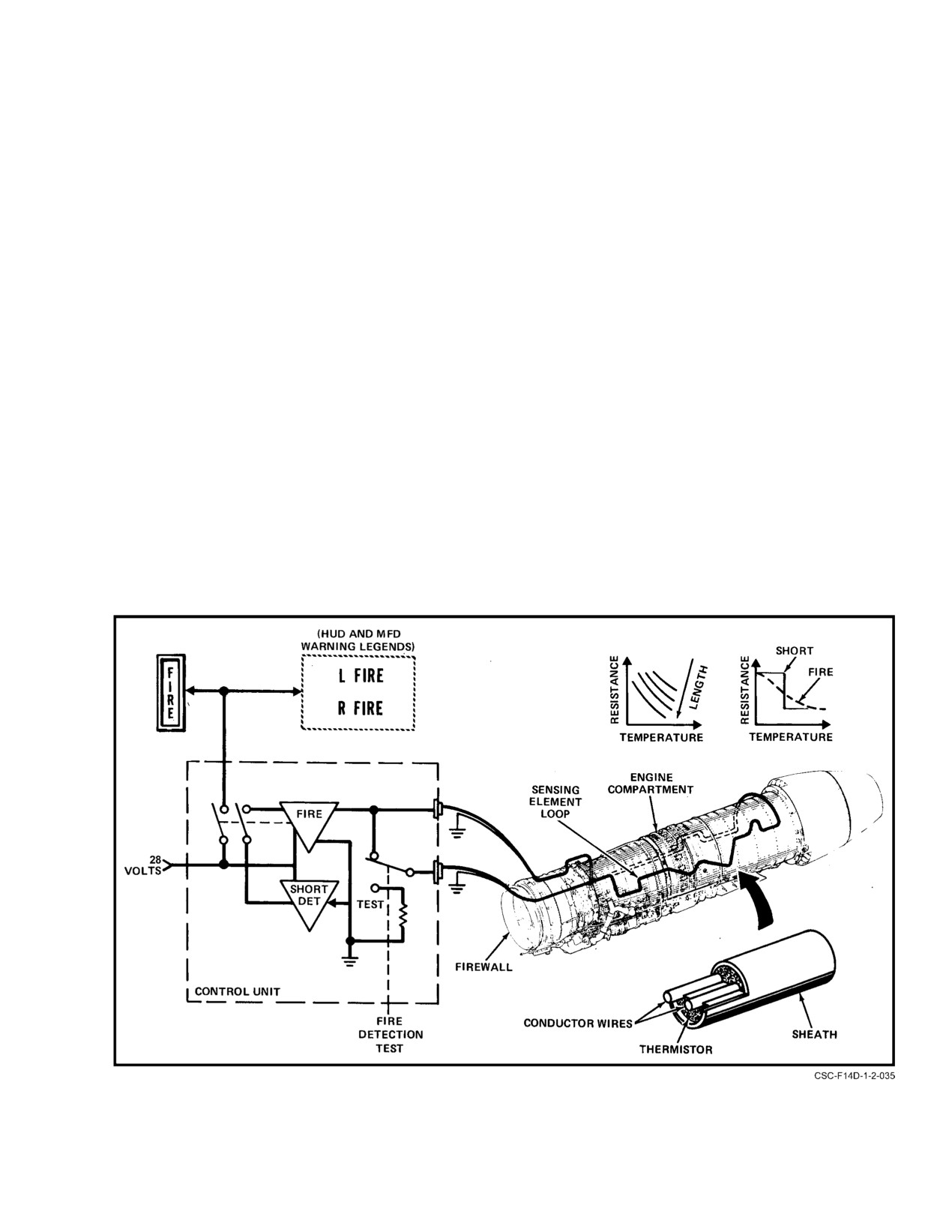
NAVAIR 01−F14AAD−1
Note
the entire length of the engine compartment on both sides
above the nacelle door hinge line. The tube sheath, which is
In SEC mode, FEMS and, therefore, the engine
clamped in grommets to the engine compartment structure,
stall detection circuit, is inoperative. However,
contains a ceramic−like thermistor material in which are
overtemperature warning is still available and
embedded two electrical conductors; one of the conductors
will activate both the STALL warning legends
is grounded at both ends of the loop. Electrical resistance
and aural warning tone.
between two conductors varies inversely as a function of
temperature and length, so that heating of less than the full
When an overtemperature condition occurs, the EGT
length will require a higher temperature for the resistance to
display rises above 940° C, the warning chevrons begin to
decrease to the alarm point. The L or R FIRE warning lights
flash, and a signal from the EGT indicator activates the
in the cockpit illuminate when the respective entire sensing
STALL warning legend and the aural tone. The overtemperaĆ
loop is heated to approximately 600° F or when any 6−inch
ture warning system is checked by the pilot during prestart as
section is heated to approximately 1,000_ F.
part of the MASTER TEST check in INST test.
The fire alarm output relay to the light is a latching type
2.12 FIRE DETECTION SYSTEM
that remains in the last energized position independent of
power interruptions until the fault clears.
The fire detection system provides a cockpit indication
of fire or overheating in either engine compartment. There is
False alarms triggered by moisture in the sensing eleĆ
a separate system for each engine compartment, each consistĆ
ment and connectors or by damage resulting in short circuits
ing of a thermistor−type sensing loop monitored by a transisĆ
or grounds in the sensing element are unlikely because of the
torized control unit. The system is powered by 28 volts from
system design. Additionally, there is no loss or impairment
the essential dc No. 1 bus. Figure 2Ć27 is a functional scheĆ
of fire detector capability from a single break in the sensing
matic of the system.
element as long as there is no electrical short. With two
breaks in the sensing element the section between the breaks
The sensing loop for each engine compartment consists
becomes inactive although the remaining segment ends
of a 45−foot continuous tubular element routed throughout
remain active.
Figure 2Ć27.ĄFire Detection System
2−39
ORIGINAL
NAVAIR 01−F14AAD−1
Fire detection circuits in the engine compartments
be pulled to make the pushbutton for that engine accessible
detect a leak in the high−temperature duct and illuminate the
(see Figure 2Ć28). If the left or right fire extinguishing
appropriate FIRE warning light and activate the L FIRE or
pushbutton is activated, the contents of both extinguishing
R FIRE warning legend on the MFD and HUD. The warning
containers are discharged into the selected engine and its
legend is a repeat of a discrete signal from the fire detect
accessory section. Since it is a one−shot system, both system
system.
advisory lights, ENG FIRE EXT and AUX FIRE EXT, will
illuminate and remain illuminated after container pressures
2.12.1
Fire Detection Test
drop below a preset level.
An integrity test of the fire detection system can be
2.13.2
Fire Extinguisher Advisory Lights
performed by selection of FIRE DET/EXT on the pilot
MASTER TEST switch. The integrity test simultaneously
Two advisory lights are provided to indicate low
checks the sensing element loops of both engine compartĆ
pressure in the fire extinguishing agent containers. The
ments for continuity and freedom from short circuits, and the
lights, ENG FIRE EXT and AUX FIRE EXT, illuminate
fire alarm circuits and FIRE warning lights for proper
when container pressure drops 90 psi below a nominal
functioning. Presence of a short circuit or control unit
pressure of 600 psi at 70° F (see Figure 2Ć28).
malfunction causes the warning light to remain out. Fire
detection test is not available on the emergency generator.
2.13.3
Fire Extinguisher Test
The fire extinguishing system is tested by raising and
2.13 FIRE EXTINGUISHING SYSTEM
rotating the MASTER TEST switch to FIRE DET/EXT and
The fire extinguishing system is capable of discharging
depressing the knob. If the fire extinguisher test passes, the
an extinguishing agent into either engine nacelle and its
GO light illuminates; if the NO GO light illuminates or if both
accessory section. The system consists of two containers of
or neither GO and NO GO lights illuminate, the system has
extinguishing agent, piping and nozzles to route and
not tested properly and a failure exists somewhere in the
discharge the agent, cockpit switches to activate the system,
system.
and advisory lights that alert the flightcrew to a drop in
system pressure below a predetermined level.
2.14 AIRCRAFT FUEL SYSTEM
The aircraft fuel system normally operates as a split
The fire extinguishing agent is a clean, colorless, odorĆ
feed system, with the left and aft tanks feeding to the left
less, and electrically nonconductive gas. It is a low−toxicity
engine and the right and forward tanks feeding the right
vapor that chemically stops the combustion process. It will
engine (refer to FO−6). Except for the external tanks, the
not damage equipment because it leaves no water, foam,
system uses motive flow fuel to transfer fuel. The supply of
powder, or other residue.
high−pressure fuel from engine−driven motive fuel pumps
operates fuel ejector pumps to transfer fuel without the need
The retention time of an adequate concentration of the
of moving parts. The system is not dependent on electrical
extinguishing agent in the engine compartment will deterĆ
power for normal fuel transfer and feed. Total internal and
mine probability of reignition, and, therefore, the probability
external fuel quantity indication is provided, with a selectĆ
of aircraft survival. At high airspeeds, where airflow through
able quantity readout for individual tanks. Fuel system
the engine compartment is increased, agent retention time is
management requirements are minimal under normal operaĆ
reduced.
tion for feed, transfer, dumping, and refueling. Sufficient
cockpit control is provided to manage the system under
The slower the airspeed at the time the extinguisher is
failure conditions. The aircraft fuel system is designed so that
fired, the higher the probability of fire extinction and the
all usable fuel will normally be depleted under two or
lower the probability of reignition.
single−engine operating conditions before an engine flameĆ
out occurs from fuel starvation. However, with complete
Circuit breaker protection is provided on the RIO
motive flow failure, engine fuel starvation can occur with
essential No. 1 circuit breaker panel by the R FIRE EXT
usable fuel aboard.
(7C4) circuit breaker and the L FIRE EXT (7C5) circuit
breaker.
Note
2.13.1
Fire Extinguisher Pushbuttons
All fuel weights in this manual are based on
the use of JP−5 fuel at 6.8 pounds per gallon,
The discharge pushbuttons for the fire extinguishing
JP−4 fuel at 6.5 pounds per gallon, or JP−8 fuel at
system are located behind the FUEL SHUT OFF handles.
6.7 pounds per gallon.
The FUEL SHUT OFF handle for the affected engine must
ORIGINAL
2−40
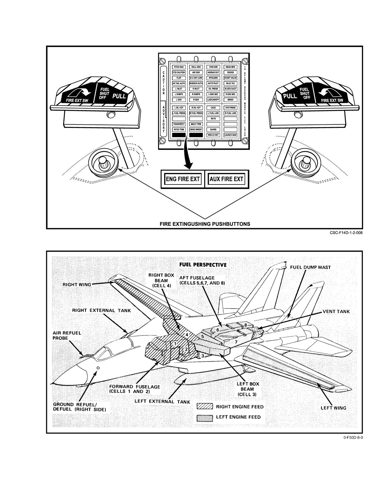
NAVAIR 01−F14AAD−1
Figure 2Ć28.ĄFire Extinguishing Switches and Advisory Lights
Figure 2Ć29.ĄFuel Tanks
2−41
ORIGINAL
NAVAIR 01−F14AAD−1
2.14.1
Fuel Tankage
forward−most cell in the aft tank group (cell No. 5) lays
laterally across the center fuselage. Extending aft are two
Figure 2Ć29 shows the general fuel tankage arrangeĆ
coffin−shaped tanks that contain two cells (Nos. 6 and 8) on
ment in the aircraft. The fuel supply is stored in eight separate
the right side and one cell (No. 7) plus an integral fuel vent
fuselage cells, two wing box cells, two integral wing cells,
tank on the left side. The coffin tanks straddle the center
and (optional loading) two external fuel tanks.
trough area, which contains the control rods, Sparrow missile
launchers, and electrical and fluid power lines. All fuel cells
2.14.1.1
Sump Tanks
in the aft tank group are interconnected by one−way flapper
valves at the base for aft−to−forward fuel gravity transfer.
The engine feed group, consisting of the left and right
box−beam tanks and the left and right sump tanks, spans the
2.14.1.4
Wing Tanks
fuselage slightly forward of the mid−center of gravity. Fuel
in each box−beam tank gravity flows to its respective sump
There are integral fuel cells in the movable wing panels
tank. The sump tanks (self−sealing) are directly connected
between the front and aft wing spars. Because of the wing−
to the box−beam tanks and contain the turbine−driven
sweep pivot location and the extensive span (20 feet) of the
boost pumps. The feed tanks supply fuel to the engine.
wing tanks, wing fuel loading provides a variable aft cg conĆ
A negative−g check valve traps fuel in the feed tank during
tribution to the aircraft longitudinal balance as a function of
negative−g flight.
wingsweep angle. Each wing panel consists of the integral
fuel cell, which is designed to withstand loads because of fuel
sloshing during catapulting and extreme rolling maneuvers
with partial or full wing fuel. Fuel system plumbing (transfer
and refuel, motive flow, and vent lines) to the wing tanks
incorporate telescoping sealed joints at the pivot area to proĆ
D Zero− or negative−g flight longer than 10 secĆ
vide normal operation independent of wing−sweep position.
onds in AB or 20 seconds in MIL or less will
deplete the fuel sump tanks (cell Nos. 3 and 4),
2.14.1.5
External Tanks
resulting in flameout of both engines.
D AB operation in the 0 to ć0.5−g regime may
Fuel, air, electrical, and fuel precheck line connectors
result in air ingestion into the fuel boost
are under the engine nacelles for the external carriage of two
pumps, causing possible AB blowout or
fuel tanks. Check valves in the connectors provide an autoĆ
engine flameout.
matic seal with the tank removed. Although the locations are
D With fuel in feed group below 1,000 pounds,
designated as armament stations Nos. 2 and 7, no other store
AB operation could result in AB blowout.
is designed to be suspended there so that the carriage of
external fuel tanks does not limit the weapon−loading capaĆ
Note
bility of the aircraft. Suspension of the drop tanks and their
fuel content has an insignificant effect on the aircraft longituĆ
AB operation with less than 1,000 pounds in
dinal center of gravity, and, even under the most adverse
either feed group may illuminate the FUEL
asymmetric fuel condition, the resultant movement can be
PRESS light because of uncovering of the boost
compensated for by lateral trimming.
pump inlet.
2.14.1.2
Forward Tank
The forward fuselage fuel tank is between the inlet
ducts and immediately ahead of the feed group. The forward
See Chapter 4 for external tank limitations.
tank is partitioned into two bladder cells (Nos. 1 and 2) that
are interconnected by open ports at the top for vent and overĆ
2.14.2
Fuel Quantity System
flow purposes. Flapper valves at the base provide for
forward−to−aft fuel gravity transfer.
The fuel quantity measurement and indication system
2.14.1.3
Aft Tank
provides the flightcrew with a continuous indication of total
internal and external fuel remaining, a selective readout for
all fuel tanks, independent low−fuel detection, and automatic
The aft fuselage fuel tank group is partitioned into four
fuel system control features.
bladder cells (Nos. 5, 6, 7, and 8) and a vent tank. The
ORIGINAL
2−42
NAVAIR 01−F14AAD−1
2.14.2.2
FUEL LOW Caution Lights
A L FUEL LOW or R FUEL LOW caution light
illuminates with 1,000 ± 200 pounds of fuel remaining in the
respective feed group. The RIO is provided with a single
To prevent fuel spills from an overfilled vent tank
FUEL LOW caution light that illuminates with one or both
caused by a failed level−control system, set the
of the pilot FUEL LOW caution lights.
WING/EXT TRANS switch to OFF if the
left tape reading reaches 6,200 pounds or the
Each FUEL LOW caution light is illuminated by two
right tape reading reaches 6,600 pounds. If either
thermistors operating in series. One set of thermistors is in the
fuel tape reading is exceeded, the aircraft shall be
right box−beam tank and cell No. 2. The other set of thermisĆ
downed for maintenance inspection.
tors is in the left box−beam tank and cell No. 5. The FUEL
LOW light illuminates only if both thermistors operating in
Note
series are uncovered.
Fuel in the vent tank is not gauged.
The quantity measurement system uses dual−element,
capacitance−type fuel probes to provide the flightcrew with
a continuous display of fuel quantity remaining. Fuel thermĆ
D If the thermistors in either cell No. 2 or No. 5
istor devices and caution light displays provide a backup fuel
remain covered during a fuel transfer failure,
low indicating system, independent of the capacitance gaugĆ
it is possible to partially deplete the sump tank
ing system. Additionally, the pilot is provided with a BINGO
without illuminating the respective FUEL
set capability on the fuel quantity indicator to preset the total
LOW caution light.
quantity level for activation of a BINGO caution light.
D When both FUEL LOW caution lights illumiĆ
Note
nate, less than 1 minute of fuel is available if
both engines are operating in zone five AB.
Fuel quantity system malfunctions that result in
erroneous totalizer readings will invalidate the
D If the BINGO CAUTION circuit breaker
use of the BINGO caution light.
(8F6) is pulled, the L and R FUEL LOW
caution lights will be disabled.
2.14.2.1
Fuel Quantity Indicators
2.14.2.3
Fuel Quantity Indication Test
The pilot and RIO fuel quantity indicators are shown in
Actuation of the master test switch in INST causes the
Figure 2Ć30 with a definitive breakdown of tape and counter
fuselage tapes and total and feed/wing/external fuel quantity
readings. The white vertical tapes on the pilot indicator show
indicators to drive to 2,000 pounds and illuminates the FUEL
fuselage fuel quantity. The left tape indicates fuel quantity in
LOW caution lights. The test can be performed on the ground
the left feed and aft fuselage; the right tape indicates fuel
or in flight. The test does not check the fuel probes or the
quantity in the right feed and forward fuselage. The L" and
thermistors. A test of the BINGO set device can be obtained
R" labeled counters display either feed group, wing tank, or
concurrently with the INST test by setting the BINGO level
external tank fuel quantity on the side selected using the
at greater than 2,000 pounds. In this case, the BINGO caution
QTY SEL rocker switch on the fuel management panel. The
light will illuminate when the totalizer reading decreases to
rocker switch is spring loaded to FEED. The pilot TOTAL
a value less than the BINGO setting.
quantity display and the RIO display indicate total internal
and external fuel.
2.14.3 Engine Feed
Note
The feed group for each engine is comprised of a
box−beam tank and a sump tank. Each box−beam tank holds
The RIO fuel quantity indicator is a repeater of
approximately 1,300 pounds of fuel and is fed from external
the pilot total fuel indicator. The difference
tank transfer, wing transfer, and fuselage transfer from cell
between the two should not exceed 300 pounds.
No. 2 or 5. When a box−beam tank is full, excess fuel is
returned to the fuselage tanks through an overflow pipe. The
sump tanks, which hold approximately 300 pounds of fuel
2−43
ORIGINAL
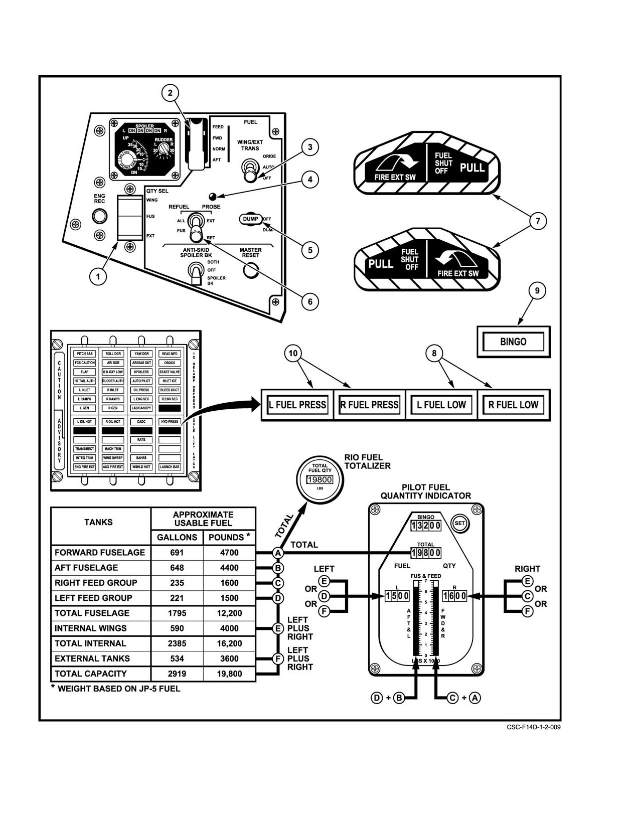
NAVAIR 01−F14AAD−1
Figure 2Ć30.ĄFuel Controls and Indicators (Sheet 1 of 3)
ORIGINAL
2−44
NAVAIR 01−F14AAD−1
NOMENCLATURE
FUNCTION
1
QTY SEL switch
WING Ċ
Fuel quantity in each wing is displayed on L and R counter of
pilot’s fuel quantity indicator.
FEED Ċ
Spring−loaded rocker switch returns to FEED when not held in
WING or EXT. FEED group fuel quantity displayed on L and R
counter of pilot’s fuel quantity indicator
EXT Ċ
Fuel quantity in each external tank displayed on L and R counter
of pilot’s fuel quantity indicator.
2
FEED switch
FWD Ċ
Both engines feed from right and forward tanks. Opens sump
tank interconnect valve, box beam vent valves, fuselage motive
flow isolation valve, defueling and transfer selector valve, and
shuts off motive flow fuel to all aft tank ejector pumps.
NORM Ċ
Right engine feeds from forward and right tanks. Left engine
(guarded
feeds from aft and left tanks
position)
AFT Ċ
Both engines feed from aft and left tanks. Opens sump tank interĆ
connect valve, box beam vent valves, fuselage motive flow isolaĆ
tion valve, defueling and transfer selector valves, and shuts off
motive flow fuel to forward tank ejector pumps.
3
WING/EXT TRANS
ORIDE Ċ
Airborne − Allows transfer of wing fuel, fuselage tank
switch
pressurization, and pressurization and transfer of external tanks
with landing gear down, and with electrical malfunction in transfer
system. Weight on Wheels −Allows transfer of wing and external
tank fuel.
AUTO Ċ
Airborne − Normal position. Wing fuel is automatically transferred.
Transfer of external fuel and fuselage pressurization is automatic
with landing gear retracted. Automatic shut off of wing and
external tanks when empty. Weight on Wheels −Automatic
transfer of wing and external tank fuel cannot be accomplished;
switch must be set to ORIDE for wing fuel transfer.
OFF Ċ
Closes solenoid operated valve to shut off motive flow fuel to
wing and also inhibits external tank transfer and fuselage
pressurization. Spring return to AUTO when master test switch
is actuated in INST, and when either thermistor in cell 2 and 5 is
uncovered, when DUMP is selected, and when REFUEL PROBE
switch is in ALL EXTD.
4
In−flight refueling probe
Illuminates whenever probe cavity forward door is open during retraction or
transition light
extension of probe.
5
DUMP switch
OFF Ċ Dump valve closed.
DUMP Ċ Opens a solenoid operated pilot valve, which ports motive flow
fuel pressure to open the dump valve and allows gravity fuel
dump overboard from cells 2 and 5. Wing and external tank
transfer automatically initiated. Dump electrically inhibited with
weight on wheels or speed brakes not fully retracted.
Figure 2−30. Fuel Controls and Indicators (Sheet 2 of 3)
2−45
ORIGINAL
NAVAIR 01−F14AAD−1
NOMENCLATURE
FUNCTION
6
REFUEL PROBE switch
ALL EXTD Ċ Extends refueling probe. Shuts off wing and external
tank fuel transfer to permit refueling of all tanks.
Returns transfer switch from OFF to AUTO.
FUS EXTD Ċ Extends refueling probe. Normal transfer and feed.
Used for practice plugins, fuselage−only refueling,
or flight with damaged wing tank.
RET Ċ
Retracts refueling probe.
7
Left and right FUEL SHUT
Pulling respective handle manually shuts off fuel to that engine.
OFF PULL handles
Push forward resets engine fuel feed shutoff valve to open.
8
L and R FUEL LOW
Fuel thermistors uncovered in aft and left or forward and right feed group.
caution lights
Illuminates with approximately 1,000 pounds remaining in individual feed
(Also single light on RIO
group and the respective fuselage tanks empty.
CAUTION panel.)
9
BINGO caution light
Illuminates when total fuel quantity indicator reads lower than BINGO
counter value.
10
L and R FUEL PRESS
Indicates insufficient discharge pressure (less than 9 psi) from respective
caution lights
turbine−driven boost pump.
NOTE
If fuel pressure light is illuminated an engine overtemp warning
tone will sound.
Figure 2−30. Fuel Controls and Indicators (Sheet 3 of 3)
each, are located directly beneath the box−beam tanks and
tank. The pressure head at interconnect A or B created
have three sources of fuel (see Figure 2-31 for identification
by the higher vertical location of the fuel in the box−
of tank interconnects):
beam tank, is greater than that created at interconnect
1. Interconnect A or B provides gravity sump from
C or D by the fuel in either cell No. 2 or 5. Therefore,
the respective box−beam tank.
fuel to replenish the sump tanks will come from the
2. Interconnect C or D connects the sump tank to its
box−beam tanks through interconnects A and B.
respective fuselage tank (cell No. 4 to cell No. 2/
2. Situation 2
cell No. 3 to cell No. 5).
a. Fuel in cell Nos. 2 and 5
3. The sump tank interconnect line and valve E
b. FEED switch in NORM
connect the two sump tanks.
c. High−engine fuel demands (afterburner).
The proportion of fuel supplied to each sump tank
Under these conditions the sump tank interconnect
through the five interconnects (A through E) is a function of
valve is closed and the left and right systems are
the pressure differential existing at each of the interconnects.
isolated. Engine fuel demand can exceed the transfer
The interconnect with the highest pressure differential will
rate into the box−beam tank. If this occurs, the fuel level
provide the most fuel. Valve E is commanded open during
in the box−beam tank will start to drop; however the
low−fuel states and during fuel balancing when the FEED
box−beam tanks are not vented, resulting in a pressure
switch is selected FWD or AFT.
drop above the declining fuel level. This reduced
In a normal sequence, three situations can be defined:
pressure lowers the total pressure at A and B, below the
1. Situation 1
pressure at C and D. Therefore, the majority of the fuel
to replenish the sump tanks comes directly from
a. Fuel in cell Nos. 2 and 5
fuselage cell Nos. 2 and 5 through interconnects C and
b. FEED switch in NORM
D, respectively. The reduction in box−beam tank fuel
c. Normal engine fuel flow (MIL thrust or less).
quantity should not normally result in a feed group
Under these conditions, the sump tank interconnect
quantity indication of less than 1,200 pounds. If the
valve is closed, and the left and right systems are
feed groups drop and then hold in the 1,200−pound
isolated. The transfer capacity into the box−beam tank
range during a high−speed dash, the system is working
exceeds the engine demand, ensuring a full box−beam
normally.
CHANGE 2
2−46
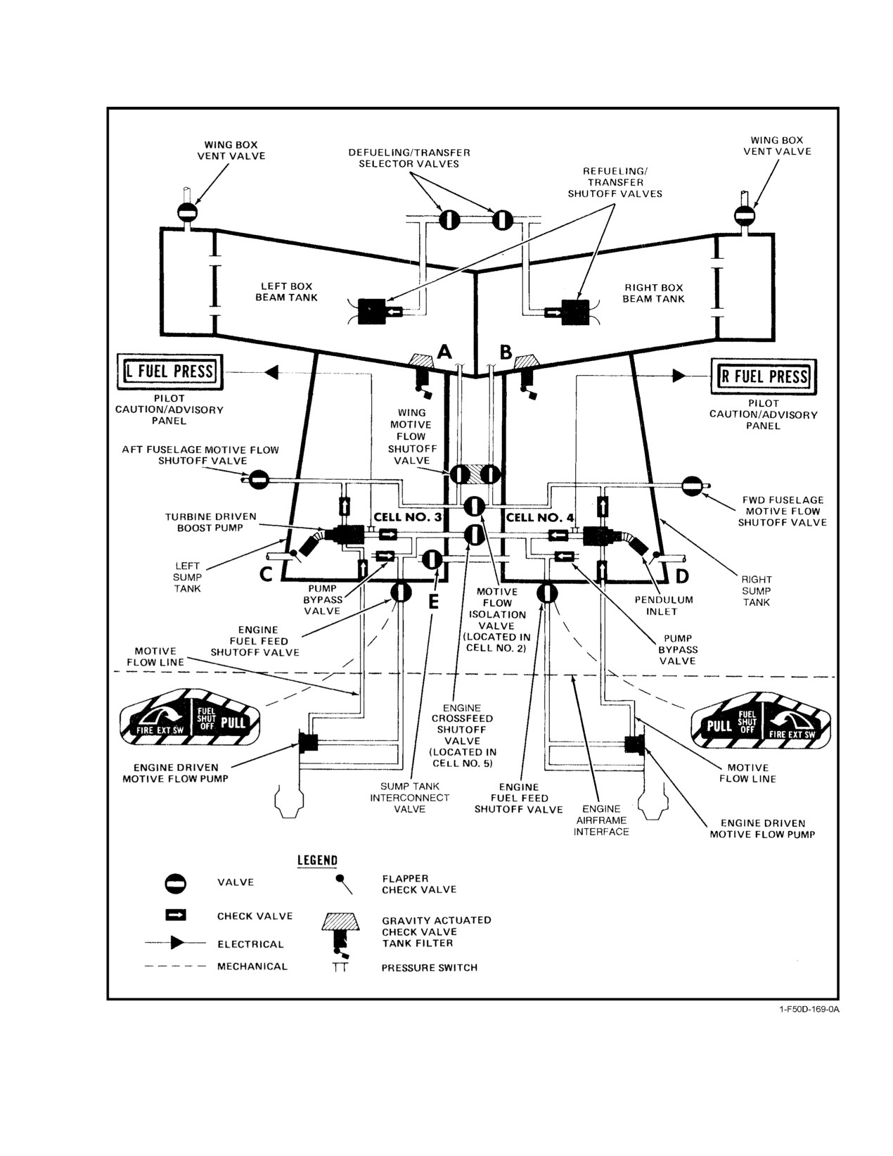
NAVAIR 01−F14AAD−1
Figure 2Ć31.ĄEngine Fuel Feed
2−47
ORIGINAL
NAVAIR 01−F14AAD−1
3. Situation 3
only in emergencies. Suction feed is drawn from an inlet at
the bottom of the fuel cell that does not incorporate a flexible
a. Fuel in either cell No. 2 or 5 has been depleted
pendulum pickup.
b. FEED switch in NORM
c. Any normal engine demand.
When the low−level thermistor in either cell No. 2 or 5
With a left or right FUEL PRESS light, flight at
is uncovered, both box−beam tanks are vented and the
zero or negative g should be avoided or engine
sump tank interconnect valve is opened. The two
fuel starvation may result.
groups become a common system and will seek a
common level to equalize the static pressure head. Fuel
With both FUEL PRESS caution lights illuminated,
will flow through the open sump tank interconnect
there is a potential that total loss of motive flow pressure has
valve only as a function of differential pressure. With
occurred because both motive flow pumps are not function-
open vent valves, the fuel in both box−beam tanks has
ing. Total loss of motive flow pressure will preclude transfer
a positive vent pressure, forcing the fuel into the
of any remaining wing fuel or fuel dump and result in total
respective sump tank through interconnect A or B.
segregation of the FWD/RIGHT and AFT/LEFT systems
since motive flow provides the force to open the sump tank
Fuel in the sump tank is picked up by the turbine−driven
interconnect valve. Without motive flow pressure, all fuse-
boost pump through a flexible pendulum pickup, boosted to
lage fuel transfer is by gravity, which makes the quantity of
greater than 10 psi, and fed to the engine through the engine
usable fuel a function of aircraft attitude. At cruise attitude,
feed line. Normally the right boost pump only feeds the right
approximately 400 pounds of usable fuel will be trapped in
engine and the left boost pump only feeds the left engine;
the aft fuselage. After illumination of both fuel pressure
however, the boost pump output lines are connected by a
caution lights, any of the following events indicate that some
normally closed engine automatic crossfeed valve. If either
motive flow pressure is available:
boost pump output pressure falls below 9 psi, as indicated by
the illumination of the appropriate FUEL PRESS caution
1. Wing fuel transfer
light, the engine automatic crossfeed valve is commanded
open. The engine automatic crossfeed valve allows fuel from
2. With the FEED switch in FWD or AFT and no
the operating boost pump to supply pressurized fuel to the
transfer of external fuel
engine on the failed side. The engine automatic crossfeed
valve is also opened when either of the low level thermistors
a. The feed group of the selected side remains full.
in cell No. 2 or 5 is uncovered; however if equal boost pump
pressures exist, negligible flow will occur through the valve.
b. Fuel migration from one side to the other.
2.14.3.1
L/R FUEL PRESS Caution Lights
NOTE
If fuel pressure light is illuminated an engine
Illumination of the L or R FUEL PRESS caution light
overtemp warning tone will sound.
results from a malfunction of the boost pump, failure of the
motive flow pump, exhaustion of fuel, or fuel flow interrup-
2.14.3.2
Engine Fuel Feed During Afterburner
tion. With illumination of the caution light, the engine auto-
matic crossfeed valve is commanded open and the fuselage
Operations
motive flow shutoff valve on the failed side is automatically
closed. Because of the reduced pumping and transfer capac-
High AB fuel consumption places extreme demands on
ity while operating on a single boost pump, afterburner
the engine feed system. In addition, the g forces experienced
operation is restricted to altitudes below 15,000 feet. Fuel to
with AB use, especially during unloaded accelerations
both engines is supplied from the side with the operating
( bugouts") and low−g nose−high maneuvering, tend to
boost pump; therefore a fuel quantity imbalance will result.
reduce forward fuel transfer to cell No. 5 and the left engine
Use of the FEED switch to balance fuel quantity will override
sump tank (cell No.3). When these conditions are sustained,
the low−fuel pressure signal to the fuselage motive flow shut-
fuel in cell No. 5 is depleted by both high suction feed through
off valve, allowing normal fuel balancing procedures. Illumi-
the gravity transfer line (C, Figure 2-32), and by reducing
nation of both FUEL PRESS caution lights indicates
gravity fuel transfer from cell Nos. 6 and 7. Zero− or low−g
reduced (< 9 psi) or loss of boosted fuel pressure to both
(less than 0.5) flight tends to force the fuel remaining in cell
engines. Fuel will continue to be supplied by suction feed;
No. 5 toward the aft wall of the tank or, at reduced fuel level,
however, thrust settings should be minimized and AB used
uncovers gravity transfer line
(C) and allows air to be
CHANGE 2
2−48
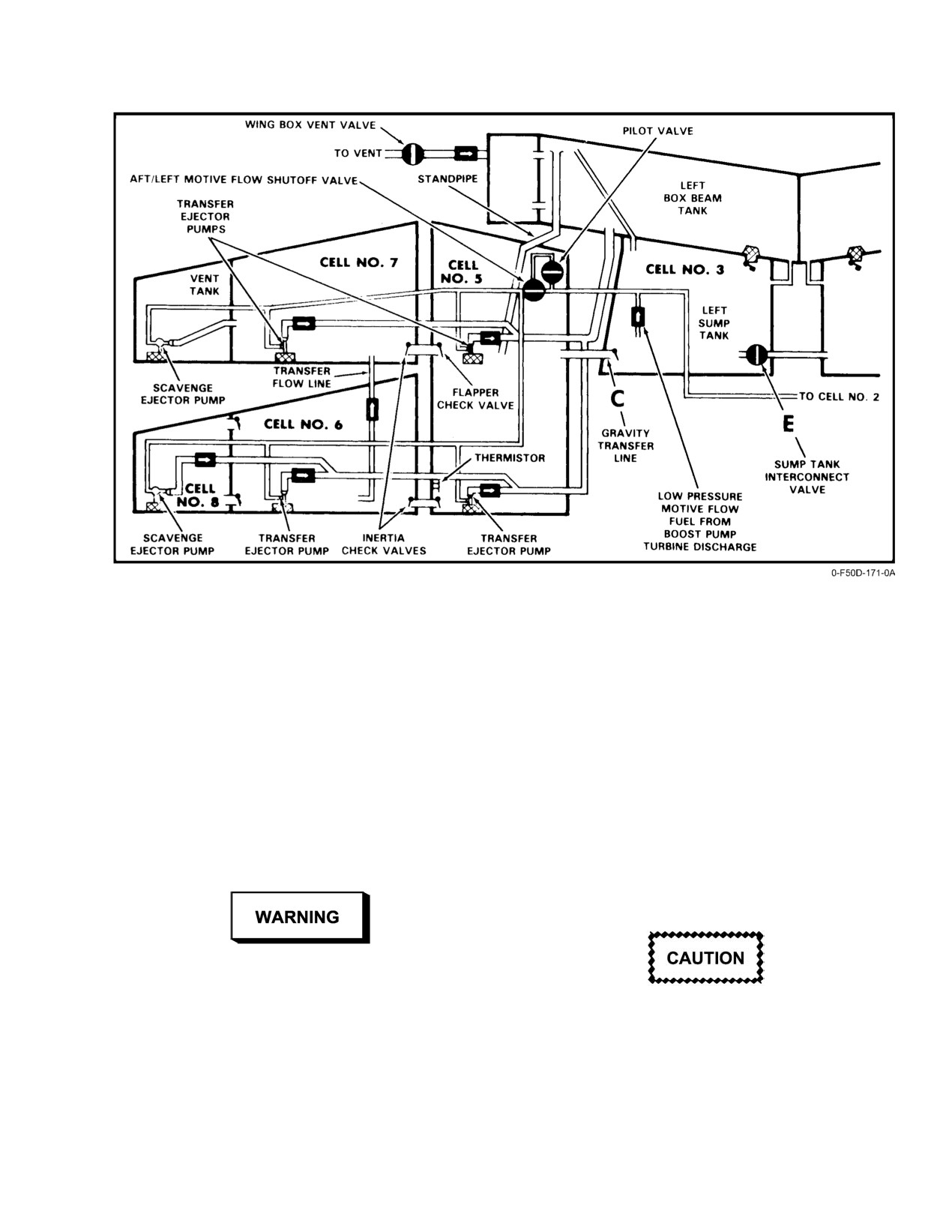
NAVAIR 01−F14AAD−1
Figure 2Ć32.ĄAft Fuselage Fuel Transfer
drawn into the sump tank. Continued zero− or low−g (less
D In the presence of a fuel pressure light, fuel
thanĂ0.5) maneuvers will aggravate this condition and
demand must be reduced and positive g
increase the probability of air ingestion. If air enters the boost
restored to prevent possible engine flameout.
pump and engine feed line, the fuel pressure light will
illuminate. If the maneuver is continued, the left AB will
2.14.3.3
Fuel Shutoff Handles
blow out and subsequent left−engine flameout can occur.
Right−engine flameout can follow after left−engine flameout
Individual engine fuel feed shutoff valves in the left
because engine feed crossfeed operation will reduce the
and right feed lines at the point of nacelle penetration are
effective output of the right boost pump. Aircraft deceleraĆ
connected by control cables to the FUEL SHUT OFF handles
tion can further interrupt fuel transfer from cell No. 2 to the
on the pilot instrument panel. During normal operation, the
right sump through the gravity transfer line (D, Figure 2Ć33).
handles should remain pushed in so that fuel flow to the
Once initiated, this sequence can occur rapidly and is
engine fuel feed system is unrestricted. If a fire is detected in
independent of total fuel state.
the engine nacelle, the pilot should pull (approximately 3 or
4 inches) the FUEL SHUT OFF handle on the affected side
to stop the supply of fuel to the engine.
D During zero− or negative−g flight, the oil
pressure light will normally illuminate and
activate the master caution light. Subsequent
Securing the engine at high power settings using
illumination of a fuel pressure light may go
the FUEL SHUTOFF handles may result in
unnoticed, allowing the pilot to continue the
damage to the aircraft fuel system.
maneuver to the point of AB blowout and
engine flameout.
2−49
ORIGINAL
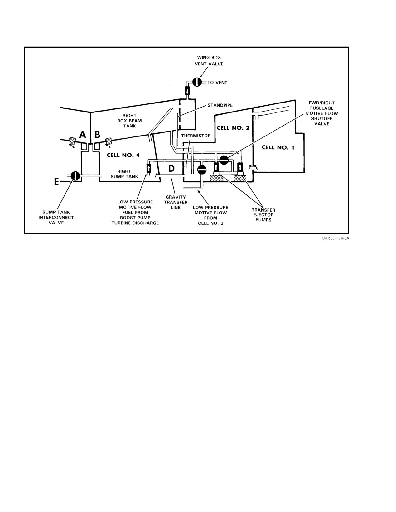
NAVAIR 01−F14AAD−1
Figure 2Ć33.ĄForward Fuselage Fuel Transfer
Note
The path of the motive flow fuel is essentially the same
for either side. Fuel from the engine feed line is pressurized
Engine flameout will occur approximately 4 secĆ
by the engine−driven motive flow pump and initially routed
onds after the FUEL SHUT OFF handle(s) is
through the boost pump turbine. The motive flow fuel is then
pulled with the throttle(s) at MIL. With lower
routed through its respective transfer system. As the presĆ
power settings, time to flameout will increase
surized fuel passes through each ejector pump, it induces
(approximately 30 seconds at IDLE).
transfer fuel to flow along with the motive flow fuel. This
combination of fuel eventually is transferred into the respecĆ
2.14.4
Fuel Transfer
tive wing box−beam tank.
2.14.4.1
Motive Flow Transfer
There are four valves that control motive flow transfer:
With the exception of the external tanks, which utilize
1. Motive flow isolation valve Ċ Normally closed, but
bleed air, all fuel transfer is accomplished by gravity and
when the low−level thermistor in cell Nos. 2 or 5 is
motive flow. In motive flow, a relatively small amount of
uncovered or the FEED switch is out of NORM, the
pressurized fuel moves at high speed through ejector pumps,
valve is commanded open, providing a path for
using the venturi effect to induce flow of the transfer fuel.
motive flow fuel from a normally operating side to
The ejector pumps have no rotating parts or power requireĆ
cross over and power a malfunctioning opposite
ments other than motive flow.
side.
Like other elements of the fuel transfer system, motive
flow transfer is initially segregated to right and left. The
2. Forward fuselage motive flow shutoff valve Ċ
motive flow pump driven by the right engine provides motive
Normally open except when the R FUEL PRESS
flow and pressure to drive the right boost pump and to run the
caution light is illuminated or the FEED switch is in
ejector transfer pumps in the forward fuselage and right wing.
AFT. When the valve is closed, all motive flow
The motive flow pump driven by the left engine provides
transfer in the forward fuselage is shut off. If the
motive flow and pressure to drive the left boost pump and
valve is closed because of the R FUEL PRESS
runs the ejector transfer pumps in the aft fuselage and left
caution light, positioning the FEED switch to FWD
wing.
will open the valve.
ORIGINAL
2−50
NAVAIR 01−F14AAD−1
3. AFT fuselage motive flow shutoff valve Ċ
lage, aft fuselage transfer does not have any high−level control
Normally open except when the L FUEL PRESS
associated with it. Excess fuel in the box−beam tank passes
caution light is illuminated or the FEED switch is in
through an overflow pipe back into cell No. 5. When cell No.Ă5
FWD. When the valve is closed, all motive flow
is full, the fuel cascades into cell Nos. 6, 7, and 8. The aft
transfer in the aft fuselage is shut off. If the valve is
fuselage fuel will continue to circulate until consumed by the
closed because of the L FUEL PRESS caution light,
engine. When their respective cells are empty, the motive flow
positioning the FEED switch to AFT will open the
ejector pumps will be shutoff by their own low−level floats.
valve.
The scavenge ejector pumps do not incorporate shutoff floats.
In the event of loss of aft fuselage motive flow transfer, fuel
4. Wing motive flow shutoff valve Ċ The motive flow
may be gravity fed forward to cell No. 5 and eventually to the
to each wing passes through separate paths in a
left sump tank through interconnect C.
single motive flow shutoff valve. The valve is norĆ
mally open except when:
2.14.4.4
Wing Transfer
a. The WING/EXT TRANS switch is in OFF or in
Wing fuel is transferred by two motive flow ejector
AUTO with both left and right wing thermistors
pumps located in each wing. To prevent overfilling the fuseĆ
dry.
lage, entry of wing fuel into the box−beam tank is controlled
by the refueling/transfer shutoff valve. In the forward fuseĆ
b. Weight is on wheels.
lage, excess fuel overflows through an overflow pipe from
the right box−beam tank into cell No. 2, and then cascades
c. The REFUEL PROBE switch is in ALL EXTD.
into cell No. 1. A high−level pilot valve senses when cell
No.Ă1 is full and sends a signal to close the right refueling/
In any case, the wing motive flow shutoff valve can be
transfer shutoff valve, preventing additional wing fuel from
commanded open by selecting ORIDE on the WING/EXT
entering. When engine fuel consumption provides room in
TRANS switch.
cell No. 1 for additional fuel, the high−level pilot will signal
the refueling/transfer shutoff valve to open. The sequence is
2.14.4.2
Forward Fuselage Transfer
identical for the left box−beam tank and aft fuselage with the
Fuel in cell No. 1 flows by gravity into cell No. 2 where
exception that the high−level pilot valve is located in cell
two motive flow ejector pumps transfer it into the right wing
No.Ă7 and controls the left refueling/transfer shutoff valve
box−beam tank at approximately 18,000 pph. Fuel entering
(see Figure 2Ć34 for wing and external tank fuel transfer).
the box−beam tank beyond engine demands overflows
through an overflow pipe back into cell No. 2. There is no fuel
Normally wing fuel can only transfer to the box−beam
level control associated with fuselage motive flow transfer;
tank on its respective side, except when the thermistor in
therefore, the fuel will continue to circulate from cell No. 2
either cell No. 2 or 5 is uncovered or the FEED switch is
into the right box−beam tank and back through the overflow
selected FWD or AFT. For either condition, the motive flow
pipe. When the fuel in cell Nos. 1 and 2 is depleted, the
isolation valve opens, making motive flow pressure available
motive flow ejector pumps are shut off by their own low−level
to either wing from either engine, and the two defuel/transfer
floats. In the event of failure of the forward fuselage motive
selector valves open, permitting fuel from either wing to
flow, the fuel can reach the right sump tank by gravity flow
transfer to either box−beam tank. Total loss of wing motive
through interconnect D.
flow will preclude transfer of any remaining wing fuel.
Failure of either high−level pilot valve or refueling/transfer
2.14.4.3
Aft Fuselage Transfer
shutoff valve to the closed position could cause a single−wing
transfer failure. Selection of FWD or AFT on the FEED
Fuel in the aft fuselage is transferred forward by
switch opens the defuel/transfer selector valves allowing the
scavenge ejector pumps in cell No. 8 and the vent tank, single
trapped wing fuel to transfer to the opposite box−beam fuel
ejector pumps in cell Nos. 6 and 7, and two ejector pumps in
tank.
cell No. 5. All aft motive flow transfer is into the left box−
Note
beam tank, producing a rate of approximately 36,000 pph.
This flow rate is approximately twice that of the forward
Premature automatic wing motive flow valve
fuselage transfer rate because there are more motive flow
shutoff may occur because of formation of air
ejector pumps in the aft transfer system. More fuel tanks and
bubbles in the wingtip fuel thermistors. Pilot
thus more motive flow ejector pumps are required in the aft
selection of ORIDE with the WING/EXT
transfer system than the forward transfer system because of
TRANS switch will re−enable fuel transfer.
the aircraft structural configuration. Like the forward fuseĆ
2−51
ORIGINAL
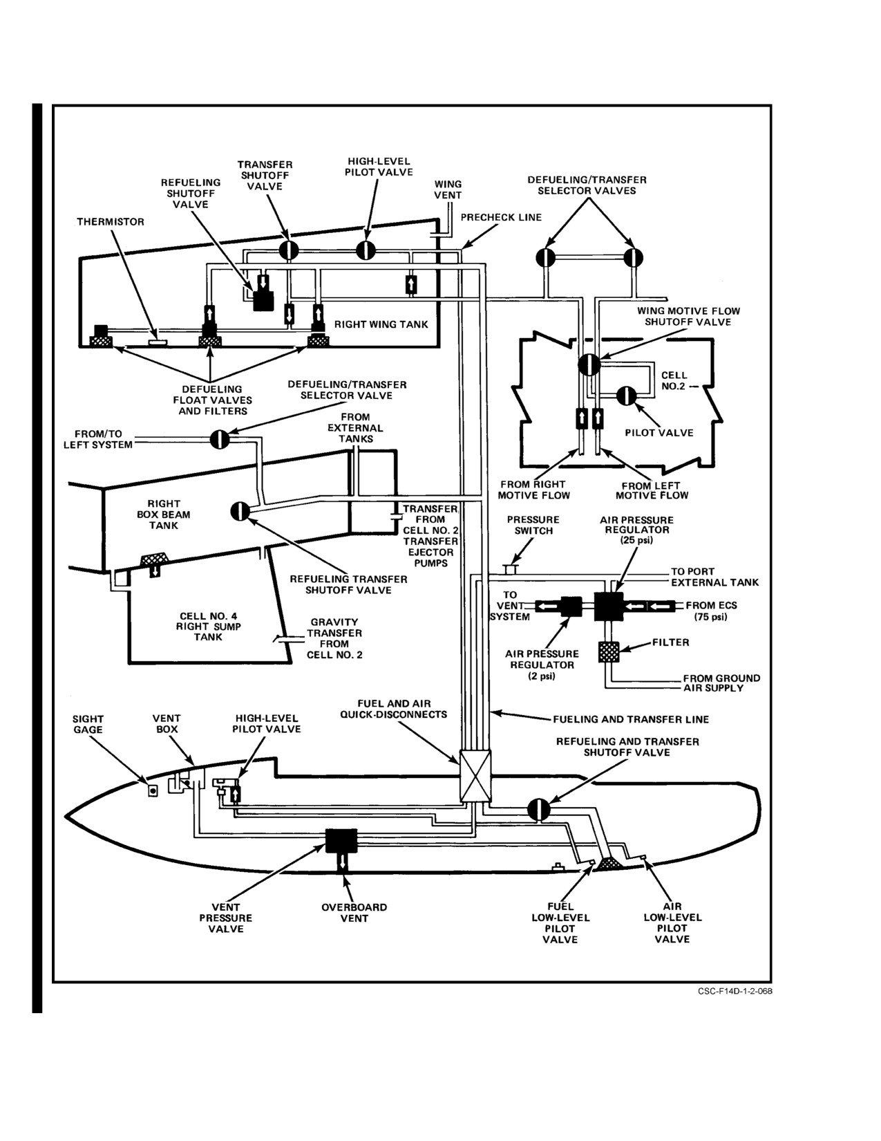
NAVAIR 01-F14AAD-1
Figure 2-34. Wing and External Tank Fuel Transfer
CHANGE 1
2-52
NAVAIR 01−F14AAD−1
Note
bypass the landing gear down interlock in the external tank
transfer circuit, the WING/EXT TRANS switch may remain
in the AUTO (normal) position for this check.
D ORIDE transfer should not normally be used
unless AUTO transfer fails to complete transĆ
Note
fer of wing or external tank fuel. ORIDE use
when the wing tanks are dry may allow air to
D Verifying tank operation by observing fuel
enter the box−beam tanks, reducing the effiĆ
transfer is both time consuming with a full fuseĆ
ciency of gravity transfer to the sump tanks.
lage fuel load and aggravates fuel slosh loads
in the external tanks during catapult launch.
D When the thermistor in either cell No. 2 or 5
is uncovered, the WING/EXT TRANS switch
D Engine rpm above idle may be required to
will be deenergized from OFF to AUTO. This
provide sufficient bleed air pressure for a satĆ
automatic feature is to ensure all wing and
isfactory check.
external fuel has been transferred. After 5 secĆ
onds, the pilot may reset this switch to OFF.
2.14.4.6
Vent Valve Failure
A weight−on−wheels inhibit function prevents opening
The vent valves in the right and left box−beam tank are
of the wing motive flow shutoff valve. To transfer wing fuel
always commanded open with the sump tank interconnect
during ground operations, the WING/EXT TRANS switch
valve, making the right and left feed groups a common
must be set to ORIDE to bypass the weight−on−wheels
system. This function occurs when the low−level thermistor
function.
in cell No. 2 or 5 is uncovered. To equalize the static pressure
head at the interconnect valve, the fuel in the sump tanks will
Activation of fuselage fuel dump automatically initiĆ
seek a common level. At matched engine demands, each
ates wing fuel transfer in sequence after external tank transfer
engine will feed from its own side and negligible flow will
by automatically moving the WING/EXT TRANS switch to
occur across the sump tank interconnect valve. If a vent valve
AUTO if in OFF. Positioning the REFUEL PROBE switch to
fails to open, the additional vent pressure on top of the fuel
ALL/EXTD also releases the solenoid holding the WING/
on the vented side creates a pressure differential between the
EXT TRANS switch in OFF.
left and right sump tanks and results in migration through the
interconnect valve to the side with the inoperative vent valve.
2.14.4.5
External Tank Transfer
Therefore, sump tank replenishment of fuel to the side with
the failed vent valve will come primarily from the opposite
External tank transfer is also controlled by the WING/
sump tank because the head pressure at the interconnect
EXT TRANS switch. When external tanks are installed,
valve (E) may be higher than that at interconnects A, B, C,
transfer from the wings and external tanks occurs concurĆ
or D (Figure 2Ć31). A fuel quantity imbalance will occur with
rently. Transfer from the wings and external tanks cannot be
the side of the properly operating vent valve decreasing more
accomplished separately; however, the external tanks should
rapidly than the malfunctioning side. The box−beam tank
complete transfer before the wing tanks. External tank fuel
with the malfunctioning vent valve will eventually vent
is transferred by bleed air pressure regulated to 25 psi. MaxiĆ
through the overflow pipe when the respective fuselage tank
mum transfer rate of each external tank is approximately
(cell No. 2 or 5) is empty. If for any reason the fuel is not
45,000 pph. External tank fuel transfer into the fuselage is
transferred out of the respective fuselage tank, the imbalance
controlled by the same valves that control wing transfer.
will continue until the vented sump tank fuel quantity is
Fuselage level is controlled by the refueling/transfer shutoff
low enough to uncover the interconnect valve and line
valves and, until both the defuel/transfer valves are comĆ
(256 pounds approximately). This permits venting of the
manded open, external tank fuel can only transfer into the
unvented side and permits use of the balance of the fuel in
box−beam tank located on the same side of the aircraft.
the sump tanks.
External tank transfer can be checked on the deck by
Vent valve malfunctions can create disconcerting fuel
placing the WING/EXT TRANS switch to ORIDE, or selectĆ
imbalances. Although engine operation is not affected and all
ing FLT GR UP with the MASTER TEST switch and noting
of the fuel in the aircraft is available, AB use should be
depletion of external tank fuel quantity. In addition, when
avoided when low feed group fuel quantities are indicated. If
FLT GR UP is selected, the GO/NO GO light on the
both engine/boost pumps are operating, there is no advantage
MASTER TEST panel is illuminated by a pressure switch in
in using the cockpit fuel FEED switch to attempt to correct
the aircraft pressure line leading to the external tanks and
the imbalance. Positions other than NORM may simply
indicates status of line pressure. Since FLT GR UP serves to
aggravate the imbalance.
2−53
ORIGINAL
NAVAIR 01−F14AAD−1
2.14.5
Fuel Quantity Balancing
2.14.6
Fuel Transfer/Feed During Single−Engine
Operation
Fuel quantity balancing is not normally required prior
to completion of wing/external tank transfer or until one
Loss of an engine before the low−level thermistor in
fuselage tape drops below 4,500 pounds. The procedure
either cell No. 2 or 5 is uncovered will terminate all motive
requires use of the FEED switch that opens the sump tank
flow transfer on the failed side. External tank fuel will conĆ
interconnect valve, joining the FWD/R and AFT/L systems.
tinue to transfer if room is available in the failed side fuselage
With a high quantity in the FWD/R group, the greater static
tanks. If no pilot action is taken, the operating engine will
head pressure, particularly in noseup attitudes, can cause
feed only from its own side. This will lead to a fuel imbalance
overfilling of the AFT/L group. To prevent this, the FEED
that can normally be corrected through the use of the fuel
switch should be returned to NORM before the AFT/L tape
FEED switch. Selecting the high side (inoperative engine
reaches 6,200 pounds.
side) results in the following:
When the FEED switch is moved to select the high−fuel
1.
Selected side fuselage motive flow shutoff valve is
quantity side, the following occurs:
opened. The valve was commanded closed when the
FUEL PRESS caution light illuminated.
1. Sump tank interconnect valve opens and provides a
fuel path between the right and left tanks.
2.
Operating side fuselage motive flow shutoff valve
2. Both box−beam tank vent valves open and provide
is closed and stops operating side fuselage fuel
equal vent pressure on top of the fuel in each box−
transfer into the box−beam tank.
beam tank, regardless of the fuel level.
3.
Motive flow isolation valve opens. Operating side
3. Fuselage motive flow shutoff valve on the non−
motive flow pressure now powers the inoperative
selected (low−fuel quantity) side closes and termiĆ
side. Failed side fuselage fuel will begin transferĆ
nates the last source of transfer of that fuselage fuel
ring into its respective box−beam tank.
into its respective box−beam tank.
4.
Sump tank interconnect valve opens and provides a
4. Motive flow isolation valve opens and provides a
path for the inoperative side fuel to reach the operĆ
path for the nonselected side motive flow pressure
ating engine.
to reach the opposite side. Thus motive flow transfer
should maintain a full box−beam tank on the
5.
Wing box−beam tank vent valves open and equalize
selected side.
the pressure above the fuel in each wing box−beam
tank, permitting the higher static pressure created
5. Both defuel/transfer selector valves open and
by the full wing box−beam tank on the inoperative
permit either wing/external tank to transfer into
side to induce flow through the open sump tank
either wing box−beam tank.
interconnect valve to the operating engine.
The higher static pressure head created by the full box−
6.
Both defuel/transfer selector valves open and allow
beam tank on the selected side results in the nonselected side
either wing or external tank fuel to transfer into
engine feeding primarily from the sump tank interconnect
either wing box−beam tank.
rather than interconnects A, B, C, or D. With both engines
feeding from the fuel in primarily one side, the correction rate
If no crew action is taken with the FEED switch, the
of the fuel quantity imbalance is essentially a function of
same fuel system functions are automatically provided when
engine demand.
the thermistor in either cell No. 2 or 5 is uncovered. AddiĆ
tional actions that will occur when the cell No. 2 or 5 thermisĆ
tor is uncovered are:
1. Both right and left fuselage motive flow shutoff
valves open, overriding any previous commands to
D During AB operations, NORM shall be
close. Manual override of each valve is still proĆ
selected. FWD or AFT could deplete fuel in
vided through the FEED switch.
sump tanks.
D Aircraft attitude will have a significant influĆ
ence on the direction of fuel movement if
FWD or AFT is selected. Nosedown attitude
will transfer fuel forward, and noseup attitude
will transfer fuel aft.
ORIGINAL
2−54
NAVAIR 01−F14AAD−1
2. Engine crossfeed valve receives a redundant comĆ
2.14.7
Fuel Dump
mand to open. An initial command was provided
when the FUEL PRESS caution light illuminated.
Figure 2Ć35 shows aircraft fuel system components
associated with fuel dump operation. Fuel dump standpipes
3. WING/EXT TRANS switch will automatically go
in the forward (cell No. 2) and aft (cell No. 5) fuselage tanks
to AUTO if originally in OFF. If desired, OFF can
are connected to the fuel dump manifold at the dump shutoff
be reselected after 5 seconds.
valve. The manifold extends aft to the fuselage boattail.
Actuation of the fuel DUMP switch to DUMP supplies power
2.14.6.1
Sump Tank Interconnect Valve Failure
(dc essential No. 2) to open the solenoid−operated pilot valve,
which ports motive flow fuel pressure to open the dump
The major fuel system consideration while operating
shutoff valve with weight off the main landing gear and the
single engine is that the sump tank interconnect valve opens
speedbrakes retracted.
when commanded. This constitutes the only path through
which inoperative side fuselage fuel can reach the operating
The fuel DUMP switch circuit is deactivated on deck
engine. While the probability of an inoperative sump tank
or with speedbrakes extended. Fuel dump with the speedĆ
interconnect valve is very low, the consequences of a malĆ
brakes extended is inhibited because of the resulting flow
function under single−engine conditions are severe, particuĆ
field disturbance, which would result in fuel impingement on
larly at landing fuel weights. With a failed closed sump tank
the fuselage boattail and exhaust nozzles. The speedbrake
interconnect and full fuselage cells on the inoperative side,
switch is electrically bypassed during a combined hydraulic
only the wing fuel on the inoperative side and external fuel
system failure, enabling the pilot to dump fuel when the
can be transferred into the operating side fuselage. Attempts
speedbrakes are floating. The electrical bypass is accomĆ
to transfer the fuel from the inoperative side with the FEED
plished whenever the combined pressure falls below 500 psi.
switch compound the problem when the motive flow isolation
valve and inoperative side motive flow shutoff valve open.
Operating side motive flow fuel, pumped through the open
motive flow isolation valve to permit inoperative side wing
and/or fuselage motive flow transfer cannot be retrieved. Fuel
migration is approximately 100 pounds per minute because
The speedbrake/fuel dump interlock does not
of wing transfer, and approximately 200 pounds per minute
prevent speedbrakes from being deployed if fuel
for fuselage transfer. Coupled with a normal engine demand
dump is activated. It only prevents the dumping
of approximately 100 pounds per minute, a balancing attempt
of fuel if the speedbrakes are already extended.
will result in usable fuel in the operative side being depleted
at approximately 400 pounds per minute.
Note
D The FUEL FEED/DUMP circuit breaker (RE1)
Note
is on the pilot right−knee circuit breaker panel.
Operating side fuel remaining can be protected
D Dump operations with either engine in afterĆ
by pulling the FUEL SHUT OFF handle for the
burner should be avoided since the fuel dump
inoperative side and concurrently selecting the
mast discharge will be torched.
operative side on the FEED switch. This will elimĆ
inate a potential fuel path across the engine autoĆ
D After terminating fuel dump, wait approxiĆ
matic crossfeed valve, through the inoperative
mately 1 minute to allow residual fuel in the
sump tank boost pump into the inoperative side.
fuel dump line to drain before extending
speedbrakes or lighting afterburners.
If the sump tank interconnect is failed closed, the
following additional considerations apply:
Fuel in the wings and external tanks is dumped by
transferring to the fuselage. When the fuselage fuel dump
With the FEED switch selected to the operating side.
circuit is activated, wing and external tank transfer to the
box−beam tanks is automatically initiated. Fuel dump is by
1. Wing and external tank fuel from both sides will
gravity flow with a nominal discharge rate of 1,500 pounds
transfer into the operating side fuselage if the
per minute. The dump rate is affected by aircraft pitch attiĆ
inoperative side fuselage is full.
tude and total fuselage fuel quantity with discharge flow
inhibited at nosedown conditions. The standpipes in the fuel
2. If DUMP is selected, wing motive flow is autoĆ
cells control the minimum fuel dump level in the tanks,
matically activated; therefore, approximately 100
which, under normal operations (feed group full), is approxiĆ
pounds per minute of fuel available to the operating
mately 4,000 pounds.
engine will be lost.
2−55
ORIGINAL
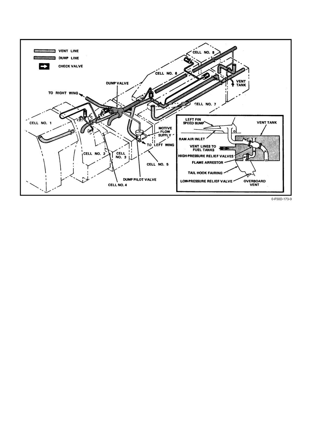
NAVAIR 01−F14AAD−1
Figure 2Ć35.ĄFuel Vent and Dump
2.14.8
Internal Tank Pressurization and Vent
2.14.9
Fueling and Defueling
The internal fuel vent system is shown in Figure 2Ć35.
Figure 2Ć36 shows the refueling system. The aircraft is
It is an open−vent−type system, pressurized by ram air and
equipped with a single−point refueling system, which enables
engine bleed air from the
25−psi external tank pressure
pressure filling of all aircraft fuel tanks from a single recepĆ
system that is reduced to 1.75 psi by a fuselage pressure
tacle. The receptacle is at the recessed ground refuel and
regulator and distributed to all tanks through the fuselage
defuel station, behind a quick−access door on the lower right
vent system. This air is automatically supplied when the
side of the forward fuselage. The maximum refueling rate is
landing gear handle is UP or the WING/EXT TRANS switch
450 gallons per minute at a pressure of 50 psi. Since ground
is in ORIDE. When the WING/EXT TRANS switch is in
and air refueling connections use a common manifold, the
OFF, the low−pressure bleed air is cut off.
refueling sequence is the same.
In flight, the vent tank is maintained at a positive
Standpipes refuel the aft and forward fuselage tanks by
pressure up to 2.5 psi maximum. This pressure is fed by
overflow from the left and right box−beam tanks. A high−
connecting lines to all internal tanks. These connecting lines
level pilot valve at the high point of the forward tank shuts
are routed to provide venting to both the forward and aft end
off the fuselage refueling valve in the right box−beam tank
of each fuselage tank so it can function as both a climb and
when the forward tank group is full. Fuel flows from the left
dive vent. Venting of the box−beam tanks is controlled by
box−beam tank to cell No. 5, after which it overflows to the
solenoid−operating valves, which when closed, provide
right side, then the left side. A high−level pilot valve at the
suction transfer through the gravity flow paths in cell Nos. 2
high point of the left box−beam tank and aft tank (cell No. 7)
and 5 to the sump tanks.
shuts off the fuselage refueling valve in the left box−beam
tank when the aft tank group is full. Individual wing and
external tank filling is accomplished by flow through a
shutoff valve in each tank.
ORIGINAL
2−56
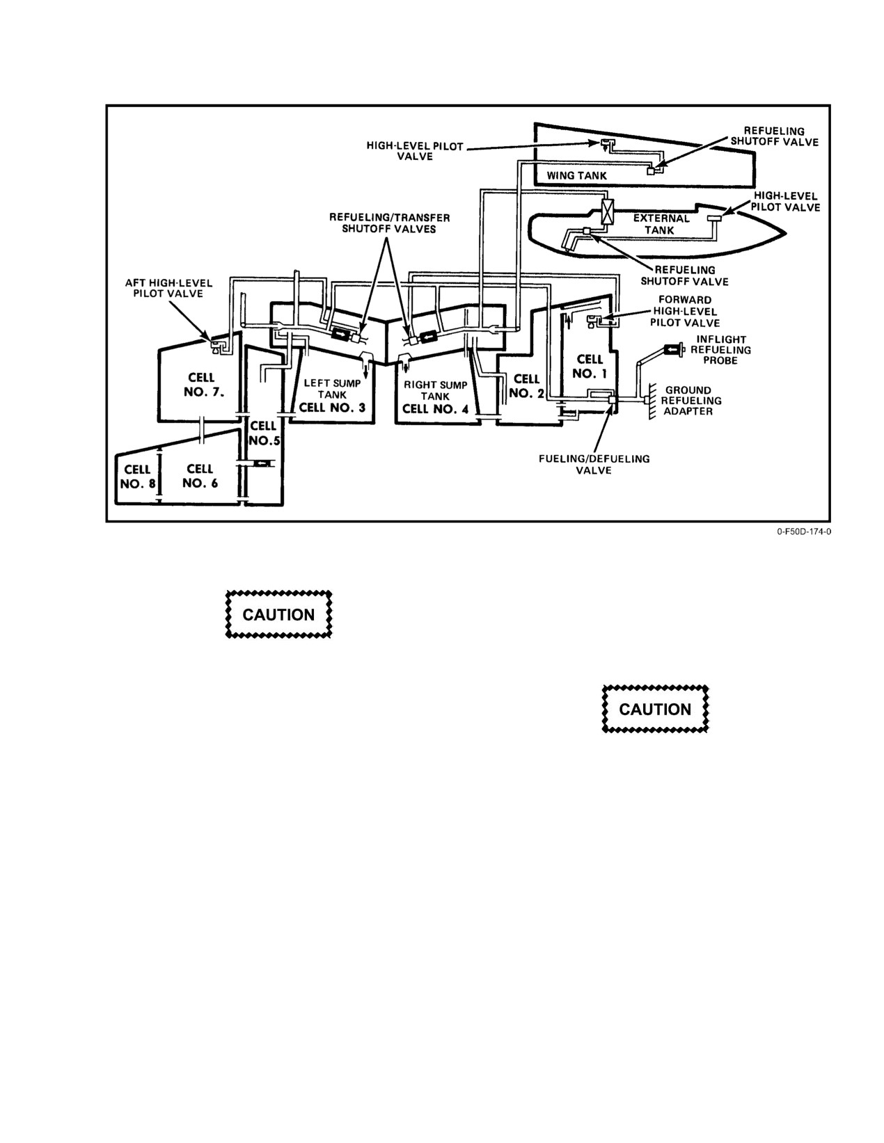
NAVAIR 01−F14AAD−1
Figure 2Ć36.ĄRefueling System
vent pressure indicator monitors pressure in the vent lines.
The gauge consists of a pointer on a scale having two bands,
one green and one red.
The green band indicates a safe pressure range (0 to
Gravity refueling of the aircraft fuel system
4 psi), and the red band indicates an unsafe range (4 to 8 psi).
should be accomplished only under emergency
situations. While performing such an operation,
avoid introducing contaminants into the fuel tanks
or damaging the fuel quantity probes and wiring.
2.14.9.1
Precheck System
During ground refueling operations, the direct−
reading vent pressure indicator shall be observed
Ground refueling control is by two precheck selector
and refueling stopped if pressure indicates in the
valves and a vent pressure gauge adjacent to the refueling
red band (above 4 psi).
receptacle on the ground refuel and defuel panel. The
precheck valves functionally test high−level pilot valve
2.14.10
In−Flight Refueling
operation incident to ground pressure refueling; the valves
Note
separately check the pilot valves in the fuselage tanks and the
See paragraph
9.1 for in−flight refueling
wing and external tanks. In addition to this precheck
procedures.
function, the precheck valves can be used for ground
selective refueling of only the fuselage or all tanks. Since the
The in−flight refueling system permits partial or
precheck valves, which are manually set by the groundcrew,
complete refueling of the aircraft fuel tanks while in flight.
port pressurized servo fuel to the high−level pilot valves and
The retractable refueling probe has an MA−2−type nozzle,
subsequently to the shutoff valves, no electrical power is
which is compatible with any drogue−type refueling system.
necessary on the aircraft to perform ground refueling
A split refueling system is provided with fuel routed into the
operations. Additionally, ground refueling control without
left and right box−beam tanks for initial replenishment of
engines running is completely independent of switch posiĆ
sump tank fuel. Selectable fuel management controls dictate
tioning on the fuel management panel. The direct−reading
the extent of further distribution to the wing tanks, external
2−57
ORIGINAL
NAVAIR 01-F14AAD-1
tanks, and/or fuselage tanks. The maximum refueling rate is
approximately 475 gallons per minute (3,000 lbs per minute
depending on fuel type) at a pressure of 57 psi.
Loss of combined pressure may indicate impend-
ing fluid loss. Without fluid in the combined
system return line, the in-flight refueling probe
will not extend with the handpump. Early exten-
To prevent fuel fumes from entering the cockpit
sion of the refueling probe at the first indication
through the ECS because of possible fuel spill
of a combined system malfunction is recom-
during in-flight refueling, select L ENG air
mended in a carrier environment.
source.
Note
D Extension or retraction of the refueling probe
using the hydraulic hand pump requires the
refuel probe switch to be placed in EXT or RET
D
57 psi limitation could be exceeded when
(as appropriate), combined system fluid in the
refueling from some aircraft operating more
return line, and essential dc No. 2 electrical
than one transfer pump. Damage to fuel sys-
power. With a total loss of combined hydraulic
tem can result.
pressure in flight, fluid trapped in the return
line/handpump reservoir can be isolated,
D Maximum airspeed for extension or retraction
exclusively for refueling probe extension, by
of the refueling probe is 400 knots (0.8 Mach).
placing the landing gear handle in the up posi-
Note
tion. Extension of the refueling probe requires
approximately 25 cycles of the pump handle.
D With the in-flight refueling probe extended,
D Probe retraction is not available if the FUEL P/
the pilot and RIO altimeter and airspeed and
MOTIVE FLOW ISOL V (P-PUMP) circuit
Mach indicators will show erroneous indica-
breaker (RG1) is pulled.
tionsbecause ofchangesinairflowaroundthe
pitot static probes.
2.14.10.2
Refueling Probe Transition Light
D Flight operations with the in-flight refueling
The red probe transition light immediately above the
probe door removed are not recommended
REFUEL PROBE switch illuminates whenever the probe
because of the effects of water intrusion,
cavity forward door is not in the closed position. Since the
exposure to elements, and structural fatigue to
closed-door position is indicative of both the probe retracted
electrical hydraulic hardware assemblies. If
and extended position, the light serves as a probe transition
operational necessity dictates, the door may
indicator as well as a terminal status indicator. The probe
be removed to prevent damage, loss or engine
external light illuminates automatically upon probe exten-
FOD.
sion with the EXT LTS master switch ON.
D The RUDDER AUTH caution light may
2.14.10.3
In-Flight Refueling Controls
illuminate when the in-flight refueling probe
is extended. Press the MASTER RESET
Regardless of fuel management panel switch position-
button to reset the light.
ing, at low-fuel statesthe initial resupplyoffuel isdischarged
into the left and right box-beam tanks. The split refueling
2.14.10.1
In-Flight Refueling Probe
system to the left and right engine feed group provides for a
relatively balanced cg condition during refueling. Selective
The retractable in-flight refueling probe is in a cavity
refueling of the fuselage or all fuel tanks is provided on the
on the right side of the forward fuselage section, immediately
REFUEL PROBE switch with the probe extended. In
forward of the pilot vertical console panel.
FUS/EXTD normal fuel transfer and feed is unaltered. This
Extension of the refueling probe is provided through
position is used for practice plug-ins, fuselage-only re-
redundant circuits by the REFUEL PROBE switch. A
fueling, or return flight with a damaged wing tank. The
hydraulic actuator within the probe cavity extends and
ALL/EXTD position shuts off wing and external drop tank
retracts the probe. The probe actuator is powered by the
transfer to permit the refueling of all tanks.
combined hydraulic system. It can be extended and retracted
by means of the hydraulic handpump in the event of
2.14.11
Hot Refueling
combined system failure.
Hot refueling can be accomplished with the refueling
probe extended or retracted. If the probe is extended, control
CHANGE 1
2-58
NAVAIR 01−F14AAD−1
of the tanks to be refueled is accomplished in the same
2.15 ELECTRICAL POWER SUPPLY SYSTEM
manner as during in−flight refueling. If the probe is not
extended, select WING/EXT TRANS switch to OFF to refuel
In normal operation, ac power is supplied by the
all tanks. Select ORIDE to refuel the fuselage only.
engine−driven generators. This ac power is converted by two
transformer−rectifiers
(T/R) into dc power (refer to FO−8).
2.14.12
Automatic Fuel Electrical Controls
One generator is capable of assuming the full ac power load
and one T/R is capable of assuming the full dc power load.
2.14.12.1
Automatic Low−Level Wing Transfer
Additionally, a hydraulically driven emergency generator
Shutoff
provides an independent backup supply of both ac and dc
power for electrical operation of essential buses. Ground
A thermistor is located at the low point in each wing
operation of all electrically powered equipment is provided
cell. When both are uncovered, a discrete electrical signal is
through the supply of external ac power to the aircraft.
generated, and through a control, the wing motive flow
Switching between power supply systems is automatically
shutoff valve is energized and closes, terminating all wing
accomplished without pilot action; however, sufficient
transfer. If either or both thermistors are again submerged,
control is provided for the flightcrew to selectively isolate
wing transfer resumes.
power sources and distribution in emergency situations. See
Figure 2Ć37 for a functional description of the control
Failure of this override system could result in a wing
switches. All electrical circuits are protected by circuit
breakers accessible in flight to the pilot and RIO.
transfer failure. Selection of WING/EXT TRANS switch to
ORIDE removes all power from the wing motive flow shutoff
valve, permitting it to open.
2.15.1
Normal Electrical Operation
2.14.12.2
Automatic Fuel Low−Level Override
2.15.1.1
Main Generators
Under normal operating conditions, the forward and
Two engine−driven, oil cooled, integrated drive generĆ
right fuselage tank complex is isolated from the aft and left
ators (IDG) produce the normal 115−volt, 400 Hz, three−
tank. This is necessary for proper longitudinal cg control and
phase ac electrical power. The normal rated output of each
battle damage conditions. However, as fuel depletion progĆ
generator is 75 kVA, which is sufficient to individually
resses to the point of sump tank only remaining, it becomes
assume the complete electrical load of the aircraft. Each main
mandatory that the tanks be connected to maintain an equal
ac generator is controlled by a separate switch on the pilot
balance. To accomplish this, two thermistors are located at
MASTER GEN control panel. Indication of a main power
the low points in cell Nos. 2 and 5, and when either is
supply malfunction is provided by a L GEN and R GEN
uncovered (approximately 1,700 to 2,000 pounds per side)
caution light. The IDG oil system is used for cooling as well
the following operations are electrically performed:
as lubricating the IDG. The oil is normally cooled by the IDG
air/oil cooler and returned to the constant speed drive (CSD)
1. Sump tank interconnect valve is opened.
for recirculation. When AB is used, additional cooling is
provided by the AB fuel/oil cooler before returning to the
2. Motive flow isolation valve is opened.
IDG. Should an excessive amount of heat be developed in an
3. Box−beam vent valves are opened.
IDG, a thermal (390_ F) actuated device automatically
decouples the input shaft from the remainder of the CSD,
4. Engine crossfeed valve is opened.
protecting both the CSD and generator. There are no proviĆ
sions for recoupling the IDG unit in flight.
5. WING/EXT TRANS switch is energized to move
from OFF to AUTO. This signal is maintained for
5 seconds.
6. Defuel transfer selector valves are opened.
Failure of the weight−on−wheels circuit to the in−
flight mode while on the deck will cause the loss
of ECS engine compartment air ejector pumps,
causing a subsequent IDG disconnect and illumiĆ
Uncovering either thermistor in cell No. 2 or 5
nation of the GEN light.
will move the WING/EXT TRANS switch from
OFF to AUTO but under no circumstances will
it override a wing transfer failure.
2−59
ORIGINAL
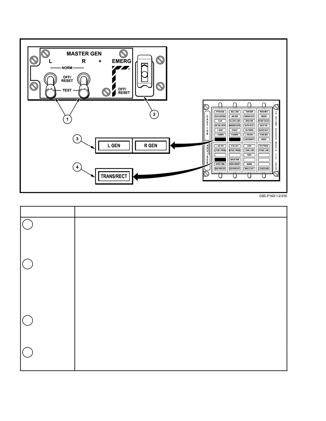
NAVAIR 01−F14AAD−1
NOMENCLATURE
FUNCTION
1
MASTER GEN
NORMĂĊ
Connects the generator to the main buses through the line contactor.
switch
OFF/RESETĂĊ Disconnects generators from the buses. Resets the generator if tripped by
(lock lever)
an overvoltage, undervoltage, or fault condition.
TESTĂĊ
The generators are energized but are not connected to the buses. Provides
a means to analyze a system malfunction indicated by a generator caution
light when an attempt to reset a generator is unsuccessful.
2
EMERG
NORMĂĊ
Safety guard down. Electrically controlled by a solenoid control valve
generator
energized by the left main dc bus. Operation is automatically initiated,
switch
connecting to the essential buses, with the loss of the left main dc bus,
regardless of other sources of ac or dc power. Total loss of ac or dc power
will result in the loss of the left main dc bus and, therefore, activation of the
emergency generator.
OFF/RESETĂĊ Safety guard must be lifted. Disconnects the emergency generator from the
essential buses. Resets the generator if tripped by an undervoltage or
under−frequency condition.
3
L GEN and R
GEN caution lights are on the pilot’s caution/advisory light panel. Each light is tied to its
GEN caution
respective main ac contactor and is powered by the essential bus no. 2. Illumination of the
lights
L GEN or R GEN caution light indicates that the corresponding generator is not supplying
power, due to a fault in the generator, generator control unit, or electrical distribution
system.
4
TRANS/RECT
A TRANS/RECT advisory light is on the lower half of the pilot’s caution/advisory indicator
advisory light
panel. Illumination of the TRANS/RECT advisory light indicates either a single or dual
transformer−rectifier failure has occurred.
Figure 2Ć37.ĄGenerator Panel
ORIGINAL
2−60
NAVAIR 01−F14AAD−1
2.15.1.1.1
Generator Control Units
An external power monitor prevents application of external
power that is not within tolerances and disconnects external
Generator output voltage and frequency are individu-
power from the buses if undervoltage, overvoltage, under-
ally monitored by GCUs, that prevent application of inter-
frequency, overfrequency, or phase−reversal occurs. Power
nally generated power to the aircraft bus system until the
can be reapplied to the aircraft by pressing the reset button
generator output is within prescribed operating limits. With
adjacent to the receptacle, provided it is within prescribed
the main generator switch in NORM, the applicable genera-
limits. External electrical power is automatically inhibited
tor is self−excited, so that during the engine start cycle, it
from HUD, MFD, AICS, APX−76, CADC, and CIU without
automatically comes on−line at approximately 50−percent
external air−conditioning connected to the aircraft. When the
rpm under normal load conditions. Likewise, during engine
left generator comes on the line during start, it automatically
shutdown, the GCU automatically trips the generator off the
disconnects external power. Although there is no direct
line as the power output decreases below prescribed limits at
cockpit indication of external power being applied after one
approximately 55−percent rpm.
generator is operating, the HYD TRANSFER PUMP will not
operate if the external power plug is still in the aircraft
During normal operations, the generator control
receptacle.
switches remain in NORM continuously. However, subse-
quent to an engine shutdown, stall, or flameout in flight
2.15.2
Electrical Power Distribution
where the GCU has tripped the generator off−line, the relight
of the engine will not automatically reset the generator unless
Electrical power is distributed through a series of
the engine speed decreased below about 30−percent N2 rpm.
buses. Under normal operation, the ac generator power dis-
If a transient malfunction or condition causes the generator
tribution is split between the left and right main ac buses.
to trip, the generator must be manually reset by cycling the
Failure of either main ac generator trips a tie connector to
applicable generator control switch to OFF/RESET then
connect both buses to the operative generator. If the bus tie
back to NORM.
fails to trip when the generator goes bad, the respective
transformer−rectifier will not be powered and the indication
When normal reset cannot be accomplished, TEST, on
of this double failure will be a L GEN or R GEN caution light
the generator control switch, allows the generator to be
and a TRANS/RECT advisory light. The left and right main
excited but not connected to the aircraft buses. In test, a CSD,
ac buses in turn supply ac power directly to the respective
generator, or GCU failure causes the GEN light to remain
transformer−rectifiers, and the left main ac bus also supplies
illuminated. If the light goes out, the problem is in the dis-
power to both essential ac buses under normal operation.
tribution system.
External power is distributed through the aircraft elec-
2.15.1.2
Transformer−Rectifiers
trical system in the same manner as main generator power.
Like the main ac generators, dc power distribution from the
Two transformer−rectifiers convert internal or external
two transformer−rectifiers under normal operations is split
ac power to 28−Vdc power. A single TRANS/RECT advisory
between the left and right main dc buses. Failure of either
light on the pilot advisory panel provides failure indication
transformer−rectifier trips the respective tie contactor to
for one or both transformer−rectifiers. No flightcrew control
connect both main dc buses to the operative transformer−
is exercised over transformer−rectifier operation aside from
rectifier. The TRANS/RECT advisory light provides a direct
controlling the ac power supply or circuit breakers for the
indication of dc bus tie status. An interruption−free dc bus
power converters. The transformer−rectifiers have a rated
interconnects the left and right main dc buses to provide a
output of 100 amperes each. Each unit is capable of assuming
continuous source of dc power with failure of either main ac
the complete dc electrical load of the aircraft. Forced air
generator and/or transformer−rectifier. The left main dc bus
cooling is provided with engines running to dissipate the heat
additionally supplies power to both essential dc buses under
generated by the power converters.
normal operations. Power to the DFCS bus is normally
supplied from the interruption−free dc bus; however, with an
2.15.1.3
External Power
output failure from both transformer−rectifiers, the DFCS bus
load is automatically transferred to the essential No. 2 bus.
Loss of main dc power automatically activates the emer-
Ground power is applied through a receptacle just aft
gency generator. The emergency generator is electrically
of the nosegear. The pilot has control over external power
application only through hand signals to the plane captain.
2−61
CHANGE 2
NAVAIR 01-F14AAD-1
inhibited by a solenoid control valve energized by the left
5are onthe RIO’sleft andpanels6to9are onthe RIO’sright.
main dc bus. Operation of the generator is automatically
The pilot left and right knee panels are designated L and R,
initiated, connecting to the essential buses, with the loss of
respectively.
the main dc bus, regardless of other sources of ac or dc power.
Total loss of ac or dc power will consequently result in the
The first digit in the three-part locator is the alpha-
loss of the left main dc bus and, therefore, activation of the
numeric that identifies the circuit breaker panel. The second
emergency generator. This, in turn, trips power transfer
part is a letter that designates the row in which the circuit
relays to change essential ac & dc bus loading from the left
breaker will be found. The top row is designated A, the next
main ac and dc buses to the emergency generator, regardless
row lower is B, etc. The third part is a number and designates
of main generator output status.
the column in which the circuit breaker will be found. The
innermost column of each panel 1, 2, 5, 8, and 9 or aft most
2.15.2.1
Circuit Breakers
column on each panel 3, 4, 6, 7 L and R is designated “1,”
the next outboard/forward column is 2, etc. Figure 2-38 is an
Individual circuit protection from an overload condi-
alphanumeric listing of circuit breakers.
tion is provided by circuit breakers, which are all located in
the cockpits for accessibility in flight. The appropriate circuit
Note
breaker will pop out and isolate a circuit that draws too much
current, thus preventing equipment damage and a possible
D Panel No. 1 row A, the column numbering is
fire.
different from rows B to J.
D Panel No. 2 rows A to F, the column number-
ing is different from Rows G to I.
2.15.3
Degraded Electrical Operation
Popped circuit breakers should not be reset more
2.15.3.1
Emergency Generator
than once nor held depressed unless the associ-
ated equipment is absolutely required by opera-
The emergency generator provides a limited but
tional necessity. A popped circuit breaker indi-
independent backup source of ac (5 kVA, 115/200 volts) and
cates an equipment malfunction or an overload
dc (50 amperes, 28 volts) power for flight-essential compo-
condition. Repeated resets or forced depressions
nents. It is driven by combined hydraulic system pressure.
of popped circuit breakers can result in equip-
ment damage and/or serious electrical fire.
With normal combined hydraulic system operation, the
emergency generator powers the essential ac and dc No. 1
Cockpit circuit breaker panels are shown on FO-8 and
and No. 2 buses and the DFCS dc bus in the 5 kVA mode.
FO-9. Circuit breakers in the pilot cockpit comprise the
Operation of the generator is automatically initiated with the
majority of those required for essential aircraft systems. The
loss of dc left main bus even if other dc buses remain ener-
circuit breakers are arranged in rows and are oriented so that
gized. Approximately 1 second elapses from the time of auto-
the white banded shaft of a popped breaker is readily visible
matic initiation before the generator delivers rated power to
to the flightcrew. Panels, rows, and columns of breakers are
flight-essential ac and dc buses. This delay will force the
identified to facilitate breaker location and designation. Plac-
DFCS computers into a power-up BIT sequence, requiring a
ards adjacent to the breakers identify individual circuit
MASTER RESET to regain SAS and ARI functions.
breakers by affected components; amperage ratings are indi-
cated on top of each circuit breaker.
2.15.2.1.1
Circuit Breaker Location
The alphanumeric system for locating circuit breakers
The spoiler actuators are mechanically biased to
in the aircraft is as follows.
the retracted position in order to cause the
spoilers to retract in the event that the command
The panels in the RIO cockpit are labeled 1 through 9
signal from the DFCS is lost (i.e., DFCS power
starting left-aft and proceeding clockwise. Thus, panels 1 to
failure).
CHANGE 1
2-62
NAVAIR 01−F14AAD−1
If this bias is reversed, the affected spoiler will
The exact hydraulic pressure at which the emergency
extend instead of retracting when the command
generator is unable to power all three buses is dependent on
signal is lost. A DFCS power failure coupled
the load placed on the generator and can vary from 2,000 to
with a reverse spoiler bias will result in a fully
1,100 psi indicated. If the emergency generator is required
deployed spoiler. All unaffected spoilers will
and there is a hydraulic emergency that could lower comĆ
remain retracted and will not respond to flight
bined system operating pressure, the ac essential No. 2 and
control inputs until the DFCS command signals
dc essential No. 2 and dc DFCS buses can be powered with
are restored.
lower hydraulic pressure securing nonessential equipment in
order to reduce the electrical load and to maintain DFCS
Note
functionality.
D DFCS synchronization can take up to two
Note
seconds following a power interrupt. If the
MASTER RESET pushbutton is depressed
D When the emergency generator is operating
during the synchronization time, an addiĆ
with one main hydraulic system inoperative,
tional depression of the MASTER RESET
large hydraulic flow requirements for flight
pushbutton will be required to restore spoiler
controls may cause loss of the essential ac and
functionality.
dc No. 2 and DFCS buses. To regain these
D Do not press and hold the MASTER RESET
buses the emergency generator switch must be
pushbutton. Pressing and holding the
cycled through OFF/RESET to NORM after
MASTER RESET pushbutton during the synĆ
the hydraulic pressure recovers. Engine
chronization time will have no effect since the
instruments are powered by essential ac bus
DFCS computers only recognize the leading
No. 1. Engine instruments will be available or
edge of the pulse from the MASTER RESET
restored at lower engine rpm. The airspeed at
pushbutton, and not the fact that the button is
which engine instrumentation is restored
continuously depressed.
(either automatically or by pilot cycling the
emergency generator switch) could be higher
Pilot control of the emergency generator is through the
than the maximum airspeed.
guarded EMERG switch on the MASTER GEN control
panel. The emergency generator is electrically inhibited by
D In the event of L and R generator failure, an
a solenoid control valve energized by the left main dc bus.
attempt should be made to reduce unnecesĆ
sary electrical loads to maintain DFCS SAS
With the switch in NORM, operation of the generator
and ARI functionality.
is automatically initiated, connecting to the essential buses,
with the loss of the left main dc bus, regardless of other
2.15.3.1.2
Emergency Generator Test
sources of ac or dc power. Total loss of ac or dc power will
consequently result in the loss of the left main dc bus and
An operational check of the emergency generator can
activation of the emergency generator. The OFF/RESET
be accomplished anytime the combined system is pressurĆ
switch position provides the pilot with the capability of
ized and at least one main generator is on the line by selecting
isolating emergency electrical power from the aircraft buses
EMERG GEN on the master test switch and depressing the
(as in the case of an electrical fire) or resetting the generator.
switch. This provides 28 Vdc to activate the emergency
generator and checks the tie contactors by connecting
2.15.3.1.1
Emergency Power Distribution
electrical power to the essential ac and dc buses. The GO light
on the MASTER TEST panel indicates a satisfactory check.
An emergency generator control unit monitors the
A malfunction in the emergency generator operation is
emergency generator output. If it senses that the emergency
indicated by the NO GO light.
generator cannot supply power within the proper frequency
and voltage tolerances, the control unit disconnects the
Note
essential ac and dc essential No. 2 and the dc DFCS buses
from the emergency generator (1 kVA mode). It is possible
During the emergency generator test the essenĆ
that this could happen if the combined hydraulic system is not
tial ac No. 2 bus is switched between the left main
operating normally. If combined hydraulic pressure subseĆ
and emergency generator. The DFCS computers
quently recovers, the emergency generator switch must be
detect this as a loss of ac power and perform a
cycled through OFF/RESET and back to NORM to regain the
power−up BIT sequence when the emergency
5 kVA mode, restoring power to the essential No. 2 and DFCS
generator test is completed. A MASTER RESET
buses. The DFCS computers will respond with a power up
is required to regain SAS and ARI functions.
BIT sequence, requiring a MASTER RESET to regain SAS
and ARI functions.
2−63
ORIGINAL