F-14D. FLIGHT MANUAL (2004) - page 3
NAVAIR 01-F14AAD-1
3F6
26 VAC BUS FDR
8E6
APN-154
3F7
AC ESS BUS NO. 2 FDR PH A
4D6
APX-100 AC
4F1
AC ESS BUS NO. 2 FDR PH B
7F7
APX-100 DC
4F2
AC ESS BUS NO. 2 FDR PH C
7C2
ARC-182 NO. 1
2I4
ACM LT/SEAT ADJ/STEADY POS LT
7C1
ARC-182 NO. 2
3C6
ADF AC
8A5
ARMT GAS/L ENG AFT CONT/RAT IND
8D6
ADF DC
9A4
ASC
RC2
AFCS/NOSE WHEEL STEER
1D2
ASC PH A
LF1
AICS L
1D5
ASC PH B
2I5
AICS L HTR
1D6
ASC PH C
8E2
AICS L LKUP PWR/EMER GEN TST
1F1
ASPJ AUG PH A
7A6
AICS L RAMP STOW
1F3
ASPJ AUG PH B
LG1
AICS R
1F6
ASPJ AUG PH C
2I8
AICS R HTR
1F2
ASPJ BASIC PH A
8E1
AICS R LKUP PWR/ANTI SKID
1F4
ASPJ BASIC PH B
7A5
AICS R RAMP STOW
1F5
ASPJ BASIC PH C
RD2
AIR SOURCE CONTROL
9G5
ASPJ DC
8C2
AIR/ANTI ICE CONTR HOOK CONT/WSHLD
9G6
ASW-27
9B6
ALE-47 CHAFF/FLARE DISP
1J2
ASW-27 AC
9B5
ALE-47 SEQ 1 & 2 SQUIBS
RB1
ALPHA COMP/PEDAL SHAKER
LA3
AUTO PITCH DRIVE TRIM
4F4
ALPHA HTR
1J1
AUTO THROT AC
2H1
ALR-67 CMPTR
9B7
AUTO THROT DC
9F5
ALR-67 CONTR
8G3
AUX FLAP/FLAP CONTR
2H3
ALR-67 RCVR PH A
2H6
ALR-67 RCVR PH B
7D3
BARO ALT/TURN SLIP
2H9
ALR-67 RCVR PH C
3D4
BDHI INST PWR/JTIDS/DPG
7B6
ALT LOW WARN
8E7
BDHI/JTIDS DPG
9D1
AMC BIT/R DC, TEST
1B3
BEAM PS
7A3
ANGLE OF ATTACK IND DC
8F6
BINGO CAUTION
3F3
ANGLE OF ATTK IND AC
8F2
BLEED AIR/L OIL HOT
4F5
ANL ATTK/TOTAL TEMP HTR
4B4
BLEED DUCT AC
9C2
ANN PNL DIM CONTR
7A4
BOS CONTR/B/U OXY LOW
8C1
ANN PNL PWR
9D5
BRAKE ACCUM SOV
9A6
ANT LOCK EXCIT
7A2
B/U OXY PRESS IND
1C2
ANT SVO HYD PH A
1C4
ANT SVO HYD PH B
8A1
CABIN PRESS
1C6
ANT SVO HYD PH C
8C5
CAN/LAD CAUTION/EJECT CMD IND
8C2
ANTI-ICE CONTR HOOK CONT/
LA2
CHAN 1 CADC PH A
WSHLD/AIR
LB2
CHAN 1 CADC PH B
8E1
ANTI SKID/R AICS LKUP PWR
LC2
CHAN 1 CADC PH C
2I1
ANTICOLL/SUPP POS/POS LT
LD2
CHAN 2 CADC
RG2
ANTI-ICE/ENG/PROBE
3E7
CIU PH A
6C3
AN/AWW 4 PH A
4E1
CIU PH B
6C2
AN/AWW 4 PH B
4E2
CIU PH C
6C1
AN/AWW 4 PH C
3B3
COMB HYD PRESS IND
9A2
APG-71 ANT
9F4
COOLING INTLK/GND PWR
2G3
APG-71 PUMP PH A
8D8
CURSOR CONT/SNSR
2G6
APG-71 PUMP PH B
2G7
APG-71 PUMP PH C
7B5
DC ESS NO. 1 FDR
1I1
APG-71 XMTR AC
8A2
DC ESS NO. 2 FDR
9A3
APG-71 XMTR DC
Figure 2-38. Circuit Breaker Alphanumeric Index (Sheet 1 of 5)
CHANGE 1
2-64
NAVAIR 01−F14AAD−1
7A7
DC L TEST/RUDDER TRIM
RF2
FLT CONTR AUTH DC
9D1
DC R TEST/AMC BIT
2A1
FLT HYD BACKUP PH A
9B2
DD ENABLE/RDP
2C1
FLT HYD BACKUP PH B
9I6
DEKI
2E1
FLT HYD BACKUP PH C
8B1
DFCS BUS FDR
3B4
FLT HYD PRESS IND
3F4
DP 1 PH A
3A2
FORM LT/TAXI
4F3
DP 1 PH B
RE1
FUEL FEED/DUMP
4F6
DP 1 PH C
8F7
FUEL LOW CAUTION
1G2
DP 2 PH A
RD1
FUEL MGT PNL
1G4
DP 2 PH B
8F1
FUEL PRESS ADVSY
RG1
FUEL P/MOTIVE FLOW ISOL V
1G6
DP 2 PH C
3C3
FUEL QTY IND AC
9G2
DSS
7D1
FUEL QTY IND DC
RE1
DUMP/FUEL FEED
8E4
FUEL TRANS ORIDE
9E7
DYHR UNIT
8F9
FUEL VENT VALVE
8D4
ECS TEMP CONTR DC
8F5
GEN L CAUTION
9H3
ELECT COOLING
8F4
GEN R CAUTION
7B2
EMER FLT HYD AUTO
9F4
GND PWR/COOLING INTLK
7B1
EMER FLT HYD MAN
8G1
GND ROLL BRAKING/SPOILER POS IND
9I2
EMER GEN CONTR
9D6
GND TEST
8E2
EMER GEN TEST/L AICS LKUP PWR
3E2
GPS
7E3
EMER JETT #1
8E9
GPS ANT AMPL
7E2
EMER JETT #2
6A1
GUN CONTRL PWR AC
RC1
ENG ANTI−ICE VALVES
5D2
GUN PWR NO. 1
7D5
ENG INST NO. 1
5C2
GUN PWR NO. 2
7D4
ENG INST NO. 2
8A5
ENG L AFT CONT/ARMT GAS/RATS IND
1H1
HUD CAMERA PH A
3A3
ENG L BACKUP IGN
1H5
HUD CAMERA PH B
3B1
ENG L OIL PRESS
1H7
HUD CAMERA PH C
8A4
ENG R AFT CONT/EXHAUST NOZZLE
3C1
HUD PH A/MFD 1
3A4
ENG R BACKUP IGN
4C5
HUD PH B/MFD 1
3B2
ENG R OIL PRESS
4C6
HUD PH C/MFD 1
8D1
ENG OIL COOL
1A1
HV PWR SUP PH A
8D3
ENG SEC
1A3
HV PWR SUP PH B
8F10
ENG STALL TONE
1A5
HV PWR SUP PH C
RF1
ENG START
7B3
HYD PRESS IND
RG2
ENG/PROBE/ANTI−ICE
8G11
HYD PUMP SPOILER CONTR
8A4
EXHAUST NOZZLE/R ENG AFT CONT
8E5
HYD VALVE CONTR
8G10
EXT LT CONTR
LE3
ICE DET
9D2
FEMS
7F3
ICS NFO
7C7
FIRE L DET LT
7F2
ICS PILOT
7C5
FIRE L EXT
1J7
IFF A/A AC
7C6
FIRE R DET LT
9F6
IFF A/A DC
8C7
ILS ARA−63 DC
7C4
FIRE R EXT
3E5
ILS ARA−63 PH A
8G3
FLAP CONTR/AUX FLAP
4E3
ILS ARA−63 PH B
3D6
FLAP IND/TAIL/RUDDER
4E4
ILS ARA−63 PH C
RA2
FLAP/SLAT CONTR SHUT−OFF
8G9
INBD SPOILER CONTR
9B6
FLARE DISP/ALE−39 CHAFF
1I7
INS BATT PWR
LC1
FLT CONTR AUTH AC
Figure 2−38. Circuit Breaker Alphanumeric Index (Sheet 2 of 5)
2−65
ORIGINAL
NAVAIR 01−F14AAD−1
3C7
INS PH A
LE2
MACH TRIM AC
4C1
INS PH B
RE2
MACH TRIM DC
4C2
INS PH C
1A8
MAIN L XFMR RECT
3E4
INS SYNC
2F4
MAIN R XFMR RECT
3A1
INST LTS
LE1
MANUV FLAP/WG SWP DR NO. 2
3F5
INSTR BUS FDR
5A2
MASTER ARM
1I2
INTEG TRIM AC
9H4
MASTER TEST
9F3
INTEG TRIM DC
9G3
MDL
9I5
INTRF BLANKER
9G4
MFA
9I1
INTRPT FREE DC BUS FDR NO. 1
3C1
MFD 1/HUD PH A
9C6
INTRPT FREE DC BUS FDR NO. 2
4C5
MFD 1/HUD PH B
9D4
IRST DC
4C6
MFD 1/HUD PH C
2G2
IRST PH A
1G1
MFD 2/MFD 3 PH A
2G5
IRST PH B
1G3
MFD 2/MFD 3 PH B
2G8
IRST PH C
1G5
MFD 2/MFD 3 PH C
1G1
MFD 3 PH A/MFD 2
1J4
JTIDS BATT HEATER
1G3
MFD 3 PH B/MFD 2
1J3
JTIDS DPG PH A
1G5
MFD 3 PH C/MFD 2
1J5
JTIDS DPG PH B
8G5
MLG HANDLE RLY NO. 1
1J6
JTIDS DPG PH C
8G4
MLG HANDLE RLY NO. 2
8E7
JTIDS DPG/BDHI
7F5
MLG SAFETY RLY NO. 1
3D5
JTIDS RT PH A
7F4
MLG SAFETY RLY NO. 2
4D3
JTIDS RT PH B
9D3
MONITOR BUS CONTR
4D4
JTIDS RT PH C
RG1
MOTIVE FLOW ISOL V/FUEL P
3D4
JTIDS/DPG/BDHI INST PWR
5B2
MPRU DC PWR
7C3
KY−58/Z−AHP
6D3
MPRU PH A/SMP
LF1
L AICS
6D2
MPRU PH B/SMP
2I5
L AICS HTR
6D1
MPRU PH C/SMP
8E2
L AICS LKUP PWR/EMER GEN TST
8C8
MSL PWR HUD TEST
7A6
L AICS RAMP STOW
6B3
MSL PWR SUP PH A
7A7
L DC TEST/RUDDER TRIM
6B2
MSL PWR SUP PH B
8A5
L ENG AFT CONT/ARMT GAS/RATS IND
6B1
MSL PWR SUP PH C
3A3
L ENG BACKUP IGN
3C5
MSN CMPTR NO. 2 PH A
3B1
L ENG OIL PRESS
4C3
MSN CMPTR NO. 2 PH B
7C7
L FIRE DET LT
4C4
MSN CMPTR NO. 2 PH C
7C5
L FIRE EXT
1D1
MSN CMPTR NO. 1 PH A
8F5
L GEN CAUTION
1D3
MSN CMPTR NO. 1 PH B
1A8
L MAIN XFMR RECT
1D7
MSN CMPTR NO. 1 PH C
8F2
L OIL HOT/BLEED AIR
3B7
L PH A TEST/P−ROLL TRIM
8A3
NLG STRUT LCH BAR ADVSY
4B1
L PH B TEST/P−ROLL TRIM
RC2
NOSE WHEEL STEER/AFCS
4B2
L PH C TEST/P−ROLL TRIM
2I2
NFO CONSOLE LT
4E5
L PITOT STATIC HTR
3C4
OBOGS CONC
8C5
LAD CAUTION/EJECT CMD IND/CAN
7A1
OBOGS CONTR
9E1
LANTIRN POD CONT/RECON ECS
8F2
OIL L HOT/BLEED AIR
9E2
LANTIRN POD PWR/RECON CONTR
8D2
OIL R HOT
2C3
LANTIRN PWR/RECON HTR 3 PH
2H10
LIQUID COOLING CONTR AC
9C5
OUTBD SPOILER CONTR
9B4
LIQUID COOLING CONTR DC
2B3
OUTBD SPOILER PUMP
Figure 2−38. Circuit Breaker Alphanumeric Index (Sheet 3 of 5)
ORIGINAL
2−66
NAVAIR 01−F14AAD−1
2H5
OXY CONC HTR
9B1
RDP
8F6
OXY/BINGO CAUTION
1E4
RDP PH A
1E5
RDP PH B
3B7
P−ROLL TRIM/L PH A TEST
1E6
RDP PH C
4B1
P−ROLL TRIM/L PH B TEST
9B2
RDP/DD ENABLE
4B2
P−ROLL TRIM/L PH C TEST
2G4
RECON ECS CONT AC
4A6
PANEL FLOOD LTS
9E1
RECON ECS/LANTIRN POD CONT
RB1
PEDAL SHAKER/ALPHA COMP
9E2
RECON CONTR/LANTIRN POD PWR
3B7
PH A L TEST/P−ROLL TRIM
2C3
RECON HTR/LANTIRN PWR 3 PH
4B1
PH B L TEST/P−ROLL TRIM
1E2
RECON POD
4B2
PH C L TEST/P−ROLL TRIM
9E4
RECON POD DC PWR NO. 1
2H2
PH A R TEST
9E3
RECON POD DC PWR NO. 2
2H4
PH B R TEST
1A8
RECT/L MAIN XFMR
2H8
PH C R TEST
5H1
REL PWR/STA 1 TYPE I DCDR
4A5
PILOT CONSOLE LTS
5G1
REL PWR/STA 1 TYPE II DCDR
4A3
PILOT LCD INST LTS
5F1
REL PWR/STA 3 DCDR
LB1
PITCH A AC
5E1
REL PWR/STA 4 DCDR
8B7
PITCH A DC
5D1
REL PWR/STA 5 DCDR
LH1
PITCH B AC
5C1
REL PWR/STA 6 DCDR
8B3
PITCH B DC
5B1
REL PWR/STA 8 TYPE I DCDR
4E5
PITOT STATIC HTR L
5A1
REL PWR/STA 8 TYPE II DCDR
4E6
PITOT STATIC HTR R
LB3
ROLL A/YAW M
8F3
PLT ANN PNL AUX PWR/TR ADVSY
8B4
ROLL A DC
2I1
POSLT/ANTICOLL/SUPP POS
LA1
ROLL B AC
4A4
PROBE LT
8B2
ROLL B DC
RG2
PROBE/ANTI−ICE/ENG
9A7
RSP
1B2
RSP PH A
LG1
R AICS
1B5
RSP PH B
2I8
R AICS HTR
1B8
RSP PH C
8E1
R AICS LKUP PWR/ANTI SKID
3D7
RUDDER TRIM PH A
7A5
R AICS RAMP STOW
4D1
RUDDER TRIM PH B
8A5
RAT IND/L ENG AFT CONT/ARMT GAS
4D2
RUDDER TRIM PH C
9D1
R DC TEST/AMC BIT
7A7
RUDDER TRIM/L DC TEST
8A4
R ENG AFT CONT/EXHAUST NOZZLE
3D6
RUDDER/TAIL/FLAP IND
3A4
R ENG BACKUP IGN
3B2
R ENG OIL PRESS
9I3
SAHRS DC
7C6
R FIRE DET LT
1I3
SAHRS A
7C4
R FIRE EXT
1I5
SAHRS B
1I6
SAHRS C
8F4
R GEN CAUTION
2E4
R MAIN XFMR RECT
2I4
SEAT ADJ/STDY POS LT
8D2
R OIL HOT
RA2
SLAT CONTR SHUT−OFF/FLAP
7E5
SMP ESS
2H2
R PH A TEST
2H4
R PH B TEST
6D3
SMP/MPRU PH A
6D2
SMP/MPRU PH B
2H8
R PH C TEST
4E6
R PITOT STATIC HTR
6D1
SMP/MPRU PH C
8D8
SNSR/CURSOR CONT
4B3
RADAR ALTM
1B1
SOL PWR SUP PH A
1C3
RADAR DD PH A
1B4
SOL PWR SUP PH B
1C5
RADAR DD PH B
1B7
SOL PWR SUP PH C
1C7
RADAR DD PH C
Figure 2−38. Circuit Breaker Alphanumeric Index (Sheet 4 of 5)
2−67
ORIGINAL
NAVAIR 01−F14AAD−1
RB2
SPD BK P−ROLL TRIM ENABLE
6F6
STA 8B PWR PH A
8G1
SPOILER POS IND/GND ROLL BRAKING
6F5
STA 8B PWR PH B
5D3
STA 1 AIM−9 COOL
6F4
STA 8B PWR PH C
2I10
STA 1 BOL PWR
8F8
STARTER VALVE LT
5I3
STA 1 IFOL
3A7
STBY ATTD IND PH A
5H1
STA 1 TYPE I DCDR/REL PWR
4A1
STBY ATTD IND PH B
5G1
STA 1 TYPE II DCDR/REL PWR
4A2
STBY ATTD IND PH C
6A3
STA 1A AIM−9 PWR AC
2I1
SUPP POS/ANTICOLL/POS LT
5B3
STA 1A AIM−9 PWR DC
2I6
STORM FLOOD LTS
5J2
STA 1B NO. 1/2 DC
3D6
TAIL/RUDDER/FLAP IND
6A6
STA 1B PWR PH A
3A2
TAXI/FORM LT
6A5
STA 1B PWR PH B
1H2
TCS PH A
6A4
STA 1B PWR PH C
1H3
TCS PH B
5F1
STA 3 DCDR/REL PWR
5I2
STA 3 NO. 1/2 DC
1H6
TCS PH C
9C3
TCS SEL
6B6
STA 3 PWR PH A
6B5
STA 3 PWR PH B
4B5
TEMP CONT AC
4F5
TOTAL TEMP HTR/ANL ATTK
6B4
STA 3 PWR PH C
5H3
STA 3/6 IFOL
8F3
TR ADVSY/PLT ANN PNL AUX PWR
7D3
TURN SLIP/BARO ALT
5E1
STA 4 DCDR/REL PWR
5H2
STA 4 NO. 1/2 DC
7F6
UHF CONTR/VHF
6C6
STA 4 PWR PH A
3A6
UTILITY LTS
6C5
STA 4 PWR PH B
6C4
STA 4 PWR PH C
7F6
VHF/UHF CONTR
5G3
STA 4/5 IFOL
5D1
STA 5 DCDR/REL PWR
LE1
WG SWP DR NO. 2/MANUV FLAP
5G2
STA 5 NO. 1/2 DC
7D6
WHEELS POS IND
6D6
STA 5 PWR PH A
3F2
WING POS IND AC
6D5
STA 5 PWR PH B
7D2
WING POS IND DC
6D4
STA 5 PWR PH C
LD1
WING SWEEP DRIVE NO. 1
5C1
STA 6 DCDR/REL PWR
8C3
WSHLD DEFOG CONTR
5F2
STA 6 NO. 1/2 DC
8C2
WSHLDAIR/ANTI ICE CONTR/
6E6
STA 6 PWR PH A
HOOK CONT
6E5
STA 6 PWR PH B
6E4
STA 6 PWR PH C
8B6
YAW A DC
5C3
STA 8 AIM−9 COOL
8B5
YAW B DC
2I9
STA 8 BOL PWR
LD3
YAW A AC
5F3
STA 8 IFOL
LC3
YAW B AC
5B1
STA 8 TYPE 1 DCDR/REL PWR
LB3
YAW M/ROLL A
5A1
STA 8 TYPE II DCDR/REL PWR
6F3
STA 8A AIM−9 PWR AC
3F6
26 VAC BUS FDR
5A3
STA 8A AIM−9 PWR DC
5E2
STA 8B NO. 1/2 DC
Figure 2−38. Circuit Breaker Alphanumeric Index (Sheet 5 of 5)
ORIGINAL
2−68
NAVAIR 01−F14AAD−1
2.16 HYDRAULIC POWER SUPPLY SYSTEMS
transfer pump. This unit consists of two hydraulic pumps, one
in each of the main hydraulic systems, interconnected by a
The aircraft employs two main, independent, engine−
common mechanical shaft. Thus, a pressure deficiency in
powered hydraulic systems, supplemented by two electroĆ
one system is automatically augmented using pressure in the
hydraulic power modules, a bi−directional transfer unit, and
other system as the motive power. The result is bi−directional
a cockpit handpump. The systems are pressurized to 3,000 psi
transfer of energy without an interchange of system fluid.
and use MIL−H−83282 hydraulic fluid circulated through
The efficiency of the pump is such that a 3,000 psi system on
stainless steel and titanium lines. Hydraulic fluid is cooled by
one side will pressurize the other system to approximately
heat exchangers that use ejector air on deck. Hydraulic power
2,400 to 2,600 psi.
system controls and indicators are shown in Figure 2Ć39. The
components serviced by each hydraulic power system are
To prevent damage to the hydraulic transfer pump with
shown in FO−10.
the loss of system fluid on one side and to conserve hydraulic
power in the remaining good system, the pump is automatiĆ
2.16.1
Flight and Combined Systems
cally secured when pressure less than 500 psi is detected on
either side of the pump for 10 seconds. In addition, the pilot
2.16.1.1
Engine−Driven Pumps
can manually shut off the hydraulic transfer pump by lifting
the guarded HYD TRANSFER PUMP switch, located aft on
the right outboard console.
The flight and the combined systems are each pressurĆ
ized by engine−driven pumps. The flight hydraulic system
pump is driven by the right engine and the combined hydrauĆ
lic system pump by the left engine. Each of the main systems
is normally pressurized to 3,000
$ 100 psi at any time the
respective engine is operating.
If pressure in either system remains below 500
2.16.1.2
Hydraulic Pressure Light
psi for 5 seconds, immediately lift the guard and
select SHUTOFF with the HYD TRANSFER
A HYD PRESS caution light illuminates when the disĆ
PUMP switch. Failure of the hydraulic transfer
charge pressure from either engine−driven hydraulic pump
pump to automatically shut off after 10 seconds
falls below 2,100 psi; thereafter, the light goes out when
below 500 psi may cause the driving system to
pressure in both systems via the engine−driven pumps
cavitate and overheat.
exceeds 2,400 psi. If the HYD PRESS caution light has been
illuminated by low pressure in one main system, pressure
With ground electrical power connected to the aircraft,
failure in the other system will not cause the MASTER
the hydraulic transfer pump is deactivated and can only be
CAUTION light to illuminate again. The COMB and FLT
energized by a switch on the ground check panel. Normally,
gauges on the hydraulic pressure indicator reflect system
with both engines running, the hydraulic transfer pump is off.
pressure provided by either the engine−driven pumps or the
However, with less than 2,100 psi hydraulic pump discharge
hydraulic transfer pump. With both systems normally presĆ
pressure from either system, the pump will automatically
surized to 3,000 psi, the gauge needles form a horizontal line.
come on and supply hydraulic power to the faulty system. In
addition, the HYD PRESS caution light will also illuminate.
Note
The pilot has no direct control over the direction of pump
flow, the system automatically shifts in the direction that
High−rate lateral movements may illuminate the
supplemental power is required. Because of the location of
HYD PRESS light when engines are at idle
the flight and combined system pressure switches, the presĆ
power.
surization contribution of the hydraulic transfer pump is
reflected on the hydraulic pressure indicator but the HYD
2.16.1.3
Hydraulic Transfer Pump
PRESS caution light will remain illuminated. Operation on
(Bi−Directional Pump)
the hydraulic transfer pump may produce slight pressure
fluctuations. If the failed system discharge pressure is
To assure the continuance of main system hydraulic
restored to normal operating pressure (>2,400 psi) by the
pressure with an engine or engine−driven pump inoperative,
engine−driven pump, this HYD PRESS light will go out and
a second source of pressure is provided by the hydraulic
the hydraulic transfer pump will shut off.
2−69
ORIGINAL
NAVAIR 01−F14AAD−1
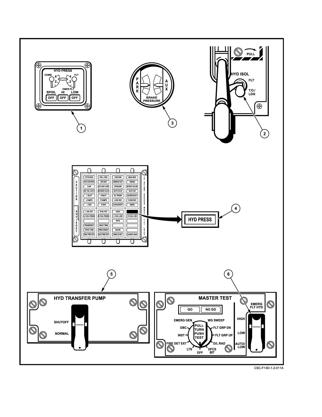
Figure 2Ć39.ĄHydraulic System Controls and Indicators (Sheet 1 of 2)
ORIGINAL
2−70
NAVAIR 01−F14AAD−1
NOMENCLATURE
FUNCTION
1
HYD PRESS indicator
COMB and FLT Ċ Indicates pump discharge pressure on each engine,
normally 3,000 psi, or hydraulic transfer pressure
approximately 2,400 psi.
SPOIL Ċ
When the outboard spoiler hydraulic module is pressurized
(1,950 to 2,050 psi) the ON flag appears. If pressure drops
below 1,900 to 1,800 psi, the OFF flag appears.
EMER FLT Ċ When pressure from the backup flight control hydraulic
module reaches 500
$ 50 psi the ON flag appears.
Pressure below 350
$ 50 psi: the OFF flag appears.
2
HYD ISOL switch
FLT Ċ
Combined system hydraulic pressure is shutoff to landing
gear, nosewheel steering, antiskid, and wheel brakes.
T.O./LDG Ċ
Hydraulic pressure is available to all combined system
components.
3
BRAKE PRESSURE
AUX Ċ
Green segment indicates hydraulic pressure (2,150
$ 50
gage
to 3,000 psi) in the auxiliary brake accumulator; auxiliary
braking may be applied by rudder toe pedals (approximately
13 to 14 applications available). Red segment indicates
1,900 to 2,150 psi (approximately 5 applications available).
PARK Ċ
Green segment indicates hydraulic pressure (2,150
$ 50
to 3,000 psi) in the parking brake accumulator. The
parking/emergency brake handle must be pulled to apply
emergency braking (approximately 3 applications available).
Red segment indicates 1,900 to 2,150 psi.
4
HYD PRESS caution
Illuminates when hydraulic pressure from either engine−driven pump is below
light
2,100 psi. It will go out with pressure in both systems at 2,400 psi or above, if
pressure is provided by engine−driven pumps.
5
HYD TRANSFER
SHUTOFF Ċ Guard must be lifted. Shuts off hydraulic transfer pump.
PUMP switch
The pump should be secured when hydraulic pressure
drops below 500 psi and does not rise again within
5 seconds.
NORMAL Ċ Safety guard down. Pressure loss below 2,100 psi in one
(Guarded)
hydraulic system activates hydraulic transfer pump to
supply pressure from the other system.
6
EMERG FLT HYD
HIGH Ċ
Guard must be lifted. Activates the power module
switch
(high speed mode) bypassing flight and combined
2,100−psi switches.
LOW Ċ
Guard must be lifted. Activates the backup power module
(low−speed mode) bypassing flight and combined
2,100−psi switches.
AUTO (LOW) Ċ Safety guard down. The backup flight control system is
automatically activated (low−speed mode) when pressure
in both the flight and combined systems is less than
2,100 psi.
Figure 2−39. Hydraulic System Controls and Indication (Sheet 2 of 2)
2−71
ORIGINAL
NAVAIR 01−F14AAD−1
2.16.1.4
Cockpit Handpump
Major components in the combined and flight hydrauĆ
lic power supply systems are shown on FO−10. Each system
A manually operated pump handle is provided as a
has a piston−type reservoir and filter module in the sponson
supplementary source of power for ground operations with
aft of the main landing gear strut on the respective side
engines shut down and as a backup for the loss of combined
(combined−left; flight−right). Protrusion of mechanical pins
system pressure to operate the in−flight refueling probe or
on each filter module indicates a clogged filter.
charge the brake accumulator. It is an extendable handle in
the pilot cockpit between the left console and ejection seat.
2.16.2.1
Hydraulic Priority Valves
Forward and aft stroking of the handpump operates a double−
acting wobble pump. The pump, which draws fluid from the
The combined and flight hydraulic systems each incorĆ
combined system return line, recharges wheelbrake accumuĆ
porate two priority valves (1,800 psi and 2,400 psi) shown on
lator pressure when the landing gear handle is down. With the
FO−10. Hydraulic fluid will not pass through the one−way
gear handle up, it also serves as a backup means of extending
priority valves unless the input pressure exceeds the cracking
or retracting the in−flight refueling probe by placing
threshold of the valve. Basically, the 2,400 psi priority valves
the REFUEL PROBE switch in the desired position (EXT
give priority of the individual engine−driven pump discharge
or RET).
pressure to the primary flight controls
(horizontal tails,
rudders, inboard spoilers) and stability augmentation actuaĆ
The handpump is the only means of pressurizing the
tors. Conversely, the 1,800 psi priority valves give priority to
radome fold actuator, an operation that must be manually
the remaining systems on the other side (inlet ramps, wing
selected and the radome unlocked on deck from the nose
sweep, etc.) with pressure supplied by the hydraulic transfer
wheelwell. The recommended rate of operation is approxiĆ
pump. Under such circumstances, the pilot should be aware
mately 12 cycles per minute (a cycle is a complete forward
of the hydraulic energy available and demands of the various
and aft movement of the pump handle).
system components. Large and abrupt control commands can
rapidly consume total energy with the engine(s) at IDLE
2.16.2
Hydraulic Power Distribution
speed. For example, during a single−engine landing rollout,
if excessive horizontal tail movements are commanded, the
The distribution of hydraulic power in the flight and
nosewheel steering and wheelbrake operation could be
combined systems is shown on FO−10. Except for the left
temporarily lost.
empennage control surfaces, the flight system services only
those components on the right side of the aircraft and does not
2.16.2.2
Normal Hydraulic Isolation
penetrate into the wings. The combined system distribution
is more extensive throughout the aircraft, yet its services are
The combined system incorporates isolation circuits to
predominantly concentrated to the left side and extend to the
limit distribution to flight essential components. With the
inboard sections of the movable wing panels and to the
LDG GEAR handle UP, normal isolation may be selected by
landing gear. Although the flight and combined systems are
the pilot to prevent loss of hydraulic fluid in the event of
completely independent of each other, in certain components
material failure or combat damage to the isolated systems.
both pressure sources are used without an interchange of
Normal isolation electrically shuts off hydraulic pressure to
fluid. Both systems operate in parallel to supply power for
wheelbrakes, antiskid, landing gear and nosewheel steering.
operation of the primary flight control surfaces
(except
It is activated by placement of the HYD ISOL switch to FLT
spoilers) and stability augmentation actuators; if one system
on the landing gear panel. Placement of the gear handle to DN
fails, the other can continue to supply pressure for operation
mechanically cams the HYD ISOL switch to T.O./LDG or the
(with reduced power capability of such components). If
pilot can manually select it before lowering the landing gear.
either or both main hydraulic systems should fail, backup
Such action returns all combined−system components to norĆ
sources provide the capability for safe return flight and
mal operation.
landing.
ORIGINAL
2−72
NAVAIR 01−F14AAD−1
2.16.3
Outboard Spoiler System
2.16.4
Backup Flight Control System
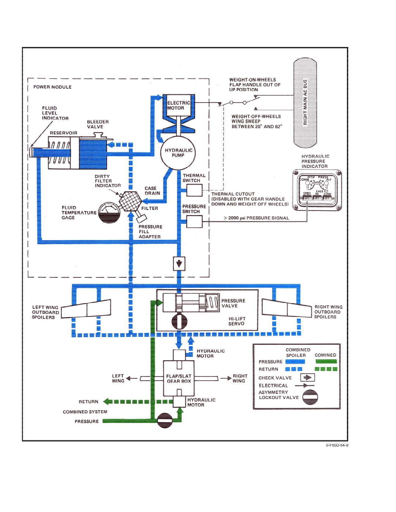
The outboard spoilers are powered by a separate
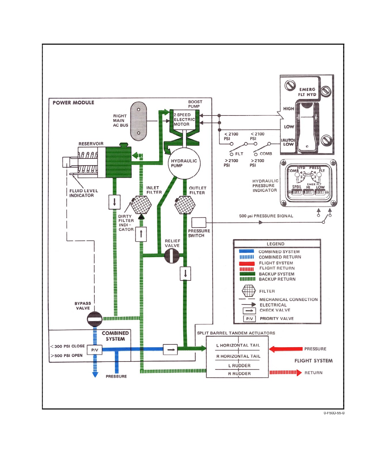
The backup flight control system consists of a two−
closed−loop system, independent of the main hydraulic sysĆ
speed electrohydraulic power module known as the backup
tems (see Figure 2Ć40). An electrohydraulic power module
flight control module. The BFCM provides fluid energy to
supplies hydraulic pressure for outboard spoiler deflection
operate the horizontal tails and rudders at a reduced rate
and provides a backup power source for the main flaps and
(see Figure 2Ć41). Emergency power provides sufficient
slats. Outboard spoiler operation is electrically inhibited at
pitch, roll, and yaw control for return flight and landing with
wing−sweep angles greater than 62_ and the power module
both main hydraulic power systems inoperative.
is deactivated at wing−sweep angles greater than 65.
Return flow from the combined side of the rudder and
stabilizer actuators is first used to ensure the BFCM reservoir
A thermal cutout circuit secures the system in the event
is filled. When filled, a reservoir bypass valve opens, which
of overheating. Normal operation is automatically restored
allows return flow to the combined system. A priority valve
when fluid temperature falls below the prescribed limit. The
connects the BFCM return to the aircraft’s combined sys−
thermal cutout circuit is disabled with the gear handle down
tem return. When the combined system pressure falls below
and weight off wheels to prevent overtemperature shutdowns
300 psi, the priority valve closes, isolating the BFCM return
during takeoff or landing. To avoid overheating due to proĆ
from the combined system return. When the combined presĆ
longed ground operations, the outboard power module is
sure exceeds 500 psi, the priority valve opens allowing the
deactivated with the flap handle up when on internal electriĆ
backup system return to flow into the combined system
cal power with weight on wheels. Electrical power for the
return. A check valve isolates backup system pressure from
outboard spoiler system motor is supplied from the right main
the combined system when the BFCM is energized.
ac bus. The module can be activated using external ac electriĆ
cal power. With the module pressurized, the ON flag appears
2.16.4.1
Backup Flight Control Operation
in the SPOIL window at the bottom of the hydraulic pressure
indicator; otherwise, an OFF indication is displayed in the
window.
The BFCM may be operated in two modes: emergency
and ground test. In the emergency mode, the BFCM is conĆ
trolled by the EMERG FLT HYD switch, on the MASTER
Reservoir servicing level is shown by an indicator rod
TEST panel. The switch has three positions:(AUTO) LOW,
protruding from the integral power package. A fluid temperaĆ
LOW, and HIGH mode. Electric power to the motor is supĆ
ture gauge that registers current and retained peak system
plied by the right main ac electrical bus through the FLT
temperatures is on the power module. Protrusion of a red−
HYD BACKUP PH A (2A1), PH B (2C1), and PH C (2E1)
tipped pin on the integrated filter package is an indication of
circuit breakers located on right main ac circuit breaker panel
a clogged filter.
(No. 2) in the rear cockpit. Loss of both engine−driven electriĆ
cal generators eliminates in−flight use of the BFCM.
2.16.3.1
Flap and Slat Backup Operation
Although normal operation of the main flap and slat
segments is powered by a combined system motor on the flap
and slat gearbox, an auxiliary motor powered by the outboard
spoiler system is geared to the same shaft to provide for
Never use the three−phase circuit breakers (PH A,
emergency operation (retraction and extension) of the main
PH B, and PH C) to start or shut off the BFCM as
flaps and slats at a reduced rate. Failure of combined system
damage to the motor may result. These circuits
pressure activates the auxiliary motor to drive the flap and
must be engaged prior to any system test.
slat gearbox when selected by the normal flap handle or
maneuvering flap thumbwheel.
Automatic control of the BFCM is provided by the
closing of both flight and combined hydraulic system presĆ
sure switches. Since the switches are set at 2,100 psi, both
flight and combined hydraulic system pressures must drop
below 2,100 psi before the BFCM is turned on in the
2−73
ORIGINAL
NAVAIR 01-F14AAD-1
Figure 2-40. Outboard Spoiler System
ORIGINAL
2-74
NAVAIR 01-F14AAD-1
Figure 2-41. Backup Flight Control System
2-75
ORIGINAL
NAVAIR 01−F14AAD−1
automatic low mode. Once in this automatic mode of
Ground checks of the BFCM are performed by the pilot
operation, the BFCM cannot be turned off unless either or
using the EMER FLT HYD switch. Before performing
both flight and combined systems are pressurized above
ground checks, the combined and brake system accumulators
2,400 psi. The EMERG FLT HYD switch is used to select the
must be charged. The BFCM has a small volume capacity,
low or high mode. Either of these positions overrides the
1,000 cc (@ 1 qt.) when full, but will decrease in volume
circuitry of the automatic low mode and the BFCM will
to
500 cc (@ ½ qt.) when the aircraft is not in use.
remain on even if either or both system pressures become
Below 500 cc (@ ½ qt.), cavitation of the pump and overheatĆ
pressurized above 2,400 psi. When the BFCM pump reaches
ing of the motor may occur. If the accumulators are not
500 psi, the ON flag appears in the selected window at the
charged prior to starting the BFCM, depletion of the reservoir
bottom of the hydraulic pressure indicator.
hydraulic fluid will occur. If this occurs too frequently, sysĆ
tem damage and failure may result. Both hydraulic system
In the low−speed mode, the system can operate indefiĆ
pressures should indicate zero in order to fully test indepenĆ
nitely and should be used for maximum range and endurance.
dent operation of the BFCM.
Emergency power
(high mode) provides a maximum
unloaded horizontal tail deflection rate approximately one
fourth of that available from a full powered hydraulic system
(10_ per second vice 36_ per second). The maximum deflecĆ
tion rate available will decrease as airloads increase.
D A 180_F thermal cutoff switch is bypassed
when the BFCM is selected on with the
EMERG FLT HYD switch. Prolonged ground
operation in the emergency mode will result
in BFCM burnout.
When operated in conjunction with zero comĆ
D Since flight control demands can exceed
bined system pressure, some BFCM hydraulic
BFCM capability, all surface demands must
fluid will be forced out by thermal expansion.
be performed slowly and cautiously in order
The BFCM will remain fully serviced and will
not to exceed the output rate of the system.
operate normally as long as the elevated temperĆ
Excessive system demands will cause the
atures are maintained. Once operating, the
pump to cavitate and the motor to overheat.
BFCM should not be turned off in flight without
Checks should be made slowly enough to
combined system pressure available to reservice
ensure continuous on indication in the
it. Doing so would result in fluid contraction and
hydraulic pressure indicator.
an underserviced condition that could prevent
subsequent pump operation.
2.16.4.2.1
Ground Test Mode
The ground test mode of operation is controlled by the
AUX HYD CONT switch on the ground test panel in the rear
cockpit. In this mode, the BFCM operates in the high mode
only. Ground test from the rear cockpit is electrically inhibĆ
D If either the flight or the combined hydraulic
ited when the aircraft is on internal electrical power.
system pressure drops below 2,100 psi withĆ
out illuminating the HYD PRESS caution
light, the automatic low mode of the backup
flight control system may be inoperative.
D Prolonged use
(approximately
8 minutes
cumulative time) of the BFCM in the high
The ground test mode incorporates a solenoid
mode may result in a failure of the BFCM.
valve that allows the BFCM to pressurize the
entire combined hydraulic system. If the comĆ
2.16.4.2
Ground Operations
bined and brake accumulators are not fully
charged
(brake pressure indicator at top of
For ground inspection purposes, protrusion of a red−
green), or if the combined system is not fully
tipped button on either the inlet or outlet filter cases is a
serviced, the reservoir will be depleted and the
positive indication of a dirty filter. Both such indications may
motor will cavitate and overheat. This could
be observed through an access door on the underside of the
result in motor failure prior to activation of the
aft fuselage.
thermal cutoff switch.
ORIGINAL
2−76
NAVAIR 01−F14AAD−1
2.17 PNEUMATIC POWER SUPPLY SYSTEMS
side of the nose wheelwell. Expenditure of bottle pressure
is controlled by a twist−pull operation of the landing
The pneumatic power supply systems consist of three
gear handle. Minimum bottle pressure for accomplishing
independent, stored pneumatic pressure sources for normal
emergency extension of the gear to the down−and−locked
and auxiliary operation of the canopy and for emergency
condition is 1,800 psi. Normal preflight bottle pressure is
extension of the landing gear. The high−pressure bottles for
3,000 psi at 70_ F.
normal canopy operation and emergency landing gear extenĆ
Note
sion are ground−charged through a common filter connection
in the nose wheelwell to 3,000 psi at 70_ F ambient temperaĆ
D Emergency extension of the landing gear shall
ture. Individual bottle pressure is registered on separate
be logged in the Maintenance Action Form
gauges on the right side of the nose wheelwell. An auxiliary
(OPNAV Form 3760−2).
canopy−open N2 bottle, filter valve, and gauge is on the
D Once the landing gear is extended by emerĆ
turtleback behind the cockpit to allow opening the canopy
gency means, it cannot be retracted while
from the cockpit or ground. Charges may be compressed air;
airborne and must be reset by maintenance
however, pressurized dry nitrogen is preferred because of its
personnel.
low moisture content and inert properties.
D Use of emergency gear extension results in
2.17.1
Normal Canopy Control
loss of nosewheel steering.
The bottle that supplies a pressurized charge for normal
2.18 MISSION COMPUTER SYSTEM
operation of the canopy is on the right side of the forward
fuselage, inboard of the air refuel probe cavity. Expenditure
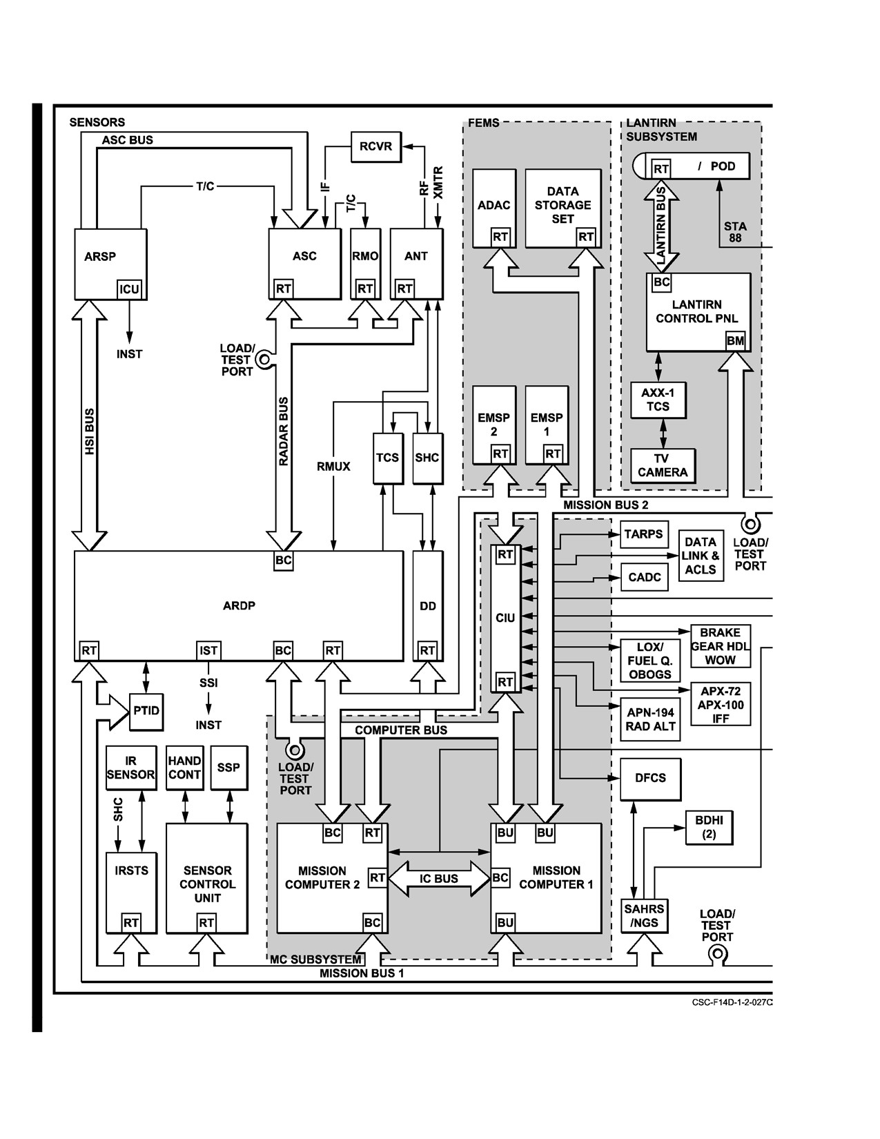
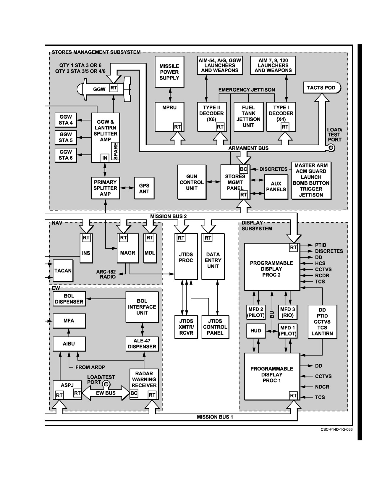
The MCS consists of two AN/AYK−14 digital comĆ
of bottle pressure for normal operation of the canopy is
puter
(MC1 and MC2) and the dual redundant MIL−
controlled by three (pilot, RIO, and ground) canopy control
STD−1553B buses. The MCS is operated at 16 MHz clock
handles. A fully charged bottle provides approximately 10
speed to perform 1 million instructions per second using up
complete cycles (open and close) of the canopy before
to 1 megabyte of memory. The 1553B bus system in the
reaching the minimum operating pressure of 225 psi.
F−14D uses time division multiplexing (TDM) with informaĆ
tion coded into 20−bit words.
2.17.2
Auxiliary Canopy Open Control
Communication protocol is established by a command
The auxiliary canopy air bottle supplies a pneumatic
response system in which all bus transmissions occur under
charge to translate the canopy aft so that the counter−poise
command of a bus controller or, in case of failure of primary
action of the canopy actuator facilitates opening. It is on the
bus controller, a backup bus controller. Each bus is capable
turtleback behind the canopy hinge line.
of addressing up to 31 remote terminals; however, address 31
is not used in the aircraft. Figure 2Ć42 depicts the physical
Activation of the auxiliary mode can be effected from
connection of the WRAs in the MCS data bus system.
either of the three (pilot, RIO, or ground) canopy control
Remote terminals incapable of communicating directly with
handles. After activation of the auxiliary open mode, the
the MCS on the 1553 data buses are routed through the
control system will not return to the normal mode of operaĆ
converter interface unit for required analog−to−digital and
tion (canopy will lower but will not translate forward) until
digital−to−analog conversion.
the auxiliary selector valve on the aft canopy deck is manuĆ
ally reset (lever in vertical position). Servicing of the auxilĆ
2.18.1
Aircrew Interface
iary canopy air bottle is through the small access panel immeĆ
diately behind the canopy on the turtleback. The reservoir is
The principle aircrew interface with the MCS is
normally serviced to 3,000 psi at 70_ F ambient temperature.
accomplished through the pushbuttons on each MFD. The
A fully charged bottle provides more than 20 operations
RIO has an additional interface through the DEU communiĆ
in the auxiliary open mode. Minimum preflight pressure is
cating directly with the MCS as a remote terminal. The RIO
800 psi.
can also interface indirectly with the MCS through the radar
system digital display.
2.17.3
Emergency Gear Extension
The bottle that supplies the pneumatic force for a
single emergency extension of the landing gear is on the right
2−77
ORIGINAL
NAVAIR 01-F14AAD-1
Figure 2-42. Mission Computer System Architecture (Sheet 1 of 2)
CHANGE 1
2-78
NAVAIR 01-F14AAD-1
Figure 2-42. Mission Computer System Architecture (Sheet 2 of 2)
2-78a (Reverse Blank)
CHANGE 1
NAVAIR 01−F14AAD−1
2.18.2
Operational States
2.19 STANDARD CENTRAL AIR DATA COMPUTER
The MCS has three operational states: startup, full up,
Note
and backup. These states are mutually exclusive and are
The acronyms SCADC and CADC are used
determined automatically based on aircraft operation and
interchangeably throughout this manual.
MC1/MC2 condition.
The SCADC CPU−175/A is installed in F−14D aircraft
The SYS RESET button on the NAV MODE panel
incorporating AFC 793. The SCADC is functionally interĆ
forces both mission computers to transition to the startup
state and execute cold start logic. It can be used to assure the
changeable with the CADC 1166B/A with one difference,
the SCADC software incorporates the static−error source−
aircrew that the MCS is functioning properly and/or to
correction curve required for the true values of Mach
reinitialize the MCS by restarting the OFP. When SYS
number,ăairspeed, and altitude. In aircraft prior to AFC 793
RESET is pressed, the following events occur:
(CADC 1166B/A), aircrew should refer to performance
1. The MCS immediately stops executing the OFP.
charts, NAVAIR 01−F14AAP−1.1 for HUD−displayed altiĆ
tude and Mach number correction curves.
2. The mission computers go off line and run software
BIT.
Note
3. The OFP is automatically restarted.
The standby airspeed indicator is not corrected
for position error.
4. The aircraft goes into the TLN master mode.
The SCADC is a single−processor digital computer
5. Displays revert to defaults.
with a separate, independent, analog, backup wing−sweep
channel. It is capable of making yes and no decisions, solving
Recycling power (by cycling circuit breakers) to the
mathematical problems, and converting outputs to either digĆ
MCS has the same effect as pressing the SYS RESET except
ital or analog form as required by each aircraft system. The
that both hardware and software BIT is performed.
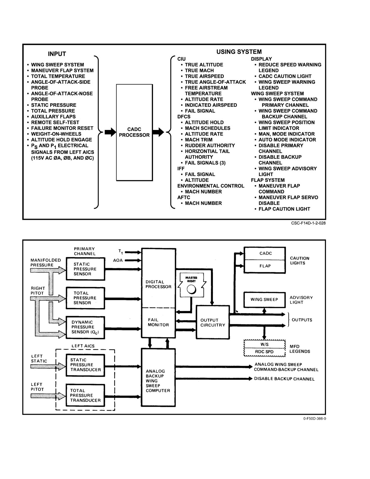
SCADC gathers, stores, and processes pitot pressure, static
pressure, total temperature and AOA data from the aircraft
Note
airstream sensors (see Figure 2Ć43). It performs wing−sweep
and flap and slat schedule computations, limit control and
Cycling subsystem circuit breakers initiates a
electrical interlocks, failure detection, and systems test logic.
cold start for that subsystem. A system reset may
Major systems that depend on all or part of these CADC
be required to resynchronize the MCS and the
functions are shown in Figure 2Ć44.
restarted subsystem.
The following legends appear on the MFD when actiĆ
Refer to the Supplemental NATOPS, NAVAIR
vated by the CADC:
01−F14AAD−1A for a complete description of the MCS
architecture, operational states, and backup operation.
1. RDC SPD (warning legend) (REDUCE SPEED)
Indicates flaps down above 225 knots; maximum
2.18.3
Aircraft Master Modes
safe Mach exceeded (2.4 Mach/total temperature
above 388_ F).
There are three aircraft master modes of operation:
takeoff−landing−navigation (TLN), air−to−air (A/A), and air−
2. W/S
(caution legend)
(WING SWEEP)
to−ground (A/G). The controls, displays, and avionics equipĆ
Indicates dual wing−sweep channel failure or wing−
ment are tailored as a function of the master mode selected
sweep detent disengaged.
by the pilot. The TLN master mode is entered automatically
when power is applied to the aircraft, when the landing gear
2.19.1
Standard Central Air Data Computer Tests
is down, or when the TLN master mode pushbutton is
selected on the PDCP. The A/A master mode is entered by
2.19.1.1
Built−In Test
pressing the A/A master mode pushbutton on the PDCP,
selecting an air−to−air weapon with the weapon select switch
BIT capabilities provide continuous monitoring of the
on the pilot control stick, or by commanding a radar dogfight
SCADC and its inputs and outputs. The failure indicator
mode. The A/G master mode is entered by pressing the A/G
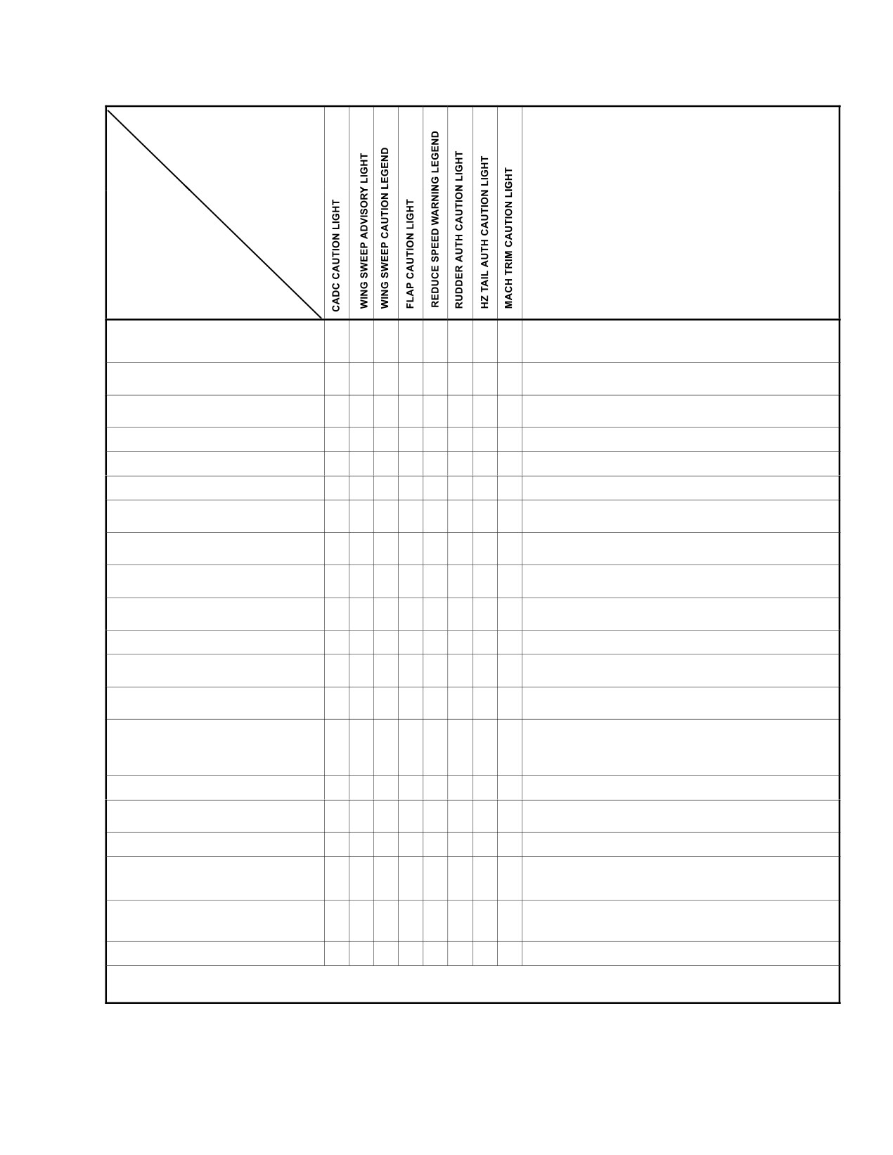
matrix (Figure 2Ć45) tabulates the functions that are moniĆ
master mode pushbutton on the PDCP.
tored and associated fail indications.
2−79
ORIGINAL
NAVAIR 01−F14AAD−1
Figure 2Ć43.ĄCADC Functional Relationships
Figure 2Ć44.ĄCADC Processor
ORIGINAL
2−80
NAVAIR 01−F14AAD−1
INDICATION
REMARKS
FAILURE
CADC − PS/Pt SENSOR COMPARE DIGITAL
WING−SWEEP LIMIT BUG MAY BE INACCURATE, MAXIMUM
PROCESSOR
F
F
F
F
F
F
F
SAFE MACH INDICATOR MAY BE INACCURATE, MANEUVER
FLAPS.
CADC WING−SWEEP COMMAND
F
F
(SINGLE FAILURE)
CADC WING−SWEEP COMMAND
AUTO WING SWEEP INOPERATIVE
F
F
F
(DUAL FAILURE)
WING SWEEP (SINGLE FAILURE)
F
WING SWEEP (DUAL FAILURE)
F
F
AUTO WING SWEEP INOPERATIVE
CADC MANEUVER FLAP COMMAND
F
F
MANEUVER FLAPS VIA THUMBWHEEL INOPERATIVE
MANEUVER FLAP − COMMAND AND
MANEUVER FLAPS VIA THUMBWHEEL INOPERATIVE
F
[
SERVO MISCOMPARE
MANEUVER FLAP − HYDRAULIC VALVE
F
[
AND/OR ACTUATOR MISCOMPARE
MANEUVER FLAP − HANDLE AND/OR
F
HYDRAULIC VALVE MISCOMPARE
AUXILIARY FLAP AND MANEUVER FLAP
F
MISCOMPARE
AUXILIARY FLAP ASYMMETRY
F
CADC RUDDER OR STABILIZER
F
F
F
COMMAND AUTHORITY
ANGLE−OF−ATTACK SIGNAL
ANGLE−OF−ATTACK DISPLAY NOT PRESENT ON HUD DURING
F
LANDING MODE
TOTAL TEMPERATURE SIGNAL
AUTO PILOT CAUTION LIGHT ILLUMINATES IF IN ALTITUDE
HOLD. ALTITUDE HOLD WILL BE DISENGAGED. VERTICAL
F
SPEED NOT PRESENT ON HUD DURING TAKEOFF AND
LANDING MODE
CADC WING SWEEP INDICATOR OUTPUT
F
WING SWEEP INDICATOR INACCURATE
ECS FAILURE AND MACH >0.25.
CABIN TEMPERATURE MAY RISE AFTER LANDING. COOLING
F
AIR ADVISORY LIGHT MAY ILLUMINATE
ECS FAILURE AND MACH >0.4.
F
CADC− DIGITAL DATA TO CSDC
ALTITUDE AND MACH NOT DISPLAYED ON HUD. ANGLE−OF−
F
ATTACK DURING LANDING DISPLAY NOT ON HUD. DURING
TAKE OFF AND LANDING VERTICAL SPEED NOT ON HUD.
ALTITUDE HOLD OUTPUT
AUTO PILOT CAUTION LIGHT ILLUMINATES IF IN ALTITUDE
F
HOLD. ALTITUDE HOLD WILL BE DISENGAGED
ALTITUDE RATE OUTPUT
MACH TRIM OUTPUT
F
F
* REDUCE SPEED LEGEND WILL APPEAR IF AIRSPEED >225 KNOTS AND FLAPS ARE DOWN OR MAXIMUM SAFE MACH EXCEEDED
2.4 IMN/TOTAL TEMPERATURE ABOVE 388_ F.
Figure 2Ć45.ĄCADC Processor Indicators
2−81
ORIGINAL
NAVAIR 01−F14AAD−1
2.19.1.2
On−Board Checkout
Under normal operating conditions, the wings are
automatically positioned to the optimum sweep angle for
The CADC performs a self−test during OBC only with
maximum maneuvering performance. The pilot can selecĆ
weight on wheels. When OBC is initiated, normal air data
tively position the wings at sweep angles aft of optimum.
inputs are locked out and in their place constants from the
computer memory are received. Self−test detected failures
A mechanical backup control system is provided for
may be manually reset by pressing the MASTER RESET
emergency and oversweep operations. Details of the wing−
pushbutton.
sweep system are shown in FO−11.
Pressing the MASTER RESET pushbutton for 1 second
The outboard location of the wing pivot reduces the
resets transient failures in the CADC. Activating the master
change in longitudinal stability as a function of wing−sweep
reset circuit recycles the failure detection process in the
angle. Two independently powered, hydromechanical screwĆ
CADC. This recycling process puts off the caution and
jack actuators, mechanically interconnected for synchroĆ
advisory light(s) and may take as long as 10 seconds to check
nization, position the wings in response to pilot or CADC
out the status of the system. If a failure exists, the light(s) will
commands. In flight, the wings can be positioned between
illuminate again. If a transient failure existed, the light(s)
20_ and 68_ wing sweep angle. On the deck, the range is
will remain off.
extended aft to 75_ (oversweep position) to reduce the span
for spotting. Such authority results in a variation of wing span
The following caution and advisory lights are activated
from approximately 64 to 33 feet.
by the SCADC:
Cavities above the engine nacelles and the midfuselage
1. CADC
accommodate the inboard portions of the wing panels as they
2. FLAP
sweep aft. Sealing of the underside is by a wiper seal and
airbag. The bag is pressurized by engine bleed air. Airbag
3. WING SWEEP (advisory) If the WING SWEEP
pressure is released during oversweep to avoid overloading
advisory light does not recycle when MASTER
of the flap mechanism. An overwing fairing encloses the wing
RESET pushbutton is depressed, the light is actiĆ
cavity and provides a contoured seal along the upper surface
vated by the wing flap controller.
of the wing for the normal range of in−flight sweep angles. The
Three independent SCADC fail signals drive the DFCS
left and right overwing fairing actuators are pressurized by
failure detection circuits. If these signals exist, the DFCS will
the combined and flight hydraulic systems, respectively.
illuminate the following lights:
2.20.1
Wing−Sweep Performance
1. CADC fail signal pitch computer No Light
Maximum wing−sweep rate (approximately 15_ per
2. CADC fail signal to yaw computer RUDDER
second) is adequate for most transient flight conditions;
AUTH and HZ TAIL AUTH
however, wing−sweep rate can be significantly reduced or
3. CADC fail signal to roll computer MACH TRIM.
stalled by negative−g or large positive−g excursions. SuffiĆ
(FCS CAUTION and ARI DGR lights will also be
cient capability has been provided in the system, consistent
illuminated.)
with the sustained performance capabilities of the aircraft.
With a failure of either the combined or flight hydraulic
Note
systems, the wings will move at a reduced rate.
If autopilot is engaged the AUTOPILOT light
will illuminate when any of the three fail signals
exist. If ACL is engaged the AUTOPILOT and
ACLS/AP lights will illuminate when any of the
three fail signals exist.
Slower than normal wing sweep cycling times
Pressing MASTER RESET pushbutton will also
may also be indicative of a failed hydraulic wing
update the wing−sweep and flap commands to their respecĆ
sweep motor or an impending failure. With airĆ
tive feedback signals. As a result, there may be movement in
craft on the ground and both FLT and COMB
the wings and maneuver flaps when MASTER RESET
hydraulic power, the time to sweep the wings
pushbutton is depressed.
from 68° to 20° should not exceed 9 seconds.
Note
2.20 WING−SWEEP SYSTEM
D The overwing fairings and flaps are susceptiĆ
The variable geometry of the wing−sweep system
ble to a high frequency (60 cycles per second),
provides the pilot with considerable latitude for controlling
low−amplitude oscillation that can be felt in
wing lift and drag characteristics to optimize aircraft
the cockpit. This overwing fairing and flap
performance over a broad flight spectrum.
ORIGINAL
2−82
NAVAIR 01−F14AAD−1
buzz is normal and is influenced by the rigging
optimum sweep angle for developing maximum maneuverĆ
of the fairings and air in the hydraulic systems.
ing performance. In addition to providing an automatic wing
positioning function, the programmer also defines the
D Overwing fairing and flap buzz is usually
forward sweep limit that cannot be penetrated using any of
encountered between 0.9 and 1.4 Mach.
the other electrical (manual or bomb) modes. The forward
sweep limiter prevents electrical mispositioning of the wings
2.20.2
Wing−Sweep Modes
from a wing structure standpoint.
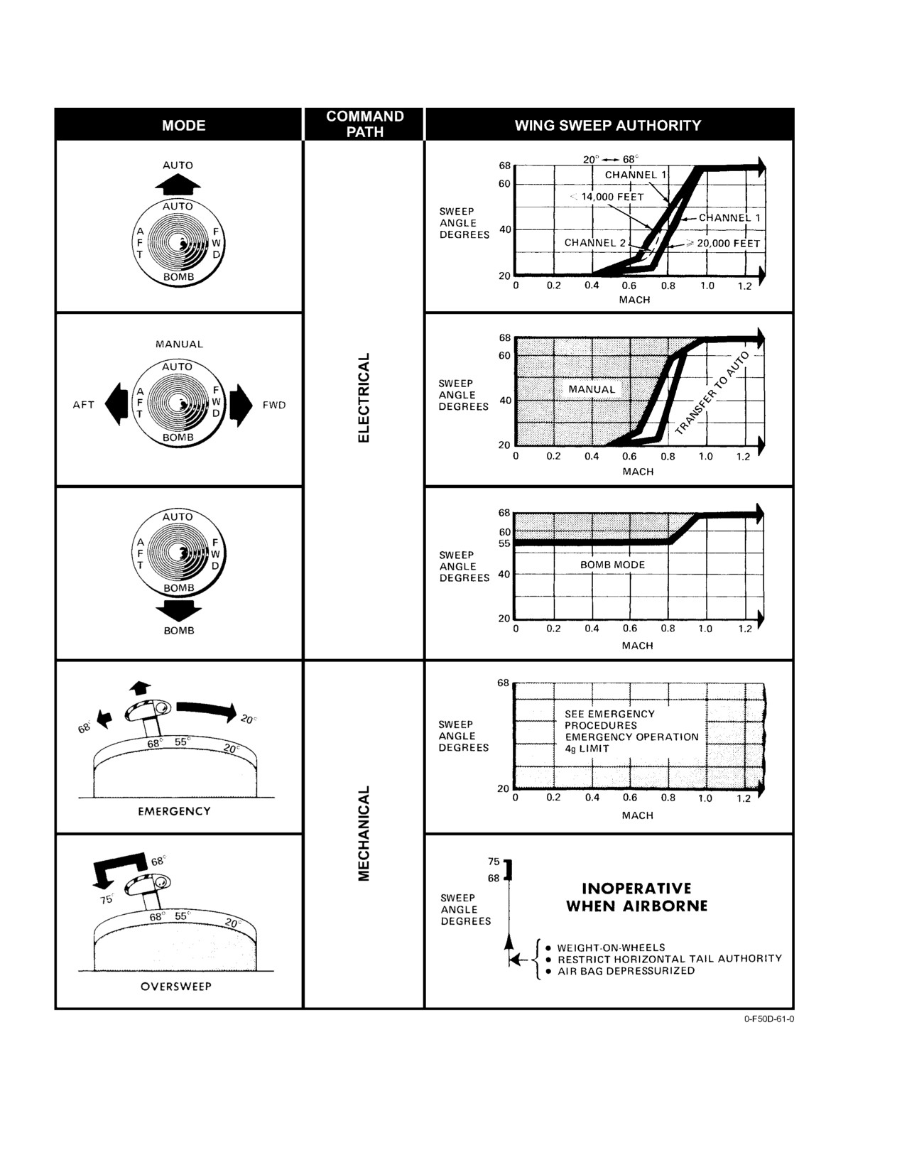
Normal control of the wing−sweep position in AUTO,
AFT, FWD, and BOMB modes is by the four−way wing−
Pilot selection of the AUTO mode or automatic transfer
sweep switch on the inboard side of the right throttle grip
from the manual mode causes the AUTO flag to appear in the
(Figure 2Ć46). As an emergency mode of control, changes in
wing−sweep indicator. Once in the AUTO mode, the four−
wing−sweep position can be selected manually with the
way wing−sweep switch can be in the center position without
emergency WING SWEEP handle on the inboard side of the
changing the command mode.
throttle quadrant. The handle is connected directly to the
wing−sweep hydraulic valves. The command source for
2.20.2.2
Manual Mode
positioning the wings depends upon the mode selected by the
The manual wing−sweep mode is commanded by
pilot or, in certain cases, is automatically selected. Electrical
selecting AFT or FWD from the neutral position of the
and mechanical wing−sweep command paths are shown on
wing−sweep switch, driving the wings in the commanded
FO−11. Wing−sweep modes are shown in Figure 2Ć47.
direction to any wing−sweep position aft of the automatic
program. The switch is spring−loaded to return to the center
position. Manual command mode exist unless the wing−sweep
program is intercepted, at which point transfer to the AUTO
mode is automatic. Indication of the existing mode is provided
The emergency wingsweep handle can be moved
by the AUTO and MAN flags in the wing−sweep indicator.
independent of the wings and wingsweep indicaĆ
tors when no hydraulic power and/or electrical
2.20.2.3
Bomb Mode
power are on the aircraft. Care must be taken to
accurately determine the position of the emerĆ
Bomb mode is selected by moving the wing−sweep
gency wingsweep handle prior to application of
switch to the down (BOMB) position. With the switch in
hydraulic power. Inadvertent wingsweep to the
BOMB, the following occurs:
position selected by the emergency wingsweep
1. Wing SWEEP indicator shows MAN flag.
handle may occur anytime hydraulic power is on,
resulting in potential damage to the aircraft.
2. If wing sweep is less than 55_, wings will drive
When positioning the wings during ground
to 55_.
operation other than pilot poststart or postĆ
3. If wing sweep is greater than 55_, wings will not
landing checklist procedures, use the emergency
move.
wingsweep handle to minimize the possibility of
moving the wings inadvertently.
4. If maneuver flaps are extended, they will retract and
wings will sweep to 55_.
Note
As the aircraft accelerates and the AUTO wing−sweep
D When positioning the wings, do not command
schedule is intercepted, the wings will follow the AUTO
opposite direction until wings have stopped in
schedule even though the switch remains in BOMB mode.
original commanded position
(all sweep
Upon decelerating, the wings will sweep forward to 55_ and
modes) to increase motor life.
stop.
D The optimum wing position (triangular index)
and the AUTO/MAN flags may be unreliable
2.20.2.4
Emergency Mode
when the CADC caution light is illuminated.
During normal mode operation of the wing−sweep
system, the wing−sweep control drive servo drives the
2.20.2.1
AUTO Mode
hydraulic valve command input through a spider detent
Selection of the AUTO mode is made by placing the
mechanism. The emergency handle under a transparent
four−way wing−sweep switch in the upper detented position
guard is moved in parallel with the servo output. The
(AUTO) permitting the CADC wing−sweep program to
emergency mode provides an emergency method of controlĆ
position the wings automatically. The program positions the
ling wing sweep. It bypasses the normal command path of the
wings primarily as a function of Mach number but includes
system (CADC and control drive servo loop).
pressure altitude biasing. Wing position is scheduled to the
2−83
ORIGINAL
NAVAIR 01−F14AAD−1
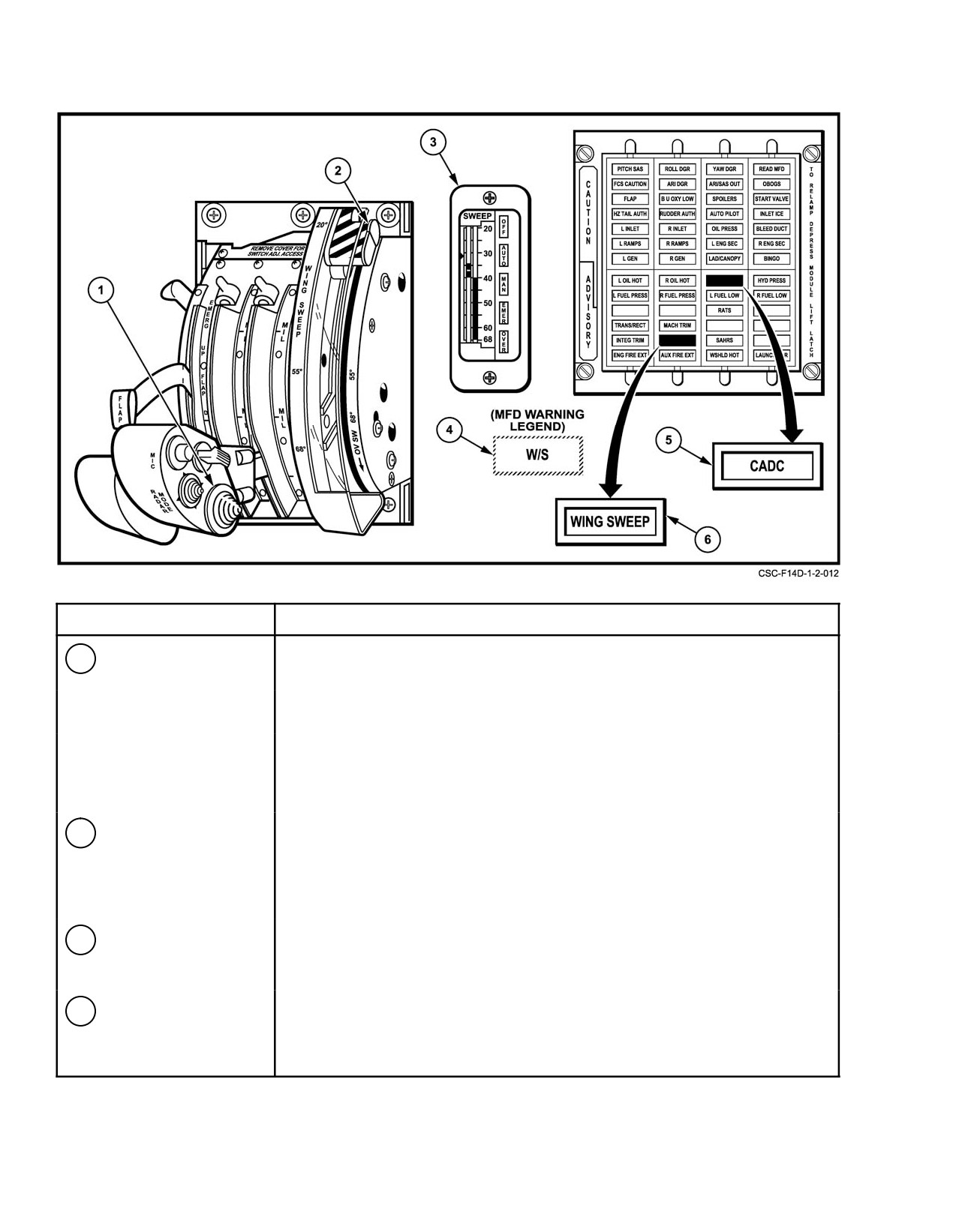
NOMENCLATURE
FUNCTION
1
Wing sweep switch
AUTO Ċ Wing sweep angles are determined by CADC according to wing
sweep program. Detented switch position.
BOMB Ċ Wings are positioned at 55_ or further aft if commanded by the
CADC program. Detented switch position.
AFT/FWD Ċ The pilot can select AFT or FWD wing positions within limits
imposed by the wing sweep program. Switch is spring−loaded to
the center position. When the forward limit is intercepted, the
mode is transferred to AUTO.
2
Emergency WING
Provides a mechanical means of wing sweep control that overrides the
SWEEP handle
CADC program commands. Wing sweep angles between 20_ and 68_ are
unrestricted except for flap interlocks. Oversweep 75_ is provided with
weight−on−wheels, horizontal stabilizer authority restricter in reduced range,
and air bag pressure dumped.
3
Wing SWEEP
Displays (from right to left) actual wing sweep position, commanded position
indicator
and wing sweep program position, which is the maximum forward angle at
present airspeed and attitude. Indicator windows show the operating mode.
4
W/S caution legend
Indicates failure of both wing sweep channels and/or disengagement of spider
on MFD
detent. Wing sweep positioning requires using the emergency wing sweep
handle.
Figure 2Ć46.ĄWing−Sweep Controls and Indicators (Sheet 1 of 2)
ORIGINAL
2−84
NAVAIR 01−F14AAD−1
NOMENCLATURE
FUNCTION
5
CADC caution light
Indicates hardware failure and/or that certain computations of the air data
computer are unreliable. Illumination of WING SWEEP advisory light and/or
W/S caution legend on MFD determines pilot action.
6
WING SWEEP
Indicates failure of a single channel in the system. Illumination of both
advisory light
WING SWEEP advisory and CADC caution light indicates failure of one
channel in CADC.
Figure 2−46. Wing−Sweep Controls and Indicators (Sheet 2 of 2)
To select emergency mode, the handle must be
D If operating in the emergency wing−sweep
extended vertically. The guard should be moved out of the
mode, positively confirm all flaps are
way before the handle is operated. Vertical extension of
retracted prior to attempting AFT wing
the emergency handle provides for better accessibility and
sweep.
leverage. The detent is not disengaged by raising the handle
Note
vertically. An initial fore or aft force of up to 30 pounds
In certain failure modes, the flap indicator may
breakout and 13 pounds maximum is necessary for operation.
not accurately reflect the position of all flaps.
The spider detent is reengaged if the handle is
Since the wing−sweep program acts as a forward limiter
repositioned to the detent (servo) position.
only for the normal modes of operation, the pilot must follow
The emergency WING SWEEP handle incorporates
the following schedule in the emergency mode:
locks at approximately 4_ increments between 20_ and 68_.
1. 0.4 Mach 20_
These locks are provided to eliminate random wing moveĆ
ment in the emergency mode should electrical system
2. 0.7 Mach 25_
transients be experienced. When the locks are engaged, wing
3. 0.8 Mach 50_
movement is inhibited provided that the wings match handle
position. The wing−sweep locks eliminate the need for the
4. 0.9 Mach 60_
installation of wing−sweep servo cutout switches. Locks are
5. 1.0 Mach 68_.
engaged by raising the handle
1 inch from the stowed
position. In order to bypass the locks and select a wing
When operating in the emergency mode, pulling the
position, the handle is raised an additional 1 inch (2 inches
WING SWEEP DRIVE NO. 1 (LD1) and WG SWP DR
from stowed) and moved to the desired position. The handle
NO.Ă2/MANUV FLAP (LE1) circuit breakers on the pilot left
is spring−loaded to return to the lock position when released.
knee panel assures that the electrical command path cannot
The handle can be raised from 20_ to 68_ and oversweep, but
interfere with the emergency mode.
can only be returned to the stowed position at 20_ and
oversweep. This feature is intended to prevent inadvertent
2.20.2.5
Oversweep Mode (75_)
engagement of the AUTO MODE, commanding the wings to
spread causing possible damage to the aircraft or injury to
The wing oversweep mode allows sweeping the wings
aft of 68_ to 75_ during on−deck operation only, thereby
personnel in a confined area. The handle is spring−loaded
toward the stowed position, but requires depressing the
reducing the overall width of the aircraft for deck spotting.
At 75_, the wing trailing edge is over the horizontal tail surface.
release button on the inboard side of the lever in order to
return the handle to the stowed position.
If the over" flag is not displayed in the wingĆ
sweep indicator with the wings in oversweep, the
D Except for wing flap (main and auxiliary) and
stick should remain centered.
oversweep interlocks in the control box, the
emergency mode does not prevent pilot misĆ
With the wings at 68_, oversweep can be initiated by
positioning of the wings from a structural
raising the emergency WING SWEEP handle to its full
standpoint.
extension and holding. Raising the handle releases air pressure
2−85
ORIGINAL
NAVAIR 01−F14AAD−1
Figure 2Ć47.ĄWing−Sweep Modes
ORIGINAL
2−86
NAVAIR 01−F14AAD−1
from the wing−seal airbags and activates the horizontal tail
2.20.3
Wing−Sweep Interlocks
authority system, restricting the surface deflections to 18_
Automatic limiting of wing−sweep authority is proĆ
trailing edge up and 12_ trailing edge down. During motion
vided under normal in−flight control modes to prevent
of the horizontal stabilizer restrictors, the HZ TAIL AUTH
mispositioning of the wings at conditions that could result in
caution light is illuminated. When the horizontal tail
the penetration of structural boundaries. Wing−sweep interĆ
authority restriction is accomplished
(approximately
15
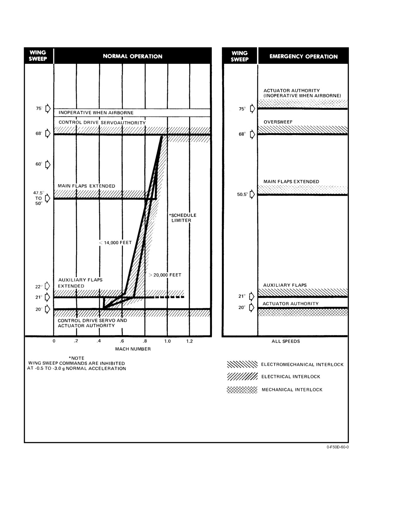
locks within the CADC are shown in Figure 2Ć48. Wing
seconds), the HZ TAIL AUTH caution light will go off and
sweep is also electrically inhibited at normal accelerations
the OVER flag on the wing−sweep indicator will be visible.
less than −0.5 g.
This advises the pilot that the oversweep interlocks are free,
allowing movement of the emergency WING SWEEP handle
2.20.3.1
Flap and Slat Wing−Sweep Control Box
to
75_ and stow. The EMER and OVER flags on the
wing−sweep indicator will be visible.
Electromechanical (auxiliary flaps, oversweep enable)
and mechanical (main flap) interlocks in the control box limit
aft wing−sweep commands at 21_15′, 50_, and 68_. InterĆ
locks in the control box are shown in Figure 2Ć48.. These
interlocks, which serve as a backup to the electronic
interlocks in the CADC, are imposed on both the normal and
D Failure of the oversweep interlocks while
the emergency inputs to the control box and assure nonĆ
trying to achieve oversweep may result in
interference between movable surfaces and the fuselage.
damage to the wingtip and horizontal tail
trailing edges, and the maneuver flap actuator.
2.20.4
Wing−Sweep System Test
D If unusual resistance is encountered while
2.20.4.1
Continuous Monitor
attempting to put the wings into oversweep,
continued aft pressure on the WING SWEEP
The command and execution of the wing−sweep
handle may cause failure of the wing−sweep
system is continually monitored by a failure detection
actuator.
system. The failure detection system in the CADC governs
the change from wing−sweep channel 1 to channel 2 or the
The reverse process takes place when sweeping forĆ
disabling of wing−sweep channel 1 or 2 by switching the
ward from oversweep. However, there is no need to hold the
respective control drive servo off. A single channel failure in
emergency handle in the raised position at 68_. Motion out
the wing−sweep electrical command path is indicated by
of oversweep is completed (wing−seal airbag pressure estabĆ
illumination of the WING SWEEP advisory light followed
lished and horizontal tail authority restriction removed)
by normal operation on the remaining channel. Failure of the
when both the OVER flag and the HZ TAIL AUTH caution
remaining channel is indicated by a W/S caution legend on
lights are off. Six seconds later the WING SWEEP advisory
the MFD and requires that wing−sweep control be exercised
light will illuminate. Upon engagement of the spider detent
through the emergency WING SWEEP handle. Transient
by further unsweeping the emergency handle, MASTER
failures in the CADC can be reset by pressing the MASTER
RESET pushbutton is pressed to clear the WING SWEEP
RESET pushbutton, which recycles the failure detection
advisory light, thus activating the electrical command cirĆ
system.
cuits of the wing−sweep system.
2.20.4.2
Preflight Check
A preflight check of the wing−sweep system to assure
proper operation of the electrical command circuits without
moving the wings should be accomplished after starting
engines while the wings are in oversweep (75_).
When coming out of oversweep and a 68_ wing
position is desired, the wings should be moved
1. Set wing−sweep mode switch to AUTO.
forward to approximately 60_ and then back
to 68_.
Note
The CADC caution light will illuminate and test
will not run if AUTO is not selected on the wing−
sweep switch.
2−87
ORIGINAL
NAVAIR 01−F14AAD−1
Figure 2Ć48.ĄWing−Sweep Interlocks
ORIGINAL
2−88
NAVAIR 01−F14AAD−1
2. Press MASTER RESET pushbutton.
2.21.1.1.1
Emergency Flaps
EMER UP enables the pilot to override any electroĆ
3. Set MASTER TEST switch to WG SWP.
mechanical commands that may exist because of malĆ
4. Monitor test by observing:
function of the CADC. To position the flaps, move the FLAP
handle to the end of the normal travel range; then, move the
a. Wing−sweep limit pointer drives to 44°.
handle outboard and continue moving to extreme EMER UP.
While moving the handle, forces may be higher than normal.
b. Illumination of the WING SWEEP advisory light
EMER DN has no function.
and FLAP caution light.
Note
The WING SWEEP advisory light will illumiĆ
nate 3 seconds after test starts, then go off and
A slip clutch assembly is installed between the
illuminate again at 8 seconds into test.
combined system forward flap hydraulic motor
and the center gearbox assembly. While this will
c. RDC SPD warning legend on MFD.
relieve some stall torque on the hydraulic motor,
extremely fast reversals of flap direction while
d. At end of test (approximately 25 seconds) the
flaps are in motion may result in eventual failure
limit pointer will drive to 20_ and the above
of the flap and slat flexible driveshaft.
lights will go off.
2.21.1.2
Maneuver Flap and Slat Thumbwheel
5. Set MASTER TEST switch to OFF.
The maneuver flap and slat thumbwheel is located on
Note
the left side of the stick grip and is spring loaded to the center
position. With LDG GEAR and FLAP handles up, automatic
Ignore illumination of RUDDER AUTH caution
CADC flap and slat positioning can be overridden with pilot
or MACH TRIM advisory lights and motion of
thumbwheel inputs to partially or fully extend or retract the
the control stick if they occur during the test.
maneuvering flaps and slats; however, the next time angle of
attack crosses an extension or retraction threshold, the
2.21
FLAPS AND SLATS
automatic command will again take precedence, unless
The flaps and slats form the high−lift system, which
manually overridden again. Manual thumbwheel command
provides the aircraft with augmented lift during the two
is a proportional command.
modes of operation: takeoff or landing, and maneuvering
2.21.1.3
Main Flaps
flight. The flaps are of the single−slotted type, sectioned into
three panels on each wing. The two outboard sections are the
The main flaps on each wing consist of two sections
main flaps utilized during both modes of operation. The
simultaneously driven by four mechanical actuators geared
inboard section (auxiliary flap) is commanded only during
to a common flap driveshaft. Each wing incorporates a flap
takeoff or landing. The slats consist of two sections per wing
asymmetry sensor and flap overtravel switches for both the
mechanically linked to the main flaps. Flaps down greater
extension and retraction cycles.
than 10_ enables the wheels warning light interlock, and
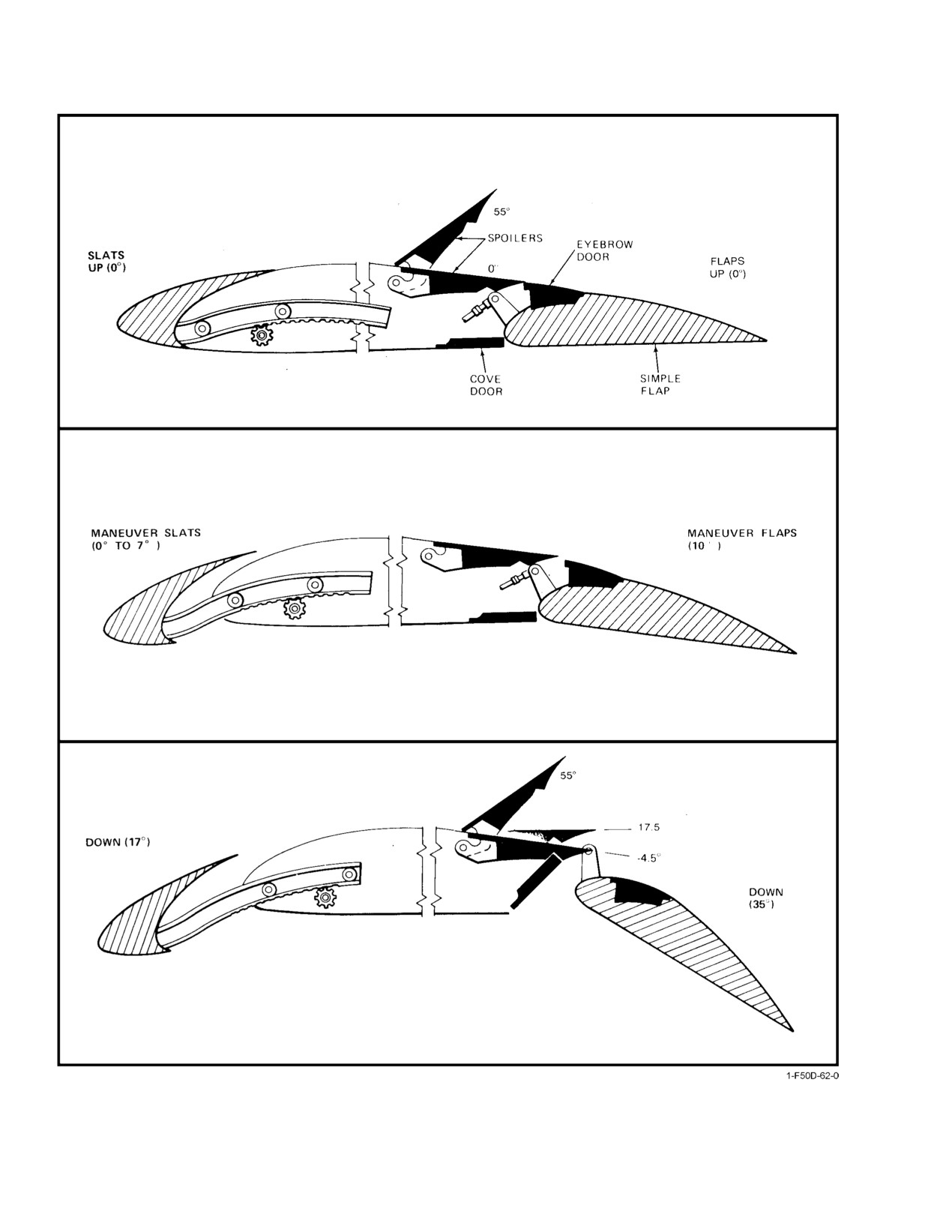
Cove doors, spoilers, eyebrow doors, and gusses
greater than
25_ enables direct lift control and power
operate with the flaps to form a slot to optimize airflow
approach spoiler gearing.
over the deflected flap. The cove doors are secondary
surfaces along the underside of the wing forward of the flap
2.21.1
Flap and Slat Controls
(Figure 2Ć50.) As the flaps pass 25_ deflection, a negative
Pilot controls for flap and slat takeoff, landing, and
command received from the DFCS depresses the spoilers to
maneuvering modes are illustrated in Figure 2Ć49.
− 4½_ to meet with the cove doors. Because the spoilers do
not span the entire wing as do the flaps, gusses inboard and
2.21.1.1
FLAP Handle
outboard of the spoilers perform the flaps−down function of
the spoilers. With the flaps retracted, the eyebrow doors,
The FLAP handle, located outboard of the throttles, is
which are the forward upper surface of the flaps, are
used to manually command flaps and slats to the takeoff and
spring−loaded in the up position to close the gap between
landing position. Flap handle commands are transmitted by
the trailing edge of the spoiler or guss and the leading edge
control cable to the flap and slat and wing−sweep control box
of the flaps. Mechanical linkage retracts the eyebrow door
where they are integrated with CADC electromechanical
when the flaps are lowered to provide a smooth contour over
inputs to command proper flap and slat position.
the upper surface of the deflected flap.
2−89
ORIGINAL
NAVAIR 01−F14AAD−1
NOMENCLATURE
FUNCTION
1
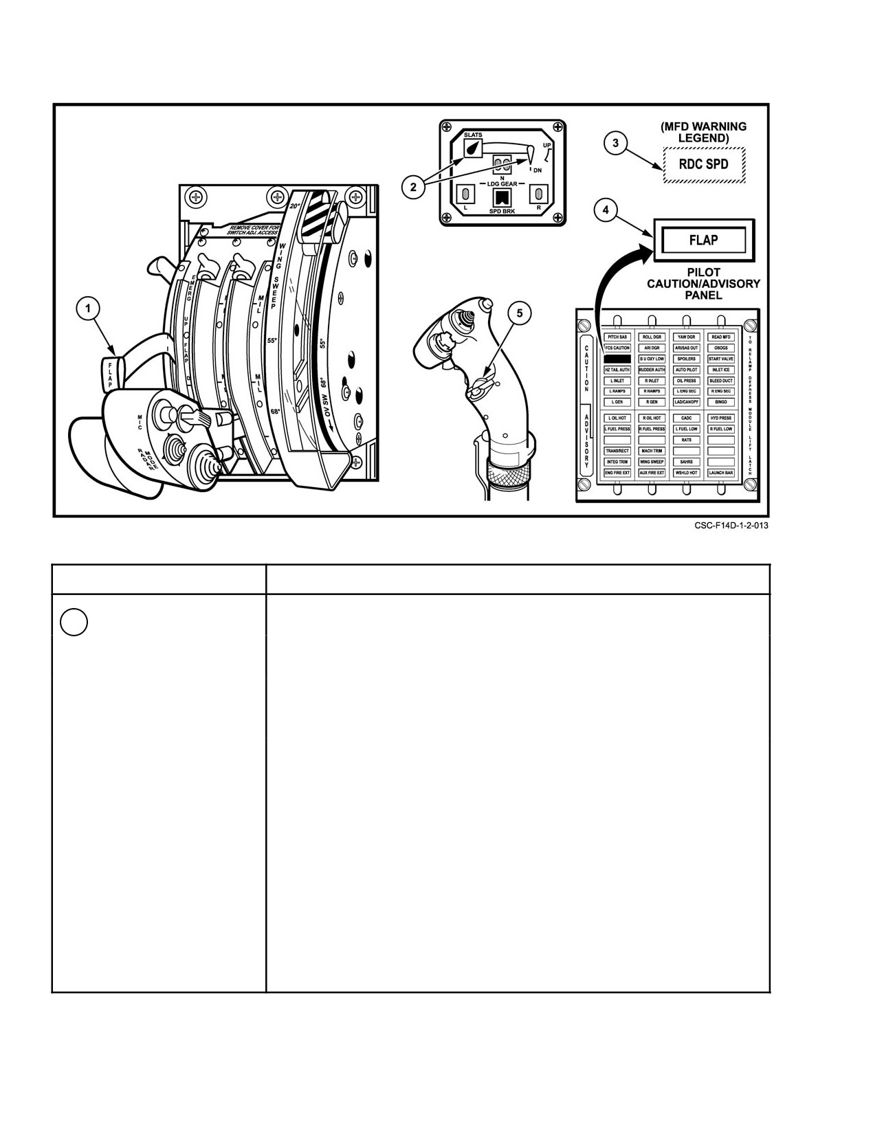
FLAP handle
UP Ċ
Normal retraction of main and auxiliary flaps.
DN Ċ
Normal extension of main and auxiliary flaps.
EMER UP Ċ Emergency retraction of main flaps to full up overriding any
electromechanical command faults.
EMER DN Ċ No function.
Figure 2Ć49.ĄFlap and Slat Controls and Indicators (Sheet 1 of 2)
ORIGINAL
2−90
NAVAIR 01−F14AAD−1
NOMENCLATURE
FUNCTION
2
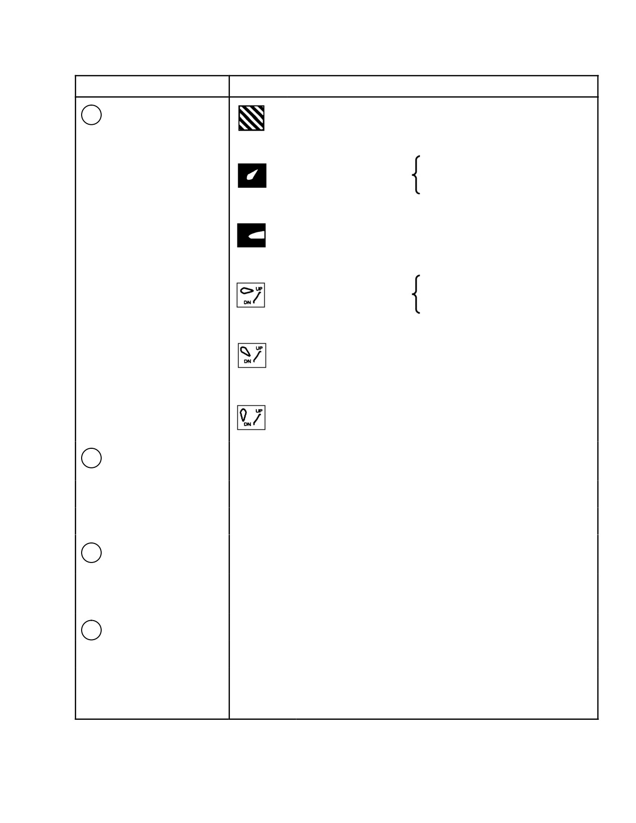
Flaps and Slats
Ċ Power off; maneuver slats extended.
Indicator
Slats position is an electrical
Ċ Slats extended (17_).
pickoff of right slat position only.
Ċ Slats retracted (0_).
Flap position is pickoff from
Ċ Flaps full up (0_).
hydraulic motor for main flaps only.
Ċ Maneuver flaps down (10_).
Ċ Flaps full down (35_).
3
RDC SPD legend on
Main flap comparator failures with flaps not retracted and airspeed
MFD and HUD
>225 KIAS (see Figure 2Ć43).
Maximum safe Mach exceeded (2.4 M).
Total temperature exceeds 388_F.
4
FLAP caution light
Disagreement between main and/or AUX flap position (10 second light)
or asymmetry lockout (3 second light).
CADC failure. WG SWP DR NO. 2/MANUV FLAP (LE1) circuit breaker
pulled.
5
Maneuver flap and slat
Forward Ċ Commands maneuver flaps and slats to retract.
thum bw he el
Neutral Ċ Automatic CADC program.
Aft Ċ
Commands maneuver flaps and slats to extend.
Figure 2−49. Flap and Slat Controls and Indicators (Sheet 2 of 2)
2−91
ORIGINAL
NAVAIR 01−F14AAD−1
Figure 2Ć50.ĄWing Control Surfaces
ORIGINAL
2−92
NAVAIR 01−F14AAD−1
2.21.1.4
Auxiliary Flaps
2.21.2.3
Flap Wing Interlocks
The auxiliary flaps are inboard of the main flaps and are
The main flap and auxiliary flap commands are
powered by the combined hydraulic system. The actuator is
interlocked electrically and mechanically with the wing
designed to mechanically lock the auxiliary flaps when in the
sweep to prevent flap/fuselage interference. An electrical
up position. In the event of high dynamic pressure conditions,
interlock in the CADC and a mechanical command in the
a bypass valve within each control valve opens causing the
wing−sweep control box prevent wing sweep aft of 22_ with
auxiliary flap to be blown back, thus avoiding possible
auxiliary flaps extended. In a similar manner, upon extension
structural damage. During loss of electrical power, the
of the main flaps, the wings are electrically and mechanically
control valve is spring−loaded to retract, retracting the
limited to wing−sweep angles less than 50_. The FLAP
auxiliary flaps within 1 minute. The auxiliary flaps use cove
handle is mechanically prevented from moving to the down
doors, eyebrow doors, and gusses identical in purpose and
position if wing position is aft of 50_. If flaps are lowered
operation with those associated with the main flaps.
with wings between 21_ and 50_, main flaps will extend but
auxiliary flaps will remain retracted.
2.21.1.5
Slats
The slats on each wing are divided into two sections,
both of which are driven simultaneously by a single−slat
driveshaft. The slats are supported and guided by seven
curved tracks.
D If flaps are extended with wings between 21_
and 50_, auxiliary flap extension is inhibited and
2.21.2
Flap and Slat Operation
a large nosedown pitch trim change will occur.
D Pulling the FLAP/SLAT CONTR SHUT−OFF
Note
circuit breaker (RA2) will eliminate flap overĆ
travel protection, could eliminate mechanical or
D There is no automatic flap/slat retraction.
electrical main and auxiliary flap interlocks and
may allow the wings to be swept with the flaps
D With flaps extended by the FLAP handle and
partially or fully down in the wing−sweep
an airspeed of 225 knots or greater, the RDC
emergency mode.
SPD legend appears on the MFD and HUD.
2.21.2.4
Maneuver Flap and Slat Mode
2.21.2.1
Normal Operation
The main flaps can be extended to 10_ with the slats
The main flap and slat portion of the high−lift system
extended to 7_ within the altitude and Mach envelope shown
is positioned with a dual redundant hydromechanical servoĆ
in Figure 2Ć51.
loop in response to the FLAP handle command. The auxiliary
flap is a two−position control surface powered by the
Maneuver flaps and slats are automatically extended
combined hydraulic system. With the FLAP handle exceedĆ
and retracted by the CADC as a function of angle of attack
ing 5_ deflection, the auxiliary flaps fully extend. ConĆ
and Mach number (Figure 2Ć52). The schedule commands
versely, they retract for a FLAP handle position equal to or
full maneuver flaps and slats as soon as the slatted wing
less than 5_. The torque of the flap and slat drive hydraulic
maneuvering efficiency exceeds that of the clean wing.
motor is transmitted by flexible driveshafts to each wing.
Note
2.21.2.2
Degraded Operation
CADC maneuver flap commands are automatiĆ
cally reset when the flap handle is placed down
In the event of a combined hydraulic system failure,
greater than 2_, wing−sweep BOMB mode is
outboard spoiler module fluid is automatically directed to a
selected, or maneuver flaps are commanded to less
backup hydraulic motor to lower main flaps and slats only. In
than 1_ by the CADC because of dynamic pressure.
the event of main flap asymmetry greater than 3_, slat
asymmetry greater than 4_, or flap surface overtravel, the
The angle−of−attack input to the CADC from the alpha
flap and slat system is disabled. Flaps and slats will remain
computer is inhibited and will retract the maneuver devices
in the position they were in when failure or malfunction
if they are extended when the LDG GEAR handle is lowered.
occurred. The auxiliary flaps are automatically commanded
This is to ensure that the maneuver devices are retracted
to retract. There is no asymmetry protection for the auxiliary
before lowering the FLAP handle. Maneuver devices
flaps.
extended condition is indicated by a SLATS barberpole and
an intermediate (10_) flap position.
2−93
ORIGINAL
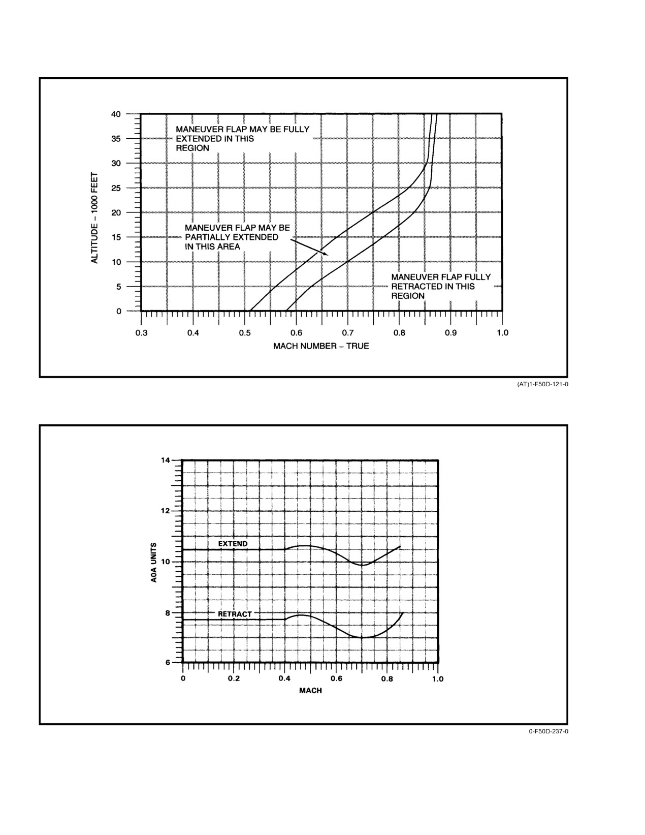
NAVAIR 01−F14AAD−1
Figure 2Ć51.ĄManeuver Flap Envelope
Figure 2Ć52.ĄManeuver Slat/Flap Automatic Schedule for CADC
ORIGINAL
2−94
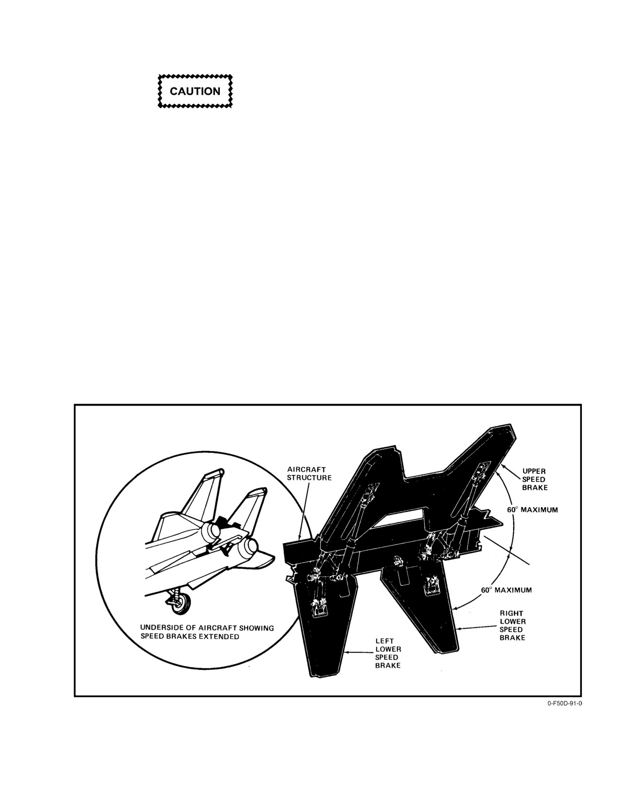
NAVAIR 01−F14AAD−1
To avoid fuel impingement on the fuselage boattail and
nozzles, fuel dump operations are prevented with the speedĆ
brakes extended.
If maneuver devices are not retracted prior to lowĆ
Note
ering the FLAP handle, a rapid reversal of the flaps
D Loss of combined hydraulic pressure with the
will occur with possible damage to the flap system.
speedbrakes retracted or extended will cause
the speedbrakes to move to a floating position.
2.22 SPEEDBRAKES
D The speedbrake/fuel dump interlock is elecĆ
The speedbrakes consist of three individual surfaces,
trically bypassed during a combined hydrauĆ
one upper and two lower panels on the aft fuselage between
lic system failure, enabling the pilot to dump
the engine nacelles (Figure 2Ć53). The speedbrakes may be
fuel when the speedbrakes are floating or
infinitely modulated on the extension and retraction cycle.
modulating. The electrical bypass is enabled
Operating time for full deflection is approximately 2 seconds.
whenever the combined pressure falls below
Hydraulic power is supplied by the combined hydraulic
500 psi.
system (nonisolation circuit), and electrical power is through
the essential No. 2 dc bus with circuit overload protection
D Do not extend the speedbrakes in flight within
on the pilot right circuit breaker panel (SPD BK P−ROLL
1 minute
(nominal) after terminating fuel
TRIM ENABLE) (RB2).
dump operations to allow residual fuel in the
dump mast to drain.
2.22.1
Speedbrake Operation
D A throttle must be held in MIL (or greater) for
Pilot control of the speedbrakes is effected by use of the
approximately
3 seconds in order for the
three−position speedbrake switch on the inboard side of the
automatic function to completely retract the
right throttle grip
(Figure 2Ć54). Automatic retraction of
speedbrake. Anything less will cause partial
the speedbrakes occurs with placement of either or both
retraction.
throttles at MIL or loss of electrical power.
Figure 2Ć53.ĄSpeedbrakes
2−95
ORIGINAL
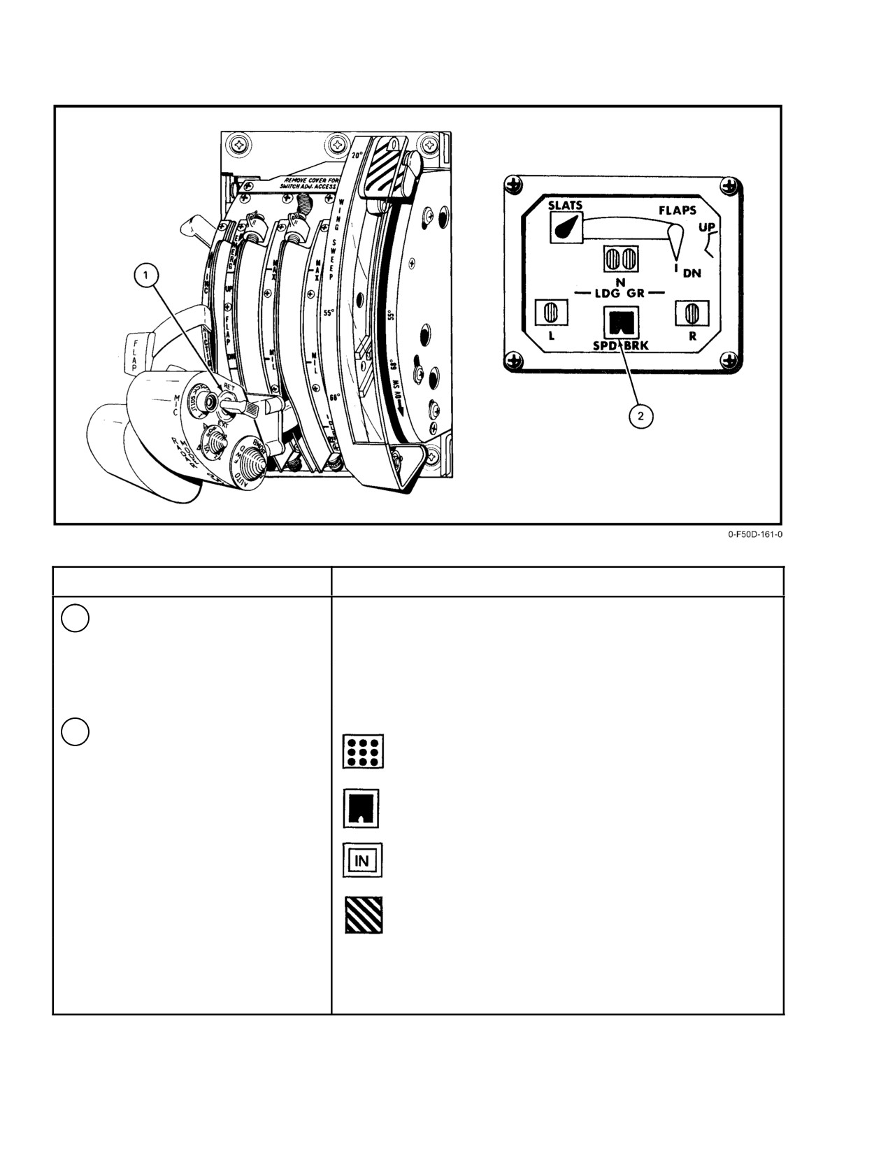
NAVAIR 01−F14AAD−1
NOMENCLATURE
FUNCTION
1
Speed brake switch
EXT Ċ Momentary position used for partial or full extension.
When released, switch returns to center (hold) position.
RET Ċ Normal position of switch. Retracts and maintains speed
brakes closed.
2
SPEED BRAKE indicator
Ċ Partial extension (hold).
Ċ Full extension (60_).
Ċ Full retracted position.
Ċ Speed brakes power off.
Note
Automatic retraction of speed brakes occurs
when either or both throttles are at MIL.
Figure 2Ć54.ĄSpeedbrake Control and Indicator
ORIGINAL
2−96
NAVAIR 01−F14AAD−1
The speedbrakes will start to blowback
(close) at
and pitch acceleration are produced by fore and aft bobĆ
approximately 400 knots and will continue toward the closed
weights. Aircraft overstresses from abrupt stick inputs are
position as airspeed increases to prevent structural damage.
minimized by an eddy current damper that resists large, rapid
A reduction in airspeed will not automatically cause the
control deflections.
speedbrakes to extend to the originally commanded position.
2.23.1.2
Longitudinal Trim
2.23 FLIGHT CONTROL SYSTEMS
Longitudinal trim is provided by varying the neutral
Flight control is achieved through an irreversible,
position of cam and roller feel assembly with an electroĆ
hydraulic power system operated by a control stick and
mechanical screwjack actuator. The manual pitch trim button
rudder pedals. Aircraft pitch is controlled by symmetrical
on the stick is a five−position switch, spring loaded to the
deflection of the horizontal stabilizers. Roll control is
center (off) position (Figure 2Ć58). The fore and aft switch
effected by differential stabilizer deflections and augmented
positions produce corresponding nosedown and noseup trim,
by spoilers at wing−sweep positions less than 62_. DirecĆ
respectively. The manual trim switch is deactivated when the
tional control is provided by dual rudders. During power
autopilot is engaged.
approach maneuvers, the aircraft flightpath can be controlled
through symmetric spoiler displacement by the pilot selectĆ
2.23.1.3
Mach Trim
ing direct lift control. Control surface indicators are shown
in Figure 2Ć55.
Mach trim control is provided by the DFCS and is
continuously engaged to provide automatic Mach trim
The horizontal stabilizer and rudders are powered by
compensation during transonic and supersonic flight. A
the flight and combined hydraulic systems and controlled by
failure of Mach trim compensation is indicated by the
pushrods and bellcranks. A third independent flight control
MACH TRIM advisory light. Transient failures can be reset
hydraulic power source is provided by the backup module.
by depressing the MASTER RESET pushbutton.
Spoiler control is effected by an electrohydraulic, fly−by−
wire system and powered by the combined hydraulic system
The manual and DFCS automatic trim and Mach trim
(inboard spoilers) and outboard spoiler module (outboard
actuator is installed in parallel with the flight control system.
spoilers).
Trim actuation produces a corresponding stick and control
surface movement.
The DFCS includes a stability augmentation system,
an autopilot and auxiliary control functions for spoiler
2.23.2
Integrated Trim System
control, rudder authority control, lateral stick authority
control, and Mach trim compensation.
The ITS is incorporated to reduce longitudinal trim
changes because of the extension and retraction of flaps and
2.23.1
Longitudinal Control
speedbrakes. Disagreement of command position removes
power from the motor and illuminates the INTEG TRIM
Longitudinal control
(Figure 2Ć56) is provided by
advisory light. Transient failures can be reset by pressing the
symmetric deflection of independently actuated horizontal
MASTER RESET pushbutton. ITS schedules are shown in
stabilizers. Control stick motion is transmitted to the
Figure 2Ć59.
stabilizer power actuators by pushrods and bellcranks to dual
tandem actuators independently powered by the flight and
combined hydraulic systems. The power actuators control
the stabilizers symmetrically for longitudinal control and
differentially for lateral control. This is accomplished by
mechanically summing pitch and roll commands at the
When the AIM−54 weapon rail pallet(s) is
pitch−roll mixer assembly. Nonlinear stick−to−stabilizer gearĆ
installed, the speedbrake compensation schedule
ing provides appropriate stick sensitivity for responsive and
in the integrated trim computer changes. If less
smooth control. Longitudinal system authority is shown in
than four AIM−54 missiles are carried on the
Figure 2Ć57.
weapon rails, the ITS may overcompensate for
the speedbrake trim change. In the worst case
2.23.1.1
Longitudinal Feel
(low altitude, between 0.7 and 0.8 Mach, PITCH
SAS OFF, and weapon rails without AIM−54 misĆ
Artificial feel devices in the control system provide the
siles), the ITS can cause an incremental 2 g noseĆ
pilot with force cues and feedback. A spring−loaded cam and
down trim change when the speedbrake is
roller assembly produces breakout force when the stick is
extended. Under these conditions with the
displaced from neutral trim and provides increasing stick
PITCH SAS engaged, maximum trim change is
forces proportional to control stick displacement. Control
reduced to approximately 1 g.
stick forces, proportional to normal acceleration (g forces)
2−97
ORIGINAL
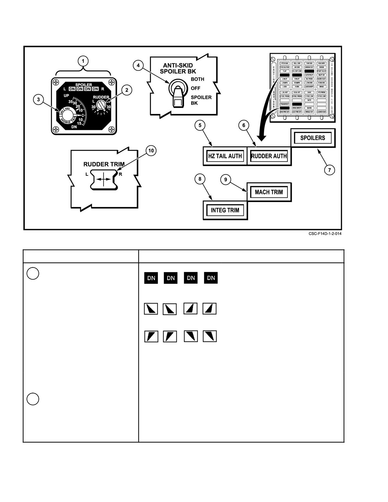
NAVAIR 01−F14AAD−1
NOMENCLATURE
FUNCTION
1
SPOILER position indicators
Ċ Spoilers down (flush with wing
surface).
Note
A right inboard or outboard
spoiler
position
indicator
Ċ Either spoiler of the appropriate pair is
showing one position higher
extended more than 0_.
than
the
corresponding
spoilers actual position indiĆ
Ċ Both spoilers of the appropriate pair at
cates a possibility of ground
a dropped position (0−4½_ below wing
roll braking in flight and loss of
surface)
spoiler asymmetry protection
due to a failed zero degree
switch.
2
RUDDER position indicator
Individual rudder pointers marked R (right) and L (left) display the
trailing−edge position of the rudders in degrees (0 to 30).
Figure 2Ć55.ĄControl Surface Indicators (Sheet 1 of 2)
ORIGINAL
2−98
NAVAIR 01−F14AAD−1
NOMENCLATURE
FUNCTION
3
HORIZONTAL tail
Indicated by two pointers marked R (right) and L (left) on a scale
stabilizers position
35_ up and 15_ down. Scale is graduated in 2_ increments.
The inner pointer indicates left wing down or right wing down
(differential stabilizer position).
4
ANTI SKID SPOILER
BOTH Ċ Antiskid activated. Spoiler brakes operate with weight on
BK switch
wheels and throttle at IDLE.
OFF Ċ Antiskid and spoiler brakes inoperative with weight on wheels.
SPOILER BK Ċ Spoiler brakes operate with weight on wheels and
both throttles at IDLE. Antiskid is deactivated.
5
HZ TAIL AUTH
Failure of lateral tail authority actuator to follow schedule or CADC
caution light
failure.
6
RUDDER AUTH
Disagreement between command and position, failure of rudder
caution light
authority actuators to follow schedule, or CADC failure.
Note
The RUDDER AUTH caution light may illuminate when the
in−flight refueling probe is extended. Press the MASTER
RESET button to reset the light.
7
SPOILERS caution
Spoiler system failure, causing a set of spoilers to be locked down.
light
Note
SPOILERS caution light will not illuminate with SPOILER
FLR ORIDE switches in ORIDE position.
8
INTEG TRIM advisory
Discrepancy between input command signal and actuator position
light
or an electrical power loss within the computer.
9
MACH TRIM advisory
Failure of Mach trim actuator to follow schedule.
light
Note
Transient failures involving HZ TAIL AUTH, RUDDER
AUTH, or SPOILERS caution lights and INTEG TRIM and
MACH TRIM advisory lights can be reset by pressing the
MASTER RESET pushbutton.
10
RUDDER TRIM switch
Controls the electromechanical actuator that varies the neutral position
of the mechanical linkage for rudder trim.
Figure 2−55. Control Surface Indicators (Sheet 2 of 2)
2−99
ORIGINAL
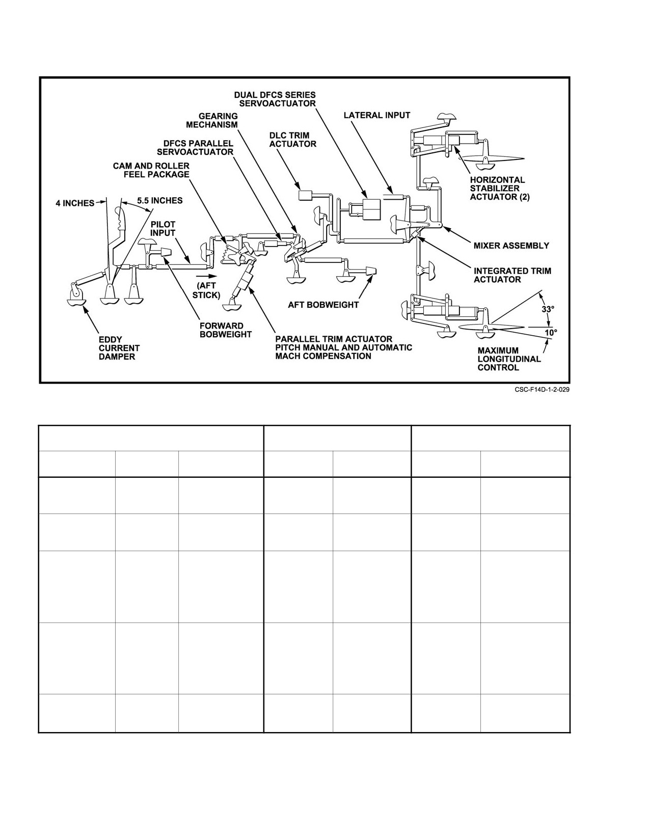
NAVAIR 01−F14AAD−1
Figure 2Ć56.ĄLongitudinal Control System
COCKPIT CONTROL
STABILIZER SURFACE
PARALLEL TRIM
ACTUATION
MODE
MOTION
AUTHORITY
RATE
AUTHORITY
AVERAGE RATE
Control Stick
Manual
4 inches forward
10_ TED
36_ per second
9_ TED
1_ per second
5.5 inches aft
33_ TEU
18_ TEU
DFCS
Series
None
$3_
20_ per second
Ċ
Ċ
(SAS)
Ċ
Parallel
4 inches forward
10_ TED
36_ per second
9_ TED
0.1_ per second
Automatic
5.5 inches aft
33_ TEU
18_ TEU
Carrier
Landing
(ACL only)
Maneuver Flap
Series
$45_ DLC
8.4_ TED
36_ per second
Ċ
Ċ
Integrated
Thumbwheel
Maximum
Trim System
Mode
(ITS) and DLC
Thumbwheel
Ċ
Ċ
$45_ Maneuver
$3_
3_ per second
Ċ
Ċ
Flap Mode
Figure 2Ć57.ĄLongitudinal System Authority
ORIGINAL
2−100
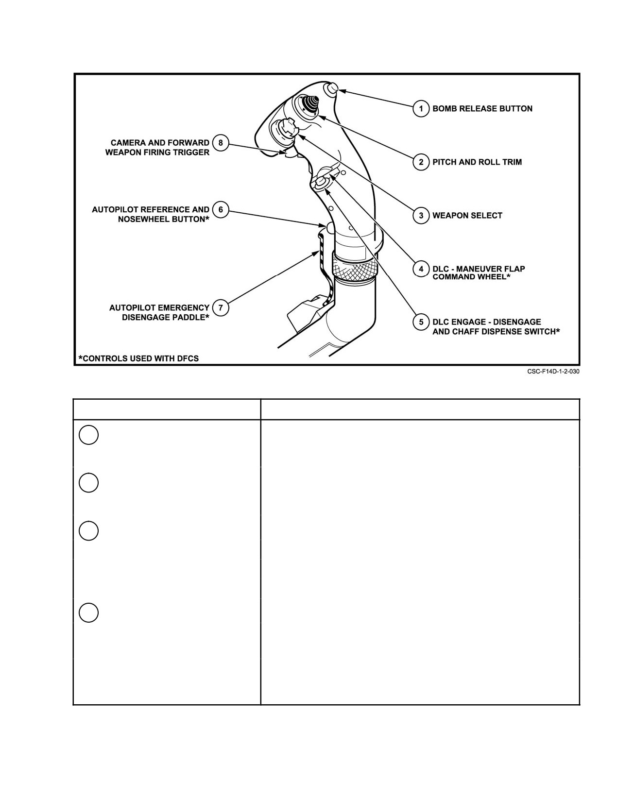
NAVAIR 01−F14AAD−1
NOMENCLATURE
FUNCTION
1
Bomb release button
Pilot control for release of stores. In aircraft with the weapons rail
defensive electronic countermeasures (DECM) chaff adapter,
the bomb release button is used to dispense chaff.
2
Pitch and roll trim button
Spring−loaded to (center) off position. Up and down positions
control pitch trim and left and right positions control roll trim.
Manual trim is inoperative during autopilot operation.
3
Weapon Selector switch
LR Ċ Selects Phoenix missiles.
MR Ċ Selects Sparrow missiles.
SR Ċ Selects Sidewinder missiles.
GN Ċ Selects gun.
4
Maneuver flap, slat, and
Spring−loaded to a neutral position.
DLC
command
With DLC engaged: Forward rotation extends spoilers
(aircraft down); aft rotation retracts spoilers (aircraft up).
With gear and flaps up: Forward rotation retracts maneuvering
flaps/slats; aft rotation extends maneuvering flaps/slats.
Figure 2Ć58.ĄControl Stick and Trim (Sheet 1 of 2)
2−101
ORIGINAL
NAVAIR 01−F14AAD−1
NOMENCLATURE
FUNCTION
5
DLC engage, disengage,
Momentary depression of the switch with flaps greater than 25 degrees
and chaff switch
down, throttle less than MIL, and no failures in spoiler system engages
DLC. With flaps up, switch will dispense chaff or flares. DLC is
disengaged by momentarily pressing the switch, raising the flaps,
or advancing either throttle to MIL.
6
Autopilot reference and
With weight on wheels, nosewheel steering can be engaged by
nosewheel steering
depressing switch momentarily. Weight off wheels and autopilot engaged;
pushbutton
switch engages compatible autopilot modes. The switch also disengages
ACL mode.
7
Autopilot emergency
Disengages all autopilot modes and DLC. Releases all autopilot switches.
disengage paddle
Depressing the paddle switch reverts throttle system from AUTO or
BOOST mode to MAN mode and reverts engines to SEC MODE only
while depressed and with weight on wheels.
8
Camera and forward
Pilot control of CCTVS, gun camera, and/or forward firing weapons.
weapon firing trigger
First detent of trigger starts gun camera and color cockpit television
sensor (CCTVS).
Figure 2−58. Control Stick and Trim (Sheet 2 of 2)
2.23.2.1
Preflight
2.23.3.2
Lateral Trim
Lateral trim is by differential deflection of the
The ITS is automatically energized with hydraulic and
horizontal stabilizers. The wing spoilers are not actuated for
electrical power applied. It can be checked by operating flaps
lateral trim control. Trim is provided by adjusting the neutral
or speedbrakes and observing a change in indicated stabilizer
position of the spring roller−cam−feel assembly with an
position.
electromechanical screwjack. Left or right deflection of the
roll trim button on the stick grip produces corresponding stick
2.23.3
Lateral Control
movement and left or right wing−down trim, respectively.
The normal stick grip trim switch is inoperative when the
Lateral control (Figure 2Ć60) is effected by differential
autopilot is engaged.
displacement of the horizontal stabilizers and augmented by
Note
wing spoilers at wingsweep positions of less than 62_. With
gear handle up, a ±½−inch stick deadband is provided to
With lateral trim set at other than 0_, maximum
preclude spoiler actuation with small lateral stick commands.
spoiler deflection is reduced in the direction of
The spoilers are commanded to the flush−down (0_) position
applied trim.
at wing−sweep angles of greater than 62_, and roll control is
provided entirely by differential stabilizer. At wing−sweep
2.23.3.3
Lateral Control Stops
angles of 65_ and greater, the hydraulic power to the spoiler
To limit the torsional fuselage loads, variable lateral
actuators is cut off, locking the spoiler in the 0_ position.
control authority stops are installed. The lateral stick stops
Lateral stick commands are transmitted by pushrods and bellĆ
vary according to dynamic pressure airloads from full stick
cranks to the independent stabilizer power actuators and
authority at low Q, to one−half−stick throw limits at high−Q
electrically to the spoiler actuators. Lateral system authority
conditions. Failure of the lateral stick stops is indicated by the
is tabulated in Figure 2Ć61.
HZ TAIL AUTH caution light. Transient failures can be reset
with the MASTER RESET pushbutton. Failure of the stops
2.23.3.1
Lateral Feel
in the one−half−stick position limits low−Q rolling perforĆ
mance. However, ample roll control is available for all
An artificial feel system provides the pilot with force
landing conditions and configurations. Failure in the open
cues and feedback. The lateral feel mechanism is a spring
condition with SAS ON requires the pilot to manually limit
roller−cam assembly with a neutral stick position detent and
stick deflection at higher speeds to avoid exceeding fuselage
a constant stick deflection force gradient.
torsional load limits, as lateral stops do not limit SAS
authority.
ORIGINAL
2−102
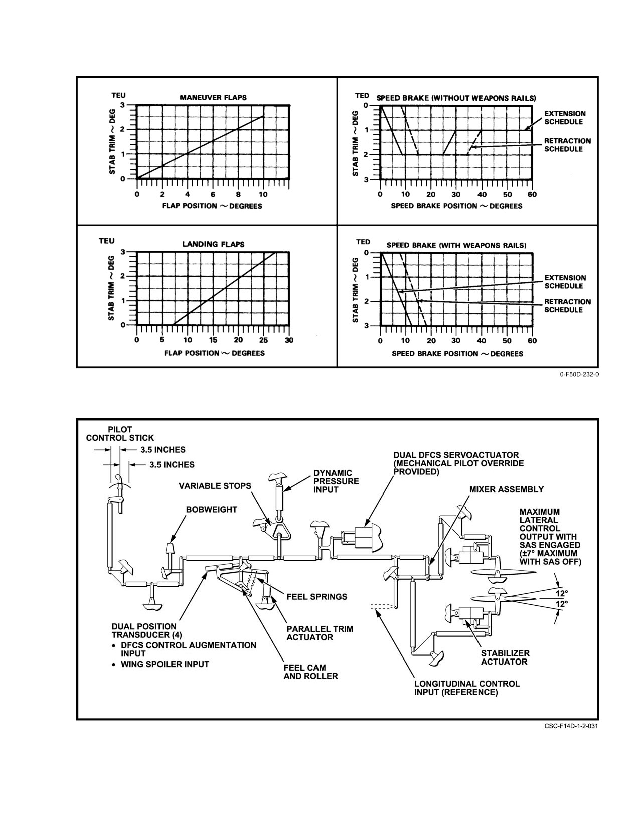
NAVAIR 01−F14AAD−1
Figure 2Ć59.ĄIntegrated Trim Schedules
Figure 2Ć60.ĄLateral Control System
2−103
ORIGINAL
NAVAIR 01−F14AAD−1
COCKPIT CONTROL
SURFACE
PARALLEL TRIM
CONTROL
SURFACE
ACTUATION
MODE
MOTION
AUTHORITY
RATE
AUTHORITY
RATE
Differential
Control Stick
Manual
3.5 inches
$7_
36_ per
$3
3/8_ per
Stabilizer
left
second
second
3.5 inches
right
DFCS
Series
None
$5_
33_ per
Ċ
Ċ
second
Inboard
Control Stick
Manual
3.5 inches
$55_
250_ per
None
None
and
for
left
second
Outboard
Ω v62_
3.5 inches
Spoilers
right
DFCS (ACL)
Series
None
15_ maximum
250_ per
None
None
(inboard only)
8_ neutral
second
DLC/
Manual
DLC/
inbd only
125_ per
None
None
Maneuver
Maneuver
17.5_ neutral
second
Flap
Flap
−Ă4.5_ down
(minimum)
(inboard only)
Command
+55_ up
Thumb−
wheel
$45_
Ground Roll
Series
None
55_ up
250_ per
None
None
Braking
second
Armed,
Weight−on−
Wheels
*Lateral
Control Stick
Manual
1.75 inches
$3½_ Diff.
36_ per
Ċ
Ċ
Stops
Restricted
left
Stabilizer
second
1.75 inches
**28_ĄSpoiler
250_ per
right
second
* Programmed by CADC (Horizontal Tail Authority) as a function of dynamic pressure.
** Maximum SAS off deflection limits with full lateral stops engaged.
Figure 2Ć61.ĄLateral System Authority
ORIGINAL
2−104
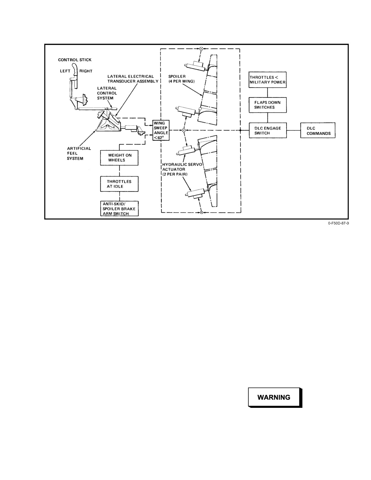
NAVAIR 01−F14AAD−1
Figure 2Ć62.ĄSpoiler Control System
2.23.4
Spoiler Control
for all landing configurations, the DFCS uses the power
approach spoiler gearing whenever the landing gear or main
Four spoiler control surfaces (Figure 2Ć62) on the upper
flaps are down. With DLC engaged in the power approach
surface of each wing augment roll control power and
mode, the inboard spoilers are positioned from normal − 4.5_
implement aerodynamic ground−roll braking. The inboard
to +17.5_ position. Lateral stick inputs result in the spoilers
spoilers also provide DLC. The inboard and outboard spoilers
extending on one side in the direction of stick displacement
are powered and controlled by separate hydraulic and
and depressing toward the landing flaps down drooped
electrical command systems. The DFCS monitors each spoiler
(− 4.5_) stowed position on the other side. This is the primary
panel individually. The pitch computer and outboard spoiler
reason for better roll response in the landing configuration
module control the outboard spoilers; and the roll computer
with DLC engaged.
and the combined hydraulic system control the inboard
spoilers. (Refer to digital flight control system in FO−12.)
2.23.4.1
Lateral Trim and Spoiler Deflection
The inboard spoilers are controlled and monitored by
As mentioned earlier, lateral trim is provided by
the ROLL A and PITCH A computer segregations respecĆ
adjusting the neutral position of the stick. This movement of
tively. The outboard spoilers are controlled and monitored by
the neutral position has an effect on the amount of spoiler
the PITCH B and YAW B computer segregations respecĆ
deflection available. That is, as lateral trim is applied away
tively. Hydraulic actuation of the servo actuators is conĆ
from the neutral trim position, maximum spoiler deflection
trolled by electric servo valves at the actuator and comĆ
is reduced in the same direction (right trim ć less right wing
manded by control stick displacement. The aircraft has two
spoiler deflection).
spoiler gearing curves called cruise and power approach.
Cruise spoiler gearing is the schedule that spoilers follow in
the clean configuration and is shown in Figure 2Ć63. Power
approach is the schedule that spoilers follow with the flaps
down greater than 25° and is shown in Figure 2Ć63 (DLC
Full slat asymmetry (17_) can result in an out−of−
engaged). The power approach spoiler gearing schedule is
control situation at 15 units AOA or greater even
modified to provide predictable roll response with lateral
with 55_ of spoilers available.
stick deflection. To provide the appropriate spoiler gearing
2−105
ORIGINAL
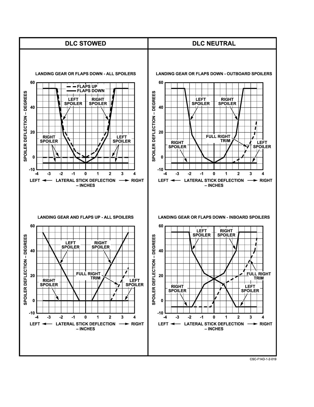
NAVAIR 01−F14AAD−1
Figure 2Ć63.ĄSpoiler Gearing Schedule
ORIGINAL
2−106
NAVAIR 01−F14AAD−1
Full lateral trim in the same direction as lateral stick
signal from the DFCS is lost (i.e., DFCS power
displacement will still provide approximately 25_ to 35° of
failure). If this bias is reversed, the affected
spoiler deflection to counteract an asymmetric flap and slat
spoiler will extend instead of retracting when the
condition (see Figure 2Ć63). This is sufficient to control full−
command signal is lost. A DFCS power failure
flap asymmetry with symmetrically down slats.
coupled with a reverse spoiler bias will result in
a fully deployed spoiler. All unaffected spoilers
2.23.4.2
Ground−Roll Braking
will remain retracted and will not respond to
flight control inputs until the DFCS command
Aerodynamic ground−roll braking is provided by
signals are restored.
symmetric deflection of all spoilers to +55_. Ground−roll
braking is controlled by the ANTI SKID SPOILER BK
Note
switch on the pilot left vertical console. The three−position
D DFCS synchronization can take up to two
switch allows optional selection of BOTH (spoiler brake and
seconds following a power interrupt. If the
wheel antiskid braking), SPOILER BK (spoiler brake only),
MASTER RESET pushbutton is depressed
or OFF where neither spoilers nor antiskid is armed. With
during the synchronization time, an addiĆ
SPOILER BK or BOTH selected, two conditions are required
tional depression of the MASTER RESET
to actuate the spoilers:
pushbutton will be required to restore spoiler
functionality.
1. Weight on wheels
D Do not press and hold the MASTER RESET
2. Both throttles at idle.
pushbutton. Pressing and holding the
Failure to satisfy any one of the above conditions will
MASTER RESET pushbutton during the
cause the spoilers to return to the down position.
synchronization time will have no effect since
the DFCS computers only recognize the
leading edge of the pulse from the MASTER
RESET pushbutton, and not the fact that the
button is continuously depressed.
Ground−roll braking may fail to extend spoilers
D On deck, when the flap handle is cycled to UP,
on touchdown due to a momentary miscompare
the outboard spoiler module is shut down.
of the weight−on−wheels switches. MASTER
This will cause the outboard spoilers to
RESET should restore normal ground−roll
remain extended if activated. If this occurs,
braking operation.
position the flap handle to DN and deactivate
Note
the spoilers. This may also cause the spoiler
indicators to inaccurately indicate a droop or
During initial spoiler brake operation, it is
down position. If this occurs, position the flap
normal for the indicators in the SPOILER
handle to DN and move the control stick
window to momentarily flip−flop.
laterally to correct spoiler indicators.
2.23.4.3
Spoiler Failure
2.23.4.4
Spoiler Test
Spoiler monitoring is accomplished by directly
Proper spoiler operation is verified when IBIT is run
comparing the commanded spoiler position with the actual
during startup if wings are at 20 degrees and flaps are down.
spoiler position. When a miscompare is detected, the affected
See Chapters 7 and 38.
individual spoiler panel and the corresponding spoiler panel
on the opposite wing are commanded to − 4½_ and the
2.23.5
Yaw Control
SPOILERS caution light illuminated. Transient spoiler
failures can be reset by depressing the MASTER RESET
Yaw control (Figure 2Ć64) is effected by twin rudders,
pushbutton. If the affected spoiler panel is mechanically
one on each vertical tail. The rudder pedals adjust through a
stuck−up, the DFCS automatically restores normal operation
10−inch range in 1−inch increments with the adjust control on
of the opposite spoiler panel within 2 seconds.
the lower center pedestal, forward of the control stick.
Yaw commands are transmitted mechanically from the
rudder pedals to the rudder power actuators by pushrods and
bellcranks. Tandem power actuators are powered indepenĆ
dently by the flight and combined hydraulic systems. Yaw
The spoiler actuators are mechanically biased to
system authority is tabulated in Figure 2Ć65.
the retracted position in order to cause the
spoilers to retract in the event that the command
2−107
ORIGINAL
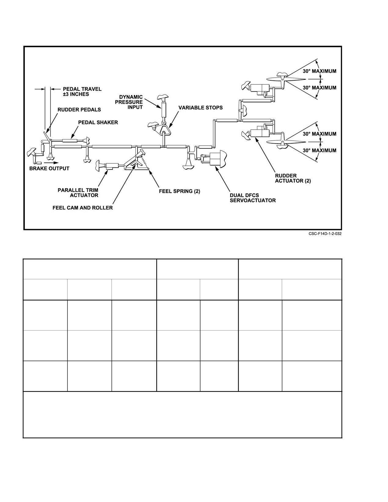
NAVAIR 01−F14AAD−1
Figure 2Ć64.ĄYaw Control System
COCKPIT CONTROL
RUDDER SURFACE
PARALLEL TRIM
ACTUATION
MODE
MOTION
AUTHORITY
RATE
AUTHORITY
AVERAGE RATE
Rudder
Manual
3 inches left,
$30_
106_ per
7_
1.13_ per second
Pedals
(unrestricted)
3 inches right
maximum
second
Ċ
*Manual
1 inch left,
$9.5_
106_ per
7_
1.13_ per second
(restricted)
1 inch right
minimum
second
DFCS
Series
None
*$19_
80_ per
Ċ
Ċ
second
*Stops programmed by CADC (rudder authority) as a function of dynamic pressure.
Figure 2Ć65.ĄYaw System Authority
ORIGINAL
2−108
NAVAIR 01−F14AAD−1
2.23.5.1
Rudder Feel
Before DLC can be engaged, the following conditions
are required:
Artificial feel is provided with a spring roller−cam
mechanism similar to the longitudinal and lateral feel systems.
1. Flaps down greater than 25_.
Rudder force with pedal deflection is nonlinear with a
2. Throttles less than MIL power.
relatively steep gradient about the neutral detent and
gradually decreasing with increased pedal travel.
3. Inboard spoilers operational.
4. Pitch B, and yaw B computers operational.
2.23.5.2
Rudder Trim
Rudder trim is effected by varying the neutral position
5. Operable combined hydraulic pump.
of the feel assembly with an electromechanical screwjack
actuator. Rudder trim control is actuated by a three−position
2.23.6.1
DLC Operation
switch on the left console outboard of the throttle quadrant.
DLC is engaged with the control stick DLC switch and
Left (L) and right (R) lateral switch movement commands
commanded by the thumbwheel. The thumbwheel is spring−
left and right rudder trim, respectively. The switch is
loaded to a neutral position. Forward rotation of the wheel
spring−loaded to the center off position. Trim actuation
extends spoilers and aft rotation retracts them proportionally
produces an associated movement of the rudder pedals,
to the degree of thumbwheel rotation. Absolute spoiler
rudders, and rudder indicator.
deflection is dependent upon lateral stick position
(see
Figure 2Ć63). DLC is provided by the yaw computer.
2.23.5.3
Rudder Authority Stops
Upon engagement of DLC, the roll computer extends
Rudder authority control stops limit rudder throws in
the inboard spoilers from the landing flaps down drooped
the high−Q flight environment. Rudder deflection limits are
(− 4½_) position to +17.5_ above the flush (0_) position. The
scheduled by the CADC, commencing at about 250 knots.
pitch computer displaces the trailing edges of the horizontal
Above approximately 400 knots, the stops are fully engaged,
stabilizers
2.75_ down from their trim position. If the
restricting manual rudder deflection to 9.5_. Disagreement
thumbwheel control is rotated fully forward, the spoilers
between command and position removes power from the
extend to their 55_ position and the stabilizer trailing edges
motor and illuminates the RUDDER AUTH caution light.
remain at 2.75_. This increases the rate of descent. If the
thumbwheel control is rotated fully aft, the spoilers retract to
their − 4.5_ position and the stabilizer trailing edges return
to the trim position. This decreases the rate of descent.
2.24 DIGITAL FLIGHT CONTROL SYSTEM
A CADC failure may drive the rudder authority
stops to 9.5_. This condition should be deterĆ
The DFCS (FO−12) augments the aircraft natural
mined prior to making a single−engine or crossĆ
damping characteristics and provides automatic commands
wind landing. With the 9.5_ stops in, rudder
for control of attitude, altitude, heading, and approach modes
control may be insufficient to maintain direcĆ
selected by the pilot. All DFCS functions are integrated into
tional control with single−engine afterburner
the primary flight control system.
operation or during crosswind conditions. NoseĆ
wheel steering authority is greatly reduced with
The DFCS also provides an Up and Away Automatic
the 9.5_ stops engaged.
Rudder Interconnect (UA−ARI) to enhance departure resistĆ
ance, spin recovery and high angle of attack flying qualities,
2.23.5.4
Rudder Pedal Shaker
and a Power Approach Automatic Rudder Interconnect
(PA−ARI) to enhance the landing approach flying qualities.
The rudder pedal shaker operates during IBIT and in
The DFCS consists of three computers, one computer for
flight when the landing gear is extended and angle of attack
each axis (pitch, roll, and yaw). Each computer has two
is above ~20 units. Rudder pedal shaker will deactivate once
distinct and independent processors called channels or
the angle of attack is reduced below ~19 units.
segregations (one A" and one B" channel per axis), each
controlling one of the dual series servoactuators. All
2.23.6
Direct Lift Control
channels share data through cross channel data links.
During landing approaches, the inboard spoilers and
A BIT capability is provided to exercise in−flight
horizontal stabilizers can be controlled simultaneously to
monitoring and to conduct an automatic operational readiĆ
provide vertical glidepath correction without changing
ness test for preflight checks. DFCS rates and authorities are
engine power setting or angle of attack. Only the inboard
tabulated in Figure 2Ć66.
spoilers are used for DLC.
2−109
ORIGINAL
NAVAIR 01−F14AAD−1
AXIS
ACTUATOR
SURFACE
AUTHORITY
SURFACE RATE
Pitch
Dual Series SAS
Stabilizer
± 3_
20_ per second
Ċ
Dual Series ITS
Stabilizer
± 3_
3_ per second
Ċ
Parallel (ACL only)
Stabilizer
10_ TED
36_ per second
33_ TEU
Ċ
Parallel Trim
Stabilizer
10_ TED
0.1_ per second
18_ TEU
Roll
Dual Series
Differential Stabilizer
± 5_
33_ per second
Spoilers (ACL)
15_ maximum
250_ per second
Yaw
Dual Series
Rudder
± 19_
80_ per second
Figure 2Ć66.ĄDFCS Rates and Authorities
2.24.1
Stability Augmentation System
Note
Depressing the paddle switch does not disable
Stability augmentation is provided for all three aircraft
the PITCH and ROLL SAS. If problems are
axes (pitch, roll, and yaw) and is controlled by the three
suspected with any SAS axis, the appropriate
STAB AUG switches on the upper half of the DFCS control
STAB AUG switch must be manually selected
panel (DCP) (Figure 2Ć67). SAS is engaged by placing these
OFF. Depressing the paddle switch will disĆ
switches to ON during normal poststart procedures. The
engage the autopilot and DLC inflight, revert the
PITCH, ROLL, and YAW STAB AUG switches are manually
throttles to MANUAL mode on deck, and revert
operated toggle switches mechanically held in the selected
fuel control to SEC mode.
ON or OFF position.
2.24.1.1
DFCS Control Panel/Fault Display
The PITCH SAS incorporates a pitch rate feedback
function that is reduced as airspeed is increased above 650
The DFCS control panel (Figure 2Ć67), located on the
KIAS. This is necessary to maintain adequate control system
pilot’s left side console, includes all the controls for the
stability and is not noticeable. The ROLL SAS is independent
DFCS and an LED alphanumeric fault display with the
with the landing gear up, at low angle of attack (less than 15
associated INC and DEC pushbuttons to control display
units), and at supersonic flight conditions. At all other condiĆ
operation. This fault display is intended for ground use only
tions, the ROLL SAS is part of the UA−ARI and PA−ARI.
to assist in the troubleshooting and repair of the DFCS and
Similar to the PITCH SAS, the roll rate feedback is reduced
related components.
as airspeed is increased above 300 KIAS. With the landing
gear down, the YAW SAS becomes part of the PA−ARI.
2.24.1.2
Up and Away Automatic Rudder
Interconnect (UA−ARI)
All SAS switches should remain ON during flight.
Deselection of either the ROLL or YAW SAS switch will
The UA−ARI is selected when the landing gear handle
disable the affected SAS axis and all ARI functions, and
is up and provides several functions designed to improve high
illuminate the ARI/SAS OUT caution light. Deselection of
angle of attack flying qualities and departure resistance
the PITCH SAS switch will disable the PITCH SAS, but no
(Figure 2Ć67). These include:
caution light will illuminate since no restriction exists for
D Differential Stabilizer Fadeout
PITCH SAS OFF.
D Lateral Stick−to−Rudder Interconnect (LSRI)
D Low airspeed/high angle of attack cross
control (LSXC)
D Wing Rock Suppression
Maneuvering with YAW SAS OFF or inoperative
shall not be conducted above 15 units AOA with
D Spin Recovery Function.
landing gear retracted.
ORIGINAL
2−110
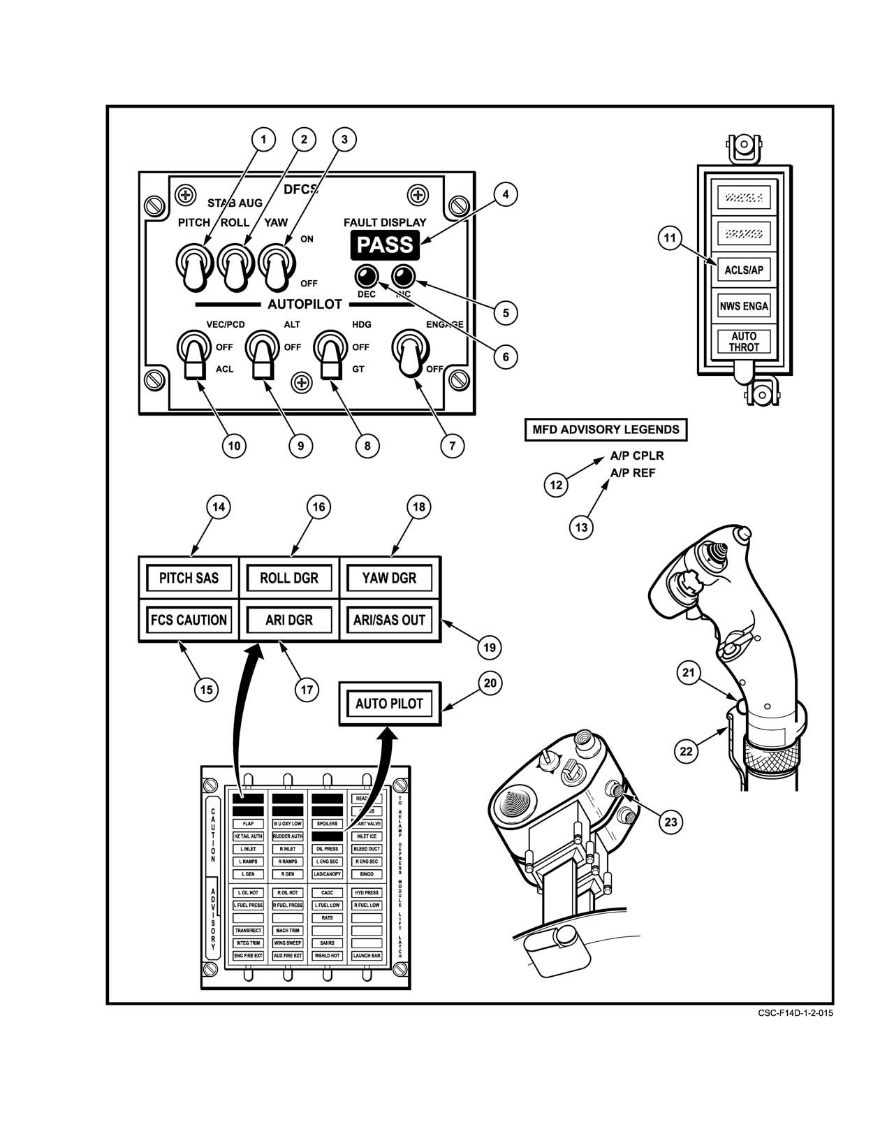
NAVAIR 01−F14AAD−1
Figure 2Ć67.ĄDFCS Controls and Indicators (Sheet 1 of 3)
2−111
ORIGINAL
NAVAIR 01−F14AAD−1
NOMENCLATURE
FUNCTION
1
PITCH STAB AUG
Engages dual−channel pitch stability augmentation.
engage switch
2
ROLL STAB AUG
Engages dual−channel roll stability augmentation.
engage switch
3
YAW STAB AUG
Engages dual−channel yaw stability augmentation.
engage switch
4
DFCS fault display
With weight on wheels, the DFCS fault display yields three categories of fault
codes including: currently existing failures (FAIL), in−flight detected failures
(FLT), and IBIT detected failures (IBIT).
5
INC pushbutton
With weight on wheels, depressing the INC pushbutton scrolls forward through
logged DFCS fault codes.
6
DEC pushbutton
With weight on wheels, depressing the DEC pushbutton scrolls backward
through logged DFCS fault codes.
7
AUTOPILOT ENGAGE−
ENGAGE Ċ Engages autopilot. PITCH, ROLL, and YAW SAS switches
OFF switch
must be engaged. No warmup required. Engages attitude hold.
Requires weight off wheels.
OFF Ċ
Disengages autopilot.
8
HDG−OFF−GT switch
HDG Ċ
Autopilot will lock on constant aircraft heading when aircraft is
less than "5 roll.
OFF Ċ
Disengages heading hold and ground track.
GT Ċ
Selects autopilot ground tracking computed at time of
engagement using inertia navigation system (INS) data.
Engaged by nosewheel steering pushbutton.
9
ALT−OFF switch
ALT Ċ
Autopilot will maintain barometric altitude. Engaged by
nosewheel steering pushbutton.
OFF Ċ
Disengages altitude mode.
10
VEC/PCD−OFF−ACL
VEC/PCD Ċ Autopilot roll axis commands steer aircraft using data link
switch
signals for vectoring. If the precision course direction (PCD)
discrete is present, both roll and pitch axis commands are used.
Engaged by nosewheel steering pushbutton.
OFF Ċ
Disengages VEC/PCD and ACL modes.
ACL Ċ
Autopilot will accept data link signals for carrier landing, using
spoilers for roll and parallel servo for pitch. Only pitch
commands are transmitted to stick movement. Engaged and
disengaged by nosewheel steering pushbutton.
11
ACLS/AP caution light
Autopilot and automatic carrier landing system (ACLS) mode disengaged.
12
A/P CPLR advisory
Indicates the aircraft can be coupled to the ACL system for a mode I or
legend on MFD
mode IA approach. A/P CPLR legend remains displayed in conjunction
with the CMD CTRL legend after coupling is accomplished.
13
A/P REF advisory
Autopilot mode is selected but is not engaged. (Except attitude and
legend on MFD
heading hold.)
Figure 2−67. DFCS Controls and Indicators (Sheet 2 of 3)
ORIGINAL
2−112
NAVAIR 01−F14AAD−1
NOMENCLATURE
FUNCTION
14
PITCH SAS caution light
Indicates inoperative pitch channel or PITCH SAS failure.
15
FCS CAUTION light
Indicates DFCS failure has occurred. If no other lights are illuminated, indicates
loss of redundancy only (subsequent failure may result in loss of significant
DFCS functionality).
16
ROLL DGR caution light
Indicates inoperative roll channel and degraded roll authority.
17
ARI DGR caution light
Indicates degraded ARI performance. If caused by loss of a Mach number
signal, LSXC and wing rock suppression functions will be inoperative.
18
YAW DGR caution light
Indicates inoperative yaw channel and degraded yaw authority.
19
ARI/SAS OUT caution
Indicates loss of either ROLL or YAW SAS and all ARI functions.
light
Will be illuminated if either the ROLL STAB AUG or YAW STAB AUG switches
are selected off.
20
AUTOPILOT caution light
Indicates failure of one or more of pilot relief modes.
21
Autopilot reference and
Engages the ALT, GT, ACL or VEC/PCD autopilot mode selected.
nosewheel steering
Autopilot must be engaged and compatible autopilot modes selected.
pushbutton
Also disengages ACL mode. Requires weight off wheels.
22
Autopilot emergency
Disengages all autopilot modes and releases all autopilot switches.
disengage paddle
23
PLM pushbutton
With the A/P CPLR legend and the VEC/PCD ACL switch latched in the
ACL position, depressing the PLM pushbutton engages and disengages
the ACL mode and autopilot.
Figure 2−67. DFCS Controls and Indicators (Sheet 3 of 3)
These functions are active throughout the subsonic
by activation of LSXC or spin recovery functions). As Mach
flight envelope and are scheduled with Mach number and
number is increased, the differential stabilizer is faded out at
angle of attack (Figure 2Ć68). The effects of these functions
a lower AOA. This reduces the effects of kinematic coupling
on flight characteristics are discussed in Chapter 11.
and results in less adverse sideslip with lateral stick deflecĆ
tion as angle of attack is increased and reduces the tendency
Note
for lateral control induced departures.
The primary AOA input for control law schedulĆ
The LSRI function gradually applies coordinating
ing is based on degrees AOA provided by the ARI
rudder with lateral stick as angle of attack is increased above
alpha nose−probe vice units AOA as displayed on
~15 units AOA. A maximum of +/−19 deg coordinating
the cockpit AOA indicator provided by the ADD
rudder is provided by the LSRI above ~23 units AOA. This
AOA side−probe. Descriptions of control law
results in the desired roll response with lateral stick input
functions are written in units AOA, but it should
alone at elevated AOA.
be noted that the correlation between units and
degrees AOA is a function of Mach number.
The LSXC function provides a means to override the
differential stabilizer fadeout and LSRI functions when
The differential stabilizer fadeout function reduces the
CADC Mach number is below 0.4 and angle of attack is
amount of differential stabilizer the pilot can command as
above ~30 units. At these conditions, the pilot can command
angle of attack and Mach number are increased. Below ~15
up to +/−10 deg differential stabilizer deflection in the direcĆ
units angle of attack, the pilot can command up to the maxiĆ
tion of lateral stick and up to +/−30 deg rudder deflection in
mum +/−12 deg differential stabilizer authority. Above ~30
the direction of commanded rudder. Because rudder
units angle of attack, the differential stabilizer is limited to
a maximum of +/−2 deg deflection (except when overridden
2−113
ORIGINAL
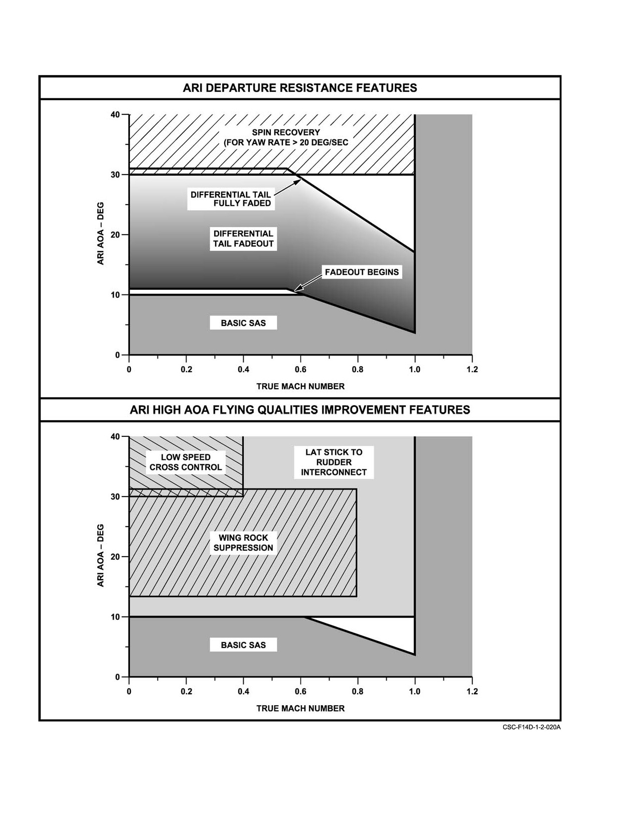
NAVAIR 01−F14AAD−1
Figure 2Ć68.ĄDFCS Up and Away ARI Functions
ORIGINAL
2−114
NAVAIR 01−F14AAD−1
effectiveness is diminished above 30 units angle of attack, the
roll rate. Because the pilot’s roll rate command
LSXC function is necessary to provide adequate roll/ yaw
is based upon lateral stick position from a
maneuvering capability at extreme angles of attack. When
trimmed position, it may be necessary to select
LSRI is no longer effective, the aircraft can still be rolled
ROLL SAS OFF, trim the airplane, and then reseĆ
through LSXC by manually applying greater than 1.75 inch
lect the ROLL SAS ON. The same procedure
of rudder pedal in the direction of the desired roll, and greater
may be necessary to trim an airplane with a latĆ
than 1 inch lateral stick in the opposite direction. This will
eral store asymmetry, trapped wing fuel, etc.
create an adverse yaw response causing the aircraft to
The LSRI function gradually fades in coordinating
roll/yaw in the same direction as the rudder input.
rudder with lateral stick as angle of attack is increased above
The wing rock suppression function uses roll rate
~10 units AOA. This minimizes adverse yaw response from
feedback to command the differential stabilizer and rudder to
lateral stick only inputs, greatly enhancing heading and
damp lateral−directional oscillations from between 20 to 30
centerline capture during lineup corrections. At normal
units AOA. This results in smoother tracking capability for
approach conditions (15 units angle of attack, flaps down), up
the majority of the maneuvering flight envelope. Wing rock
to +/− 19 deg coordinating rudder is provided by the LSRI.
suppression is disabled when a pedal input greater than 2
Raising the flaps decreases the amount of coordinating
inches is applied or CADC Mach number is above 0.77 to
rudder available.
prevent the system from applying inadvertent cross control
The Dutch roll damping function provides sideslip rate
inputs and allow the pilot to roll the aircraft with rudder
feedback to the rudder to reduce directional nose wandering
inputs alone.
during approach. Airplane roll rate, yaw rate, lateral
The spin recovery function applies full SAS authority
acceleration, Mach number, and angle of attack are used to
of up to +/−19 deg rudder and up to +/−5 deg differential
calculate sideslip rate. At normal approach conditions, the
stabilizer to oppose yaw rate during a departure. The spin
sideslip rate feedback to rudder provides a deadbeat Dutch
recovery function is activated when angle of attack is above
roll response.
~30 units and yaw rate is above 20 deg/sec. The spin recovery
The spiral mode stabilization function provides yaw
inputs are in addition to the pilot’s mechanical inputs,
rate feedback to the differential stabilizer to reduce bank
providing full control surface authority for departure recovĆ
angle excursions during stabilized turns. At normal approach
ery
(+/−30 deg rudder opposite roll/yaw and
+/−12 deg
conditions, the yaw rate feedback to differential stabilizer
differential stabilizer into roll/yaw). Misapplied pilot
provides an essentially neutral spiral mode.
recovery inputs are limited to +/−11 deg pro−spin rudder and
+/−2 deg pro−spin differential stabilizer.
2.24.1.4
Aircraft Sensors
2.24.1.3
Power Approach ARI
The DFCS uses the aircraft sensor inputs distributed to
the various computer channels as shown in Figure 2Ć69. The
The PA−ARI is selected when the landing gear handle
DFCS distributes sensor inputs to all computer channels
is down and provides roll rate command, LSRI, Dutch roll
through cross channel data link (CCDL) communication.
damping, and spiral mode stabilization functions. In addiĆ
Each computer channel compares like sensor data
(for
tion, the spoiler gearing has been modified for 0.1 inch lateral
example, yaw rate A, B, and M) to determine validity of each
stick spoiler breakout to improve roll sensitivity and
input and then consolidates the good inputs. The consoliĆ
predictability.
dated sensor inputs are then used to generate output
The roll rate command function tailors differential
commands. This provides an additional level of monitoring
stabilizer to maintain a constant lateral stick to roll rate
and redundancy.
relationship. This is achieved by comparing the roll rate
Note
command (based upon lateral stick position as measured
from trimmed position) to the actual roll rate, then increasing
Loss of a computer segregation or individual
or decreasing the differential stabilizer deflection to maintain
cross channel data link will result in loss of
the commanded roll rate. The control gains are designed to
sensor information provided by the affected segĆ
provide approximately 20 deg/sec roll rate per inch of lateral
regation or link and illuminate the appropriate
stick deflection from trim.
caution/advisory lights.
Note
The aircraft sensors are supplemented by a pitch/roll
voter monitor and air data redundancy management algoĆ
The PA−ARI will perceive a lateral trim offset as
rithm to provide a fail−operational capability following a
an uncommanded roll rate and will attempt to
single sensor failure. Following a second sensor failure, the
reduce roll rate to zero with the stick in the
DFCS reverts to a fail−safe configuration.
trimmed position. As a result, it is possible to
have the stick offset due to lateral trim with zero
2−115
ORIGINAL
NAVAIR 01−F14AAD−1
2.24.1.4.1
Pitch/Roll Voter Monitor
The pitch/roll voter monitor (PQVM) algorithm proĆ
vides triple redundancy for the existing duplex pitch and roll
rate gyro sensors. The PQVM operates by calculating aircraft
Pulling the Alpha computer circuit breaker will
pitch and roll attitudes from three axis rate information and
result in loss of the primary AOA source. This
comparing this against pitch and roll attitudes supplied by the
may degrade DFCS performance as the backup
IMU/INS. If a pitch or roll rate sensor miscompare occurs,
ADD AOA is subject to sideslip−induced errors.
the PQVM algorithm is used to select the remaining good
For the DFCS to operate properly, the Alpha
sensor signal. The monitor does not provide additional rate
computer should not be disabled.
information for averaging with the sensor signals. Since only
pitch and roll attitude are available from the IMU/INS, the
The primary Mach number input is provided by the
effectiveness of the monitor depends on aircraft attitude. The
CADC calculated from the left and right pitot−static probe
monitor is incapable of detecting pitch rate failures with the
inputs. Total and static pressure data (Mach number) inputs
wings near vertical (±90 deg bank angle) or roll rate failures
from the left and right AICS programmers are used for
with the fuselage near vertical (±90 deg pitch angle).
comparison. Similar to the AOA implementation, the upwind
AICS Mach number is selected based upon estimated sideslip
Note
and is compared with the CADC Mach number. When the
estimated sideslip angle is less than
2 deg, the Mach
Transient IMU/INS attitude failures will result in
calculations from both the left and right AICS programmers
a PQVM miscompare. This will be indicated by
are cross checked to determine pressure validity. An AICS
an FCS CAUTION light accompanied by PS and
cross check miscompare (1st Mach fault) results in a loss of
RS acronyms. Depressing the MASTER RESET
Mach redundancy and is indicated by an FCS CAUTION
pushbutton will restore normal PQVM operation
light and PS acronym. Mach scheduling functions are still
and clear the failure indications. Failed velocity
being performed using the CADC Mach number. A single
information from the IMU/INS does not affect
Mach miscompare between the CADC Mach number and the
operation of the PQVM function.
upwind AICS Mach number results in a default Mach number
being set and is indicated by FCS CAUTION, ARI DGR
2.24.1.4.2
Angle of Attack / Mach Redundancy
caution lights and PS acronym. Any subsequent Mach failure
Management
(2nd Mach fault) results in the UA control laws configuring
to a fail−safe degraded mode and is indicated by PITCH SAS,
The primary angle of attack (AOA) input is provided
FCS CAUTION, ROLL DGR, ARI DGR, and ARI/SAS
by the ARI alpha nose−probe (AOA range 0° to +37°). The
OUT caution lights and PS acronym with the landing gear
fuselage−mounted ADD AOA side−probe (AOA range −4° to
handle up. Subsequent Mach failures do not further degrade
+24° for Mach <0.4) is used for comparison and as a backup
the PA control laws and are indicated by an FCS CAUTION,
AOA source in the event of a detected failure of the ARI
ARI DGR lights and PS acronym with the landing gear
AOA input. Although two AICS AOA inputs are available
handle down.
(AOA range
0° to
+30° for Mach
>0.5), significant
sideslip−induced errors distort these measurements as a
function of their locations on either side of the fuselage.
Location of sensor probes is discussed in paragraph 2.32
(Pitot Static System). A sideslip estimation routine, based
Pulling either AICS programmer circuit breakers
upon lateral acceleration, differential stabilizer, and rudder
(LF1 or LG1) will result in DFCS air data failures
position, is implemented to select the upwind AICS AOA
and degraded control system capability. This will
source. This AICS AOA is utilized as a triplex monitor to
be indicated by one or more of the following
vote out a failed ARI or ADD AOA (1st AOA fault), but is not
caution lights depending on flight condition:
of sufficient accuracy to be used as a primary source for
FCS CAUTION, PITCH SAS, ROLL DGR, and
control law gain scheduling. In the event of a subsequent
ARI DGR. Once the AICS circuit breaker is
miscompare between the remaining AOA sources (2nd AOA
reset, depressing MASTER RESET should
fault), the ARI control laws are reverted to fail−safe fixed
restore normal operation and clear the failure
values for AOA. First AOA miscompares are indicated by an
indications.
FCS CAUTION light and PS acronym. Second AOA
Note
miscompare are indicated by FCS CAUTION, ROLL DGR,
ARI DGR, and ARI/SAS OUT caution lights and PS acronym
D Extremely aggressive maneuvering at high
with the landing gear handle up and FCS CAUTION, ARI
AOA or intermittent CADC problems may
DGR caution lights and PS acronym with the landing gear
result in a transient AOA or Mach misĆ
handle down.
compare. Depressing the MASTER RESET
ORIGINAL
2−116
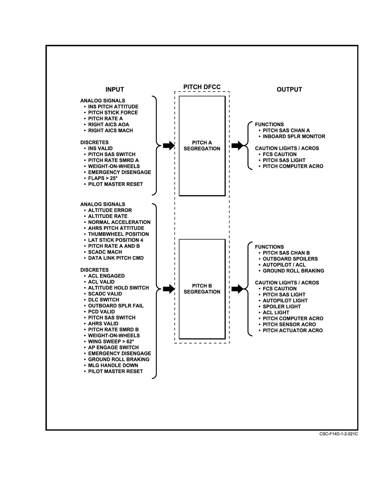
NAVAIR 01−F14AAD−1
Figure 2Ć69.ĄDFCS Pitch Interfaces and Control Functions (Sheet 1 of 3)
2−117
ORIGINAL
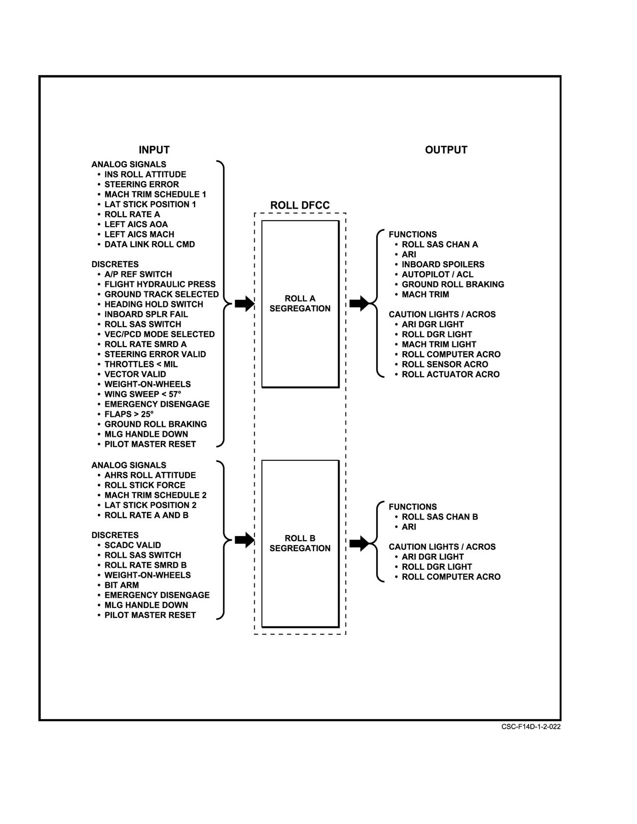
NAVAIR 01−F14AAD−1
Figure 2−69. DFCS Pitch Interfaces and Control Functions (Sheet 2 of 3)
ORIGINAL
2−118
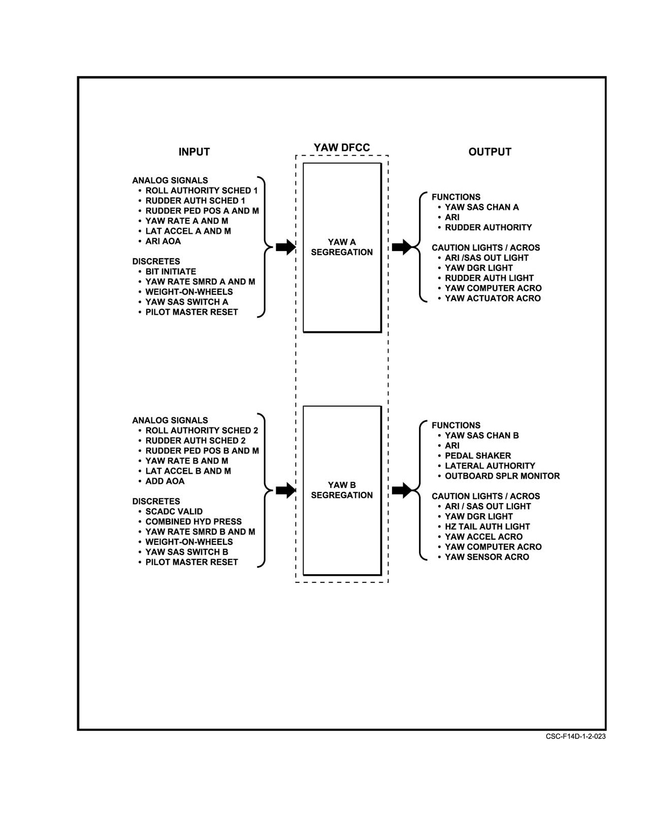
NAVAIR 01−F14AAD−1
Figure 2−69. DFCS Pitch Interfaces and Control Functions (Sheet 3 of 3)
2−119
ORIGINAL
NAVAIR 01−F14AAD−1
pushbutton will restore normal operation and
2.24.1.6
Digital Flight Control Computers
clear the failure indications for all single
The DFCS consists of three computers, one for each
failure situations. Dual failure of either the
axis (pitch, roll, and yaw) (Figure 2Ć69). Each computer has
Mach or AOA inputs is not resettable with
two distinct channels/segregations (A and B), each in turn
MASTER RESET.
controlling one of the dual series servoactuators in the
D With a dual AOA or Mach failure set, lowerĆ
respective axis. The DFCS uses cross channel data link
ing the landing gear handle will result in the
communication to provide redundancy management so that
PITCH SAS (Mach only), ROLL DGR, and
a miscompare between the A and B channels of a given axis
ARI/SAS OUT lights extinguishing. This
cannot result in a loss of the entire axis. Each A channel (for
does not imply the dual failure is no longer
example, pitch A) is monitored by every B channel (pitch B,
present, only that the impact of the dual failĆ
roll B, and yaw B) and conversely each B channel is
ure on PA control functions are less severe
monitored by every A channel. As a result of this monitoring
than on the UA control functions due to the
structure, loss of a single channel will only result in loss of
more confined operational flight envelope.
functions controlled by that channel and the corresponding
series servoactuator, rather than the entire axis
(sensor
2.24.1.5
Sensor Failures
information provided by the affected channel will also be
lost). Loss of a second channel will significantly degrade
First sensor input failures are indicated by the FCS
DFCS performance or result in a complete loss of all DFCS
CAUTION light and the appropriate acronym (PS, RS, YS,
functions. Computer failure effects and cockpit indications
or AM). An FCS CAUTION light with no other lights indiĆ
are summarized in Figure 2Ć70.
cates a loss of sensor redundancy with no loss of functionĆ
ality. The only single sensor failure to light more than the
2.24.1.6.1
Flight Control Computer Reset
FCS CAUTION light is a single Mach miscompare that is
Each computer channel is independently powered and
indicated by FCS CAUTION, ARI DGR caution lights and
can be disabled by pulling the appropriate DC or AC circuit
PS acronym. With a single Mach miscompare, the LSXC and
breaker. In general, there should be no need to cycle DFCS
wing rock suppression functions will be lost. Depressing the
circuit breakers. If power is removed from a channel and then
MASTER RESET pushbutton should clear transient first
restored, the pilot must depress MASTER RESET to restore
sensor failures and failure indications. Second sensor failures
full DFCS functionality. If power is removed from two or
result in loss of functions in the affected axis. The affected
more of the same letter" channels/segregations, most or all
axis will be indicated by a PITCH SAS, ROLL DGR, or YAW
of the DFCS functions will be lost. Restoring power will
DGR caution light. For failures affecting either the roll or
cause the DFCS to execute a power on reset" (POR) and the
yaw axis, all ARI functions may be lost. Partial loss or
system will re−initialize interpreting the current sensor
degrade of the ARI is indicated by an ARI DGR caution light.
information as valid. This can create a potentially hazardous
Complete loss of the ARI is indicated by the ARI/SAS OUT
situation under conditions where a dual sensor failure
light. For second AOA, Mach, or roll rate sensor failures the
occurred prior to restoring power. When the DFCS re−
spin recovery function is retained even though the ARI/SAS
initializes it is possible for the failed signals to be interpreted
OUT light is illuminated.
as valid and the remaining good signal to be interpreted as
invalid. Therefore, careful consideration should be given
DFCS failure indications and effects are summarized
before executing a POR airborne, since it can result in
in Figure 2Ć70. The DCP fault codes are listed in alpha−
erroneous DFCS commanded control deflections.
numeric order followed by their classification to the IBIT
and/or OFP fault group(s). The IBIT fault group includes
fault codes generated by the IBIT self−test and will be identiĆ
fied in the DCP FAULT DISPLAY following the IBIT"
group header. The OFP fault group includes fault codes genĆ
erated by the PBIT and/or ABIT self−test(s) and will be idenĆ
If a dual failure has been declared, performing a
tified in the DCP FAULT DISPLAY following the FAIL"
power on reset" to clear the failure can result in
and/or FLT" group header. The failure indication and potenĆ
erroneous DFCS commanded control deflections.
tial functions lost are listed for each individual fault code.
The associated caution lights and maintenance file acronyms
When performed on deck, the DC breakers (ROLL A
are listed for each fault code in addition to any applicable
DC, YAW B DC, and YAW A DC − 8B4, 8B5, 8B6) are
notes. In certain cases, potential functions lost for multiple
generally used to avoid inadvertently inducing additional
failures (also known as a dual faults or 2nd faults) have been
faults. A MASTER RESET is required to extinguish the
identified.
resulting DFCS caution lights following restoration of power.
ORIGINAL
2−120
NAVAIR 01-F14AAD-1
CAUTION LIGHTS
FAILURE
FUNCTIONS LOST
SENSOR FAILURES
PITCH RATE 1F
X
PS
PGYx
REDUNDANCY LOSS ONLY.
PITCH RATE 2F
X
X
+
+
PS
PGY7
PITCH SAS OFF.
ROLL RATE 1F
X
RS
RGYx
REDUNDANCY LOSS ONLY.
ROLL RATE 2F
X
X
X
X
+
+
RS
RGY7
ROLL SAS/ARI OFF. SPIN
RECOVERY RETAINED.
YAW RATE 1F
X
YS
YGYx
REDUNDANCY LOSS ONLY.
YAW RATE 2F
X
X
X
X
+
+
YS
YGYx
YAW SAS/ARI OFF. ALSO
(PA MODE)
GENERATES PQVM FAULT.
YAW RATE 2F
X
X
X
X
X
+
+
YS
YGYx
ROLL AND YAW SAS/ARI
(UA MODE)
OFF. ALSO GENERATES
PQVM FAULT.
LATERAL
X
AM
LATx
REDUNDANCY LOSS ONLY.
ACCELERATION 1F
LATERAL
X
X
X
X
+
+
AM
LATx
YAW SAS/ARI OFF.
ACCELERATION 2F
(PA MODE)
LATERAL
X
X
X
X
X
+
+
AM
LATx
ROLL AND YAW SAS/ARI
ACCELERATION 2F
OFF.
(UA MODE)
LATERAL STICK
X
RS
RCPx
REDUNDANCY LOSS ONLY.
POSITION 1F
LATERAL STICK
X
X
X
X
X
RS
RCPx
ROLL SAS/ARI OFF.
POSITION 2F
NO SPOILERS.
RUDDER PEDAL
X
YS
RPPx
REDUNDANCY LOSS ONLY.
POSITION 1F
RUDDER PEDAL
X
X
YS
RPPx
NO PEDAL FADEOUT
POSITION 2F
(NO SLIPPED
(PA MODE)
APPROACHES).
RUDDER PEDAL
X
X
YS
RPPx
NO LSXC OR WING ROCK
POSITION 2F
SUPPRESSION.
(UA MODE)
ANGLE OF ATTACK
X
PS
NOTE(1)
REDUNDANCY LOSS ONLY.
1F
ANGLE OF ATTACK
X
X
PS
NOTE(1)
SLIGHTLY DEGRADED
2F (PA MODE)
PA-ARI FUNCTIONS.
Figure
2-70.
DFCS Failure Modes and Indications (Sheet
1 of 4)
2-121
CHANGE 1
NAVAIR 01-F14AAD-1
CAUTION LIGHTS
FAILURE
FUNCTIONS LOST
ANGLE OF ATTACK
X
X
X
X
PS
NOTE(1)
ROLL SAS/ARI OFF. SPIN
2F (UA MODE)
RECOVERY RETAINED.
MACH NUMBER 1F
X
X
+
PS
AD02
NO LSXC OR WING ROCK
SUPPRESSION.
MACH NUMBER 1F
X
X
+
PS
NOTE(2)
SLIGHTLY DEGRADED
OR 2F (PA MODE)
DUTCH ROLL DAMPING.
MACH NUMBER 2F
X
X
X
X
X
+
+
PS
NOTE(2)
PITCH AND ROLL SAS/ARI
(UA MODE)
OFF. SPIN REC. RETAINED.
AICS MACH
X
PS
AICX
REDUNDANCY LOSS ONLY.
CROSS CHECK
AICS MACH
X
X
X
PS
AICX
PITCH SAS OFF. SLIGHTLY
CROSS CHECK
DEGRADED ROLL SAS.
(QBAR>1230)
INS ATTITUDE
X
+
+
PS,
IMUx
REDUNDANCY LOSS ONLY.
(PQVM ATTITUDE
RS
MONITOR)
SCADC VALID TO
+
+
AD03
NO AUTOPILOT.
PITCH COMPUTER
SCADC VALID TO
X
X
X
+
+
PS
AD04
NO AUTOPILOT OR MACH
ROLL COMPUTER
TRIM. MACH FAULT SET.
SCADC VALID TO
X
X
AD05
NO AUTOPILOT OR
YAW COMPUTER
AUTHORITY STOPS.
MAIN LANDING
RS
LDGx
REDUNDANCY LOSS ONLY.
GEAR 1F
MAIN LANDING
X
RS
LDGx
DEFAULTS TO UA-ARI
GEAR 2F
(SAME AS AFCS AT 15U).
(PA MODE)
MAIN LANDING
RS
LDGx
REMAINS IN UA-ARI.
GEAR 2F
(UA MODE)
Figure 2-70. DFCS Failure Modes and Indications (Sheet 2 of 4)
CHANGE 1
2-122
NAVAIR 01-F14AAD-1
CAUTION LIGHTS
FAILURE
FUNCTIONS LOST
COMPUTER FAILURES
PITCH A CHANNEL
X
X
X
X
X
+
+
PS,
PC05
HALF AUTHORITY PITCH
PC,PA
SAS. NO INBOARD SPOIL-
RA, RS
ERS,
DLC, OR AUTOPILOT.
PITCH B CHANNEL
X
X
X
X
X
PS, PC,
PC06
HALF AUTHORITY PITCH
PA,
SAS. NO OUTBOARD SPOIL-
RS
ERS, DLC, OR AUTOPILOT.
MACH FAULT SET.
ROLL A CHANNEL
X
X
X
X
X
+
+
PS, RS,
RC05
HALF AUTHORITY ROLL
RC, RA
SAS/ARI. NO INBOARD
SPOILERS, DLC, MACH
TRIM, OR AUTOPILOT.
ROLL B CHANNEL
X
X
X
X
RS, RC,
RC06
HALF AUTHORITY ROLL
SAS/ARI. NO MACH TRIM
OR AUTOPILOT.
YAW A CHANNEL
X
X
X
X
X
PS, YS,
YC05
HALF AUTHORITY YAW
YC, YA,
SAS/ARI. NO AUTHORITY
AM
STOPS.
YAW B CHANNEL
X
X
X
X
X
X
+
+
PS, PA,
YC06
HALF AUTHORITY YAW
YS,
SAS/ARI. NO OUTBOARD
YA(4),
SPOILERS, DLC, OR
YC, AM
AUTHORITY STOPS.
ACTUATOR FAILURES
ROLL OR YAW
X
—
—
INDICATES ROLL OR YAW
STAB AUG
SAS/ARI SELECTED OFF.
SWITCH OFF
PITCH SERIES
X
PA
PSA1
HALF AUTHORITY PITCH
SERVO 1F
OR
SAS.
PSA2
PITCH SERIES
X
+
+
PA
PSA1
PITCH SAS OFF.
SERVO 2F
AND
PSA2
ROLL SERIES
X
X
RA
RSA1
HALF AUTHORITY ROLL
SERVO 1F
OR
SAS/ARI.
RSA2
Figure 2-70. DFCS Failure Modes and Indications (Sheet 3 of 4)
2-123
CHANGE 1
NAVAIR 01-F14AAD-1
CAUTION LIGHTS
FAILURE
FUNCTIONS LOST
ACTUATOR FAILURES (continued)
ROLL SERIES
X
X
X
+
+
RSA1
RSAA/B
ROLL SAS/ARI OFF
SERVO 2F
AND
RSA2
YAW SERIES SERVO
X
X
YSA1
YSAA/B
HALF AUTHORITY YAW
1F
OR
SAS/ARI (GAINS DOUBLED).
YSA2
YAW SERIES SERVO
X
X
X
+
+
YSA1
YSAA/B
YAW SAS/ARI OFF.
2F
AND
(PA MODE)
YSA2
YAW SERIES SERVO
X
X
X
X
+
+
11
YSAA/B
ROLL AND YAW SAS/ARI OFF.
2F
(UA MODE)
INBOARD SPOILER
X
+
+
SP1/2
SP1/2/
AFFECTED SPOILER PANEL
ACTUATOR
L/R
L/R
INOPERATIVE.
OUTBOARD
X
+
+
SP3/4
SP3/4/
AFFECTED SPOILER PANEL
SPOILER
L/R
L/R
INOPERATIVE.
ACTUATOR
RUDDER
X
RUDA
FROZEN AT LAST
AUTHORITY ACTUA-
COMMANDED POSITION.
TOR
HORIZONTAL TAIL
X
HZTA
FROZEN AT LAST
AUTHORITY ACTUA-
COMMANDED POSITION.
TOR
MACH TRIM ACTUA-
X
MTRM
FROZEN AT LAST
TOR
COMMANDED POSITION.
PITCH PARALLEL
X
X
PA
PPA
NO ACLS.
ACTUATOR
(ACL ENGAGED)
DLC TRIM
X
+
+
PA
DLT1
NO DLC.
ACTUATOR
PITCH AUTOTRIM
X
+
PA
PTRM
NO AUTOPILOT.
ACTUATOR
+ Lights will illuminate only if autopilot or ACL mode engaged when failure occurs.
“x” or “xx” in fault code depicts multiple numeral possibilities.
NOTE: 1. DCP CODES MAY INCLUDE AOAC, AOAT, DPSR, DPSL, AOAL, AOAR, AC28.
2. DCP CODES MAY INCLUDE AD01, AD02, AD04, CAD7, SPSR, SPSL, TPSR, TPSL, MACL,
MACR, AICX.
3. DCP CODES MAY INCLUDE SPSR, SPSL, TPSR, TPSL, LAIC, RAIC
Figure 2-70. DFCS Failure Modes and Indications (Sheet 4 of 4)
CHANGE 1
2-124
NAVAIR 01-F14AAD-1
Note
2.24.3
Autopilot
z DFCS synchronization can take up to two
The autopilot is controlled by four switches on the
seconds following a power interrupt. If the
lower half of the DFCS control panel (Figure 2-67) and the
MASTER RESET pushbutton is depressed
autopilot reference and nosewheel steering pushbutton on the
during the synchronization time, an addi-
stick grip. With all three SAS axes engaged, autopilot opera-
tional depression of the MASTER RESET
tion is commanded by placing the ENGAGE/OFF switch to
pushbutton will be required to restore spoiler
ENGAGE. Nowarmup period is required. The autopilot may
functionality.
be engaged with the aircraft in any attitude. If, however,
z Do not press and hold the MASTER RESET
aircraft attitude exceeds ±30
in pitch and ±60
in roll, the
pushbutton. Pressing and holding the
autopilot will automatically return the aircraft to these limits.
MASTER RESET pushbutton during the
Normally, IMU/INS is the prime reference and SAHRS a
synchronization time will have no effect since
backup.
the DFCS computers only recognize the
leading edge of the pulse from the MASTER
2.24.3.1
DFCS Series Actuator
RESET pushbutton, and not the fact that the
button is continuously depressed.
The series actuator is a dual-channel servoactuator that
An IBIT must always be run following POR on deck to
is controlled and commanded by the DFCS computers to
ensure full system capability is restored.
provide a low-authority input that can be mechanically over-
ridden by the pilot. Each servo of the dual actuator is moni-
Note
tored to provide failure detection and automatic shutdown of
a malfunctioning actuator channel. The remaining functional
Both pitch rate gyros are powered through the
channel will continue to provide half authority in the affected
Pitch A AC circuit breaker (LB1), while both roll
axis. In the yaw axis, the output command is doubled to
rate gyros are powered through the ROLL B AC
provide normal YAW SAS response up to the authority of the
circuit breaker (LA1). Removing DFCS Pitch A
remaining yaw series servoactuator (+/-9.5 deg). Autopilot
or Roll B computer channel AC power via one of
modes may be engageable but will have reduced authority. A
these circuit breakers for more than ~15 seconds
dual pitch series servoactuator failure results in loss of the
either on deck or airborne can result in latched
PITCH SAS. A dual roll or yaw series servoactuator failure
dual rate sensor faults requiring a POR to clear.
results in loss of the affected SAS and all ARI functions.
With landing gear retracted, the ROLL SAS will be disabled
The only situation in which an airborne power on reset
whenever ARI functions are lost. This is to minimize risk
should be considered is when a DFCS failure has resulted in
of departure if a dual failure occurs during aggressive
unsuitable controllability for landing approach (i.e., com-
maneuvering.
plete loss of spoilers and asymmetric load condition). In this
case, the risk of potential uncommanded SAS inputs is
Pitch series servoactuator failures are indicated by the
outweighed by the risk of attempting landing with marginal
PITCH SAScaution light and PA acronym. Roll series servo-
or uncontrollable flying qualities at approach speed. Refer to
actuator failures are indicated by the ROLL DGR, ARI DGR
Chapter 14.12.1 - Controllability Check.
caution lights and RA acronym for a first failure and ROLL
DGR, ARI DGR, ARI/SAS OUT caution lights and RA acro-
2.24.2
Voltage Monitoring
nym for a second failure. Yaw series servoactuator failures
The DFCS monitors voltage levels internally and no
are indicated by the YAW DGR, ARI DGR caution lights and
longer requires the VMCU. When a low voltage condition of
YA acronym for a first failure and YAW DGR, ARI DGR,
88.5 volts ac or less or a high voltage condition of 126.5 volts
ARI/SAS OUT caution lights and YA acronym for a second
ac or more is detected, the computer channel detecting the
failure. With landing gear handle up, the ROLL DGRcaution
abnormal voltage will be isolated andits associated functions
light will also be illuminated indicating inhibited UA ROLL
will be lost. Failure indications for an isolated computer
SAS. Series servoactuator failure effects and cockpit indica-
channel are shown in Figure 2-70. Depressing MASTER
tions are summarized in Figure 2-70.
RESET will restore normal system operation once the
voltage is within allowable limits.
Note
Similar to the ac power, when dc voltage drops below
Taxiing with one engine shut down and the
11.0 volts, the affected computer channel will be isolated and
HYD TRANSFER PUMP off may illuminate
the associated functions will be lost. Depressing MASTER
the PITCH SAS, ROLL DGR, ARI DGR, and
RESET will restore normal system operation once the
YAW DGR caution lights.
voltage is within allowable limits.
2-125
ORIGINAL
NAVAIR 01-F14AAD-1
2.24.3.2
DFCS Pitch Parallel Actuator
2.24.3.4
Autopilot Emergency Disengage
The DFCS pitch parallel actuator is a single-channel
Operation of the autopilot emergency disengage
electrohydraulic servoactuator that provides automatic longi-
paddle on the control stick (Figure 2-58), disengages the
tudinal control during mode I and mode IA ACLS approaches.
autopilot and DLC. Depressing the paddle with weight on
Pitch commands received by the data link are supplied to the
wheels reverts throttle system from the auto or boost mode
parallel actuator via the DFCS pitch computer. As a safety
to the manual mode; reverts the engines to SEC mode only
feature, the parallel actuator system contains a mechanical
while depressed.
force link that is designed to disconnect the actuator from the
Note
control system whenexcessive force (greater than 90pounds)
The AUTO PILOT light may or may not illumi-
is encountered at the actuator control rod, thus uncoupling the
nate when the autopilot is disengaged with the
autopilot from the ACL system. Upon ACL engagement, the
autopilot emergency disengage paddle.
parallel actuator centers itself automatically as a function of
stick position, pitch rate, and pitch attitude. Coupling with the
2.24.4
Pilot Relief and Guidance Modes
aircraft out of trim or in a climb or descent will result in
improper centering of the parallel actuator and decreased
2.24.4.1
Control Stick Steering
actuator authority in one direction. This will greatly increase
the probability of uncoupling during the approach since the
With the autopilot engaged, the aircraft may be
actuatormaycommandthecontrolsystemagainstthephysical
maneuvered using control stick steering. In control stick
stop in the direction of reduced authority and disconnect the
steering mode, the DFCS automatically synchronizes to the
force link. Similarly, it is possible for the force link to
new attitude.
disconnect during pilot OBC if longitudinal trim is not
properlysetpriortoOBCcommencement. Oncetheforcelink
2.24.4.2
Attitude Hold
is disconnected, further mode I or mode IA approaches will
Attitude hold is selected by setting the AUTOPILOT
be impossible until the force link is reset by maintenance.
ENGAGE switch to ENGAGE. To change attitude, use
control stick steering. Reengagement is achieved by releas-
ing pressure on the stick. The autopilot will hold pitch
attitudes up to ±30
and bank angles up to ±60 . Inertial
measurement unit failure will cause mode disagreement and
z It is absolutely imperative that the aircraft be
the engage switch will return off. The mode may be
trimmed hands-off in level, on-speed, wings-
reengaged using SAHRS as a reference.
level flight with landing checks complete prior
to coupling in order toachieve propercentering
2.24.4.3
Heading Hold
of the pitch parallel actuator. Engagement of
Heading
(HDG) hold is engaged by setting the
ACL in anyother flight condition will seriously
HDG-OFF-GT switch to HDG. After maneuvering the
degrade mode I/IA flight characteristics and
aircraft to the desired reference heading, release the control
may result in a force link disconnect. The
stick at a bank angle of less than ±5
. The autopilot will then
recommended method for coupling is to
hold the aircraft on the desired heading. Heading reference
engage ACL after 15 to 30 seconds of flight in
is obtained from the SAHRS via the CIU.
the landing configuration with DFCS attitude
and altitude hold engaged to utilize the DFCS
2.24.4.4
Ground Track
automatic pitch trim system.
z Commencement of OBC with longitudinal
To engage ground track, set the HDG-OFF-GT switch
trim set below zero units with flaps up or
to GT. When the A/P REF legend appears, press the
3 units nose up with the flaps down will likely
nosewheel steering pushbutton on the control stick grip.
result in a force link disconnect when the
When the A/P REF legend goes out, the mode is engaged.
control stick hits the forward stop during
Disengagement will occur if more than 1½ pounds
DFCS pitch parallel actuator checks.
lateral stick force is applied and will be indicated by the A/P
REF legend. The ground-track mode may be reengaged by
2.24.3.3
Automatic Pitch Trim
releasing the stick force and pressing the nosewheel steering
Automatic pitch trim is used in all autopilot pitch modes
pushbutton.
to trim the aircraft in order to minimize pitch transients when
Ground-track steering computations are performed by
disengaging autopilot functions. The pitch servo position is
the weapon system computer, based on inputs from the CIU,
monitored to drive the aircraft pitch trim motor at one-tenth
IMU, and SAHRS. The computer output, in the form of
manual trim rate. The pilot manual trim button on the control
ground-track error signals, is processed in the CIU, which
stick is inoperative during all autopilot operations.
ORIGINAL
2-126
NAVAIR 01-F14AAD-1
generates steering commands to the autopilot roll axis. Bank
roll computers in response to inputs from the data-link
angles are limited to ± 30°. Failure of the INS or SAHRS will
converter and IMU. If the data-link vector discrete is present,
cause loss of ground-track steering.
the autopilot roll axis will respond to data-link heading
commands and bank angle authority will be limited to ± 30 .
Note
When the PCD discrete is present, the autopilot roll and
Performingasystemreset withgroundtrack(GT)
pitch axes will respond to data-link commands.
engaged will cause the DFCS AUTO PILOT
caution light to illuminate, which may cause the
ground-track mode to disengage.
2.24.4.7
Automatic Carrier Landing
The DFCS incorporates ACLS software with control
2.24.4.5
Altitude Hold
laws provide a vertical rate (h-dot) command system with
integrated direct lift control
(DLC). These control laws
Altitude hold mode is engaged by setting the ALT-OFF
provide corrections for glidepath deviations commanded
switch to ALT. When the A/P REF legend appears, press the
directly by horizontal stabilizer and DLC through altitude
nosewheel steering pushbutton when at the desired altitude.
rate “h-dot” feedback. Since the F-14 DFCS does not have a
This will engage the altitude hold mode and the A/P REF
direct altitude rate input from the IMU/INS, the DFCS has
legend to go out. Applying 10 pounds longitudinal stick force
incorporated the normal accelerometer (Nz) sensor to derive
will cause the A/P REF legend to appear. The mode may be
a pseudo vertical rate feedback signal by sensing motion in
reengaged by depressing the nosewheel steering pushbutton
the vertical axis. This normal accelerometer is the same
on the stick grip, when at the desired altitude, and observing
sensor used in the autothrottle approach power compensator
that the A/P REF legend goes out. Altitude hold should not
(APC) system and the autopilot altitude hold mode.
be engaged during any maneuvers requiring large, rapid,
pitch trim changes because of limited servo authority and
ACLS control of the aircraft is achieved through the
slow automatic trim rate. Disengagement of altitude hold is
autopilot by pitch parallel servo actuator and DLC com-
accomplished by applying 10 pounds or more longitudinal
mands in pitch and spoiler commands in roll. The pitch
stick force or by placing the ALT-OFF switch to OFF.
parallel actuator is utilized to command the control stick and
horizontal stabilizers to provide a large amplitude, low
Note
frequency control response. The integrated “blended” DLC
z Do not actuate in-flight refueling probe with
is utilized to provide a small amplitude, high frequency
altitude hold engaged because of large tran-
control response. This system is significantly more capable
sients in pitot-static systems sensed by the
than previous versions of compensating for varying engine
CADC.
response, winds, and/or deck motion. The DFCScontinues to
z Altitude hold performance in the landing con-
provide roll control through the spoilers only and does not
figuration with cg forward of 12% will be
capitalize on the full benefits of the automatic rudder
degraded due to rapid limiting of servoactua-
interconnect (ARI). The lateral axis is the primary limitation
tor authority. Aircrew should avoid aggressive
of the F-14 DFCS ACLS and must be closely monitored for
power or bank angle changes in this condition
any unacceptable course deviations during the approach.
or undesirable pitch attitudes may result (with-
out decoupling of AUTOPILOT switch).
Note
If the pitch parallel actuator force link is mechan-
2.24.4.6
Data-Link Vector —
ically disconnected, the A/P REF legend indicat-
Precision Course Direction
ing ACL mode engagement may go out when
coupling is attempted, but the aircraft will not
This mode is engaged by placing the VEC/PCD switch
respond to SPN-46 commands and the autopilot
to VEC/PCD and pressing the nosewheel steering push-
will then uncouple from the ACLS when the first
button. Mode engagement is evidenced by the A/P REF
pitch commands are received.
legend going out.
The F-14
DFCS ACLS control laws require the
Disengagement of the mode is accomplished by
incorporation of a software upgrade in the AN/SPN-46
application of stick forces of 7½ pounds lateral or 10 pounds
Automatic Carrier Landing System.
longitudinal, or by placing the VEC/PCD switch to OFF. If
the switch is left in VEC/PCD, the A/P REF legend will
Note
appear and the mode may be reengaged by depressing the
ACLS mode I/IA approaches are authorized for
autopilot reference and nosewheel steering pushbutton.
F-14 DFCS aircraft incorporating OFP 4.4 or
Determination of whether data link or precision course
subsequent only.
direction signals are present is made in the DFCS pitch and
2-127
ORIGINAL
NAVAIR 01-F14AAD-1
the ACL mode. DLC disengagement during an
approach will result in automatic downgrade.
z
When the ACL mode is engaged, the DLC
neutral spoiler position is shifted from 17.5°to
DFCS software OFP 4.4 is not compatible with
8°. In the event of a downgrade, the DLC
AN/SPN-42
systems. ACLS mode I/IA ap-
neutral spoiler position will return to 17.5°.
proaches are only authorized with AN/SPN-46
This slight transient will occur over a 1 sec
systems.
fade-in schedule so as not to result in any
perceptible change in aircraft energy and/or
2.24.4.7.1
ACL Operation
rate of descent during the approach.
PriortoACLSengagement, theaircraft shouldbe inthe
z
Between the time the autopilot ACL mode is
landing gear down, full flaps, speedbrakes extended
engaged (A/PREFlegend goesout) andtransi-
approach configuration with direct lift control
(DLC),
tion to command control (CMD CONTROL
autothrottle approach power compensator (APC), and auto-
legend appears), the aircraft may experience a
pilot altitude hold mode engaged.
slight altitude deviation of less than 100 feet.
Normal system operation should correct for
this deviation prior to tip-over.
z
Care should be taken not to couple above glide-
slope. If above glideslope or reference altitude
ACLS mode I/IA approaches are not authorized
wheninitial pitchcommands aresent, theresult-
with the THROTTLE MODEswitch inMANUAL.
ing nose down correction may cause a force link
disconnect resulting in automatic decouple and
Note
an inability to perform mode I/IA approaches
The APG-71 should be in STBY to avoid beacon
until maintenance action is performed.
interference problems.
z
Care should be taken not to couple after tip
With a valid ACLS coupler discrete (A/P CPLR legend),
over or prior to tip over with greater than 500
the autopilot can be armed in the ACL mode with the A/P REF
foot per minute rate of climb or descent. If
advisory legend displayed, indicating that a pilot relief mode
coupling is attempted after tip over, degraded
(in this case, ACL) has been selected, but not engaged (altitude
system performance should be expected,
hold mode will automatically disengage). The pilot can then
possibly requiring a PTOno later than 200 feet
couple the autopilot ACL mode to the data link by means of
or ½ mile on final. If excessive climb/descent
the autopilot reference pushbutton on the control stick, at
rate is established prior to coupling, system
which time, if the DFCS is functioning properly and the ACL
control authority may be insufficient to arrest
mode interlocks are satisfied, the AP REF light will be
the trend and capture reference altitude.
extinguished. The pilot should report coupled and the
The ACL mode (and autopilot) will be automatically
controller will then sendadiscrete command controlmessage
disengaged by loss of any aircraft autopilot or ACL mode
that illuminates the CMD CONTROL light. The Naval
interlock requirement, if the information stored in the data
Tactical Data System (NTDS) begins transmitting ACLS
link is not updated within any 2-second period, or the aircraft
data-link pitch and bank commands to the aircraft. The
exceeds the flightpath control envelope. The DFCS will
autopilot actuates the appropriate control surface to execute
revert to basic stability augmentation and the pilot can
the desired command, while the autothrottle APC maintains
continue the descent in mode II or mode III.
approach angle of attack by controlling the throttle setting.
Note
z Application of more than 2 to 3 pounds of
stick force while attempting to couple will
If the autopilot/ACLS uncouples after approach
cause the AUTOPILOT caution light to illu-
commencement, donotattempttorecouplewiththe
minate and coupling cannot be accomplished.
CMD CONTROL light illuminated. To do so could
It is imperative that any stick force be avoided
cause abrupt attitude changes and a possible force
while depressing the autopilot reference
link disconnect. The pilot should verbally instruct
pushbutton to preclude illumination of the
the approach controller, “downgrade to mode II.”
AUTOPILOT caution light.
Upon downgrading, the CMD CONTROL
z In the autopilot ACL mode, the ACLS control
lawsutilize DLCtoaugment glideslope control.
DLC engaged is an interlock requirement for
ORIGINAL
2-128
NAVAIR 01-F14AAD-1
light should go out. The ACL RDY and A/P
aircraft bolters or if the pilot decides to go around, the
CPLR legends must be displayed prior to any
autopilot/ACL mode is disengaged automatically by weight-
attempt at recoupling.
on-wheels or overriding the control stick, as the pilot enters
the bolter/waveoff pattern. If the aft longitudinal stick force
Until
12.5
seconds from touchdown, the landing
method is used at or inside the in-close position, the pilot
system commands the aircraft to follow a stabilized glide-
must avoid over-rotation. The waveoff technique described
slope. Inside of 12.5 seconds, the landing system commands
in Chapter 8 applies.
the aircraft to follow the vertical movement of the intended
touchdown point. As a result, some deviations from the
SLOLS glideslope will be noted with large pitching deck
motions.
Between 12.5 and 1.5 seconds from touchdown, the
A PTO initiated by autothrottle APC disengage-
approachcontrollersendsanautomatic waveoffdiscreteifany
ment with large power additions prior to uncou-
part of the carrier-based equipment fails and up to 5 seconds
pling from ACLS will result in large nose down
from touchdown if the aircraft exceeds the AN/SPN-46
commands. A force link disconnect may occur if
flightpath control envelope. Waveoff signals may also be
the control stick hits the forward stop.
issued by the final controller between lock-on and touchdown
and the landing signal officer between 1mile andtouchdown.
Approaches must be wavedoff atprecision approach weather
minimums if the pilot cannot see the meatball.
At 1.5 seconds from touchdown, the landing system
The paddle switch will disengage the autopilot.
freezes the vertical rate command and sends a bank command
Use of the paddle switch to disengage DFCS for
to return the aircraft to a wings-level attitude. The DFCS
mode IAlanding is not recommended since DLC
followsthese commands totouchdown, unlessthe pilot elects
will also be disengaged. The PITCH and ROLL
to disengage from the ACL mode via pilot takeover.
SAS switches will remain engaged.
Note
z The paddle switch will revert throttles to
MANUAL mode with weight-on-wheels.
z The paddle switch, control stick forces, orloss
If the pilot and/or LSO recognizes a course drift
of any aircraft ACL mode interlock will
immediately prior to or at command freeze, the
illuminate the MASTER CAUTION light,
pilot will be required to make a lateral correction
AUTOPILOT caution light, and ACLS/AP
toprevent unacceptable deviation fromcenterline.
caution ladder light.
Pilot takeovers (PTO) may be desired/required during
ACL mode disengagement via the autopilot reference
ACLS approaches. In the case of an ACLS mode IA approach
pushbutton or PLM pushbutton will illuminate the ACLS/AP
the PTO shall be executed prior to 200-feet altitude and
caution ladder light, but not the MASTER CAUTION and
½ -mile. All approaches must be waved off at precision
AUTOPILOT caution lights. The PLM pushbutton com-
approach weather minimums if the pilot cannot see the
mands the radar to pilot lock-on mode when the A/P CPLR
meatball. The recommended method for a PTO is via the
legend is not displayed. However, when the A/P CPLR
autopilot reference pushbutton located on the control stick to
legend is displayed, selection of the PLM pushbutton
disengage the ACL mode and the CAGE/SEAM pushbutton
disengages the ACL mode. ACL mode disengagement via
on the throttle to disengage autothrottle APC. An alternative
control stick forces or the emergency disengage paddle will
method to disengage the ACL mode is via the PLM
illuminate the MASTER CAUTION light, the AUTOPILOT
pushbutton. Another method to disengage the ACL mode is
caution light, and the ACLS/AP caution ladder light.
via the manual deselection of the ACL or AUTOPILOT
Manually disengaging the ACL mode and/or AUTOPILOT
switches. Manual deselection of the THROTTLE MODE
switches will illuminate the ACLS/AP caution ladder light,
switch will disengage the autothrottle APC. Manual deselec-
but not the MASTER CAUTION and AUTOPILOT caution
tion of these switches may be difficult to accomplish,
lights.
especially during the final stages of the approach. The paddle
switch will disengage the ACL mode and autopilot, but will
2.24.5
DFCS Test
also disengage DLC. As a last resort, overriding the control
stick with 10 pounds longitudinal or 7 pounds lateral control
The DFCS has several self-test modes. These include
stick force will disengage the ACL mode and 11 pounds of
power-up BIT (PBIT), initiated BIT (IBIT), and automatic
force per throttle will disengage the autothrottle APC. If the
BIT (ABIT). The results of these tests are indicated by the
2-129
ORIGINAL
NAVAIR 01-F14AAD-1
illumination of applicable caution lights, maintenance file
serve as an indication that IBIT is running. The IBIT
acronyms, and DFCS control panel (DCP) fault display
sequence will continue with the pitch trim check (slow longi-
codes.
tudinal stick motion), PITCH SAS actuator check (no longi-
tudinal stick motion), the pitch parallel actuator check (rapid
2.24.5.1
DFCS Power-up BIT (PBIT)
longitudinal stick motion), the individual spoiler operation
check (from right to left), and the ROLL and YAW SAS
A DFCS power-up BIT is an automatic function of
actuator checks. DFCS IBIT concludes with disengagement
the DFCS that is initiated when power is initially applied
of the AUTOPILOT switch, activation of the rudder pedal
to the aircraft. Power-up BIT is completed in approximately
shaker check, and illumination of an alternating test pattern
2 seconds. Following a successful power-up BIT, the flight
to test all pixels of the DCP LED fault display.
control computers will synchronize and enter the operational
flight program mode following depression of the MASTER
Premature termination of the IBIT sequence will cause
RESET pushbutton. Failure of power-up BIT will result in
the ACLS/AP and AP REF lights to stop flashing and leave
illumination of caution lights and DCP fault display codes
all other DFCS caution lights illuminated. The DCP fault
(Figure 2-71) associated with the failed computer(s) that will
display will indicate
“ABRT” when IBIT is terminated
not reset with MASTER RESET. The failed computer(s)
prematurely.
will remain isolated and will not enter the operational flight
program mode.
Following completion of a successful IBIT, all DFCS
caution lights will be extinguished, the AUTOPILOT switch
2.24.5.2
DFCS Initiated BIT (IBIT)
will be OFF, and the DFCS will automatically enter the
operational flight program mode. The DCP will display a
“PASS” indication in the DCP fault display.
ADFCSInitiated BITis athorough preflight indication
of DFCS performance and can be obtained during poststart
OBC or a DFCS BIT. All SAS switches must be engaged,
Following an IBIT with one or more failures, caution
weight-on-wheels, flaps extended greater than 25°or wings
lights and acronyms for the detected failures will be dis-
swept aft of 62°, and ANTI-SKID SPOILER BK switch OFF.
played. The DCP fault display will indicate “NO GO” and
If one of these interlocks is not satisfied the DFCS will not
fault codes for the specific failed WRAs can be viewed using
enter the IBIT ARM state. The AUTOPILOT switch must be
the INC and DEC pushbuttons. The DFCS will automatically
engaged to test autopilot functions and can only be engaged
enter the operational flight program, even though IBIT has
in the IBIT ARM state.
detected failures. Depression of the MASTER RESET push-
button will extinguish caution lights and acronyms, but will
Longitudinal trim should be greater than 0°for flaps up
not clear DCP IBIT fault codes. Any discrepancies detected
and greater than 3° for flaps down. The MASTER TEST
by IBIT may still exist even though caution lights have been
switch must be selected to “IBIT ARM” by raising and rotat-
extinguished with MASTER RESET. Another IBIT must be
ing to the “OBC” or “DFCS BIT” position. The DCP fault
completed to ensure proper system operation.
display will alternate between an “IBIT” and “ARM” indica-
tion to confirm that IBIT is in the armed state. The AUTO-
PILOT switch can be engaged at this time in order to test
autopilot functions during IBIT. If the INC or DEC push-
buttons are depressed in the IBIT ARM state the DCP will
indicate any existing fault display codes. In this case, the
Following an IBIT, a MASTER RESET will
DFCS is still in the IBIT ARM mode and the depression of
clear the IBIT caution/advisory light failure indi-
a MASTER RESET will restore the IBIT ARM codes to the
cations, but will not clear the FAULT DISPLAY
fault display, but is not required. A DFCS IBIT test sequence
IBIT codes. This does not indicate that the fail-
will commence upon depression of the MASTER TEST
ures detected during IBIT are resolved. The
switch in the “DFCS BIT” position, or a complete OBC
DFCS should not be considered fully opera-
encompassing all aircraft functions may be subsequently
tional. Only the successful completion of another
initiated by the RIO with the MASTER TEST switch in the
IBIT can verify proper system operation.
“OBC” position.
Note
The DFCS IBIT sequence will commence with the
following: The DCP fault display will alternate between an
Spoiler actuator IBIT tests are run only with the
“IBIT” and “RUN” during the entire IBIT run sequence. All
wings forward and flaps down. During IBIT,
ten DFCS caution lights (including the HZ TAIL AUTH,
spoilers are deflected individually, one at a time
RUD AUTH, and SPOILERS lights) will illuminate and the
starting with the right no. 4 spoiler.
ACLS/AP and AP REF lights will flash once per second to
ORIGINAL
2-130
NAVAIR 01-F14AAD-1
CODE
REMARKS
ARM
IBIT is armed awaiting BIT initiate (alternates between “IBIT” and “ARM”).
RUN
Indication that IBIT is running (alternates between “IBIT” and “RUN”).
ABRT
IBIT has aborted before it completed.
PASS
IBIT passed without any failures.
NOGO
IBIT completed with failures.
GO
No current, in-flight, or IBIT failures have been logged.
FAIL
Failures following this code are current fault indications.
FLT
Failures following this code were logged during flight.
IBIT
Failures following this code were logged during the most recent IBIT run.
END
Failure list end has been reached.
CLR
Failure clearing sequence has been started.
----
Indicates completion of clearing sequence.
Figure 2-71. DFCS DCP System Display Codes
If the pitch parallel actuator is functioning properly,
2.24.6
DFCS Control Panel Fault Reporting
large
longitudinal control stick deflections should be
observed during IBIT. An IBIT with the flaps down requires
The DFCS control panel (DCP) incorporates an LED
a longitudinal trim of 3
or more noseup; an IBIT with the
alphanumeric fault display. This fault display is intended for
wings at 68
requires notless than 0
noseup.Apitch parallel
ground use only to assist in the troubleshooting and repair of
actuator force link disconnect during IBIT is indicated by
the DFCS and related components. The DCP will not display
illumination of the AUTOPILOT caution light, a PA
anyfault data with weight off wheels. DFCSoperational DCP
acronym, and the absence of large control stick deflections.
system display codes are listed in Figure 2-71. The fault dis-
It is possible for the force link to be partially disconnected;
play will group faults into three categories: currently existing
that is, disconnected mechanically while electrical
faults (FAIL), faults detected in flight (FLT), and faults that
continuity is maintained. If this has occurred, the
are detected during initiated BIT (IBIT). Fault codes will be
AUTOPILOT caution light or PA acronym may be absent
displayed in order by repeated depression of the INC push-
after IBIT, but no large stick deflection will be observed. The
button. Current failures will be displayed first followed by
implications of this condition are the same as for a total
in-flight detected failures, and any IBIT detected failures.
disconnect (no ACL capability).
This will be indicated by “FAIL” followed by any current
failures, then “FLT” followed by any in-flight logged fail-
2.24.5.3
DFCS Automatic BIT (ABIT)
ures, and finally by “IBIT” followed by failures detected
during the last executed IBIT. If there are no failures in a
A DFCS Automatic BIT provides continuous failure
particular group that group’s header will not be displayed.
monitoring of the DFCS. Test coverage for ABIT is not as
When all faults have been displayed, “END” will be dis-
extensive as IBIT and should not be used as a replacement for
played. The INC or DEC pushbuttons may be used to scroll
performing a pre-flight IBIT. ABIT failures will be recorded
forward or backward through the fault codes. If no failures
in a maintenance data store and are listed on the DCP fault
have been logged, depression of the INC or DEC pushbutton
display following the “FAIL” and “FLT” headers. Depending
will display a “GO” indication.
on the severity of the problem detected, functionality may be
lost and the appropriate caution/advisory lights illuminated
and acronyms displayed.
2-131
ORIGINAL