F-14D. FLIGHT MANUAL (2004) - page 5
NAVAIR 01−F14AAD−1
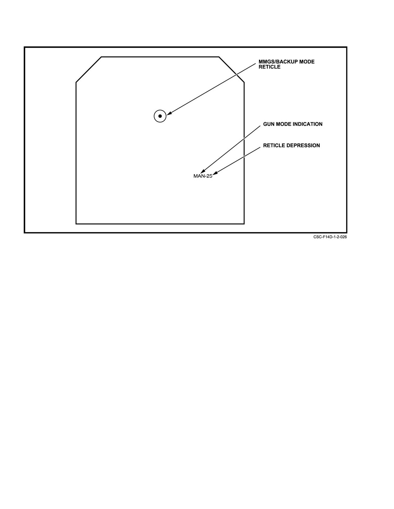
Figure 2Ć104.ĄHUD Manual Reticle Format
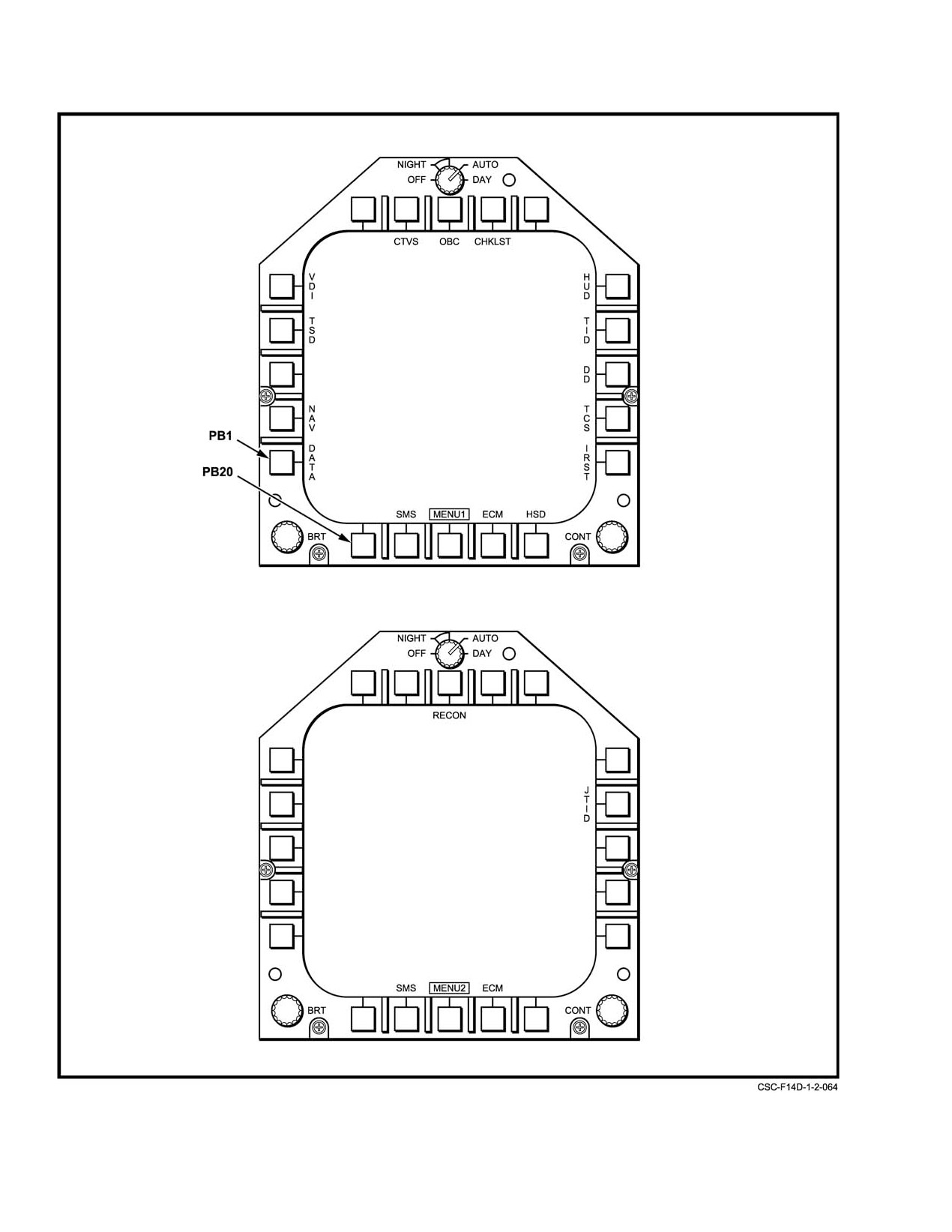
With a MENU display selected, format legends
the RIO cockpit. Either OWN A/C basic, ground
(Figure 2Ć106) are displayed around the edges of the CRT. A
align, CVA (carrier align), or IFA (in−flight align)
format is selected by cursor designation or by pressing the
formats will be displayed.
pushbutton adjacent to the legend. When a format is selected,
its legend on the display is enclosed by a rectangular box.
2. PB2 NAV Selecting NAV presents one of a
number of NAVAID or SAHRS ALIGN formats,
When a display processor acknowledges a pushbutton
depending on alignment mode conditions. Formats
being depressed, the legend is boxed with a dashed line.
that may be displayed include NAV AID options,
When the MC acknowledges the pushbutton request, the line
NAV AID corrections, NAV AID enabled, SAHRS
becomes solid. If the MC does not acknowledge the request,
ALIGN (NORM, MAG, SHDG), or SAHRS ALIGN
the dashed box disappears. This system is used to show the
(CV).
crew that the display system has received the request.
Selecting MENU only changes the pushbutton legends. The
3. PB3 No selection.
current display remains until a selection is made from
MENU.
4. PB4 TSD Selection results in placement of the
tactical situation display format on the selected
For convenience in describing format selection, numĆ
MFD. Switching logic prevents the TSD from
bers are assigned to the pushbuttons starting from the lower
appearing on two MFDs at the same time. ThereĆ
left side and counting clockwise. On the MENU1 display,
fore, selecting TSD on MFD1, while TSD is
PB1 is the pushbutton corresponding to the DATA legend.
displayed on MFD2, will result in the TSD moving
From MENU1 the following formats may be selected:
to MFD1 and MENU1 appearing on MFD2. Refer
to the Supplemental NATOPS Flight Manual,
1. PB1 DATA This selection presents one of four
NAVAIR 01−F14AAD−lA, for a description of TSD
OWN A/C formats. The format to be displayed de−
formats.
pends on the position of the NAV MODE switch in
ORIGINAL
2−202
NAVAIR 01−F14AAD−1
5.
PB5 VDI This selection places one of several
SLAVED DEU
MFD3 FORMAT
VDI formats on the display. VDI formats are headĆ
FORMAT
down attitude displays presenting basic flight inforĆ
mation as well as steering and weapon delivery
OWN A/C BASIC
OWN A/C
cues. Format selection depends on PDCP MODE
OWN A/C GROUND
OWN A/C
pushbutton selection, steering selection, weapon
OWN A/C CVA
OWN A/C
selection, and track or search modes.
OWN A/C IFA
OWN A/C
6.
PB6 No selection.
HSD TACAN
OWN A/C
GPS STAT
OWN A/C
7.
PB7 CTVS This selection displays video from
the HUD color cockpit television sensor on the
HSD WAYPOINT
WAYPOINT PLOT
MFD. The video consists of a real−world view plus
WAYPOINTS DATA (Note 1, 2)
WAYPOINT
the symbology appearing on the HUD.
FLIGHT PLAN
WAYPOINT
8.
PB8 OBC Selecting OBC places the ON BOARD
RECON WPT DATA 1 (Note 6)
WAYPOINT
CHECKOUT basic format on the display. From the
RECON WPT DATA 2 (Note 7)
WAYPOINT
basic format, other OBC formats can be selected,
allowing BITs to be commanded and test results to
CV MAN DATA (Note 3)
CV ALIGN
be displayed. There are 10 OBC formats. Refer to
CV SINS DATA (Note 4)
CV ALIGN
Chapter 38 for a description of these formats and
CSS
CSS
their use.
SMS
SMS
9.
PB9 CHKLST This selection initially places the
SAHRS ALIGN (NORM, MAG,
OWN A/C
TAKEOFF checklist on the MFD. From the TAKEĆ
SHDG)
OFF format, the LANDING checklist may be
selected. PB9 toggles between TAKEOFF and
SAHRS ALIGN (CV)
CV ALIGN
LANDING when CHKLST has been selected.
NAV AID OPTIONS
NAV AID
NAV AID ENABLED (Note 5)
NAV AID
10. PB10 No selection.
TSD
NAV GRID
11. PB11 HUD This selection displays a repeat of the
current HUD symbology on the MFD.
Notes:
(1) No slaved DEU format shall be established if MFD
12. PB12 PTID This selection displays a repeat of
3’s previous format was WAYPOINT DATA 2 or
the programmable tactical information display
RECON WPT DATA 1.
presentation on the MFD.
(2
)
No slaved DEU
format shall be established i
f
MFD
3’s previous format was WAYPOINT DATA 1 or
13. PB13 DD This selection displays a repeat of the
RECON WPT DATA 2.
digital display presentation on the MFD.
(3) No slaved DEU format shall be established if MFD
3’s previous format was CV SINS DATA.
14. PB14 TCS This selection displays the video from
the television camera set on the MFD.
(4) No slaved DEU format shall be established if MFD
3’s previous format was CV MAN DATA.
15. PB15 IRST This selection displays the infrared
(5) No slaved DEU format shall be established if MFD
search and track system normal format on the MFD.
3’s previous format was NAV AID CORRECTIONS.
(6) No slaved DEU format shall be established if MFD
16. PB16 HSD This selection displays one of three
3’s previous format was RECON WPT DATA 2.
horizontal situation display formats on the MFD.
The format displayed will be the last previously disĆ
(7) No slaved DEU format shall be established if MFD
3’s previous format was RECON WPT DATA 1.
played. If no HSD format has been selected after a
cold start or system reset, then the HSD waypoint
format will be presented.
Figure 2Ć105.ĄSlaved DEU Page Control
2−203
ORIGINAL
NAVAIR 01−F14AAD−1
Figure 2Ć106.ĄMFD MENU Displays
ORIGINAL
2−204
NAVAIR 01−F14AAD−1
17. PB17 ECM This selection displays the ECM
is frozen, and an X is superimposed over the spin
format on the MFD. A second selection of ECM
arrow. The airspeed, AOA, and altimeter scales are
while viewing the ECM format returns the previous
not obscured (refer to Chapter 11).
format to the MFD, providing that ECM ORIDE has
been selected and a threat is being reported.
2.33.9.1.2
ECM Format
If the pilot and/or RIO ECM switches (Figure 2Ć86)
18. PB18 MENU1 This legend will be boxed. SelecĆ
are set to ORIDE and a threat is reported, the ECM format
tion of MENU1 when boxed presents MENU2.
will override the present formats on MFD 2 and/or MFD 3.
19. PB19 SMS This selection displays the stores
ECM override is enabled independently by pilot and RIO and
management system format on the MFD. In addiĆ
may be deselected independently. When the threat is no
tion to weapon test and select via the SMS format,
longer being reported, the ECM format is replaced by the
TACTS and SIM modes are enabled. Refer to
previous format. If MFD 2 is not on, the ECM format is
NAVAIR 01−F14AAD−1A for a complete descripĆ
established on MFD 1. Only the spin indicator format can
tion of TACTS and SIM modes. A second selection
override the ECM format.
of SMS while viewing the SMS format returns the
The ECM format can also be selected manually by
previous format to the MFD.
pushbutton selection. The ECM legend appears on all MFD
formats above PB17. When selected, the legend is boxed.
20. PB20 No selection.
Pressing PB17 with ECM boxed returns the previous format
MENU2 (Figure 2Ć106) allows selection of the
to the display. For further information, refer to NAVAIR
RECON and JTIDS formats on the MFD.
0l−F14AAD−1A.
21. PB21 JTID This selection displays the JTIDS
2.33.9.2
Warning/Caution/Advisory, System
OWN A/C DATA format. From the JTIDS OWN
Message, and Advisory Formats
A/C DATA format, the TSD MENU (TMENU) or
JTIDS Hook −TSD or PTID format can be selected.
Warning/caution/advisory indications and data−link
advisory readouts appear as overlays on displays as required.
Figure 2Ć108 shows the locations of these overlays and
2.33.9.1
High−Priority Formats
describes their control logic.
High−priority formats include spin indicator, ECM,
Warning/caution/advisory indications are displayed on
warning/caution/advisory and system message displays.
the MFD in the upper left readout, and data−link JTIDS
advisories are displayed in the upper right readout. The
2.33.9.1.1
Spin Indicator
readouts have the capability to present up to four indications
If a spin condition is detected, that is, if body yaw rate
at a time with each indication consisting of up to eight
exceeds 30° per second, a spin indicator format (Figure 2Ć107)
characters in length. When more than four indications are
is displayed on MFD 1 and the PTID, MFDs 2 and 3 display
designated for display within a readout, the indications will
the VDI. If MFD 1 is not on, the spin display will appear on
cyclically scroll up from the bottom at a rate of one indication
MFD 2. When the spin condition is no longer valid (yaw rate
per second. The warning/caution/advisory indications are
of 27° per second or less), the spin indicator format is removed
capable of being acknowledged and removed from the
and the previous format is restored to the display except as
display whereas the data−link/JTIDS advisories are not
follows:
acknowledgeable. When a warning/caution is displayed, the
MASTER CAUTION light flashes and the READ MFD
1. If conditions for the display of the ECM format
caution lights come on.
exist, the ECM format will appear on the display
Systems messages are generated by the mission
instead.
computer to alert the crew of system conditions. Two
2. If the previous format was a HUD, DD, or PTID
categories of system messages are displayed: computer
repeat, MENU with a display of warning/caution/
messages
(those that can appear on any MFD format),
advisory and/or data link (D/L) advisory messages
and OBC messages (those that can only appear on the
will be displayed.
OBC and maintenance current−failure display formats).
The OBC and maintenance current−failure display formats
3. If INS and SAHRS failures occur while the spin
are capable of supporting both categories of system messages
arrow format is displayed, the pointer on the yaw
simultaneously. The messages are displayed on the upper
rate scale is removed from the MFD, the spin arrow
2−205
ORIGINAL
NAVAIR 01−F14AAD−1
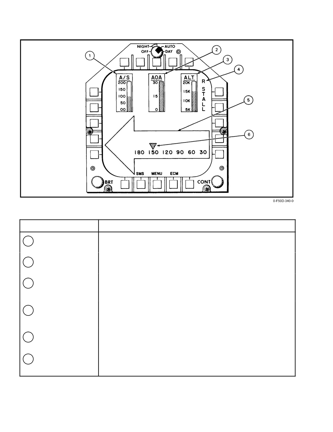
SYMBOL
FUNCTION
1
Airspeed scale
Presents indicated airspeed in knots on a vertical tape.
2
AOA scale
Presents angle−of−attack in units on a vertical tape.
3
Altitude scale
Presents altitude in thousands of feet on a vertical tape. The tape flashes
when altitude is below 10,000 feet MSL.
4
Engine stall indicator
Displays either R STALL on right side of MFD or L STALL on left side of
MFD to indicate a stalled engine.
5
Spin arrow
Displays an arrow pointing either left or right indicating direction of spin.
6
Yaw rate scale
Moving carat indicates yaw rate in degrees per second against a stationary
scale.
Figure 2Ć107.ĄMFD Spin Indicator Display
ORIGINAL
2−206
NAVAIR 01−F14AAD−1
SYMBOL
FUNCTION
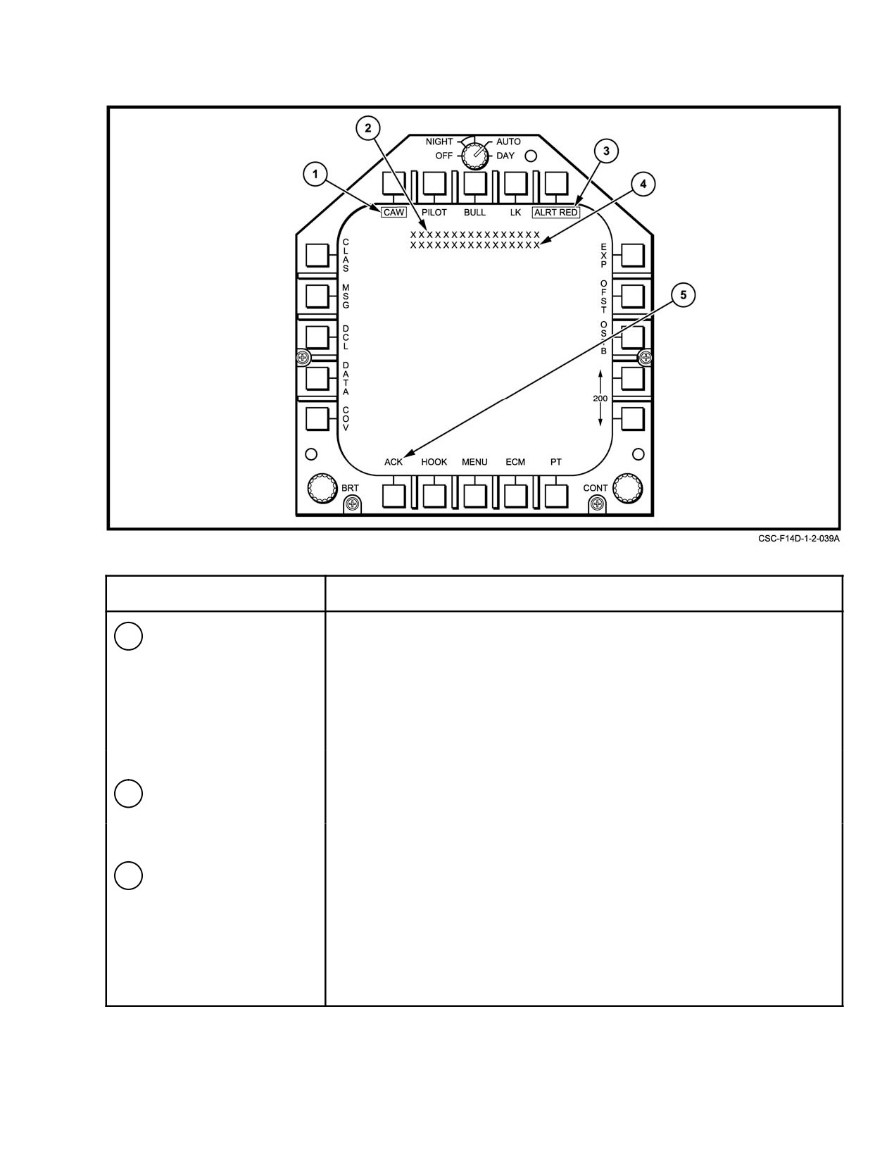
1
Warning/caution/
The Warning/caution/advisory readout is referred to as the CAW box.
advisory readout
The CAW box is selected on and off via PB6. When the CAW box is not disĆ
played, the CAW select legend is displayed and boxed (CAW). The
CAW box displays warning messages steady and bright, cautions at normal
intensity flashing at a 3 Hz rate, and advisories at normal intensity and
steady. If the caution is displayable in the pilot cockpit, pressing the
MASTER CAUTION light causes the caution message to become steady.
2
Computer message
The first row of ASCII characters is used to display the computer messages
for all display formats. See Figure 2−109 for a listing of these messages.
3
Data link/JTIDS advisory
Provides display of data link/JTIDS advisories. The data link JTIDS advisory
readout
indications are not acknowledgeable. Indications that will be presented on
the HUD and MFD and their logic are described in the Supplemental
NATOPS Flight Manual, NAVAIR 01−F14AAD−1A.
Figure 2Ć108.ĄMFD Warning/Caution/Advisory and Message Overlays (Sheet 1 of 2)
2−207
ORIGINAL
NAVAIR 01−F14AAD−1
SYMBOL
FUNCTION
4
OBC messages
The second row of ASCII characters is used to display the OBC messages
on the OBC and maintenance current failure formats. See Figure 2−109 for
a listing of these messages.
5
Acknowledge (ACK)
The ACK pushbutton legend appears whenever a system message is disĆ
pushbutton
played. When the ACK pushbutton is pressed the message will be removed
from the MFD. System messages must be acknowledged before new mesĆ
sages can be displayed.
Figure 2−108. MFD Warning/Caution/Advisory and Message Overlays (Sheet 2 of 2)
center portion of the MFD and consist of two rows of
3. RECON WPT DATA 2 −This format displays wayĆ
19 ASCII characters, each row displaying a category of
point information for waypoints 11 through 20 as
system messages. System messages (Figure 2Ć109) appear as
well as latitude, longitude, altitude information for
required on the MFDs. They may be computer or OBC
the selected waypoint. It is selected via PB9 (R−2)
messages. When a system message is displayed an ACK
from formats RECON DATA and RECON WPT
(acknowledge) legend appears above PB20. System mesĆ
DATA 1 (Figure 22Ć5 and Figure 22Ć6).
sages remain displayed until the ACK button is pressed.
Should a subsequent message be sent while one is already
Note
being displayed, the first must be acknowledged before the
next will be displayed.
See Chapter 22 for more information on reconĆ
naissance formats.
2.33.9.3
Alphanumeric (Data) Formats
4.
TAKEOFF CHECKLIST This format lists the
items be checked before takeoff; it is selected via
Many MFD formats have no symbols, but rather
PB9 (CHKLST) and PB7 (T/O) on the LANDING
display navigation, alignment, weapon, avionics, and diagĆ
CHECKLIST format.
nostic data. Takeoff and landing checklists may also be
selected. Use of such formats is explained in the chapter
5.
LANDING CHECKLIST This format lists the
where it pertains. Data formats are identified by titles
items to be checked before landing; it is selected via
displayed just below the upper pushbutton legends. When a
PB7
(LDG) on the TAKEOFF CHECK−LIST
format is selected, its pushbutton legend is boxed. The
format.
following paragraphs describe these formats and how they
are selected. Figure 2Ć110 shows a typical format.
6.
OWN A/C formats These formats consist of
basic, ground, CVA (carrier align), and IFA (inflight
1. RECON DATA This format permits selection
align). OWN A/C basic displays own−ship data such
of reconnaissance waypoint and steering mode
as latitude, longitude, altitude, groundspeed, magĆ
(point−to−point, commanded course, map) to wayĆ
netic variation, true airspeed, navigation quality,
point; displays selected waypoint and mission data;
wind speed and direction, barometer (altimeter) setĆ
and displays camera status. It is selected via PB8
ting, and true heading (Figure 20Ć15). The other
from formats MENU2, RECON WPT DATA 1
OWN A/C formats are alignment−related and add
and RECON WPT DATA 2 (Figure 22Ć5 and
alignment information to the basic format, includĆ
Figure 22Ć6).
ing an alignment quality indicator scale. These forĆ
mats are selected via PB1 (DATA) on MENU1,
2. RECON WPT DATA 1 This format displays
VDI, HSD, NAV AID, GPS STAT, and SAHRS
waypoint information for waypoints 1 through 10 as
ALIGN formats. The format displayed depends on
well as latitude, longitude, and altitude information
the alignment mode. As transitions occur between
for the selected waypoint. It is selected via PB7
alignment modes, the formats will automatically
(R−1) from formats RECON DATA and RECON
change. On MFD 3, an alignment or INS mode tranĆ
WPT DATA 2 (Figure 22Ć5 and Figure 22Ć6).
sition will cause the current format to be replaced by
an OWN A/C, CV DATA, or IFA format.
ORIGINAL
2−208
NAVAIR 01−F14AAD−1
COMPUTER MESSAGE
PRIMARY MFD
SECONDARY MFD
NOT OPERATIONAL
(Note 7)
WAYPOINT INVALID
(Note 7)
TCN STEER INVALID
(Note 9)
SEL TACAN STEERING
(Note 7)
TEST COMPLETE−GGGGG (Note 1)
(Note 7)
PREFLT OBC COMPLETE
1,3
2 (Note 8)
INFLT OBC COMPLETE
1,3
2 (Note 8)
ALIGN SUSPENDED
1,3
2 (Note 8)
RETEST COMPLETE
1,3
2 (Note 8)
OBC SEQ ABORTED
1,3
2 (Note 8)
RETEST ABORTED
1,3
2 (Note 8)
OBC FAIL DETECTED
1,3
2 (Note 8)
INVALID WWWWW LOAD (Note 2)
1,3
2 (Note 8)
MC1 ERROR CODE XXX (Note 3)
1,3
2 (Note 8)
MC2 ERROR CODE XXX
1,3
2 (Note 8)
E BLOCK ADD SSSS (Note 4)
3
E FLYCH ADD SSSS
3
FLYCH EXISTS SSSS
3
E TRAP ADD SSSS NN (Note 5)
3
E 4 TRAPS SSSS NN
3
E TRAP VAR SSSS NN
3
E TRAP ALGO SSSS NN
3
E FLYCH INC SSSS
3
N FLYCH IN SSSS
3
E FLYCH DEC SSSS
3
NO TRAP NO. SSSS NN
3
TRAP TRU INB SSSS NN
3
ILS STEER INVALID
(Note 9)
ACL STEER INVALID
(Note 9)
D/L STEER INVALID
(Note 9)
TACAN NOT AVAIL
(Note 7)
SET PARKING BRAKE
1,3
2 (Note 8)
NO IFA/NO VEL
3
32 PLOTLINE DEFINED
3
E NOT AVAIL SSSS
3
DEST STEER INVALID
(Note 9)
MAN STEER INVALID
(Note 9)
DATA REQUIRED
13
2
PILOT OBC DISABLE
1
2
INTERLOCK ABORT
1,3
2 (Note 8)
Figure 2Ć109.ĄComputer and OBC Messages (Sheet 1 of 4)
2−209
ORIGINAL
NAVAIR 01−F14AAD−1
COMPUTER MESSAGE
PRIMARY MFD
SECONDARY MFD
RDR ALLOTMENT GFL
3
2
CHALLENGE IFF
3
2
INVALID PLOT WPT
3
2
VIDEO REC NOT AVAIL
3
VIDEO SWITCH ERROR
3
VIDEO REC LOST
3
ECM DATA INVALID
(Note 9)
BAD RWR LOAD
1,3 (Note 9)
2 (Note 8)
RDR CFL
3
ASPJ CFL GO TO SA
3
ASPJ CFL GO TO PH
3
ASPJ CFL GO TO SD
3
ASPJ CFL
3
AAAAA ALGN COMPL (Note 6)
3,1
2 (Note 8)
GB−NORM
3
GB−INIT ALIGN
3
GB−SLEW
3
GB−CARD ALIGN
3
GB−GND CAL COMPL
3
GB−SEA CAL COMPL
3
NO AIC − DSS LOAD
3
2 (Note 8)
NO AIC − NET ENTRY
3
2 (Note 8)
NO AIC − XMIT MODE
3
2 (Note 8)
NO AIC − NO RESPONSE
3
2 (Note 8)
NO AIC − REQ DENIED
3
2 (Note 8)
JTIDS NOT AVAIL
3
2 (Note 8)
NO LOAD − NEED DSS
3
2 (Note 8)
NO LOAD − DSS FAIL
3
2 (Note 8)
LOAD ERROR − JTIDS
3
2 (Note 8)
JTIDS FAIL DETECTED
3
2 (Note 8)
MCS FULLUP ENTERED
3,1
2 (Note 8)
MCS FULLUP AVAIL
3,1
2 (Note 8)
MCS COLD START
3,1
2 (Note 8)
NO CHNG RECON WPTS
1,3
2 (Note 8)
GPS FAIL
1,3
2 (Note 8)
IFA AVAILABLE
1,3
2 (Note 8)
MDL FAIL DETECTED
1,3
2 (Note 8)
INVALID MDL FORMAT
1,3
2 (Note 8)
Figure 2−109. Computer and OBC Messages (Sheet 2 of 4)
ORIGINAL
2−210
NAVAIR 01−F14AAD−1
COMPUTER MESSAGE
PRIMARY MFD
SECONDARY MFD
Notes:
(1) through (6) indicates the range of the ADVISORY DATA from the application function and the
corresponding ASCII strings:
(1)
GGGGG
(3)
XXX
0−999
1
AUX
2
CD
(4)
SSSS
3
CNI
6
MDS1
4
FLT
8
CIU
5
NAV
9
DEU
6
EW
10
MC1
7
TAC
11
MDS2
8
IRST
12
ADAS
(2)
WWWWW
13
SMS
1
MC1
15
MC2
2
MC2
16
IRST
4
DEU
17
SDIS
5
MDS1
18
JTIDS
6
MDS2
(5)
NN
0−99
7
RDR
(6)
AAAAA
8
CIU
9
SAHR
1
INS
10
SMS
2
SAHRS
11
ADAC
12
DSS
13
ASPJ
14
PWR
15
IRST
16
SDIS
(7)
The MFD these messages are presented on is the MFD from which the pushbutton causing the message
is received or on other MFDs when unique display conditions exist.
(8)
MFD 2 is secondary only when MFD 1 fails.
(9)
These computer messages are displayed on all MFDs displaying a VDI format. If no VDI format is disĆ
played on MFD 1 and MFD 2, this computer message is displayed on MFD 1 (provided no repeat format is
displayed) with MFD 2 as a secondary when MFD 1 fails.
Figure 2−109. Computer and OBC Messages (Sheet 3 of 4)
2−211
ORIGINAL
NAVAIR 01−F14AAD−1
COMPUTER MESSAGE
PRIMARY MFD
SECONDARY MFD
OBC/CSS Messages Removed After 3 Seconds
WOW NOT SATISFIED
TAS NOT SATISFIED
MULTI INTLK NOT MET
EQUIPMENT CONFLICT
NO COMMAND BIT
OBC SEQ IN PROGRESS
RETEST IN PROGRESS
OBC/CSS Messages Removed When Condition Change
MASTER TEST NOT SET
HANDBRAKE NOT SET
Figure 2−109. Computer and OBC Messages (Sheet 4 of 4)
7.
CV DATA formats These formats consist of CV
using arrows (PB 4 and PB 5) and the waypoint
MAN DATA and CV SINS DATA. Data presented
name, number, latitude, longitude, and altitude will
is similar to OWN A/C except that it includes addiĆ
be displayed in the lower left of the display
tional information from manual entry or the ship’s
(Figure 20Ć35 and Figure 20Ć37).
SINS. These formats are selected via PB3 (CV) on
11. INS UPDATE This format is used to update and
OWN A/C CVA and SAHRS ALIGN formats. The
correct INS information. Update data may be
format displayed depends on whether or not data
selected via radar, TACAN, visual sighting, JTIDS,
link is providing SINS data. PB5 (MAN) on the CV
or HUD hooking. The format is selected via PB13
DATA format toggles between MAN and SINS
(UPDT) on the HSD formats as well as PB15 (SWP)
(Figure 20Ć24 and Figure 20Ć25).
on the SURFACE WPT format.
8.
IFA This format presents similar data to OWN
12. SURFACE WPT This format permits the creĆ
A/C and also provides selection of in−flight alignĆ
ation of new waypoints or the update of existing
ment. It is selected via PB4 (IFA) on the OWN A/C
waypoints. It is selected via PB15 (SWP) on the INS
IFA format (Figure 20Ć23).
UPDATE format.
9.
WPT DATA Up to 649 waypoints are stored on
13. NAV AID formats The NAV AID formats, which
the MDL. This format displays the latitude, longiĆ
consist of NAV AID OPTIONS, NAV AID
tude, and altitude of these waypoints as well as
CORRECTIONS, and NAV AID ENABLE, permit
OWN A/C and CVA, INS/SAHRS formats. Ten
updating of navigational information for greater
waypoints are presented on each waypoint data page
accuracy. The formats are selected via PB2 (NAV)
and the waypoint page number is indicated at the top
on the HSD, OWN A/C, CV DATA, or IFA formats.
of the display. The data page can be incremented
The format displayed depends on the selection or
(PB 10) or decremented (PB 9). To select the wayĆ
deselection of alignment mode, continuous data
points for display, PB 1 through PB 5 and PB 11
source, and whether ENABLE (PB8 on NAV AID
through PB 15 may be used to box waypoint data,
CORRECTIONS) was previously selected. PB7
highlighting waypoints of interest (Figure 20Ć29).
(GEO/REL) is used to select which JTIDS navigaĆ
tion data is used for track corrections and continuĆ
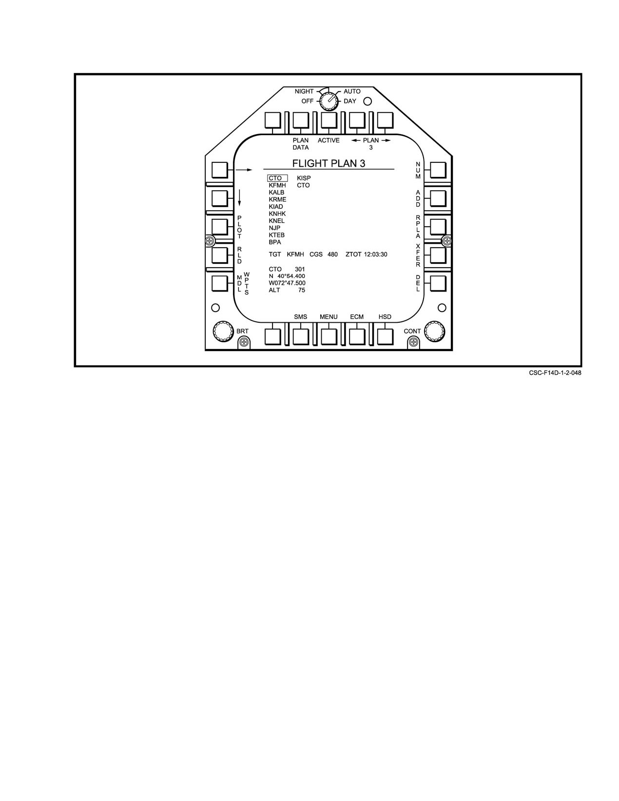
10. FLIGHT PLAN Ċ This format is selectable from
ous position updates.
the OWN A/C formats or HSD format. This format
shows the waypoints contained in Flight Plans 1
14. SAHRS ALIGN formats These formats SAHRS
through 7. The flight plans are selected by increĆ
ALIGN (NORM, MAG, and SHDG) and SAHRS
menting
(PB 10) or decrementing (PB 9). The
ALIGN (CV), permit selection of data to be used in
format presents the flight plan number and up to
SAHRS alignment. They are selected via PB2
50 waypoints associated with waypoints by name or
(NAV) on the HSD, OWN A/C, CV DATA, or IFA
by number when NUM (PB 11) is boxed. The indiĆ
formats. The format presented depends on alignĆ
vidual waypoint in each flight plan can be selected
ment mode selection and SAHRS test status.
ORIGINAL
2−212
NAVAIR 01−F14AAD−1
Figure 2Ć110.ĄTypical MFD Alphanumeric Format
Also, the display automatically transitions to a
when awaiting test, is flashing during test, and is
SAHRS ALIGN format from a NAV AID format
displayed at normal brightness after test. An alignĆ
when align mode changes from none or IFA to an
ment quality indicator appears on all OBC formats
alignment mode.
to inform the crew of the progress of the alignment
while tests are being performed (Figure 38Ć12 and
Note
Figure 38Ć13).
Refer to Chapter 20 for more information on
navigation related formats.
17. MAINTENANCE Displays a list of current
WRA failures. It is selected via PB9 (FAULT) on the
15. MISSILE SUBSYSTEM formats Two formats
OBC formats. It is also selected via PB3 (FHF) on
display the status of the missiles. Refer to the
the FAILURE HISTORY FILE and PB4 (CSS) on
Supplemental NATOPS Flight Manual, NAVAIR
the COOPERATIVE SOFTWARE SUPPORT forĆ
01−F14AAD−1A.
mat. These legends appear boxed before selection.
16. OBC formats There are 10 OBC formats. They
18. FAILURE HISTORY FILE The FHF format lists
are used to initiate BIT of the avionics equipment
the WRA failures, the type of failure, if this inforĆ
and to display test results. OBC basic presents an
mation is available to the MCS, and the time of up
overall view of subsystem test results and allows for
to 10 failure occurrences since the file was cleared.
selection of the other OBC formats. It is selected via
This format is available via PB3 (FHF) on the
PB8 on the MENU1 format. It may also be selected
MAINTENANCE and CSS formats.
from the other OBC formats by pressing the pushĆ
button for the boxed legend
(the format being
19. COOPERATIVE SOFTWARE SUPPORT The
displayed). The legends on OBC basic show
CSS format is a diagnostic tool that can be used by
which groups of subsystems may be selected. The
maintenance personnel to troubleshoot system and
OBC subsystem formats display failures to the
WRA anomalies. It is selected via PB4 (CSS) on the
WRA level. A WRA legend is brightly displayed
MAINTENANCE and FHF formats (Figure 38Ć20).
2−213
ORIGINAL
NAVAIR 01−F14AAD−1
Note
vectors, indicators, range, and breakaway symbols. There is
one level of declutter on VDI formats that adds a waterline
Chapter 38 includes a complete description of
symbol and removes information such as airspeed, altitude,
the OBC, MAINTENANCE, FHF, and CSS
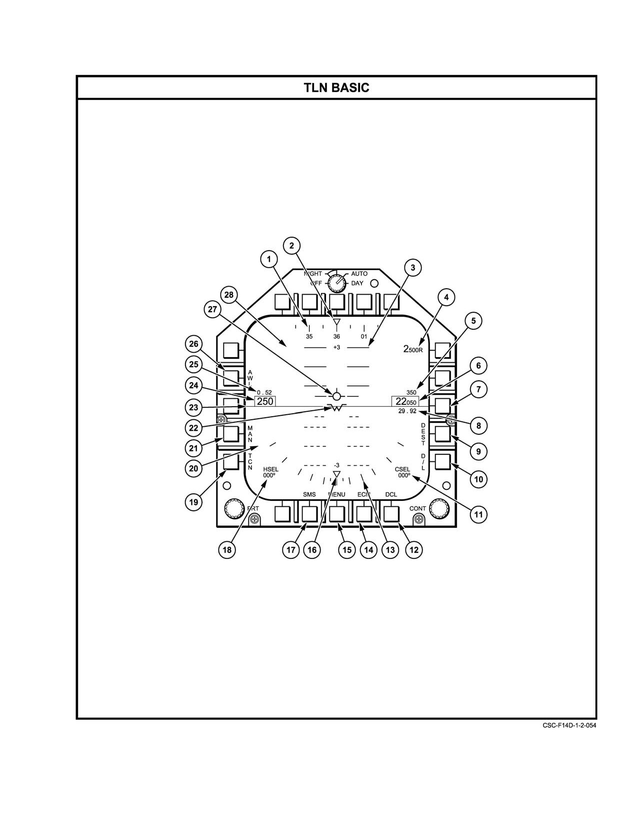
barometric pressure setting, etc. Figure 2Ć111 identifies and
formats with a discussion of their use and
describes TLN symbol functions in various steering and
interpretation.
tracking modes. The last example in Figure 2Ć111 illustrates
VDI declutter. Refer to Figure 2Ć111 for a listing of symbols
20. IRSTS SUMMARY This format, which is used
available on VDI TLN formats in normal and declutter
in conjunction with other IRSTS formats, provides
modes.
information on the hooked IRSTS target. It can be
selected via PB13 (SMY) on the IRSTS NORMAL
2.33.9.4.2
VDI Air−to−Air (A/A) Formats
and IRSTS CSCAN formats.
With A/A selected on the PDCP, one of a number of
21. JTIDS DATA formats There are four alphaĆ
VDI A/A formats will appear when VDI is selected on an
numeric JTIDS data formats. They are the OWN
MFD from the MENU1 or RECON DATA format. The actual
A/C DATA, F−14D PPLI, Non−F−14D PPLI, and
format that is presented depends on which weapon has been
TARGET formats. The OWN A/C format displays
selected. With no weapon selected, the A/A basic format is
own−ship PPLI data and JTIDS status. The PPLI
presented. Most symbols are common between VDI formats
formats display the data received for the hooked
and have been shown in Figure 2Ć112. Figure 2Ć113 describes
PPLI. The TARGET format displays data associated
additional target symbology and data that is provided in VDI
with a hooked target (radar, IRST, or JTIDS). The
A/A formats.
PPLI and TARGET formats are available for a
Unlike HUD A/A formats that have unique search
hooked symbol on either the TSD or PTID.
symbols depending on weapon selection, all VDI A/A search
formats are identical except for the weapon select legends.
2.33.9.4
VDI Formats
VDI basic, gun, and missile track formats add a steering T,"
The VDI presentation on the MFD provides essentially
range bar, and target aspect symbols as well as target range,
the same information as that displayed on the HUD.
altitude, and closing velocity and DD selected range digital
However, in order to more easily distinguish between
information. The missile tracking formats also add maxiĆ
ground, horizon, and sky, shading simulation is used. The
mum, optimum, and minimum range symbols to the range
format is generated by internal raster scanning with the sky
bar and an allowable steering error circle. Figure 2Ć114 lists
being presented in lighter shades than the ground.
the symbols available on VDI A/A formats.
VDI formats consist of TLN basic, TLN AWL, TLN
2.33.9.4.3
VDI Air−to−Ground (A/G) Formats
data link, TLN destination, TLN manual, TLN TACAN, A/A
basic, A/A Phoenix search, A/A Phoenix track, A/A Sparrow
When VDI is selected from the MENU1 or RECON
search, A/A Sparrow track, A/A Sidewinder search, A/A
DATA format with the A/G MODE button on the PDCP
Sidewinder track, A/A gun, A/G, and TWS and recon
selected, that MFD displays the VDI A/G format. Unlike
overlays.
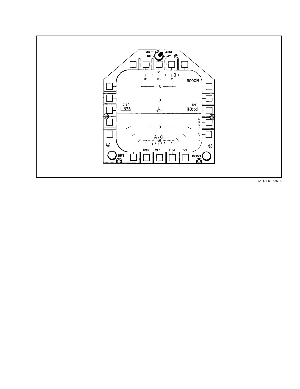
HUD A/G formats, the VDI A/G format does not have target,
aiming, gun, or pullup information, nor does it have any
2.33.9.4.1
VDI TLN Formats
unique VDI symbols other than the A/G select legend.
Figure 2Ć114 shows the A/G symbol set and Figure 2Ć115
With TLN selected on the PDCP (TLN MODE button
shows the format.
depressed), selecting VDI via PB5 on the MENU1 or
RECON DATA formats presents one of a number of TLN
Note
formats on the MFD from which the selection was made. The
format displayed will depend on whether a steering mode has
In A/G mode the basic VDI symbology and forĆ
been previously selected. Initially TLN basic, the MFD 1
mat will generally be the same as TLN with the
default format, is used to select the steering mode. When any
following differences: (1) selection of manual,
steering mode (all weather landing, TACAN, destination,
TACAN, and all−weather landing steering modes
data link, or manual) is selected, formats on both the HUD
will not be provided; (2) the waterline reference
and MFD change to accommodate the selection. These other
dot and the heading and course select settings
VDI TLN formats have pushbutton selections to change the
will not be displayed; and (3) the pitch/flightpath
steering mode. When steering is selected, a heading comĆ
ladder will be compressed and modified.
mand scale is added as well as steering aids such as steering
ORIGINAL
2−214
NAVAIR 01−F14AAD−1
Figure 2Ć111.ĄMFD VDI Formats Takeoff, Landing, Navigation (Sheet 1 of 9)
2−215
ORIGINAL
NAVAIR 01−F14AAD−1
SYMBOL
FUNCTION
1
Heading scale
Aircraft magnetic heading is indicated by the moving 360_ heading scale.
In TLN, the major divisions are numbered every 10 degrees.
2
Heading pointer
Actual aircraft heading is displayed below the stationary heading pointer.
3
Pitch/flight path ladder
Ladder displays aircraft pitch angle and roll angles. Aircraft vertical flight
path angle is indicated by the position of the flight path marker on the pitch/
flight path ladder. Positive pitch lines are solid and negative pitch lines are
dashed. To aid in determining flight path angle when it is changing rapidly,
the pitch lines are angled toward the horizon at an angle half that of the
flight path angle. For example, in a 40° climb, the pitch lines are angled 20°
toward the horizon. UP appears at +90° and DOWN appears at −90°.
4
Radar altitude indicator
Displays radar altitude when the aircraft is below 5,000 ft AGL. When radar
altitude is selected for display on the HUD and MFD (via the switch located
on the pilot display control panel) the radar altitude indicator will be
decluttered from the display.
5
Vertical velocity
Displays aircraft rate of climb/descent. Descent will be indicated by a
negative (−) sign.
6
Altitude
Barometric, radar, or GPS altitude may be displayed depending on the
source of data. When the ALTITUDE switch is in BARO, barometric altitude
is displayed. When the ALTITUDE switch is in RDR, radar altitude is disĆ
played and is identified by an R next to the altitude. If the radar altitude is
invalid, barometric altitude will be displayed and a B next to the altitude will
be flashed to indicate that barometric altitude is being displayed rather than
radar altitude. A G is only displayed when SCADC altitude becomes invalid
and the GPS altitude is used. The G acronym will flash if radar altitude is
selected and both SCADC and radar altitude are invalid. The bottom of the
altitude box is positioned at the waterline reference position.
7
BARO pressure setting
Enables display of the barometric pressure setting used by the display
pushbutton
system and the weapon system. Successive depression of the pushbutton
will cause the setting to alternately appear and disappear.
8
Barometric pressure
The barometric pressure setting used by the display system and the
setting
weapon system is the value set via pilot’s barometric altimeter. When the
BARO setting is changed, the BARO setting will be momentarily displayed
for 5 seconds after the change is made.
9
DEST steering
Enables selection of the destination steering mode.
pushbutton
10
D/L steering pushbutton
Enables selection of the data link steering mode.
11
Course select setting
Indicates the magnetic course selected by the pilot via the COURSE knob.
12
DCL pushbutton
In TLN, selection of the declutter button removes the airspeed Mach
number, altitude, vertical velocity and heading and course line settings, and
adds waterline reference indicators. Selection of the declutter option is
indicated by a box around the DCL legend.
Figure 2−111. MFD VDI Formats Takeoff, Landing, Navigation (Sheet 2 of 9)
ORIGINAL
2−216
NAVAIR 01−F14AAD−1
SYMBOL
FUNCTION
13
Bank scale
Provides indication of bank angle to 60°. Marks are provided at 0°, 5°,10°,
20_, 30_, 45_ and 60_.
14
ECM display
Selects the ECM threat display. Once depressed, subsequent depression of
pushbutton
the ECM pushbutton will return the display to the VDI display. This will
permit a quick look at the threat display and provide a quick return to the
VDI display.
15
MENU display
Depression of menu will result in the MENU list to appear in the border area
pushbutton
of the VDI display for subsequent selection.
16
Bank angle pointer
Moving pointer provides indication of aircraft bank angle. At bank angles in
excess of 65° the pointer will be removed from the display.
17
SMS display
Selects the SMS display. Once depressed, subsequent depressing of the
pushbutton
SMS pushbutton will return the display to the VDI display. This will permit a
quick look at the SMS display and provide a quick return to the VDI display.
18
Heading select setting
Indicates the magnetic heading selected by the pilot.
19
TCN steering
Selects the TACAN steering mode.
pushbutton
20
Ground plane
The dark shaded ground plane.
21
MAN pushbutton
Selects the manual steering mode.
22
Waterline
In TLN, a fuselage reference line appears at the optical center to denote
the waterline reference position.
23
Horizon
Denotes demarcation between the ground and the sky. It represents the
horizon with respect to the aircraft and changes orientation with any change
in aircraft pitch or roll.
24
Airspeed
Provides display of indicated airspeed. The bottom of the airspeed box is
positioned at the waterline reference position.
25
Mach number
Provides display of aircraft speed in mach to the nearest hundredth.
26
AWL steering
Selects the all weather landing (AWL) steering mode. Selection permits
pushbutton
option to display either ACL, ILS, both or no steering information on the
VDI and/or HUD.
Note
With VDI on MFD 3, AWL selection is possible, but
deselection is inhibited.
Figure 2−111. MFD VDI Formats Takeoff, Landing, Navigation (Sheet 3 of 9)
2−217
ORIGINAL
NAVAIR 01−F14AAD−1
SYMBOL
FUNCTION
27
Flight path marker
The vertical position of the flight path marker with respect to the flight path
ladder indicates the vertical flight path angle of the aircraft.
28
Sky plane
The light shaded area represents the sky.
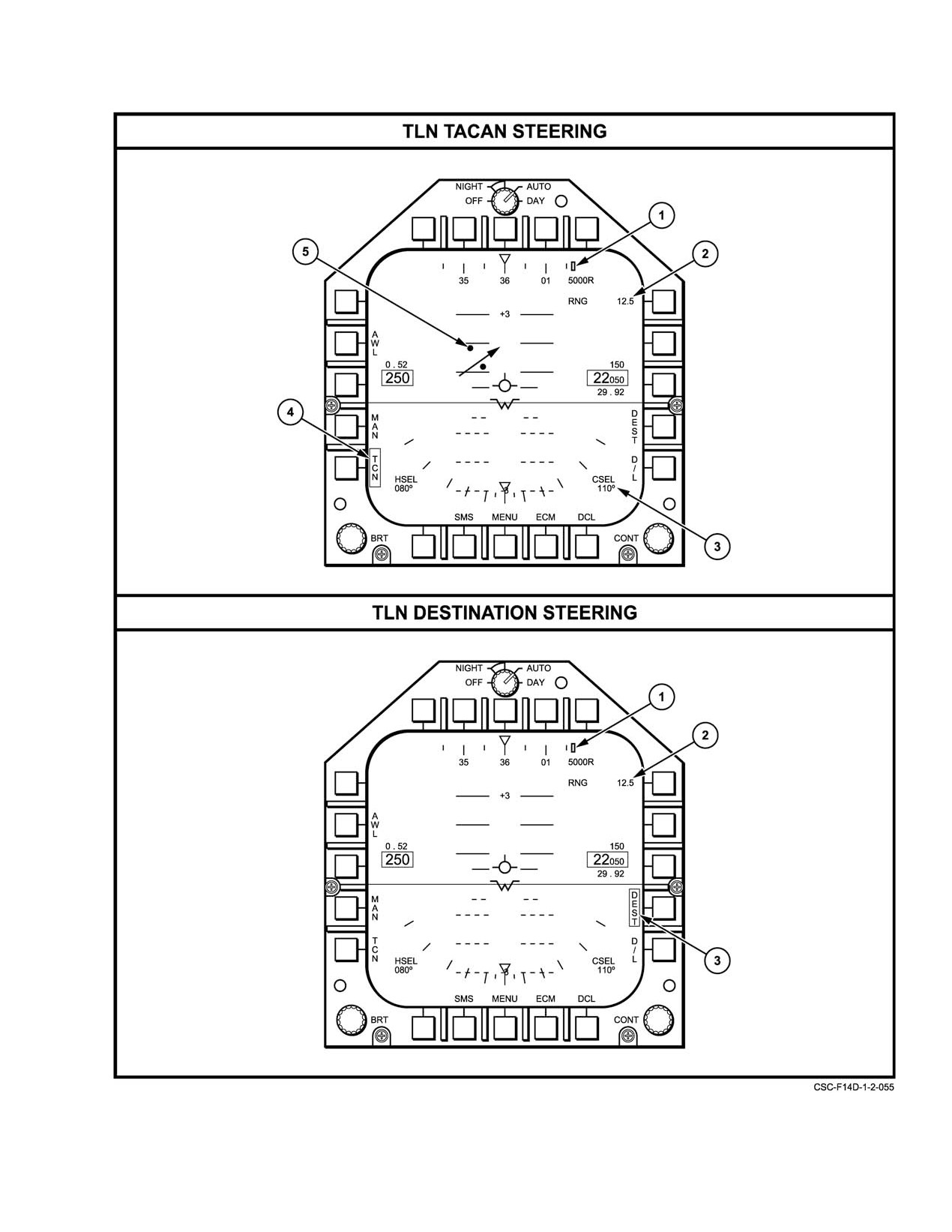
TLN TACAN STEERING
Note
The following changes or additions occur when
TACAN steering is selected.
1
Command heading marker
Command heading marker is positioned relative to the magnetic heading
scale. Where commanded heading is beyond display scale limits, the
marker will be pegged at the edge nearest to the commanded heading.
2
TACAN range
Indicates distance to the selected TACAN station.
3
VDI selected course
Indicates selected course.
indicator
4
TACAN steering mode
Box around TCN pushbutton legend indicates the TACAN steering mode
selection
has been selected.
5
Course arrow
Represents the pilot selected course to the TACAN station. Two dots will
appear on the side of the flight path marker toward the course arrow and
perpendicular to the arrow. The dot closest to the flight path marker repreĆ
sents a deflection of 4_ off course, while the outermost dot represents a
deflection of 8° off course. When the aircraft crosses the selected course,
the arrow moves to the opposite side of the flight path marker and the dots
would appear on that side. For deviations of more than 9°, the arrow pegs.
If the arrow is centered on course, the dots disappear. The flight path
marker centered over the course arrow indicates being on course.
For TACAN bearings aft of +90_, the arrow will be dashed.
TLN DEST STEERING
Note
The following changes or additions occur when desĆ
tination steering is selected.
1
Command heading marker
Indicates the heading required to steer to the waypoint selected by the pilot/
RIO. Where commanded heading is beyond display limits, the marker will
be pegged at the edge nearest to the commanded heading.
2
Destination range
Indicates distance to the selected waypoint.
3
DEST steering mode
Box around DEST pushbutton legend indicates the destination steering
selection
mode has been selected.
Figure 2−111. MFD VDI Formats Takeoff, Lading, Navigation (Sheet 4 of 9)
ORIGINAL
2−218
NAVAIR 01−F14AAD−1
Figure 2−111. MFD VDI Formats Takeoff, Landing, Navigation (Sheet 5 of 9)
2−219
ORIGINAL
NAVAIR 01−F14AAD−1
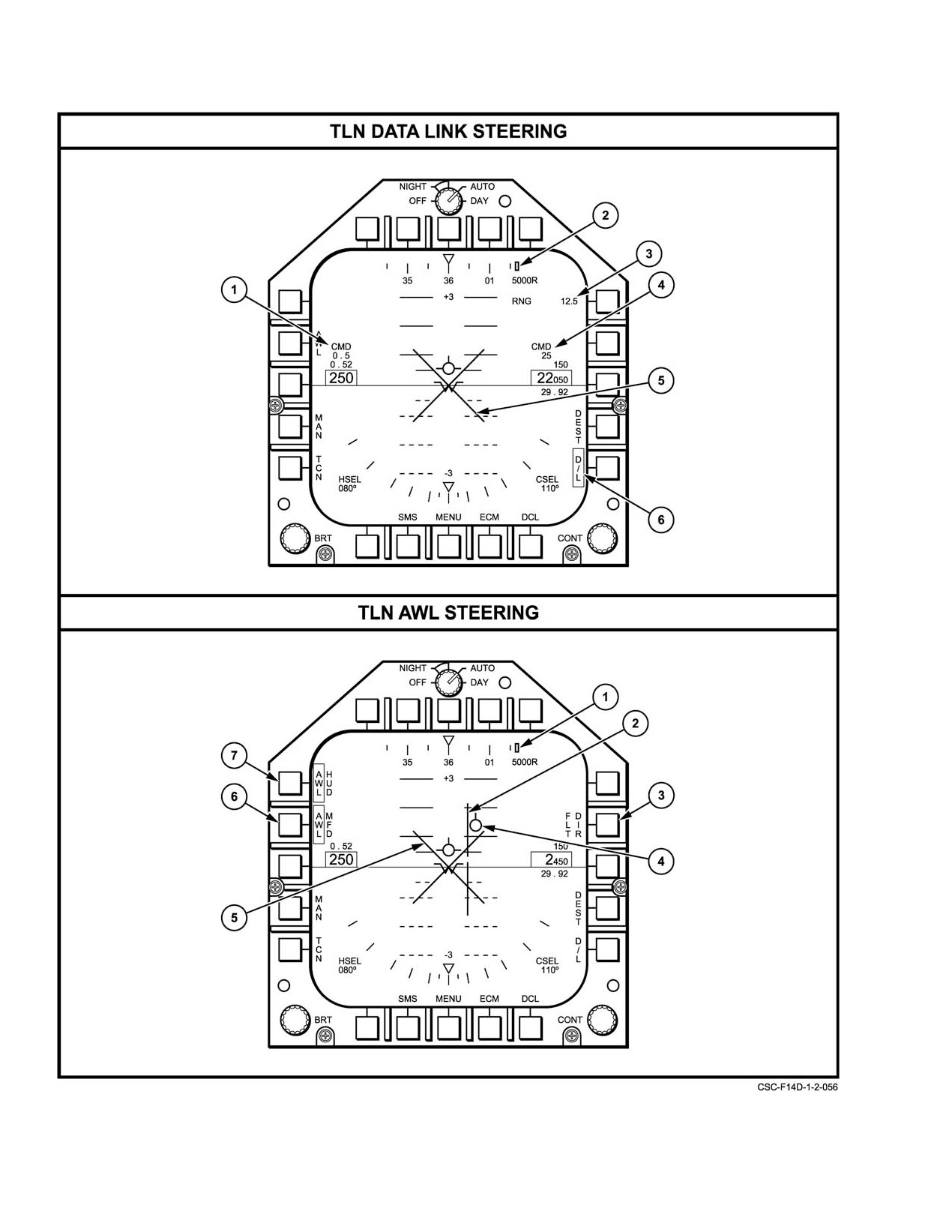
Figure 2−111. MFD VDI Formats Takeoff, Landing, Navigation (Sheet 6 of 9)
ORIGINAL
2−220
NAVAIR 01−F14AAD−1
SYMBOL
FUNCTION
TLN DATA LINK
Note
STEERING
The following changes or additions occur when data
link steering is selected.
1
Command Mach Indicator
Indicates data link commanded mach number.
2
Command heading marker
Command heading marker is positioned relative to the magnetic heading
scale to indicate data link command heading. Where commanded heading
is beyond display scale limits, the marker will be pegged at the edge
nearest to the commanded heading.
3
Data link range
Indicates data link commanded range.
4
Command altitude indicator
Indicates data link commanded altitude. The two digits displayed represent
thousands of feet.
5
Breakaway
Appears as a flashing symbol in the center of the display. Symbol is
commanded by data link to indicate an immediate change in flight path is
warranted.
6
D/L steering mode
Box around D/L pushbutton legend indicates the data link steering mode
selection
has been selected.
Figure 2−111. MFD VDI Formats Takeoff, Landing, Navigation (Sheet 7 of 9)
2−221
ORIGINAL
NAVAIR 01−F14AAD−1
SYMBOL
FUNCTION
TLN AWL STEERING
Note
The following changes or additions occur when AWL
steering is selected.
1
Command heading marker
Positioned relative to the magnetic heading scale to indicate ACL data link
command heading. Where commanded heading is beyond display scale
limits, the marker will be pegged at the edge nearest to the commanded
heading.
2
Precision course needles
Consist of two independent vectors (vertical and horizontal) which form a
cross pointer. The horizontal vector responds to ILS glide slope error and
the vertical vector responds to ILS localizer error. Null/center indications
are provided to enable the pilot to null the error and keep the vertical and
horizontal needles centered.
3
Flight Director
The pilot’s FLT DIR pushbutton controls the display of the flight director on
the HUD. The FLT DIR pushbutton legend is displayed on the AWL VDI for-
mat when valid navigation data is available and a/c vector or ACL data link
mode is selected. The pushbutton will toggle between boxed and unboxed
upon selection if the data link mode is ACL. The HUD flight director is dis-
played when the FLT DIR pushbutton is boxed if the autopilot is not
engaged and MODE I control commands are being sent to the aircraft.
4
ACL steering indicator
Provides ACL steering commands driven by the ASW−27C data link.
5
Waveoff
During carrier landings, a large X will appear flashing in the center of the
display to indicate a waveoff command.
6
MFD AWL display select
Permits option to display AWL (both ACL and ILS), ACL, ILS or no steering
information on the MFD. Initial selection of the AWL steering mode on the
basic VDI format displays both ACL and ILS steering information on the
MFD. This will be indicated by AWL in the box adjacent to the MFD legend.
Successive depression of the pushbutton cycles AWL, ILS, ACL, and no
steering information on the MFD, in that order.
7
HUD AWL display select
Permits option to display AWL (both ACL and ILS), ACL, ILS, or no steering
information on the HUD. Initial selection of the AWL steering mode on the
basic VDI format displays both ACL and ILS steering information on the
HUD. The HUD flight director is displayed when the FLT DIR pushbutton is
boxed (only available when the autopilot is not engaged) and flight director
commands are being sent to the aircraft. If the pilot intends to make a
MODE I approach, he must advise the ground controller of his intentions.
The ground controller will then disable the flight director commands and
enable the autopilot commands. Until this is done, the pilot will not have the
capability to couple the autopilot to the ACLS commands. The only informa-
tion that is displayed on the HUD during MODE I approaches is the ACLS
tadpole situation information and the ILS needles situation information.
Figure 2−111. MFD VDI Formats Takeoff, Landing, Navigation (Sheet 8 of 9)
CHANGE 2
2−222
NAVAIR 01−F14AAD−1
SYMBOL
FUNCTION
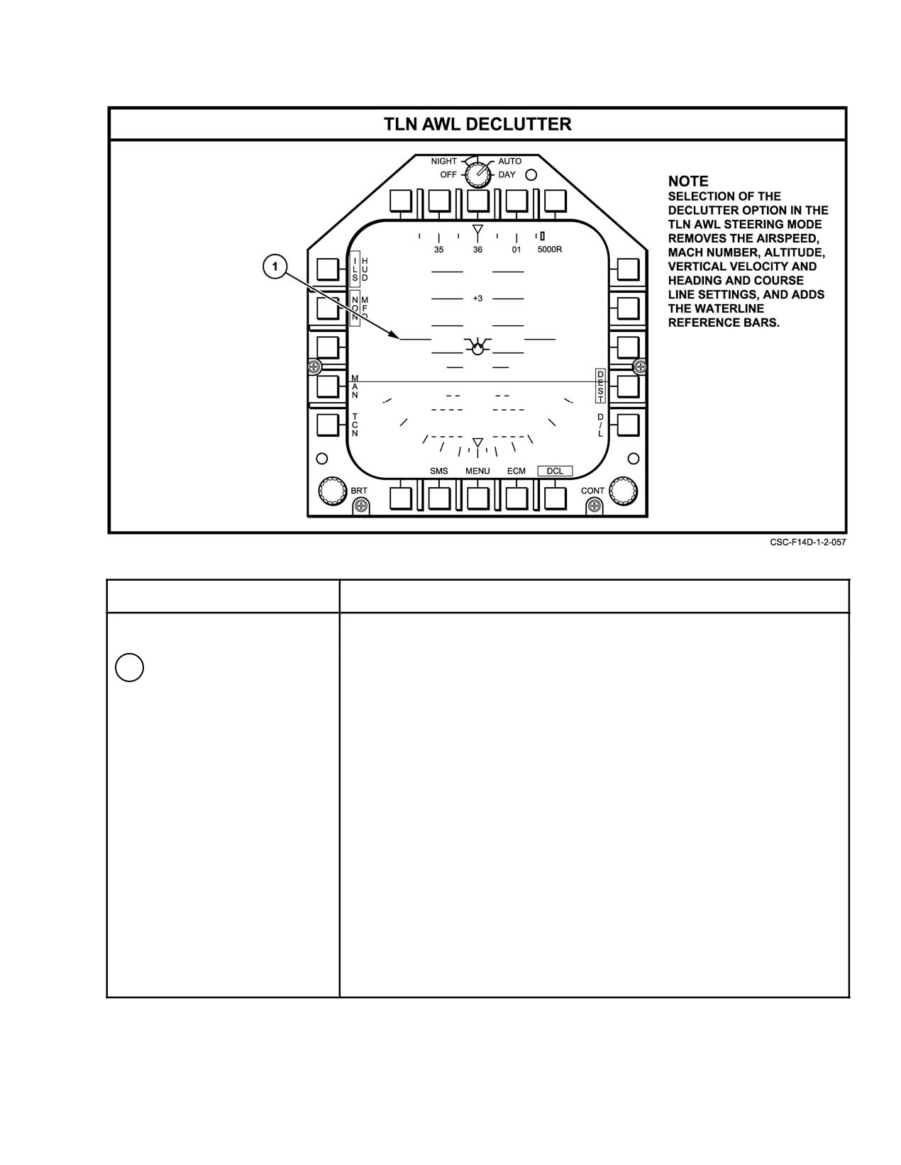
TLN AWL DECLUTTER
1
Waterline reference
The waterline reference indicators are displayed when DCL is selected and
indicators
indicate the fuselage reference line.
Figure 2−111. MFD VDI Formats Takeoff, Landing, Navigation (Sheet 9 of 9)
2−223
ORIGINAL
NAVAIR 01−F14AAD−1
FORMAT
DATA
SYMBOL
BASIC
AWL
LINK
DESTINATION
MANUAL
TACAN
Aircraft Readout & Box
(On all formats except when DECLUTTER)
Altitude Readout and Box
(On all formats except when DECLUTTER)
Bank Scale
+
+
+
+
+
+
Baro Setting Readout
(On all formats except when DECLUTTER)
Course Line Setting−CSEL, #
(On all formats except when DECLUTTER)
Heading Select Point Setting−
(On all formats except when DECLUTTER)
HSEL, #
Heading Scale
+
+
+
+
+
+
Horizon/Ground Plane
+
+
+
+
+
+
Ground/Sky Texture
+
+
+
+
+
+
Ground Perspective Lines
+
+
+
+
+
+
Mach Readout
(On all formats except when DECLUTTER)
Pitch Ladder−VDI
+
+
+
+
+
+
Radar Altitude Readout
+
+
+
+
+
+
Flight Path Marker
+
+
+
+
+
+
Vertical Velocity ’Readout’
(On all formats except when DECLUTTER)
Altitude Source−‘B’ or ‘R’
(On all formats except when DECLUTTER)
MFD Cursor
+
+
+
+
+
+
VDI Center
+
+
+
+
+
+
Caution/Advisory/Warning
+
+
+
+
+
+
Breakaway Symbol
o
+
+
o
o
o
Command Heading marker
o
+
+
+
+
+
Command Alt Data Link−CMD, #
o
o
+
o
o
o
Figure 2Ć112.ĄMFD VDI Symbology Available on TLN Formats (Sheet 1 of 2)
ORIGINAL
2−224
NAVAIR 01−F14AAD−1
FORMAT
DATA
SYMBOL
BASIC
AWL
LINK
DESTINATION
MANUAL
TACAN
Command Mach−CMD, #
o
o
+
o
o
o
MFD Steering Legend−AWL
+
o
+
+
+
+
MFD Steering Legend−TCN
+
+
+
+
+
+
MFD Steering Legend−D/L
+
+
+
+
+
+
MFD Steering Legend−MAN
+
+
+
+
+
+
MFD Steering Legend−DEST
+
+
+
+
+
+
MFD Steering Legend−AWL/HUD
o
+
o
o
o
o
MFD Steering Legend−AWL/MFD
o
+
o
o
o
o
HUD FLT DIR Legend−FLT DIR
o
+
o
o
o
o
VDI DECLUTTER Legend−DCL
+
+
+
+
+
+
Format Select Legend−SMS
+
+
+
+
+
+
Format Select Legend−MENU
+
+
+
+
+
+
Format Select Legend−ECM
+
+
+
+
+
+
Baro PB Legend−B
+
+
+
+
+
+
PB Legend Crossouts
+
+
+
+
+
+
Waterline
(Added to all formats during DECLUTTER)
ILS Precision Course Needles
o
+
o
o
o
o
Range Readout−RNG, #
o
o
+
+
o
+
ACL Steering Indicator Tadpole
o
+
o
o
o
o
Course Arrow & Deviation Dots
o
o
o
o
o
+
Note:
‘+’ indicates that the symbol is available for display on the selected format.
‘o’ indicates that the symbol is not available for display on the selected format.
Figure 2−112. MFD VDI Symbology Available on TLN Formats (Sheet 2 of 2)
2−225
ORIGINAL
NAVAIR 01−F14AAD−1
SYMBOL
FUNCTION
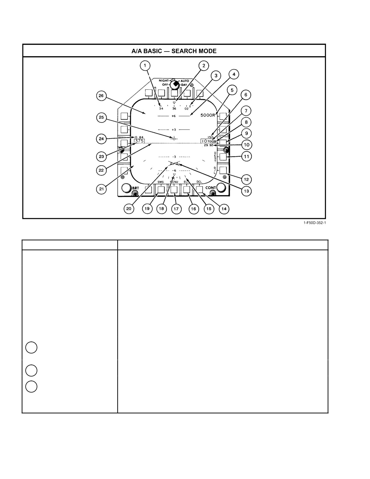
A/A Basic − Search
Note
In A/A search mode and no weapon selected, the basic
VDI symbology and format will generally be the same as
TLN with the following differences:
(1) selection of
manual, TACAN and all weather landing steering modes
will not be provided; (2) the waterline reference and the
heading and course select settings will not be displayed;
(3) the heading scale numerics will be provided at 20
degree intervals, and (4) the pitch/flight path ladder will
be compressed and modified.
1
Heading scale
Aircraft magnetic heading is indicated by the moving 360_ heading scale in
A/A. The major divisions are numbered every 20 degrees.
2
Heading pointer
Actual aircraft heading is displayed below the stationary pointer.
3
Command heading marker
Positioned along the heading scale to correspond with the command
heading.
Figure 2Ć113.ĄMFD VDI Air−to−Air and Air−to−Ground Formats (Sheet 1 of 6)
ORIGINAL
2−226
NAVAIR 01−F14AAD−1
SYMBOL
FUNCTION
4
Pitch/flight path
Ladder displays aircraft pitch angle and roll angle. Aircraft vertical flight path
angle is indicated by the position of the flight path marker on the pitch/flight
path ladder. Positive pitch lines are solid and negative pitch lines are dashed.
To aid in determining flight path angle when it is changing rapidly, the pitch
lines are angled toward the horizon at an angle half that of the flight path
angle. For example, in a 40° climb the pitch lines are angled 20° toward the
horizon. UP appears at +90° climb and DOWN appears at −90° dive. The
VDI pitch ladder will always be caged.
5
Radar altitude indicator
Displays radar altitude when the aircraft is below 5,000 ft AGL. When radar
altitude is selected for display on the HUD and MFD (via the HUD/VDI ALT
switch located on the pilot display control panel), the radar altitude indicator
will not be displayed.
6
Vertical velocity
Displays aircraft rate of climb/descent In feet per minute. Descent will be
indicated by a negative (−) sign. Absence of the negative sign indicates a
positive value.
7
Altitude
Barometric, radar, or GPS altitude will be displayed depending on the source
of data. When SCADC altitude is invalid, GPS altitude will be displayed and
identified by a G next to the altitude. When the ALTITUDE switch is in RDR,
radar altitude will be displayed and will be identified by an R next to the
altitude. If the radar altitude is invalid, barometric altitude will be displayed
and a B next to the altitude will be flashed to indicate that barometric altitude
is being displayed rather than radar altitude. If both radar and SCADC
altitude are invalid, GPS altitude will be indicated by a flashing G next to
the altitude. The bottom of the altitude box will be positioned at the waterline
reference position.
8
Altitude source
Indicates source of altitude data.
9
Barometric pressure
In A/A and A/G, pushbutton enables momentary display of the barometric
setting pushbutton
pressure setting on the pilot’s altimeter. The setting will appear for 5 seconds
each time the pushbutton is depressed. However, in TLN the barometric
pressure setting will be displayed continuously on the HUD and VDI.
10
Barometric pressure
The barometric pressure setting used by the display and weapon system is
setting
the value entered on the pilot’s altimeter. When the baro setting is changed
on the DEU in the A/A and A/G mode, the baro setting will be momentarily
displayed for 5 seconds after the change is made or will appear for
5 seconds when the barometric pressure setting pushbutton is depressed.
It will also appear and flash for 5 seconds when the aircraft drops below
10,000 feet, 300 knots.
11
DEST steering button
Selects destination steering mode.
Figure 2−113. MFD VDI Air−to−Air and Air−to−Ground Formats (Sheet 2 of 6)
2−227
ORIGINAL
NAVAIR 01−F14AAD−1
SYMBOL
FUNCTION
12
D/L steering pushbutton
Selects data link steering mode.
13
A/A mode selection
Indicates selection of the A/A mode.
legend
14
Declutter
In A/A, selection of the declutter option removes the indication of airspeed,
(DCL pushbutton)
Mach number, altitude and vertical velocity from the display, and adds
waterline reference indicators. Selection of the declutter option is indicated
by a box around the pushbutton legend.
15
Bank scale
Provides indication of bank angle to ±60_. Marks are provided at 0_, ±5_,
±10°, ±20_, ±30_, ±45_ and ±60°.
16
ECM pushbutton
Selects the ECM threat display once depressed. Subsequent depression of
the ECM pushbutton will return the display to the previous format. This will
permit a quick look at the threat display and provide a quick return to the
previous format.
17
MENU pushbutton
Depression of MENU will result in the MENU list to appear in the border
area of the display. Subsequent depression of the pushbutton will result in
the alternate presentation of the MENU1 and MENU2 list in the border area
of the display.
18
Bank angle pointer
Moving pointer provides indication of aircraft bank angle. At bank angles in
excess of 65° the pointer will be removed from the VDI display.
19
SMS pushbutton
Selects the SMS display. Subsequent depression of the SMS pushbutton
will return the display to the previous format. This will permit a quick look at
the SMS display and provide a quick return to the previous format.
20
Master arm switch safe
An X through the A/A mode selection legend indicates that the master arm
indication
switch is in the safe position.
21
Ground plane
The dark shaded ground plane.
22
Horizon
Denotes demarcation between the ground and the sky. It represents the
horizon with respect to the aircraft and changes orientation with any change
in aircraft pitch and roll.
Figure 2−113. MFD VDI Air−to−Air and Air−to−Ground Formats (Sheet 3 of 6)
ORIGINAL
2−228
NAVAIR 01−F14AAD−1
SYMBOL
FUNCTION
23
Airspeed
Provides display of indicated airspeed. The bottom of the airspeed box is
positioned at the waterline reference position.
24
Mach number
Provides display of aircraft speed in Mach to the nearest hundredth.
25
Flight path marker
The vertical position of the flight path marker with respect to the pitch ladder
indicates the vertical flight path angle of the aircraft.
26
Sky plane
The light shaded area represents the sky.
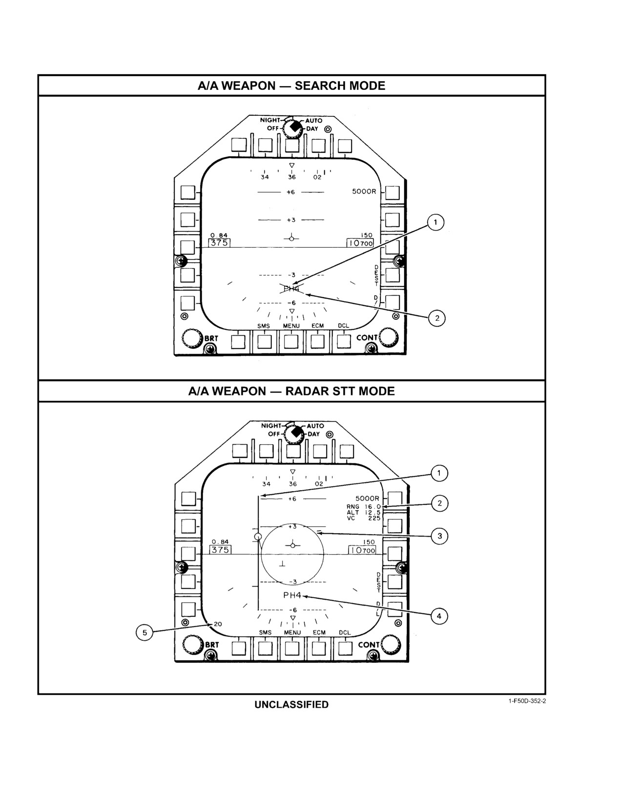
A/A Weapon − Search
Note
When a weapon has been selected for launch in the A/A search
mode the basic VDI symbology and format will generally be the
same as A/A search mode with no weapon selected. The selecĆ
tion of the missile type and quantity of ready missiles will replace
the A/A mode selection legend and the master arm switch safe
indication will appear as appropriate.
1
Selected weapon type and
Indicates which missile has been selected for launch via the weapon select switch,
quantity indication
the type and the quantity available for launch are displayed. Selections are PH
(Phoenix), SP (Sparrow), SW (Sidewinder), and G (gun).
2
Master arm switch safe
An X through the weapon type and quantity indicates that the master arm switch
indication
is in the safe position.
A/A Weapon − Radar STT
Note
When a weapon has been selected for launch in the A/A radar
single target track (STT) mode and the radar target is FONO 1,
the basic VDI symbology and format will generally be the
same as the A/A radar STT mode with no weapon selected.
Selection of a missile in radar STT will enable the display of an
allowable steering error (ASE) circle, range bar and DD range
scale selection.
1
Range bar
The range bar is a fixed length vertical bar range scale against which maximum,
minimum and present range of the radar STT FONO 1 target may be displayed.
Scaling changes are determined by DD selection. Scaling is for 200, 100, 50, 20,
10, and 5 miles. The range bar moves sideways as a function of target azimuth.
The upper tic represents maximum range. The middle tic represents optimum
range and the lower tic represents minimum range. The circle represents the target
and moves vertically as a function of range. Target aspect is represented by a
pointer which points in the direction of the aspect angle. Zero target aspect is
straight down.
Figure 2−113. MFD VDI Air−to−Air and Air−to−Ground Formats (Sheet 4 of 6)
2−229
ORIGINAL
NAVAIR 01−F14AAD−1
Figure 2−113. MFD VDI Air−to−Air and Air−to−Ground Formats (Sheet 5 of 6)
ORIGINAL
2−230
NAVAIR 01−F14AAD−1
SYMBOL
FUNCTION
2
Radar STT FONO 1 target
Range, altitude and closing velocity of the radar STT FONO 1 target.
data
3
Allowable steering error
ASE circle indicates the steering error allowed for launching a missile.
circle
Size of the circle is variable and is determined by the magnitude of the
allowable error.
4
Selected weapon type and
When missiles are selected for launch via the weapon select switch, the
quantity indication
type and the quantity available for launch are displayed. An X through
the indication will signify that the master arm switch is in the safe position.
5
DD range scale
Readout provides indication of RIO’s DD range scale selection of 5, 10, 20,
indication
50, 100, or 200 miles.
Figure 2−113. MFD VDI Air−to−Air and Air−to−Ground Formats (Sheet 6 of 6)
FORMAT
PHOENIX
SPARROW
SIDEWINDER
SYMBOL
BASIC
SEARCH
TRACK
SEARCH
TRACK
SEARCH
TRACK
GUN
Aircraft Readout and Box
(On all formats except when DECLUTTER)
Altitude Readout and
(On all formats except when DECLUTTER)
Box
Bank Scale
+
+
+
+
+
+
+
+
Baro Setting Readout
(On all formats except when DECLUTTER)
Heading Scale
+
+
+
+
+
+
+
+
Horizon Line, Ground
+
+
+
+
+
+
+
+
Plane
Command Attitude D/L
+
+
+
+
+
+
+
+
Command Mach
+
+
+
+
+
+
+
+
Pitch Ladder
+
+
+
+
+
+
+
+
Radar Altitude Readout
+
+
+
+
+
+
+
+
Flight Path Marker
+
+
+
+
+
+
+
+
Vertical Velocity Readout
(On all formats except when DECLUTTER)
Altitude Source ć
(On all formats except when DECLUTTER)
‘B’ or ‘R’
Figure 2Ć114.ĄMFD VDI Symbology Available on Air−to−Air and Air−to−Ground Formats (Sheet 1 of 2)
2−231
ORIGINAL
NAVAIR 01−F14AAD−1
FORMAT
PHOENIX
SPARROW
SIDEWINDER
SYMBOL
BASIC
SEARCH
TRACK
SEARCH
TRACK
SEARCH
TRACK
GUN
Mach Readout
(On all formats except when DECLUTTER)
MFD Cursor
+
+
+
+
+
+
+
+
Warning/Caution/
+
+
+
+
+
+
+
+
Advisory
Breakaway Symbol
+
+
+
+
+
+
+
+
Command Heading
+
+
+
+
+
+
+
+
Marker
Select Legends, Weaponć
A/A
PH#
PH#
SP#
SP#
SW#
SW#
G#
Qty
Sky Texture
+
+
+
+
+
+
+
+
Push Button LegendćSMS
+
+
+
+
+
+
+
+
Push Button Legendć
+
+
+
+
+
+
+
+
MENU
Push Button LegendćECM
+
+
+
+
+
+
+
+
Push Button LegendćD/L
+
+
+
+
+
+
+
+
Push Button Legendć
+
+
+
+
+
+
+
+
DEST
Push Button LegendćDCL
+
+
+
+
+
+
+
+
BARO PB Legend ćB
+
+
+
+
+
+
+
+
PB Legend Crossout
+
+
+
+
+
+
+
+
Master Arm Safe Cue
+
+
+
+
+
+
+
+
Waterline
(Added to all formats during DECLUTTER)
Steering RangećRNG, #
o
+
+
+
+
+
+
+
Steering Tee
+
o
+
o
+
o
+
+
Range Bar
+
o
+
o
+
o
+
+
Max/Min/Opt* Range
o
o
+
o
+
o
+
o
Target Range Heading
+
o
+
o
+
o
+
+
Target Range Numeric
+
o
+
o
+
o
+
+
Target Closing Velocity
+
o
+
o
+
o
+
+
A/A Target Altitude
+
o
+
o
+
o
+
+
DD Selected Range
+
o
+
o
+
o
+
+
ASE Circle
o
o
+
o
+
o
+
o
Note
‘+’ indicates that the symbol is available for display on the selected format.
‘o’ indicates that the symbol is not available for display on the selected format.
* Sidewinder does not display opt range.
Figure 2−114. MFD VDI Symbology Available on Air−to−Air and Air−to−Ground Formats (Sheet 2 of 2)
ORIGINAL
2−232
NAVAIR 01−F14AAD−1
Figure 2Ć115.ĄMFD VDI Air−to−Ground (A/G) Format
2.33.9.4.4
VDI Overlay Formats
When the IRSTS detects valid targets, IRSTS triangles
are overlaid on VDI formats. Position scaling is the same as
The MFD VDI overlay formats are track while scan
that of radar priority target diamonds. However, since range
(TWS), infrared search and tracking system−TWS (IRSTS−
cannot be accurately determined by the IRSTS, no range
TWS), and reconnaissance.
information is presented on this overlay.
When RECON is selected from the RECON DATA
Both target diamonds and IRSTS triangles may be
formats, reconnaissance symbols are overlaid on the HUD
overlaid at the same time on VDI A/A or A/G formats.
and any MFD (Figure 2Ć116) that is displaying a VDI format.
An exception is when a weapon has been selected; then only
2.33.9.5
HSD Formats
the MFD displays the overlay.
The HSD formats provide system navigation informaĆ
When radar detects a valid target, a priority target
tion such as magnetic heading, magnetic course, wind
diamond is overlaid on VDI formats. The diamond’s lateral
direction and speed, true airspeed, groundspeed, waypoint
position indicates the target’s position relative to own aircraft
data, and TACAN data.
and the angular scaling is the same as the VDI A/A pitch
ladder. The diamond vertical position indicates target
The HSD format family consists of HSD waypoint,
altitude relative to own aircraft and the scaling is 10,000
TACAN, and TACAN CDI. Selection of PB16 from the
feet/0.8 inch. (The distance between pushbuttons is 0.8 inch.)
MENU, OWN A/C, CV, IFA, WPT DATA, RECON DATA,
A target at the horizon line would be at the same altitude as
INS UPDATE, NAV AID, SURFACE WPT, GPS STAT, FLT
own aircraft. Up to four target diamonds may be displayed at
PLN, MDL WPTS, or SAHRS ALIGN formats will place the
one time. Unlike the HUD diamonds, which are sized to
previously selected HSD format on the MFD. After a cold
indicate target proximity, VDI target diamonds are the same
start, the HSD waypoint format is shown. Figure 2Ć118
size. Target range in nautical miles is shown by the numbers
describes HSD symbols. Figure 2Ć119 illustrates the activaĆ
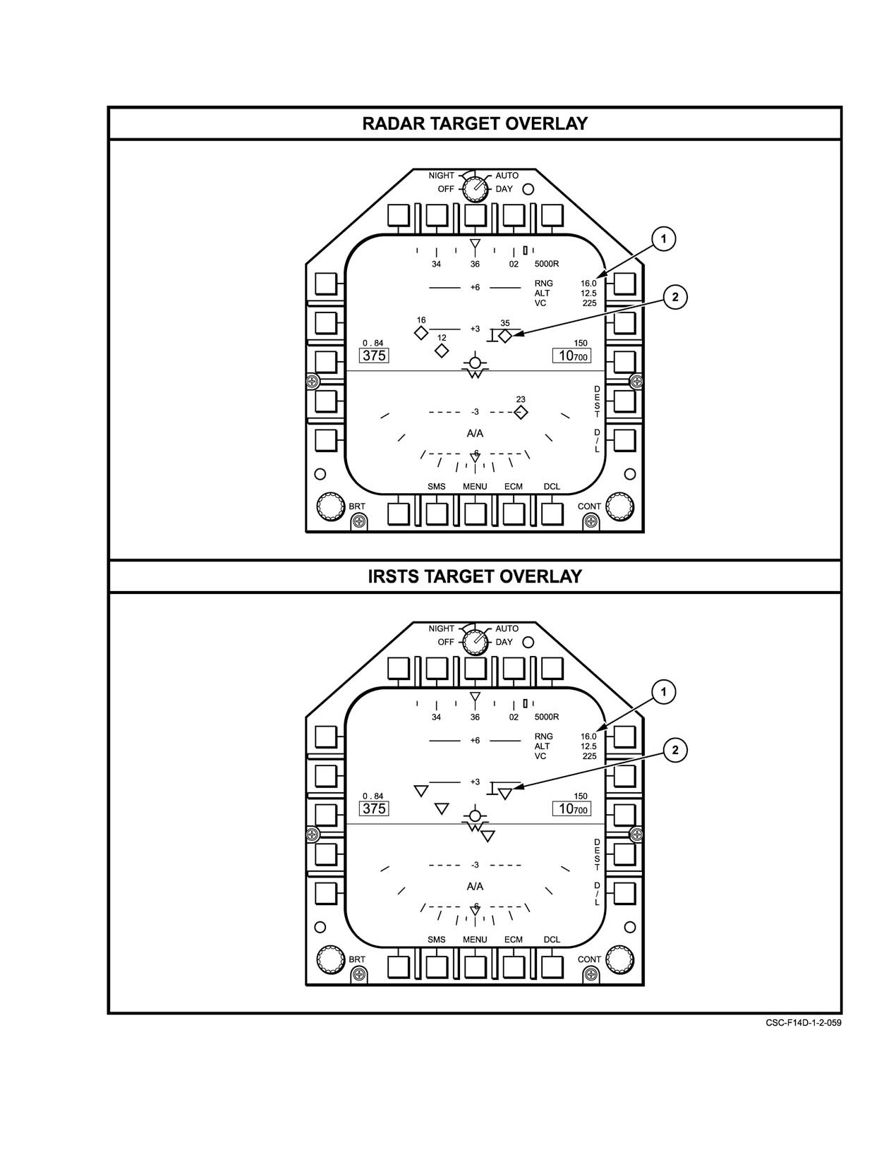
appearing directly above the symbol. The radar target
tion of the plot line display and shows the selected course line
overlay example in Figure 2Ć117 shows the radar TWS mode
that appears when a steering mode (in this case, destination
and is overlaid on an A/A basic format.
steering) has been selected.
2−233
ORIGINAL
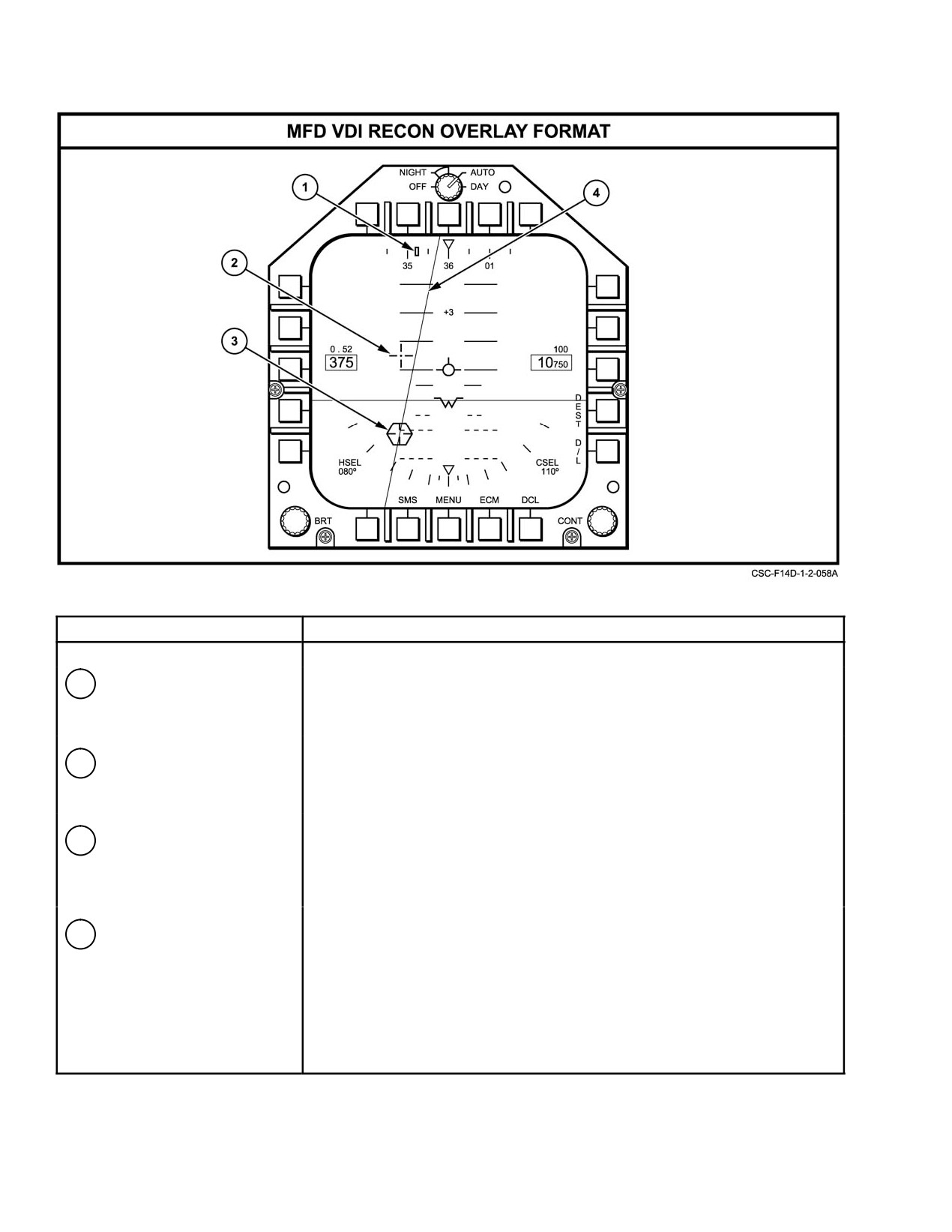
NAVAIR 01−F14AAD−1
SYMBOL
FUNCTION
1
Recon Command Heading
Indicates the magnetic heading for Recon steering.
Marker
2
Recon Steering Symbol
Provides elevation and azimuth steering information when in reconnaisĆ
sance mode. When steering symbol is coincident with flight path marker,
the aircraft is flying the bank command to the dynamic steering point.
3
Target Designator,
Displays target position. Positioned by on−board sensors or data link.
Hexagon
When displayed on VDI formats, the degrees per inch scaling of the symbol
corresponds to the scaling of the rungs of the pitch ladder of the format
being overlaid (TLN, A/G, or A/A).
4
Command Ground
Displays the path of the command ground track. When displayed on VDI
Track Line
formats the degree scaling of rotation corresponds to the scaling of the
rungs of the pitch ladder for the format being overlaid (TLN, A/G, A/A).
Figure 2Ć116.ĄMFD VDI Recon Overlay Format
ORIGINAL
2−234
NAVAIR 01−F14AAD−1
Figure 2Ć117.ĄMFD VDI Radar and IRSTS Overlay Formats (Sheet 1 of 2)
2−235
ORIGINAL
NAVAIR 01−F14AAD−1
SYMBOL
FUNCTION
Radar Target Overlay
Note
In the A/A radar track while scan (TWS) mode and no weapon
selected, the basic VDI symbology and format will generally be
the same as A/A radar single target track except that up to
4 target priority diamonds may be displayed to show direction and
relative altitude of the 4 closest radar targets. IRST TWS targets
may be displayed simultaneously with radar TWS targets. When
this situation occurs, the target data will pertain to the closest
radar TWS targets.
1
Radar target data
Range, altitude, and closing velocity of the closest radar TWS target will be
presented.
2
Radar TWS target
Up to 4 target priority diamonds may be displayed to show direction and
priority diamonds
relative altitude of the 4 closest radar targets. The numerics above the
diamonds indicate the target range to the nearest nautical mile.
IRSTS Target Overlay
Note
In the A/A IRST track while scan (TWS) mode and no weapon
selected the basic VDI symbology and format will generally be the
same as A/A radar track while scan except that up to 4 target
priority triangles may be displayed to show direction and relative
altitude of the 4 closest IRST targets. IRST TWS targets may be
displayed simultaneously with radar TWS targets. When this
situation occurs, the target data will pertain to the closest radar
TWS targets.
1
Target data
Range, altitude, and closing velocity of the closest IRST TWS target will be
presented.
2
IRST TWS target priority
Up to 4 TWS target priority triangles may be displayed to show direction
triangles
and relative altitude of the 4 closest IRST targets.
Figure 2−117. MFD VDI Radar and IRSTS Overlay Formats (Sheet 2 of 2)
ORIGINAL
2−236
NAVAIR 01−F14AAD−1
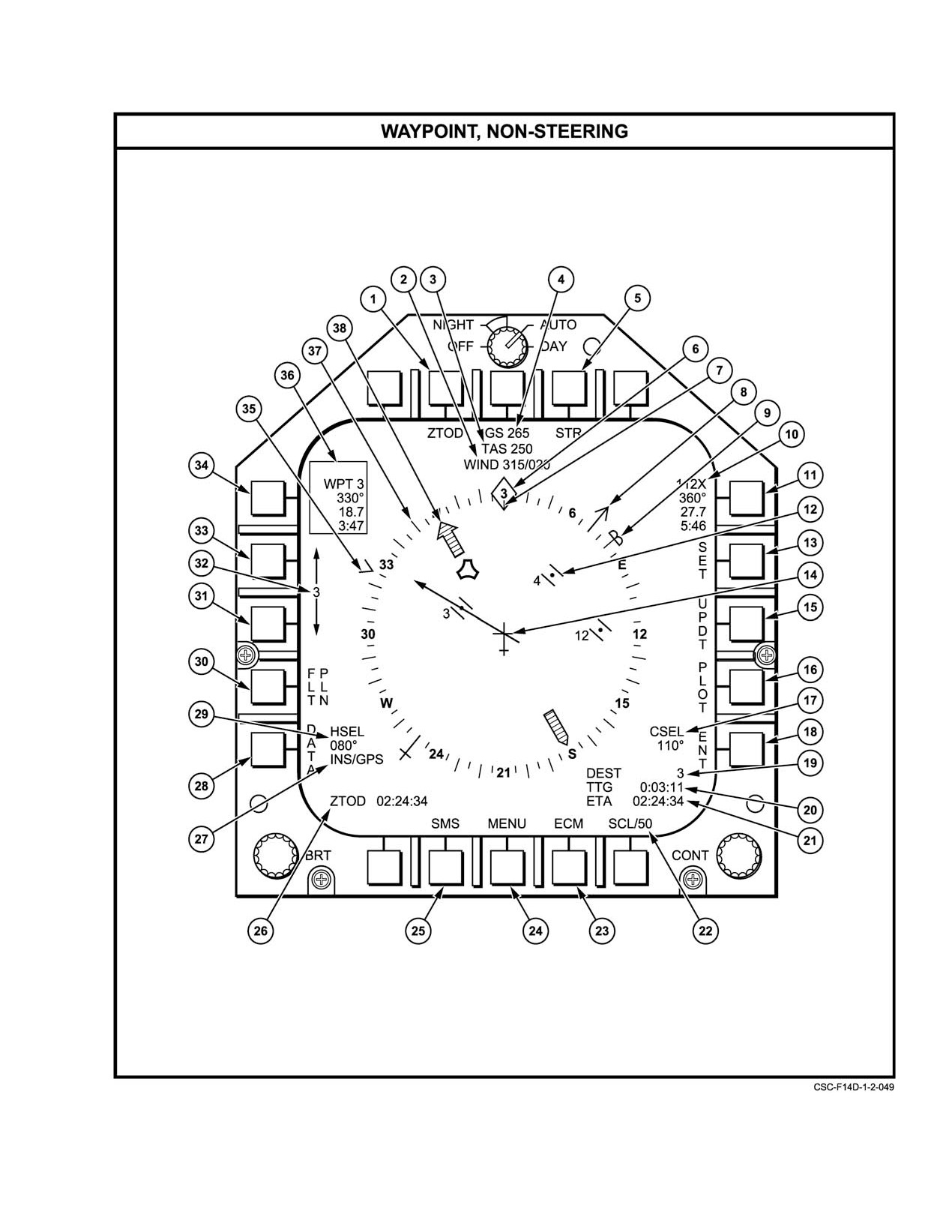
Figure 2Ć118.ĄMFD HSD Format (Sheet 1 of 4)
2−237
ORIGINAL
NAVAIR 01−F14AAD−1
SYMBOL
FUNCTION
1
Clock/timer pushbutton
Selects clock/timer display for HUD and corresponding readout. Options are
ZTOD, ETA, TTG, ET, or CD.
2
Wind
Displays wind direction in degrees and wind speed in knots.
3
True airspeed
Displays true air speed in knots.
4
Ground speed
Displays ground speed in knots.
5
Steering mode pushbutton
STR pushbutton cycles through steering modes: DEST, AUTO, GPS, and
TACAN.
6
Lubber line
The lubber line indication (diamond) is fixed at the top of the compass rose
and indicates aircraft magnetic heading.
7
Ground track line
The ground track line rotates inside the compass rose to represent the
ground track.
8
ADF pointer
The ADF symbol shows the direction of the nearest automatic direction
finder station.
9
Heading select pointer
Displays selected or commanded heading. The symbol rotates outside the
compass rose when manually controlled by the heading potentiometer knob
located in the pilot’s crew station.
10
TACAN data
Displays TACAN channel, range, bearing, and time−to−go to the selected
TACAN station.
11
TACAN display option
Enables the presentation of the TACAN situation symbol, selects TACAN
pushbutton
steering mode, results in the appearance of the TACAN, course deviation
indication (CDI) pushbutton selection, and AWL pushbutton selection.
Selection is indicated by a box around the TACAN data.
12
Waypoint symbol
The numbers (1 to 750) adjacent to the symbol identify the waypoint and
are located on the display to provide an indication of relative range and
bearing from own A/C.
13
Set pushbutton
Enables the establishment of a waypoint at the designated cursor position
on the HSD.
14
Aircraft symbol
The stationary aircraft symbol is positioned in the center of the compass
rose. The symbol in conjunction with the compass rose indicates magnetic
heading.
Figure 2−118. MFD HSD Format (Sheet 2 of 4)
ORIGINAL
2−238
NAVAIR 01−F14AAD−1
SYMBOL
FUNCTION
15
Update (UPDT)
Selects the INS update format on the MFD.
pushbutton
16
Plot pushbutton
Enables/disables the display of plotted lines between waypoints on the HSD
waypoint format.
17
Course line setting
Indicates selected course in degrees.
18
Enter (ENT)
Selects the boxed waypoint for destination steering.
pushbutton
19
Steering readout
Steer mode indication and steerpoint.
20
Time remaining readout
Selected automatically based on steering mode target selected or weapon
selected. Options are TTG, TTGT, or TREL.
21
Clock/timer readout
Clock indication per PB7 selection.
22
Scale (SCL XXX)
Selects range scale (200, 100, 50, 25, and 10 nautical miles).
pushbutton
The scale is the distance from the aircraft symbol to the inside edge of the
compass rose. Successive depressions of the pushbutton causes the range
scale to decrement and then start again at 200 miles.
23
ECM pushbutton
Selects the ECM threat display. Subsequent depression of the ECM pushĆ
button will return the display to the previous format. This will permit a quick
look at the threat display and provide a quick return to the previous format.
24
MENU pushbutton
Selects the MENU displays. Depression of MENU will result in the MENU1
list to appear in the border area of the display. Subsequent depression of
the pushbutton will result in the alternate presentation of the MENU2 and
MENU1 list in the border area of the display.
25
SMS pushbutton
Selects the SMS display. Subsequent depression of the SMS pushbutton
will return the display to the previous format. This will permit a quick look at
the SMS display and provide a quick return to the previous format.
26
ZTOD readout
Zulu time of day always displayed in this location on HSD formats.
27
Navigation mode
Indicates the current navigation mode.
28
DATA pushbutton
Selects own A/C data format.
Figure 2−118. MFD HSD Format (Sheet 3 of 4)
2−239
ORIGINAL
NAVAIR 01−F14AAD−1
SYMBOL
FUNCTION
29
Heading select setting
Indicates the magnetic heading selected.
30
FLT PLAN pushbutton
Selects the appropriate NAV AID or SAHRS ALIGN format as determined
by the mission computer.
31
Waypoint decrement
Selects the decrement of the waypoint number of the associated waypoint
(down arrow)
data display and is used to select the waypoint for destination steering.
pushbutton
32
Waypoint number
Indicates the selected waypoint number (via the increment/decrement pushĆ
buttons) of the associated waypoint data display and the desired waypoint
for destination steering.
33
Waypoint increment
Selects the increments of the waypoint number of the associated waypoint
(up arrow)
data display and is used for the selection of the waypoint for destination
pushbutton
steering.
34
Waypoint (WPT) display
Enables the presentation and activation of waypoint−related symbology and
option pushbutton
display options. Selection of this option allows the appearance of the plot
line display selection. Selection of this option is indicated by a box around
the waypoint data.
35
Waypoint bearing
Provides bearing indication of the waypoint entered by the aircrew for
pointer
destination steering.
36
Waypoint data
Range, bearing and time−to−go to the waypoint selected via the increment/
decrement pushbuttons.
37
Compass rose
The compass rose is a circular magnetic scale that consists of major diviĆ
sions at 10 degree intervals, minor divisions at 5 degree intervals, numerics
at 30 degree increments and cardinal points at 90 degree increments.
38
TACAN bearing pointer
Provides bearing indication to and from the selected TACAN station.
head and tail
Figure 2−118. MFD HSD Format (Sheet 4 of 4)
ORIGINAL
2−240
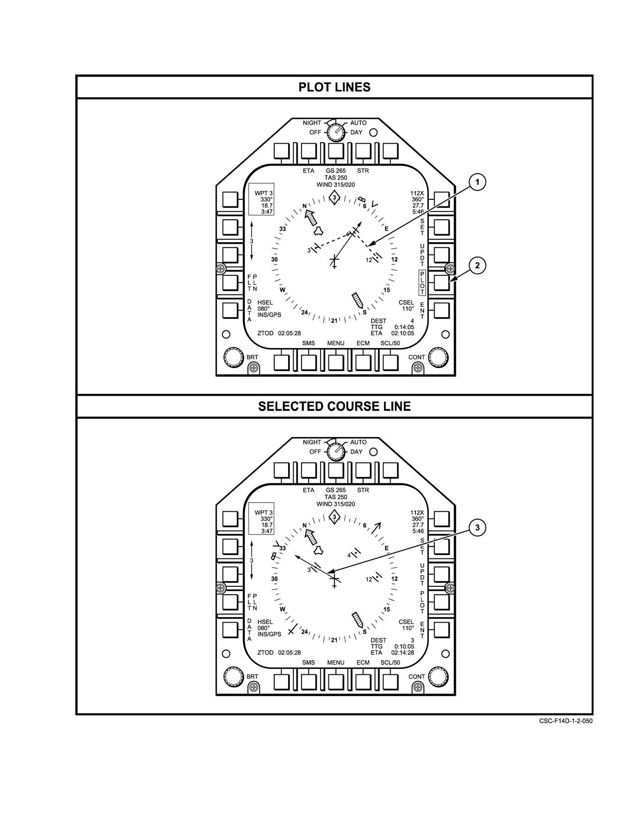
NAVAIR 01−F14AAD−1
Figure 2Ć119.ĄPlot Line and Course Line Displays (Sheet 1 of 2)
2−241
ORIGINAL
NAVAIR 01−F14AAD−1
SYMBOL
FUNCTION
1
Plot lines
Dashed plot lines are drawn between waypoints to aid in navigation.
The waypoints for plotting are selected via the DEU.
2
PLOT pushbutton
Box around the PLOT pushbutton legend indicates the display of plotted
lines between waypoints has been enabled.
3
Selected course line
The course line rotates within the compass circle and depicts the aircraft
commanded course during the destination steering mode.
Figure 2−119. Plot Line and Course Line Displays (Sheet 2 of 2)
HSD steering is selected by PB9 (STR). Selecting the
2.33.9.8
IRSTS Formats
pushtile cycles through the available steering modes: DEST
There are three dedicated IRSTS formats in the IRSTS
(destination), AUTO (automatic), GPS, TACAN, and blank.
format family. They are IRSTS normal, IRSTS CSCAN, and
CDI can be selected from TACAN or GPS steering.
IRSTS summary (refer to NAVAIR 01−F14AAD−1A). Other
IRST information and symbols appear on the HUD, VDI, and
Chapter 20, NAVIGATION, describes the use of the HSD
TSD formats.
formats.
2.33.9.9
TSD Format
2.33.9.6
SMS Formats
The TSD format is chosen via the TSD legend on
Selection of the SMS formats may be made from any
MENU1. The format consists of five distinct legend sets that
format via PB19 (SMS). Depressing PB19 a second time
appear in response to crew MFD inputs. Refer to NAVAIR
returns the previously selected display. This toggle action
01−F14AAD−1A for a description of the TSD format and
permits the crewmember to check the weapon status quickly.
associated symbols.
The MC determines the wingform configuration that will be
2.33.9.10
JTIDS Data Readout Formats
displayed. The CAP/attack and fighter configurations are
shown in Figure 2Ć120.
Refer to NAVAIR 01−F14AAD−1A.
For SMS symbols, configurations, and phases of
2.34 DATA ENTRY UNIT
launch, including an explanation of the AIM−54 MOAT and
DMA results, refer to the Supplemental NATOPS Flight
The DEU (Figure 2Ć122) on the RIO right vertical
Manual, NAVAIR 01−F14AAD−1A.
console provides manual data entry and control of certain
mission functions. The DEU is a remote terminal that
2.33.9.7
Engine Monitor Format
communicates with the mission computers via the multiplex
buses. The DEU is powered by the 28−Vdc main bus. The
The engine monitor format
(Figure 2Ć121) is
DEU consists of a DEU control knob, data entry display, 20
selected via PB15 (ENG) on the OWN A/C formats. This
option keys, and four option display legends. The DEU
format includes a representation of the aircraft engine
control knob controls power, brightness, and the test
instruments, displaying instrument readings for left and right
function. The option display legends display the options for
engines, fuel endurance (based on existing conditions), and
the function or parametr selected. The option keys enable
any engine exceedance conditions. Rpm is provided as N1
selection of the desired menu functions and entry of required
and temperature as turbine blade temperature
(TBT not
mission parameters. The data entry display is a two−line
EGT). Fuel flow is shown as either main (M) or total (T),
display. The top line indicates the currently selected
depending on power setting (either nonafterburner or afterĆ
parameter while the bottom line (scratchpad) is used to enter
burner range). This information is provided by the FEMS.
data. The scratchpad consists of a 14−character display. The
Engine monitor format is not provided while in SEC mode.
character locations are often denoted by underlines that, as
Refer to FEMS in this chapter for additional information.
data is keyed in, disappear.
2.34.1
Data Entry Unit Operating Modes
As selected by the RIO, the DEU operates in one of two
modes: slaved to the RIO multifunction display (MFD3) or
ORIGINAL
2−242
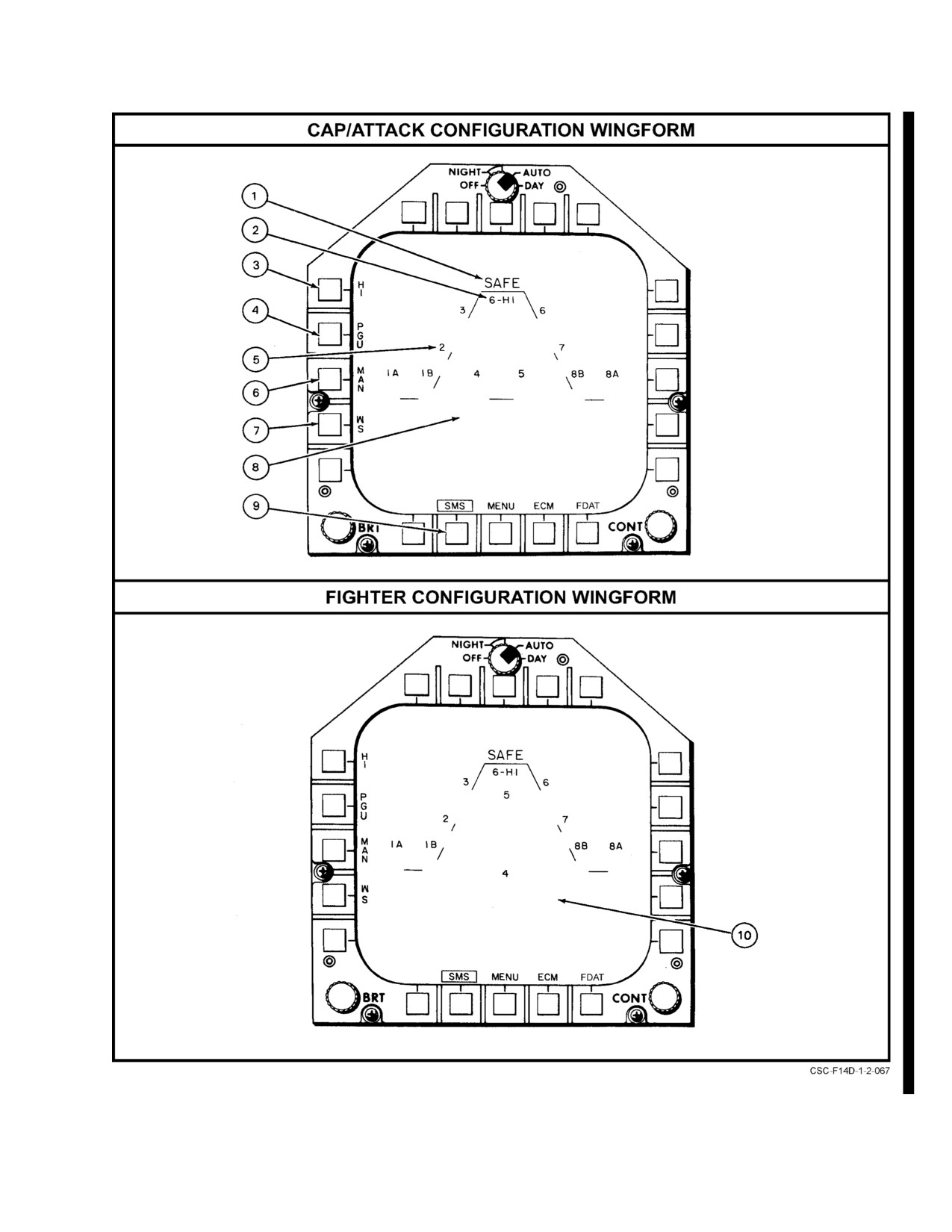
NAVAIR 01-F14AAD-1
Figure 2-120. MFD SMS Format—CAP/Attack, Fighter Wingforms (Sheet 1 of 2)
2-243
CHANGE 1
NAVAIR 01−F14AAD−1
SYMBOL
FUNCTION
1
ARM/SAFE status
SAFE or ARM is displayed to indicate the status of the master arm switch.
indicator
2
Rounds remaining
Rounds remaining is indicated in hundreds (6, 5, 4, 3, 2, 1 and 0) by a
single digit. An X will appear when the gun is empty. HI or LO indicates the
selected fire rate.
3
HI/LO gun rate pushbutton
Toggles the HI or LO rate of gun fire. HI rate is default mode.
4
PGU/M56
Toggles the PGU or M56 round.
5
Store station numbers
Indicates the location of the stores (weapons and fuel tanks) loaded on the
(1A, 1B, 2, 3, 4, 5, 6, 7,
aircraft.
8A, and 8B)
6
Manual (MAN) gun
Selects the manual option during air−to−ground operations. CCIP mode is
mode pushbutton
the primary gun mode and is obtained immediately upon gun selection.
(A/G only)
A box will appear around the pushbutton legend to indicate the manual
option has been selected. Refer to the Supplemental NATOPS Flight
Manual, NAVAIR 01 −F14AAD−1A.
7
Missile status (MS)
Selects the missile status display.
pushbutton
8
CAP/attack wingform
Wingform provides a plan view of the stores carried on an aircraft
configured for the CAP/attack role.
9
SMS pushbutton
Box around the SMS pushbutton legend indicates the SMS display is
selected. Once selected, a subsequent depression of the SMS pushbutton
will enable return to the previous display.
10
Fighter wingform
Wingform provides a plan view of the stores carried on an aircraft
configured for the fighter role.
Figure 2−120. MFD SMS FormatĊCAP/Attack, Fighter Wingforms (Sheet 2 of 2)
ORIGINAL
2−244
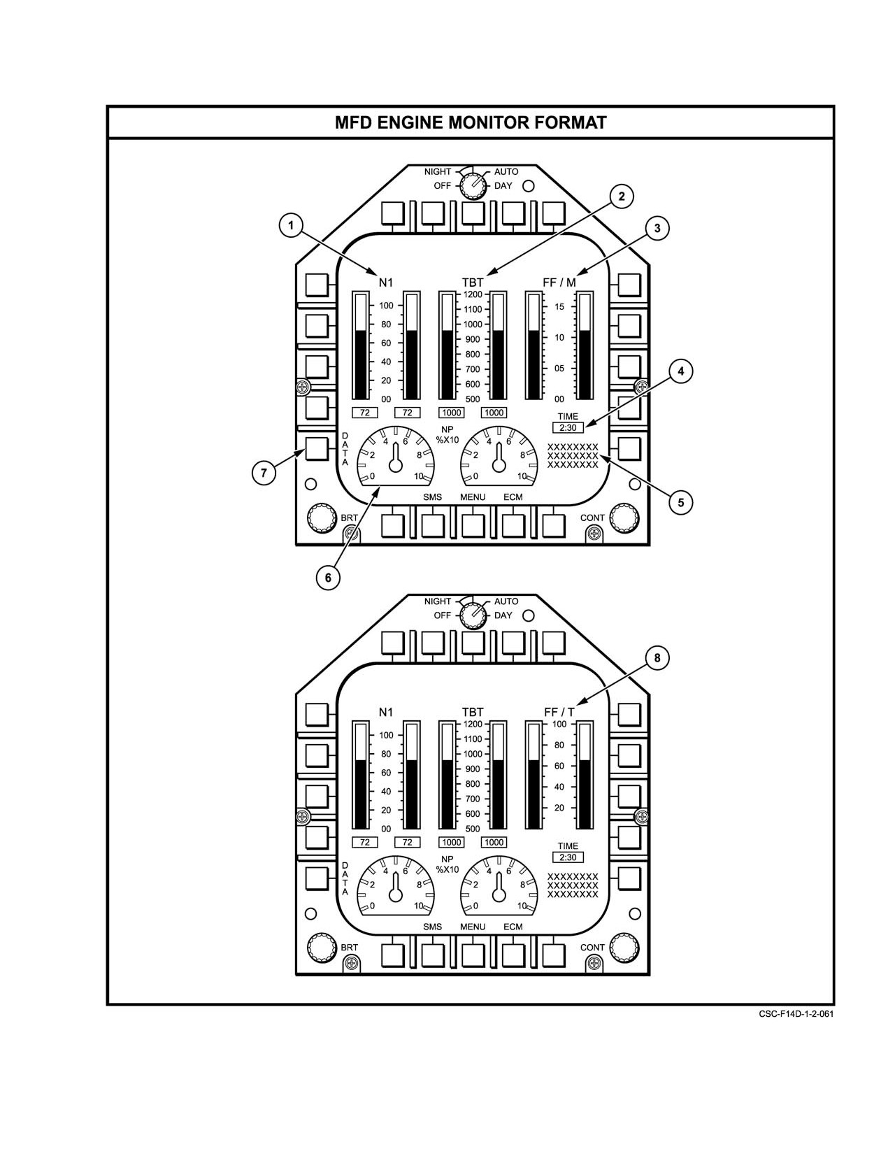
NAVAIR 01−F14AAD−1
Figure 2Ć121.ĄMFD Engine Monitor Format (Sheet 1 of 2)
2−245
ORIGINAL
NAVAIR 01−F14AAD−1
SYMBOL
FUNCTION
1
Rotor speed
Left and right rotor speeds (N1) are displayed both in an analog and digital
format in percent RPM. The digital indications are located immediately
below the corresponding analog scale.
2
Turbine blade temperature
Left and right engine turbine blade temperature (TBT) are displayed both
in an analog and digital format. The analog scale ranges from 500 to
1200 degrees Fahrenheit. The digital indications are located immediately
below the corresponding analog scale.
3
Main fuel flow
Left and right main fuel flow (FF/M) are displayed in an analog format in
thousands of pounds per hour (PPH). The analog scale ranges from 0 to
17,000 PPH.
4
Fuel endurance
Readout provides an indication of the flight time remaining in hours and
minutes. The readout is based on the existing fuel supply for the selected
engine condition (normal or afterburner).
5
Engine exceedance
Up to three engine exceedance conditions are capable of being displayed
conditions
at a time. The indications will scroll upward at a rate of 1 per second when
more than three exceedance conditions exist. The indications may be:
L/R MACH #, L/R LO THR, L/R A/ICE, L/R OIL LO, or L/R AUG.
6
Nozzle position
Left and right engine nozzle positions (NP) are displayed in an analog forĆ
mat between 0 and 100 percent to indicate relative position from fully
closed to fully open, respectively.
7
Data pushbutton
Enables the presentation of the OWN A/C DATA display
8
Total fuel flow
Left and right engine total fuel flow (FF/T) are displayed in an analog
format in thousands of pounds per hour (PPH). The analog scale ranges
from 0 to 100,000 PPH.
Note
D Engine data is not provided while in SEC mode.
D When afterburner is selected, the total fuel flow conĆ
sists of main and augmented fuel. This format illusĆ
trates the afterburner condition where total fuel flow
are displayed.
Figure 2−121. MFD Engine Monitor Format (Sheet 2 of 2)
ORIGINAL
2−246
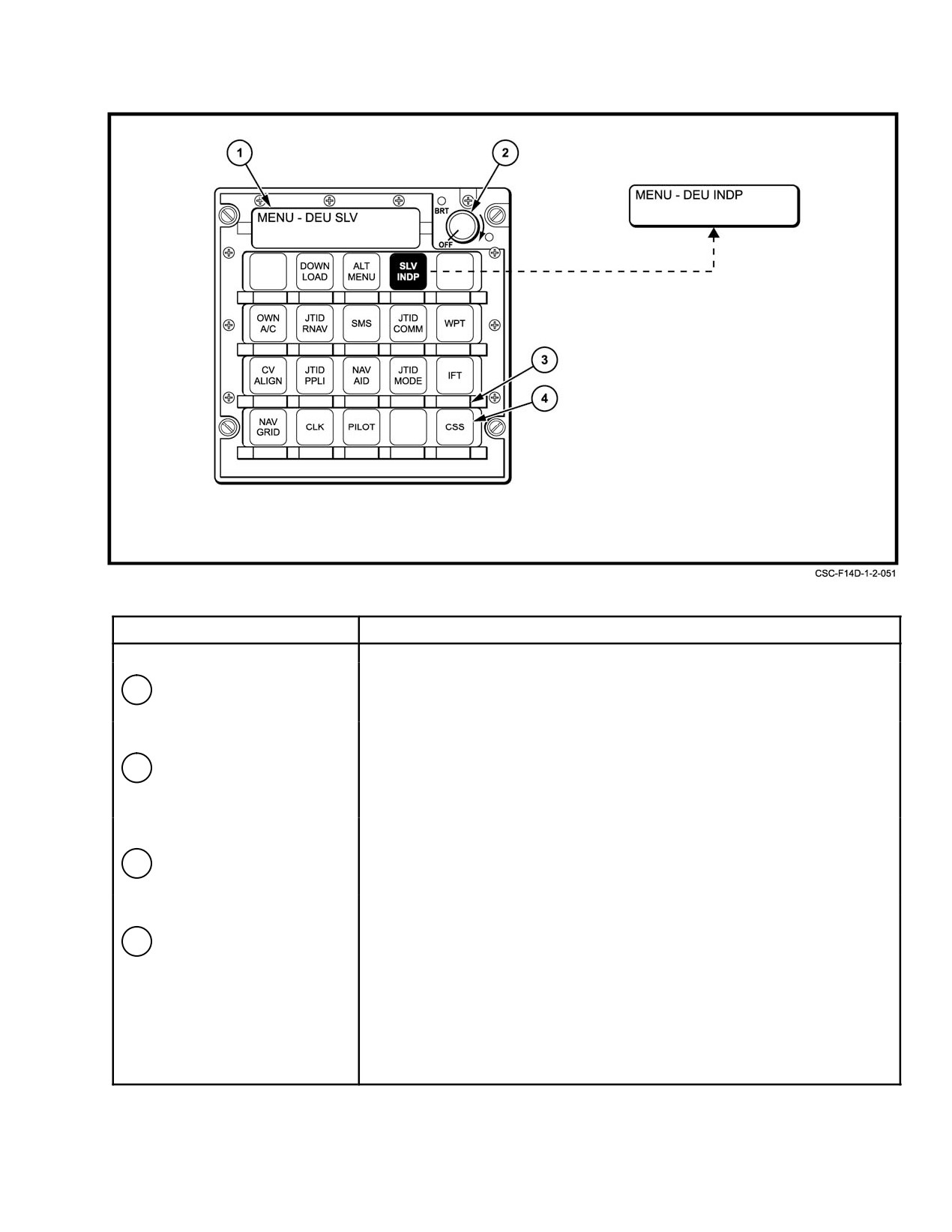
NAVAIR 01−F14AAD−1
NOMENCLATURE
FUNCTION
1
Data Entry Display
Displays the name of the page selected and provides a scratchpad used
to enter and change data as required.
2
DEU control knob
Initial clockwise rotation past the detent turns system power on; continued
rotation increases brightness of the data entry display and option legend
placarding. When depressed, a self−test of the panel is initiated.
3
Option keys (twenty)
Selects the desired menu options and used to enter required mission
data.
4
Option legend
Displays the various menu options for the function or parameter selected.
Option legends vary with page selection.
Figure 2Ć122.ĄData Entry Unit/Main Menu Page
2−247
ORIGINAL
NAVAIR 01−F14AAD−1
independent of MFD3. Initially, when the DEU is powered
2.34.2.2
Subpages
on, it defaults to the slave mode. The slave and independent
The operating characteristics of the subpages are as
modes are toggled by pressing the SLV/INDP option key.
follows: Parameters requiring input often have associated
When operating in the slave mode, the data entry display on
limits and qualifiers. Data entry parameters are shown in
the main menu page reads MENU−DEU SLV (Figure 2Ć122).
Figure 2Ć123. All data input left to right is validated character
When the MFD displays a format to which the DEU is slaved,
by character. This includes the parameter of latitude,
the DEU configures the corresponding page (Figure 2Ć105.
longitude, and time. Data input from right to left is validated
However, when the MFD displays a format to which the DEU
upon depression of the ENT option key. When latitude and
cannot slave, the DEU remains on whatever format it is
longitude are input from left to right, leading zeroes must be
displaying. Operating in the independent mode enables
entered but trailing zeroes for minutes and minute fractions
access to all menu options without being affected by changes
are not required. Keying additional numerics after the
to the MFD3 display. When the MENU option key is pressed,
dedicated character locations are filled will not change the
the main MENU page is displayed with the present DEU
initial keyed−in data. The applicable East, West, North, or
mode displayed on the scratchpad.
South (E, W, N, S) can be keyed in before, during, or after
numerical data entry. The backspace option key (BKSP) is
2.34.2
DEU Menu Pages
used to delete data in the reverse order of entry. The return
The DEU consists of the following menu pages.
option key (RTN) is used to display the next higher level page
in the branch category.
2.34.2.1
Main Menu Page
2.35 FLIGHT INSTRUMENTS
The main menu page (Figure 2Ć122) enables access
to the various subpages. Pressing the desired option key on
2.35.1
Standby Attitude Indicator
the main menu displays the desired subpage. The subpages
are as follows:
A 3−inch standby gyro horizon indicator on the left side
of the pilot instrument panel and another on the left side of
1.
SMS − Stores management system.
the RIO instrument panel are for emergency use should the
2.
OWN A/C − Own aircraft.
system
(INS or SAHRS) attitude information become
unreliable. It is a self−contained, independent gyro that
3.
WPT − Waypoint.
displays aircraft roll and pitch from the horizontal and
4.
CV ALGN − Carrier align.
includes a standard turn−and−slip indicator.
5.
NAV AID − Navigation aid.
The presentation consists of a miniature aircraft
viewed against a rotating gray and black backg0round, which
6.
NAV GRID − Navigation grid.
represent sky and ground conditions, respectively. Caging
7.
JTID RNAV − JTIDS relative navigation.
should be accomplished at least 3 to 4 minutes before takeoff
to allow the spin axis to orient to true vertical. After the gyro
8.
JTID COMM − JTIDS communications.
has erected to vertical, the miniature aircraft reference may
9.
JTID PPLI − JTIDS precise participant location
be raised or lowered +5_, −10_ to compensate for pitch trim
identification.
by turning the adjustment knob in the lower right corner of
the instrument. Electrical power should be applied for at least
10. JTIDS MODE − JTIDS mode.
1 minute before caging. The unit should be caged prior to
11. DOWN LOAD − JTIDS initialization.
engine start during cockpit interior inspection. In flight,
recaging should be initiated only when error exceeds 10_ and
12. IFT − Nonfunctional.
only when the aircraft is in a wings−level normal cruise
13. PLOT − Plot.
attitude. Errors of less than 10_ will automatically erect out
at a rate of 2.5_ per minute.
14. CSS − Cooperative support software.
Electrical power is supplied by the essential ac buses.
15. SLV/INDP − Slave/independent.
An OFF flag appears on the right side of the instrument face
when power is removed or when the gyro is caged, but the
16. ALT MENU − When available.
gyro is capable of providing reliable attitude information
(within 9_) for up to 3 minutes after a complete loss of power.
17. CLK ć Clock control.
The gyro can be manually caged by pulling the pitch trim
knob on the lower right corner of the instrument. Depressing
TEST centers the ARA−63 needles and the turn−and−slip
pointer deflects to the right and lines up with the fixed
marker.
ORIGINAL
2−248
NAVAIR 01−F14AAD−1
VARIABLE
INPUT NAME
UNITS
LIMITS
SIGN
FIELD/PROMPT
DIR OF ENTRY
ALTITUDE
FT
−5000 to
±(1)
QXXXXXX
(2) RT to LT
+131071
(5)
Baro pressure
IN HG
25 to 35
NONE
XX.XX
RT to LT
Bearing
DEG
1 to 360
NONE
XXX
RT to LT
Channel number
0 to 127
NONE
XX
RT to LT
Coverage
DEG
0 to 180
NONE
XXX
RT to LT
Direction
DEG
1 to 360
NONE
XXX
RT to LT
Heading
DEG
1 to 360
NONE
XXX
RT to LT
Latitude
DEG, MIN
−90 to +90
S, N (3)
QbXXbXX.XX
(4) LT to RT
Longitude
DEG, MIN
−180 to +180
W, E (3)
QbXXXbXX.XX
(5) LT to RT
Magnetic variation
DEG
−180 to +180
W, E (3)
XXX.XbQ
RT to LT
lFT number
0 to 31
NONE
XX
RT to LT
Waypoint number
1 to 750
NONE
XX
RT to LT
Weapon option
0 to 6
NONE
X
RT to LT
Range
NM
0 to 500
NONE
XXX.X
RT to LT
Sector
1 to 6
NONE
X
RT to LT
Carrier speed
KNOTS
0 to 64
NONE
XX
RT to LT
IFT TGT speed
KNOTS
0 to 2047
NONE
XXXX
RT to LT
Wind speed
KNOTS
0 to 200
NONE
XXX
RT to LT
Time
HRS
0 to 23
NONE
XXXXbXX
(4) LT to RT
MIN, SEC
0 to 59
(5)
Vertical lever arm
FT
to 128
NONE
XXX
RT to LT
Map lines
to 99
NONE
XX
RT to LT
Map offset
FT
±131071
± (1)
QXXXXXX
RT to LT
Target length
NM
0−2048
NONE
XXXX.X
RT to LT
Command course
DEG
1−360
NONE
XXX
RT to LT
Notes:
(1) If a sign is not input, the number is assumed positive.
(2) Prompt underscores disappear as numerics are input. Pressing ‘BKSP’ will delete a keyed−in numeric
and the underscore will reappear. Continued backspacing will delete inputs in the reverse order in
which they were input. If the prompt is a single underscore, it disappears upon the first keyed entry.
When backspacing, it will reappear when the first keyed entry has been deleted.
(3) Qualifiers ‘S’, ‘N’, ‘E’, ‘W’, ‘+’ and ‘−’ can be keyed in before, after or during keying of numeric data.
‘BKSP’ will not delete these symbols; however, they can be overwritten. The last keyed symbol
will be implemented. Depression of ‘CLR’ will also reset the total scratchpad.
(4) Trailing zeroes for minutes and seconds will be assumed if not entered from keypad.
(5)
‘b’ implies blank or space; ‘Q’ implies qualifier (S, N, E, W, +, −).
Figure 2Ć123.ĄData Entry Parameters
2−249
ORIGINAL
NAVAIR 01-F14AAD-1
2.35.1.1
Turn-and-Slip Indicator
Reliable system operation in the altitude range of 0 to
5,000 feet permits close altitude control at minimum altitudes.
The standby attitude indicator includes a standard
The system will operate normally in bank angles up to 45_
needle and ball turn-and-slip indicator. The pointer is tested
and in a climb or dive except when the reflected signal is too
when the TEST button is pressed and it deflects to the right
weak.
and lines up with the fixed marker.
The system includes a height indicator (altimeter), a test
2.35.2
Standby Airspeed Indicator
light on the indicator, a low-altitude warning tone, a radar
The standby airspeed indicator on the pilot and RIO
receiver-transmitter under the forward cockpit, and two
instrument panels is a pitot-static instrument that displays
antennas (transmit and receive) one on each side of the IR
indicated airspeed from 0 to 800 knots. The indicator is
fairing, in the aircraft skin. During descent, the warning tone
graduated in 10-knot increments up to 200 knots, then in
is heard momentarily (landing gear handle down) when the
50-knot increments.
aircraft passes through the altitude set on the limit index. If
the landing gear handle is up, the tone will remain on
Note
continuously until the landing gear handle is placed down or
The indicated airspeed displayed is not corrected
aircraft altitude rises above the limit index setting. When the
for position error.
aircraft isbelowthe altitude indexlimit setting,a nightvision
compatible post light will illuminate with a yellow radiance.
2.35.3
Standby Altimeter
The post light is located just below the height indicator, on
Both the pilot and RIO standby altimeters display
the forward instrument panel.
altitude up to 99,000 feet on the five-digit counter but only
Note
the left two digits are moveable. The pointer moves about a
dial calibrated from 0 to 1,000 feet in 50-foot increments.
D Radar altimeter can read as much as 100 feet
A BARO setting knob, on the bottom left, is used to set
higher than actual altitude when operating
over water.
in the local atmosphere pressure (INCHES HG) between
28.10 to 30.99 inclusive. The four-digit counter displays the
D The low altitude warning light is an anvis
BARO setting. The BARO setting from the pilot standby
green grimes light mounted on a bracket
altimeter is provided to the mission computers via the
below the RADALT.
converter interface unit and can be displayed on the HUD and
the MFDs.
The radar altimeter receives power from the ac essential
bus No. 1 through the RADAR ALTM circuit breaker (4B3)
2.35.4
AN/APN-194(V) Radar Altimeter System
and from dc essential bus No. 1 through the ALT LOW WARN
circuit breaker (7B6). The radar altimeter has a minimum
The radar altimeter is a low-altitude (0 to 5,000 feet),
warmup time of 3 minutes. During this time, failure indica-
pulsed, range-tracking radar that measures the surface or
terrain clearance below the aircraft. Altitude information is
tions and erroneous readouts should be disregarded.
developed by radiating a short-duration radio frequency pulse
from the transmit antenna to the Earth’s surface and
2.35.4.1
Radar Altimeter
measuring elapsed time until radio frequency energy returns
The radar altimeter (FO-12) on the pilot instrument
through the receiver antenna. The altitude information is
panel has the only controls for the system. The indicator
continuously presented to the pilot, in feet of altitude, on an
displays radar altitude above the Earth’s surface on a
indicator dial. The system also outputs a digital signal for
single-turn dial that is calibrated from 0 to 5,000 feet in
display of radar altitude on the HUD from 0 to 5,000 feet
decreasing scale to provide greater definition at lower
during takeoff and landings.
altitudes. The control knob in the lower right corner of the
indicator is a combination power switch, self-test switch, and
The radar altimeter has two modes of operation. In the
search mode, the system successively examines increments
positioning control for the low-altitude limit bug.
of range until the complete altitude range is searched for a
return signal. When a return signal is detected, the system
2.35.4.2
Altimeter BIT
switches to the track mode and tracks the return signal to
Depressing and holding the control knob energizes the
provide continuous altitude information.
self-test circuitry; the green test light illuminates, the
When the radar altimeter drops out of the track mode,
indicator reads 100
10 feet, and the HUD altitude scale
an OFF flag appears and the pointer is hidden by a mask. The
reads approximately 100 feet. If the indicator passes below
altimeterremainsinoperativeuntila returnsignal isreceived,
the altimeter limit bug setting, the aural and visual warnings
at which time the altimeter will again indicate actual altitude
are triggered. Normal operation is resumed by releasing the
above terrain.
control knob.
CHANGE 1
2-250
NAVAIR 01-F14AAD-1
2.35.4.3
Low-Altitude Aural Warning
with the landing gear handle down and the switch in
ORIDE/ON. With weight on wheels, the position OFF/OFF
A low-altitude aural warning alarm provides a
and AUTO/OFF deactivate the probe heating element.
1,000-Hz tone, modulated at two pulses per second and is
available to both crewmembers. The tone activates for 3 to
2.36.1
AOA Test
5 seconds when aircraft altitude descends below the limit
index setting, with the landing gear handle in the DOWN
A safety of flight check of the AOA indicator and other
position. If the landing gear handle is in the UP position, the
aircraft instrumentscanbeperformedwhileinflightoronthe
tone will remain on continuously.
deck. When INST is selected on the pilot’s MASTER TEST
switch, the reference bar on the AOA indicator should
2.35.5
Vertical Velocity Indicator
indicate 18.0
0.5 units. A check of the index can be made
by selecting LTS on the MASTER TEST switch.
The vertical velocity indicator on the left side of the
pilot and RIO instrument panel is a sealed case connected to
2.36.2
AOA Indicator
a static pressure line through a calibrated leak. It indicates
rate ofclimb ordescent. Suddenor abrupt changes inattitude
This indicator
(Figure 2-125) displays the aircraft
may cause erroneous indications because of the sudden
AOA and provides a stall warning reference marker, a climb
change of airflow over the static probe.
bug, cruise bug, and an AOA approach reference bar for
landing approach.
2.35.6
Standby Compass
AOA is displayed by a vertical tape on a calibrated
scale from 0 to 30 units, equivalent to a range of -10_ to +40_
A conventional standby compass is above the pilot
of rotation of the probe. The approach reference bar is
instrument panel. It is a semifloat-type compass suspended
provided for approach (on speed) AOA at 15 units. The AOA
in compass fluid.
indexer and approach lights will automatically follow the
indicator.
2.35.7
Clock
The climb reference marker is set at 5.0 units, the cruise
A mechanical 8-day clock ison the instrument panel in
marker at 8.5 units, and the stall warning marker at 29 units.
each cockpit. It incorporates a 1-hour elapsed-time capabil-
These reference markers are preset to the optimum AOA
ity. A winding and setting selector is in the lower left corner
values and cannot be changed by the pilot.
of the instrument face. The knob is turned in a clockwise
direction to wind the clock and pulled out to set the hour and
2.36.3
AOA Indexer
minute hands. An elapsed time selector in the upper right
The AOA indexer on the pilot glareshield
corner controls the elapsed time mechanism. This mecha-
(Figure 2-125) has two arrows and a circle illuminated by
nism starts, stops, and resets the sweep second and elapsed
colored lamps to provide approach information. The relay-
time hands.
operated contacts in the AOA indicator also control the AOA
indexer. The upper arrow is for high AOA (green), the lower
2.36 ANGLE-OF-ATTACK SYSTEM
arrow is for low AOA (red), and the circle is for optimum
The AOA system measures the angle between the
AOA (amber). When both an arrow and a circle appear, an
longitudinal axis of the aircraft and the relative wind. This is
intermediate position is indicated.
used for approach monitoring and to warn of an approaching
2.36.3.1
Indexer Lights
stall. Optimum approach AOA is not affected by gross
weight, bank angle, density altitude, or load configuration
The indexer lights function only when the landing gear
(see Figure 2-124 for AOA conversions).
handle is down. A flasher unit causes the indexer lights to
pulsate when the arresting hook is up and the HOOK
The system includes a probe-type transmitter,
BY-PASS switch is in CARRIER. The intensity of the
approach lights, an indicator, and an indexer. The indexer and
indexer lights is controlled by the INDEXER thumbwheel
approach lights are controlled by the indicator, which is
control on the pilot MASTER LIGHT panel.
electrically slaved to the sensor probe transmitter. In flight,
the probe, which is on the left side of the fuselage, aligns itself
2.36.4
Approach Lights
with the relative airflow like a weather vane.
The approach lights consist of red, amber, and green
Probe anti-icing is provided by means of a 115-Vac
indicator lights above the nosegear strut. The lights are
heating element along the probe and probe housing. The
actuated by the AOA indicator and provide qualitative AOA
heating element is controlled by the ANTI-ICE switch on the
information to the landing signal officer during landing
pilot right console. During ground operation, probe heat is on
approaches. A flasher unit in the AOA system will cause
2-251
CHANGE 1
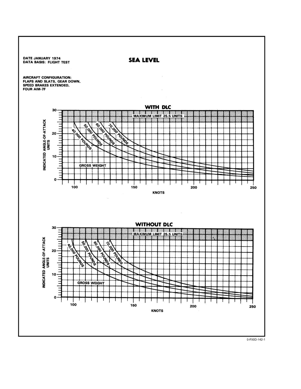
NAVAIR 01−F14AAD−1
Figure 2Ć124.ĄAngle−of−Attack Conversion (Sheet 1 of 2)
ORIGINAL
2−252
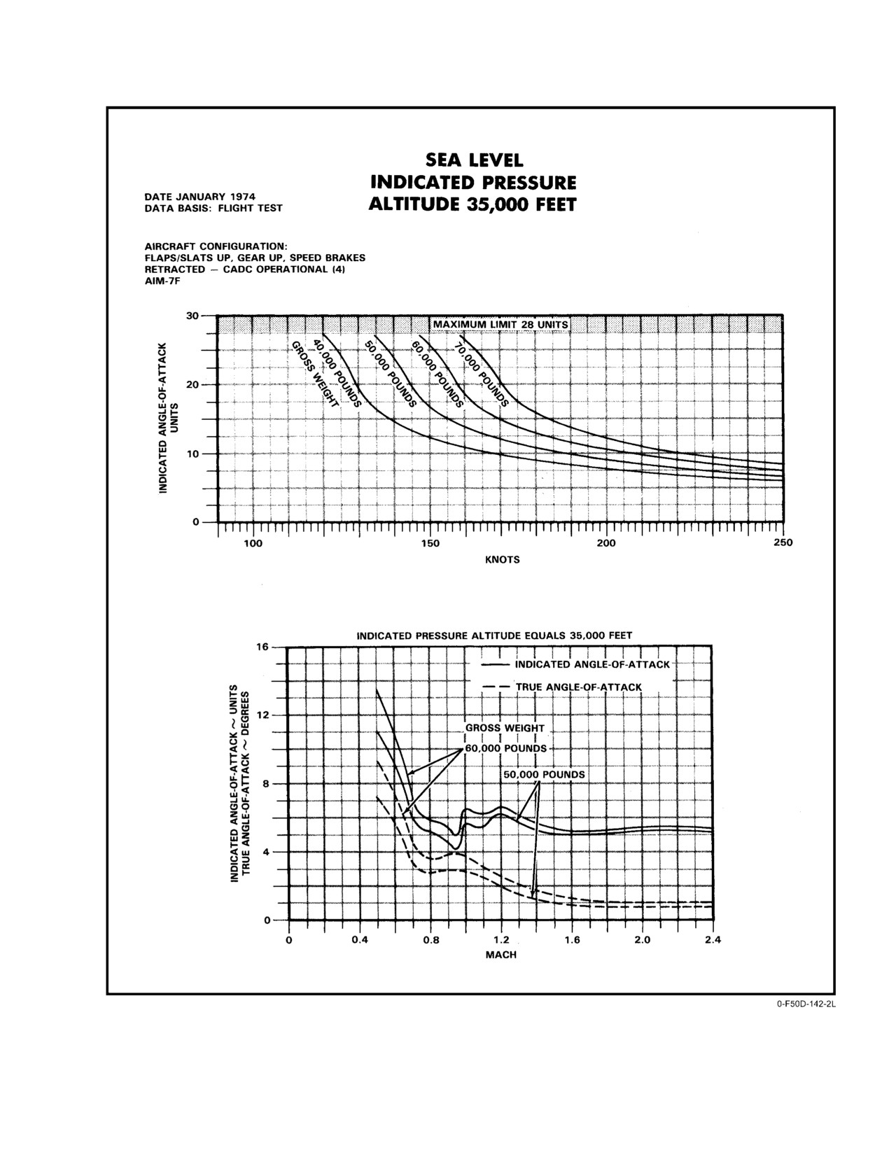
NAVAIR 01−F14AAD−1
Figure 2−124. Angle−of−Attack Conversion (Sheet 2 of 2)
2−253
ORIGINAL
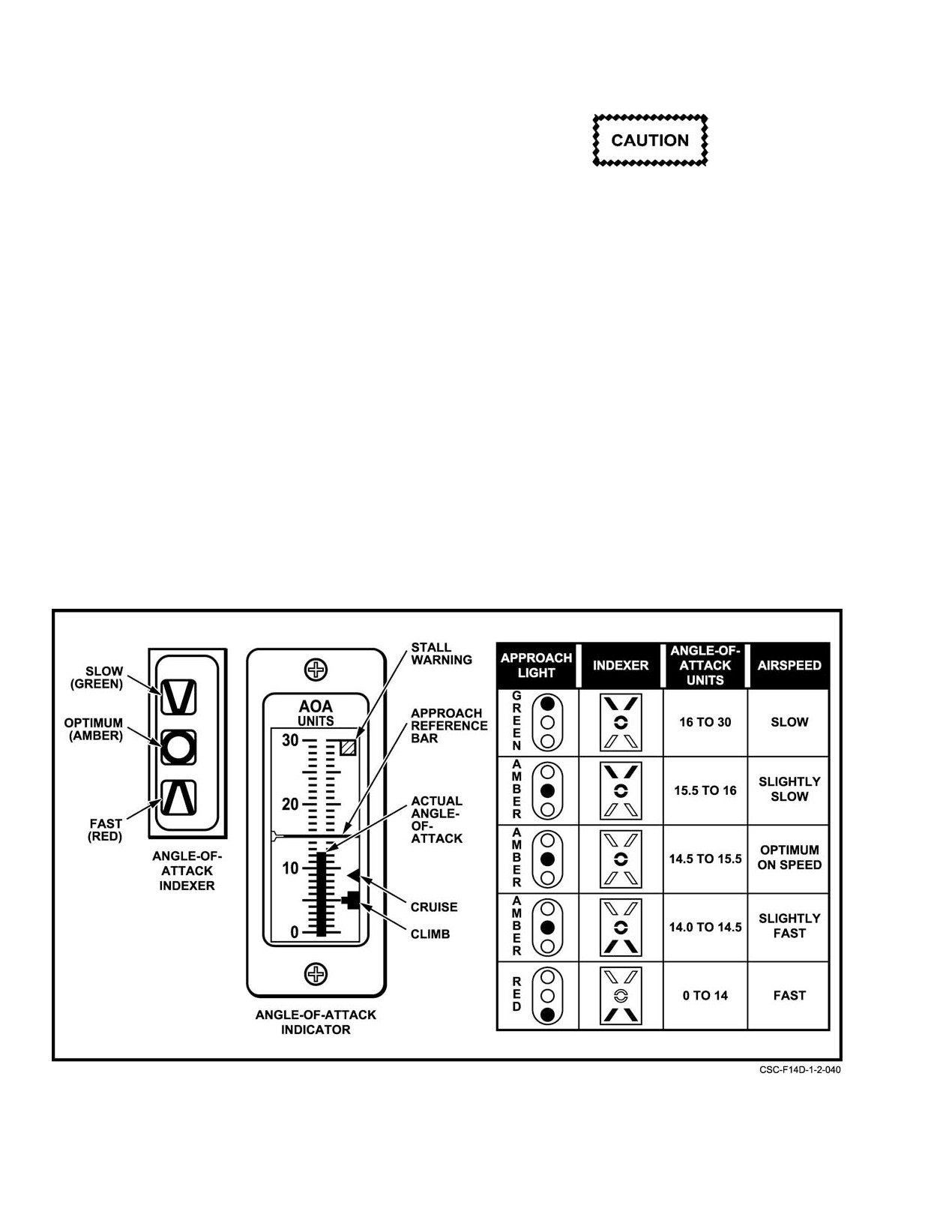
NAVAIR 01−F14AAD−1
the approach lights to pulsate when the arresting hook is up
with the landing gear down and the HOOK BY−PASS switch
is in the CARRIER position. When the FIELD position of the
HOOK BY−PASS switch is selected, the flasher unit is
disabled.
The maximum permitted taxi speed and headĆ
wind component with the canopy open is
A green approach light indicates a high AOA, slow
60 knots.
airspeed; an amber light indicates optimum AOA; and a red
approach light indicates a low AOA, fast airspeed.
Note
An occasional howl inside the canopy may occur
2.37 CANOPY SYSTEM
in some aircraft when subjected to an approxiĆ
mate 4g maneuver. The howl has been attributed
The cockpit is enclosed by a one−piece, clamshell,
to the canopy rain seals; when they are removed
rear−hinged canopy. Provisions are included to protect the
the howl disappears. A canopy howl in aircraft
pilot and RIO from lightning strikes by the installation of
with rain seals installed does not limit aircraft
aluminum tape on the canopy above the heads of the crew.
operation.
Normal opening and closing of the canopy is by a pneumatic
and hydraulic actuator with a separate pneumatic actuator
The canopy system is controlled with the canopy
for locking and unlocking. The canopy can be opened to
control handle under the right forward canopy sill at each crew
approximately 25_ for ingress and egress in approximately
position. An external canopy control handle is on the left side
8 to 10 seconds. In emergencies, the canopy can be jetti−
of the fuselage directly below the boarding ladder. A
soned from either crew position or externally from either
CANOPY caution light on the RIO CAUTION ADVISORY
side of the forward fuselage. For rescue procedures, see
panel illuminates when the canopy is not locked. A LAD/
paragraph 12.1.6.
CNPY caution light on the pilot CAUTION ADVISORY
panel illuminates when the canopy is not locked or the ladder
is not stowed. Electrical power for the caution lights
is supplied from the essential dc bus No. 2, through the
Figure 2Ć125.ĄAngle−of−Attack Displays
ORIGINAL
2−254
NAVAIR 01−F14AAD−1
CAN/LAD/CAUTION/EJECT CMD IND circuit breaker
(8C5). A 1−inch by 2−inch white stripe is painted on the
canopy frame and sill above the canopy control handle panel.
Alignment of this stripe provides an additional visual guide
Flightcrews shall ensure that hands and foreign
that the canopy is in a closed−and−locked position.
objects are clear of front cockpit handholds, top
Pneumatic pressure for normal canopy operation is
and sides of ejection seat headboxes, and canopy
stored in a high−pressure, dry−nitrogen reservoir. Servicing is
sills to prevent personal injury and/or structural
accomplished externally through the nose wheelwell. NorĆ
damage during canopy opening or closing
mal pressure should be serviced to 3,000 psi. A pressure
sequence. Foreign objects can catch ejection sysĆ
gauge in the nose wheelwell should be checked during
tem initiators on the right aft side of the ejection
preflight. A fully charged nitrogen bottle provides approxiĆ
seat headboxes causing inadvertent ejection even
mately 10 complete cycles (open and close) of the canopy
with seat locking handles safe. Only minimum
before the system is reduced to a minimum operating
clearance is afforded when canopy is transiting
pressure of 225 psi. If pneumatic pressure drops below 225
fore or aft.
psi, the canopy control module automatically prevents
2.37.1.2.1
Open
further depletion of the main reservoir and the canopy must
be opened by the auxiliary mode.
When OPEN is selected, nitrogen is ported to the
locking actuator through the control module and the canopy
2.37.1
Canopy Operation
is moved aft disengaging the canopy hooks from the sill
hooks. Pneumatic pressure is then ported to the canopy
2.37.1.1
External Canopy Controls
actuator to raise the canopy.
Access to the external canopy control is obtained
2.37.1.2.2
Hold
through an access door on the left fuselage directly below the
Selection of CANOPY HOLD during transition of the
boarding ladder. Pulling the handle out and rotating it
canopy stops the canopy in any intermediate position
counterclockwise to NORM CL closes the canopy. Rotating
between closed and open by pressurizing the lock valves in
further counterclockwise to the BOOST close position will
the canopy actuator. These lock valves stop the transfer of
allow the canopy to be closed under a high headwind or cold
pneumatic pressure.
weather conditions. If BOOST is used to close the canopy, the
handle should be returned to NORM CL. Rotating it
With the canopy in any intermediate
(CANOPY
clockwise to NORM OPEN opens the canopy under normal
HOLD) position, moving the handle slowly toward OPEN
operating conditions and rotating it further to AUX OPEN
will allow the canopy to begin to close until the handle is
allows the canopy to be opened manually.
finally in OPEN. This occurs because the first motion of the
handle moves the selector valve cam, which vents pressure
Note
from the lock valves and allows the canopy weight to transfer
pneumatic pressure. Once the selector valve cam is comĆ
NORM OPEN is not detented; therefore, do not
pletely moved to OPEN, pressure is then applied to the open
rotate the handle further clockwise unless the
side of the canopy actuator.
AUX OPEN position is desired. Using AUX
OPEN unnecessarily will deplete the auxiliary
uplock nitrogen bottle.
2.37.1.2
Cockpit Canopy Controls
If the canopy handle is left in an intermediate
position for an extended period, the canopy will
The canopy pneumatic and hydraulic system is operĆ
slowly close.
ated by actuation of either of the cockpit control handles
(Figure 2Ć126), or the external control handle, which posiĆ
2.37.1.2.3
Close
tions valves within the pneumatic control module to open or
close the canopy. The canopy pneumatic and pyrotechnic
Selecting CLOSE allows the canopy to close under
systems are shown on FO−15. Modes of operation available
normal conditions (30−knot headwind) using its own weight
are: OPEN, AUX OPEN, HOLD, CLOSE, and BOOST.
without an expenditure of stored nitrogen. When the control
2−255
ORIGINAL
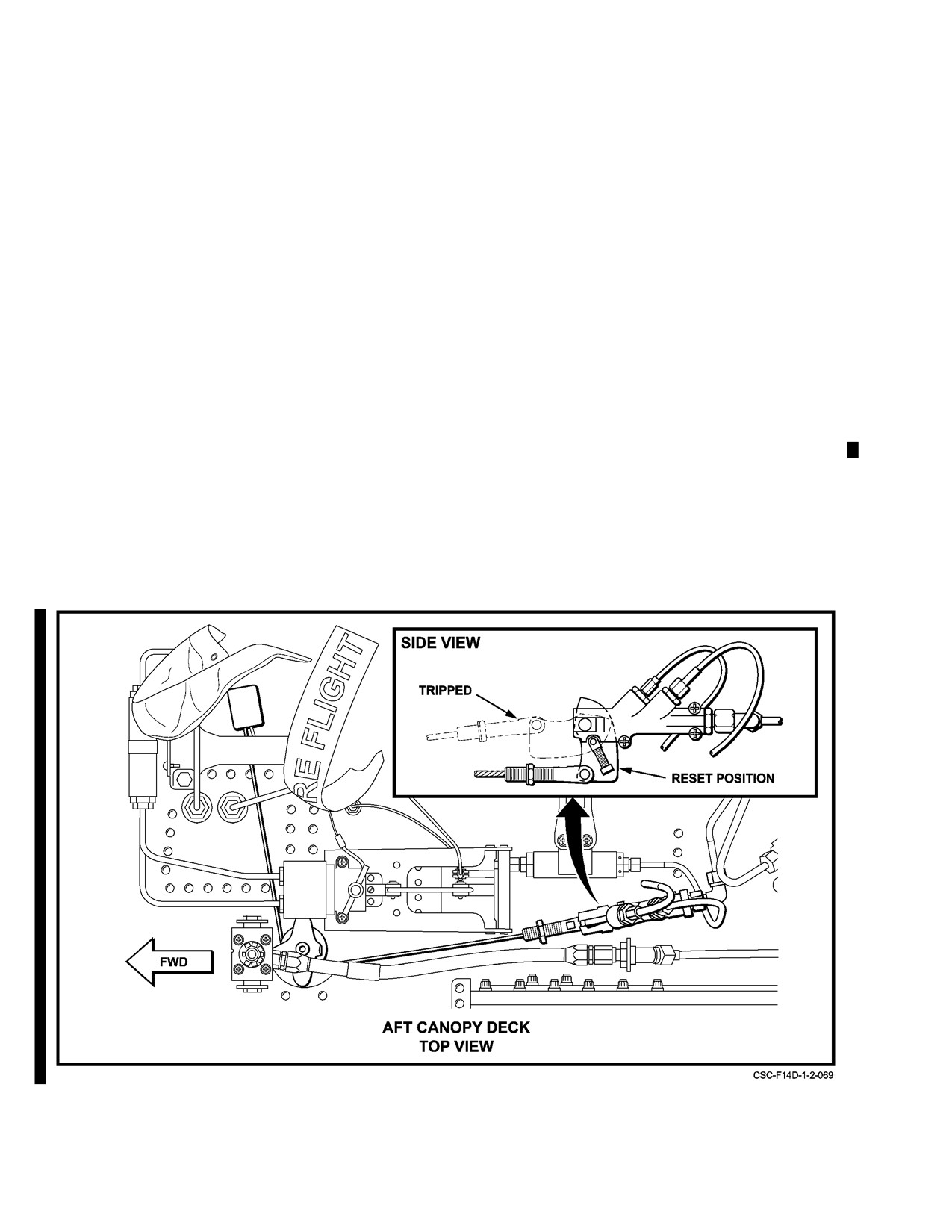
NAVAIR 01-F14AAD-1
handle is set to CLOSE, both sides of the canopy actuator are
mode, the canopy control handle in the cockpit must be
vented to the atmosphere, allowing the canopy to lower itself.
rotated outboard to move the handle past the OPEN stop and
The final closing motion actuates a pneumatic timer which
then pulled aft to AUX OPEN. This activates a pneumatic
directs pressure from the control module to the locking
valve, which admits regulated pneumatic pressure from an
actuator and the canopy is moved forward to engage the
auxiliary nitrogen bottle to the locking actuator and moves
canopy hooks in the sill hooks.
the canopy aft out of the sill locks. When the canopy is
unlocked, pneumatic pressure from the main reservoir is
To close the canopy under high headwind conditions
ported to the open side of the canopy actuator to counterbal-
(30 to 60 knots) or when difficulty is experienced because of
ance the weight of the canopy, allowing the canopy to be
hot or cold temperatures, BOOST is used. The BOOST mode
manually opened or closed by the flightcrew.
is activated by rotating the canopy control handle outboard
Before leaving the cockpit, the control handle should
past the CLOSE stop and pushing the handle forward. With
be returned to HOLD. If left in AUX OPEN, the canopy’s
the control handle in this position, the control module ports
own weight or a tailwind could force the canopy down
additional regulated pneumatic pressure to the closed side of
with low pressure in the main reservoir. Once the auxiliary
the canopy actuator. If BOOST is used to close the canopy,
canopy unlock bottle is used, the canopy will not return to
the handle should be returned to CLOSE.
the normal mode of operation and cannot be locked closed
until the auxiliarypneumatic selectorvalve onthe aft canopy
2.37.1.3
Auxiliary Canopy Opening
deck is manually reset (lever in vertical position). (See
Figure 2-125A.)
When the main pneumatic reservoir pressure is
reduced to 225 psi, the canopy control module automatically
The auxiliary canopy unlock nitrogen bottle is on the
prevents further depletion of reservoir pressure and the
turtleback behind the canopy hinge line (refer to FO-15).
canopy must be opened using the auxiliary mode. Actuation
Servicing of the auxiliary bottle is through the small access
of the auxiliary mode can be affected from either the pilot or
panel immediately behind the canopy on this turtleback. A
RIO canopy control handle or from the ground external
fully charged bottle will provide approximately 20 canopy
canopy control. To open the canopy from the cockpit in this
cycling operations in the auxiliary open mode.
Figure 2-125A. Auxiliary Pneumatic Selector Valve Reset
CHANGE 1
2-256
NAVAIR 01-F14AAD-1
2.37.1.4
Canopy Jettison
appropriately marked for rescue. Opening either access door
and pulling the T-handle fires an initiator that detonates the
The canopy can be jettisoned from either cockpit
canopy separation charge and actuates the canopy gas
or from external controls on each side of the fuselage.
generator. The sequence is the same as when the cockpit
An internal canopy jettison handle in each cockpit
handles are pulled. The external canopy jettison handles
(Figure 2-126) is on the forward right side of each flightcrew
require squeezing the inner face of the handle and then
instrument panel and is painted yellow and black for ease of
pulling for actuation. The length of pull is approximately
identification. To activate the canopy jettison handle,
one-half to three-quarter inch and the T-handle comes free on
squeeze the inner face of the handle and then pull.
the aircraft when actuated. Refer to Chapter 12 for canopy
The length of pull is approximately one-half to
external jettisoning procedures.
three-quarter inch, and the handle comes free of the aircraft
when actuated. Pulling either CANOPY JETTISON handle
2.38 EJECTION SYSTEM
actuates aninitiator that ignites the canopy separationcharge
The aircraft is equipped with an automatic electroni-
and actuates the canopy gas generator. The canopy separation
cally sequenced command escape system incorporating two
charge ignites the expanding, shielded, mild-detonating cord
Navy aircrew common ejection seat (SJU-17(V) 3/A (pilot)
lines, routed through the canopy sill hooks, breaking the sill
and SJU-17(V) 4/A (RIO)) rocket-assisted ejection seats.
hook frangible bolt. This allows the hooks to rotate upward,
Both seats are identical in operation and differ only in nozzle
releasing the canopy. The canopy gas generator produces
direction of their lateral thrust motors, which provide a
high-pressure gas that forces the canopy hydraulic actuator
divergent ejection trajectory away from the aircraft path.
shaft upward, ballistically removing the canopy.
When either crewmember initiates the command escape
Ejection through the canopy can result in injury and is
system, the canopy is ballistically jettisoned and each
provided only as a backup method; therefore, the canopy is
crewmember is ejected in a preset-time sequence. The RIO
jettisonedaspartofthenormal ejectionsequence. Anupward
is ejected to the left and the pilot to the right.
pull on the ejection seat firing handle jettisons the canopy
Safe escape is provided for most combinations of
prior to ejection.
aircraft altitude, speed, attitude and flightpath within an
envelope from zero airspeed, zero altitude in a substantially
2.37.1.4.1
External Canopy Jettison Handles
level attitude to a maximum speed of 600 KCAS between
There are two external canopy jettison handles located
on the lower left and right fuselage below the pilot cockpit,
2-256a (Reverse Blank)
CHANGE 1
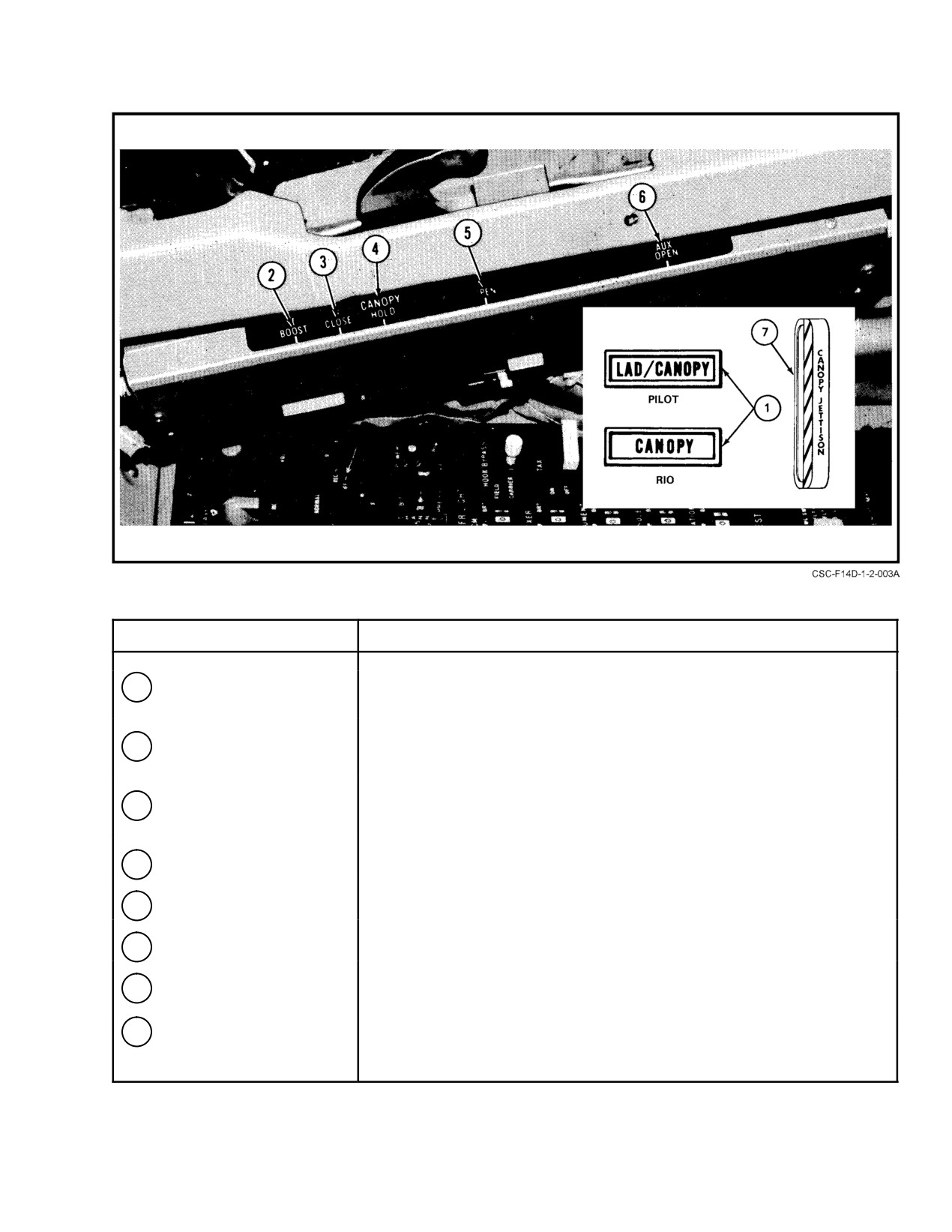
NAVAIR 01−F14AAD−1
NOMENCLATURE
FUNCTION
1
CANOPY caution light
Advises that the canopy is not in a down and locked position.
2
LAD/CANOPY caution
Advises that the boarding ladder is not in the up and locked position or that
light
the canopy is not in the down and locked position.
3
BOOST
Used to close the canopy in cold or hot weather or when headwinds are
greater than 30 to 60 knots.
4
CLOSE
Closes canopy under normal conditions.
5
HOLD
Used to hold canopy in any position other than closed.
6
OPEN
Used to open the canopy under normal conditions.
7
AUX OPEN
Used to open canopy manually, which is required when nitrogen bottle
pressure drops below 225 psi.
8
CANOPY JETTISON
Used to jettison canopy.
handle
Figure 2Ć126.ĄCockpit Canopy Control Handle and Indicator Lights
2−257
ORIGINAL
NAVAIR 01−F14AAD−1
zero altitude and 50,000 feet. Preflight procedures are shown
2.38.1.1
Seat Firing Handle
in Chapter
7 of this manual; ejection procedures are
Ejection is initiated by pulling up on the seat firing
discussed in Chapter 16. Ejection sequence is illustrated in
handle on the front of the seat bucket between the crewmemĆ
FO−16 and FO−17.
ber’s thighs. A pull force of 25 to 40 pounds is required to
remove the firing handle from its housing. A continued pull
force of 30 to 60 pounds is required to initiate ejection. This
action operates linkage that withdraws the sears from the two
seat initiator cartridges, commencing the ejection sequence.
D Regardless of the SJU−17 Ejection Seat limiĆ
tations, any person whose nude body weight
2.38.1.2
SAFE/ARMED Handle
is below 136 pounds or above 213 pounds is
The SAFE/ARMED handle on the right side of the seat
subject to increased injury from ejection.
bucket forward of the manual override handle is the only
D Loose gear in the cockpit is a FOD and missile
control for arming and safing the seat. (On the ground, a
hazard, especially during carrier operations,
safety pin is also installed in the seat firing handle.) The
maneuvering flight, or ejection sequences.
handle locks in the selected position. It is operated by
Carriage of gear that cannot be contained in
releasing a catch to remove the locking plunger. When the
the cockpit storage compartment shall be kept
handle is rotated forward (up) to safe the seat, the SAFE
to a minimum consistent with mission
legend is displayed on a white backg0round and a safety
requirements and the mission environment.
plunger is inserted into the firing handle linkage so that the
handle cannot be pulled up, rendering the seat inoperative.
2.38.1
Ejection Seat
Rotating the handle aft (down) displays the ARMED legend
on a yellow−black striped backg0round. This pulls the safety
The Navy Aircrew Common Ejection Seat (NACES)
plunger from the firing handle linkage, freeing the handle and
(Figure 2Ć127) is provided with a rocket−deployed 6.5 meter
allowing the seat to be fired. With the canopy closed, the
(20−foot), aeroconical, steerable parachute that is packed
SEAT UNARMED caution light in the RIO cockpit is
with a ribbon extraction drogue in a container behind the seat
illuminated if the SAFE/ARMED handle on either seat is in
occupant’s head. The seat bucket holds the survival kit and
the SAFE position.
also has the seat firing handle and other operating controls.
The parachute risers attach to the crewmember’s torso
2.38.1.3
Manual Override Handle
harness by means of seawater−activated release switches.
Normal ejection includes canopy jettison before the seats are
The manual override handle on the right side of seat
catapulted out of the cockpit; however, the parachute
bucket behind the SAFE/ARMED handle is connected by
container is fitted with canopy penetrators. This permits a
linkage to the lower harness lock release mechanism and to
backup ejection through the canopy after a time delay in the
an initiator in the seat bucket. The handle is locked in the
event of safe−and−arm unit failure or failure of the canopy to
down position by a catch operated by a thumb button at the
separate from the aircraft.
forward end of the handle. Depressing the thumb button
allows the handle to be rotated aft. Operating the handle also
After ejection has been initiated, two pitot heads
rotates the SAFE/ARMED handle to the SAFE position. A
mounted next to the parachute container are deployed.
catch in the lower part of the manual release handle must be
Airspeed and altitude are provided to the battery−operated
reset before the handle can be returned to the down position.
electronic sequencer mounted under the parachute container.
With the seat in the aircraft, operation of the handle linkage
The sequencer uses the information to determine the release
is restricted by the pin puller and releases only the lower
time for the drogue bridles, the deployment time for the
locks, and the leg restraint line locks to permit emergency
parachute, and release time for the harness locks. Depending
ground egress with the survival kit attached.
on MSL altitude and airspeed, the seat drogue, which is
catapult−deployed from a canister on the back of the seat and
Note
has a three−point attachment bridle, can be used to stabilize
the seat, slow its descent, or be jettisoned before the
The parachute risers and personnel services must
parachute deployment rocket is fired. To ensure parachute
be disconnected manually.
deployment and man−seat separation, a barostatic release
operates to fire the parachute deployment rocket and release
After ejection, the pin puller disengages permitting
the harness locks in the event of complete or partial
further movement of the linkage so that operating the handle
sequencer failure. As a further backup, operating the manual
releases the lower harness locks and fires the manual override
release handle on the seat bucket will also fire the parachute
initiator that provides gas pressure to release the upper torso
deployment rocket and release the harness locks.
harness locks and fire the parachute deployment rocket in the
event of automatic sequencing failure.
ORIGINAL
2−258
NAVAIR 01−F14AAD−1
Figure 2Ć127.ĄEjection Seat (Sheet 1 of 2)
2−259
ORIGINAL
NAVAIR 01−F14AAD−1
Figure 2−127. Ejection Seat (Sheet 2 of 2)
ORIGINAL
2−260
NAVAIR 01−F14AAD−1
2.38.1.4
Torso Harness
The switch is spring loaded to the center OFF position
RAISE is aft and LOWER is forward. Electric power is
The torso harness is worn by the crewmember and
supplied from phase B of the right main ac bus through the
takes the place of a separate lapbelt and shoulder harness.
ACM LT/SEAT ADJ/STEADY POS LT circuit breaker (2I4).
The upper torso harness is connected by release fittings
(Koch fittings) to the inertial reel via straps passed through
roller yokes attached to the parachute risers. The release
fittings incorporate SEWARS to allow automatic release on
saltwater entry. Two buckles on the lower part of the torso
harness connect to the seat lapbelt fittings. Lapbelt girth can
The seat height actuator motor has a maximum
be adjusted to accommodate the individual crewmember by
duty cycle of 1 minute on in any 8−minute period.
adjusting each belt strap.
2.38.1.9
Survival Kit
2.38.1.5
Harness Lock Control Lever
The survival kit
(Figure 2Ć128) forms the sitting
The harness lock control lever on the left side of the
platform for the crewmember and consists of a fabric survival
seat bucket has two detented positions. In the forward
aids container covered by a contoured, rigid platform with a
(locked) position, forward movement of the occupant is
cushion on top to provide a firm seat and additional comfort
restricted and any slack created by rearward movement is
for the crewmember. The kit is retained in position by pivot
taken up by the inertial reel. The control is locked in this
fittings at the front and lugs attached to the lower harness
position by a detent. In the aft position, the occupant can
locks at the rear. Attached to the lower harness lock lugs are
move forward freely, unless the reel locks owing to excessive
two adjustable harness lap straps with integral lapbelt release
forward velocity. When the forward velocity decreases
fittings.
sufficiently, the inertia straps are released without the
necessity of repositioning the manual control. Both straps
The survival kit accommodates a liferaft, an emerĆ
feed from the same shaft, and it is impossible for one to lock
gency oxygen cylinder, and the survival aids. The emergency
without the other. If the reel is locked manually the control
oxygen cylinder is mounted to the underside of the platform,
must be positioned aft to the unlocked position to release the
a pressure gauge is on the left thigh support, and a green
straps.
manual operating handle is on the left side of the platform.
The emergency oxygen is also automatically activated
2.38.1.6
Leg Restraints
during ejection by a static line connected to the cockpit floor.
The leg garters and restraint cords keep the occupant’s
Note
legs firmly against the leg rests during ejection. The garters
are placed around the leg below the calf and above the knee.
Flow of oxygen from the emergency cylinder can
be stopped by reseating the manual actuation
The leg−restraint cords are attached to the aircraft deck
handle.
and routed through the seat snubber box structure. They are
then passed through garter rings and snapped into the leg−line
A URT−33C radio locator beacon is in a cutout in the
locks. The garter rings are snapped into the bayonet fitting
left thigh support and is connected to the cockpit floor by a
when strapping in. Leg−line release is accomplished by
static operating cable so that it can be automatically actuated
pulling the manual override handle. Leg restraints may be
during ejection. The fabric survival aids container can be
adjusted by pulling the tab on the inner side of each leg−line
deployed on a lowering line after ejection by pulling on either
snubber box.
of the two yellow handles located on the back side. The
liferaft is automatically inflated when the survival aids
2.38.1.7
Negative−G Strap
container is deployed. Contents of the survival aids container
The negative−g strap is not incorporated in the F−14D
may vary depending on the area of operation, but the
NACES ejection seat.
following is a typical list:
2.38.1.8
Seat Height Adjustment Switch
1. Liferaft dye markers
Seat height is adjusted by an actuator driven by a
2. Signal flares
single−phase 115−Vac electric motor. Operation of the actuaĆ
tor is controlled by a three−position switch on the right aft side
3. Morse code and signal card
of the seat bucket marked RAISE, OFF, and LOWER.
4. Space blanket
2−261
ORIGINAL
NAVAIR 01−F14AAD−1
Figure 2Ć128.ĄSurvival Kit
ORIGINAL
2−262
NAVAIR 01-F14AAD-1
5. Desalter kit or canned water
full-aft (MCO) position. Adjusting the handrest
to the full-down position will minimize this
6. 50 feet of nylon cord
interference and should allow normal operation
7. Bailing sponge
of the CMD EJECT lever.
8. SRU-31/P flightcrew survival kit.
2.38.3
Ejection Initiation
If over water, the survival aids container should be
deployed on its lowering line before reaching the surface to
With the SAFE/ARMED handle in the ARMED
make the raft immediately available on landing. If over land,
(down) position, pulling the seat firing handle upward to the
it should not be deployed. This will reduce the risk of
extent of its travel begins the ejection by pulling the sears on
entanglement and protect against injury.
the seat initiators. The following events occur:
1. Canopy jettison is initiated.
2.38.1.10
Rocket Motor
2. The powered inertia reel retracts, pulling the crew-
The rocket motor is on the bottom of the seat bucket.
member back in the seat.
It is ignited by a lanyard attached to the cockpit floor as the
3. The delay initiators are activated. These initiators
catapult nears the end of its stroke. The rocket thrust is
have built-in delays of 1.0 second for the RIO seat
approximately 4,800 pounds for .25 second and sustains the
and 1.5 seconds for the pilot seat.
thrust of the catapult to carry the seat to a sufficient height for
4. The restriction is removed from the manual override
a safe zero/zero ejection from a level attitude. The rocket
mechanism.
motor nozzles are inclined so that the thrust passes close to
the cg of the seat and occupant. The motor also includes a
5. The 4.0-second delay cartridge for the barostatic
release is initiated.
lateral thrust nozzle that imparts a divergent trajectory
carrying the seat away from the aircraft flightpath.
6. The safe and armed device is armed.
When canopy jettison is complete, a lanyard attached
2.38.2
Command Ejection Lever
tothe canopypullsa sear, firingthe safe andarm device. This
A command ejection lever (Figure 2-129) above the
initiates the thermal batteries that power the seat electronic
RIO left outboard console allows the RIO to select either
sequencer and fires the two-stage catapult, ejecting the seat.
pilot or RIO control of the command ejection system. Each
The RIO seat is fired immediately on firing of the safe and
position has an internal locking detent. The handle is
arm device, while the pilot seat is delayed 0.4 second. The
unlocked by lifting upward and moved by a forward or aft
IFF switch is actuated when the pilot seat is fired.
motion. If the handle is released before reaching the aft
position, it is spring loaded to return forward. It will
If the canopy fails to separate or the safe and arm device
automatically lock in the forward position; however a
does not fire, the backup initiators operate at the expiration
of their delays, firing the RIO seat 1.0 second after firing
downward motion is required to positively lock it into the aft
handle actuation and the pilot seat 0.5 second later, through
position. To select MCO command ejection position, raise
the canopy.
the handle and pull aft. An EJECT CMD flip-flop-type
indicator on the landing gear panel indicates the command
As the seat ascends the guide rails, the following events
mode selected. The RIO may eject individually when the
occur:
command ejection lever is in the pilot control position. When
1. The multipurpose initiator lanyards begin to
the command ejection lever is in the MCO command
withdraw.
position, the RIO can initiate ejection of both seats.
2. Personnel services between seat and aircraft are
Regardless of the position of the command ejection lever,
disconnected.
an ejection initiated by the pilot will always eject both
crewmen. Command ejection by either crewmember will
3. The emergency oxygen supply is initiated.
eject the RIO first and the pilot 0.4 second later Depending
4. The emergency locator beacon is activated.
on aircraft dynamics, the total time for command ejection of
5. The leg restraint lines are drawn through the snub-
both seats in the normal (safe and arm device) mode is from
bers and restrain the crewmember’s legs to the front
0.4 to 0.9 second; in the backup initiator mode, the total time
of the seat bucket. When the leg restraint lines
is 1.5 second.
become taut, the break ring in each line fails and the
lines are freed from the aircraft. The snubbers pre-
vent forward movement of the legs.
At the end of the catapult stroke
(approximately
In aircraft with an LCP installed, the controller
35 inches of seat travel), the multipurpose initiator lanyards
handrest may interfere with the CMD EJECT
become taut and withdraw the firing unit sears. This routes
lever, preventing the handle from reaching the
gas pressure to the electronic sequencer start switches,
2-263
CHANGE 1
NAVAIR 01−F14AAD−1
NOMENCLATURE
FUNCTION
1
EJECT CMD lever
PILOT− Ejection initiated by the pilot will eject pilot and RIO (RIO first).
(RIO cockpit)
Ejection initiated by the RIO will eject only the RIO.
Pilot eject command indicator ć pilot.
MCO − Ejection initiated by the pilot will eject pilot and RIO (RIO first).
Ejection initiated by the RIO will eject pilot and RIO (RIO first).
Pilot eject command indicator − MCO.
2
EJECT CMD (flip−flop)
PILOT− Indicates command ejection lever is in PILOT. Only the pilot can
indicator
eject pilot and RIO. RIO−initiated ejection will eject only RIO.
MCO − Indicates command ejection lever is in MCO. Both pilot and RIO
can eject both flightcrew members. RIO will eject first.
Figure 2Ć129.ĄCommand Ejection Lever
ORIGINAL
2−264
NAVAIR 01−F14AAD−1
beginning sequencer timing to the pitot deployment mechaĆ
2.38.4.2
Barostatic Release
nisms and to the rocket motor, firing it. The electronic
To ensure that the parachute is deployed and the
sequencer determines the proper mode of seat operation
harness locks are released, the barostatic release unit,
based on altitude and airspeed.
consisting of a barostat and a cartridge, provides an
independent automatic backup to the electronic sequencer.
2.38.4
Seat Operation After Ejection
The cartridge is fired one of three ways: electrically by the
Post−ejection operation (FO−16 and FO−17) begins at
sequencer at a preset altitude of 18,000 feet (FO−16 and
the end of catapult travel when the rocket motor fires and the
FO−17), mechanically by the barostatic release unit between
start switches actuate. In normal operation, the electronic
14,000 and 16,000 feet; or mechanically by gas pressure from
sequencer selects the operating mode depending on altitude
a 4−second delay cartridge when the manual override handle
and airspeed. A barostatic release unit provides an automatic
is pulled. After the time delay, gas pressure is applied to the
backup for electronic operation. Four seconds after the seat
barostat cartridge firing mechanism. Above the barostat
firing handle is pulled, the barostatic unit is armed permitting
altitude setting, the mechanism is restricted from moving; at
parachute deployment and harness release as determined by
or below the barostat altitude it is free to move and fire the
the barostat setting if the sequencer has not functioned. As a
cartridge if it has not already been fired electrically. When
further backup, the crewmember can manually fire the
fired, the barostat cartridge provides gas pressure to fire the
parachute deployment rocket and release the harness locks by
parachute deployment rocket and operate the harness lock
using the manual override handle.
release.
2.38.4.3
Manual Override
2.38.4.1
Electronic Sequencing
After ejection, the manual override handle provides a
In all modes, following start switch actuation, the pitot
further backup to both the electronic sequencer and the
heads extend, environmental sensing for mode selection
barostatic release. Pulling the handle fires a cartridge that
commences, and the seat drogue is deployed on its three−
provides gas pressure to fire the parachute deployment rocket
point bridle to stabilize and slow the seat. While this is
and operate the harness lock release.
occurring, the sequencer selects one of the five operating
modes (FO−16 and FO−17) from its lookup tables based on
2.39 LIGHTING SYSTEM
sensed altitude and airspeed. The modes are described as
follows:
2.39.1
Exterior Lights
The exterior lights include position lights, formation
1. Mode 1 This is the low−altitude, low−airspeed
lights, anticollision lights, a taxi light, approach lights, and
mode. The bridles are released 0.32 seconds after
an air refueling probe light. All exterior lighting controls,
seat first motion. The parachute deployment rocket
except for the air refueling probe light and approach lights,
fires to deploy the parachute and the harness release
are located on the MASTER LIGHT panel on the pilot right
system operates to free the occupant from the seat.
console. The exterior lights master switch on the outboard
2. Modes 2, 3, and 4 These modes are for low to
throttle must be on for any exterior light to function (except
medium altitudes. The seat is decelerated by the
for approach lights). The pilot light control panel is shown in
Figure 2Ć130. A two−channel flasher unit is used for flashing
drogue and after a time delay determined by the
electronic sequencer, the parachute deployment
lights. One channel flashes the anticollision and position
lights and has circuit protection from the ANTICOLL/SUPP
rocket fires to deploy the parachute before the
drogue bridles are released. The harness release sysĆ
POS/POS LT circuit breaker
(2I1). The second flasher
channel flashes the AOA indexer and approach lights and has
tem operates to free the occupant from the seat.
circuit protection from the ANGLE OF ATTK IND AC
3. Mode 5 This mode is selected at high altitude.
circuit breaker (3F3).
The seat (with drogue bridles connected) descends
Note
to
18,000 feet, where the bridles are released.
The anticollision, position, and supplementary posiĆ
The parachute deployment rocket fires to deploy the
tion, formation, and taxi lights are inoperative when
parachute and the harness release system operates to
operating on emergency generator.
free the occupant from the seat.
In all modes, parachute deployment lifts the crew−
2.39.1.1
Position Lights
member and survival kit from the seat, pulling the sticker
The position lights consist of a red light on the left
straps from the clips.
wingtip, a green light on the right wingtip, and a white
position light in the left fin cap assembly. Supplemental
2−265
ORIGINAL
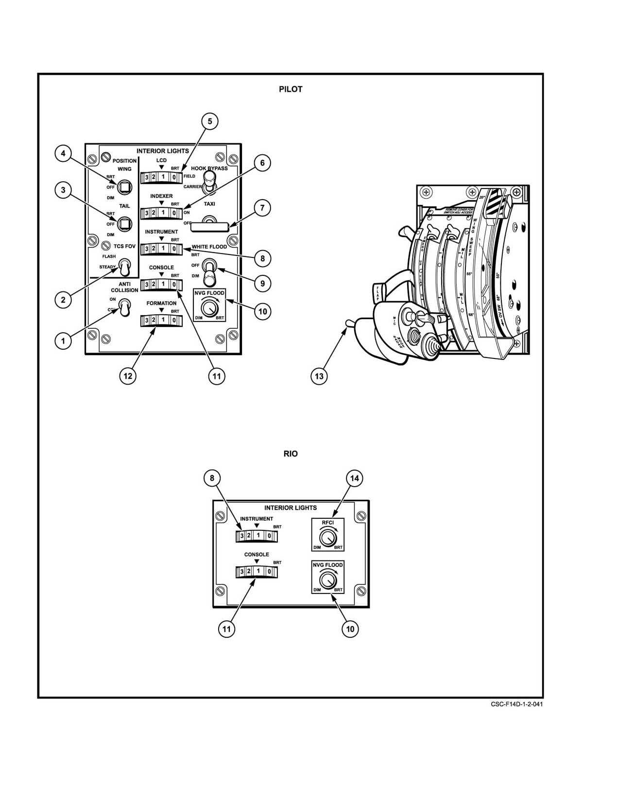
NAVAIR 01−F14AAD−1
Figure 2Ć130.ĄCockpit Light Controls (Sheet 1 of 3)
ORIGINAL
2−266
NAVAIR 01−F14AAD−1
NOMENCLATURE
FUNCTION
1
ANTI COLLISION light
ON and OFF ć
Energizes or deenergizes the anticollision lights. When
switch
anticollision lights are on, the flasher unit for the position
lights is disabled.
2
POSITION lights flasher
FLASH ć
Causes the wing or supplementary tail and position lights
switch
to operate in a flashing mode with landing gear up. With
gear down supplementary lights operate steady only.
STEADY ć
With the wing and tail (or either) position lights on, lights
are on steady.
3
TAIL POSITION light
BRT ć
Bright tail light.
switch
OFF ć
Deenergizes tail position light.
DIM ć
Dim tail light.
4
WING POSITION light
BRT ć
Bright wing lights switch.
switch
OFF ć
Deenergizes wing lights.
DIM ć
Dim wing lights.
5
LCD panel light
0 to 1 ć
Pilot’s liquid crystal display (LCD) and EIG white
thumbwheel
backlighting on.
1 to 14 ć
Sets intensity of pilot’s LCD.
6
INDEXER thumbwheel
0 to 14 ć
Sets intensity of indexer lights.
7
TAXI light switch
ON ć
Nose gear must be down and locked and the master
exterior light switch must be on.
OFF ć
Turns light off.
8
INSTRUMENT lights
0 to 1 ć
Turns instrument panel lights on.
thumbwheel
1 to 14 ć
Sets instrument lights intensity, maximum brightness
at 14.
9
WHITE FLOOD lights
BRT ć
Bright white flood lights.
switch
DIM ć
Dim white flood lights.
Note
OFF ć
Turns white flood lights off.
Switch must be pulled
up to be moved to BRT
or DIM.
10
NVG FLOOD lights control
Variable control ć
Sets intensity of green instrument and console flood
lights from DIM to BRT.
11
CONSOLE lights
0 to 1 ć
Turns console lights and console white flood lights on.
thumbwheel
1 to 14 ć
Sets console lights intensity, maximum brightness at 14.
12
FORMATION lights
0 to 1 ć
Turns formation lights on.
thumbwheel
1 to 14 ć
Sets formation of light intensity, maximum at 14.
Figure 2−130. Cockpit Light Controls (Sheet 2 of 3)
2−267
ORIGINAL
NAVAIR 01−F14AAD−1
NOMENCLATURE
FUNCTION
13
Exterior lights master
ON ć
Enable all exterior lights except approach lights.
switch
Dims approach lights to night intensity.
OFF ć
Permits pilot to turn off all exterior lights except approach
lights. Sets daylight intensity on approach lights.
14
RIO’s light control RFCI
Variable control ć Sets intensity of green flood light illuminating Radio
Frequency Control Indicator.
Figure 2−130. Cockpit Light Controls (Sheet 3 of 3)
position lights include upper and lower red lights on the left
All formation lights are green. Intensity of the lights
wing glove and upper and lower green lights on the right wing
is controlled by the FORMATION thumbwheel on the
glove. When the wing−sweep angle is forward of 25_, the
MASTER LIGHT panel. Electrical power is supplied
wingtip position lights are operational; when the wings are
through the right main bus with circuit protection on the RIO
swept aft of 25_, the wingtip position lights are disabled and
ac right main circuit breaker panel TAXI/FORM LT (3A2).
the glove position lights are operational. When operating in
steady mode with the nosegear down and locked and the
2.39.1.4
Taxi Light
wings forward of 25_, both the wingtip position lights and the
The taxi light installed on the nosewheel is a fixed−
glove position lights are operational. The position lights are
position light. A limit switch on the nosegear door will turn
powered from the right main ac bus through the exterior
the light off when the gear is retracted. A two−position, ON
lights master relay.
and OFF, switch is on the MASTER LIGHT panel. Electrical
power is supplied through the right main bus with circuit
Note
protection on the RIO circuit breaker panel TAXI/ FORM LT
When the anticollision lights are on, the flasher
(3A2).
for the position lights is disabled and the lights
revert to steady.
2.39.2
Interior Lights
The interior lighting of the cockpit consists of green
2.39.1.2
Anticollision Lights
floodlights mounted on the glareshield, the instrument
There are three red, flashing anticollision lights. One
console and above each outboard console, and utility lights
anticollision light is installed in the bottom of the infrared
for each flightcrew station. The MASTER LIGHT panel, at
pod on the lower forward fuselage. Another anticollision
the pilot’s station on the right outboard console, permits
light is installed in the top forward part of the left vertical
varying the intensity of the floodlights from dim to bright.
stabilizer and its lens is blacked out except for 1½ inches at
The RIO’s interior lights control panel permits varying the
the rear of the light. The third anticollision light is on the top
intensity of his interior lighting.
aft part of the right vertical stabilizer and directs its
anticollision beacon up and down.
2.39.2.1
Instrument and Console Panel Lights
The lower fuselage forward anticollision light remains
All flight instruments in the pilot and RIO instrument
off during takeoff and landing with the nosewheel door open.
panel and console panel lights are lighted by white lighting.
With the nosewheel door closed, the lower fuselage forward
Individual thumbwheel controls are provided for the pilot
anticollision light will operate with the ANTI COLLISION
and RIO instrument and console lighting. The thumbwheels
light switch set to ON. The anticollision lights are powered
have 14 variable selections from 0 to 14. Initial rotation from
through the right main bus with circuit protection on the RIO
0 to 1 activates the circuitry and provides a low−intensity
ac right main circuit breaker panel TAXI/FORM LT (3A2).
light. Further rotation up to a maximum intensity
(14)
increases the brightness. The INSTRUMENT thumbwheel
2.39.1.3
Formation Lights
also controls the intensity of the CAUTION ADVISORY
panels, the left and right vertical consoles, and the digital data
The formation lights consist of wingtip lights on each
indicator lights, which consist of high− and low−intensity
wing, fuselage lights, and vertical fin tip lights on both sides
lighting. The console lights thumbwheel turns power on for
of the aircraft.
both the console lights and the floodlights. The pilot and
ORIGINAL
2−268
NAVAIR 01-F14AAD-1
RIO instrument and console lights are protected by circuit
of the lamp to reselect a white light with a flood or spot
breakers. Lighting for the pilot turn-and-slip indicator is
illumination option. An alligator clip and swivel mounting
controlled by the INSTRUMENT lighting thumbwheel. The
allow the light to be positioned on a clipboard or other
engine indicator group uses integral white lighting for
convenient location. A flasher button on the heel of the lamp
daylight operations, and liquid crystal display brightness is
allows either crewmember to use the light as a signal lamp.
controlled by the LCD thumbwheel.
The utility and map lights are supplied electrical power from
the ac essential No. 2 bus and are protected by the UTILITY
Note
LTS circuit breaker (3A6).
When pilot’s instrument panel lighting is turned
2.39.3
Warning and Indicator Lights
off (daytime or to enable NVD compatibility),
RIO instrument panel and console panel lighting
Warning, caution, and advisory lights (Figure 2-131
is disabled.
and Figure 2-132) are provided in both cockpits to alert the
pilot and RIO of aircraft equipment malfunctions, unsafe
2.39.2.2
Floodlights
operating conditions, or that a particular system is in
operation.
The floodlights consist of night vision green flood-
Warning lights illuminate red with black letters to warn
lights that illuminate the instrument and console panels.
of hazardous conditions that require immediate corrective
When navigating around thunderstorms, the storm flood-
action. Caution lights show yellow letters on an opaque
lights should be turned on bright to assist in preventing
backg0round to indicate an impending dangerous condition.
temporary blindness from lighting. The WHITE FLOOD
toggle switch on the pilot master light panel and another on
The lower half of the CAUTION ADVISORY panel consists
of advisory lights that show green letters on opaque
the RIO light panel are safety interlock switches that must be
backg0round. Advisory lights indicate degraded operations
pulled up to be positioned to BRT or DIM. In DIM,
that may require corrective action.
low-intensity floodlighting is provided. During NVIS mode,
rotating the NVIS FLOOD potentiometer on the RIO interior
light panel to vary the intensity of the NVIS flood lights will
also vary the intensity of the backlighting on the CDNU.
Note
Radiation hazard exists on deck when the RDR
When the storm floodlights are on (BRT or DIM),
ENABLED caution light is illuminated. The
the intensity of the CAUTION and ADVISORY
light indicates that the RADAR TEST ENABLE
panel lights is increased to day (bright) illumi-
switch (maintenance switch) is in the “A” (radi-
nation mode.
ate andscan)position. Thisconditionpermitsthe
weight-on-wheels interlock to be bypassed,
Console and instrument panel floodlights are available
allowing the transmitter to radiate through the
in BRT. In the MED and DIM, only console floodlights are
antenna when RADAR XMIT is selected on the
available. The green console and instrument panel flood-
hand control unit. Illumination of the light does
lights are continuously variable in intensity using the NVG
not indicate a weight-on-wheels failure.
FLOOD control on the pilot’s MASTER lights and RIO’s
interior light controls. The panel floodlights are protected by
2.39.3.1
MASTER CAUTION Light
a PANEL FLOOD LTS circuit breaker (4A6) on the RIO ac
essential No. 1 circuit breaker panel. The white floodlights
The pilot MASTER CAUTION light is centrally
are protected by the STORM FLOOD LTS circuit breaker
located on the master caution/master arm control panel, and,
(2I6) on the RIO ac right main circuit breaker panel.
in the aft cockpit, the RIO MASTER CAUTION light is on
the left instrument panel. When the lights are illuminated,
2.39.2.3
Utility and Map Lights
yellow letters show on an opaque backg0round. Individual
MASTER CAUTION lights flash whenever a caution light
The pilot utility and maplight ison a bracket above the
on the respective caution and advisory panel illuminates.
right outboard console. The RIO utility and map light is in a
A MASTER CAUTION light may be turned off by depress-
bracket above and midway along the right and left console.
ing its lens. This will activate a reset switch that rearms the
Each light has a rheostat control including an ON and OFF
master circuit for a subsequent caution light. A caution light
on the rear of the lamp. A night vision green filter may be
lit on the caution and advisory panel will not be turned off by
selected by rotating the face of the lamp. Pressing the
resetting the MASTER CAUTION light.
locking button on top of the lamp permits rotating the face
2-269
CHANGE 1