F-14D. FLIGHT MANUAL (2004) - page 10
NAVAIR 01−F14AAD−1
14.12.4.3
Runaway Stabilizer Trim
pressure. Failure of the lateral stick stops is indicated by the
HZ TAIL AUTH caution light. Failure of the stops in the fully
A runaway trim failure is sensed by the pilot by both
closed position does limit low−speed rolling performance,
uncommanded stick motion and by changes in aircraft pitch
but ample roll control is available for all landing conditions
and load factor. This failure state causes the horizontal tail to
and configurations. Failure in the open condition, with SAS
move along the normal stick−to−tail gearing curve for the
on, requires the pilot to manually limit stick deflection to
hands−off condition. Aircraft response to a runaway stabilizer
prevent exceeding fuselage torsional load limit.
trim, even in the high−speed configuration, is slow enough
(about 1° per second stabilizer change) to be recovered from
14.12.5.1
HZ TAIL AUTH Light
safely.
1. MASTER RESET pushbutton
Depress
The most critical steady−state trim conditions are those
(10 seconds).
for which the greatest stick force is required. A field or carrier
landing with either a full noseup or nosedown runaway stabiĆ
If light remains illuminated above 400 KIAS/0.9 IMN:
lizer trim requires an average stick force of 14 to 19 pounds
to maintain longitudinal control. If pilot fatigue becomes a
2. ROLL STAB AUG switch OFF.
factor with full noseup trim, stick forces may be significantly
Note
reduced by placing the wings aft of 21° and lowering the
FLAP handle causing the main flaps to extend while the
ARI/SAS OUT light will illuminate.
auxiliary flaps remain retracted.
3. Restrict lateral control inputs above
400 KIAS/
This overrides the wing sweep 21° interlock and the
0.9 IMN to one−quarter throw.
FLAP light will be illuminated. This configuration is not
recommended for landing. At approach speed, the worst
nosedown trim condition requires a maximum stick pull of
27 pounds without DLC engaged and approximately 24
pounds with DLC engaged. A full noseup runaway trim
requires a maximum of 17 pounds of stick push without DLC
Above 400 KIAS/0.9 IMN there is a danger of
engaged and 23 pounds with DLC engaged.
torsional overstress to the fuselage with large
Note
lateral stick deflections.
With abnormal stabilizer trim response, continuĆ
4. Reduce airspeed and remain below
400 KIAS/
ing to trim may preclude ability to retrim to a
0.9 IMN.
neutral position.
Below 400 KIAS/0.9 IMN:
1. SPD BK/P−ROLL TRIM ENABLE cbPull
(RB2).
5. ROLL STAB AUG switch ON.
2. Decelerate to below 300 knots.
Note
At low airspeeds, lateral control effectiveness
3. Use DFCS, if available, in cruise configuration to
reduce pilot workload.
may be reduced.
4. Minimum stick forces are achieved under the folĆ
6. Do not select OV SW after landing.
lowing conditions:
14.12.6
Spoiler Malfunction
a. Runaway nosedown flaps up.
b. Runaway noseup flaps down.
Spoiler monitoring and fault isolation is internal to the
DFCS. DFCS should recognize and disable any malfunctionĆ
5. Straight−in approach.
ing spoiler and permit other spoilers to operate normally.
DFCS will therefore automatically maintain greater control
Note
authority in event of a spoiler malfunction.
Force required (push or pull) may be as much as
30 pounds.
For malfunctions where failed spoilers are successfully
commanded to trail, straight−in full flap CV approaches can
be accomplished with minor degradation in handling qualiĆ
14.12.5
Horizontal Tail Authority Failure
ties. The control capability remaining with a failed up spoiler
Lateral stick input are limited by control authority
is influenced by flap position, SAS operation, and availabilĆ
stops scheduled by the CADC as a function of dynamic
ity of the remaining spoilers.
CHANGE 1
14−42
NAVAIR 01−F14AAD−1
14.12.6.1
SPOILERS Caution Light/Spoiler
the critical factor. With flaps down, roll control
Malfunction/Spoiler Stuck Up
using lateral stick alone may be impossible.
However, with flaps up, adequate roll control to
regain wings level flight is available with use of
lateral stick alone. Choice of flap position for
landing and CV recovery/divert decision should
be made following a controllability check.
If the current configuration is acceptable for
landing, careful consideration should be given
4. Perform Controllability Check procedure, paraĆ
before depressing MASTER RESET when a
graph
14.12.1, using maneuvering flap/slat
spoiler actuator mechanical malfunction is susĆ
(preferred) or no flap configuration only.
pected. A deployed spoiler that resulted from
Note
DFCS computers dropping off line is not considĆ
ered a mechanical failure.
If controllability is unsuitable for landing
approach due to a complete loss of spoilers, conĆ
Note
sideration may be given to attempting a Power
D Use lateral stick as primary control and rudder
On Reset (POR) in an attempt to regain at least
only as needed to maintain balanced flight.
one spoiler set. See DFCS POR procedures
paragraph 14.12.6.3.
D Subsequent depression of the MASTER
RESET pushbutton may clear failure until
If controllability satisfactory:
spoiler is commanded to move again.
5. Perform maneuver flap/slat or no flap straight−in
approach at or above minimum control airspeed.
1. MASTER RESET pushbutton Ċ Depress.
If controllability still unsatisfactory:
Note
DFCS synchronization can take up to 2 seconds
following a power interrupt. If the MASTER
RESET pushbutton is depressed during the synĆ
chronization time, an additional depression of
With both INBD and OUTBD spoiler control cb’s
the MASTER RESET pushbutton will be
pulled, all opposing spoiler control will be lost.
required to restore spoiler functionality.
If failure remains/reoccurs:
2. Avoid abrupt lateral control movements and high
roll rates.
Marginal control or loss of control may be expeĆ
rienced due to removal of a spoiler set with multiĆ
ple failures present.
Note
With wings forward of 62°, excessive horizontal
If multiple failed up spoiler panels result in unsatĆ
isfactory handling qualities regardless of flap
tail differential may cause severe structural
damage.
position, an attempt may be made to fail the panels
down by removing power via the corresponding
If spoiler(s) fail down:
spoiler control cb’s. This may take as long as 60
seconds, and result in a marginal control situation
3. Perform Controllability Check procedure, paraĆ
graph 14.12.1.
or loss of control situation because power to the
other spoilers has been removed. Therefore, it
If spoiler(s) remain up or floating, or if control
should be considered only as a last resort.
unsatisfactory with flaps down:
5. SPOILER CONTR cb for affected pair Ċ Pull (8G9
Note
for INBD, 9C5 for OUTBD).
Any single, fully deflected, failed up spoiler is
If uncontrollable roll, or no improvement in
controllable even with flaps down and ROLL
controllability:
SAS OFF if the remaining spoilers are operating.
With multiple failures, aircraft configuration is
6. SPOILER CONTR cb (affected spoiler) Ċ Reset.
14−43
CHANGE 1
NAVAIR 01−F14AAD−1
7. MASTER RESET pushbutton Ċ Depress.
2. Evaluate flaps−down lateral control characteristics
Functionality lost from cycling spoiler control cb
at safe altitude.
will not be regained until the MASTER RESET
pushbutton is depressed.
If unacceptable:
8. If Unsuitable for landing, Perform Controlled
3. Make flaps−up landing.
Ejection.
14.12.6.3
DFCS Power On Reset (POR)
If controllability improves:
If controllability is unsuitable for landing approach due
9. Perform straight−in approach in best configuration
to complete loss of spoilers or other major flight control
with cb(s) out.
malfunction, consideration may be given to attempting a
flight control computer reset in an attempt to regain adequate
Note
controllability for landing. A POR will reinitialize the DFCS
computers, interpreting the current sensor information as
D Outboard spoiler position indicators will indiĆ
valid. This can create a potentially hazardous situation under
cate down with cb 9C5 pulled.
conditions where a dual sensor failure occurred prior to
restoring power. When the DFCS reinitializes, it is possible
D With cb’s 8G9 and 9C5 pulled, ground roll
for the failed signals to be interpreted as valid and the remainĆ
braking is not available. Reset on landing rolĆ
ing good signal to be interpreted as invalid. Therefore, careĆ
lout if desired.
ful consideration should be given before executing a POR
airborne, since it can result in erroneous DFCS commanded
14.12.6.2
Outboard Spoiler Module Malfunction
control deflections. Aircrew must be alert for erroneous
uncommanded SAS and/or spoiler control inputs following
an airborne POR.
An outboard spoiler module failure with flaps
extended, below 180 knots, and with a combined
hydraulic failure rendering the inboard spoilers
If a dual failure has been declared that will not
inoperative, can result in asymmetric spoiler
clear with a MASTER RESET, performing a
float such that the aircraft may not be flyable at
power on reset (POR) to clear the failure can
normal approach airspeeds.
result in erroneous uncommanded SAS and/or
spoiler control inputs.
Note
As with any controllability check, a POR should
be performed above 10,000 ft AGL and in the
If outboard spoilers fail with airspeed greater
cruise configuration between 250 and 300 knots
than 225 knots and wing sweep is less than 62°,
if possible to minimize the potential effects of
limit lateral stick to one−half pilot authority.
transient series servo actuator inputs.
1. OUTBD SPOILER PUMP cb Check (2B3).
1. BOTH SPOILER CONTR cb’s ć Pull (8G9, INBD
a. If OUT Attempt Reset.
and 9C5, OUTBD).
b. If IN and outboard spoiler module flag indicates
2. PITCH, ROLL, and YAW STAB AUG switches Ċ
OFF Pull.
OFF.
3. ROLL A DC, YAW B DC, and YAW A DC cb’s
The following important equipment is inoperative:
(8B4, 8B5, and 8B6) Ċ Cycle (RIO). Observe
PITCH SAS, ROLL DGR, YAW DGR, FCS CAUĆ
(1) Outboard SPOILERS.
TION, ARI DGR, ARI/SAS OUT, SPOILERS, HZ
(2) FLAP and SLAT BACKUP.
TAIL AUTH, RUDDER AUTH, and AUTOPILOT
caution lights illuminated.
(3) ACL.
ORIGINAL
14−44
NAVAIR 01−F14AAD−1
Note
If no uncommanded ROLL SAS control inputs:
Attempt to reset cb’s 8B4, 8B5, and 8B6 simultaĆ
6. Reset SPOILER CONTR cb’s.
neously to optimize DFCS power−up sequence.
7. Perform Controllability Check procedure.
4. MASTER RESET pushbutton Ċ Depress.
14.12.7
FLAP Light
Observe all lights extinguished with the exception of
ARI/SAS OUT light due to ROLL and YAW STAB
14.12.7.1
Not After Landing/Takeoff Flap
switches OFF.
Transition
1. Airspeed Below 225 Knots.
2. FLAP handle Ensure Full Up.
D If the system continues to display any DFCS
3. MASTER RESET pushbutton Depress.
related caution lights following MASTER
RESET, this could be indicative of a recurring
4. While holding MASTER RESET pushbutton
flight control malfunction.
depressed, maneuver flap thumbwheel
Full
D If a SPOILERS caution light will not extinĆ
Forward.
guish following the execution of a POR,
5. Check FLAP light out (light can take up to 10 secĆ
selection of ROLL STAB AUG switch ON
onds to reilluminate).
can result in erroneous uncommanded SAS
control inputs.
14.12.7.2
After Landing/Takeoff Flap Transition,
D When attempting to individually reset
or Reillumination After Above
PITCH, ROLL, and YAW STAB AUG
Procedures
switches, be prepared to isolate the affected
STAB AUG switch OFF if any uncommanded
1. MASTER RESET pushbutton Depress.
SAS inputs are observed.
2. If light still illuminated, check FLAP handle and
Note
indicator position, then proceed with appropriate
D Minimize control stick inputs during or folĆ
steps below.
lowing MASTER RESET as this can result in
the SPOILERS caution light with SPOILER
14.12.7.3
FLAP Handle Up and Flaps Not Fully
CONTR cb’s pulled.
Retracted
D More than one MASTER RESET may be
1. FLAP handle EMER UP.
required to extinguish all caution lights.
If FLAP handle or flaps will not respond or FLAP
5.
Individually select PITCH, ROLL, and YAW STAB
light remains illuminated, refer to Flap and Slat
AUG switches ć ON.
Asymmetry procedures, paragraph 14.12.8.
If any uncommanded SAS control inputs:
14.12.7.4
FLAP Handle Up and Flaps Indicating
Full Up
6. Affected STAB AUG switch ć OFF.
1. Flaps Cycle.
If FLAP handle or flaps will not respond or FLAP
light remains illuminated, refer to Flap and Slat
Asymmetry procedures, paragraph 14.12.8.
If uncommanded ROLL SAS inputs are observed
following a POR, reselection of the SPOILER
14.12.7.5
FLAP Handle Down and Flaps Not Fully
CONTR cb’s can result in full spoiler deflection
Extended
and an out of control aircraft.
1. Wing sweep Ensure at 20°.
7. If uncommanded ROLL SAS control inputs, DO
Flaps will not respond or FLAP light remains
NOT reset SPOILER CONTR cb’s.
illuminated, refer to Flap and Slat Asymmetry
8. Perform Controllabilty Check procedure.
procedures, paragraph 14.12.8.
14−45
ORIGINAL
NAVAIR 01−F14AAD−1
14.12.7.6
FLAP Handle Down and Flaps Down
1. FLAP/SLAT CONTR SHUT−OFF cb Check
In (RA2).
2. Wing sweep Ensure at 20_.
3. MASTER RESET pushbutton Depress (allow 10
seconds for auxiliary flaps to extend).
Note
Lack of asymmetry protection
(RA2 circuit
breaker out) may cause uncommanded roll
If FLAP handle or flaps will not respond or FLAP
and/or yaw during flap or landing gear handle
light remains illuminated, refer to Flap and Slat
movement.
Asymmetry procedures, paragraph 14.12.8.
2. FLAPS Match Handle With Flaps Position.
14.12.8
Flap and Slat Asymmetry
3. Obtain visual check if possible to ascertain position
Flap and slat asymmetry can occur with failure of an
of all flap and slat surfaces.
asymmetry sensor and subsequent failure of the flap and slat
drive mechanism for one wing. The pilot’s only indication
4. Slow−fly aircraft in approach configuration at or
will be an uncommanded roll followed by a FLAP light
above 10,000 feet AGL to determine approach charĆ
approximately 10 seconds later. The flap indicator does not
acteristics, conditions permitting.
indicate actual flap position, but the position to which the flap
and slat control box has been driven. The slat indicator shows
5. Land as soon as practicable if aircraft is controllable
up, down, or transition (barber pole) for the starboard slat
and minimum approach airspeed is within shipĆ
only. The port slat position is not monitored. Asymmetric
board arresting gear limits.
flaps cause an immediate roll. Asymmetric slats may not be
apparent until just before wing stall. Asymmetric slats can
If asymmetry is so large as to make landing impossible
cause rapid rolloff above 15 units AOA. Slat position must be
or minimum safe approach speed is above shipboard arrestĆ
monitored by the RIO during transition.
ing gear limits with no possible divert field available:
6. Climb above 10,000 feet AGL.
7. AUX FLAP/FLAP CONTR cb Pull (8G3).
The use of lateral trim to reduce stick force will
reduce spoiler control significantly. An unconĆ
trollable situation can develop if lateral trim is
out of neutral before flap and slat asymmetry or
Failure to complete step 7 before the subsequent
if the pilot trims laterally in the neutral direction
steps can result in large uncommanded pitch trim
(opposite the roll) during flap and slat transition.
changes because of auxiliary flap movement.
This situation will be aggravated and recovery
may not be possible with ROLL SAS OFF
8. FLAP/SLAT CONTR SHUT−OFF cb
Pull
because of reduced differential tail authority.
(RA2).
Once asymmetry occurs, do not trim out stick
forces. If lateral control is marginal, trim oppoĆ
9. Slowly move FLAP handle in direction to minimize
site to the natural direction until full spoiler
asymmetry and/or lateral control requirements.
deflection is available. For example, stick to the
right, trim left.
10. Stop flap and slat travel before reaching full up or
down.
If a roll is encountered during flap and slat transition or
if RIO notes asymmetric slat extension or retraction:
11. FLAP/SLAT CONTR SHUT−OFF cb Reset
(RA2).
Note
Uncommanded roll/yaw procedures take preceĆ
dence if appropriate. Otherwise perform the proĆ
cedures below.
ORIGINAL
14−46
NAVAIR 01−F14AAD−1
14.12.10
Unscheduled Wing Sweep
1. Emergency WING SWEEP handle Raise and
Hold.
Asymmetric slats may not be apparent until just
before wing stall. Asymmetric slats can cause
rapid rolloff above 15 units AOA.
12. If asymmetry has been corrected, land using 15 units
AOA.
Unscheduled wing sweep at supersonic speed
may cause structural damage.
13. If asymmetry has not been corrected, flaps and slats
did not respond to above procedure, or lateral conĆ
2. Airspeed Decelerate to 0.6 TMN or Less in 1g
trol problems exist, land using minimum safe AOA
Nonmaneuvering Flight.
if landing is elected.
3. Emergency WING SWEEP handle Full Forward.
14.12.9
WING SWEEP Lights
If wings do not move full forward:
14.12.9.1
Advisory Light Only − No Loss of
Normal Control
4. EMERGENCY WING SWEEP handle Match
With Actual Wing Position.
1. MASTER RESET pushbutton Depress.
5. WING SWEEP DRIVE NO. 1 and WG SWP DR
14.12.9.2
WING SWEEP Light and W/S Caution
NO. 2/MANUV FLAP cb Pull (LD1, LE1) (refer
Legend No Automatic or Manual
to aft wing−sweep landing).
Control
6. Land a soon as practicable.
1. Airspeed Decelerate to 0.9 Mach or Less.
Note
2. Check spider detent engaged.
D After a wing−sweep malfunction, the WING
SWEEP advisory light and the W/S legend
3. MASTER RESET pushbutton Depress (wait
may take 15 seconds to illuminate/display.
15 seconds to determine system status).
D FLAP light will be illuminated with cb LE1
If WING SWEEP light and W/S caution legend
pulled.
illuminate again:
14.12.11
CADC Light
4. WING SWEEP DRIVE NO. 1 and WG SWP DR
NO. 2/MANUV FLAP cb Pull (LD1, LE1).
1. MASTER RESET pushbutton Depress.
5. Emergency WING SWEEP handle Comply with
2. CADC cb’s (LA2, LB2, LC2, LD2) Cycle.
below schedule:
3. MASTER RESET pushbutton Depress.
a.
≤ 0.4 Mach 20°.
b. ≤ 0.7 Mach 25°.
If light still remains illuminated:
c.
≤ 0.8 Mach 50°.
4. Remain below 1.5 Mach.
d. ≤ 0.9 Mach 60_.
One or more of the following systems may be affected
e.
> 0.9 Mach 68°.
by CADC malfunction that illuminates only the CADC light.
a. Maximum safe Mach.
b. Autopilot.
c. Idle lockup function of AFTC.
Avoid ACM and aerobatics.
14−47
ORIGINAL
NAVAIR 01−F14AAD−1
d. Wing−sweep indicator.
e. Cockpit cooling less than Mach 0.25.
f. HUD Display.
With RATS enabled airborne, military power
provides 20 to 25 percent less thrust than normal,
Note
resulting in less than optimum waveoff and
bolter performance.
D Erroneous Mach inputs to the AFTC may
cause uncommanded acceleration of both
If two or more of the above anomalies are detected, the
engines to near−military values in the PRI
following action should be taken:
engine mode.
D If illumination of the CADC light is accompaĆ
14.12.13.1
In Flight Ċ Pilot
nied by other caution or advisory light(s),
refer to the appropriate procedure that will
1. Throttles Any Position Except IDLE.
dictate the most restrictive limitation.
14.12.12
AUTOPILOT Light
5. MASTER RESET pushbutton Ċ Depress.
Do not move both throttles to IDLE unless ANTI
SKID SPOILER BK switch is set to OFF if
14.12.13
Weight On−Off Wheels Switch
weight on−off wheels switch is suspected because
Malfunction
of loss of thrust and lift caused by nozzles openĆ
ing and spoilers deploying.
For most systems, failure of both the left and right
WOW switches is required to cause the systems to revert to
2. ANTISKID SPOILER BK switch OFF.
the on−deck mode. Should such failures occur, the following
anomalies can result:
3. Land as soon as practicable.
1. Approach indexers are inoperative.
2. APC will not engage.
3. Outboard spoiler module is inoperative (flaps up).
If weight on−off wheels switch failure is susĆ
pected, cocked up, high sink rate landing with
4. Nozzles may go full open (with LDG GEAR handle
throttles at idle can result in damage to the afterĆ
down, throttles IDLE).
burner.
5. Ground−roll spoiler braking (throttles IDLE).
14.12.13.2
In Flight Ċ RIO
6. Radar will not scan.
1. MLG SAFETY RLY NO. 1 and NO. 2 cb
Pull (7F5, 7F4).
7. Autopilot cannot be engaged.
Note
8. BOL chaff will not dispense.
D Circuit breakers can be reset after touchdown
9. At high altitude, ground cooling fans may overĆ
to enable ground−roll braking, antiskid,
speed and shut down, causing smoke in cockpit.
nozzles open at idle, and nosewheel steering.
D Circuit breakers must be reset simultaneously
10. RATS will be enabled airborne with the hook handle
(within 0.1 sec) once on deck or a secondary
down or the hook out of the stowed position.
fault may be incurred which will inhibit
ground roll braking.
ORIGINAL
14−48
NAVAIR 01−F14AAD−1
14.13 DEPARTURE/SPIN
3. If roll and/or yaw develop, wait until aircraft is in a
nosedown attitude and accelerating before correct-
Successful recovery from out−of−control flight requires
ing with rudder or lateral stick.
correct situation analysis, timely and correct application of
4. Use longitudinal control as necessary to keep nose
procedures, crew coordination, and recognition of recovery.
Departure from controlled flight should be recognized and
down and accelerating.
the appropriate recovery procedures initiated as soon as the
5. Above 100 knots, pull out, using 17 units AOA.
aircraft begins uncommanded motion. Throttles should be
immediately placed to IDLE to ensure maximum stall margin
6. Recovery to level flight from point of pitchover can
and prevent asymmetric thrust from delaying recovery. If
normally be completed in less than 10,000 feet.
recovery is not immediately apparent, instrument cues must
be cross−checked. Full departures/spins are indicated by
14.13.2
Upright Departure/Flat Spin
pegged AOA (30 units for upright, 0 units for inverted), low
airspeed (less than 150 knots), and sustained yaw rate as
*1. Stick Forward/Neutral Lateral
indicated by the turn needle and/or spin arrow. The spin
Harness Lock
arrow is the best indicator of yaw direction if it is available.
If the above indications are not present, neutralize the con-
*2. Throttles Both IDLE.
trols and fly the aircraft as airspeed increases. Recovery con-
trols should be applied and maintained until recovery is indi-
*3. Rudder Rudder−Opposite Turn Needle/Yaw/
cated, minimum altitude reached, or an increase in
Spin Arrow.
eyeball−out g threatens aircrew incapacitation. The most pos-
itive indication of recovery is a break in AOA as yaw rate is
If no recovery:
reduced, followed by an increase in airspeed and g load in the
direction commanded by longitudinal stick. To minimize
*4. Stick Into Turn Needle.
altitude loss for recovery, pull out at 17 units AOA.
If yaw rate is steady/increasing, spin arrow is flashing, or
Crew coordination is essential. The RIO must be able
eyeball−out g is sensed:
to analyze the situation and provide timely and accurate
information and procedural backup to the pilot without
*5. ROLL SAS ON
excess communication. The RIO should use airspeed, alti-
Stick Full Into Turn Needle and Aft.
tude remaining, and the spin arrow as cues. Lateral stick
application can be confirmed by observing spoilers deflected
If recovery is indicated:
up on the wing pointed to by the spin arrow. Ejection in an
out−of−control flight situation can best be accomplished by
*6. Controls Neutralize.
the RIO after consultation with the pilot. A thorough under-
*7. Recover at 17 units AOA, thrust as required.
standing of Chapter 11, Flight Characteristics, is required of
the aircrew when dealing with these high task emergencies.
If flat spin verified by flat attitude, increasing yaw rate,
14.13.1
Vertical Recovery
increasing eyeball−out g, and lack of pitch and roll rates:
*8. Canopy Jettison.
1. Above 100 knots, use longitudinal stick to pitch the
nose down. At extreme nose−high attitudes, aft stick
*9. EJECT RIO Command Eject.
facilitates recovery time and will avoid prolonged
engine operation with zero oil pressure.
2. Below 100 knots, release controls and wait for air-
craft to pitch nose down. This prevents depletion of
hydraulic pressure in the event both engines are lost
and provides quickest recovery.
Ejection guidelines are not meant to prohibit ear-
lier canopy jettison and/or ejection. If insuffi-
cient altitude exists to recover from departed
flight, the flightcrew should not hesitate to eject.
14−49
CHANGE 2
NAVAIR 01−F14AAD−1
Note
If recovery is indicated:
*4. Controls Neutralize.
D At high yaw rates where eyeball−out g is
sensed, aft stick and full lateral stick into the
*5. Recover at 17 units AOA, thrust as required.
turn needle may arrest the yaw rate and
increase the possibility of recovery. At these
If spinning below 10,000 feet AGL:
yaw rates, the additional differential tail pro-
vided by ROLL SAS ON will also increase the
*6. EJECT RIO Command Eject.
possibility of recovery.
D It may be necessary to center stick laterally
momentarily to engage ROLL SAS.
14.13.3
Inverted Departure/Spin
Dual compressor stalls may be expected in an
*1. Stick Full AFT/Neutral Lateral
inverted spin.
Harness Lock.
Note
*2. Throttles Both IDLE.
If pedal adjustment and/or pilot positioning
*3. Rudder Rudder−Opposite Turn Needle/Yaw/Spin
(because of negative g forces) is such that full
Arrow.
rudder pedal travel cannot be obtained, full
lateral control opposite the turn needle/yaw may
provide an alternate recovery method. Aft
longitudinal stick should be relaxed enough to
allow full lateral stick application.
CHANGE 2
14−50
NAVAIR 01−F14AAD−1
CHAPTER 15
Landing Emergencies
15.1
DUAL−ENGINE LANDING, ONE OR
degrade waveoff performance. The LSO should move the
BOTH ENGINES IN SECONDARY MODE
waveoff window such that only minor glideslope/lineupĆ
corrections are required from in the middle position.
With either one engine in secondary mode (the other
engine in primary) or both engines in secondary mode, a
straight−in approach should be conducted with slats and flaps
fully extended, 15 units AOA, DLC engaged, and speedĆ
brakes extended. Approaches can be accomplished safely up
to the normal gross weight limits of the aircraft. Throttle
Waveoff performance with both engines in SEC
position in secondary mode will be 5° to 10° higher than in
mode may be severely degraded. Extreme care
primary mode for the same amount of thrust. Thrust response
should be used to avoid an underpowered,
in secondary mode is nonlinear and very sluggish. Engine
high−rate−of−descent situation.
acceleration time can be as much as three times longer than
in primary mode. Secondary mode MIL power thrust levels
15.2
SINGLE−ENGINE LANDING PRIMARY MODE
can vary from as little as 65 percent to as much as 116 percent
of primary mode MIL thrust.
Perform a straight−in approach with flaps and slats
extended and speedbrakes retracted
(to reduce thrust
required). External tanks have a negligible effect on thrust
required and need to be dropped only if necessary for gross
weight considerations. If operating on the left engine, DLC
is available and is recommended. DLC can be used to aid in
the control of glideslope, thereby minimizing required power
For shipboard landing, the LSO and tower must
changes and the resultant lateral/directional deviations. The
be informed if the landing is to be made with both
engines in secondary mode to ensure wind−
8−knot increase in airspeed with DLC engaged results in more
control authority and improved waveoff and bolter perforĆ
over−deck requirements are met as RATS is not
operative in secondary mode.
mance. Flight in the power approach configuration is critical.
Turns should be made away from the failed engine using
bank angles that do not exceed 20°. Remain below 12 units
During flight tests with one engine in secondary mode,
AOA until established on final approach. Final approach
optimum results were obtained by matching the engines’
should be conducted at 15 units AOA with DLC engaged/14
rpm prior to commencing final approach and maintaining the
units with DLC stowed (DLC is not available when combined
throttle split when making power corrections. Use of DLC to
hydraulic system is pressurized by the BI−DI pump). Small
make small glideslope changes will improve lineup control
rudder inputs should be made in conjunction with power
by reducing throttle activity and the associated yaw excurĆ
changes to reduce the amount of yaw.
sions. Waveoff and bolter performance is essentially the
same as in dual−engine primary mode except for a slight yaw
into the secondary mode engine.
Waveoff and bolter (with RATS) may be accomplished
up to normal gross weight limits of the aircraft. Test results
have shown that MIL power provides satisfactory waveoff
With both engines in secondary mode, expect very
performance. Minimum AB (ATLS on) reduces altitude loss
sluggish power response and throttle positions 5° to 10° more
when waveoff occurs from a high rate of descent. The use of
forward than in primary mode. Extreme care should be taken
maximum AB is prohibited.
to avoid an underpowered condition as this will significantly
15−1
ORIGINAL
NAVAIR 01−F14AAD−1
No significant difference in altitude loss during
the yaw rate and then reduce the rudder as required to track
waveoff was noted between minimum AB and maximum
centerline. If unable to control yaw rate during AB waveoff
AB. The aircraft is extremely difficult to control in maximum
(possible ATLS failure), immediately reduce power to MIL.
AB and large bank angles into the operating engine are
required to maintain centerline. Late or inadequate control
inputs during a maximum AB waveoff can result in large
lateral flightpath deviations. Waveoff technique is to select
MIL or minimum AB (ATLS on), maintain approach AOA
until a positive rate of climb is established, then accelerate
Use of maximum AB during waveoff or bolter is
and climb out at the airspeed indicated in the Climb
prohibited. If unable to control yaw rate (possible
Performance After Takeoff
(Single Engine) Charts in
ATLS failure), immediately reduce power to
NAVAIR 01−F14AAP−1.1.
MIL.
During single−engine operations at fuel states above
Note
4,000 pounds, a fuel split will develop between the aft/left
and forward/right sides. When either cell No. 2 or cell No. 5
Altitude loss during a single−engine waveoff is
thermistor is uncovered (at approximately 2,000 pounds on
minimized by maintaining approach AOA until
either tape), or when FWD or AFT is selected on the FEED
a positive rate of climb is established. Avoid
switch, the motive flow isolation and sump tank interconnect
overrotating in close as this will increase the
valves open, making wing and fuselage fuel on both sides
chance of an in−flight engagement. Minimum
available to the operating engine. However, if the sump tank
AB (ATLS on) will improve waveoff perforĆ
interconnect valve fails to open, fuel will migrate to the wing
mance (minimize altitude loss) from high sink
and fuselage tanks on the inoperative engine side and will not
rates.
be available to the operating engine. Under these conditions,
the maximum migration rate could reach 300 ppm. If the
The bolter maneuver is affected by selecting MIL or
FUEL SHUT−OFF handle on the inoperative engine is not
minimum AB (ATLS on) and slight aft control stick until the
pulled, an additional migration path could exist through the
desired flyaway attitude is established. During a bolter
engine crossfeed valve. During single−engine operation, the
following a DLC stowed approach, nose rotation will be
following procedures will minimize fuel migration if the
more sluggish than normal (because of the slower approach
sump tank interconnect valve fails to open.
speed) requiring a slightly more aggressive aft control stick
1. FUEL SHUT OFF handle (inoperative engine) Ċ
input.
Pull.
If not on final approach:
2. Refer to Single−Engine Cruise Operations, paraĆ
graph 14.5.3.2.
If after commencing final approach or in landing pattern:
The use of excessive backstick on a bolter may
cause the tail surface to stall, delaying aircraft
2.ăATLS Ċ Check ON.
rotation and causing the aircraft to settle off the
angle deck.
As power is advanced during a waveoff or bolter,
simultaneously apply rudder (approximately two−thirds to
Use of maximum AB during waveoff or bolter is
three−fourths of full deflection) to counter the asymmetric
prohibited and provides little or no improvement
thrust and prevent lateral drift. Rudder may be supplemented
over minimum AB. If unable to control yaw rate
with small lateral stick inputs. If yaw rate develops into the
(possible ATLS failure), immediately reduce
dead engine, immediately apply full opposite rudder to arrest
power to minimum AB or MIL.
ORIGINAL
15−2
NAVAIR 01−F14AAD−1
Note
Altitude loss during waveoff is minimized by
maintaining approach AOA until positive rate of
climb is established. Avoid overrotating in close
If combined hydraulic pressure is zero, do not
as this will increase the chance of an in−flight
return to AUTO (LOW) mode once module is
engagement. Minimum AB
(ATLS on) will
selected on. If module is shut off after operation
improve waveoff performance (minimize altiĆ
commences, it may not restart.
tude loss) from high sink rates.
14. For landing pattern use 12 units AOA for pattern
3. Afterburner operation (airspeed > 170 knots, fuel
airspeed and do not attempt turns greater than 20_
permitting, and full rudder authority) (RUDDER
angle of bank.
AUTH light out) Ċ Stage to Verify Proper
Operation of ATLS.
4. Wing sweep Ċ Set at 20_ (EMER).
Extreme caution must be exercised when perĆ
forming turn into dead engine. Decaying
airspeed/increasing AOA can rapidly result in a
situation where there is not enough rudder
authority to return the aircraft to level flight, and
insufficient altitude to effect a recovery.
If hammering (cavitation) is experienced in the
hydraulic system, component rupture is immiĆ
15. Final approach airspeed:
nent. Turn the HYD TRANSFER PUMP switch
DLC engaged Ċ 15 Units AOA.
(BI−DI) off.
DLC stowed Ċ 14 Units AOA.
5. Reduce gross weight/minimize lateral asymmetry
into the inoperative engine as required.
6. Speedbrakes Ċ RET (on final approach).
Military power climb performance during heavy
7. LDG GEAR handle Ċ DN (if combined hydraulic
waveoffs may not adequately arrest high−sink−
pressure zero Ċ EMERG DN).
rate conditions. Use of AB provides an increase
in climb performance. Up to full rudder may be
8. Hook Ċ As Required.
required to counter AB asymmetric thrust yawĆ
ing moment during waveoff or bolter. Do not
9. Check SAS Ċ ON.
exceed 14 units AOA during waveoff or bolter.
10. If combined pressure is zero Ċ Pull AUX FLAP/
15.3
SINGLE−ENGINE LANDING
FLAP CONT Cb (8G3).
SECONDARY MODE
11. Flaps Ċ DN.
Approaches in single−engine secondary (SEC) mode
are considered extremely hazardous. Engine military (MIL)
12. DLC (if operating on right engine) Ċ Do Not
power thrust levels can vary from as little as 65 percent to as
Engage.
much as 116 percent of primary mode MIL thrust. Although
the majority of engines produce greater than 90 percent of
If operating on the left engine and
3,000 psi combined
primary mode thrust (at MIL power), the possibility exists
pressure Engage on Final.
that in the full−flap configuration, a low−thrust engine will not
provide enough thrust for level flight. Engine acceleration
13. EMERG FLT HYD switch Ċ HIGH (on final,
times also vary and can be as much as three times longer than
committed to landing).
15−3
ORIGINAL
NAVAIR 01−F14AAD−1
in primary mode. Aircraft in this configuration should
The natural tendency will be to underestimate the sluggish
recover shore based. Shipboard landings should be attempted
power response resulting in an underpowered condition.
only as a last resort and only if performance is adequate. For
Waveoff capability is dependent on engine thrust, thrust
example,
72 percent of primary mode MIL thrust is
response, aircraft rate of descent, and power setting at
considered the minimum required for a safe CV approach
waveoff initiation. Waveoffs should be conducted by rotating
with a 48,000−pound aircraft with no stores.
toward 14 units (maximum) AOA until a positive rate of
climb is attained, then slowly reducing AOA to 10 units AOA
To accomplish the performance check, configure the
to achieve maximum rate of climb. Bolters should be conĆ
aircraft at 2,000 feet AGL or greater and 10 units AOA with
ducted by rotating to 10_ pitch attitude not to exceed 14 units
the maneuvering flaps down (if available) and leave the
AOA. Avoid increasing AOA, as performance will degrade
landing gear up. With the engine at MIL thrust, establish a
and wing drop will occur at 16.5 to 17.5 units AOA.
constant airspeed climb (±5 knots) at the airspeed correĆ
sponding to 10 units AOA. The minimum change in altitude
required in 30 seconds is as follows:
CHANGE IN ALTITUDE Ċ FEET
Waveoff performance from high rates of descent
MANEUVER
MANEUVER
in SEC mode may be severely degraded.
FLAPS DN
FLAPS UP
Extreme care should be used to avoid an underĆ
powered, high rate−of−descent situation.
2,000 feet
950 feet
900 feet
4,000 feet
800 feet
750 feet
Shipboard landings in single−engine SEC mode are not
recommended and should be attempted as a last resort (divert
6,000 feet
700 feet
650 feet
not available) and if the performance check is successful.
Jettison all external stores and reduce fuel weight as much as
Note
practicable to reduce gross weight and drag. Configure the
aircraft for landing no lower than
2,000 feet AGL.
Climb performance will improve by 20 feet in a
Approaches should be conducted with the flaps and slats fully
30−second climb for every 1,000−pound gross
extended, speedbrake retracted, and DLC stowed.
weight reduction.
Conduct a straight−in approach. Any turns should be
If the test is passed based on predicted gross weight, do
made away from the dead engine using bank angles that do
not lower the landing gear and flaps until the predicted gross
not exceed 20_. Maintain 10 units AOA until established on
weight is reached. If the performance test is passed and divert
final, at which time the aircraft should be slowed to 13 units
is not possible, a CV approach may be attempted. The
(maximum) AOA. Extreme care should be used when
minimum performance is required for optimum conditions
working off a high and/or fast condition, as any large power
(day, VMC, steady deck, experienced aircrew, normal wind
reductions could result in an underpowered situation. A high
over deck, etc.). For degraded conditions, the minimum
and/or fast condition should be corrected using only small
performance should be increased based on judgment. If the
power reductions. Upon detection of a deceleration or settle,
minimum performance test is not passed, and all other
immediate selection of MIL power may be required to correct
options are exhausted
(stores jettisoned, gross weight
the situation in a timely manner. To minimize the chance of
minimized, divert not possible), eject under controlled
a hook−skip bolter, it is important to maintain aft stick
conditions.
pressure on touchdown. Waveoffs should be conducted by
rotating the aircraft to 14 units (maximum) AOA until a
For shore−based landings, conduct a straight−in
positive rate of climb is attained, then slowly reducing AOA
approach with flaps up and speedbrakes retracted. If conĆ
to 11 to 12 units to achieve a maximum rate of climb. Bolters
ditions warrant a full−flap landing, conduct a performance
should be conducted by rotating to 10_ pitch attitude not to
test and proceed as in the case of a shipboard landing. Gross
exceed 14 units AOA.
weight should be reduced as much as practicable to improve
flyaway performance. Maintain 10 units AOA in the pattern
15.3.1
Single−Engine Landing Ċ SEC Mode
slowing to 15 units AOA at touchdown when a safe landing
is assured. Use extreme caution when working off a high
1. FUEL SHUTOFF handle (inoperative engine) Ċ
and/or fast situation, avoiding any large power reductions.
Pull.
ORIGINAL
15−4
NAVAIR 01−F14AAD−1
2. In CV environment Ċ Divert.
If configured for landing:
3. Refer to Single−Engine Cruise Operations, paraĆ
4. Throttle Ċ MIL.
graph 14.5.3.2, and Engine Transfer to SEC Mode
procedures, paragraph 14.5.6.
5. Ensure a minimum of 500−fpm rate of climb at
14 units AOA available for CV approach.
If not preparing for CV approach:
See step 6.
When preparing for landing:
If divert is not possible:
Shipboard recovery in single−engine SEC mode
Engine thrust and thrust response can be severely
is considered extremely hazardous and should be
degraded such that level flight cannot be mainĆ
conducted only as a last resort and if the perforĆ
tained in the full−flap landing configuration. DO
mance check is successful.
NOT configure for landing until the performance
test has been accomplished.
6. RUDDER AUTH light Ċ Verify Out.
If not configured for landing:
7. Wing sweep Ċ Set at 20°.
4. Perform constant airspeed climb
(±5 knots) at
10 units AOA, landing gear up, maneuvering flaps
down (if possible), above 2,000 feet. Minimum
climb required in 30 seconds is as follows:
If hammering (cavitation) is experienced in the
CHANGE IN ALTITUDE Ċ FEET
hydraulic system, component rupture is
imminent. Turn the HYD TRANSFER PUMP
MANEUVER
MANEUVER
switch (BI−DI) off.
FLAPS DN
FLAPS UP
8. External stores Ċ Jettison for Shipboard Recovery.
2,000 feet
950 feet
900 feet
4,000 feet
800 feet
750 feet
9. Fuel Ċ Dump or Burn
(reduce as much as
practicable).
6,000 feet
700 feet
650 feet
10. Speedbrakes Ċ RET (on final approach).
11. LDG GEAR handle Ċ DN (if combined hydraulic
pressure zero Ċ EMERG DN).
12. Hook Ċ As Required.
If minimum performance test is passed based on
predicted gross weight, do not lower landing gear
and flaps until predicted gross weight is reached.
Note
Climb performance will improve by 20 feet in a
Shore−based landings should be conducted with
30−second climb for every 1,000−pound gross
flaps up. If conditions warrant a full−flap landing,
weight reduction. Minimum performance
conduct a performance test and proceed as in the
criteria is based on optimum conditions (day,
case of shipboard landing.
VMC, steady deck, experienced aircrew, normal
13. Check SAS Ċ ON.
wind over deck, etc.) and should be increased for
degraded conditions based on judgment.
14. If combined pressure is zero Ċ Pull AUX FLAP/
FLAP CONTR Cb (8G3).
5. If minimum performance criteria are not passed and
all options are exhausted
(stores jettisoned,
minimum gross weight, and divert not possible),
eject under controlled conditions.
15−5
ORIGINAL
NAVAIR 01−F14AAD−1
15. Flaps DN (shipboard recovery), As Required
15.4
LANDING GEAR EMERGENCIES
(field landing).
15.4.1
Landing Gear Emergency Lowering
16. DLC Ċ Do Not Engage.
Use emergency lowering of the landing gear only as a
17. EMERG FLT HYD switch Ċ HIGH (on final,
last resort. Once this system is used, the gear cannot be
committed to landing).
retracted; therefore, the landing must be made in whatever
configuration you have at that time. If a long flight is necĆ
essary to make a field landing, it will have to be made with
the gear down (see Figure 15−1).
1. Airspeed Ċ Less Than 280 Knots.
If combined hydraulic pressure is zero, do not
return to AUTO (LOW) mode once module is
2. LDG GEAR handle Ċ DN.
selected on. If module is shut off after operation
commences, it may not restart.
18. For landing pattern, use 10 units AOA for pattern
airspeed and do not attempt turns greater than 20_
angle of bank.
The LDG GEAR handle should be pulled with a
rapid and continuous 55−pound force until the
handle is loose (fore and aft) in its housing as an
indication of complete extension of the handle.
3. Push LDG GEAR handle in hard, turn it 90_ clockĆ
Extreme caution must be exercised when
wise, pull, and hold.
performing turns into a dead engine. Decaying
airspeed/increasing AOA can rapidly result in a
4. Gear position indication Ċ Check (12 seconds).
situation where there is not enough rudder
authority to return the aircraft to level flight and
5. Make arrested landing if available.
insufficient altitude to effect a recovery.
Note
19. Final approach airspeed Ċ 13 Units (CV), (field
landing slow to 15 units, no flaps at touchdown).
D The nosegear cannot be confirmed as locked
by visual observation. If both the indicator
and transition light indicate unsafe, assume
that the downlock is not in place.
D If there is disagreement between the indicator
Waveoff performance from high rates of descent
and light and the gear appears down, the malĆ
in SEC mode may be severely degraded.
function may be because of a faulty contact on
Extreme care should be used to avoid an underĆ
the nosegear downlock microswitch.
powered, high−rate−of−descent situation.
D Use of emergency gear extension results in
loss of nosewheel steering.
Note
D To facilitate in−flight refueling probe extenĆ
D Waveoff should be conducted by rotating to
sion when the gear has been blown down,
14 units (maximum) AOA until a positive rate
raise the LDG GEAR handle to give priority
of climb is attained.
to the refueling probe system.
D Bolters should be conducted by rotating to
If any gear does not come down:
10_ pitch attitude not to exceed 14 units AOA.
6. Increase airspeed. Do not exceed 280 Knots.
7. Apply positive and negative g to force gear down.
ORIGINAL
15−6

NAVAIR 01−F14AAD−1
FIELD LANDING
ARRESTING
NO ARRESTING
CARRIER LANDINGS
GEAR AVAILABLE
GEAR AVAILABLE
FINAL
CONFIGURATION
NOTES
NOTES
NOTES
Cocked Nose
Land
1, 8, 11
Arrested Landing
6, 8, 9,
Land
6, 9, 11,
Gear
11, 12,
13
13
Side−Brace
Land
1, 2, 8,
No Arrested
3, 6, 7,
Land
3, 6, 7,
Not In Place
11
Landing
8, 11
8, 11
Nose Gear Up/
Land
1, 2, 4,
No Arrested
4, 6, 8,
Land
6, 8, 9,
Unsafe Down
8, 11
Landing
9, 10, 11
10, 11
Stub Nose Gear
Land
1, 2, 4,
No Arrested
4, 6, 8,
Land
6, 8, 9,
8, 11
Landing
9,10,11
10, 11
Nose Gear Up,
Eject Pilot Option
1, 2, 4,
Pilot Option
6, 8, 10,
Eject
Ċ
One Main Up
To Land If Tanks
8, 11
Eject Or Arrest
11, 12
Installed
One Main Up/
Land
1, 2, 8,
Arrested Landing
6, 8, 10,
Pilot Option Eject
5, 6, 8,
Unsafe Down
11
11, 12,
Or Land
10, 11,
13
13
Both Main Up/
Eject Pilot Option
1, 2, 8,
Pilot Option
6, 8, 10,
Pilot Option Eject
6, 8, 10,
Unsafe Down
To Land If Tanks
11
Eject Or Arrest
11, 12
Or Land
11
Installed
Mains One Or
Land
1, 2, 4,
No Arrested
4, 5, 6,
Land
5, 6, 8,
Both Stub/Mount/
8, 11
Landing
8, 11
11
Hyperextended/
Wheel Cocked
All Gear Up
Eject Pilot Option
1, 2, 8,
Pilot Option
4, 6, 8,
Pilot Option Eject
6, 8, 10,
To Land If Tanks
11
Eject Or Land
10, 11
or Land
11
Installed
1. Divert if possible.
2. Hook down barricade engagement.
3. Minimize skid and drift rollout.
4. Remove all arresting gear.
5. Land off center to gear down side.
6. Minimum rate of descent landing (480 fpm max).
7. Gradual symmetrical braking.
8. Retain empty drop tanks.
9. Lower nose gently prior to fail through.
10. Secure engines at airframe contact.
11. External ordnance −SEL JETT if required. Activate emerg landing gear lowering to enable raising gear
handle for SEL or ACM JETT.
12. Hold damaged gear off deck until pendant engagement.
13. Engage NWS if operable, use as required.
Figure 15Ć1.ĄLanding Gear Malfunction Emergency Landing Guide
15−7
ORIGINAL
NAVAIR 01−F14AAD−1
8. Obtain visual in−flight check if possible.
15.4.2.2
Landing Gear Indicates Unsafe Gear
Down, Transition Light Out
If still unsafe and visually confirmed unsafe, or gear position
cannot be confirmed:
This indication means a failure in one of the dual−pole
downlock microswitches.
9. Refer to Figure 15−1 (as appropriate).
1. Transition light bulb Ċ Check (LTS TEST).
15.4.2
Landing Gear Malfunctions
1. Remain below 280 knots.
2. Combined hydraulic pressure Ċ Check.
3. If less than 3,000 psi, refer to combined hydraulic
If associated with LAUNCH BAR light, leave
failure procedures in Chapter 14.
gear down and obtain visual check.
15.4.2.1
Landing Gear Indicates Unsafe Gear Up
2. Landing gear Ċ Cycle.
or Transition Light Illuminated
If condition still exists:
1. LDG GEAR handle Ċ DN.
3. Obtain visual check if possible.
If safe gear down indication is obtained and transition light
out:
4. Make normal landing.
2. Landing gear Ċ Leave Down.
15.4.2.3
Landing Gear Indicates Unsafe, Gear
Down, Transition Light Illuminated
3. Obtain visual check of gear condition.
Nosegear unsafe indicates that the downlock pin
through the drag brace is not in place. Visual determination
of nosegear−unlocked status is assisted by a red band painted
on the landing nosegear brace oleo. However, a positive
check for locked nosegear is not possible visually. Main gear
A hyperextended main strut, whether because of
unsafe should be verified by visual inspection. If the drag
a broken piston or overextended piston barrel
brace is fully extended, the main gear should be down and
and/or main strut with a cocked wheel, will likely
locked.
result in a combined hydraulic system failure
1. Obtain visual check if possible.
while airborne and a sheared strut upon touchĆ
down. A hyperextended main strut is evident to
a wingman by full vertical extension of the
scissors and broken brake lines and to the tower
or LSO by one main gear hanging noticeably
lower than the other. When either of these situĆ
D Visual determination of nose landing gear−
ations occurs, landing procedures for a stub
unlocked status is assisted by a red band
(MLG) mount must be followed.
painted on the nose landing gear drag brace.
If red is visible, the nosegear is not locked.
4. Land as soon as practicable.
D During an airborne visual inspection of the
main landing gear (even if the paint stripe
across the drag brace knee pin appears to be
straight), the possibility exists that the downĆ
lock actuator has failed and the gear may not
If landing gear indicates unsafe after retraction
be locked in the down position.
and a down−and−locked indication can be
obtained, the brake pedals should be depressed
2. LDG GEAR handle Ċ Cycle.
for
60 seconds to ascertain whether brake
If still unsafe:
hydraulic lines have been severed. If brake
hydraulic lines are severed and a combined
3. Increase airspeed to 280 knots, pull positive g’s and
hydraulic failure occurs, refer to combined
yaw aircraft.
hydraulic system failure procedures in
Chapteră14.
If main landing gear is still unsafe go to step 5.
ORIGINAL
15−8
NAVAIR 01-F14AAD-1
If nose landing gear indicates unsafe, transition light illu-
15.4.2.4
Landing Gear Indicates Safe Gear
minated, continue with step 4:
Down, Transition Light Illuminated
4. LDG GEAR handle — Cycle UP then DN in Less
This indication can be caused by a malfunction of the
Than 2 Seconds.
following:
a. Half of the dual-pole micro in the nosegear
downlock.
b. Half of the dual-pole micros in either of the main
gear downlocks.
Failure to place the LDG GEAR handle to DN
immediately after selecting UP may allow the
c. The proximity micros in the sidebraces.
main landing gear doors to receive the signal to
close with main gear struts extended, causing
d. Failure of the LDG GEAR handle position micro.
damage to the doors and inducing a possible
e. If a visual check confirms the gear is extended
combined hydraulic or brake system failure. Do
and both sidebraces are in place, a malfunction
not reselect UP with the LDG GEAR handle after
of one of the transition light micros is indicated.
the doors attempt to close, as indicated by an
unsafe main mount or visual inspection.
1. LDG GEAR handle — Cycle.
Note
Use of the above procedure should be done at the
intended point of landing or within range of an
acceptable divert field exercising a gear-down
bingo profile.
If associated with LAUNCH BAR light, leave
gear down and obtain visual check.
5. LDG GEAR handle — EMERG DOWN (refer to
landing gear emergency lowering).
If transition light remains on:
Note
2. Obtain visual check.
Use of the emergency gear lowering procedure
3. Gear/sidebraces appear in place
— Normal
will result in loss of nosewheel steering.
Landing.
If still unsafe and visually confirmed unsafe, or gear position
Sidebraces confirmed not in place:
cannot be confirmed:
4. Refer to Figure 15-1.
6. Refer to Figure 15-1.
15.4.3
LAUNCH BAR Light
1. Landing gear Leave Down.
2. Obtain visual inspection.
If nosegear cocked, see Figure 15-1.
D When landing with nosegear unsafe down
indication, anticipate possible nose landing
If launch bar is down or visual inspection is not available:
gear collapse. This possibility shall be
reduced by using the brake pedals to prevent
3. Request removal of arresting cables for field
rollback as the arresting gear reaches full
landing.
extension and by setting the parking brake
after the aircraft has stopped.
4. Request removal of cross-deck pendants Nos. 1 and
4 for CV landing.
D Do not attempt to tow aircraft by nosegear
until gear is secured in down position.
D Nose landing gear ground safety pin instal-
lation will not prevent nosegear collapse. The
nose landing gear strut must be restrained
against forward rotation.
15-9
CHANGE 1
NAVAIR 01-F14AAD-1
15.5
BLOWN-TIRE LANDING
15.6
FLAP AND SLAT LANDING EMERGENCIES
Blown-tire landings should be performed into arresting
15.6.1
No-Flaps and No-Slats Landing
gear whenever possible. Rollout is extremely rough on blown
A no-flaps and no-slats landing is basically the same as
tires. If go-around is elected, do not apply full aft stick in
a normal landing except that the pattern is extended and the
attempt to rotate the aircraft before reaching flying speed.
approach speed is approximately 15 knots faster than a
The drag from full-up deflection of the stabilizers is large and
full-flap approach. Field arresting gear should be used if
significantly delays acceleration. Blown tires will frequently
necessary. CV arrestments are permitted. Consult applicable
result in damaged main landing gear hydraulic lines.
recovery bulletins for WOD requirements.
Anticipate possible combined hydraulic system failure and
attendant committal to gear-down bingo following a blown
1. Gross weight — Reduce (weight consistent with
existing runway length and conditions).
tire.
2. Flaps — UP.
Setting the FLAP handle to the DN position
D Blown tire(s) can cause engine FOD and/or
inflight may create or aggravate a flap asymme-
structural damage. Leave flaps and slats as
try condition and could make the aircraft uncon-
set. Aircraft should have ground locks
trollable.
installed and engines secured before moving
aircraft.
Note
If outboard spoilers are needed for
D Do not allow the aircraft to roll backward after
ground-roll braking, FLAP handle must be
the arrestment. The downlock actuator may
lowered at least 5_ on landing rollout.
have been damaged by tire failure and
rearward movement of the aircraft could
3.
Fly landing pattern slightly wider than normal or
cause the gear to collapse.
make straight-in approach at 15 units AOA.
4.
Use normal braking technique.
1. Obtain in-flight visual check if possible.
2. ANTI SKID SPOILER BK switch — SPOILER BK
(OFF for CV).
3. HOOK — DN.
D Maximum airspeed for wheelbrake appli-
4. Make carrier or short-field fly-in arrested landing as
cation is 165 knots at a grossweight of46,000
soon as practicable.
pounds and 145 knots at 51,000 pounds.
5. HYD ISOL switch — T.O./LND (on final).
D Use of full aft stick during landing in this
configuration can result in tailpipe ground
If arresting gear is not available:
contact.
D Avoid slow approaches. Wing drop and
6. Land on centerline.
increased sink rate may occur at
16.5
to
17.5 units AOA.
7. Nosewheel steering — Engaged.
D Aircrew should expect hot brakes following
high speed landings. Application of the
parking brake could cause the brake assembly
to fail and result in a brake fire.
15.6.2
Auxiliary Flap Failure
Do not delay engaging nosewheel steering in
order to center rudder pedals.
A no-auxiliary-flaps landing is basically the same
as a normal landing except that the approach speed is 6 knots
faster than with auxiliary flaps extended, and the longi-
Note
tudinal stick position during the approach is further aft. CV
Antiskid will sense a constant release on a
arrestments are permitted; consult applicable recovery
dragging blown tire.
bulletin for WOD requirements.
CHANGE 1
15-10
NAVAIR 01−F14AAD−1
1. Wing sweep Ċ Ensure at 20_.
If main flaps are inoperative:
2. AUX FLAP/FLAP CONTR cb Ċ Pull (8G3).
4. Maneuvering flaps Ċ Extend.
3. Approach Ċ 15 Units AOA.
Note
With AUX FLAP/FLAP CONTR cb pulled,
If maneuvering flaps are used, ensure that the
wings will not sweep aft.
maneuver flap thumbwheel is not actuated
during the approach.
15.7
WING−SWEEP EMERGENCIES
5. DLC and APC Ċ Do Not Engage.
15.7.1
Aft Wing−Sweep Landings
6. Slow−fly aircraft at a safe altitude to determine
approach airspeed (up to 17 units AOA for field
CV arrestments are permitted with up to 40_ of wing
landings with wings aft of
50_) and to eval−
sweep, and emergency barricade engagements are permitted
uate handling/stall characteristics and waveoff
with up to 35_ of wing sweep. Shipboard aft wing−sweep
performance.
landings should be conducted at 15 units AOA. Field aft
wing−sweep landings may be conducted at AOAs up to 17
Note
units when wings are stuck aft of 50_ to minimize approach
airspeed for normal landings or remain within published field
arresting gear limitations for short−field arrested landings.
D Refer to emergency field arrestment guide
Main flaps and slats should be utilized to reduce approach
for maximum engagement speed if field
speed with aft wing sweeps up to 50_. Maneuver flaps may
arrestment is desired.
be utilized if main flaps and slats fail to extend.
D Refer to Figure 11−9 for approach airspeeds.
If wings are determined to be stuck aft of 20_ position:
7. Fly straight−in approach at 15 units AOA (up to
17 units for field landings with wings aft of 50_).
1. Emergency WING SWEEP handle Ċ Match
Captain Bars With Actual Wing−Sweep Position
Tape.
Nozzle clearance is reduced at elevated approach
AOA. Ensure that a maximum of 17 units is
maintained at touchdown.
Closely monitor wing−sweep movement
when attempting to match handle with
Note
wing−sweep position. If abnormal moveĆ
ment is noticed, immediately return handle
Maximum airspeed for wheelbrake application is
to previous position.
165 knots at gross weight of 46,000 pounds and
145 knots at 51,000 pounds.
2. Gross weight Ċ Reduce as Required.
15.7.2
Asymmetric Wing Sweep
If wings ≤ 50_:
Refer to Chapter 11 for asymmetric wing−sweep design
3. Main flaps Ċ FULL DN.
limitations and flight characteristics.
Note
With asymmetric wing−sweep emergency condition,
divert field landing is preferable to a CV landing attempt.
Main flap/slat extension with the wings
Aircrew must fully consider approach speed and aircraft
aft of 20_ will result in a large nosedown
controllability characteristics prior to attempting CV
pitch transient.
arrestment. See Figure
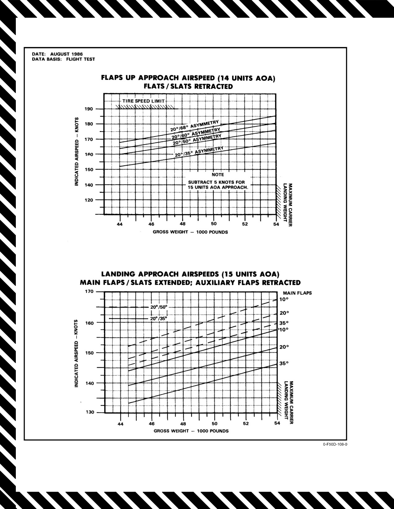
15−2 for recommended approach
airspeed for 14 or 15 units AOA with asymmetric wing
configurations.
15−11
ORIGINAL
NAVAIR 01−F14AAD−1
Figure 15Ć2.ĄAsymmetric Wing−Sweep Landing Approach Airspeed
ORIGINAL
15−12
NAVAIR 01-F14AAD-1
To preclude potential damage to aircraft, avoid
D Aircraft controllability in approach configu-
all wing-sweep commands prior to performing
ration with spoilers inoperative and a large
steps 1 through 9. Limit maneuvering envelope
wing-sweep asymmetry will range from diffi-
to 350 knots and 1.5g’s.
cult to impossible depending on split.
1. Leave wings and flaps as set.
D Upon lowering the landing gear an uncom-
manded but controllable roll transient may
2. Altitude
— Climb/Remain Above 10,000 Feet
occur because of spoiler gearing change from
AGL.
cruise to PA.
3. Airspeed — 250 Knots/Do Not Exceed 12 Units
c. Landing gear — Down.
AOA.
d. Leave flaps as set until further determinations are
4. Maneuver devices — Thumbwheel Manual Retract.
complete.
5. WING SWEEP DRIVE NO. 1 and WG SWP DR
NO. 2/MANUV FLAP cb’s — Pull (LD1, LE1).
e. Slowly increase AOA to no more than 15 units
(attempt to maintain 0_ sideslip).
6. All SASs — ON.
f. Make small lateral stick inputs to simulate lineup
Note
corrections.
If aircraft controllability is questionable for safe landing,
If ROLL SAS will not engage, accelerate and
perform Asymmetric Wing Sweep Unacceptable for Landing
attempt to reset at approximately 20-knot inter-
procedure, paragraph 15.7.2.2.
vals. Stick may have to be released laterally in
order to reengage ROLL SAS.
If aircraft controllability is safe for landing, perform
Asymmetric Wing Sweep Acceptable for Landing proce-
7. Confirm left and right wing position.
dure, paragraph 15.7.2.1.
Note
15.7.2.1
Asymmetric Wing Sweep Acceptable
for Landing
Wing-sweep tape indicates actual right-wing
position. All other cockpit wing position indi-
Establish final landing configuration as follows:
cations may be unreliable, including wing-
sweep handle position. Visually verify left-wing
1. AUX FLAP/FLAP CONTR cb - Pull (8G3).
position.
Note
If left wing is aft of 62_ spoiler cutout and right wing is 20_,
Pulling the AUX FLAP/FLAP CONTR cb (8G3)
perform Asymmetric Wing Sweep Unacceptable for Landing
with the emergency WING SWEEP handle at the
procedure, paragraph 15.7.2.2.
20_ position disables wingsweep commands.
8. Perform preliminary controllability check as
If both wings are forward of 50_:
follows:
a. Airspeed
Below 225 Knots.
a. Trim away from forward wing (opposite stick
force) to ensure that maximum spoiler deflection
is available.
b. Assess spoiler function by controlled left- and
right-stick inputs.
Extending the main flaps with either wing aft of
50_ could result in damage to both the flaps and
the aft fuselage.
15-13
CHANGE 1
NAVAIR 01−F14AAD−1
b. Flaps Ċ Lower Incrementally 20_ to 25_.
2.
Emergency WING SWEEP handle Ċ Leave
in
Position that
Established Satisfactory
Controllability.
3.
Gross weight Ċ Reduce as Required.
4.
DLC Ċ Stowed.
When flaps are set greater than 25_, lateral pilot−
induced oscillations are likely and may result in
5.
Autothrottles (APC) Ċ Do Not Engage.
wingtip damage at touchdown and/or hard
landings.
6.
Confirm flight characteristics by flying simulated
landing approach at safe altitude, to include lineup
Note
corrections, power changes, and waveoff.
The 25_ flap position can be established by first
noting when the spoiler position indicators
switch to the drooped position during flap
extension. An uncommanded but controllable
roll transient because of spoiler gearing change
will also occur. Upon observing either event,
Full spoiler authority will be required for
retract the flaps to just less than 25_. The roll
landing with large wing−sweep asymmetry.
transient will occur in the opposite direction as
Before attempting actual approach, trim
the flaps pass through 25_. Main flap extension
away from the forward wing (opposite
without auxiliary flaps will require greater than
stick forces) to ensure maximum spoiler
normal aft stick trim.
deflection is available.
c. Approach airspeed Ċ 15 Units AOA.
7.
Fly straight−in approach to arrested or normal
landing.
Note
Indicated AOA is subject to a 1 to 2−unit sideslip−
induced error. Verify proper AOA at zero
sideslip.
Avoid rapid lateral stick inputs, as significant
If either wing is aft of 50°:
pitch−roll coupling may result in roll ratcheting,
pitching motion, and lateral PIO tendency; an
a. Flaps Ċ UP.
excessive descent rate may develop and/or wingĆ
tip damage at touchdown may occur.
b. Approach airspeed Ċ 14 Units AOA.
Note
D A crosswind from the swept−wing side is
favorable while a crosswind from the
Wing rock and wing stall may occur at 16 to
forward−wing side is unfavorable.
16½ units AOA during flaps−up approaches.
D To reduce lateral stick force, the landing
Rapid lateral stick inputs will result in pitch
approach can be flown with rudder trim into
coupling. Excessive descent rates may develop
the forward wing, allowing aircraft to yaw
and/or wingtip damage at touchdown may occur.
into the forward wing. Sideslip should be
Precise AOA control and smooth lateral control
reduced with rudder just prior to touchdown.
inputs are required.
Note
Indicated AOA is subject to a 1 to 2−unit sideslip−
induced error. Verify proper AOA at zero
sideslip.
ORIGINAL
15−14
NAVAIR 01-F14AAD-1
Note
If spoilers are operational:
a. Emergency WING SWEEP handle — Input a
D If desired, sideslip can be reduced to zero with
Small Forward Command.
rudder at the beginning of the approach and
held to touchdown. Lateral stick force
increases as sideslip is reduced. Method of
If spoilers are not operational:
approach is pilot’s option.
a. Emergency WING SWEEP handle — Input a
D In the event of bolter or go-around, as airspeed
Small Aft Command.
increases, the aircraft will roll toward the
swept wing and yaw toward the forward wing.
3. Note movement of left and right wings and attempt
to regain wing-sweep asymmetry by using the
D Maximum airspeed for wheelbrake appli-
following wing-sweep commands.
cation is 165 knots at gross weights of 46,000
pounds and 145 knots at 51,000 pounds.
If both wings are moveable and left wing is forward of right
wing:
15.7.2.2
Asymmetric Wing-Sweep
Unacceptable for Landing
a. Airspeed — 300 Knots.
b. Emergency WING SWEEP handle — 68_.
c. Emergency WING SWEEP handle — 20_.
Efforts to improve controllability by attempting
d. AUX FLAP/FLAP CONTR cb Pull (8G3).
to minimize or eliminate wing-sweep mismatch
couldresult inanacceptable conditionbecoming
e. Repeat preliminarylandingcontrollabilitycheck
unacceptable.
(step 9 of paragraph 15.7.2).
Note
If both wings are moveable and right wing is forward of left
wing:
Once spoiler operation is assessed, stick forces
may be trimmed to reduce pilot workload during
a. Emergency WING SWEEP handle — 20_.
transit to field or CV. The use of lateral trim to
reduce stick forces during actual approach and
b. AUX FLAP/FLAP CONTR cb — Pull (8G3).
landing should be avoided as this reduces the
spoiler deflection available for roll control.
c. Repeat preliminarylandingcontrollabilitycheck
(step 9 of paragraph 15.7.2).
1. Flaps — UP.
If right wing is jammed and left wing is moveable:
2. AUX FLAP/FLAP CONTR cb — In (8G3).
a. Airspeed — 300 Knots.
Note
Note
D At any point during the following procedures,
If right wing is jammed aft of spoiler cutout
if wing-sweep symmetry is regained at aft
wing-sweep position and runway length/
angle, matching left wing will result in loss of
spoiler control. If this reduced lateral control is
approach speed permit, aircrew may elect to
perform Aft Wing-Sweep Landing emer-
undesirable, left wing should be commanded just
gency procedure, paragraph 15.7.1.
forward of spoiler cutout to regain spoiler
control.
D If left wing is jammed, wing-sweep command
can result in right wing driving to either 19_
(forward command) or 69_ (aft command)
actuator overtravel stop. Subsequent wing-
sweep commands may not move the right
wing.
15-15
CHANGE 1
NAVAIR 01−F14AAD−1
b. Emergency WING SWEEP handle Ċ Match
the stores−aboard switch regularly occurred during flight test
Left Wing to Right Wing Position.
and will indicate hung stores when none actually exists.
c. AUX FLAP/FLAP CONTR cb Ċ Pull (8G3).
In−flight actual cg location varies as fuel is burned but
remains relatively constant at its most forward position
d. Repeat preliminary landing controllability check
between 5,000 to 10,000 pounds. Below 5,000 pounds, the cg
(step 9 of paragraph 15.7.2).
moves aft towards the ZFGW position. Landing should be
accomplished at 5,000 pounds of fuel or more if possible.
If left wing is jammed and spoilers are operational:
Wing−mounted AIM−7/9s move the cg location slightly
forward and have no adverse effects on flying qualities.
a. Emergency WING SWEEP handle Ċ 20_.
External tanks produce no change to the cg location and also
have no adverse effects. Combinations of forward and aft
b. AUX FLAP/FLAP CONTR cb Ċ Pull (8G3).
stores will produce a cg change slightly less than considering
the difference as hung on the aft stations alone (i.e., the cg
c. Repeat preliminary landing controllability check
location with 2,000 pounds forward and 4,000 pounds aft will
(step 9 of paragraph 15.7.2).
be slightly more forward than 2,000 pounds aft alone).
If left wing is jammed aft of spoiler cutout wing−sweep angle
Flying qualities at aft cg locations with gear and flaps
and spoilers are inoperative:
up are only slightly degraded. This degradation will probably
a. Airspeed 300 Knots.
not be apparent to the pilot. Stick force per g remains
relatively nominal even with
4,000 pounds of aft hung
b. Emergency WING SWEEP handle Ċ 68_.
bombs. No change in flying qualities is noted during dive
recoveries between 400 and 500 KCAS. At 20_ of wing
c. AUX FLAP/FLAP CONTR cb Ċ Pull (8G3).
sweep with the gear and flaps down and an aft cg, the aircraft
is extremely susceptible to pilot−induced oscillations during
d. Repeat preliminary landing controllability check
closely controlled tasks such as flying the ball. Loss of
(step 9 of paragraph 15.7.2).
control is likely.
If final wing configuration is unsafe for landing:
The transition to landing configuration should be
performed in straight−and−level flight to allow handling
a. Prepare for and execute controlled ejection.
qualities to be evaluated in benign conditions. Wings should
be swept to the desired position before the gear and flaps are
15.8
AFT HUNG ORDNANCE LANDINGS
lowered. The AUX FLAP/FLAP CONTR (8G3) cb should be
pulled in case of a wing/flap interlock failure and also to
The normal NATOPS cg ZFGW limit for tunnel−
prevent the auxiliary flaps from deploying if 20_ of wing−
mounted stores is 17.0 percent. On a typical fleet aircraft, one
sweep is inadvertently selected. Sweeping the wings with
Mk 84 2,000−pound bomb placed on station No. 4 or 5 result
auxiliary flaps retracted results in significant pitch−trim
in a ZFGW cg aft of 17.0 percent MAC, possibly as far aft as
changes. A straight−in approach should be flown as power
18.5 to 19.0 percent MAC. Two aft hung Mk 84s can produce
requirements with aft wing sweep in a turn are significantly
a ZFGW cg of up to 22 percent MAC. These aft cg locations
different than normal and could produce a severely
reduce the normal static stability of the F−14, producing a
underpowered approach. Once established in the optimum
marked degradation in landing flying qualities. Aft
wing−sweep configuration appropriate for the amount of
wing−sweep can be used to restore the normal static longiĆ
ordnance hung on the aft stations, normal approach
tudinal stability margin, regaining normal flying qualities
techniques can be used. No abnormalities in aircraft response
even with extremely aft cg locations.
or performance are apparent during landing approaches at
15 units, even with 4,000 pounds of aft hung ordnance. APC
Aircrew may have difficulty detecting aft hung
is not optimized for aft wing−sweep landings and should not
ordnance following bomb release. The only cockpit indiĆ
be used. DLC should not be used as it adds 8 knots to recovery
cation of an unsuccessful release will be a hot trigger light
WOD requirements and has improper pitch trim response at
that remains illuminated following the intended release of all
aft wing−sweep. Expect onspeed airspeed for 25_ of wing−
selected stations. With MA ARM ON, individually selecting
sweep to increase 6 knots over the normal DLC on, 20_ of
stations will illuminate the HOT TRIG light when the hung
wing−sweep approach speed, and a 12−knot increase if wings
station is selected. Check SMS for hung stores. Obtain a
are at 30_. For CV arrestments, the appropriate recovery
visual check if possible to validate this check as failures of
bulletin should be consulted.
ORIGINAL
15−16
NAVAIR 01-F14AAD-1
Ashore, a field arrestment is recommended with
spoiler brakes dearmed because of the large noseup pitch
occurring at spoiler deployment. If a field arrestment is not
possible, expect to use full forward stick to counter the
Expect a significant nose pitchup during landing
noseup pitching moment and to maintain forward stick until
below 80 KCAS with a resultant longer rollout.
rollout as spoilers deploy. Full forward stick may
be required to avoid a tail strike.
15.8.1
Landing with Aft Hung Ordnance
15.9
FIELD ARRESTMENTS
1. Determine location of hung stores. Obtain visual
check if possible.
15.9.1
Field Arresting Gear
If hung ordnance exceeds 1,000 pounds:
The types of field arresting gear in use include the
anchor chain cable, water squeezer, and Morest-type
2. Wing sweep — Set at 25_ if
2,000-Pounds Hung
equipment. All require engagement of the arresting hook in
Aft; Set at 30_ if > 2,000 Pounds Hung Aft.
a cable pendant rigged across the runway. Location of the
pendant in relation to the runway will classify the gear as
3. Perform transition to gear-down configuration in
follows:
straight-and-level flight.
1. Short-field gear — Located 1,500 to 2,000 feet past
4. AUX FLAP/FLAP CONTR cb — Pull (8G3)
approach end of runway. Usually requires prior noti-
fication in order to rig for arrestment.
5. Flaps — Full DN.
2. Midfield gear — Located near the halfway point of
the runway. Usually requires prior notification in
6. Fly straight-in approach at 15 units AOA. Do not
order to rig for arrestment in the direction desired.
engage APC or DLC.
3. Abort gear — Located 1,500 to 2,500 feet short of
CV approach:
the departure end of the duty runway and usually
rigged for immediate use.
7. Perform CV arrestment in accordance with
applicable recovery bulletin.
4. Overrun gear — Located shortly past the upwind
end of the duty runway. Usually rigged for imme-
Field approach:
diate use.
Some fields will have all types of gear, others none. For
7. Spoiler brake — OFF.
this reason, it is imperative that all pilots be aware of the type,
location, and compatibility of gear in use with the aircraft,
8. Perform field arrestment.
and the policy of the local air station with regard to which
gear is rigged for use and when.
Note
As various modifications to the basic types of arresting
Refer to emergency field arrestment guide
gear are made, exact speeds will vary accordingly. Certain
(Figure 15-3) for maximum engagement speed.
aircraft service changes may also affect engaging speed and
weight limitations.
If arresting gear is not available:
8. If field arrestment is not available, spoiler brake —
BOTH.
An engagement in the wrong direction into chain
gear can severely damage the aircraft.
15-17
CHANGE 1
NAVAIR 01−F14AAD−1
In general, arresting gear is engaged on the centerline
15.9.3
Long−Field Arrestment
at as slow a speed as possible. Burn or dump down to an
acceptable landing weight. Conditions permitting, make
The long−field−arrestment is used when a stopping
practice passes to accurately locate the arresting gear.
problem exists with insufficient runway remaining (that is,
Engagement should be made with feet off the brakes,
aborted takeoffs, icy or wet runways, loss of brakes after
shoulder harness locked, and with the aircraft in a three−point
touchdown, etc.). Lower the hook, allowing sufficient time
attitude. After engaging the gear, good common sense and
for it to extend fully before engagement (normally 1,000 feet
existing conditions dictate whether to keep the engines
before reaching the arresting gear). Do not lower the hook too
running or to shut down and egress the aircraft.
early and weaken the hook point. Line up the aircraft on the
runway centerline. Inform the control tower of your
In an emergency situation, first determine the extent of
intentions to engage the arresting gear, so that aircraft landing
the emergency by whatever means are available (instruĆ
behind you may be waved off. If leaving the runway is ineviĆ
ments, other aircraft, LSO, RDO, tower or other ground
table, secure the engines.
personnel). Next, determine the most advantageous arresting
gear available and the type of arrestment to be made under
15.9.4
Engaging Speeds
the conditions. Whenever deliberate field arrestment is
intended, notify control tower personnel as much in advance
The maximum permissible engaging speed, gross
as possible and state estimated landing time in minutes.
weight, and off−center engagement distance for field
arrestment are listed in Figure 15−3. The data in the long−field
If gear is not rigged, it will probably require 10 to
landing columns may be used for lightweight aborted takeoff
20 minutes to prepare. If foaming of the runway or area of
where applicable; data in the aborted takeoff columns may be
arrestment is required or desired, it should be requested by
used for heavy gross weight landings.
the pilot at this time.
As various modifications to the basic types of arresting
If fuel is streaming from the bottom of the aircraft, a
gear are incorporated, engaging speeds or gross−weight
field arrested landing is not recommended because of the
limitations may change. For this reason and for more detailed
high probability of sparks and heat from the arresting hook
information, the applicable aircraft recovery bulletin should
igniting the streaming fuel and air mixture. If an arrested
be consulted.
landing is mandated because of the lack of adequate braking
or runway conditions, an effort should be made to foam the
15.10 BARRICADE ARRESTMENT
runway in the runout area of the arresting gear.
1. External stores Ċ Jettison
(except AIM−7 or
AIM−54 on fuselage stations if wing is at full
15.9.2
Short−Field Arrestment
for−ward sweep).
If at any time before landing a directional control
2. External tanks Ċ Jettison (empty tanks retained
problem exists or a minimum rollout is desired, a short−field
only for landing gear malfunction).
arrestment should be made and the assistance of LSO
3. Fuel Ċ Dump or burn (reduce to 2,000 pounds).
requested. The LSO should be stationed near the touchdown
point and equipped with a radio. Inform the LSO of the
4. HOOK Ċ DN (Lower to permit engagement of a
desired touchdown point. A constant glideslope approach to
cross−deck pendant, which will minimize barricade
touchdown is permitted (mirror or Fresnel lens landing aid)
engagement speed and damage to aircraft).
with touchdown on centerline at or just before the arresting
5. Fly normal pattern and approach, on−speed, angle of
wire with the hook extended. The hook should be lowered
attack, centerline, and meatball.
while airborne and a positive hook−down check should be
made. Use midfield gear or Morest−type, whenever
available. If neither is available, use abort gear. Use an
Note
approach speed commensurate with the emergency experiĆ
Anticipate loss of meatball for a short period of
enced. Landing approach power will be maintained until
time during the approach. Barricade stanchions
arrestment is assured or a waveoff is taken. Be prepared for
may obscure the meatball.
a waveoff if the gear is missed. After engaging the gear, retard
the throttles to IDLE or secure engines and abandon aircraft,
Upon engaging the barricade:
depending on existing conditions.
6. Throttles Ċ OFF.
7. Evacuate aircraft as soon as practical.
ORIGINAL
15−18

NAVAIR 01−F14AAD−1
MAXIMUM ENGAGING SPEED (KNOTS)(D)
GROSS WEIGHT X 1,000 POUNDS
TYPE OF
MAXIMUM
LONG−
ARRESTING
OFF−CENTER
SHORT−FIELD
FIELD
ABORTED TAKEOFF
GEAR
ENGAGEMENT
LANDING (K)(L)
LANDING
(A)
(M)
(FT)
40
44
48
51.8
54
57
60
64
68
69.8
72
E−28
176
180
179
178
177
176
175
174
172
172
171
40
(B)
E−28 (G)
176
176
160
160
160
160
156
145
145
145
145
40
(B)
M−21
130
130
130
130
125
125
120
115
115
115
113
10
BAK−9
160
160
160
155
150
144
138
131
124
122
118
30
BAK−12 (H)
160
160
159
146
137
118
(J)
(J)
(J)
(J)
(J)
50
DUAL BAK−12
160
160
160
160
160
160
160
160
160
160
160
30
(C)
BAK−13
160
160
160
160
160
160
160
160
160
160
160
40
(A) Data provided in aborted takeoff column may be used for emergency high gross weight arrestment.
(B) Maximum engaging speed limited by aircraft limit horizontal−drag load factor (mass item limit g").
(C) Dual BAK−12 limits are based on 150 to 300−foot span, 1¼−inch cross−deck pendant, 50,000−pound weight
setting, and 1,200−foot runout. No information is available regarding applicability to other configurations.
(D) Maximum engaging speed is limited by arresting gear capacity except as noted.
(E) Off−center engagement may not exceed 25 percent of the runway span.
(F) Before making an arrestment, the pilot must check with the air station to confirm the maximum engaging
speed because of a possible installation with less than minimum required rated chain length.
(G) Only for the E−28 systems at Keflavik and Bermuda with 920−foot tapes.
(H) Standard BAK−12 limits are based on 150−foot span, 1−inch cross−deck pendant, 40,000−pound weight setting,
and 950−foot runout. No information is available regarding applicability to other configurations.
(J) Engaging speed limit is 96 knots at 59,000 pounds. Because of runout limitations, it is recommended this
gear not be engaged at weights greater than 59,000 pounds.
(K) Maximum of 3.0_ glideslope.
(L) Consult appropriate section for recommended approach speed.
(M) Flared or minimum rate of descent landing.
Figure 15Ć3.ĄEmer gency Field Arrestment Guide (Sheet 1 of 2)
15−19
ORIGINAL

NAVAIR 01−F14AAD−1
AIRCRAFT ENGAGING SPEED LIMITS
FOR E−5 EMERGENCY ARRESTING GEAR
AIRCRAFT: F−14 D
SHORT FIELD LANDING
LONG FIELD LANDING
ABORTED TAKEOFF
UP TO 54,000 POUNDS
UP TO 60,000 POUNDS
60,100 TO 72,000 POUNDS
ARRESTING
STANDARD
HEAVY
STANDARD
HEAVY
STANDARD
HEAVY
GEAR
CHAIN
CHAIN
CHAIN
CHAIN
CHAIN
CHAIN
RATING
E−5
E−5−1
E−5
E−5−1
E−5
E−5−1
E−5
E−5−1
E−5
E−5−1
E−5
E−5−1
E−5−2
E−5−3
E−5−2
E−5−3
E−5−2
E−5−3
E−5−2
E−5−3
E−5−2
E−5−3
E−5−2
E−5−3
COL. 1
COL. 2
COL. 3
COL. 4
COL. 5
COL. 6
COL. 7
COL. 8
COL. 9
COL. 10
COL. 11
COL. 12
COL. 13
300 to 349
39 (D)
39 (D)
40 (D)
40 (D)
37 (D)
37 (D)
38 (D)
38 (D)
33 (D)
33 (D)
34 (D)
34 (D)
350 to 399
45 (D)
45 (D)
47 (D)
47 (D)
43 (D)
43 (D)
44 (D)
44 (D)
39 (D)
39 (D)
40 (D)
40 (D)
400 to 449
51 (D)
51 (D)
54 (D)
54 (D)
48 (D)
48 (D)
51 (D)
51 (D)
44 (D)
44 (D)
47 (D)
47 (D)
450 to 499
57 (D)
57 (D)
61 (D)
61 (D)
54 (D)
54 (D)
58 (D)
58 (D)
49 (D)
49 (D)
53 (D)
53 (D)
500 to 549
63 (D)
63 (D)
68 (D)
68 (D)
60 (D)
60 (D)
65 (D)
65 (D)
55 (D)
55 (D)
59 (D)
59 (D)
550 to 599
69 (D)
69 (D)
76 (D)
76 (D)
65 (D)
65 (D)
72 (D)
72 (D)
60 (D)
60 (D)
66 (D)
66 (D)
600 to 649
75 (D)
75 (D)
84 (D)
84 (D)
71 (D)
71 (D)
79 (D)
79 (D)
65 (D)
65 (D)
73 (D)
73 (D)
650 to 699
81 (D)
81 (D)
91 (D)
91 (D)
77 (D)
77 (D)
87 (D)
87 (D)
71 (D)
71 (D)
79 (D)
79 (D)
700 to 749
87 (D)
87 (D)
99 (D)
99 (D)
83 (D)
83 (D)
94 (D)
94 (D)
76 (D)
76 (D)
86 (D)
86 (D)
750 to 799
93 (D)
93 (D)
107 (D)
107 (D)
89 (D)
89 (D)
102 (D)
102 (D)
82 (D)
82 (D)
93 (D)
93 (D)
800 to 849
99 (D)
99 (D)
115 (D)
115 (D)
94 (D)
94 (D)
109 (D)
109 (D)
87 (D)
87 (D)
100 (D)
100 (D)
850 to 899
105 (D)
105 (D)
123 (D)
123 (D)
100 (D)
100 (D)
117 (D)
117 (D)
93 (D)
93 (D)
107 (D)
107 (D)
900 to 949
111 (D)
111 (D)
131 (D)
131 (D)
106 (D)
106 (D)
125 (D)
125 (D)
98 (D)
98 (D)
114 (D)
114 (D)
950 to 999
117 (D)
117 (D)
140 (D)
140 (D)
112 (D)
112 (D)
133 (D)
133 (D)
104 (D)
104 (D)
121 (D)
121 (D)
1,000 to 1,049
123 (D)
123 (D)
148 (D)
148 (D)
118 (D)
118 (D)
140 (D)
140 (D)
109 (D)
109 (D)
129 (D)
129 (D)
1,050 to 1,099
129 (D)
129 (D)
150 (D)
156 (D)
123 (D)
123 (D)
148 (D)
148 (D)
115 (D)
115 (D)
136 (D)
136 (D)
1,100
135 (D)
135 (D)
150 (D)
165 (D)
129 (D)
129 (D)
150 (D)
156 (D)
120 (D)
120 (D)
143 (D)
143 (D)
NOTES (E) AND (F) APPLY
Figure 15−3. Emergency Field Arrestment Guide (Sheet 2 of 2)
ORIGINAL
15−20
NAVAIR 01-F14AAD-1
If light is illuminated and hook visually is checked down:
6. WSHLD AIR/ANTI-ICE HOOK CONT cb — Pull
(8C2).
Weight limits for barricade engagement are as
follows:
Note
a. Wings at 20_ — 51,800 pounds (maximum).
Cb 8C2 also controls windshield air and anti-ice.
b. Wing sweep
20_ < 35_ — 46,000 pounds
15.12 FORCED LANDING
(maximum).
Landing the aircraft on unprepared surfaces is not
c. Wings 35_ — Not permitted.
recommended. If it is necessary to do so, landing with the
landing gear down, regardless of the terrain, will assist in
15.11 ARRESTING HOOK EMERGENCY DOWN
absorbing the shock of ground impact and reduce possibility
of flightcrew injuries. External stores should be jettisoned in
1. HOOK handle — DN.
a safe area prior to touchdown. External tanks should be
jettisoned if they contain fuel, but retained to absorb landing
2. HOOK handle — Pull, Then Rotate.
shock if they are empty. If time permits, dump fuel to allow
touchdown at the slowest possible speed with full flaps.
Note
15.13 GROUND ROLL BRAKING FAILURES
Pull handle aft approximately 4 inches and turn
counterclockwise. This will mechanically
*1. ANTISKID SPOILER BK switch — Check.
release the uplatch mechanism and allow hook to
extend.
*2. MASTER RESET pushbutton — Depress.
3. Hook transition light — Check OFF.
If light is illuminated and hook visually is checked up:
4. HOOK handle — Restow in Down Position.
Ground roll braking may fail to extend spoilers
5. HYD VALVE CONTR cb — Pull and Reset After 5
on touchdown due to a momentary miscompare
Seconds (8E5).
of the weight-on-wheels switches. MASTER
RESET should restore normal ground roll
braking operation.
15-21 (Reverse Blank)
CHANGE 1
NAVAIR 01−F14AAD−1
CHAPTER 16
Ejection
16.1
EJECTION
attempt is made during zoom, and there is no
evidence of a relight, eject at peak altitude. If no
Responsibility for the decision to eject shall be
airstart attempt is made, eject at peak altitude.
determined and briefed before flight. Thereafter the decision
to abandon the aircraft shall rest with the crewmember
3. If decision to abandon aircraft is made at high
assigned responsibility for that particular situation. The
altitude, the recommended minimum altitude for
decision should be made before sink rate, altitude, and
ejection is 10,000 feet AGL, or higher, if conditions
attitude conditions jeopardize safe ejections for both
so indicate. Under any circumstances and if at all
occupants. In flight, the aircraft must be abandoned by means
possible, ejection should be accomplished prior to
of the ejection seats since there is no provision for manual
descending below 2,000 feet AGL.
bailout. Prior to ejection from a flyable or controllable
aircraft, it is the pilot’s responsibility to do everything
16.1.1
Ejection Envelope
reasonable to ensure that the abandoned aircraft will inflict
Figure 16−1 shows minimum ejection altitude for a
the least possible damage on impact.
given airspeed and sink rate, bank angle, and dive angle. For
Ejection may be necessary as a result of fire, engine
all ejections, it is recommended that airspeed be reduced as
failure, structural failure, midair collision, or when the
much as practicable; however in uncontrolled situations, do
aircraft becomes uncontrollable. In each case, the pilot must
not delay ejection because the aircraft is not within the
decide when to eject, using the following as a guide:
published safe escape envelope. For ejection at low altitude,
it is recommended that a climb be initiated to convert excess
1.
Ejection is mandatory under the following
airspeed into altitude. Although the escape system is capable
conditions except when unusual circumstances
of zero−zero ejection, it should be borne in mind that a
clearly indicate to the pilot that the cause of safety
combination of low airspeed and high rate of descent at low
to self and others will be better served by a flameout
altitude can present a condition more severe than zero−zero.
approach than by ejection.
Ejection sequences are shown in FO−16 and FO−17.
a. Serious, uncontrolled fire.
For details of ejection seat mechanical operation, see
paragraph 2.38.
b. If aircraft is in uncontrolled flight at 10,000 feet
AGL or below.
c. When dual−engine flameout occurs below 1,500
feet AGL and 250 knots.
During ejection seat development and testing,
d. If repeated relight attempts are not successful
the SJU−17(V)3/A and SJU−17(V)4/A were
between 30,000 and 10,000 feet, eject by 10,000
qualified for use by male aviators with nude
feet AGL.
weights from 136 pounds to 213 pounds. OperaĆ
e. If still on first or second relight attempt when
tion of the seat by personnel not within these paĆ
passing through 10,000 feet AGL and it appears
rameters subjects the occupant to an increased
that a relight is likely, airstart attempt may be
risk of injury.
continued to a minimum of 5,000 feet AGL.
1. General Injury Risks:
2.
If dual−engine flameout occurs below 10,000 feet,
a. Ejection stability is directly related to occupant
zoom to convert excess airspeed to altitude.
restraint. All occupants should be properly
Attempt airstart as time permits. If peak altitude is
restrained in the seat by their torso harness for
above 5,000 feet AGL and airstart attempt is not
optimum performance and minimum injury risk.
successful, eject no lower than 5,000 feet AGL. If
peak altitude is below 5,000 feet AGL and airstart
16−1
ORIGINAL
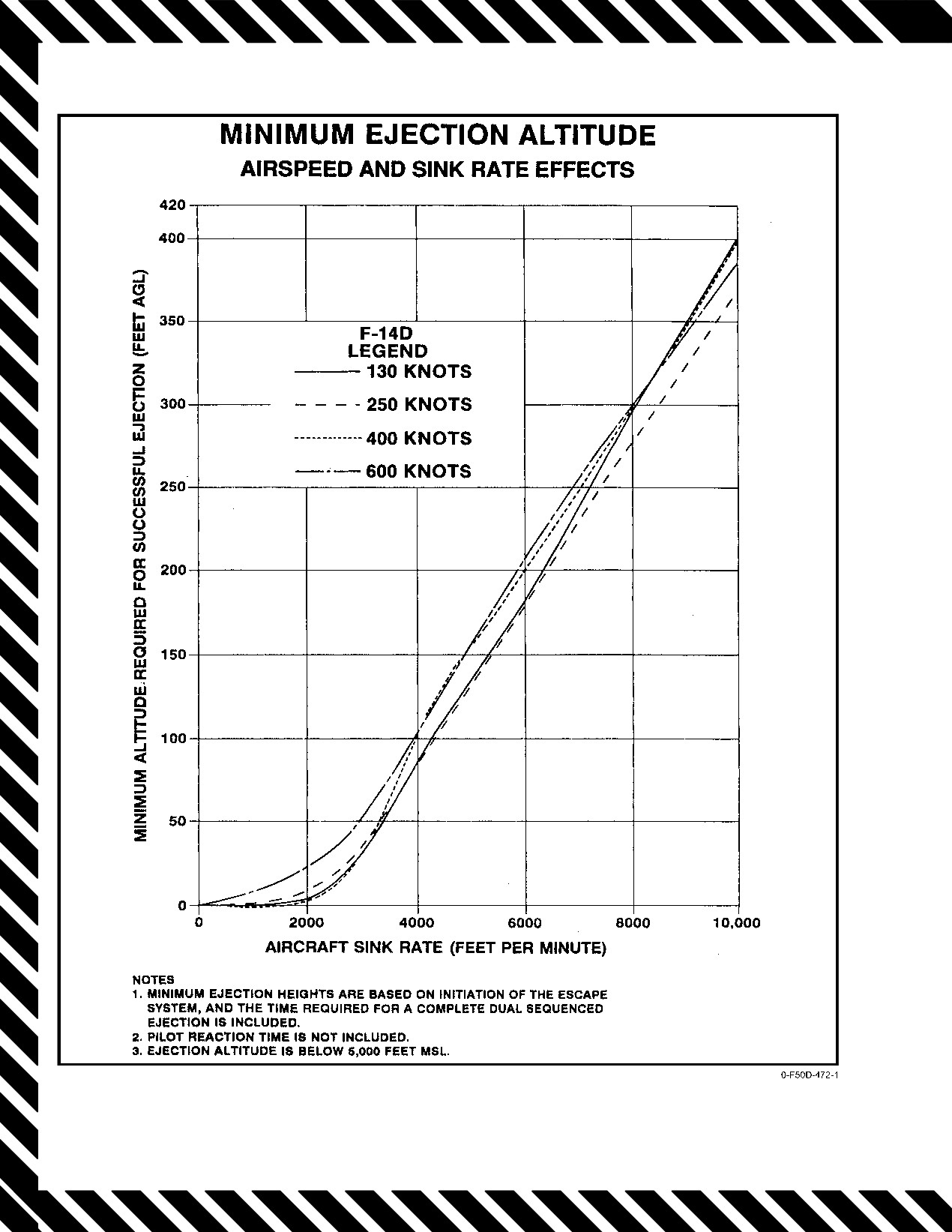
NAVAIR 01−F14AAD−1
Figure 16Ć1.ĄMinimum Ejection Altitude (Sheet 1 of 3)
ORIGINAL
16−2
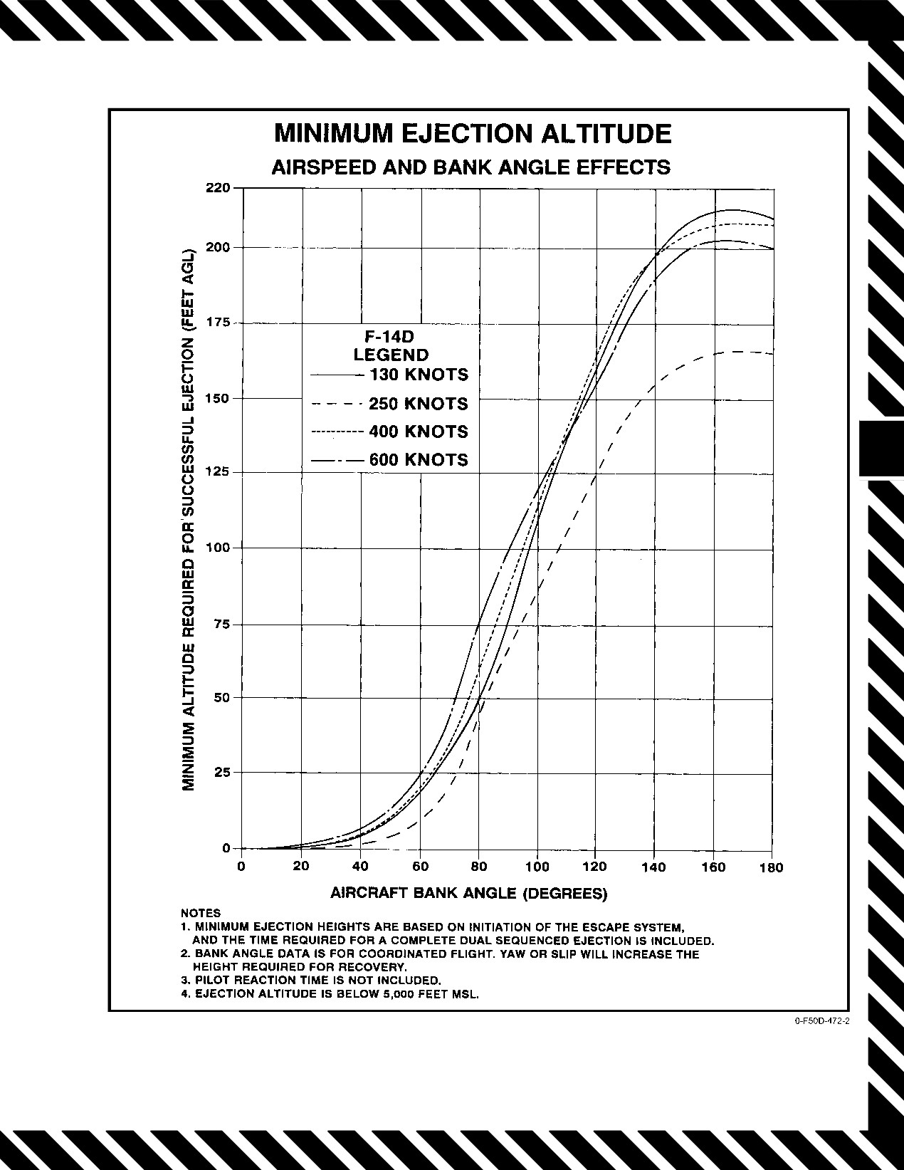
NAVAIR 01−F14AAD−1
Figure 16−1. Minimum Ejection Altitude (Sheet 2 of 3)
16−3
ORIGINAL
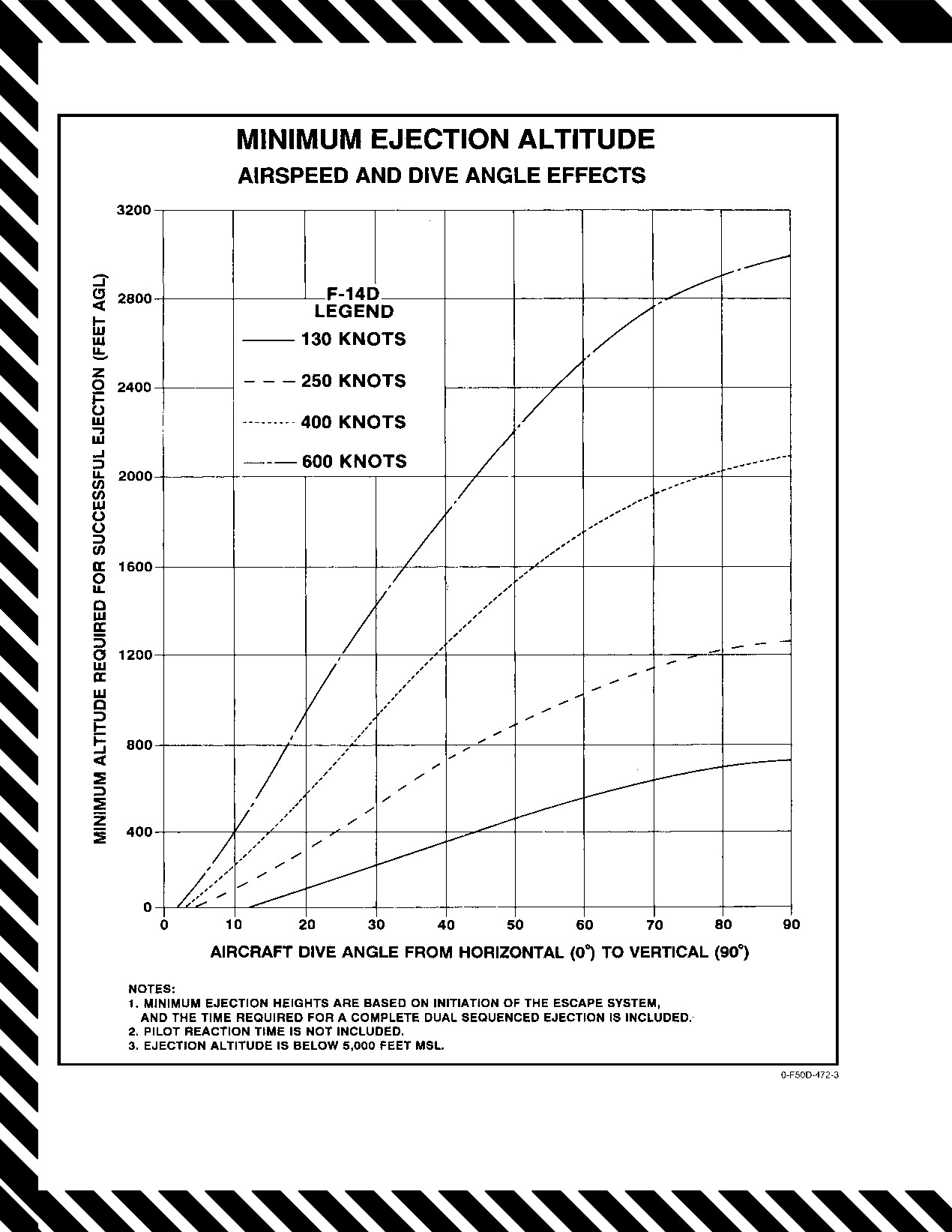
NAVAIR 01−F14AAD−1
Figure 16−1. Minimum Ejection Altitude (Sheet 3 of 3)
ORIGINAL
16−4
NAVAIR 01−F14AAD−1
b. Inertia reel performance may be degraded for ocĆ
ARMED/SAFE handle is at ARMED before trying again.
cupants outside of the qualified weight range.
Ejection through the canopy is an automatic backup. There
Lighter occupants may be injured during the
is no provision for manual bailout.
haulback, and both light and heavy occupants
may experience poor ejection positions,
16.1.2
Ejection Preparation
resulting in an increased risk of injury during
ejection.
2.
Injury risks for aviators with nude weights less than
136 pounds:
Never pull the manual override handle before
a. The catapult was designed for the ejection seat
ejection. Pulling the handle releases the
qualified weight range. Lighter weight
crewmember from the seat and moves the
occupants are subject to a higher risk of injury
ARMED/SAFE handle to SAFE, making it
from the catapult due to greater acceleration.
impossible to initiate ejection from the seat.
Further, if ejection is initiated by the other
b. Lighter weight occupants are at a greater risk of
crewmember, results could be fatal.
injury during ejections above 300 KIAS due to
Time permitting, perform all or as much as possible of
instability during drogue deployment.
the following:
c. Lighter weight occupants are at a greater risk of
1.
Place aircraft in safe envelope and attitude for
injury during ejections near the upper end of
ejection.
Mode 1 (approaching 300 KIAS) due to high
2.
Warn other crewmember.
parachute opening shock.
3.
EJECT CMD lever Select (RIO).
3.
Injury risks for aviators with nude weights greater
than 213 pounds:
4.
IFF/SIF EMERG/7700 (RIO).
5.
Position report Transmit.
a. Larger occupants may not attain sufficient
altitude for parachute full inflation in zero−zero
6.
Check altimeter.
cases or at extremely low altitudes and
7.
Assume proper ejection position (see Figure 16Ć2).
velocities.
a. Head pressed back against headrest
b. Larger occupants may not attain sufficient
b. Chin slightly elevated (10° up).
altitude to clear the aircraft tail structure.
c. Back straight.
The escape system will function up to 0.9 IMN or 600 KIAS,
d. Hips against seat back.
whichever is greater. However, human limitations are more
e. Thighs flat on seat survival kit.
restrictive as indicated below:
f. Outside of thighs pressed against side of seat.
1. Zero to
250 KIASĊSafe ejection
(injury
improbable).
g. Elbows and arms pressed firmly against body.
2. 250 to 600 KIASĊHazardous ejection (appreciable
h. Feet on rudder pedals, heels on deck.
forces are exerted on the body, making injury
i. Visor down, oxygen mask tightened, helmet
probable).
secure.
3. Above 600 KIASĊExtremely hazardous ejection
(excessive forces are exerted upon the body, making
serious injury or death highly probable).
Usually, there will be enough time to do several things
to prepare for a successful ejection prior to pulling the seat
D Positioning the legs aft prior to ejection will
firing handle. However, when the emergency condition
cause the spine to flex and will increase the
requiring ejection is such that ejection must be made without
possibility of spinal injury, and, will also
hesitation, simply grasp the handle and pull forcibly to the
increase likelihood of seat/thigh slap with
fullest extent until the seat ejects. If the seat fails to eject,
attendant leg injury.
immediately pull again. If the handle will not move, ensure
D Proper body position is a critical factor in
that the ground safety pin has been removed and that the
preventing ejection injuries.
16−5
CHANGE 1
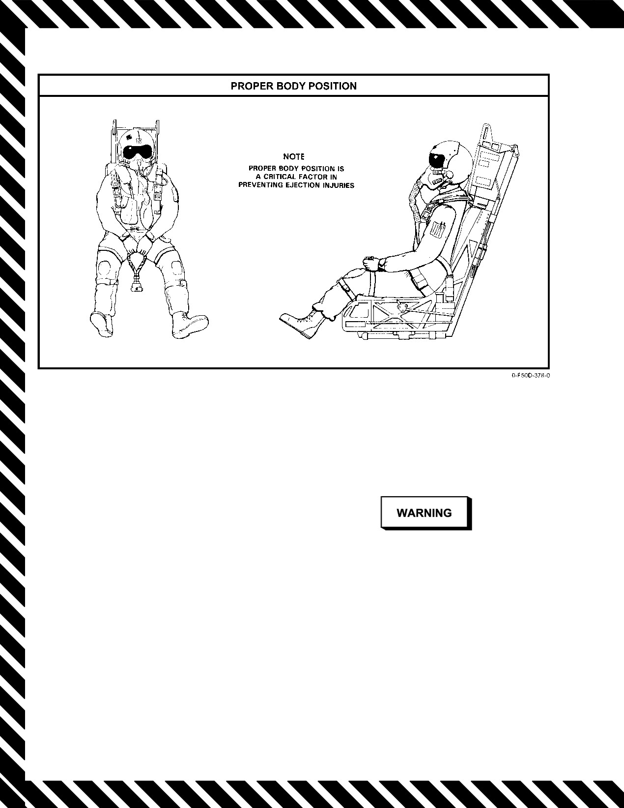
NAVAIR 01−F14AAD−1
Figure 16Ć2.ĄProper Ejection Position
16.1.3
Ejection Initiation
Note
LPA inflation may not be desirable over land.
See Figure 16−3 for ejection initiation.
The paragraphs that follow provide procedures
After the seat firing handle is pulled:
applicable to the NACES seat. Additional post−ejection/
1. The harness retraction unit retracts the shoulder harĆ
survival procedures are to be found in the NATOPS Survival
ness pulling the occupant to an upright position. The
Manual, NAVAIR 00−80T−101.
leg garters are retracted as the seat moves up the rail.
2. Ejection through the canopy is a backup method
only; therefore, canopy is jettisoned as part of
normal ejection sequence. Ejection through the
D Ejection at low altitude allows only a matter
canopy or out of the aircraft occurs after a delay if
of seconds to prepare for landing. Over water,
the normal sequence fails.
inflation of the LPA is the most important step
3. Seats eject individually and in opposite directions
to be accomplished. Release of the parachute
(pilot right, RIO left).
quick−release fittings as the feet contact the waĆ
ter is the second most important step to prevent
entanglement in the parachute shroud lines.
16.2
MANUAL BAILOUT
D When ejection is in the immediate vicinity of
There is no provision for manual bailout. Ejection
the carrier, parachute entanglement combined
through the canopy is an automatic backup if the canopy fails
with wake and associated turbulence can rapĆ
to jettison or the safe and arm unit fails to fire.
idly pull a survivor under.
16.3
SURVIVAL/POSTEJECTION PROCEDURES
Figure
16−4 describes step−by−step procedures for
inflation of the LPA configured with beaded handles and the
35−gram CO2 cylinder.
CHANGE 1
16−6
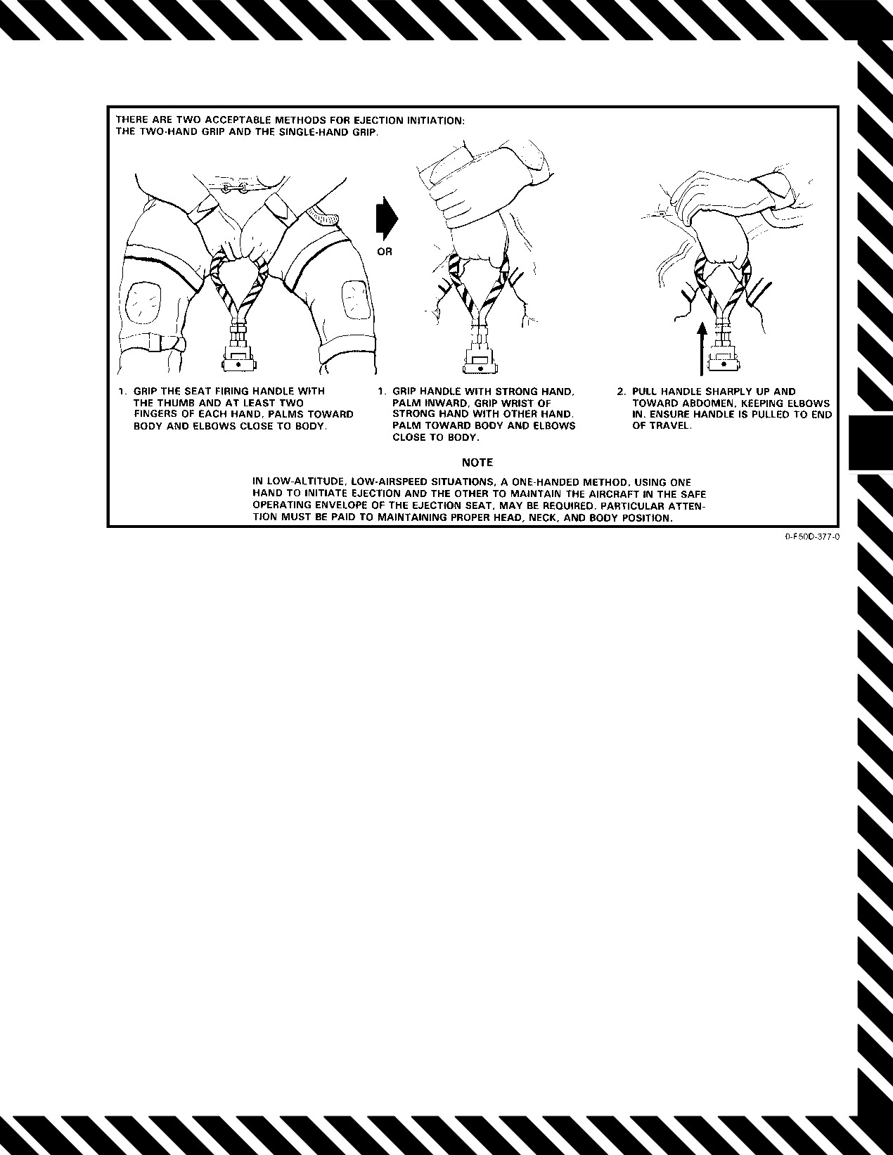
NAVAIR 01−F14AAD−1
Figure 16Ć3.ĄEjection Initiation
The deployed seat survival kit may contribute
Locate the manual override handle on the right side of the
to shroud−line entanglement. The survivor
seat bucket, depress the handle release button and pull handle
must be prepared to cut shroud lines that are
sharply upward as far as possible. This fires a cartridge to
dragging him down.
activate the parachute deployment rocket and release the
upper and lower harness locks. Man/seat separation occurs
D The crashed aircraft may release large
when the main parachute is extracted and deployed.
quantities of jet fuel and fumes that could
hamper breathing and create a fire hazard if
16.3.2
Survival Kit Deployment
smoke or flare marker is present. The
emergency oxygen system may be invaluable
Note
in this case and discarding the seat pan would
terminate its use. However, totally discarding
Survival kit deployment is not recommended in
the seat pan may be appropriate after
an overland ejection situation. The kit can be
considering weather, sea conditions, and
opened after landing by removing the closure
rescue potential.
pins from the cones.
Note
With either hand, locate one of the deployment handles
The variety and complexity of conditions
at the rear of the seat kit. Firmly pull on the handle until it is
free of the kit and the survival package falls away on its
encountered during the time−critical movements
following a low−altitude, overwater ejection
dropline. The package remains attached to the kit lid by the
dropline. At full dropline stretch, the liferaft is inflated
make it impossible to formulate procedures to
cover every contingency.
automatically.
16.3.1
Manual Man/Seat Separation
If below 14,000 feet and man/seat separation have not
occurred, the procedure will have to be initiated manually.
16−7
ORIGINAL
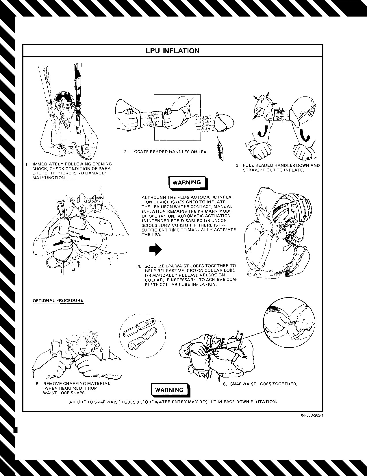
NAVAIR 01−F14AAD−1
Figure 16Ć4.ĄLife Preserver Assembly Inflation
ORIGINAL
16−8
NAVAIR 01−F14AAD−1
16.3.3
Parachute Steering
16.3.5
Raft Boarding
A gentle pull of approximately 6 inches on the left or
Note
right steering line (attached to the riser) will rotate the canopy
to enable steering. Pulling on the left line steers left. The
D If the liferaft has not inflated automatically,
canopy will continue to rotate for a time after the steering line
pull on the red operating handle on the
is released, so it is necessary to compensate for this lag by
dropline to inflate.
releasing the steering line before the desired direction is
D If the survival package has not been deployed
reached.
before water entry, first pull the yellow
deployment handle then the red operating
16.3.4
Parachute Landing Preparation
handle.
Preparations over land and over water are essentially
When clear of the canopy, retrieve the raft by locating
the same except that over land the visor should be kept down,
the dropline and pulling the raft to you. The raft retaining
the gloves worn, and the survival kit should not be deployed.
lanyard is in a pocket next to the CO2 cylinder. Attach the end
In low−level, overwater situations, the mask and regulator
of the lanyard securely to the gated helo hoist ring on the
should be retained since they provide an underwater
harness, then ensure that the oxygen hose is disconnected
breathing capability. If there is time before a water landing,
from the kit lid and release the lapbelt quick−release fittings,
the gloves may be removed and stowed safely. This may
releasing the kit lid. Bring the raft around for entry from the
make it easier to operate the canopy releases.
small end (stem); grasp the stem, and forcibly push under
Try to determine the direction of the wind at the surface
LPA waist lobes. Using the boarding handles, pull into the
using white caps, smoke from the wreckage, or known
raft and turn into a comfortable, balanced, seated position.
surface winds in the vicinity. Note that surface winds may be
Locate the dropline and retrieve the survival package.
quite different from those at altitude. When nearing the
surface, steer into the wind and assume the proper body
position for landing:
1. Feet together, knees slightly bent, toes pointed
slightly downward.
Do not attempt to retrieve the kit lid. Any attempt
to do so could capsize the raft.
2. Eyes on the horizon.
Close the canopy and orally inflate the canopy and
3. Grasp canopy risers and tuck elbows in prior to
floor. An integral baler is provided to bale the raft as
water entry.
necessary.
4. On water entry, release the canopy manually. The
SEWARS releases will operate the canopy release
fittings on saltwater entry as a backup.
16−9 (Reverse Blank)
ORIGINAL
NAVAIR 01−F14AAD−1
PART VI
All−Weather Operations
Chapter 17 Ċ Instrument Procedures
Chapter 18 Ċ Extreme Weather
85 (Reverse Blank)
ORIGINAL
NAVAIR 01−F14AAD−1
CHAPTER 17
Instrument Procedures
17.1
AUTOMATIC CARRIER LANDING SYSTEM
17.1.2
Mode II
ACLS approaches apply to properly configured
The control of the aircraft remains with the pilot along
aircraft utilizing carrier or shore−based AN/SPN−10 or
the entire glideslope to touchdown. Glideslope error signals
AN/SPN−42 ACLS radar facilities. Three primary modes of
are transmitted to the aircraft for cockpit displays from the
operation and two submodes are available.
AN/SPN−41 or the AN/SPN−42. The pilot flies the aircraft to
null the error and to keep the vertical and lateral crosshairs
1. Mode I approach automatically controlled to
centered. During a Mode II T approach, the final controller
touchdown
provides a Mode III−type talkdown to assist the pilot in flying
2. Mode IA approach automatically controlled to a
his needles or for controller training.
minimum of 200 feet and one−half mile; manual
control remainder of approach
17.1.3
Mode III
3. Mode II approach manually controlled using AN/
The pilot flies the aircraft in response to voice radio
SPN−41 or AN/SPN−42 vertical display indicator
commands from the final controller to keep the aircraft on the
and/or heads−up display presentation for glideslope
proper glideslope. From the radar azimuth and elevation
and lineup information
displays, the final controller determines the aircraft position
with respect to the desired glidepath and gives guidance to
4. Mode III approach manually controlled using only
the pilot.
CCA−controller−supplied information
5. Flight director approach manually controlled using
17.1.4
Flight Director
HUD flight director presentation derived from AN/
The pilot flies the aircraft so that the FPM stays inside
SPN−42/46 information and navigation system data
the flight director symbol on the HUD. The flight director
for glidepath intercept and following.
symbol provides glideslope and centerline steering
information computed by the mission computer using
17.1.1
Mode I
navigation system parameters and data−link information
Mode I provides a fully automatic, hands−off landing
from the SPN−42/46 ACLS system. The box with the three
capability, called automatic carrier landing or all−weather
dots provides the pilot with optimal glidepath intercept and
landing. The landing radar system (AN/SPN−42) tracks the
following when the flightpath marker is inside the flight
aircraft and compares its position with the desired position.
director box and the three dots are aligned with the wings and
The aircraft position is corrected to fly the desired glidepath
the tail of the flightpath marker. The horizontal deviation of
by commands from the naval tactical data system using
the flight director symbol from the FPM represents the error
the radar computer. These commands are transmitted over
between the commanded and actual bank angle. The vertical
the UHF data link to the aircraft, where the automatic flight
deviation represents the error between the commanded
control system executes the pitch and bank commands.
vertical rate. The flight director symbol also rotates an
Additional ramp input commands tailored to each specific
amount corresponding to the error between the bank
ship or field are applied at the proper time to assist the aircraft
command and the bank attitude to give an indication of the
through the burble. In addition to control of the aircraft,
size of the bank correction required (primarily useful for
discrete words and glideslope error signals are transmitted
following large bank commands during centerline captures).
for cockpit displays to show the pilot where the aircraft is in
The vertical deviation is scaled on the HUD so that it gives
relation to the desired glideslope. Independent glideslope
an indication of the vertical flightpath angle correction
error signals from the AN/SPN−41 instrument landing system
required.
may also be displayed. The pilot may take control at any time
and continue the landing via Mode II.
17−1
ORIGINAL
NAVAIR 01−F14AAD−1
17.2
AIRCRAFT SUBSYSTEMS
Note
Mode I (automatic) landings are possible only if the
If a pitch parallel actuator force link disconnect
ACLS installation, including data link, DFCS, radar beacon
occurs prior to an ACLS approach, the A/P REF
and augmentor, inertial navigation system, and ACLS
advisory may go out when coupling is attempted,
displays (MFD and/or HUD) are all fully operational. The
but the aircraft will not respond to SPN−42
approach power compensator should be used during the
commands and the aircraft will uncouple when
coupled portion of the approach. Mode II (manual) landings
the first pitch commands are received.
can be made using displayed crosspointer information from
Following ACL engagement, the pilot can take control
either the data link or the AN/ARA−63 receiver decoder, or
of the aircraft by simply overriding the data−link commands
both (providing dual displays).
with his control stick. This causes immediate disengagement,
and the DFCS will again revert to STAB AUG. Refer to
17.2.1
Data Link
paragraph 2.24.4.7, Automatic Carrier Landing, for further
Data−link
(link
4A) messages are received and
information on ACL.
transmitted by a UHF frequency−shift−key−modulated radio
link. Data link receives control messages in serial form from
17.2.3
Radar Beacon (AN/APN−154)
the NTDS and processes each message as necessary. For
The radar beacon enhances aircraft tracking (range and
ACL, the position error information is furnished to the MFD
accuracy) by ship and/or ground−based I−band radars for
and/ or HUD ACL steering indicator, discrete messages
precision vectoring. Pulsed
(coded) I−band signals
appear on MFDs 1 and 3, and control information is provided
transmitted by the surface radar station are received by the
for the DFCS. Reply messages are transmitted to the NTDS
beacon and decoded; if they match the mode (six available)
with detailed information on aircraft heading, speed,
selected by the RIO, the beacon responds with a return pulse
altitude, fuel quantity, weapons, stores, and autopilot status.
to the radar site. The reply signal, considerably stronger than
The shipboard data link continuously transmits a
a normal radar echo, enhances the radar acquisition and
universal test message and a monitor control message. When
tracking capability of the surface station.
in operation, the UTM or MCM is used by the aircraft as a
self−test feature. The aircraft data−link system self−test is
17.2.4
ACLS Beacon Augmentor (R−1623)
performed by selecting AWL steering on the MFD. Only the
The beacon augmentor is a crossband receiver that
pilot can deselect AWL steering from the MFD VDI format
once selected.
extends the tracking capability of the AN/SPN−42 shipboard
radar with the capability of operating with either or both
Note
channels of the AN/SPN−42 without interference.
AWL steering is only available in the TLN mode.
The beacon augmentor eliminates radar scintillation
In A/A and A/G, the AWL pushbutton selection
by providing a large source of reply energy from one point on
on the MFD VDI format is removed.
the aircraft. The beacon augmentor receives interrogations
from the AN/SPN−42 carrier−based radar in the Ka−band at
17.2.2
Digital Flight Control System
33.0 to 33.4 GHz, processes them, and retransmits modulated
I−band pulses at 8.8 to 9.5 GHz to the AN/SPN−42, which has
The DFCS performs two functions: stability
an I−band receiving system mounted contiguous with the
augmentation and autopilot.
basic Ka−band radar transmitting antenna. The unique
Stability augmentation (STAB AUG) provides added
feature of the augmentor is that it uses the AN/ APN−154
stability to the aircraft and is, in general, necessary for
beacon as its I−band transmitter. This is accomplished by
effective aircraft control.
coupling the output of the augmentor to the AN/ APN−154
and triggering its modulator and transmitter. During the
The autopilot ACL mode can be engaged only after
landing phase, it is necessary to manually place the radar
engaging all STAB AUG axes and then by placing the AUTO
beacon MODE switch to ACLS. In this mode, the AN/
PILOT ENGAGE switch in ON. Selection of ACL on the
APN−154 receiver is disabled to ensure that I−band signals in
DFCS control panel arms the mode and displays the A/P REF
the area will not trigger the AN/APN−154 transmitter during
advisory on the pilot MFD No. 1. A/P REF indicates that an
landing.
DFCS pilot relief mode has been selected (in this case, ACL),
but not engaged. The pilot engages ACL through the
reference engage switch on the stick grip, at which time
the A/P REF advisory goes out.
ORIGINAL
17−2
NAVAIR 01−F14AAD−1
17.2.4.1
Beacon Controls
degraded control on the glideslope and unacceptable
touchdown dispersion. A properly functioning APC should
The RADAR BEACON panel (Figure 17−1) is on the
hold the aircraft on−speed ±0.5 unit throughout the majority
RIO right console. POWER or STBY can be used for radar
of the approach. At tipover, the aircraft may accelerate to as
beacon warmup; to preclude response to a premature or
much as two units faster but should correct to on−speed within
unintentional interrogation, the STBY (ACLS not selected)
5 seconds. The APC should be checked for satisfactory
position should be used.
operation prior to coupling. If the performance of the APC
There are no cockpit displays for the beacon, although
does not meet the above criteria, the approach should be
the ACLS TEST button will be illuminated if the beacon is
downgraded to Mode II.
responding during an ACLS approach. A selfcheck of the
beacon ACLS mode is accomplished by depressing the
17.2.6
ACLS/ILS Displays (MFD and HUD)
ACLS TEST or performing an on−board check. Either of
ACLS and instrument landing system steering inĆ
these two use the receiver video processing circuits of the
formation can be displayed on any MFD and the HUD
augmentor in the same manner as a Ka−band input from the
(Figure 17−2). When the AWL pushbutton is depressed, final
AN/SPN−42. If operation of the receiver is normal, the ACLS
determination of the display submode is governed by the
TEST pushbutton light on the RADAR BEACON panel will
HUD and MFD pushbuttons on the MFD when in AWL
illuminate. A BAG acronym will be displayed when
steering, which provide for separate ILS and ACLS selection
performing an OBC and in the event of a beacon augmentor
for both the HUD and MFD VDI format. This enables any
failure. The radar beacon has a minimum warmup time of 5
mix of ILS
(ANN/SPN−41/AN/ARA−63), ACL
(AN/
minutes. During this time, failure indications will be
SPN−42/data link), or no displays at the pilot’s option.
displayed and self−test results should be regarded as
inconclusive. A NO GO light during OBC should be verified
The ILS and ACL displays differ in that the ILS errors
by depressing the ACLS TEST pushbutton. If the ACLS test
are displayed by needles and the ACL errors are displayed
light illuminates, the system is functioning regardless of the
with the ACL steering indicator. The ACL steering indicator
NO GO light indication.
(Figure
17−2) represents where the intersection of ACL
needles would be if presented. Azimuth and glideslope
deviation are represented by the relationship of the velocity
vector to the needles/ACL steering indicator. Two different
means of displaying ILS and ACL steering are used to allow
the option of displaying both sources of information
If the aircraft is parked on the flight deck aft
simultaneously on either display
(MFD or HUD). Both
of the island, the radar beacon should be in either
displays in the ACL mode display a command heading
OFF or STBY with ACLS not selected. With
marker. This marker, during AN/SPN−42 approaches,
ACLS selected, stray energy can trigger beacon
indicates final bearing.
response and may seriously degrade perforĆ
The ILS steering displays approach information in the
mance or preclude lockon of aircraft attempting
form of precision course vectors. A vertical vector is used for
ACLS approaches. After shipboard arrestment
azimuth steering while the horizontal vector is for elevation.
and upon clearing the landing area, the radar
The pair form a crosspointer and are displayed on the HUD
beacon power switch should be turned to OFF to
and VDI presentations simultaneously. Full−scale deflection
prevent possible beacon signal interference with
limits of the HUD and VDI vector symbols are 20 and 1.5
other aircraft.
inches, respectively. The vectors are limited to this deflection
to ensure the displayed symbol will always have an
Note
intersection. Full scale deflection limits correspond to 6° of
lateral deviation from centerline and
1.4° of vertical
Do not depress the ACLS TEST pushbutton after
coupling on a Mode I approach as it will cause the
deviation from glideslope.
ground station to break lock.
The ACL submode uses the ACL steering indicator that
is driven by the data link instead of the AN/ARA−63 receiver
17.2.5
Approach Power Compensator
decoder. Any combination of ILS needles, ACL steering
Performance
indicator, or neither is available for the HUD or VDI
presentations. Selection of each is controlled by the pushĆ
For successful Mode I and Mode IA ACLS approaches,
buttons contained on the MFD once AWL steering is
it is essential that the APC be functioning satisfactorily.
selected.
Sluggish APC performance or its inability to maintain
on−speed accurately during the approach will result in
17−3
ORIGINAL
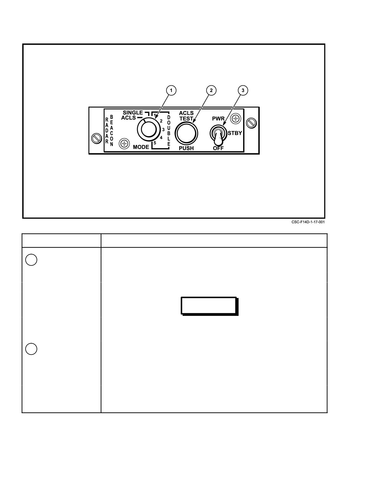
NAVAIR 01−F14AAD−1
NOMENCLATURE
FUNCTION
1
MODE switch
SINGLE Ċ Limits beacon response to single pulse of any code group
received.
DOUBLE Ċ Beacon response set to one of five double−pulse interrogations.
ACLS Ċ
Enables augmentor operation.
WARNING
ACLS shall not be selected on the flight deck
when the power switch is in STBY or PWR, or
during the 5−minute beacon warm up period.
2
ACLS TEST PUSH
On (green) Ċ Indicates a AN/SPN−42 lockon in ACLS mode; when pressed with
light/pushbutton
radar beacon mode selector in ACLS, indicates a satisfactory
self−test of ACLS mode only.
Flashing Ċ Indicates AN/SPN−42 is sweeping through aircraft but has not
locked on.
Intermittent
(or no light) Ċ During self−test, indicates a fault In the ACLS mode only.
Figure 17Ć1.ĄRadar Beacon Panel (Sheet 1 of 2)
ORIGINAL
17−4
NAVAIR 01−F14AAD−1
NOMENCLATURE
FUNCTION
3
Power switch
PWR Ċ
With radar beacon mode selector in ACLS, enables I−band replies
to Ka−band interrogations.
STBY Ċ
Used for warmup with radar beacon MODE switch in SINGLE or
DOUBLE.
Note
The beacon will warm up with the switch in either
position STBY or PWR. To prohibit response to
premature or unintentional interrogations, warmup
should be accomplished in STBY. For optimum
performance allow 5−minute warmup.
OFF Ċ
Turns off all power to radar beacon.
Figure 17−1. Radar Beacon Panel (Sheet 2 of 2)
Additionally, certain ACLS commands that are
The aircraft system receives and decodes glideslope
uplinked to aircraft via the data−link system are displayed to
azimuth and elevation signals that are converted into
both aircrew on MFD No. 1 and No. 3.
command fly−to indications in the CIU and displayed via VDI
and/or HUD in the TLN mode (Figure 17−2). If the ILS or
Note
ACL landing submodes selected on the pilot display control
For more detailed information on the data link
panel becomes invalid, the invalid submode symbology will
symbology, refer to NAVAIR 01−F14AAD−1A.
be removed. A computer message informing the aircrew
which submode became invalid will be posted on MFD No.
The ACLS and ILS systems provide angular situation
1 and No. 3. As a backup to the display subsystem, ILS
information (ILS needles and ACLS tadpole) of glidepath
steering indications are also displayed directly on the pilot
errors that requires the pilot to determine the corrections
standby attitude indicator vertical and horizontal needles.
needed to eliminate those errors, resulting in higher workload
and possible degraded approach performance (overshoots
Note
and oscillations). The flight director display provides the
optimum glidepath steering information (as computed by the
The ILS has a minimum warmup time of 1
mission computer using navigation system parameters and
minute. During this time, a failure indication
data−link information from the SPN−42/46 ACLS system) to
should be disregarded.
intercept and follow the glideslope and centerline, which
reduces pilot workload and improves approach performance.
The ILS performs a self−test when the BIT pushbutton
The flight director symbol can be selected for display on the
on AN/ARA−63 decoder panel is depressed and held.
HUD by boxing the FLT DIR pushbutton on the pilot AWL
Response to the ILS self−test is displayed, providing ILS or
VDI MFD format.
BOTH is selected on HUD and MFD. The correct ILS
landing mode display on the HUD and VDI display during
17.2.7
Instrument Landing System (AN/ARA−63)
system checkout shows the vertical precision course vector
The aircraft ILS uses the AN/ARA−63 receiver decoder
symbol slowly oscillating on the right side of the display, then
on the left side. The horizontal precision course vector
to process AN/SPN−41 confirmation. This system is used for
manual instrument landing approaches or as an independent
symbol remains stationary in the center of the display.
monitor during final approach with the ACLS. The AN/
ARA−63 decoder panel (Figure 17−3) is located on the pilot
right−side outboard console.
17−5
ORIGINAL
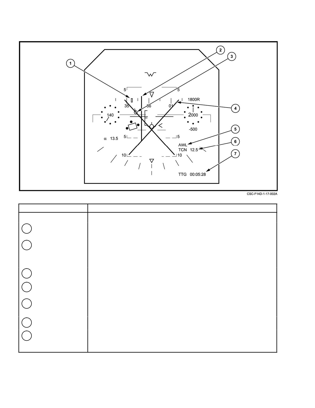
NAVAIR 01−F14AAD−1
NOMENCLATURE
FUNCTION
HUD Symbology ć TLN Gear Up Basic Format
1 Command Heading
Indicates ACL data link final bearing. Where final bearing is beyond display scale
Marker
limits the marker will be pegged at the edge nearest to the final bearing.
2 ILS Precision Course
Consists of two independent vectors (vertical and horizontal) that form a cross
Vectors
pointer. The horizontal vector responds to ILS glide slope error and the vertical
vector responds to ILS localizer error. Null/center indications are provided to enable
the pilot to null the error and keep the vertical and horizontal needles centered.
3 ACLS Tadpole
Provides ACL Steering commands driven by the SPN−42 data link.
4 Waveoff
A large X" will appear flashing in the center of the display to indicate a waveoff
data link discrete command.
5 All Weather Landing
Indicates the selection of AWL Steering.
Steering Legend
6 TACAN Range
Indicates distance to the TACAN station.
7 Clock/Timer
Indicates time−to−go to selected destination (TACAN) if selected from HSD CLK
pushbutton.
Figure 17Ć2.ĄACLS/ILS Steering (Sheet 1 of 3)
ORIGINAL
17−6
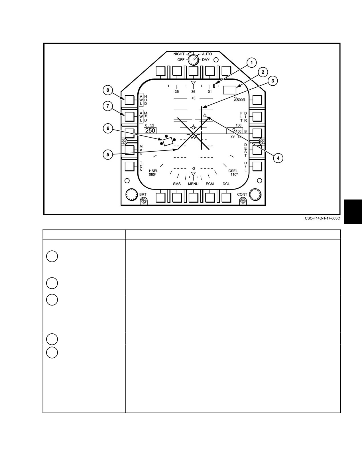
NAVAIR 01−F14AAD−1
NOMENCLATURE
FUNCTION
VDI Symbology ć AWL Steering Mode
1
Command Heading
Positioned relative to the magnetic heading scale to indicate ACL data link final
Marker
bearing. Where final bearing is beyond display scale limits, the marker will be
pegged at the edge nearest to the final bearing.
2
D/L Message Window
Provides certain ACLS commands that are uplinked to aircraft via the data link
system.
3
ILS Precision Course
Consists of two independent vectors (vertical and horizontal) that form a cross
Vector
pointer. The horizontal vector responds to ILS glide slope error and the vertical
vector responds to ILS localizer error. Null/center indications are provided to
enable the pilot to null the error and keep the vertical and horizontal needles
centered.
4
ACL Steering Indicator
Provides ACL Steering commands driven by the SPN−42 data link.
5
Waveoff
During carrier landings, a large X" will appear flashing in the center of the display
to indicate a waveoff data link discrete command.
Figure 17−2. ACLS/ILS Steering (Sheet 2 of 3)
17−7
ORIGINAL
NAVAIR 01−F14AAD−1
NOMENCLATURE
FUNCTION
6
Flight Director
The flight director symbol provides glide slope and centerline steering information
computed by the mission computer using navigation system parameters and Data
Link information from the SPN−42/46 ACLS system. The flight director provides the
pilot with optimal glide path intercept and following when the flight path marker is
inside the flight director box and the three dots are aligned with the wings and the
tail of the flight path marker. The same procedures are used whether the flight path
marker is caged or uncaged. The flight director symbol is removed from the HUD
when the FLT DIR pushbutton on the VDI is unboxed. The pushbutton is removed
from the VDI if the Flight director is not available for display (for example, a/c vector
or ACL data link mode is not selected).
7
MFD AWL Display
Permits option to display AWL (both ACL and ILS), ILS, ACL, or NO STEERING
Option pushbutton
information on the MFD. Initial selection of the AWL steering mode on the basic VDI
format displays both ACL and ILS steering information on the MFD. This will be
indicated by AWL in the box adjacent to the MFD legend. Successive depression of
the pushbutton cycles AWL, ILS, ACL and NO STEERING information on the MFD
in that order.
8
HUD AWL Display
Permits option to display AWL (both ACL and ILS), ILS, ACL, or NO STEERING
Option pushbutton
information on the HUD. Initial selection of the AWL steering mode on the basic VDI
format displays both ACL and ILS steering information on the HUD. This will be
indicated by AWL in the box adjacent to the HUD legend. Successive depression of
the pushbutton cycles AWL, ILS, ACL, and NO STEERING information on the HUD
in that order.
Note
The RIO is inhibited from deselecting AWL steering once
selected from any MFD.
Figure 17−2. ACLS/ILS Steering (Sheet 3 of 3)
17.3
SURFACE SUBSYSTEMS
To satisfy the system capability and landing−rate
requirements, the shipboard subsystem landing control
17.3.1
Automatic Landing System (AN/SPN−42)
central AN/SPN−42 has a dual−channel configuration. This
provides increased system reliability through redundancy. At
The AN/SPN−42 radar uses a conically scanning
full operational capability, both channels are in use, con-
antenna beam of Ka−band energy, which is received at the
trolling two aircraft on the glideslope at the same time. Two
aircraft in direct proportion to its position within the antenna
aircraft are normally spaced approximately 60 seconds apart
coverage area. This microwave energy is received as
along the glideslope. In addition, the three operating modes
amplitude modulation of the pulsed carrier and, by means of
act as backups for each other should partial system failure
the beacon augmentor, the AM is put on the I−band beacon for
occur.
retransmission back to the ship as an active radar signal. The
AM on this retransmitted signal is therefore identical to
17.3.2
Instrument Landing System (AN/SPN−41)
the AM received at the aircraft. By relating the amplitude of
the returned signal to the AN/SPN−42 antenna position within
The aircraft ILS uses carrier or shore−based AN/
its conical scanning area, the system knows the exact location
SPN−41 (C−scan) transmitters. The system operates in the
of the aircraft in relation to the axis of the conical scan, which
K−band, between 15.4 and 15.7 GHz, on any of 20 channels.
is the desired glidepath. From this information, the system
The transmitted azimuth signal produces a 2° beam, which
can generate corrections to bring the aircraft to the desired
is scanned ± 20° from the deck centerline. The transmitted
glidepath. Additional ramp input pitch commands, tailored
elevation signal produces a 1.3_ beam with a scan pattern
to each specific ship or field by the Naval Air Test Center
from 0_ to 10_ above the horizon. A proportional azimuth
during Mode I certification, are applied at the proper time to
angle for steering is 6° right or left of centerline; proportional
assist the aircraft through the burble.
elevation angle for steering is
1.4° from the reference
glideslope (above or below).
Change 2
17−8
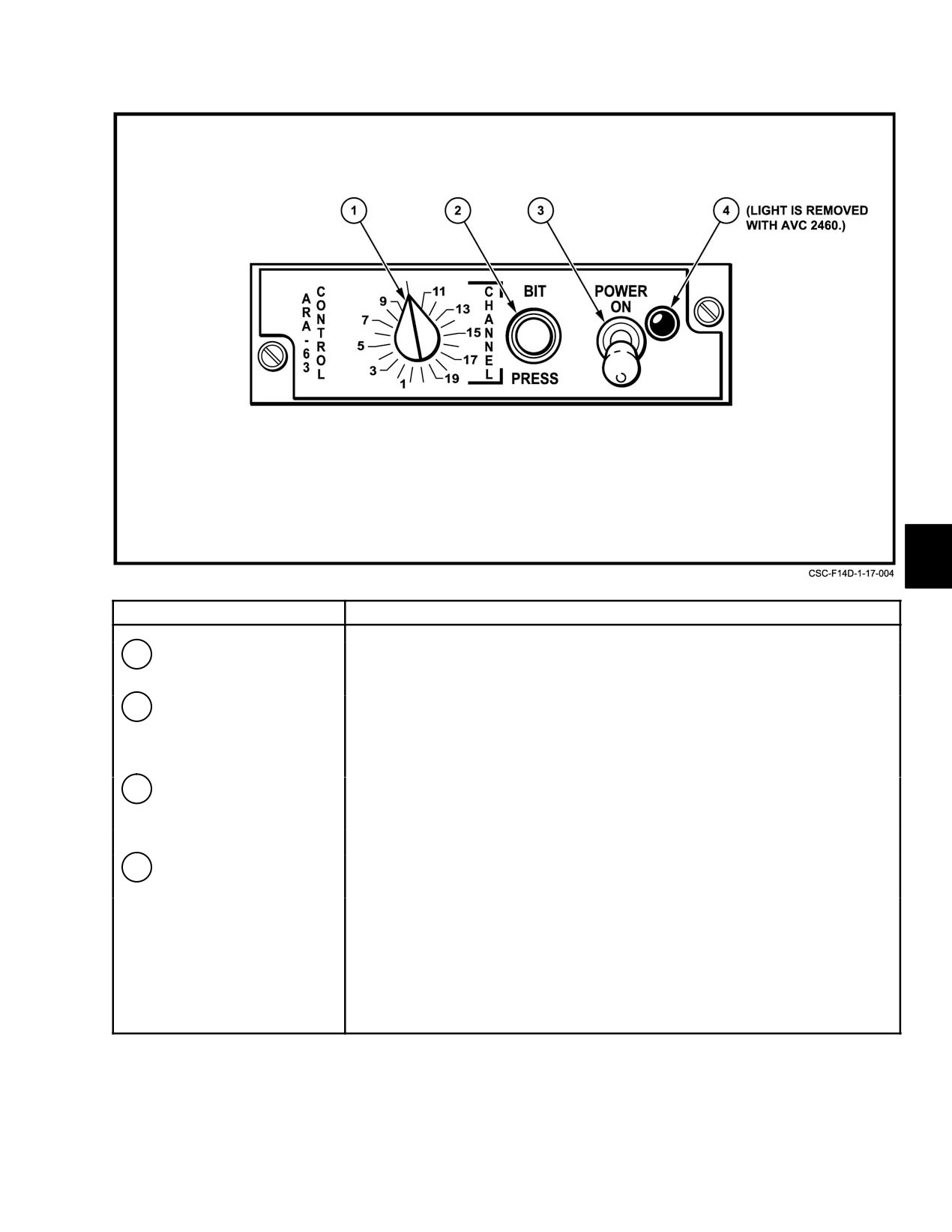
NAVAIR 01−F14AAD−1
NOMENCLATURE
FUNCTION
1
CHANNEL selector
Twenty possible channel selections by rotation of selector knob.
2
BIT PRESS−to−test
Depressing button activates BIT test circuitry. Landing symbols available on HUD
button
and/or VDI if AWL or ILS display option is selected, and on pilot’s standby attitude
indicator.
3
POWER switch
ON ć Activates receiver decoder for all−weather carrier landing.
(lock−lever)
OFF ć Turns system off. Lock−lever switch must be lifted to OFF.
4
Indicator light (light is
Lights when AN/ARA−63 is on.
removed with AVC 2460)
Figure 17Ć3.ĄAN/ARA−63 Decoder Panel
17−9
ORIGINAL
NAVAIR 01−F14AAD−1
Operating range is approximately 20 nautical miles.
1. Data−link vector
The signal is transmitted in J−band on a carrier frequency of
15.4 to 15.7 GHz.
2. TACAN
The AN/SPN−41 can be used to guide the pilot to the
3. AWL.
window of the AN/SPN−42 radar for an ACL Mode I
All are directly selectable on the VDI format of the
approach and as an independent glideslope and azimuth
MFD. Switching between submodes requires a choice
display during a Mode I approach. Should the AN/SPN−42
between DATA LINK, TACAN, and AWL steering. If a
radar system fail, the AN/SPN−41 can be used for Mode II
submode selected becomes invalid, the steering information
approaches.
will cease. The pilot has the option of reselecting another
landing display submode. A computer message will also
17.4
ACLS PROCEDURES
inform the aircrew of invalid steering modes.
The successful completion of a Mode I or Mode IA
During the letdown from marshaling, an AN/SPN−42
ACLS approach is dependent on the proper performance and
channel is assigned to the aircraft and a computer program of
complex interaction of a variety of shipboard and aircraft
aircraft control parameters is selected. A data−link discrete
systems. It is the responsibility of the aircrew to verify that
message (the first of a series to be transmitted), LANDING
all ACLS−related aircraft systems are functioning properly
CHECK, is sent to the aircraft to initiate communications
and that proper procedures are followed in order to ensure a
with CATCC and to indicate to the pilot that an AN/SPN−42
safe coupled approach.
channel is available. The aircraft will usually already be in
a landing configuration upon receipt of LANDING CHECK.
17.4.1
Preflight
During the exterior preflight, the aircrew should ensure
17.4.3.1
Data−Link Vector Approach
that both beacon antennas are in good repair and not painted.
When DATA LINK is selected, the D/L vector display
The receive antenna is located on the lower starboard
is added to the basic landing display. Command heading
fuselage just aft of the radome and is mounted flush with the
relative to the heading tape is added to the HUD and VDI
fuselage. The transmit antenna is a blade antenna located on
display along with commanded altitude and airspeed on the
the aft portion of the chin dome (IR/TV pod). Poor condition
right and left side of the VDI display. Data−link vector
of these antennas will seriously degrade beacon performance
information is available only for the approach phase (i.e., to
and will result in degraded tracking capability by the
the radar acquisition window). When the aircraft is vectored
AN/SPN−42 system.
(D/L vector commands) to the acquisition window, the pilot
has to make a new submode selection for the descent phase.
17.4.2
Poststart Checks
This is not the case with the TACAN submode, as TACAN
Following start, the aircrew should verify proper
information is available throughout landing, from marshalĆ
operation of the beacon and data−link systems along with
ing to touchdown.
associated lights and advisories and indications by performĆ
ing the prescribed built−in tests. In addition, the pitch parallel
17.4.3.2
TACAN Approach
actuator should be checked during OBC to make sure that the
The course deviation indicator is used for TACAN
force link is not totally or partially disconnected. If any of
deviation along with a manually set command heading
these systems are not functioning properly, a coupled
indicator on both the HUD and VDI display.
approach will not be possible.
17.4.3.3
AWL Approach
17.4.3
Approach Phase
ILS information from the AN/SPN−41 is available
In ACL, the purpose of the approach phase is to get the
during both the approach and descent phase. Selection of
aircraft to the acquisition window (Figure
17−4). At the
AWL on the VDI display enables vertical and lateral
marshaling area, some 20 miles astern of the carrier, the
glideslope error display. Final determination of the AWL/
aircraft about to land are stacked according to fuel status and
PCD mode is governed by the ILS/ACL selection, which
other relevant parameters that determine landing priority, the
provides for separate HUD and VDI selection. Additionally,
ILS (AN/ARA−63) system is energized, and the proper
the pilot may independently select HUD flight director for
channel and displays are selected. The pilot, in concurrence
display by boxing the FLT DIR pushbutton on the AWL VDI.
with the controller, has the option of choosing from three
display submodes to aid him in reaching the radar acquisition
window:
ORIGINAL
17−10
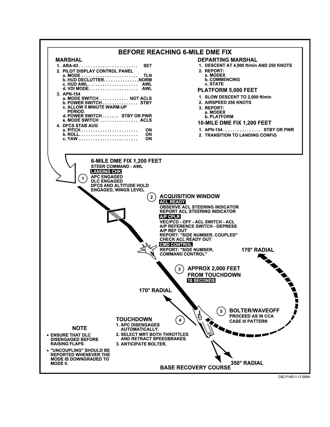
NAVAIR 01−F14AAD−1
Figure 17Ć4.ĄACLS Mode I and II Approaches
17−11
ORIGINAL
NAVAIR 01−F14AAD−1
The normal ACLS approach mode will display the
17.4.4.1
Mode I Landing Sequence
ACL tadpole situation information, the ILS needles situation
information, and the ACL flight director steering
Note
information on the HUD. If the pilot intends to make a Mode
I approach, he must advise the ground controller of his
D ACLS Mode I/IA approaches are authorized
intentions. The ground controller will then disable the flight
with AN/SPN−46 systems.
director commands and enable the autopilot commands.
Until this is done, the pilot will not have the capability to
D Refer to paragraph
2.24.4.7, Automatic
couple the autopilot to the ACLS commands. The only
Carrier Landing (ACL), for further informaĆ
information that is displayed on the HUD during Mode I
tion on ACL.
approaches is the ACLS tadpole situation information and
The landing system (CATCC) (Figure 17−4) generates
the ILS needles situation information.
a coupler available discrete that displays the A/P CPLR
advisory and indicates that the pilot has the option of
17.4.4
Landing Phase
coupling the DFCS to data−link commands of pitch and bank.
As the aircraft continues its approach and passes
At this time, the aircraft should be in a landing configuration
with APC, DLC, DFCS, and altitude hold engaged.
through the 4−nm ACLS radar acquisition window, a smooth
transition, not requiring pilot action, occurs. If TACAN
information has previously been selected (for the approach
Note
phase), the pilot could use this information to land. Assume,
The radar should be in STBY or PULSE search
however, that AWL has been selected, ILS and ACL
to avoid beacon interference problems.
information is being displayed on the HUD and VDI.
The DFCS should be armed in the ACL relief mode
At the radar acquisition window, the AN/SPN−42 radar
with the A/P REF displayed, indicating that a pilot relief
acquires the aircraft with the aid of the airborne radar beacon
mode (in this case, ACL) has been selected but not engaged.
augmentor, and the system automatically sends a discrete
The pilot can couple the DFCS to the data link by means of
indicating radar lock−on that displays the ACL RDY
the autopilot engage button on his control stick, at which
advisory. Transmission of vertical and lateral glidepath
time, if the DFCS is functioning properly and the ACL
errors and flight director commands, derived by the AN/
interlock is true, the AP REF legend will go out. The pilot
SPN−42/46 radar, commences. The glidepath error signals
should report coupled; at which time, the controller will send
drive the ACL tadpole on the VDI and HUD. The flight
a discrete command control message that displays the CMD
director symbol is selected for display by boxing the FLT DIR
CONTROL advisory. The NTDS begins transmitting
pushbutton on the AWL VDI MFD format. The flight director
data−link, pitch and bank commands to the aircraft. The
display information is computed by the mission computer
autopilot actuates the appropriate control surface to execute
using navigation system parameters and data−link informaĆ
the desired command, while the autothrottle
(APC)
tion, if desired. If the pilot intends to make a Mode I
maintains approach angle of attack by controlling the throttle
approach, he must advise the ground controller of his
setting.
intentions. The ground controller will then disable the flight
director commands and enable the autopilot commands.
Note
Until this is done, the pilot will not have the capability to
couple the autopilot to the ACLS commands. The only
Care should be taken not to couple up in even a
information that is displayed on the HUD during Mode I
slight climb. If above reference altitude when
approaches is the ACLS tadpole situation information and
initial pitch commands are sent, the resulting
the ILS needles situation information.
nose down correction is likely to cause a force
The HUD and VDI symbology has thus been
link disconnect resulting in automatic decouple
determined for the landing phase and no further pilot
and an inability to perform mode IA approaches
selection is required (unless a system malfunction occurs).
until maintenance action is performed.
The mode of operation for this phase of the landing is a
Whenever the aircraft exceeds the Mode I flightpath
function of the type of equipment used. In particular, there
control envelope, the system automatically sends a signal to
are three modes of landing applicable: Mode I, Mode II, and
uncouple the DFCS (A/P CPLR legend goes out). The
Mode III.
approach may be continued in Mode II or Mode III. If the
flightpath error increases to the point where a large maneuver
is required to bring the aircraft back on course, the controller
will send a waveoff message that is displayed on the HUD
and VDI and turns on the WAVEOFF advisory. This discrete
also disconnects the autopilot (if engaged) and the DFCS
ORIGINAL
17−12
NAVAIR 01−F14AAD−1
reverts to stability augmentation. The controller then
D The paddle switch will illuminate the
transfers the guidance of the aircraft to the bolter/waveoff
MASTER CAUTION light.
controller, who directs the pilot back into the landing
sequences.
17.4.4.2
Mode II Landing Sequence
If the information stored in the data link is not updated
The early phases of a Mode II descent (Figure 17−5) are
within any 2−second period during the descent, the TLT
identical to a Mode I descent sequence. The aircraft to be
advisory goes on
(missed message) and the DFCS
recovered is directed through the marshaling area, receives
automatically disconnects and reverts to STAB AUG. The
LANDING CHK, and arrives at the ACLS radar acquisition
pilot can continue the descent in Mode II or Mode III.
gate. When the lock−on discrete (ACL RDY) message is
received, the pilot continues to fly the aircraft manually
At
12.5 seconds from touchdown
(approximately
(using APC as desired) in response to VDI and/or HUD
2,200 feet from the touchdown point), the 10 SECOND
displays.
advisory goes on, indicating deck motion data are being
added to the glidepath commands. This information is in the
If there is an equipment failure, the system (CATCC)
form of a slight increase (or decrease) in aircraft altitude to
will send a voice discrete signal that turns on the VOICE
adjust for the movement of the touchdown point caused by
advisory, and the AN/SPN−42 error information displayed
the ship’s motion (roll, pitch, and heave). Between 12.5 and
will be invalid and thus removed. The pilot then expects to
1.5 seconds from touchdown, the CATCC sends an automatic
receive standard voice commands and will probably use the
waveoff if any part of the carrier−based equipment fails and
redundant ILS information or switch to TACAN steering.
up to 5 seconds from touchdown if the aircraft exceeds the
As long as the aircraft is located within the AN/SPN−42
AN/SPN−42 flightpath control envelope. Waveoff signals
flightpath control envelope for Mode II, the descent is
also may be issued by the final controller (between lock−on
continued until visual contact is made with the Fresnel lens
and touchdown) and the landing signal officer between 1 mile
optical landing system meatball. All waveoffs in Mode II
and touchdown. Approaches must be waved off at weather
are given by the final controller or the LSO. Approaches are
minimums (200−feet altitude and ½−mile visibility) if the
terminated at weather minimums
(200−feet altitude and
pilot cannot see the meatball.
½−mile visibility) if the pilot cannot see the meatball.
At 2 seconds from touchdown, the landing system
At any time before 12.5 seconds from touchdown, the
freezes the pitch and bank commands and the DFCS holds the
pilot can switch from a Mode II manual to a Mode I automatic
aircraft’s attitude to touchdown unless the pilot elects to
flightpath control, provided the coupler available discrete is
override the DFCS either by maneuvering the control stick or
being received and the ACL interlock is true.
by manually disengaging the DFCS and assuming control.
Aircraft may also be disengaged by momentarily depressing
17.4.4.3
Mode III Landing Sequence
the A/P REF / NWS pushbutton located on the control stick
(this will not illuminate a MASTER CAUTION light). If the
Mode III descents follow the same general sequence as
aircraft bolters or if the pilot decides to go around, the DFCS
that of Modes I and II, but Mode III approaches are talkdown
is disengaged automatically by means of overriding the
landings; that is, all flightpath corrections are provided by
control stick, and the pilot enters the bolter/waveoff pattern.
voice and no computerized discrete signals are sent. The use
of APC is optional. Approaches are terminated at the weather
Note
minimums if the FLOLS (meatball) is not visible to the pilot
D The paddle switch will only disengage the
for continuing the landing.
autopilot; the DLC as well as PITCH and
ROLL SAS will remain engaged.
D The paddle switch will still revert throttles to
MANUAL mode and the engines to emergenĆ
cy SEC mode with weight−on wheels. The
paddle switch may revert the engines to the
emergency SEC mode in flight with a WOW
failure.
17−13
ORIGINAL
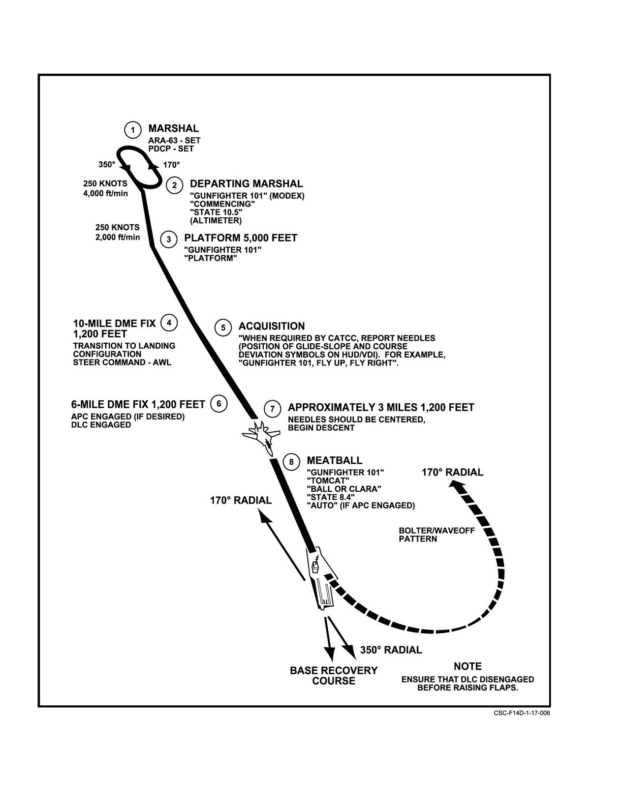
NAVAIR 01−F14AAD−1
Figure 17Ć5.ĄSPN−41 ILS Approach
ORIGINAL
17−14
NAVAIR 01−F14AAD−1
CHAPTER 18
Extreme Weather Operations
18.1
ICE AND RAIN
be made to eliminate the ice before landing by remaining
well below the freezing level for an extended period of time.
18.1.1
Icing
Icing conditions should be avoided whenever possible.
Before flight, check freezing levels and areas of probable
icing from weather service.
The primary concern with flying in icing conditions is
Icing conditions can cause heavy ice
ice accumulation sufficient to cause engine damage. Ice
accumulation in the inlet ramp areas or on engine
accumulation on engine probes located between the engine
probes and the compressor face. Aircraft
guide vanes and above the number three inlet ramp is not
maneuvers and arrested landings may dislodge
detectable from the cockpit. Aircraft maneuvers or landing
this accumulation and cause extensive engine
impact can dislodge accumulated ice and can cause severe
FOD or failure. A straight−in field landing is
FOD to the engine. Visual detection of icing on exterior
preferred. Minimum power setting after landing
surfaces and/or illumination of the pilot’s INLET ICE
is recommended.
caution light should be treated as indications of the
potentially more serious problems described above. The
following precautionary action should be taken immediately
in known or suspected icing environments:
1. ANTI−ICE switch ORIDE/ON.
Operation of main flaps/slats and maneuvering
devices increases the likelihood of a flap/slat
2. CABIN AIR DEFOG lever FWD DEFOG.
lockout because of shearing of the torque tube.
Attempt to descend below the freezing level for
3. Engine instruments Monitor Frequently.
20 to
30 minutes before operating main or
Carefully monitor rpm and EGT indications. A
maneuvering flaps/slats.
reduction of rpm or an increase in EGT accompanied by a
loss of thrust is an indication of engine icing.
18.1.2
Rain
Whenever rain is encountered, turn ANTI−ICE switch
4. Avoid clouds and other areas of visible
to AUTO/OFF.
precipitation.
5. If unable to avoid precipitation, adjust aircraft Mach
Note
or altitude as necessary to remain outside of the
In heavy rainfall, maintain a minimum engine
icing zone shown in Figure 18−1.
power setting of 70−percent rpm. This will assure
Extended operations in icing conditions should be
adequate acceleration margin and prevent posĆ
considered an emergency situation. If time and fuel permit,
sible engine speed hangup.
a descent below the freezing level is recommended. If
unable, altitudes above approximately
25,000 feet or
18.1.2.1
Takeoff in Rain
ambient temperatures below −30°C are generally free of icing
Takeoffs performed with standing water on the runway
conditions. If inadvertent or unavoidable operation in known
may result in unstable engine operation because of water
or suspected icing conditions has occurred, an effort should
ingestion.
18−1
ORIGINAL
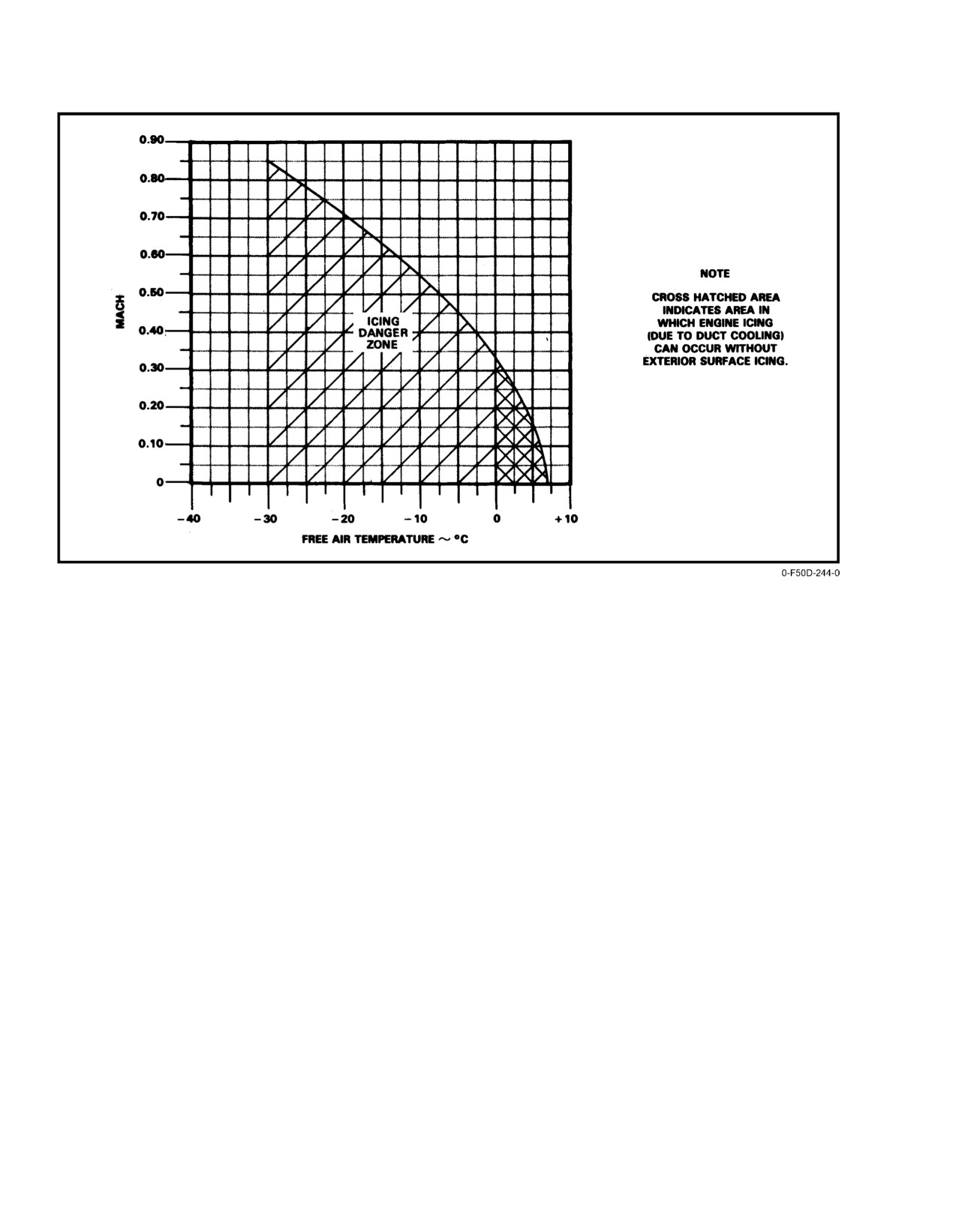
NAVAIR 01−F14AAD−1
Figure 18Ć1.ĄIcing Danger Zone
18.1.2.2
Landing in Rain
18.2.1
Dynamic Hydroplaning
Selecting ON with the WSHLD AIR switch controls a
Dynamic hydroplaning is a condition in which a fluid
blast of air that blows rain off the windshield. Be aware of the
separates the tires from the runway surface. When standing
possibility of flameout in a heavy rain and of reduced braking
water on a wet runway is not displaced by the tire fast enough
action because of a wet runway.
to allow contact over the complete footprint area of the tire,
the tire rides on a wedge (or film) of water over all or part of
18.2
HYDROPLANING
the footprint area. Total dynamic hydroplaning occurs when
the pressure between the tires and the runway lifts the tires
Operations on wet or flooded runways may produce
off the runway surface to the extent that a nonrotating tire will
four conditions under which tire traction may be reduced to
not spin up (landing) or a rolling, unbraked tire will slow in
an insignificant value.
rotation and may actually stop
(takeoff). Total dynamic
hydroplaning speed (in knots) is represented by the following
1. Dynamic hydroplaning
mathematical formulas: 9 times the square root of the tire
inflation pressure (in psi) for a rotating tire (as in takeoff);
2. Viscous hydroplaning
7.7 times the square root of the tire inflation pressure for a
nonrotating tire (as in landing).
3. Reverted rubber skids
Dynamic hydroplaning is insensitive to vertical load
4. Combined viscous and dynamic hydroplaning.
changes (weight), but is greatly affected by tire inflation
pressure and tire wear. Since the fluid cushion is incapable of
Note
developing any appreciable shear force, braking and sideĆ
force coefficients become almost nonexistent.
Hydroplaning has been experienced in the F−14
at speeds down to 40 knots.
ORIGINAL
18−2
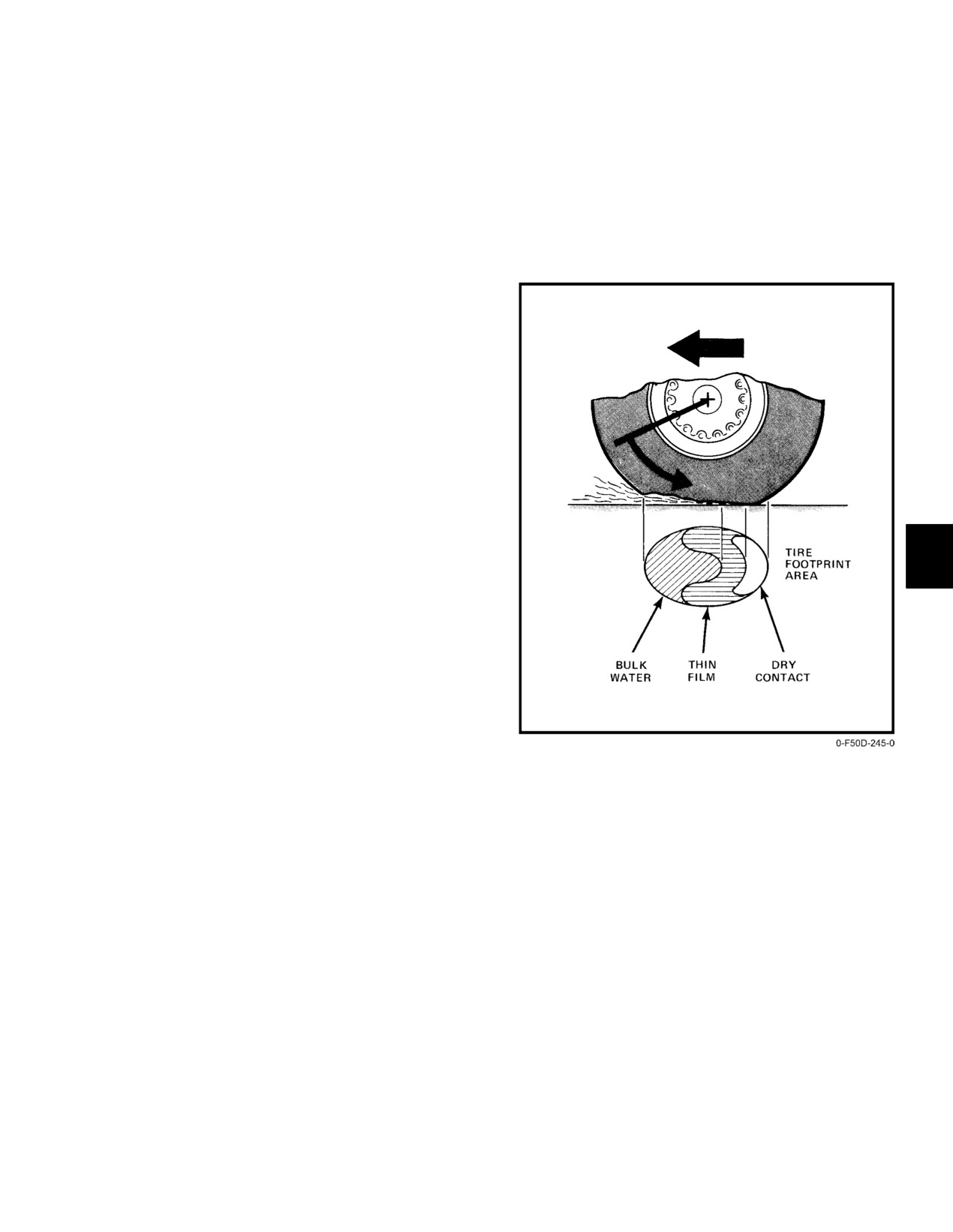
NAVAIR 01−F14AAD−1
18.2.2
Viscous Hydroplaning
and dynamic hydroplaning. As speed is further increased, a
point is reached where bulk water penetrates the entire
Viscous hydroplaning occurs when the tires are
footprint; this condition is called dynamic hydroplaning. If
separated from the runway surface by a thin film. Viscous
the runway is not flooded (no bulk water), such as on a
fluid pressures in the tire−ground contact zone of rolling tires
runway covered with heavy dew, it is possible for the second
build up with speed to the danger levels required for
zone to cover the entire footprint as speed is increased or
hydroplaning only when water−covered pavements are
decreased. The pavement would have to be smooth or smooth
smooth or smooth acting, as when contaminants
acting, as in the case where contaminants are present, for this
considerably more viscous than water coat the pavements.
to take place; this is called viscous hydroplaning.
Since a tire operating on a surface with rubber deposits, paint,
fuel, or oil can only partially displace the trapped water film,
considerably higher hydroplaning pressures will be develĆ
oped in the tire footprint area with these more viscous fluids.
Even slight amounts of precipitation, for example, a heavy
dew that coats the pavement with a thin film of fluid, can
produce this effect. Because the tire footprint separates on the
runway with less fluid depth and at a lower relative
groundspeed than dynamic hydroplaning speed, viscous
hydroplaning is potentially more dangerous than dynamic
hydroplaning and is not greatly affected by changes in
vertical tire load or tire inflation pressure. Grooved tires offer
a greater advantage than smooth tires in reducing the effects
of viscous hydroplaning. The runway pavement surface
texture is also an important factor in combating viscous
hydroplaning effects.
18.2.3
Combined Dynamic and
Viscous Hydroplaning
Loss of tire friction with increasing or decreasing speed
on wet or flooded runway pavements can be caused by the
combined effects of viscous and dynamic hydroplaning.
Figure 18−2 shows a pneumatic tire rolling at medium speed
across a flooded pavement in a partial hydroplaning condiĆ
tion. The first zone shows the fraction of the tire footprint that
is supported by bulk water (dynamic); the second zone, the
fraction supported by a thin film of water (viscous); and the
third zone, the fraction essentially in dry contact with the
Figure 18Ć2.ĄCombined Viscous and Dynamic
peaks of the pavement surface texture. The length of the first
Tire Hydroplaning
zone represents the time required for a rolling tire in this
speed condition to expel bulk water from under the footprint;
18.2.4
Reverted Rubber Skids
correspondingly, the length of the second zone represents the
time required for the tire to squeeze out the residual thin
A reverted rubber hydroplaning condition (also called
water film remaining under the footprint after the bulk water
reverted rubber skid) takes place when a wheel skid has
has been removed. Since fluids cannot develop shear forces
started on a wet runway and enough heat is produced to turn
of appreciable magnitude, it is only in the third zone
the entrapped water to steam. The steam in turn melts the
(essentially dry region) that friction can be developed
rubber in the tire footprint. The molten rubber forms a seal
between the tire and the pavement for steering, decelerating,
preventing the escape of water and steam. Thus, the tire rides
and accelerating a vehicle. The ratio of the dry contact area
on a cushion of steam that greatly reduces the coefficient of
(third zone) to the total tire footprint area (zones 1, 2, and 3)
friction. On inspection of the portion of the tire involved, a
multiplied by the coefficient the tire develops on a dry
patch of rubber would show signs of reverting to its uncured
pavement, yields the friction coefficient the tire develops for
state and hence the name, reverted rubber. Once established,
this flooded pavement and speed condition. As speed is
this condition may persist to very low groundspeeds. The
increased, a point is reached where the third zone disappears
characteristic marks on a pavement for the reverted rubber
and the entire footprint is supported by either bulk water or
skid are white, as opposed to the black marks left on the
a thin film. This speed condition is called combined viscous
pavement during a dry skid. These white marks are
18−3
ORIGINAL
NAVAIR 01−F14AAD−1
associated with the cleaning process of super−heated steam
18.3.1.1
If Necessary to Penetrate a
and high pressures that are present in the skid. The reverted
Thunderstorm:
rubber condition tends to make all runway surfaces smooth
acting. Pavement surface texture, which has a large effect on
1. Slow to between 275 to 300 KIAS.
traction losses from dynamic and viscous hydroplaning, has
but little effect for the reverted rubber case with the possible
2. ANTI−ICE switch AUTO/OFF.
exception of grooved surfaces. NASA research confirms the
3. AUTO PILOT switch OFF.
theory that the reverted rubber skid is the most catastrophic
for aircraft operational safety because of the low−braking
4. Loose equipment Secured.
friction and the additional fact that tire cornering capability
drops to zero when the wheels rotation is stopped.
5. Tighten lapbelt and lock shoulder harness.
18.2.5
Landing On Wet Runway
6. Cockpit lights On Bright.
Refer to Chapter 7 for landing discussion.
7. Fly attitude and heading indicators primarily while
in extreme turbulence, because altimeter and
18.3
TURBULENCE AND THUNDERSTORMS
airspeed will fluctuate.
Unless the urgency of the mission precludes a deviation
from course, intentional flight through thunderstorms should
Note
be avoided to preclude the high probability of damage to the
During severe icing conditions, the pilot can
airframe and components by impact of ice, hail, and
expect to lose airspeed indications even with the
lightning. Flameouts because of water ingestion or
compressor stalls caused by rapid changes in flight attitudes
pitot heat on. Ground−controlled intercept
stations, if available, can aid the pilot with
could also occur. Radar provides a means of navigating
tracking assistance through thunderstorm areas.
between or around storm cells. If circumnavigating the storm
is impossible, penetrate the thunderstorm in the lower third
Severe turbulent air at high altitudes may cause the
of the storm cell, away from the leading edge of the storm
inlet airflow distribution to exceed acceptable limits of the
cloud, if possible. It is recommended that the autopilot
engine, thereby inducing compressor stalls. To avoid
functions of DFCS be disengaged. Structural damage could
compressor stalls during flight because of turbulent air,
result with the automatic functions operating.
maintain 275 to 300 KIAS at all altitudes.
18.3.1
In the Storm
18.4
COLD−WEATHER OPERATIONS
Maintain a normal instrument scan with added
A careful preflight will eliminate many potential
emphasis on attitude displays. Attempt to maintain a constant
hazards found in cold−weather operations. Inspect engine
pitch attitude and, if necessary, accept moderate altitude and
intakes for accumulation of ice and snow. If possible, preheat
airspeed fluctuations. In heavy precipitation, a reduction in
the engine for easier engine starts. When removing ice and
engine speed may be necessary because of the increased
snow from the aircraft surfaces, be careful not to damage the
thrust resulting from water ingestion. If compressor stalls or
aircraft. Also, use precautions not to step on any no−step
engine stagnation develops, attempt to regain normal engine
surfaces that could be covered with ice or snow. Check the
operation by momentarily retarding the throttle to IDLE then
pitot−static tube for ice as well as the fuel pressurization ram/
advance to the operating range. If the stall persists, shut down
air intakes, and yaw, pitch, and angle−of−attack transducers.
the engine and attempt to relight. If the engine remains
Moisture in the fuel system greatly increases
stagnated at reduced power and the EGT is within limits,
maintain reduced power until clear of the thunderstorm.
operational problems in cold weather. At lower temperatures,
the water−dissolving capacity of fuel is greatly reduced and
While in the storm, the longitudinal feel trim, angle−of−
attack, total temperature, windshield overheat, static
will result in considerably more water accumulation
pressure correction, and cabin pressurization systems may
(as much as several gallons of water to 1,000 gallons of fuel).
If the water separation occurs at below freezing temperaĆ
experience some abnormalities because of rain, ice, or hail
damage. No difficulty should be encountered in maintaining
tures, the water will crystallize on the fuel drain and internal
valves. Any water accumulation will settle to the bottom of
control of the aircraft; however, the rapid illumination of
numerous warning lights may be somewhat distracting to the
the tanks and freeze up the fuel drains.
pilot if he is not prepared.
Normal operating procedures as outlined in Chapter 7,
Shore−Based Procedures, should be adhered to with the
following additions and exceptions.
ORIGINAL
18−4
NAVAIR 01−F14AAD−1
18.4.1
Preflight
Note
1. Check entire aircraft to ensure that all snow, ice, or
If external transfer does not initiate or is inĆ
frost is removed.
complete, flight below the freezing level for 20
to 30 minutes will allow frozen valves to thaw
permitting external transfer.
In severely cold weather, allow a short time for warmup
before increasing rpm out of the idle range. If oil pressure is
low or fails to come up in a reasonable length of time, shut
Snow, ice, and frost on the aircraft surface are a
down. Attempt another start after heating the engines.
major flight hazard. The result of this condition
is a loss of lift and increased stall speeds.
2. Shock struts and actuation cylinders Free of Ice
and Dirt.
If abnormal sounds or noises are present during
3. Fuel drain cocks
Free of Ice and Drain
starting, discontinue starting and apply intake
Condensation.
duct preheating for 10 to 15 minutes.
4. Pitot tubes Ice and Dirt Removed.
18.4.3
Taxiing
5. Exterior protective covers Removed.
Avoid taxiing in deep or rutted snow since frozen
brakes will likely result.
18.4.2
Engine Start
To ensure safe stopping distance and prevent icing of
Be sure that the aircraft is adequately checked before
aircraft surfaces by melted snow and ice blown by jet blast
engine start.
of a preceding aircraft, increase spacing between aircraft
When operating in subfreezing temperatures, moisture
while taxiing at subfreezing temperatures.
in the air entering the aircraft from the starting unit may
freeze, causing ECS malfunctions. Starting the aircraft with
18.4.4
Takeoff
the AIR SOURCE in OFF will prevent the problem. The AIR
When operating from runways that are covered with
SOURCE in BOTH ENG should be selected after both
excessive water, snow, or slush, highspeed aborts may result
engines have been started and the starter air disconnected.
in engine flameout because of precipitation ingestion. The
ECS malfunctions after engine start may still occur because
probability of flameout is highest when throttles are chopped.
of moisture internally present in the aircraft.
With a double flameout, normal braking, anti−skid and
nosegear steering will be lost as hydraulic pressure decreases
If this occurs, select:
with engine spool down. Check applicable takeoff distance
1. TEMP mode selector switch MAN.
charts in NAVAIR 01−F14AAP−1.1.
2. TEMP control thumbwheel Full Hot (14).
Thrust available will be noticeably greater in cold
temperatures during the takeoff run.
3. WSHLD AIR switch ON.
4. With both engines at IDLE, the ECS should thaw in
about 20 minutes. During this warmup period, leave
all avionics and radar off.
If external fuel tanks are installed:
Before initial takeoff roll, ensure that all
instruments are sufficiently warmed up. After
5. MASTER TEST switch Ċ FLT GR UP.
takeoff, cycle landing gear a few times to prevent
the possibility of the gear freezing in the
Advance throttles as necessary to
80 percent
wheelwells.
maximum to check for GO light and positive
external transfer. Once airborne, external fuel
transfer should not be delayed to ensure complete
external tank transfer.
18−5
ORIGINAL
NAVAIR 01−F14AAD−1
18.4.5
Landing
18.5.1
Taxiing
Frozen downlock microswitch actuators, because of
While taxiing in hot weather, the canopies may
moisture combined with extremely cold temperatures, can
be opened, if necessary, to augment crew
cause spurious unsafe down indications when landing gear is
comfort.
extended. Use antiskid during the landing roll.
Note
Hard braking on ice or a wet runway, even with
ANTISKID on, could result in dangerous
Do not operate the engines in a sand or dust
skidding.
storm, if avoidable. Park the aircraft crosswind
and shut down the engines to minimize damage
18.4.6
After Landing
from sand or dust.
During operations where the temperature is below
freezing with heavy rain, or expected to drop below freezing
18.5.2
Takeoff
with heavy rain, the aircraft may be parked with wings
The required takeoff distances are increased by a
forward (20°) and flaps in the full down position.
temperature increase. Check the applicable takeoff distance
charts in NAVAIR 01−F14AAP− 1.1.
18.4.7
Before Leaving Aircraft
Weather permitting, leave the canopy partially open to
allow for air circulation. This will help prevent canopy
cracking from differential cooling and decrease the
possibility of windshield and canopy frosting.
Do not attempt takeoff in a sand or dust storm, if
18.5
HOT−WEATHER AND
avoidable, to prevent sand or dirt from blowing
DESERT OPERATIONS
into the intake ducts and causing engine damage.
Check for accumulation of sand or dust in the intakes.
18.5.3
Landing
Normal starting procedures will be employed.
Anticipate a slightly longer landing distance and the
Normal operating procedures as outlined in Chapter 7,
possibility of turbulence because of thermal action of the air
Shore−Based Procedures, should be adhered to with the
close to the ground. Use the defogging system if necessary,
following additions and exceptions:
in warm, humid weather.
1. Expect higher temperatures than normally obtained
in operating ranges.
2. Engine ground operation should be minimized as
much as possible.
ORIGINAL
18−6
NAVAIR 01−F14AAD−1
PART VII
Communications−Navigation Equipment
and Procedures
Chapter 19 Ċ Communications
Chapter 20 Ċ Navigation
Chapter 21 Ċ Identification
87 (Reverse Blank)
ORIGINAL
NAVAIR 01−F14AAD−1
CHAPTER 19
Communications
19.1
COMMUNICATIONS AND ASSOCIATED
control panel controls antenna selection and is described in
EQUIPMENT
Chapter 21. TACAN antenna selection is completely autoĆ
matic. If a signal is lost or is too weak to maintain receiver
Figure 19Ć1 lists the CNI equipment associated with
lockup, the TACAN cycles between the upper and lower
the aircraft/weapons systems.
seeking a stronger signal. See Chapter
20 for TACAN
operation.
19.1.3
Mutual Interference
Mutual interference among the V/UHF communicaĆ
tion radios and between the V/UHF communication radios
Operation of electronic equipment for more than
and D/L can occur. In the UHF band, minimize mutual
5 minutes without adequate cooling will permaĆ
nently damage the equipment.
interference by selecting opposite antennas or a frequency
separation of at least 55 MHz between radios if both are being
used. When D/L is in use, mutual interference can be
19.1.1
Communications Antennas
minimized by using VHF channels for voice communicaĆ
Four V/UHF/L−band, dual−blade antennas provide
tions. If this is not possible, frequency separation of at least
omnidirectional coverage for V/UHF voice, JTIDS voice,
55 MHz and selection of opposite antennas for voice and D/L
UHF D/L, JTIDS Link 16, TACAN, and IFF/SIF transponder
are recommended. If necessary, V/UHF 1 or 2 can be shut off.
operation. V/UHF 2, JTIDS voice and data, and TACAN
UHF communications interference with D/L may cause the
share one set of antennas; the upper is immediately aft of the
TILT computer message to appear and the autopilot ACL or
canopy turtleback and the lower is embedded in the left
VEC/PCD mode to disengage. D/L interference with the
ventral fin. The F/UHF 1, D/L, and IFF/SIF share the second
radios may cause audible chirping at the D/L message reply
set; the upper is the second antenna aft of the canopy
rate.
turtleback and the lower is embedded in the right ventral fin.
In the VHF band, both radios should not be operated
Each system is connected to the appropriate portion of an
simultaneously at VHF frequencies.
upper and lower antenna through a coaxial switch and
diplexer. For information on the AN/ASW−27 DL (Link 4),
JTIDS will not interfere with any of the V/UHF
and JTIDS (Link 16), refer to NAVAIR 01−F14AAD−1A.
communication radios or data link because it uses a higher
frequency band. TACAN compatibility, which is in the same
The APX−76 IFF interrogator antenna is an integral
frequency band (L−band) as JTIDS, is performed internally
part of the radar antenna. See FO−1 and FO−2 for antenna
by JTIDS.
locations.
19.2
INTERCOMMUNICATIONS
19.1.2
Communications Antenna Selection
The ICS provides normal, backup, or emergency
Selection of the upper or lower antenna for use by the
communications between crewmembers. It also combines
two communication radios and the D/L or JTIDS is manual
and amplifies audio signals received from other electronic
and is controlled by switches on the RIO ANT SEL panel
receiving equipment (ECM, Sidewinder tone, IFF/SIF, radar
(Figure 19−2). The D/L is always on the opposite antenna
altimeter, and voice radios, etc.).
from V/UHF 1. Antenna selection for the IFF/SIF can be
either automatic or manual. The ANT switch on the IFF
19−1
ORIGINAL
NAVAIR 01−F14AAD−1
TYPE AND
LOCATION
DESIGNATION
FUNCTION
RANGE
OPERATOR
OF CONTROLS
INTERCOM
Provides voice communications
Within the aircraft
Both, and
Pilot and RIO left
(LS−460B)
between crewmembers and
and groundcrew
groundcrew
console and in
between cockpit and
personnel.
personnel
the nosewheel
groundcrew, also amplifies variĆ
well
ous warning and weapon tones,
and voice communications.
JTIDS
Provides jam−resistant,
Line of sight (LOS)
Both
Pilot left console,
(AN/URC−107)
cryptographically secure digital
up to 300 nautical
RIO right and left
voice and data, navigation, relay,
miles.
consoles
and TACAN.
TACAN
Navigation aid provides bearing
LOS up to 390 nm,
Both
Pilot and RIO left
(AN/ARN−118(V))
and distance information to local
depending on
console
(AN/URC−107)
stations.
altitude.
UHF DATA LINK
Provides two−way digital
LOS up to 180
Both
RIO right console
(AN/ASW−27C)
message communication.
nautical miles.
V/UHF 1
Provides two−way voice and tone
LOS up to 200
Both
Pilot left console
COMMUNICATIONS
communication.
nautical miles.
SET (AN/ARC−182(V))
V/UHF 2
Provides two−way voice and tone
LOS up to 200
Both
RIO left console
COMMUNICATIONS
communication.
nautical miles.
SET (AN/ARC−182(V))
V/UHF DIRECTION
Provides bearing information to
LOS up to 180
Both
Pilot and RIO left
FINDER
selected stations.
nautical miles.
console
(OA−8697/ARD)
UHF VOICE
Cryptographic encoding
Same as radio in
RIO
Left console
SECURITY
and decoding of UHF voice
use.
EQUIPMENT (KY−58)
communications.
IFF TRANSPONDER
Responds to interrogations
LOS.
RIO
Right console
(AN/APX−100)
by other aircraft or ground
stations.
IFF INTERROGATOR
Requests identification from
LOS.
RIO
DD and right
(AN/APX−76B)
other aircraft.
console
RECEIVER
Provides glideslope signals
LOS up to 20
Pilot
Right console
DECODER
for carrier landing system.
nautical miles.
(AN/ARA−63A)
RADAR ALTIMETER
Displays height above earth’s
0 to 5,000 feet.
Pilot
Pilot’s instrument
(AN/APN−194)
surface.
panel
RADAR BEACON
Aids in tracking by ship and
LOS.
RIO
Right console
(AN/APN−154)
ground−based x−band radars.
Provides down link for
automatic carrier landing system.
Figure 19Ć1.ĄCommunications and Associated Equipment
ORIGINAL
19−2
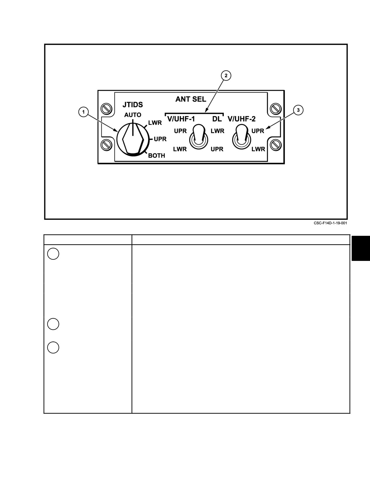
NAVAIR 01−F14AAD−1
NOMENCLATURE
FUNCTION
1
JTIDS antenna select
AUTO Ċ Enables JTIDS to transmit on the upper antenna and to receive
switch
on either the upper or lower antenna depending upon signal
strength.
LWR Ċ Enables JTIDS to transmit and receive on the lower antenna.
UPR Ċ
Enables JTIDS to transmit and receive on the upper antenna.
BOTH Ċ Enables JTIDS to transmit and receive on both the upper and
lower antenna. 200 watt output power is equally divided between
the upper and lower antenna, 100 watts each.
2
V/UHF−1 DL antenna
UPR/LWR Ċ Selects upper V/UHF 1 and lower D/L antenna.
select switch
LWR/UPR Ċ Selects lower V/UHF 1 and upper D/L antenna.
3
V/UHF−2 antenna
UPR Ċ
Selects upper V/UHF 2 antenna.
select switch
LWR Ċ Selects lower V/UHF 2 antenna.
Figure 19Ć2.ĄAntenna Select Panel
19−3
ORIGINAL
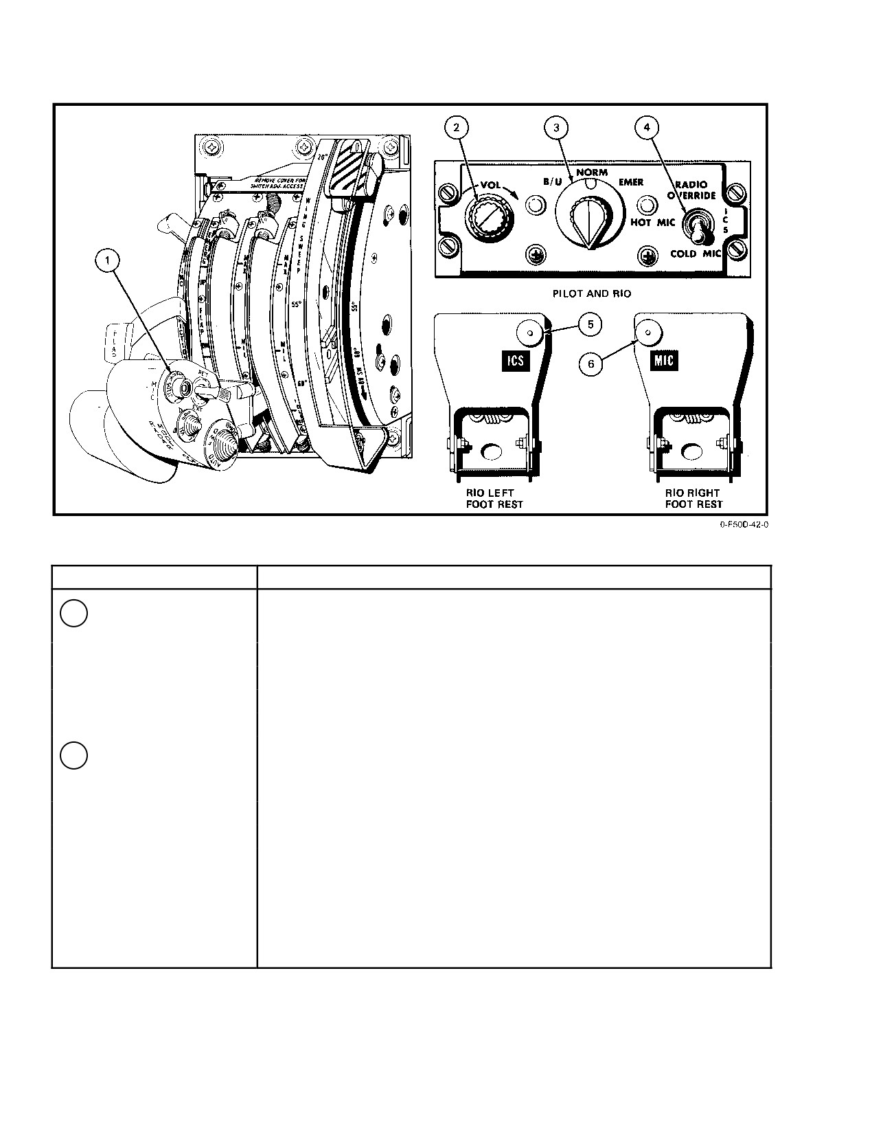
NAVAIR 01−F14AAD−1
NOMENCLATURE
FUNCTION
1
Pilot’s COMM switch
ICS Ċ
Permits intercommunication when COLD MIC is selected on
function selector. Overrides V/UHF communications.
JTIDS Ċ Keys the JTIDS terminal for voice communications.
V/UHF 1 Ċ Keys ARC−182 radio for operation.
V/UHF 2 Ċ Keys ARC−182 radio for operation.
2
VOL control
Controls intercommunication audio level at that cockpit station. Audio level at
other station not affected; however in EMER volume is controlled by other
station.
Figure 19Ć3.ĄIntercommunication Controls (Sheet 1 of 2)
ORIGINAL
19−4
NAVAIR 01−F14AAD−1
NOMENCLATURE
FUNCTION
3
Amplifier selector
B/U Ċ
(Backup) used to bypass a fault amplifier and uses a backup
output amplifier at own station.
NORM Ċ
(Normal) used when all amplifiers are functioning properly.
EMER Ċ
(Emergency) uses the backup amplifier at own station, and
makes use of input amplifier of other station over the emergency
line. Volume is controlled by other station.
4
Function selector
RADIO
OVERRIDE Ċ Attenuates non critical radio audio to emphasize
intercommunication when urgent.
HOT MIC Ċ Intercommunication without keying.
COLD MIC Ċ Intercommunication only when pilot actuates COMM switch on
inboard throttle or RIO actuates keying switch on left foot rest.
5
RIO’s ICS button
Permits intercommunication if COLD MIC is selected on the function selector
(left foot rest)
control. Overrides V/UHF communications.
6
RIO’s MIC button
Permits transmission on V/UHF 1, V/UHF 2, or BOTH radios as well as JTIDS
(right foot rest)
as selected on the radio frequency channel indicator (RFCI).
Figure 19−3. Intercommunication Controls (Sheet 2 of 2)
Identical ICS control panels (Figure 19−3) are on the
pilot and RIO left−side consoles. The ICS includes four
amplifiers, two at each cockpit station, that permit duplex
operation during normal operation. If one amplifier fails, it
may be bypassed by selecting either the B/U (backup) or
With the front cockpit ICS amplifier selector
EMER (emergency) position on the ICS control panel. This
knob in the EMER position, engine stall/
permits continued ICS operation.
overtemperature and Sidewinder tones will not
be available to the pilot.
Note
Note
If two amplifiers fail at the same station,
intercommunication is impossible.
D Selection of EMER via the ICS amplifier
The external interphone connection is in the nose
selector knob in either cockpit allows use of
wheelwell. When the pilot’s COMM switch is set to HOT
the other cockpit’s input amplifier.
MIC, ground personnel can communicate with the cockpit
stations.
D The RIO can obtain a Sidewinder and engine
stall/overtemperature tone by selecting
EMER on his ICS panel. This allows the RIO
19.2.1
Audio Warning Signals
to use the pilot’s input amplifier.
Audio warning signals from the weapon system are
Figure
19−4 provides a glossary of audio warning
available to either or both crewmen through the ICS. Each
signals available within the aircraft weapon systems. Two
signal has a distinct tone. A visual display accompanies most
28−Vdc circuit breakers, ICS NFO (7F3) and ICS PILOT
audio signals so that the flightcrew can expect the tone and
(7F2), control power to and provide circuit protection for the
interpret its meaning. Most audio signals may be attenuated
ICS. Power to both circuit breakers is from dc essential bus
or turned off if not required, allowing the flightcrew to
No. 1. Approximately 1 minute of warmup is required in
concentrate on more critical tones. Critical warning tones
order to achieve normal operating temperature.
cannot be attenuated by any mode of ICS operation.
19−5
ORIGINAL