F-14D. FLIGHT MANUAL (2004) - page 13
NAVAIR 01−F14AAD−1
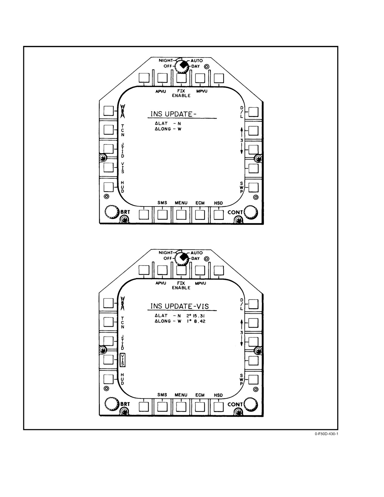
Figure 20Ć51.ĄINS UPDATE MFD Formats (Sheet 1 of 4)
ORIGINAL
20−92
NAVAIR 01−F14AAD−1
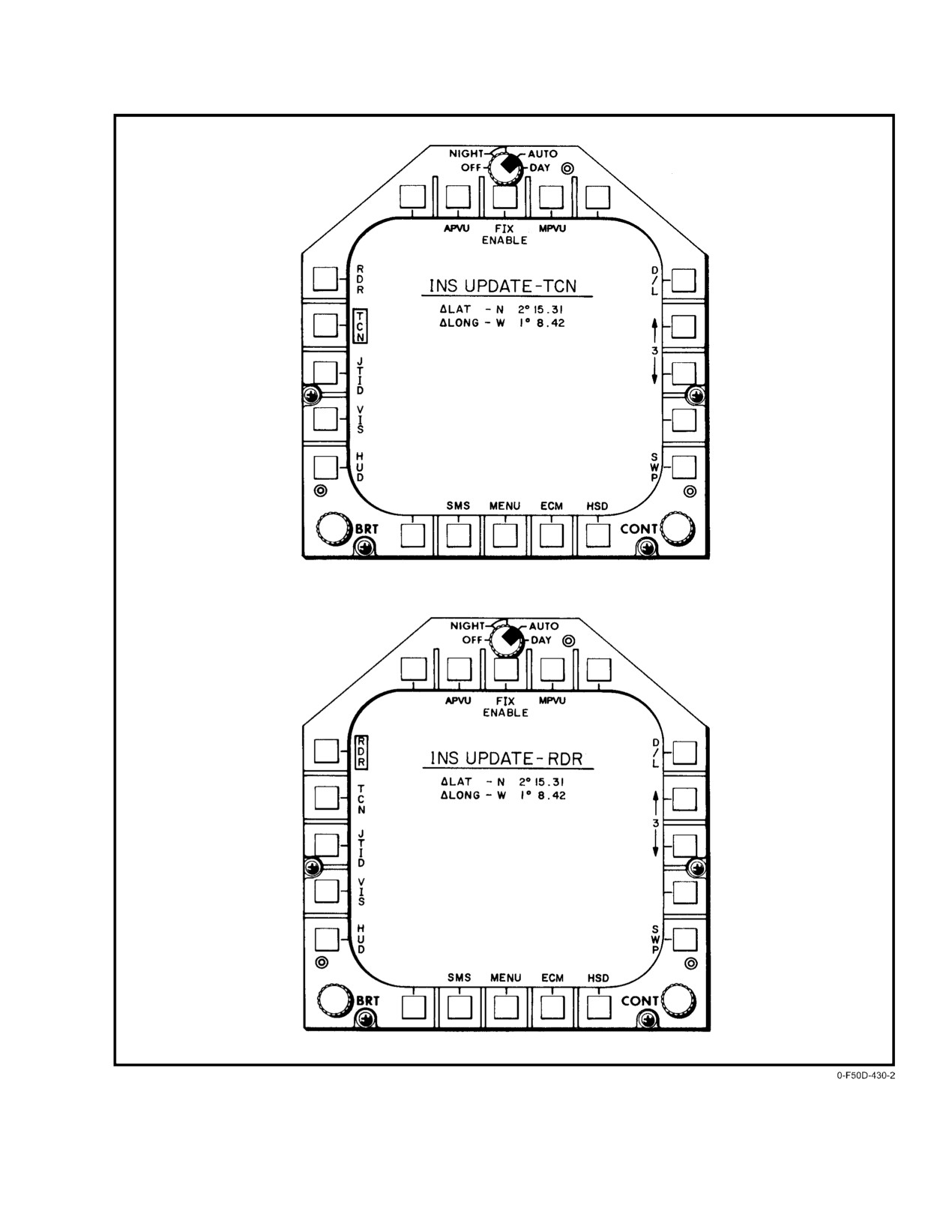
Figure 20−51. INS UPDATE MFD Formats (Sheet 2 of 4)
20−93
ORIGINAL
NAVAIR 01−F14AAD−1
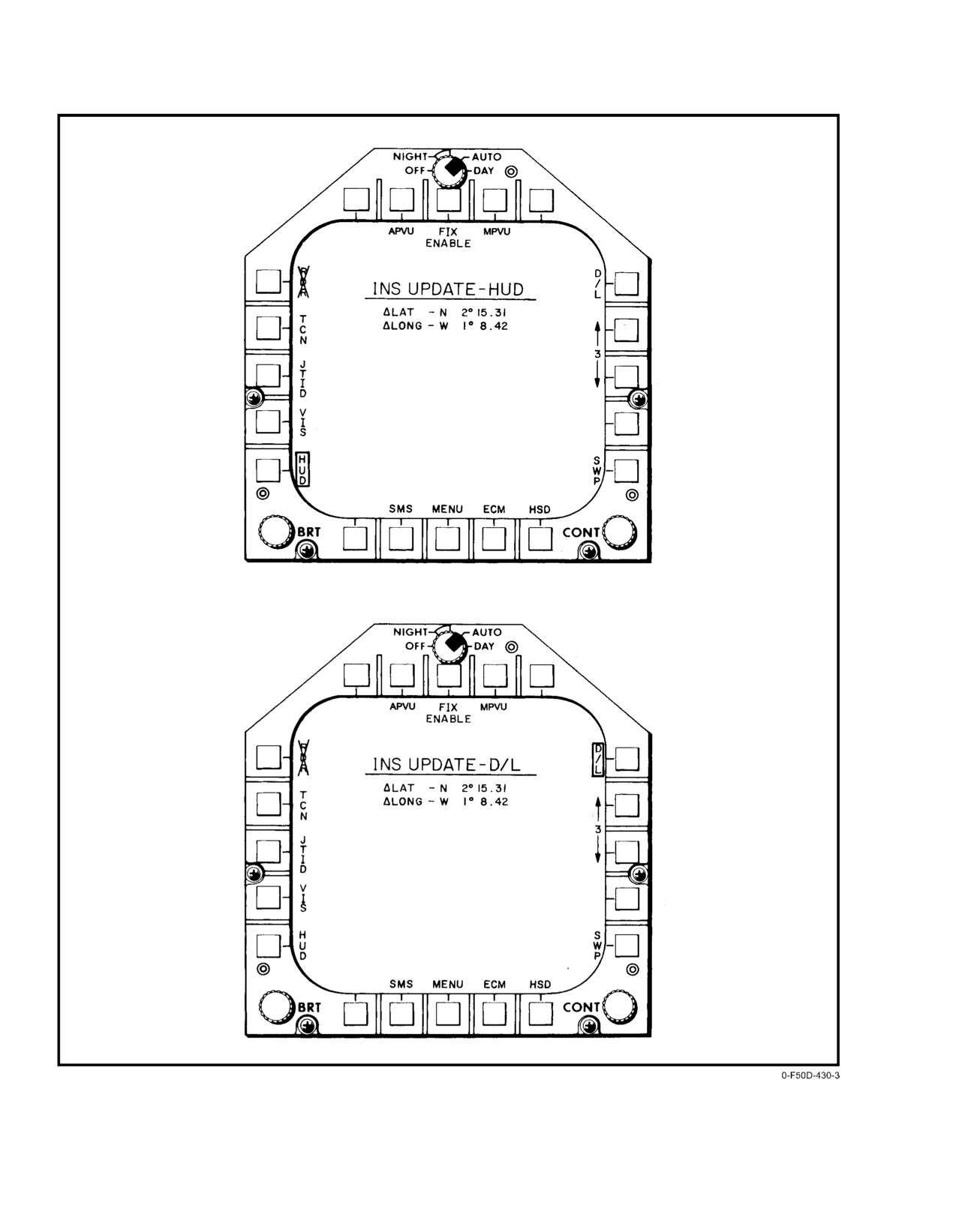
Figure 20−51. INS UPDATE MFD Formats (Sheet 3 of 4)
ORIGINAL
20−94
NAVAIR 01−F14AAD−1
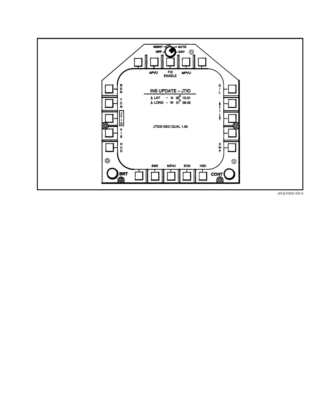
Figure 20−51. INS UPDATE MFD Formats (Sheet 4 of 4)
20.3.9.3.3
Radar One−Fix Update
coordinates of the radar−identifiable point via the
increase/decrease pushbuttons on the right side of
Radar one−fix update computes aircraft position using
the INS UPDATE MFD format.
radar measurements of range, azimuth, and elevation angles
from a radar−identifiable target whose coordinates are known
4. Select half−action mode by depressing the trigger
and are stored in the waypoint file. This procedure requires
on the RIO sensor hand control to the first detent
that the radar is operating in the ground−map mode and that
position.
the DD cursor be positioned over the DD displayed target
prior to designating via the sensor hand control as described
5. Place the DD cursor over the displayed radar target
below. Like other one−fix update modes it also requires that
on the DD (Figure 20−52) using the sensor hand
the waypoint corresponding to the radar target coordinates is
control and depress the trigger to the second detent
selected for the update as described below. Since this
(full action).
procedure requires the use of the DD control panel, it can be
performed only by the RIO. The procedure is as follows:
6. Depress the RDR pushbutton on the INS Update
MFD format. The RDR legend will become boxed
1. Select the radar ground−map mode via the GND
and the computed delta LAT/delta LONG will
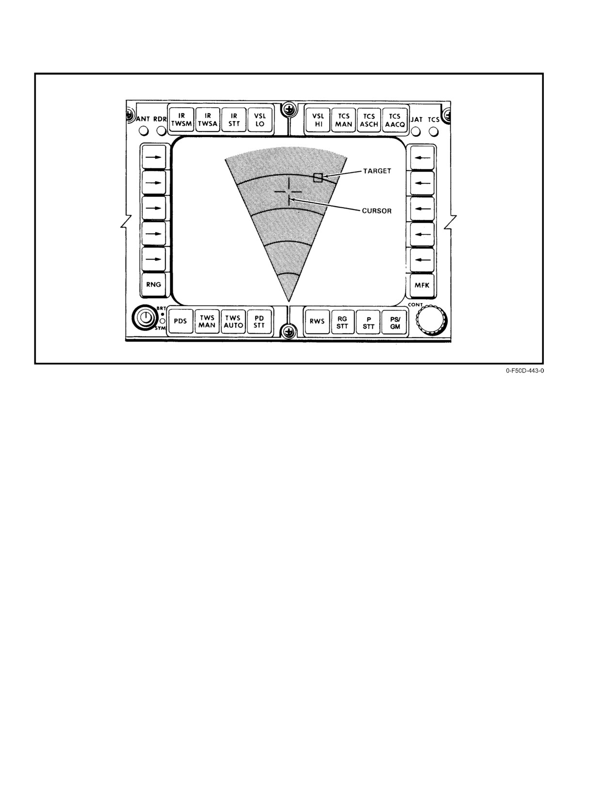
MAP pushtile on the DD, shown in Figure 20−52.
appear as shown in Figure 20−51.
2. Verify that the coordinates of the radar identifiable
7. If the delta LAT/LONG corrections appear
point are the same as those of the waypoint to be
reasonable and a correction is required, depress the
selected for updating by calling up the appropriate
FIX ENABLE pushtile. The corrections will be
WPT Data MFD format, Figure 20−29. If incorrect,
incorporated into the system and the sensors and the
enter the correct values via the DEU or DD.
correct latitude and longitude will be displayed on
3. Call up the INS UPDATE format, Figure 20−51.
the OWN A/C MFD format, which will now appear.
Select the correct waypoint corresponding to the
20−95
ORIGINAL
NAVAIR 01−F14AAD−1
Figure 20Ć52.ĄDD Control Panel With GND MAP Selected
20.3.9.3.4
Data−Link One−Fix Update
3.
Call up the INS Update MFD format (Figure 20−49)
and select waypoint 18 via the increase/decrease
Data−link one−fix update computes aircraft position
pushbuttons.
using inputs from an external platform that measures the
4.
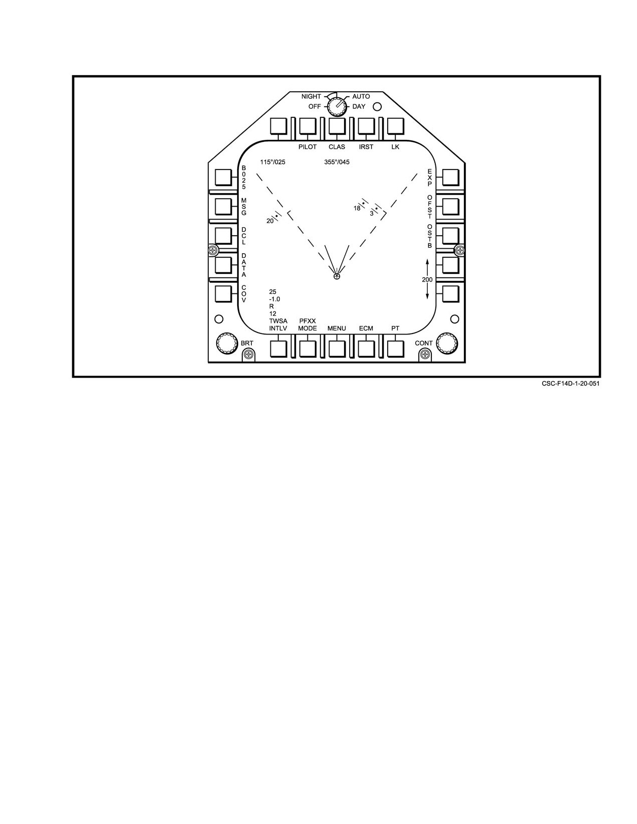
Call up the TSD MFD format
(Figure
20−53)
aircraft position with respect to an agreed data−link target
point whose coordinates are stored in a specific location in
available from the MENU1 MFD format. Using the
pilot cursor control or the RIO sensor hand control,
the waypoint file. The measured information consist of
components of slant range to the waypoint that are
place the cursor over the data−link target point
position and depress the switch.
transmitted to the aircraft via a specific data−link message.
The procedure requires that the coordinates of the agreed
data−link target point are stored as waypoint 18 in the wayĆ
Note
point file and that the data link is operating in the tactical
Both waypoint 18 from the waypoint file and
mode. Verification and selection of the waypoint are
the data−link reported location of this point
performed similar to other one−fix update procedures but the
appear on the TSD format. Since both
tactical situation display on the MFD is used for location and
symbols represent the same point, the
designation of the data−link target point (Figure 20−53). Both
difference in their location on the TSD MFD
the pilot and the RIO can perform this update procedure. The
format is an indication of the aircraft position
pilot uses the cursor control switch on the throttle, and the
error. A check should be made to ascertain
RIO uses the sensor hand control for designating and
that this error is reasonable prior to
positioning the cursor. The procedure is as follows:
performing the update.
1. Verify data−link operation in the tactical mode
5.
Call up again the INS UPDATE MFD format.
(i.e., DATA LINK MODE switch is in TAC).
Depress the D/L pushbutton. A delay of several
seconds may occur prior to the boxing of the D/L
2. Verify the coordinates of waypoint
18 are the
legend and the appearance of the delta LAT and
previously agreed values by calling up the
LONG displays (Figure 20−51).
appropriate page of the WPT Data MFD format.
ORIGINAL
20−96
NAVAIR 01−F14AAD−1
Figure 20Ć53.ĄMFD TSD Format
6. If the errors appear reasonable and an update is
to the HUD visual target via the increase/decrease
desired, depress the FIX ENABLE pushbutton. The
pushbuttons on the right side of the format.
corrections will be incorporated into the system and
sensor and the correct latitude and longitude will be
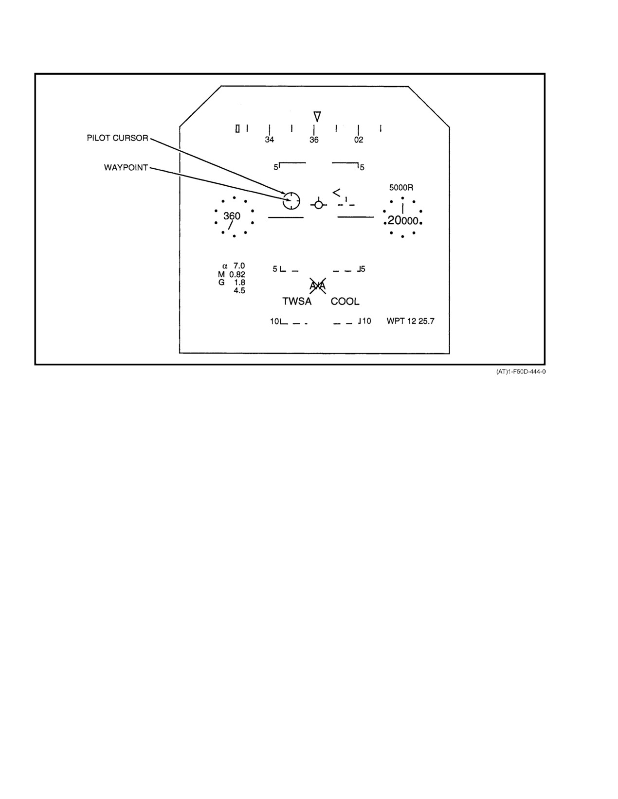
3. Position the cursor over the visual target seen
displayed on the INS UPDATE format and will also
through the HUD using the cursor control switch
appear on the OWN A/C MFD format.
and then depress the switch (Figure 20−54).
4. Depress the HUD pushbutton on the INS UPDATE
20.3.9.3.5
HUD/Designate One−Fix Update
MFD format. The HUD legend will become boxed
and the computed delta LAT/delta LONG will
HUD/designate one−fix update computes aircraft
appear as shown in Figure 20−51.
position, using measurements of azimuth and elevation from
the HUD center to a designated target point that is visible
5. If the delta LAT/LONG corrections appear
through the HUD and whose coordinates are known and
reasonable and a correction is required, depress the
stored in the waypoint file and system altitude. This
FIX ENABLE pushbutton on the INS UPDATE
procedure is performed only by the pilot using the cursor
MFD format. The corrections will be incorporated
control switch on the throttle to position the HUD cursor over
into the system and sensors and the correct latitude
the visually sighted target and to designate. Like other
and longitude will be displayed on the OWN A/C
one−fix update modes, it also requires that the waypoint
MFD format.
corresponding to the visual target coordinates is selected for
the update as described below.
20.3.9.3.6
JTIDS One−Fix Update
1. Verify that the coordinates of the HUD visual target
JTIDS one−fix update uses the delta latitude and
are the same as those of the waypoint to be selected
longitude information calculated by JTIDS to perform a
for updating by calling up the appropriate WPT
one−time update of the system and sensors. This function will
DATA MFD format (Figure 20−29).
always use the JTIDS geodetic latitude and longitude
2. Call up the INS UPDATE MFD format
correction data regardless of JTIDS NAV MODE. This
(Figure 20−51). Select the waypoint corresponding
procedure requires JTIDS operating in the net as an active
20−97
ORIGINAL
NAVAIR 01−F14AAD−1
Figure 20Ć54.ĄHUD/Designate Position Update
participant (NORM selected on JTIDS control panel) with
20.3.9.4
Continuous Position Updating
NET ENTR−OK. See Chapter 19 for JTIDS operating
procedures. The JTIDS geodetic position quality must be ≤Ă3
In addition to one−fix position updates, the navigation
to display the data and allow the update. This procedure can
system has the capability to accept continuous navigation
be performed by either the pilot or RIO as follows:
corrections from external sources when they exist and are
valid. For the current configuration of the aircraft, the only
1. Verify JTIDS operating and in sync.
two sources available for continuous position updating are
TACAN and JTIDS data. The TACAN mode of continuous
2. Call up INS UPDATE MFD format (Figure 20−51)
updating uses TACAN measurements of range and bearing to
available from the MENU MFD format.
a prestored selected waypoint that also is an active TACAN
station. Thus, as in one−fix updating, it is necessary to ensure
3. Depress the JTID pushbutton on the INS UP−DATE
that the selected waypoint corresponds to the TACAN station
MFD format.
that is being received. The JTIDS mode of continuous updatĆ
ing uses delta latitude, longitude, and altitude calculated by
If the data from JTIDS is not valid or the quality
JTIDS to continuously update the navigation system. The
is
>3, the JTID pushbutton will be crossed out.
JTIDS continuous update will update the navigation system
The JTID pushbutton boxes and the JTIDS comĆ
with either geodetic latitude, longitude, and altitude correcĆ
puted delta LAT and delta LONG will appear as
tions in the GEO mode or relative latitude, longitude, and
shown in Figure 20−51.
geodetic altitude corrections in the REL mode. When the
JTIDS altitude correction data quality is ≤ 10, this function
4. If the delta LAT/LONG corrections appear
will display and use only the latitude and longitude correcĆ
reasonable and a correction is required, depress the
tions.
FIX ENABLE pushbutton on the INS UPDATE
MFD format. The corrections will be incorporated
Selection of JTIDS continuous position updating
into the system and sensors and the corrected
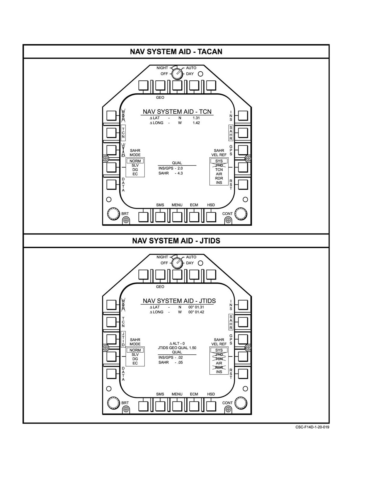
is made via the MFD NAV SYSTEM AID format
latitude and longitude will be displayed on the
(Figure 20−55) that will appear when the NAV pushbutton is
OWN A/C MFD format.
ORIGINAL
20−98
NAVAIR 01−F14AAD−1
depressed on the MFD HSD or OWN A/C format. The
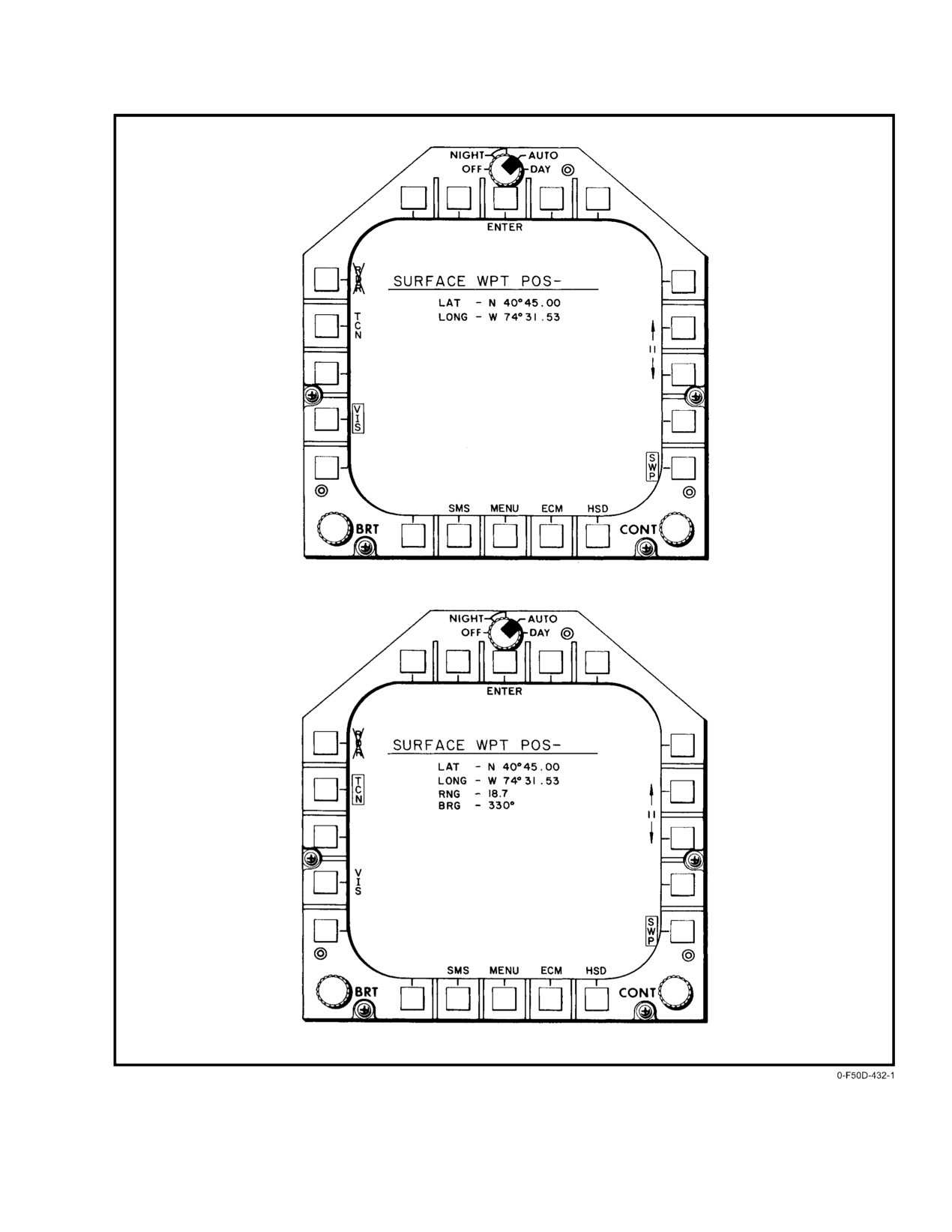
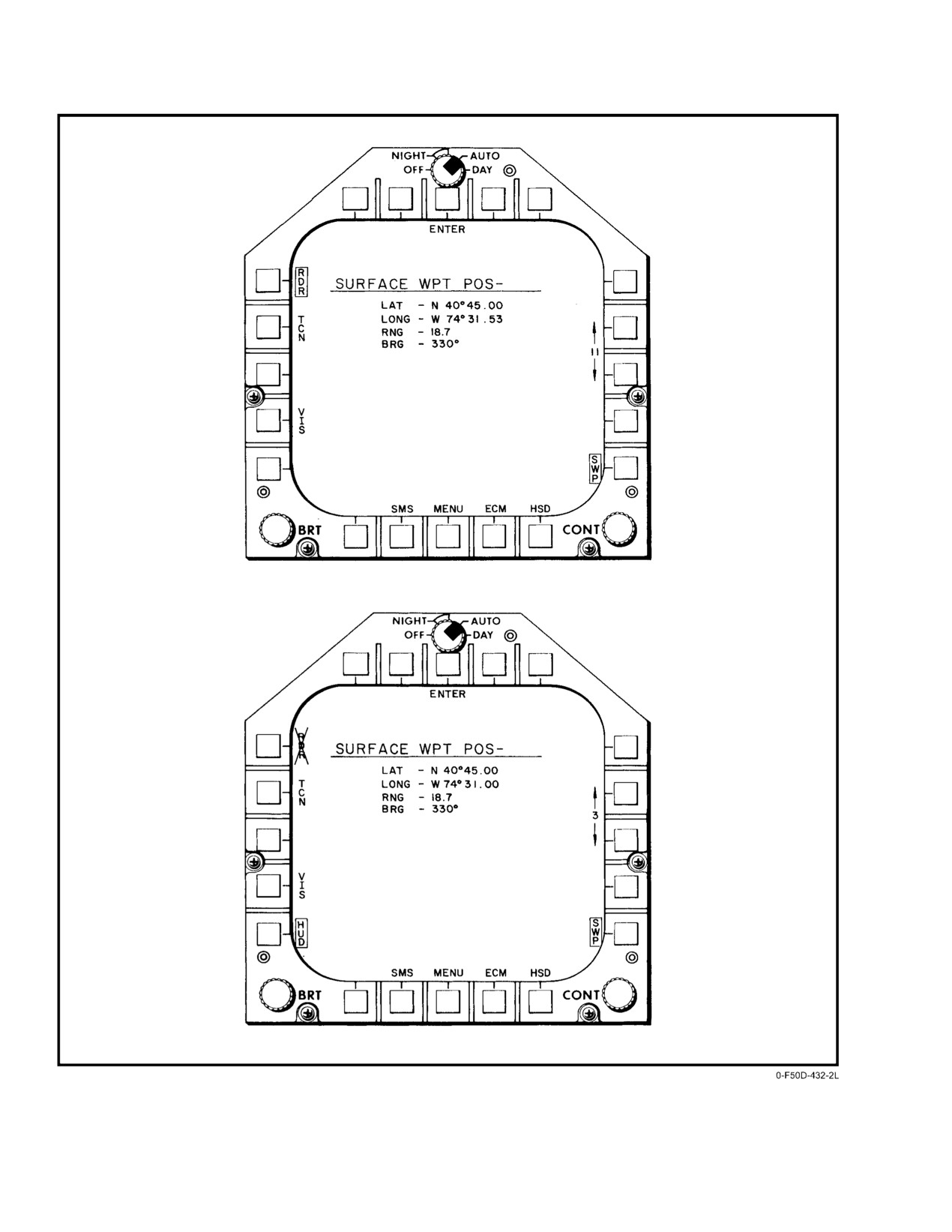
On the SURFACE WPT POS MFD format
remaining procedures for JTIDS continuous update are the
(FigureĂ20−56), an X" over the legend for a position
same as JTIDS one−fix update. Depress the JTID pushbutton
determination mode indicates that the mode is not available.
on the NAV SYSTEM AID−JTID format. If the data from
Until one of the available modes is selected, the format
JTIDS is not valid or the quality is >3, the JTID pushbutton
shown in Figure 20−56 displays only the mode legends, the
will be crossed out. The JTID pushbutton boxes and the
boxed SWP legend, and the SURFACE WPT POS header.
JTIDS computed delta LAT, LONG, and ALT will appear as
shown in Figure 20−55. Depression of the ENABLE pushĆ
When using the visual, radar, or HUD/designate
button on the top center of the NAV SYSTEM AID format
procedure, after the surface waypoint latitude and longitude
now allows the corrections, which are continuously
have been computed and displayed on the MFD, pressing the
computed, to update the system.
ENTER pushbutton on the MFD format enters the
coordinates into the waypoint file in an assigned waypoint
Selection of continuous position updating is made via
number. For the DEU method, the coordinates are also
the MFD NAV SYSTEM AID format (Figure 20−55) that will
displayed on the MFD, but are entered by pressing the DEU
appear when the NAV pushbutton is depressed on the MFD
ENTER pushtile. When using the PTID method, pressing the
HSD or OWN A/C format. If TACAN data is being received
sensor hand control trigger enters the coordinates that are
from a transmitting station, the TCN legend will not be
displayed on the MFD.
crossed out. The procedure for TACAN operation is the same
as for one−fix TACAN position update described in
The paragraphs that follow describe the various
paragraph 20.3.9.3.2. Select the correct waypoint using the
methods and provide procedures.
up or down arrows on the HSD format, then depress the NAV
pushbutton. Once this is done, depressing the TCN pushĆ
20.3.9.5.1
Visual Mode
button on the resulting NAV SYSTEM AID format boxes the
TCN legend and computed corrections for latitude and
For a visual waypoint position determination, the airĆ
longitude are then displayed. Depression of the ENABLE
craft present−position coordinates are assigned to the wayĆ
pushbutton on the top center of the NAV SYSTEM AID
point position at the instant of flyover. This requires that the
format now allows the corrections, which are being continĆ
VIS pushbutton be pressed at that time. The assigned coordiĆ
uously computed, to be provided to the system.
nates are displayed when the VIS pushbutton is pressed. This
procedure can be performed by either crewmember.
Note
Note
For continuous position updating neither the INS
nor the SAHRS are updated. Once this aiding
D Visual mode is inoperable with GPS boxed.
mode is deselected or becomes invalid, the
computed corrections will not be provided and a
D For best results, the aircraft should be flown
change in position may occur.
low and slow for this procedure.
20.3.9.5
Surface Waypoint Position
1.
Call up the MFD INS UPDATE format
Determination
(Figure 20−51).
The position of a surface waypoint is determined by
2.
Depress the SWP pushbutton to display the MFD
SURFACE WPT POS update format.
measuring its location with respect to the aircraft or with
respect to some other known point. The following sensors
3.
Depress the up or down arrow pushbutton until the
and procedures can be used: visual, TACAN, radar, HUD/
desired waypoint number is displayed.
designate, DEU, and PTID. Selection is made from the
SURFACE WPT POS format on the MFD. The computed
4.
At the instant of overflight, depress the VIS
latitude and longitude are displayed on the MFD or DD. The
push−button, boxing the VIS legend and displaying
SURFACE WPT POS format is called by selecting the SWP
the latitude and longitude of the surface waypoint.
pushbutton on the INS UPDATE format.
5.
If the latitude and longitude appear reasonable,
Note
press the ENTER pushbutton on the SURFACE
WPT POS format. This enters the coordinates into
The INS UPDATE format is called by selecting
the waypoint file; they can be verified by selecting
the UPDT legend on any of the HSD MFD
the WPT DATA format (Figure 20−29).
formats.
20−99
ORIGINAL
NAVAIR 01−F14AAD−1
Figure 20Ć55.ĄNavigation System Continuous Update MFD Format
ORIGINAL
20−100
NAVAIR 01−F14AAD−1
Figure 20Ć56.ĄSurface Waypoint Position MFD Formats (Sheet 1 of 2)
20−101
ORIGINAL
NAVAIR 01−F14AAD−1
Figure 20−56. Surface Waypoint Position MFD Formats (Sheet 2 of 2)
ORIGINAL
20−102
NAVAIR 01−F14AAD−1
20.3.9.5.2
TACAN Surface Waypoint Position
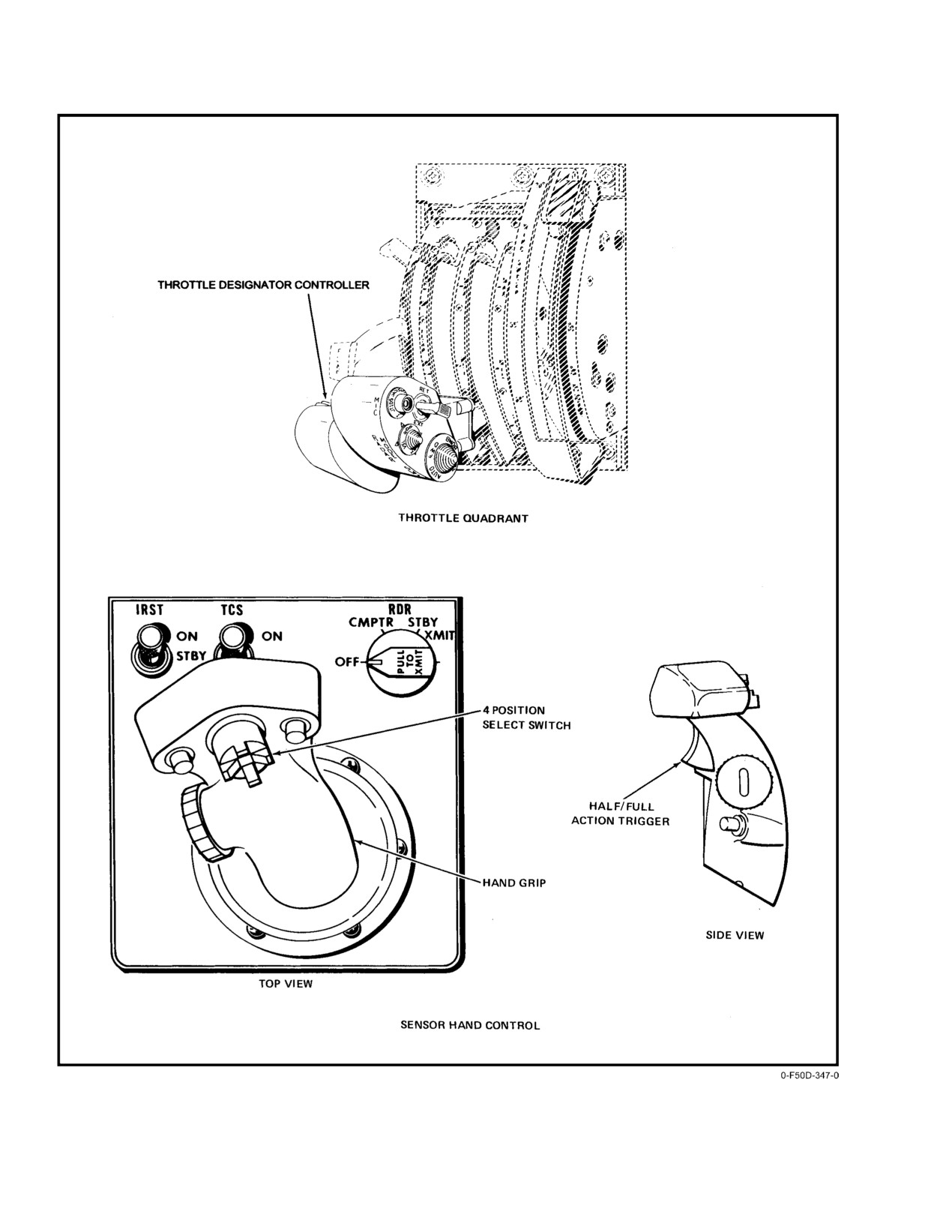
5. Set the sensor hand control cursor switch to the up
Determination
position (Figure 20−57).
For TACAN surface waypoint position determination,
Select the half−action mode by depressing the trigger on the
the position of the TACAN station is computed using
RIO sensor hand control to the first detent position.
TACAN measurements of range and bearing from aircraft
present position. This procedure can be performed by either
6. Using the RIO sensor hand control, place the DD
cursor over the radar target and depress the trigger
crewmember and requires that the TACAN be operating.
to the second detent position (full action).
1. With the TACAN operating, select the channel for
7. Depress the RDR pushbutton on the SURFACE
the station location to be determined.
WPT POS format to display the waypoint latitude
2. Call up the INS UPDATE format (Figure 20−51).
and longitude and box the RDR legend.
3. Depress the SWP pushbutton to display the MFD
8. If the coordinates appear reasonable, press the
SURFACE WPT POS format.
ENTER pushbutton to place the surface waypoint
coordinates into the proper waypoint file; they can
4. Depress the up or down arrow pushbutton until the
be verified by selecting the WPT DATA format.
desired waypoint number is displayed.
20.3.9.5.4
HUD/Designate Mode
5. Depress the TCN pushbutton on the MFD
SURFACE WPT POS format. This boxes the TCN
Using the HUD/designate mode, the pilot uses the
legend and displays the TACAN station latitude and
HUD cursor to designate a visual target and the target
longitude.
position is computed using aircraft present position and
azimuth/elevation measured from the HUD center to the
6. If the coordinates appear reasonable, press the
designated target.
ENTER pushbutton to place the surface waypoint
coordinates into the proper waypoint file. They can
1. Call up the INS UPDATE format (Figure 20−51).
be verified by selecting the WPT DATA format
(Figure 20−29).
2. Depress the SWP pushbutton to display the
SURFACE WPT POS format and box the SWP
20.3.9.5.3
Radar Mode
legend.
For a radar surface way−point position determination,
3. Depress the up or down arrow pushbutton until the
the position of a radar surface target is computed using radar
desired waypoint number is displayed.
measurements of range, bearing, and elevation angle to the
target from the known aircraft present position. The radar
4. Using the TDC (Figure 20−57), place the HUD
must be in the GND MAP mode. This procedure can only be
cursor over the visual target and depress the switch
performed by the RIO.
to designate the waypoint.
5. Depress the HUD pushbutton on the SURFACE
1. On the DD control panel, select GND MAP.
WPT POS format to display waypoint latitude and
2. Call up the INS UPDATE format (Figure 20−51).
longitude and box the HUD legend.
3. Depress the SWP pushbutton, which results in the
6. If the coordinates appear reasonable, depress
display of the SURFACE WPT POS format with
ENTER pushbutton to place the surface waypoint
SWP boxed.
coordinates into the waypoint file; they can be
verified by selecting the WPT DATA format.
4. Depress the up or down arrow pushbutton until the
desired waypoint number is displayed.
20−103
ORIGINAL
NAVAIR 01−F14AAD−1
Figure 20Ć57.ĄCursor Controls
ORIGINAL
20−104
NAVAIR 01−F14AAD−1
20.3.9.5.5
DEU Mode
1. Set the sensor hand control cursor select switch to
the down (PTID cursor) position.
In the DEU mode, the position of a new waypoint is
computed based on its range and bearing from an existing
2. On the PTID control panel (FO−4), depress the
NON ATTK and SYM ELEM pushbuttons.
waypoint already in the waypoint file. The range and bearing
values are entered by the RIO via the DEU (Figure 20−28).
3. Set the azimuth scan to ±20° on the sensor control
panel (FO−4) and adjust the antenna scan center to
1. On the DEU, select the number of the known
zero.
waypoint to be used as a reference.
4. Call the WPT DATA MFD format and depress the
2. On the DEU, enter the range and bearing from the
desired waypoint number to box the waypoint
reference waypoint to the new waypoint.
legend.
5. On the PTID control panel, set the RANGE switch
3. On the DEU, press the SET pushtile and select a
waypoint number for the new waypoint.
as required and the MODE switch to A/C STAB.
6. Place the sensor hand control trigger to the half−
4. Press the ENTER pushtile on the DEU. This causes
the coordinates of the new waypoint to be computed
action position.
and entered into the waypoint file.
7. Place the PTID cursor on the desired screen location
5. The latitude and longitude of the new waypoint may
and hook by selecting full action. This causes the
latitude and longitude of the hooked position to be
be verified by calling the WPT DATA format on the
computed and entered in the waypoint file.
MFD.
20.3.9.5.6
PTID Spot Hook Mode
The coordinates of the hooked position can be verified
by calling the WPT DATA format.
In the spot hook mode, coordinates are computed for a
point designated by the RIO by spot hooking on the PTID
based on aircraft present position.
20−105 (Reverse Blank)
ORIGINAL
NAVAIR 01−F14AAD−1
CHAPTER 21
Identification
21.1
IDENTIFICATION TRANSPONDER
an antenna diversity comparator identifies which antenna
(AN/APX−100)
received the strongest interrogation signal and automatically
selects that antenna to transmit the reply. It is therefore
21.1.1
IFF Transponder
recommended that the antenna select switch be left in DIV
The APX−100 IFF transponder system is capable of
at all times.
automatically reporting coded identification and altitude
signals in response to interrogations from surface
(or
airborne) stations so that the stations can establish aircraft
identification, control air traffic, and maintain vertical
separation. The system has five operating modes (1, 2, 3/A,
If either TOP or BOT is selected on the APX−100
C, and 4). Modes 1 and 2 are IFF modes, mode 3 (civil
antenna select switch, a Mode IV reply will be
modeĂA) and mode C (automatic altitude reporting) are
transmitted only if the Mode IV interrogation
primarily air traffic control modes, and mode 4 is the secure
signal is strongest on the antenna selected. If the
(encrypted) IFF mode. The IFF control panel is in the rear
stronger of the two antennas was not selected at
cockpit (Figure 21−1).
the time of interrogation, the aircrew will not
have any indication that their aircraft was interĆ
21.1.1.1
Master Switch
rogated or that no reply was made.
The MASTER switch applies power to all the transĆ
21.1.1.3
IDENT−OUT−MIC Switch
ponder system components except the altimeter components.
It is a four−position rotary switch placarded OFF, STBY,
The IDENT−OUT−MIC switch is a three−position
NORM, and EMER. The switch must be lifted over a detent
toggle switch. The spring−loaded IDENT adds an identificaĆ
to switch to EMER or to OFF. STBY should be selected for
tion of position pulse to mode 1, 2, and 3/A replies for a
2 minutes prior to switching to NORM to allow the
period of 15 to 30 seconds. In MIC, the identification of
transponder to warm up. In NORM, the transponder system
position function is activated for 15 to 30 seconds each time
is operational at normal receiver sensitivity. In EMER, the
the UHF microphone switch is pressed.
transponder transmits emergency replies to mode 1, 2, or 3/A
interrogations. The mode 3/A emergency reply includes
21.1.1.4
Mode 1, 2, and 3/A Code Selectors
codeĂ7700. When EMER is selected, all modes are enabled
The two mode l thumbwheel selector switches allow
regardless of the position of the selector switches. When the
selection of
32 mode 1 codes and the four mode 3/A
front seat ejects, a switch is tripped that automatically selects
thumbwheel selectors allow selection of 4096 mode 3/A
the emergency mode if the MASTER switch is in any
codes. The mode 2 code that is set on the four MODE 2
position other than OFF.
selector switches may be read by moving the sliding cover.
The code may be reset by inserting a pointed object like a pen
21.1.1.2
Antenna Select Switch
tip or a paper clip to rotate the thumbwheel. Mode 2 codes are
The position of the antenna select switch determines
not normally changed in flight.
APX−100 antenna reply logic. Although the system is
designed to receive an interrogation on either antenna at all
21.1.1.5
Mode Switches
times regardless of switch position, with TOP or BOT
The four mode switches (M−1, M−2, M−3/A, and M−C)
selected, it will only reply on the selected antenna, and only
each have OUT, ON, and spring−loaded TEST positions. The
if the strongest interrogation signal was received on that
center position ON of each switch enables that mode. To test
antenna. For example, if BOT were selected and the
the transponder, press the mode switch of each mode to
interrogation signal was stronger from the top antenna, no
TEST.
reply would be transmitted. In the DIV (diversity) position,
21−1
ORIGINAL
NAVAIR 01−F14AAD−1
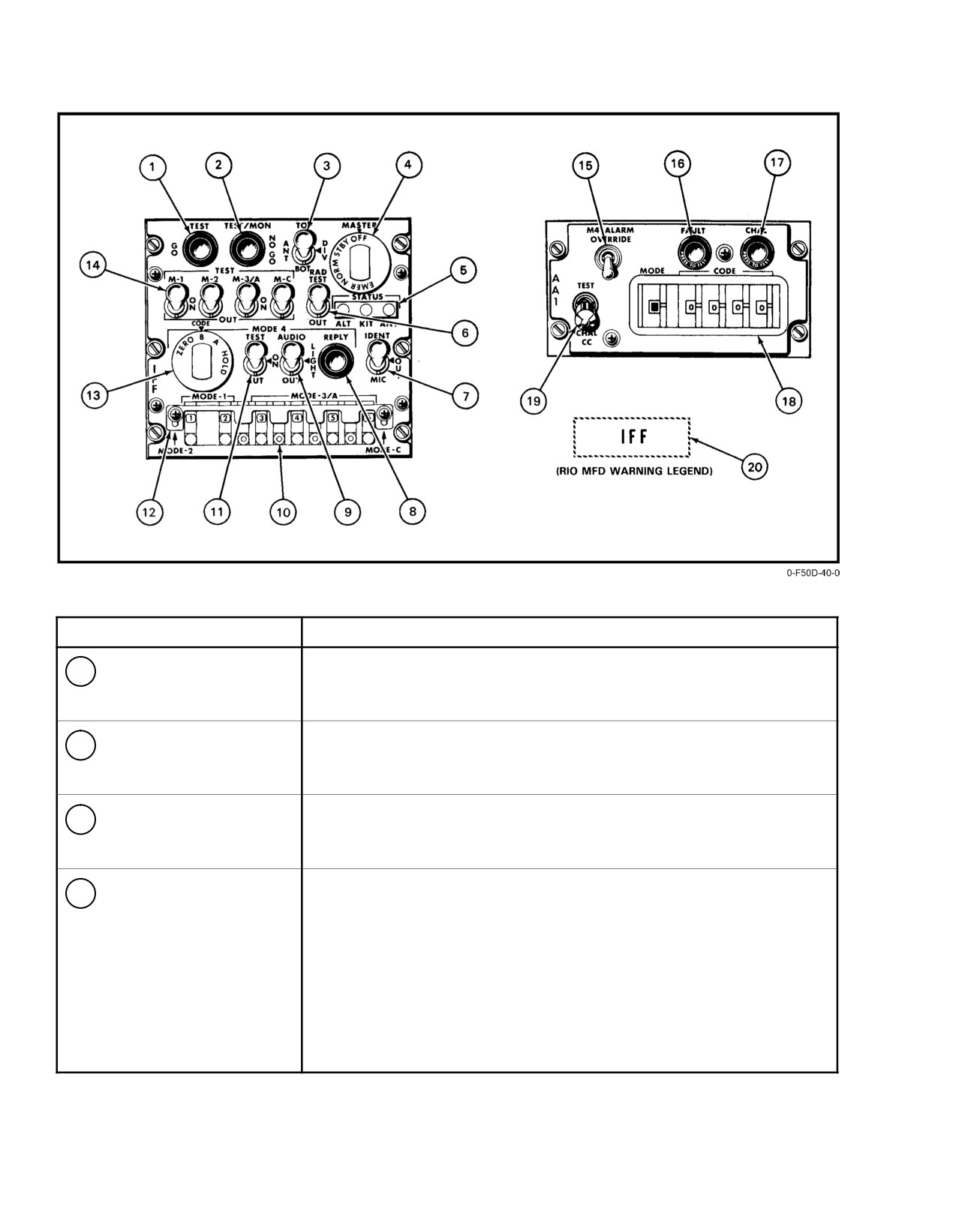
NOMENCLATURE
FUNCTION
1
TEST light (GO)
Illuminates when respective MODE switch TEST position is actuated;
indicates proper (GO) operation of modes 1, 2, 3/A, and C. Master
switch must be set to NORM.
2
TEST/MON light
The light has two functions. Illuminates when respective MODE switch
(NO GO)
TEST position is actuated; indicates failure (NO GO) of modes 1, 2, 3/A
and C. Master switch must be set to NORM.
3
ANT switch
Selects upper (TOP), lower (BOT), or both (DIV) antennas. DIV
(diversity) permits the IFF to switch automatically for transmission to the
antenna that received the strongest interrogation signal.
4
MASTER switch
OFF
Deenergizes set.
STBY Energizes receiver−transmitter for immediate operation upon
switching to an operating position.
NORM Allows receiver−transmitter response to interrogations.
EMER Energizes receiver−transmitter and generates emergency
replies to mode 1,2 (thumbwheel settings), and 3/A (code
7700) and a normal reply to mode C, when interrogated,
whether mode switches are at ON or OUT.
Figure 21Ć1.ĄIFF Control Panels (Sheet 1 of 3)
ORIGINAL
21−2
NAVAIR 01−F14AAD−1
NOMENCLATURE
FUNCTION
5
STATUS lights (red)
ALT
Illumination indicates altitude encoder circuit failure during MODE C
test.
KIT
Illumination indicates KIT/KIR TSEC failure during MODE 4 test.
ANT
Illumination indicates excessive voltage standard wave ratio (VSWR)
to antenna during MODE C or MODE 4 tests.
6
RAD switch
OUT
Deenergized position.
TEST
When selected, transponder replies to mode 3/A or 4 TEST mode
interrogations from a ramp test set during ground maintenance
testing.
7
IDENT OUT
IDENT Momentary position provides IDENT reply for 15 to 30 seconds after
MIC switch
releasing switch; replies to interrogation in modes 1, 2, 3/A.
OUT
Deenergizes circuit.
MIC
Transfers IDENT reply activation switch from IDENT to radio
microphone switch
8
MODE 4 REPLY light
Illuminates when system has successfully replied to a mode 4 interrogation
provided the AUDIO/LIGHT/OUT switch is not in the OUT position.
9
MODE 4 AUDIO/ LIGHT/
AUDIO Enables: (1) An ICS tone indicating either incomplete signal reception
OUT switch
or that the received interrogation code does not match the installed
code; (2) no go and IFF caution lights indicating no reply to a valid
mode 4 interrogation; and (3) MODE 4 REPLY light indicating a valid
mode 4 interrogation reply.
LIGHT Enables: (1) no go and IFF caution lights indicating no reply to a valid
mode 4 interrogation; and (2) MODE 4 REPLY light indicating a valid
mode 4 interrogation reply. Disables ICS audio tone monitoring.
OUT
Disables all ICS tone and light monitoring of mode 4 interrogations,
replies, and nonreplies.
10
CODE selectors
Code selectors are rotatable drums with imprinted numbers that appear in code
(MODE 1 and 3/A)
selector windows, permitting selection of codes for mode 1 and 3/A.
11
MODE 4 switch
ON
Enables mode 4.
See Figure 21−2 for mode 4 caution/reply light logic.
TEST
Activates KIT mode 4 computer self−test. TEST GO light illuminates if
system is functional, NO GO if it is not.
If KIT computer is at fault, STATUS KIT light illuminates red.
If KIT/KIR is not installed, NO GO and STATUS KIT lights illuminate.
Figure 21−1. IFF Control Panels (Sheet 2 of 3)
21−3
ORIGINAL
NAVAIR 01−F14AAD−1
NOMENCLATURE
FUNCTION
12
MODE 2
Code selectors are rotatable drums with imprinted numbers that can be seen when
sliding cover is moved out of view. Changing requires pointed object. Not normally
changed in flight.
13
MODE 4 CODE
ZERO
Erases code 4 from KIR−1A and KIT−1A computers. IFF ZERO
switch
advisory legend appears on upper left of RIO’s MFD.
B
Selects KIT−1A computer B code.
A
Selects KIT−1A computer A code.
HOLD
Retains code in KIR−1A computers when landing gear is down or when
system is turned off.
14
MODE switches
TEST
GO TEST light illuminates if system is functioning properly;
(1,2, 3/A, and C)
NO GO TEST light illuminates if system failure.
ON
Permits selection of interrogating modes to which the transponder will
reply.
OUT
Deenergized position.
15
M4 ALARM OVERĆ
Disables the mode 4 tone alarm to the RIO’s ICS.
RIDE switch
16
FAULT light
Indicates a malfunction of APX−76 receiver−transmitter, caused by receiver, video, or
transmitter signals.
17
CHAL light
Remains Illuminated for the duration of a challenge period indicating correct
operation.
18
CODE selectors
First thumbwheel selects mode, 1, 2, 3A, 4A, or 4B. Last four thumbwheel rotatable
drums with imprinted numbers appearing in code selector windows, permit selection
of desired interrogation code.
19
TEST−CHAL CC
Momentary two−position center−return switch.
switch
TEST
Onboard transponder is triggered by onboard interrogator. Both sets
must have same code setting. IFF solid lines are displayed on DD at 3
and 4 miles.
CHAL CC A selective identification feature (SIF) interrogation cycle starts
the 5 to 10−second challenge period. Only correct modes and code
replies are displayed (two brackets only on DD).
20
IFF warning legend
Indicates mode 4 interrogation was received, but system has not generated a reply;
mode 4 KIT/KIR computers have been zeroized; or KIT/KIR has failed
self−test.
Figure 21−1. IFF Control Panels (Sheet 3 of 3)
ORIGINAL
21−4
NAVAIR 01−F14AAD−1
TRANSPONDER
INTERROGATOR
CAUTION
REPLY (APX−100)
(APX−100)
(APX−76)
4 OUT (A) STBY
A
ON
OFF
4 ON (A) STBY
A
ON
OFF
4 ON (A) NORM
A
OFF
ON
4 ON (A) NORM
B
OFF
OFF
4 ON (B) NORM
A
OFF
OFF
4 ON (B) NORM
B
OFF
ON
4 ON (B) STBY
B
ON
OFF
4 ON (B) STBY
B
ON
OFF
4 ON (A) NORM RAD
VERIFY BIT 1 (A)
OFF
ON
TEST
4 ON (A) NORM
VERIFY BIT 1 (A)
ON
OFF
4 ON (A) STBY
VERIFY BIT 1 (A)
ON
OFF
KIT ZERO
A OR B
ON
OFF
Figure 21Ć2.ĄMode 4 Caution and Reply Light Logic
Illumination of the GO TEST light indicates proper
The MODE 4 CODE switch is placarded ZERO, B, A,
operation of that mode. Illumination of the NO GO TEST
and HOLD. The switch must be lifted over a detent to switch
light indicates failure of the selected mode. The MASTER
to ZERO. It is spring−loaded to return from HOLD to position
switch must be set to NORM for the test function to operate.
A. Position A selects the mode 4 code for the present code
The modes not being tested should be OUT when testing on
period and position B selects the mode 4 code for the
the ground to prevent unnecessary interference with nearby
succeeding code period. Both codes are mechanically
ground stations. If a malfunction exists during these self−
inserted into the transponder by maintenance personnel. The
tests, an IFX acronym will appear on the programmable
codes are mechanically held in the IFF, regardless of the
tactical information display (PTID). The IFF transponder is
position of the MASTER switch or the status of aircraft
also continuously checked by aircraft self−test. Failure causes
power, until the first time the landing gear is raised.
the IFX acronym to be shown on the PTID. Calling up the
Thereafter, the mode 4 codes will automatically zeroize
failure history file or the CNI OBC display on any MFD will
anytime the MASTER switch or the aircraft electrical power
show whether the failure is in the transponder computer
is turned off. The code settings can be mechanically retained
(IFA), the transponder (IFXPN), or the entire system (IFX).
after the aircraft has landed (landing gear must be down and
locked) by turning the CODE switch to HOLD and releasing
21.1.1.6
RAD TEST−OUT Switch
it at least 15 seconds before the MASTER switch or aircraft
electrical power is turned off. The codes again will be held,
The springloaded RAD TEST is used for testing. It
regardless of the status of aircraft power or the MASTER
enables a mode−3/A code reply to a TEST mode interrogation
switch, until the next time the landing gear is raised.
from a ramp test set. It also enables a mode 4 reply to a
VERIFY 1 interrogation from a surface station or a ramp test
The mode 4 codes can be zeroized anytime the aircraft
set. A VERIFY 1 interrogation is a modified mode 4
power is on and the MASTER switch not OFF by turning the
interrogation used for testing.
CODE switch to ZERO.
An audio signal, the REPLY light, and the IFF caution
21.1.1.7
Mode 4 Operation
light are used to monitor mode 4 operation. The AUDIO/
Mode 4 operation is selected by setting the MODE 4
LIGHT/OUT switch controls these mode 4 indicators. When
toggle switch ON, provided that the MASTER switch is
NORM. Setting the MODE 4 switch to OUT disables
modeĂ4.
21−5
ORIGINAL
NAVAIR 01−F14AAD−1
the IFF MASTER switch is in NORM and the MODE 4
increments of 100 feet, and referenced to 29.92 inches of
TEST/ON/OUT switch is on, selecting AUDIO on the
mercury.
MODE 4 AUDIO/LIGHT/OUT switch provides two types of
mode 4 caution indications: (1) an ICS audio tone indicating
21.2
IFF INTERROGATOR (AN/APX−76)
either incomplete signal reception or the received interrogaĆ
tion code does not match the installed code, and (2) a no go
The AN/APX−76 provides radar identification of airĆ
light and IFF caution light indicating the system is not
borne and surface Mark 10 IFF systems. It operates in conĆ
responding to a valid mode 4 interrogation. Selecting the
junction with the radar and is automatically turned on whenĆ
light position disables the ICS audio tone and provides only
ever the RDR power switch is placed to any position except
the IFF caution light and no go light. Selecting the OUT
OFF. A minimum warmup time of 3 minutes is required
position disables the ICS tone, no go light, and IFF caution
before successful operation or BIT can be performed. The
light indications and disables the REPLY light indication of
system requires 115−VAC from the main ac bus through the
a valid reply. (Caution and REPLY light logic is shown in
IFF A/A AC circuit breaker (1J7) and 28−VDC from the main
Figure 21−2.)
dc bus through the IFF A/A DC circuit breaker (9F6). It is
capable of interrogation and display of modes 1, 2, 3A and
21.1.1.8
IFF Caution Light
4, and of displaying EMERG AND IDENT on the DD. Refer
to NAVAIR 01−F14AAD−1A, the Classified NATOPS SupĆ
The IFF caution light on the RIO’s ladder lights comes
plement.
on to indicate that mode 4 is not operative. The light is operaĆ
tive whenever aircraft power is on and the MASTER switch
The APX−76 interrogator consists of an antenna array
is not OFF. However, the light will not operate if the mode 4
that is part of the radar antenna, a control panel, receiver−
computer is not physically installed in the aircraft. IlluminaĆ
transmitter, switch amplifier, and for mode 4 operation, an
tion of the IFF caution light indicates that: (1) the mode 4
interrogator computer.
codes have zeroized,
(2) the self−test function of
the KIT−1A/TSEC computer has detected a faulty computer
The IFF antenna consists of six dipole antennas
or (3) the transponder is not replying to proper mode 4 interĆ
mounted on the surface of the radar planar array antenna. The
rogations.
antenna azimuth and vertical coverage is the same as that of
the radar antenna except that the beam width of the APX−76
If the IFF caution light illuminates, switch the MASĆ
is
13°. The transmitter operates at a fixed frequency of
TER switch to NORM (if in STBY) and ensure that the
1,030ĂMHz and the receiver operates at a fixed frequency of
MODE 4 toggle switch is ON. If illumination continues,
1,090 MHz.
employ operationally−directed flight procedures for an inopĆ
erative mode 4 condition.
Except for the display of IFF video, the APX−76 is the
same in all modes of radar operation. The radar analog signal
21.1.1.9
IFF ZERO CAW
converter provides an IFF pretrigger for the purpose of synĆ
chronizing the IFF and radar. On receiving the pretrigger
An IFF ZERO CAW is displayed in the MFD CAW
from the radar, the IFF synchronizer generates triggers that
window when a KIT computer is installed and the mode 4
establish the timing of transmission of challenges and deĆ
codes have been zeroized. The IFF ZERO CAW is only valid
coded reply video for display on the DD. With the radar in
if the APX−100 MASTER switch is not OFF. If the MASTER
low PRF, IFF video is mixed with radar video and displayed
switch is OFF, the IFF ZERO CAW is displayed regardless
in the radar format. In high PRF, the IFF video is displayed
of whether the IFF codes are zeroized or not.
in a B−scan format without radar video. Figure 21−3 shows
IFF display formats.
21.1.2
Altitude Computations
The synchronizer also sends a mode 4 pretrigger to the
Altitude computations are performed by the CADC.
interrogator computer.
The computer outputs are altitude information corĆ
The interrogator computer generates mode 4 interrogaĆ
rected for static position error. The synchro output is supplied
tions and interpolates mode 4 replies. Display of mode 4 is
to the altimeter providing the crew with a corrected altitude
the same as all other modes. The mode 4 codes are prevented
indication. The digital output from the computer is applied
from zeroing when the RDR power switch is cycled.
to the transponder for transmission on mode C, coded in
ORIGINAL
21−6
NAVAIR 01−F14AAD−1
21.2.1
IFF Self−Test
challenge by momentarily holding the CHAL CC/TEST
switch in CHAL CC in order to reset the BIT flags associated
Prior to APX−76 operation, self−test of the unit should
with the APX−76. The APX−76 normally powers up with the
be performed. The APX−76 contains a self−test function that
BIT flags in the fault position. The system will continuously
provides closed loop testing in conjunction with the on−board
fault until the flags are reset. The APX−76 antenna is checked
APX−100 (IFF Transponder). To perform the self−test, the
during the test by receiving actual video from the APX−100
RIO must set the mode and code switches on the control panel
antenna. Failure of any part of the APX−76 closed loop test
to correspond with the mode and code switches of the APX−
will cause IFI to be displayed in continuous monitor. A
l00. The APX−l00 must be in NORM or EMER before perĆ
further breakdown as to what portion of the system has failed
forming the test. The RIO may now initiate self−test by holdĆ
can be verified by calling up the maintenance file. Testing of
ing the TEST/CHAL CC switch in TEST for 5 to 10 seconds.
all modes of the APX−76 should be performed independently.
Provided both the IFF and the APX−76 are functioning propĆ
Failure of one mode does not necessarily mean that all modes
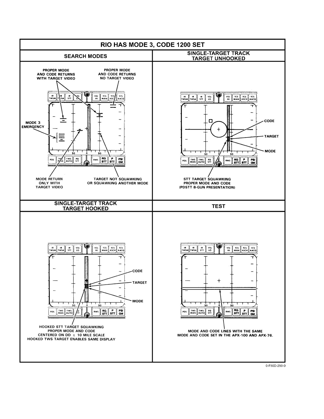
erly, two horizontal bars will be displayed across the DD at
are malfunctioning.
approximately
4 and 5 miles. Illumination of the green
CHAL light on the control panel while the switch is being
The APX−76 receiver−transmitter, switch amplifier, inĆ
held in the test position also indicates that the APX−76 made
terrogator
(KIR) computer, and synchronizer are checked
a valid interrogation. The bottom line on the DD indicates
during CNI OBC. Results can be called up on any MFD.
that the APX−100 responded in mode and the top line
These units are also subject to continuous monitoring. Status
indicates it responded in code. Both lines together indicate
can be read by calling up the failure history file. In addition,
that the APX−76 is decoding properly. Biasing of the mode
the PTID displays the IFI acronym if the receiver−transmitter
and code lines enables them to be spread out on the DD during
or switch transponder fails continuous monitoring. During
test. Figure
21−3 shows the correct IFF self−test display
OBC, CHALLENGE IFF is displayed on MFD 3 in order to
format. If the first attempt to test the APX−76 fails because
remind the RIO to reset the BIT flags by making a valid
of lack of video on the DD, or the amber fault light on the
challenge.
control panel illuminates, the RIO should initiate a valid
21−7
ORIGINAL
NAVAIR 01−F14AAD−1
Figure 21Ć3.ĄIFF Display Formats
ORIGINAL
21−8
NAVAIR 01-F14AAD-1
PART VIII
Weapon Systems
Chapter 22 — TARPS Subsystem
Chapter 23 — Navigation Command and Control Grid
The following chapters are to be found in NAVAIR 01-F14AAD-1A:
Chapter 24 — F14D Weapon System
Chapter 25 — Weapon System Controls and Displays
Chapter 26 — AN/APG-71 Radar System
Chapter 27 — AN/AAS-42 Infrared Search and Track System
Chapter 28 — AN/AXX-1 Television Camera Set
Chapter 29 — Integrated Sensor Operation
Chapter 30 — Stores Management System
Chapter 31 — Air-to-Air Weapons
Chapter 32 — Air-to-Ground Weapons
Chapter 33 — LANTIRN Targeting System
Chapter 34 — Electronic Warfare Systems
Chapter 35 — Data-Link Systems
Chapter 36 — Weapon System Degraded Operation
89
(Reverse Blank)
CHANGE 1
NAVAIR 01−F14AAD−1
CHAPTER 22
TARPS Subsystem
22.1
RECONNAISSANCE SYSTEM
This capability is compatible with the F−14 tactical air
reconnaissance pod system and includes target designation
The reconnaissance system establishes the aircraft as a
and steering command functions and reconnaissance sensor
multisensor reconnaissance aircraft with the flexibility for a
control as well as specific reconnaissance displays to crew
wide range of reconnaissance missions. Specific missions
and in−flight annotation of reconnaissance data.
include order−of−battle generation, prestrike/poststrike phoĆ
tography, and maritime surveillance.
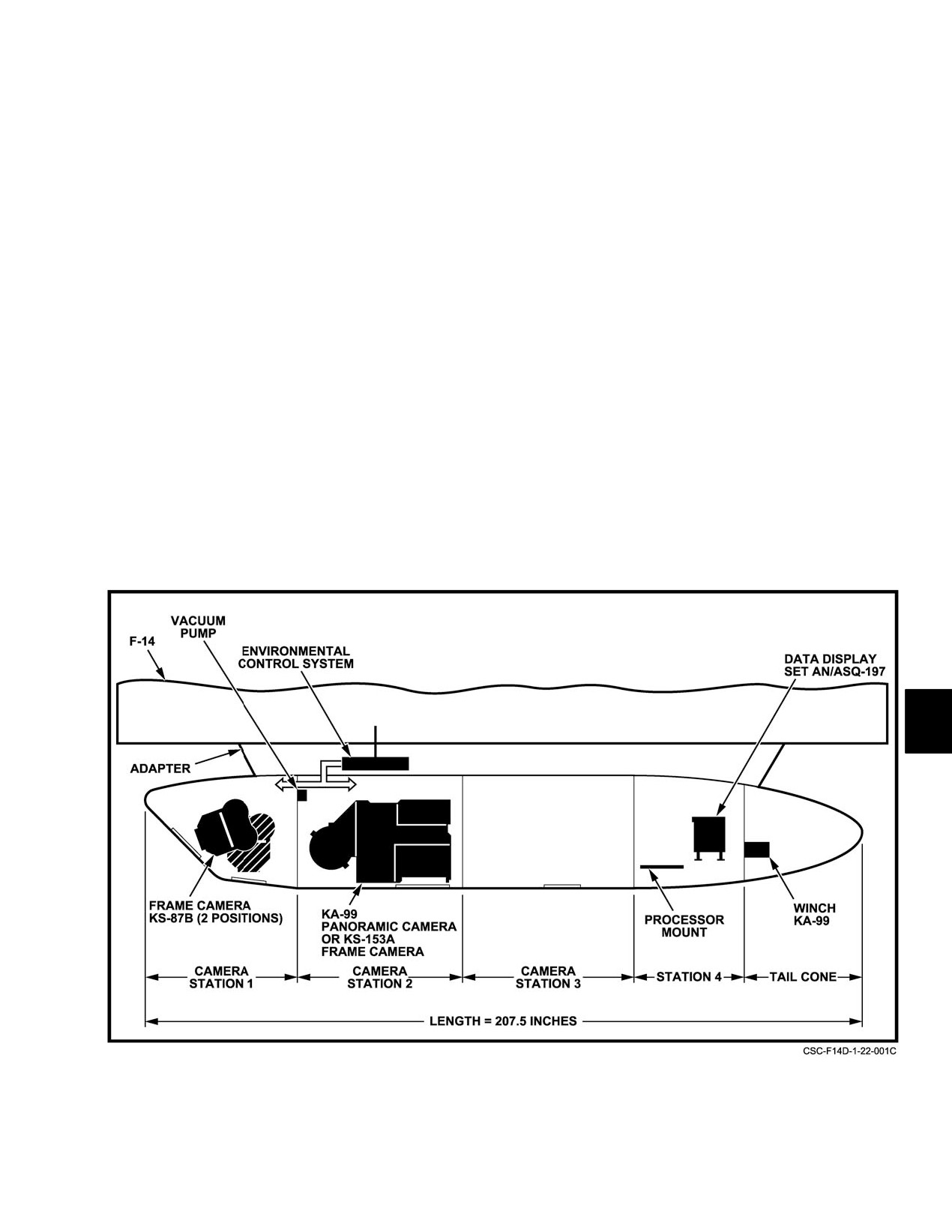
The TARPS consists of the following components (as
shown in Figure 22−1):
The sensors and associated equipment are contained in
the pod’s four compartments (Figure 22−1). The sensors are:
1. TARPS pod
serial frame camera (KS−87D); and low− to medium−altitude
panoramic camera (KA−99), or long−range standoff frame
2. Serial frame camera
camera (KS−153A with 24−inch lens).
3. Panoramic camera or standoff frame camera
Figure 22Ć1.ĄTactical Air Reconnaissance Pod System
22−1
ORIGINAL
NAVAIR 01−F14AAD−1
4. Data display system
displays, the RIO has full control of TARPS. A description
of the CPS controls and their functions are provided in
5. TARPS environmental control system
FigureĂ22−3.
6. Controller processor signal unit
22.2
DISPLAY SYSTEM
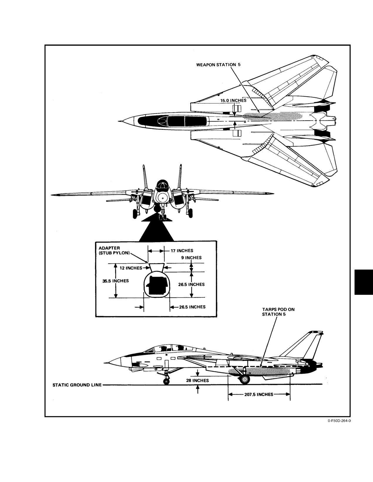
The TARPS location on the aircraft is shown in
As described in Chapter 2, the display system provides
Figure 22−2.
the following:
22.1.1
TARPS Pod
1.
Selection of waypoint to be reconnoitered and
steering mode (point−to−point, command course, or
The TARPS pod (Figure 22−2) is 207.5 inches long and
mapping) to be employed.
weighs approximately 1,625 pounds including sensor equipĆ
ment. The pod is nonjettisonable and is mounted to the
2.
Display of reconnaissance steering cues and camera
aircraft on weapon station 5 with an integral pylon adapter.
status the HUD when valid steering is selected and
The adapter provides the pod with sensor control signals, data
the aircraft is not in A/A with a weapon selected.
annotation signals, electrical power, and ECS support from
the aircraft. Circuit breaker protection is provided through
3.
Display of reconnaissance steering cues on the VDI
the ac left and right main circuit breaker panel. The pod is
when the VDI is selected.
designed for carriage throughout the flight envelope.
4.
Command steering displays using the reconnaisĆ
22.1.2
Serial Frame Camera
sance steering symbol and reconnaissance command
heading marker.
The serial frame camera can be directed in flight either
to the forward oblique position to obtain photographs of the
5.
Displays of reconnaissance TARPS sensor status
area as seen by the pilot, or to a vertical position for use as
and camera solution cues to crew on the MFD
a backup sensor in the event the panoramic camera fails or for
RECON DATA status format.
mapping missions.
The serial camera mount assembly holds the camera
6.
Display of target waypoint (reference point) data on
and provides the capability to move the camera in flight from
the MFD RECON DATA status format.
the vertical position to the forward position. Controls for the
7.
Display of waypoint reconnaissance parameters
camera positioning are on the CPS.
(command crossing angle, target length, map lines,
map separation distance
(map offset)) on two
22.1.3
Panoramic Camera
formats.
The panoramic camera offers full horizon−to−horizon
panoramic imagery over a broad velocity/above ground level
8.
Provide selection of TARPS air−to−ground ranging
mission envelope.
for altitude above ground level determination.
22.1.4
Data Display System
22.3
TARPS EQUIPMENT CIRCUIT BREAKERS
The DDS performs two basic TARPS functions. It
The main power circuit breakers that control TARPS
provides coded annotation on the sensor film for future
equipment are in the aft cockpit. FO−8 and FO−9 show their
interpretation of the recorded intelligence data and supplies
location. The circuit breakers are numbered and labeled as
necessary control signals to the individual sensors.
follows:
22.1.5
TARPS Environmental Control System
CARD
RECON POD
1E2
The ECS supplies conditioned air for pod cooling and
RECON CONTR/LANTIRN POD PWR
9E2
heating and for defogging the camera windows.
RECON POD DC PWR NO. 1
9E4
RECON POD DC PWR NO. 2
9E3
22.1.6
Controller Processor Signal Unit
RECON HTR/LANTIRN PWR 3 PH
2C3
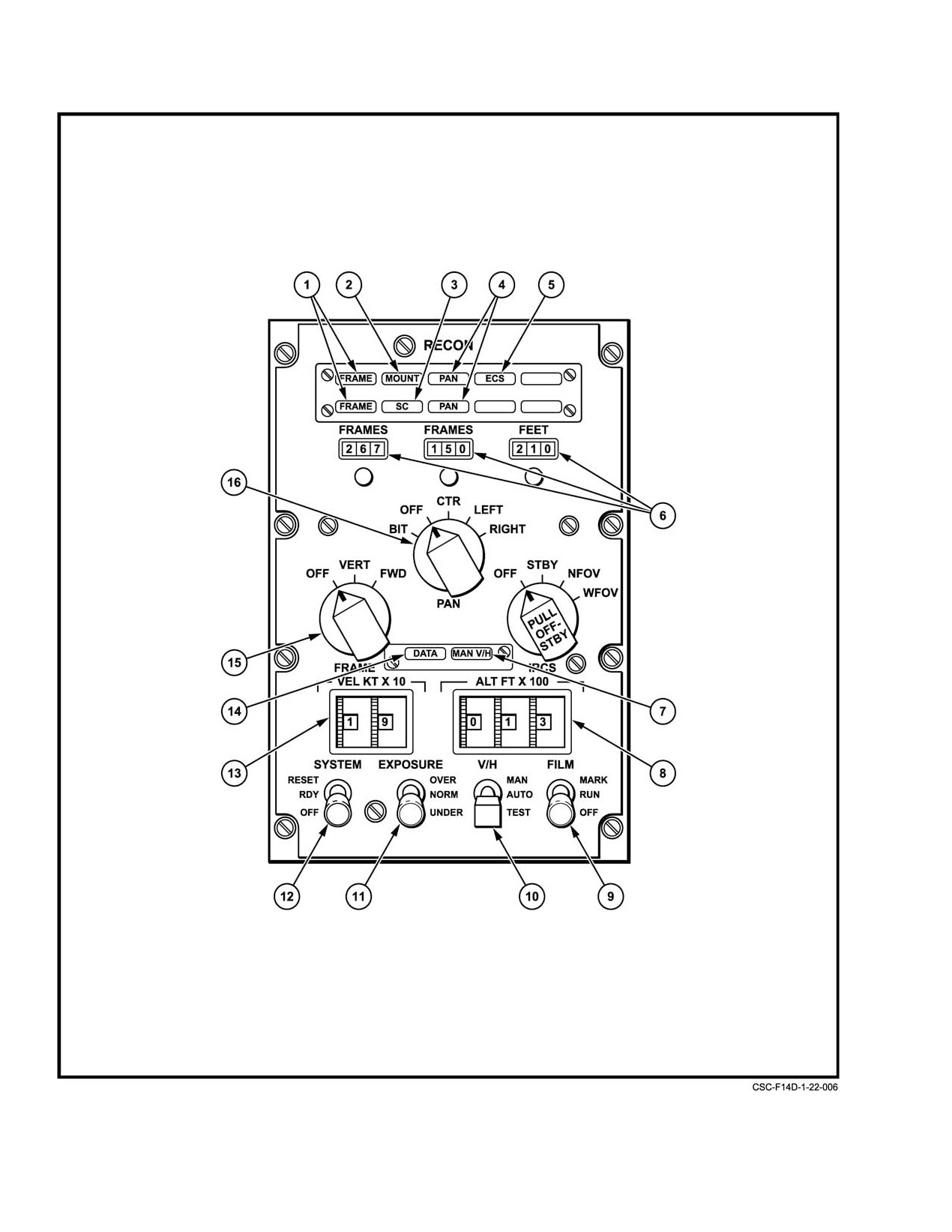
The CPS (Figure 22−3) and cockpit displays provide
RECON ECS CONT AC
2G4
the controls and information required by the RIO and pilot for
RECON ECS/LANTRIN POD CONT
9E1
operation and checkout of TARPS. The CPS is in the aft
Refer to Chapter 2 for an alphanumeric listing of circuit
cockpit left console and contains the primary TARPS
breakers.
controls and indicators. Using the CPS with the multifunction
ORIGINAL
22−2
NAVAIR 01−F14AAD−1
Figure 22Ć2.ĄTARPS Component Locations
22−3
ORIGINAL
NAVAIR 01−F14AAD−1
Figure 22Ć3.ĄController Processor Signal Unit (Sheet 1 of 5)
ORIGINAL
22−4
NAVAIR 01−F14AAD−1
NOMENCLATURE
FUNCTION
1
FRAME lights
Green FRAME light flashes once per camera cycle when serial frame camera is
• Amber
activated and no failure exists. Amber FRAME light illuminates if failure exists in
• Green
serial frame camera and green FRAME light goes off.
2
MOUNT light
Illuminates indicating mount failure. This occurs when serial frame camera fails to
• Amber
achieve directed position within 23 seconds. (It may be firmly locked in position
opposite to directed one.) CIPDU internal failure can also give mount failure
indication.
3
SC (Sensor Control)
Illuminates when SC/DDS has failed to furnish Film Motion Compensation (FMC) or
light
cycle commands to sensors. Failure to deliver formatted data on command to
• Amber
sensors will not show SC failure. Consequently, SC GO indication can result in
good sensor imagery operation but without data annotation.
4
PAN lights
Green PAN light flashes once per camera cycle when the panoramic camera has
• Amber
been activated and no failure exists. Amber PAN light illuminates and green light
• Green
goes out if failure occurs.
5
ECS (Environmental
Illuminates only under failure condition (compartment temperature
Control System) light
below 0_C or above 51_C). ECS is automatically activated on takeoff by weight−on−
• Amber
wheels switch.
6
Frames and feet
Display number of frames remaining in frame and pan cameras, and number of feet
(indicators)
of film remaining in infrared sensor. Indicators are set initially as part of sensor
servicing via reset knobs directly under indicators. Each frame or pan camera cycle
decreases indication by 1.
7
MAN V/H light
OFF ć Vg/H from aircraft computer within acceptable limits.
• Amber
ON ć Illuminated amber:
V/H switch in TEST. With VEL set at 90 (900 kts) and ALT set at 005
(500Ăft), or any equivalent of 1.8 ratio, the thumbwheel circuitry has failed if
the light stays on.
V/H switch in AUTO. Computer failed or computer fail discrete is received
with or without TARPS pod on aircraft. Manual Vg/H being used. Set correct
values to Vg/H in thumbwheels. Set V/H switch to MAN.
If negative AGL or computed Vg/H = 0, MAN Vg/H is being used.
Set corrected values of Vg/H in thumbwheels.
V/H switch in MAN. Manual V/H intentionally selected. Values set in
thumbwheels being used. Set correct values in thumbwheels.
• A TARPS advisory will appear on the Reconnaissance
MFD CAWS window when MAN V/H is selected
(FigureĂ24−7). In addition, a TARP1 is generated on the
OBC Basic Display and Maintenance Failure Format
(Figure 24−8).
• If negative AGL or Vg/H = 0, and the TARPS pod is not on
the aircraft, there is no MAN Vg/H advisory.
Figure 22−3. Controller Processor Signal Unit (Sheet 2 of 5)
22−5
ORIGINAL
NAVAIR 01−F14AAD−1
NOMENCLATURE
FUNCTION
8
ALT FT × 100
Used to set manual altitude inputs to pod. Counter range is from 000 to 999,
read in multiples of 100 feet.
9
FILM switch
MARK Ċ (momentary position) Allows RIO to mark special interest frame
with * in data block.
RUN Ċ Activates selected sensor when SYSTEM switch is set to RDY.
OFF Ċ Terminates TARPS sensor operation.
10
V/H selector switch
MAN Ċ Selects manual thumbwheel inputs. (TARPS advisory appears on
MFD CAWS Figure 24−7. TARP1 appears on OBC Basic Display and
Maintenance Failure Format Figure 24−8).
AUTO Ċ Selects aircraft computer value of Motion Compensation Factor
(MCF).
TEST Ċ (Momentary position) Tests proper functioning of thumbwheels
Vg/H circuitry. With a 1.8 ratio set in the thumbwheels, a good test is
indicated by the MAN V/H light extinguishing.
11
EXPOSURE selector
UNDER Ċ −1 f−stop exposure for doubled SC film setting.
switch
NORM Ċ Normal exposure for doubled SC film setting.
OVER Ċ +1 f−stop for doubled SC film setting.
12
SYSTEM switch
OFF Ċ Aircraft power denied to TARPS. No sensors can be operated.
RDY Ċ Aircraft power available at sensor connectors. If respective sensor
moved from OFF position, sensor is placed in standby or ready mode.
RESET ĊClears TARPS failure signal. If failure is other than transient, TARPS
advisory remains.
Figure 22−3. Controller Processor Signal Unit (Sheet 3 of 5)
ORIGINAL
22−6
NAVAIR 01−F14AAD−1
NOMENCLATURE
FUNCTION
13
VEL KT × 10
Use to set manual ground speed inputs to pod. Counter range is from 00 to 99,
thumbwheels
read in multiples of 10 knots.
14
DATA light
OFF Ċ Data received from computer ON −Data from aircraft computer failed
(via CPS DATA FAIL discrete).
Note
A TARPS advisory will appear on the Reconnaissance MFD CAWS
window (Figure 24−7) when MAN V/H is selected. In addition, a TARP1
and TARP2 are generated on the OBC Basic Display and Maintenance
Format. (Figure 24−8).
15
FRAME camera switch
OFF Ċ Frame camera is shut off.
VERT Ċ SYSTEM switch is RDY. Power applied to frame camera.
Mount placed in vertical position. When FILM switch in RUN,
camera is cycling.
FWD Ċ SYSTEM switch in RDY; power is applied to frame camera.
Mount placed in forward position (depressed 16_ from horizon).
When FILM switch in RUN, camera is cycling.
Note
Requires approximately 15 seconds to transition betweenFWD and
VERT (The amber mount light illuminates if transition not completed in
23 seconds.)
Figure 22−3. Controller Processor Signal Unit (Sheet 4 of 5)
22−7
ORIGINAL
NAVAIR 01−F14AAD−1
NOMENCLATURE
FUNCTION
16
PAN camera switch
BIT Ċ
(momentary position) SYSTEM switch must be in RDY to get BIT.
Applies power to pan camera. Initiates 12 second BIT. With FILM
switch to RUN, BIT will not function.
Do not run PAN BIT check. (May cause the film to jam)
OFF Ċ Pan camera is shut off.
CTR Ċ SYSTEM switch in RDY. Pan camera enabled. Awaiting operate
command.
FILM switch to RUN; pan camera cycling. Exposure, average of left
and right light sensors. Camera set for 55% overlap at NADIR.
KS−153A/24 inch: selects 21.4 degree scan centered on NADIR.
LEFT Ċ SYSTEM switch in RDY. Pan camera enabled. Awaiting operate
command.
FILM switch to RUN; pan camera cycling. Exposure controlled by left
light sensor. Camera set for 55% overlap at 30_ below left horizon.
KS−153A/24 inch: selects 21.4 degree scan centered on one of the
preset depression angles.
To prevent interference in coverage by the external fuel tanks the
following preset value is recommended: 27_ depression angle.
RIGHT Ċ SYSTEM switch in RDY. Pan camera enabled. Awaiting operate
command.
FILM switch in RUN; pan camera cycling. Exposure controlled by right
light sensor. Camera set for 55% overlap at 30° below right horizon.
KS−153A/24 inch: selects 21.4 degree scan centered on one of the
preset depression angles.
To prevent interference in coverage by the external fuel tanks the
following preset value is recommended: 31_ depression angle.
Note
LEFT or RIGHT positions should only be selected for high
altitude standoff, or low angle photography. With LEFT or
RIGHT selected, blurring of imagery at NADIR will occur at
lower altitudes because focus is set 30 degrees below horizon
slant range.
Figure 22−3. Controller Processor Signal Unit (Sheet 5 of 5)
ORIGINAL
22−8
NAVAIR 01−F14AAD−1
22.4
RECONNAISSANCE DISPLAYS
4. Provides selection of TARPS air−to−ground ranging
AND FORMATS
for AGL determination and AGL data display.
The reconnaissance display symbology provides
22.4.2
Reconnaissance Fault/Problem Reporting
sensor status/reconnaissance steering selection (via the MFD
The reconnaissance system will report the TARPS
RECON DATA status page) and the steering cues (via
faults/problems via the MFD warning, caution, and advisory
HUD/VDI displays) to the flightcrew. In addition, the
window and store the faults in the OBC file and failure
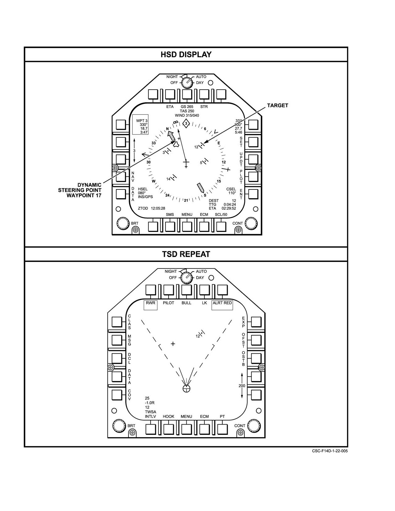
position of the dynamic steering point can be displayed on the
history file.
horizontal situation display or programmable tactical inforĆ
mation display/repeat on the MFD.
22.4.2.1
MFD Warning/Caution/Advisory
Window
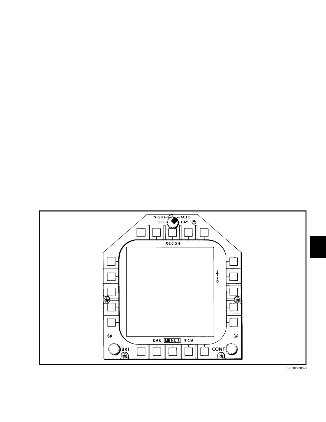
The MFD RECON DATA status format is selected
from the MFD MENU2 format (Figure 22−4) by depressing
The mission computer will report the following
the RECON pushbutton.
advisories on the MFD (Figure 22−6):
1. TARPS Ċ Reports a general failure (crew alert)
22.4.1
MFD RECON DATA Status Format
from the CPS. Monitor CPS to determine whether or
not this is a catastrophic failure (sensor(s) fail). A
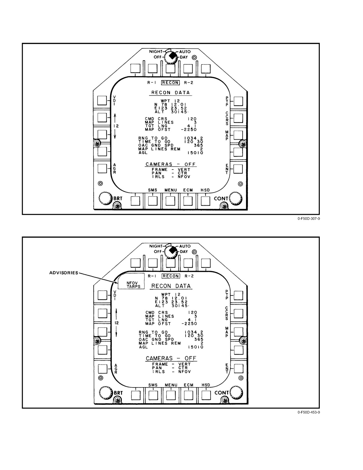
This MFD format (Figure 22−5) provides the following
TARPS advisory need not scrub the reconnaissance
functions:
mission.
1. Selection of waypoint to be reconnoitered
(via
Note
increment/decrement pushtile on the upper left
corner of the MFD RECON DATA status format)
A crew alert is generated from the CPS when any
and steering mode
(point−to−point, command
of the following conditions occur:
course, or mapping) to be employed.
a. Sensor failure
(includes serial frame camera
2. Displays TARPS sensor status, advisories and
mount position).
camera solution cues to crew.
b. ECS failure.
3. Displays target waypoint (reference point) data.
c. SC/DDS failure.
Figure 22Ć4.ĄMFD MENU2 Format
22−9
ORIGINAL
NAVAIR 01−F14AAD−1
Figure 22Ć5.ĄMFD RECON DATA Status Format
Figure 22Ć6.ĄTARPS Advisories
ORIGINAL
22−10
NAVAIR 01−F14AAD−1
d. Manual Vg/H in use.
In addition, the algorithm will put the reconnaissance
target designator over the target on the HUD. The PTP
e. CPS data fail (a TARP2 will be simultaneously
steering will transition into CCRS for final approach over the
stored in OBC/failure history file).
target.
f. Manual Vg/H test fail.
Note
22.4.2.2
OBC/Failure History File
PTP remains boxed on the MFD RECON DATA
status format. The reconnaissance steering
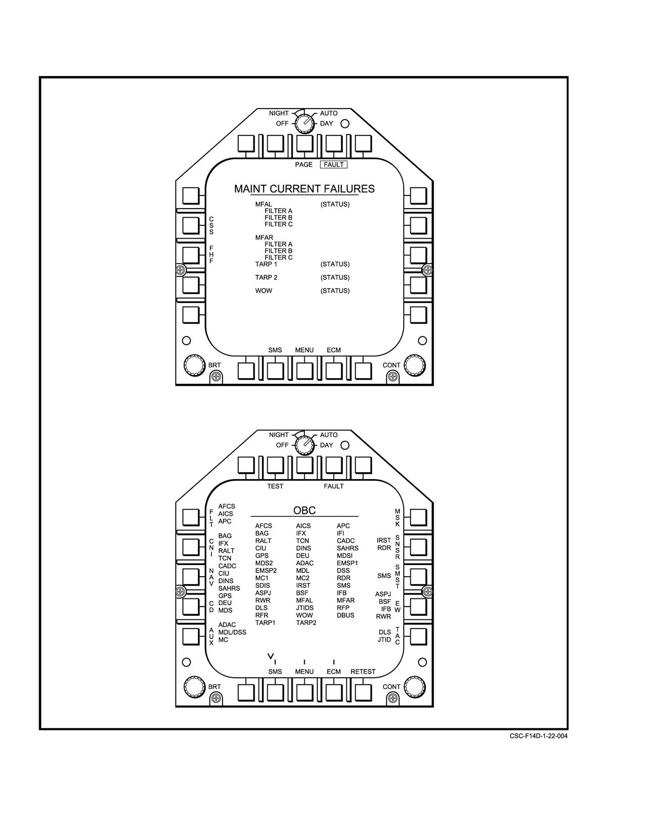
The following faults will be simultaneously stored in
symbol and command ground−track line assist
the OBC and failure history file (Figure 22−7) when the
the pilot in a wings−level flight over the target.
TARPS advisory is displayed on the MFD:
PTP steering is deselected when the aircraft has flown
1. TARP1 Ċ Reports a general failure (crew alert)
0.5 nm past the target or the crew manually deselects PTP on
from the CPS.
the reconnaissance MFD RECON DATA status format. At
this time, all steering cues are removed from the HUD and
2. TARP2 Ċ Reports a data communication failure
VDI. In addition, the DSPT (waypoint 17) is removed from
between the mission computer and the CPS. This
the HUD.
means that the annotation data and control signals
are no longer being transmitted to TARPS.
22.4.3.2
Command Course Steering
CCRS is selectable if the navigation system is properly
22.4.3
Reconnaissance Steering Selection
operating and the selected waypoint to be reconnoitered has
There are three reconnaissance steering modes availĆ
a nonzero value for target length. When the above conditions
able: PTP, CCRS, and mapping. They are selected via the
are satisfied, the selection of CCRS on the MFD RECON
MFD RECON DATA status format in either TLN, A/G, or
DATA status format will box CCRS. Immediately following
A/A. The steering function is initiated when a TARPS
that, TARPS will compute the DSPT, which is displayed on
steering mode is selected. Steering cues will always be
the HSD format, and the complete set of steering cues (the
computed when a steering mode is selected and will be
reconnaissance steering symbol, CGTL, reconnaissance
displayed on the HUD except in A/A with a weapon selected.
target designator, and reconnaissance command heading
The VDI will always display steering cues.
marker) to guide the aircraft to fly over the target at a
command crossing angle (stored in the waypoint file). When
Before a steering mode can be selected, the waypoint
the aircraft approaches the wings−level position (indicated
must be selected. In order to do so, the up−down arrow on the
when the DSPT initiates movement to the target), the CGTL
MFD RECON DATA status format is used to select the
will appear to provide additional visual cues for proper target
desired waypoint number. Next, by hitting ENT, the desired
crossing.
waypoint parameters will be displayed. Waypoint
17 is
inhibited for reconnaissance steering since this waypoint
Note
contains the position of the DSPT.
PTP would be selected (instead of CCRS) if the
22.4.3.1
Point−to−Point Steering
target length is zero.
PTP is selected when the navigation system is properly
CCRS steering is deselected when the aircraft has
operating. Selecting PTP on the reconnaissance MFD
flown the target length (stored in the waypoint file) past the
RECON DATA status format immediately computes the
target or when the crew manually deselects CCRS on the
wings−level position for the initial placement of the DSPT
MFD RECON DATA status format. As in PTP, all steering
and computes a heading to command the pilot to fly to that
cues are removed from the HUD and VDI. In addition, the
position.
DSPT (waypoint 17) is removed from the HSD.
Note
The wings−level distance is approximately 4 to 8
nm from target
(depends on velocity and
altitude).
22−11
ORIGINAL
NAVAIR 01−F14AAD−1
Figure 22Ć7.ĄMFD OBC/Maintenance Failure Formats
ORIGINAL
22−12
NAVAIR 01−F14AAD−1
22.4.3.3
Mapping Steering
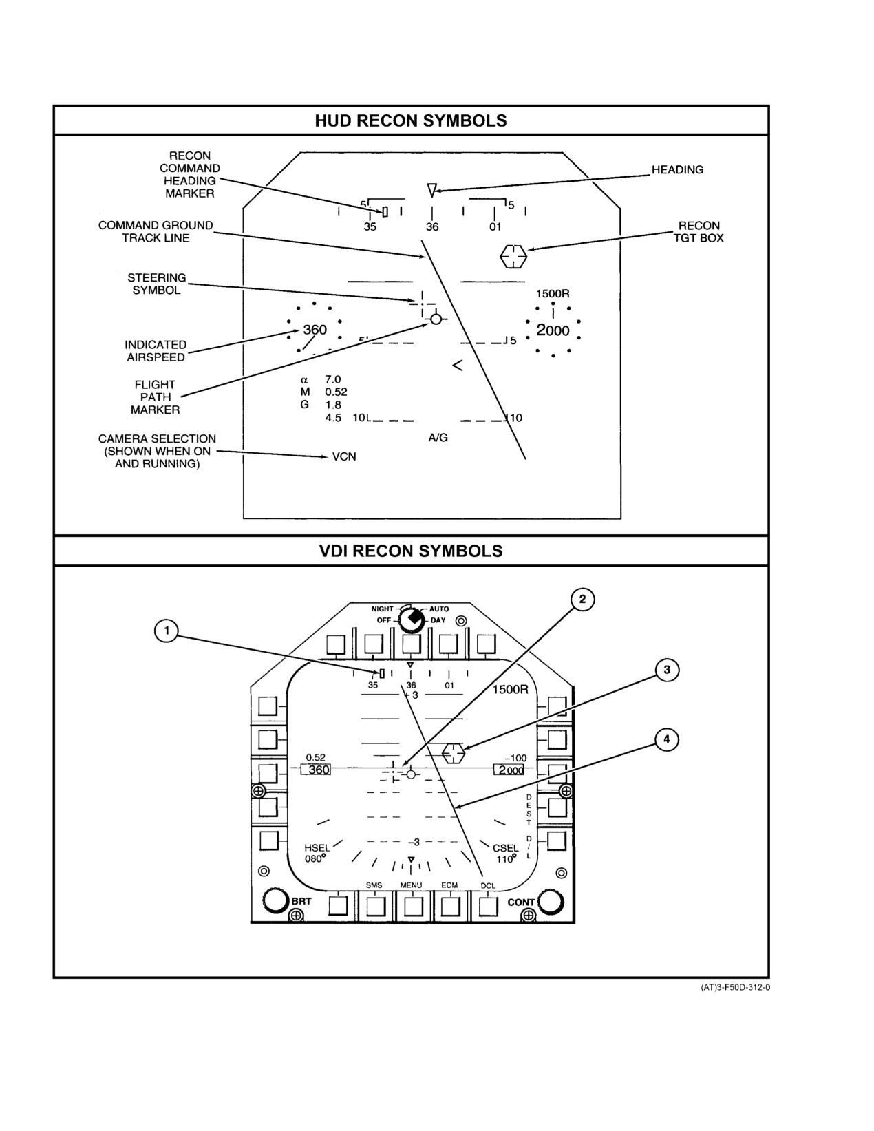
The HUD/VDI symbols are listed and displayed in
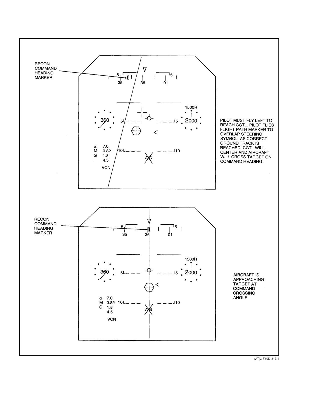
Figure 22−8, Figure 22−9, and Figure 22−10.
MAP is selectable under the following conditions:
22.5
RECONNAISSANCE SYSTEM OPERATION
1. Navigation system is properly operating.
The RIO is primarily responsible for the entry of
2. The selected waypoint to be reconnoitered has a
reconnaissance parameters for waypoints and selection/
nonzero value for target length.
operation of TARPS sensors. In addition, the RIO may assist
in updating the INS just prior to flying over the target and
3. The two map parameters, map offset (separation
plotting the target leg (in CCRS and MAP modes) on the
distance between adjacent map legs) and map lines,
HSD.
are nonzero values.
When the above conditions are satisfied, the selection
22.5.1
Reconnaissance Parameter Entry
of MAP on the MFD RECON DATA status format will box
Reconnaissance parameters are entered into the wayĆ
MAP. TARPS will then compute the DSPT (displayed on the
point file (Figure 22−11 and Figure 22−12) by the RIO via the
HSD) and the complete set of steering cues
(the
DEU. The maximum number of waypoints available for
reconnaissance steering symbol, CGTL, reconnaissance
reconnaissance is
19.
(Waypoint 17 is reserved for the
target designator, and reconnaissance command heading
dynamic steering point. Waypoints
18 to 20 have dual
marker).
functions as recce files or as hostile area, FLRP, and data
MAP steering includes guidance through the required
link.) In addition to the standard waypoint entry
(target
90_ to 270_ turn maneuvers, using command heading and
latitude, longitude, and altitude), the following reconnaisĆ
steering symbology, for the necessary return legs of the
sance parameters are entered: command crossing angle,
reconnaissance missions.
target length, map lines, and map offset (separation distance
between adjacent map legs). The altitude entered is the target
Note
MSL altitude. The target length is entered via the DEU.
Figure 22−13 shows TARPS DEU entry matrix.
D PTP would be selected if only condition 1 was
Note
valid. Insufficient parameters are available
for mapping.
D A target altitude of 0 is considered invalid. In
D CCRS would be selected if only conditions 1
the event that the radar altimeter and radar
and 2 were valid.
altitude from APG−71 is not available, then
MAP is deselected at the completion of the last map leg
the AGL altitude will be the difference beĆ
or when manually deselected by the crew on the MFD
tween the system altitude and hostile area altiĆ
RECON DATA status format. When MAP is deselected, the
tude (and not the waypoint altitude).
following will occur: removal of the reconnaissance overlay
D Entries of odd tenths will be rounded to the
symbols (CGTL, reconnaissance command heading marker,
next lowest even digit.
reconnaissance target designator, and reconnaissance steerĆ
ing symbol) from the HUD and VDI; removal of the DSPT
22.5.1.1
Reconnaissance Parameter Display
from the HSD; and MAP LINES REM (on the MFD RECON
DATA status format) will be zero.
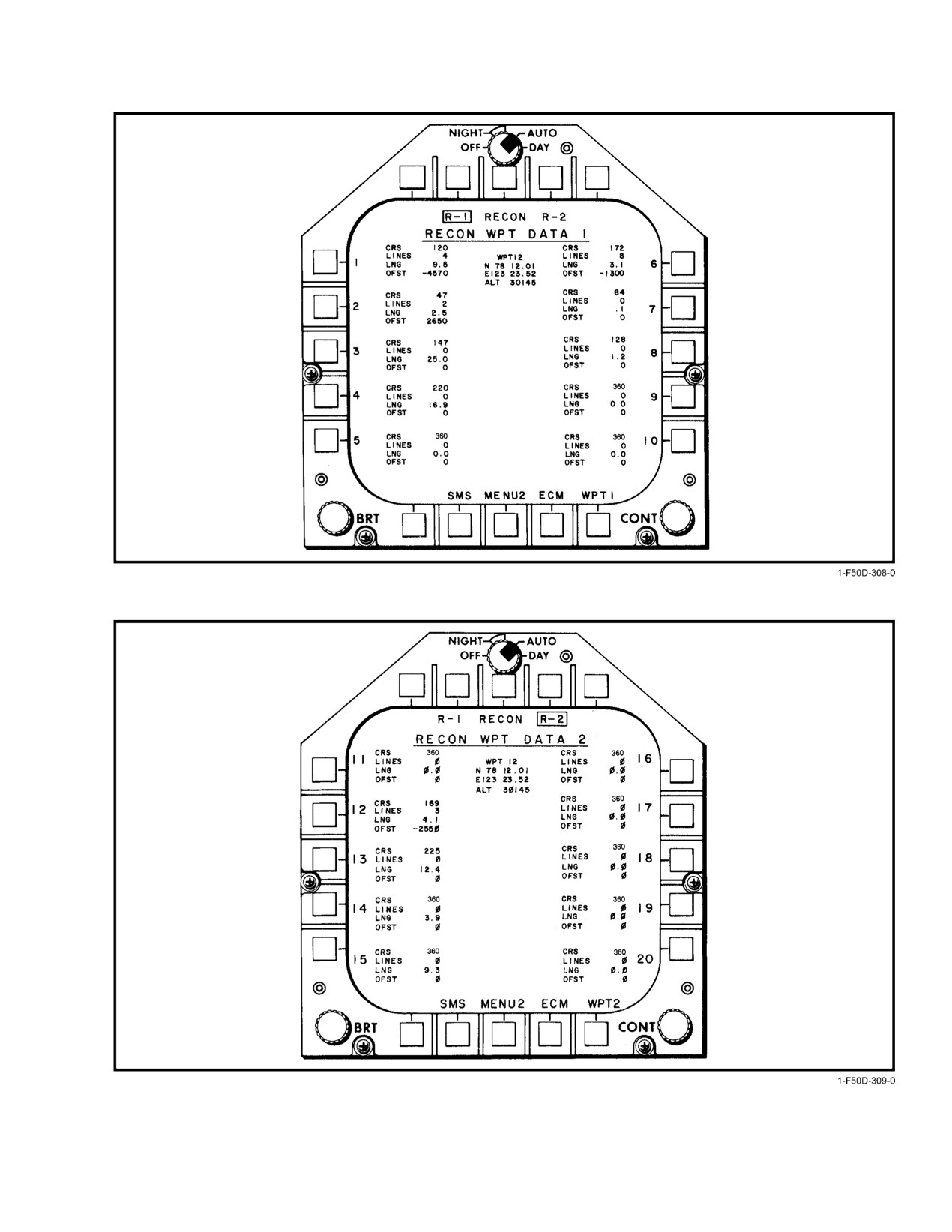
Reconnaissance parameters are displayed on the MFD
RECON WPT DATA 1 (Figure 22−11) and MFD RE−CON
22.4.4
HUD/VDI Symbology
WPT DATA 2 formats (Figure 22−12). MFD RE−CON WPT
DATA 1 format contains the reconnaissance parameters for
The HUD/VDI symbology is available when there is a
the first ten waypoints. This page is selected by depressing
valid selection of reconnaissance steering. This symbology
the R−1 pushbutton on the MFD RECON DATA status
consists of the following functions:
format. The RECON WPT DATA 2 format contains the
remaining ten waypoint reconnaissance parameters. These
1. Displays reconnaissance steering cues and sensor
parameters are accessed by depressing the R−2 pushbutton on
status to the HUD when valid steering is selected
the MFD RECON DATA status format.
and the aircraft is not in A/A with a weapon selected
(Figure 22−8 and Figure 22−9).
The reconnaissance parameters consist of command
crossing angle, target length, map lines, and map separation
2. Displays reconnaissance steering cues on the VDI
distance (map offset).
when the VDI is selected (Figure 22−8).
22−13
ORIGINAL
NAVAIR 01−F14AAD−1
Figure 22Ć8.ĄHUD/VDI Reconnaissance Symbology (Sheet 1 of 2)
ORIGINAL
22−14
NAVAIR 01−F14AAD−1
NOMENCLATURE
FUNCTION
1
Recon Command
Indicates the magnetic heading for Recon steering.
Heading Marker
ć Primary steering cue for initial phase of PTP steering.
ć Indicates intended magnetic heading to DSPT (as commanded by the
Recon Steering Symbol).
2
Recon Steering Symbol
Provides command bank information via azimuth displacement from velocity
vector.
3
Target Designator,
Displays target position referenced to the aircraft navigation system.
Hexagon
4
Command Ground
Displays the path of the command ground track. Indicates cross track
Track Line (CGTL)
displacement error.
Camera Selection
Displays the camera operational mode. First letter indicates frame position:
Legend
V = vertical, F = forward, blank = not selected.
Second letter indicates pan position: C = center, R = right, L = left, or
blank = not selected.
Third letter indicates IRLS position: N = narrow field of view; W = wide field
of view; S = Standby; or blank = not selected.
(Note ć This is only available on the HUD)
Note
When weapon is selected in A/A, the Recon Steering Symbol set (which
includes the Recon Steering Symbol; GCTL; Recon Target Designator,
and Recon Command Heading Marker) will be displayed on the VDI.
Figure 22−8. HUD/VDI Reconnaissance Symbology (Sheet 2 of 2)
22−15
ORIGINAL
NAVAIR 01−F14AAD−1
Figure 22Ć9.ĄHUD Reconnaissance Display (Command Course Steering) (Sheet 1 of 2)
ORIGINAL
22−16
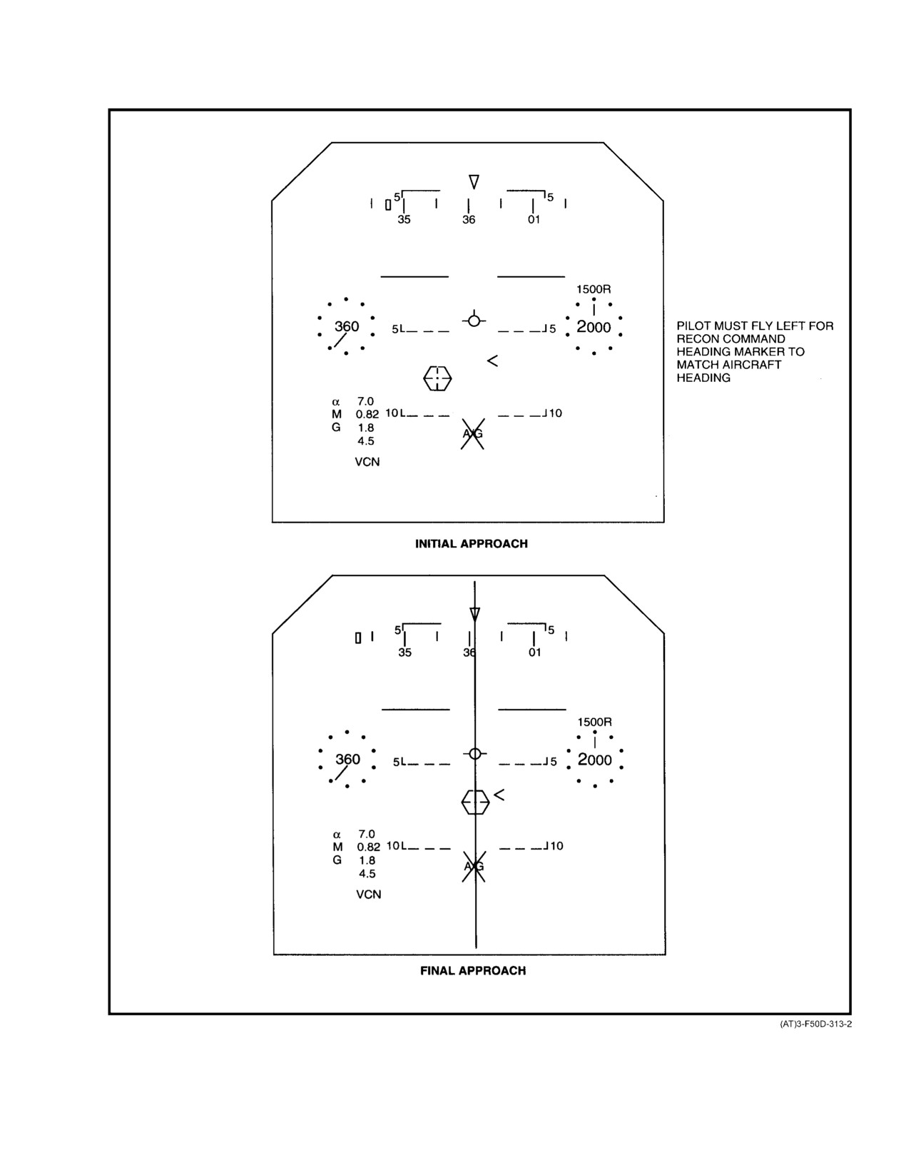
NAVAIR 01−F14AAD−1
Figure 22−9. HUD Reconnaissance Display (Command Course Steering) (Sheet 2 of 2)
22−17
ORIGINAL
NAVAIR 01−F14AAD−1
Figure 22Ć10.ĄDynamic Steering Point Display
ORIGINAL
22−18
NAVAIR 01−F14AAD−1
Figure 22Ć11.ĄMFD RECON WPT DATA 1 Format
Figure 22Ć12.ĄMFD RECON WPT DATA 2 Format
22−19
ORIGINAL
NAVAIR 01−F14AAD−1
Figure 22Ć13.ĄDEU Reconnaissance Selection
ORIGINAL
22−20
NAVAIR 01−F14AAD−1
22.5.2
In−Flight Entry of Reconnaissance
22.6
PILOT RECONNAISSANCE OPERATION
Waypoint Parameters
A sensor operating button is provided on the pilot
The RIO may update the waypoint file at any time
control stick. With the SYSTEM switch on the controller
when a reconnaissance steering mode is engaged, without
processor signal unit set to RDY and any or all sensor selector
affecting the current steering. In order for the pilot to use the
switches in the ready position, the activated sensor can be
updated reconnaissance parameters, he must reselect the
cycled by the pilot pressing the BOMB button on the control
steering mode.
stick. This is the only TARPS control capability provided to
the pilot. Each camera will cycle at its proper rate for
22.5.3
One−Fix Update
velocity/height ratio
(V/H) and the IRLS will run
continuously at the proper speed until the pilot releases the
Unless the aircraft is flying in a JTIDS net, it is
BOMB button.
recommended that one−fix position update be performed just
prior to flying over the intended target to minimize miss
Note
distance. Refer to Chapter 20 for the procedures for one−fix
position updates.
The BOMB button will not initiate camera
operation with the expanded chaff adapter
22.5.4
Plotting Command Course/Map Target Leg
installed.
This optional procedure provides the flightcrew with
22.6.1
Navigation Visual Surface
additional steering cue/information on the HSD. If a file
Waypoint Update
waypoint is available, the RIO may use this waypoint to mark
the end of a target leg by performing the following steps:
Unless the aircraft is flying in a JTIDS net, it is
recommended that the one−fix position update be performed
1. On the DEU, select WPT and enter the designated
just prior to flying over the intended target to minimize miss
waypoint for reconnaissance.
distance. Refer to one−fix position update in Chapter 20 for
INS update operations.
2. Select RNG and enter the target length of the
reconnoitered target.
22.6.2
Pilot TARPS Steering
3. Select BRG and enter the command course of the
TARPS aircraft steering is displayed on the VDI and on
reconnoitered target.
the HUD in A/G and A/A (weapon not selected). The VDI is
selected via the MFD RECON DATA status format.
4. Press SET and enter the number of the available
(or free) waypoint.
HUD TARPS steering using TARPS symbology
(Figure
22−9) is obtained by selecting a reconnaissance
5. Select MENU.
steering mode (PTP, CCRS, or MAP) on the reconnaissance
MFD RECON DATA status format.
6. Select PLOT.
Note
7. Select DRAW. The DEU will respond
Plot from . .Ă ." Enter waypoint number to which
In addition to the steering cues, the reconnaisĆ
aircraft is flying. When DEU responds Plot to . . . ,"
sance target designator will be positioned on the
enter the waypoint number used in step 4.
HUD/VDI to indicate actual target position. (It is
recommended to perform a surface waypoint upĆ
22.5.5
Cycling Sensors
date to the navigation system to ensure that the
reconnaissance target designator will overlay the
The RIO will put the FILM switch on the CPS in the
expected target site.) Steering is accomplished
RUN position when the RANGE−TO−GO goes to zero or
by noting the direction that the reconnaissance
transitions to RANGE REMAINING. The RIO will turn off
steering symbol is displaced from the velocity
the selected sensors when RANGE REMAINING goes to
vector. Banking the aircraft in the same direction
zero.
to achieve and maintain alignment of the two
symbols will produce the desired flightpath. If in
PTP steering, match aircraft heading with reconĆ
naissance command heading marker.
22−21
ORIGINAL
NAVAIR 01−F14AAD−1
At the completion of a PTP, CCRS, or MAP mission,
Note
the TARPS symbology will be removed from the HUD/ VDI.
Valid target altitude is nonzero. An altitude of
In addition, the steering mode will become unboxed on the
zero is considered invalid.
MFD RECON DATA status format. There is no sequencing
of waypoints. To steer to the next waypoint the desired
4. Own−ship system altitude (hostile area) Used
waypoint number must be selected.
when the APN−194 and APG−71 derived altitude are
not available and the target altitude is invalid (wayĆ
point contains zero altitude). The AGL is calculated
as the navigation system altitude minus the hostile
area altitude. The hostile area altitude is chosen that
represents the average terrain in the area of interest
Following steering too closely can result in pilot
and inserted into the hostile area waypoint prior to
fixation to the exclusion of safe altitude control.
flight.
22.6.3
Identification of Targets Using
In the event of data transmission failure or navigation
Television Camera Set
system failure, as indicated by the DATA light on he CPS,
which is addressed by the TARPS advisory on the MFD, the
The aircrew can enhance their ability to identify
RIO must manually enter the velocity and AGL. This entry
ground targets by using the TCS. The TCS is slaved to the
of velocity (groundspeed) and AGL is facilitated via the
reconnaissance target line of sight when RADAR is selected
velocity and altitude thumbwheels on the CPS. Manual Vg/H
as MASTER on the SSP, MAN ACQ is selected on the DD,
(AGL) may be selected at any time by the RIO and should be
and wide field of view is selected.
used instead of steps 3 or 4 above when doubt exists also the
quality of the inputs.
22.6.4
Altitude (AGL) Mechanization
AGL information for F−14D/TARPS software calculaĆ
22.7
SENSOR CAPABILITIES AND LIMITATIONS
tion of Vg/H uses following sources in the order given:
22.7.1
Lineal Coverage
1.
APN−194 radar altimeter This altitude source is
Total lineal coverage available for specific sensors
used under the following conditions
(when the
depends on film load and altitude. Complete lineal coverage
APN−194 is operating properly):
data for all sensors will be provided in the F−14 Tactical
a. System altitude is less than 2,500 feet.
Manual (NWP 3−22.5−F14A/B, NAVAIR 01−F14AAA−1T)
and Tactical Pocket Guide
(NWP 3−22.5−F14A/B PG,
b. System altitude is between 2,500 and 5,000 feet
NAVAIR 01−F14AAA−lT−3).
and radar altimeter is selected on the PDCP.
22.7.2
Serial Frame Camera
When the radar altimeter is being used, an R" is
The KS−87D serial frame camera has a fixed−focus,
placed by the altitude reading on the HUD/VDI.
6−inch focal length lens, weighs about 79 pounds, and can
(Figure 22−8)
hold up to 1,000 feet of 2.5 mil thick, 5−inch film.
2.
APG−71 radar altitude Altitude will be calculated
The fixed focus is set at a hyperfocal distance of 1,339
using a
55_ lookdown angle, earth stabilized
feet, which gives excellent imagery from about 750 feet to
antenna (TARPS AGR mode). This source will be
medium altitudes. Below 750 feet, the imagery is less sharp
used if above 5,000 feet or the APN−194 is inoperaĆ
but is still good down to about 500 feet. The KS−87D provides
tive. AGR must be selected on the MFD RECON
a 41_ field of view with a 4.5 × 4.5−inch negative. A full
DATA status format. The radar altitude is being used
1,000−foot roll allows 2,400 exposures.
to compute the AGL when AGR is boxed (Figure
The RHA exposes a data block on each flame. The data
22−5).
is encoded BCD, A/N, or alternate BCD and A/N. The data
3.
Own−ship system altitude (selected waypoint)
block provides time, date, latitude, longitude, altitude, drift,
Used whenever the APN−194 and APG−71 derived
heading, pitch, roll, classification (if known in advance), and
altitude are not available. AGL is calculated as
a mission code. The BCD also provides Vg/H, which allows
system altitude minus selected waypoint altitude.
the aircraft velocity to be calculated.
ORIGINAL
22−22
NAVAIR 01−F14AAD−1
The KS−87D two−position mount allows the RIO to
22.7.3
Panoramic Camera
select vertical
(VERT) or forward (FWD). In the vertical
The KA−99A is a 9−inch focal length, f/4.0 lens
position, the KS−87 backs up the pan camera and is also used
panoramic camera that provides high−quality, medium−to
for bomb damage assessment, route reconnaissance, and is
low−altitude imagery. Located in bay 2, the KA−99A offers
the primary camera for mapping missions. The forward
full horizon−to−horizon imagery with 55−percent overlap up
position looks 16_ down from the horizon and is very useful
to a maximum of 1.06 Vg/H (8 cps). When external fuel tanks
for pilot’s view flightpath tracing and ship surveillance
are installed, the field of view is reduced about 25° on the
photography. Changing the mount position requires about 16
right and 17_ on the left. The film cassette will hold a
seconds and a mount fail indication will result if the transition
maximum of 2,000 feet of film. A single exposure measures
is not complete within 23 seconds. Frequent FWD−VERT
4.5 × 28 inches, and a data code block appears between each
switching can cause the mechanical drive to overheat and
frame. The camera will indicate FAIL when the film load is
seize, resulting in a mount fail. The mount will automatically
down to approximately 40 exposures, preventing the film
move to vertical when the SYSTEM switch is at RDY and the
bitter end from going through the high−speed drive gears and
FRAME switch is turned OFF, or if the landing gear handle
causing camera damage. The KA−99A will automatically
is moved to DN.
focus down to approximately 500 feet but will revert to a
The KS−87D can be reloaded or replaced in approxiĆ
focus altitude of 6,000 feet if the TARPS program fails to
mately 10 minutes and with the aircraft’s engines tuning, if
input and there is no manual input of V/H from the CPS.
necessary.
The RIO may select CTR, LEFT, or RIGHT for the
Figure 22−14 summarizes some specific characteristics
KA−99A on the CPS. When LEFT or RIGHT is selected, the
and information on the KS−87D serial frame camera.
camera uses only the light sensor on the side selected
Focal length
6 inches
Diaphragm range
f 2.8 to 6.7
Field of view
41_ × 41_
Negative Format
4.5 × 4.5 inches
Vg/H Range*
0.01 to 1.18
Maximum Cycle Rate
6 cycles per second
Effective Shutter Speeds
1/60 to 1/3,000
Filters
Yellow, red, or none
Angle of View
Vertical or Forward (16_ below horizon)
Hyperfocal Distance**
1339 feet (fixed focus)
*Vg/H is listed as a knots per foot of altitude ratio (computed for vertical camera position only).
The DDS is capable of generating a maximum of 1.42 Vg/H.
**The hyperfocal distance is the distance from the optical center of the lens to the nearest point of acceptable
sharp focus, when focused at infinity. The sensor may be effectively used well below the hyperfocal distance,
but will render increasingly soft imagery at lower altitudes.
The automatic exposure control (AEC) system uses an external light meter. The AEC can be overridden
(plus−or−minus one F−stop) on the CPS.
The mount requires approximately 16 seconds to move the camera from vertical to forward, or back to vertiĆ
cal. The CPS will display a mount fail light if the transition is not completed within 23 seconds.
Optional 3−inch focal length lens available.
Figure 22Ć14.ĄKS−87D Serial Frame Camera Characteristics
22−23
ORIGINAL
NAVAIR 01−F14AAD−1
instead of averaging the two as it does when CTR is selected;
2. Medium−altitude standoff (610 mm/24−inch focal
in addition, the cycle rate and FMC are based on the slant
length standoff configuration)
range distance from aircraft to the ground at a 30_ depression
The 24−inch standoff configuration will be utilized to
angle. To avoid degraded imagery, do not use LEFT or
replace the KA−93C LOROP sensor and will be mounted in
RIGHT settings below 1,500−foot altitude. The KA−99A can
bay 2 of the TARPS pod in lieu of the KA−99.
be set for air to air (focus on infinity, no FMC, and 1 cycle per
The KS−153A features true angle corrected FMC
second) on the CIPDU. There is no cockpit indication that
across the entire film format for any oblique angle; automatic
air−to−air settings have been selected. The KA−99 is favored
range focus from 1,000 feet to infinity, and self−contained
by flightcrews on combat missions because its horizon−to−
automatic temperature/pressure focus compensation; shutter
horizon lateral coverage allows it to be used with a
priority automatic exposure control using preflight setting of
considerable offset. This capability increases the flightĆ
aerial film speed and aircraft V/H signal; 12−or 56−percent
crew’s probability of successfully completing the mission in
preflight−selectable overlap; roll compensation; and data
defended areas where evasive combat maneuvering will be
annotation. The
4.5−inch
× 9−inch film format provides
necessary. Although it is not necessary for the aircraft to be
sequential frames 10.7_ along−track and 21.4_ across−track
flown wings level when photographing a target with the
coverage on 9.5−inch wide film. This image format reduces
KA−99 camera, the lack of roll−rate stabilization dictates that
processing time and allows direct stereo viewing without
an established angle of bank be maintained while the target
cutting the film.
is within the camera’s FOV.
The KS−153A can be programmed for any desired
Figure 22−15 summarizes some specific characteristics
depression angle from horizon to horizon, limited in
and information on the KA−99A panoramic camera.
coverage only by the aircraft fuel tanks (17_ left, 25_ right).
22.7.4
Long−Range Oblique Photography Camera
Typically, the KS−153A will be preprogrammed for the
(KS−153A With 610−mm Lens)
following three depression angles: 27_ left oblique, vertical,
and 31° right oblique. These are selected using the LEFT,
The KS−153A still picture camera set is a modular,
CTR, and RIGHT positions on the CPS PAN camera control
pulse−operated, sequential−frame camera designed for
switch. When selected, a 21.4_ scan will be used, centered
oblique or vertical reconnaissance photography at medium to
about the preset oblique angle. Depression angles cannot be
high altitude. Two configurations are available:
changed in flight.
1. Low−altitude, high−speed photography
(80 mm
Figure 22−16 summarizes some specific characteristics
focal length tri−lens configuration)
and information on the KS−153A standoff camera.
Focal Length
9 inches
Maximum Aperture
f/4.0
Field Of View
28_ × 180_
Negative Format
4.5 × 28 inches
Vg/H Range
0.5 to 1.06
Maximum Cycle Rate
8 cycles per second
Effective Shutter Speeds
1/43 to 1/22,600
Filters
Yellow, red, or clear
Forward Overlap
CTR 55% at NADIR; L/R 55% at 30_ below side horizon
Film Load
2,000 feet (2.5 mil); 800 exposures (750 usable)
Note
• The Automatic Exposure Control (AEC) system uses internally mounted light
meters which average the scanned field. AEC can be overridden
(± 1 Fstop) in−flight with the CPS.
• Sensor does not have roll stabilization, thus aircraft rolling will alter angle of
view and may blur imagery.
• Maximum listed Vg/H can be exceeded, but the imagery will be degraded by
incorrect FMC and reduced overlap.
Figure 22Ć15.ĄKA−99A Panoramic Camera Characteristics
ORIGINAL
22−24
NAVAIR 01−F14AAD−1
Focal Length
24 inches/610 mm
Angular Field Of View
21.4 across track, 10.7 along track
Film Format
4.5 × 9.5 inches
Image Frame Format
9.06 inches across track, 4.53 inches along
track
Frame overlap (preflight selected)
12% or 56%
Film Capacity
200 feet of 2.5 mil /2.47 frames per foot
(500 feet optional)
Aperture Range
f/4 to f/16 continuously
Maximum Cycle Rate
4 frames per second
Average Resolution
75 Lp/mm, EK 3412
Shutter Speed Range
1/150 to 1/2,000 sec
Film Speed (preflight setting)
AFS 0 to AFS 999
Linear Coverage (200 feet film @ 30K, 12 nm
467 nm
standoff @ 56% overlap)
Weight (500 foot cassettes without film)
233 pounds
V/R Rate
0 − 0.196 knots/foot @ 56%
0 − 0.39 knots/foot @ 12%
1.25 knots/foot maximum
Camera Oblique Rotation (24 inch)
+/ć 86° of vertical
Angle of View (preflight adjustable)
Vertical and left/right (at selected depression
angles)
Note
• Optional yellow, red, orange, or clear filters.
• Shutter priority automatic exposure control by preflight film speed setting and airĆ
craft V/H signal, accuracy ½ f/stop.
• Sensor will automatically compensate for altitude pressure (sea level to 5,000 feet)
and temperature (25°C to 45°C stable within +/− 2°C).
• Sensor produces a LED matrix array data block with a 3 millisecond write time.
Figure 22Ć16.ĄKS−153A Still Picture Camera Characteristics (610−Mm Standoff Configuration)
22−25
ORIGINAL
NAVAIR 01−F14AAD−1
22.7.5
Photographic Film
color films are reversed in the processing, so that they
reproduce the colors in the original scene without printing.
Film can be separated by general type as follows:
These films are termed reversal or transparency film. CDIR
color film is used to show contrasts between live vegetation
1. Black and white film:
and camouflage material. This greatly increases the chances
of locating difficult targets. Aerial color films require
a. Aerial film speed
expensive, complex processing that is not generally available
b. Resolution
at sea.
c. Spectral sensitivity
22.7.6
Digital Data System
The reconnaissance pod carries a digital data system
2. Color film:
that interfaces with the aircraft inertial navigational system,
a. Aerial film speed
altimeters, computers, and standard heading reference
system to automatically control and integrate the reconnaisĆ
b. Negative/reversal
sance system.
Reconnaissance system control is accomplished by the
c. Camouflage detection infrared.
data converter. Sensor stabilization signals and operating rate
Film speed is a value assigned to a specific film to
voltages are generated and routed to the sensors. StabilizaĆ
enable you to determine the correct exposure in various light
tion signals are provided from the inertial navigation system,
conditions. High−speed films are required for low−available−
or, if it fails, from the SAHRS. Operating rate signals are
light missions and for high−speed, low−level missions where
determined from inertial navigation and radar altimeter
very fast shutter speeds are required. High−resolution films
inputs. A semiautomatic backup method of generating Vg/H
provide greater detail but require more light. A film’s
signals is available if the inertial navigation system fails. A
spectral sensitivity means some colors will reproduce on the
fully manual option is available through the CPS if other
film better than other colors. Most of the common black and
components (including the data converter) fail. Maximum
white films are panchromatic: sensitive to all three primary
automatic Vg/H is 1.42 knots per foot.
colors
(red, green, and blue) that are found in normal
If the aircraft is carrying a TARPS pod, flying below
daylight. Since the red light does not scatter in haze as much
sea level causes the MAN Vg/H light on the CPS panel to be
as blue, contrast filters are used to reduce the blue light. A
lit. This light goes out when AGL becomes positive. Without
yellow filter will pass the green and red light, eliminating the
a TARPS pod on the aircraft, negative AGL does not light the
scattered blue light. A red filter will pass only the red light,
MAN Vg/H light CADC or computer failure, however,
eliminating the scattered blue and also the green (which
causes the light to be lit with or without a pod aboard.
scatters less than the blue). However, the yellow filter will
normally require one additional f/stop of exposure and the
Reconnaissance system integration is accomplished
dark red filter will normally require two additional f/stops of
through digital information from the data converter, which is
exposure. Some black and white films have extra sensitivity
translated into binary or alphanumeric form and added to
to infrared light. This film is most helpful in producing
preset information and real time, which is adjusted prior to
contrast detail between some objects that would tend to blend
flight. Code matrix boxes are printed on all imagery in either
with normal films. Most notable would be the difference
binary or alphanumeric form. Integration information inĆ
between water and vegetation. Color films produce greater
cludes data, squadron and detachment, sortie, sensor identifiĆ
shadow detail than black and white films and show color
cation, system altitude, heading, roll, pitch, latitude, longiĆ
separation in some objects that would reproduce at the same
tude, radar altitude, time, inertial navigation system status,
density on black and white film. However, color film has less
relative drift to ground track, and Vg/H.
fine resolution to show very intricate detail in a target. Some
ORIGINAL
22−26
NAVAIR 01−F14AAD−1
CHAPTER 23
Navigation Command
and Control Grid
23.1
NAVIGATION COMMAND
23.1.1.1
DEU Data Entry Procedures
AND CONTROL GRID
(See Figure 23−1)
NAV GRID enhances fleet air defense by providing
1. From the DEU menu page, select NAV GRID.
navigation command and control information during combat
air patrol operations and for fleet defense of a specific fixed
2. Using the NAV GRID page, enter the following
position. NAV GRID provides aircraft position relative to a
parameters:
geographic reference point (grid origin) that is common to all
fleet defense units. This eliminates dependence on navigaĆ
a. Latitude and longitude (LAT, LONG) of grid
tion aids such as TACAN for position reference during AAW
origin, or range and bearing (RNG, BRG) from
operations. Combat air patrols using NAV GRID can report
own−aircraft to grid origin.
target contacts using grid coordinates or range and bearing
relative to grid origin in addition to normal reports referenced
b. Threat axis heading (HDG) (0_ to 359_).
to own−aircraft position.
c. Grid coverage angle (COVR) (0_ to 180°).
23.1.1
NAV GRID Data Entry
d. Number of grid sectors (SECT) (1 to 6).
In order to display a NAV GRID, the RIO must first
define the following parameters:
23.1.1.2
DD Data Entry Procedures
1. Grid origin, either in latitude and longitude coordiĆ
1. On the DD, press the MFK pushtile to bring up the
nates or as a range and bearing from own−aircraft.
MFK menu on the display.
2. Grid heading (threat axis), in degrees, from 0° to
2. On the MFK menu, select the SPL legend to bring
359_ (magnetic).
up the SPL menu on the display.
3. Grid coverage angle (threat sector, in degrees, from
3. Select NAV GRID legend on the SPL menu
0° to 180°). Grid heading will always define the
(FigureĂ23−2).
center of the total grid coverage.
4. On the DD keyboard, enter:
4. Number of grid sectors, from 1 to 6. Total grid covĆ
erage angle divided by the number of sectors yields
a. Latitude and longitude (LAT, LONG) of grid oriĆ
the angular coverage of each sector.
gin, or range and bearing (RNG, BRG) from own−
aircraft to grid origin.
Grid parameters can be entered via the DEU or the DD
computer address panel. The DEU NAV GRID parameters
b. Azimuth scan coverage (grid coverage angle)
are used for NAV GRID entries and are the primary entry
(ALT) (0_ to 180_).
device with the DD as the backup.
c. Azimuth scan center (threat axis heading) (HDG)
(0_ to 359_).
d. Number of grid sectors (NBR) (1 to 6).
23−1
ORIGINAL
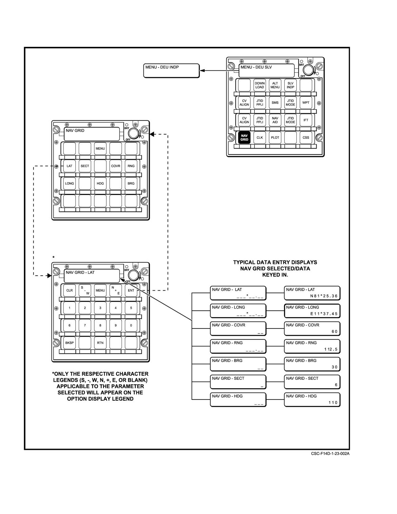
NAVAIR 01−F14AAD−1
Figure 23Ć1.ĄDEU NAV GRID Data Entry Typical
ORIGINAL
23−2
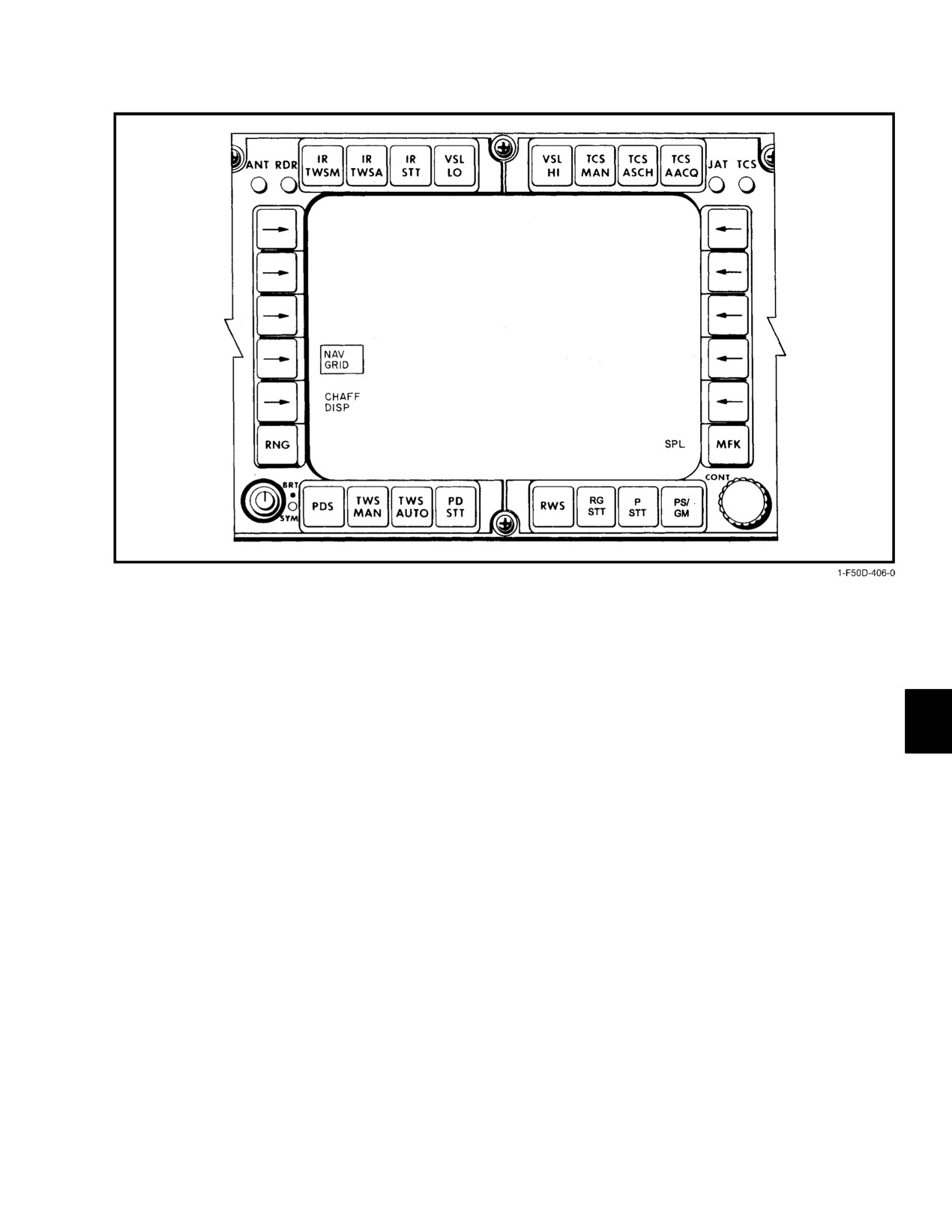
NAVAIR 01−F14AAD−1
Figure 23Ć2.ĄDD NAV GRID Data Entry
23.1.2
NAV GRID Displays
(threat axis) with each sector bounded by two strobes. Short
tic marks on the strobes represent 50−mile increments from
NAV GRID can be displayed independently on both the
grid origin; longer tic marks represent 100−mile increments.
TSD and PTID in either a ground−stabilized or aircraft−stabiĆ
A maximum of seven range tics (350 miles) is displayed.
lized format.
When the grid contains six sectors, no range tics are
displayed on the center strobe.
23.1.2.1
Programmable Tactical Information
Display
Selectable range scales are 25, 50, 100, 200, and 400
in either stabilized mode. A PTID offset can be utilized to
The PTID NAV GRID display is enabled by selecting
reposition own−aircraft anywhere on the display. The grid is
the A/C STAB position of the PTID mode switch. Selecting
repositioned accordingly and may only be partially displayed
this position directly from ATTK results in an aircraft−
(Figure 23−3, details B and C). Offset positioning is canceled
stabilized NAV GRID. Own aircraft is fixed at the bottom
by momentarily cycling out of the selected STAB mode.
center of the PTID with the top of the display oriented to
Tactical use of the NAV GRID often makes it desirable
own−aircraft magnetic heading (Figure 23−3, detail A).
to reference tracks, waypoints, or own−aircraft position as a
A ground−stabilized NAV GRID display on the PTID
range and bearing from grid origin rather than from
is achieved by moving the PTID MODE switch to GND
own−aircraft. This is accomplished by RIO selection of NAV
STAB then to A/C STAB. Own aircraft is initially displayed
GRID on the DD (SPL category) as shown in Figure 23−2.
at the center of the PTID. The top of the PTID is oriented to
magnetic north. Own−aircraft and sensor tacks transit the
23.1.2.2
Tactical Situation Display
display in the direction of magnetic heading at own−aircraft
groundspeed while the grid and any waypoint positions
The TSD format can be selected on any MFD. NAV
remain fixed (Figure 23−3, detail B).
GRID can be selected for display via the GRID pushtile on
the TSD DCL format (Figure 23−4). Like the PTID, the TSD
The grid itself is represented by grid strobes emanating
from grid origin. Grid center is oriented to grid heading
23−3
ORIGINAL
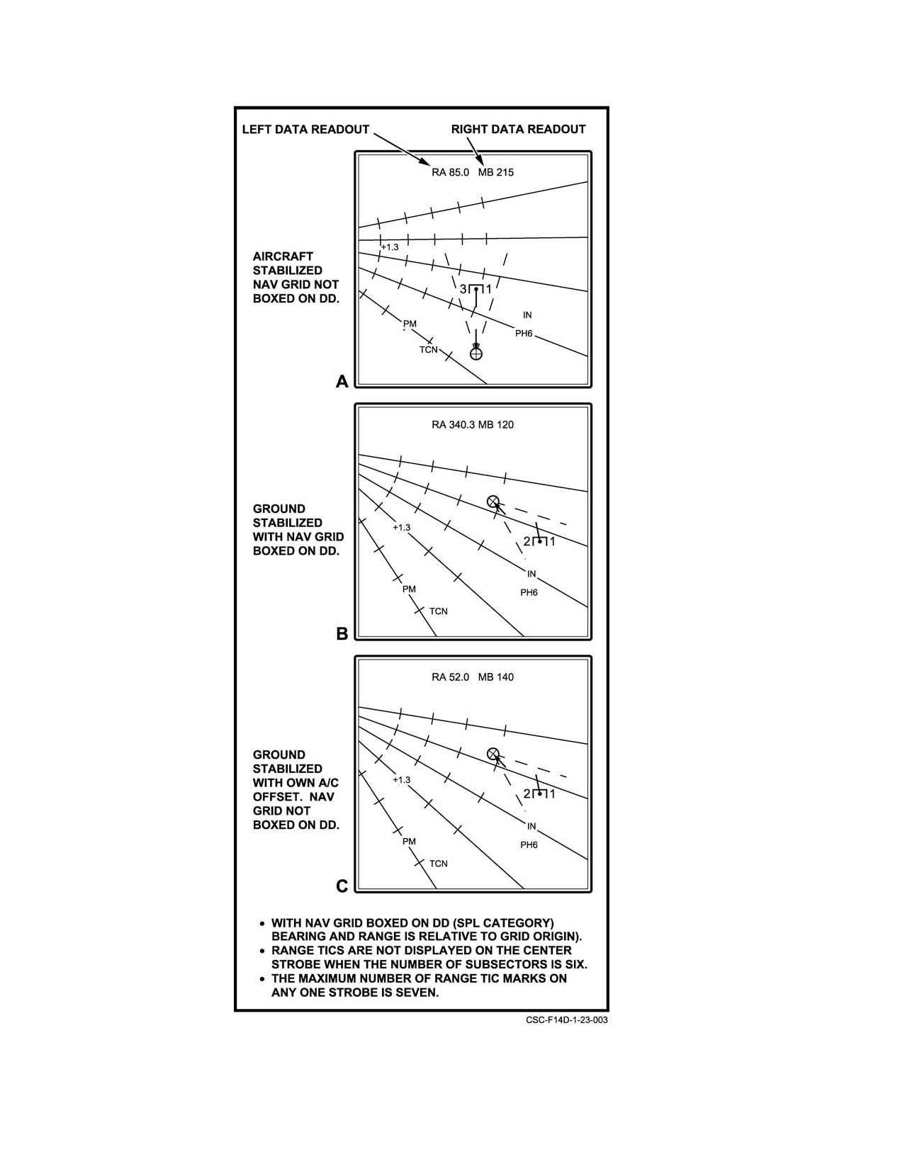
NAVAIR 01−F14AAD−1
Figure 23Ć3.ĄPTID NAV GRID Displays
ORIGINAL
23−4
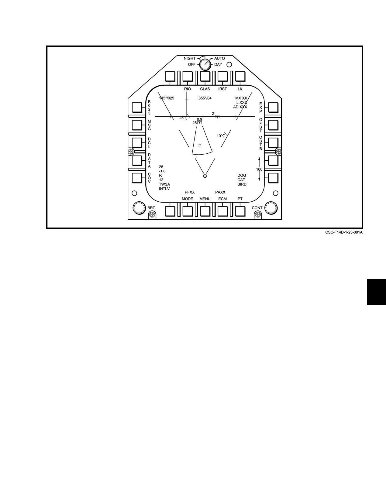
NAVAIR 01−F14AAD−1
Figure 23Ć4.ĄTSD NAV GRID Display
can display the NAV GRID in either ground or aircraft−
The grid itself is displayed as on the PTID with up to
stabilized formats as selected by the GSTAB or ASTAB
six sectors defined by strobes emanating from grid origin and
pushtiles. The ASTAB display has own−aircraft position
centered on grid heading (threat axis). Short and long tic
fixed on the lower third of the display with the top of the
marks represent 50−and 100−mile increments, respectively.
display representing own−aircraft magnetic heading. The
Any TSD range scale (25, 50, 100, 200, or 400) is selectable.
GSTAB display initializes with own−aircraft at the center of
Future software will include an OFF−SET and EXPAND
the display. The top of the display represents magnetic
capability for all TSD formats. Unlike the PTID, bearing and
north.Own−aircraft and sensor tracks transit the display based
range data hooked tracks or waypoints cannot be referenced
on magnetic heading and groundspeed while the grid and any
to grid origin.
waypoint positions remain fixed.
23−5 (Reverse Blank)
ORIGINAL
NAVAIR 01−F14AAD−1
PART IX
Flightcrew Coordination
Chapter 37 Ċ Flightcrew Coordination
Chapter 38 Ċ Aircraft Self−Test
91 (Reverse Blank)
ORIGINAL
NAVAIR 01−F14AAD−1
CHAPTER 37
Flightcrew Coordination
37.1 INTRODUCTION
will normally be responsible for all communications except
in tactical situations as designated in squadron SOP.
The duties of the pilot and RIO are necessarily
integrated. The performance of one crewmember contributes
37.2.4
Mission Commander
to the performance of the other. Successful crew interaction
can provide cockpit synergy that significantly improves
The mission commander may be either a pilot or a RIO.
mission success. However, a pilot/ RIO team that does not
The mission commander shall be qualified in all phases of the
interact successfully can be a major detriment to mission
assigned mission and be designated by the unit commanding
success. In this chapter, specific responsibilities are delinĆ
officer. When the assigned mission commander is a RIO, they
eated for each phase of flight. Specific mission flightcrew
shall be responsible for all phases of the assigned mission
responsibilities are also delineated.
except those aspects of safety of flight that are directly
related to the physical control of the aircraft. The mission
37.2 PILOT AND RIO RESPONSIBILITIES
commander shall direct a coordinated plan of action and shall
be responsible for the effective execution of that plan.
37.2.1
Aircrew Coordination
37.2.5
Specific Responsibilities
Aircrew coordination is the flightcrew’s use and
integration of all available skills and resources in order to
37.2.5.1
Flight Planning
collectively achieve and maintain crew efficiency, situation
awareness, and mission effectiveness. Integration of the
37.2.5.1.1
Pilot
flightcrew’s activities will provide error protection through
human redundancy. Crew coordination is one of the most
The pilot is responsible for the preparation of required
significant factors contributing toward mission success.
charts, flight logs, and navigation computations including
fuel planning, checking weather and NOTAMS, and for filing
37.2.2
Pilot Responsibilities
required flight plans.
The pilot is the aircraft commander and responsible for
37.2.5.1.2
RIO
the safe and orderly flight of the aircraft and the well−being
The RIO is responsible for the preparation of charts,
of the crew. In the absence of direct orders from higher
flight logs, navigation computations including fuel planning,
authority cognizant of the mission, responsibility for starting
checking NOTAMs, obtaining weather for filing purposes,
or continuing a mission with respect to the weather, mission
and completing required flight plans.
environment, or any other condition affecting the safety of
the aircraft rests with the pilot.
37.2.5.2
Briefing
37.2.3
Radar Intercept Officer Responsibilities
The briefing shall include confirmation that those tasks
delineated in paragraph
37.2.5.1 have been or will be
The RIO constitutes an extension of the pilot’s
accomplished.
observation facilities. By effective communication, the RIO
should anticipate rather than await developments in flight.
37.2.5.2.1
Mission Commander
The RIO will be a safety backup for the pilot. In this capacity,
the RIO shall offer constructive comments and recommendaĆ
The mission commander, pilot or RIO, is responsible
tions, as necessary, throughout the mission in order to
for briefing all crewmembers on all aspects of the mission to
maintain the safest and most effective flight environment.
be flown. Refer to Chapter 6 of this manual for specific items.
The RIO will be responsible for the reading of appropriate
checklists utilizing a challenge and reply system. The RIO
37−1
ORIGINAL
NAVAIR 01−F14AAD−1
37.2.5.3
Preflight
37.2.5.6.2
RIO
At completion of the emergency generator check, the
37.2.5.3.1
Pilot
RIO will perform the poststart checks prescribed in NAVAIR
The pilot is responsible for accepting and preflighting
01−F14AAD−1B. When OBC is completed and the inertial
the assigned aircraft and coordinating preflight operational
navigation system aligned, the RIO informs the pilot, Ready
checks in accordance with this manual and appropriate
to taxi."
preflight checks contained in NAVAIR 01−F14AAD−1B, the
F14−D NATOPS Pocket Checklist.
37.2.5.7
Pretakeoff
37.2.5.3.2
RIO
37.2.5.7.1
Pilot
The RIO will be capable of and proficient in performĆ
The pilot will execute Pretakeoff, Instrument, and
ing a complete aircraft preflight, including armament, in
Takeoff Checklists prescribed in NAVAIR 01−F14AAD−1B
accordance with this manual and appropriate preflight
and as posted in the aircraft. The pilot will report to the RIO
checklists contained in NAVAIR 01−F14AAD−1B, the F14−D
Takeoff Checklist items, using the challenge−reply method.
NATOPS Pocket Checklist.
The pilot will receive the Ready for takeoff" report from the
RIO and advise him of type and configuration takeoff
37.2.5.4
Prestart
planned, prior to rolling or catapulting. The pilot will report
Rolling" or Saluting," as appropriate, to the RIO.
37.2.5.4.1
Pilot
37.2.5.7.2
RIO
The pilot will execute prestart checks prescribed in
NAVAIR 01−F14AAD−1B and, when external power is
The RIO will execute Pretakeoff Checklists prescribed
applied and checks requiring external power are completed,
in NAVAIR
01−F14AAD−1B; will initiate, using the
will inform the RIO Prestart checks completed. Ready to
challenge−reply method, the posted Takeoff Checklist in the
start."
aircraft; and, at completion of the Takeoff Checklist, RIO
informs the pilot Ready for takeoff."
37.2.5.4.2
RIO
37.2.5.8
Takeoff and Departure
The RIO will execute prestart checks prescribed in
NAVAIR 01−F14AAD−1B and, when external power is
37.2.5.8.1
Pilot
applied, will inform the pilot Prestart checks completed."
The pilot shall ensure that the intercom remains in HOT
37.2.5.5
Starting
MIKE for normal flight operations and will report Gear up"
and Flaps up" to the RIO insofar as safety permits. The RIO
37.2.5.5.1
Pilot
should be advised of any unusual occurrences during takeoff
that may affect safety of flight. The pilot or RIO will request,
The pilot will start engines as prescribed in para−
copy, and acknowledge all clearances.
graph 7.4.3 and will keep the RIO informed of any unusual
occurrences.
37.2.5.8.2
RIO
37.2.5.5.2
RIO
Where departures are made in actual instrument
conditions, the RIO will monitor the published clearance
The RIO will remain alert for any emergency signal
departure procedures and inform the pilot of any deviation
from the groundcrew and will inform the pilot if such signals
from the prescribed flightpath. The RIO will copy all
are observed.
clearances received and at all times be prepared to provide the
pilot with clearance information and/or navigational informaĆ
37.2.5.6
Poststart
tion derived from the RIO’s instruments. Built−in−test checks
will not be conducted during instrument climbouts.
37.2.5.6.1
Pilot
37.2.5.9
In Flight (General)
At completion of the emergency generator check, the
pilot will inform the RIO Emergency generator check
37.2.5.9.1
Pilot
complete." The pilot will complete all poststart checks
prescribed in NAVAIR 01−F14AAD−1B and coordinate with
The pilot will inform the RIO of any unusual occurĆ
the RIO the initiation of OBC.
rences and will ensure that the aircraft is operated within
ORIGINAL
37−2
NAVAIR 01−F14AAD−1
prescribed operating limitations at all times. The pilot or RIO
descents (VFR or IFR), the RIO will report to the pilot the
will normally request, copy, and acknowledge all clearances.
aircraft descent through each 5,000 feet of altitude above
5,000 feet and each 1,000 feet of altitude loss below 5,000
37.2.5.9.2
RIO
feet, until, on reaching the desired altitude, the RIO will
report when altitude error exceeds
10 percent of actual
The RIO will assist the pilot in normal or emergency
altitude or ±300 feet.
situations, including navigation, communication, and visual
lookout. The RIO will inform the pilot of the weapon system
37.2.5.12
Landing
status. During ascent or descent, the RIO will inform the pilot
1,000 feet prior to the intended level−off altitude.
37.2.5.12.1
Pilot
37.2.5.10
Intercept
The pilot will utilize the Landing checklist and will
report each item to the RIO prior to reporting Gear down,
37.2.5.10.1
Pilot
hook down" to the final controller, tower, or Pri−Fly. The pilot
will receive a Ready to land" report from the RIO.
The pilot will maneuver or coordinate aircraft maneuĆ
vers with, or as directed by, the RIO, observing normal
37.2.5.12.2
RIO
operating limitations. The pilot will inform the RIO of
weapons status, weapons selected and armed, and when the
In the landing pattern, the pilot shall read and the RIO
target is sighted visually. The pilot will monitor aircraft
acknowledge the posted Landing Checklist. The RIO shall
position from initial vector through breakaway by pigeons
visually check the flap position and landing gear position by
information or navigational display.
looking through the opening on the left side of the instrument
panel. The RIO will report Ready to land" to the pilot.
37.2.5.10.2
RIO
Built−in−test checks shall not be conducted while in the
landing pattern.
The RIO will handle all communications from initial
vector through breakaway, excluding missile−away transmisĆ
37.2.5.13
Postflight
sions; provide the pilot with descriptive commentary,
including weapon status and target aspect, if available; and
37.2.5.13.1
Pilot
direct and coordinate aircraft maneuvers with the pilot, as
necessary, to complete the intercept.
The pilot will inform the RIO of any unusual occurĆ
rences on the landing roll or arrestment. The pilot will report
37.2.5.11
Instrument Approaches
flap and wing position to the RIO when clear of the runway
or landing area and will report when the wing is actuated. The
37.2.5.11.1
Pilot
pilot will receive a Ready for Shutdown" report from the
RIO. The pilot will inform the RIO when shutting down
The pilot is responsible for the safe control of the
engines. The pilot will conduct a postflight inspection of the
aircraft, the decision to commence the approach with the
aircraft.
existing weather, and the selection of the type of approach to
be made. The pilot, before commencing any penetration, will
37.2.5.13.2
RIO
report to the RIO the completion of each item of the
Instrument Checklist. In addition, the pilot will challenge the
The RIO will challenge the pilot on flap position if the
RIO Instrument Penetration Checklist, as to approach plate
report is not received. When informed by the pilot that the
availability and corrected altimeter setting.
wing has been actuated, the RIO will visually verify wing and
spoiler positioning. The RIO will complete the built−in−test
37.2.5.11.2
RIO
checks remaining and secure that rear cockpit for shutdown,
then notify the pilot Ready for shutdown." The RIO will
The RIO will monitor aircraft instruments and
assist the pilot in conducting a postflight inspection of the
appropriate approach plate during holding, penetration, and
aircraft.
approach and shall be ready to provide the pilot with any
required information. He shall be particularly alert to advise
Note
the pilot of deviations from the course of minimum altitudes
The RIO will vacate the aircraft first and after the
prescribed on the approach plate. Built−in−test checks will not
aircraft is on the ground, flight deck, or hangar
be conducted in actual instrument conditions. The RIO will
deck, the pilot will exit. This is particularly
inform the pilot of the status of the radar and will do nothing
important during shipboard operations.
to cause the display to be lost. During penetrations and/or
37−3
ORIGINAL
NAVAIR 01−F14AAD−1
37.2.5.14
Debriefing
37.3.2.3
RIO
The pilot and RIO will complete the yellow sheet and
The RIO will monitor formation separation and closure
all required debriefing forms.
during joinup and advise the pilot when an unsafe situation
exists.
37.2.5.14.1
Maintenance
37.3.3
Training
The pilot and RIO will complete the yellow sheet, BER
card, and all other required maintenance debrief forms. The
37.3.3.1
Instructors
crew will ensure a complete debrief is provided for all
maintenance discrepancies.
All instructors will be designated in formal directives
by unit commanding officers. In FRS the instructor will be
37.2.5.14.2
Mission
charged with authority and responsibility to provide proper
The mission commander will be responsible for
direction to pilot and RIO replacements to ensure safe and
conducting a thorough mission debrief to include the
successful completion of each training mission. On training
accomplishment of mission goals, adherence to SOP/ROE/
missions where a pilot under instruction is the pilot in
NATOPS, intercockpit and flight communication, and conĆ
command, the instructor’s guidance shall be advisory in
flict resolution.
nature and under no circumstance shall the pilot in command
be relieved of his authority and responsibility as aircraft
commander. Termination of the training or evaluation
37.3 SPECIAL CONSIDERATIONS
portions of the flight for reasons of safety, unsatisfactory
37.3.1
Functional Checkflights
performance, or material discrepancy shall be the instrucĆ
tor’s prerogative.
The pilot and RIO shall brief with maintenance to
determine the discrepancies that were corrected and the goals
37.3.4
SAR
of the functional checkflight.
The mission commander, or senior member of the
37.3.1.1
Pilot
flight should the mission commander be unavailable, shall
assume responsibility for the rescue operation until relieved
The pilot is responsible for adherence to all FCF
on scene or fuel dictates a return to base. The primary
procedures as described in NAVAIR 01−F14AAD−1F, the
responsibility of the on−scene commander will be commuĆ
Functional Checkflight Checklist.
nication of the downed crew’s position and condition to
potential rescue aircraft or vessels. Additionally, the on−
37.3.1.2
RIO
scene commander will ensure search coordination, traffic
The RIO is responsible for monitoring the FCF
control on the scene, and communication with the downed
procedures and the completion of specific tasking outlined in
crews, if feasible.
NAVAIR
01−F14AAD−1F, the Functional Checkflight
Checklist.
37.4 PROCEDURES, TECHNIQUES,
AND CHECKLISTS
37.3.2
Formation Flights
37.4.1
General
37.3.2.1
Formation Leader
Even though some of the procedures, techniques, and
A pilot will be designated the formation leader. The
checklists are specifically designed for the pilot and RIO, the
status of each member of the formation shall be briefed and
entire contents of the flight manual and pocket checklist
clearly understood prior to takeoff. As a minimum, formation
should be thoroughly read, understood, discussed, and agreed
brief items shall include loss of sight, lost communication,
upon collectively by the pilot−RIO team. Discrepancies in
inadvertent IMC, and formation integrity. The formation
procedures or the need for additional procedures should be
leader is responsible for the safe and orderly conduct of the
brought to the attention of the NATOPS evaluator and/or
formation. This includes visual lookout, the separation
instructor. Most of the procedures (individual and coordiĆ
between aircraft within the formation and during transition
nated) are covered in this manual and are grouped under flight
periods, breakups, and rendezvous.
phases and/or categories. Aircraft systems descriptions, with
their individual operating criteria, are covered in Chapter 2.
37.3.2.2
Pilot
Classified systems descriptions and procedures, and some
The pilot is responsible for the safe separation of his
limitations information, are covered in the classified suppleĆ
aircraft and the other aircraft in the formation. Lead changes
ment
(NAVAIR 01−F14AAD−1A). The pocket checklist
will include a positive acknowledgment by both pilots.
(NAVAIR 01−F14AAD−1B) contains the pilot and RIO
ORIGINAL
37−4
NAVAIR 01−F14AAD−1
checklist items for preflight, prestart, start, poststart, takeoff,
37.4.3
RIO
built−in test, instrument and descent, emergency and postĆ
flight procedures. Improper crew coordination is usually
The RIO should monitor all critical flight parameters
an attributable factor to improperly executed emergency
and read all applicable checklists in a challenge and reply
procedures.
system. He should assist in navigation, communication, and
coordinate with outside agencies and aircraft, but not to the
37.4.2
Pilot
detriment of the resolution of an emergency.
The pilot should relate to the RIO all indications releĆ
vant to an ongoing emergency. The pilot should assess the
situation, set emergency priority, and direct the RIO to effecĆ
tively assist him.
37−5 (Reverse Blank)
ORIGINAL
NAVAIR 01−F14AAD−1
CHAPTER 38
Aircraft Self−Test
38.1
AIRCRAFT SELF−TEST OVERVIEW
available in all system modes and are used for
troubleshooting and maintenance purposes.
Aircraft self−test allows testing of the operational status
of all major avionics and radar subsystems and display of the
38.2
MASTER TEST PANEL CHECKS
results. This capability is also referred to as OBC throughout
this section. Figure 38−1 identifies the major components
Master test checks are initiated by the pilot through the
associated with this function. Most of the status information
MASTER TEST panel (Figure 38−3) on the right outboard
is derived from BIT implemented within the avionics and
console. These tests check the operational status of specific
radar subsystems. All operational aspects of aircraft self−test
aircraft systems basic to safety of flight and mission success.
are fully supported by the MCS if one of the mission
The OBC, WG SWP, FLT GR UP, and FLT GR DN positions
computers has failed.
are used on the deck only and are prevented from inadvertent
use in flight by the weight−on−wheels safety switches. The
There are two categories of test: (1) tests that are
remaining tests, except for emergency generator, which also
performed by the system automatically; (2) those that require
requires combined hydraulic pressure, can be done whenever
initiation by the flightcrew. Testing should be initiated by the
electrical power and cooling air are available. For details of
flightcrew as part of the normal preflight checkout to obtain
specific aircraft systems tests, refer to the applicable system
the overall status of each system. Figure 38−2 is a summary
description.
description for the various test types, including origin and
purpose. Avionics testing is controlled by the pilot and the
RIO primarily through the MFDs and cockpit control panels.
Radar testing is controlled by the RIO via the DD and PTID.
The majority of the displayed information is the result of each
subsystem performing a particular mode of BIT or the MCS
During ground operations, once the OBC
performing data bus or software configuration tests. On an
position is selected, do not deselect OBC until
automatic (i.e., periodically by the MCS) basis, subsystems
the program has completed the entire cycle.
are polled by the MCS in order to determine their operational
When the disable signal, which inhibits throttle
status. Operational status is displayed at a subsystem and
movement, is removed, the APC will run through
WRA level through a series of OBC formats on the MFDs.
its BIT and advance the throttles to greater than
Both current and historical equipment status is displayable.
80 percent.
Warning/caution/advisory cues are displayed on the MFDs
for critical equipment failures and overtemperature
Note
conditions. Details of radar subsystem failures are available
only on the DD and PTID. Avionics and radar failure
acronyms are displayed on the PTID during normal tactical
D Before starting the test, depress the MASTER
operation.
RESET button on the left vertical console to
turn off any caution or advisory lights
Aircraft self−test also allows examination of memory
associated with the air data computer.
contents for WRAs that support a CSS capability. CSS is
controlled with the DEU and the results are displayed on the
D In LTS, the MASTER CAUTION light will
MFDs. The radar subsystem provides a similar but limited
flash unless there is a circuit failure within the
capability that is controlled via the DD. These features are
caution advisory indicator, in which case the
light will be steady.
38−1
ORIGINAL

NAVAIR 01−F14AAD−1
Figure 38Ć1.ĄOn−Board Checkout
ORIGINAL
38−2
NAVAIR 01−F14AAD−1
NAME
ORIGINATOR
PURPOSE
Master Test Checks
PILOT
Selectable tests of instruments, fuel system, warning system
(lights), wingsweep, AOA
Onboard Checkout (OBC)
PILOT and RIO
Tests various avionics, flight controls, actuators, AICS, and
Sequences
computers
Continuous Monitor
AUTOMATIC
Monitors majority of avionics and radar functions for in−flight or
on−deck failures. Typically performed every 2 seconds
Unit/Subsystem Self−test
PILOT and RIO
Independent testing of individual, or groups of functionally
related subsystems
Data Bus Tests
AUTOMATIC
Tests each data bus channel for each subsystem bussed
Software Configuration Test
AUTOMATIC
Tests the compatibility of subsystem software program loads
Figure 38Ć2.ĄTest Types
38.2.1
MASTER TEST Switch Operation
if the MASTER TEST switch is not rotated out
of the DFCS BIT position following completion
The master test check is made by pulling the knob up,
of a DFCS IBIT.
rotating to the desired position, and depressing it. After the
test is completed, the MASTER TEST switch must be pulled
Electrical power for the master test panel comes from
up and deselected to deenergize the system.
the left main dc bus through the MASTER TEST circuit
breaker (9H4) on the DC MAIN circuit breaker panel. When
operating on aircraft power or when external electrical power
is connected to the aircraft, cooling air must be supplied to
all avionic equipment before a test is initiated.
Cycling the CIU PH A, B, and C circuit breakers
38.3
ON−BOARD CHECKOUT
(3E7, 4E1, and 4E2) with the MASTER TEST
switch in or above the OBC position will cause
OBC checks the operational status of the equipment
the DFCS BIT sequence to initiate. DFCS BIT
listed in Figure 38−4. It provides fault isolation to the WRA
sequence tests and deflects various aircraft conĆ
level without the use of ground support equipment. The
trol surfaces, which could be a hazard to
system automatically monitors all equipment providing an
unsuspecting ground personnel.
initial, periodic, or operator−initiated mode of BIT in order
to detect failures or command subsystems into test as a result
System status and test results are indicated on the
of selections made with the MFD OBC display formats.
cockpit instruments: GO−NO GO lights on the master test
When a test is completed, the tested equipment responds with
panel; warning, caution, and advisory lights in both cockpits;
either a GO (when all tests have passed) or NO GO (when at
and displays including MFDs and PTID.
least one test has failed) for each WRA tested. Detected
The GO−NO GO indicator lights on the MASTER
failures are processed by the MCS in order to maintain
TEST panel will illuminate only in LTS, FIRE DET/EXT,
current status and a historical record of failure information.
EMERG GEN, and FLT GR UP. In the LTS test position, only
Test status is also used to control the operation of the system
the bulbs in the GO−NO GO indicators are checked. In
and is displayable on the MFDs. OBC formats present failure
EMERG GEN, FIRE DET/EXT, and FLT GR UP, a GO light
acronyms for failed equipment only (i.e., the absence of a
indicates a valid test and a NO GO light indicates an
failure acronym implies that the equipment is operational).
unsatisfactory test. The DFCS BIT switch position allows the
A historical record of failures is maintained during the course
independent execution of DFCS IBIT. DFCS IBIT is armed
of a flight and is displayable at any time on the FHF format
by raising the MASTER TEST switch and rotating it to the
including during postflight operations by maintenance
DFCS BIT position. Depressing the MASTER TEST switch
personnel. The historical record of failures should be cleared
while DFCS IBIT is armed will initiate DFCS IBIT. Results
(erased from the FHF) prior to a mission by the flightcrew so
of this test are displayed through the caution/advisory lights,
that only failures relevant to the current mission are retained
acronyms on the MFDs, and fault codes on the DCP.
by the system.
Note
The DCP fault codes cannot be cleared while
DFCS IBIT is armed. This condition will occur
38−3
ORIGINAL
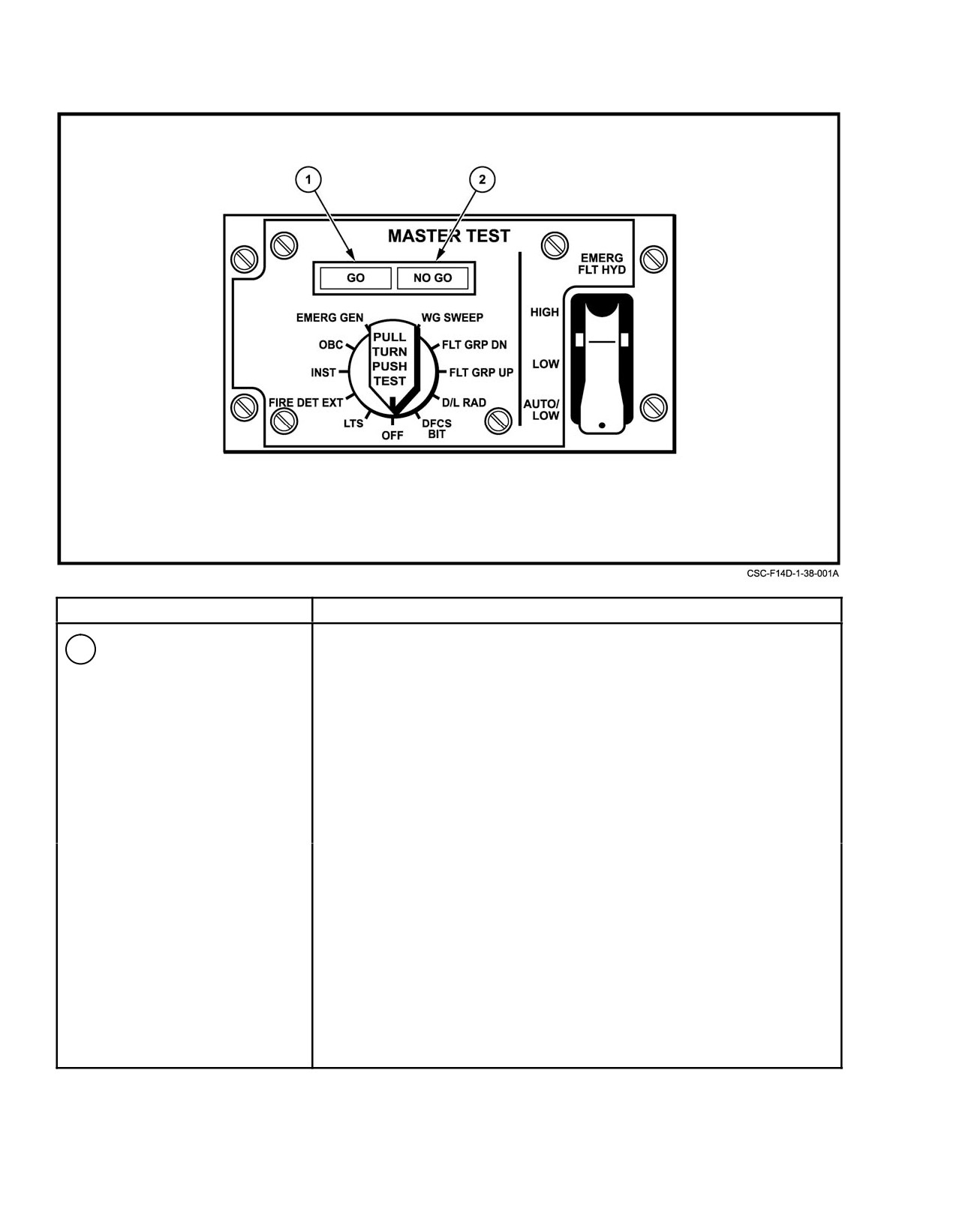
NAVAIR 01−F14AAD−1
NOMENCLATURE
FUNCTION
1
MASTER TEST switch
OFF Ċ
Disables test functions.
LTS Ċ
Tums on caution, warning, and advisory lights; emergency
stores jettison button; GO and NO GO lights; landing gear
and hook transition lights; approach indexer FIRE warning
lights.
FIRE DET/EXT Ċ L and R FIRE warning lights illuminate. If a circuit problem
exists, the corresponding FIRE light will not illuminate.
Simultaneously, the fire extinguishing system initiates a self−
test. If tests pass, the GO light illuminates. If the
NO−GO light illuminates or if both or neither GO or NO−GO
lights illuminate, a failure exists in the system.
Note
INST Ċ
Decreases the RIO’s fuel counter to 2000 pounds,
illuminates the FUEL LOW, MASTER CAUTION, and
•
The 10 second audio alarm
BINGO (if the pilot bingo counter set >2000 pounds) lights.
goes on.
Displays the following pilot cockpit indications.
•
If EIG fails self test, the BIT
RPM
96%
segment to the left of the EGT
EGT .
960_C (initiates engine over temperature alarm)
legend remains illuminated
FF
10,500 pounds per hour
FUEL QTY
2,000 ± 200 pounds(both cockpits)
WING SWEEP
45_ ± 2.5_
AOA
18 ± .5_ units
BINGO
ON (if Bingo set > 2,000)
FEED/WING/EXT FUEL QTY
2,000 pounds
Figure 38Ć3.ĄMaster Test Panel (Sheet 1 of 2)
ORIGINAL
38−4
NAVAIR 01−F14AAD−1
NOMENCLATURE
FUNCTION
OBC Ċ
Enables preflight testing when selected prior to
selecting a subsystem for test via the MFDs. Failure
acronyms are displayed on the MFDs.
EMERG GEN Ċ
Activates automatic transfer feature of generator and
checks tie connectors. GO lights indicate satisfactory
check. If the NO GO light remains illuminated, a
malfunction is indicated.
WG SWP Ċ
Air data computer simulates that circuit to the
wing sweep system (wings do not move).
Requires wings in oversweep, and wing sweep button
in AUTO.
FLT GR DN Ċ
Initiates ground check of auto throttle interlocks.
Requires throttles in AUTO throttle region and enables
ground selection of AUTO throttles. Engines will
respond to stick movement and nozzles remain
closed.
FLT GR UP Ċ
Permits checking external fuel tank pressurization.
GO light indicates required pressure. WING/EXT
TRANS switch must be in AUTO and DUMP switch
set to OFF.
D/L RAD Ċ
Tests the data link converter. Test results are available
on the MFDs. Inhibits tactical control messages during
test sequence. Symbology displayed is determined by
the display mode selected.
DFCS BIT Ċ
Permits running DFCS IBIT independently of the
(after engine start)
rest of OBC.
2
GO−NO GO lights
GO Ċ
Indicates valid test.
NO GO Ċ
Indicates unsatisfactory test.
Note
Functional only in LTS,
FIRE DET/EXT, INST
EMERG GEN, and FLT
GR UP.
Figure 38−3. Master Test Panel (Sheet 2 of 2)
38−5
ORIGINAL