C-130T. FLIGHT MANUAL (2006) - page 12

01-75GAL-1
If no pressure is indicated, both pumps are inoperative:
9. Refer to Chapter 4 for allowable fuel unbalance (FE).
Note
Fuel remaining in that tank will not be available and the flight shall be
altered accordingly.
11.4.12 Fuel Dumping
A fuel dump system is provided to enable all fuel (except approximately 1,600 pounds each from the No. 1 and No.
4 wing tanks, 1,500 pounds each from No. 2 and No. 3 wing tanks, 65 pounds from each external tank, and 1,008
pounds from the fuselage tank, if installed) to be dumped overboard. Should it become necessary to dump fuel in
preparation for an emergency landing, to reduce gross weight in an emergency, or to provide for additional buoyancy
in a ditching operation, follow the procedure outlined below.
11.4.12.1 Dumping Precautions
1. Do not dump fuel below 6,000 feet above the terrain. This will prevent the possibility of a ground source
igniting the fuel vapors.
2. Do not dump in a circular pattern; this will prevent turning into the dumped fuel.
3. Do not transmit on HF radios.
4. After the dumping operation, inspect the aircraft for fumes.
11.4.12.2 Dumping Procedures
1. ATC — Advise (CP).
2. Fuel Panel — Main Tank to Engine (FE).
If the fuel dump switches for the auxiliary or external tanks are placed in
the DUMP position whilethose tanks are supplying fuel to the engines, the
respective tank crossfeed valves are automatically closed, shutting off fuel
flow to the crossfeed manifold.
3. INTER CONN valve switches — FLOW (FE).
4. DUMP SHUTOFF VALVE switches — DUMP (FE).
5. DUMP PUMP switches — DUMP (FE).
Note
Dump opposite tanks at the same time in order to maintain lateral balance.
6. Monitor the fuel quantity indicators (FE).
11-31
ORIGINAL
01-75GAL-1
When dumping is complete:
7. DUMP PUMP switches — OFF/NORM (FE).
8. INTER CONN valve switches — NO FLOW (FE).
CAUTION
When returning the dump valve switches to the NORM position, press
firmly on the top of the switch guard until the maximum resistance is felt.
This will ensure that the switch toggle has returned to NORM.
9.
DUMP SHUTOFF VALVE switches — NORM (FE).
Note
With all eight fuel dump switches in the DUMP position, fuel will be
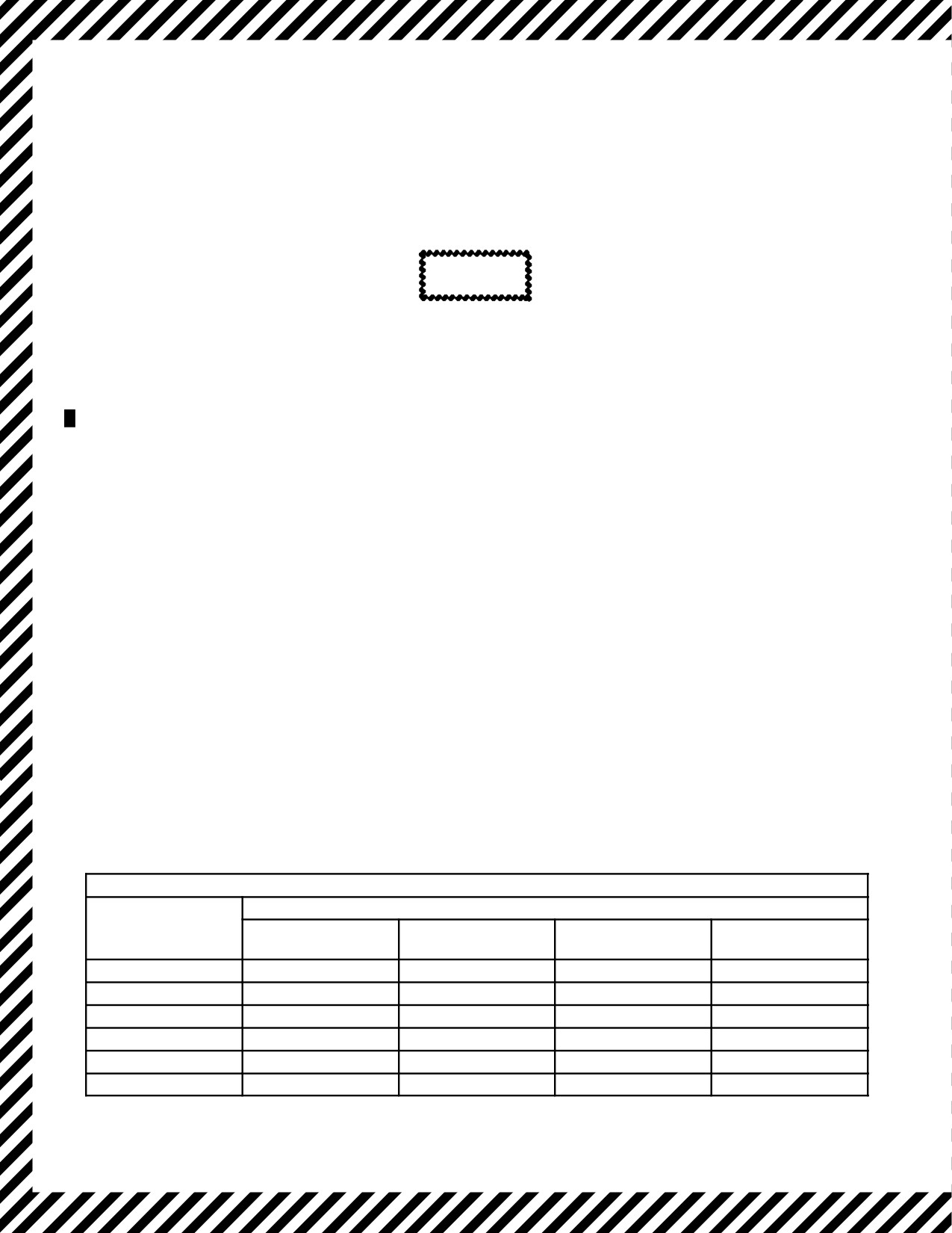
dumped at a rate of approximately 3,400 pounds per minute (see Figure
11-4). If the external tank forward boost pumps are switched on manually,
the rate increases to approximately 3,900 pounds per minute.
10.
Clear fuel manifold (P/FE).
Note
After completing fuel dumping and if time permits prior to landing, the fuel
dumping manifold should becleared ofresidual fuel. Cross-controlling the
aircraft and ensuring a wing-low attitude with slight skid will deplete all
residual fuel except that located at low points in the manifold. This will
minimize the fire hazard of excessive fuel drainage coming from the fuel
dump mast because of normal wing deflections and attitudes during taxi or
while the aircraft is parked.
11.
Check for negative fuel flow and fumes (LM).
APPROXIMATE WING FUEL DUMP TIME
MINUTES TO DUMP
POUNDS FUEL TO
4 PUMPS
6 PUMPS
8 PUMPS
10 PUMPS
BE DUMPED
OPERATING
OPERATING
OPERATING
OPERATING
5,000
3.0
2.0
1.5
1.3
10,000
6.0
3.5
3.0
2.5
20,000
12.0
7.0
6.0
5.0
30,000
18.0
10.5
9.0
8.0
40,000
23.5
14.0
11.5
10.0
50,000
29.5
17.5
14.5
13.0
Figure 11-4. Approximate Wing Fuel Dump Time
ORIGINAL
11-32

01-75GAL-1
11.4.13 Electrical Systems Failure
With modern complex aircraft, it is extremely difficult to anticipate all the possible electrical failures and to plan
corrective action and procedure for each failure. However, a broad analysis of the situation indicates that failures fall
into three possible categories:
1. Loss of one or more of the primary power sources.
2. Faults on the main bus or distribution system.
3. Faults within equipment items.
Faults in the distribution system and load circuits should be controlled through protective devices such as circuit
breakers, fuses, and current limiters. Should one of these devices fail to operate, considerable smoke can result and
some emergency action on the part of the crew may be needed.
Do not operate the aircraft without a serviceable battery. Power would not
be available to operate the fire extinguishing system, alarm bells, or
emergency depressurization.
CAUTION
Circuit breakers, after popping, may be reset once, except as noted in this
chapter. Clamp and tag any circuit breaker that will not be reset. Any circuit
breaker that pops shall be recorded for maintenance action.
Loss of the essential ac bus is unlikely. Loss of one or more primary power sources, however, will require the crew
to take prompt action by closely watching electrical load so that theremaining powersources will not beoverloaded.
11.4.13.1 Loss of Essential AC Bus
A loss of one phase of the essential ac bus may occur with or without illumination of the essential ac bus off light.
The malfunction is most likely to occur during high load conditions of the essential ac bus and may be indicated by
one of the following conditions:
1. Failure of ANTI-SKID.
2. Illumination of pilot and copilot PITOT HEAT OFF lights.
3. Erratic autopilot operation (if in use).
4. Loss or malfunction of heading indication.
5. Auxiliary hydraulic pump failure.
6. Illumination or flickering of the No. 2 fuel boost pump LOW PRESS warning light.
7. Illumination of the Hydraulic suction boost pump light(s).
8. Essentialacbus-offlightwhichremainsilluminatedaftertheaffectedgeneratoristurnedoff(anothergenerator
does not assume the bus load).
11-33
ORIGINAL

01-75GAL-1
9. Loss of propeller synchrophaser.
10. Malfunctioning navigation/communication equipment.
Note
Onaircraft165313andup,lossoftheessentialormainacbuswillnotaffect
the items powered by the essential avionics buses. The bus switching
system continues to supply power to the avionics buses from alternative
sources. Items on the essential avionic bus, controlled through BSU 1,
could be receiving power from either the essential ac or main ac bus.
11.4.13.2 Partial Essential AC Bus Failure
A loss of one phase of the essential ac bus may occur with or without illumination of the essential ac bus-off light.
The malfunction is most likely to occur during high load conditions of the essential ac bus and may be indicated by
the same conditions as stated in paragraph 11.4.13.1.
11.4.13.3 Partial Loss of Essential AC Bus (Aircraft Prior to 165313)
If partial loss of the essential ac bus occurs or is suspected, proceed as follows:
Land as soon as possible regardless of the success of the corrective action.
1. PROPELLER GOVERNOR CONTROL switches — MECH GOV (CP).
Note
If all four PROPELLER GOVERNOR CONTROL switches are not placed
inMECHGOVpriortorestoringpowerto theessential acbus, asignificant
power fluctuation may be experienced.
2. GENERATOR — OFF (FE).
3. Monitor for failed bearing (FE).
If generator indications are subsequently lost:
4. Perform Generator Out Light procedures, paragraph 11.4.14.1 and 11.4.14.2.
If power is restored to the essential ac bus:
5. PROPELLER GOVERNOR CONTROL switches — NORMAL (CP).
If power is not restored, proceed as follows:
6. ANTI-SKID switch — OFF (CP).
7. Autopilot — Disengage (P).
ORIGINAL
11-34

01-75GAL-1
Do not change the position of the attitude select switch with the autopilot
engaged. A violent pitch maneuver may result in structural damage.
8. Attitude select switches — GYRO ATT (P) (CP).
9. INVERTER switches — STANDBY (dc bus) position (FE).
10. Reduce load on the essential ac bus (FE).
Note
Do not operate the auxiliary hydraulic pump.
11. Check and reset all A-, B-, and C-phase essential ac bus circuit breakers on the pilot side circuit breaker panel
and on the main ac distribution panel at FS 245 (FE).
If the circuit breakers will not reset or trip again:
12. APU — START/RUN (FE).
13. APU generator switch — ON/CHECKED (FE).
14. Again attempt to reset the tripped A-, B-, and C-phase essential ac bus power circuit breakers (FE).
If the breakers still will not reset or trip again:
15. Perform the Bus Isolation procedure (Essential AC bus), paragraph 11.4.16.1.
11.4.13.4 Battery Discharge Light
The BAT DISCH light on indicates that the battery charge is being depleted by the isolated dc bus loads because of
failure of the reverse current relay. Illumination may be caused by momentary high dc loads. After approximately
30 seconds, the BAT DISCH light should extinguish. If light does not extinguish, proceed as follows:
1. Shut down all equipment possible that receives power from the isolated dc bus.
2. Land as soon as practical.
11.4.13.5 AC Bus-Off Light (Aircraft Prior to 165313)
When an ac bus-off light illuminates, check the frequency, voltage, and load of the affected generator.
1. If the frequency, voltage, and load are within limits, leave the generator on.
2. If the frequency, voltage, and load are not within limits, place the respective generator switch to the OFF
position.
a. Monitor the voltage and frequency indications closely. If the three-phase average voltage of a generator
drops below approximately 96 volts or if any one of the phases of the bus drops below approximately 90
11-35
ORIGINAL

01-75GAL-1
volts,thebus-offlightwillilluminate.Ifthefrequencyremainsnormal,thecontactorwillremainenergized,
the generator will continue to power its respective bus, and the bus-off light will be illuminated until the
generator switch is placed to the OFF position. With this condition, place the generator switch to the OFF
position to prevent damage to aircraft equipment because of low voltage and allow another generator to
assume that bus.
b. Monitor the loadmeter for the generator assuming the load. The low-voltage condition may have been
caused by a malfunctioning voltage regulator, generator, or bus fault. Monitor the FAILED BRG light.
Upon illumination of this light, perform Generator Disconnect Procedures, paragraph 11.4.14.4.
3. If the failed bus cannot be returned to normal operation, follow the Bus Isolation Procedures for therespective
failed bus.
11.4.13.6 AC Bus-Off Light (Aircraft 165313 and Up)
1. If the affected generator-out light is also illuminated, place the generator control switch to OFF/RESET.
Monitor the FAILED BRG indicator for the generator that was turned OFF.
2. If the affected generator-out light is not illuminated and systems associated with the failed bus are operating
normally, verify normal voltage, frequency, and load indications for the affected generator.
a. If voltage, frequency, and load are normal, continue operation. The bus-off indicator is the result of a failed
bus-off indicator relay.
b. Monitor the affected generator and the systems associated with the ac bus for any further indications of a
failure.
3. If the affected generator-out light is not illuminated and systems associated with the failed bus are
malfunctioning, the failed bus cannot be returned to normal operation. Chapter 2 should be reviewed to
ascertain what systems have been lost.
Note
Loss of the essential or main ac bus will not affect systems powered by the
essential and main avionics ac buses. The bus switching units will continue
to supply power to the avionics buses from the primary/alternate source.
4. If the failed bus cannot be returned to normal operation, follow the Bus Isolation Procedures for therespective
failed bus.
11.4.13.7 Illumination of an Avionics AC Bus Light (Aircraft 165313 and Up)
If the essential avionics (ESS AV), or main avionics (MAIN AV) OFF light illuminates:
1. Place the affected BSU switch to OFF to place the BSU in the bypass mode. If the avionics bus light
extinguishes, continue normal operation. If the avionics bus light remains illuminated, proceed with step 2.
2. Check to see if systems powered by the avionics bus are operating normally. If so, the failed bus indication
istheresultofafailedbusoffindicatorrelay.Continuewithnormaloperation.Ifsystems poweredby thefailed
bus are malfunctioning, leave the avionics bus isolated and land as soon as possible.
3. Check the BSU input power circuit breaker on the primary AC bus. If the circuit breaker is open, reduce load
on the affected avionics bus and attempt to reset the circuit breaker. If power is restored, continue operation
with reduced load and, if the initial problem was the essential avionics bus, land as soon as possible. If power
cannot be restored, leave the avionics bus isolated and, if the initial problem is associated with essential
avionics bus, land as soon as possible.
ORIGINAL
11-36

01-75GAL-1
11.4.13.8 Illumination of Secondary AC SEL PWR OUT Light
Illumination of either SEL PWR OUT light indicates problems with either the inverter or the AC power source for
the affected system. Proceed with the following steps as appropriate.
11.4.13.8.1 Illumination of Copilots AC lnstrument SEL PWR OUT Light
Illumination of copilots AC instrument SEL PWR OUT light may indicate loss of power to the copilots AC
instrument power system. Actual loss of power to this system will result in both failure of both flight director gyros
and attitude indicators with corresponding warning flags. Illumination of the SEL PWR OUT light with no
corresponding system failure indicates failure of the COPILOTS AC INSTR POWER FAILURE RELAY. If copilots
AC instrument SEL PWR OUT light illuminates, perform the following steps:
CAUTION
Prior to placing the COPILOTS AC INSTR switch to STANDBY, select
GYRO ATT and disengage all flight director modes.
1.
PlaceCOPILOTS AC INSTRswitch toSTANDBY position,check invertervoltageandfrequency, andverify
proper operation of flight director gyros and attitude indicators is regained.
2.
If proper operation is regained and light remains out, continue flight at discretion of aircraft commander.
3.
If proper operation is regained but light remains on, there are dual malfunctions of both the copilots AC
instrument power system and the indicating system.
a. Check essential AC bus, essential avionics bus (165313 and up), and BSU No. 1 (165313 and up) for
possible malfunctions and COPILOTS AC INST STANDBY CONTROL circuit breaker. If malfunctions
are found and cleared, attempt to regain normal systems operation.
b. If normal system operation is regained, continue flight at discretion of the aircraft commander.
c. If malfunctions cannot be cleared, land as soon as practical.
4.
If proper operation of the flight director gyros and attitude indicators cannot be regained or inverter fails to
operate properly, utilize standby attitude indicator, and attempt to maintain VFR flight.
a. Check essential AC bus, essential avionics bus (165313 and up), and BSU No. 1 (165313 and up) for
possible malfunctions and COPILOTS INVERTER CONTROL, COPILOTS INVERTER POWER, and
COPILOTS AC INST STANDBY CONTROL circuit breakers. If malfunctions are found and cleared,
attempt to regain normal system operation.
b. If normal system operation is regained, continue flight at discretion of aircraft commander.
c. If normal system operation cannot be regained, land as soon as practical.
11.4.13.8.2 Illumination of AC Instrument and Engine Fuel Control SEL PWR OUT Light
Illumination of AC instrument and engine fuel control SEL PWR OUT light tray indicate loss of power to the AC
instrument and engine fuel control bus and the associated indicating systems that receive power from that bus. Actual
loss of power to the bus will result in failure of most engine indicators, certain engine control systems, all pressure
11-37
ORIGINAL

01-75GAL-1
indicators, fuel quantity indicator system, and anti-skid system with corresponding warning flags. If the AC
instrument and engine fuel control SEL PWR OUT light illuminates, perform the following steps:
If light illuminates with AC INST and ENG switch in STANDBY position:
1.
Check voltage and frequency of inverter and affected system components for operation.
2.
If inverter output checks good and system components are operating, indicates failure of the NORMAL
POWER FAILURE relay.
a. Place AC INST and ENG switch to NORMAL position and verify light goes out.
3.
If inverter output checks bad system components are operating, indicates inverter has failed and automatic
switching has occurred.
a. Place AC INST and ENG switch to NORMAL position and verify light goes out.
b. Check essential DC bus, AC INST and ENG FUEL CONTROL DIVERTER and AC INST and ENG FUEL
CONT INV PWR circuit breakers for malfunctions. If malfunction is cleared, reattempt operation in
STANDBY as required.
c. If malfunction cannot be cleared, continue flight at aircraft commander’s discretion.
4.
If inverter output checks bad and system components are not operating, indicates inverter has failed and either
automatic switching system has failed or normal AC power source is malfunctioning.
a. Place AC INST and ENG switch to NORMAL position and verify light goes out.
b. Check essential DC bus, essential AC bus, essential avionics bus (165313 and up), BSU No. 1 (165313 and
up), AC INST and ENG FUEL CONTROL INVERTER, AC INST and ENG FUEL CONT INV PWR,
and AC INST and ENG FUEL CONT INV PWR circuit breakers for malfunctions. If malfunction
is cleared, attempt to regain system operation.
c. If system operation cannot be regained in either NORMAL or STANDBY, land as soon as practical.
If light illuminates with AC INST and ENG switch in NORMAL position:
Check essential AC bus, essential avionics bus (165313 and up), BSU No. 1 (165313 and up), and system components
for proper operation. Perform the following steps:
d. If no malfunctions are found, failure of the STANDBY POWER FAILURE RELAY is indicated. Monitor
system components for proper operation and continue flight at discretion of aircraft commander.
e. If any malfunctions are found, place AC INST and ENG switch in STANDBY position. Verify light goes
out and system components are operating correctly.
f. Check essential AC bus, essential avionics bus (165313 and up), BSU No. 1 (165313 and up), and AC INST
and ENG FUEL CONT POWER circuit breaker for malfunctions. If malfunction is cleared, attempt to
regain NORMAL system operation.
g. If malfunction cannot be cleared, refer to appropriate procedures and continue flight at discretion of the
aircraft commander. Illumination
5. If system operation cannot be regained in either NORMAL or STANDBY, land as soon as practical.
ORIGINAL
11-38

01-75GAL-1
11.4.13.8.3 Illumination of Both Copilots AC Instrument and AC Instrument and Engine Fuel
Control SEL PWR OUT Lights
Illumination of both SEL PWR OUT lights at the same time indicates a failure of the common power supply. This
situation is highly unlikely to occur in the STANDBY position and would indicate separate and unrelated
malfunctions. If this situation occurs in the NORMAL position, perform the following steps:
Aircraft prior to 165313:
CAUTION
Prior to placing the COPILOTS AC INSTR switch to STANDBY, select
GYRO ATT and disengage all flight director modes.
1. Place COPILOTS AC INSTR and AC INST and ENG switch to STANDBY. Verify lights go out and system
operation is regained.
2. Check for primary AC system malfunctions and proceed with appropriate emergency procedures.
3. If secondary AC system operation cannot be regained, land as soon as practical.
Aircraft 165313 and up:
CAUTION
Prior to placing the COPILOTS AC INSTR switch to STANDBY, select
GYRO ATT and disengage all flight director modes.
1. Place BSU No. 1 switch to OFF to place the BSU in bypass mode. If both SEL PWR OUT lights extinguish,
continue normal operations.
2. If both SEL PWR OUT lights remain illuminated, place COPILOTS AC INSTR and AC INST ENG switch
to STANDBY.
3. Check operation of other systems powered by essential avionics bus. If no other problems noted, continue
flight at discretion of the aircraft commander. If essential avionics bus is malfunctioning, proceed with step
4.
4. Check BSU No. 1 input power circuit breakers on primary AC bus. If a circuit breaker is open, reduce load
on essential avionics bus and attempt to reset the circuit breaker. If power is restored, continue operation with
reduced load and if initial problem was determined to be the essential avionics bus, land as soon as possible.
If power cannot be restored, leave the essential avionics bus isolated and land as soon possible.
11.4.14 Generator Failure
Generator malfunctions can result from mechanical failure or electrical faults within the generating system. Electrical
faults that disconnect the generator from the bus will be indicated by illumination of the generator-out light when
voltage is below approximately 70 volts on any phase (aircraft prior to 165313) and 95 volts on any phase (aircraft
165313 and up).
11-39
ORIGINAL

01-75GAL-1
11.4.14.1 Generator-Out Light (Aircraft Prior to 165313)
Check for the frequency, voltage, and load of the affected generator.
1.
Frequency, voltage, and load normal:
a. This indicates the power indicator relay or the transformer rectifier unit within the generator control panel
has failed.
b. Leave the generator control switch in the ON position and monitor the frequency, voltage, and load of the
generator.
Note
If the generator switch is turned OFF, it may not be possible to utilize power
from the generator because the power to energize the generator contactor
relay is supplied by the transformer rectifier unit within the generator
control panel.
c. Upon loss of indications, perform the procedures listed in step 2 or 3, as applicable.
2.
Frequency and voltage normal with no indication of load:
a. This indicates the generator contactor for that generator is not energized.
b. Place the generator control switch to the OFF position and monitor voltage and frequency.
c. Upon loss of indication, perform the procedures listed in step 3, as appropriate.
3.
Frequency, voltage, and load zero:
a. Place the generator control switch to RESET, then OFF.
b. If frequency and voltage are normal on all three phases, resume normal operation.
c. If frequency and voltage are not indicated on all three phases, it can be assumed that the generator has failed.
Monitor FAILED BRG light. Upon illumination of this light, perform Generator Disconnect procedures,
paragraph 11.4.14.4.
d. If frequency and voltage are indicated after placing the switch to RESET but voltage is observed to
momentarily peak above normal and return to zero, it can be assumed an overvoltage or generator feeder
fault condition caused illumination of the light. In this case, place that generator switch to FIELD TRIP,
then to OFF position. Monitor FAILED BRG light. Upon illumination of this light, perform Generator
Disconnect procedures, paragraph 11.4.14.4.
e. If frequency and voltage are normal after placing the generator switch to RESET but are lost when normal
operation is attempted, place the generator switch to RESET and leave it off line. Monitor frequency and
voltage.
ORIGINAL
11-40

01-75GAL-1
11.4.14.2 Generator-Out Light (Aircraft 165313 and Up)
Check for frequency, voltage, and load of the affected generator.
1. If frequency, voltage, and load are normal, leave generator on. Continue operation.
2. If frequency and voltage are normal, but no load is indicated, place the generator to OFF/RESET and monitor
the generator FAILED BRG indicator. If FAILED BRG indicator illuminates, perform Generator Disconnect
procedures, paragraph 11.4.14.4.
3. If no frequency, voltage, or load are indicated, place the generator switch to OFF/RESET and then to ON.
a. If frequency and voltage are normal, resume normal operation.
b. Ifnofrequency,voltageorloadareindicated, placethegeneratorswitch toOFF/RESET. Monitorgenerator
FAILED BRG indicator.
11.4.14.3 Generator FAILED BRG Light
This light indicates the possibility of a generator mechanical failure. To prevent further generator damage:
1. Perform Generator Disconnect procedures, paragraph 11.4.14.4.
11.4.14.4 Generator Disconnect
The generator can be mechanically disconnected from the engine. Firing of the disconnect mechanism is indicated
by the illumination of the DISC FIRED light. Once disconnected, a generator cannot be reconnected in flight.
1. GEN DISC switch — DISC (hold for 2 seconds) (FE).
If generator fails to disconnect:
2. Perform Engine Shutdown Procedure, paragraph 11.1.2.
11.4.14.5 Loss of Electrical Systems
The possibility of the loss of all electrical systems is very remote. In the event of a complete loss of electrical power,
the following systems will be operable:
1. Flight instruments:
a. Copilot altimeter.
b. Airspeed indicator needle.
c. Magnetic compass.
d. Attitude director indicator (slip indicator portion).
e. Accelerometer.
2. Engines and propellers:
a. Engine shutdown can be accomplished by placing the condition lever to FEATHER.
b. Full throttle control (no TD control system).
c. Tachometer.
d. Propellers will go to mechanical governing.
11-41
ORIGINAL

01-75GAL-1
3. Flight controls:
a. Normal boost (rudder boost pressure reduced to low boost).
b. Wing flaps (hydraulic override only).
Note
Because of the loss of power to the trim tab system, a no-flap landing is
recommended.
4. Fuel available from main tanks.
5. Normal brake system.
6. Nosewheel steering.
7. Landing gear system (hydraulic override only).
8. Emergency lights.
9. Oxygen system.
10. Cargo door and ramp system (manual).
11.4.15 Fuselage Fire/Smoke and Fumes Elimination
In the event a fire is near an oxygen component or there is a possibility that the oxygen could increase the fire,
consideration should be given to closing the oxygen manual shutoff valve, providing portable oxygen bottles are
adequate for the situation.
Any crewmember detecting fire, smoke or fumes shall immediately alert the flight station. The pilot will direct
crewmembers to fight the fire as required. Upon alert, notify the crew/passengers and proceed as follows:
*1. Oxygen — ON/100 percent (ALL).
*2. Pressurization — Emergency Depressurize (FE).
If oxygen equipment is not available for all crewmembers/passengers,
descend to a lower altitude before actuating the emergency depressuriza-
tion switch. If the emergency depressurization switch fails, pull the
emergency depressurization control handle.
*3. Descent — As Required (P).
Note
Good judgement should be exercised before deciding on an emergency
descent in case of fuselage fire. When oxygen is provided for the entire
crew/passengers, staying at high altitude and depressurizing may help to
control fuselage fires.
ORIGINAL
11-42

01-75GAL-1
*4. Extinguish the fire — As Required (ALL).
5. EPOS/VRU — AS REQUIRED (LM).
6. ENGINE BLEED AIR switches — OFF (FE).
After depressurization is completed, proceed as follows:
7. AIR-CONDITIONING MASTER switch — AUX VENT (FE).
8. Paratroop doors/aft escape hatch — OPEN (LM).
D If flammable fumes are present, electrical equipment not required to
complete the above procedure should not be turned on or off until fumes
are eliminated.
D The loadmaster shall wear a restraining harness when opening the
paratroop doors.
Note
If additional ventilation is required, open the air deflectors and paratroop
doors.
9. Flight station emergency escape hatch — OPEN (as required) (FE).
11.4.16 Electrical Fire
Because of the important part electrical controls play in the operation of this
aircraft, electrical power should not be shut off until the pilot is reasonably
certain that it is, or will be, a contributing factor to smoke or fire, and the
loss of electrical controls will not be a greater hazard than the smoke or fire.
In the event a fire is near an oxygen component or there is a possibility that the oxygen could increase the fire,
consideration should be given to closing the oxygen manual shutoff valve, providing portable oxygen bottles are
adequate for the situation. The manual shutoff valve is mounted on the right side of the cargo compartment forward
bulkhead above the air-conditioning unit.
If fire, smoke, or overheat of electrical equipment occurs, every attempt should be made to locate the malfunctioning
unit(s)/bus. If able to locate the source of the malfunction, isolate by turning off/pulling circuit breaker(s)/removing
the electrical connector(s).
11-43
ORIGINAL

01-75GAL-1
1. Isolate affected equipment by pulling circuit breaker and turning switch OFF (ALL).
If unable to locate the malfunctioning unit(s), proceed as follows:
With APU generator:
2. APU control switch — START/RUN (FE).
3. APU generator switch — ON/CHECKED (FE).
4. All engine generator switches — OFF (FE).
If the situation stabilizes:
5. Again attempt to locate and isolate affected equipment by pulling circuit breaker and turning switch OFF
(ALL).
If condition persists, proceed as follows:
6. Autopilot — OFF (P).
7. Attitude select switches — GYRO ATT (P), (CP).
8. Copilot ac instrument switch — STANDBY (DC BUS) (FE).
Operating the copilot bus with inverter (STBY) power while INS is
selected as an attitude reference for either pilot or copilot may cause
oscillation of the associated ADI and/or erroneous attitude information to
be displayed.
9. Oil cooler flap switches — OPENED/FIXED (CP).
10. APU generator and APU control switches — OFF/STOP (FE).
When power is removed from the essential dc bus, the engine bleed-air
regulators will close, shutting off the airflow to both air-conditioning
systems, thus depressurizing the aircraft.
Without APU generator:
1. Autopilot — OFF (P).
2. Attitude select switches — GYRO ATT (P), (CP).
ORIGINAL
11-44

01-75GAL-1
3. Copilot ac instrument switch — STANDBY (DC BUS) (FE).
Operating the copilot bus with inverter (STBY) power while INS is
selected as an attitude reference for either pilot or copilot may cause
oscillation of the associated ADI and/or erroneous attitude information to
be displayed.
4. Oil cooler flap switches — OPEN/FIXED (CP).
5. Radar — OFF (P/FE).
6. All generators switches — OFF (FE).
When power is removed from the essential dc bus, the engine bleed-air
regulators will close, shutting off the airflow to both air-conditioning
systems, thus depressurizing the aircraft.
Note
The BATT DISCH light indicates the battery charge is being depleted by
the isolated dc bus.
7. Three main ac bus current limiters at station 245 (upper main distribution panel) — REMOVED (FE).
8. Any operating engine generator — ON (FE).
If the situation stabilizes:
9. Isolate affected equipment by pulling circuit breakers and turning switches OFF (ALL).
If the condition persists, proceed as follows:
10. Remaining engine generator — OFF (FE).
If the condition persists:
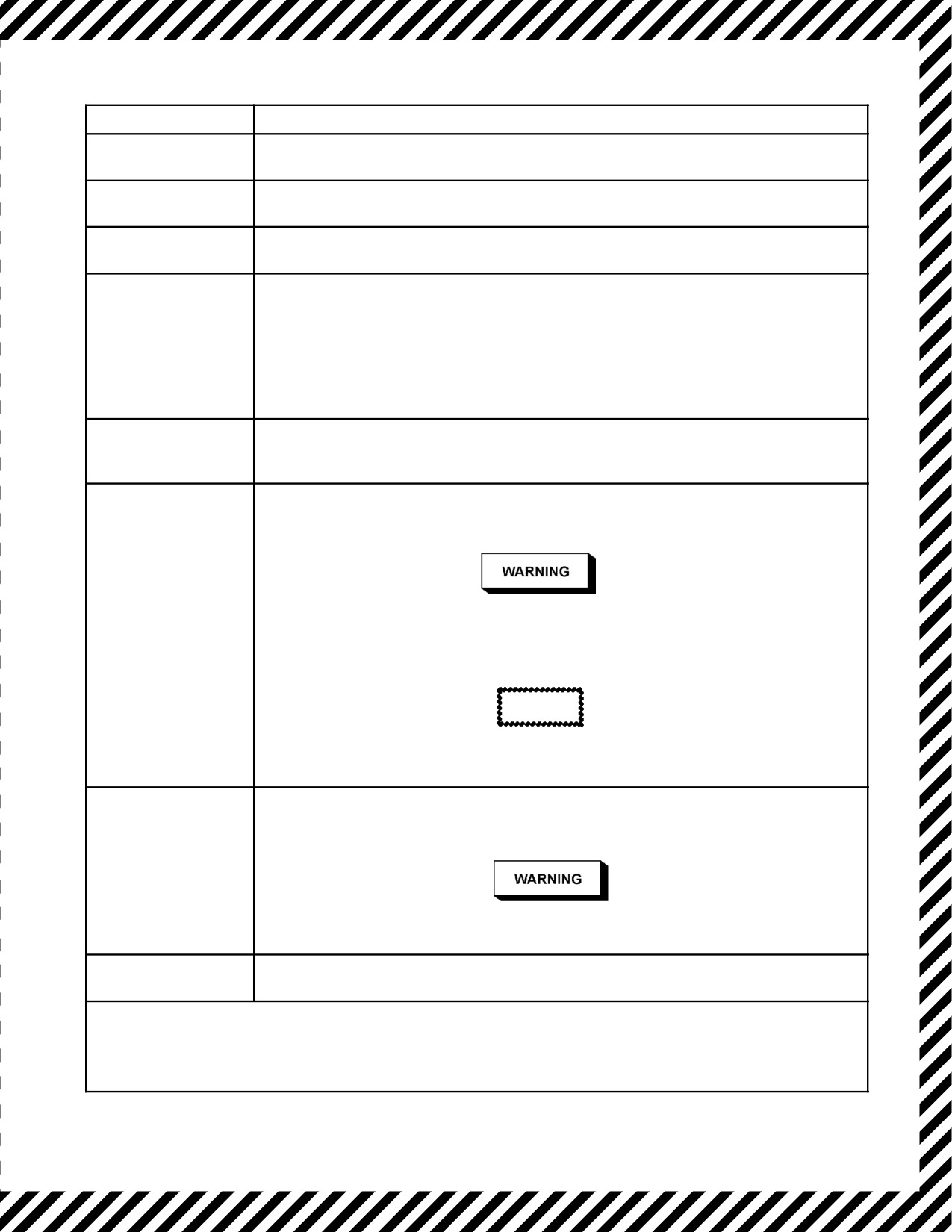
11. Perform Isolated Dc Bus Isolation Procedures (see Figure 11-5).
11.4.16.1 Bus Isolation Procedure
High voltage is present on the upper main ac distribution panel. Use
extreme caution with the access cover open.
11-45
ORIGINAL

01-75GAL-1
Note
Thebus isolation procedure(seeFigure11-5)should beused asalastresort
when the malfunctioning unit(s) cannot be located, but the malfunctioning
bus is known. The purpose of this procedure is to allow a return to normal
operation oftheunaffected buses. Ifabus must beisolated, refertoChapter
2 to ascertain which systems have been lost.
11.4.17 Cargo Compartment Refrigerator Overheat Warning Light
When the cargo compartment refrigerator overheat warning light illuminates, immediate steps to correct the overheat
must be taken as follows:
1. Cargo Compartment Air Conditioning Shutoff switch — OFF (FE).
2. UNDERFLOOR HEAT switch — OFF (FE).
If the warning light does not go out within approximately 1 minute:
3. Bleed-air divider valve — CLOSED (FE).
4. No. 3 and No. 4 ENGINE BLEED AIR switches — OFF (FE).
This will isolate the ducts to the cargo compartment and should eliminate the overheat condition.
CAUTION
It is not recommended that any air valve be reopened once it has been closed
for an overheat condition. Damage to the warning system may prevent
detection of a subsequent overheat condition.
11.4.18 Bleed-Air Ducting Failure/Overheat Detection System (ODS) Warning Lights
A rupture of the bleed-air manifold may be indicated by illumination of ODS indicator lights with corresponding
audible warning, and/or simultaneous loss of torque on all engines supplying bleed air, depending on the location
of the rupture. Additional indications may include the master fire warning light, an unsafe gear indication, or visible
evidence of fire in the wheelwell or wing area. If a combination of these conditions indicates a bleed-air duct failure,
proceed as follows:
If bleed-air ducting failure or ODS warning occurs, the aircraft shall be
landed as soon as possible regardless of the apparent success of the
corrective action.
ORIGINAL
11-46
01-75GAL-1
BUS
ISOLATION PROCEDURE
LH Ac
Remove the three LH ac bus power current limiters at the upper main ac distribution
panel.
RH Ac
Remove the six current limiters (three RH ac bus power and three deicing power) at
the upper main ac distribution panel.
Main Ac
Remove the three main ac bus power current limiters at the upper main ac distribution
panel.
Main Dc
Pull the six MAIN DC BUS TRANS RECT circuit breakers on the copilot upper circuit
breaker panel and the DC MAIN BUS GRD CONT circuit breaker on the copilot lower
circuit breaker panel.
Note
When pulling the TR circuit breakers, pull all three circuit breakers in A, B, C, order
for one TR unit, then pull all three circuit breakers in A, B, C, order for the other TR
unit.
Essential Ac
Pull the nine essential ac bus power circuit breakers at the upper main ac distribution
panel and the nine essential ac bus power circuit breakers on the pilot side circuit
breaker panel.
Essential Dc
Pull the six MAIN DC BUS TRANS RECT circuit breakers on the copilot upper circuit
breaker panel and the six DC ESS BUS TR 1 and TR 2 circuit breakers on the pilot
side circuit breaker panel. Do not tie the bus tie switch after landing.
Anytime power is removed from the essential dc bus, the engine bleed-air
regulators will close, shutting off airflow to both air-conditioning units, thus
depressurizing the aircraft.
CAUTION
Prior to pulling the essential DC BUS TR circuit breakers, ensure that the OIL
COOLER FLAP switches are OPEN and FIXED.
Isolated Dc
Pull the six MAIN DC BUS TRANS RECT circuit breakers on the copilot upper circuit
breaker panel, the six DC ESS BUS TR 1 and TR 2 circuit breakers on the pilot side
circuit breaker panel, and turn the dc power switch to the OFF position.
On aircraft prior to 164993, anytime power is removed from the isolated dc bus,
there will be no power for the ADI regardless of the power source selected.
Battery Bus
The battery is powered anytime the battery is connected. There is no isolation
procedure for the battery bus.
Note
Any time the Main AC BUS TRANS RECT and DC ESS BUS TR circuit breakers have been pulled as a
method of isolating a dc bus, the battery is powering the remaining dc buses and is not being charged from
the ac buses.
Figure 11-5. Bus Isolation Procedure
11-47
ORIGINAL

01-75GAL-1
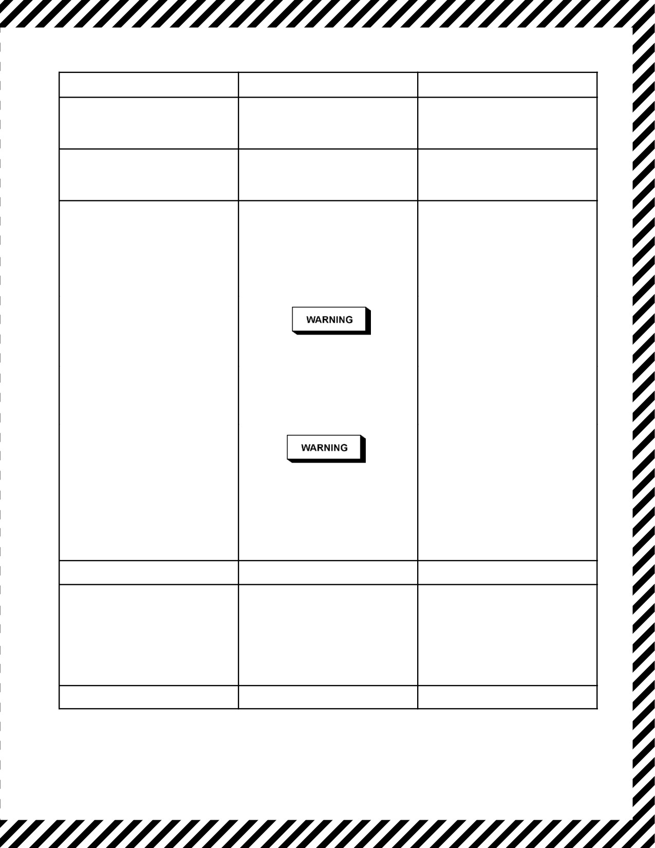
1. Isolate the affected duct. For ODS warning alarm, see Figure 11-6.
If leaky duct cannot be determined, proceed as follows:
2. Close the bleed-air divider valve and shut off wing bleed air to isolate the leak.
D Positive closing of the engine bleed-air regulators must be determined by
observing torqueincreasewhen closing thecorresponding enginebleed-air
valve.
D If an engine bleed-air regulator fails to close, it may be necessary to follow
Engine Shutdown Procedures (paragraph 11.1.2) for that engine to prevent
fire in the area of the leaking or blown duct.
If suspected wing cannot be isolated or ODS warning alarm persists, proceed as follows:
3. Shut off engine bleed air for all engines.
Shutting off all engine bleed air will shut off air supply to both
air-conditioning units and depressurize the aircraft.
CAUTION
Do not re-open any bleed-air valve or operate any affected system until the
cause of the malfunction has been determined. Damage to the warning
system may prevent detection of a subsequent overheat condition.
Note
It may take some time for ODS sensing elements to cool.
4. If visible evidence of a fire exists, those crewmembers not required to control the aircraft shall immediately
begin to fight the fire. Perform Fuselage Fire/Smoke and Fume Elimination procedures (paragraph 11.4.15).
5. If structural damage is suspected, perform in-flight controllability check, paragraph 11.7.1. Land as soon as
possible.
ORIGINAL
11-48
01-75GAL-1
ALARM SIGNAL
ACTION REQUIRED
SYSTEMS AFFECTED
1. Left Wing Area
1. Isolate Left Wing.
LH Wing and Empennage Anti-icing,
Auto Pressurization, Flight Station Air
(LH OUTER, LH CENTER, LH INNER
Conditioning.
WING Indicator Lights)
2. Right Wing Area
1. Isolate Right Wing.
RH Wing Anti-Icing, Underfloor Heating,
Cargo Compartment Air Conditioning.
(RH OUTER, RH CENTER, RH INNER
WING Indicator Lights)2
3. TRANSFUSELAGE and FWD
1. Isolate Left Wing.
FUSELAGE Indicator Lights
2. If it can be positively determined
With LH wing isolated, same as
that the overheat condition
Alarm 1.
originated from the small section
right of the bleed-air divider
valve, restore bleed air to the left
wing, then isolate the right wing.
With RH wing isolated, same as
Alarm 2.
Bleed air is extremely hot, use
caution during inspection.
3. If previous actions do not correct
the situation, close all bleed-air
valves and the bleed-air divider
valve.
Shutting off all engine bleed air
will shut off air supply to both
air-conditioning units and depres-
surize the aircraft.
Note
It may take some time for the
element to cool.
4. AFT FUSELAGE Indicator Light
1. Isolate Left Wing
Same as Alarm 1.
5. APU Indicator Light
During ground operation:
During ground operations, APU bleed
air will not be available.
1. Close APU BLEED AIR VALVE
and isolate the left wing.
Other systems same as Alarm 1.
During flight:
1. APU fire handle — PULL.
During flight, same as Alarm 1.
2. Isolate Left Wing.
6. AIR CONDITION Indicator Light
1. Isolate Right Wing.
Same as Alarm 2.
Figure 11-6. ODS Warning Alarm Procedures
11-49
ORIGINAL

01-75GAL-1
11.4.19 Emergency Operation of Cabin Pressurization System
Two types of pressurization system failures may occur. One type can result only from failure of the outflow valve
in a closed or nearly closed position when it cannot be opened either by automatic ormanual control methods. In this
case, cabin pressure might increase at an excessive rate and could not be reduced by normal means. If this condition
is encountered, proceed as follows:
1. Immediately shut off engine bleed air, oneengine at a time, until therate ofpressure increaseis at a safevalue.
2. Control pressure by using engine bleed air as necessary to vary the amount of conditioned air supplied for
pressurization.
3. If necessary for further control when descending, one of the air-conditioning systems can be shut down to
expedite depressurization of the aircraft.
The other type of pressurization system failure is loss of ability to pressurize or maintain pressurization on either
automatic or manual control and may result from any of several causes. If this situation is encountered, proceed as
follows:
1. The crew should don oxygen masks immediately while instituting a descent.
2. Descend to or maintain an aircraft altitude where oxygen is not required.
3. Check for excessive cabin leakage by checking doors, windows, hatches, and the safety valve.
Do not attempt to lock or unlock any window, door, or hatch while the
aircraft is pressurized. First, depressurize the aircraft, then turn the AIR
CONDITIONING MASTER switch to AUX VENT.
4. Check the bleed-air system for excessive external leakage. Turn off all pneumatic systems and observe the
bleed-air pressure gauge. Shut off all engine bleed air, and time the bleed-air pressure drop from 65 to 35 psi.
The time required for the pressure drop from 65 to 35 psi shall not be less than 30 seconds.
11.4.20 Emergency Operation of Air-Conditioning Systems
If a system is leaking hot bleed air into the aircraft, it shall be shut down immediately. If the system cannot be shut
off because of regulator malfunctioning and it is leaking bleed air, the engine bleed air shall be shut off to depressurize
the bleed-air system.
11.4.21 Emergency Operation of Leading Edge Anti-Icing System
An emergency condition arises if any of the leading edge anti-icing regulators malfunction so that they allow an
overtemperaturecondition. This condition is indicated by theanti-icing temperatureindicators and overheat warning
lights.
ORIGINAL
11-50

01-75GAL-1
11.4.21.1 Wing Leading Edge Overheat
1. Wing anti-icing switch — OFF (FE).
2. If the affected leading edge section temperature indicators do not return to normal readings with system off
or the overtemperature warning light does not go out within approximately 1 minute, close the affected wing
engine bleed air and close the bleed-air divider valve.
D Shutting off all engine bleed air will shut off the air supply to both
air-conditioning units and depressurize the aircraft.
D Prolonged leading edge overheat may result in a wing fire.
3. If anti-icing is necessary, engine bleed air may be used as necessary, providing the leading edge temperatures
do not go above the normal operating range. After landing, an inspection is required for heat damage.
11.4.21.2 Empennage Leading Edge Overheat
1. Empennage anti-icing switch — OFF (FE).
2. If the empennage temperature indicator does not return to normal reading with system off or the
overtemperature warning light does not go out within 1 minute, close the bleed-air divider valve and No. 1
and No. 2 engine bleed air.
Shutting off all engine bleed air will shut off the air supply to both
air-conditioning units and depressurize the aircraft.
3. If anti-icing is necessary, engine bleed air may be used as necessary, providing the leading edge temperatures
do not go above the normal operating range. After landing, an inspection is required for heat damage.
11.4.22 Wing Fire
If a fire develops in the wing, attempt to extinguish, control, or contain the fire as follows:
1. Fuel crossfeed valve switches — CLOSED (FE).
2. Engine hydraulic pumps and suction boost pump for the affected wing — OFF (CP).
3. Bleed-air divider valve and bleed-air valves for engines on that wing — CLOSED (FE).
4. Wing electrical equipment — OFF (FE).
5. If necessary, sideslip the aircraft to keep the fire away from the fuselage (P).
6. Land the aircraft as soon as possible (P).
11-51
ORIGINAL

01-75GAL-1
11.4.22.1 Oxygen Flow Degradation
Thecapability oftheliquid oxygen heat exchangers to provide breathable100-percent oxygen for theentire crew can
be exceeded when large consumption demands are placed on the system. When this occurs, the temperature of the
oxygen to the masks will be lowered markedly and the gas pressure at the oxygen regulators will be reduced. In
extreme cases, a near total lack of oxygen pressure and flow can occur. Reducing or eliminating demand will allow
the system to warm and the flow of oxygen to return to normal.
If oxygen flow degradation occurs, check the oxygen system integrity and immediately reduce the need for oxygen
by performing one or more of the following:
1. Move the diluter levers at the regulators from 100-percent oxygen to normal (if possible).
2. Change altitude to reduce oxygen flow demand (if possible).
3. As a last resort, selectively remove crewmembers from the aircraft oxygen system to the portable oxygen
bottles.
Portable oxygen bottles can provide only temporary relief. They are of
limited capacity and may have to be recharged from the internal aircraft
oxygen system. Recharging portable oxygen bottles while experiencing
oxygen flow degradation will further degrade the flow of oxygen.
11.4.23 In-Flight Door Warning
When the door warning light illuminates, notify crew/passengers and proceed as follows:
*1. Seatbelts — Fastened (ALL).
*2. Oxygen — As Required (ALL).
3. Pressurization — Begin Depressurization (FE).
If any crewmember observes an individual door warning light, the
crewmember will notify the pilot which light has illuminated. If it is not
determined which light illuminated or if the light goes out during
depressurization, the aircraft shall be completely depressurized before
making a door check. If it is determined that the light illuminated for a
paratroop door or a cargo door, complete depressurization will be at the
discretion of the pilot.
4. Descent — As Required (P).
Note
If range is an important consideration, the pilot may elect to have the
flightcrew go on oxygen, the aircraft depressurized, and the door inspection
made at altitude.
ORIGINAL
11-52

01-75GAL-1
5. AIR CONDITIONING MASTER switch — AS REQUIRED (FE).
Do not unlock any door with the aircraft pressurized. After depressuriza-
tion, place the AIR CONDITIONING MASTER switch to AUX VENT.
The flight engineer and loadmaster will check the doors wearing a
parachute or restraining harness. The restraining harness shall be worn to
check the crew entrance door. If it cannot be determined what caused the
door light to illuminate, the flight may be continued with partial
pressurization (below the point where the light illuminates) and with all
personnel secured by a safety belt at the discretion of the pilot. If the doors
are secure and the trouble is determined to be a limit switch, the aircraft may
be fully pressurized.
6.
Doors — Checked (FE) (LM).
a. Cargo door. Ensure the door lock on each side is fully engaged. If fully engaged, check microswitch
integrity at each aft door lock.
b. Cargo ramp. Ensure all 5 locks on each side are fully engaged. If fully engaged, check microswitch integrity
of the adjacent corresponding ramp locks on the end of the ramp.
c. Paratroop door. Ensure all 4 latch pins are fully engaged. If fully engaged, check microswitch integrity on
the upper forward latch pin.
d. Crew entrance door. Ensure the “J” hooks contact the eyebolts. If fully engaged, check microswitch
integrity on the 2 micro switches (1 is located on the door linkage on the bellcrank assembly, and the other
is located on the upper aft edge of the crew entrance door).
7.
Master door warning light switch — OFF (FE) (LM).
Note
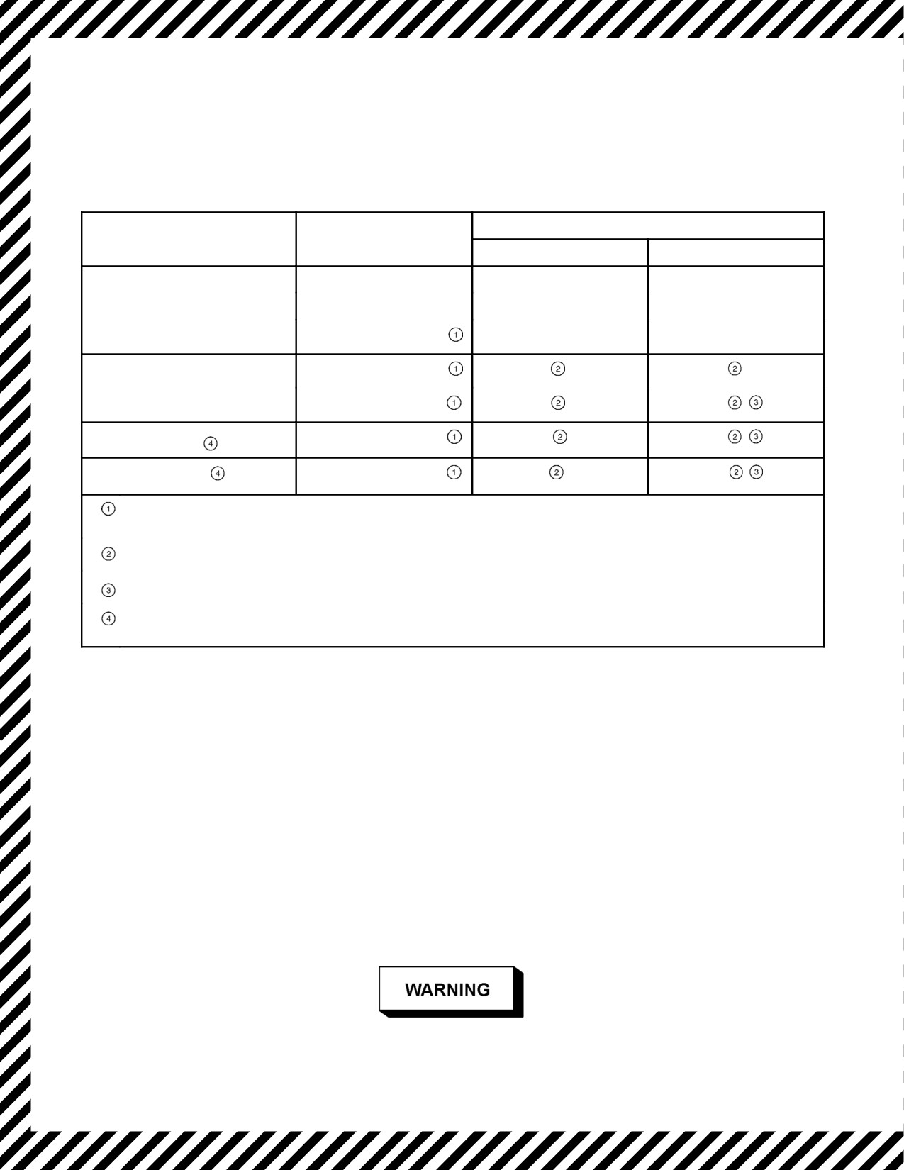
When utilizing the low-pressure portable oxygen bottle, duration will vary
with physical activity level and cabin altitude. See Figure 11-7.
11.4.24 In-Flight Release of Liferaft
If severe vibration occurs in flight, cause unknown, proceed as follows:
1. Airspeed — Reduce (P).
2. Flaps — Extend as required (CP).
3. Visual Inspection — (2LM/LM).
Note
The absence of a liferaft should be noticeable through one of the inspection
windows provided on the lower sides of the liferaft compartments.
11-53
ORIGINAL
01-75GAL-1
If a raft has released and lodged on the tail:
4. Fish tail the aircraft slightly or execute a shallow banking maneuver right or left (P).
5. Land as soon as practical (P).
PHYSICAL ACTIVITY LEVEL
REGULATOR SETTINGS
CABIN ALTITUDE
MODERATE
PASSIVE
Sea level to 12,000 feet
4 Minutes
10 Minutes
12,000 to 20,000 feet
7 Minutes
16 Minutes
NORMAL
20,000 to 30,000 feet
10 Minutes
23 Minutes
30,000 to 40,000 feet
14 Minutes
30 Minutes
30M
40,000 to 42,000 feet
17 Minutes
28 Minutes
42M
42,000 to 45,000 feet
19 Minutes
23 Minutes
EMER
42,000 to 45,000 feet
20 Minutes
20 Minutes
Flight rules governing cargo-passenger aircraft require immediate descent to below 25,000-foot altitude
upon complete loss of cabin pressurization.
These duration times do not provide for leakage around the facemask seal.
Physical stress limit for individuals not conditioned to pressure breathing.
Do not use smoke mask PN 53C3971-1 or PN 651-110 in aircraft designed to operate above 30,000 feet.
Rapid depletion of the MA-1 system will result (less than 1 minute depletion).
Figure 11-7. Portable Oxygen Bottle Duration
11.4.25 Windshield and Window Failure
If the inner or outer pane of the windshield or aft compartment windows crack during flight:
1. Cabin differential pressure — 10 inches of mercury or less (FE).
If both panes of the windshield crack:
2. Continue at 10 inches of mercury or less (FE).
If both panes of an aft compartment window crack or a wing leading edge light lens cracks:
3. Cabin differential pressure to zero (FE).
With NESA anti-icing inoperative, limit aircraft speed to 187 KIAS below
10,000 feet.
ORIGINAL
11-54

01-75GAL-1
11.4.26 Rapid Decompression
If pressure loss is uncontrollable, notify crew and proceed as follows:
*1. Oxygen — ON/100 percent (ALL).
*2. Pressurization — As Required (FE).
*3. Descent — As Required (P).
D A crewmember should make an inspection of the fuselage during descent
(using a walk-around oxygen bottle and wearing a parachute or restraining
harness) to determine what caused the decompression and the extent of any
damage.
D With certain types of structural damage, changing the center of lift with the
flaps may induce further damage. Consider the type of damage prior to
changing aircraft configuration.
CAUTION
Type of descent is dependent upon degree of structural damage; use rapid
descent (gear and flaps up) without structural damage, or rapid descent
(gear and flaps down) when structural damage necessitates. If pressure loss
occurred because of structural failure, the flight will be completed at a safe
speed determined by the pilot. Any suspected or known structural failure
may cause aircraft control problems and will require a check of aircraft
controllability prior to landing.
4. EPOS/VRU — AS REQUIRED (LM).
11.4.27 Hydraulic Systems Failure
If the utility, boost, or auxiliary hydraulic systems fail, the equipment served by that system can be operated either
by an alternate source of hydraulic power or by means of mechanical linkage. The only exceptions are the nosegear
steering system and the antiskid system, for which there are no alternates. Hydraulic system failures are discussed
in the following paragraphs.
11.4.27.1 Hydraulic System Warning Lights
Hydraulic system warning lights will illuminate for a loss of system pressure and/or an engine-driven pump failure.
The engine-driven hydraulic pump is geared to the gearbox of the engine, and if the shear neck of the pump drive
spline does not separate, the pump can generate enough heat to cause a fire. Because of this hazard, pilot discretion
should be exercised as to the need of continued engine operation.
11-55
ORIGINAL

01-75GAL-1
1. Switches for the affected system — OFF (CP).
CAUTION
When an engine-driven hydraulic pump warning light is illuminated with
a visible hydraulic leak on the engine nacelle, an engine shutdown is
necessary.
2. Check fluid level in reservoir (LM).
3. Isolate unit causing trouble, if possible.
If unit is isolated:
4. Restore system pressure.
If unit cannot be isolated:
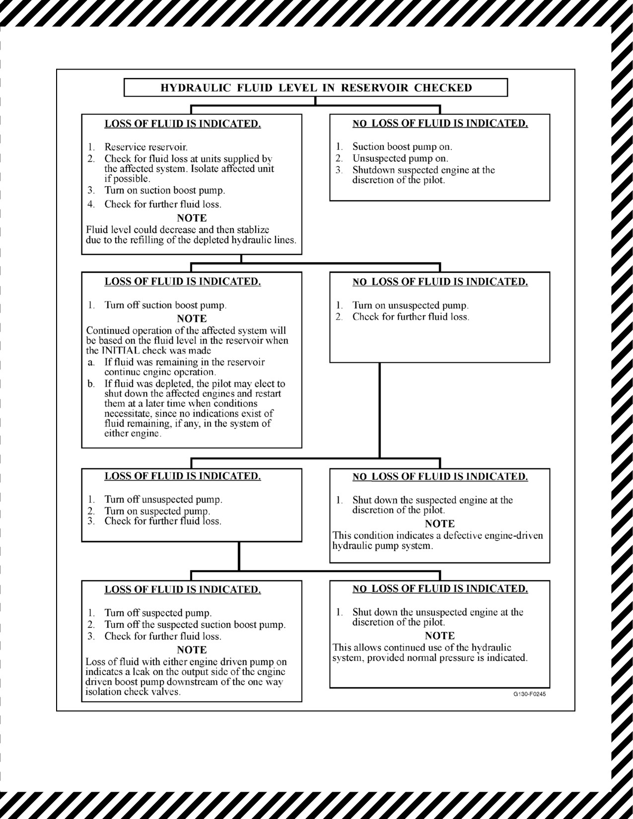
5. Refer to Figure 11-8.
6. Switches for affected system — As Required (CP).
11.4.27.2 System Overpressure
If the pressure of the utility or booster hydraulic system is greater than 3,500 psi, proceed as follows:
CAUTION
Do not place any hydraulic pump switches to the OFF position.
1. Check the direct reading gauge on the affected hydraulic accumulator sight gauge in the cargo compartment.
2. Check the fluid level of the affected system. Check for boiling or spewing.
3. If fluid loss is noted or system pressure is above 3,900 psi, shut down either engine of the affected system
in accordance with the cruise engine shutdown procedure.
Note
D Utility or booster hydraulic pressure in excess of 3,900 psi indicates failure
of an engine driven pump pressure regulating system and that the
associated hydraulic system relief valve is in the full open position.
D Thereis no method to determinewhich pump is thesource ofoverpressure.
Shut down one engine, beginning with the inboard engine. If the
overpressure is not corrected, restart the secured engine and shut down the
other engine with the condition lever.
11.4.27.3 Electric Suction Boost Pump Failure
In-flight loss of hydraulic boost pump operation will be indicated by illumination of the suction boost pump
pressure-off light and the only noticeable difference in hydraulic system operation will be that pressure will drop
approximately 100 to 200 psi below normal and that additional time will be required to cycle controls.
ORIGINAL
11-56
01-75GAL-1
Figure 11-8. Hydraulic Fluid Level Check
11-57
ORIGINAL

01-75GAL-1
Should the suction boost pump warning light illuminate:
1. Immediately turn off all pumps for the affected system only.
2. Check the hydraulic fluid level in the reservoir.
a. If loss of fluid is indicated, perform the Hydraulic System Warning Light procedure, paragraph 11.4.27.1.
b. If no loss of fluid is indicated:
(1) Check pump motor for an overheat condition or, if the boost pump has failed internally resulting in
noisy operation, leave suction boost pump off.
(2) Turn on both engine-driven hydraulic pumps and continue flight.
11.4.27.4 Utility System Failure
Failure of the utility hydraulic system will result in loss of normal landing gear extension and retraction, flap
retraction and normal extension, normal brake supply, nosewheel steering, antiskid, in-flight refueling reel control,
and half the power supplied to the flight controls. In each case, alternate provisions are made for essential operations,
see Landing Gear System Failure, Flap System Failure, Flight Controls System Failure, and Brake System Failure
in this chapter.
11.4.27.5 Booster System Failure
Failure of the booster hydraulic system affects only the flight controls systems. See Flight Controls Systems Failure
for information on emergency management.
11.4.27.6 Auxiliary System Failure
Failure of the motor-driven pump in the auxiliary hydraulic system results in the loss of hydraulic pressure for normal
in-flight operation of the cargo door, loss of electrically controlled emergency hydraulic pressure for emergency
brakes, and loss of electrically controlled emergency hydraulic pressure for extension of the nose landing gear. If
circumstances require opening the cargo door, supplying emergency brake pressure manually, or lowering the nose
landing gear without electrically controlled hydraulic system pressure, the handpump may be used. If both utility and
auxiliary pressure are lacking for the brakes, stopping and taxiing control must be accomplished with reverse thrust,
differential power application, and normal and emergency system accumulator. Stop the aircraft as soon as possible.
Taxiing the aircraft under its own power without brakes is not recommended.
11.4.27.7 Flight Control Systems Failure
Never purposely remove the hydraulic assistance from the flight control
boosters to simulatecompleteloss ofboost assistancetotheflightcontrols.
To remove the assistance would result in an immediate pitch change and
the requirement for high manual forces to move the flight controls.
Note
If a hydraulic leak develops in any of the flight control booster units, it may
be isolated by placing the respective control boost shutoff valve switch to
the OFF position.
ORIGINAL
11-58

01-75GAL-1
Failure of only one control booster unit may indicate a leak or other malfunction within the unit. It should be examined
immediately, if possible, to determine corrective action. Loss of hydraulic assistance for movement of the flight
controls will result in loss of ability to move these controls in flight, except at low airspeeds. Maneuvering the aircraft
at cruising speeds under these conditions must be accomplished with the trim tabs. Landing the aircraft without
hydraulic assistance is a marginal operation and requires skillful handling of the trim tabs and engine power, plus
coordinated efforts of the pilot and copilot on the flight controls. When possible, avoid crosswinds, short fields, or
narrow runways since the chances of making a successful landing will be decreased. When a landing without
hydraulic assistance for the flight controls is necessary, proceed as follows:
1. Reduce the weight of the aircraft as much as possible.
2. With elevator hydraulic assistance failure, land with minimum flaps.
3. Make a long, flat approach to reduce the amount of flaps necessary and fly the aircraft onto the ground.
4. After landing, use reverse thrust with caution to prevent loss of directional control as nosewheel steering is
not available.
If a control boost unit is suspected of having failed in a hard-over position,
turn the respective control boost switches to OFF (verified by the cockpit
control matching the hard-over maneuver being experienced). Greatly
increased forces will be required to move the control for which the
hydraulic assistance has been turned off.
11.4.27.8 Elevator Failure
If elevator control should fail (hydraulic assistance lost) or become erratic, the elevators can be moved manually but
only at a reduced airspeed and with greatly increased effort. Increasing airspeeds will require increased pilot effort
on the controls. The use of inboard engines will facilitate pitch changes. Adding power on the inboard engines will
cause the aircraft to pitch up, and reducing power will have the opposite effect. Leaving the inboard engines at a
constant power setting and increasing power on the outboard engines will allow for an increase in airspeed with
minimal change in pitch attitude, and reducing power on the outboards will have the opposite effect.
11.4.27.9 Aileron Failure
The ailerons are powered concurrently by both the utility and the booster hydraulic system. Should both hydraulic
systems fail, the ailerons can be moved manually but only at a reduced airspeed and with greatly increased effort.
Increasing airspeeds will require increased pilot effort on the controls.
11.4.27.10 Rudder Failure
The rudder is powered concurrently by both the utility and booster hydraulic system. Should both hydraulic systems
fail, the rudder can be moved manually but only at a reduced airspeed and with greatly increased effort. Increasing
airspeeds will require increased pilot effort on the controls.
11-59
ORIGINAL

01-75GAL-1
11.4.27.11 Aileron Trim Tab System Failure
Failure or “run away” of the aileron trim tab will not cause a serious control problem. Should the aileron trim tab
“run away,” proceed as follows:
1. Hold the AILERON TRIM TAB switch in the opposite direction (P).
2. Pull the AILERON TRIM TAB circuit breaker on the pilot side circuit breaker panel (FE).
11.4.27.12 Rudder Trim Tab System Failure
Directional control cannot be maintained at high airspeeds if the rudder trim tab runs away to an extreme position.
If this occurs, airspeed should be reduced until directional control is regained. Should the rudder trim tab run away,
proceed as follows:
1. Hold the RUDDER TRIM TAB switch in the opposite direction (P).
2. Pull the RUDDER TRIM TAB circuit breaker on the pilot side circuit breaker panel (FE).
11.4.27.13 Elevator Trim Tab System Failure
In the event of runaway elevator trim:
1. Elevator trim tab switch — Trim Opposite (P/CP).
2. Elevator Tab Power Switch — OFF (P/CP).
3. Elevator Tab Power Switch — EMER (P/CP).
If condition persists:
4. Elevator Tab Power Switch — OFF (P/CP).
Note
D The elevator tab switches on the control wheels will not operate the
emergency system. Emergency operation is controlled only by the
pedestal-mounted switch.
D When the autopilot operation and the ELEV TAB power selector switch are
in the OFF or EMER position, the elevator servo is disconnected from the
autopilot and the elevator must be controlled manually.
D If failure results in uncontrollable nose-up condition, slow aircraft in a turn
extending flaps as structural limits permit. For uncontrollable nose-down
condition, reduce power and airspeed to reduce force required to overpower
trim condition and maintain control.
11.4.27.14 Flap System Failure
Flap system failures may be classified as follows: electrical control system failure, failure of the utility hydraulic
system, an asymmetrical positioning of the wing flaps, or a cocked flap causing obstructions to aileron movement.
The flap system is normally powered by theutility hydraulicsystem and is controlled electrically. Protection against
ORIGINAL
11-60

01-75GAL-1
asymmetrical extension or retraction (with the exception of binding and component failure) of the flaps is provided
only when Main dc power and utility hydraulic pressure are simultaneously available for the flap acuation system.
Amanually operated wing-flap selectorvalve, located on theleft hydraulicpanel in thecargo compartment, provides
flap control if the flap electrical control system fails. Also, a system is provided for mechanical operation of the flaps
in the event that utility hydraulic pressure is lost.
11.4.27.15 Flap Electrical Control Failure
If the WING FLAP CONTROL circuit breaker is in or if resetting the WING FLAP CONTROL circuit breaker does
not clear the trouble:
1. Pull the WING FLAP CONTROL circuit breaker.
2. Place the flap handle in the desired position (this will give proper rudder boost pressure).
3. Station a crewmember at the forward face of the left wheelwell, and establish communications with the flight
station by means of an intercommunication extension cord.
4. Remove the left-hand hydraulic panel cover and remove the electrical connector from the flap selector valve.
5. Reset the WING FLAP CONTROL circuit breaker to prevent unnecessary loss of asymmetrical protection.
6. Depress the raise or lower button on the flap selector valve for about 1 second so the flaps move only at an
increment of about 10 percent. Proceed with successive increments only if there is no change in roll trim and
as directed by the pilot.
Failure of the flaps to move may be caused by asymmetry protective
actuation of the emergency flap brakes, which must not be released in
flight. Such asymmetric protection will not be available if electrical power
through the WING FLAP CONTROL circuit breaker is lost or if a bad
connection occurs in the asymmetry detection circuit. Therefore, should a
change in trim about the roll axis occur during any flap actuation, do not
attempt any further in-flight movement of the flaps.
11.4.27.16 Loss of Hydraulic Pressure
Normal operation of the flaps will cause a loss of utility hydraulic pressure as long as the flaps are in motion. A leak
in the flap system hydraulic plumbing will be indicated by a rapid loss of pressure while the flaps are operating and
by slower than normal flap movement. Under these conditions, proceed as follows:
1. Ensure the flap levercorresponds to the flap position and place theutility hydraulicpump switches to theOFF
position.
2. Pull the WING FLAP CONTROL circuit breaker on the copilot lower circuit breaker panel.
3. Remove the utility hydraulic panel cover and establish communications between the flight station and a
crewmember stationed at the forward face of the left wheelwell.
4. Turn on the utility hydraulic pumps one at a time, while making an inspection for plumbing leaks, breaks, and
any other faults.
11-61
ORIGINAL

01-75GAL-1
If fault is corrected:
5. Reset the WING FLAP CONTROL circuit breaker and proceed with normal flap operations.
If fault is not corrected:
6. Place the utility hydraulic pump switches to the OFF position and deplete the utility system pressure.
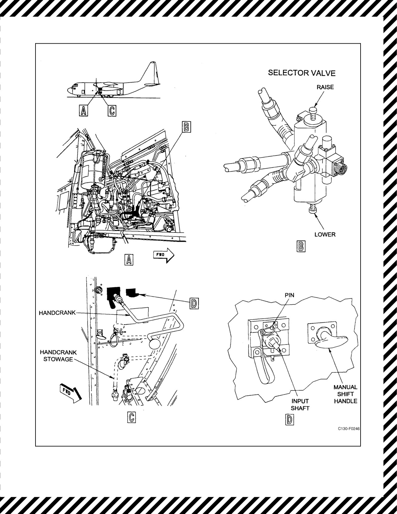
7. Remove the handcrank (see Figure 11-9) from the stowed position in the special equipment compartment.
Engage the handcrank on the input shaft and hold the crank firmly to prevent rotation.
8. Remove the pin from the input shaft. It may be necessary to rotate the crank slightly in either direction to relieve
binding on the pin.
9. Pull the manual shift handle(see Figure11-9) to its stop, then rotatethe manual shift handlecounterclockwise
against its stop to engage the manual extension system. The handle will lockout after it is pulled.
10. Operate the flaps to the desired position (approximately 650 turns for full extension) as shown on the flap
position indicator. A slip clutch is provided in the manual gearbox to prevent the operator from overloading
the drive system. Slippage of the clutch indicates the screwjack nuts are bottomed and the flaps are full up or
full down or that interference will not permit flap operation.
Protection against asymmetrical operation is provided only during normal
hydraulic flap operation. Should a failure of the flap drive torque tubes
occur during manual operation, resulting in a change in trim about the roll
axis, stop flap movement immediately. Manually return the controllable
flaps to the position assumed by the uncontrollable flaps.
11. Replace the pin in the input shaft to hold the flaps in the selected position.
12. Remove the crank and return to the stowed position.
13. Leave the manual shift handle out.
14. Turn the No. 1 and No. 2 engine-driven hydraulic pumps on if available and no leaks are evident.
11.4.27.17 Shift From Manual to Hydraulic Flap Drive
The shift from manual back to hydraulic drive after an actual in-flight failure normally would be accomplished on
the ground. However, after practicemanual extension or recovery of hydraulicpressure, usethe following procedure
to shift back to hydraulic drive:
1. Rotate the manual shift handle clockwise against its stop and push the handle back in place to disengage the
manual extension system (LM).
2. Remove the pin in the input shaft and then rotate the shaft with the handcrank. The shaft should turn freely,
indicating that the manual drive has disengaged (LM).
3. Replace the pin in the input shaft and remove the handcrank and return it to the stowed position (LM).
4. Place the flap lever to correspond with the position of the flaps (CP).
ORIGINAL
11-62
01-75GAL-1
Figure 11-9. Wing-Flap Emergency Controls
11-63
ORIGINAL

01-75GAL-1
5. Reset the WING FLAP CONTROL circuit breaker (FE).
CAUTION
When the wing-flap control lever is first moved after shifting from manual
tohydraulicactuation,observetheutilityhydraulicsystempressureandthe
wing-flap position indicator. A drop in pressure with no result in flap
movement indicates failure of the flap drive to re-engage. If this happens,
immediately return the wing-flap lever to its original position and pull the
WING FLAP CONTROL circuit breaker. If these steps are not observed,
serious damage to the wing-flap drive could result.
11.4.27.18 Flap Selector Valve Failure
If the flap selector valve fails because of internal leakage, as indicated by a continuous cycling of the flaps, the
following steps should be accomplished:
1. Deplete the utility system pressure by turning the utility system pumps off and cycling the flight controls.
2. Disconnect the electrical connector plug from the flap selector valve.
3. Rotate the manual shift handlein thecargo compartment counterclockwise to its stop and pull (approximately
2 inches) to engage the manual extension system.
4. Restore pressure to the utility system.
5. When needed, crank flaps up or down as desired. Asymmetrical flap protection is available because of the flap
hydraulic system being pressurized.
11.4.27.18.1 Split Flap/Asymmetrical Flaps Procedures
During normal flap operations, failure of certain components or binding in the jackscrew of one side ofthe wing flap
area may cause a split-flap or asymmetrical flap condition. This condition will most likely be accompanied by a
change in flight characteristics affecting the aircraft roll controls. In the event of an asymmetrical flap condition, the
following actions shall be taken:
1. If there is a change in characteristics — Evaluate controllability.
a. If aircraft is controllable — Do not move flaps.
b. If aircraft is uncontrollable — Move the functional flaps in 10 percent increments toward the same
deflection of non-functional flaps to obtain as close symmetrical flap condition as possible. Maintain safe
airspeeds corresponding to these flap positions.
2. Ifthereis no changein flight characteristics affecting aircraft attitude about the roll axis — Reposition theflap
lever to correspond to the flap position.
3. No further in-flight movement of the flaps should be attempted.
ORIGINAL
11-64

01-75GAL-1
D During flap movement, check aileron control constantly. If it is noted that
binding increases, stop the flap movement immediately.
D Should flap movement stop before the flaps have reached the position
desired, failure of the flaps to move in either direction may be the indication
of either having a total utility hydraulic failure, or the engagement of the
emergency flap brake. While the aircraft is in flight, do not release the
manual override on the emergency flap brake valve after an asymmetrical
condition of the flap. This override is for ground use only.
D A controllability check shall be performed prior to any changes in aircraft
speed or configuration.
11.4.27.19 Wing-Flap Position Indicator Failure
If no change in flap position is shown on the wing-flap position indicator after movement of the flap lever, the trouble
may be in the indicator rather than in the flap system. This trouble may be identified by observing hydraulic pressure
and by observing the pitch attitude of the aircraft. Immediately after selecting a change in flap position, a pressure
drop in the utility hydraulic system indicates either that the flaps are moving or that there is a hydraulic leak or failure
in the actuating system. If the flaps are moving, this will be indicated by a change in the pitch attitude of the aircraft.
During flap extension, the pilot may direct a crewmember to make a visual inspection of the flap position. Also, while
inthecargocompartment,checktheTABSANDFLAPSPOSITIONINDICATORcircuitbreakerontheaftfuselage
junction box.
11.4.28 Landing Gear System Failure
Emergency operation of the landing gears is accomplished by means of the landing gear lever, overriding controls,
and manually actuated controls.
Note
Pressure-sealed doors are provided in the wheelwell bulkheads to permit
access while in flight to inspect the two gearboxes and hydraulic brake
assemblies and the vertical torque shafts in the event of a malfunction of
the MLG system. A nose landing gear inspection window is provided to
permit visual inspection in flight. The emergency extension handcranks fit
the nuts on the MLG pressure-sealed doors and on the NLG inspection
window. Depressurize the aircraft before removing the pressure-sealed
doors or windows.
11.4.28.1 Emergency Extension
If the main and nose landing gears fail to extend after normal operation of the landing gear control lever, attempt to
identify the malfunction before making further attempts to lower the gear. Check circuit breakers, utility hydraulic
pressure, and hydraulic fluid quantity. Check for evidence of hydraulic leaks. If a hydraulic leak is the cause of the
malfunction, further attempts to extend the gear hydraulically may serve only to deplete the utility hydraulic system.
If the fault is not located and there is no evidence of leaks, proceed to lower the gear by emergency operation.
11-65
ORIGINAL
01-75GAL-1
11.4.28.2 Overriding the Utility Hydraulic Control Valve
If the landing gears fail to extend while using utility hydraulic system pressure because of failure of the control valves
to operate(no evidenceofhydraulicpressureloss), proceed to extend them by overriding theutility hydrauliccontrol
valve.
1. Pull the LANDING GEAR CONTROL circuit breaker located on the copilot lower circuit breaker panel.
2. Place the landing gear lever in the DOWN position.
3. Directacrewmembertoestablishcommunicationswiththeflightstationbymeansoftheintercommunications
extension cord and go to the left wheelwell.
4. Remove the left hydraulic panel cover.
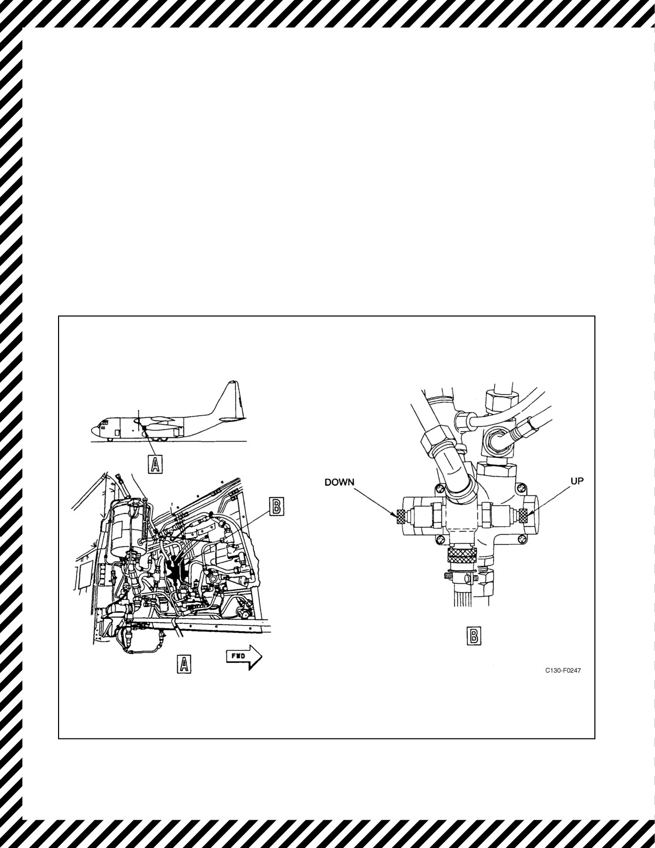
5. Depress the down button on the aft side of the landing gear selector valve (see Figure 11-10) to lower the
landing gear.
Figure 11-10. Landing Gear System Selector Valve
ORIGINAL
11-66

01-75GAL-1
CAUTION
D If the landing gear does not extend, depress and hold the down button until
the main and nose landing gear are extended. If thebutton requires holding
to lower the gear, the mechanical detent in the landing gear selector valve
has failed.
D If the nosewheel steering is required, the button must be held in. If
nosewheel inspection window is removed, do not allow it to be blown
through the opening.
Note
The landing gear position indicators should continue to operate regardless
of landing gear malfunction. The pilot should inform the crewmember
when a down position is indicated so that the crewmember will know when
to release the manual override button. If a malfunction of the landing gear
position indicator is suspected, observe the main landing gear position
through the glass panels on the wheelwells and the nosegear position
through the nosewheel inspection window.
6.
If the landing gear does not extend following depression of the down button, the landing gear selector valve
may still be powered. Remove the cannon plug and repeat steps 1 through 5.
D Do not reattach the cannon plug until the aircraft is on jacks.
D With certain malfunctions, normal brakes may not function.
11.4.28.3 Manual Gear Extension
If the landing gear fails to extend and lock after the manual override control valves are used, manually extend the
gear as follows:
1. Pull the LANDING GEAR CONTROL circuit breaker located on the copilot lower circuit breaker panel.
2. Place the landing gear control handle in the DOWN position.
3. Deplete the utility hydraulic pressure by turning off the No. 1 and No. 2 engine-driven hydraulic pumps,
suction boost pump, and operating the flight controls.
11.4.28.4 Main Landing Gear Manual Extension
1. Remove the extension handcrank from the stowed position. Pull the emergency engaging handle (see Figure
11-11)toitsstop,thenrotatetheemergencyengaginghandlecounterclockwisetoitsstop toengagethemanual
extension system. The handle will lock out after it is pulled.
11-67
ORIGINAL
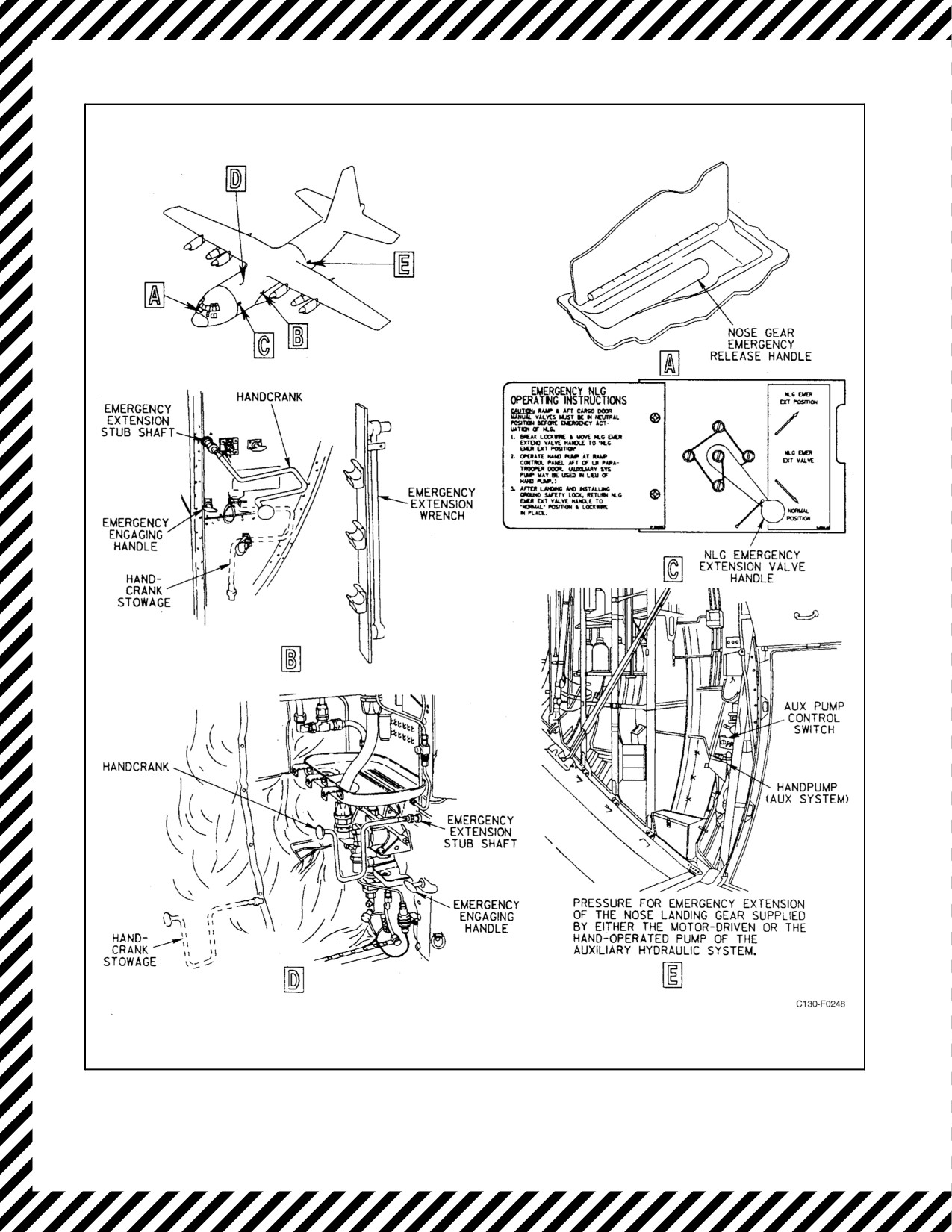
01-75GAL-1
Figure 11-11. Landing Gear Emergency Extension Controls
ORIGINAL
11-68

01-75GAL-1
CAUTION
Do not force the emergency engaging handle out. To do so may result in
a bent manual drive-clutch lever, making it difficult or impossible to
engage the manual drive. It may be necessary to place the extension
handcrank on the emergency extension stub shaft and rotate slightly until
the manual drive gear teeth align.
If determined main landing gear manual drive has engaged proceed to step 4.
If manual drive fails to engage due to cable jamming or failure:
2. Remove the main landing gear hydraulic gearbox access panel located forward and high on the wheelwell wall.
3. Shift main landing gear hydraulic gearbox manual drive-clutch lever from power to manual drive.
If the main landing gear does not free fall:
4. Place the extension handcrank on the emergency extension stub shaft.
5. Extend the landing gear by rotating the extension stub shaft approximately 330 turns in the direction of the
arrow above the shaft.
D Make sure the ratchet on the handcrank is set for down rotation before
placing it on the emergency extension stub shaft.
D If the main landing gear starts to free fall after the handcrank is placed on
the emergency extension stub shaft, immediately remove the handcrank.
The extension handle ratchet may change direction because of the rotation
speed of the emergency extension stub shaft.
6. Make sure the landing gear is down and locked.
7. After manual operation, return the emergency engaging handle to the disengaged position by rotating
clockwise to its stop and pushing in.
8. Verify proper disengagement by rotating the handcrank one turn in each direction.
CAUTION
If landing gear was extended manually due to a utility hydraulic system leak
that was isolated in the landing gear system, DO NOT reset the Landing
Gear Control circuit breaker. Resetting the circuit breaker will result in the
return of the leak and additional fluid loss. With the circuit breaker pulled,
nose wheel steering will not be available.
11-69
ORIGINAL

01-75GAL-1
Note
If the manual extension mechanism does not disengage, pull the emergency
engaging handle again and rotate the handcrank in each direction.
9. Reset the LANDING GEAR CONTROL circuit breaker.
10. TurnontheutilitysuctionboostpumpandNo.1andNo.2hydraulicpumpstoobtainhydraulicpressure(when
available) for operation of flaps, normal brakes, and nosewheel steering.
11. Check that the landing gear stays in the down position.
Note
If the landing gear returns to the up position, place the utility hydraulic
switches in the OFF position and crank the landing gear down manually.
11.4.28.5 Nose Landing Gear Manual Extension
Determine that the manual controls for the ramp and cargo door control valves (see Figure 11-11) are in the 6N and
NEUT positions, respectively. Move the nose landing gear emergency extension valve handle, just aft of the cargo
compartment forward bulkhead on the left-hand side (see Figure 11-11), to the NLG EMER EXT position. Operate
either the auxiliary system hydraulic pump or the auxiliary system handpump until the landing gear is down and
locked.
CAUTION
Do not move the nose landing gear emergency extension valve handle from
the NLG EMER EXT position until after the aircraft lands and the ground
safety lock is installed. Maintain hydraulic pressure on the system.
If complete electrical failure occurs, the nosegear emergency release handle (see Figure 11-11), recessed into the
flight station floor at the left of the copilot seat, may be used to release the nose landing gear uplock. This will permit
the nosegear to free fall to the down, but not necessarily locked, position. Use the auxiliary system handpump to
position the nose landing gear to the down-and-locked position.
Note
Dropping the nose landing gear by using the emergency release handle may
allow air to enter the hydraulic system and may require bleeding before
normal operation can be restored.
11.4.28.6 Emergency Nosegear Extension
1. Position the landing gear handle to the DOWN position.
2. Decrease airspeed to or below 120 KIAS.
3. Pull the nosegear emergency release handle.
Note
The nosegear should extend into the slipstream. Allow the nosegear to
extend until the forward gear door starts to close at a reduced airspeed; this
may require 30 to 45 seconds.
ORIGINAL
11-70

01-75GAL-1
4. Increase airspeed (not to exceed 170 KIAS) as rapidly as possible.
Note
The nosegear should extend to the down-and-locked position.
11.4.28.7 Main Landing Gear Extension After Normal and Emergency System Failure
A malfunction that locks any component of the main landing gear extension system may also lock the remainder of
thesystem. In such acase, iftheloweruniversaljoint companionflanges ontheverticaltorqueshaft aredisconnected,
the landing gear may free fall to the down position. If the landing gear does not free fall, each landing gear strut can
be extended by using the emergency extension wrench. The emergency extension wrench is stowed on a litter
stanchion forward of the left wheelwell bulkhead (see Figure 11-11). Use this procedure to lower the main landing
gear only after all other normal and emergency procedures have failed. See Figure 11-12 for access doors.
CAUTION
Extend the aft strut first. The main landing gear doors are opened by a
mechanical connection to the aft strut, and damage to the doors could result
if the forward strut is extended first.
Note
The vertical torqueshaft lower universal joint companion flanges are
connected by a single-knurled quick-disconnect coupling nut (see Figure
11-12).
1. Leave the main landing gear manual extension system engaged, the utility hydraulic system depleted, and the
LANDING GEAR CONTROL circuit breaker pulled.
2. Depressurize the aircraft. Place the AIR CONDITIONING MASTER switch to AUX VENT.
3. Remove the two polyfoam covers from the forward side of each of the wheelwells.
4. Remove the upper access doors with the emergency extension handcrank.
The weight of the landing gear may cause the gear to extend rapidly when
released. If the above steps are not followed in proper sequence, serious
injury to the hands may result when the gear falls.
5. At the aft strut, cut and remove the two safety wires from the vertical torque strut lower universal joint
quick-disconnect coupling nut.
11-71
ORIGINAL
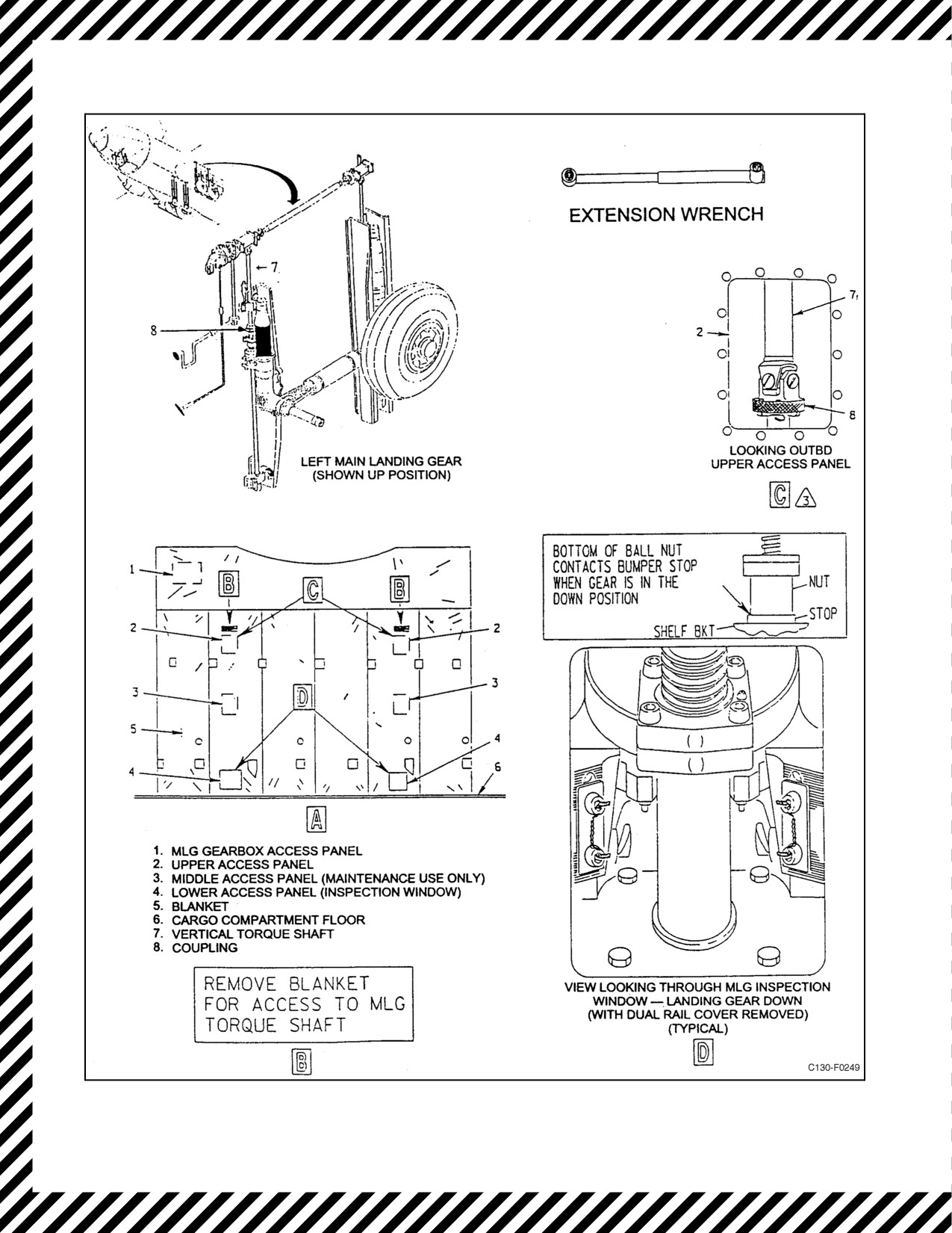
01-75GAL-1
Figure 11-12. Main Landing Gear Access and Tiedown (Sheet 1 of 3)
ORIGINAL
11-72
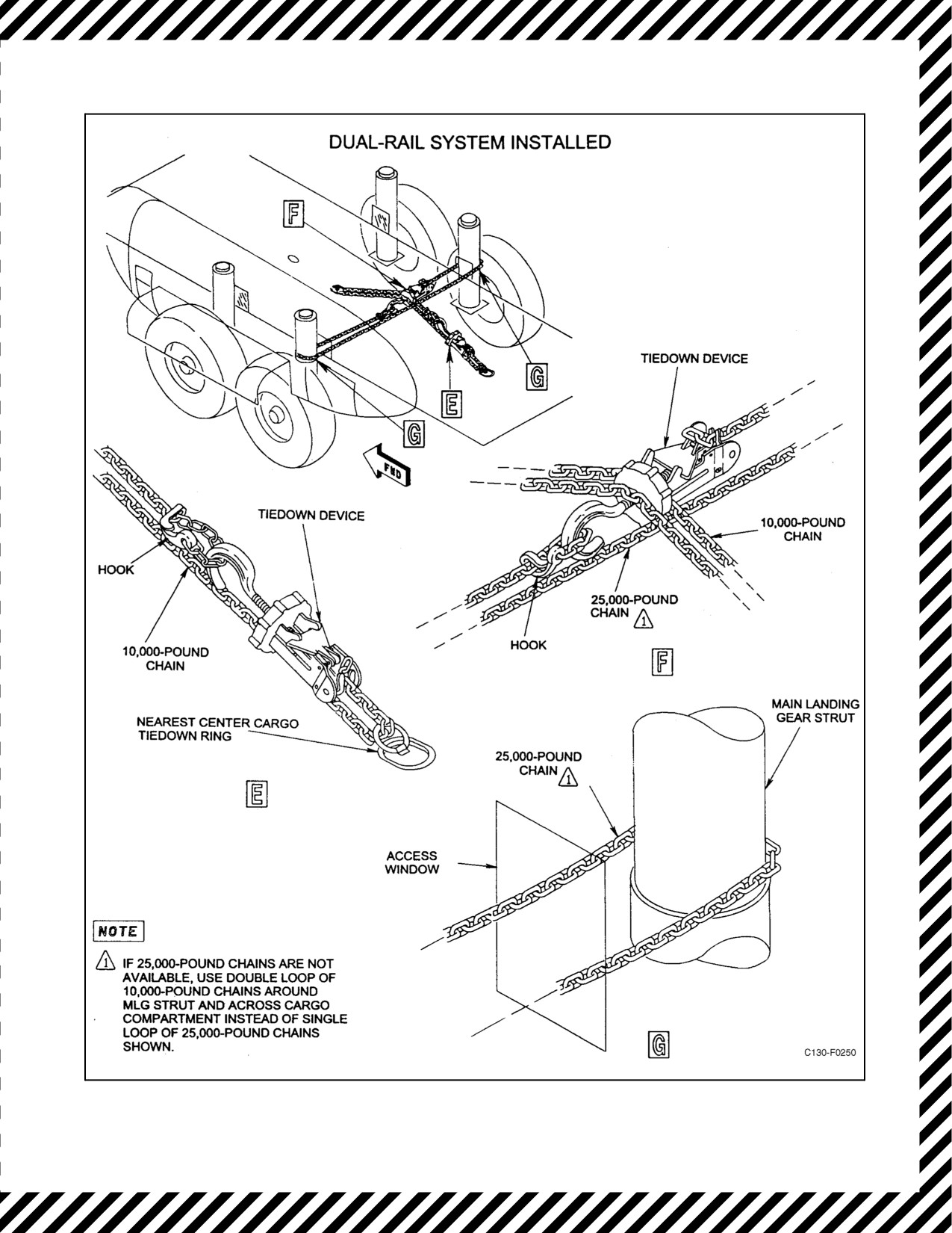
01-75GAL-1
Figure 11-12. Main Landing Gear Access and Tiedown (Sheet 2)
11-73
ORIGINAL
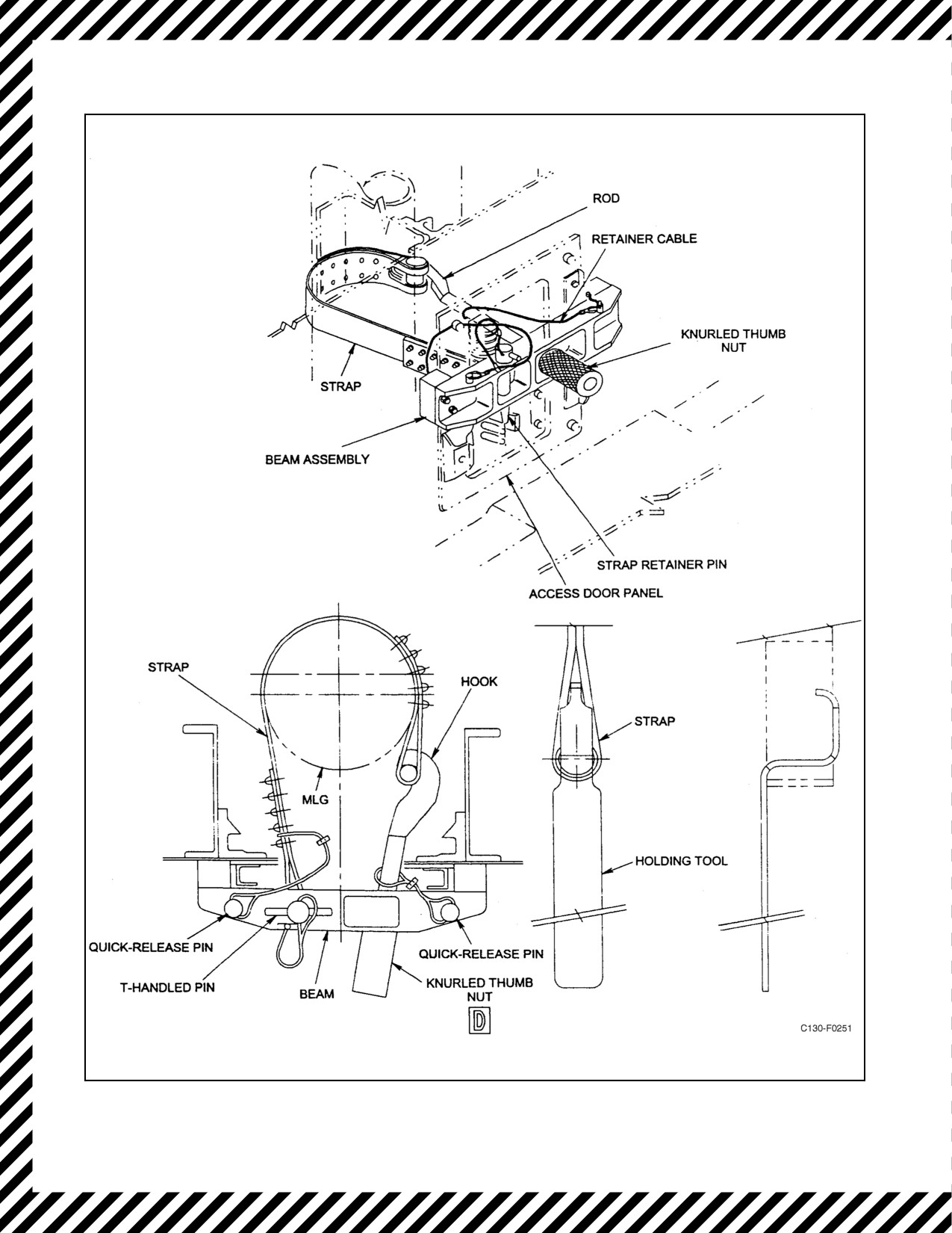
01-75GAL-1
Figure 11-12. Main Landing Gear Access and Tiedown (Sheet 3)
ORIGINAL
11-74

01-75GAL-1
6. Place a screwdriver against the coupling nut lugs and tap counterclockwise to loosen and remove the nut.
Note
One-quarter to one-half turn is sufficient to allow the coupling nut to drop
free of the companion flanges.
7. Place the tip of a blade-type screwdriver into one of the slots between the companion flanges and pry the
flanges apart until the lower flange pins disengage from the upper flange. Immediately withdraw the
screwdriver once the pins are disengaged.
The weight of the landing gear may cause the gear to extend rapidly when
released. If the above steps are not followed in proper sequence, serious
injury to the hands may result when the gear falls.
Note
If the strut does not free fall, application of g forces may aid in extending
the strut.
8.
If the aft strut free falls approximately halfway down, attempt to extend the forward strut using the manual
extension system (extension wrench). The horizontal torque strut will prevent the aft strut from fully extending
until the forward strut is extended.
If the landing gear does not extend using the above procedure, extend the struts using steps 9 through 11.
Note
It may be necessary to partially retract the aft strut to relieve the binding
before the forward strut can be extended.
9.
Move the vertical torqueshaft clear of the companion flange on the upper end of the ball screw.
10.
At the aft strut, slip the companion flange off the splines on the upper end of the ball screw.
11.
Using the emergency extension wrench, engage the splines on the upper end of the ball screw. Rotate the ball
screw counterclockwise approximately one-half revolution. Application of g forces may aid in extending the
strut.
Note
D Use the fixed end of the wrench to start the ball screw. If the strut has not
extended, rotate the ball screw counterclockwise to extend the strut halfway
down.
D Use the rachet end of the emergency extension wrench to rotate the ball
screw. The handcrank may be installed in the square drive of the wrench
to extend the strut more rapidly.
12.
Extend the forward strut using the above procedure. Fully extend the aft strut.
11-75
ORIGINAL

01-75GAL-1
11.4.28.8 Emergency Retraction
If the landing gear lever will not move to the UP position because of a malfunction of the touchdown switch or
downlock, manually releasethedownlock by pushing thelock releasebutton on thelanding gearleverpanel. Ifeither
or both of the main gear fail to retract, an emergency retraction may be attempted at the discretion of the pilot.
Investigation of the system should be made prior to manual retraction. To accomplish emergency retraction proceed
as follows:
1. Pull the LANDING GEAR CONTROL circuit breaker located on the copilot lower circuit breaker panel.
2. Remove the left hydraulic panel cover.
3. Depress and hold the UP button on the landing gear selector valve until the landing gears are retracted and the
doors are closed. Release the button.
If the main landing gear fails to retract after operation of the manual override of the landing gear selector valve,
proceed as follows:
4. Pull the LANDING GEAR CONTROL circuit breaker located on the copilot lower circuit breaker panel.
5. Place the landing gear control handle in the UP position.
6. Deplete the utility hydraulic pressure by turning off the No. 1 and No. 2 engine-driven hydraulic pumps and
operating the flight controls.
7. Rotate the emergency engaging handle (see Figure 11-11) counterclockwise to its stop and pull whilerotating
the handcrank until the force required for rotation indicates engagement of the manual extension system. The
handle will lock out after it is pulled.
8. Retract the main landing gears with the handcranks, reversing the rotational direction used in extending the
gears.
9. After retraction, return the emergency engaging handle to the disengage position by rotating clockwise to its
stop and pushing in.
10. Verify handle in disengaged position by rotating the handcranks one revolution each way. Handcrank will
rotate with no resistance when disengaged.
11. Check visually that the main landing gears are up.
CAUTION
D When removing the inspection door and window, do not allow them to be
blown through their respective openings.
D Do not attempt a takeoff with a known or suspected landing gear
malfunction.
Note
No provisions exist for manual retraction of the nose landing gear.
ORIGINAL
11-76

01-75GAL-1
11.4.28.9 Main Landing Gear Tiedown
Note
Variable pallet configurations preclude jettisoning loads under some
circumstances. Outsized and bulky cargo on pallets will cause the aircrew
to secure the questionable gear by any means available.
Before landing with a broken shelf bracket or drag pins not engaged in the shelf bracket, the following procedure will
be used to tie down the landing gear. If utilizing 25,000-pound chains and devices, two 25,000-pound connectors
(tiedown devices), six 25,000-pound chains, two 10,000-pound chains, and two 10,000-pound devices are required.
One loop of three chains is required for each pair of struts.
If utilizing 10,000-pound chains and devices only, 6 10,000-pound connectors and 14 10,000-pound chains are
required. Two loops of three chains are required for each pair of struts.
See Figure 11-12 for the arrangement of the chains.
1. Depressurize the aircraft and place the AIR CONDITIONING MASTER switch to AUX VENT.
2. Remove the main landing gear inspection windows in the appropriate wheelwell.
Note
Securing a piece of safety wire to the end of the chain will make it easier
to guide the chain around the strut.
3. Pass the ends of two 10,000-pound segments (or the end of a single 25,000-pound chain segment) around the
applicable strut and back through the inspection opening. Repeat this for the opposite strut.
4. Fasten two other 10,000-pound chain segments (or a single 25,000-pound chain segment) between the ends
of the chains placed around the struts.
5. Install connectors between the remaining loose ends of the chains around the struts and tighten the connectors.
6. Pass the end of a 10,000-pound chain through the center cargo tiedown rings. Join the chain with a connector
to form an aft-forward loop across the chains between the struts. This will remove any possible slack in the
cross chains.
7. Repeat the process for the other pair of opposite struts, if necessary.
Move all personnel to the forward and aft ends of the cargo compartment
to prevent injury if a chain should break.
8. Land the aircraft in a normal manner after notifying the control tower of the difficulty and requesting that the
crash equipment be alerted. Do not attempt to taxi the aircraft after landing.
CAUTION
Do not attempt a takeoff with a known or suspected landing gear
malfunction.
11-77
ORIGINAL

01-75GAL-1
11.4.28.10 Main Landing Gear Tiedown Using Emergency Tiedown Fixture
If emergency tiedown fixtures are available, they may be used in lieu of standard cargo tiedown chains. Before
landing with a broken shelf bracket or drag pins not engaged in the shelf bracket, the following procedure will be
used to tie down the main landing gear (see Figure 11-12).
1. Depressurize the aircraft.
2. Pull the LANDING GEAR CONTROL circuit breaker.
3. Remove the main landing gear inspection windows in the appropriate wheelwell.
4. Attach strap and hook to the steel beam by means of the quick-release pins and cable.
5. Insert hook retaining pin end of strap through the lower end of the access window and guide around the strut
with the help of the holding tool.
6. Insert strap retainer pin through strap and steel beam.
7. Insert hooked rod through steel beam and engagethehook retaining pin in theloop at theshort end ofthestrap.
Note
The steel beam feet must be in direct contact with the wheelwell bulkhead.
8. Install knurled thumb nut on hooked rod, align steel beam on bulkhead, and tighten nut securely by hand.
9. Land the aircraft in the normal manner, after notifying the control tower of the difficulty and requesting that
the crash equipment be alerted. Do not attempt to taxi or turn the aircraft after landing.
11.4.28.11 Unsafe Nose Landing Gear Indication
1. Depressurize the aircraft.
CAUTION
When removing the inspection door and window, do not allow them to be
blown through their respective openings.
Note
Because of the configuration of the nose landing gear on these aircraft,
tiedown is not necessary, nor is it practicable.
2. Remove the nosegear inspection panel. Visually check the pin that protrudes from the aft end of the actuator
and operates the down-and-locked indicator switch. If indicator groove is visible on the pin, the downlock is
engaged. If this band is not visible, the downlock is not engaged. In either case, maintain pressure on the down
side of the nose landing gear hydraulic system.
3. During landing, hold the nosewheel off the ground as long as possible but touch down while elevator
effectiveness allows gentle lowering of the nose. Do not attempt to taxi the aircraft. Set the parking brake. Place
chocks in front of the nosewheels, or jack the nose of the aircraft, and then install the ground lockpin. Chock
the main landing gear fore and aft.
ORIGINAL
11-78

01-75GAL-1
11.5
CARGO JETTISON
11.5.1 Cargo Jettison Procedure
Detailing of emergency procedures is not practical because of the many variables. The following provides a basic
procedure applying to emergency jettison of palletized cargo on rollers but must be supplemented by sound pilot
judgement for the specific conditions.
Before attempting to jettison, the loadmaster should compute the aircraft
cg to ensure that normal cg would be maintained within normal limits for
landing and the cargo is jettisonable in accordance with NA 01-75GAA-9
Section V.
Note
D Ensure all pallet D-rings are secured to prevent binding with the dual rail
system.
D Ensure all vertical restraint flanges are retracted.
1. Alert the crew — Alerted (CP).
2. Passengers — Secured Forward of Cargo (LM).
3. Descend — As Required (P).
Without supplemental oxygen for all crew and passengers, descend below
10,000 feet if possible.
4. Pressurization — Begin Depressurization (FE).
Note
When depressurized, place the AIR CONDITION MASTER switch to
AUX VENT.
5. Airspeed — Reduce to Below 150 KIAS (P).
6. Flaps — As Required (P, CP).
7. Parachutes/restraining harness — On/Adjusted (LM).
8. Pressurization — AUX VENT (FE).
CAUTION
Ensure area aft of cargo is clear of obstructions.
11-79
ORIGINAL

01-75GAL-1
9. Auxiliary pump switch — ON (CP).
10. Ramp and door — Clear to Open (LM).
CAUTION
Do not open the ramp and door when airspeed is above 150 KIAS. To do
so can cause severe buffeting.
Note
The flight engineer shall open ramp and door from ADS panel, upon
concurrence with the pilot.
11. Ramp and Door — OPENED (FE).
During cargo jettison, move the elevator controls slowly, smoothly, and no
more than is necessary to avoid the possibility of exceeding structural
limits.
Note
D Establish a nose-up attitude (10_) to obtain a component of gravity for the
extraction force.
D Apply power to accelerate the aircraft and increase the effective extraction
force.
D After cargo has been jettisoned, add power as needed while setting flaps to
50 percent; do not exceed 150 KIAS.
12. Jettison cargo — As Required.
13. Flaps — 50 percent (P, CP).
14. Ramp and door — Clear to Close (LM), Closed (LM).
15. Auxiliary pump switch — OFF (CP).
11.6
BAILOUT PROCEDURES
In-flight evacuation exits are shown in Figure 11-13. See Figure 11-21 for parachute operation. If time and aircraft
control permit, proceed as follows:
1. Give bailout warning over the public address system, interphone, and three short rings on the alarm bell.
2. Depressurize the aircraft.
ORIGINAL
11-80
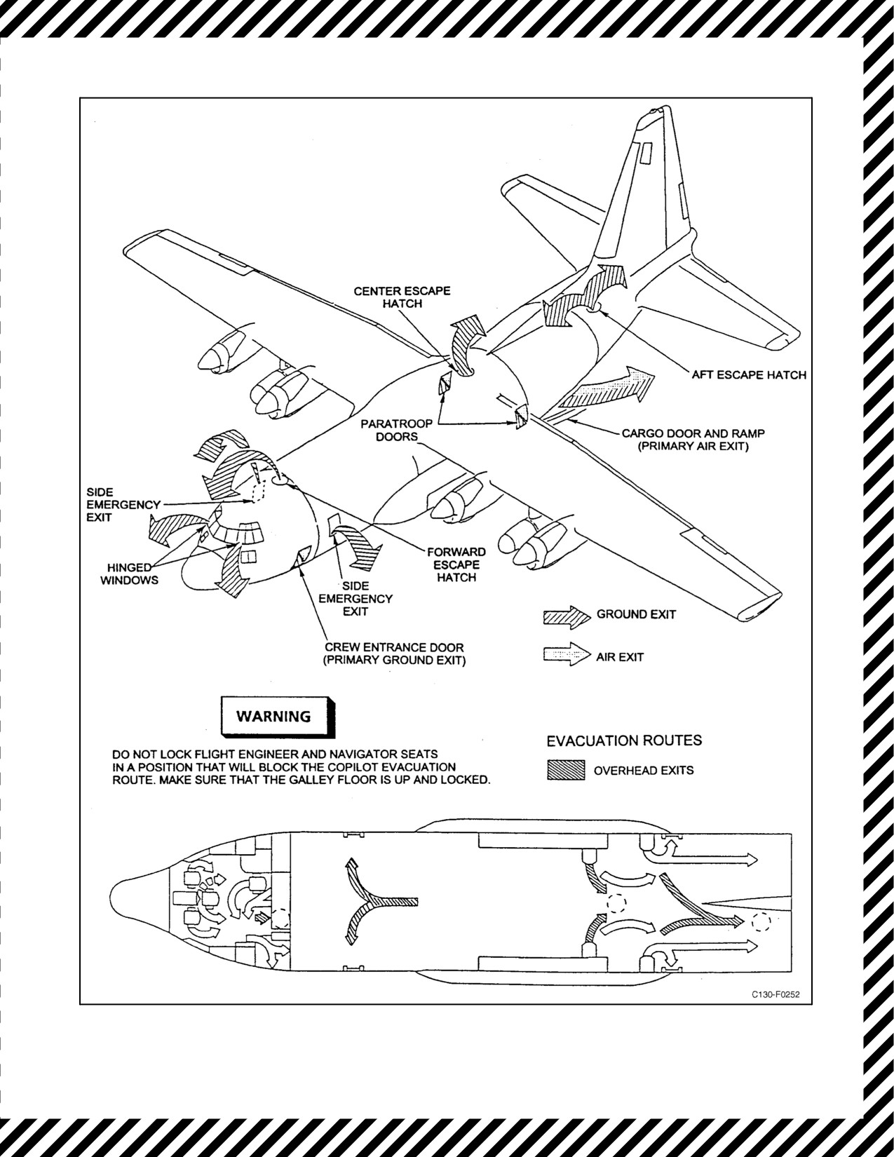
01-75GAL-1
Figure 11-13. Emergency Exits — Air and Ground
11-81
ORIGINAL

01-75GAL-1
3. Place the AIR CONDITIONING MASTER switch in the AUX VENT position.
4. If possible, head the aircraft toward an isolated area and engage the autopilot.
Note
Thorough consideration should be given to the consequences of scattering
flightcrewmembers over a large area of ocean without the benefit of
liferafts. Bailout should be conducted with the aircraft circling to avoid
widespread separation of crewmembers.
5. Turn on the auxiliary hydraulic pump at the copilot hydraulic control panel.
6. Reduceairspeed to below 150 KIAS ifpossible. Iftheairspeed can bereduced to below 150 KIAS, thepriority
of emergency exits is as follows:
a. Cargo ramp and door.
b. Paratroop doors.
c. Forward crew door.
If the airspeed cannot be reduced to below 150 KIAS, the cargo door will
be the primary means of escape.
7. When airspeed is below 150 KIAS:
a. Open the air-deflector and paratroop doors.
b. Give the abandon aircraft signal over the public address system, interphone, and by one long ring on the
alarm bell.
c. Evacuate the aircraft.
8. If the airspeed is above 150 KIAS or the paratroop doors will not open:
a. Open the cargo door by placing the manual control valve in the OPEN position.
b. Give the abandon aircraft signal over the public address system, interphone, and by one long ring.
c. Evacuate the aircraft.
9. When time and aircraft control do not permit crew use of the paratroop doors or the ramp door, proceed as
follows:
Number 2 engine should be secured prior to jettisoning crew door.
ORIGINAL
11-82

01-75GAL-1
a. Give bailout warning over the public address system, interphone, and by three short rings on the alarm bell.
Ensure parachute and applicable equipment are passed to the flight deck
and the door area is clear prior to jettisoning the crew entrance door.
b. Jettison the crew door by pulling the emergency release handle just forward of theflight station emergency
escape hatch release.
Note
It may not be possible to jettison the crew entrance door at a pressure
differential greater than 3.1 inches of mercury because of the load on the
door hinge and the latching mechanism.
c. Reduce airspeed if possible.
Bailout from the crew entrance door is not recommended at airspeeds above
150 knots or with the landing gear extended.
d. Give abandon-aircraft signal over the public address system, interphone, and by one long ring on thealarm
bell.
e. Bail out of the crew entrance door from a squatting position at the rear.
Push head first outward and downward, using the rear edge of the door frame for leverage. Do not attempt to exit
feet first or in a spread position.
11.6.1 NB-8 Personnel Parachute
The C-130T is equipped with five NB-8 personnel parachute assemblies. The NB-8 is a back-type parachute,
consisting of a 28-foot diameter, flat, multicolored nylon canopy. The canopy is packed in a container and secured
to the aircrewmember by a harness assembly.
Executing Bailout with NB-8 Personal Parachute:
Note
The parachute should fit tightly, high on the back and snug in the seat. All
pocket objects should be removed and stowed. Gloves should be worn.
Minimum recommended altitude for bailout is 3,000 feet AGL. Bailout
should not be attempted below 1,000 feet AGL.
1. Depart aircraft in a quick orderly fashion at one second intervals. Exit forcefully to ensure separation from
aircraft, keeping feet together.
2. When clear of aircraft, grip ripcord handle and pull to maximum length of travel to allow for complete release
of pins from parachute pack.
11-83
ORIGINAL

01-75GAL-1
3. Immediately following opening shock, check for proper deployment and condition of parachute canopy.
4. Consider activating four-line release system to reduce oscillation and provide an optional method of
maneuvering the parachute to an optimal landing site. Grasp release lanyard loops, located on the inside of
the rear risers, and break release ties by a sharp pull. This action frees the rear four suspension lines allowing
canopy to form a lobe in the rear center and permit a steady escape of air, reducing oscillation and providing
minimal directional control by pulling on the respective release lanyard.
Four-line release should not be activated if a damaged canopy or broken
suspension lines are observed.
5. Attempt to turn into the wind by pulling on the left riser to turn left or the right riser to turn right in order to
avoid being caught under the parachute canopy after landing.
6. To prepare for water entry, grasp left side of parachute harness with right hand. Unfasten chest strap and left
leg strap with left hand. With left hand, grasp right harness and place right hand on right leg strap.
7. Upon water entry, unfasten right leg strap with right hand and roll free of parachute harness.
8. If trapped under parachute canopy in the water, remove it by finding a panel seam and pulling from the head
toward the feet along a panel seam toward the nearest edge. Do not kick feet until clear of canopy and
suspension lines.
11.7
CONTROLLABILITY
11.7.1 Controllability Check
A controllability check is conducted to determine the minimum safe airspeed to maintain during approach and
landing. If suspected or actual in-flight damage, fuel imbalance, or differential airspeed occurs, the following
procedure should be used as necessary to determine the extent of the damage and controllability for landing. Maintain
careful control of the aircraft at all times throughout the procedure. If at any time it becomes apparent that you will
be unable to land the aircraft, consider bailout procedure while controlled flight is still possible.
1. Conduct a preliminary check for aircraft damage and personnel injuries.
2. Attempt climb to 10,000 feet AGL.
3. Consider dumping fuel to lighten aircraft.
4. Complete the descent checklist.
5. Configure the aircraft for landing.
D The speed must never be decreased to the point at which full control
deflection is required since there may be no recovery capability beyond this
point. Control and configuration changes should be input gradually.
D With structural damage, there is a possibility of a split-flap condition
occurring when the flaps are lowered.
ORIGINAL
11-84

01-75GAL-1
6. Gradually slow the aircraft in 5-knot increments while evaluating the control capabilities in turns and
simulatedlandingapproaches.Anyimpendingcontrolproblemsareindicatedby anexcessiverolling,yawing,
or pitching moment. The airspeed is decreased until the desired landing speed is attained or an undesirable
control problem is approached.
7. If a stall buffet occurs, immediately accelerate the aircraft to a safe flying speed. If a stall buffet occurs, plan
touchdown speed to be 1.2 times speed at buffet for the selected flap setting. The landing flare requirement
can be decreased by making a low, flat landing approach.
11.8
LANDING EMERGENCIES
11.8.1 Landing With Engines Inoperative
For the effect of various engine losses on aircraft systems, see Figure 11-3. In addition to declaring an emergency
and completing the engine shutdown procedure and Landing Checklists, the following items shall be briefed prior
to any engine(s) out landing.
1. System degradation:
a. Hydraulic.
b. Electrical.
c. Other.
2. Trim — Trim tab coordination:
a. Rudder.
b. Elevator (as required).
c. Aileron (as required).
3. Airspeed — Airspeed adjustment/increase.
4. Reverse — Reverse using symmetrical engines.
5. Swerve — Direction of swerve.
6. Go-around — Waveoff intentions:
a. 5_ wing up.
b. Power setting on operating engines.
11.8.1.1 Landing With One Engine Inoperative
The approach for landing with one engine inoperative is made in the same manner as for a normal landing except
flaps should not be extended more than 50 percent until landing is assured. Below 97 KIAS, during flareout, the
combined flight idle thrust on the side with two operating engines will tend to turn the aircraft into the side with only
one operating engine. Above 97 KIAS, the aircraft will tend to turn into the side with two engines operating because
of the negative thrust or drag produced with propellers at the low pitch stop. These characteristics are particularly
noticeable when a landing is made with a propeller feathered on an outboard engine. Reference Figure 11-14 for
flight-idle thrust factors affecting low-speed landing characteristics.
11-85
ORIGINAL
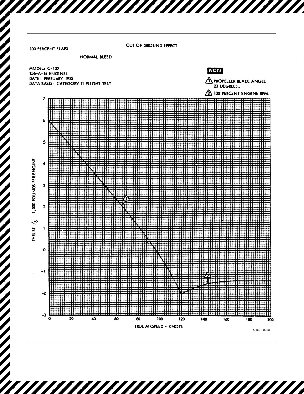
01-75GAL-1
Figure 11-14. Low-Speed Flight-Idle Thrust
ORIGINAL
11-86

01-75GAL-1
CAUTION
D Reverse thrust on asymmetrical engines may cause the aircraft to veer to
one side.
D Copilot must hold the wheel firmly on the ground and the wings level.
Note
At light gross weights, counteracting the crosswind effect by adding power
to the side with the dead engine will contribute to floating and consequent
overshooting. After nosewheel touchdown, retard throttles to GROUND
IDLE and use reverse thrust from symmetrical engines.
11.8.1.2 Landing With Two Engines Inoperative
After loss of two engines, attempt to decrease aircraft weight, if necessary, dumping fuel and/or jettisoning equipment
before landing.
CAUTION
If both the No. 1 and No. 2 engines are inoperative, additional time is
required to extend gear and flaps.
1. Downwind leg:
a. 160 KIAS minimum.
b. Gear and flaps as required.
2. Base leg:
a. 160 KIAS.
b. Gear and flaps as required.
3. Turn to final:
a. 150 KIAS minimum.
4. Final approach:
a. Maintain 150 KIAS, or approach speed, whichever is higher, until landing is assured.
b. Extend gear and flaps, as required.
11-87
ORIGINAL

01-75GAL-1
A go-around is not recommended after flaps are lowered. Do not extend full
flaps until landing is assured. When landing with two engines inoperative,
ensure firm nosewheel contact before reversing and use reverse thrust only
as needed. With symmetrical power available, use maximum inboard
power as control is available.
11.8.2 Go-Around With One or Two Engines Inoperative
The use of 5_ of bank away from the inoperative engine is required to
maintain directional control when power is applied during go-around.
Go-around with two engines inoperative is not recommended. Every
precaution should be taken so as not to let a situation develop that
necessitates a go-around under these conditions. Descents below safe,
comfortable altitudes and airspeeds should not be made until absolutely
assured of landing.
1. Alert crew by giving command, “Go-around.”
2. Begin the go-around at or above minimum control airspeed.
3. Advance throttles for all operating engines to maximum power as directional control will permit. Power
applied to the asymmetrical engines will depend on the airspeed of the aircraft at initiation of go-around.
4. Give command to copilot to raise flaps to 50 percent.
CAUTION
Raising the flap handle prematurely above approximately the 15-percent
position or raising the gear will increase the minimum control speed
because of reduction in available hydraulic pressure.
5. Raise the gear when certain that the aircraft will not touch down.
6. Continue to raise flaps as airspeed and altitude permit.
Note
D At low airspeeds, raise flaps in 10-percent increments with airspeed
increasing approximately 5 knots between retraction increments.
D Two-engine minimum control speed must be obtained as soon as possible
after initiation of go-around.
7. After gear and flaps are up, continue as a normal take-off, using three-engine climb speeds.
ORIGINAL
11-88

01-75GAL-1
11.8.3 Landing With Tire Failure
11.8.3.1 Nose Landing Gear Tire Failure
If one nosewheel tire is flat at the time of landing, a normal landing may be made. If both nosewheel tires are flat
at the time of landing, keep the nosewheels off the ground as long as possible. After nosegear contact, use maximum
reverse thrust and minimum braking. This procedure gives minimum nosewheel loading. Taxiing is not
recommended.
11.8.3.2 Main Landing Gear Tire Failure
If a main landing gear tire is flat at the time of landing, touch down the nosegear as soon as possible and use maximum
reverse thrust. Taxiing is not recommended. If both tires of the main landing are flat, there will probably be a tendency
to swerve toward that side. Line up and land on the side of the runway with the good tires. Touch down the nosegear
as soon as possible, hold full forward on the control column, and assure directional control with the nosewheel
steering system. Use wheelbrakes (on the side opposite the flat tires only) to assist the nosegear in maintaining
directionalcontrol.Usereversethrustcautiouslybuttothefullestextentpossibletoreducelandingrolltoaminimum.
Do not attempt to taxi.
11.8.4 Landing Gear Retracted
11.8.4.1 Landing With One or Both Main Gears Retracted
If one main landing gear cannot be extended, the recommended procedure is to retract the other main gear and land
with only the nose landing gear down, or to land with all gears retracted (refer to Gear-Up Landing, paragraph
11.8.4.3).
11.8.4.2 Landing With Nosegear Retracted and Main Gear Down
If the nosegear fails to respond to normal and emergency operating procedure, an emergency landing may be
accomplished, holding the nose of the aircraft up as long as possible. Use the following procedure to make a
nosegear-up landing.
1. Give warning over the public address system and the interphone and give six short rings on the alarm bell.
Reduce weight to minimum practical gross weight. Manually activate emergency exit lights.
2. Request foam on the runway (20 feet wide, 3,000 feet long, beginning 2,000 feet from the approach end of
the runway). Request removal of arresting gear.
3. Stow or secure all loose equipment. If cargo can be safely moved, shift cargo aft to a cg of not more than 30
percent.
4. Depressurize the aircraft and place all ENGINE BLEED AIR switches to OFF. Pull GPWS ESS AC and DC
circuit breakers. Pull LANDING GEAR WARNING LIGHT circuit breaker.
5. Open overhead emergency escape hatches and paratroop doors.
6. Turn off all unnecessary electrical equipment.
7. Close the oxygen manual shutoff valve located on the aft side of the flight station bulkhead.
8. Take crash position, passengers behind cargo.
11-89
ORIGINAL

01-75GAL-1
9. Lock shoulder harness inertial reel.
Ensure that all controls that cannot be easily reached are properly
positioned before locking the harness.
10. Assume a normal landing attitude using 100-percent flaps.
11. Uponmaingeartouchdown,retardthrottlestoFLIGHTIDLE,maintain levelattitude, donot usewheelbrakes,
do not allow nose to fall through, and decelerate aerodynamically to 97 KIAS.
12. Upon reaching foam, lower nose to runway.
13. Upon nose touchdown, apply reverse thrust, maintain nose in light contact with runway and do not use
wheelbrakes (except to avoid over run).
14. Upon stop, executeground evacuationprocedures. Usecaution exitingtheaircraft;theexitsmay notbeattheir
normal height above the ground and the crew door may not fully open.
11.8.4.3 Gear-Up Landing
Before making a gear-up landing, perform the following operations:
1. Give warning over the public address system and theinterphone. Manually activate theemergency exit lights.
2. Request foam on the runway (20 feet wide and 3,000 feet long, beginning 1,500 feet from the approach end
of the runway).
3. Stow or secure all loose equipment.
4. Depressurize the aircraft and place all ENGINE BLEED AIR switches to OFF. Pull GPWS ESS AC and DC
circuit breakers.
5. Consider cargo jettison and dump or consume all unnecessary fuel (refer to paragraph 11.4.12).
6. Open overhead emergency escape hatches and paratroop doors.
7. Close the oxygen manual shutoff valve located on the aft side of the flight station bulkhead.
8. Pull the LANDING GEAR WARN LIGHT circuit breaker on the copilot lower circuit breaker panel.
9. Turn off all unnecessary electrical equipment.
10. Take the crash position.
11. Fasten shoulder harness and inertial reel lock.
Ensure that all controls that cannot be easily reached are properly
positioned before locking the harness.
ORIGINAL
11-90

01-75GAL-1
12. Assume a normal landing attitude using 100-percent flaps.
13. Touch down on foam, applying reverse thrust.
14. Upon stop, execute ground evacuation procedure. Usecaution exiting the aircraft; the exits may not be at their
normal height above the ground and the crew door may not fully open.
15. Evacuate the aircraft as soon as possible.
11.8.4.4 No-Flap Landing
1. Place the GPWS switch to OVERRIDE.
2. Fly a slightly wider, slightly longer pattern to compensate for the higher no-flap airspeeds.
3. Do not flare but, rather, allow the aircraft to fly onto the runway.
CAUTION
If the touchdown is lower than the charted speed, it is possible for the aft
end of the fuselage to contact the ground.
4. When applying reverse thrust at high speed, pull the throttles into reverse slowly.
5. Longer ground rolls will result from the higher touchdown speeds.
11.8.5 Landing on Soft Ground or Unprepared Runways
If it becomes necessary to land on soft ground or an unprepared runway, it is recommended that the landing gear stay
extended. However, the final decision to land with the landing gear up or down must be made by the pilot.
11.8.6 Loss of Nosewheel Steering During Landing
Whenever a loss of nosewheel steering is indicated by an immovable pilot steering wheel, no further attempt will
be made to “force” the wheel to turn, as this might prevent the nosewheel from castering. Under this condition, the
pilot will pull back on the control column to relieve pressure on the nosewheel and maintain directional control of
the aircraft through the coordinated use of flight controls, differential power, and differential brakes according to the
prevailing circumstances of speed, crosswinds, engine out, and runway conditions.
11.8.7 Landing With a Cocked Nosewheel
Basically, the procedure for landing with a cocked nosewheel is the same as landing with loss of nosewheel steering,
with the following additions. Request foam on the runway (20 feet wide, 3,000 feet long, beginning 1,500 feet from
the approach end of the runway).
11.8.8 Nosewheel Shimmy
Nosewheel shimmy is an indication of an unbalanced condition of one or both of the nosewheel tires or failure of
the steering system. If this occurs during takeoff, the decision regarding whether to abort or to continue will depend
on the severity of the shimmy and whether the refusal point has been passed. If shimmy occurs during the landing
roll, decelerate gradually and apply up-elevator to keep as little load as possible. In landing with a known shimmy
condition, keep nosewheel off the ground as long as possible but touch down while elevator effectiveness allows
gentle lowering of the nose.
11-91
ORIGINAL

01-75GAL-1
11.9
DITCHING
Under ideal conditions of wind and sea, and by skillful execution of the recommended techniques, the ditching of
transport-type aircraft can usually be accomplished with a high degree of success. However, because of the high-wing
configuration of this aircraft, the fuselage may be expected to settle after touchdown with consequent flooding of the
cargo compartment. Consideration of various unfavorable factors involved in an overwater bailout limits the decision
recommending bailout to several specific instances; namely, when near to land or adequate surface help; when wind
and sea conditions are such as to preclude ditching; or when fire or loss of control makes ditching impossible.
Therefore, it is considered better to ditch if circumstances permit, since this makes available the additional liferafts
and survival equipment carried in the aircraft. In any event, the decision to ditch or bail out must be made by the pilot
in view of the existing circumstances. This decision should never be delayed until thefuel supply is exhausted, since
the most effective ditching approach is made with power on at a speed slightly above the power-off stall speed. A
minimum of 2,000 pounds of fuel should remain at time of descent from altitude to allow for jettisoning of cargo,
assessment of sea condition, communication with or maneuvering around surface vessels when present, and to
establish a landing pattern to the smoothest surface condition.
11.9.1 Ditching Characteristics
Actual experience in ditching the C-130 is limited; however, NACA-controlled ditching tests of models similar to
the C-130 configuration indicate that there is a reasonably high probability that the aircraft can be landed on water
without major collapse of structure or a sudden rush of water into occupied compartments. On the basis of limited
experience and the NACA tests, it is concluded that the following results can be expected upon ditching.
CAUTION
D Thesecharacteristicsassumeapower-onapproach,approximately7_nose-
high pitch attitude with full flaps extended, landing gear retracted, and
touchdown at 10 KIAS above stall speed. Any speed above full flap ap-
proach speed will result in additional structural damage on touchdown.
D Actual ditchings of other aircraft have indicated that excessive airspeed will
cause control problems once on the water and increase the likelihood of
nose-section failure. Extremely rapid flooding oftheaircraft wouldfollow.
1.
Upon contact with the water, moderate bottom damage may occur in the area immediately forward of the cargo
loading ramp hinge. Thebottom damagewill tend to stabilizetheaircraftdirectionally duringtheditchingrun,
maintaining the wings in an essentially level attitude. Wing dipping or water looping are not expected.
2.
During the initial portion of the ditching run, the taildown portion of the cargo door may be damaged. The
damage probably will not affect either the ditching run or the sinking rate since the location of the door is such
that it will be above the waterline when the nose settles during the latter part of the run. It is very unlikely that
the ramp will open. The crew door, the side emergency exit(s), and the paratroop doors, which will be out of
the water during the taildown portion of the ditching run, probably will not experience any damage during the
ditching run.
3.
During the tail-low initial contact with the water, the water-drag forces on the aircraft will tend to bring the
nose down. Continued up-elevator force should be applied. This nosedown tendency plus possible damage
to theelevatorwillresult intheaircraftassuming anosedown, tail-highattitudeandcould generateporpoising.
If in this nosedown attitude a wave or swell of large magnitude is encountered, considerable damage to the
radome and nose of the aircraft will occur, with probable rupture of the forward bulkhead and immediate
flooding of the flight station. Some damage may occur in the area of the cargo door and ramp, but expect the
primary flooding to occur in the forward portion of the aircraft if the ditching is in a heavy sea.
ORIGINAL
11-92

01-75GAL-1
D If porpoising occurs, do not try to catch the aircraft but maintain backyoke
and keep the nose out of the water. If control is reestablished, continue to
keep the aircraft in a trim-up attitude. Hold the nose up as long as possible.
Do not drop it.
D As the nose settles during the final part of the ditching run, the fuselage will
fill with water fairly fast. The aircraft will sink to the wings, then float.
11.9.2 Preparation for Ditching
Plans forditching cannot bemadewithout taking thewind direction into consideration. Waves move downwind, and
the spray from wave crest is blown downwind. Swells, however, do not always indicate wind direction and can be
very large even when the wind is calm. Swells are the result of underwater disturbances. Over a sea, a pilot must be
more exacting and alert when judging height.
11.9.3 Ditching Procedures
The ditching chart outlines duties of personnel prior to and during ditching (see Figure 11-17). Figure 11-15
illustrates the water emergency exits and evacuation routes used during ditching. Figure 11-18 illustrates the liferaft
releases.
The following are the standard alarm signals for ditching:
1. Six short rings — Prepare for Ditching.
2. One long ring — Brace for Impact.
11.9.3.1 Normal Power-On Ditching
Best results will be obtained by following the procedures outlined below:
1. Ditchwhilepowerisavailable.Powerwillallowthepilottochoosethespotforditchingandthemostfavorable
landing position and attitude.
2. Use 100-percent flaps with landing gear up.
3. Ditch at 10 knots above power-off stall speed. This will give an approximate angle of ditching slightly above
level flight. Under no circumstances should the aircraft be stalled, since this will result in severe impact and
cause the aircraft to nose into the water.
4. In daylight, it is recommended that the aircraft be ditched along the top of the swell, parallel to the rows of
swells, if the wind does not exceed 30 knots. In high winds, it is recommended that ditching be conducted
upwind to take advantage of lowered forward speed. However, it must be remembered that the possibility of
ramming nose on into a wave is increased, resulting in failure of the nose of the aircraft and immediate flooding
of the flight deck. Also, there is the possibility of striking the tail on a wave crest and nosing in.
11-93
ORIGINAL
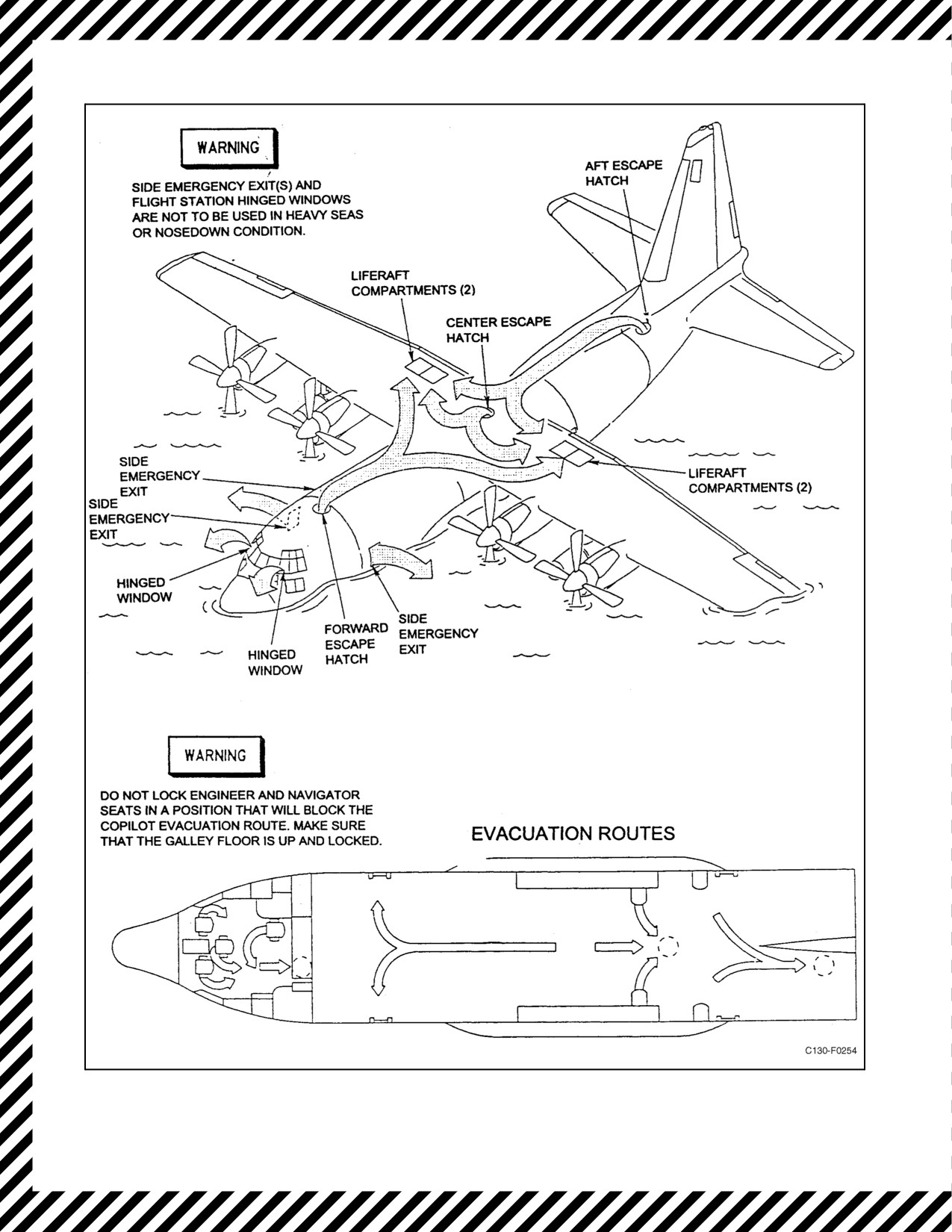
01-75GAL-1
Figure 11-15. Emergency Exits — Water
ORIGINAL
11-94
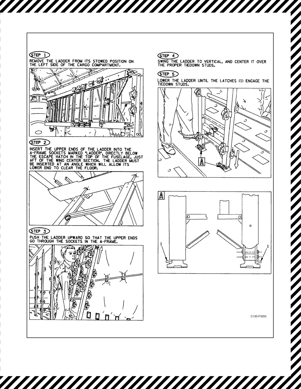
01-75GAL-1
Figure 11-16. Center Escape Ladder Installation
11-95
ORIGINAL

01-75GAL-1
CREW-
DITCHING IMMINENT
MEMBER
FIRST ACTION
(10 MINUTES LEFT)
AFTER DITCHING
PILOT
1.
Order crew to prepare for ditching,
1.
Alert Crew — Ditching
1.
If possible, check flight
giving approximate time remaining.
imminent.
station and cargo
DUTIES
Order crew to start emergency
compartment to ensure that
2.
Direct copilot to transmit final
procedures. Give six short rings on
all personnel and
distress signal.
alarm bell system.
emergency equipment have
3.
Order all crewmembers and
been evacuated.
2.
Direct copilot to send distress
passengers to assume the
signal.
2.
Exit through forward escape
ditching position.
hatch and inflate lifevest.
3.
Advise flightcrew to reduce fuel
4.
Lock shoulder harness.
quantity/gross weight and jettison
3.
Board left inboard liferaft
cargo, as necessary.
5.
Immediately before ditching,
and receive emergency
warn personnel over the
equipment.
4.
Obtain flashlight and
interphone to “Brace for
PRC-90/PRC-149.
impact,” and order copilot to
5.
Don antiexposure suit and lifevest.
give one long ring on the alarm
Fasten shoulder harness and
bell.
safety belt.
COPILOT
1.
Acknowledge pilot’s order to
1.
Upon order from pilot, transmit
1.
Exit through forward escape
prepare for ditching.
final distress and intentions of
hatch.
DUTIES
pilot as to ditching.
2.
Upon order from pilot, send
2.
Inflate lifevest and board
distress signal.
2.
Lock shoulder harness.
right inboard liferaft.
3.
Select emergency on transponder.
3.
On orders from pilot, give one
Upon order from pilot, transmit
long ring on alarm bell.
emergency signal on HF radio
followed as soon as possible by
emergency message.
4.
Obtain flashlight and PRC-90/
PRC-149.
5.
Don antiexposure suit and life vest,
fasten shoulder harness and
safety belt.
FLIGHT
1.
Acknowledge pilot’s order to
1.
Remove and stow forward
1.
Pull liferaft release handles
prepare for ditching.
escape hatch.
in flight station.
ENGINEER-
AND SECOND
2.
Upon order from pilot, dump fuel
2.
Secure loose articles.
2.
Exit through forward escape
as required. Close dump valves.
hatch with container of
FLIGHT
3.
EMERGENCY
water if possible.
ENGINEER
3.
Depressurize aircraft; place
DEPRESSURIZATION switch
DUTIES
ENGINE BLEED-AIR switches to
— NORMAL; AIR
3.
Inflate lifevest; check liferaft
OFF.
CONDITIONING MASTER
and radio and discard hand
switch — AIR COND MAN
ax.
4.
Obtain flashlight, PRC-90/
PRESS; hold MANUAL
PRC-149, and hand ax.
4.
Board right outboard liferaft.
PRESS CONT switch to
5.
Don antiexposure suit and lifevest.
INCREASE pressure for 90
seconds.
4.
Pull the GPWS circuit
breakers on the copilot upper
circuit breaker panel.
5.
Pull the LANDING GEAR
WARN LIGHT circuit breaker
on the copilot lower circuit
breaker panel.
6.
Turn the seat to face forward
and lower seat to full-down
position.
7.
Fasten safety belt and lock
shoulder harness.
Figure 11-17.
Ditching Chart (Sheet 1 of 2)
ORIGINAL
11-96

01-75GAL-1
CREW-
DITCHING IMMINENT
MEMBER
FIRST ACTION
(10 MINUTES LEFT)
AFTER DITCHING
LOADMASTER
1.
Acknowledge pilot order to
1. Ensure that aft crewmembers
1.
Pull liferaft release handles aft
&
prepare for ditching.
and passengers are behind
of the right paratroop door.
SECOND
cargo if possible and properly
2.
Advise aft crewmembers and
2.
Ensure that passengers have
LOADMASTER
seated with belts fastened.
passengers of impending
exited the aircraft.
DUTIES
emergency.
2. Ensure that the light by each
3.
Obtain portable emergency
emergency exit is on.
3.
Complete cargo jettison
exit lights/flashlight, first-aid
procedures (as required).
3. Extend emergency escape
kit, and water jugs. Exit
ropes to nearest person to be
through the aft escape hatch
4.
Remove and stow hatches.
used as an escape
and inflate lifevest.
Install center escape ladder.
assistance in reaching the
4.
Board left outboard liferaft.
5.
Obtain flashlight and PRC-90/
hatch.
PRC-149.
4. Fasten safety belt. Upon one
6.
Distribute lifevests to crew
long ring of the alarm bell,
and passengers. Do not
assume the crash position.
inflate. Don lifevest. Don
anti-exposure suit (as
required).
7.
Rebrief passengers on the
crash position, evacuation
routes, and liferaft boarding.
8.
Notify pilot when cabin is
prepared for ditching.
Figure 11-17.
Ditching Chart (Sheet 2)
11.9.3.2 Partial-Power Ditching
When ditching with one or more engines inoperative, the following should be borne in mind:
1. With the engines inoperative on the same side of the aircraft, use power on the inboard engine only.
2. If power is available from the No. 2 and 4 engines orthe No. 1 and 3 engines, considerable powermay beused
to control the aircraft.
3. Use power as required to give the flattest approach.
4. In final approach, it is advisable to hold speed 20 knots above power-off stall speed until flareout, at which
time speed will be reduced to 10 knots above power-off stall speed.
11.9.3.3 Crosswind Ditching
The basic rules for ditching listed in Normal Power-On Ditching, paragraph 11.9.3.1, will still apply, in addition to
the following:
1. Keep the wings level and crab the aircraft to kill the drift. It may be advantageous to permit some drift to
maintain a parallel relationship with a wave.
2. Land on the downward side of the swell or wave.
11-97
ORIGINAL

01-75GAL-1
11.9.3.4 Upwind Ditching
The basic rules for ditching listed in Normal Power-On Ditching, paragraph 11.9.3.1, will still apply, in addition to
the following:
1. Maintain noseup condition; avoid the nose striking wave surface.
2. Touch down immediately behind the crest of a rising wave; avoid the face of the wave.
3. Hold nose up after impact.
11.9.3.5 Night Ditching
Night ditching will be conducted with the aid of instruments to establish the proper attitude of the aircraft.
1. Makean instrument approach, holding airspeed 20 knots abovepower-offstallspeed. At500 to700 feetabove
the water (use radar altimeter if available), set up approximately 200 fpm rate of descent, and establish an
airspeed 10 knots above power-off stall speed with full flaps.
2. Use landing lights as necessary.
3. Hold wings level to avoid digging a wing into the water and cartwheeling the aircraft.
4. Ditch at 10 knots above power-off stall speed.
5. Use 100-percent flaps with landing gear up.
11.9.4 Abandoning Aircraft
Evacuation of the aircraft after ditching should be accomplished in an orderly manner in the shortest time possible.
This cannot be done well without practice, and, in the event that the fuselage is dark and filling with water, further
difficulty can be expected.
The crew and/or passengers must not leave ditching positions until it is
ascertained that the aircraft has stopped forward movement. Serious
injuries can occur as the result of personnel unfastening safety belts prior
to the aircraft coming to a full stop.
Immediately after the aircraft comes to a stop, additional emergency equipment may be collected and distributed to
each crewmember. The crewmembers must carry out their after ditching duties (see Figure 11-17) and then evacuate
the aircraft through the hatch previously assigned to them. They must also see that each piece of equipment for use
in the liferaft is secured by lines to prevent its being lost overboard.
ORIGINAL
11-98
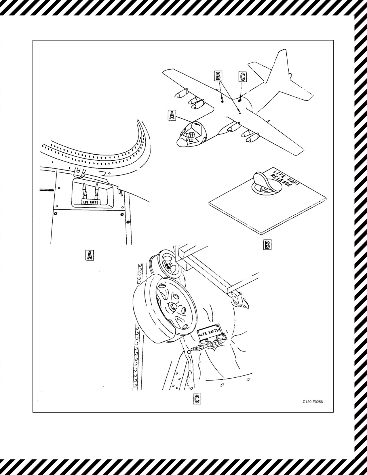
01-75GAL-1
Figure 11-18. Liferaft Releases
11-99
ORIGINAL

01-75GAL-1
D Ensure that personnel are outside of the aircraft and clear of the escape
hatches prior to inflating life vests.
D Liferaft releasehandles (seeFigure11-18)mustbepulledthrough theirfull
travel for complete ejection and inflation of the liferaft.
D In an emergency, the pilot and copilot side windows may be used as
emergency exits; however, heavy flooding may occur.
11.9.4.1 Emergency Ditching Exits (Flightcrew)
See Figure 11-15 for emergency exits. Normally, crewmembers on the flight deck will use the forward escape hatch
for exit after ditching. Crew-members in the cabin will use the center or aft escape hatch for exit after ditching. If
cargo permits, the center escape hatch ladder should be installed prior to takeoff. If cargo prevents this installation,
personnel in the cabin should be instructed on how to install this ladder after cargo is jettisoned (see Figure 11-16).
All crew-members will normally board the assigned liferaft as shown in Figure 11-17.
11.9.4.2 Ditching Exits (Passengers)
Passengers will be briefed on the use of emergency equipment and assigned exits prior to flight. They should be
divided into groups corresponding to the capacity of the available rafts.
11.10 EMERGENCY EQUIPMENT
Various types of emergency equipment are furnished to minimize hazards to the aircraft and to personnel in case of
fire or accident.
11.10.1 Hand-Operated Fire Extinguishers
CO2 fire extinguishers for fighting interior fires are located as follows (see Figure 11-1).
1. Flight station aft bulkhead — 1.
2. Cargo compartment forward bulkhead — 1.
3. Rear of left wheelwell — 1.
4. Aft of left paratroop door — 1.
11.10.2 Master Light Shutoff Switches
Each door is provided with a master door warning light shutoff switch (see Figure 2-149). The switches are located
with each individual door-open light. The switches are used to turn off the master door-open light on the pilot
glareshield after it has gone on to indicate that one of the doors is not securely locked. This will provide for another
indication for the flightcrew should another door become insecure.
ORIGINAL
11-100