C-130T. FLIGHT MANUAL (2006) - page 13

01-75GAL-1
11.10.3 First-Aid Kits
Mounting provisions are included for the installation of 22 first-aid kits as follows:
1. Flight station aft bulkhead — 2.
2. Forward of right wheelwell — 6.
3. Forward of left wheelwell — 6.
4. Forward of right paratroop door — 4.
5. Forward of left paratroop door — 4.
11.10.4 Hand Axes
Three hand axes (Figure 11-1) are installed in the aircraft, one on each side of the 245 bulkhead, and one aft of the
left-hand paratroop door.
11.10.5 Emergency Lights
Portable, battery operated emergency lights (Figure 11-1) are installed on stationary terminal blocks located near each
normal or emergency exit. The lights are located as follows:
LOCATION
NO. OF LIGHTS
Crew entrance door
1
Paratroop doors
2
Overhead emergency escape hatches
3
Right-side exit
1
Left-side exit
1
When installed, the lights can be either individually controlled by the three-position (ON, OFF, ARM) switch on each
light assembly or collectively extinguished by the EMER EXIT LT EXTINGUISH pushbutton on the overhead
electrical control panel. In order for the EMER EXIT LT EXTINGUISH push-button to be able to extinguish a light,
however, the associated light assembly switch must be positioned to ARM. An inertia switch in each of the light
assemblies actuates the light when the aircraft is subjected to a decelerating force exceeding 2-1/2g. The lights will
also illuminate if power on the essential dc bus fails. An individual light assembly can be removed for emergency
portable use by pulling the release handle on the light assembly. The control system for the installed system is
supplied 28-Vdc power from the essential dc bus through the EMER EXIT LIGHT CONTROL circuit breaker on
the copilot lower circuit breaker panel and from the battery bus through the EMER EXIT LIGHT EXTINGUISHER
circuit breaker on the pilot side circuit breaker panel. The batteries are not recharged by the exit light control circuit.
11.10.6 Liferafts
Stowage provisions are provided for installation of four20-man pneumaticliferafts (Figure11-1) in the trailing edge
of the center wing section. Liferaft release handles (Figure 11-18) are located as follows: two on the flight station
bulkhead, below the escape hatch; two on the fuselage structure, aft of the right paratroop door; and two on the wing
upper surface, inboard of each raft stowage compartment. The release handles on the wing upper surface can be
reached by removing the protective canvas covering over the handle openings. The rafts are automatically inflated
upon actuation of the release handles.
11.10.7 Emergency Transmitters
An emergency radio transmitter (Figure 11-1) is stowed in each of the four liferafts.
11-101
ORIGINAL

01-75GAL-1
11.10.8 Lifevests
Stowage provisions are provided for 80 lifevests (see Figure 11-1).
11.10.9 Antiexposure Suits
Stowage provisions are provided for five antiexposure suits (see Figure 11-1).
11.10.10 Restraining Harnesses
There are three restraining harnesses installed on the aircraft; one on the flight deck and one by each paratroop door.
11.10.11 Emergency Passenger Oxygen System (EPOS)/Victim Rescue Unit (VRU)
1.
Description as outlined below.
2.
The EPOS/VRU is a vacuum-sealed self-contained protective breathing device typically used by aircraft
passengers in emergency situations. It provides oxygen during aircraft decompression and when smoke or
toxic fumes are present, to aid in exiting oxygen deficient smoke filled cabins.
Note
Provides supplemental passenger oxygen for flight up to 30,000 feet.
3.
The system consists of five major components: hood, oxygen cylinder, carbon dioxide scrubbers, neck seal,
and storage pouch. The hood incorporates multiple layers of Kapton and Teflon film whose properties provide
heat and flame resistance to 1,832 _F (1,000 _C), ease of communication, tear resistance, and durability. An
anti-fog coating is applied to the inside of the hood. The oxygen cylinder is filled with 18 liters of aviator grade
oxygen at 3,000 psig. To facilitate semi-automatic activation, the oxygen cylinder activation lever is tethered
to theoppositesideofthehood and activated in theprocess ofdonning the hood. The forcerequired to activate
theflow ofoxygen isapproximately 12pounds. Thecarbon dioxidescrubbers areaseriesoflithiumhydroxide
panels mounted around the inside bottom portion of the hood behind the metallized film. The neck seal is
fabricated from a high strength, highly elastic silicone rubber material that fits neck sizes from 11 to 19 inches,
without adjustment. The storage pouch is fabricated from cordura, and protects thevacuum-sealed VRU from
damage.
4.
The system operates by emptying the oxygen from the cylinder into the hood. As the user breathes in the
oxygen and exhales carbon dioxide (CO2), the lithium hydroxide scrubber panels remove excess CO2 and
moisture, allowing the oxygen to be rebreathed. The duration of positive flow of oxygen stops after five
minutes. However, there is sufficient oxygen inside the hood for escape situations. Eventually the oxygen
supply will deplete and the CO2 level will increase to such a state as the hood must be removed to avoid
suffocation.
a. Rapidly walking/Evacuating — Up to 8 minutes.
b. Sitting at rest — Up to 18 minutes.
5.
The VRU is not to be worn by on-duty aircrew, it is intended for use by passengers only. The VRU is not
intendedforuseinfire-fightingorasabailoutorunderwaterbreathingdevice. Aircrewshould briefpassengers
on the use of the VRU before flight. Aircrew should observe passengers wearing the VRU in order to prevent
passengers from rebreathing gasses in the hood after the oxygen supply has been depleted.
11.10.11.1 EPOS/VRU Donning Procedures
1. Open flap on stowage pouch.
ORIGINAL
11-102

01-75GAL-1
2. Remove bag from storage pouch.
3. Pull red tape to open bag.
4. Remove hood from pouch and unfold.
5. Hold hood with neck seal (silver end) facing user. Pull red ball with one hand while holding the oxygen
cylinder with the other hand.
Note
The red ball and lever must pull free of the oxygen bottle.
6. Spread the neck seal open with palms facing towards each other.
7. Pull hood over head and breathe normally.
If hissing sound is not audible after the red ball has been pulled,
immediately remove the VRU from your head.
8. Remove hood after you are clear of the hazard or when instructed.
11.10.12 Main Landing Gear Tiedown Fixtures
Two main landing gear tiedown fixtures (see Figure 11-1) are stowed in the cargo door storage compartments.
11.10.13 Hazmat Spill Kit
A hazmat spill kit (see Figure 11-1) is stowed aft side of the 245 bulkhead below the SDRS.
11.10.14 Emergency Ditching Equipment
Ditching equipment should be in readiness at all times when flying over water. Prior to each overwater flight, the
pilot will ensure that the necessary equipment is aboard, in serviceable condition, and stowed in the proper places.
If possible, seats and safety belts should be provided in the cabin aft of the wheelwells for all personnel on board
except for the pilot, copilot, and flight engineer. The cabin is the safest area with the greatest possibility of escape
during ditching; therefore, the number of personnel on the flight deck should be kept to a minimum because of the
probability of immediate flooding of the flight deck.
11.10.14.1 Liferaft
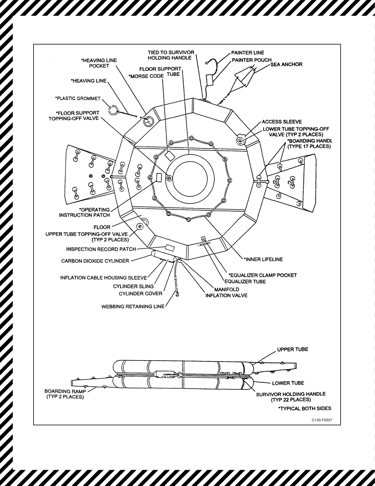
The C-130T is equipped with four LRU-15/A (Mk 20) liferaft assemblies. The liferaft is constructed of
polychloroprene-coated cloth with an inflation assembly (CO2 cylinder, inflation valve and cover.) The liferaft
consists of two single-compartment circular tubes connected by an equalizer tube, a noninflatable floor, and a
boarding ramp. The floor is provided with a built-in inflatable floor support. The raft is equipped with a sea anchor,
inner lifeline, boarding handles, a heaving line, and emergency survival equipment.
The liferaft assembly is automatically ejected from the wing compartments when the liferaft handles have been pulled
or the liferaft compartment door has been released. The liferaft inflates within 1 minute and is always right-side-up
11-103
ORIGINAL

01-75GAL-1
after inflation. The CO2 assembly inflates the circular tubes and boarding ramps only. In the event the inflation
assembly does not function properly, the equalizer tube distributes gas equally between each circular tube. After
boarding, the floor support is inflated manually with the handpump provided in the accessory container. The circular
tubes may be topped-off if necessary. See Figure 11-19 for liferaft assembly.
11.10.14.2
Life Preserver
The LPP-1, -1A life preserver assembly is not suitable for use by small
children in naval aircraft.
Note
The LPP-1, -1A life preservers are identical with the exception of the
mechanical inflation assemblies.
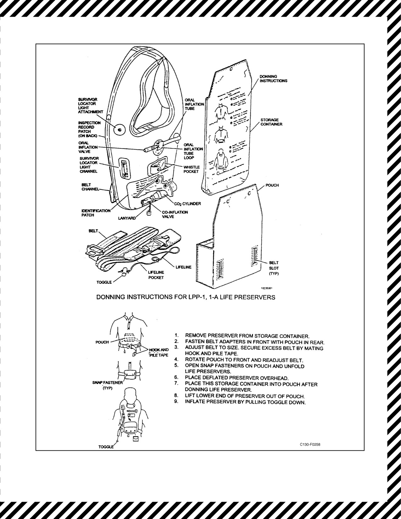
The LPP-1, -1A life preserver assembly weighs 3 pounds and provides a minimum of 29 pounds of buoyancy. The
lifepreserverconsistsofasingle-compartment, yoke-typeflotation assembly,apouchand beltassembly, aninflation
assembly, and a storage container. The preserver is constructed of polychloroprene-coated nylon, equipped with an
oral inflation tube, a valve stem, survival locator light attachments, a whistle pocket, a belt loop, and an inspection
record. See Figure 11-20.
The LPP-1, -1A is manually inflated by pulling the inflation lanyard down. In an emergency situation, the oral
inflation valve should be used to top off an inflated preserver, maintain inflation of a leaky preserver, or to inflate
a preserver that malfunctioned.
Note
The pouch must be opened and the flotation assembly unrolled prior to
inflation through theoral inflation valveorviathecarbon-dioxideinflation
assembly.
11.10.14.3 Radio Sets
11.10.14.3.1 AN/PRC-90 Radio Set
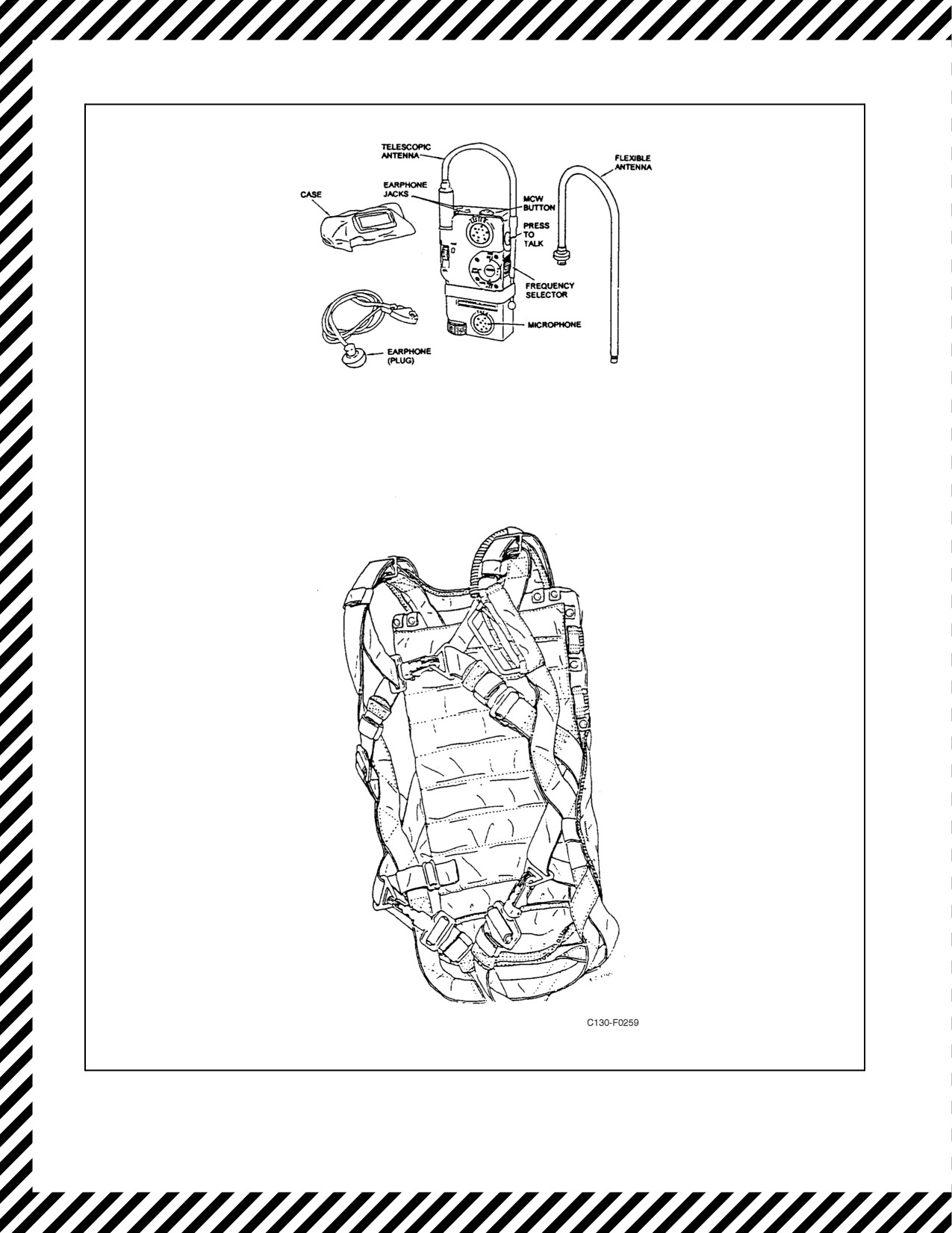
TheC-130Tis equippedwith fivePRC-90/PRC-149s thathelp SARaircraft andground rescueparties locatedowned
aircrewmembers during rescue operations, frequencies are 243.0 MHz and 282.8 MHz frequency. Once the beacon
tone is received by SAR personnel, two-way voice communication will follow. See Figure 11-21.
Use of the ear plug is optional. When used, the ear plugs are clipped to the two earphone jacks on top of the radio.
To use the PRC-90/PRC-149 as a Morse-code transmitter, set the frequency selector at the 6-o’clock position
(243.0 MHz). Press the MCW button on top of the radio to signal; hold for dash, click for dot. The Morse code
alphabet is inscribed on the back of the radio.
When two-way voice contact has been established, do not point the antenna directly toward the oncoming SAR
aircraft (cone of silence) or allow the antenna to touch the body or other objects. Any such contact reduces the signal.
ORIGINAL
11-104

01-75GAL-1
11.10.14.3.2 AN/PRC-149 Radio Set
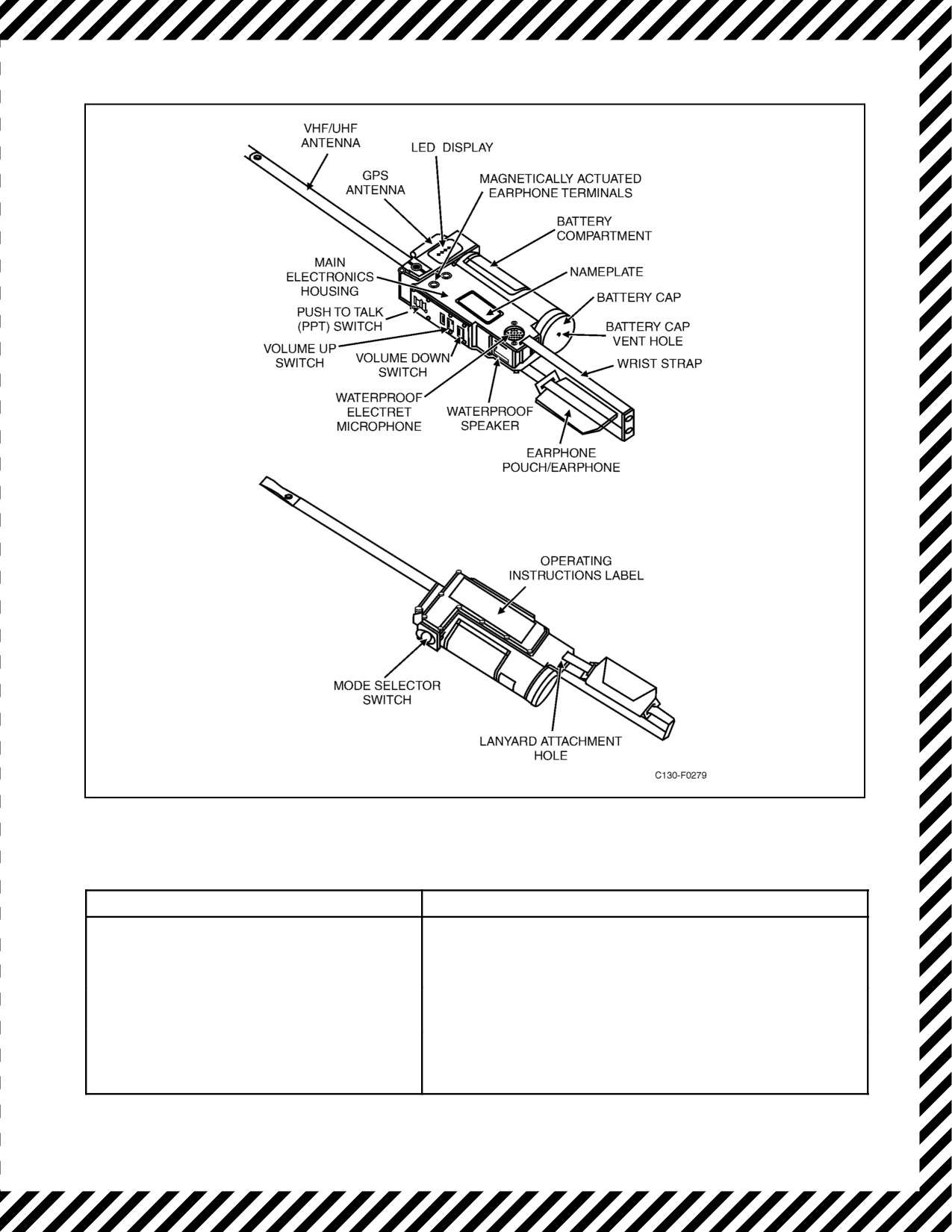
The C130-T may be equipped with five PRC-149s (see Figures 11-22 and 11-23) in place of the older PRC-90s. The
AN/PRC-149 Radio Set is a noncombat radio that combines an AM (Amplitude Modulation) voice transceiver at
selectable frequencies of 121.5 MHz, 243.0 MHz, and 282.8 MHz, with a multi-modes personal locator beacon that
transmits the older 121.5 MHz and 243.0 MHz beacons with the newer digital 406.025 MHz beacon. In the triple
frequency beacon mode, the AN/PRC-149 simultaneously transmits an enhanced multi-moded emergency rescue
message on the 121.5 MHz and 243.0 MHz emergency channels along with interspersed 406 MHz signals. In the
406.025 MHz only mode, the AN/PRC-149 Radio Set transmits a digital message containing beacon identification
to COSPAS-SARSAT satellites. An embedded GPS Receiverprovides position location information included in the
digital message.
The COSPAS-SARSAT satellite system is capable of estimating the location of the AN/PRC-149, based on the
relative satellite doppler without GPS data (see Chapter 6).
The primary advantage of a 406.025 MHz beacon over the 121.5 MHz and 243.0 MHz beacons, when used in
conjunction with the COSPAS-SARSAT satellite system, is its ability to provide search and rescue forces with the
beacon’s location coordinates. The beacon’s location is computed by the COSPAS-SARSAT system based on the
Doppler shift between the 406.025 MHz beacon and the satellite orbital motion. If the embedded GPS receiver has
acquired a position fix, then an even more accurate location of the beacon is made available to the SAR forces.
The AN/PRC-149 Radio Set 121.5 MHz and 243.0 MHz transmissions provides approaching search and rescue
forces with a beacon for their direction finding equipment. The radio set uses an enhanced multi-modes waveform
that facilitates location and detection during search and rescue operations.
11.10.14.3.3 AN/PRT-5E Emergency Transmitter
An emergency radio transmitter is stowed in each of the four liferafts (see Figure 11-1). The radio is a battery-powered
emergency beacon transmitter. When properly activated, the radio transmits a tone-modulated radio frequency signal
on the emergency guard frequencies of 8.364 MHz and 243.0 MHz simultaneously. The transmitting set includes
an inflatable float assembly that allows the transmitting set to float at sea and provides a support platform for use
on land. The entire set is packed in a carrying case.
11.10.14.4 Normal Operation of the Emergency Transmitter
11.10.14.4.1 Opening the Carrying Case
1. Unsnap and pull the self-adhering strap on the carrying case.
2. Remove the transmitting set assembly.
3. Attach the float assembly mooring-line snaphook to an eyelet on the liferaft.
11.10.14.4.2 Inflating the Float Assembly
1. Be sure the CO2 bottle is firmly screwed into its valve.
2. Pull sharply on the CO2 valve lanyard to pierce the end of the CO2 bottle.
3. In the event the CO2 bottle is empty, the float assembly can be inflated by blowing into the oral valve.
11.10.14.4.3 Operating Procedure
1. Pull the free end of the UHF antenna through the grommet in the float assembly to allow the antenna to stand
vertically.
11-105
ORIGINAL

01-75GAL-1
CAUTION
Any attempt to turn the antenna bushing assembly below the knurled knob
will result in internal damage and failure of the transmitting set to transmit.
2. Unscrew the knurled cap located on top of the telescopic HF antenna housing and pull the antenna out to its
full length (9 feet).
3. Pull out the switch safety pin.
4. Turn the power toggle switch to ON.
5. Place the entire assembly in the water and tow it behind the liferaft.
6. When operating on land, besure thetransmitting set is placed on level ground so that theantennas arevertical.
Stand away from the transmitting set to avoid changes in the radiation pattern of the transmitted signals.
7. If desired, the safety pin can be replaced to prevent the transmitting set from being turned off accidentally.
To turn the transmitter off:
8. Turn the power switch to OFF, and replace the switch safety pin.
9. Lower the HF antenna completely and screw down the top section screwcap.
10. Put the free end of the UHF antenna through its retaining grommet in the float assembly.
11.11 GPWS AURAL WARNING (TERRAIN TERRAIN/WHOOP, PULL UP GPWS) AND
WINDSHEAR ESCAPE MANEUVER
If at low altitudes in mountainous terrain, conducting an approach during night or in IMC conditions, or when
operating in an environment where the ground is not clearly visible, regardless of familiarity with the topographical
features and the GPWS aural warning activates or during takeoff or approach uncommanded changes from normal
flight that approximate the below guidelines are experienced:
± 15 knots indicated airspeed,
± 500 fpm vertical speed,
± 5_ pitch attitude,
or on approach and
± 1 dot glideslope displacement and unusual power settings are required for a significant period of time:
Note
Recognition and response to a windshear encounter may take 5 to 15
seconds; therefore, timely recognition and effective crew coordination is
required.
ORIGINAL
11-106

01-75GAL-1
To counter the loss of airspeed and lift resulting from windshear, pitch attitude must be controlled while accepting
a reduced airspeed to prevent flight path degradation. The spirit of the procedure is to position the aircraft for
continued safe flight, then troubleshoot a suspected GPWS malfunction. The Aircraft Commander must use prudent
judgment in cases of known GPWS erroneous terrain warnings.
Simultaneously perform:
*1. Autopilot — DISENGAGE (P).
*2. Throttles — MAX POWER (P).
*3. Attitude — MINIMUM OF 10° to 15_ NOSE UP (P).
D Adjust nose attitude to ensure positive rate of climb.
D Do not change aircraft configuration prior to termination of GPWS aural
warning or clear of windshear conditions.
D In the absence of a published procedure, fly a ground track that ensures the
aircraft remains clear of terrain.
Note
Copilot repeatedly calls out radio altitude and altitude trend (climbing or
descending) until the recovery is complete.
4. Proceed with normal Go-Around procedures following termination of GPWS aural warning or when clear of
windshear conditions.
11-107
ORIGINAL
01-75GAL-1
Figure 11-19. LRU-15/A Liferaft Assembly
ORIGINAL
11-108
01-75GAL-1
Figure 11-20. LPP-1, -1A Life Preserver
11-109
ORIGINAL
01-75GAL-1
Figure 11-21. Emergency Radio and Parachute
ORIGINAL
11-110
01-75GAL-1
Figure 11-22. AN/PRC-149 Radio Set Main Items Identification
MODE SELECTOR SWITCH POSITION
AN/PRC-149 RADIO SET STATUS AND OPERATING STATE
Position: 0
Powered Off completely
Mode: OFF
1. At power-on, all 4 LEDs come ON. After BIT completes
(2-3 sec.) LEDs change to their operational states.
2. GPS LED is initially set OFF after power-on (since GPS
receiver has not acquired a position fix yet).
3. Power is NOT supplied to backup Random Access
Memory (RAM) in the GPS receiver when AN/PRC-149
Radio Set is powered OFF.
Figure 11-23. AN/PRC-149 Mode Selector Switch (Sheet 1 of 5)
11-111
ORIGINAL

01-75GAL-1
MODE SELECTOR SWITCH POSITION
AN/PRC-149 RADIO SET STATUS AND OPERATING STATE
Switch Position:
1
1.
Beacon transmissions are disabled.
Mode: GPS
2.
AM voice transceiver is disabled.
3.
Speaker and Unmodified Electrical Headset are both
disabled on entering this mode.
4.
GPS receiver is powered ON by entering this mode.
Position fix acquisition might take 2 minutes (typical), or
more depending on GPS antenna’s view of sky.
5.
GPS LED blinks (0.5 seconds ON, 0.5 seconds OFF)
until a valid position has been acquired.
6.
GPS LED turned ON (and remains ON continuously)
after GPS receiver acquires a valid position fix.
Note
Poor positioning of GPS antenna could result in wasted
battery life. If possible, hold radio in the vertical
position.
7.
GPS receiver is powered OFF after first valid position
fix is acquired. GPS receiver is then powered ON every
20 minutes and left powered ON until a valid position fix
is acquired again, after which it is powered OFF. The
GPS LED remains ON after the first acquisition even if
a reacquisition does not occur. This is to indicate that
the position transmitted in the 406.025 MHz mode
always includes the last position fix.
8.
AN/PRC-149 Radio Set BIT can be initiated in this
mode by pressing and holding down both the Up
Volume and Down Volume pushbutton switches
continuously for 10 seconds. BIT result is reported by a
blink pattern using the Beacon LED display.
9.
If this mode is entered from 406.025 MHz Beacon Only
mode or from Triple Frequency Beacon mode, and if a
valid GPS position fix has already been acquired, then:
a. The GPS LED is turned ON immediately on entry
into this mode.
b. The GPS receiver is powered OFF (if not already
OFF).
Figure
11-23.
AN/PRC-149 Mode Selector Switch (Sheet 2)
ORIGINAL
11-112

01-75GAL-1
MODE SELECTOR SWITCH POSITION
AN/PRC-149 RADIO SET STATUS AND OPERATING STATE
Switch Position:
2
1.
AM voice transceiver operation is half-duplex.
Mode: VOICE
2.
AM voice transceiver receive mode and 243 MHz (AM
Voice Channel #1) and are always automatically
selected upon entry into this mode.
3.
The Beacon mode is OFF when returned to AM Voice
mode.
4.
Operator toggles between 243 MHz (Channel #1), 282.8
MHz (Channel #2), and 121.5 (Channel #3) voice
channels by pressing Up and Down Volume buttons
simultaneously. Operator must hold both in the pressed
position for at least 1.5 seconds for channel change to
occur. If the operator continues to hold both Volume
switches in the pressed position, then after each
1.5-second interval, another channel change will be
performed.
5.
AM CH1 LED and AM CH2 LED indicate which channel
is selected:
a. (AM CH LED1 = ON, AM CH LED2 = OFF) indicates
Channel #1 (243 MHz).
b. (AM CH LED1 = OFF, AM CH LED2 = ON) indicates
Channel #2 (282.8 MHz).
c. (AM CH LED1 = ON, AM CH LED2 = ON) indicates
Channel #3 (121.5 MHz).
6.
Speaker output is disabled by microprocessor and
Unmodified Electrical Headset output enabled if
magnetic reed switch indicates that external Unmodified
Electrical Headset is connected to AN/PRC-149 Radio
Set.
7.
Audio output (speaker or Unmodified Electrical Headset,
whichever is enabled) volume level is always set to
default level on entry into this mode. (Default for both
speaker and Unmodified Electrical Headset = minimum
(mute) volume).
8.
Beacon is powered OFF on entry into this mode.
9.
GPS receiver is powered OFF on entry into this mode.
Figure
11-23.
AN/PRC-149 Mode Selector Switch (Sheet 3)
11-113
ORIGINAL

01-75GAL-1
MODE SELECTOR SWITCH POSITION
AN/PRC-149 RADIO SET STATUS AND OPERATING STATE
Switch Position:
3
1.
Speaker and Unmodified Electrical Headset are both
disabled upon entering this mode.
Mode:
406 BCN
2.
COSPAS-SARSAT T.001 compliant beacon
transmissions are made at approximately 50-second
intervals.
3.
121.5 MHz and 243 MHz beacon transmissions are
disabled.
4.
Beacon Status LED blinks repeatedly ON for 2 seconds
and OFF for 8 seconds.
5.
AM voice transceiver is powered OFF on entry into this
mode.
Note
Poor positioning of GPS antenna could result in wasted
battery life. If possible, hold radio in the vertical
position.
6.
GPS receiver is powered ON upon entering this mode.
Position acquisition might take 2 minutes (typical), or
more depending on antenna’s view of sky. The GPS
receiver is turned off after acquisition, and then powered
ON every 20 minutes and left powered ON until a valid
position fix is acquired again, after which it is powered
OFF.
7.
GPS LED blinks (1 second ON, 1 second OFF) until a
valid position has been acquired.
8.
GPS LED turned ON (and remains ON continuously)
after GPS receiver acquires a valid position fix.
Position: 4
1.
COSPAS-SARSAT T.001 compliant beacon
transmissions are made at approximately 50-second
Mode: TRIPLE BCN
intervals.
2.
Multi-moded simultaneous 121.5 MHz and 243 MHz
beacon transmissions are made continuously during the
interval between 406.025 MHz beacon transmissions.
3.
Beacon Status LED blinks repeatedly ON for 2 seconds
and OFF for 4 seconds.
4.
AM voice transceiver is powered OFF on entry into this
mode.
Note
Poor positioning of GPS antenna could result in wasted
battery life. If possible, hold radio in the vertical
position.
Figure
11-23.
AN/PRC-149 Mode Selector Switch (Sheet 4)
ORIGINAL
11-114

01-75GAL-1
MODE SELECTOR SWITCH POSITION
AN/PRC-149 RADIO SET STATUS AND OPERATING STATE
Position: 4
(cont.)
5.
GPS receiver is powered ON upon entering this mode.
Position acquisition might take 2 minutes (typical), or
more depending on antenna’s view of sky. The GPS
receiver is turned off after acquisition, and then powered
ON every 20 minutes and left powered ON until a valid
position fix is acquired again, after which it is powered
OFF.
6.
GPS LED blinks (1 second ON, 1 second OFF) until a
valid position has been acquired.
7.
GPS LED turned ON (and remains ON continuously)
after GPS receiver acquires a valid position fix.
8.
An audible indication that 121.5/243 MHz beacon
transmissions are occurring is output to the speaker or
Unmodified Electrical Headset. Speaker output is
disabled by microprocessor and Unmodified Electrical
Headset output enabled if the magnetic reed switch
indicates that an external Unmodified Electrical Headset
is connected to AN/PRC-149 Radio Set.
9.
Audio output volume to the speaker or Unmodified
Electrical Headset, whichever is enabled, is always set
to default level (minimum volume) on entry into this
mode. The operator may adjust the volume by pushing
the volume up and down control buttons.
10. During the swept-tone portion of the 121.5/243 beacon
transmission, a 1,000 Hz tone is output as an audio
tone to the speaker or Unmodified Electrical Headset for
approximately 2 seconds every 8 seconds.
Figure
11-23.
AN/PRC-149 Mode Selector Switch (Sheet 5)
11-115
ORIGINAL

01-75GAL-1
ENGINE SHUTDOWN PROCEDURE
IN-FLIGHT DOOR WARNING
*1. CONDITION LEVER
FEATHER (CP)
*1. SEATBELTS
FASTENED (ALL)
*2. OXYGEN
AS REQUIRED (ALL)
*2. FIRE HANDLE
PULLED AS REQUIRED (CP)
3. PRESSURIZATION
BEGIN DEPRESS (FE)
*3. FIRE EXT
DISCHARGED AS REQUIRED (CP)
4. DESCENT
AS REQUIRED (P)
*4. FLAPS
AS REQUIRED (CP)
5. AIR CONDITIONING
*5. LANDING GEAR
AS REQUIRED (CP)
MASTER SWITCH
AS REQUIRED (FE)
*6. PROPELLER
FEATHERED (CP)
6. DOORS
CHECKED (FE)(LM)
7. MASTER DOOR WARN LT SW
OFF (FE)(LM)
CLEANUP
1. ENGINE BLEED AIR SWITCH
OFF (FE)
RAPID DECOMPRESSION
2. GENERATOR SWITCH
SET (FE)
*1. OXYGEN
ON/100% (ALL)
3. FUEL BOOST PUMP SWITCH
AS REQUIRED (FE)
*2. PRESSURIZATION
AS REQUIRED (FE)
4. CROSSFEED VALVE SWITCH
AS REQUIRED (FE)
*3. DESCENT
AS REQUIRED (P)
5. PROP GOV CONT SWITCH
MECH GOV (CP)
4. EPOS/VRU
AS REQUIRED (LM)
6. PROP FEATH OVRD BUTTON
OUT (CP)
7. SYNC MASTER
RESET AS REQUIRED (FE)
FUEL DUMPING
8. TD VALVE SWITCH
NULL (FE)
1. ATC
ADVISE (CP)
9. THROTTLE
FULL FORWARD (P)
2. FUEL PANEL
MAIN TANK TO ENGINE (FE)
10. OIL COOLER FLAPS SWITCH
CLOSED/
FIXED (CP)
3. INTERCONNECT VALVE SWITCHES
FLOW (FE)
4. DUMP SHUTOFF VALVE SWITCHES
DUMP (FE)
APU FIRE (ON GROUND)
5. DUMP PUMP SWITCHES
DUMP (FE)
*1. APU FIRE HANDLE
PULLED (CP)
6. MONITOR THE FUEL QUANTITY
*2. FIRE EXT
DISCHARGE AS REQUIRED (CP)
INDICATORS
(FE)
7. DUMP PUMP SWITCHES
OFF/NORM (FE)
*3. APU GENERATOR
OFF (FE)
4. EVACUATE AIRCRAFT
(ALL)
8. INTER CONN VALVE
SWITCHES
NO FLOW (FE)
9. DUMP VALVE SWITCHES
NORM (FE)
APU FIRE (IN FLIGHT)
10. CLEAR FUEL MANIFOLD
(P/FE)
*1. APU FIRE HANDLE
PULLED (CP)
11. CHECK FOR NEGATIVE FUEL
*2. FIRE EXT
DISCHARGE AS REQUIRED (CP)
FLOW AND FUMES
(LM)
*3. APU GENERATOR
OFF (FE)
4. APU CONT SWITCH
STOP (FE)
DITCHING
5. APU BLEED AIR VALVE SWITCH
CLOSED (FE)
1. TIME TO IMPACT
CREW ALERTED (CP)
2. ALTIMETERS
SET _____,_____ (P)(CP)
WING FIRE
1. FUEL CROSSFEED VALVE
3. PRESSURIZATION
EMER DEPRESS (FE)
SWITCHES
CLOSED (FE)
4. FUEL DUMP
AS REQUIRED (FE)
2. ENGINE HYDRAULIC PUMPS/
5. CARGO JETTISON
AS REQUIRED (LM)
SUCTION BOOST PUMP FOR THE
6. DITCH HEADING
CHECKED (P)(CP)
AFFECTED WING
OFF (CP)
7. DITCH SPEED
CHECKED (P)(CP)
3. BLEED-AIR DIVIDER VALVE AND
8. OVERHEAD HATCHES
REMOVED (FE)(LM)
BLEED-AIR VALVES FOR ENGINES
ON THAT WING
CLOSED (FE)
9. LAND GEAR WARN LIGHT CB
PULLED (FE)
4. WING ELECTRICAL EQUIPMENT
OFF (FE)
10. GPWS CBS
PULLED (FE)
5. SIDESLIP AIRCRAFT TO
11. EMERGENCY MSG/IFF
SEND (CP)
KEEP THE FIRE AWAY
12. FLAPS
AS REQUIRED (P)(CP)
FROM FUESLAGE
(P)
13. LANDING GEAR
UP (P)(CP)(FE)
6. LAND ASAP
(P)
14. SEATBELTS
FASTENED, LOCKED (ALL)
15. ALERT FOR IMPACT
CREW ALERTED (CP)
FUSELAGE FIRE/SMOKE AND FUME
ELIMINATION
*1. OXYGEN
ON/100% (ALL)
GROUND EVACUATION
*2. PRESSURIZATION
EMER DEPRESS (FE)
1. PARKING BRAKE
SET (P)
*3. DESCENT
AS REQUIRED (P)
2. TOWER/GROUND
NOTIFIED (CP)
*4. EXTINGUISH THE FIRE
AS REQUIRED (ALL)
3. CREW
NOTIFIED (P)
5. EPOS/VRU
AS REQUIRED (LM)
4. DC BUS TIE SWITCH
TIED (FE)
6. ENGINE BLEED AIR SWITCHES
OFF (FE)
5. CONDITION LEVERS
FEATHER (CP)
7. AIR-COND MASTER SWITCH
AUX VENT (FE)
6. FIRE HANDLES
PULLED (CP)
8. PARATROOP DOORS/AFT HATCH
OPEN (LM)
7. AC/DC POWER SWITCHES
OFF (FE)
9. FLT STA ESCAPE HATCH
OPEN AS
8. ALARM BELL
ONE LONG RING (CP)
REQUIRED (FE)
9. EVACUATE AIRCRAFT
(ALL)
10. CHOCK AIRCRAFT
AS REQUIRED (LM)
Figure 11-24. Emergency Procedures (Sheet 1 of 2)
ORIGINAL
11-116

01-75GAL-1
PROPELLER FAILS TO FEATHER
IF THE CONDITION PERSISTS:
1. ATTAIN 150 KTAS (IF POSSIBLE)
(P)
11. PERFORM ISOLATED DC BUS ISOLATION
2. FEATHER AND AIRSTART, EMER
PROCEDURES.
FEATHER, FEATHER PUMP MOTOR
CIRCUIT BREAKERS
CHECKED IN (FE)
CARGO JETTISON
3. FEATHER OVERRIDE BUTTON
HOLD IN FOR
1. ALERT THE CREW
ALERTED (CP)
30 SECONDS,
2. PASSENGERS
SECURED FORWARD
PULL OUT (FE)
OF CARGO (LM)
4. FIRE HANDLE
RESET (CP)
3. DESCEND
AS REQUIRED (P)
5. OIL SHUTOFF VALVE CIRCUIT
4. PRESSURIZATION . . BEGIN DEPRESSURIZATION (FE)
BREAKER
PULL (FE)
5. AIRSPEED
REDUCE TO BELOW 150 KIAS (P)
6. FLAPS
AS REQUIRED (P, CP)
6. FIRE HANDLE
PULL (CP)
7. PARACHUTES/
RESTRAINING HARNESS
ON/ADJUSTED (LM)
ELECTRICAL FIRE
8. PRESSURIZATION
AUX VENT (FE)
1. ISOLATE AFFECTED EQUIPMENT BY
9. AUXILIARY PUMP SWITCH
ON (CP)
PULLING CIRCUIT BREAKER AND
10. RAMP AND DOOR
CLEAR TO OPEN (LM)
TURNING SWITCH OFF
(ALL)
11. RAMP AND DOOR
OPENED (FE)
IF UNABLE TO LOCATE THE MALFUNCTIONING UNIT(S),
12. JETTISON CARGO
AS REQUIRED
PROCEED AS FOLLOWS:
13. FLAPS
50 PERCENT (P, CP)
14. RAMP AND DOOR
CLEAR TO CLOSE (LM),
WITH APU GENERATOR:
CLOSED (LM)
2. APU CONTROL SWITCH
START/RUN (FE)
15. AUXILIARY PUMP SWITCH
OFF (CP)
3. APU GENERATOR SWITCH
ON/CHECKED (FE)
4. ALL ENGINE GENERATOR SWITCHES
OFF (FE)
GPWS AURAL WARNING (TERRAIN TERRAIN/WHOOP, PULL
UP GPWS) AND WINDSHEAR ESCAPE MANEUVER
IF THE SITUATION STABILIZES:
*1. AUTOPILOT
DISENGAGE (P)
5. AGAIN ATTEMPT TO LOCATE AND ISOLATE
AFFECTED EQUIPMENT BY PULLING CIRCUIT
*2. THROTTLES
MAX POWER (P)
BREAKER AND TURNING SWITCH OFF
(ALL)
*3. ATTITUDE
MINIMUM OF 10° TO 15° NOSE UP (P)
IF CONDITION PERSISTS, PROCEED AS FOLLOWS:
4. PROCEED WITH NORMAL GO-AROUND
6. AUTOPILOT
OFF (P)
PROCEDURES FOLLOWING TERMINATION OF GPWS
AURAL WARNING OR WHEN CLEAR OF WINDSHEAR
7. ATTITUDE SELECT SWITCHES
GYRO ATT (P),
CONDITIONS.
(CP)
8. COPILOT AC INSTRUMENT SWITCH
STANDBY
TAILPIPE FIRE OR TORCHING DURING ENG START
(DC BUS) (FE)
1. CONDITION LEVER
GROUND STOP (P)
9. OIL COOLER
2. CONTINUE TO MOTOR THE ENGINE (P)
FLAP SWITCHES
OPENED/FIXED (CP)
3. PERFORM GROUND
10. APU GENERATOR AND APU
EVACUATION PROCEDURE
AS REQUIRED (ALL)
CONTROL SWITCHES
OFF/STOP (FE)
WITHOUT APU GENERATOR:
TAILPIPE FIRE DURING SHUTDOWN
1. AUTOPILOT
OFF (P)
1. PERFORM ENGINE SHUTDOWN PROCEDURE.
2. ATTITUDE SELECT SWITCHES
GYRO ATT (P),
(CP)
TURBINE OVERHEAT (GND)
3. COPILOT AC
1. THROTTLES
GND IDLE (CP)
INSTRUMENT SWITCH
STANDBY (DC BUS) (FE)
2. CONDITION LEVER
GND STOP (CP)
4. OIL COOLER FLAP SWITCHES
OPEN/FIXED (CP)
5. RADAR
OFF (P/FE)
START VALVE OPEN LIGHT ILLUMINATION (GND)
6. ALL GENERATORS SWITCHES
OFF (FE)
1. CONDITION LEVER
GND STOP (CP)
7. THREE MAIN AC BUS CURRENT
2. ENGINE BLEED AIR SWITCH
OFF (FE)
LIMITERS AT STATION 245 (UPPER
MAIN DISTRIBUTION PANEL)
REMOVED (FE)
BRAKE FIRE
8. ANY OPERATING ENGINE GENERATOR
ON (FE)
1. STOP AIRCRAFT USING REVERSE
(P)
IF THE SITUATION STABILIZES:
2. REQUEST FIREFIGHTING EQUIP
(CP)
3. PERFORM GROUND
9. ISOLATE AFFECTED EQUIPMENT BY
EVACUATION PROCEDURE
(ALL)
PULLING CIRCUIT BREAKERS AND
TURNING SWITCHES OFF
(ALL)
SPONGY/CHATTERING BRAKES
IF THE CONDITION PERSISTS, PROCEED AS FOLLOWS:
1. ANTISKID SWITCH
OFF (CP)
10. REMAINING ENGINE GENERATOR
OFF (FE)
2. BRAKE SELECT SWITCH
AS REQUIRED (CP)
CRITICAL ITEMS PRECEDED BY AN ASTERISK SHALL BE COMMITTED TO MEMORY
Figure 11-24. Emergency Procedures (Sheet 2)
11-117/(11-118 blank)
ORIGINAL
01-75GAL-1
PART VI
All-Weather Operations
Chapter 12 — All-Weather Operations
63/(64 blank)
ORIGINAL
01-75GAL-1
CHAPTER 12
All-Weather Operations
12.1
INTRODUCTION
This chapter contains only those procedures that differ from or are in addition to the normal operating instructions
covered in Part III, except for some repetition necessary for emphasis, clarity, or continuity of thought. References
in this section to operation of the aircraft component systems or auxiliary equipment mean the operation described
in Part I.
12.2
INSTRUMENT FLIGHT PROCEDURES
Theaircraftiscompletely equippedfortheuseofall standardradio navigationaland flightaids. Itis theresponsibility
of the pilot to ensure that each crewmember is thoroughly briefed on the exact procedures expected to be followed
during all phases of aircraft operation. In planning IFR flights, remember that fuel requirements at low altitudes are
greater than at higher altitudes. If required to land under IFR conditions, additional allowance must be made for
letdown and holding procedures. Follow the normal takeoff and cruise procedures in Chapter 8 and the NATOPS
Instrument Flight Manual, NAVAIR 00-80T-112, for instrument flight procedures. During takeoff, use a 4_ to 7_
noseup pitch attitude on the ADI to allow the aircraft to fly off the ground.
12.2.1 Holding
Conduct holding operations at 170 KIAS. If maximum endurance is required, conduct holding operations at
maximum-endurance airspeed plus 20 KIAS according to instructions from the airway traffic controller. This
airspeed permits holding to be accomplished at a constant power setting and allows turns to be executed with little,
if any, loss of airspeed. Any loss of airspeed may be regained when level flight attitude is resumed.
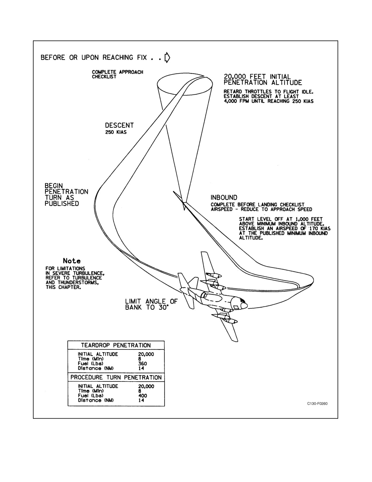
12.2.2 Penetrations
Penetrations may be accomplished in this aircraft, making certain that the current airspeed limitations in Chapter 4
are adhered to. Handling characteristics are very good, and pitch attitude is not extreme. A typical penetration is
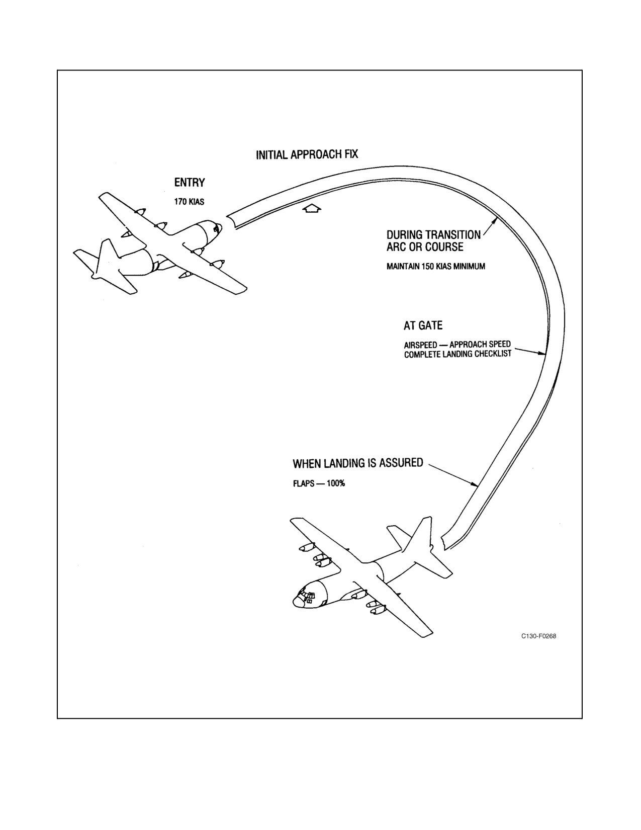
shown in Figure 12-1.
The recommended procedure is as follows:
1. Before or upon reaching fix, complete the Approach Checklist.
2. Beginthepenetrationatholdingairspeedfromtheappropriateradiofix,inthecleanconfiguration,byretarding
throttles to FLIGHT IDLE and smoothly establish descent at least 4,000 fpm until reaching the penetration
airspeed.
Note
During penetration, turbulence may be encountered without warning.
3. Follow the published penetration procedure.
4. Start level-off 1,000 feet above the published minimum inbound altitude and establish an airspeed of 170
KIAS.
5. Complete the Before Landing Checklist prior to reaching the fix. Allow the airspeed to decrease to approach
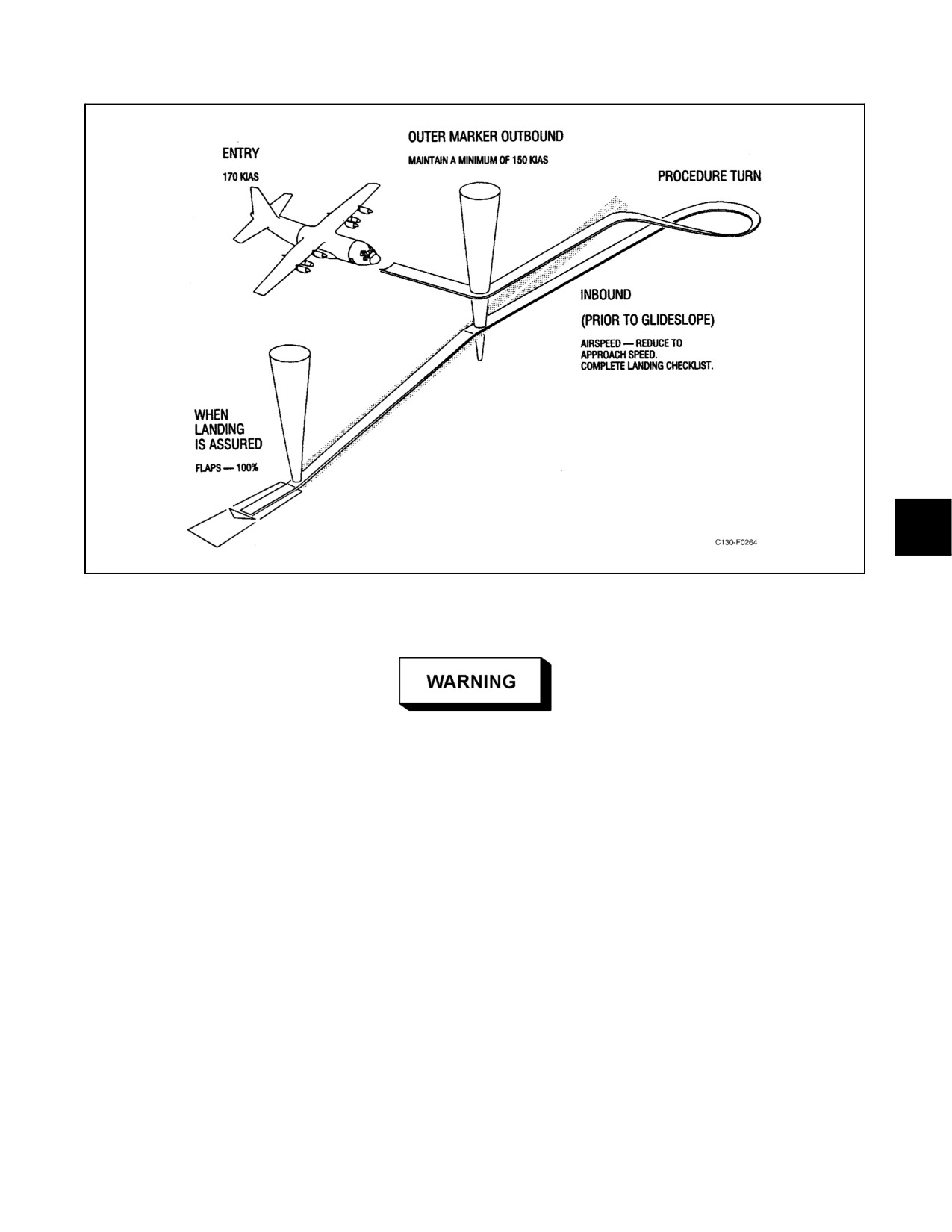
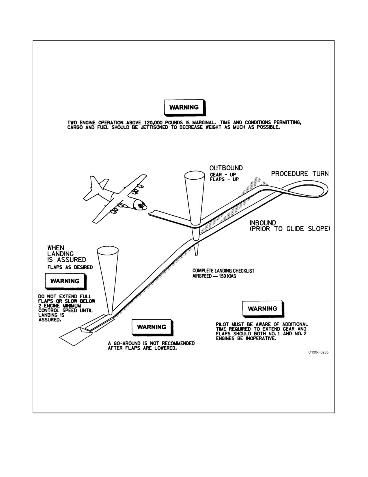
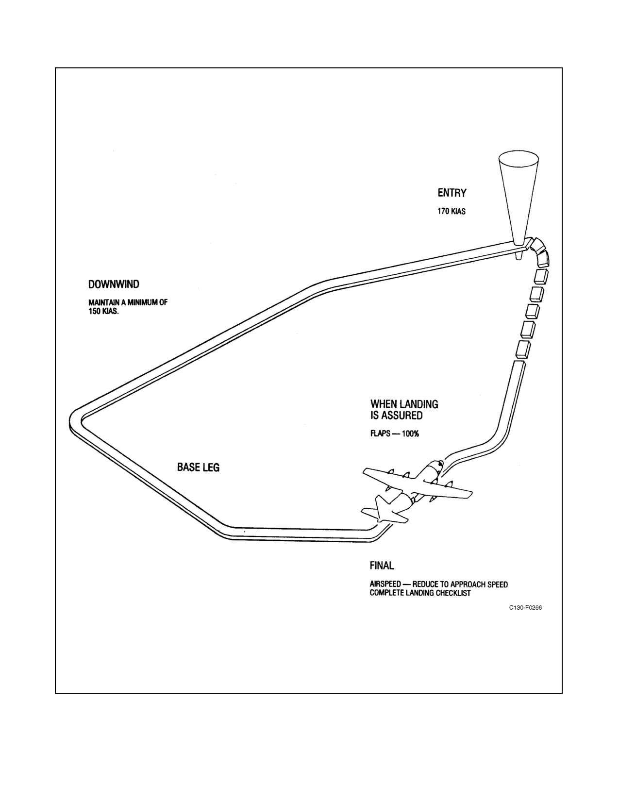
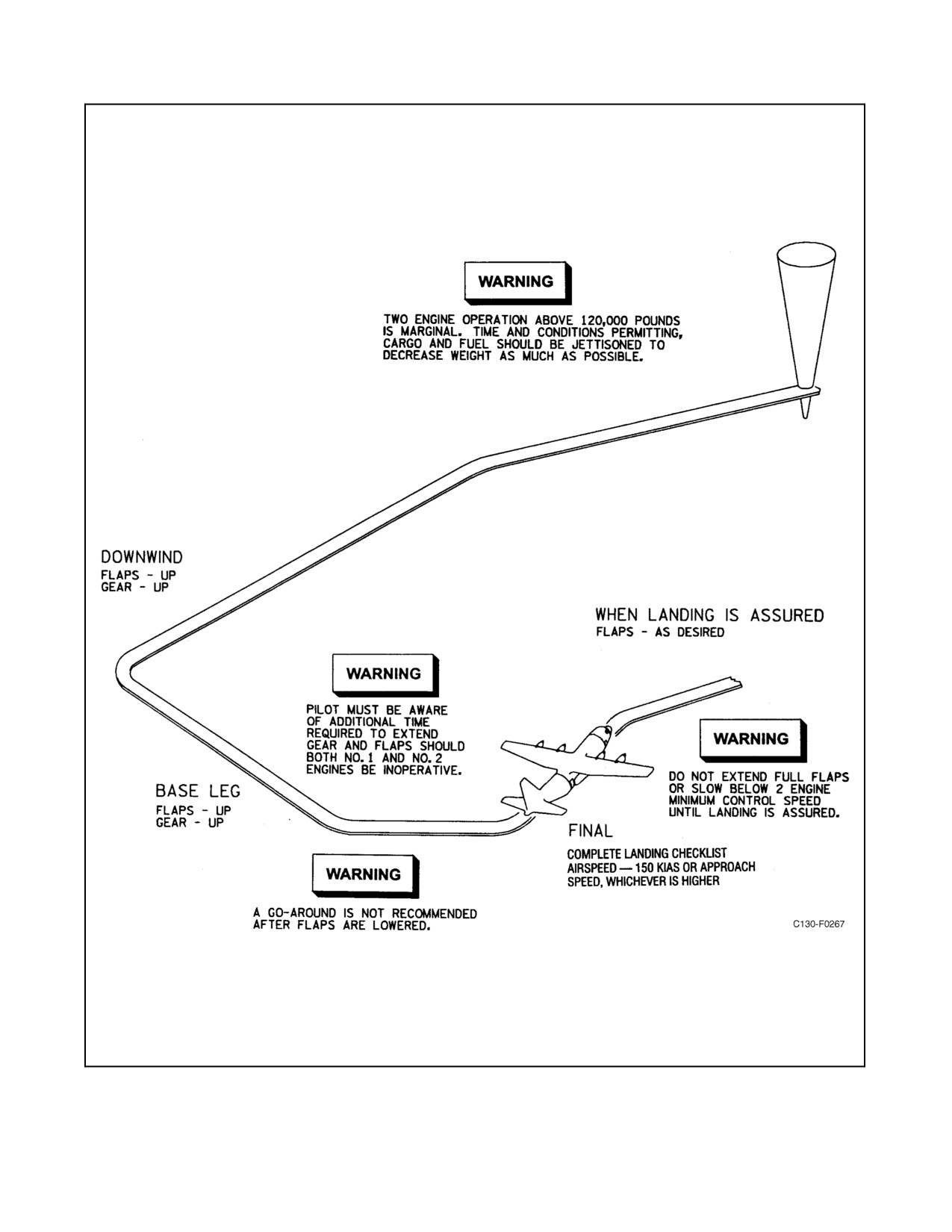
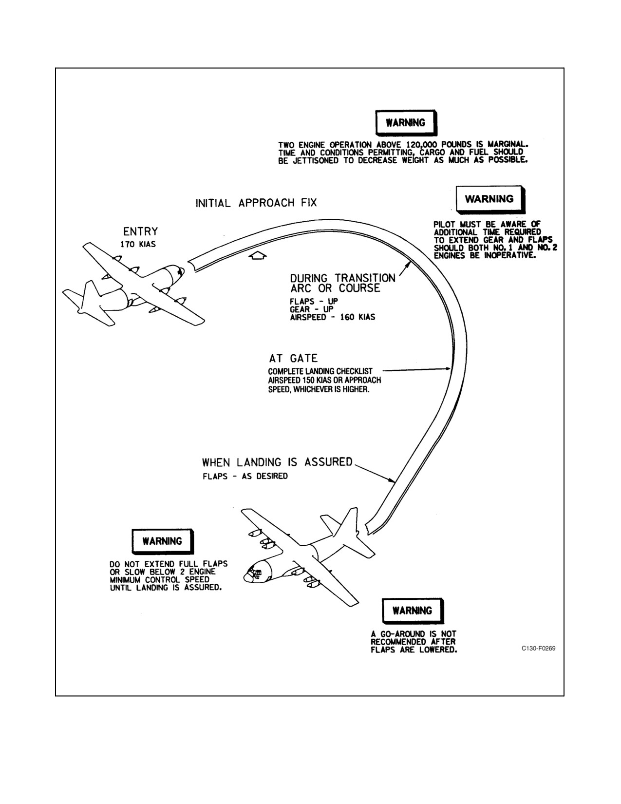
speed and execute an approach as depicted in Figures 12-3 through 12-10.
12-1
ORIGINAL
01-75GAL-1
Figure 12-1. Typical Penetration
ORIGINAL
12-2
01-75GAL-1
12.2.3 Instrument Approaches
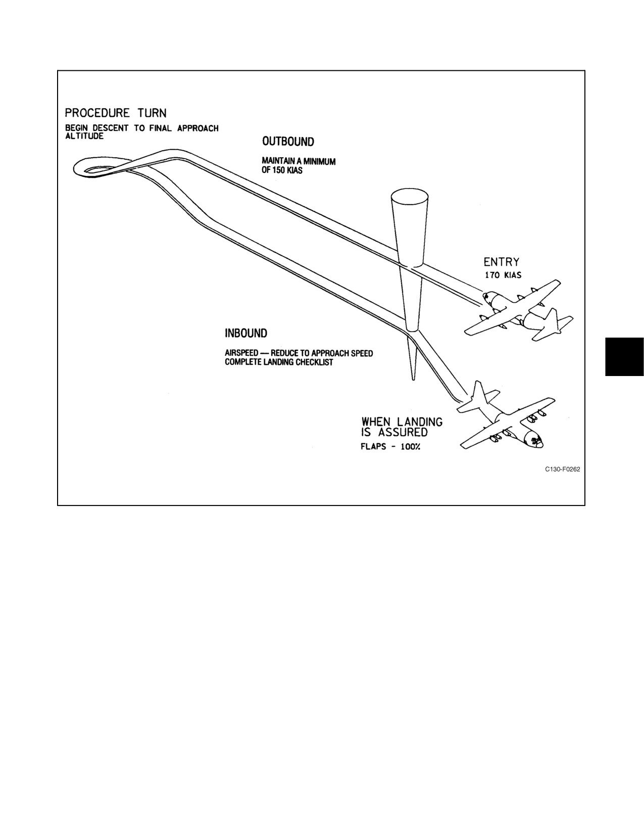
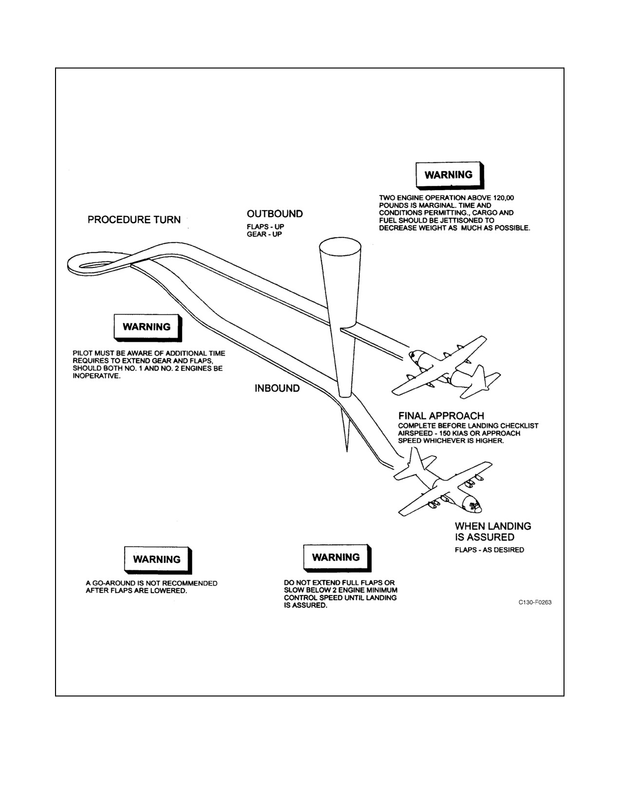
All conventional systems of instrument approach may be used. Flight characteristics during instrument approaches
do not differ from those encountered during normal visual flight. Normally, 170 KIAS is used for entry. Airspeed
after the Before Landing Checklist is initiated will be commensurate with the approach and aircraft gross weight. Do
notreducetoapproachairspeeduntilonfinalapproachtothestationorfix.SeeFigures12-3 through12-10 fortypical
approaches.
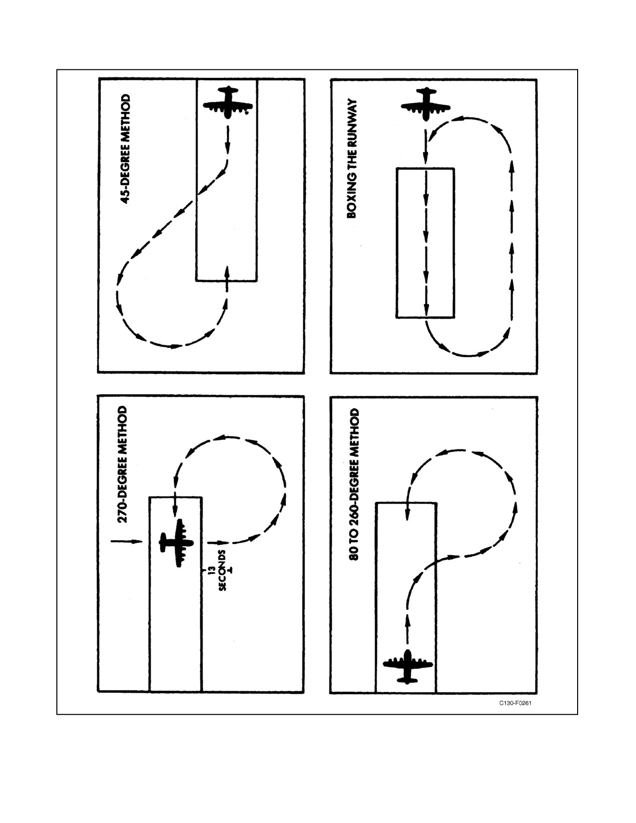
12.2.3.1 Circling Approach
The penetration and approach procedures are based on straight-in approach speeds. In the event it becomes necessary
to make a circling approach to align the aircraft with the runway, maintain 150 KIAS or computed approach speed,
whichever is higher until on final approach. When on final approach, select the desired final flap setting and proceed
with a normal landing. One of the following runway offset methods may be used (see Figure 12-2).
1.
270_ method — The 270_ method may be used when it is practical to cross the runway at 90_ from the
low-approach course of the aircraft. The runway is crossed at a 90_ angle. Fly this heading for approximately
13 seconds, then make a standard-rate turn to the runway heading.
2.
45_ method — The 45_ method consists of a standard-rate turn to a heading 45_ from the downwind heading
for 40 seconds and then make a standard-rate turn to the runway heading.
3.
80_ to 260_ method — The 80_ to 260_ method consists of a standard-rate turn of 80_ from the downwind
heading, then rolling out of this turn and into a standard-rate turn to the runway heading.
4. Boxing runway method — Boxing the runway is basically a closed-traffic pattern made by flying down the
runway, making a standard 180_ turn, and then another 180_ turn to the runway heading.
12.3
ICING CONDITIONS
Avoid icing conditions whenever possible. The biggest danger caused by ice accumulation is the reduced
aerodynamic efficiency of the aircraft. Increased drag and diminished lift because of airfoil deformation and loss of
thrust because of lowered propeller efficiency and engine power are typical results. Specifically, ice accumulation
may have the following effects:
1. Increased lift-off speed and increased stalling speed. Higher take-off, landing, and minimum flight speeds are
then required.
2. Reduced rate-of-climb ability of the aircraft.
3. Increase power requirement, causing increased fuel consumption and decreasing range and endurance.
4. Impaired control response.
5. Reduced engine power caused by obstruction of engine inlet air duct.
If cruise must be made in icing conditions, consideration must be given to the effect of using bleed air from the engines
for anti-icing system. Use of bleed air for anti-icing will reduce speed, and thus range, for any power setting. Refer
to NAVAIR 01-75GAI-1.1 Combined Performance Data Manual Figure 5-3 for cruise performance with anti-icing
systems in operation. Meanwhile, it is recommended that altitude be changed, when possible, until icing no longer
occurs. If climbing to a non-icing altitude is not possible, a check of fuel flow versus groundspeed should be made
to determine if range or radius of action will complete the mission.
12-3
ORIGINAL
01-75GAL-1
Figure 12-2. Circling-Approach Runway Offset Methods
ORIGINAL
12-4
01-75GAL-1
Figure 12-3. Typical Instrument Approach — Four or Three Engines — NDB, VOR, or Range Procedures
Although the leading edge is capable of full evaporative, continuous anti-icing, it has been found more satisfactory
to use the system exclusively as a deicing system by operating it periodically to remove accumulated ice. The
empennage system is exclusively an anti-icing system. Operation in this manner presents no problem with
“run-back.” The aircraft can penetrate icing conditions if the procedure given below is followed:
1. Select theleast severealtitude, from thestandpoint of icing conditions, consistent with mission objectives and
thetrafficorcombatconditions.ConsiderOAT,natureofclouds,typeoficing(rime,clear)anticipatedorbeing
encountered, and the duration of icing.
2. Fly with the PROP & ENGINE ANTI-ICING MASTER switch in the AUTO position.
3. Place the PROPELLER ICE CONTROL switch in the ON position.
4. Place the ENGINE INLET DUCT ANTI-ICING switch in the ON position.
12-5
ORIGINAL
01-75GAL-1
Figure 12-4. Typical Instrument Approach — Two Engines — NDB, VOR, or Range Procedures
ORIGINAL
12-6
01-75GAL-1
Figure 12-5. Typical ILS — Four or Three Engines
Engine inlet airduct icing may occur prior to illumination of the warning
icing condition ON light. Consider manually activating the ENGINE
INLET DUCT ANTI-ICING system prior to entering visible moisture
when IOAT is 10 _C or lower. If steps 2 through 4 have been accomplished,
momentarily place the PROP & ENGINE ANTI-ICING MASTER switch
to MANUAL. The system should be turned to AUTO when visible
moisture is no longer present by following the procedures in step 6.
Note
When icing conditions are encountered, the anti-icing system for the above
operates automatically, providing steps 2 through 5 have been accom-
plished. When the warning icing condition ON light is illuminated, make
frequent visual checks of wing leading edges.
5. Deice the wing leading edges whenever the ice appears to be 3/8 to 3/4 of an inch thick, although little
performance penalty has been noted when far heavier loads of ice have been allowed to build up. Deicing
switches should be turned on until wing leading edges are clean, then turned off. This will normally require
20 seconds orless ofon time. Fortheempennage, leavethe switch on as an anti-icing system. Theuse ofbleed
air from only one or two engines is not recommended.
12-7
ORIGINAL
01-75GAL-1
Figure 12-6. Typical ILS — Two Engines
ORIGINAL
12-8
01-75GAL-1
Figure 12-7. Typical Radar Approach Pattern — Four or Three Engines
12-9
ORIGINAL
01-75GAL-1
Figure 12-8. Typical Radar Approach Pattern — Two Engines
ORIGINAL
12-10
01-75GAL-1
Figure 12-9. Typical TACAN Pattern — Four or Three Engines
12-11
ORIGINAL
01-75GAL-1
Figure 12-10. Typical TACAN Pattern — Two Engines
ORIGINAL
12-12
01-75GAL-1
6. When icing conditions no longer exists, turn the PROP & ENG ANTI-ICING MASTER switch to the RESET
position. When turned to the RESET position, all anti-icing systems except wing and empennage are turned
off automatically. The WING and EMPENNAGE ANTI-ICING switches must be manually turned off.
CAUTION
Avoid high angles of attack during periods of transition from icing to
melting conditions and/or ice shedding for the center wing section.
Maintain a straight and level flight-path until all ice has been shed from the
center wing section. If ice is shed from the center wing section when the
aircraft is at high angles of attack, it is very likely the shedding ice will
strike the horizontal stabilizer and possibly cause extensive damage to the
stabilizer leading edge.
7. Delay extension of flaps and landing gear until absolutely necessary. This will help to avoid excessive ice
accumulation on the flaps and landing gear. While flying through icing conditions, watch the leading edge
anti-icing current indicators to make certain that the anti-icing equipment is working properly. Make frequent
visual checks of wing leading edges, engine inlet air duct leading edges, and propeller. If leading edge
anti-icing/deicing is seen to be inadequate for preventing ice accumulation, seek a less severe icing level.
If possible avoid prolonged flight in freezing rain, particularly at low
airspeeds with corresponding higher angles of attack, as there is a
possibility of ice accretion on the upper inside surface of the engine inlet
air ducts and other areas that are not normally exposed and that are not
anti-iced. Ice may accumulate on areas of the wing that are not anti-iced in
quantities sufficient to cause loss of control.
12.3.1 Clear-Air Icing
Engine inlet air duct icing in clear air is possible in some combinations of temperature and humidity, depending on
the engine power setting and the airspeed. This icing is caused by the sudden drop in temperature resulting from
pressure loss in the engine inlet air duct. Such icing is indicated by a falling torquemeter indication. If torquemeter
indicationfallsfornoapparentreason,assumethatengineinletairducticingisoccurring.TurnthePROP &ENGINE
ANTI-ICING MASTER switch to the MANUAL position, place the ENGINE INLET AIR DUCT ANTI-ICING
switch in the ON position, and take the following action immediately.
1. Increase airspeed to the maximum consistent with continuous operation, to increase ram pressure in the air
duct.
2. Seek an altitude that is less likely to produce air duct icing.
12.4
TURBULENCE AND THUNDERSTORMS
Rain has no appreciable aerodynamic effects on the aircraft. At cruise speeds, however, visibility through the
windshields will be reduced by streaking as thewindshield wipers are ineffectiveat speeds above approximately 180
KIAS.
12-13
ORIGINAL
01-75GAL-1
Flying under conditions of extreme turbulence, such as through thunderstorms, must be avoided whenever possible.
When flying under conditions of low visibility, clear passage around or between thunderstorms can usually be found
with the navigation and search radar. The possibility remains, however, that a storm cannot be dodged or that flight
through a storm may be a matter of military necessity.
Flight through thunderstorms or other conditions of extreme turbulence
should be avoided whenever possible.
Recommended airspeed for penetration into thunderstorms is 65 knots above power-off stall speed, not to exceed 180
KIAS.
Note
The autopilot may be used and, in some cases, is desirable. The altitude
hold mode should be disengaged and the autopilot not assisted or
overpowered in the autopilot mode. If autopilot cannot control attitude,
disengage and fly manually.
12.5
COLD-WEATHER PROCEDURES
Extreme cold causes general bad effects on aircraft materials. Rubber, plastic, and fabric materials stiffen and may
crack, craze, or even shatter when loads are applied. Oils and lubricants congeal. Adjoining metals contract
differentially and could result in adverse variations in tolerances. Moisture, usually from condensation or melted ice,
freezes in critical areas. Tire, landing gear strut, fire extinguisher bottle, and accumulator air pressures decrease with
a temperature decrease. Extreme diligence on the part of both groundcrews and flightcrews is required to ensure
successful cold-weather operation. The procedures and precautions outlined here pertain to operating unhangared
aircraft in cold weather and are in addition to the normal procedures given in Part III.
Note
Arrange the preheating period, whether by portable ground heaters or the
APU, so that aircraft components will be warmed and inspected prior to
starting the engines.
12.5.1 Before Entering the Aircraft
Perform a normal preflight inspection of the aircraft as outlined in paragraph 8.2. In particular, check the following:
1. Check for removal of all exterior protective covers and shields.
2. Check for ice, snow, heavy frost, and any remaining moisture from the entire aircraft.
Do not attempt takeoff with ice, snow, or frost on the wings or empennage.
The roughness caused by ice and snow on the surfaces varies the airfoil
shape with a resulting loss of efficiency. Takeoff run is increased, and rate
of climb is decreased. Stall speed is increased, and stall characteristics are
unpredictable.
ORIGINAL
12-14
01-75GAL-1
CAUTION
D Ensure that moisture from melted ice is not allowed to remain in critical
areas where it may refreeze.
D Do not attempt to scrape or chip ice from flight surfaces or fuselage.
Exercise care to prevent personnel injury from slipping and falling.
Note
If anti-icing compound has not been used on the crew door telescoping rod,
frozen condensation may prevent full opening until the rod is heated.
3. Check that fuel tank vents, fuel drains, filters, static ports, and pitot tubes are free of ice and snow.
4. Check for proper inflation of landing gear struts, tires, and hydraulic accumulators.
5. Check that landing gear strut extensions have been wiped with a hydraulic-fluid-soaked cloth to remove ice
and dirt.
6. Check that a warm, well-charged battery has been installed.
7. Check that dry bays are free of hydraulic fluid and fuel seepage.
12.5.2 Before Starting Engines
In addition to the normal procedures outlined in paragraph 8.4, perform the following checks:
1. Ifisopropyl alcohol has been used to removefrost from theaircraft, check theinterioroftheaircraft foralcohol
leaks and fumes. This condition may create a fire hazard.
During theapplication ofdeicing fluid, the APU and air-conditioning units
shall be shut down and all doors and hatches closed. Deicing fluid or mist
can enter the APU inlet. The resulting fumes entering the aircraft through
the bleed-air system are toxic and an extreme eye and lung irritant.
2. If external ac power is available, energize the Nesa windshields. Bring temperature up gradually to prevent
cracking glass. As ice and frost begin to melt, operate the windshield wipers to help clear the windshield. Other
windows may be cleared by portable ground heaters.
Note
Either portable ground heaters or the APU may be used to heat the interior
oftheaircraftduringtheinteriorinspection.Inextremecoldweather,itmay
be necessary to preheat the APU before it can be started. During starting,
torching may be observed. After start, allow approximately 4 minutes
warm-up before applying load.
12-15
ORIGINAL
01-75GAL-1
3. Increase warm-up times on navigation equipment listed below:
a. INS/GPS — 5 to 10 minutes.
b. Radar — 10 minutes.
c. HF radios — 10 minutes.
d. C-12 compass — 5 minutes.
e. Radio Altimeter — 5 minutes.
f. TACAN — 3 minutes.
g. VOR — 3 minutes.
h. ADF — 3 minutes.
CAUTION
D Do not attempt to taxi ifevidenceofhydraulicleakageis found in any main
landing gear area. Danger of fire and loss of brakes exists when hydraulic
fluid contacts hot brakes.
D Donotstaticallychangethebladeangleofapropellerthathasbeenexposed
to prolonged temperatures of 0 _C (32 _F) or below. Warm the propeller
hub oil by using warm air or by running the engine at ground idle until
engine oil temperature is within 60 to 80 _C. Propeller blade seal damage
and oil leakage may occur if this is not observed.
4. Before starting engines, remove all ground heater ducts from the aircraft.
5. In extremelow temperatures, thecrew doorseals may stiffen, thus making it impossibleto closethe doorfrom
inside the aircraft. When groundcrewmen are not available to assist in closing this door, it may be necessary
to have one or more flightcrewmembers assist in closing the door from outside, and then enter the aircraft
through one of the paratroop doors.
12.5.3 Starting Engines
When the engines have been exposed to prolonged temperatures below 0 _C/ 32 _F start engines using the following
procedure:
1. Start engines symmetrically in low speed ground idle.
2. After engine oil has been warmed above 0 _C, engines may be shifted to normal ground idle.
CAUTION
When attempting a start with JP-5/JP-8 and kerosene-type fuels at ambient
temperatures below approximately -32 _C (-25 _F) the TIT and rpm
should be closely monitored since stall and overtemperature may be
experienced during the start.
ORIGINAL
12-16
01-75GAL-1
3. Leave engines in normal ground idle until oil temperature reaches 60 _C.
CAUTION
Perform reverse checks only when engine oil temperature is within normal
limits or damage to propeller seals may occur.
12.5.4 Before Taxi
If not already accomplished with external power, energize the Nesa windshields, bringing temperature up gradually
to prevent cracking the glass. As ice and frost begin to melt, operate the windshield wipers to help clear the
windshield. Other windows may be cleared by airblast from the defogging ducts.
CAUTION
Do not overheat anti-icing systems on theground. Do not operatepropeller
anti-icing and deicing systems unless engines are running.
Note
During extremely low temperatures, refer to Operation of Windshield
Anti-Icing System in Part III.
12.5.5 Taxiing Instructions
At the start of taxiing on snow or ice, visually check the landing gear to assure that the wheels are rotating. The
combination of increased engine power at low temperatures and slippery ramp surfaces because of ice and snow
require that utmost caution be used during taxiing operations. Ground-handling characteristics of the aircraft on loose
or compacted snow at temperatures below 0 _F are good and braking action is fair to good. However, as temperatures
rise toward freezing, snow-covered surfaces become more slippery and increasing caution must be exercised. Use
of antiskid is recommended during all taxiing in cold weather.
In cold weather, make sure all instruments have warmed up sufficiently to
ensure normal operation. Check for sluggish instruments during taxiing.
CAUTION
Nosewheel steering becomes ineffective when abrupt turns are attempted
on slippery surfaces. Use nosewheel steering, differential braking, and
differential power for best directional control. Maintain safetaxi speeds by
use of brakes and partial application of reverse thrust. Excessive reverse
thrust will cause loss of visibility when taxiing over loose snow.
When operating on snow or slushy surfaces, use Nesa and pitot heat prior to and during propeller reversing.
12-17
ORIGINAL
01-75GAL-1
12.5.6 Ground Tests
Select the area that has the best available surface for braking and conduct the engine and propeller checks outlined
in Part III. Avoid parking aircraft close together or near obstructions when performing ground tests.
Note
Surfaces covered with loose snow generally provide better braking than
surfaces covered with compacted snow.
A modification of normal procedures may be required when making runup on slippery surfaces. Engines and
propellers may be checked in symmetrical pairs while using reverse thrust on the other pair to prevent the aircraft
from sliding forward. When runup must be conducted on snow-covered surfaces, do not attempt to make full power
checks until the aircraft is lined up on the runway and ready for takeoff.
12.5.7 Takeoff
If the aircraft starts to slide before takeoff power is reached, release the brakes and begin the takeoff run. Continue
the power check during the early part of the run.
Takeoffs in conditions of freezing rain or moderate freezing drizzle are
prohibited.
CAUTION
Under low ambient temperature conditions, never place throttles in the
TAKEOFF position without monitoring the torquemeters. At these
temperatures, it is possible to exceed maximum allowable torque without
exceeding the maximum allowable TIT. In addition, increasing ram effect
during the takeoff will increase torque for any fixed TIT. This means either
that torque must be set below the maximum allowable when setting power
for takeoff or that power must be reduced as airspeed builds up.
After takeoff from slushy runways, cycle the landing gear to reduce the possibility of doors freezing in the closed
position.
Note
During operation of the propeller anti-icing system, there is a possibility
that an indicator “jitter” may occur in the TIT indicators, the torquemeters,
tachometers, and fuel flow gauges. This needle
“jitter” may make
monitoring the affected instruments difficult. If this condition occurs,
momentarily turn the PROP & ENGINE ANTI-ICING MASTER switch
to RESET; then read the indicators.
12.5.8 Landing
Make a normal pattern and landing as outlined in Part III. Use nosewheel steering gently. Use reverse thrust during
the early part of the landing roll. As forward speed decreases, decrease reverse power. If reverse thrust is used at slow
ORIGINAL
12-18
01-75GAL-1
speeds on snow- or slush-covered surfaces, complete loss of visibility may occur. Use Nesa and pitot heat during
landing and be prepared to turn on windshield wipers.
Note
During use of maximum braking on slippery surfaces, cycling of the
antiskid system will be felt on the brake pedals.
12.5.9 Landing on Icy Runways
Refer to Landing on Icy Runways, paragraph 8.15.11.
12.5.10 Stopping Engines
Make a normal engine shutdown, as outlined in paragraph 8.18.
12.5.11 Before Leaving the Aircraft
Perform normal Before Leaving the Aircraft Checklist, as outlined in paragraph 8.19, and the following steps:
1. Remove ice and dirt from shock struts.
2. Install all exterior protective covers and shields.
3. If the aircraft is to remain outside more than 4 hours at temperatures below -29 _C (-20 _F), remove the
batteries and store them in a heated area.
4. Close all doors and hatches.
12.6
HOT-WEATHER PROCEDURES
Hot-weather operation, as distinguished from desert operation, generally means operation in a hot, humid
atmosphere. High humidity usually results in the condensation of moisture throughout the aircraft. Possible results
includemalfunctioning ofelectricalequipment, foggingofinstruments,rusting ofsteel parts,and thegrowth offungi
in vital areas of the aircraft. Further results may be pollution of lubricants and hydraulic fluids and deterioration of
nonmetallic materials. The procedures essential to operation and maintenance under such conditions aregiven in the
following paragraphs.
12.6.1 Before Entering the Aircraft
Perform a normal preflight inspection as outlined in paragraph 8.2. Give special attention to the following:
1. Cool the flight station and special equipment compartments with portable coolers, if available.
2. Inspect for freedom of corrosion or fungus at joints, hinge points, and similar locations.
3. Check for hydraulic leaks, as heat and moisture may cause seals and packings to swell.
4. Inspect the shock struts for cleanliness.
5. Inspect tires for proper inflation.
6. Remove all protective covers and shields.
12-19
ORIGINAL
01-75GAL-1
12.6.2 Before Starting Engines
Continue the normal preflight inspection, as outlined in paragraph 8.2. Give special attention to the following:
1. If instruments, equipment, and controls are moisture coated, wipe them dry with a clean, soft cloth.
12.6.3 Taxiing Instructions
Taxi the aircraft as directed in paragraph 8.7. Use brakes as little as possible, to avoid overheating.
CAUTION
To preclude the possibility of ongoing bog down/flameout when operating
in high ambient temperatures, turn off the oil cooler augmentation prior to
shiftingfromnormaltolow-speedground idleorfromlow-speed tonormal
ground idle.
12.6.4 Takeoff
Execute normal takeoff and climb, as outlined in paragraphs 8.9 and 8.10.
Note
Takeoff run is considerably increased, and rate of climb decreased, in high
temperatures. Refer to the appropriate performance charts.
12.6.5 Cruise
Follow normal procedures for the operation of the aircraft, as outlined in Chapter 8.
Note
Fuel densities will decrease as the ambient temperature rises, resulting in
a decrease in operating range. In addition, the boiloff rate will increase, and
it may be necessary to restrict rate of climb of the aircraft at altitude. Refer
to Fuel in Part I.
12.6.6 Landing
Execute normal approach and landing, as outlined in paragraphs 8.13, 8.14, and 8.15. Make a normal engine
shutdown as outlined in paragraph 8.18. As soon as the aircraft is parked, chock wheels and release brakes in order
to avoid possible damage to brake components from excessive heat generated when taxiing.
12.6.7 Before Leaving the Aircraft
Make a normal postflight inspection as outlined in paragraph 8.19 and complete the following steps:
1. Have appropriate protective covers installed for protection from the sun.
2. When weather conditions permit, leave flight station windows and compartment doors open to ventilate the
aircraft.
ORIGINAL
12-20
01-75GAL-1
12.7
DESERT PROCEDURES
Desert operation generally means operation in a very hot, dry, dusty, often windy atmosphere. Under such conditions,
sand and dust will often be found in vital areas of the aircraft, such as hinge points, bearings, landing gear shock struts,
and engine cowling and intakes. Severe damage to the affected parts may be caused by the dust and sand. Position
the aircraft so that propwash will not expose other aircraft, personnel, and ground equipment to blown sand or dust.
The necessary operations under such conditions are given in the following paragraphs.
12.7.1 Before Entering the Aircraft
Perform a normal preflight inspection as outlined in paragraph 8.2. Give special attention to the following:
1. Cool the flight station and special equipment compartments with portable coolers, if available.
Note
Use of the APU for ground air-conditioning may pull in quantities of sand
and dust.
2. Inspect all control surface hinge and actuating linkage for freedom of sand and dust.
3. Inspect tires for proper inflation.
4. Inspect shock struts for cleanliness.
5. Remove all protective covers and shields.
12.7.2 Before Starting Engines
Continue the normal preflight inspection of the aircraft, as outlined in paragraph 8.2. Give special attention to the
following:
1. Inspect instrument panels, switches, and controls for freedom of sand and dust.
2. Operate all controls through at least two full cycles to ensure unrestricted operation.
12.7.3 Taxiing Instructions
Taxi the aircraft as directed in paragraph 8.7, using care to avoid blowing sand or dust on other aircraft, personnel,
or equipment. Use brakes as little as possible to prevent overheating. The use of reverse thrust may blow sand and
dust into the air directly in front of the engine intakes. In deep sand, use differential power, rather than nosewheel
steering, for directional control. Minimize ground operation to avoid excessive sand and dust intake by the engines.
12.7.4 Takeoff
Execute normal takeoff and climb as outlined in paragraphs 8.9 and 8.10. Avoid takeoff during sand or dust storms,
if possible. Sand and dust will cause damage to internal engine parts. Takeoff run is considerably increased and rate
of climb decreased in high atmospheric temperatures. Refer to the appropriate performance charts.
Note
When takeoff performance is not critical, use a rolling takeoff whenever
possible in order to decrease time in adverse conditions.
12-21
ORIGINAL
01-75GAL-1
12.7.5 Cruise
Follow normal procedures for the operation of the aircraft, as outlined in Part III. Avoid flying through dust or sand
storms, when possible. Excessive dust and grit in the air will cause considerable damage to internal engine parts.
12.7.6 Landing
Execute a normal approach and landing as outlined in Part III. Therefore, on very hot days, follow traffic and landing
procedures strictly and anticipate a longer landing roll. Avoid the use of reverse thrust, since reverse thrust may blow
sand and dust into the air directly in front of the engine intakes.
12.7.7 Stopping Engines
Make normal engine shutdown as outlined in Part III. As soon as the aircraft is parked, chock the wheels and release
the brakes to avoid damage to brake components because of excessive heat generated while taxiing.
12.7.8 Before Leaving the Aircraft
Make a normal Before Leaving the Aircraft inspection, as outlined in Part III, giving special attention to the
following:
1. Have all protective covers and shields installed.
2. Except in dust or rainy weather, leave flight station windows and compartment doors open to ventilate the
aircraft.
ORIGINAL
12-22
01-75GAL-1
PART VII
Communication Procedures
Chapter 13 — Communication Procedures
65/(66 blank)
ORIGINAL
01-75GAL-1
CHAPTER 13
Communication Procedures
13.1
INTRODUCTION
The primary means of communication in the aircraft is voice radio. It is, of course, limited by the condition of the
equipment, frequencies and channels available, and operating conditions. Radio equipment carried on the aircraft is
described in detail in Chapter 2. It is essential that all pilots know and understand the use of the equipment. Operation
of the equipment will be in accordance with current applicable directives, depending on the type of flight and the area
inwhichtheflight willbeconducted.Communication proceduresareoutlinedin FederalAviation Regulations,FLIP
Publications, Flight Information Manual, ICAO Regulations, Air Traffic Control Procedures, OPNAV Instructions,
and ACP and JANAP publications.
13.2
RADIO COMMUNICATIONS
The aircraft commander is responsible for all communications transmitted from the aircraft and shall ensure
compliance with all procedures to which reference is made in this action. The aircraft commander is responsible for
a continuous watch to be maintained on appropriate radio frequencies, and that position reporting procedures and
requirements outlined in appropriate directives, or as required by the agency controlling the flight, are complied with.
13.3
VISUAL SIGNALS
The aircraft is equipped with an Aldis lamp to transmit visual signals. The running lights and landing lights may be
used as signals by utilizing the on-off switches.
13.4
LOST COMMUNICATION AND EMERGENCY COMMUNICATION PROCEDURES
Emergency situations are so varied that exact rules to be followed cannot be established for each situation. However,
when an emergency is encountered in a flight condition, the pilot is expected to act in accordance with the procedures
set down in the aforementioned referenced manuals.
13-1/(13-2 blank)
ORIGINAL
01-75GAL-1
PART VIII
Special Missions
Chapter 14 — Special Missions
67/(68 blank)
ORIGINAL
01-75GAL-1
CHAPTER 14
Special Missions
14.1
FORMATION FLYING
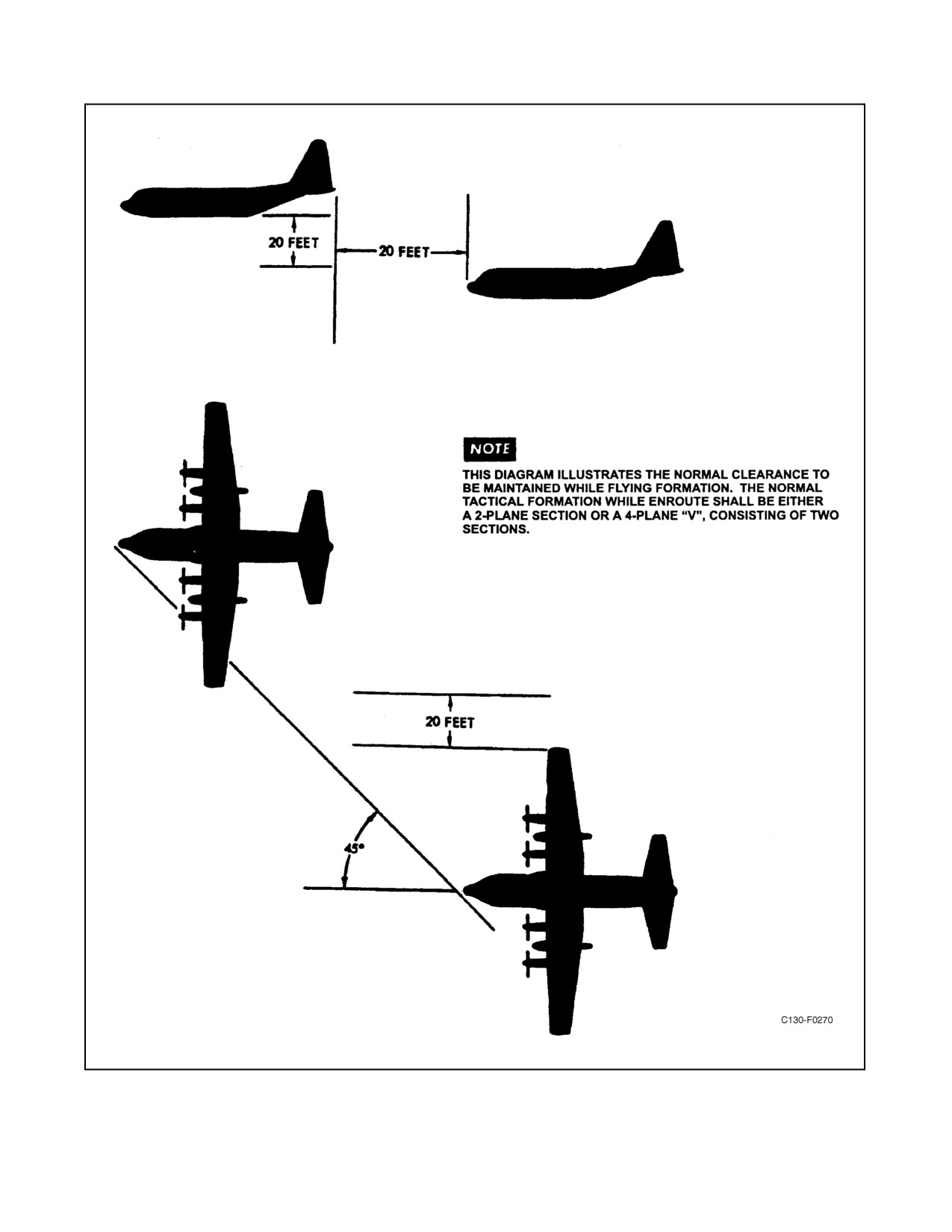
Formation flying in this aircraft is similar to formation flying in any other aircraft; however, you must recognize the
restrictions inherent because of the aircraft size and weight. Figure 14-1 depicts standard formation wing position.
14.1.1 Tactical Formation Procedures
14.1.1.1 Formation Taxiing
Formation taxiing will be accomplished utilizing four engines prior to takeoff and after landing. Taxiing distance
between the tail of the preceding aircraft and the nose of following aircraft will be two aircraft lengths.
14.1.1.2 Runway Positioning
When hard-surface runways permit, one section of aircraft may be positioned on the runway simultaneously. When
gravel, dust, or loose debris is prevalent, aircraft will be fed individually onto the runway. Aircraft will alternate
positioning on the sides of the runway, remaining two aircraft lengths behind the preceding aircraft on the same side.
This separation is applicable to “section positioning” as well as to feeding onto runway. Normally, a section will
position on the runway simultaneously. In the event runway conditions warrant feeding single aircraft onto the
runway, a determination to this effect will be made by the mission commander and will be adequately covered at
mission briefing.
14.1.1.3 Takeoff
Takeoff interval should not be less than 30 seconds if dual runways are used, or 1 minute if a single runway is used,
provided the aircraft ahead has completed its takeoff roll and commenced its climb.
14.1.1.4 Joinup After Takeoff
Joinup after takeoff shall be accomplished on a prebriefed assembly heading or track. After taking off and
commencing a climb, the flight leader shall reduce power and establish climb speed as briefed, consistent with
mission requirements. This climb power and airspeed should be held until completion of the formation joinup.
Joining aircraft should use power as necessary to accomplish the joinup expeditiously, joining in their respective en
route positions. The last aircraft to join up should call the flight leader when in position, and the flight leader may
then add power as necessary to complete the climb, using climb-schedule airspeeds. The end-of-climb speed should
be modified to suit the heaviest aircraft gross weight.
14.1.1.5 Joinup Over a Geographical Point
Joinup over a geographical point shall be accomplished at a prebriefed altitude and airspeed, the formation leader
holding 170 KIAS. Normally, the rendezvous can best be accomplished in a gentle orbit to allow joining aircraft the
advantage of relative motion in addition to airspeed. Departure on course may be commenced at the discretion of the
flight leader, maintaining reduced airspeed until joinup is complete.
14-1
ORIGINAL
01-75GAL-1
Figure 14-1. Formation Flying -- Normal Wing Position
ORIGINAL
14-2
01-75GAL-1
14.1.1.6 Climb
Climb under VFR conditions as outlined in the paragraph above. Under IFR conditions, an individual takeoff and
climb, utilizing departure control, should be made. After becoming VFR on top, the flight leader should reduce power
and hold a prebriefed heading or proceed to a prebriefed fix for the rendezvous. The interval between aircraft should
be the minimum allowed by departure control. One-minute separation will provide adequate lateral and altitude
separation to satisfy the dictates of flight safety.
14.1.1.7 En Route Procedures
The basic en route formation is a division made up of two independent sections. The second section is free to cruise
on either side of the formation leader, with sufficient separation to allow use of the autopilot as a measure to reduce
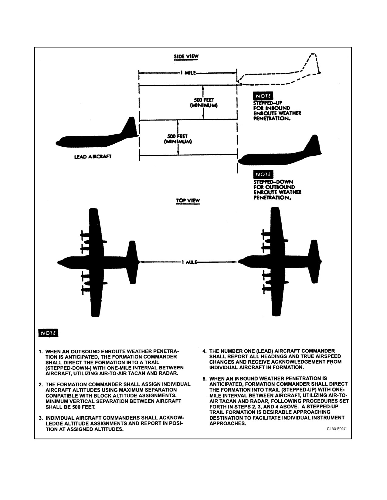
crew fatigue. The sections themselves may spread out in the same manner. In the event that penetration of weather
becomes necessary (see Figure 14-2), the following procedures shall be used and should be accomplished prior to
entering IFR conditions. It is the responsibility of the flight leader to obtain clearance from the appropriate controlling
agency prior to commencing breakup to weather penetration formation. A base-altitude airspeed and heading must
beestablished by theformation leaderand rigidly adhered to by thewingmen to provide separation as necessary. The
radar of the last aircraft in the formation should be utilized to keep track of the formation while IFR. After passing
through weather and becoming VFR, the flight leader should reduce to 170 knots until assembly is complete. The
other aircraft should add power to climb or descend to base altitude and accomplish the rendezvous as rapidly as
possible on the base heading.
14.1.1.8 Descent
VFR descent may be made in any formation deemed necessary by the flight leader. The flight leader should exercise
care not to reduce power to the point that a wing position becomes difficult or impossible to hold. About 3,000
inch-pounds of torque is the minimum power setting to allow wingmen to maintain position without radical throttle
and/or control movements. IFR descents must be made on an individual basis, and it is the responsibility of the flight
leader to obtain clearances for the aircraft in the flight and to place the formation in trail to allow safe individual
departures from the formation when under approach control.
14.1.1.9 Break and Landing
Break and landing shall be accomplished from an echelon, utilizing a 10-second break interval and a 30-second
landing interval.
14.1.1.10 Formation Techniques
Formation procedures suitable for fighter aircraft are readily adaptable to this aircraft. It is normally easier to fly on
the starboard side of the leader because of cockpit construction and visibility restrictions. En route, the autopilot may
be easily used to maintain formation position. It should be engaged when steady in position, and minor changes of
power or heading should be made as necessary. Normally, when en route and flying on autopilot, it is more
comfortable to move out from a normal wing position to a three- to four-wing span distance.
Note
Close formation flying should be held to a minimum to reduce effects of
thermal shock on turbines because of constant power lever movement.
14-3
ORIGINAL
01-75GAL-1
Figure 14-2. En Route Weather Penetration
ORIGINAL
14-4

01-75GAL-1
14.1.1.11 Formation Lighting
During day formation flights, all aircraft in the formation shall have their top and bottom anti-collision/strobe on.
The lights for night formation are as shown in Figure 14-3.
LIGHT
POSITION
INTENSITY
FORMATION POSITION
Cabin
On
Dim/clear
All
Formation
On
Bright
All
Navigation (for assembly)
On/flash
Dim
Section leaders
Navigation (for assembly)
On/steady
Dim
Wing aircraft
Navigation (en route)
On/steady
Dim
Section leaders
Navigation (en route)
On/flash
Dim
Wing aircraft
Navigation (landing)
On/flash
Bright
All (on break)
Anticollision (assembly)
On
All
Anticollision (en route)
On
Last aircraft each section
Anticollision (land)
On
All (on break)
Landing Lights
As required
All
Figure 14-3. Formation Lighting
Note
In addition to lights prescribed above, leading edge lights shall be used as
follows: (1) By division leaders from takeoff until joint-up is completed,
to assist succeeding aircraft in recognizing the assembly turn. (2) By all
aircraft after break to assist in determining interval.
14.2
ASSISTED TAKEOFF SYSTEM
Provisions are made for external mounting of eight solid-fuel ATO units of 1,000-pound thrust each, which supply
additional thrust when it is desired to shorten takeoff distance. The system is electrically controlled and operated from
theATO control panel (Figure 14-4)on theflight control pedestal. Theunits arefired simultaneously and givethrust
until the propellant is exhausted. After firing, the expended ATO units may be jettisoned to reduce aircraft weight
and drag.
14.2.1 Mounting of the Assisted Takeoff Units
The mounting provisions for the ATO units are the air deflectors in front of the paratroop doors (see Figure 14-4).
Four units can be mounted on each deflector. Each ATO unit is supported by a mounting hook at the forward end
and by a mounting channel at the aft end. The mounting hook remains extended at all times, while the mounting
channel is normally held flush with the air deflector skin by two springs. When an ATO unit is to be installed, the
channel is turned out to the extended position and is held out by a spring-and-latch arrangement. The ATO unit
forward attachment fitting pin is locked in the mounting hook by a spring-loaded latch. This latch is operated to
release the ATO unit by movement of a cam. One part of the cam engages the inboard end of the latch, while the other
14-5
ORIGINAL
01-75GAL-1
portion of the cam contacts a roller. The cam is connected by a cable to a release handle in the cargo compartment
and to the latch that holds the mounting channel in the extended position. As the release cable is pulled, the cam and
latch rotate. The cam rotates to retract the spring-loaded latch on the mounting hook. When the spring-loaded latch
is retracted, the cam slips off the roller and the pull of the release cable causes the hook to rotate so that the ATO unit
is pushed aft, to free it from the mounting channel. The ATO unit then falls away from the mounting hook and
channel. When the ATO unit is pushed aft, the latch rotates to release the mounting channel, which is pulled to the
flush position by springs.
14.2.2 Assisted Takeoff System Storage and Operating Temperature
ATO storage and operating limits for units usable with this system, are as follows:
UNIT
UPPER LIMIT
LOWER LIMIT
15-KS-1,000 Mk 6, Mod 0 with Mk 165, Mod 0 Igniter
140 _F
-65 _F
14.2.3 Assisted Takeoff System Controls
The flight station controls and the indicator for the ATO system are located on the ATO panel on the flight control
pedestal (see Figure 14-4). The jettison handles for the ATO system are located in the cargo compartment forward
of the paratroop doors (see Figure 14-4).
14.2.3.1 ARMED-SAFE Switch and Ready Light
The ARMED-SAFE switch, located on the ATO control panel (see Figure 14-4), is a two-position toggle switch
designed to prevent accidental operation of the ATO system. When the switch is in the SAFE position, the 28-Vdc
ATO CONTROL circuit is open and the system will not operate. When the switch is in the ARMED position, the
ATO CONTROL circuit is completed to the fire switch. A press-to-test READY light illuminates when the system
is armed and ready to fire. The ARMED-SAFE switch and READY light receive 28-Vdc power from the main dc
bus through the ATO CONTROL circuit breaker on the copilot lower circuit breaker panel.
14.2.3.2 FIRE Switch
The pushbutton FIRE switch, located on the ATO control panel, controls the operation of the ATO ignition circuits.
When the ARMED-SAFE switch is in the ARMED position and the FIRE switch is depressed, 28-Vdc power from
theATOCONTROLcircuitbreakerenergizestheignitionrelay.Actuationoftheignitionrelayapplies28-Vdcpower
from the main dc bus, through the ATO IGNITION circuit breaker on the copilot lower circuit breaker panel, to the
ATO igniters.
14.2.3.3 ATO Jettison Handles
Four manually actuated ATO release handles (see Figure 14-4) are located in the cargo compartment on the fuselage
structure forward of each paratroop door.
Each set of handles is reached through a zippered flap in the insulation. Pulling a handle mechanically releases the
ATO bottle.
ORIGINAL
14-6
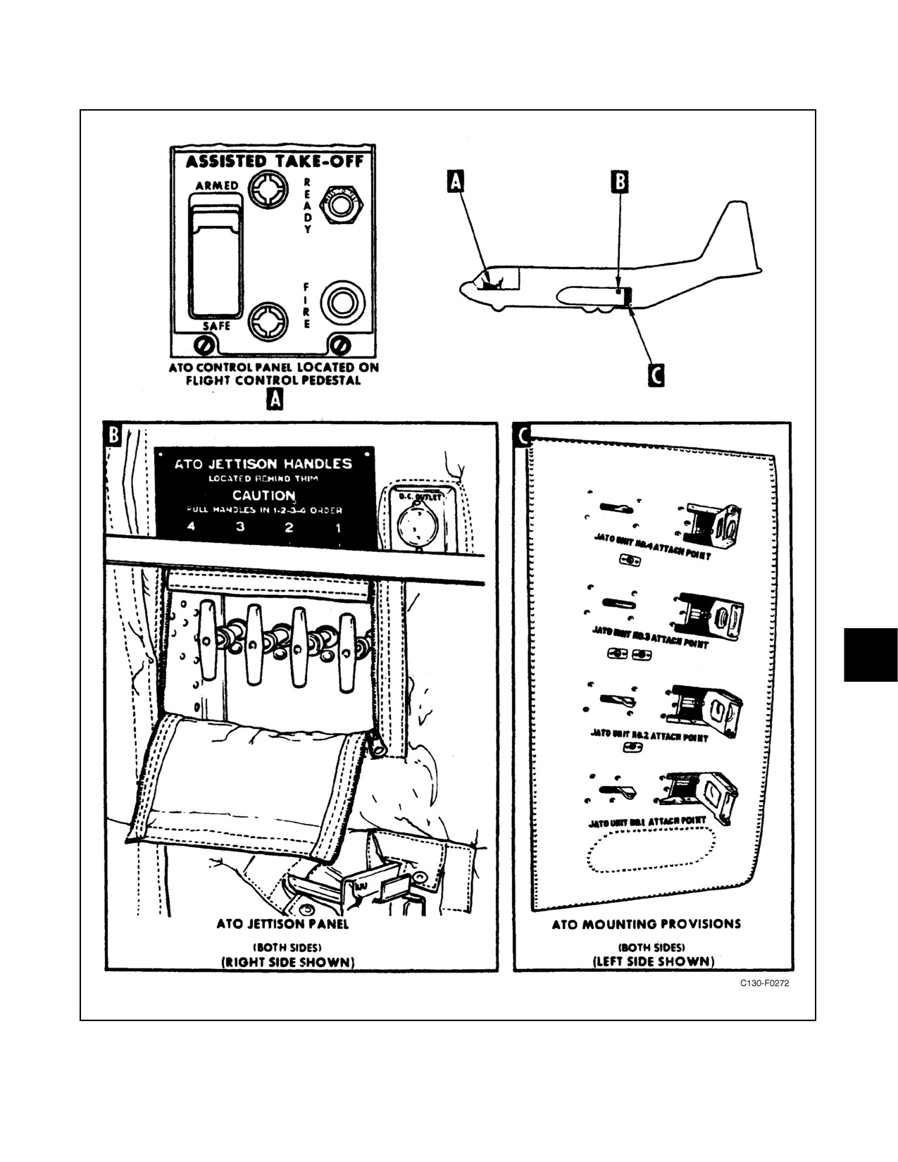
01-75GAL-1
Figure 14-4. Assisted Takeoff System
14-7
ORIGINAL
01-75GAL-1
14.2.3.4 Ignition Control
The ignition control circuit is arranged so that all the ATO units are ignited at the same time. An ignition relay in
the main dc distribution box closes the parallel circuits to apply voltage from the main dc bus through an ATO
IGNITION circuit breaker to the igniters. The control circuit for the relay includes limit switches actuated by the two
air deflectors, an arming switch, and a fire switch connected in series with the relay coil. If the air deflectors are closed,
the two limit switches are closed. The control circuit is then closed from the main bus through the ATO IGNITION
circuit breaker, an ATO control circuit breaker, and the two air-deflector limit switches to the arming switch.
Operation of the guarded arming switch then closes the circuit to the fire switch and completes a circuit to energize
a ready light next to the switch. If the FIRE switch is then pushed, the circuit is completed to energize the ignition
relay coil. The ignition relay cannot be energized unless both air deflectors are closed and both the arming and firing
switches are operated. The READY light indicates that the deflectors are closed when the arming switch is actuated.
Thewiringoftheignitioncircuitontheaircraftterminatesatquickdisconnectfittingsontheairdeflectors.Onefitting
is placed in a recess next to each of the ATO unit supports. Each fitting is a ball-type receptacle. The plugs on the
igniter leads with the ATO units fit the ball receptacles. The circuit through each igniter squib is completed to ground
through the igniter case. The air-deflector limit switch for each deflector is mounted in the deflector recess and is
actuated by the deflector as it closes. The effect of temperature on the ignition interval is shown in Figure 14-5.
14.2.4 Effect of Temperature on Assisted Takeoff Performance
Variations in ATO performance because of differences in temperatures are shown in Figure 14-5.
14.2.5 Inspection of Assisted Takeoff Units
Before installation, the ATO units and igniters must be inspected for serviceability.
14.2.5.1 ATO Unit Inspection
If any of the following defects or conditions are noted upon inspection of the entire external surface of the ATO unit,
that unit must not be used:
1. Damaged or cracked welds on the attachment fittings.
2. Damaged or loose attachment and/or fitting pins.
3. Excessive rust or corrosion of the attachment fittings and pins .
4. Obstruction of the nozzle orifice (other than normal plastic closure).
5. Damage resulting from blows or dropping.
Visual inspection of the interior walls of the chamber and nozzle is not possible. The following observations can be
made, and an ATO unit with any of the following defects must not be used:
1. Extensive rust on interior surfaces.
2. Rust particles or other foreign materials, except slight paint scales, on the surface of the propellant.
3. Moisture on the surface of the propellant.
4. Cracks in the surface of the propellant or broken pieces of propellant.
14.2.5.2 Igniter Inspection
Upon removal of igniter assemblies from the packing, they must be inspected. An igniter with one of the following
defects must not be used:
ORIGINAL
14-8
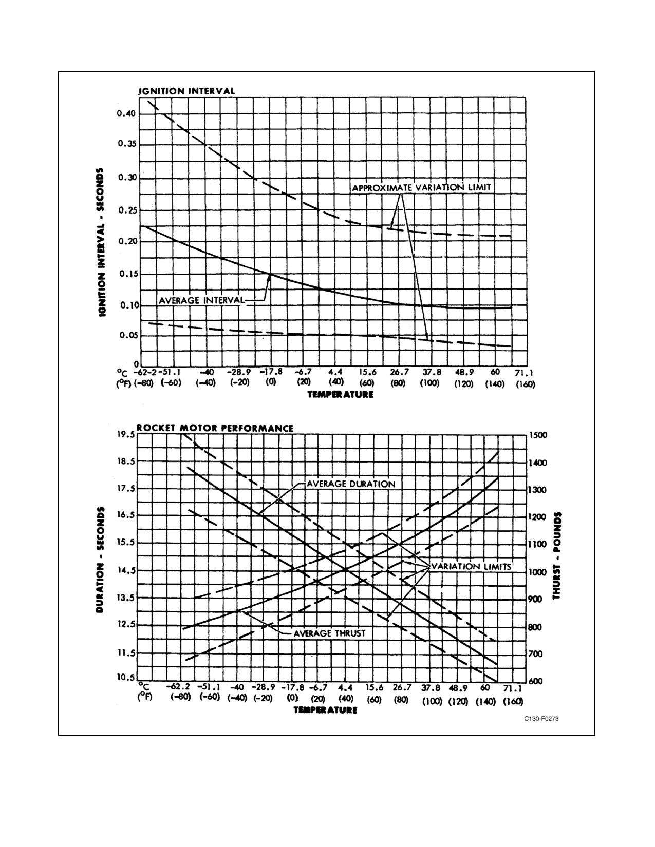
01-75GAL-1
Figure 14-5. Typical Effect of Temperature on ATO
14-9
ORIGINAL
01-75GAL-1
1. Signs of moisture within the polystyrene case container that houses the black powder element.
2. Damaged threads that would prevent proper assembly to the ATO unit.
3. Corrosion on the contact electrode where the igniter cable attaches.
4. Broken or cracked polystyrene case container.
Note
If the polystyrene case is broken during igniter installation and powder has
been spilled into the ATO unit chamber, both the igniter and the unit must
be rejected and not used.
5. The seating on the chamber boss is not firm when assembled in the ATO unit.
14.2.6 Assisted Takeoff System Installation and Removal
14.2.6.1 Installation of ATO Units on the Aircraft
1. Make an operational test of the aircraft ATO provisions.
2. Make sure that the hook openings of each channel and hook fitting, and each ball receptacle, are bright and
clean. Clean with light sanding, if necessary, to ensure good electrical contact.
3. Inspect each ATO unit. Do not use a unit with any of the following defects:
a. Damaged or cracked welds on attachment fittings.
b. Damaged or loose attachment pins.
c. Dented or distorted case.
d. Moisture,dust,ordirtwithinthecase.(Inspectthecasethroughtheigniteropeningafterremovingtheplug.)
4. Pull out the aft mounting channels on each air deflector until the channels latch.
5. Make sure that the attachment pins on the ATO units are bright and clean.
6. Lift each ATO unit into position so that the attachment pins engage the forward and aft hooks of the mount.
Make sure that the forward attachment pin is locked in the hook by the latch.
Do not activate the air-deflector doors after the ATO units have been
installed. Binding releasecables can causetheforward hook latch to retract
and the latch to disengage, thereby jettisoning the ATO units.
7. After all ATO units are mounted, inspect the igniters. Reject an igniter with any of the following defects:
a. Cracked powder case.
b. Evidence of moisture in powder case.
ORIGINAL
14-10
01-75GAL-1
c. Corroded electrical contactor.
d. Incorrect type.
8. Immediately after inspection of an igniter, install it in an ATO unit. Remove the plug from the forward end
of the unit and thread the igniter into the opening. Make sure that the igniter seats against the boss after
tightening.
After the igniters are installed, stay clear of the area aft of the ATO bottles.
Do not connect ignition leads until ready to start engines. When ignited, the
units eject high-temperature exhaust gases. Do not approach a unit for at
least 10 minutes after a misfire because the unit remains hot for that length
of time.
9. Make sure that the ATO arming switch is in the SAFE position then connect the igniter electrical leads.
Remove the plastic cover from each igniter, disconnect the lead from the shorting terminal, and connect it to
the ball receptacle on the door next to the ATO unit.
14.2.6.2 Postflight Removal of ATO Units
Do not attempt to remove an ATO unit within 30 minutes after it has been fired. Remove each unit by operating the
release mechanism while supporting the unit. Wash off any deposits of powder left on the aircraft skin by gases from
the units.
14.2.7 Assisted Takeoff
When the variables influencing takeoff lengths, acceleration, and obstacle clearance indicate a marginal takeoff, the
use of ATO is required. When considering the use of ATO, first consider the objective for a particular takeoff
condition. The objectives, acceleration to nosegear lift-off speed, acceleration to takeoff speed, or minimum roll to
clear obstacles will dictate when to actuate the ATO fire switch. The 12- to 15-second duration of the ATO units will
accomplish the objective when fired at a pre-selected airspeed in consideration of the objective. The ATO cut-in speed
charts in the performance data sections will furnish the necessary information to determine the point at which the ATO
units should be fired; they are predicated on the basis of burnout at 50-foot altitude. The units will be fired by the
copilot at the command of the pilot.
Failure of the ATO units to fire on one side will produce momentary yaw, which is easily controlled with proper
application of rudder. The acceleration effect when ATO is fired does not produce extreme abnormal stresses on either
flightcrew or cargo.
If it is possible, jettison the ATO bottles prior to landing to prevent additional stress on the attaching fittings. Open
the air deflectors to prevent the bottles from striking the fuselage. The ATO bottles should be jettisoned at the
command of the pilot.
CAUTION
When jettisoning the ATO bottles, pull handles in 1-2-3-4 order to prevent
upper ATO units from dropping into lower units and jamming the release
system. Do not jettison ATO units while they are producing thrust.
14-11
ORIGINAL
01-75GAL-1
14.3
AERIAL DELIVERY SYSTEM
Provisions for aerial delivery of equipment are made by an in-flight ramp operating system, a pendulum release
system, and miscellaneous aerial delivery system accessories that are carried as loose equipment. The in-flight ramp
operating system and the pendulum release system provide control of the ramp system and ejection of the extraction
parachute. The miscellaneous accessories of the ADS are stowed in an ADS flyaway stowage box. For detailed
information on the installation of miscellaneous equipment, refer to NAVAIR 01-75GAA-9.
14.3.1 Crew Requirements
The minimum crew for aerial delivery operations should be an airdrop qualified TAC, copilot, flight engineer, and
two loadmasters.
14.3.2 Pendulum Release System
The pendulum type extraction parachute ejector is mounted overhead at the aft end of the ramp. The extraction
parachute may be attached to one or both of the bomb rack tangs, depending on the size of extraction parachute used.
The bomb rack tangs are cocked by pulling down on the tee handle attached to the cocking cable. Pressing the chute
release switch or pulling the emergency chute release handle allows the parachute to swing down, aft, and out of the
aircraft. The windblast strips off the bag pack, allowing the extraction parachute to deploy and extract the cargo from
the aircraft over the aft end of the ramp.
14.3.3 Static Line Anchor Cables
Two static line anchor cables are stowed on reels mounted on the left and right side of the aft fuselage over the aft
cargo door. These are used for anchoring the static lines of parachutes during airdrops. The cables are installed by
attaching one end to the hooks on the aft anchor arms and the other end to hooks on the cargo compartment forward
bulkhead.
14.3.4 Static Line Retrievers
Two motor-operated static line retrievers are mounted on the cargo compartment forward bulkhead to facilitate the
recovery of parachute static lines after an airdrop. The retrievers operate from 28-Vdc power through the STATIC
LINE RETRIEVER circuit breakers on the copilot lower circuit breaker panel and the STATIC LINE RETRIEVER
MOTOR fuses on the right-hand distribution panel.
14.3.5 Aerial Delivery System Controls
Controls for operating the ramp system are on the ADS control panel on the flight control pedestal. Controls for the
aft anchor arms and static line retrievers are in the cargo compartment.
14.3.5.1 Ramp and Door Control Switch
Therampanddoorcontrolswitchisathree-position(CLOSE,OFF,OPEN)toggleswitchlocatedontheADScontrol
panel (see Figure 2-62) that controls operation of the ramp system during flight. When the switch is in the OPEN
position, electrical power through the RAMP and ADS CONTROL circuit breaker on the aft fuselage junction box
is supplied through atouchdown relay to energizethecargo doorand ramp system. Thecargo door rises and theramp
lowers to the aerial delivery position. When the switch is placed in the CLOSE position, power is applied to the aft
cargo door and ramp system, and the cargo door and ramp move to the closed position.
Install the ADS ramp supports prior to operation of the ramp in flight to
permit the ramp to extend only to a horizontal position.
ORIGINAL
14-12
01-75GAL-1
14.3.5.2 Chute Release Switch
The chute release switch is located on the ADS control panel (see Figure 2-61) on the flight control pedestal. It is
a press-to-actuate-type switch that controls the ease of the extraction parachute on the extraction parachute ejector.
When the switch is pressed, electrical power through the RAMP and ADS CONTROL circuit breaker on the aft
fuselage junction box and a touchdown relay energizes a solenoid-operated latch on the ejector, allowing the
parachute to swing down, aft, and out of the aircraft.
14.3.5.3 Extraction Parachute Manual Release Handle
An emergency manual release handle is connected to the release mechanism on the extraction parachute ejector
through an overhead cable and pulleys. The handle is located below the aft side of the aft flight station bulkhead,
inboard of the flight station ladder. Pulling this handle releases the extraction parachute and allows it to swing out
of the aircraft over the aft edge of the ramp.
CAUTION
The manual release handle should be used to eject the extraction parachute
only in case of failure of the chute release switch.
14.3.5.4 RAMP AND DOOR OPEN Light
A RAMP AND DOOR OPEN light is located on the ADS control panel (see Figure 2-62) on the flight control
pedestal. This is a green press-to-test-type light that goes on when the cargo door is fully open and the ramp is lowered
to the airdrop position. This light is energized through the RAMP and ADS CONTROL circuit breaker on the aft
fuselage junction box.
14.3.5.5 Aft Anchor Line Arm Controls
Controls for the aft anchor line arms are on the cargo compartment forward bulkhead (see Figure 14-6). Thecontrols
consist of two three-position (UP, OFF, DOWN) switches, one for each anchor arm. When the switches are placed
in the DOWN position, electrical power is supplied to two actuators that lower the arms into position for airdrops.
The UP position raises the arms to the stowed position, and the OFF position removes power from the actuators.
Power for operation of the anchor arm actuators is supplied from the main dc bus through the AFT ANCHOR LINE
ARM circuit breakers on the copilot lower circuit breaker panel.
CAUTION
Do not lower the anchor arms while the cargo door is being raised or
lowered. Severe structural damage could result.
14.3.5.6 Static Line Retriever Control Switches
Controls for the static line retrievers are in the cargo compartment (see Figure 14-7). Two control panels, one for each
retriever, are mounted on the cargo compartment forward bulkhead; a pistol-grip control handle for each retriever
is hung aft ofeach paratroop door. Each control panel on thecargo compartment forward bulkhead has two switches:
one with UNWIND and OFF positions and one with REWIND and OFF positions. The UNWIND switch is spring
loaded to the center neutral position and the REWIND switch is spring loaded to the OFF position. When the
14-13
ORIGINAL
01-75GAL-1
UNWIND switch is placed in the UNWIND position, power is supplied through a holding circuit to the retriever to
unwind the retriever cable. Momentary contact of the switch in the UNWIND position is all that is necessary to start
theretriever.Theretrieverwillcontinuetooperateuntiltheretrievercableis completelyunwound; thenalimitswitch
on the retriever is actuated to open the circuit. The retriever can be stopped at any intermediate position by
momentarilyholdingtheUNWINDswitchintheOFFpositionorbyactuatingthetriggerswitchonthecontrolhandle
at the paratroop door. To rewind the retriever cable, the REWIND switch must be held in the REWIND position. A
limit switch will stop theretriever when the cableis rewound. Each ofthe pistol-grip control handles at theparatroop
doorshasatrigger-typeswitchandathumb-operatedthree-position(OUT,OFF,IN)switch spring-loadedto theOFF
position. When the trigger switch is actuated, the circuit to the thumb-operated switch is completed and the controls
at the cargo compartment forward bulkhead are overridden. When the thumb-operated switch is placed in the OUT
position, the cable will unwind. The IN position rewinds the cable, and the OFF position stops either operation in
any intermediate position.
14.3.6 Operation of Aerial Delivery System
For operation of the ADS during an airdrop mission, refer to NAVAIR 01-75GAA-9.
14.4
EXPEDITIOUS OFFLOAD
Expeditious offload provides a means of offloading ramp, single and multiple pallets without the use of handling
equipment. Unit commanders may authorize expeditious offloads when conditions warrant. Expeditious offload
procedures should only be utilized as a last resort when no other means to off-load is available. Permission from the
user or lift requestor should be obtained if possible.
Note
Offloading married pallets (T2, T3, etc.) is prohibited.
14.4.1 Expeditious Offload Procedures
Cargo pallets can be offloaded without damage to the aircraft with the cargo ramp positioned 12 inches above the
ground. The maximum weight for a pallet to be expeditious offloaded across the ramp is 10,000 pounds. Pallets may
be offloaded in a train like fashion or one-by-one as the situation dictates. A taxiway or ramp at least 500 feet long
is required; however, 1,000 feet is desired to provide a margin of safety. When pallets are offloaded one at a time,
usealongertaxiwaybasedonthenumbertobeoffloaded.Fragileitemsthatmightbedamagedby expeditiousoffload
shall not beoffloaded without userconcurrence. Whenoffloading multiplepallets, itis recommendedthat eachpallet
be tied together to prevent them from falling over (tomb stoning) as they roll out the aircraft. The paratroop doors
shall not be used for expeditious offloading.
All crewmembers participating in the offload will refer to the following checklist. Prior to commencing expeditious
offload operations, the TAC will brief each crewmember. The loadmaster will maintain constant ICS contact with
the TAC and is the only crewmember authorized to operate the dual rail locks during combat offload operations.
Passengers should be offloaded to a safe area prior to commencing expeditious offload procedures.
ORIGINAL
14-14
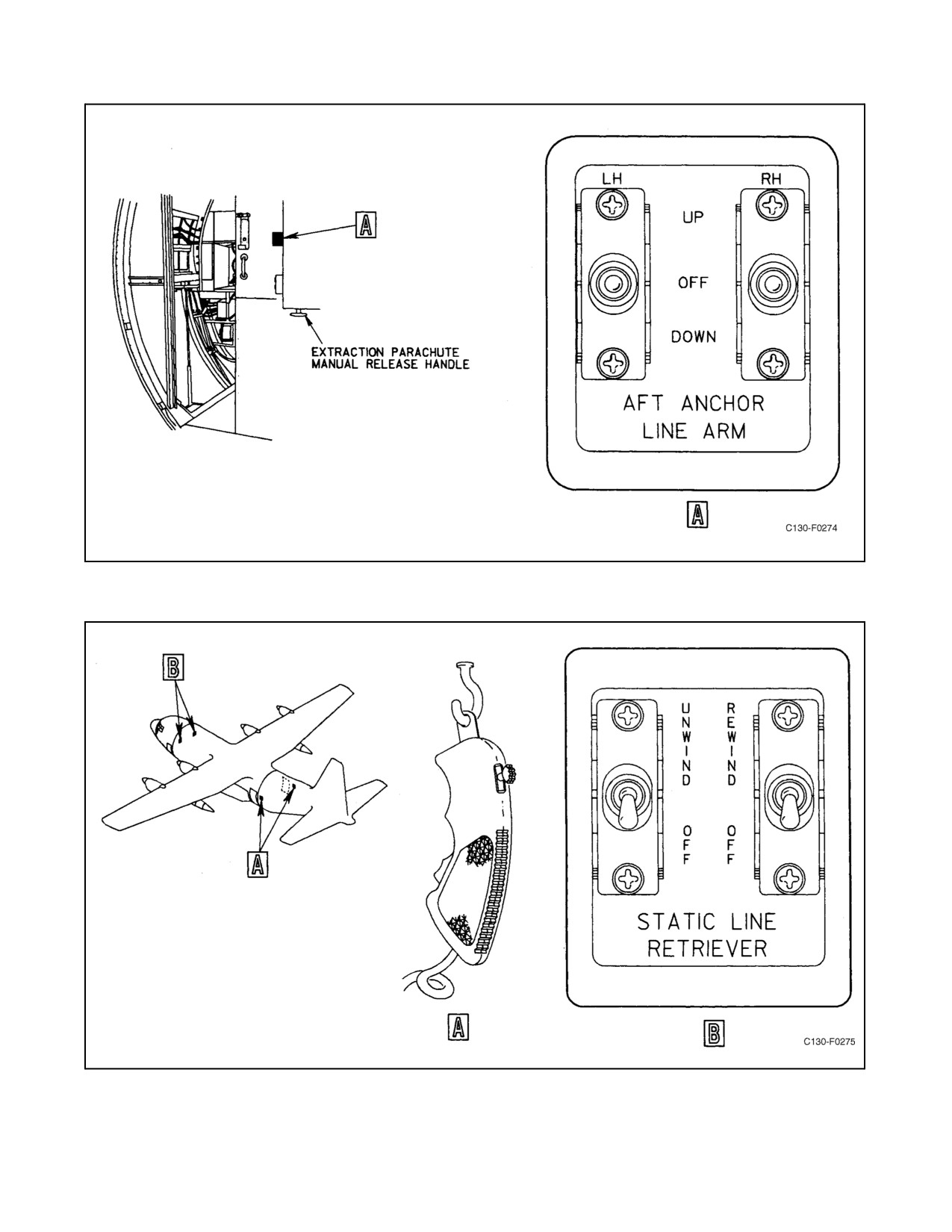
01-75GAL-1
Figure 14-6. Paratroop Anchor Line Support Controls
Figure 14-7. Static Line Retriever Control Panels
14-15
ORIGINAL
01-75GAL-1
D Manyexplosiveitems havespecific“drop”criteriathat,ifexceeded,render
the item useless or dangerous to the user. With the exception of small arm
ammunition (hazard class or division 1.4), explosives and munitions shall
not be expeditious offloaded without approval of the Wing Commander.
D During the entire offload operation, no one is permitted behind or beside
the load unless the loadmaster checks that all rail locks are locked and
engaged in the pallet detents or secures each pallet to aircraft tiedown rings
to ensure positive aft restraint.
CAUTION
When offloading on excessively rough surfaces, damage to the aircraft
ramp may occur. Reducing forward taxi speed on these surfaces will reduce
aircraft oscillation. The TAC must determine if the offload area will permit
the offload operation to be conducted without damage to the aircraft or
equipment.
14.4.2 Expeditious Offload Checklist
1. Crew Brief — Complete (P).
2. Interphone/Hot Mike — Checked (All).
3. Ramp and Door — Clear to Open (P/FE).
4. Aircraft — Positioned and stopped (P).
5. Ramp and Door — Open (LM).
6. Safety Observer — Set (LM).
A safety observer will take position at the bottom of the flight deck steps
and transmit verbal warnings to any personnel over ICS.
7. Offload Preparation Checks — Complete (LM).
CAUTION
A safety chain shall be secured across the cargo compartment attached to
thedual railforward ofthepalletsorplatforms.This willprevent thepallets
or platforms from rolling forward in case of a dual rail failure.
ORIGINAL
14-16
01-75GAL-1
8. Taxi Clearance — Cleared to taxi (CP).
Note
Notify the airport tower and request taxi clearance prior to offload.
9. Brakes — Set (P).
To unload ramp pallets:
Note
If no ramp pallet is aboard, proceed to step 18.
10. Right-hand ramp lock and flanges — Released/Retracted, handle stowed, stowage pin installed (LM).
CAUTION
Always maintain forward restraint with the right-hand locks.
11. Power — Set (P/CP, FE).
Note
Advance power to approximately 5,000 inch/lbs. of torque. This setting
will vary depending upon surface condition, slope, wind, aircraft weight,
and cargo weight.
12.
“READY TO TAXI” (LM).
Note
The loadmaster will indicate ready for offload by stating “Ready to Taxi.”
Upon hearing the loadmaster state “Ready to Taxi,” the pilot will release
the brakes.
13. Brakes — Released (P).
CAUTION
Taxi the aircraft in a straight line. Any attempt to turn the aircraft during
offload may damage the aircraft.
14. Left-hand ramp lock and flanges — Released/Retracted (LM).
Note
Release left-hand ramp lock and flanges when the pilot releases brakes and
the aircraft starts to accelerate
14-17
ORIGINAL
01-75GAL-1
15.
“LOAD CLEAR” (LM).
Do not stop aircraft until loadmaster reports “LOAD CLEAR.”
16. Brakes — Set (P).
17. Left-hand ramp lock handle — Stowed/Pin Installed (LM).
To unload remaining pallets:
Do not proceed to step 18 before ensuring the area behind and beside cargo
is clear of personnel and obstructions.
Note
If only the ramp pallet is to be offloaded, proceed to step 28.
18. Loadmaster positioned at FS245.
19. Right-hand Master Control Handle — EMERGENCY POSITION (LM).
CAUTION
Always maintain forward restraint with the right-hand locks.
20. Power — Set (P/CP, FE).
Note
Advance power to approximately 5,000 inch/lbs. of torque. This setting
will vary depending upon surface condition, slope, wind, aircraft weight,
and cargo weight.
21.
“READY TO TAXI” (LM).
Note
The loadmaster will indicate ready for offload by stating “Ready to Taxi.”
Upon hearing the loadmaster state “Ready to Taxi”, the pilot will release
the brakes.
ORIGINAL
14-18
01-75GAL-1
22. Brakes — Released (P).
CAUTION
Taxi the aircraft in a straight line. Any attempt to turn the aircraft during
offload may damage the aircraft.
23. Left-hand locks — Released (as required).
Note
Release left-hand locks when the pilot releases brakes and the aircraft starts
to accelerate. If all pallets on the cargo floor are to be offloaded, place
left-hand simul control handle in the aft restraint release position. For less
than a complete offload, use sequential lock/unlock control handle and
unlock only those locks for pallets to be off-loaded. Pallets not intended to
beoffloaded shall berestrainedfor1gaft restraintfrom availablefloor/wall
tiedowns.
24.
“LOAD CLEAR” (LM).
Do not stop aircraft until loadmaster reports “LOAD CLEAR.”
25. Brakes — Set (P).
Note
Repeat steps 20 through 25 for remaining pallets.
After last pallet is offloaded:
26. Right-hand master control handle — CHECK, then NORMAL position (LM).
Before proceeding aft of any remaining pallets, visually inspect each
left-hand dual rail lock to ensure positive aft restraint.
27. Left-hand dual rail locks — Extended/checked (LM).
28. Interphone/Hot Mike — OFF (P, CP, FE).
29. Ramp and door — Closed and Locked (LM).
14.5
DANGEROUS OR HAZARDOUS CARGO
Transportation of passengers with hazardous cargo aboard is normally prohibited. Exceptions to this policy will be
found in the current edition of NAVSUPPUB 505, Packaging and Handling of Dangerous Materials for
Transportation by Military Aircraft.
14-19
ORIGINAL
01-75GAL-1
14.6
HOSPITAL AIR EVACUATION
The following safety requirements and procedures are considered essential to air evacuation aircraft carrying litter
patients. These precautions or procedures shall be followed, where applicable, prior to each landing, takeoff,
refueling, loading, and unloading operation. Aircraft commanders shall make appropriate requests in order that these
procedures will be followed as far as practicable.
1. Notify the control tower to alert the crash rescue unit to stand by on landing.
2. Crash equipment will follow the taxiing aircraft until it is spotted and chocked. The crash unit will remain as
long as litter patients are being off-loaded or loaded.
3. When litterpatients areaboard during refueling, onememberofthefirefighting unit shall stand by in thecabin
with a fire extinguisher.
4. Prior to refueling the aircraft, the refueling crew shall ascertain that all grounding devices are properly
connected and that the necessary ramps are in position for the exit of patients should the need arise. One
medical attendant shall remain in the aircraft with the patients.
5. The gas truck shall be parked in a position downwind from the aircraft being refueled.
6. A tractor with a towbar attached to the aircraft shall be ready to move the aircraft in the event of a fire in the
refueling unit.
7. Prior to takeoff, the crash rescue unit shall follow the aircraft to the warmup position and remain in position
until the aircraft is airborne.
8. Fire and crash protection shall be requested if the aircraft is experiencing even minor difficulty.
14.7
SINGLE-POINT REFUELING WITH AUXILIARY POWER UNIT OR ENGINE RUNNING
The aircraft may be refueled with the APU or an engine running to furnish electrical power only when all of the
following conditions exist:
1. A satisfactory external power source is not available. The aircraft battery charge is too low to permit refueling
with battery power.
2. The mission requirements of local conditions do not allow sufficient ground timeto chargethe aircraft battery
and then refuel with battery power.
3. Local existing regulations permit this method of refueling.
When refueling with the APU or an engine running, use single-point
refueling only. Gravity refueling through the wing filler ports is prohibited
because of the increased possibility of fuel spillage and the release of fuel
vapor in proximity to the APU or the engine exhaust stream and hot section.
14.7.1 Preparation for Refueling
Perform the following steps prior to refueling the wing tanks or fuselage tanks:
1. If the APU is to be used, start the APU prior to shutting down all engines. Check APU generator voltage and
frequency for indication within limits. Check for normal power on the ac instrument and engine fuel control
bus and on the main dc bus. Monitor APU operation throughout refueling.
ORIGINAL
14-20
01-75GAL-1
2. If an engine is to be used, shut down all engines except No. 2. This engine is preferable to No. 1 because of
the wing tank vent outlet near the No. 1 engine exhaust area. Operate No. 2 engine in normal ground idle
throughout refueling and monitor engine instruments for operation within the limits shown in Chapter 4.
Check voltage and frequency of the operating engine generator for indication within limits. Check for normal
power on the ac instrument and engine fuel control bus and on the main bus.
Restrict movement of personnel and equipment along the left side of the
aircraft. Close all doors on the left side if this does not seriously hinder other
essential operations.
3. Ensure that adequate fire protection equipment is available in the refueling area.
4. Do not operate the aircraft air-conditioning system during refueling.
5. Make sure that all electrical and electronic equipment not required for refueling is turned off at all crew stations.
6. Locate the refueling unit on the right side of the aircraft. Connect static ground wires from a common ground
point to the aircraft nose static fitting on the right side of the fuselage aft of the radome, to the refueling panel
static ground fitting, and to the refueling unit.
7. Connect the refueling nozzle ground wire to the refueling panel ground wire. Uncap the refueling receptacles
and connect a refueling nozzle to one or both receptacles.
14.7.2 Refueling Wing Tanks
Refuel wing tanks as follows:
1. Place the MASTER switch in the REFUEL & GRD TRANS position; place the tank selector switches, for the
tanks to be refueled, in the OPEN position and open the offload valve.
Maintain a fuel balance in accordance with Chapter 3.
2. Establish fuel flow.
3. Within thefirst minute, placetheMASTER switch in thePRE-CHK PRIM position and observethe fuel truck
flow meter and the quantity gauges. Flow should stop within 15 seconds.
4. Return the MASTER switch to the REFUEL & GRD TRANS position and observe that flow resumes; then
place the switch in the PRE-CHECK SEC position. Flow should stop within 15 seconds.
If flow into any tank did not stop in at least one of the PRE-CHK positions,
do not rely on automatic shutoff at full capacity. Proceed with caution and
stop the refueling unit pump in ample time to avoid overflow or wing
structural damage. Fuel spillage would create a serious hazard with an
engine or the APU running.
14-21
ORIGINAL
01-75GAL-1
5. Return the MASTER switch to the REFUEL & GRD TRANS position.
6. After refueling is complete, place all tank selector switches in the CLOSE position, the OFF LOAD VALVE
switch in the CLOSE position, and the MASTER switch in the OFF position.
Note
When less than full capacity is planned, and flow into a tank does not stop
when the selector switch is placed in the CLOSE position, shut down the
refueling unit pump if the planned total fuel load is not aboard. If further
total fuel is required, continue refueling but shut down the pump before
reaching full capacity of the affected tank, then transfer fuel as necessary
after at least two engines have been started.
7. Perform the securing after refueling steps in paragraph 14.7.3.
14.7.3 Securing After Refueling
Perform the following steps after refueling the wing tanks or fuselage tank.
1. Shut down the refueling unit pump, disconnect the nozzles from the receptacles, and then disconnect the nozzle
ground wire.
2. Cap the refueling receptacles.
3. Place the MASTER switch in the DRAIN position for 5 minutes, then turn it to the OFF position.
Note
The manual drain valve must be opened while operating the drain pump.
4. Disconnect the ground wire from the panel static ground fitting.
5. Close and lock the refueling panel door.
6. Drain the refueling receptacles through the manual drain valve. Close and secure the drain valve door.
7. Remove ground wires and refueling equipment before starting the engines from the operating engine or APU.
14.8
SINGLE-POINT DEFUELING WITH APU OR ENGINE RUNNING
The safety precautions, location of defueling unit, and static grounding of the aircraft are the same for defueling with
an engine running as for refueling with the APU or an engine running.
With the defueling unit positioned and the aircraft and the defueling unit static grounded as directed in paragraph 14.7,
proceed as follows:
1. Operate APU and ac bus tie only. Throughout defueling, monitor APU instruments for operation within the
limits shown in Chapter 4. Check voltage and frequency of the APU generator for indication within limits.
Check for normal power on the essential and main ac and dc buses and on the ac instrument and engine fuel
control bus.
2. Operate No. 1 engine only in normal ground idle. Throughout defueling, monitor engine instruments for
operation within thelimits shown in Chapter4. Check voltageand frequencyoftheoperating enginegenerator
for indication within limits. Check for normal power on the essential and main ac and dc buses and on the ac
instrument and engine fuel control bus.
3. Determine the total weight of fuel to be offloaded, and divide this weight between all tanks that are to be
defueled. From this and the present gauge readings for these tanks, calculate the final desired fuel load in each
affected tank. This fuel loading must be compatible with normal fuel loading between tanks for flight
operation.
ORIGINAL
14-22