C-130T. FLIGHT MANUAL (2006) - page 11
01-75GAL-1
18. Signal front aircraft to reduce power.
Note
D If constant acceleration fails to occur prior to 16-percent rpm, move the
condition lever to the FEATHER position momentarily and return to RUN.
Increased rpm and acceleration should occur. Do not move the condition
lever toward FEATHER after 16-percent rpm unless a stop-start situation
exists.
D In the event above procedures are ineffective, starting may be attempted by
presetting propeller blade angles at an intermediate position between
alignment with the spinner base island and the full-feather position.
Continue start as outlined above.
8.34
WINDMILL TAXI START
CAUTION
Successive windmill taxi runs with repeated braking applications will
result in hot brakes, decreased braking efficiency, and/or wheelwell fires.
Note
Use of the following procedure is not recommended when aircraft gross
weight exceeds 135,000 pounds.
The following procedure can be used to start an engine if it cannot be started by normal procedures. It should beused
only if mission requirements dictate. A runway length of 7,000 feet or more is recommended to ensure safety.
1. Engine — Inspected:
a. Inspect engine to be started as necessary to ensure maximum safety.
CAUTION
Prior to attempting a windmill taxi start because of a defective starter,
ensure that the starter or starter shaft is removed.
2. Propeller — Feathered.
3. Before Takeoff Checklist — Complete.
Note
The flaps will be set at 15-percent. This will provide full-rudder boost
pressure without creating extra drag and lift at low speeds.
4. Auxiliary hydraulic pump switch — ON.
8-97
ORIGINAL
01-75GAL-1
5.
Throttle — FLIGHT IDLE.
6.
Engine condition lever — RUN.
7.
Align the aircraft on the runway.
8.
Parking brake — Set.
9.
Throttles (for operating engines) — FLIGHT IDLE.
10.
Throttles (for symmetrical engines) — TAKEOFF POWER.
11.
Parking brake — Released.
12.
Throttle (other operating engine) — As Required:
a. Increase power on the other operating engine as directional control becomes available through coordinated
use of nosewheel steering and rudder.
Note
D On long runways, actuation of the throttle may not be required.
D The copilot shall hold the yoke forward, maintaining positive pressure on
thenosewheel andkeeping thewings level.Thepilotshall maintaincontrol
of nosewheel steering, throttles, and rudder.
13.
Condition lever — AIRSTART:
a. The copilot shall place the condition lever to AIRSTART at 50 KIAS and hold until light-off is achieved.
14.
Throttles — GROUND IDLE:
a. As the rpm increases to 40 percent, retard all throttles to GROUND IDLE and reverse symmetrical for the
on-speed engines and apply brakes as required to stop theaircraft. Oilpressureandengineinstrumentsshall
be monitored the same as for a normal start.
CAUTION
Regardless of the progress of the windmill taxi start, decelerate to a stop
when the aircraft reaches a speed of 100 KIAS or a point where 4,000 feet
of runway remains, whichever occurs first.
15. Resume normal operation beginning with the Starting Engines Checklist.
8.34.1 Three-Engine Takeoff
This type of takeoff requires particular caution because of the possibility of losing another engine during the takeoff
roll prior to reaching minimum control speed. A three-engine takeoff may be attempted only when all of the following
criteria are fulfilled:
1. Permission of Commander, Fleet Logistics Support Wing.
a. Minimum essential flightcrew.
ORIGINAL
8-98
01-75GAL-1
b. No passengers or cargo.
c. Fuel only as necessary for particular flight.
d. Three-engine takeoff procedures are followed.
e. Three-engine performance data are computed and used.
Note
D Although not required, ATO should be used for three-engine takeoff when
it is available.
D If the inoperative engine could not be started because of a faulty starter, and
if an airstart of the inoperative engine is to be made, the starter should be
removed prior to takeoff.
D Place the ENGINE BLEED AIR switches to the OFF position for
maximum performance.
D Before making thetakeoff, thepropeller forthe inoperativeengine must be
feathered.
To make the takeoff:
2. Hold the aircraft with the brakes and advance the throttles to FLIGHT IDLE.
3. Advancethe throttles for symmetrical engines to maximum power, then releasethe brakes and advancepower
for the other operative engine as directional control will permit.
4. When safely airborne and certain that the aircraft will not touch down again, raise the gear while accelerating
to flap retraction speed.
5. After the gear is up, and airspeed permits, commence flap retraction. Flap retraction should be accomplished
in 10-percent increments with airspeed increasing approximately 5 knots between retraction increments.
Raising the flaps above approximately the 15-percent position will increase
the minimum control airspeed because of reduction in rudder boost
pressure from 3,000 to 1,300 psi.
Note
It is important to obtain two-engine air minimum control speed as soon as
possible after takeoff and prior to raising the flaps above 15 percent.
6. After gear and flaps are up, continue as a normal takeoff, accelerating to three-engine climb speed.
8-99
ORIGINAL
01-75GAL-1
8.35
EXTERNAL AIR (HUFFER) APPLICATION
1.
Station huffer behind the left wing and extend air hose forward and securely couple to the external air
connection forward of the left wheelwell.
Note
Ensure huffer exhaust blast clears all aircraft surfaces.
2.
Station the ground observer to the left of the nose of the aircraft in full view of the crewmember occupying
the pilot seat. The ground observer must have full view of the huffer operator.
3.
Complete the Before Start Checklist up through item 6.
4.
Direct theground observerto relayto thehufferoperatorto startthehufferand applyairpressureto theaircraft.
5.
The flight engineer shall observe a minimum of 25 psi manifold pressure.
6.
Complete the Before Start Checklist.
7.
Start the No. 3 engine (or engine requiring turn). Leave the engine in low-speed ground idle.
8.
Place the ENGINE BLEED AIR switch OFF.
9.
Place the AIR CONDITIONING master switch NO PRESSURE.
10.
Direct the ground observer to relay to the huffer operator to secure bleed air and shut down the huffer.
11.
The flight engineer shall observe zero pressure on the manifold pressure gauge.
12.
Directthegroundobservertorelay tothehufferoperatortodisconnect theexternal airhoseandclosethepanel.
The ground observer shall visually verify the panel closed and report that the external air unit is removed from
the area.
13.
The flight engineer shall place the AIR CONDITIONING master switch to OFF, ENGINE BLEED AIR
switch to OVRD, and observe manifold pressure.
14.
Bring the engine that was started to normal ground idle and continue the Starting Engines Checklist.
ORIGINAL
8-100

01-75GAL-1
COCKPIT CHECKLIST
7. GROUND EQUIP
CLEAR (P)(CP)(LM)
1. NLG PIN AND GROUND WIRE
REMOVED
8. CREW ABOARD
ABOARD, DOORS
CLOSED, CHECKED (LM)
2. PROP PANEL
SET
9. HYDRAULIC PRESSURES,
3. CIRCUIT BREAKERS
CHECKED
QUANTITIES
CHECKED (CP)(LM)
4. FUEL PANEL
SET
10. OIL COOLER AUG
AS REQUIRED (FE)
5. THROTTLES
GND IDLE
11. PAX, CARGO, SDRS
SET (LM)
6. CONDITION LEVERS
GND STOP
7. SYNC MASTER
OFF
TAXI
8. TD VALVES
AS REQUIRED
1. BRAKES
CHECKED (P)(CP)
2. GENS/LOADS
ON, CHECKED (FE)
BEFORE START
3. ICE DETECTION
CHECKED (FE)
1. HOT MIKE
ON (P)(CP)(FE)
4. PROP REVERSING
CHECKED (P)(FE)
2. COCKPIT CHECKLIST
COMPLETE (FE)
3. PASSENGERS
BRIEFED (LM)
RUNUP
4. ELECTRICAL PANEL
SET (FE)
1. NOSEWHEEL,
5. RADIOS
ON ____ PRIMARY (CP)
PARKING BRAKE
CENTERED, SET (P)
6. LIGHTS
SET (FE)
2. ENGINE RUNUP
COMPLETE (FE)
7. CLEAR APU
CLEAR (LM)
8. APU PANEL
SET (FE)
TAKEOFF
9. APU GEN
AS REQUIRED (FE)
10. INVERTERS
SET (FE)
1. EXITS
SECURE (ALL)
11. FUEL QTY, DIST
CHECKED _____LBS (P)(FE)
2. FUEL PANEL
SET (FE)
3. FLAPS
50% (P)(CP)(LM)
12. OIL COOLER FLAPS
AS REQUIRED (CP)
4. FLIGHT CONTROLS
CHECKED (P)(CP)
13. RAMP AND DOOR
6N, NEUTRAL (LM)
5. HYDRAULIC QUANTITIES
CHECKED (LM)
14. HYDRAULIC PANEL
SET, EMERGENCY
SELECTED (CP)
6. TRIM
SET (P)
15. PARKING BRAKE
SET, REMOVE CHOCKS (P)
7. SEATBELTS
FASTENED (ALL)
8. CREW
BRIEFED (P)
16. OXYGEN
CHECKED, OFF (ALL)
17. GROUND IDLE BUTTONS
LOW (FE)
9. ELECTRICAL PANEL
SET (FE)
10. INSTRUMENTS, ALTIMETERS
CHECKED,
18. FLAP LEVER
SET (CP)
SET____,____(P)(CP)(FE)
19. CHOCKS, NOSE PIN
REMOVED (LM)
11. APU PANEL
SET (FE)
20. INS/GPS
AS REQUIRED (CP)(FE)
12. PRESSURIZATION
SET (FE)
13. ANTISKID
CHECKED (FE)
STARTING ENGINES
14. RADAR, IFF
AS REQUIRED (P)(CP)
1. CLEAR NO. 3 ENGINE
NO. 3 CLEAR (LM)
15. OIL COOLER AUG
OFF (FE)
TURNING 3 (P), ROTATION (LM)
16. OIL COOLER FLAPS
AUTO (CP)
2. APU GEN
ON, CHECKED (FE)
17. LIGHTS
SET (CP)(FE)
3. DC POWER
BATTERY, REMOVE
18. ANTI-ICING
SET (FE)
EXTERNAL POWER (FE)
4. CLEAR NO. 4 ENGINE
NO. 4 CLEAR (LM)
19. LINEUP
COMPLETE (P)(CP)(FE)
TURNING 4 (P), ROTATION (LM)
5. AIR COND MASTER
NO PRESS (FE)
AFTER TAKEOFF
6. EXTERNAL POWER,
1. GEAR, FLAPS, LIGHTS
CHECKED (CP)(FE)
GROUND EQUIPMENT
REMOVED, CLEAR (LM)
2. HYDRAULIC PANEL
CHECKED SET (CP)
7. CLEAR NO. 2 ENGINE
NO. 2 CLEAR (LM)
3. SYNC MASTER
AS REQUIRED (FE)
TURNING 2 (P), ROTATION (LM)
4. PRESSURIZATION
CHECKED (FE)
8. CLEAR NO. 1 ENGINE
NO. 1 CLEAR (LM)
5. WINGS, AIRCRAFT INTERIOR
CHECKED (LM)
TURNING 1 (P), ROTATION (LM)
9. BLEED AIR
SET (FE)
6. LEADING EDGE ANTI-ICING
CHECKED, SET (FE)
10. FUEL PANEL
SET (FE)
7. FUEL PANEL
AS REQUIRED (FE)
8. HOT MIKE
AS REQUIRED (P)(CP)(FE)
BEFORE TAXI
DESCENT
1. ANTI-ICING
AS REQUIRED (FE)
2. RADAR, IFF
STBY (P)(CP)(FE)
1. CREW
BRIEFED (P/CP)
3. COMPASSES
CHECKED _____#1 (P)
2. PAX, CARGO
AS REQUIRED (LM)
CHECKED _____#2 (CP)
3. PRESSURIZATION
SET (FE)
4. ATTITUDE SELECT
CHECKED _____ (P)(CP)
4. BARO ALTIMETER
SET _____ (P)(CP)
5. GPWS
SET (CP)
5. TD VALVES
AS REQUIRED (FE)
6. FLAPS
50% (CP)
ONLY CIRCLED ITEMS NEED TO BE CHECKED AT OPERATIONAL STOPS
Figure 8-8. Normal Procedures Checklist (Sheet 1 of 2)
8-101
ORIGINAL
01-75GAL-1
APPROACH
BEFORE LEAVING THE AIRCRAFT
1. GALLEY FLOOR
SET (LM)
1. OIL COOLER FLAPS
AS REQUIRED
2. RADAR
OFF
2. FUEL PANEL
AS REQUIRED (FE)
3. AIR-CONDITIONING
OFF
3. SEATBELTS
FASTENED (ALL)
4. BLEED AIR
OFF
4. ALTIMETERS
SET ___,____ (P)(CP)
5. ELECTRICAL PANEL
SET
5. NAV SELECT
AS REQUIRED (P)(CP)
6. FUEL PANEL
SET
7. TD VALVES
NULL
8. OXYGEN
NORMAL/100%/OFF
LANDING
9. HYDRAULIC PANEL
SET
1. HOT MIKE
ON (P)(CP)(FE)
10. AC BUS TIE SWITCH
OFF
2. FLAPS
AS REQUIRED (P)(CP)
11. APU GENERATOR
OFF
3. LANDING GEAR
DOWN, CHECKED,
12. APU PANEL
SET
CENTERED (P)(CP)(FE)
13. RADIOS
OFF
4. HYDRAULIC PANEL
CHECKED, SET (CP)
14. WHEELS
CHOCKED
5. LIGHTS
SET (CP)
15. PARKING BRAKE
RELEASED
16. LIGHTS
SET/OFF
6. SYNC MASTER
OFF (FE)
17. DC BUS TIE AND BATTERY
SET
7. PRESSURIZATION
CHECKED (FE)
18. INS/GPS
OFF
8. ANTISKID
CHECKED (FE)
19. EMER EXIT LT SWITCH
DEPRESSED
20. COVERS, PLUGS
INSTALLED
TOUCH AND GO LANDING
21. INT/EXT LIGHTS
OFF
22. DOORS AND RAMP
AS REQUIRED
ON THE RUNWAY
23. AIRCRAFT BATTERY
DISCONNECTED
1. FLAPS
50% (P/CP)
2. TRIM
SET (P/CP)
CRUISE ENGINE SHUTDOWN
3. THROTTLES
AS REQUIRED (P/CP)
1. CREW
BRIEFED (CP)
AFTER TAKEOFF
2. SYNC MASTER
OFF (FE)
3. PROP GOV CONT
MECH (CP)
1. GEARS, FLAPS, LIGHTS
CHECKED (P/CP)(FE)
4. FEATH VALVE AND NTS SWITCH
VALVE (CP)
LANDING
5. AIRSPEED
BELOW 180 KIAS (P)
1. CREW
BRIEFED (P/CP)
6. NTS CHECK
COMPLETE (FE)
2. FLAPS
AS REQUIRED (P)(CP)
7. THROTTLE OF ENGINE TO BE
3. LANDING GEAR
DOWN, CHECKED
SHUT DOWN
FLIGHT IDLE (P)
CENTERED (P)(CP)(FE)
8. ENGINE BLEED AIR SWITCHES ON
OPERATIVE ENGINES
ON (FE)
4. HYDRAULIC PANEL
CHECKED (P/CP)
9. SYNC MASTER
RESET AS REQUIRED (FE)
10. CONDITION LEVER
FEATHER (CP)
AFTER LANDING
11. FUEL BOOST PUMP
OFF (FE)
1. FLAPS
AS REQUIRED (CP)
12. ENGINE BLEED AIR SWITCH
OFF (FE)
2. OIL COOLER FLAPS, AUG
AS REQUIRED (FE)
13. ENGINE GENERATOR SWITCH
SET (FE)
14. PROP FEATH OVRD BUTTON
OUT (CP)
3. LIGHTS
SET (CP)(FE)
15. THROTTLE OF ENGINE
4. RADAR, IFF
STBY (P)(CP)(FE)
SHUTDOWN
FULL FORWARD (P)
5. PRESSURIZATION
NO PRESS (FE)
16. OIL COOLER FLAP
CLOSED/FIXED (CP)
6. ANTI-ICING
OFF (FE)
17. FUEL MANAGEMENT
CHECKED (FE)
7. APU PANEL
SET (FE)
8. ELECTRICAL PANEL
SET (FE)
AIRSTART
1. FIRE HANDLE
IN (CP)
2. THROTTLE
SET APPROX 1I
SECURE
ABOVE FLIGHT IDLE (P)
1. PARKING BRAKE
SET (P)
3. FUEL BOOST PUMP
ON (FE)
2. OIL COOLER AUG
OFF (FE)
4. OIL COOLER FLAP
AUTO (CP)
3. SHUTDOWN, NTS CHECK
COMPLETE (ALL)
5. FUEL ENRICHMENT
NORM (P)
6. PROP GOV CONT
MECH (CP)
4. UNNECESSARY EQUIPMENT
OFF (ALL)
7. NTS CHECK
VALVE (CP)
5. OXYGEN
CHECKED, OFF (ALL)
8. TD VALVE
AUTO (FE)
6. CHOCKS, NOSE PIN
INSTALLED (LM)
9. CONDITION LEVER
AIRSTART (CP)
7. PARKING BRAKE
RELEASED (P)
10. GENERATOR
RESET/ON (FE)
11. FUEL ENRICHMENT
OFF (P)
8. HYDRAULIC PANEL
SET, EMERGENCY
12. BLEED AIR
ON (FE)
SELECTED (CP)
13. PROP GOV CONT
NORM (CP)
9. AIR CON MASTER
AUX VENT (FE)
14. ENGINE INSTRUMENTS
IN LIMITS (FE)
ONLY CIRCLED ITEMS NEED TO BE CHECKED AT OPERATIONAL STOPS
Figure 8-8. Normal Procedures Checklist (Sheet 2)
ORIGINAL
8-102
01-75GAL-1
CHAPTER 9
Functional Checkflight Procedures
9.1
GENERAL
9.1.1 Checkpilots
The most important factor in obtaining good checkflights on the aircraft is to pick experienced, conscientious
checkpilots. Commanding officers will designate, in writing, those pilots within their command who are currently
eligible to perform this duty.
9.1.2 Checkflights and Forms
Checkflights will be performed when directed by, and in accordance with, OPNAVINST 4790.2 series and the
directions of NAVAIRSYSCOM type commanders or other appropriate authority. Functional checkflight
requirements and applicable minimums are described below. Functional checkflight checklists are promulgated
separately.
9.1.3 Conditions Requiring Functional Checkflights
Checkflights are required under the following conditions (after the necessary ground check and prior to release of
the aircraft for operational use):
A. At the completion of aircraft rework or acceptance inspection (all checkflight items required are prefixed by A).
B. After the installation or reinstallation of an engine, fuel control, major fuel system components, or any other
systems/components that cannot be checked in ground operation (minimum required are prefixed by B).
C. After the installation or reinstallation of a propeller, propeller governor, or valve housing (minimum required are
prefixed by C).
D. When fixed flight surfaces have been installed or reinstalled or when movable flight surfaces or flight controls
have been installed or reinstalled, adjusted, or rerigged, and improper adjustment or replacement of such components
could cause an unsafe operating condition (minimum required are prefixed by D).
E. When an aircraft with dual or multi-independent attitude reference sources has had the indicators/displays, attitude
reference sources, subsystems, or components removed, replaced, or adjusted in two or more of the attitude reference
systems. Aircraft with four or more independent attitude reference sources in which two sources are known good,
and the integrity of those two sources has not been jeopardized, will not require a FCF.
F. When an aircraft that has not flown 30 days or more and has had a complete engine run sheet completed (all
checkflight items required are prefixed by F).
Note
FCFs are not required when the maintenance action involves only the
removal and reinstallation of connecting hardware without a change in
adjustment or alignment to one of the above systems. However, a thorough
ground functional check shall be conducted before the aircraft is released
for flight. An appropriate entry noting the system disconnected and
reconnected and the accomplishment of a ground functional check shall be
made on a VIDS/MAF or entered in NALCOMIS.
9-1
ORIGINAL
01-75GAL-1
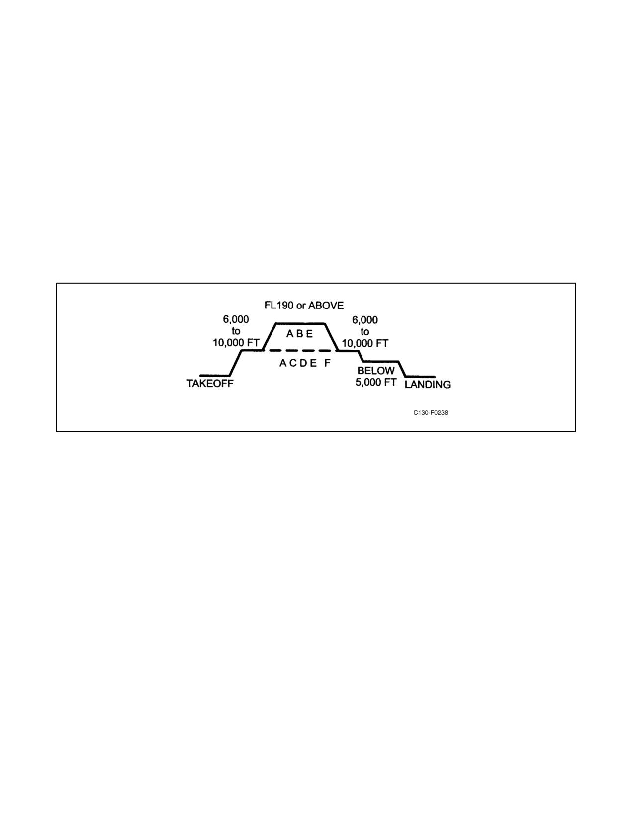
Every effort shall be made to perform the entire profile, however, these profiles may be modified to meet specific
requirements and/or aircraft configurations. It is not required to complete every step in any one profile if the steps
are not applicable, certain systems are inoperative, or required NAVAIDS are unavailable. FCF crews, together with
Quality Assurance, shall ensure that, as a minimum, those systems affected by maintenance action are tested.
9.2
PROCEDURES
Flight profiles for functional checkflight are depicted in Figure 9-1. The following items provide a detailed
description of the functional checks, sequenced in the order in which they should be performed. In order to complete
the required checks in the most efficient and logical order, a flight profile has been established for each checkflight
condition stated above and identified by the corresponding letter. The applicable letter identifying the profile prefixes
each check both in the following test and in the functional checkflight checklists. Checkflight personnel will
familiarize themselves with these requirements prior to the flight. NATOPS procedures will apply during the entire
checkflight unless specific deviation is required by the functional check to record data or ensure proper operation
within the approved aircraft envelope. A daily inspection is required prior to the checkflight.
Figure 9-1. Flight Profile
ORIGINAL
9-2
01-75GAL-1
PROFILE
9.2.1 Pretaxi
A
D
1.
Flap operation.
a.
Pull FLAP CONTROL circuit breaker.
b.
Override operation.
(1) Have crewmember lower flaps to 20 percent by depressing the manual override button
on the down side of the flap selector valve.
(2) Have crewmember raise flaps to 0 percent by depressing the manual override button
on the up side of the flap selector valve.
c.
Manual operation.
(1) Set flap lever to 10 percent.
(2) Turn off the No. 1 and No. 2 hydraulic pumps, utility suction boost pump, and deplete
system pressure.
(3) Have a crewmember engage the handcrank, remove the input shaft pin, and shift to
MANUAL drive.
(4) Manually lower the flaps to 10 percent.
(5) Remove handcrank, shift back to NORMAL drive, and replace the input shaft pin.
(6) Turn on the utility suction boost pump and the No. 1 and No. 2 hydraulic pumps.
(7) Push in flap control circuit breaker and raise flap lever to UP.
d.
Ensure that normal flap operation has been regained.
A
D
F
2.
Flight controls and boost shutoff.
a. Check ailerons, elevators, and rudder for freedom of movement with booster hydraulic
system switches in the OFF position.
Note
Restrain the control column when checking
elevator movement to prevent the bobweight
from slamming the controls against the stops.
b. Turn utility hydraulic system switches to the OFF position and check flight for no boost
operation.
c. Turn on booster hydraulic system switches and recheck flight controls.
d. Turn on utility hydraulic system switches and ascertain that all boost shutoff switches are
in the ON position.
9-3
ORIGINAL
01-75GAL-1
PROFILE
ABC
F
3. Ice detection system.
Completeengine, propellersystem check as specified in the TAXIchecklist, Chapter8 ofPart
III, in both MANUAL and AUTO.
A D
F
4. Trim tabs.
a. Check trim for freedom of movement and proper travel.
b. Check elevator trim tab in EMERGENCY.
c. Check copilot elevator control.
d. Set trim tabs for takeoff.
9.2.2 Pretakeoff
A
F
5.
Brakes.
a. Check emergency system operation by ensuring firm response upon application.
b. Check normal system with ANTI-SKID switch OFF.
c. Check normal system with ANTI-SKID switch ON.
d. Check copilot brake pedals.
ABC
6.
Nosewheel steering.
a. Check nosewheel steering for smooth operation in both directions, no lag response, ease
of motion, and ease of return to center.
b. An aircraft requires excessive steering control if it fails to track straight with the throttles
adjusted as follows:
(1) Fuel flow — Maximum 50 lb/hr differential.
(2) Torque symmetrical.
c. A steering correction while tracking in a straight line that causes a pointer deviation outside
the white radius on the steering position indicator is excessive.
A
E
7.
Flight instruments.
a. Check heading and turn and slip indicators for correct movement in a turn. (Check both left-
and right-hand turn.)
b. Check airspeed and VSIs for proper readings.
c. Check ADIs for proper operation.
d. Check standby attitude indicator for proper operation.
ORIGINAL
9-4
01-75GAL-1
PROFILE
ABC F
8. Propeller reversing.
Reverse propeller in symmetrical pairs and check rpm and torque differential; if torque
differential is greater than 1,000 pounds, compensate on subsequent reversing and record
discrepancy.
ABC F
9. Engine runup.
a. Complete engine runup as prescribed in Chapter 8 of Part III.
b. Ensure all engine instrument readings are within normal limits.
9.2.3 Climb (Profiles A, B, and E FL 190; Profiles C, D and F 6,000 Feet)
ABC F
10. NTS check.
Perform NTS check for engines to be shut down in accordance with procedures in Cruise
Engine Shutdown checklist in Chapter 8 of Part III.
A
E
11. Flight instruments.
a. Check pilot and copilot ADI and HSI for smooth operation and accuracy, one against the
other.
b. In a standard-rate turn, check turn needles for 30_ turn in 10 ±1 seconds.
c. Check airspeed indicators for a maximum differential of 6 knots.
d. Check pilot, copilot, and navigator altimeters against each other to be within 230 feet at
10,000 feet and 340 feet at 20,000 feet.
e. Establish a constant rate of climb. Time altimeter for 1 minute to determine actual rate of
climb. Both VSI/TRAs must agree within 100 fpm.
f. Check standby attitude indicator for smooth operation and accuracy.
A
12. Pressurization/rate of climb.
a. Set cabin rate of climb to MIN; check climb rate 30 to 200 fpm.
b. Set cabin rate of climb to MAX; check climb rate 1,600 to 2,900 fpm.
c. Set rate-of-climb knob at a midposition and check rate between MIN and MAX limits.
A
F
13. Leading edge anti-ice system check.
Turn on wing and empennageanti-icesystem individually and check that the anti-icing valves
modulate to maintain temperature within normal limits.
9.2.4 Level (Profiles A and B FL 190, Profiles C and D 6,000 Feet)
A
14. Auxiliary power unit check.
a. Start APU in accordance with instructions contained in Chapter 8 of Part III. APU shall start
normally and EGT shall remain in normal range.
Note
APU shall only be started below 20,000 feet
and 200 KIAS.
9-5
ORIGINAL

01-75GAL-1
PROFILE
b. If APU generator was not checked previously, apply electrical load and verify frequency,
voltage and load are within normal limits.
Do not open the APU bleed air valve in flight.
c. Stop the APU in accordance with instructions contained in Chapter 8 of Part III.
A
15. Air conditioning/fuselage leak check.
a. Select MAN PRESS and ensure positive control of the outflow valves by increasing and
decreasing.
b. Hold the manual pressure switch in the increase position. The safety valve should regulate
cabin pressure to 15.9 (±0.3) inches Hg. Note the pressure.
Do not exceed a maximum of 16.4 inches Hg
differential pressure.
CAUTION
Do not hold manual pressure switch for over
30 seconds to preclude burning out the valve
motor.
c.
Select AUTO PRESS. The pressure should decrease slowly and the outflow valve should
regulate cabin pressure to 15.4 ±0.4 inches Hg but lower than the pressure noted in step b.
d.
Select MAN PRESS and pressurize aircraft to pressure noted in step c plus 0.2 inches Hg
(this will ensure that the outflow valve is closed).
Note
A properly functioning air-conditioning and
pressurization system will exceed 15.9 inches
Hg if the outflow valve is held toward closed in
MAN PRESS. This will cause the safety valve
to openbeforetheoutflow valveis fullyclosed.
Beginning the check with the outflow valve
partially open will result in a failed check. If
this situation occurs, close engine bleed air
valves as necessary, one at a time, to keep cabin
pressure within limits and ensure outflow valve
is fully closed prior to continuing.
ORIGINAL
9-6
01-75GAL-1
PROFILE
e.
Place the ENGINE BLEED AIR switches to OFF.
f.
Time differential pressure decreases from 14 to 12 inches. Time shall be no less than
36 seconds at FL 190.
g.
The minimum time limit shall be 50 seconds at completion of scheduled depot level
maintenance.
h.
Place all ENGINE BLEED AIR switches to ON and repressurize to step c pressure.
i.
Select AUTO PRESS.
j.
Check windshield defogging for proper airflow.
k.
Check control of flight deck and forward and aft cargo compartment temperature, both
manually and automatically.
l.
Place the flight station AIR CONDITIONING SHUTOFF switch to OFF.
m. Place FLT STA AIRFLOW switch to MIN, NORMAL, INTMED and MAX, in turn.
Note
Airflow to the flight station distribution ducts
from the cargo compartment air-conditioning
system should be greatest in MIN and become
progressively less in each position to no flow in
the MAX position.
n.
Place the flight station AIR CONDITIONING SHUTOFF switch to ON.
A
D
16. Flight control system (FCS 105) auto operation.
Note
Displacement of the pitch rate knob will
disengage ALT except when coupled to a
glideslope. Displacement of the turn control
will disengage all modes if AP CPLD is
engaged. Each mode can be disengaged by its
individual switch.
a. With the YD and AP engage levers ENGAGED:
(1) Check that YD and AP disengage by alternately pressing the pilot and copilot autopilot
release switches.
(2) Check that YD (on aircraft prior to 165313) and AP disengage by alternately actuating
the pilot and copilot normal elevator trim tab switches.
Note
Check AP CPLD on each system. Observe
operations to be normal on all modes while not
coupled.
9-7
ORIGINAL
01-75GAL-1
PROFILE
(3) Check disengagement by moving the elevator tab power selector switch out of the
NORMAL position.
(4) Check that the AP DISENGAGE light illuminates with each disengagement.
(5) Check that the rate of response is relative to the amount of displacement to the turn
control and the pitch control movement. When the controls are released, check that the
bank angle and the pitch attitude remain constant.
(6) Check the maximum bank limits.
b.
Engage the YD and AP engage levers while in a 45_ bank and some amount of command
bar pitch command.
(1) Check that the autopilot decreases the bank angle to the maximum autopilot bank limit
and that engagement provides an initial pitch hold automatically.
(2) Level aircraft and set heading marker under lubber line.
c.
Select HDG, ALT, and AP CPLD.
(1) Check the annunciator HDG, ALT, and AP CPLD lights are illuminated and that the
mode selector flags indicate selected.
(2) Check turns to the desired headings and command bar response by moving the heading
marker for the HSI.
(3) Check the maximum bank limits and the maximum altitude change during turns.
(4) Check that turn control will deselect all modes and that all mode lights extinguish.
(5) Check that the pitch control will deselect the ALT mode, that the ALT ON flag is
removed, and the ALT HOLD light extinguishes.
Note
When the autopilot is disengaged, it will not
disengage altitude hold for the other system; if
the aircraft altitude is changed approximately
800 feet, the computer warning flag will appear
for the system with the ALT engaged.
d.
Select NAV LOC then AP CPLD.
(1) Check that the system remains in HDG by adjusting the heading selector.
(2) Check that the AP CPLD light and the NAV ARM light are illuminated and the NAV
LOC ON flag is in view.
e.
Check the capture and track of a VOR radial.
(1) Select a VOR station at least 30 miles away from present position. Adjust the heading
marker on the HSI for a 60_ intercept to the desired radial. When the system
automatically captures the desired radial, check that the NAV CAPT light illuminates
and the HDG and NAV ARM lights extinguish.
(2) Check the maximum bank-angle limits.
ORIGINAL
9-8
01-75GAL-1
PROFILE
(3) Check tracking performance (both autopilot and flight director commands).
(4) Press the SYNC pushbutton on the side the AP is coupled. AP CPLD will disengage,
and vertical modes for the appropriate system will disengage. Check that the aircraft
can be maneuvered and the autopilot will hold the attitude existing when the SYNC
is released.
(5) Disengage AP and YD engage levers and alternately increase and decrease pitch
attitude. Press the SYNC buttons simultaneously to check that the command bars
synchronize for holding the pitch angle.
f.
Check vertical modes as follows while coupled to the No. 1 system:
(1)
Set IAS, and change power. Commands and/or autopilot response should hold existing
IAS.
Note
Thespeed deviation pointershould becentered
when maintaining an airspeed equal to that
selected on the appropriate IAS indicator, and
the pointer should move fast or slow as the
airspeed is varied.
(2)
Select VS while changing altitude. Commands and/or autopilot response should
maintain existing vertical speed.
(3)
While doing the above, select an altitude on the altitude selector at least 2,000 feet in
the direction used above and depress ALT SEL. The ALT ARM light should
illuminate; the ALT WARN light should illuminate, and a 2-second tone should occur
1,000 feet from selected altitude; the ALT WARN light should extinguish 300 feet
from selected altitude.
(4)
The selected vertical mode should disengage, and the ALT HOLD light illuminates
prior to reaching the selected altitude. Commands and/or autopilot response should
level off and capture the selected altitude. (Altitude capture in the ALT SEL mode will
be softer than if captured by depressing ALT, but after capture overshoots, the limits
are the same.) ALT ARM light remains on after altitude capture if done in ALT SEL
mode, and extinguishes if ALT mode is selected.
(5)
When leaving a selected altitude, the ALT WARN light should come on and a 2-second
tone should sound at 300 feet from the altitude. The light should remain on until the
aircraft returns to less than 300 feet from the selected altitude or a new altitude is
selected.
g.
Limits.
(1) Bank-angle limits:
(a) Turn rate knob — 30_ ±3_.
(b) Heading mode — 25_ ±3_.
9-9
ORIGINAL
01-75GAL-1
PROFILE
(c) VOR capture — 25_ ±3_.
(d) VOR track — 8_ maximum.
(e) ILS capture — 25_ ±3_.
(f) ILS track — 15_ ±3_.
(2)
Vertical modes (ALT HOLD/ALT SEL):
(a) Engage overshoot — 7.5 percent of climb/dive (fpm).
(b) Altitude hold accuracy — ±25 feet or 0.1 percent of altitude, whichever is greater.
(c) Altitude hold in turns — ±40 feet or 0.4 percent of altitude.
(d) IAS hold — ±3 knots.
(e) VS hold — ±70 fpm at 1,000 fpm.
(f) ALT SEL-CAPTURE — ±50 feet or 7.5 percent of climb/dive rate.
(3)
VOR or localizer capture.
Maximum of one overshoot. The magnitude of the overshoot may vary but never more
than one dot. If maximum bank angle is not experienced, then there should be no
overshoot.
(4)
Maximum intercept angles.
(a) VOR/front-course ILS — 90_.
(b) Back-course ILS (localizer) — 75_.
A
17. Radios and navigation aids.
a. Obtain a two-way radio check on all transceivers.
b. Check for operation of the ICS and PA systems.
c. Check all navigation receivers for proper indications.
d. Check INS for proper operation.
e. Check for proper operation of the radar.
f. Obtain IFF check on all modes including emergency and mode C.
g. Check operation of the TCAS system for proper display of local traffic as encountered.
ABC
18. Engine shutdown and airstart.
a. Complete Cruise Engine Shutdown checklist for affected engines.
ORIGINAL
9-10
01-75GAL-1
PROFILE
b. Prior to shutdown, each engine condition lever should be momentarily placed to GROUND
STOP. The engine should continue to run.
Should the engine flame out, immediately
place the condition lever to feather.
c. Feather cycle should complete within 10 seconds. If the feather override button fails to pop
out within 4 to 5 seconds, pull it out manually.
Should the propeller continue to rotate, slow to
minimum safe control speed and follow Pro-
peller Fails to Feather procedures outlined in
Chapter 11 of Part V.
d.
Accelerate to 200 KIAS. Propeller should not rotate.
e.
Affected engine-driven hydraulic pump light on.
Note
Certain engine driven hydraulic pumps will not
always cause the light to come on when the
engine is shut down in flight. If the light does
not come on immediately, cycle the flight
controls. If the light still does not come on, turn
off the other engine-driven pump for the
affected system and bleed down the pressure.
When the secured engine’s light comes on,
turn-ontheengine-driven pumpfortherunning
engine and note that the light for the secured
engine stays on.
f.
Perform Airstart Procedure Checklist.
g.
Repeat for the remaining engines.
ABC
19. Propeller reindexing (if required).
a. Accomplish reindexing procedure as outlined in Chapter 8.
ABC
20. Throttle alignment.
a. Match all TITs above crossover (one-half-knob width of each other).
9-11
ORIGINAL
01-75GAL-1
PROFILE
ABC
21. Cruise power.
a. Record all engine cruise power settings with TIT above crossover and while maintaining
a constant IAS.
AB
22. Fuel jettison.
a. Perform fuel jettison as outlined in Part V.
9.2.5 Descent/Level 2,000 Feet or Below (Profiles A, D and F)
A
D
23. Flap operation.
a. Reduce airspeed below 145 KIAS.
b. Lower flaps from 0 to 100 percent; operating time should be 8 to 15 seconds.
c. Check operation of warning horn at 80 (±5) percent with the gear up.
d. Raise flaps from 100 to 0 percent; operating time should be 10 to 15 seconds.
A
24. Emergency depressurization/auxiliary vent system check.
a. With aircraft pressurized to less than 3 inches Hg, place the EMERGENCY DEPRESSU-
RIZATION switch to EMERG DEPRESS. Ensure a rapid loss of remaining pressure.
b. Return the EMERGENCY DEPRESSURIZATION switch to NORMAL.
c. Place the AIR CONDITIONING master switch to AUX VENT.
d. Verifyairflowthroughbothflightstationandcargodepartmentductandbothoutflowvalve
and safety valve are open.
e. Reset air-conditioning as desired.
A
25. Landing gear operation.
F
a. Normal operation.
(1) Lower gear normally; all gear should indicate DOWN in 19 seconds or less.
(2) Raise gear; all gear should indicate UP in 19 seconds or less (the NLG must take at least
3 seconds to retract).
b. Manual override operation.
(1) Pull LANDING GEAR CONTROL circuit breaker.
(2) Place the landing gear lever in the DOWN position.
(3) Have crewmember lower landing gear by depressing the override button on the down
side of the landing gear selector valve.
Note
Verify that once the DOWN button is de-
pressed, it will hold in until the extension is
complete and the UP button is energized, either
manually or by restoring electrical power and
activating the landing gear handle to the UP
position.
ORIGINAL
9-12
01-75GAL-1
PROFILE
(4) Push in LANDING GEAR CONTROL circuit breaker.
(5) Raise landing gear.
c.
Manual extension of the main landing gear.
(1)
Pull out the LANDING GEAR CONTROL circuit breaker.
(2)
Lower the landing gear lever.
(3)
Deplete all utility hydraulic pressure by securing the No. 1 and No.
2
engine-driven
hydraulic pumps and the utility suction boost pump.
Note
Establish communication with a crewmember
stationedforwardofeachMLGwheelwell.The
crewmember will remove the hydraulic panel
cover. The crewmember will respond with
“Port” and
“Starboard” when an action is
complete.
(4)
Pull and lock port and starboard emergency locking handle.
CAUTION
Do not force the emergency engaging handle
out. To do so may result in a bent manual drive
clutch lever, making it difficult or impossible
toengagethemanualdrive.Itmay benecessary
to place the extension handcrank on the
emergency extension stub shaft and rotate
slightly until the manual drive gear teeth align.
(5)
If the MLG does not freefall, place the handcrank on the stub shaft and extend the gear
by rotating the stub shaft approximately 330 turns in the direction of the arrow above
the shaft.
D Make sure the ratchet on the handcrank is set
for down rotation before placing it on the stub
shaft.
D If the MLG starts to freefall after the handcrank
isplacedonthestubshaft,immediatelyremove
the handcrank. The extension handle ratchet
may change direction because of the rotation
speed of the stub shaft.
9-13
ORIGINAL
01-75GAL-1
PROFILE
(6) Note that the MLG indicates DOWN and LOCKED.
(7) Have crewmembers push emergency locking handles IN and rotate handcrank to verify
disengagement.
(8) Emergency NLG extension.
(a) Position the NLG emergency extension valve to NLG EMERGENCY
EXTENSION.
(b) Turn auxiliary hydraulic pump ON.
(c) Observe the NLG — DOWN and LOCKED.
(d) Position the NLG emergency extension valve to NORMAL.
(e) Turn the auxiliary hydraulic pump OFF.
(9) Push in the LANDING GEAR CONTROL circuit breaker.
(10) Turn the utility hydraulic pumps ON and note all gear DOWN and LOCKED.
(11) Raise the landing gear lever and note all gear UP and LOCKED.
d. NLG manual release.
(1) Pull LANDING GEAR CONTROL circuit breaker.
(2) Decrease airspeed to or below 120 KIAS.
(3) Pull the NLG emergency release handle.
Note
The nosegear should extend into the slip
stream. Allow the nosegear to extend until the
forward gear door starts to close at reduced
airspeed; this may require 30 to 45 seconds.
Increase airspeed as rapidly as possible not to
exceed 165 KIAS. The nosegear should extend
to the DOWN and LOCKED position.
(4) Position the landing gear lever DOWN.
(5) Push in the LANDING GEAR CONTROL circuit breaker.
(6) Note all gear indicators DOWN and LOCKED.
(7) Recheck normal landing gear operation.
A
26. ADS system check.
a. Position crewmember on ICS at ramp. (Ensure that ramp arms are connected and bomb rack
is cocked.)
ORIGINAL
9-14
01-75GAL-1
PROFILE
b. Place AUX PUMP switch to ON.
c. Open cargo door and ramp from cockpit (7 to 30 seconds).
d. Press ADS release button in cockpit; observe shackle operation on bomb rack.
e. Close cargo door and ramp from cockpit (7 to 30 seconds).
f. Place AUX PUMP switch to OFF.
9.2.6 Approach (Profiles A, D and F)
A
27. Check radar altimeter.
A
D
28. Flight control system (FCS 105) approach and go-around.
a.
ILS back course (if available).
(1) Select ILS frequency, set course arrow on front course bearing, and place AP and YD
engage levers to ENGAGE.
(2) Set the heading marker to intercept the back course at an angle of 45_ (75_ is the
maximum capacity). BACK LOC illuminates.
(3) Select the following modes: NAV LOC, ALT, and AP CPLD. (The autopilot should
follow the heading marker command until NAV CAPT light illuminates and the HDG
annunciator extinguishes.) GS flap and pointer out of view, GS ARM not illuminated.
Select APR and verify glideslope disabled.
(4) Check the maximum bank angle obtained and the tracking performance.
b.
ILS front course.
(1) Set the heading marker for a 45_ intercept angle.
(2) Select NAV LOC then ALT and AP CPLD.
(3) The autopilot should turn to the heading marker command and the command bar should
coincide. The AP CPLD, HDG, NAV ARM, and ALT HOLD light should be
illuminated. When NAV CAPT is obtained, the NAV CAPT light should be
illuminated and the HDG and NAV ARM lights extinguished.
(4) After NAV CAPT, select APPR and the GS ARM light should illuminate.
(5) When the GS CAPT light illuminates, the GS ARM and ALT lights should extinguish
and the aircraft and flight director should follow the glideslope.
(6) Select nose up and nose down with the pitch control and the autopilot should remain
coupled to the ILS.
Note
LOC should capture at least 18 miles from
antenna and GS should capture at least 10
miles. (Flags should pull.)
9-15
ORIGINAL
01-75GAL-1
PROFILE
c. Go-around check.
While inbound in the ILS and prior to decision height:
(1) Select the heading marker to the desired go-around heading.
(2) When reaching decision height, press the G/A (go-around) pushbutton. All modes and
the autopilot should disengage and the GA light should illuminate. The command bar
should command wings level and approximately 7_ to pitch up.
(3) Actuate SYN pushbutton and go-around will be canceled.
9.2.7 Landing and Shutdown (Profiles A, B, C, D, E and F)
ABCDEF
29. Landing and shutdown.
a. NTS and drip valve.
(1) Check NTS drip valve during engine shutdown.
ORIGINAL
9-16
01-75GAL-1
PART IV
Flight Characteristics
Chapter 10 — Flight Characteristics
57/(58 blank)
ORIGINAL
01-75GAL-1
CHAPTER 10
Flight Characteristics
10.1
INTRODUCTION
The aircraft was designed for cargo and passenger transport and for support and utility operations from small fields
and emergency airstrips. In this, and in all other areas of flight operations including formation and instrument flying,
the aircraft has satisfactory flight characteristics. The outstanding and most useful characteristic in all ground and
flight operating conditions is the capability of the aircraft for rapid acceleration and its immediate and precise
response to power and control applications.
10.2
STALLS
Stall warning occurs in the form of airframe buffeting. The margin of airspeed between initial warning and actual
stall is from 2 to 5 knots in the landing configuration and comfortably greater in other configurations. There is little
or no stall warning with gear and flaps retracted at flight idle power. Power-off staff speeds for typical configurations
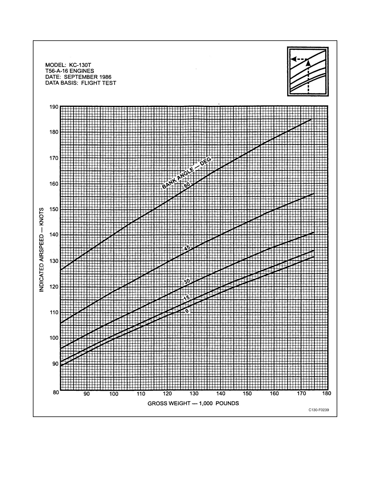
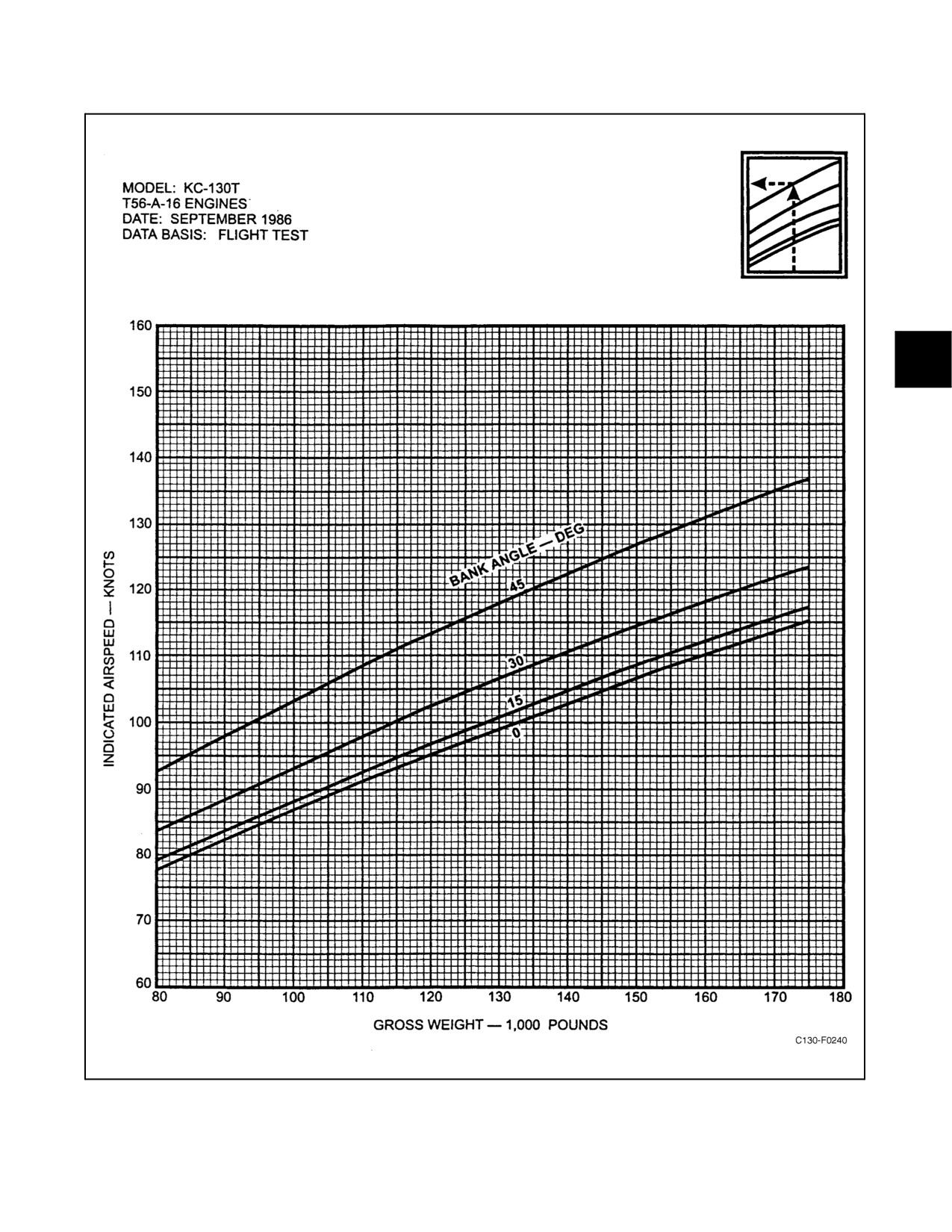
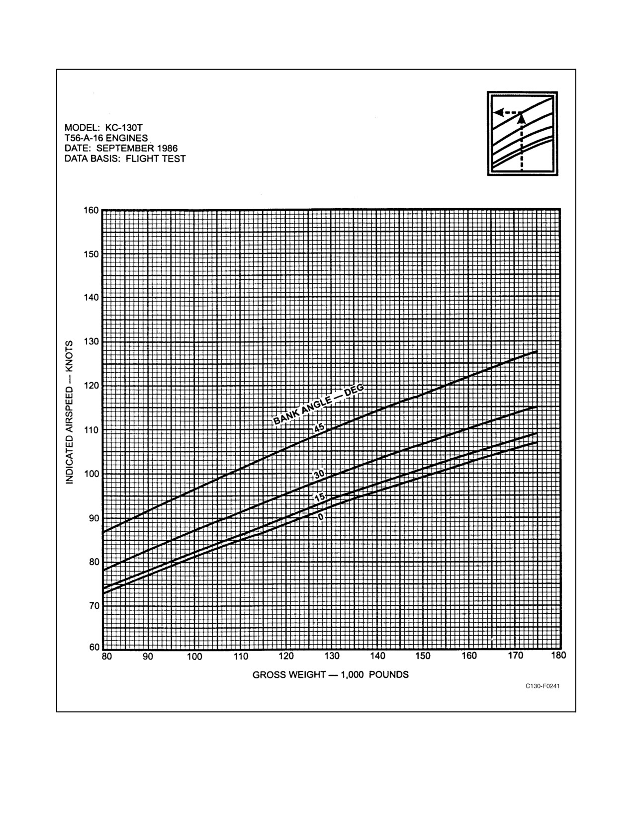
and flight attitudes are given in Figures 10-1 through 10-4. Use care to avoid accidental stalls. Should a stall be
entered, it is recommended that recovery be made as follows:
1. If in level flight, immediately drop the nose and apply power to limit loss of altitude. Use ailerons and rudder
to counteract any wing-dropping tendency. Move controls smoothly, avoiding abrupt actions. Avoid diving
the aircraft, and avoid abrupt or accelerated pull-up after recovery.
2. If in climbing or banked attitude, immediately drop the nose, level the wings, and apply power to limit loss
of altitude. Move controls smoothly, and avoid abrupt actions. Avoid diving the aircraft, and avoid abrupt or
accelerated pull-up after recovery.
3. Heavy gross weight cruise configuration power-on stalls will be accompanied by reduction of rudder and
elevator control forces. Recovery should be made by applying nose down elevator.
10.2.1 Practice Stalls
Any practice stall entry and recovery should be made at light weights (not to exceed 120,000 pounds) and with the
cargo compartment empty. Practice at a minimum altitude of 10,000 feet above the ground. The aircraft should be
trimmed at a speed not less than 1.4 times the stall speed for the entry configuration and weight, and should not be
adjusted until recovery is completed.
During stall entry, the nose should be raised at a rate to produce an airspeed decrease of approximately 1 knot per
second.
ThethrottleshouldbeincreasedaboveflightidleonlyasnecessarytopreventNTSactionfromoccurring duringentry
into the stall. The synchrophase master switch should be OFF. When stall warning in the form of light airframe
buffeting occurs, recovery should be initiated. Avoid abrupt control movements and avoid any control action that
may result in sudden attitude change or in excessive acceleration of buffeting.
10-1
ORIGINAL
01-75GAL-1
Figure 10-1. Power-Off Stall Speeds — Sea Level, ICAO Standard Atmosphere, Flaps Up
ORIGINAL
10-2
01-75GAL-1
Figure 10-2. Power-Off Stall Speeds — Sea Level, ICAO Standard Atmosphere, 50-Percent Flaps
10-3
ORIGINAL
01-75GAL-1
Figure 10-3. Power-Off Stall Speeds — Sea Level, ICAO Standard Atmosphere, 100-Percent Flaps
ORIGINAL
10-4
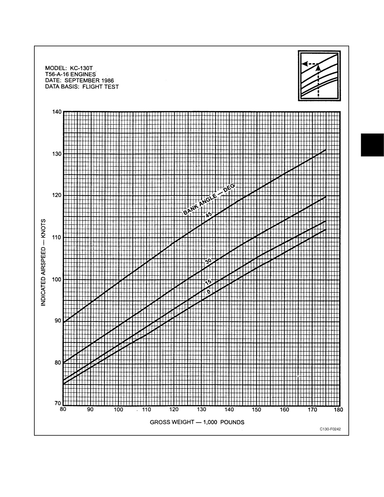
01-75GAL-1
Figure 10-4. Power-Off Stall Speeds — Sea Level, ICAO Standard Atmosphere,
Gear Up or Down, 70-Percent Flaps, Out of Ground Effect
10-5
ORIGINAL
01-75GAL-1
The following conditions adversely affect stall characteristics and/or performance and should be taken into
consideration prior to any practice stall training:
1. High power settings.
2. Asymmetric power.
3. One or more engines producing negative torque or causing a negative torque signal.
4. Retrimming or continually trimming the elevator nose up during stall entry.
5. Changing flap deflection during stall entry or recovery.
6. Increasing power during stall entry.
7. Practicing stalls at too low an altitude or over an overcast.
8. High fuel weights-low cargo weight conditions.
9. Aft center of gravity position.
Clean-configuration stalls should be discontinued at the onset of buffet.
Power-on stalls should not be attempted because of the excessively
nose-high attitude required.
10.3
SPINS
Spins are a prohibited maneuver, and should never be intentionally entered. Accidental spins can be prevented by
immediate recovery from any stall condition. If a spin is accidentally entered, it is anticipated that a normal recovery
for multi-engine aircraft will be effective. As in any maneuvering flight, proper care should be taken to avoid
exceeding the structural limits of the aircraft by a sudden pull-up.
10.4
FLIGHT CONTROLS
The flight controls are designed to be operated with hydraulic boost on at all times. With boost on, the aircraft can
becontrolledwithoutundueeffortbythepilotunderany reasonableload, flap,and powercombinations. Lighterstick
forces are encountered in the power-approach configuration with aft center of gravity loadings. At airspeeds below
100KCASinthepower-approachconfiguration,alesspositiverollstabilityeffectisexperienced.Incaseofcomplete
failure of the hydraulically powered control systems, refer to Part V.
Landing under these conditions will be marginal if turbulence or
crosswinds are encountered. Do not deliberately turn off properly
functioning boost control in flight. To do so may result in an uncontrollable
attitude change and acceleration.
ORIGINAL
10-6
01-75GAL-1
10.5
LEVEL-FLIGHT CHARACTERISTICS
Therangebetweenslow-andhigh-speedflightisunusuallylarge,butcontrolandstabilityarenormalforanytrimmed
condition. During landing at light gross weights, the aircraft has a tendency to float due to the large wing area, the
propeller blade angle, and the flight idle horsepower.
10.6
MANEUVERING FLIGHT
Maneuvering flight within the category of acrobatics is prohibited. Do not make hard rudder kicks that result in large
angles of yaw. Normal maneuvers may be accomplished with moderate pilot effort, since control movement is
assisted by the boost system. There are no conditions of normal maneuvering flight which will produce a reversal
of control pressures, and maneuvers can be accomplished with ease. In executing turns under combat conditions,
remember that 60_ is the maximum bank angle. The recommended speed for minimum-radius turns is the best climb
speed at that altitude.
Abrupt pushover to a negative-g condition with flaps either up or down
should be avoided. This type of maneuver will result in a reduction in
maneuvering longitudinal stability, in that the angle of pitch-down and the
negative-g condition continue to increase even after the stick direction has
been reversed. After movement of the stick toward the former position is
begun, there is a time lag before the aircraft starts to reverse its pitching
motion.Final recoveryfrom themaneuverrequiresconsiderablepullforce.
This is due to the large pitching inertia of the aircraft and the longitudinal
rotational effect on the hinge moments of the elevator. These characteristics
could result in an excessive negative load factor, an uncomfortable
nosedown attitude, and an excessive positive load factor because of an
abrupt recovery.
10.6.1 Fin Stall
Fin stall maneuvers are prohibited.
If the aircraft is maneuvered to abnormally high sideslip angles (15_ to 20_), a fin stall resulting in large yawing
transients and a loss of directional stability can be encountered. This is an unusual flight maneuver and will not result
from power transients, gusts, wake turbulence or execution of normal flight maneuvers. The fin stall condition is more
likely to occur during abnormal amounts of left-rudder-input maneuvers if held until fin buffet occurs. Fin stall can
be encountered at all speeds between stall speed and approximately 170 KIAS in all flap configurations with power
on. The susceptibility of encountering the fin stall condition is greatest at low speed with high power. Consequently,
under these conditions rapid yawing maneuvers can be produced with relatively low abrupt rudder inputs or
abnormally high rudder deflections. As the aircraft attitude approaches the critical sideslip angle, heavy vertical fin
buffet will develop.
10-7
ORIGINAL
01-75GAL-1
10.6.2 Fin Stall Recovery
Fin stall recovery must be initiated at the onset of buffet by returning the rudder to the neutral position and rolling
to a wings-level attitude. If altitude and flight conditions permit, pushing the nose down to increase airspeed and/or
reducing power will also assist in recovery.
Note
D Ensure that adequate flying speed is maintained at all times.
D If fin stall is entered, it will require approximately 50 to 100 pounds rudder
pedal force to return the rudder to neutral.
10.7
DIVING
Conduct dives or descents within the airspeed limitations given in Part I. Avoid abrupt pullups at any time.
10.8
FLIGHT CHARACTERISTICS UNDER PARTIAL POWER CONDITIONS
The aircraft has excellent flight characteristics even when an engine is inoperative. All control surfaces are booster
operated, so that no great amount of pilot force is necessary to correct the turning action caused by uneven power
conditions. Some trim changes will be required. More rudder deflection will be required at low speed to counteract
the unbalanced thrust. With uneven power conditions, the minimum control speed will be limited by the available
rudder effectiveness. Failure of an outboard engine may require the reduction of power on the opposite outboard
engine. Consult NAVAIR 01-75GAI-1.1, combined performance data manual, for recommended cruise and climb
procedure for two- and three-engine operation. In the event two engines fail and a safe altitude cannot be maintained,
dump fuel and jettison equipment as necessary.
10.8.1 Practice Maneuvers with One or More Engines Inoperative
Engine failures may be simulated for practice, when desired. To simulate a feathered propeller, retard one or more
throttles to FLIGHT IDLE position. The checklist procedure for engine failure can be called out without actually
performing the operations named. Practice maneuvers at a safe altitude. Select a base point and set up a simulated
field elevation. Traffic patterns can be flown at the normal altitude above this base point.
During takeoff, or while airborne, do not move the throttles below the
FLIGHT IDLE position. Placing any propeller in the taxi range may result
in immediate loss of control of the aircraft.
During practice feathering, perform engine shutdown by engine shutdown procedures. Prior to practice engine
shutdown in flight, perform an NTS check as outlined in Part III.
10.8.2 Turns
Turns can be safely made in either direction with one or two engines inoperative on the same side if airspeed is
maintained with sufficient margin for air minimum control speed and stall speed. Air minimum control speed is based
on utilizing 5_ of bank angle away from the inoperative engine(s).
Banking into the dead engine(s) increases the minimum speed at which directional control can be maintained.
ORIGINAL
10-8
01-75GAL-1
10.8.3 Effect of Speed on Trim
During engine-out operation, asin allothertypesofoperation,trim isaffected byspeed. Aftertrim isset, anyincrease
of airspeed increases the effect of the trim tabs. Conversely, any decrease of airspeed reduces the effect of trim tabs.
10.8.4 Landing and Go-Around
Landings and go-arounds with feathered engines may be simulated at altitude by flying a traffic pattern over a basic
altitude. Roll out most of the trim as touchdown point is reached. During a go-around practice, note the altitude lost
between the go-around decision and the time the aircraft is safely in a climb condition. Note the aircraft acceleration
characteristics during these maneuvers.
10-9/(10-10 blank)
ORIGINAL

01-75GAL-1
PART V
Emergency Procedures
Contents
Page
No.
CHAPTER
11
— EMERGENCY PROCEDURES
11.1
INTRODUCTION
11-1
11.1.1
Engine Shutdown Conditions
11-1
11.1.2
Engine Shutdown Procedure
11-4
11.1.3
Cleanup
11-4
11.2
GROUND EMERGENCIES
11-5
11.2.1
Auxiliary Power Unit Fire
11-5
11.2.2
Cargo Compartment Refrigerator Overheat Warning Light
11-5
11.2.3
Start Valve Open Light Illumination
11-5
11.2.4
Engine Fire
11-6
11.2.5
Engine Overheating
11-6
11.2.6
Emergency Entrances
11-7
11.2.7
Ground Evacuation
11-7
11.2.8
Brake System Malfunctions
11-9
11.3
TAKEOFF EMERGENCIES
11-11
11.3.1
Abort Procedures
11-11
11.3.2
Engine Failure After Refusal Speed
11-12
11.4
IN-FLIGHT EMERGENCIES
11-13
11.4.1
Engine Failure
11-13
11.4.2
Propeller Malfunctions
11-15
11.4.3
Engine Fires
11-21
11.4.4
Engine Overheating
11-21
11.4.5
Auxiliary Power Unit Fire
11-21
11.4.6
Turbine Overheat Warning
11-22
11.4.7
Nacelle Overheat Warning
11-22
11.4.8
High Turbine Inlet Temperature
11-22
11.4.9
High Oil Temperature
11-22
11.4.10
Engine Systems Failure
11-22
11.4.11
Fuel System Failure
11-26
11.4.12
Fuel Dumping
11-31
11.4.13
Electrical Systems Failure
11-33
11.4.14
Generator Failure
11-39
59
ORIGINAL

01-75GAL-1
Page
No.
11.4.15
Fuselage Fire/Smoke and fumes Elimination
11-42
11.4.16
Electrical Fire
11-43
11.4.17
Cargo Compartment Refrigerator Overheat Warning Light
11-46
11.4.18
Bleed-Air Ducting Failure/Overheat Detection System (ODS) Warning Lights
11-46
11.4.19
Emergency Operation of Cabin Pressurization System
11-50
11.4.20
Emergency Operation of Air-Conditioning Systems
11-50
11.4.21
Emergency Operation of Leading Edge Anti-Icing System
11-50
11.4.22
Wing Fire
11-51
11.4.23
In-Flight Door Warning
11-52
11.4.24
In-Flight Release of Liferaft
11-53
11.4.25
Windshield and Window Failure
11-54
11.4.26
Rapid Decompression
11-55
11.4.27
Hydraulic Systems Failure
11-55
11.4.28
Landing Gear System Failure
11-65
11.5
CARGO JETTISON
11-79
11.5.1
Cargo Jettison Procedure
11-79
11.6
BAILOUT PROCEDURES
11-80
11.6.1
NB-8 Personnel Parachute
11-83
11.7
CONTROLLABILITY
11-84
11.7.1
Controllability Check
11-84
11.8
LANDING EMERGENCIES
11-85
11.8.1
Landing With Engines Inoperative
11-85
11.8.2
Go-Around With One or Two Engines Inoperative
11-88
11.8.3
Landing With Tire Failure
11-89
11.8.4
Landing Gear Retracted
11-89
11.8.5
Landing on Soft Ground or Unprepared Runways
11-91
11.8.6
Loss of Nosewheel Steering During Landing
11-91
11.8.7
Landing With a Cocked Nosewheel
11-91
11.8.8
Nosewheel Shimmy
11-91
11.9
DITCHING
11-92
11.9.1
Ditching Characteristics
11-92
11.9.2
Preparation for Ditching
11-93
11.9.3
Ditching Procedures
11-93
11.9.4
Abandoning Aircraft
11-98
11.10
EMERGENCY EQUIPMENT
11-100
11.10.1
Hand-Operated Fire Extinguishers
11-100
11.10.2
Master Light Shutoff Switches
11-100
ORIGINAL
60

01-75GAL-1
Page
No.
11.10.3
First-Aid Kits
11-101
11.10.4
Hand Axes
11-101
11.10.5
Emergency Lights
11-101
11.10.6
Liferafts
11-101
11.10.7
Emergency Transmitters
11-101
11.10.8
Lifevests
11-102
11.10.9
Antiexposure Suits
11-102
11.10.10
Retaining harnesses
11-102
11.10.11
Emergency Passenger Oxygen System (EPOS)/Victim Rescue Unit (VRU)
11-102
11.10.12
Main Landing Gear Tiedown Fixtures
11-103
11.10.13
Hazmat Spill Kit
11-103
11.10.14
Emergency Ditching Equipment
11-103
11.11
GPWS AURAL WARNING (TERRAIN TERRAIN/WHOOP, PULL UP GPWS)
AND WINDSHEAR ESCAPE MANEUVER
11-106
61/(62 blank)
ORIGINAL

01-75GAL-1
CHAPTER 11
Emergency Procedures
11.1
INTRODUCTION
This chapter contains the procedures to beused in coping with the various emergencies that may bemet during flight
and landing. A thorough knowledge of these emergency procedures will enable crewmembers to perform their
emergency duties in an orderly manner and to judge more quickly the seriousness of the emergency. This will permit
early planning for a bailout or forced landing and will greatly increase the crew chances for survival (see Figure 11-1
for location of emergency equipment). The procedures consist of items classified as critical or noncritical. The critical
items are actions that must be performed immediately to avoid aggravating the emergency and causing injury or
damage. Critical items are preceded with an asterisk and must be committed to memory. Noncritical items are actions
that contribute to an orderly sequence of events. After determining that an emergency exists, the pilot should
immediately establish communications with a ground station. The ground station should be given a complete
description of the emergency, the action taken, and an accurate position. The ground station should be further notified
of any changes or developments in an emergency so that the station can alert the Aerospace Rescue and Recovery
Service or other agencies to stand by, if necessary. In the checklists presented, the codes P, CP, FE, and LM stand
for pilot, copilot, flight engineer, and loadmaster. This presentation does not preclude the pilot from redelegating the
duties at crew briefing.
Note
Never initiate a procedure before command of the pilot.
11.1.1 Engine Shutdown Conditions
If any of the following conditions occur in flight or on the ground, shut down the affected engine when the necessary
corrective action fails to remedy the adverse condition:
1. Engine fire.
9. Unusual vibration or roughness.
2. Nacelle overheat
10. Certain propeller malfunctions (see Propeller
3. Turbine overheat.
Malfunctions, paragraph 11.4.2).
4. Uncontrollable rise in TIT.
11. Start valve light illuminates.
5. Uncontrollable rise in oil temperature.
12. Throttle control cable failure.
6. Uncontrollable drop in oil pressure.
13. Excessive visible fluid leak.
7. Generator fails to disconnect.
14. Certain hydraulic malfunctions.
8. Excessive or uncontrollable power.
When it is necessary to continue operation of an engine with any of these conditions present, operate the engine with
extreme caution and at the minimum power required.
Note
Before making a precautionary engine shutdown, consider performing an
NTS check using the procedures in Chapter 8.
11-1
ORIGINAL

01-75GAL-1
Figure 11-1. Emergency Equipment (Sheet 1 of2)
ORIGINAL
11-2
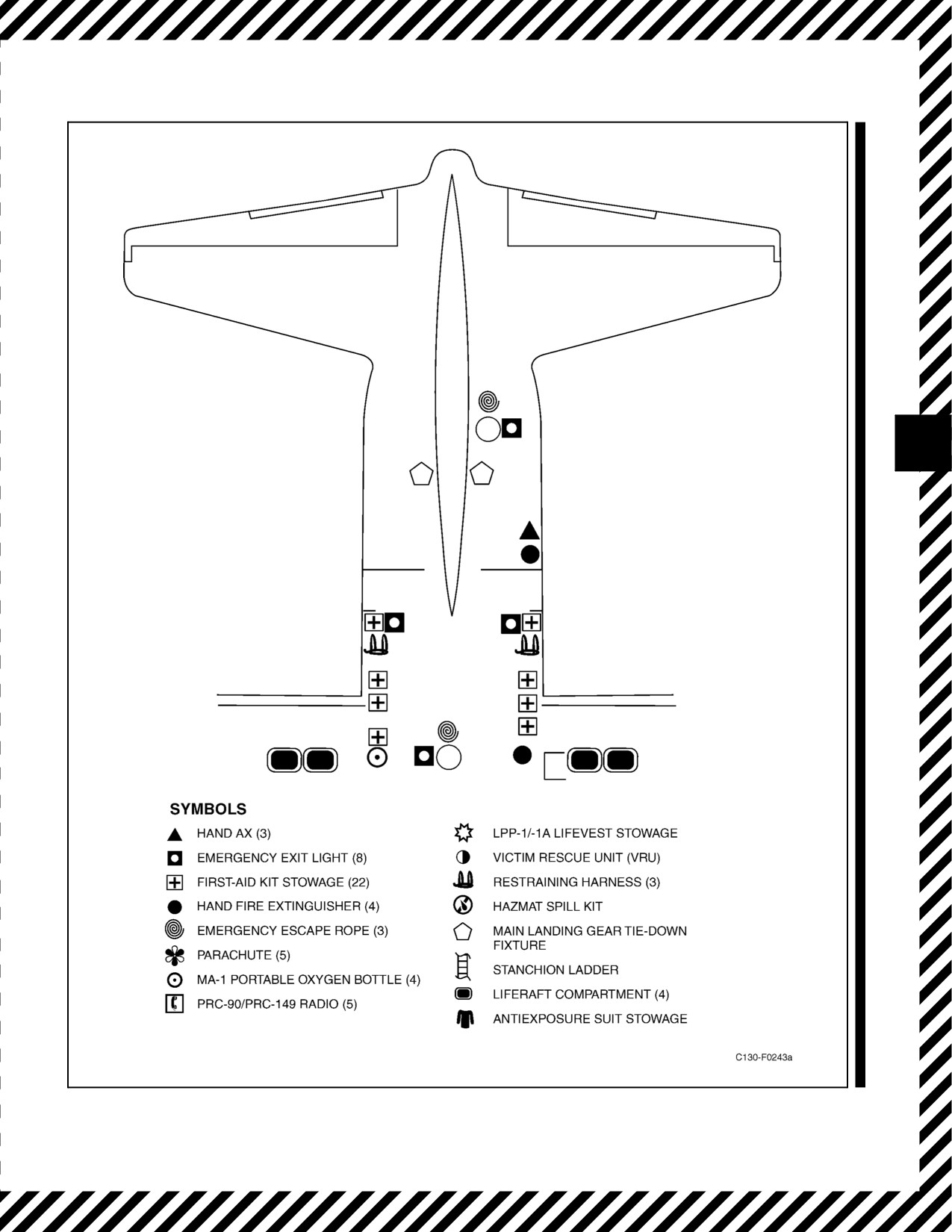
01-75GAL-1
(5)
Figure 11-1. Emergency Equipment (Sheet 2)
11-3
ORIGINAL

01-75GAL-1
11.1.2 Engine Shutdown Procedure
*1. Condition lever — FEATHER (CP).
CAUTION
When pulling a condition lever to FEATHER, pull it all the way to the
detent to ensure that the propeller is fully feathered when the engine fuel
is shut off. If the lever is left at midposition and NTS is inoperative, an
engine decoupling is possible.
*2. Fire Handle — PULLED (as required) (CP).
If a fire, nacelle overheat, visible fluid leak or throttle control cable failure is indicated.
*3. Fire extinguisher — DISCHARGED (as required) (CP).
If a fire, nacelle overheat or other indication of fire persists.
Note
If fire indication condition persists, a break in the bleed-air manifold may
exist.
*a. If condition persists, isolate the wing.
*b. If condition persists, discharge the remaining bottle.
*4. Flaps — As Required (CP).
*5. Landing gear — As Required (CP).
*6. Propeller — Feathered (CP).
Note
D The copilot shall verbally confirm propeller feathered with the loadmaster
and visually confirm feather override button release.
D If a propeller continues to rotate, refer to Propeller Fails to Feather,
paragraph 11.4.2.5.
11.1.3 Cleanup
1. ENGINE BLEED AIR switch — OFF (FE).
2. Generator switch — Set (FE).
a. Generator switches (aircraft prior to 165313) — Tripped/OFF (FE).
b. Generator switch (aircraft 165313 and up) — OFF (FE).
3. Fuel BOOST PUMP switch — As Required (FE).
Note
If on crossfeed, ensure source of fuel to operate engines before shutting off
fuel boost pump and crossfeed valve for the affected engine.
ORIGINAL
11-4

01-75GAL-1
4. CROSSFEED VALVE switch — As Required (FE).
5. PROPELLER GOVERNOR CONTROL switch — MECH GOV (CP).
6. Propeller feather override button — Out (CP).
7. SYNCHROPHASE MASTER switch — Reset as Required (FE).
8. TD VALVE switch — NULL (FE).
9. Throttle — Full Forward (P).
10. OIL COOLER FLAPS switch — CLOSED/Fixed (CP).
Note
Performance data should be checked (refer to NAVAIR
01-75GAI-1.1,
Combined Performance Data Manual).
11.2
GROUND EMERGENCIES
11.2.1 Auxiliary Power Unit Fire
*1. APU fire handle — Pulled (CP).
*2. Fire extinguisher — Discharge (as required) (CP).
*a. If condition persists, discharge the remaining bottle.
*3. APU generator — OFF (FE).
4. Evacuate (refer to Ground Evacuation procedures, paragraph 11.2.7) — (All).
11.2.2 Cargo Compartment Refrigerator Overheat Warning Light
1. Cargo compartment air-conditioning shutoff switch — OFF (FE).
2. UNDERFLOOR HEATING switch — OFF (FE).
3. APU CONTROL switch — STOP (FE).
4. Bleed-air divider valve — CLOSED (FE).
5. No. 3 and 4 ENGINE BLEED AIR switches — OFF (FE).
CAUTION
It is not recommended that any bleed-air valve be reopened once it has been
closed for an overheat condition. Damage to the warning system may
prevent detection of a subsequent overheat condition.
11.2.3 Start Valve Open Light Illumination
If the start valve open light illuminates other than during normal engine start:
1. Condition lever — GROUND STOP (CP).
2. ENGINE BLEED AIR switch — OFF (FE).
11-5
ORIGINAL

01-75GAL-1
11.2.4 Engine Fire
Engine fires are indicated by a steady illumination in the respective fire handle and the master fire warning light on
the pilot instrument panel. If an engine fire is experienced on the ground or in flight:
1. Perform Engine Shutdown Procedure, paragraph 11.1.2.
11.2.4.1 Tailpipe Fire or Torching During Engine Start
A tailpipe fire is defined as abnormal flame or torching coming from the engine tailpipe during start.
Note
Unless taxiing, inform groundcrew ofthe situation so they may useground
fire extinguishers if necessary.
1. Condition lever — GROUND STOP (P).
2. Continue to motor the engine with the starter (if the switch has not been released) (P).
If flames spread beyond the tailpipe or continue:
3. Perform Ground Evacuation Procedure, paragraph 11.2.7.
11.2.4.2 Tailpipe Fire During Engine Shutdown
1. Perform Engine Shutdown Procedure, paragraph 11.1.2.
CAUTION
Tailpipe fire during engine shutdown may be caused by an oil leak in the
turbine section. Do not motor the engine when a tailpipe fire exists on
engine shutdown.
11.2.5 Engine Overheating
There are four indications of overheating in the engines and nacelles:
1. Turbine overheat warning light.
2. Nacelle overheat warning light.
3. High TIT.
4. High oil temperature.
11.2.5.1 Turbine Overheat Warning
If an overheat condition is indicated by the flashing of the master fire warning light and/or lights in a fire handle:
1. Throttles — GROUND IDLE (P).
2. Condition lever — GROUND STOP (CP).
ORIGINAL
11-6

01-75GAL-1
11.2.5.2 Nacelle Overheat Warning
When an overheat warning is indicated by a nacelle overheat warning light on the copilot instrument panel:
1. Perform Engine Shutdown Procedure, paragraph 11.1.2.
11.2.5.3 High Turbine Inlet Temperature
Should an overtemperature be indicated by high TIT, proceed as follows:
1. Throttle of affected engine — GROUND IDLE (P).
If this fails to eliminate the overtemperature:
2. Condition lever — GROUND STOP (CP).
11.2.5.4 High Oil Temperature
Refer to Engine Oil System Failure, paragraph 11.4.10.3.
11.2.6 Emergency Entrances
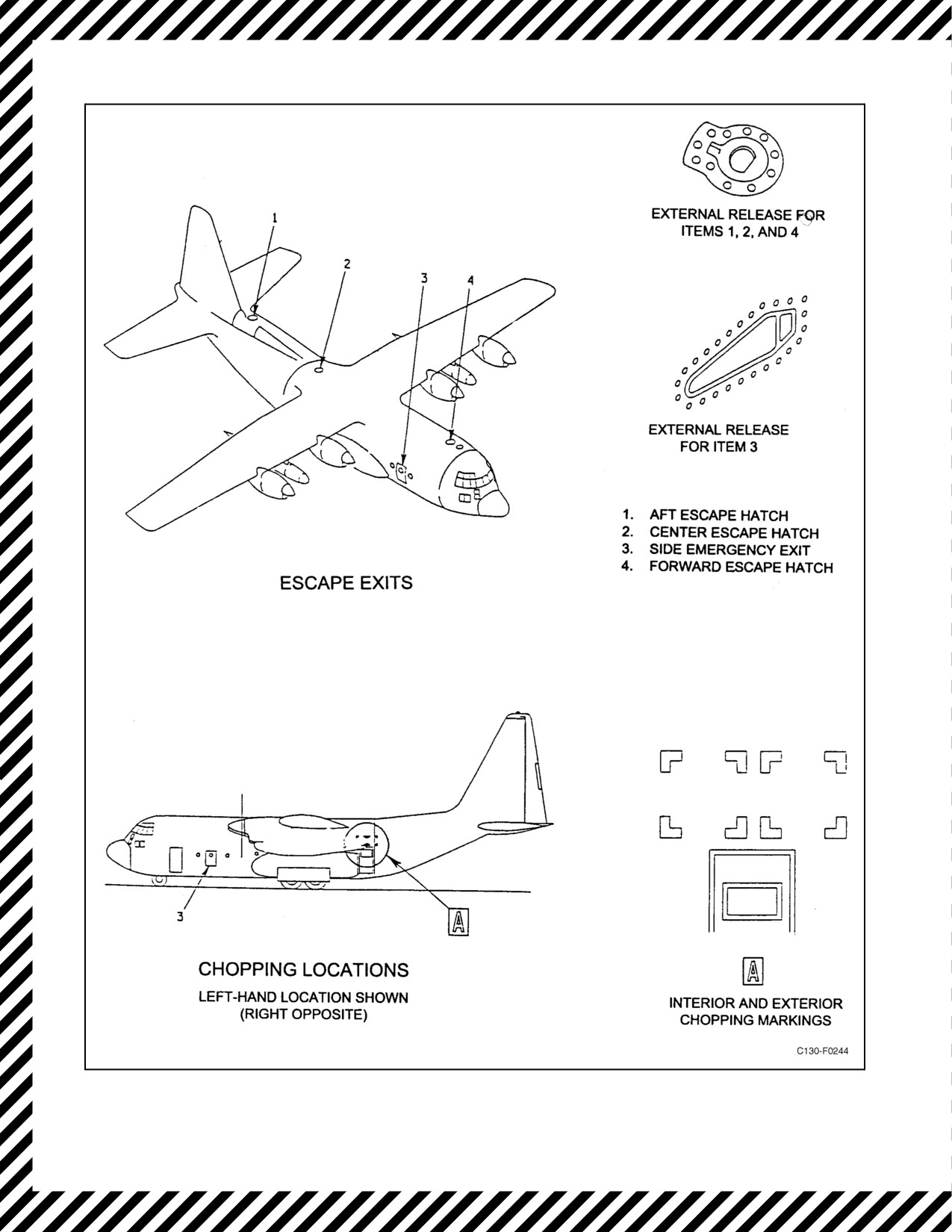
Emergency entrances are those used by ground rescue personnel (see Figure 11-2).
11.2.6.1 External Releases
The side emergency exits are each equipped with an external rotate-to-unlock-type release handle that is stowed in
a flush position on the exit. Depressing the handle release button allows the handle to pop out of its stowed position
so it can be rotated. Rotating the handle permits the exit to be pushed inward and entrance may be made.
11.2.6.2 Chopping Locations
Chopping locations, marked in yellow (see Figure 11-2) are painted on each side of the fuselage above the paratroop
jump doors. The locations are marked on the inside and outside of the fuselage.
11.2.7 Ground Evacuation
Note
If a hot brake is suspected or a main wheelwell fire exists, set opposite brake
only.
1. Parking brake — Set (P).
2. Tower/Ground — Notified (CP).
3. Crew — Notified (P).
4. Dc BUS TIE switch — TIED (FE).
5. Condition levers — FEATHER (CP).
6. Fire handles — Pulled (CP).
11-7
ORIGINAL
01-75GAL-1
Figure 11-2. Emergency Entrances
ORIGINAL
11-8

01-75GAL-1
7. Ac/dc power switches — OFF (FE).
8. Alarm bell — One Long Ring (CP).
9. Evacuate aircraft — All.
10. Chock aircraft — As Required (LM).
If a hot brake is suspected or a main wheelwell fire exists, chock nosegear
only.
11.2.8 Brake System Malfunctions
11.2.8.1 Loss of Utility System Hydraulic Pressure
The normal brake system will be inoperative if utility system hydraulic pressure is lost. If pressure is not available
to the normal brake system:
1. BRAKE SELECT switch — EMERGENCY (CP).
CAUTION
Usebrakes cautiously; noantiskid protectionis availableon theemergency
system. Avoid taxiing into congested areas because of the possibility of
auxiliary hydraulic pump failure.
Note
D With antiskid off, there are approximately two brake applications available
from a fully charged normal brake accumulator and approximately one
application from a fully charged emergency brake accumulator.
D The auxiliary hydraulic system handpump may be used for stopping the
aircraft in an emergency by holding the brake pedals down while the
handpump is being operated.
11.2.8.2 Dragging Brake
A dragging brake may be difficult to detect. If it is not evident to the pilot, the first knowledge of the problem may
be a report from the tower operator that the brake is smoking. Continued taxiing with a dragging brake will result
in a brake fire. A dragging brake may be caused by improper adjustment of a new or overhauled brake or by trapped
air in the brake system.
1. Stop aircraft, using reverse thrust and nosewheel steering (P).
2. Request firefighting equipment — As Required (CP).
11-9
ORIGINAL

01-75GAL-1
Note
D Allow brake to cool and maintenance performed prior to moving the
aircraft.
D If a hot brake is suspected or a main wheelwell fire exists, set opposite brake
only.
11.2.8.3 Brake Fire
1. Stop aircraft, using reverse thrust and nosewheel steering (P).
Note
If a hot brake is suspected or a main wheel well fire exists, set opposite
brake only.
2. Request firefighting equipment — (CP).
3. Perform Ground Evacuation Procedure, paragraph 11.2.7 (ALL).
D All personnel other than those in the fire department should evacuate the
immediate area. The area on both sides of the wheel will be cleared of
personnel and equipment for at least 300 feet. Do not approach the main
wheel area when extreme temperatures because of excessive braking are
suspected. If conditions require personnel to be close to an overheated
brake or tire assembly, the approach shall be from the fore and aft only.
D Do not use CO2 directly on the wheel. It may cause the wheel to shatter.
11.2.8.4 Spongy or Chattering Brakes
This condition may be caused by air in the brake system or a defective antiskid valve.
1. ANTI-SKID switch — OFF (CP).
If condition persists:
2. BRAKE SELECT switch — EMERGENCY (CP).
11.2.8.5 Fading Brakes
This condition would normally be the result of overheating caused by hard or continuous braking.
1. Avoid further braking.
2. Stop the aircraft by reversing.
3. Have a crewman exit via the crew entrance door with a chock and place the chock in front of the nosewheel.
4. If there is a brake fire, refer to Brake Fire, paragraph 11.2.8.3.
ORIGINAL
11-10

01-75GAL-1
11.2.8.6 Antiskid Test Unsatisfactory
Duringtestoftheantiskidsystem,failureofawheeltotestproperlyindicatesthatthewheelmayhavebrakingwithout
antiskid protection, or the wheel may rotate freely without any braking capability. Use of the antiskid system after
an unsatisfactory test indication may result in uneven braking and a tendency for the aircraft to swerve when brakes
are applied.
1. ANTI-SKID switch — OFF (CP).
CAUTION
Failure of certain antiskid or brake system components can result in loss of
brakes or skid protection on one side of the aircraft without illuminating the
ANTI-SKID INOPERATIVE light.
11.2.8.7 Antiskid System Failure
Whenever the antiskid system is not operating as an integral part of the brake system, an ANTI-SKID
INOPERATIVE light will illuminate. Use of the antiskid system after the light illuminates may result in uneven
braking and a tendency for the aircraft to swerve.
1. ANTI-SKID switch — OFF (CP).
Note
The parking brake handle must be completely in to extinguish the
ANTI-SKID OFF warning light.
11.3
TAKEOFF EMERGENCIES
11.3.1 Abort Procedures
If a serious malfunction occurs on the takeoff roll prior to refusal speed, proceed as follows:
1. Announce — ABORT
2. Throttles — retard smoothly to FLIGHT IDLE (P).
If aborting because of a propeller malfunction, the affected engine shall be
shut down with the condition lever, prior to retarding the throttles below
FLIGHT IDLE. Directional control problems may be encountered when all
throttles are placed to GROUND IDLE if a propeller malfunction prevents
the affected propeller from entering the ground range.
3. Condition lever (affected engine) FEATHER — As Required (CP).
4. Throttles — GROUND IDLE (P).
11-11
ORIGINAL

01-75GAL-1
5. Reverse symmetrical engines — As Required (P).
6. Brakes — As Required (P).
7. Perform Engine Shutdown Procedure, paragraph 11.1.2 — As Required.
CAUTION
Setting the parking brake after an aborted takeoff may cause the brake
assemblies to fuse together if excessive braking was used.
11.3.2 Engine Failure After Refusal Speed
If an engine failure or fire occurs after reaching refusal speed:
1. Continue takeoff — (P).
If a propeller malfunction is suspected, proceed with Propeller Malfunc-
tions, paragraph 11.4.2.
2. Maintain directional control with flight controls and engine power as necessary (P).
3. Gear — Up (once safely airborne) (CP).
4. Perform Engine Shutdown Procedure, paragraph 11.1.2 (CP).
D Obstacle clearance performance data are based on the assumption that gear
retraction is initiated
3 seconds after takeoff and propeller feather is
initiated 6 seconds after takeoff.
D Obtain two-engine air minimum control speed as soon as possible after
takeoff and prior to raising the flaps above 15 percent.
D Flap retraction should be accomplished in 10-percent increments with
airspeed increasing approximately 5 knots between retraction increments.
This procedure will prevent the aircraft from settling during flap retraction
at heavy gross weights.
ORIGINAL
11-12

01-75GAL-1
11.4
IN-FLIGHT EMERGENCIES
11.4.1 Engine Failure
The effect of losing various combinations of engines must be understood and anticipated because related systems
are integrated between the engines (see Figure 11-3). In all combinations of two-engine failures, monitor the
generator loading. If generator loading is too high, shut off electrical equipment, as required, to keep the loading
within the range of available output.
D Two-engine operation above 120,000 pounds is marginal.
D Below two-engine air minimum control speed, it may be necessary to
reduce power on the opposite engine to help maintain directional control.
11.4.1.1 Four-Engine Power Loss/RPM Rollback
Loss ofpositivefuel boostpressure, fuelsystem malfunction,ornon-standardfuel managementtechniques cancause
erratic engine performance or fuel starvation resulting in decreasing amounts of power available to the engines. Low
voltage on the essential ac bus or synchrophaser malfunctions can cause all four engines to lose torque. When the
ac voltage is between 50 and 70 volts, the synchrophaser can malfunction causing the torque to drop 2,000
inch-pounds or more. The following steps should be taken if low-voltage or four-engine power loss is encountered:
1. Propeller governor switches — MECH GOV (CP/FE).
2. Synchrophaser Master switch — OFF (FE).
3. Fuel Panel — Main Tank to Engine (FE).
4. Generator #2 (Aircraft prior to 165313) — OFF (FE).
If a synchrophaser malfunction is suspected:
5. Synchrophaser AC and DC circuit breakers — Pulled (FE).
If condition persists:
6. Remove the synchrophaser from the electrical equipment control supply rack.
7. Land as soon as possible. (P).
D These procedures should correct the loss of power on four engines because
of low essential ac voltage or synchrophaser malfunctions, but there are
other malfunctions that can cause loss of engine power such as a failure in
the bleed-air system.
D When the above procedures have been completed, the crew shall check all
other essential systems for proper operation.
11-13
ORIGINAL

01-75GAL-1
CAUTION
In all combinations of two-engine failures, monitor generator loading to keep it within the range of available
output.
SYSTEMS AFFECTED
ENGINES INOPERATIVE
HYDRAULIC
ELECTRICAL
No.
1
and No. 4
One pump each for booster and
No. 1 and No. 4 generator out.
utility systems will be out.
Operation of equipment will take
longer.
No.
2
and No. 3
One pump each for booster and
No. 2 and No. 3 generator out.
utility systems will be out.
Automatic ice detection system will
Operation of equipment will take
be out. Deicing systems may be
longer.
operated manually. Synchrophaser
master will be inoperative.
No.
1
and No. 2
Utility system pumps will be out.
No.
1 and No.
2 generator out.
Wing flaps and main landing gear
to be operated manually. Auxiliary
system available for nose landing
gear emergency extension and
emergency brake operation. Flight
controls boost to be supplied by the
booster system only.*
CAUTION
Nosewheel steering and anti-
skid are not operative after
loss of the utility system.
No.
1
and No. 3
One pump each for booster and
No.
1 and No.
3 generator out.
utility systems will be out.
Operation of equipment will take
longer.
No.
2
and No. 4
One pump each for booster and
No.
2 and No.
4 generator out.
utility systems will be out.
Operation of equipment will take
longer.
No.
3
and No. 4
Booster system pumps will be out.
No.
3 and No.
4 generator out.
Flight controls boost to be supplied
by the utility system only.*
*Additional rudder hydraulic boost may be obtained by moving the flap lever greater than 15 percent.
Figure 11-3. Two Engines Inoperative
ORIGINAL
11-14

01-75GAL-1
11.4.2 Propeller Malfunctions
A propeller malfunction may be caused by electrical or synchrophaser malfunction, or hydraulic malfunction, and
will be indicated by one of the following conditions:
1. Propeller LOW OIL light or visible oil leak.
2. Overspeed or underspeed.
3. Rpm surge or fluctuation.
4. Failure of propeller to feather.
Note
A tachometer generator failure will give a false indication of propeller
failure when underspeeding or fluctuations occur. Refer to Tachometer
Generator Failure, paragraph 11.4.10.4.
11.4.2.1 Propeller Malfunctions During Takeoff
11.4.2.1.1 Before Refusal Speed
1. Perform Abort Procedure, paragraph 11.3.1 (P).
11.4.2.1.2 After Refusal Speed
1. Continue takeoff (P).
Propeller malfunctions during takeoff may be difficult to analyze at this
most critical phase. If the engine is shut down immediately and the
propeller fails to feather, it is possible that higher than normal air minimum
control speed may result. When fire is not indicated, it is recommended that
the engine be allowed to run until at least two-engine air minimum control
speed is reached (at least 135 KIAS).
2. Maintain directional control with flight controls and engine power as necessary (P).
Below two-engine air minimum control speed, it may be necessary to
reduce power on the opposite engine to help maintain directional control.
3. Gear — Up (CP).
4. PROPELLER GOVERNING CONTROL switch — MECH GOV (CP/FE).
11-15
ORIGINAL

01-75GAL-1
If rpm stabilizes within allowable limits:
5. Continue operation in MECH GOV.
If an overspeed condition exists:
6. Accelerate to and maintain 150 KTAS (P).
7. Perform Engine Shutdown Procedure, paragraph 11.1.2, when a suitable landing area has been reached.
For all propeller malfunctions refer to In-flight Propeller Malfunctions, paragraph 11.4.2.2.
D A go-around with a windmilling propeller should not be attempted if
airspeed is below two-engine air minimum control speed (at least 135
KIAS).
D Positioning the flap lever above approximately 15 percent or operating the
gear or flaps will increase the air minimum control speed because of
reduction in available hydraulic pressure.
11.4.2.2 In-Flight Propeller Malfunctions
If uncontrolled overspeed (above 105-percent rpm) occurs, reduce airspeed
as rapidly as possible to the speed at which safe control of the aircraft or
propeller can be maintained but not less than two-engine air minimum
control speed (at least 135 KIAS). Do not adjust the throttle position for the
affected engine before the malfunction is analyzed.
11.4.2.2.1 Rpm Within Allowable Limits and LOW OIL Warning Light Illuminated
1. Perform Engine Shutdown Procedure, paragraph 11.1.2.
If continued operation of the affected propeller is required in the interest of
safety, it is permissible to defer engine shutdown until landing is assured,
provided moderately high power is maintained.
11.4.2.2.2 Rpm Outside Allowable Limits With LOW OIL Light Illuminated
1. Place propeller governing control switch to MECH GOV.
ORIGINAL
11-16

01-75GAL-1
a. If rpm stabilizes within allowable limits, perform Engine Shutdown Procedure, paragraph 11.1.2.
If continued operation of the affected propeller is required in the interest of
safety, it is permissible to defer engine shutdown until landing is assured,
provided that moderately high power is maintained.
2. If rpm does not stabilize within allowable limits, perform Pitchlock Check Procedure, paragraph
11.4.2.3.
11.4.2.2.3 Rpm Outside Allowable Limits Without LOW OIL Light Illuminated
1. Place propeller governing control switch to MECH GOV.
a. If rpm stabilizes within allowable limits, continue operation in MECH GOV.
b. If rpm remains outside allowable limits, perform the following Pitchlock Check Procedure.
11.4.2.3 Pitchlock Check Procedure
1. TD valve — Locked (FE).
2. Slowly move the throttle or vary the TAS (P).
Note
If a TIT change is not noted and engine rpm is high, the engine may be on
fuel control governing and throttle travel may be insufficient for rpm to
follow. In this case, a change in TAS will be necessary to verify pitchlock.
A reduction in TAS is recommended (not below two-engine air minimum
control speed) as rpm is already on the high side.
If the rpm does not follow the throttle or TAS:
3. Perform Engine Shutdown Procedure, paragraph 11.1.2.
If the rpm follows the throttle or TAS:
4. Perform Pitchlock Propeller Operation procedure, paragraph 11.4.2.4.
11.4.2.4 Pitchlock Propeller Operation
1. Establish 96- to 98-percent with airspeed adjustment.
2. ENGINE BLEED AIR switch — OFF (FE).
3. Continue to operate the propeller while maintaining 96- to 98-percent rpm.
4. When a suitable landing area is reached, descend at an airspeed that will allow 96- to 98-percent rpm to be
maintained with throttle adjustment.
11-17
ORIGINAL

01-75GAL-1
Note
D Operating a pitchlocked propeller in the underspeed range,
96- to
98-percent rpm, helps to ensure continued positive pitchlock engagement.
Maintaining at least 96-percent rpm will ensure that the engine compressor
bleed valves do not open with resultant loss of engine power.
D If an rpm of at least 96 percent cannot be maintained when slowing to 150
KTAS, it is reasonable to assume that the propeller is pitchlocked at a high
blade angle. Shutdown at the airspeed where 96-percent rpm can no longer
be maintained should give acceptable wind-milling drag and rpm should
the propeller fail to feather. This high-blade-angle pitchlock case is
associated with propeller malfunctions at cruise speeds.
D If 96- to 98-percent rpm can be maintained at 150 KTAS, the propeller is
at a low blade angle. In this case, shutdown at speeds above 150 KTAS
could produce excessive drag and overspeed if the propeller does not
feather.
5. During the traffic pattern, attain a speed (not below 150 KTAS) where 96- to 98-percent rpm cannot be
maintained with throttle adjustment, and perform Engine Shutdown Procedure, paragraph 11.1.2.
Regardless of the operation of the propeller in the traffic pattern, the engine
shall be shut down prior to landing.
Note
Shutdown at 150 KTAS should ensure decoupling if the propeller fails to
feather.
6. Ifpropellerdoesnotfeather,alandingcanbemadewithawindmillingpropeller;however,thedragandyawing
tendency will be greater than with a feathered propeller and excessive rpm and noise may be experienced.
Maintain airspeed above two-engine air minimum control speed until landing is assured (at least 135 KIAS).
D A go-around should not be attempted if airspeed is below two-engine air
minimum control speed (at least 135 KIAS).
D Below two-engine air minimum control speed, it may be necessary to
reduce power on the opposite engine to help maintain directional control
(at least 135 KIAS).
7. If a go-around is attempted, follow the go-around procedures in this chapter. Go-around with a windmilling
propeller may be marginal.
ORIGINAL
11-18

01-75GAL-1
Positioning the flap lever above 15 percent or operating the gear or flaps
will increase the air minimum control speed because of reduction in
available hydraulic pressure.
11.4.2.5 Propeller Fails to Feather
If the propeller rotation continues after feather has been initiated:
1. Attain 150 KTAS (if possible) (P).
Note
Slow aircraft to the minimum safe airspeed, but not less than two-engine
air minimum control speed (135 KIAS minimum).
2. FEATHER and AIRSTART, EMER FEATHER, FEATHER PUMP MOTOR circuit breakers — Checked
In (FE).
3. Feather Override Button — Hold in for 30 seconds, Pull Out (FE).
If propeller rotation continues:
Restore oil only if there is no indication of a fire.
4. Fire handle — Reset (CP).
5. OIL SHUTOFF VALVE circuit breaker — Pull (FE).
6. Fire handle — Pull (CP).
If a go-around is attempted, follow Go-around with One or Two Engines
Inoperative, paragraph 11.8.2. Go-around with a windmilling propeller
may be marginal.
Note
D If the propeller does not feather, a landing can be made with a windmilling
propeller; however, the drag and yawing tendency will be greater than with
a feathered propeller, and excessive rpm and noise may be experienced.
D If prop continues to rotate or is rotating backwards and engine was not shut
down due to any of the Engine Shutdown Conditions, paragraph 11.1.1,
restart may be performed in accordance with AIRSTART procedures,
paragraph 8.21.
11-19
ORIGINAL

01-75GAL-1
11.4.2.6 In-Flight Decoupling of Engine and Propeller
Thereduction gearsection decouples from thepowersection oftheengineifthepropellerattempts todrivethepower
section, and the engine negative torque control system fails to operate. As negative torque builds up before decoupling
of an engine takes place, aircraft yaw may be noticed. However, there may be little or no difference in aircraft feel,
and the knowledge that an engine has decoupled must be gained from instrument indication. If the decoupling is
caused by engine failure or flameout, torque, TIT, and fuel flow will drop to near zero and power section oil pressure
will drop. Rpm may temporarily increase, then settle to normal. Hydraulic pressure, generator output, and reduction
gear section oil pressure will remain normal. Extremely low TIT and fuel flow for a given throttle position,
accompanied by fluctuating and near-zero torque, may be an indication of a decoupling in which the engine continued
to operate. When decoupling is observed:
1. Perform Engine Shutdown Procedure, paragraph 11.1.2.
CAUTION
Although it may be possible, it is not recommended that an engine restart
be attempted after a known decoupling until a thorough ground inspection
has been accomplished.
11.4.2.7 Excessive/Uncontrollable Power/Throttle Control Cable Failure
A malfunction of the TD control valve system or a throttle control cable failure may cause a sudden increase or
decrease in TIT with an accompanying change in torque and fuel flow indications. If these indications occur during
stabilized operation, proceed as follows:
D Do not move the throttle prior to engine shutdown; to do so could cause the
propeller to go into reverse pitch.
D If throttle movement occurs that is not pilot initiated, a broken throttle
control cable should be suspected. Perform engine shutdown procedure
(paragraph 11.1.2), starting with Step 2.
1. Ifthethrottleis abovethecrossoverpoint, activatethewing/empennageanti-icing.MonitorTITfortheengine
being checked. If TIT rises and returns to its original setting as in a temperature controlling check, the TD
control valve system is working normally and a throttle cable failure must be suspected. Perform engine
shutdown procedure (paragraph 11.1.2), starting with Step 2. If TIT does not return to its original setting,
proceed with step 3.
2. If the throttle is at or below the crossover point, do not retard the throttle.
CAUTION
Monitor TIT closely during NULL operation as maximum TIT can often
be exceeded at advanced throttle setting under these conditions.
3. Place the TD control valve switch to the NULL position.
ORIGINAL
11-20

01-75GAL-1
If TIT stabilizes and returns to near normal:
4. Continue operation.
If the malfunction persists in NULL:
5. Perform Engine Shutdown Procedure, paragraph 11.1.2, starting with step 2.” (AIRS 030)
Do not move the affected throttle or condition lever. To do so could cause
the propeller to go into reverse or bind with other engine control cables.
11.4.3 Engine Fires
Engine fires are indicated by a steady illumination in the respective fire handle and the master fire warning light on
the pilot instrument panel. The fire detection system design is such that it is unlikely that the wrong engine would
be shut down. If an engine fire is experienced on the ground or in flight:
1. Perform Engine Shutdown Procedure, paragraph 11.1.2.
11.4.4 Engine Overheating
There are four indications of overheating in the engines and nacelles:
1. Turbine overheat warning light.
2. Nacelle overheat warning light.
3. High TIT.
4. High oil temperature.
11.4.5 Auxiliary Power Unit Fire
*1. APU fire handle — Pulled (CP).
*2. Fire extinguisher — Discharged (as required) (CP).
*a. If condition persists, discharge the remaining bottle.
*3. APU generator — OFF (FE).
4. APU CONTROL switch — STOP (FE).
5. APU BLEED AIR VALVE switch — CLOSE (FE).
11-21
ORIGINAL

01-75GAL-1
11.4.6 Turbine Overheat Warning
If an overheat condition is indicated by the flashing of the master fire warning light and/or by the flashing of lights
in the fire handle:
1. Retard the throttle toward FLIGHT IDLE.
If the overheat condition persists:
2. Perform Engine Shutdown Procedure, paragraph 11.1.2.
11.4.7 Nacelle Overheat Warning
When an overheat warning is indicated by a nacelle overheat warning light on the copilot instrument panel:
1. Perform Engine Shutdown Procedure, paragraph 11.1.2.
11.4.8 High Turbine Inlet Temperature
Should an overtemperature be indicated by a high TIT:
1. Retard throttle of affected engine toward FLIGHT IDLE — (P).
2. TD control switch — NULL (FE).
If this fails to eliminate the overtemperature condition:
3. Perform Engine Shutdown Procedure, paragraph 11.1.2.
11.4.9 High Oil Temperature
See engine oil system failure under Engine Systems Failure, paragraph 11.4.10.3.
11.4.10 Engine Systems Failure
11.4.10.1 Secondary Fuel Pump Pressure Light
Illumination or flickering of the secondary fuel pump pressure light other than during the engine start cycle may be
caused by failure of the engine-driven primary fuel pump or failure of the speed-sensitive control.
1. Fuel panel — Main Tank to Engine (FE).
If light is extinguished:
2. Continue normal operation.
Note
This is an indication of a bad pressure switch, a bad secondary pump outlet
check valve in the high pressure filter assembly, or a worn paralleling valve.
Normal crossfeed operation may be resumed.
ORIGINAL
11-22

01-75GAL-1
If light remains illuminated:
1. IGNITION CONTROL circuit breaker — PULL (FE).
If the light extinguishes:
2. Continue normal operation.
Note
D If the light extinguishes when the IGNITION CONTROL circuit breaker
for the corresponding engine is pulled, failure of the speed-sensitive control
is indicated. Ice detection is unavailable from an engine that has an
IGNITION CONTROL circuit breaker pulled.
D The IGNITION CONTROL circuit breaker must be reset before normal
engine shut-down on the ground.
If the light remains illuminated:
3. IGNITION CONTROL circuit breaker — RESET (FE).
CAUTION
Normal engine operation with a failure of the primary fuel pump or a failure
of the pressure switch is possible. The secondary fuel pump is capable of
providing all engine fuel requirements. However, internal failure of the
primary fuel pump could cause engine fuel system contamination and
erratic engine operation. In all cases, engine operation should be monitored
for abnormal secondary indications.
If secondary indications are present:
4. Perform Engine Shutdown Procedure — As Required.
11.4.10.2 Speed-Sensitive Control Failure (Sheared Shaft)
A sheared shaft on the speed sensitive control with the throttle above 65_ travel may be indicated by a momentary
illumination of the secondary fuel pump pressure light, fuel correction light illumination, and TIT will not exceed
thestart limiting temperature of830 _C. A sheared shaft with the throttlebelow 65_ may beindicated by momentary
illumination of the secondary fuel pump pressure light, and TIT will not exceed the start limiting temperature of 830
_C. If either of the following conditions occur:
CAUTION
Monitor TIT closely during null operation as maximum TIT can often be
exceeded at advanced throttle settings under these conditions.
11-23
ORIGINAL

01-75GAL-1
1. TD control switch — NULL (FE).
2. IGNITION CONTROL circuit breaker — Pull (FE).
3. Continue operation.
Note
D The IGNITION CONTROL circuit breaker must be reset before normal
engine shutdown on the ground.
D Ice detection is unavailable from an engine that has an IGNITION
CONTROL circuit breaker pulled.
11.4.10.3 Engine Oil System Failure
The indications of an engine oil system failure that may lead to engine failure are: loss of oil pressure, complete loss
of engine oil, or an oil temperature increase.
11.4.10.3.1 High Oil Temperature
High oil temperature may result from failure of an oil cooler flap to function in automatic. In the event of high oil
temperature:
1. OIL COOLER FLAP switch — OPEN (CP/FE).
2. Manually open or close the OIL COOLER FLAP as required to maintain normal engine oil temperature
(CP/FE).
If engine oil temperature remains excessively high:
3. Perform Engine Shutdown Procedure, paragraph 11.1.2.
11.4.10.3.2 Low Oil Quantity Warning
The Engine LOW OIL quantity warning light glows when the oil level in a tank drops to approximately 4 gallons.
In the event of a LOW OIL quantity light:
1. Monitor engine instruments with low oil quantity reading (FE).
CAUTION
Failure of the reduction gearbox assembly scavenge pumps will result in
oil being retained and overheating in thegearbox. This condition can result
in a potential catastrophic failure of the reduction gearbox and propeller
separation. Carefully monitor oil pressure.
2. No further corrective action is required as long as other engine instrument readings are within limits. In the
case of ”Low Oil Quantity” light with a loss of oil pressure or erratic/unstable oil pressure, Perform Engine
Shutdown Procedures, paragraph 11.1.2.
ORIGINAL W/IC 10
11-24

01-75GAL-1
11.4.10.3.3 Loss of Oil Pressure
In case of a loss of oil pressure:
1. Perform the Engine Shutdown Procedure, paragraph 11.1.2.
CAUTION
If engine oil pressure loss was caused by a negative-g condition and the
gearbox and engine oil pressures do not return to normal within 10 seconds
after returning to a positive-g condition, perform Engine Shutdown
Procedure, paragraph 11.1.2. After the propeller stops rotating, an airstart
may be attempted according to the AIRSTART procedures in Chapter 8.
11-24a (b Blank)
W/IC 10

01-75GAL-1
11.4.10.4 Tachometer Generator Failure
A tachometer generator failure may be indicated by the following simultaneous indications:
1. RPM decrease or fluctuation.
2. Fuel flow increase or fluctuation.
3. Torque decrease or fluctuation.
If the above occurs:
1. SYNCHROPHASE MASTER SWITCH — As required (FE).
a. If engine is selected as master, select the unaffected master engine position.
2. PROPELLER GOVERNOR CONTROL for affected engine — MECH GOV (CP/FE).
If fluctuations persist:
3. Perform Engine Shutdown Procedure, paragraph 11.1.2 (refer to In-Flight Propeller Malfunctions, paragraph
11.4.2.2).
11.4.10.5 Start Valve Open Light
If the start valve open light illuminates other than during normal start cycle:
1. Perform Engine Shutdown Procedure, paragraph 11.1.2.
11.4.10.6 Visible Fluid Leak
If excessive visible fluid leak from an engine is present and cannot be isolated:
1. Perform Engine Shutdown Procedure, paragraph 11.1.2.
11.4.10.7 Fuel Leaks (Drip or Running Type)
Fuel leaks encountered in flight present a fire hazard if the leak is in close proximity to an engine. The possibility
of a wing fire from a fuel leak is increased on landing if reverse thrust is applied. If a fuel leak is encountered near
an engine, shutdown of the engine should be considered. Land at the nearest airfield that has sufficient runway to
complete the landing ground roll without the use of reverse thrust. Because of the possibility of a fire, an emergency
should be declared and fire suppression equipment requested.
Do not use reverse thrust when landing with a known or suspected fuel leak.
If reverse thrust is used, a fire may develop.
11.4.10.8 Liquid Oxygen Quantity Indicator Failure
Amalfunction oftheoxygen quantityindicatorisindicativeofapossiblefailurethatwould, withthepropersequence
of events, allow the introduction of high voltage electrical power into the aircraft oxygen converter system. In the
event that the oxygen quantity indicator goes off-scale high, off-scale low, or fluctuates erratically:
11-25
ORIGINAL

01-75GAL-1
1. Pull the oxygen quantity indicator circuit breaker.
The oxygen quantity circuit breaker shall not be reset until proper
inspection and repairs have been made.
11.4.11 Fuel System Failure
11.4.11.1 Fuel LOW PRESS/AUX TANK EMPTY Warning Light
In the event of a fuel boost pump failure as indicated by a low-pressure warning light or aux tank empty light in a
tank containing fuel:
1. Check fuel pressure indicator (FE).
2. BOOST PUMP switch — OFF (FE).
3. Set up another fuel supply — As Required (FE).
4. BOOST PUMP circuit breakers — Pull (FE).
If fuel LOW PRESS light remains illuminated, then a leak may be indicated.
The fuel boost pump should not be turned on or the circuit breakers reset
until proper inspection and repairs have been performed. Resetting of the
circuit breakers and turning the switch on should be considered only to
prevent fuel starvation of the engines when a landing cannot be
accomplished within the range of available fuel.
Note
Gradual power losses will occur between 12,000 feet and 20,000 feet
during rapid climbout to an engine without boost pump pressure; this
altitude will vary with the prevailing fuel temperature and type of fuel in
the tanks (the higher the fuel temperature, the lower the altitude at which
the power loss will occur). This condition results from the highly aerated
condition of fuel caused by rapidly decreasing atmospheric pressure during
climb, allowing entrapped air in the fuel to expand. The period of time
required for the fuel to stabilize from this aerated condition will depend
upon both the rate of climb and fuel temperature.
ORIGINAL
11-26

01-75GAL-1
Note
Fuel stabilization should occur a few minutes after level off at cruise
altitude once the excess air has escaped from the fuel. Maximum power
settings can be maintained up to altitudes of 30,000 feet with a boost pump
inoperative if noseup or nosedown attitude and rapid acceleration are
avoided. Fuel aeration does not occur during descent. The loss of a boost
pump may result in fuel starvation for the affected engine in an extreme
nosedown attitude unless crossfeed operation is used. It is impossible to
gravity feed fuel from a tank with an inoperative boost pump through the
crossfeed system to another engine. If a partial tank and an empty tank are
on crossfeed with theboost pump inoperative in the partial tank, theengine
being fed from the empty tank will be starved by air being drawn into the
fuel line.
To ensure positive fuel flow during climb with a failed boost pump:
1.
Continue crossfeeding the engine from another tank (FE).
2.
Allow the fuel to stabilize for several minutes (FE).
3.
Switch the engine back to the tank with the inoperative boost pump (FE).
4.
Monitor fuel flow, TIT, and torque (FE).
If the engine operates satisfactorily in this condition:
5.
Continue the flight as planned (P).
If the engine will not operate satisfactorily in the tank-to-engine position:
6.
Switch back to crossfeed operation (FE).
Note
D When operating in the tank-to-engine position with an inoperative boost
pump, avoid rapid acceleration or nose-low attitudes. Descents should be
made with minimum nosedown attitude. If a high rate of descent is
required, it is advisable to select crossfeed operation.
D It may be necessary for the pilot to change the flight plan to avoid major
fuel unbalancing and loss of range because of unavailable fuel. If the flight
can be accomplished at a lower altitude, descend until the engine will run
satisfactorily on tank-to-engine flow.
D Do not select crossfeed if a main tank boost pump has failed and crossfeed
from another tank is not desired.
11-27
ORIGINAL

01-75GAL-1
11.4.11.1.1 Crossfeed Utilizing a Main Tank Dump Pump
The affected tank dump pump may be used to feed the engine from a tank with an inoperative boost pump by use
of the following procedure:
1. Main tank CROSSFEED switches — CLOSED (FE).
2. Affected tank DUMP PUMP switch — DUMP (FE).
3. Respective external tank CROSSFEED switch — OPEN (FE).
4. CROSSFEED SEPARATION switch — OPEN (FE).
5. CROSSFEED PRIMER button — Press for 1 minute (FE).
6. Affected tank CROSSFEED switch — OPEN (FE).
7. Monitor crossfeed fuel pressure (FE).
Note
When tank quantity approaches approximately 1,600 pounds in No. 1 and
4 tanks and 1,500 pounds in No. 2 and 3 tanks, dump pump cavitation will
occur.
11.4.11.2 Fuel Strainer BYPASS OPEN Light
1. If possible, select an alternate source of fuel.
2. Monitor the engine instruments for further indications of malfunction.
3. Consideration should be given to possible contamination, the amount of usable fuel remaining, wing fuel
balance, and possible diversion to the nearest suitable landing field.
11.4.11.3 Fuel Quantity Indicator Failure
This system is designed as an electrically inert capacitance system specifically designed to eliminate the possibility
of arcing from electrically charged components within the aircraft fuel tank system. The cockpit fuel quantity
indicator requires 115 volts 400 Hz power for proper operation. With the appropriate sequence of failures, the fuel
probes, coaxial cable, and associated wiring can operate as a vehicle for the introduction of high-voltage power into
the aircraft fuel system.
The fuel quantity indicator, electrical connectors, fuel probes and associated wiring should be operative before the
aircraft is released for flight. If any of these components are inoperative by incomplete maintenance action, or in the
event that a fuel quantity indicator goes blank or the display is unusable, the following action shall be complied with:
1. Pull and tag the FUEL QUANTITY INDICATOR circuit breaker for that associated tank.
The fuel quantity indicator must not be swapped or the circuit breaker reset
until proper inspection and repairs are made. The aircraft may be flown on
a subsequent flight with a malfunctioning indicator, provided the circuit
breaker remains pulled and the breaker pin lock is installed.
ORIGINAL
11-28

01-75GAL-1
11.4.11.4 Main Tank Dump Pump/Dump Valve Failure
If a main tank dump pump or dump valve fails to operate, fuel may be dumped by use of the following procedures:
CAUTION
Fuel dumping will be at a greatly reduced rate. Caution must be exercised
to maintain proper wing distribution.
1. Aft External Tank Pump circuit breakers (on affected side) — PULL (FE).
2. Main tank BOOST PUMP switch — ON (FE).
3. Main tank CROSSFEED VALVE switch — OPEN (FE).
4. Auxiliary tank CROSSFEED VALVE switch — OPEN (FE).
5. BYPASS VALVE switch (on affected side) — OPEN (FE).
6. External tank DUMP PUMP switch (on affected side) — ON (FE).
7. INTER CONN valve switch — FLOW (FE).
8. DUMP VALVE switch — OPEN (FE).
9. Monitor fuel dumping (CP/FE).
10. DUMP PUMP switches — OFF (FE).
11. INTER CONN valve switches — NO FLOW (FE).
12. DUMP VALVE switches — NORM (FE).
CAUTION
When returning the DUMP VALVE switches to the NORM position, press
firmly on the top of the switch guard until the maximum resistance is felt.
This will ensure that the switch toggle has returned to NORM.
Note
This procedure may be used in reverse by using the auxiliary tank dump
system and the external tank crossfeed valve.
11.4.11.5 External or Auxiliary Tank Crossfeed Valve Failure
If an external or auxiliary tank crossfeed valve fails to open when crossfeed operation from a tank is desired, fuel can
be crossfed through the BYPASS valve and the operative external or auxiliary crossfeed valve.
1. BYPASS valve — OPEN (FE).
2. Operative external or auxiliary CROSSFEED valve — OPEN (FE).
11-29
ORIGINAL

01-75GAL-1
11.4.11.6 External or Auxiliary Tank Dump Valve Failure
If an external or auxiliary tank dump valve fails to open when fuel dumping from that tank is desired, the fuel may
be dumped through the bypass valve and the operative dump system for the external or auxiliary tank on that side.
1. BYPASS valve — OPEN (FE).
2. Operative external or auxiliary CROSSFEED valve — OPEN (FE).
3. FUS TANK CROSSFEED switch — OPEN (FE).
11.4.11.7 EXT TANK EMPTY Light
If an external tank empty light illuminates when its respective quantity gauge indicates fuel aboard, it can be because
of failure of the pump or one of several other components. To locate the failure, proceed as follows:
1. Alternate tank pump switch — ON (FE).
2. Tank pump switch in use — OFF (FE).
If tank empty light goes out, failure of previously selected pump is indicated. Refer to paragraph 11.4.11.1 step 4.
3. Continue normal operation.
If tank empty light remains ON:
4. Main tank to engine — All engines (FE).
5. Verify external pump pressure (FE).
a. Crossfeed separation valve — OPEN.
b. All crossfeed valves except for the external tank being checked — CLOSED.
c. Check pressure from each of the pumps in the external tank.
d. The crossfeed prime button may be used to bleed the crossfeed pressure to zero between checks.
If a pressure of approximately 28 psi is indicated, the pumps are operating properly and the external tank empty light
pressure-sensing switch has malfunctioned.
6. Continue flight (P/CP).
7. Monitor fuel quantity gauge to determine empty condition (FE).
If a pressure of less than 28 psi is indicated on a single boost pump, this is an indication of a possible failure of the
external tank boost pump.
8. Operation continued with caution (P).
Note
Otherboostpumpssupplying pressureto thesamemanifoldmust beturned
off to allow the tank with the lower boost pressure to dominate.
ORIGINAL
11-30