C-130T. FLIGHT MANUAL (2006) - page 9
01-75GAL-1
FIND:
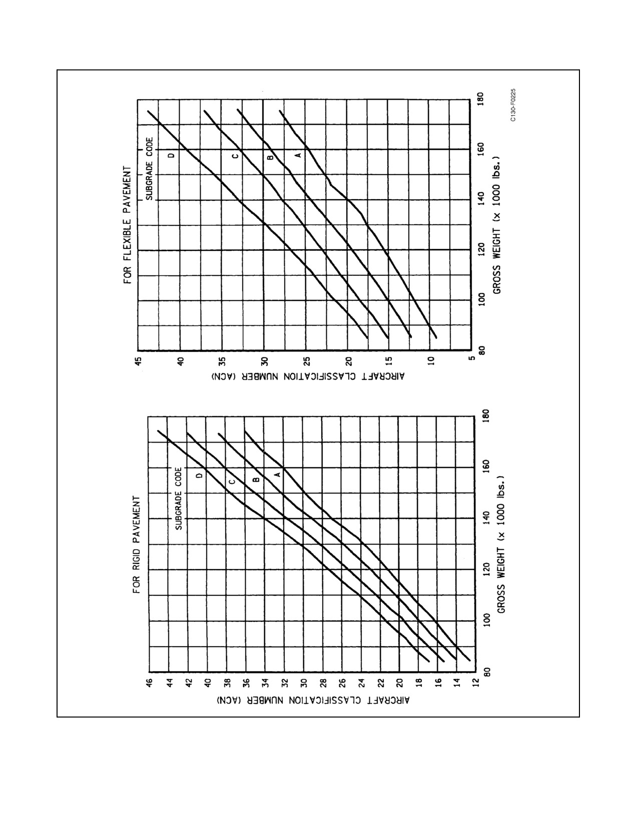
1. ACN.
2. Is the aircraft allowed to land on the runway?
SOLUTION:
1. Enter Figure 4-10 at 120,000 pounds. Move up to line C and left to read an ACN of 23.5.
2. The aircraft should not land since 23.5 is greater than the PCN of 21.
ORIGINAL
4-30
01-75GAL-1
Figure 4-10. Aircraft Classification Number
4-31
ORIGINAL
01-75GAL-1
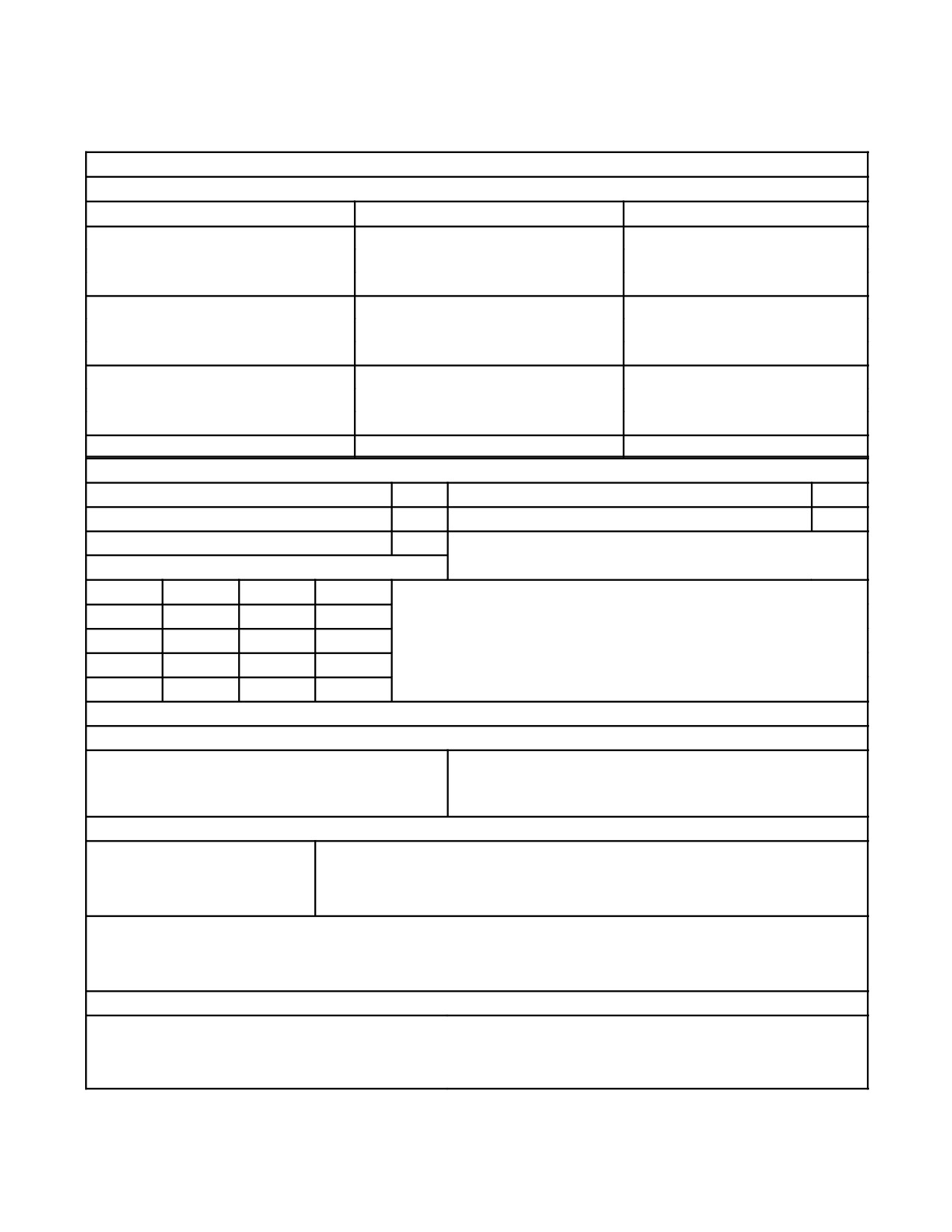
NOTE
REFERENCE SHOULD BE MADE TO APPLICABLE DISCUSSIONS WITHIN THIS SECTION FOR THE VALUES SHOWN BELOW.
WEIGHTS — POUNDS
C-130T
CONDITION
EXTERNAL TANKS ON
LANDING RATE OF SINK
MAXIMUM TAXI
RECOMMENDED
155,000
OVERLOAD
175,000
MAXIMUM TAKEOFF
RECOMMENDED
155,000
OVERLOAD
175,000
MAXIMUM LANDING
300 FPM RATE OF SINK
RECOMMENDED
155,000
OVERLOAD
175,000
NORMAL LANDING
130,000
540 FPM RATE OF SINK
SPEEDS — KNOTS INDICATED AIRSPEED
LANDING GEAR EXTENDED
170
AFT CARGO DOOR AND RAMP OPEN
150
PARATROOP AIR DEFLECTORS OPEN
150
PARATROOP DOORS (OPENING OR CLOSING)
150
LANDING LIGHTS EXTENDED
250
THUNDERSTORM OPERATION 65 KNOTS ABOVE POWER
OFF STALL NOT TO EXCEED 180 KIAS
FLAPS EXTENDED:
10%
220
60%
165
20%
210
70%
155
30%
200
80%
150
40%
190
90%
145
50%
180
100%
145
SYSTEM LIMITS
FUEL
MAIN TANK BOOST PUMP PRESSURE
MINIMUM 15 PSI — MAXIMUM 24 PSI
AUXILIARY AND EXTERNAL TANK BOOST PUMP
MINIMUM 28 PSI — MAXIMUM 40 PSI
PRESSURE
HYDRAULIC
UTILITY SYSTEM
NORMAL 2,900 TO 3,200 PSI — MAXIMUM 3,500 PSI
BOOSTER SYSTEM
NORMAL 2,900 TO 3,200 PSI — MAXIMUM 3,500 PSI
AUXILIARY SYSTEM
NORMAL 2,900 TO 3,300 PSI — MAXIMUM 3,500 PSI
RUDDER BOOST:
0% TO 15% FLAPS NORMAL, 1,100 TO 1,400 PSI — MAXIMUM 1,600 PSI
15% TO 100% FLAPS NORMAL, 2,900 TO 3,200 PSI — MAXIMUM 3,500 PSI
ACCUMULATOR PRELOAD
UTILITY SYSTEM
1,500 PSI ±100
NORMAL BRAKE
1,500 PSI ±100
BOOSTER SYSTEM
1,500 PSI ±100
EMERGENCY BRAKE
1,000 PSI ±100
FUEL SURGE SUPPRESSOR 40 PSI ±5
Figure 4-11. Summary of Limitations (Sheet 1 of 2)
ORIGINAL
4-32

01-75GAL-1
PRESSURIZATION
CABIN DIFFERENTIAL PRESSURE
MINIMUM -1.2 IN HG — MAXIMUM 15.8 IN HG
OXYGEN
MINIMUM PRESSURE FOR NORMAL USE
50 PSI
STARTER
1 MINUTE ON, 1 MINUTE OFF, 1 MINUTE ON, 5 MINUTES OFF, 1 MINUTE ON, 30 MINUTES OFF. RELEASE SWITCH
AT 60 PERCENT RPM. START VALVE OPEN LIGHT SHOULD EXTINGUISH WITHIN 15 SECONDS AFTER SWITCH IS
RELEASED.
PROPELLER AUXILIARY PUMP
1 MINUTE ON, 1 MINUTE OFF, NOT TO EXCEED 2 MINUTES OF OPERATION IN A 30-MINUTE PERIOD.
ELECTRICAL
FREQUENCY
MINIMUM 380 HZ — MAXIMUM 420 HZ
AC VOLTS (GENERATOR AND INVERTER)
MINIMUM 110 VOLTS — MAXIMUM 125 VOLTS
DC VOLTS
MINIMUM 25 VOLTS — MAXIMUM 30 VOLTS
AC LOAD
MAXIMUM CONTINUOUS 1.050
DC LOAD
MAXIMUM CONTINUOUS 1.030
BATTERY
MINIMUM 21 VOLTS
PROPELLER BLADE DEICING
MINIMUM SUFFICIENT 60 AMP — MAXIMUM 90 AMP
PROPELLER SPINNER ANTI-ICING AND DEICING
MINIMUM SUFFICIENT 65 AMP — MAXIMUM 90 AMP
Figure 4-11. Summary of Limitations (Sheet 2)
4-33
ORIGINAL
01-75GAL-1
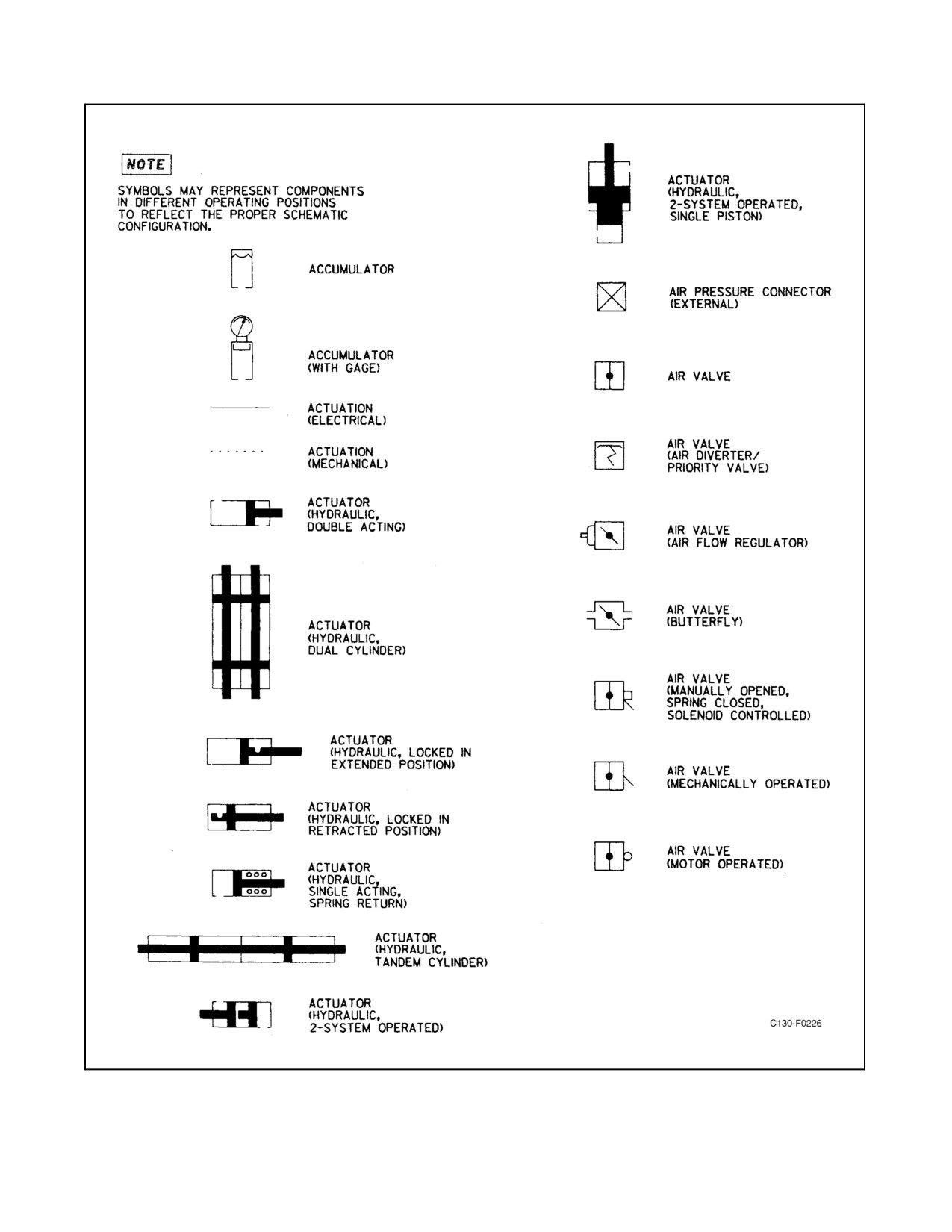
Figure 4-12. Standard Symbols (Sheet 1 of 5)
ORIGINAL
4-34
01-75GAL-1
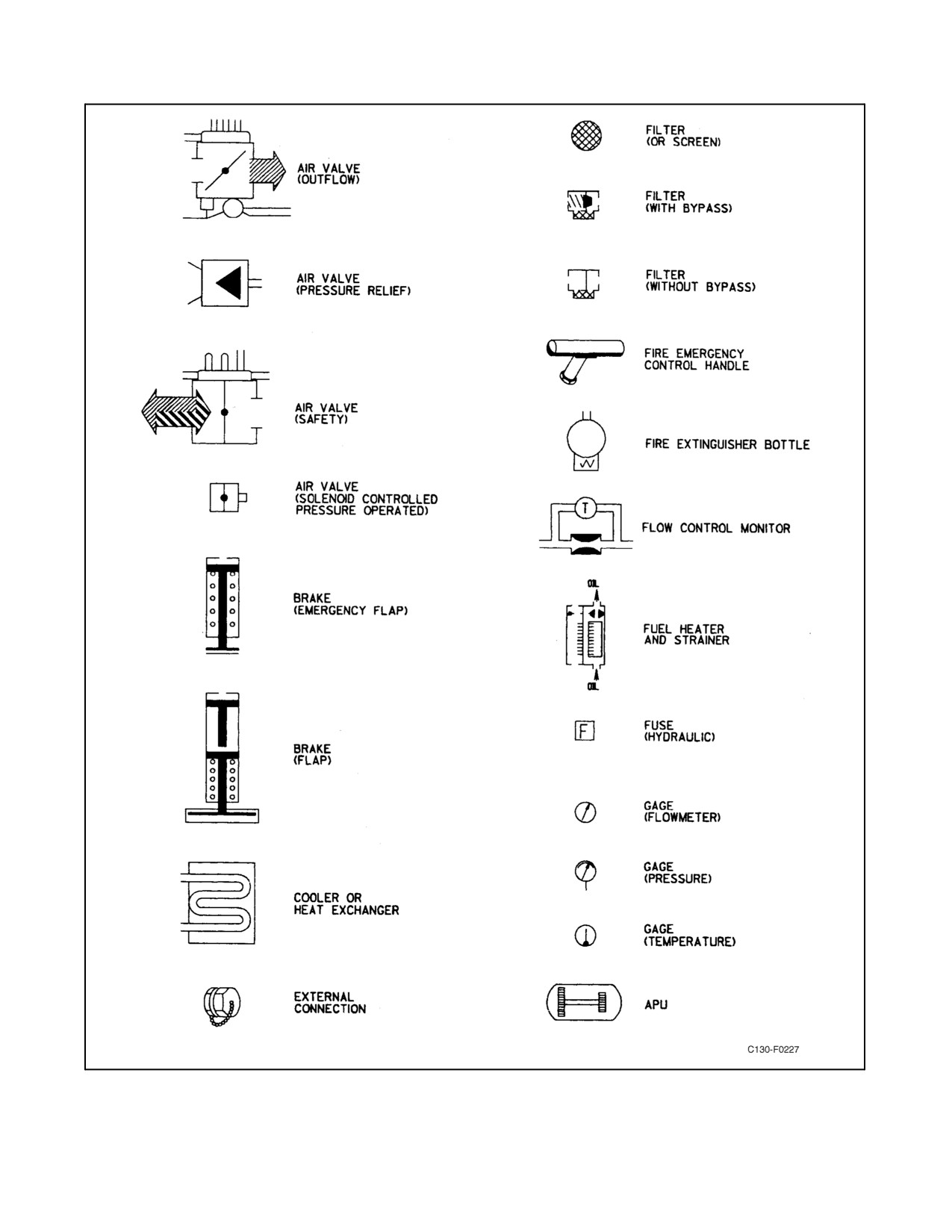
Figure 4-12. Standard Symbols (Sheet 2)
4-35
ORIGINAL
01-75GAL-1
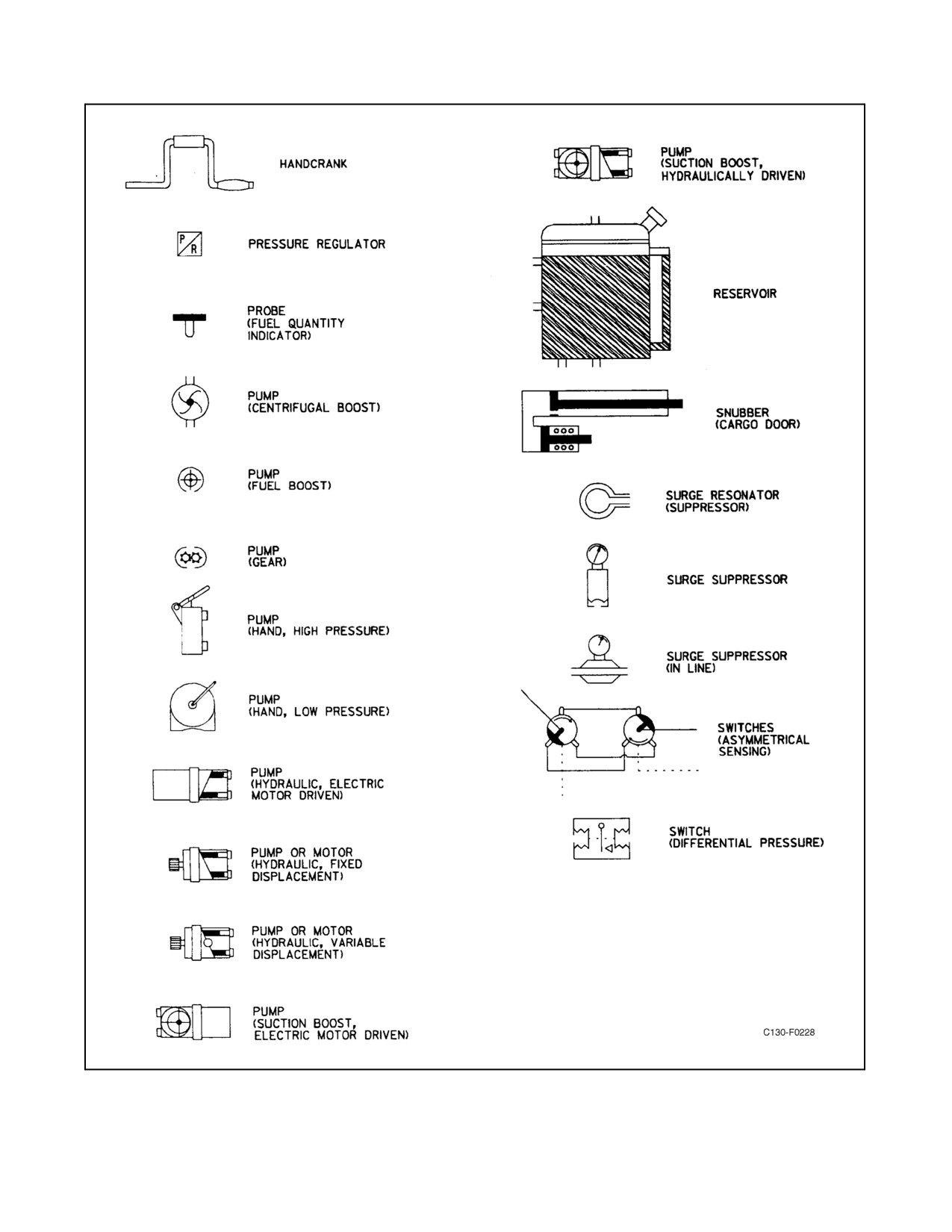
Figure 4-12. Standard Symbols (Sheet 3)
ORIGINAL
4-36
01-75GAL-1
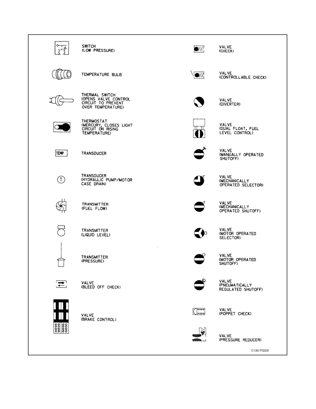
Figure 4-12. Standard Symbols (Sheet 4)
4-37
ORIGINAL
01-75GAL-1
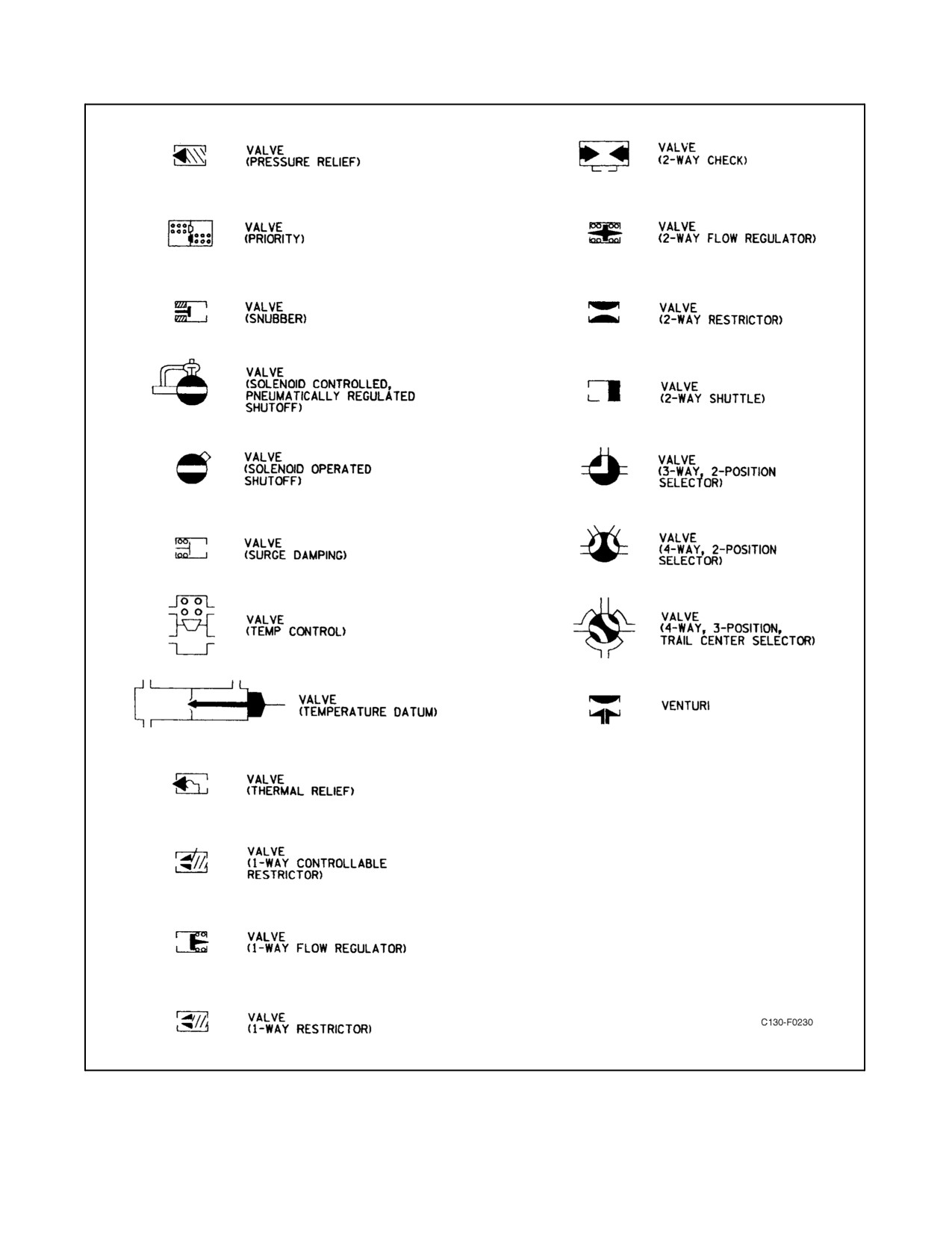
Figure 4-12. Standard Symbols (Sheet 5)
ORIGINAL
4-38
01-75GAL-1
PART II
Indoctrination
Chapter 5 — Indoctrination
53/(54 blank)
ORIGINAL
01-75GAL-1
CHAPTER 5
Indoctrination
5.1
INDOCTRINATION
This chapter provides general information on the operation of the aircraft and prescribes minimum aircrew training
and operating procedures and techniques. This chapter will be the primary directive for training and maintaining
standardized operating procedures. As a crewmember, you have the ultimate responsibility of fulfilling the mission
of your command. This is the crucial test of your training and judgment. To be successful, you must accomplish your
tasks with professional competence and strive for perfection in the operation of your aircraft system. Information in
this chapter has been developed to aid you in the attainment of this goal. Befamiliar with the established procedures,
withyourmission,andwithyouraircraft.Constantly evaluateyourselfandyourskillto performthemissionassigned
to you.
5.2
GROUND-TRAINING SYLLABUSES
The ground-training syllabuses contained in this section are considered the minimum prerequisites to attain
qualification for all aircrewmembers not previously qualified in the aircraft. Aircrewmembers previously qualified
in the aircraft will, prior to being requalified for the crew position previously held, complete such portions of the
syllabus as may be deemed necessary by the unit commander. Ground training will be conducted by squadron
personnel or by outside agencies, such as naval aid mobile trainers or factory training, if available. Flight simulator
training shall be conducted for all pilots and flight engineers as delineated by the model manager in the respective
training instructions. Simulator training is considered extremely valuable and should not be waived if at all possible.
Ground and Phase 1 training shall be completed prior to the first flight as an aircrewmember.
5.2.1 Pilot Ground-Training Syllabus
A formal course of instruction will be completed, utilizing the following outline:
1. Aircraft general.
2. Electrical systems.
3. Radio/radar/navigation equipment.
4. Auxiliary power unit.
5. Instruments and autopilot.
6. Hydraulics/brakes/cargo ramp and door.
7. Pneumatics.
8. Fuel system.
9. Engines.
10. Propellers.
5-1
ORIGINAL
01-75GAL-1
11. Aerial delivery system.
12. Normal and emergency procedures.
13. Weight and balance.
14. Performance and cruise charts.
15. Fire and overheat detection/fire extinguishing.
16. Oxygen system.
17. Air-route traffic-control procedures.
5.2.1.1 Basic Simulator Course
A basic course in the flight simulator will be completed, utilizing the following lesson outline.
5.2.1.1.1 Period I (To Be Conducted in Aircraft or Simulator)
1. Description of cockpit to include:
a. Operation of crew seats.
b. Operation of parking brake.
c. Operation of trim tab controls.
d. Operation of rudder pedal adjustments.
e. Operation of microphone buttons, radios, and radio jack boxes.
f. Operation of throttles and condition levers.
g. Operation of cockpit and external lights.
h. Identity of pertinent panels and switches (i.e., ice control panel, fuel panel, pressurization panel, electrical
panel, APU panel, fire control panel).
2. Description of checklists, using the flight manual and pocket checklist, to include:
a. Basic structure.
b. Responsibilities for various sections of checklist.
c. Adaptability of checklist to various climatic conditions and various pieces of ground equipment.
5.2.1.1.2 Period II
1. Complete coverage of flight station checks.
2. Before Start Checklist (explain difference in operation with and without external power).
ORIGINAL
5-2
01-75GAL-1
3. Engine start to include:
a. Coverage of instrument indications.
b. Limitations of the following:
(1) Starters.
(2) Oil pressure/temperatures.
(3) TIT.
(4) Hydraulic pressure.
(5) Light-off.
(6) Starting time.
c. Functions of speed-sensitive control.
d. Discuss use of fuel enrichment.
e. Before Taxi Checklist.
f. Complete coverage of Taxi Checklist.
5.2.1.1.3 Period III
1. Compute performance prior to entering simulator.
2. Complete coverage of flight station checks and Before Start Checklist.
3. Engine start to include:
a. Coverage of instrument indications.
b. Limitations of the following:
(1) Starters.
(2) Oil pressure/temperatures.
(3) TIT.
(4) Hydraulic pressure.
(5) Light-off.
(6) Starting time.
c. Functions of speed-sensitive control.
4. Description of engine-driven fuel pump and operation during engine start.
5. Coverage of Taxi Checklist.
5-3
ORIGINAL
01-75GAL-1
6. Engine Runup Checklist.
7. Before Takeoff Checklist to include comprehensive briefing (takeoff performance computed prior to entering
simulator).
8. Normal takeoff.
9. Normal operation of the following:
a. Pressurization.
b. Anti-icing and deicing.
c. Fuel system.
d. Propeller controls.
e. Electronic fuel correction system.
10. Discuss negative torque system and decoupling.
11. Landing and engine secure, using normal checklist.
5.2.1.1.4 Period IV
1.
Compute performance prior to entering simulator.
2.
Before Start Checklist.
a. Explanation of APU operation.
(1) Starter limits.
(2) Power source for starter and fuel control.
(3) Speed switch functions.
3.
Engine start to include the following:
a. Coverage of instrument indications.
b. Limitations of the following:
(1) Starters.
(2) Oil pressure/temperatures.
(3) TIT.
(4) Hydraulic pressure.
(5) Light-off.
(6) Starting time.
c. Functions of speed-sensitive control.
ORIGINAL
5-4
01-75GAL-1
4.
Question student on meaning of parallel light during start and on speed.
5.
Question student on battery APU start.
6.
Hydraulic pump failure during start.
7.
Simulate starter control valve failure by pulling air/oil circuit breaker.
8.
Taxi Checklist.
9.
Engine runup (test student on rpm and TIT limits).
a. Demonstrate propeller reindexing.
10.
Before Takeoff Checklist.
a. Discuss autopilot checklist.
b. Comprehensive briefing to include performance data.
11.
Normal takeoff, with air-conditioning and pressurization off for maximum available power.
12.
Discuss maximum allowable torque on takeoff.
13.
Emergency operation of the following:
a. Pressurization.
b. Anti-icing and deicing (manual).
c. Electrical systems.
d. Propeller controls (discuss switch positions and synchronization).
14.
Normal Landing, After Landing, Engine Secure, and Before Leaving the Aircraft, using normal checklists.
5.2.1.1.5 Period V
1. Compute performance prior to entering simulator.
2. Before Start checklist.
3. Discuss brake selector valves.
4. Discuss dc electrical power failure during engine start.
5. Introduce hot start.
6. Discuss failure of 94-percent speed switch.
7. Taxi Checklist.
8. Discuss possibility of an anti-icing valve sticking open and corrective action.
9. Engine warmup (while above crossover, discuss relationship among TIT, fuel flow, and torque, and explain
how faulty TIT indications may be detected).
5-5
ORIGINAL
01-75GAL-1
10. Before Takeoff Checklist to include comprehensive crew briefing.
11. Cause student to abort on takeoff by flaming out engine (discuss refusal speed).
12. Normal takeoff.
13. Failure of gear to retract, using normal system (discuss manual operation of normal selector valve).
14. Precautionary engine shutdown.
15. Fire emergency engine shutdown.
16. Airstart procedure.
17. Emergency operation of electrical systems.
18. Failure of gear to extend.
19. Landing and engine secure, using normal checklist.
20. Discuss the NTS lockout feature.
21. Discuss the mechanics of the NTS shutdown.
5.2.1.1.6 Period VI
1.
Perform Flight Station Checks, using the abbreviated checklist.
2.
Before Start Checklist (test student knowledge of limitations).
3.
Stalled start.
4.
Simulate failure of ignition relay by pulling fuel and ignition relay circuit breaker.
5.
Taxi Checklist.
6.
Engine Runup Checklist.
7.
Before Takeoff Checklist to include comprehensive crew briefing (discuss definition of critical engine failure
speed and critical field length).
8.
Normal takeoff.
9.
Discuss acceleration limits of TIT during takeoff.
10.
Discuss failure of one engine generator and also failure of a bus system.
11.
Individually fail each inverter system, discussing what equipment is affected by each.
12.
Failure of booster hydraulic system (discuss restarting of engines before landing).
13.
Reinstate booster hydraulic system and fail utility hydraulic system (discuss use of auxiliary hydraulic system
for emergency brake pressure).
14.
Landing and engine secure, using normal checklist.
ORIGINAL
5-6
01-75GAL-1
5.2.1.1.7 Period VII
This period shall be utilized to conduct a thorough briefing and for demonstrating the use of the following:
1. Communications, navigation, and radar equipment.
2. Pointer selector switches.
3. Flight director switches.
4. NAV selector switches.
5. Horizontal situation indicator.
6. Attitude director indicator.
5.2.1.1.8 Period VIII
For cruise-control flight, plan a mission requiring maximum range at maximum gross weight.
5.2.2 Flight Engineer Ground Training Syllabus
A formal course of instruction shall be completed, utilizing the following outline:
1.
Aircraft general.
2.
Emergency equipment.
3.
Flight controls.
4.
Cargo door and ramp.
5.
Aerial delivery system.
6.
Hydraulic systems.
7.
Brakes and antiskid system.
8.
Landing gear system.
9.
Fuel system.
10.
Oil system.
11.
Air-conditioning and pressurization.
12.
Anti-icing, deicing, and defogging system.
13.
Electrical systems.
14.
Instruments and autopilot.
15.
Power plant and associated system.
16.
Auxiliary power unit.
5-7
ORIGINAL
01-75GAL-1
17. Propeller system.
18. ATO auxiliary propulsion system.
19. Engine overheat, fire detection, fire isolation, and fire extinguisher system.
20. Oxygen system.
21. Performance and cruise charts.
22. Emergency procedures.
23. Weight and balance.
24. Forms and publications.
25. Preflight and postflight inspection requirements.
26. Radio procedures.
27. Comprehensive oral examination.
28. Final written examination.
5.2.2.1 Basic Simulator Course
A basic simulator course, similar in nature to the pilot basic simulator course, shall be completed by all flight
engineers. Because of its similarity, it is recommended that the two be integrated and conducted simultaneously, if
at all possible.
5.2.3 Second Flight Engineer Ground Training Syllabus
A formal course of instruction shall be completed, utilizing the following outline:
1. Aircraft general.
2. Emergency equipment.
3. Flight controls.
4. Fueling/defueling procedures.
5. Engine fuel system.
6. Hydraulic systems.
7. Brakes and antiskid system.
8. Landing gear system.
9. Fuel system.
10. Oil system.
11. Air-conditioning and pressurization.
ORIGINAL
5-8
01-75GAL-1
12.
Anti-icing, deicing, and defogging system.
13.
Electrical systems.
14.
Instruments and autopilot.
15.
Power plant and associated systems.
16.
Auxiliary power unit.
17.
Propeller system.
18.
Fire extinguishing system.
19.
Emergency procedures.
20.
Oxygen system.
21.
Cruise performance charts.
22.
Communication systems.
23.
Publications.
24.
Preflight and postflight inspection requirements.
25.
Radio procedures.
26.
Comprehensive oral exam.
27.
Final written examination.
5.2.4
Loadmaster Ground Training Syllabus
The ground training syllabus for the loadmaster is designed to familiarize a loadmaster with the equipment in the
aircraft. Qualification as a loadmaster assumes completion of a local loadmaster course conducted by the parent
squadron and completion qualification as a second loadmaster. Minimum requirements shall be established by the
Unit commander, but should contain the following:
1. Weight and balance.
2. Forms and publications.
3. Checklists and ICS procedures.
4. Ramp and cargo door operation.
5. Cargo loading procedures.
6. Securing cargo in accordance with established restraint procedures.
7. Rigging of seats and litters.
8. Passenger briefing.
5-9
ORIGINAL
01-75GAL-1
9. Preflight.
10. Location of emergency equipment.
11. Emergency procedures.
12. Cargo offloading procedures.
13. Hazardous material handling procedures.
14. Wheeled vehicles.
15. Limitations.
5.2.5 Second Loadmaster Ground Training Syllabus
The ground training syllabus for second loadmaster is designed to familiarize a second loadmaster with the aircraft
basics and associated equipment. Qualification as a second loadmaster assumes completion of a local second
loadmaster course conducted by the parent squadron. Minimum requirements shall be established by the unit
commander but should contain the following:
1. Basic aircraft and GSE familiarization.
2. Checklists and ICS procedures.
3. Hydraulic and oxygen systems.
4. Emergency entrances, exits, and equipment.
5. Interior preflight.
6. Emergency procedures.
7. Passenger movement procedures.
8. Cargo movement familiarization.
5.3
FLIGHT TRAINING SYLLABUSES
The flight training syllabus sets forth the minimum requirements for transitioning aircrewmembers to the aircraft.
Aircrewmembers who are engaged in any part of the training program shall be considered “in-training” until
satisfactorily completing a flight check, after which they shall be designated, in writing. Although minimum hours
for each phase are shown. Commanding officers may increase or decrease the training requirements as necessary to
fit the individual qualifications and previous experience.
5.3.1 Pilot Flight Training Syllabus
The pilot flight training syllabus is designed to train a naval aviator as a copilot in the aircraft. Phase I training, as
outlined in this section, is considered theminimum required to accomplish this task; however, unit commanders may
accelerate or decelerate the training consistent with the ability and experience of the pilot concerned.
Because of the versatility of the aircraft, Phase II training is dictated by the mission of the command, and, therefore,
no minimum requirements are established. Qualification in any or all of the Phase II flight syllabus is left to the
prerogative of the unit commander.
ORIGINAL
5-10
01-75GAL-1
5.3.1.1 Phase I
1.
Familiarization (7 periods, 14 hours).
a. Cockpit familiarization.
b. Use of checklists.
c. Starting engines.
d. Taxi.
e. Takeoffs.
(1) Normal emergencies before refusal speed.
(2) Emergencies after refusal speed.
(3) Obstacle takeoff.
f. Air work and power control.
g. Stalls and recovery.
h. Landings.
(1) Normal.
(2) Half flap.
(3) No flaps.
(4) Short field.
(5) Obstacle landing.
(6) Simulated one and two engines out.
i. Use of reverse pitch.
(1) Symmetrical.
(2) Asymmetrical.
j. Engine shutdown.
k. Airborne discussion of the following:
(1) Hydraulic system.
(2) Engines and propellers.
(3) Air-conditioning and pressurization system.
(4) Anti-icing, deicing, and ice detector system.
5-11
ORIGINAL
01-75GAL-1
(5) Electrical system.
(6) Fuel system and in-flight refueling system.
(7) Radios, navigation and flight instruments.
2.
Instruments (5 periods, 10 hours).
a. Instrument takeoffs.
b. Climbout.
c. Holding patterns and entry.
d. Penetrations.
e. GCA.
f. ILS.
g. AACS.
3.
Night familiarization (2 periods, 4 hours).
a. Normal takeoffs and landings.
4.
Navigation (4 periods, 16 hours).
a. Use of performance and cruise control charts.
b. ARTC procedures.
c. Strange field approaches and landings.
d. Instrument cross-country procedures.
e. Complete review of all aircraft systems.
f. Induced emergencies (S or A, as appropriate).
g. Use of navigation and flight instruments.
5.
Flight evaluation check (6 hours).
5.3.1.2 Phase II
1. Advanced navigation.
2. Aerial delivery.
3. Combat unit movement.
4. Casualty air evacuation.
5. Formation tactics.
ORIGINAL
5-12
01-75GAL-1
6. Three-engine takeoff with simulated inoperative engine in flight idle.
7. Windmill taxi start.
5.3.2 Flight Engineer Flight Training Syllabus
The flight training syllabus is designed to correlate information received during ground training and simulator
training and to integrate the flight engineer as an aircrewmember. Therefore, this syllabus deals with the use of
checklists and crew coordination, the diagnosis of airborne malfunctions, and the remedial action that can be
accomplished while airborne. It is imperative that prospective flight engineers be completely proficient and have
demonstrated a thorough working knowledge of all the aircraft systems and auxiliary equipment prior to flight
training. The syllabus shall cover the following:
1.
Preflight inspections.
2.
Cockpit familiarization.
3.
Use of checklists.
4.
Engine start.
a. Starting sequence.
b. Correct and incorrect indications during start.
c. Reasons for aborting a start and trouble-shooting.
5.
Engine and propeller runup.
a. Correct runup procedure.
b. Reindexing.
c. Allowable engine and propeller indications.
d. Generator and load checks.
e. Temperature controlling check.
6.
Crew duties during start, taxi, runup, takeoff, cruise, landing, and after landing.
7.
Airborne systems checkout.
a. Engine malfunctions.
b. Propeller malfunctions.
c. Fuel system and fuel management.
d. Electrical system.
e. Pneumatic system.
f. Air-conditioning and pressurization system.
5-13
ORIGINAL
01-75GAL-1
g. Anti-icing, deicing, and defogging system.
h. Hydraulic systems.
i. Aerial delivery system.
8.
Emergency procedures.
a. Emergency equipment.
b. Engine failure.
c. Engine fire during start, ground operation, and flight.
d. APU fire.
e. Generator failure and bus failure.
f. Hydraulic failure, emergency extension of landing gear.
g. Propeller overspeed, low oil quantity.
h. Fuselage fire, cargo compartment refrigerator overheat warning.
i. Wing fire.
j. Electrical fire.
k. Smoke and fumes elimination.
l. Loss of pressurization.
m. Door warning light.
n. Wing and/or empennage overheat warning light.
o. Loss of inverters.
9.
Descent and Landing Checklists.
10.
After Landing Checklist.
11.
Engine secure and NTS check.
12.
Securing the aircraft.
13.
Postflight inspection.
5.3.3 Second Flight Engineer Training Syllabus
The flight-training syllabus for the second flight engineer is designed to familiarize a qualified second flight engineer
with theduties and equipment in theaircraft in orderto effectively assisttheflightengineer. Qualificationas asecond
flight engineer assumes completion of the second flight engineer course. The syllabus shall cover the following:
ORIGINAL
5-14
01-75GAL-1
1.
Preflight inspections.
2.
Servicing.
a. Aircraft fueling and defueling.
b. Engine oil servicing.
c. Propeller servicing.
d. APU oil servicing.
e. Tire servicing.
3.
Normal procedures.
4.
Plane Captain responsibilities.
5.
Crew Resource Management (CRM)/Operational Risk Management (ORM).
6.
Aircraft systems operation.
a. APU.
b. Air conditioning and pressurization.
c. Bleed air.
d. Anti-icing and deicing.
e. Fuel system.
f. Electrical.
g. Lighting.
h. Hydraulics.
7.
Emergency procedures during flight.
a. Emergency equipment.
b. Engine failure.
c. Engine fire.
d. APU fire.
e. Generator failure and bus failure.
f. Propeller overspeed, low oil quantity.
g. Fuselage fire, cargo compartment refrigerator overheat warning.
h. Wing fire.
5-15
ORIGINAL
01-75GAL-1
i. Electrical fire.
j. Smoke and fumes elimination.
k. Loss of pressurization.
l. Door warning light.
m. Wing and empennage overheat warning light.
n. Loss of inverters.
8. Cruise procedures/performance.
9. Postflight inspection.
10. Securing the aircraft.
5.3.4 Loadmaster Flight Training Syllabus
The flight training syllabus for the loadmaster is designed to familiarize a qualified loadmaster with the equipment
intheaircraft.Qualification asaloadmasterassumes completionofalocal loadmastercourseconductedby theparent
squadron. Minimum requirements shall be established by the unit commander.
1. Operation of cargo door and ramp.
2. Cargo loading procedures.
3. Securing cargo in accordance with established restraint criteria.
4. Rigging of seats and litters.
5. Passenger briefing.
6. Location of door warning light switches.
7. Correct interphone procedures.
8. Location of all emergency equipment.
9. Emergency landing gear and flap extensions.
10. Explosive decompression.
11. Offloading procedures.
12. Aerial delivery procedures.
5.3.5 Second Loadmaster Flight Training Syllabus
The flight training syllabus of the second loadmaster is designed to familiarize a second load-master with flight
operation of the aircraft systems. The flight training syllabus will cover the following subjects:
1. Basic aircraft and GSE familiarization.
2. Checklist and ICS procedures.
3. Hydraulic and oxygen systems.
ORIGINAL
5-16

01-75GAL-1
4. Emergency entrances and exits and equipment.
5. Emergency procedures.
6. Rigging seats and litters.
7. Passenger briefing.
8. Forms and paperwork.
9. Cargo restraint and tie-down familiarization.
5.4
MINIMUM EXPERIENCE REQUIREMENTS
Minimum requirements for qualification in crew position are listed in Figure 5-1. In addition to these requirements,
specific requirements for demonstrating maturity and leadership ability are established by the current OPNAV
Instruction 3710.7.
Training prior to requalification for previously qualified individuals who have not flown the aircraft in the previous
90 days will be determined on an individual basis by the unit commander.
TAC
T2P
FE
LM/2LM
1. Pilot Hours
700
225
—
—
2. Hours in Model
250(3)
40(4)
100
100/50
3. Instrument Hours
100
50
—
—
4. Night Hours
100
25
—
—
5. Instrument Rating
STD
STD
—
—
6. Basic Ground School
X
X
X
X
7. Simulator Course
X
X
X
—
8. NATOPS Open-/Closed-Book Exam
X
X
X
X
9. Oral Flight Evaluation
X
X
X
X
10. Route Evaluation
X
—
—
—
Notes:
1. Commander, Fleet Logistics Support Wing may waive, in writing, requirements 1 through 4 where previous
experience warrants.
2. Pilot’s senior to the designating authority shall be designated by the next superior in the chain of command.
3. Minimum of 500 hours in model for pilots with no previous aircraft commander experience.
4. Ten hours first pilot time minimum in the aircraft (non-simulator time) for pilots with previous fleet experience.
Newly winged aviators need 40 hours in the actual aircraft.
Figure 5-1. Minimum Military Experience Requirements
5.5
FLIGHT CREW REQUIREMENTS
5.5.1 Normal Crew
A normal crew shall consist ofoneaircraftcommander, oneT2P, oneflight engineer,oneloadmaster,and onesecond
loadmaster.
5-17
ORIGINAL
01-75GAL-1
5.5.2 Functional Checkflight Crew
The minimum crew required for a functional checkflight is one aircraft commander, one T2P, one flight engineer,
and one loadmaster or second loadmaster.
5.5.3 Essential Crew
The essential crew required for aircraft operation is one aircraft commander, one T2P, one flight engineer, and one
loadmaster or second loadmaster.
Note
D Asecondloadmastermaycarryuptoamaximum of1,000lbs. loosecargo
and 10 passengers. In this case, the flight engineer shall ensure accuracy of
the Form-F. This cargo shall not include palletized, hazardous, rolling
stock and/or individual bulk containers exceeding 100 lbs.
D With only one LM assigned, the maximum number of passengers shall be
limited to 35.
5.5.4 Augmented Crew
An augmented crew consists of the following:
1. One aircraft commander.
2. Two additional qualified pilots.
3. Two flight engineers, or one flight engineer and one second flight engineer.
4. Two loadmasters.
5. One second loadmaster.
5.5.5 Crew Scheduling
Squadron commanding officers shall ensure crew scheduling is adjusted to satisfy training,
proficiency,
and
operational requirements. Crew experience, currency, and proficiency shall be closely monitored to maximize
operational risk management.
5.5.6 Crew Duty, Rest, and On-Deck Time
1. Crew duty.
a. Crew duty commences at preflight showtime (normally 2 hours prior to blockout) and terminates at block
in on the final leg of the day.
ORIGINAL
5-18

01-75GAL-1
b. Crew duty limits:
CREW
PARAMETER
DUTY
EXTENDIBLE*
0700-1459 show
16 hours
18 hours by aircraft commander
1500-0659 show
13 hours
15 hours by aircraft commander
Augmented crew
24 hours
Not extendible
Autopilot inoperative
12 hours
Not extendible
*Crew duty can be extended for a maximum of 2 consecutive days.
2.
Crew rest.
a. Crew rest is that time during which no duties may be performed.
b. Crewmembers shall be provided a crew rest period commencing 12 hours prior to reporting for a mission.
3.
On-deck time.
a. On-deck time is block in to block out.
b. On-deck time limits:
ON-DECK
PARAMETER
TIME
REDUCIBLE
RON
17 hours
12 hours by aircraft commander provided 8 hours of crew rest
is allowed and only if previous crew duty was not extended.
c. Reduction of crew duty may be required because of crew fatigue resulting from time zone changes, multiple
maximum-hour days, and “back side of the clock” flying. It is the aircraft commander’s prerogative to
shorten crew duty.
5.5.7
Minimum Currency Requirements
Currency shall be in accordance with OPNAVINST 3710.7 for semi-annual and annual minimums, and in accordance
with applicable TYCOM/WING directives for monthly requirements.
5.5.8 Ferry Pilots
Training requirements, checkout procedures, evaluation procedures, and weather minima for ferry squadrons are
governed by the provisions contained in the current OPNAV Instruction 3710.7.
5.6
PERSONAL FLYING EQUIPMENT REQUIREMENTS
All safety and survival equipment shall be utilized as prescribed by the current OPNAV Instruction 3710.7.
5-19/(5-20 blank)
ORIGINAL
01-75GAL-1
PART III
Normal Procedures
Chapter 6 — Briefing and Debriefing
Chapter 7 — Mission Planning
Chapter 8 — Inspections, Checklists, and Procedures
Chapter 9 — Functional Checkflight Procedures
55/(56 blank)
ORIGINAL
01-75GAL-1
CHAPTER 6
Briefing and Debriefing
6.1
BRIEFING
Prior to any flight, it is the responsibility of the aircraft commander to ensure that the entire crew has been properly
briefed for the mission. All pertinent points related to the specific flight must be covered. The length of time for each
briefing may vary, depending on the nature of the flight. This briefing should include the following applicable items:
1. General:
a. Aircraft assignments and call signs.
b. Starting, taxiing, loading, and takeoff times.
2. Mission:
a. Destination.
b. Intermediate stops.
c. Load.
3. Weather.
4. Navigational and flight planning.
5. Emergency procedures.
6. Intelligence and special instructions.
All in-flight refueling, formation, and special missions require a detailed briefing for the flightcrews involved by a
qualified individual to include all pertinent information related to the flight.
6.1.1 Passenger Briefing
1. Flight number/aircraft commander’s name/crewmember’s name.
2. Origin/destination/en route stops.
3. Flight duration.
4. En route weather.
5. Seatbelts.
a. Seatbelts shall remain fastened while seated.
6-1
ORIGINAL
01-75GAL-1
6.
Illness.
a. Inform crewmember.
b. Airsickness bags available.
7.
Ground evacuation.
a. Primary/secondary exits.
b. Follow crewmember’s instructions.
8.
Inflight Emergencies.
a. EPOS/VRU Demonstration.
9.
Ditching.
a. Proper seat position.
b. LPP demonstration.
c. Liferaft distribution.
d. Exits.
e. Distribution of emergency equipment.
10.
Head facilities.
a. Urinals.
b. Aft toilet.
11.
Coffee, water, lunches (if available).
12.
Passenger movement.
a. One passenger at a time on flight station escorted by crewmember (visits are at the discretion of the aircraft
commander).
13.
Aircraft cleanliness.
a. Garbage can/trash bag location(s).
14.
Destination information.
a. Transportation/quarters/messing.
b. Customs/agriculture (if required).
c. RON (give ETD and muster location).
d. Time zone update.
ORIGINAL
6-2
01-75GAL-1
15. No pyrotechnics, ammunition, BIC-type lighters, or use of cellular phones. In accordance with the current
OPNAVINST 3710, the use of tobacco products is prohibited. The use of electronic devices is prohibited
during the takeoff and landing phase.
6.2
DEBRIEFING
6.2.1 All Flights
After each flight, it is the responsibility of the aircraft commander to bring to the attention of the flightcrewmembers
any discrepancies noted during the flight. Any deviation from the standardized procedures, as outlined in this manual,
will be thoroughly reviewed and corrected. It is the responsibility of the aircraft commander to ensure that all reports
required have been completed, that the flight plan has been closed out, and that all aircraft discrepancies have been
listed on the VIDS/MAF or NALCOMIS.
6.2.2 Special Flights
Additional debriefings may be scheduled, as necessary, to cover flights of a special nature requiring detailed reports
and information concerning the flight.
6-3/(6-4 blank)
ORIGINAL
01-75GAL-1
CHAPTER 7
Mission Planning
7.1
INTRODUCTION
Refer to the performance chart to determine the capability of the aircraft for takeoff, climb, cruise, descent, and
landing for a complete mission under any combination of conditions and circumstances. Mission planning requires
consideration of all factors affecting the successful completion of the assigned mission. Most commonly, mission
planning determines the fuel load necessary for the safe accomplishment of a given mission for which cargo load and
distance are known. The aircraft has a three-fold capability: use as an air refueler, use as a cargo/passenger carrier,
and use on special missions, such as search-and-rescue and aerial delivery. The mission requirements will, of
necessity, dictate the planning considerations. Survival equipment for crew and passengers must be compatible with
the mission to be flown.
Note
Mission requirements permitting, the escape ladder leading to the center
overhead cargo compartment escape hatch will be installed when
passengers are embarked.
7.2
WEIGHT AND BALANCE
It is the pilot in commmand’s responsibility to ascertain that the takeoff and anticipated landing gross weights have
been determined and that center of gravity limits are not exceeded. Refer to Handbook of Weight and Balance, NA
01-1B-40, and Chapter 4 of this manual for information on weight limitations. Make certain that the weight and
balance clearance (Form F) is complete.
Note
Accurate cargo weights shall be obtained prior to the loading of the aircraft
and the computation of Weight and Balance Clearance Form. Accurate
passenger and baggage weights should be obtained whenever possible. If
accurate passenger and baggage weights cannot be obtained, the estimated
passenger weight of 200 pounds per person and baggage weight of 50
pounds per person should be utilized.
7.3
FLIGHT PLANNING PROCEDURES
Determine the type of flight and whether long-range or high-speed cruise is dictated by the mission requirements.
7.3.1 Long-Range Cruise (Utilizing Constantly Decreasing Torque with Decrease in Weight)
1. To establish long-range cruise, set fuel flow and cross-check torque from the operating chart for the particular
flight gross weight and altitude. For nonstandard temperature conditions, hold constant the standard day fuel
flow. Torque and IAS will remain approximately the same.
2. For constant-altitude operation, decrease power settings for each 5,000 pounds of fuel burnoff. Establish
power settings at a gross weight 2,500 pounds higher than the weight shown in the operating chart. For
7-1
ORIGINAL
01-75GAL-1
example, the settings for 105,000-pound gross weight would be used from 107,500 pounds down to 102,500
pounds, thus averaging the speed, torque, and fuel flow values given. Airspeed initially will be slightly below
and will gradually increase to slightly above the value shown.
7.3.2 Long-Range Cruise (Utilizing Constant True Airspeed)
To establish cruise at a constant true airspeed, maintain climb power on the aircraft until the desired indicated airspeed
is obtained. Reducetorqueforthe remainderof theflight to maintain this true airspeed as theaircraft becomes lighter
in weight.
7.3.3 High-Speed Cruise
Fly maximum continuous TIT for all gross weights, attitudes, and outside air temperatures. Power settings for
standard temperature and correction factors for non-standard temperature are given in the operating chart.
CAUTION
Do not exceed maximum level-flight speed.
Note
D Engine sulfidation occurs when engines are run at high temperatures for
long periods of time. Operating engines at less than maximum conditions
will greatly extend turbine life.
D The use of maximum-range operating tables extends turbine life as long as
an appropriate altitude is selected for initial cruise.
7.3.4 Maximum Endurance
When maximum endurance is required, use power settings to maintain the airspeed from the performance charts for
the gross weight and the flight altitude.
7.4
FACTORS AFFECTING RANGE
7.4.1 Effect of Altitude on Range
Since engine-specific fuel consumption improves with increasing altitude, maximum range is obtained by
four-engine cruise-climb operation. Cruise-climb operation provides greater range than can be obtained by flying at
a constant altitude or with partial power operation (three or two engines) at a lower altitude. One exception is under
conditions of high wind shear, when operation at a lower altitude may provide greater ground miles per pound of fuel.
Also, some missions may be restricted below optimum range altitude because of traffic control, passengers, oxygen,
or pressurization considerations. The determination of optimum cruise altitude for maximum-range capability
requires a comparison of the actual ground miles per pound of fuel for the existing wind/altitude conditions under
consideration.
7.4.2 Effect of Nonstandard Temperature on Range
1. For long-range cruise, utilizing the performance charts, fly constant standard-day fuel flow. Range will
increase 2 percent for each 10 _C above standard temperature, and decrease 2 percent for each 10 _C below
standard temperature.
ORIGINAL
7-2
01-75GAL-1
2. For high-speed cruise, fly constant maximum-cruise power. Range will increase 5 percent for each 10 _C
above standard temperature, and decrease 5 percent for each 10 _C below standard.
3. The performance charts provide correction factors for temperature effects.
7.4.3 Effect of Wind on Range
The specific range charts are predicted on a zero-wind condition, so that long-range cruise may be defined as that
airspeed that gives 99 percent of maximum range in still air. To maintain 99-percent long-range cruise, as headwind
is encountered, airspeed should be increased 1.5 percent for each 10 knots of headwind. However, in practice, this
factor can be neglected with conservatism.
7.4.4 Effect of Gross Weight on Range
For constant-altitude operation, specific range increases with decreasing gross weights. Since maximum range is
achieved by decreasing power settings and indicated airspeed with decreasing gross weights, it is recommended that
a new power setting be established for each 5,000 pounds of fuel burnoff if utilizing the performance charts.
7.4.5 Effect of Partial-Power Cruise on Range
Maximum range is obtained by four-engine operation at optimum cruise altitude. At altitudes below the optimum
cruise altitude for any gross weight, specific range may be increased by partial-power cruise, three- or two-engine
operation. At lower altitudes (25,000 feet and below) range can possibly be extended by three- or two-engine
operation;however,thisconsiderationshouldbecarefullyplanned,asanyimprovementinspecificrangeisafunction
of gross weight, altitude, and headwind component. A false sense of fuel saving could easily result in aloss ofrange.
7.4.6 Effect of Icing on Range
Since the aircraft pressurization and wing and empennage anti-icing is accomplished with hot-air bleed from the
engine compressor, a power loss occurs when these systems are used. The pressurization power loss is small, but the
anti-icing power loss, under severe conditions, can result in losses up to 25 to 30 percent. Normally, the aircraft will
cruise at altitudes at which most icing weather can be overflown. However, if operation is at an altitude where
continuous icing is encountered, the effect on cruising is considerable. Maximum anti-icing has the following effects
on cruise control:
1. True airspeed is decreased 20 percent.
2. Fuel flow is decreased 6 percent.
3. Range is decreased 16 percent.
7.4.7 Effect of Fuel Temperature on Range
Maximum range is affected by fuel temperature variation because of the change in fuel density, pounds per gallon.
For example, 1 gallon of JP-4 fuel at a temperature of 30 _F weighs 6.65 pounds, whereas 1 gallon of JP-4 fuel at
a temperature of 80 _F weighs 6.34 pounds.
7.4.8 Effects of Alternate Fuel On Range
Alternate fuels, because of their density, also vary range capabilities. For example, at 60 _F without the fuselage tank,
the aircraft has a maximum single-point refueling capacity of 9,316 gallons of any fuel, which equates to 63,349
pounds of JP-5 but only 53,567 pounds of 115/145 aviation gasoline for aircraft with pods. See Figures 4-3 and 4-4
for alternate fuel preference and weight per gallon.
7-3
ORIGINAL
01-75GAL-1
CAUTION
Do not refuel the aircraft to its volume capacity with JP-5/JP-8
(standard-day density of 6.79 ppg), since the maximum permissible fuel
weight will be exceeded.
7.4.9 Effect of Increased Headwind Versus Higher Altitude
For planning purposes, when maximum range becomes a consideration and the specific range performance charts
are utilized, an increase of more than 5 knots of headwind component for each additional 1,000 feet of altitude
climbed will result in a reduction of maximum range.
7.5
FUEL REQUIREMENTS
Careful analysis of fuel requirements must be made for all flights. In addition to the fuel requirements set forth by
the current OPNAV Instruction 3710.7 and other controlling instructions, it is recommended that the fuel
requirements be in accordance with the following:
1. Average fuel for taxi and runup prior to takeoff is 1,000 pounds. For taxi without runup, the average fuel
requirement is 500 pounds.
2. Sufficient fuel to fly from takeoff point to preplanned altitude over destination and thence to alternate, if one
is required, plus 10 percent.
3. Approach fuel of 1,000 pounds.
4. Holding fuel of 1,034 pounds (20 minutes of fuel at 10,000 feet maximum endurance, four engines operating).
5. On overwater flights where no alternate is available, item 4 (holding fuel) will be increased to 2 hours at
maximum endurance, four engines operating, at 20,000 feet. Determine fuel from the maximum endurance
performance charts using the anticipated gross weight of the aircraft upon arrival at the holding fix.
7.6
ADDITIONAL OVERWATER REQUIREMENTS
On all overwater flights, time to ETP will be figured at flight-plan cruise altitude and 10,000 feet, on four engines,
and entered in the remarks section of the DD175. ETP is defined as the point (either in distance or time) at which
the aircraft will be required to spend the same amount of time continuing to destination or returning to its departure
point. Since it is obvious that depressurization is possible and descent to a lower altitude may be mandatory, the
distance for ETP should be computed at 10,000 feet of altitude. A TAS for ETP distance computations of 245 knots
is recommended, as this is the average TAS at 10,000 feet on four engines, long-range cruise.
The first reading after departure may fall above the maximum curve. This
may be caused by additional amounts of fuel used in an unexpected
departure climb or by stronger winds than were forecast for the first hour.
The maximum curve line is based on actual takeoff fuel. The actual-fuel-
used curve should fall below the maximum curve prior to reaching ETP.
If the actual-consumption curve falls above the maximum-consumption
curve two consecutive times prior to ETP, a return to the departure point
or a change of destination shall be accomplished.
ORIGINAL
7-4
01-75GAL-1
PSR will be figured for the directed mission profile(s). Generally PSR is a decision point along the planned route
of flight where a divert destination is achievable with the minimum required fuel reserve. PSR is based on actual
takeoff fuel.
7.7
FORMS
Standard navigational forms will be utilized on all flights. Flight clearance will normally be filed on military form
(DD175) but may be on the Federal Aviation Agency form USAFE Form 249 or on the International Civil Aviation
Organization form, as required. On overwater flights, the pilot should use standardized local/Navy flight plans and
range control logs.
7-5/(7-6 blank)
ORIGINAL
01-75GAL-1
CHAPTER 8
Inspections, Checklists, and Procedures
8.1
PREPARATION FOR FLIGHT
8.1.1 Aircraft Status Check
All crewmembers shall review previous discrepancies to ensure that the aircraft is safe for flight. The flight engineer
will ensure that the aircraft has been serviced with the required amount of fuel, oil, and oxygen for the assigned
mission. It is the responsibility of the aircraft commander to ensure that the inspections required by NAVAIR
01-75GAA-6-1 are completed. The aircrew inspections are based on the assumption that these inspections have been
completed. Therefore, duplicate inspections and system checks have been eliminated, except for items required in
the interest of safety.
8.1.2 Checklists
The aircraft commander is responsible for ensuring that all preflight checks are accomplished. The actual
accomplishment may be delegated as required. Starting with the Before Start Checklist, the remaining checklists
through the Secure Checklist in this section are of the challenge and response type. Only circled (
) items need to
be checked when taxiing back for takeoff after landing with all engines operating and crewmembers remaining at their
crew positions. The copilot reads the item in the checklist aloud as a challenge, and the response listed is given by
the crewmember indicated. When more than one crewmember has the same response to the same item, each
crewmember subsequent to the initial crewmember responding need respond only with the crew position. Before
answering the challenge that indicates a complete control panel, the responsible crewmember will check that all
switches and controls on the panel are in the positions indicated in the response. When the response is listed “as
required,” the crewmember will respond by stating the present operating status of the system. The codes: P, CP, FE,
LM, and 2LM stand for pilot, copilot, flight engineer, loadmaster, and second loadmaster, respectively.
8.1.2.1 Through-Flight Operations
When the aircraft is flown on the same mission and no maintenance or servicing is required, it is unnecessary for the
preflight checks to be performed after the first flight of the day. When maintenance or servicing is required, only those
items or systems affected need be checked prior to the next flight. The checklists have been designed so that, for
through-flight operation, the crew may begin with the Before Start Checklist to assure a safe flight.
8.2
AIRCRAFT PREFLIGHT
8.2.1 Prior to Entrance Inspection
1. Prior to commencing the preflight checks, the flight engineer and/or second flight engineer shall check:
a. Aircraft discrepancy book — Reviewed.
b. FE toolbox — Inventoried.
c. Chocks — In Place.
d. Ground wire — Attached.
8-1
ORIGINAL
01-75GAL-1
e. Portable fire bottle — In Place.
f. Nose landing gear pin — Installed.
g. External power unit — As Required.
h. Plugs and covers — Removed/Stowed.
i. Intakes and exhausts — Checked.
Note
A workstand or ladder will be required to accomplish the check of the
engine intakes, exhaust areas, aircraft fire bottles, external fuel tank levels,
and auxiliary fuel tank magnetic sight gauges.
j. Aircraft fire bottles — Checked.
k. APU oil level — Checked.
l. Auxiliary/external fuel quantity — Checked/Noted.
m. Battery — Connected.
CAUTION
Ensure the dc power switch is in the OFF position prior to connecting the
battery.
8.2.2
Prior to External Power Application
1.
Cargo compartment:
a. Nose landing gear emergency extension valve — Normal/Shearwired.
b. Utility hydraulic reservoir condition, fluid level, accumulator pressure — Checked.
c. Left main landing gear and flap emergency engaging handles — Disengaged/pinned (Flap Only).
d. Ramp and cargo door controls — 6N/Neutral.
e. Auxiliary hydraulic reservoir condition, fluid level — Checked.
f. Bleed air divider valve — Checked.
g. Booster hydraulic reservoir condition, fluid level, accumulator pressure — Checked.
h. Flight engineer tool box — Inventoried.
i. Oxygen manual shutoff valve — ON/Shearwired.
2.
Flight station:
a. Landing gear lever — Down.
b. Suction boost pump switches — OFF.
ORIGINAL
8-2
01-75GAL-1
c. Auxiliary pump switch — OFF.
d. Copilots side circuit breakers — In/Set.
Circuit breakers pulled by maintenance and flightcrew personnel shall be
clamped and not reset until the proper repairs have been made. Circuit
breakers that are tripped and not clamped shall be investigated.
e. Navigator station — Checked:
(1) Radar function selector switch — OFF.
(2) Antenna stab — ON.
(3) IFF interrogator — OFF.
(4) Radar scope — OFF.
f. Upper main distribution panel — Checked.
g. Auxiliary fuel control panel — Checked:
(1) Pod Lights — OFF.
(2) SPR drain switch — OFF.
(3) Dump mast switches — OFF/Shearwired.
(4) Interconnect valve switches — Closed.
(5) All remaining switches — OFF/Normal/Closed.
h. Auxiliary power unit panel — SET:
(1) Bleed air valve — Closed.
(2) APU control switch — STOP.
i. Anti-ice/de-ice control panel — Set:
(1) NESA switches — OFF.
(2) Pitot heat switches — OFF.
(3) Propeller and engine anti-ice master — Auto.
(4) Engine inlet/prop anti-ice switches — OFF.
(5) Wing and empennage anti-icing switches — OFF.
(6) Engine bleed air switches — OFF.
(7) Bleed air divider valve switch — Normal.
j. Electrical panel — Checked:
(1) Generator switches — OFF.
(2) Generator disconnect switches — OFF/Shearwired.
8-3
ORIGINAL
01-75GAL-1
(3) BSU switches (165313 and up) — ON.
(4) External AC/DC power switches — OFF.
(5) Inverter switches — OFF.
(6) AC bus tie switch — OFF.
(7) DC bus tie switch — Normal.
k. Fuel panel — Set:
(1) Dump pump and boost pump switches — OFF.
(2) Cross feed valve switches — Closed.
l. Fire emergency control panel:
(1) Fire emergency control handles — IN.
(2) Agent discharge switch — OFF.
m. Fuel enrichment switches — OFF.
n. Control boost switches — ON/Shearwired.
o. Oil cooler flap switches — Fixed.
p. Flight control pedestal — Checked:
(1) All radios — OFF.
(2) Throttles — Ground Idle.
(3) Condition levers — Ground Stop.
(4) Synchrophase master switch — OFF.
(5) Prop re-synchrophase switch — Normal/Shearwired.
(6) Temperature datum switches — Null.
q. Pilots radar function selector switch — OFF.
r. Pilot’s side circuit breakers — In/Set.
Circuit breakers pulled by maintenance and flightcrew personnel shall be
clamped and not reset until the proper repairs have been made. Circuit
breakers that are tripped and not clamped shall be investigated.
s. Electrical surge suppressor — Checked.
ORIGINAL
8-4
01-75GAL-1
8.2.3
External Power Application
1.
Dc voltmeter — Battery/Check Volts.
2.
Dc power switch — BATTERY:
a. All bus off lights illuminate.
3.
Dc BUS TIE switch — Tied/Ground:
a. Top row of bus off lights extinguish.
4.
Dc Power switch — OFF:
a. Emergency exit lights — Illuminated.
b. Emergency exit light extinguish switch — Depress.
c. Emergency exit lights — Extinguished.
Note
The bulbs of the emergency exit lights receive power from
batteries
contained within the lights. The check for bulb illumination
shall be
accomplished as quickly as possible to conserve the batteries.
5.
Dc power switch — BATTERY.
6.
External power volts and frequency — Checked.
7.
External power switch — ON.
Note
D Before placing the external power switch to ON, check voltage and
frequency within limits and illumination of the external power light.
D If external power is not available, the APU may be used for ac power-on
checks. A radio check and a fire warning system test shall be performed
prior to starting the APU.
8.
Inverter switches — STANDBY/ESS DC:
a. Check the copilot inverter through the phase A, and the ac instrument and engine fuel control inverter
through the phase C on the phase selector switch and the voltage and frequency selector switch.
CAUTION
Ensure that both attitude select switches are in GYRO, prior to switching
the copilot inverter to STANDBY.
Note
The power-on portion of this preflight shall be started from the copilot
position.
9. Inverter switches — ESS AC/ESS AV BUS.
8-5
ORIGINAL
01-75GAL-1
8.2.4
Interior Inspection (Flight Station)
1.
No. 1 INS alignment — Enter/Align.
2.
GPS — ON.
Note
CDNU1 receives electrical power from the isolated dc bus and shall be
turned on first to ensure that it serves as the bus controller in the event of
power loss or fluctuations to the essential dc bus.
3.
Emergency NLG release handle — Checked/Shearwired.
4.
Engine instrument panel — Checked:
a. Oil cooler augmentation lights — Checked.
b. Master ENG/PROP LOW OIL lights — Checked.
5.
Copilot instrument panel — Checked:
a. Nacelle overheat lights — Test, Press.
b. Landing gear lever — Down, Indicating, Light Test.
c. Clock — Wind/Set.
d. Liquid oxygen quantity — Noted.
e. Liquid oxygen quantity low light — Test.
6.
Hydraulic control panel — Set:
a. BRAKE SELECT switch — EMERGENCY.
b. Auxiliary hydraulic pump switch — OFF.
c. ANTI-SKID switch — ON.
d. Engine-driven pump switches — ON, Lights ON.
e. SUCTION BOOST PUMP switches — ON, Lights OFF.
f. SUCTION BOOST PUMP switches — OFF, Lights ON.
7.
Copilot side panel — Checked:
a. No. 2 UHF radio — ON, Tuned.
b. Copilot portable oxygen bottle — Serviced/Secured.
c. WINDSHIELD WIPER CONTROL — OFF.
d. Alarm bell and jump lights — Checked/OFF.
ORIGINAL
8-6
01-75GAL-1
e. FEATHER VALVE AND NTS CHECK switch — VALVE, Lights Checked.
f. PROPELLER LOW OIL WARNING lights — Checked.
g. PROPELLER GOVERNOR CONTROL — As Required.
h. Instrument lights — As Required.
8.
Tachometer test switch — OFF:
9.
Bleed-air manifold gauge — Zero Pressure.
10.
Electrical spares — Checked.
11.
Navigator station — Checked:
a. Radar display control switch — RDR/NAV.
b. Oxygen — NORMAL, 100%, OFF.
c. No. 1 and No. 2 C-12 compass controllers — Correct LAT, MAG/DG, Slewed.
12.
No. 2 INS alignment — Enter/Align.
13.
No. 3 INS alignment (if installed) — Enter/Align.
14.
Crew bench oxygen (two) — NORMAL, 100%, OFF.
15.
Safety equipment — Checked:
a. Liferaft release handles — In, Shearwired.
b. Escape rope — Checked.
c. Emergency exit light — Checked, Arm.
d. PRC-90/PRC-149s — Stowed, Secured.
e. First-aid kits — Checked.
f. Fire extinguisher — Checked.
g. Crew door jettison handle — In, Shearwired.
h. Restraining harness — Checked, Fitted.
Ensure harness is fitted to allow the Flight Engineer to physically inspect
the crew entrance door without falling from the aircraft.
8-7
ORIGINAL
01-75GAL-1
16.
Flight engineer oxygen — Checked.
Note
Refer to paragraph 8.4 item 16 in this chapter for inspection/testing of
oxygen regulator.
17.
Fuel governor check switches — Safety wired.
18.
Oil cooler augmentation — OFF.
19.
Pressurization test valves — Open/Safety wired.
20.
Emergency depressurization handle — In/Shearwired.
21.
Pilot side panel — Checked:
a. Instrument lights — As Required.
b. Alarm bell and jump lights — Checked, OFF.
c. Portable oxygen bottle — Serviced/Secured.
22.
Nosewheel steering — Centered.
23.
Pilot instrument panel — Checked:
a. STBY Attitude indicator — UNCAGE.
b. Door-open light — Checked.
c. Clock — Wind/Set.
d. Electronic fuel correction lights — Checked.
e. Marker beacon lights — Checked.
f. Compass display — As Required.
24.
Ground proximity warning system check — Completed:
a. CARA — ON.
b. Check that the GPWS INOP annunciator light is not illuminated.
c. Momentarily depress the PULL UP GPWS TEST annunciator, and verify the following occur:
(1) GPWS INOP annunciator light illuminates.
(2) After approximately 1 second, the PULL UP, BELOW G/S, and GPWS TACT annunciators illuminate.
(3) After approximately 3 seconds, a “Ground prox OK/System OK” audio message sounds and the PULL
UP, BELOW G/S, and GPWS TACT annunciators extinguish.
(4) After approximately 5 seconds, the GPWS INOP annunciator extinguishes.
d. CARA — OFF.
ORIGINAL
8-8
01-75GAL-1
25.
TCAS/IFF self test — Completed:
a. CARA — ON and functioning.
b. TCAS/IFF Control Panel Master Switch — OFF.
c. Mode 1/2 SEL — 1 + 2.
d. Mode Select and TCAS Enable Switch — TA/RA.
e. Mode 4 — ON/OFF (as desired).
f. Display Select Switch — STAT.
g. TCAS/IFF Control Panel Master Switch — STBY.
h. Depress TEST switch:
(1) All LCD segments, GO, NOGO, REPLY annunciators and IFF CAUTION light illuminate while the
TEST pushbutton is depressed.
(2)
“TCAS TEST” audio shall be heard from the cockpit speaker.
(3) TCAS TEST display shall be present on the pilot’s and copilot’s VSI/TRA displays.
(4) GO annunciator is illuminated and CP PASS should be displayed for 5 seconds.
(5)
“TCAS PASS” should be heard from the cockpit speaker.
i. CARA — OFF.
j. TCAS/IFF Control Panel Master Switch — OFF.
26.
Air-conditioning control panel — Set:
a. Shutoff switches — NORMAL.
b. Master switch — OFF.
c. Flight station airflow switch — NORMAL.
d. Underfloor heat switch — OFF.
e. Fan switch — OFF.
f. EMERGENCY DEPRESSURIZATION switch — NORMAL/Shearwired.
27.
APU control panel — Set:
a. APU CONTROL switch — RUN.
b. APU BLEED AIR VALVE switch — CLOSE.
c. APU lights — Checked.
8-9
ORIGINAL
01-75GAL-1
28. Anti-icing and deicing control panel — Checked:
a. NESA windshields — Checked, OFF.
CAUTION
Do not check NESA when OAT is above 27 _C (81 _F).
29. Overhead electrical control panel — Set:
a. Generator indicating lights — Checked.
b. Generator disconnect — Test.
c. Loadmeters — Checked.
30. Fuel quantity and distribution — Checked:
a. Fuel quantity gauges — Checked.
b. Fuel distribution — Checked, Within Limits.
Failure of the indicator to test is indicative of a malfunction in the fuel
quantity system. If maintenance is not completed prior to flight, the circuit
breaker for that indicator shall be pulled and clamped.
Note
Refer to Chapter 2 for fuel quantity error codes.
31.
Fuel control panel — Checked:
a. Low pressure lights — Checked.
b. TANK EMPTY lights — Checked.
c. Bypass open lights — Checked.
d. Fuel boost pump and crossfeed valve operation — Checked:
(1) Open all CROSSFEED VALVE switches, except for the crossfeed separation valve.
(2) Turn the No. 1 boost pump on; the No. 1 and 2 low-pressure warning lights should extinguish. The No.
3 and 4 lights should remain illuminated. No pressure should be indicated on the manifold pressure
indicator.
(3) Open the crossfeed separation valve. Check that the No. 1 boost pump pressure is within limits and that
the No. 3 and 4 low-pressure warning lights extinguish.
ORIGINAL
8-10
01-75GAL-1
(4)
ClosetheNo. 1 crossfeed valve. Deplete manifold pressure by pressing theprimer button. Turn theNo.
1 boost pump off.
(5)
Turn the No. 2 boost pump on. Check that the pressure is within limits. Close the crossfeed valve and
deplete the pressure. Turn the No. 2 boost pump off.
(6)
Turn the left auxiliary pump on. Check the pressure limits. Close the crossfeed valve.
(7)
Open the left bypass valve. Check for an indication that the valve opened. Close the bypass valve and
deplete the pressure. Turn the left auxiliary pump off.
(8)
Turn the left external forward pump on. Check that the pressure is within limits. Turn the left external
forward pump off and deplete the pressure.
(9)
Turn the left external aft pump on. Check that the pressure is within limits. Close the crossfeed valve
and deplete the pressure. Turn the left external aft pump off.
(10)
Turn the right external forward pump on. Check that the pressure is within limits. Turn the right external
forward pump off and deplete the pressure.
(11)
Turn the right external aft pump on. Check that the pressure is within limits. Close the crossfeed valve
and deplete the pressure.
(12)
Open the right bypass valve. Check for an indication that the valve opened. Close the bypass valve and
deplete the pressure. Turn the right external aft pump off.
(13)
Turn the right auxiliary pump on. Check that the pressure is within limits. Close the crossfeed valve
and deplete the pressure. Turn the right auxiliary pump off.
(14)
Turn the No. 3 boost pump on. Check that the pressure is within limits. Close the crossfeed valve and
deplete the pressure. Turn the No. 3 boost pump off.
(15)
Turn theNo. 4 boost pump on. Check that thepressureis withinlimits. Pressand holdtheprimerbutton
for 30 seconds to allow any trapped air to be forced out of the manifold. Close the crossfeed valve and
deplete the pressure. Turn the No. 4 boost pump off.
(16)
Close the crossfeed separation valve.
32.
Bleed Air Duct Overheat Detection System Panel — Checked:
a. Place the NORMAL/TEST switch on the ODS panel to the TEST position. Eleven indicator lights should
illuminate and the warning horn should sound in a pulsing mode.
b. While the NORMAL/TEST switch is in the TEST position, momentarily depress the HORN SILENCE
switch. The horn should silence and the indicator lights remain illuminated.
c. Release the NORMAL/TEST switch and ensure all eleven indicator lights are extinguished.
33.
Fire emergency control panel — Checked:
a. Turbine overheat — Test.
b. Engine fire — Test.
8-11
ORIGINAL
01-75GAL-1
34. Engine starting control panel — Checked:
a. Secondary fuel pump pressure lights — Checked.
b. Start valve open lights — Checked.
35. Ice detection panel — Checked:
a. ON light — Checked.
b. NO ICE light — Checked.
36. Control boost shutoff switch panel — Checked:
a. Booster off lights — Checked.
37. Oil cooler flap control panel — Checked:
a. Oil cooler flap operation — Checked:
(1) Check oil coolers in AUTO and MANUAL control and then open the oil cooler flaps fully and return
the switch to FIXED.
38. Flight control pedestal — Checked:
a. Radios — As Required.
Ensure the top of the aircraft is clear and fueling/defueling operations are
terminated prior to the operation of either HF radio.
b. Flap control handle — Set to Match Indicator.
c. ADS control panel — Checked:
(1) Ramp and door control switch — OFF.
(2) Ramp and door open light — Checked.
d. IFF system control panel — OFF, Press to Test Lights.
e. ATO control panel — Safe.
39. Coordinated checks (LM/2LM required) — Complete:
Note
The following checks will be performed from the pilot position.
a. Exterior lights — Checked/Set:
(1) Landing lights — Extended, ON, Checked, OFF.
(2) Taxi lights — Checked.
ORIGINAL
8-12
01-75GAL-1
(3) Strobe lights — Checked:
(a) Check both top and bottom lights for RED and WHITE.
(4) Leading edge lights — Checked.
(5) Position lights — Checked (DIM and BRIGHT):
(a) Wingtip — STEADY, FLASH.
(b) Tail — STEADY, FLASH.
(6) PITOT HEAT switches — ON, Checked, OFF.
CAUTION
Do not allow the pitot heat to remain on for more than 30 seconds on the
ground.
(7) BATTERY switch — ON.
(8) Dc BUS TIE switch — TIED.
(9) Radio check — Complete:
(a) Use either VHF 1 or UHF 1.
(10) APU clear and fireguard posted — Clear and Posted.
(11) Start APU — Started.
Note
When the APU is on speed, continue with steps (12) and (13).
(12) Bleed-air system — Checked:
(a) Make sure that the bleed-air circuit breakers on the copilot side circuit breaker panel are closed.
(b) Place the ENGINE BLEED AIR switches to OVRD and turn off all systems that use bleed air.
(c) Open the APU bleed-air valve.
(d) Check the system pressure for a minimum reading of 35 psi. Failure to reach this pressure indicates
that some valve in the system has not closed, that a duct is leaking, or that the compressor output
is low.
(e) Close the APU bleed-air valve.
(f) As pressure in the system drops, time the drop from 30 to 15 psi. This time should not be less than
16 seconds.
8-13
ORIGINAL
01-75GAL-1
Use the following steps to check out the bleed air system with air supplied by an engine.
(a) Place the ENGINE BLEED AIR switches to OFF and turn off all systems that use bleed air.
(b) Place the bleed-air switch for one operating engine and all engines not operating to OVRD.
(c) When the system pressure reaches 70 psi or higher, place the bleed-air switch of the operating
engine to OFF. Pressure should begin to drop almost immediately. If pressure does not drop, the
engine bleed air has failed to shut off.
(d) The time required for the pressure to drop from
65
to 35 psi should not be less than
30
seconds.
(13) APU generator — Checked, OFF (if not required).
(14) APU shutdown — Complete:
(a) Bleed-air valve — Close.
(b) APU switch — STOP.
(15) Hydraulic control panel — Set:
(a) Auxiliary pump — OFF.
(b) Suction boost pumps — OFF.
(c) Pressures — Depleted.
(16) Ground test valve — Tied.
(17) Ramp and cargo door controls — 6N, NEUTRAL.
(18) Flap control handle — Set to Match Indicator.
(19) Auxiliary hydraulic pump — ON.
(20) Flaps — Clear, DOWN, 100%.
(21) Flight controls and trim tabs — Checked:
(a) Movement and proper direction — Free, Checked.
(b) Elevator, aileron, and rudder trim tabs — Checked.
(c) Ensure proper operation and direction.
Note
Elevator trim tabs shall be operated in both
normal
and
emergency
positions.
(22) FCS 105 flight control system check — Completed:
(a) FCS 105 annunciator lights control panel — Test, BRIGHT.
(b) ADI test button — Depressed.
ORIGINAL
8-14
01-75GAL-1
Note
ADI should indicate 10_ ±3_ pitchup and 20_ ±5_ right bank. The gyro flag
will also appear.
(c)
Heading — Selected.
(d)
Heading and course knobs — Rotate.
(e)
Autopilot and yaw damper — Engaged.
(f)
Go-around button and pitch sync — Depress.
Note
When the go-around button is depressed, the command bars in the ADI
should indicate approximately 7_ pitchup attitude and the autopilot/yaw
damper will disengage. When the pitch sync button is depressed, the
command bars should go out of view.
(g)
Autopilot and yaw damper — Engaged.
(h)
Trim monitor test — Tested.
(i)
Autopilot — Engaged.
(j)
Pull back on the control column. After a delay (2.7 seconds), the elevator trim light illuminates.
Press the trim monitor test switch. The trim fail annunciator flashes at 1-second intervals and
elevator trim drives the nose up at 1-second intervals. Release the test switch, and the indications
return to normal.
(k)
Autopilot disengage switch — Depressed.
Note
Repeat steps (22)(g) through (22)(k) for the copilot side.
(23) Auxiliary hydraulic pump — OFF.
(24) BRAKE SELECT switch — NORMAL, Deplete Pressure.
(25) BRAKE SELECT switch — EMERGENCY, Deplete Pressure.
(26) Hydraulic system pressures — Depleted.
(27) Ground test valve — Untied, Pinned, Panel Secured.
(28) Air deflector doors — Checked (if required).
8-15
ORIGINAL
01-75GAL-1
(29) Propeller feather checks — Complete:
CAUTION
Donotstaticallychangethebladeangleofapropellerthathasbeenexposed
toprolongedtemperaturesof0°C(32°F)orbelow.Warmthepropellerhub
fluid using warm air or by running the engine at ground idle until the engine
oil temperatureis within 60 to 80 °C. Propellerblade seal damage and fluid
leakage may occur if this is not observed. During cold-weather operations,
perform this check during the postflight.
(a)
FEATHER VALVE & NTS CHECK switch — VALVE.
(b)
#1 Throttle — MAXIMUM REVERSE.
(c)
#1 Condition lever — AIRSTART.
Blade angle shall move toward MAXIMUM REVERSE.
Note
Cycling timemust not exceed 23 seconds. Begin timing offeathering cycle
when condition lever is moved to “FEATHER position.” The feather
override button shall pull in while blades are moving toward feather
position. The valve light must be illuminated during the entire feather
cycle, but may not remain illuminated after completion of the feather cycle.
(d)
#1 Condition lever — FEATHER.
Blade angle shall move to FEATHER position and the feather override button shall pop out.
(e)
#1 Throttle — GROUND IDLE.
(f)
#1 Condition lever — AIRSTART.
Blade angle shall move to ground idle with a slight hesitation at flight idle.
(g)
#1 Throttle — Full travel and unrestricted movement.
(h)
Repeat steps (a) through (g) for propellers 2, 3, and 4.
If hesitation is not observed, a malfunction exists in the mechanical low
pitchstopswhichcouldallowthepropellertoentertheground rangeduring
flight. Maintenance action shall be completed prior to flight.
(30) Loadmaster/Second loadmaster — Released.
ORIGINAL
8-16
01-75GAL-1
(31) All unnecessary equipment — OFF/As required:
(a) Inverters — OFF/As required.
(b) Dc power switch — OFF/As required.
(c) Dc BUS TIE switch — Untied/As required.
(d) Radios — OFF/As required.
8.2.5 Interior Inspection (Cargo Compartment)
Paragraphs 8.2.5.1 through 8.2.5.4 shall be completed by the loadmaster and/or the second loadmaster. Flight
engineers shall be familiar with this inspection.
8.2.5.1 Crew Entrance Area
1. Crew entrance door warning light, master door warning light shutoff switch — Checked.
Visually check the hooks on the crew entrance door to see that they engage
the eyebolts.
2. Crew entrance door latch mechanism — Checked.
3. Galley:
a. Galley power — OFF.
b. Provisions — Checked.
4. Radio and electrical equipment racks — Checked.
5. Emergency equipment:
a. Lifevest — Checked.
b. Fire extinguisher — Checked.
c. First-aid kits — Checked.
d. Emergency exit lights — Arm.
8.2.5.2 Left-Side Cargo Compartment
1. ICS panel/cord, lighting controls, and PA system — Checked.
2. Nose landing gear emergency extension valve — NORMAL, Shearwired.
3. First-aid kits (seven) — Checked.
8-17
ORIGINAL
01-75GAL-1
4. Emergency exit light — Arm.
5. Side emergency exit and windows — Checked.
6. Cargo compartment temperature sensor — Checked.
7. Main landing gear emergency extension wrench and handcrank — Checked.
8. Utility hydraulic system:
a. General condition — Checked.
b. Quantity — Checked.
c. Accumulator pressure — Checked.
d. Control and drain valves — Checked.
e. Suction boost pump — Checked.
9. Left main landing gear and flap emergency engaging handles — In.
CAUTION
The main landing gear emergency engaging handles shall not be pulled
while the aircraft is on the ground.
10. Manual flap drive — Pinned.
11. Left main landing gear inspection windows, pins, and bolts — Checked.
12. Flap drive motor, gearbox, aileron booster package and autopilot servo — Checked.
13. Fire extinguisher, first-aid kits (four) and restraining harness — Checked.
Ensure harness is fitted to allow physical inspection of doors.
14. ICS panel/cord, aft fuselage junction box, light control switches, and circuit breakers — Checked.
CAUTION
Circuit breakers that are pulled by maintenance and flightcrew personnel
shall be clamped and not reset until the proper repair has been made. Circuit
breakers that are tripped and not clamped shall be investigated.
15. Oxygen regulator — NORM, 100%, OFF.
ORIGINAL
8-18
01-75GAL-1
Note
Refer to paragraph 8.4 item 16 in this chapter for inspection/testing of
oxygen regulator.
16. Lower seat supports (four) and windows — Checked.
17. Left paratroop door, warning light, master door warning light shutoff switch — Checked.
18. Emergency exit light — Arm.
19. Static line retriever control handle and stowed PA cord — Checked.
The static line retrievers shall not be used to winch cargo loads.
8.2.5.3 Cargo Ramp and Door Area
1. Ramp and cargo door manual control valves — 6N, NEUTRAL.
During ground operation, clear the area of personnel and equipment prior
to operation of the aft cargo door and ramp.
CAUTION
D The aft cargo door and ramp shall not be operated unless the anchor cable
supports are in the stowed position.
D After closing the ramp, inspect all ramp locks to ensure they are properly
engaged.
D When operating the ramp manually, ensure the ramp control knob is rotated
in a clockwise direction to prevent adverse lock sequence action.
2. Auxiliary hydraulic system reservoir, handpump, auxiliary hydraulic pump, and drain valves — Checked.
3. Fire extinguisher, hand ax, and cargo door manual uplock release handle — Checked.
4. Ten-thousand-pound chains (minimum 14), 10,000-pound devices (minimum 6) and cargo straps — Checked.
5. Left-side ramp locks, ADS arm and ramp telescoping arm — Checked.
Prior to flight, the ADS arms shall be connected.
8-19
ORIGINAL
01-75GAL-1
6. Left-side anchor cable and anchor arm — Up/Stowed.
7. Emergency water bottles (five) — Checked.
8. Left-side cargo door locks — Checked.
9. Aft escape hatch, emergency escape rope — Checked.
10. Emergency exit light — Arm.
11. Pressurization safety valve — Checked.
12. Elevator booster package, rudder booster package, rudder diverter panels, and autopilot servos — Checked.
13. Bleed-air ducts, cargo door actuator, snubber, cargo door uplock (unlocked), and pendulum release system —
Checked.
14. Cargo door stowage bins, auxiliary ground loading ramps, emergency tiedown fixtures, and engine oil (6
gallons)/hydraulic fluid (6 gallons) — Checked.
Stowage of excessive equipment in the door may cause the door to come
out of the uplock.
15. Right-side cargo door locks — Checked.
16. Right-side anchor cable and anchor arm — Up/Stowed.
17. Right-side ramp locks, ADS arm, and ramp telescoping arm — Checked.
Prior to flight, the ADS arms shall be connected.
18. Emergency water bottles (five) — Checked.
19. Twenty-five-thousand-pound tiedown chains (six), 25,000-pound connectors (two), 25,000 pound D-rings,
and auxiliary truck loading ramps (two) — Checked.
20. Ramp support (milk stool), seat support ends, and crowbar/prybars — Checked/Stowed.
21. Toilet facilities — Checked.
22. Liferaft release handles — In, Shearwired.
8.2.5.4 Right-Side Cargo Compartment
1. Static line retriever control handle — Checked.
The static line retrievers shall not be used to winch cargo loads.
ORIGINAL
8-20
01-75GAL-1
2.
Right paratroop door, cargo door, ramp warning lights, and master door warning light shutoff switches —
Checked.
3.
Emergency exit light — Arm.
4.
First-aid kits (four), restraining harness, portable oxygen bottle, and filler port — Checked.
5.
ICS panel/cord — Checked.
6.
Oxygen regulator — NORM, 100%, OFF.
Note
Refer to paragraph 8.4 item 16 in this chapter for inspection/testing of
oxygen regulator.
7.
Lower seat supports (four) and windows — Checked.
8.
Overhead escape hatch, ladder (as required), depressurization hatch — Checked.
9.
Emergency exit light — Arm.
10.
Right main landing gear inspection windows, pins, and bolts — Checked.
11.
Booster hydraulic system:
a. General condition — Checked.
b. Quantity — Checked.
c. Accumulator pressure — Checked.
d. Control and drain valves — Checked.
e. Suction boost pump — Checked.
12.
Right main landing gear emergency engaging handles and handcrank — Checked.
CAUTION
The main landing gear emergency engaging handles shall not be pulled
while the aircraft is on the ground.
13. Bleed-air divider valve — Open.
14. Single-point hydraulic servicing unit — Checked.
15. Side emergency exit and windows — Checked.
16. Emergency exit light — Arm.
17. Upper center seat supports (eight) — Checked.
18. First-aid kits (six) — Checked.
19. Oxygen regulators — NORM, 100%, OFF.
Note
Refer to paragraph 8.4 item 16 in this chapter for inspection/testing of
oxygen regulator.
8-21
ORIGINAL
01-75GAL-1
20. Oxygen manual shutoff valve — Open, Shearwired.
When opening the oxygen shutoff valve after it has been turned to the OFF
position, open slowly to the ON position. A sudden rush of pressurized
oxygen into adepleted system could causeafireand subsequentexplosion.
21. Jackpads — Checked.
22. Portable oxygen bottle and filler port — Checked.
23. Center seat stanchions (eight) — Checked.
24. Static line retrievers, controls, and anchor arm controls — Checked.
25. Overhead electrical equipment racks — Checked.
26. A/A32H-4A cargo-handling system preflight checklist core bolts — Checked.
All restraint rail sections must have all attachment bolts/washers installed
and properly torqued. If attachment bolts/washers are loose or missing
from the restraint rail sections, the aircraft shall be restricted from flight in
accordance with missing bolt criteria specified in NA 01-75GAA-9.
27. Cargo winch — Secured.
Do not leave the winch unattended unless it is tied down. An unsecured
winch will roll on the slightest incline.
28. Lifevests, parachutes, antiexposure suits — Checked.
8.2.6 Exterior Inspection
D Conducting this inspection during high winds or other severe weather
conditions can be dangerous. Under these circumstances, the aircraft
commander may waive this inspection.
D Ensure that the APX 76 is off and that HF transmissions are not being
conducted while the topside of the aircraft is being preflighted.
ORIGINAL
8-22
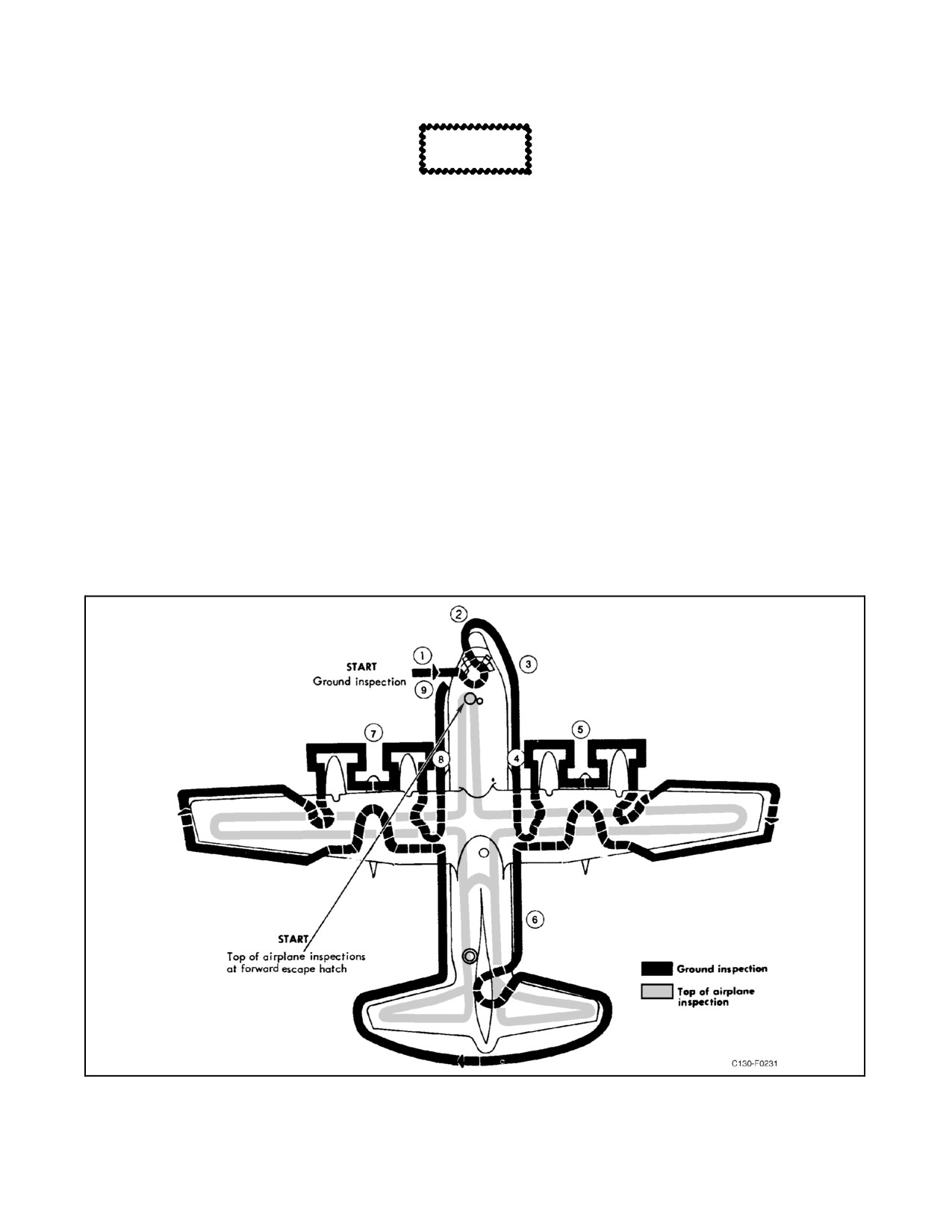
01-75GAL-1
CAUTION
Use extreme care at all times to avoid scratching or denting the skin while
walking on the fuselage.
8.2.6.1 Top of Aircraft.
Conduct a walkaround inspection following the route shown in Figure 8-1.
Note
This inspection shall be started at the forward escape hatch.
1. Antennas — Checked for Security.
2. Dry bay areas — Checked:
a. Fuel or hydraulic leaks.
b. Fumes.
c. Fire extinguisher control valves — Proper Operation.
Figure 8-1. Inspection Diagram
8-23
ORIGINAL
01-75GAL-1
3.
Engine nacelles — Checked:
a. Oil servicing access panels — Secured.
b. Propeller servicing panels — Secured.
c. Propellers — Checked for Damage to Blades and Deice Boots.
d. Access panels for loose or missing fasteners.
4.
Fuel tank quantity and caps — Checked, Secured.
5.
Ailerons — Checked.
6.
Flaps — Checked.
7.
Liferaft access doors for security — Checked.
8.
Empennage — Checked.
9.
Elevators — Checked.
10.
Rudder — Checked.
11.
Escape hatches — Checked:
a. Security — Secured.
b. Release handles — Clean and Free.
12.
Top exterior lights — Checked.
13.
Upper wing surface — Checked:
a. Missing fasteners.
b. Bare metal/corrosion.
c. Leakage from fuel tank access panels.
8.2.6.2 Exterior of Aircraft Inspection
Conduct a walkaround inspection following the route shown in Figure
8-1.
1. Nose section — Checked:
a. Crew entrance door — Checked for Security and ease of operation.
b. Battery compartment:
Do not operate the aircraft without a serviceable battery.
ORIGINAL
8-24
01-75GAL-1
(1) Battery.
(2) Vent lines.
(3) Properly secured.
c. Pitot tubes:
(1) Obstructions.
(2) Damage.
d. Windshields:
(1) Delamination.
(2) Crazed and cracks.
e. Radome.
2.
Nose wheelwell — Checked:
Note
Always enter and exit on the left side.
a. Nosegear assembly:
(1) Actuating cylinders.
(2) Scissors.
(3) Overall condition.
(4) Steering cables.
b. Brake accumulators.
c. Radome attaching bolts.
d. Liquid oxygen converter — Check for Icing of Lines.
e. Hydraulic lines — Check for Leakage.
f. Landing gear doors.
3.
Forward fuselage right side and bottom — Checked:
a. Radome.
b. Windshields:
(1) Delamination.
(2) Crazed and cracks.
8-25
ORIGINAL
01-75GAL-1
c. Pitot tubes:
(1) Obstructions.
(2) Damage.
d. Liquid oxygen filler access panel.
e. Flight deck air-conditioning:
(1) Intake and exhaust.
(2) Oil level.
f. Static ports.
g. Outflow valve exhaust.
h. Antennas.
i. Strobe light.
j. Exterior structure — General Condition.
4.
Right wheelwell and center fuselage — Checked:
a. Cargo compartment air-conditioning:
(1) Intake and exhaust.
(2) Oil level.
b. Right main landing gear, wheelwell area:
(1) Wheels, tires.
(2) Struts, jackscrews.
(3) Brakes, hydraulic lines.
(4) Structure general condition.
c. Single-point refueling panel:
(1) Drain lines, vents.
(2) Gauges, switches.
d. Exterior structure — General Condition.
5.
No. 3 and 4 engines, nacelles, propellers, right wing — Checked:
a. Nacelle exterior structure — General Condition, Fluid Leaks.
b. Propeller spinner and blades.
ORIGINAL
8-26