C-130T. FLIGHT MANUAL (2006) - page 8
01-75GAL-1
6. Painted flight control surfaces.
a. Do not exceed 250 KIAS when any flight control surface is painted, unless the following has been
accomplished:
(1) The underside of the ailerons and elevators and either side of the rudder have been stenciled as follows:
CAUTION
Subsequent repainting restricted to minor touchup unless performed at
depot level.
OR
(2) An entry has been made in the aircraft form that, after painting, rebalance has been accomplished in
accordance with NAVAIR 01-75GAA-2-2, NAVAIR 01-75GAA-3, and NAVAIR 01-1A-509.
7.
Cargo door and/or ramp open — Do not exceed 150 KIAS with the ramp (or ramp and cargo door) open
regardless of whether the paratroop doors are open or closed or the position of the paratroop air deflectors. Do
not exceed 185 KIAS with the ramp up and locked and the cargo door open.
8.
Paratroop air deflectors — Do not exceed 150 KIAS when operating the paratroop air deflectors or with the
air deflectors extended, regardless of whether the paratroop doors are open or closed.
9.
Paratroop doors — Do not exceed 150 KIAS when operating the paratroop doors or when operating with the
paratroop doors open.
10.
Flight without landing geardoors — Do not exceed 200 KIAS with landing gearup or170 KIAS with landing
gear down if any landing gear door is removed. Flight is permitted with the doors removed in the following
manners only:
a. Main landing gear — All doors of the affected wheelwell must be removed.
b. Nose landing gear — Both forward and aft doors removed oraft doorremoved with forward doorinstalled.
CAUTION
Flight is not permitted with the forward door removed and the aft door
installed.
11. Inoperative windshield anti-icing — Do not exceed 187 KIAS with inoperative windshield anti-icing below
10,000 feet altitude.
12. Maximum tire speed.
4-19
ORIGINAL

01-75GAL-1
TYPE III TIRES
KNOTS TRUE GROUNDSPEED
12.50-16
139
12-ply rating (nose)
20.00-20
174
26-ply rating (main)
TYPE VII TIRES
KNOTS TRUE GROUNDSPEED
39×13
174
14-ply rating (nose)
56×20.0 - 20
174
24-ply rating (main)
4.8
CROSSWIND LIMITATIONS
Maximum recommended crosswind — 35 knots.
See Figure 3-11 of NAVAIR 01-75GAI-1.1 for more information.
4.9
MANEUVER LOAD FACTOR LIMITS
Never exceed the structurally safe maneuver load factors for the applicable flight conditions and for the aircraft load
distribution. The limit load factors for fuel load and cargo load combinations aregiven in Figure 4-6 forsymmetrical
and unsymmetrical maneuvers with the flaps retracted. Symmetrical maneuvers (pullups and pushdowns) involve
no aileron deflections. Unsymmetrical maneuvers include a combination of aileron and elevator inputs (turns and
rolling pullouts). The aircraft accelerometer indicates the acceleration (g) at its location that is quite different from
the g at the cg or other locations. The accelerometer should be used as an indicator of cg load factor only for sustained
turns or pullups. Since feel is often misleading, particularly when the pilot attention is diverted or distracted, abrupt
and unnecessary maneuvering must always be avoided.
CAUTION
With any flap extension, the maximum maneuver load factor is 2.0g in
symmetrical maneuvers and 1.5g in unsymmetrical maneuvers.
4.10
WEIGHT LIMITATIONS
Aircraft weight limits may be divided into two categories: gross weight limits and limits on cargo-fuel combinations.
The gross weight limits in this chapter are design weights on which airframe strength is based. Taxi and landing gross
weights are limited by the strength of the landing gear and the related fuselage structure. Takeoff and flight gross
weights and cargo weight are limited by wing strength and the effects of fuel weight and distribution, airspeed,
maneuver, and turbulence. Takeoff and flight gross weights may be further limited by performance capability.
ORIGINAL
4-20
01-75GAL-1
Alternatively, airspeed and maneuver load factor may be limited by wing and empennage strength, cargo weight, and
fuel weight and distribution. Fuel weights for taxiing and landing are limited by wing strength and landing gear
shock-strut reaction.
4.10.1 Gross Weight Limits
Aircraft gross weight limits are summarized in Figure 4-7 for the conditions indicated. Gross weight in excess of those
recommended must be authorized by the commanding officer.
4.10.1.1 Maximum Takeoff Gross Weight
Take-off gross weights must take into account the available runways, surrounding terrain, airfield elevation,
atmospheric conditions, mission requirements, and the urgency of the mission.
CAUTION
Gross weights exceeding those required for the mission will result in
unnecessary risk and wear of the aircraft.
4.10.2 Landing Gross Weights
Observe the landing gross weight limits and the respective landing rate-of-sink limits shown in the following table.
If required, the aircraft can be landed at rates of sink up to 300 fpm with all tanks full, including the external tanks.
For rates of sink from 300 to 540 fpm, usable fuel limits are as follows:
1. Main tank:
a. Total fuel — 25,000 pounds.
b. Tank Nos. 1 and 4 — 6,600 pounds each.
2. External tanks — 500 pounds each.
3. Auxiliary tanks:
a. Primary management — 500 pounds each.
b. Secondary management — Full.
CAUTION
The gross and fuel weight limitations for a maximum-effort landing are
those corresponding to a landing sink rate of 540 fpm.
Note
D Although the aircraft can be landed at a 300 fpm rate of sink at the
maximum overload landing gross weight, overload gross weight landing
should be limited to emergency situations. Consideration should be given
to dumping fuel to reduce landing weight.
D The aircraft can be landed at a rate of sink of 300 fpm with all fuel tanks
full. However, it is recommended that landings be made with little, if any,
usable fuel in the external tanks.
4-21
ORIGINAL

01-75GAL-1
GROSS WEIGHT — POUNDS
CONDITION
EXTERNAL TANKS ON
LIMITATIONS
MAXIMUM TAXI
Recommended
155,000
Refer to taxi and ground limitations.
Overload
175,000
MAXIMUM TAKEOFF
Recommended
155,000
2.25g maneuver load factor.
Overload
175,000
MAXIMUM LANDING
Recommended
155,000
300 fpm rate of sink.
Overload
175,000
NORMAL LANDING
130,000
540 fpm rate of sink. See Figure
4-5 for fuel limits.
Figure 4-7. Gross Weight Limits
4.10.3 Weight Limitations Chart
The weight limitations chart graphically presents the cargo/fuel carrying capability of the aircraft as a function of
varying operating weights, airspeeds, and maneuver load factors (see Figure 4-6).
Airspeed limitations are shown on sheet 1 of Figure 4-6. Weight limitations for primary fuel management are shown
on sheet 2 of Figure 4-6. Weight limitations for secondary fuel management are shown on sheet 3 of Figure 4-6.
4.10.3.1 Operating Weight Effects
To account for variations in operating weight, operating weight scales are provided on the weight limitations charts.
4.10.3.2 Primary Fuel Management
Primary fuel management is based on JP-4 fuel at the standard day density of 6.5 pounds per gallon, except that
maximum fuel weight (per tank and total) is based on JP-5 fuel at the standard day density of 6.8 pounds per gallon.
The following distribution requirements define the primary fuel management.
1. Maximum usable fuel weights for the wing tanks are those shown in Figure 2-20 for JP-5/JP-8 fuel.
2. Tank Nos. 1 and 4 always contain 500 to 1,000 pounds more fuel per tank than tank Nos. 2 and 3, except when
total usable fuel is less than 1,000 pounds.
3. The main tanks are full, except for fuel used for taxi and takeoff when the external and/or auxiliary tanks
contain usable fuel.
4. Fuel asymmetry is within the limits specified in paragraph 4.5.
4.10.3.3 Secondary Fuel Management
Any fuel management that fails to meet the requirements forprimary fuel management is defined as a secondary fuel
management. This will occur anytime there is usable fuel in the external and/or auxiliary tanks and the main tanks
are partly filled, or when the prescribed fuel weight difference between each inboard and outboard main tank is not
observed.AnextremecasewouldbeoperationwithtankNos.1and4ortank Nos.2 and3 empty.Thefuelasymmetry
limits for secondary fuel management are the same as for primary fuel management.
ORIGINAL
4-22
01-75GAL-1
CAUTION
The aircraft should be flown with tank Nos. 1 and 4 empty only in an
emergency or when it must be ferried to another facility for repair of a fuel
leak in either of these tanks.
Note
D Although not required for secondary fuel management, it is recommended
that the prescribed fuel weight difference between each inboard and
outboard main tank for primary fuel management be observed for
secondary fuel management whenever possible.
D Effects of secondary fuel management on service life and inspection
requirements have not been established; therefore, secondary fuel manage-
ment should be used advisedly, especially when operating near the gross
weight limit for the applicable maneuver or airspeed.
4.10.3.4 Weight Limitations Charts (Primary Fuel Management)
The weight limitations charts (primary fuel management) (sheet 2 of Figure 4-6) shows the design weight capabilities
of the aircraft. The chart may be used in three ways:
1. With operating weight, cargo weight, and fuel weight established, determine airspeed and maneuver
limitations.
2. With operating weight, cargo weight, and airspeed and/or maneuver requirements established, determine
maximum and minimum fuel or gross weight.
3. With operating weight, fuel weight, and airspeed and/or maneuver requirements established, determine
maximum cargo weight.
4.10.3.5 Weight Limitations Charts (Secondary Fuel Management)
The weight limitations charts (secondary fuel management) (sheet 3 of Figure 4-6) are derived from the weight
limitations charts (primary fuel management). Airspeed and maneuver limitations for areas A, B, and C of the chart
for secondary fuel management are the same as depicted on the chart for primary fuel management. Landing gross
weight and fuel weight limits for secondary fuel management are the same as for primary fuel management.
The weight limitations charts (secondary fuel management) are entered on the inboard fuel scale. For aircraft with
refueling pods removed, the entry fuel weight on sheet 3 is the smaller of (1) the actual weight of fuel in tank Nos.
2 and 3, or (2) the weight of fuel in tank Nos. 1 and 4 minus 1,300 pounds. The latter corresponds to the design
difference of 650 pounds less fuel per tank in tank Nos. 2 and 3 than in tank Nos. 1 and 4, which is used to define
the weight limitations charts (primary fuel management). In the latter case, with or without refueling pods installed,
any additional fuel in tank Nos. 2 and 3 is included in the gross weight and total fuel, although it is not included in
the entry fuel weight.
4.10.3.6 Recommended Loading Limits
The weight limitations charts, sheets 2 and 3 of Figure 4-6, have three areas of recommended cargo-fuel
combinations, provided the associated limits on maneuver load factor and airspeed are observed. These
recommended areas are shown in different shades of green. Area A encompasses those cargo-fuel combinations for
which the maximum symmetrical maneuver load factor is 3.0g at speeds up to the highest recommended speed
4-23
ORIGINAL
01-75GAL-1
VH1 inFigure4-6.AreasBandCencompassthosecargo-fuelcombinationsorgrossweightsforwhichthe
maximum symmetrical maneuver load factor is 2.5g and, to preclude excessive forces because of turbulence, the
recommended speed is VH2 for area B and VH 3 for area C.
4.10.3.7 Cautionary Loading Limits
On sheet 2 of Figure 4-6, the cautionary area, area D (shown in yellow), encompasses those cargo-fuel combinations
that are permissible for overload gross weight operations but require extra caution to avoid damaging the aircraft.
For area D, the recommended speed is VH 2 shown on sheet 1 of Figure 4-6, and the maximum maneuver load factor
is 2.25g. Limitations given in paragraph 4.14 must be observed.
4.10.3.8 Loading Area Not Recommend
Operation of the aircraft in the red area should be avoided. If flight is
conducted in this area, an entry must be made in the aircraft records.
The red area, area E of the weight limitations chart, encompasses those cargo-fuel combinations or gross weights that
present a high degree of risk of structural damage. Under conditions of extreme emergency when the risk of damage
to the aircraft is secondary, the commander will determine if the degree of risk warrants operation of the aircraft at
loadings appearing in the red area. Fuel weights in the red area on the right of the chart represent a high risk of damage
to the wing structure during ground operation. Cargo weights in the red area at the top of the chart represent a high
risk of damage during flight; if used, the maximum maneuver load factor is 2.0g and flight through severe turbulence
is prohibited. Exceeding themaximum gross weight shown on the chart imposes ahigh risk of damageto thelanding
gear and supporting structure during taxi.
4.11
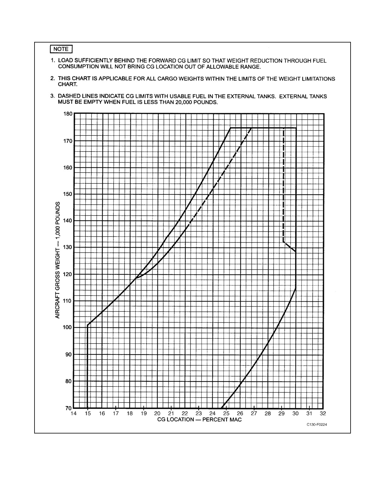
CENTER OF GRAVITY LIMITATIONS
The location of the center of gravity for any gross weight configuration, determined from NA 01-1B-40, Handbook
of Weight and Balance Data, must fall within the percent of the mean aerodynamic chord shown in Figure 4-8.
These limitations represent the combined structural, aerodynamic, and control limitations that must be observed to
obtain safe and effective aircraft performance. For information and method of calculating the aircraft center of
gravity, refer to the applicable Cargo Loading Handbook and NA 01-1B-40, Handbook of Weight and Balance Data.
When mixing passengers and cargo on aircraft, caution should be exercised
during ground operations to prevent aircraft tipping aft because of possible
aft cg with no passengers on board.
The center of gravity of fuel in the external tanks shifts fore and aft with changes in aircraft attitude. The zero fuel
weight consists of the operating weight plus any payload.
ORIGINAL
4-24
01-75GAL-1
Figure 4-8. Center of Gravity Limitations
4-25
ORIGINAL
01-75GAL-1
4.12
PROHIBITED MANEUVERS
Although the aircraft structure is designed for 1.0g maneuvers when loaded within area A of Figure 4-6, sustained
pushovers to a zero or negative condition will cause loss of hydraulic pressure and thus loss of control boost.
Aerobatics of any kind (including those that produce a negative-g condition), intentional spins, excessively nose-high
stalls, steep dives, and any other maneuvers resulting in excessive accelerations are strictly prohibited. Do not make
hard rudder kicks that result in large angles of yaw. Do not exceed a 60_ angle of bank with flaps retracted or a 45_
angle of bank with flaps extended. The bank angle limits provide an indication of load factor during turns. A constant
altitude turn with 60_ of bank corresponds to a load factor of 2.0g, and 45_ of bank corresponds to 1.4g.
4.13
RAMP LOADING LIMITATIONS
The ramp loading limitations are contained in the applicable loading manual.
4.14
TAXI AND GROUND LIMITATIONS
CAUTION
Turns with brakes locked on one side or pivoting are prohibited. While
turning the aircraft, avoid hard or abrupt brake applications or braking to
a stop since damage to the nose landing gear and supporting structure may
result. If any of the above is required during a turn, record it in the aircraft
records.
Do not exceed the following taxi speeds, regardless of runway conditions.
1. Five knots with nosegear deflected 60_.
2. Twenty knots with nosegear deflected 20_.
Fuel tanks may be filled to the fuel weights shown in Figure 2-22 for JP-5/JP-8 fuel. However, when the fuel weight
per tank exceeds that shown for JP-4, the following limitations apply:
1. Taxi and takeoff are permissible only on surfaces where qualities of smoothness and freedom from dips,
depressions, and holes are comparable to those of a major airbase.
2. Maximum taxi speed is 20 knots.
Note
For taxi limitations on rough-terrain airfields, see paragraph 4.15. At gross
weights up to 155,000 pounds, taxiing over rough terrain should be
avoided. If this is unavoidable, extreme caution must be exercised and very
low taxi speeds observed.
For overload gross weights above 155,000 pounds, observe the following taxi limitations:
1. Taxi and takeoff are permissible only on surfaces where qualities of smoothness and freedom from dips,
depressions, and holes are comparable to those of a major airbase.
2. Maximum taxi speed is 10 knots.
3. Taxi shortest distance possible.
ORIGINAL
4-26
01-75GAL-1
4. Use minimum braking during all taxi operations.
5. Use only light braking while turning.
6. Limit nosegear steering angle to 20_.
7. Avoid abrupt or uneven application of brakes.
4.15
SUBSTANDARD AIRFIELD OPERATIONS
Substandard airfields are defined as those that lack the flotation properties necessary foreveryday normal operations
or that have unusually rough, undulating, pitted, or rutted runways and/or taxiways. They may be either paved or
unpaved. Conversely, unpaved surfaces (gravel, dirt, etc.) need not be considered substandard if the surface is hard
and smooth. Any airfield on which the tires produce easily visible ruts should be considered substandard.
Note
Planning for substandard airfield operations should allow for increased
maintenance and accelerated inspections according to the severity of the
environment and the frequency of such operations.
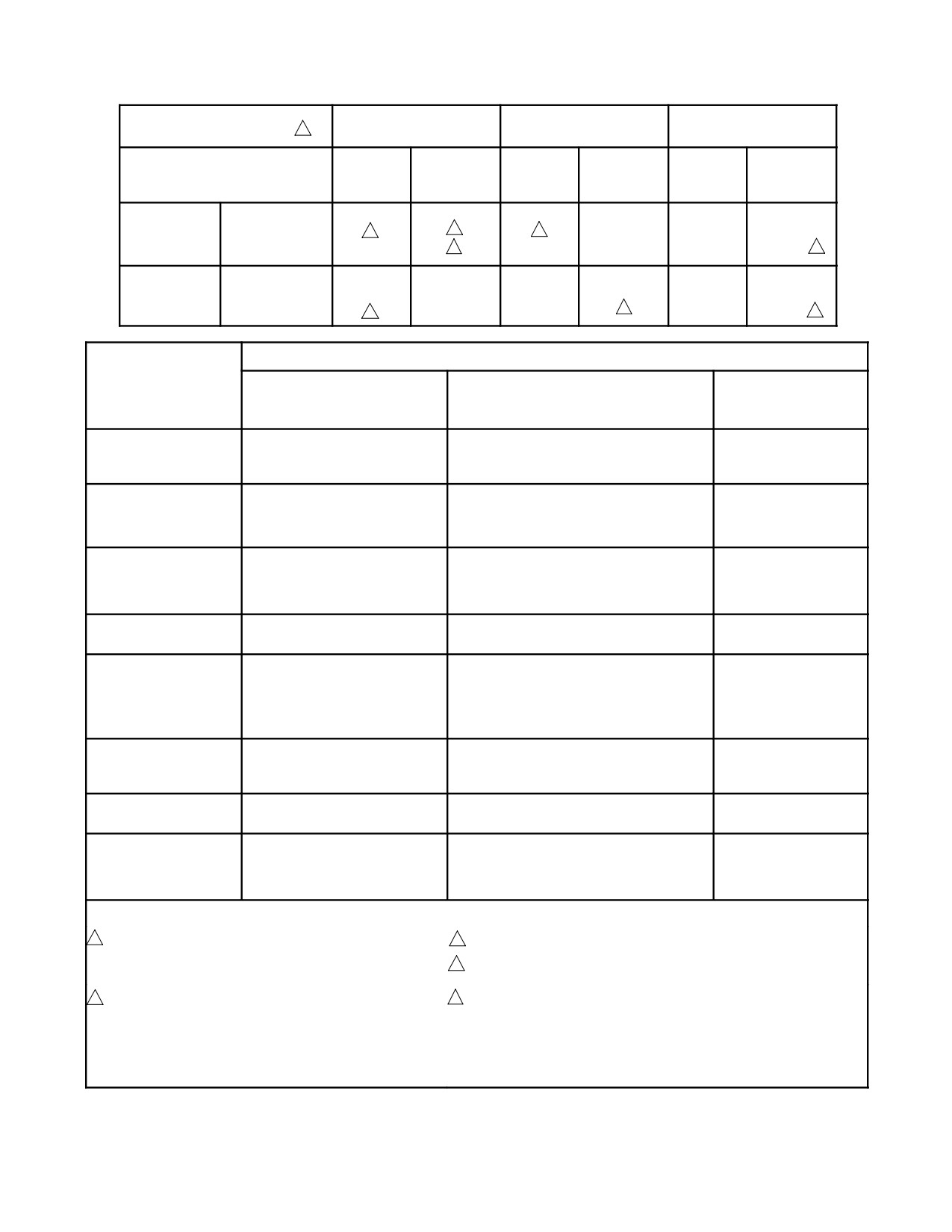
Figure 4-9 defines the weight limitations for operating on substandard airfields. Contact rates of sink should be
expected to be significantly higher on substandard airfields than on standard airfields. Thus the “recommended”
landing gross weights and fuel weights shown in Figure 4-9 are within the structural limits for touchdown at 540 fpm.
The “recommended” weights of Figure 4-9 are considered safe for the specified limits of roughness. The “allowable
withcaution”weightsincurunknownrisksthatincreasewithanincreaseinweightand/orairfieldroughnessspecified
in Figure 4-9. The decision to use the “allowable with caution” weights shall be made by proper authority.
Where Figure 4-9 shows a fuel weight limit less than the capacity of the main tanks, additional fuel, if needed to meet
mission requirements, is allowed in the auxiliary tanks. Since the gross weight is limited, the fuel in the auxiliary
tanks will be at some sacrifice of cargo capability. Following takeoff, use the fuel in the auxiliary tanks before using
the fuel remaining in the main tanks.
In addition to the weight limitations of Figure 4-9, observe the following to minimize maintenance and the chance
of damaging the aircraft:
1. Service main gear tires as shown on Figure 3-2.
2. External tanks (if installed) must be empty.
3. Maximum taxi speed is 10 knots.
4. Minimize braking if porpoising results.
5. Minimize nosegear loads by use of elevator during takeoff and landing rollout and by loading the aircraft to
a mid or aft center of gravity.
6. In addition, when operating on unpaved surfaces, the flight station and cargo compartment refrigeration units
should be shut off to prevent clogging of the heat exchanger by debris.
4.16
MAXIMUM PASSENGER LOAD FOR EXTENDED OVERWATER FLIGHTS
In order to ensure sufficient liferaft capacity, no more than 80 persons, including crewmembers, may be carried on
extended overwater flights that operate more than 50 nm from the nearest shoreline. Extended over-water operations
withmixedcargo/passengerloadsarerestrictedto amaximum of35 occupantsperunobstructedoverhead exit.When
normal egress routes are obstructed by cargo tiedown arrangements, passenger capacity shall be reduced accordingly.
4-27
ORIGINAL
01-75GAL-1
4.17
GROUND FLOTATION
Figure 3-2 is provided for generalized operational planning. This chart permits matching the load that the aircraft
imposes on an airfield to the strength capability of the airfield. Ground flotation characteristics are correlated for the
following five methods of evaluating airfield/runway strength.
4.17.1 Footprint Loading (Pressure)
For operational planning purposes, footprint loading is the same as tire inflation pressure. Figure 3-2 shows tire
pressure values versus gross weights for normal operation from either high-strength airfields or marginal-strength
airfields.
4.17.2 Unit Construction Index
UCI values are used to determine relative flotation characteristics of comparative aircraft and are seldom used in
operational planning.
4.17.3 Equivalent Single-Wheel Load
Values of ESWL are determined from the geometry of the multiple-wheeled landing gears, the number and size of
the tires, and the aircraft gross weight. Where airfield strength data are given in terms of ESWL, values of UCI and
LCN can be calculated from these ESWL values, when required.
4.17.4 Load Classification Number
When LCN airfield strength data are used (primarily outside the United States) the data shown on the ground flotation
chart can be used to estimate the capability of the aircraft to operate from a given airfield.
4.17.5 California Bearing Ratio
Values of CBR shown in Figure 3-2 represent the required airfield surface hardnesses for operation of the aircraft
in terms ofgross weight and numberof passes. Only unpaved surface (dirt, grass, gravel, coral, etc.)can beevaluated
in terms of CBR.
4.17.6 Aircraft Classification Number/Pavement Classification Number
The ACN/PCN is a method of reporting the load-bearing capability of a runway. When the ACN is greater than the
PCN, then the aircraft is normally not allowed to land on therunway. TheACN depends on theaircraft gross weight,
the subgrade code, and the flexibility of the runway. The subgrade code is “A” for high, “B” for medium, “C” for
low, and “D” for very low strength of the soil-bearing runway. The runway pavement will either be “R” for rigid or
“F” for flexible. Each runway should have a PCN, a subgrade code, and a flexibility reported before the ACN/PCN
is used.
Example problem for all C-130 aircraft using the charts in Figure 4-10.
GIVEN:
1. Gross weight = 120,000 pounds.
2. PCN = 21.
3. Subgrade code = C.
4. Flexible pavement.
ORIGINAL
4-28
01-75GAL-1
ROUGHNESS
CHARACTERISTICS
1
A
B
C
RECM
ALLOWABLE
RECM
ALLOWABLE
RECM
ALLOWABLE
WITH
WITH
WITH
CAUTION
CAUTION
CAUTION
LANDING
GROSS WT (LB)
130,000
155,000
120,000
______
______
111,000
2
3
2
FUEL (LB)
25,000
5
25,000
______
______
6,600
4
TAKE-OFF
GROSS WT (LB)
155,000
______
120,000
135,000
______
111,000
FUEL (LB)
5
______
25,000
5
______
6,600 4
ROUGHNESS CHARACTERISTICS
C — EMERGENCY
A — SMOOTH
B — INTERMEDIATE
(NO PREPARATION OR
PARAMETER
(REGULARLY MAINTAINED)
(MAINTAINED ONLY AS NECESSARY)
MAINTENANCE)
DEVIATION FROM
±2 INCHES IN 50 FEET
±4 INCHES IN 25 FEET
±6 INCHES IN 25 FEET
SURROUNDING
SURFACE LEVEL
MAXIMUM GRADIENT
LONGITUDINAL
±2%
±4%
±6%
TRANSVERSE
±2%
±3%
±3%
MAXIMUM CHANGE
2 FT IN 100 FT
3 FT IN 100 FT
3 FT IN 100 FT
IN LONGITUDINAL
4 FT IN 200 FT
6 FT IN 200 FT
6 FT IN 200 FT
ELEVATION
8 FT IN 400 FT
10 FT IN 400 FT
10 FT IN 400 FT
2% OVER 400 FT
2% OVER 400 FT
2% OVER 400 FT
MAXIMUM CHANGE
2% IN ANY 50 FT LENGTH
3% IN ANY 50 FT LENGTH
4% IN ANY 50 FT
IN GRADIENT
LENGTH
MAXIMUM ALLOWABLE
2 IN.
4 IN.
6 IN.
RUTTING (MEASURED
FROM SURROUNDING
SURFACE — NOT
EDGES OF RUT)
SOLID OBJECTS
NONE
3 IN. FROM FIRM OR
6 IN. FROM
PROJECTING FROM
UNDISTURBED SURFACE
UNDISTURBED
SURFACE
SURFACE
POT HOLES OR
2 IN. DEPTH MAXIMUM
6 IN. DEPTH, 15 IN. MAX DIA;
8 IN. DEPTH,
DEPRESSIONS
FOR ALL DIAMETERS
4 IN. DEPTH, ANY DIA
2 FT MAX DIA
LOOSE OR SOFT FILL
NONE
NONE ADJACENT TO ROCKS, STUMPS,
AS NEEDED TO FILL
OR RIGID SURFACES
DITCHES OR HOLES.
PACK WITH FEET OR
USE HAND TAMPER
Notes
1
THE LOWER TABLE DEFINES ROUGHNESS
3
MAXIMUM TOUCHDOWN RATE OF SINK IS 300 FPM.
CHARACTERISTICS WHICH IMPOSE THE GROSS
4
OUTBOARD TANK FUEL IS LIMITED TO 2,000 POUNDS PER SIDE.
WEIGHT AND FUEL WEIGHT LIMITS OF THIS TABLE.
2
MAXIMUM TOUCHDOWN RATE OF SINK IS
5
MAXIMUM FUEL WEIGHTS FOR MAIN, AUXILIARY, AND
540 FPM. OUTBOARD TANK FUEL IS LIMITED TO
EXTERNAL TANKS WITHOUT AFC--424 FOAM ARE THOSE
6,600 POUNDS PER SIDE.
WEIGHTS SHOWN IN FIGURE 2--22 FOR JP--4 FUEL. MAXIMUM
JP--4 FUEL WEIGHTS FOR MAIN, AUXILIARY, AND EXTERNAL
TANKS WITH AFC--424 FOAM MUST BE CALCULATED AS
DESCRIBED IN NOTE 4 ON FIGURE 2--23.
Figure 4-9. Gross Weight and Fuel Weights for Substandard Airfield Operations
4-29
ORIGINAL