C-130T. FLIGHT MANUAL (2006) - page 6

01-75GAL-1
above the aircraft, the data tag will be placed above the traffic symbol and preceded by a plus (+) sign and a two-digit
number. For traffic below the aircraft, the data tag will be placed below the traffic symbol and preceded by a minus
(-) sign and a two-digit number. The two-digit number represents the relative altitude of the intruder, proximate, or
other aircraft traffic in relation to own aircraft. For example; a data tag of +21 would indicate that the traffic is 2,100
feet above own aircraft’s present altitude. If an intruder aircraft is either climbing or descending in excess of 500 feet
per minute, an arrow will appear to the immediate right of the traffic symbol. The arrow will point down if the traffic
is descending and will point up if the traffic is climbing.
During a resolution advisory (RA), red and green bands will overlay the vertical speed scale. The bands reflect the
RA in progress and act as vertical speed advisories for the pilot. The red band indicates what vertical speed range
is to be avoided by the pilot. The green band indicates the recommended vertical speed that the pilot is to attain in
order to achieve safe separation from an intruder aircraft. Climb commands are inhibited at or above 24,000 feet for
C-130T aircraft. Climb commands will not exceed a 1,500 FPM climb rate.
DISPLAY
SYMBOL
COLOR
FUNCTION
DEFINITION
Solid Circle
Amber
Traffic Advisory
Intruder aircraft are entering the caution area, 20
(TA)
to 48 seconds from the TCAS collision area. A
F
visual search is recommended to prepare for
intruder avoidance.
Solid Square
Red
Resolution
Intruder aircraft are entering the warning area, 15
Advisory (RA)
to 35 seconds from the TCAS collision area.
J
Prompt action is required to avoid the intruder.
Solid Diamond
Blue
Proximate Traffic
Aircraft are within 6.0 nautical miles and +1,200
feet vertically from own aircraft. Proximate traffic
z
is shown to improve situational awareness in the
event of a potential conflict with other aircraft.
The flightpaths of proximate traffic are not
predicted to enter the TCAS collision area.
Hollow Diamond
Blue
Other Traffic
Aircraft are within the range of the VSI/TRA
display and +2,700 feet vertically from own
Z
aircraft. The flightpaths of other traffic are not
predicted to enter the TCAS collision area.
Figure 2-123. TCAS Traffic Symbology
An off-scale traffic advisory occurs when TCAS is tracking an intruder that is outside the range of the VSI/TRA but
has entered the Caution or Warning areas. One half of the appropriate symbol will appear at the proper bearing at
the edge of the display area. The symbol will appear at the appropriate color and shape and will display a data tag,
provided there is enough room.
If TCAS is unable to track the bearing of an intruder, a no-bearing advisory will appear. The inability to track the
bearing of an intruder is usually caused by temporary antenna shielding due to steep bank angles or by a failure in
the TCAS antennas. TCAS will still be able to compute traffic and resolution advisories. When TCAS is unable to
track the bearing of the intruder aircraft, no symbol will be displayed on the VSI/TRA. Instead, a no-bearing advisory
will appear in alphanumeric form. It will display the acronym “TA” or “RA,” the distance of the intruder from the
own aircraft in nautical miles, and the relative altitude and direction of the intruder from the own aircraft. For
example, an intruder creating a resolution advisory that is 0.6 nautical miles and 600 feet below the own aircraft
would causeadisplay that would read “RA 0.6 -06.”This display will also appearin theappropriate colordepending
on the type of alert.
Current operation modes appear in white letters. The modes include TCAS OFF and TA only. Failure modes appear
in amber letters and displace the current operation modes in case of system failure. The failure modes include TCAS
FAIL, RA FAIL, VSI FAIL, and TA FAIL.
2-281
ORIGINAL
01-75GAL-1
2.21.21.2.5 TCAS Aural Announcements
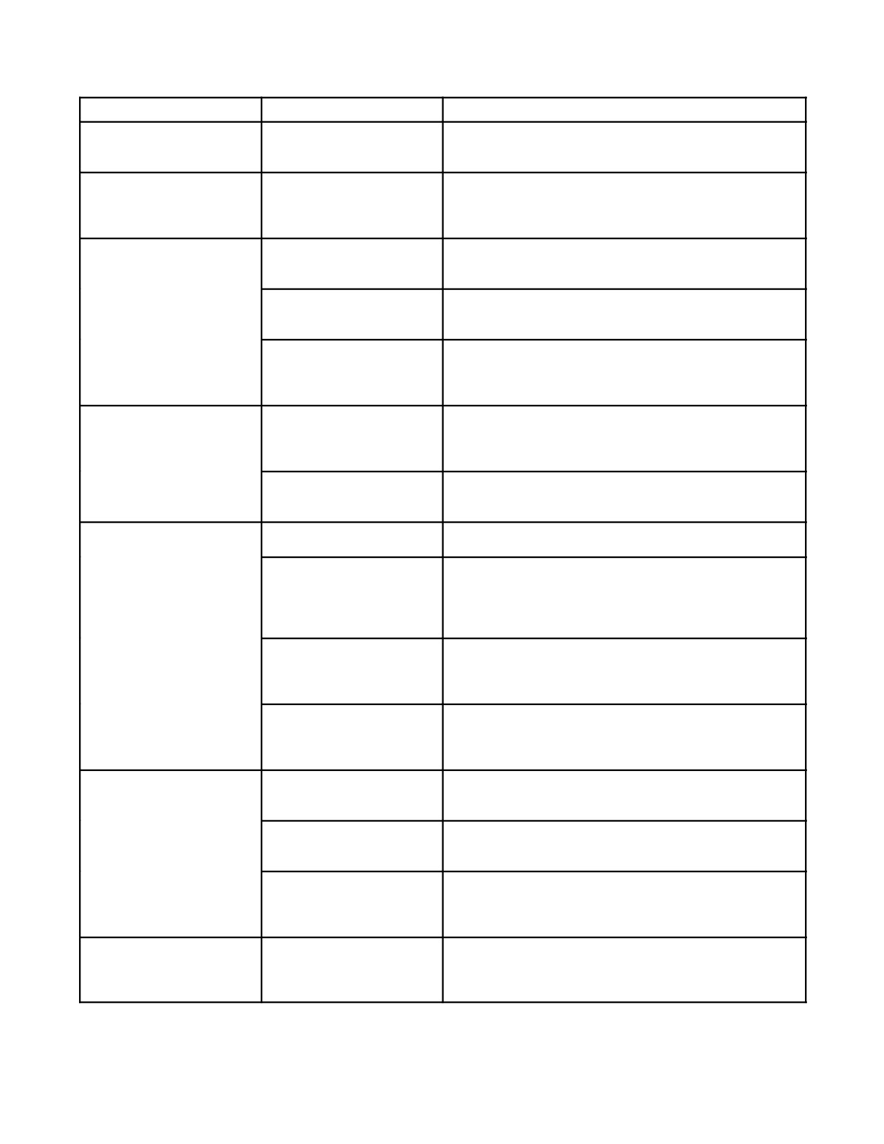
TCAS is programmed with 14 aural announcements (see Figure 2-124), excluding test announcements. These 14
announcements alert the aircrew to changing traffic conditions and are broadcast from a cockpit loud speaker as well
as to the flightcrew headsets from the interphone communication system. The aural announcement, TRAFFIC,
TRAFFIC, is generated when a potential traffic threat is approaching. A variety of aural alerts are given when the
first RA of an encounter is displayed and each time a subsequent change in the advisory is displayed, either
strengthened or weakened. The announcements differentiate the advisories by type. The weakened advisory,
MONITOR VERTICAL SPEED, is initiated to facilitate minimizing the vertical deviation from ATC clearances.
An aural announcement also indicates that the aircraft is CLEAR OF CONFLICT. This announcement occurs when
the RA is removed from the VSI/TRA and the intruder aircraft has begun to diverge in range.
2.21.21.2.6 Pilot Responsibilities
TCAS is intended as a backup to visual collision avoidance, application of “right-of-way rules,” and Air Traffic
Control (ATC) separation service. To work effectively, timely and reliable crew response to TCAS advisories is
essential. Flightcrews operating in United States airspace are expected to respond to TCAS in accordance with the
following guidelines. Flightcrews operating in other country’s airspace are expected to familiarize themselves with
any special rules that may be in effect relating to TCAS operations prior to entering that airspace.
Traffic Advisories
Respond immediately to TAs (Traffic Advisories) by attempting to establish visual contact with the intruder aircraft
and other aircraft that may be in the vicinity. If traffic is acquired visually, continue to maintain or attain safe
separation in accordance with good operating practices and current FAR’s (United States Federal Aviation
Regulations) or other applicable air regulations. TA displays and advisories are intended only for assistance in
visually locating the traffic.
Note
D Thepilot should not initiateevasivemaneuvers using information from the
traffic display only, or upon receipt of a Traffic Advisory (TA) only,
without positive visual identification of the traffic.
D Thepilot should reducevertical speed to 1,500 feet perminuteorlesswhen
within 2,000 feet of an ATC directed level-off altitude to reduce the
incidence of unnecessary TAs.
Resolution Advisories
Respond immediately to satisfy Corrective RAs using positive control inputs, in the direction and with the magnitude
TCAS advises, while attempting to sight the conflicting traffic. The aircraft’s vertical speed indication as shown on
the VSI/TRA must be moved out of the RED band and into the GREEN band. Compliance with TCAS Resolution
Advisories (RAs) is necessary and authorized according to United States Federal Air Regulation (FAR 91.123) which
allows pilots to deviate from an ATC clearance if “the deviation is in response to a traffic alert and collision avoidance
system resolution advisory.”Following aTCAS “CLEAR OF CONFLICT”advisory, thepilot should expeditiously
return to the applicable ATC clearance unless otherwise directed, and notify ATC.
For TCAS to properly function, initial vertical speed response is expected within five seconds of an RA. A prompt,
smooth pitch change of 2_ to 6_ should be sufficient to resolve nearly all conflicts. Maneuvering g-forces should be
similarto thosefelt when responding to an ATC clearanceto climb ordescend immediately (0.25g increment).From
level flight, proper response to a TCAS RA typically results in an overall altitude deviation of 300 to 700 feet in order
to successfully resolve a traffic conflict. If possible, visually confirm the necessity and suitability of the avoidance
maneuver but recognize that any other aircraft seen visually may not necessarily be the threat aircraft or the only
aircraft that is triggering the TCAS system response.
ORIGINAL
2-282
01-75GAL-1
MESSAGE TYPE
AURAL WARNING
MEANING
Traffic Advisories (TA)
“Traffic - Traffic”
TCAS predicts that an intruder aircraft will enter the collision
area within 20 to 48 seconds. Amber solid circle showing the
range and relative bearing on the VSI/TRA.
Preventive Resolution
“Monitor Vertical Speed -
Indicates that certain changes in vertical speed may not be
Advisory (RA)
Monitor Vertical Speed”
safe. Pilot should monitor the vertical speed of the aircraft
and keep the VSI pointer out of the RED area on the VSI
scale.
Corrective Resolution
“Climb - Climb”
The VSI/TRA is RED from the negative limit to +1,500 fpm
Advisories (RA)
and GREEN from +1,500 to +2,000 fpm. Pilot should
immediately climb at the rate indicated by the green arc.
“Descend - Descend”
The VSI/TRA is RED from the positive limit to -1,500 fpm
and GREEN from -1,500 to -2,000 fpm. Pilot should immedi-
ately begin to descend at the rate indicated by the green arc.
“Climb, Crossing Climb -
The VSI/TRA is RED from the negative limit to +1,500 fpm
Climb, Crossing Climb”
and GREEN from +1,500 to +2,000 fpm. Pilot should start to
climb at the rate shown on the VSI. This flightpath will cross
the intruder aircraft’s altitude.
Strengthening Resolution
“Descend, Crossing Descend
The VSI/TRA is RED from the positive limit to -1,500 fpm
Advisories (RA)
- Descend, Crossing
and GREEN from -1,500 to -2,000 fpm. Pilot should start to
Descend”
descend at the rate shown on the VSI. This flightpath will
cross the intruder aircraft’s altitude.
“Adjust Vertical Speed,
The VSI/TRA indicates the prohibited vertical speeds by a
Adjust”
RED arc. The goal is to make the aircraft smoothly attain the
recommended vertical speed indicated by the GREEN arc.
Strengthening Resolution
“Increase Climb - Increase
Inhibited on C-130T aircraft.
Advisories (RA)
Climb”
“Increase Descent -
The VSI/TRA is RED from the positive limit to -2,500 fpm
Increase Descent”
and GREEN from -2,500 to -3,000 fpm. This indicates that
the vertical speed must be increased to ensure adequate
separation. Pilot should immediately increase descent rate
as indicated by the GREEN arc.
“Climb, Climb Now! - Climb,
Indicates that a reversal of vertical speed is necessary to
Climb Now!”
provide vertical separation between the aircraft and an
intruder aircraft. The VSI/TRA is RED from the negative limit
to +1,500 fpm and GREEN from +1,500 to 2,000 fpm.
“Descend, Descend Now! -
Indicates that a reversal of vertical speed is necessary to
Descend, Descend Now!”
provide vertical separation between the aircraft and an
intruder aircraft. The VSI/TRA is RED from the positive limit
to -1,500 fpm and GREEN from -1,500 to -2,000 fpm.
Weakening or Restrictive
“Maintain Vertical Speed,
Indicates vertical speed is not within the RED restricted
Resolution Advisories (RA)
Maintain”
vertical speeds shown on the VSI/TRA. Keep vertical speed
out of the RED unsafe areas as indicated on the VSI/TRA.
“Adjust Vertical Speed,
The VSI/TRA indicates the prohibited vertical speeds by a
Adjust”
RED arc. The goal is to make the aircraft smoothly attain the
recommended vertical speed indicated by the GREEN arc.
“Maintain Vertical Speed,
The VSI/TRA indicates prohibited vertical speeds in RED
Crossing Maintain”
and the target vertical speeds in GREEN. Separation with the
intruder aircraft is adequate if a current vertical speed
commanded is maintained.
Clear of Conflict Advisory
“Clear of Conflict”
The VSI/TRA RED and GREEN arcs are removed. Confirms
that the encounter has ended and separation between the
aircraft and intruder aircraft is increasing. A return to the
original ATC clearance profile is expected.
Figure 2-124. TCAS Aural Announcements
2-283
ORIGINAL
01-75GAL-1
D During multiple aircraft encounters, when other traffic is above and below
your aircraft, the TCAS computer and the VSI-TRA indicator may give
conflicting information to aircrews. The VSI-TRA indicator may indicate
an RA fail message while the TCAS audio annunciation indicates
“MAINTAIN VERTICAL SPEED, MAINTAIN”. When in this situation
the flight crew shall follow the audio annunciation
“MAINTAIN
VERTICAL SPEED, MAINTAIN” until “CLEAR OF CONFLICT” audio
annunciation has occurred.
D During any airplane configuration that could limit the normal climb
capability of the airplane (such as engine out, ramp open, etc.) or during an
operational situation where a resolution advisory
(RA) maneuver is
prohibited, TCAS should be placed in TA only if used.
CAUTION
D Maneuvering in responseto RAs must bedonemanually by thepilot flying
theaircraft. Autopilot responsetimemay betoo slow toprovidethedesired
separation. Pilots must disconnect the autopilot and establish the proper
pitch attitude manually.
D Altitude excursions to cardinal altitudes not assigned, or beyond that
directed by the TCAS, may compromise the safety of the entire ATC
system and may cause severe and dangerous effects for all aircraft.
D Noncompliance with a Crossing RA by one airplane may result in reduced
vertical separation. Therefore, safe horizontal separation must also be
assured by visual means.
D Once a Non-Crossing RA has been issued, safe separation could be
compromised if current vertical speed direction is changed, except as
necessary to comply with the RA. This is because TCAS-to-TCAS
coordination with the intruder airplane may be in progress and any change
in vertical speed that does not comply with the RA may negate the
effectiveness of the other aircraft’s compliance with the RA.
ORIGINAL
2-284
01-75GAL-1
Note
D AClimbRAdoesnotmandateaMissedApproach.Thepilotmustexercise
appropriate judgment to assure the airplane is properly configured for the
maneuver, whether it be a subsequent landing or a Go-Around/Missed
Approach. In most cases, the TCAS event will be resolved with only a
minor deviation to the intended flight path and sufficient time and altitude
may exist to recover safely to the desired flight path.
D An Altitude-Crossing maneuver may occur when the intruder or host
aircraft is climbing or descending at a high rate. Under these conditions, the
TCAS logic determines that safe separation is best achieved through an
Altitude-Crossing maneuver. This maneuver will result in the TCAS
aircraft and the intruder crossing through each other’s altitude. This safe
strategy will result in adequate vertical separation between aircraft.
2.21.22 AN/APX-76B IFF Interrogator
The AN/APX-76B IFF interrogator is an air-to-air interrogator that operates in conjunction with the AN/APN-59E
search radar or the AN/APS-133(M) multimode radar. It is capable of generating interrogations on IFF/SIF mode
1, 2, 3/A, or4 anddevelops avideo outputto thesearch radarindicator. Returnsfrom theinterrogated aircraftindicate
theaircraft identification, position in azimuth, and rangefrom interrogatingaircraft. Theinterrogatorsystemconsists
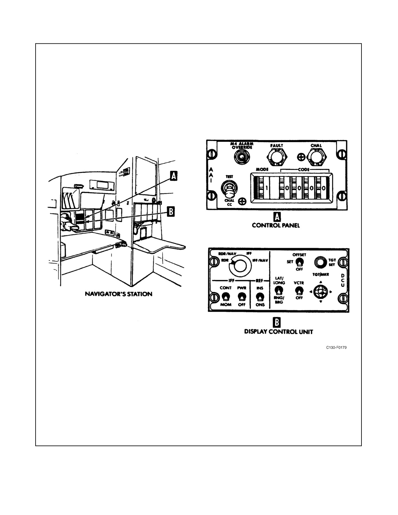
of an IFF interrogator control panel and a display control unit located on the navigator control panel (see Figure
2-125). An IFF interrogator antenna (see Figure 2-83) is mounted on top of the fuselage. The system receives 115-Vac
power from the essential ac bus on, and 28-Vdc power from the essential dc bus through the IFF interrogator circuit
breakers on the copilot upper circuit breaker panel.
2.21.22.1 IFF Interrogator Control Panel
The interrogator control panel (see Figure 2-125) contains the controls, indications, and functions as follows:
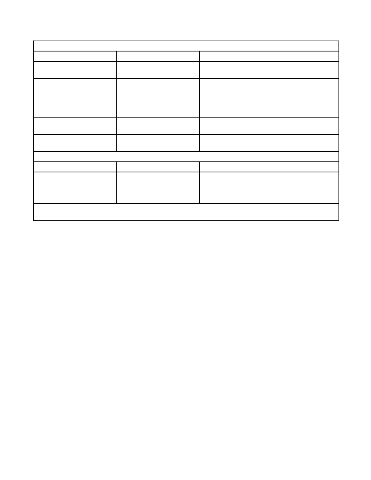
1. IFF interrogator controls — See Figure 2-125 for control panel functions.
2. IFF interrogator switch panel controls — Display control unit contains the controls as shown in Figure2-125.
3. Display control unit.
Note
See AN/APS-133(M) multimode radar for an explanation of the remaining
switches on the display control unit.
2.21.22.2 Normal Operation of the IFF Interrogator System
To place the IFF interrogator into operation, proceed as follows:
Note
On the AN/APS-133(M) multimode radar, the radar indicator must be on.
2-285
ORIGINAL
01-75GAL-1
Figure 2-125. AN/APX-76B(V) IFF Interrogator Controls and Indicators (Sheet 1 of 2)
ORIGINAL
2-286
01-75GAL-1
IFF INTERROGATOR CONTROLS
CONTROL
POSITION
FUNCTION
M4 ALARM OVERRIDE
M4 ALARM OVERRIDE
Allows overriding of the mode 4 alarm, if desired.
Switch
TEST-CHAL CC Switch
TEST
Activates the interrogator for loop testing with the
aircraft IFF transponder.
CHAL CC
Initiates a challenge resulting in correct code dis-
play.
FAULT Light Indicator
Press-to-test and turn-to-dim
When illuminated, advises that there is a fault in
(amber)
the system.
CHAL Light
Press-to-test and turn-to-dim
Light remains on during the length of time
(green)
interrogation is being made.
DISPLAY CONTROL UNIT
IFF Power
PWR-OFF
Connects ac and dc power to the system.
IFF Challenge
CONT-MOM (center OFF
Used to operate the system. Continuous (CONT)
position)
or momentary (MOM) challenge is provided. The
MOM position is spring-loaded to return to the
OFF position.
Note
See AN/APS-133(M) multi-mode radar for an explanation of the remaining switches on the display control unit.
Figure 2-125. AN/APX-76B(V) IFF Interrogator Controls and Indicators (Sheet 2)
On the control panel:
1. Set the mode selector switch to the desired mode.
2. Set the code selector switches to the desired code.
On the AN/APS-133M display control unit:
3. Place the PWR/IFF switch to the ON position.
On the IFF audio monitor panel:
4. Set the copilot interphone IFF audio as desired (see Figure 2-86).
Note
With the CHAL switch on the switch panel in the CONT position
(continuous interrogation), bracket returns (single video slash) can be
eliminated by placing the TEST-CHAL CC switch on the control panel to
CHAL CC, leaving only the correct code (double video slash) returns
displayed.
5. With the AN/APS-133(M) multimode radar in the IFF or IFF/NAV mode, press the TEST-CHAL CC switch
on the IFF interrogator control panel to the CHAL CC position to interrogate aircraft on the correct code.
6. To test the system, set up both the interrogator and transponder system to the same mode and code and press
the TEST-CHAL CC to the TEST position. The interrogation reply of the transponder will appear on the search
radar indicator at approximately a 4-mile range (may be a continuous line).
2-287
ORIGINAL
01-75GAL-1
2.21.23 FCS 105 Flight Control System
FCS 105 is a combination of autopilot, guidance, displays, and sensors and is made up of two flight directorsystems
(Collins FD 109) and the autopilot (Collins AP-105V). Flight director system Nos. 1 and 2 receive 28-Vdc power
from the essential dc bus through the FLT DIR NO. 1 and FLT DIR NO. 2 circuit breakers located on the copilot
upper circuit breaker panel and 115-Vac power from the essential ac bus through the FLT DIR NO. 1 and FLT DIR
NO. 2 circuit breakers located on the copilot upper circuit breaker panel. The autopilot is powered by 28-Vdc power
from the essential dc bus through the AUTOPILOT PWR and ANN LIGHTS circuit breakers on the copilot lower
circuit breaker panel and 115-Vac power from the essential ac bus through the AUTOPILOT circuit breaker on the
pilot upper circuit breaker panel.
2.21.23.1 Attitude Director Indicator
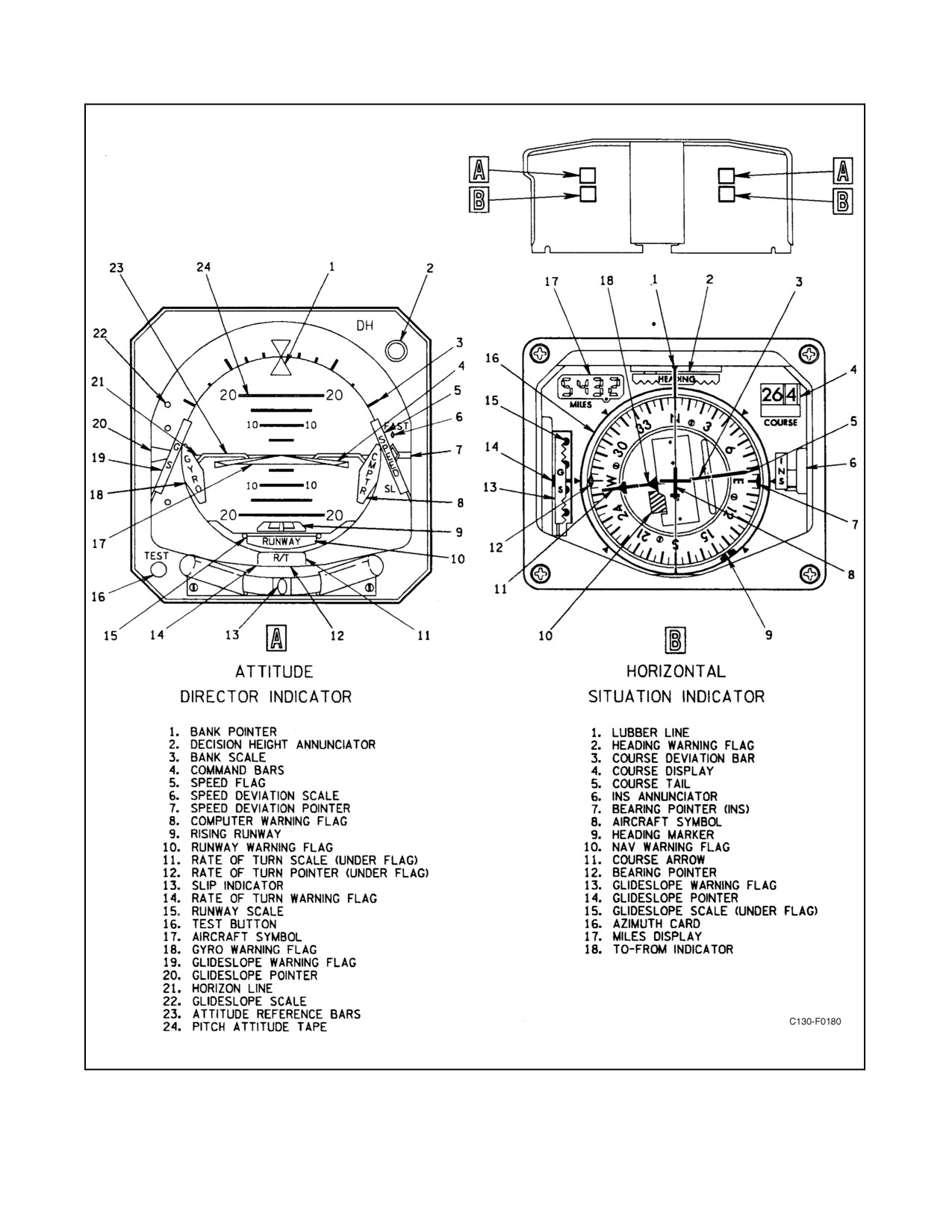
ADIs present a three-dimensional display of aircraft attitude, steering commands, localizer and glideslope deviation,
rate of turn, aircraft slip or skid, radar altitude, and decision height (see Figure 2-126). When the autopilot is coupled,
the ADI is used to monitor autopilot performance. When the autopilot is not coupled, the pilot uses the display to
manually fly the aircraft. The following paragraphs describe the ADI.
2.21.23.1.1 Aircraft Symbol and Attitude Display
A fixed delta-shaped symbol represents the aircraft. Aircraft pitch and roll attitude is displayed by the relationship
of the aircraft symbol to the movable attitude tape. Pitch indexes are shown on the attitude tape. The pitch attitude
tape is colored with a blue sky above a brown earth separated by a white horizon line; roll indexes show 10_, 20_,
30_, 45_, and 60_ of right and left bank. Two sources of pitch and roll attitude reference are available for use by the
attitude display: gyro attitude (GYRO ATT) or INS attitude (INS ATT). The source is controlled by the attitude select
switches located on the pilot and copilot instrument panel (see Figure 2-129). INS attitude is the primary attitude
reference.
2.21.23.1.2 Command Bars
The command bars display computed pitch and bank commands. These bars move up or down to command a climb
or descent and roll clockwise or counterclockwise to command a right or left bank. Theaircraft is maneuvered in roll
and pitch to align the aircraft symbol and command bars.
2.21.23.1.3 Glideslope Pointer and Scale
The glideslope pointer represents the center of the glideslope beam and displays vertical aircraft displacement from
the glideslope-beam center. The center of the glide-slope scale represents the aircraft. When the pointer is deflected
upward, the aircraft is below the glidepath. This is displacement information only; pitch commands are presented
by the pitch command bars. The glideslope pointer is in view only when the navigation receiver is tuned to a localizer
frequency. It is not in view during a back-course approach.
2.21.23.1.4 Runway Symbol
The rising runway symbol represents a combination of radio altitude and expanded-scale localizer information. It
depicts aircraft altitude relative to the runway during the last 200 feet of descent. Left and right movement displays
the aircraft deviation from localizer center. Full-scale deflection (outside marks) is equivalent to the inner dots on
the HSI (approximately 1-1/4_ from the localizer center-line). Up and down movement is controlled by the
radio/radar altimeter. Vertical movement begins at 200-feet radio/radar altitude and is marked in 50-foot increments.
The symbol comes into view and displays information when a reliable localizer signal is being received.
ORIGINAL
2-288
01-75GAL-1
Figure 2-126. FCS 105 Flight Control System Indicators
2-289
ORIGINAL
01-75GAL-1
2.21.23.1.5 Decision Height Annunciator
On C-130T aircraft prior to 164993, the radar altimeter illuminates the decision height annunciator at the preselected
radar altitude set on the CARA indicator. On C-130T aircraft 164993 and up, the radar altimeter illuminates the pilot
and copilot decision height annunciators at the preselected radar altitude set on the respective (pilot/copilot) CARA
indicator.
2.21.23.1.6 Slip Indicator (Inclinometer)
The slip indicator or inclinometer displays aircraft slip or skid. The inclinometer consists of a weighted ball in a
liquid-filled, curved glass tube.
2.21.23.1.7 Rate-of-Turn Pointer
The rate-of-turn pointer displays aircraft rate of turn about the yaw axis. A two-needle width deviation shows a
standard rateturn of3_persecond;aone-needlewidth deviationshows ahalf-standard rateturn of1-1/2_ persecond.
2.21.23.1.8 Speed Deviation Pointer and Speed Flag
The speed deviation pointer and SPEED flag are used to display the difference between actual aircraft speed and a
computed optimum speed as manually set on the pilot airspeed indicator. When speed exceeds the target speed by
approximately 20 knots, the pointer is deflected out of view. When approximately 20 knots below target speed, the
pointer remains in view. When not in use, the pointer is deflected out of view.
Note
The SPEED flag remains out of view any-time dc power is applied to the
system anddoes notindicateproperoperation ofthesystem.When inview,
it indicates only that power is off.
2.21.23.1.9 Test Switch
TheTEST pushbuttonswitch permitspartial testingoftheADIpitchand rollservo systems.Pressing thispushbutton
causes the attitude display to change by 10_ (+3_) pitchup and 20_ (-5_) right bank. The gyro flag also appears.
2.21.23.1.10 ADI Warning Flags
1. Glideslope (GS) warning flag — When VOR/ILS 1 or VOR/ILS 2 has been selected on the NAV SEL switch
and the receiver set on a localizer frequency, the glideslope warning flag appears when the glideslope deviation
being displayed is unreliable. All glideslope-related vertical commands are unusable while the flag is in view.
The glideslope warning flag is removed from view in the back-course mode.
2. Computer (CMPTR) warning flag — The CMPTR warning flag indicates that any steering commands from
the flight computerto theassociated ADIcommand bars and autopilot (if coupled)are unreliablefor themode
selected. When the flag appears, the command bars go out of view.
3. Runway warning flag — The RUNWAY warning flag indicates that the runway symbol information is
unreliable. An unreliable localizer signal causes the flag to come into view. A CARA malfunction or a failure
of the symbol to follow input signals causes the flag to come into view.
4. GYRO warning flag — The GYRO warning flag indicates that the attitude information being displayed may
be incorrect. The cause of the flag may be because of a malfunction of or loss of power to the vertical reference
furnishing attitude information or internal failure of the attitude display mechanism.
5. Rate of turn (R/T) warning flag — The R/T warning flag indicates that the rate-of-turn pointer is unreliable.
A malfunction of or loss of power to the turn rate gyro will cause the flag to come into view.
ORIGINAL
2-290
01-75GAL-1
2.21.23.2 Horizontal Situation Indicator
HSIs display a pictorial view of an aircraft with respect to magnetic north, selected course, and selected heading (see
Figure 2-126). Selected heading and course are read against a servo-driven azimuth card. Digital miles and course
displays are provided. Meter movements display course deviation, to-from indication, and glideslope deviation.
Warning flags monitor the azimuth card and navigation and glideslope signals. Remote selection of course and
heading are controlled by the course indicator remote HDG and COURSE control knobs. The following paragraphs
describe the HSI.
2.21.23.2.1 Aircraft Symbol
The aircraft symbol shows aircraft position and heading in relation to the azimuth card, course deviation bar, and
heading marker.
2.21.23.2.2 Azimuth Card
The rotating azimuth card displays magnetic heading information from its respective C-12 compass system. If INS
or Omega is selected with the NAV SEL switch, the card displays heading information from the selected system.
When INS is selected, the heading is true unless modified by a manual conversion to magnetic heading. When Omega
is selected, the heading is true and, during turns, there will be small jumps of the azimuth card because of the delay
in the ONS processing the heading. The jumps will depend upon the rate of turn and, under normal conditions, will
be in very small increments. The heading is read on the azimuth card beneath the lubber line.
2.21.23.2.3 Heading Marker
The heading marker is set to the desired heading as read on the azimuth card by rotating theHDG knob on theremote
heading and course selector control panel.
2.21.23.2.4 Course Arrow
The course arrow is set to the desired course with the COURSE knob on the remote heading and course selector
control panel. When INS or ONS data is displayed, the course arrow is driven to the desired course. The course tail
displays the reciprocal of the course arrow and is read with respect to the azimuth card.
2.21.23.2.5 Course Display
The course display on the upper right corner of the HSI displays a digital readout of course indicated by the course
arrow. When INS or Omega is selected with the NAV SEL switch, the course display will be the desired course.
2.21.23.2.6 Course Deviation Bar
The course deviation bar represents the centerline of the VOR, TACAN, or localizer course. When INS or ONS data
is displayed, the course deviation bar displays crosstrack deviation.
2.21.23.2.7 Miles Display
The miles display on the upper left corner of the HSI provides a digital readout of distance in nautical miles. This
distance information is provided from the No. 1 TACAN system, when operating, for the pilot HSI as long as the
pilot NAV SEL switch is in any position except TAC2 ONSorINS1. Similarly,distanceinformationfrom theNo. 2
TACAN system is displayed on the copilot HSI whenever system No. 2 is operating and the copilot NAV SEL switch
is in any position except TAC 1, ONS, or INS 2. The miles display goes blank when receiving an unreliable distance
signal.
2-291
ORIGINAL
01-75GAL-1
2.21.23.2.8 To-From Indicator
The to-from indicator reflects the direction to or from the VOR or TACAN station. The indicator arrow is not visible
when a localizer frequency is selected. When the HSI displays INS or ONS data, the to-from indicator reflects the
direction to the TO waypoint.
2.21.23.2.9 Bearing Pointer
When VOR is selected, the diamond-shaped pointer displays bearing to the navigational aid. When INS is selected,
the INS actual track is read against the azimuth card on the “T” end of the pointer.
2.21.23.2.10 Glideslope Pointer
The glideslope pointer represents the center of the glideslope beam and displays glideslope position above or below
theaircraft. When thepointeris abovetheglideslopescalecenterline, theaircraft is below theglideslope. Thepointer
isinviewonlywhenthenavigationreceiveristunedtoavalidlocalizerfrequencyandtheFCS105isnotintheBACK
LOC mode.
2.21.23.2.11 INS Annunciator
The INS annunciator appears when the inertial navigation system is the source of navigation data displayed on the
HSI.
2.21.23.3 HSI Warning Flags
2.21.23.3.1 Heading Warning Flag
The heading warning flag indicates an unreliable heading signal.
2.21.23.3.2 Navigation Warning Flag
The NAV warning flag indicates an unreliable navigation signal.
2.21.23.3.3 Glideslope (GS) Warning Flag
TheGS warning flag indicates an unreliableglideslopesignal. The GS flag is out ofview except when thenavigation
receiver is tuned to a localizer frequency and the FCS 105 is not in BACK LOC mode.
2.21.23.4 Flight Selector (FLT SEL) Panels
FLT SEL panels provide separate mode control over the No. 1 and 2 flight computers (see Figure 2-127). Each flight
selector panel is configured with solenoid-held pushbuttons (push on, push off) used for flight mode selection. An
FCS 105 flight mode can be engaged by depressing the desired mode pushbutton. If the pushbutton remains
depressed, the green ON flag at the bottom of the pushbutton appears and the mode is engaged. Depressing an engaged
pushbutton again will disengage the flight mode. Light intensity for the pushbutton is controlled through the PILOT
CENTER STAND & PILOTS SIDE PANEL lights switch. When a flight mode is engaged, steering commands from
the flight computer will be displayed on the corresponding attitude director indicator command bars. The auto-pilot,
if engaged, can be coupled to either of the two flight computers by depressing the AP CPLD push-button. Once
engaged, the autopilot will accept steering commands from the selected flight computer. HDG and NAV LOC are
lateral modes, and APPR is a combination of both lateral and vertical modes. The ALT SEL (altitude preselect), ALT
(altitude hold), VS (vertical speed hold), and IAS (indicated airspeed hold) are vertical modes and require prior lateral
modeengagement beforethey will engage. When lateral modes, including go-around, arenot engaged, thecommand
bars are out of view, the flight computer is in the off mode, and the autopilot will not couple. Pitch attitude hold
steering is provided when a lateral mode is engaged without a vertical mode being selected. The flight selector
pushbuttons are described in the following paragraphs.
ORIGINAL
2-292
01-75GAL-1
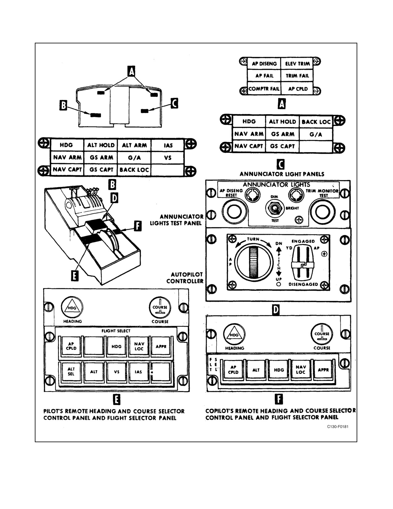
Figure 2-127. Flight Control System Controls and Annunciator Lights
2-293
ORIGINAL
01-75GAL-1
2.21.23.4.1 AP CPLD
This pushbutton engages theautopilot coupled mode. In this mode, flight computersteering commands for themode
selected will control the autopilot. The flight selector panel on which the pushbutton is depressed determines which
flight computer will control the autopilot. Depressing the opposite AP CPLD pushbutton releases the prior
pushbutton and transfers control to the opposite computer. Disengaging the autopilot releases the AP CPLD
pushbutton.
2.21.23.4.2 HDG
Thispushbuttonengagestheheadingselectmode.Lateral steeringcommands arecontrolled throughtheHSIheading
marker. Maximum bank angle command during this mode is 25_. Depressing the NAV LOC or APPR pushbutton
or selecting the go-around mode automatically disengages the HDG pushbutton.
2.21.23.4.3 NAV LOC
This pushbutton engages a lateral NAV mode. In this mode, a lateral steering command is provided to capture and
track the NAVAID selected by the NAV SEL switch. Prior to the capture point, heading-select-mode steering is
provided. Bank angle commands are limited to 25_ during capture. The bank limit during track is 8_ for VOR, 30_
for INS or ONS, and 15_ for localizer. Depressing either the HDG or APPR pushbutton or selecting the go-around
mode automatically disengages the NAV LOC pushbutton.
2.21.23.4.4 APPR
This pushbutton engages the approach mode, which is the same as NAV LOC mode, with the addition of glideslope
guidance. With ILS selected by the NAV SEL switch, this mode will provide lateral and vertical steering commands
to intercept and track localizer and glideslope beams. Prior to localizer capture, heading select mode steering is
provided. Unless altitude hold is engaged, pitch attitude hold mode is provided. Bank angle limit during localizer
capture is 25_, being reduced to 15_ on track. Following glideslope capture, pitch angle commands are limited to
20_. Depressing the HDG or NAV LOC pushbutton or selecting the go-around mode automatically disengages the
APPR pushbutton.
2.21.23.4.5 ALT SEL
The altitude preselect mode is functional only on the No. 1 flight computer. In the ALT SEL mode, the flight control
system is armed to captureapreselected altitudeas set in thealtitudealerter/preselect control. Inthearmedcondition,
IAS, or VS vertical mode may be selected and flown to capture the selected altitude. The system will remain armed
until the preselected altitude is captured. At capture, the ALT HOLD annunciator light illuminates, a smooth
transition from either ascent or descent is made, and the desired altitude is maintained. After capture, a new altitude
may be selected on the altitude alerter/preselect control and the system will be commanded to ascend or descend to
the newly selected altitude. The ALT SEL mode is automatically released when autopilot controller pitch control is
moved from the detent.
2.21.23.4.6 ALT
This pushbutton engages the altitude hold mode. Vertical steering commands are provided to maintain pressure
altitude present when the pushbutton was depressed. This mode disengages if the existing lateral mode is disengaged,
glideslope capture during ILS occurs, go-around mode is engaged, or the pitch control is moved out of detent prior
to glideslope capture with the autopilot coupled to the flight computer.
2.21.23.4.7 VS
The vertical-speed hold mode is functional only on the No. 1 flight computer. In the VS hold mode, the flight
computer uses pitch attitude and a vertical speed error signal to generate steering commands. These steering
commands are to maintain the vertical speed at which the VS mode was selected. The VS mode is automatically
ORIGINAL
2-294
01-75GAL-1
released when the glideslope is captured, another vertical mode is selected, or when the flight control system is
engaged and coupled and the autopilot controller pitch control is moved out of the detent.
2.21.23.4.8 IAS
The IAS hold mode is functional only on the No. 1 flight computer. In the IAS hold mode, the flight computer uses
pitch attitude and an indicated airspeed error signal to generate vertical steering commands. These steering
commands are to maintain the indicated airspeed at which the IAS mode was selected. The IAS mode is automatically
released at glideslope capture, when another vertical mode is selected, or when the flight control system is engaged
and coupled and the autopilot controller pitch control is moved out of the detent.
2.21.23.5 Aircraft Control Wheels
Located on the outboard side of the pilot and copilot, control wheels contain a sync (SYN) pushbutton and a
go-around (G/A) pushbutton (see Figure 2-47).
2.21.23.5.1 SYNC (SYN) Pushbutton
The SYN pushbutton is primarily used as an attitude-director indicator function. Its secondary function is to provide
synchronized control wheel steering with the basic autopilot engaged. Each pushbutton separately affects its
respective flight computer only. Pressing a pushbutton when the autopilot is disengaged synchronizes the ADI pitch
command bars with the aircraft attitude. When the sync pushbutton is released, the command bar is referenced to the
aircraft attitude at the moment of release. If agreement between the pilot and copilot ADI is desired, both sync
pushbuttons must be activated at about the same time, or the second one must be activated when the first command
bar is aligned with the aircraft symbol. Pressing a pushbutton during autopilot operation allows the aircraft to be
manually flown to the desired attitude without disengaging the basic autopilot. Upon actuation, the autopilot coupled
and any coupled vertical flight mode will be disengaged. When the sync pushbutton is released, the autopilot coupled
and any desired vertical flight mode must be reengaged. If the flight computer is in the APPR mode, pressing the
SYN pushbutton will have no effect after glideslope capture.
2.21.23.5.2 Go-Around (G/A) Pushbutton
Go-around is selected by pressing the G/A pushbutton on either control wheel. Actuating either push-button
disengages the autopilot, releases all mode pushbuttons on the flight selector panel, and provides signals from the
flight computer to the command bars for a wings-level, 7_ pitchup attitude. The autopilot may then be reengaged,
if desired.
2.21.23.6 Autopilot Controller
Theautopilot controllercontains theyaw damper(YD) and autopilot (AP)engage levers and autopilot turn and pitch
controls (see Figure 2-127). Placing the engage levers to ENGAGED couples the flight control system rudder,
aileron, and elevator servos to the aircraft main surface control-cable system. Autopilot engagement also maintains
automatic pitch trim through the elevator trim tab system.
2.21.23.6.1 Engage Lever
The engage lever is a dual section lever having two positions: ENGAGED and DISENGAGED. This solenoid-held
lever is spring loaded to the DISENGAGED position. The lever is mechanically designed such that the autopilot
cannot be engaged without yaw damper engagement. However, the yaw damper may be engaged independent of the
autopilot lever. (Pilot-initiated autopilot disengagement will release the levers from the solenoid-held ENGAGED
position.) Automatic release occurs if selected attitude reference failure is detected, failure of the servo motors is
detected, system power is lost, manual elevator trim is attempted, or the ELEV TAB power selector switch is moved
from the NORMAL position. The engage lever is the master disconnect for both systems.
2-295
ORIGINAL
01-75GAL-1
Onaircraft 165313and upwhen disengagingtheautopilotsystem usingthe
control wheel elevator trim (ELEV TRIM) switches, you must manually
select the yaw damper (YD) switch to DISENGAGE prior to landing.
Failure to ensure yaw damper disengagement may cause significant
resistance to pilot-initiated rudder pedal inputs with loss of normal control
authority, damage to the aircraft and injury to personnel. Normal use of the
AP disconnect switches will disengage both the autopilot and yaw damper
switches.
When the autopilot engage lever is in the ENGAGED position, elevator tab control is transferred from the pilot to
the autopilot, allowing the autopilot to automatically maintain pitch trim and preventing abrupt elevator movements
when the autopilot is disengaged.
2.21.23.6.2 PITCH Control
When the autopilot is engaged and not coupled, the PITCH control supplies pitch commands to the autopilot system.
The PITCH control supplies a pitch rate command that increases in proportion to control displacement from the center
detent. Pitchdown is commanded when the control is rotated forward toward DN, and pitchup is commanded when
thecontrol is rotated aft toward UP. Thepitch control is spring loaded to acenterdetent. When engaged, theautopilot
maintains the aircraft pitch attitude that exists when the control is returned to the detent.
Moving the PITCH control out of the detent with the autopilot coupled causes the altitude hold (ALT), altitude
preselect (ALT SEL), indicated airspeed hold (IAS), and vertical speed hold (VS) modes to release, placing the
autopilot and flight computer in the pitch hold mode. The PITCH control is disabled by glide-slope capture.
Note
Refer to paragraph 2.21.23.4 for operation of the attitude select switches.
2.21.23.6.3 TURN Control
When the autopilot is engaged, the TURN control supplies bank command to the autopilot system. It is a roll-rate
command that increases in proportion to the TURN control displacement from the center detent. The TURN control
is also spring loaded to a center detent. Rotating the TURN control out of detent with the autopilot coupled causes
all mode pushbuttons of the respective flight selector to release. Bank-angle limit during turn control operation is
30_. When the aircraft bank attitude is greater than 2_ and the TURN control is returned to the center detent, the
autopilot holds bank attitude. When the aircraft bank attitude is less than 2_ and the control is returned to the detent,
the autopilot remains in heading hold.
2.21.23.7 Autopilot Release Switch
An autopilot release pushbutton switch is installed on both the pilot and copilot control wheels. Pressing either one
ofthepushbutton switches releases theAPand YDswitches, allowingthem toreturn totheDISENGAGEDposition,
disconnecting the servos from each axis.
ORIGINAL
2-296
01-75GAL-1
Onaircraft 165313and upwhen disengagingtheautopilotsystem usingthe
control wheel elevator trim (ELEV TRIM) switches, you must manually
select the yaw damper (YD) switch to DISENGAGE prior to landing.
Failure to ensure yaw damper disengagement may cause significant
resistance to pilot-initiated rudder pedal inputs with loss of normal control
authority, damage to the aircraft and injury to personnel. Normal use of the
AP disconnect switches will disengage both the autopilot and yaw damper
switches.
2.21.23.8 AP Disengage Reset Switch
The AP DISENG RESET pushbutton switch is located on the annunciator lights test panel (see Figure 2-127). This
pushbutton switch extinguishes the AP DISENG annunciator light.
2.21.23.9 Remote Heading and Course Selector Control Panel
The remote heading and course selector control panels are located on the flight control pedestal (see Figure 2-127).
The HDG and COURSE knobs on each panel position the heading marker and course arrow on the respective HSI.
2.21.23.10 System Annunciator Lights
There are four annunciator light panel assemblies, two annunciator warning or advisory light panels, and two flight
selector mode annunciator panels. One of each of these panels is located on the pilot instrument panel and one each
on the copilot instrument panel (see Figure 2-127). The warning or advisory annunciator lights are as follows:
1. AP DISENG (amber) — Illuminates when the autopilot is disengaged.
2. AP FAIL (red) — Illuminates when monitoring system indicates gyro, power, servo, or internal failure.
3. COMPTR FAIL (red) — Illuminates whenever flight computer or mode input fails. Indicates that the flight
selector panel or failed mode must not be used. Attitude information is still supplied to the ADI and autopilot
for basic gyro mode, provided failure was not because of the gyro.
4. ELEV TRIM (amber) — The elevator servo is sensing an out-of-trim condition. Pilot should expect to see
elevator trim moving to satisfy the trim requirements, at which time the light will extinguish.
5. TRIM FAIL (red) — Illumination indicates the monitoring system is sensing a trim system failure. The pilot
should anticipate an out-of-trim condition upon disengagement of the autopilot.
6. AP CPLD (green) — Illuminates on pilot panel when autopilot is coupled to the No. 1 flight computer and
on copilot panel when coupled to the No. 2 flight computer.
The flight-selector-mode annunciator lights are illuminated to indicate the following:
1. HDG (green) — Bank command is responding to heading marker selection on HSI.
2. ALT HOLD (green) — Pitch command is responding to barometric altitude existing at time of ALT HOLD
engagement.
2-297
ORIGINAL
01-75GAL-1
3. BACK LOC (green) — Back localizer mode active in NAV LOC. Glideslope pointer and flag are biased out
of view. If APPR is engaged, GS pointer and flags are biased out of view and GS ARM and GS CAPT
annunciator lights are inhibited.
4. NAV ARM (white) — System is set up (armed) for a capture of set course.
5. NAV CAPT (green) — Capture of set course has been initiated.
6. GS ARM (white) — System is set up (armed) for a capture of glideslope.
7. GS CAPT (green) — Glideslope capture has been initiated.
8. G/A (green) — The flight computer is in the go-around mode.
9. ALT ARM (white)— System is armed to captureapreselected altitude. Pitch command is responding to pitch
attitude existing at time of ALT SEL engagement.
10. VS (green) — System is using pitch attitude and a vertical speed error signal to generate steering commands.
11. IAS(green)—System isusing pitchattitudeandan indicatedairspeed errorsignal togenerateverticalsteering
commands.
2.21.23.11 ANNUNCIATOR LIGHTS Test Switch
Theannunciatorlights test switch is located on thepedestal (seeFigure2-127). This three-position switch has TEST,
BRIGHT, and DIM positions.
2.21.23.12 TRIM MONITOR TEST Switch
The TRIM MONITOR TEST switch is located on the pedestal (see Figure 2-127). This switch is used to test the
autopilot automatic trim circuitry and annunciator lights. The test must be performed while the aircraft is on the
ground.
2.21.23.13 NAV SEL Switches
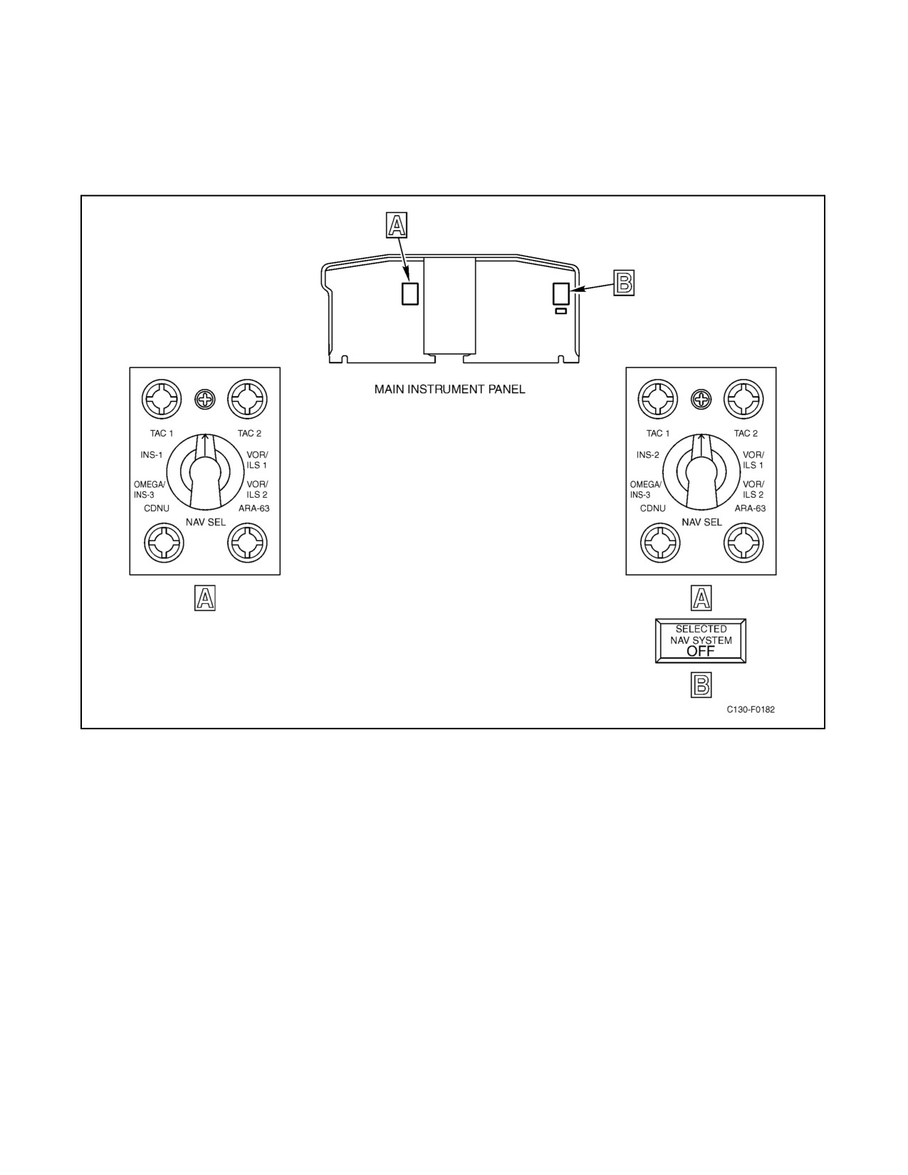
There are two navigation selectorcontrol panels (see Figure2-128) located on thepilot and copilot instrument panel.
Each panel contains a NAV SEL switch. The multiposition NAV SEL switches are provided to connect a navigation
system to the HSIs and the flight control system computers. Eight positions (CDNU, OMEGA INS 3, INS 1 (pilot),
INS 2 (copilot), TAC 1, TAC 2, VOR/ILS 1, VOR/ILS 2, ARA-63) are available on the pilot and copilot switches.
2.21.23.13.1 NAV SEL Switch Modes of Operation
INS Selection
When INS 1 (pilot) or INS 2 (copilot) or INS 3 (if installed) is selected with the corresponding NAV SEL switch,
information from the INS is provided to the flight control system (FSC 105). The course arrow is controlled by the
INS computer to display desired track information. The course deviation indicates cross-track displacement with full
scale (2 dots) being equivalent to 7.5 nm. The azimuth card displays true heading (or magnetic heading when variation
is inserted into the INS) from the INS, and the to-from indicatorreflects direction to theset waypoint. With theNAV
LOC pushbutton on the flight selector panel depressed, the flight computer is placed in the INS NAV mode and
produces guidance commands to capture and maintain the desired track. Two minutes prior to a waypoint the alert
annunciator on the CDU illuminates. If the function selector switch on the CDU is in AUTO, the INS automatically
switches from the present track to the next track at a computed point prior to reaching the waypoint. When this occurs,
ORIGINAL
2-298
01-75GAL-1
the new course is displayed on the HSI, the alert annunciator extinguishes, and a guidance command is produced to
capture and maintain the new track. If the function selector is in MAN, automatic switching does not occur and the
command is along the extended desired track beyond the waypoint. The alert annunciator light begins to flash
30 seconds prior to reaching a waypoint and continues to flash until the operator initiates a track change.
Figure 2-128. Navigation Selector Control Panels
TAC 1, TAC 2 (TACAN) Selections
With the NAV SEL switch in TAC 1 or TAC 2 and the FLT SEL switch in NAV LOC, the associated flight computer
will be in the NAV LOC mode after capture of the set course (NAV CAPT), using information from the selected
TACAN system that is tuned to the desired station. The course arrow on the associated HSI is set to the selected
TACAN radial to supply a course-error signal (difference between aircraft heading and set course) to the flight
computer and to resolve the signals from the TACAN receiver. The flight computer combines course-error input with
course deviation and bank angle to produce a steering command for display on the ADI command bars and for use
by the autopilot if coupled. This command will provide an asymptotic intercept after capture of the set course (NAV
CAPT). Once on course it will be maintained. When overstation is sensed, bank commands because of course
deviation are minimized and course changes can be made to intercept the new outbound course. The computer
warning flag remains out of view as long as the computer functions properly and is receiving valid information. All
otherflagsintheADIremainout ofview. Informationdisplayed ontheHSIconsists ofcoursedeviationon thecourse
deviation bar, distance to the station on the miles display, and ambiguity on the to-from indicator. The outer mark
(dot) on course deviation scale is equal to 10. The NAV warning flag remains out of view while a valid signal from
the TACAN set is maintained.
2-299
ORIGINAL
01-75GAL-1
VOL/ILS Selection
With the NAV SEL switch in VOR/ILS I or VOR/ILS 2, and the FLT SEL switch in NAV LOC, the flight computer
will be in the NAV LOC mode when the corresponding NAV receiver is tuned to a VOR or localizer frequency. When
the NAV receiver is tuned to a VOR frequency, information displayed on the HSI and the ADI is the same as described
for TACAN. Distance information is not available unless TACAN is tuned and DME is valid. When the NAV
receiver is tuned to a localizer frequency, the NAV SEL switch is in VOR/ILS 1 or VOR/ILS 2, and the FLT SEL
switch is in APPR, the flight computer selects the ILS mode. The flight computer now uses information from the
localizer and glideslope receivers. The course arrow on the HSI must be set to the inbound localizer course. The ADI
runway flag uncovers the runway symbol as long as valid information is being received and the navigation receiver
and radar altimeter are functioning properly. The glideslope warning flag remains out of view as long as valid
information is being received and the glideslope receiver is functioning properly. Localizer deviation is displayed
by thecoursedeviation baron theHSIand by therunway symbol on the ADI. No ambiguity information is available.
The glideslope pointer continues to give glideslope deviation. The flight computer produces the necessary steering
commands to the ADI command bars and autopilot to intercept and track the localizer and glideslope beam centers.
If the autopilot is coupled, the aircraft will be controlled automatically by the autopilot. The point for start of localizer
capture is variable depending on the intercept angle, rate of closure on beam center, and course deviation. Once this
point is reached, the flight computer combines course error, localizer deviation, and bank angle to capture and then
maintain beam center. Glideslope capture occurs at a fixed glideslope deviation and can be accomplished from above
or below the beam. When the capture point is reached, a pitch up or down command is produced. Once the glideslope
is captured, the flight computer uses the glideslope deviation, normal acceleration, and pitch angle to command a
pitch attitude to maintain beam center. The glideslope signal is desensitized as a function of radar altitude or marker
beacon to reduce the effects of beam narrowing, noise, and bends.
ARA-63 Selection
With the NAV SEL switch in the ARA-63 position, the attitude director indicator command bars will display lateral
and vertical deviations from the optimum approach line.
CDNU Selection
When CDNU is selected with the NAV SEL switch, information from the CDNU is provided to the flight control
system (FSC-105) and HSI. The course arrow is controlled by the CDNU to display desired track information and
distance to the next waypoint will be displayed. Full scale displacement on the course deviation indicator will be
determined by the flight mode. The flight mode is set via the CDNU expanded FPLN page and displayed on the
annunciator panel. Maximum deviations for each mode are as follows:
1. EN ROUTE mode — Full scale deflection on the HSI equals 4.0 nm. NAV invalid flag will appear on HSI
if GPS estimated horizontal error (EHE) exceeds 1,000 meters.
2. TERMINAL mode — Full scale deflection on the HSI equals 1.0 nm. NAV invalid flag will appear on HSI
if GPS EHE exceeds 500 meters.
3. APPROACH mode — Full scale deflection on the HSI equals .3 nm. NAV invalid flag will appear on HSI
if GPS EHE exceeds 100 meters.
The HSI azimuth card will display either true or magnetic heading based on the reference source selected on the
CDNU INAV RNAV page and the to-from indicator will point in the direction of the set waypoint. With the NAV
LOCpushbuttonontheflightselectorpaneldepressed,theflightcomputerproduces guidancecommands tomaintain
the desired track. Upon passing a waypoint, sequencing to follow-on waypoints is automatically controlled by the
CDNU and new track, distance, and guidance commands to capture and maintain the new track are displayed on the
HSI.
ORIGINAL
2-300
01-75GAL-1
2.21.23.14 Pointer Selector Switch
Pointer selector switches, located on the pilot and copilot instrument panels and on the navigator instrument panel,
are provided to permit selection of the source of information to be displayed on BDHIs. The pilot and copilot can
selectively direct VOR 1 or VOR 2 information on the No. 1 pointer of the VOR/TAC BDHI located on their
respective instrument panels; the navigator can selectively direct TAC 1 or ADF 2 information to the No. 2 pointer
on the ADF/TAC BDHI or can selectively direct VOR 2 or TAC 2 information to the No. 2 pointer of the VOR/TAC
BDHI.
2.21.23.15 SELECTED NAV SYSTEM OFF Indicator
The SELECTED NAV SYSTEM OFF indicator, located on the copilot instrument panel, will illuminate to indicate
that the copilot selection with his NAV SEL switch has been disconnected (see Figure 2-128). Selection of a
VOR/ILS, TAC, ARA-63, or Omega/INS 3 mode by the copilot will be disconnected if the pilot selects the same
mode of operation. For INS mode, the pilot selects No. 1 and the copilot No. 2 exclusively. The SELECTED NAV
SYSTEM OFF indicator is powered through the circuit breaker associated with the system selected by the pilot and
is affected by the interlock relays of both the pilot and copilot NAV SEL switches.
2.21.23.16 Operational Checkout of the FCS 105 Flight Control System
CAUTION
As the autopilot is engaged, hold the control wheel and rudder pedals to
cushion rapid movement against the limit stops. Accomplish the checks
with autopilot engaged as rapidly as practical to avoid servo overheating.
Note
Copilot AC INST switch and the ELEV TAB power switch must be in the
NORMAL position. If the G/A annunciator light(s) is illuminated, press
the SYN pushbutton on the corresponding control wheel to extinguish the
light.
1.
Check flight control system annunciator lights in TEST.
2.
Test both attitude director indicators. Check that the attitude display indicates a change of 10_ ±3_ pitchup
and 20_ ±5_ right bank, and that the gyro warning flag comes into view.
3.
Set both heading markers to the lubber line.
4.
Center all flight controls.
5.
Engage autopilot.
6.
Relax centering force on column. Observe that elevator trim tab is driving nose up and both ELEV TRIM
annunciator lights are illuminated.
7.
Slowly exert a back force on the control column until a nosedown trim direction is observed; hold this column
position. Press and hold the TRIM MONITOR TEST switch. Check that the TRIM FAIL warning annunciator
light starts flashing, the ELEV TRIM annunciator light remains illuminated, and the elevator trim tab begins
driving in the noseup direction. Release TRIM MONITOR TEST switch and observe that the TRIM FAIL light
2-301
ORIGINAL
01-75GAL-1
extinguishes, the ELEV TRIM light remains illuminated, and the elevator trim tab again moves in the
nosedown direction. Relax back force until the control column is centered.
8.
Depress HDG and ALT pushbutton on both FLT SEL panels. Depress AP CPLD pushbutton on No. 1 FLT
SEL panel. Check that the pilot AP CPLD annunciator light illuminates. Check that the pilot and copilot HDG
and ALT HOLD annunciator lights illuminate.
9.
Move pilot and copilot heading markers 5_ right of the lubber line. Check that the control wheel turns right
and both ADI command bars indicate right bank command. Return both heading markers to lubber line.
10.
Depress AP CPLD pushbutton on No. 2 FLT SEL panel. Check that the copilot AP CPLD annunciator light
illuminates and the pilot AP CPLD annunciator extinguishes.
11.
Move pilot and copilot heading markers 5_ left of the lubber line. Check that the control wheel turns left and
both ADI command bars indicate a left bank command. Return both heading markers to the lubber line.
12.
Depress the pilot G/A pushbutton. Check the following:
a. The YD and AP switches move to the DISENGAGED position.
b. The pilot command bars indicate a 7_ pitchup command above zero attitude reference.
c. The pilot G/A annunciator light illuminates.
d. Both AP DISENG annunciator lights illuminate.
e. HDG and ALT hold annunciator lights extinguish.
13.
Depress the pilot SYN pushbutton. The G/A annunciator light will extinguish and the pilot command bars will
be removed from view.
14.
Engage the autopilot.
15.
Repeat steps 12 and 13 substituting the word “copilot” for “pilot.”
16.
Engage the autopilot and depress the HDG, ALT, and AP CPLD pushbuttons on No. 1 FLT SEL panel. Slowly
rotate the autopilot pitch control toward UP. After aft-column movement, rotate the autopilot pitch control
toward DN. Center column with the autopilot pitch control. Check that the ALT HOLD annunciator light is
extinguished.
17.
Slowly rotate autopilot turn control to the right. After right control wheel movement is observed, rotate
autopilot turn control left past the center detent. After control wheel rotates left past center, check that HDG
and AP CPLD annunciator lights are extinguished.
18.
Depress pilot autopilot release switch. The AP and YD switches will move to the DISENGAGED position
and the AP DISENG annunciator lights will illuminate.
19.
Engage the autopilot.
20.
Repeat step 18 using copilot release.
21.
Depress the AP DISENG reset switch and check that the AP DISENG annunciator light extinguishes.
22.
Zero the elevator trim tab.
ORIGINAL
2-302
01-75GAL-1
2.21.23.17 Normal Operation of the FCS 105 Flight Control System
Do not operate with the autopilot engaged during takeoff and landing or at
gross weights above 155,000 pounds. During ILS coupled approach, do not
operate with the autopilot engaged below 200 feet AGL.
Theautopilotmaybeusedforfour-orthree-engineoperationduringclimb,cruise,anddescent.Three-enginecoupled
approaches are not recommended. The autopilot is capable of intercepts up to 90_ (75_ during course ILS), but to
enhance intercept performance a maximum of 45_ is recommended.
Before engaging the autopilot:
1. Ensure that all flight control system circuit breakers are in.
2. Ensure that the No. 1 compass and flight control system attitude reference are operating properly.
3. Ensure that the ELEV TAB power selector switch is in the NORMAL position.
4. Trim the aircraft for straight-and-level flight.
Engaging basic autopilot:
1. Position the YD and AP switches to ENGAGED.
Note
Do not press the pilot ADI test pushbutton with the autopilot engaged.
Pressing the pilot ADI test pushbutton may cause a slight autopilot roll
reaction of momentary duration.
2. Maneuver the aircraft with the AP pitch and turn knobs on the autopilot controller.
CAUTION
Disengage autopilot and yaw damper prior to switching attitude reference.
2.21.23.17.1 Autopilot Coupled (AP CPLD)
The basic autopilot can be coupled to either of the two flight computers for automatic lateral and vertical guidance
in a selected flight mode. Coupling occurs with selection ofAP CPLD on oneof therespective FLT SEL panels after
any lateral mode is engaged.
2.21.23.17.2 Selected Heading (AP CPLD)
1. Engage the basic autopilot.
2. Set the heading marker on the HSI to the aircraft heading with the heading control knob.
2-303
ORIGINAL
01-75GAL-1
3. Depress the HDG pushbutton, then the AP CPLD pushbutton on the FLT SEL panel. The HDG and AP CPLD
annunciator lights illuminate.
4. For aircraft heading control, set the desired heading on the HSI heading marker. The autopilot will turn to and
maintain the set heading. The bank angle is limited to 25_ during selected heading mode.
2.21.23.17.3 VOR or TACAN Navigation (AP CPLD)
1. Engage the basic autopilot.
2. Tune the VHF NAV or TACAN receiver to the correct frequency and select VOR/ILS or TAC with the NAV
SEL switch.
3. Set the desired course on the HSI with the course control knob and set the heading marker to the desired
intercept heading with the HDG control knob.
4. Depress the NAV LOC pushbutton, then the AP CPLD pushbutton on the FLT SEL panel. The HDG, NAV
ARM, and AP CPLD annunciator lights illuminate and the aircraft will assume the selected intercept heading.
5. When the capture point is reached, the aircraft turns to capture the desired course. The HDG and NAV ARM
annunciator lights extinguish and the NAV CAPT annunciator light illuminates. The bank angle limit during
capture is 25_.
6. Onceoncourse,themaximumbankproduced bycoursedeviationis 8_.When passingoveraVOR orTACAN
station, this limit is further reduced to 3_. However, if a course change is made during overstation, a full bank
angle may be obtained since the bank limit caused by course error is 25_.
7. To initiate a new capture or manually place the system on course, depress the HDG pushbutton on the FLT
SEL panel, set the heading marker to the new intercept heading, then depress the NAV LOC pushbutton.
2.21.23.17.4 INS Navigation (AP CPLD)
To establish the aircraft on a desired track, perform the following:
1. Engage the basic autopilot.
2. With the INS set up to provide track information, place the CDU function selector switch to the AUTO
position.
3. Place the NAV SEL switch to the INS position. Observe proper HSI presentation.
4. Set the HSI heading marker to aircraft heading, using the HDG knob on the remote heading and course selector
control panel.
5. Depress NAV LOC pushbutton on the FLT SEL panel. The NAV ARM and HDG annunciator lights
illuminate, indicating that the system is armed for navigation capture.
6. Depress the AP CPLD pushbutton on the appropriate FLT SEL panel and observe that the AP CPLD
annunciator light illuminates. Set intercept angle with the heading marker.
7. When capture is initiated, the NAV ARM and HDG annunciator lights extinguish and the NAV CAPT
annunciator light illuminates. Once capture occurs, the steering is provided directly from the INS through the
flight computer. This INS-generated steering signal is bank limited at 30_.
ORIGINAL
2-304
01-75GAL-1
8. Two minutes before reaching a waypoint, the alert annunciator legend will illuminate. At 30 seconds prior to
reaching a waypoint, the to-from display will change to the next set of waypoints. When this occurs, the
ALERT annunciator legend extinguishes and the change is displayed on the HSI.
2.21.23.17.5 Altitude Preselect (AP CPLD)
1. Engage basic autopilot.
2. Set the altitude alerter/preselect control at the desired altitude.
3. Select a lateral mode and depress the ALT SEL pushbutton on the No. 1 FLT SEL panel. The ALT ARM
annunciator light illuminates and the command bars will display the command to ascend or descend to capture
the preselected altitude.
4. Depress the AP CPLD pushbutton on the No. 1 FLT SEL panel.
5. When the preselected altitude is captured, the ALT HOLD annunciator light illuminates. Depress the ALT
pushbutton. The ALT ARM annunciator light will extinguish and the ALT HOLD annunciator light remains
illuminated.
2.21.23.17.6 Altitude Hold (AP CPLD)
1. Engage basic autopilot.
2. Select a lateral mode and depress the ALT pushbutton on the FLT SEL panel. The command bars will display
the command to maintain the altitude at the time of selection.
3. Depress the AP CPLD pushbutton on the FLT SEL panel.
2.21.23.17.7 Indicated Airspeed Hold (AP CPLD)
1. Engage basic autopilot.
2. Select a lateral mode and depress the IAS pushbutton on the No. 1 FLT SEL panel. The command bars will
display the vertical steering command to maintain the airspeed at which the IAS mode was selected.
3. Depress the AP CPLD pushbutton on the No. 1 FLT SEL panel.
2.21.23.17.8 Vertical Speed Hold (AP CPLD)
1. Engage basic autopilot.
2. Select a lateral mode and depress the VS push-button on the No. 1 FLT SEL panel. The command bars will
display the vertical steering command to maintain the vertical speed at which the VS mode was selected.
3. Depress the AP CPLD pushbutton on the No. 1 FLT SEL panel.
2.21.23.17.9 ILS Approach (AP CPLD)
1. Tune and identify localizer station on both VHF NAV receivers.
2. Place the NAV SEL switch to VOR/ILS 1 on the pilot navigation selector control panel and VOR/ILS 2 on
the copilot navigation selector control panel.
2-305
ORIGINAL
01-75GAL-1
3.
Set the course arrows on the HSIs to the published localizer inbound course.
4.
Set decision height on the radar altimeter indicator.
5.
Set HSI heading markers to aircraft heading. Depress the HDG pushbutton on the FLT SEL panels. The HDG
annunciator lights will illuminate.
6.
Engage the basic autopilot and depress the AP CPLD pushbutton on the No. 1 or No. 2 FLT SEL panel. The
AP CPLD annunciator light on the side selected will illuminate.
7.
Depress the ALT pushbutton on the FLT SEL panels when constant altitude is to be maintained. The ALT
HOLD annunciator lights will illuminate.
8.
Depress the VS or IAS pushbutton on the No. 1 FLT SEL panel when constant vertical speed or constant
indicated airspeed is to be maintained. The VS or IAS annunciator light will illuminate as selected.
9.
Use the heading marker to fly the aircraft to the desired intercept angle. Depress the NAV LOC pushbutton
on the FLT SEL panels. The NAV ARM annunciator lights will illuminate.
10.
The aircraft assumes and maintains intercept heading until the capture point is reached, then turns to capture
the localizer course. The NAV ARM and HDG annunciator lights extinguish and the NAV CAPT annunciator
lights illuminate. Once established on localizer course, bank angle is limited to 15_.
11.
Prior to capture of glideslope, depress the APPR pushbutton on the FLT SEL panels. The GS arm annunciator
lights illuminate.
12.
After glideslope capture, monitor ILS progress on the ADI and HSI. The GS CAPT annunciator lights
illuminate, and the ALT HOLD and GS ARM annunciator lights extinguish.
13.
Disengage the autopilot when normal landing is to be executed (no lower than 200 feet AGL).
Note
The ADI command bars should be utilized to monitor the approach;
however, theglide-slopepointers and coursedeviation bars will beutilized
as primary indication for aircraft position when flying ILS.
2.21.23.17.10 Back-Course Localizer (AP CPLD)
1. Engage the basic autopilot.
2. Tune and identify localizer station on both VHF NAV receivers.
3. Place the NAV SEL switch to VOR/ILS 1 on the pilot navigation selector control panel and VOR/ILS 2 on
the copilot navigation selector control panel.
4. Set the course arrow on the HSIs to the published localizer inbound front course.
5. Set minimum descent altitude on the radar altimeter indicator.
6. Set HSI heading markers to aircraft heading. Depress the HDG pushbutton on the FLT SEL panels. The HDG
annunciator lights illuminate.
7. Depress the AP CPLD pushbutton on No. 1 or No. 2 FLT SEL panel. The AP CPLD annunciator light on the
side selected illuminates.
ORIGINAL
2-306
01-75GAL-1
8.
Depress the ALT pushbutton on the FLT SEL panels when constant altitude is to be maintained. The ALT
HOLD annunciator lights will illuminate.
9.
Use heading marker to fly aircraft to the desired intercept angle.
10.
After established on intercept heading, depress the NAV LOC pushbutton on the FLT SEL panels. The BACK
LOC annunciator lights will illuminate.
Note
When the BACK LOC annunciator light illuminates, the glideslope
pointers and warning flags will be removed from view.
11.
After capture has been initiated, all localizer indications will be the same as a normal ILS. Set heading markers
to back course.
12.
Disengage altitude hold and use the autopilot pitch control on the autopilot controller to establish and maintain
desired rate of descent.
Note
After disengaging ALT HOLD, all pitch indications on command bars are
referenced to a fixed pitch attitude as in paragraph 2.21.23.17.2.
13.
Disengage the autopilot at no lower than 200 feet AGL or before flying over the localizer transmitter.
Note
It is recommended that the HDG mode be used when flying over the
localizer transmitter because of large radio deviations.
2.21.23.17.11 Disengaging the Autopilot
Autopilot control is normally discontinued by either of the following actions:
1. Depressing the pilot or copilot autopilot release switch pushbutton.
2. Placing the YD and AP switches to the DISENGAGED position.
In addition, the autopilot may be disengaged by any of the following methods:
1. Positioning the ELEV TAB power selector switch out of the NORMAL position.
2. Actuating the ELEV TAB switch on the pilot or copilot control wheel.
3. Pulling the AUTOPILOT circuit breaker.
4. Depressing the pilot or copilot G/A pushbutton.
2.21.23.17.12 Attitude Director Indicator (Autopilot Disengaged)
TheADIcommand bars display steering guidancethat can beused by thepilot to control theaircraft manually during
takeoff, initial climb, cruise navigation modes, ILS approaches, and go-around maneuver. To satisfy the commands,
theaircraftmustbemaneuveredsothattheaircraftsymbolisflowninto thecommand barsuntil theyareinalignment.
2-307
ORIGINAL
01-75GAL-1
2.21.23.17.13 Cruise Modes (NAV LOC)
The procedures and results using the ADI command bar steering during cruise navigation modes are the same as the
autopilot, except the autopilot is disengaged and the pilot controls the aircraft to maintain command bar alignment
with aircraft symbol.
2.21.23.17.14 ILS Approach
The procedures for use of the ADI during ILS operation are the same as autopilot, including indications, except the
autopilot is disengaged and the pilot controls the aircraft to maintain command bar alignment with aircraft symbol
during the approach.
Note
The ADI command bars should be utilized to fly the approach; however,
theglideslopepointersand coursedeviation barswill beutilized asprimary
indicators for aircraft position when flying ILS.
2.21.23.17.15 Back-Course Localizer
The procedures for use of the ADI during back-course localizer operation are the same as autopilot, including
indications, except theautopilot is disengaged and the pilot controls theaircraft to maintain command-baralignment
with aircraft symbol during the approach.
Note
After disengaging the altitude hold mode, all pitch indications on command
bars are referenced to a fixed pitch attitude as in paragraph 2.21.23.17.2.
2.21.23.18 Go-Around
Note
If the flaps fail to retract to 50 percent at initiation of go-around, do not
activate the go-around mode. Manually establish the desired climb.
The go-around mode can be engaged by depressing the G/A pushbutton switch on the control wheel.
1. G/A pushbutton — Depressed.
2. Fly aircraft symbol into command bars. Command bars will command wings level and 7_ nose up.
3. If desired, depress the HDG pushbutton on the FLT SEL panel. The command bars will command bank angles
necessary to follow the heading marker, but the pitch bars will remain at 7_ nose up.
The go-around mode can be disengaged by depressing the SYN pushbutton switch on the control wheel. However,
if this is done before step 3 above, the command bars will be biased out of view.
Note
Depressing either G/A pushbutton will disengage the autopilot. The
corresponding ADI command bars will display go-around command
steering, but the other ADI will not change from the previously selected
mode.
ORIGINAL
2-308
01-75GAL-1
2.21.23.18.1 SYNC
To maintain afixed pitch attitudeafterapitch attitudechange, depress and releasetheSYN pushbuttonon thecontrol
wheel and fly the aircraft symbol into the command bars.
Note
Depressing and releasing the SYN push-button only affects the correspond-
ing ADI display and will not disengage the autopilot. Pitch sync is
inoperative after glideslope capture.
2.21.24 LTN-72/LN-100 Inertial Navigation System
Two INS are installed on the aircraft. A third system (No. 3 INS) may be installed. The INS is a self-contained
navigational aid that provides accurate navigation and position determination anywhere on the Earth, in any weather,
without the aid of ground-based equipment. Each INS consists of the following units: inertial navigation unit,
inverter, modeselectorunit, control display unit, and switches and indicators.TheINSprovides steeringinformation
to the FCS 105 flight control system for autopilot automatic control and ADI manual control using the indicator
command bar lateral steering. Search mode capability is also available. Position and heading information are also
provided for display on the HSI. Navigation signals from the No. 1 INS are displayed on the pilot ADI and HSI.
Navigation signals from the No. 2 INS are displayed on the copilot ADI and HSI. Navigation signals from the No.
3 INS, if installed, can be displayed on either the pilot or copilot ADI and HSI. The LN-100 INS can be set up to use
GPS velocity and position data for in-flight alignment (IFA) or for automatic position, velocity, and bias updating
in NAV mode. The INS is supplied with 115-Vac power from the essential ac bus through INERTIAL NAV SYS
NO. 1 AND NO. 2 circuit breakers on the copilot upper circuit breaker panel. Each INS is supplied with 26-Vac power
from the essential ac bus through INERTIAL NAV SYS circuit breakers on the pilot upper circuit breaker panel. The
INS is supplied with 28-Vdc power from the essential dc bus through INERTIAL NAV SYS NO. 1 AND NO. 2
circuit breakers on the copilot upper circuit breaker panel. An auxiliary battery is available to provide 28-Vdc power
in the event essential dc bus power is lost. The No. 3 INS, if installed, is supplied with 115-Vac power and 28-Vdc
power from the essential ac and dc buses through OMEGA/INS NO. 3 circuit breakers on the copilot upper circuit
breaker panel.
Note
Provisions for the installation of LN-100 Inertial Navigation Units are only
present in the No. 1 and No. 2 positions.
2.21.24.1 INS Controls
The MSU controls the mode of operation of the INS and is used to energize and align the system before flight (see
Figure 2-129). Located on the MSU panel is a rotary-type selectorswitch that provides themode control for theINS.
Also on this panel are two press-to-test annunciator lights (READY NAV, BATT). The CDU controls the entry of
navigational data into the INS, displays data selected by the CDU display selector switch in two numerical displays,
and provides three annunciators that illuminate as certain failures or events occur. The CDU also controls the
automatic, manual, and remote operational functions with the CDU function selector switch. INU fan or blower
warning lights are provided on the main instrument panel and/or at the navigator station and illuminate when cooling
air is not being supplied to the INU.
2.21.24.1.1 Mode Selector Unit
The No. 1 MSU is located on the flight control pedestal. The No. 2 MSU and No. 3 MSU (if installed), are located
on the navigator control panel. The five-position (OFF, STBY, ALIGN, NAV, ATT REF) MSU mode selector switch
is detented in the NAV position to prevent the INS from inadvertently being switched out of the NAV position. The
knob must be pulled away from the MSU panel before the switch can be moved out of the NAV position. The
following functions are performed for each position of the MSU mode selector switch.
2-309
ORIGINAL
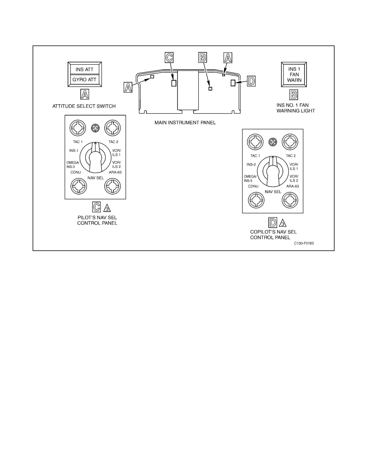
01-75GAL-1
Figure 2-129. LTN-72/LN-100 Inertial Navigation Controls and Indicators (Sheet 1 of 2)
1. OFF — Power is applied only to the MSU and CDU edge lighting. Primary power to the INS is off.
2. STBY — In standby, INS primary power is applied. While in this position, the navigation tests can be
performed and present position entered. The alignment sequence starts during which the platform cages to the
aircraft axis, and platform temperature stabilization and gyro runup are initiated.
3. ALIGN — The automatic alignment sequence begins, and a platform alignment sequence is initiated. When
theautomaticalignment sequenceis completed, theREADY NAV annunciatorilluminates to indicatethat the
navigate mode may be selected by setting the MSU mode selector switch to NAV. The aircraft must not be
moved when the MSU mode selector switch is set to ALIGN. However, gusty wind conditions and movement
caused by fueling or crew loading do not significantly affect alignment.
4. NAV — In navigate, the aircraft may be moved and/or normal in-flight operations performed.
Note
If the MSU mode selector switch of the LTN-72 INS is moved out of the
NAV position, the INS navigational capability is lost and an alignment
must be performed on the ground. An in-flight alignment can be performed
for the LN-100 INS.
ORIGINAL
2-310
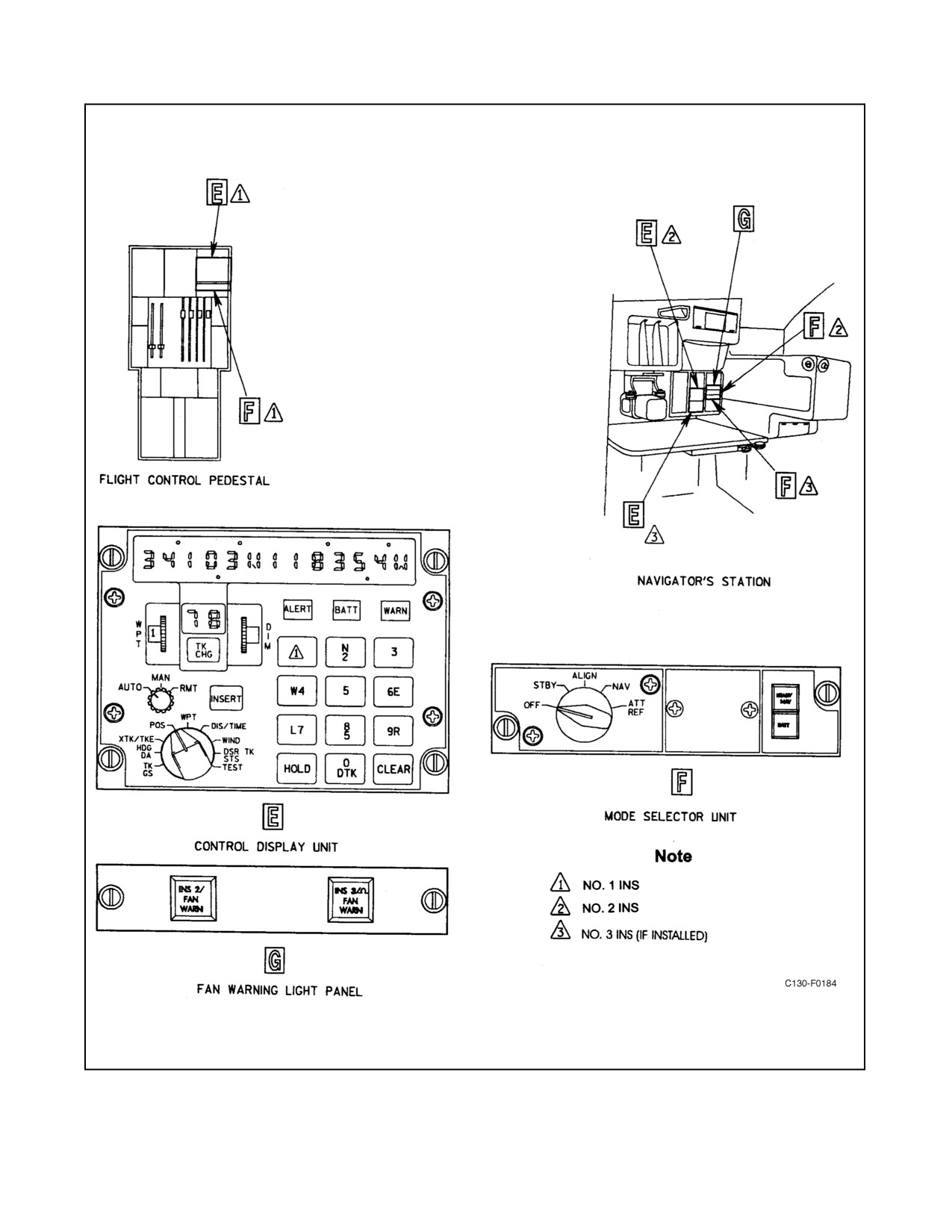
01-75GAL-1
Figure 2-129. LTN-72/LN-100 Inertial Navigation Controls and Indicators (Sheet 2)
2-311
ORIGINAL
01-75GAL-1
5. ATT REF — In attitude reference, the INS provides pitch, roll, and platform heading outputs only. No
navigational capability exists, and the CDU numerical displays are blank. Once the switch has been placed
in the ATT REF position, a complete ground alignment must be performed before in-flight navigation will
be available.
6. READY NAV annunciator (green) — When this annunciator illuminates, the INS is ready to perform the
navigation function. Rotating the mode selector switch to NAV will cause the READY NAV annunciator to
extinguish.
7. BATT annunciator (red) — This annunciator illuminates when backup power is less than the minimum
required to operate the INS. The annunciator must be pressed to reset to off when power is restored or it will
remain illuminated as long as sufficient power is available to illuminate the annunciator lamp.
2.21.24.1.2 Control Display Unit
The No. 1 CDU is located on the flight control pedestal. The No. 2 CDU and No. 3 CDU (if installed), are on the
navigator control panel. The controls, numerical displays, and annunciators located on the CDU are used to perform
the following functions.
Display Selector Switch
The CDU display selector is a nine-position, rotary-type switch that controls the selected data to be presented on the
left and right numerical displays. Certain positions of the switch are required during data entries and navigational
changes. The nine positions and functions controlled by this switch are as follows:
1.
Track angle and groundspeed (TK GS) — The track angle being made to the nearest tenth of a degree is shown
on the left numerical display. Groundspeed to the nearest knot is shown on the right numerical display.
2.
Heading and drift angle (HDG DA) — The aircraft true heading to the nearest tenth of a degree is shown on
the left numerical display. Drift angle to the nearest tenth of a degree is shown on the right numerical display.
The R or L preceding the reading indicates that the aircraft present track is to the right or left of the aircraft
heading.
3.
Crosstrack distance and track angle error (XTK TKE) — Crosstrack distance to the nearest tenth of a nautical
mileis shown on theleft numerical display. TheR orL preceding the readout indicates that the aircraft present
position is to the right or left of the desired track. Track angle error to the nearest tenth of a degree is shown
on the right numerical display. The R or L preceding the readout indicates that the present track angle is to
the right or left of the desired track angle.
4.
Present position (POS) — Aircraft present position coordinates in latitude and longitude, to the nearest tenth
of an arc-minute, are shown on the left and right numerical displays, respectively. The readout is frozen to
facilitate position checks by pressing the HOLD pushbutton. The HOLD pushbutton illuminates and remains
illuminated until the display is restarted by pressing the HOLD pushbutton again. The INS continuously
computes position during the display freeze, and, when the display is restarted, correct present position is
shown.
5.
Waypoint positions (WPT) — Waypoint latitude and longitude to the nearest tenth of an arc-minute are shown
on the left and right numerical displays, respectively. WPT selector switch settings 1 through 9 represent the
corresponding waypoint positions that are stored in the digital computer. WPT 0 represents the current aircraft
position anytime it is desired to initiate a track from present position to a waypoint.
6.
Distance and time to waypoint (DIS TIME) — Distance to go to the nearest nautical mile is shown on the left
numerical display and is measured between the aircraft present position and to waypoint of the track being
ORIGINAL
2-312
01-75GAL-1
navigated. Time to go to the nearest tenth of a minute, up to 480 minutes maximum, is shown on the right
numerical display and is derived from the distance along the desired track and groundspeed along the present
track.
7. Wind direction and speed (WIND) — The wind direction to the nearest degree is shown on the left numerical
display and windspeed to the nearest knot is shown on the right numerical display after manual input of true
airspeed. For the LTN-72 and LN-100 systems, true airspeed will be supplied by the TAS computer and no
operator action is required.
8. Desired track angle (DSR TK STS) — When search pattern parameters are not being entered, desired track
angle measured from true north, from 0.0_ to 360.0_ is shown on the left display. The left display reads 0_
until a track leg is inserted. The right display indicates action codes and alignment status. If the HOLD
pushbutton is depressed, the right display will display the malfunction codes as well as status. After a search
pattern has been initialized, the to/from display, with the display switch set to DSR TK STS, will always
display search status (00, 22, 33, 44, 55, or 66). Also, with the display switch set to DSR TK STS, search
parameters are recalled during search mode operation.
9. Display test (TEST) — The display test enables the operator to verify that the CDU numerical displays, to-from
display, and annunciators are operating correctly. The display test may be performed with the MSU mode
selector switch set to STBY, ALIGN, or NAV.
DIM Control
The DIM controls the intensity of the numerical and to-from displays; intensity can be reduced to zero, causing
displays to extinguish.
Waypoint Selector
When the WPT thumbwheel is set to a waypoint (0 through 9) with the CDU display selector switch positioned to
WPT, the waypoint coordinates will appear on the left and right numerical displays. It is also used during waypoint
data insertion.
TK CHG Pushbutton
Allows initiation of manual track leg change.
To-From Waypoint Display
Displays from waypoint number and to waypoint number of track leg being navigated.
Function Selector Switch
The CDU function selector is a three-position, rotary-type switch. The functions performed at each position of the
switch are as follows:
1. AUTO — Provides automatic sequential track changes at waypoints.
2. MAN — Allows manually initiated track changes to be accomplished.
3. RMT — Used for remote ranging and to display inserted crosstrack offset, inserted TAS, time, and inserted
magnetic variation.
2-313
ORIGINAL
01-75GAL-1
Numerical Displays
The numerical displays display data selected by the display selector switch.
HOLD Pushbutton
The HOLD pushbutton holds present position on left and right numerical displays or initiates manual updating of
present position.
CLEAR Pushbutton
The CLEAR pushbutton removes entered data if pressed before the INSERT pushbutton is pressed.
Data Keyboard
The data keyboard provides 10 keys (0 through 9) that are used to enter present position and waypoint coordinates
and from-to waypoints along with other data.
INSERT Pushbutton
The INSERT pushbutton transfers entered data into the INS computer when pressed.
ALERT Annunciator (Amber)
The annunciator will illuminate 2 minutes before each approaching to waypoint is reached and then either is
extinguished when a track leg change is automatically made (automatic operation) or flashes to indicate that a track
leg change must be manually initiated (manual operation). When track change is initiated manually, the annunciator
will extinguish.
BATT Annunciator (Amber)
The BATT annunciator illuminates when primary INS power is lost and the system has switched to backup battery
power.
WARN Annunciator (Red)
TheWARN annunciatorilluminates when asystem malfunction occurs or, during thealign mode, flashes to indicate
that incorrect present position latitude is inserted or an INS alignment failure has occurred.
2.21.24.2 Pilot/Copilot INS Control/Indicators
2.21.24.2.1 NAV SEL Switch
The INS position of the NAV SEL switch can be selected to display INS information on the HSI and ADI and for
INS steering when the autopilot is engaged and coupled (refer to paragraph 2.21.23.13.1).
2.21.24.2.2 Horizontal Situation Indicator
When the NAV SEL switch on the instrument selector panel is in the INS position, the INS will provide the following
information to be displayed on the HSI:
1. True heading (TH) — The HSI azimuth card is supplied true heading data from the INS. The heading under
the lubber line is the true heading of the aircraft, unless magnetic variation has been manually inserted in the
computer.
ORIGINAL
2-314
01-75GAL-1
2. Desired track angle (DSR TRK) — The course arrow on the HSI is supplied desired track angle data from the
INS. This allows the course arrow to be driven to a position on the azimuth card to indicate desired track angle
to be flown. A digital readout of the desired track angle appears in the course display. When a track change
is made, the new track will be automatically displayed.
3. Crosstrack distance (XTK) — The crosstrack distance is supplied to the HSI course deviation bar. A two-dot
course deviation is equivalent to approximately 7.5 nm. The bearing pointer displays present track.
4. To-From — The to-from indicator receives to-from data from the INS to indicate direction to the set waypoint.
The heading and NAV warning flags on the HSI come into view to indicate a failure of the INS heading or navigation
input. These warning flags are controlled by the INS only when INS has been selected with the NAV SEL switch.
2.21.24.2.3 Attitude Director Indicator
The gyro warning flag in the ADIcomes into view to indicate afailure ofthe INS attitude input, if INS ATT has been
selected.
2.21.24.2.4 Attitude Select Switch
An attitude select switch is located on each pilot instrument panel. The switch is a push/push-type switch with either
upper green (INS ATT) portion, which selects the INS as the primary source of attitude reference, or the lower white
(GYRO ATT) portion illuminated at all times. Anytime the switch is momentarily depressed, the opposite light
illuminates and signal source switches as described below.
2.21.24.2.5 Pilot Attitude Select Switch
When GYRO ATT legend is illuminated, the pilot ADI, the No. 1 flight computer, and the autopilot receive roll and
pitch attitude information from vertical gyro No. 1 and the autopilot receives heading information from the No. 1
C-12 compass. When INS ATT is illuminated, the attitude source is switched from vertical gyro No. 1 to INS No.
1 and heading for the autopilot is also furnished by the INS.
Note
When the autopilot is using INS (true heading) input for heading hold and
magnetic heading is displayed on the HSI, a change in magnetic variation
as the flight progresses will produce an apparent change in the heading
being maintained.
2.21.24.2.6 Copilot Attitude Select Switch
When GYRO ATT is illuminated, the copilot ADI and the No. 2 flight computer receive roll and pitch attitude
information from vertical gyro No. 2. When INS ATT is illuminated, they receiveattitude information from INS No.
2.
2.21.24.2.7 INS FAN Warning Lights
The INS FAN warning lights are located on the copilot instrument panel and on the navigator control panel. INS 1
FAN WARN light is on the copilot instrument panel and INS 2 FAN WARN light and INS 3/OMEGA FAN WARN
lightareonthenavigatorcontrolpanel.TheINSFAN WARNlights illuminatewhen coolingairisnot beingsupplied
to the applicable INU.
2-315
ORIGINAL
01-75GAL-1
2.21.24.3 Initial Operation of the INS
CAUTION
Prior to placing the copilot AC INST SEL switch to the STBY position,
select GYRO ATT and disengage all flight director modes. Do not select
INS ATT while in standby as this will result in damage to the ADI.
2.21.24.3.1 INS FAN Warning
If an INS blower/fan warning light illuminates, visually check the INS cooling fan to determine if the fan is operating.
Check the INS fan warning light probe for correct position. Reposition the probe if necessary. If the INS cooling fan
has stopped, shut down the INS, at pilot discretion, or the system will automatically shut down without damage to
the equipment.
2.21.24.3.2 INS Startup
1. MSU mode selector switch — STBY.
If ATT REF is selected for flight operations on the LTN-72 INS, a 3-minute
period under stable conditions is required to enable the INS inertial
platform to level, prior to relying on the INS for attitude outputs. The time
required for the LN-100 system is 30 seconds.
Note
The MSU mode selector switch should be placed to the ATT REF position
anytime it is not planned to proceed with the alignment procedures for the
purposeofusing theINS navigational capability. WiththeLN-100system,
an in-flight alignment can be performed at a later time. The following
procedures need not be accomplished if the attitude reference mode is
selected for flight operations.
2.21.24.3.3 CDU System Tests
1. Complete the INS STARTUP procedure.
2. CDU function selector switch — MAN.
3. CDU display selector switch — POS.
Note
For the LTN-72 system, verify that the CDU right numerical display
indicates the appropriate program number. The left display should contain
00000N, and the from-to display should be 0, 0. Pressing hold on the
LN-100 system will cause the display to cycle between program number,
program checksum, and date of program assembly.
ORIGINAL
2-316
01-75GAL-1
4.
CDU display selector switch — TEST.
5.
CDU displays and annunciators — Checked.
Note
Check that left and right numerical displays, degree sign, decimal points,
arc-minute signs, NS and EW, and from-to display are functioning and that
the ALERT, BATT, and WARN annunciators illuminate. All numerical
displays indicate 8.
6.
NAV SEL switch — INS.
Note
D Verify that the heading on the HSI is between 118_ and 122_, the desired
track is between 168_ and 171_, the “T” end of the bearing pointer indicates
between 131_ and 134_, and the course deviation bar displays a crosstrack
deviation of 3.5 nm (one dot) left of track.
D Verify that the ADI attitude warning flag goes out of view.
7.
Place the NAV SEL switch to a position other than INS.
2.21.24.3.4 Present Position Entry
1.
INS STARTUP procedure — Completed.
2.
CDU display selector switch — POS.
Note
If correct present position is displayed, proceed to step 9.
3.
Keyboard pushbutton N or S — Depressed.
4.
Present latitude — Entered.
Note
Starting with the most significant digit, enter latitude to the nearest tenth
ofaminutebypressingthecorrespondingpushbuttononthedatakeyboard.
As each pushbutton is pressed, verify that the corresponding digit is
displayed on the left numerical display as the last significant digit and that
each preceding digit moves one place to the left.
5.
INSERT pushbutton — Depressed.
6.
Keyboard pushbutton W or E — Depressed.
7.
Present longitude — Entered.
8.
INSERT pushbutton — Depressed.
9.
MSU mode selector switch — Align.
2-317
ORIGINAL
01-75GAL-1
Note
TheREADY NAV annunciatorlegend shall normally illuminate within 18
minutes for the LTN-72 INS and within 4 minutes for the LN-100 INS. Do
not move the aircraft (and for optimum alignment, do not start engines)
until alignment has been completed (i.e., READY NAV annunciator has
illuminated and MSU mode selector switch is rotated to NAV position).
2.21.24.3.5 LTN-72 INS Alignment Status Indications
The status of INS alignment is monitored by placing the CDU display selector switch to DSR TK STS with the MSU
mode selector switch in STBY or ALIGN. The two-digit numeral that appears in the right CDU display is the status
number. The initial status number is 90, which appears when STBY is selected. If INS attitude selection is activated
and the NAV SEL switch is placed to the INS position, the HSI heading and NAV warning flags will come into view
as the display status changes to 80. The heading warning flag will go out of view when the display changes to status
50. After 2 minutes and with the MSU mode selector switch positioned to ALIGN with present position inserted,
the status changes to 70. Status 70 is maintained until INS operating temperature has been reached. Once this occurs,
status is changed to 60. At status 60, the INS roughly determines the accuracy of the present position inserted. If
present position is incorrect, the CDU WARN annunciator begins to flash. If entered present position, when checked,
iscorrect,theflashingannunciatormeansthattheINShasfailed.Ifpresentpositionisincorrect,rotatetheMSUmode
selector switch to OFF and restart alignment procedure with the correct position entered.
CAUTION
If the MSU mode selector switch has just been set to the OFF position, it
should remain in the OFF position for at least 4 minutes before selecting
STBY, or damage to the equipment may result.
Status 50 indicates that present position is satisfactory. Status continues to decrease. When status 02 is reached, or
approximately 6 minutes has elapsed since status 10, the MSU READY NAV annunciator illuminates to indicate
that the system is ready to navigate. If the CDU WARN annunciator begins to flash, check the action code.
2.21.24.3.6 LN-100 Alignment Status Indications
When the display selector is set to DSR TRK STS, the right display indicates alignment status of the LN-100 with
the MSU mode selector switch in STBY or ALIGN. Upon being set to STBY, the status will be 90 and will decrement
to status 02 after present position has been entered and the MSU has been positioned to either ALIGN or NAV.
Note
Although it is recommended that the NAV mode be selected just prior to
flight operations, the mode switch can be set directly to NAV from STBY
as soon as present position coordinates have been inserted. The INU will
automatically enter the NAV mode upon completion of the alignment as
indicated by an 01 status on the CDU right display.
If present position has not been entered, the alignment will be held at status 80. At status 60, the INU tests for Normal
Automatic Alignment. If alignment is within tolerance, the alignment will proceed to status 50 where True Heading
becomes valid and the heading flag goes out of view. If the INU detects a fault in the alignment, the WARN light
on the CDU will begin to flash. After a 4 minute normal alignment time with ALIGN selected on the MSU, the
ORIGINAL
2-318
01-75GAL-1
READY NAV light will illuminate indicating the alignment was successful and the MSU may now be set to NAV.
If NAV was selected immediately after present position entry was completed, the INU will proceed directly into
Navigate mode without illuminating the READY NAV light.
CAUTION
The LN-100 system defaults to a closed-loop mode during alignment. In
this mode (indicated by a “⊂” on the DSR TK/STS display), the INS
positionwillbeautomaticallyupdatedbyGPSdata.GPSisonlyauthorized
as a back-up to visual navigation; therefore, closed-loop updates shall be
terminated prior to using LN-100 data as a primary means of instrument
navigation or prior to overwater navigation. Refer to paragraph
2.21.24.4.2.
2.21.24.3.7 INS Action Code
With the CDU display selector switch positioned to DSR TK STS and with a possible INS malfunction present, an
action code will appear in the right display to the left of the status code. Should the CDU WARN annunciator
commence flashing with the MSU mode selector switch in ALIGN and the action code is 2, 3, or 6, turn the MSU
mode selector switch to OFF, check the INS circuit breakers, and restart the alignment procedure. If the MSU mode
selector switch is in NAV and the CDU WARN annunciator remains illuminated with an action code 1 displayed,
turn the MSU mode selector switch to OFF. If a warning flag (HEADING, NAV) comes into view on the HSI, without
a CDU WARN annunciator and an action code of 4, do not use the INS steering or display information. After any
failure or repeat failure, determine the malfunction code by pressing the CDU HOLD pushbutton before turning the
MSU mode selector switch to OFF. The malfunction code will appear in place of the action code.
Note
More than one malfunction may exist. Repeated pressing of the CDU
HOLD pushbutton will cause a sequential display of code numbers for all
malfunctions. This should be repeated until the initial malfunction code
reappears.
2.21.24.3.8 Rapid Alignment (LN-100 Only)
A rapid alignment mode is available for use when it is anticipated that the normal four-minute alignment time will
affect mission requirements. A rapid alignment is based on the stored position and heading from a reference
alignment. It is therefore required that a normal alignment be performed as a reference alignment at some time
previous to the need for a rapid alignment and that the aircraft remain stationary during the interval between the
reference alignment and the rapid alignment (i.e., the heading, latitude, and longitude of the aircraft must not change).
A rapid alignment at 70 _F requires about 30 seconds. At the end of Status 70, the status goes directly to Status 02
if in ALIGN mode. If in NAV mode, the status goes directly to Status 01. Navigation performance may be degraded
uptofourmilesperhourfollowingarapidalignment.Toperformarapidalignment,firstperformanormalalignment.
Then set theMSUModeswitchto OFF(MSU mustnot beset totheNAVposition). Afternormal alignment,perform
the following:
1. Set the MSU Mode switch to STBY.
2. Set the CDU Display switch to POS and press HOLD, 9, and then INSERT.
3. Verify that the present position from the reference alignment is displayed on the CDU.
2-319
ORIGINAL
01-75GAL-1
4. Set the MSU Mode switch to ALIGN.
5. On the MSU, observe that the green READY NAV annunciator illuminates in approximately
0.6 seconds.
2.21.24.3.9 Waypoint Coordinates Entry
1.
INS Startup and present position entry — Completed.
2.
CDU function selector switch — MAN or AUTO.
3.
CDU display selector switch — WPT.
4.
Press TK CHG and INSERT pushbuttons.
5.
WPT selector — As Required.
Note
Theinitialenroutewaypointcoordinatesareenteredintowaypoint1unless
an anticipated return track to point of departure is required, in which case
the initial en route waypoint coordinates are entered into waypoint 2 and
the point of departure waypoint is entered in waypoint 1.
6.
Keyboard pushbutton N or S — Depressed.
7.
First waypoint latitude — Entered.
8.
INSERT pushbutton — Depressed.
9.
Keyboard pushbutton W or E — Entered.
10.
First waypoint longitude — Entered.
11.
INSERT pushbutton — Depressed.
Note
Repeat steps 5 through 11 for subsequent waypoint entries.
2.21.24.3.10 Intersystem Crossfill
Crossfill is a feature that is utilized for multiple INS installations. Waypoint coordinates are entered into any one of
the INS systems and then the waypoints are automatically transmitted to the other INS systems in the aircraft. The
INS selected for entry of the data is referred to as the Master INS. Crossfill can be performed while the aircraft is on
the ground and the MSU mode switches are set to STBY, ALIGN, or NAV. Crossfill can also be performed in flight
with the MSU mode switches set to NAV. Crossfill waypoint coordinates are entered as follows:
1. On the desired Master (transmitting) INS system, set AUTO/MAN/RMT switch on the CDU to RMT. Verify
that the From/To display starts flashing.
2. Press TK CHG and then INSERT on the Master CDU. Verify that the CDU From/To display flashes 00.
3. Repeat steps 1 and 2 for the Slaved (receiving) CDU. Verify that the CDU From/To display flashes 00.
ORIGINAL
2-320
01-75GAL-1
4. Enter the desired waypoint coordinates into the Master CDU or, if waypoints are already present, reenter any
single waypoint into the Master CDU. This transfer may take up to 18 seconds.
5. Verify that the crossfill was performed by setting the Slaved CDU Display switch to WPT and sequence
through all of the waypoint coordinates. Waypoint coordinates should be the same for all of the INS systems.
6. Set AUTO/MAN/RMT switches on all of the CDUs to AUTO or MAN.
2.21.24.3.11 CDNU to INS Intersystem Crossfill
Waypoint coordinates can be entered into any of the CDNUs and then automatically transferred to any INS in the
aircraft. Waypoint coordinates that are entered into the CDNU Flight Plan are transferred to any INS as follows:
1. Enter waypoints into the CDNU Flight Plan.
2. Access the Waypoint Start Page on the CDNU. Enable the crossfill function.
3. Place the INS to the transfer mode by setting the AUTO/MAN/RMT switch to RMT.
4. Place the CDU Display switch to WPT.
5. Press TK CHG, and then press INSERT. Allow two minutes for waypoint transfer.
6. Compare the CDNU Flight Plan waypoint list with the INS waypoints. The waypoint coordinates should be
the same.
2.21.24.3.12 Status Check
Status check of alignment progress is normally made after waypoint entry; however, it can be accomplished at any
time during system alignment.
1. INS startup, present position entry, and waypoint coordinates entry procedures — Completed.
2. CDU display selector switch — DSR TK STS.
Note
Observe status number on CDU right numerical display. After the status
number decreases to 02 and approximately 6 minutes have elapsed since
start of status 10, the READY NAV annunciator illuminates.
3. READY NAV annunciator — Illuminated.
4. MSU mode selector switch — NAV.
5. READY NAV annunciator — Extinguished.
6. INS alignment — Completed.
CAUTION
The LN-100 system defaults to a closed-loop mode during alignment. In
this mode (indicated by a “⊂” on the DSR TK/STS display), the INS
positionwillbeautomaticallyupdatedbyGPSdata.GPSisonlyauthorized
as a back-up to visual navigation; therefore, closed-loop updates shall be
terminated prior to using LN-100 data as a primary means of instrument
navigation or prior to overwater navigation. Refer to paragraph
2.21.24.4.2.
2-321
ORIGINAL
01-75GAL-1
Note
D This completes the alignment procedure, and the aircraft can now be
moved.
D If desired, the MSU mode selector switch can be set directly to NAV from
STBY after present position has been inserted. System alignment will
progress normally, except the READY NAV annunciator will not
illuminate when alignment is complete. A 01 status is the only indication
that the system has aligned.
2.21.24.3.13
Attitude Reference Check
1. Attitude select switch — Depressed.
Note
Check that the GYRO ATT legends illuminate, ADI GYRO flags are not
in view, and proper attitude references are displayed.
2. Attitude select switch — Depressed.
Note
Observe that normal INS ATT indications return.
2.21.24.3.14
Initial Track Selection
The initial track selection to a waypoint must be accomplished before INS navigational steering will be provided.
Normally, this would be accomplished in flight after takeoff when cleared to the first waypoint. The selection,
however, may be accomplished on the ground if the after takeoff flightpath makes it convenient to do so. The initial
en route waypoint latitude and longitude should be entered before Initial Track Selection procedures are
accomplished.
To enter the initial track without return to point of departure entry, accomplish the following:
1. Alignment — Completed.
2. CDU function selector switch — As Desired.
3. TK CHG keyboard pushbutton — Depressed.
Note
Verify the TK CHG and INSERT pushbutton legends illuminate and the
from-to display is blank.
4. Keyboard pushbuttons 0, then 1 — Depressed.
Note
Verify that from-to display is 0, 1.
5. INSERT pushbutton — Depressed.
ORIGINAL
2-322
01-75GAL-1
Note
D Verify that INSERT and TK CHG pushbutton legends extinguish. Verify
that initial desired track is accurate.
D Crosstrack distance and track-angle error (XTK/TKE), distance and time
to next waypoint (DIS/TIME), and desired track angle (DSR TK) data are
not available until the initial track is initiated.
To enter initial track when return to point of departure procedure is used, accomplish the following procedures.
1. CDU function selector switch — As Desired.
2. TK CHG keyboard pushbutton — Depressed.
Note
Verify that TK CHG and INSERT push-button legends illuminate and the
from-to display is blank.
3. Keyboard pushbuttons 0, then 2 — Depressed.
Note
Verify that from-to display is 0, 2.
4. INSERT pushbutton — Depressed.
Note
D Verify that INSERT and TK CHG pushbutton legends extinguish. Verify
that initial desired track is accurate.
D Crosstrack distance and track-angle (XTK/TKE), distance and time to next
waypoint (DIS/TIME), and desired track angle (DSR TK) data are not
available until the initial track is initiated.
2.21.24.3.15 Taxi Speed/Track Angle Monitoring
The INS displays taxi speed when taxi speed exceeds 1 knot and displays meaningful track angle indications at taxi
speeds in excess of 10 knots. Track angle and heading displays are the same at taxi speeds less than 10 knots.
1. CDU display selector switch — TK GS.
Note
Read groundspeed to the nearest knot from the right numerical display.
Read track-angle to the nearest tenth of a degree from the left numerical
display.
2.21.24.4 ln-Flight Operation of the INS
The terms automatic and manual, as used in these procedures, apply only to track selection. When in the navigate
mode, the INS provides the same navigation data whether the CDU function selector switch is set to AUTO
2-323
ORIGINAL
01-75GAL-1
(automatic) or MAN (manual). During automatic operation, the INS navigates through each selected waypoint in
sequence and automatically changes track at each waypoint. During manual operation, the INS navigates from
waypoint to waypoint, but the operator must initiate a track change at each waypoint. CDU display selection and
waypoint position entries may be accomplished with the CDU function selector switch set to either AUTO or MAN.
2.21.24.4.1 In-Flight Warn Indications
The INS provides integral warn indications and signals that cause aircraft instruments to provide warn indications
pertaining to INS operation. These warn indications are as follows.
INS WARN Indications
If the WARN annunciator illuminates, the INS is malfunctioning and may not be providing accurate data. Refer to
paragraph 2.21.24.4.3 for operating procedures.
Aircraft Instrument Warn Indications
The INS provides signals that cause aircraft instruments to provide warn indications as follows:
WARN SIGNAL
WARN INDICATION
Pitch or roll
ADI altitude warning flag
HSI
ADI course warning flag
If the MSU mode selector switch is set to ATT REF, the INS attitude
outputs must not beused until theaircraft hasbeen flownin thewings-level
attitude at a constant speed for the first 3 minutes after ATT REF is selected
to allow the INS inertial platform to complete a level sequence. If this
procedure is not followed, erroneous INS attitude outputs may occur.
Note
D Do not set the MSU mode selector switch on the LTN-72 INS out of NAV
unless an INS malfunction occurs. If the INS is switched out of NAV, the
NAV MODE cannot be reset in flight, as the INS must be aligned on the
ground. An in-flight alignment may be performed for the LN-100 INS.
D If the CDU BATT annunciator illuminates, the INS is operating on dc
backup power. The dc backup power is a battery unit with approximately
2 hours duration for INS operation. The No.
3 INU battery is a
nickel-cadium unit packaged in a metal case. The battery has a
6.5-ampere-hour capacity, which is sufficient to operate the system for 15
minutes. A battery trickle charger is included in the No.
3 inertial
navigation unit to maintain full battery capacity when the system is
operating from 400-Hz power. Action must be taken to substitute for the
INS, particularly if the INS is providing information for automatic flight
control of the aircraft.
ORIGINAL
2-324
01-75GAL-1
Note
If the MSU BATT annunciator illuminates, the dc backup power is less than
the minimum required to operate the INS. Automatic INS shutdown will
occur, and the warn annunciator will illuminate. The MSU mode selector
switch should be set to OFF if the MSU BATT annunciator illuminates. If
normal poweris restored, ground alignment,in-flight alignment(LN-100),
or in-flight leveling may be attempted a maximum of three times.
2.21.24.4.2 GPS Aided Operations
The INS can be updated in NAV mode utilizing GPS data. Navigation updates are performed in either closed loop
mode(whereGPS datais used to updateposition, velocity, platform tilts, and gyro biases)or open loop mode(where
inertial solutions are maintained in the computer separate from the GPS updated solution). The LN-100 INS can be
aligned during flight. In-flight alignments can only be performed in a closed loop mode. During normal ground
alignment, by default, the LN-100 INS will be aided by GPS in closed loop (Align status will indicate 02) when
valid GPS data is available. With the INS in NAV, open or closed loop GPS updating can be enabled, terminated
and flushed as required. When GPS updating is terminated, the CDU displays and data bus parameters are returned
to free inertial outputs.
CAUTION
GPS is only authorized as a back-up to visual navigation. Closed loop mode
shall be terminated prior to using INS data as a primary means of instrument
navigation or for overwater navigation.
Navigation Updates
All GPS aided operations are under CDU control and several status and advisory displays are available. Both control
and display are performed with the CDU Display Switch in the DSR TK/STS position. Basic GPS mode data is
provided in the space between the action/malfunction code and the system status, with ∪ indicating open loop and
indicating closed loop operation. For example: ∪01 indicates GPS open loop aided NAV mode. 01 indicates
GPS closed loop aided NAV mode. GPS mode control and additional status displays are enabled by pressing the 1
key on the CDU, which causes the left display to blank and the right display to display status. After pressing the 1
key, the mode selection entry codes are as follows:
1 key
Enable open loop update.
2 key
Enable closed loop update.
5 key
Terminate open or closed loop updates.
9 key
Flush open loop updates.
The left display provides visual confirmation of mode selection in the fifth (from left) digit. After selecting the
required mode, press INSERT to enable or disable GPS aiding. The previous display will return.
To enable open loop update:
1. Set CDU Display Switch to DSR TK/STS.
2. Press 1, the left display blanks and INSERT light illuminates.
2-325
ORIGINAL
01-75GAL-1
3. Press 1 and verify the left display is 1.
4. Press INSERT and verify INSERT light extinguishes, left display is DSR TK, and right display is ∪01.
5. Ifthe∪ does not appear(STSdisplay is01), press1 toobtain theupdatestatusdisplay. PressCLEAR torevert
to standard DSR TK/STS.
To enable closed loop update:
1. Set CDU Display Switch to DSR TK/STS.
2. Press 1, the left display blanks and INSERT light illuminates.
3. Press 2 and verify the left display is 2.
4. Press INSERT and verify INSERT light extinguishes, left display is DSR TK, and right display is 01.
5. Ifthe does not appear(STSdisplay is01), press1 toobtain theupdatestatusdisplay. PressCLEAR torevert
to standard DSR TK/STS.
To terminate open and closed loop updates:
1. Set display switch to DSR TK/STS.
2. Press 1, the left display blanks and INSERT light illuminates.
3. Press 5 and verify the left display is 5.
4. Press INSERT and verify INSERT light extinguishes, left display is DSR TK, and right display is 01.
To terminate and flush open loop updates:
1. Set display switch to DSR TK/STS.
2. Press 1, the left display blanks and INSERT light illuminates.
3. Press 9 and verify the left display is 9.
4. Press INSERT and verify INSERT light extinguishes, left display is DSR TK, and right display is 01.
In-Flight Alignment (IFA) (LN-100 Only)
The LN-100 may be aligned by one of three methods:
1. Normal Ground Alignment.
2. In-Flight Align (IFA). Alignment is initiated and completed during flight.
3. Hybrid Align. Alignment is started on the ground with the aircraft stationary and completed during taxi or in
flight.
Note
The preferred operational procedure is to perform a normal ground
alignment, allowing the system to enter NAV mode.
ORIGINAL
2-326
01-75GAL-1
In-Flight Alignment can be used when preflight time does not allow a normal ground alignment or the operator desires
to realign the system during flight. A system can be realigned in flight by recycling the MSU to OFF then to STBY.
Cycling through the OFF mode will allow the LN-100 to perform a fast level during Status 90 at turn on, thereby
removing any large platform tilt errors that may have occurred. If a large position error is not present, the MSU can
becycledtoSTBYwithoutgoingtoOFF.GPSwillinitializethesystempositionandnopositionentrybytheoperator
is necessary. When IFA is initiated, the system will remain in Air Align Hold mode with the CDU displaying align
status 80, with no # present, until both of the following conditions are met:
1. GPS ground speed is greater than 20 knots.
2. Alignment time is less than 85 seconds.
When these conditions are met the system will exit Air Align Hold mode, sequence to align status 70, and initialize
position and velocity from the GPS values. 70 indicates that GPS updating is enabled and proceeding. If the
does not appear, updates are being rejected. Press CLEAR to revert to standard DSR TK/STS.
If possible, aircraft maneuvers should be restricted to straight and level flight until about one minute after status 70
has been achieved. Moderate aircraft maneuvering thereafter is desirable and will speed the alignment. During a
maneuver that exceeds the acceleration and heading rate limits, GPS updates will not be accepted and a status code
1 2 b b 2 (Acceleration/Heading Rate Excessive) will be displayed. Approximately 15 seconds after completion of
the excessive maneuver GPS updates will again be allowed.
IFA can be enabled during any part of a ground alignment if it is necessary to complete the alignment with the aircraft
moving. This procedure is termed a Hybrid IFA. For an IFA initiated during align status 70, the system will enter
Air Align Hold until GPS ground speed exceeds 20 knots. For an IFA initiated after status 70, the 20 knot limitation
does not apply.
When the alignment is complete, STS display is 02 and the READY NAV light illuminates. The system may be
left in ALIGN mode or may be switched to NAV mode. Alternatively the MSU can be cycled directly to NAV after
IFA is enabled. If an IFA is terminated by the operator prior to the system sequencing to NAV mode then the align
status will be reset to status 80 and Action Code 3/22 (Enter Present Position) will be displayed until the MSU is
switched to STBY.
Note
If the system is left in ALIGN, the LN-100 remains in closed loop update
mode and continues to align the system based on GPS inputs. If thesystem
is switched to NAV, two separate navigation solutions are maintained in
theLN-100 computer, oneinertial and theotherfrom theKalman filterbest
estimate based on INU and GPS measurements. By default, GPS-aided
data is displayed on the CDU. Switching to NAV is recommended to
prevent possible corruption of the alignment from loss of lock conditions.
IFA procedures are as follows:
1. Set CDU Display Switch to DSR TK/STS.
2. Press 1 and verify left display blanks and INSERT illuminates.
3. Press 2 and verify a 2 is displayed.
4. Press INSERT. The display reverts to standard DSR TK/STS with either align status 90 or 80 displayed.
5. Set MSU to ALIGN.
2-327
ORIGINAL
01-75GAL-1
6. When STS display indicates 02 and READY NAV light illuminates, set MSU to NAV.
7. Terminate and flush closed loop updates.
8. Perform manual position update with an accurate known position fix.
2.21.24.4.3 Attitude Reference Selection
When only pitch, roll, and platform heading outputs are required and navigational capability is not necessary, the
INS can be operated in the attitude reference mode.
Note
To ensure that the INS inertial platform is level, keep the aircraft stationary
or taxiing at a constant speed and a steady course for 3 minutes after placing
the INS mode selector switch to the ATT REF position.
1. MSU mode selector switch — ATT REF.
Note
The MSU mode selector switch is detented in the NAV position and the
knob must be pulled away from the MSU panel before the mode selector
switch can be moved through the NAV position.
2.21.24.4.4 Initial Track Selection
1. Without return to point of departure — Perform same procedure as outlined for ground initial track selection
(without return to point of departure entry). When the INSERT pushbutton is depressed, steering is provided
from aircraft present in-flight position (WPT 0) to waypoint 1.
2. With return to point ofdeparture—Perform sameprocedureasoutlined forground initialtrack selection(with
return to point of departure entry). When the INSERT pushbutton is depressed, steering will be provided from
the aircraft in-flight position (WPT 0) to waypoint 2.
2.21.24.4.5 Flight Plan and Update Changes
Anormal flight plan includes several flight legs. TheINS is capableofstoring ninewaypoint coordinatesat onetime.
When the system is operating automatically, the navigation will be sequential through each waypoint as indicated
on the from-to display, thereby producing automatic sequential track steering. During manual operation, the desired
from-to waypoints are manually inserted, and the track steering associated with these waypoints will be produced.
2.21.24.4.6 Automatic Track Switching at Waypoint
Automatic track switching at a point prior to reaching a waypoint is provided when the CDU function selector switch
is in theAUTO position. When this track switching point is reached, theINS automatically changes to the next track,
the new leg (track) is displayed in the from-to display, steering to the new track is supplied, and the ALERT
annunciator extinguishes. This operation will continue sequentially through each waypoint. Should a new track be
established manually, such as between waypoints 2 and 4, and the CDU function selector switch is returned to AUTO,
automatic switching at waypoint 4 occurs. The new track between waypoints 4 and 5 is established and automatic
sequential track switching will resume.
2.21.24.4.7 Manual Track Switching at Waypoint
When the CDU function selector switch is in the MAN position, a track change to the next desired track must be
accomplished manually by the pilot as the waypoint is approached. To accomplish this operation, the following
operations would be performed:
ORIGINAL
2-328
01-75GAL-1
1. CDU function selector switch — MAN.
2. TK CHG keyboard pushbutton — Depressed.
Note
After TK CHG pushbutton is depressed, the TK CHG and INSERT
pushbutton legends will be illuminated.
3. Keyboard pushbuttons — Depressed.
Note
Depress the next from waypoint numerical keyboard pushbutton, then
depress the next to waypoint numerical keyboard pushbutton.
4. INSERT pushbutton — Depressed.
Note
When the INSERT pushbutton is depressed, a track change is initiated;
steering to the next track is produced and the new track will be displayed.
As long as the manual function is used, a new track will haveto beinserted
manually at each waypoint.
2.21.24.4.8 Waypoint Bypassing from Present Position
The operator can bypass a waypoint or a number of waypoints from present position at any time. Assume theaircraft
is on a from-to track of 1, 2 and it is necessary to fly from present position to waypoint 3.
1. CDU function selector switch — As Desired.
2. TK CHG keyboard pushbutton — Depressed.
3. TK CHG and INSERT pushbutton legends — Illuminated.
4. Keyboard pushbutton 0, then 3 — Depressed.
5. INSERT pushbutton — Depressed.
Note
D When the INSERT pushbutton is depressed, steering from present position
to waypoint 3 will be initiated and the new from-to track of 0, 3 will appear
in the from-to display.
D If the CDU function selector switch is set to AUTO, automatic switching
occurs as the next waypoint is reached and the from-to track of 3, 4 becomes
the new desired track.
2-329
ORIGINAL
01-75GAL-1
2.21.24.4.9 Intermediate Waypoint Bypassing
The operator can bypass one or more waypoints by performing certain manual operations on the CDU. Forexample,
assume the aircraft is on a from-to track of 1, 2 and is midway to waypoint 2. A decision is made to bypass waypoint
3 and go directly from waypoint 2 to waypoint 4. The following manual operation will be performed:
1. CDU function selector switch — As Desired.
2. TK CHG keyboard pushbutton — Depressed.
3. TK CHG and INSERT pushbutton legends — Illuminated.
4. Keyboard pushbutton 2, then 4 — Depressed.
5. INSERT pushbutton — Depressed.
Note
When the INSERT pushbutton is depressed, the programmed from-to track
between 2 and 3 is deleted, a new from-to track between 2 and 4 is
established, and steering to the new track is provided. Normally, the track
change would not be initiated until at or near waypoint 2.
2.21.24.4.10 Track Offset
This mode allows the operator to fly a track parallel to the present track at a fixed offset distance. This distance will
be set in by the operator. To enter this mode, the following operation will be performed.
1. CDU display selector switch — XTK/TKE.
2. Keyboard pushbutton 1 — Depressed.
Note
D Observe that the left CDU display goes blank and INSERT pushbutton
legend is illuminated.
D Left 5.3 nm will be used as an example.
3. In sequence, press L, 5, and 3 keyboard pushbuttons — Depressed.
Note
The left display will indicate L 5.3. For a right effect, use R in place of L.
Track offset must be entered to the nearest tenth of a nautical mile.
4. INSERT pushbutton — Depressed.
Verify that correct offset distance is displayed prior to depressing the INSERT pushbutton. After insertion, the right
display will display crosstrack distance from the original track and steering to the offset track. As the aircraft is flown
to the offset track, the crosstrack distance will begin to increase (as shown in left display) and the track-angle error
(right display) steadily increases from the value prior to offset track insertion. As the new track is intercepted, steering
will be produced to allow the aircraft to be flown to and maintain the offset track. When on offset track, the offset
distance (L 005.3) is displayed in the left display and track-angle error is displayed in the right display.
ORIGINAL
2-330
01-75GAL-1
To return to original track, accomplish the following operations:
5. CDU display selector switch — XTK/TKE.
6. In sequence, press 1, L or R, and INSERT pushbuttons.
Note
Steering is provided to return the aircraft to the original track.
2.21.24.4.11 Waypoint Position Change
The operator can change the coordinates of waypoints or use past waypoint storage locations as future waypoints.
Enter waypoints as described in paragraph 2.21.24.3.9. If past waypoint storage locations are to be used as future
waypoints, enter future waypoints sequentially, starting with 1 and continuing through the last number used to permit
automatic sequential switching.
2.21.24.4.12 Flight Plan Change Between Waypoints
A flight plan change to a new waypoint or destination can be initiated at any time between waypoints. Assume the
aircraft is between waypoints 3 and 4, and it becomes necessary to fly direct from present position to the new
destination. Assuming the destination to be waypoint 7, insert new waypoint 7 latitude and longitude, using the
Waypoint Coordinates Entry procedure. Use waypoint bypassing from present position procedure to insert new track,
0, 7 into system. When INSERT pushbutton is depressed, the new from-to track will beinitiated and the new from-to
track of 0, 7 will appear in the from-to display.
2.21.24.4.13 INS Track Select Mode
The operator can initiate an INS track select mode of operation (referenced to true north from the aircraft present track,
rather than a track between waypoints). By this method, the pilot may fly the aircraft off track.
1. CDU display selector switch — DSR TK STS.
2. CDU function selector switch — MAN.
3. Keyboard pushbutton 0 — Depressed.
Note
Verify that left numerical and from-to displays are blank and that the
INSERT pushbutton legend illuminates.
4. Enter desired track angle to the nearest tenth of a degree on the data keyboard.
Note
Verify that left numerical display is the track angle entered.
5. INSERT pushbutton — Depressed.
Note
Verify that INSERT pushbutton legend extinguishes, the from-to display
is 9, 9 and the DIS/TIME and XTK numerical displays are all zeros.
2-331
ORIGINAL
01-75GAL-1
The aircraft will turn and fly along a line parallel to the inserted track at the point of insertion. The lateral displacement
from this line is determined by the maximum roll rate commanded, aircraft speed, and autopilot characteristics. The
aircraft will maintain the inserted track.
6. When desired, return to previous mode by initiating the next track change.
2.21.24.4.14 Position Update, Check, and Selection
At any time during flight, the INS present position can be updated to a position fix apparently more accurate than
the inertially derived position. Present position can be updated a maximum 30 arc-minutes in both latitude and
longitude for any one update. The INS retains the original updated present position forthe duration of thenavigation
mode, thereby permitting future comparison of updated with nonupdated positions. If in a future comparison, the
nonupdated position proves more accurate than the updated position, the system may drop the updated position and
revert to the nonupdated position. In the following procedure, when the CDU HOLD pushbutton is pressed, the
present position display freezes. The INS, however, automatically compensates for position changes during this
display freeze.
2.21.24.4.15 Position Update
1. CDU HOLD pushbutton — Depressed.
2. CDU display selector switch — POS.
If update is not necessary, proceed to step 3; if necessary, proceed to step 4.
3. CDU HOLD pushbutton — Depressed.
Note
Step 3 restores display to normal operation.
4. Latitude and longitude of fix position — Entered.
Refer to steps 3 through 8 of paragraph 2.21.24.3.4, noting that the original (nonupdated) coordinate will appear on
the numerical display when the INSERT pushbutton is pressed and will not be updated until the second coordinate
is inserted or the CDU HOLD pushbutton is pressed.
If both latitude and longitude have been updated, numerical displays will restart when the INSERT pushbutton is
pressed the second time. If only latitude or longitude is updated, press the CDU HOLD pushbutton to restart the
display. The CDU HOLD pushbutton legend extinguishes, position changes that occurred during the display freeze
and updating procedures are automatically compensated for, and position display reflects new present position
referenced from updated coordinates.
2.21.24.4.16 Position Update Check
Check the position update versus nonupdated position as follows:
1. At known waypoint, CDU HOLD pushbutton — Depressed.
2. CDU display selector switch — POS.
The display will indicate the frozen value of present position with update (if applicable). With this position noted,
a comparison with a known point (waypoint) can be accomplished by proceeding to the next step.
3. CDU display selector switch — WPT.
ORIGINAL
2-332
01-75GAL-1
Verify that coordinates of nonupdated position appear in the numerical displays. If updated position is more accurate
than nonupdated position, restart displays by pressing the CDU HOLD pushbutton. The updated position will
continue to be displayed when the display selector switch is set to POS.
2.21.24.4.17 Update Removal
If the non-updated position is more accurate than the updated position, remove the updated position by performing
the following steps.
1. CDU HOLD pushbutton — Depressed (if not illuminated).
2. CDU display selector switch — DSR TK/STS.
3. Keyboard O/DTK pushbutton — Depressed.
4. INSERT pushbutton — Depressed.
Note
If track is being flown from present position to any waypoint, reinitiate
track to pick up new 0 position. If a track hold mode is being flown,
reinitiate the track hold procedure.
TheCDU HOLD pushbutton legend extinguishes, and the nonupdated position will be displayed when CDU display
selector switch is set to POS.
A new updated position can be entered at any time during the navigation mode by performing steps
2 through 8 of
paragraph 2.21.24.3.4.
2.21.24.4.18 True Airspeed and Time Entry and Display
Note
True airspeed is supplied to the INS by a TAS computer. In order to obtain
TAS inputs to the INS from the TAS computer, a zero TAS must be entered
manually. In the event that the TAS goes invalid, the TAS may be entered
manually.
Enter the true airspeed and time data as follows:
1. CDU function selector switch — RMT.
2. CDU display selector switch — WIND.
3. Keyboard DTK pushbutton — Depressed.
Note
Verify that the INSERT pushbutton legend illuminates.
4. True airspeed — Entered.
5. If the true airspeed display is correct, press the INSERT pushbutton.
2-333
ORIGINAL
01-75GAL-1
6. If the true airspeed display is incorrect, press the CLEAR pushbutton and repeat steps 3 through 5.
7. Keyboard pushbutton 5 — Depressed.
Note
Verify that the INSERT pushbutton legend illuminates.
8. Time — Entered.
9. If time display is correct, press the INSERT pushbutton.
10. If time display is incorrect, press the CLEAR pushbutton and repeat steps 7 through 9.
Note
True airspeed and time can be displayed by setting the CDU function
selector switch to RMT and the CDU display selector switch to WIND. Last
entered values of true airspeed and current time will be displayed.
2.21.24.4.19 Magnetic Heading Entry and Display
The magnetic heading is displayed on the CDU left display and HSI whenever a manual entry of the magnetic
variation has been entered. Determine the magnetic variation for present position, then accomplish the following
procedure for magnetic variation entry.
1.
CDU function selector switch — RMT.
2.
CDU display selector switch — HDG DA.
3.
Keyboard pushbutton W or E — Depressed.
Note
If direction of variation is west, depress W; for east, depress E.
4.
Degrees of magnetic variation — Entered.
Note
Verify magnetic heading in the left display and magnetic variation in the
right display.
5.
INSERT pushbutton — Depressed.
Note
D A zero will appear as the extreme left character of the right display when
true heading is being displayed. A 1 will appear when magnetic heading is
being displayed.
D If correct magnetic heading is to be maintained, it will be necessary to
update the INS as variation changes.
To remove magnetic heading, accomplish Magnetic Heading Entry procedure except that a zero variation is entered
in step 4.
ORIGINAL
2-334
01-75GAL-1
2.21.24.4.20 Wind Computation
The wind display is blank until TAS is entered or the computer (if installed) accepts computed true airspeed. If the
TAS computer is available, manually zero the TAS to get the computer to accept manual insertion. Refer to paragraph
2.21.24.4.18.
2.21.24.4.21 Distance/Time Along Flight Plan Route
The cumulativedistance and time along the flight plan routefrom present position to any waypoint can bedisplayed.
This can beobtained on theground as well as in flight, as long as theMSU modeselectorswitch is in STBY, ALIGN,
or NAV with present position and route to be flown entered. To obtain this distance and time, perform the following
manual operation:
1. CDU function selector switch — RMT.
2. Keyboard TK CHG pushbutton — Depressed.
3. Keyboard pushbutton 0 and desired waypoint number pushbutton — Depressed.
Note
Verify that from-to display is the two selected waypoints or present
position and waypoint.
4. INSERT pushbutton — Depressed.
The total distance along the flight plan route selected will appear in the left display. The time will appear in the right
display. Time is based on a fixed velocity of 512 knots when groundspeed is less than 100 knots, and is based on
actual groundspeed when speed is greater than 100 knots.
2.21.24.4.22 Altitude Reference Mode Operation
Attitude reference mode operation enables the aircraft to use the INS as a source of pitch, roll, and platform heading
(attitude) data. Attitude reference is selected in flight when the INS is providing attitude data but no navigational data,
as indicated when the WARN annunciator illuminates with the MSU mode selector switch set to NAV, and
extinguishes when the MSU mode selector switch is set to ATT REF.
Note
Switching to ATT REF with the MSU mode selector switch does not affect
the attitude selection made with the attitude select switch(es) on the main
instrument panel, since the same output is available with the MSU mode
selector switch in either NAV or ATT REF.
If the WARN annunciator illuminates:
1. MSU mode selector switch — ATT REF.
If the WARN annunciator remains illuminated, the INS has malfunctioned and is not providing reliable navigational
or attitude data. If the annunciator extinguishes, the INS is providing accurate attitude data but no navigational data.
If the WARN annunciator extinguishes:
2. Verify that the left and right numerical and from-to displays are blank.
2-335
ORIGINAL
01-75GAL-1
If the WARN annunciator remains illuminated:
CAUTION
Disengage autopilot prior to switching attitude reference with the attitude
select switch(es).
3. Attitude select switches — GYRO ATT.
4. MSU mode selector switch — OFF.
5. NAV SEL switch — As Desired (except INS).
Note
Once the MSU mode selector switch on the LTN-72 INS is placed in ATT
REF, a ground alignment must be performed before normal navigation can
be resumed. An in-flight alignment may be performed for the LN-100 INS.
2.21.24.4.23 Search Mode Operation
Search mode data can be entered and search pattern initiated whenever the system is in NAV mode. Search pattern
designation as well as initiation and termination of search modes are all accomplished through use of the CDU
from-to display. Both systems can be programmed for search patterns and coupled to the autopilot.
In all CDU selector positions except DSR TK STS, the from-to display functions as described previously until a
search mode is initiated, and then displays 77. With the CDU display selector switch in DSR TK STS, the following
search mode information is displayed:
FROM-TO
DESCRIPTION
00
Search Mode Disabled
22
Ladder
33
Sector
44
Square
55
Auto Search Start (when to waypoint is reached)
66
Manual Search Start
Like numbers only can be inserted when the CDU display selector switch is in DSR TK STS. Unlike numbers will
be rejected. Search pattern designation, data entry, search mode initiation, and termination are accomplished as
follows:
1. A search pattern may be designated by depressing the TK CHG pushbutton with the CDU display selector
switchinDSRTKSTSandenteringeither22(ladder),33(sector),or44(square)asdesired.TheCDUfunction
selector switch must be in either AUTO or MAN.
2. Search mode parameters required to define each search pattern may then be entered through the DSR TK STS
left and right displays. Search mode data must be entered and verified on the CDU prior to beginning the
search.
ORIGINAL
2-336
01-75GAL-1
3. Search mode may then be enabled in one of two ways:
a. Manually — By inserting 66 into the from-to display (with CDU display selector switch set to DSR TK
STS), the search pattern is immediately initiated and present position is used as the datum modem point.
b. Automatically — When 55 is inserted into the from-to display (with CDU display selector switch set to
DSR TK STS), search mode will not be entered until distance to go to the to waypoint reaches 0. At that
time, present position is stored as the datum modem point and the search pattern is initiated.
Note
Manually inserted crosstrack offsets are automatically removed at the time
55 or 66 is entered.
The search pattern (22, 33, or 44) must have been designated before search initiation (55 or 66) can be accomplished.
Once 55 or 66 is entered, it will be displayed in the from-to display (with the CDU display selector switch in DSR
TK STS)for approximately 5 seconds, afterwhich thedisplay will revert back to thesearch pattern being flown. The
from-to display indicates 77 in all CDU display selector switch positions other than DSR TK STS, once a search
pattern has been initiated.
Note
Should the operator wish to recall search mode parameters during search
execution, the CLEAR pushbutton may be pressed on the CDU. With the
CDU display selector switch set to DSR TK STS, search data will be
displayed for approximately 5 seconds. The method of search mode
initiation (55 or 66) will also be displayed for 5 seconds. During search
operation, search mode data cannot be entered or altered.
4. Two steps are required to terminate a search mode:
a. 00 must be entered through the from-to display with the CDU display selector switch set to DSR TK STS.
b. A new track must be established by entering a track change. The CDU display selector switch must be in
a position other than DSR TK STS.
Once a search mode is partially terminated (by entering 00), the TK CHG pushbutton will flash, indicating the need
to establish a new track. Should the operator fail to make a track change before the aircraft reaches the current
waypoint (waypoint 8), the INS will behave as if in the manual mode, regardless of the setting of the CDU function
selector switch. The ALERT light will begin flashing as an indication to change tracks, but the aircraft will continue
on the previously determined track until a track change has been initiated.
Once a 55 or 66 has been entered into the system, the only entry allowed with the CDU function selector switch in
DSR TK STS is 00; anything else will be rejected.
Search Mode Initialization
The operator has the option of initiating a search mode either manually (66) or automatically (55). The procedure
for automatic search initialization with the INS coupled to the autopilot is as follows:
1. Enter the search initialize latitude and longitude position into the CDU as a waypoint.
2. Set the CDU function selector switch to AUTO or MAN.
2-337
ORIGINAL
01-75GAL-1
3. Select a desired track to the search initialize waypoint (by entering the waypoint used for the search initialize
position as the to waypoint).
4. Two steps are required to terminate a search mode: in DSR TK STS, enter and verify the search mode data
for the desired searchpath.
5. Couple the autopilot to the INS.
6. With the CDU display selector switch set to DSR TK STS, enter 55 into the from-to display. When distance
to go reaches zero, the search pattern will automatically begin.
Note
Should search parameters be entered that would produce nonoptimal
steering(i.e.,excessiveovershooting)theTKCHGandINSERTlightswill
flash at the time the search pattern is initiated. The pattern may be
continued, should the operator desire, with the lights flashing, or search
mode may be terminated and new parameters inserted.
Search Mode Readouts
CDU readouts during search mode operation are as follows:
1. From-to display indicates 77 in all positions of the display selector switch except DSR TK STS.
2. XTK/TKE display values are aircraft position with respect to the searchpath.
3. Waypoints 7, 8, and 9 contain position coordinates of from, to, and next waypoints.
Note
Waypoints 7, 8, and 9 coordinates change as search progresses. During
search mode operation, waypoints 7, 8, and 9 cannot be manually changed.
4. DIS/TIME display values are with respect to the to waypoint (waypoint 8) of the search.
5. Desired track with respect to the searchpath is displayed in the DSR TK STS position.
HSI readouts for the INS being used are as follows:
1. Course arrow with respect to the compass card is the desired track angle of the searchpath.
2. Course arrow with respect to the “T” end of the bearing pointer is the track-angle error of aircraft track with
respect to desired track angle of the searchpath.
3. Coursebarindications display crosstrack distancedeviation from desiredsearchpath (onedot deviationequals
3,000 yards, about 1.5 nm).
4. Compass card with respect to the lubber line is the true heading of the aircraft.
5. The “T” end of the bearing pointer with respect to the compass card is the track angle of the aircraft.
6. The “T” end of the bearing pointer with respect to the lubber line is the drift angle of the aircraft.
ORIGINAL
2-338
01-75GAL-1
Termination of Search Mode
The following procedure must be used in order to terminate the search mode:
1.
Verify that the coordinates of fly-to waypoint are entered into any numbered waypoint except waypoints 7,
8, or 9.
2.
CDU display selector switch — DSR TK STS.
3.
Keyboard TK CHG pushbutton — Depressed.
Note
Verify that TK CHG and INSERT pushbuttons are illuminated.
4.
In sequence, press 0 pushbutton two times.
Note
Verify that TK CHG pushbutton is now flashing.
5.
CDU display selector switch — Any position except DSR TK STS.
6.
Keyboard TK CHG pushbutton — Depressed.
Note
Verify that TK CHG and INSERT pushbuttons are illuminated.
7.
In sequence, press 0 pushbutton and then waypoint number selected in step 1. Search mode is now terminated.
Note
Termination is required before a new search pattern can be designated.
Search Modes Data Entry and Display
The three search patterns that have been mechanized in the INS are:
1. Ladder (creeping line).
2. Sector.
3. Square (expanding square).
Any one of the three search modes is capable of being programmed into the INS (see Figure 2-130). Search mode
data may be entered and displayed either on the ground or in flight, but only with the MSU mode selector switch
positioned to NAV.
Search mode data must be entered and verified on the CDU prior to beginning the search pattern.
Note
D Recall of the original search mode data may be accomplished by
momentarily depressing the CDU CLEAR pushbutton.
D If less than minimum values of track spacing, radius, or sweep width are
entered into the INS, the CDU TK CHG and INSERT pushbuttons will
flash at the time the search is initiated and erratic track leg switching may
occur during execution of the search pattern.
2-339
ORIGINAL
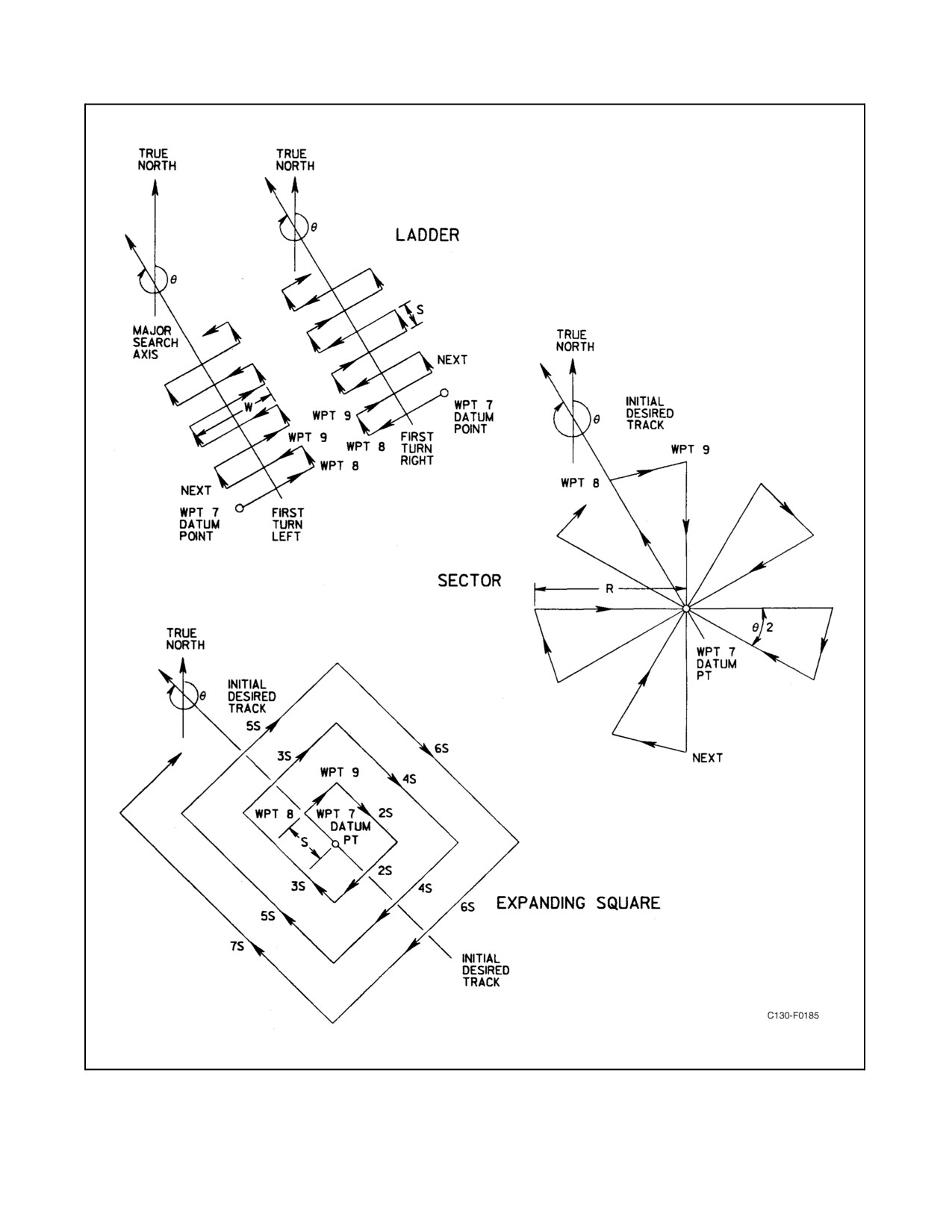
01-75GAL-1
Figure 2-130. INS Search Patterns
ORIGINAL
2-340
01-75GAL-1
Ladder Search Variables
Four variables are required to be inserted into the INS to define the ladder searchpath:
1. Major search axis-angle (0) with respect to true north in degrees and tenths of degrees. Range of variable is
0.0_ to 359.9_.
2. Sweep width (W) in nautical miles. Range of variable is 0.0 to 999.9 nm.
3. Track spacing (S) in nautical miles. Range of variable is 0.0 to 99.9 nm.
4. Direction of first turn: right bank R, left bank L.
Note
Track leg switching will occur prior to each waypoint. Switching time is
variable, depending on groundspeed.
Ladder Search Data Entry and Display
The ladder search data for the following example is major search axis (0) of 310.1_, a sweep width (W) of 40.0
nm,
a track spacing (S) of 10.0 nm, and the first turn to the left. Enter the ladder search data as follows:
1.
CDU function selector switch — MAN or AUTO.
2.
CDU display selector switch — DSR TK STS.
Note
Verify that from-to display shows 00.
3.
Keyboard TK CHG pushbutton — Depressed.
4.
Keyboard pushbuttons — Depressed.
Note
Depress keyboard pushbutton 2, two times.
5.
Keyboard INSERT pushbutton — Depressed.
Note
Verify that four zeros appear in both the left and right displays.
6.
Keyboard pushbutton L — Depressed.
Note
Verify that left display blanks and INSERT pushbutton illuminates.
7.
In sequence, press 3, 1, 0, and 0 keyboard pushbuttons — Depressed.
Note
Verify that the left display is the major search axis angle entered.
2-341
ORIGINAL
01-75GAL-1
8.
INSERT pushbutton — Depressed.
9.
Keyboard pushbutton R — Depressed.
Note
Verify that right display blanks and INSERT pushbutton illuminates.
10.
In sequence, press 4, 0, and 0 keyboard push-buttons — Depressed.
Note
Verify that the right display is the sweep width entered.
11.
INSERT pushbutton — Depressed.
12.
CDU function selector switch — RMT.
13.
Keyboard pushbutton L — Depressed.
Note
LispressedforthefirstturnleftdirectionandRispressed forfirst turnright
direction. Also verify that INSERT pushbutton is on.
14.
In sequence, press 1, 0, and 0 keyboard pushbuttons — Depressed.
Note
Verify that first turn direction and track spacing are correct on the display.
15.
INSERT pushbutton — Depressed.
Note
CDU TK CHG and INSERT pushbuttons will flash if less than minimum
values have been entered for search pattern track legs.
Sector Search Variables
Three variables are required to be inserted into the INS to define the sector searchpath:
Note
All turns are right bank.
1. Radius(R) in nautical miles; range of variable is 0 to 99 nm.
2. Leg separation angle (02) in degrees and tenths of a degree; range of variable is 0.0_ to 99.9_. 10_ minimum
02 is recommended for groundspeeds above 140 knots.
3. Initial desired track angle (01) with respect to true north in degrees and tenths of a degree. Range of variable
is 0.0_ to 359.9_.
Note
Track leg switching will occur prior to each waypoint. Switching time is
a variable as a function of groundspeed.
ORIGINAL
2-342
01-75GAL-1
Sector Search Data Entry and Display
The sector search data for the following example with an initial desired track angle (01) of 33_, a search radius (R)
of 10 nm, and a leg separation angle(02) of30.0_. Forsector search patterns, all turns areright bank. Enter thesector
search data as follows:
1.
CDU function selector switch — MAN or AUTO.
2.
CDU display sector switch — DSR TK STS.
Note
Verify that from-to display shows 00.
3.
Keyboard TK CHG pushbutton — Depressed.
4.
Keyboard pushbuttons — Depressed.
Note
Depress keyboard pushbutton 3, two times.
5.
Keyboard INSERT pushbutton — Depressed.
Note
Verify that four zeroes appear in the left display and that five zeroes appear
in the right display.
6.
Keyboard pushbutton L — Depressed.
Note
Verify that left display blanks and INSERT pushbutton illuminates.
7.
In sequence, press 3, 3, 0, and 0 keyboard pushbuttons — Depressed.
Note
Verify that the left display is the initial desired track angle entered.
8.
Keyboard INSERT pushbutton — Depressed.
9.
Keyboard pushbutton R — Depressed.
Note
Verify that right display blanks and INSERT pushbutton illuminates.
10.
In sequence, press 1, 0, and then 3, 0, and 0 keyboard pushbuttons — Depressed.
Note
Verify that the right display shows the search radius and leg separation
entered.
2-343
ORIGINAL
01-75GAL-1
11. INSERT keyboard pushbutton — Depressed.
Expanding Square Search Variables
Two variables are required to be inserted into the INS to define the expanding square searchpath:
Note
All turns are right bank.
1. Sweep width (S) in tenths of a nautical mile; range of variable is 0.0 to 99.9 nm.
2. Initial desired track angle (0) with respect to true north in degrees and tenths of a degree; range of variable is
0.0_ to 359.9_.
Expanding Square Data Entry and Display
The expanding square data for the following example is with an initial desired track angle (0) of 315.0_ and sweep
width (S) of 15.0 nm. For the expanding square search pattern, all turns are right bank.
Enter expanding square search data as follows:
1.
CDU function selector switch — MAN or AUTO.
2.
CDU display selector switch — DSR TK STS.
Note
Verify that from-to display shows 00.
3.
Keyboard INSERT pushbutton — Depressed.
4.
Keyboard pushbuttons — Depressed.
Note
Depress keyboard pushbutton 4, two times.
5.
Keyboard INSERT pushbutton — Depressed.
Note
Verify that four zeroes appear in the left display and three zeroes appear in
the right display.
6.
Keyboard L pushbutton — Depressed.
Note
Verify that left display blanks and INSERT pushbutton illuminates.
7.
In sequence, press 3, 1, 5, and 0 pushbuttons — Depressed.
Note
Verify that the left display is the initial desired track angle entered.
ORIGINAL
2-344
01-75GAL-1
8. Keyboard INSERT pushbutton — Depressed.
9. Keyboard pushbutton R — Depressed.
Note
Verify that right display blanks and INSERT pushbutton illuminates.
10. In sequence, press 1, 5, and 0 pushbuttons — Depressed.
Note
Verify that the right display is the sweep width entered.
11. Keyboard INSERT pushbutton — Depressed.
2.21.24.4.24 After Landing Operations
Navigation Accuracy Check. The accuracy of the INS should be determined at the end of each INS flight prior to
system shutdown. The check should be made when the aircraft is parked at a known location.
Check the INS accuracy as follows:
1. Using Update Removal or Position Update Check procedure, remove all position updates.
2. Verify correct parking position coordinates and enter as a waypoint.
3. CDU function selector switch — AUTO or MAN.
4. Enter TK CHG from present position (0) to parking position waypoint.
5. CDU display selector switch — DIS/TIME.
6. System error in nm/hr — Computed.
Divide distance display by the number of hours and tenths of an hour of flight time in the navigation mode.
In-Transit Stops
The system should be left in the navigation mode of operation during short in-transit stops when the navigation
accuracy does not require improvement.
INS Shutdown
The system is shut down by pulling and rotating the MSU mode selector switch to the OFF position.
2.21.25 LTN-211 Omega Navigation System
Note
As of 1 October 1997, ONS is inoperative because of decommissioning of
Omega stations worldwide.
2.21.26 True Airspeed Computer
The TAS computer provides TAS input to the No. 1, No. 2, or No. 3 INS. True airspeed is displayed on the TAS
indicator on the navigator instrument panel (see Figure 2-131). The TAS computer and a transducer are mounted on
2-345
ORIGINAL
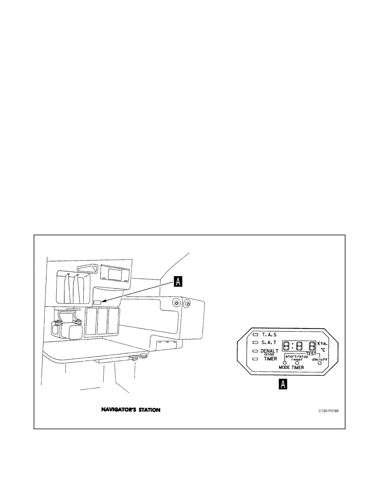
01-75GAL-1
the right-hand underdeck rack (see Figure 2-84). Ram air pressure and atmospheric pressure to operate the TAS
computer is provided by the pitot-static system (see Figure 2-80). Outside air temperature is provided from a total
temperature probe installed on the left side of the aircraft above the crew entrance door. The TAS computer uses
26-Vac power from the essential ac bus through the TAS circuit breaker on the pilot upper circuit breaker panel. The
TAS computer also uses 28-Vdc power from the essential dc bus through the TAS circuit breaker on the copilot upper
circuit breaker panel.
2.21.26.1 True Airspeed Computer Indicator
Thetrueairspeedcomputerindicatorismountedonthenavigatorinstrumentpanel (seeFigure2-131).Therearethree
pushbutton switches on the front of the indicator. Each switch is momentary and will continuously advance the
operation until released. One pushbutton is for changing modes. One pushbutton is for starting, stopping, and
resetting the timer. The other pushbutton is used to control the brightness of the display and for lamp test. Legends
are backlighted for indicating the display operating mode and _C or knots.
To test the true airspeed computer indicator lights, depress the MODE and dim/off buttons simultaneously. Assure
that the three displays indicate 8 and that the mode indicators, the colon, Kts, and _C annunciators flash.
2.21.27 AN/APS-133(M) Multimode Radar Set
The AN/APS-133(M) multimode color radar set consists of the following components: an antenna, a
receiver-transmitter, a pilot and navigator indicator, an interface unit, a radar control panel, a display control unit,
and a sector scan control panel (see Figure 2-132). The radar set operates on 28-Vdc power from the main dc bus and
115-volt primary ac power from the essential ac bus on aircraft prior to 165313 and from the essential avionics bus
on aircraft 165313 and up through the RADAR circuit breakers on the copilot upper circuit breaker panel.
Figure 2-131. True Airspeed Computer Indicator
ORIGINAL
2-346
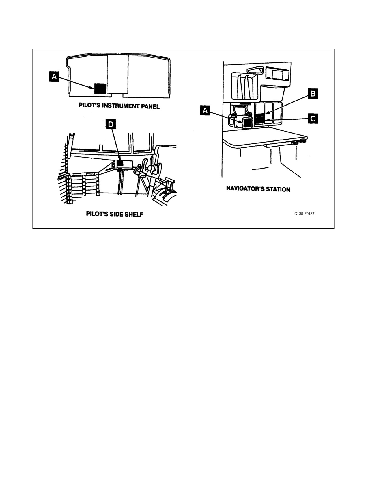
01-75GAL-1
Figure 2-132. AN/APS-133(M) Multimode Radar Indicator Control Panels (Sheet 1 of 2)
The multimode radar features include weather avoidance, long-range beacon homing incorporating marker and delay
modes,groundandair-to-airmappingcapability,IFFdisplay,INSwaypointandcourselineoverlays,refuelingoffset
line, and target marker providing either LAT/LONG coordinates or range/bearing data.
As a weather avoidance radar, the set detects and displays precipitation areas in red, yellow, and green. The red areas
indicate heaviest precipitation or storm centers, yellow indicates lower precipitation rates, and green indicates lightest
rainfall. Azimuth lines, fixed range marks, and alphanumerics are displayed in blue. Automatic penetration circuits
prevent storm areas at close range from masking other storm areas at the same azimuth but longer range.
As a terrain mapping radar, the set scans a selected range of Earth and provides a display of prominent topographical
features such as lakes, rivers, islands, high ground, bridges, cities, etc. These features are presented on the indicator
in adisplay resembling an ordinary pilotagechart. Thedetected terrain features are displayed in red, yellow, and blue
according to the strength of the target returns: red for strongest returns, yellow for medium, and blue for lowest.
Azimuth lines, range marks, and alphanumerics are displayed in green.
In the air-to-air mapping function, the set presents a display of other aircraft in the immediate vicinity of the present
flightpath. Detected aircraft are displayed in red, yellow, or blue: red for strongest returns, yellow for medium level,
and blue for lowest level. Azimuth lines, fixed-range marks, and alphanumerics are displayed in green. The effective
range in this function is limited by the size of the target aircraft, but detection of a large aircraft such as a C-130 could
be expected at 10 nm.
As a beacon navigation radar, the set transmits an interrogation signal to trigger an X-band beacon. Operating beacons
within range transmit a response pulse that is received by the radar set and displayed as an arc on the indicator at the
relative bearing and distance to the beacon. The beacon response is displayed in green only. Azimuth lines, range
marks, and internally generated alphanumerics are displayed in blue.
2-347
ORIGINAL
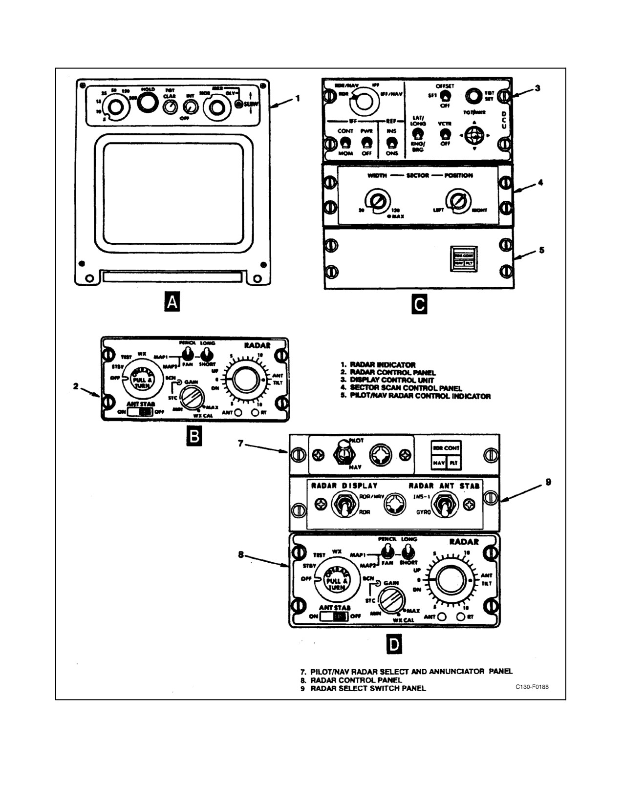
01-75GAL-1
Figure 2-132. AN/APS-133(M) Multimode Radar Indicator Control Panels (Sheet 2)
ORIGINAL
2-348
01-75GAL-1
IFF codes from cooperating aircraft (green lines) can be displayed along with LAT/LONG or range/bearing when
the target marker feature is used. Azimuth lines, range marks, and internally generated alpha-numerics are displayed
in blue.
INS waypoints and connecting course lines can be displayed in addition to IFF codes from cooperating aircraft.
Azimuth lines, range marks, and internally generated alphanumerics are displayed in blue.
2.21.27.1 Controls and Indicators
The radar set operating controls and indicators are contained on the radar indicators and the following panels:
1. At the navigator station — Radar control panel, display control unit, sector scan control panel, and
pilot/navigator radar control indicator.
2. At the pilot side panel — Pilot/navigator radar select and annunciator panel, radar control panel, and radar
switch panel.
2.21.27.1.1 Radar Indicators
The radar indicators contain the following controls for radar indicator presentation.
Range Selector
The range selector selects the range in nautical miles displayed on the radar indicator and the distance between
fixed-range markers: 5 nm with 1-nm range markers; 10 nm with 2-nm range markers; 15 nm with 3-nm range
markers; 25 nm with 5-nm range markers; 50 nm with 10-nm range markers; 150 nm with 30-nm range markers; or
300 nm with 60-nm range markers. The selected range/range-marker combination is displayed in the upper right
corner of the radar indicator scope.
HOLD Pushbutton
The HOLD pushbutton allows the operator to freeze the display. When HOLD is pressed in, the present display on
the radar indicator is retained instead of being updated by subsequent azimuth scans. The notation HOLD flashes
alternately with the function (WX, BCN, etc.) in the upper left corner of the radar indicator scope. Pressing HOLD
again or changing range selector position resumes normal updating of the display.
TGT CLAR Control
TheTGTCLARcontroladjuststhreshold forfirst-level radarreturns (greendatainWX andBCN, bluedatainMAP1
and MAP2) and allows reduction of extraneous backg0round noise.
INT Control
The INT control adjusts brightness (intensity) of presentation on the radar indicator for best signal visibility and
contrast, and also contains the OFF switch for the indicator.
NOR-MKR-DLY Switch
The NOR-MKR-DLY switch selects the video presentation mode. In NOR, the normal video display is presented
with zero range at the bottom center of the scope. In MARK, a yellow variable range marker is added. The position
(range) of the variable marker is controlled by the SLEW control and is displayed in the upper right corner of the radar
indicator. In DLY, the range sweep starts at the variable range marker setting, as displayed in the upper right of the
indicator. The full range (with fixed-range marks) selected by the range selector switch on the indicator is displayed.
2-349
ORIGINAL
01-75GAL-1
Thenotation DLYis displayedin theupperleftoftheradarindicatorand theminimum rangeis displayedin theupper
right. For example, if the range scale selected is 50/10 and the variable marker is set at 100 nm, only the range from
100 nm to 150 nm would be displayed, with 100 nm at the bottom center of the indicator and the legends DLY and
100 would be displayed in the upper left and upper right, respectively.
2.21.27.1.2 Radar Control Panel
The radar control panel contains the following controls for the multimode radar set.
Function Selector Switch
The function selector is a seven-position, pull-and-turn action switch. In OFF, all power is removed from the radar
set. In STBY, a 3-minute warmup time delay is activated. In TEST, the radar set radiates into a dummy load, a test
pattern is displayed on the radar indicator (if 3-minute delay from OFF has expired), and the system executes an
internal test sequence. TheANT and/orRTfault indicatorsmay lightto signaldetected faults.In WX,thesetdisplays
weather detection information and the antenna radiates a narrow pencil beam. MAP1 and MAP2 are used for terrain
mapping. The antenna beam pattern is selectable by the PENCIL/FAN switch. The MAP2 position is recommended
for low-level mapping and for short-range, air-to-air operation. In BCN, bearing and distance information relative
to responding beacon stations is displayed. In all positions except OFF and STBY the selected function is displayed
on the upper left of the radar indicator scope.
PENCIL-FAN Switch
The PENCIL-FAN switch is enabled only in the MAP1 and MAP2 functions. When enabled, it selects the radiated
beam shape. The pencil beam is a narrow, symmetrical beam approximately 3_ in elevation and azimuth. The fan
beam is broadened in the elevation plane.
LONG-SHORT Switch
The LONG-SHORT switch selects long (5.0 microseconds) or short (0.4 microsecond) pulse while in map modes.
ANT TILT Control
The ANT TILT control selects the tilt of the azimuth scan plane from +14_ to -14_ in relation to the selected 0_ plane
selected by the ANT STAB switch.
ANT STAB Switch
The ANT STAB switch enables or disables antenna stabilization. In ON, the antenna is roll and pitch stabilized within
limits throughout azimuth scan so that 0_ tilt is the true horizontal plane. In OFF, the 0_ antenna tilt is the present
plane of the aircraft.
CAUTION
The ANT STAB switch should be in ON during all normal operation of the
AN/APS-133(M). It may be turned to OFF if antenna stabilization fails
during flight.
ORIGINAL
2-350