C-130T. FLIGHT MANUAL (2006) - page 4
01-75GAL-1
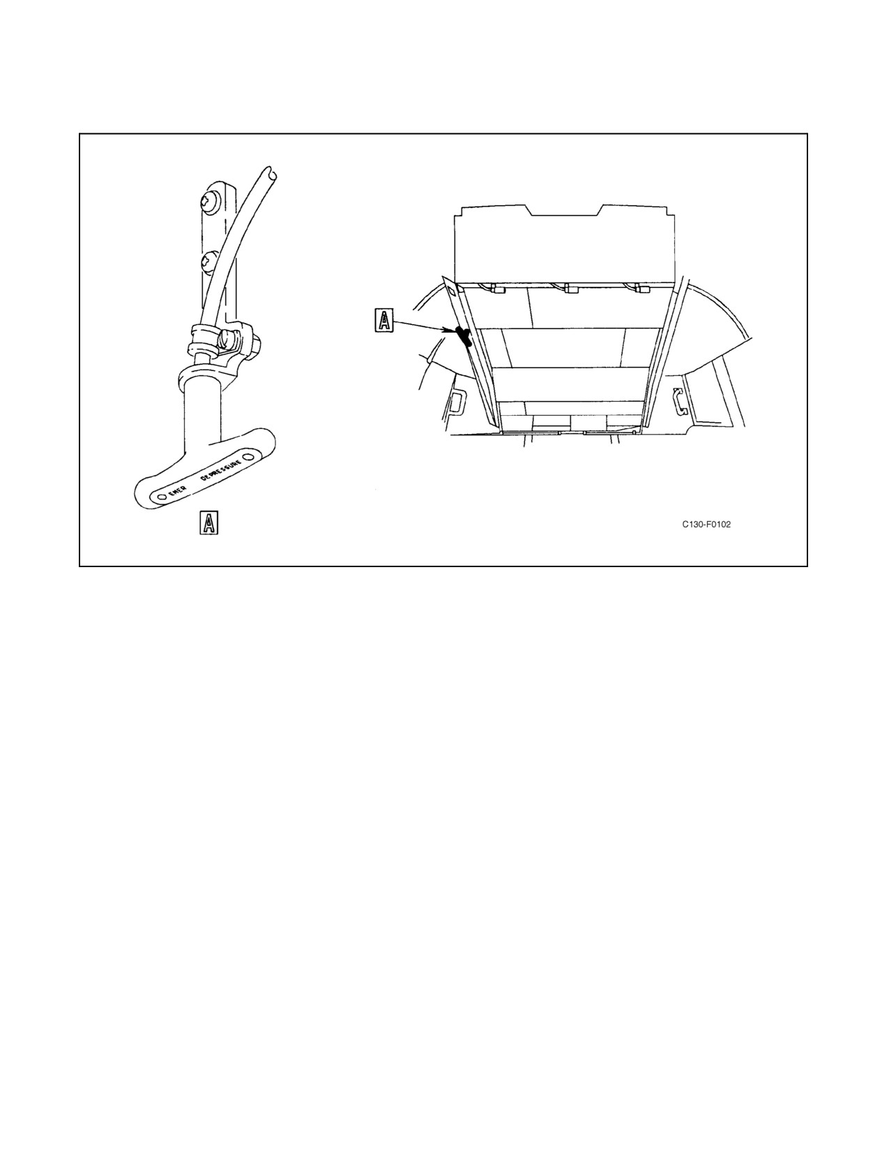
Figure 2-70. Emergency Depressurization Handle
2.17.4.6 Pressurization Test Valves
An isobaric and an atmospheric test valve, labeled NO. 1 and NO. 2 respectively, are located on the left side of the
overhead control panel. These valves, wired in the open position, are intended only for ground use.
2.17.4.7 Differential Pressure Gauge
The differential pressure gauge, located on the air-conditioning and pressurization control panel (see Figure 2-66),
senses both cabin and atmospheric pressures and indicates the pressure differential in inches of mercury.
2.17.4.8 Indicator
The cabin rate-of-climb indicator, which shows the rate of change of cabin altitude in feet per minute, is mounted
on the air-conditioning and pressurization control panel (see Figure 2-66).
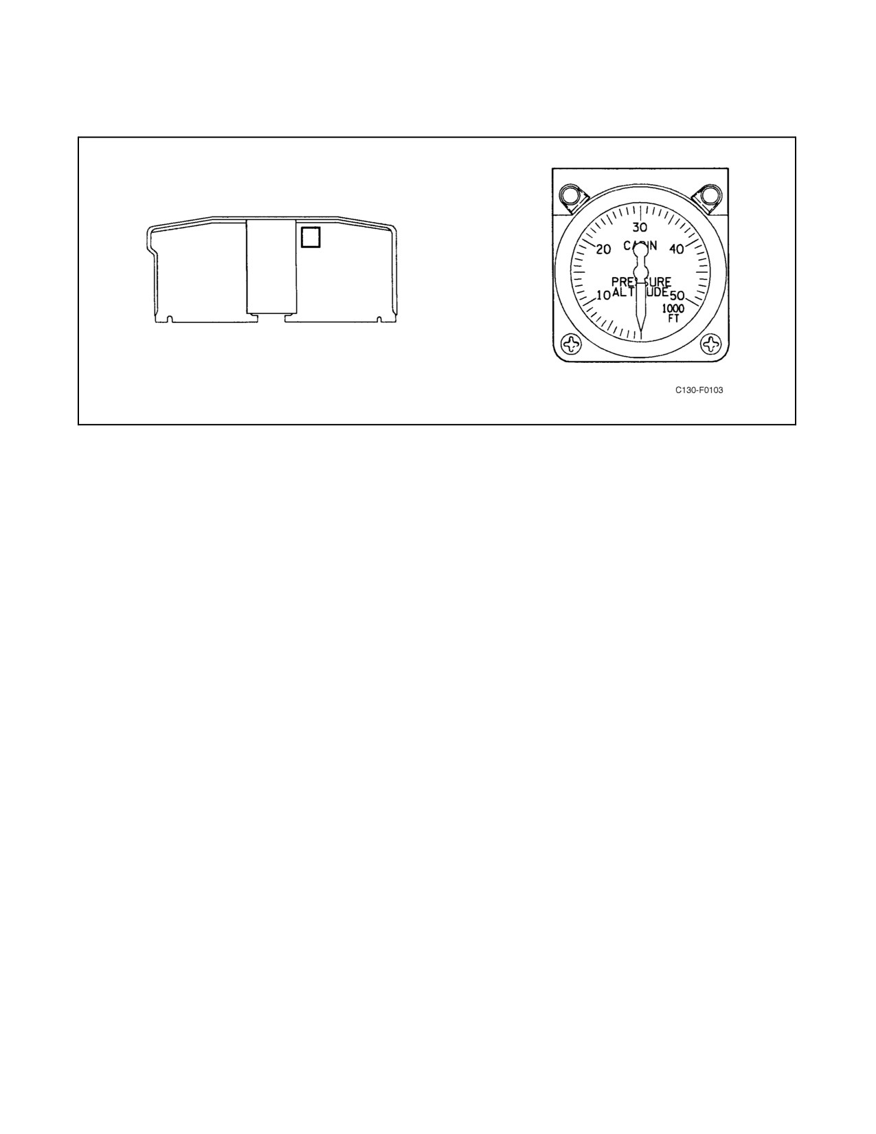
2.17.4.9 Cabin Altimeter
The cabin altimeter (see Figure 2-71) in the copilot instrument panel indicates cabin air pressure altitude within the
range of 0 to 50,000 feet.
2.18
ANTI-ICING AND DEICING SYSTEMS
Anti-icing systems, which can be used to prevent the formation of ice on critical areas of the aircraft, and de-icing
systems, which will remove ice after it is formed, are installed on the aircraft. Heat for the systems is obtained either
by the use of electrical heating elements or by heated air drawn from the compressor of each engine.
2-141
ORIGINAL
01-75GAL-1
Figure 2-71. Cabin Altimeter
Anti-icing systems using heated air from the bleed-air system serve thewing and empennage leading edges, thenose
radome, and the engine inlet air and oil cooler scoops. Anti-icing of the engine compressor inlet vanes also is
accomplished by heated air, but this is supplied directly from the engine compressor and not through the bleed-air
system.
Anti-icing systems using heat from electrical sources are installed for the windshield, pitot tubes, and the forward
section and afterbody of the propeller spinner. De-icing of the propeller blades and rear section of the propeller
spinner also is accomplished electrically. An ice detection system may be used to achieve automatic operation of the
following anti-icing and deicing systems:
1. Engine inlet airscoop anti-icing.
2. Compressor inlet vane anti-icing.
3. Propeller spinner forward section and afterbody anti-icing.
4. Propeller blade deicing.
5. Propeller spinner middle and rear section deicing.
6. Propeller spinner plateaus deicing.
2.18.1 Wing and Empennage Leading Edge Anti-Icing System
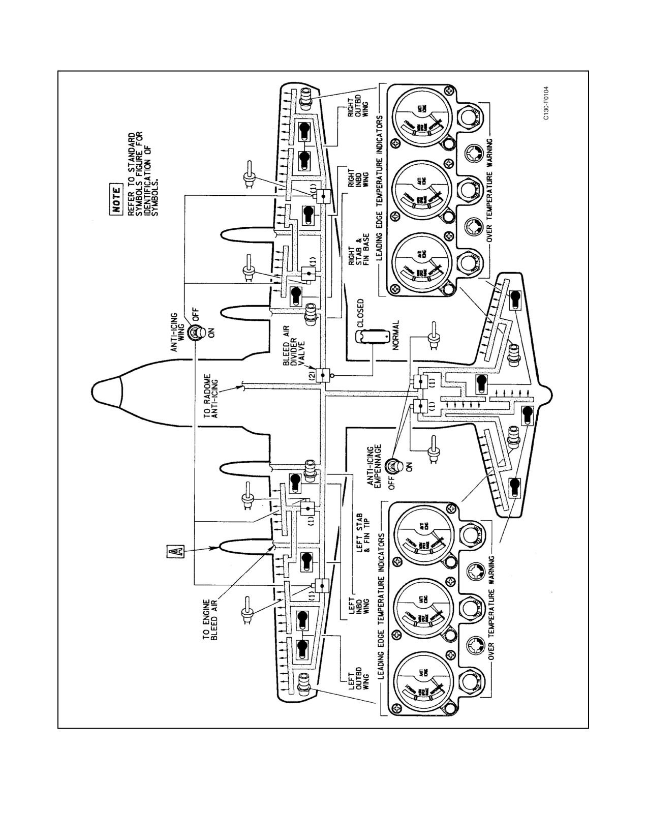
The leading edge anti-icing system (see Figure 2-72) is divided into six sections, each consisting of a shutoff valve,
ejectors, and control components. The shutoff valves control the flow of air from the bleed-air system to the ejectors,
where it is ejected through small nozzles into mixing chambers. The hot bleed air at approximately 600 _F is mixed
with the ambient air drawn into the mixing chambers. The resultant mixed air at approximately 350 _F flows through
passages next to the leading edge skin. Since some of the air leaving the passages is drawn back in for recirculation,
a lower percentage of bleed air is required for continuous anti-icing. An overheat warning system is installed in the
leading edge area.
When the temperature in the leading edge area reaches approximately 200 _F, the overheat warning light for that area
is energized and the light illuminates.
ORIGINAL
2-142
01-75GAL-1
Figure 2-72. Anti-Icing System (Sheet 1 of 2)
2-143
ORIGINAL
01-75GAL-1
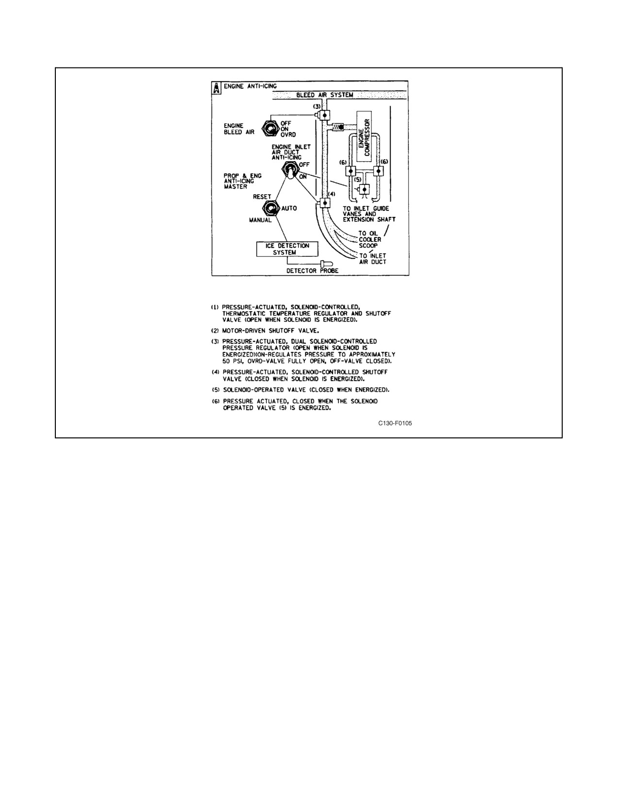
Figure 2-72. Anti-Icing System (Sheet 2)
2.18.1.1 WING and EMPENNAGE ANTI-ICING Switches
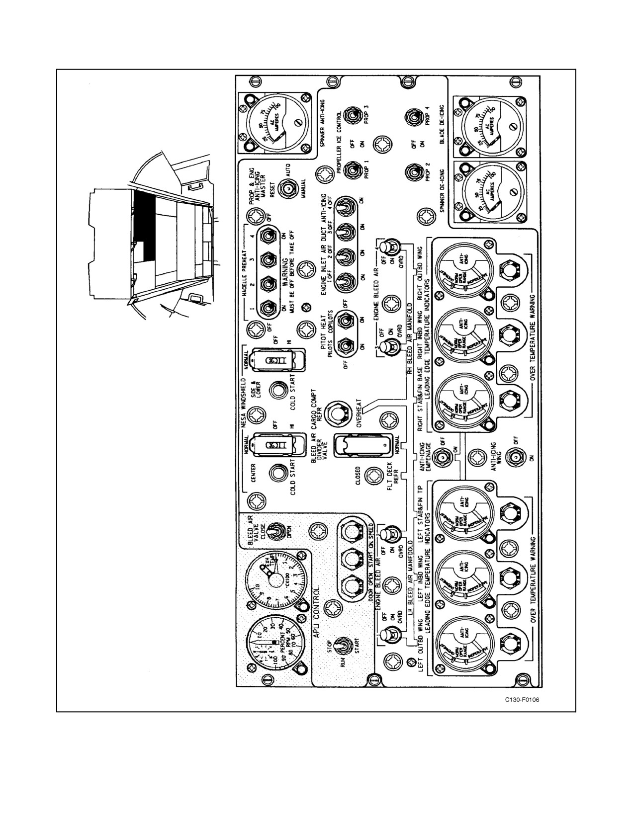
The WING and EMPENNAGE ANTI-ICING switches are two-position (ON, OFF) toggle switches, located on the
anti-icing and deicing system control panel (see Figure 2-73). When the switches are placed in the ON position,
solenoids on theanti-icing shutoffvalves areenergized and thevalves control theflowofbleedairtotheleadingedge
air ejectors. When the switches are in the OFF position, the anti-icing regulators shut off the flow of bleed air.
Electrical power for control of the wing and empennage anti-icing shutoff valves is supplied from the essential dc
bus, through the WING and EMPENNAGE ICE CONTROL circuit breakers on the copilot lower circuit breaker
panel.
2.18.1.2 Leading Edge Temperature Indicators
Six leading edge temperature indicators, one for each section of the anti-icing system, are located on the anti-icing
and deicing system control panel (see Figure 2-73). Each indicator is connected to a resistance bulb located in the
leading edge area. The resistance bulbs are placed so that they sense the temperature of the air in the area aft of the
leading edge skin, not the hot air passing next to the skin. Electrical power for the indicators is supplied from the
essential dc bus, through the WING and EMPENNAGE TEMP INDICATOR circuit breaker on the copilot lower
circuit breaker panel.
ORIGINAL
2-144
01-75GAL-1
Figure 2-73. Anti-Icing and Deicing Systems Control Panels
2-145
ORIGINAL
01-75GAL-1
2.18.1.3 Leading Edge Over Temperature Warning Lights
Six OVERTEMPERATURE WARNING lights, one for each section of the leading edge anti-icing system, are
located below the temperature indicators on the anti-icing and deicing system control panel (see Figure 2-73). When
the temperature in the leading edge reaches approximately 200 _F, the warning light for that area illuminates.
Electrical power for the lights is supplied from the essential dc bus through the WING and EMPENNAGE
OVERHEAT LIGHTS circuit breaker on the copilot lower circuit breaker panel.
2.18.1.4 Normal Operation of Leading Edge Anti-Icing System
The wing and empennage leading edge anti-icing system is turned on or off by the ANTI-ICING switches on the
anti-icing and deicing system control panel. Regulation of temperatures within the leading edges is achieved
automatically by thermostatic control of the valves permitting entry of bleed air to the system ejectors. The
temperature indicators on the control panel, however, should be monitored while the system is operating since an
emergency condition will exist if either the associated indicators or the warning lights show an overheated condition
in any section.
CAUTION
The leading edge anti-icing system must not be used to remove ice from
surfaces when the aircraft is on the ground. With no airflow over the
surface, the air within the leading edge area quickly rises in temperature and
the excessive heat damages fuel tank sealants, paint, structure, and other
equipment. If the system is operated for testing, constant monitoring of the
temperature indicators must be maintained and the system must not remain
on for more than 30 seconds.
2.18.2 Radome Anti-Icing System
Deactivated.
2.18.3 Engine Inlet Air Duct Anti-Icing Systems
Two systems (see Figure 2-72) are provided for engine inlet air duct anti-icing. One system routes bleed air from the
bleed-air system to passages in the engine inlet airscoop and oil cooler scoop to heat the scoops.
The other system routes air from the compressor diffuser section of the engine to passages in the compressor inlet
vanes. The scoop anti-icing airflow is shut off by a solenoid valve that is energized closed. The air flows when the
valve is deenergized open. The vane anti-icing airflow is controlled by two pressure-actuated valves, which are
controlled by a single solenoid valve. When the solenoid valve is energized, the pressure-actuated valves shut off
the airflow, and, when thesolenoid valveis deenergized, the pressure-actuated valves open. Both thescoop and vane
anti-icing systems are termed fail-safe, meaning that anti-icing is provided when the system power supply is lost.
The electrical control circuits are interconnected with the ice detection system so that the duct anti-icing can be turned
on automatically when the detection system senses icing.
2.18.3.1 ENGINE INLET AIR DUCT ANTI-ICING Switches
Four ENGINE INLET AIR DUCT ANTI-ICING switches are located on the anti-icing and deicing systems control
panel (see Figure 2-73). Each switch has ON and OFF positions. If a switch is in the ON position, the scoop and vane
anti-icing systems for that engine are turned on if the PROP & ENG ANTI-ICING MASTER switch is in MANUAL.
If the master switch is in the AUTO position, anti-icing is turned on when the ice detection system detects ice. When
an ENGINE INLET AIR DUCT ANTI-ICING switch is in the OFF position, both scoop and vane anti-icing valves
for that engine close to shut off the anti-icing airflow.
2.18.4 Propeller Anti-Icing and Deicing Systems
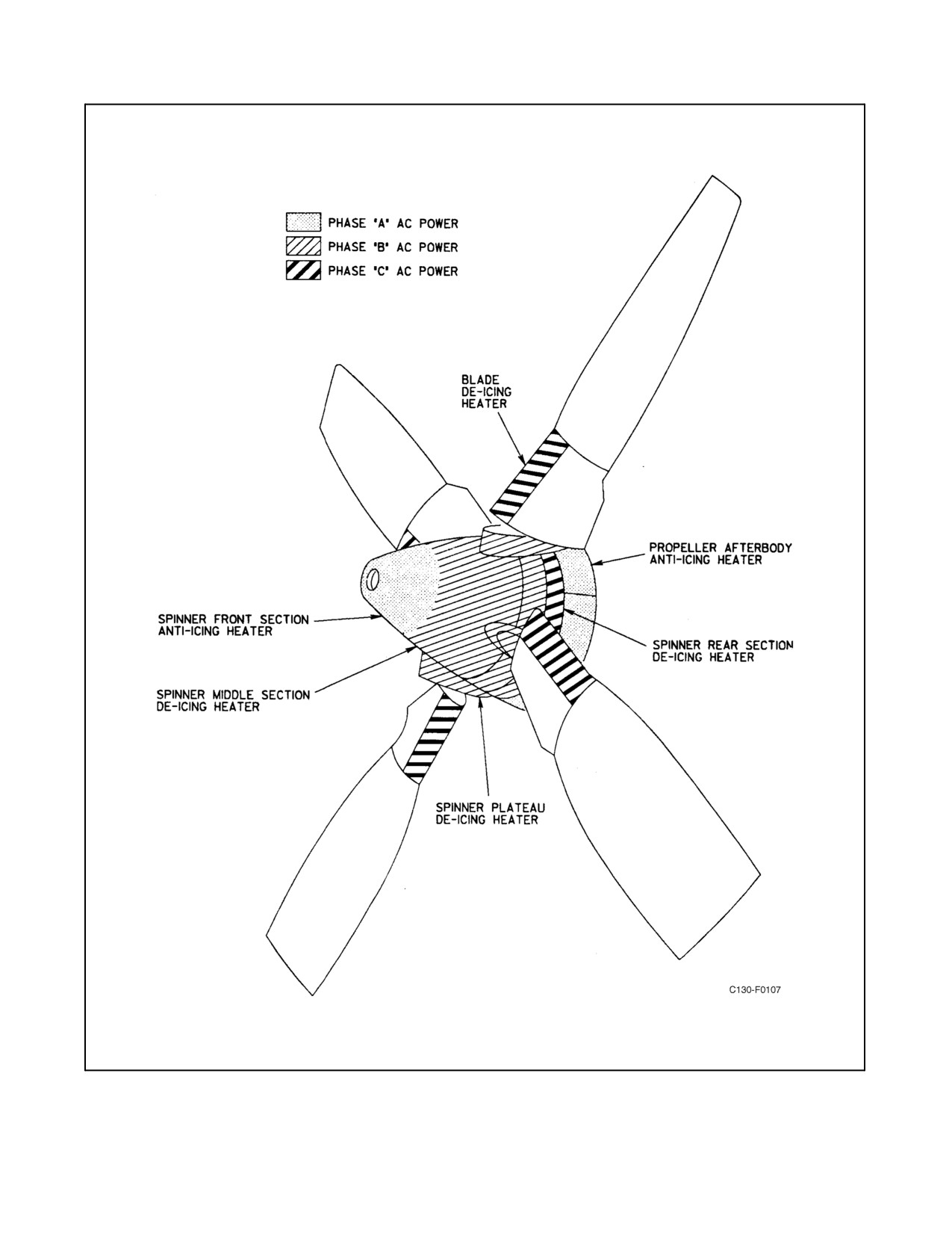
The propeller spinner and blades are equipped with heating elements for anti-icing and deicing (see Figure 2-74).
ORIGINAL
2-146
01-75GAL-1
Figure 2-74. Propeller Anti-Icing and Deicing System
2-147
ORIGINAL
01-75GAL-1
2.18.4.1 Propeller Anti-Icing System
The forward section of the spinner and the propeller afterbody are covered by electrical-resistance heating elements
to provide anti-icing. Phase A primary ac power is applied to the heating elements to warm the surface of thespinner
and prevent the formation of ice. The ac power is applied by relays controlled by dc control circuits that are protected
by the SPINNER ANTI-ICING circuit breakers on the pilot upper circuit breaker panel. The control circuits are
interconnected with the ice detection system so that the propeller anti-icing can be turned on automatically when the
detection system senses icing. The propeller anti-icing is a continuous-heating-type system.
2.18.4.2 Propeller Deicing System
The aft portion of the front spinner section, the rear rotating spinner section, the spinner plateaus, and the leading
edges and fairing of the propeller blades contain heating elements for deicing the surfaces. The aft portion of the front
spinner section, along with the forward part of the rear rotating spinner section and the spinner plateaus, use phase
B p rimary ac power and are protected by the SPINNER DE-ICING circuit breaker on the upper main ac distribution
panel. The aft portion of the rear rotating spinner section and the leading edges and fairing of the propeller blades
use phase C primary ac power and are protected by the BLADE DE-ICING circuit breaker on the upper main ac
distribution panel. The heating elements are supplied with 115-Vac power from the RH ac bus through the BLADE
and SPINNER DE-ICING circuit breakers on the upper main ac distribution panel. The control circuits for the
propeller deicing, like the control circuits for the propeller anti-icing system, are connected to the ice detection system
so that they may be turned on automatically. The application of spinner and blade deicing power to the heating
elements is controlled by the deicing timer. The timer receives 28-Vdc power from the essential dc bus through the
PROPELLER DE-ICING TIMER circuit breakeron thecopilot lowercircuit breakerpanel. Thetimer applies power
to theheating elements ofonly onepropellerat atime; theelements of each propellerareenergized15 secondsduring
each 1-minute cycle.
2.18.4.3 PROPELLER ICE CONTROL Switches
Four PROPELLER ICE CONTROL switches are located on the anti-icing and deicing systems control panel (see
Figure 2-73). These two-position (ON, OFF) toggle switches control the propeller anti-icing and deicing systems.
When a switch is placed in the ON position and the PROP & ENG ANTI-ICING MASTER switch is in the MANUAL
position, the anti-icing and deicing systems for the corresponding propeller are energized. If a switch is positioned
to ON while the PROP & ENGINE ANTI-ICING MASTER switch is in the AUTO position, the anti-icing and
deicing systems are energized only when the ice detection system detects icing. When a switch is placed in the OFF
position, the anti-icing and de-icing systems for the corresponding propeller are deenergized.
2.18.4.4 Anti-Icing and Deicing Ammeters
Three ammeters located on the anti-icing and deicing systems control panel (see Figure 2-73) indicate the amperage
of the various phases of primary ac power drawn for the propeller anti-icing and deicing systems. The SPINNER
ANTI-ICING ammeter indicates the amperage of phase A power drawn for anti-icing; the SPINNER DE-ICING
ammeter indicates the amperage of phase B power drawn for deicing; and the BLADE DE-ICING ammeter indicates
the amperage of phase C power drawn for deicing.
2.18.5 Ice Detection System
The ice detection system is used as an automatic control for turning on the radome anti-icing, engine inlet air duct
anti-icing, and propeller anti-icing and deicing systems. The detection system consists of a PROP & ENG
ANTI-ICING MASTER switch, two sets of detector units, indicator lights, a test switch, and control relays. Each
set of detection units has a detector and an interpreter. Each detector includes a probe: one is mounted in the No. 2
engine inlet air duct, and the other is in the No. 3 engine duct. The detection units are armed by dc power applied
through theenginestarting circuits, and they areoperativewhen theNo. 2 orNo. 3 engines arerunning and thePROP
& ENG ANTI-ICING MASTER switch is in AUTO. If either probe becomes iced over while the engine in which
it is installed is running, and if the PROP & ENG ANTI-ICING MASTER switch is in the AUTO position at that
ORIGINAL
2-148
01-75GAL-1
time, the detection units trigger a control relay. This relay turns on the anti-icing and deicing systems if the switches
for those systems are in the ON or AUTO positions. The relay also turns on an indicator light. The ice detection system
does not turn off the anti-icing and de-icing systems automatically when icing conditions no longer exist, but the
master switch can be held at the RESET position to turn them all off simultaneously. Timers in the ice detection
systemoperateaftertheNo.2andNo.3enginesareshutdownanddisarmthedetectionsystem.Ifanyoftheanti-icing
or deicing systems have been left in automatic operation, they are turned off upon disarming of the detection system
at engine shutdown.
2.18.5.1 PROP & ENGINE ANTI-ICING MASTER Switch
The PROP & ENG ANTI-ICING MASTER switch is located on the anti-icing and deicing systems control panel
(see Figure 2-73). It has three positions: AUTO, MANUAL, and RESET. When in the AUTO position, it permits
control of the radome anti-icing, engine inlet air duct anti-icing, and propeller anti-icing and deicing systems by the
ice detection system. The AUTO position is also used to permit testing of the ice detection system. When in the
MANUAL position, the switch permits control of the anti-icing and deicing systems by the individual control
switches for the systems. The RESET position is a momentary position used to turn off the anti-icing and deicing
systems when icing conditions no longer exist. When the switch is positioned at RESET and allowed to return to
AUTO, the ice detection system remains armed; therefore, it will automatically turn on the anti-icing and deicing
systems again if it senses icing.
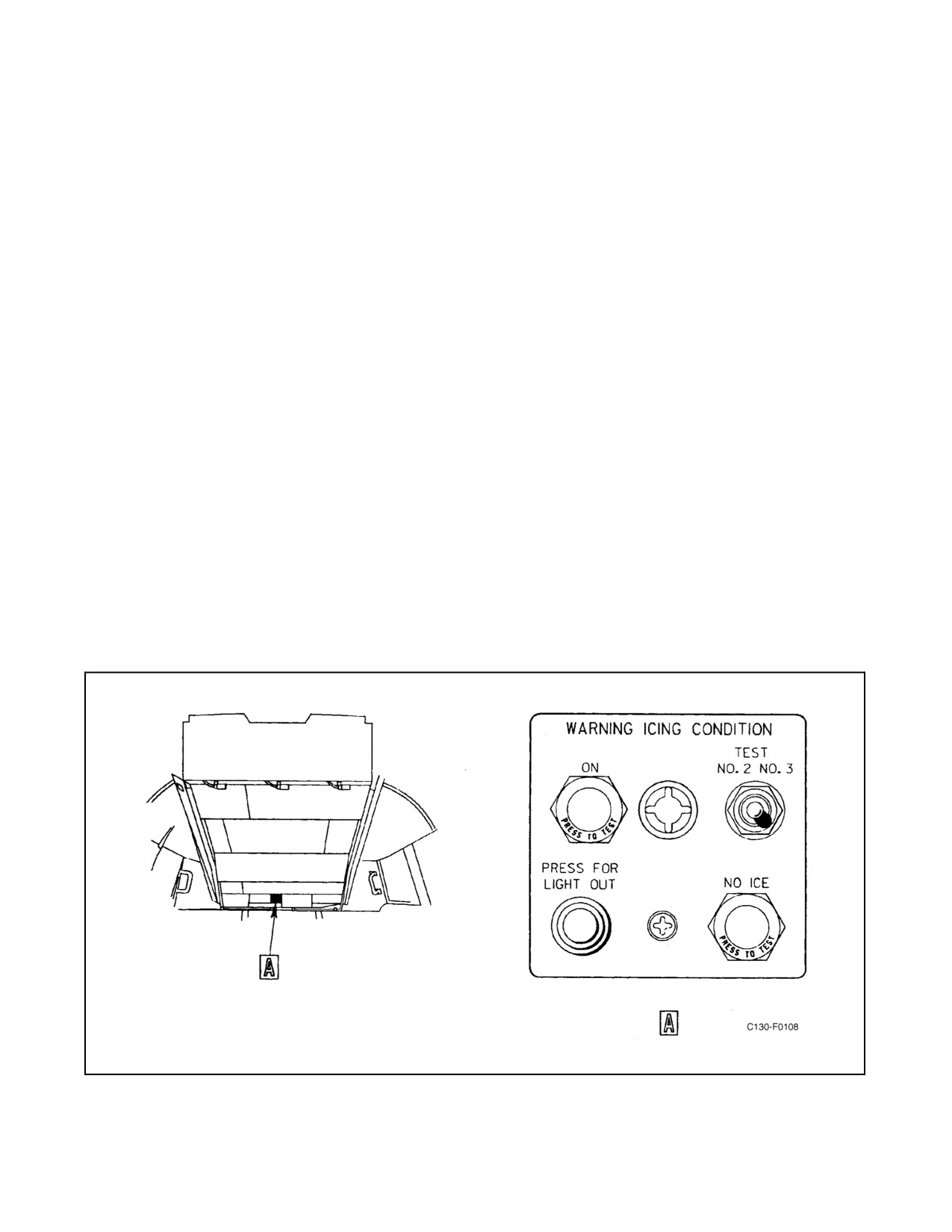
2.18.5.2 TEST Switch
The TEST switch is located on the ice detection panel (see Figure 2-75). It has NO. 2 and NO. 3 momentary positions
and a center off position. It is used to test operation of the two sets of ice detector units by simulating ice detections.
If it is held in the NO. 2 position while the No. 2 engine is running and the PROP & ENG ANTI-ICING MASTER
switch is in AUTO, the ON indicator light on the ice detection panel illuminates to indicate that the ice detection
system has triggered the control relay that turns on the anti-icing and deicing systems. The NO. 3 position of the
switch is used in thesamemannertotest operationoftheothersetofdetectorunits. AftertheTESTswitch isoperated
to either position, the PROP & ENG ANTI-ICING MASTER switch must be held at RESET momentarily in unlock
the control relay and to rearm the detection system.
Figure 2-75. Ice Detection Panel
2-149
ORIGINAL
01-75GAL-1
2.18.5.3 ON Light and PRESS FOR LIGHT OUT Switch
The ON light and the PRESS FOR LIGHT OUT switch are located on the ice detection panel (see Figure 2-75). The
indicator light is turned on by the ice detection system whenever it detects ice while the PROP & ENG ANTI-ICING
MASTER switch is in the AUTO position. When lighted, it indicates that icing has been detected by probes in the
engine inlet airscoops and that anti-icing systems have been turned on automatically if the individual system switches
are set at ON or AUTO. It also lights when the TEST switch is operated and, then, indicates that the detection units
are functioning. The momentary light out switch can be operated to turn the light off. If the PROP & ENG
ANTI-ICING MASTER switch is held in the RESET position to turn off the anti-icing and deicing systems, the light
remains off if icing no longer exists.
2.18.5.4 NO ICE Light
The NO ICE light is on the ice detection panel (see Figure 2-75). It is turned on when the probes of the detection
system areno longericingand indicatesthat theanti-icing anddeicing systemscan beturned off.IfthePROP &ENG
ANTI-ICING MASTER switch is held in the RESET position to turn the anti-icing and deicing systems off, the light
also goes off.
2.18.6 Pitot Tube Anti-Icing System
Pitot-static tube anti-icing is provided to the four pitot-static tubes by ac electric heating elements. The heating
elements are energized by 115-volt, single-phase ac power from the essential ac bus through the PITOT HEAT NO.
1, NO. 2, NO. 3 and NO. 4 circuit breakers on the pilot side circuit breaker panel. Control of the pitot-static tube
anti-icing system is provided by the PITOT HEAT switches located on the overhead anti-icing control panel. Two
PITOT HEAT OFF indicator lights are installed on the main instrument panel to inform the pilot of system status.
2.18.6.1 PITOT HEAT Switches
The pilot and copilot PITOT HEAT switches are located on the anti-icing and deicing systems control panel (see
Figure 2-73). These two-position toggle switches have ON and OFF positions. The PITOT HEAT PILOTS switch
energizes the No. 1 (upper left side) and the No. 3 (lower right side) pitot-static tube heating elements. The PITOT
HEAT COPILOTS switch energizes the No. 2 (upper right side) and the No. 4 (lower left side) pitot-static tube
heating elements. When a switch is placed in the ON position, the heating elements for the corresponding pitot tubes
are energized and the corresponding PITOT HEAT OFF indicator light is extinguished. When the switch is in the
OFF position, the corresponding heating elements are deenergized and the corresponding PITOT HEAT OFF
indicator light is illuminated.
2.18.6.2 PITOT HEAT OFF Lights
Two amber PITOT HEAT OFF indicator lights are installed on the main instrument panel to show that the affected
system is turned off, or, if the system is turned on to show that a heating element is inoperative (see Figures 2-78
and 2-79). The indicator lights use 28-Vdc power from the isolated dc bus through the PITOT HEATER IND circuit
breaker on the pilot side circuit breaker panel.
2.18.7 Windshield Anti-Icing System
The three windshields, the two windows on each side of the windshields, and the two lower windows in front of the
pilot are NESA-type. These panels are heated by applying unregulated ac power from the left-hand ac bus to a
resistance material between the layers of glass. The ac power is applied by automatic dc control systems that cycle
to maintain window temperature within specific limits. A center windshield system controls heating of the three
center windshields, and a side and lower system controls heating of the side and lower windows. The two systems
are identical except for the amount of total ac power provided. Provisions are made for selecting either a normal or
ORIGINAL
2-150
01-75GAL-1
highrateofheating.Whenahighrateisselected,highervoltageisappliedforshorterperiodsoftimesothattheNESA
heats more rapidly, but not to a higher temperature. Provisions are also made for controlling the temperature increase
manually when the NESA panels are extremely cold. The control systems do not function automatically when
window temperature is below -45 _F.
CAUTION
Operation ofNESA anti-icing when outsideairtemperatureis above27 _C
(81 _F) will increase the possibility of delamination within the NESA
panels.
2.18.7.1 NESA WINDSHIELD Switches
The NESA WINDSHIELD switches are on the anti-icing and deicing systems control panel (see Figure 2-73). Each
switch has NORMAL, OFF, and HI positions. When the center windshield switch is in the NORMAL position, the
three center windshields are heated at the normal rate. If the switch is positioned to HI, the three center windshields
have higher voltage applied to the heating material so that they heat more rapidly. Heating of the side and lower
windows is controlled in the same manner by the side and lower windshield switch.
2.18.7.2 NESA WINDSHIELD COLD START Switches
The COLD START switches are located on the anti-icing and deicing systems control panel (see Figure 2-73) next
to theNESA WINDSHIELD control switches. TheCOLD START switchesarepush-typemomentary switches.The
purpose of the switches is to provide manual control of windshield heating to raise the windshield temperature
gradually from extremely cold temperatures to prevent damaging the glass panels. If the temperature of the
windshield panels is below -45 _F, the control systems do not function automatically. Pressing the COLD START
switches causes the control systems to apply ac power to the windshield panels while the switches are held.
2.18.8 Nacelle Preheat System (If Installed)
Note
The NACELLE PREHEAT system is inoperative due to the NACELLE
PREHEAT valve not being installed.
When the nacelle preheat valves are installed, the nacelle preheat system allows hot air from the bleed-air system to
flow into the nacelle to heat the engine and nacelle equipment before starting the engine. A solenoid valve and diffuser
in each nacellecontrols theairflow. Theenginebleed-airregulatorin anacellemust beopen beforebleed air can flow
to the preheat valve; the ENGINE BLEED AIR switch must be in OVRD. The preheat valves are controlled by four
nacelle preheat switches on the anti-icing and deicing systems control panel (see Figure 2-73). The control circuits
for the valves are energized by 28-Vdc power from the isolated dc bus through the NACELLE PREHEAT circuit
breakers on the copilot lower circuit breaker panel only while the corresponding engine condition levers are in the
GROUND STOP or FEATHER position and the aircraft is on the ground.
2.18.8.1 NACELLE PREHEAT Switches
The four NACELLE PREHEAT switches, located on the anti-icing and deicing systems control panel, are
two-position (ON, OFF) toggle switches (see Figure 2-73). When a switch is placed in the ON position while the
aircraft is on the ground and the corresponding engine condition lever is at GROUND STOP or FEATHER, the
nacelle preheat valve (when installed) is energized open and remains open as long as the switch is in the ON position.
Placing the NACELLE PREHEAT switch in the OFF position deenergizes the valve (when installed) closed.
2-151
ORIGINAL
01-75GAL-1
Note
Nacelle preheat is operational only when the touchdown switch is closed,
that is, when the aircraft is on the ground.
2.19
AUXILIARY POWER UNIT
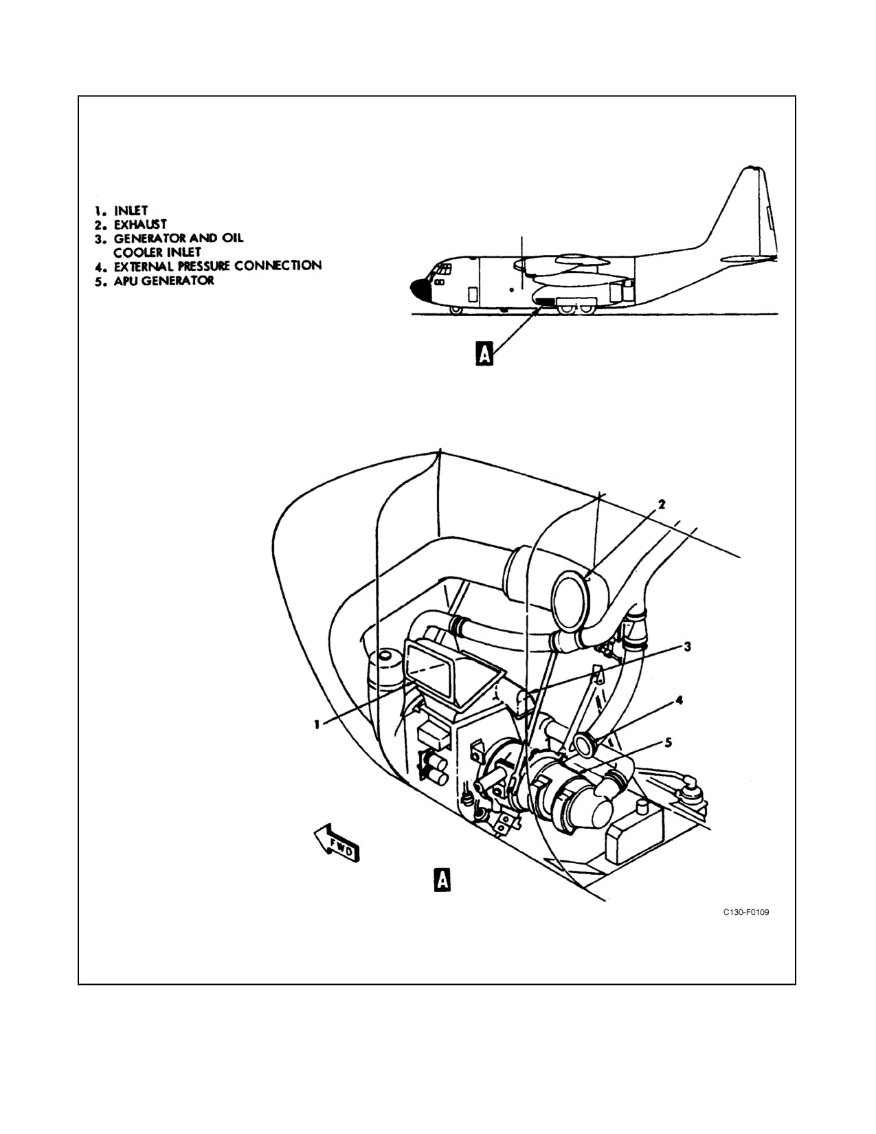
The APU (see Figure 2-76), located forward in the left wheelwell, supplies air for ground operation of the
air-conditioning systems, for engine starting, and provides shaft power to drive a 40-Kva ac generator.
The unit is composed of a compressor assembly, power turbine assembly, and an accessory assembly. The APU
ignition and electrical controls are energized by 28-Vdc power provided by the isolated dc bus through the APU
CONTROL circuit breaker on the pilot side circuit breaker panel.
2.19.1 Compressor Assembly
The APU uses a two-stage, centrifugal-type compressor. When the compressor is operating at full speed, part of the
compressed air is discharged into the power turbine to support combustion and the remainder is available as
pneumatic power.
2.19.2 Power Turbine Assembly
The power turbine assembly drives the compressor and the APU accessories. The assembly consists of a turbine
section and a combustor . Fuel is injected into the combustion chamber, mixed with air, and burned. The combustion
gases are directed against the turbine wheel, which supplies rotary power to drive the compressor and accessory
assemblies. After being used to turn the turbine wheel, the combustion gases pass out the exhaust.
2.19.3 Accessory Assembly
The accessory assembly of the APU consists of a starter motor, oil and fuel pumps, an oil generator cooler fan,
tachometer generator, mounting pad for shaft powered accessories (APU generator), and a governor. The accessory
group, with the exception of the starter motor, is powered through a reduction gear train directly coupled to the
compressor drive shaft. The starter motor is coupled to the reduction gear train through a spring-loaded clutch.
2.19.4 APU Oil System
The APU oil circulation system provides lubrication for all gears and shaft bearings. Oil from a reservoir in theAPU
compartment is delivered by a gear-type pump through an oil filter to the various lubrication points. A relief valve
in the system maintains the desired pressure. Oil is removed from the unit by a dual scavenge pump and returned to
the reservoir, either through the oil cooler or, if oil temperature is below 27 _C (80 _F), through theoil coolerbypass
valve. An oil drain line is connected to the accessory section to eliminate the possibility of oil accumulation after
the APU is stopped. Oil used in this unit must conform to the specification and grade listed in the servicing diagram
(see Figure 3-1).
2.19.5 APU Fuel System
Fuel is gravity fed from the No. 2 main fuel tank through a motor-operated shutoff valve located in the No. 2 dry bay.
The valve is open when the APU CONTROL switch is in the START position and is held open when the switch is
released to RUN and the START light is illuminated. The valve is closed when the switch is in the STOP position
or when the APU fire emergency control handle is pulled. A fuel strainer is located in line behind the APU
compartment. During the starting cycle, when the oil pressure in the APU oil system reaches approximately 4 psi,
the fuel and ignition circuits are energized through a switch actuated by oil pressure.
ORIGINAL
2-152
01-75GAL-1
Figure 2-76. Auxiliary Power Unit
2-153
ORIGINAL
01-75GAL-1
2.19.6 APU Control System
The operation of the APU is governor-controlled to maintain a nearly constant speed of approximately 100-percent
rpm under varying load conditions. The speed-sensing governor, powered by the accessory gear train, controls the
unit byregulating fuelflow intothecombustionchamber. Anoverspeed switchdeenergizes thecontrol circuit,which
shuts the unit down.
2.19.7 APU Controls
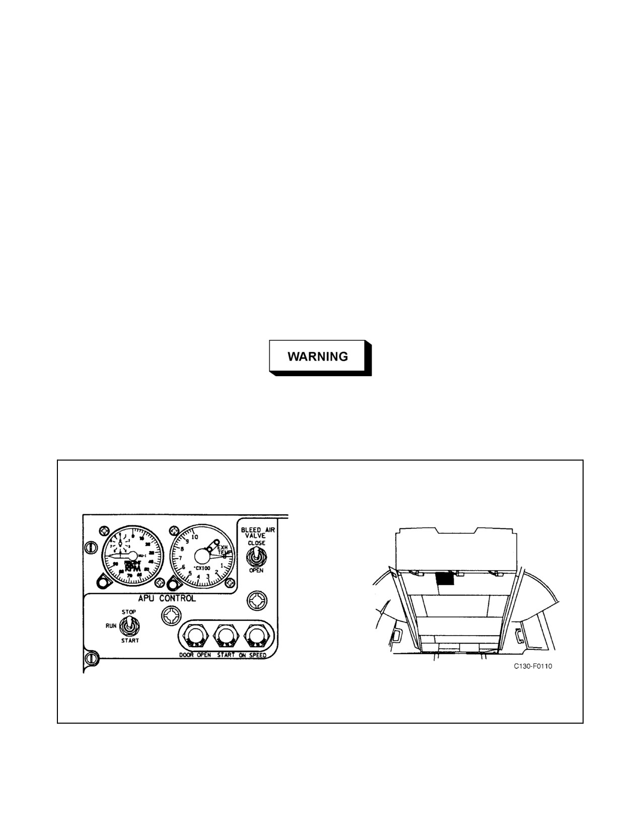
All APU controls are located on the APU control panel on the overhead control panel (see Figure 2-77). The APU
controls are energized by 28-Vdc power from the isolated dc bus through the APU CONTROL circuit breaker on
the pilot side circuit breaker panel.
Athree-position(STOP,RUN,START)toggleswitchcontrolstheoperationoftheAPU.WhentheAPUCONTROL
switch is placed in the RUN or START position, power is supplied to open the APU inlet door. The inlet door is
powered through contacts of the auxiliary touchdown relay. The door opens approximately 35_ on the ground and
15_ in flight.
Ensure that the APU CONTROL circuit breaker on the pilot side circuit
breaker panel is open before working around the APU air intake door.
Failure to comply could result in injury to personnel because of the action
of the APU door.
Figure 2-77. Auxiliary Power Unit Control Panel
ORIGINAL
2-154
01-75GAL-1
Note
The APU door can be opened on the ground to run the APU when the door
actuator has failed by removing the access panel, removing the retaining
bolt on the actuator, sliding the actuator forward to open the door, and
replacing the bolt to retain the door in the open position. To bypass the
actuator limit switch, disconnect the actuator connector plug and attach it
to the dummy receptacle adjacent to the actuator.
Holding the APU CONTROL switch in the spring-loaded START position energizes the start and holding relays,
which opens the wing tank APU fuel shutoff valve and energizes the starter. The start relay remains energized until
the circuit is broken by the 35-percent speed switch or by moving theAPU CONTROL switch to the STOP position.
When the switch is released, it moves to the RUN position. In this position, all APU circuits are energized to the
various automatic controls. These oil-pressure and speed-sensitive switches control their respective circuits to
accomplish starting and running of the APU. When the switch is in the STOP position, all circuits are deenergized.
When the APU CONTROL switch is placed in the STOP position, the overspeed test solenoid breaks the contacts
on the 110-percent speed switch and shuts down the APU. If the 110-percent speed switch is inoperative, the APU
will not shut down and thefireemergency control handlemust bepulled todeenergizetheholding circuitand toclose
the APU fuel shutoff valve in the No. 2 dry bay. When the APU CONTROL switch is placed in the STOP position
or the fire emergency control handle is pulled, the APU inlet door is energized to close after the APU speed has
decreased to approximately 18-percent rpm. This action is provided by an oil pressure switch that actuates at
approximately 20 psi and is done to prevent collapse of the inlet duct because of negative pressure when the door
closes.
2.19.7.1 BLEED AIR VALVE Switch
A BLEED AIR VALVE switch is located on the APU control panel. After the compressor reaches 95-percent rpm,
this two-position (OPEN, CLOSE) toggle switch controls the normally closed, solenoid-operated bleed-air valve.
With the valve closed, air is supplied to the power turbine combustion chamber only. With the valve open, air is
supplied to both the combustion chamber and the bleed-air manifold of the aircraft. Applying a bleed-air load to the
compressor before it reaches operating speed is prevented by the 95-percent speed switch, which completes the circuit
to the BLEED AIR VALVE switch only after operating speed is reached.
2.19.7.2 Fire Emergency Control Handle
The APU fire emergency control handle on the overhead control panel provides for emergency shutdown of the APU.
This handle, when pulled, energizes themotor-operated fuel shutoff valveclosed and energizes theAPU doorclosed
after APU speed has decreased to approximately 18-percent rpm. It also interrupts control power to the APU, causing
it to shut down. The fire extinguisher system control valves are positioned, and the extinguishing AGENT
DISCHARGE switch is armed.
2.19.8 APU Indicators
The indicators for the APU are located on the APU control panel, which is part of the overhead control panel.
2.19.8.1 START Light
A press-to-test START light is located on the APU control panel. This press-to-test light illuminates to indicate that
the starter circuit is energized and engaged with the APU drive train. The light remains illuminated until the
compressor reaches approximately 35-percent rpm, at which time a centrifugal switch deenergizes both the starter
and the start light.
2-155
ORIGINAL
01-75GAL-1
2.19.8.2 APU ON SPEED Light
A press-to-test, ON SPEED light, located on the APU control panel, is energized through the 95-percent speed switch
and indicates that the APU has reached or is maintaining operating speed.
2.19.8.3 APU DOOR OPEN Light
An APU DOOR OPEN light is located on the APU control panel. This press-to-test light illuminates when the APU
intake door is not closed.
2.19.8.4 APU Tachometer
The tachometer located on the APU control panel indicates APU speed in percent of normal APU rpm. Normal rpm
(100 percent) equals 42,000 rpm. A vernier dial on each indicator makes it possible to read to the nearest percentage.
The tachometer system has an APU-driven tachometer generator and is not dependent upon the aircraft electrical
system for operation.
2.19.8.5 Exhaust Gas Temperature Indicator
The EGT indicator is located on the APU control panel. The indicator is graduated from 0 to 1,000 _C with
20_ increments. The EGT system is a thermocouple thermometer that is not dependent upon the aircraft electrical
system for operation.
2.20
INSTRUMENTS
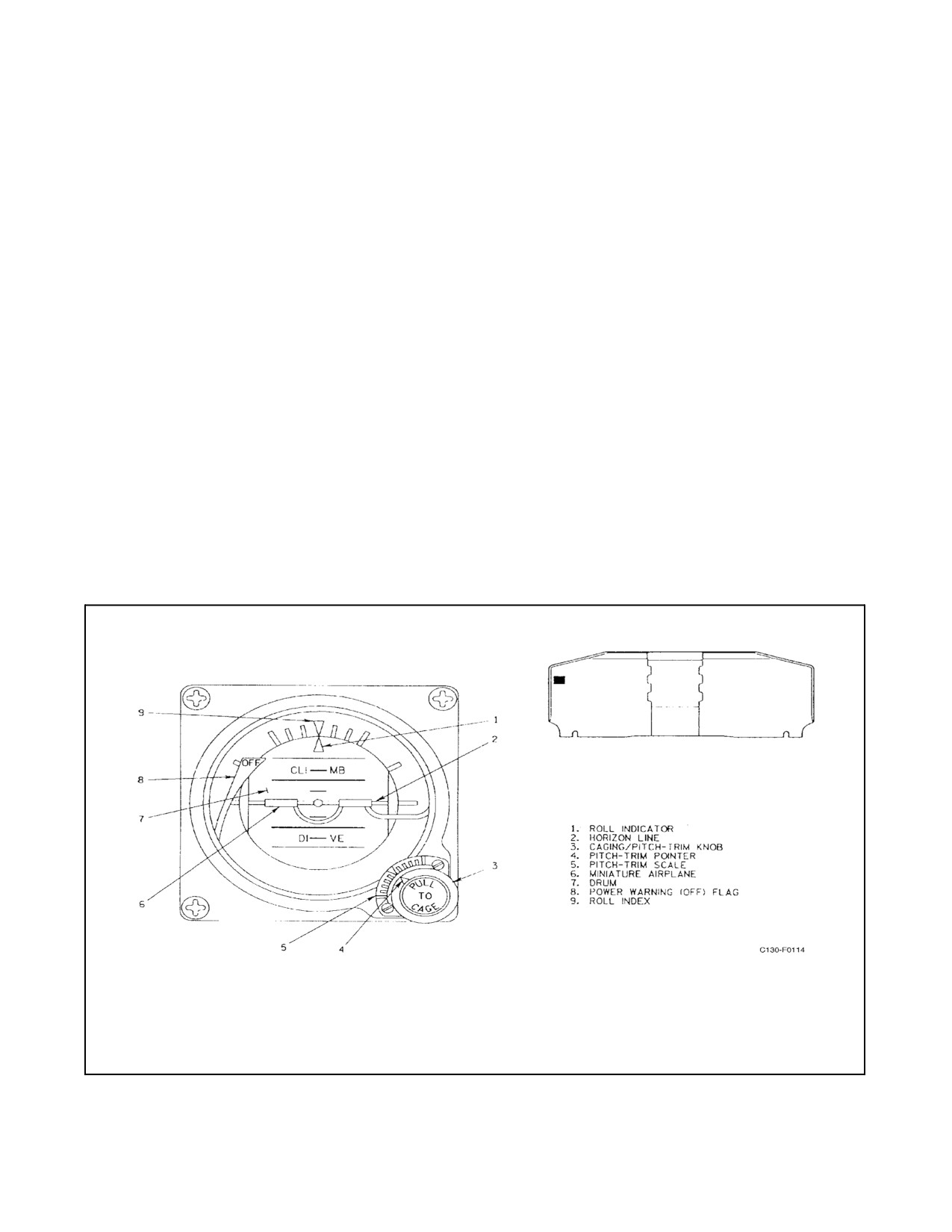
2.20.1 Standby Attitude Indicator
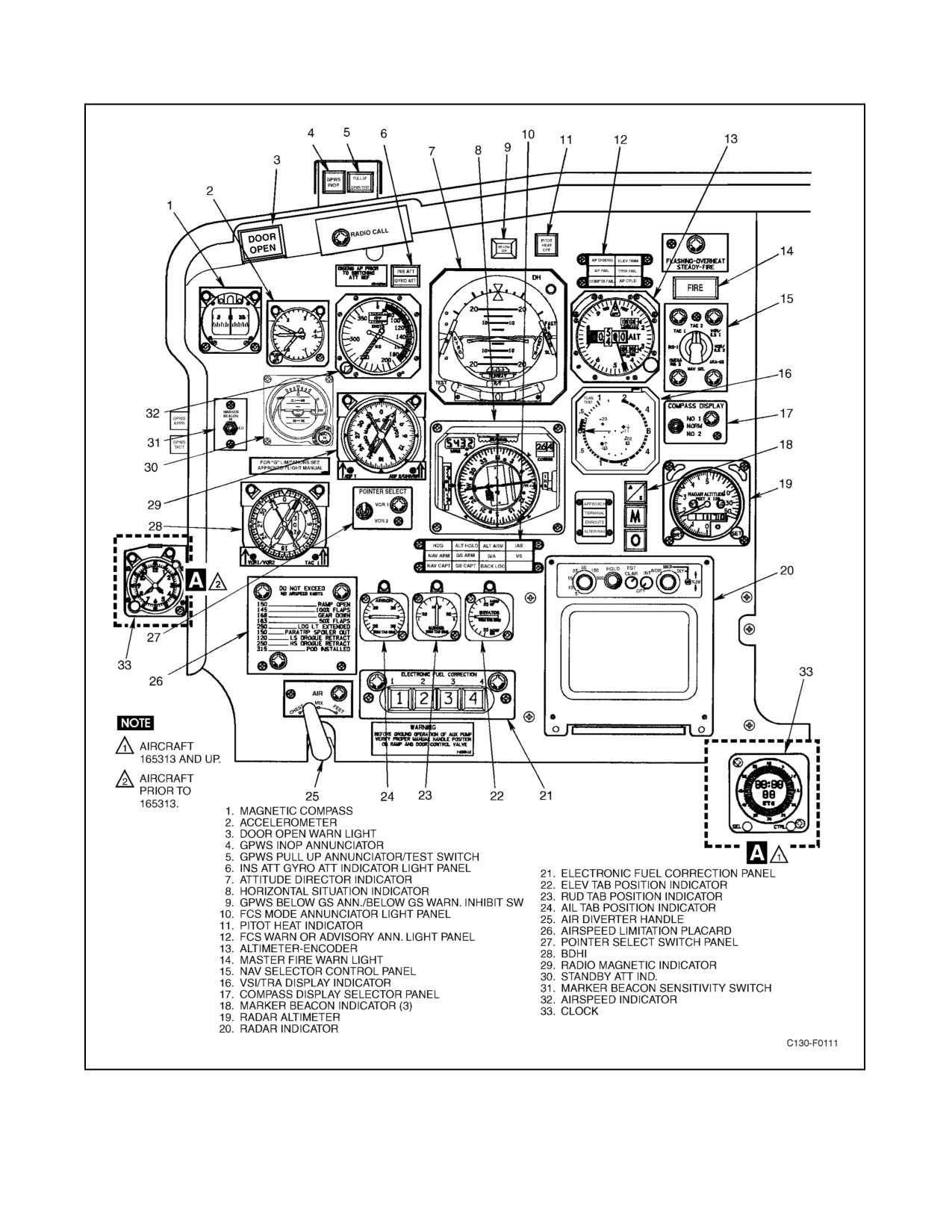
A standby attitude indicator is provided on the pilot instrument panel (see Figure 2-78). The indicator (see Figure
2-81) contains an electrically driven vertical gyro that maintains vertical orientation through use of a mechanical
erection system. The erection system incorporates automatic erection cutoff when subjected to fore-aft or lateral
accelerations exceeding approximately 0.16g. The display of attitude information is accomplished by mechanical
coupling from the vertical gyro to the display drum. A caging pitch trim knob is provided on the lower right corner
of the indicator. A warning (OFF) flag appears when power is removed from the indicator. The warning flag drives
out of view on application of power and appears immediately when power is removed. A switch actuated by the
caging knob causes the warning flag to appear when the caging knob is pulled. The gyro wheel speed and the unique
nature of the erection mechanism combine to provide a minimum of 9 minutes of attitude information after a loss
of power to the indicator. The warning flag being in view during this time period does not invalidate the attitude
information. Power is supplied to the standby attitude indicator from the isolated dc bus through the STANDBY
ATTITUDE INDICATOR circuit breaker on the pilot side circuit breaker panel.
Caging the indicator by pulling the caging/pitch trim knob to its fully extended position orients the gyro spin axis
to the position of thecase. Ifthe indicatorcase is misoriented during caging operation, the spin axis will not becaged
to true vertical and will require time to erect to true vertical. This erection rate is a nominal 2.5 degrees per minute.
Caging of the attitude indicator after power is off during shutdown is recommended.
Note
Pulling the caging/pitch trim knob to the fully extended position, rotating
clockwise, and releasing to a detent position locks the gimbals of the gyro.
This position may be used during turn-on procedure to eliminate nutations
of the drum. To unlock the gimbals (uncage gyro), pull the caging/pitch
trim knob from the detent to fully extended, rotate counterclockwise to
align the miniature aircraft with the horizon line, and slowly allow the knob
to return to its in position. An increase in audible noise may be evident
when operating in the caged position.
ORIGINAL
2-156
01-75GAL-1
2.20.1.1 Operating Procedures
2.20.1.1.1 Startup and Checkout
To place the indicator in operation, perform the following:
1. Adjust lighting via the pilot’s instrument lighting control on the pilot’s side shelf.
2. Uncagethegyro by pulling thecaging/pitch trim knob out, rotating counterclockwise, and gradually releasing
the knob to the full “in” position. Observe that the warning flag is driven from view and the indication is
completely stabilized within 3 minutes.
3. Adjust the caging knob clockwise or counterclockwise to obtain the desired pitch axis presentation.
Note
If the desired pitch trim adjustment cannot be obtained, the indicator may
be installed improperly. Do not recage the indicator to correct pitch attitude
misalignment.
2.20.1.1.2 In-Flight
Theindicatordoesnotnormallyrequireadjustmentduringflight.However,intheeventerrors arecaused byextended
steep maneuvers, the aircraft should be brought to level flight and the indicator should be momentarily caged.
Note
Cage and lock the operating attitude indicator only when the aircraft is at
a complete stop. Never cage and lock the operating attitude indicator while
the aircraft is in motion (i.e., flying, taxiing, towing).
2.20.1.1.3 Postflight
To power down the standby attitude indicator, perform the following:
1. Cage the indicator by pulling the caging/pitch trim knob to the fully extended position, rotating clockwise,
and releasing into the detent position.
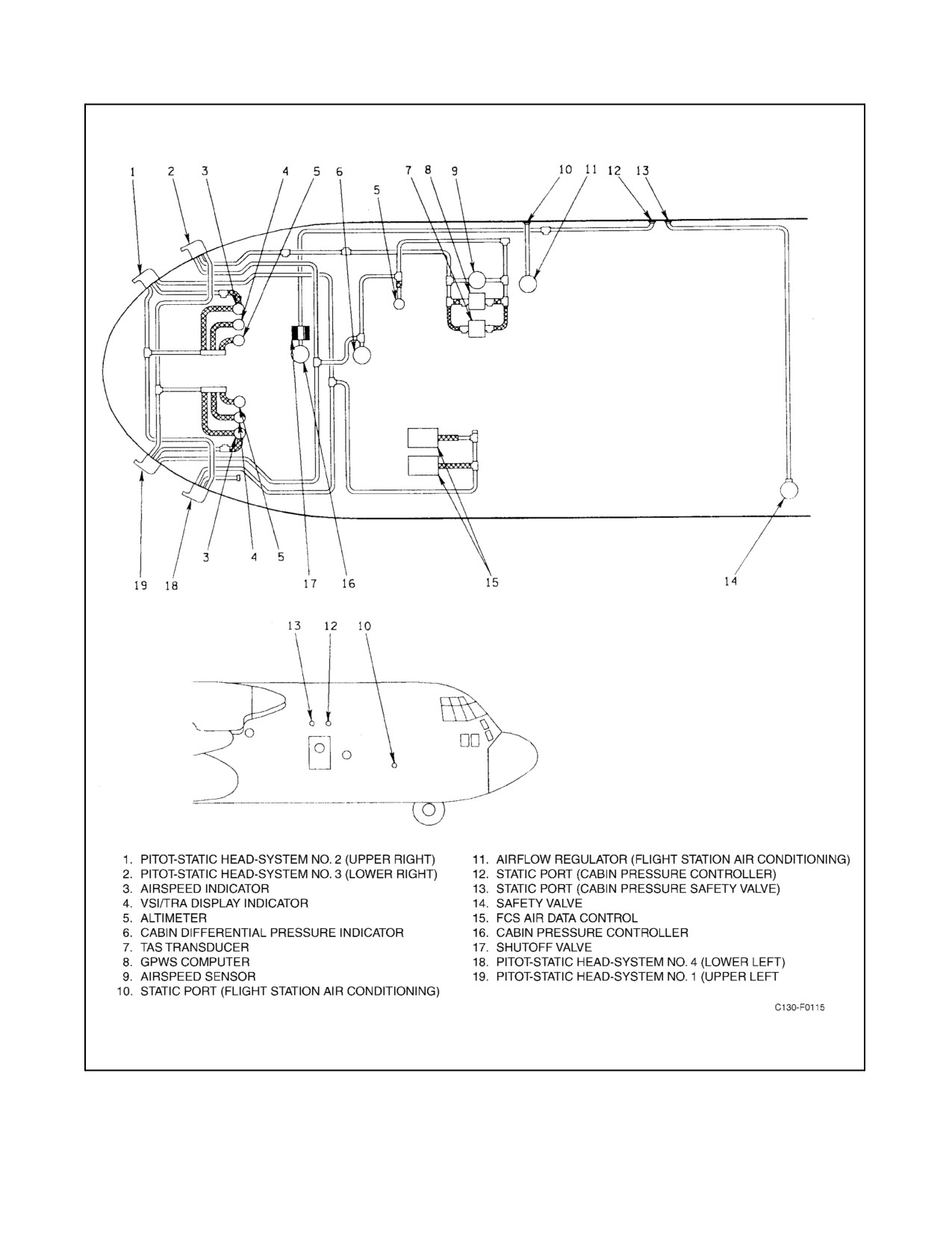
2.20.2 Pitot-Static Instruments
Ram air (pitot) pressure and atmospheric (static) pressure to operate the vertical velocity, airspeed, and altimeter
indicatorsaresuppliedbythepitot-staticsystem(seeFigure2-80).Staticpressureissuppliedforthecabindifferential
pressure indicator, cabin pressure controller, cabin pressure safety valve, and the flight station air-conditioning unit
airflow regulator. Each aircraft is equipped with Rosemount pitot-static probes, two on each side of the aircraft. Each
probe provides one pitot pressure and two static pressure sources for a total of four systems. One system is dedicated
to the pilot instruments; one is for the copilot instruments; and one is for the navigator instruments, TAS computer,
airspeed sensor and cabin differential pressure gauge. The fourth system provides static pressure only to the FCS air
data control units. There are three static ports on the right side of the aircraft to provide atmospheric pressure for the
flight station air-conditioning and cabin pressure control systems.
2.20.2.1 Vertical Speed Indicator/Traffic and Resolution Advisory Display Indicators (VSI/TRA)
Two VSI/TRA indicators, one mounted on the pilot’s instrument panel and the other mounted on the copilot’s
instrument panel, display vertical speed data (current rate of climb/descent) and Traffic Alert and Collision
2-157
ORIGINAL
01-75GAL-1
Figure 2-78. Pilot Instrument Panel
ORIGINAL
2-158
01-75GAL-1
Figure 2-79. Copilot Instrument Panel (Sheet 1 of 2)
2-159
ORIGINAL
01-75GAL-1
Figure 2-79. Copilot Instrument Panel (Sheet 2)
ORIGINAL
2-160
01-75GAL-1
Figure 2-80. Pitot-Static System
2-161
ORIGINAL
01-75GAL-1
Avoidance System (TCAS) information. As a vertical speed indicator, the VSI/TRA provides a standard display of
vertical speed in feet per minute with a range of ±6,000 feet per minute. Refer to paragraph 2.21.21.2 for TCAS
display and operating information. The pilot’s VSI/TRA receives 28 Vdc from the isolated dc bus through the PILOT
VSI/TRA circuit breaker on the copilot’s upper circuit breaker panel. The copilot’s VSI/TRA receives 28 Vdc from
the essential dc bus through the COPILOT VSI/TRA circuit breaker on the copilot’s upper circuit breaker panel.
2.20.2.2 Airspeed Indicators
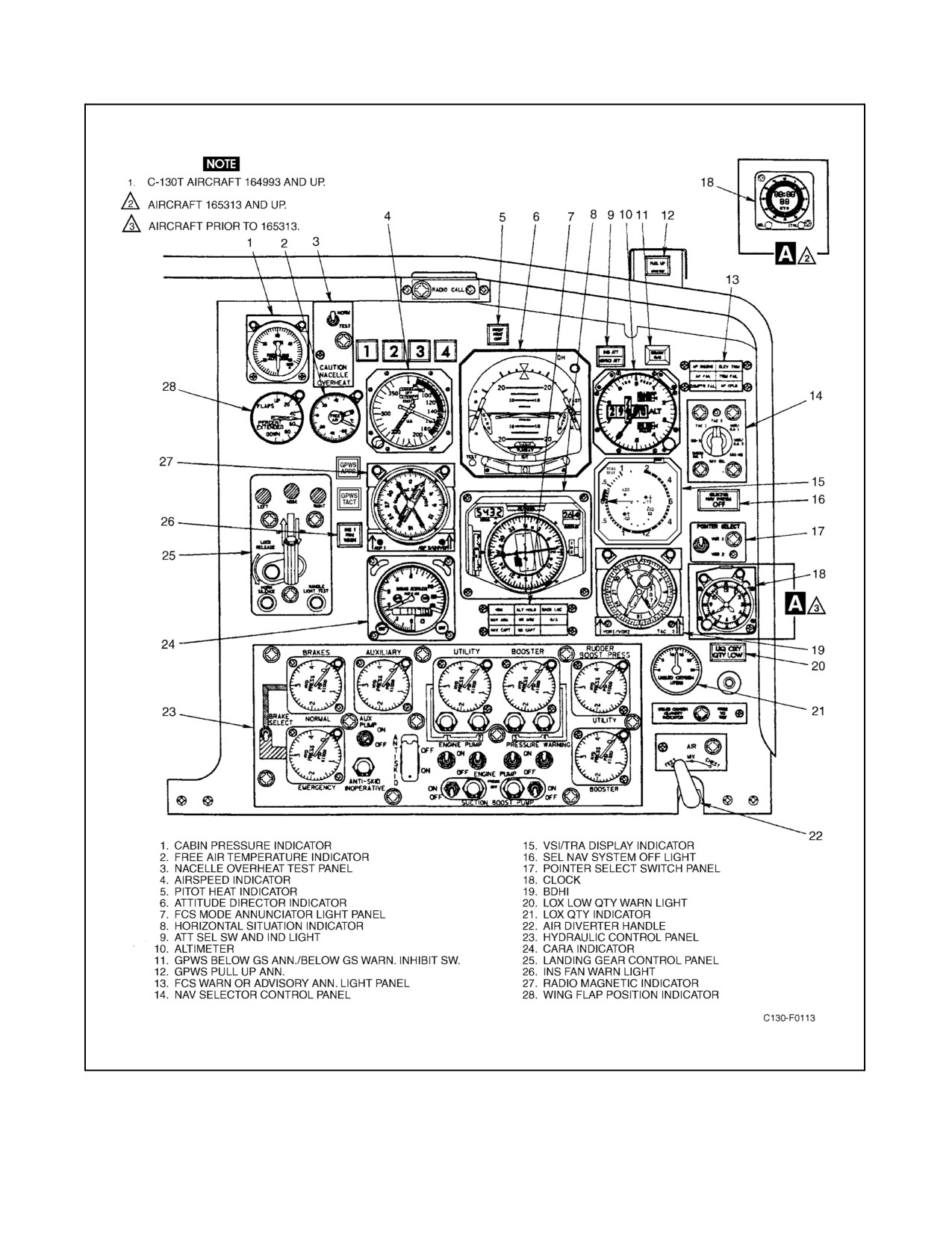
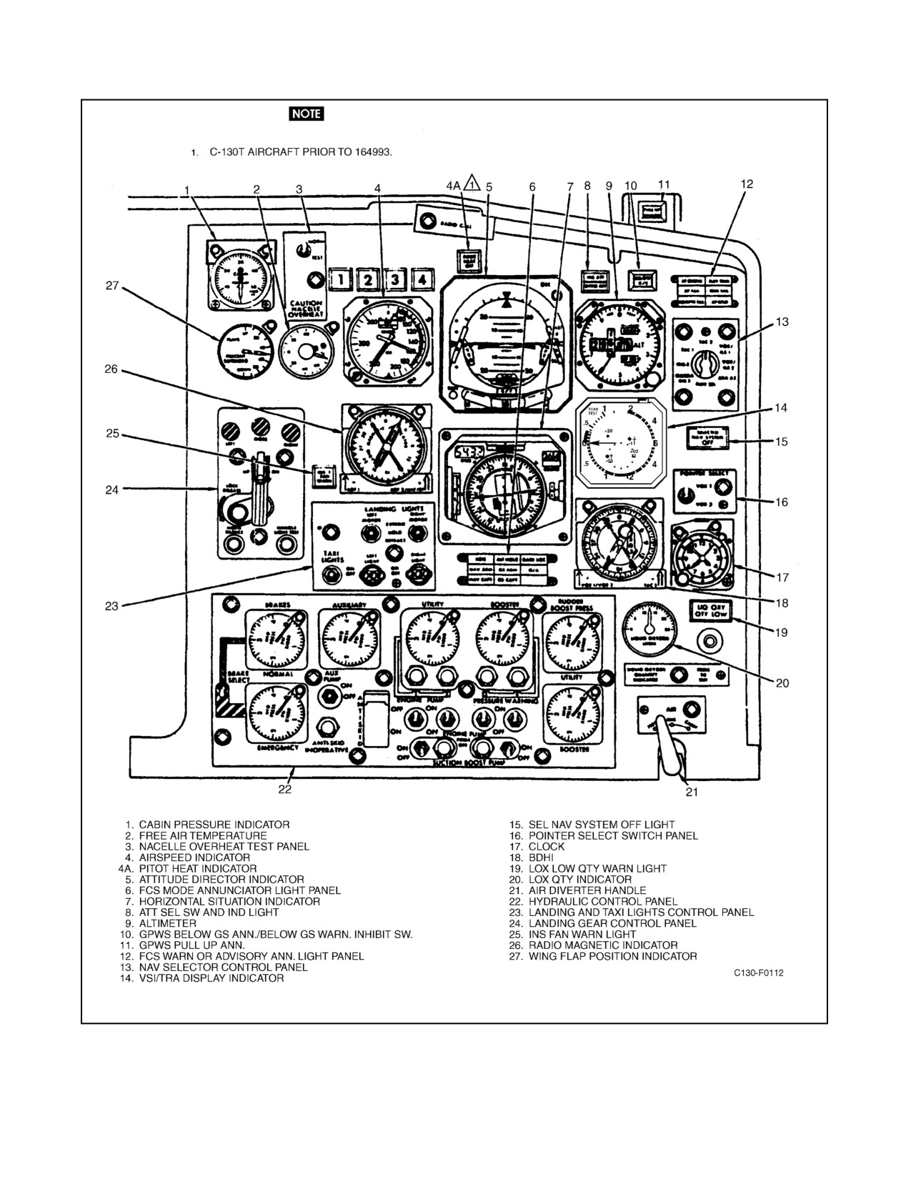
The three airspeed indicators, one mounted on the pilot instrument panel (see Figure 2-78), one on the copilot
instrument panel (see Figure 2-79), and a true airspeed indicator on the navigator instrument panel (see Figure 1-7),
are instruments that use differential air pressure to determine airspeed. Each of the indicators is calibrated in knots.
The banded pointer (maximum allowable pointer) on the pilot and copilot indicator constantly indicates the
maximum recommended speed limit (VH-1 with refueling pods off) for the respective aircraft altitude. The IAS
pointer reflects the aircraft airspeed. The IAS counter repeats the IAS pointerindication as a digital readout. An OFF
flag will be displayed in the IAS counter window until the aircraft speed exceeds 60 KIAS, at which time the flag
will be biased out of view. An IAS push-to-test button, located on the lower right of the instrument face, is provided
to test the IAS counter. Depressing and holding the pushbutton until the digital readout registers 300 indicates that
the IAS counter is operational. The press-to-test button is functional on the ground or in flight and does not affect
the indicator signal output when activated.
Note
A loss of ac power to the indicator will cause the IAS counter to fail and
the OFF flag to appear in the counter window. The IAS pointer will
continue to operate.
Figure 2-81. Standby Attitude Indicator
ORIGINAL
2-162
01-75GAL-1
The indicator also incorporates a bug-typepointer that can beset with an adjustableknob on the faceof theindicator.
The pointer provides the pilot with a means of referencing appropriate selected airspeeds for approach, climb, etc.
Thepilot and copilot airspeed indicators providesignals to therespectiveADI speed flag and speed deviation pointer
to display the difference between actual aircraft speed and manually set speed. Signals from the pilot airspeed
indicatorareusedbyairdatacontrolNo.1forIASholdmodeduringautopilot-coupled operation.Theairspeedsignal
circuits are powered by 26-Vac from the essential ac bus through the AIRSPEED-PILOT and COPILOT circuit
breakers on the pilot upper circuit breaker panel.
2.20.2.3 Altimeters
Thethreealtimeters,onemountedonthepilotinstrumentpanel(seeFigure 2-78),oneon thecopilot instrumentpanel
(see Figure 2-79), and one on the navigator instrument panel (see Figure 1-7), are barometric-type instruments
measuring variations in pressure by means of aneroid units. Each altimeter is calibrated in feet.
The pilot altimeter combines a conventional barometer altimeter and an altitude-reporting encoder in one
self-contained unit. A 10,000- and 1,000-foot digital counter indicator and a 100-foot drum indicator provide direct
digital output and readout ofaltitudeinincrements of100 feet,from -1,000to 50,000feet. Theencoderdigitaloutput
is referenced to 1,013 millibars and to 29.92 inches of mercury, and is not affected by changes in barometric setting.
A pointer repeats the indications of the 100-foot drum and serves both as a vernier for the drum and as a quick
indication of the rate and sense of altitude changes. Two methods may be used to read indicated altitude on the
counter-drum-pointer altimeter:
1. Read the digital counter indicator and the 100-foot drum indicator without reference to the pointer, as shown
by a direct digital readout in thousands and hundreds of feet.
2. Read the thousands of feet on the two digital counter indicators without referring to the drum indicator, and
then add the 100-foot pointer indication.
The self-contained servodriven encoder provides altitude data encoded in 100-foot increments for automatic
transmission when the air traffic control transponder is interrogated in mode C. In case of power loss to the
encoder-altimeter, an orange OFF flag will appear in a window in the upper portion of the display, indicating that
thepilotaltimeterisinoperative.Thepilotencoderispoweredby26-Vacfromtheessentialacbusthrough theALTM
ENCODER PILOT circuit breaker on the pilot upper circuit breaker panel.
The pilot altimeter is interconnected with the altitude alerter/preselect system to provide synchro outputs of
baro-corrected altitude and flag alarm signals. The altimeter setting is entered by use of a manually operated
barometric set knob in the lower right front of the instrument case. The altimeter setting appears on digital displays
at the right of the altitude display and has a range of settings from 950 to 1,050 millibars, and from 28.1 to 31.0 inches
of mercury. A press-to-test button, located on the lower left front of the instrument case, is provided to functionally
test the servomechanism. When actuated, the button causes a negative pointer offset indicating that the servo is
operating.
The copilot and navigator altimeters are read in the same manner as the pilot altimeter. However, these altimeters
do not contain an altitude reporting encoder and, hence, no OFF flag. The altimeters also are not equipped with the
functional test button. The copilot and navigator altimeters have internal vibrators that operate continuously
whenever aircraft dc power is turned on. The vibrator minimizes internal mechanical friction, enabling the instrument
to provide a smoother display during changing altitude conditions. Should vibrator failure occur, the altimeter will
continue to function pneumatically, but a less smooth movement of the instrument display will be evident with
changes in altitude. The vibrators are powered by 28-Vdc power from the essential dc bus through the ALTIMETER
VIBRATOR CO-PILOT & NAV dc circuit breaker on the copilot upper circuit breaker panel.
2-163
ORIGINAL
01-75GAL-1
If the altimeter internal vibrator is inoperative because of either internal
failure or dc power failure, the 100-foot pointer may hang up momentarily
when passing through 0 (12-o’clock position). Ifthevibratorhas failed, the
100-foot pointer hangup can be minimized by tapping the case of the
altimeter. Pilots should be especially watchful for this failure when their
minimum approach altitude lies within the 800- to 1,000-foot part of the
scale (1,800 to 2,000 feet, 2,800 to 3,000 feet, etc.), and should use any
appropriate altitude backup information available.
2.20.3 Miscellaneous Instruments
2.20.3.1 Free-Air Temperature Indicators
The free-air temperature indicator, located on the copilot instrument panel (see Figure 2-79), indicates ambient,
outsideairtemperature. This temperaturemust becorrected forcompressibility fortrue airtemperature during flight.
Theindicatoriselectricallyconnectedtoaresistancebulbmountedonthesideoftheaircraft.Thefree-airtemperature
indicator receives 28-Vdc from the TEMP IND FREE AIR circuit breaker on the copilot lower circuit breaker panel.
2.20.4 Magnetic Compass
Amagneticcompass(seeFigure2-78)ismountedonthepilotinstrumentpanel.Itis astandard floating-cardcompass
that indicates the direction that the aircraft is headed with respect to magnetic north.
Note
The magnetic compass is intended as a standby compass and should not be
used except in case of emergency. For the most reliable operation of the
magnetic compass, the pitot heat should be turned on and the HSI set to
correspond with the aircraft heading.
2.20.4.1 Accelerometer
An accelerometer (see Figure 2-78) on the pilot instrument panel gives instantaneous readings and maximum positive
and negative readings of the g forces exerted on the aircraft. The gauge is calibrated from +4 g to -2 g. The maximum
indication needles will remain at their highest readings until the push-to-set button on the gauge case is pushed, then
they both will return to +1g and immediately register maximum value until again reset.
2.20.4.2 Clocks
Three clocks are mounted in the aircraft, one each on the pilot, copilot , and navigator instrument panels (see Figures
2-78, 2-79, and 1-7).
2.20.4.3 Electronic Clocks (Aircraft 165313 and Up)
Three electronic six-digit liquid-crystal display clocks are installed. Two are installed on the main instrument panel,
one for the pilot and one for the copilot (see Figure 2-78 and 2-79). An additional clock is installed at the navigator
station. Each clock has an internal battery that allows continuous timekeeping when 28-Vdc power is not applied.
The clocks have two operating modes: elapsed time (ET) and clock time (C). To select between ET and C, press the
SEL pushbutton. Power is supplied to the clocks from the isolated dc bus through the CLOCKS circuit breaker on
the pilot side circuit breaker panel.
ORIGINAL
2-164
01-75GAL-1
Self-Test:
1. During the first 5 seconds of operation, the clocks initiate a self-test that illuminates all of the segments. After
completion of the self-test, the clocks start up in C mode.
Elapsed-time operation:
2. If ET operating mode is not indicated, press SEL pushbutton to select ET operating.
3. Press CTRL pushbutton to start elapsed timer counting upward.
4. Press CTRL pushbutton a second time to stop elapsed time.
5. Press CTRL pushbutton a third time to zeroize elapsed timer.
6. Press CTRL pushbutton a fourth time to reset elapsed timer.
To set time in C mode:
7. Press SEL and CTRL pushbuttons simultaneously.
8. When the hour digits are flashing, press CTRL pushbutton to advance hours in one unit increments, or hold
to scroll to desired time.
9. To set minutes, press SEL pushbutton. When the minutes digits are flashing, press CTRL pushbutton to
advance hours in one unit increments, or hold to scroll to desired time.
10. To set seconds, press SEL pushbutton. When the seconds digits are flashing, press CTRL pushbutton to
advance hours in one unit increments, or hold to scroll to desired time.
11. Pressing SEL pushbutton while the seconds digits are flashing returns the clock to the C mode.
2.21
COMMUNICATION AND NAVIGATION EQUIPMENT
The communication and associated electronic equipment consists of radio and intercommunication equipment to
provide aircraft-to-aircraft communication, aircraft-to-ground communication, and intra-aircraft communication;
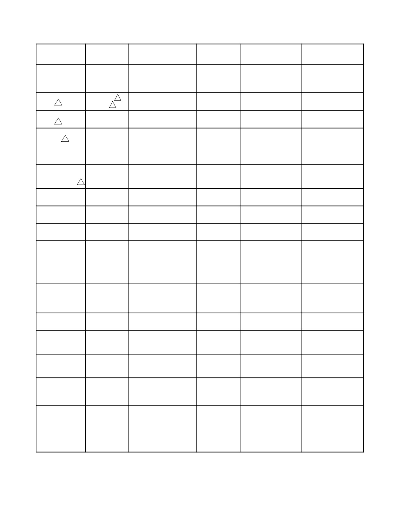
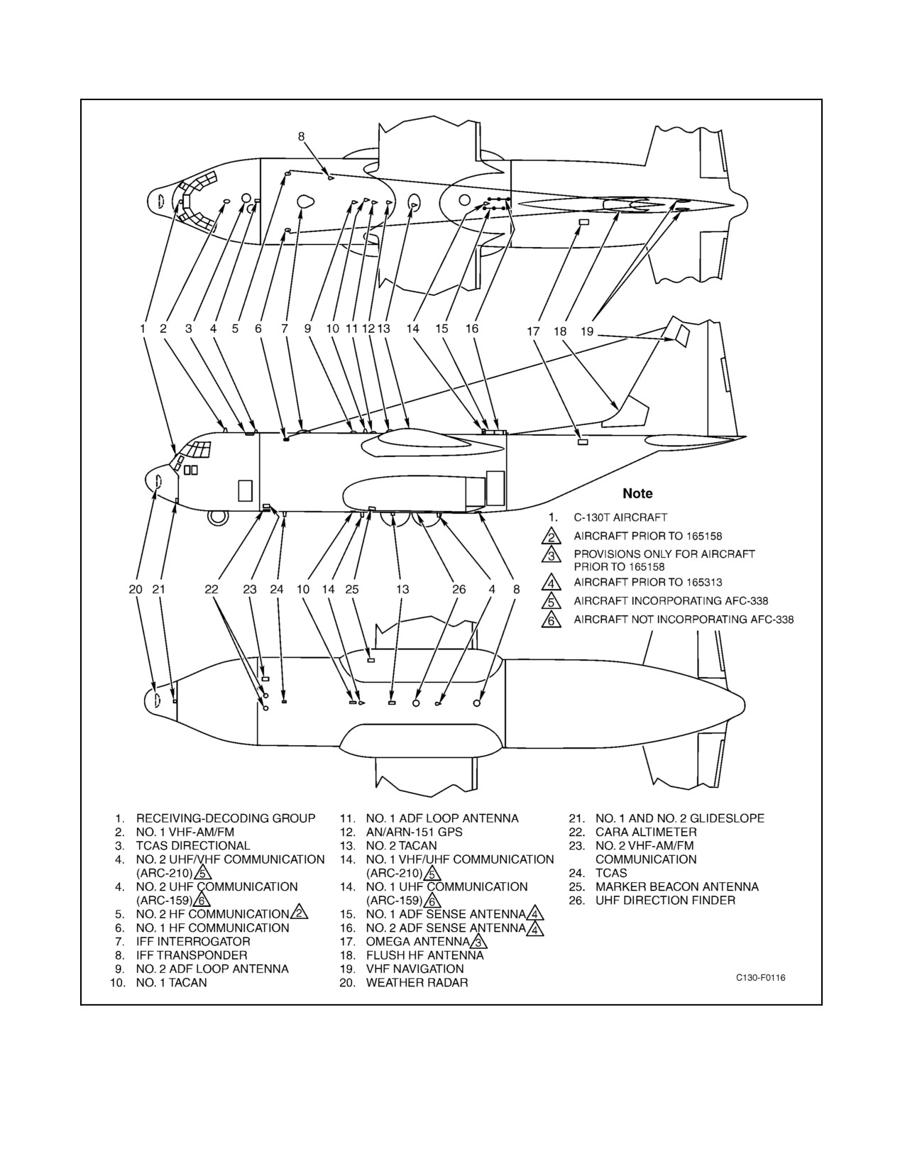
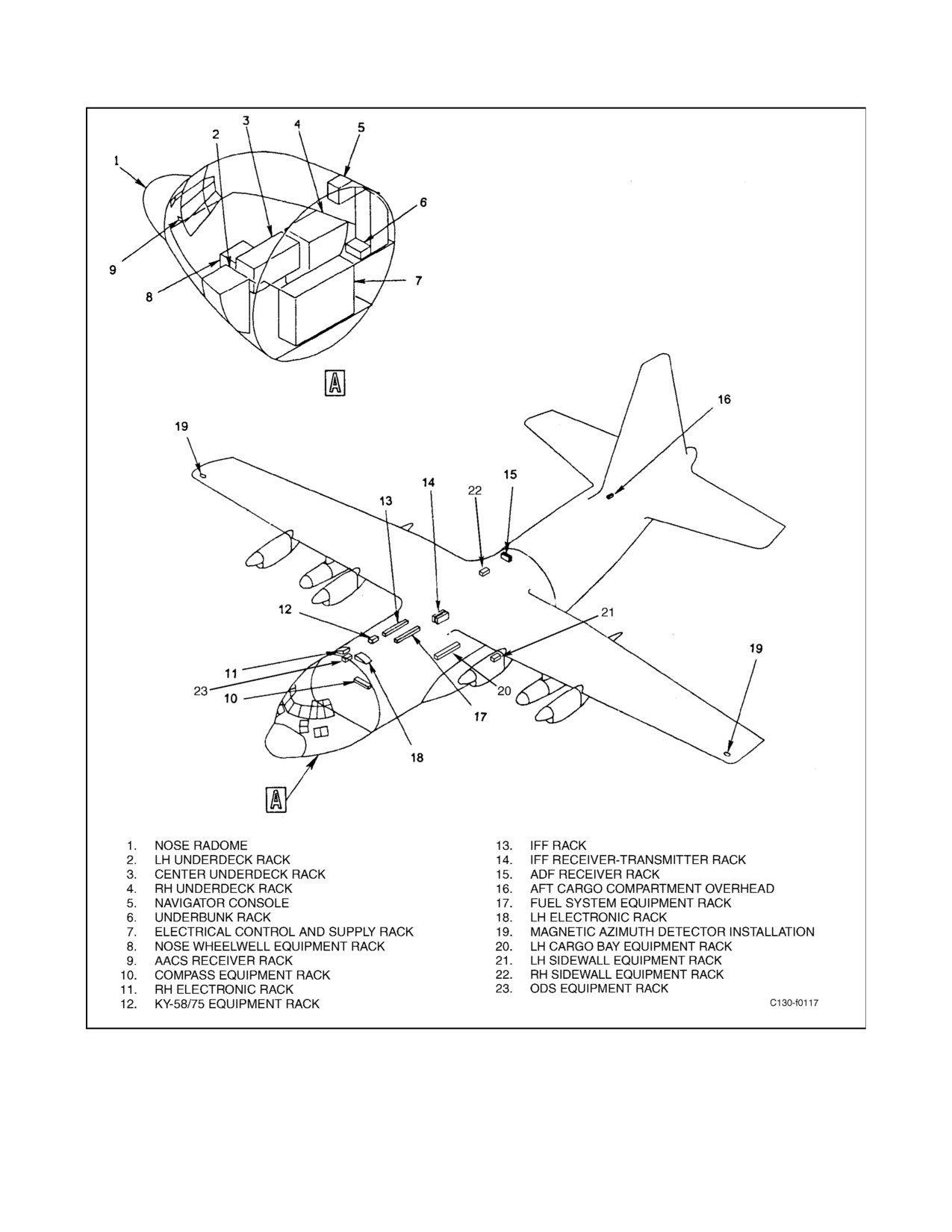
navigation sets for guidance; and radar sets for identification and warning (see Figure 2-82). For antenna locations,
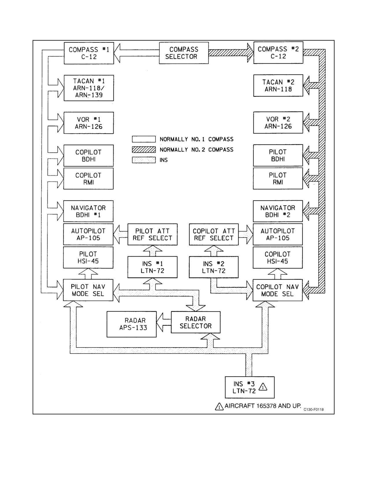
see Figure 2-83. For equipment rack locations, see Figure 2-84. For an interface illustration of the heading/naviga-
tional reference component relationship, see Figure 2-85.
2.21.1 AN/AIC-18 or AN/AIC-25 Intercommunication System
The ICS permits voice communication among flight station and cargo compartment intercommunication stations.
TheAN/AIC-18 ICS is installed on aircraft priorto 165313, whiletheAN/AIC-25 ICS is installedon aircraft165313
and up. Voice communication is also possible with the groundcrew through an external interphone receptacle at the
left aft edge of the radome. Audio signals from the command and liaison radio receivers and transmitters can be
monitored at each of the flight station intercommunication stations. Audio signals from the VHF and UHF radio
receivers and transmitters (aircraft not modified by AFC-338) or VHF and V/UHF radio receivers and transmitters
(aircraft modified by AFC-338) can be monitored at each of the observer stations. Transmissions through all radio
transmitters can be accomplished at the flight station intercommunication stations. The observers can transmit only
on VHF 1, VHF 2, UHF 1, and UHF 2 (aircraft not modified by AFC-338) or VHF 1, VHF 2, V/UHF 1, and V/UHF
2-165
ORIGINAL
01-75GAL-1
2
(aircraft modified by AFC-338). Reception and transmission over the channels available at a particular station are
made possible by headset microphones at each intercommunication station. A three-position microphone/interphone
switch on both the pilot and copilot control wheels permits transmissions from these positions. A press-to-talk button
on the connector cords at all other intercommunication stations can be used to talk from these stations. A foot switch
is located at the navigator station and flight engineer station, and can be used as an alternateswitch to talk from these
stations. The auxiliary intercommunication control panel, installed in the forward cargo compartment, differs from
all other panels both in appearance and capability. It is equipped with two controls, a call button, and a volume knob
and is restricted to voice communication through the ICS. The forward cargo compartment interphone station at FS
245 bulkhead includes a microphone headset with a 75-foot extension cord stowed in a protective bag next to the
control panel. The ICS is operated from 28-Vdc power supplied from the isolated bus and essential dc bus through
the INTERPHONE circuit breakers on the copilot upper circuit breaker panel.
2.21.1.1 Intercommunication System Controls
2.21.1.1.1 Main Control Panel
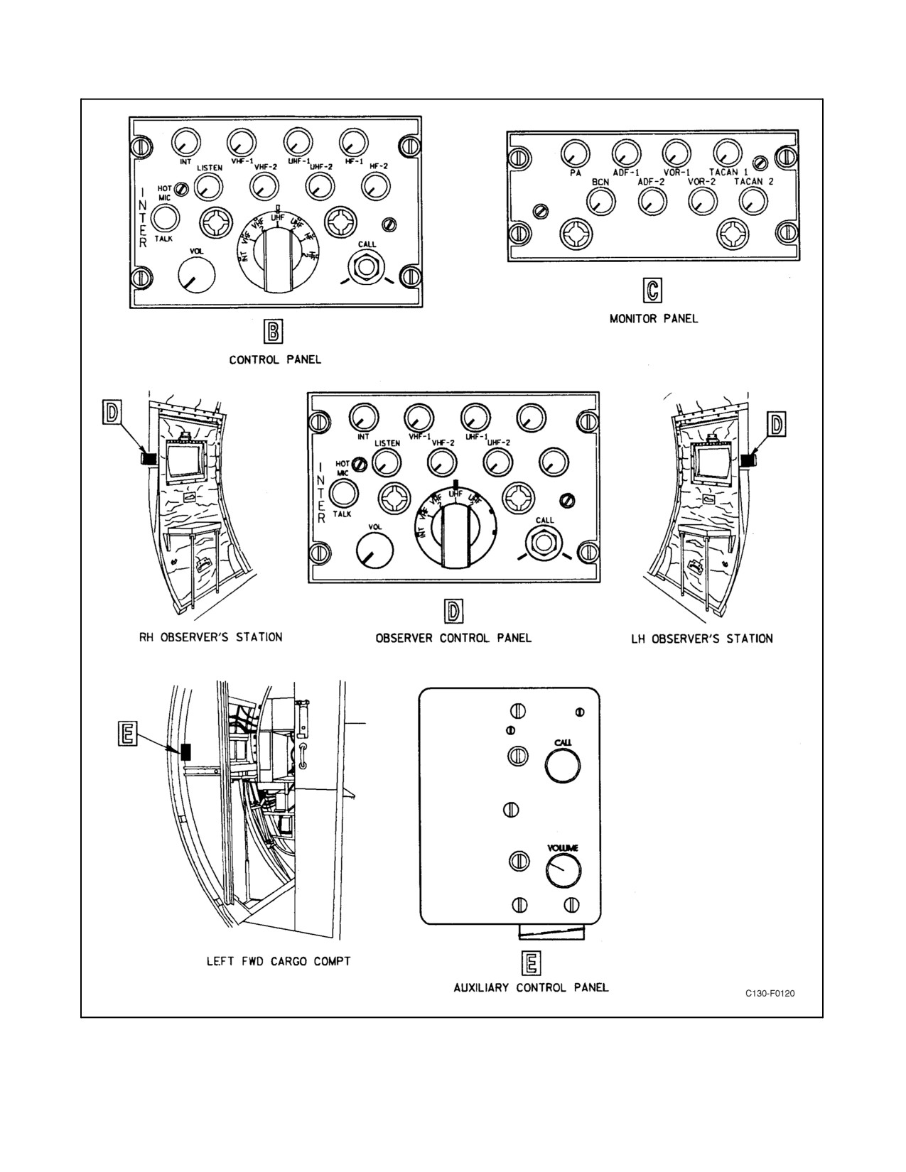
Identical ICS control panels (see Figure 2-86) are installed on each pilot side shelf extension, on the overhead control
panel, on the navigator side panel/console, at the lower crew bunk, and above the pilot upper circuit breaker panel
for use by a flight instructor. A similar control panel is installed at each observer station.
The main control panels are equipped with similar push-pull switches for:
1. VHF 1 — AN/ARC-186 VHF command radio No. 1.
2. VHF 2 — AN/ARC-186 VHF command radio No. 2.
3. UHF 1 — AN/ARC-159 UHF command radio No. 1 (aircraft not modified by AFC-338).
4. V/UHF 1 — AN/ARC-210 V/UHF command radio (aircraft modified by AFC-338).
5. UHF 2 — AN/ARC-159 UHF Command Radio No. 2 (aircraft not modified by AFC-338).
6. V/UHF 2 — AN/ARC-210 V/UHF command radio (aircraft modified by AFC-338).
7. HF 1 — AN/ARC-190 HF command radio No. 1.
8. HF 2 — AN/ARC-190 HF command radio No. 2 (except HF 1 and HF 2, which are not available at observer
stations).
Push-pull switches are also provided on the control panel for interphone (INT) and hot mike (HOT MIC) operation;
the latter uses a listen switch and a talk switch. This panel also carries a master volume control, a call button, and
a rotary transmission selector switch.
2.21.1.1.2 Transmission Selector Switch
The transmission selector switch on the control panels in the flight station may be set to any one of seven positions,
by rotation from left to right: INT for interphone and PA system operation; VHF 1 and VHF 2 for transmission
through the two VHF command radios; UHF 1 and UHF 2 for transmission through the two UHF command radios;
and HF 1 and HF 2 for transmission through the two HF command radios. The observers can transmit only on INT,
VHF 1, VHF 2, UHF 1, and UHF 2 by placing their transmission selector switches in the desired position. On aircraft
modified by AFC-338, switch and panel nomenclature “UHF” has been replaced with “V/UHF.”
2.21.1.1.3 HOT MIC Switches
The hot mike (HOT MIC) mode of operation permits direct transmission to all other intercommunication stations
on the aircraft without operating the individual microphone switches.
ORIGINAL
2-166

01-75GAL-1
PRIMARY
LOCATION OF
TYPE
DESIGNATION
FUNCTION
OPERATOR
RANGE
CONTROLS
Intercommunication
AN/AIC-18A or
Crew intercommunication
Crewmembers
Crew stations within the
Pilot side shelf
equipment
AN/AIC-25
aircraft and external for
extension, copilot side
ground crew
shelf extension,
overhead control panel,
navigator station, left
forward bulkhead,
forward for each
paratroop exit door, at
top of pilot side circuit
breaker
Public address
AN/AIC-13
One-way communication
Crewmembers
Interior of aircraft and
Navigator station,
system
for cargo compartment
servicing personnel
auxiliary: pilot side shelf,
left forward bulkhead,
and at left-hand
paratroop door
VHF AM-FM radio
AN/ARC-186(V)
Two-way voice
Pilot and copilot
Line of sight
CDNUs
(2)
communication in the range
of 30 to 87.975 MHz FM to
151.975 MHz AM
UHF
AN/ARC-159(V)
Two-way voice
Pilot and copilot
Line of sight
UHF No. 2 copilot side
communication
1
communication in the range
shelf extension UHF No.
radio (2)
3
of 225 to 399.975 MHz
1 flight control pedestal
Encryption
KY-58
Secures voice
Pilot and copilot
—
UHF No. 2 copilot side
unit (4)
3
communication for VHF
shelf extension Others
and UHF radios
flight control pedestal
HF command radio
AN/ARC-190
Airborne voice
Pilot and copilot
100 to 2,500 miles on
Flight control pedestal
(2)
communication in the range
AM and greatly
(No. 1), copilot side shelf
of 2 to 30 MHz
extended range on SSB
extension (No. 2)
depending on operating
frequency, altitude, and
time of day
Encryption unit (2)
AN/USC-43
Secures voice
Pilot and copilot
—
Flight control pedestal,
communication for HF
copilot side shelf
radios
extension and navigator
station
Automatic direction
DF-206
For homing and bearing;
Pilot and copilot
20 to 200 miles
Flight control pedestal
finder (2)
also receives voice and
depending on power,
code signals
class of ground station,
frequency, and time of
day
VHF navigation
AN/ARN-126
Reception of all VHF/VOR,
Pilot and copilot
Localizer — 45 miles;
CDNUs
system (2)
tone localizer and voice
Omni — 200 miles
facilities; reception of
depending on altitude;
glideslope information and
Glideslope — 15 miles;
location marker symbols
Marker beacon — any
altitude
TACAN (2)
AN/ARN-118(V)
Receives bearing and
Pilot and copilot
Line of sight depending
CDNUs
or
distance information
on altitude
AN/ARN-139(V)
Figure 2-82. Table of Communications and Associated Electronic Equipment (Sheet 1 of 3)
2-167
ORIGINAL
01-75GAL-1
PRIMARY
LOCATION OF
TYPE
DESIGNATION
FUNCTION
OPERATOR
RANGE
CONTROLS
Receiving
AN/ARA-63A
Enables the aircraft to land
Pilot
20 miles
Flight control pedestal
decoding group
at airfields equipped with
an Aircraft Approach
Control System (AACS)
UHF direction
Homing on ARC-159
Pilot and copilot
Line of sight
Flight control pedestal
AN/ARA-50 1
finder
3
transmitter
DF-301E 2
UHF direction
AN/ARA-50
Homing on AN/ARC-210
Pilot and copilot
Line of sight
CDNUs
finder
4
DF-301E
transmitter
Encryption
KY-58
Secures voice
Pilot and copilot
VHF 1 and 2 control
units (4)
4
communications for VHF
pedestal; V/UHF 1
and V/UHF radios
control pilot side shelf;
V/UHF 2 control copilot’s
side shelf
V/UHF
AN/ARC-210
Two-way voice
Pilot and copilot
Line of sight
CDNUs
communication
communication
radio
4
TCAS/IFF control
—
Control of TCAS and IFF
Pilot and copilot
—
Flight control pedestal
panel
functions
Global positioning
AN/ARN-151
Provides highly accurate
Pilot and copilot
—
CDNUs
system (GPS)
position, velocity, and time
Combined altitude
AN/APN-232(V)
Indicates absolute altitude
Pilot and copilot
0 to 50,000 feet altitude
Pilot and copilot
radar altimeter
6
of aircraft above the terrain
instrument panels
Ground proximity
Provides the pilot and copilot
Automatic
Any altitude
Flight control pedestal
warning system
with visual and aural
warnings of a flight condition
that could cause the aircraft
to come in close proximity to
the ground
Altitude alerter/
540-25100-004
Provides automatic visual
Pilot
0 to 50,000 feet altitude
Pilot glareshield
system
and aural signals during
approach to or departure
from a preselected altitude
IFF interrogator
AN/APX-76B
Interrogates properly
Line of sight
Navigator control panel
equipped receiver aircraft
Flight control
FCS 105
For automatic pilot or
Pilot and copilot
—
Flight control pedestal
system
instrument flying with INS,
and main instrument
VOR/ILS, or TACAN
panel
Inertial navigation
LTN-72 or
Provides accurate navigation
—
CDU No. 2 navigator
system
LN-100
and position determination
station; CDU No. 1 flight
information
control pedestal
True airspeed
Model 2504
Computes and displays
—
Navigator control panel
computer
true airspeed using
temperature, altitude, and
airspeed data
Multimode radar
AN/APS-133 (M)
Navigation and weather
Pilot
5 to 300 miles
Indicators: navigator
radar — displays IFF, INS,
station and pilot
ONS data and mapping
instrument panel; control
panels: navigator control
panel, pilot side
shelf/extension, and
pedestal
Figure 2-82. Table of Communications and Associated Electronic Equipment (Sheet 2)
ORIGINAL
2-168

01-75GAL-1
PRIMARY
LOCATION OF
TYPE
DESIGNATION
FUNCTION
OPERATOR
RANGE
CONTROLS
Compass
C-12
Detects and indicates
—
Navigator station
system (2)
5
relative heading referenced
to magnetic north
Emergency rescue
AN/PRT-5E
Distress signals
Crewmembers
1,000 miles
On transmitter
transmitter (4)
Notes
1. C-130T aircraft prior to 164993
4. Aircraft modified by AFC-338
2. C-130T aircraft 164993 and up
5. C-12 compass systems have been removed from 165378
3. Aircraft without AFC-338
Figure 2-82. Table of Communications and Associated Electronic Equipment (Sheet 3)
When the hot mike system is not being used, the HOT MIC switches should be pushed in to restore the
inter-communication system to normal functioning. The three-position (INPH, OFF, MIC) microphone switches on
the control wheels are spring loaded to the OFF position. With the switch held at the INPH position, the pilot can
transmit to all other intercommunication stations. If the switch is held to the MIC position, the pilot can transmit
through the communication transmitter selected on the transmission selector switch. Foot-controlled microphone
switches are located on the floor at the flight engineer and navigator stations.
2.21.1.1.4 CALL Button
A CALL button is located at the lower right corner of each of the crew station intercommunication control panels.
When the button is pressed, all radio receiver transmissions on the ICS are subdued 6 dB and all intercommunication
stations are put into direct contact with the calling station.
2.21.1.1.5 Intercommunication System Monitor Panel
Each crew station, except the left and right observer stations, is equipped with monitoring or mixer switches, enabling
all audio navigational systems to be connected to the ICS. The switches are of the push-pull type (pulled for ON,
pushed for OFF). They may be turned to regulate volume at the individual intercommunication station. The ICS
monitor panels (see Figure 2-85) serve to provide interconnection with the following communication and audio
navigational systems:
1. PA — AN/AIC-13 public address system
2. BCN — AN/ARN-126 marker beacon receiver.
3. ADF 1 — DF-206 automatic direction finder No. 1.
4. ADF 2 — DF-206 automatic direction finder No. 2.
5. VOR 1 — AN/ARN-126 VHF navigation receiver No. 1.
6. VOR 2 — AN/ARN-126 VHF navigation receiver No. 2.
7. TACAN 1 — AN/ARN-139(V) TACAN No. 1.
8. TACAN 2 — AN/ARN-118(V) TACAN No. 2.
9. AUXILIARY — Control panel.
2-169
ORIGINAL
01-75GAL-1
Figure 2-83. Antenna Locations
ORIGINAL
2-170
01-75GAL-1
Figure 2-84. Electrical and Electronic Equipment Installation (Sheet 1 of 5)
2-171
ORIGINAL

01-75GAL-1
SYSTEM — COMPONENTS
LOCATION — RACK
Aircraft Approach Control System (AACS)
(AN/ARA-63A):
Pulse decoder
LH underdeck rack
Receiver
AACS receiver rack
Altimeter (CARA)
Receiver-transmitter
Electrical control and supply rack
Audible fire warning:
Amplifier
LH electronic rack
Generator
LH electronic rack
Relay
LH electronic rack
Automatic direction finder (ADF) (DF-206):
Receiver No. 1
ADF receiver rack
Receiver No. 2
ADF receiver rack
Compass (C-12):
Amplifier — Power supply No. 1
Compass equipment rack
Amplifier — Power supply No. 2
Compass equipment rack
Directional gyro No. 1
Compass equipment rack
Directional gyro No. 2
Compass equipment rack
Magnetic azimuth detector No. 1
LH wingtip
Magnetic azimuth detector No. 2
RH wingtip
Electrical:
Ac generator control panels (4)
Electrical control and supply rack
Ac generator voltage regulators (4)
3
Electrical control and supply rack
Ac instrument and engine fuel control inverter
RH underdeck rack
APU ac generator control panel
Electrical control and supply rack
APU ac generator voltage regulator
Electrical control and supply rack
APU generator control unit
4
Electrical control and supply rack
Copilot inverter
RH underdeck rack
Essential bus transformer-rectifier units (2)
Electrical control and supply rack
Generator control unit (4)
4
Electrical control and supply rack
Main bus transformer-rectifier units (2)
Electrical control and supply rack
Flight control systems (FCS 105):
Acceleration sensor
LH underdeck rack
Air data control No. 1
LH underdeck rack
Air data control No. 2
LH underdeck rack
Airspeed sensor
Navigator console
Autopilot amplifier
LH underdeck rack
Flight computer No. 1
LH underdeck rack
Flight computer No. 2
LH underdeck rack
Figure 2-84. Electrical and Electronic Equipment Installation (Sheet 2)
ORIGINAL
2-172

01-75GAL-1
SYSTEM — COMPONENTS
LOCATION — RACK
Mode coupler No. 1
LH underdeck rack
Mode coupler No. 2
LH underdeck rack
Turn rate sensor No. 1
Center underdeck rack
Turn rate sensor No. 2
Center underdeck rack
Vertical gyro No. 1
Underbunk rack
Vertical gyro No. 2
Underbunk rack
Yaw damper computer
LH underdeck rack
Fuel:
Fuel flow meter power supply
Fuel system equipment rack
Fuel quantity totalizer
Fuel system equipment rack
Relays (3)
Fuel system equipment rack
Global Positioning System (GPS):
Interface ship set
LH cargo equipment rack
Database couplers
LH cargo equipment rack
Signal data converter
LH cargo equipment rack
Ground proximity warning system:
Adapter
Underbunk rack
Air data computer
Navigator console
Computer
Navigator console
HF communication radio (ARC-190):
Antenna coupler No. 1 — HF
LH electronic rack
Antenna coupler No. 2 — HF
RH electronic rack
Coaxial resistor No. 1
LH electronic rack
Coaxial resistor No. 2
RH electronic rack
HF relay No. 1
LH electronic rack
HF relay No. 2
RH electronic rack
Interface boxes (if installed)
Equipment rack KY-58/75
Transceiver No. 1
Center underdeck rack
Transceiver No. 2
Center underdeck rack
IFF (AN/APX-100(V)):
Antenna selection relay
IFF rack
Mode 4 computer
LH underdeck rack
Receiver-transmitter
IFF rack
IFF interrogator (AN/APX-76B(V)):
Converter-synchronizer
IFF equipment rack
Mode 4 computer
LH equipment rack
Power relay
IFF receiver-transmitter rack
Receiver-transmitter
IFF receiver-transmitter rack
Transient suppressor
IFF receiver-transmitter rack
Inertial navigation (LTN-72 or LN-100):
Inertial nav unit No. 1
Electrical control and supply rack
Inertial nav unit No. 2
Electrical control and supply rack
INS battery (if installed)
Electrical control and supply rack
Figure 2-84. Electrical and Electronic Equipment Installation (Sheet 3)
2-173
ORIGINAL

01-75GAL-1
SYSTEM — COMPONENTS
LOCATION — RACK
INU fan No. 1
Electrical control and supply rack
INU fan No. 2
Electrical control and supply rack
INU fan power relay No. 1
Electrical control and supply rack
INU fan power relay No. 2
Electrical control and supply rack
INU fan warn relay No. 1
Electrical control and supply rack
INU fan warn relay No. 2
Electrical control and supply rack
Overheat detection system control unit
ODS equipment rack
Propeller synchrophaser unit
Electrical control and supply rack
Public address (AN/AIC-13):
Audio frequency amplifiers (3)
Center underdeck rack
Radar, multimode (AN/APS-133(M)):
Interface unit
RH underdeck rack
Receiver-transmitter
RH underdeck rack
Roll compensator
RH underdeck rack
Radar control switching relays
Underbunk rack
Secure voice system (KY-58):
Processors, UHF (2)
5
KY-58/75 equipment rack
Processors, VHF (2)
KY-58/75 equipment rack
Processors, V/UHF (2)
6
LH avionics equipment rack
TCAS/IFF
IFF transponder
IFF rack
TCAS receiver-transmitter
IFF rack
Mode 4 computer
IFF rack
Secure voice system (KY-75):
Keyers HF (2)
KY-58/75 equipment rack
Remote control units (RCU-11A/B):
(RCU-IIIA)
Navigator control panel
(RCU-111B)
Pedestal (No. 1) copilot side shelf extension (No. 2)
TACAN (AN/ARN-118)/(AN/ARN-139(V)):
Bearing adapter No. 1
LH underdeck rack
Digital to analog adapter No. 1
LH underdeck rack
Digital to analog adapter No. 2
LH underdeck rack
Receiver-transmitter No. 1
LH underdeck rack
Receiver-transmitter No. 2
LH underdeck rack
True airspeed computer (model 2504):
Computer
RH underdeck rack
Transducer
RH underdeck rack
Figure 2-84. Electrical and Electronic Equipment Installation (Sheet 4)
ORIGINAL
2-174

01-75GAL-1
SYSTEM — COMPONENTS
LOCATION — RACK
UHF communication radio (AN/ARC-159(V)):
5
Receiver/transmitter No. 1
Pedestal
Receiver/transmitter No. 2
Copilot’s side extension shelf
Antenna selector No. 1
Electrical control and supply rack
Antenna selector No. 2
LH underdeck rack
Antenna switch No. 1
Electrical control and supply rack
Antenna switch No. 2
LH underdeck rack
UHF low pass filter
Electrical control and supply rack
UHF direction finder (AN/ARA-50):
1
Amplifier relay
Electrical control and supply rack
UHF direction finder (DF-301E):
2
UHF/DF selector
LH underdeck rack
VHF AM-FM communication radio (AN/ARC-186(V)):
Receiver-transmitter No. 1
Underbunk rack
Receiver-transmitter No. 2
Underbunk rack
VHF Navigation system (AN/ARN-126):
Receiver No. 1
LH underdeck rack
Receiver No. 2
LH underdeck rack
V/UHF communication radio (AN/ARC-210):
6
Antenna converter No. 1
LH sidewall equipment rack
Antenna converter No. 2
RH sidewall equipment rack
Receiver-transmitter No. 1
LH cargo bay equipment rack
Receiver-transmitter No. 2
LH cargo bay equipment rack
Antenna selector coaxial switch No. 1
LH cargo bay equipment rack
Antenna selector coaxial switch No. 2
LH cargo bay equipment rack
Filter No. 1
LH cargo bay equipment rack
Filter No. 2
LH cargo bay equipment rack
Audio amplifier No. 1 (provisions)
LH cargo bay equipment rack
Audio amplifier No. 2 (provisions)
LH cargo bay equipment rack
Control unit No. 1
LH cargo bay equipment rack
1
Aircraft prior to 164993
5
Aircraft not modified by AFC-338
2
Aircraft 164993 and up
6
Aircraft modified by AFC-338
3
Aircraft prior to 165313
4
Aircraft 165313 and up
Figure 2-84. Electrical and Electronic Equipment Installation (Sheet 5)
2-175
ORIGINAL
01-75GAL-1
Figure 2-85. Heading Reference System
ORIGINAL
2-176
01-75GAL-1
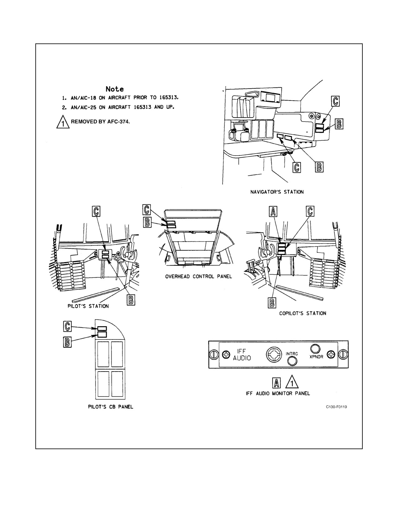
Figure 2-86. Intercommunication System Control Panels (Sheet 1 of 2)
2-177
ORIGINAL
01-75GAL-1
Figure 2-86. Intercommunication System Control Panels (Sheet 2)
ORIGINAL
2-178
01-75GAL-1
2.21.1.1.6 Auxiliary Control Panel
The ICES auxiliary control panel (see Figure 2-86) is equipped only with a CALL button and a VOLUME control.
This control panel is located at the forward bulkhead on the left side. The function of the call button on the auxiliary
panel is the same as for the CALL buttons on the crew station control panels; pressing the button puts the calling
station in direct communication with all other intercommunication stations and causes all radio receiver
transmissions on the ICS to be subdued 6 dB.
2.21.1.1.7 IFF Audio Monitor Panel
The IFF audio monitor panel (see Figure 2-86) located on the copilot side shelf extension provides a capability for
the pilot to monitor audio signals generated by either the AN/APX-100 IFF transponder or the AN/APX-76B IFF
interrogator.Tworotaryknobs, INTRGand XPNDR,areutilizedto selectand controlvolumefortheselectedsystem
audio signals. The audio signal will be heard as a short burst (buzz) in the 300- to 400-Hz range when monitoring
mode 4 interrogations.
2.21.1.2 Operation of the Intercommunication System (Crew Station Positions)
The procedure for operating the ICS from any of the crew positions or the crew bunk positions is as follows:
Note
Classified information will not be discussed on the ICS or on radios
operating in securemode whileother radios are transmitting in clearmode.
Conversely, no radio will transmit in clear mode while classified
information is being discussed on the ICS or another radio is transmitting
in secure mode.
1. To talk:
a. Set the transmission selector switch as desired.
b. Press the microphone switch (except for HOT MIC operation), and speak into the microphone.
2. To listen:
a. To listen to any radio communication receiver, pull the switch for the selected communication system; turn
the switch after pulling to regulate the volume to a desired level.
b. Push the switch in to disconnect the selected radio communication system.
2.21.1.3 Operation of the Intercommunication System (Auxiliary Stations)
To talk from the auxiliary intercommunication station, press the microphone switch on the microphone and speak
into the microphone. To listen, adjust the volume control to a comfortable level. Listening is possible only on the
ICS line.
Note
Classified information will not be discussed on the ICS or on radios
operating in securemode whileother radios are transmitting in clearmode.
Conversely, no radio will transmit in clear mode while classified
information is being discussed on the ICS or another radio is transmitting
in secure mode.
2.21.2 AN/AIC-13 Public Address System
The PA system provides one-way communication with the cargo area through seven speakers located in the cargo
compartment. The main control panel for the PA system is located at the navigator station, with auxiliary control
2-179
ORIGINAL
01-75GAL-1
panels located on the pilot side shelf extension, at the forward cargo compartment control panel, and on the left
observer panel forward of the left paratroop door. The PA system operates using 28-volt powerfrom themain dcbus
through a circuit breaker on the copilot upper circuit breaker panel.
2.21.2.1 Public Address System Controls
2.21.2.1.1 Main Control Panel
The main control of the PA system is from a control panel (see Figure 2-87) located at the navigator station.
Microphone connections to the PA system are made through all intercommunication control panels and through
microphoneconnectorsforusewith extensioncords onthecargocompartment auxiliarycontrol panelsat theforward
cargo compartment and left paratroop door positions. A power switch, a speaker selector switch, four mixer switches,
and a volume control switch constitute the controls on the main control panel.
2.21.2.1.2 Power Switch
The power switch has PWR ON and OFF positions. When the switch is placed in the PWR ON position, power is
supplied to all circuits of the system for normal operation.
2.21.2.1.3 Speaker Selector Switch
The four-position (ALL, FWD, AFT, JUMP) speaker selector switch selects the speaker or combination of speakers
to be operated. In the ALL position, all the speakers except the one located over the cargo ramp are in operation. In
the FWD position, only the speaker in the cargo compartment forward area is in operation. In theAFT position, only
the speaker over the cargo ramp is in operation. In the JUMP position, the two speakers adjacent to the paratroop exit
doors are in operation.
2.21.2.1.4 VOL Control Switch
The 11-position VOL control switch is used to adjust the audio output of the PA system. This switch is manually
controlled at the navigator station and electrically actuated by the PA GAIN control switch on the pilot side shelf
and auxiliary control panels.
2.21.2.1.5 Mixer Switches
Four mixer switches (ADF 1, ADF 2, UHF COMM, VHF COMM for aircraft not modified by AFC-338 or ADF-1,
ADF-2, V/UHF COMM, VHF COMM for aircraft modified by AFC-338) are located on the main control panel for
supplying radio receiver signals to the PA system. To connect a receiver to the system, place the mixer switch for
that receiver in the ON (up) position.
Note
The UHF COMM switch is for use with the UHF No. 1 system for aircraft
not modified by AFC-338. The V/UHF COMM switch is for use with the
V/UHF 1 system for aircraft modified by AFC-338.
2.21.2.1.6 Auxiliary Control Panels
After the PA system has been actuated and speaker selections made at the main control panel, the auxiliary control
panels (see Figure 2-87) can be used to operate the system. The PA SELECT switch on the pilot auxiliary control
panel and the PA ON-OFF switch on the cargo compartment auxiliary control panel are used to connect each station
to the PA system. Voice communication from the flight station intercommunication control positions is transmitted
to the PA system through the ICS. The audio output of the PA system is controlled by a PA GAIN switch on each
of the auxiliary control panels.
ORIGINAL
2-180
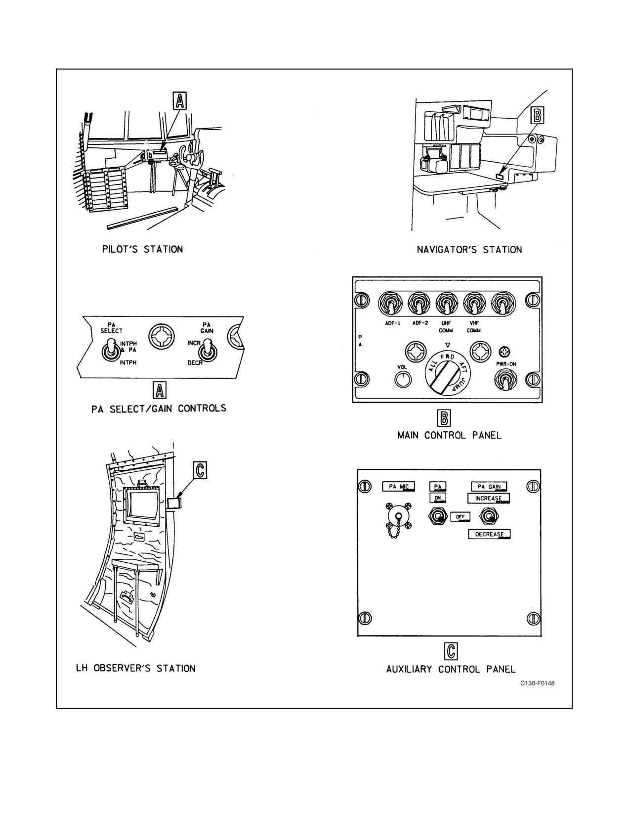
01-75GAL-1
Figure 2-87. AN/AIC-13 Public Address Control Panels (Sheet 1 of 2)
2-181
ORIGINAL
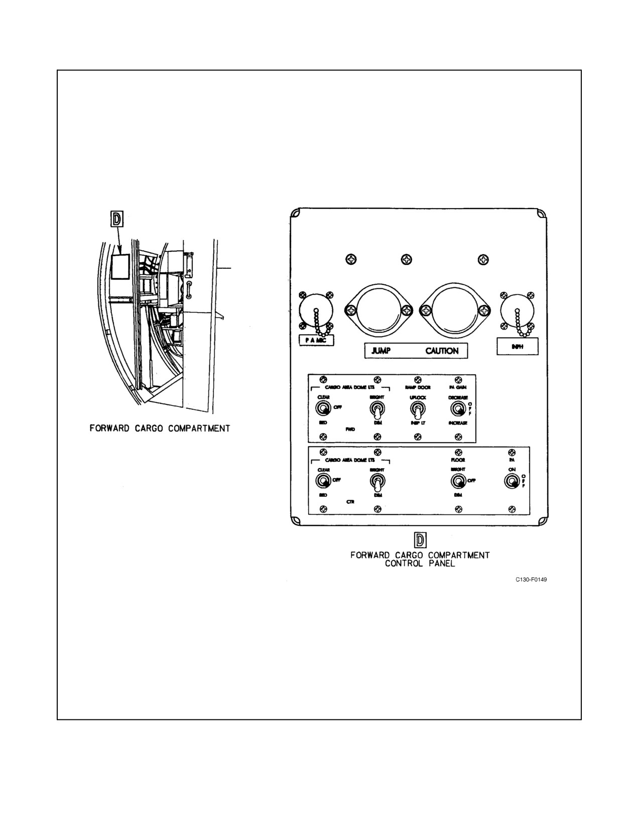
01-75GAL-1
Figure 2-87. AN/AIC-13 Public Address Control Panels (Sheet 2)
ORIGINAL
2-182
01-75GAL-1
2.21.2.1.7 PA SELECT Switch
The PA SELECT switch is a two-position (INTPH & PA, INTPH) switch located on the pilot side shelf extension
and is used to connect the ICS to the PA system. When the switch is placed in the INTPH position,
intercommunication conversation is confined to the interphone circuit. When the switch is placed in the INTPH &
PA position, intercommunication conversation is supplied to thePA system and radio receiversignals areeliminated
from the PA system.
2.21.2.1.8 PA Switch
This switch, installed on the cargo compartment auxiliary control panels, is a two-position (ON, OFF) momentary
switch used to connect that station to the PA system. Holding the PA switch in the ON position permits voice
communication through the speaker(s) selected on the main control panel. Activating this switch silences any radio
inputs that may be selected on the main control panel but does not silence microphone inputs from other PA stations
on the aircraft.
2.21.2.1.9 PA GAIN Switch
The PA GAIN switch is a three-position (INCREASE, OFF, DECREASE) momentary-type switch. When the switch
is held in the INCREASE position, the audio output of the PA system increases. When the switch is held in the
DECREASE position, the audio output of the system decreases. When the switch is released from either position,
a spring return moves it to the OFF (center) position. The manual control knob on the main control panel will be
physically rotated by an electric motor controlled by these switches.
2.21.2.2 Normal Operation of the Public Address System
Operate the PA system as follows:
1. Place the power switch in the ON position.
2. Place the speaker selector switch in the desired position.
3. If the PA system is to be operated from the flight station, place the PA SELECT switch in the INTPH & PA
position. When the PA system is keyed, radio receiver signals will be eliminated, and voice communication
from the flight station will be transmitted through the PA system and through the ICS. If the PA system is to
be operated from the cargo compartment forward auxiliary panel, or the observer station in the left rear of the
cargo compartment, hold the PA switch to the ON position.
4. Press the microphone button and talk.
5. If radio signals are to be heard over the PA system, place the desired mixer switch to the ON (up) position and
place the PA SELECT switch in the INTPH position.
6. To adjust the audio output of the system, rotate the VOL knob on the main control panel, or actuate the PA
GAIN switch on the auxiliary panel(s).
7. PA audio may be monitored at all flight station positions by turning on the PA switch on the respective
interphone panels.
8. When the PA system is operated from either cargo compartment position, monitor the speaker audio so the
volume can be adjusted to a suitable level.
To turn the PA system off:
9. Place the power switch in the OFF position.
2.21.3 Communication-Navigation Management System
The Communication-Navigation Management System (CNMS) provides control of the systems listed in Figure
2-88. System control and status monitoring is accomplished using Control Display Navigation Units (CDNUs).
2-183
ORIGINAL

01-75GAL-1
CAUTION
CDNU1 receives electrical power from the isolated DC bus and should be
turned on first to ensure that it serves as the BC controller in the event of
power loss or fluctuations to the essential DC bus.
SYSTEM
DESIGNATION
VHF/UHF Comm. No. 1
AN/ARC-210(V) (Aircraft with AFC-338)
VHF/UHF Comm. No. 2
AN/ARC-210(V) (Aircraft with AFC-338)
VHF1 Comm. No. 1
AN/ARC-186(V)
VHF2 Comm. No. 2
AN/ARC-186(V)
VHF Nav. No. 1
AN/ARN-126(V)
VHF Nav. No. 2
AN/ARN-126(V)
TACAN No. 1
AN/ARN-139(V)
TACAN No. 2
AN/ARN-118(V)
Satellite Signals Navigation Set (GPS)
AN/ARN-151(V)
Figure 2-88. CNMS Controlled Systems
2.21.3.1 Control Display Navigation Unit (CDNU)
CNMS control and status monitoring are accomplished using the Control Display Navigation Units (CDNUs).
CDNUs are installed on the flight control pedestal, the copilot side panel and navigator station (see Figures 2-89 and
2-90). The pilot’s CDNU is designated as CDNU1, the copilot’s is CDNU2, and the navigator’s is CDNU3. Any
single CDNU has all the required resources to completely operate the CNMS and associated systems. Each CDNU
operates as either a bus controller (BC) or a remote terminal/backup bus controller (RT/BBC). The CDNU that
receives electrical power first will function as the BC CDNU. The BC CDNU performs navigation computations,
builds page displays, communicates with associated equipment, and performs all other computations required to
support CNMS and associated systems operations. The RT/BBC CDNUs serve as spare BCs which process
keystroke inputs, display pages built by the BC CDNU, and perform continuous built-in-testing (BIT) with any free
processor time. CDNU 1 receives 28 Vdc power from the isolated DC bus through the PILOTS CDNU circuit breaker
on the pilot’s upper circuit breaker panel. CDNUs 2 and 3 receive 28 Vdc power from the essential DC bus through
the COPILOTS CDNU and NAV CDNU circuit breakers on the pilot’s upper circuit breaker panel.
2.21.3.2 CDNU Display
The CDNU display has 8 lines of 22 characters each (see Figure 2-90). Lines 1, 3, 5, and 7 are data lines with a line
select key on both the left and right side of the field. Line 2 is reserved for the page title and line 6 is reserved as an
annunciation line. Line 4 is an unreserved data line and line 8 is the scratchpad for displaying keypad entries.
ORIGINAL
2-184
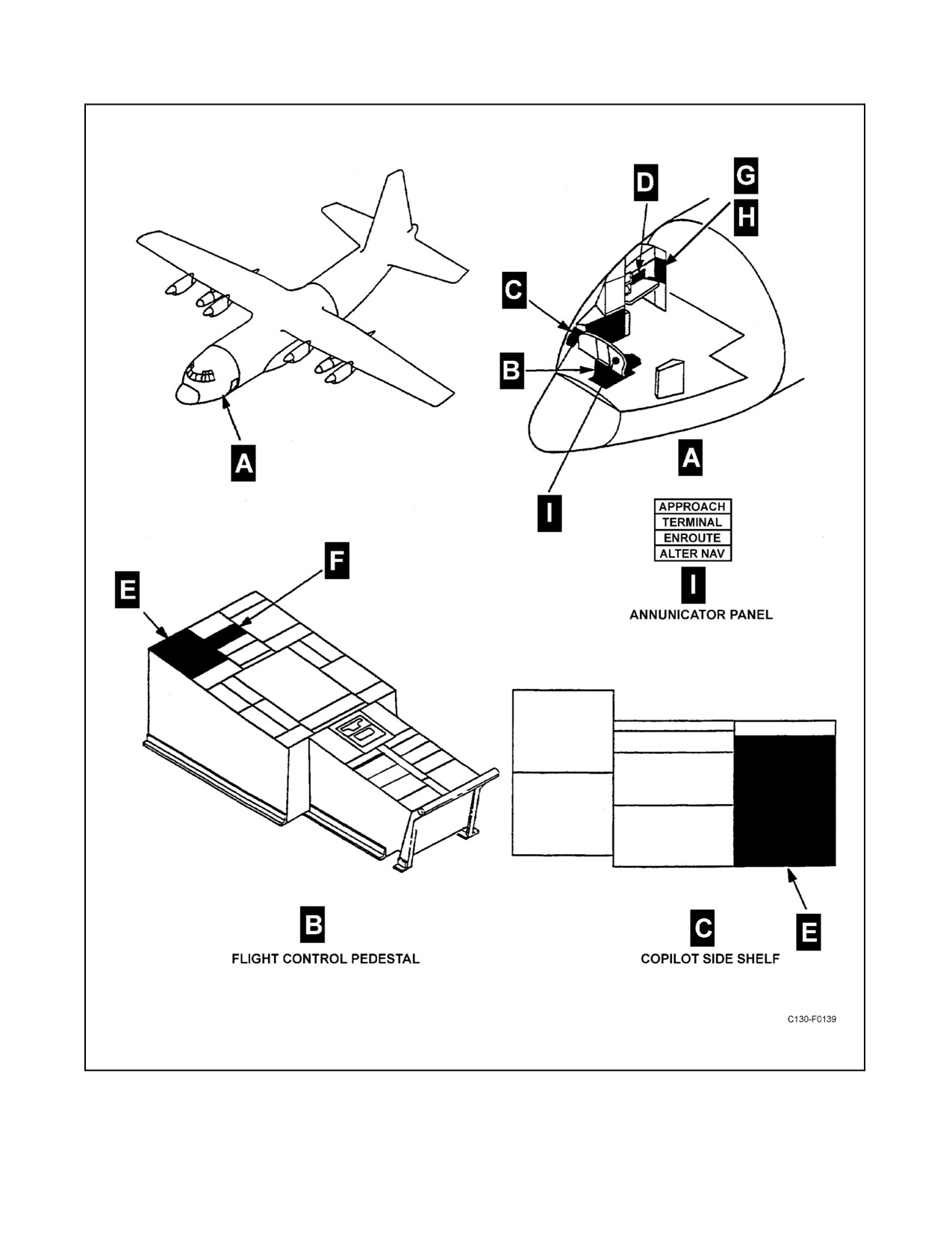
01-75GAL-1
Figure 2-89. CNMS Components Locations (Sheet 1 of 2)
2-185
ORIGINAL
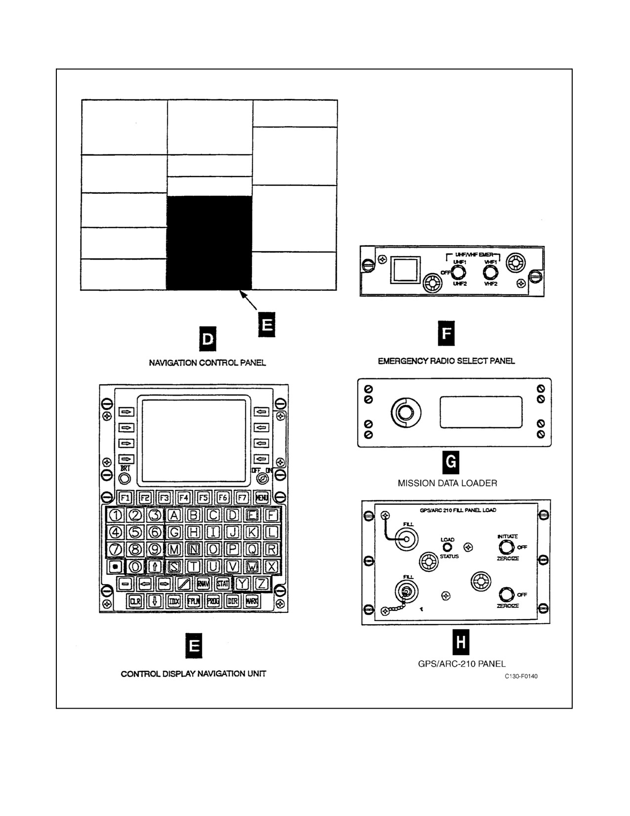
01-75GAL-1
Figure 2-89. CNMS Components Locations (Sheet 2)
ORIGINAL
2-186
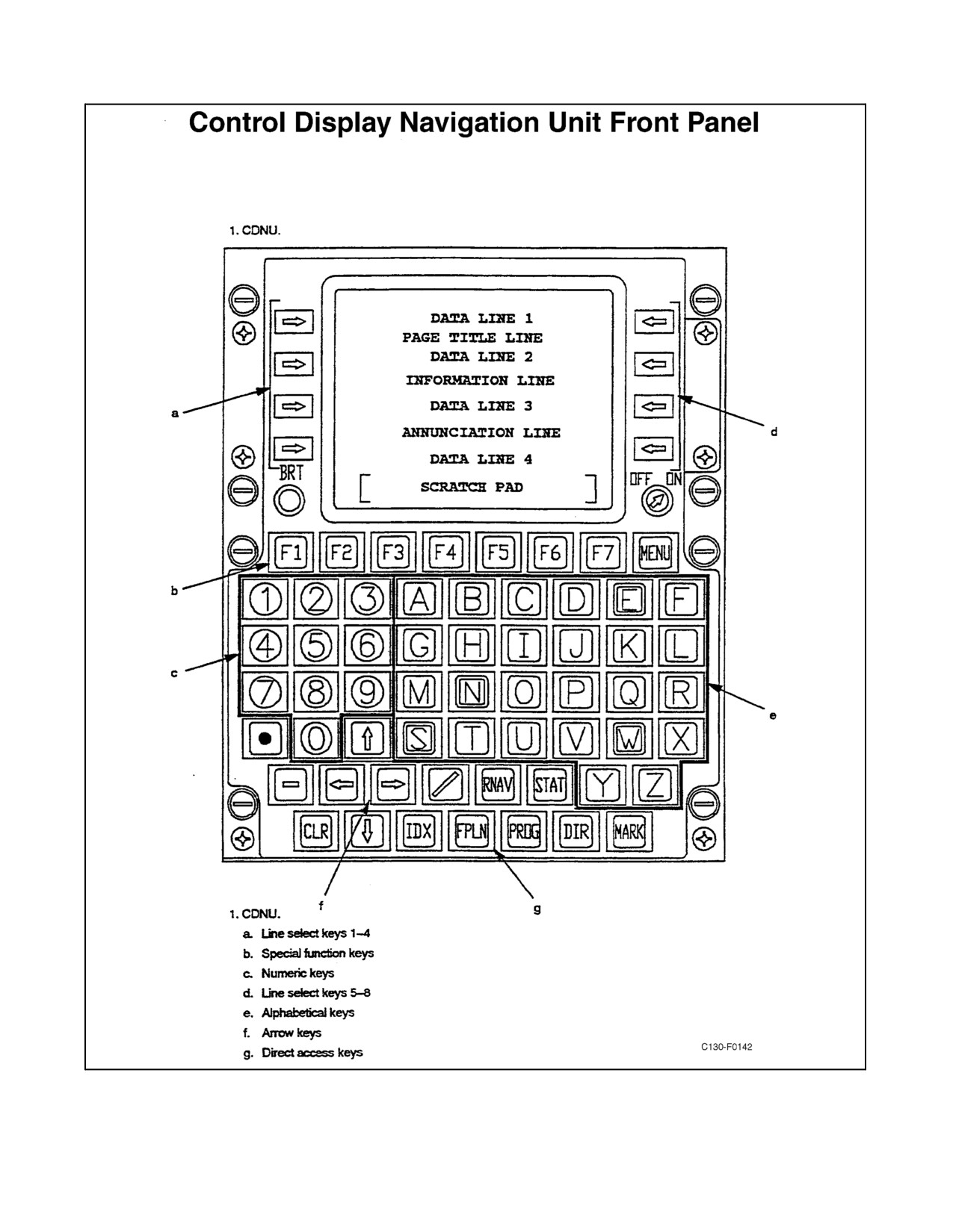
01-75GAL-1
Figure 2-90. Control Display Navigation Unit Front Panel
2-187
ORIGINAL
01-75GAL-1
2.21.3.2.1 Scratchpad
The scratchpad is used to hold all keystrokes prior to executing theinput. Incorrect scratchpad entries may becleared
using the CLR key. A single press of the CLR key clears the last character entered and a second press (without
additional intervening keystrokes) will clear the entire scratchpad. Holding the CLR key begins to repeat deletion
of one character at a time. The scratchpad is cleared automatically when the system accepts valid data inputs.
2.21.3.3 CDNU Controls
CDNU data entry operations are performed with a full alphanumeric keypad, arrow keys, function keys and eight
line select keys (see Figure 2-90). Each CDNU provides simultaneous and independent operation; meaning that one
CDNU can be used to display systems status while another is being used to edit the flight plan. The only exception
to the simultaneous and independent operation involves system annunciations on Line
6 of all CDNUs
simultaneously. Symbolic aids are used to indicate what entries can be made, what functions are on or engaged, and
what selections are possible. Figure 2-91 lists several symbol aids and their definition.
CDNU SYMBOL
DEFINITION
Pushing line select key accessed different page
←→
Pushing line select key selects item or enables mode
→←
Indicates function is engaged or enabled
Alternate selection among modes
:
Check, as in check status for equipment failures
---
Indicates no computed data is available or power is off
Indicates data entry from scratchpad is possible or required
[
]
Indicates vertical page or line scrolling is possible
Indicates lateral page scrolling is possible
Indicates lateral and vertical page scrolling is possible
Figure 2-91. CDNU Symbology
2.21.3.3.1 OFF/ON
The rotary knob on the lower right side of the CDNU display screen turns CDNU power on and off.
ORIGINAL
2-188
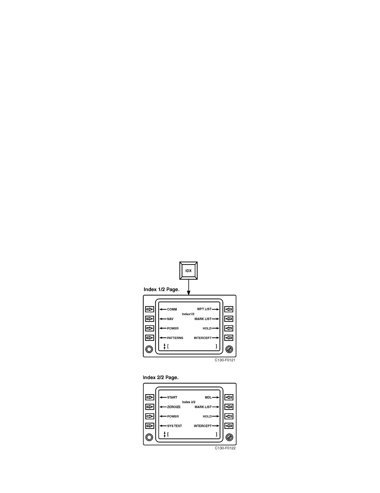
01-75GAL-1
2.21.3.3.2 BRT
The rotary knob on the lower left side of the CDNU display controls the intensity and brightness of the CDNU display.
2.21.3.3.3 Line Select Keys
These keys can be used to access lower level pages, toggle modes of a function, or enter data in an associated field.
For certain functions, line selects may be used both for selecting a mode and for input of numeric values used by the
mode. If the scratchpad is blank, pressing the line select toggles the mode. If the scratchpad is not blank, pressing
thelineselect will input numericdata(ifvalid)andwill nottogglethemode. Whenundefined lineselects arepressed,
no operation is performed.
2.21.3.3.4 Alphabetic, Numeric and Punctuation Keys
These keys allow for data entry into the scratchpad. The period (.) and slash (/) keys are used to enter navigational
data. The dash (-) key can be used to delete input data or to enter negative valued data.
2.21.3.3.5 Special Function Keys
Keys F1 through F7 are special function keys. The functions of each key are shown in Figures 2-92 and 2-93.
2.21.3.3.6 Direct Access Keys
The direct access keys consist of RNAV (area navigation), STAT (system status), IDX (index), FPLN (flight plan),
PROG (progress), DIR (direct to), MENU (menu), and MARK (current position to scratchpad). The direct access
keys provide access to various functional CDNU pages as shown in Figures 2-92 and 2-94.
1. INX — Index pages provide access to a variety of Utility pages (see Figure 2-92 and paragraph 2.21.3.4) and
support functions required to operate and test system hardware.
2-189
ORIGINAL
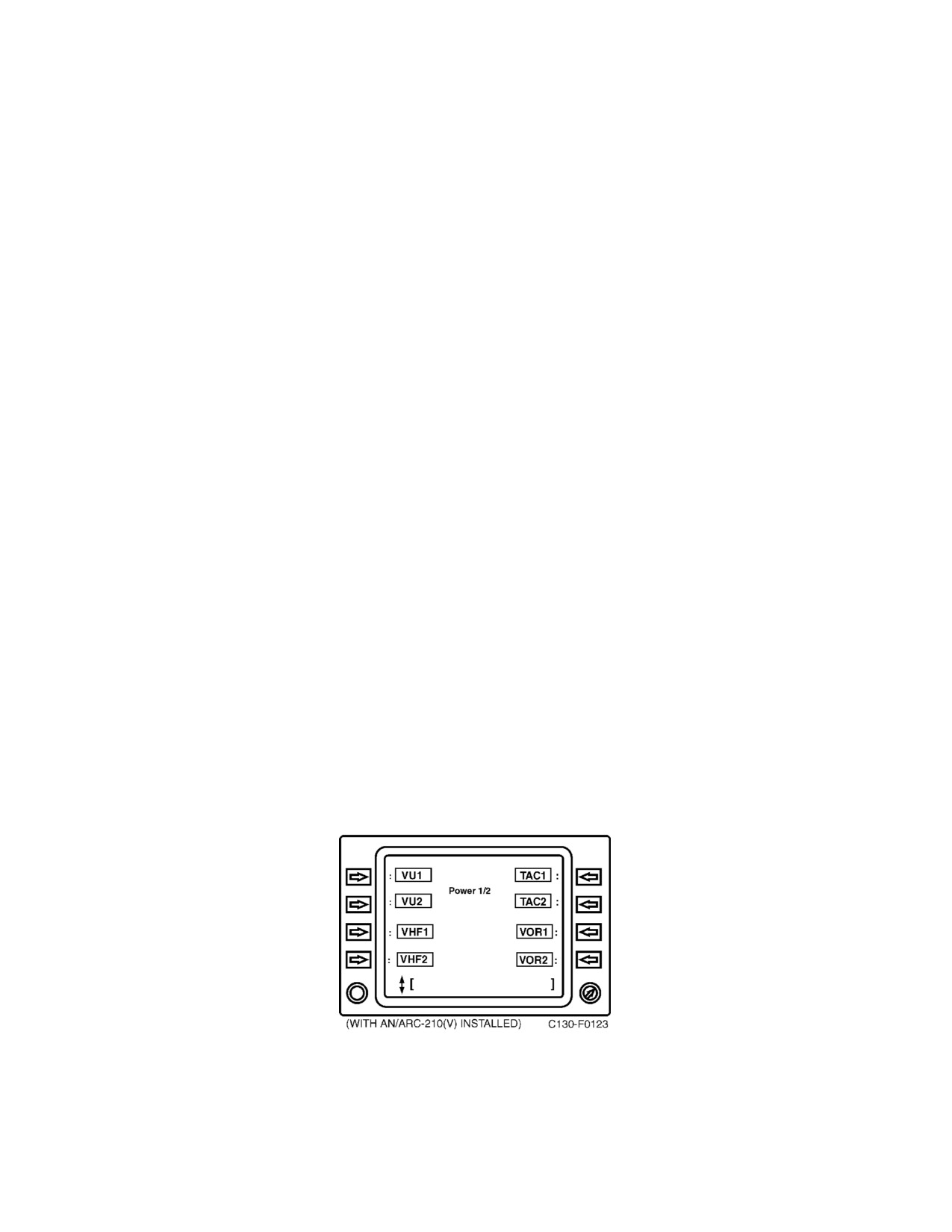
01-75GAL-1
2. FPLN — The Flight Plan page is the center of the navigation function, providing access not only to the flight
plan itself, but also to the associated functions in support of flight plan maintenance and execution. This key
provides for display of the flight plan on CDNU. Past and present waypoint data may be accessed using the
scroll keys (refer to paragraph 2.21.4.4.3).
3. DIR — Pressing the DIR key causes the CDNU to display flight plan waypoints on the direct to [ ] page.
Waypoints may be accessed via the scroll page and selected for direct to navigation with the corresponding
line select key (refer to paragraph 2.21.4.4.6).
4. STAT — System Status pages provide information concerning the availability of various system equipment
(refer to paragraph 2.21.3.4).
5. PROG — Progress pages indicate where the aircraft is in relation to the desired flight plan and provide
guidance to acquire and execute the flight plan (refer to paragraph 2.21.4.4.5).
6. RNAV — The Area Navigation pages provide control and display or individual navigation sensors and how
they are integrated to form the navigational solution (refer to paragraph 2.21.4.4.4).
7. MARK— Themark keywrites theinstantaneous presentposition solutionofthesystem integratednavigation
solution into the scratchpad.
8. MENU — The Menu Page provides a list of the functions associated with the special function keys.
2.21.3.4 CDNU Utility Pages
The CDNU utility pages consist of the Power, Zeroize, Start, Systems status and Systems test pages. These pages
are accessed via the IDX and STAT direct access keys. They provide for overall operation and test of the CDNU and
CNMS associated equipment.
1. Power page — The Power page gives the operator control of system power for CNMS navigation and
communication equipment. Line select keys next to the system name are used to turn system power on and
off. A line box around the equipment name indicates the system is powered.
2. Zeroizepage— TheZeroizepagepermits selectivezeroing ofnon-volatilememory in theCDNU, MDL,GPS
receiver and AN/ARC-210(V) radio set. In addition to selective blanking, a single key commands a master
zeroize of all data stored in the system. All requests for zeroize require confirmation by pressing the associated
line select key a second time.
ORIGINAL
2-190
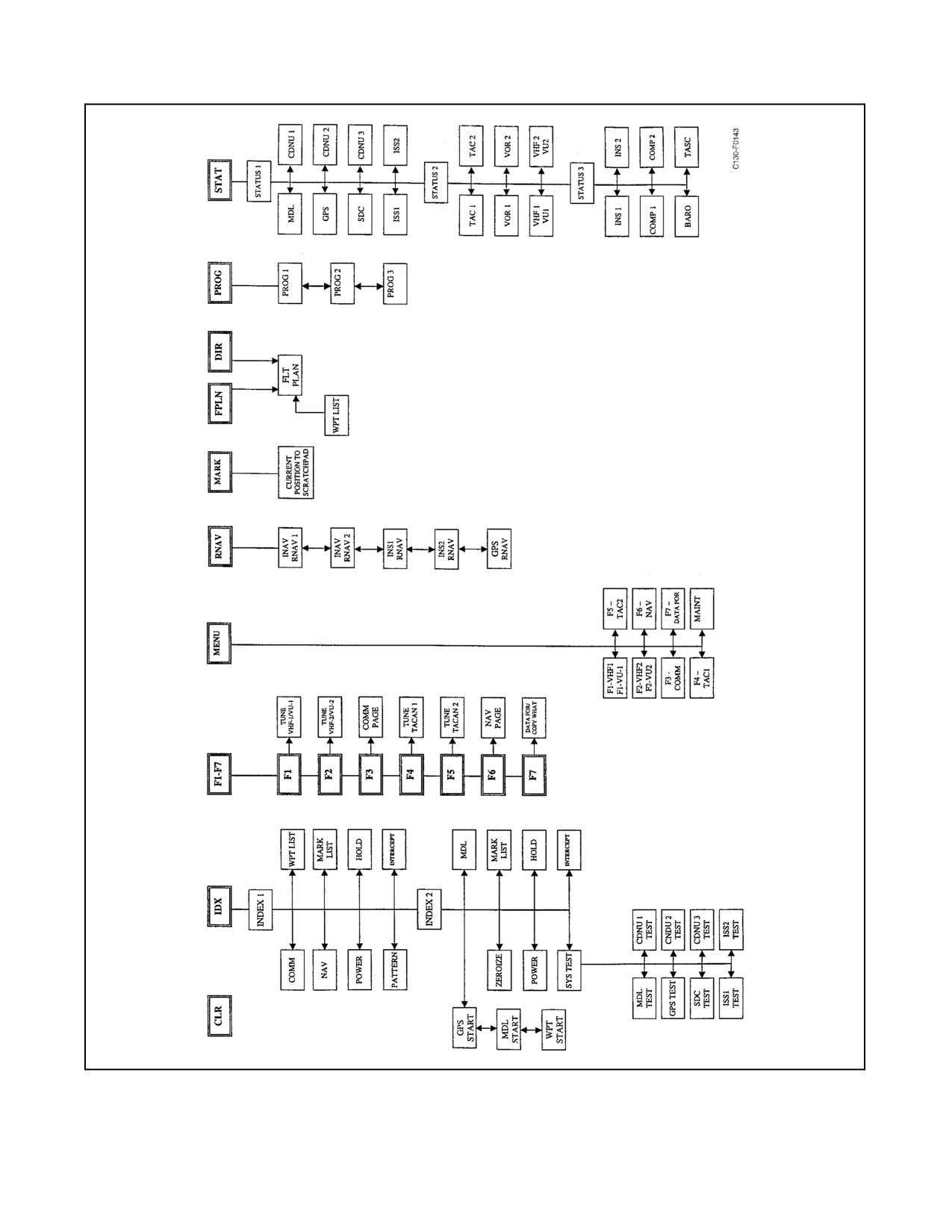
01-75GAL-1
Figure 2-92. CDNU Page Tree
2-191
ORIGINAL
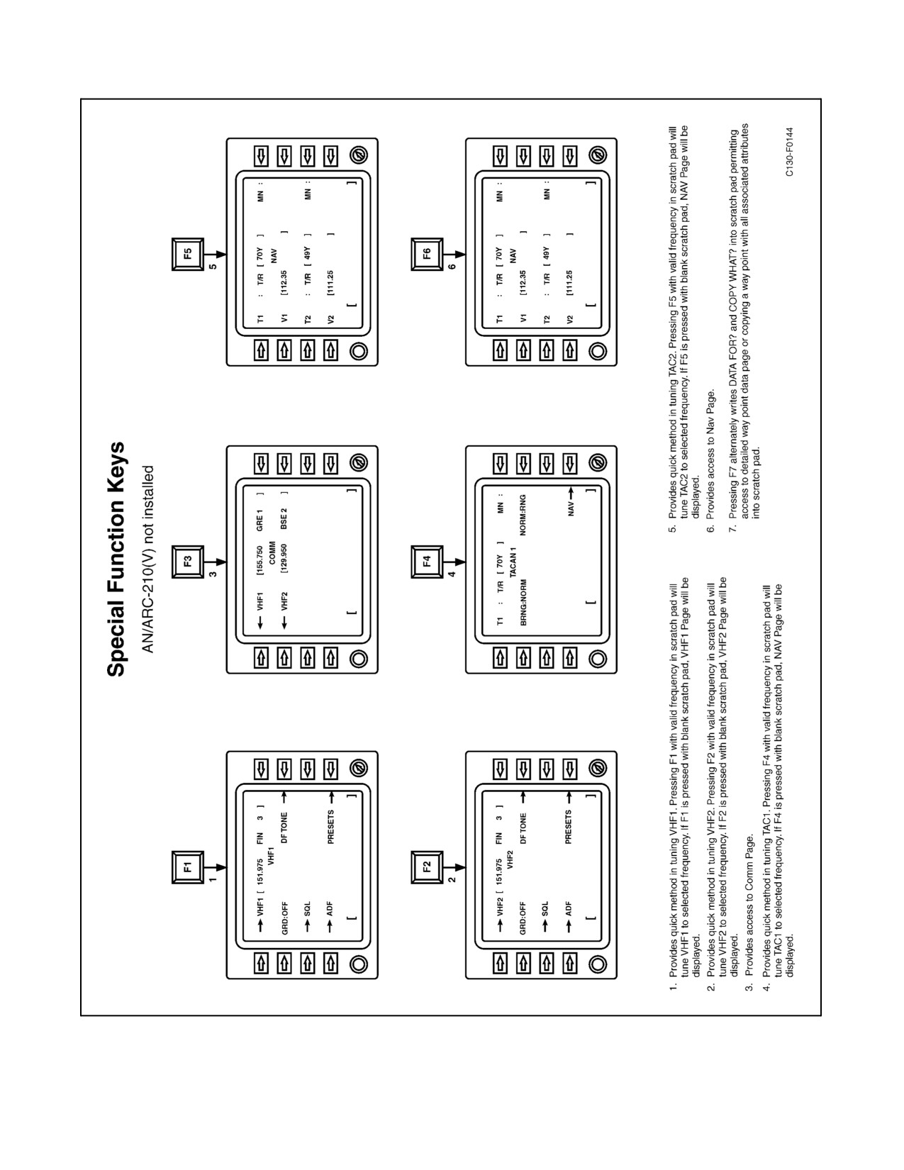
01-75GAL-1
Figure 2-93. Special Function Keys [AN/ARC-210(V) Not Installed] (Sheet 1 of 2)
ORIGINAL
2-192
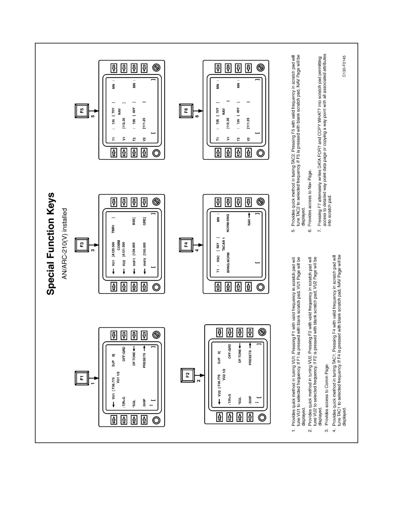
01-75GAL-1
Figure 2-93. Special Function Keys [AN/ARC-210(V) Installed] (Sheet 2)
2-193
ORIGINAL
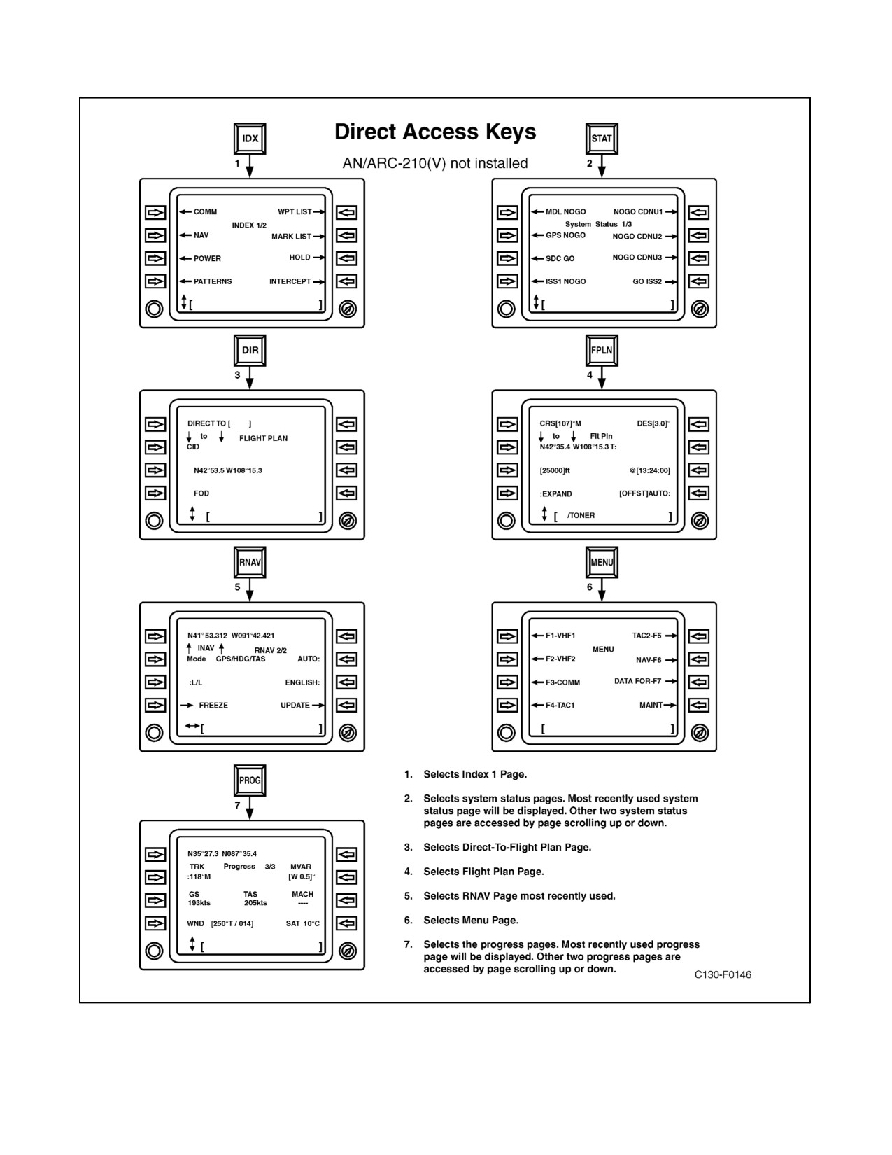
01-75GAL-1
Figure 2-94. Direct Access Keys [AN/ARC-210(V) Not Installed] (Sheet 1 of 2)
ORIGINAL
2-194
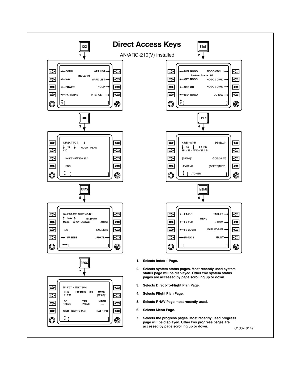
01-75GAL-1
Figure 2-94. Direct Access Keys [AN/ARC-210(V) Installed] (Sheet 2)
2-195
ORIGINAL
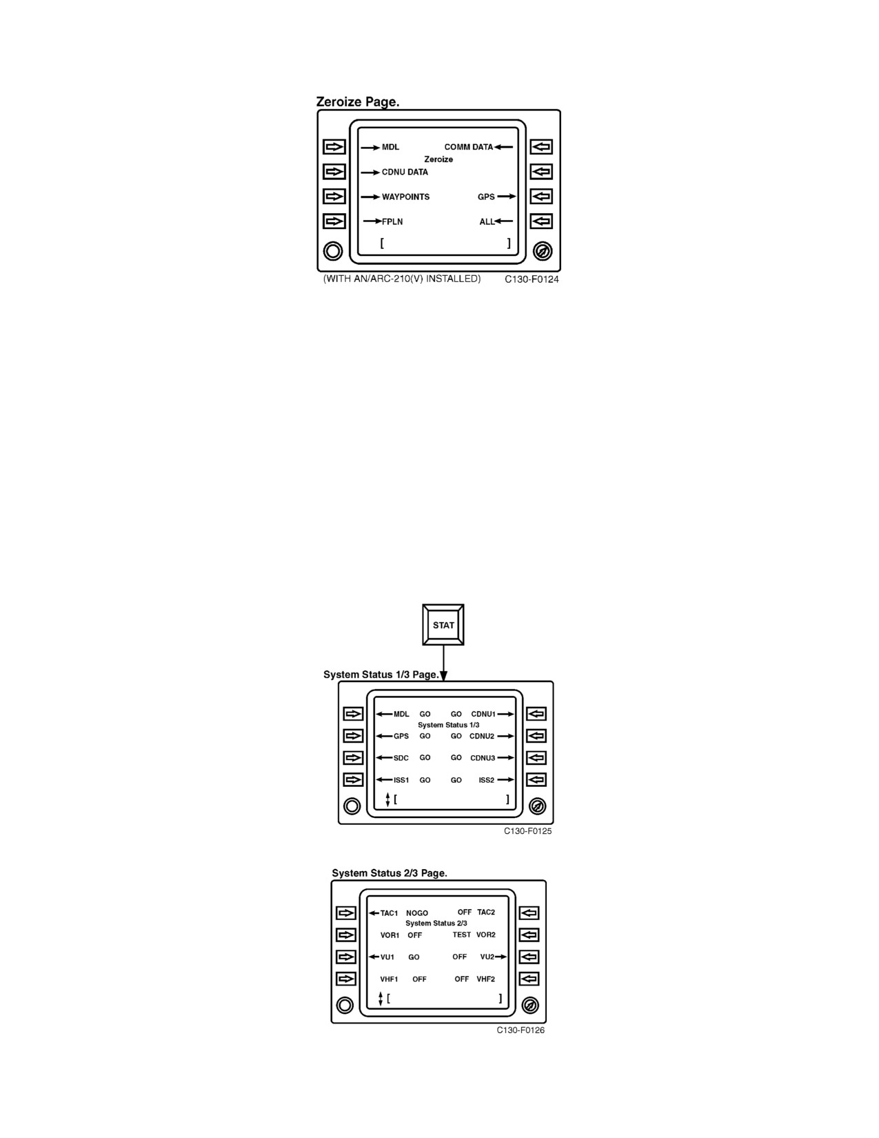
01-75GAL-1
Note
To avoid erasing the operational flight program and rendering the system
unusable, flight crew personnel should not select ZEROIZE MDL (LS1)
or ZEROIZE ALL (LS8).
3. Systems Status Pages — The CDNU monitors the status of each CNMS component and executes continuous
built-in test (CBIT) software which evaluates those items that can be assessed during normal operations with
thehardwareon-line. This occurs without any required operator action and theresults areavailable fordisplay
at all times. When a failure is detected in the CBIT routine, a STATUS annunciation appears on the line
6 annunciation line. A XXXX STATUS message is displayed in the scratchpad if operation is attempted
which cannot be performed due to conditions causing the
STATUS annunciation. Outputs from a
component indicating a failed status are not used for computations or display. Results from CBIT routines are
compiled and reported on the Systems Status Pages. Additionally, detailed status pages are available for most
components and are indicated by outward pointing arrows on the status pages.
ORIGINAL
2-196
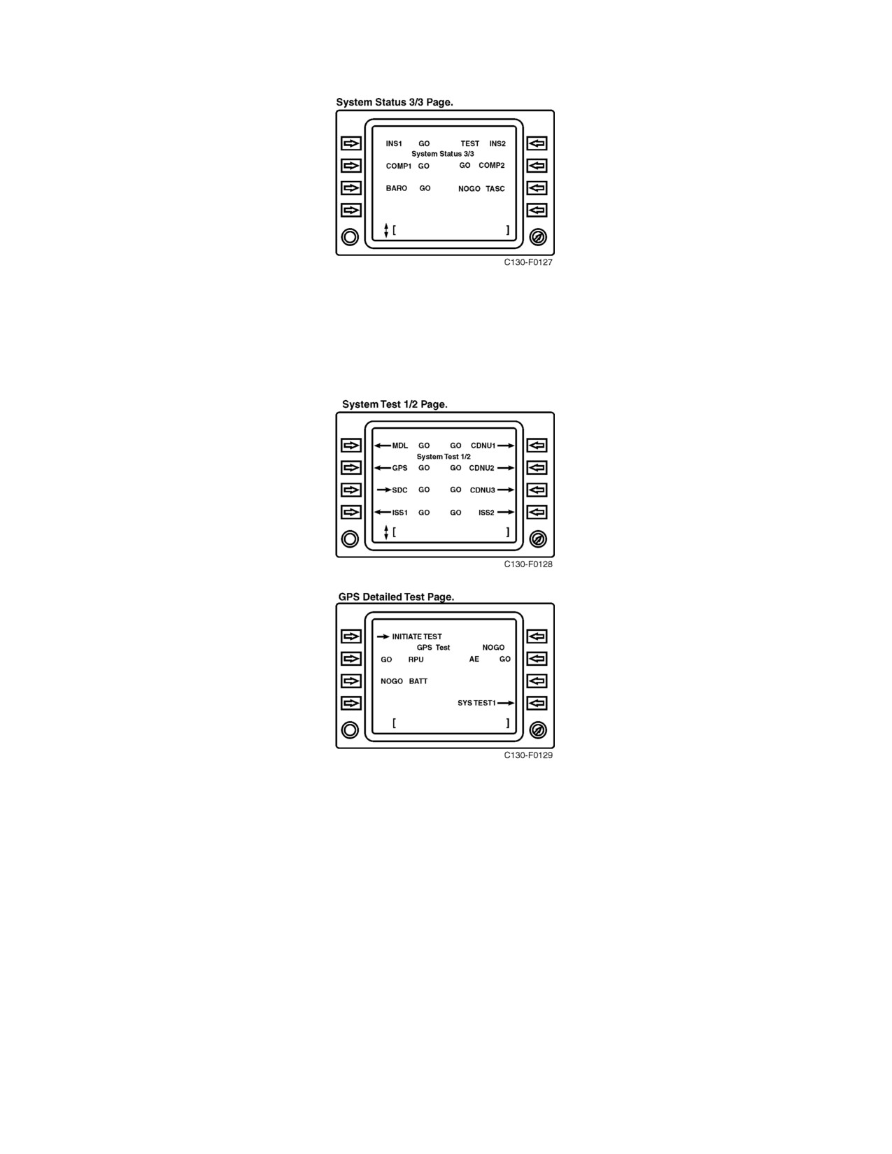
01-75GAL-1
4. System Test Pages — The SYS TEST page provides the capability to BIT test the CDNU, MDL, GPS receiver,
ISS and CDNU units. When the line select key is pressed on the SYS TEST page, the CDNU screen will either
go to the detailed test page of the associated component or perform the BIT test of that component. Systems
with detailed test pages have outward pointing arrows on the SYS TEST page. Tests for systems with inward
pointing arrows are initiated when the associated line select is pressed.
5. Comm Page — The comm page controls tuning and other function settings for the VHF 1 and VHF 2
communication systems and also V/U-1 and V/U-2 communication systems for ARC-210 equipped aircraft.
The comm page is accessed via the F3 key or via the index page. Tuning is accomplished by entering the
appropriate frequency in the scratchpad and then pressing the line select key next to the corresponding radio.
Pressing the line select key with no frequency in the scratchpad (blank scratchpad) will access the detailed page
for the corresponding radio. Quick tuning can be accomplished by entering the frequency in the scratchpad
and pressing F1 for VHF 1/VU-1 or F2 for VHF 2/VU-2. Returning to the previously selected frequency may
be accomplished by tuning 0.
2-197
ORIGINAL
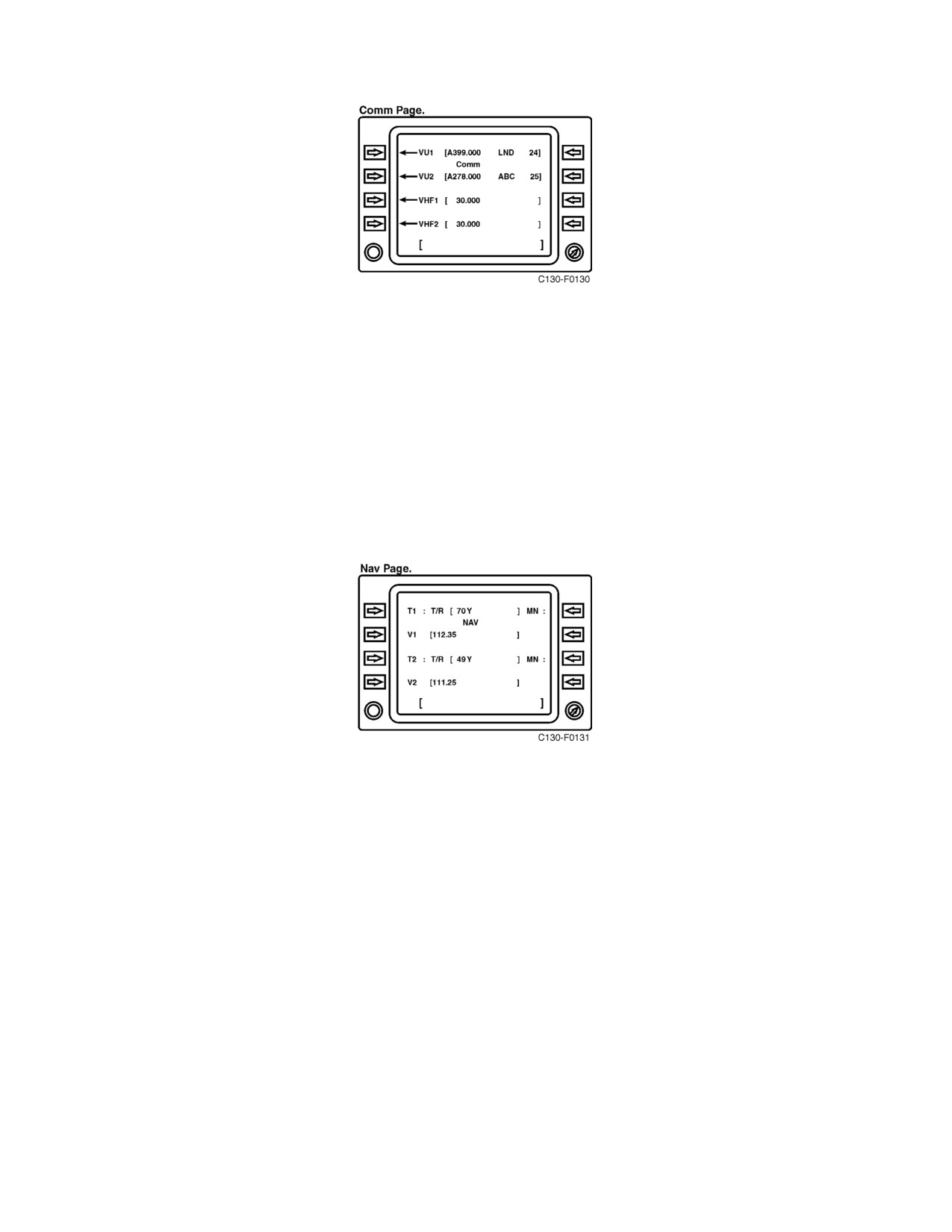
01-75GAL-1
6. Nav Page — The NAV page controls tuning and basic function settings for the VOR-1, VOR-2, TACAN-1
and TACAN-2 navigation systems. The NAV page is accessed via the F6 key or via the index page. Tuning
is accomplished by entering the appropriate channel/frequency in the scratchpad and then pressing the
corresponding left-side line select key. Pressing the line select key with no channel or frequency in the
scratchpad (blank scratchpad) will access the detailed page for the corresponding VOR or TACAN. Quick
tuning for the TACANs can be accomplished by entering the channel in the scratchpad and pressing F4 for
TACAN-1 or F5 for TACAN-2. Returning to the previously selected frequency may be accomplished by
tuning 0. Additionally, the operator can also pair TAC-1 to VOR-1 and TAC-2 to VOR-2 for simultaneous
tuning to paired NAVAID frequencies. Paired operation is enabled using the right-side line select key next
to the respective TACAN. The letters “PR” on the CDNU display indicates the paired function is enabled and
the paired TACAN channel will automatically be tuned to correspond with the VOR frequency; “MN”
indicates that the paired function is not enabled.
2.21.3.5 Interface Shipsets
Two interface shipsets (ISS) are incorporated with the CNMS to convert analog and discrete signals to the digital
format required by the CDNU. The ISS units receive 26 Vac power through the ISS circuit breaker on the pilot’s upper
circuit breaker panel. ISS1 receives 28 Vdc power from the isolated DC bus through the ISS NO. 1 circuit breaker
and ISS2 receives 28 Vdc power from the essential DC bus through the ISS NO. 2 circuit breaker.
2.21.3.6 Signal Data Converter
The Signal Data Converter (SDC), CV-4138/A, converts serial digital outputs from the CDNU to analog signals used
to driveflight instruments, displays and annunciators. The SDC is located in theleft-hand cargo bay equipment rack.
The SDC receives 115 V and 26 Vac power from the essential AC bus through the SDC circuit breakers on the pilot’s
upper circuit breaker panel.
2.21.4 AN/ARN-151(V) Satellite Signals Navigation Set (Global Positioning System)
The AN/ARN-151 Satellite Signals Navigation Set is a worldwide all-weather navigation aid that receives and
processes navigation information from NAVSTAR GPS satellites. GPS is a space-based radio positioning system
that provides its users with highly accurate position, velocity and time data. This service is provided globally,
ORIGINAL
2-198
01-75GAL-1
continuously, and under all weather conditions to users. GPS receivers operate passively, thus allowing an unlimited
number of simultaneous users. The GPS has features that can deny accurate service to unauthorized users, prevent
spoofing and reduce receiver susceptibility to jamming.
Use of GPS for approaches or as a primary means of instrument navigation
is not authorized at this time. GPS is only authorized as an aid to visual
navigation (VFR).
GPS provides the most useful and accurate navigation solution available, but operators are cautioned not to be
over-confident of the system. Appropriate cross-checking of GPS with other forms of navigation (INS, VOR,
TACAN and visual methods) should be employed to ensure safety and mission accomplishment.
2.21.4.1 Theory of Operation
The GPS comprises three major segments: Space, Control and User. The Space segment consists of a constellation
ofGPSsatellitesinorbit aroundtheEarth.Each satellitebroadcasts radio-frequencyranging codesand anavigational
data message. The Control segment consists of a Master Control Station (MCS) and a number of monitor stations
located around the world. The MCS tracks, monitors and manages the satellite constellation and updates the
navigational data messages. The User segment consists of various navigational receivers specifically designed to
receive, decode and process the GPS satellite-ranging codes and navigational data messages.
CAUTION
Standard military GPS systems do not provide a navigation integrity
function which would monitor and cross check the validity of satellite
transmitters and GPS receivers.
The ranging codes broadcast by the satellites enable a GPS receiver to measure the transit time of the signals and
thereby determine the range between a satellite and the user. The navigation data message enables a receiver to
calculate the position of each satellite at the time of transmission of the signal. Four satellites are generally required
to be simultaneously “in-view” of the receiver for three-dimensional (3-D) positioning purposes. Less than four
satellites can be used if the user altitude or system time is precisely known.
2.21.4.2 Levels of Service
Two levels of navigation are provided by the GPS, the Precise Positioning Service (PPS) and the Standard
Positioning Service (SPS). The PPS is a highly accurate positioning, velocity and timing service that is made
available only to authorized users. The SPS is a less accurate positioning and timing service that is available to all
GPS users.
2.21.4.2.1 Precise Positioning Service (PPS)
The PPS provides 16-meter Spherical Error Probable (SEP) positioning accuracy and 100 nanosecond Universal
Coordinated Time (UTC) time transfer accuracy to authorized users. The PPS is primarily intended for military
purposes. Authorization to use the PPS is determined by the Department of Defense (DoD), based on U.S. defense
requirements and international commitments.
2-199
ORIGINAL
01-75GAL-1
Access to the PPS is controlled by two features using cryptographic techniques. A Selective Availability (S/A) feature
(when turned on) is used to reduce the accuracy of the GPS position, velocity and time data available to unauthorized
users. S/A operates by introducing controlled errors into the satellite signals. System accuracy degradations can be
increased during crises or war. An Anti-Spoofing (A-S) feature is invoked at random times without warning by the
U.S. to negate potential spoofing (hostile information) of PPS signals. Encryption keys and techniques are provided
toPPSusers thatallow themto removetheeffectsofS/Aand A-Sand therebyattain themaximum availableaccuracy
of GPS. PPS-capable receivers that do not have the proper encryption keys installed will be subject to the accuracy
degradations of S/A and potential spoofing or jamming of GPS signals.
CAUTION
D Operate GPS receivers in keyed mode for greater position, velocity and
time accuracy as well as improved anti-spoofing and anti-jam capability.
Failure to do so may lead to gross navigational errors.
D Aircrews should be aware that GPS is susceptible to intentional and
unintentional interference and loss of GPS timing can affect HaveQuick
operation.
2.21.4.2.2 Standard Positioning Service (SPS)
The SPS provides 100-meter horizontal positioning accuracy to any GPS user during peacetime. SPS receivers can
also achieve approximately 337-nanosecond UTC time transfer accuracy. The SPS is primarily intended for civilian
purposes, although it has many peacetime military uses as well. The SPS horizontal accuracy specification includes
the peacetime degradation of S/A that is the dominant SPS error source.
2.21.4.3 AN/ARN-151(V) System Components
The AN/ARN-151 Satellite Signals Navigation Set consists of the following primary components:
1. GPS Receiver.
2. Mission Data Loader.
3. GPS Fill Panel.
4. Control Display Navigation Unit (CDNU).
5. Main Annunciator Panel.
2.21.4.3.1 GPS Receiver
The R-2332/AR GPS receiver is the receiver/processor for the GPS. The receiver decodes satellite signals and
provides position coordinates, altitude, speed and time data to aircraft systems. The GPS receiver is located in the
LH Cargo Bay Equipment rack. The system receives 115 Vac power from the essential AC bus through the GPS
RCVR circuit breaker and 28 Vdc power from the essential DC bus through the FLT DATA SW PNL and DATA
LOADER circuit breakers located on the pilot’s upper circuit breaker panel. Three C-cell batteries comprise a battery
power supply that is located at the front of the receiver. The battery power supply ensures that critical data in memory
will not be lost when aircraft electrical power is secured. A time source and nuclear event detector is also powered
by the battery supply.
ORIGINAL
2-200
01-75GAL-1
2.21.4.3.2 Mission Data Loader
The AN/ASQ-215 Mission Data Loader is designed to provide bulk memory storage for military aircraft parameters,
waypoint database, and maintenance and avionics initialization data. It consists of an Interface Receptacle Unit (IRU)
located in the navigator’s sidewall equipment panel (see Figure 2-89) and a Data Transfer Module (DTM). The
removable DTM contains data that can be accessed by the CDNU. The MDL provides flight crews with the ability
to transfer flight plans, current GPS almanac data and a waypoint database directly to the CDNU.
2.21.4.3.3 GPS Fill Panel
The GPS Fill Panel enables loading of the GPS security codes from a KYK-13 Electronic Transfer Device (see Figure
2-89). These codes enable precision GPS navigation during times when S/A and/or A-S are activated. The fill panel
has two switches, one to initiate loading of security codes and one to zeroize existing codes. An LED status indicator
on the panel will illuminate briefly when the GPS receiver has accepted the security code. Reaction time is
approximately 4 to 5 seconds. Illumination indicates correct parity, but does not indicate that the code is correct. The
panel is located in the navigator’s sidewall equipment panel.
2.21.4.3.4 Control Display Navigation Unit (CDNU)
System control and status monitoring are accomplished using the Control Display Navigation Units (CDNUs). The
CDNU is the primary pilot-to-GPS interface. The CDNU performs all control, display, crew data entry, processing
and navigation computations for the GPS. CDNUs are installed on the flight control pedestal, the copilot side panel
and navigator station. Each CDNU is capable of operating the GPS. GPS information and status is displayed on
various CDNU screen pages. Refer to paragraph 2.21.3 for CDNU specifics.
2.21.4.3.5 Main Annunciator Panel
The main annunciator panel is located on the pilot’s instrument panel (see Figure 2-89). The annunciator panel has
four CNMS/GPS related indicator lights associated with the corresponding flight mode. Flight mode is set by the
operator on the CDNU expanded FPLN page. Indicator light and flight modes are as follows:
1. EN ROUTE light: Indicates the aircraft is in the enroute mode. With CDNU selected on the Navigation
Selector, two dots of deflection on the HSI equals 4.0 nm. A NAV invalid flag will appear on the HSI if GPS
Estimated Horizontal Error (EHE) exceeds 1,000 meters.
2. TERMINAL light: Indicates the aircraft is in the terminal mode. With CDNU selected on the Navigation
Selector, two dots of deflection on the HSI equals 1.0 nm. A NAV invalid flag will appear on the HSI if GPS
EHE exceeds 500 meters.
3. APPROACH light: Indicates the aircraft is in the approach mode. With CDNU selected on the Navigation
Selector, two dots of deflection on the HSI equals .3 nm. A NAV invalid flag will appear on the HSI if GPS
EHE exceeds 100 meters.
4. ALTER NAV light: Indicates the GPS is not being used as a navigation sensor and errors are no longer bounded
to the GPS navigation solution.
2.21.4.4 GPS and CDNU Navigation Operations
2.21.4.4.1 System Power
GPS system power is controlled via the CDNU power page. A rectangle box around the GPS component name
indicates the unit is ON.
2-201
ORIGINAL
01-75GAL-1
2.21.4.4.2 Loading GPS Secure Keys
GPS secure keys provide for secure (PPS) operation and are loaded at the GPS fill panel using the KYK-13.
Note
If keying GPS with power applied, ensure date and time are correct as
displayed on the GPS Start Page. Keys may not be loaded when GPS IBIT
testing is in progress.
1. Connect KYK-13 to FILL connector on GPS Fill Panel.
2. Set KYK-13 address switch to desired setting (1-6).
3. Set KYK-13 Mode switch to ON.
4. Momentarily hold GPS Fill Panel INITIATE/ZEROIZE switch to INITIATE (parity indicator flashes).
5. On GPS Fill Panel, verify LOAD/STATUS indicator flashes within 5 seconds to indicate successful load.
6. Set KYK-13 Mode switch to OFF.
7. Disconnect KYK-13 from GPS Fill Panel.
CAUTION
Failure to re-initialize the GPS after loading crypto keys may result in
significant navigation errors. After the GPS system has been loaded with
crypto keys and has acquired a figure of merit of one or two navigation
solution, access the power page of the control display navigation unit and
cycle the GPS power off and then back on or access the system test page
and perform an initiated built in test on the GPS system. Either of these two
procedures will re-initialize the GPS receiver.
2.21.4.4.3 Loading Flight Plans and Waypoints
The CDNU maintains several databases internally and on the MDL cartridge to support flight-planning operations.
The crew can create and maintain a flight plan of up to 50 geographic locations, stored in the order to be flown. The
flight plan is maintained through addition, modification, or deletion of waypoints. When waypoints are added in the
middle of the flight plan, succeeding waypoints are automatically moved down the list. Similarly, when waypoints
are deleted, the flight plan automatically eliminates all holes by moving waypoints up the list. The flight plan may
be selected and loaded from the MDL or created within the CDNU manually point-by-point.
A magnetic variation database is maintained in the CDNU for conversion of references from True and Magnetic
North. This database is automatically transferred from the MDL cartridge each time the cartridge is inserted if it is
more recent than the existing CDNU database. Once loaded, a magnetic variation database remains in effect until
overwritten by insertion of a new cartridge containing a more recent magnetic variation database.
1. Flight Plan Page — Pressing the FPLN direct access key accesses the Flight Plan page. All information
defining the flight plan is available by scrolling through the Flight Plan Page with the up and down arrow keys.
ORIGINAL
2-202
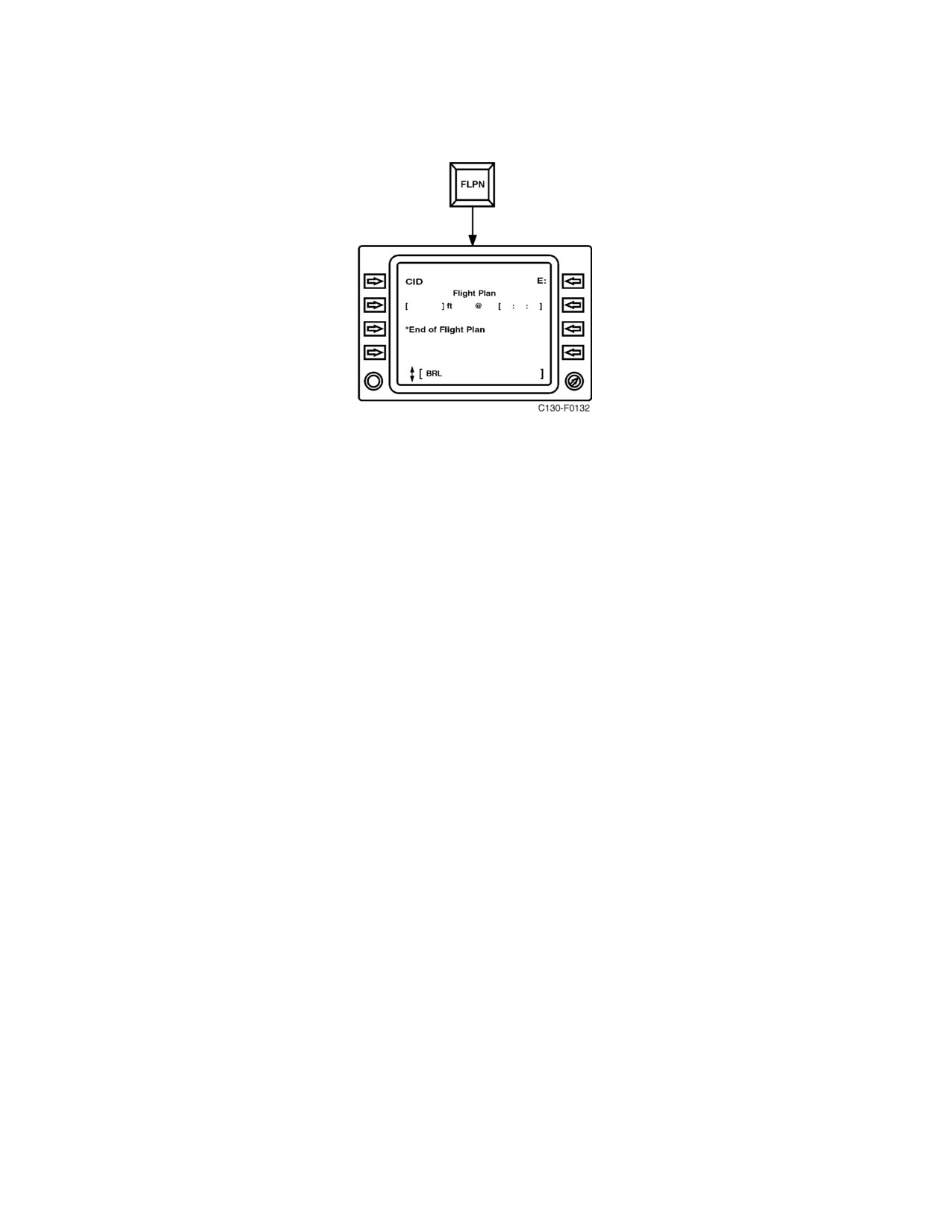
01-75GAL-1
Two display modes are available: Expanded display shows full display of waypoint attributes; Compact
display shows only horizontal positions.
2.
Load a Flight Plan from the MDL.
a. Press IDX key to access Index Page 1/2.
b. Press down arrow to access Index Page 2/2.
c. Press LS1 to access Start Pages.
d. Scroll up/down to MDL Start Page. Select MDL Start Page with corresponding LS key.
e. Press LS8 to access Flight Plan Select 1/2 Page.
f. Scroll up/down to desired Flight Plan and select with corresponding LS key.
3.
Manual Entry of Waypoints into a Flight Plan.
a. Press FPLN key to access FLIGHT PLAN.
b. Press down arrow to scroll to desired portion of flight plan.
c. If MDL is loaded, insert waypoint by typing fix or NAVAID identifier into scratchpad.
d. If MDL is not loaded or waypoint is not in database, enter coordinates into scratchpad (N1234.5W12345.6).
e. Press LS key to place waypoint into flight plan.
Note
Fix coordinates may be assigned a specific label for display vice the
underlying coordinates and definition. Enter 2-, 3-, 4-, or5-letter label into
the scratchpad preceded by a slash “/” (i.e. /HOME). Press the LS key
adjacent to waypoint coordinates to assign the label.
4.
Deleting Waypoints from the Flight Plan.
a. Press FPLN key to access FLIGHT PLAN.
b. Press down arrow to scroll to desired portion of flight plan.
2-203
ORIGINAL
01-75GAL-1
c. Enter minus symbol (-) into the scratchpad.
d. Press LS key to place waypoint into flight plan.
Note
Current waypoint cannot be deleted. Use DIRect to follow-on waypoint.
5.
Calculate Waypoint Lat/Long from Radial/DME Information.
a. Enter base NAVAID as a waypoint.
b. Enter radial/DME information into scratchpad (e.g. 150/10).
c. Press LS key of NAVAID waypoint.
d. Scratchpad will display calculated coordinates of the radial/DME fix.
e. Verify the accuracy of the calculated position using navigation charts.
f. Enter calculated coordinates into flight plan and label as required.
6.
GPS to INS Crossfill — The CDNU can download up to nine waypoints of a flight plan to the inertial
navigation systems (INS). For crossfill to work correctly, the crewmember must first initialize crossfill
acceptance as follows:
a. Press IDX key to access Index Page 1/2.
b. Press down arrow to access Index Page 2/2.
c. Press LS1 to access Start Pages.
d. Scroll up/down to WPT Start Page. Select WPT Start Page with corresponding LS key.
e. On WPT Start Page, ensure CROSSFILL ENABLE/DISABLE toggle reads ENABLE.
f. Set INS AUTO/MAN/RMT function select switch to RMT.
g. Set INS Display Selector Switch to WPT.
h. Press TK CHG, then INSERT. Verify 00 flashes in From/To display.
i. Verify up to 9 waypoints transferred to INS using WPT selector thumbwheel.
j. Return INS AUTO/MAN/RMT function select switch back to AUTO or MAN.
2.21.4.4.4 Navigation Computations
The function of the area navigation computations is to maintain an estimate of present horizontal position and
velocity. This is done using integrated navigation (INAV) computations that determine the method of computing the
position and velocity depending on the availability of sensor data.
ORIGINAL
2-204
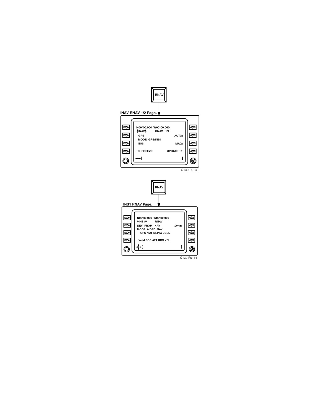
01-75GAL-1
INAV computations are displayed and controlled via the RNAV pages. INAV RNAV pages 1 and 2 display and
control data for integrated navigation. There are two INAV modes available: AUTOmatic and MANual. In MANual,
a colon (:) will appear adjacent to LS2 allowing the operator to toggle between GPS, INS1 or INS2 as the primary
sensor. The default setting is GPS. In AUTOmatic, the primary sensor and navigation mode will be automatically
selected. Lateral scrolling from the INAV RNAV pages will access the GPS RNAV, INS1 RNAV and INS2 RNAV
pages that display specific sensor navigation data; including GPS EHE, FOM and number of satellites, and sensor
deviation from the INAV solution.
2.21.4.4.5 Flight Progress Monitoring
In-flight navigation guidance and tracking information relative to the current waypoint can be obtained from the
PROGress pages. The PROGress pages provide detailed situation awareness displays to indicate the current aircraft
position, TAS, groundspeed, waypoint bearing and distance, waypoint ETE, wind, course deviations, etc. Progress
pages are accessed via the PROG direct access key and vertical scrolling arrow keys. Progress Page 1 provides lateral
guidance information relative to the flight plan, Progress Page 2 provides vertical information relative to VNAV
functions, and Progress Page 3 displays aircraft operating conditions that are independent from the flight plan. Basic
navigational data (bearing, distance and ETE) for flight plan follow-on waypoints may be obtained by accessing the
FPLN page and pressing the LS key next to the corresponding waypoint.
2-205
ORIGINAL
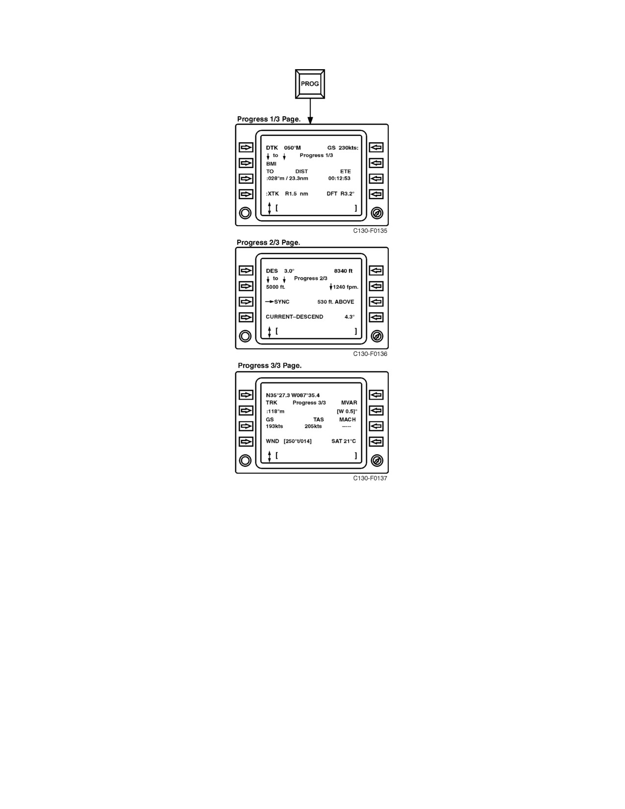
01-75GAL-1
2.21.4.4.6 Direct-To Courses
Direct-To courses are used to either bypass existing waypoints in the flight plan or to insert an impromptu waypoint,
interrupting the current leg. Direct-To operations are accessed via the DIR direct access key.
1. Press DIR to access DIRECT TO page.
2. Press up/down arrow keys to display desired waypoint.
3. Press LS key adjacent to desired waypoint.
ORIGINAL
2-206
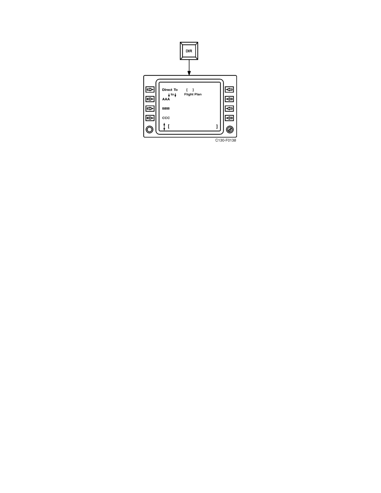
01-75GAL-1
2.21.5 AN/ARC-186(V) VHF AM-FM Radio
The VHF AM-FM communication system consists of a transceiver and a control panel. Manual frequency selection
of 4,080 channels is available in the range of 30.000 MHz to 87.975 MHz in the FM band, and in the range of 108.000
MHz to 151.975 MHz in the AM band. Twenty preset channels are also available, as well as FM and AM emergency
channels. Channel selection is provided from the VHF communication/navigation control panel located on the flight
control pedestal. The No. 1 VHF radio receives 28-Vdc power from the isolated dc bus through the VHF COMM
NO. 1 circuit breaker on the copilot upper circuit breaker panel. The No. 2 VHF radio receives 28-Vdc power from
the essential dc bus through the VHF COMM NO. 2 circuit breaker on the copilot upper circuit breaker panel.
2.21.5.1 VHF AM-FM Radio Tuning and Control
The VHF radios are tuned and controlled via the CDNU Comm page or detailed VHF page. System power is
controlled via the CDNU Power page (a box around the system name indicates the unit is powered). The Comm page
is accessed via the F3 key or via the index page. Tuning is accomplished by entering the appropriate frequency in
the scratchpad and then pressing the line select key next to the corresponding radio. Pressing the line select key with
no frequency in the scratchpad (blank scratchpad) will access the detailed page for the corresponding radio. Quick
tuning of the VHF radios on aircraft without ARC-210 radios (aircraft without AFC-338) can be accomplished by
entering the frequency in the scratchpad and pressing F1 for VHF 1 or F2 for VHF 2. Pressing the F1 or F2 keys with
no frequency in the scratchpad will access the corresponding detailed VHF page (or the detailed V/U page for aircraft
after AFC-338). Returning to the previously selected frequency may be accomplished by tuning 0. For additional
functions and controls of the VHF radios, refer to Figure 2-95.
2.21.5.2 Normal Operation of the VHF AM-FM Radio
Operate the VHF radio as follows:
1. Tune desired frequency in VHF 1 or VHF 2 via the CDNU.
2. To receive, pull the corresponding VHF push-pull mixer switch on the intercommunication control panel
(ICS).
3. Adjust squelch (via CDNU) and volume (via individual mixer switch or master volume knob on ICS panel).
4. To transmit, place the transmission selector on the ICS panel to the VHF 1 or VHF 2 position.
2.21.6 AN/ARC-159(V)1 UHF Command Radio (Aircraft Not Modified by AFC-338)
Two UHF command radio sets, designated UHF No. 1 and UHF No. 2, provide voice transmission and reception
in the frequency range of 225.000 to 399.975 MHz, with 7,000 frequencies in steps of 25 kHz. Receiver and
2-207
ORIGINAL
01-75GAL-1
transmitter tuning is accomplished automatically after a frequency change. In addition, the UHF radio set is capable
of guard frequency reception and transmission and ADF reception. The guard receiver module is self-contained, fix
tuned, set to a guard frequency, and can receive simultaneously with the main receiver. The No. 1 UHF command
radio operates from 28-Vdc power from the isolated dc bus through the UHF NO. 1 circuit breaker on the copilot
upper circuit breaker panel. The No. 2 UHF command radio operates from 28-Vdc power from the essential dc bus
through the UHF NO. 2 circuit breaker on the copilot upper circuit breaker panel.
2.21.6.1 UHF Command Radio Controls
2.21.6.1.1 Radio Controls
The two UHF command radios (see Figure 2-96), located on the flight control pedestal and the copilot side shelf
extension, provide operating controls on the radio. The four-position (OFF, MAIN, BOTH, ADF) function switch
permits selection of the operational mode of the radio. In the MAIN position, the main receiver and transmitter are
operational. In the BOTH position, the functions are operational and the guard receiver is turned on. The ADF
position on the No. 1 UHF radio activates the UHF direction finder.
The three-position (PRESET, MANUAL, GUARD) mode selector switch determines frequency selection and
permits indication of frequency and/or channel selection. The PRESET position permits one of 20 preset channels
to be selected with the preset channel selector knob and displays the channel selected on the readout indicator. The
MANUAL position permits selection of any one of 7,000 frequencies by use of the manual frequency selector
switches. The frequency selected is displayed on the FREQ/(CHAN) readout indicator. The preset channel selector
knob is ineffective when the mode selector switch is in the MANUAL position. The GUARD position shifts the
transceiver to the guard frequency and causes the guard frequency to be displayed on the readout indicator. The preset
CHAN SEL and manual frequency selector switches are ineffective when the mode selector switch is in the GUARD
position.
Note
D The GUARD position of the mode selector switch should not be used
except in actual emergencies.
D When utilizing the radio mode selector (GUARD/MANUAL/PRESET)
switch, ensure that the switch is cleanly placed into one of the three detent
positions. If the switch is placed between two of the detent positions, the
radio FREQUENCY DISPLAY may be either blank or will not display the
correct preset channel/frequency. Cycling power to the radio will correct
the situation.
The PRESET CHAN SEL knob is used to select any one of 20 preset channels when the mode selector switch is in
the PRESET position.
The BRT/TEST knob is used to adjust light intensity of the readout lamps and to test the readout lamps when the
switch is positioned to TEST.
The four spring-loaded toggle switches below the readout indicator are used to select the operating frequency when
the mode selector switch is in MANUAL.
The VOL knob is used to adjust the level of the audio signal.
The TONE pushbutton, when depressed, causes the transmitter to transmit a 1020-Hz tone signal.
The SQL switch enables or disables the main receiver squelch.
ORIGINAL
2-208
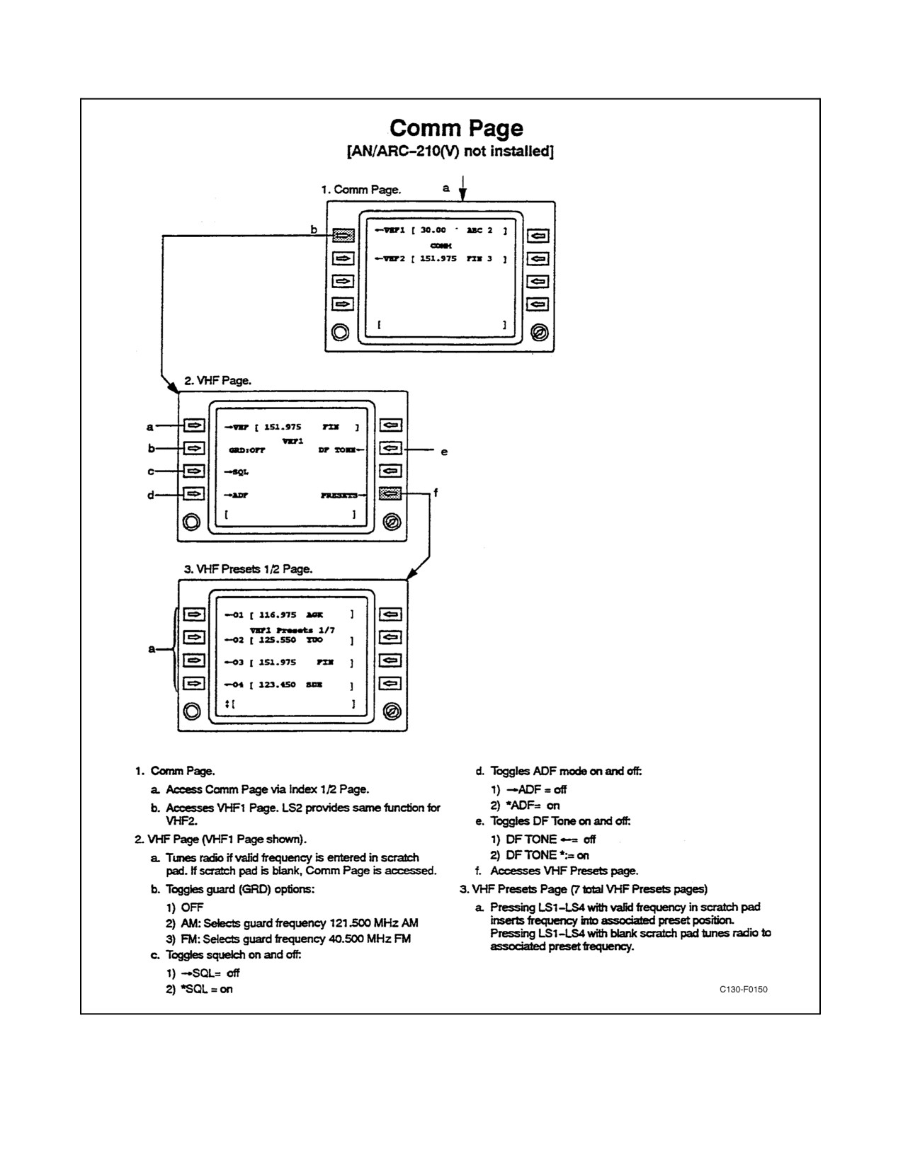
01-75GAL-1
Figure 2-95. VHF Comm Page [AN/ARC-210(V) Not Installed]
2-209
ORIGINAL
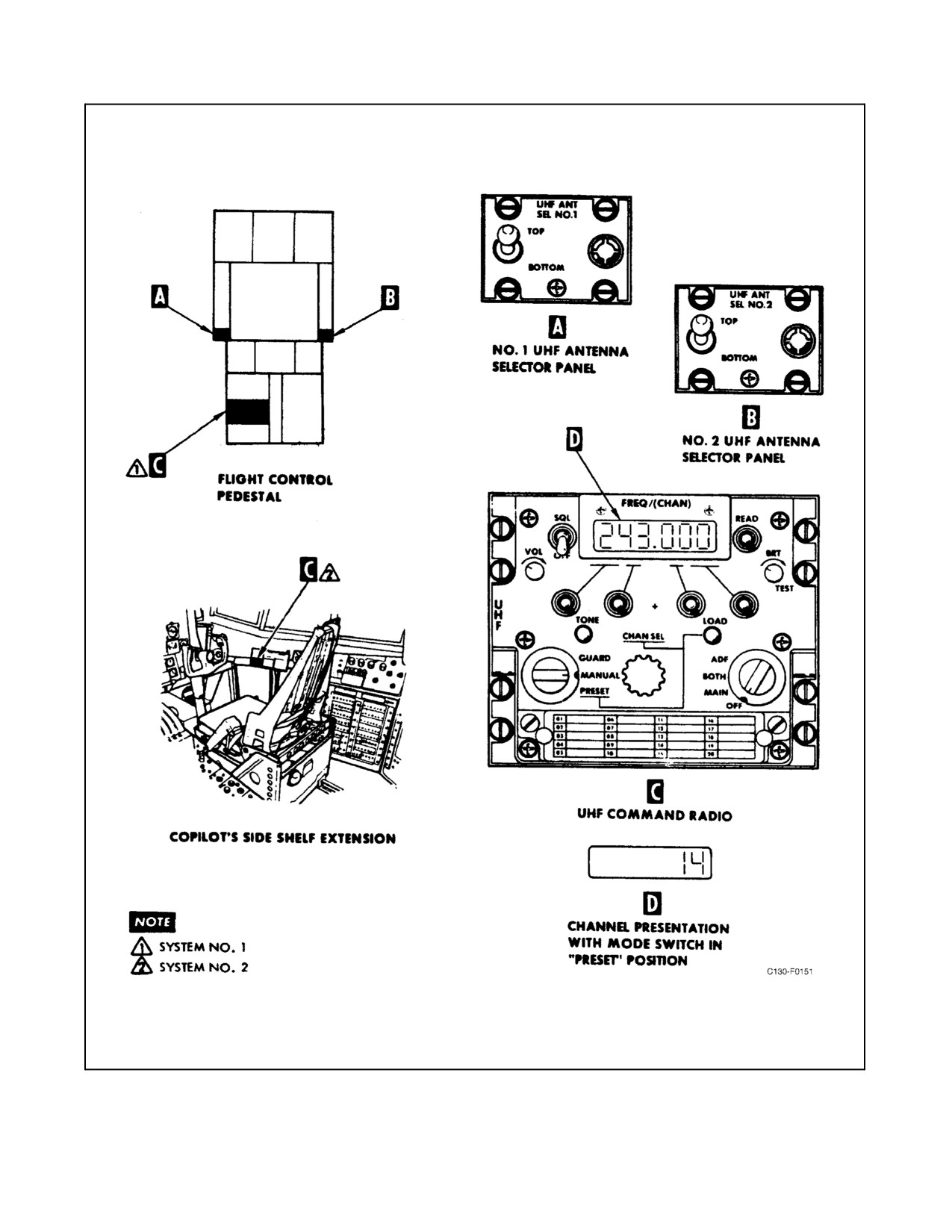
01-75GAL-1
Figure 2-96. AN/ARC-159(V)1 UHF Command Radio Control Panels
ORIGINAL
2-210