C-130T. FLIGHT MANUAL (2006) - page 3
01-75GAL-1
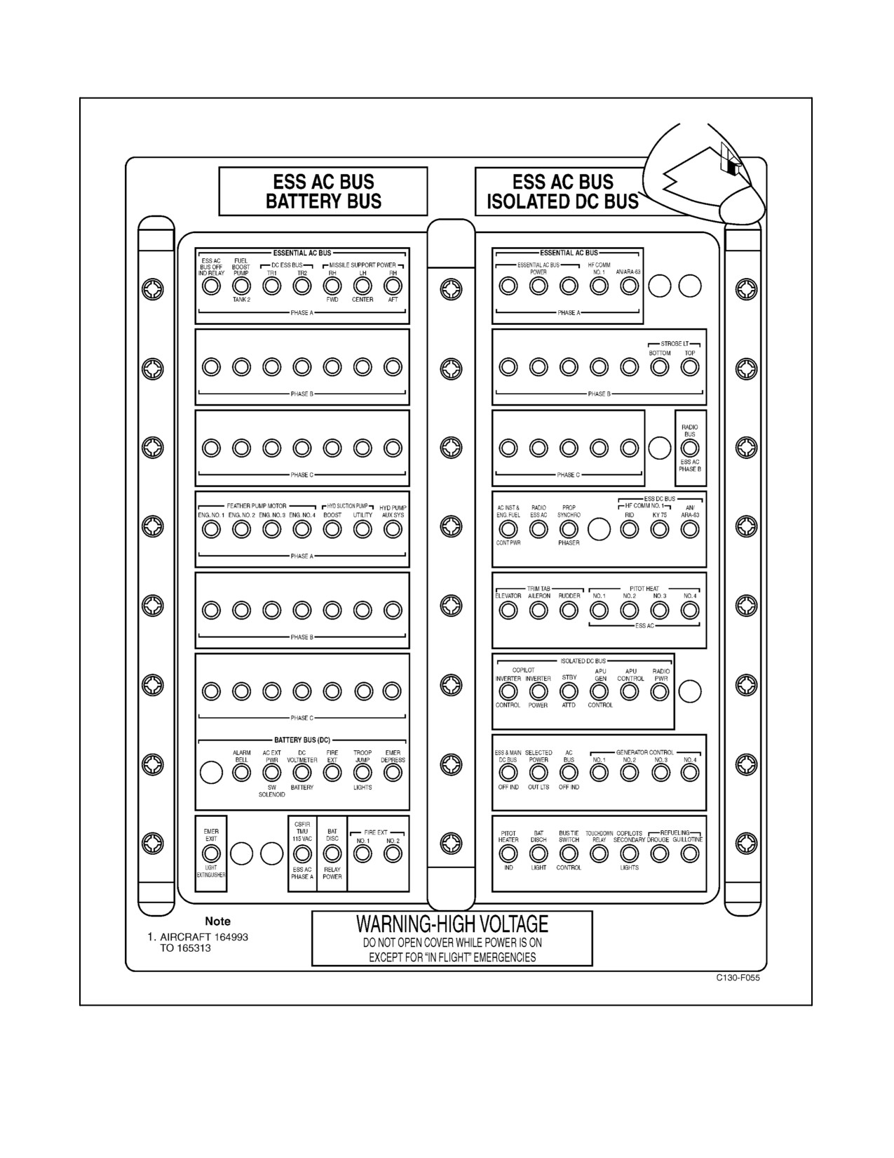
Figure 2-34. Pilot Side Circuit Breaker Panel (Sheet 2)
2-71
ORIGINAL
01-75GAL-1
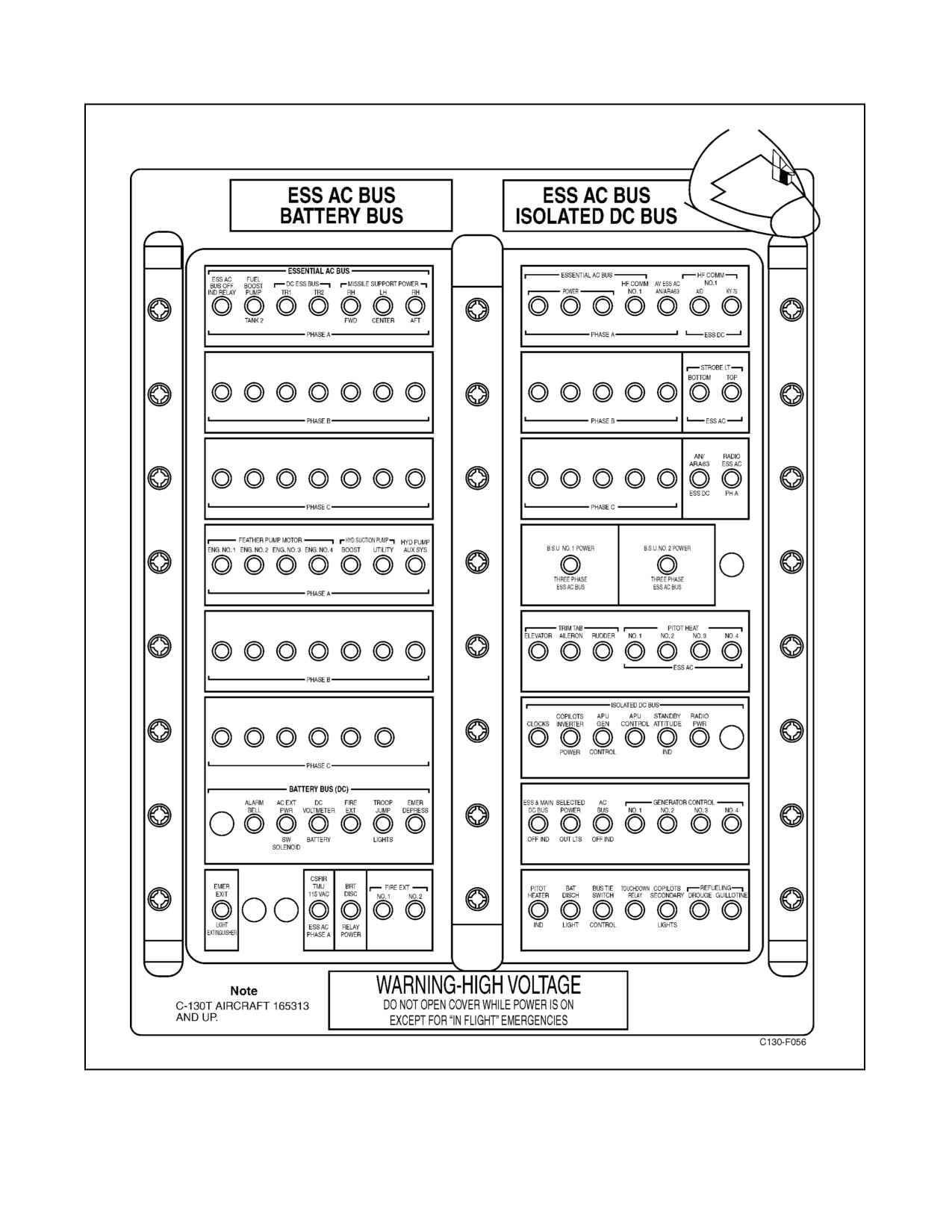
Figure 2-34. Pilot Side Circuit Breaker Panel (Sheet 3)
ORIGINAL
2-72
01-75GAL-1
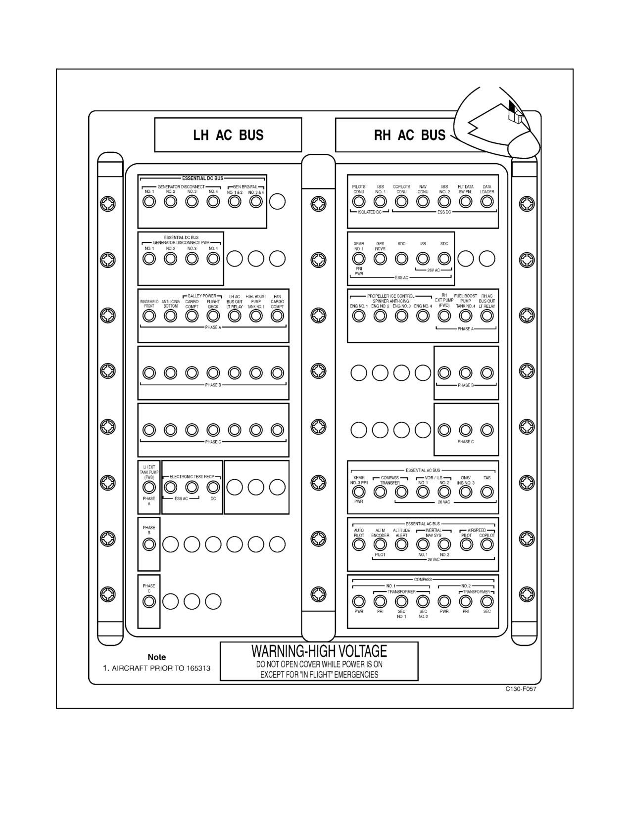
Figure 2-35. Pilot Upper Circuit Breaker Panel (Sheet 1 of 2)
2-73
ORIGINAL
01-75GAL-1
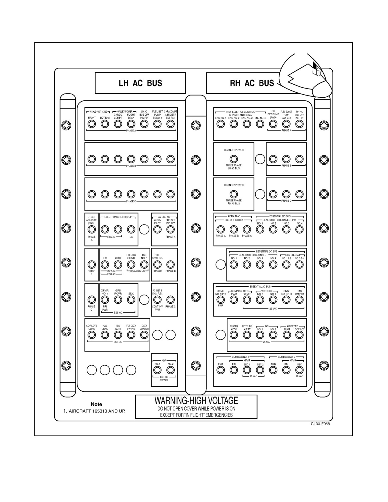
Figure 2-35. Pilot Upper Circuit Breaker Panel (Sheet 2)
ORIGINAL
2-74
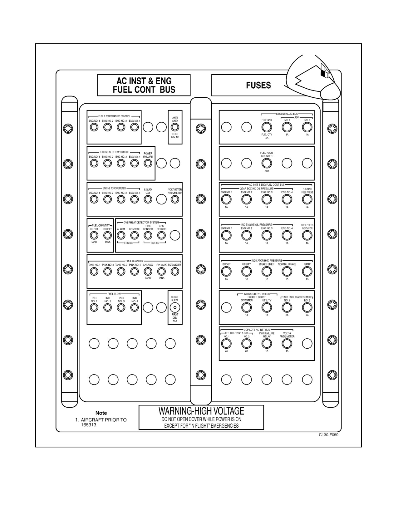
01-75GAL-1
Figure 2-36. Pilot Lower Circuit Breaker Panel (Sheet 1 of 2)
2-75
ORIGINAL
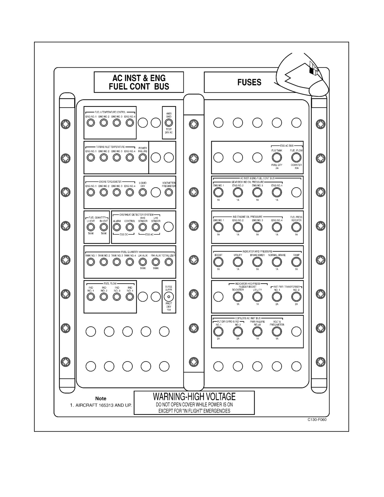
01-75GAL-1
Figure 2-36. Pilot Lower Circuit Breaker Panel (Sheet 2)
ORIGINAL
2-76
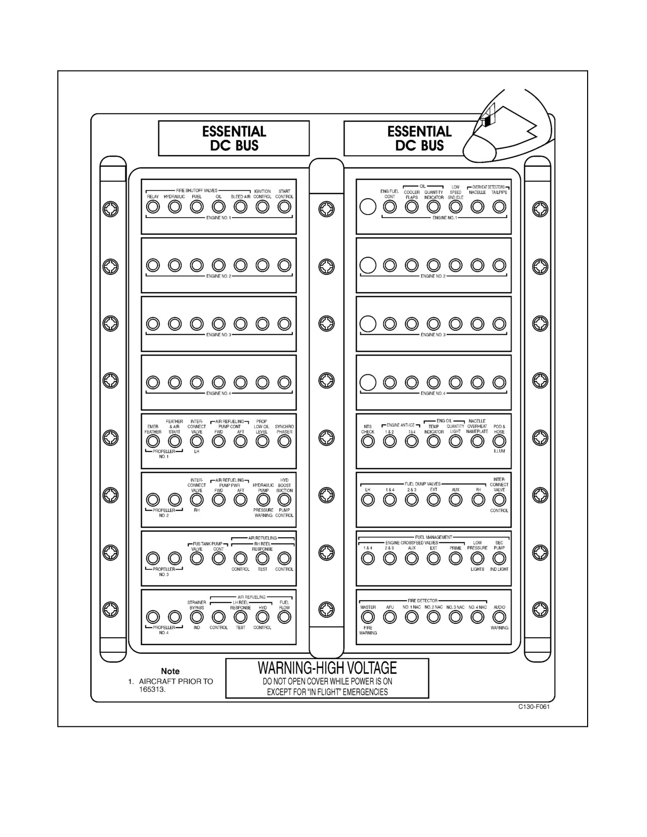
01-75GAL-1
Figure 2-37. Copilot Side Circuit Breaker Panel (Sheet 1 of 2)
2-77
ORIGINAL
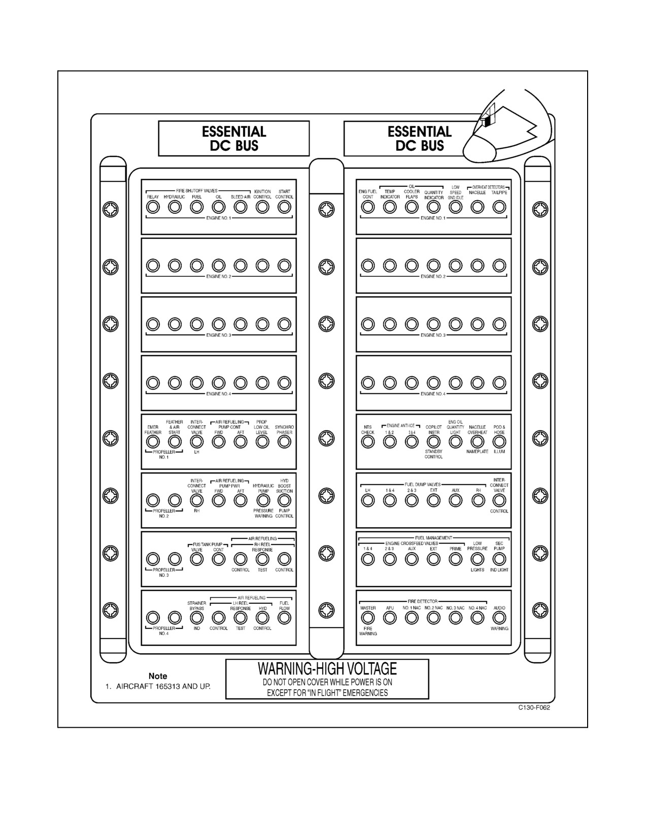
01-75GAL-1
Figure 2-37. Copilot Side Circuit Breaker Panel (Sheet 2)
ORIGINAL
2-78
01-75GAL-1
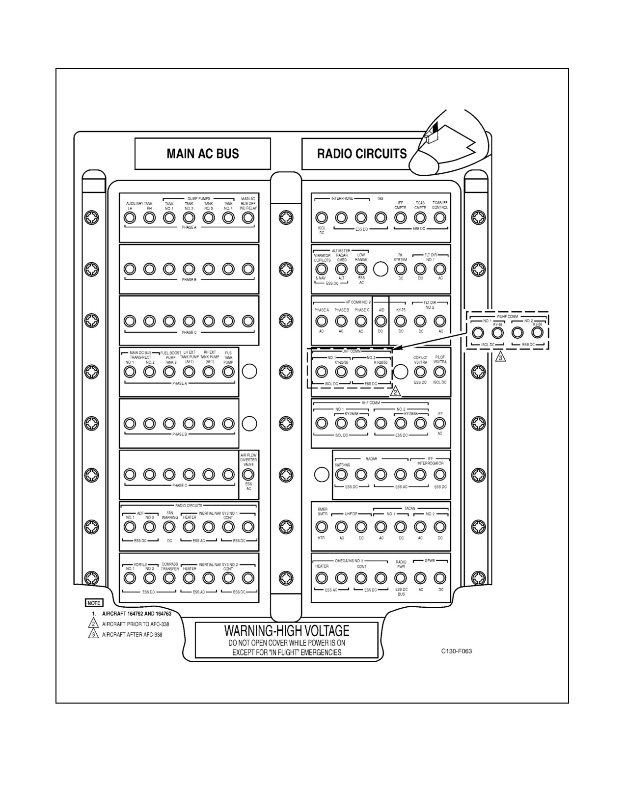
Figure 2-38. Copilot Upper Circuit Breaker Panel (Sheet 1 of 3)
2-79
ORIGINAL
01-75GAL-1
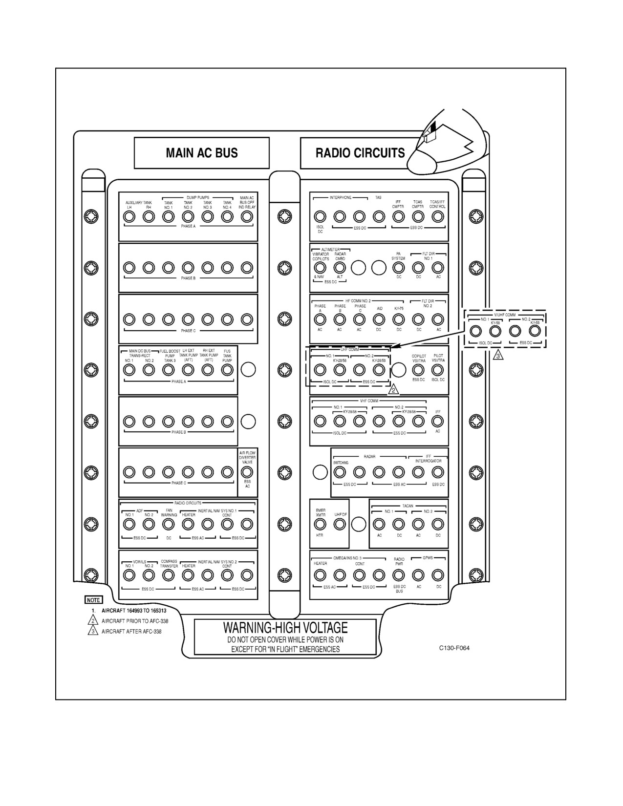
Figure 2-38. Copilot Upper Circuit Breaker Panel (Sheet 2)
ORIGINAL
2-80
01-75GAL-1
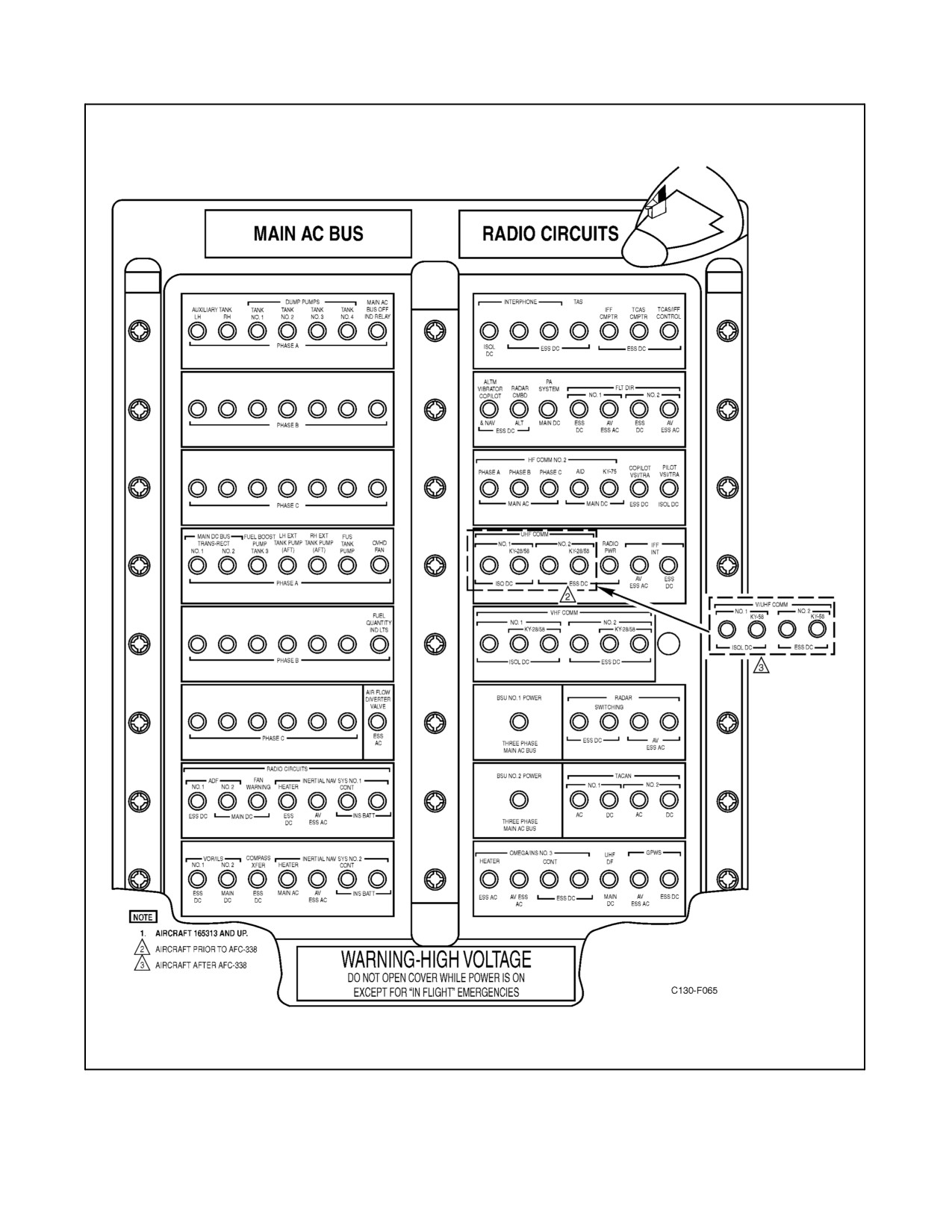
Figure 2-38. Copilot Upper Circuit Breaker Panel (Sheet 3)
2-81
ORIGINAL
01-75GAL-1
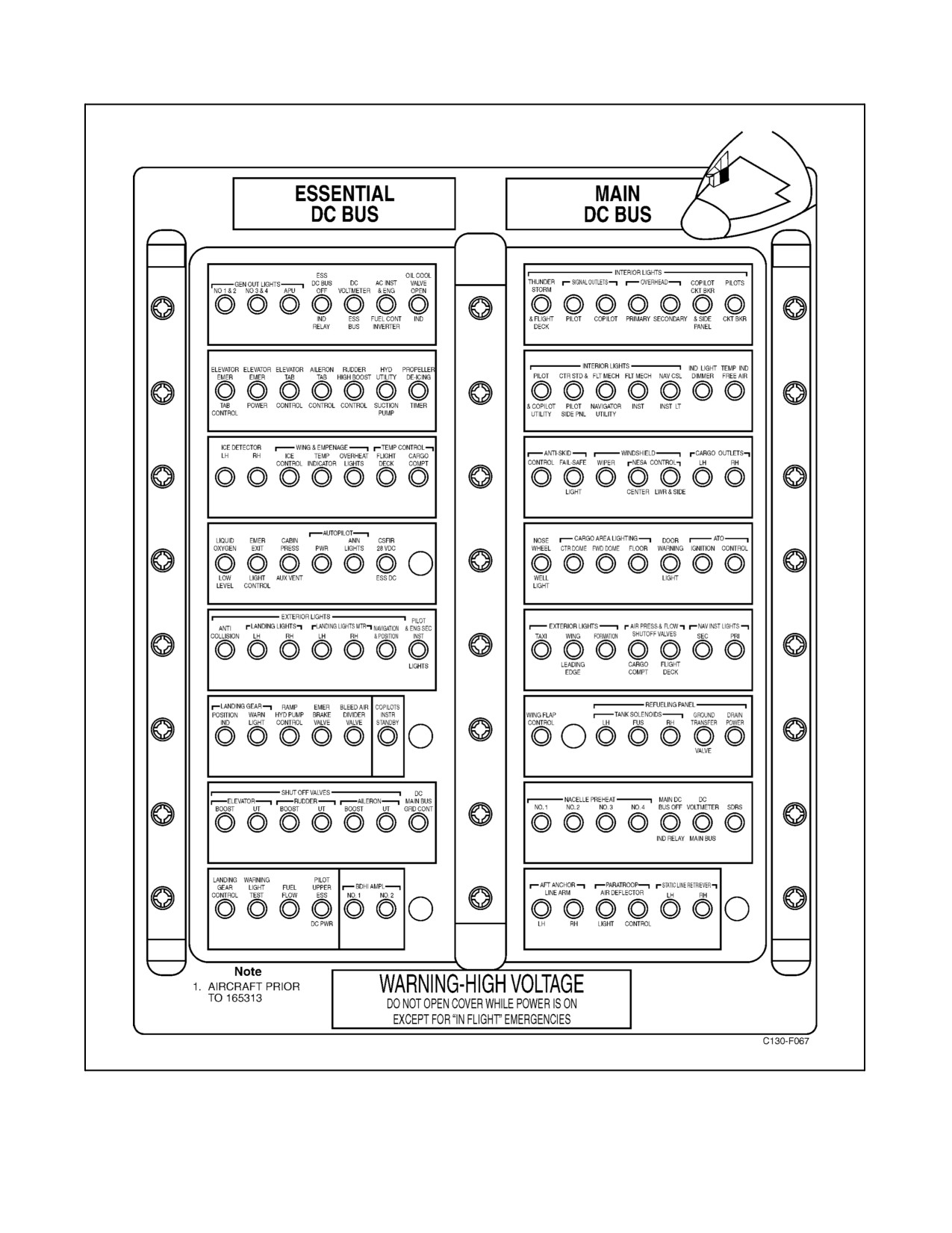
Figure 2-39. Copilot Lower Circuit Breaker Panel (Sheet 1 of 2)
ORIGINAL
2-82
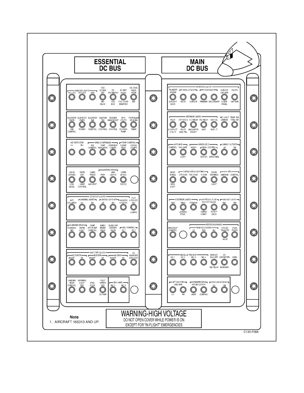
01-75GAL-1
Figure 2-39. Copilot Lower Circuit Breaker Panel (Sheet 2)
2-83
ORIGINAL
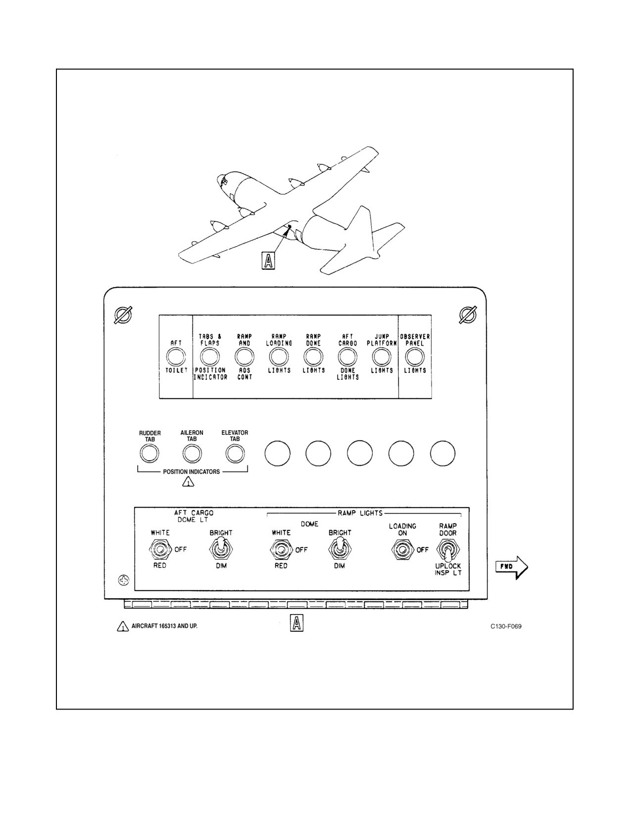
01-75GAL-1
Figure 2-40. Aft Fuselage Junction Box
ORIGINAL
2-84
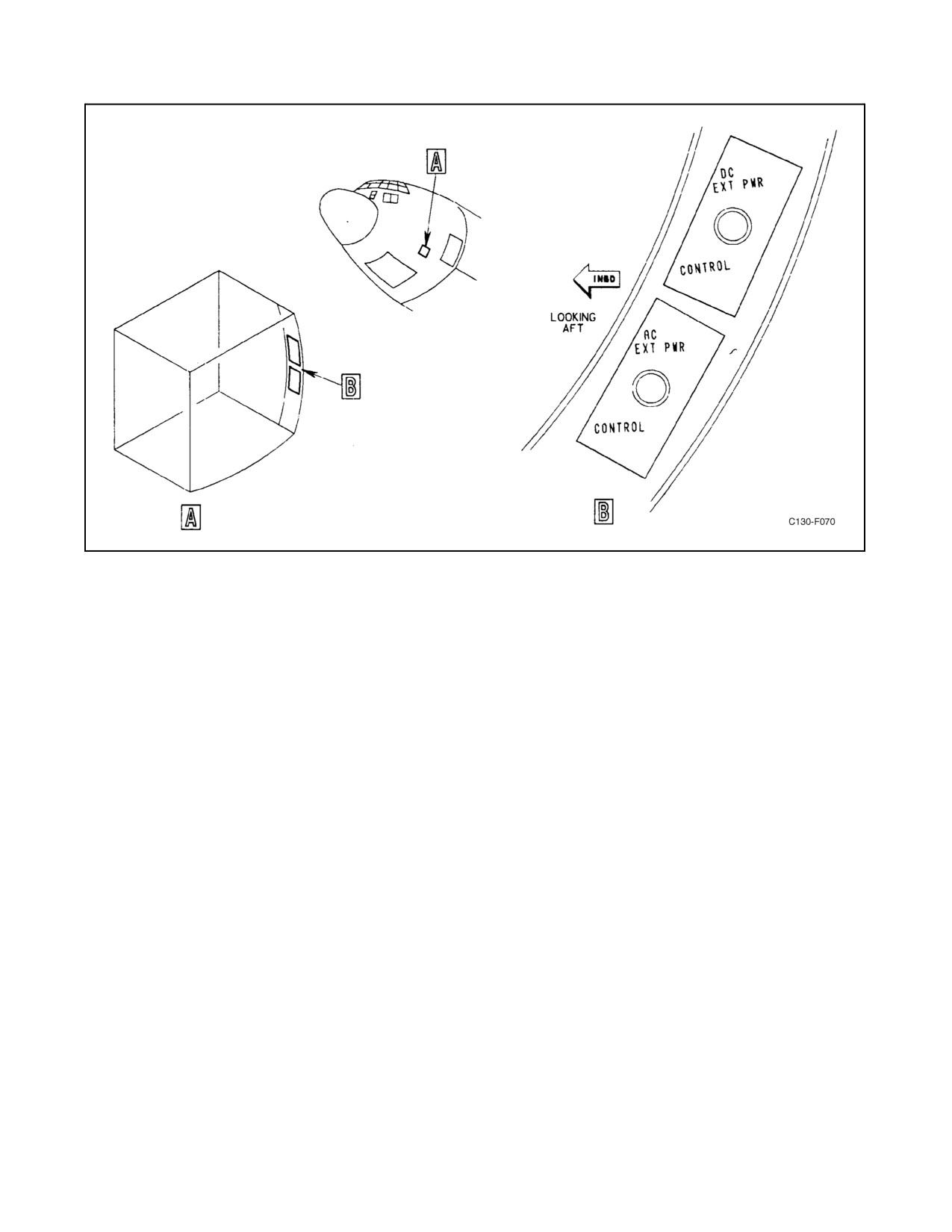
01-75GAL-1
Figure 2-41. Battery Compartment Circuit Breakers
The isolated bus is connected to the battery bus by the dc power switch through the battery relay. During ground
operation with no engines operating, all of the dc buses may be connected and powered through either the battery
or the essential dc bus, which can utilize APU ac generator output to the essential ac bus as a power supply. External
dcpoweris fed through themain dcbus and will supply all dcbuses, exceptthebattery,when theDC POWERswitch
(see Figure 2-31) is in the EXT DC PWR position.
2.7.7.2 Batteries
Two 24-volt, 30-ampere-hour batteries are located in a fuselage compartment forward of the crew entrance door(see
Figure 1-1). The first battery supplies power to the battery bus and to the isolated bus. A reverse current cutout is
connected between the isolated bus and the essential and main dc buses. During flight, it prevents the battery from
powering equipment connected to the essential and main dc buses and permits power from the essential and main
dc buses to be used to power equipment connected to the isolated bus, and to charge the battery. An amber BAT
DISCH light is located on the exterior lights control panel. When the BAT DISCH light is on, it indicates that the
battery charge is being depleted by the isolated dc bus loads because of failure of the reverse current cutout. During
APU starting, the battery powers the APU starter and control circuits through the APU CONTROL circuit breaker
on thepilotsidecircuitbreakerpanel.Thesecondbattery providesstandby powerfortheNo. 1and No.2 INSsystem.
A reverse current relay, normally closed, permits the INS battery to be charged and the INS to be powered from the
essential dc bus. When essential dc bus power is lost, the reverse current relay opens, preventing reverse current flow
from the INS battery to the essential dc bus and allows the INS battery to power the INS.
2-85
ORIGINAL
01-75GAL-1
2.7.8 Dc System Controls
The dc electrical system is powered directly by the ac electrical system and is controlled from the overhead electrical
control panel (see Figure 2-28).
2.7.8.1 Dc BUS TIE Switch
Note
On aircraft 165313 and up, the dc BUS TIE switch is labeled GROUND
BUS TIE. DC BUS TIE switch is considered the generic term and is used
as such throughout this manual.
The dc BUS TIE switch is a two-position, guarded toggle switch which functions in conjunction with the touchdown
switch. When the aircraft is on the ground, the dc BUS TIE switch can connect the isolated dc bus and the essential
dc bus for current flow in either direction. This allows battery power to feed all dc buses and circuits when the dc
power switch is in the BATTERY position.
2.7.8.2 Dc Power Switch
The dc power switch is a three-position, rotary-type switch. When the switch is in the EXT DC PWR position, the
external power relays will close when external power is applied in the correct polarity, to connect the external power
receptacle to the main dc bus. When the switch is in the BATTERY position, the battery relay is closed and the battery
isconnectedtotheisolatedbus.Thispositionoftheswitchpermitspowertoflowfromthemaindcbusortheessential
dc bus through the reverse-current relay to the isolated bus to charge the battery. When the switch is in the OFF
position, the external power relay is opened and the external power receptacle is disconnected from the main dc bus
and from the isolated bus. When the dc power switch is in the EXT DC PWR position, 24-volt dc control power is
supplied from the dc external power source through the aircraft DC EXT PWR control circuit breaker in the aircraft
battery compartment.
2.7.8.3 Dc System Indicators
The dc system indicators are located on the overhead electrical control panel (see Figure 2-28).
2.7.8.4 Loadmeters
Four loadmeters, one for each transformer-rectifier unit, indicate percent of rated current load flowing from each
unit.
2.7.8.5 Bus Switching Unit Indicators
On aircraft 165313 and up, two bus switching unit indicators (BYPASS) are located on the overhead electrical panel.
The indicators indicate the status of the BSUs. When illuminated, they indicate the BSU is in the bypass mode
because of an overload condition, the BSU switch is in the OFF position, or the BSU has failed to pass BIT.
2.7.8.6 BUS OFF Indicator Lights
Two bus off indicator lights, one each for the main dc bus, and the essential dc bus give a visual indication of power
off condition of the buses. Both the main and the essential dc bus lights are powered from the isolated dc bus.
Note
The isolated dc BUS OFF indicator light will never glow except for
malfunction, or if the dc power switch is placed in the EXT DC PWR
position when no external power is connected and no internal ac generator
power is powering the dc system.
ORIGINAL
2-86
01-75GAL-1
2.7.8.7 Voltmeter and Bus Selector Switch
The voltmeter is connected to the main dc bus, essential dc bus, or battery bus by means of the voltmeter selector
switch adjacent to the voltmeter on the overhead electrical control panel (see Figure 2-28). The switch is a rotary
selector with three positions: ESSENTIAL DC BUS, MAIN DC BUS, and BAT. Selected bus voltage will be
indicated on the voltmeter.
2.7.8.8 External Dc Power Indicator
The EXT DC PWR press-to-test light illuminates when external dc power is connected to the external dc power
receptacle in the correct polarity.
2.8
HYDRAULIC POWER SUPPLY SYSTEMS
A booster hydraulic system, a utility hydraulic system, and an auxiliary hydraulic system comprise power supply
sources for all hydraulic component operation on the aircraft. The booster system furnishes hydraulic power to a
portion of the flight control boost system only. The utility system normally operates the landing gear, wing flaps,
brakes, nosewheel steering, a portion of the flight control boost system, and the in-flight refueling reels. The auxiliary
system operates the ramp and cargo door, provides emergency pressure for brake operation, provides pressure for
emergency extension of the nose landing gear, and emergency pressure for the air refueling reels. Three methods are
provided for servicing the hydraulic reservoirs; a single-point system consisting of a fluid receptacle, a manually
operatedselectorvalve,andahandpumpforremoteservicing;afillconnectiontobeusedwithaportablefluidservice
unit; and afillerport located on thetop ofthe reservoirfor direct filling. Thehydraulic powersupply systems contain
a manually operated valve for obtaining a hydraulic fluid sample.
2.8.1 Utility Hydraulic System
Theutilityhydraulicsystem(seeFigure2-42)operatesfromtheoutputoftheNo.1and No.2 engine-drivenhydraulic
pumps and supplies hydraulic power to the wing flap hydraulic motor, the main landing gear hydraulic motors, the
nose landing gear hydraulic system, the main landing gear brakes, the nosewheel steering, to a portion of theaileron,
rudder, and elevator control boost system, and the in-flight refueling reels. The engine-driven variable-displacement
pumps are supplied hydraulic fluid under electric suction boost pump pressure from a 6.5-gallon reservoir mounted
on the left side of the cargo compartment. The engine-driven pumps are provided with internal control mechanisms
to vary their output volume with system demand and to control pressure to maintain approximately 3,000-psi output
pressure. If the pump is not operating, the low-pressure warning light will illuminate. The pressurized output fluid
of each pump passes through a filter, an electrically operated shutoff valve, and a one-way check valve before merging
as system pressure. The one-way check valve allows the system to continue to function in case of failure of a single
pump. Fluid supply and output of the engine-driven pumps can be cut off by actuation of the fire emergency handle
or engine-driven pump switch for that particular engine. The fluid supply and output is cut off by the closing of
electrically actuated shutoff valves. External connections are provided so an external supply of pressure may be used
for ground maintenance operation of the system. A ground test valve is incorporated in the system so that system
pressure from the auxiliary hydraulic system may be used to check hydraulically supplied systems before the engines
are started for ground maintenance operations. The valve provides supply, return, and case drain functions. Four
filters are used in the system to provide protection from foreign material contamination. A pressure relief valve
provides protection against system overpressures. An accumulator is installed in the utility hydraulic system pressure
line to provide reserve pressure and a damping effect during demand and pressure fluctuations. A sight-level gauge
mounted on the reservoir gives a visual indication of the reservoir fluid quantity.
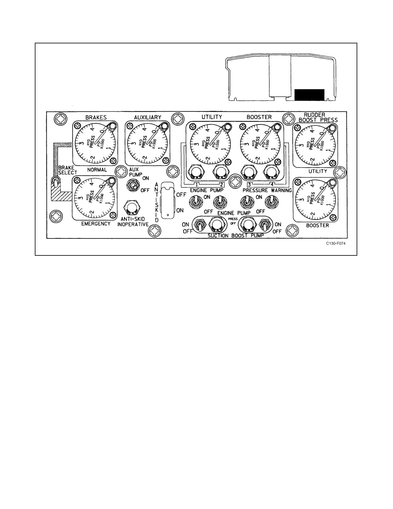
All controls and indicators for the utility hydraulic system are on the hydraulic control panel (see Figure 2-45).
2.8.1.1 Utility SUCTION BOOST PUMP Switch
The utility system SUCTION BOOST PUMP switch is a two-position (OFF, ON) toggle switch that furnishes
28-Vdc power from the essential dc bus, through the HYD UTILITY SUCTION PUMP circuit breaker on the copilot
lower circuit breaker panel, to operate a relay that controls three-phase ac power to the suction boost pump motor.
2-87
ORIGINAL
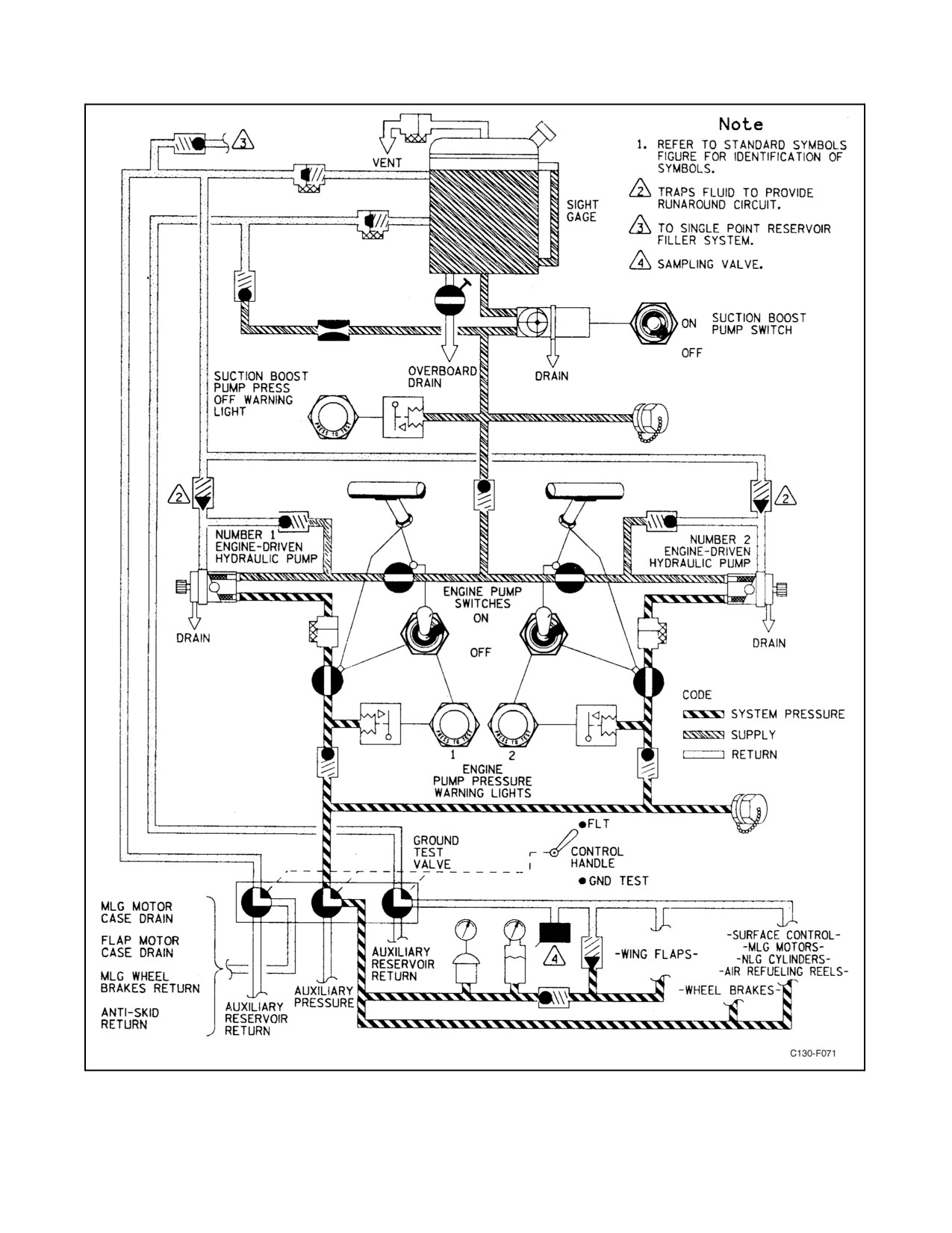
01-75GAL-1
Figure 2-42. Utility Hydraulic System
ORIGINAL
2-88
01-75GAL-1
2.8.1.2 Suction Boost Pump Pressure Warning Light
The suction boost pump low-pressure warning light is an amber warning light controlled by a pressure-sensitive
switch. The warning light will illuminate if pressure output of the suction boost pump drops below approximately
20 psi. The suction boost pump motor is protected by thermal circuit breakers that open and stop the motor if the
current exceeds 11 or 12 amperes. When this occurs, the low-pressure warning light will illuminate. As the circuit
breakers cool, the circuits will close to restore power to the pump motor, and the light will go off. The light receives
28-Vdc power from the essential dc bus through the HYD UTILITY SUCTION PUMP circuit breaker on the copilot
lower circuit breaker panel.
2.8.1.3 ENGINE PUMP Switch
The ENGINE PUMP switch is a two-position (OFF, ON) toggle switch that controls two hydraulic shutoff valves.
One of these valves shuts off supply flow to the engine-driven pump, and the other shuts off pump output. These are
thesamevalves operated by thefireemergency handle. Sincetheengine pump continues to turn afterboth thesupply
and output valves are closed, normal flow from the pump case drain passes through a check valve back into the suction
portofthepumptoformarunaroundcircuit.Thisfeatureisprovidedtopreventdamagetothoseengine-drivenpumps
that require a runaround system. The valves receive 28-Vdc power from the essential dc bus through the FIRE
SHUTOFF VALVES HYDRAULIC circuit breaker on the copilot side circuit breaker panel.
2.8.1.4 Engine Pump Pressure Warning Light
The engine pump pressure amber warning lights are controlled by pressure-actuated switches that sense the
engine-driven pump output pressures. When either engine pump output pressure drops below approximately 1,000
psi, its light will illuminate. The pressure warning light will also illuminate when the engine pump switch is placed
in the OFF position. The lights receive 28-Vdc power from the essential dc bus through the HYDRAULIC PUMP
PRESSURE WARNING circuit breaker on the copilot side circuit breaker panel.
2.8.1.5 Utility Hydraulic Pressure Gauge
The utility hydraulic pressure gauge is controlled by a remote transmitter and indicates utility system pressure. The
gauge receives 26-Vac power from the No. 2 instrument transformer through the INDICATOR HYD PRESSURE
UTILITY fuse on the pilot lower circuit breaker panel.
2.8.2 Booster Hydraulic System
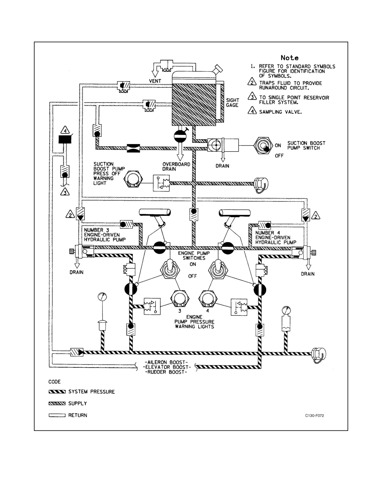
The booster hydraulic system (see Figure 2-43) operates from the output of No. 3 and No. 4 engine-driven hydraulic
pumps, and supplies hydraulic power to a portion of the elevator, rudder, and aileron control boost system. The
engine-driven, variable-displacement pumps are supplied hydraulic fluid under electric suction boost pump pressure
from a 2-gallon reservoir mounted on the right side of the cargo compartment. The engine-driven pumps are provided
with internal control mechanisms to vary their output volume with system demand and to control pressure to maintain
approximately 3,000-psi output pressure. If the pump is not operating, the low-pressure warning light will illuminate.
The pressurized output fluid of each pump passes through a filter, an electrically operated shutoff valve, and a
one-way check valve before merging as system pressure. The one-way check valve allows the system to continue
to function in case of failure of a single-pump. Fluid supply and output of the engine-driven pumps can be cut off
by actuation of the fire emergency handle or engine pump switch for that particular engine. The supply fluid and
output are cut off by the closing of electrically actuated shutoff valves. Provisions are included in the system for
manual overboard draining of the system fluid. External connections are also provided so an external supply of
pressure may be used for ground maintenance operation of the system. Four filters are incorporated in the system
toprovideprotection fromforeign materialcontamination. Apressurereliefvalveprovidesprotection againstsystem
overpressures. An accumulator in the system provides reserve pressure and a damping effect during demand and
pressure fluctuations. A sight level gauge mounted on the reservoir gives a visual indication of the reservoir fluid
quantity.
All controls and indicators for the booster hydraulic system are on the hydraulic control panel (see Figure 2-45).
2-89
ORIGINAL
01-75GAL-1
Figure 2-43. Booster Hydraulic System
ORIGINAL
2-90
01-75GAL-1
2.8.2.1 Booster SUCTION BOOST PUMP Switch
The booster system SUCTION BOOST PUMP switch is a two-position (OFF, ON) toggle switch that furnishes
28-Vdc power from the essential dc bus through the HYD BOOST SUCTION PUMP CONTROL circuit breaker
on the copilot side circuit breaker panel, and controls three-phase ac power to the suction boost pump motor.
2.8.2.2 Suction Boost Pump Pressure Warning Light
The suction boost pump low-pressure warning light is an amber warning light controlled by a pressure-sensitive
switch. The warning light will illuminate if pressure output of the suction boost pump drops below approximately
20 psi. The suction boost pump motor is protected by thermal circuit breakers that open and stop the motor if the
current exceeds 11 or 12 amperes. When this occurs, the low-pressure warning light will illuminate. As the circuit
breakers cool, the circuit will close to restore power to the pump motor and the light will go off. The light receives
28-Vdc power from the essential dc bus through the HYD BOOST SUCTION PUMP CONTROL circuit breaker
on the copilot side circuit breaker panel.
2.8.2.3 ENGINE PUMP Switch
The ENGINE PUMP switch is a two-position (OFF, ON) toggle switch that controls two hydraulic shutoff valves.
One of these valves shuts off supply flow to the engine-driven pump, and the other shuts off pump output. These are
the same valves operated by the fire emergency handle. Since the engine-driven pump continues to turn after both
the supply and output valves are closed, normal flow from the pump case drain passes through a check valve back
into the suction port to form a run-around circuit. This feature is provided to prevent damage to those engine-driven
pumps that require a run-around system. The valves receive 28-Vdc power from the essential dc bus through the FIRE
SHUTOFF VALVES HYDRAULIC circuit breaker on the copilot side circuit breaker panel.
2.8.2.4 Engine Pump Pressure Warning Lights
Theenginepump pressurewarning lightsareamberwarning lightscontrolled bylow-pressure-actuated switchesthat
sense the engine-driven pump output pressures. When either engine pump output pressure drops below
approximately 1,000 psi, its light will illuminate. The pressure warning light will also illuminate when the engine
pump switch is placed in the OFF position. The lights receive 28-Vdc power from the essential dc bus through the
HYDRAULIC PUMP PRESSURE WARNING circuit breaker on the copilot side circuit breaker panel.
2.8.2.5 Booster Hydraulic Pressure Gauge
The booster system hydraulic pressure gauge is controlled by a remote transmitter and indicates booster system
pressure. The gauge receives 26-Vac power from the No. 1 instrument transformer through the INDICATOR HYD
PRESSURE BOOST fuse on the pilot lower circuit breaker panel.
2.8.3 Auxiliary Hydraulic System
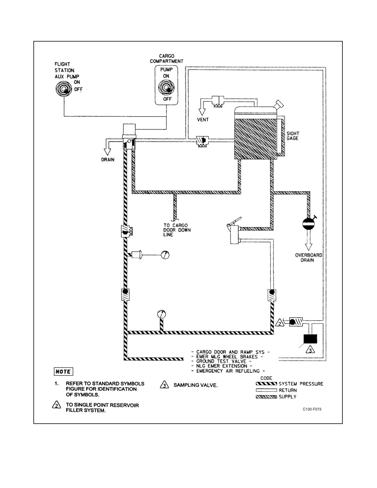
Theauxiliary hydraulicsystem (seeFigure2-44)operates from athree-phase, ac, electrically driven hydraulicpump.
The pump is air cooled and can be operated continuously. It powers the cargo door and ramp system and provides
emergency pressure for the main landing gear brakes, nosegear emergency extension, and air-refueling reels. The
system is located in the cargo compartment and may bemanually orelectrically operated. A handpump in thesystem
provides an optional source of system pressure for ground or in-flight operation. The electrically driven system pump,
supplied hydraulic fluid from a
5.8-gallon reservoir, is a variable-volume-output type that will maintain
approximately 3,000 psi output pressure. Check valves allow handpump pressure to operate the system when the
handpump is operated and the electric pump is off. A manually operated shutoff valve is provided to furnish
overboard drain provisions. A manually operated nose landing gear emergency extension valve connects the system
to the nose landing gear system, allowing auxiliary system pressure to be transferred to the nose landing gear uplock
and to the down actuating cylinder for emergency extension of the nosegear. Two filters provide protection from
foreign material contamination within the system.
Controls and indicators for the auxiliary hydraulic system are on the hydraulic control panel (see Figure 2-45) and
the ramp control panel (see Figure 2-62).
2-91
ORIGINAL
01-75GAL-1
Figure 2-44. Auxiliary Hydraulic System
ORIGINAL
2-92
01-75GAL-1
Figure 2-45. Hydraulic Control Panel
2.8.3.1 Auxiliary Hydraulic Pump Switches
The auxiliary hydraulic pump may be controlled by either of two ON-OFF toggle switches located on the hydraulic
control panel and the ramp control panel. When either switch is placed in the ON position, 28-Vdc power is supplied
from the essential dc bus through the RAMP HYD PUMP CONTROL circuit breaker, located on the copilot lower
circuit breaker panel, to energize the auxiliary hydraulic pump relay. When the relay is energized, 115/200-volt,
three-phase ac power is supplied from the essential ac bus through the HYD PUMP AUX SYS circuit breakers,
located on the pilot side circuit breaker panel, to drive the auxiliary hydraulic pump motor. When both switches are
placed in the OFF position, the relay is deenergized and power is removed from the auxiliary hydraulic pump
motor.
2.8.3.2 Auxiliary Hydraulic Pressure Gauges
The auxiliary hydraulic system pressure is indicated by the gauge located on the hydraulic control panel and by the
gauge located in the cargo compartment near the handpump. The gauge located in the cargo compartment is a
direct-reading instrument and shows system pressures at all times, whether from the handpump or from the electric
pump. The gauge located on the hydraulic control panel is controlled by a remote transmitter; it receives 26-Vac
power from the No. 2 instrument transformer through the ramp indicator HYD PRESSURE fuse located on the pilot
lower circuit breaker panel.
2.9
FLIGHT CONTROL SYSTEMS
The flight controls include the main surface control systems (aileron, rudder, and elevator), the trim tab control
systems, and the flap control system. The main surfaces are controlled by mechanical systems with hydraulic boost.
2-93
ORIGINAL
01-75GAL-1
The trim tabs are controlled by electrical control systems. The autopilot, when operating, controls the main surfaces
and elevator trim tabs. The flaps are controlled by hydraulic pressure.
2.9.1 Main Surface Control Systems
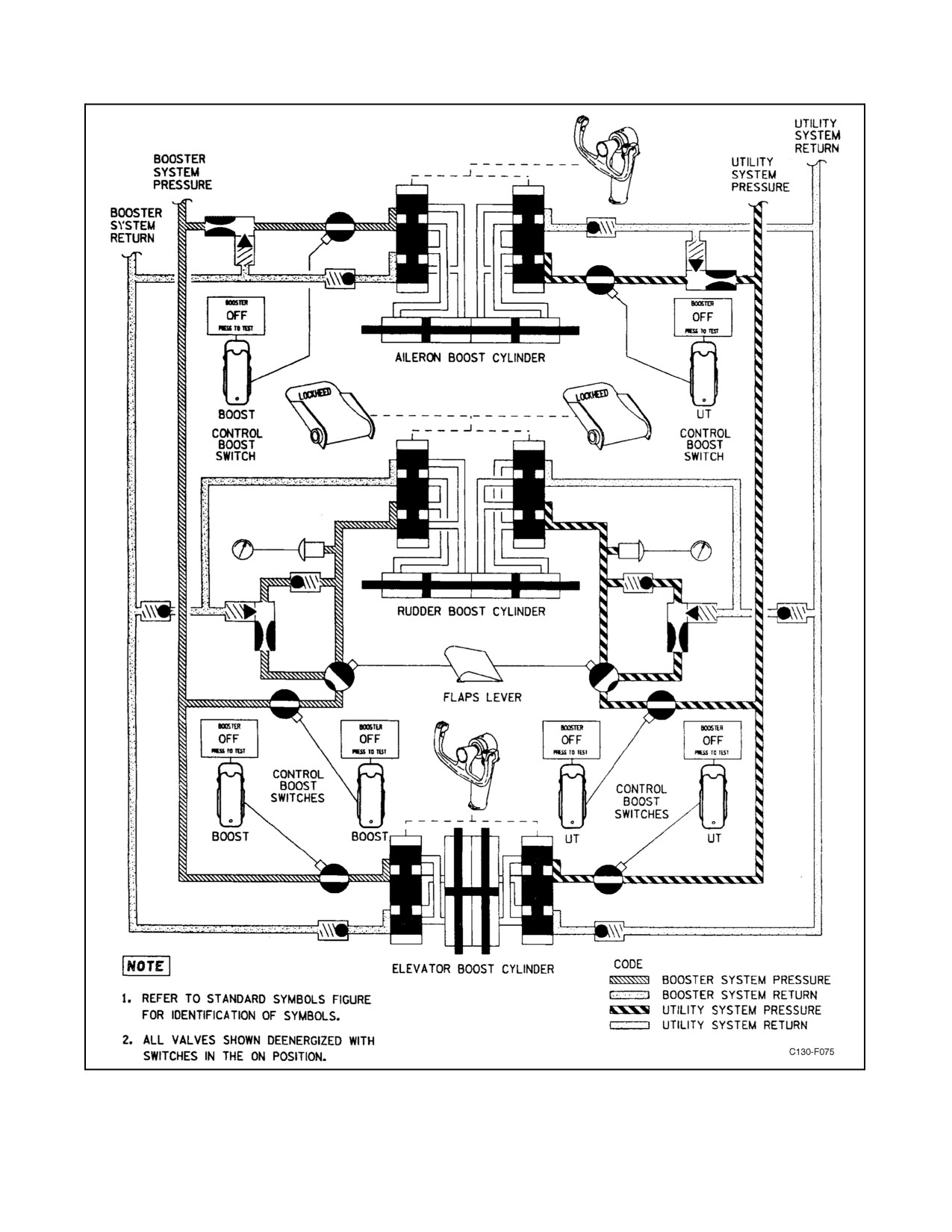
The main surfaces (ailerons, rudder, and elevators) are controlled by mechanical control systems consisting of cables,
pushrods,bellcranks,andtorquetubes.Hydraulically-drivenboosterunitsprovidemost oftheforcerequired tomove
the surfaces. The booster units are driven by hydraulic pressure supplied simultaneously by the booster and utility
hydraulic systems (see Figure 2-46), each of which serves to power one portion of the booster units. System operation
is such that failure or malfunction of any component of either system in any booster unit will allow normal function
of the other system powering the same unit. A loss of hydraulic pressure in either hydraulic system results in a
corresponding loss in the booster unit, and a proportionate loss of power to operate the unit. The aircraft may be
controlled with complete loss of booster unit power by the use of trim tabs and engine power, plus coordinated,
increased efforts of the pilot and copilot. Solenoid-operated shutoff valves in each surface control system can be
actuated by switches on the control boost switch panel (see Figure 2-46) at the flight station to shut off supply pressure
to either of the systems. The valves are spring loaded and will open when deenergized (control boost switches in the
ON position). A booster-off warning light for each switch is also powered by the solenoid shutoff valve switch and
will illuminate when the switch is in the OFF position. An autopilot servomotor is cable-rigged to each booster unit
to substitute for manual control during autopilot operation. Electrical power for operation of the booster shutoff
valves is supplied from the essential dc bus through the AILERON, ELEVATOR, and RUDDER SHUTOFF
VALVES circuit breakers on the copilot lower circuit breaker panel.
2.9.1.1 Rudder Booster Assembly
The rudder booster assembly is a single tandem-type hydraulic actuating cylinder that furnishes most of the force
to actuate the rudder. During normal operation, fluid supplied at approximately 3,000 psi pressure is routed by
solenoid-controlled, normally deenergized diverter valves through pressure reducer valves in each of the systems and
from there, at a pressure of approximately 1,300 psi, to the rudder booster assembly. This system pressure produces
desirable characteristics of sensitivity and surface travel for normal in-flight operation. Movement of the flap lever
from the retracted (UP) position to approximately the 15-percent position or beyond will energize the solenoids of
the diverter valves, actuating the valves in such a manner that the pressure reducers are bypassed, thereby permitting
supply fluid at approximately 3,000 psi pressure to reach the booster assembly. This doubles the available actuating
force and gives desirable characteristics of sensitivity and surface travel at low airspeeds such as are encountered in
takeoff, landing, and flying traffic patterns, where flaps are used. The diverter valves are powered from the essential
dc bus through the RUDDER HIGH BOOST CONTROL circuit breaker located on the copilot lower circuit breaker
panel. The amount of pressure actuating the rudder booster assembly (both the booster and utility portion of the
system) is indicated on pressure gauges located on the hydraulic panel (see Figure 2-45) of the copilot instrument
panel. Transmitters for these indicators are located downstream of the diverter valve, and, therefore, will show high-
or low-pressure operation.
2.9.1.2 Aileron Booster Assembly
The aileron booster assembly is a single tandem-type hydraulic actuating cylinder that furnishes most of the force
to actuatetheailerons. Theboosterassembly is furnished fluid through apressurereducerat approximately 2,050 psi
from both the booster and utility hydraulic systems.
2.9.1.3 Elevator Booster Assembly
The elevator booster assembly has dual actuating cylinders connected to the booster assembly output power lever
that operates the elevator control surfaces. The actuating cylinders operate simultaneously by 3,000 psi pressure
supplied by the booster and utility hydraulic systems, each of which powers one actuating cylinder.
ORIGINAL
2-94
01-75GAL-1
Figure 2-46. Surface Control System
2-95
ORIGINAL
01-75GAL-1
2.9.1.4 Main Surface Control System Controls and Indicators
2.9.1.4.1 Control Columns and Wheels
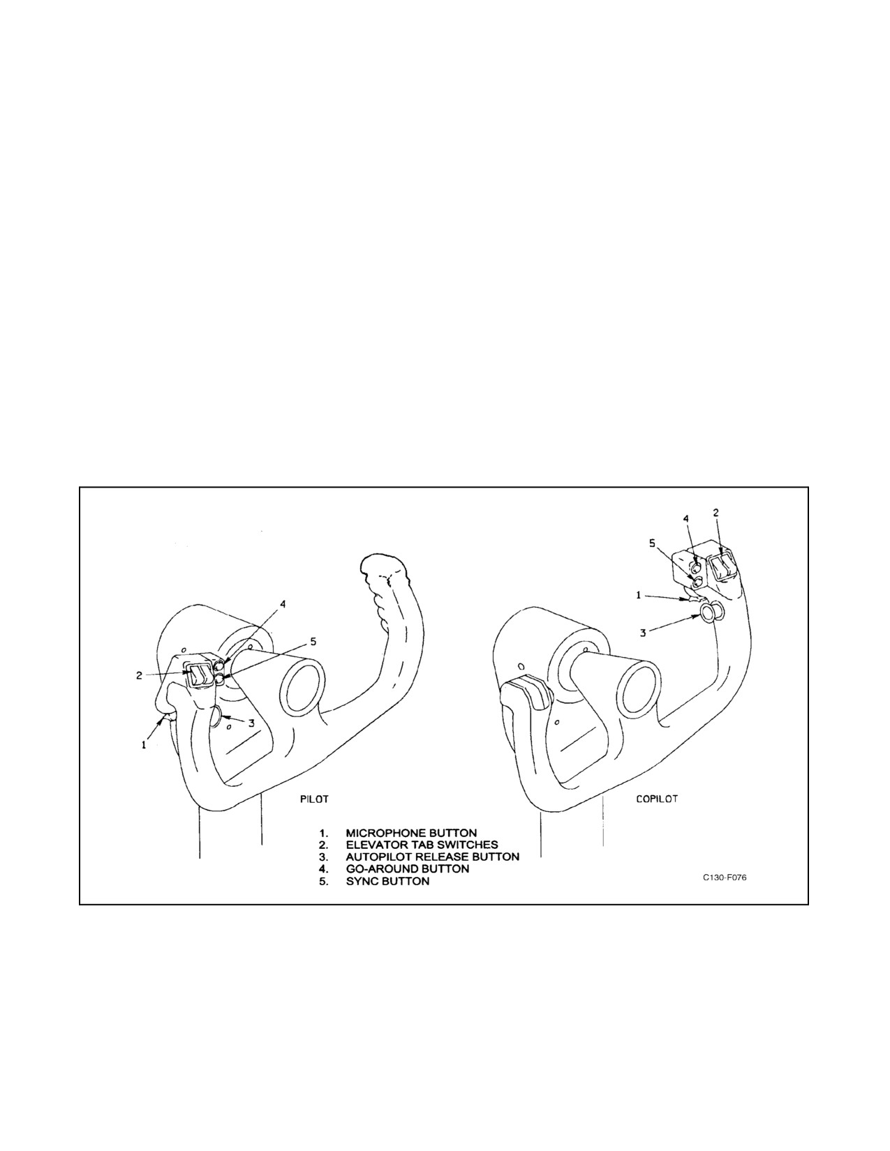
Control columns and wheels (see Figure 2-47) installed at the pilot and copilot stations to operate the aileron and
elevator surface controls are of the conventional type. Mechanical linkage actuates the hydraulically-powered booster
unit control valves and servomotors for each of these surface controls. Pushrods (elevator) and a chain-and-cable
arrangement (ailerons) connect the control column to bellcranks on torque tubes that are mounted under the flight
station beneath the pilot and copilot seats. From there, dual sets of steel cables continue the elevator linkage as far
as the pressure bulkhead at the extreme rear of the cargo compartment and the aileron linkage to the rear face of the
center-section wing rear-beam web. From these points, pushrods and bellcranks pick up the motion and transmit it
to the booster unit control valves and servo units.
2.9.1.4.2 Rudder Pedals and Adjustment Controls
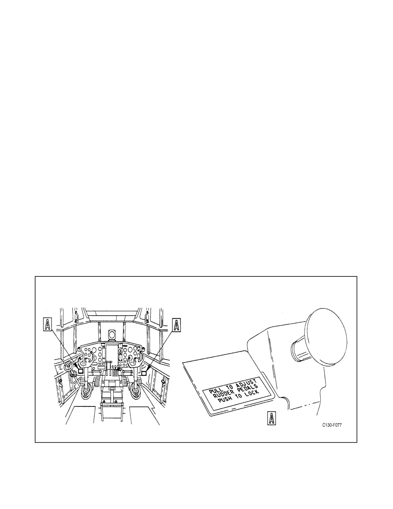
Rudder pedals are of the conventional type. Each pair of rudder pedals can be adjusted individually by unlocking the
rudder pedal adjustment control (see Figure 2-48) and pushing or releasing the spring-loaded pedals to the desired
position. The rudder pedals are used to operate the rudder boosters when hydraulic power is available and to operate
the rudder manually when hydraulic power is not available. The pressure on the rudder pedals actuates the brake
during either normal or emergency braking.
Figure 2-47. Control Wheels
ORIGINAL
2-96
01-75GAL-1
2.9.1.4.3 Control Boost Switches and Warning Lights
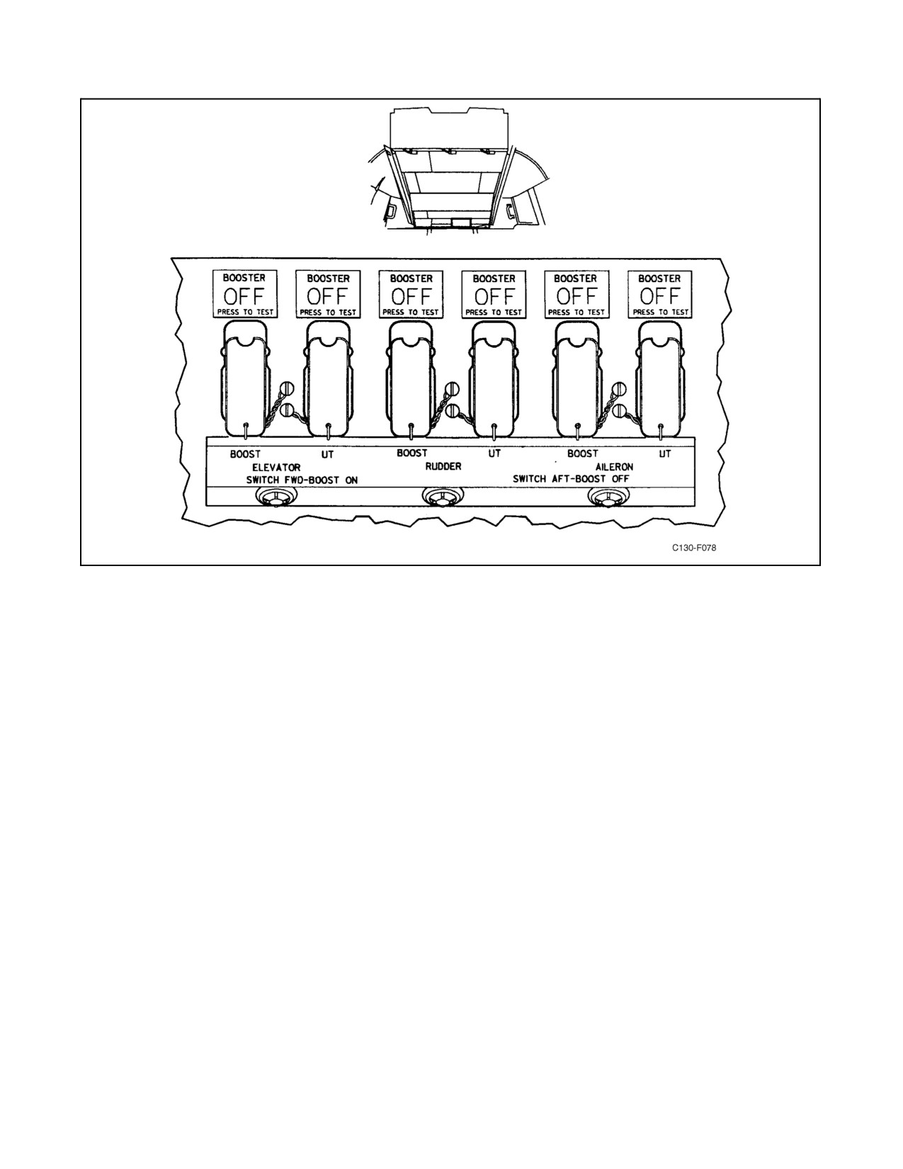
The control booster unit shutoff-valve-actuating switches are located on the control boost switch panel (see Figure
2-49) on the overhead control panel. There are six guarded, two-position toggle switches (ON with cover down,
deenergized) that will actuate the shutoff valves to isolate the corresponding booster package and to energize six
hoodedwarninglightsthatilluminateBOOSTEROFF whentheirrespectiveswitches areplaced intheOFFposition.
The panel switches supply power to the warning lights directly through the copilot lower circuit breaker panel when
in the OFF position, and, therefore, furnish no independent indication directly ofboost unit failure orthat theshutoff
valves are closed. The warning light only indicates that the switch is in the OFF position and dc power is routed to
the solenoid shutoff valve. Individual pressure control from both the booster and utility systems is available to each
boost package. The 28-Vdc power for the lights and valves is supplied from the essential dc bus through the
SHUTOFF VALVES circuit breakers on the copilot lower circuit breaker panel.
2.9.2 Trim Tab Control Systems
Trim tabs are provided on the control surfaces to aid in trimming the aircraft during flight. Lateral trim is obtained
throughoperationofatrimtabontheleftaileron.Agroundadjustabletabislocatedontherightaileron tocompensate
for any inherent imbalance about the longitudinal axis of the aircraft. Noseup and nosedown trim is obtained through
operation of the trim tabs on the elevators, one trim tab on each elevator control surface. Left and right trim is obtained
by operation of the rudder trim tab. During autopilot operation, operation of the ELEV TRIM switch located on either
of the control wheels will cause the autopilot to disengage. The autopilot elevator servo will function only when the
elevator tab switch is placed in the NORMAL position. All trim tab actuators are driven by 115-volt, single-phase
ac motors, except during emergency operation when the elevator trim tab actuator is driven by a 28-Vdc motor.
2.9.2.1 Trim Tab System Controls and Indicators
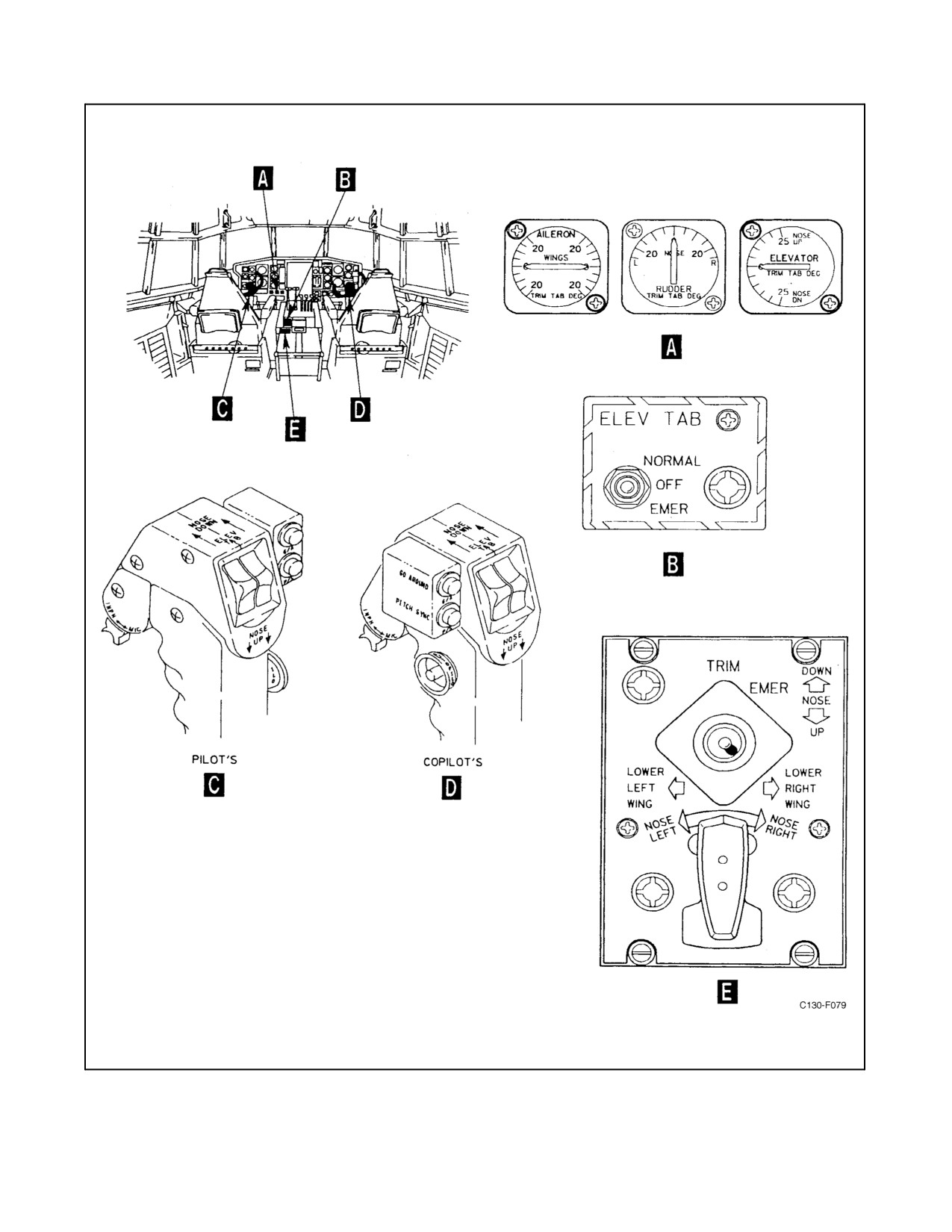
Trim tab system controls and indicators are shown in Figure 2-50.
Figure 2-48. Rudder Pedal Adjustment Control
2-97
ORIGINAL
01-75GAL-1
Figure 2-49. Control Boost Switch Panel
2.9.2.1.1 Aileron and Emergency Elevator Trim Tab Switch
An aileron and emergency elevator trim tab switch is located on the trim control panel on the flight control pedestal.
It is a recessed, five-position (EMER NOSE UP, EMER NOSE DOWN, OFF, LOWER LEFT WING, LOWER
RIGHT WING) toggle switch, with all switch positions other than the OFF (center) position spring loaded to return
to the center position upon release of the switch. When the switch is held in the LOWER LEFT WING or LOWER
RIGHT WING position, the trim tab on the left aileron control surface is actuated by a tab motor to trim the aircraft
laterally. With the ELEV TAB power-selector switch positioned to EMER and the emergency elevator trim tab
switch held in the EMER NOSE UP or EMER NOSE DOWN position, the elevator trim tabs are actuated by a tab
motor to raise or lower the nose of the aircraft. When the switch is in the OFF (center) position, the electric motors
that actuate the trim tabs are deenergized.
The emergency elevator trim tab switch is operative only when the ELEV TAB power selector switch is placed in
the EMER position. With the ELEV TAB power selector switch in EMER, 28-Vdc power is supplied to the elevator
trim tab control relays, through the emergency elevator trim tab switch, from the essential dc bus through the
ELEVATOR EMER TAB CONTROL circuit breaker on the copilot lower circuit breaker panel. When the
emergency elevator trim tab switch is placed in the EMER NOSE UP position, it will energize the elevator tab down
relay that connects 28-Vdc power to the elevator trim tab dc actuator and will raise the nose of the aircraft. When
the switch is placed in the EMER NOSE DOWN position, the elevator tab up relay is energized, connecting 28-Vdc
power to the elevator trim tab dc actuator and will lower the nose of the aircraft. The emergency elevator tab actuator
receives 28-Vdc power from the essential dc bus through the ELEVATOR EMER POWER circuit breaker on the
copilot lower circuit breaker panel.
ORIGINAL
2-98
01-75GAL-1
Figure 2-50. Trim Tab System Controls and Indicators
2-99
ORIGINAL
01-75GAL-1
Two control relays in the aileron trim tab power circuit are energized by the trim tab control switch. The relays
eliminate the necessity to route the 115-Vac power required to operate the aileron trim tab actuator through the trim
tab control switch. When the switch is placed in the LOWER LEFT WING position, it will energize the tab down
relay that connects 115-Vac power to the aileron trim tab actuator and lowers the left wing. When the switch is placed
in the LOWER RIGHT WING position, it will energize the tab up relay that connects 115-Vac power to the aileron
trim tab actuator and lowers the right wing. The aileron tab motor receives 115-Vac power from the essential ac bus
through the TRIM TAB AILERON circuit breaker on the pilot side circuit breaker panel. The relays are actuated by
28-Vdc power from the essential dc bus through the AILERON TAB CONTROL circuit breaker on the copilot lower
circuit breaker panel.
2.9.2.1.2 Elevator Tab Switches
Dual NOSE UP, NOSE DOWN, and center off elevator trim tab switches are located on the outboard handgrip of
each control wheel. The dual switches on the pilot or copilot control wheels must be operated simultaneously on their
respective wheels to provide both power and ground to the control relays. The two sets of dual switches are connected
in parallel and either set of switches can control the tab when the ELEV TAB power selector switch is positioned
to NORMAL. When either the pilot or copilot control wheel dual switches are in the NOSE UP or NOSE DOWN
position, dual relays are actuated to apply power to the elevator trim tab actuator. With the ELEV TAB power selector
switch in NORMAL, 115-Vac power from the essential ac bus, through the TRIM TAB ELEVATOR circuit breaker
on the pilot side circuit breaker panel, is applied to the actuator. The elevator tab switches on the control wheels are
inoperative when the ELEV TAB power selector switch is placed in the EMER or OFF position.
2.9.2.1.3 Elevator Tab Power Selector Switch
An elevator tab power selector switch is located on the flight control pedestal. It is a three-position (NORMAL, OFF,
EMER) toggle switch used to select the source of electrical power for operation of the elevator trim tabs. When the
switch is in the NORMAL position, 115-Vac power is supplied from the essential ac bus, through the ELEVATOR
TRIM TAB circuit breaker on the pilot side circuit breaker panel, to a trim tab actuating motor relay for autopilot
orcontrol wheel handgrip switch operation oftheelevator trim tabs. In the NORMAL position, theelevator trim tabs
can be controlled only from the control wheels. When in the EMER position, the elevator trim tabs can be controlled
only from the emergency elevator trim tab switch located on the pedestal. During emergency operation, 28-Vdc
power is supplied from the essential dc bus through the ELEVATOR EMER POWER circuit breaker, located on the
copilot lower circuit breaker panel, to a trim tab actuating motor that will drive the elevator trim tabs either up or down
when the respective elevator trim tab control relay is energized by actuation of the trim tab control switch on the
pedestal. When the ELEV TAB power selector switch is in the NORMAL position, the ELEVATOR TRIM TAB
CONTROL relays are powered by 28-Vdc from the essential dc bus, through the ELEV TAB CONTROL circuit
breaker located on the copilot lower circuit breaker panel. When the elevator tab power selector switch is in the EMER
position, the elevator trim tab control relays are powered by 28-Vdc from the essential dc bus, through the
ELEVATOR EMER TAB control circuit breaker located on the copilot lower circuit breaker panel. When the ELEV
TAB power selector switch is placed in the OFF position, all circuits to the elevator trim tabs are deenergized.
2.9.2.1.4 Rudder Trim Tab Switch
A rudder trim tab switch is located on the trim tab control panel of the flight control pedestal. It is a three-position
(NOSE LEFT, OFF, NOSE RIGHT) switch that controls operation of the rudder trim tab motor. The NOSE LEFT
and NOSE RIGHT positions are spring loaded to return to the OFF (center) position upon release of the control
switch. When the switch is in NOSE LEFT or NOSE RIGHT position, 115-Vac power from the essential ac bus,
through the RUDDER TRIM TAB circuit breaker on the pilot side circuit breaker panel, energizes the rudder trim
tab motor to position the rudder trim tab and trim the aircraft.
2.9.2.1.5 Rudder Trim Tab Position Indicator
A rudder trim tab position indicator is located on the pilot instrument panel. The indicator is connected to a transmitter
mounted on the rudder trim tab actuator housing and indicates to the pilot the degree of rudder trim tab positioning
ORIGINAL
2-100
01-75GAL-1
relative to the rudder control surface. This indicator is energized by 28-Vdc power from the main dc bus, through
the TABS & FLAPS POSITION INDICATOR circuit breaker in the aft fuselage junction box. For aircraft 165313
and up, this indicator is energized by 28 Vdc from the main DC bus through the RUDDER TAB circuit breaker in
the aft fuselage junction box. The indicator dial face is calibrated from 0_ to L and 0_ to R in increments of 5_ of
rudder trim tab travel from the neutral 0_ marking. The needle on the indicator shows the exact angle between the
rudder trim tab and rudder surface, and shows the direction in which the trim will act.
2.9.2.1.6 Aileron Trim Tab Position Indicator
An aileron trim tab position indicator is located on the pilot instrument panel. This indicator is connected to a
transmitter mounted on the left aileron trim tab actuator, and indicates to the pilot the degree of left aileron trim tab
positioning relative to the aileron control surface. This indicator is energized by 28-Vdc power from the main dc bus
through the TABS & FLAPS POSITION INDICATOR circuit breaker in the aft fuselage junction box. For aircraft
165313 and up, this indicator is energized by 28 Vdc from the main DC bus through the AILERON TAB circuit
breaker in the aft fuselage junction box. The indicator dial face is calibrated from the neutral position of 0_ to 20_
up and 0_ to 20_ down in 5_ increments of left aileron trim tab travel. The needle on the indicator shows the exact
angle between the aileron trim tab and the left aileron surface and the direction in which the trim will act.
2.9.2.1.7 Elevator Trim Tab Position Indicator
An elevator trim tab position indicator is located on the pilot instrument panel. The indicator is connected to a
transmitter mounted on the elevator trim tab rotary actuator housing and indicates to the pilot the degree of elevator
trim tab positioning relative to the elevator control surface. This indicator is energized by 28-Vdc power from the
main dc bus through the TABS & FLAPS POSITION INDICATOR circuit breaker in the aft fuselage junction box.
For aircraft 165313 and up, this indicator is energized by 28 Vdc from the main DC bus through the ELEVATOR
TAB circuit breaker in the aft fuselage junction box. The indicator dial face is calibrated from the neutral position
0_ to 25_ up or 25_ down in 5_ increments of elevator trim tab travel. The needle on the indicator shows the exact
angle between the elevator trim tabs and the corresponding elevator surface, and the direction in which the trim will
act.
Note
Trim tab travel is controlled by limit switches set at 6_ nose down and 25_
nose up, and by mechanical stops set at 8_ nose down and 27_ nose up.
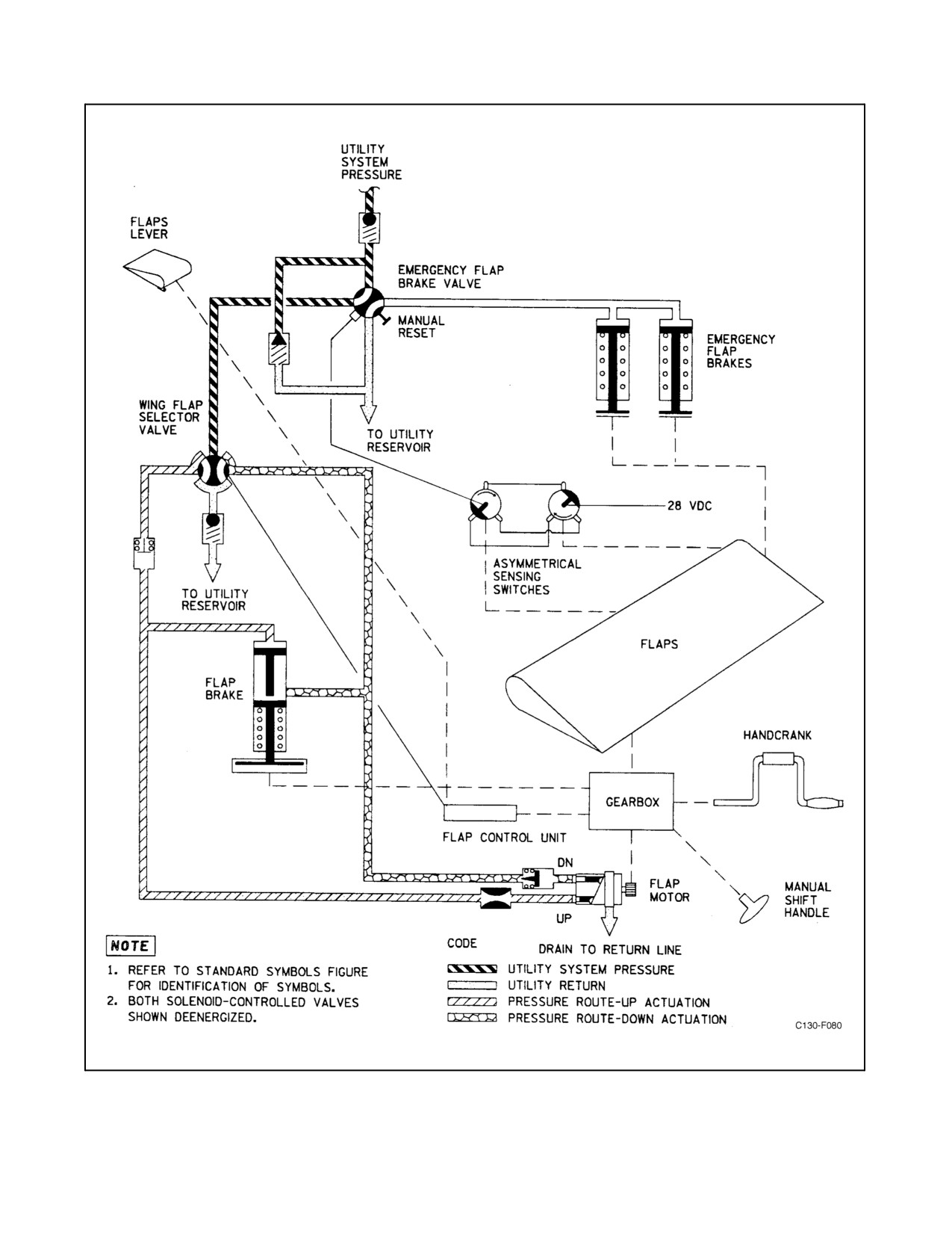
2.9.3 Flap Control System
The aircraft is equipped with four flaps, consisting of an outboard and an inboard flap in each wing. The flaps are
oftheLockheed-Fowlerhigh-lift type, in which theflapmotion isacombinationofanaft movementto increasewing
area and a downward tilting movement to alter the airfoil section to increase lift and drag. The time required for full
extension of the flaps is between 8 and 15 seconds. Full retraction time is between 10 and 15 seconds. When 100
percent extended, the flaps form an angle of approximately 35_ with the wings. The flaps are operated by a reversible
hydraulic motor, a cam-actuated microswitch followup mechanism, torque tubes, gearbox, and drive screw
assemblies. Hydraulic pressure is directed through a check valve to the emergency flap brake valve and the wing flap
selector valve, where pressure is directed to the up or down system. The hydraulic motor operates the torque shaft
section extending outboard to the gearbox, which rotates ball bearing drive screws for actuation of the flaps. The flaps
may be operated manually with a handcrank. Disk-type, spring-loaded flap brakes hold the flaps in the selected
position and prevent movement by aerodynamic loads. The brakeis released by fluid pressure supplied to thesystem
for operation of the flap drive motor. Emergency flap brakes are splined to the outer ends of the flap drive torque shaft
to prevent unequal actuation oftheflaps during normal extension and retraction ofthe flaps. Utility hydraulicsystem
pressure is used for operation of the flap system (see Figure 2-51).
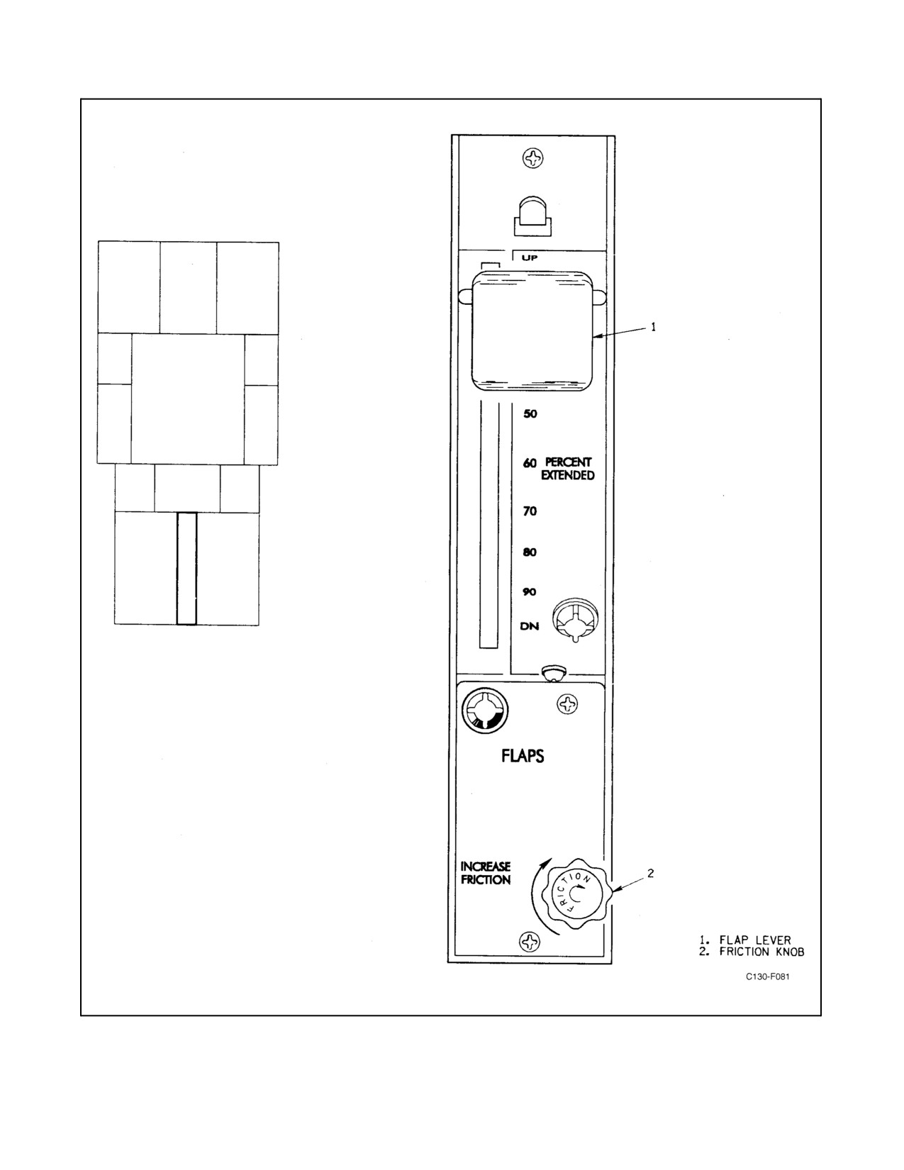
2.9.3.1 Flap System Controls and Indicator
Flap system controls are shown in Figure 2-52.
2-101
ORIGINAL
01-75GAL-1
Figure 2-51. Flap Control System
ORIGINAL
2-102
01-75GAL-1
Figure 2-52. Flap Control Panel
2-103
ORIGINAL
01-75GAL-1
2.9.3.1.1 Flap Lever
A flap lever is located on the aft end of the flight control pedestal. It is a manually actuated control lever, with the
lever range calibrated from UP to DN in increments of 10 percent. There is a detent at approximately the 50-percent
position, but the flaps can be extended to any desired position by placing the lever at the selected percent of flap
extension. The lever is attached by cables to a movable cam inside a flap control unit mounted on the center section
wing rear beam in the cargo compartment. Movement of this cam closes limit switches that close a 28-Vdc control
circuit for the wing flap selector valve. The actuated valve directs a flow of hydraulic fluid to drive the flap motor
in the selected direction. A rudder pressure diverter valve, electrically actuated by a switch on the flap control lever
mechanism, controls the pressure available for operation of the rudder. Pressure available for rudder operation of flap
settings from 0 to 15 percent is approximately 1,300 psi as compared to approximately 3,000 psi for flap settings from
15 to 100 percent. The pressure control system is provided to prevent excessive air loads at high speeds. When the
selected position of the flaps is reached, the limit switches open, the selector valve shuts off hydraulic flow, and a
spring-loaded hydraulic brake locks the flaps in the selected position. The wing flap selector valve receives 28-Vdc
power from the main dc bus, through the WING FLAP CONTROL circuit breaker on the copilot lower circuit breaker
panel.
Note
D The GPWS is interconnected with the flap system. A switch is located on
the flap control lever mechanism, at the 40-percent flap setting, to signal
theGPWS computerwhenevertheairspeed/altitudeand flapsetting arenot
commensurate to a landing configuration. The 40-percent flap switch may
be inhibited by placing the ground proximity flap override switch to the
OVERRIDE
position.
D The landing gear warning horn is inter-connected with the flap system.
When the flap lever is set at approximately 80 percent or more with the
landing gear up, the landing gear warning horn will sound; it cannot be
silenced until the landing gear is down and locked or the flap lever is
retracted above 80 percent.
2.9.3.1.2 Flap Lever Friction Knob
A flap lever friction knob is located on the flap control panel. Turning the knob clockwise mechanically tightens the
friction on the flap cables, preventing the flap lever from vibrating out of its set position.
2.9.3.1.3 Wing Flap Selector Valve
A wing flap selector valve is mounted on the left-hand hydraulic panel, forward of the left-hand wheelwell. It is a
solenoid-operated valve, directing the flow of utility hydraulic fluid to either the up or down side of the flap motor
for normal raising and lowering of the flaps, depending on the position of the flap lever. Override controls, consisting
of two buttons marked RAISE and LOWER, are located on the selector valve for use in case of electrical failure.
Pushing the button marked LOWER routes hydraulic fluid to release the flap brakes and to the gearbox drive motor
to lower the flaps. Pushing the button marked RAISE routes hydraulic fluid to release the brakes and to the gearbox
drive motor to raise the flaps. In normal operation, the valve is energized by 28-Vdc power from the main dc bus,
through the WING FLAP CONTROL circuit breaker on the copilot lower circuit breaker panel.
2.9.3.1.4 Manual Operation
An emergency method of operating the flaps mechanically is provided by an extension stub shaft connected through
a universal joint to the torque shaft that drives the flap screwjacks. The extension stub shaft and the handcrank are
located on the forward wall of the left-hand main landing gear wheelwell.
ORIGINAL
2-104
01-75GAL-1
2.9.3.1.5 Flaps Position Indicator
A flaps position indicator is located on the copilot instrument panel, Figure 2-79. The indicator is connected to a
transmitter that is mounted on the flap drive control unit located on the aft face of the wing rear beam. The indicator
dialiscalibratedfromUPtoDOWNinincrementsof10percent.Theindicatingsystemisenergizedby28-Vdcpower
from the main dc bus through the TABS & FLAPS POSITION INDICATOR circuit breaker in the aft fuselage
junction box.
2.9.3.2 Flap Asymmetrical Control System
The flap asymmetrical control system is designed to sense certain malfunctions in the flap drive system and actuate
the emergency flap brakes to stop any further movement of the flaps.
2.9.3.2.1 Asymmetrical Sensing Switches
There are two asymmetrical sensing switches, one at each of the outboard flap drive gearboxes. If a torque tube in
the system breaks or a coupling comes apart, the switches sense the resulting out-of-phase condition. When this
occurs, 28-Vdc power through the WING FLAP CONTROL circuit breaker on the copilot lower circuit breaker panel
is routed by the switches to the emergency flap brake valve to lock the flap brakes.
2.9.3.2.2 Emergency Flap Brake Valve
The emergency flap brake valve is a solenoid-operated hydraulic valve located on the utility hydraulic panel. In its
deenergized position, hydraulic pressure passes through it to the flap selector valve. When energized by the
asymmetrical sensing switches, the valve routes hydraulic fluid pressure to the emergency flap brakes and closes off
pressure to the flap selector valve. The valve is equipped with a manual override. When locked by the emergency
flap brakes, the flaps cannot be raised or lowered by any means until the manual override is moved. The manual
override resets the emergency flap brake valve, releasing the emergency flap brakes.
Note
The manual override is for ground use only.
2.9.3.2.3 Emergency Flap Brakes
There are two emergency flap brakes, located one at each of the out-board flap drive gear boxes. The emergency flap
brakes are spring-loaded released and hydraulically applied by pressure supplied through the emergency flap brake
valve. When actuated, the brakes lock the flaps, preventing any further motion of the flaps. The brakes are released
by operating the emergency flap brake valve manual override.
2.10
LANDING GEAR SYSTEM
The landing gear system includes a dual-wheel, steerable nosegear and two tandem-mounted main landing gears.
Normal operation of the system is through the utility hydraulic system. The nosegear retracts forward into the nose
section of the fuselage; the main landing gears retract vertically into the left and right wheelwells on the sides of the
fuselage. In the retracted position, all landing gears are enclosed by mechanically operated flush doors. A landing
gear position-indicating system gives a visual indication of the position of each gear and gives a visual and audible
indication of an unlocked condition of thelanding gear. Under normal operation, retraction or extension time ofboth
nose and main landing gears is 19 seconds or less.
2.10.1 Main Landing Gear
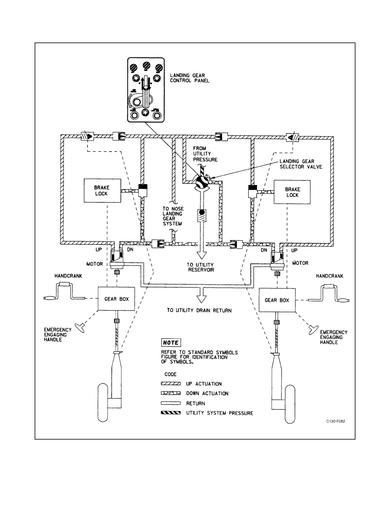
The main landing gear system (see Figure 2-53) consists of four wheels, two mounted in tandem on each side of the
fuselage. Each wheel has a separate strut. The landing gear actuation system is normally supplied hydraulic fluid
2-105
ORIGINAL
01-75GAL-1
under pressure from the utility system. Fluid from the utility system flows through a landing gear selector valve to
each of the two main landing gear motors. Each pair of struts is raised and lowered in vertical tracks by screwjacks
driven by torque shafts that are powered by the hydraulic motor through a gearbox. The gearbox contains a
spring-loaded brake assembly. After the landing gear contacts the up-limit switch, the landing gear selector valve
remains energized, allowing landing gear up hydraulic pressure to be continuously applied to the main landing gear
motors. In the event of loss of hydraulic pressure, the main landing gear spring-loaded retraction brakes are applied.
With the main gear down and the aircraft on the ground, friction washers on the screwjack assemblies serve as
downlocks. Mechanical linkage between the aft main landing gear struts and the doors causes the doors to open and
close as the main landing gears are extended and retracted.
2.10.1.1 Manual Operation Provisions
Emergency methods ofactuating themain landing gearmanually areprovided by means oftwo emergency engaging
handles, two extension stub shafts, two handcranks, a main landing gear emergency extension wrench, and six easily
removed pressure-sealed doors. The two emergency engaging handles, one located on the forward side of each
wheelwell bulkhead, are connected by cables to their respective gearbox assemblies. Pulling an emergency engaging
handle shifts the gearbox from power to manual drive and bypasses the brake.
Note
The emergency engaging handles should not be pulled while the aircraft is
on the ground. The aircraft may have to be jacked to reset the handles.
Either handcrank (one is located on each side of the fuselage near the wheelwell bulkhead) can then be used to operate
the appropriate extension stub shaft for manual extension of either main landing gear. The shaft is connected by
mechanical linkage to the gearbox assembly that drives the retraction screwjacks. One extension stub shaft is
mounted on the forward wall of each main landing gear wheelwell. The emergency extension wrench is provided for
manually extending the main landing gear after both the normal and emergency extension systems have failed. There
are seven pressure-sealed access panels on each wheelwell wall. The main landing gear gearbox access panel is
located forward and high on each wheelwell wall. This panel provides access to the MLG hydraulic gearbox for
manual shift from power to manual drive in the event of manual release-cable jamming or failure. The two upper
access panels on each wheelwell wall provide access to the lower end of each vertical torque shaft for disconnecting
the vertical torque shaft and use of the MLG emergency extension wrench. The two middle access panels on each
wheelwell wall are for maintenance use and are not to be removed in flight. These panels are secured with screws.
The two lower access panels at the floor level on each wheelwell wall are inspection windows for determining that
the MLG is fully extended. They also provide access to the MLG struts for emergency tiedown. All of the
pressure-sealed access panels except the two middle access panels on each side can be removed in flight for
emergency requirements. The emergency extension handcrank can be used to remove the bolts securing the access
panels. The landing gear down-and-locked indicators remain operative during manual operation.
2.10.2 Nose Landing Gear
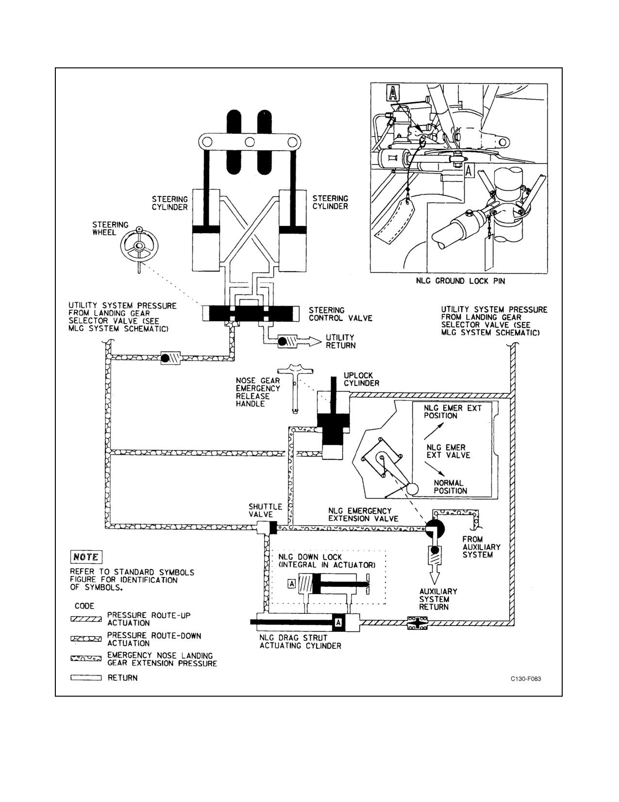
The nose landing gear is a swing-type gear, extending down and aft, actuated by a hydraulic cylinder and secured
in theup and down positions by locks.Thegearis normallysupplied withhydraulicfluidunderpressureby theutility
supply system; however, during an emergency it can be supplied by the auxiliary hydraulic system (for extension
only). Hydraulic fluid from either the up or down side of the landing gear selector valve flows to the nose landing
gear uplock and downlock cylinders and to the nose landing gear actuating cylinder (see Figure 2-54). The landing
gear selector valve remains energized open in the up position, allowing landing-gear-up pressure to be continuously
applied to the nose landing gear actuating cylinder and uplock. In the event of loss of hydraulic pressure, the nose
landing gear is held in place mechanically by the uplock. Fluid for the nose landing gear steering control valve is
supplied from the landing gear selector valve in the down position only. A shuttle valve connects the utility pressure
downlineto theauxiliary system pressureline, permitting auxiliary pressureto beused to place thenose landing gear
inthedown-and-lockedpositionwhentheutilitysystem isinoperative. Themanual releasehandleattheflightstation
ORIGINAL
2-106
01-75GAL-1
provides a mechanical means of unlocking the nosegear uplock. The nosegear can be visually checked through a nose
landing gear inspection window on the aft bulkhead of the nose wheelwell under the flight deck. There are no
provisions for emergency retraction of the nose landing gear.
2.10.3 Landing Gear System Controls and Indicators
2.10.3.1 Landing Gear Lever
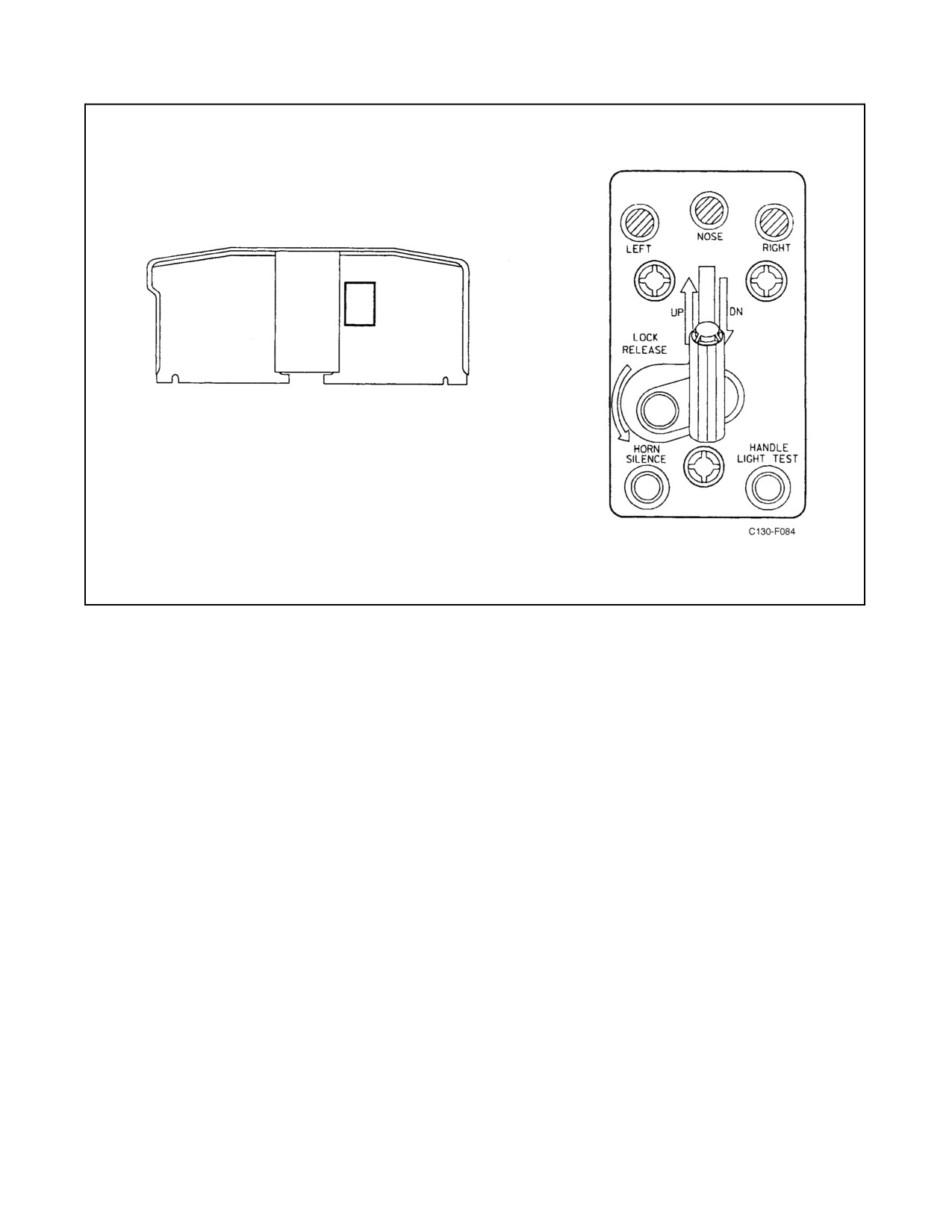
A landing gear lever (see Figure 2-55) is located on the left side of the copilot instrument panel. It is a two-position
(UP, DN) lever that directs the gear actuating mechanism to raise or lower the nose and main landing gears. When
the lever is moved to the UP position, a solenoid-operated selector valve directs pressure from the utility hydraulic
system to release the nosegear downlock, to the up side of the nose landing gear actuating cylinder, to both main
landing gear hydraulic motors, and the landing gears retract. When the lever is moved to the DN position, the nose
landing gear uplock is released, the main landing gear motors are reversed, and the landing gear extends. The valve
circuit is powered by 28-Vdc from the essential dc bus, through the LANDING GEAR CONTROL circuit breaker
on the copilot lower circuit breaker panel. A mechanical locking device is engaged when the landing gear lever is
moved to the DN position so that the lever stays in the DN position until released. During takeoff or in flight, the
energized position of the touchdown relay energizes the landing gear lever release solenoid to reduce the locking
device to a simple detent. At other times, the LOCK RELEASE finger latch (see Figure 2-55) must be pulled down
before the landing gear lever can be moved to the UP position. When the landing gear lever is in the UP position,
28-Vdc power is routed from the LANDING GEAR CONTROL circuit breaker on the copilot lower circuit breaker
panel to energize the normal brake selector valve to prevent application of normal brakes. When the landing gear lever
is in the DN position, the normal brake selector valve is deenergized to allow brake application regardless of main
landing gear strut compression. See paragraph 2.13 for interrelation of antiskid provisions.
2.10.3.2 Main Landing Gear Touchdown Switch
Atouchdown switch is installed on theloweraft sideofeach forward main gear strut. The switches are safety devices
that either prevent some aircraft system from operating or permit it to operate when the aircraft is on the ground or
in flight. The weight of the aircraft on the gear operates these switches.
Some systems are wired directly through the touch-down switches and others through relays that are controlled by
the touchdown switches. Systems that are affected by the touchdown switches and relays are as follows:
1. Touchdown switch.
a. Engine ground stop (inoperative in flight).
b. Touchdown relay.
c. Auxiliary touchdown relays.
2. Touchdown relay.
a. Landing gear lever lock (unlocked in flight).
b. Wheelbrakes (antiskid) (brakes inoperative in flight).
c. Cockpit controls for cargo door and ramp (inoperative on the ground).
d. Airdrop release (inoperative on the ground).
2-107
ORIGINAL
01-75GAL-1
Figure 2-53. Main Landing Gear System
ORIGINAL
2-108
01-75GAL-1
Figure 2-54. Nose Landing Gear System
2-109
ORIGINAL
01-75GAL-1
Figure 2-55. Landing Gear Controls and Indicators
3. Auxiliary touchdown relay No. 1.
a. Dc bus tie control (inoperative in flight).
b. APU door control (door opens 35_ on the ground and 15_ in flight).
c. TCAS (enables test on ground).
4. Auxiliary touchdown relay No. 2.
a. Autopilot trim monitor test (inoperative in flight).
b. TCAS and transponder computers.
5. Auxiliary touchdown relay No. 3.
a. Ground/anticollision/strobes.
2.10.3.3 Emergency Engaging Handle
A yellow emergency engaging handle is located on the forward wall of each wheelwell, just below the landing gear
manual operation stub shaft. The handle operates a cable that disengages the main landing gear mechanism brake
and the drive motor, and simultaneously engages the mechanical linkage that connects the stub shaft to the gearbox,
thereby permitting manual raising or lowering of the main landing gear. The handle must be pulled out and turned
counterclockwise approximately one-quarter turn to lock before the landing gear can be extended or retracted
manually. To restore the system to normal, the handle must be turned approximately one-quarter turn clockwise to
unlock, and then be released to the normal position. Proper positioning of theemergency engaging handle is verified
byrotatingthehandcrankinboth directions.Ifthehandleisin thenormal position,thehandcrankwill rotatefreely.
ORIGINAL
2-110
01-75GAL-1
2.10.3.4 Landing Gear Handcrank
Two landing gearreversibleratchet-typehandcranksareprovidedforthemanual operationofthemain landinggears.
One handcrank is stored in retaining clips on the forward face of the left wheelwell, and the other is stored on the
fuselage wall forward of the right wheelwell. One end of each crank is made to fit over the protruding end of the
extension stub shaft located on each wheelwell forward wall, just above the emergency engaging handles. The
handcrank also fits the landing gear access panel bolts.
2.10.3.5 Main Landing Gear Emergency Extension Wrench
The emergency extension wrench is provided for manual extension of the main landing gear if both the normal and
emergency extension systems fail to extend the gear. The wrench has a fixed splined socket on one end and a ratchet
and splined box on the other end. The wrench is used to manually rotate the landing gear ball screws to lower the
struts. The wrench is stowed in a bracket located forward of the left main wheelwell area.
2.10.3.6 Main Landing Gear Ground Lock
Two main landing gear ground locks are provided to prevent accidental retraction of the main landing gears while
performing maintenance on the gears. The locks are installed on the hexagonal ends of the main landing gear ball
screw assemblies, one lock on each side of the aircraft. The locks are stowed in the miscellaneous equipment box
aft of the right paratroop door.
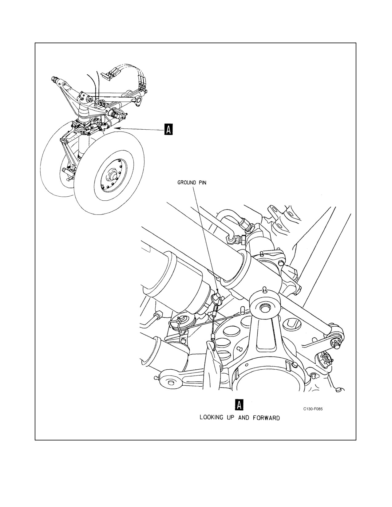
2.10.3.7 Nose Landing Gear Ground Pin
A nose landing gear ground pin (see Figure 2-56) is provided to prevent accidental retraction of the nose landing gear
while the aircraft is parked. The ground pin consists of a ball-lock pin that is inserted in a hole in the nose landing
gear actuator rod-end and prevents release of the internal downlock in the actuator.
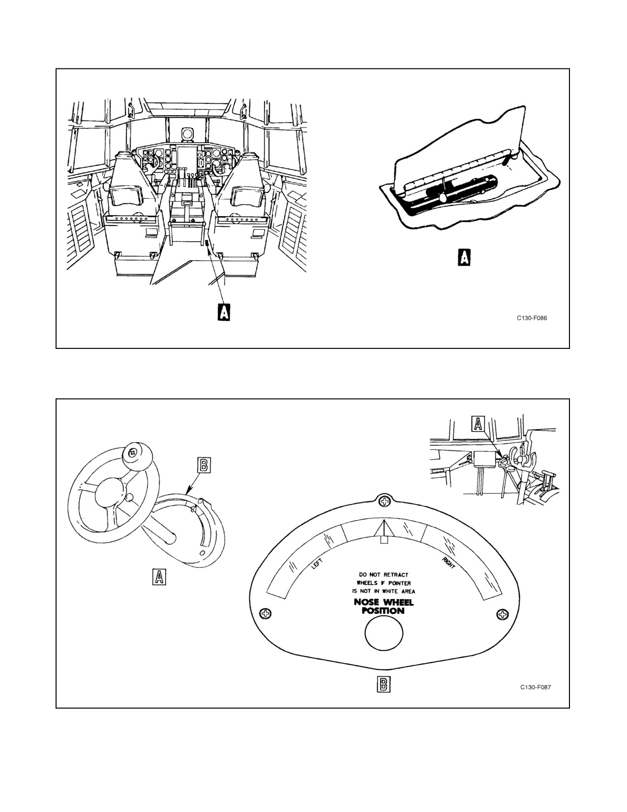
2.10.3.8 Nosegear Emergency Release Handle
A nose gear uplock emergency release handle (see Figure 2-57) is located below the floor of the flight station under
a hinged panel between the copilot seat and the control pedestal. The handle operates a cable system that releases
the nose landing gear uplock and allows the nosegear to fall free.
Note
Practice extension of the nose landing gear with the emergency release
handle and auxiliary hydraulic system is not recommended and should be
avoided. Extending the nose landing gear by this method and subsequently
raising the gear can cause approximately one quart of hydraulic fluid to
transfer from the auxiliary hydraulic system to the utility hydraulic system.
2.10.3.9 Landing Gear Warning Horn and Silence Switch
The landing gear warning horn is located above and to the left of the pilot seat. Two things will cause the landing
gear warning horn to sound: retarding a throttle to a position within 5_ forward of the FLIGHT IDLE position with
the landing gear up, and extending the flaps more than approximately 80 percent with the landing gear up. A HORN
SILENCE switch (see Figure 2-55) is located on the landing gear control panel. It is a press-type switch used to silence
the landing gear warning horn when a throttle is retarded. It will not silence the horn when flaps are extended more
than80percent.Whentheswitchispressed,thehorn-silencingrelayisactuatedandthewarninghornelectricalcircuit
is broken. Cycling of the landing gears or advancement of an engine throttle will reset the horn-silencing relay so
that the horn can sound again. The landing gear warning horn circuit is energized by 28-Vdc power from the essential
2-111
ORIGINAL
01-75GAL-1
dc bus through the LANDING GEAR WARN LIGHT circuit breaker on the copilot lower circuit breaker panel. After
C-130 AFC-368, audible alarms from the Bleed Air Duct Overheat Detection System are interfaced with existing
landing gear warning horn. An audible alarm from the ODS would pulse the horn at a rate of 90 times per minute
to distinguish it from the landing gear warning.
2.10.3.10 Landing Gear Warning Light and Warning Light Test Switch
The landing gear warning lights are connected to the landing gear retraction system and the throttle warning switches;
they will illuminate whenever the landing gear is not in a locked position or when an engine throttle is retarded to
within 5_ of the FLIGHT IDLE position and the landing gear is not fully extended. A HANDLE LIGHT TEST switch
(see Figure 2-55) is located on the landing gear control panel. It is a press-type switch used to test the continuity of
the landing gear warning light electrical circuit. When the switch is pressed, the landing gear warning light bulbs in
thelanding gearleverhandle will illuminate. Failureof thebulbs to illuminate shows a defectivecircuit. Thelanding
gear warning lights are energized by 28-Vdc power from the essential dc bus, through the LANDING GEAR WARN
LIGHT circuit breaker on the copilot lower circuit breaker panel.
2.10.3.11 Landing Gear Position Indicators
A left main gear position indicator, a nosegear position indicator, and aright main gear position indicator arelocated
onthelandinggearcontrolpanel (seeFigure2-55).Theseindicatorsgiveavisual indicationofpositionofthelanding
gear. When the letters UP appear on the face of an indicator, it means that the gear represented by that indicator is
retracted and locked. When the picture of a landing gear wheel appears on the face of an indicator, it means that the
landing gear represented by that picture is extended and locked. Diagonal lines on the face of an indicator indicates
that agearis somewherebetween theextended and retractedpositions orthat theindicatorisinoperative. Thelanding
gear position indicators are energized by 28-Vdc power from the essential dc bus, through the LANDING GEAR
POSITION IND circuit breaker on the copilot lower circuit breaker panel.
2.11
NOSEWHEEL STEERING SYSTEM
Theaircraft is steered during taxiing by directional control ofthenosewheel.Thenosewheelis hydraulicallyactuated
and governed by a steering control valve in the utility hydraulic system. The steering control valve is connected by
a cable to a manually operated nose steering wheel (see Figure 2-58) located in the flight station at the left of the pilot
control column. Directional control of the nosewheel is limited by means of mechanical stops to 60_ right and left
of center. One and one-fourth turns from center position of the nose steering wheel will turn the steering wheel to
thefull-leftorthefull-rightposition.Orificesinthesteeringcylindersprovidesnubbingactionto dampenoscillations
of the nosewheel and to prevent shimmy. Centering cams on the nosegear strut return the nosewheel to a centered
position whenever the weight of the aircraft is removed from the nosegear.
2.12
BRAKE SYSTEM
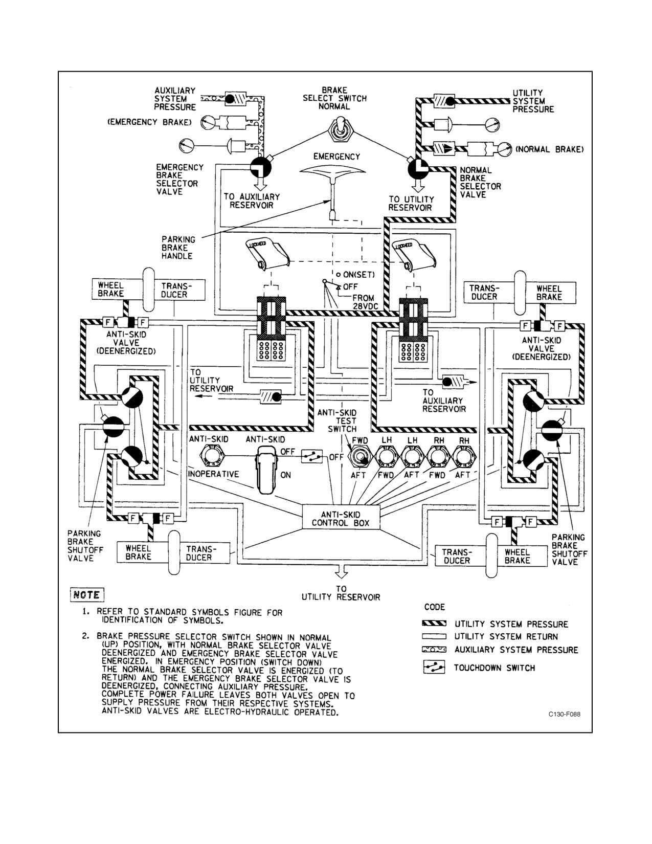
The main landing gear brake system (see Figure 2-59) utilizes a hydraulically operated, multiple-disk brake on each
of the four main landing gear wheels. The nose landing gear wheels do not havebrakes. Thebrakes normally operate
from utility hydraulic system pressure, with an alternate supply available through the auxiliary hydraulic system. If
electrical power is off, the system with the highest pressure will supply pressure to operate the brakes. Fluid for the
normal brake system flows through a brake pressure selector valve to the right- and left-hand brake control valves.
When the fluid leaves the brake control valves, it flows through the dual antiskid valves, brake fuses, and shuttle
valves to the brakes. Each brake is controlled by a brake control valve, an antiskid valve, and brake shuttle valve.
The auxiliary system supply flows through the emergency brake pressure selector valve. When the emergency brake
system is actuated, fluid is directed to the brake control valves, then through hydraulic fuses and shuttle valves
directly to the brakes, bypassing the antiskid valves. Utility or auxiliary system pressure is selected by manually
positioning a brake pressure selector switch. Auxiliary system handpump pressure can also be used for brake
operation in towing operations when utility or electrically driven auxiliary system pressure is not available. The
accumulator in the auxiliary system will provide only one brake application; therefore, the brake pedals should be
depressed firmly and held when braking is required. System pressure will not build up when the brake pedals are
pumped on and off while the auxiliary system handpump is being operated.
ORIGINAL
2-112
01-75GAL-1
Figure 2-56. Nose Landing Gear Ground Pin
2-113
ORIGINAL
01-75GAL-1
Figure 2-57. Nosegear Uplock Emergency Release Handle
Figure 2-58. Steering Wheel
ORIGINAL
2-114
01-75GAL-1
Figure 2-59. Main Landing Gear Brake System
2-115
ORIGINAL
01-75GAL-1
2.12.1 Brake System Accumulators
Air-charged accumulators are used in both the normal brake and the emergency brake. Hydraulic systems provide
a reserve source of hydraulic pressure in the event of certain system failures and absorb pressure surges. The
accumulator in the normal brake system is capable of supplying pressure for about two brake applications. The
accumulator in the emergency brake system, having one-half the capacity of the normal brake system accumulator,
is capable of supplying pressure for about one additional brake application.
2.12.2 Brake Antiskid Provisions
Skidding because of excessive brake application during normal brake operation is controlled by an antiskid system,
maintaining maximum braking without excessive wheel skid (refer to paragraph 2.13).
2.12.3 Brake System Controls and Indicators
2.12.3.1 Brake Pedals
Actuation of the brakes is through application of toe pressure on the rudder pedals at either the pilot or copilot station.
The amount of braking force is proportional to the force applied to the brake pedals. The right pedals actuate the
right-hand brakes, and the left pedals actuate the left-hand brakes. This arrangement allows directional control of the
aircraft through differential braking. When the antiskid system is energized, application of brake pressure before
touchdown is prevented by a locked-wheel signal through the touchdown relays.
2.12.3.2 Brake Pressure Selector Switch
Atwo-position (NORMAL, EMERGENCY)BRAKE SELECT toggleswitch located on thehydraulic control panel
(see Figure 2-45) provides selection of either normal or auxiliary hydraulic pressure for applying the brakes. The
NORMAL position will supply utility hydraulic pressure to the brakes, and the EMERGENCY position will supply
auxiliary hydraulic pressure to the brakes. With the BRAKE SELECT switch in the NORMAL position and the
landing gear lever in the UP position, the normal brake selector valve is energized closed by 28-Vdc power from the
essential dc bus through the LANDING GEAR CONTROL circuit breaker on the copilot lower circuit breaker
panel.
When the landing gear lever is placed to DN, the normal brake selector is deenergized to open. With the BRAKE
SELECT switch in theNORMAL position, the emergency brake selectorvalve is energized closed by 28-Vdcpower
from the essential dc bus, received through the EMER BRAKE VALVE circuit breaker located on the copilot lower
circuit breaker panel. With the BRAKE SELECT switch in the EMERGENCY position, the normal brake selector
valve is energized closed by 28-Vdc power from the main dc bus through the ANTI-SKID CONTROL circuit breaker
on the copilot lower circuit breaker panel. When the switch is in the EMERGENCY position, the antiskid system
is inoperative. Both the normal and emergency brake selector valves are deenergized open.
Note
In case of dc electrical power failure, the deenergized valves admit either
utility or auxiliary hydraulic system pressures to the brake system. The
shuttle valves are positioned by the system supplying the greater pressure.
Hydraulic fuses are provided in the normal and emergency systems for each of the main landing gear brakes. If a
failure is experienced in the hydraulic line between the fuse and the brake, the fuse will allow approximately 10 cubic
inches offluid to bleed out ofthesystem and then close, thereby retaining theremaining hydraulicfluid foroperation
of the other three brakes.
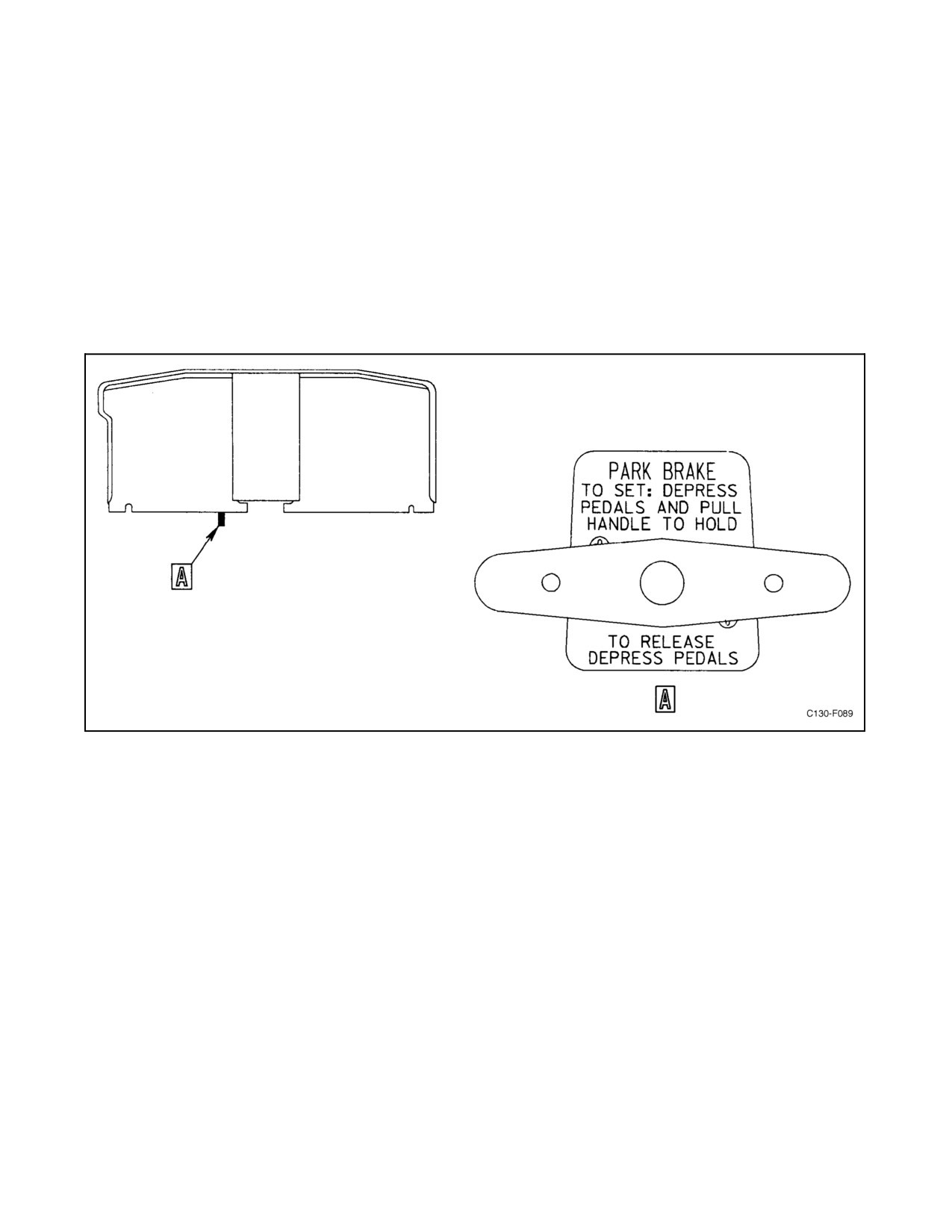
2.12.3.3 Parking Brake Handle
A parking brake handle (see Figure 2-60) is located in front of the pilot seat, to the right of the pilot right footrest.
The control handle is mounted on a panel support and is attached to a flexible cable. This cable pulls a pawl into a
detent in the brake control lever to lock the pedals in a depressed (brakes on) position.
ORIGINAL
2-116
01-75GAL-1
Note
When a hydraulic pump is not supplying pressure, brake pressure will
gradually decrease and eventually cause the parking brake to become
ineffective. Wheel chocks shall be used for long-term parking.
The brakes are set for parking by first fully depressing the toe section of the rudder pedals, then pulling firmly on
the parking brake control handle while letting off slowly on the brakes. The brakes are released by depressing the
toe section of the rudder pedals. When the parking brake is set with poweron theaircraft and the ANTI-SKID switch
ON, a solenoid in the antiskid valve is deenergized to block the return port of the antiskid valve. This prevents rapid
leakage and subsequent release of the pressure used for setting the parking brake. With power on the aircraft, the
ANTI-SKID INOPERATIVE light will illuminate when the parking brake is set.
Figure 2-60. Parking Brake Handle
2.12.3.4 Brake Pressure Indicators
Two brakepressureindicators arelocated on thehydrauliccontrol panel (seeFigure2-45)at thebottom ofthecopilot
instrument panel. The indicators, which are connected to pressure transmitters in the pressure lines of the brake
control system, register the hydraulic pressure available in the brake sections of both the utility and auxiliary
hydraulic systems. The indicators are energized by 26-Vac power from the instrument transformers through the
BRAKE EMER and NORMAL BRAKE fuses on the pilot lower circuit breaker panel.
2.13
ANTISKID SYSTEM
The antiskid system, an integral part of the main landing gear brake system (see Figure 2-59), consists of four
wheel-speed transducers, an electrical control box, and two dual-type electrohydraulic servobrake pressure control
(antiskid) valves.
2.13.1 Antiskid System Operation
The system prevents skidding of wheels when too much brake pressure is in effect during aircraft decelerations. This
is done through a brake-releasing system, controlled by signals from wheel-speed transducers.
2-117
ORIGINAL
01-75GAL-1
2.13.2 Skid-Detector Operation
The wheel-speed transducer unit mounted in the axle of each main landing gear wheel applies controls to the braking
operation through the antiskid valves when the landing gear wheel begins to approach a skid condition. One dual
antiskid valve is located above the booster hydraulic reservoir on the forward right-hand wheelwell wall, and the other
is on the left-hand hydraulic panel forward of the utility hydraulic reservoir. Each wheel-speed transducer unit
contains a frequency generator that senses wheel rotational speed and wheel speed change. The transducers form part
of an electrical circuit that prevents landing with brakes on and that releases brakes in case of a locked condition.
Should the wheel speed decrease rapidly, indicating approach of a skid condition, the control box sends an electric
impulse to an antiskid valve which reduces pressure to the affected brake below the pressure that caused sensing of
the skid. As subsequent skids are sensed, they are electronically compared with the amount the hydraulic pressure
had to be reduced to eliminate earlier skids detected. This comparison results in a more accurate determination of
the minimum reduction in brake pressure required to eliminate the skid. The skid detection and control function is
independent for each wheel. The skid control system will not function when the brake system is operating from the
auxiliary hydraulic system or when the parking brakes are set.
2.13.3 Antiskid System Controls and Indicators
2.13.3.1 ANTI-SKID Switch
An ANTI-SKID two-position (OFF, ON) guarded toggle switch is located on the hydraulic control panel (see Figure
2-45). It is energized by 28-Vdc power from the main dc bus through the ANTI-SKID CONTROL circuit breaker
on the copilot lower circuit breaker panel. When the switch is in the ON position and the ANTI-SKID
INOPERATIVE light is extinguished, the antiskid system is operative and becomes an integral part of the wheelbrake
system. When the switch is in the OFF position, the landing gear brake system operates as a standard brake system.
2.13.3.2 ANTI-SKID INOPERATIVE Light
An ANTI-SKID INOPERATIVE (press-to-test) light, located on the hydraulic control panel (see Figure 2-45) glows
whenever the antiskid system is not operating as an integral part of the landing gear brake system. It warns the pilot
that skid protection has been lost on all wheels. This light will also illuminate when the parking brake is set. This
system is energized by 28-Vdc power from the main dc bus through the ANTI-SKID FAIL-SAFE LIGHT circuit
breaker on the copilot lower circuit breaker panel.
2.13.3.3 ANTI-SKID TEST Switch and Indicator Lights
An antiskid test panel (seeFigure 2-44)is located on theaft end oftheoverhead controlpanel. Thetest panelcontains
a three-position (FWD, OFF and AFT) ANTI-SKID TEST switch and four green indicator lights identified as LEFT
FWD, RIGHT FWD, LEFT AFT, and RIGHT AFT. When the test switch is placed in the FWD position, 26-volt,
400-Hz power obtained from the ac instrument and engine fuel control bus (through the ANTI-SKID TEST 26-Vac
circuit breaker, located on the pilot lower circuit breaker panel) is applied to the antiskid control box to simulate a
skid condition. When the switch is released to the OFF position, the FWD indicator lights should illuminate
momentarily. Illumination of the lights indicates that the antiskid control box would have properly responded to an
actual skid. When the test switch is placed in the AFT position and released, the AFT indicator lights should
illuminate momentarily.
2.14
CARGO DOOR AND RAMP SYSTEM
The cargo door and ramp, providing entry for wheeled vehicles and large loads, are used also for egress during aerial
delivery system operations. Normal operation of the door and ramp is achieved by hydraulic pressure supplied
through the auxiliary hydraulic system (see Figure 2-61); alternatively, the operating pressure can be supplied in an
emergency by a handpump connected to the reservoir of the auxiliary hydraulic system. Control of the system is
accomplished electrically or manually from a ramp control panel located aft of the left paratroop door, electrically
ORIGINAL
2-118
01-75GAL-1
from the auxiliary ramp control panel, or electrically from the airdrop system control panel (see Figure 2-62) on the
flight control pedestal. The airdrop system control panel, however, cannot be operated while the aircraft is on the
ground. The cargo door actuating system incorporates an independent hydraulic snubber to prevent the door from
being rapidly driven from the uplock during closing. The snubber quantity indicator and servicing instructions are
on the snubber cylinder.
2.14.1 Cargo Door and Ramp Controls
2.14.1.1 Door Control Switch
A door control switch is located on the ramp control panel (see Figure 2-62) aft of the left paratroop door. This
three-position (CLOSE, unmarked neutral, OPEN) toggle switch, spring loaded to the neutral position, controls the
normal ground operation of the cargo door. When the switch is held in the OPEN position, the cargo door control
valve is energized by 28-Vdc power through the RAMP & ADS CONT circuit breaker on the aft fuselage junction
box. The control valve directs hydraulic pressure to the open side of the cargo door actuating cylinder to unlock the
downlocks and open the cargo door. As the door reaches the open position, it engages the cargo door uplock assembly,
which latches mechanically. When the switch is held in the CLOSE position, hydraulic pressure is directed to the
cargo door uplock cylinder, which unlatches the uplock. The control valve also directs pressure to the closed side
of the cargo door actuating cylinder, and the door swings downward to the closed position and locks in place. When
the switch is released, the cargo door circuit deenergizes and the valves return to a neutral position.
2.14.1.2 Ramp Control Switch
A ramp control switch is located on the ramp control panel (see Figure 2-62) aft of the left paratroop door. This
three-position (RAISE, unmarked neutral, LOWER) toggle switch, spring loaded to the neutral position, controls
the normal ground operation of the ramp. When the switch is held in the LOWER position, the ramp control valve
is energized by 28-Vdc power through the RAMP & ADS CONT circuit breaker on the aft fuselage junction box.
The control valve directs hydraulic pressure to the up side of the ramp actuating cylinders and to the unlock side of
the ramp uplock cylinder, until the uplock is unlatched. The hydraulic pressure then is directed to the down side of
therampactuatingcylinderstolowertheramp.When theswitch isheld intheRAISEposition, theramp controlvalve
directs hydraulic pressure to the up side of the ramp actuating cylinders to raise the ramp. At the same time, pressure
is directed into the unlock side of the ramp uplock cylinder to unlock the ramp uplock until the ramp is raised into
the normal raised position. Pressure then is directed to the lock side of the ramp uplock cylinder to lock the ramp in
place. When the switch is released, the ramp circuit is deenergized, and the valves return to a neutral position.
2.14.1.3 Ramp Manual Control Knob
The ramp manual control knob (see Figure 2-62) is a rotary selector located above the ramp control panel. It may
be set to any of six numbered positions: DOWN -1 (unlock) and 2 (lower); 3N (neutral); UP -4 (raise) and 5 (lock);
and 6N (neutral). These settings of the knob manually position the system valves that control flow, supplied either
from the handpump or the auxiliary hydraulic system electric pump, to and from the ramp actuating and ramp uplock
cylinders.
CAUTION
When operating the ramp manually, ensure the ramp control knob is rotated
in a clockwise direction to prevent adverse lock sequence action.
When the knob is placed in position 1, hydraulic pressure is directed to the up side of the ramp extension cylinders
to raise the ramp off the uplocks, then pressure is directed to the unlock side of the ramp uplock cylinder to unlatch
the ramp uplocks. When the knob is moved to position 2, pressure is directed to the down side of the ramp actuating
2-119
ORIGINAL
01-75GAL-1
cylinders to lower the ramp. Position 3N on the selector knob is a neutral position. When the knob is moved to position
4, pressure is directed to the up side of the ramp actuating cylinders to raise the ramp. Position 5 directs pressure to
the lock side of the ramp uplock cylinder to lock the ramp in the closed position. Position 6N on the selector knob
is a neutral position; the knob should be left in this position when the ramp is closed and not being operated.
2.14.1.4 Cargo Door Manual Control Valve Handle
The cargo door manual control valve handle (see Figure 2-62) has three positions: OPEN, NEUT (center), and
CLOSE. When the handle is set to OPEN, the valve directs hydraulic pressure, either from the handpump or the
auxiliary hydraulic system electrically-driven pump, to the up side of the door actuating cylinder, thus unlocking the
downlocks and opening the door. On reaching the fully open position, the door is secured by a spring-loaded uplock.
When the handle is set to CLOSE, hydraulic pressure, either from the handpump or the auxiliary hydraulic system
electrically driven pump, is directed by the valve to the uplock cylinder to release the uplock engagement of the door
and to the down side of the actuating cylinder to close the door. Setting the handle in the NEUT (center) position shuts
off hydraulic pressure to the door operating system and leaves the control valve in a position from which it can be
actuated by selection at the cargo door control switch.
CAUTION
The cargo door manual control valve handle and the ramp manual control
knob must always be placed at the NEUT/6N position when manual
operation is not desired; otherwise, the door and ramp may open or close
when the auxiliary hydraulic pump is turned on.
2.14.1.5 System Handpump
Theauxiliarysystemhandpump(seeFigure2-62), justbelow theramp controlpanel, providesan alternativepressure
source to operate the cargo door and ramp in an emergency. The handpump can also be used to provide alternative
pressure to operate the nosegear for emergency extension and the emergency brakes.
2.14.1.6 Release
The cargo door uplock release (see Figure 2-62) is a mechanical lever to release the spring-loaded uplock. The lever,
connected by a system of cables and pulleys to the door uplock mechanism, is mounted on the outboard side of the
tubularstrut aft oftheleft paratroop door. Thelever,normally stowedin thevertical (locked)position, pivotsforward
and downward when pulled to release the door uplock mechanism. The lever resumes the vertical position when it
is released.
2.14.1.7 Auxiliary Hydraulic System Pump Switch
A two-position (PUMP ON, OFF) toggle switch, located on the ramp control panel, is used to turn the auxiliary
hydraulic system electrically driven pump on and off. If this switch is in the ON position, the auxiliary pump cannot
be turned off from the cockpit. When the switch is depressed and held, the auxiliary hydraulic pump provides
hydraulic pressure for operation of the ramp and door.
2.14.2 Cargo Door and Ramp Indicators
Indicators are provided to show auxiliary hydraulic system pressure, engagement of the cargo door in the uplock
mechanism, and open positions of the ramp and door for airdrop operations. The pressure indicators are on the ramp
control panel and the hydraulic control panel. The door and ramp position indicators are lights on the ramp control
panel and the ADS control panel. The uplock engagement indicator is a mechanically operated metal flag, illuminated
by a red inspection light, attached to the cargo door uplock mechanism. Circuits are provided to illuminate door
warning lights located on a panel aft of the right paratroop door, and a master warning light on the pilot instrument
panel.
ORIGINAL
2-120
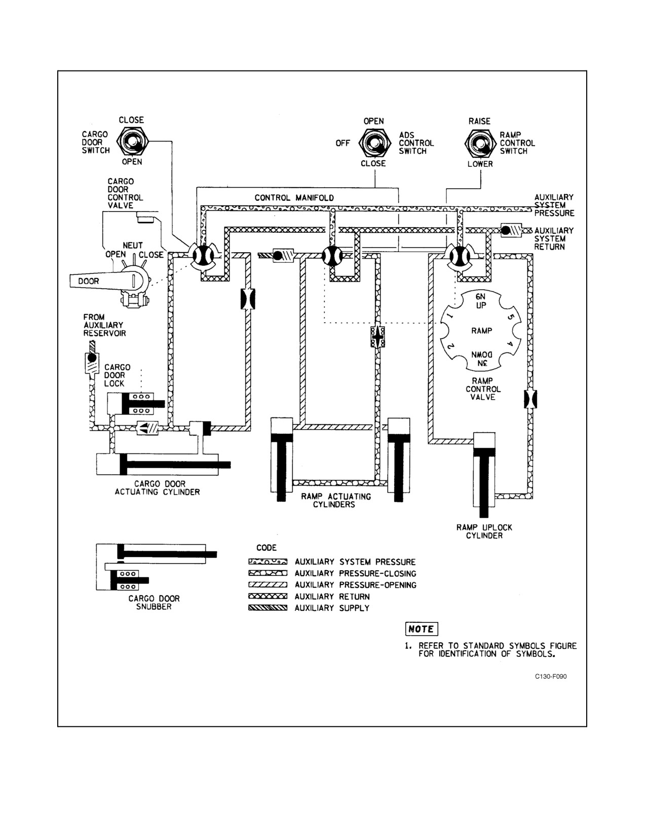
01-75GAL-1
Figure 2-61. Cargo Door and Ramp Hydraulic System
2-121
ORIGINAL
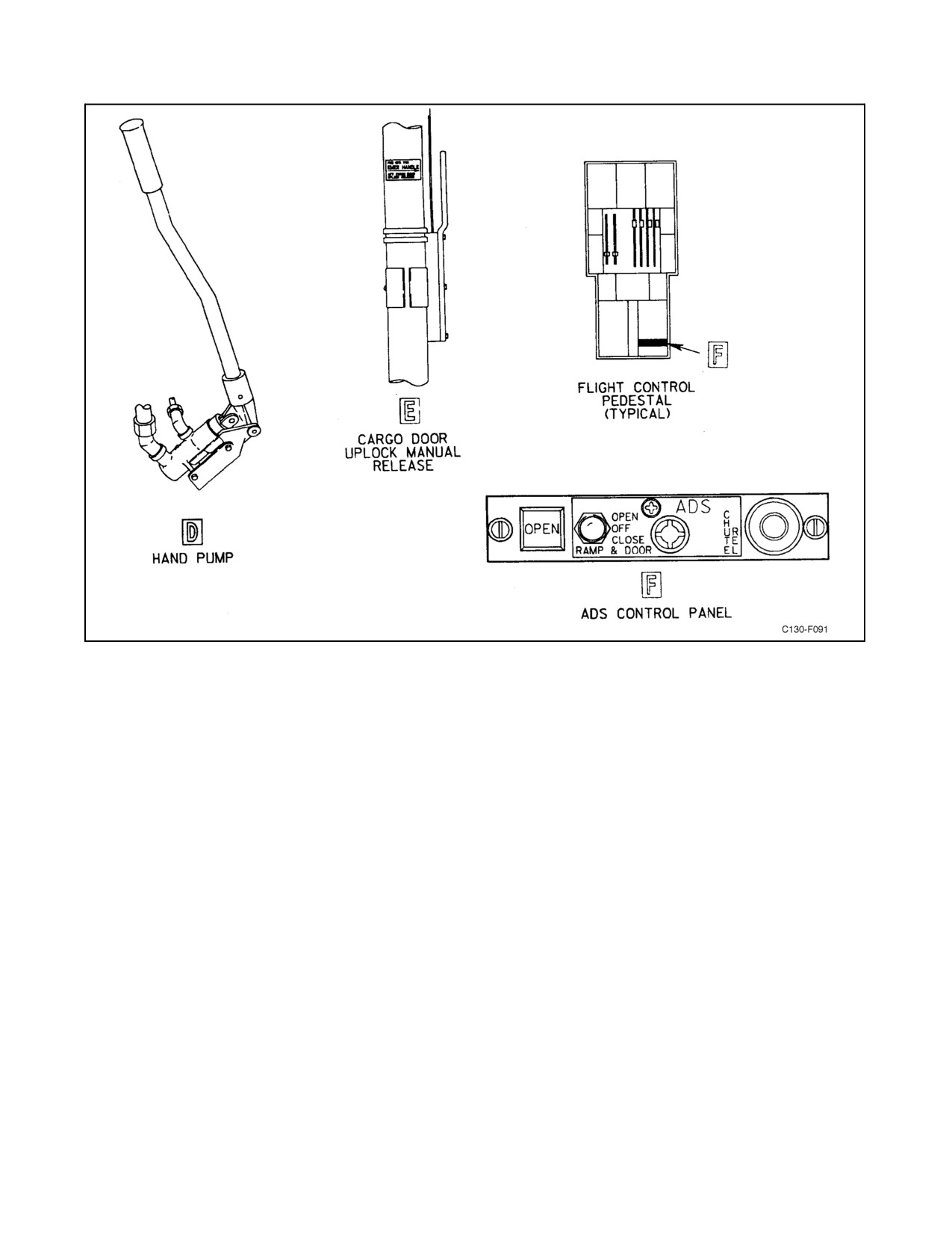
01-75GAL-1
Figure 2-62. Cargo Door and Ramp Controls (Sheet 1 of 3)
2.14.2.1 Pressure Gauges
Thepressuregauges, onemounted on theramp control panel (seeFigure2-62)and oneon thehydrauliccontrol panel
(see Figure 2-45), register the pressure of the auxiliary hydraulic system. The gauge located on the ramp control panel
is direct indicating, while the one on the hydraulic control panel is electrically operated. The gauge on the ramp
control panel, although registering the system pressure supplied either by the electric-driven pump or the handpump,
is intended primarily for use during handpump operations and is identified as HAND PUMP PRESS on thepanel.
2.14.2.2 RAMP POSITION AIR DROP Light
A press-to-test RAMP POSITION AIR DROP light is located on the ramp control panel (see Figure 2-62) aft of the
left paratroop door. The light illuminates when the ramp is in the airdrop position and the cargo door is open and
locked. It is energized by 28-Vdc power through the RAMP & ADS CONT circuit breaker on the aft fuselage junction
box. This press-to-test light will not illuminate when pressed unless the aft anchor arm supports are in the stowed
(raised) position.
2.14.2.3 Ramp and Door Open Light
A press-to-test ramp and door open light is located on the ADS control panel (see Figure 2-62) on the flight control
pedestal. The light illuminates when the aft cargo door is fully open and locked and the ramp is lowered to the airdrop
position. This light is energized through the RAMP & ADS CONT circuit breaker on the aft fuselage junction box.
ORIGINAL
2-122
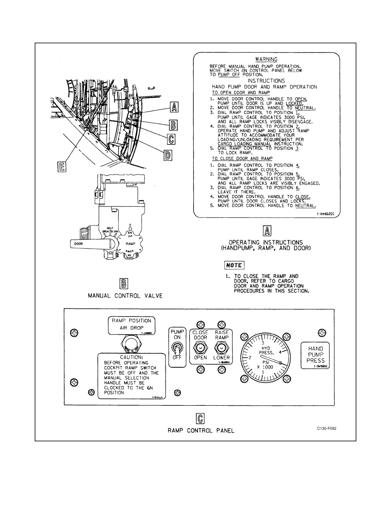
01-75GAL-1
Figure 2-62. Cargo Door and Ramp Controls (Sheet 2)
2-123
ORIGINAL
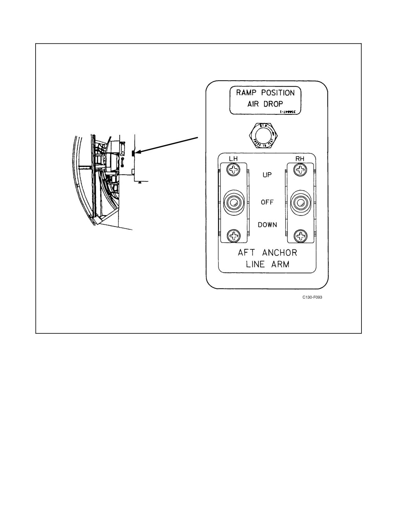
01-75GAL-1
Figure 2-62. Cargo Door and Ramp Controls (Sheet 3)
2.14.2.4 Cargo Door Uplock Indicator
The cargo door uplock indicator is a black metal flag with a yellow circle. The flag is attached to the uplock
mechanism so that when the cargo door is open and locked in the up position, the flag will swing down to provide
a visual indication. The flag is spring loaded to return to the masked position whenever the cargo door is not locked
in the up position. A red inspection light is installed to illuminate the flag indicator. This light is controlled by a
two-position (ON, OFF) toggle switch on the aft fuselage junction box and another switch on the forward public
address control panel.
ORIGINAL
2-124
01-75GAL-1
2.15
BLEED-AIR SYSTEM
Thebleed-airsystem (seeFigures 2-63 and2-64)consistsofhigh-pressure,stainless steelducts andairshutoffvalves
that direct compressed air to pneumatically operated systems of the aircraft. The entire system of ducts serves as a
plenum from which air is distributed to other systems. The following pneumatic systems are served by the bleed-air
system:
1. Engine starting system.
2. Air-conditioning system.
3. Cabin pressurization system.
4. Windshield defogging system.
5. Engine air inlet scoop anti-icing system.
6. Leading edge anti-icing system.
7. Oil cooler augmentation.
Compressed air is supplied to the bleed-air system from the engines when they are running, or compressed air is
supplied from either the APU or from an external pressure source when the aircraft is on the ground and the engines
are not running. The normal procedure is to supply air from the auxiliary power unit or from an external source until
the first engine is started; then, engine bleed air is used. The main bleed-air manifold extends across the leading edge
of the wing. Air enters the main manifold through five ports, four from the engines and one from the APU or an
external source.
Branch ducts connected to the main manifold distribute air for operating the following:
1. Air-conditioning system.
2. Leading edge anti-icing system.
Each engine bleed-air manifold is connected to the main manifold just aft of the firewall by an engine bleed-air
pressure regulator valve. Branch ducts connected to the engine manifold forward of the firewall distribute air for
operating the following:
1. Engine starting system.
2. Nacelle preheat system (if installed).
3. Engine air inlet scoop anti-icing.
4. Oil cooler augmentation system.
Check valves installed in each engine bleed-air manifold, the APU supply duct, and the external pressure supply duct
prevent reverse flow when any of these sources of supply are inoperative.
2.15.1 Engine Bleed-Air Pressure Regulator Controls
Four ENGINE BLEED-AIR switches on the anti-icing systems control panel (see Figure 2-73) control the opening,
closing, and regulation of the engine bleed-air pressure regulators. The control circuit for each regulator is connected
through a switch actuated by the fire emergency control handle. When the fire emergency control handle is pulled,
the engine bleed air regulator is closed and the normal switch control is rendered inoperative. The 28-Vdc power for
operation of each regulator is supplied from the essential dc bus through the BLEED AIR FIRE SHUTOFF circuit
breaker on the copilot side circuit breaker panel.
2.15.2 Bleed-Air Pressure Gauge
A direct-reading pressure gauge (see Figure 2-64), located on the right-hand circuit breaker box above the copilot
upper circuit breaker panel, indicates main bleed-air manifold pressure in pounds per square inch. The gauge is used
to check the pressure of the bleed-air supply and the operation of the pneumatic systems.
2-125
ORIGINAL
01-75GAL-1
Note
When the flight station air-conditioning system is on, the bleed-air pressure
gauge reads 6 psi lower than the actual pressure in the bleed-air manifold.
2.15.3 BLEED AIR DIVIDER VALVE Switch
The BLEED AIR DIVIDER VALVE switch is a guarded, two-position (CLOSED, NORMAL) switch located on
the anti-icing and deicing control panel (see Figure2-73). Theswitch controls a shutoffvalve located in thebleed-air
ductbetween theoutlets goingto theflight deckand cargocompartment air-conditioningunits. Thevalveisnormally
in the open position. Closing the valve isolates the bleed-air supply so that one air-conditioning unit can continue
to operate in case of a bleed-air duct failure. Electrical power for the valve is supplied from the 28-volt essential dc
bus through the BLEED AIR DIVIDER VALVE circuit breaker on the copilot lower circuit breaker panel.
2.16
AIR-CONDITIONING SYSTEMS
The aircraft is equipped with two independently operating air-conditioning systems (see Figure 2-65), one for the
flight station and the other for the cargo compartment. Both are operated by bleed air supplied from the engine
compressors, or they may be operated on the ground by air supplied from the APU or by the attachment of an external
ground compressor unit. Each system keeps the air at a required temperature and removes excess moisture before
sending the air through a system of ducts into the respective flight station or cargo compartment. The principal
components of each system comprise a venturi-type airflow regulator, an electrical temperature control system, a
water separator, a refrigeration unit, auxiliary vent valve and controls, and distribution ducts. The flight station
system includes a windshield defogging system and controls; the cargo compartment system includes arecirculating
fan that can be operated independently or in conjunction with a separate heating system for the cargo compartment
floor. Both systems are the same except for the distribution duct arrangement. Electrical power for the
air-conditioning system control components is supplied through circuit breakers on the copilot lower circuit breaker
panel. Air-conditioning on the ground can be accomplished by connecting an external unit to the cooling airscoops
with airscoop adapters, and using the aircraft ducting.
2.16.1 Airflow Regulation
The amount of air flowing through each air-conditioning system is controlled by the venturi-type airflow regulator
inthesystem.Eachregulatoriscontrolled byatwo-positionswitch locatedon theair-conditioning andpressurization
control panel, for two operating conditions: during flight and during the shutoff condition when neither
air-conditioning nor pressurization is required (see Figure 2-66). The flight station and cargo compartment airflow
regulators compensate for altitude. The standard day sea level airflow from each regulator is 70 pounds per minute,
and, at 35,000 feet, the airflow is 33 pounds per minute. The underfloor heating system provides an additional 34
pounds per minute airflow at 35,000 feet. The regulators operate when the AIR CONDITIONING master switch is
in NO PRESS, AUTO PRESS, or MAN PRESS. They are utilized as shutoff valves when the AIR CONDITIONING
master switch is in OFF or AUX VENT. They also shut off airflow when the EMERGENCY DEPRESSURIZATION
switch is placed to EMERGENCY DEPRESSURIZATION. Switches are installed to protect the refrigeration unit
during adverse operating conditions; the flight station and cargo compartment refrigeration unit airflow regulators
will shut off automatically if excessive pressure occurs in the water separator, caused by icing because of failure of
thelow-temperaturecontrol. A changeof thetemperature control setting forthe affected system will tend to alleviate
the above cited condition and allow reset of the affected unit. To reset the unit, change to a warmer temperature
setting, wait 3 minutes or longer, place the AIR CONDITIONING master switch to OFF, and back to the original
position. After the air-conditioning unit operation stabilizes, select temperature as desired. Electrical power for
control of the airflow regulators is supplied from the 28-volt essential dc bus through the CABIN PRESS AUX VENT
circuit breaker on the copilot lower circuit breaker panel.
ORIGINAL
2-126
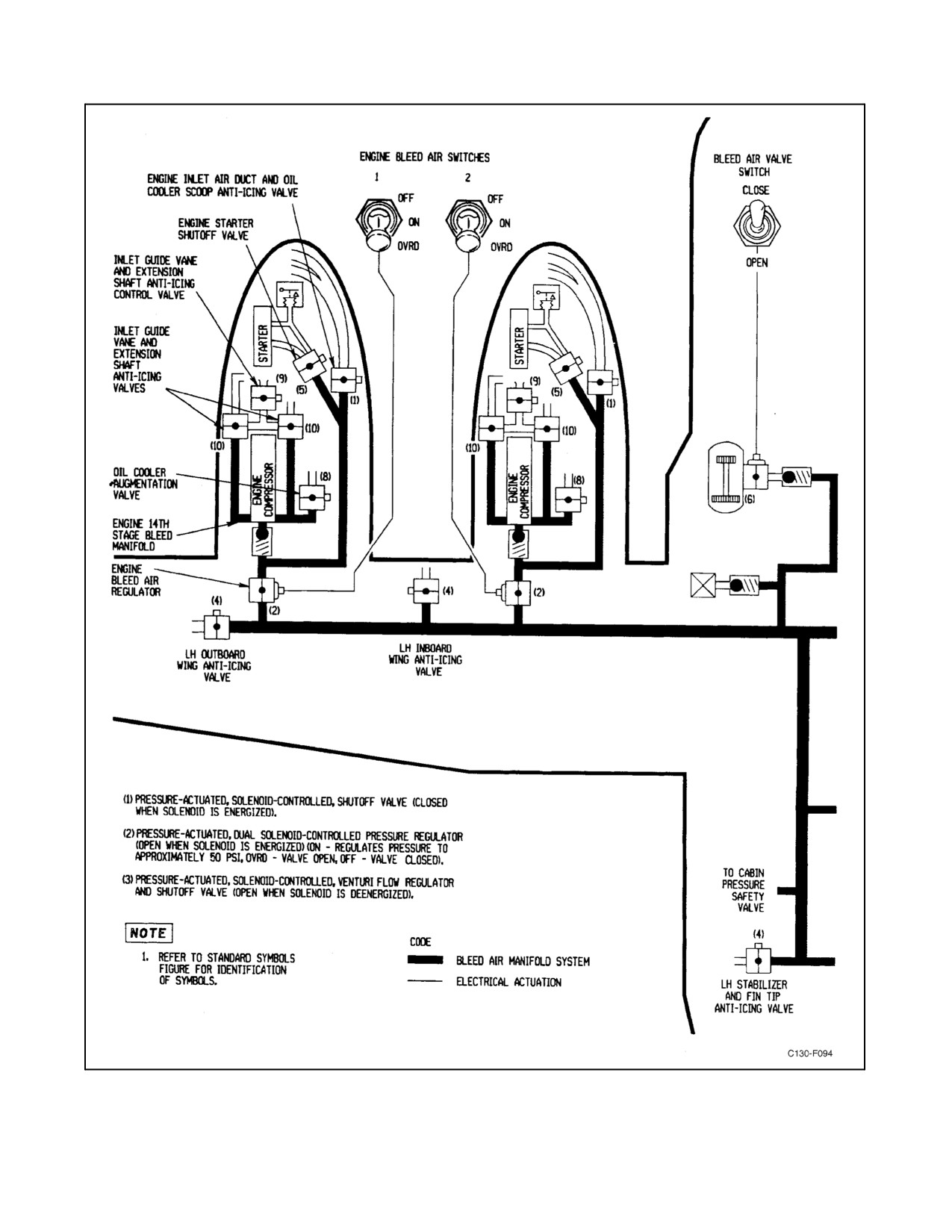
01-75GAL-1
Figure 2-63. Bleed-Air System (Sheet 1 of 2)
2-127
ORIGINAL
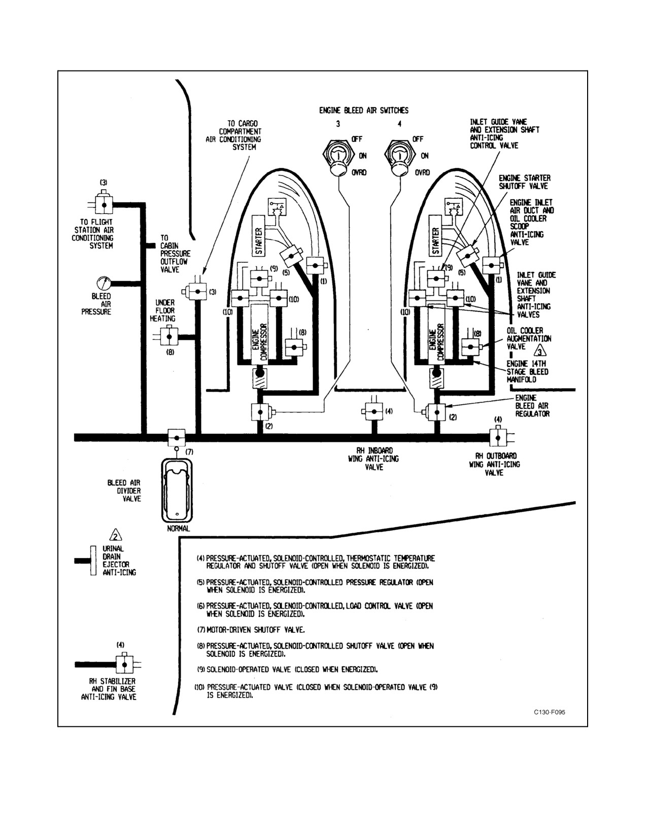
01-75GAL-1
Figure 2-63. Bleed-Air System (Sheet 2)
ORIGINAL
2-128
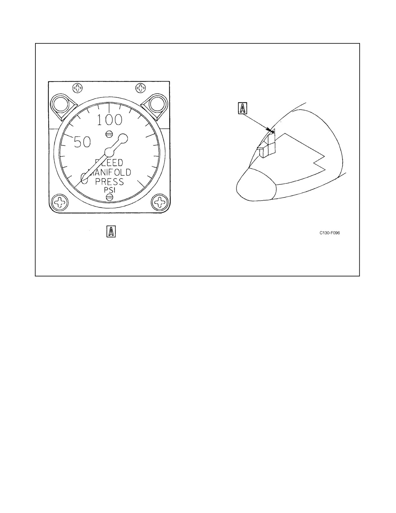
01-75GAL-1
Figure 2-64. Bleed-Air Pressure Gauge
2.16.2 Air Temperature Control
The temperature control system for each air-conditioning system utilizes a single valve to direct hot bleed air from
downstream of the airflow regulator to a point downstream of the water separator, thus bypassing the refrigeration
unit.Thetemperaturecontrolvalvesareelectricallyoperatedbyeitherautomaticormanualcontrol.Duringautomatic
operation, a desired temperature is selected and the system positions the valve intermittently until the selected
temperature is sensed by a sensor. Approximately 5 minutes are required for the valve to travel from one extreme
positiontotheotherduringautomaticoperation.Ahigh-limitsensorpreventsexcessivelyhighoutput airtemperature
during automatic operation of the temperature control valve. When the valve is controlled manually, it will travel
from full cold to full hot in approximately 4 minutes, and from full hot to full cold in approximately 35 seconds.
Electrical power for temperature control is supplied from the 28-volt essential dc bus through the TEMP CONTROL
FLIGHT DECK and CARGO COMPT circuit breakers on the copilot lower circuit breaker panel.
2.16.3 Refrigeration
Part or all of the bleed air flowing to each air-conditioning system flows through the heat exchanger and turbine. The
first stage of cooling is provided by heat transfer in the air-to-air heat exchanger. During flight, ambient air under
ram pressure passes through the heat exchanger and provides the cooling medium to initially reduce the bleed-air
temperature. Some of this partly cooled bleed air is routed from downstream of the heat exchanger back into the
refrigeration unit through an aspirator-type nozzle. Under humid conditions, drain water from the water separator
flows into the nozzle and is sprayed on the heat exchanger to obtain maximum cooling. Air that enters the turbine
2-129
ORIGINAL
01-75GAL-1
after being partly cooled in the heat exchanger is cooled further by expending its energy to drive the turbine, which
is loaded by the cooling air fan. In loading the turbine, the fan also augments the cooling airflow through the heat
exchanger. During ground operation, with no ram air provided, the fan will draw air through the heat exchanger
whenever the turbine is rotating to ensure first-stage cooling of the bleed air. The cargo compartment refrigeration
unit draws supplemental ambient air from the air-conditioning equipment compartment through a check valve into
thecoolingairplenum.Thetemperatureoftheoutputairdependsonwhatportionofthetotalairflowisroutedthrough
the heat exchanger and turbine.
2.16.4 Water Separator
The water separator will remove from 70 to 85 percent of the moisture that condenses when air is refrigerated.
Moisture remaining in the air maintains a comfortable humidity level in the compartments. The water separator
contains a cone-shaped bag and a drain. The bag causes fog in the air to form into water droplets that are swirled and
thrown against the shell of the separator; they then collect and run down to the drain. If the bag in the water separator
becomes clogged, a pressure-sensitive relief valve at the tip of the bag opens to bypass the airflow. To prevent
separator icing, a low-limit control valve, sensor, and control box maintain water separator exit temperature at 37
or ±3 _F.
Water separators do not remove all moisture from conditioned air. When CARGO COMPT and/or FLT STA
temperature control selectors on the air-conditioning control panel are moved all the way over to COOL, a
considerable amount of fog may enter the compartments from the diffusers (see Figure 2-66). Evaporation of fog
increases the cooling effect of the air, and the moisture provides a comfortable humidity level in the compartments.
Output of fog normally decreases as the selectors are moved toward WARM.
2.16.5 Cargo Compartment Underfloor Heating
The cargo compartment underfloor heating is controlled by the UNDERFLOOR HEATING heat switch on the
air-conditioning and pressurization control panel (see Figure 2-66). This two-position (ON, OFF) toggle switch
energizes the floor heat shutoff and the floor heat temperature control valves to the underfloor heating ducts. Placing
the HEAT switch in the ON position opens the shutoff valve, and the cargo floor thermostat modulates the floorheat
temperature control valve to maintain an underfloor temperature of 75 to 85 _F. The bleed air to the underfloor ducts
passes through a double jet pump to ensure circulation of the warm air. An overhead duct recirculating fan operates
when the underfloor heat switch is turned ON. This fan ensures proper circulation of the air entering the cargo
compartment from the overhead ducts.
2.16.6 Auxiliary Ventilation
The auxiliary ventilation provision in each system consists of a valve connecting the heat exchanger cooling air inlet
to theconditionedairdistributionducts. Whenthevalveis opened,most oftheairentering thecooling airscoopflows
directly into the distribution ducts. In flight, the air thus admitted to the aircraft is ambient air under ram pressure.
On the ground, adapters can be attached to the cooling airscoops so that air from an external air conditioner can be
supplied for ventilation. Collapse of the air-conditioning low pressure ducts is prevented by a check valve and the
duct arrangement. The power for the auxiliary vent valves is supplied from the main dc bus through the AIR PRESS
& FLOW SHUTOFF VALVES CARGO COMPT and FLIGHT DECK circuit breakers on the copilot lower circuit
breaker panel.
2.16.7 Air-Conditioning System Controls and Indicators
Themain controls forthetwo air-conditioning systems arelocated on the air-conditioning and pressurization control
panel (see Figure 2-65). Other air-conditioning controls in the flight station include air delivery diverter levers on
the main instrument panel and windshield defogging outlet valve controls on the pilot and copilot side shelves. A
CARGO COMPT REFR overheat warning light is located on the anti-icing and deicing systems control panel (see
Figure 2-73).
ORIGINAL
2-130
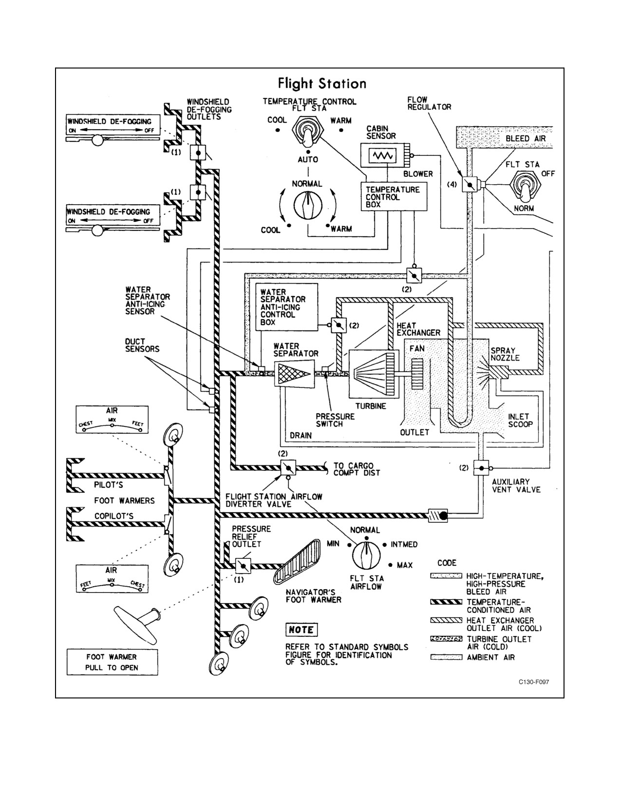
01-75GAL-1
Figure 2-65. Air-Conditioning Systems (Sheet 1 of 2)
2-131
ORIGINAL
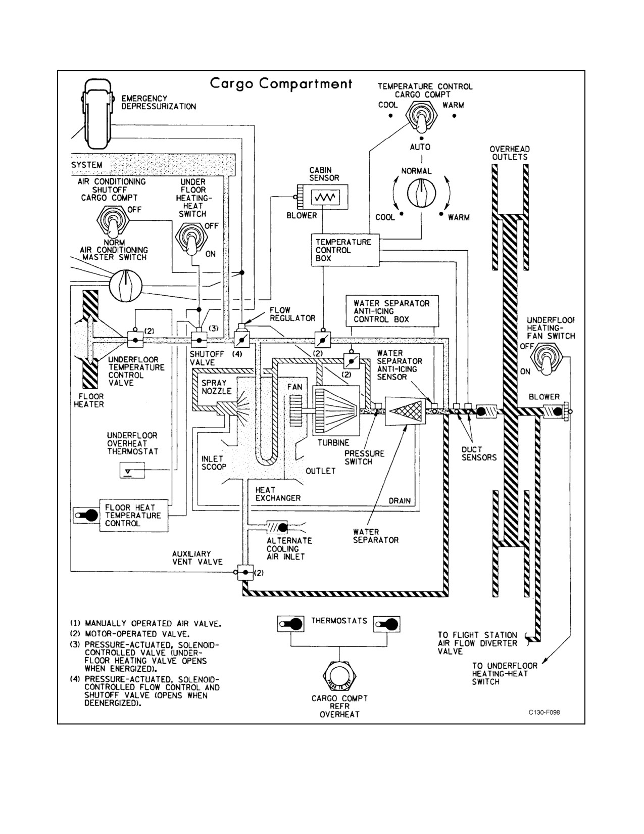
01-75GAL-1
Figure 2-65. Air-Conditioning Systems (Sheet 2)
ORIGINAL
2-132
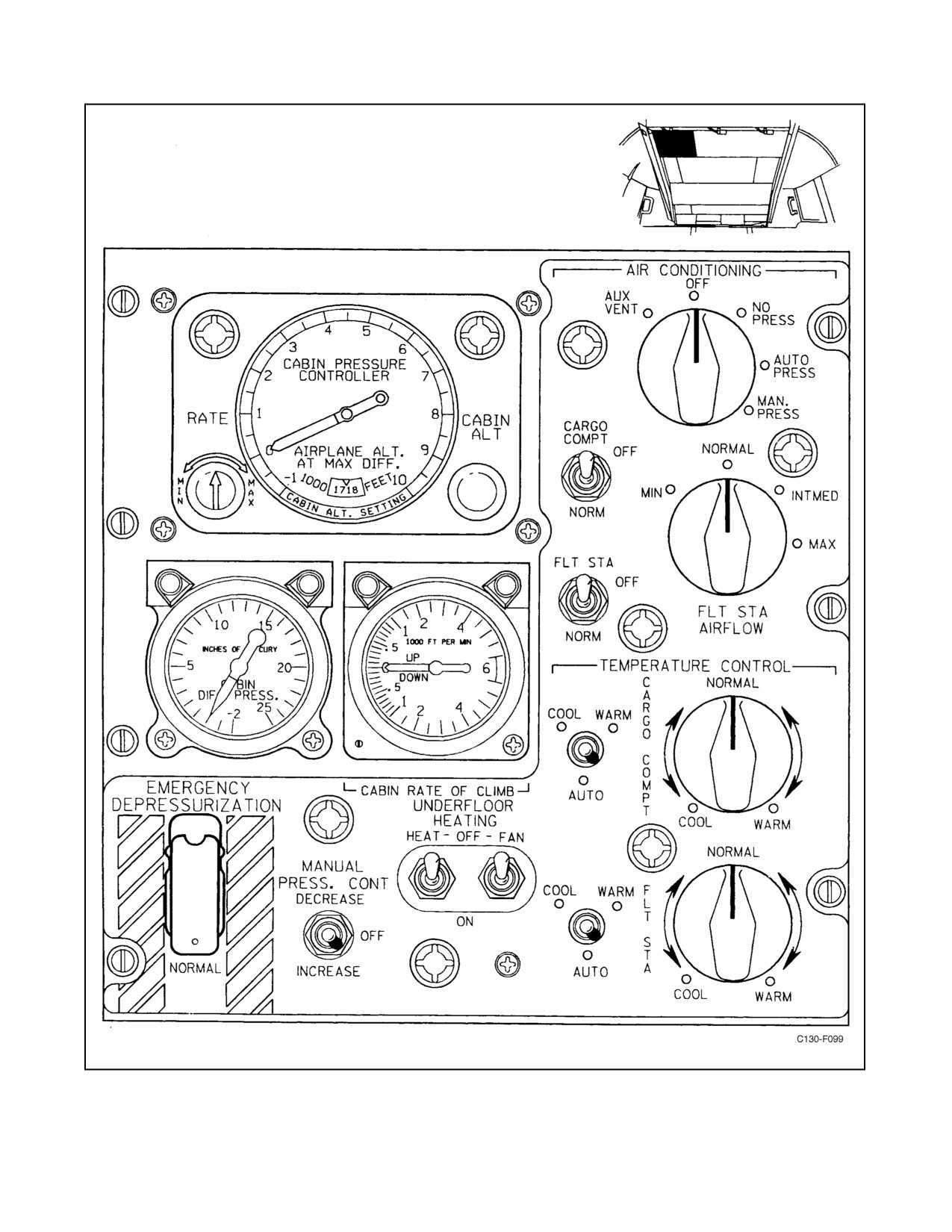
01-75GAL-1
Figure 2-66. Air-Conditioning and Pressurization Control Panel
2-133
ORIGINAL

01-75GAL-1
2.16.7.1 AIR CONDITIONING Master Switch
The AIR CONDITIONING master switch, located on the air-conditioning and pressurization control panel, is a
five-position (AUX VENT, OFF, NO PRESS, AUTO PRESS, MAN PRESS) rotary switch that selects the type of
air-conditioning and pressurization desired. The control functions of the master switch are shown in Figure 2-67.
2.16.7.2 Flight Station and Cargo Compartment Temperature Controls
The flight station and cargo compartment temperaturecontrols consist of two, four-position toggleswitches and two
rheostats on the air-conditioning and pressurization control panel (see Figure 2-66). One switch and one rheostat are
used to control temperature within the cargo compartment.
The toggle-type temperature control switches are used to select WARM, COOL, or AUTO for automatically
controlled temperature conditions, but they function only when the AIR CONDITIONING master switch is set to
a position other than OFF or AUX VENT. Each switch may be moved from the center (OFF) position upward to
COOL or WARM or downward to AUTO. With the temperature control switch set to AUTO, the temperature control
valve is controlled automatically to maintain the compartment temperature selected on the temperature rheostats.
When the switch is moved to the COOL position, the temperature control valve moves toward the extreme cold
setting; the switch must be held for approximately 35 seconds for the valve to move from the extreme hot position
to the extreme cold setting. With the switch at WARM, the valve moves toward the extreme hot setting. Complete
movement of the valve from theextreme cold setting to the extremehot position takes approximately 4 minutes. The
switch may be released at any time for either the WARM or COOL positions and is spring loaded to return to the
center (OFF) position. The temperature control valve will remain at the setting achieved when the switch is released.
Thesystem sensorblowers areactivated whenevertheAIR-CONDITIONING masterswitch is set to aposition other
than OFF or AUX VENT.
AIR CONDITIONING
MASTER SWITCH
AUX VENT
OFF
NO PRESS
AUTO PRESS
MAN PRESS
AIR FLOW
REGULATORS
Closed
Closed
Open
Open
Open
AUX VENT
Open
Closed
Closed
Closed
Closed
OUTFLOW VALVE
Open
Open
Open
Pneumatic
Manually1
modulation
modulated
SAFETY VALVE
Open
Closed
Open
Closed
Closed
TEMP CONTROLS
Power off
Power off
Power on
Power on
Power on
UNDERFLOOR HEAT
Off
Off
As selected
As selected
As selected
1 Electric actuator energized by use of manual PRESS CONT switch.
Figure 2-67. AIR CONDITIONING Master Switch Control Functions
The two temperature rheostats, located next to their respective temperature control switches, are used to select the
temperature conditions desired within the flight station and cargo compartment during automatic temperature
control. The settings of each rheostat cover a temperature range from COOL through NORMAL to WARM. Power
for the temperature control system is supplied from the essential dc bus, through FLIGHT DECK and CARGO
COMPT TEMP CONTROL circuit breakers on the copilot lower circuit breaker panel.
ORIGINAL
2-134
01-75GAL-1
CAUTION
Do not open the TEMP CONTROL circuit breakers on the copilot lower
circuit breaker panel during operation of the air-conditioning systems.
Opening these circuit breakers will disable the automatic shutoff circuit and
may result in damage to the air-conditioning equipment.
2.16.7.3 UNDERFLOOR HEATING FAN Switch
The UNDERFLOOR HEATING FAN switch is a two-position (ON, OFF) toggle switch located on the
air-conditioning and pressurization control panel (see Figure 2-66). The switch provides control of a cargo
compartment recirculating fan without operating the underfloor heating. The AIR CONDITIONING master switch
must be in a position other than OFF or AUX VENT and the UNDERFLOOR HEATING switch must be in the OFF
position before the fan switch will operate the recirculating fan. The recirculating fan will operate when the
UNDERFLOOR HEATING switch is ON regardless of the FAN switch position. The FAN switch directs 28-volt
essential dc power from the TEMP CONTROL CARGO COMPT circuit breaker on the copilot lower circuit breaker
panel to the fan relay. The relay directs 115-volt, three-phase ac power from the left-hand ac bus, through the FAN
CARGO COMPT circuit breaker on the pilot upper circuit breaker panel, to the underfloor heating recirculating fan.
2.16.7.4 Flight Station Airflow Switch
The FLT STA AIRFLOW switch is a four-position (MIN, NORMAL, INTMED, MAX) rotary switch that controls
theflightstationairflowdivertervalve(seeFigure2-66).Withbothair-conditioningsystemsoperating,theFLTSTA
AIRFLOW switch provides the following distribution from the flight station system:
1. MIN — Diverter valve full open, 70 percent to cargo compartment, 30 percent to flight station.
2. NORMAL — Diverter valve partially open, 40 percent to cargo compartment, 60 percent to flight station.
3. INTMED — Diverter valve partially open, 20 percent to cargo compartment, 80 percent to flight station.
4. MAX — Diverter valve closed, 100-percent flow to the flight station.
The flight station airflow switch may be used to provide airflow from the cargo compartment system to the flight
station when the flight station is not operating. The diverter valve receives 115-volt single-phase ac electrical power
from the essential ac bus through the AIRFLOW DIVERTER VALVE ESS AC circuit breaker located on the copilot
upper circuit breaker panel.
2.16.7.5 BLEED AIR DIVIDER VALVE Switch
The BLEED AIR DIVIDER VALVE switch, located on the anti-icing and deicing control panel, controls a shutoff
valve located in the bleed-air duct between the outlets going to the flight station and cargo compartment
air-conditioning units (see Figure 2-73).
Thevalveis normallyin theopen position.Closing thevalveisolatesthebleed-airsupply sothat oneair-conditioning
unit can continueto operatein caseofableed-airduct failure. Function oftheswitch is furtherdescribed in paragraph
2.15.
2-135
ORIGINAL
01-75GAL-1
2.16.7.6 Air Diverter Controls
A three-position (FEET, MIX, CHEST) air diverter lever at each side of the main instrument panel controls a valve
through which the conditioned airflow may be directed, by way of a louver, toward each pilot’s chest or through
floor-level outlets toward each pilot’s feet. A central position for the lever, marked MIX, divides the available airflow
between the upper and lower outlets. At the rear of the flight station, a similar valve arrangement controlled by a
foot-warmer handle on the right-hand edge of the navigator table directs the conditioned airflow through a
foot-warming louver below the navigator table or through three directable louvers disposed about the aft flight
station. Thehandle is pulled to open thefoot-warming louverand admit temperature-conditioned airto thenavigator
station, or it is pushed in to close the louver. The three individual louvers in the rear of the flight station and similar
louvers at the pilot stations may be moved manually to change the direction of the airflow.
2.16.7.7 Windshield Defogging Levers
A windshield defogging lever on either the pilot or copilot side shelf controls a valve connecting the
temperature-conditioned air duct to the windshield defogging outlets on that side of the flight station. With the lever
moved to ON, the valve is opened and the available airflow is directed to the windshield defogging outlets and away
from the flight station air distribution louvers and outlets.
Note
If the windshield defogging lever is in an intermediate position, with the
flight station airflow switch in INTMED or MAX, a loud noise may be
heard in the defogging system.
2.16.7.8 Air-Conditioning Shutoff Switches
Two shutoff switches on the air-conditioning and pressurization control panel override the AIR CONDITIONING
master switch and enable either air-conditioning system to be shut down individually (see Figure 2-66). Each switch
may be set to either OFF or NORM. If the FLT STA switch is set to OFF, the airflow regulator for the flight station
air-conditioning system stops the flow of bleed air regardless of the setting of the AIR CONDITIONING master
switch. Similarly, if the CARGO COMPT switch is placed to OFF, the airflow regulator closes off the supply of bleed
air to the cargo compartment air-conditioning system. With either switch set to NORM, the associated airflow
regulator maintains the normal flow of air to the air-conditioning system.
2.16.7.9 Cargo Compartment Refrigerator Overheat Warning Light
A red press-to-test CARGO COMPT REFR OVERHEAT light located on the anti-icing and deicing control panel
is provided to warn the pilot of an overheat condition in the cargo compartment refrigerator area (see Figure 2-73).
Two overheat detectors are located in the refrigerator area of the wheelwell. When an overheat condition of 200 _F
exists, the warning light will illuminate and the overheat condition must be corrected to extinguish the light. Electrical
power for the light is supplied from 28-volt essential dc bus through the WING AND EMPENNAGE OVERHEAT
lights circuit breaker on the copilot lower circuit breaker panel.
2.16.7.10 EMERGENCY DEPRESSURIZATION Switch
The EMERGENCY DEPRESSURIZATION switch is a guarded, two-position (NORMAL, EMERGENCY
DEPRESSURIZATION) toggle switch on the air-conditioning and pressurization control panel (see Figure 2-66).
When the switch is moved from NORMAL to EMERGENCY DEPRESSURIZATION, an electrical circuit closes
both air-conditioning system flow regulators and opens the outflow and safety valves of the pressurization system.
The cargo underfloor heat shutoff valve is also closed. The switch receives 28-Vdc power from the battery bus
through the EMER DEPRESS circuit breaker on the pilot side circuit breaker panel.
ORIGINAL
2-136
01-75GAL-1
2.17
PRESSURIZATION SYSTEM
Pressurization of the flight deck and cargo compartment for high-altitude flight is achieved by air supplied from the
bleed-airsystemandductedthroughtheair-conditioningsystem(seeFigures2-68and 2-69).Thecargocompartment
distribution system incorporates a check valve to prevent rapid loss of cabin pressure in case of failure in the
recirculating duct system. The outflow valve, which opens to relieve excess pressure, is used with the pressure
controller to maintain cabin pressure automatically at a constant level or to limit the cabin-to-atmosphere differential
pressure. The safety valve gives excess pressure relief if the combination of the pressure controller and outflow valve
fails to regulate the cabin pressure properly.
2.17.1 Outflow Valve
The outflow valve, located on the right aft side of the flight station (see Figures 2-68 and 2-69) exhausts cabin air
to the atmosphere through a louver in the skin. The valve consists of a butterfly valve, a main actuating diaphragm,
a relay valve, an air jet pump, and an electric actuator. During automatic pressurization, the butterfly valve is
pneumatically positioned by differential pressure across the main actuating diaphragm. The relay valve and air jet
pump control the differential pressure in accordance with the cabin altitude selected on the pressure controller. The
actuator opens the butterfly valve for depressurization and for any nonpressure operation. Electrical power to energize
dump operation is supplied by the battery bus, through the EMER DEPRESS circuit breaker on the pilot side circuit
breaker panel. The electric actuator is controlled by a switch to position the butterfly valve during manual operation
ofthesystem.Electricalpowerformanualoperationoftheoutflowvalveissuppliedfromtheessentialdcbusthrough
the CABIN PRESS AUX VENT circuit breaker on the copilot lower circuit breaker panel.
2.17.2 Cabin Pressure Controller
The cabin pressure controller, on the air-conditioning and pressurization control panel (see Figure 2-66), is divided
into three chambers, each providing a separate cabin pressure control system: a constant pressure or isobaric control,
a differential control system, and a rate-of-climb control.
The isobaric control system positions the outflow valve to maintain a constant cabin pressure. Any desired cabin
altitude from -1,000 feet to 10,000 feet can be selected on the controller, and during automatic pressurization the
cabin altitude will be held constant upon reaching the selected cabin altitude. The cabin pressurization chart (see
Figure 2-69) should be used to determine the maximum permissible aircraft altitude for any selected cabin altitude
setting or to determine the differential pressure expected at any aircraft altitude for any selected cabin altitude setting.
The differential control system positions the outflow valve to vary the cabin pressure altitude when the maximum
differential pressure is reached. The cabin altitude then will change in order to maintain a constant differential
pressure. This system protects the aircraft structure from excessive pressures by overriding the isobaric control
system. The rate control system positions the outflow valve to maintain a constant rate of cabin pressure change up
to the isobaric altitude selected. During automatic pressurization, the cabin pressure will change at the selected rate
until the cabin pressure altitude reaches the isobaric altitude selected on the controller.
2.17.3 Safety Valve
The safety valve is located on the cargo door. It is electrically controlled and pneumatically opened in a nonpressure
condition or for emergency depressurization. The valve is normally closed during any pressurized operation. It will
open to relievecabin pressureifthepositivedifferential pressurereaches 15.9inches Hgorifthenegativedifferential
pressure reaches 0.76 inches Hg. When aux vent or nonpressure operation is selected, the valve is opened. Electrical
power to energize the safety valve solenoid is supplied from the battery bus through the EMER DEPRESS circuit
breaker on the pilot side circuit breaker panel.
2.17.4 Pressurization System Controls and Indicators
Controls and indicators for the cabin pressurization system are located on the air-conditioning and pressurization
control panel (see Figure 2-66).
2-137
ORIGINAL
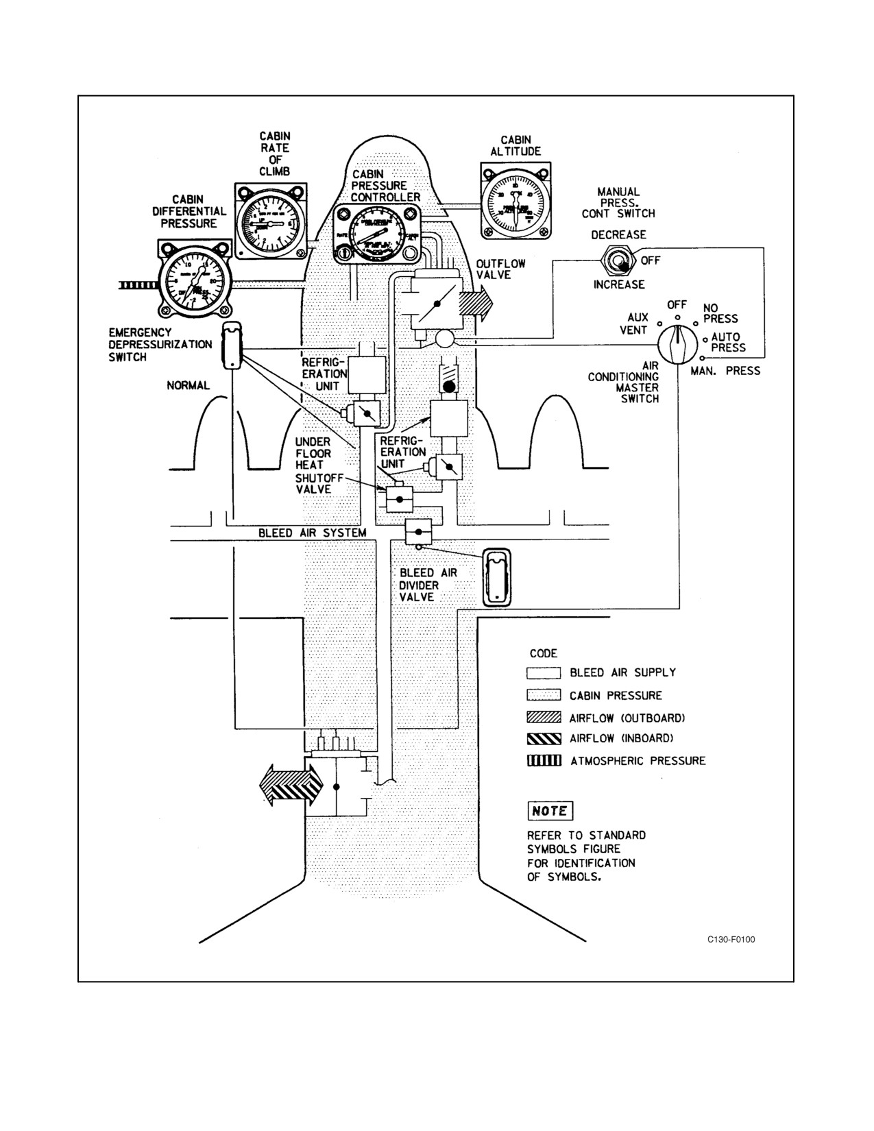
01-75GAL-1
Figure 2-68. Pressurization System
ORIGINAL
2-138
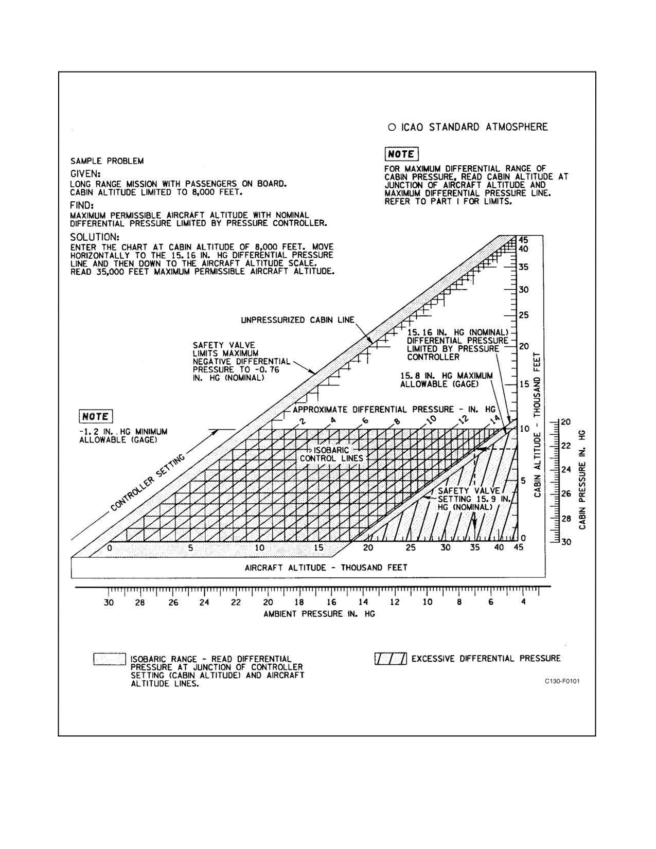
01-75GAL-1
Figure 2-69. Cabin Pressurization Chart
2-139
ORIGINAL
01-75GAL-1
2.17.4.1 Master Switch
The AIR CONDITIONING master switch on the air-conditioning and pressurization control panel (see Figure 2-66)
is used to select the type of operation for the air-conditioning and pressurization systems. It controls operation of the
outflow valve under conditions of pressurized and nonpressurized operation. For functions of the switch positions,
see Figure 2-67. Electrical power for control circuits of the outflow and safety valves is supplied from the essential
dc bus through the CABIN PRESS AUX VENT circuit breaker on the copilot lower circuit breaker panel.
2.17.4.2 Cabin Pressure Controller
The cabin pressure controller, on the air-conditioning and pressurization control panel (see Figure 2-66), includes
thecabinDIFFPRESSindicators,cabinrate-of-climbindicator,aCABINALTselectorknob,aRATEselectorknob,
and a CABIN ALT setting indicator. The CABIN ALT selector knob and pointer are used to preset the required cabin
altitude. For the chosen altitude, shown by the pointer on the indicator and selected by turning the knob, a window
on the indicator dial face indicates the maximum aircraft altitude that can be reached before cabin differential
pressurization begins.
CAUTION
Do not force the CABIN ALT knob below a setting of -1,000 feet or above
10,000 feet. To do so may damage the pressure controller.
The RATE selector knob is used to determine the rate of cabin pressure change until the cabin altitude, as shown by
the pointer, is reached. The knob is turned from MIN (30 to 200 feet per minute) clockwise to MAX (1,600 to 2,900
feet per minute).
2.17.4.3 MANUAL PRESS CONT Switch
The MANUAL PRESS CONT switch is a three-position (INCREASE, OFF, DECREASE) toggle switch located
on theair-conditioning and pressurization control panel (seeFigure 2-66). It has a centerspring-loaded OFF position
and momentary INCREASE and DECREASE positions. The switch controls the electric actuator of the outflow
valve when the AIR CONDITIONING master switch is in the MAN PRESS position. When the switch is held in
the INCREASE position, the actuator turns the outflow butterfly valve toward its closed position. When the switch
is held in the DECREASE position, the actuator turns the butterfly valve toward its open position. When operating
the system manually, the cabin vertical velocity indicator will give the first indication of pressurization. Electrical
power for manual pressure control is supplied from the essential dc bus through the CABIN PRESS AUX VENT
circuit breaker on the copilot lower circuit breaker panel.
2.17.4.4 EMERGENCY DEPRESSURIZATION Switch
The EMERGENCY DEPRESSURIZATION switch is a two-position (NORMAL, EMERGENCY DEPRESSU-
RIZATION) guarded toggle switch (see Figure 2-66). When the switch is positioned to EMERGENCY
DEPRESSURIZATION, battery power from the battery bus (through the EMER DEPRESS circuit breaker on the
pilot side circuit breaker panel) is used to override the normal control circuit to open the outflow and safety valves,
to close both air-conditioning shutoff valves, and to close the cargo underfloor heat shutoff valve.
2.17.4.5 Emergency Depressurization Handle
An emergency depressurization door, located in the center escape hatch, is released by pulling the EMER
DEPRESSURE handle (see Figure 2-70) on the overhead control panel directly above the pilot. The handle is
connected by a cable to the release mechanism of the door, which is restrained from consequential loss by two shock
cords. After depressurization is accomplished, the door can be closed and the release mechanism reset manually.
ORIGINAL
2-140