C-130T. FLIGHT MANUAL (2006) - page 2
01-75GAL-1
CHAPTER 2
Systems and Equipment
2.1
ENGINES
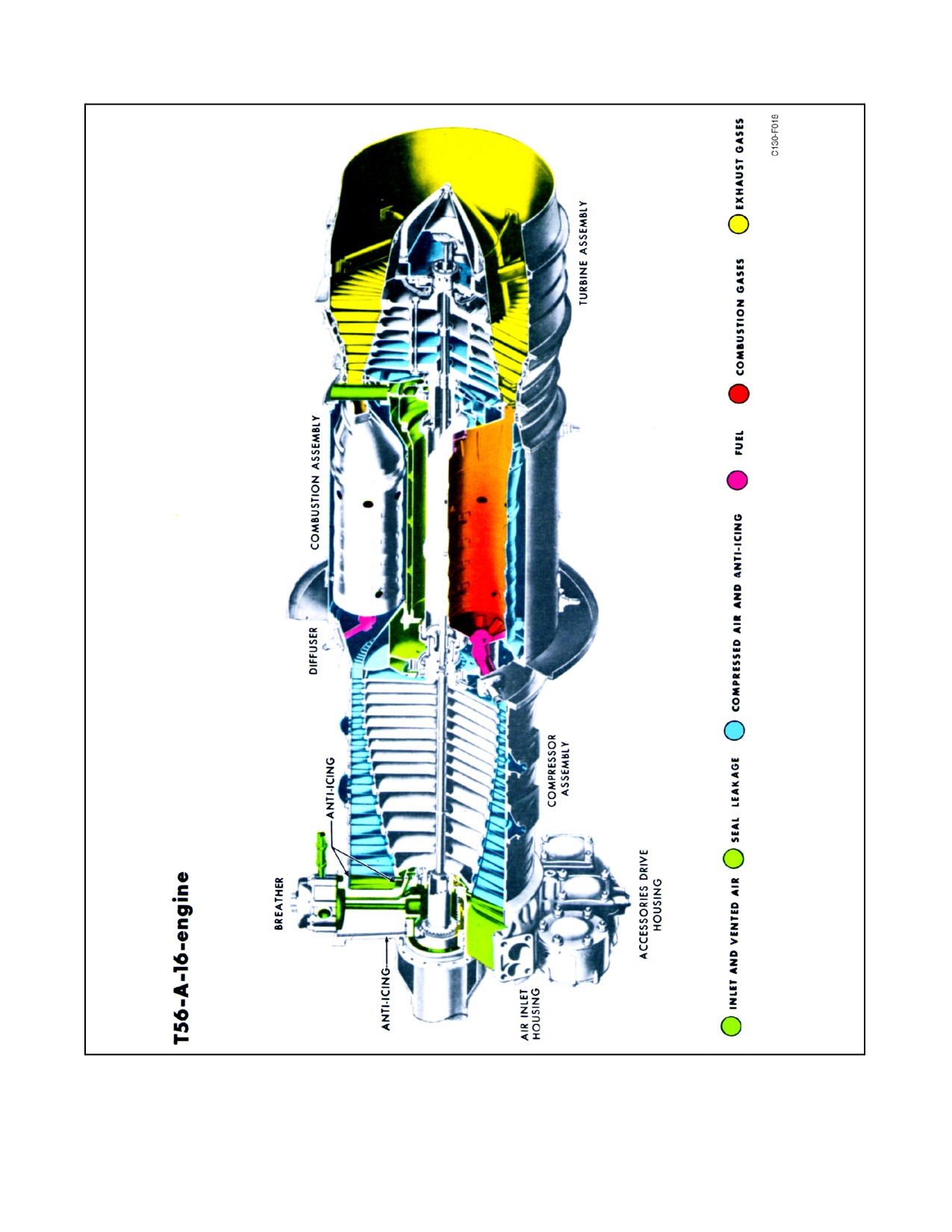
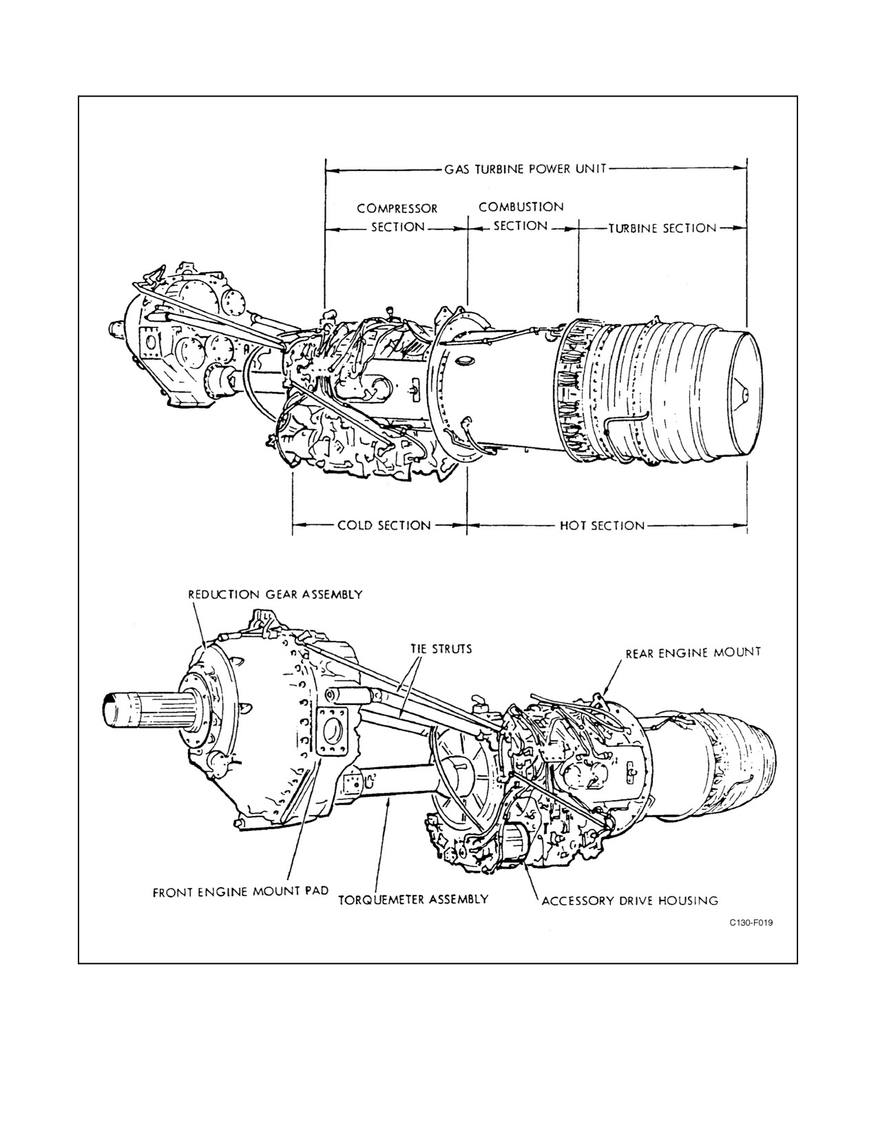
The aircraft is powered by four Allison T56-A-16 turboprop engines (see Figure 2-1). The basic engine consists of
two major assemblies, a power section, and a reduction gear assembly, which are attached to each other by an
extension shaft assembly and two supporting struts. The engine is provided with fuel, oil, starting, ignition, and
control systems. The engine operates at a constant speed; therefore, engine power is related to TIT, which varies
according to the rate of fuel flow. An increase in fuel flow causes an increase in TIT and a corresponding increase
in energy available at the turbine. The turbine then absorbs more energy and transmits it to the propeller in the form
oftorque.In orderto absorbtheincreasedtorque, thepropellerincreasesbladeangleto maintainconstant enginerpm.
A decrease in torque results in a decrease in propeller blade angle to maintain engine speed. Thrust is obtained from
the propeller, and a small amount of additional thrust (approximately 10 percent at takeoff) is created by the tailpipe
exhaust.
2.1.1 Power Section
The power section of the engine is composed of a single-entry, 14-stage, axial-flow compressor; a set of six
combustion chambers of the through-flow type; and a 4-stage turbine. Mounted on the power section are an
accessories drive assembly and components of the engine fuel, ignition, and control systems. Acceleration bleed
valves are installed at the 5th and 10th compressor stages. A manifold is installed at the diffuser to bleed air from
the compressor for aircraft pneumatic systems. Anti-icing systems are provided to prevent accumulation of ice in the
engine inlet air duct and the oil cooler scoop. Inlet air enters the compressor through a scoop and duct below the
compressor and is progressively compressed through the 14 stages of compression. The compressed air (at
approximately 125 psi and 600 _F) flows through a diffuser into the combustion section. Fuel is introduced into the
combustion chambers and burned to increase the temperature and, thereby, the energy of the gases. The gases pass
through the turbine causing it to rotate and drive the compressor, the propeller, and accessories. The gases, after
expanding through the turbine, flow out through a tailpipe.
2.1.2 Extension Shaft Assembly
The extension shaft assembly consists of two concentric shafts and torquemeter components. The inner shaft
transmits power from the power section to the reduction gear. The outer shaft serves as a reference so that the torsional
deflection of the loaded inner shaft can be detected by the magnetic pickups of the torque indicating system.
Torquemeter amplifiers are provided with adjustment screws for calibration purposes.
2.1.3 Reduction Gear Assembly
The reduction gear assembly contains a reduction gear train, a propeller brake, a NTS system, and a safety coupling.
Mounted on the accessory drive pads are the engine starter, an ac generator, a hydraulic pump, an oil pump, and a
tachometer generator. The reduction gear has an independent dry-sump oil system. The reduction gear train is in two
stages, providing an overall reduction of 13.54 to 1 between engine speed (13,820 rpm) and propeller shaft speed
(1,021 rpm). The propeller brake, NTS system, and safety coupling are described in the following paragraphs.
2-1
ORIGINAL
01-75GAL-1
Figure 2-1. T56-A-16 Engine (Sheet 1 of 2)
ORIGINAL
2-2
01-75GAL-1
Figure 2-1. T56-A-16 Engine (Sheet 2)
2-3
ORIGINAL
01-75GAL-1
2.1.3.1 Propeller Brake
The cone-type propeller brake acts on the first stage of reduction gearing. During engine operation, it is held
disengaged by gearbox oil pressure when rpm exceeds 23 percent and is engaged below this speed. As engine speed
is reduced and oil pressure drops, the braking surfaces are brought into contact by spring force to help slow the
propeller to a stop. Helical splines between the starter shaft and the starter gear on the outer brake member cause the
brake to disengage when starting torque is applied during starting. The brake also engages to stop reverse rotation
of the propeller.
2.1.3.2 Negative Torque Protective Devices
Very high windmilling drag upon sudden loss of turbine power is a problem in propeller-jet aircraft operation. High
windmilling drag results when the compressor absorbs a great amount of power. If a power failure is experienced
in flight at high speed, the engine starts to slow down; the propeller, sensing rpm, reduces blade angle and drives the
compressor, trying to bring it up to speed. Two safety devices are provided to prevent a sudden increase in
windmilling drag that could result in high structural loads on the tail of the aircraft and loss of directional control.
These devices are the NTS system, which increases blade angle of the propeller, and the safety coupling, which can
decouple the propeller and reduction gear from the power section of the engine upon failure of the power section.
2.1.3.3 Negative Torque Signal System
The NTS system provides a mechanical signal to limit negative torque. Negative torque is encountered when the
propeller attempts to drive the engine. If not relieved, this condition creates a great amount of drag, causing the aircraft
to yaw. The NTS system consists of an actuating mechanism housed partly within the reduction gear assembly and
partly in the propeller control assembly. It operates when negative torque applied to the reduction gear exceeds
approximately 1,260 ±600 inch-pounds. A ring gear is then moved forward against springs as a result of torque
reaction generated through helical splines. In moving forward, the ring gear actuates a plunger extending through
thenoseofthegearbox.Theplungerpushesagainstacaminthecontrolassemblytoactuatecontrollinkageconnected
tothepropellerfeathervalve.WhenaNTSistransmittedtothepropeller,thepropellerincreasesbladeangletorelieve
thecondition, except when thethrottles arebelow theFLIGHT IDLEposition. WhenthethrottlesarebelowFLIGHT
IDLE, a cam moves the actuator away from the NTS plunger and renders the system inoperative. This is necessary
to prevent a propeller from receiving a possible NTS at high landing speeds when the throttles are moved toward
reverse. If the negative torque is sufficiently reduced, the signal mechanism returns to normal by springs acting on
the ring gear.
Note
Properly adjusted, the NTS will not commit the propeller to feather. An
improperly adjusted or malfunctioning NTS system receiving continual
NTSs will cause a propeller to move to a high blade angle. The resultant
load may cause an engine stall and flameout.
2.1.3.4 Safety Coupling
The safety coupling is provided to decouple the power section from the reduction gear if negative torque applied to
the reduction gear exceeds approximately 6,000 inch-pounds, a value much higher than that required to operate the
NTS system. Because of its higher setting, the safety coupling backs up the NTS system to reduce drag until the
propeller can be feathered. The safety coupling connects the engine extension shaft to the pinion of the first stage
ofreduction gears. It consists ofthree members: an outermember is attached to the extension shaft; an innermember
is attached to the pinion; and an intermediate member is engaged to the outer member by straight teeth and to the
inner member by helical teeth. Reaction of the helical teeth tends to force the intermediate member aft out of
engagement when negative torque is applied, and the members disengage if approximately 6,000 inch-pounds of
negative torque is reached. While disengaged, the two members are forced together by springs so that the teeth will
ratchet. The teeth can thus be damaged; therefore, the engine should not be continued in operation after a decoupling.
Before restarting the engine, the coupling must be replaced.
ORIGINAL
2-4
01-75GAL-1
2.1.4 Engine Fuel and Control System
In flight, the engine operates at a constant speed that is maintained by the governing action of the propeller. Power
changes are made by changing fuel flow and propeller blade angle rather than engine speed. An increase in fuel flow
causes an increase in TIT and a corresponding increase in energy available at the turbine. The turbine absorbs more
energy and transmits it to the propeller in the form of torque. The propeller, in order to maintain governing speed,
increases blade angle to absorb the increased torque. TIT is a very important factor in the control of the engine. It
is directly related to fuel flow and consequently to power produced. It is also limited because of the strength and
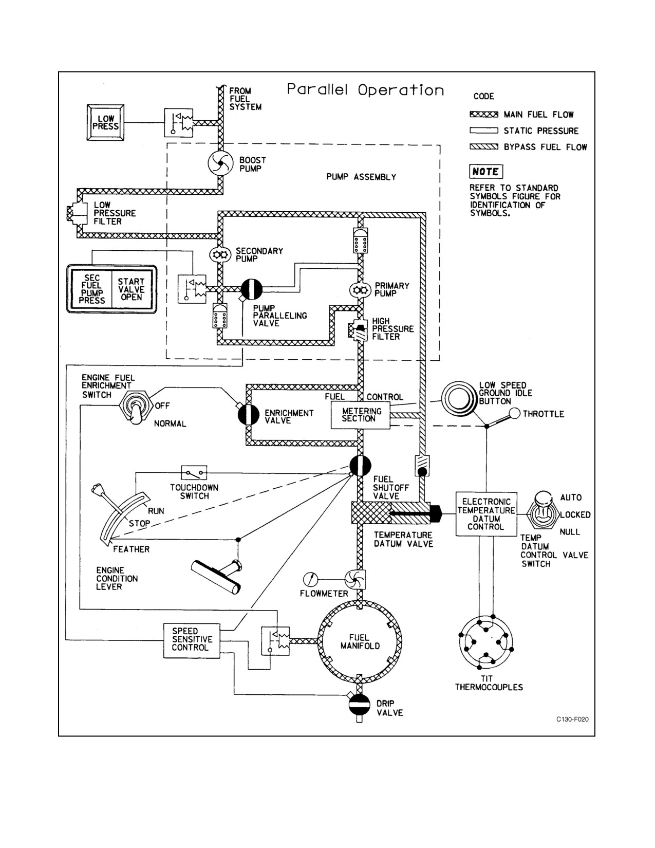
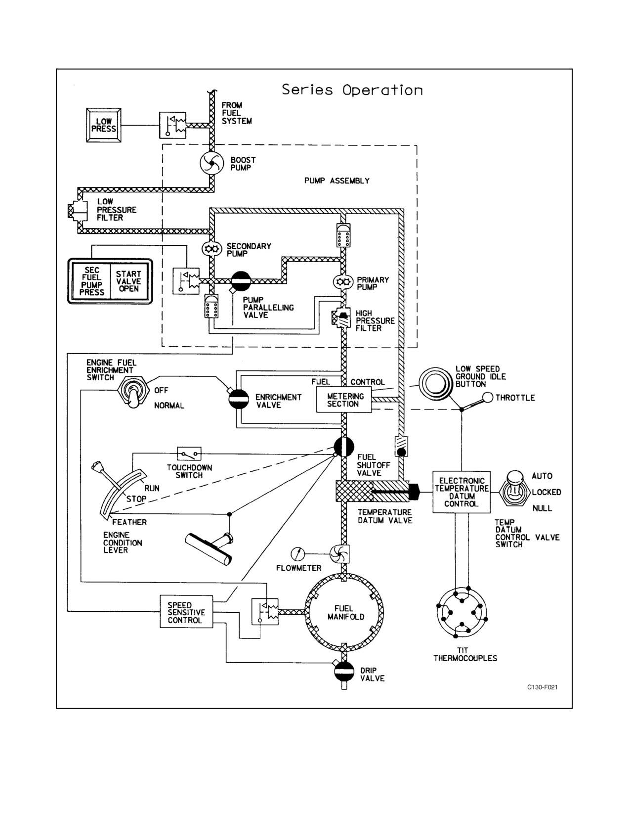
durability of the combustion and turbine section materials. The fuel control system schedules fuel flow (see Figure
2-2) to produce specific TITs and to limit those temperatures so that the temperature tolerances of combustion and
turbine section materials are not exceeded. Changes in power settings are effected by the throttle, which is connected
to the fuel control and the propeller through a mechanical coordinator. During ground operation, changes in throttle
position mechanically affect both the fuel flow and the propeller blade angle. In flight, changes in throttle position
mechanically affect fuel flow, and the propeller governor regulates blade angle, maintaining constant engine speed.
The hydromechanical fuel control, which is part of the basic fuel system, senses engine inlet air temperature and
pressure, rpm, and throttle position, and varies fuel flow accordingly. The electronic TD control system senses TIT
and throttle position and makes any necessary changes in the fuel flow from the fuel control before it reaches the fuel
nozzles. The TD system compensates for minor variables not sensed by the hydromechanical fuel control and for
mechanical tolerances within the fuel control itself. By means of switches, the TD system can be turned off (NULL
position) and the engine will operate on the basic hydromechanical system alone. With the TD system in AUTO,
temperature protection is provided through the entire throttle range and automatic temperature scheduling is provided
when the throttle is in the range of 65_ to 90_. When the TD system is in NULL, the functions of temperature limiting
and temperature scheduling must be accomplished manually by adjustment of the throttle.
2.1.4.1 Basic Hydromechanical Fuel System
Thebasichydromechanicalfuelsystemconsistsofathrottle,acoordinator,alow-pressurefuel filter,a high-pressure
fuel filter, a dual-element fuel pump, a hydromechanical fuel control, and six fuel nozzles.
2.1.4.2 Throttle, Coordinator, and Propeller Control Linkage
The coordinator is a mechanical discriminating device that coordinates the throttle, the propeller, the fuel control,
and the electronic TD system. Movements of the throttle are transmitted to the coordinator and, in turn, to the fuel
control and the propeller by a series of levers and rods. A potentiometer in the coordinator provides signals to the
TD system. Propeller blade angle is scheduled by throttle position from MAXIMUM REVERSE to FLIGHT IDLE.
For throttle settings between FLIGHT IDLE and TAKE-OFF, the propeller is governing. Throttle movement in this
range serves primarily to change fuel flow and also to change propeller hydraulic pitch stop (beta followup) settings.
2.1.4.3 Fuel Control
Fuel flows from the fuel pump to the hydromechanical fuel control. The control is sensitive to throttle position, air
temperature and pressure at the engine inlet, and engine speed. The engine speed function of the fuel control maintains
engine speed in the taxi range and limits engine speed in the flight range if the propeller governor fails. Governor
action is controlled by flyweights that respond to engine rpm.
Thecontrol will start to reducefuel to theengineat approximately 103.5 percent at a rateof 900 pounds per1-percent
rpm. A speed servo system provides for speed acceleration during engine start and underspeed control during normal
engine operation. Fuel metered by the control is equal to engine requirements plus an additional 20 percent, which
is fortheuseoftheTD valve. With theTD system in NULL, theexcess fuel provided by the fuel control is constantly
bypassed by the TD valve back to the fuel pump, and fuel metering is accomplished by the fuel control alone. The
required fuel flow passes on through the TD valve to the fuel nozzles and into the combustion liners, where it is
burned.
2-5
ORIGINAL
01-75GAL-1
Figure 2-2. Engine Fuel Flow (Sheet 1 of 2)
ORIGINAL
2-6
01-75GAL-1
Figure 2-2. Engine Fuel Flow (Sheet 2)
2-7
ORIGINAL
01-75GAL-1
2.1.4.4 Fuel Pump and Filter Assembly
Thepumpandfilterassemblycontainsacentrifugal boostpump, aprimary andasecondarygearpump,high-pressure
filter, pressure switch, pump paralleling valve, and bypass and check valves. After engine start, the primary and
secondary gear pumps operate in series; that is, the secondary pump receives fuel from the centrifugal pump and
directs its output to the primary pump, which supplies fuel to the engine. If either pump fails, the operating pump
will bypass the failed pump and supply sufficient fuel to sustain normal full-power engine operation. During engine
starting, the solenoid-operated pump paralleling valve is energized closed by the speed-sensitivecontrol through the
ignition relay to block flow from the secondary to the primary pump. The centrifugal boost pump then feeds both
gear pumps, and the combined output of the pumps operating in parallel is fed to the engine to provide increased fuel
flow capacity during the start cycle. The pressure switch is closed to turn on the secondary pump pressure light while
the pump paralleling valve is closed, or when the primary pump has failed.
2.1.4.5 Low-Pressure Filter
A low-pressure, paper-element filter assembly is installed between the centrifugal boost pump and the two gear
pumps to remove contamination from the incoming fuel. This filter assembly is mounted externally from the fuel
pump and filter assembly.
2.1.4.6 Acceleration Bleed-Air Valves
The bleed-air valves on the 5th and 10th stages of the compressor are provided for compressor unloading during
starting and while the engine is operating in the low-speed, ground-idle range. These bleed valves remain open only
when engine speed is below 94-percent rpm. The 5th- and 10th-stage bleed-air valves are automatic in operation and
are actuated by 14th-stage compressor air pressure through an engine-driven, speed-sensitive valve assembly.
2.1.4.7 Starting Fuel Enrichment System
The enrichment system consists of a bypass line in which is mounted a solenoid valve, a pressure switch, and the
engine fuel-enrichment selector switch. The valve is opened by the speed-sensitive control through the ignition relay
when engine speed reaches 16-percent rpm during starting when the engine fuel enrichment switch is in NORM.
While open, it allows pump discharge fuel to flow around the metering section of the fuel control to add to the metered
flow from the fuel control. After fuel pressure in the manifold reaches approximately 50 psi (gauge), the manifold
pressure switch opens to deenergize the valve, which then closes.
2.1.4.8 Fuel Nozzles
Six duplex fuel nozzles are used. The small slots of the nozzles open when manifold pressure is low during engine
starting. Both small and large slots open when manifold pressure increases to 65 psi as the engine accelerates to
normal speed.
2.1.4.9 Burner Drain Valves
Two burnerdrain valvesareprovidedto drainfuel fromthecombustionsection oftheenginewhen itis stopped.They
are spring-loaded and operate automatically to close when internal combustion pressure exceeds external pressure.
2.1.4.10 Drip Valves
Thepurposeofthedripvalveistodrainthefuelmanifoldtominimizetheamountoffueldrippingintothecombustion
chambers and causing fire at shutdown. The valve is closed by a solenoid that is controlled by the speed-sensitive
control through the ignition relay when engine speed reaches approximately 16-percent rpm during starting. It is held
against a spring by pressure in the fuel manifold after the engine is started. When fuel pressure in the manifold drops
to approximately 9 psi during engine shutdown, the valve opens and drains the manifold.
ORIGINAL
2-8
01-75GAL-1
2.1.5 Starting System
An airturbinestarterunit drives theengineforground starts.This starterunit consistsofanair-driven turbinesection,
a clutch, and a reduction gear section that is splined to the reduction gear assembly of the engine. Air for driving the
starter can be supplied by the auxiliary power unit, by an operating engine, or by an external air source. The air is
routed through the bleed-air system and the engine bleed-air regulators.
When the respective bleed-air regulator is opened, air is supplied to the starter regulator valve. When the ENGINE
GROUND START switch is placed to START, the starter regulator valve opens (when its solenoid is energized) and
allows airflow into the starter turbine section. Releasing the ENGINE GROUND START switch to OFF will
deenergize the regulator valve. Within approximately 15 seconds the START VALVE OPEN light will extinguish,
indicating that the starter valve is closed. Each engine starting circuit is electrically interlocked with the
corresponding engine oil fire shutoff valve control circuit. This renders the starting circuit inoperative unless the fire
emergency control handle is pushed in and the FIRE SHUTOFF VALVE-OIL circuit breaker is engaged.
2.1.6 Ignition System
The ignition system is a high-voltage, condenser-discharge type, consisting of an exciter, two igniters, and control
components. The system is controlled by the speed-sensitive control through the ignition relay, which turns it on at
16-percent engine rpm and off at 65-percent engine rpm during starting.
2.1.6.1 Electronic Temperature Datum Control System
The electronic TD control, together with the coordinator potentiometer, temperature adjustment network, a TIT
measurement system, and the temperature datum valve make up the electronic temperature datum system. The system
compensates for variations in fuel heat value and density, engines, and control system characteristics. The TD control
is furnished actual TIT signals from a set of thermocouples, and is furnished desired TIT signals by the throttle
through thecoordinator potentiometerand thetemperature adjustment network. Thecontrol compares the actual and
the desired TIT signals. In the temperature controlling range (65_ to 90_ throttle movement), if there is a difference,
the TD control signals the temperature datum valve to increase or decrease fuel flow to bring the temperature back
on schedule. In the temperature limiting range (0_ to 65_ throttle movement), the TD control acts only when the
limiting temperatureis exceeded, at which time, it signals theTD valveto decreasefuel flow.TheTDvalveislocated
between the fuel control and the fuel nozzles. It is a motor-operated bypass valve that responds to signals received
from the TD control. In throttle positions between 0_ and 65_, the valve remains in a 20-percent bypass or null
position and theengineoperates on thefuel flow scheduled by thefuel control. The valveremains in the null position
unless it is signaled by the TD control to limit TIT. The valve then reduces the fuel flow (up to 50 percent during
starting, 20 percent above 94-percent rpm) to the nozzles by returning the excess to the fuel pump. When the TIT
lowers to thedesired level, theTD control signals thevalveto return to thenullposition. Inthrottlepositionsbetween
0_ and 65_, the control system is in the temperature limiting range. In throttle positions between 65_ and 90_, the
TD valve acts to control TIT to a preselected schedule corresponding to throttle position; this is the temperature
controlling range. In this range the valve may be signaled by the TD control to allow more (higher temperature
desired) or allow less (lower temperature desired) of the fuel to flow to the fuel nozzles. Any specific fuel flow trim
correction applied in the 65_ to 90_ throttle range can be locked into the TD valve while above 65_ and will be
maintained in the 0_ to 65_ range by the use of the TEMP DATUM CONTROL VALVE switch located at the flight
station.Also,theTDsystemcanbereturnedtonullatanytimebytheuseoftheTEMPDATUM CONTROLVALVE
switch. When the switch is in NULL, automatic temperature-limiting circuits are inoperative, the TD valve remains
in the null (20-percent bypass) position, and all fuel metering is then accomplished by the fuel control. Temperature
limiting then must be accomplished by throttle adjustment.
2.1.7 Engine Controls and Control Systems
Engine control in the flight range of operation is based on regulation of engine speed by propeller constant-speed
governing and control of torque through regulation of fuel flow. Note that the throttle acts only as a power control.
2-9
ORIGINAL
01-75GAL-1
It exercises no direct control over the propeller, which is controlled entirely by the propeller regulator to regulate
engine speed and to limit the low blade angle. The fuel control regulates the rate of increase and decrease of fuel
metering for acceleration and deceleration. The TD control system functions at all throttle positions (MAXIMUM
REVERSE through TAKE-OFF) either as a temperature-limiting or a temperature-controlling system. When
performing temperature limiting, the system operates to prevent overtemperatures by “taking” a portion of fuel flow
when maximum allowable TIT is exceeded. When performing temperature controlling (past 65_ of throttle travel,
fuel correction lights out), it adjusts fuel flow to obtain the desired temperature. This is accomplished by using a
voltage signal from a potentiometer, positioned by the throttle, as a reference for desired TIT. The system compares
this reference with actual TIT and adjusts fuel flow to obtain the desired temperature. The TD control system may
be operated to provide a fixed correction of fuel flow. By positioning the TEMP DATUM CONTROL VALVE
switches in LOCKED while the throttles are in the temperature-controlling range, all of the TD control valves are
locked in theposition in which theyhavebeenset bythetemperature-controllingsystems. WhentheTEMPDATUM
CONTROL VALVE switches are positioned in LOCKED, the electronic fuel correction warning lights should
remain out through all throttle movements. Should an overtemperature condition occur, the light, or lights, will come
on indicating that a“take”signal has been initiated, thattheTDvalvebrakehas beenreleased, andthat fuelcorrection
has been lost. The light will stay on until the TD system is reset. In throttle positions below FLIGHT IDLE, the throttle
selects propeller blade angle as well as fuel flow. The TD control system still functions to limit TIT.
An engine is stopped by closing a fuel shutoff valve on the fuel control. The valve is closed electrically when the
condition lever is at GROUND STOP if the control circuit is completed through a landing gear touchdown switch,
when the condition lever is pulled to FEATHER, or when the fire emergency handle is pulled. The valve is also closed
mechanically when the condition lever is pulled to FEATHER. Propeller feathering can be accomplished by pulling
the condition lever to FEATHER, or by pulling the fire emergency handle.
For starting an engine, a speed-sensitive valve and a speed-sensitive control, which contains three speed-sensitive
microswitches,provideautomaticcontrolofallfunctions involvedin thestarting cycle.Thespeed-sensitiveswitches
turn on the fuel, control ignition, parallel fuel pump elements, initiate starting fuel enrichment, close a manifold drip
valve, and switch the electronic datum control system from starting limiting to normal limiting. The speed-sensitive
valve controls the compressor bleed valves. These operations are timed according to engine speed to ensure that the
proper sequence of starting operations is followed. For airstarts, the engine condition lever operates switches that start
the propeller feather pump motor to provide pressure to decrease the propeller blade angle and to apply power to the
speed-sensitive control, energizing fuel and ignition control circuits.
2.1.7.1 Throttles
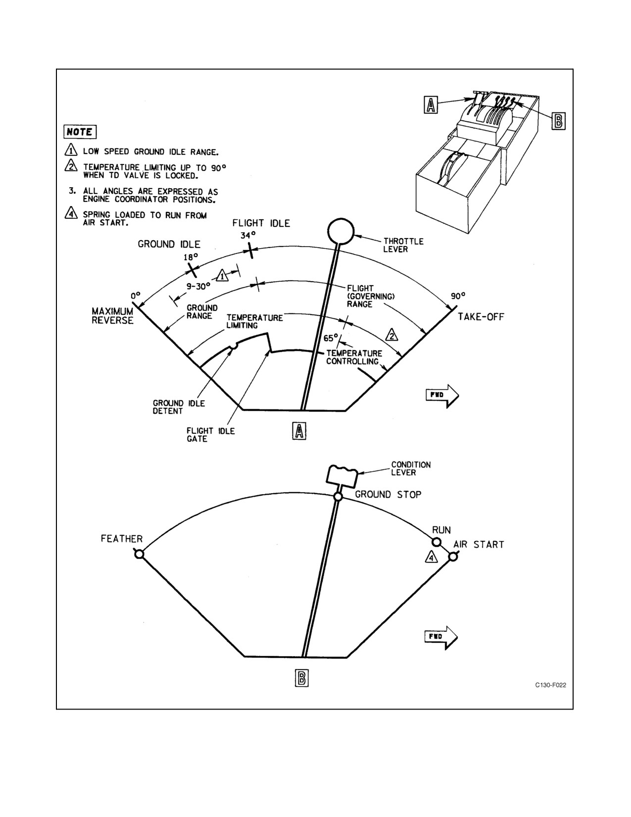
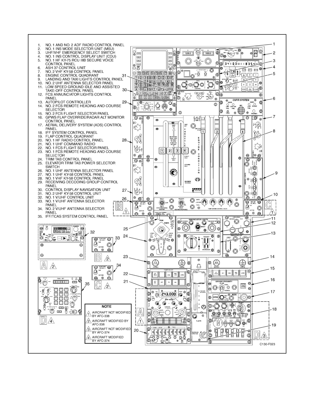
The throttles (see Figures 2-3 and 2-4) are quadrant mounted on the flight control pedestal. Throttle movements are
transmitted through mechanical linkage to an engine-mounted coordinator. The coordinator transmits the movements
through mechanical linkage to the propeller and to the engine fuel control, and it also actuates switches and a
potentiometer that affect electronic TD control system operation. Each throttle has two distinct ranges ofmovement,
taxi and flight, that are separated by a stop (see Figure 2-3). Both ranges are used for ground operation, but the taxi
range must not be used in flight. In the taxi range, the throttle position selects a propeller blade angle and a
corresponding rate of fuel flow. In the flight (governing) range, throttle position selects a rate of fuel flow and the
propeller governor controls propeller blade angle. The throttles have four placarded positions as follows:
1. MAXIMUM REVERSE (0_ travel) gives maximum reverse thrust with engine power approximately 40
percent of takeoff power.
2. GROUND IDLE (approximately 18_ travel) is a detent position. This is the ground-starting position at which
blade angle is set for minimum thrust.
Note
Throttles must not be moved out of GROUND IDLE detent during ground
starting because the resultant increase in propeller blade angle might
overload the starter, reducing the rate of engine acceleration.
ORIGINAL
2-10
01-75GAL-1
Figure 2-3. Engine Control Quadrant
2-11
ORIGINAL
01-75GAL-1
Figure 2-4. Flight Control Pedestal
ORIGINAL
2-12
01-75GAL-1
3. FLIGHT IDLE (34_ travel) is the transition point between the taxi and flight (governing) ranges. A step in
the quadrant limits aft travel of the throttle at this position until the throttle is lifted.
4. TAKE-OFF (90_ travel) is the maximum power position.
The throttle quadrant is also divided into two unmarked ranges with respect to control of the electronic TD
control system. The crossover point is at 65_ throttle travel, at which point the switches in the coordinator are
actuated. Below this point, the electronic TD control system is limiting TIT. Above this point, it is controlling
TIT if the TD valve switches are in the AUTO position.
2.1.7.2 LOW SPEED GROUND IDLE Control Buttons
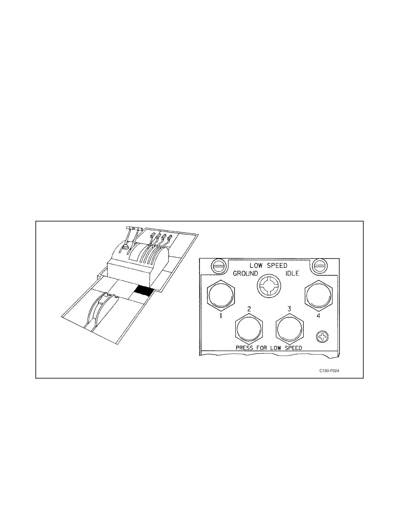
Four LOW SPEED GROUND IDLE control buttons (see Figure 2-5) on the control pedestal may be pushed in to
reduce engine rpm to approximately 72 percent at any time the throttles are in the range between 9_ and 30_. The
low speed ground idle buttons send a signal to the fuel topping governor on the fuel control, to reduce fuel flow to
the engine. This allows the fuel nozzles to cool down and extends engine life. In addition, this allows the aircraft to
taxi at a slower speed without having to use excess braking. Moving the throttles out of this range will automatically
disengage the LOW SPEED GROUND IDLE buttons. Power is supplied from the essential dc bus through the LOW
SPEED GND IDLE circuit breakers on the copilot side circuit breaker panel.
Figure 2-5. Low-Speed Ground Idle Buttons
2-13
ORIGINAL
01-75GAL-1
CAUTION
D With engines in low-speed ground idle, movement of throttles beyond the
limits of 9_ to 30_ (coordinator angle) at ambient temperatures above 80
_F may cause engine stall and overtemperature. Therefore, the recom-
mended procedure for coming out of low-speed ground idle is to disengage
the buttons manually with the throttles in GROUND IDLE detent.
D If all four engines are operated at low-speed ground idle, the APU generator
must be on since the engine-driven ac generators will not supply ac power.
If the APU generator fails and the BUS TIE switch is in the TIED position,
the LOW SPEED GROUND IDLE buttons must be disengaged manually
in orderto restoreacpowerand to prevent adrain on thebattery. IftheBUS
TIE switch is not in the TIED position, the LOW SPEED GROUND IDLE
buttons will disengage automatically.
2.1.7.3 Throttle Friction Knob
A friction knob (see Figure 2-4) on the throttle quadrant adjusts the amount of friction applied to the throttles to
prevent creeping or accidental movement.
2.1.7.4 ENGINE CONDITION Levers
Four pedestal-mounted condition levers (see Figure 2-4) are primarily controls for engine starting and stopping and
propeller feathering and unfeathering. They actuate both mechanical linkages and switches that provide electrical
control. Each lever has four placarded positions as follows:
1. RUN is a detent position. At this position, the lever closes a switch that places engine fuel and ignition systems
undercontrolofthespeed-sensitivecontrol.ForenginesNo.2andNo.3,theice-detectionsystem isenergized.
2. AIRSTARTisapositionattainedbyholdingtheleverforward againstspring tension.In thisposition, thelever
closes the same switch closed by placing the lever at RUN and, in addition, closes a switch that causes the
propeller feathering pump to operate.
3. GROUND STOP is a detent position. In this position, the lever actuates a switch that causes the electrical fuel
shutoff valve on the engine fuel control to close only if the landing gear touchdown switches are closed. The
switch also closes the nacelle preheat control circuit making this system operable, if installed.
4. FEATHER is a detent position. When the lever is pulled toward this position, mechanical linkages transmit
themotiontotheengine-mountedcoordinatorandfromthecoordinatortothepropellerandtotheshutoffvalve
on the engine fuel control. Switches are also actuated by the lever as it is pulled aft. The results of moving the
lever to FEATHER are the following:
a. The propeller receives a feather signal and mechanically and electrically energizes the feather solenoid
valve.
b. The fuel shutoff valve on the engine fuel control is closed both mechanically and electrically.
c. The propeller feathering pump is turned on.
d. The nacelle preheat system remains operable only when the aircraft is on the ground (if installed).
ORIGINAL
2-14
01-75GAL-1
CAUTION
When pulling a condition lever to FEATHER, pull it all the way to the
detent to ensure that the propeller is fully feathered when the engine fuel
is shut off. If the lever is left at midposition and the NTS is inoperative, an
engine decoupling is possible.
2.1.7.5 TEMP DATUM CONTROL VALVE Switches
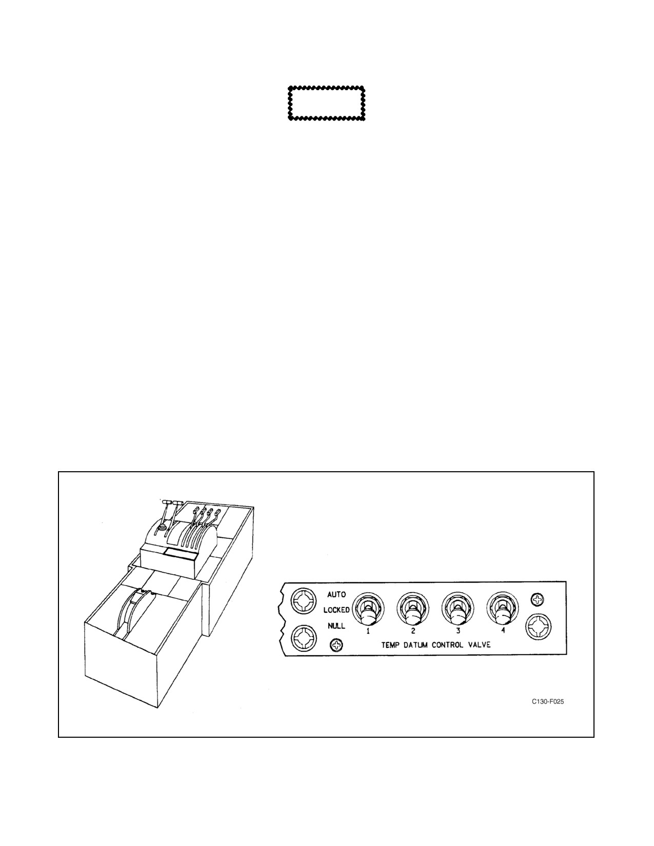
Four temperature datum control valve switches (see Figure 2-6) are mounted on a control panel on the flight control
pedestal. Each switch has AUTO, LOCKED, and NULL positions. The switch positions are used as follows.
The AUTO position permits normal operation of the electronic TD control system by applying single-phase, ac power
to the amplifier through a FUEL & TEMPERATURE CONTROL circuit breaker on the pilot lower circuit breaker
panel.
The LOCKED position may be set when the throttles are in temperature-controlling range, to provide a
fixed-percentage correction on the metered fuel flow throughout the engine operating range and will permit the fuel
control to compensate for changes in ambient temperatures in order to maintain a symmetrical shaft horse-power at
flight idle. If the TD control valve switch is then positioned at LOCKED, the TD valve is locked at whatever position
it is in at the time. The TD valves remain locked and the fuel correction lights remain out through all throttle
movements, unless an overtemperature condition is sensed by the amplifier. When the switch is in the AUTO or
LOCKED position, the TD valve for an engine is unlocked and set to a “take” position if TIT for the engine exceeds
approximately 1,083 _C. If a valve is unlocked by its control system to correct an overtemperature condition, the fuel
correction light for that engine comes on to indicate that the valve is unlocked.
Figure 2-6. Temperature Datum Control Valve Panel
2-15
ORIGINAL
01-75GAL-1
Note
The switches lock the TD valves only when they are positioned at
LOCKED while the throttle is in temperature-controlling range and the fuel
correction light is out.
The NULL position removes ac power from the control system amplifier; the TD valve, receiving no control signals,
returns to its null position so that it does not correct the fuel flow according to TIT. The TD valve brake is released
by dc power supplied through a FUEL & TEMPERATURE CONTROL circuit breaker on the pilot lower circuit
breaker panel.
The NULL position of these switches is used to deactivate the control systems when erratic fuel scheduling is
suspected or when the engines are not operating.
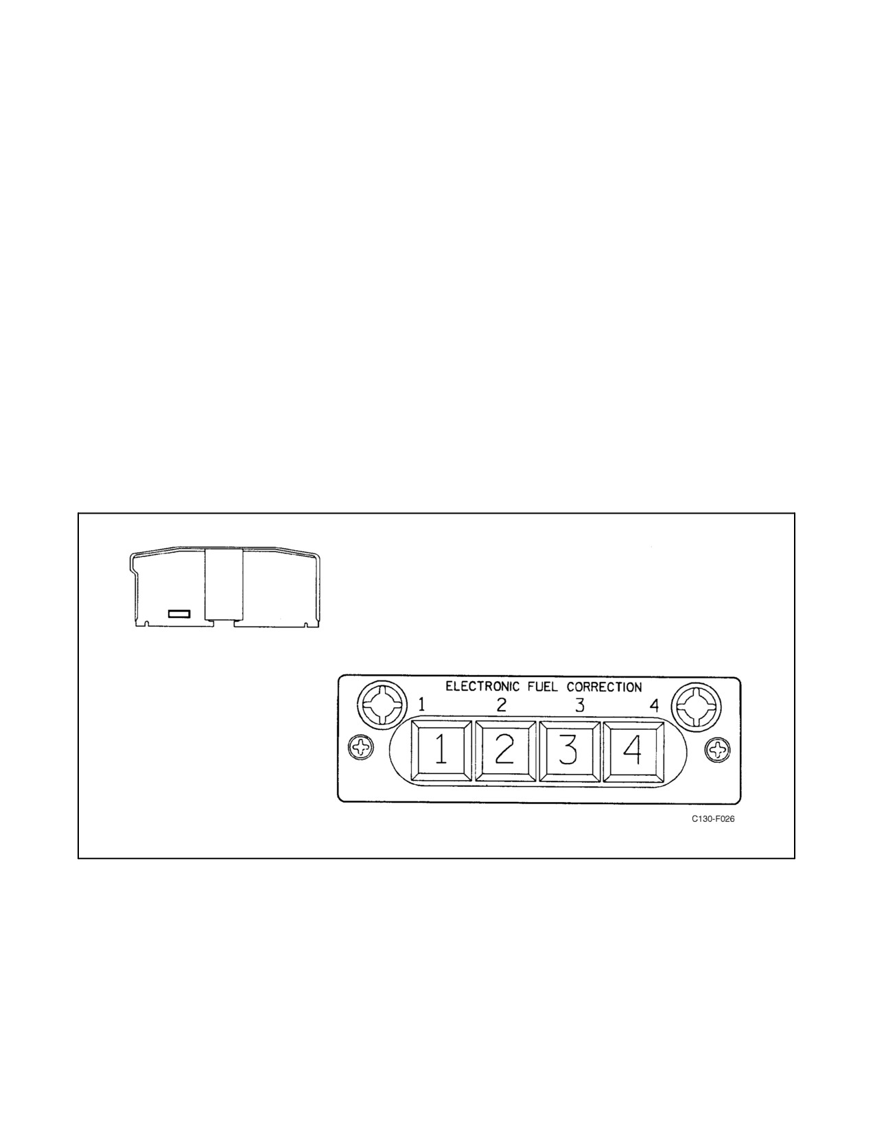
2.1.7.6 Electronic Fuel Correction Lights
The four amber press-to-test ELECTRONIC FUEL CORRECTION lights (see Figure 2-7) are located on the pilot
instrument panel. Thelights areilluminated in thetemperature-limiting range(throttles below65_)andextinguished
in thetemperature-controlling range(throttles above65_), ifthe TEMP DATUM CONTROL VALVE switches (see
Figure 2-6) are in the AUTO position. The lights will be illuminated below 65_ throttle and extinguished above 65_
throttle, but will illuminate again if temperature limit is reached when the TEMP DATUM CONTROL VALVE
switches are in the LOCKED position.
Figure 2-7. Electronic Fuel Correction Lights
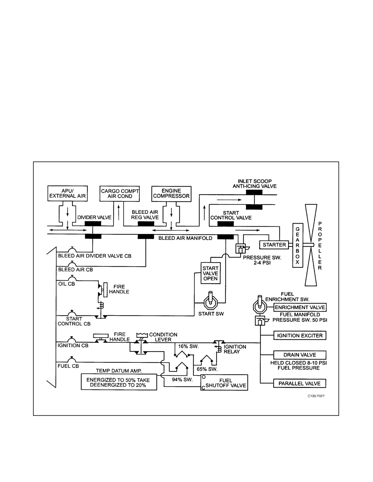
2.1.7.7 Starting Control System
The starting control system (Figure 2-8) automatically controls fuel flow and ignition during ground and air starts.
Electrical power for the control circuits is supplied from the essential dc bus through engine START CONTROL
circuit breakers and the IGNITION CONTROL circuit breakers on the copilot side circuit breaker panel. The
ORIGINAL
2-16
01-75GAL-1
automatic control of the starting control system has a speed-sensitive control and a speed-sensitive valve, which is
engine-driven and performs the following functions:
1. On acceleration to 16-percent rpm — The fuel shutoff valve in the engine fuel control is opened, the ignition
relay is energized completing circuits to the ignition exciter, the engine fuel pump paralleling valve closes,
the fuel enrichment valve opens, and the manifold drip valve closes.
2. On acceleration to 65-percent rpm — Ignition system is deenergized, fuel pump paralleling valve is opened
to return pumps to series operation, manifold drip valve is deenergized (it is then held closed by pressure).
3. On acceleration to 94-percent rpm — Electronic TD control system is switched from start limiting to normal
limiting, and the speed-sensitive valve opens to allow 14th-stage bleed air to force the 5th- and 10th-stage
compressor bleed valves closed.
Figure 2-8. Engine Start Control System (Simplified Diagram)
2-17
ORIGINAL

01-75GAL-1
2.1.7.8 Normal Engine Starting Sequence
During a normal start, the following actions take place automatically (provided Chapter 8 checklist procedures have
been followed) as listed in Figure 2-9. An examination of the sequence will be helpful in understanding the overall
operation of any start.
PERCENT ENGINE RPM
(APPROXIMATE)
ACTION
CONTROLLED BY
0 to 94
TIT limited to 830_ by TD control
Speed-sensitive switch
0 to 94
5th- and 10th-stage compressor bleeds
Speed-sensitive valve
open
—
Electronic fuel correction light on
Throttle and electronic fuel correction switch
16
Fuel shutoff opened
Speed-sensitive switch
16
Fuel enrichment on
Speed-sensitive switch and fuel enrichment
switch
16
Fuel pumps in parallel operation
Speed-sensitive switch
16 and up
Drip valve closed
Speed-sensitive switch and pressure
16
Ignition on
Speed-sensitive switch
50 psig fuel manifold pressure
Fuel enrichment off
Manifold pressure switch
60
Starter switch released
Pilot
65
Fuel pumps in series operation
Speed-sensitive switch
65
Ignition off
Speed-sensitive switch
94
5th- and 10th-stage compressor bleeds
Speed-sensitive valve
closed
94
TIT limited by TD
Speed-sensitive switch
Figure 2-9. Normal Engine Starting Sequence
2.1.7.9 Compressor Unloading
Bleed valves are located in the 5th and 10th stages of the compressor to allow more rapid acceleration of the turbine
during starting and to minimize compressor surge or stall problems. The opening and closing of the 5th- and
10th-stage bleed valves is controlled by an engine-driven centrifugally actuated valve. On acceleration, the bleed
valves are open from 0 to 94 percent at which point the engine-driven speed-sensitive valve opens to allow control
air pressure flow from the 14th stage to close the bleed valves. The bleed valves remain closed until engine speed
decelerates below 94 percent.
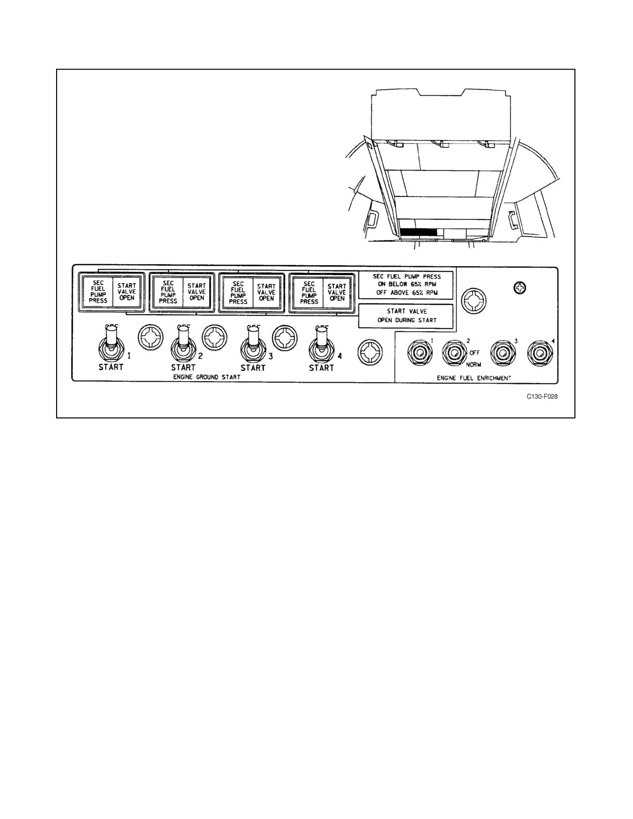
2.1.7.10 ENGINE GROUND START Switches
Four spring-loaded ENGINE GROUND START switches are located on the overhead control panel (see Figure
2-10). Holding the ENGINE GROUND START switch to the START position opens the starter regulator valve to
permit bleed air from the bleed air manifold to drive the engine starter turbine. The ENGINE GROUND START
switch should be released to OFF at 60-percent engine rpm.
ORIGINAL
2-18
01-75GAL-1
Figure 2-10. Engine Starting and Fuel Enrichment Panel
2.1.7.11 Engine Fuel Enrichment Switches
The ENGINE FUEL ENRICHMENT switches are located on the engine starting panel (see Figure 2-10). They are
toggle switches with NORM and OFF positions. In NORM, each switch allows the engine fuel enrichment valve to
be controlled by the speed-sensitive control and manifold pressure switch during starting. The OFF position is
provided to permit deactivating the fuel enrichment system for any engine. During the engine starting cycle the fuel
enrichment system furnishes unmetered fuel to the TD valve to supplement normal flow through the fuel control.
This enriching starts at 16 percent rpm and lasts only until fuel manifold pressure reaches approximately 50 psi.
Note
If fuel enrichment is used and the engine does not start, the drip valve
should drain all excess fuel in the engine overboard when the start is
discontinued. If the drip valve fails to drain the excess fuel, it is advisable
to place the ENGINE FUEL ENRICHMENT switch to OFF for the next
starting attempt and motor the engine, with the condition lever in
GROUND STOP, to eliminate the accumulated fuel from the engine to
preclude a hot start or torching.
Characteristics of the starts will vary during extreme cold weather. With fuel enrichment off, light-off occurs between
22.0- and 26.5-percent rpm and several seconds may elapse between maximum turbine-starter-driven rpm and
light-off. Torching may occur also. Starting with fuel enrichment normal produces light-off between 19.0- and
27.0-percent rpm with rapid engine acceleration. If a stalled start takes place, it can be noted by rpm lag at about
2-19
ORIGINAL
01-75GAL-1
40-percent rpm and a sharp TIT increase. When theengine is still hot from previous operation, stalled starts aremore
likely to occur with fuel enrichment on. After an unsuccessful attempt to start the engine with fuel enrichment OFF,
the next attempt should be made with fuel enrichment normal.
2.1.7.12 ENGINE BLEED AIR Switches
The ENGINE BLEED AIR switches, located on the anti-icing and deicing control panel, are three-position (OFF,
ON, OVRD) toggle switches. Each switch controls a pressure-actuated, dual solenoid-controlled pressure regulator.
When the bleed-air switch is in OFF, the regulator shuts off all airflow to or from the engine. When the switch is in
the ON position, the regulator regulates airflow from the engine to the bleed-air manifold to approximately 50 psi
and prevents airflow into the engine nacelle if the bleed-air manifold pressure is above approximately 50 psi. Low
bleed-air manifold pressure will allow airflow into an engine nacelle. When the switch is in OVRD (override), the
regulator is fully open and permits air flow in either direction. It is necessary to use the OVRD position during engine
starting,nacellepreheating(ifinstalled),andforengineinletairscoopanti-icingwith theenginenotrunning. Acheck
valve is provided to prevent backflow into the engine diffuser. The bleed-air regulators receive 28-Vdc power from
the essential dc bus through the BLEED AIR FIRE SHUTOFF VALVES circuit breakers on the copilot side circuit
breaker panel. The regulators go to the closed position when deenergized.
2.1.7.13 Feather Valve and NTS Test Switch and Lights
The feather valve and NTS check system (see Figure 2-18) consist of a FEATHER VALVE AND NTS CHECK
switch, four indicator lights (one for each engine), four NTS check relays (one for each engine), and a feather valve
switch and an NTS switch in each propeller control assembly. When the FEATHER VALVE AND NTS CHECK
switch is in the VALVE position, it completes the light circuits from the essential dc bus through the lights and
contacts of each NTS check relay to the feather valve switch in each propeller control assembly. If the feather valve
is positioned by thecondition leverforfeathering thepropeller, it completes a circuit to ground for thecorresponding
indicator light. The light will come on to indicate that the feather valve is in position to feather the propeller. When
a propeller is feathered by a fire emergency control handle, the corresponding light will not come on, although the
feather valve is in the feather position. When the FEATHER VALVE AND NTS CHECK switch is in the NTS
position, it completes two circuits. One circuit is completed from the essential dc bus through each indicator light
to a set of contacts in each NTS check relay. The other circuit is completed from the essential dc bus through the coil
of each NTS check relay to the NTS check switch in the propeller control assembly. When a negative torque condition
exists, the engine NTS plunger actuates a linkage that closes the NTS switch. The NTS switch completes a circuit
to ground for the NTS check relay coil and energizes the relay. The relay actuates to provide a ground path for the
light circuit and the relay coil. The relay will remain energized, and the indicator light will glow as long as the
FEATHER VALVE AND NTS CHECK switch is in the NTS position.
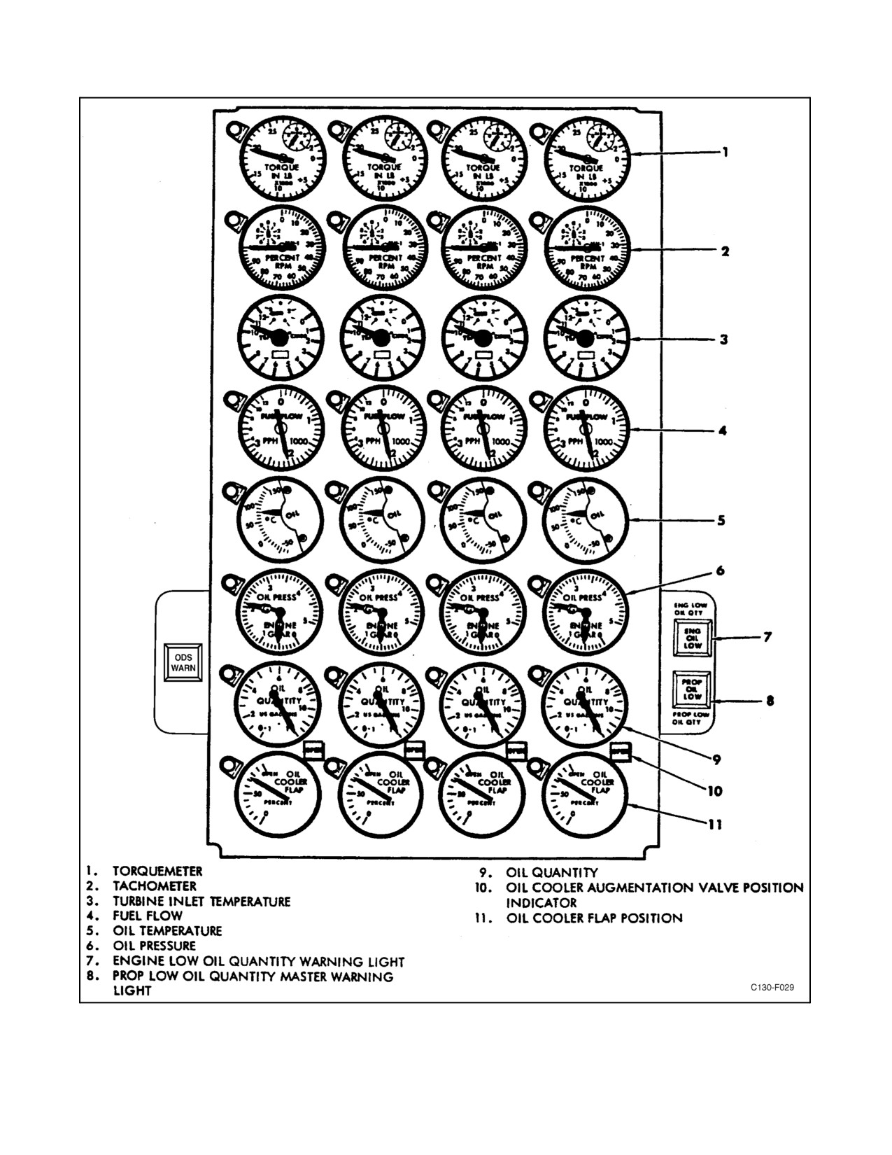
2.1.8 Engine Instruments
The engine instruments are located on a panel at the center of the main instrument panel. Indicator lights for fuel
pressure warning are on the overhead control panel. For additional information on fuel flow gauges and pressure
warning lights, refer to Fuel System Indicators, paragraph 2.6.11.
2.1.8.1 Torquemeters
Each of the four torquemeters (see Figure 2-11) indicates positive and negative torque in inch-pounds. The indicated
torque is detected at the extension shaft between the engine power section and reduction gear assembly. The
torquemetersystem uses 115-volt, single-phase, acpowerfrom theacinstrument andenginefuelcontrol busthrough
the ENGINE TORQUEMETER circuit breakers on the pilot lower circuit breaker panel.
2.1.8.2 Tachometers
Each of the four tachometers (see Figure 2-11) indicates engine speed in percent of normal engine rpm. A vernier
dial on each indicator makes it possible to read to the nearest percent. The tachometer system uses a separate
engine-driven tachometer generator, mounted on each engine, that is not dependent upon the aircraft electrical system
for operation.
ORIGINAL
2-20
01-75GAL-1
Figure 2-11. Engine Instrument Panel
2-21
ORIGINAL
01-75GAL-1
2.1.8.3 Turbine Inlet Temperature Indicators
Each of the TIT indicators (see Figure 2-11) indicates temperature sensed by thermocouples in the engine turbine
inlet casing. Each indicator registers temperature in degrees Centigrade and contains a vernier scale graduated in
degrees. The indicator system uses 115-volt, single-phase, ac power from the ac instrument and engine fuel control
bus through the TURBINE INLET TEMPERATURE circuit breakers on the pilot lower circuit breaker panel.
2.1.8.4 Fuel Flow Gauges
Each of the four fuel flow gauges (see Figure 2-11) indicates flow in pounds per hour. Flow is measured at the point
where fuel enters the manifold on the engine. The indicating system receives single-phase, 115-Vac power from the
ac instrument and engine fuel control bus through the FUEL FLOW circuit breakers on the pilot lower circuit breaker
panel, and it receives 28-Vdc power from the essential dc bus through the FUEL FLOW circuit breaker on the copilot
lower circuit breaker panel.
2.1.8.5 Secondary Fuel Pump Pressure Lights
Four press-to-test secondary fuel pump pressure lights are located on the engine starting and fuel enrichment panel
(see Figure 2-10). Each light is controlled by a pressure switch on the engine fuel pump and filter assembly. The light
is normally on while the two gear pumps in the assembly are operating in parallel during engine starting (prior to
65-percent rpm). The light also illuminates at any other time if the pump paralleling valve is closed or if the primary
gear pump fails. If the light does not illuminate during starting, either the pump paralleling valve is open or the
secondary pump has failed. The lights are energized by 28-Vdc power from the essential dc bus through the SEC
PUMP IND LIGHT circuit breaker on the copilot side circuit breaker panel.
2.1.8.6 Oil Temperature Gauges
Thefouroil temperaturegauges (seeFigure 2-11)indicate oil temperature in the oil inlet lines in degrees Centigrade.
The electrical-resistance-type indicators receive 28-Vdc power from the essential dc bus through the ENGINE OIL
TEMP INDICATOR circuit breaker on the copilot side circuit breaker panel.
2.1.8.7 Oil Pressure Gauges
Four dual oil pressure gages (see Figure 2-11) register oil pressure for both the engine power sections and reduction
gears. The rear needle marked “G” on each indicator shows reduction gear oil pressure, and the front needle marked
“E” indicates power section oil pressure. The oil pressure gauges receive 26-Vac power from the instrument
transformers through engine Nos. 1, 2, 3, and 4 GEAR BOX IND OIL PRESSURE and IND ENGINE OIL
PRESSURE fuses on the pilot lower circuit breaker panel.
2.2
FIRE AND OVERHEAT DETECTION SYSTEMS
A fire detection system is provided for each engine and the APU. An overheat detection system is provided for the
engine turbine and nacelle, anti-icing, and air-conditioning. The engine and nacelle fire and overheat detection
systems are described below. Refer to the appropriate system for description of other detection systems.
2.2.1 Fire Detection System
The fire detection system for each engine and APU consists of a continuous loop detector, an amplifier, and warning
lights in the flight station. When a high temperature is detected, the amplifier unit initiates a signal to the warning
lights. These lights give a steady red glow when activated. The fire detection system receives 28-Vdc power from
the essential dc bus through the FIRE DETECTOR circuit breakers on the copilot side circuit breaker panel.
2.2.1.1 Fire Detection System Test Switch
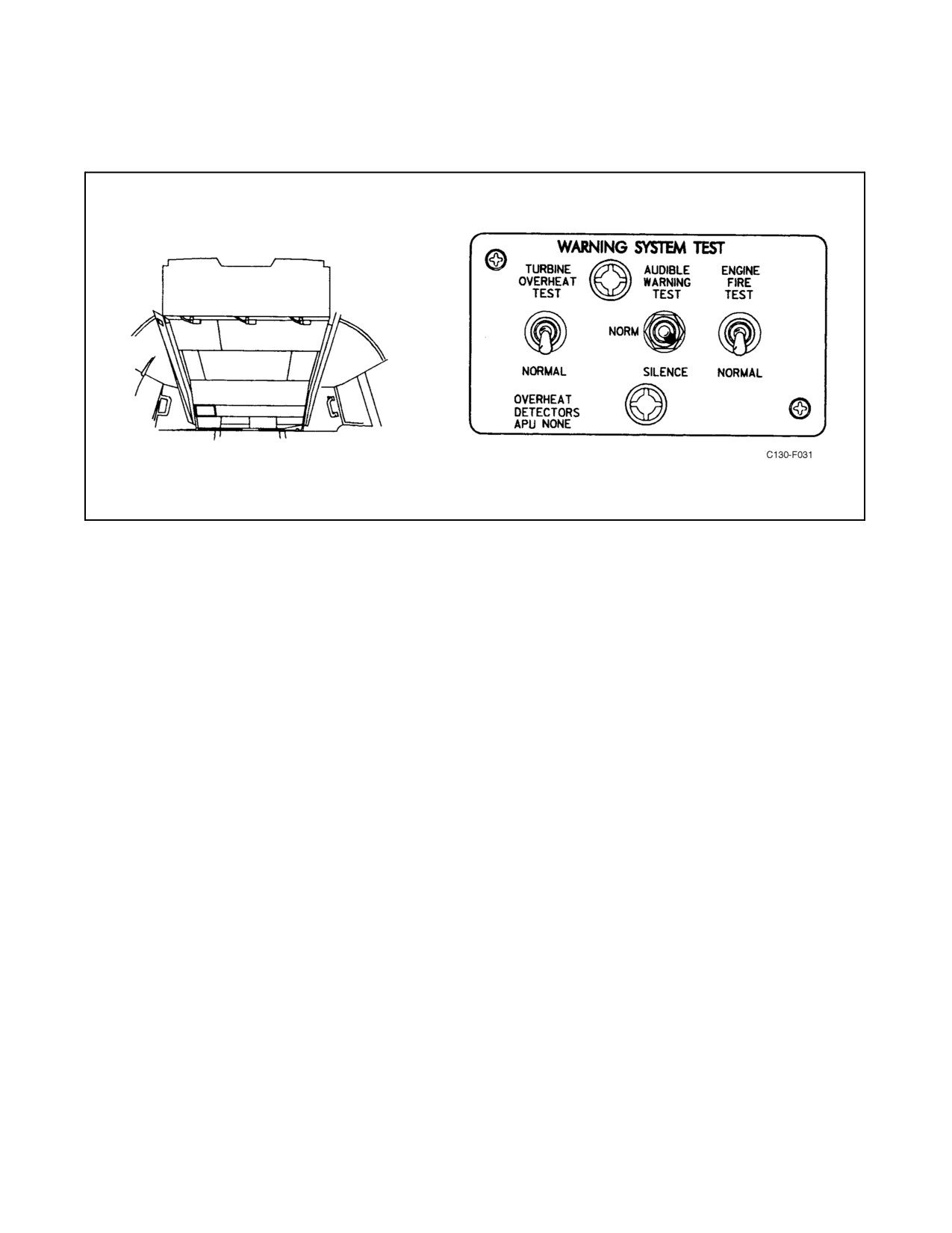
The fire detection test switch labeled ENGINE FIRE is located on the warning system test panel (see Figure 2-12)
on theoverhead control panel. Thetest systemis providedto testtheoperationofthedetectors andthewarninglights.
ORIGINAL
2-22
01-75GAL-1
When the switch is placed in the TEST position, all five fire detection systems are activated and the warning lights
will go on. Failure of a warning light to go on indicates a break in continuity in the warning circuit.
Figure 2-12. Warning System Test Panel
2.2.1.2 Fire Detection System Warning Lights
The fire detection system warning lights consist of the master fire warning light and the lights in the fire emergency
control handles.
2.2.1.2.1 Master Fire Warning Light
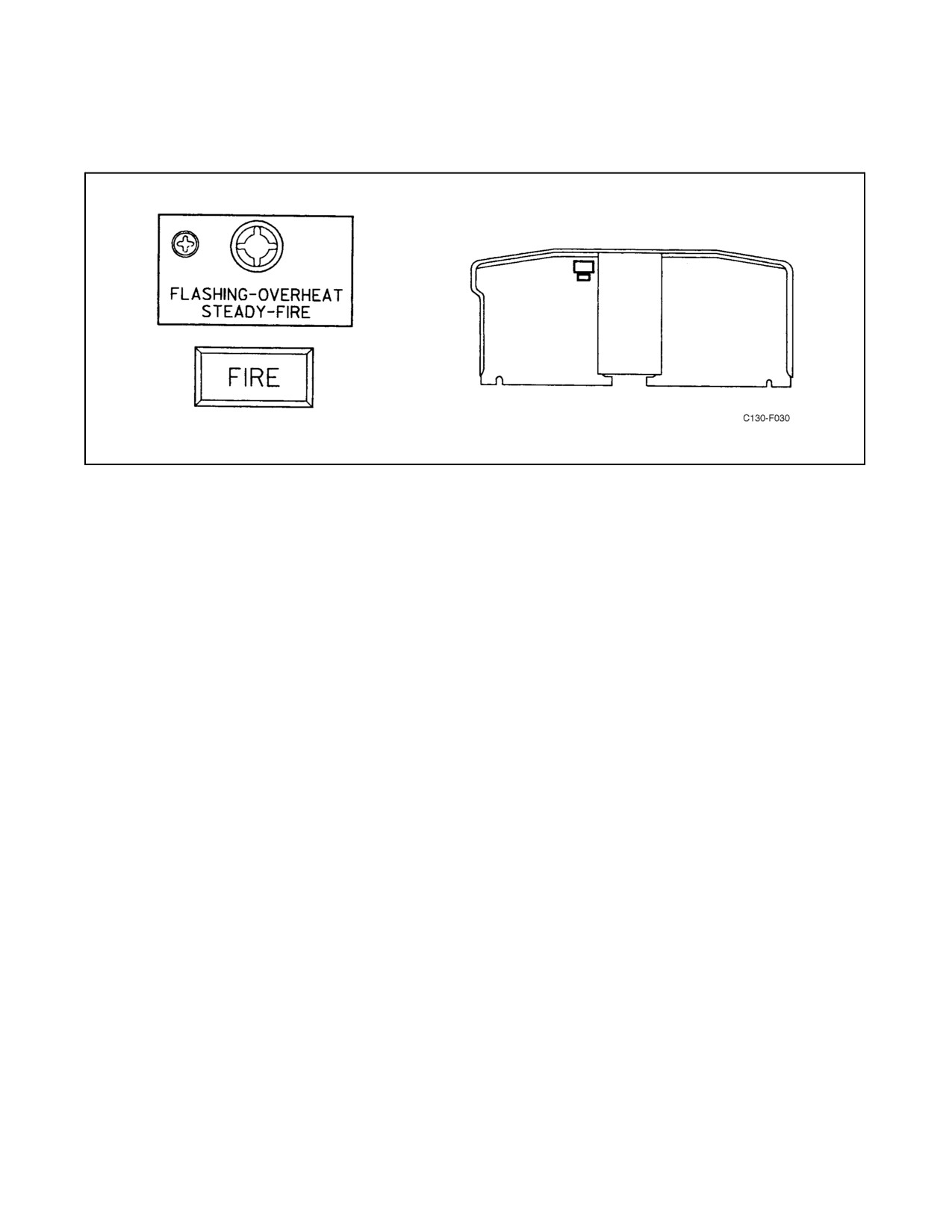
A red master fire warning light and an edge-lighted panel are located on the pilot instrument panel (see Figure 2-13).
If a fire is detected by any one of the detection systems, the warning light and panel light will glow steadily. The steady
light distinguishes the signal from an overheat warning indication, which is a flashing of the same light. When the
master light indicates a fire, the lights in one of the fire emergency control handles will be on also to indicate the
location of the fire. The master fire warning light receives power from the essential dc bus through the MASTER
FIRE WARNING circuit breaker on the copilot side circuit breaker panel.
2.2.1.2.2 Fire Emergency Control Handle Lights
Each emergency control handle (see Figure 2-17) contains four indicator lights. The top two lights in the handle flash
indicating a turbine overheat, while the two lower lights glow steady when a fire is detected in the corresponding
engine.
2.2.2 Turbine Overheat Warning Systems
An overheat warning system is provided for each engine turbine. Each system consists of four thermal-switch detector
units mounted in the “hot section” of the nacelle aft of the firewall, a flasher, and indicator lights. These components
are interconnected so that an overheat condition sensed by any one of the detectors causes the lights to flash. The
detectors are connected in parallel to a loop; and if part of the detectors is inoperable, the remaining detectors can
still close the circuit to turn on the lights. A test switch permits testing all four systems at the same time. The fenwal
setting at which the detector lights will give an overheat warning is approximately 700 _F. The 28-Vdc power for
2-23
ORIGINAL
01-75GAL-1
energizing the system is supplied from the essential dc bus through OVERHEAT DETECTORS TAILPIPE circuit
breakers on the copilot side circuit breaker panel.
Figure 2-13. Master Fire Warning Light
2.2.2.1 Turbine Overheat Warning Lights
Overheat warning of the engine turbine is indicated by flashing of the master fire warning light and the lights in the
fire emergency control handles.
2.2.2.1.1 Master Fire Warning Light
A red master fire warning light and an edge-lighted panel are located on the pilot instrument panel (see Figure 2-13).
The master fire warning light and the panel light flash when any one of the engine overheat warning systems senses
an overheat condition. The lights in the fire emergency control handle for the overheated engine will flash also. The
master fire warning light receives power from the essential dc bus through the MASTER FIRE WARNING circuit
breaker on the copilot side circuit breaker panel.
2.2.2.1.2 Fire Emergency Control Handle Lights
Each fire emergency control handle (see Figure 2-17) contains two red indicator lights that flash when an overheat
condition is sensed in its respective engine.
2.2.2.2 Turbine Overheat Detector Test Switch
The overheat detection test switch labeled TURBINE OVERHEAT (see Figure 2-12) is located on the warning
system test panel on the overhead control panel. The switch has NORMAL and TEST positions. When positioned
at TEST, it closes all four of the overheat warning system circuits in the same manner as if they were closed by
detectors sensing an overheat condition. If the indicator lights all come on and flash when the switch is operated,
circuit continuity and flasher operation are satisfactory.
Note
The test switch will only check circuit continuity and that the switch is
functioning properly. Even though all indicator lights come on and flash,
this does not indicate the detectors are properly set or even operating.
ORIGINAL
2-24
01-75GAL-1
2.2.2.3 Audible Warning Test Switch
The AUDIBLE WARNING test switch (see Figure 2-12) is a three-position (TEST, NORM, SILENCE),
spring-loaded toggle switch, located on the warning system test panel. The TEST and SILENCE positions of the
switch are both test positions. Holding the switch to TEST while visually monitoring the master fire warning light
and No. 1 fire emergency control handle light provides a check of the continuity of the fire warning system. The
master fire warning light panel and the No. 1 fire emergency control handle light should illuminate with a steady
glow. When the switch is released, it should return to NORM. Holding the switch to SILENCE while simultaneously
holding the engine test switch to TEST and repeating both monitoring operations provides a check on the current
operational status of a holding relay in the system. If the master fire warning light and all fire emergency control
handle lights glow, the relay is functioning as desired. Releasing the switch from the SILENCE position should cause
it to return to NORM. Electrical power for the system is furnished from the essential dc bus through an AUDIO
WARNING circuit breaker located on the copilot side circuit breaker panel.
Note
There is no audible fire warning on any Navy C-130T aircraft. This switch
only tests a holding relay.
2.2.3 Nacelle Overheat Warning Systems
An overheat warning system is provided for each nacelle. Each system consists of eight thermal-switch detector units,
seven mounted in the nacelle area forward of the firewall, one mounted in the horse collar area, and a warning light
on the copilot instrument panel. A test switch is provided for testing all four warning systems simultaneously. The
purpose of each system is to warn of an overheat condition in the area around the engine compressor section. Overheat
in this areacan result from thenacellepreheat valvebeing openedoraruptureoccurringin thebleed-airsystemducts.
Theoverheatconditioncould alsoresult fromfire. Theoverheat conditioncan bedetected byany oneofthedetectors,
which are connected in parallel to a loop. The fenwal setting at which the detector lights will give an overheat warning
is approximately 300 _F.
2.2.3.1 Indicator Lights
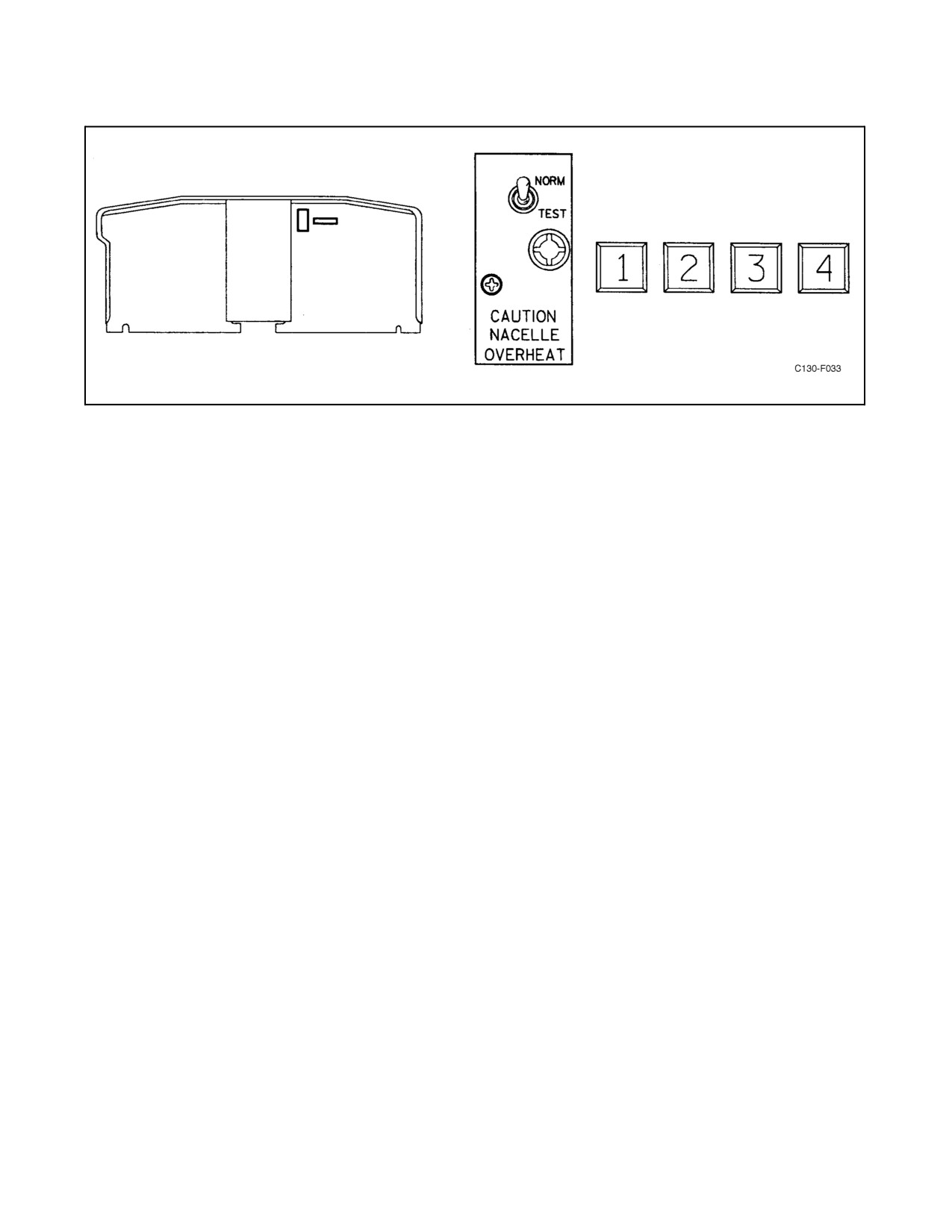
Fournumberednacelleoverheatwarninglightsandatestpanel(seeFigure2-14)arelocated onthecopilotinstrument
panel. If overheat is detected in any nacelle, the corresponding overheat warning light and the light on the test panel
will go on. Power for the overheat warning lights comes from the essential dc bus through the OVERHEAT
DETECTORS NACELLE TAILPIPE circuit breakers on the copilot side circuit breaker panel. The indicator lights
receive 28-Vdc power from the essential dc bus through the NACELLE OVERHEAT NAMEPLATE and
OVERHEAT DETECTORS NACELLE circuit breakers on the copilot side circuit breaker panel.
2.2.3.2 Nacelle Overheat Test Switch
A nacelle overheat test switch is located on the copilot instrument panel next to the warning lights (see Figure 2-14).
Operation of the test switch closes all four nacelle overheat warning circuits simultaneously, causing all four warning
lights and the panel lights to glow as long as the switch is held in TEST. Failure of a light to go on indicates a break
in continuity in the warning circuit.
Note
The test switch will check only circuit continuity and that the switch is
functioning properly. Even though all indicator lights go on, this does not
indicate that the detectors are properly set or even that they are operating.
2-25
ORIGINAL
01-75GAL-1
Figure 2-14. Nacelle Overheat Control Panel and Lights
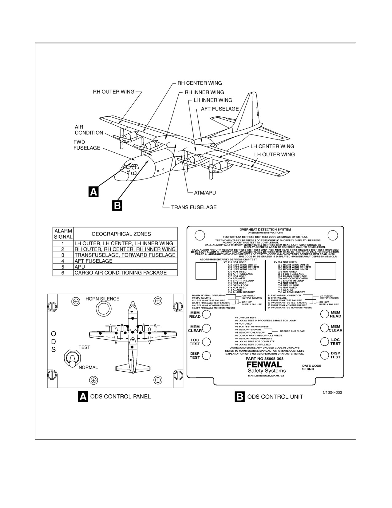
2.2.4 Bleed Air Duct Overheat Detection System (ODS)
An overheat warning system is provided for the aircraft’s high-pressure bleed air ducts. The system will provide
warnings upon detection of small leaks in the bleed air duct system, which if left undetected could cause extensive
collateral damage to other aircraft systems and structures. The system consists of a control unit, a relay panel, an ODS
control panel, and several continuous discrete sensing elements divided into 11 zones. The sensing elements will
detect a rise in temperature and are set to provide visual and audible warnings at temperatures of 310 _F for elements
located outsidetheaircraft and 255 _F forelements withinthefuselagecompartment (seeFigure2-15).Ifanoverheat
condition is detected, warning lights in the flight station will illuminate and the landing gear warning horn will pulse
at 90 cycles per minute. The control unit in the cargo compartment will also display a code that can be used for further
troubleshooting. When the overheat condition diminishes, the system will reset and the sensing elements return to
theiroriginal condition with no external actionrequired. Abroken sensingelement willcontinuetofunction oneither
side of the break; however, the system will not properly test. The system receives 115-Vac power from the essential
ac bus through the LHS SENSORS and RHS SENSORS circuit breakers and 28-Vdc power from the essential dc
bus through the ODS ALARM and ODS CONTROL circuit breakers located on the pilot’s lower circuit breaker
panel.
2.2.4.1 ODS Control Panel
The ODS control panel is located on the flight engineer’s overhead panel (Figure 2-15). The control panel provides
visual indications of an ODS warning and incorporates a warning horn silence button and system test switch. Eleven
NVIS red indicator lights correspond to the 11 zones of the sensor elements and are grouped into six output alarms.
Alarm signal 1 illuminates all three indicator lights in the left wing. Alarm signal 2 illuminates all three indicator
lightsintherightwing.Alarmsignal3illuminatesboththetransfuselageandforwardfuselageindicatorlights.Alarm
signal 4 illuminates the aft fuselageindicator light. Alarm signal 5 illuminates theAPU indicatorlight. Alarm signal
6 illuminates the air conditioning indicator light.
2.2.4.1.1 ODS Test Switch
A lever locked NORMAL/TEST toggle switch located on the ODS control panel allows the operator to activate a
system self-test. The switch is spring-loaded to the NORMAL position. Placing the switch to the test position will
illuminate the 11 indicator lights, the ODS master warning light, and cause the landing gear warning horn to sound
in pulsing mode (90 cycles per minute).
ORIGINAL
2-26
01-75GAL-1
Figure 2-15. Bleed Air Overheat Detection System (ODS)
2-27
ORIGINAL
01-75GAL-1
2.2.4.1.2 ODS Horn Silence Switch
A HORN SILENCE switch is located on the ODS control panel and allows the ODS warning horn to be silenced
during an alarm condition or self-test.
2.2.4.2 ODS Master Warning Light
An amber ODS master warning light is located on the lower left side of the engine instrument panel (Figure 2-11).
If an overheat condition is detected, the master warning light will illuminate steady along with the pulsing landing
gear warning horn and corresponding alarm indicator lights on the overhead control panel.
2.2.4.3 ODS Control Unit
The ODS control unit is located on the starboard side of the cargo compartment. The control unit monitors sensing
elements mounted in 11 zones throughout the aircraft and groups them into 6 alarm zones. The control unit’s
monitoringcircuitsrecordanyalarmconditionand transmitsignals tothecontrolpanel intheflightstation toindicate
where the overheat condition exists. Specific alarm and malfunction codes are displayed on LED readouts on the face
panel of the control unit. All malfunction and alarm codes are stored in memory for maintenance and repair purposes.
2.3
FIRE EXTINGUISHING SYSTEM
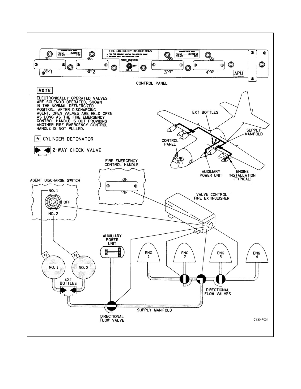
A two-shot bromotrifluoromethane (BT) fire extinguishing system (see Figure 2-16) is connected through a series
of directional-flow valves to each of the four engine nacelles and to the APU compartment. The extinguishing agent
is contained in two bottles mounted in the left wheelwell. Each bottle contains approximately 27 pounds of agent.
One bottle is discharged each time the system is actuated. A check valve prevents a discharged bottle from being
recharged when a fresh bottle is fired. Each bottle is charged to approximately 600 psi with nitrogen, the nitrogen
acting as a propellant for the BT. Individual pressure gauges on each bottle show charged pressure.
Repeated or prolonged exposure to high concentrations of BT or
decomposition products should be avoided. BT is a narcotic agent of
moderate intensity but of prolonged duration. It is considered to be less
toxic than carbon tetrachloride, methyl bromide, or the usual products of
combustion. BT is safer to use than these fire extinguishing agents.
However, normal precautions should be taken, including the use of oxygen
when available.
2.3.1 Fire Extinguishing System Controls
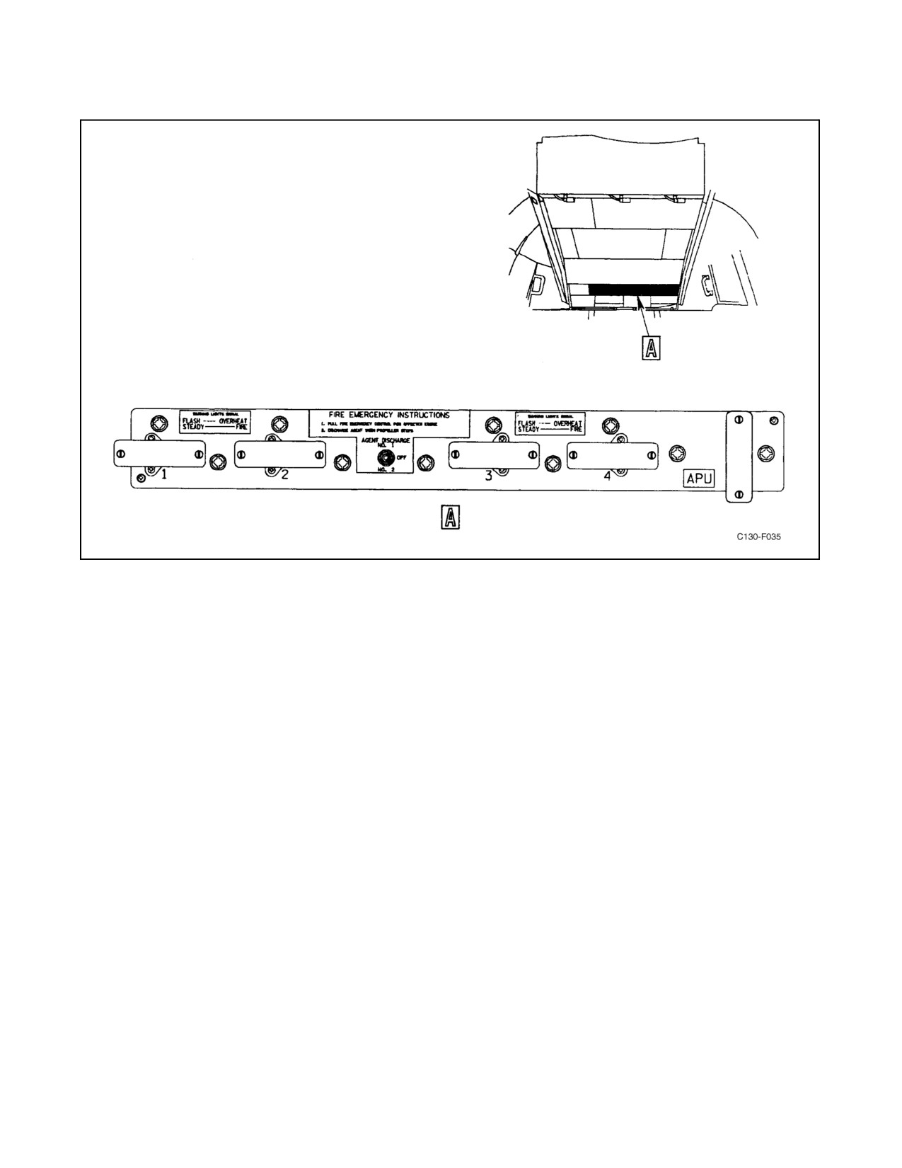
The fire extinguishing system controls are located on the fire emergency control panel (see Figure 2-17) forward of
the overhead electrical control panel. The fire extinguishing system control circuits use dc power supplied from the
battery bus through three FIRE EXT circuit breakers on the pilot side circuit breaker panel. One circuit breaker labeled
FIRE EXT is in the control circuit and the other two labeled FIRE EXT NO. 1 and NO. 2 are in the squib firing circuits
(one for each squib).
ORIGINAL
2-28
01-75GAL-1
Figure 2-16. Fire Extinguishing System
2-29
ORIGINAL
01-75GAL-1
Figure 2-17. Fire Emergency Control Panel
2.3.1.1 AGENT DISCHARGE Switch
A three-position (NO. 1, OFF, NO. 2) toggle switch located on the fire emergency control panel (see Figure 2-17)
controls the discharge of the bottles. The AGENT DISCHARGE switch is spring-loaded to the OFF position. The
agent will not discharge unless a fire emergency control handle is pulled. The fire emergency handle circuit powers
the correct sequence of solenoid directional control valves in the system to direct flow ofagent to the selected engine
when one of the bottles is fired. The directional flow valves move in the same order as the handles are pulled. If two
fire emergency control handles are pulled, the agent will be routed to the engine for the last handle pulled. In order
to route agent to the engine for the first handle pulled, the first handle must be pushed in and pulled again.
2.3.1.2 Fire Emergency Control Handles
The five plastic fire emergency control handles are mounted on the fire emergency control panel (see Figure 2-17).
They operate emergency shutdown switches for the APU and the four engines. When an engine handle is pulled out,
it closes dc circuits to operate valves that isolate the engine as follows:
1. The shutoff valve on the engine fuel control is closed.
2. The engine oil shutoff valve is closed.
3. The firewall fuel shutoff valve is closed.
4. The firewall hydraulic shutoff valves are closed.
5. The engine bleed-air regulator is closed.
ORIGINAL
2-30
01-75GAL-1
6. Engine starting control circuits are deenergized.
7. The propeller is feathered.
8. The fire extinguisher system directional flow valves are positioned for routing agent to the engine. The
extinguishing AGENT DISCHARGE switch is armed.
When the APU handle is pulled, the APU is isolated as follows:
1. The fuel shutoff valve is closed.
2. The bleed-air valve is closed.
3. The fire extinguisher system directional flow valve is positioned for routing agent to the APU.
4. The extinguisher AGENT DISCHARGE switch is armed. The APU door closes.
2.4
PROPELLERS
Each engine is equipped with a Hamilton Standard, four-blade, electro-hydromatic, full-feathering, reversible-pitch
propeller. The propeller operates as a controllable-pitch propeller for throttle settings below flight idle and as a
constant-speed propeller for throttle settings of flight idle or above. The major components of the propeller system
are the propeller assembly, the synchrophasing system, the control system, and the anti-icing and deicing system.
2.4.1 Propeller Assembly
The propeller assembly is made up of the propeller blades, barrel assembly, dome assembly, spinner assembly,
control assembly, and the anti-icing and deicing assembly.
2.4.1.1 Propeller Blades
The propeller blades are solid aluminum alloy with hollow shanks for weight reduction. On the mounting end of the
blades are located the blade gear segments, thrust bearings, oil seals, and deicing rings.
2.4.1.2 Barrel Assembly
The principal functions of the barrel assembly are to retain the blades within the propeller assembly, to provide the
necessary means of attaching the propeller to the engine shaft, and to transmit engine torque to the blades. The barrel
assembly is made in two sections that are bolted together to retain the propeller blades. An extension on the rear half
of the assembly is machined to fit over the splined engine shaft. The pitchlock assembly, located inside the barrel
assembly, consists of a stationary pitchlock ratchet ring, a pitchlock rotating ratchet, a pitchlock valve, and fly-weight
assembly. The pitchlock prevents the blades from decreasing pitch if hydraulic pressure is lost, and it locks the blades
at a fixed pitch angle if overspeeding occurs. The stationary and rotating pitchlock ratchet rings are held disengaged
by propeller oil pressure and are spring loaded to engage when pressure is lost. When the ratchet rings are engaged,
the propeller can increase pitch to allow feathering. In an overspeed condition, the flyweight assembly will remove
oil pressure and allow the pitchlock to engage and prevent a decrease in blade angle. When the overspeed condition
is corrected, oil pressure is restored to release the pitchlock.
2.4.1.3 Dome Assembly
The dome assembly is mounted on the forward section of the barrel assembly. It contains the pitch changing
mechanism and the low-pitch stop assembly. The pitch changing mechanism converts hydraulic pressure into
mechanical torque. Its main parts are a piston assembly, a stationary cam, a rotating cam, and the dome shell. The
2-31
ORIGINAL
01-75GAL-1
piston is a double-walled assembly that fits over the two cams and inside the dome shell. The piston is held in place
by rollers that ride in the cam tracks of both cams. The rear of the rotating cam is connected by beveled gears to the
propeller blades. As hydraulic pressure is applied to the piston, causing it to move, the rollers riding in the cam tracks
turn the rotating cam, changing the blade angle. The low-pitch stop in the dome mechanically stops the piston from
decreasing blade angle below the flight range. The low-pitch stop is retracted to allow lower blade angles during
ground operation.
2.4.1.4 Control Assembly
The propeller control assembly is mounted on the aft extension of the propeller barrel but does not rotate. It contains
the oil reservoir, pumps, valves, and control components that supply the pitch changing mechanism with hydraulic
pressure of the proper magnitude and direction to vary the propeller blade angle as required for the selected operating
condition. The valve housing assembly section of the control assembly contains the flyweight speed-sensing pilot
valve, feather valve, feather solenoid valve, and feather actuating valve. The pump housing assembly contains a
scavenge, main, and standby pump, and an electrically driven, double-element, auxiliary pump. The flow of fluid
from these pumps is controlled by the valves in the valve housing assembly to accomplish the desired propeller
operation. All mechanical and electrical connections necessary for propeller operation are made through the control
assembly.
The mechanical connections are linkages from the engine control system and the NTS system. The electrical
connections are for oil level indication, pulse generator coil, auxiliary pump motor, synchrophasing system,
anti-icing and deicing systems, and the electrical feathering system.
2.4.1.5 Spinner Assembly
Thespinnerassembly,whichimprovestheaerodynamiccharacteristicsofthepropellerassembly,encloses thedome,
barrel, and control assemblies. It consists of a front section, a rear section, and a nonrotating afterbody assembly.
Cooling air is admitted through an air inlet at the front of the spinner and passes over the dome assembly, barrel
assembly, and control assembly fins, and exhausts through vents in the engine nacelle.
2.4.1.6 Anti-Icing and Deicing Assembly
The anti-icing and deicing assembly is made up of stationary and moveable contacts for conducting electrical power
to the resistance-type heating elements on the leading edge and shank of each blade and the entire spinner assembly.
Continuous anti-icing heaters cover the spinner front section and the afterbody assembly. Cyclic deicing heaters
cover the remainder of the spinner front section, the spinner rear section, the blade shanks, and part of each blade’s
leading edge. The contact ring holder assembly mounted on the aft end of the barrel assembly contains four sliprings
and four contact brush housing assemblies. Power from the aircraft electrical system is transmitted through the
brushes and sliprings to the spinner anti-icing and deicing elements and the blade’s deicing elements.
2.4.1.7 Propeller Low Oil Level Warning Lights
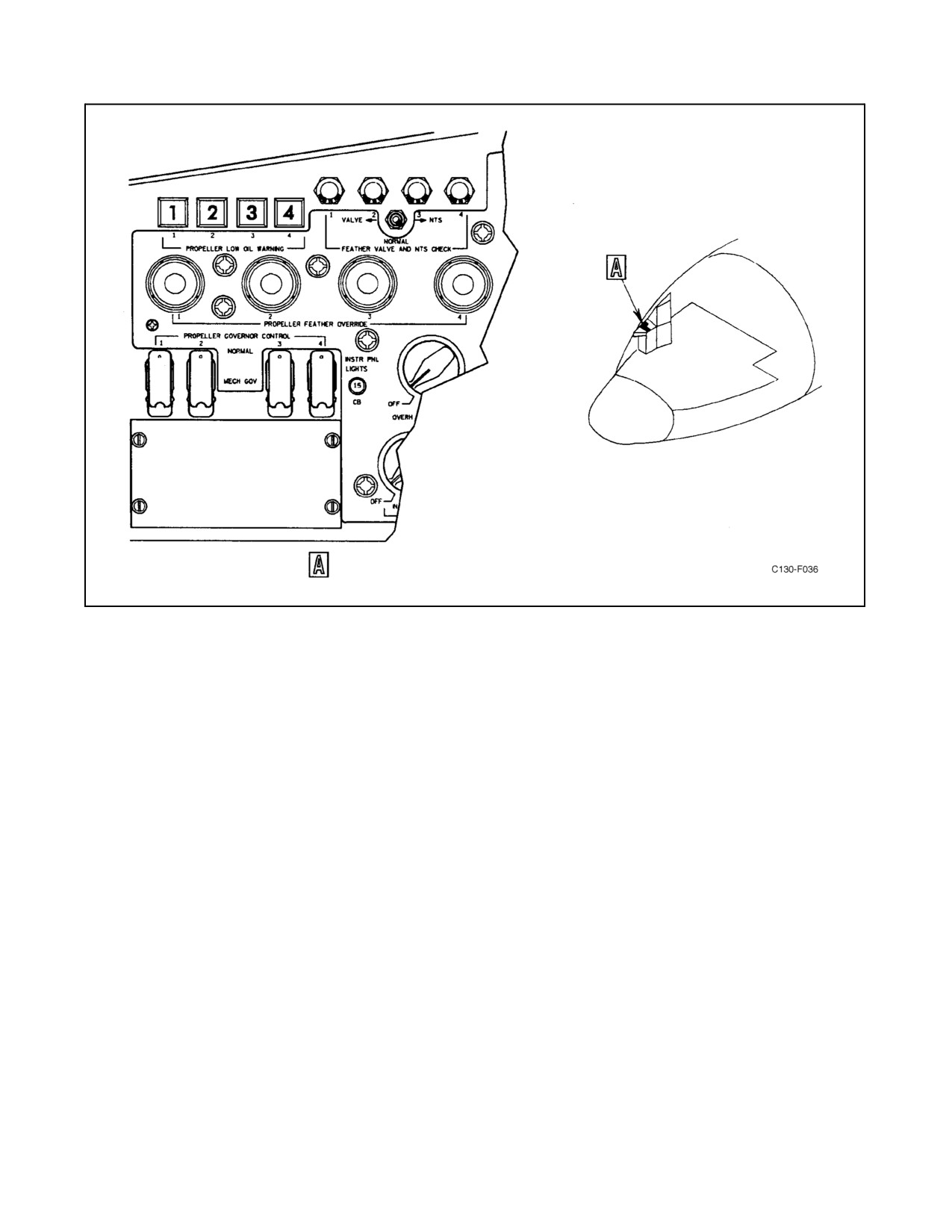
A PROPELLER LOW OIL WARNING light for each propeller is located on the copilot side shelf(see Figure2-18);
a PROP LOW OIL quantity light, which acts as a master warning light, is located on the engine instrument panel
(see Figure 2-11). The propeller low oil warning system is controlled by a float-actuated switch in each propeller
control assembly. When the oil quantity for each propeller drops approximately 2 quarts below normal, the
float-actuated switch closes and illuminates the PROPELLER LOW OIL WARNING light for that engine and the
PROPLOWOILquantity light.Iftheoil quantitybecomes lowforanotherpropeller, theonly indicationwill befrom
the PROPELLER LOW OIL WARNING light for that engine. The low oil warning lights receive 28-Vdc power from
the essential dc bus through the PROP LOW OIL LEVEL circuit breaker on the copilot side circuit breaker panel.
2.4.2 Propeller Speed Control System
The speed of the propeller is controlled by the propeller governing system and the synchrophasing system.
ORIGINAL
2-32
01-75GAL-1
Figure 2-18. Propeller Controls
2.4.2.1 Propeller Governing System
The principal function of the propeller governing system is to maintain constant engine operating rpm. Propeller
governing is accomplished by the action of the flyweight speed-sensing pilot valve. This valve is controlled by the
mechanical action of the flyweight opposing the tension of the speeder spring. When the propeller is in an on-speed
condition, the pilot valve meters sufficient fluid to the increased pitch or forward side of the dome assembly piston
to overcome twisting movement and maintain the required blade angle. When an overspeed condition occurs, the
flyweight force overcomes the speeder spring force, and the pilot valve moves to increase the flow to the
increased-pitch side of the piston. If the propeller slows below governed speed, the force of the speeder spring
overcomes the force exerted by the flyweights, and the pilot valve meters fluid to the aft side of the dome assembly
piston to decrease blade angle and allow the propeller to increase speed. The low-pitch stop prevents the propellers
from decreasing blade angle below the flight range while the throttles are in the flight range.
2.4.2.2 Synchrophasing System/Electronic Governing
The synchrophaser electronic unit provides circuits for the following governing functions: speed stabilization
(derivative), throttle anticipation, and synchrophasing. The propeller mechanical governor will hold a constant speed
in theflight rangebut throttlechanges willcausethegovernortooverspeed orunderspeed whiletrying tocompensate
for the change in power. A stabilization circuit stabilizes the mechanical governor during these changes when the
propeller governor control switch is in the NORMAL/NORM position by sending a signal to the speed bias servo
control motor to change the speeder spring compression. The throttle anticipation circuit stabilizes the propeller
speed during rapid movement ofthethrottlewhen thepropellergovernorcontrol switch is in the NORMAL position.
Throttle movement rotates the anticipation potentiometer in the propeller control assembly sending a signal to the
2-33
ORIGINAL
01-75GAL-1
anticipation circuit which sends an amplified signal to the speed bias servo control motor to change the speeder spring
compression. The synchrophasing system acts to keep all the propellers turning at the same speed, and it maintains
a constant blade rotational position relationship to decrease vibration and to lower the noise level. The system uses
either No. 2 or No. 3 engine as the master engine, and it relates the blade position of the other three engines to the
master. The blade position of a slave engine is changed by moving the pilot valve to increase or decrease the speed
of that engine. The synchrophasing circuit determines the blade position by comparing an electrical pulse generated
by each slave propeller to a modified pulse from the master propeller. If the blades are in the correct position, the
resultant voltage of the slave and master pulse will be zero. Any deviation in blade position will produce a positive
or negative voltage from the two compared pulses. This voltage drives the speed bias servo control motor to change
the speeder spring compression, correcting the blade position. If propeller operation is erratic, see paragraph 11.4.2,
Propeller Malfunctions. The electronic propeller governing system is powered by the essential dc bus through the
SYNCHROPHASER circuit breaker on the copilot side circuit breaker panel.
2.4.3 Negative Torque Signal Lockout System
The propeller is equipped with a lockout system to deactivate the NTS system for throttle settings below FLIGHT
IDLE. When the throttle is moved below FLIGHT IDLE, a cam moves the actuator away from the NTS plunger and
renders the system inoperative. This is necessary to prevent a propeller from receiving a possible negative torque
signal at high landing speeds when the throttles are moved toward reverse, with resultant asymmetrical power
problems.
2.4.4 Propeller Controls
Propeller controls include the throttles, condition levers, SYNCHROPHASE MASTER switch, PROP RESYN-
CHROPHASE switch, PROPELLER GOVERNOR CONTROL switches, fuel governor check switches, and feather
override buttons.
2.4.4.1 Throttles
Each throttle (see Figure 2-4) is mechanically linked through the engine coordinator to an input shaft on the propeller
control assembly. When the throttle is in the governing range, between FLIGHT IDLE and TAKE-OFF positions,
the input shaft rotates with throttle movement but has no effect on propeller speed. When the throttle is in the range
below FLIGHT IDLE, any movement of the throttle is transmitted to the speed-sensing pilot valve to increase or
decrease blade angle. The maximum negative blade angle is obtained when the throttle is at MAXIMUM REVERSE.
Approximate minimum thrust angle is obtained when the throttle is at GROUND IDLE. When the throttle is moved
below FLIGHT IDLE, a cam locks out the NTS system and a switch interrupts synchrophaser signals to the
propeller.
2.4.4.2 Engine Condition Levers
The engine condition levers (see Figure 2-4) serve primarily as feathering and unfeathering controls. Each lever is
mechanically linked to the engine coordinator, which transmits the motion of the lever to the propeller linkage only
when it is moved to the FEATHER position. When pulled to FEATHER, the condition lever also actuates switches
to turn on theelectrically-driven auxiliary pump in thepropellercontrol assembly and thepropellerblades aremoved
to the feather angle. For unfeathering, the engine condition lever is held in the AIRSTART position. A switch is
actuated to turn on the propeller auxiliary pump, and the pump continues to operate as long as the lever is held in
this position. When the engine condition lever is in the AIRSTART position and the auxiliary pump is operating,
fluid is routed to the aft side of the dome assembly piston to move the blades to low-pitch angle. When the condition
lever is in GROUND STOP or RUN positions, the propeller is controlled normally and the lever has no effect on its
operation.
ORIGINAL
2-34
01-75GAL-1
2.4.4.3 SYNCHROPHASE MASTER Switch
The SYNCHROPHASE MASTER switch (see Figure 2-19) is located on the flight control pedestal. This
three-position (ENG 2, OFF, ENG 3) toggle switch controls the operation of the synchrophase system and selects
the engine to be used as the master. When the switch is in the ENG 2 position, the No. 2 engine is selected as the
master and the other propeller phase angles are referenced to this engine. When the switch is in the OFF position and
the propeller governor control switches are in the NORMAL position, the synchrophasing system is turned off and
the propellers operate in normal governing. If the propeller governor control switches are in the MECH GOV
position, the propellers operate in mechanical governing. When theswitch is in theENG 3 position, theNo. 3 engine
is the master and the other propeller phase angles are referenced to this engine.
2.4.4.4 Prop Resynchrophase Switch
The prop resynchrophase switch (see Figure 2-19) is a two-position (NORMAL, RESYNC) toggle switch located
on the flight control pedestal. The switch is spring-loaded and shear-wired to the NORMAL position. The prop
resynchrophase switch shall not be positioned to RESYNC except when performing the propeller re-indexing
procedure and should be used only for correcting an out-of-sync or off-speed condition by performing the complete
re-indexing procedure. These airplanes will have a decal installed above the prop resynchrophase switch on the flight
control pedestal stating SOLID STATE SYNCHROPHASER INSTALLED. REFER TO APPROVED FLIGHT
MANUAL FOR OPERATION. Power is supplied through the SYNCHROPHASER 28V essential dc circuit breaker
located on the copilot side circuit breaker panel.
CAUTION
The PROP RESYNCHROPHASE switch shall not be positioned to
RESYNC except when performing the propeller reindexing procedure and
should be used only for correcting an out-of-sync or off-speed condition by
performing the complete reindexing procedure.
2.4.4.5 Propeller Governor Control Switches
The four PROPELLER GOVERNOR CONTROL switches are two-position (NORMAL, MECH GOV) guarded
toggle switches located on the copilot side shelf (see Figure 2-18). When the switches are in the NORMAL position,
the throttle anticipation and speed stabilization (derivative) circuits are operative, and if the SYNCHROPHASE
MASTER switch is positioned to either master engine, the blade rotational position of the slave engines is related
to the master by the synchrophasing system. Placing a switch in the MECH GOV position disconnects the electrical
speed control to that propeller and the speed of the propeller is controlled by basic mechanical governing.
2.4.4.6 Fuel Governing Check Switches
The four FUEL GOVERNING check switches located on the aft end of the overhead control panel, provide a means
of checking the operation of the propeller pitch-lock mechanism and the engine fuel control governor.
CAUTION
The fuel governing check switches must never be used in flight.
2-35
ORIGINAL
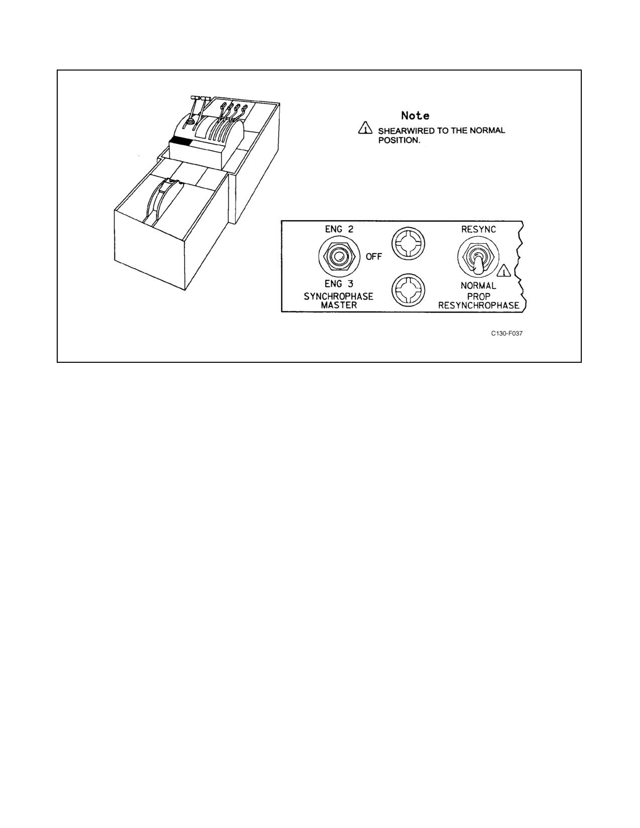
01-75GAL-1
Figure 2-19. Synchrophaser Control Switch Panel
2.4.4.7 Feather Override Buttons
Four FEATHER OVERRIDE buttons are located on the copilot side shelf (see Figure 2-18) to provide a means of
manually stopping the propeller auxiliary pump. When a condition lever is moved to FEATHER, electrical circuits
are completed to the feather solenoid valve, propeller auxiliary pump, pressure cutout switch, and a holding circuit
to thefeather overridebutton. Ifa FEATHER OVERRIDE button is manually pulled aftera condition lever is placed
in FEATHER, the electrical circuits for propeller feathering are interrupted. If a FEATHER OVERRIDE button does
not pop out after the feather cycle is complete, it should be pulled manually to prevent damage to the propeller
auxiliary pump. The holding coil of the override button receives 28-Vdc power from the essential dc bus through the
FEATHER & AIRSTART or EMER FEATHER circuit breaker on the copilot side circuit breaker panel.
2.5
OIL SYSTEM
Independent oil systems, one for each engine, supply lubrication to the engine power section and the reduction gear
assembly. An oil tank with a 12-gallon usable oil capacity is located in each nacelle above the engine. The oil tanks
are provided with a pendulum-tube oil pickup to prevent loss of oil pressure under negative-g conditions. The
pendulum will accompany the oil in a negative-g condition, assuring positive oil pressure. Oil from the tank enters
the power section and the reduction gear assembly, where it is circulated and returned by scavenger pumps through
a heat exchanger and oil cooler back into the oil tank. Hot oil passing through the heat exchanger heats the engine
fuel and prevents ice from forming in the fuel filter. Air flowing through an oil cooler duct and over the coils of the
oil cooler absorbs excess heat from the oil. A bleed-air ejector, located in the oil cooler air exit duct, provides
additional airflow through the oil cooler for ground operations. A thermostatic element in the oil tank return line
controls the oil temperature by regulating the amount of air flowing through the oil cooler duct. Four motor-operated
valves provide an emergency means of shutting off oil flow to the engines when the fire emergency control handles
are pulled. Oil used in the aircraft must conform to the specification and grade listed in the servicing diagram (see
Figure 3-1).
2.5.1 Oil System Controls
Oil system controls availableto theflightcrew aretheoil coolerflap switches and thefireemergency control handles.
ORIGINAL
2-36
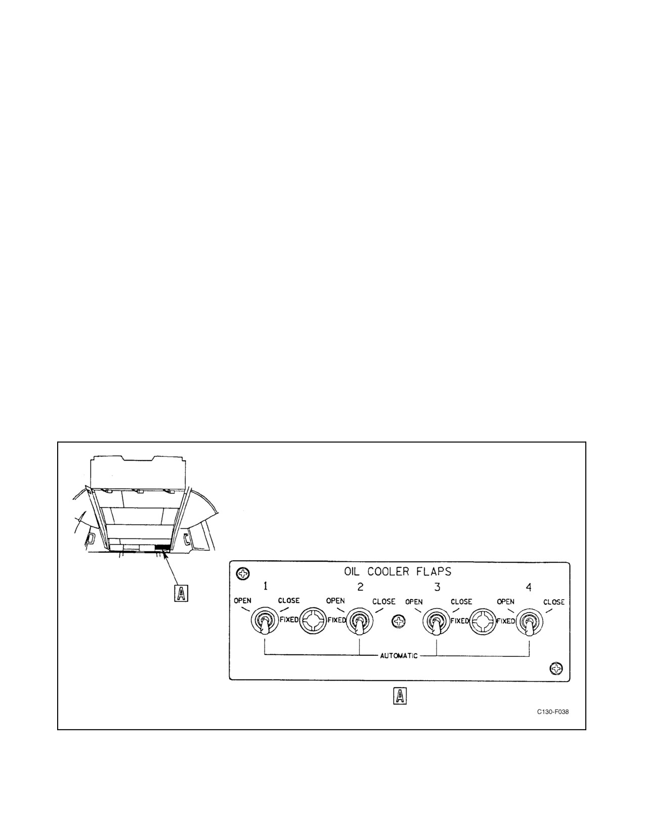
01-75GAL-1
2.5.1.1 Oil Cooler Flap Switches
Airflowthroughtheoilcoolerisgoverned byacontrollableoil coolerflap whichrestricts theopening oftheoilcooler
air exit duct, and by an oil cooler augmentation valve which controls the flow of fourteenth stage compressor bleed
air to an ejector assembly in the oil cooler exit duct. Four, four-position (AUTOMATIC, OPEN, CLOSE, FIXED)
oil cooling toggle switches are located on the oil cooling control panel on the overhead control panel (see Figure
2-20). These switches control the electrical circuits of the oil cooler flap actuators and the oil cooler augmentation
valves. In the AUTOMATIC position, the oil cooler flap position is regulated by a thermostatic unit to maintain an
oiltemperatureofapproximately80 _C.IntheOPENorCLOSEpositions(spring-loaded)thethermostat isexcluded
from the circuit and the actuator is directly energized to open or close the oil cooler flap. When the switch is moved
to FIXED, the actuator is deenergized and the flap will remain in the position it was in prior to moving the switch.
TheOPEN, CLOSE, and FIXED positions areused to control theoil coolerflapactuatormanuallyifthethermostatic
control unit fails. The oil cooler flap actuators receive 28-volt, dc power from the essential dc bus through OIL
COOLER FLAPS circuit breakers on the copilot side circuit breaker panel.
2.5.1.2 Oil Cooler Augmentation Switches
Oil coolerairflow augmentation is provided by ahigh-pressure bleed-airejector located in theoil coolerair exit duct.
Four two-position (ON, OFF) toggle switches on the overhead control panel operate oil cooler augmentation valves
that control the flow of 14th-stage compressor bleed air to the ejectors (see Figure 2-21). The oil cooler flap must
be at least 90-percent open, the throttle must be in the ground operating range, and the ENGINE GROUND START
switch must be in the OFF position before power is available to the OIL COOLER AUGMENTATION switch. The
oil cooler augmentation valves are energized through the OIL COOLER AUGMENTATION switches by 28-Vdc
power from the essential dc bus, through the START CONTROL circuit breakers on the copilot side circuit breaker
panel.
2.5.1.3 Fire Emergency Control Handles
Motor-operated shutoff valves, energized by 28-volt essential dc powerand controlled by thefire emergency control
handles (see Figure 2-17), are installed in the engine oil systems to shut off the flow of oil to the engine during an
emergency. See paragraph 2.3.1.2 for other functions of the fire emergency control handles.
Figure 2-20. Oil Cooler Flap Control Panel
2-37
ORIGINAL
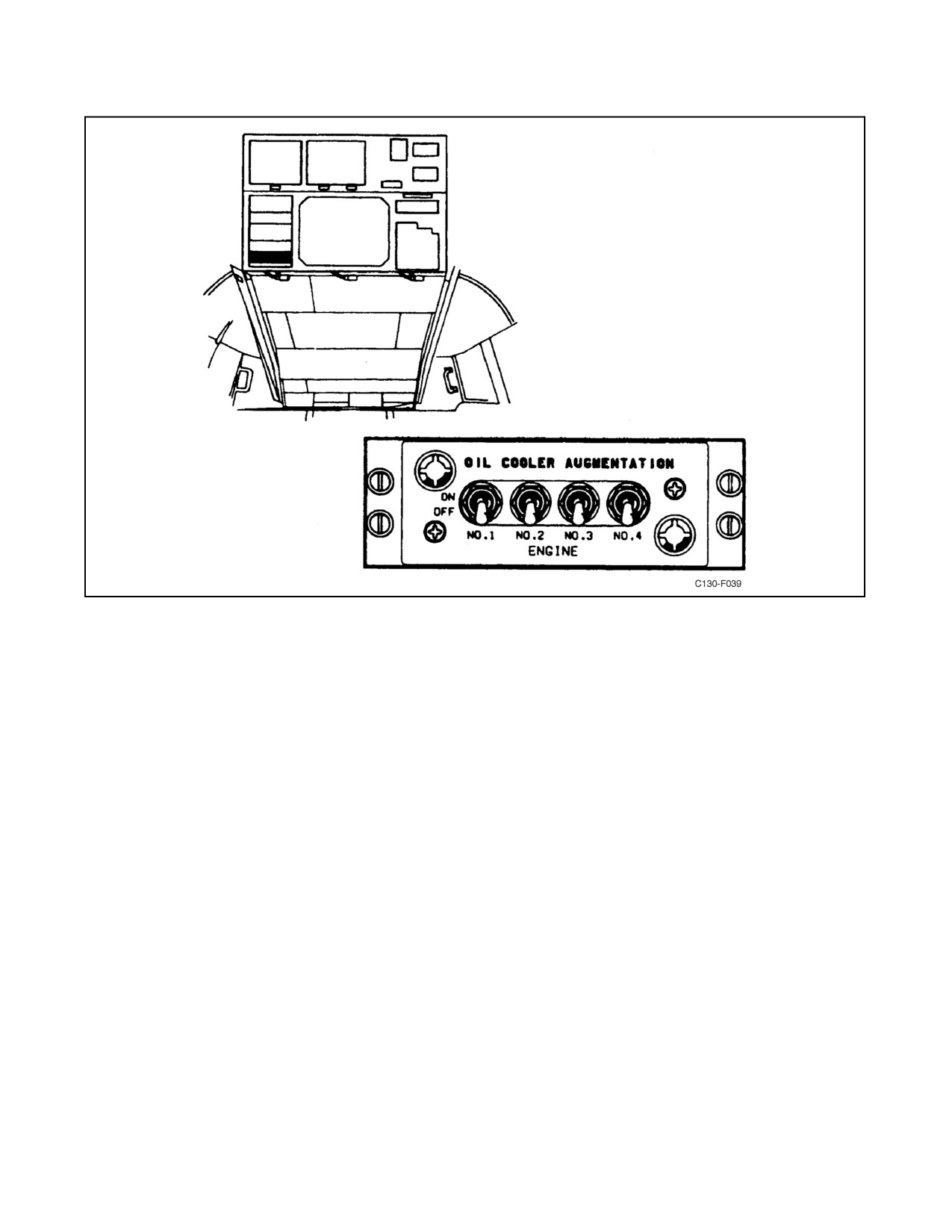
01-75GAL-1
Figure 2-21. Oil Cooler Augmentation Control Panel
2.5.2 Oil System Indicators
The oil system indicators are an oil quantity gauge for each engine, a low-oil-quantity warning light, and an oil cooler
flap position indicator for each engine. All of the indicators are located on the engine instrument panel (see
Figure 2-11).
2.5.2.1 OIL QUANTITY Gauges
Four OIL QUANTITY gauges (see Figure 2-11), one for each engine oil system, are located on the engine instrument
panel. Each indicator is calibrated from 0 to 1 (empty) to F (full) in increments of 1 gallon. The indicators are
energized by 28-Vdc power from the essential dc bus through the OIL QUANTITY INDICATOR circuit breakers
on the copilot side circuit breaker panel.
2.5.2.2 Low Oil Quantity Warning Light
A low-oil-quantity warning light (see Figure 2-11) is located on the engine instrument panel. A microswitch in each
engine oil tank quantity transmitter, actuated by the tank float arm, will cause the light to illuminate when any oil
tank level drops to 4 gallons. Operation of the light is independent of quantity indicators; however, no additional
warning is supplied should a second tank reach a low level. The warning light receives 28-Vdc power from the
essential dc bus through the engine oil quantity light circuit breaker on the copilot side circuit breaker panel.
2.5.2.3 Oil Cooler Augmentation Valve Position Indicators
Fouroil cooleraugmentation valveposition indicators, oneforeach valve, arelocatedon theengineinstrumentpanel
(see Figure 2-11). The press-to-test indicators are connected electrically to pressure switches in the ejector bleed-air
duct downstream of the augmentation valves and illuminate (OPEN) when the pressure switch closes. The lights are
energized by 28-Vdc power from the essential dc bus through the OIL COOLER VALVE OPEN IND circuit breaker
on the copilot lower circuit breaker panel.
ORIGINAL
2-38
01-75GAL-1
2.5.2.4 OIL COOLER FLAP Position Indicators
Four OIL COOLER FLAP position indicators (see Figure 2-11), one for each engine oil system, are located on the
engine instrument panel. The indicators are electrically connected to position transmitters geared to the oil cooler
flap actuators. The indicator dials, calibrated from 0 to OPEN in increments of 10 percent, indicate the percentage
that the oil cooler flaps have opened. The indicators are energized by 28-Vdc power from the essential dc bus through
the OIL COOLER FLAPS circuit breakers on the copilot side circuit breaker panel.
2.6
FUEL SYSTEMS
Note
On aircraft incorporating AFC-424, all of the fuel tanks are equipped with
baffle systems fabricated from reticulated, explosion-fire suppressant
conductive foam.
Thefuel system is amodified manifold-flow-type,incorporating afuel crossfeedsystem, asingle-point refuelingand
defueling system, and a fuel dump system. The system provides fuel supply for the four engines and the auxiliary
power unit. It is adaptable to a number of flow arrangements (see FO-1). For systems diagrams, see FO-1. Fuel
specifications and grades are listed in Figure 3-1. Total usable capacity of the fuel tanks is shown in Figure 2-22.
For system management, refer to paragraph 8.28. Aircraft limitations resulting from use of emergency fuels are
discussed in Chapter 4.
2.6.1 Fuel Flow
Each engine may be supplied fuel either directly from the main respective fuel tank or through the crossfeed manifold
system from any tank. Fuel for the APU is routed directly from the No. 2 fuel tank.
2.6.2 Refueling and Defueling
All wing tanks and the fuselagetank (ifinstalled) may be refueled or defueled from thesingle-point ground refueling
and defueling receptacle located in the right main landing gear fairing. When refueling, fuel is routed from the
single-point receptacle through the refueling manifold to each tank through separate supply lines from the manifold.
Fuel level in the tanks is controlled by float shutoff valves. All tanks except No. 1 and 4 contain one shutoff valve
that allows the tanks to be filled to their maximum capacity, maintaining a minimum of 3-percent expansion space.
Two shutoff valves in both the No. 1 and 4 tanks are located at different levels. These valves are controlled by the
refueling pod disconnects.
The low-level valves operate when the refueling pods are installed and allow the tanks to become only partially full.
When the pods are removed, the high-level valves operate and allow the tanks to fill completely. Refueling and
defueling are controlled at the single-point refueling control panel located in the right landing gear fairing. As an
alternate method of refueling, the main and external tanks may be fueled separately through a filler opening in the
top of each tank. The fuselage tank does not incorporate a manual filler opening, but it can be refueled by transferring
fuel from the wing tanks, or from the single-point refueling control panel, and selecting the OPEN position of the
fuselage tank fill switch on the auxiliary fuel control panel. In defueling the wing tanks, fuel flows into the crossfeed
manifold through the refueling manifold, and overboard through the single-point refueling receptacle. Defueling flow
from the fuselage tank is into the refueling manifold and overboard through the single-point refueling receptacle.
2.6.3 Internal Tanks
Six fuel tanks are located within the wing (see FO-1). The No. 1, 2, 3, and 4 tanks are integral and use sealed wing
structure for tank walls. The left and right auxiliary fuel tanks are each comprised of units of three bladder cells. The
three cells are interconnected to form one assembly and are laced within the center wing section. Each of the six tanks
has a three-phase, ac-powered boost pump to ensure fuel flow. The water removal system, located in each main tank,
maintains the fuel level around the boost pump when the aircraft is in a nosedown attitude with low fuel level in the
tank. The No. 1, 2, 3, and 4 tanks have, in addition, a dump pump that is used for fuel dumping and transfer.
2-39
ORIGINAL
01-75GAL-1
USABLE FUEL
UNUSABLE FUEL (JP-4)
UNUSABLE FUEL (JP-4)
BOOST PUMP ON
BOOST PUMP ON
BOOST PUMP OFF
LB
GAUGE
GAUGE
TANK
GAL
JP-4
JP-5/JP-8
LB
GAL
READING
LB
GAL.
READING
No. 1
1,288
8,372
8,758
78
12
0
475
73
397
No. 2
1,186
7,709
8,065
91
14
0
592
91
501
Left Ext
3
1,379
8,964
9,377
137
21
0
1
137
21
0
Left Aux
901
5,857
6,127
59
9
0
2
2
2
Right Ext
3
1,379
8,964
9,377
137
21
0
1
137
21
0
Right Aux
901
5,857
6,127
59
9
0
2
2
2
No. 3
1,186
7,709
8,065
91
14
0
592
91
501
No. 4
1,288
8,372
8,758
78
12
0
475
73
397
Lines
39
6
TOTALS
Main Tanks Only
4,948
32,162
33,646
377
58
Main and Aux Tanks
6,750
43,876
45,900
495
76
Main and Ext Tanks 3
7,706
50,090
52,400
651
100
Main, Aux, and Ext Tanks
9,508
61,804
64,654
769
118
Notes
1
The external tanks are equipped with dual pumps and a single pump off will not affect the unusable fuel quantity in
these tanks.
2
The unusable fuel for an auxiliary tank is the quantity in the tank at the time the boost pump becomes inoperative.
3
External tank installation (Lear Siegler part no. 305J001).
4.
Fuel quantities based on 6.5 pounds per U.S. gallon for JP-4 and 6.8 pounds per U.S. gallon for JP-5.
5.
Pounds (LB) and gallons (Gal) are rounded off to the nearest whole number.
Figure 2-22. Fuel Quantity Data Table (Without AFC-424 Foam) (Sheet 1 of 2)
2.6.4 Water Removal System
The water removal system provides continual water removal from the tank low points during boost pump operation.
The system consists of two ejectors, a check valve, a strainer, and associated plumbing in each main tank. The ejectors
are connected by plumbing to the boost pump discharge line, and a part of the boost pump fuel flow is routed through
each ejector housing and discharged through its nozzle. This fuel flow through the ejectors causes a differential
pressure, and additional fuel is drawn from between the lower wing panel risers and is ejected into the surge box.
Anytime the fuel boost pump is operating, the fuel will be continually stirred to prevent water from settling in the
bottom of the tank.
2.6.5 Vent System
All of the six wing fuel tanks are vented to the atmosphere to equalize pressure at all times. Tank Nos. 2 and 3, and
the left and right auxiliary tanks have a wraparound vent system. The wraparound system permits venting for these
tanks even though the aircraft is not in a wings-level attitude. The outboard tanks (Nos. 1 and 4) are vented by a
float-controlled vent valve to prevent fuel loss overboard on the ground when the aircraft is not in a wings-level
attitude and in flight when the wings deflect upward. Vent air leaving the tank passes through a drainbox on its way
overboard. Any fuel entering the vent lines because of an aircraft change of attitude collects in the drainbox and is
returned to the tank continuously by the water removal system in the inboard and outboard tanks and by the jet pump
eductors in the auxiliary tanks. Boost pump pressure is necessary for the water removal system and jet pump eductors
ORIGINAL
2-40
01-75GAL-1
to operate. The No. 1 and 4 tanks also contain a pressure-relief valve that vents tank pressure directly to the jettison
manifold, downstream of the dump mast shutoff valve.
The external tanks are vented through the spaces at the top of the bulkheads separating the tank compartments and
through the fuel vent line. The vent line runs from the forward compartment of each tank through the pylon and up
into the wing trailing edge, where it vents to the atmosphere. Fuel will not fill the vent line because each tank is
separated by compartments. The vent line is at the top of the tanks and runs upward to the wing.
USABLE FUEL -- BOOST PUMP ON
UNUSABLE FUEL -- BOOST PUMP OFF
TANK
LB
GAL
GAL
GAUGE READING
JP--5/JP--8
No. 1
1,222
8,310
73
390
No. 2
1,126
7,657
91
490
LEFT EXT
1,309
8,901
1
21
0
LEFT AUX
855
5,814
2
2
RIGHT EXT
1,309
8,901
1
21
0
RIGHT AUX
855
5,814
2
2
No. 3
1,126
7,657
91
490
No. 4
1,222
8,310
73
390
TOTALS
Notes
MAIN TANKS ONLY
4,696
31,934
The external tanks are equipped with dual
1
pumps. A single pump off will not affect the unus-
MAIN AND AUX
able fuel quantity in these tanks.
6,404
43,562
TANKS
2
The unusable fuel fo an auxiliary tank is the
quantity in the tank at the time the boost pump be-
MAIN AND EXT
comes inoperative.
7,314
49,736
TANKS
3
Fuel quantities based on 6.8 pounds per US
gallon for JP--5/JP--8. Pounds per gallon are
MAIN, AUX AND
rounded off to the nearest whole calculated number.
9,024
61,364
EXT TANKS
For gauge readings, round down to the nearest 10
pounds.
To calculate weights for JP--4 fuel, multiply fuel
4
quantities by 6.5 pounds per gallon.
Figure 2-22. Fuel Quantity Data Table (With AFC-424 Foam) (Sheet 2)
2.6.6 Crossfeed Primer System
A press-to-actuate CROSSFEED PRIMER VALVE button is located on the fuel control panel (see Figure 2-23). This
button, when pressed, moves the motor-operated crossfeed fuel primer valve to the open position and opens the
motor-driven crossfeed separation valve. This allows fuel to flow through the manifold into the No. 2 fuel tank to
remove any trapped air. Releasing the button actuates the primer valve to the closed position and closes the crossfeed
separation valve. Power for the system comes through the ENGINE CROSSFEED VALVES PRIME circuit breaker
on the copilot side circuit breaker panel.
2.6.7 External Tanks
Two all-metal external fuel tanks are mounted under thewings on pylons between the inboard and outboard engines.
The tanks are partially compartmented for center-of-gravity control. All fuel flows into the center compartment
through check valves. A surge box in the tank center compartment contains a forward and an aft boost pump,
providing dual reliability and an increased fuel dumping rate if both pumps are operated during fuel dumping. Both
pumpshaveoverridingoutputpressures that,undernormaloperation, ensuredepletion offuel fromtheexternaltanks
before the main tanks are affected.
2-41
ORIGINAL
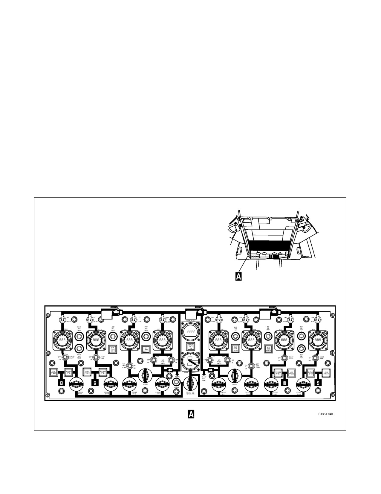
01-75GAL-1
2.6.8 Fuel Dump System
A fuel dump system is provided to enable all fuel, except approximately 1,600 pounds each from the No. 1 and 4
wing tanks, 1,500 pounds each from the No. 2 and 3 wing tanks, and 65 pounds from each external tank, to be dumped
overboard.Eighttwo-position(OFF,DUMP)toggleswitchesforthewingtanksarelocatedon theenginefuelcontrol
panel. Two-position (NORM, DUMP) guarded toggle switches and two rotary interconnect switches are located on
theauxiliaryfuelcontrolpanel(Figure2-24).Thedumprateisapproximately3,900 poundsperminutefromthewing
tanks with all pumps operating. All tanks feed into a common manifold in the wing, then to a dump mast in each
wingtip. Check valves at each tank dump outlet prevent reverse flow. The four main wing tanks have individual
integral pumps specifically for fuel dumping. The two auxiliary and two external tanks use the same pumps for
dumping that are used for normal boost operation. Actuation of the tank dump switch will open the tank dump valve
and turn the pump on for the selected tank (see FO-1). To complete the dump operation, the interconnect switches
on the auxiliary fuel panel are turned to the flow condition and the two guarded dump switches on the auxiliary fuel
control panel are placed in the DUMP position. When the auxiliary tank dump switches are actuated, the auxiliary
tank crossfeed valves will close. Refer to Chapter 11 for operation of the wing tank fuel dump system and to Part
VIII for operation of the fuselage tank dump system. All pumps are powered by three-phase, 200/115-volt, 400-Hz
ac. Power for the motor-operated dump valves is supplied from the essential dc bus through the LH and RH FUEL
DUMP VALVES circuit breakers on the copilot side circuit breaker panel. The dump pumps in the four main wing
tanks are supplied power from the main ac bus through the DUMP PUMPS circuit breakers on the copilot upper
circuit breaker panel.
Figure 2-23. Fuel Control Panel
ORIGINAL
2-42
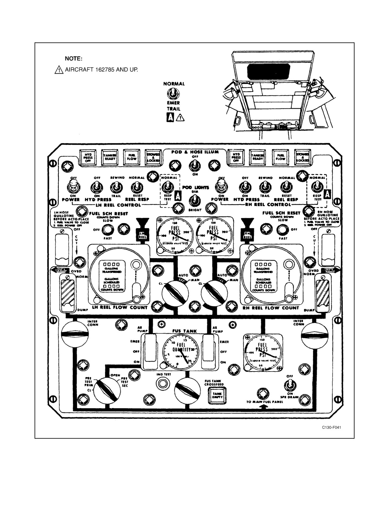
01-75GAL-1
Figure 2-24. Auxiliary Fuel Control Panel
2-43
ORIGINAL
01-75GAL-1
2.6.9 Fuel Strainer and Heater Unit
A combination fuel strainer and heater is located in the right side of each nacelle. Heat is transferred from engine oil
to the fuel in the heater unit, and the temperature is controlled thermostatically.
2.6.10 Fuel System Controls
Controls for normal in-flight management of engine fuel are located on the fuel control panel (see Figure 2-23).
2.6.10.1 BOOST PUMP Switches
Ten BOOST PUMP switches are located on the fuel control panel. The No. 1, 2, 3, and 4 fuel tank boost switches
control the internal boost pumps for their respective tanks. The left and right AUX TANK PUMP switches control
the pump in each of the auxiliary tanks. Four BOOST PUMP switches, one forward and one aft for each external tank,
control the pumps in the external tanks. All of the boost pumps are powered by three-phase, 115/200volt, 400-Hz
ac. The No. 1 tank pump is supplied power through the FUEL BOOST PUMP TANK NO. 1 circuit breakers on the
pilot upper circuit breaker panel left-hand ac bus. The No. 2 tank pump is supplied power through the FUEL BOOST
PUMP TANK NO. 2 circuit breakers on the pilot side circuit breaker panel essential ac bus. The No. 3 tank pump
is supplied power through the FUEL BOOST PUMP TANK NO. 3 circuit breakers on the copilot upper circuit
breaker panel main ac bus. The No. 4 tank pump is supplied power through the FUEL BOOST PUMP TANK NO.
4 circuit breakers on the pilot upper circuit breaker panel right-hand ac bus. The left- and right-hand auxiliary fuel
tank boost pumps are supplied power through the AUXILIARY TANK LH and RH circuit breakers on the copilot
uppercircuit breakerpanel main acbus. Theright- and left-hand external fuel tank forward boost pumps aresupplied
power through the RH and LH EXT PUMP (FWD) circuit breakers on the pilot upper circuit breaker panel from the
RH and LH ac buses respectively. The right- and left-hand external fuel tank aft boost pumps are supplied main ac
power through the RH and LH EXT TANK PUMP (AFT) circuit breakers on the copilot upper circuit breaker
panel.
2.6.10.2 CROSSFEED VALVE Switches
Eight CROSSFEED VALVE switches are located on the fuel control panel (see Figure 2-23). These two-position
rotary switches route 28-Vdc through the ENGINE CROSSFEED VALVES circuit breakers on the copilot side
circuit breaker panel to the motor-operated crossfeed valves. When the switches are placed in the flow position
(switch markings aligned with the fuel control panel markings), the valve motors are energized to open the valves.
When the switches are placed in the no-flow position (switch markings at right angles to the panel markings), the
valve motors are energized to close the valves. In case of power failure, the valves hold the last energized position.
2.6.10.3 Bypass Valve Switches
Two bypass valve switches are located on the fuel control panel to permit an alternate path for fuel from the left and
right auxiliary and external fuel tanks if crossfeed valves fail to open. These two-position rotary switches route power
to motor-operated bypass valves.When theswitches areplaced inbypass position(switch markingsaligned withfuel
control panel markings), valve motors are energized to open the valves and allow external tank fuel to be crossfed
or jettisoned through the auxiliary tank crossfeed or jettison valves, and vice versa. The bypass valves may be used
to jettison main tank fuel in the event of main tank dump valve/pump failure. When switches are placed in the off
position (switch markings at right angles to panel markings), valve motors are energized to close the valves. In case
of power failure, the valves hold the last energized position. The bypass valve switch receive power from the essential
dc bus through the FUEL MANAGEMENT ENGINE CROSSFEED VALVES 1 & 4 (LEFT VALVE) and 2 & 3
(RIGHT VALVE) circuit breakers located on the pilot side circuit breaker panel.
2.6.10.4 Crossfeed Separation Valve Switch
The CROSSFEED separation switch is located on the fuel control panel (see Figure 2-23). The crossfeed separation
valve is provided in the crossfeed manifold system to permit additional control on fuel routing. With the crossfeed
separation valve closed, the left wing tanks supply fuel to engine Nos. 1 and 2, while the right wing tanks supply fuel
toengineNos.3and4.Thisprocedureensuresamoreeven fuelconsumption whenoperating fromtheauxiliarytanks
through the crossfeed manifold. Since there may be aslight variation in boost pump pressureand ifboth pumps were
supplying the manifold, the pump operating at the highest pressure would feed the manifold if not prevented by the
separation valve. However, the crossfeed separation valve is used primarily for fuel balancing between the left- and
right-hand fuel tanks and when crossfeeding from the fuselage tank. The crossfeed separation valve is electrically
ORIGINAL
2-44
01-75GAL-1
actuated by 28-Vdc power received from the essential dc bus through the ENGINE CROSSFEED VALVES PRIME
circuit breaker, located on the copilot side circuit breaker panel.
2.6.10.5 Fire Emergency Control Handles
Five fire emergency control handles, one for each engine and one for the auxiliary power unit, are mounted on the
fire emergency control panel (see Figure 2-17). These control handles route 28-Vdc power to the motor-operated,
engine firewall fuel shutoff valves and to the motor-operated, auxiliary power unit fuel supply shutoff valve. In case
of power failure, valves hold the last energized position. Circuit protection is provided by the FIRE SHUTOFF
VALVES circuit breakers on the copilot side circuit breaker panel and the APU CONTROL circuit breaker on the
pilot side circuit breaker panel. Other functions of the handles are described under paragraph 2.3.1.2.
2.6.11 Fuel System Indicators
Quantity gauges and warning lights are located on the fuel control panel (see Figure 2-23) and on the auxiliary fuel
control panel (see Figure 2-24) to give the crew a continuous, visual indication of the status of the fuel system. For
additional information on fuel indicators, refer to paragraph 2.1.8.
2.6.11.1 TOTAL FUEL QUANTITY Indicator
A TOTAL FUEL QUANTITY indicator is located in the center of the fuel control panel (see Figure 2-23). The
indicator continuously shows the total fuel quantity (in pounds) in the fuel tanks when the single-point refueling
master switch is in the OFF position. When the master switch is in any position other than OFF, the TOTAL FUEL
QUANTITY indicator is deenergized. The indicator is tested when an individual tank quantity indicator is tested as
described in paragraph 2.6.11.2. The TOTAL FUEL QUANTITY indicator receives single-phase, 115-volt, ac power
from the ac instruments and fuel control bus through the FUEL QUANTITY TOTALIZER circuit breaker on the pilot
lower circuit breaker panel.
2.6.11.2 FUEL QUANTITY Indicators and Test Switches
Note
On aircraft 165313 and up there is no analog bar graph on the flight
station indicators.
FUEL QUANTITY indicators are located on the fuel control panel (see Figure 2-23). Each tank indicator provides
a continuous visual display of the pounds of fuel contained in that tank. A liquid crystal display shows fuel quantity
in both digital and analog format. A three-digit numeric readout shows fuel quantity in thousands of pounds. An
analog bar display around the periphery of the dial shows the percentage of total fuel capacity of that tank. Each
illuminated small mark represents 2 percent of tank capacity. The major marks for each 10 percent of tank capacity
are always illuminated. Separate conductors in the aircraft wiring harness provide a binary code that tells the
individualindicatorcomputertowhichtankitisconnected.Theindicatoris thenproperly scaledforthattank. Aletter
(M, E, A) and a number (1, 2, 3, 4) appear at the bottom of the indicator display that identifies the tank. The main
tanks are identified as M1, M2, M3, and M4; the auxiliary tanks are identified as Al and A2, and the external tanks
are identified as El and E2. All eight indicators on the fuel control panel are interchangeable. Each indicator has
computerized built-in-test equipment. The BITE is designed to test the entire fuel quantity indicating system, not just
the indicator. The BITE functions are continually processed during normal system operation. Additional test
functions are performed at power-up and when the IND TEST pushbutton is depressed. The results of the BITE test
are displayed in numerical code by the indicator. Pressing the IND TEST pushbutton on the fuel control panel
adjacent to the indicator causes the display reading to decrease toward zero. Releasing the IND TEST pushbutton
causes all segments of the digital display, analog display, tank identification and error code to illuminate for
approximately 4 seconds, after which all segments will extinguish for approximately 4 seconds. Then any error code
that has been detected since power-up will be displayed for approximately 4 seconds until all errors found by thebite
test are displayed. During normal operation, all fault conditions are detected within 10 seconds after occurrence, and
the error code is displayed on the indicator. If thedetected fault condition should return to normal, theerror codewill
be removed and the normal fuel quantity display will automatically resume. The following error codes may be
displayed:
2-45
ORIGINAL

01-75GAL-1
ERROR CODE
DESCRIPTION
FUEL QUANTITY INDICATION
E0
Open or missing tank unit
Zero
E1
Tank unit leakage
Displayed at reduced accuracy
E2
Tank unit Hi-Z fault
Zero
E3
Compensator Lo-Z fault
Displayed at reduced accuracy
E4
Tank unit Lo-Z fault
Zero
E5
Compensator fault
Normal display at reduced accuracy
E6
Shorted tank unit
Zero
E7
Compensator leakage or out of
Displayed at reduced accuracy
range
E8
Indicator internal failure
Zero or blank
E9
Internal calibration failure
Zero
Blank Display
Indicator failure
Blank
The BITE for the TOTAL FUEL QUANTITY indicator is continually processed during normal operation of the
system. The indicator displays error codes that are either detected within the indicator itself or received from any of
the eight fuel quantity indicators. The TOTAL FUEL QUANTITY indicator is tested when the IND TEST
pushbutton for any individual fuel quantity indicator is depressed. When an IND TEST pushbutton is depressed, the
TOTAL FUEL QUANTITY indicator reading will decrease in response to the decrease in the individual tank fuel
quantity indicator. The fuel quantity indication will continue to decrease to zero until the IND TEST pushbutton is
released. When the pushbutton is released, all segments of the total fuel quantity indicator display will illuminate
for approximately 4 seconds. Then all segments will be extinguished for 4 seconds. When the TOTAL FUEL
QUANTITY indicator is in the BITE mode, it will not display any type of error code. If an individual tank fuel
quantity indicator has more than one error code to display during the BITE test, the total fuel quantity indicator will
return to normal fuel quantity display. The error codes are continuously displayed whenever the fault is present. If
more than one fault is present, each fault will be sequentially displayed for 1 second.
Note
Tank indicator error codes indicate an error in the individual fuel tank
quantity indicator. A communications errorcodeis displayed when nodata
or invalid data is received from a tank indicator. The number appearing
after the first letter identifies the tank. For example, M2E0 indicates No.
2 main tank communications error.
The following error codes are detected by the TOTAL FUEL QUANTITY indicator and the repeater indicators.
ERROR
CODE
DESCRIPTION
M—E
Main tank indicator error
A—E
Auxiliary tank indicator error
E—E
External tank indicator error
M — E0
Main tank indicator communication error
A — E0
Auxiliary tank indicator communication error
E — E0
External tank indicator communication error
Blank Display
Total fuel quantity indicator failure
E8
Display is blank with error code; indicator internal failure
E9
Display shows zero with error code; calibration failure
The fuel quantity indicating system receives 115-Vac power from the ac instrument and engine fuel control bus.
Circuit protection is provided by the FUEL QUANTITY circuit breakers on the pilot lower circuit breaker panel.
ORIGINAL
2-46
01-75GAL-1
2.6.11.3 Auxiliary Fuel Tank Magnetic Sight Gauge
An auxiliary fuel tank magnetic sight gauge is located on the underside of the wing center section for each auxiliary
fuel tank. The magnetic sight gauge consists of three components: a mounting base and outer tube, a float, and a gauge
stick. The mounting base is attached to the lower surface of the auxiliary fuel tank with the outer tube secured to the
mounting base. The float rides on the outside of the tube and has magnets in its inner diameter. The gauge stick is
contained within the outer tube, has magnets on its upper end, markings to indicate fuel quantity, and latches on the
lower end that latch into the mounting base. The gauge stick markings indicate fuel quantity and are marked from
5 to 59 in 500-pound increments.
2.6.11.4 AUX and EXT TANK EMPTY Lights
Two AUX TANK EMPTY lights and two EXT TANK EMPTY lights are located on the fuel control panel (see Figure
2-23), in the flight station. If the BOOST PUMP switch associated with a given auxiliary or external tank is positioned
to ON and there is no source of higher pressure to that side of the manifold, the associated tank empty light will be
illuminated whenever output flow pressure is below approximately 23 psi. Illumination of the light indicates either
depleted tank quantity or an inoperative boost pump or (in the case of the external tanks only) failure of the fuel level
control valve in the open position. The tank empty lights receive 28-Vdc power from the essential dc bus through
the respective FUEL DUMP VALVES AUX or EXT circuit breakers on the copilot side circuit breaker panel. Refer
to Part VIII for discussion of the fuselage tank empty light.
2.6.11.5 REFUEL PANEL ON Light
AREFUEL PANEL ON light is located on thefuel control panel (seeFigure 2-23). This press-to-test light will come
on anytime the single-point refueling MASTER switch is in any position other than OFF. Power for the REFUEL
PANEL ON light is supplied from the essential dc bus through the WARNING LIGHTS TEST circuit breaker on
the copilot lower circuit breaker panel.
2.6.11.6 Fuel STRAINER BYPASS OPEN Light
A fuel STRAINER BYPASS OPEN light is located on the fuel control panel (see Figure 2-23). A pressure switch
on the strainer unit actuates the light when the pressure drop across the strainer exceeds approximately 4 PSID. Power
for the bypass light is supplied from the essential dc bus through the ENG FUEL STRAINER BYPASS INDICATOR
circuit breaker on the copilot side circuit breaker panel.
2.6.11.7 Fuel LOW PRESS Warning Lights
Four fuel LOW PRESS warning lights are located on the fuel control panel (see Figure 2-23). Each light goes on when
pressure in the fuel supply line to the engine pump drops below approximately 8.5 psi. When a light goes on, it
indicates a possible booster pump failure, valve failure, fuel line failure, or a malfunctioning pressure switch. The
lights are energized by 28-Vdc power from the essential dc bus through the LOW PRESSURE LIGHTS circuit
breaker on the copilot side circuit breaker panel.
2.6.11.8 MANF PRESS Indicator
AMANFPRESSindicator,locatedonthefuelcontrolpanel(seeFigure2-23),indicatesfuel pressurein thecrossfeed
manifold. The indicator is used to check fuel boost pumps before starting engines and used during flight only to
determine if a pump is operating. This indicator is electrically connected to a fuel pressure transmitter. The transmitter
measures the pressures of the crossfeed manifold. Thus, when the fuel boost pumps are turned on individually, the
pressure supplied the crossfeed system by any pump is measured by the transmitter and shown by the indicator.
Single-phase, 26-Vac to operate the pressure indication system is supplied by the No. 1 instrument transformer.
Circuit protection is provided by the FUEL PRESSURE INDICATOR fuse on the pilot lower circuit breaker panel.
2.6.12 Single-Point Refueling and Defueling System
A single-point refueling and defueling system enables all normal refueling and defueling operations to be
accomplished through a single receptacle located in the aft end of the right wheelwell fairing. Controls and indicators
for all tanks except the fuselage tank are installed on the single-point refueling control panel located immediately
above the receptacle (see Figure 2-25). Controls and indicators for the fuselage tank are mounted on the auxiliary
2-47
ORIGINAL
01-75GAL-1
fuel control panel (see Figure 2-24). When refueling, fuel enters the tanks by way of the refueling manifold. A dual
float valve in each tank shuts off the flow when the tank is filled to its single-point refueling capacity. Defueling can
be accomplished by using the tank boost pumps or the dump pumps. When using the boost pumps, the fuel flow is
through the crossfeed manifold, through the ground transfer valve to the refueling manifold, and out the refueling
receptacles. Defueling flow, when using the dump pumps, is through the dump line to the refueling manifold and
out the refueling receptacles. Fuel can be transferred between fuel tanks when the aircraft is on the ground by using
the tank boost pumps or dump pumps and single-point refueling controls. A surge suppressor is located in the
refueling line to absorb pressure surges during offloading. A surge suppressor pressure gauge is located on the surge
suppressor and may be observed through the starboard air deflector door.
2.6.12.1 Single-Point Refueling and Defueling System Controls and Indicators
2.6.12.1.1 MASTER Switch
Amasterswitchforthesingle-point refuelingsystem islocated onthesingle-pointrefueling controlpanel (seeFigure
2-25). The switch is a six-position (DRAIN, DEFUEL, OFF, PRE-CHKSEC, REFUEL & GRD TRANS, PRE-CHK
PRIM) rotary-type by which the system function is selected. Placing the MASTER switch in the REFUEL & GRD
TRANS position supplies power to the tank selector switches and the ground transfer switch, permitting selective
(OPEN, CLOSE) operation of the tank fill valves and the ground transfer valve. Placing the MASTER switch in the
DEFUEL position supplies power to operate the ground transfer valve only. The tank fill valves cannot be opened
when the MASTER switch is in the DEFUEL position. Placing the switch in either the PRE-CHK PRIM position
or the PRE-CHK SEC position interrupts power to the corresponding solenoid in the tank fill valves, closing the fill
valves and simulating a tank-full condition, thus providing a check on the automatic operation of the tank fill valves.
In both the PRE-CHK PRIM and the PRE-CHK SEC positions, power is supplied to the ground transfer switch,
permitting operation of the ground transfer valve. In the DRAIN position, power is supplied to open the drain valve
and to operate the drain pump. Power is also supplied directly to the offload valve, bypassing the OFFLOAD VALVE
switch(closingthevalve),andpowerisremovedfromthetankselectorswitches(renderingtheswitchesinoperative).
In all positions except OFF, the single-point refueling panel fuel quantity gauges are energized. The refueling system
receives 28 Vdc from the main dc bus through the REFUELING PANEL circuit breakers on the copilot lower circuit
breaker panel.
2.6.12.1.2 Tank Selector Switches
Each of the selector switches, one for each tank, located on the single-point refueling control panel (see Figure 2-25),
is a two-position (OPEN, CLOSE), rotary-type switch through which power is supplied to the solenoids of the
associated tank fill valve. The switches can operate the valves only while the fueling control MASTER switch is in
REFUEL & GRD TRANS.
2.6.12.1.3 GROUND TRANSFER Switch
The GROUND TRANSFER switch, located on the single-point refueling control panel (see Figure 2-25), is a
two-position (OPEN, CLOSE), rotary-type switch, used to control the ground transfer valve. The MASTER switch
mustbeintheDEFUEL,PRE-CHKSEC,REFUEL&GRDTRANS,orPRE-CHKPRIMpositionbeforetheground
transfer valve will operate. When the master switch is in the OFF or DRAIN position, the GROUND TRANSFER
switch is bypassed, and the valve is energized to the closed position.
2.6.12.1.4 OFF-LOAD VALVE Switch
The OFF-LOAD VALVE switch, located on the single-point refueling control panel (see Figure 2-25), is a
two-position (CLOSE, OPEN), toggle-type switch used to control the offload valve when the MASTER switch is
inanypositionexceptOFForDRAIN.WhentheMASTERswitchis intheOFForDRAINposition, theOFF-LOAD
VALVE SWITCH is bypassed and the offload valve is energized to the closed position. The OFF-LOAD VALVE
switch must be in the OPEN position to refuel and defuel.
ORIGINAL
2-48
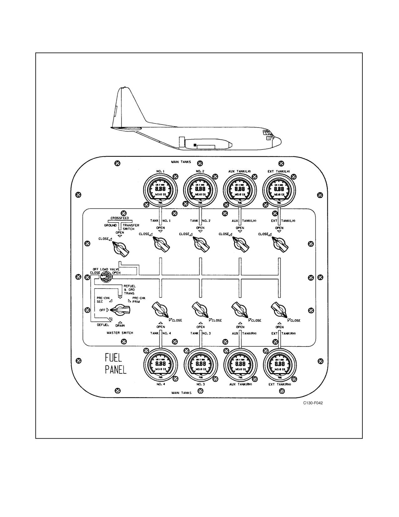
01-75GAL-1
Figure 2-25. Single-Point Refueling Control Panel
2-49
ORIGINAL
01-75GAL-1
2.6.12.1.5 FUEL QUANTITY Indicators
One FUEL QUANTITY indicator for each fuel tank is located on the single-point refueling control panel (see Figure
2-25). All the indicators register tank fuel quantity in pounds and are energized when the MASTER switch is at any
setting other than OFF. The fuel quantity indicators have a liquid crystal display that shows fuel quantity in pounds
on a digital display and the percentage of total fuel capacity on an analog display. The single-point refueling control
panel indicators are similar to those installed on the flight station fuel control panel except for a zero adjustment screw
located on the aft end of the flight station indicators. The single-point refueling control panel repeater indicators are
tested by depressing the corresponding flight station fuel control panel IND TEST pushbutton with the single point
refueling system MASTER switch in any position other than OFF. An E0 error code on the repeater indicator
indicates that no signal is being supplied from the primary indicator in the flight station. An E-error code on the
repeater indicator indicates that the primary indicator is presently displaying an error code. The repeater indicator
error codes are the same as the total fuel quantity indicator error codes. With an IND TEST pushbutton depressed,
both primary and repeater indicator numeric readouts count down to zero. When the IND TEST pushbutton is
released, the LCD segments illuminate for 4 seconds, then go blank for 4 seconds. The repeater indicator then
displays fuel quantity. The indicators receive single-phase, 115-Vac power from the ac instruments and fuel control
bus through the FUEL QUANTITY TOTALIZER circuit breaker on the pilot lower circuit breaker panel.
2.6.12.1.6 INTER CONN Switches
Two rotary, two-position (flow, no-flow) interconnect valve switches are provided on the auxiliary fuel control panel.
The switches enable dumping to be accomplished from the wing tanks and external tanks. When the switch is in the
FLOW position, fuel is supplied from the wing, external and fuselage tanks; however, the fuel supplied from the
fuselage tank must be by the FUS TANK CROSSFEED switch. Power for operation of the interconnect valves is
supplied from the essential dc bus through the INTERCONNECT VALVE RH and LH circuit breakers on the copilot
side circuit breaker panel. Power for operation of the interconnect valve relay is supplied from the essential dc bus
through the INTERCONNECT VALVE CONTROL circuit breaker on the copilot side circuit breaker panel. The
interconnect valves must be open for dumping fuel from the wing and external tanks.
2.6.12.1.7 Fuel Dump Switches
Two two-position (NORM, DUMP) fuel dump switches are provided on the auxiliary fuel control panel for dumping
fuel from the wing tanks. When the switches are placed in DUMP (unguarded) position, the dump valves will open.
Wing tank fuel can be dumped by placing the desired wing tank dump switch to the DUMP position and turning the
interconnect switches to the FLOW position. Power to the dump switches is supplied from the essential dc bus
through the FUEL DUMP VALVES LH and RH circuit breakers on the copilot side circuit breaker panel.
2.6.12.2 Refueling Procedure
Refer to Chapter 3.
2.7
ELECTRICAL POWER SUPPLY SYSTEMS
Note
Never use circuit breakers as switches. Circuit breakers should be pulled
only during emergencies or maintenance. (See Figures 2-34 through 2-41
for circuit breaker panels.)
All internal electrical power for aircraft use comes from five ac generators (see Figure 2-26), or from the battery. Each
engine drives one 40-Kva, ac generator, and a 40-Kva generator is driven by the APU. The APU-driven generator
is the same type as the engine-driven generator. Power from these ac generators is used to provide electrical power
for aircraft use: 28-Vdc; 200/115-volt, 400-Hz, 3-phase primary ac; and 115-volt, 400-Hz, single-phase, secondary
and primary ac. The four engine-driven ac generators are connected through transfer contactors (relays) to four ac
ORIGINAL
2-50
01-75GAL-1
buses: the left-hand ac bus, the essential ac bus, the main ac bus, and the right-hand ac bus. The transfer system
operates in such a manner that any combination of two or moreof theengine-driven acgenerators will power all four
of the buses. On aircraft 165313 and up, two bus switching units conduct ac power from the unregulated ac buses
to two additional (essential and main)avionics acbuses. (SeeFigure2-29foradistribution schematicofthesebuses.)
The bus switching units provide uninterrupted ac power to critical avionics components through the avionics buses
by monitoring the various sources and switching rapidly between thesesources as required. TheBSUs arecontrolled
by BSU 1 and BSU 2, two-position (OFF, ON) toggle switches on the overhead electrical control panel. (See Figure
2-28.) If only one generator is operating, it will power only the essential ac bus and the main ac bus. Placing the APU
generator control switch in the APU position energizes the APU generator contactor, which connects the APU
generator to the essential ac bus. The APU-driven ac generator normally will power only the essential ac bus. The
APU generator will also power the main ac bus provided there are no engine-driven generators supplying power and
the AC BUS TIE switch is placed to the ON position. This feature is for ground use only. The APU generator, voltage
regulator, and generator control are the same as the engine-driven generator, voltage regulator, and generator control.
(Refer to paragraph 2.19.) Combinations of operating generators and the buses that they power are shown on the ac
bus power sources chart (see Figure 2-32). All in-flight controls for operation of the electrical system are located on
the overhead electrical control panel (see Figure 2-28). Circuit breakers are shown in Figures 2-34 through 2-41.
2.7.1 Bus Switching Units (Aircraft 165313 and Up)
Two bus switching units (BSU 1 and BSU 2) provide continuous no-break power to the essential and main avionics
ac buses for critical avionics systems. BSU No. 1 supplies the essential avionics ac bus, and BSU No. 2 supplies the
main avionics ac bus. During normal operation with generator power, BSU No. 1 and No. 2 both receive power from
the essential and main ac buses. For BSU No. 1, the essential ac bus is the primary source and the main ac bus is the
alternate source. For BSU No. 2, the main ac bus is the primary source and the essential ac bus the alternate source.
When external ac power is being used, BSU No. 1 receives power from the left-hand ac bus only and BSU No. 2
receives power from the right-hand ac bus only. When the BSU switches are OFF or the BSUs are in the bypass mode,
the essential and main avionics buses are powered directly from their respective primary source. Each BSU receives
logic inputs that provideelectrical system status. It monitors theengine generatorline contactors, the APU generator
contactor, and the ac external power contactor, thus receiving advance information of impending bus transfers. It also
monitors voltage, frequency and current, and selects the best source of power for output to the respective avionics
bus.Duringnormalstableoperations,BSUNo.1selectspowerfromtheessentialacbusandBSUNo.2 selectspower
from the main ac bus.
Note
With the APU generator connected to the essential ac bus, programmed
logic in BSU No.1 does not recognize the APU on status. Simultaneous
disconnecting or reconnecting engine generator Nos. 2 and 3 when in this
configuration will cause momentary interruption of power to the essential
ac avionics bus.
When ac power is first applied to the aircraft with the BSU switches OFF, the BSUs are in the bypass mode with the
BSU BYPASS lights illuminated. When theBSU switches are placed to ON, the BSUs each perform a 5-secondBIT
check. After a successful BIT check, the BSU BYPASS lights will extinguish and the BSUs will connect the avionics
busestotheprimaryoralternatesource, asavailable, ifon generatorpower, orto theleft-hand andright-hand acbuses
if external ac power is selected. With external ac power selected, when the first generator is placed on line, external
ac power is removed from the essential and main ac buses as their load is assumed by the generator. External power
is then removed from the left- and right-hand ac buses after a delay of 0.5 seconds, and the BSUs then transfer to the
primary or alternate sources, as available. As additional generators are brought on line, if the BSU detects a power
interruption or a condition that would cause a degradation in output power quality, it will transfer the output to the
alternate source until the primary source stabilizes. After a 7-second delay, the BSU will switch back to the primary
source, provided it is stable.
2-51
ORIGINAL
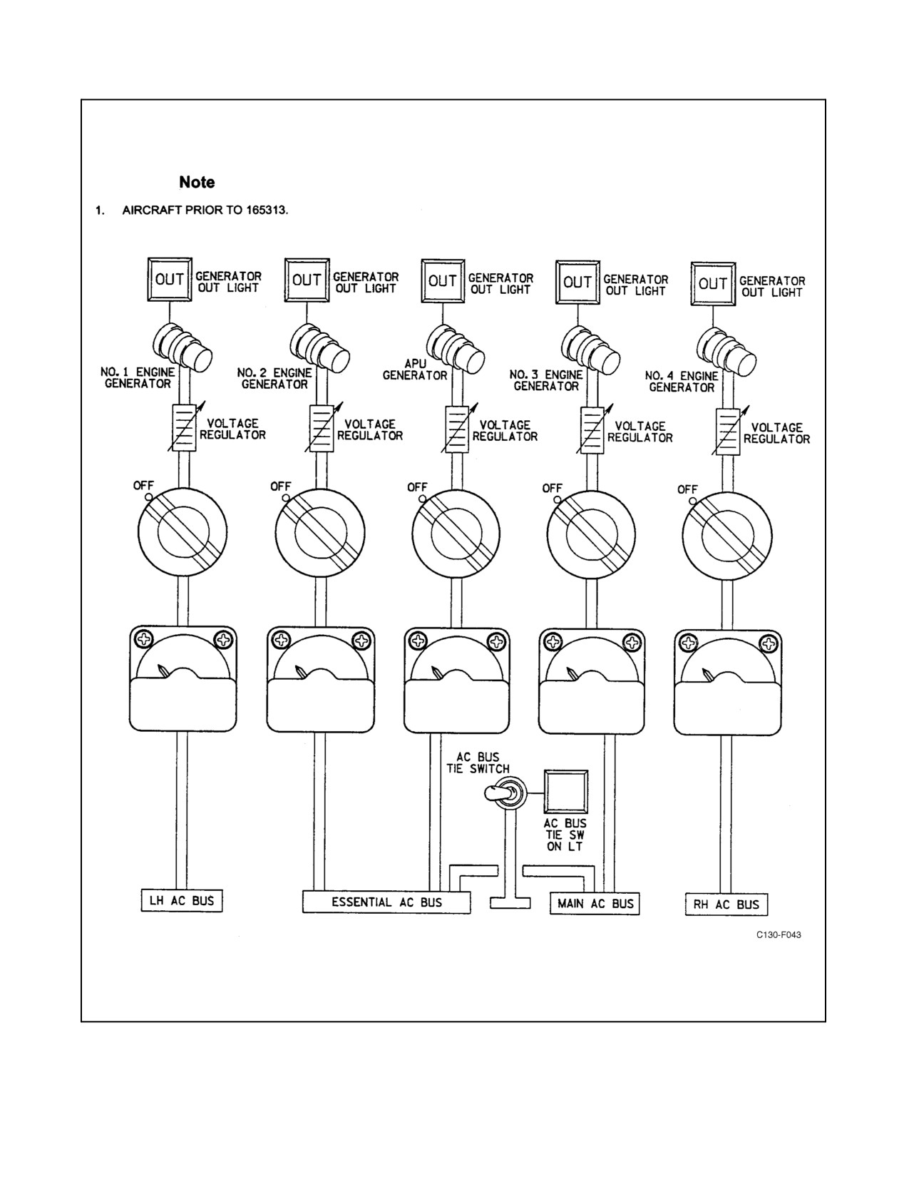
01-75GAL-1
Figure 2-26. Ac Primary Power Supply (Sheet 1 of 2)
ORIGINAL
2-52
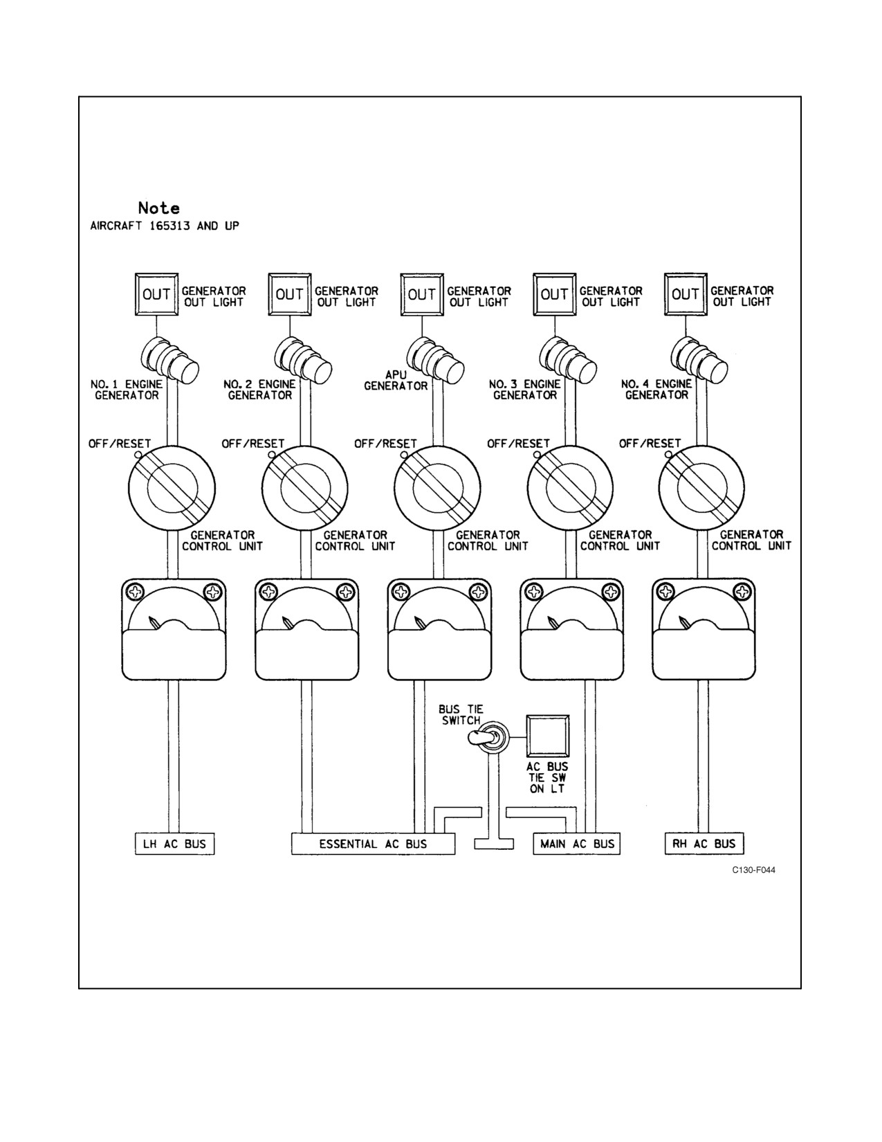
01-75GAL-1
Figure 2-26. Ac Primary Power Supply (Sheet 2)
2-53
ORIGINAL
01-75GAL-1
Note
In order to ensure a smooth transition of power to the main avionics ac bus,
place the AC BUS TIE switch to ON prior to switching from external ac
power to APU generator power.
The BSUs receive 28-Vdc control power through BSU 1 and BSU 2 two-position (OFF/ON) toggle switches on the
overhead electrical control panel. When placed in the OFF position, the BSU reverts to a bypass condition that
supplies power to the respective avionics bus from its primary ac bus. During normal operation, the BSU may
automatically go into the bypass mode if it fails to pass BIT. Two advisory lights illuminate to indicate the BSUs
are in the bypass mode either because the BSU has failed BIT or the BSU switch has been placed to OFF. In the event
of an overload condition on an avionics bus, the affected BSU will go into bypass mode and the respective BSU 1
or 2 BYPASS light will illuminate if the overload is not cleared in a specified time. The specific time varies from
5 minutes at 150-percent BSU overload, to 5 seconds at 200-percent overload, to 2 Hz for a short to ground. The delay
allows time for circuit protection devices to trip or open to relieve the overload. These switches can also be used at
any time to try to reset the BSU if it should automatically go into the BYPASS or OFF mode. It takes approximately
10 seconds for the BSU to reset. The BSU will remain in the bypass mode and will not reset until all power to the
BSU has been removed and reapplied.
2.7.2 External Power Provisions
Note
The 200/115-volt, three-phase, 400-Hz ac external source should have a
capacity of 40 Kva; its phase rotation must be A-B-C. The 28-Vdc external
source should have a capacity of 400 amperes.
Both dc and ac external power receptacles are located on the left side of the fuselage just aft of the battery
compartment. Dc power from the external source is supplied through two current limiters to the main dc bus. Any
dc electrically operated equipment on the aircraft, except equipment connected to the battery bus, can be supplied
from an external dc power source. The battery is disconnected from all dc buses except the battery bus when external
dc power is being used. When an external ac power source is connected to the aircraft, power is supplied to all ac
buses, to the dc buses through transformer-rectifier units, and to the battery bus to charge the battery if the DC
POWER switch is in the BATTERY position.
Note
The APU generator switch must be in the OFF position before external ac
power can be fed into the aircraft system.
2.7.3 Primary Ac System
Power for the primary ac system is supplied by five ac generators (see Figure 2-26). This power supply is also used
to operate the secondary ac systems and the dc system.
2.7.4 Primary Ac System Controls
The ac system controls, with the exception of a manual reset lever on each generator control panel, are located aft
of the overhead electrical control panel (see Figure 2-28) in the flight station. The generator control panels are located
in racks under the flight station and are accessible from the cargo compartment.
2.7.4.1 Generator Switches
The generator switches consist of five four-position rotary-type switches. When aswitch is in theON position (knob
stripe aligned with panel stripe), a relay closes contacts to connect the generator to the buses if the generator is
ORIGINAL
2-54
01-75GAL-1
operating normally. The distribution of generated power to the various buses under all conditions of generator
operation is shown in Figures 2-27 and 2-33. All engine generators are off the line when the low-speed ground idle
buttons are engaged; therefore, the APU generator must be used to provide power to the essential ac bus, which is
the only bus it supplies. The APU generator may also supply the main ac bus, provided there are no engine-driven
generators supplying power and the ac BUS TIE switch is placed in the ON position. This feature is for ground use
only. When a generator switch is placed in the OFF or (for aircraft 165313 and up) OFF/RESET position, the relay
disconnects the generator from the system. If the switch is turned to TRIP, the field circuit of the generator is opened
by a field relay to remove generator excitation. No voltage is then produced by the generator. The RESET position
of the switch is used to operate the field relay to its reset position after it has been tripped. The relay then closes the
generator field circuit to allow the generator to build up voltage. On aircraft prior to 165313, the RESET position
of the generator switch knob is spring loaded. The generator switch knob must be pulled out to move it to the TRIP
position.
2.7.4.2 Generator Disconnect Switches
Each engine-driven generator is provided with a spring-loaded, two-position (OFF, DISC) guarded switch. When
the switch is held in the DISC position (approximately 2 seconds), a direct short in the firing mechanism causes the
fused portion of the plunger to burn through and be actuated by spring tension. As the plunger of the firing mechanism
passes over the generator disconnect fired light switch, the generator DISC FIRED light will illuminate, indicating
the firing mechanism has been fired. The plunger then engages a wing on the generator stub shaft causing it to shear.
The generator cannot be reconnected in flight since a new stub shaft must be installed. Power to the switches is
supplied from the essential dc bus through the four GENERATOR DISCONNECT PWR circuit breakers on the pilot
upper circuit breaker panel.
2.7.4.3 Generator Disconnect Test Switch
A spring-loaded, two-position OFF, TEST GEN DISC switch is provided to check the continuity of the firing
mechanism. If the continuity check is good, the generator DISC FIRED lights will illuminate. Power to the switch
is supplied from the essential dc bus through the GENERATOR DISCONNECT PWR circuit breaker on the pilot
upper circuit breaker panel.
2.7.4.4 Ac BUS TIE Switch
Atwo-position(OFF,ON)acBUSTIEswitchontheoverheadelectricalcontrolpanelprovides ameans forpowering
the main ac bus from the APU generator during ground operation with no engine-driven generators supplying power.
The switch receives 28-Vdc power from the essential dc bus through the APU GEN ESS TO MAIN 53K circuit
breaker in the main ac distribution panel.
2.7.4.5 Ac External Power Switch
A two-position, ac external power switch is located immediately below the LH ac bus loadmeter on the overhead
electrical control panel. The OFF position of the switch disconnects external power from the ac distribution system.
The external power position (stripe on knob aligned with stripe on panel) connects external power to the ac
distribution system. The ac external power switch receives 28-Vdc control power from the ac external power source
throughtheaircraftexternalacpowerunit,or24-Vdccontrolpowerdirectlyfromtheacexternal powercart dcbattery
through the aircraft ac EXT PWR CONTROL circuit breaker in the aircraft battery compartment.
Note
Anoverridesolenoidinthesystemispoweredfromthebatteryandwillturn
the switch off if the APU generator control switch is on, if the ac power is
not in the correct phase sequence, if any engine generator is on the line, or
if the external power plug is not in the receptacle.
2-55
ORIGINAL
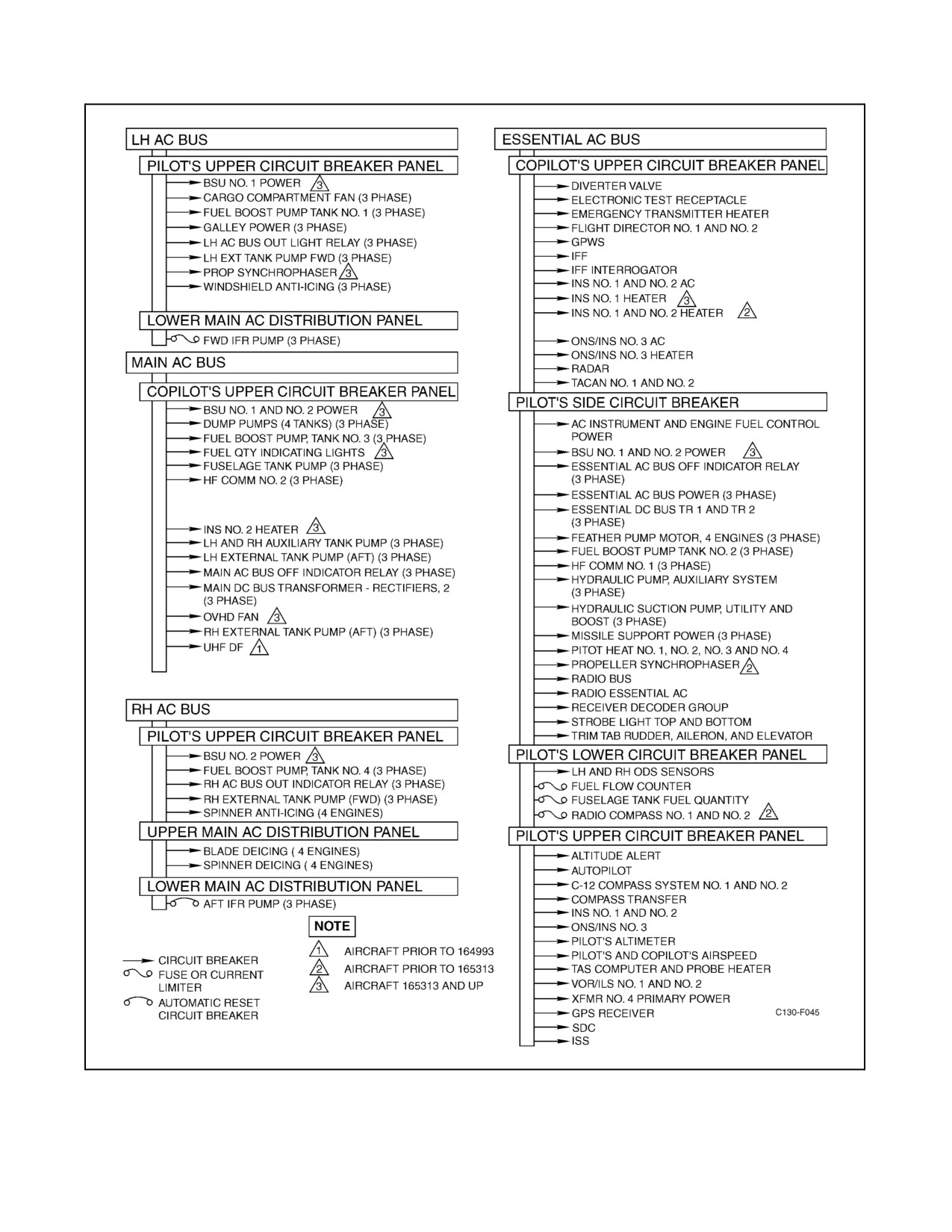
01-75GAL-1
Figure 2-27. Ac Primary Power Distribution (Sheet 1 of 2)
ORIGINAL
2-56
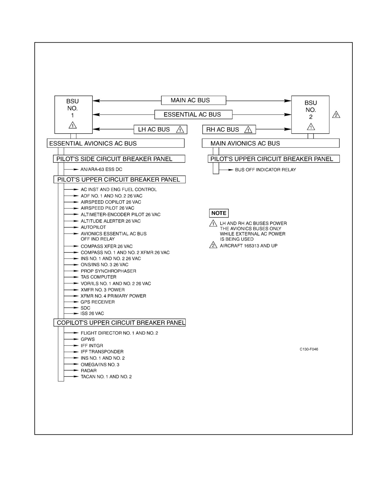
01-75GAL-1
Figure 2-27. Ac Primary Power Distribution (Sheet 2)
2-57
ORIGINAL
01-75GAL-1
2.7.4.6 VOLTAGE & FREQUENCY SELECTOR Switch
Aseven-position (ENG GEN NO. 1, ENG GEN NO. 2, ENG GEN NO. 3, ENG GEN NO. 4, APU GEN, EXT PWR,
COPLT INV φA AC INST & ENG FUEL CONT INV φC) rotary switch is used to isolate a chosen source of ac power
for measurement.
2.7.4.7 PHASE SELECTOR Switch
A three-position PHASE SELECTOR switch selects one of the three phases of ac generator output to be measured
by the ac meters on the panel. Placing the switch in a given position determines which phase is measured by the five
ac loadmeters, the ac voltmeter, and the frequency meter on the overhead electrical control panel. The switch can be
used in conjunction with the VOLTAGE & FREQUENCY SELECTOR switch to test a given ac power source.
2.7.4.8 Primary Ac System Indicators
Indicators for the primary ac power system are located in the overhead electrical control panel (see Figure 2-28) in
the flight station.
2.7.4.9 Generator-Out Indicator Lights
Each generator is provided with a generator-out press-to-test indicator light. This light will illuminate when the
generator control switch is in the ON position and one or more of the following conditions exist: the generator is not
developing sufficient voltage, the generator output is below proper frequency, or the field-trip relay has opened the
field circuit of the generator. The field relay will trip when the generator switch is turned to the TRIP position, when
the generator output voltage is too high, or when a fault exists in the generator output circuit.
2.7.4.10 Ac Loadmeters
Five ac loadmeters, one for each generator, give a continuous indication of the percent of rated current flow of any
one PHASE SELECTOR switch from their respective generators.
2.7.4.11 AC BUS OFF Indicators
The AC BUS OFF warning system consists of four red press-to-test warning lights and four indicator relays. The
warning lights are located on the flight station overhead electrical control panel and the relays are located behind the
LH and RH distribution panels. The lights are labeled ESS AC OFF, MAIN AC OFF, LH AC OFF, and RH AC OFF.
On aircraft 165313 and up there are six red press-to-test warning lights and six indicator relays. Labeled ESS AC
OFF, MAIN AC OFF, LH AC OFF, RH AC OFF, ESS AV AC OFF, and MAIN AV AC OFF. The indicator relays
receive power from their respective ac bus. The warning lights receive 28-Vdc power from the isolated dc bus through
the AC BUS OFF IND circuit breaker on the pilot side circuit breaker panel.
2.7.4.12 AC VOLTMETER
The AC VOLTMETER can be used to measure the output voltage of the generator or inverter that has been selected
with the VOLTAGE & FREQUENCY SELECTOR switch. Each of the three phases of generator output, or the
appropriate phase of inverter output, can be measured by selectively positioning the PHASE SELECTOR switch.
2.7.4.13 Frequency Meter
A frequency meter permits measuring the frequency of the output power of the generator selected with the VOLTAGE
& FREQUENCY SELECTOR switch. Each of the three phases of the generator output power can be measured by
selecting the appropriate position on the PHASE SELECTOR switch.
2.7.4.14 Ac External Power-On Indicator Light
An ac external power-on (EXT AC PWR) press-to-test indicator light is energized by dc power through small pins
in the ac external power receptacle and through the closed contacts of a phase sequence relay on the lower main ac
distribution panel when the relay is energized. The phase sequence relay is energized when three-phase external ac
power with correct phase sequence and no open phases is connected to the aircraft.
ORIGINAL
2-58
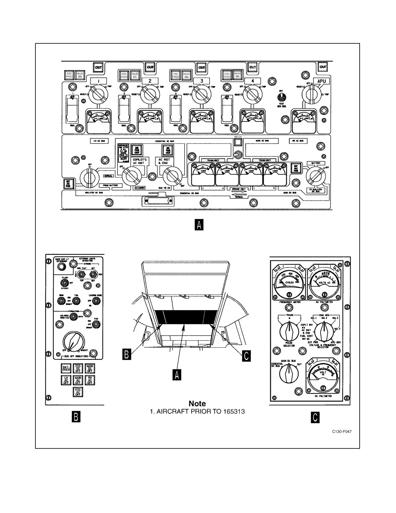
01-75GAL-1
Figure 2-28. Overhead Electrical Panel (Sheet 1 of 2)
2-59
ORIGINAL
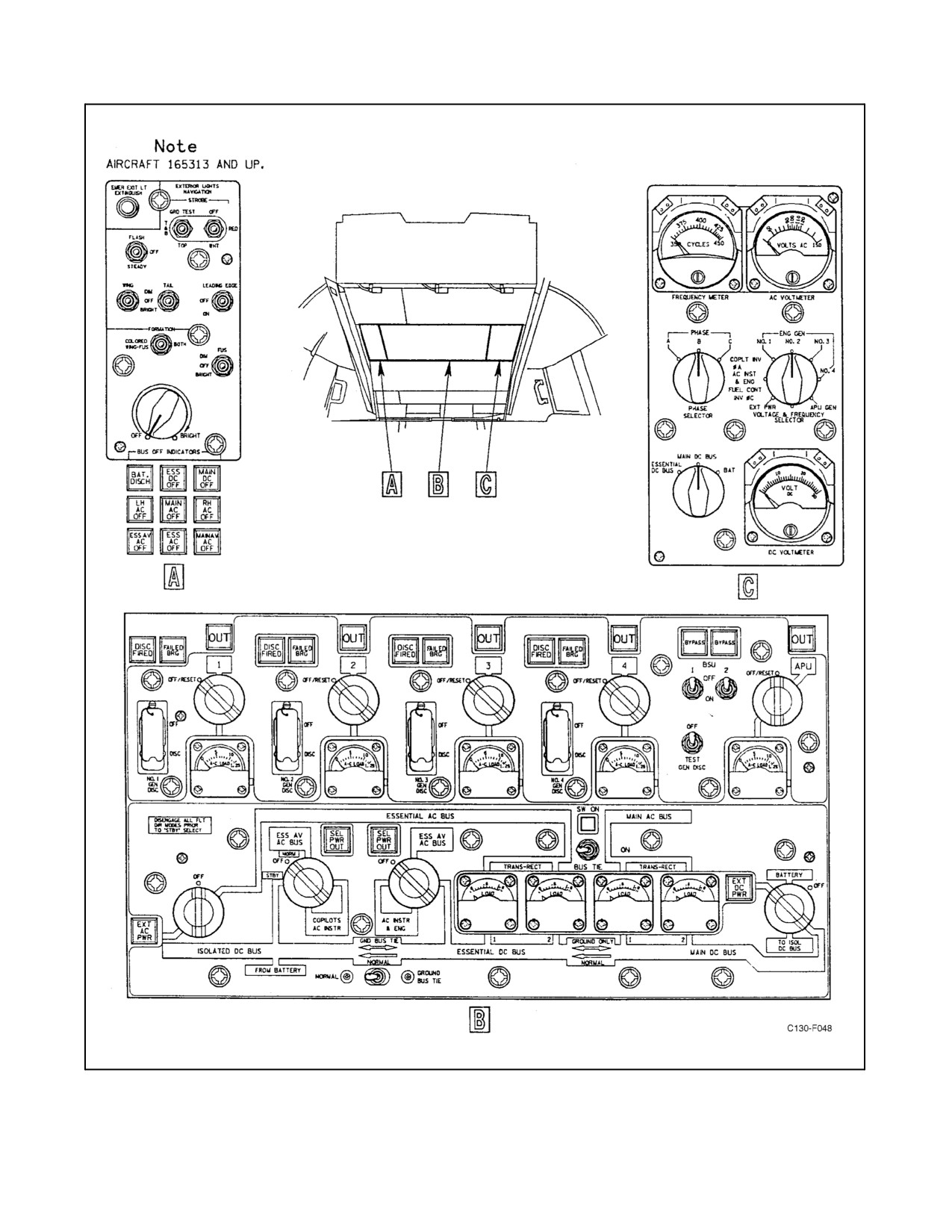
01-75GAL-1
Figure 2-28. Overhead Electrical Panel (Sheet 2)
ORIGINAL
2-60
01-75GAL-1
2.7.4.15 Generator Disconnect Fired Indicator Lights
Each engine-driven generator is provided with a generator disconnect fired (DISC FIRED) indicator light that will
illuminate when one of the following conditions exists: a generator disconnect switch is held in the DISC position
and the firing mechanism is fired, or when the generator disconnect test switch is held in the TEST GEN DISC
position. Power to the lights is supplied from the essential dc bus through the GENERATOR DISCONNECT circuit
breaker on the pilot upper circuit breaker panel.
2.7.4.16 Generator Bearing-Failure Indicator Lights
Each engine-driven generator is provided with a generator bearing failure (FAILED BRG) warning indicator light.
Each generator stator contains a soft wire winding that grounds out the stator when contact is made with the rotor.
When this occurs, a circuit is completed for illumination of the generator bearing-failure indicator light. Once the
indicator light is illuminated, it will remain illuminated until dc power to the circuit is removed. The power for the
lights and holding circuit is supplied from the essential dc bus through two GEN BRG FAIL circuit breakers on the
pilot upper circuit breaker panel.
2.7.4.17 Ac BUS TIE Switch On Light
An amber SW ON light, located adjacent to the ac BUS TIE switch, illuminates when the ac BUS TIE switch is in
the ON position. The light receives 28-Vdc power from the essential dc bus through the GEN OUT LIGHT APU
circuit breaker on the copilot lower circuit breaker panel.
2.7.5 Secondary Ac System
The secondary ac power is comprised of two systems: the copilot ac instrument system, and the ac instrument and
engine fuel control system (see Figures 2-29 and 2-30).
2.7.5.1 Copilot Ac Instrument Power System
On aircraft prior to 165313, a single 250-volt-ampere inverter supplies 115-volt, 400-Hz, single-phase power. The
inverter draws dc power from the isolated bus; therefore, it can be operated from the battery during emergency
conditions of flight. Power can also be supplied from the essential ac bus to operate the pilot and copilot ac
instruments.
On aircraft 165313 and up, a 250-volt-ampere solid-state inverter supplies 115-volt, 400 Hz, single-phase ac power.
The inverters are operated by dc power from the isolated bus, and therefore, can be operated from the battery during
emergency conditions. During normal operations, power is supplied from the essential avionics ac bus to operate the
pilot and copilot instruments.
2.7.5.2 Ac Instrument and Engine Fuel Control System
On aircraft prior to 165313, the ac instruments and engine fuel control system are powered by a 115-volt, 400-Hz,
single-phase ac bus. One source of power is a 2,500-volt-ampere, single-phase inverter powered from the essential
dcbus through acurrent limiterlocated in theright-hand distribution box. Invertercontrol poweris provided through
the AC INST & ENG FUEL CONT INVERTER circuit breaker on the copilot lower circuit breaker panel from the
essential dc bus. Power can also be supplied from phase A of the essential ac bus through the AC INST & ENG FUEL
CONT PWR circuit breaker on the pilot side circuit breaker panel. The ac instruments and engine fuel control bus
circuits are protected from voltage spiking by a voltage surge suppressor (varistor) through the SURGE SUPPR
PROT DEV fuse on the pilot lower circuit breaker panel. Two instrument transformers are powered from the
115-volt, 400-Hz, single-phase bus, and provide 26-volt, single-phase, ac power for instrument use.
2-61
ORIGINAL
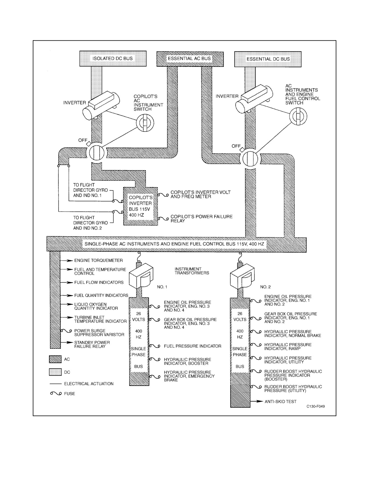
01-75GAL-1
Figure 2-29. Ac Secondary Power System (Aircraft Prior to 165313)
ORIGINAL
2-62
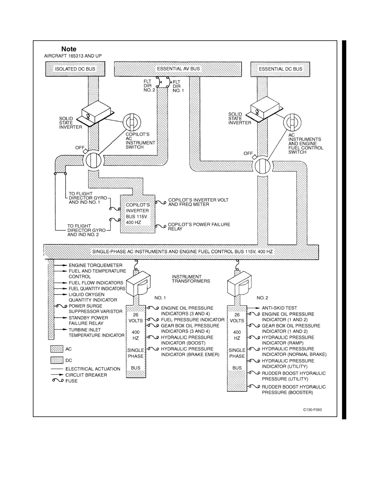
01-75GAL-1
Figure 2-30. Ac Secondary Power System (Aircraft 165313 and Up)
2-63
ORIGINAL
01-75GAL-1
On aircraft 165313 and up, the ac instruments and engine fuel control system are powered by a 115-volt, 400-Hz,
single-phase, ac instrument and engine fuel control bus. Power for the bus is supplied from one of two sources. One
source of power is a solid-state 1,000-volt-ampere inverter. Inverter control power is provided through the AC INST
& ENG FUEL CONT INVERTER circuit breaker on the copilot lower circuit breaker panel from the essential dc
bus. Power can also be supplied from Phase A of the essential avionics bus through the AC INST & ENG FUEL
CONT PWR circuit breaker on the pilot side circuit breaker panel. The ac instruments and engine fuel control bus
circuits are protected from voltage spiking by a voltage surge suppressor (varistor) through the SURGE SUPPR
PROT DEV fuse on the pilot lower circuit breaker panel. Two instrument transformers are powered from the
115-volt, 400-Hz, single-phase bus and provide 26-volt, single-phase, ac power for instrument use.
2.7.5.3 Secondary Ac System Controls
Controls for the secondary ac power system are located on the overhead electrical control panel (see Figure 2-28).
2.7.5.4 Copilot Ac Instruments Switch
The COPILOT AC INST switch is a three-position (STANDBY, OFF, NORMAL) rotary switch. In the STANDBY
position, poweris routed from theisolated dcbus to operate thecopilot instrument inverter forthe copilot instrument
powersupply system. IntheNORMALposition, theinverteristurned offand powerforthecopilot instrumentpower
system is taken from the essential ac bus. In the OFF position, no power is supplied to the system.
On aircraft 165313 and up, the COPILOTS AC INSTR switch is a three-position, rotary-type switch. In the STBY
(horizontal) position, dc power is routed from the isolated dc bus to operate the copilot instrument inverter for the
copilot instrument power supply system. In the ESS AV AC BUS position, the inverter is turned off and power for
the copilot instrument power supply system is supplied from the essential avionics ac bus. In the OFF position, no
power is supplied to the system.
2.7.5.5 Ac Instrument and Engine Switch
The AC INST & ENG switch is a three-position rotary switch. In the horizontal position, power is supplied to the
115-volt, 400-Hz, single-phase bus from phase A of the essential ac bus. In the vertical position, power is supplied
to theacinstruments and enginefuel control inverter, which will then powerthesystem. Iftheinverteroutputvoltage
is insufficient, the power supply is automatically switched from the essential dc bus to the essential ac bus. In the
OFF position, no power is supplied to the system.
On aircraft 165313 and up, the AC INSTR & ENG switch is a three-position rotary switch. In the NORM (ESS AV
AC BUS) position, power is supplied to the ac instrument and engine fuel control bus from phase A of the essential
avionics ac bus. In the STBY (horizontal) position, essential dc bus power energizes the ac instruments and engine
fuel inverter, which will then power the bus. If the inverter output voltage is insufficient, the power supply is
automatically switched from the inverter to the essential ac bus. In the OFF position, no power is supplied to the
system.
2.7.5.6 VOLTAGE & FREQUENCY SELECTOR Switch
The VOLTAGE & FREQUENCY SELECTOR switch has seven positions for measuring the output voltage and
frequency of the ac power supply sources. Placing the switch in the COPLT INV φA AC INST & ENG FUEL CONT
INV φC position, while simultaneously placing the PHASE SELECTOR switch in the PHASE A position, provides
an indication of the frequency and voltage of the copilot inverter on the frequency meter and the ac voltmeter,
respectively. Positioning the PHASE SELECTOR switch to PHASE C provides an indication of the output frequency
and voltage of the ac instrument and engine fuel control inverter. If the switch is at the COPLT INV φA AC INST
& ENG FUEL CONT INV φC position and essential ac power is being used in place of the inverter, the frequency
meter and the ac voltmeter will not indicate output frequency.
2.7.5.7 PHASE SELECTOR Switch
A three-position PHASE SELECTOR switch permits selection of the appropriate phase of electrical power when
measuring the output voltage and frequency of either of the inverters.
ORIGINAL
2-64
01-75GAL-1
2.7.6 Secondary Ac System Indicators
Indicators for the secondary ac power system are located on the overhead electrical control panel (see Figure 2-28).
2.7.6.1 Ac Voltmeter
An ac voltmeter permits measuring the output voltage of that phase of inverter power selected with the PHASE
SELECTOR switch. In order for the voltmeter to measureinverter output voltage, theVOLTAGE & FREQUENCY
SELECTOR switch must be in the COPLT INV φA AC INST & ENG FUEL CONT INV φC position. If the switch
is at either position and a bus source of power is being used in place of the inverter, however, the voltmeter will not
indicate output voltage.
2.7.6.2 Frequency Meter
A frequency meter permits measuring the frequency of the output power of that phase of inverter output selected with
the PHASE SELECTOR switch. In order for the frequency meter to measure the frequency of the inverter output
power, the VOLTAGE & FREQUENCY SELECTOR switch must be in the COPLT INV φA AC INST & ENG
FUEL CONT INV φC position. If the switch is at either position and a bus source of power is being used in place
of the inverter, however, the frequency meter will not indicate output frequency.
2.7.6.3 Selected Power OUT Lights
Two SEL PWR OUT press-to-test lights are located on the electrical control panel. If the COPILOT AC
INSTRUMENT or the AC INST & ENG fuel control SEL PWR OUT light illuminates, it indicates that no power
is available to therespective bus. When theAC INST & ENG switch is in theSTBY position and its SEL PWR OUT
light illuminates, the inverter has failed; however, the 115-Vac instrument and engine bus is then automatically
connected to the NORM power source. The light does not illuminate when the corresponding selector switch is OFF.
2.7.7 Dc Power System
Power from the essential ac bus and the main ac bus operates four transformer-rectifier units (two from each ac bus)
to provide dc power to the respective dc buses for the aircraft (see Figure 2-31). The four transformer-rectifier units,
mounted on theelectroniccontrol and supply rack, convert the powerfrom theac buses to 28-Vdc. Both theessential
ac bus and the main ac bus may be powered by any of the engine-driven generators (refer to Figure 2-32).
The essential ac bus is powered from the APU generator also, so it may be used as a source of dc power for ground
operation. The transformer-rectifier units feed current through reverse-current relays to the main dc bus and the
essential dc bus.
2.7.7.1 Dc System Buses
There are four buses in the DC POWER system: essential dc bus, battery bus, main dc bus, and isolated dc bus (see
Figure 2-33). The main and essential buses are connected through a reverse-current relay, which, in flight, allows
current to flow from the main bus to the essential bus but limits current flow in the opposite direction. When the
aircraft is on the ground, a touchdown switch is actuated to complete a circuit that overrides the reverse-current
limiting features of the reverse-current relay and permits current flow in either direction between the main and
essential buses. The essential and isolated buses are similarly connected through another reverse-current relay that
limits current flow from the isolated bus to the essential bus in flight. When the aircraft is on the ground, the
touchdown switch completes a circuit so that manual positioning of the dc BUS TIE switch overrides the
reverse-current limiting features of the reverse-current relay and permits current flow in either direction between the
isolated and essential buses.
Note
The dc BUS TIE switch is only effective if the touchdown switch is
actuated by the aircraft being on the ground.
2-65
ORIGINAL
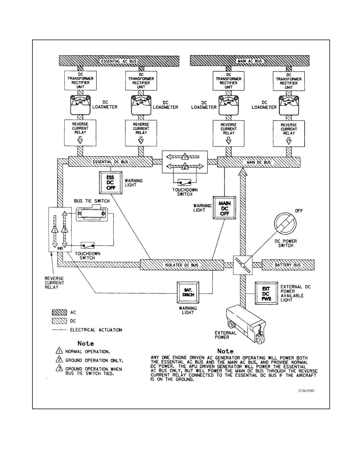
01-75GAL-1
Figure 2-31. Dc Power Supply
ORIGINAL
2-66
01-75GAL-1
ENGINE DRIVEN GENERATORS
AC GENERATOR POWER SOURCE
AC BUS POWER SOURCE 2
ESSENTIAL
MAIN
AVIONICS
AVIONICS
BUS
BUS
LH
ESSENTIAL
MAIN
RH
NO.
1
NO.
2
NO.
3
NO.
4
AC BUS
AC BUS
AC BUS
AC BUS
PRI
ALT
PRI
ALT
1
2
3
4
ESS
MAIN
MAIN
ESS
2
2
3
4
ESS
MAIN
MAIN
ESS
1
1
3
4
ESS
MAIN
MAIN
ESS
1
2
4
4
ESS
MAIN
MAIN
ESS
1
2
3
3
ESS
MAIN
MAIN
ESS
4
3
3
4
ESS
MAIN
MAIN
ESS
1
1
4
4
ESS
MAIN
MAIN
ESS
1
2
2
1
ESS
MAIN
MAIN
ESS
2
2
3
3
ESS
MAIN
MAIN
ESS
2
2
4
4
ESS
MAIN
MAIN
ESS
1
1
3
3
ESS
MAIN
MAIN
ESS
4
4
ESS
MAIN
3
3
ESS
MAIN
2
2
ESS
MAIN
1
1
ESS
MAIN
APU Gen
APU Gen
ESS
3
ESS
Ext
Ext
Ext
Ext
LH
RH
Generator Out
Generator On
Note
1.
The APU generator will power the main ac bus when the ac bus tie switch is placed in the on position. This function is
for ground checks only.
2
Aircraft 165313 and up.
3
If the ac bus tie switch is on, BSU no. 2 will select the main ac bus to power the main avionics bus.
4.
Example:
No. 2 and No. 3 engine-driven generators out.
LH ac bus supplied by No. 1 generator.
Essential ac bus supplied by No. 1 generator.
Main ac bus supplied by No. 4 generator.
RH ac bus supplied by No. 4 generator.
5.
If generator frequency drops below 368 Hz, the respective bus should transfer automatically.
Figure 2-32. Ac Bus Power Sources
2-67
ORIGINAL
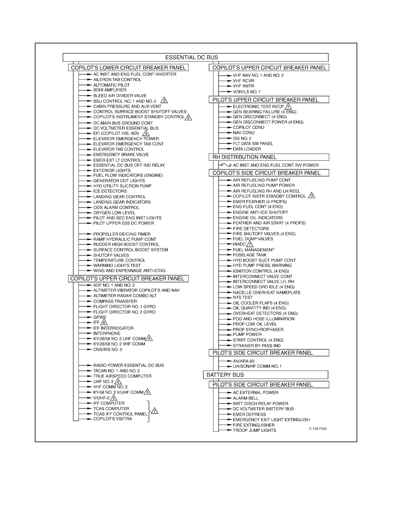
01-75GAL-1
Figure 2-33. Dc Power Distribution (Sheet 1 of 2)
ORIGINAL
2-68
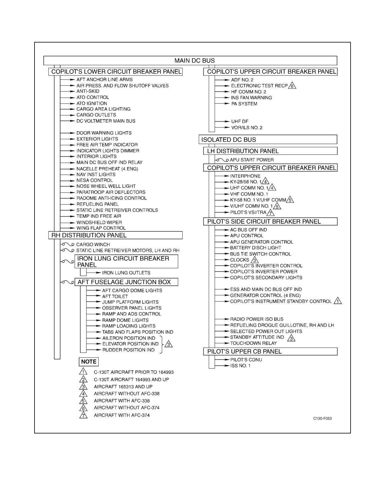
01-75GAL-1
Figure 2-33. Dc Power Distribution (Sheet 2)
2-69
ORIGINAL
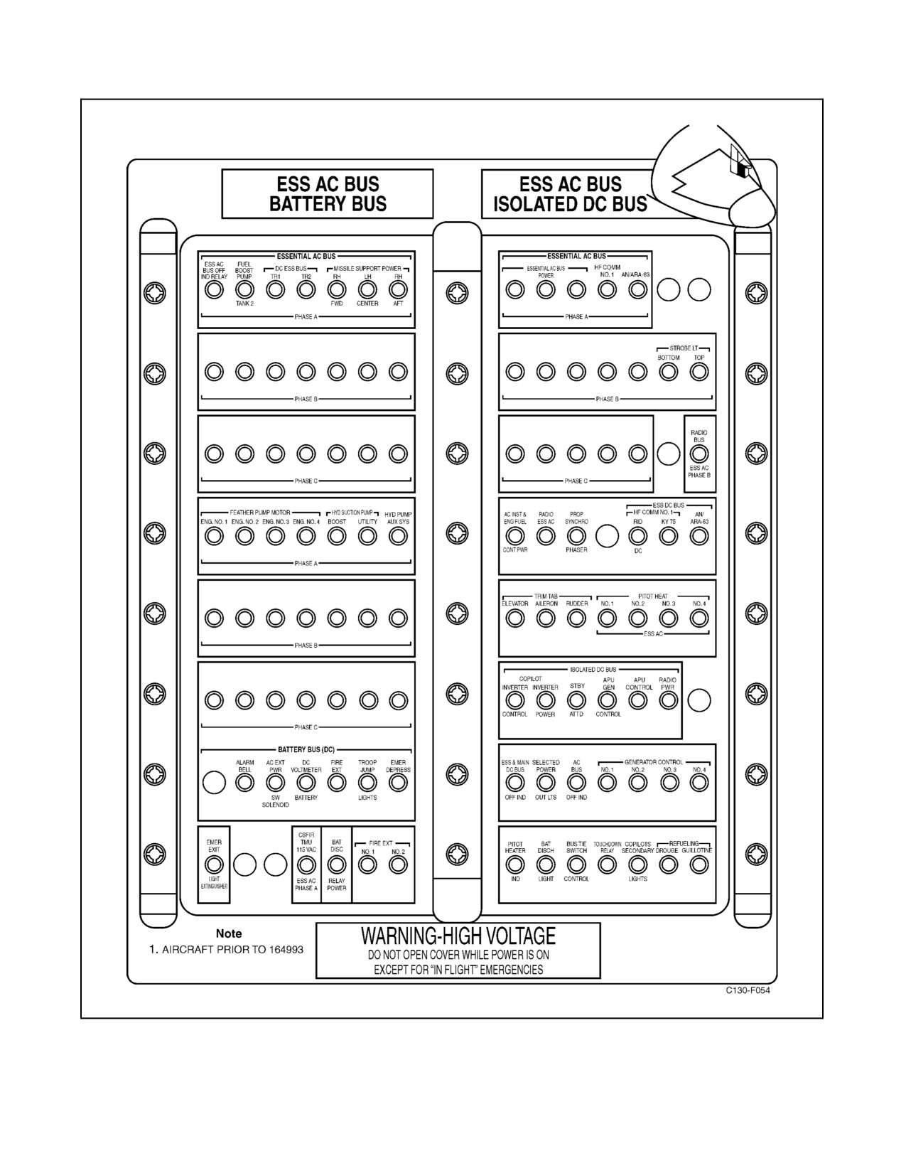
01-75GAL-1
Figure 2-34. Pilot Side Circuit Breaker Panel (Sheet 1 of 3)
ORIGINAL
2-70